EL1016 ELLIPTICAL
CROSS TRAINER
USER MANUAL

2
CONTENTS
Important Safety Information
Weight Limit Capacities
Hardware Parts List
Pre Assembly Check List
Assembly Instructions
Computer Instructions
Exercise Instructions
Exploded Diagram
Parts List
ADDITIONAL INFORMATION
Warranty Information
3
4-5
6
7-13
14-15
16-17
18-19
20-21
22
23
Supplied by:
Pure-Tec Limited
Tel: +44 (0) 1482 212098
Email: service@puretecfitness.com
www.puretecfitness.com

3
IMPORTANT SAFETY INFORMATION
READ ALL INSTRUCTIONS BEFORE USING
1.
This Trainer is intended for class H (H=Domestic) use only. It is not designed for
commercial use.
2.
This machine has been tested to EN 957.
3.
Read the OWNER’S OPERATION MANUAL and all accompanying literature and follow it
carefully before using your Elliptical CrossTrainer.
4.
Keep children and pets away from the Trainer at all times. Do not leave children
unattended in the same room with the Trainer. The Trainer is not a toy and therefore
parents and guardians should be aware of the natural tendency for children to play,
leading to situations and behaviour for which the Trainer is not intended.
5.
If children are allowed to use the Trainer their physical/mental development and above
all, temperament should be taken into account. Constant supervision is therefore
needed.
6.
Position the Trainer on a clear levelled surface which is clear of all obstacles as not to
restrict movement whilst exercising. DO NOT use the Trainer near water or outdoors.
7.
Exercise equipment has moving parts. In the interest of safety, keep others, especially
children, at a safe distance while exercising.
8.
Never hold your breath while exercising. Breathing should remain at a normal rate in
conjunction with the level of exercise being performed.
9.
Rest adequately between workouts. Muscle tone develops during these rest periods.
Beginners should work out twice a week and increase gradually to 4 to 5 times per
week.
10.
Remove all jewellery, including rings, chains and pins before commencing exercise.
11.
Always wear suitable clothing and footwear during exercise. Do not wear loose fitting
clothing that could become entangled with the moving parts of your exercise machine.
IMPORTANT!!! THE MAXIMUM RECOMMENDED WEIGHT CAPACITY FOR YOUR
TRAINER IS 110KGS.
THIS OWNER’S MANUAL CONTAINS ASSEMBLY, OPERATION, MAINTENANCE AND
SAFETY INFORMATION. IN THE INTEREST OF SAFETY, PLEASE MAKE CERTAIN THAT
YOU READ AND UNDERSTAND ALL THE INFORMATION BELOW.
4
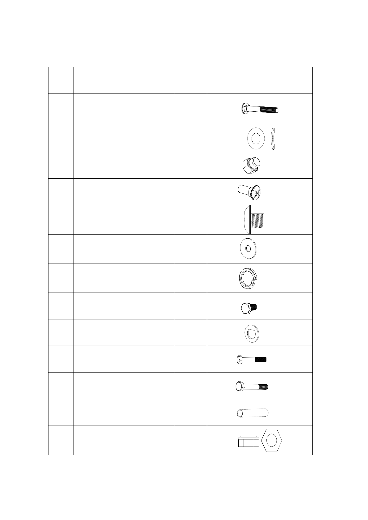
HARDWARE PACKING LIST
NO.
DESCRIPTION
Q’TY
DRAWING
2
Carriage bolt M10*75
4
4
Curved washerФ10*Ф22
4
5
Domed nut M10
4
21
Hollow carriage nutФ8*20
4
22
Allen bolt M6*12
4
26
Flat washerФ10*Ф32
2
27
Spring washerФ10
2
28
Hex head bolt M10*20
2
29
D type washer
2
31
Hex head bolt M8*45
2
32
Hex head bolt M10*78
2
33
Sleeve
2
34
Nylon nut M10
2

5
42
Club knob
4
44
Washer Ф10*Ф22
6
46
Washer Φ27*Φ12.8
2
47
Allen bolt M8*16
6
54
Curved washer Ф8*Ф20
6
59
Hinge bolt L/R
1/1
36
Wave washer
2
60
Nut L/R
1/1
Allen Key
2
Allen key L8
1
Allen Key L6
1
Allen Key L4
1
6
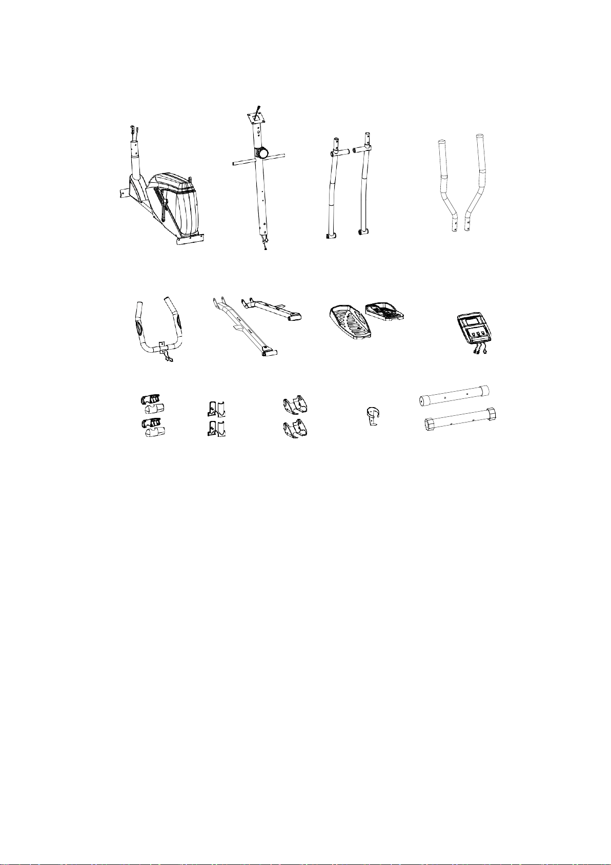
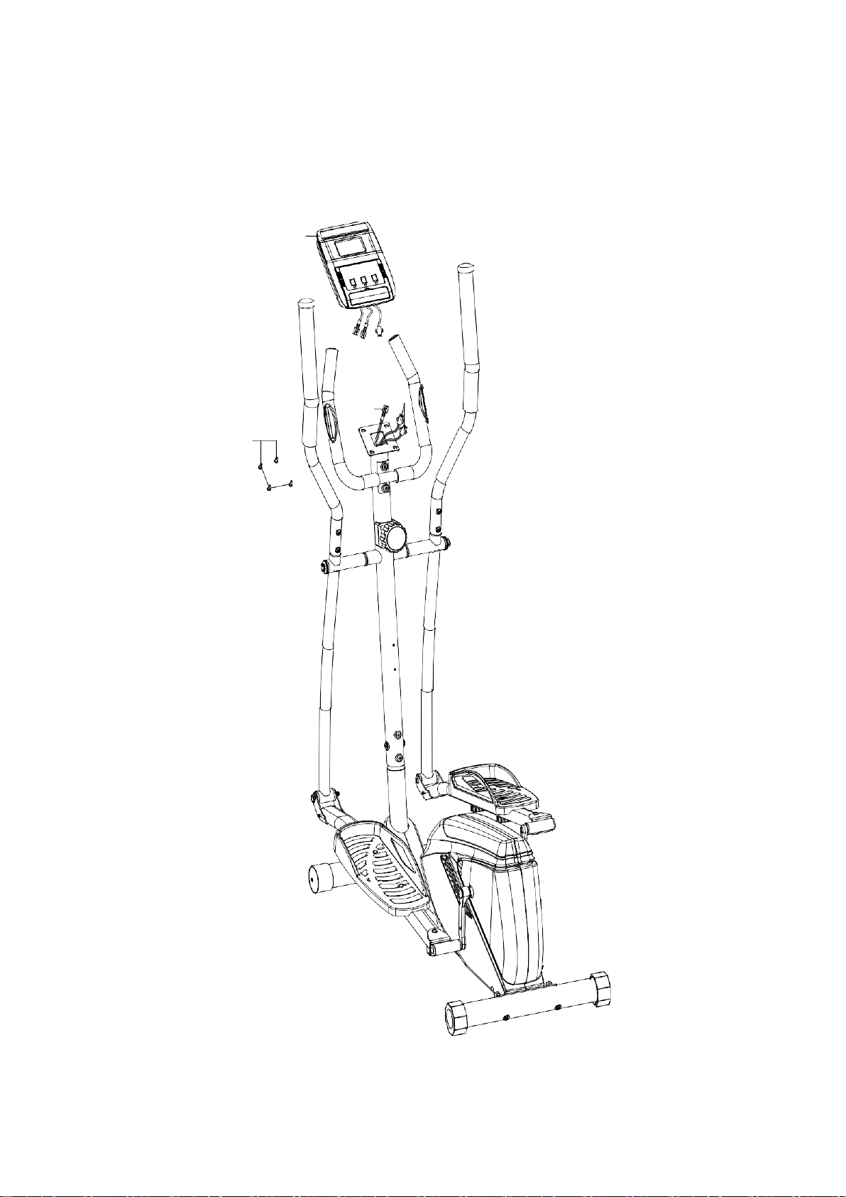
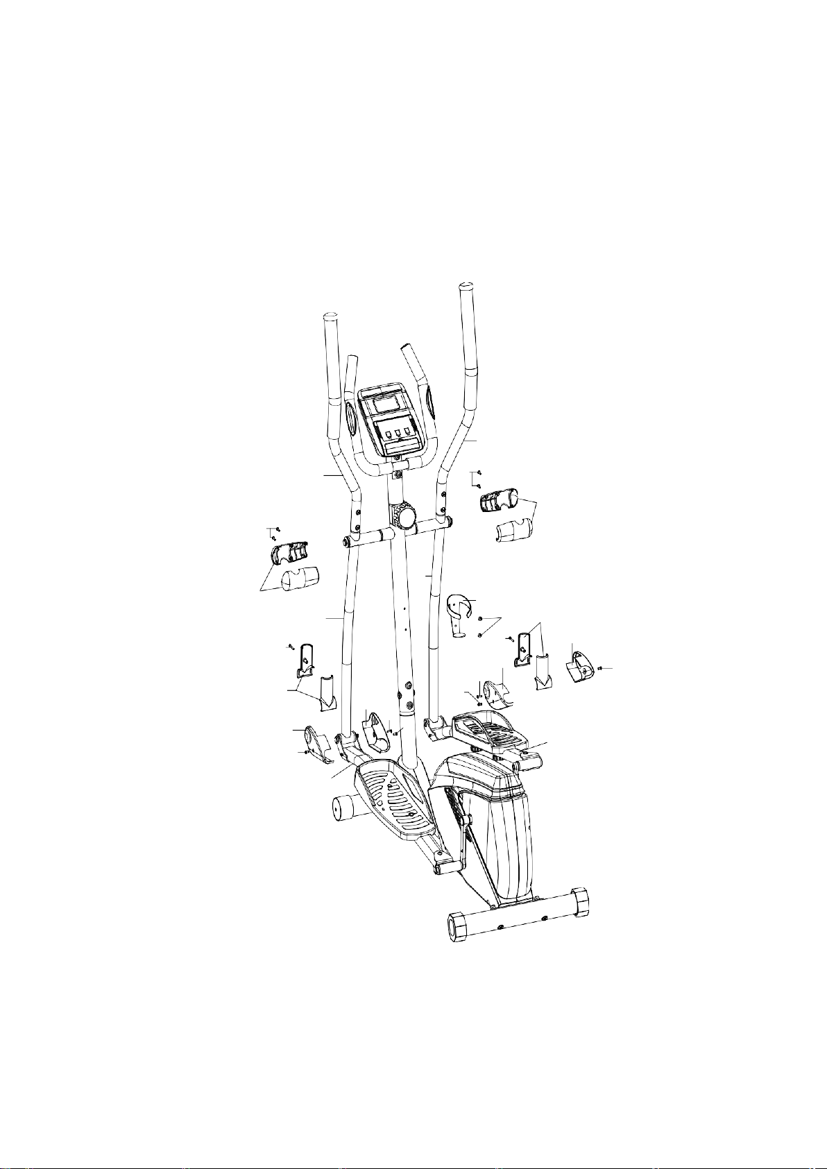
PRE-ASSEMBLY CHECK LIST
NO:1
NO:9/51
NO:52/53
NO:12/13
NO:11
NO:41L/R NO:48L/R
NO:10
NO:35
NO:39
NO:37L/R
NO:43
NO:6/3
PART NO.
DESCRIPTION
Q’TY
1
Main Frame
1
9/51 Front post/ Tension control knob w/cable 1/1
52/53 Bottom handlebar L/R 1/1
12/13 Top handlebar L/R 1/1
41 Pedal tube L/R 1/1
11 Fixed handlebar
1
6/3 Front stabilizer/ Rear stabilizer 1/1
10 Computer
1
48 Pedal L/R 1/1
35 Top handlebar cover
4
39 Bottom handlebar cover
4
37 Pedal tube cover L/R 2/2
43
Bottle holder
1
7
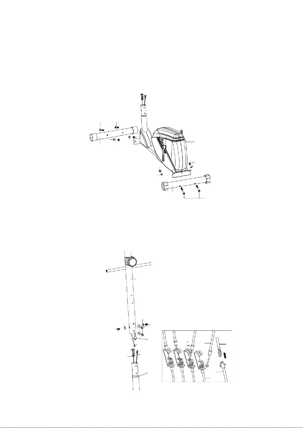
ASSEMBLY INSTRUCTION
STEP 1
Attach rear stabilizer (3) to main frame (1), tighten with two curved washers (4), domed nuts
(5) and carriage bolts (2). Then attach the front stabilizer (6) to the main frame (1), tighten
with two carriage bolts (2) ,curved washers (4) and domed nuts (5).
2
5
4
4
6
5
5
5
4
4
3
2
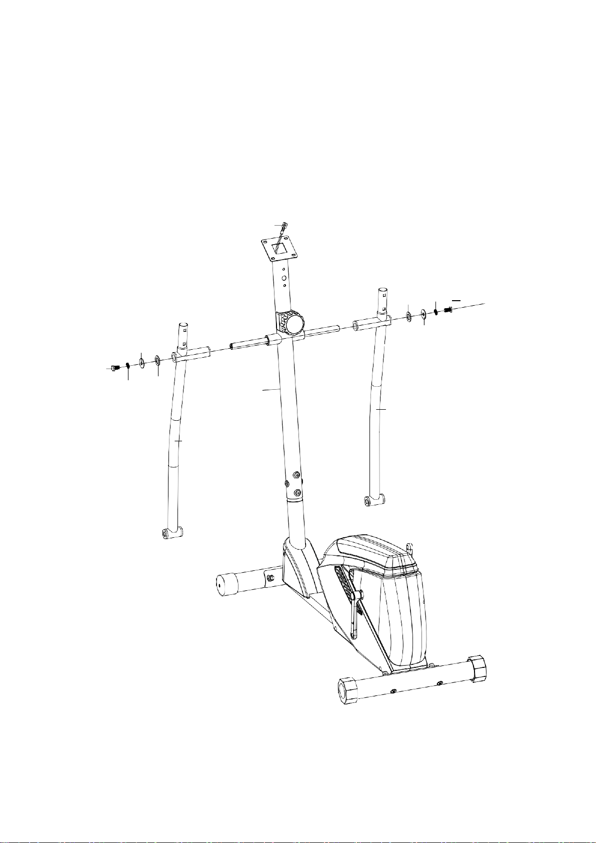
STEP 2
Connect the extension lower sensor wire (49) with the middle sensor wire (55).
Turn the tension control knob w/cable (51) to level 8, connect it to extension tension
cable (50).
Insert the front post (9) into the main frame (1) and secure using four allen bolts (47)
and four curve washers (54).
9
54
54
47
47
55
51
50
49
1
51
55
49
50
1
8
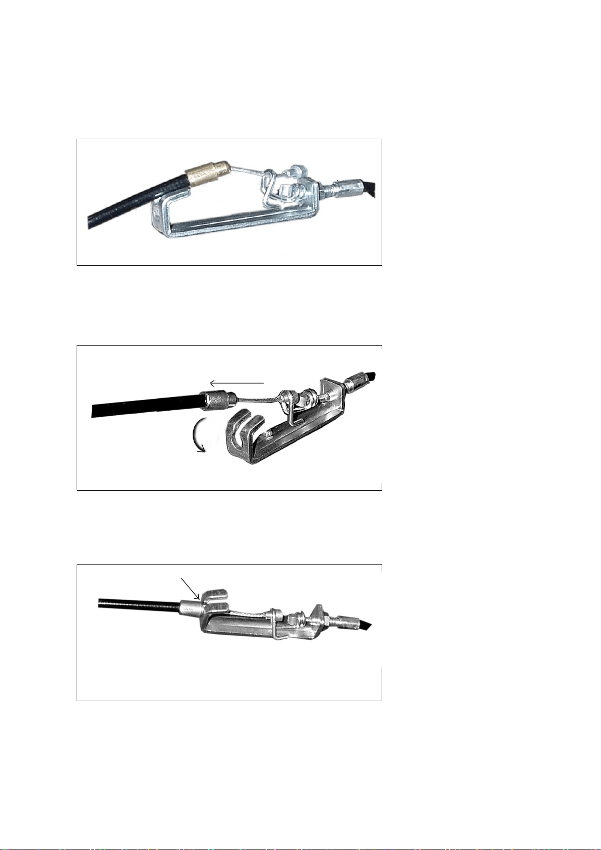
HOW TO CONNECT TENSION CONNECTOR
Slide the Cable wire from the
extension sensor wire
Connector in between the
opening on the wire holder on
sensor wire Connector.
Pull the extension sensor
wire Connector backward and
slide the wire through the slot
on the bracket.
Drop down the Connector
so the fitting sits firmly on top
of the bracket.
NOTE: In able to hold the Front Post while connecting the cables and wires
,
extra help may be needed
9
Step3
Attach the bottom handlebar L (52) into the front post (9), tighten with one D type washer
(29), washer (26), spring washer (27) and hex head bolt (28). Repeat for bottom handlebar
R (53).
55
26
28
27
29
9
29
27
28
26
53
52
10
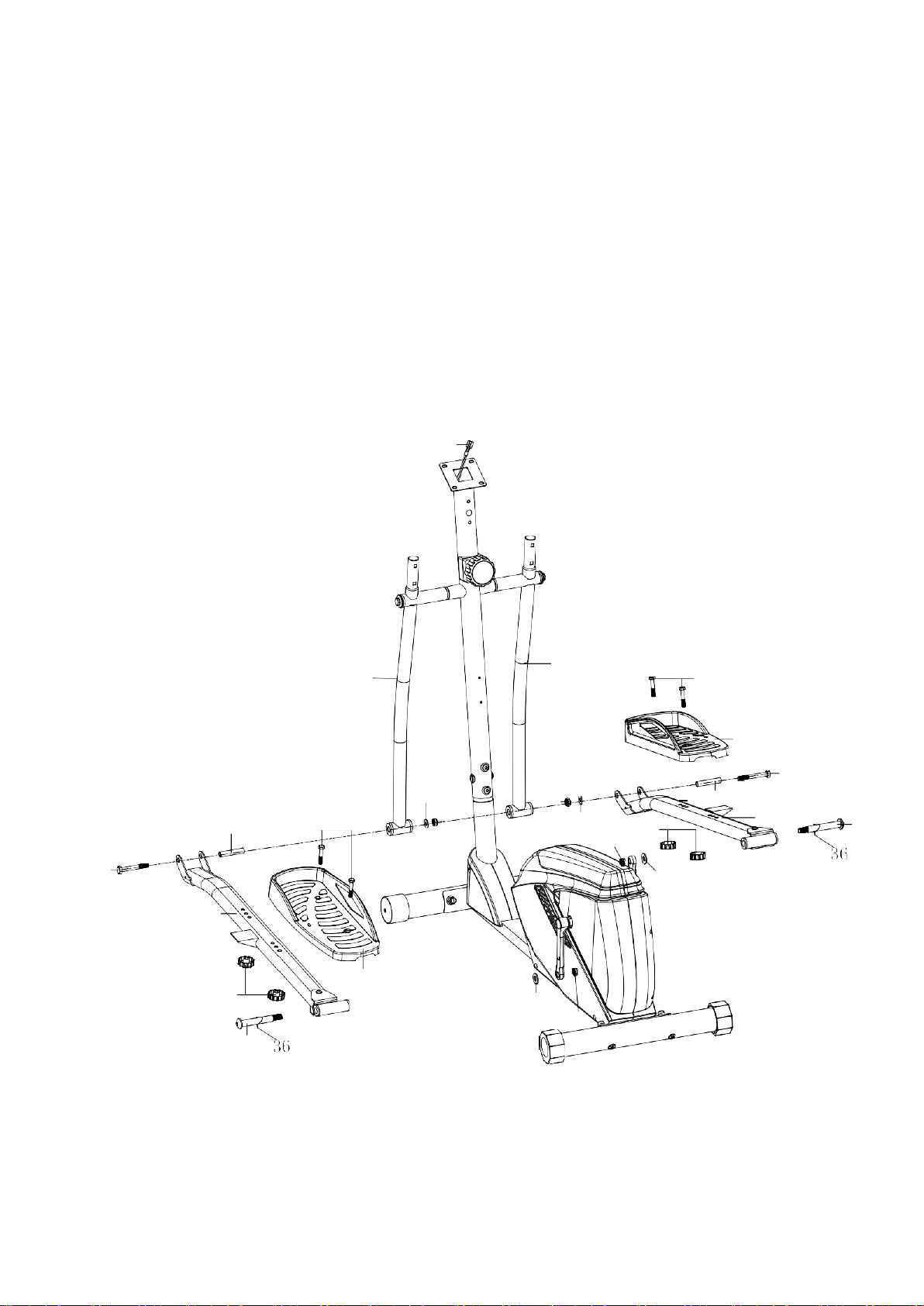
STEP 4
Attach pedal tube L (41L) to the crank, secure using one nut (60L), wave washer (36), and
hinge bolt L (59L).
Slide bottom handlebar L (52) into pedal tube L (41L) then insert sleeve (33). Insert hex
head bolt (32) through sleeve (33) then fasten and secure with one washer (44) and nylon
nut (34).
Repeat above procedure for pedal tube R (41R) and bottom handlebar R (53).
Attach pedal L (48L) to pedal tube L (41L), tighten with two hex head bolt (31) and club
knob (42). Repeat for pedal R (48R).
55
53
52
31
44
34
33
48R
32
33
31
32
34
44
60R
42
46
41R
59R
41L
48L
42
46
59L
60L
11
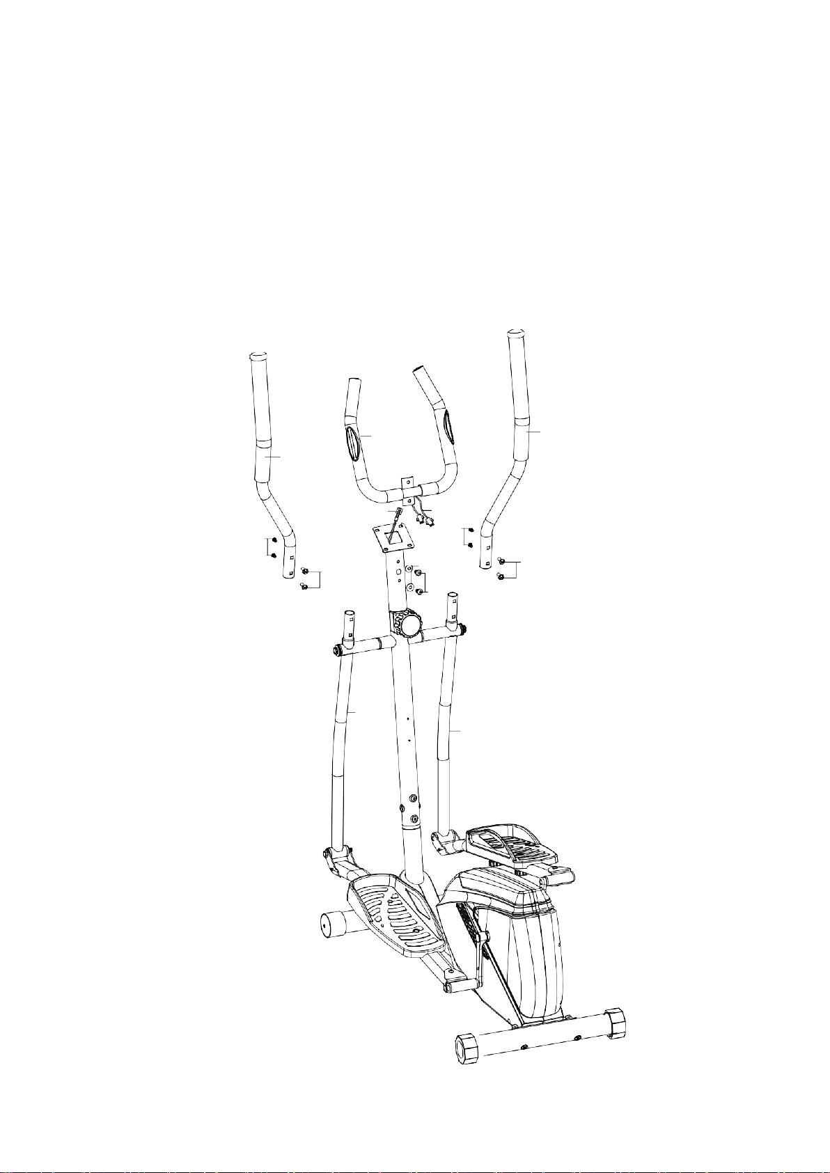
Step5
Insert the top handlebar L (12) into the bottom handlebar L (52), tighten with two hollow
carriage nuts (21) and allen bolts (22). Repeat for top handlebar R (13).
Insert the hand pulse wire (58) through front post (09) and pull the hand pulse wire (58) out
of front post (09)
Attach fixed handlebar (11) to the front post (09), tighten with two allen bolts (47) and two
curved washers (45).
11
13
12
55
58
22
22
21
54
21
47
52
53
12
Step6
Connect upper sensor wire from the back of computer (10) with middle sensor wire (55).
Connect lower pulse wire (58) with upper pulse wire from the back of the computer (10).
Attach computer (10) to bracket on front post (09), tighten with four screws (20).
10
58
55
20
13
Step7
Attach computer (10) to bracket on front post (09), tighten with two screws (20).
Attach top handlebar cover (35) to the top handlebar L/R (12/13), tighten with four self
tapping screws (23).
Attach bottom handlebar cover (39) to the bottom handlebar L/R (52/53), tighten with two
self tapping screws (30).
Attach pedal tube cover L (37L) and pedal tube cover R (37R) to the pedal tube L (41L),
tighten with two self tapping screws (25) and one self tapping screw (45). Repeat for right
pedal tube R (41).
13
12
23
35
23
53
35
43
52
56
39
9
30
39
25
30
37R
45
37R
25
37R
45
37L
25
25
41R
41L
CHECK ALL BOLTS AND NUTS ARE TIGHTENED
BEFORE USING THE MACHINE

14
COMPUTER INSTRUCTIONS
FUNCTIONAL BUTTONS:
MODE - Push down for selecting functions.
SET - To Set the consumer movement of time、distance、calories and hand pulse.
RESET -For resetting consumer movement of time、distance、calories and hand pulse.
FUNCTION AND OPERATIONS:
1.
SCAN: Press “MODE” button until “SCAN” appears, monitor will rotate through all the 6
functions: Time、speed、distance、calorie ODO and pulse. Each display will be
hold 6 seconds.
2.
TIME: (1) Count the total time from exercise start to end.
(2) Press “MODE” button until “TIME” appears, press “SET” button to set
exercise time. When the “set” is zero, the computer will alarm 15 seconds.
3.
SPEED: Display current speed.
4.
DIST: (1) Count the distance from exercise start to end.
(2) Press “MODE” button until “DIST” appears. Press “SET” button to set
exercise distance. When the “set” is zero, the computer will alarm 15 seconds.
5.
CALORIES: (1) Count the total calories from exercise start to end.
(2) Press “MODE” button unit “CAL” appears. Press “SET” button to set
exercise calories. When the “set” is zero, the computer will alarm 15 seconds.
6.
ODO: Monitor will display the total accumulated distance.
7.
PULSE: Press MODE button until “PULSE” appears. Before measuring your pulse
rate, please place your palms of your hands on Both of your contact pads and the
monitor will show your current heart beat rate in beats per minute(BPM) on the LCD
after 6~7 seconds. Remark: During the process of pulse measurement, because of
the contact jamming, the measurement value may be higher than the virtual pulse
rate during the first 2~3 seconds, then will return to normal level. The measurement
value can not be regarded as the basis of medical treatment.
Press “MODE” button until “PULSE” appears. Press “SET” button to set exercise pulse.
The setting values of 40-240 RPM , the consumer computer alarm when heart rate is below
the SET value.

15
NOTE:
1.
If the display is faint or shows no figures ,please replace the batteries.
2.
The monitor will automatically shut off if there is no signal received after 4 minutes .
SPECIFICATIONS:
FUNCTIO
N
AUTO SCAN
Every 6 seconds
TIME
00:00’~99:59’
CURRENT
SPEED
The maximum signal can be pickup is
99.9KM/H
TRIP DISTANCE
0.00~99.99KM or 0.00~9999KM
CALORIES
0.1~999.9kCAL
ODO
0.1~999.9KM or 1 ~ 9999KM
PULSE RATE
40~240BPM
BATTERY TYPE
2pcs of SIZE –AA or UM –3
OPERATING
TEMPERATURE
0°C ~ +40°C
STORAGE TEMPERATURE
-10°C ~ +60°C
16
INNER THIGH
FORWARD
BENDS
CALF / ACHILLES
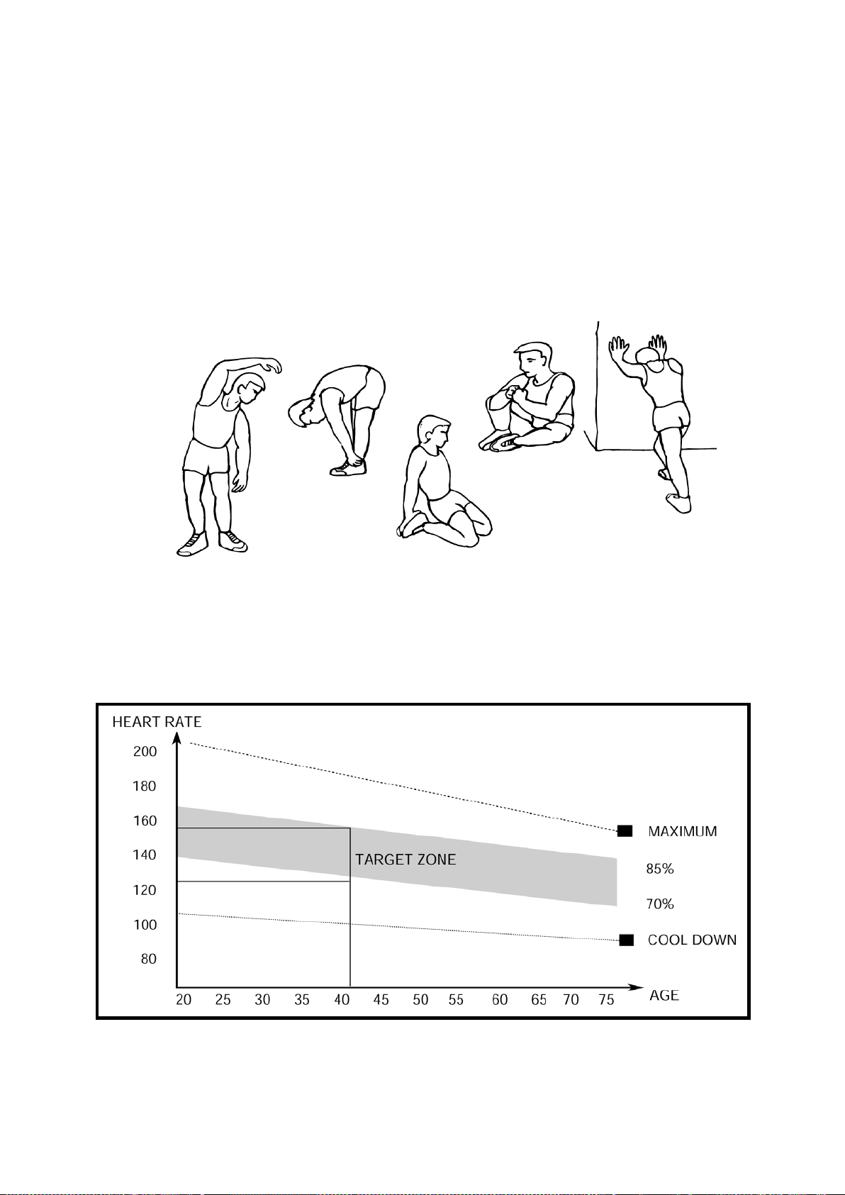
EXERCISE INSTRUCTIONS
Using your ELLIPTICAL TRAINER will provide you with several benefits, it will improve
your physical fitness, tone muscle and in conjunction with a calorie controlled diet help you
lose weight.
1.
The Warm Up Phase
This stage helps get the blood flowing around the body and the muscles working properly. It
will also reduce the risk of cramp and muscle injury. It is advisable to do a few stretching
exercises as shown below. Each stretch should be held for approximately 30 seconds, do
not force or jerk your muscles into a stretch - if it hurts, STOP.
SIDE BENDS OUTER THIGH
2.
The Exercise Phase
This is the stage where you put the effort in. After regular use, the muscles in your legs will
become more flexible. Work to your but it is very important to maintain a steady tempo
throughout. The rate of work should be sufficient to raise your heart beat into the target
zone shown on the graph below.
This stage should last for a minimum of 12 minutes though most people start at about 15-20
minutes

17
3.
The Cool Down Phase
This stage is to let your Cardio-vascular System and muscles wind down. This is a repeat of
the warm up exercise e.g. reduce your tempo, continue for approximately 5 minutes. The
stretching exercises should now be repeated, again remembering not to force or jerk your
muscles into the stretch.
As you get fitter you may need to train longer and harder. It is advisable to train at least
three times a week, and if possible space your workouts evenly throughout the week.
MUSCLE TONING
To tone muscle while on your ELLIPTICAL CROSS TRAINER you will need to have the
resistance set quite high. This will put more strain on our leg muscles and may mean you
cannot train for as long as you would like. If you are also trying to improve your fitness you
need to alter your training program. You should train as normal during the warm up and
cool down phases, but towards the end of the exercise phase you should increase
resistance making your legs work harder. You will have to reduce your speed to keep your
heart rate in the target zone.
WEIGHT LOSS
The important factor here is the amount of effort you put in. The harder and longer
you work the more calories you will burn. Effectively this is the same as if you were
training to improve your fitness, the difference is the goal.

18
59R
47
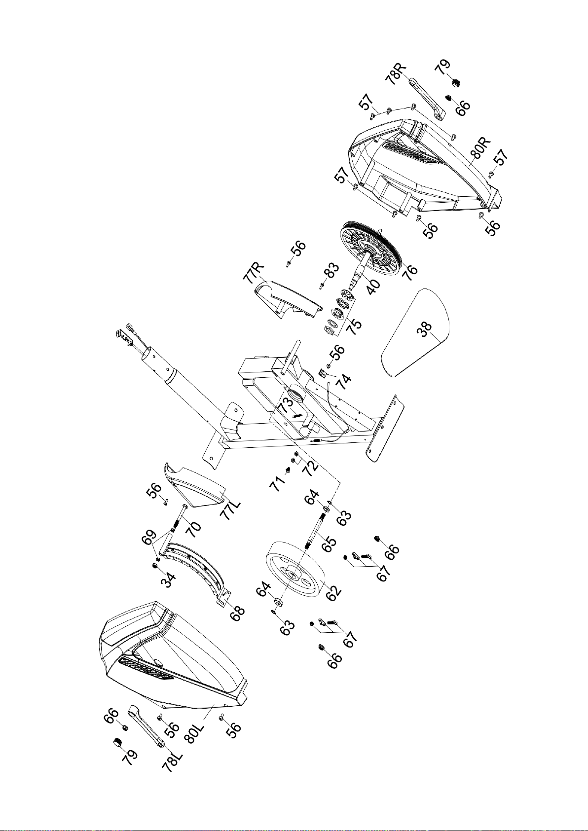
EXPLODED DIAGRAM
14
24
14
15
16
12
11
13
16
18
19
18
17
17
19
20
22
21
23
35
61
26
28
58
10
22
55
54
23
47
61
35
9
21
29
27
28
26
27
29
52
30
53
43
56
54
30
54
47
32
33
44
34
44
33
34
51
31
32
50
49
39
39
2
6
7
7
4
5
45
37L
37R
48R
25
5
4
25
37R
31
45
46
60R
41R
42
36
37L
25
25
41L
42
59L
36
48L
8
1
5
5
46
4
60L
4
8
3
2
19

20
PARTS LIST
PART NO.
DESCRIPTION
QTY
1
Main frame
1
2
Carriage bolt M10*75
4
3
Rear stabilizer
1
4
Curved washerФ10*Ф20
4
5
Domed nut M10
4
6
Front stabilizer
1
7
End cap for front stabilizer
2
8
End cap for rear stabilizer
2
9
Front post
1
10
Computer
1
11
Fixed handlebar
1
12
Top handlebar L
1
13
Top handlebar R
1
14
End cap
2
15
Foam grip for fixed handlebar
2
16
Foam grip
2
17
Self-tapping screw ST4*20
2
18
WasherФ4.2*Ф12
2
19
Hand pulse sensor
2
20
Screw M5*15
4
21
Hollow carriage nutФ8*20
4
22
Allen bolt M6*12
4
23
Self tapping screw ST4*16
4
24
End cap
2
25
Self-tapping screw M5*10
4
26
Washer Ф32*Ф10
2
27
Spring washer Ф10
2
28
Hex head bolt M10*20
2
29
D type washer
2
30
Self tapping screw ST4*30
2
31
Hex head bolt M8*45
4
32
Hex head bolt M10*78
2
33
Sleeve
2
34
Nylon nut M10
3
35
Top handlebar cover
4
36
Wave washer
2
37
Pedal tube cover L/R
2/2
38
Belt
1
39
Bottom handlebar cover
4
40
Axle
1
41
Pedal tube L/R
1/1
42
Club knob
4

21
43
Bottle holder
1
44
Washer Ф22*Ф10
2
45
Self tapping screw ST5*15
2
46
Washer Ф27*12.8
2
47
Allen bolt M8*16
6
48
Pedal L/R
1/1
49
Lower sensor wire
1
50
Extension tension cable
1
51
Tension control knob w/cable
1
52
Bottom handlebar L
1
53
Bottom handlebar R
1
54
Curved washer Ф8*Ф20
6
55
Middle sensor wire
1
56
Self tapping screw ST5*15
9
57
Self tapping screw ST5*15
7
58
Hand pulse wire
2
59
Hinge bolt L/R
1/1
60
Nut L/R
1/1
61
Plastic spacer
2
62
Flywheel
1
63
Clip Ф17
2
64
Bearing
2
65
Axle for flywheel
1
66
Flange nut
4
67
Flywheel adjuster
2
68
Magnetic assembly
1
69
Spacer
2
70
Hex head bolt M8*105
1
71
Screw M6*25
1
72
Nut M8
2
73
Spring
1
74
Sensor bracket
1
75
BB assembly
1
76
Pulley
1
77
Front chain cover L/R
1/1
78
Crank L/R
1/1
79
Main crank cover L/R
1/1
80
Chain cover L/R
1/1

22
Packaging Disposal
ADDITIONAL INFORMATION
Government guidelines ask that we reduce the amount of waste material disposed of in
land fill sites. We therefore ask that you dispose of all packaging waste responsibly at
public recycling centres.
End of Life Disposal
We at Pure-Tec Limited hope you enjoy many years of enjoyable use from your Cross
Trainer. However, a time will come when your Cross Trainer will come to the end of its
useful life. Under ‘European WEEE Legislation‘ you are responsible for the appropriate
disposal of your Cross Trainer to a recognised public collection facility.
CARE AND MAINTENANCE
1. Inspect and tighten all parts before using the Trainer.
2. The Trainer can be cleaned using a damp cloth and mild non-abrasive detergent. DO
NOT use solvents.
3. Examine the Trainer regularly for signs of damage or wear.
4. Failure to examine the Bike regularly may affect the safety level of the equipment.
5. Replace any defective components immediately and/or keep the Elliptical Cross Trainer
out of use until repair.

23
LIMITED WARRANTY
Pure-Tec. warrants this product to be free from defects in workmanship and material,
under normal use and service conditions. Please refer to www.puretecfitness.com for
warranty conditions. This warranty extends only to the original purchaser and is valid
for home use only. Pure-Tec’s obligation under this Warranty is limited to replacing
damaged or faulty parts at Pure-Tec’s option.
All returns must be pre-authorised by Pure-Tec. This warranty does not extend to
any product or damage to a product caused by or attributable to freight
damage, abuse, misuse, improper or abnormal usage, purchasers own repairs or
for products used for commercial or rental purposes. No other warranty beyond
that specifically set forth above is authorised by Pure-Tec.
Pure-Tec is not responsible or liable for indirect, special or consequential damages
arising out of or in connection with the use or performance of the product or other
damages with respect to any economic loss, loss of property, loss of revenues or profits,
loss of enjoyments or use, costs of removal, installation or other consequential damages
or whatsoever natures.
The warranty extended hereunder is in lieu of any and all other warranties and any
implied warranties of merchantability or fitness for a particular purpose is limited in its
scope and duration to the terms set forth herein.
Your statutory rights are not affected.
ORDERING
REPLACEMENT PARTS
Replacement parts can be ordered by contacting our Customer Solutions
Department,
www.puretecfitness.com
Email: service@puretecfitness.com
When ordering replacement parts, please give the following information,
1. Model
2. Description of Parts
3. Part Number
4. Date of Purchase