NOTE:
Please read all instructions
carefully before using this
product
Table of Contents
Important Precautions
Components
Assembly
Operation and Adjustment
Maintenance
Parts List
Warranty
Model
JX-651BW
Retain This
Manual for
Reference
161101
OWNER'S
MANUAL
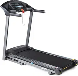
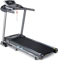
MARCY JX-651BW
Easy Folding Motorized Treadmill
IMPEX
®
INC.
2801 S. Towne Ave, Pomona, CA 91766
Tel: (800) 999-8899
www.marcypro.com

TABLE OF CONTENTS
BEFORE YOU BEGIN.......................................................................................................................1
IMPORTANT PRECAUTIONS...........................................................................................................2
COMPONENTS-PARTS....................................................................................................................4
ASSEMBLY........................................................................................................................................5
OPERATION AND ADJUSTMENT.....................................................................................................9
MAITENANCE..................................................................................................................................14
SUGGESTED STRETCHES............................................................................................................18
EXPLODED DIAGRAM....................................................................................................................20
PARTS LIST.....................................................................................................................................21
LIMITED WARRANTY......................................................................................................................24
Before you Begin
Thank you for selecting the MARCY EASY FOLDING MOTORIZED
TREADMILL JX-651BW by IMPEX
®
INC. For your safety and benefit, read
this manual carefully before using the equipment. As a manufacturer, we
are committed to provide you complete customer satisfaction. If you have
any questions, or find there are missing or damaged parts, we guarantee
you complete satisfaction through direct assistance from our factory. To
avoid unnecessary delays, please call our TOLL-FREE customer service
number. Our Customer Service Agents will provide immediate assistance to
you.
Toll-Free Customer Service Number
1-800-999-8899
Mon. – Fri. 9 a.m. – 5 p.m. PST
www.marcypro.com
support@impex-fitness.com
1

Important Precautions
WARNING: To reduce the risk of serious injury, read all important precautions and
instructions in this manual and all warnings on your treadmill before using your treadmill. Impex
assumes no responsibility for personal injury or property damage sustained by or through the use of
this product.
1. It is the responsibility of the owner to
ensure that all users of this treadmill are
adequately informed of all warnings and
precautions.
2. Before beginning any exercise program,
consult your physician. This is especially
important for persons over age 35 or
persons with pre-existing health problems.
3. Use the treadmill only as described.
4. The treadmill is intended for home use only.
Do not use the treadmill in any commercial,
rental, or institutional setting.
5. Keep the treadmill indoors, away from
moisture and dust. Do not put the treadmill
in a garage or covered patio, or near water.
6. Place the treadmill on a level surface, with
at least 8 ft. (2.4 m) of clearance behind it
and 2 ft. (0.6 m) on each side. Do not place
the treadmill on any surface that blocks air
openings. To protect the floor or carpet
from damage, place a mat under the
treadmill.
7. Do not operate the treadmill where aerosol
products are used or where oxygen is
being administered.
8. Keep children under age 12 and pets away
from the treadmill at all times.
9. The treadmill should be used only by per-
sons weighing 245 lbs. (110kg) or less.
10. Never allow more than one person on the
treadmill at a time.
11. Wear appropriate exercise clothes while
using the treadmill. Do not wear loose
clothes that could become caught in the
treadmill. Athletic support clothes are
recommended for both men and women.
Always wear athletic shoes. Never use the
treadmill with bare feet, wearing only
stockings, or in sandals.
12. Plug the power cord into a surge
suppressor (not included), and plug the
surge suppressor into an appropriate
outlet (see page 10). To avoid overloading
the circuit, do not plug other electrical
devices, except for low-power devices
such as cell phone chargers, into the surge
suppressor or into an outlet on the same
circuit.
13. Use only a surge suppressor that meets all
of the specifications described on page 10.
To purchase a surge suppressor, see your
local WESLO dealer, call the telephone
number on the front cover of this manual,
or see your local electronics store.
14. Failure to use a properly functioning surge
suppressor could result in damage to the
control system of the treadmill. If the
control system is damaged, the walking
belt may slow, accelerate, or stop
unexpectedly, which may result in a fall
and serious injury.
15. Keep the power cord and the surge
suppressor away from heated surfaces.
16. Never move the walking belt while the
power is turned off. Do not operate the
treadmill if the power cord or plug is
damaged, or if the treadmill is not working
properly. (See TROUBLESHOOTING on
page 16 if the treadmill is not working
properly.)
17. Read, understand, and test the emergency
stop procedure before using the treadmill
(see HOW TO TURN ON THE POWER on
page 8).
18. Never start the treadmill while you are
2

standing on the walking belt. Always hold
the handrails while using the treadmill.
19. The treadmill is capable of high speeds.
Adjust the speed in small increments to
avoid sudden jumps in speed.
20. The heart rate monitor is not a medical
device. Various factors, including the user’
s movement, may affect the accuracy of
heart rate readings. The heart rate
monitor is intended only as an exercise
aid in determining heart rate trends in
general.
21. Never leave the treadmill unattended while
it is running. Always remove the key, press
the power switch into the off position and
unplug the power cord when the treadmill
is not in use.
22. Do not attempt to move the treadmill until it
is properly assembled. You must be able
to safely lift 45 lbs. (20 kg) to move the
treadmill.
22. When folding or moving the treadmill,
make sure that the storage latch is holding
the frame securely in the storage position.
23. Do not change the incline of the treadmill
by placing objects under the treadmill.
24. Never insert any object into any opening
on the treadmill.
25. Inspect and properly tighten all parts of
the treadmill regularly.
26. DANGER: Always unplug the power cord
immediately after use, before cleaning the
treadmill, and before performing the
maintenance and adjustment procedures
described in this manual. Never remove
the motor hood unless instructed to do so
by an authorized service representative.
Servicing other than the procedures in this
manual should be performed by an
authorized service representative only.
27. Over exercising may result in serious
injury or death. If you feel faint or if you
experience pain while exercising, stop
immediately and cool down.
SAVE THESE INSTRUCTIONS
3
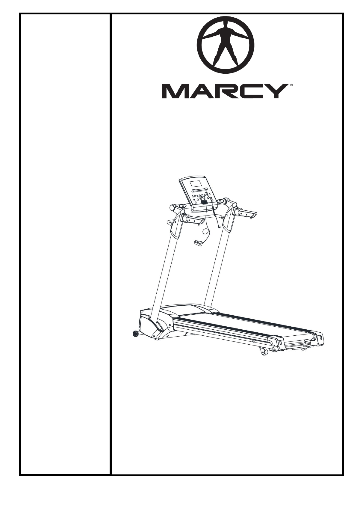
Components - Parts
Lubrication Oil x 2
Main Frame x 1
Power Cord x 1
Safety Key x 1
MP3 Connection x 1
4
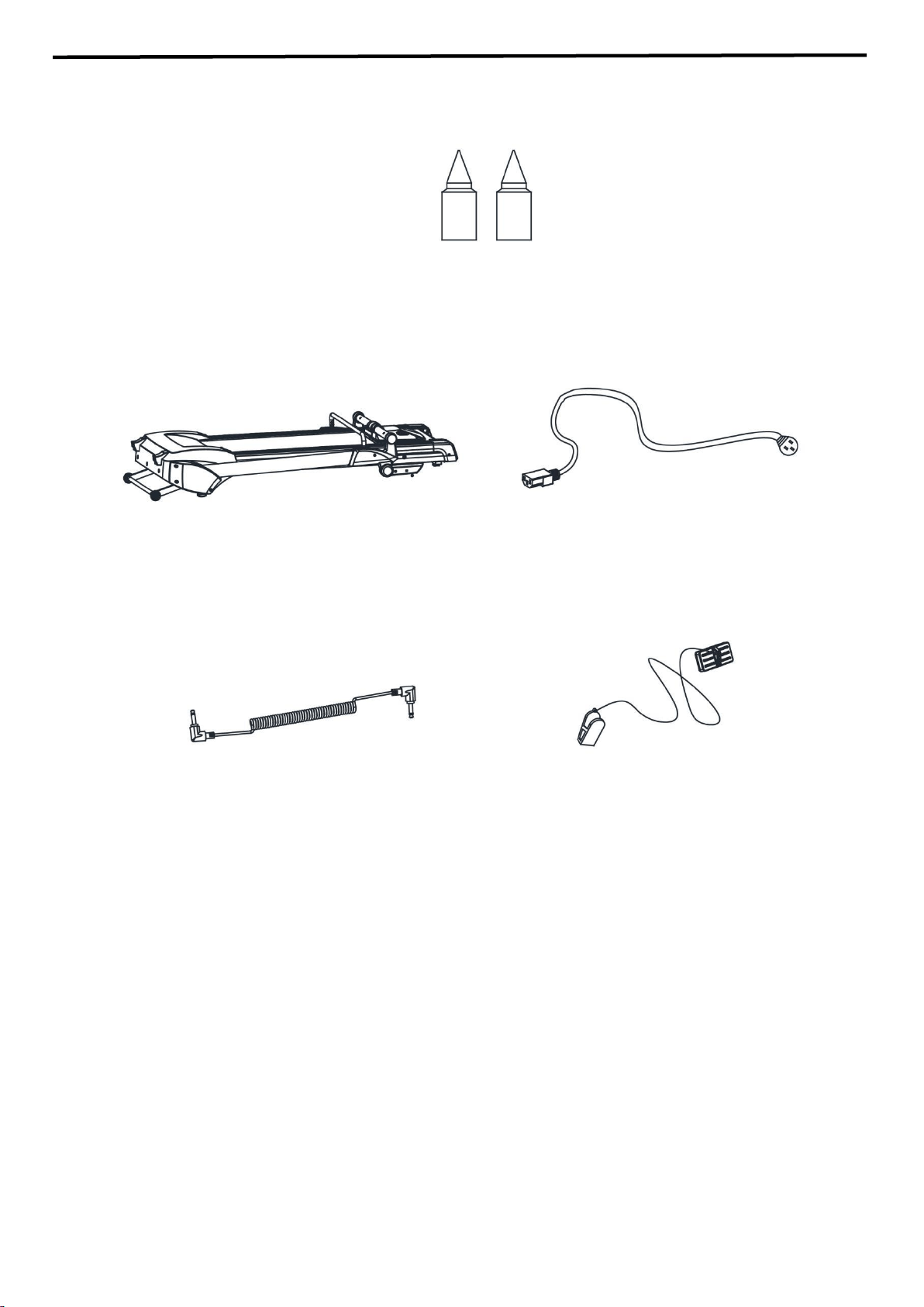
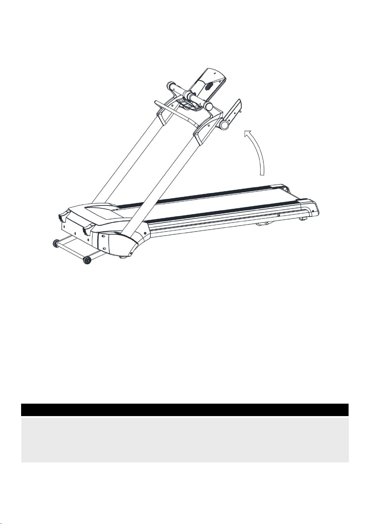
Assembly
This treadmill is shipped completely assembled for your convenience.
Folding and Unfolding Mechanism
Remove the Treadmill from the Carton.
Grasp the console rod with one hand, and disengage the lock by pulling the lifting bar with the other hand
towards the console rod as shown in the diagram.
Step 1
5
Grasp the lifting bar and lift the console in the direction as shown in the diagram.
Step 2
6
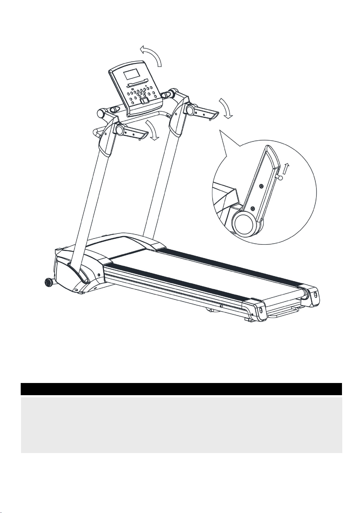
When the console posts are locked in place, release the lifting bar. You should hear and feel the locking
mechanism engage. Flip the console housing and handrail into place as shown in the diagram.
Note: the handles can be flipped only after pulling the locking ball pin on the end of the handle.
Step 3
7
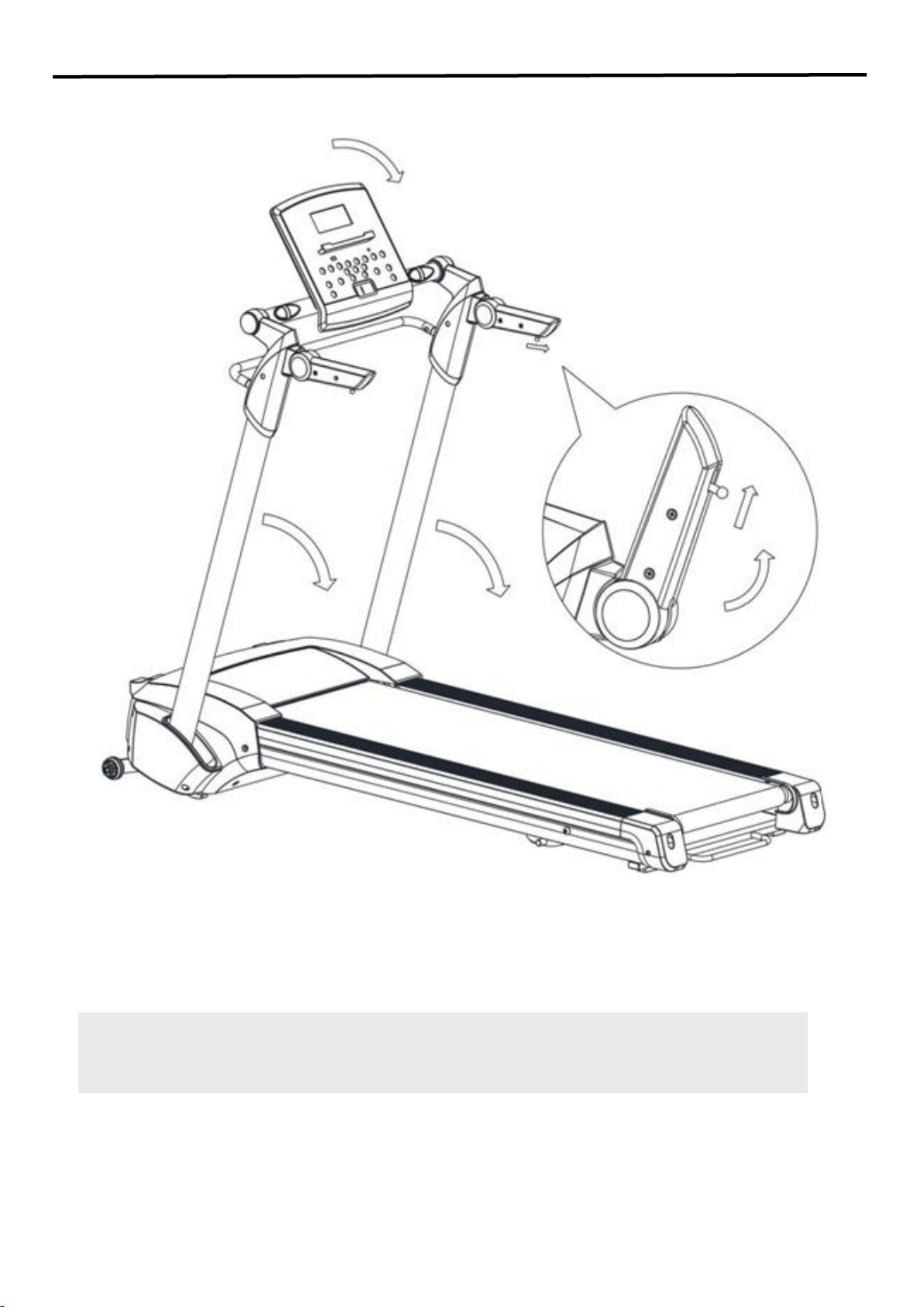
Folding Mechanism
Pull and hold the armrest pin to fold up armrest. Flip down the Console. Grip and hold the
Handrail Bar (1) with one hand; hold Lifting Bar (122) in middle and pull the Bar up, and slowly
folding down the Uprights.
8
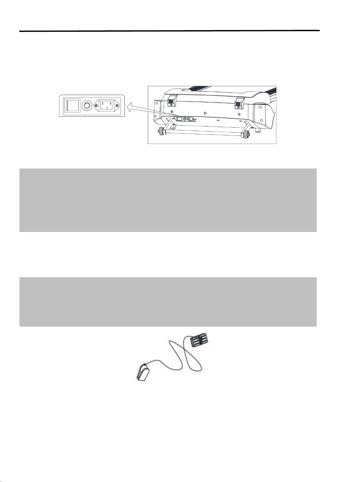
Operation and Adjustment
IMPORTANT NOTICE:
Plug in the main power and turn on the switch (1).
You will hear a signal tone and the Computer screen will light up.
CIRCUIT BREAKER:
There is an circuit breaker (2) located on the right side of the switch (1) (see above picture); in case of
short circuit or over-current, the circuit breaker button will pop up and the treadmill will power off.
Please unplug the power source and push down the button, and then plug in the power cord and turn on
the switch to restart your workout. If the button pops up again, please contact Impex.
9
SAFETY KEY:
The treadmill will only work if the safety key (104) is properly locked in the provided notch of the console.
Insert the safety key (104) and attach the clip onto the waist part of your clothes. If it is necessary to turn
off the motor immediately, just pull the safety key (104) out of the console.
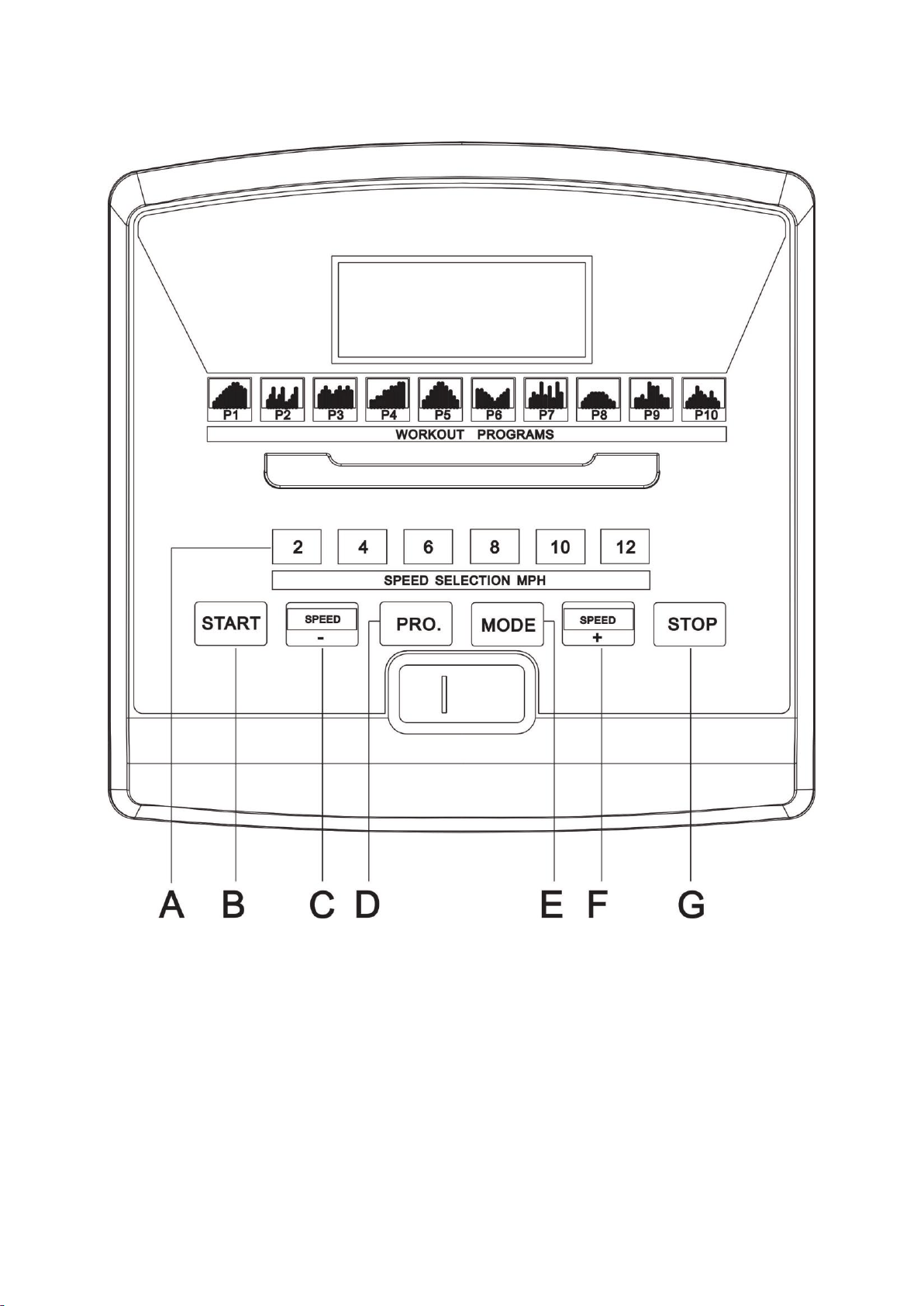
CONSOLE DIAGRAM
A Quick Speed Select
B Start
C Speed-
D PRO.
E MODE
F Speed+
G Stop
10

FUNCTIONS AND OPERATIONS
TECHNICAL SPECIFICATION
Time---------------------------------00:00--99:59 Min
Speed-------------------------------0.0--8.0 mile/h
Distance----------------------------0.00--99.9 mile
Calorie------------------------------0.0--999 Kcal
Circle -------------------------------0-99 circles
START
Press to start exercise at initial speed 0.5 mile/h.
STOP
Press during workout, and the treadmill will stop by
gradually reducing the speed.
QUICK SPEED SELECT
Press to select your desired running speed with 2, 3,
4, 5, 6, 7, 8mile/h
SPEED UP/DOWN
1. Press to increase/decrease exercise speed
by 0.1mile/h.
2. Press to select training time under program
workout model
3. Press to select the desired training target
(Time, Distance, Calorie) under training target
control workout mode)
MODE
Press to select training target workout mode
(Time-Distance-Calorie count down)
PROGRAM
Press to select workout program (P01-P02-…-P10).
IMPORTANT
The console will turn off automatically about ten
minutes after the belt has stopped.
SAFETY KEY
1. The safety key must be placed into the
magnetic recess on the console in order to
operate the treadmill. Always place the
safety key on its position and attach the clip
to your clothing at your waist before
beginning your workout.
2. If you need to stop the motor immediately,
simply pull the safety key away from the
console.
GENERAL OPERATION
1. Turn on the Power Switch at the front of your
Treadmill. This switch is located next to the Mains
Power Cord inlet.
2. Place the Safety Key into the magnetic recess on
the middle front of the Computer Console.
The console will give an audible signal and all
console window displays function with a start
display value of 0.
Note: If the Safety Key is not placed correctly or is
faulty, the “Speed” window will display "E00", which
indicates that the treadmill will not operate.
To stop the treadmill in an emergency, simply pull
the safety key off its mount in the console front or
simply press the red STOP button in the right of the
console. It is important that you connect the clothing
clip to your shirt or other suitable clothing during
exercise to ensure that this safety system can
operate easily.
11

STARTING YOUR TREADMILL
1. Turn on the treadmill, and press “Start” button
on the console.
2. Press “Speed +” or “Speed -” button to adjust
speed button to adjust speed. Press the key
once, and the speed changes 0.1mile/h.
3. Also the user can press the “Quick Speed
Select” button to select desired running
speed.
STOPPING YOUR TREADMILL
1. Press the “Speed -” button on the console to
reduce the speed and deck incline to lower,
then press the “Stop” key on the Console, and
the treadmill will stop; turn off the switch if you
intend to finish workout.
2. Pull away the safety key and the treadmill will
stop itself, and then “Speed” window will
display “E00”.
TRAINING TIME CONTROL WORKOUT
MODE
1. Turn on the treadmill,press the “Mode”
button one time, and the “Time” window
flashes and displays “15:00”, which is the
pre-set training time of the treadmill. Press
“Speed +” / “Speed -” button to select your
desired training time, (the range is
5:00—99:00).
2. Press “Start” button to start your workout, the
time data will reduce gradually during your
training and the treadmill will stop
automatically when the “Time” window
displays “0:00”.
TRAINING DISTANCE CONTROL
WORKOUT MODEL
Turn on the treadmill, press the “Mode” key
two times, and the “Dis” (Distance) window
flashes and displays “1.00”, which is the
pre-set training distance of the treadmill.
Press “Speed +” / “Speed -” button to select
your desired training distance (the range is
0.50—99.9).
Press “Start” button to start your workout, the
distance data will reduce gradually during your
training and the treadmill will stop
automatically when the “Dis” (Distance)
window displays “0.0”.
BURNING CALORIE CONTROL WORKOUT
MODEL
1. Turn on the treadmill,press the “Mode”
button three times continuously, the “Cal”
(Calorie) window flashes and displays “50.0”,
which is the pre-set burning calories of the
treadmill. Press “Speed +” / “Speed -” button
to select target burning calories (the range is
10.0---999).
2. Press “Start” button to start your workout, the
calories data reduce gradually during your
training, and the treadmill will stop
automatically when the “Cal” (Calorie) window
display “0.0”.
SPEED ADJUSTMENT
In any training target control workout model,
press “Speed +” /“Speed -” button to choose
your desired running speed.
12

Program Workout Model (P01—P10)
In this mode, the user has a choice of Program P01
– Program P10.
1. Press the “Prog. ” button, the “Speed” window
will display “P01” and the “Time” window will
display “10:00”, which is the preset time of the
treadmill for each program. Press the “Pro.”
button to select your desired training program
“P01-P10”.
2. The preset workout time of the treadmill for
each program is 10:00 Min, when you finish
selecting workout program, press “Speed +” /
“Speed -” button to select your desired workout
time (the range is: 5:00---99:00).
3. Press “Start” button and the treadmill will count
down three and start operation. The start speed
depends on the program you have chosen.
4. For all preset values, please refer to following
table and diagrams.
Any of the training program levels has 10 segments,
and each segment time is 1/10 of total setting time;
during any training segments, press the “Speed +” /
“Speed -” button to adjust training speed.
TIME
PROG
Set Time/10 =Running time for each program
1
2
3
4
5
6
7
8
9
10
P01
SPEED
0.9
1.8
2.7
3.6
4.5
5.4
6.3
6.3
5.4
3.6
P02
SPEED
1.8
2.7
4.5
1.8
2.7
4.5
1.8
2.7
4.5
2.7
P03
SPEED
2.7
3.6
4.5
3.6
2.7
3.6
4.5
3.6
2.7
3.6
P04
SPEED
1.8
1.8
2.7
2.7
3.6
3.6
4.5
4.5
5.4
5.4
P05
SPEED
1.8
2.7
3.6
4.5
5.4
5.4
4.5
3.6
2.7
1.8
P06
SPEED
4.5
4.5
3.6
2.7
1.8
0.9
1.8
2.7
3.6
4.5
P07
SPEED
1.8
3.6
2.7
1.8
5.4
4.5
1.8
5.4
3.6
2.7
P08
SPEED
0.9
1.8
2.7
3.6
3.6
3.6
3.6
2.7
1.8
0.9
P09
SPEED
1.8
1.8
2.7
4.5
4.5
4.5
4.5
2.7
1.8
1.8
P10
SPEED
0.9
1.8
2.7
4.5
3.6
2.7
1.8
3.6
1.8
0.9
13

Maintenance
Proper maintenance is very important to ensure a
faultless and operational condition of the treadmill.
Improper maintenance can cause damage to the
treadmill or shorten the life of the product and
exceed the LIMITED WARRANTY coverage.
Important: Never use abrasives or solvents to
clean the treadmill. To prevent damage to the
computer, keep liquids away and keep it out of
direct sunlight.
All parts of the treadmill must be checked and
tightened regularly. Worn out parts must be
replaced immediately.
BELT ADJUSTMENT
You may need to adjust the running belt during the
first few weeks of use. All running belts are
properly set at the factory. It may stretch off the
center after use. Stretching is normal during the
break-in period.
ADJUSTING THE BELT TENSION
If the running belt feels as though it is “slipping” or
hesitating when you plant your foot during a run,
the tension on the running belt may have to be
increased.
TO INCREASE THE RUNNING BELT TENSION
STEP 1: Place 6# Allen wrench on the left belt
tension bolt. Turn the wrench clockwise 1/4 turn to
draw the rear roller and increase the belt tension.
STEP 2: Repeat STEP 1 for the right belt tension
bolt. You must be sure to turn both bolts the same
number of turns, so the rear roller will stay square
relative to the frame.
Repeat STEP 1 and STEP 2 until the slipping
is eliminated.
Be careful not to tighten the running belt
tension too much as you can create excessive
pressure on the front and rear roller bearings.
An excessively tightened running belt may
damage the roller bearings that would result in
bearing noise from the front and rear rollers.
TO DECREASE THE TENSION ON THE
RUNNING BELT, TURN BOTH BOLTS
COUNTER-CLOCKWISE THE SAME NUMBER
OF TURNS.
CENTERING THE RUNNING BELT
When you run, you may push off harder with one
foot than with the other. The severity of the
deflection depends on the amount of force that
one foot exerts in the relation to the other. This
deflection can cause the belt to move off-center.
This deflection is normal and the running belt will
center when nobody is on the running belt. If the
running belt remains consistently off-center, you
will need to center the running belt manually.
14
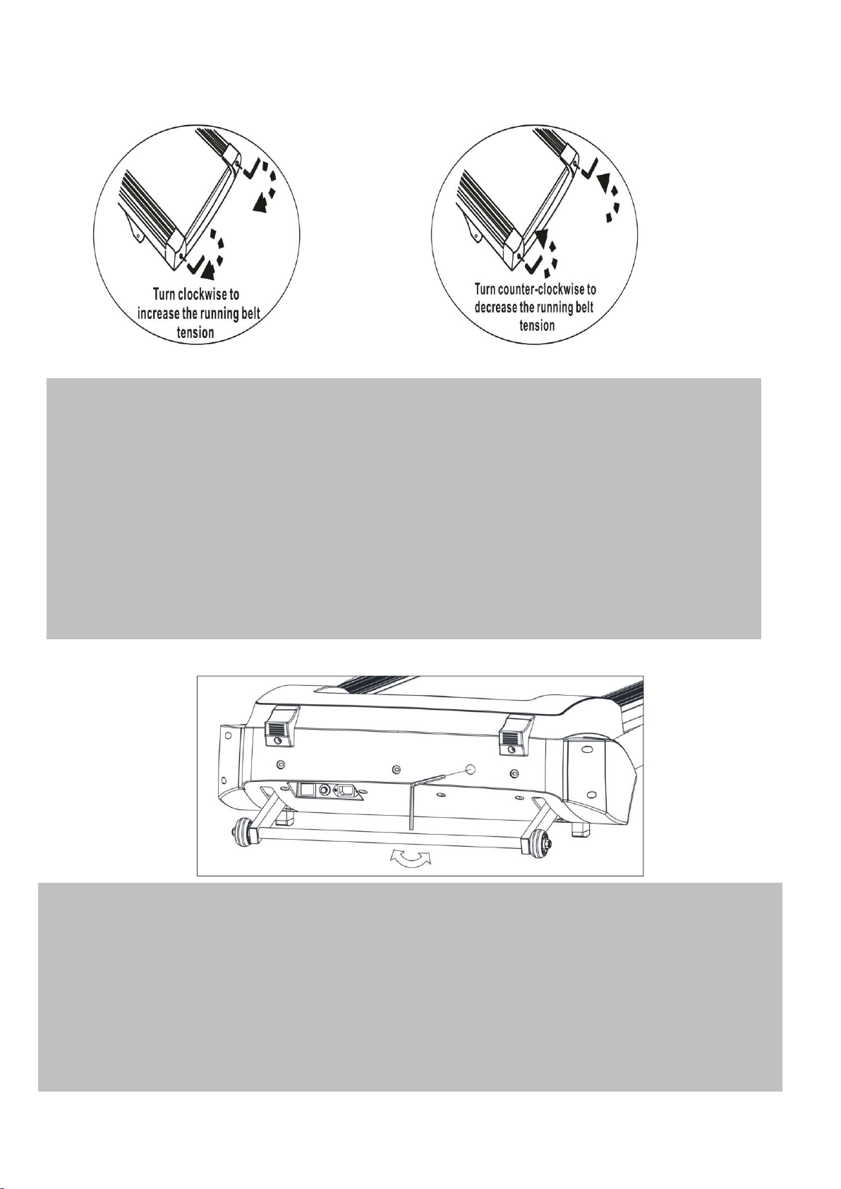
CENTERING THE RUNNING BELT
MOTER BELT TENSION ADJUSTMENT
During your workout, if you find the running belt is not running smoothly, it could mean that the motor belt
has lost some tension, please follow the below steps to adjust the motor belt tension:
When you need to adjust the tension of motor belt,please open the cover of the motor.
1.Turn the motor belt adjustment bolt using an M8 Allen wrench 1/4 turn in a clockwise direction.
2.Re-Start the treadmill and run on the treadmill; if the running belt is still not working properly, repeat the
above step.
3.Please do not make the motor belt too tight; if the belt is over tightened it will overload the treadmill and
reduce the motor's life.
1. Start the treadmill without anyone on the running belt, press “Speed+” button until speed reaches
4mile/h.
2. Observe whether the running belt is toward the right or left side of the deck.
a) If toward the left side of the deck, using 6# Allen Wrench, turn the left adjustment bolt
clockwise 1/4 turn and let the running belt find its new position; if it’s still moving toward left side,
turn the bolt another 1/4 turn.
b) If toward the right side of the deck, using 6# Allen Wrench, turn the right adjustment bolt
clockwise 1/4 turn and let the running belt will find its new position; if it’s still moving toward right
side, turn the bolt further for 1/4 turn.
c) If the belt is still not centered, repeat the above steps until the running belt is centered.
3. After the belt is centered, increase the speed to 8mile/h and verify that it is running smoothly.
Repeat the above steps if it is necessary. If the above procedure is unsuccessful in resolving the
off-center issue, you may need to increase the belt tension.
15

DECK LUBRICATION
The treadmill is pre-lubricated. However, it is
recommended to check the lubrication of the
treadmill regularly, to ensure an optimal operation
of the treadmill.
After every 2 months of operation, lift the sides of
the treadmill and feel the surface of the belt, as far
as possible. If traces of silicon spray are found,
lubrication is not necessary. In case of a dry
surface, refer to the instructions below.
Only use 100% silicon oil to lubricate your
treadmill deck.
To apply lubricant on the belt
Position the belt so that the seam is located in
the middle of the plate.
Lift the belt at one side and hold the spray
valve at a distance of approximately 15cm to
the front end of belt and plate.Then spray from
front to the end. Repeat this process on the
other side of the belt. Spray each side for
about 4 seconds.
Wait 1 minute to let the silicon spray spread,
before starting the machine.
CLEANING
Regular cleaning of the belt ensures a long
product life.
Warning: The treadmill must be turned off to
avoid electric shocks. The power cord must be
pulled out of the socket, before starting the
cleaning or maintenance.
Caution: Do not use any abrasives or
solvents. To avoid damage to the computer,
keep any liquids away. Do not expose the
computer to direct sunlight.
After each training: Wipe the console and
other surfaces with a clean soft and damp
cloth to remove sweat residues.
Weekly: To make cleaning easier, it is
recommended to use a mat under the
treadmill. Shoes can leave dirt on the belt that
can fall beneath the treadmill. Clean the mat
under the treadmill once a week.
STORAGE
Store you treadmill in a clean and dry environment.
Ensure the master power switch is off and is
un-plugged from the electrical wall outlet.
16

TROUBLE SHOOTING
Symptom
Cause and Check
Solution
E00
Safety Key not in position
Re-locate the safety key into the front of the console
E01
Communication error (controller
not receives console signal)
A: Check speed signal wire if connected properly
B: Replace the speed signal wire
C: Replace the driver
E02
Stalling protection
A: Re-insert the motor wire or replace motor
B: Replace driver
C: Stop use and ask electrician for trouble shooting
E03
No speed sensor signal
A: Re-insert the speed signal wire or replace sensor
B: Replace driver
E05
Over current protection
A: System protection and re-start the system
B: Adjust transmission part or add lubrication oil
C: Replace motor
D: Replace driver
E10
Motor peak
Adjust the torsion potentiometer to an appropriate
position
E13
Communication error (console not
receives controller signal)
A: Replace console
B: Replace driver
17
EXERCISE INSTRUCTIONS
Each workout should include the following three parts:
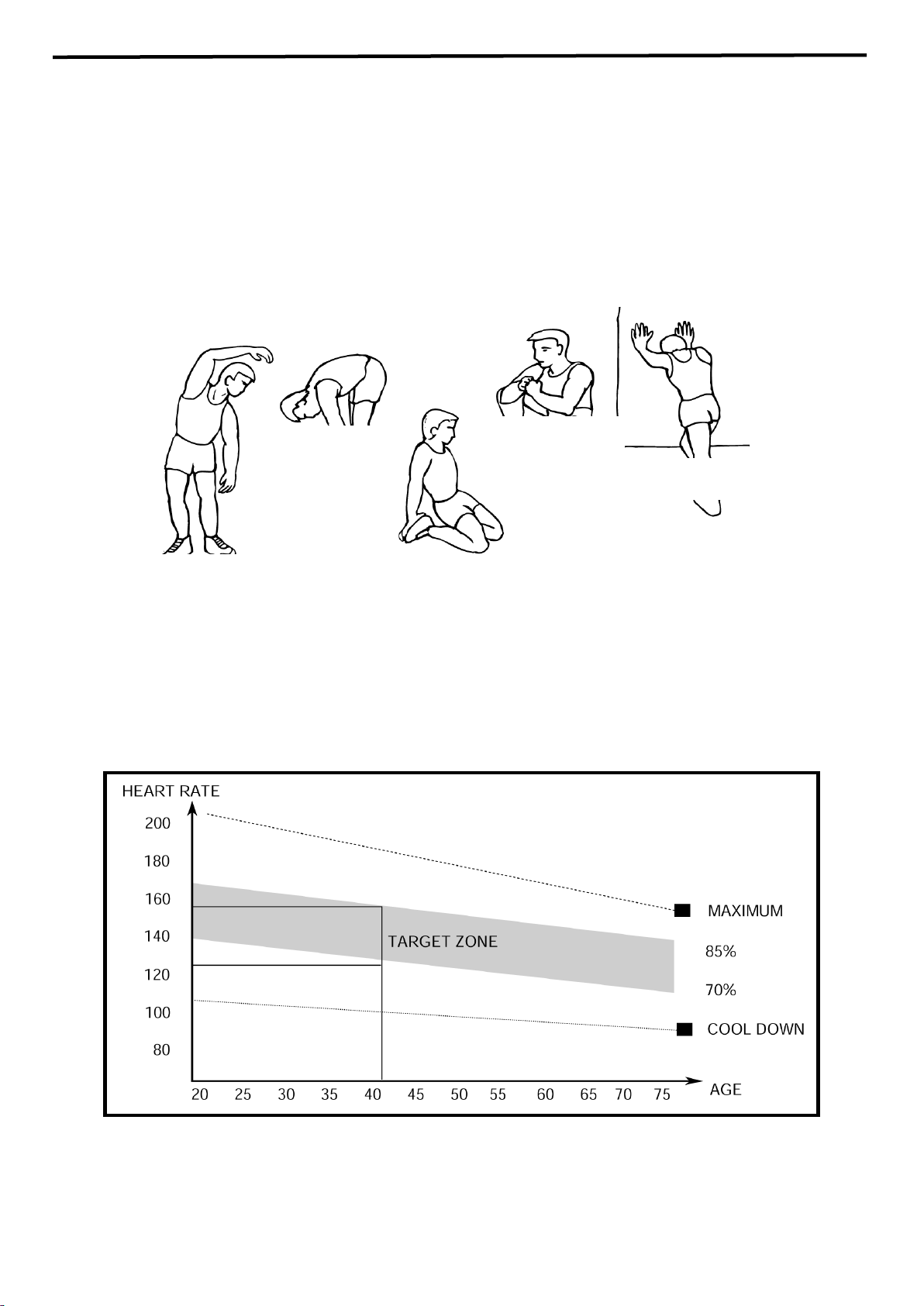
1. The Warm Up Phase
This stage helps get the blood flowing around the body and the muscles working properly. It will also
reduce the risk of cramp and muscle injury. It is advisable to do a few stretching exercises as shown
below. Each stretch should be held for approximately 30 seconds, do not force or jerk your muscles
into a stretch - if it hurts, STOP.
2. The Exercise Phase
This is the stage where you put the effort in. After regular use, the muscles in your legs will become more flexible.
Work to your targeted heart rate but it is very important to maintain a steady tempo throughout. The rate of work
should be sufficient to raise your heartbeat into the target zone shown on the graph below.
This stage should last for a minimum of 12 minutes though most people start at about 15-20 minutes
18
SIDE BENDS OUTER THIGH
INNER THIGH
FORWARD
BENDS
CALF / ACHILLES

3. The Cool Down Phase
This stage is to let your Cardio-vascular System and muscles wind down. This is a repeat of the
warm up exercise e.g. reduce your tempo, continue for approximately 5 minutes. The stretching
exercises should now be repeated, again remembering not to force or jerk your muscles into the
stretch.
As you get fitter you may need to train longer and harder. It is advisable to train at least three times a
week, and if possible space your workouts evenly throughout the week.
.
WEIGHT LOSS
The important factor here is the amount of effort you put in. The harder and longer you work
the more calories you will burn. Effectively this is the same as if you were training to improve
your fitness, the difference is the goal.
19
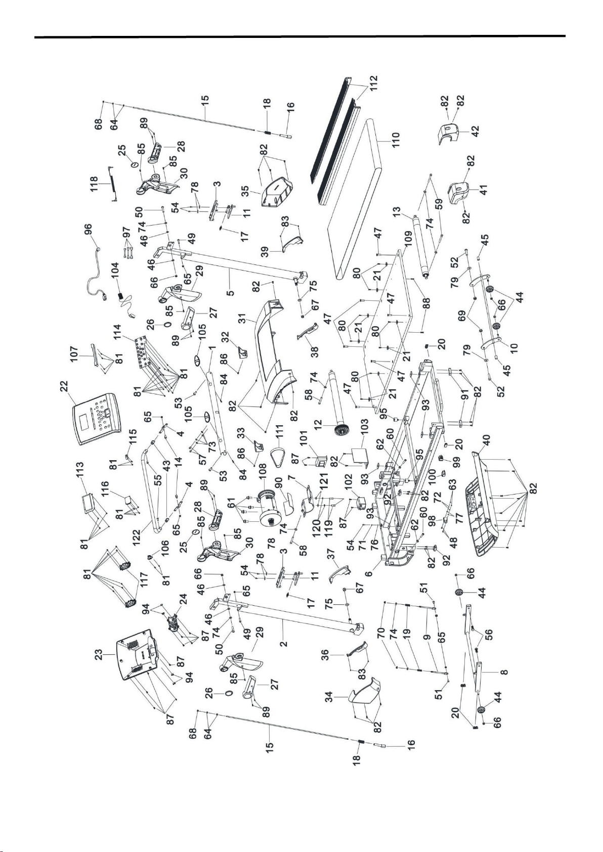
EXPLODED DIAGRAM
20

JX-651BW PARTS LIST
PART NO
DESCRIPTION
SIZE
QUANTITY
1
Handrail Bar
1
2
Left Console Mast
1
3
Handle
2
4
Connector
2
5
Right Console Mast
1
6
Running Stage
1
7
Motor Support
1
8
Base Frame
1
9
Spring Rod
2
10
Incline Adjustment Frame
1
11
Sliding Pin Plate
2
12
Front Roller
1
13
Rear Roller
1
14
Step Bolt
2
15
Thread Rod
2
16
Thread Rod Base
2
17
Tension Spring
Ø ⅜” x 1 ⅝”
2
18
Compressed Spring
Ø ¾” x 1 ¾”
2
19
Compressed Spring
Ø ⅜” x 2 ⅝”
2
20
End Cap
4
21
Side Rail Fixer
8
22
Console Upper Housing
1
23
Console Bottom Housing
1
24
Console Rotate Cover
1
25
Handrail Decoration Cap
2
26
Handrail Decoration Ring
2
27
Left Handle Cover
2
28
Right Handle Cover
2
29
Left Handrail Cover
2
30
Right Handrail Cover
2
31
Motor Cover
1
32
Left Ground Support
1
33
Right Ground Support
1
34
Left Console Mast Cover
1
35
Right Console Mast Cover
1
36
Left Console Mast Decoration (L)
1
37
Left Console Mast Decoration (R)
1
38
Right Console Mast Decoration (L)
1
39
Right Console Mast Decoration (R)
1
40
Motor Bottom Cover
1
41
Left End Cap
1
42
Right End Cap
1
21

43
Plug
2
44
Transport Wheel
4
45
Nylon Sleeve
2
46
Plastic Washer
Ø ⅝” x Ø ⅜”
4
47
Sunk Bolt
M8 x ⅞”
6
48
Sunk Bolt
M3 x ½”
2
49
Allen Bolt
M6 x 1 ⅛”
2
50
Allen Bolt
M8 x 1 ⅝”
2
51
Allen Bolt
M6 x ⅝”
2
52
Allen Bolt
M10 x 1 ⅝”
2
53
Allen Bolt
M8 x 1”
2
54
Phillips Screw
M4 x ⅜”
5
55
Phillips Screw
M6 x ⅝”
2
56
Hex Bolt
M10 x 1”
2
57
Cylinder Head Bolt
M6 x ½”
2
58
Cylinder Head Bolt
M8 x 2 ⅜”
2
59
Cylinder Head Bolt
M8 x 2 ¾”
2
60
Cylinder Head Bolt
M8 x 1 ⅛”
2
61
Cylinder Head Bolt
M10 x 1”
4
62
Nut
M8
2
63
Nut
M3
2
64
Hex Nut
M5
4
65
Aircraft Nut
M6
6
66
Aircraft Nut
M8
6
67
Aircraft Nut
M12
2
68
Aircraft Nut
M5
2
69
Aircraft Nut
M10
2
70
Flange Lock Nut
M6
2
71
Lock Washer
Ø ⅛”
1
72
Lock Washer
Ø ⅛”
2
73
Washer
Ø ¼”
4
74
Washer
Ø ⅜”
8
75
Washer
Ø ½”
2
76
Washer
Ø ⅛”
1
77
Washer
Ø ⅛”
2
78
Large Washer
Ø ¾”
4
79
Plastic Washer
Ø 1”
2
80
Phillips Screw (Z)
ST4.8 x ⅝”
8
81
Phillips Screw
ST2.9 x ⅜”
40
82
Phillips Screw
ST4.8 x ⅝”
34
83
Phillips Screw
ST2.9 x ⅜”
4
84
Phillips Screw
ST4.2 x 1”
2
85
Phillips Screw
ST4.2 x ⅝”
6
86
Phillips Screw
ST4.8 x ¾”
2
87
Phillips Screw
ST4.2 x ⅝”
13
88
Sunk Screw
ST4.2 x 1 ⅛”
2
22

89
Sunk Screw
ST4.2 x ⅝”
8
90
Motor Base
1
91
Shock Pad
2
92
Air Cushion
2
93
Running Deck Bumper
4
94
Damper Pad
4
95
Rubber Cushion
2
96
Power Cord
1
97
Short Cord
1
98
Power Socket
1
99
Power Switch
1
100
Over Current Protector
1
101
Inductor
1
102
Filter
1
103
Driving Board
1
104
Safety Key
1
105
Handle Grip
1
106
Insert Switch
1
107
IPAD Holder
1
108
Motor
1
109
Running Deck
1
110
Running Belt
1
111
Motor Belt
1
112
Side Rail
2
113
LCD Screen
1
114
PCB Board
1
115
MP3 Module
1
116
Power Amplifier
1
117
Speaker
2
118
MP3 Connection
1
119
Hex Bolt
M8 x ⅝”
2
120
Lock Washer
Ø ⅜”
2
121
Washer
Ø ⅝”
2
122
Lifting Bar
1
23

IMPEX
®
INC.
LIMITED WARRANTY
IMPEX Inc. ("IMPEX
®
") warrants this product to be free from defects in workmanship and material, under
normal use and service conditions, for a period of two years on the Frame from the date of purchase.
This warranty extends only to the original purchaser. IMPEX's obligation under this Warranty is limited
to replacing or repairing, at IMPEX's option.
All returns must be pre-authorized by IMPEX. Pre-authorization may be obtained by calling IMPEX
Customer Service Department at 1-800-999-8899. All freights on products returned to IMPEX must be
prepaid by the customer. This warranty does not extend to any product or damage to a product caused
by or attributable to freight damage, abuse, misuse, improper or abnormal usage or repairs not provided
by an IMPEX authorized service center or for products used for commercial or rental purposes. No
other warranty beyond that specifically set forth above is authorized by IMPEX.
IMPEX is not responsible or liable for indirect, special or consequential damages arising out of or in
connection with the use or performance of the product or other damages with respect to any economic
loss, loss of property, loss of revenues or profits, loss of enjoyments or use, costs of removal, installation
or other consequential damages or whatsoever natures. Some states do not allow the exclusion or
limitation of incidental or consequential damages. Accordingly, the above limitation may not apply to
you.
The warranty extended hereunder is in lieu of any and all other warranties and any implied warranties of
merchantability or fitness for a particular purpose is limited in its scope and duration to the terms set forth
herein. Some states do not allow limitations on how long an implied warranty lasts. Accordingly, the
above limitation may not apply to you.
This warranty gives you specific legal right. You may also have other rights which vary from state to
state. Register on-line at www.marcypro.com
IMPEX
®
INC.
2801 S. Towne Ave.
Pomona, CA 91766
ORDERING REPLACEMENT PARTS
Replacement parts can be ordered by calling our Customer Service Department toll-free at
1-800-999-8899 during our regular business hours: Monday through Friday, 9 am until 5 pm Pacific
standard time.
support @impex-fitness.com
When ordering replacement parts, always give the following information.
1. Model
2. Description of Parts
3. Part Number
4. Date of Purchase
24