

v. 091709
T25
Endurance
®
T25 Treadmill
User Manual
v. T25-20200720

IMPORTANT SAFETY INSTRUCTIONS..........................
SAFETY gUIdElINES......................................................
ASSEMblY INSTRUCTIONS...........................................
HARdWARE PACK CHECK lIST.......................................
ASSEMblY PART lIST.......................................................
ASSEMblY STEPS............................................................
SETTINg UP YOUR TREAdMIll....................................
OPERATINg THE CONSOlE.............................................
PROgRAM FEATURES......................................................
gENERAl MAINTENANCE...............................................
TROUblESHOOTINg gUIdE............................................
PARTS lIST.........................................................................
EXPlOdEd dRAWINg........................................................
3
4
8
9
10 - 11
12 - 25
26 - 29
30 - 33
34 - 37
38 - 40
41
42 - 44
45 - 46
Table of Contents
2

Before beginning any tness program, you should obtain a complete physical examination
from your physician.
Il est conseille de subir un examen medical complet avant d’entreprendre tout programme d’exercise. Si vous
avez des etourdissements ou des faiblesses, arretez les exercices immediatement.
When using exercise equipment, you should always take basic precautions,
including the following:
Read all instructions before using the T25. These instructions are written to
ensure your safety and to protect the unit.
do not allow children on or near the equipment.
Use the equipment only for its intended purpose as described in this guide.
do not use accessory attachments that are not recommended by the manufacturer.
Such attachments might cause injuries.
Wear proper exercise clothing and shoes for your workout, no loose clothing.
Use care when getting on or o the unit.
do not overexert yourself or work to exhaustion.
If you feel any pain or abnormal symptoms, stop your workout immediately and
consult your physician.
Never operate the unit after it has been dropped or damaged.
Return the equipment to a service center for examination and repair.
Never drop or insert objects into any opening in the equipment.
Always check the unit before each use.
Make sure that all fasteners are secure and in good working condition.
do not use the equipment outdoors or near water.
Personal safety During assembly
It is strongly recommended that a qualied dealer assemble the equipment.
Assistance is required.
before beginning assembly, please take the time to read the instructions thoroughly.
Read each step in the assembly instructions and follow the steps in sequence.
do not skip ahead. If you skip ahead, you may learn later that you have to
disassemble components and that you may have damaged the equipment.
Assemble and operate the T25 on a solid, level surface.
locate the unit a few feet from the walls or furniture to provide easy access.
The T25 is designed for your enjoyment. by following these precautions and using common
sense, you will have many safe and pleasurable hours of healthful exercise with your
Endurance
T25.
After assembly, you should check all functions to ensure correct operation. If you experience
problems, rst recheck the assembly instructions to locate any possible errors made during
assembly. If you are unable to correct the problem, call the dealer from whom you purchased
the machine or call 1-800-556-3113 for the dealer nearest you.
Important Safety Instructions
3

Successful cardio training programs have one prominent feature in common...safety.
Cardio training has some inherent dangers, as do all physical activities.
The chance of injury can be greatly reduced or completely removed by using correct
running techniques, proper breathing, maintaining equipment in good working
condition, and by wearing the appropriate clothing.
It is highly recommended that you consult your physician before beginning
any exercise program. This is especially important for individuals over the
age of 35, or persons with pre-existing health problems.
Always warm up before starting a workout. Try to do a total body warm up
before you start. It is especially important to warm up the specic muscle
groups you are going to be using. This can be as simple as performing a
warm up set of high repetitions and light weight for each exercise.
Always wear appropriate clothing and shoes when exercising.
Wearing comfortable athletic shoes with good support and loose tting,
breathable clothing will reduce the risk of injury.
Maintaining equipment in proper operating condition is of utmost
importance for a safe cardio training program.
Read and study all warning labels on this machine. It is absolutely
necessary that you familiarize yourself and all others with the proper
operation of this machine prior to use.
Keep hands, limbs, loose clothing and long hair well out of the way of all
moving parts.
Inspect the machine daily for loose or worn parts. If a problem is found do
not allow the machine to be used until all parts are tightened or worn or
defective parts are repaired or replaced.
To reduce the risk of burns, re, electric shock, or injury to persons, install
the treadmill on a at level surface with access to a 110VAC, 20Amp,
grounded outlet.
Do not use an extension cord unless it is 12awg or larger, with only one
outlet on the end. the treadmill should be the only appliance in the electrical
circuit. do not attempt to disable the grounded plug by using improper
adapters, or in any way modify the cord set. a serious shock or re hazard
may result along with computer malfunctions.
Safety Guidelines
4
eleCtriCal safety
WARNINg!
NEVER use a RCd - Residual Current device (U.S. ver.= gFCI) - wall outlet with this treadmill. As with
any appliance with a large motor, the RCd/gFCI will trip often. Route the power cord away from any
moving part of the treadmill including the elevation mechanism and transport wheels.
NEVER remove any cover without rst disconnecting AC power. If voltage varies by ten percent (10%)
or more, the performance of your treadmill may be aected. Such conditions are not covered under
your warranty. If you suspect the voltage is low, contact your local power company or a licensed
electrician for proper testing.
NEVER expose this treadmill to rain or moisture. This product is NOT designed for use outdoors, near
a pool or spa, or in any other high humidity environment. The temperature specication is 40 degrees
c, and humidity is 95%, non-condensing (no water drops forming on surfaces).
Circuit breakers: Some circuit breakers used in homes are not rated for high inrush currents that can
occur when a treadmill is rst turned on or even during normal use. If your treadmill is tripping the circuit
breaker (even though it is the proper current rating and the treadmill is the only appliance on the circuit)
but the circuit breaker on the treadmill itself does not trip, you will need to replace the breaker with a
high inrush type. This is not a warranty defect. This is a condition we as a manufacture have no ability
to control. This part is available through most electrical supply stores
grounDing instruCtion
This product must be grounded. If the treadmill’s electrical system should malfunction or breakdown
grounding provides a path of least resistance for electric current, reducing the risk of electric shock.
This product is equipped with a cord having an equipment-grounding plug. The plug must be plugged
into an appropriate outlet that is properly installed and grounded in accordance with all local codes and
ordinances.
DANGER - Improper connection of the equipment-grounding conductor can result in a risk of
electric shock. Check with a qualied electrician or serviceman if you are in doubt as to whether
the product is properly grounded. Do not modify the plug provided with the product if it will not
t the outlet; have a proper outlet installed by a qualied electrician.
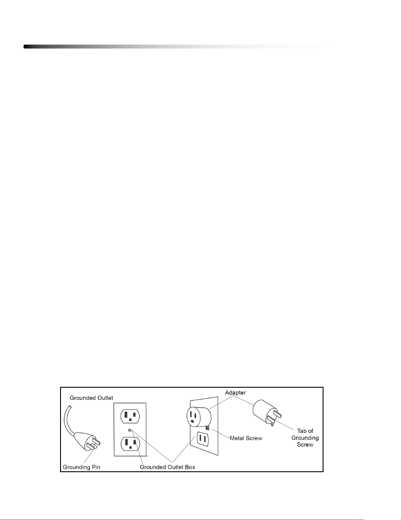
This product is for use on a nominal 120-volt circuit, and has a grounding plug that looks like the plug
illustrated below. A temporary adapter that looks like the adapter illustrated below may be used to
connect this plug to a 2-pole receptacle as shown below if a properly grounded outlet is not available.
The temporary adapter should be used only until a properly grounded outlet, (shown below) can be
installed by a qualied electrician. The green colored rigid ear-lug, or the like, extending from the
adapter, must be connected to a permanent ground such as a properly grounded outlet box cover.
Whenever the adapter is used, it must be held in place by a metal screw.
Safety Guidelines
5
-3-
WARNING!
NEVER use a RCD - Residual Current Device (U.S. ver.= GFCI) - wall outlet with this treadmill.
As with any appliance with a large motor, the RCD/GFCI will trip often. Route the power mains
cord away from any moving part of the treadmill including the elevation mechanism and
transport wheels.
NEVER remove any cover without first disconnecting AC power. If voltage varies by ten percent (10%)
or more, the performance of your treadmill may be affected. Such conditions are not covered
under your warranty. If you suspect the voltage is low, contact your local power company or a
licensed electrician for proper testing.
NEVER expose this treadmill to rain or moisture. This product is NOT designed for use outdoors,
near a pool or spa, or in any other high humidity environment. The temperature specification is 40
degrees c, and humidity is 95%, non-condensing (no water drops forming on surfaces).
Circuit Breakers: Some circuit breakers used in homes are not rated for high inrush currents that
can occur when a treadmill is first turned on or even during normal use. If your treadmill is tripping the
circuit breaker (even though it is the proper current rating and the treadmill is the only appliance on
the circuit) but the circuit breaker on the treadmill itself does not trip, you will need to replace the
breaker with a high inrush type. This is not a warranty defect. This is a condition we as a
manufacture have no ability to control. This part is available through most electrical supply stores.
This product must be grounded. If the treadmill’s electrical system should malfunction or
breakdown grounding provides a path of least resistance for electric current, reducing the risk of
electric shock. This product is equipped with a cord having an equipment-grounding plug. The plug
must be plugged into an appropriate outlet that is properly installed and grounded in accordance
with all local codes and ordinances.
DANGER - Improper connection of the equipment-grounding conductor can result in a risk
of electric shock. Check with a qualified electrician or serviceman if you are in doubt as to
whether the product is properly grounded. Do not modify the plug provided with the
product if it will not fit the outlet; have a proper outlet installed by a qualified electrician.
This product is for use on a nominal 120-volt circuit, and has a grounding plug that looks like the
plug illustrated below. A temporary adapter that looks like the adapter illustrated below may be
used to connect this plug to a 2-pole receptacle as shown below if a properly grounded outlet is
not available. The temporary adapter should be used only until a properly grounded outlet, (shown
below) can be installed by a qualified electrician. The green colored rigid ear-lug, or the like,
extending from the adapter, must be connected to a permanent ground such as a properly
grounded outlet box cover. Whenever the adapter is used, it must be held in place by a metal
screw.
Important Electrical Information
Grounding Instructions

This exercise equipment is designed and built for optimum safety for home use.
However, certain precautions always apply whenever you operate any exercise
equipment.
be sure to read the entire manual before assembly and operation of this machine.
Also, please note the following safety precautions.
MECHANICAL SAFETY
Inspect the equipment prior to exercising to ensure that all nuts and bolts are
fully tightened before each use.
Replace any defective components immediately and/or keep the equipment out
of use until repair.
do not use attachments not recommended by the manufacturer.
Never drop or insert an object into any opening.
Only one person may use the treadmill at a time.
Never activate the treadmill when someone is standing on the belt.
APPROPRIATE ATTIRE
Always wear appropriate clothing.
do not wear loose clothing that might catch on any part of this treadmill.
Always wear non-slippery shoes while working with the treadmill.
do not wear shoes with heels or leather soles.
Check the soles of your shoes and remove any dirt and embedded stones.
CHILDREN AND PETS
Most exercise equipment is not recommended for small children.
Children should not use the equipment unless they are under strict adult supervision.
To ensure safety, keep young children o the treadmill at all times.
Exercise equipment has many moving parts.
In the interest of safety, keep others (especially children and pets) at a safe distance
while you exercise.
Safety Guidelines
6

Safety Guidelines
7
IMPORTANT OPERATION INSTRUCTIONS
● NEVER operate this treadmill without reading and completely understanding the
results of any operational change you request from the computer.
● Understand that changes in speed and incline do not occur immediately. Set your
desired speed on the computer console and release the adjustment key. The
computer will obey the command gradually.
● NEVER use your treadmill during an electrical storm. Surges may occur in your
household power supply that could damage treadmill components.
● Use caution while participating in other activities while walking on your treadmill;
such as watching television, reading, etc. These distractions may cause you to lose
balance or stray from walking in the center of the belt; which may result in serious
injury.
● NEVER mount or dismount the treadmill while the belt is moving. treadmills start
with at a very low speed and it is unnecessary to straddle the belt during start up.
Simply standing on the belt during slow acceleration is proper after you have
learned to operate the unit. Always hold on to a handrail or hand bar while making
control changes (incline, speed, etc.).
do not use excessive pressure on console control keys. They are precision set to
function properly with little nger pressure. Pushing harder is not going to make the
unit go faster or slower. If you feel the buttons are not functioning properly with
normal pressure contact your dealer.
SAFETY TETHER CORD
A safety tether cord is provided with this unit. It is a simple magnetic design that should be
used at all times. It is for your safety should you fall or move too far back on the tread-belt.
Pulling this safety tether cord will stop tread-belt movement.
To Use:
1. Place the magnet into position on the console control head. Your treadmill will not start
and operate without this.
2. Fasten the plastic clip onto your clothing securely to assure good holding power.
Note: The magnet has strong enough power to minimize accidental, unexpected
stopping. The clip should be attached securely to make certain it does not come o. Be
familiar with its function and limitations. The treadmill will stop, depending on speed, with a
one to two step coast anytime the magnet is pulled o the console. Use the red Stop / Pause
switch in normal operation.
Assembly Instructions
8
Professional installers are highly recommended!
However, if you acquire the appropriate tools, obtain assistance, and follow the
assembly steps sequentially, the process will take time, but is fairly easy.
ASSEMBLY TIPS
Read all “NoteS” on each page before beginning each step.
While you may be able to assemble the T25 using the illustrations only, important safety
notes and other tips are included in the text.
Some pieces may have extra holes that you will not use. Use only those holes indicated in
the instructions and illustrations.
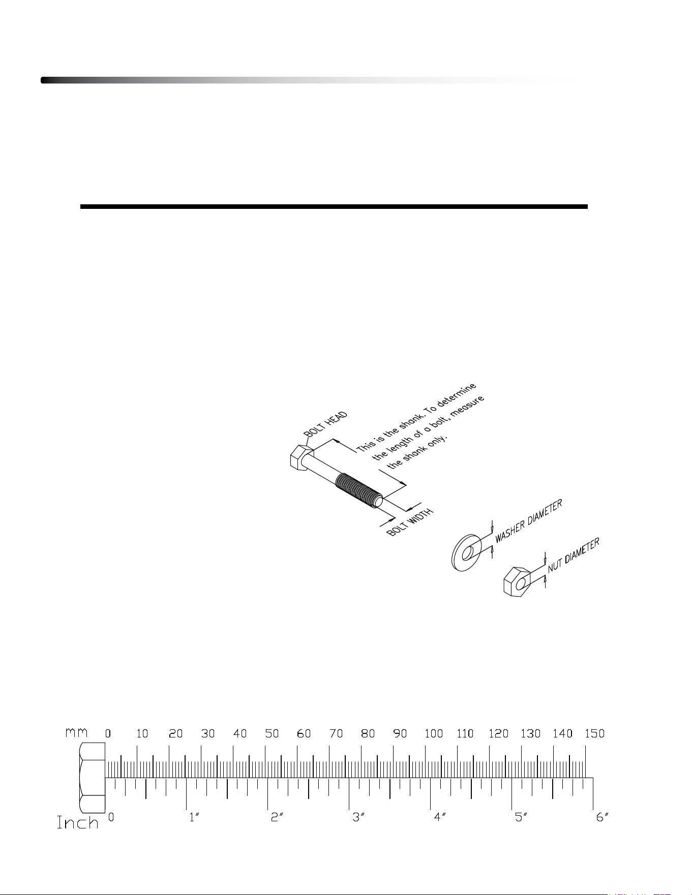
Note: To nd out the length of a particular bolt, measure its shank (the long, narrow part
beneath the head).
Refer to the following diagram:
Do not fully tighten bolts until instructed to do so.
Note: After assembly, you should check all functions to ensure correct operation. If you
experience problems, rst recheck the assembly instructions to locate any possible errors
made during assembly. If you are unable to correct the problem, call the dealer from whom
you purchased the machine or call 1-800-556-3113 for the dealer nearest you.
Hardware Pack Check List
9
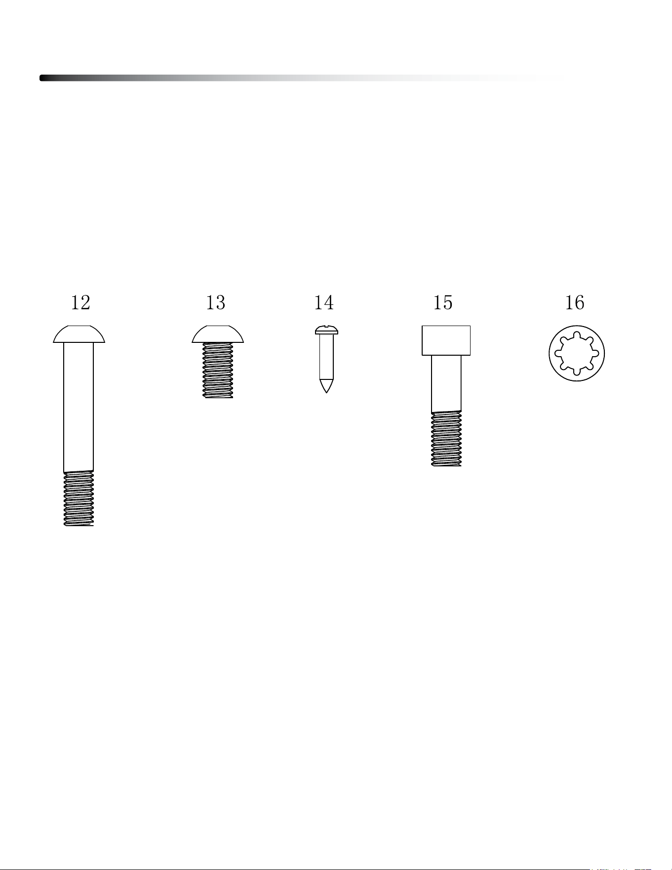
12. M8x80mm Button Head Cap Screw, 8pcs
13. M8x15mm Button Head Cap Screw, 8pcs
14. ST4.2x15mm Phillips Screw, 10pcs
15. M8x30mm Socket Head Cap Screw, 4pcs
16. M8 Washer, 16pcs
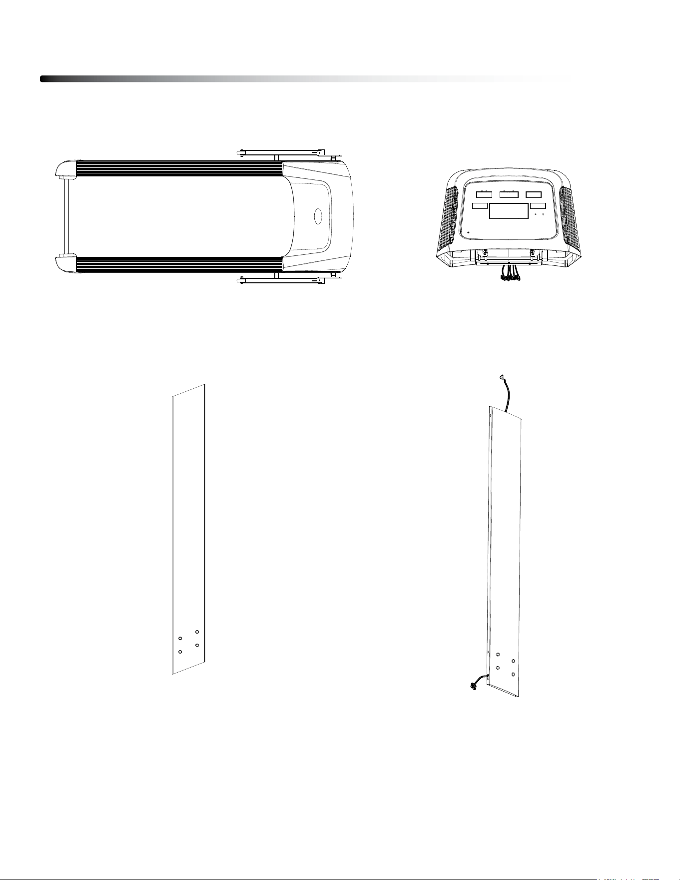
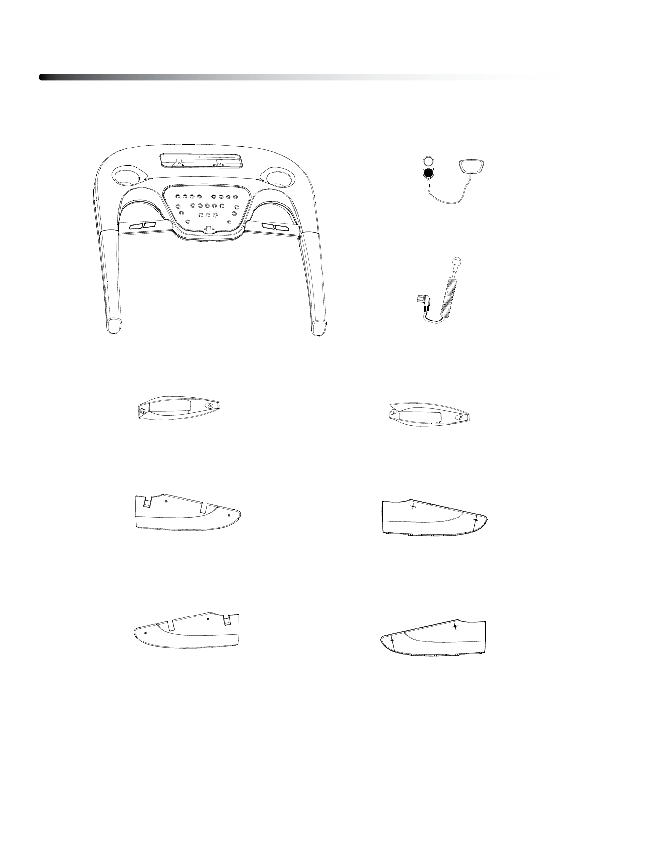
5. Upper Console, 1 pcs.
Parts List
10
1. Main Frame, 1 pcs.
2. left Upright, 1 pcs. 3. Right Upright, 1 pcs.
Parts List
11
4. lower Console, 1 pcs.
17. Safety Key, 1 pcs.
18. Power Cord, 1 pcs.
6. left Upright Cover, 1 pcs.
7. Right Upright Cover, 1 pcs.
8. left Inner Cover, 1 pcs.
9. left Outer Cover, 1 pcs.
10. Right Inner Cover, 1 pcs.
11. left Outer Cover, 1 pcs.

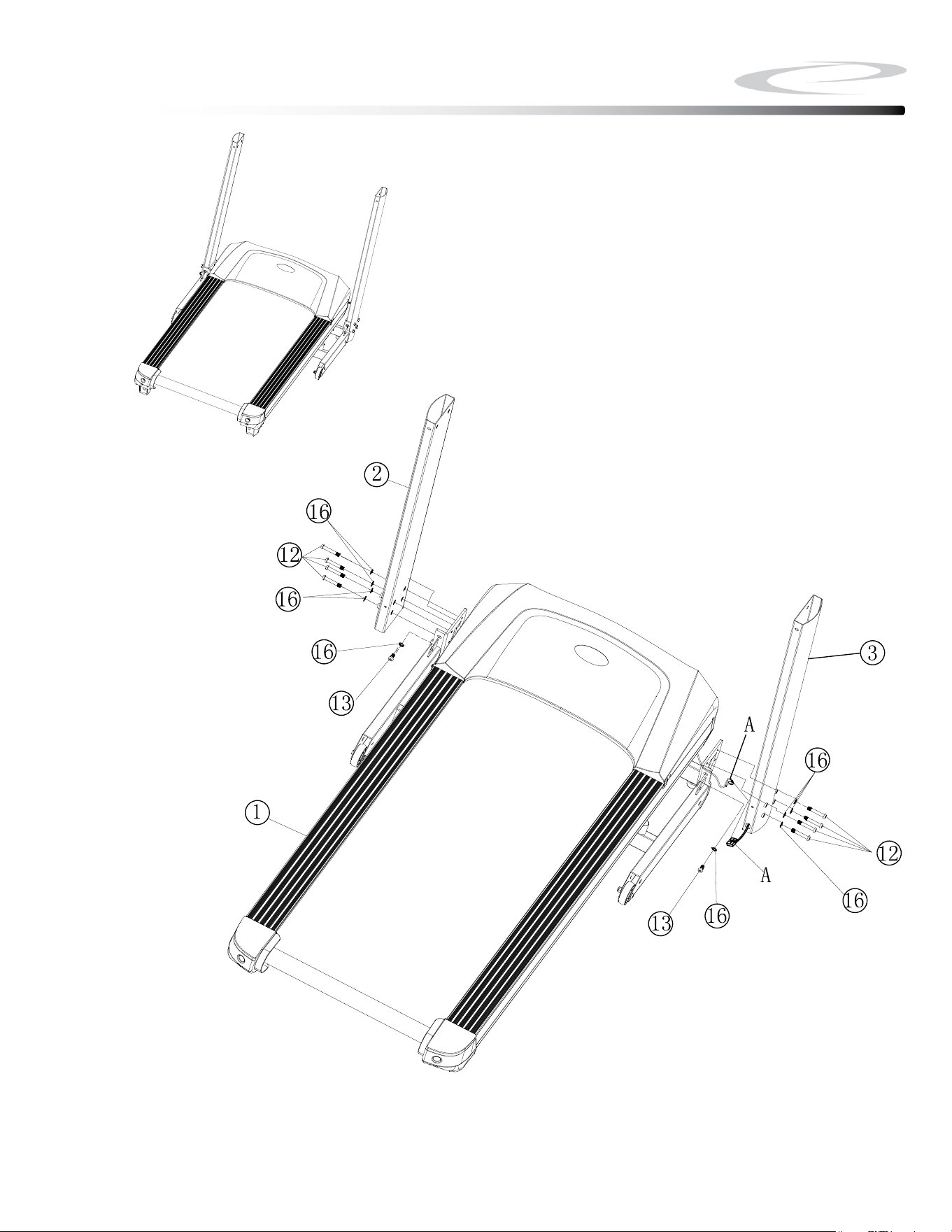
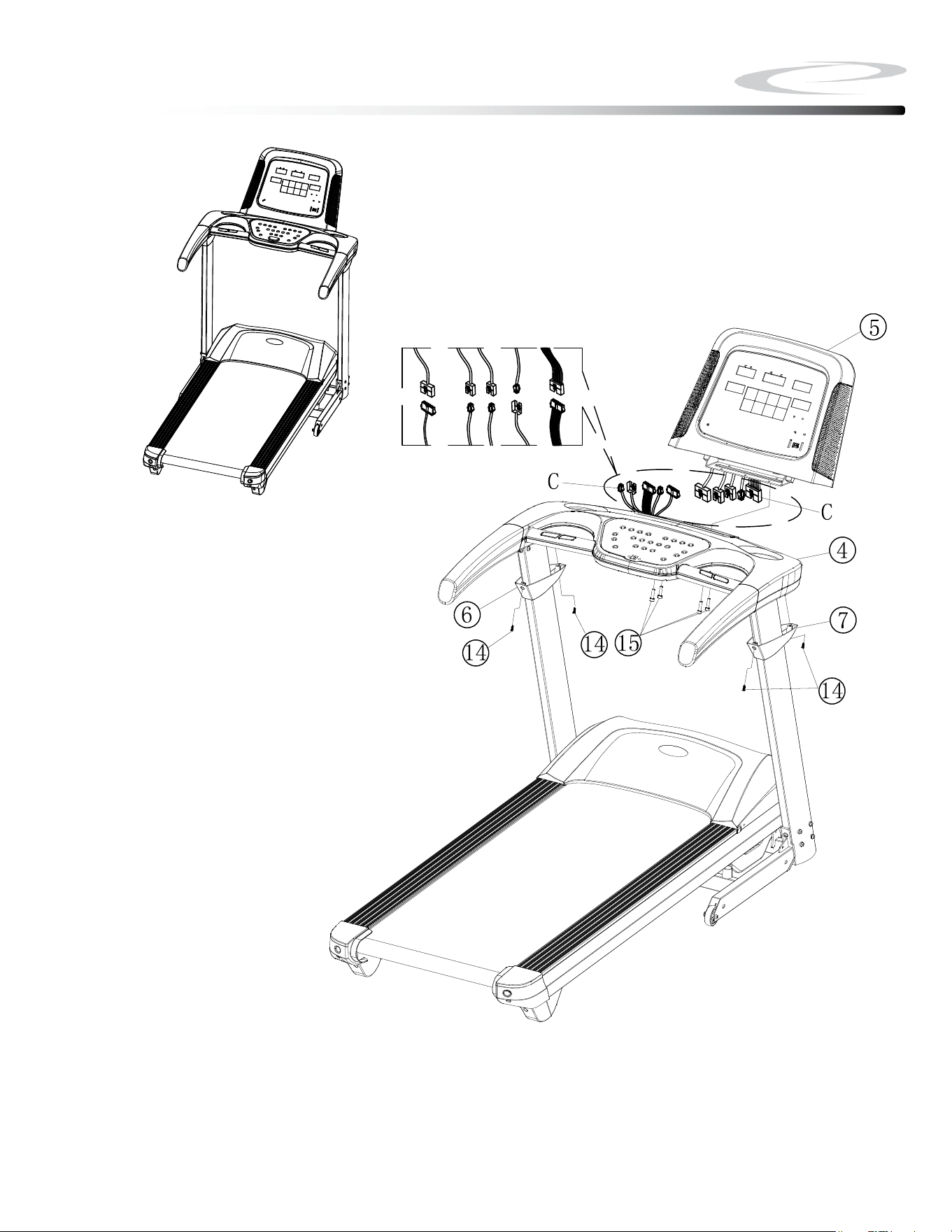
Be careful to assemble all components
in the sequence they are presented.
Note: Finger tighten all hardware in this step. DO NOT wrench tighten
unless instructed.
Look for Stickers to identify Left and Right Uprights.
1A. Attach left Upright (#2) to Main Frame (#1) using
4 - (#12) m8x50mm button Head Cap screw
1 - (#13) m8x15mm button Head Cap screw
5 - (#16) m8 Washer
1B. Connect Cable A from the Main Frame (#1) to Cable A from the Right
Upright (#3).
Note: Be careful not to damage the cables.
1C. Attach Right Upright (#3) to Main Frame (#1) using
4 - (#12) m8x50mm button Head Cap screw
1 - (#13) m8x15mm button Head Cap screw
5 - (#16) m8 Washer
12
Step 1
Step 1
13
Above shows STEP 1 assembled and completed.

Be careful to assemble all components
in the sequence they are presented.
Note: Finger tighten all hardware in this step. DO NOT wrench tighten
unless instructed
2A. Insert left Upright Cover (#6) onto left Upright (#2).
2B. Insert Right Upright Cover (#7) onto Right Upright (#3).
14
Step 2
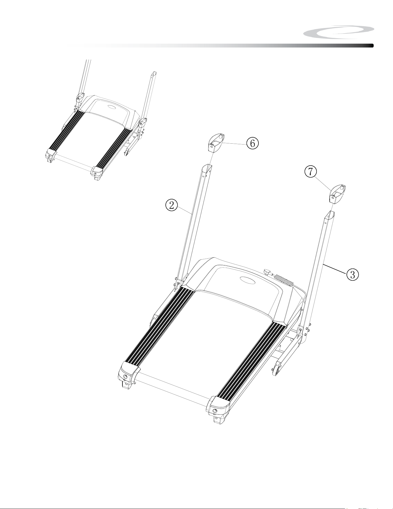
Above shows STEP 2 assembled and completed.
Step 2
15

Be careful to assemble all components
in the sequence they are presented.
Note: Wrench tighten all hardware at the end of Step 3B
3A. Connect Cable b from the Right Upright (#3) to Cable b from the lower
Console (#4).
Note: Be careful not to damage the cables.
3B. Attach lower Console (#4) to Uprights (#2 & #3) using
6 - (#13) m8x15mm button Head Cap screw
6 - (#16) m8 Washer
16
Step 3
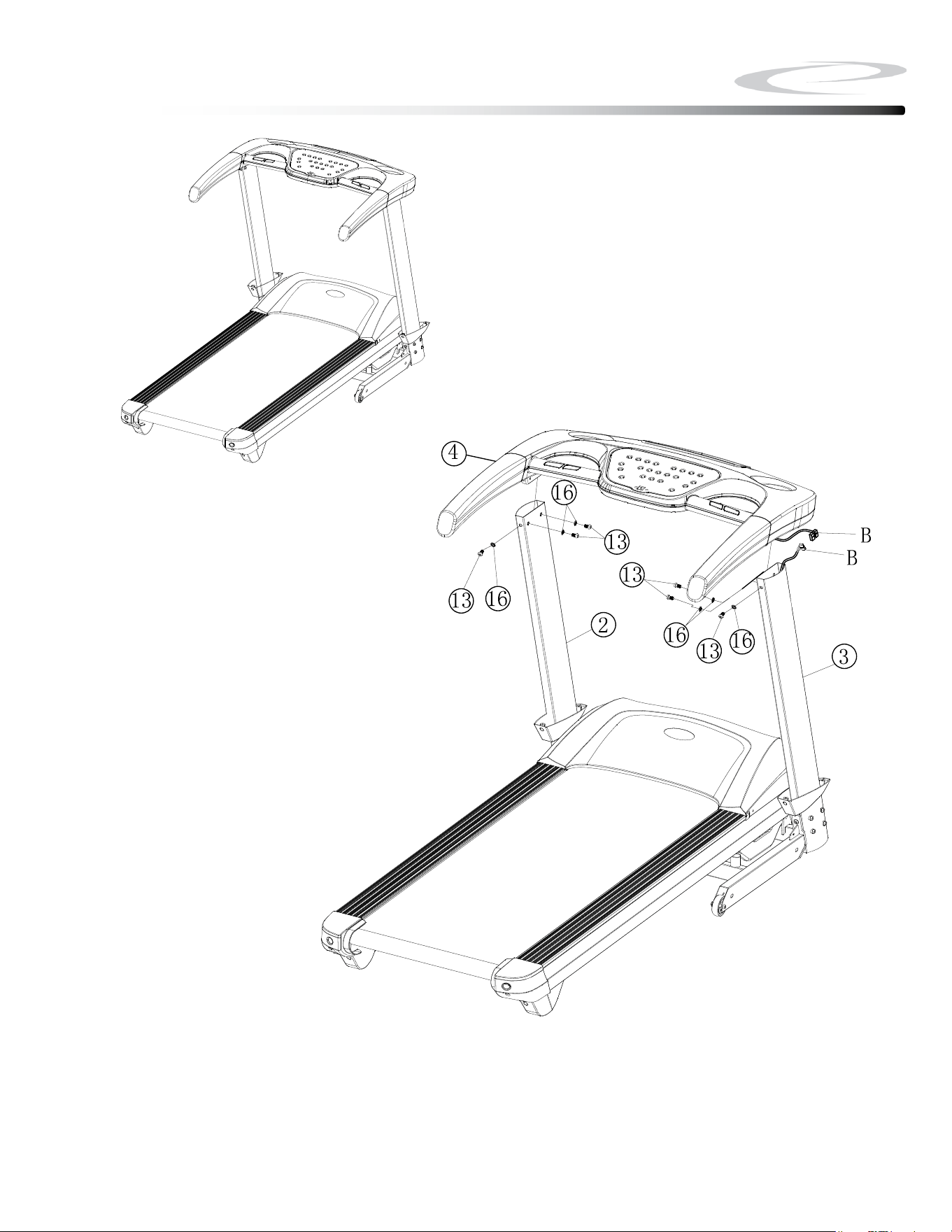
Above shows STEP 3 assembled and completed.
Step 3
17

Be careful to assemble all components
in the sequence they are presented.
Note: Wrench tighten all hardware at the end of Step 4B
4A. Connect Cables C from the lower Console (#4) to Cables C from the Upper
Console (#5).
Note: Be careful not to damage the cables.
4B. Attach Uppper Console (#5) to lower Console (#4) using
4 - (#15) m8x30mm socket Head Cap screw
4C. Attach Upright Covers (#6 & #7) to lower Console (#4) using
4 - (#14) st4.2x15mm Phillips screws
18
Step 4
Above shows STEP 4 assembled and completed.
Step 4
19

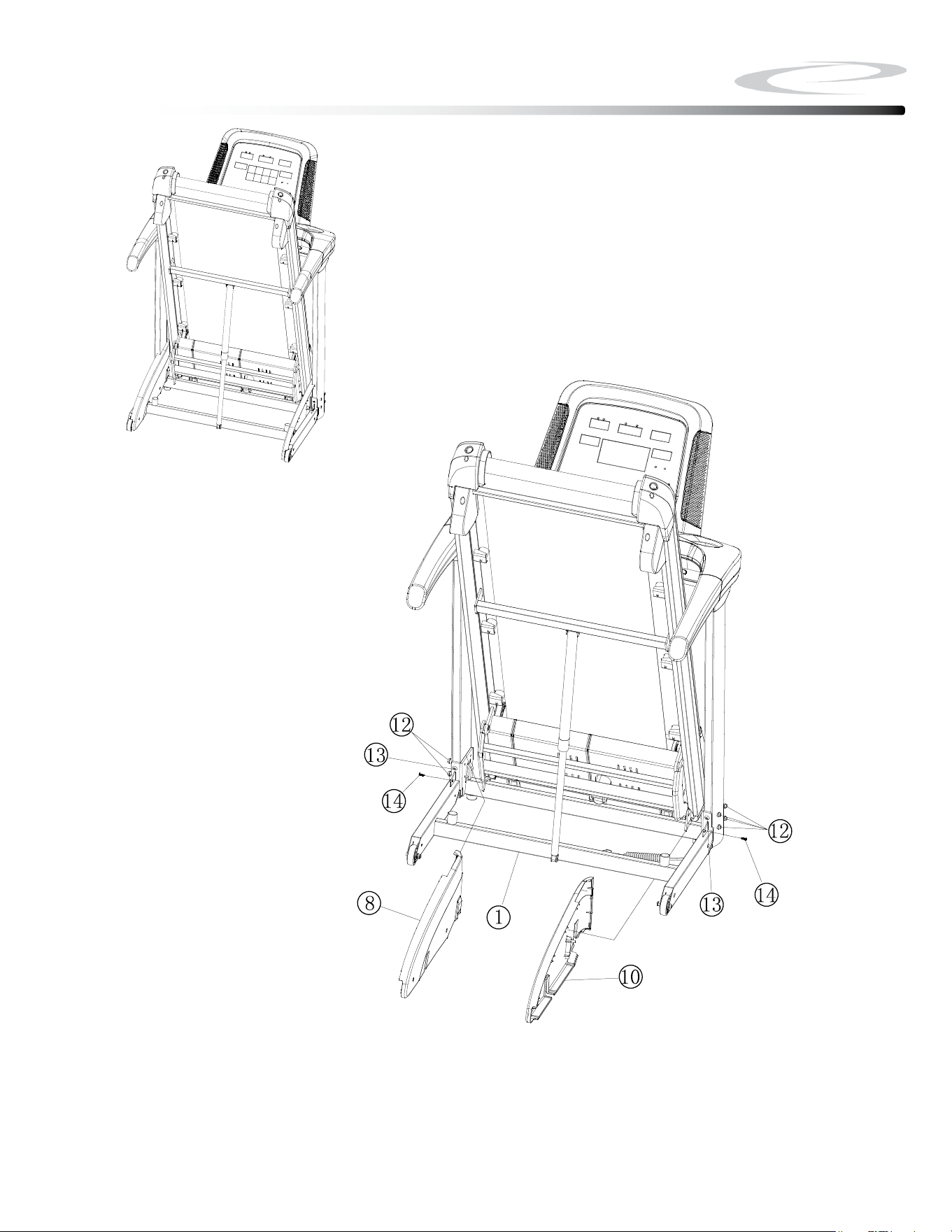
Be careful to assemble all components
in the sequence they are presented.
Note: Please make sure the Deck of the Main Frame is fully folded up
and locked. See Folding Instruction on Page 27.
5A. Attach left Inner Cover (#8) to Main Frame (#1) using
1 - (#14) st4.2x15mm Phillips screws
5B. Attach Right Inner Cover (#10) to Main Frame (#1) using
1 - (#14) st4.2x15mm Phillips screws
20
Step 5
Above shows STEP 5 assembled and completed.
Step 5
21

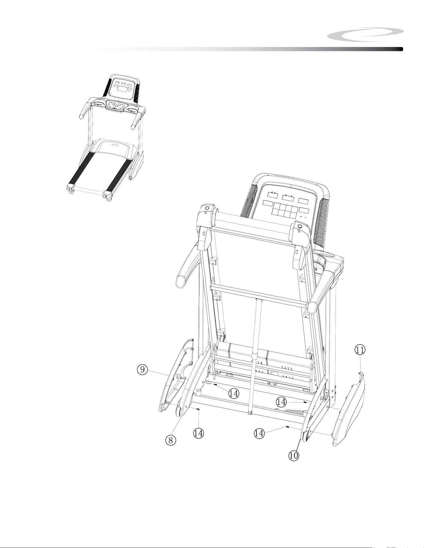
Be careful to assemble all components
in the sequence they are presented.
6A. Attach left Outer Cover (#9) and left Inner Cover (#8) together using:
2 - (#14) st4.2x15mm Phillips screws
6B. Attach Right Outer Cover (#11) and left Inner Cover (#10) together using:
2 - (#14) st4.2x15mm Phillips screws
Note: Please make sure the Deck of the Main Frame is fully folded up
and locked.
22
Step 6
Above shows STEP 6 assembled and completed.
Step 6
23

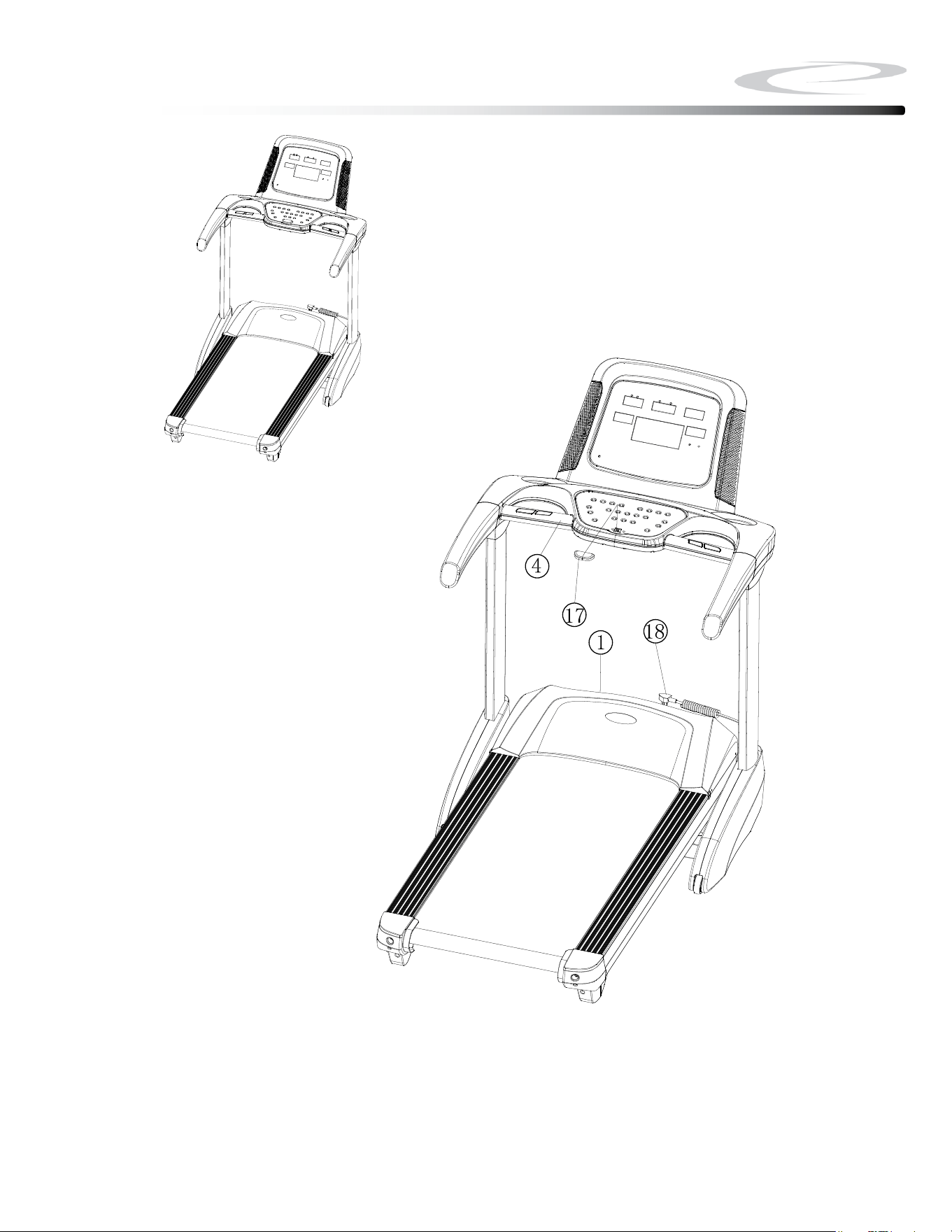
Be careful to assemble all components
in the sequence they are presented.
7A. Connect Power Cord (#18) to the Main Frame (#1).
7B. Insert Safety Key (#17) onto the lower Console (#4).
24
Step 7
Above shows STEP 7 assembled and completed.
Step 7
25
Setting up your Treadmill
26
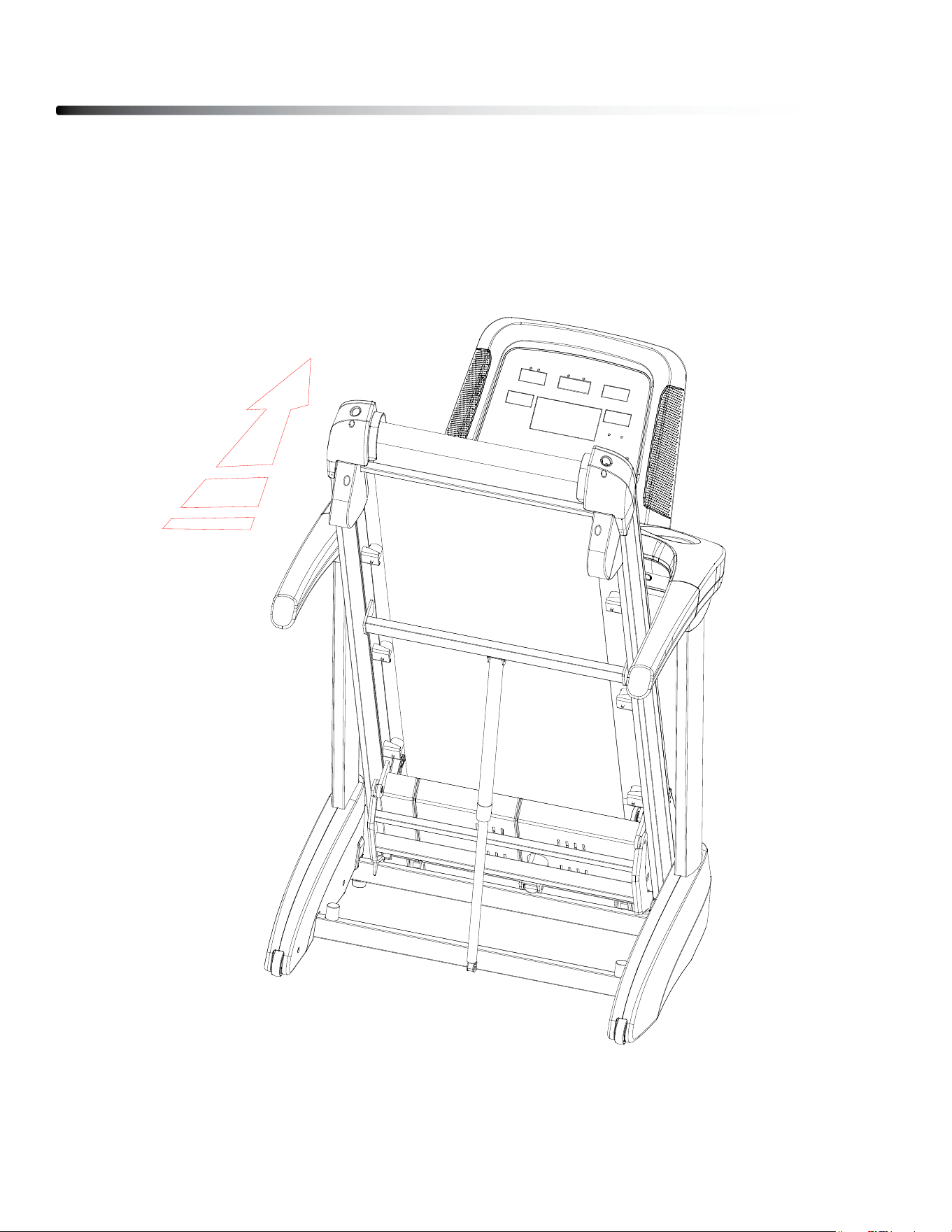
FOLDING THE TREADMILL
1. lift the deck of the treadmill up as shown in the drawing until you head the gas spring
gives a snap sound.
2. Make sure the deck is in upright and locked position.
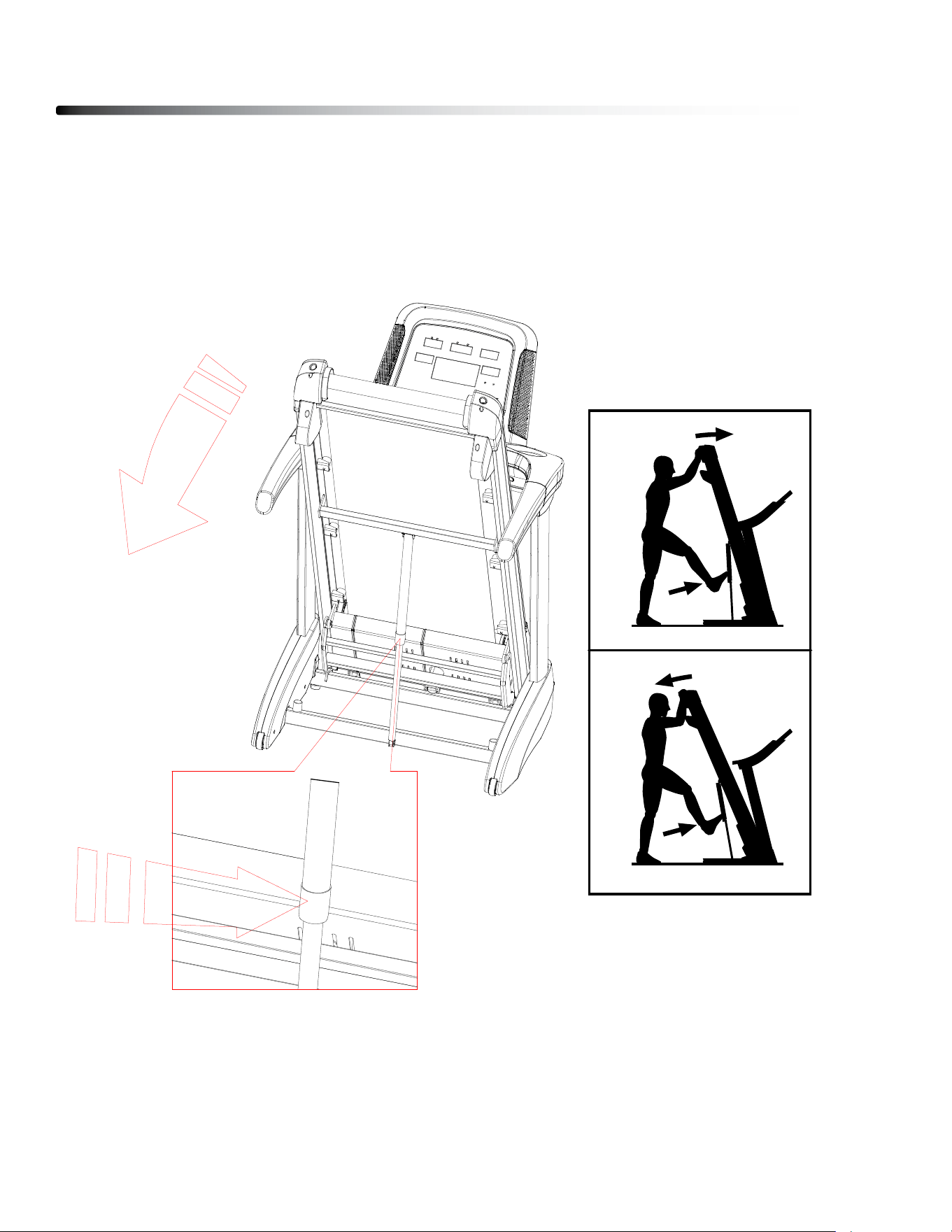
UNFOLDING THE TREADMILL
1. Hold the rear end of the running deck with both hands.
2. gently kick gas Spring to release the gas Spring.
3. let the deck unfold slowly by itself.
Setting up your Treadmill
27
29
HOW TO FOLD THE TREADMILL
To avoid damaging the treadmill, adjust the incline
to zero before you fold the treadmill. Then, remove
the key and unplug the power cord. CAUTION: You
must be able to safely lift 45 lbs. (20 kg) to raise,
lower, or move the treadmill.
1. Hold the metal frame (A) rmly in the location
shown by the arrow below. CAUTION: Do not hold
the frame by the plastic foot rails. Bend your
legs and keep your back straight.
2. Raise the frame (A) until the storage latch (B) locks
in the storage position. CAUTION: Make sure that
the storage latch locks.
To protect the oor or carpet, place a mat under
the treadmill. Keep the treadmill out of direct
sunlight. Do not leave the treadmill in the storage
position in temperatures above 85°F (30°C).
HOW TO MOVE THE TREADMILL
Before moving the treadmill, fold it as described at the
left. CAUTION: Make sure that the storage latch is
in the locked position. Moving the treadmill may
require two people.
1. Hold the frame (A) and one of the handrails (C),
and place one foot against a wheel (D).
2. Pull back on the handrail until the treadmill will roll
on the wheels, and carefully move it to the desired
location. CAUTION: Do not move the tread-
mill without tipping it back, do not pull on the
frame, and do not move the treadmill over an
uneven surface.
HOW TO LOWER THE TREADMILL FOR USE
1. Push the upper end of the
frame forward, and gently
press the upper part of
the storage latch with your
foot at the same time.
2. While pressing the storage
latch with your foot, pull
the upper end of the frame
toward yourself.
3. Step back and let the
frame lower to the floor.
A
1
B
2
A
C
A
D
1
1
2
HOW TO FOLD AND MOVE THE TREADMILL
PLACEMENT IN YOUR HOME
To make exercise a desirable daily activity for you, the treadmill should be placed in a
comfortable and attractive setting. This treadmill is designed to use minimal oor space and
to t nicely in your home.
do not place or operate the treadmill outdoors.
do not place the treadmill near water or in a high moisture content environment.
Make sure the power cord is not in the path of heavy trac.
It is highly recommended to place a dedicated treadmill mat beneath your treadmill.
A dedicated mat provides superior stability and rmness for a proper workout.
locate the treadmill at least 4 feet from walls or furniture.
It is important that the treadmill is placed on a rm level surface.
Occasionally, after extended use, you will nd a ne black dust below your treadmill. This
is normal wear and dOES NOT mean there is anything wrong with your treadmill. This dust
can be easily removed with a vacuum cleaner. If you wish to prevent this dust from getting
on your oor or carpet, place a dedicated treadmill mat beneath your treadmill.
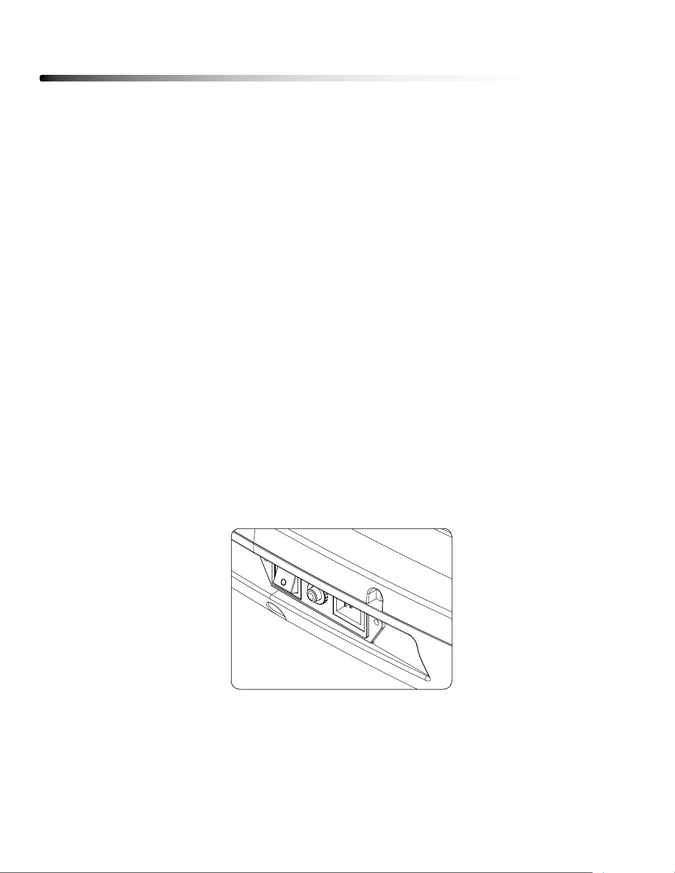
TURN POWER ON
The On/O switch for the treadmill is located next to the power supply cord receptacle on
the front of the treadmill. Insert the power supply cord into the receptacle and ip the switch
to the “ON” position.
Setting up your Treadmill
28
MOVING THE TREADMILL
This treadmill is easy to move around safely.
To move the treadmill:
1. Turn the power switch o.
2. Unplug the power cord.
3. lift the deck of the treadmill up as shown in the drawing until you head the gas spring
gives a snap sound. The deck is in upright locked position.
4. Simply roll the treadmill on its front two wheels to the desired location.
STORE YOUR TREADMILL
Please follow these safety precautions, especially if you have children at home.
We suggest to take the following precautions when storing your treadmill.
1. When you nish your workout, turn the power switch to the o position.
2. Remove the plug from the outlet.
3. Remove the safety key.
It is imperative that the safety key is removed and kept away from children.
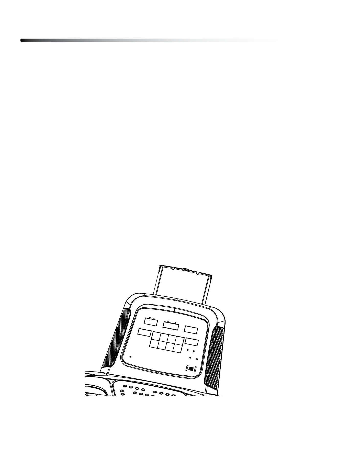
HOLD YOUR TABLET
There is a tablet holder on the top of the console. It can slide up and down to hold a
tablet or other items that t the holder.
Setting up your Treadmill
29

CONSOLE LAYOUT OVERVIEW
Operating the Console
30

Operating the Console
31
DISPLAY OVERVIEW
TIME: displays duration of the workout in minutes and seconds.
PULSE: displays Heart Rate in beats per minute.
DISTANCE: displays traveled distance during workout in miles/kilometers
COLORIES: displays Calories burned during workout.
SPEED: displays current speed during workout in mph
INCLINE: displays current incline of your workout.

BUTTON OVERVIEW
START/PAUSE : To start or pause workout.
STOP : To stop workout and back to the Standby Mode.
INCREASE SPEED : To increase workout speed .
DECREASE SPEED : To decrease workout speed.
INCREASE INCLINE : To increase workout incline level.
DECREASE INCLINE : To decrease workout incline level.
WEIGHT LOSS : To select Weight loss program.
QUICK INCLINE : To quickly select dierent incline level.
Operating the Console
32

PROGRAM : To select dierent programs (Manual, Time Countdown, Distance
Countdown, Calories Countdown, P01-P08, HP1-HP3).
MARATHON TRAINING : To select Marathon training. distance is 26.3 miles
WARM UP : To start a 3 minutes warm up. The speed is 1.0 MPH initially. The
speed will increase gradually to 3.7 MPH.
COOL DOWN : To start cool down. If the speed is greater than 5 mph, It will
take 3 minutes to slow down unitl it stops. If the speed is less
than 5 mph, but greater than 1.5 mph, it will take 2 minutes to
slow down until it stops. If the speed is less than 1.5 mph, it will
stop in 18 seconds.
MUTE SPEAKER : There is a audio Jack on the console that can connect
to the MP3 Player. This button is to be used to mute
the speaker.
INCREASE VOLUME : To increase the volume of the speaker.
DECREASE VOLUME : To decrease the volume of the speaker.
QUICK SPEED : To quickly select dierent speed.
Operating the Console
33

PROGRAMS
METRIC & STANDARD UNIT:
The initial factory setting is in “Miles”. To switch between Miles & Kilometers, press
QUICK SPEEd 2, 4, 6 at the same time.
QUICK START:
1. In Standby mode, press the START button to enter QUICK START mode.
2. during workout, SPEEd and INClINE can be changed using INClINE &
SPEEd buttons.
WEIGHT LOSS:
1. In Standby mode, press the WEIgHT lOSS button to enter WEIgHT lOSS mode.
2. Workout time is 40 minutes. Speed cannot be change. Incline can be
changed using the INClINE buttons.
MARATHON TRAINING:
1. In Standby mode, press the MARATHON TRAININg button to enter MARATHON
TRAININg mode.
2. Press START button to start the workout
3. distance is set to 26.3 miles. Speed and Incline can be changed using SPEEd
and INClINE buttons.
TIME COUNTDOWN:
1. In Standby mode, press the PROgRAM button to choose TIME COUNTdOWN
mode.
2. Press INClINE ANd SPEEd buttons to change the TIME setting.
3. Press START button to start the workout
4. during workout, SPEEd and INClINE can be changed using INClINE &
SPEEd buttons.
Program Features
34
TIME 0-2 min. 2-15 min. 15-20 min. 20-35 min. 35-40 min.
SPEED 1.0 to 3.7 MPH 3.7-7.5 MPH 7.5-3.7 MPH 3.7-7.5 MPH 7.5-1.0 MPH
DISTANCE COUNTDOWN:
1. In Standby mode, press the PROgRAM button to choose dISTANCE
COUNTdOWN mode.
2. Press INClINE ANd SPEEd buttons to change the dISTANCE setting.
3. Press START button to start the workout
4. during workout, SPEEd and INClINE can be changed using INClINE &
SPEEd buttons.
CALORIES COUNTDOWN:
1. In Standby mode, press the PROgRAM button to choose CAlORIES
COUNTdOWN mode.
2. Press INClINE ANd SPEEd buttons to change the CAlORIES setting.
3. Press START button to start the workout
4. during workout, SPEEd and INClINE can be changed using INClINE &
SPEEd buttons.
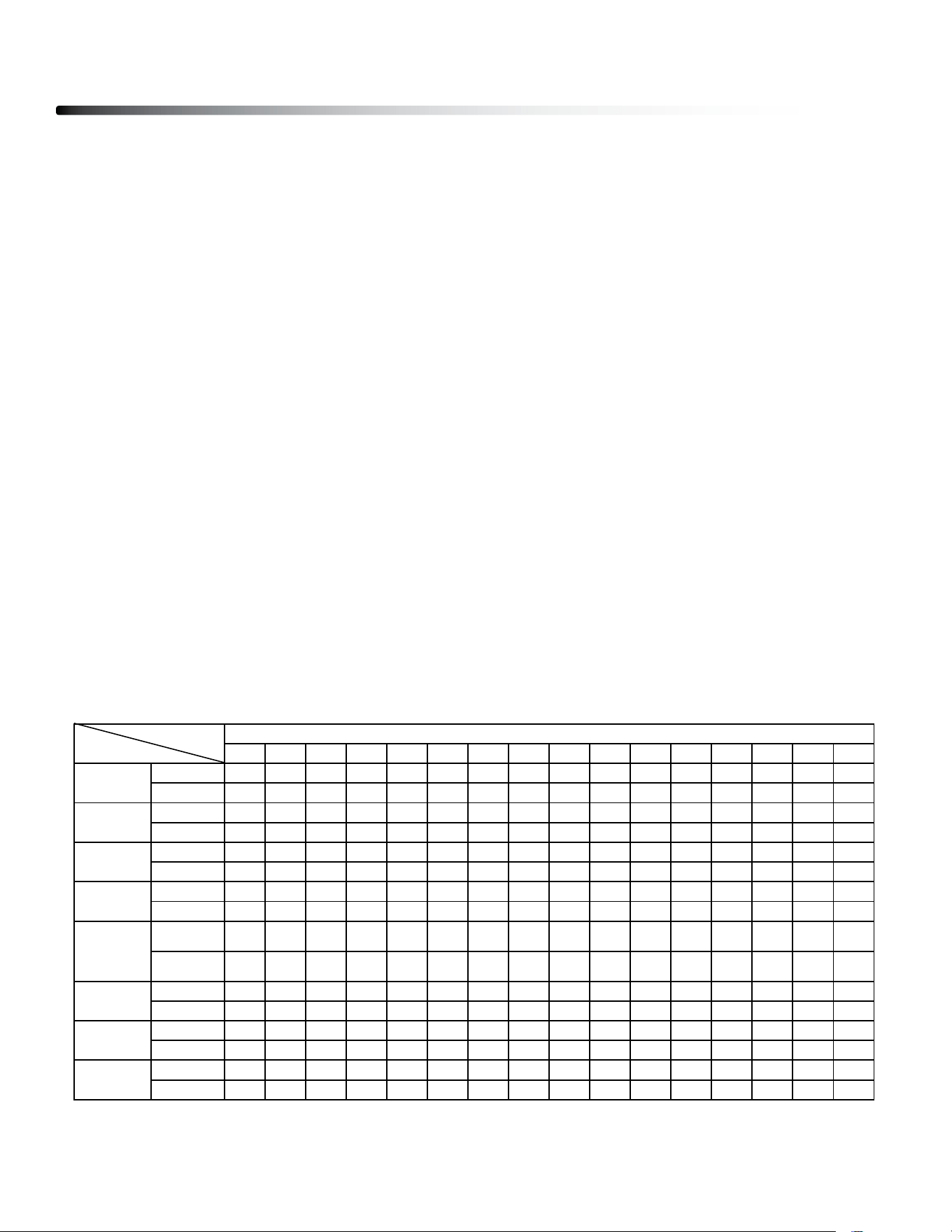
P01 - P08
1. In Standby mode, press the PROgRAM button to choose P01-P08 mode.
2. Press INClINE ANd SPEEd buttons to change the TIME setting.
3. Press START button to start the workout. Below table is the prole setting for
P01-P08.
Program Features
35
INTERVAL
PROGRAM
12345678910111213141516
SPEED
1.2 2.5 3.1 3.1 3.7 3.7 4.3 4.3 4.3 4.3 3.7 3.7 3.1 2.5 1.8 1.2
INCLINE
1122223333222211
SETTIME/16=TIMEPEREACHINTERVAL
P01
WALK
SPEED
1.2 3.1 3.7 5 5.6 5.6 5.6 5.6 5.6 5.6 5.6 5 4.3 3.7 3.1 1.8
INCLINE
1233223322333321
SPEED
1.2 2.5 3.7 3.7 5.6 6.2 6.2 5.6 3.7 3.7 5.6 5.6 5.6 4.3 3.1 1.8
INCLINE
1234554455336632
SPEED
1.2 3.7 4.3 4.3 6.8 6.8 6.8 5.6 5.6 5.6 5.6 3.7 3.7 3.7 2.5 1.2
P02
JOG
P03
HILL
P04
INCLINE
4566337864567742
SPEED
2.5 3.1 4.3 5 5.6 6.2 6.2 5 5 5.6 5.6 5.6 5.6 3.7 2.5 1.8
INCLINE
1332223443224431
SPEED
1.8 3.7 3.7 3.7 5 5 5 5 6.2 6.2 6.2 6.8 6.8 5 3.1 1.8
P06
RANDOM
P05
WEIGHT
LOSS
INCLINE
0224442223344321
SPEED
1.8 3.7 4.3 4.3 5 5.6 5.6 6.2 6.2 6.2 5.6 5.6 5 3.7 2.5 1.8
INCLINE
1122333222332211
SPEED
1.2 3.7 3.7 5.6 5.6 6.8 6.8 6.8 6.8 6.8 3.7 3.7 3.7 3.1 2.5 1.2
INCLINE
456789101099567852
CARDIO
P07
RACE
P08
SPRINT

Program Features
36
HP01 - HP03 (HEART RATE SPEED CONTROL):
1. In Standby mode, press the PROgRAM button to choose HP01 - HP03 mode.
2. Press and hold PROgRAM button to enter AgE. AgE can be changed using
INClINE & SPEEd buttons.
3. Press PROgRAM button to enter TARgET HEART RATE. Please refer to below
Heart Rate table. TARgET HEART RATE can be changed using INClINE &
SPEEd buttons.
4. Press PROgRAM button to enter TIME. TIME can be changed using INClINE &
SPEEd buttons.
4. Press START button to start the workout.
5. If user’s heart rate is 5 bmp lower than the target heart rate, the speed will
increase 0.3 MPH every 10 seconds until the maxinum speed limit is reach.
Please refer to the below Heart Rate table for maxinum speed limit.
6. If user’s heart rate is 5 bmp higher than the target heart rate, the speed will
decrease 0.3 MPH every 10 seconds.
5. during workout, INClINE & SPEEd can be change manually using INClINE &
SPEEd buttons. but the Speed cannot exceed the maxinum speed limit.
MIN INITIAL MAX MIN INITIAL MAX MIN INITIAL MAX
15 128 133 138 149 154 159 169 174 179
16
128
133
138
148
153
158
168
173
178
AGE
MAX SPEED: 5.0 MPH MAX SPEED: 5.6 MPH MAX SPEED: 6.2 MPH
HP01
BEATS PER MINUTE
HP02
BEATS PER MINUTE
HP03
BEATS PER MINUTE
16
128
133
138
148
153
158
168
173
178
17 127 132 137 147 152 157 168 173 178
18 126 131 136 147 152 157 167 172 177
19 126 131 136 146 151 156 166 171 176
20 125 130 135 145 150 155 165 170 175
21 124 129 134 144 149 154 164 169 174
22 124 129 134 144 149 154 163 168 173
23 123 128 133 143 148 153 162 167 172
24 122 127 132 142 147 152 162 167 172
25 122 127 132 141 146 151 161 166 171
26 121 126 131 141 146 151 160 165 170
27 120 125 130 140 145 150 159 164 169
28 120 125 130 139 144 149 158 163 168
29
119
124
129
138
143
148
157
162
167
29
119
124
129
138
143
148
157
162
167
30 119 124 129 138 143 148 157 162 167

Program Features
37
31 118 123 128 137 142 147 156 161 166
32 117 122 127 136 141 146 155 160 165
33 117 122 127 135 140 145 154 159 164
34 116 121 126 135 140 145 153 158 163
35 115 120 125 134 139 144 152 157 162
36 115 120 125 133 138 143 151 156 161
37 114 119 124 132 137 142 151 156 161
38 113 118 123 132 137 142 150 155 160
39 113 118 123 131 136 141 149 154 159
40 112 117 122 130 135 140 148 153 158
41 111 116 121 129 134 139 147 152 157
42 111 116 121 129 134 139 146 151 156
43 110 115 120 128 133 138 145 150 155
44 109 114 119 127 132 137 145 150 155
45 109 114 119 126 131 136 144 149 154
46 108 113 118 126 131 136 143 148 153
47 107 112 117 125 130 135 142 147 152
48 107 112 117 124 129 134 141 146 151
49 106 111 116 123 128 133 140 145 150
50 106 111 116 123 128 133 140 145 150
51 105 110 115 122 127 132 139 144 149
52 104 109 114 121 126 131 138 143 148
53 104 109 114 120 125 130 137 142 147
54 103 108 113 120 125 130 136 141 146
55 102 107 112 119 124 129 135 140 145
56 102 107 112 118 123 128 134 139 144
57 101 106 111 117 122 127 134 139 144
58 100 105 110 117 122 127 133 138 143
59 100 105 110 116 121 126 132 137 142
60 99 104 109 115 120 125 131 136 141
61 98 103 108 114 119 124 130 135 140
62 98 103 108 114 119 124 129 134 139
63 97 102 107 113 118 123 128 133 138
64 96 101 106 112 117 122 128 133 138
65 96 101 106 111 116 121 127 132 137
66 95 100 105 111 116 121 126 131 136
67 94 99 104 110 115 120 125 130 135
68 94 99 104 109 114 119 124 129 134
69 93 98 103 108 113 118 123 128 133
70 93 98 103 108 113 118 123 128 133
71 92 97 102 107 112 117 122 127 132
72 91 96 101 106 111 116 121 126 131
73 91 96 101 105 110 115 120 125 130
74 90 95 100 105 110 115 119 124 129
75 89 94 99 104 109 114 118 123 128
76 89 94 99 103 108 113 117 122 127
77 88 93 98 102 107 112 117 122 127
78 87 92 97 102 107 112 116 121 126
79 87 92 97 101 106 111 115 120 125
80 86 91 96 100 105 110 114 119 124
General Maintenace
38
Belt and Bed - Your treadmill uses a very high-ecient low-friction bed. Performance is
maximized when the bed is kept as clean as possible. Use a soft, damp cloth or paper
towel to wipe the edge of the belt and the area between the belt edge and frame. Also
reach as far as practical directly under the belt edge. This should be done once a month to
extend belt and bed life. Use water only - no cleaners or abrasives. A mild soap and water
solution along with a nylon scrub brush will clean the top of the textured belt. Allow the belt
to dry before using.
Belt Dust - This occurs during normal break-in or until the belt stabilizes. Wiping excess
o with a damp cloth will minimize buildup.
General Cleaning - dirt, dust, and pet hair can block air inlets and accumulate on the run-
ning belt. On a monthly basis: vacuum underneath your treadmill to prevent buildup. Once
a year, you should remove the black motor hood and vacuum out dirt that may accumu-
late. UNPlUg POWER CORd bEFORE THIS TASK.
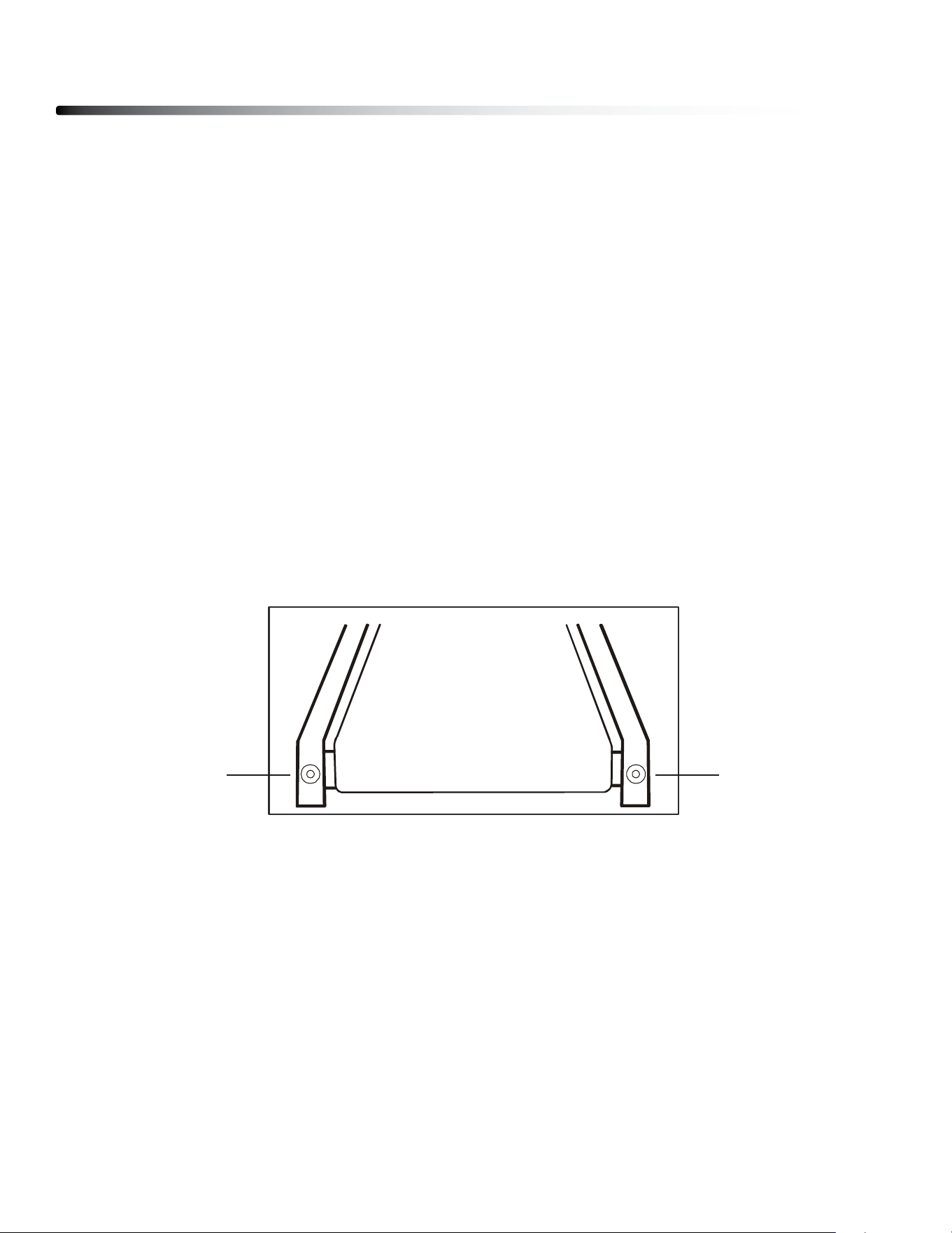
BELT ADJUSTMENTS:
Running belt Tension Adjustment - Adjustment must be made from the rear roller. The
adjustment bolts are located at the end of the step rails in the end caps, as noted in dia-
gram below.
Tighten the rear roller bolts only enough to prevent slippage at the front roller. Turn both
tread-belt tension adjustment bolts in increments of 1/4 turn each and inspect for proper
tension by walking on the belt at a low speed, making sure the belt does not slip. Keep
tensioning the bolts until the belt stops slipping.
• If you feel the belt is tight enough, but it still slips, the problem may be a
loose Motor drive belt under the front cover.
dO NOT OVERTIgHTEN – Over tightening will cause belt damage and premature bearing
failure.
-21-
Belt and Bed - Your treadmill uses a very high-efficient low-friction bed. Performance is
maximized when the bed is kept as clean as possible. Use a soft, damp cloth or paper towel to
wipe the edge of the belt and the area between the belt edge and frame. Also reach as far as
practical directly under the belt edge. This should be done once a month to extend belt and bed
life. Use water only - no cleaners or abrasives. A mild soap and water solution along with a nylon
scrub brush will clean the top of the textured belt. Allow the belt to dry before using.
Belt Dust - This occurs during normal break-in or until the belt stabilizes. Wiping excess off with
a damp cloth will minimize buildup.
General Cleaning - Dirt, dust, and pet hair can block air inlets and accumulate on the running
belt. On a monthly basis: vacuum underneath your treadmill to prevent buildup. Once a year, you
should remove the black motor hood and vacuum out dirt that may accumulate. UNPLUG
POWER CORD BEFORE THIS TASK.
BELT ADJUSTMENTS:
Tread-belt Tension Adjustment - Adjustment must be made from the rear roller. The
adjustment bolts are located at the end of the step rails in the end caps, as noted in diagram
below.
Tighten the rear roller bolts only enough to prevent slippage at the front roller. Turn both
tread-belt tension adjustment bolts in increments of 1/4 turn each and inspect for proper tension
by walking on the belt at a low speed, making sure the belt does not slip. Keep tensioning the
bolts until the belt stops slipping.
• If you feel the belt is tight enough, but it still slips, the problem may be a loose
Motor drive belt under the front cover.
DO NOT OVERTIGHTEN – Over tightening will cause belt damage and premature bearing
failure.
General Maintenance
Note: Adjustment is through small hole in the end cap.
Tracking / Tension
Adjustment
Tracking / Tension
Adjustment
General Maintenance
39
RUNNING BELT TRACKING ADJUSTMENT:
The performance of your treadmill is dependent on the frame running on a reasonably
level surface. If the frame is not level, the front and back roller cannot run parallel, and
constant belt adjustment may be necessary.
The treadmill is designed to keep the tread-belt reasonably centered while in use. It is
normal for some belts to drift near one side while the belt is running with no one on it. After
a few minutes of use, the tread-belt should have a tendency to center itself. If, during use,
the belt continues to move toward one side, adjustments are necessary.
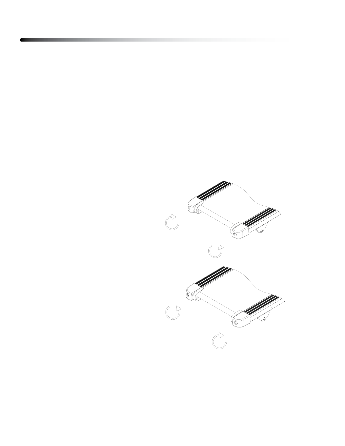
TO SET RUNNING BELT TRACKING:
7mm Allen wrench is needed to adjust the rear roller. Set belt speed at approximately 2 to
3 mph.
Remember, a small adjustment can make a dramatic dierence!
ATTENTION:
DAMAGE TO THE RUNNING BELT RESULTING FROM IMPROPER TRACKING /
TENSION ADJUSTMENTS IS NOT COVERED UNDER THE WARRANTY.
To move the belt to the Right:
1) Turn the left Roller bolt 1/4 turn
Clockwise (Tighten)
2) Turn the Righ Roller bolt 1/4 turn
Counterclockwise (loosen)
To move the belt to the left:
1) Turn the left Roller bolt 1/4 turn
Counterclockwise (loosen)
2) Turn the Righ Roller bolt 1/4 turn
clockwise (Tighten)
26
·把电动跑步机放在平整的地面上。
·使电动跑步机以大约 3.5 公里/小时的速度运行。
·如果跑步带偏向右边,将右边的调节螺栓沿顺时针方向旋转 1/2 圈或将左边的调节螺
栓沿逆时针方向旋转 1/2 圈。如图 A 直至跑步带调节到居中
·如果跑步带偏向左边,将左边的调节螺栓沿顺时针方向旋转 1/2 圈或将右边的调节螺
栓沿逆时针方向旋转 1/2 圈。如图 B 直至跑步带调节到居中
图 A 跑
带调向左边 图 B 跑带调向右边
跑
步带松紧度:
·若跑步带太松可调节后滚筒螺栓沿顺时针方向旋转(滚筒左右两端调节螺栓需调节相
同圈数)直至跑步带松紧度适宜且处于居中;若跑步带过紧可调节后滚筒螺栓沿逆时
针方向旋转,参照上述步骤直至跑步带松紧度适宜且居中。
General Maintenance
40
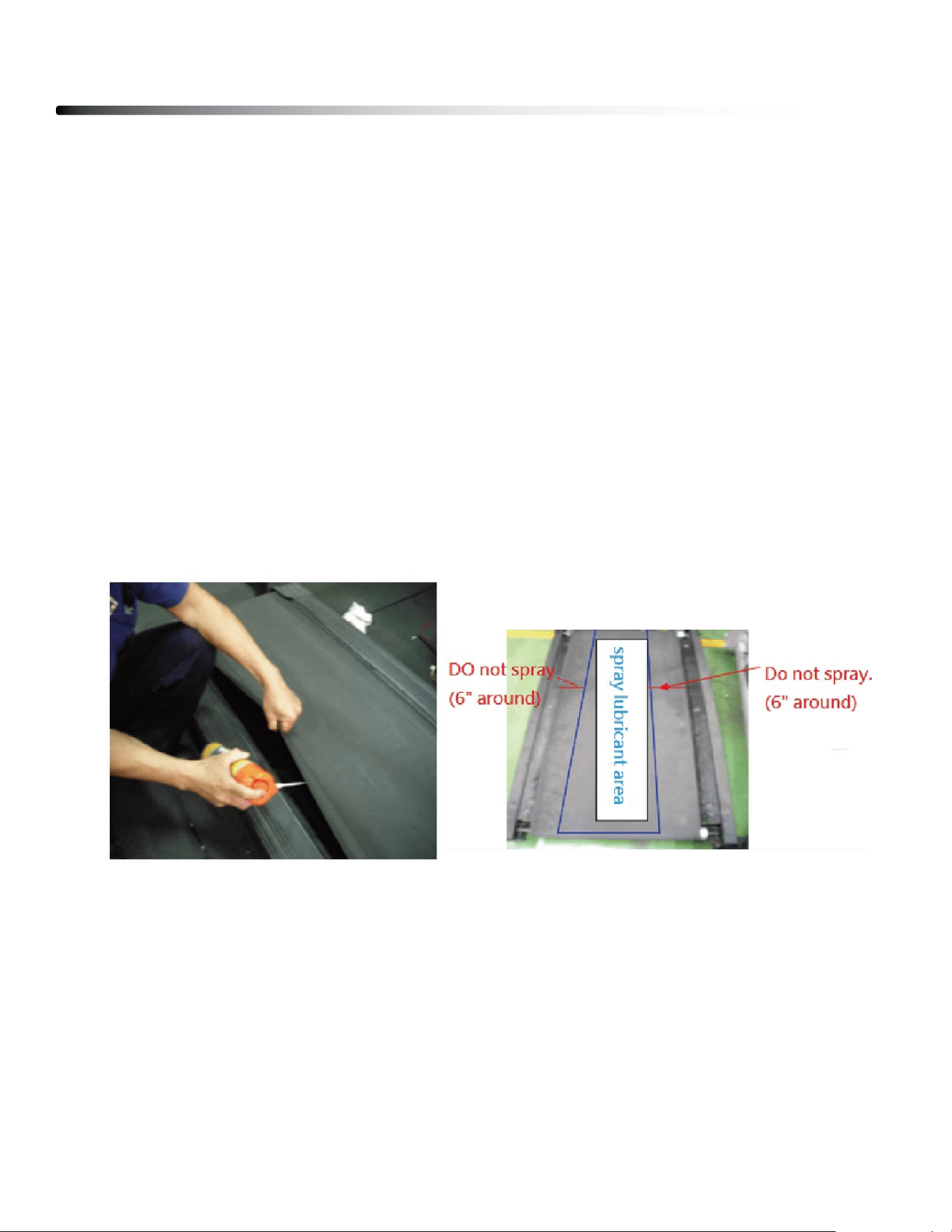
Belt Lubrication Procedure
1) Turn o the Power.
2) lift the running belt and check if there is any lubricant on the back of the running belt.
If running belt needs to be lubricated, take a wiper to clean the running deck and
rollers.
3) lift the running belt and spray lubricant as below photo shown. While spraying, pull
the running belt and make it turn one revolution.
Note: Please only spray in the center area, do not spray on the side area.
4) Turn on the power.
5) Press START button and increase the speed to 1.0 MPH (1.6KPH). Have a person to
walk on the tradmill to help the running belt absorbs the lubricant.
Note: dO NOT run the treadmill in high speed when lubricant is just sprayed on, lubricant
may spread to drive motor and Control board.

Troubleshooting Guide
41
Problem/ Fault
Code
Possible Reason Corrective action
1.Not
p
lu
gg
ed in 1.Plu
g
cord into outlet
2.Safet
y
ke
y
not inserted 2.Insert safet
y
ke
y
3.Switch on OFF 3.Turn switch to ON
4.treadmill circuit breaker tripped 4.Lubricate treadmill belt and rest
Running belt slips
Running belt not tight enough Adjust running belt tension
1. Insufficient lubrication 1. Apply silicone lubricant
2. Running belt worn out 2. Replace running belt
Running belt not
centered
Running belt tension not adjusted
on the left or right sides of the
runnin
g
board
Tighten the adjustment bolts on
the left and right side of the rear
rolle
r
1. Safet
y
Ke
y
not en
g
a
g
e 1. Re-insert safet
y
ke
y
2. Loose Cable 2. Check cable connections
3. Switch damaged
3. Contact Body-Solid
Customer Service
1. Dirt & dust buildup 1. Clean inverter & surrounding
2. Inverter damaged
2. Contact Body-Solid
Customer Service
1. Runnin
g
belt is too ti
g
ht 1. Ad
j
ust runnin
g
belt tension
2. Running belt is lack of
lubrication.
2. Add lubricate to the running
belt.
3. Incomin
g
volta
g
e is too low 3. Check incomin
g
volta
g
e
4. IPM Module dama
g
ed 4. Chan
g
e Inverter
E3
(
Over Volta
g
e
)
Incoming voltage is too high. Check incoming voltage
E5
(Inverter MCU
Fault
)
MCU module fault Change Inverter
1. Loose cable 1. Check cable connections
2. Cable dama
g
ed 2. Chan
g
e Cables
1. Inverter dama
g
ed 1. Chan
g
e Inverter
2. Incline Motor dama
g
ed 2. Chan
g
e Incline Moto
r
EE
(Erprom Error)
Delete MCU data
Perform a factory reset:
1. Remove the Safety Key,
Press STOP & DECREASE
SPEED buttons.
2. Put the Safety Key back on.
E1
(Inverter Over
Heat)
E2
(Over Current)
E7
(
Incline Fault
)
E6
(
Comm Fault
)
Treadmill will not
start
Running belt
hesitates when
ste
pp
ed on
--/---
(Emergency
Circuit Opened)

Parts List
42
#
1
2
3
4
5
6
7
8
9
10
11
12
13
14
15
16
17
18
19
20
21
22
23
24
25
26
27
28
29
30
31
32
33
34
35
36
37
DESCRIPTION
MAIN FRAME
ElEVATION FRAME
FRONT bASE FRAME
lEFT UPRIgHT
RIgHT UPRIgHT
lOWER CONSOlE FRAME
UPPER CONSOlE FRAME
lEFT bRACKET
RIgHT bRACKET
SPACER
RUNNINg dECK
RUNNINg bElT
AC MOTOR
INClINE MOTOR
FRONT ROllER
REAR ROllER
POWER SWITCH
OVERlOAd PROTECTOR
POWER SOCKET
POWER CORd
MOTOR dRIVE bElT
CUSHION (blACK)
CUSHION (blUE)
MAIN FRAME SUPPORT CUSHION
FOOT PAd
TRANSPORT WHEEl, Ø51.5xØ8.1x20
TRANSPORT WHEEl, Ø65xØ8.1x20
gAS SPRINg
MOTOR COVER
FRONT COVER
TOP RAIl
SIdE RAIl
lEFT REAR COVER
RIgHT REAR COVER
lEFT REAR SUPPORT
RIgHT REAR SUPPORT
lEFT OUTER COVER
QTY
1
1
1
1
1
1
1
1
1
12
1
1
1
1
1
1
1
1
1
1
1
2
4
2
2
2
2
1
1
1
2
2
1
1
1
1
1

Parts List
43
#
38
39
40
41
42
43
44
45
46
47
48
49
50
51
52
53
54
55
56
57
58
59
60
61
62
63
64
65
66
67
68
69
70
71
72
73
74
DESCRIPTION
lEFT INNER COVER
RIgHT OUTER COVER
RIgHT INNER COVER
TAblET HOldER
CONSOlE SUPPORT COVER
FRONT CONSOlE COVER
REAR CONSOlE COVER
dISPlAY
CONSOlE TOP COVER
CONSOlE bOTTOM COVER
KEY bOARd COVER
lEFT UPRIgHT COVER
RIgHT UPRIgHT COVER
lEFT HANdRAIl COVER
RIgHT HANdRAIl COVER
SPRINg
PlASTIC WASHER
AdHESIVE TAPE, 28x38x1mm
AdHESIVE TAPE, 10x1340x1mm
AdHESIVE TAPE, 40x1340x2mm
CAblE STRAP, ST-100
CAblE STRAP, ST-200
WARNINg lAbEl, 45x145mm
dISPlAY dECAl
bUTTON dECAl
WARNINg lAbEl, 120x30mm
lOWER SECTION CAblE, 650mm
MIddlE SECTION CAblE, 1350mm
UPPER SECTION CAblE, 650mm
T25 lOgO
WIRE, blUE 150mm
WIRE, bROWN 100mm
WIRE, blUE 200mm
WIRE, bROWN 200mm
gROUNd WIRE, YEllOW/gREEN 150mm
SAFETY KEY
SAFETY KEY HOldER
QTY
1
1
1
1
1
1
1
1
1
1
1
1
1
1
1
2
2
2
2
2
4
6
1
1
1
1
1
1
1
1
1
2
1
1
1
1
1

Parts List
44
#
75
76
77
78
79
80
81
82
83
84
85
86
87
88
89
90
91
92
93
94
95
96
97
98
99
100
101
102
103
104
105
106
107
108
109
DESCRIPTION
SPEAKER
dISPlAY bOARd
KEY bOARd
INVERTER
HANd PUlSE PlATE
HEX HEAd bOlT, M10x45mm
HEX HEAd bOlT, M10x60mm
bUTTON HEAd CAP SCREW, M8x40mm
bUTTON HEAd CAP SCREW, M8x50mm
CARRIAgE bOlT, M8x20mm
HEX HEAd bOlT, M8x70mm
HEX HEAd bOlT, M8x60mm
PAN HEAd PHIllIPS SCREW, M4x10mm
PAN HEAd PHIllIPS SCREW, M4x15mm
SOCKET HEAd CAP SCREW, M8x75mm
HEX HEAd bOlT, M10x25mm
HEX HEAd bOlT, M10x35mm
SOCKET HEAd CAP SCREW, M8x15mm
lARgE HEAd SElF-TAPPINg SCREW, ST4.2x10mm
SOCKET HEAd CAP SCREW, M6x15mm
SElF-TAPPINg SCREW, ST4.2x10mm, blACK OXIdE
SElF-TAPPINg SCREW, ST3.0x10mm
SElF-TAPPINg SCREW, ST4.2x10mm, ZINC PlATEd
WASHER, M10
WASHER, M8
TOOTH lOCK WASHER, M8
lOCK WASHER, M8
NYlON lOCK NUT, M10
NYlON lOCK NUT, M8
FlAT HEAd PHIllIPS SCREW, M6x25mm
SElF-TAPPINg SCREW, ST4.2x25mm
bUTTON HEAd CAP SCREW, M8x15mm
SOCKET HEAd CAP SCREW, M8x30mm
bUTTON HEAd CAP SCREW, M8x40mm
EMI FIlTER
QTY
2
1
1
1
1
1
1
1
4
9
4
1
1
10
1
3
2
2
2
88
8
8
2
2
6
12
19
4
6
6
8
1
8
4
1

Parts List
44
#
110
111
112
113
114
115
116
117
DESCRIPTION
CAblE, 800mm
gROUNd CAblE, 600mm
MAgNETIC RINg, Ø24.75xØ15.2x14.9mm
MAgNETIC RINg, Ø39xØ13x31mm
MAgNET, Ø20xØ8.5x36mm
MAgNET, b5H
lOWER CONSOlE ASSEMblY
UPPER CONSOlE ASSEMblY
QTY
1
1
1
1
2
1
1
1
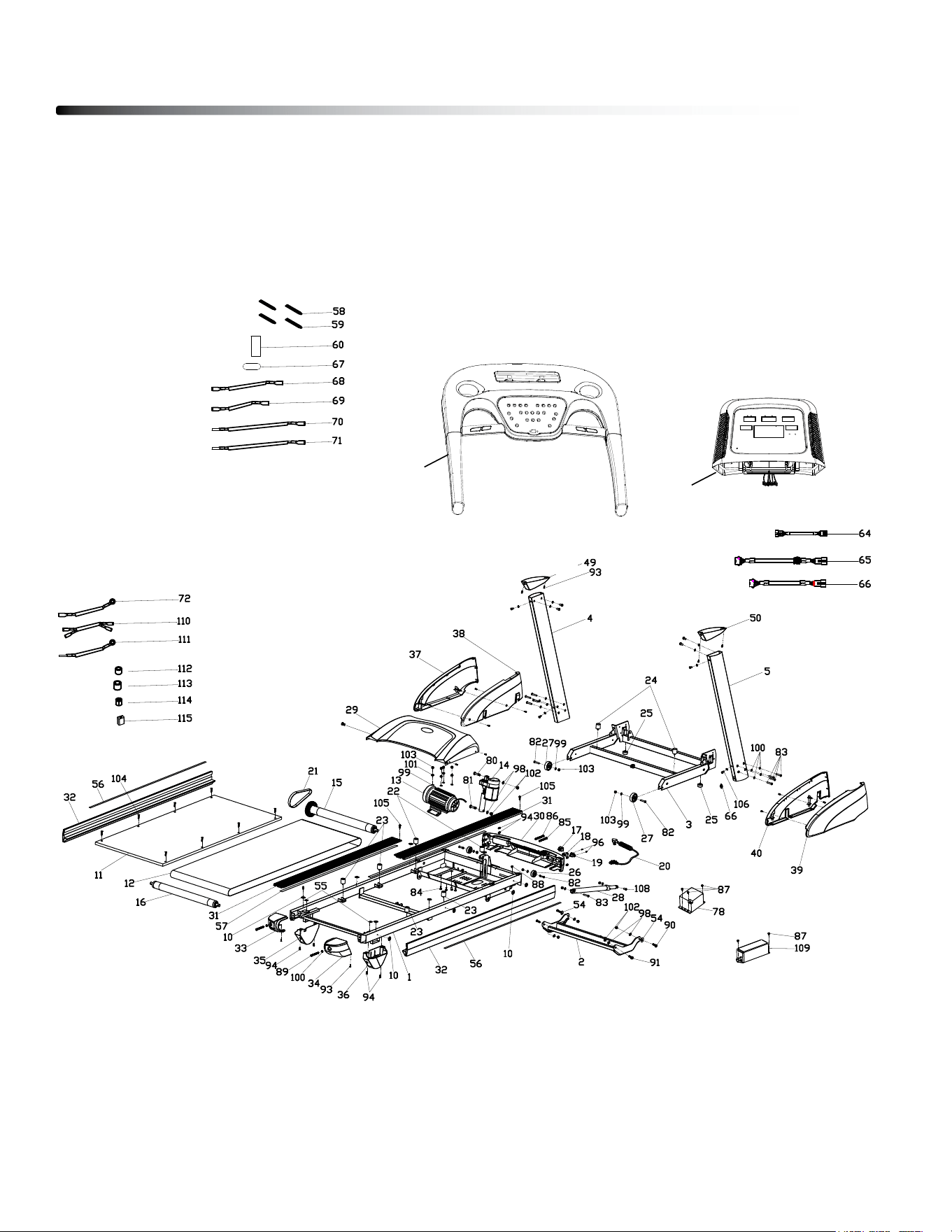
Exploded Drawing
45
116
117
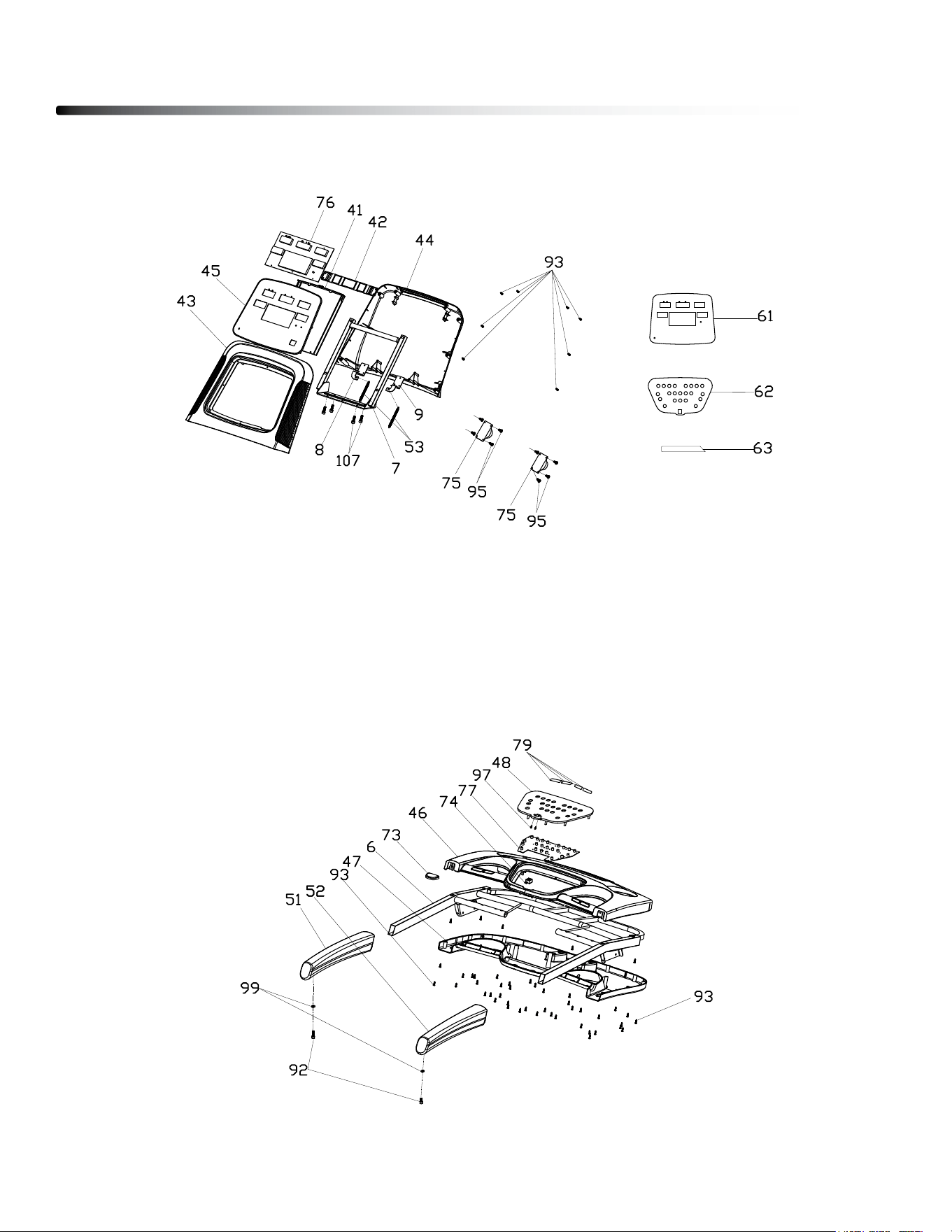
46
Exploded Drawing
EXPlOdEd dRAWINg OF lOWER CONSOlE ASSEMblY
EXPlOdEd dRAWINg OF UPPER CONSOlE ASSEMblY
c
Copyright 2009. Body-Solid. All rights reserved. Body-Solid reserves the right to change design and specications when we feel it will improve the product.
Body-Solid machines maintain several patented and patent pending features and designs. All rights reserved on all design patents and utility patents.
Customer Tech Support Hotline
Toll Free: 1-800-556-3113
Phone: 1-708-427-3555
Fax: 1-708-427-3556
Hours: M-F 8:30-5:00 CST
E-Mail: servic[email protected]
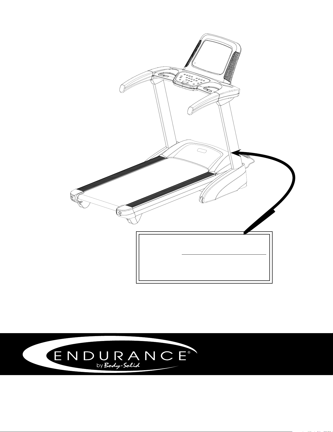
Serial Number is Located on the Upright
Model Name
: _______________________________
Purchase Date
: _______________________________
Serial Number
: 016057-_______________________
T25