
Ed : 01/13 Rev : 00
Codice :
INSTRUCTION
GRLDEVEFTFKMAG
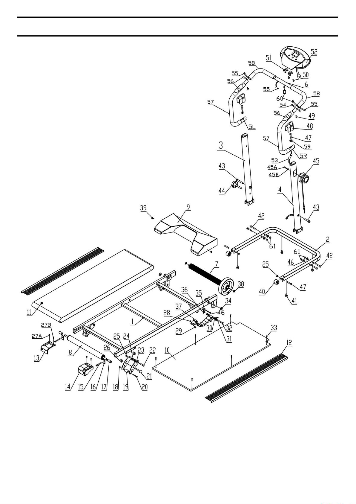
EXPLODE
-2-

PART LIST
NO
DESCRIPTION
QTY
NO
DESCRIPTION
QTY
1
Main Frame
1
32
Bolt(M8*1.25*70mm)
1
2
Base Frame
1
33
Bolt(M4*25mm
6
3
Left Upright
1
34
Washer(Ø10.2)
2
4
Right Upright
1
35
Sensor Wire
1
5L
Left Handrail Tube
1
36
Bolt(M3*15mm)
2
5R
Right Handrail Tube
1
37
Magnetic Brake
1
6
Middle Handrail Tube
1
38
Washer(Ø13)
2
7
Front Roller
1
39
Bolt(M6*1*15mm)
2
8
Rear Roller
1
40
Wheel
2
9
Protective cover
1
41
Cushion
4
10
Running board
1
42
Bolt(M8*1.25*50mm)
4
11
Running belt
1
43
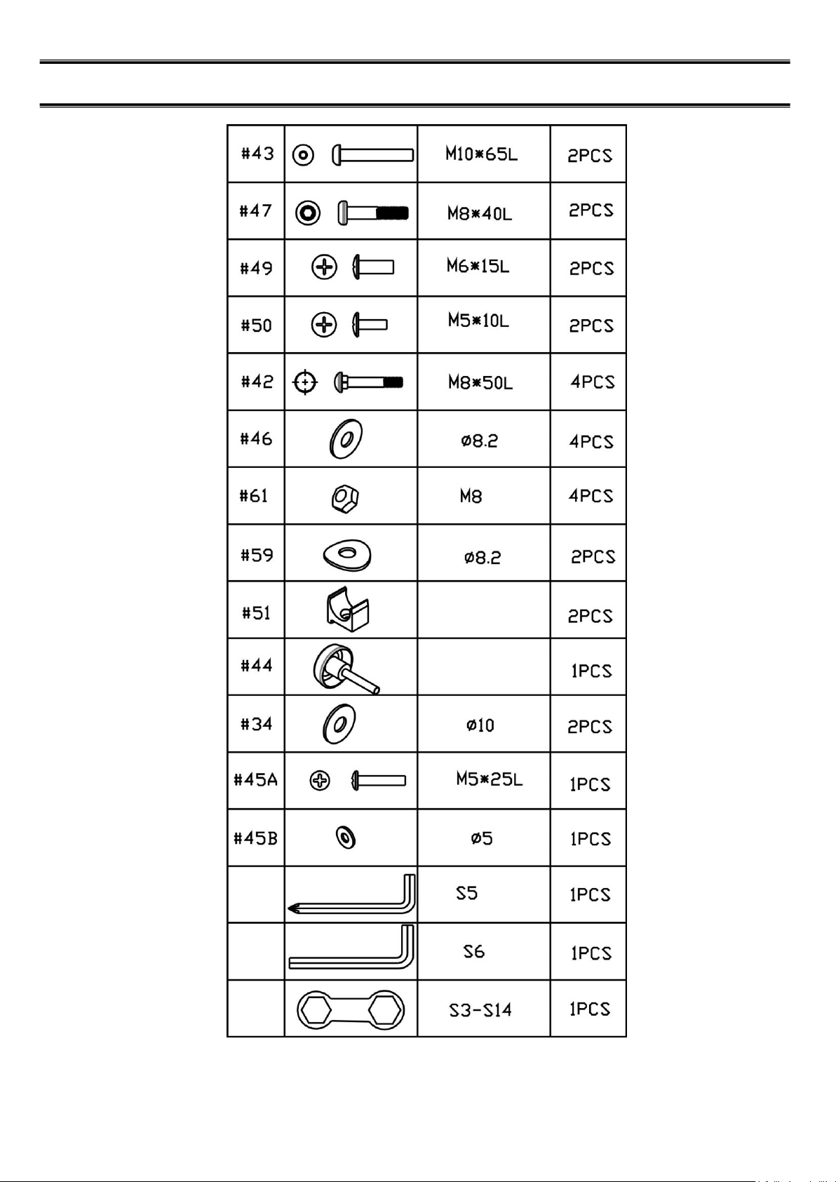
Bolt(M10*1.5*65mm)
2
12
Side rail
2
44
Locking Knob
1
13
Left Rear Cap
1
45
Tension knob
1
14
Right Rear Cap
1
45A
Round head screw(M5x25mm)
1
15
Bolt(M6*1*65mm)
2
45B
Washer Ø5
1
16
Adjustment Plate
2
46
Washer(Ø8.2)
5
17
Casing
2
47
Bolt(M8*1.25*40mm)
4
18
Nut(M6)
2
48
Handrail Cap
2
19
Plastic roller
2
49
Bolt(M6*1*15mm)
2
20
Bolt(M6*1*45mm)
2
50
Bolt(M5*1*10mm)
2
21
Pin
2
51
Meter Clip
2
22
Bolt(M8*1.25*45mm)
2
52
Meter
1
23
adjustment sheet
4
53
Sensor Connecting Wire
1
24
Washer(Ø8.2)
4
54
Sensor Connecting Wire
1
25
Nylon Nut(M8)
5
55
Handle pulse
1
26
Inner plug
4
56
Handle pulse wire
2
27A
Bolt(M4*15mm)
2
57
Handrail Foam
2
27B
Bolt(M4*15mm)
2
58
Middle Handrail Foam
2
28
Nut(M6)
1
59
Arc Washer(Ø8.2)
2
29
Bolt(M6*1*15mm)
1
60
Meter Connecting Wire
1
30
Twister spring
1
61
Nut(M8)
4
31
Plastic Washer(Ø8.2)
1
-3-
PART LIST OF ASSEMBLY
-4-
ASSEMBLY
-5-
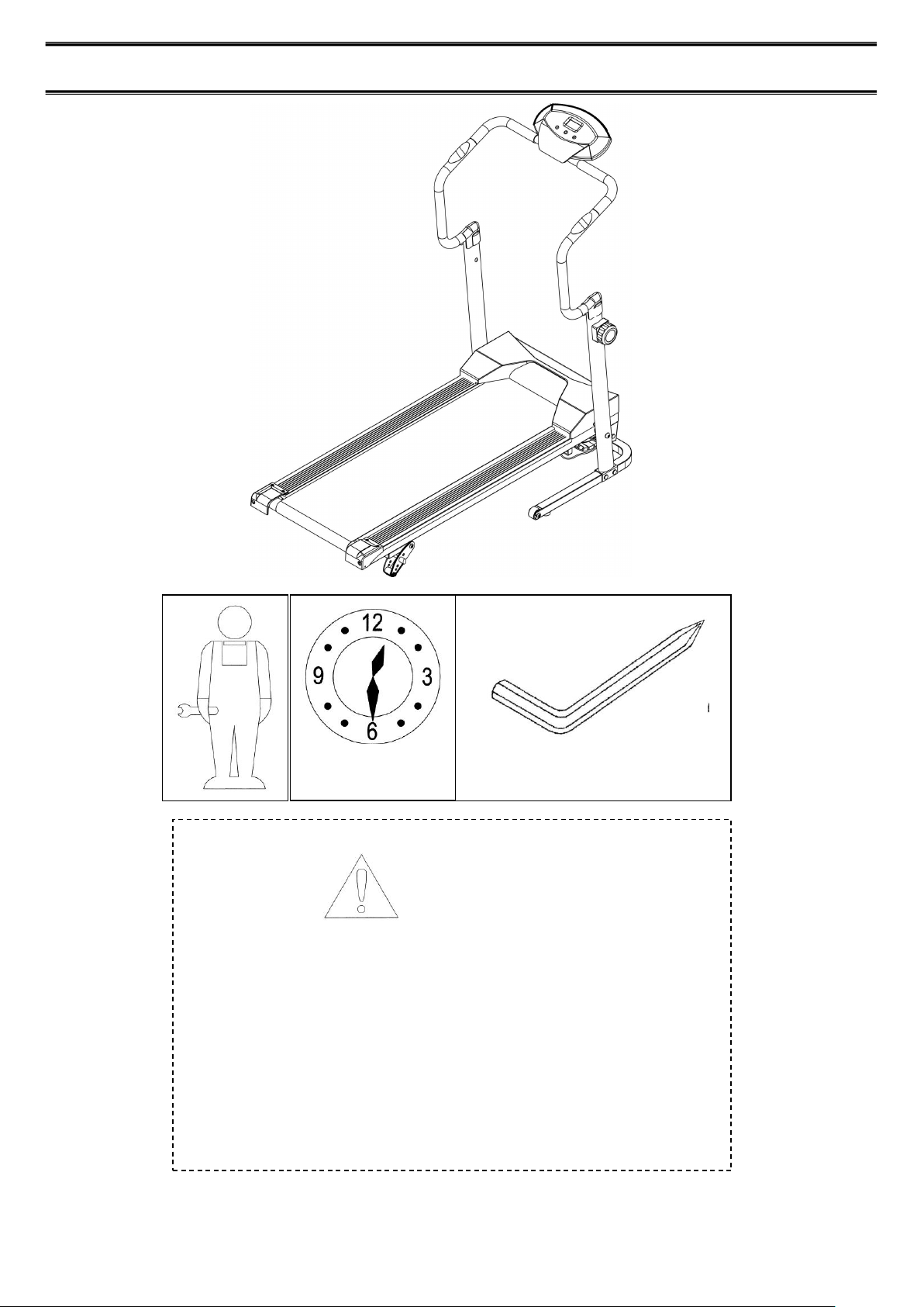
30 MIN
NOTICE
• Read this manual before assmbly
• Recognize the spare parts first.
• Check the hardware.
• Ensure that you have the right tool.
• Prepare an area to assemble.
• Follow the instruction accordingly.
• Never force the joints
• Periodically tighten the joints.
• Keep this manual with you
5MM x 1
ASSEMBLY
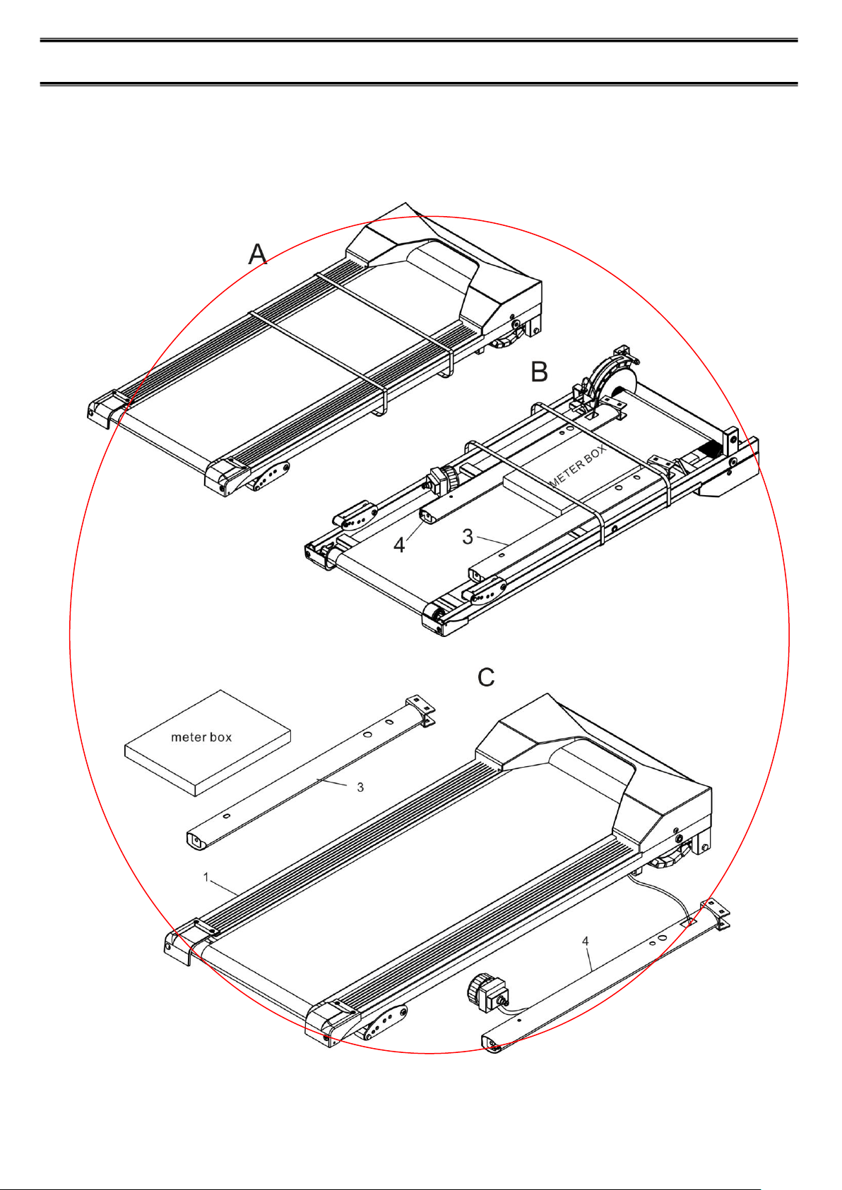
STEP 1:
1).Get the product out from the box as picture A, then turn the product around as picture B.
2).Cut the packing belt off, and get the let upright tube (3) and computer box out, then turn over
the right upright tube (4) and picture B with 180 degrees as the degree of picture A, put the
right upright tube (4) along with the main frame as picture C.
- 6-
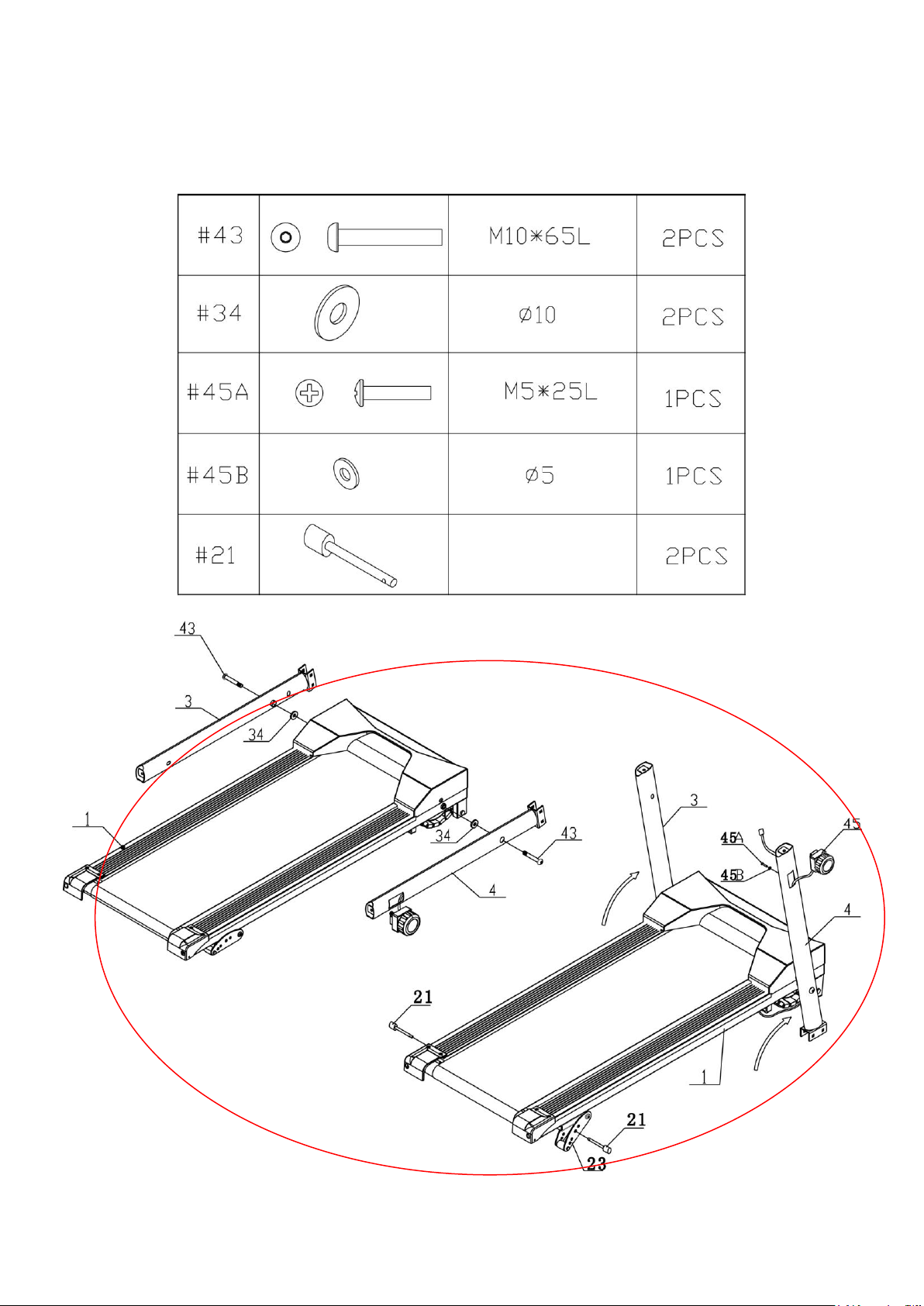
3)Keep the left upright (3) and right upright (4) are aligned with main frame (1) ,and lock with bolt (43) and
washer (34). Please don’t lock the bolt (43) totally.
4 Turn over the left/right upright tube (3,4) around 70 degrees as picture D.
5)Install the TENSION KNOB(45) into the opening in the RIGHT UPRIGHT(4) and secure with ROUND HEAD
SCREW(M5x25mm) (45A) and Washer(45B)
6) Insert the Pin (21) into the hole of adjust sheet (23).
-7-
D
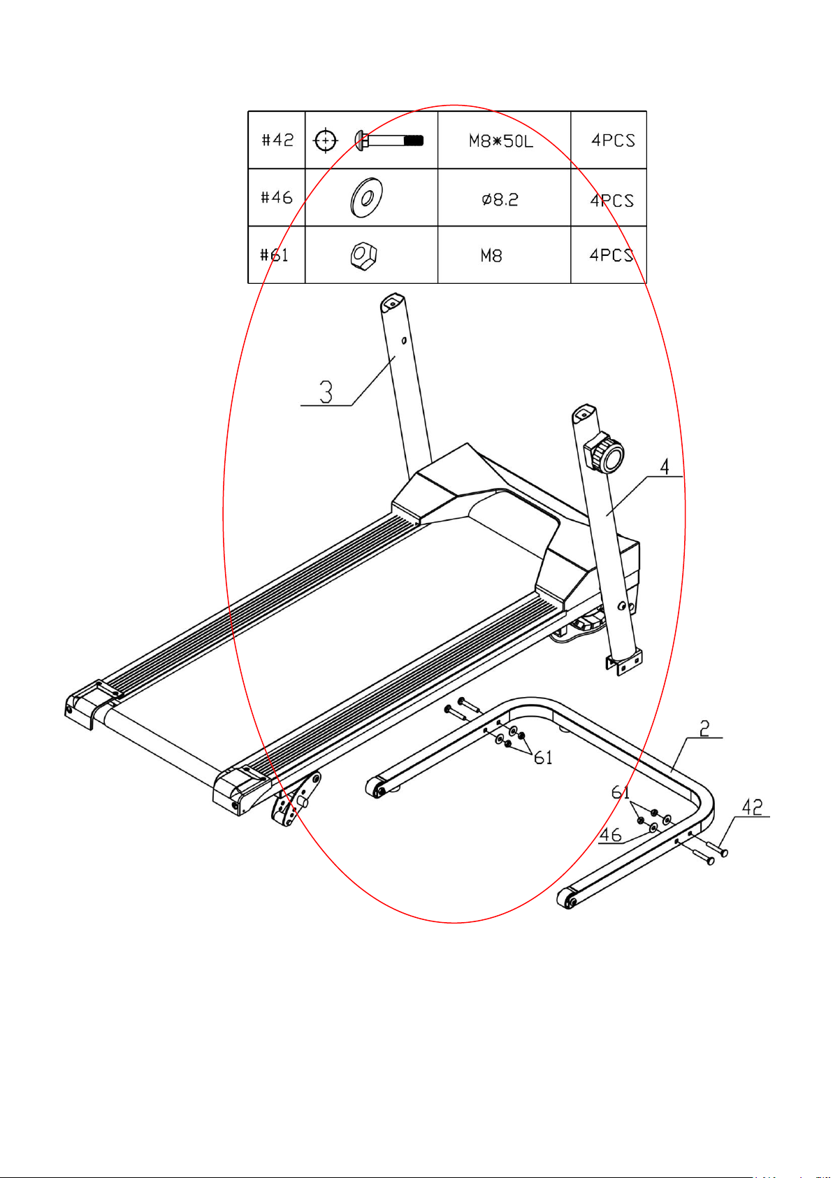
STEP 2
Assemble the base frame (2) and left/right upright (3, 4) with bolt (42), washer (46) and nut (61).
-8-
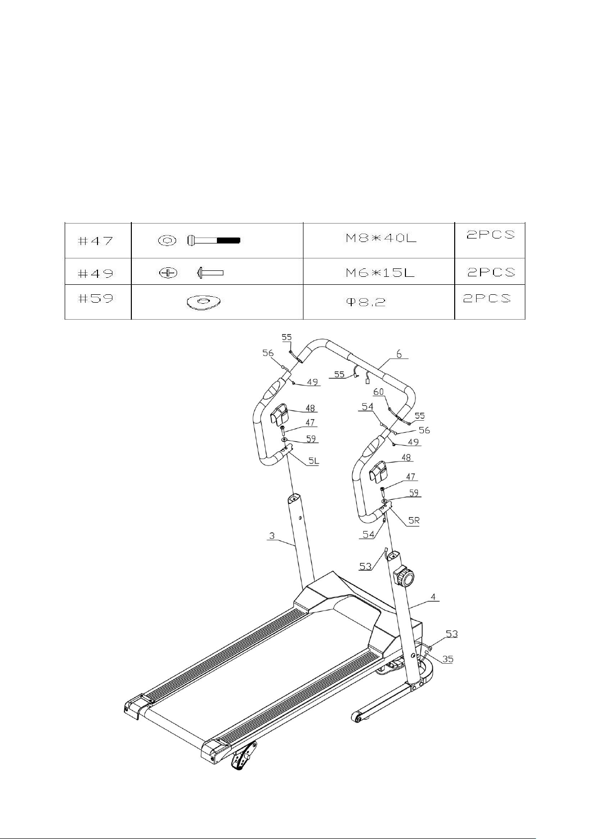
STEP 3
1. Please plug the SENSOR WIRE(35) into the SENSOR CONNECTING WIRE(53)
2. Please plug the SENSOR CONNECTING WIRE(54) into the METER CONNECTING WIRE(60), plug the
HANDLE PULSE (55) into the HANDLE PULSE WIRE(56).
3. Insert the LEFT HANDRAIL (5L) and RIGHT HANDRAIL (5R) into the MIDDLE HANDRAIL (6) and
Secure with the BOLT M6*15mm(49).
4. Attach the HANDRAIL ASSEMBLY(5L,5R) to the LEFT and RIGHT UPRIGHT(3,4) with BOLTS
(M8*40)(47) and ARC WASHERS(∮ 8.2)(59);
5. Plug the SENSOR CONNECTING WIRE(53) into the SENSOR CONNECTING WIRE(54). Push the wires back
Inside of the RIGHT UPRIGHT(4). Press the HANDRAIL CAPS(48) onto the LEFT and RIGHT
HANDRAILS(5L,5R) to Cover the top ends of the LEFT and RIGHT UPRIGHT(3,4)
-9-
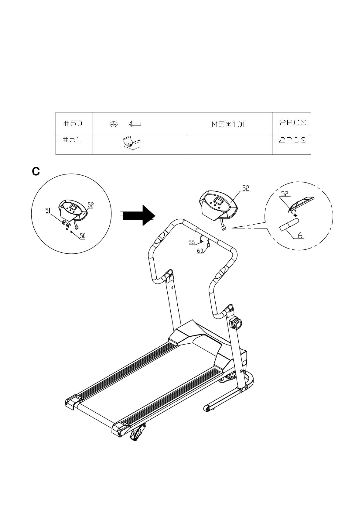
STEP 4
1. Refer to illustration C. Attach the Meter CLIPS (51) to the back of the METER (52) with BOLT (M5*10mm, 50).
2. Install two AA batteries into the METER (52), the batteries are not included. See page 14 for detailed
battery installation instructions.
3. Refer to illustration below and the Side view. Press and clip the Meter (52) onto the MIDDLE HANDRAILS (6).
Plug the METER CONNECTING WIRE (60) into the METER (52). Adjust the METER (52) to find the best angle
to fit with your workout.
4. Plug the handle pulse (55) into the meter (52).
-10-
SIDE VIEW

STEP 5
1. For the adequate tension power, you just need to adjust the tension knob.
-11-
STORAGE WAY
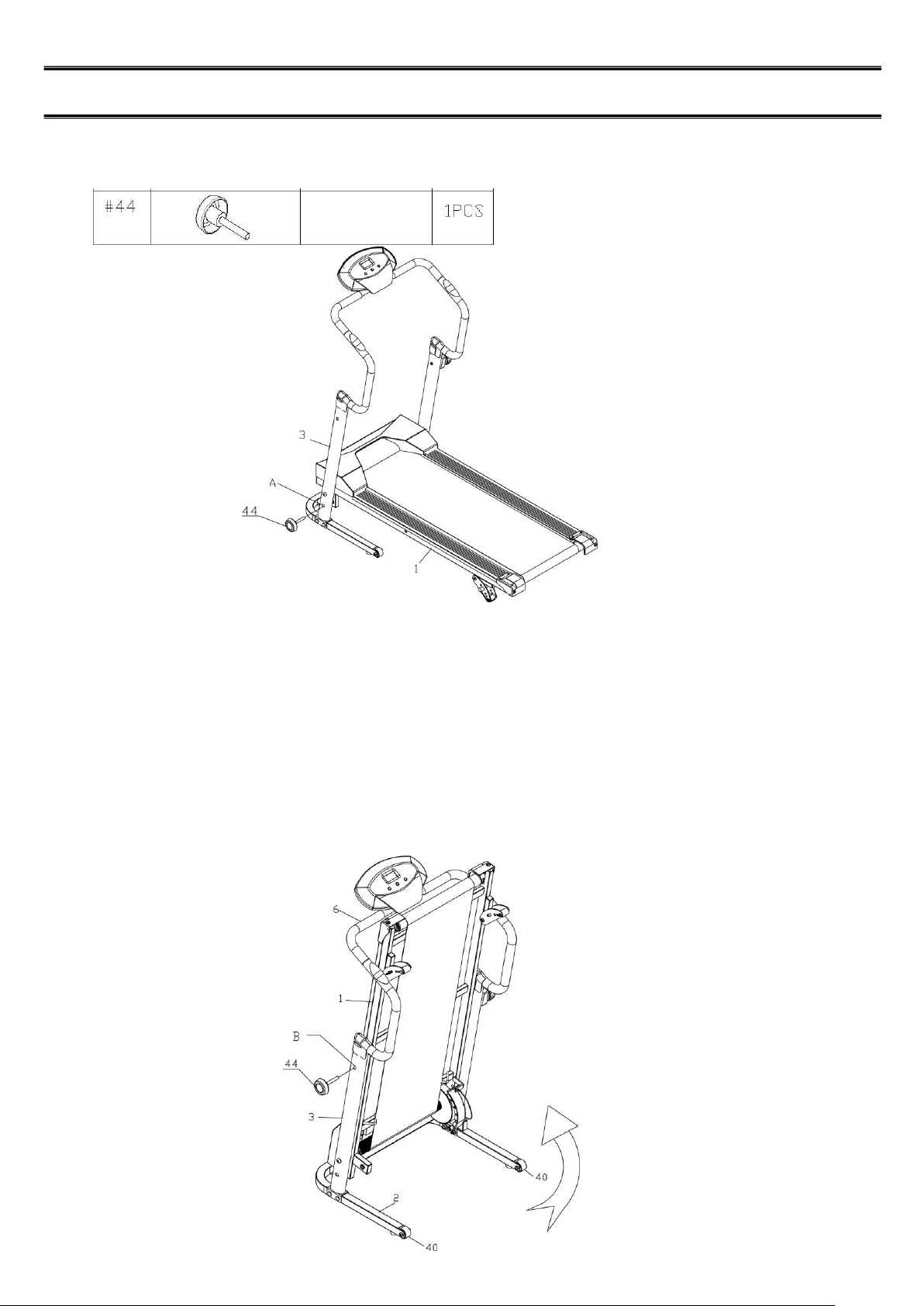
STEP 6
Insert the LOCKING KNOB (44) through the hole in the LEFT UPRIGHT (3) and screwing it into the MAIN
FRAME (1). Refer to detail view A.
STORAGE
1. To store the Magnetic Treadmill, simply keep it in a clean dry place.
2. To avoid damage from the electronics, remove the batteries before storing the Magnetic Treadmill for one
Year or more.
3. To fold the Magnetic Treadmill for easy storage, follow this process. Refer to the illustrations below.
a. Remove the LOCKING KNOB(44) to unlock the MAIN FRAME(1)
b. Fold up the MAIN FRAME(1). To lock the MAIN FRAME(1) in the folded position, Insert the
LOCKING KNOB(44) throngh the hole in the LEFT UNRIGHT(3) and screwing it into the
MAIN FRAME(1). refer to detail view B.
C. Move the Magnetic treadmill with the Wheels(40) on the BASE FRAME(2).Stand behind the Magnetic
Treadmill, grasp the HANDRAILS(6) and tilt it toward you to easily roll the Magnetic Treadmill.
-12-
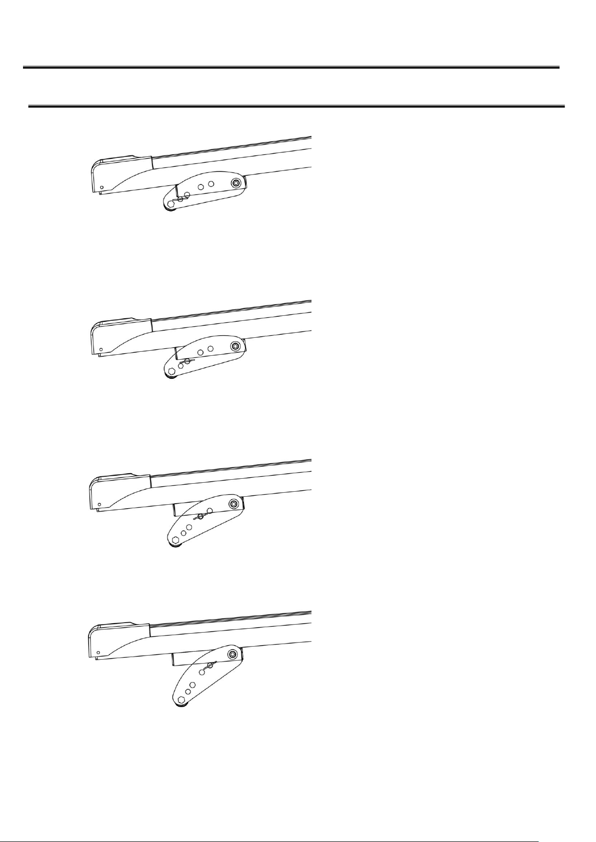
INCLINE INSTRUCTIONS
As left drawing, you can adjust lifting
angle by means of changing ball pin
latch's position. Here are 4 sections
manual adjustment to be used.
-13-
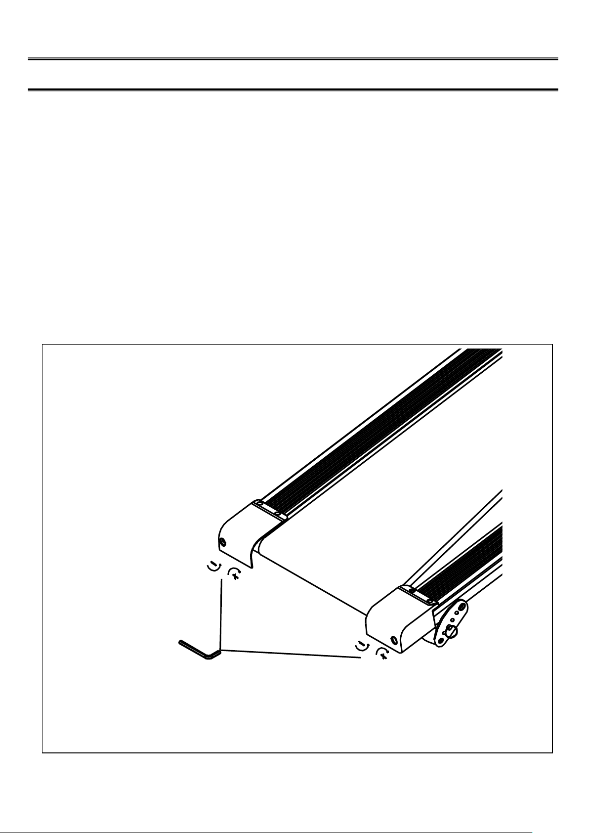
TREADBELT ADJUSTING
If the following situation is happened on the tread belt, it will make some noise on the machine. So if the tread
belt is not in the center position, too tight or too loose, please use the tool to adjust it .
1. When the tread belt moves to the right side, please revolve the right side hexagon socket screw clockwise 1
or 2 circles, revolve back a little bit.
2. When the tread belt moves to the left side, please revolve the left side hexagon socket screw clockwise 1 or
2 circles, revolve back a little bit.
3. When the tread belt is too tight, please revolve the left and the right side hexagon socket screw anticlockwise,
then revolve back a little bit.
4. When the tread belt is too loose, please revolve the left and the right side hexagon socket screw clockwise,
then revolve back a little bit.
-14-
5MM
-16-

GARLANDO SPA
Via Regione Piemonte, 32 - Zona Industriale D1
15068 - Pozzolo Formigaro (AL) - Italy
www.evert.it - info@evert.it