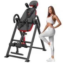
Inversion Table
Note: read the instruction carefully before use.

O
w
n
er
s
M
anua
l
WARNING:
Carefully read all Warnings and Instructions
before using this inversion table!
Do not let children under the age of 12 use
the inversion table !
Do not put hand or fingers inside the
Protective Cover for the Angle Selector
Pin !
Keep body, clothing, and hair free of all
moving parts !
Tighten all nuts bolts and screws before
using equipment !
Leave adequate space to invert !
This equipment is for indoor !
This products designed adjust from 131CM
(52 INCH ) to 195CM(77 INCH ) !
Maximum User Weight of 300 LBS!

M8x55
STEP1
STEP2
M8x65
M 8 x5 0
M 8x 55
STEP3
STEP4
M8x2
M 8 x 4 5
M 8 x 4 5
STEP3
He x Wrenches #5 1PC
Wrench #13# 17 2PCS
0 inch 1 2 3 4 5 6 7 8
9
0 cm 1 2 3 4 5 6 7 8 9 10 1 2 3 4 5 6 7 8 9 20 1 2 3 4
Hardware Pack & Manual
ASSEMBLY INSTRUCTIONS
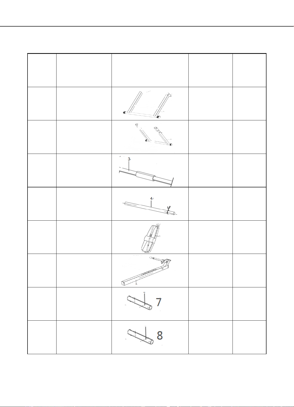
9
Footrest plate
1
10
Arm-rest frame
2
11
Foot pressing
foam + shoulder
pad foam
6
12
Z-shape holder
2
13
Headrest pad
1
14
Hexagonal screw
M8×55
6
15
Flat gasket
Φ8
20
16
Inner hexagonal
screw
M8×20
5
17
Lock-nut
M8
11
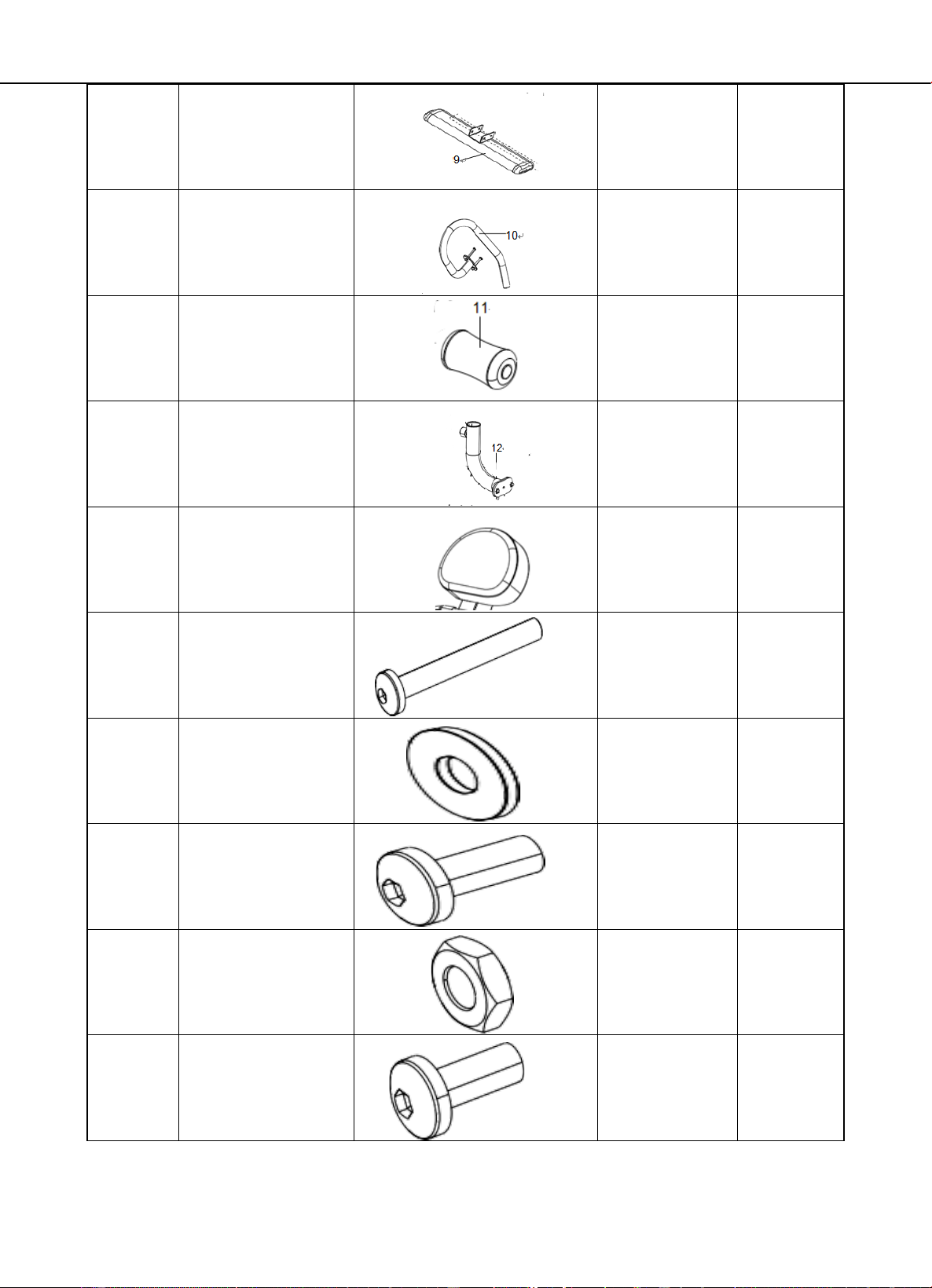
18
Cross-shape big
and flathead
screw
M6
6
19
Flat gasket
Φ10
1
20
Lock-nut
M10
1
21
Bolt of pulling ring
Φ 8×55
4
22
Pulling pin
M16×20
1
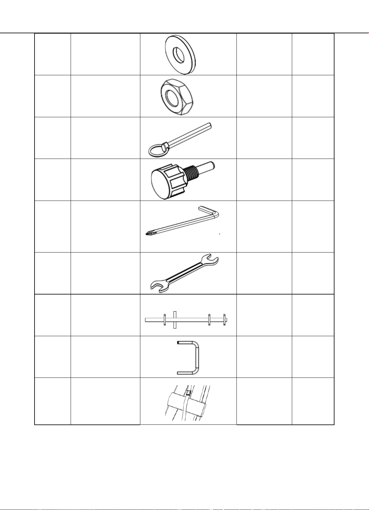
23
7-shape inner
hexagonal
installation tool
5#
1
24
Wrench
13#&17#
1
25
Backplane holder
Backplane holder
1
26
Shoulder pad U-
shape tube
1
27
Waist cushion
1
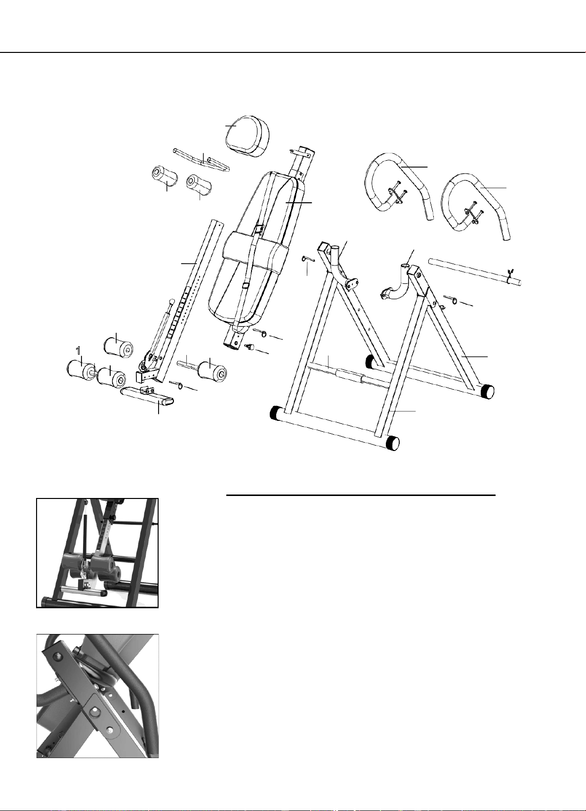
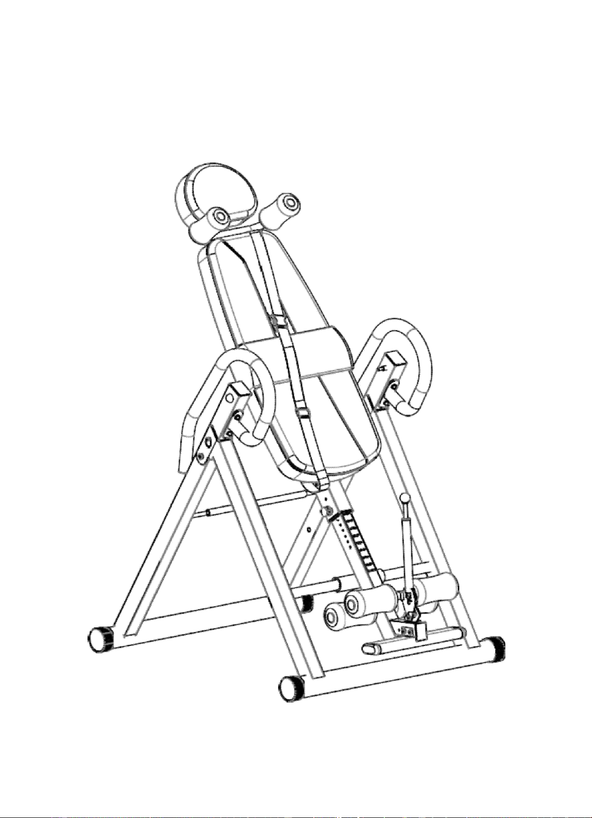
Parts diagram
13
26
10
10
11
11
5
11
11
7
11
6
8
11
12
12
21
21
21
22
3
2
21
1
9
ADJUST
TO YOUR HEIGHT SETTING
NOTE: Before starting, ensure that the inversion table is at
the correct setting to match your height and weight
distribution. As each individual body type is different, you will
need to find your own height setting.
NOTE: It is recommended that someone be with you during
inversion. Although the inversion table is easy to use, having
someone nearby to spot you will provide extra safety
and support to the inversion process.
NOTE: For your safety, the bolts of pulling ring MUST be in
secured in one of the Angle Slots at all times.
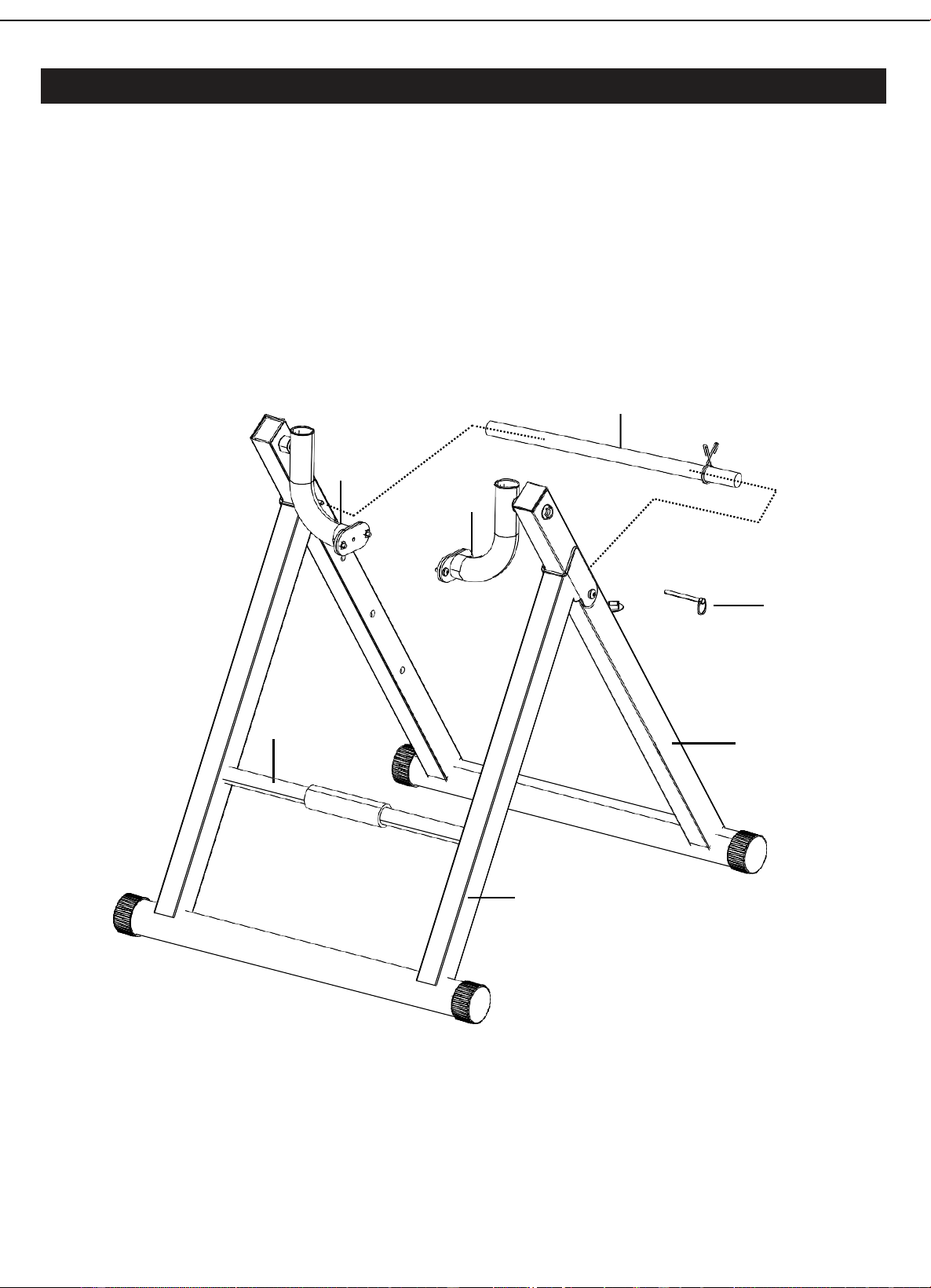
Ste
p
1
–
B
a
s
e
Fra
m
e
Assembl
y
Stand up the base of the machine by separating the frames as shown above. Pull the
Rear Front Frames as far apart as possible from each others and find the pin holes.
Then insert the Ring Pin (21) from inner side Into the holes on the Rear Frames and
the front Frame to lock the frames in place.
Note: Please notice that the some Front Holding bar (3) is pre-installed.
4
12
12
21
3
2
1
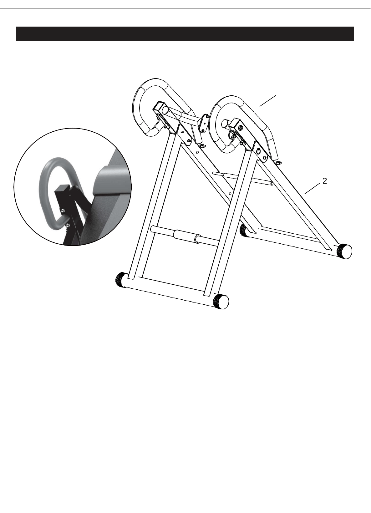
Ste
p
2
–
H
a
nd
l
e
b
a
r
Assembl
y
THE HANDLEBARS
For added convenience and safety, a set of Handlebars (10) (Arm-rest frame) has been
added to the inversion table.
These Handlebars (10) are located at the top of the Rear Frame (2).The Handlebars (10)
are there to help you return to the upright position from any degree of inversion.
If you wish to return to the upright position, and the backrest is moving too slowly, or not
moving at all, simply grab the Handlebars (10) and pull on them until you return to the
upright position.
NOTE: The inversion table should always return to the upright position when you move
your hands below your waist. If it does not, the inversion table is probably not adjusted
correctly to your height.
Always hold on to the handlebars and go back slowly. Failure to comply could result
in serious physical injury.
10
2
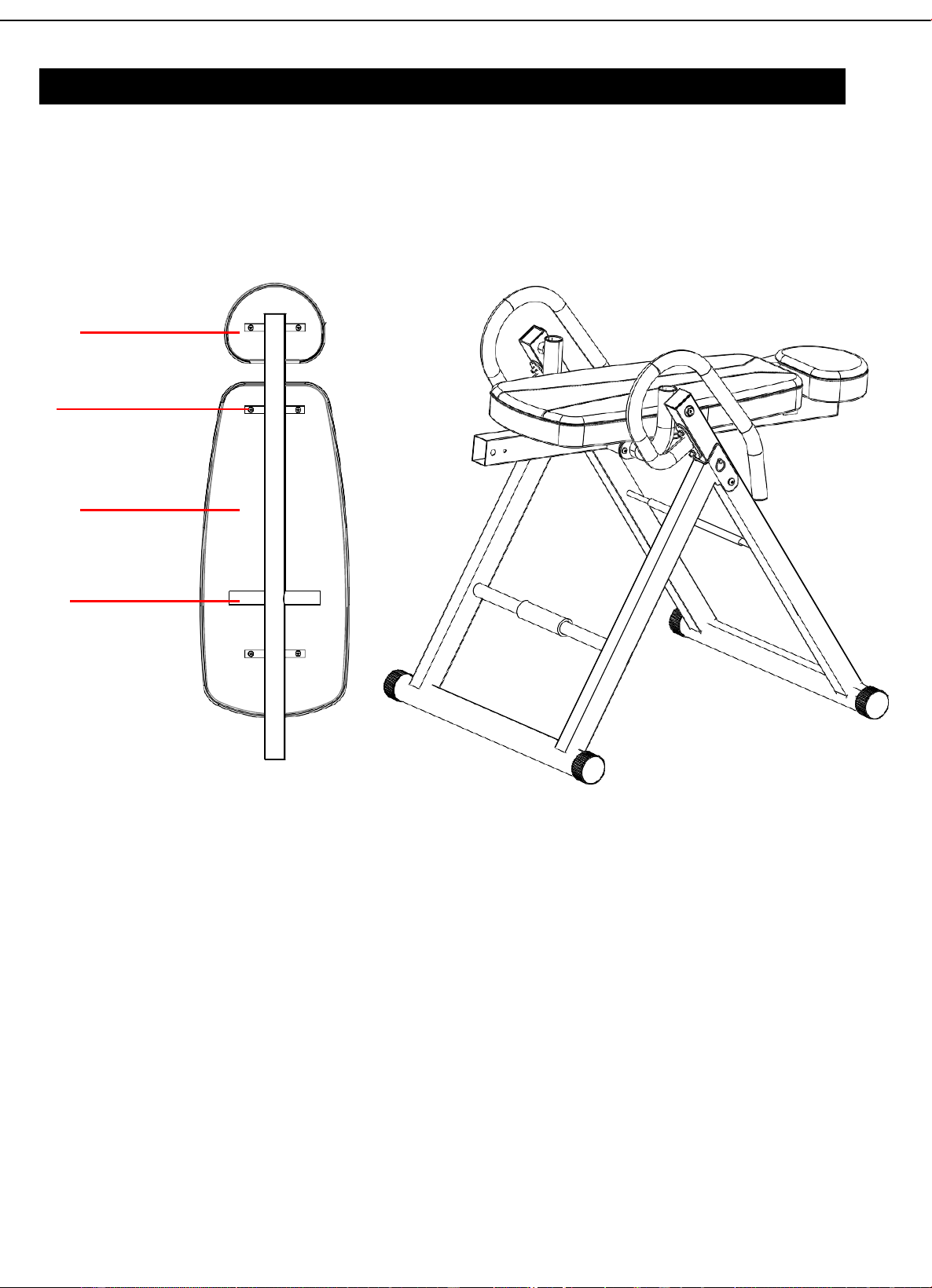
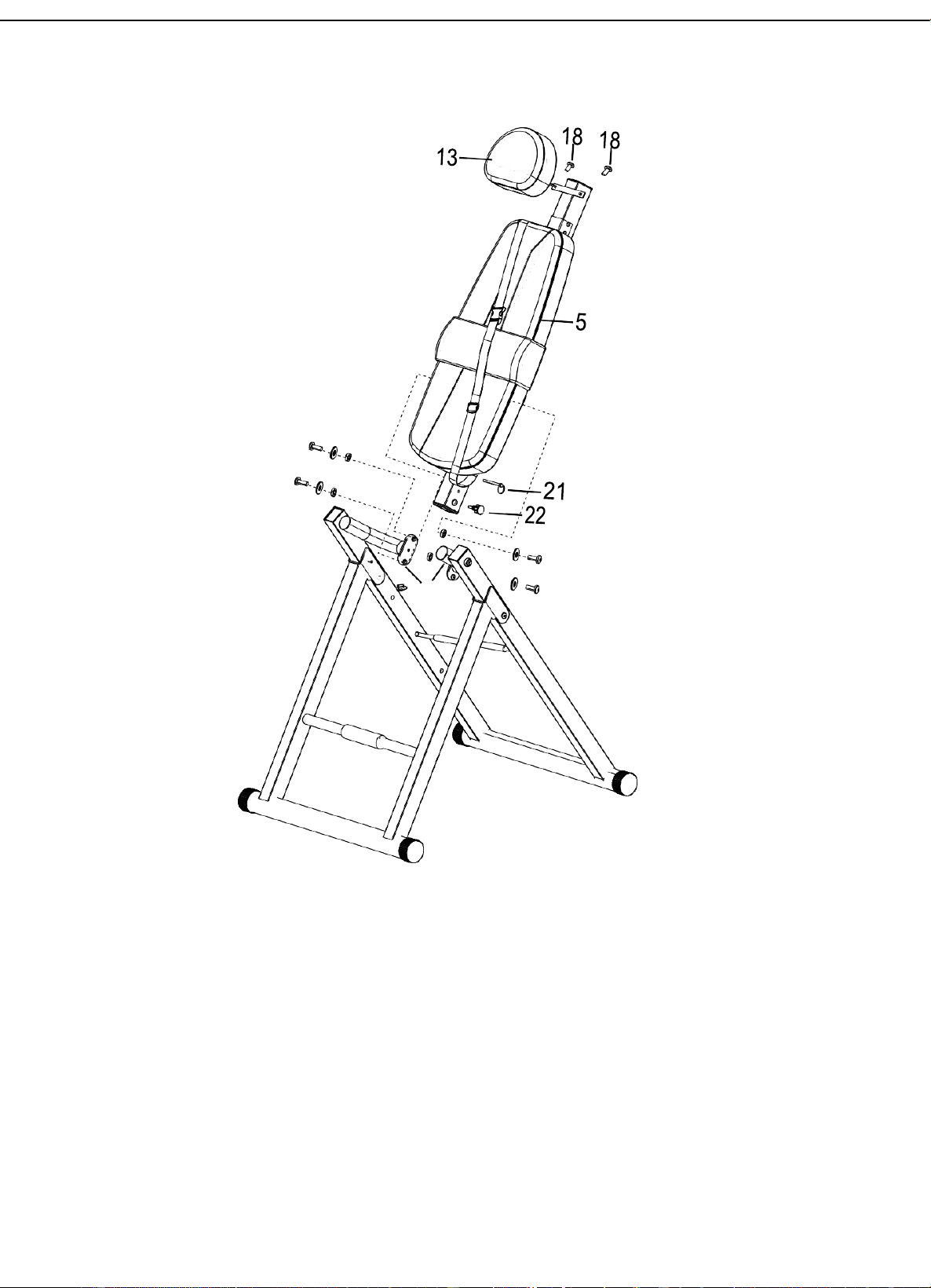
Backrest Pad installation:
Put the Head restpad
(
13
)
to the backrest holder(27),use the(18)M6 cross-shape big and
fathead screw insert it.
Put the Backplane ( 5 ) stick to the backrest holder, also use the the (18) M6 cross-shape
big and fat head screw insert it.
Insert the other two (18) M6 cross-shape big and fat head screw to fixed all the back rest
pad.
Ste
p
3
–
Bac
k
re
s
t
Pad Assembly
13.Headrest pad
18.Cross-shape big
and flat head screw
5.Backplane
27.Backplane
holder
Assemble and lock 4 iron sheets on the Z-shape holder (12) and iron sheet on the side of
backplane holder(27) tightly with inner hexagonal screws (16)flat gaskets(15) and lock-
nuts(17).
12
Ste
p
4
–
He
i
gh
t
A
d
j
u
s
t
ment t
u
b
e
an
d
Ankl
e
Holde
r
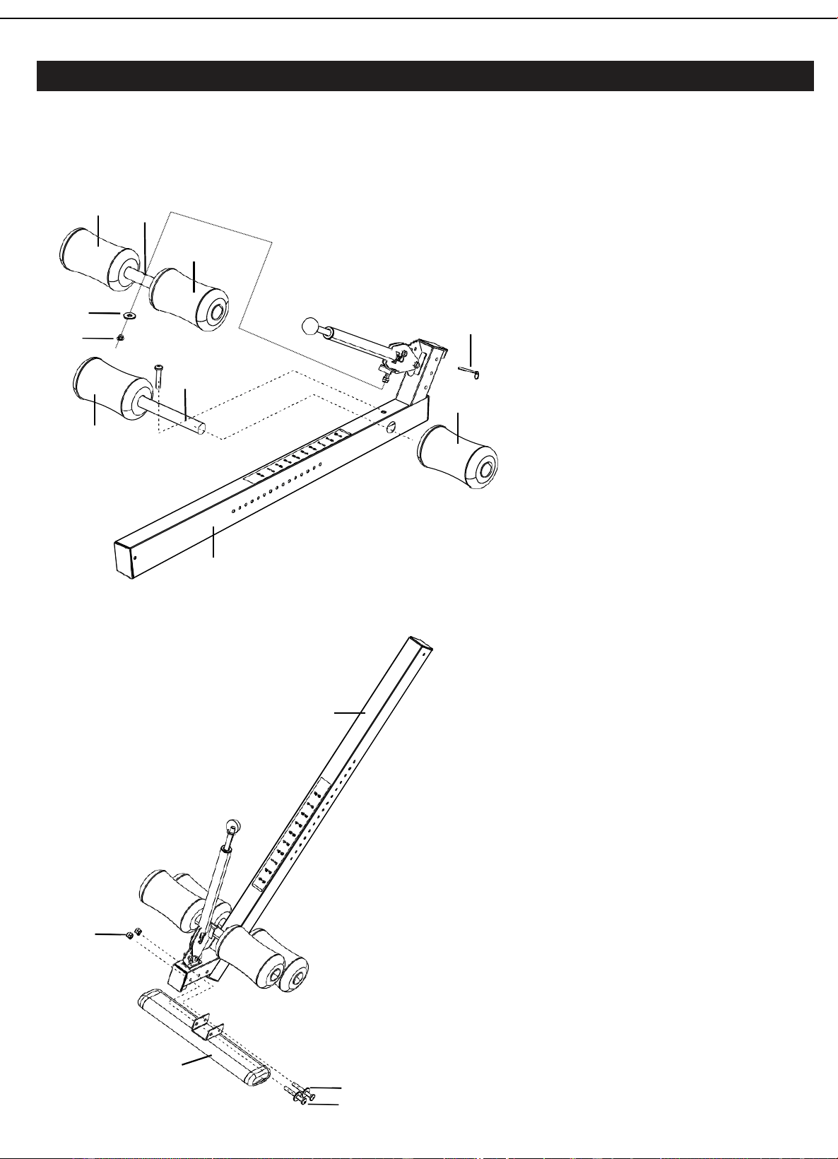
Insert the steel pipe of lower foot
pressing tube(8) into the big hole
in the height adjusting holder,
keep two sides the same length,
fix lower foot pressing tube on
the height adjusting holder(6)
with inner hexagonal screws
(16) and then put 4 foams rollers
(11)into two sides respectively.
Lock the upper foot pressing
tube(7)from bottom to top on the
screws of height adjusting holder
(6)with nuts(17) and flat gaskets
(19)as shown in the figure,
note that the cambered surface
of elbow should be downwards.
6
17
Adjust the corresponding place of
the footrest plate(9) with inner
hexagonal screws
(14),flat gaskets(15) and nuts
(18)according to the size of feet,
lock with the height adjusting holder
(6)Pull the Long pin lever and at the
same time slide the Front support
bottom tube into the Front Support
Tube to your desired height number
and release the Long pin lever .
Make sure the Long pin lever locks
securely into a hole on the Front
support bottom tube .
9
15
14
11
7
11
19
20
21
8
11
11
6
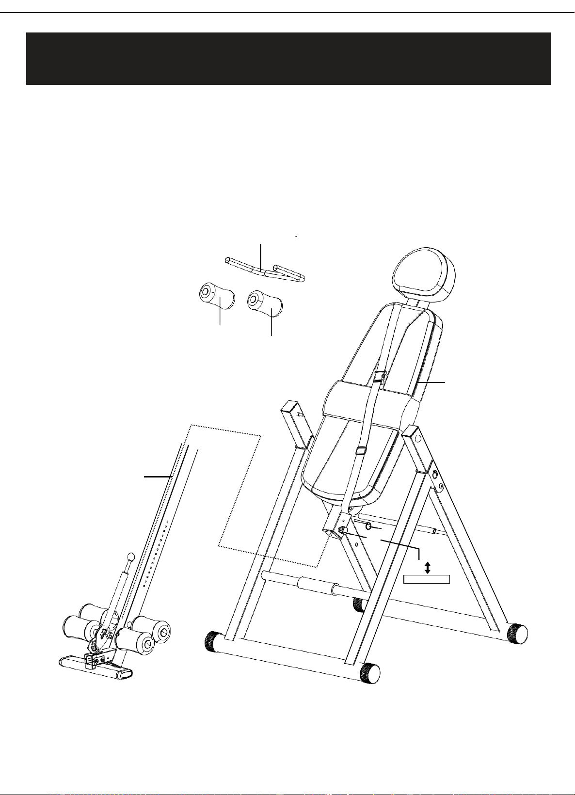
Insert the height adjusting tube(6)into the backplane holder(27),plug into the
corresponding hole with the pulling pin(22) and bolt of pulling ring(21)according to the
requirement of height and tighten them.
Insert the shoulder pad U-shape tube (28) into the hole in the upper of the back
Plane holder(27), tighten with flat gaskets (15) and lock-nuts (17), and then insert foams
(11) into the Tube on both sides of the shoulder pad U-shape tube(28).
28
11
11
5
6
21
22
Pull out , screw
Ste
p
5
–
Hei
gh
t
ad
j
u
s
ti
ng
hol
de
r, b
ac
k
p
la
ne
hold
e
r,
sh
o
ul
d
er
pad U-shape Tube assembly
10
10
21
1
2
21
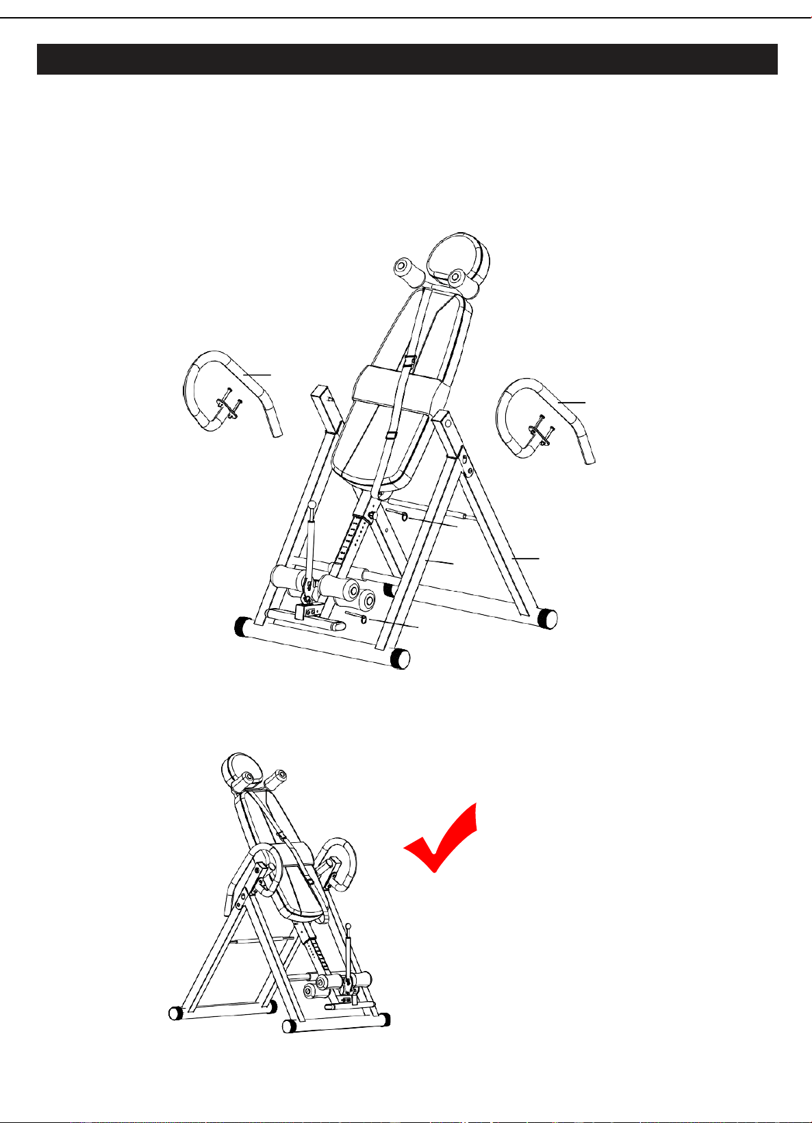
A.
Tighten2 holes in the upper middle of the pedestal(1/2)and Arm-rest frame(10), attach the waist
cushion(29) to the velro below the backplane(27).
B.
Plug two bolts of pulling ring (21) into the hole in the height adjusting tube, you can plug
out 2 bolts of pulling ring (21) and fold them when not in use, which takes up no space at all.
C.
When in use, fix your feet well, plug bolts of pulling ring (21) in the hole of rotary tooth table
and put the safety belt on.
RIGHT
St
e
p
6
–
Hand
bar
frame
and
wa
i
s
t
c
u
s
h
i
on
a
ss
e
m
b
ly
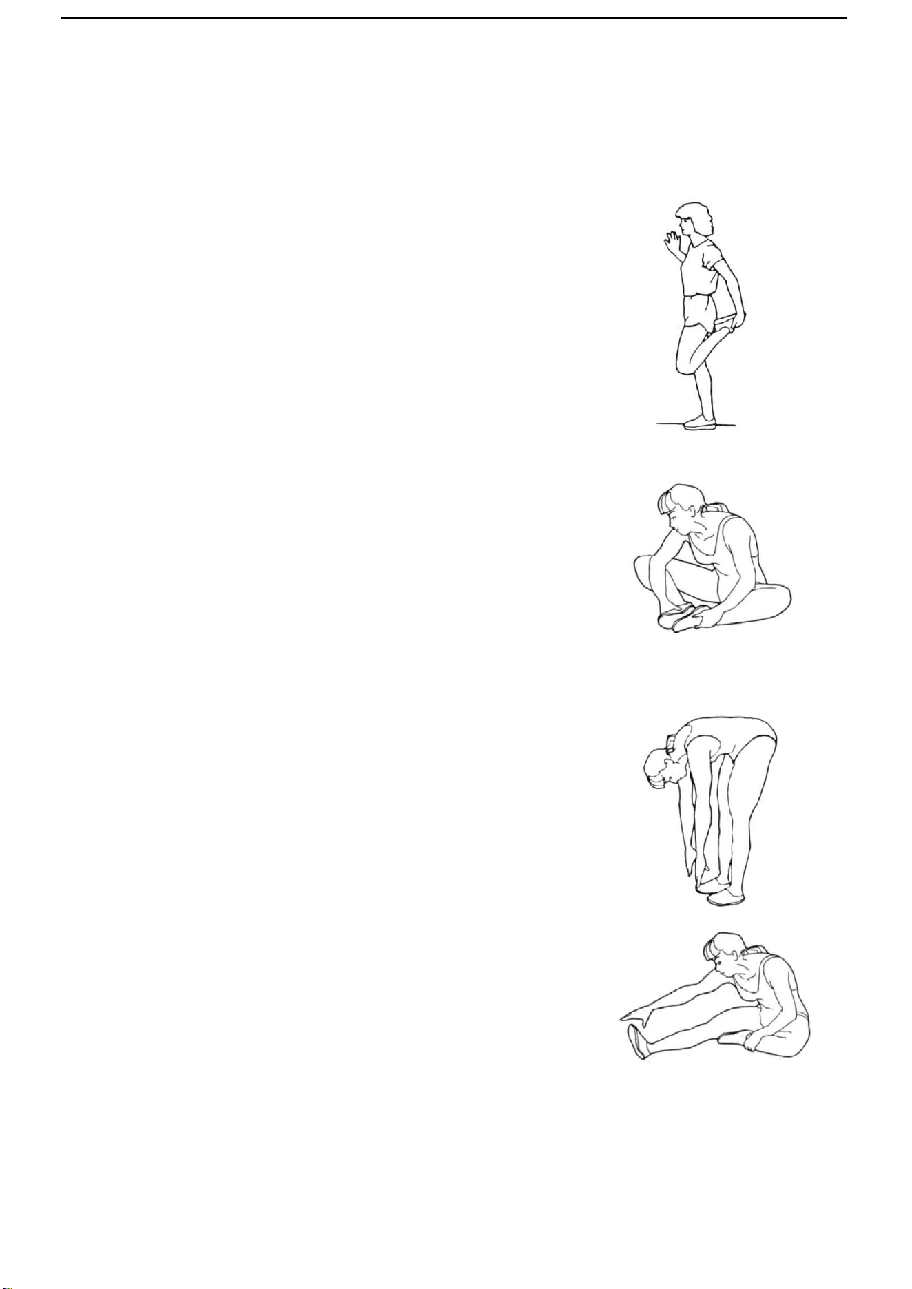
Warm Up
Quadriceps Stretch
With one hand against a wall for balance, reach behind
you and pull your right foot up. Bring your heel as
close to your buttocks as possible. Hold for 15 counts
and repeat with left foot up.
Inner Thigh Stretch
Sit with the soles of your feet together with your knees
pointing outward. Pull your feet as close into your
groin as possible.
Gently push your knees towards the floor. Hold for 10
counts.
Toe Touches
Slowly bend forward from your waist, letting you back
and shoulders relax as you stretch toward your toes.
Reach down as far as you can and hold for 15 counts.
Hamstring Stretches
Sit with your right leg extended. Rest the sole of your
left foot against your right inner thigh. Stretch toward
your toe as far as possible. Hold for 15 counts Relax and
then repeat with left leg extended.