
EP-550
™
/EP-650
™
R
Inversion Table Assembly Instructions
T
E
E
T
E
R
H
A
N
G
U
P
S
5
YEAR
W
A
R
R
A
N
T
Y

IMPORTANT SAFETY INSTRUCTIONS
READ ALL INSTRUCTIONS BEFORE USING THE INVERSION TABLE.
WARNING
!
SAVE THESE INSTRUCTIONS
WARNING - To reduce the risk of injury to persons:
• Read and understand all the instructions, view the instructional DVD, review all other accompanying documents, and inspect the equipment before using the inversion
table. It is your responsibility to familiarize yourself with the proper use of this equipment and the inherent risks of inversion, such as falling on your head or neck,
pinching, entrapment, or equipment failure. It is the responsibility of the owner to ensure that all users of the product are fully informed about the proper use of the
equipment and all safety precautions.
•
Close supervision is necessary when the inversion table is used near children, or by or near invalids or disabled persons.
• Use the inversion table only for its intended use as described in this manual. DO NOT use attachments not recommended by the manufacturer.
• NEVER drop or insert any object into any opening.
• DO NOT use or store product outdoors.
• DO NOT use if you are over 6 ft 6 in (198 cm) or over 300 lbs. (136 kg). Structural failure could occur or head/neck may impact the oor during inversion.
• DO NOT allow children to use this machine.
• Keep children, bystanders, and pets away from machine while in use.
• Keep body parts, hair, loose clothing and jewelry clear of all moving parts.
• The inversion table has no user serviceable parts.
• This product is intended for indoor home use only. DO NOT use in any commercial, rental or institutional setting.
• DO NOT use the equipment without a licensed physician’s approval and a review of the medical contraindications, as noted in the Owner’s Manual.
• Failure to assemble and/or use the equipment as directed may void the manufacturer’s warranty on this product and could result in injury or death.
• Choose a level surface for assembling and operating the table.
• Follow each step in sequence. DO NOT skip ahead.
• Make sure that all fasteners are secure.
• ALWAYS test and inspect the table. Make sure the table rotates smoothly to inverted position and back.
• ALWAYS replace defective components immediately and/or keep the equipment out of use until repair.
FAILURE TO FOLLOW INSTRUCTIONS AND WARNINGS COULD RESULT IN SERIOUS INJURY OR DEATH.
BEFORE YOU BEGIN: Review all steps before beginning assembly and read all precautions before using the inversion table. Carefully adhere to the Assembly
Instructions and Owner’s Manual to help ensure safety and product integrity.
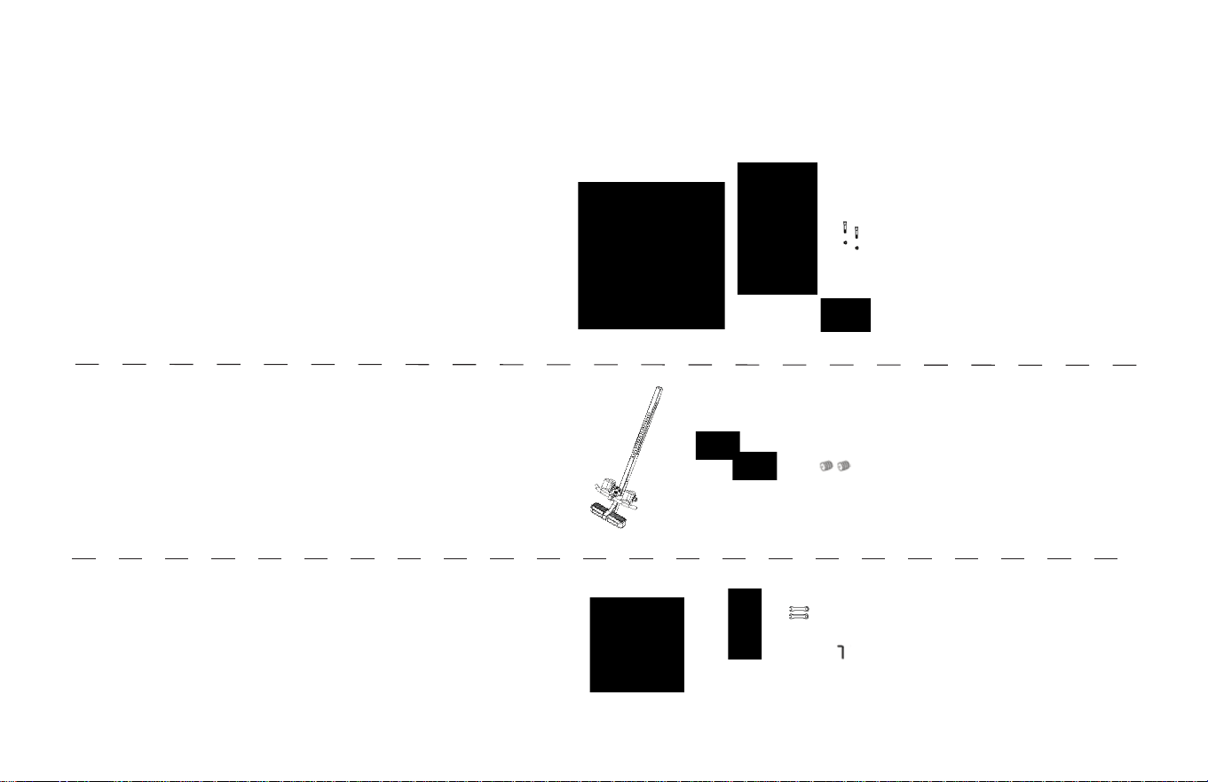
ItemsforAssembly
Carefullyremovetheindividualpartsfromthecarton.Youshouldhavealloftheitemslistedbelow.Ifanyitemsaremissingordamaged,
contact Customer Service at 1-800-847-0143.
ItemsforAssembly ItemNumbers
A-frame Base (F7-1002)
T
ether
(F5-1007)
T
able Bed Assembly
(EP-1
140)
Bolts and Nuts
(EP-1
149)
Head Pillow (EP-1105)
Main Shaft with
Ankle Lock System
(EP-1
120)
Foam Rollers (2)
(F5-1051)
Rubber Plugs (2)
(F5-1056)
Hand Grips
(F5-1069)
1/2” (13mm)
hex bolts (6)
(H1-1202)
Roller Hinges (2)
(F5-1064)
W
renches (2)
(F5-1088)
Allen W
rench
(IA-1
149)
(F7-1002)
(EP-1140)
(EP-1105)
(EP-1120)
(F5-1051)
(F5-1069)
(F5-1064)
(F5-1088)
(IA-1149)
(EP-1149)
(F5-1007)
(F5-1056)
(H1-1202)
Bolts may
be packaged
separately or
assembled in
hand grips

Before reading further, study the drawing below to familiarize
yourself with the important components of your new Teeter Hang
Ups
®
inversion table.
A-frame
Main Shaft
Ankle Locking
Pin
Adjustable
Foot Platform
Hand Grip
Stability Feet
Rear and
Front Ankle
Clamps
Tether Strap
Crossbar
Table Bed
BeforeBeginning

Step 1
AssembletheA-frameBase(F7-1002)andInstalltheHandles(F5-1069)
• Open the A-frame and make sure the spreader arms are locked, rest the A-frame on the oor (Figure 1). The
Crossbar is at the front.
•
Place each Hand Grip (left/right) over the outside edge of the
corresponding Hinge Plate (Figure 2).
• Insert three 1/2” (13mm) hex bolts (H1-1202) through the hinge plate into each Hand Grip. Use the wrenches
provided to tighten the bolts, being careful not to over-tighten.
Figure 2
Figure 1
spreader arms
front
back
Crossbar
Right
Left

Step2
Attach the Upper Support Arms to the Table Bed (EP-1140)
• Before following this step, make sure you have read the orange insert that came attached to the Table Bed.
•
Place the
Table Bed face down on the oor and push down on the Support Beam, so the two holes align
evenly with holes at the base of Upper Support Arms (Figure 3). You may have to exert extra pressure to
ensure the Support Beam slides over the rubber spacers.
•
Insert the two bolts (EP-1
149) into the open holes.
•
Fasten each bolt with a nut.
•
Use the Allen Wrench (IA-1149) to steady the bolts, tighten the nut onto the bolt with the larger wrench
(F5-1088) (Figure 4). Repeat with the second bolt.
Figure 3
Upper Support Arms
Figure 4
Support Beam

A B C
Step 3
Install the Roller Hinges (F5-1064) onto the Table Bed (EP-1140)
• For ease-of-assembly, rest the Table Bed against the side of the A-frame (Figure 5).
• Open the Cam Locks on each side of the Table Bed (Figure 5A).
• With the Pivot Pins facing outward, insert the Roller Hinges into the brackets on each side of the
Table Bed. The Roller Hinges must slide between the Cam Locks and the brackets.
• Make sure the Roller Hinges are in the same hole setting on both sides. Figure 6 shows the Roller
Hinges engaged correctly in setting C.
• Push down on the Cam Locks (Figure 6A) to secure the hinges.
NOTE: Refer to the Owner’s Manual for an explanation of the hole settings. If you are unsure, use
setting C to start.
Figure 6A
Figure 6
Pivot Pin
Cam Lock
Figure 5A
Figure 5

Step 4
AttachtheTableBed(EP-1140)totheA-frame(F7-1002)
• Holding each side near the Roller Hinges, pick up the Table Bed and stand at the front of the A-frame where the
Crossbar is located. Lower each Pivot Pin into the A-frame hinge plates one at a time (Figure 7). You may need
to push outward on the A-frame in order to slide the second Pivot Pin into the hinge. Figure 8 shows the correct
placement of the Pivot Pin into the hinge plate.
• Make sure that both Pivot Pins are seated at the base of the slot in the hinge plate. Check to make sure that the
self-locking hooks have closed over both Pivot Pins, and the table rotates smoothly (Figure 9).
Figure 9
Figure 7
Figure 8

Step 5
InserttheMainShaft(EP-1120)intotheTableBed(EP-1140)
• Loosen the De-rattler knob on the Main Shaft Housing.
• With the height adjustment settings on the Main Shaft facing up, slide the end of the Main Shaft into the Main Shaft
Housing on the Table Bed.
• Pull out the height-selector locking pin to allow the Main Shaft to slide in farther (Figure 10). For the purpose of
easy assembly, slide in the Main Shaft and release the pin in the last height setting (Refer to the Owner’s Manual
for proper height adjustment before use).
NOTE: The De-rattler knob is an optional accessory that helps prevent a slight shift in the table when you invert.
The security of the product is not compromised if you choose not to tighten the knob.
• The Main Shaft must rest against the Crossbar of the A-frame (Figure 11). The Crossbar prevents the table
from rotating forward when the user steps on the Foot Platform. If the Main Shaft does not rest on the Crossbar
as shown in Figure 11 then the Table Bed has been assembled backwards onto the A-frame and this must be
corrected before use.
Figure 10
De-rattler Knob
Main Shaft
Housing
Height-Selector
Locking Pin
Figure 11
Crossbar

Step 6
Install the Front Foam Rollers (F5-1051)
• Slide the Foam rollers over each side of the Front Ankle Bar (Figures 12 and 12A).
• Insert the black plugs (F5-1056) into each open end of the Front Ankle Bar if they are not already assembled.
Figure 12
Figure 12A

AttachtheTetherStrap(F5-1007)toLimittheDegreeofRotation
• Hook the clip at the end of the tether strap to the loop at the base of the table bed (Figure 13) to limit your
degree of rotation.
• Tighten or loosen the strap to restrict or extend your angle of rotation.
AttachtheHeadPillow
• Attach the Head Pillow by securing the Velcro straps through the holes in the Table Bed – the position of the
pillow can be adjusted depending on the user (Figure 14).
Step 7
Figure 13
Figure 14
Step 8
BeforeUse
• Test the table by hand for smooth and steady rotation (Figure 15).
• Ensure that all fasteners are secure.
• Please complete the warranty registration online at www.teeter-inversion.com.
• For your reference, the serial number can be found on the back of the Table Bed.
WARNING
!
Read the Owner’s Manual thoroughly before using your Teeter Hang Ups Inversion Table.
Improper settings could result in serious injury or death!
Figure 15

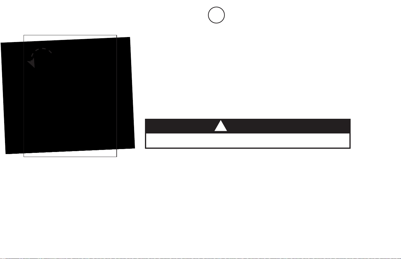
Adjustments / Maintenance / Storage
WARNING
Tipping Hazard: For upright storage, leave A-frame open wide enough to remain stable, or secure to the wall
to prevent tipping. In households with small children, the table should be stored at on the oor, not upright
.
!
CHANGING THE ROLLER HINGE SETTING
• Stand with your legs on either side of the Main Shaft.
• Reach under each Roller Hinge with your index ngers. Use your thumbs to release the locks over
the Roller Hinges (See Figure 16).
• Lift both sides of the table out of the A-frame at the same time. You may rest the table on the
Crossbar of the A-frame.
• Unlock the Cam Locks for each Roller Hinge. Change the Roller Hinges to the desired setting
(A, B or C) (Figure 17).
• Re-lock the Cam Locks. Replace the Roller Hinges into the hinge plates of the A-frame.
MAINTENANCE
• To clean the Table Bed, wipe down with a damp cloth. Do not use abrasive cleaners.
STORING THE INVERSION TABLE
• Loosen the De-rattler knob.
• Pull the height-selector locking pin and slide the Main Shaft in all the way to the nal hole setting.
Engage the pin in the storage setting.
• Rotate the table opposite from use until the table has turned 180 degrees and rests against the
Crossbar on the A-frame.
• Pull up on the spreader arms to fold the A-frame (Figure 18). WARNING: This operation may
pinchngersifnotdoneslowlyandcarefully.
Figure 17
Figure 16
Figure 18
A B C

U.S. and Foreign Patents Pending. Teeter Hang Ups is a registered trademark of Teeter.
Specications subject to change without notice.
© COPYRIGHT 2011 Teeter. International Law Prohibits Any Copying
EP-2011 0611-3
Any modication to
this device will void
the UL Listing.
MDSS GmbH
Schiffgraben 41
30175 Hannover, Germany
EC REP
If you have any problems assembling the equipment, or questions about its use, please contact customer service at:
USA: Teeter
Toll Free (Phone) 800-847-0143
(Fax) 800-847-0188
www.teeter-inversion.com
International: Inversion International, Ltd.
(Phone) +1-242-362-1001
(Fax) +1-242-362-1002
www.InversionInternational.com