Loading ...
Loading ...
Loading ...
196 Part Number STH14 9/10
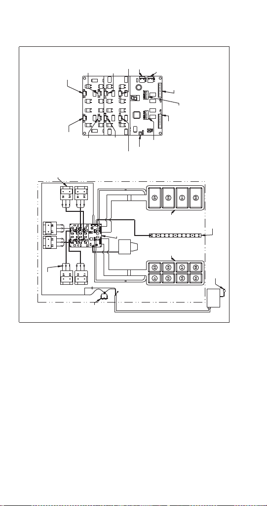
FT-12 WIRING DIAGRAM
S3 - S4 Valve
Connection
S7 - S8 Valve
Connection
Connection
Not Used
Connection
Not Used
S11 - S12
Valve
Connection
S1 - S2 Valve
Connection
S9 - S10 Valve
Connection
S5 - S6 Valve
Connection
Water Valve
Connection
Left Touchpad
Activation
Connection
Left Touchpad
LED
Connection
Right
Touchpad
Activation
Connection
Right
Touchpad
LED
Connection
High
Intensity
LED Lights
Connection
24 Volt Inlet
Power
Connection
Circuit Board Detail
Part No. 020000894
Revision No. 0
Syrup Valve
(6) Total
Quick
Disconnect
Circuit
Board
On/Off
Switch
Touchpad
(Left)
Touchpad
(Right)
High Intensity
LED Lights
120 Volt Power
Supply Cord
Water
Val ve
External
Power
Supply
24 Volt Supply Cord
(Gnd)
Red
Black
White
Red
Black
White
White
Red
White
Red
Red
Black
White
Black
FT - 12
24 Volts 60/50 Hz Wiring Diagram
Red
Black
White
Red
Black
White
Black
White
Red
Black
White
Red
Black
White
STH14.book Page 196 Thursday, September 23, 2010 3:35 PM
Loading ...
Loading ...
Loading ...