Loading ...
Loading ...
Loading ...
49-2000707 Rev. 3 21
Installation Instructions
5
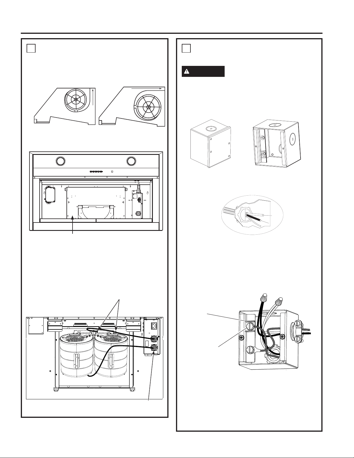
INSTALL MOTOR
I) Align the motor exhaust with the top damper as
shown in the Figure A for top venting. In case of
back venting, rotate the motor 90° to align with the
back damper as shown in Figure B.
II) Secure the motor to motor mounting plate using
screws (D).
III) Plug the motor connector into the mating
connector on top of the control housing.
IV) Repeat steps I through III for dual motor models.
V) For dual motor models, secure the motor wires
to the motor clips as shown in image below.
6
CONNECT ELECTRICAL
Verify that power is turned off at the source.
WARNING
If house wiring is not 2-wire with
a ground wire, a ground must be provided by the
installer. When house wiring is aluminum, be sure
to use UL approved anti-oxidant compound and
aluminum-to-copper connectors.
• Remove junction box cover.
• Pull the house wiring through the knockout at the
top or back of the hood and secure with the strain
relief.
• Use UL listed wire nuts to connect incoming white
to white, and black to black wires.
• Loosen the green grounding screw (with grounding
bracket) in the junction box. Loop solid copper
house wire clockwise around the green grounding
screw and above the bracket. Firmly tighten the
screw over the loop.
• Replace junction box cover and ensure wires are
not pinched.
NOTE:
For corded installation: Use only with rangehood
cord-connection kits that have been investigated
and found acceptable for use with this model
rangehood.
Top Venting
Figure A
Back Venting
Figure B
Grounding
Bracket
Green
Grounding
Screw
Motor Mounting Plate
INSTALLATION INSTRUCTIONS
Wire Clips
Motor Mating
Connector Location
Dual Motor Top Venting Installation
Loading ...
Loading ...
Loading ...