Loading ...
Loading ...
Loading ...
18 49-2000707 Rev. 3
INSTALLATION INSTRUCTIONS
Installation Instructions
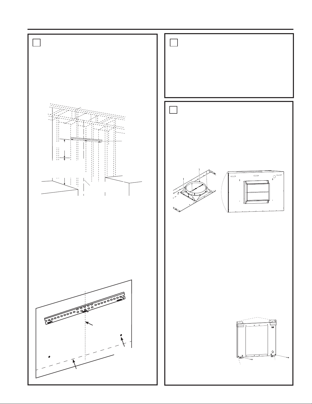
1
INSTALL HOOD SUPPORT
IMPORTANT: Framing must be capable of
supporting 100 lbs for 30" and 36" models and 150
lbs for 48" models.
• Locate a minimum of 2 vertical studs for the
installation bar by tapping drywall with a hammer
or use a stud finder.
• Level the installation bar and center left to right
above the marked line. Hold bar against the wall.
• Drill 1/8” pilot holes at the 2 vertical stud locations
through holes in the installation bracket. Secure
the installation bar with supplied screws (A) as
shown above.
Drill Bottom Mounting Hole Locations:
• Hang hood on installation bar to mark anchor
locations. Mark hole locations through the back of
the hood. NOTE: If installing to the soffit or cabinet,
push hood flush to the soffit or cabinet before
marking screw hole locations.
• Remove the hood and drill 5/16” clearance holes
centered at the marks you made.
2
INSTALL DAMPER
IMPORTANT: Remove shipping tape from damper
and check that damper moves freely.
Install Top Damper:
• The motor mounting plate comes pre-installed in
the hood for top venting.
• Install the top damper to the hood body as shown
in Figure A using screws (B) from top of hood.
Install Back Damper:
• In case of back venting through the wall, back
damper accessory UXBDA812 must be purchased
separately.
• Remove the square knockout panel on hood body
for back venting.
•
Install the back damper to the hood body as shown in
Figure B using screws provided with the accessory.
• Uninstall the motor mounting plate from top
venting position. Save the screws.
• Install the metal plate provided with the accessory
to cover the opening for top damper.
• Remove the two screw knockout holes on the
motor mounting plate as shown in Figure C.
• Install the motor
mounting plate so
that arrow is pointing
upwards and on right
side.
• Slide plate into the
metal brackets and
push in until metal clips
at the bottom engage.
• Fasten the plate
through the two screw hole knockouts as shown in
Figure C. Use the two screws you saved.
Installation Bar
Centerline of
Installation Space
16-3/4”
24” minimum over electric
range or cooktop, or
30” minimum over gas
range or cooktop, and 36”
recommended maximum.
Figure A
Figure B
1
INSTALL HOOD SUPPORT (Cont.)
• Install wall anchors (C) by tapping the anchors
with a hammer to seat the teeth of the flanges into
the wall. This keeps anchor from rotating.
• Drive the anchor screws until the barrels crimp
against the inside of the wall.
• Remove the screws from the wall anchors before
installing the hood.
Bottom of Hood
Wall Anchor
Locations
Centerline of
Installation Space
Screw Knockouts
Metal Clips
Figure C(Single motor will look different)
Metal Brackets
Loading ...
Loading ...
Loading ...