ENGLISH
XC8871-001
Printed in Japan
<< PE-Design Ver.6.0 >> cover 1-4
Instruction Manual
Instruction Manual
Personal Embroidery Design Software System
PE-DESIGN
PE-DESIGN
Ver.6Ver.6
Instruction Manual
PE-DESIGN Ver.
6
IMPORTANT INFORMATION: REGULATIONS
Federal Communications Commissions (FCC) Declaration of Conformity
(For USA Only)
Responsible Party: Brother International Corporation
100 Somerset Corporate Boulevard
Bridgewater, NJ 08807-0911 USA
declares that the product
Product Name: Brother USB Writer
Model Number: PE-Design
complies with Part 15 of the FCC Rules. Operation is subject to the following two conditions: (1) this
device may not cause harmful interference, and (2) this device must accept any interference
received, including interference that may cause undesired operation.
This equipment has been tested and found to comply with the limits for Class B digital device, pursu-
ant to Part 15 of the FCC Rules. These limits are designed to provide reasonable protection against
harmful interference in a residential installation. This equipment generates, uses, and can radiate
radio frequency energy and, if not installed and used in accordance with the instructions, may cause
harmful interference to radio communications. However, there is no guarantee that interference will
not occur in a particular installation. If this equipment does cause harmful interference to radio or
television reception, which can be determined by turning the equipment off and on, the user is
encouraged to try to correct the interference by one or more of the following measures:
– Reorient or relocate the receiving antenna.
– Increase the separation between the equipment and receiver.
– Consult the dealer or an experienced radio/TV technician for help.
– Changes or modifications not expressly approved by the manufacturer or local sales distributor
could void the user’s authority to operate the equipment.
Canadian Department of Communications Compliance Statement
(For Canada Only)
This digital apparatus does not exceed the Class B limits for radio noise emission from a digital appa-
ratus as set out in the interference-causing equipment standard entitled “Digital Apparatus”, ICES-
003 of the Department of Communications.
Radio Interference
(Other than USA and Canada)
This machine complies with EN55022 (CISPR Publication 22) /Class B.
Frontcover.fm Page 1 Thursday, July 8, 2004 1:48 PM
Congratulations on choosing our product!
Thank you very much for purchasing our product. To obtain the best performance from this unit
and to ensure safe and correct operation, please read this Instruction Manual carefully, and then
keep it in a safe place together with your warranty.
Please read before using this product
For designing beautiful embroidery patterns
• This system allows you to create a wide variety of embroidery patterns and supports a wider
range of sewing attribute settings (thread density, sewing pitch, etc.). However, the final result
will depend on your particular sewing machine model. We recommend that you make a trial
sewing sample with your sewing data before sewing on the final material.
For safe operation
• Avoid dropping a needle, a piece of wire or other metallic objects into the unit or into the card
slot.
• Do not store anything on the unit.
For a longer service life
• When storing the unit, avoid direct sunlight and high humidity locations. Do not store the unit
close to a heater, iron or other hot objects.
• Do not spill water or other liquids on the unit or cards.
• Do not drop or hit the unit.
For repairs or adjustments
• In the event that a malfunction occurs or adjustment is required, please consult your nearest
service center.
Notice
This Instruction Manual does not explain how to use your computer under Windows. Please refer
to the Windows manuals.
Copyright acknowledgment
MS-DOS and Windows are registered trademarks of Microsoft Corp.
IBM is a registered trademark of International Business Machine Corporation.
Important
Using this unit for unauthorized copying of material from embroidery cards, newspapers and mag-
azines for commercial purpose is an infringement of copyrights which is punishable by law.
Caution
The software included with this product is protected by copyright laws. This software can be used
or copied only in accordance with the copyright laws.
For additional product information and updates, visit our web site at:
www.brother.com
SAVE THESE INSTRUCTIONS
This product is intended for household use.
Frontcover.fm Page 2 Thursday, July 8, 2004 1:48 PM
New Features of Version 6.0
Stitch generating
• Improved variable functions for satin stitch and fill stitch . . . . . . . . . . . . . . . . . . . . . . . . . . . . . . . . 173, 174
• Color gradation function. . . . . . . . . . . . . . . . . . . . . . . . . . . . . . . . . . . . . . . . . . . . . . . . . . . . . . . . . .96, 179
• Variations for region sewing:
piping stitch, concentric circle stitch, radial stitch, spiral stitch . . . . . . . . . . . . . . . . . . . . . . . .95, 177, 178
• Variations for line sewing:
E-stitch, V-stitch. . . . . . . . . . . . . . . . . . . . . . . . . . . . . . . . . . . . . . . . . . . . . . . . . . . . . . . . . . . . . . . . . . .173
• Added the Stamp function and expanded the programmable fill stitch . . . . . . . . . . . . . . .94, 98, 165, 176
• Automatic running pitch adjustment for running stitch . . . . . . . . . . . . . . . . . . . . . . . . . . . . . . . . . . .91, 172
• Half stitch for satin stitch, manual-punching object, etc. . . . . . . . . . . . . . . . . . . .91, 92, 93, 172, 174, 175
• Selectable stitch path. . . . . . . . . . . . . . . . . . . . . . . . . . . . . . . . . . . . . . . . . . . . . . . . . . . . .92, 93, 174, 175
• Selectable edge pattern (turning point) for fill stitch. . . . . . . . . . . . . . . . . . . . . . . . . . . . . . 92, 94, 174, 176
Editing functions
Layout & Editing
• Creates patterns larger than the hoop size . . . . . . . . . . . . . . . . . . . . . . . . . .59, 108, 189, 194, 196, 198
• Enlarges/reduces while maintaining the density and stitching pattern . . . . . . . . . . . . . . . . . . . . . 132, 133
• Selects an object from the Sewing Order/Color dialog box . . . . . . . . . . . . . . . . . . . . . . . . . . . . . . . . . .184
• Monogramming function . . . . . . . . . . . . . . . . . . . . . . . . . . . . . . . . . . . . . . . . . . . . . . . . . . . . . . . . . . . .162
• Automatically eliminates the background with the Cross Stitch and Photo
Stitch functions . . . . . . . . . . . . . . . . . . . . . . . . . . . . . . . . . . . . . . . . . . . . . . . . . . .116, 120, 122, 124, 125
• Improved Auto Punch function. . . . . . . . . . . . . . . . . . . . . . . . . . . . . . . . . . . . . . . . . . . . . . . . . . . . . . . .115
• Improved stitch editing (selecting entry and exit points for each color, inserting or deleting feeds) . . . 141
• Improved point editing:
Transforms lines to straight lines or curves . . . . . . . . . . . . . . . . . . . . . . . . . . . . . . . . . . . . . . . . . . . . . .137
Selects points with arrow keys. . . . . . . . . . . . . . . . . . . . . . . . . . . . . . . . . . . . . . . . . . . . . . . . . . . . . . . . 135
Edits points without cancelling hole sewing. . . . . . . . . . . . . . . . . . . . . . . . . . . . . . . . . . . . . . . . . . . . . . 180
• Edits regions without ungrouping. . . . . . . . . . . . . . . . . . . . . . . . . . . . . . . . . . . . . . . . . . . . . . . . . . . . . .134
• Split function for printing at actual size . . . . . . . . . . . . . . . . . . . . . . . . . . . . . . . . . . . . . . . . . . . . . . . . .207
• Split off parts of stitch data . . . . . . . . . . . . . . . . . . . . . . . . . . . . . . . . . . . . . . . . . . . . . . . . . . . . . . . . . . 143
User interface
• Changed grid interval range (1–10 mm → 0.1–25.4 mm) . . . . . . . . . . . . . . . . . . . . . . . . . . . . . . .105, 202
• Provides edit commands on the menu that appeared by right-clicking . . . . . . . . . . . . . 236, 242, 249, 253
• Added the Reference window . . . . . . . . . . . . . . . . . . . . . . . . . . . . . . . . . . . . . . . . . . . . . . . . . .10, 70, 107
• Improved the dialog box for setting sewing attributes (Beginner and Expert mode) . . . . . . . . . . . .89, 171
Design Center
• Added the stitch simulator . . . . . . . . . . . . . . . . . . . . . . . . . . . . . . . . . . . . . . . . . . . . . . . . . . . . . . . . . . . 101
• Allows the sewing order to be changed from the Sewing Order dialog box. . . . . . . . . . . . . . . . . . . . . . 100
Layout & Editing
• Automatically creates appliqué data (material, position, basting, sewing). . . . . . . . . . . . . . . . . . . . . . . 181
• Improved Sewing Order/Color dialog box . . . . . . . . . . . . . . . . . . . . . . . . . . . . . . . . . . . . . . . . . . . . . . . 184
• Improved stitch simulator. . . . . . . . . . . . . . . . . . . . . . . . . . . . . . . . . . . . . . . . . . . . . . . . . . . . . . . . . . . .188
Others
• Added the .phc file format to those that can be imported . . . . . . . . . . . . . . . . . . . . . . . . . . . . . . . . . . .127
• Organizes embroidery patterns in the Design Database. . . . . . . . . . . . . . . . . . . . . . . . . . . . . . . . . . . .224
• Added more sample files for images, embroidery patterns and stitch patterns
Frontcover.fm Page 3 Thursday, July 8, 2004 1:48 PM
Basic Operation
Advanced Opreation
Design Center
Advanced Opreation
Layout & Editing
Advanced Opreation
Programmable
Stitch Creator
Advanced Opreation
Design Database
Reference
Design Center
Reference
Layout & Editing
Reference
Programmable
Stitch Creator
Reference
Design Database
i
Table of Contents
Before Use ................................................... 1
What You Can Do With This Software.............. 1
Automatically Create an Embroidery Pattern
From an Image........................................................ 1
Automatically Create an Embroidery Pattern
From a Photo .......................................................... 1
Easily Create Large-Size Embroidery Designs ...... 2
Have Fun Creating Embroidery Patterns
Manually................................................................. 2
Create Embroidery Patterns Using All Three
Applications............................................................ 2
Overview of the Manual .................................... 3
Structure of the manual .......................................... 3
List of terms used ................................................... 3
Introduction ....................................................... 4
Applications of the software................................... 4
Package contents .................................................... 5
Optional supplies.................................................... 6
Principal parts......................................................... 6
Installation......................................................... 7
Installation procedure ............................................. 7
System requirements .............................................. 8
[STEP 1] Installing the software ............................ 8
[STEP 2] Installing the driver for the card writer
module .................................................................. 10
[STEP 3] Upgrading the USB card writer
module .................................................................. 12
Online registration................................................ 13
Uninstallation ....................................................... 13
Technical support ................................................. 13
Tips and Techniques for Creating Embroidery
Patterns........................................................... 14
Sew Types ...................................................... 15
Chapter 1
Basic Operation........................ 17
Getting Started .......................................... 18
About This Chapter ......................................... 18
Automatically Creating Embroidery
Patterns...................................................... 19
Using the Auto Punch Function ...................... 19
Step1 Starting up Layout & Editing ................. 19
Step2 Opening an image file ............................ 20
Step3 Adjusting the size and position of the
image ...................................................... 21
Step4 Automatically converting the image to an
embroidery pattern.................................. 21
Step5 Displaying a preview of the embroidery
pattern..................................................... 22
Step6 Saving the embroidery pattern................ 23
Step7 Transferring the pattern to an original
card ......................................................... 24
Step8 Quitting Layout & Editing...................... 24
Using a Photo Stitch Function......................... 25
Step1 Starting up Layout & Editing ................. 25
Step2 Opening an image file............................. 26
Step3 Adjusting the size and position of the
image ...................................................... 27
Step4 Automatically converting the image
to an embroidery pattern......................... 27
Creating and Editing Embroidery
Patterns ......................................................30
Using Design Center....................................... 30
Step1 Starting up Design Center....................... 30
Step2 Opening an image file............................. 31
Step3 Continuing to stage 2 (Line Image
stage)....................................................... 31
Step4 Editing lines............................................ 32
Step5 Continuing to stage 3 (Figure Handle
stage)....................................................... 33
Step6 Continuing to stage 4 (Sew Setting
stage)....................................................... 34
Step7 Specifying sewing attributes................... 34
Step8 Previewing the image ............................. 37
Step9 Saving the file......................................... 38
Using Layout & Editing.................................... 39
Step1 Importing embroidery patterns from
Design Center ......................................... 39
Step2 Adjusting the size and position of the
embroidery pattern.................................. 40
Step3 Adding shapes......................................... 41
Step4 Adding text ............................................. 43
Step5 Fitting the text around the oval............... 44
Step6 Adding a circle for the center of the
sun........................................................... 45
Step7 Selecting a programmable fill stitch....... 46
Step8 Adding a closed broken line for the sun’s
rays.......................................................... 48
Step9 Changing the sewing order of sun and
rays.......................................................... 49
Step10 Adjusting the rays................................... 50
Step11 Setting hole sewing................................. 50
Step12 Previewing the embroidery pattern......... 51
Step13 Transferring the pattern to an original
card ......................................................... 52
Step14 Saving the file......................................... 53
Step15 Quitting Layout & Editing...................... 53
Using Programmable Stitch Creator ...............54
Step1 Starting up Programmable Stitch
Creator .................................................... 54
Step2 Opening a programmable stitch pattern.. 55
Step3 Drawing lines to edit the stitch pattern... 56
Step4 Applying embossing/engraving effects .. 57
Step5 Saving the edited stitch pattern............... 58
Step6 Quitting Programmable Stitch Creator ... 58
Creating Large-Size Embroidery
Patterns ......................................................59
Designing a large-size embroidery pattern........... 59
PeDesignV6Eng.book Page i Thursday, July 8, 2004 11:59 AM
ii
Table of Contents
Step1 Starting up Layout & Editing ................. 59
Step2 Specifying a Design Page size................ 60
Step3 Creating the embroidery pattern............. 60
Step4 Checking the embroidering order........... 61
Step5 Saving the pattern ................................... 61
Step6 Transferring the pattern to an original
card ......................................................... 62
Step7 Quitting Layout & Editing...................... 63
Embroidering large-size embroidery patterns ...... 63
Step1 Attaching stabilizer to the fabric ............ 63
Step2 Marking the embroidering position ........ 63
Step3 Hooping the fabric.................................. 65
Step4 Embroidering.......................................... 65
Chapter 2
Advanced Operation ................ 67
Advanced Operations ............................... 68
About This Chapter ......................................... 68
Design Center............................................ 69
Main Window .................................................. 70
Stage 1 (Original Image Stage) ..................... 71
Importing Image Data ..................................... 71
Using the wizard ................................................. 71
Importing image data from a TWAIN device ..... 72
Stage 2 (Line Image Stage) ........................... 73
Continuing to Stage 2 (Line Image Stage)...... 73
Creating a new Design Page in stage 2
(Line Image stage)............................................... 74
Drawing and erasing outlines.............................. 74
Stage 3 (Figure Handle Stage) ...................... 76
Continuing to Stage 3 (Figure Handle Stage). 76
Specifying the Design Page size ......................... 77
Creating a new Design Page in stage 3 (Figure
Handle stage)....................................................... 78
Editing Outlines............................................... 78
Selecting outlines ................................................ 78
Moving outlines .................................................. 78
Scaling outlines ................................................... 79
Flipping outlines horizontally or vertically......... 79
Rotating outlines ................................................. 79
Deleting outlines ................................................. 80
Editing Points in Outlines................................ 81
Moving points ..................................................... 81
Inserting points.................................................... 81
Deleting points .................................................... 81
Drawing a Broken Line.................................... 82
Stage 4 (Sew Setting Stage) .......................... 83
Continuing to Stage 4 (Sew Setting Stage) .... 83
Specifying display colors .................................... 83
Applying Sewing Attributes to Lines and
Regions........................................................... 84
Region sewing..................................................... 84
Line sewing ......................................................... 85
Using the Sewing Attributes bar ......................... 87
Specifying sewing attributes ............................... 89
Creating a gradation ............................................ 96
Moving the center point of the concentric circle
stitch and radial stitch.......................................... 97
Specifying hole sewing ....................................... 97
Applying and Editing Stamps .......................... 98
Applying a stamp ................................................ 98
Editing a stamp.................................................... 99
Viewing and Modifying the Sewing Order ..... 100
Checking the Stitching ..................................101
Previewing the Sewing Image.......................102
Changing realistic preview settings .................. 102
Viewing Patterns in the Reference Window ..103
Zooming ............................................................ 103
Moving the display area frame.......................... 103
Redrawing the display area frame..................... 103
Scaling the display area frame .......................... 104
Saving ........................................................... 104
Overwriting ....................................................... 104
Saving with a new name ................................... 104
Changing Software Settings.......................... 105
Changing the grid settings................................. 105
Changing the measurement units ...................... 105
Layout & Editing ......................................106
Main Window.................................................107
Inputting Images and Embroidery
Patterns .........................................................108
Creating a Design Page................................ 108
Creating a new Design Page ............................. 108
Specifying the Design Page .............................. 108
Opening a Layout & Editing file....................... 109
Importing Image Data....................................111
Importing image data ........................................ 111
Importing image data from a TWAIN device,
such as a scanner ............................................... 111
Creating a portrait image................................... 112
Importing image data from the Clipboard......... 113
Changing the display settings of images........... 113
Changing the Size and Position of the
Image.............................................................114
Saving the Image Data..................................114
Automatically Converting Image Data Into an
Embroidery Pattern .......................................115
Importing Embroidery Patterns ..................... 127
Importing embroidery patterns from a file........ 127
Importing embroidery patterns from Design
Center ................................................................ 128
Importing embroidery patterns from an
embroidery card ................................................ 128
Editing Embroidery Patterns .......................130
Editing Embroidery Patterns ......................... 130
Selecting patterns .............................................. 130
Moving patterns ................................................ 131
Scaling patterns ................................................. 132
PeDesignV6Eng.book Page ii Thursday, July 8, 2004 11:59 AM
Basic Operation
Advanced Opreation
Design Center
Advanced Opreation
Layout & Editing
Advanced Opreation
Programmable
Stitch Creator
Advanced Opreation
Design Database
Reference
Design Center
Reference
Layout & Editing
Reference
Programmable
Stitch Creator
Reference
Design Database
iii
Table of Contents
Flipping patterns horizontally or vertically....... 133
Rotating patterns ............................................... 133
Grouping embroidery patterns .......................... 134
Editing Points in Embroidery Patterns .......... 135
Selecting points ................................................. 135
Moving points ................................................... 135
Inserting points.................................................. 136
Deleting points .................................................. 137
Transforming straight lines into curves or curves
into straight lines............................................... 137
Moving entry/exit points and the center point .. 138
Editing Stitch Data ........................................ 140
Converting objects to stitch data....................... 140
Editing stitch points of stitch data..................... 140
Changing colors of stitch data........................... 142
Converting stitch data to blocks........................ 142
Splitting off parts of stitch data......................... 143
Drawing Circles and Arcs.............................. 145
Drawing a circle or an oval ............................... 145
Drawing an arc .................................................. 145
Drawing a fan shape.......................................... 146
Drawing an arc & string.................................... 147
Specifying the geometric attribute .................... 147
Drawing a Rectangle..................................... 148
Specifying the geometric attribute .................... 148
Drawing Straight Lines and Curves .............. 149
Specifying the geometric attribute .................... 150
Creating Manual Punching Data................... 151
Entering Text................................................. 153
Specifying text attributes................................... 154
Editing entered text ........................................... 156
Selecting characters........................................... 157
Specifying text attributes................................... 157
Specifying text arrangement ............................. 158
Transforming text.............................................. 160
Specifying TrueType text attributes.................. 161
Converting text to outline data.......................... 161
Entering Monograms..................................... 162
Specifying monogram attributes ....................... 163
Editing monograms ........................................... 163
Editing monogram characters and the decorative
pattern................................................................ 164
Applying and Editing Stamps........................ 165
Applying a stamp .............................................. 165
Editing a stamp.................................................. 166
Applying Sewing Attributes to Lines and
Regions......................................................... 167
Setting the thread color and sew type ............... 168
Specifying sewing attributes ............................. 171
Creating a gradation .......................................... 179
Specifying hole sewing ..................................... 180
Using the Applique Wizard............................... 181
Checking Embroidery Patterns ................... 182
Measuring the Distance Between Two
Points............................................................ 182
Specifying the Sewing Area .......................... 183
Checking and Editing the Sewing Order/
Color..............................................................184
Zooming ........................................................ 186
Zooming in ........................................................ 186
Zooming out ...................................................... 186
Zooming to actual size ...................................... 186
Zooming on selected objects............................. 186
Zooming Design Page to window ..................... 186
Previewing the Sewing Image.......................187
Changing realistic preview settings .................. 187
Checking the Stitching ..................................188
Checking Embroidery Pattern Information .... 189
Editing User Thread Color Lists .................... 190
Viewing Patterns in the Reference Window ..193
Zooming ............................................................ 193
Moving the display area frame.......................... 193
Redrawing the display area frame..................... 193
Scaling the display area frame .......................... 193
Saving and Printing ...................................... 194
Saving ........................................................... 194
Overwriting ....................................................... 194
Saving with a new name ................................... 194
Outputting data in a different format ................ 195
Writing an embroidery pattern to an original
card.................................................................... 195
Writing multiple embroidery files to an original
card.................................................................... 196
Adding comments to saved .pes files................ 199
Printing.......................................................... 200
Specifying print settings.................................... 200
Checking the print image .................................. 201
Printing.............................................................. 201
Changing Software Settings ....................... 202
Changing the Settings................................... 202
Changing the grid settings................................. 202
Changing the measurement units ...................... 202
Information for Optional Large-Size Hoop
Users .............................................................203
Creating Patterns for Multi-Position Hoops ... 203
Selecting the Design Page size.......................... 203
Creating the pattern........................................... 204
Optimizing hoop changes.................................. 204
Checking the pattern ......................................... 205
Saving the pattern.............................................. 206
Writing the pattern to an original card .............. 206
Printing a Design Page for a multi-position
hoop................................................................... 207
Programmable Stitch Creator................. 208
Main Window.................................................208
Opening a Pattern File .................................. 209
Creating a new pattern ...................................... 209
Opening a pattern file........................................ 209
Opening an image in the background................ 210
PeDesignV6Eng.book Page iii Thursday, July 8, 2004 11:59 AM
iv
Table of Contents
Selecting a Pattern To Be Created ............... 210
Viewing the Stitch Pattern While
Creating It ..................................................... 212
Drawing a Stitch Pattern in Fill/Stamp
Mode............................................................. 212
Editing a Stitch Pattern in Fill/Stamp Mode... 213
Selecting patterns .............................................. 213
Moving patterns ................................................ 213
Scaling patterns................................................. 214
Deleting patterns ............................................... 214
Cutting out patterns........................................... 214
Copying patterns ............................................... 214
Duplicating patterns .......................................... 214
Pasting a cut or copied pattern .......................... 214
Flipping patterns vertically ............................... 215
Flipping patterns horizontally ........................... 215
Rotating patterns ............................................... 215
Editing Points in Fill/Stamp Mode ................. 216
Moving points ................................................... 216
Inserting points.................................................. 216
Deleting points .................................................. 217
Creating a Stamp.......................................... 217
Creating a Stitch Pattern in Motif Mode ........ 218
Editing a Stitch Pattern in Motif Mode........... 219
Moving and deleting several points at a time.... 219
Scaling patterns................................................. 220
Flipping a pattern horizontally or vertically...... 220
Saving........................................................... 221
Overwriting ....................................................... 221
Saving with a new name ................................... 221
Changing the Settings................................... 222
Changing the display of the background image 222
Changing the grid settings................................. 222
Design Database ..................................... 223
Main Window ................................................ 223
Starting Up Design Database ....................... 224
Organizing Embroidery Patterns................... 224
Creating new folders ......................................... 224
Moving/copying embroidery patterns to a different
folder ................................................................. 224
Changing the name of the embroidery pattern.. 225
Deleting an embroidery pattern......................... 225
Changing the contents pane display.................. 226
Opening Embroidery Patterns....................... 227
Opening embroidery patterns with Layout &
Editing............................................................... 227
Importing embroidery patterns into Layout &
Editing............................................................... 227
Checking Embroidery Patterns ..................... 227
Previewing embroidery patterns ....................... 227
Checking embroidery pattern information........ 228
Searching for an Embroidery Pattern............ 229
Converting Embroidery Patterns to Different
Formats......................................................... 230
Outputting a Catalog of Embroidery
Patterns......................................................... 231
Printing.............................................................. 231
Outputting as an HTML file.............................. 231
Outputting as a CSV file ................................... 232
Chapter 3
Reference ................................ 233
Design Center ..........................................234
List of Tool Box Buttons ................................234
Stage 2 (Line Image stage) ................................. 234
Stage 3 (Figure Handle stage) ............................ 234
Stage 4 (Sew Setting stage) ................................ 235
List of Menus.................................................236
File menu ............................................................ 236
Edit menu............................................................ 237
Sew menu ........................................................... 238
Display menu...................................................... 238
Option menu ....................................................... 239
Stage menu ......................................................... 239
Help menu .......................................................... 240
Layout & Editing ......................................241
List of Tool Box Buttons ................................241
List of Menus.................................................242
File menu ............................................................ 242
Edit menu............................................................ 243
Image menu ........................................................ 245
Text menu........................................................... 246
Sew menu ........................................................... 246
Display menu...................................................... 247
Option menu ....................................................... 248
Help menu .......................................................... 248
Programmable Stitch Creator................. 249
List of Tool Box Buttons ................................249
List of Menus.................................................249
File menu ............................................................ 249
Mode menu......................................................... 250
Edit menu............................................................ 250
Display menu...................................................... 251
Help menu .......................................................... 252
Design Database......................................253
List of Menus.................................................253
File menu ............................................................ 253
Edit menu............................................................ 254
Display menu...................................................... 254
Option menu ....................................................... 255
Help menu .......................................................... 255
Index .........................................................256
Read the following before opening the CD-ROM
package
Product Agreement
PeDesignV6Eng.book Page iv Thursday, July 8, 2004 11:59 AM
1
Before Use
What You Can Do With This Software
This software provides digitizing and editing capabilities, allowing you the creative freedom to design original
embroidery. Easily turn illustrations, photos and lettering into custom embroidery designs.
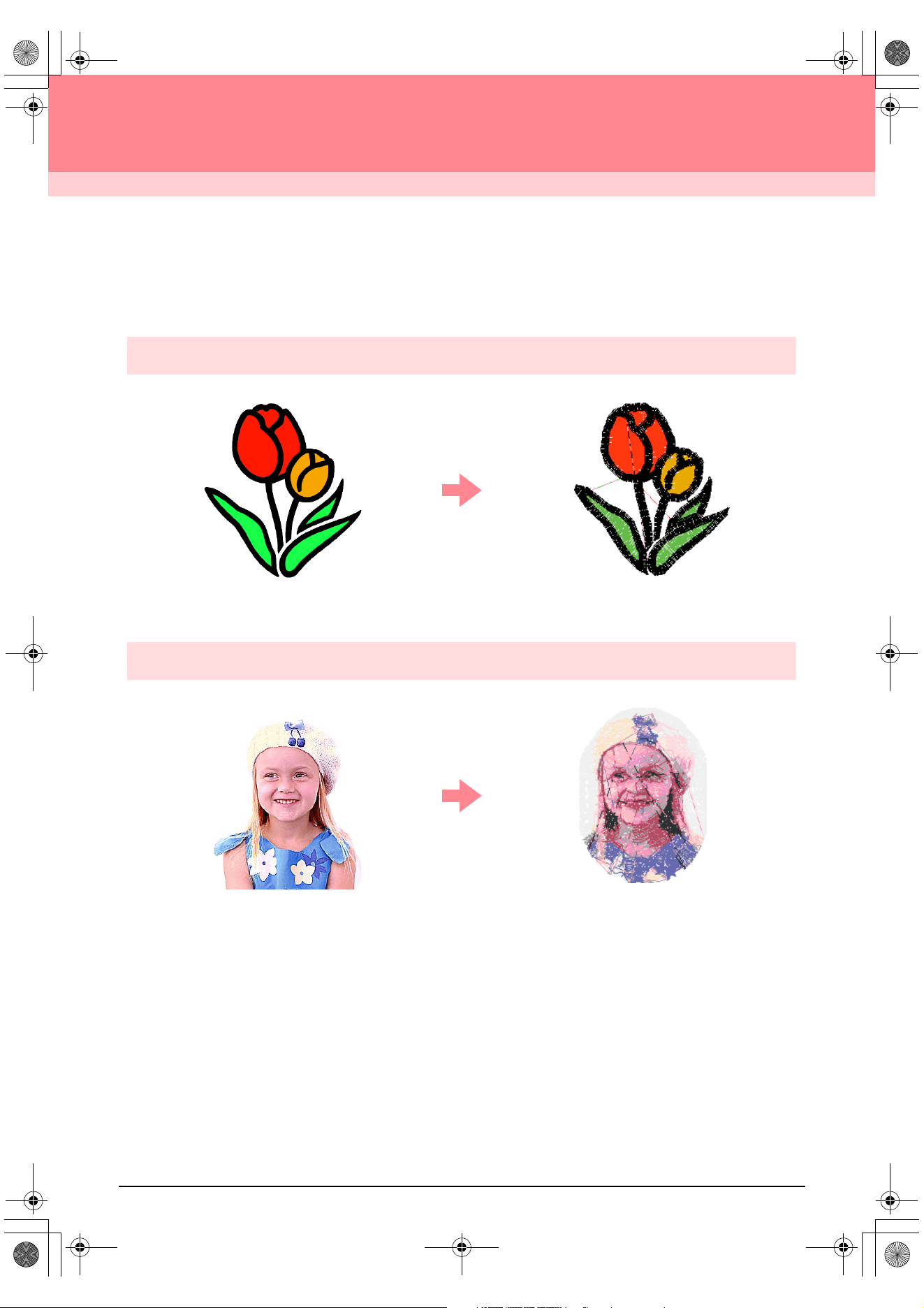
Automatically Create an Embroidery Pattern From an Image
c
For more details, refer to “Using the Auto Punch Function” on page 19.
Automatically Create an Embroidery Pattern From a Photo
c
For more details, refer to “Using a Photo Stitch Function” on page 25.
PeDesignV6Eng.book Page 1 Thursday, July 8, 2004 11:59 AM
2
Before Use
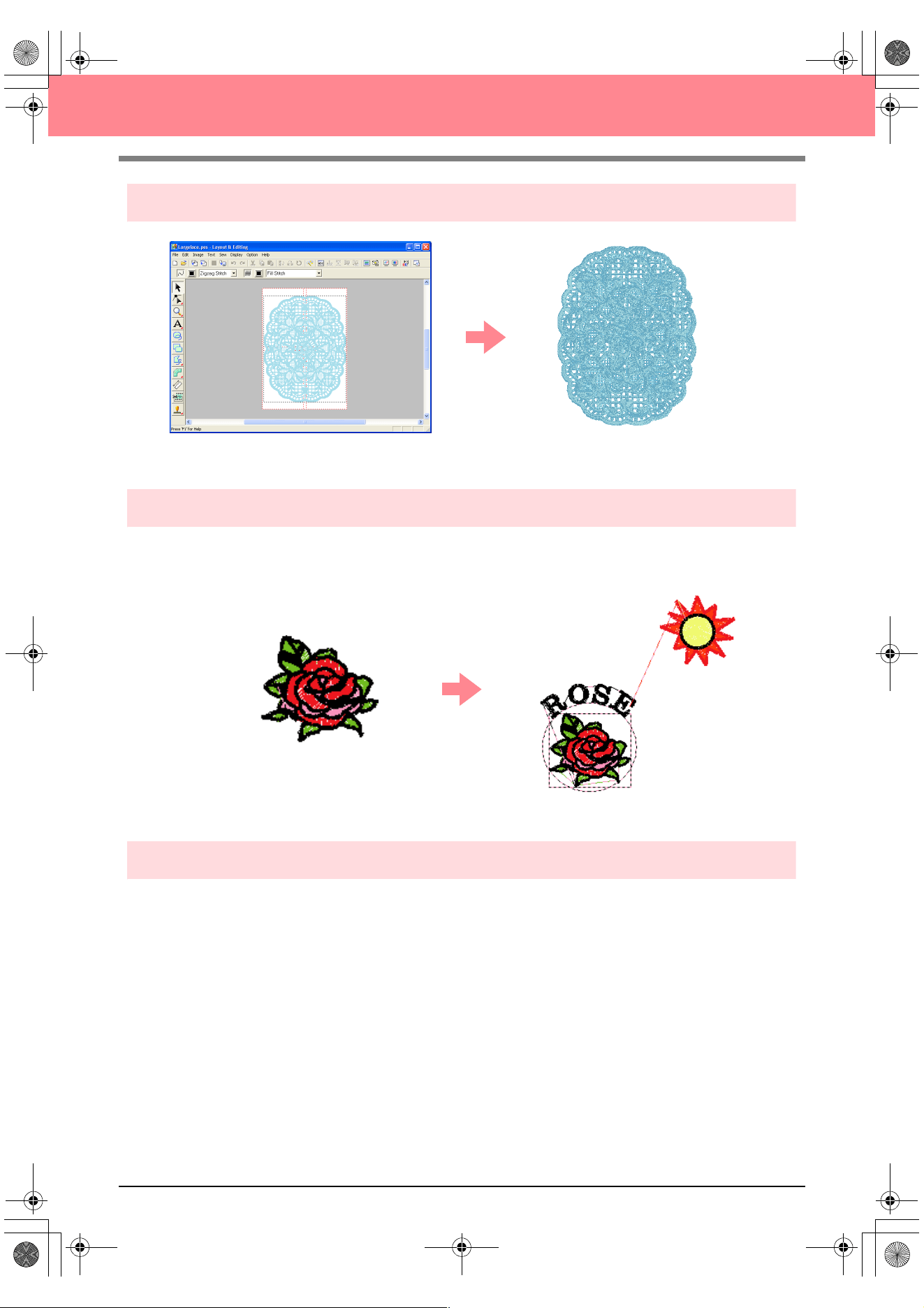
Easily Create Large-Size Embroidery Designs
c
For more details, refer to “Creating Large-Size Embroidery Patterns” on page 59.
Have Fun Creating Embroidery Patterns Manually
You can combine embroidery patterns or apply stitching to drawings and text. In addition, you can design a
wider variety of embroidery patterns by using the many sew types available.
c
For more details, refer to “Creating and Editing Embroidery Patterns” on page 30.
Create Embroidery Patterns Using All Three Applications
■ Design Center
c
Refer to “Using Design Center” on page 30.
c
For more details, refer to pages 69 through 105.
■ Layout & Editing
c
Refer to “Automatically Creating Embroidery Patterns” on page 19.
c
Refer to “Using Layout & Editing” on page 39.
c
For more details, refer to pages 106 through 207.
■ Programmable Stitch Creator
c
Refer to “Using Programmable Stitch Creator” on page 54
c
For more details, refer to pages 208 through 222.
PeDesignV6Eng.book Page 2 Thursday, July 8, 2004 11:59 AM
3
Before Use
Overview of the Manual
Structure of the manual
This manual consists of three main sections: Basic Operation, Advanced Operation, and Reference.
■ Basic Operation
By following the step-by-step instructions contained in this section, you can create basic embroidery
patterns. For first time users, this is a good way to become familiar with the various functions.
■ Advanced Operation
This section separately outlines the capabilities and use for each application, allowing you to create more
advanced and original embroidery patterns than those created in Basic Operation.
■ Reference
This section contains an explanation of the Tool Box and a summary of the menu for each application. You
can use this section to clarify the purpose and use of any icon or menu command.
List of terms used
The following terms are used throughout this manual, as described below.
Embroidery pattern: An embroidery design
Object: A component of the embroidery pattern
Multi-position hoop: An embroidery frame that can be attached to the embroidery machine at various positions
so that large-size patterns can be sewn
Sew type: A type of stitching (for example, zigzag stitch, running stitch and satin stitch)
Stitching: A series of stitches
PeDesignV6Eng.book Page 3 Thursday, July 8, 2004 11:59 AM
4
Before Use
Introduction
Applications of the software
This package consists of four applications.
■ Design Center
Design Center is used to manually create embroidery patterns from images. The images may come from
scanning a printed image or can be created with an application like Paint
®
. The extension of the image files
must be .bmp, .tif, .jpg, .j2k, .pcx, .wmf, .png, .eps, .pcd, or .fpx. Design Center automatically detects outlines
in the image and replaces them with broken lines that can be edited and assigned sewing attributes.
The procedure is divided into four stages:
❏ Stage 1 (Original Image stage): Open an image file and select one or more colors that the application
will use to trace the outlines.
❏ Stage 2 (Line Image stage): The original color image is replaced with a black-and-white image (the
colors selected in stage 1 (Original Image stage) become black, and all other colors become white).
This image can be edited using pens and erasers of different thicknesses. (You can also start with this
step to draw a black-and-white image by hand.)
When the image is ready, start the automatic tracing process.
❏ Stage 3 (Figure Handle stage): The black-and-white image is replaced with a set of outlines made of
editable broken lines. You can edit the broken lines by moving, inserting or deleting editing points.
❏ Stage 4 (Sew Setting stage): In this final step, apply sewing attributes (thread color and sew type) to
the outlines and the inside regions.
At any stage, you can save your work to retrieve it later. In stage 1 (Original Image stage) and stage 2 (Line
Image stage), the file will be saved with the .pel extension. In stage 3 (Figure Handle stage) and stage 4 (Sew
Setting stage), the file will be saved with the .pem extension. In addition, if the imported image has not yet
been saved, it can be saved with the .bmp extension.
Saving your work as you move through the stages will be helpful if you make changes, then later decide to use
the original pattern.
When your image has reached stage 4 (Sew Setting stage), you can import it into Layout & Editing, where the
image can be moved and scaled as a single object.
■ Layout & Editing
Layout & Editing is used to automatically create embroidery patterns from images, and to combine images and text to
create embroidery patterns that can be written to an original card. The images may come from scanning a printed image
or can be created with an application like Paint
®
. The extension of the image files must be .bmp, .tif, .jpg, .j2k, .pcx, .wmf,
.png, .eps, .pcd, or .fpx. In addition, the following types of embroidery patterns can be incorporated into the embroidery
pattern.
❏ Embroidery patterns created with Design Center
❏ Embroidery patterns on embroidery cards purchased from your dealer (Some patterns cannot be read.)
❏ Embroidery patterns in the Tajima (.dst), Melco (.exp), Pfaff (.pcs), Husqvarna (.hus) and embroidery
sewing machine (.phc) formats
❏ Embroidery patterns created within Layout & Editing itself (These patterns include text, circular shapes,
boxes, polygons, curves and manual punching patterns.)
After gathering the different parts of your embroidery pattern, you can use the layout functions to adjust their
relative position, orientation and scale.
When an embroidery pattern is complete, you can save it (with the .pes file extension) and write it to an original card.
The original card can then be inserted into your sewing machine for the embroidery pattern to be sewn.
PeDesignV6Eng.book Page 4 Thursday, July 8, 2004 11:59 AM
5
Before Use
■ Programmable Stitch Creator
Programmable Stitch Creator allows you to create, edit and save fill/stamp and motif stitch patterns that can
be applied as a programmable fill stitch or motif stitch, or as a stamp to the enclosed regions of embroidery
patterns both in Design Center and Layout & Editing. The fill/stamp stitch patterns are saved as .pas files, and
the motif stitch patterns are saved as .pmf files. The application comes with a number of .pas and .pmf files
that you can use as they are or edit to enhance your embroidery patterns.
■ Design Database
Design Database allows you to easily preview the embroidery pattern files on your computer so that you can
find the desired pattern, which can be opened with or imported into Layout & Editing. From Design Database,
you can also convert the files to other formats (.pes, .dst., .exp., .pcs or .hus), or print or output as an HTML
file images of the embroidery patterns in a selected folder. In addition, the sewing information for the
embroidery patterns in a selected folder can be outputted as a CSV file for use in other database applications.
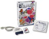
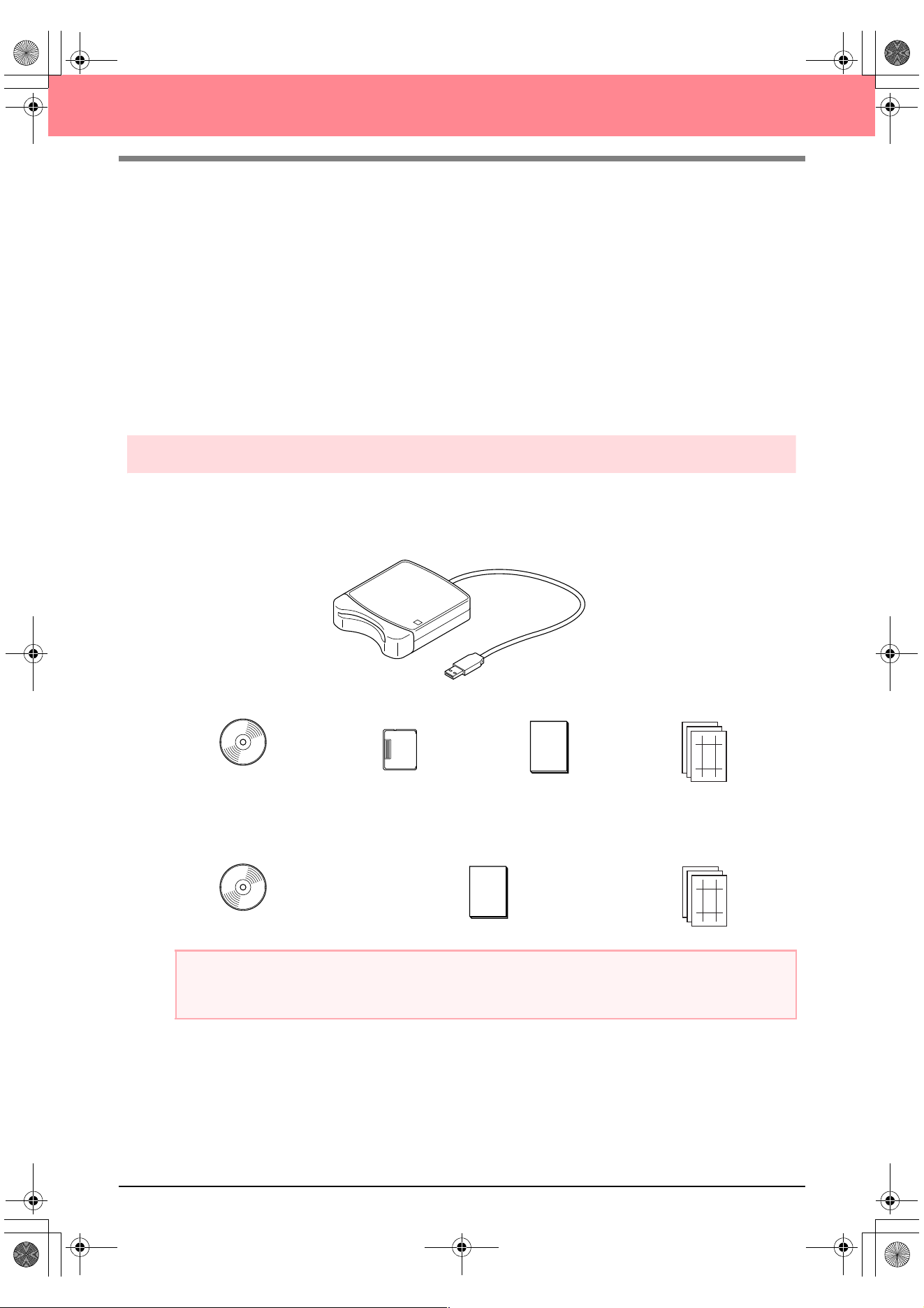
Package contents
Check that the following items are included. If anything is missing or damaged, contact your service
representative.
Version 6.0 or version 6.0 upgrade for versions 1.0 through 4.0:
Version 6.0 upgrade for version 5.0:
a Note:
The USB card writer module and the original card are not included in the kit provided for upgrading from
version 5.0.
CD-ROM Original card Instruction manual
USB card writer module
Template
CD-ROM Instruction manual
Te m pla te
PeDesignV6Eng.book Page 5 Thursday, July 8, 2004 11:59 AM
6
Before Use
Optional supplies
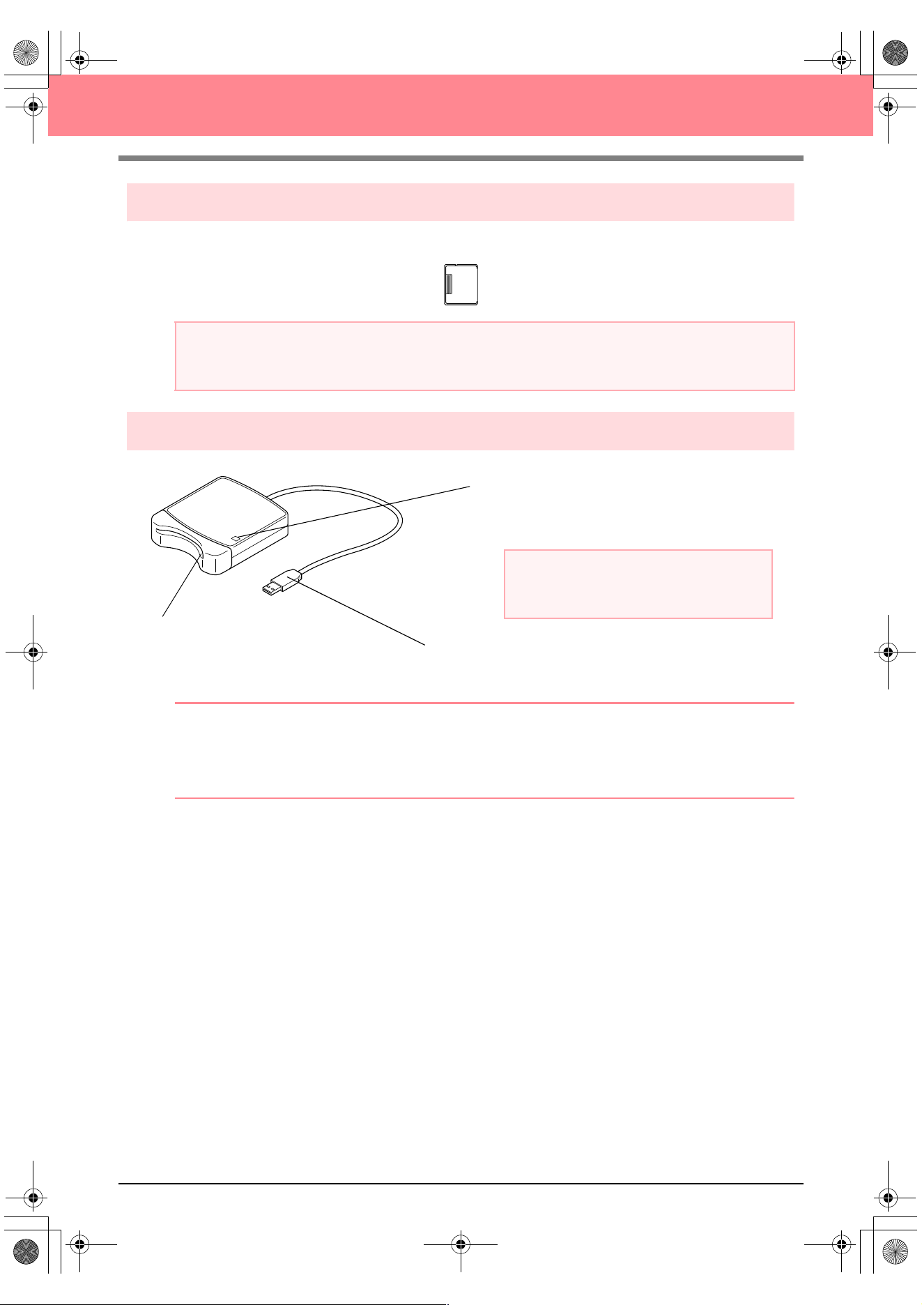
Principal parts
b Memo:
• Since power is supplied to the USB card writer module through the USB connection to the computer,
there is no power supply cable or power switch.
• Be sure to keep original cards away from high humidity, direct sunlight, static electricity and strong
shocks. Furthermore, do not bend the cards.
a Note:
The only original cards that can be used with this USB card writer module are those like the one enclosed
or optional original cards of the same type.
Original card
USB connector
Connect to the computer.
LED indicator
This indicator lights up when the unit is turned on,
and flashes when the USB card writer module is
communicating with the computer.
a Note:
Never remove an original card or unplug the
USB cable while this indicator is flashing.
Card slot
Insert an original card/embroidery
card here.
PeDesignV6Eng.book Page 6 Thursday, July 8, 2004 11:59 AM
7
Before Use
Installation
Installation procedure
The installation procedure is different depending on whether the full version or an upgrade of the software is
being installed. Be sure to perform the installation procedures listed below.
Installing version 6.0 (full version)
[STEP 1] Installing the software c page 8
[STEP 2] Installing the driver for the card writer module
c page 10
Upgrading from version 1.0 through 4.0
[STEP 1] Installing the software c page 8
[STEP 2] Installing the driver for the card writer module
c page 10
Upgrading from version 5.0 or 5.01
[STEP 1] Installing the software c page 8
[STEP 2] Installing the driver for the card writer module
c page 10
[STEP 3] Upgrading the USB card writer module
c page 12
Upgrading from version 5.02 or later
[STEP 1] Installing the software c page 8
b Memo:
When upgrading from version 5.02 or later, STEP 2 is not performed.
[STEP 3] Upgrading the USB card writer module c page 12
a Note:
• If the installation is interrupted or not performed as described, the software will not be installed correctly.
• Before turning on the computer, be sure to disconnect the USB card writer module. If the
computer is turned on while the card writer is connected, the installation may not be completed
correctly when upgrading from version 5.0 or 5.01.
• In order to upgrade the USB card writer module, you must be able to connect to the Internet. If you
cannot connect to the Internet, contact your nearest service representative.
PeDesignV6Eng.book Page 7 Thursday, July 8, 2004 11:59 AM
8
Before Use
System requirements
Before installing the software on your computer, make sure that the computer meets the following
requirements.
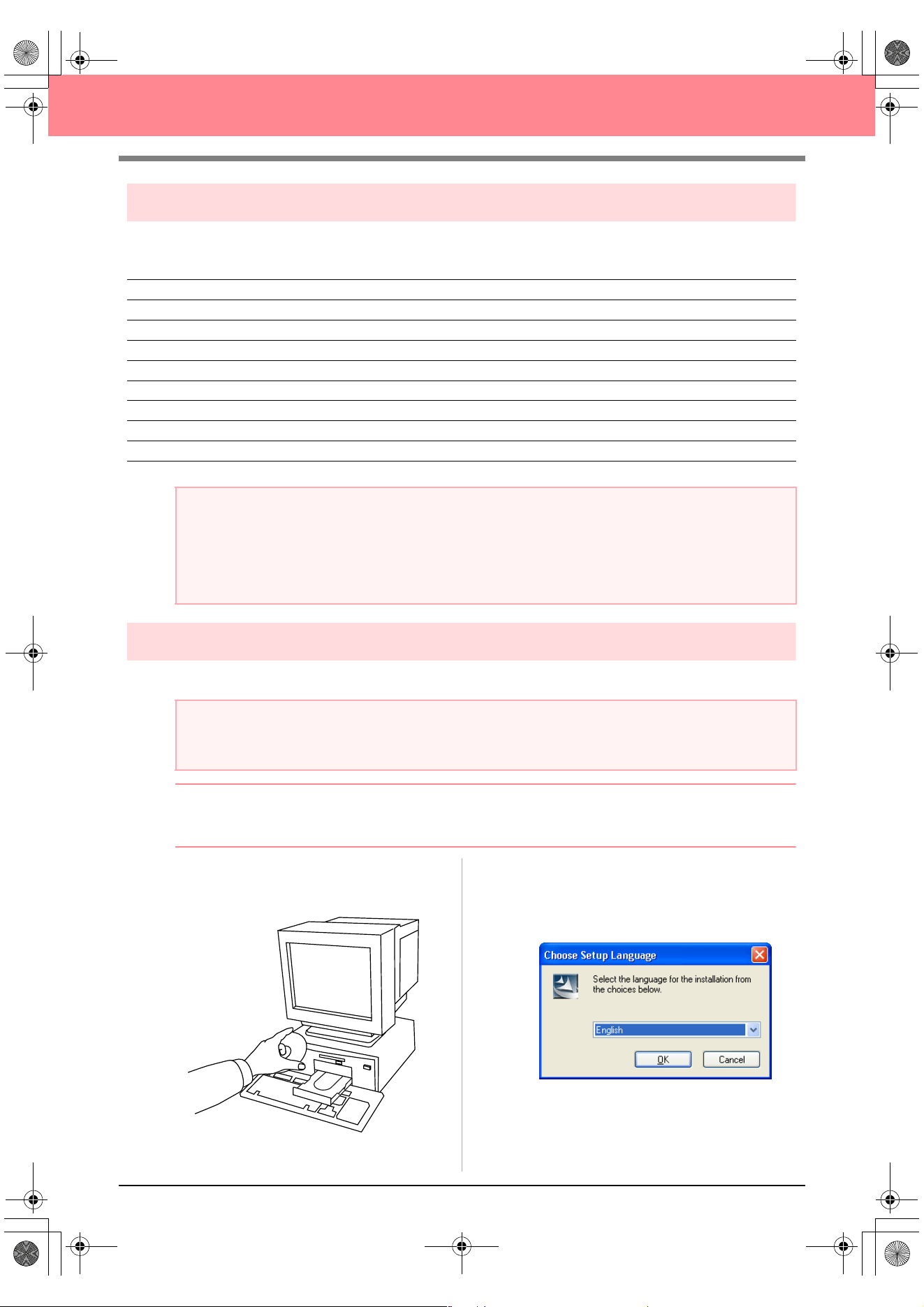
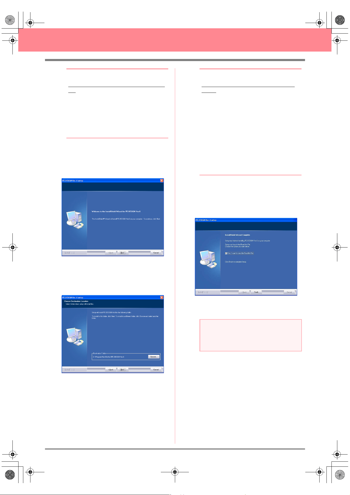
[STEP 1] Installing the software
This section describes how to install the application software.
b Memo:
The following installation procedure includes descriptions and dialog boxes for Windows XP. The
procedure and dialog boxes for other operating systems may be slightly different.
1. Insert the enclosed CD-ROM into the
computer’s CD-ROM drive.
→ After a short while, the Choose Setup
Language dialog box automatically ap-
pears.
Computer IBM-PC or compatible computer originally equipped with a USB port
Operating system Windows 98, ME, XP or 2000
Processor Pentium 500 MHz or higher
Memory Minimum 64 MB (256 MB or more is recommended.)
Hard disk free space Minimum 100 MB
Monitor SVGA (800 × 600), 16-bit color or higher
Port USB Ver. 1.1 or higher
Printer A graphic printer that is supported by your system (if you wish to print your images)
CD-ROM drive Required for installation
a Note:
• Power is supplied to the USB card writer module through the USB connection. Connect the USB card
writer module to a USB connector on the computer or to a self-powered USB hub that can supply
enough power to the card writer module. If the card writer module is not connected in this way, it may
not operate correctly.
• This product may not operate correctly with some computers and USB expansion cards.
a Note:
• If the installation is interrupted or not performed as described, the software will not be installed correctly.
• Before turning on the computer, be sure to DISCONNECT the USB card writer module.
PeDesignV6Eng.book Page 8 Thursday, July 8, 2004 11:59 AM
9
Before Use
b Memo:
If the installer does not automatically start
up:
1) Click the Start button.
2) Click Run.
→
The Run dialog box appears.
3) Type in the full path to the installer, and
then click OK to start up the installer.
For example: D:\setup.exe (where “D:”
is the name of the CD-ROM drive)
2. Select the desired language, and then click
OK.
→ The InstallShield Wizard starts up, and
the first dialog box appears.
3. Click Next to continue with the installation.
→ A dialog box appears, allowing you to se-
lect the folder where the software will be
installed.
b Memo:
To install the application into a different
folder:
1) Click Browse.
2) In the Choose Folder dialog box that
appeared, select the drive and folder. (If
necessary, type in the name of a new
folder.)
3) Click OK.
→
The Choose Destination Location
dialog box of the InstallShield Wizard
shows the selected folder.
4) Click Next to install the application into
the selected folder.
• To return to the previous step, click
Back
.
• To quit the installation, click
Cancel
.
4. Click Next to install the application into the
default folder.
→ When the installation is completed, the di-
alog box shown below appears.
5. Click Finish to complete the installation of the
software.
a Note:
Even though the installation is completed, do
not remove the CD-ROM from the
computer’s CD-ROM drive.
PeDesignV6Eng.book Page 9 Thursday, July 8, 2004 11:59 AM
10
Before Use
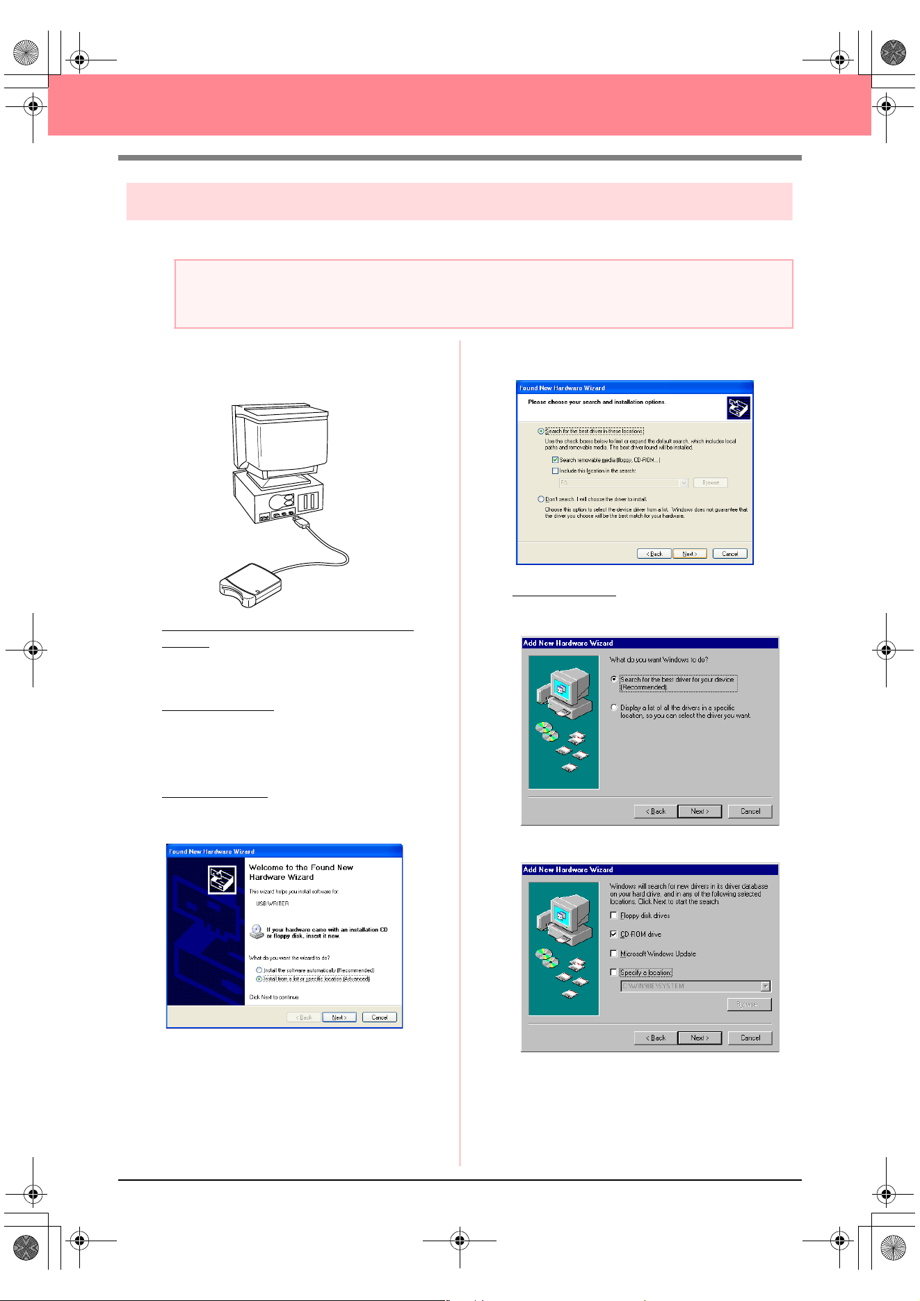
[STEP 2] Installing the driver for the card writer module
This section describes how to install the driver for the card writer module.
1. Plug the USB connector into the USB port on
the computer.
Make sure that the connector is fully inserted.
For Windows XP users connected to the
Internet:
→ The installation of the driver is completed
automatically.
For all other users
:
→ After a short while, the Found New Hard-
ware Wizard (or Add New Hardware
Wizard) dialog box appears.
2. For Windows XP: Select Install from a list or
specific location [Advanced], and then click
Next.
Select Search removable media (floppy,
CD-ROM...), and then click Next.
For Windows 98:
Select Search for the best
driver for your device. (Recommended),
and then click Next.
Select CD-ROM drive, and then click Next.
a Note:
If you upgrading from version 5.02 or later, skip this section and continue with the procedure described in
“[STEP 3] Upgrading the USB card writer module” on page 12.
PeDesignV6Eng.book Page 10 Thursday, July 8, 2004 11:59 AM
11
Before Use
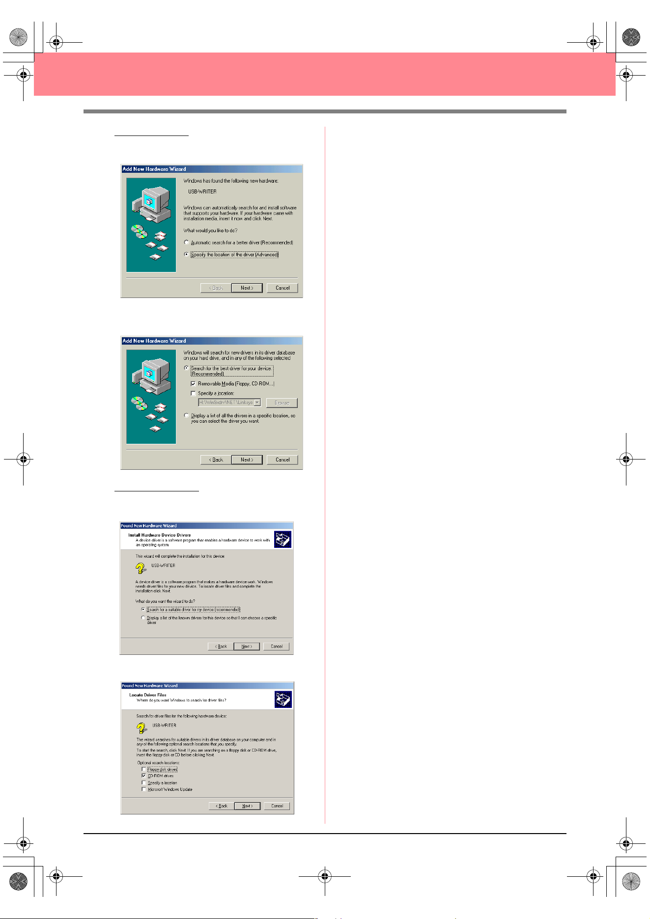
For Windows Me: Select Specify the location
of the driver [Advanced], and then click
Next.
Select Removable Media (Floppy, CD-
ROM...), and then click Next.
For Windows 2000:
Select Search for a
suitable driver for my device
[recommended], and then click Next.
Select CD-ROM drives, and then click Next.
3. Follow the instructions of the Found New
Hardware Wizard (or Add New Hardware
Wizard) to complete the installation of the
driver.
4. Remove the CD-ROM from the computer’s
CD-ROM drive.
PeDesignV6Eng.book Page 11 Thursday, July 8, 2004 11:59 AM
12
Before Use
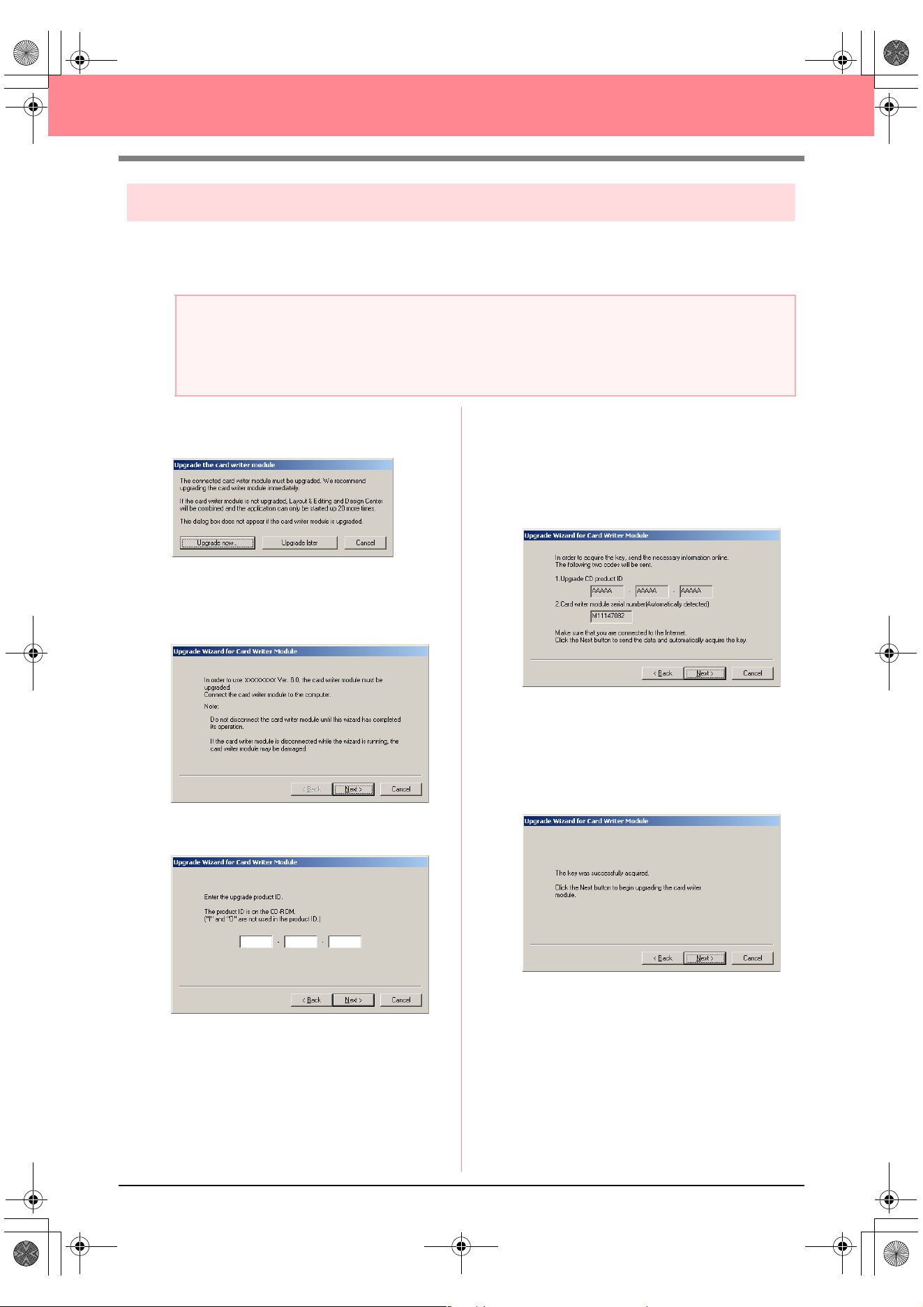
[STEP 3] Upgrading the USB card writer module
This section describes how to upgrade the USB card writer module for version 6.0. Users upgrading from
version 5.0 or later must upgrade the card writer. After installing version 5.0 or later, immediately follow the
procedure below to upgrade the card writer for version 6.0.
1. Start up Layout & Editing.
→ The dialog box shown below appears.
2. To begin the upgrade, click Upgrade now.
→ The Upgrade wizard starts up, and the
first dialog box shown below appears.
3. Click Next.
4. Type in the 15-digit product ID on the label
attached to the CD-ROM case, and then click
Next.
→ The entered product ID and the serial
number automatically retrieved from the
USB card writer module is displayed.
5. Click Next to access our server through the
Internet and retrieve the upgrade key.
→ If the upgrade key has been successfully
retrieved, the dialog box shown below ap-
pears.
6. Click Next to begin upgrading the USB card
writer module.
a Note:
• If the USB card writer module is not upgraded, Design Center and Layout & Editing of version 6.0 can
no longer be used after the specified number of trial uses has been reached.
• In order to upgrade the USB card writer module, you must be able to connect to the Internet. If you
cannot connect to the Internet, contact your nearest service representative.
PeDesignV6Eng.book Page 12 Thursday, July 8, 2004 11:59 AM
13
Before Use
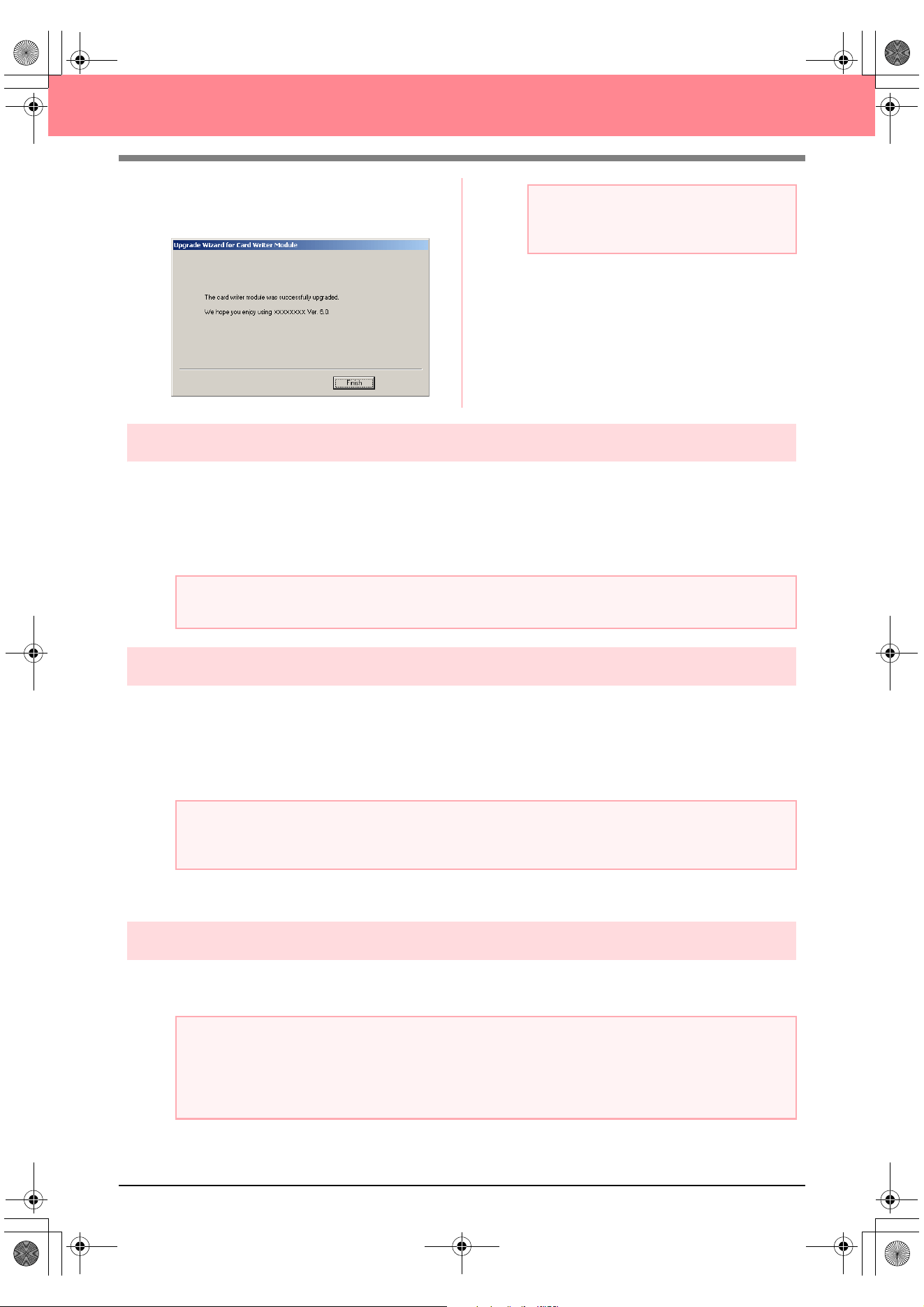
→ If the upgrade has been completed suc-
cessfully, the dialog box shown below ap-
pears.
Online registration
If you wish to be contacted about upgrades and provided with important information such as future product
developments and improvements, you can register your product online by following a simple registration
procedure.
Click Online Registration on the Help menu of Layout & Editing to start up the installed Web browser and
open the online registration page on our Web site.
Uninstallation
1. Turn on the computer and start up Windows.
2. Click the Start button in the task bar, and then click Control Panel.
3. In the Control Panel window, double-click Add or Remove Programs.
4. In the dialog box that appeared, select this software, and then click Change/Remove.
Technical support
Contact Technical Support if you have a problem. Please check the company web site (www.brother.com) to
find the Technical Support in your area.
a Note:
If a warning appears at any time, follow the
instructions that are displayed.
a Note:
Online registration may not be available in some areas.
a Note:
With an operating system other than Windows XP, point to
Settings
in the
Start
menu, and then click
Control Panel
. In the Control Panel window, double-click
Add/Remove Programs
.
a Note:
Have the following information ready before contacting Technical Support.
• The make and model of the computer that you are using as well as the Windows version (Refer to
page 8 and check the system requirements for this product again.)
• Information on any error messages that appear
BeforeUsing.fm Page 13 Thursday, July 8, 2004 2:57 PM
14
Before Use
Tips and Techniques for Creating
Embroidery Patterns
■ Sewing wide areas
When satin stitching is sewn in a wide area, the stitched area may shrink after sewing, depending on the
material and the type of thread used. If this happens, switch to this alternate method: Select the fill stitch and
use stabilizer material on the reverse side of the fabric.
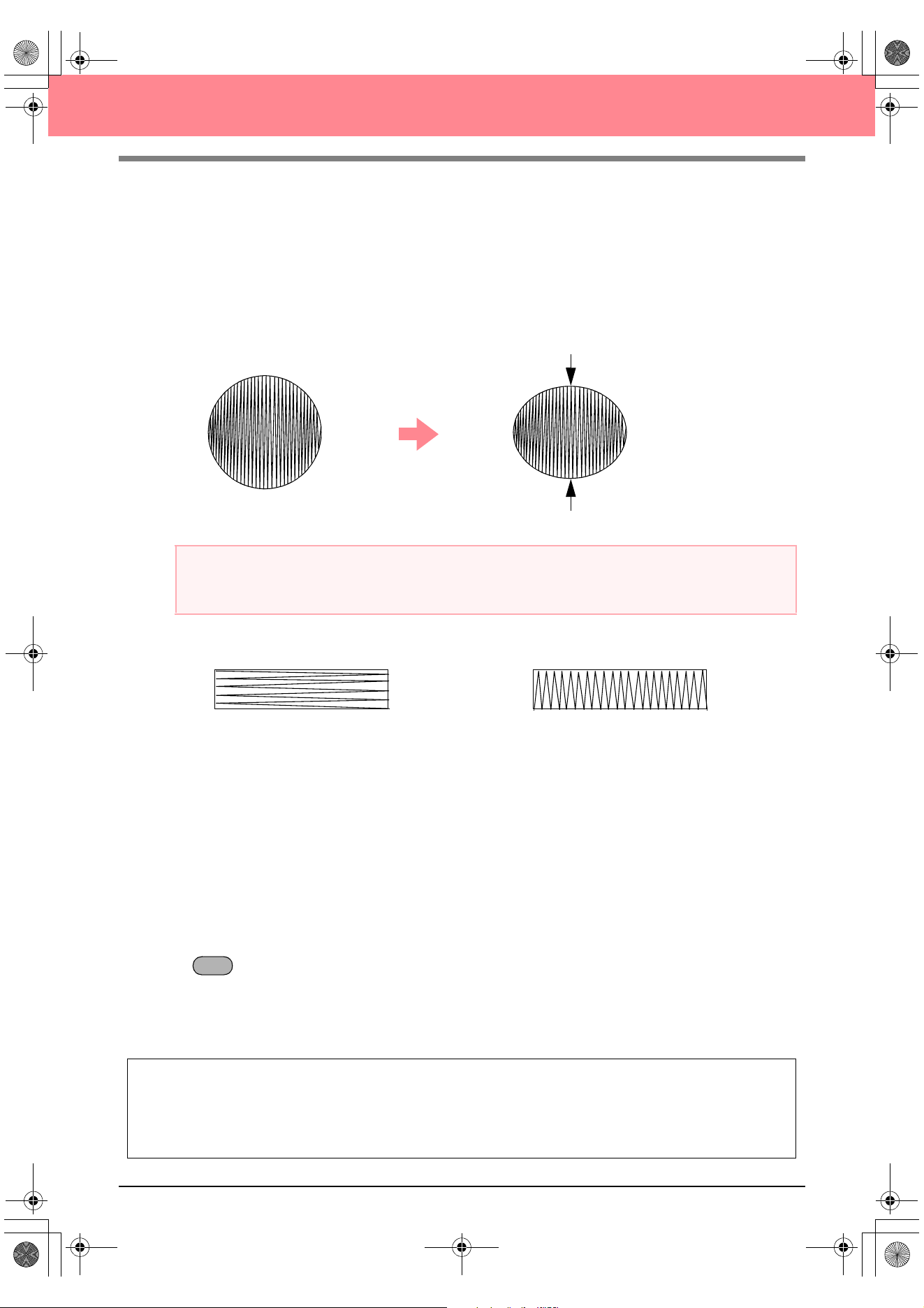
■ Sewing direction
In order to limit shrinking, select a stitch direction perpendicular to the larger edge of the area.
■ Sewing order
After creating an embroidery pattern made of several different parts (in Design Center or Layout & Editing), be
sure to check the sewing order and correct it if necessary.
With Design Center, the default sewing order is the order in which the sewing attributes are applied.
With Layout & Editing, the default sewing order is the order in which the elements are drawn.
■ Enlarging/reducing embroidery patterns
There are several ways of enlarging or reducing an imported embroidery pattern in Layout & Editing. You may
choose to scale your pattern with the pointer, or apply the Stitch to Block function, then scale the pattern.
When you normally scale an imported pattern, the number of stitches that will be sewn remains the same,
resulting in a change of embroidery quality if the size of the pattern is greatly changed. However, by holding
down the key while scaling the imported embroidery pattern, the original embroidery quality can be
maintained, since the stitch density and fill pattern automatically adapts to the new size.
Another method of maintaining the original embroidery quality of the pattern is to select the Sew – Stitch to
Block command, then scale the pattern. When a pattern is scaled only moderately, it may not be necessary
to apply the Stitch to Block function.
Pattern
After sewing
a Note:
When using the satin stitch in a wide area, the needle may move out of position by about 10 mm with some
machines. In order to avoid this, use the above-mentioned alternate method.
Shrinking more likely to occur Shrinking less likely to occur
This system allows you to create a wide variety of embroidery patterns and supports wider ranges for the
setting of the sewing attributes (thread density, sewing pitch, etc.). However, the final result also depends
on your particular sewing machine model. We recommend that you make a trial sewing sample with your
sewing data before sewing on the final material. Remember to sew your trial sample on the same type of
fabric as your final material and to use the same needle and the same machine embroidery thread.
Ctrl
PeDesignV6Eng.book Page 14 Thursday, July 8, 2004 11:59 AM
15
Before Use
Sew Types
The sewing attributes for each sew type are first set to their default settings; however, by changing the settings
of the sewing attributes, you can create custom stitching. (For details, refer to pages 91 through 95 and
pages 172 through 178.)
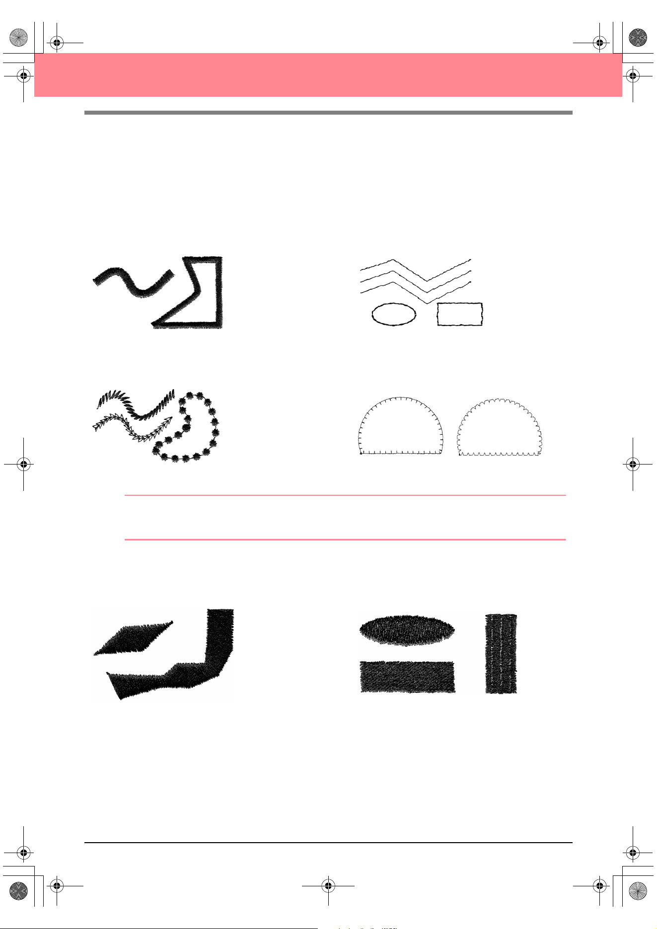
■ Line sew types
Zigzag stitch Running stitch
Motif stitch E/V stitch
b Memo:
The stitching for the programmable fill stitch and the motif stitch depends on the selected stitch pattern.
For details, refer to “Programmable fill stitch” on page 93 and 175 and “Motif stitch” on page 95 and 177.
■ Region sew types
Satin stitch Fill stitch
PeDesignV6Eng.book Page 15 Thursday, July 8, 2004 11:59 AM
16
Before Use
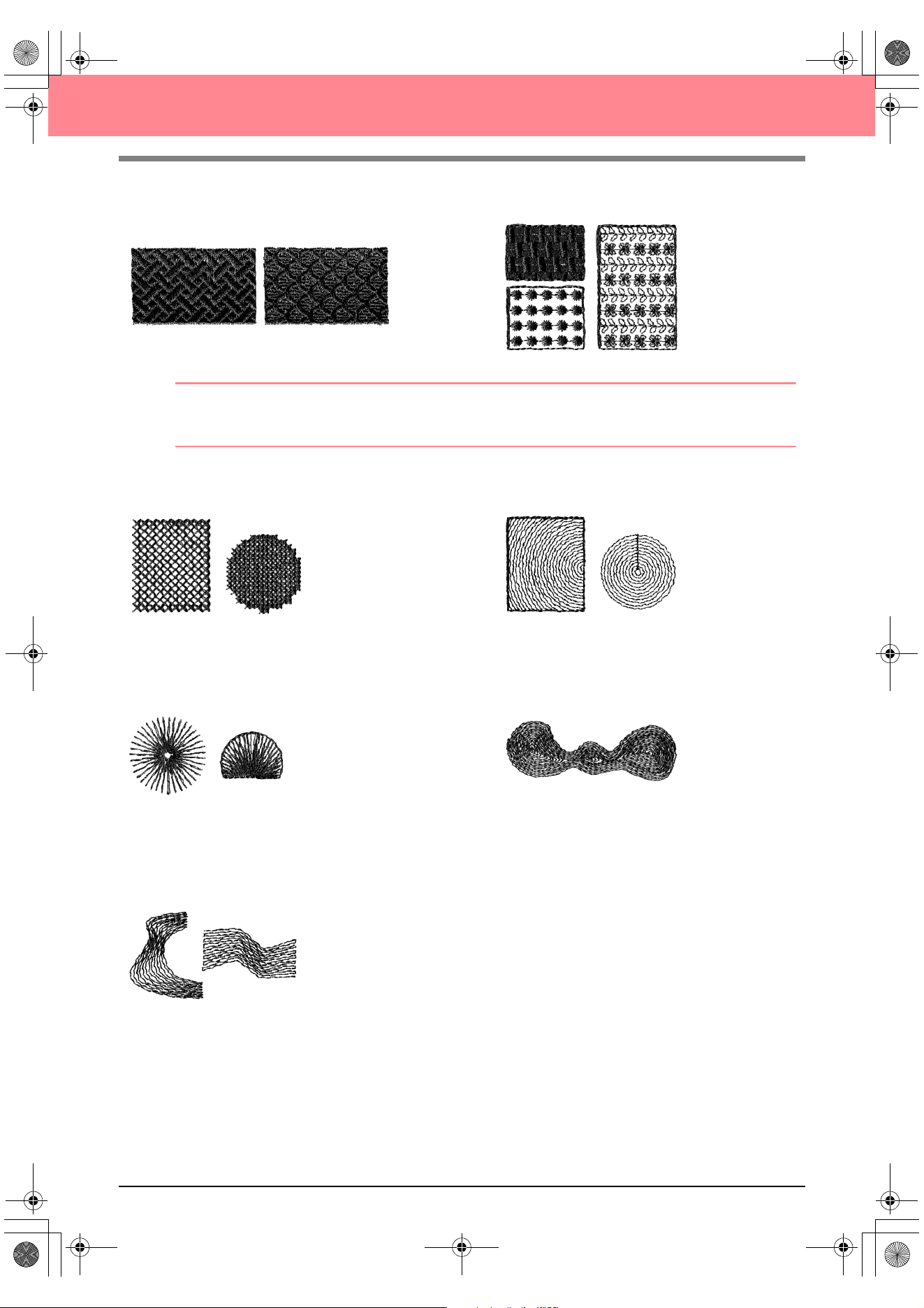
Programmable fill stitch Motif stitch
b Memo:
The stitching for the programmable fill stitch and the motif stitch depends on the selected stitch pattern.
For details, refer to “Programmable fill stitch” on page 93 and 175 and “Motif stitch” on page 95 and 177.
Cross stitch Concentric circle stitch
Radial stitch Spiral stitch
Piping stitch
PeDesignV6Eng.book Page 16 Thursday, July 8, 2004 11:59 AM

17
Chapter 1
Basic Operation
PeDesignV6Eng.book Page 17 Thursday, July 8, 2004 11:59 AM
18
Getting Started
About This Chapter
This chapter is organized as a tutorial to provide you with a hands-on introduction to the basic features of the
applications.
1. Automatically Creating Embroidery Patterns
1-1. Using the Auto Punch Function c page 19
In this section, we will use the Auto Punch function in Layout & Editing to automatically convert an
image to an embroidery pattern.
1-2. Using a Photo Stitch Function c page 25
In this section, we will use one of the Photo Stitch functions to create a more realistic embroidery
pattern from a image.
2. Creating and Editing Embroidery Patterns
2-1. Using Design Center c page 30
In this section, we will use Design Center to manually create an embroidery pattern from an image
using a four-stage procedure.
2-2. Using Layout & Editing c page 39
In this section, the embroidery pattern created in Design Center will be imported into Layout & Editing,
where a few objects will be added and the layout will be rearranged.
2-3. Using Programmable Stitch Creator c page 54
In this section, we will learn how to use Programmable Stitch Creator to edit a stitch in order to create
a custom stitch pattern.
3. Creating Large-Size Embroidery Patterns
3-1. Designing a large-size embroidery pattern c page 59
In this section, we will design an embroidery pattern that is too large to be sewn in a normal
embroidery hoop and therefore must be divided into sections.
3-2. Embroidering large-size embroidery patterns c page 63
In this section, we will sew the separate sections of the embroidery pattern to create large-size
embroidery.
PeDesignV6Eng.book Page 18 Thursday, July 8, 2004 11:59 AM
Basic Operation
19
Automatically Creating Embroidery Patterns
Using the Auto Punch Function
In this section, we are going to automatically create an embroidery pattern from an image.
Follow the instructions in this section step by step. If you have to interrupt this exercise for any reason, it is
recommended to save the file (refer to Step 6, “Saving the embroidery pattern”, on page 23). You will be able
to retrieve it later and resume your work.
The complete procedure will take you through the different steps of a normal working session using the Auto
Punch function.
Step 1
Starting up Layout & Editing
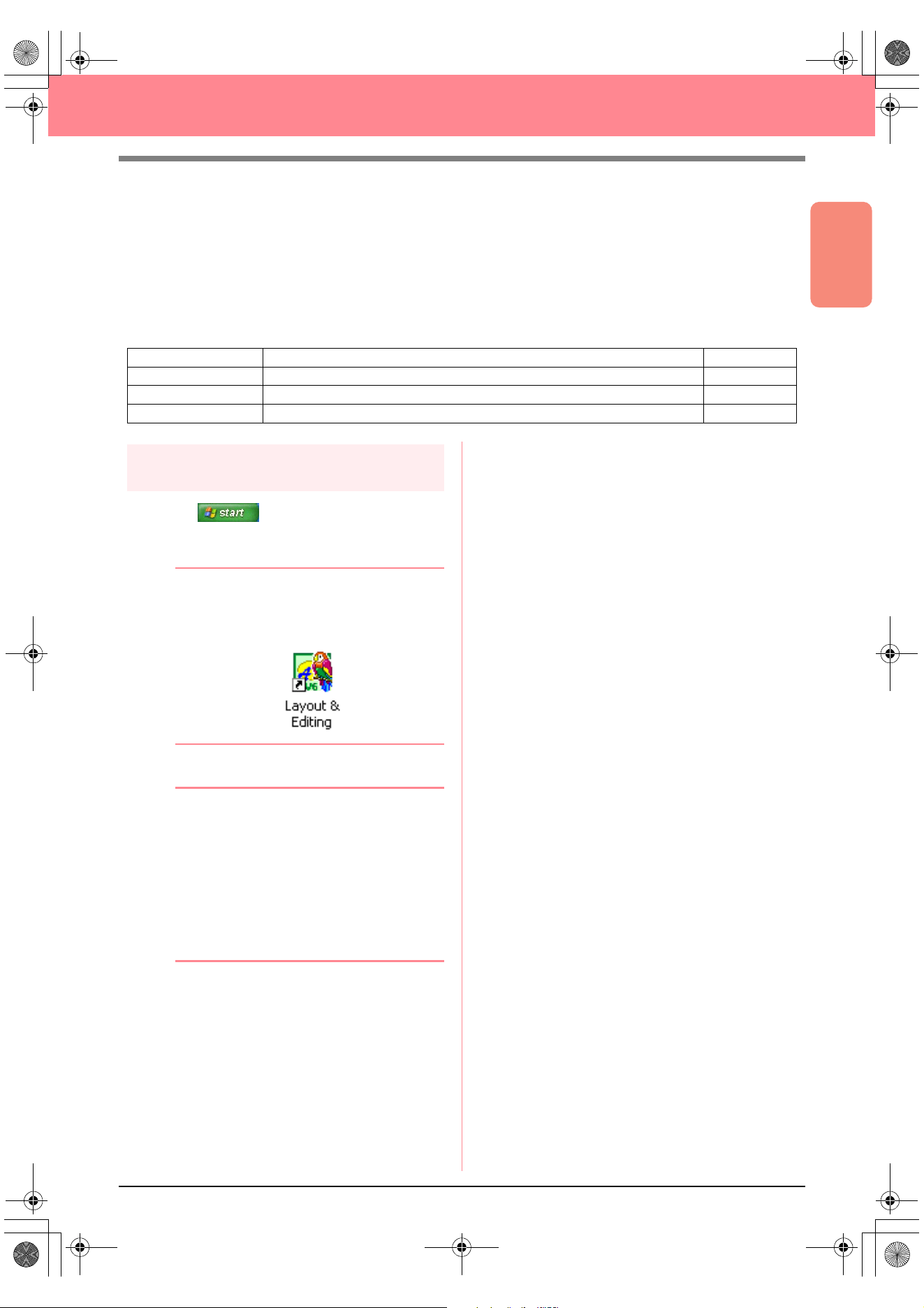
1. Click , select All Programs, then
PE-DESIGN Ver.6. Select Layout & Editing
to open the Layout & Editing window.
b Memo:
If a shortcut for Layout & Editing was
created, for example, on the desktop,
double-click it to start up the application.
→ The Layout & Editing window appears.
b Memo:
• To fill the entire screen with the Layout &
Editing window, click the maximize button
on the right end of the title bar.
• At this time, you can change the Design
Page properties by using the menu
command
Option
–
Design Page
Property
. (For more details, refer to
page 77.) For this example, we will not
change the Design Page settings.
Step 1 Starting up Layout & Editing page 19
Step 2 Opening an image file page 20
Step 3 Adjusting the size and position of the image page 21
Step 4 Automatically converting the image to an embroidery pattern page 21
Step 5 Displaying a preview of the embroidery pattern page 22
Step 6 Saving the embroidery pattern page 23
Step 7 Transferring the pattern to an original card page 24
Step 8 Quitting Layout & Editing page 24
PeDesignV6Eng.book Page 19 Thursday, July 8, 2004 11:59 AM
20
Automatically Creating Embroidery Patterns
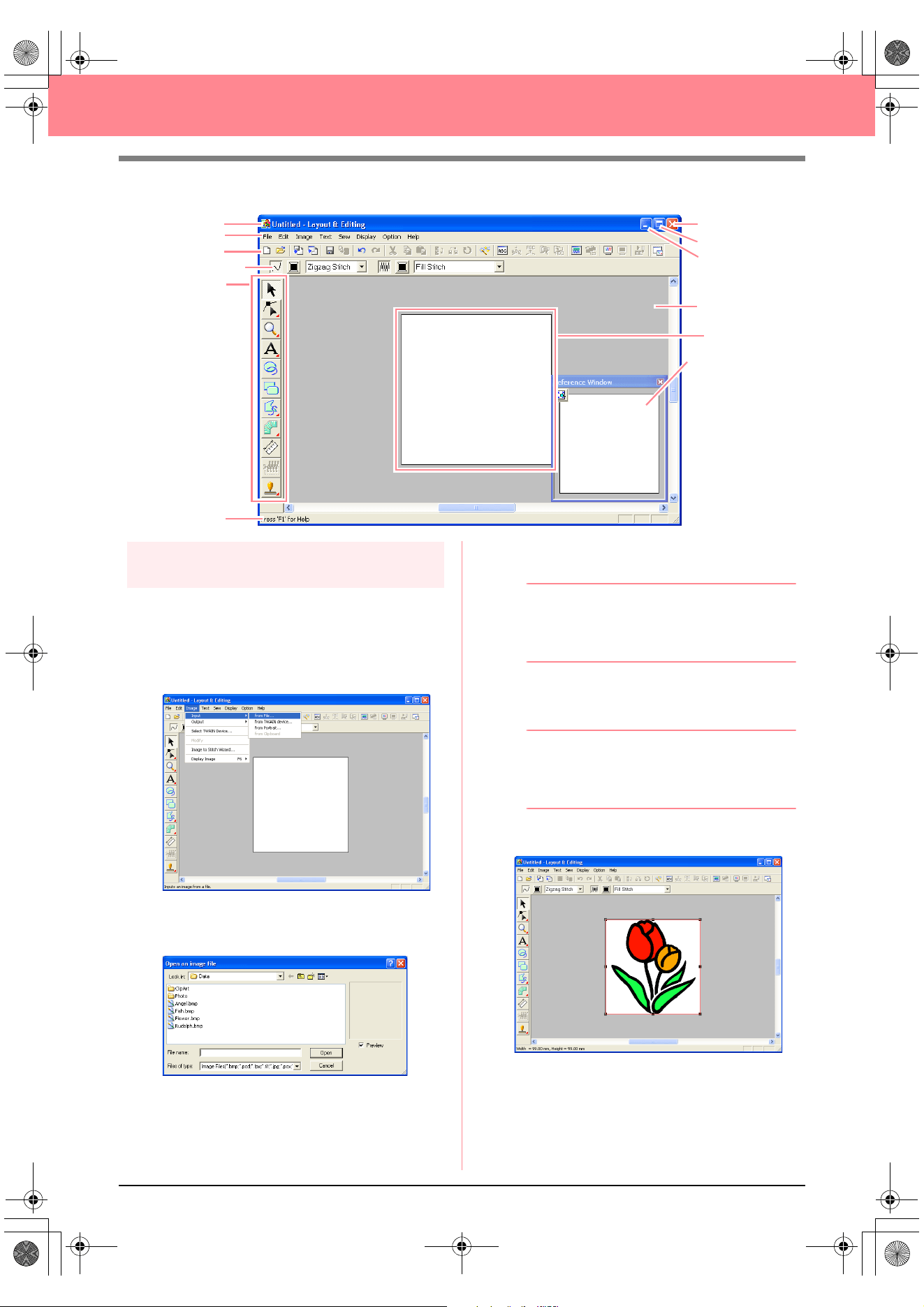
Step 2
Opening an image file
First, we need to open the image that will be
converted into the embroidery pattern.
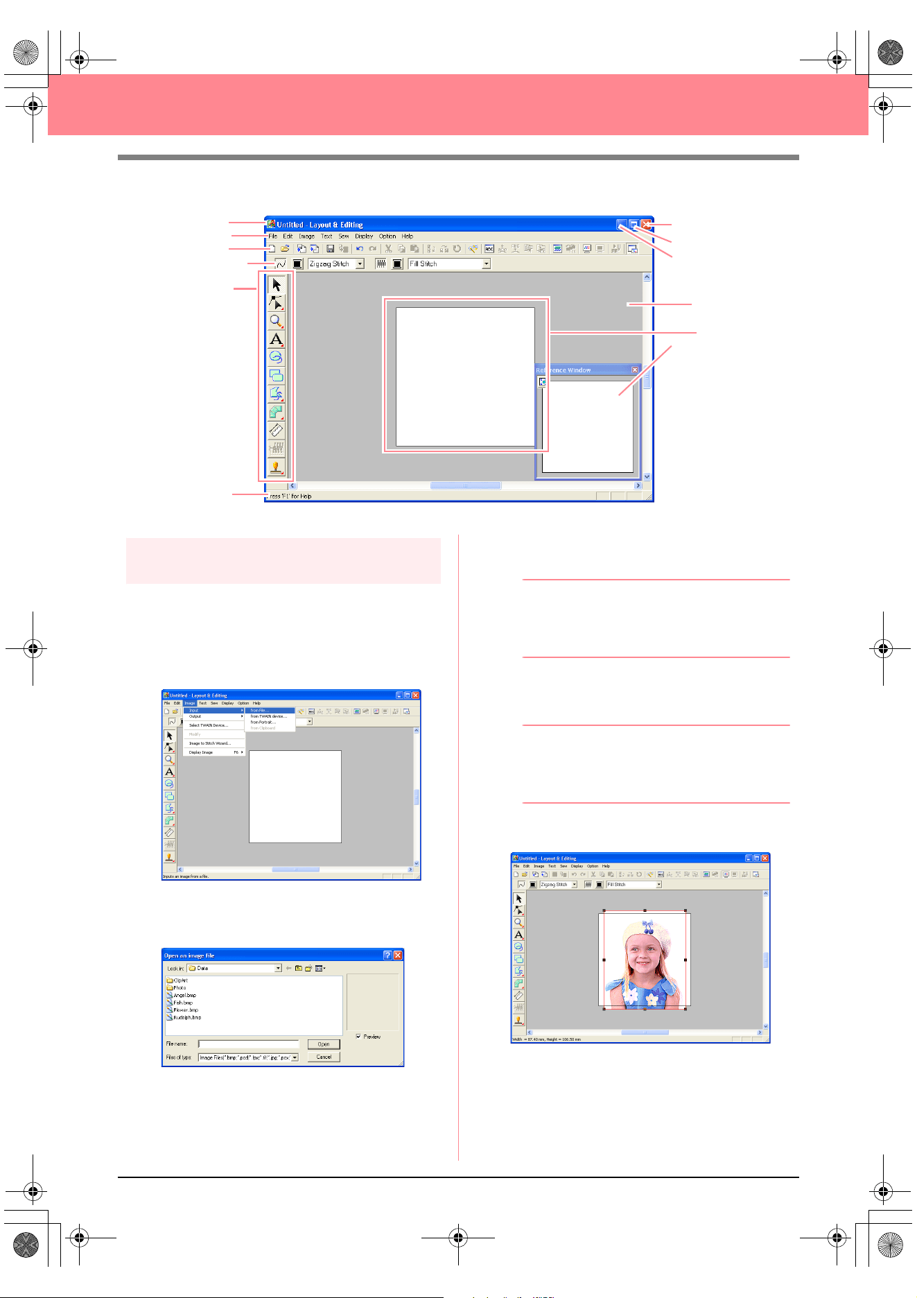
1. Click Image on the menu bar, point to Input,
and then click from File on the submenu.
→ An Open an image file dialog box similar
to the one shown below appears.
2. Double-click the ClipArt folder to open it.
3. Select the sample file tulip.bmp in the ClipArt
folder.
b Memo:
If the
Preview
check box is selected, the
contents of the selected file will appear in the
Preview
box.
4. Click Open to open the image file and to close
the dialog box.
b Memo:
Double-clicking the file name also adds the
image to the work area and closes the dialog
box.
→ The image appears in the work area.
Menu bar
Toolbar
Sewing Attributes bar
Too l Box
Work area
Design Page
Status bar
Maximize button
Close button
Title bar
Minimize button
Reference Window
PeDesignV6Eng.book Page 20 Thursday, July 8, 2004 11:59 AM
Basic Operation
21
Automatically Creating Embroidery Patterns
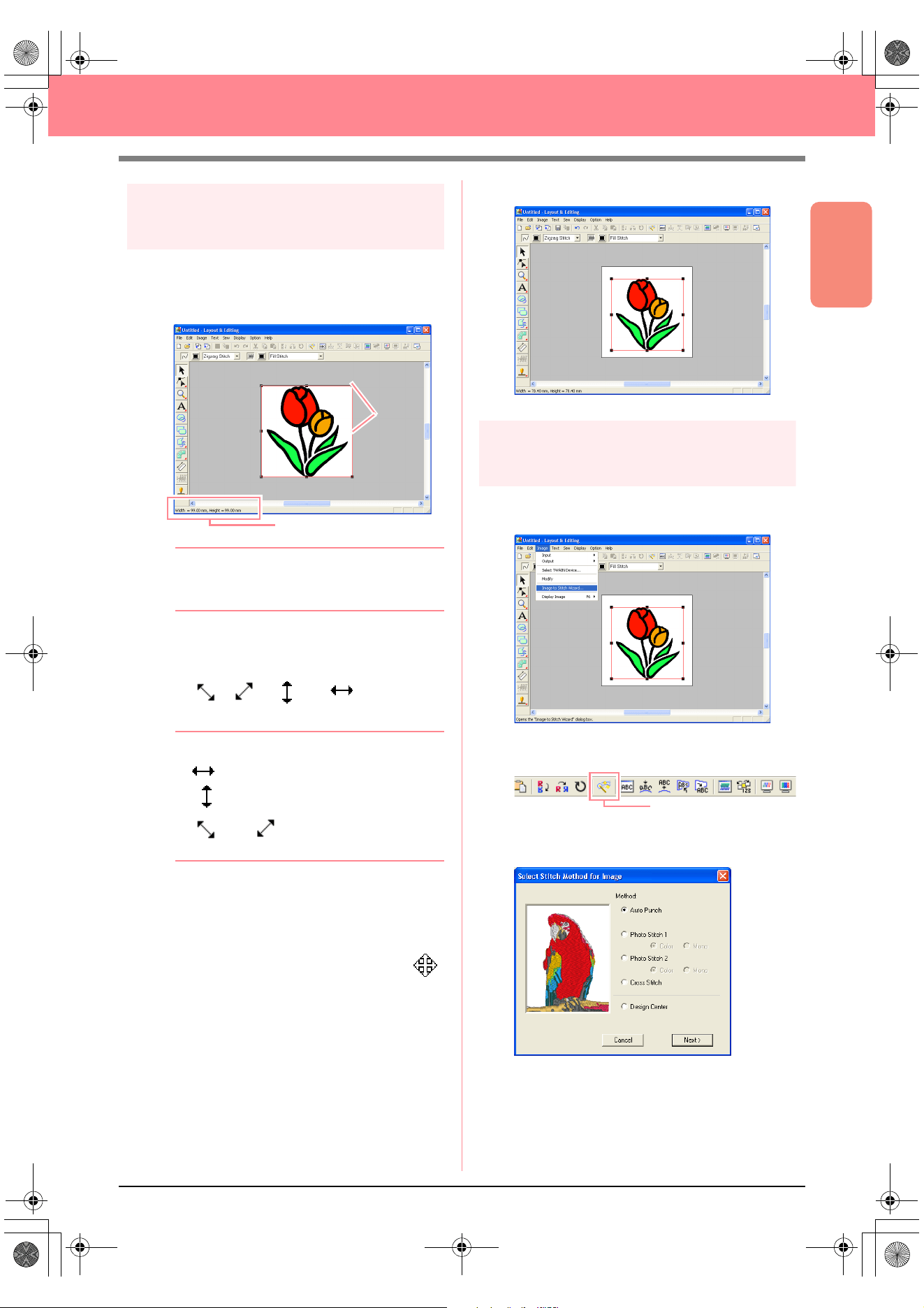
Step 3
Adjusting the size and position
of the image
1. Click Image on the menu bar, and then click
Modify.
→ Handles appear around the image.
b Memo:
The status bar shows the dimensions (width
and height) of the image.
2. Move the pointer over a handle.
→ The shape of the pointer changes to
, , , or , depending
on the handle that the pointer is over.
b Memo:
• is for scaling the width.
• is for scaling the height.
• and are for scaling both
dimensions at the same time.
3. Drag the handle to adjust the selected image
to the desired size.
4. Move the pointer over the selected image.
→ The shape of the pointer changes to .
5. Drag the image to the desired location.
Step 4
Automatically converting the
image to an embroidery pattern
1. Click Image on the menu bar, and then click
Image to Stitch Wizard.
An alternate method is to click the Toolbar
button indicated below.
→ The Select Stitch Method for Image dia-
log box appears.
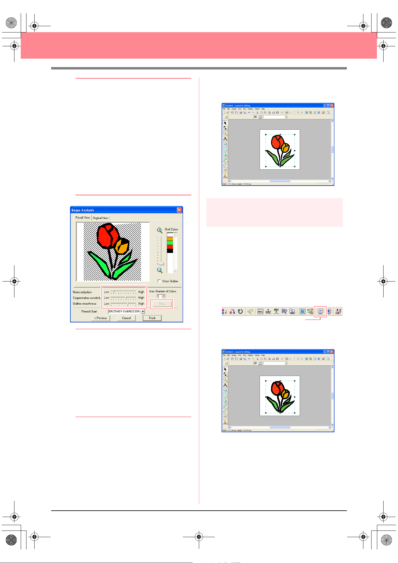
2. Select Auto Punch, and then click Next.
→ The image is analyzed, and the resulting
image is displayed in the Image Analysis
dialog box.
Status bar
Handles
Image to Stitch Wizard
PeDesignV6Eng.book Page 21 Thursday, July 8, 2004 11:59 AM
22
Automatically Creating Embroidery Patterns
b Memo:
The following stitch methods are also
available.
•
Photo Stitch 1
(
Color
and
Mono
)
Refer to page 116 for more details on the
Color
setting and to page 120 for more
details on the
Mono
setting.
•
Photo Stitch 2
(
Color
and
Mono
)
Refer to page 122 for more details on the
Color
setting and to page 124 for more
details on the
Mono
setting.
•
Cross Stitch
For more details, refer to page 125.
•
Design Center
For more details, refer to “Using Design
Center” on page 30.
b Memo:
• Various settings are available for
converting the image to an embroidery
pattern. (For more details on the various
settings, refer to page 115.) After changing
the settings, click
Retry
to display the
image with the new settings applied.
• Areas of the image that will not be
converted to the embroidery pattern
appear with a crosshatch pattern. Click
each area to select whether or not it should
be converted.
3. Click Finish.
→ The image is converted to an embroidery
pattern, which is displayed in the Design
Page.
Step 5
Displaying a preview of the
embroidery pattern
You can display a preview of the embroidery
pattern in order to see how the stitching is
connected, or you can display a realistic preview
of the embroidery pattern in order to see how the
pattern will appear once it is sewn.
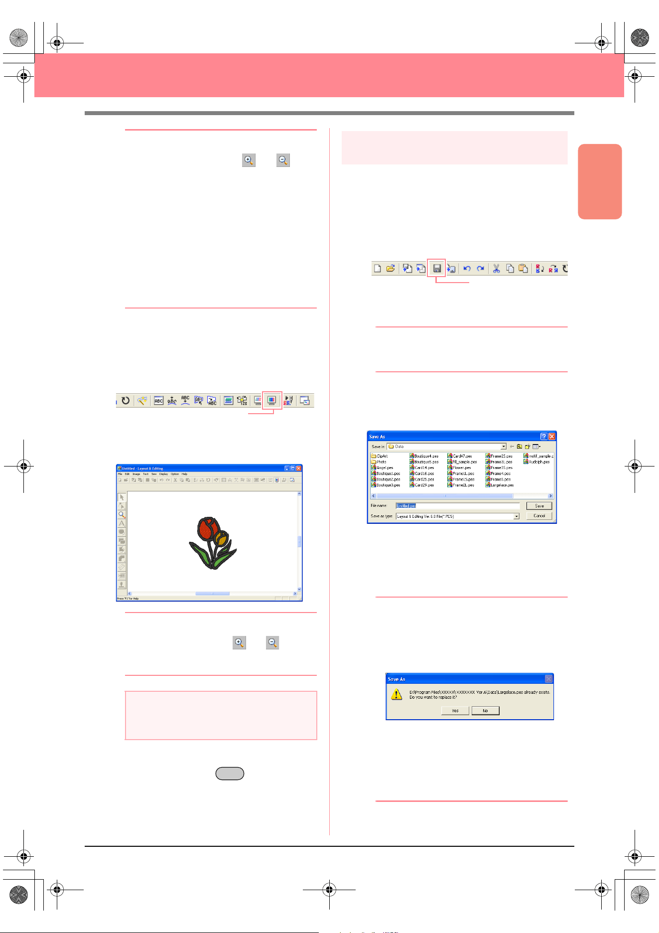
1. Click Display on the menu bar, and then click
Preview.
An alternate method is to click the Toolbar
button indicated below.
→ A preview of the embroidery pattern ap-
pears.
Preview
PeDesignV6Eng.book Page 22 Thursday, July 8, 2004 11:59 AM
Basic Operation
23
Automatically Creating Embroidery Patterns
b Memo:
• To zoom in (or out), click (or ) on
the Tool Box, and then click the desired
area of the embroidery pattern.
• To display, hide, or display a faded copy of
the original image, which remains in the
work area, click
Image
on the menu bar,
point to
Display Image
, and then click the
desired display setting.
• To display the original image, click
On
.
• To display a faded copy of the image,
click
Faded
.
• To hide the original image, click
Off
.
2. To display a realistic preview of the entire
embroidery pattern, click Display on the menu
bar, and then click Realistic Preview.
An alternate method is to click the Toolbar
button indicated below.
→ A realistic preview of the embroidery pat-
tern appears.
b Memo:
To zoom in (or out), click (or ) on the
Tool Box, and then click the desired area of
the embroidery pattern.
3. To leave the realistic preview display, repeat
step
2., or press the key.
Step 6
Saving the embroidery pattern
Once the embroidery pattern is finished, you may
want to save it in order to retrieve it later.
1. Click File on the menu bar, and then click
Save.
An alternate method is to click the Toolbar
button indicated below.
→ If the pattern has already been saved at
least once, the file is saved immediately.
b Memo:
To save the file with a different name, use the
menu command
File
–
Save As
instead.
→ If no file name has been specified or if the
file cannot be found, the Save As dialog
box appears.
2. Select the drive and the folder, and then type
in the file name.
3. Click Save to save the pattern.
b Memo:
• To quit the operation, click
Cancel
.
• If a file already exists with the name
specified in the
Save As
dialog box, the
following message appears.
• To overwrite the file, click
Yes
. The
new file name appears in the title bar
of the Layout & Editing window.
• If you do not want to overwrite the
existing file, click
No
. You can then
enter a different file name.
a Note:
The embroidery pattern cannot be edited
while the realistic preview is displayed.
Realistic Preview
Esc
Save
PeDesignV6Eng.book Page 23 Thursday, July 8, 2004 11:59 AM
24
Automatically Creating Embroidery Patterns
Step 7
Transferring the pattern to an
original card
Before you can actually sew the embroidery
pattern, you must transfer the pattern to a sewing
machine. Transfer the embroidery pattern to the
sewing machine using media of the type used by
your machine, for example, original cards, floppy
disks, CompactFlash cards, or USB media. For
this example, we will transfer the pattern to an
original card.
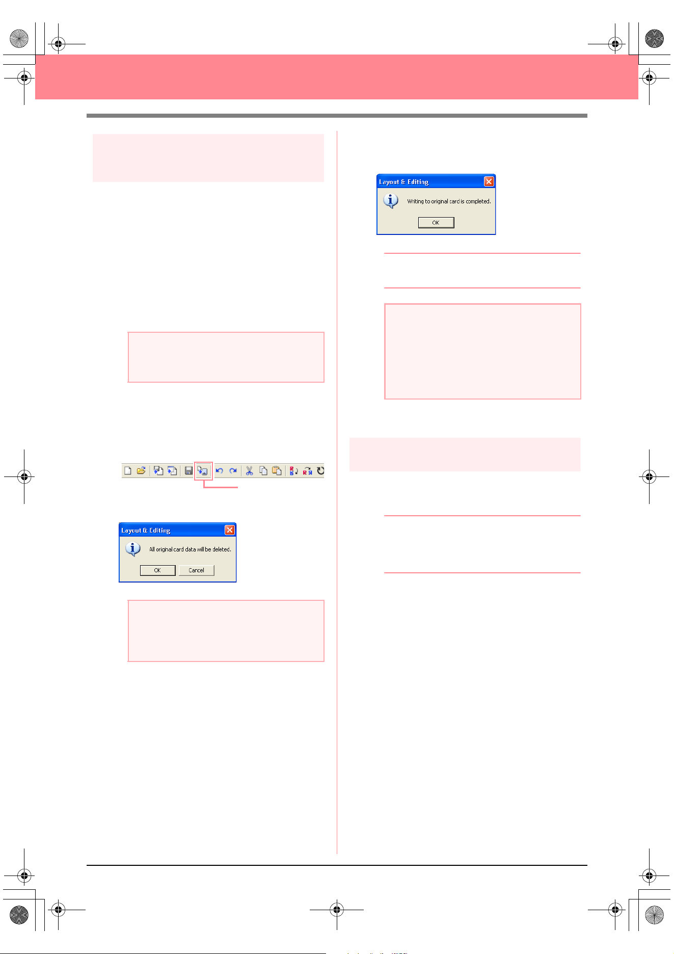
1. Insert an original card into the USB card writer
module.
2. Click File on the menu bar, point to Write to
Card, and then click Current Design on the
submenu.
An alternate method is to click the Toolbar
button indicated below.
→ The following message appears.
3. Click OK.
→ The following message appears.
b Memo:
To quit the operation, click
Cancel
.
4. Click OK to close the message.
Step 8
Quitting Layout & Editing
1. Click File on the menu bar, and then click Exit.
→ The Layout & Editing window closes.
b Memo:
Layout & Editing can also be closed by
clicking the close button on the right end of
the title bar.
a Note:
The original card is inserted correctly when
you hear it snap into place.
a Note:
If the original card is not brand new, make
sure that the patterns already stored on the
card are no longer needed.
Write to Card
a Note:
If the card writer module is not correctly
connected or powered, or if the original card
is not inserted or is defective, an error
message will appear. For more details, refer
to “Writing an embroidery pattern to an
original card” on page 195.
PeDesignV6Eng.book Page 24 Thursday, July 8, 2004 11:59 AM
Basic Operation
25
Automatically Creating Embroidery Patterns
Using a Photo Stitch Function
In this section, we are going to automatically create a more realistic embroidery pattern from a photo.
Follow the instructions in this section step by step. If you have to interrupt this exercise for any reason, it is
recommended to save the file (refer to Step 6, “Saving the embroidery pattern”, on page 23). You will be able
to retrieve it later and resume your work.
The complete procedure will take you through the different steps of a normal working session using one of the
Photo Stitch functions.
Step 1
Starting up Layout & Editing
1. Click , select All Programs, then
PE-DESIGN Ver. 6. Select Layout & Editing
to open the Layout & Editing window.
b Memo:
If a shortcut for Layout & Editing was
created, for example, on the desktop,
double-click it to start up the application.
→ The Layout & Editing window appears.
b Memo:
• To fill the entire screen with the Layout &
Editing window, click the maximize button
on the right end of the title bar.
• At this time, you can change the Design
Page properties by using the menu
command
Option
–
Design Page
Property
. (For more details, refer to
page 77.) For this example, we will not
change the Design Page settings.
Step 1 Starting up Layout & Editing page 25
Step 2 Opening an image file page 26
Step 3 Adjusting the size and position of the image page 27
Step 4 Automatically converting the image to an embroidery pattern page 27
PeDesignV6Eng.book Page 25 Thursday, July 8, 2004 11:59 AM
26
Automatically Creating Embroidery Patterns
Step 2
Opening an image file
First, we need to open the image that will be
converted into an embroidery pattern.
1. Click Image on the menu bar, point to Input,
and then click from File on the submenu.
→ The Open an image file dialog box ap-
pears.
2. Double-click the Photo folder to open it.
3. Select the sample file girl.bmp in the Photo
folder.
b Memo:
If the
Preview
check box is selected, the
contents of the selected file will appear in the
Preview
box.
4. Click Open to open the image file and to close
the dialog box.
b Memo:
Double-clicking the file name also adds the
image to the work area and closes the dialog
box.
→ The image appears in the work area.
Menu bar
Toolbar
Sewing Attributes bar
Too l B ox
Work area
Design Page
Status bar
Maximize button
Close button
Title bar
Minimize button
Reference Window
PeDesignV6Eng.book Page 26 Thursday, July 8, 2004 11:59 AM
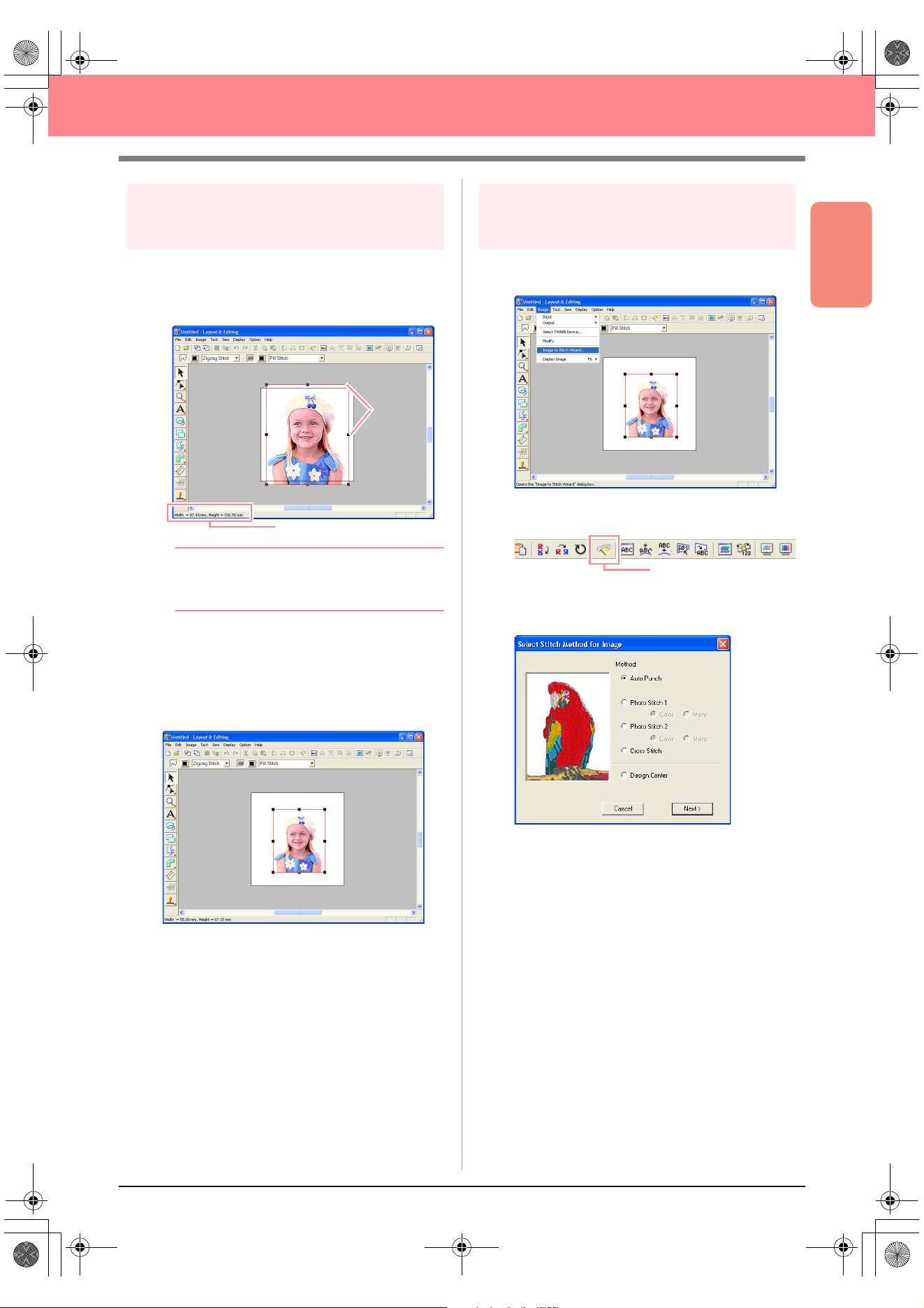
Basic Operation
27
Automatically Creating Embroidery Patterns
Step 3
Adjusting the size and position
of the image
1. Click Image on the menu bar, and then click
Modify.
→ Handles appear around the image.
b Memo:
The status bar shows the dimensions (width
and height) of the image.
2. Adjust the selected image to the desired size,
and move it to the desired location.
c
For more details, refer to , “Changing the
Size and Position of the Image”, on page
114.
Step 4
Automatically converting the
image to an embroidery pattern
1. Click Image on the menu bar, and then click
Image to Stitch Wizard.
An alternate method is to click the Toolbar
button indicated below.
→ The Select Stitch Method for Image dia-
log box appears.
Status bar
Handles
Image to Stitch Wizard
PeDesignV6Eng.book Page 27 Thursday, July 8, 2004 11:59 AM
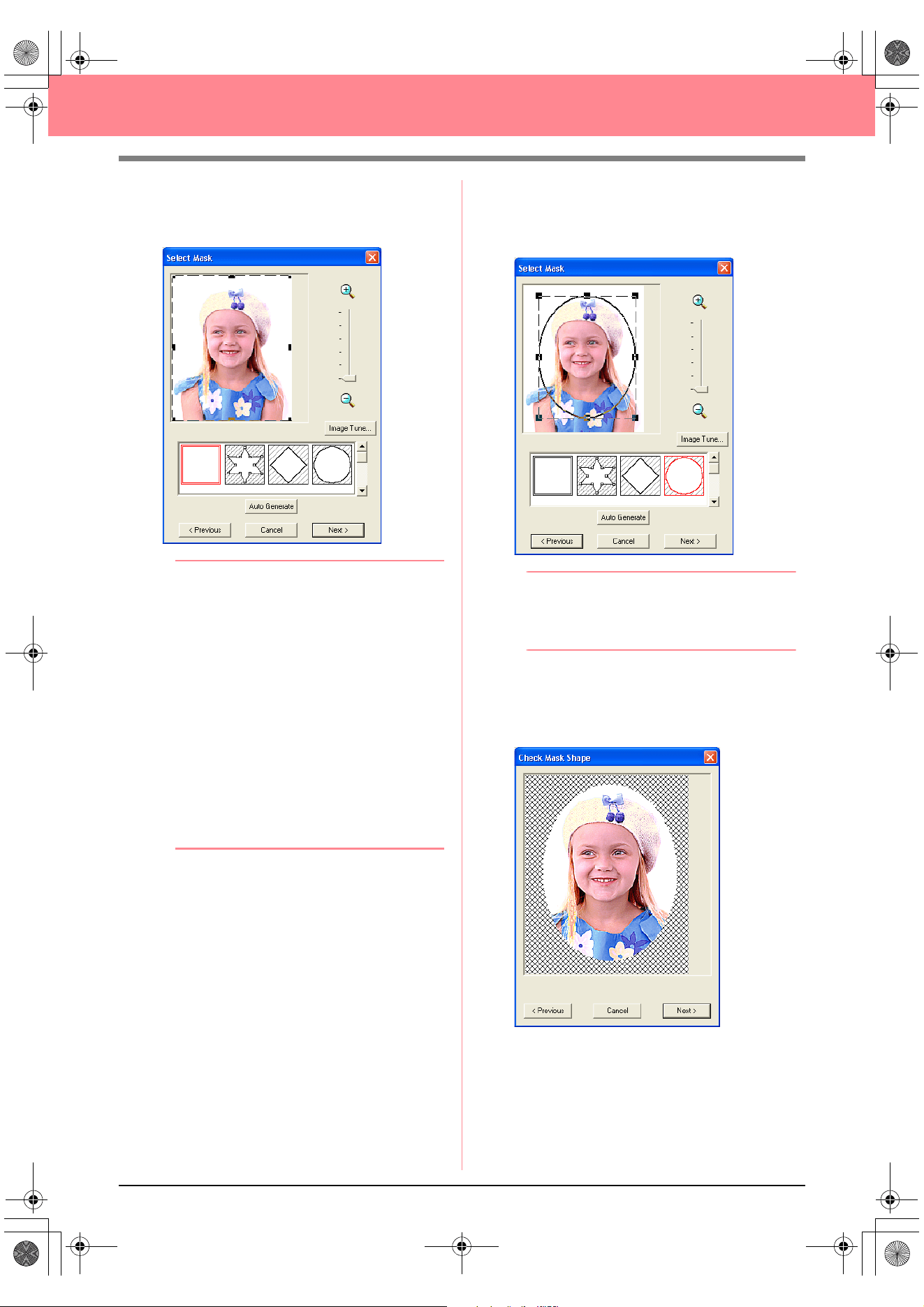
28
Automatically Creating Embroidery Patterns
2. Select Photo Stitch 1, then Color, and then
click Next.
→ The Select Mask dialog box appears.
b Memo:
The following stitch methods are also
available.
•
Auto Punch
For more details, refer to page 115.
•
Photo Stitch 1
(
Mono
)
For more details on the
Mono
setting, refer
to page 120.
•
Photo Stitch 2
(
Color
and
Mono
)
Refer to page 122 for more details on the
Color
setting and to page 124 for more
details on the
Mono
setting.
•
Cross Stitch
For more details, refer to page 125.
•
Design Center
For more details, refer to “Using Design
Center” on page 30.
3. From the list at the bottom of the dialog box,
select the desired shape that the image will be
trimmed to.
4. In the image preview box, move the handles of
the mask until it surrounds the desired part of
the image to be converted to an embroidery
pattern.
b Memo:
Any part of the image that is outside of the
mask will not be converted to an embroidery
pattern.
5. Click Next.
→ The image is analyzed, and the Check
Mask Shape dialog box appears.
PeDesignV6Eng.book Page 28 Thursday, July 8, 2004 11:59 AM
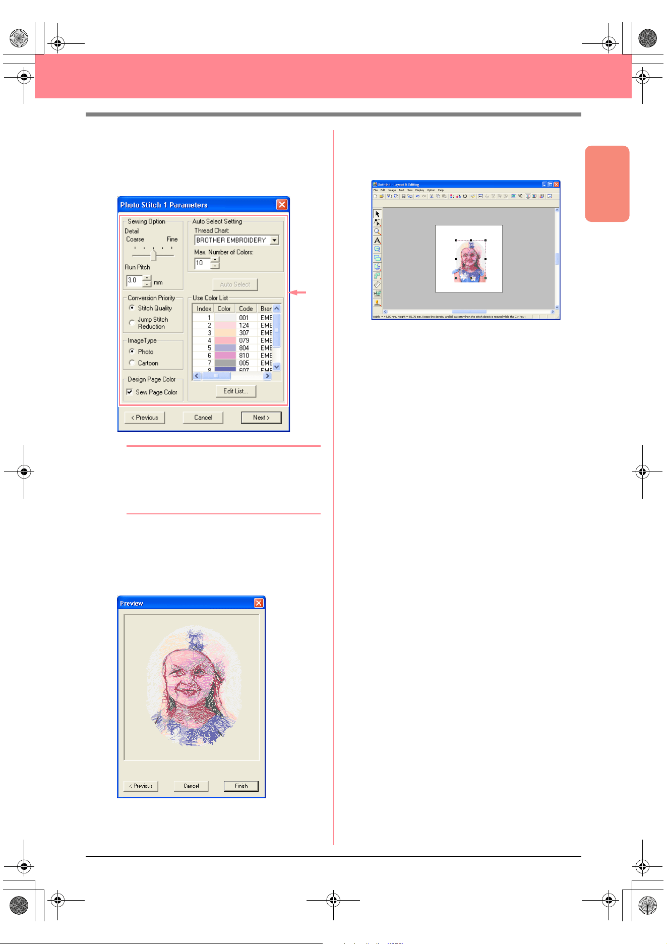
Basic Operation
29
Automatically Creating Embroidery Patterns
6. If the shape and position of the mask are as
desired, click Next.
→ The Photo Stitch 1 Parameters dialog
box appears.
b Memo:
Various settings are available for converting
the image to an embroidery pattern. (For
more details on the various settings, refer to
page 116.)
7. Click Next.
→ The image is converted to an embroidery
pattern, which is displayed in the Preview
dialog box.
8. Click Finish.
→ The embroidery pattern is displayed in the
Design Page.
c
For details on previewing the embroidery
pattern, refer to Step 5, “Displaying a
preview of the embroidery pattern”, on
page 22.
c
For details on saving the embroidery
pattern as a file, refer to Step 6, “Saving
the embroidery pattern”, on page 23.
c
For details on transferring the embroidery
pattern to an original card, refer to Step 7,
“Transferring the pattern to an original
card”, on page 24.
PeDesignV6Eng.book Page 29 Thursday, July 8, 2004 11:59 AM
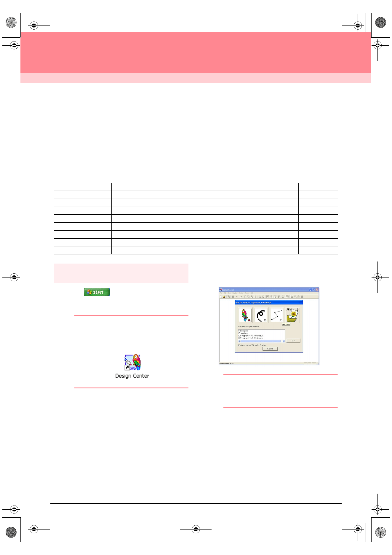
30
Creating and Editing Embroidery Patterns
Using Design Center
In this section, we are going to manually create an embroidery pattern from an image using a four-stage
procedure. This pattern will be used later as the stepping stone to create a more complex embroidery pattern.
Follow the instructions in this section step by step. If you have to interrupt this exercise for any reason, it is
recommended to save the file (refer to Step 9, “Saving the file”, on page 38). You will be able to retrieve it later
and resume your work.
The complete procedure will take you through the different steps of a normal working session with Design
Center and will introduce you to its most important features.
Step 1
Starting up Design Center
1. Click , select All Programs, then
PE-DESIGN Ver.6. Select Design Center to
open the Design Center window.
b Memo:
If a shortcut for Design Center was created,
for example, on the desktop, double-click it to
start up the application.
→ The How do you want to produce em-
broidery? dialog box and the Design
Center window appear.
b Memo:
To fill the entire screen with the Design
Center window, click the maximize button on
the right end of the title bar.
Step 1 Starting up Design Center page 30
Step 2 Opening an image file page 31
Step 3 Continuing to stage 2 (Line Image stage) page 31
Step 4 Editing lines page 32
Step 5 Continuing to stage 3 (Figure Handle stage) page 33
Step 6 Continuing to stage 4 (Sew Setting stage) page 34
Step 7 Specifying sewing attributes page 34
Step 8 Previewing the image page 37
Step 9 Saving the file page 38
PeDesignV6Eng.book Page 30 Thursday, July 8, 2004 11:59 AM
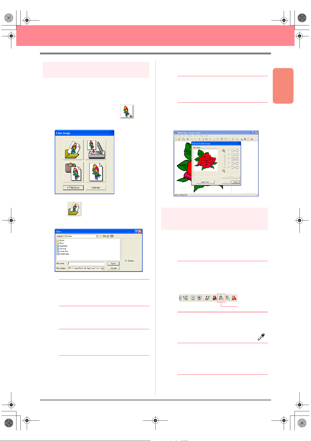
Basic Operation
31
Creating and Editing Embroidery Patterns
Step 2
Opening an image file
First, we need to open the image that will be used
to create the embroidery pattern.
1. In the How do you want to produce
embroidery? dialog box, click .
→ The From Image dialog box appears.
2. Click .
→ The Open dialog box appears.
b Memo:
The
Open
dialog box can also be displayed
by selecting the menu command
Open
–
File
in Design Center.
3. Select the sample file Flower.bmp in the Data
folder.
b Memo:
If the
Preview
check box is selected, the
contents of the selected file will appear in the
Preview
box.
4. Click Open to open the image file and to close
the dialog box.
b Memo:
Double-clicking the file name also adds the
image to the work area and closes the dialog
box.
→ The image appears in the Design Page
and in the Cut out to Line Image dialog
box.
Step 3
Continuing to stage 2 (Line
Image stage)
After opening the image, we will continue to stage
2 (Line Image stage), where we will select the
color(s) that will be used to create the line image
(outline of the image).
b Memo:
If the wizard is not being used, click
Stage
on
the menu bar, and then click
To Line Image
.
An alternate method is to click the Toolbar
button indicated below.
1. Move the pointer over the image in the Cut
out to Line Image dialog box.
→ The shape of the pointer changes to .
b Memo:
To display the image enlarged (or reduced),
move the
ZOOM
slider up (or down). When
the image is enlarged, you can scroll through
it to display different parts.
To Line Image
PeDesignV6Eng.book Page 31 Thursday, July 8, 2004 11:59 AM
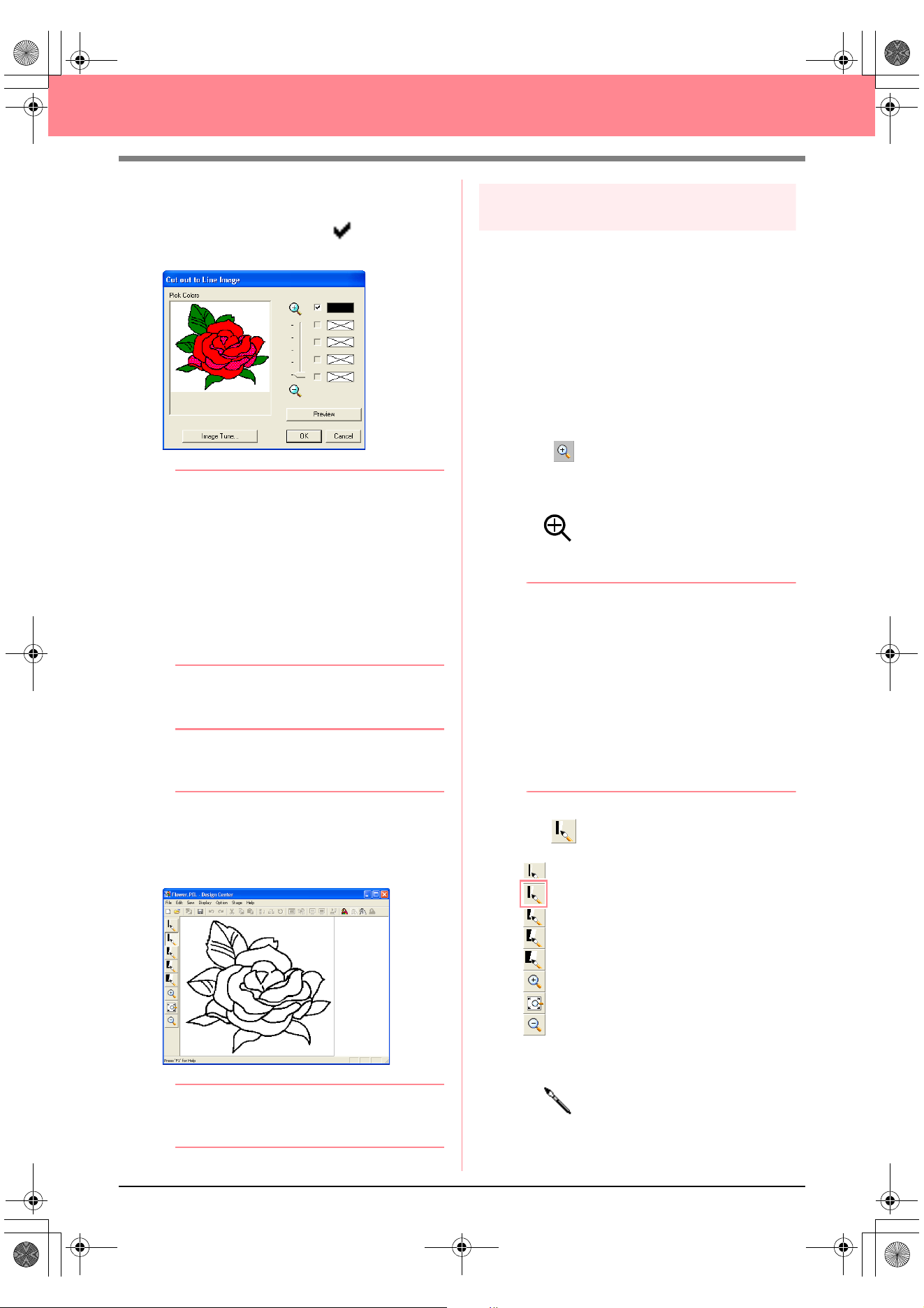
32
Creating and Editing Embroidery Patterns
2. Click any part of the outline.
→
The selected color appears in the top box
under
Pick Colors
, and appears in the
check box to show that the color is selected.
b Memo:
• If the image contains outlines of different
colors, you can repeat step
2.
to select up
to five colors. If more than five colors are
selected, only the last five colors selected
remain in the list.
• To deselect a color, clear the
corresponding check box.
• To adjust the color tone and reduce image
noise (distortions), click
Image Tune
. (For
more details, refer to page 74.)
3. Click Preview to preview the line image in the
Design Page.
b Memo:
To quit the operation and go back to stage 1
(Original Image stage), click
Cancel
.
4. When the line image appears as desired, click
OK.
→ The line image is displayed in the Design
Page.
b Memo:
At this time, the pattern can be saved as a .pel file. For
details, refer to Step 9, “Saving the file”, on page 38.
Step 4
Editing lines
At this time, you might need to correct a few lines
in the line image. You should make sure that
regions are completely enclosed by either a single
closed line or intersecting lines. You may also
want to edit the line image and either add or
remove some details. You can do this at this time
using the pens and erasers in the Tool Box.
In this example, we are going to display the line
image enlarged to make editing easier, then use
an eraser to remove some of the outline.
1. Click .
→ When the pointer is moved over the work
area, the shape of the pointer changes to
.
2. Click the line image.
b Memo:
• To further enlarge the line image, repeat
step
2.
• To zoom in on a specific area, move the
pointer near the desired area, and then
drag the pointer diagonally over the
desired area. A dotted box appears as you
drag the pointer, and the selected area is
enlarged when the mouse button is
released.
For more details on the
Zoom
buttons in
the Tool Box, refer to page 234.
3. Click on the Tool Box.
→ When the pointer is moved over the work
area, the shape of the pointer changes to
.
PeDesignV6Eng.book Page 32 Thursday, July 8, 2004 11:59 AM
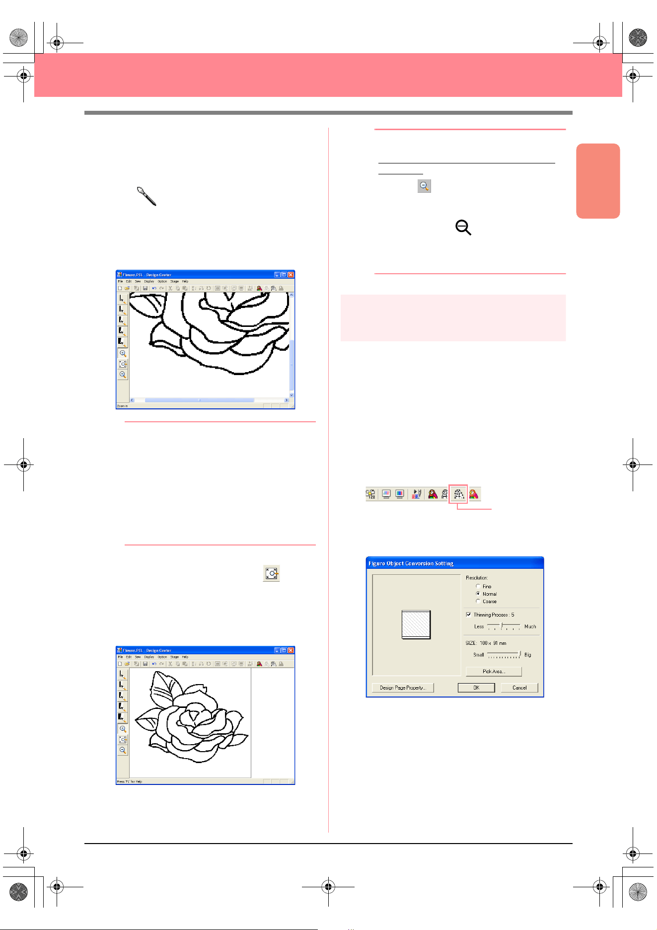
Basic Operation
33
Creating and Editing Embroidery Patterns
4. Move the pointer over the line that you want to
erase, and then hold down the right mouse
button.
→ The shape of the pointer changes to
.
5. Carefully drag the pointer to erase the line.
6. Repeat steps 4. and 5. to delete a few
leaves.
b Memo:
• If you deleted part of the outline by
mistake, you may need to redraw some of
lines. To do this, simply hold down the left
mouse button and start drawing the line.
• If you are not satisfied with your editing,
select the menu command
Stage
–
To
Original Image
to go back to stage 1
(Original Image stage), and then create
the line image and start editing again.
7. After editing the line image, click on the
Tool Box to view the entire line image so that
it fits in the window.
→ The Design Page fills the Design Center
window.
b Memo:
To select how the reduced line image is
displayed:
1) Click on the Tool Box.
→
When the pointer is moved over the
work area, the shape of the pointer
changes to .
2) Click the Design Page.
3) To further reduce the line image, repeat
step 2).
Step 5
Continuing to stage 3 (Figure
Handle stage)
In stage 2 (Line Image stage), the line image is
simply a collection of dots (or pixels). Editing in
stage 2 means adding or removing black dots.
When you move to stage 3 (Figure Handle stage),
the application automatically connects the dots to
create lines, which can be edited.
1. Click Stage on the menu bar, and then click
To Figure Handle.
An alternate method is to click the Toolbar
button indicated below.
→ The Figure Object Conversion Setting
dialog box appears.
To Figure Handle
PeDesignV6Eng.book Page 33 Thursday, July 8, 2004 11:59 AM
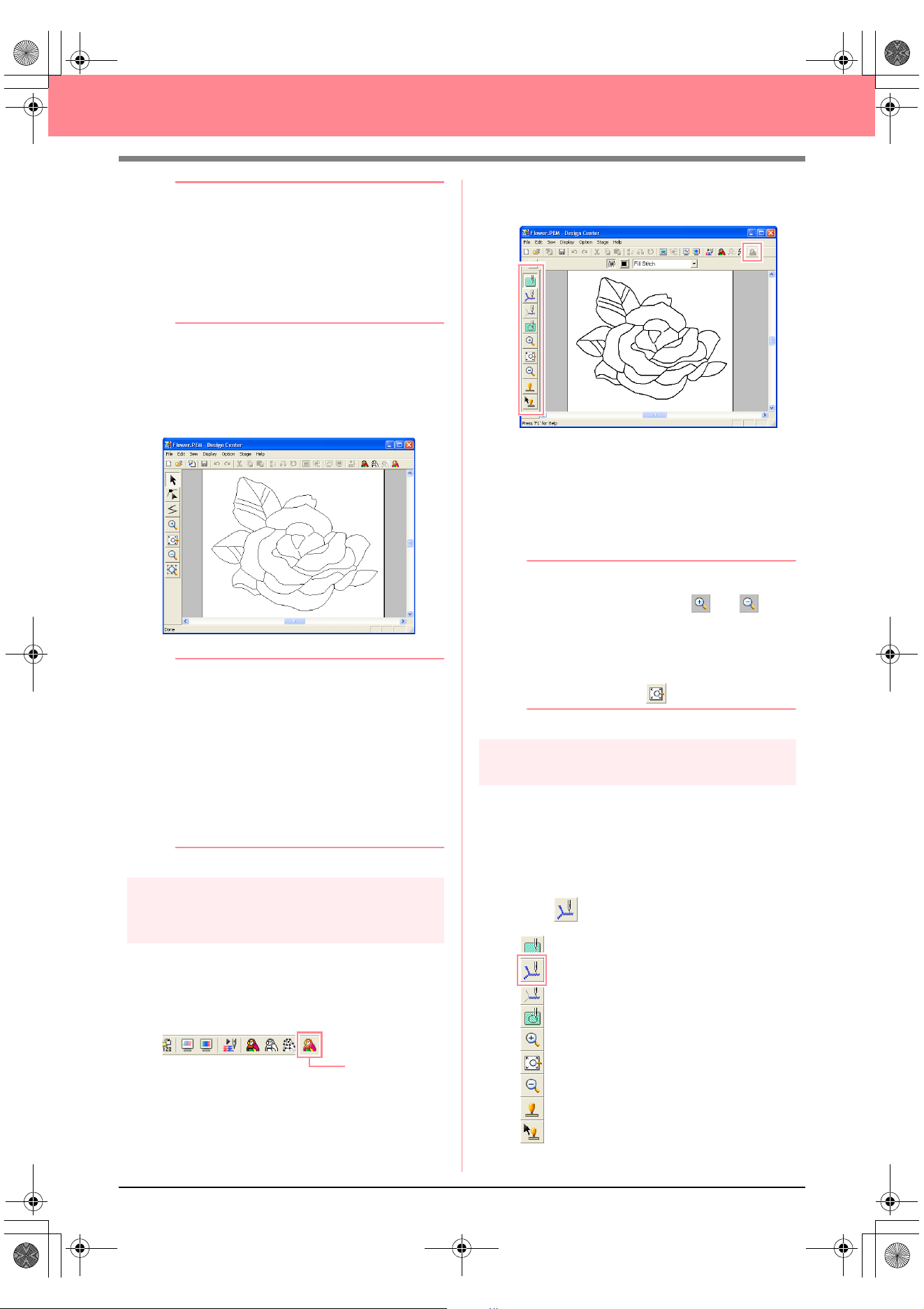
34
Creating and Editing Embroidery Patterns
b Memo:
Various settings are available for converting
the line image to a figure handle image. (For
more details on the various settings, refer to
page 76.) In addition, this dialog box allows
you to preview how the image will fit in the
selected Design Page (the size of the area to
be sewn).
2. Click OK.
→ The line image is converted to a figure
handle image, which is displayed in the
Design Page.
b Memo:
• The Tool Box for stage 3 (Figure Handle
stage) contains various editing tools for
drawing lines, moving, deleting or inserting
points as well as zooming. For details on
the editing tools, refer to page 234.
• At this time, you can change the Design
Page properties by using the menu
command
Option
–
Design Page
Property
. (For more details, refer to
page 77.)
Step 6
Continuing to stage 4 (Sew
Setting stage)
1. Click Stage on the menu bar, and then click
To Sew Setting.
An alternate method is to click the Toolbar
button indicated below.
→ The Tool Box for stage 4 (Sew Setting
stage) appears.
In this stage, you can set and check the
sewing attributes for each part of the pattern.
You can also specify hole sewing for larger
regions that completely enclose smaller ones
in order to avoid sewing the same region
twice. Other tools are available for zooming.
b Memo:
• To zoom in (or out), click (or ) on
the Tool Box, and then click the desired
area of the embroidery pattern, as in stage
3 (Figure Handle stage).
• To display the Design Page so that it fits
the window, click on the Tool Box.
Step 7
Specifying sewing attributes
We are now going to apply sewing attributes to
the different parts of the pattern.
■ Specifying sewing attributes for
the outline
1. Click on the Tool Box.
To Sew Setting
PeDesignV6Eng.book Page 34 Thursday, July 8, 2004 11:59 AM
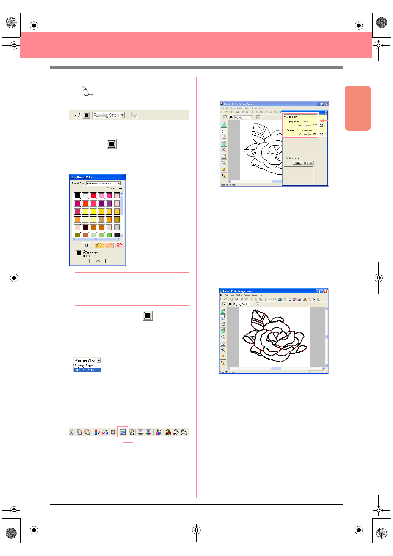
Basic Operation
35
Creating and Editing Embroidery Patterns
→ The shape of the pointer changes to
, and the Sewing Attributes bar ap-
pears as shown below.
2. To change the outline color, click the Line
color button ( ) on the Sewing Attributes
bar, click the desired color in the Line Thread
Color dialog box that appeared, and then click
Close.
b Memo:
To move the dialog box to a more convenient
place on the screen, move the pointer over
the title bar, and then drag the dialog box.
→ The Line color button ( ) on the Sew-
ing Attributes bar is displayed in the se-
lected color.
3. To change the sew type to the zigzag stitch,
click in the Line sew type selector
( ) on the Sewing Attributes bar,
and then click Zigzag Stitch.
4. To change the attributes for the zigzag stitch,
click Sew on the menu bar, and then click
Sewing Attribute.
An alternate method is to click the Toolbar
button indicated below.
→ The Sewing Attribute Setting dialog box
appears, containing the default settings
for the selected outline sew type.
5. To change the width from 2.0 mm to 1.5 mm,
move the slider to the left until Zigzag width is
set to 1.5.
b Memo:
To close the dialog box, click
Close
.
6. Click the outline of the pattern to apply the
attributes (color, sew type and width) to it.
→ The image now appears as shown below
with “marching lines” along the outline.
b Memo:
If you think that the width of the outline is too
thick, you can change it again. To change the
width of the outline, repeat step
5.
, and then
click the outline to apply the new setting. (If
the
Sewing Attribute Setting
dialog box is
not displayed, right-click the outline.)
Sewing Attribute
PeDesignV6Eng.book Page 35 Thursday, July 8, 2004 11:59 AM
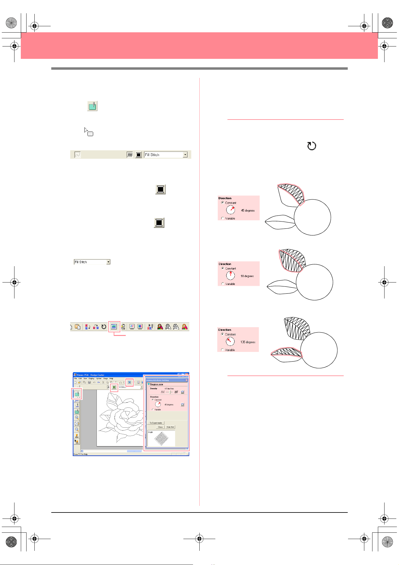
36
Creating and Editing Embroidery Patterns
■ Specifying sewing attributes for
the regions
1. Click on the Tool Box.
→ The shape of the pointer changes to
, and the Sewing Attributes bar ap-
pears as shown below.
For the leaves
2. Click the Region color button ( ) on the
Sewing Attributes bar, click the color LEAF
GREEN in the Region Thread Color dialog
box that appeared, and then click Close.
→ The Region color button ( ) on the
Sewing Attributes bar is displayed in the
selected color.
3. Click in the Region sew type selector
( ) on the Sewing Attributes bar,
and then click Fill Stitch.
4. To change the attributes for the fill stitch, click
Sew on the menu bar, and then click Sewing
Attribute.
An alternate method is to click the Toolbar
button indicated below.
→ The Sewing Attribute Setting dialog box
appears, containing the default settings
for the selected region sew type.
5. To change the direction of the fill stitching,
click Constant under Direction, move the
pointer over the red arrow inside of the circle
under Constant, and then drag the red arrow
to the desired angle.
b Memo:
• When the pointer is moved over the red
arrow, its shape changes to .
• Using different directions for different
regions can add contrast and improve the
appearance of the embroidery.
6. Click the regions of the leaves to which you
want to apply the attributes.
→ “Marching lines” appear around the se-
lected region.
7. Repeat steps 5. and 6. until attributes are
applied to all leaves.
Sewing Attribute
Direction set to 45°
Direction set to 90°
Direction set to 135°
PeDesignV6Eng.book Page 36 Thursday, July 8, 2004 11:59 AM
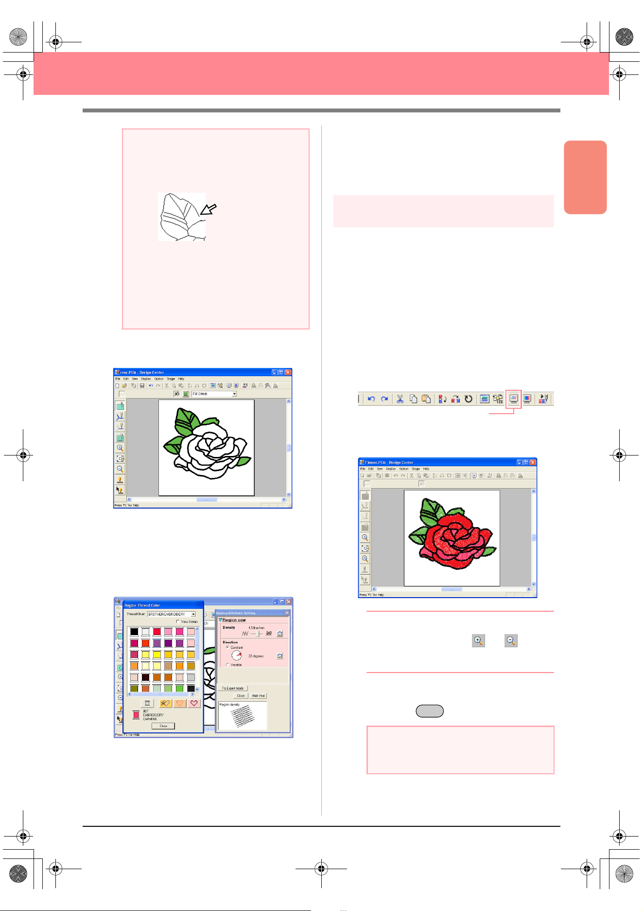
Basic Operation
37
Creating and Editing Embroidery Patterns
After applying the sewing attributes to the
leaves, the image appears as shown below.
For one side of the petals
8. Select the color CARMINE, set the stitching
direction, and then click each region where
you want to apply the attributes.
For the other side of the petals
9. Select the color RED, set the stitching
direction, and then click each region where
you want to apply the attributes.
Step 8
Previewing the image
You can display a preview of the embroidery
pattern in order to see how the stitching is
connected, or you can display a realistic preview
of the embroidery pattern in order to see how the
pattern will appear once it is sewn. (The
embroidery pattern can only be previewed in
stage 4 (Sew Setting stage) only.)
1. To display a preview of the embroidery
pattern, click Display on the menu bar, and
then click Preview.
An alternate method is to click the Toolbar
button indicated below.
→ A preview of the embroidery pattern ap-
pears.
b Memo:
To zoom in (or out), click (or ) on the
Tool Box, and then click the desired area of
the embroidery pattern.
2. To leave the preview display, repeat step 1.,
or press the key.
a Note:
Sewing attributes cannot be applied to
regions that are not fully enclosed, as shown
in the illustration of the leaf below.
If the attributes cannot be applied to a
region, go back to stage 3 (Figure Handle
stage) and make sure that region is closed.
Edit any broken lines with the Point Edit tool.
For details on editing the figure handle
image, refer to “Editing Points in Outlines” on
page 81.
a Note:
The embroidery pattern cannot be edited
while the preview is displayed.
Preview
Esc
PeDesignV6Eng.book Page 37 Thursday, July 8, 2004 11:59 AM
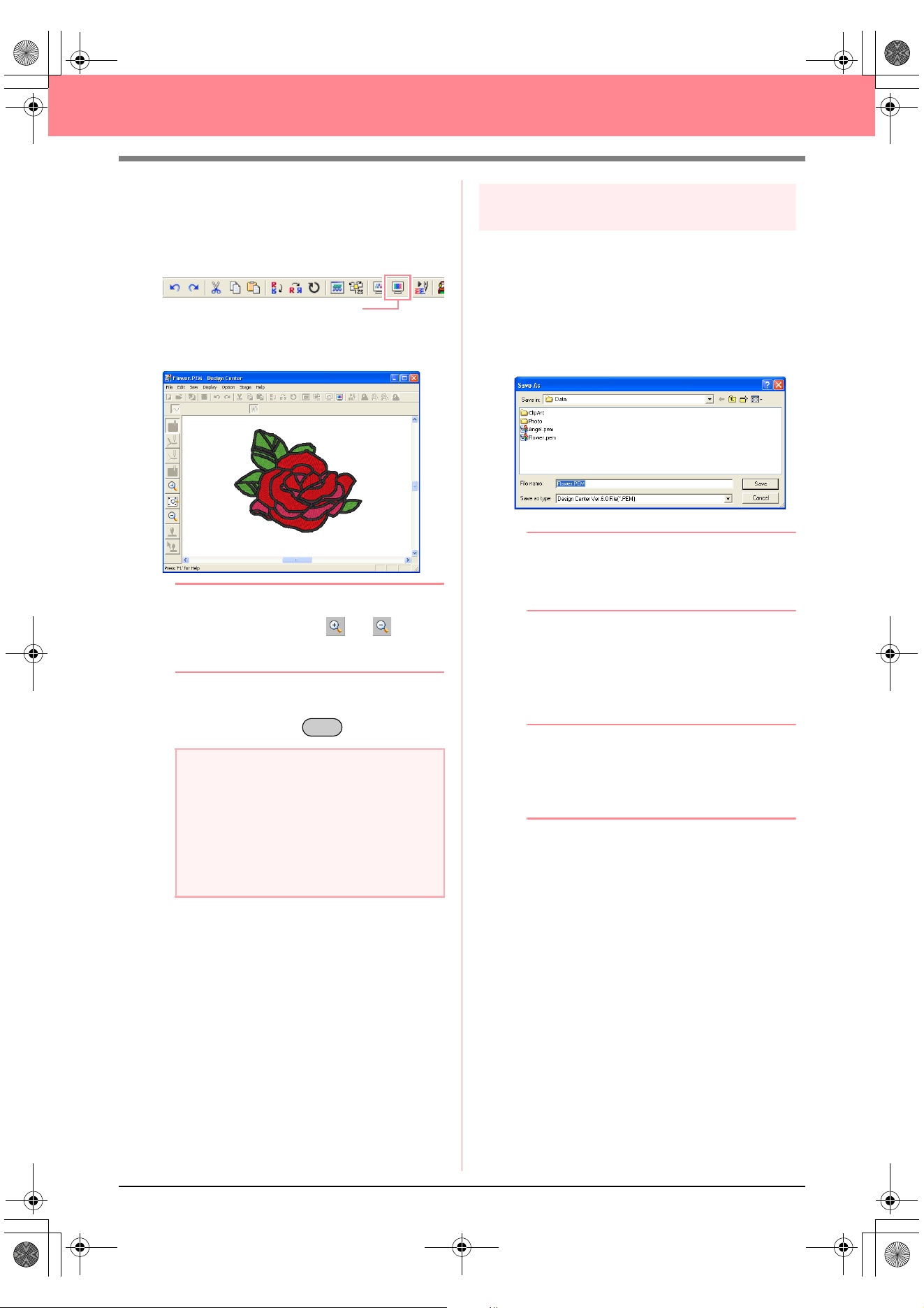
38
Creating and Editing Embroidery Patterns
3. To display a realistic preview of the
embroidery pattern, click Display on the menu
bar, and then click Realistic Preview.
An alternate method is to click the Toolbar
button indicated below.
→ A realistic preview of the embroidery pat-
tern appears.
b Memo:
To zoom in (or out), click (or ) on the
Tool Box, and then click the desired area of
the embroidery pattern.
4. To leave the realistic preview display, repeat
step
3., or press the key.
Step 9
Saving the file
Since this embroidery pattern will be used as the
basis of a more complex embroidery picture, we
need to save it.
1. Click File on the menu bar, and then click
Save As.
→ The Save As dialog box appears.
b Memo:
To overwrite the original file in the original
folder, use the menu command
File
–
Save
instead.
2. The default name Flower.pem is displayed.
3. If necessary, change the drive and folder.
4. Click Save to save the file.
b Memo:
.pem files cannot be written to original cards.
Import them into Layout & Editing first. (For
details, refer to “Importing embroidery
patterns from Design Center” on page 128.)
a Note:
• The embroidery pattern cannot be edited
while the realistic preview is displayed.
• The Realistic Preview function cannot
display a clean preview of the pattern if the
monitor is set to 256 colors or less. The
monitor should be set to at least 16-bit
High Color (65536 colors).
Realistic Preview
Esc
PeDesignV6Eng.book Page 38 Thursday, July 8, 2004 11:59 AM
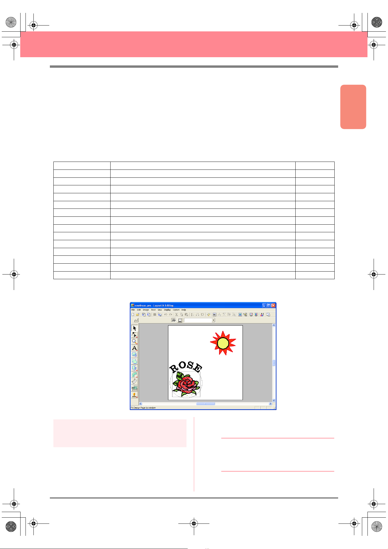
Basic Operation
39
Creating and Editing Embroidery Patterns
Using Layout & Editing
In this section, we are going to complete the embroidery pattern by combining a pattern imported from Design
Center with objects created using Layout & Editing, one of which will have a programmable fill stitch applied
to it.
Follow the instructions in this section step by step. If you have to interrupt this exercise for any reason, it is
recommended to save the file (refer to Step 14, “Saving the file”, on page 53). You will be able to retrieve it
later and resume your work.
The complete procedure will take you through the different steps of a normal working session with Layout &
Editing and will introduce you to some of its most important features.
At the end of this session, the embroidery pattern will appear as shown below.
Step 1
Importing embroidery patterns
from Design Center
The first object of the embroidery pattern will be
the file Flower.pem, which we created in Design
Center. In order to import an embroidery pattern
from Design Center into the Design Page of
Layout & Editing, the .pem file must be opened in
Design Center.
b Memo:
If Design Center has not been started up,
refer to “Starting up Design Center” on
page 30.
Step 1 Importing embroidery patterns from Design Center page 39
Step 2 Adjusting the size and position of the embroidery pattern page 40
Step 3 Adding shapes page 41
Step 4 Adding text page 43
Step 5 Fitting the text around the oval page 44
Step 6 Adding a circle for the center of the sun page 45
Step 7 Selecting a programmable fill stitch page 46
Step 8 Adding a closed broken line for the sun’s rays page 48
Step 9 Changing the sewing order of sun and rays page 49
Step 10 Adjusting the rays page 50
Step 11 Setting hole sewing page 50
Step 12 Previewing the embroidery pattern page 51
Step 13 Transferring the pattern to an original card page 52
Step 14 Saving the file page 53
Step 15 Quitting Layout & Editing page 53
PeDesignV6Eng.book Page 39 Thursday, July 8, 2004 11:59 AM
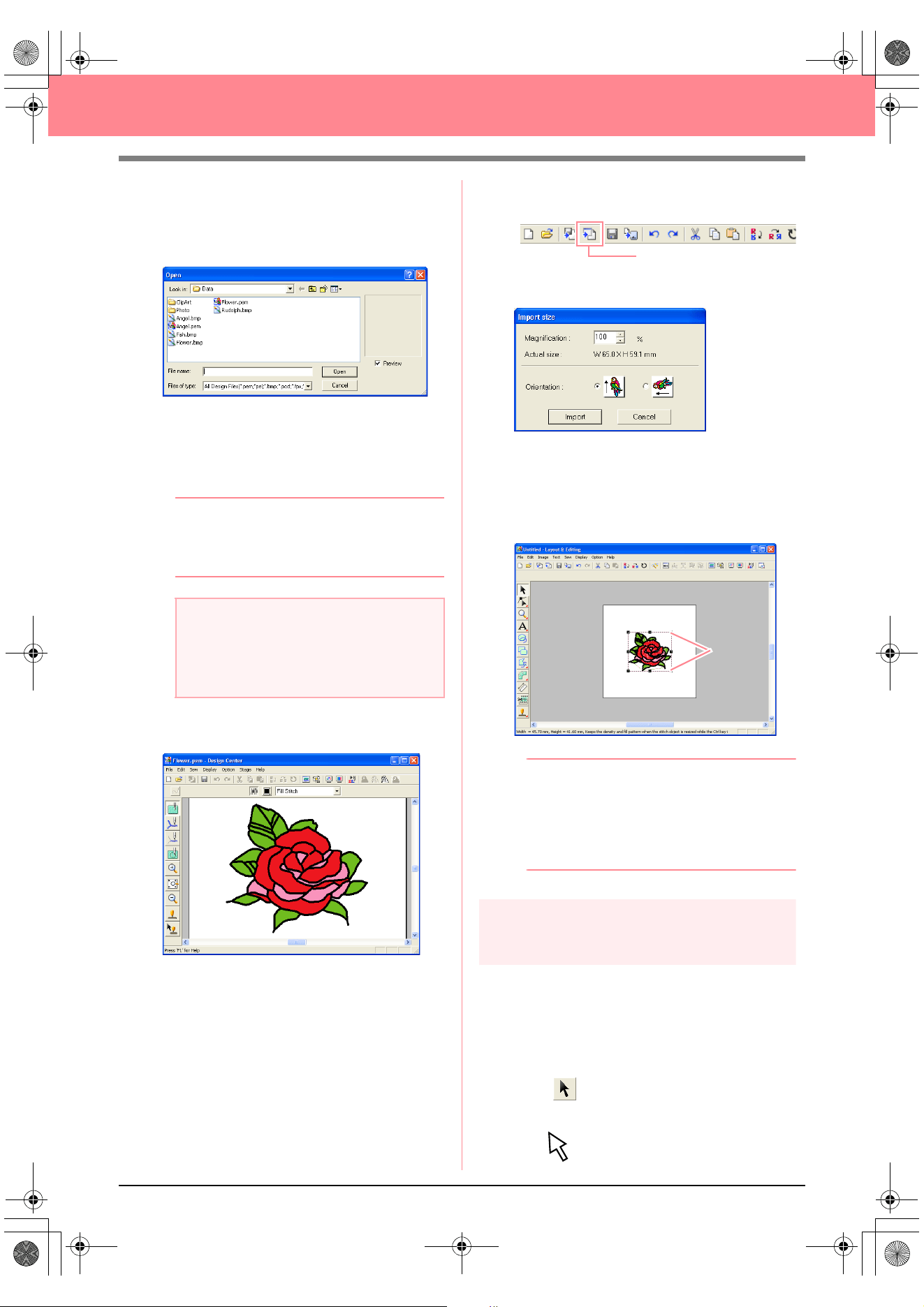
40
Creating and Editing Embroidery Patterns
1. In Design Center, click File on the menu bar,
and then click Open.
→ An Open dialog box similar to the one
shown below appears.
2. Select Design Center PEM File (*.PEM) in
the Files of type box, the sample file
Flower.pem in the Data folder, and then click
Open.
b Memo:
If the
Preview
check box is selected, the
contents of the selected file will appear in the
Preview
box.
→ The embroidery pattern is displayed in the
Design Page of Design Center.
3. Click Option on the menu bar, and then click
Layout & Editing to display the Layout &
Editing window.
4. In Layout & Editing, click File on the menu bar,
point to Import, and then click from Design
Center on the submenu.
An alternate method is to click the Toolbar
button indicated below.
→ The Import size dialog box appears.
5. In the Magnification box, type or select 70%,
and then click Import.
→ The embroidery pattern is imported into
the Design Page of Layout & Editing.
b Memo:
• The dotted line and the handles that
appear around the embroidery pattern
show that the pattern is selected.
• The status bar shows the dimensions
(width and height) of the selected pattern.
Step 2
Adjusting the size and position
of the embroidery pattern
When you import a pattern from Design Center,
Layout & Editing puts the pattern at the center of
the Design Page. We are now going to change the
size of the imported pattern and move it to a
different location.
1. Click on the Tool Box.
→ The shape of the pointer changes to
.
a Note:
Be sure to select a .pem file saved in stage
4 (Sew Setting stage).
You cannot import another file type from
Design Center.
from Design Center
Handles
PeDesignV6Eng.book Page 40 Thursday, July 8, 2004 11:59 AM
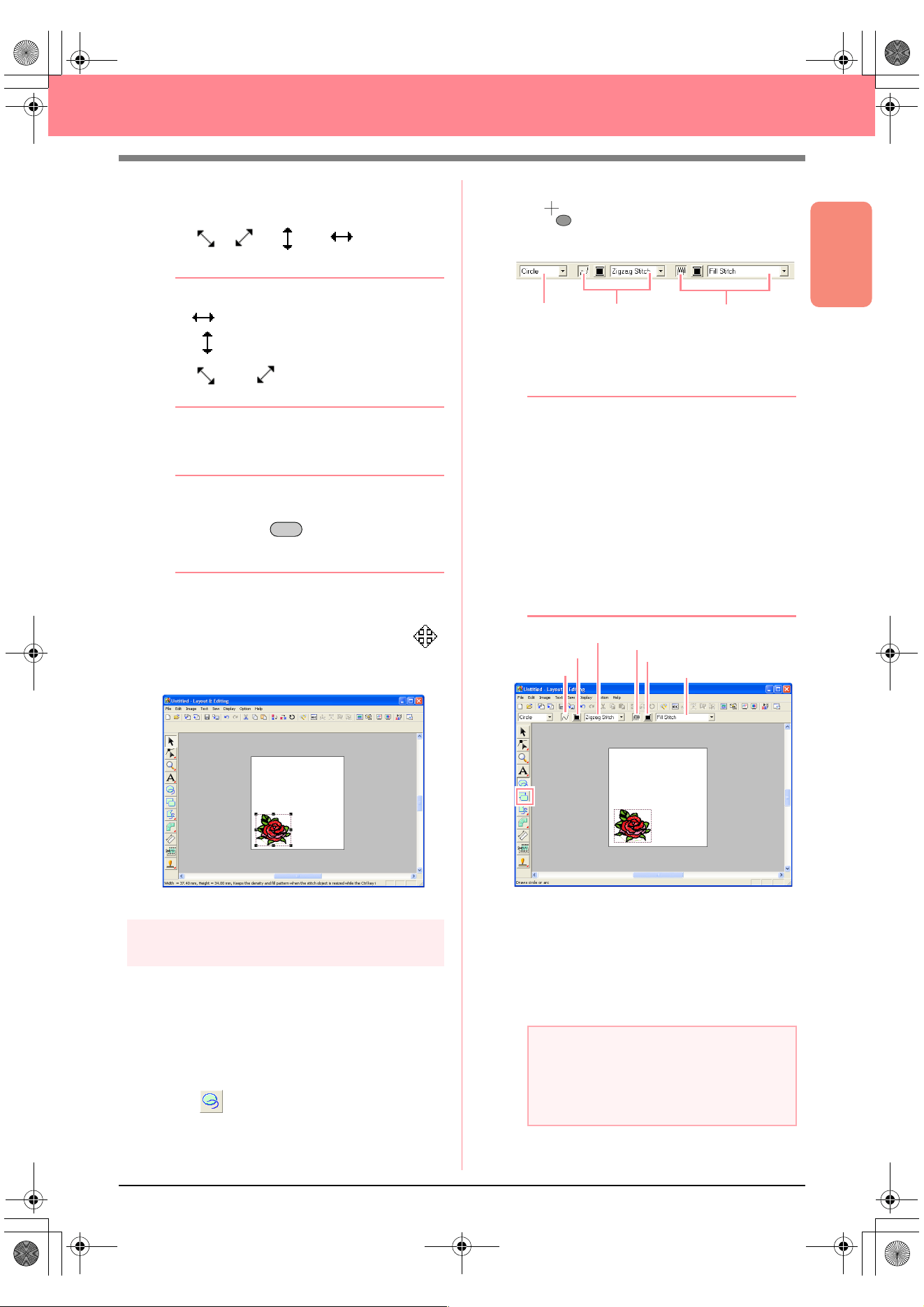
Basic Operation
41
Creating and Editing Embroidery Patterns
2. Move the pointer over a handle.
→ The shape of the pointer changes to
, , , or , depending
on the handle that the pointer is over.
b Memo:
• is for scaling the width.
• is for scaling the height.
• and are for scaling both
dimensions at the same time.
3. Drag the handle to adjust the selected pattern
to the desired size.
b Memo:
To maintain the stitch density and fill pattern,
hold down the key while dragging a
handle. (For more details, refer to “Enlarging/
reducing embroidery patterns” on page 14.)
4. Move the pointer over the selected pattern.
→ The shape of the pointer changes to .
5. Drag the pattern to the desired location.
Step 3
Adding shapes
The next object to add to our embroidery pattern
will be an oval. Since this oval will be used only as
a guide for arranging the text that we will add later,
we must set it so that it is not sewn.
■ To add the oval
1. Click on the Tool Box.
→ The shape of the pointer changes to
, and the Sewing Attributes bar ap-
pears as shown below.
When the pointer is positioned over a button or
selector in the Sewing Attributes bar, a label
indicating the name of that element appears.
b Memo:
•The
Arc shape
selector allows you to
select the shape to be drawn. For
example, click
Circle
to draw circles and
ovals. The other options are used to draw
other curved shapes such as arcs. For
more details, refer to “Drawing Circles and
Arcs” on page 145.
• The line sewing and region sewing
attributes are used to select the sew type
and thread color for the outline (line
sewing) and for the inside area (region
sewing).
2. To change the shape of the object to be
drawn, click the Arc shape selector, and then
select the desired shape.
For this example, since we will be using the
default shape Circle, you do not need to
change the setting in the Arc shape selector.
Ctrl
a Note:
When drawing a circle or other curved
shape, select the shape before drawing. You
cannot, for example, draw a circle, then
change it to an arc afterward.
Arc shape
Line sew
Region sew
Line sew
Line color
Line sew type
Region sew
Region color
Region sew type
Basic_01.fm Page 41 Friday, July 9, 2004 1:43 PM
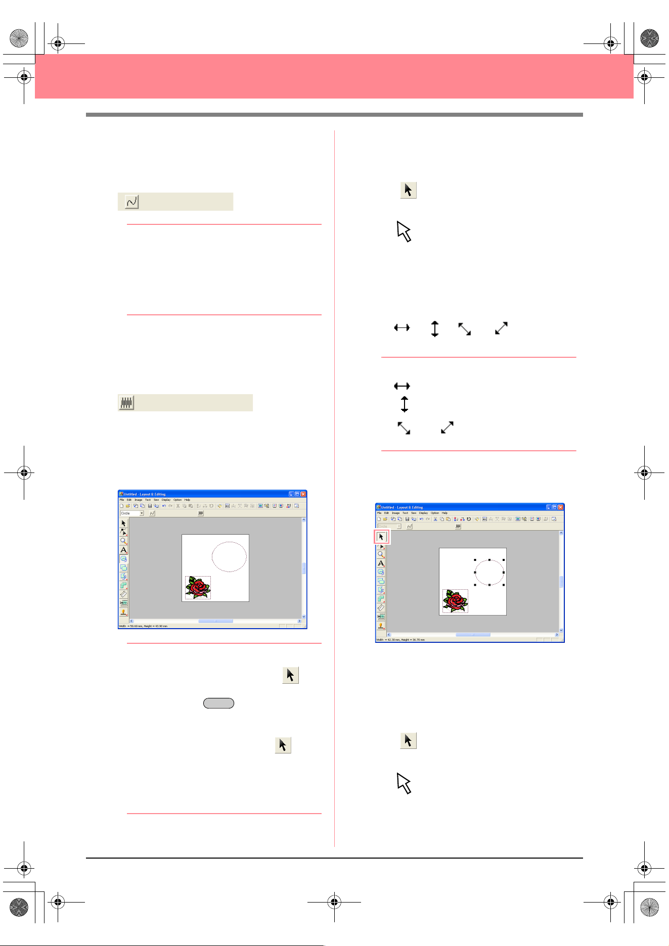
42
Creating and Editing Embroidery Patterns
3. To cancel line sewing (outline), click the Line
sew button.
→ The Line color button and the Line sew
type selector disappear.
b Memo:
If the
Line sew
button is clicked, causing the
Line color
button and the
Line sew type
selector to disappear, the outline will not be
sewn. If you want to sew the outline, click the
Line sew
button again to display the
Line
color
button and the
Line sew type
selector.
4. To cancel region sewing (inside area), click
the Region sew button.
→ The Region color button and Region
sew type selector disappear.
5. To draw the oval, drag the pointer in the
Design Page.
→ The oval (outline and inside area) ap-
pears when the mouse button is released.
b Memo:
• If you want to delete the oval, click on
the Tool Box, click the oval to select it, and
then press the key or select the
menu command
Edit
–
Delete
.
• If you want to change the color or sew type
of the oval after drawing it, click on
the Tool Box, click the oval to select it, and
then click the
Line sew
or
Region sew
button. The current attributes for the oval
appear in the Sewing Attributes bar, where
they can be changed.
■ To change the size of the oval
If your oval looks very different from the one shown
above, modify its size as described below.
1. Click on the Tool Box.
→ The shape of the pointer changes to
.
2. Click the oval to select it.
3. Move the pointer over one of the handles of
the oval.
→ The shape of the pointer changes to
, , or , depending
on the handle that the pointer is over.
b Memo:
• is for scaling the width.
• is for scaling the height.
• and are for scaling both
dimensions at the same time.
4. Drag the handle to adjust the selected pattern
to the desired size.
■ To center the flower pattern in the
oval
If the flower pattern is not centered in the oval, move
the oval as described below.
1. Click on the Tool Box.
→ The shape of the pointer changes to
.
Delete
PeDesignV6Eng.book Page 42 Thursday, July 8, 2004 11:59 AM
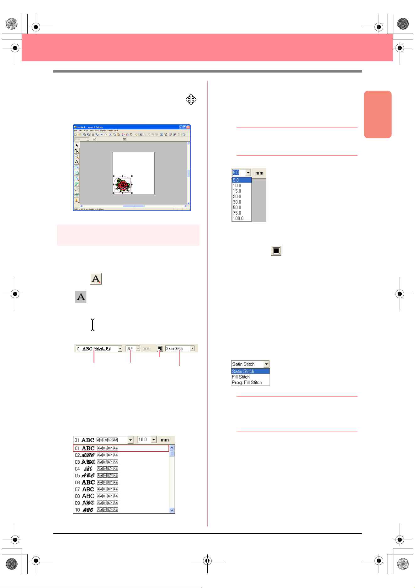
Basic Operation
43
Creating and Editing Embroidery Patterns
2. Click the oval to select it.
→ The shape of the pointer changes to .
3. Drag the oval to its final location.
Step 4
Adding text
The next object to add to our embroidery pattern
is text.
1. Click on the Tool Box, and then click
.
→ The shape of the pointer changes to
, and the Sewing Attributes bar ap-
pears as shown below.
2. To change the font, click in the Font selector
on the Sewing Attributes bar, and then select
the desired font.
For this example, since we will be using the
default font 01, you do not need to change the
font setting.
3. To change the text size, click in the Text Size
selector on the Sewing Attributes bar, and
then select the desired size for the text.
For this example, we will keep the default size
of 10.0 mm
b Memo:
The value indicates the height of the
characters.
4. To change the text color, click the Text body
color button ( ) on the Sewing Attributes
bar, click the desired color in the Region
Thread Color dialog box that appeared, and
then click Close.
For this example, since we will be using the
default color BLACK, you do not need to
change the text color setting.
5. To change the text sew type, click in the Text
body sew type selector, and then select the
desired sew type for the text.
For this example, we will use the default sew
type Satin stitch.
b Memo:
For more precise setting of the text
attributes, refer to “Specifying text attributes”
on page 157.
6. To enter the text, click in the Design Page.
Since we can move the text after creating it,
any place in the Design Page can be clicked.
Text body color
Font
Tex t S i z e
Text body sew type
PeDesignV6Eng.book Page 43 Thursday, July 8, 2004 11:59 AM
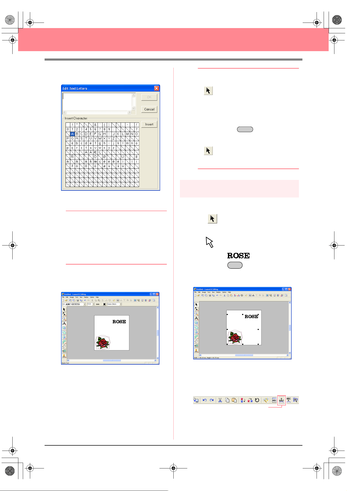
44
Creating and Editing Embroidery Patterns
→ The Edit Text Letters dialog box ap-
pears.
7. Type your text (“ROSE”, for this example).
b Memo:
• You can also enter a character by
selecting it in the character table, then
clicking
Insert
, or simply by double-
clicking it. This is particularly useful if you
have to enter accented characters that are
not available on your keyboard.
• To quit the operation, click
Cancel
.
8. Click OK.
→ The text is displayed in the Design Page.
b Memo:
• If you want to edit the entered text, click
on the Tool Box, click the text to
select it, and then select the menu
command
Text
–
Edit Letters
. Edit the
text in the
Edit Text Letters
dialog box
that appeared.
• If you want to delete the text, select it, and
then press the key.
• If you want to change the text color, font or
other attributes after entering the text, click
on the Tool Box, click the text to
select it, and then change the settings on
the Sewing Attributes bar.
Step 5
Fitting the text around the oval
Here, we are going to fit the text around the oval.
1. Click on the Tool Box.
→ The shape of the pointer changes to
.
2. Click the text to select it.
3. Hold down the key and click the oval to
select it.
→ Both the oval and the text are selected.
4. Click Text on the menu bar, and then click Fit
Text to Path Setting.
An alternate method is to click the Toolbar
button indicated below.
Delete
Ctrl
Fit Text to path
PeDesignV6Eng.book Page 44 Thursday, July 8, 2004 11:59 AM
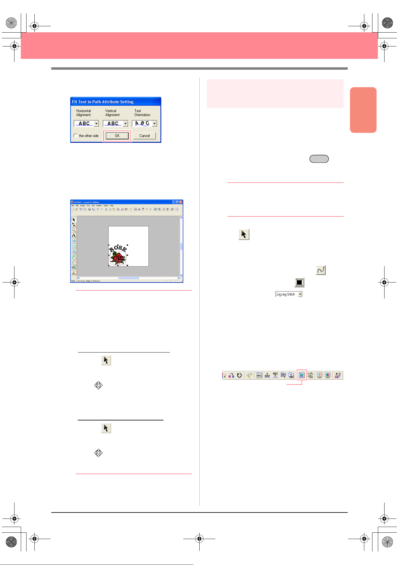
Basic Operation
45
Creating and Editing Embroidery Patterns
→ The Fit Text to Path Attribute Setting di-
alog box appears.
5. Click OK without changing any settings.
c
For more details on these settings, refer
to “Specifying text arrangement” on
page 158.
→ The text is now arranged on the oval.
b Memo:
Moving the oval and text:
Once the text is arranged on the oval, you
can move both patterns as a group, without
affecting their relative position, or you can
move the text alone to change its position on
the oval.
To move both patterns as a group:
1) Click on the Tool Box, and then
click the oval to select it.
→
The shape of the pointer changes to
.
2) Drag the oval.
→
The text moves together with the
oval.
To move the text along the oval:
1) Click on the Tool Box, and then
click the text to select it.
→
The shape of the pointer changes to
.
2) Drag the text.
→
The text only moves along the oval.
Step 6
Adding a circle for the center of
the sun
The next object to add will be a sun. We will first
draw a circle to get the basic shape, and then
change the color, sew type and width of the
outline and the color and sew type for the inside
area.
1. To draw a circle, hold down the key
while drawing as described in “To add the
oval” on page 41.
b Memo:
If you need to modify the size of the circle,
select it, and then drag a handle at one of the
corners.
2. Click on the Tool Box, and then click the
circle to select it.
3. To change the color and sew type for the
outline, click the Line sew button ( ) so
that the Line color button ( ) and the Line
sew type selector ( ) appear, and
then select a line color and sew type.
For this example, select the color BLACK,
and leave the sew type set to Zigzag Stitch.
4. To change the sewing attributes for the
outline, click Sew on the menu bar, and then
click Sewing Attribute Setting.
An alternate method is to click the Toolbar
button indicated below.
Shift
Sewing Attribute Set
PeDesignV6Eng.book Page 45 Thursday, July 8, 2004 11:59 AM
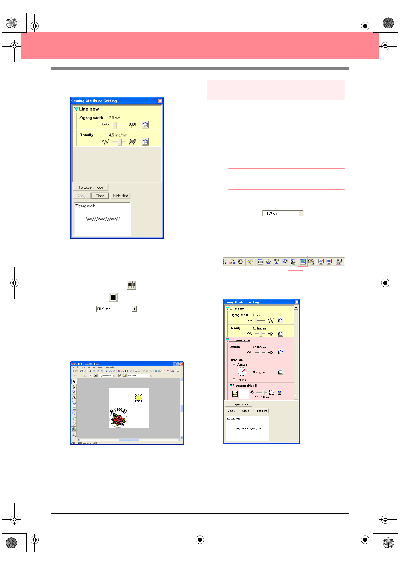
46
Creating and Editing Embroidery Patterns
→ The Sewing Attribute Setting dialog box
appears.
5. To change the width from 2.0 mm, set Zigzag
width to 1.0, and then click Apply.
6. To change the color for the region, click the
Region sew button ( ) so that the Region
color button ( ) and the Region sew type
selector ( ) appear, and then
select a region color.
For this example, select the color LEMON
YELLOW.
→ The embroidery pattern appears as
shown below.
Step 7
Selecting a programmable fill stitch
Next, we will select a special fill stitch pattern for the
inside area of the circle, and then change its
settings. Programmable fill stitch patterns, which
can be created in Programmable Stitch Creator
(refer to “Using Programmable Stitch Creator” on
page 54), are arranged in a tile-like manner within
the selected regions, creating more decorative
stitching.
b Memo:
Make sure that the circle is still selected.
1. Select Prog. Fill Stitch in the Region sew
type selector ( ).
2. Click Sew on the menu bar, and then click
Sewing Attribute Setting.
An alternate method is to click the Toolbar
button indicated below.
→ The Sewing Attribute Setting dialog box
appears.
Sewing Attribute Set
PeDesignV6Eng.book Page 46 Thursday, July 8, 2004 11:59 AM
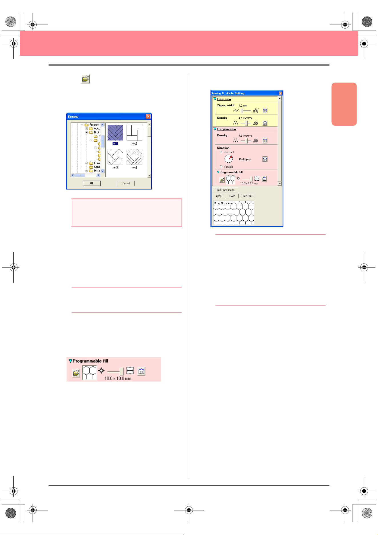
Basic Operation
47
Creating and Editing Embroidery Patterns
3. Click under Programmable fill.
→ The Browse dialog box appears, allowing
you to preview and browse through the
existing programmable fill stitch patterns.
4. From the stitch samples, click pat 07 to select
it, and then click OK.
→ The dialog box closes and a preview of
the selected stitch appears at the bottom
of the Sewing Attribute Setting dialog
box.
b Memo:
Double-clicking the stitch pattern also selects
it and closes the dialog box.
5. To change the size of the programmable stitch
pattern in Beginner Mode, set the size to 10 ×
10 mm (0.30 × 0.30 inch) by moving the slide
to the right.
→ The Sewing Attribute Setting dialog box
appears as shown below.
b Memo:
• The preview of the stitch pattern at the
bottom of the dialog box changes each
time a setting is changed. This allows you
to see how each setting affects the pattern.
• To separately change the width and height
of the stitch pattern, click
To Expert
mode
, and then type or select the desired
values in the appropriate boxes under
Programmable fill
.
6. To change the direction of the fill stitching,
click Constant under Direction, move the
pointer over the red arrow inside of the circle
under Constant, and then drag the red arrow
until 340 degrees is selected.
a Note:
Only programmable fill stitch files, which
have the .pas extension, are listed.
PeDesignV6Eng.book Page 47 Thursday, July 8, 2004 11:59 AM
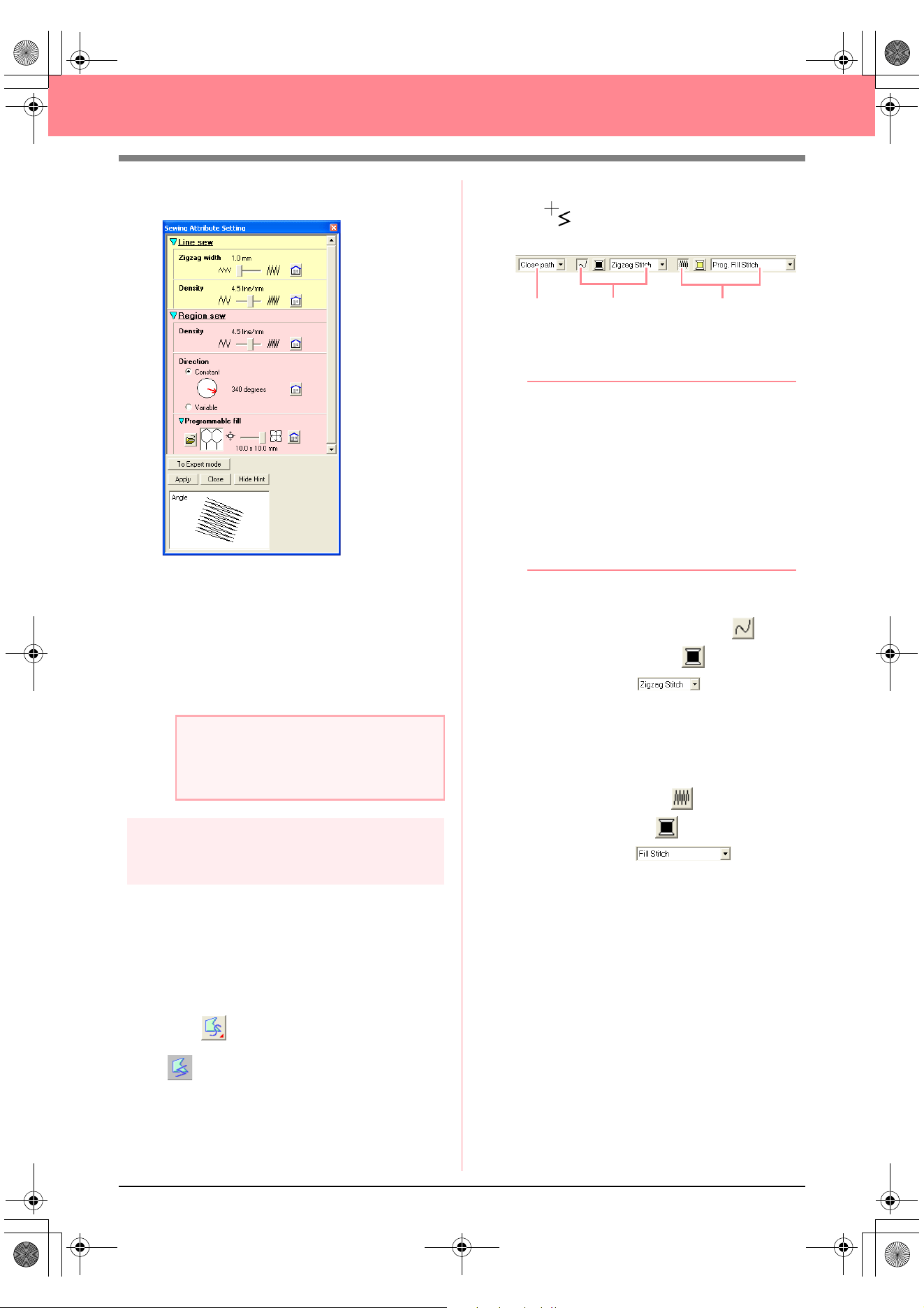
48
Creating and Editing Embroidery Patterns
→ The Sewing Attribute Setting dialog box
appears as shown below.
c
For more information on the different
settings for a programmable fill stitch,
refer to “Specifying sewing attributes” on
page 171.
7. Click Apply.
→ The stitch and its settings are applied to
the inside area of the selected circle.
Step 8
Adding a closed broken line for
the sun’s rays
Now, let’s draw a few rays around the sun. There
are, of course, many ways to do this. You could,
for example, draw a single straight line for each
ray. For this example, we will use a closed
polygonal line (broken line) to draw all of the rays
as a single star-shaped pattern.
1. Click on the Tool Box, and then click
.
→ The shape of the pointer changes to
, and the Sewing Attributes bar ap-
pears as shown below
.
2. Make sure that Close path is selected in the
Path shape selector.
b Memo:
When drawing a closed path, the first point
and the last point are automatically joined.
The pattern has an outline and an inside
area, and sewing attributes can be applied to
both.
With an open path, the broken line is left
open (the first and last point are not
automatically joined). The pattern will not
have a region, therefore you can only apply
sewing attributes to the outline.
3. To change the color and sew type for the
outline, click the Line sew button ( ) so
that the Line color button ( ) and the Line
sew type selector ( ) appear, and
then select a line color and sew type.
For this example, select the color RED, and
leave the sew type set to Zigzag Stitch.
4. To change the color for the inside area, click
the Region sew button ( ) so that the
Region color button ( ) and the Region
sew type selector ( ) appear,
and then select a region color.
For this example, select the color
VERMILION.
a Note:
The selected sewing attributes will be
applied to the regions of every object that will
be drawn, until the attributes are changed.
Path shape
Line sewing
Region sewing
Basic_01.fm Page 48 Friday, July 9, 2004 1:44 PM
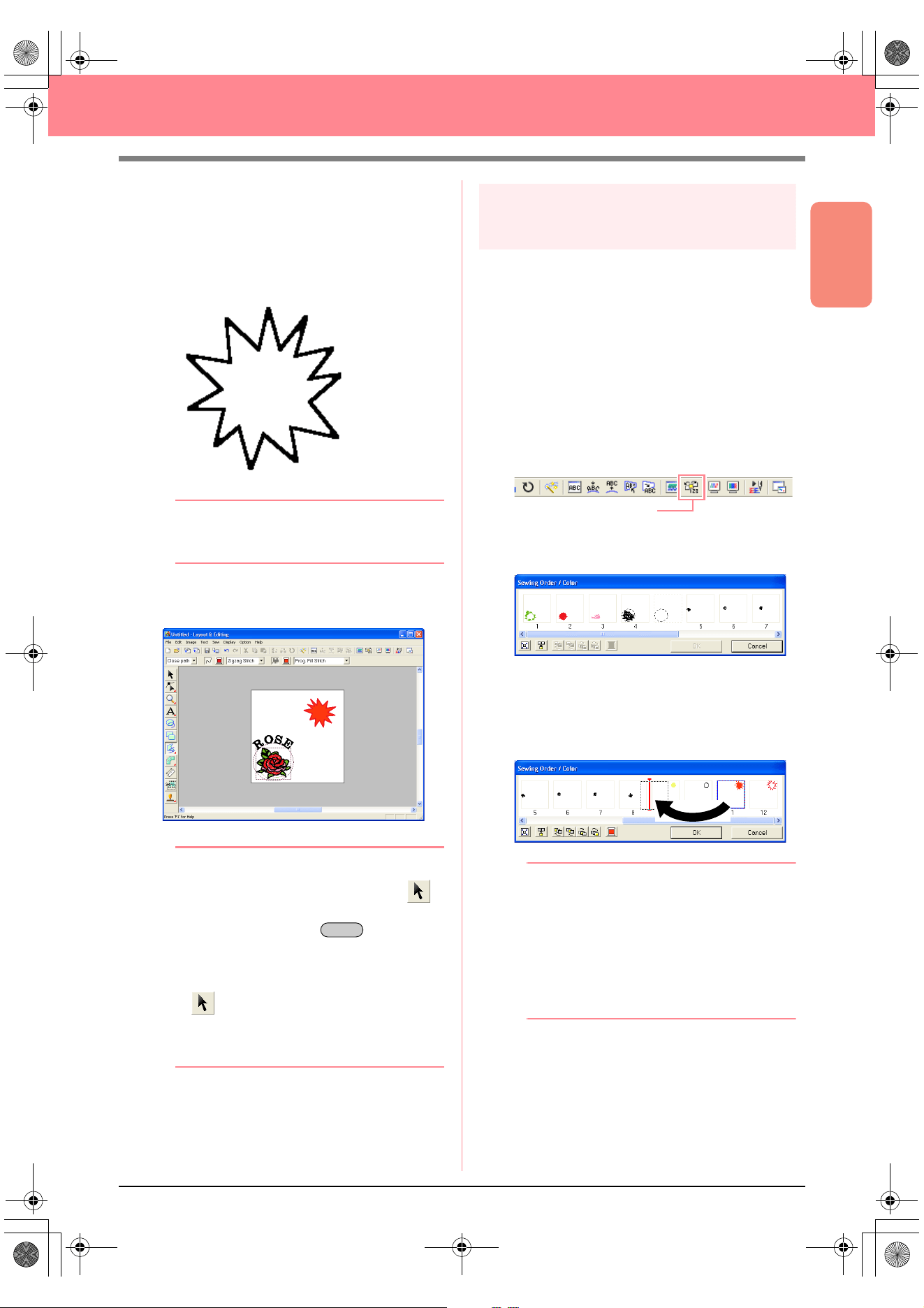
Basic Operation
49
Creating and Editing Embroidery Patterns
5. To draw the rays of the sun around the circle
using the circle as a guide, click in the Design
Page to select the start point (1), continue
clicking in the Design Page to select every
other corner (2 through L), and then double-
click.
b Memo:
To remove the last point that was entered,
click the right mouse button.
→ The embroidery pattern appears as
shown below.
b Memo:
• If you want to delete the pattern, click
on the Tool Box, click the pattern to select
it, and then press the key or
select the menu command
Edit
–
Delete
.
• If you want to change the pattern shape,
color, or sew type after drawing it, click
on the Tool Box, click the pattern to
select it, and then change the settings on
the Sewing Attributes bar or in the
Sewing
Attribute Setting
dialog box.
Step 9
Changing the sewing order of
sun and rays
Since we have drawn the closed broken line for the
sun’s rays after drawing the circle, the sun’s rays
are on top of the circle. In other words, the broken
sun’s rays are in the foreground. Since the pattern
is in the foreground, it will be sewn last. We need to
change the sewing order so that the sun (circle) will
be sewn on top of the sun’s rays.
1. Click Sew on the menu bar, and then click
Sewing Order/Color.
An alternate method is to click the Toolbar
button indicated below.
→ The Sewing Order/Color dialog box
apears.
2. Click the frame containing the region for the
sun’s rays to select it, and then drag the frame
to the left of the circle for the sun. (This part of
the sun will be sewn first.).
b Memo:
When a frame in the
Sewing Order/Color
dialog box is selected, the buttons at the
bottom of the dialog become available. The
sewing order of the selected pattern object
can also be changed by using these buttons.
For more details, refer to “Checking and
Editing the Sewing Order/Color” on
page 184.
1
2
3
4
5
6
7
8
9
0
A
B
C
D
E
F
G
H
I
J
K
L
Delete
Sewing Order/Color
PeDesignV6Eng.book Page 49 Thursday, July 8, 2004 11:59 AM
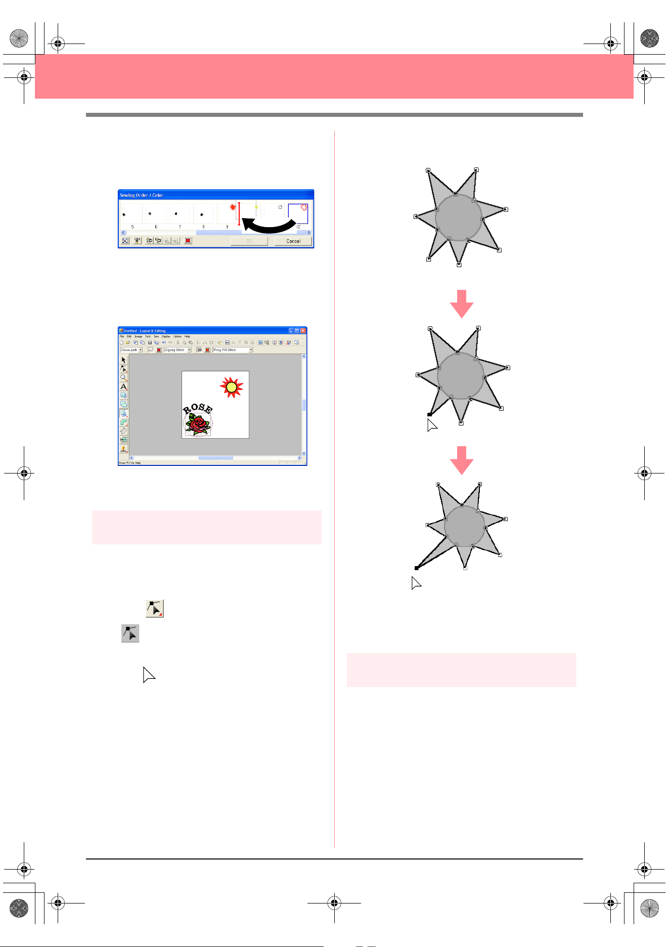
50
Creating and Editing Embroidery Patterns
3. Click the frame containing the outline for the
sun’s rays to select it, and then drag the
selected frame between the region for the
sun’s rays and the circle for the sun.
4. Click OK.
→ The sun’s rays will be sewn before the sun
(circle).
If necessary, move the circle so that it looks
centered relative to the sun’s rays.
Step 10
Adjusting the rays
At this time, you might want to modify the rays.
You can do this by moving, deleting and adding
points in the closed broken line pattern.
1. Click on the Tool Box, and then click
.
→ The shape of the pointer changes to
.
2. Click the sun’s rays to select it.
→ The points in the pattern appear as small
empty squares.
3. Click the point that you want to move.
→ The selected point appears as a small
black square.
4. Drag the point to the new location.
c
For details on adding and deleting points,
refer to “Inserting points” on page 136 and
“Deleting points” on page 137.
Step 11
Setting hole sewing
If the sun is sewn according to the current
settings, the sun’s rays will be sewn first, and then
the sun (circle) will be sewn on top of it. In order to
avoid sewing the same region twice, you can
specify hole sewing for a larger region that
completely encloses smaller ones. If hole sewing
is specified, the part of the rays behind the circle
will not be sewn.
PeDesignV6Eng.book Page 50 Thursday, July 8, 2004 11:59 AM
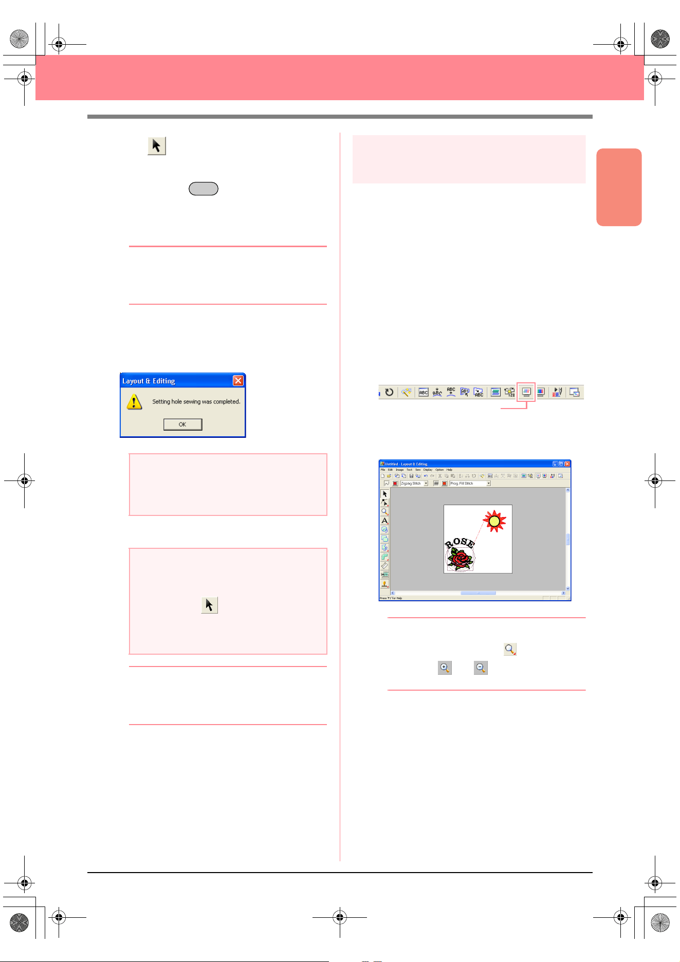
Basic Operation
51
Creating and Editing Embroidery Patterns
1. Click on the Tool Box, and then click the
sun’s circle to select it.
2. Hold down the key and click the sun’s
rays.
→ The circle and the broken line are now se-
lected together.
b Memo:
If it is difficult to select the two patterns, drag
the pointer to draw a selection frame around
the patterns.
3. Click Sew on the menu bar, and then click Set
Hole Sewing.
→ The following message appears.
4. Click OK to close the message.
b Memo:
Points on the outlines can be edited
independently with the Point Edit tool. (For
details, refer to “Moving points” on page 135)
c
For more details, refer to “Specifying hole
sewing” on page 180.
Step 12
Previewing the embroidery
pattern
You can display a preview of the embroidery
pattern in order to see how the stitching is
connected, or you can display a realistic preview
of the embroidery pattern in order to see how the
pattern will appear once it is sewn. For example,
you will be able to see that the part of the broken
line (sun rays) behind the circle is not sewn and
how the selected programmable fill stitch will be
sewn.
1. To display a preview of the embroidery
pattern, click Display on the menu bar, and
then click Preview.
An alternate method is to click the Toolbar
button indicated below.
→ A preview of the embroidery pattern ap-
pears.
b Memo:
To zoom in (or out), click on the Tool
Box, click (or ), and then click the
desired area of the embroidery pattern.
2. To display a realistic preview of the entire
embroidery pattern, deselect all objects in the
pattern by clicking in a blank area of the
Design Page.
To display a realistic preview of a single object
or a group of objects, select the object(s).
a Note:
Hole sewing cannot be applied if one of the
patterns is not completely enclosed within
the other pattern.
a Note:
Patterns with hole sewing set cannot be
moved separately. To adjust their relative
positions, click on the Tool Box, select
one of the patterns, and then cancel hole
sewing by selecting the menu command
Sew
–
Cancel Hole Sewing
.
Ctrl
Preview
PeDesignV6Eng.book Page 51 Thursday, July 8, 2004 11:59 AM
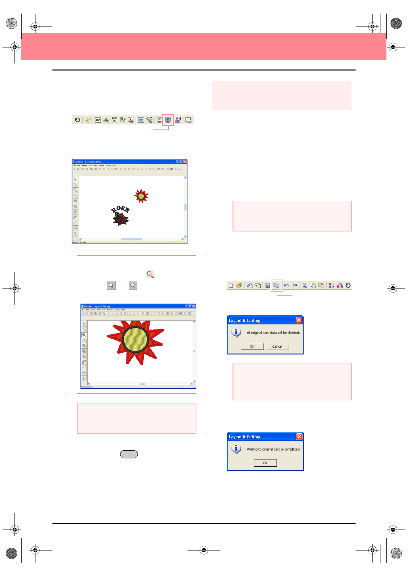
52
Creating and Editing Embroidery Patterns
3. Click Display on the menu bar, and then click
Realistic Preview.
An alternate method is to click the Toolbar
button indicated below.
→ A realistic preview of the embroidery pat-
tern appears.
b Memo:
To zoom in (or out), click on the Tool
Box, click (or ), and then click the
desired area of the embroidery pattern.
4. To return to the previous display, repeat step
3., or press the key.
Step 13
Transferring the pattern to an
original card
Before you can actually sew the embroidery
pattern, you must transfer the pattern to a sewing
machine. Transfer the embroidery pattern to the
sewing machine using media of the type used by
your machine, for example, original cards, floppy
disks, CompactFlash cards, or USB media. For
this example, we will transfer the pattern to an
original card.
1. Insert an original card into the USB card writer
module.
2. Click File on the menu bar, point to Write to
Card, and then click Current Design on the
submenu.
An alternate method is to click the Toolbar
button indicated below.
→ The following message appears.
3. Click OK.
→ The following message appears.
a Note:
The embroidery pattern cannot be edited
while the realistic preview is displayed.
Realistic Preview
Esc
a Note:
The original card is inserted correctly when
you hear it snap into place.
a Note:
If the original card is not brand new, make
sure that the patterns already stored on the
card are no longer needed.
Write to Card
PeDesignV6Eng.book Page 52 Thursday, July 8, 2004 11:59 AM
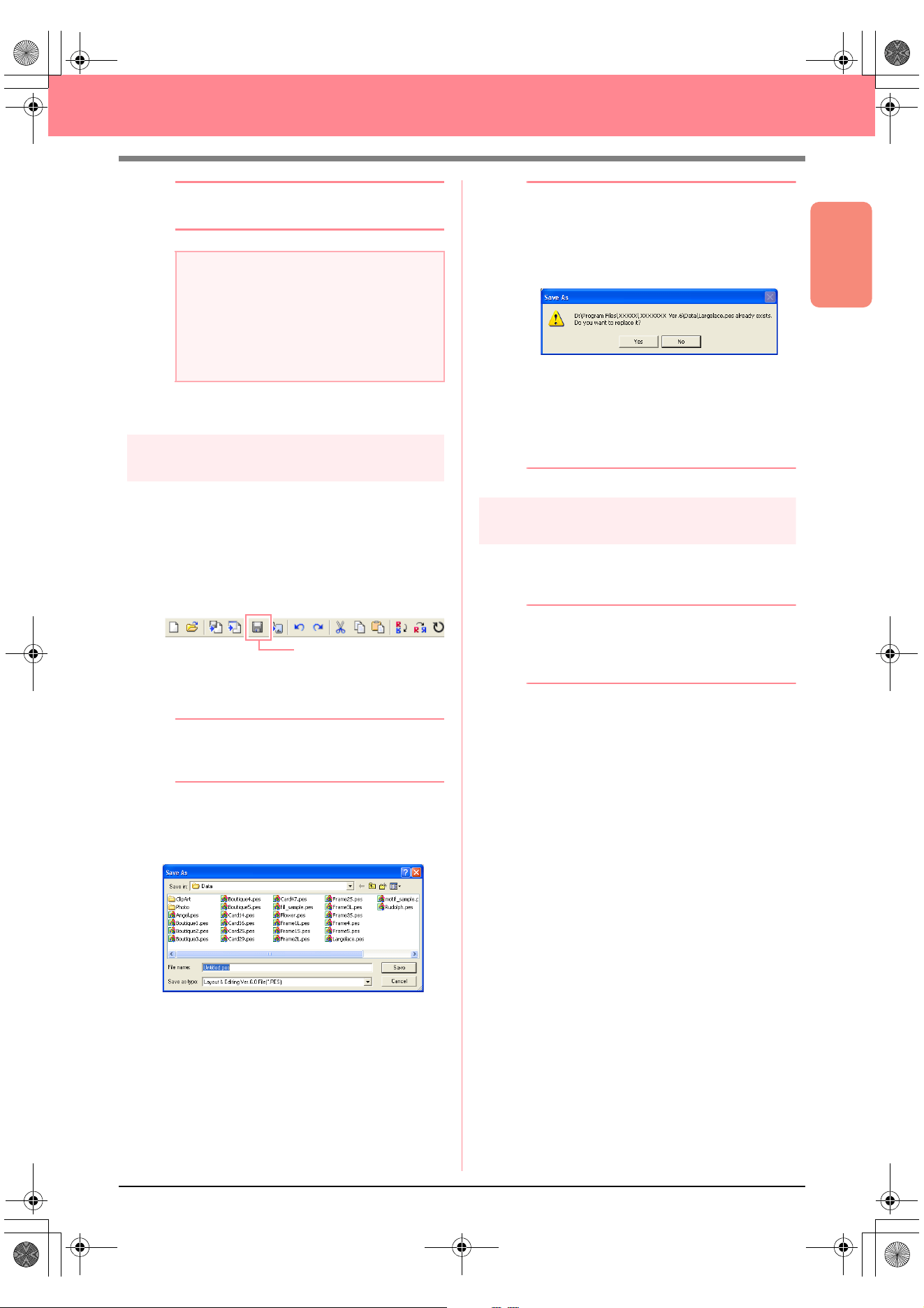
Basic Operation
53
Creating and Editing Embroidery Patterns
b Memo:
To quit the operation, click
Cancel
.
4. Click OK to close the message.
Step 14
Saving the file
Once the embroidery pattern is finished, you may
want to save it in order to retrieve it later.
1. Click File on the menu bar, and then click
Save.
An alternate method is to click the Toolbar
button indicated below.
→ If the pattern has already been saved at
least once, the file is saved immediately.
b Memo:
To save the file with a different name, use the
menu command
File
–
Save As
instead.
→ If no file name has been specified or if the
file cannot be found, the Save As dialog
box appears.
2. Select the drive and the folder, and then type
in the file name.
3. Click Save to save the pattern.
b Memo:
• To quit the operation, click
Cancel
.
• If a file already exists with the name
specified in the
Save As
dialog box, the
following message appears.
• To overwrite the file, click
Yes
. The
new file name appears in the title bar
of the Layout & Editing window.
• If you do not want to overwrite the
existing file, click
No
. You can then
enter a different file name.
Step 15
Quitting Layout & Editing
1. Click File on the menu bar, and then click Exit.
→ The Layout & Editing window closes.
b Memo:
Layout & Editing can also be closed by
clicking the close button on the right end of
the title bar.
a Note:
If the card writer module is not correctly
connected or powered, or if the original card
is not inserted or is defective, an error
message will appear. For more details, refer
to “Writing an embroidery pattern to an
original card” on page 195.
Save
PeDesignV6Eng.book Page 53 Thursday, July 8, 2004 11:59 AM
54
Creating and Editing Embroidery Patterns
Using Programmable Stitch Creator
Programmable Stitch Creator allows you to design fill stitch and motif stitch patterns that can be applied as a
programmable fill stitch or motif stitch both in Design Center and Layout & Editing, resulting in more decorative
embroidery patterns. When applied to enclosed regions, the fill stitch or motif stitch pattern fills the region in a
tile-like manner. When applied to lines, the motif stitch pattern is repeated along the length of the line. In
addition, the fill stitch patterns can be applied as an individual stamp to enclosed regions. You can create your
own fill stitch and motif stitch patterns or use the many stitch patterns provided with this application, with or
without editing them.
In this section, we are going to edit an existing stitch pattern, and then apply embossing/engraving effects to it.
The complete procedure will take you through the different steps of a normal working session with
Programmable Stitch Creator and will introduce you to its most important features.
Follow the instructions in this section step by step. If you have to interrupt this exercise for any reason, it is
recommended to save the file (refer to Step 5, “Saving the edited stitch pattern”, on page 58). You will be able
to retrieve it later and resume your work.
Step 1
Starting up Programmable Stitch
Creator
1. Click , select All Programs, then
PE-DESIGN Ver.6. Select Programmable
Stitch Creator.
b Memo:
If a shortcut for Programmable Stitch Creator
was created, for example, on the desktop,
double-click it to start up the application.
→ The Programmable Stitch Creator window
appears.
b Memo:
To fill the entire screen with the
Programmable Stitch Creator window, click
the maximize button on the right end of the
title bar.
Step 1 Starting up Programmable Stitch Creator page 54
Step 2 Opening a programmable stitch pattern page 55
Step 3 Drawing lines to edit the stitch pattern page 56
Step 4 Applying embossing/engraving effects page 57
Step 5 Saving the edited stitch pattern page 58
Step 6 Quitting Programmable Stitch Creator page 58
PeDesignV6Eng.book Page 54 Thursday, July 8, 2004 11:59 AM
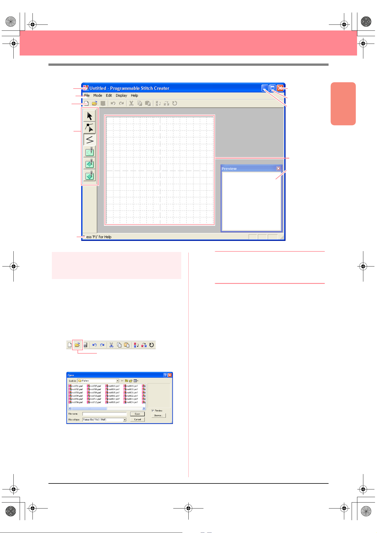
Basic Operation
55
Creating and Editing Embroidery Patterns
Step 2
Opening a programmable stitch
pattern
For this exercise, we will edit one of the
programmable fill stitch patterns provided with the
application.
1. Click File on the menu bar, and then click
Open.
An alternate method is to click the Toolbar
button indicated below.
→ The Open dialog box appears.
2. Select the stitch pattern file wave1.pas in the
Pattern folder.
b Memo:
If the
Preview
check box is selected, the
contents of the selected file will appear in the
Preview
box.
3. Click Open to open the pattern file and to
close the dialog box.
Menu bar
Toolbar
Tool Box
Work area
Status bar
Title bar
Maximize button
Close button
Minimize button
Preview window
Open
PeDesignV6Eng.book Page 55 Thursday, July 8, 2004 11:59 AM
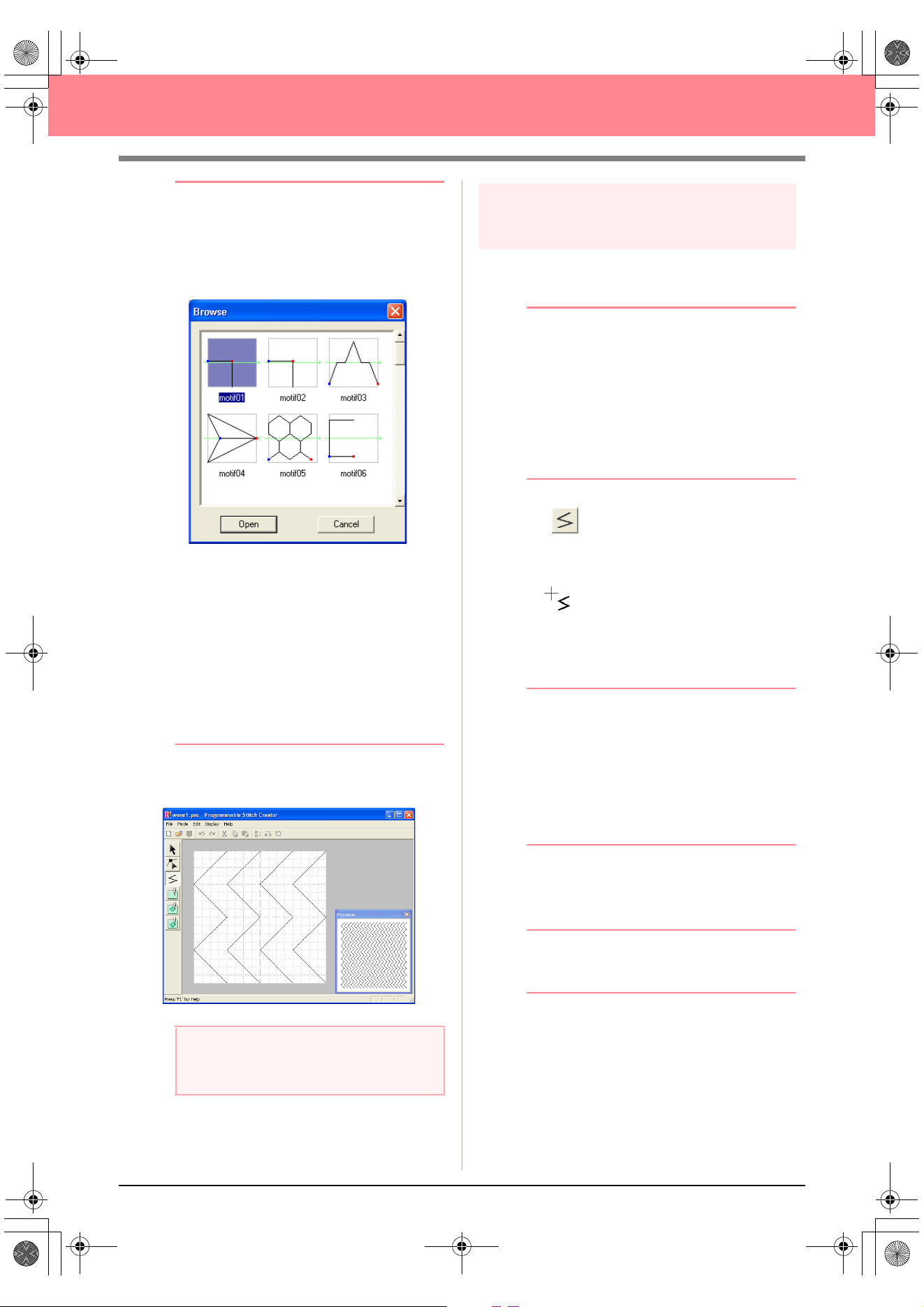
56
Creating and Editing Embroidery Patterns
b Memo:
• Double-clicking the file name also adds the
pattern to the work area and closes the
dialog box.
• To preview the available .pas files in the
selected folder, click
Browse
.
In the
Browse
dialog box that appeared,
click a stitch pattern to select it, and then
click
Open
(or double-click the pattern) to
open the file and to close both the
Open
and
Browse
dialog boxes.
• Opening a .pas file (programmable fill
stitch pattern) automatically selects
Programmable Fill
mode. Opening a .pmf
file (motif stitch patterns) automatically
selects
Motif
mode. To change the type of
stitch pattern to be created, use the
commands on the
Mode
menu.
→ The stitch pattern appears in the work
area of Programmable Stitch Creator.
Step 3
Drawing lines to edit the stitch
pattern
Now, we are going to draw a lines between the
displayed ones using the Line tool of the Tool Box.
b Memo:
For this example, we will use the grid setting
Medium
with which the stitch pattern was
saved. Grid settings should be selected
depending on how detailed you want to draw.
Select the grid setting
Narrow
for more
detailed stitches and the grid setting
Wide
for
more simple stitches. For more information
on the grid settings, refer to “Changing the
grid settings” on page 222.
1. Click on the Tool Box. Move the pointer
over the work area.
→ The shape of the pointer changes to
.
2. Move the pointer to the second vertical grid
line to the right of the leftmost wave, and then
click the top edge of the work area.
b Memo:
The horizontal and vertical lines that you
draw on the work area always follow the grid.
The points that you create by clicking are
inserted at the intersection of the horizontal
and vertical grid lines, enabling you to draw
diagonal lines as well. Therefore, regardless
of where you click, a point will automatically
be inserted at the nearest intersection.
3. Move the pointer parallel to the wave, and
then click the second vertical grid line to the
right of the corner in the leftmost wave.
b Memo:
To remove the last point that was entered,
click the right mouse button.
4. Repeat step 3. until you reach the end of the
wave, and then double-click the bottom edge
of the work area.
5. Repeat steps 2. through 4. to add another
wave between the rightmost wave.
a Note:
You can see a preview of the stitch pattern in
the
Preview
window.
PeDesignV6Eng.book Page 56 Thursday, July 8, 2004 11:59 AM

Basic Operation
57
Creating and Editing Embroidery Patterns
→ The pattern should appear as shown be-
low.
b Memo:
To edit points in the pattern, click on the
Tool Box, and then edit the points. (For
details on moving, inserting and delete
points, refer to “Editing Points in Outlines” on
page 81 or go back to Step 10, “Adjusting the
rays”, on page 50).
Step 4
Applying embossing/engraving
effects
A stamp can be made by sewing regions of a fill
stitch pattern with the fill stitch, satin stitch or the
base stitch set for the embroidery pattern in order
to create embossing and engraving effects.
In order to do this, the lines of the stitch pattern
must form closed regions. In our example, the
lines do not form closed regions, so we will need
to add enclosing lines.
1. Click on the Tool Box.
→ The shape of the pointer changes to
.
2. Click the upper-left corner of the work area.
3. Move the pointer along the top edge of the
work area, and then double-click the upper-
right corner to draw a line along the top edge.
4. Click the lower-left corner of the work area.
5. Move the pointer along the bottom edge of the
work area, and then double-click the lower-
right corner to draw a line along the bottom
edge of the work area.
6. Click (Region (engrave)) on the Tool
Box, and then click the first and fourth wave
regions.
→ These regions appear in red and will be
sewn with short stitches to give the effect
of engraving.
7. Click (Region (emboss)) on the Tool
Box, and then click the second and fifth wave
regions.
→ This region appears in blue and will be
sewn with no dropped stitches to give the
effect of embossing.
PeDesignV6Eng.book Page 57 Thursday, July 8, 2004 11:59 AM
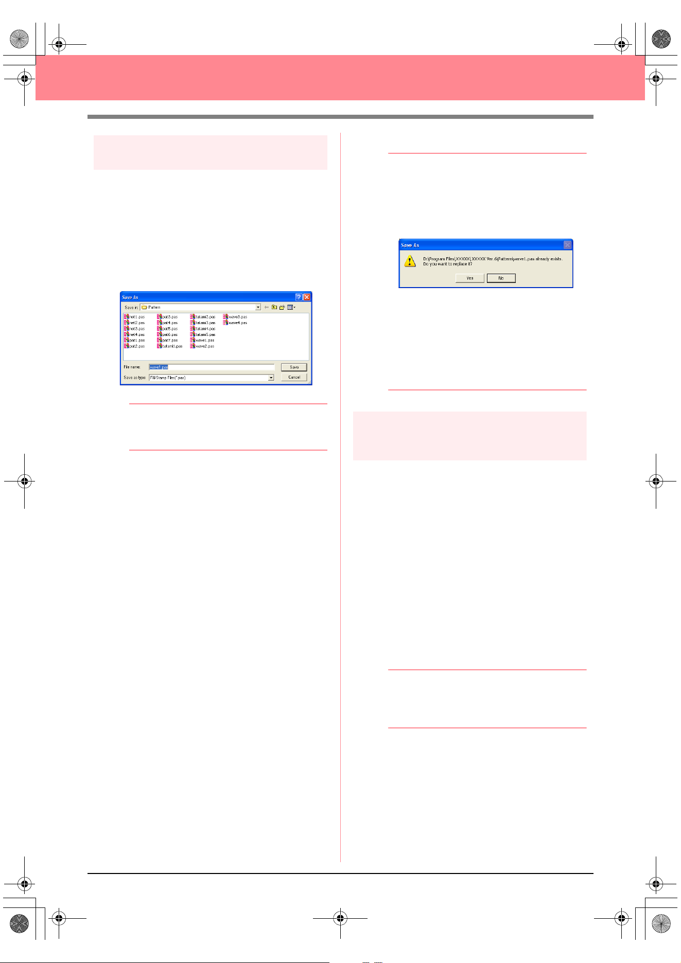
58
Creating and Editing Embroidery Patterns
Step 5
Saving the edited stitch pattern
In order to apply your edited stitch pattern as a
programmable fill stitch or as a stamp to a region
in Layout & Editing or Design Center, you must
first save it as a .pas file.
1. Click File on the menu bar, and then click
Save As.
→ The Save As dialog box appears.
b Memo:
To overwrite the original file, use the menu
command
File
–
Save
instead.
2. Select the drive and the folder, and then type
in the file name.
3. Click Save to save the pattern.
b Memo:
• To quit the operation, click
Cancel
.
• If a file already exists with the name
specified in the
Save As
dialog box, the
following message appears.
• To overwrite the file, click
Yes
. The
new file name appears in the title bar
of the Programmable Stitch Creator
window.
• If you do not want to overwrite the
existing file, click
No
. You can then
enter a different file name.
Step 6
Quitting Programmable Stitch
Creator
When you are finished creating stitch patterns in
Programmable Stitch Creator, you can close the
application.
1. Click File on the menu bar, and then click Exit.
→ If you have saved your file as described in
Step 5, “Saving the edited stitch pattern”,
the Programmable Stitch Creator window
closes immediately.
→ If you have made changes to the pattern
since the last time the file was saved, you
will be asked whether you want to save
the changes. Click Yes, and then follow
the procedure described in Step 5, “Sav-
ing the edited stitch pattern”.
b Memo:
Programmable Stitch Creator can also be
closed by clicking the close button on the
right end of the title bar.
PeDesignV6Eng.book Page 58 Thursday, July 8, 2004 11:59 AM
Basic Operation
59
Creating Large-Size Embroidery Patterns
A large-size embroidery pattern can be designed by specifying the size of the pattern, creating the embroidery
pattern, then automatically dividing the pattern into a size that can be embroidered. By separately
embroidering each section of the pattern side by side, large-size embroidery can be sewn. In addition, the
joining edges can be embroidered slightly overlapping in order to blend beautifully.
Some large-size patterns may not be appropriate for use with the split sewing feature. We recommend using
designs with many small filled areas, such as a bouquet of flowers, lace designs and embroidery created using
the Photo Stitch function. Since designs with very large filled areas may not align properly due to fabric pull,
we suggest these types of designs not be used.
In this section, we are going to adapt an existing embroidery pattern for large-size embroidery, and then sew it.
The complete procedure will take you through the different steps of a normal working session with a large-size
embroidery pattern and will introduce you to its most important options.
Follow the instructions in this section step by step. If you have to interrupt this exercise for any reason, it is
recommended to save the file (refer to Step 5, “Saving the pattern”, on page 61). You will be able to retrieve
it later and resume your work.
Designing a large-size embroidery pattern
Step 1
Starting up Layout & Editing
1.
Click , select All Programs, then
PE-DESIGN Ver.6. Select Layout & Editing
to open the Layout & Editing window.
b Memo:
If a shortcut for Layout & Editing was
created, for example, on the desktop,
double-click it to start up the application.
→ The Layout & Editing window appears.
b Memo:
To fill the entire screen with the Layout &
Editing window, click the maximize button on
the right end of the title bar.
Designing a large-size embroidery pattern
Step 1 Starting up Layout & Editing page 59
Step 2 Specifying a Design Page size page 60
Step 3 Creating the embroidery pattern page 60
Step 4 Checking the embroidering order page 61
Step 5 Saving the pattern page 61
Step 6 Transferring the pattern to an original card page 62
Step 7 Quitting Layout & Editing page 63
Embroidering large-size embroidery patterns
Step 1 Attaching stabilizer to the fabric page 63
Step 2 Marking the embroidering position page 63
Step 3 Hooping the fabric page 65
Step 4 Embroidering page 65
PeDesignV6Eng.book Page 59 Thursday, July 8, 2004 11:59 AM
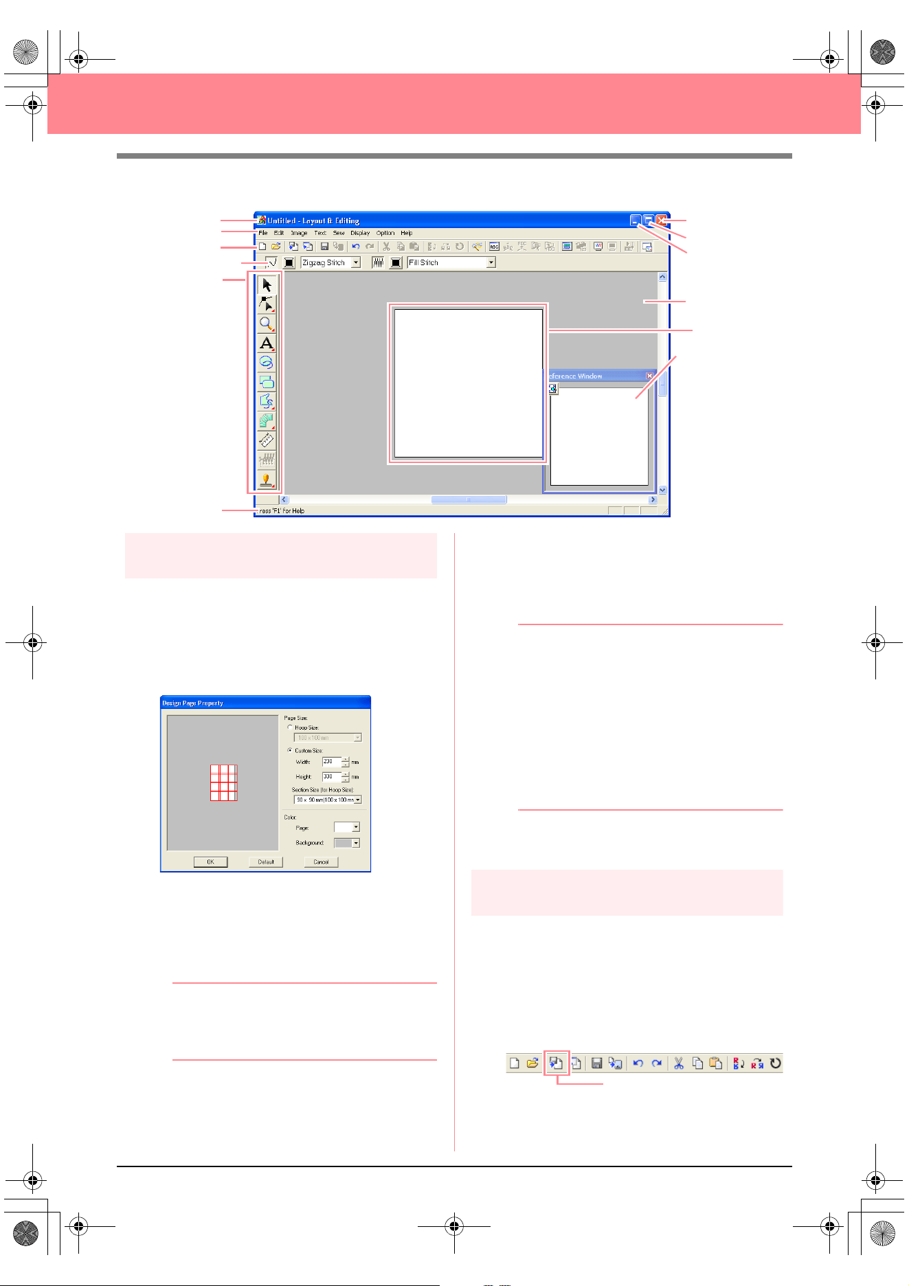
60
Creating Large-Size Embroidery Patterns
Step 2
Specifying a Design Page size
First, we need to specify the desired size for the
complete embroidery pattern.
1. Click Option, then Design Page Property.
→ The Design Page Property dialog box
appears.
2. Select Custom Size, and then type or select
the desired width and height for the Design
Page. Enter dimensions between 100 and
1000 mm. For this example, set Width to 230
mm and Height to 330 mm.
b Memo:
The width and height specified under
Custom Size determine the exact size of
the embroidery design.
3. Click in the Section Size (for Hoop Size)
selector, and then select the size of the
sections (your embroidery hoop). For this
example, select 120 × 170 mm (130 × 180
mm).
b Memo:
• With the Section Size (for Hoop Size)
setting, the width and height of the
sections are 10 mm smaller than the
actual hoop size in order to provide
space for fine positioning adjustments
with adjacent sections.
• The preview area shows the setting
changes that you make. The double
lines indicate adjoining edges where
embroidering will overlap.
4. Click OK.
Step 3
Creating the embroidery pattern
For this example, we will use one of the lace
embroidery patterns provided with the application.
1. Click File on the menu bar, point to Import,
and then click from File on the submenu.
An alternate method is to click the Toolbar
button indicated below.
Menu bar
Toolbar
Sewing Attributes bar
Too l Box
Work area
Design Page
Status bar
Maximize button
Close button
Title bar
Minimize button
Reference Window
from File
PeDesignV6Eng.book Page 60 Thursday, July 8, 2004 11:59 AM
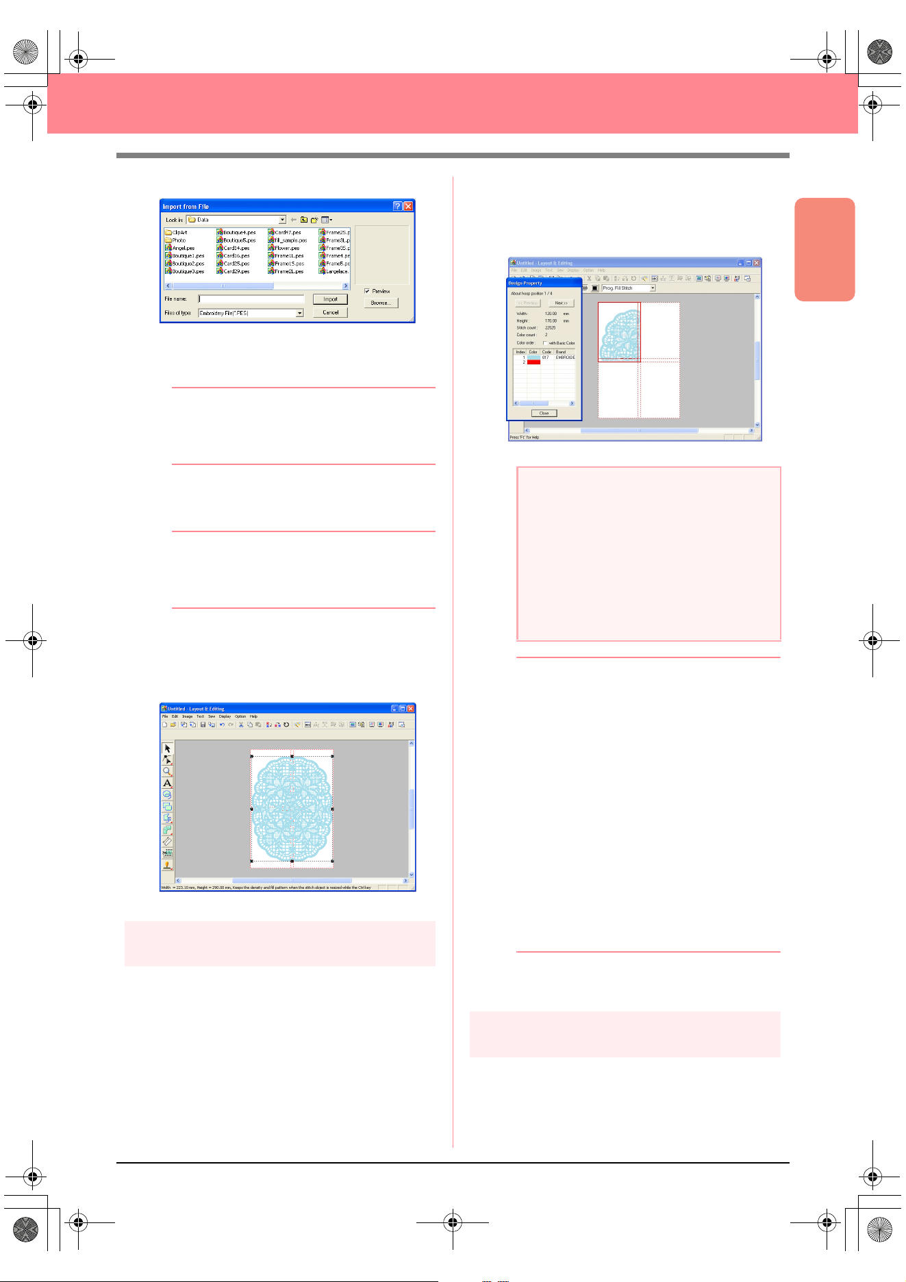
Basic Operation
61
Creating Large-Size Embroidery Patterns
→ The Import from File dialog box appears.
2. Select the embroidery pattern file
Largelace.pes in the Data folder.
b Memo:
If the
Preview
check box is selected, the
contents of the selected file will appear in the
Preview
box.
3. Click Import to import the embroidery pattern
file and to close the dialog box.
b Memo:
Double-clicking the file name also imports
the pattern into the Design Page and closes
the dialog box.
→ The embroidery pattern appears in the
Design Page. (To center the embroidery
pattern within the Design Page, select the
menu command Edit – Center.)
Step 4
Checking the embroidering order
Before the embroidery pattern is sewn, check the
embroidering order to see the order that the
pattern sections are sewn and determine which
parts of the fabric should be hooped.
The pattern sections are sewn in order from left to
right, top to bottom.
1. Click Option on the menu bar, and then click
Design Property.
→ The Design Property dialog box ap-
pears, and the first pattern section to be
sewn appears in the Design Page framed
with a red line.
b Memo:
• The embroidering order cannot be
checked while the pattern is selected;
therefore, be sure to deselect the pattern
before selecting the menu command
Option
–
Design Property
. (For details,
refer to “Selecting patterns” on page 130.)
• The Design Page is automatically zoomed
in on or zoomed out from to fit in the entire
window, with the position of the displayed
pattern section within the embroidery hoop
installation order indicated at the top of the
dialog box.
• To display information for other pattern
sections in the embroidering order, click
Previous
or
Next
.
• Pattern sections that do not contain any
stitching will not be displayed.
2. Click Close to close the dialog box.
Step 5
Saving the pattern
Once the embroidery pattern is finished, you may
want to save it in order to retrieve it later.
1. Click File on the menu bar, and then click
Save.
a Note:
Before an embroidery pattern created in a
custom Design Page is saved or transferred
to an original card, running stitches are
added at the edges of the pattern sections
so that the pattern sections can easily be
aligned during sewing. This alignment
stitching appears in the
NOT DEFINED
color
and cannot be edited. (For more details,
refer to “Embroidering” on page 65.)
PeDesignV6Eng.book Page 61 Thursday, July 8, 2004 11:59 AM
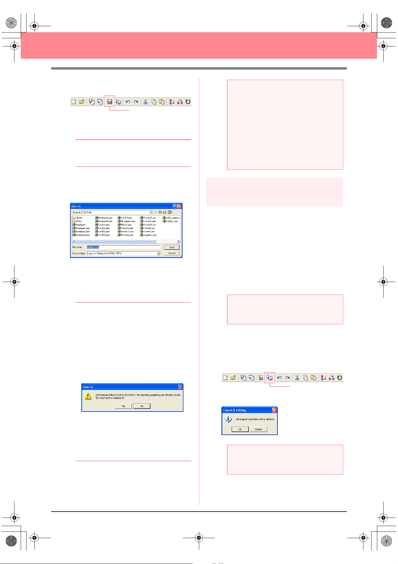
62
Creating Large-Size Embroidery Patterns
An alternate method is to click the Toolbar
button indicated below.
→ If the pattern has already been saved at
least once, the file is saved immediately.
b Memo:
To save the file with a different name, use the
menu command
File
–
Save As
instead.
→ If no file name has been specified or if the
file cannot be found, the Save As dialog
box appears.
2. Select the drive and the folder, and then type
in the file name.
3. Click Save to save the pattern.
b Memo:
• All patterns for a divided embroidery
pattern are saved as a single .pes (version
6) file.
• Only the sections that contain stitching are
saved.
• To quit the operation, click
Cancel
.
• If a file already exists with the name
specified in the
Save As
dialog box, the
following message appears.
• To overwrite the file, click
Yes
. The
new file name appears in the title bar
of the Layout & Editing window.
• If you do not want to overwrite the
existing file, click
No
. You can then
enter a different file name.
Step 6
Transferring the pattern to an
original card
This embroidery pattern can be transferred to a
sewing machine, where it can be sewn. Transfer
the embroidery pattern to the sewing machine
using media of the type used by your machine, for
example, original cards, floppy disks,
CompactFlash cards, or USB media. For this
example, we will transfer the pattern to an original
card.
1. Insert an original card into the USB card writer
module.
2. Click File on the menu bar, point to Write to
Card, and then click Current Design on the
submenu.
An alternate method is to click the Toolbar
button indicated below.
→ The following message appears.
Save
a Note:
If a section of the pattern exceeds the
maximum allowed for the stitch count or
number of colors, a message appears,
describing the limitations and asking
whether or not the pattern should be saved
anyway. If the embroidery pattern extends
off the Design Page, a message appears,
asking whether or not the pattern should be
saved anyway. If the pattern is saved
anyway, it must be edited before it can be
sewn.
a Note:
The original card is inserted correctly when
you hear it snap into place.
a Note:
If the original card already contains patterns,
they will be deleted.
Write to Card
PeDesignV6Eng.book Page 62 Thursday, July 8, 2004 11:59 AM
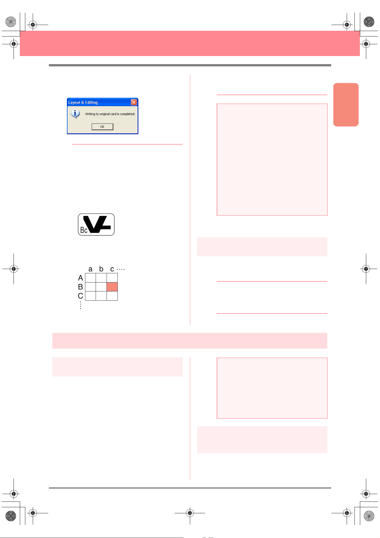
Basic Operation
63
Creating Large-Size Embroidery Patterns
3. Click OK.
→ The following message appears.
b Memo:
• Each section of the pattern is saved to the
original card as a separate pattern. When
the patterns are displayed on the sewing
machine’s display, they appear with two
letters in the lower-left corner, indicating
that section’s position in the entire pattern.
The uppercase letter indicates the row and
the lowercase letter indicates the column.
For example, for the pattern section
marked below in red, the pattern will
appear with “Bc” to indicate its position.
For the example shown above, the large-
size embroidery pattern will be saved as
nine smaller patterns marked “Aa”, “Ab”,
“Ac”, “Ba”, “Bb”, “Bc”, “Ca”, “Cb” and “Cc”.
• To quit the operation, click
Cancel
.
4. Click OK to close the message.
Step 7
Quitting Layout & Editing
1. Click File on the menu bar, and then click Exit.
→ The Layout & Editing window closes.
b Memo:
Layout & Editing can also be closed by
clicking the close button on the right end of
the title bar.
Embroidering large-size embroidery patterns
Step 1
Attaching stabilizer to the fabric
Stabilizer must always be used when
embroidering to stabilize the fabric. There are
many types of stabilizer; the type that you will use
depends on the type of fabric that you are
embroidering on. For large-size designs that are
split into sections, the stabilizer must be adhered
to the fabric, for example, by using iron-on
stabilizer, sticky stabilizer or spray adhesive.
When using spray adhesive, spray the adhesive
onto a hooped piece of stabilizer that is strong
enough for the entire large-size embroidery. In
some cases, you may need to use two pieces of
stabilizer for your embroidery.
Step 2
Marking the embroidering
position
Using the template for the size of hoop that you
are using, mark the embroidering position on the
fabric.
a Note:
• If the card writer module is not correctly
connected or powered, or if the original
card is not inserted or is defective, an error
message will appear. For more details,
refer to “Writing an embroidery pattern to
an original card” on page 195.
• If a section of the pattern exceeds the
maximum size allowed, a message
appears, describing the limitations and the
pattern is not transferred to the original
card. In addition, if the pattern is too large
to be transferred to a single original card,
select the sections to transfer. For more
details, refer to “Writing an embroidery
pattern to an original card” on page 195.
a Note:
• For best results, attach the stabilizer to the
fabric (as described in Step 1 on this
page). Without the correct stabilizer, the
design may become misaligned due to
puckering in the fabric.
• Be sure to check the recommendations on
the stabilizer package.
PeDesignV6Eng.book Page 63 Thursday, July 8, 2004 11:59 AM
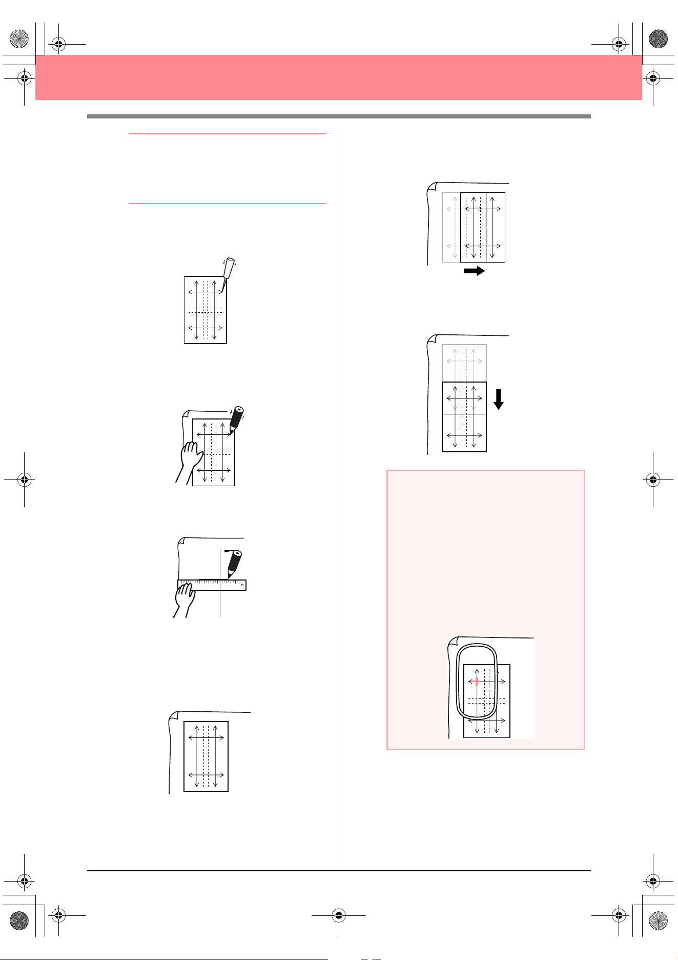
64
Creating Large-Size Embroidery Patterns
b Memo:
• The templates are included in the
package.
• The templates are also in the
Template
folder and can be printed out with a printer.
1. Punch a hole at the end of each arrow on the
template.
2. Place the template on the fabric, and then
insert the tip of a marking pen into each hole
to mark the fabric.
3. Connect the points marked on the fabric to
draw reference lines.
For a large embroidery pattern, reposition the
template to draw the embroidering position for each
section of the embroidery pattern.
1. Place the template on the fabric, and mark
points A, B, C and D.
2. To mark an area to the right of the previously
marked area, align points A and D on the
template with marks B and C on the fabric.
To mark an area below the previously marked
area, align points A and B on the template with
marks C and D on the fabric.
AB
DC
a Note:
• The intersection of the horizontal and
vertical line indicates the center of the
embroidery hoop.
•
While carefully considering how the fabric
will be hooped, place the template on the
fabric, and then draw lines to indicate the
embroidering position. In addition, because
all embroidery areas are not drawn on the
template for large embroidery hoops, be
careful that the embroidery area does not
extend from the marked area on the fabric as
shown below.
AB
DC
AB
DC
AB
DC
AB
DC
PeDesignV6Eng.book Page 64 Thursday, July 8, 2004 11:59 AM
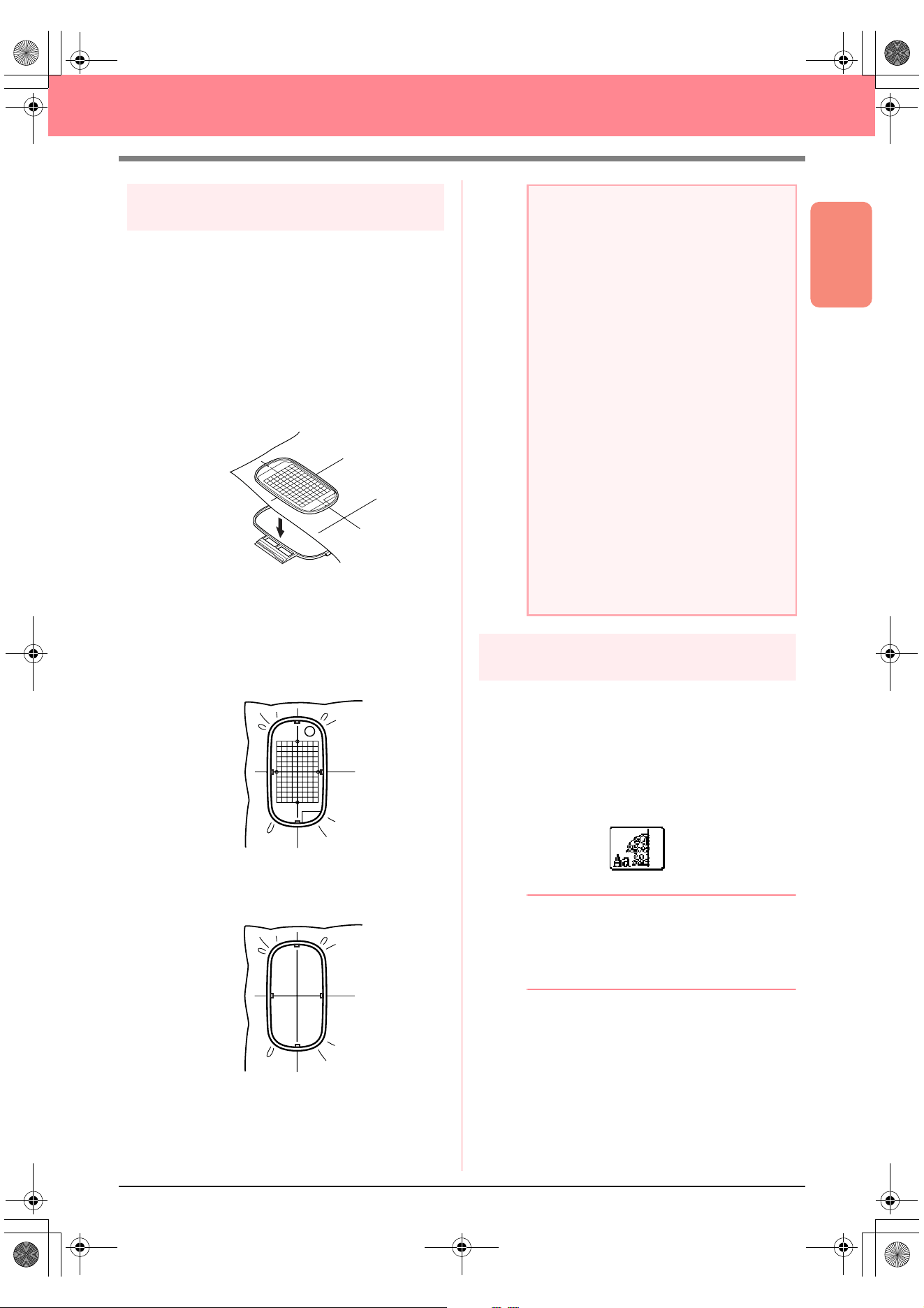
Basic Operation
65
Creating Large-Size Embroidery Patterns
Step 3
Hooping the fabric
Using the hoop’s plastic embroidery sheet, align the
reference lines on the embroidery sheet with the marks
on the fabric. Then, hoop the fabric while making sure
that the fabric remains correctly aligned.
1. Insert the embroidery sheet into the inner ring
of the embroidery hoop, and then place them
on top of the fabric with the centerline on the
embroidery sheet aligned with the reference
lines (drawn on the fabric) for the first pattern
section to be sewn.
2. Keeping the reference lines on the embroidery
sheet aligned with the reference lines for the
first pattern section, place the fabric and inner
ring of the embroidery hoop into the outer ring
of the hoop, and then pull the fabric so that it
is tight.
3. Finish hooping the fabric, and then remove the
embroidery sheet.
Step 4
Embroidering
Now, we are ready to embroider the pattern.
1. When large-size embroidery patterns are
transferred to the sewing machine, the patterns
appear on the sewing machine display as
shown below. For this example, select the first
embroidery pattern section (Aa).
b Memo:
If there is no stitching in section Aa, select
the first section that contains stitching. Select
the menu command
Option
–
Design
Property
to check the embroidering order.
2. Attach the embroidery hoop to the sewing
machine, and then using the machine’s layout
adjusting functions, align the needle position
with the intersection of the lines drawn on the
fabric.
a Note:
• Place the fabric and hoop on a level
surface, and then make sure that the inner
ring is pressed in well enough that the top
edge of the inner ring aligns with the top
edge of the outer ring.
• If the embroidery sheet is not used, the
marks on the embroidery hoop can be
used to hoop the fabric vertically and
horizontally.
However, since the center point on some
sewing machines is off center, the
embroidery sheet should be used for best
results.
• Another way to hoop the fabric is to use
sticky stabilizer that can be hooped
separately, tear away the protective
paper, then carefully align the fabric onto
the sticky surface using the embroidery
sheet as a guide.
• Tip: The fabric can be hooped more easily
if double-sided tape is affixed to the back
of the inside frame, which is placed on top
of the fabric, and then the fabric is
clamped between the inside frame and the
outside frame.
PeDesignV6Eng.book Page 65 Thursday, July 8, 2004 11:59 AM
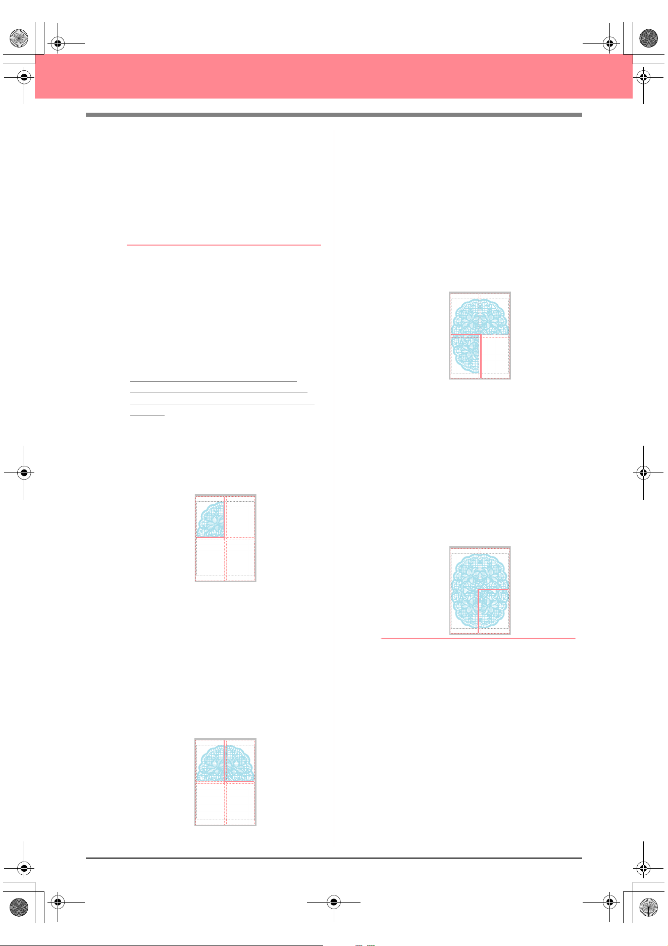
66
Creating Large-Size Embroidery Patterns
3. Embroider the selected pattern.
4. Remove the embroidery hoop from the sewing
machine, and then remove the fabric from the
hoop.
5. Hoop the fabric for the next pattern section.
(For details, refer to “Hooping the fabric” on
page 65.)
b Memo:
When an embroidery pattern created in a
custom Design Page is saved or transferred
to an original card, alignment stitching (single
lines of running stitches with the color
NOT
DEFINED
, with a pitch of 10.0 mm, and
starting with securing stitches with a pitch of
0.3 mm) is added at the edges of the pattern
sections. (The alignment stitching appears in
the print preview and is printed in red.)
Example for hooping fabric using the
alignment stitching with Largelace.pes
(Largelace.pes can be found in the Data
folder.):
1) Embroider the upper-left pattern
section.
→
Alignment stitching is sewn below
and on the right side of the
embroidered pattern section.
2) Hoop the fabric for the upper-right pattern
section with the left side of the hoop
aligned on the alignment stitching on the
right side of the pattern section sewn in
step 1, and then embroider the pattern.
→
Before the pattern section is
embroidered, alignment stitching is
sewn on the left side. Make sure that
this alignment stitching aligns with the
alignment stitching sewn in step 1.
After the pattern section is
embroidered, alignment stitching is
sewn below the pattern section.
3) Hoop the fabric for the lower-left pattern
section with the top of the hoop aligned
on the alignment stitching at the bottom
of the pattern section sewn in step 1,
and then embroider the pattern.
→
Before the pattern section is
embroidered, alignment stitching is
sewn at the top. Make sure that this
alignment stitching aligns with the
alignment stitching sewn in step 1.
After the pattern section is
embroidered, alignment stitching is
sewn on the right side of the pattern
section.
4) Hoop the fabric for the lower-right pattern
section with the left side of the hoop
aligned on the alignment stitching on the
right side of the pattern section sewn in
step 3 and with the top of the hoop aligned
on the alignment stitching at the bottom of
the pattern section sewn in step 2, and
then embroider the pattern.
→
Before the pattern section is
embroidered, alignment stitching is
sewn on the left side and at the top.
Make sure that this alignment
stitching aligns with the alignment
stitching sewn in step 3 and in step 2.
6. Continue hooping the fabric and embroidering
until the entire embroidery pattern is sewn.
PeDesignV6Eng.book Page 66 Thursday, July 8, 2004 11:59 AM

67
Chapter 2
Advanced Operation
Design Center...................................................... 69
Layout & Editing ................................................. 106
Inputting Images and Embroidery Patterns .................................... 108
Editing Embroidery Patterns ........................................................... 130
Checking Embroidery Patterns ....................................................... 182
Saving and Printing......................................................................... 194
Changing Software Settings ........................................................... 202
Information for Optional Large-Size Hoop Users............................ 203
Programmable Stitch Creator ............................ 208
Design Database ................................................. 223
PeDesignV6Eng.book Page 67 Thursday, July 8, 2004 11:59 AM
68
Advanced Operations
About This Chapter
This chapter provides you with detailed procedures on the various operations that you can perform in each of
the applications.
Design Center
Design Center is used to manually create embroidery patterns from images using a four-stage procedure.
Stage 1 (Original Image Stage) c page 71
Stage 2 (Line Image Stage)
c page 73
Stage 3 (Figure Handle Stage)
c page 76
Stage 4 (Sew Setting Stage)
c page 83
Layout & Editing
Layout & Editing is used to automatically create embroidery patterns from images and to create embroidery
patterns by combining drawn objects and text.
Inputting Images and Embroidery Patterns c page 108
Editing Embroidery Patterns
c page 130
Checking Embroidery Patterns
c page 182
Saving and Printing
c page 194
Changing Software Settings
c page 202
Information for Optional Large-Size Hoop Users
c page 203
Programmable Stitch Creator
Programmable Stitch Creator allows you to create, edit and save fill/stamp and motif stitch patterns that can
be applied as a programmable fill stitch or a motif stitch, or as a stamp to the enclosed regions of
embroidery patterns.
c page 208
Design Database
Design Database allows you to organize the embroidery pattern files on your computer so that you can
easily preview them and find the desired pattern.
c page 223
PeDesignV6Eng.book Page 68 Thursday, July 8, 2004 11:59 AM
69
Advanced Opreation
Design Center
Design Center
Design Center is used to create embroidery patterns from images created in other applications. With Design
Center, you can also apply stitch patterns created with Programmable Stitch Creator to regions of the
embroidery pattern. The resulting embroidery pattern can then be imported into the Layout & Editing Design
Page and combined with other patterns.
The embroidery pattern is created in four stages:
■ Stage 1 (Original Image Stage)
In stage 1, you can open an image (or clip art) from various sources, such as, an image created in Paint
®
, a
scanned drawing, or purchased clip art.
The image file must be in the uncompressed format, and its file name extension must be .bmp, .tif, .jpg, .j2k,
.pcx, .wmf, .png, .eps, .pcd, or .fpx.
Note that image files in other formats can be converted into the specified format if you have the proper
conversion software.
In stage 1, the image is displayed with its original colors and you cannot modify it.
■ Stage 2 (Line Image Stage)
When moving from stage 1 to stage 2, select a maximum of five colors from the image that will be converted
into black outlines. Unselected colors will be converted into white. You can then correct the black-and-white
image using pens and erasers of different thicknesses.
If you save a file in stage 2, its file name extension will be .pel.
■ Stage 3 (Figure Handle Stage)
When you move to stage 3, the application automatically detects the outline (black areas) and replaces it with
a set of broken lines. The broken lines can be edited (you can move and delete points or insert new points).
If you save a file in stage 3, its file name extension will be .pem.
■ Stage 4 (Sew Setting Stage)
You can set the sew type, thread color, and other sewing attributes for the outlines and regions to complete
the embroidery pattern.
If you save a file in stage 4, its file name extension will be .pem.
If you have to interrupt your work at stage 2, 3 or 4, save the file in order to retrieve it later to resume working
on it.
PeDesignV6Eng.book Page 69 Thursday, July 8, 2004 11:59 AM
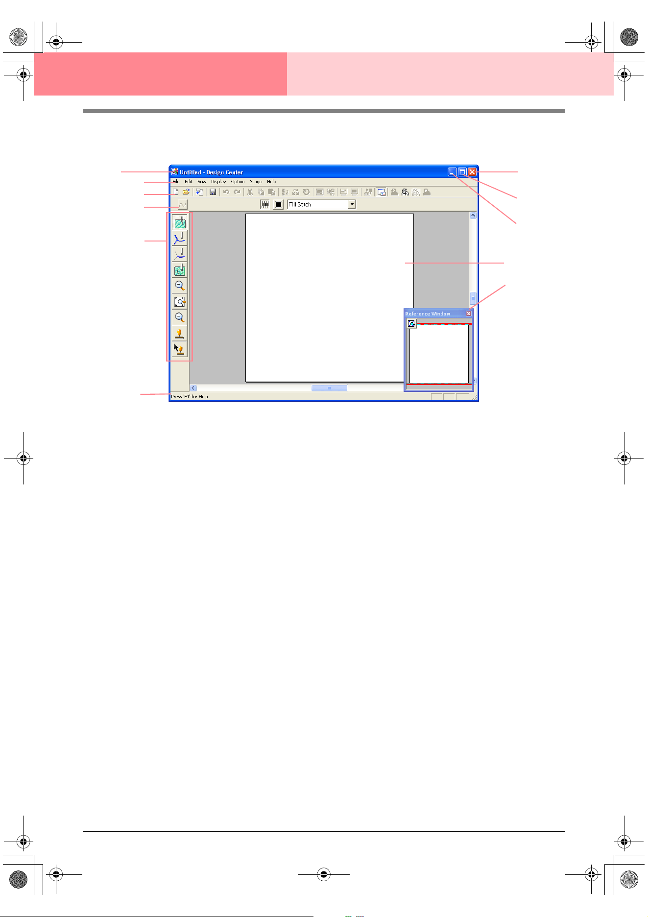
70
Design Center
Main Window
1 Title bar
2 Menu bar
Provides access to the functions.
3 Toolbar
Provides shortcuts for the menu commands.
4 Sewing Attributes bar
Sets the sewing attributes (color and sew type)
of the lines and regions in the pattern
(only in stage 4 (Sew Setting stage))
5 Tool Box
Used to select and edit the image or pattern.
Stage 1 has no Tool Box; the other stages all
have a different tools in the Tool Box.
6 Status bar
Provides helpful information, such as the size.
7 Reference Window
Displays all outlines and patterns in the work ar-
ea, giving you an overview while you work on a
detailed area. (For more details, refer to “View-
ing Patterns in the Reference Window” on
page 103.)
8 Design Page
The actual part of the work area that can be
saved and sewn.
9 Minimize button
0 Maximize button
A Close button
2
8
3
4
5
6
A
0
9
1
7
PeDesignV6Eng.book Page 70 Thursday, July 8, 2004 11:59 AM
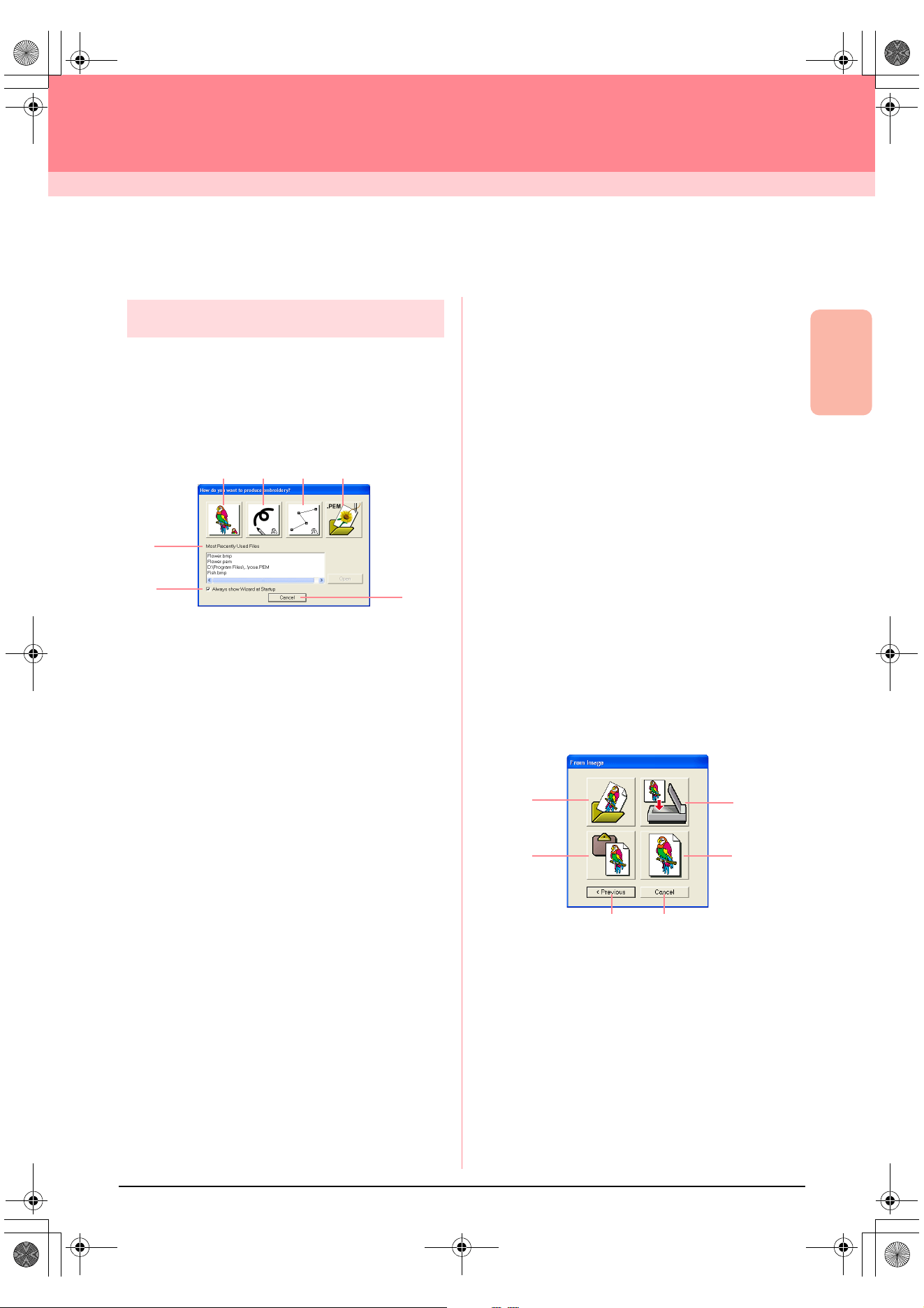
Advanced Opreation
Design Center
71
Design Center
Stage 1 (Original Image Stage)
Importing Image Data
Using the wizard
This wizard provides a step-by-step guide for
creating embroidery patterns.
1. Click File, then Wizard.
→ The How do you want to produce em-
broidery? dialog box appears.
Position the pointer over any button, and the
name of the function appears.
The functions for each button are described
below.
1 From Image
Click this button when creating embroidery pat-
tern from an image.
Clicking this button displays the From Image di-
alog box, and then continues with a step-by-step
guide for creating embroidery patterns.
c
For more details, refer to “When the From
Image button is clicked” on this page.
2 New Line Image
Clicking this button opens a new Design Page in
stage 2 (Line Image stage).
Click this button when you want to use the black
pen and eraser tools to draw an image, then cre-
ate an embroidery pattern from that image.
c
For more details, refer to “Creating a new
Design Page in stage 2 (Line Image
stage)” on page 74.
3 New Figure
Clicking this button opens a new Design Page in
stage 3 (Figure Handle stage).
Click this button when you want to draw a figure
handle image, or when you want to create pat-
terns from outlines taken from a previously
saved .pem file.
c
For more details, refer to “Creating a new
Design Page in stage 3 (Figure Handle
stage)” on page 78.
4 Open PEM
Click this button when you want to edit a saved
.pem file (saved in stage 3 (Figure Handle stage)
or 4 (Sew Setting stage)).
Clicking this button displays the Open dialog
box so that a .pem file can be selected.
5 Most Recently Used Files
A list of the most recently edited files are dis-
played.
From the list, click the name of the file that you
want to edit, and then click Open.
6 Always show Wizard at Startup
Select this check box to start up the wizard each
time Design Center is started up.
7 Cancel
Clicking this button closes this dialog box.
When the From Image button is clicked
When you click the From Image button in the How
do you want to produce embroidery? dialog box,
the From Image dialog box appears.
Position the pointer over any button, and the name
of the function appears.
12
5
4
3
7
6
5 6
1
2
3
4
PeDesignV6Eng.book Page 71 Thursday, July 8, 2004 11:59 AM
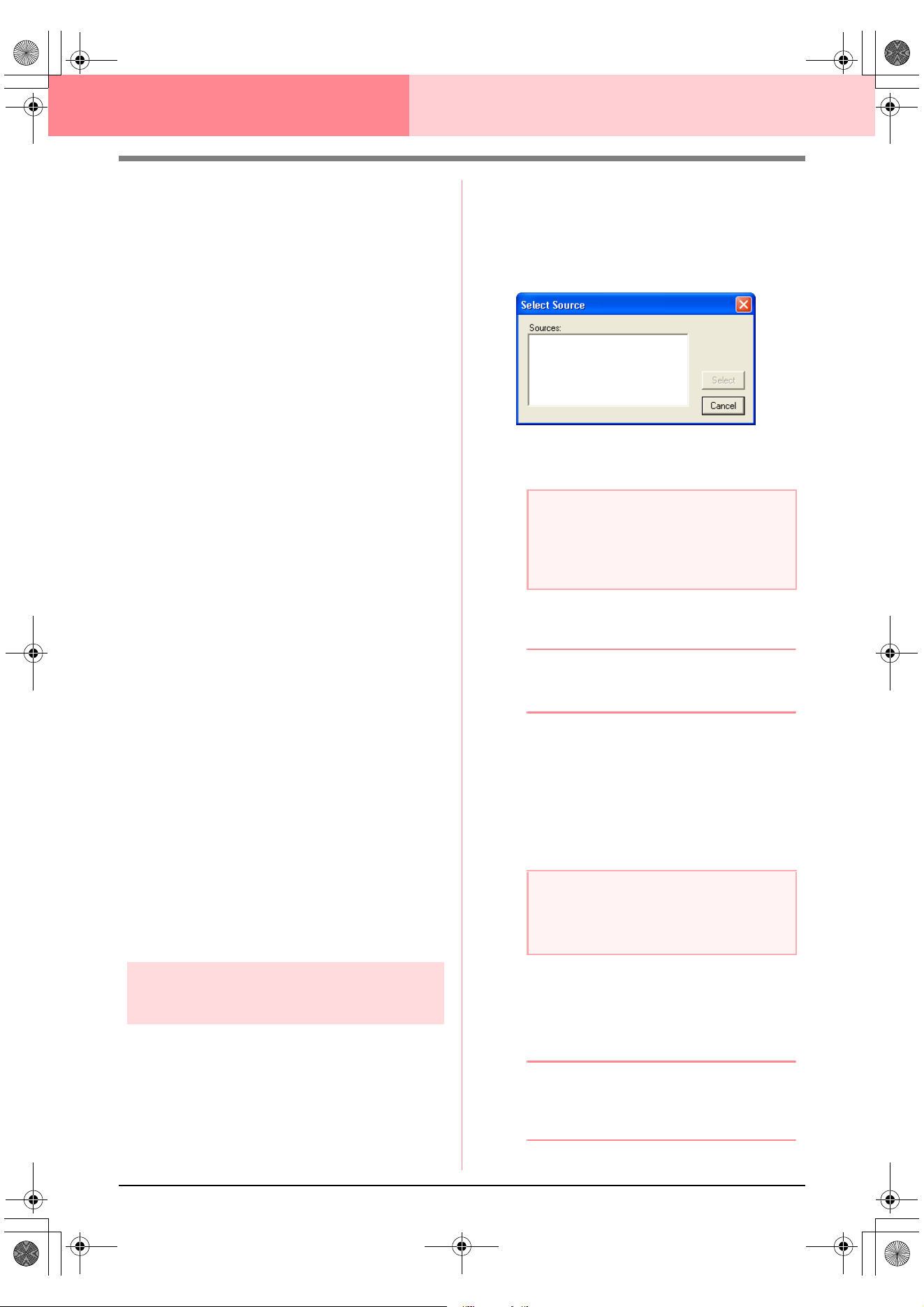
72
Design Center Stage 1 (Original Image Stage)
The functions for each button are described below.
1 Open Image File
Click this button to open a previously saved im-
age file and paste the image in the Design Page.
c
For details, refer to “Opening an image
file” on page 20.
2 From Clipboard
Clicking this button pastes the image on the Clip-
board into the Design Page. This function can
only be used when there is an image on the Clip-
board.
3 From TWAIN device
Click this button to import an image from a
TWAIN device (such as a scanner or digital cam-
era) connected to your computer, then paste it in
the Design Page.
c
For details, refer to “Importing image data
from a TWAIN device” below.
4 Use Current image
Click this button to use an image opened in
stage 1 (Original Image stage). This function can
only be used when an image is opened in stage
1.
5 Previous
Clicking this button closes the current dialog
box, and returns to the How do you want to
produce embroidery? dialog box.
6 Cancel
Clicking this button closes this dialog box.
→ If any button other than Previous or Can-
cel is clicked, the image will be imported
and pasted into the Design Page of stage
1 (Original Image stage), and the Cut out
to Line Image dialog box appears, allow-
ing you to choose colors for outlines.
c
For details on the next stages, refer to
“Continuing to Stage 2 (Line Image
Stage)” on page 73, “Continuing to Stage
3 (Figure Handle Stage)” on page 76,
then “Continuing to Stage 4 (Sew Setting
Stage)” on page 83.
Importing image data from a
TWAIN device
TWAIN is an application interface (API)
standardization for software that controls scanners
and other devices. Design Center supports TWAIN
standardized devices, allowing you to control the
device and import the image directly.
1. Check that the scanner or other TWAIN
device is correctly connected to your
computer.
2. Click File, then Select TWAIN device.
→ The Select Source dialog box appears.
3. From the Sources list, click the desired device
to select it.
4. Click Select to choose the selected device
and to close the dialog box.
b Memo:
To quit the operation and close the dialog
box, click
Cancel
.
5. Click File, then Input from TWAIN device.
→ The driver interface for the device select-
ed in the Select Source dialog box ap-
pears.
6. Specify the necessary settings for importing
an image, and then import the image.
→ When the image transfer between the
scanner (or other device) and the driver is
completed, the imported image will be
pasted in a Design Page of stage 1 (Orig-
inal Image stage).
b Memo:
If the image currently displayed in the Design
Page has not yet been saved, you will be
asked whether you want to save it.
a Note:
If no TWAIN device is installed, there will be
no names displayed in the
Sources
list.
First, install the driver software for the
TWAIN device that you want to use.
a Note:
For information on using the driver interface,
refer to the help manual for that interface, or
contact the manufacturer of the interface.
!!scr94.bmp!!
PeDesignV6Eng.book Page 72 Thursday, July 8, 2004 11:59 AM
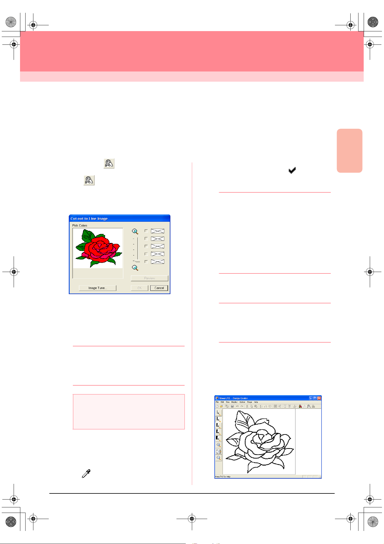
Advanced Opreation
Design Center
73
Design Center
Stage 2 (Line Image Stage)
Continuing to Stage 2 (Line Image Stage)
After opening the image, continue to stage 2 (Line Image stage), where the color(s) that will be used to create
the line image (outline of the image) will be selected. In stage 2 (Line Image stage), you can edit the image
using the pen and eraser tools. You may also want to use these tools to create outlines that are easier to draw
by hand, for example, free-hand writing. Use the zooming tools available to display the image enlarged or
reduced.
Toolbar button:
1. Click , or click Stage, then To Line
Image.
→ The Cut out to Line Image dialog box ap-
pears.
→ If you were in stage 3 (Figure Handle
stage), you are returned to stage 2, un-
less you have modified the image in stage
3. In that case, a message will appear,
asking you to confirm that you want to
abandon the changes made in stage 3.
b Memo:
To display the image enlarged (or reduced),
move the
ZOOM
slider up (or down). When
the image is enlarged, you can scroll through
it to display different parts.
2. Click the outline color(s) that you want to
convert into black outlines.
→ When the pointer is moved over the im-
age, the shape of the pointer changes to
.
→ The selected color appears in the top box
under Pick Colors, and appears in
the check box to show that the color is se-
lected.
b Memo:
• You can repeat step
2.
to select up to five
colors. If more than five colors are
selected, only the last five colors selected
remain in the list.
• To deselect a color, clear the
corresponding check box.
• To adjust the color tone and reduce image
noise (distortions), click
Image Tune
. (For
more details, refer to “Image tuning” on
page 74.)
3. Click Preview to preview the line image in the
Design Page.
b Memo:
If necessary, the settings can be changed.
After changing the settings, click
Preview
to
preview the outline with the new settings
applied.
4. Click OK.
→ All of the selected colors are converted to
a black outline (line image), which is dis-
played in the Design Page of stage 2 (Line
Image stage).
a Note:
If you started with stage 3 (Figure Handle
stage) by opening a stage 3 file, you cannot
go to stage 2.
!!scr34.bmp!!
PeDesignV6Eng.book Page 73 Thursday, July 8, 2004 11:59 AM
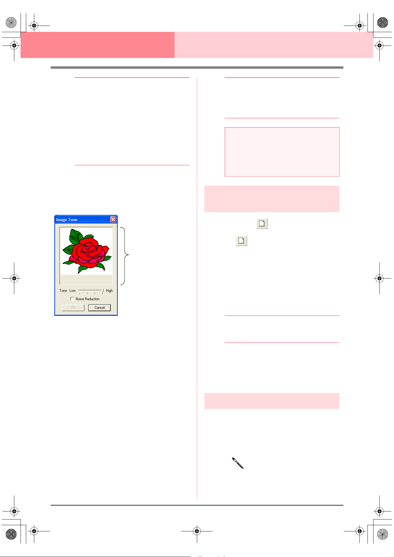
74
Design Center Stage 2 (Line Image Stage)
b Memo:
• To quit the operation and go back to stage
1 (Original Image stage), click
Cancel
.
• It is recommended to select just as many
colors as necessary to create a clear
outline of the image. In the above
example, only a single color was selected.
• If you do not like the result, select the
menu command
Stage
–
To Original
Image
to go back to stage 1 (Original
Image stage), and then create the line
image again.
Image tuning
Clicking the Image Tune button in the Cut out to
Line Image dialog box displays an Image Tune
dialog box similar to the one shown below.
From this dialog box, you can reduce the colors of
the image data (posterize) or reduce image noise
(distortions). By applying an even gradation to make
the image smoother, you can select colors more
easily, even from image data that was taken from a
scanner or other device and does not have clear
outlines.
1) The image window displays the image
resulting from the current settings.
2) Move the Tone slider to set the amount of
color reduction (posterization). Set to High to
show the original image. Set towards Low to
increase the color reduction.
3) If the Noise Reduction check box is
selected, the smaller areas of noise are
removed.
4)
Click
OK
to show the corrected image in the
image window on the
Cut out to Line Image
dialog box and to close the dialog box.
b Memo:
• To close the dialog box without applying
the changes to the settings, click
Cancel
.
• Clicking
OK
resets the
Pick Colors
list on
the
Cut out to Line Image
dialog box.
Creating a new Design Page
in stage 2 (Line Image stage)
Toolbar button:
1. Click , or click File, then New Line
Image.
→ If the current Design Page has already
been saved or has not been edited, a new
Design Page immediately appears in
stage 2 (Line Image stage).
→ If the current Design Page has not been
saved, you will be asked whether you
want to save the changes.
b Memo:
In stage 2 (Line Image stage), the file will be
saved as a .pel file.
c
“Importing image data from a TWAIN
device” on page 72, “Saving” on
page 104, and “Creating a new Design
Page in stage 3 (Figure Handle stage)” on
page 78
Drawing and erasing outlines
Drawing outlines
1. On the Tool Box, click the button for the pen
with the desired thickness.
→ The shape of the pointer changes to
.
2. To add a dot, click once. To draw a line, drag
the pointer.
Image window
a Note:
The image adjustments selected in the
Image Tune
dialog box apply only to the
image displayed in the
Cut out to Line
Image
dialog box; the image that results
from these adjustments cannot be saved.
PeDesignV6Eng.book Page 74 Thursday, July 8, 2004 11:59 AM
Advanced Opreation
Design Center
75
Design Center Stage 2 (Line Image Stage)
b Memo:
To draw vertical or horizontal lines, hold
down the key while moving the
pointer.
Erasing outlines
1. On the Tool Box, click the button for the eraser
with the desired thickness.
2. Move the pointer over the line that you want to
erase, and then hold down the right mouse
button.
→ The shape of the pointer changes to
.
3. Drag the pointer to erase the line.
Shift
PeDesignV6Eng.book Page 75 Thursday, July 8, 2004 11:59 AM
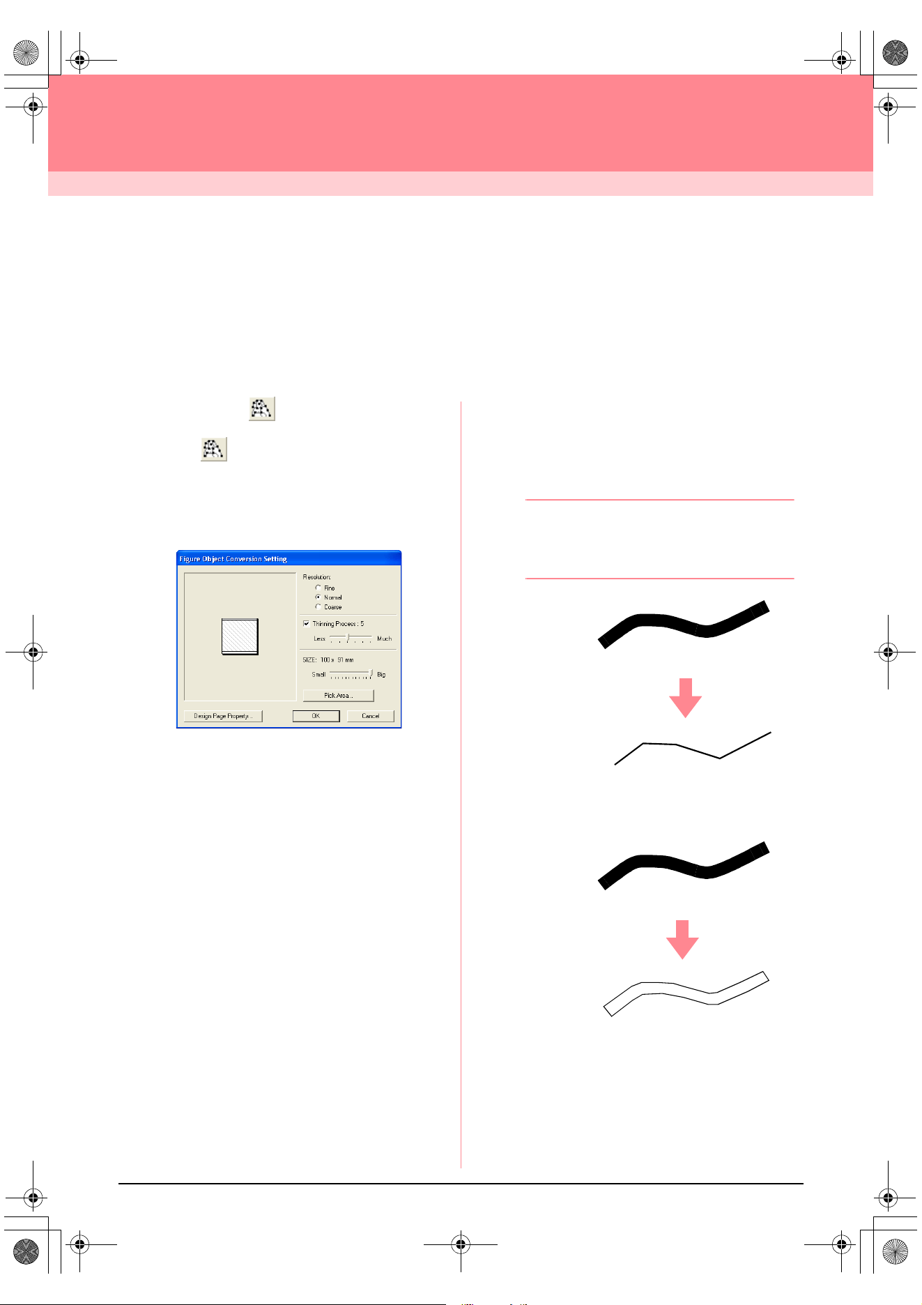
76
Design Center
Stage 3 (Figure Handle Stage)
Continuing to Stage 3 (Figure Handle
Stage)
After creating the outline, which is simply a collection of dots (or pixels) in stage 2 (Line Image stage), continue
to stage 3 (Figure Handle stage), where the dots are automatically connected to create lines that can be
edited. In stage 3 (Figure Handle stage), you can use the Point Edit tool to move, delete and insert points, or
you can use the Line tool to draw lines.
Toolbar button:
1. Click , or click Stage, then To Figure
Handle.
→ If you were in stage 2 (Line Image stage),
the Figure Object Conversion Setting
dialog box appears.
2. Select a setting under Resolution.
This setting determines how detailed the
generated figure handle image will be.
Basically, the line image is converted into
pieces of broken lines. To create more details,
more points are needed on the broken lines,
which also increases the size of the file.
In general, Normal provides a sufficient
resolution without making the file too large.
If selecting Coarse gives a satisfactory result
for a particular image, select this setting in
order to keep the file as small as possible.
Select Fine only if the image contains many
small details, and the Normal setting does not
give a satisfactory result.
3. To replace the black outlines with figure
handle lines along the center of the outlines,
select the Thinning Process check box, and
then use the slider to select the degree of
detail.
b Memo:
When the slider is set to
Much
, even very
thick black lines will be replaced with a line
along the center.
To replace the black lines with figure handle
lines following the border of the outlines, clear
the Thinning Process check box.
4. Use the SIZE slider to set the size.
!!scr97.bmp!!
ON
OFF
PeDesignV6Eng.book Page 76 Thursday, July 8, 2004 11:59 AM
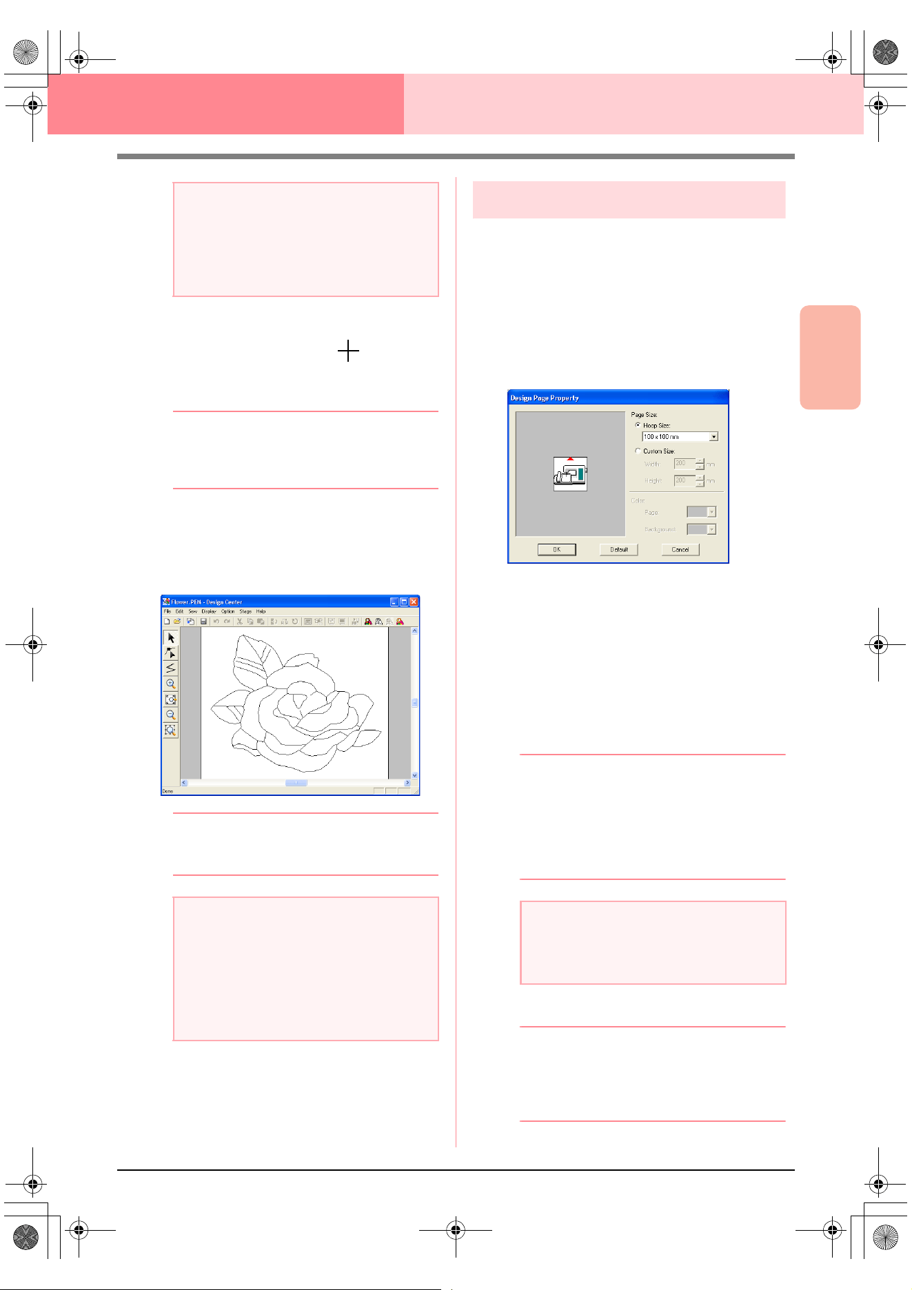
Advanced Opreation
Design Center
77
Design Center Stage 3 (Figure Handle Stage)
5. To select a specific part of the image, click
Pick Area, drag the pointer ( ) across the
image in the Design Page to select the desired
area.
b Memo:
The
Figure Object Conversion Setting
dialog box appears again when the mouse
button is released.
6. Click OK.
→ The figure handle image is displayed in
the Design Page of stage 3 (Figure Han-
dle stage).
b Memo:
To close the dialog box without applying the
changes to the settings, click
Cancel
.
c
“Creating a new Design Page in stage 2
(Line Image stage)” on page 74,
“Continuing to Stage 4 (Sew Setting
Stage)” on page 83, “Changing the grid
settings” on page 105, and “Specifying
the Design Page size” on this page
Specifying the Design Page size
In stage 3 (Figure Handle stage), you can select a
Design Page size according to the size of hoop that
you will be using with your sewing machine, or you
can customize the size to fit even very large
embroidery patterns.
1. Click Option, then Design Page Property.
→ The Design Page Property dialog box
appears.
2. Select the Design Page size.
To adjust the Design Page size according to
the hoop size, select Hoop Size, and then
select the desired hoop size from the selector.
To specify a custom Design Page size, select
Custom Size, and then type or select the
desired width and height for the Design Page.
(The setting range is 100 to 1000 mm (3.9 to
39.4 inches).)
b Memo:
• The preview area shows the setting
changes that you make.
• When
Hoop Size
is selected, the sewing
machine image shows the orientation of
the Design Page (hoop) in relation to the
machine.
3. Click OK.
b Memo:
• To return to the default settings
(
100
×
100
mm
(
4"
×
4"
) of
Hoop Size
), click
Default
.
• To close the dialog box without applying
the changes to the settings, click
Cancel
.
a Note:
You will not be able to enlarge the image
beyond the limits of the Design Page area. If
necessary, click
Design Page Property
,
and then change the Design Page size in the
dialog box that appeared.
a Note:
If the outline data cannot be created from the
image when moving from stage 2 (Line Image
stage) to stage 3 (Figure Handle stage), even
after various outline conversion settings are
specified, return to stage 2, and correct the
outlines in the line image or apply corrections
from the image.
a Note:
• When
Hoop Size
is selected, do not
select a size larger than the maximum
embroidering area for your machine.
PeDesignV6Eng.book Page 77 Thursday, July 8, 2004 11:59 AM
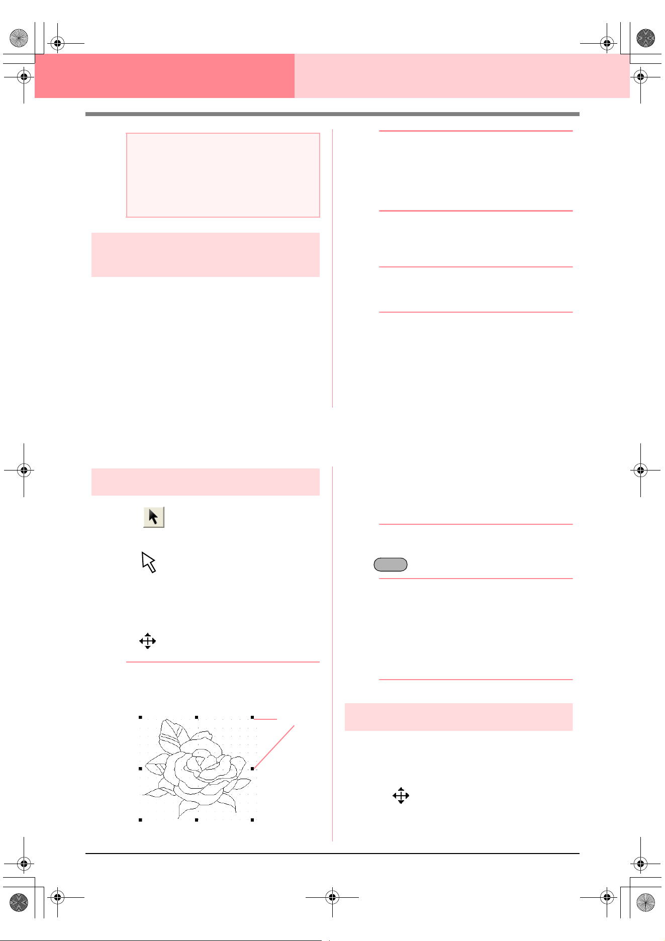
78
Design Center Stage 3 (Figure Handle Stage)
Creating a new Design Page in
stage 3 (Figure Handle stage)
An empty Design Page can be created in order to
draw a figure handle image or to create patterns
from outlines taken from a previously saved .pem
file.
1. Click File, then New Figure Data.
→ If the current Design Page has already
been saved or has not been edited, a new
Design Page immediately appears in
stage 3 (Figure Handle stage).
b Memo:
• The size of the Design Page is the
currently selected size.
• To retrieve data from a saved .pem file,
use the menu command
File
–
Import
Figure
.
→ If the current Design Page has not been
saved, you will be asked whether you
want to save the changes.
b Memo:
In stage 3 (Figure Handle stage), the file will
be saved as a .pem file.
c
“Importing image data from a TWAIN
device” on page 72, “Saving” on
page 104, and “Creating a new Design
Page in stage 2 (Line Image stage)” on
page 74
Editing Outlines
Selecting outlines
1. Click on the Tool Box.
→ The shape of the pointer changes to
.
2. Click the outline that you want to select.
→ When the pointer is moved over the out-
line, the shape of the pointer changes to
.
b Memo:
• When the outline is selected, handles
appear and the outline appears in blue.
• The outline will not be selected if an empty
part of it is selected.
• To deselect the outline, select a different
outline, or click in a blank area of the
Design Page.
3. To select an additional outline, hold down the
key and click the other outline.
b Memo:
You can also select outlines by dragging the
pointer across the outline that you want to
select. As you drag the pointer, a selection
frame is drawn. All outlines that are
completely contained in that selection frame
are selected when the mouse button is
released.
Moving outlines
1. Select the outline that you want to move.
→ When the pointer is moved over the out-
line, the shape of the pointer changes to
.
2. Drag the outline to the desired location.
a Note:
• Custom Design Page sizes cannot be
saved for version 5 and earlier.
• The selected size will be applied to every
new Design Page, until the settings are
changed.
Handles
Ctrl
PeDesignV6Eng.book Page 78 Thursday, July 8, 2004 11:59 AM
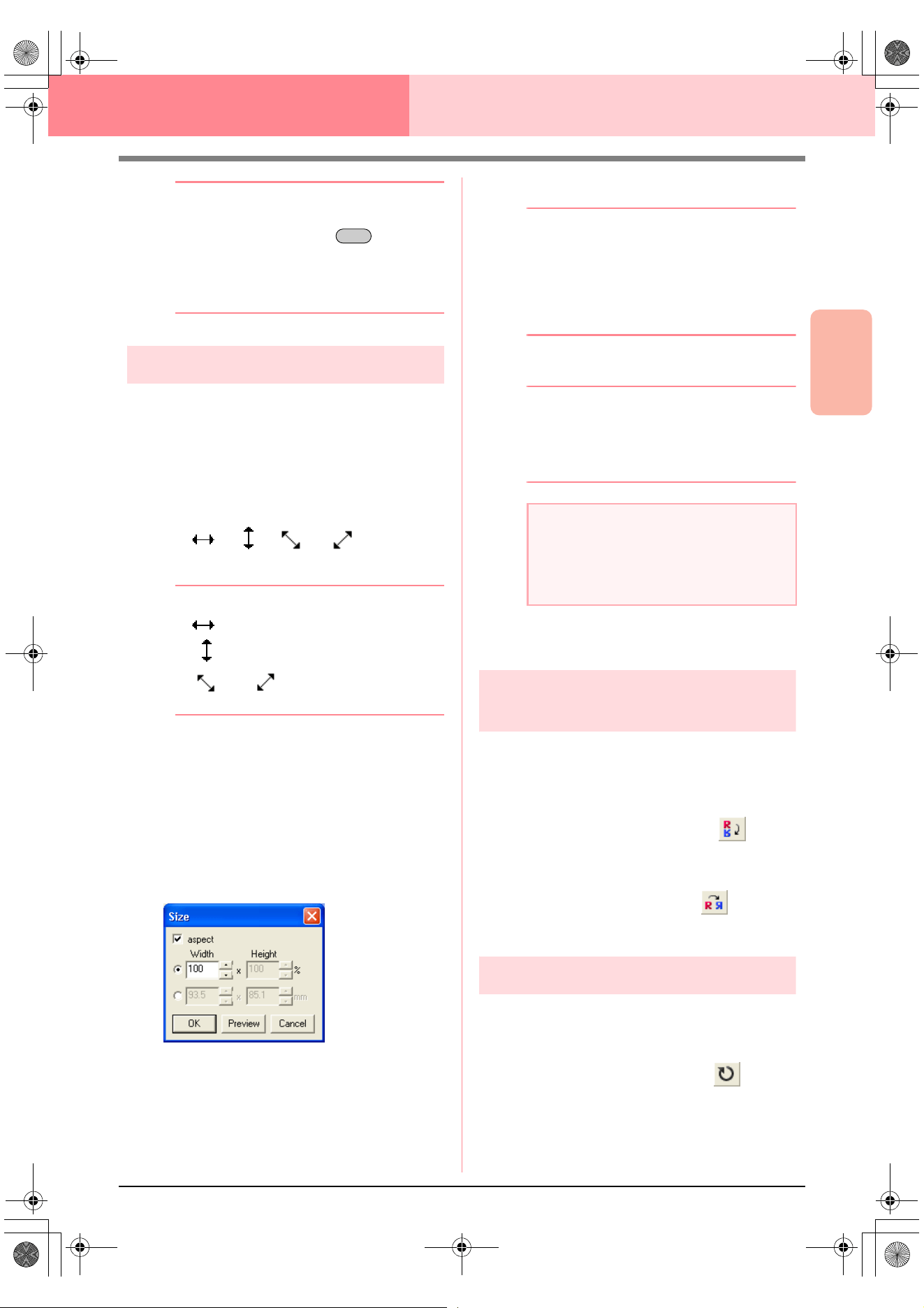
Advanced Opreation
Design Center
79
Design Center Stage 3 (Figure Handle Stage)
b Memo:
• To move the outline horizontally or
vertically, hold down the key while
dragging it.
• Pressing the arrow keys moves the
selected outline 0.5 mm (about 0.02 inch)
in the direction of the arrow on the key.
Scaling outlines
■ Scaling manually
1. Select the outline that you want to resize.
2. Move the pointer over one of the handles of a
selected outline or group of outlines.
→ The shape of the pointer changes to
, , or , depending
on the handle that the pointer is over.
b Memo:
• is for scaling the width.
• is for scaling the height.
• and are for scaling both
dimensions at the same time.
3. Drag the handle to adjust the selected
outline(s) to the desired size.
■ Scaling numerically
1. Select the outline that you want to resize.
2. Click Edit, then Numerical Setting, then Size.
→ The Size dialog box appears.
3. To change the width and height proportionally,
select the aspect check box.
4. Select the whether the width and height will be
set as a percentage (%) or a dimension
(millimeters or inches).
5. Type or select the desired width and height.
b Memo:
• Select
100%
to leave the outline
unchanged.
• If the
aspect
check box is selected,
changing one dimension automatically
changes the other so that the proportion of
the width and height remains unchanged.
6. Click OK.
b Memo:
• To preview the outline at the new size in
the Design Page, click
Preview
.
• To close the dialog box without applying
the changes to the settings, click
Cancel
.
c
“Changing the measurement units” on
page 105
Flipping outlines
horizontally or vertically
1. Select the outline that you want to flip
horizontally (up/down) or vertically (left/right).
2. To flip the outline horizontally, click Edit, then
Mirror, then Horizontal, or click on the
Toolbar.
To flip the outline vertically, click Edit, then
Mirror, then Vertical, or click on the
Toolbar.
Rotating outlines
■ Rotating manually
1. Select the outline that you want to rotate.
2. Click Edit, then Rotate, or click on the
Toolbar.
→ The handles around the selected outline
are replaced by small squares at the four
corners of the selected outline.
Shift
a Note:
• You cannot enter a size that will cause the
outline to exceed the size of the Design
Page.
• The minimum value is 1 mm (0.04 inch).
PeDesignV6Eng.book Page 79 Thursday, July 8, 2004 11:59 AM
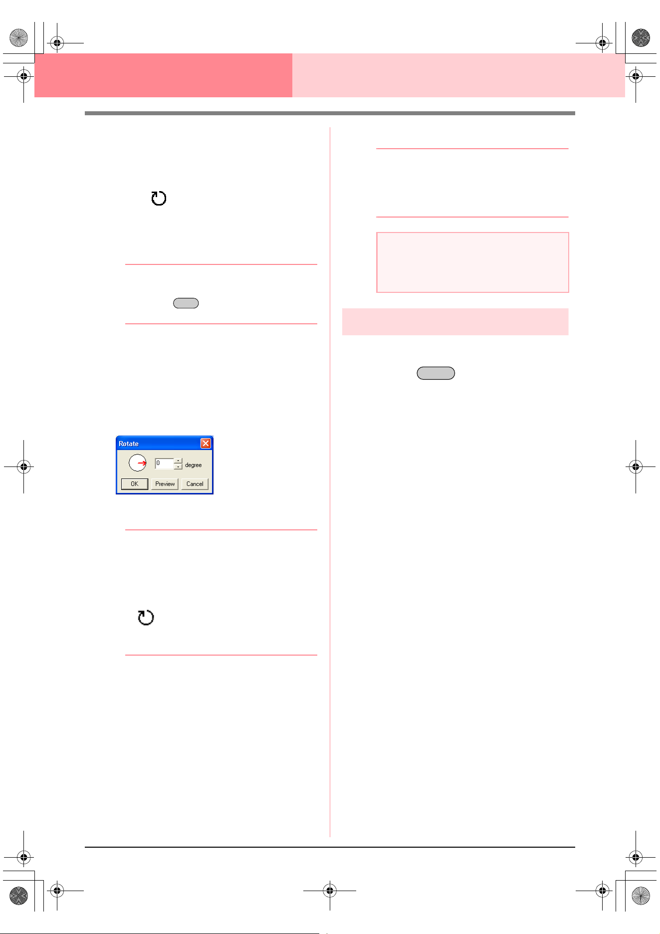
80
Design Center Stage 3 (Figure Handle Stage)
3. Move the pointer over one of the four rotation
handles.
→ When the pointer is moved over a rotation
handle, the shape of the pointer changes
to .
4. Drag the rotation handle clockwise or
counterclockwise to rotate the outline in 1°
increments.
b Memo:
To rotate the outline in 15° increments, hold
down the key while dragging the
rotation handle.
■ Rotating numerically
1. Select the outline that you want to rotate.
2. Click Edit, then Numerical Setting, then
Rotate.
→ The Rotate dialog box appears.
3. Type or select the desired rotation angle.
b Memo:
• The angle can also be specified by moving
the pointer over the red arrow inside of the
circle, then dragging the red arrow to the
desired angle. When the pointer is moved
over the red arrow, its shape changes to
.
•Select
0 degree
to leave the outline
unchanged.
4. Click OK.
b Memo:
• To preview the outline at the new angle in
the Design Page, click
Preview
.
• To close the dialog box without applying
the changes to the settings, click
Cancel
.
Deleting outlines
1. Select the outline to be deleted.
2. Press the key, or click Edit, then
Delete.
Shift
a Note:
The range of values that can be entered is
between 0 and 359 degrees, in 1-degree
increments.
Delete
PeDesignV6Eng.book Page 80 Thursday, July 8, 2004 11:59 AM
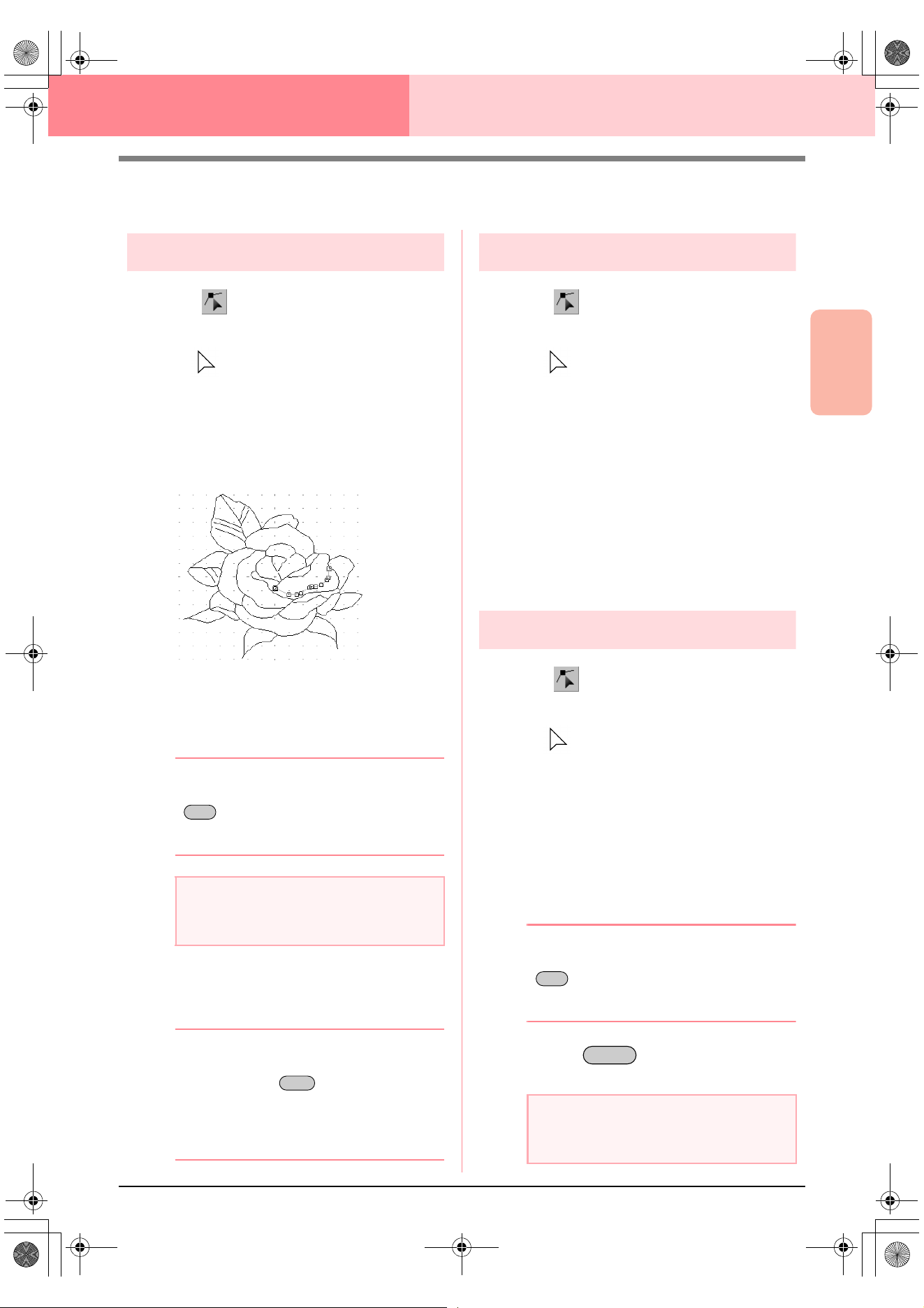
Advanced Opreation
Design Center
81
Design Center Stage 3 (Figure Handle Stage)
Editing Points in Outlines
Moving points
1. Click on the Tool Box.
→ The shape of the pointer changes to
.
2. Click the outline that you want to edit.
→ The outline appears in pink, and the
points in the selected outline appear as
small empty squares. The points at the
ends of lines appear as larger squares.
3. Click the point that you want to move.
→ The selected point appears as a small
black square.
b Memo:
To select additional points, hold down the
key and click each point, or drag the
pointer over the points that you want to
select.
4. Drag the point to the new location.
→ All selected points move in the same di-
rection.
b Memo:
• To move the point horizontally or vertically,
hold down the key while dragging
it.
• Pressing the arrow keys moves the
selected point 0.1 mm (about 0.01 inch) in
the direction of the arrow on the key.
Inserting points
1. Click on the Tool Box.
→ The shape of the pointer changes to
.
2. Click the outline that you want to edit.
→ The outline appears in pink, and the
points in the selected outline appear as
small empty squares. The points where
lines overlap appear as larger squares.
3. Click the outline at the position where you
want to insert a new point.
→ A new point, appearing as a small black
square, is added. The new point can be
edited.
Deleting points
1. Click on the Tool Box.
→ The shape of the pointer changes to
.
2. Click the outline containing the point that you
want to edit.
→ The points in the outline appear as small
empty squares.
3. Click the point that you want to delete.
→ The selected point appears as a small
black square.
b Memo:
To select additional points, hold down the
key and click each point, or drag the
pointer over the points that you want to
select.
4. Press the key to remove the point
from the outline.
a Note:
If you click the line instead of a square, a
new point is inserted.
Ctrl
Shift
a Note:
The points where lines overlap, which
appear as red squares, cannot be deleted.
Ctrl
Delete
PeDesignV6Eng.book Page 81 Thursday, July 8, 2004 11:59 AM
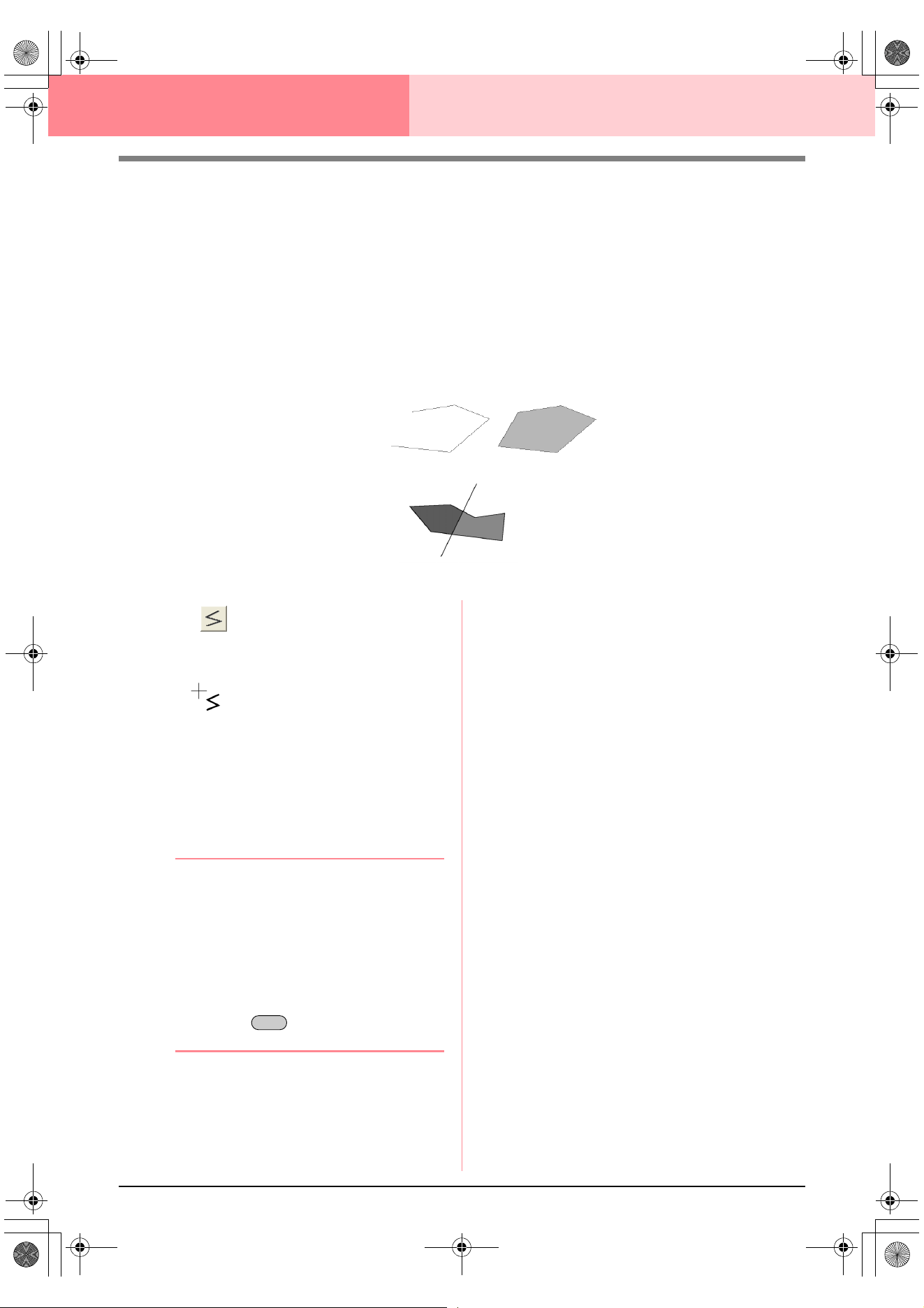
82
Design Center Stage 3 (Figure Handle Stage)
Drawing a Broken Line
The line drawing mode allows you to add broken lines to your pattern. A broken line is made of one or more
adjacent straight lines, in other words, the end point of one straight line is the start point of the next one.
If the broken line that you draw did not create enclosed regions, it remains a simple outline, and you can only
set sewing attributes for the line itself in stage 4 (Sew Setting stage).
If the broken line created enclosed regions, you can assign sew types and colors to both the outline and the
regions in stage 4.
If you draw a line through an existing region, creating two separate regions, you will be able to set sewing
attributes for both regions separately, as well as for the separating line.
1. Click on the Tool Box.
→ When the pointer is moved over the work
area, the shape of the pointer changes to
.
2. To draw a line, click in the Design Page to
specify the start point.
3. Move the pointer, and then click in the Design
Page to specify the next point.
→ The two points are connected with a
straight line.
b Memo:
• To remove the last point that was entered,
click the right mouse button.
If necessary, use the grid to help draw the
lines. You can set the grid so that each of
its vertical and horizontal lines are visible.
For details on the grid, refer to “Changing
the grid settings” on page 105.
• To draw vertical or horizontal lines, hold
down the key while moving the
pointer.
4. Repeat step 3. until you have specified all
points except the end point.
5. Double-click in the Design Page to specify the
end point.
Broken line with region
Start point
End point
Broken lines with two regions
Broken line without a region
Shift
PeDesignV6Eng.book Page 82 Thursday, July 8, 2004 11:59 AM
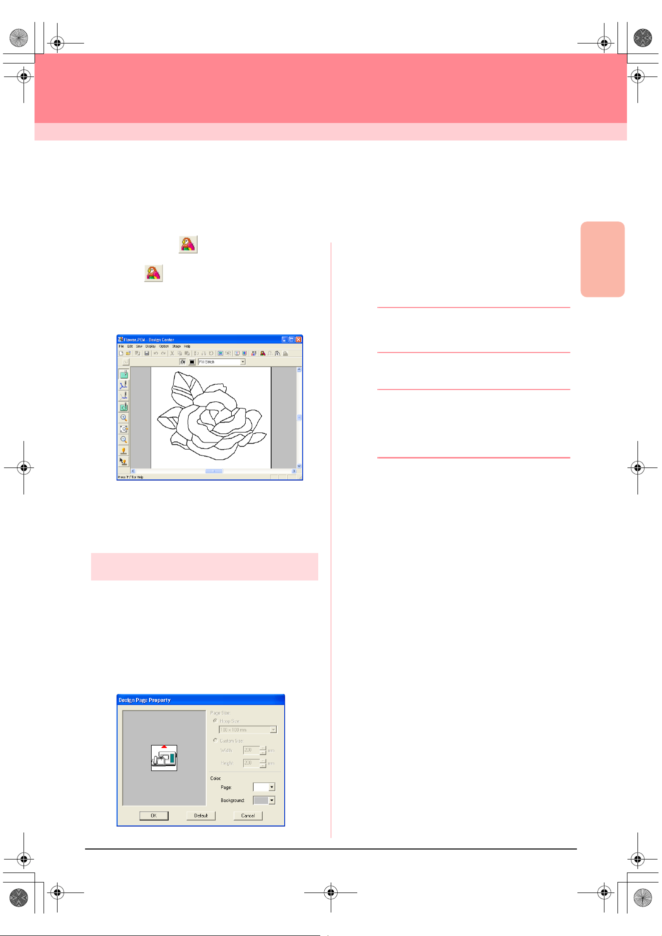
Advanced Opreation
Design Center
83
Design Center
Stage 4 (Sew Setting Stage)
Continuing to Stage 4 (Sew Setting Stage)
After editing the outline in stage 3 (Figure Handle stage), continue to stage 4 (Sew Setting stage), where the
sewing attributes can be set. Use the zooming tools available to display the pattern enlarged or reduced.
Toolbar button:
1. Click , or click Stage, then To Sew
Setting.
→ The pattern is displayed in the Design
Page of stage 4 (Sew Setting stage).
c
“Creating a new Design Page in stage 2
(Line Image stage)” on page 74“ and
“Continuing to Stage 3 (Figure Handle
Stage)” on page 76
Specifying display colors
In stage 4 (Sew Setting stage), the color of the
Design Page can be set to the color of the fabric,
and its background can be set to a different color for
contrast.
1. Click Option, then Design Page Property.
→ The Design Page Property dialog box
appears.
2. From the Page selector, select the desired
color for the Design Page.
3. From the Background selector, select the
desired color for the background.
b Memo:
The preview area allows you to check the
selected colors.
4. Click OK.
b Memo:
• To return to the default settings, click
Default
.
• To close the dialog box without applying
the changes to the settings, click
Cancel
.
PeDesignV6Eng.book Page 83 Thursday, July 8, 2004 11:59 AM
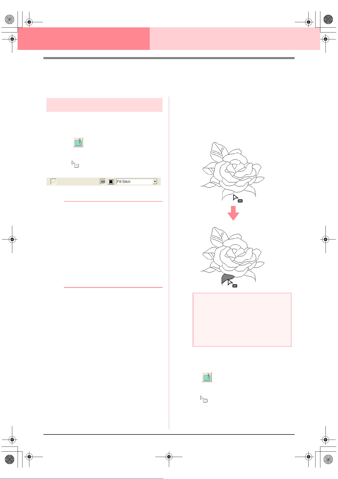
84
Design Center Stage 4 (Sew Setting Stage)
Applying Sewing Attributes to Lines and
Regions
Region sewing
■ Applying sewing attributes to
regions
1. Click on the Tool Box.
→ The shape of the pointer changes to
, and the Sewing Attributes bar ap-
pears similar to the one shown below.
2. If necessary, change the color and sew type.
b Memo:
• You can change the color and sew type
either before or after applying sewing
attributes to the region. For more details
on changing these settings, refer to “Color”
on page 89 and “Sew type” on page 89.
• You can also use the settings in the
Sewing Attribute Setting
dialog box to
define other attributes of the sew type. (For
more details, refer to “Specifying sewing
attributes” on page 89.) If you do not
change these settings at this time, the
current settings will be applied, however
you can modify them later.
3. Click the enclosed region where you want to
apply the sewing attributes.
→ “Marching lines” appear around the se-
lected region, and the color and sew type
selected on the Sewing Attributes bar are
applied to the region.
■ Checking the sewing attributes of
a region
1. Click on the Tool Box.
→ The shape of the pointer changes to
.
a Note:
If the attributes cannot be applied to a
region, go back to stage 3 (Figure Handle
stage) and make sure that region is closed.
Edit any broken lines with the Point Edit tool.
For details on editing the figure handle
image, refer to “Editing Points in Outlines” on
page 81.
PeDesignV6Eng.book Page 84 Thursday, July 8, 2004 11:59 AM
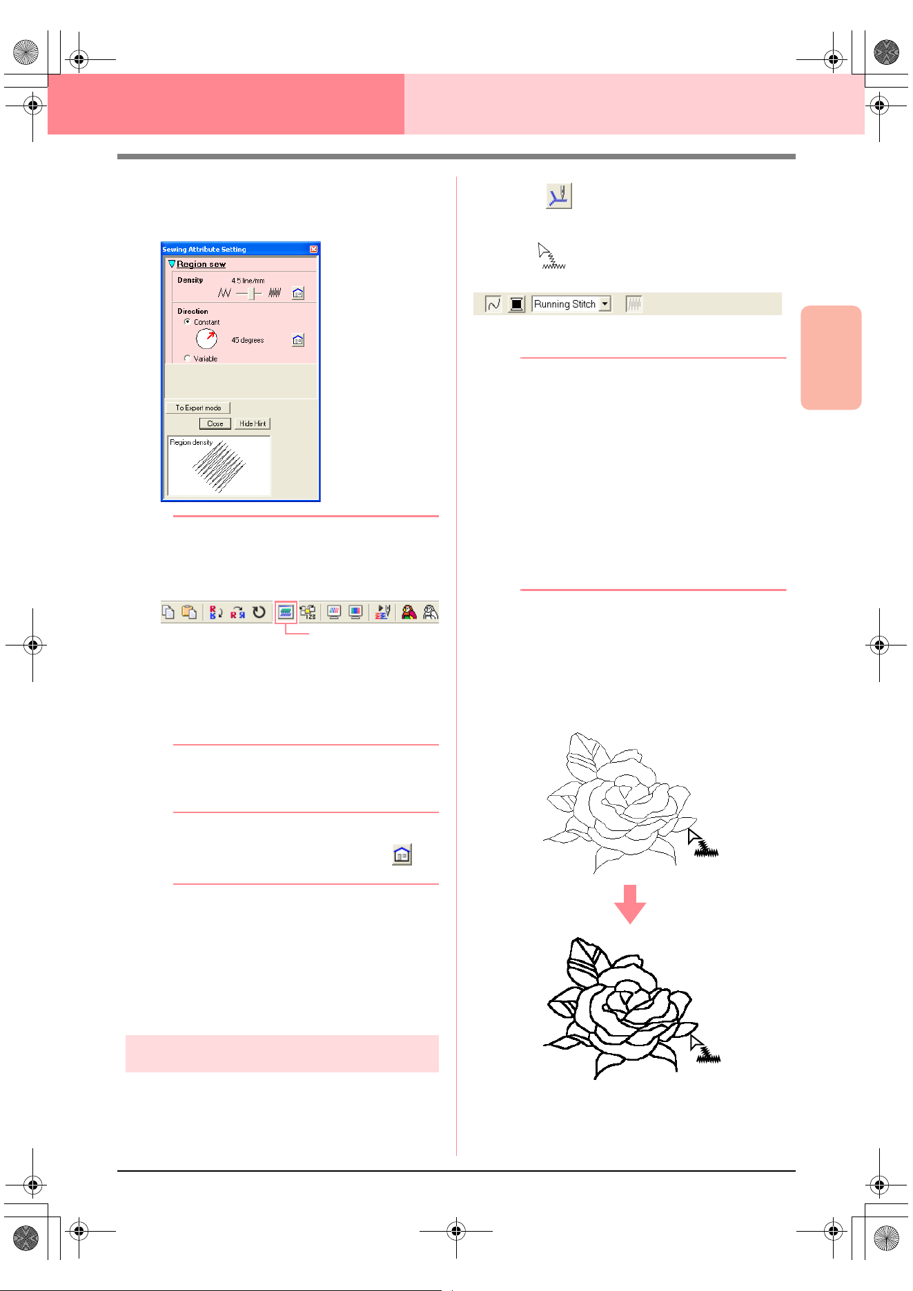
Advanced Opreation
Design Center
85
Design Center Stage 4 (Sew Setting Stage)
2. Right-click a closed region.
→ The Sewing Attribute Setting dialog box
for the selected region appears.
b Memo:
• An alternate method is to select the menu
command
Sew
–
Setting Attribute
, or
click the Toolbar button indicated below.
• The Sewing Attributes bar shows the color
and sew type for the selected region. You
can change the color and sew type at this
time. For more details on changing the
color and sew type, refer to “Color” on
page 89 and “Sew type” on page 89.
3. If necessary, change the settings in the
Sewing Attribute Setting dialog box.
b Memo:
To return to the default setting, click at
the right of the setting.
c
“Specifying sewing attributes” on page 89
4. To apply the new attributes to the region, click
each region where you want to apply the new
attributes.
5. Click Close to close the dialog box.
Line sewing
■ Applying sewing attributes to the
entire outline
1. Click on the Tool Box.
→ The shape of the pointer changes to
, and the Sewing Attributes bar ap-
pears similar to the one shown below.
2. If necessary, change the color and sew type.
b Memo:
• You can change the color and sew type
either before or after applying sewing
attributes to the outline. For more details
on changing these settings, refer to “Color”
on page 89 and “Sew type” on page 89.
• You can also use the settings in the
Sewing Attribute Setting
dialog box to
define other attributes of the sew type. (For
more details, refer to “Specifying sewing
attributes” on page 89.) If you do not
change these settings at this time, the
current settings will be applied, however
you can modify them later.
3. Click the outline where you want to apply the
sewing attributes.
→ “Marching lines” appear along the select-
ed outline, and the color and sew type se-
lected on the Sewing Attributes bar are
applied to the outline.
Sewing Attribute
PeDesignV6Eng.book Page 85 Thursday, July 8, 2004 11:59 AM
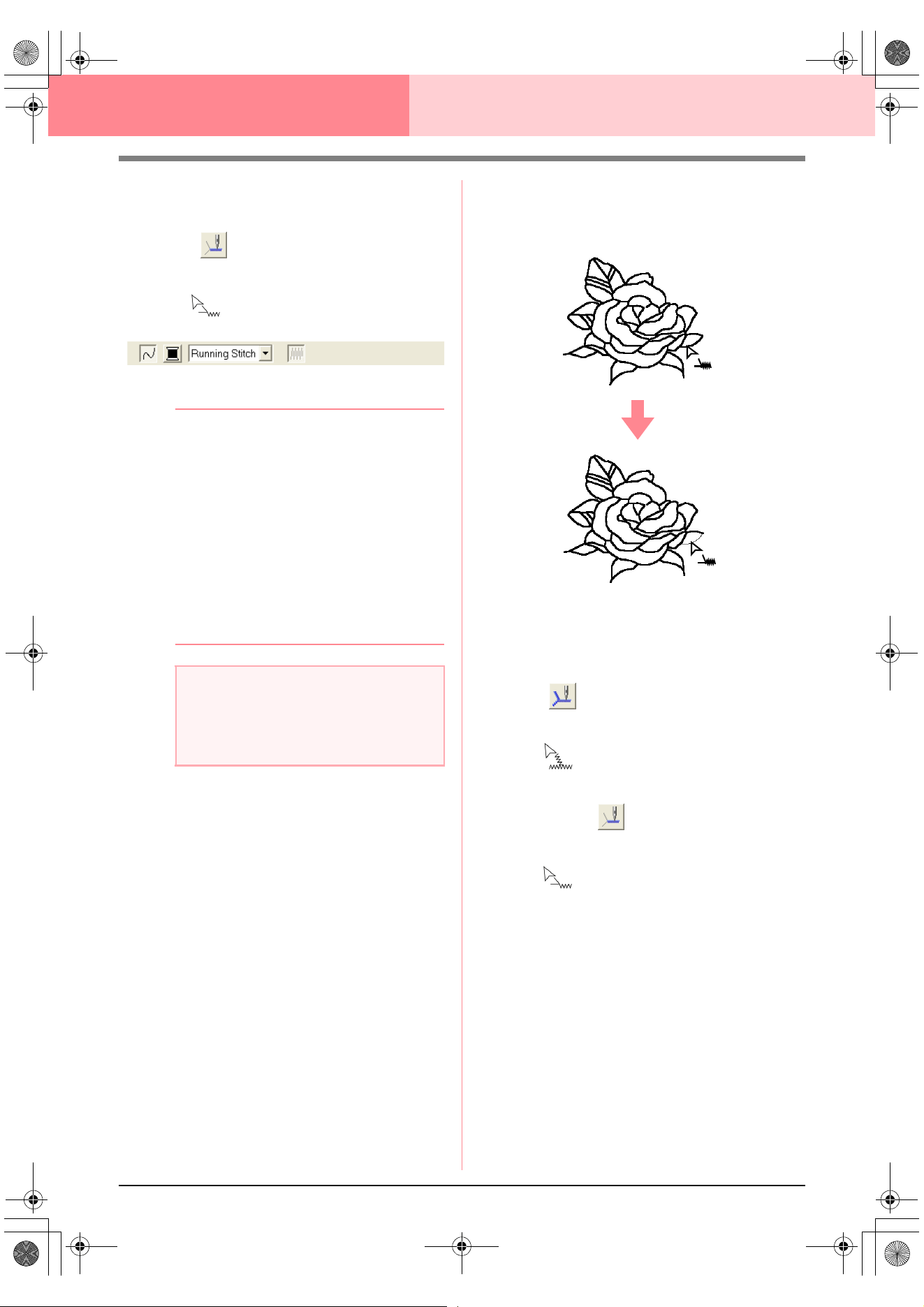
86
Design Center Stage 4 (Sew Setting Stage)
■ Applying sewing attributes to a
portion of the outline
1. Click on the Tool Box.
→ The shape of the pointer changes to
, and the Sewing Attributes bar ap-
pears similar to the one shown below.
2. If necessary, change the color and sew type.
b Memo:
• You can change the sew type either before
or after applying sewing attributes to the
portion of the outline. For more details on
changing this setting, refer to “Sew type”
on page 89.
• You can also use the settings in the
Sewing Attribute Setting
dialog box to
define other attributes of the sew type. (For
more details, refer to “Specifying sewing
attributes” on page 89.) If you do not
change these settings at this time, the
current settings will be applied, however
you can modify them later.
3. Click the portion of the outline where you want
to apply the sewing attributes.
→ “Marching lines” appear along the select-
ed portion of the outline, and the sew type
selected on the Sewing Attributes bar is
applied to the portion of the outline.
■ Checking the sewing attributes of
an outline
1. To check the attributes of the entire outline,
click on the Tool Box.
→ The shape of the pointer changes to
.
To check the attributes of a portion of the
outline, click on the Tool Box.
→ The shape of the pointer changes to
.
2. Right-click the outline or a portion of the
outline.
a Note:
The color cannot be set separately for a
portion of an outline. If you change the color,
the new color will be applied to the entire
outline of the portion that is clicked.
PeDesignV6Eng.book Page 86 Thursday, July 8, 2004 11:59 AM
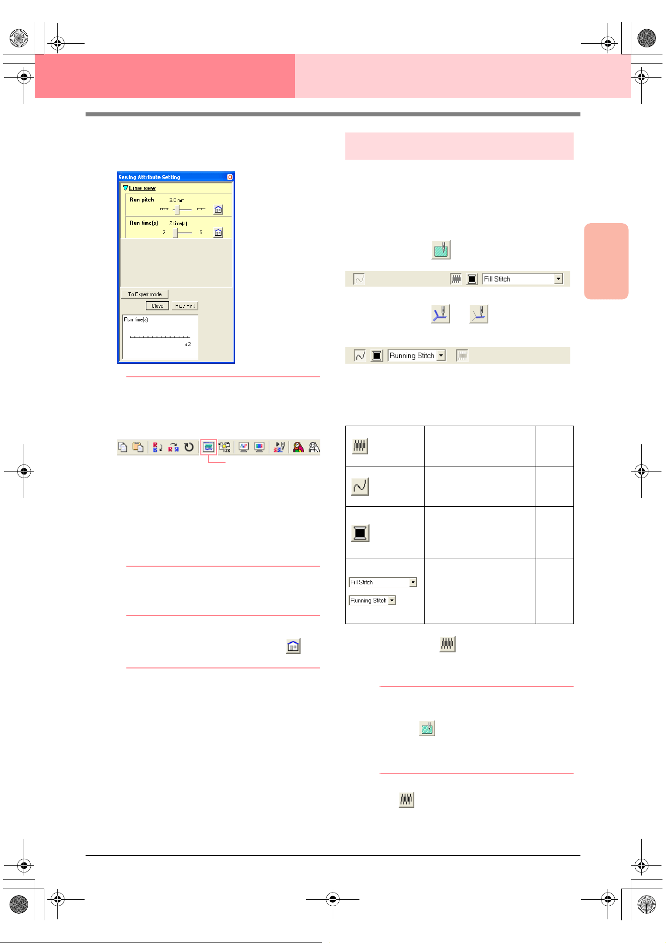
Advanced Opreation
Design Center
87
Design Center Stage 4 (Sew Setting Stage)
→ The Sewing Attribute Setting dialog box
for the selected outline or portion of out-
line appears.
b Memo:
• An alternate method is to select the menu
command
Sew
–
Setting Attribute
, or
click the Toolbar button indicated below.
• The Sewing Attributes bar shows the color
and sew type for the selected outline. At
this time, you can change the color and
sew type for the entire outline, or the sew
type for the portion of the outline. For more
details on changing the color and sew
type, refer to “Color” on page 89 and “Sew
type” on page 89.
3. If necessary, change the settings in the
Sewing Attribute Setting dialog box.
b Memo:
To return to the default setting, click at
the right of the setting.
c
“Specifying sewing attributes” on page 89
4. To apply the new attributes to the outline or
portion of outline, click the outline where you
want to apply the new attributes.
5. Click Close to close the dialog box.
Using the Sewing Attributes bar
The Sewing Attributes bar, available in stage 4 (Sew
Setting stage), allows you to set the color and sew
type of region and outlines.
The sewing attributes that are available depend on
the tool selected in the Tool Box.
Example 1: When on the Tool Box is selected
Example 2: When or on the Tool Box is
selected
When the pointer is positioned over a button or
selector in the Sewing Attributes bar, a label
indicating the name of that element appears.
■ Region sew
Clicking this button switches on/off sewing for a
region.
b Memo:
•The
Region sew
button is available only
when on the Tool Box is selected.
• When region sewing is switched off, the
region is not sewn (and you cannot set a
color or sew type).
1. Click .
This button has two settings:
Sewing Attribute
Region sew: Switches
on/off sewing for the
region.
page
87
Line sew: Switches
on/off sewing for the
line.
page
88
Region color, Line
color: Click this button
to set the thread color
for lines or regions.
page
89
Region sew type,
Line sew type: Use
these selectors to set
the sew type for lines
or regions.
page
89
!!sew4.bmp!!
PeDesignV6Eng.book Page 87 Thursday, July 8, 2004 11:59 AM
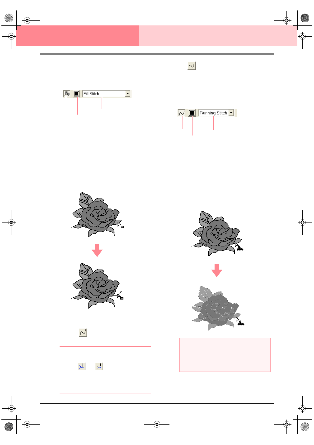
88
Design Center Stage 4 (Sew Setting Stage)
On: The Region color button and the Region
sew type selector are displayed.
Off: The Region color button and the Region
sew type selector are not displayed.
2. Click a region to apply the region sewing
attributes.
→ If the Region sew button has been
switched on, the color displayed in the
Region color button and the sew type
displayed in the Region sew type selec-
tor are applied to the region.
→ If the Region sew button has been
switched off, the color and sew type for
the region disappear.
c
“Color” on page 89 and “Sew type” on
page 89
■ Line sew
Clicking this button switches on/off sewing for a line.
b Memo:
•The
Line sew
button is available only
when or on the Tool Box is
selected.
• When line sewing is switched off, the line
is not sewn (and you cannot set its color or
sew type).
1. Click .
This button has two settings:
On: The Line color button and the Line sew
type selector are displayed.
Off: The Line color button and the Line sew
type selector are not displayed.
2. Click a line to apply the line sewing attributes.
→ If the Line sew button has been switched
on, the color displayed on the Line color
button and the sew type displayed in the
Line sew type selector are applied to the
line.
→ If the Line sew button has been switched
off, the line is replaced with a dotted line
and will not be sewn.
c
“Color” on page 89 and “Sew type” on
page 89
Region sew
Region color
Region sew type
a Note:
The color cannot be set separately for a
portion of the outline. If you change the
color, the new color will be applied to the
entire outline.
Line sew
Line color
Line sew type
PeDesignV6Eng.book Page 88 Thursday, July 8, 2004 11:59 AM
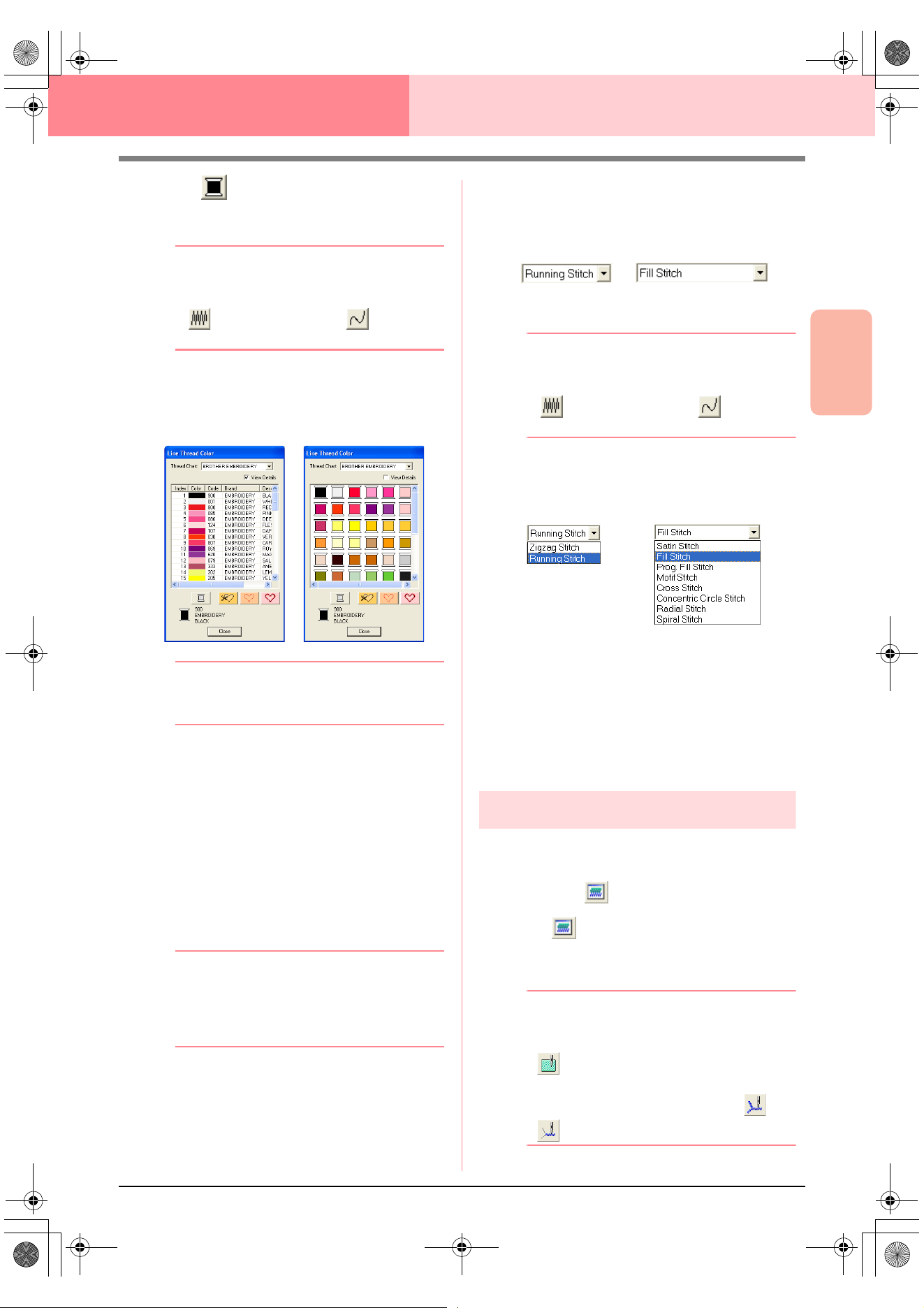
Advanced Opreation
Design Center
89
Design Center Stage 4 (Sew Setting Stage)
■ Color
Click this button to set the thread color for lines or
regions.
b Memo:
The
Color
button appears in the Sewing
Attributes bar when the
Region sew
button
() or
Line sew
button ( ) has been
turned on.
1. Click the Color button.
→ A Line Thread Color dialog box similar to
the ones shown below appears.
b Memo:
To view a list of only the thread colors, clear
the
View Details
check box.
2. From the Thread Chart selector, select a
thread color chart or a user thread chart.
c
For details on specifying a user thread
chart or for information on how machines
handle thread colors, refer to “Editing
User Thread Color Lists” on page 190.
3. From the list of thread colors, click the desired
color.
→ The new color is displayed on the Region
color button or Line color button.
b Memo:
• The name of the selected color appears at
the bottom of the dialog box.
• For details on the four buttons under the
list, refer to “Special colors” on page 170.
4. Click Close to set the color and to close the
dialog box.
5. Click the region or outline where you want to
apply the color setting.
c
“Region sew” on page 87, “Line sew” on
page 88 and “Special colors” on page 170
■ Sew type
Use these selectors to set the sew type for lines or
regions.
b Memo:
The sew type selector appears in the Sewing
Attributes bar when the
Region sew
button
() or
Line sew
button ( ) has been
turned on.
1. Click in a sew type selector.
→ The available settings appear.
2. Click the desired sew type.
→ The new setting appears in the selector.
3. Click the region or outline where you want to
apply the sew type setting.
c
“Region sew” on page 87 and “Line sew”
on page 88
Specifying sewing attributes
Various sewing attributes for lines and regions can
be set in the Sewing Attribute Setting dialog box.
Toolbar button:
1. Click in the Toolbar
→ The Sewing Attribute Setting dialog box
appears.
b Memo:
The region sew attributes appear in the
Sewing Attribute Setting
dialog box when
on the Tool Box is selected. The line
sew attributes appear in the
Sewing
Attribute Setting
dialog box when or
on the Tool Box is selected.
Region sew typeLine sew type
Region sew typeLine sew type
PeDesignV6Eng.book Page 89 Thursday, July 8, 2004 11:59 AM
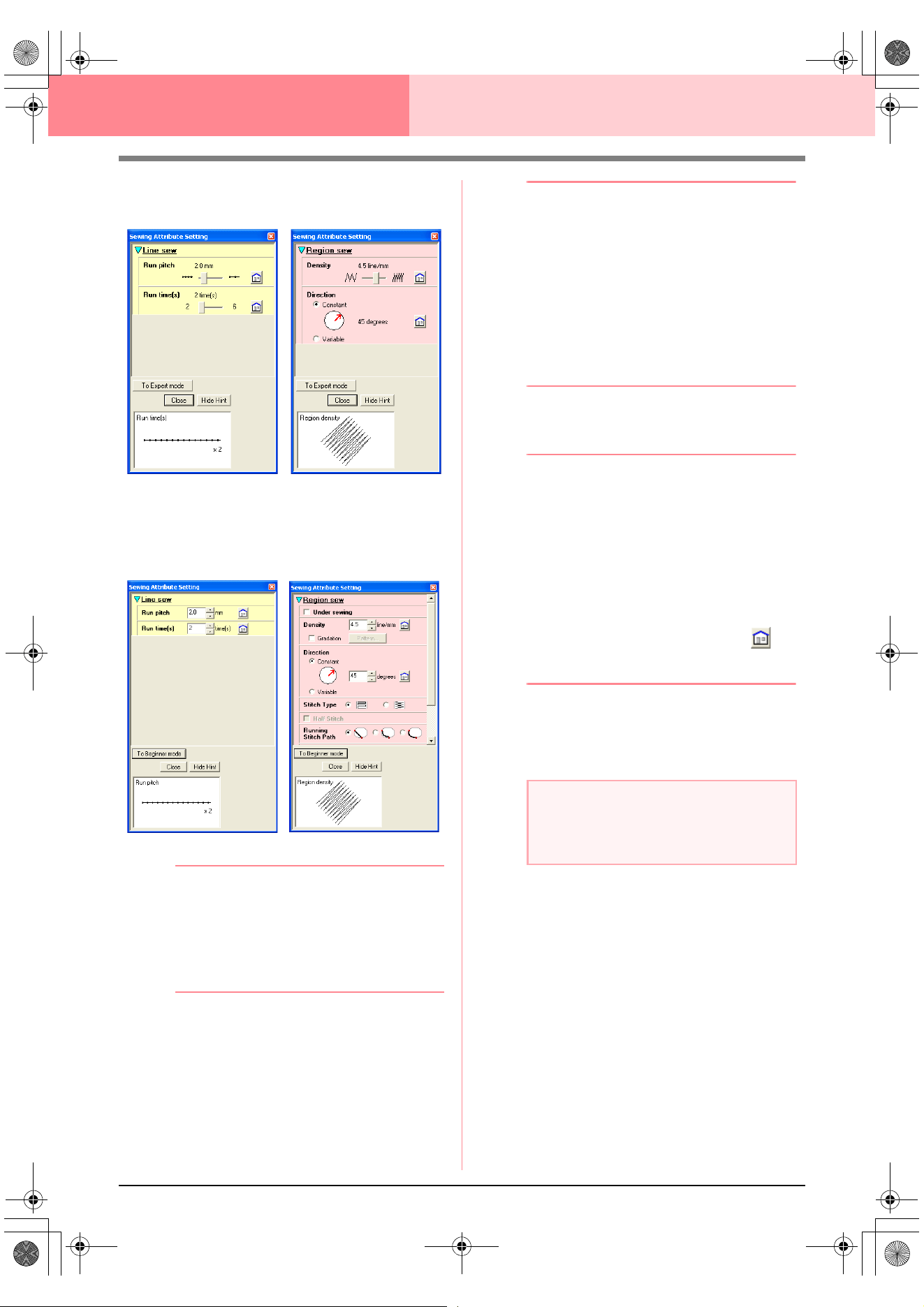
90
Design Center Stage 4 (Sew Setting Stage)
Beginner mode:
Expert mode:
b Memo:
• An alternate method is to select the menu
command
Sew
–
Setting Attribute
, or
right-click a region or line.
• The sewing attributes displayed in the
dialog box depend on the selected sew
type.
2. To display only basic sewing attributes and
simpler settings, click To Beginner mode.
To display all of the sewing attributes and
settings available for the selected sew type,
click To Expert mode.
b Memo:
• Settings that cannot be selected in
Beginner mode are retained from the
previous setting in Expert mode.
• To hide the preview box, click
Hide Hint
.
To display the preview box, click
Show
Hint
.
When the
Hide Hint
button is displayed,
the preview box is displayed, allowing you
to view a stitching sample when the pointer
is moved over the setting. The preview box
shows the setting changes that you make.
3. If necessary, change the sewing attributes
displayed under Line Sew or Region Sew.
b Memo:
• In some cases, you may need to scroll
through the settings, or resize the dialog
box by dragging one of its corners in order
to view all of the sewing attributes.
• The method for entering settings varies
according to the attribute. When entering
numerical values in Expert mode, click the
arrow buttons to select the value or enter
the value directly. In Beginner mode, use
the slider to change the settings. If
appears, click the button to return to the
default setting.
c
For details on the different sewing
attributes and settings, refer to “Line
sewing attributes” on page 91 and
“Region sewing attributes” on page 91.
4. When the line sewing attributes are displayed,
click an outline to apply the line sewing
attributes to the outline.
When the region sewing attributes are
displayed, click a region to apply the region
sewing attributes to the region.
5. Click Close to close the dialog box.
For line sewing
For region sewing
For line sewing
For region sewing
a Note:
All settings made in the dialog box are
retained and will be applied regardless of the
mode, until they are changed.
PeDesignV6Eng.book Page 90 Thursday, July 8, 2004 11:59 AM
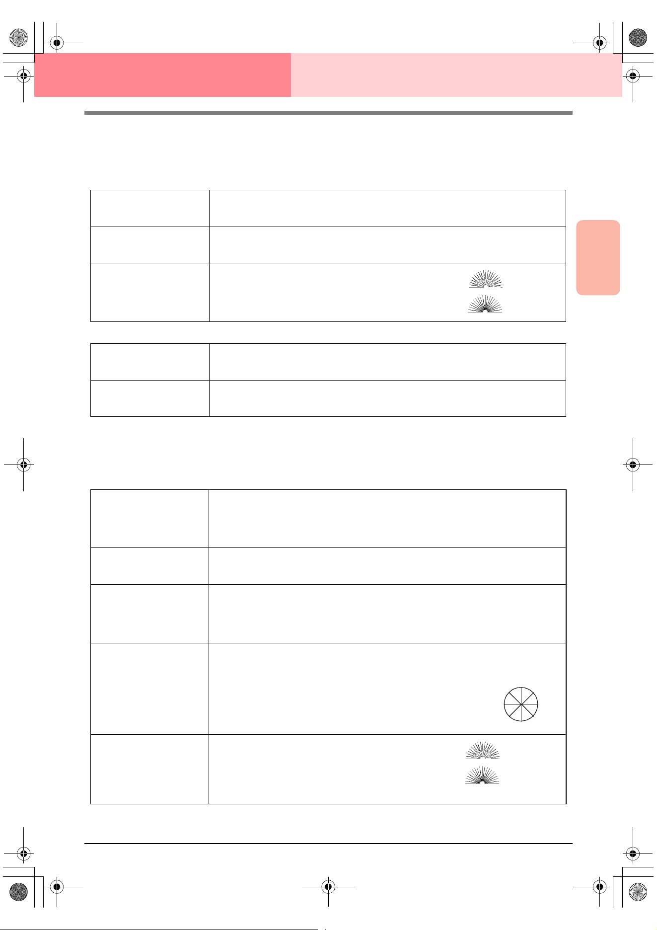
Advanced Opreation
Design Center
91
Design Center Stage 4 (Sew Setting Stage)
■ Line sewing attributes
The available attributes differ depending on the selected sew type. In Beginner mode, not all of the following
attributes appear.
Zigzag stitch
Running stitch
■ Region sewing attributes
The available attributes differ depending on the selected sew type. In Beginner mode, not all of the following
attributes appear.
Satin stitch
Zigzag width
Sets the width of the zigzag.
Range: 1–10 mm (0.04–0.39 inch)
Default: 2.0 mm (0.08 inch)
Density
Sets the number of lines per millimeter (inch).
Range: 1–7 lines per mm (25–178 lines per inch)
Default: 4.5 lines per mm (114 lines per inch)
Half Stitch
Sets half stitching on or off.
If one side of the zigzag stitching is dense, a half stitch could
be sewn automatically to provide a more even density.
Default: Off
On:
Off:
Run pitch
Sets the pitch of the line sewing.
Range: 1–10 mm (0.04–0.39 inch)
Default: 2.0 mm (0.08 inch)
Run times
Sets the number of times that the border will be sewn.
Range: 2, 4, 6
Default: 2
Under sewing
Sets underlay stitching on or off. Try to use underlay stitching for wide areas, in order to pre-
vent shrinking during stitching. Depending on the shape of the region, however, it may not be
possible to select this setting.
On: Underlay stitching will be sewn.
Off: Underlay stitching will not be sewn.
Density
Sets the number of lines per millimeter.
Range: 1–7 lines per mm (25–178 lines per inch)
Default: 4.5 lines per mm (114 lines per inch)
Gradation
Sets the density gradation setting on or off.
Available when the type of sewing direction is set to Constant.
Click Pattern to set the gradation pattern.
Default: Off
For details on this attribute, refer to“Creating a gradation” on page 96.
Direction
[Type] Specifies the type of sewing direction.
Constant: Sews at a fixed angle. The angle is specified by the angle setting.
Variable: Varies the sewing direction according to the object being sewn.
[Angle] Specifies the sewing angle.
Available only when the type sewing direction is
set to Constant.
Range: 0–359 degrees
Default: 45 degrees
Half Stitch
Sets half stitching on or off.
Available when the type of sewing direction is set to Vari-
able.
If one side of the satin stitching is dense, a half stitch could
be sewn automatically to provide a more even density.
Default: Off
0°
45°
90°
135°
180°
225°
270°
315°
On:
Off:
PeDesignV6Eng.book Page 91 Thursday, July 8, 2004 11:59 AM
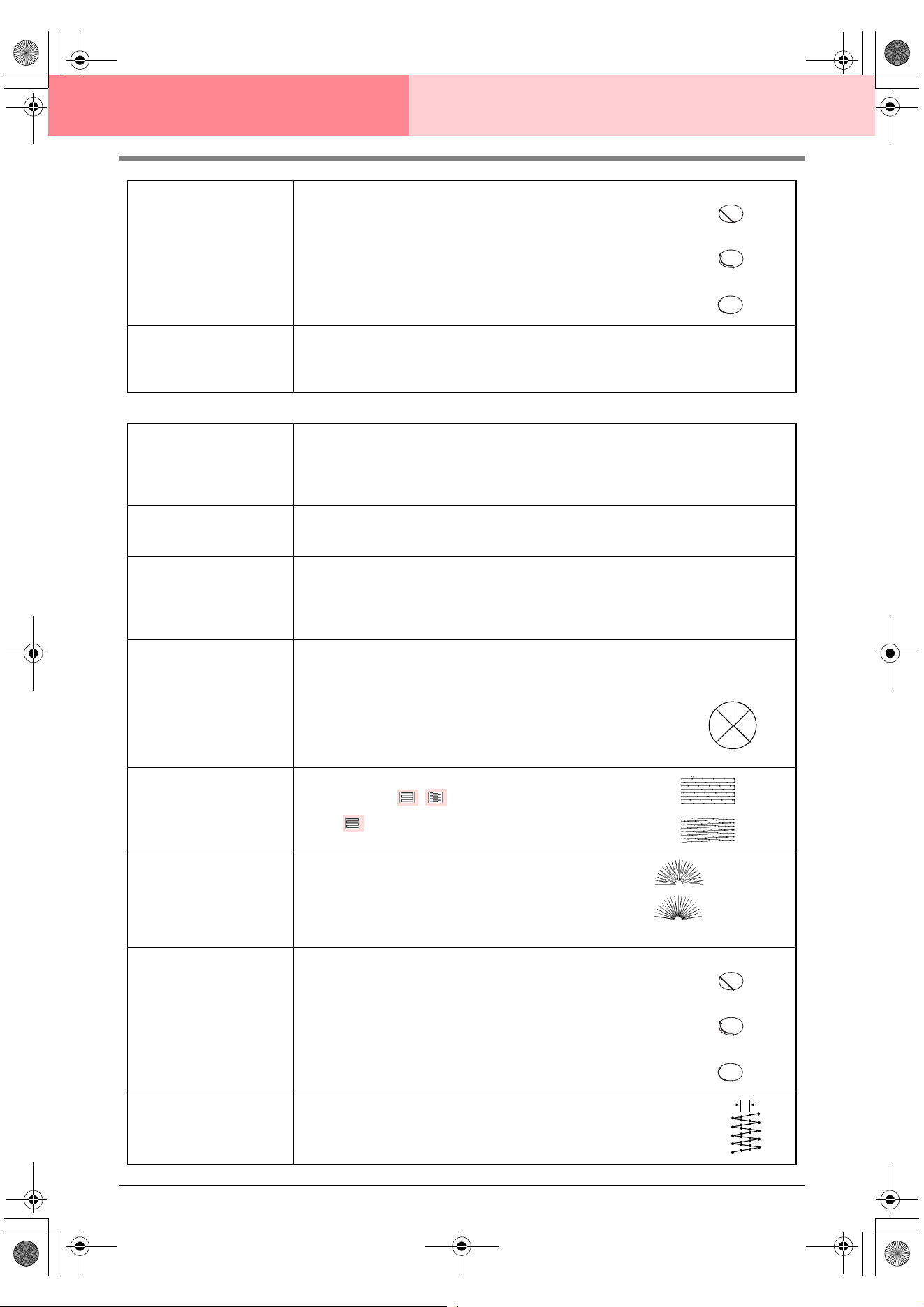
92
Design Center Stage 4 (Sew Setting Stage)
Fill stitch
Running Stitch Path
Sets the running path of the stitching.
Available when the type of sewing direction is set to Constant.
Available settings:
• Inside of region (shortest route)
• Along outline (along the inner side)
• Onto outline (on the outline)
The inside of region setting is available only when the Gradation
check box is cleared.
Default: Inside of region
Pull Compensation
Lengthens the sewing region in the stitch pattern’s sewing direction to prevent pattern shrink-
age during sewing.
Range: 0–2 mm (0.00–0.08 inch)
Default: 0.0 mm (0.00 inch)
Inside of region:
Along outline:
Onto outline:
Under sewing
Sets underlay stitching on or off. Try to use underlay stitching for wide areas, in order to pre-
vent shrinking during stitching. Depending on the shape of the region, however, it may not be
possible to select this setting.
On: Underlay stitching will be sewn.
Off: Underlay stitching will not be sewn.
Density
Sets the number of lines per millimeter.
Range: 1–7 lines per mm (25–178 lines per inch)
Default: 4.5 lines per mm (114 lines per inch)
Gradation
Sets the density gradation setting on or off.
Available when the type of sewing direction is set to Constant.
Click Pattern to set the gradation pattern and its density.
Default: Off
For details on this attribute, refer to“Creating a gradation” on page 96.
Direction
[Type] Specifies the type of sewing direction.
Constant: Sews at a fixed angle. The angle is specified by the angle setting.
Variable: Varies the sewing direction according to the object being sewn.
[Angle] Specifies the sewing angle.
Available only when the sewing direction type is
set to Constant.
Range: 0–359 degrees
Default: 45 degrees
Stitch Type
Specifies the shape of stitching on the edges.
Available settings: ,
Default:
Half Stitch
Sets half stitching on or off.
Available when the type of sewing direction is set to Vari-
able.
If one side of the fill stitching is dense, a half stitch could be
sewn automatically to provide a more even density.
Default: Off
Running Stitch Path
Sets the running path of the stitching.
Available when the type of sewing direction is set to Constant.
Available settings:
• Inside of region (shortest route)
• Along outline (along the inner side)
• Onto outline (on the outline)
The inside of region setting is available only when the Gradation
check box is cleared.
Default: Inside of region
Step Pitch
Sets the pitch of the stitching.
Range: 1–10 mm (0.04–0.39 inch)
Default: 4.0 mm (0.16 inch)
0°
45°
90°
135°
180°
225°
270°
315°
On:
Off:
Inside of region:
Along outline:
Onto outline:
Step pitch
PeDesignV6Eng.book Page 92 Thursday, July 8, 2004 11:59 AM
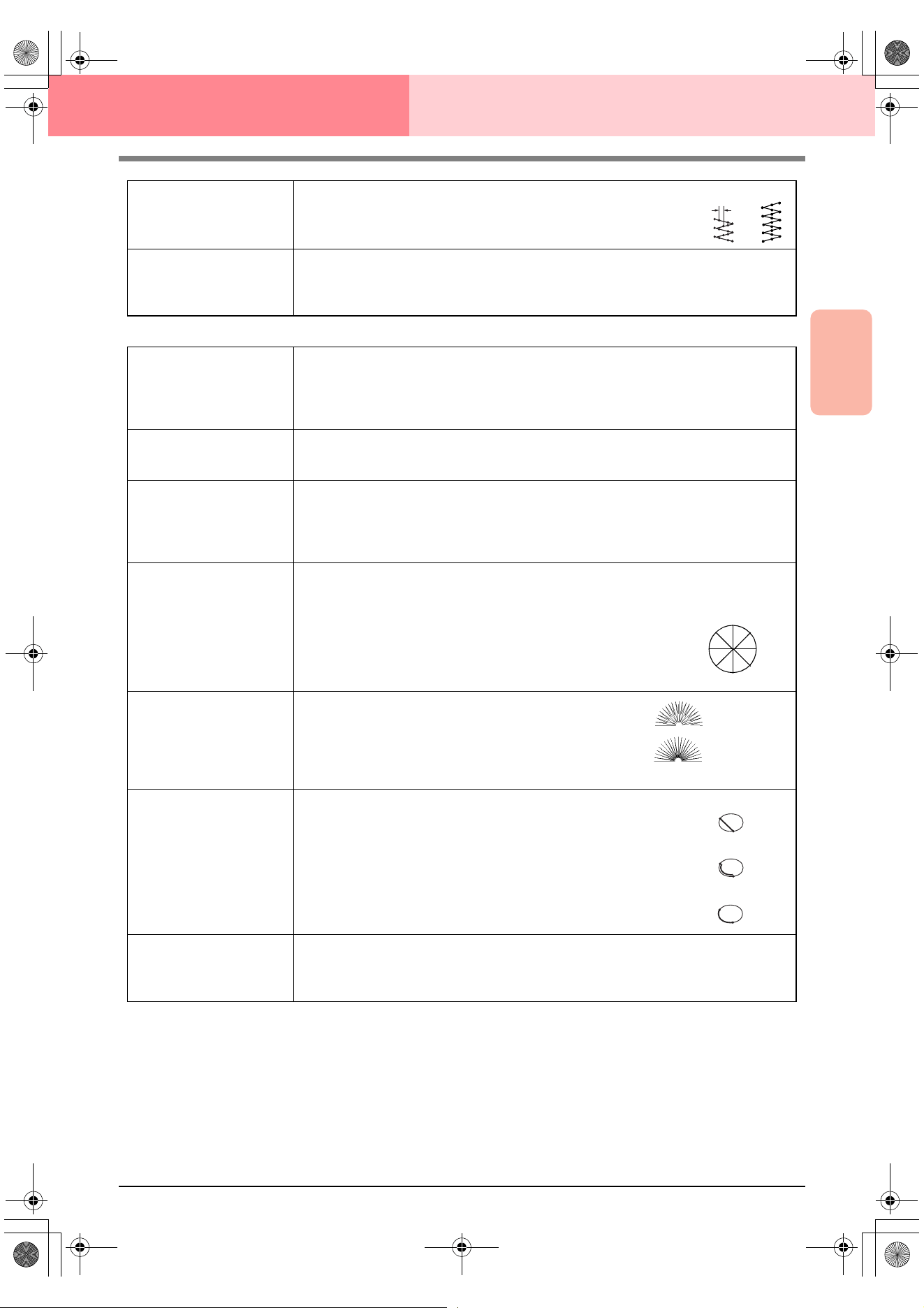
Advanced Opreation
Design Center
93
Design Center Stage 4 (Sew Setting Stage)
Programmable fill stitch
Frequency
Sets the spacial frequency steps.
Range: 0–99%
Default: 30%
Pull Compensation
Lengthens the sewing region in the stitch pattern’s sewing direction to prevent pattern shrink-
age during sewing.
Range: 0–2 mm (0.00–0.08 inch)
Default: 0.0 mm (0.00 inch)
0%
30%
Under sewing
Sets underlay stitching on or off. Try to use underlay stitching for wide areas, in order to pre-
vent shrinking during stitching. Depending on the shape of the region, however, it may not be
possible to select this setting.
On: Underlay stitching will be sewn.
Off: Underlay stitching will not be sewn.
Density
Sets the number of lines per millimeter.
Range: 1–7 lines per mm (25–178 lines per inch)
Default: 4.5 lines per mm (114 lines per inch)
Gradation
Sets the density gradation setting on or off.
Available when the type of sewing direction is set to Constant.
Click Pattern to set the gradation pattern and its density.
Default: Off
For details on this attribute, refer to“Creating a gradation” on page 96.
Direction
[Type] Specifies the type of sewing direction.
Constant: Sews at a fixed angle. The angle is specified by the angle setting.
Variable: Varies the sewing direction according to the object being sewn.
[Angle] Specifies the sewing angle.
Available only when the sewing direction type is
set to Constant.
Range: 0–359 degrees
Default: 45 degrees
Half Stitch
Sets half stitching on or off.
Available when the type of sewing direction is set to Vari-
able.
If one side of the fill stitching is dense, a half stitch could be
sewn automatically to provide a more even density.
Default: Off
Running Stitch Path
Sets the running path of the stitching.
Available when the type of sewing direction is set to Constant.
Available settings:
• Inside of region (shortest route)
• Along outline (along the inner side)
• Onto outline (on the outline)
The inside of region setting is available only when the Gradation
check box is cleared.
Default: Inside of region
Pull Compensation
Lengthens the sewing region in the stitch pattern’s sewing direction to prevent pattern shrink-
age during sewing.
Range: 0–2 mm (0.00–0.08 inch)
Default: 0.0 mm (0.00 inch)
0°
45°
90°
135°
180°
225°
270°
315°
On:
Off:
Inside of region:
Along outline:
Onto outline:
PeDesignV6Eng.book Page 93 Thursday, July 8, 2004 11:59 AM
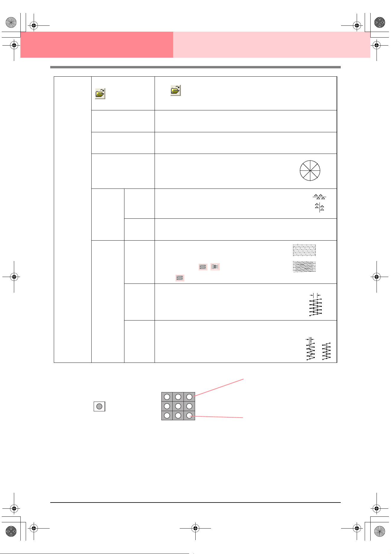
94
Design Center Stage 4 (Sew Setting Stage)
Programma-
ble fill
Select a pattern for programmable fill stitch.
Click
, and then, in the Browse dialog box that appeared, select the folder
containing the .pas file that you want to use. Double-click the desired pattern, or
select it, and then click OK.
Width (horizontal length)
Sets the stitch pattern width.
Range: 2–10 mm (0.20–0.39 inch)
Default: 7.5 mm (0.30 inch)
Height (vertical length)
Sets the stitch pattern height.
Range: 5–10 mm (0.20–0.39 inch)
Default: 7.5 mm (0.30 inch)
Direction
Allows you to rotate the angle of the stitch patterns.
Range: 0–359 degrees
Default: 0 degrees
Offset
Direction
Sets the direction of the offset as row/column.
Value
When the pattern’s arrangement is offset, sets the amount of offset.
Range: 0–99%
Default: 0%
Base
Sew
Specifies
the base
stitching.
(For details,
refer to the
illustration
below.)
Stitch
Type
Specifies the shape of stitching on the edges.
Available only when the Base Sew check box is
selected.
Available settings: ,
Default:
Step Pitch
Sets the pitch of the stitching for the base of a programmable fill stitch.
Available only when the Base Sew check box is
selected.
Range: 1–10 mm (0.04–0.39 inch)
Default: 4.0 mm (0.16 inch)
Frequency
Sets the spacial frequency steps of the stitching for the base of a programmable
fill stitch.
Available only when the Base Sew check box is
selected.
Range: 0–99%
Default: 30%
0°
45°
90°
135°
180°
225°
270°
315°
row
column
Step pitch
0%
30%
Pattern
The stitching for the base (area
other than the pattern indicated
by the diagonal lines) of the pro-
grammable fill stitch can be set.
The pattern is sewn with the
specified stitching.
PeDesignV6Eng.book Page 94 Thursday, July 8, 2004 11:59 AM
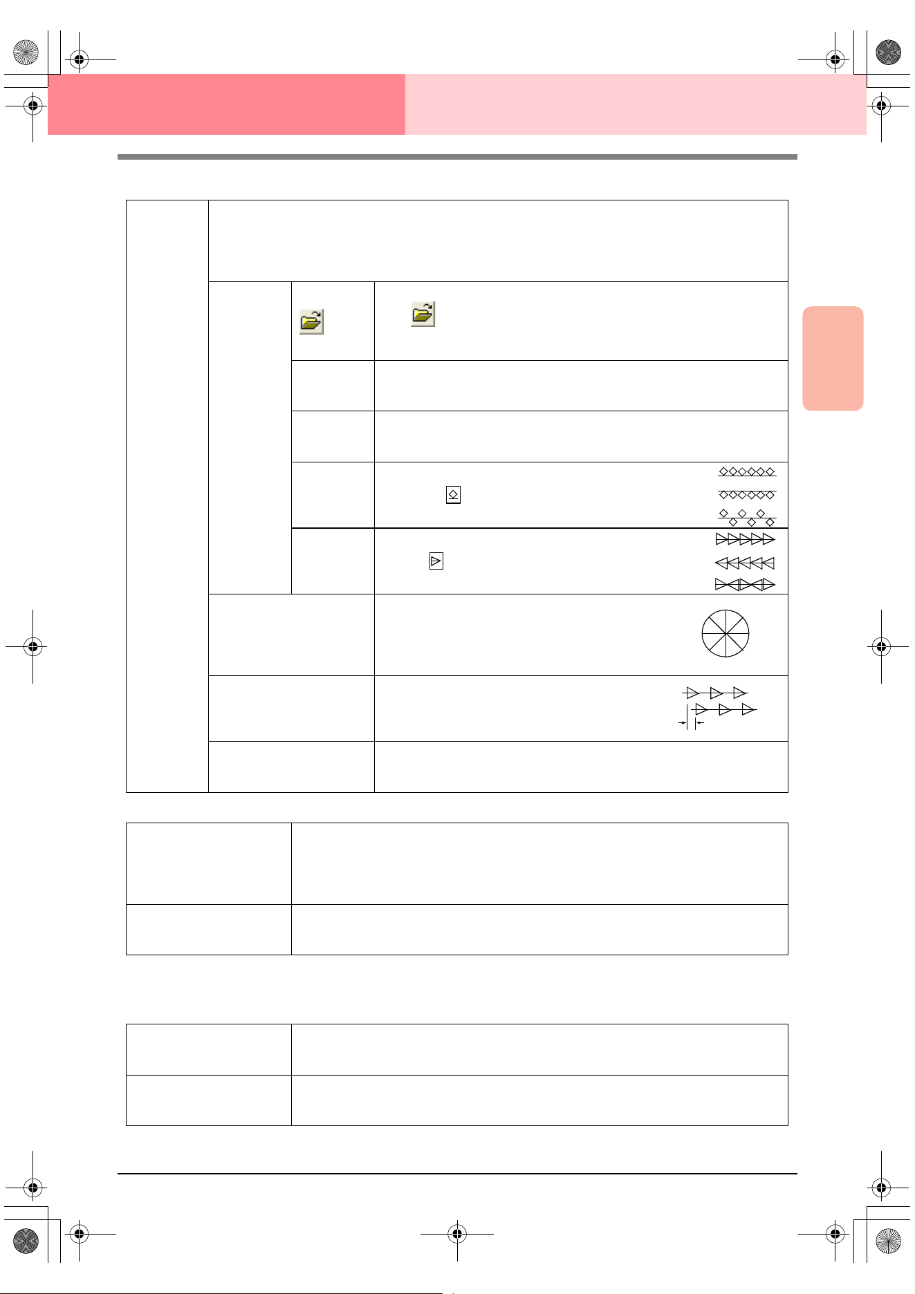
Advanced Opreation
Design Center
95
Design Center Stage 4 (Sew Setting Stage)
Motif stitch
Cross stitch
Concentric circle stitch, radial stitch and spiral stitch
For details on moving the center point of the concentric circle stitch and the radial stitch, refer to “Moving the
center point of the concentric circle stitch and radial stitch” on page 97.
Motif
Selects whether to use pattern 1 or pattern 2 for the motif stitch. If you choose to use both patterns, the data
is created to sew alternating rows of the two.
Pattern1 only: Uses only pattern 1 (Default)
Pattern2 only: Uses only pattern 2
Pattern1 and 2: Uses pattern 1 and pattern 2
Pattern1
Pattern 2
Select a pattern for the motif stitch.
Click , and then, in the Browse dialog box that appeared, select the
folder containing the .pmf file that you want to use. Double-click the desired
pattern, or select it, and then click OK.
Width (hori-
zontal length)
Sets the pattern width (the direction along the line).
Range: 2–10 mm (0.08–0.39 inch)
Default: 5.0 mm (0.20 inch)
Height (verti-
cal length)
Sets the pattern height (the direction perpendicular to the line).
Range: 2–10 mm (0.08–0.39 inch)
Default: 5.0 mm (0.20 inch)
H-Arrange
(horizontal
arrange-
ment)
Sets the horizontal arrangement of the pattern. For
patterns like , the patterns will be arranged along
the line as shown at the right.
V-Arrange
(vertical
arrange-
ment)
Sets the vertical arrangement of the pattern. For pat-
terns like , the patterns will be arranged along the
line as shown at the right.
Direction
Allows you to rotate the angle of the motif stitch.
Range: 0–359 degrees
Default: 0 degrees
Row Offset
Sets the amount of offset for each row.
Range: 0–10 mm (0.00–0.39 inch)
Default: 0.0 mm (0.00 inch)
Run Pitch
Sets the pitch of the sewing.
Range: 1–10 mm (0.04–0.39 inch)
Default: 2.0 mm (0.08 inch)
Normal:
Mirror:
Alternate:
Normal:
Mirror:
Alternate:
0°
45°
90°
135°
180°
225°
270°
315°
Size
Sets the horizontal and vertical size of the pattern.
In Expert mode, the set value is converted automatically and displayed in the box for the other
measurement units.
Range: 1.5–5.0 mm (0.06–0.20 inch) or 5–17 counts
Default: 2.5 mm (0.10 inch) or 10 counts
Times
Sets the number of times that the pattern will be sewn. Sews twice per time.
Range: Single, Double, Triple
Default: Single
Density
Sets the number of lines per millimeter.
Range: 0.5–7.0 lines per mm (13–178 lines per inch)
Default: 2.0 lines per mm (51 lines per inch)
Run pitch
Sets the pitch of the line sewing.
Range: 1–10 mm (0.04–0.39 inch)
Default: 2.0 mm (0.08 inch)
PeDesignV6Eng.book Page 95 Thursday, July 8, 2004 11:59 AM
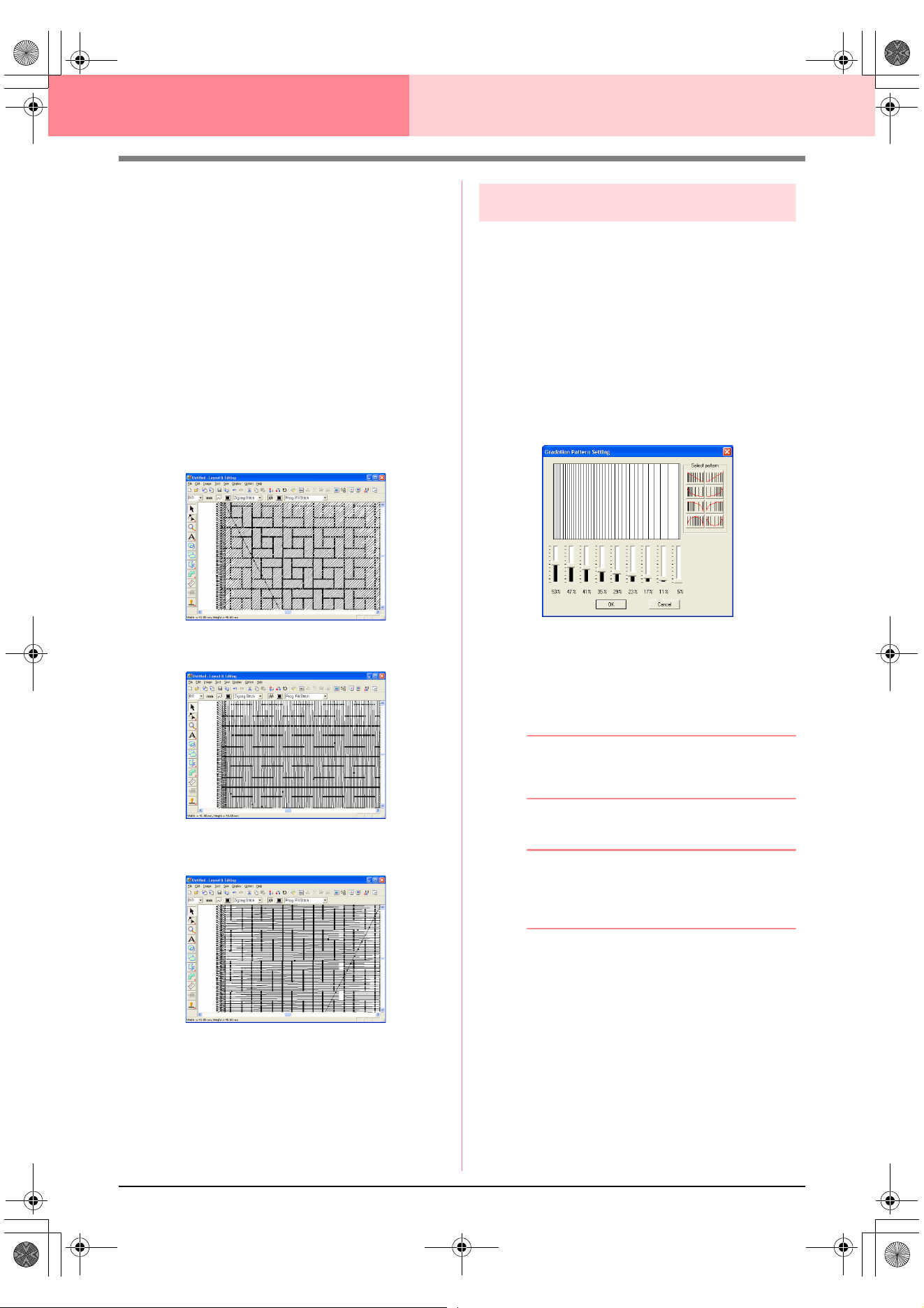
96
Design Center Stage 4 (Sew Setting Stage)
Notes on programmable fill stitches
When setting the sew type and pattern directions of
a programmable fill stitch, lines will not be sewn if
the sew type and pattern direction settings cause a
stitch to be sewn in the same direction as a line in
the stitch pattern.
Use the Preview function to view exactly how the
stitch pattern will be sewn, and then set the stitch
direction and pattern direction according to the
selected sew type or to the effect that you want to
produce. To get an even better view, make test
samples of different settings.
Examples of programmable fill stitching:
c
“Previewing the Sewing Image” on
page 102 and “Programmable Stitch
Creator” on page 208
Creating a gradation
With a satin stitch, fill stitch or programmable fill
stitch, the density of the color can be adjusted at
various locations to create a custom gradation
pattern.
1. In Expert mode of the Sewing Attribute
Setting dialog box, select the Gradation
check box.
2. Click Pattern.
→ The Gradation Pattern Setting dialog
box appears.
3. To select a preset gradation pattern, click the
desired pattern under Select pattern.
4. Move the sliders to adjust the density of the
gradation pattern.
b Memo:
The preview area shows the setting changes
that you make.
5. Click OK.
b Memo:
To close the dialog box without applying the
changes to the gradation pattern, click
Cancel
.
Example 1
Stitch direction: 45° (default)
Example 2
Stitch direction: 90°
Example 3
Stitch direction: 0°
PeDesignV6Eng.book Page 96 Thursday, July 8, 2004 11:59 AM
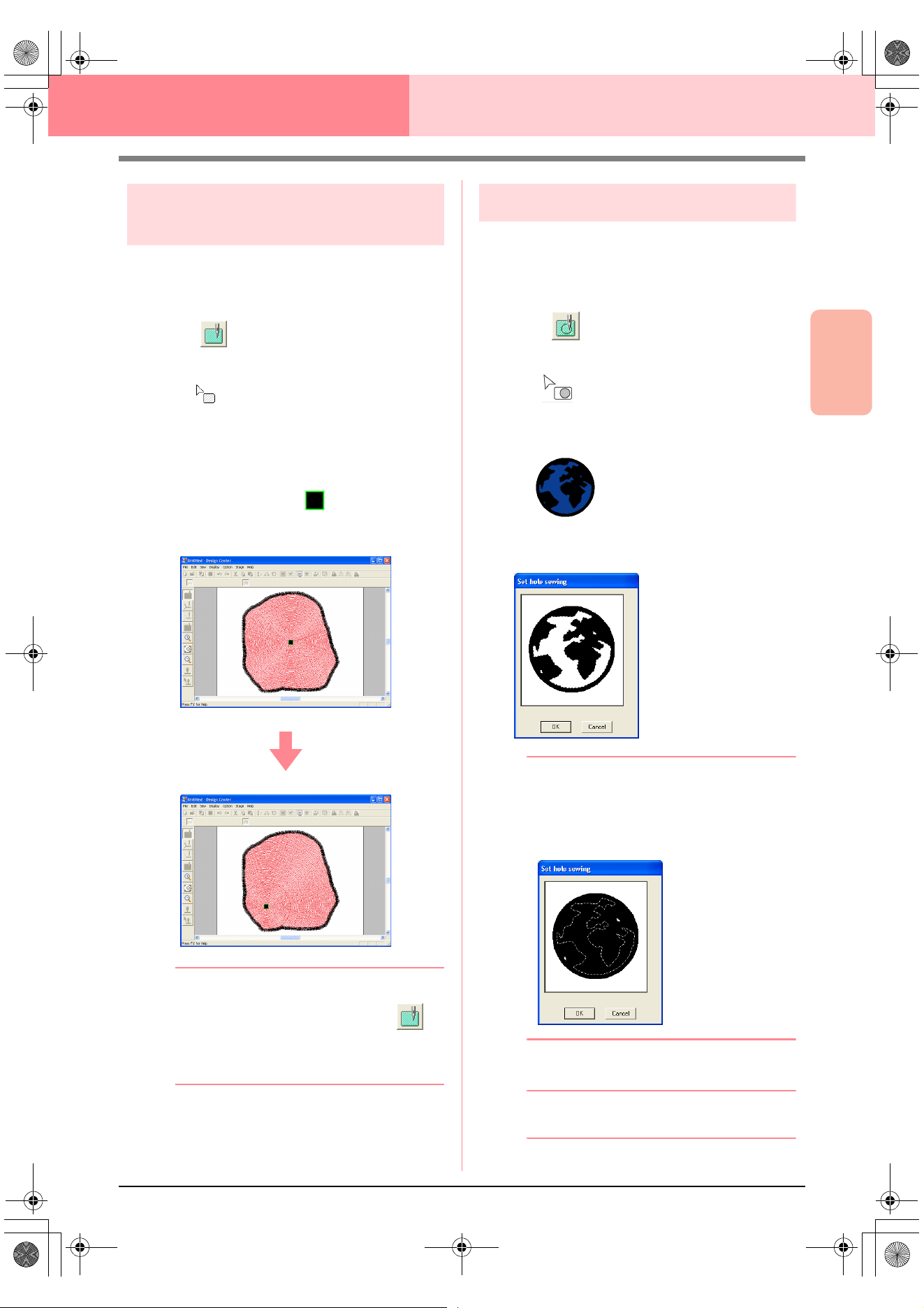
Advanced Opreation
Design Center
97
Design Center Stage 4 (Sew Setting Stage)
Moving the center point of the
concentric circle stitch and radial stitch
In order to increase the decorative effect, you can
move the center point of regions set to the
concentric circle stitch or radial stitch.
1. Click on the Tool Box.
→ The shape of the pointer changes to
.
2. Select the desired color and sew type
(Concentric Circle Stitch or Radial Stitch).
3. Click the region.
→ The center point ( ) appears.
4. Drag the center point to the desired location.
b Memo:
To move the center point later, click ,
and then click the region with the concentric
circle stitch or radial stitch applied. The
center point appears and can be moved.
Specifying hole sewing
By specifying hole sewing, the stitching in
overlapping regions will not be sewn twice. Hole
sewing can be set only when one region completely
encloses another.
1. Click on the Tool Box.
→ The shape of the pointer changes to
.
2. Click the region that completely encloses
another region.
→ A Set hole sewing dialog box similar to
the one shown below appears.
b Memo:
To cancel hole sewing, click the white inner
region. The inner region will be sewn twice
when it appears in the same color as the
outer region.
3. Click OK to set hole sewing.
b Memo:
To quit applying hole sewing, click
Cancel
.
PeDesignV6Eng.book Page 97 Thursday, July 8, 2004 11:59 AM
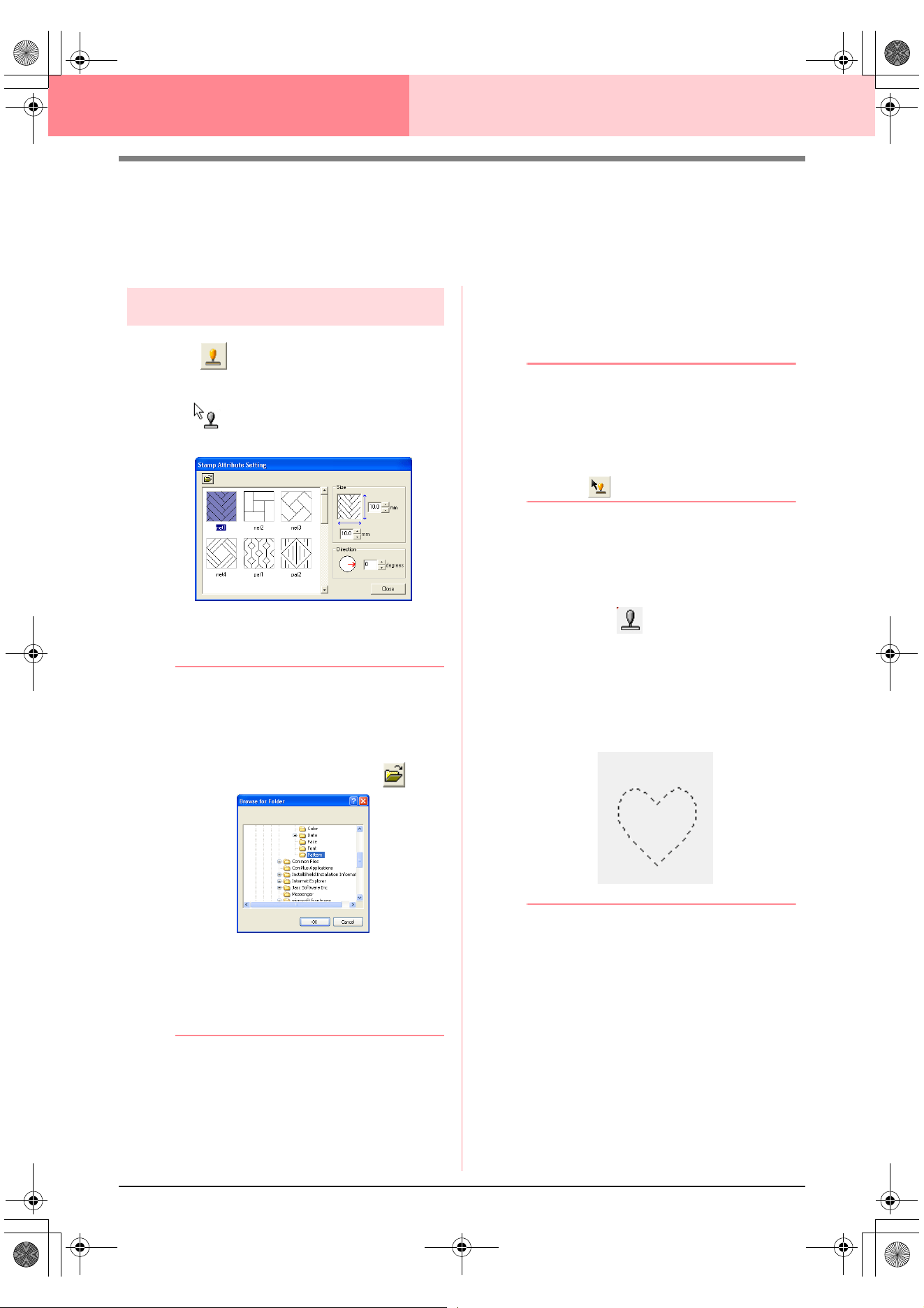
98
Design Center Stage 4 (Sew Setting Stage)
Applying and Editing Stamps
Stamps created with Programmable Stitch Creator can be applied to regions in stage 4 (Sew Setting stage) of
Design Center. Some stamp patterns are provided with this application; however, by using Programmable
Stitch Creator, you can edit the patterns that are provided or you can create your own.
Applying a stamp
1. Click on the Tool Box.
→ The shape of the pointer changes to
, and the Stamp Attribute Setting
dialog box appears.
2. In the dialog box, select a stamp pattern (.pas
file with stamp settings applied).
b Memo:
• Engraving and embossing stamp settings
appear as red- and blue-filled areas.
• .pas files with no stamp settings are also
listed.
• To select a different folder, click .
In the
Browse for Folder
dialog box that
appeared, select the desired folder, and
then click
OK
(or double-click the folder) to
close the
Browse for Folder
dialog box
and display the stamp patterns from the
selected folder in the preview window.
3. To change the width and height of the stamp,
type or select the desired size (1 to 100 mm
(0.04 to 3.94 in.)) under Size in the Stamp
Attribute Setting dialog box.
4. To change the orientation of the stamp, move
the pointer over the red arrow inside of the
circle under Direction, and then drag the red
arrow to the desired angle.
b Memo:
• The dialog box remains displayed so that
the size and orientation of the stamp can
be adjusted at any time.
• To close the dialog box, click
Close
.
• To open the dialog box again after closing
it, click .
5. Click the region where you want to apply the
stamp to select it.
→ “Marching lines” appear around the se-
lected region, and the shape of the pointer
changes to whenever it is moved
over the selected region.
6. Click the desired locations within the region
where you want to apply the stamp.
→ The stamps appear as dotted lines in the
region.
b Memo:
• The whole stamp appears, even if it is
larger than the region that it has been
applied to, however, only the parts that are
enclosed within the region will be sewn.
• Stamps can only be applied to regions that
have the satin stitch, fill stitch and
programmable fill stitch applied.
• To apply several stamps within the same
region, continue clicking the region as
often as needed.
• If the pointer cannot fit within the selected
region, the stamp cannot be applied.
•The
Stamp Attribute Setting
dialog box
appears only after a stamp tool is selected.
!!scr114.bmp!!
PeDesignV6Eng.book Page 98 Thursday, July 8, 2004 11:59 AM
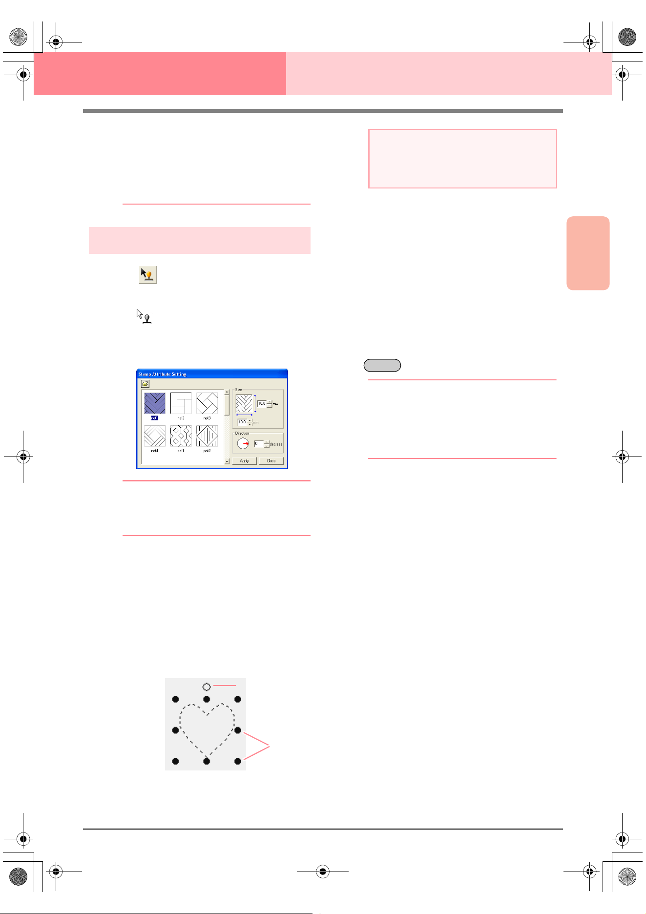
Advanced Opreation
Design Center
99
Design Center Stage 4 (Sew Setting Stage)
• Stamps are only sewn within the region
that they have been applied to.
• The size of stamps may change when they
are imported into Layout & Editing if the
size of the design has been changed with
the
Magnification
setting in the
Import
size
dialog box.
Editing a stamp
1. Click on the Tool Box.
→ The shape of the pointer changes to
, the Stamp Attribute Setting dia-
log box appears, and stamps that have
been applied are indicated by pink dotted
lines.
b Memo:
If a region was already selected, “marching
lines” appear around the region, and its
stamps are indicated by dotted lines.
2. Click the region with the stamp that you want
to edit.
→ “Marching lines” appear around the se-
lected region.
3. Click the stamp that you want to edit.
→ Round handles appear around the stamp,
and a rotation handle appears at the top of
the stamp.
4. To change the stamp pattern, select a
different pattern in the Stamp Attribute
Setting dialog box, and then click Apply.
To change the stamp size and orientation,
specify the desired settings in the Stamp
Attribute Setting dialog, or adjust it by
dragging the handles or rotation handle.
To move a stamp, drag it to another location
within the region or partially positioned on the
region.
To delete the stamp, select the menu
command Edit – Delete, or press the
key.
b Memo:
• Stamps appear only after a stamp tool is
selected.
• Stamps are only sewn within the region
that they have been applied to.
• To close the dialog box, click
Close
.
c
“Editing Outlines” on page 78
Handles
Rotation handle
a Note:
Only one stamp can be selected at a time. If
you select another stamp, the previously
selected stamp becomes deselected.
Delete
PeDesignV6Eng.book Page 99 Thursday, July 8, 2004 11:59 AM
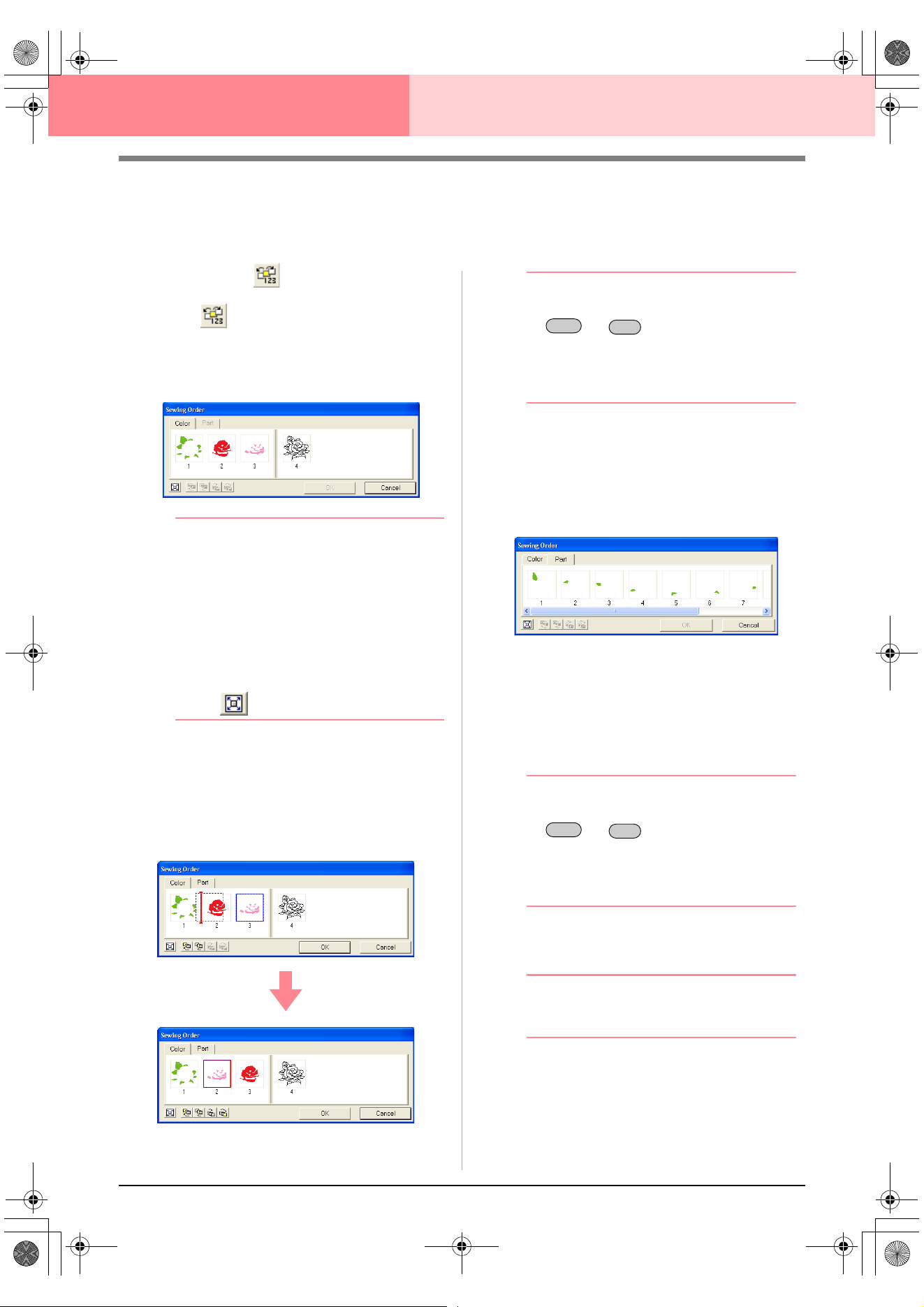
100
Design Center Stage 4 (Sew Setting Stage)
Viewing and Modifying the Sewing Order
The sewing order of pattern colors as well as the sewing order of pattern objects of the same color can be
checked and modified as necessary. (This function is available only in stage 4 (Sew Setting stage).)
Toolbar button:
1. Click , or click Sew, then Sewing Order.
→ The Color tab of a Sewing Order dialog
box similar to the one shown below ap-
pears.
b Memo:
• The frames containing regions are
separated from the frames containing
outlines with a thick vertical line. Frames
from one side of the line cannot be moved
to the other side.
• The patterns will be sewn in the order
shown, from left to right. All regions are
always sewn before the outlines.
• To enlarge the pattern for better viewing,
click .
2. To change the sewing order of a color, select
the frame for the color that you want to move,
and then drag the frame to the desired
position.
→ A red line appears, indicating the position
where the frame is being moved.
b Memo:
• To select additional frames, hold down the
or key and select each
frame.
• In the Design Page, “marching lines”
appear around the selected region or
along the selected outline.
3. To view the sewing order of multiple patterns
of the same color, select the frame that you
want to view, and then click the Part tab.
→ The individual patterns with the same col-
or appear in different frames.
4. To change the sewing order of a pattern,
select the frame for the pattern that you want
to move, and then drag the frame to the
desired position.
→ A red line appears, indicating the position
where the frame is being moved.
b Memo:
• To select additional frames, hold down the
or key and select each
frame.
• In the Design Page, “marching lines”
appear around the selected region or
along the selected outline.
5. Click OK to apply the changes and to close the
dialog box.
b Memo:
To close the dialog box without applying the
changes to the sewing order, click
Cancel
.
c
“Previewing the Sewing Image” on
page 102
Shift
Ctrl
Shift
Ctrl
PeDesignV6Eng.book Page 100 Thursday, July 8, 2004 11:59 AM
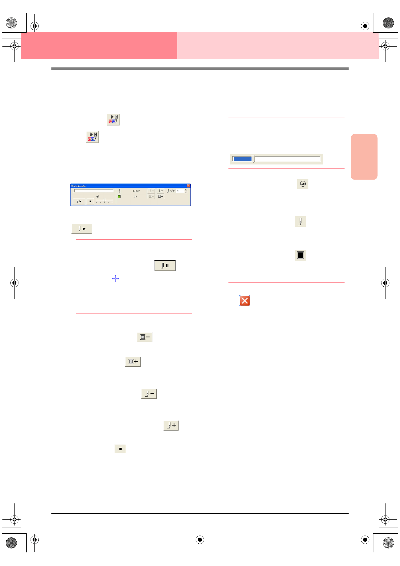
Advanced Opreation
Design Center
101
Design Center Stage 4 (Sew Setting Stage)
Checking the Stitching
The actual stitching as it will be performed by the sewing machine can be viewed using the stitch simulator.
(This function is available only in stage 4 (Sew Setting stage).)
Toolbar button:
1. Click , or click Display, then Stitch
Simulator.
The Stitch Simulator dialog box appears,
and the embroidery pattern is cleared from the
Design Page.
To begin the stitching simulation, click
.
b Memo:
• During the stitching simulation, this button
changes to a pause button ( ).
• A marker ( ) indicates the position in
the simulation.
• To get a better view of the stitching, zoom
in on the design before opening the
Stitch
Simulator
dialog box.
To reverse the simulation to the beginning of
the previous color, click .
To advance the simulation to the beginning of
the next color, click .
To reverse the stitching by a specified number
of stitches, type or select the desired number
of stitches, and then click .
To advance the stitching by a specified
number of stitches, type or select the desired
number of stitches, and then click .
To stop the simulation and return to the
beginning, click .
b Memo:
The slider shows the current location in the
simulation. In addition, adjust the slider to
change the position in the simulation.
Drag the slider indicated by to adjust the
simulation stitching speed.
b Memo:
• The first number beside indicates the
number of the current stitch, and the
second number indicates the total number
of stitches.
• The first number beside indicates the
number of the color being drawn, and the
second number indicates the total number
of colors used.
2. Click in the upper-right corner of the
dialog box to close the dialog box.
PeDesignV6Eng.book Page 101 Thursday, July 8, 2004 11:59 AM
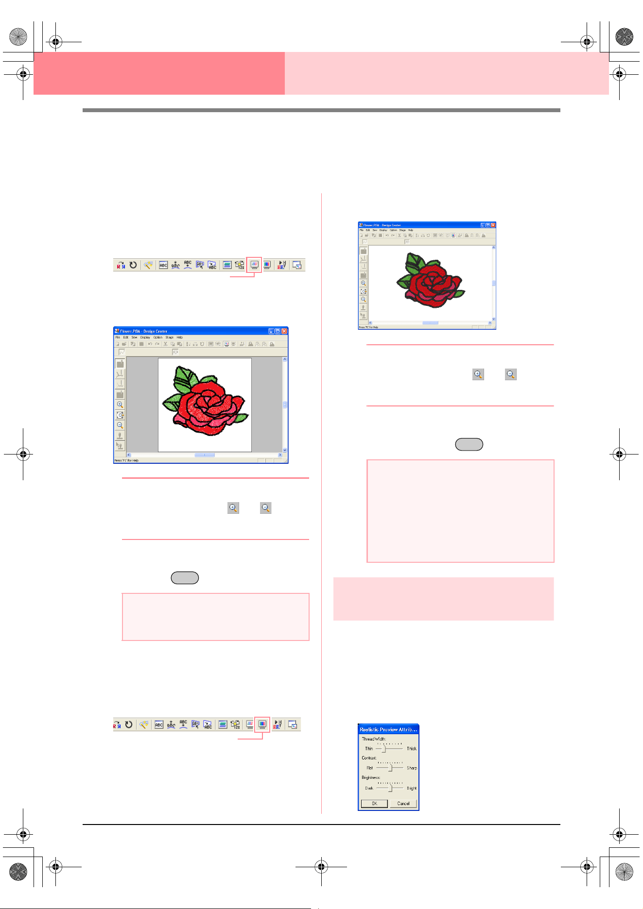
102
Design Center Stage 4 (Sew Setting Stage)
Previewing the Sewing Image
Once the embroidery pattern is complete or while you work on the design, you can preview the pattern’s
stitches. You can also view a realistic preview of the pattern in order to see how it will appear once it is sewn.
(These functions are available only in stage 4 (Sew Setting stage).)
1. To display a preview of the embroidery
pattern, click Display on the menu bar, and
then click Preview.
An alternate method is to click the Toolbar
button indicated below.
→ A preview of the embroidery pattern ap-
pears.
b Memo:
To zoom in (or out), click (or ) on the
Tool Box, and then click the desired area of
the embroidery pattern.
2. To leave the preview display, repeat step 1.,
or press the key.
3. To display a realistic preview of the
embroidery pattern, click Display on the menu
bar, and then click Realistic Preview.
An alternate method is to click the Toolbar
button indicated below.
→ A realistic preview of the embroidery pat-
tern appears.
b Memo:
To zoom in (or out), click (or ) on the
Tool Box, and then click the desired area of
the embroidery pattern.
4. To leave the realistic preview display, repeat
step
3., or press the key.
Changing realistic preview
settings
You can change the realistic preview settings to
better view the embroidery pattern. (This function is
available only in stage 4 (Sew Setting stage).)
1. Click Display, then Realistic Preview
Attribute Setting.
→ A Realistic Preview Attribute dialog box
similar to the ones shown below appears.
a Note:
The embroidery pattern cannot be edited
while the preview is displayed.
Preview
Esc
Realistic Preview
a Note:
• The embroidery pattern cannot be edited
while the realistic preview is displayed.
• The Realistic Preview function cannot
display a clean preview of the pattern if the
monitor is set to 256 colors or less. The
monitor should be set to at least 16-bit
High Color (65536 colors).
Esc
PeDesignV6Eng.book Page 102 Thursday, July 8, 2004 11:59 AM
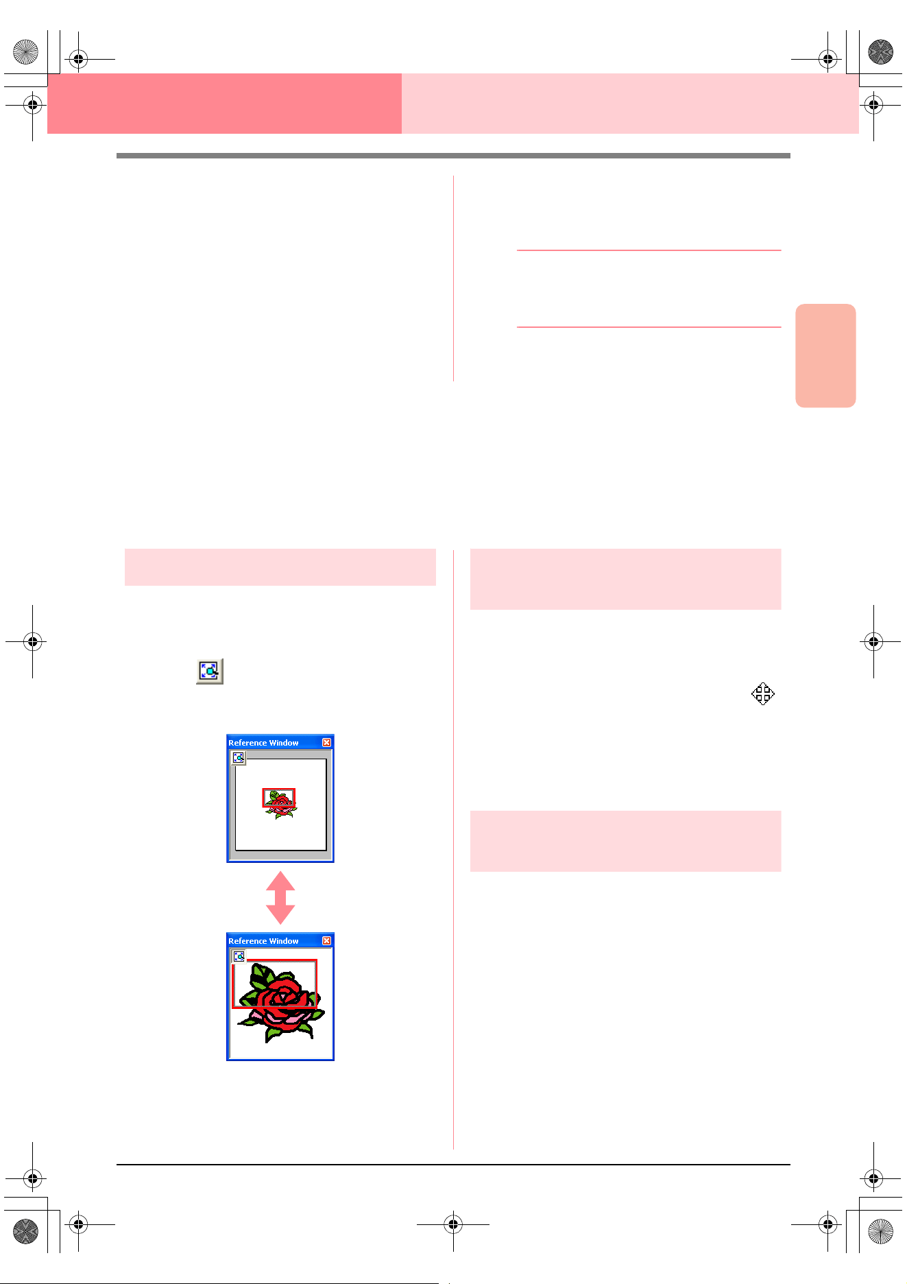
Advanced Opreation
Design Center
103
Design Center Stage 4 (Sew Setting Stage)
2. Use the Thread Width slider to set how wide
the thread will appear.
3. Use the Contrast slider to set the contrast.
4. Use the Brightness slider to set how bright
the display is.
5. Click Apply to display a realistic preview of the
patterns with the new settings (when the
realistic preview is displayed).
Or, click OK to save the settings for the next
time that the Realistic Preview function is
select (when the realistic preview is not
displayed).
b Memo:
To close the dialog box without applying the
changes to the settings, click
Close
or
Cancel
.
c
“Previewing the Sewing Image” on
page 102
Viewing Patterns in the Reference
Window
All outlines and patterns in the Design Page are displayed in the Reference Window, giving you an overall view
of the pattern while you work on a detailed area. The display area frame (red rectangle) indicates the part of
the pattern displayed in the Design Page.
Zooming
The pattern displayed in the Reference Window can
be reduced to fit completely within the Reference
Window or enlarged to display only the pattern.
1. Click .
→ The pattern is displayed so that it fills the
Reference Window.
Moving the display area
frame
The part of the pattern displayed in the Design Page
can be selected from the Reference Window.
1. Move the pointer over the display area frame.
→ The shape of the pointer changes to .
2. Drag the display area frame so that it
surrounds the desired part of the pattern.
→ The selected part of the pattern is dis-
played in the Design Page.
Redrawing the display area
frame
Instead of moving the display area frame, the frame
can be redrawn to display the desired part of the
pattern in the Design Page.
1. Drag the pointer over the desired part of the
pattern in the Reference Window.
→ The display area frame is redrawn, and
the selected part of the pattern is dis-
played in the Design Page.
PeDesignV6Eng.book Page 103 Thursday, July 8, 2004 11:59 AM
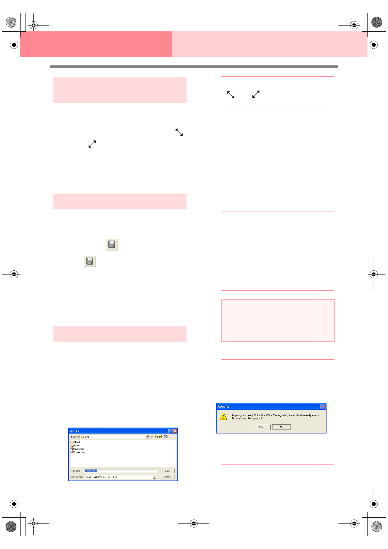
104
Design Center Stage 4 (Sew Setting Stage)
Scaling the display area
frame
1. Move the pointer over a corner of the display
area frame.
→ The shape of the pointer changes to
or , depending on the corner that the
pointer is over.
b Memo:
and are for scaling the height
and width.
2. Drag the corner to adjust the display area
frame to the desired size.
Saving
Overwriting
Once the image or pattern has been saved,
changes can easily be saved so that the latest
version can be retrieved later.
Toolbar button:
1. Click , or click File, then Save.
→ If the image or pattern has already been
saved at least once, the file is saved im-
mediately.
→ If no file name has been specified or if the
file cannot be found, the Save As dialog
box appears.
Saving with a new name
The current file can be saved with a different file
name in order to keep the original unchanged or to
keep various versions of the same image or pattern.
Files can be saved as bitmap files (.bmp) in stage 1
(Original Image stage), .pel files in stage 2 (Line
Image stage), and .pem files in stage 3 (Figure
Handle stage) and stage 4 (Sew Setting stage).
1. Click File, then Save As.
→ A Save As dialog box similar to the one
shown below appears.
2. Select the drive and the folder, and then type
in the file name.
b Memo:
• The correct extension is automatically
selected.
• Image data from stage 1 (Original Image
stage) can only be saved as a bitmap file
(.bmp).
In stage 2 (Line Image stage), image data
is saved as a .pel file.
In stage 3 (Figure Handle stage) and stage
4 (Sew Setting stage), pattern data is
saved as a .pem file.
3. Click Save to save the data.
b Memo:
• To quit the operation, click
Cancel
.
• If a file already exists with the name
specified in the
Save As
dialog box, the
following message appears.
• To overwrite the file, click
Yes
.
• If you do not want to overwrite the
existing file, click
No
. You can then
enter a different file name.
a Note:
If you select a file type of a previous software
version, saved .pem files can be opened
with that version of the software; however,
some information may be lost.
PeDesignV6Eng.book Page 104 Thursday, July 8, 2004 11:59 AM
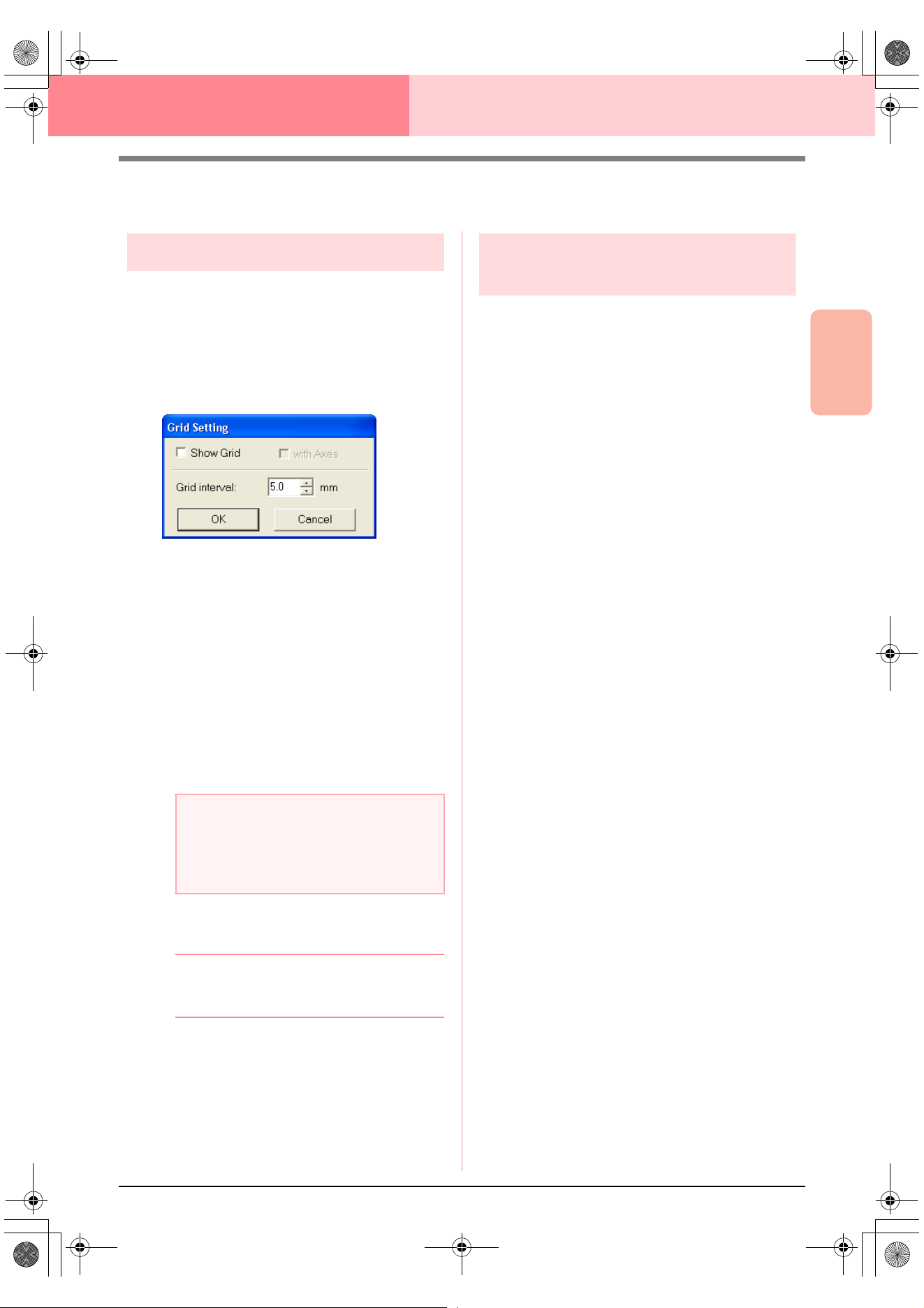
Advanced Opreation
Design Center
105
Design Center Stage 4 (Sew Setting Stage)
Changing Software Settings
Changing the grid settings
A grid of dotted lines or solid lines can be displayed
or hidden, and the spacing for the grid can be
adjusted. (This function is available only in stage 3
(Figure Handle stage).)
1. Click Display, then Grid Setup.
→ The Grid Setting dialog box appears.
2. To display the grid, select the Show Grid
check box.
To hide the grid, clear the Show Grid check
box.
3. To set the grid spacing, type or select a value
in the Grid interval box. (The setting range is
0.1 to 25.4 mm (0.004 to 1.0 inch).)
4. To display the grid as solid lines, select the
with Axes check box.
To display the grid as dotted lines, clear the
with Axes check box.
5. Click OK to apply the changes and to close the
dialog box.
b Memo:
To close the dialog box without applying the
changes to the grid, click
Cancel
.
Changing the measurement
units
The measurements for values displayed in the
application can be in either millimeters or inches.
1. Click Option, then Select System Unit, and
then select the desired measurement units
(mm or inch).
a Note:
When the
Show Grid
check box is selected
and the
with Axes
check box is cleared,
only the intersecting points of the grid will be
displayed.
PeDesignV6Eng.book Page 105 Thursday, July 8, 2004 11:59 AM

106
Layout & Editing
Layout & Editing is used to combine different objects into an embroidery pattern. The most complex objects
can be digitized in Design Center and imported into the Design Page, or created in Layout & Editing with the
wizard for automatically converting an image into an embroidery pattern. Furthermore, you can add text and
monograms, rectangles, circles, broken lines, curves, and manual punching patterns, and define sewing
attributes (thread color and sew type, including stitch patterns created in Programmable Stitch Creator) to the
different objects of the embroidery pattern. You can move all of the patterns to obtain the best layout, and cut
portions of patterns and rearrange them as desired.
Once the embroidery pattern is completed, you can save your work on the computer hard disk, print it, or
transfer it to an original card (or whatever media your sewing machine uses) so that it can be sewn from your
machine.
■ Inputting Images and Embroidery Patterns
Images from existing files, such as clip art or custom-made portrait drawings, and images from TWAIN devices
or the Clipboard can be imported into Layout & Editing. These images can be traced or used with the wizard
to automatically create embroidery patterns. In addition, embroidery patterns created in Design Center or a
pattern from an embroidery card can be imported into the Layout & Editing Design Page.
■ Editing Embroidery Patterns
The embroidery patterns in the Design Page can be edited by adding text and other drawn objects to
customize the embroidery pattern.
■ Checking Embroidery Patterns
After designing the embroidery pattern, you can preview it. In the preview, you can view the stitches. In the
realistic preview, you can see how the design will look when it is sewn. You can also view the sewing order for
each object in the design.
■ Saving and Printing
When the embroidery pattern is finished, it can be saved on the computer’s hard disk in one of many formats
(.pes, .dst, .hus, .exp, or, .pcs). In addition, the pattern can be transferred to an original card by using the USB
card writer, to a floppy disk, or to other types of media used by your sewing machine, such as CompactFlash
cards and USB media. In addition, the embroidery pattern can be printed.
■ Changing Software Settings
Grid settings for the Design Page and measurement units can be adjusted to help create the embroidery
pattern and place added objects.
■ Information for Optional Large-Size Hoop Users
Combined embroidery patterns can be created specifically for multi-position hoops, including the Jumbo Hoop
or Extra Large Hoop.
PeDesignV6Eng.book Page 106 Thursday, July 8, 2004 11:59 AM
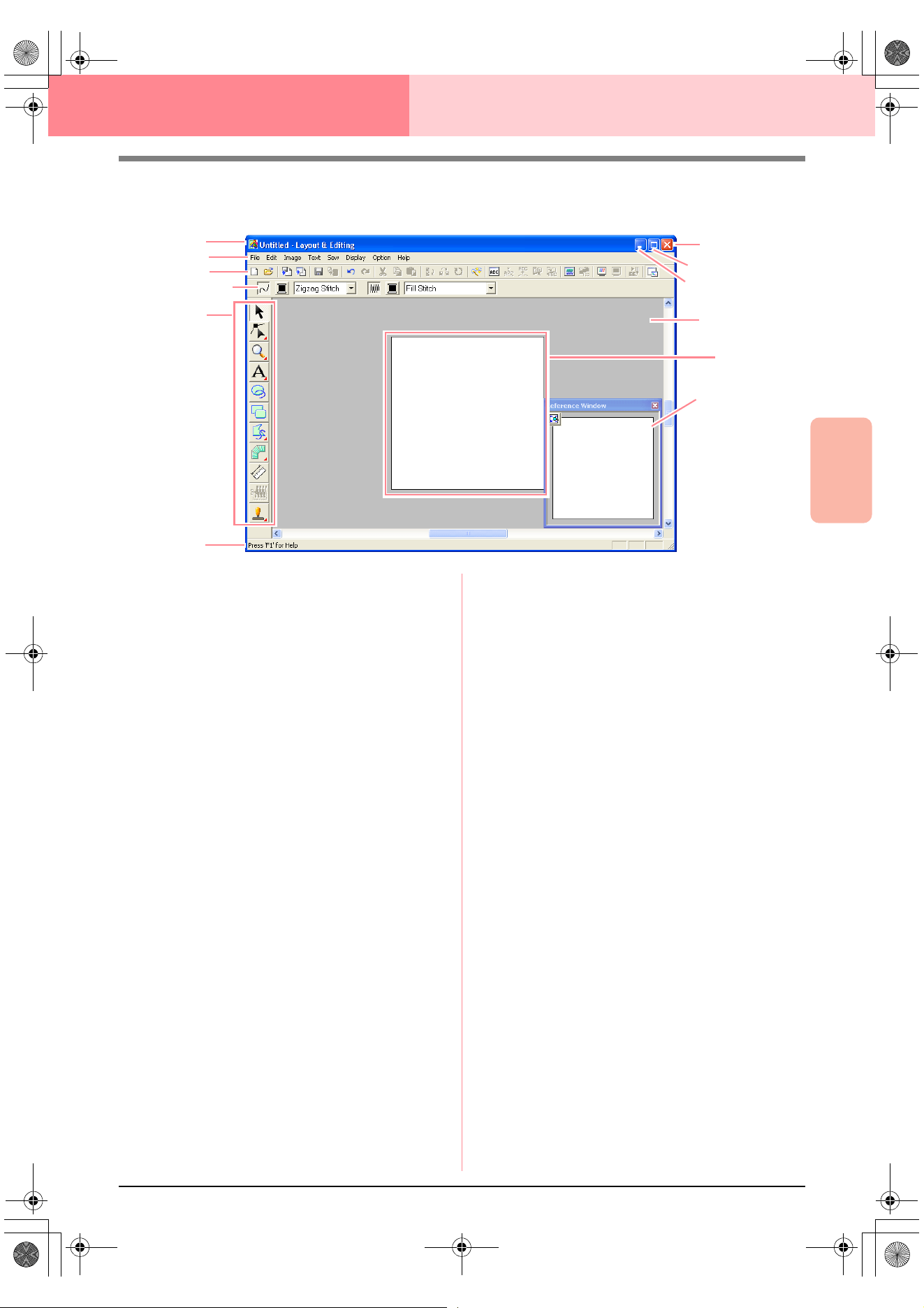
Advanced Opreation
Layout & Editing
107
Layout & Editing
Main Window
1 Title bar
2 Menu bar
Provides access to the functions.
3 Toolbar
Provides shortcuts for the menu commands.
4 Sewing Attributes bar
Sets the sewing attributes (color and sew type)
of lines and regions in the pattern.
5 Tool Box
Used to create, select and edit patterns.
6 Status bar
Provides helpful information.
7 Reference Window
Displays all patterns in the work area, giving you
an overview while you work on a detailed area.
(For more details, refer to “Viewing Patterns in
the Reference Window” on page 193.)
8 Design Page
The actual part of the work area that can be
saved and sewn.
9 Work area
0 Minimize button
A Maximize button
B Close button
2
8
3
4
5
6
A
0
9
1
B
7
PeDesignV6Eng.book Page 107 Thursday, July 8, 2004 11:59 AM
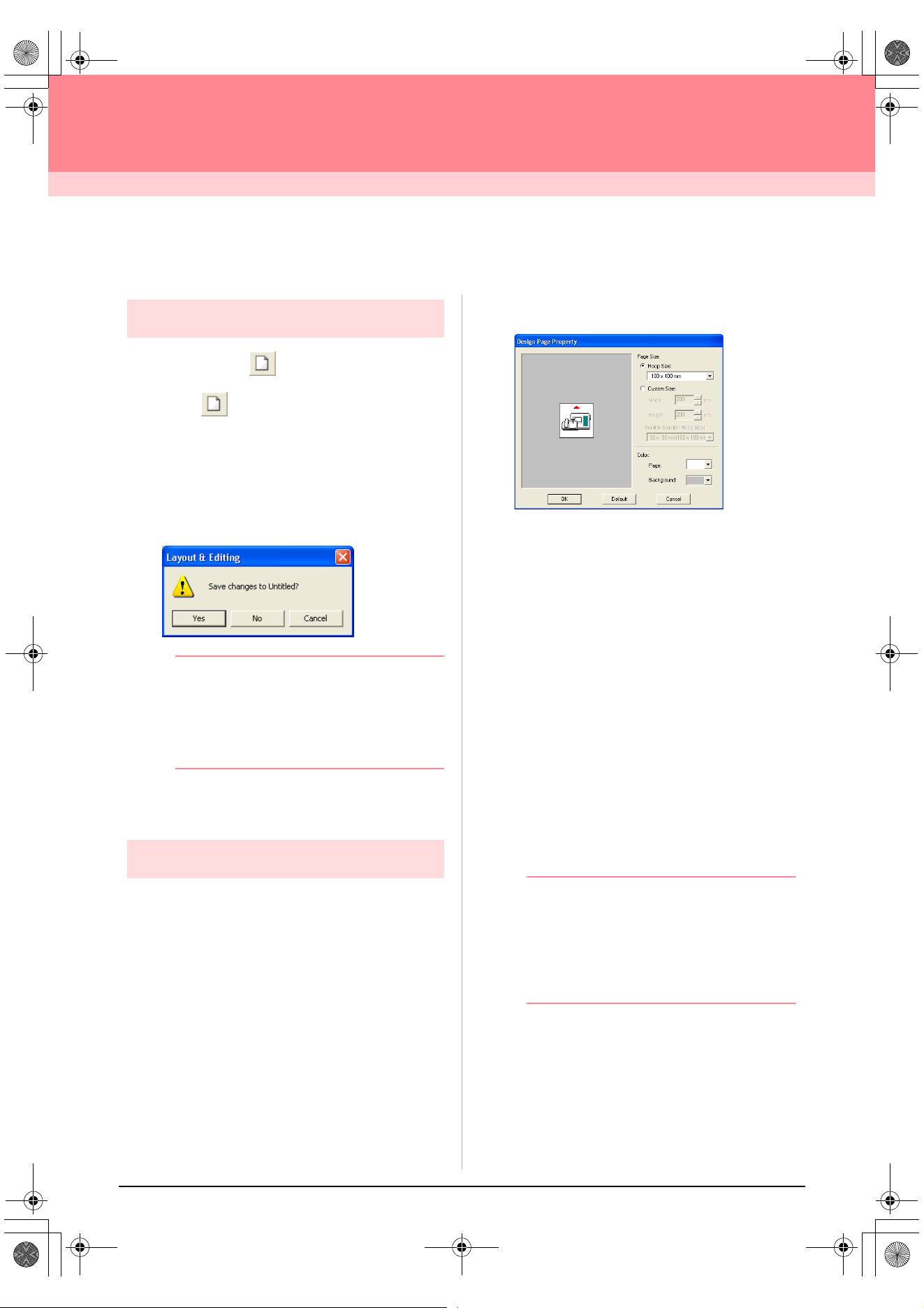
108
Layout & Editing
Inputting Images and Embroidery Patterns
Creating a Design Page
Creating a new Design Page
Toolbar button:
1. Click , or click File, then New.
→ If the current Design Page has already
been saved or has not been edited, a new
Design Page immediately appears.
→ If the current Design Page has not been
saved, you will be asked whether you
want to save the changes.
b Memo:
• To save the Design Page, click
Yes
.
• To abandon the Design Page, click
No
.
• To return to the Design Page, for example,
to modify it or save it with another file
name, click
Cancel
.
c
“Opening a Layout & Editing file” below
and “Saving” on page 194
Specifying the Design Page
The color and size of the Design Page in addition to
the color of the background can be changed. You
can select a Design Page size according to the size
of hoop that you will be using with your sewing
machine. You can also customize the Design Page
for patterns that will be split into sections.
1. Click Option, then Design Page Property.
→ The Design Page Property dialog box
appears.
2. Select the Design Page size.
To adjust the Design Page size according to
the hoop size, select Hoop Size, and then
select the desired hoop size from the selector.
To specify a custom Design Page size, select
Custom Size, and then type or select the
desired width and height for the Design Page.
(The setting range is 100 to 1000 mm (3.9 to
39.4 inches).)
In order to make adjustments to the fabric with
the layout adjustment function of your sewing
machine, select a Design Page size from the
Section Size (for Hoop Size) selector. These
Design Page sizes are 10 mm (0.39 in.)
smaller than regular embroidery hoops. (This
function is not for multi-position hooping. For
details on multi-position hoops, refer to
“Selecting the Design Page size” on
page 203.)
b Memo:
• The preview area shows the setting
changes that you make.
• When
Hoop Size
is selected, the sewing
machine image shows the orientation of
the Design Page (hoop) in relation to the
machine.
3. From the Page selector, select the desired
color for the Design Page.
4. From the Background selector, select the
desired color for the background.
5. Click OK.
PeDesignV6Eng.book Page 108 Thursday, July 8, 2004 11:59 AM
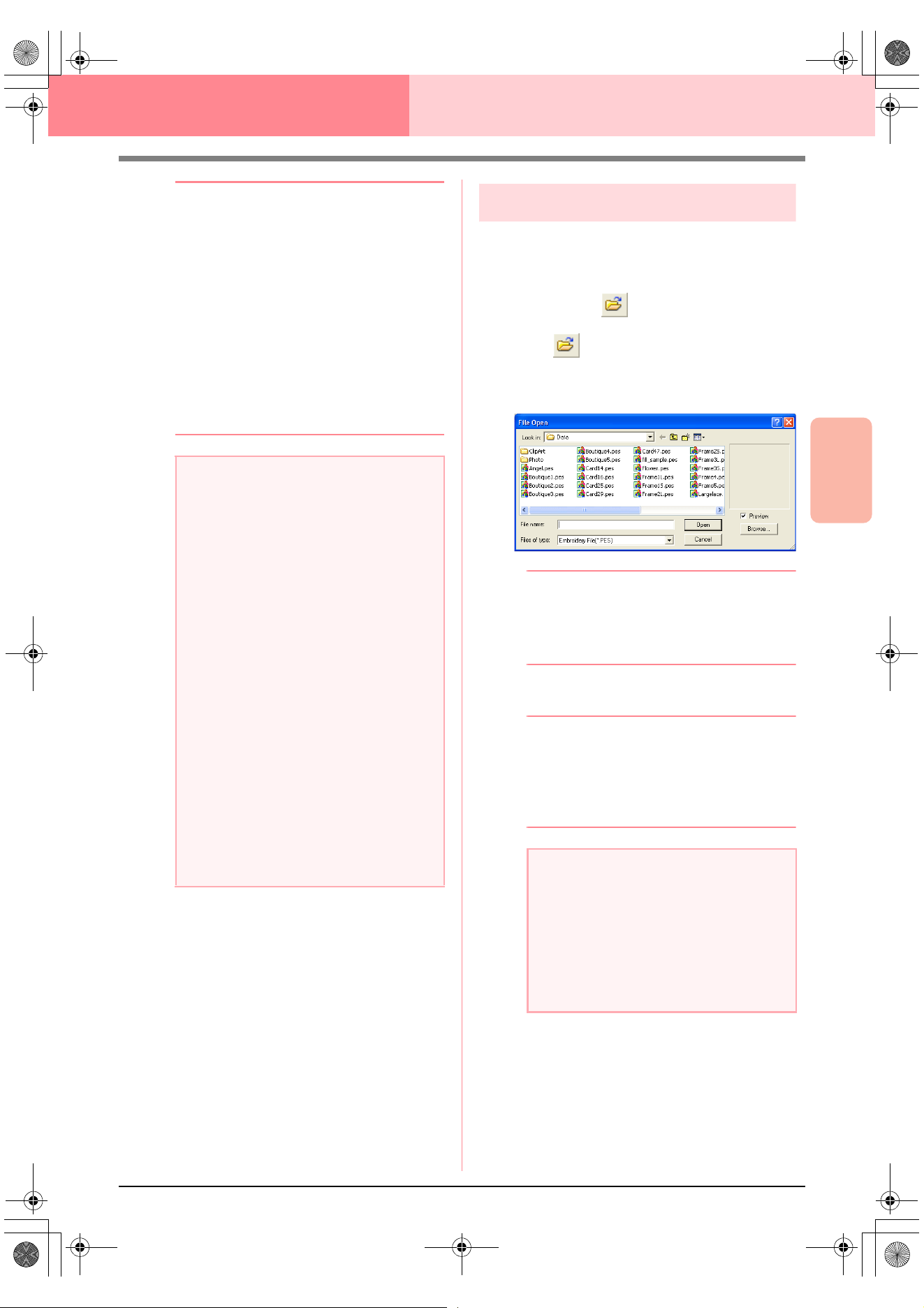
Advanced Opreation
Layout & Editing
109
Layout & Editing Inputting Images and Embroidery Patterns
b Memo:
• To return to the default settings
(
100
×
100
mm
(
4"
×
4"
) of
Hoop Size
), click
Default
.
• Before an embroidery pattern created in a
custom Design Page is saved or
transferred to an original card, running
stitches, which cannot be edited, are
added at the edges of the pattern sections
so that the pattern sections can easily be
aligned during sewing. This alignment
stitching appears in the
NOT DEFINED
color. (For more details, refer to
“Embroidering” on page 65.)
• To close the dialog box without applying
the changes to the settings, click
Cancel
.
c
“Specifying a Design Page size” on
page 60 and “Changing the measurement
units” on page 202
Opening a Layout & Editing file
An embroidery pattern that has previously been
saved as a Layout & Editing file (.pes file) can be
opened.
Toolbar button:
1. Click , or click File, then Open.
→ A File Open dialog box similar to the one
shown below appears.
b Memo:
This dialog box can be resized so that the
folder contents can be viewed better. The
size of the dialog box is retained until it is
changed again.
2. Select the drive and the folder.
b Memo:
• If the
Preview
check box is selected, the
contents of the selected file will appear in
the
Preview
box.
• To quit the operation and close the dialog
box, click
Cancel
.
3. To view the contents of the .pes files in the
currently selected folder, click Browse.
a Note:
• The Design Page sizes
130
×
300 mm
,
300
×
130 mm
,
100
×
172 mm
, and
172
×
100 mm
, indicated by “*”, are used to
embroider multi-position patterns using a
special embroidery hoop attached to the
sewing machine at three installation
positions. Check that you have the multi-
position embroidery hoop and that these
multi-position patterns can be
embroidered using your sewing machine.
• Do not select a hoop size larger than the
embroidery hoop that can be used with
your machine.
• Custom Design Page sizes cannot be
saved for version 5 and earlier.
• Although a custom Design Page size can
be specified, since processing will take too
long when trying to create an extremely
large pattern with the Photo Stitch
function, the message “Too large image to
convert” will appear if the size exceeds a
width or height of 500 mm (19 3/4 in.).
After the message is closed, the photo is
automatically selected, and is ready to be
moved or reduced.
a Note:
• Be sure to select a folder that contains.pes
files.
• If a .pes file is saved with objects
extending off the Design Page or with the
number of stitches or number of colors for
the objects exceeding the Design Page
limitations, a preview of the image cannot
be displayed.
PeDesignV6Eng.book Page 109 Thursday, July 8, 2004 11:59 AM
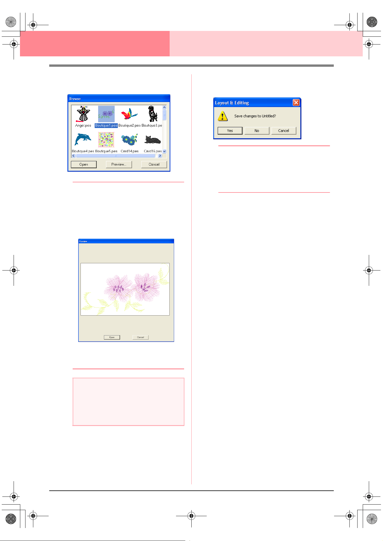
110
Layout & Editing Inputting Images and Embroidery Patterns
→ A Browse dialog box similar to the one
shown below appears.
b Memo:
• To return to the
File Open
dialog box, click
Cancel
.
• To see a more detailed image, select a file,
and then click
Preview
. A
Preview
dialog
box similar to the one shown below
appears.
• To open the displayed file, click
Open
.
• To return to the
Browse
dialog box,
click
Cancel
.
4. To open a file, select it, and then click Open,
or double-click the file’s icon.
→ If the current Design Page has already
been saved or has not been edited, the
contents of the selected file immediately
appear in the Design Page.
→ If the current Design Page has not been
saved, you will be asked whether you
want to save the changes.
b Memo:
• To save the Design Page, click
Yes
.
• To abandon the Design Page, click
No
.
• To return to the Design Page, for example,
to modify it or save it with another file
name, click
Cancel
.
c
“Saving” on page 194
a Note:
If a .pes file is saved with objects extending
off the Design Page or with the number of
stitches or number of colors for the objects
exceeding the Design Page limitations, a
preview of the image cannot be displayed.
PeDesignV6Eng.book Page 110 Thursday, July 8, 2004 11:59 AM
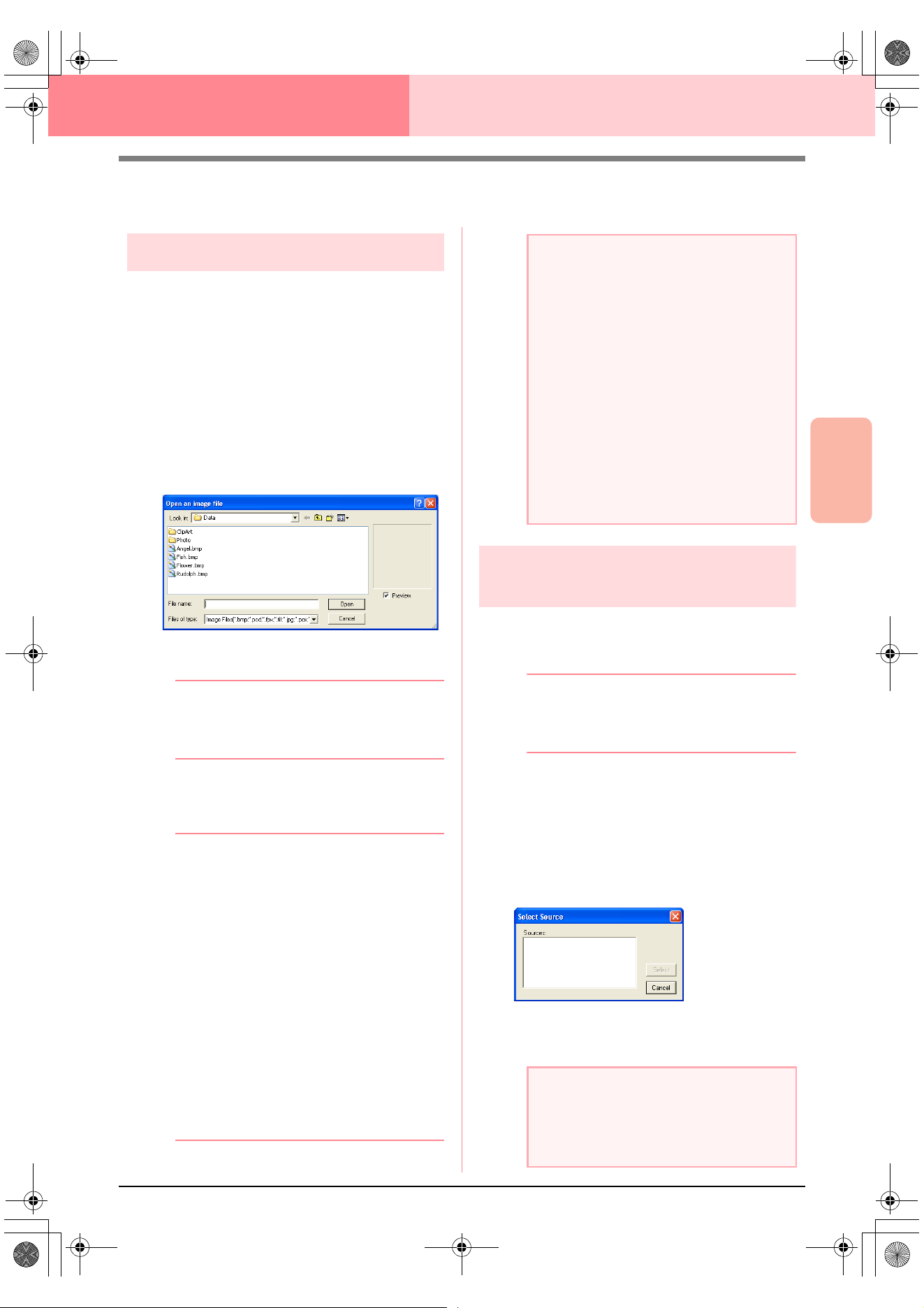
Advanced Opreation
Layout & Editing
111
Layout & Editing Inputting Images and Embroidery Patterns
Importing Image Data
Importing image data
Image data from an existing file can be imported into
a Design Page and used as a guide for creating an
embroidery pattern. The file name extension must
be one of the following: Windows bitmap (.bmp),
Exif (.tif, .jpg), ZSoftPCX (.pcx), Windows Meta File
(.wmf), Portable Network Graphics (.png),
Encapsulated PostScript (.eps), Kodak PhotoCD
(.pcd), FlashPix (.fpx), JPEG2000 (.j2k).
1. Click Image, then Input, then from File.
→ An Open an image file dialog box similar
to the one shown below appears.
2. Select the drive, the folder and the desired file.
b Memo:
If the
Preview
check box is selected, the
contents of the selected file will appear in the
Preview
box.
3. Click Open to open the file.
→ The image appears in the work area.
b Memo:
• Double-clicking the file name also opens
the file and closes the dialog box.
• To quit the operation, click
Cancel
.
• If the image was saved at a specific
resolution, it is displayed at that resolution.
• If the image currently displayed in the
Design Page has not yet been saved, you
will be asked whether you want to save it.
• To display, hide, or display a faded copy of
the image that remains in the work area,
click
Image
, then
Display Image
, and
then click the desired display setting.
• To display the original image, click
On
.
• To display a faded copy of the image,
click
Faded
.
• To hide the original image, click
Off
.
Importing image data from a TWAIN
device, such as a scanner
Images can be imported into the current Design Page
from a scanner or other TWAIN device and used as a
template for creating an embroidery pattern.
b Memo:
TWAIN is an application interface (API)
standardization for software that controls
scanners and other devices.
1. Check that the scanner or other TWAIN
device is correctly connected to your
computer.
2. Click Image, then Select TWAIN device.
→ A Select Source dialog box similar to the
one shown below appears.
3. From the Sources list, click the desired device
to select it.
a Note:
• With .pcd and .fpx files containing many
pages, only the first page can be opened.
Tiff files with LZW compression cannot be
opened.
• You can change the size and position of
an imported image, and then save that
information with the .pes file. The next
time that you import the same image into
the saved .pes file, a message appears,
asking whether to input the image at its
previously saved position and size or at its
original position (the center of the Design
Page).
• Only one image can be added to the work
area. If you try to display a different image,
it will replace the previous one.
a Note:
If no TWAIN device is installed, there will be
no names displayed in the
Sources
list.
First, install the driver software for the
TWAIN device that you want to use.
PeDesignV6Eng.book Page 111 Thursday, July 8, 2004 11:59 AM
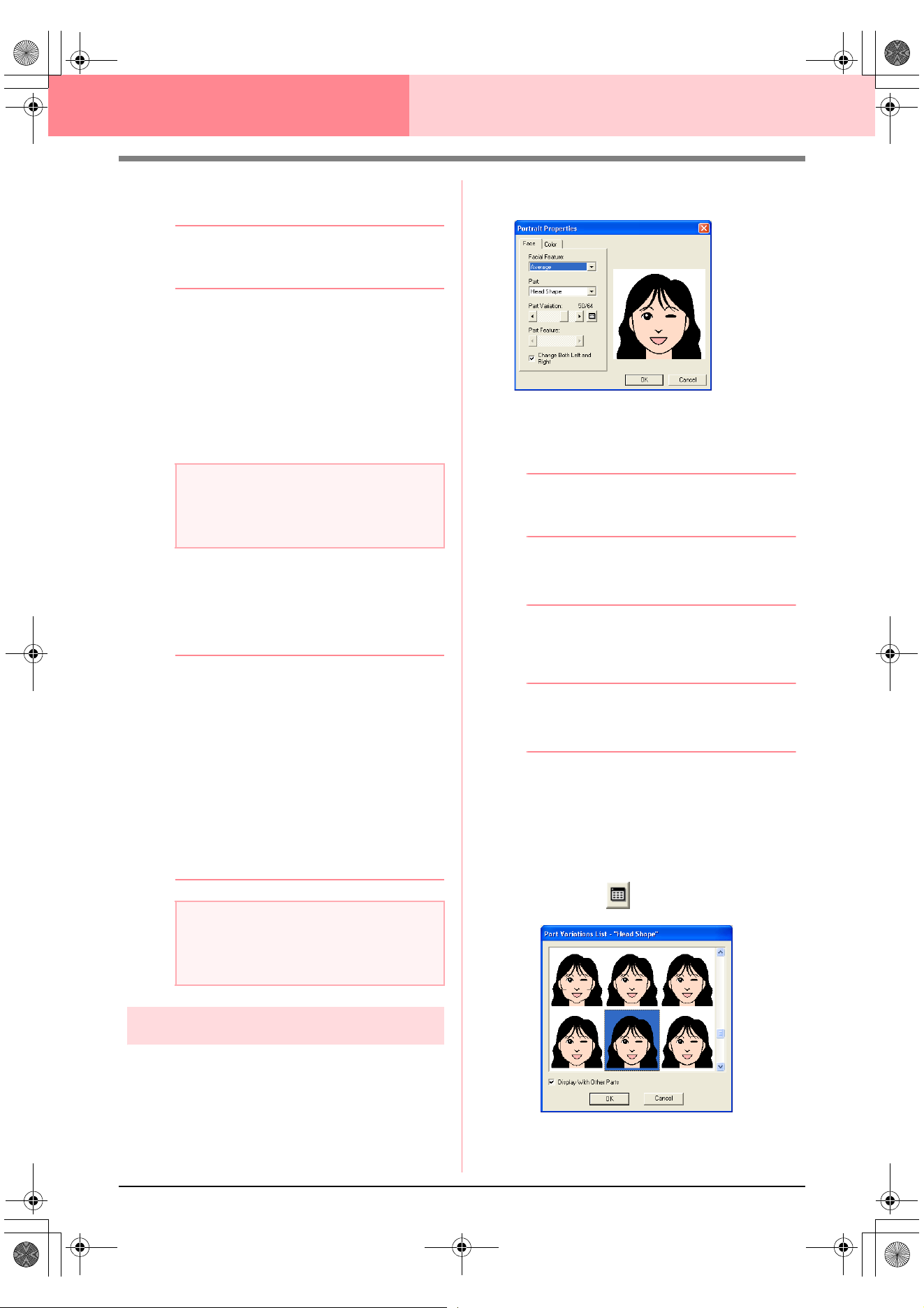
112
Layout & Editing Inputting Images and Embroidery Patterns
4. Click Select to choose the selected device
and to close the dialog box.
b Memo:
To quit the operation and close the dialog
box, click
Cancel
.
5. Click Image, then Input, then from TWAIN
device.
→ The driver interface for the device select-
ed in the Select Source dialog box ap-
pears.
6. Specify the necessary settings for importing
an image, and then import the image.
→ When the image transfer between the
scanner (or other device) and the driver is
completed, the imported image will be
pasted into the Design Page at its original
size.
b Memo:
• If the image currently displayed in the
Design Page has not yet been saved, you
will be asked whether you want to save it.
• To display, hide, or display a faded copy of
the image that remains in the work area,
click
Image
, then
Display Image
, and
then click the desired display setting.
• To display the original image, click
On
.
• To display a faded copy of the image,
click
Faded
.
• To hide the original image, click
Off
.
Creating a portrait image
Combine images of facial features provided with the
application to create an original portrait image.
1. Click Image, then Input, then from Portrait.
→ The Portrait Properties dialog box ap-
pears.
2. From the Facial Feature selector, select the
overall contour (appearance) of the portrait
(for example, narrow, wide, or child-like)
b Memo:
The preview area shows the setting changes
that you make.
3. From the Part selector, select the part of the
portrait to be changed.
b Memo:
The part of the portrait to be changed can
also be selected by clicking it in the preview
area.
4. Move the Part Variation slider to select the
desired part variation.
b Memo:
• To change both sides of a part together,
such as the eyes or ears, select the
Change Both Left and Right
check box.
• The selected part variation is shown in the
sample image.
• To display all variations of the selected
part, click .
a Note:
For information on using the driver interface,
refer to the help manual for that interface, or
contact the manufacturer of the interface.
a Note:
Only one image can be added to the work
area. If you try to display a different image, it
will replace the previous one.
PeDesignV6Eng.book Page 112 Thursday, July 8, 2004 11:59 AM
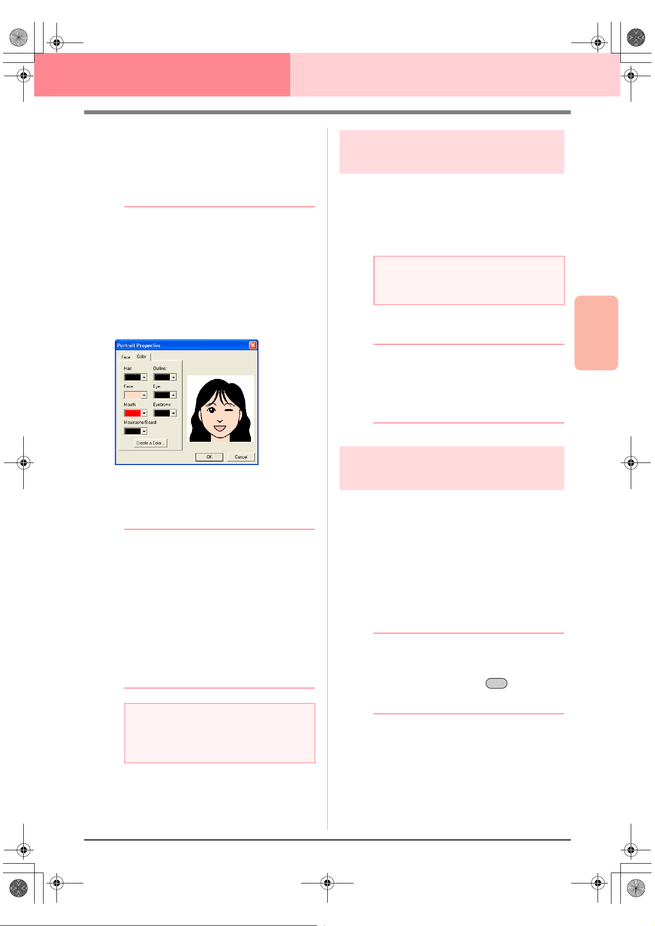
Advanced Opreation
Layout & Editing
113
Layout & Editing Inputting Images and Embroidery Patterns
• To display the images of all parts
combined, select the
Display With
Other Parts
check box in the
Part
Variations List
dialog box that
appeared.
• Select a part from the list, and then
click
OK
.
5. To select a part feature (for example, standard
size, slightly larger, slightly smaller, wider or
taller), move the Part Feature slider, if it is
available.
6. To change the color of the parts, click the
Color tab, click the selector for the color that
you want to change, and then select the
desired color from the color list that appeared.
7. Click OK.
→ The portrait image is displayed in the De-
sign Page.
b Memo:
• If the image currently displayed in the
Design Page has not yet been saved, you
will be asked whether you want to save it.
• To display, hide, or display a faded copy of
the image that remains in the work area,
click
Image
, then
Display Image
, and
then click the desired display setting.
• To display the original image, click
On
.
• To display a faded copy of the image,
click
Faded
.
• To hide the original image, click
Off
.
Importing image data from
the Clipboard
Image data can be imported into the Design Page
from the Clipboard. This allows you to import an
image without saving it first.
1. Click Image, then Input, then from
Clipboard.
→ The image is displayed in the Design
Page.
b Memo:
• The image is displayed with a resolution of
100 dpi for both the height and width.
• If the image currently displayed in the
Design Page has not yet been saved, you
will be asked whether you want to save it.
Changing the display
settings of images
The image that remains in the work area can be
displayed or hidden, or a faded copy of the image
can be displayed.
1. Click Image, then Display Image, and then
select the desired setting.
To display the original image, click On.
To display a faded copy of the image, click
Faded.
To hide the original image, click Off.
b Memo:
• This function is not available if no image
has been imported into the Design Page.
• Press the shortcut key ( ) to switch
between displaying the image to
displaying it faded to hiding the image.
a Note:
Only one image can be added to the work
area. If you try to display a different image, it
will replace the previous one.
a Note:
This can only be done when there is image
data on the Clipboard.
F6
PeDesignV6Eng.book Page 113 Thursday, July 8, 2004 11:59 AM
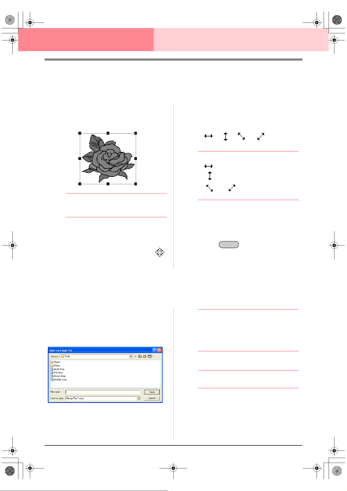
114
Layout & Editing Inputting Images and Embroidery Patterns
Changing the Size and Position of the
Image
The size and position of the image can be adjusted.
1. Click Image, then Modify.
→ A red line and handles appear around the
image.
b Memo:
The status bar shows the dimensions (width
and height) of the image.
Moving an image:
1. Move the pointer over the image.
→ The shape of the pointer changes to .
2. Drag the image to the desired location.
Scaling an image:
1. Move the pointer over one of the handles.
→ The shape of the pointer changes to
, , or , depending
on the handle that the pointer is over.
b Memo:
• is for scaling the width.
• is for scaling the height.
• and are for scaling both
dimensions at the same time.
2. Drag the handle to adjust the image to the
desired size.
Deleting an image:
1. Press the key, or click Edit, then
Delete.
→ The image will be deleted from the Design
Page.
Saving the Image Data
The image can be saved as a file or outputted to the Clipboard.
■ Saving as a file
1. Click Image, then Output, then to File.
→ A dialog box similar to the one shown be-
low appears.
2. Select the drive, the folder and the format in
which you want to save the image data.
3. Type in the file name.
b Memo:
• The correct extension is automatically
selected.
• The image data can be saved in either of
the following formats: Windows bitmap
(.bmp), Exif (.jpg).
4. Click Save to save the data.
b Memo:
To quit the operation, click
Cancel
.
■ Outputting to the Clipboard
1. Click Image, then Output, then to Clipboard.
→ The image data in the Design Page is
copied onto the Clipboard.
Delete
PeDesignV6Eng.book Page 114 Thursday, July 8, 2004 11:59 AM
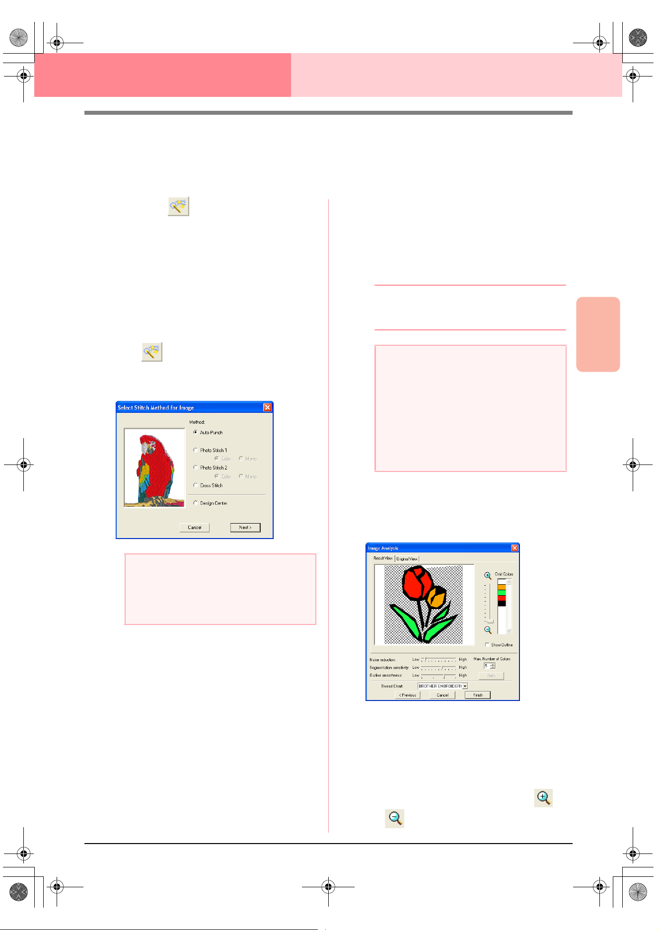
Advanced Opreation
Layout & Editing
115
Layout & Editing Inputting Images and Embroidery Patterns
Automatically Converting Image Data Into
an Embroidery Pattern
The Image to Stitch Wizard gives step-by-step instructions for converting an image into an embroidery pattern.
Toolbar button:
1. If no image is displayed in the Design Page,
use one of the commands on the Input sub-
menu of the Image menu to display the image
that you want to convert to an embroidery
pattern.
2. Click Image, then Modify, and then re-size
and re-position the image for creating the
embroidery pattern.
3. Click , or click Image, then Image to
Stitch Wizard.
→ The following dialog box appears.
4. Select the type of embroidery that you want to
create, and then click Next.
Auto Punch:
Select this option to automatically extract the
image for creating the embroidery pattern.
Photo Stitch 1:
Select this option to automatically create a
realistic photo embroidery pattern. This option
can be used to create embroidery patterns in
color (Color) or black and white (Mono).
Photo Stitch 2:
Select this option to automatically create
realistic photo embroidery in 4 colors (Color)
or 1 color (Mono).
Cross Stitch:
Select this option to create a cross stitch
pattern.
Design Center:
Select this option to start up Design Center
with the Design Page image.
b Memo:
To quit the operation and close the dialog
box, click
Cancel
.
■ If Auto Punch is selected
→ After the image characteristics are ana-
lyzed, an Image Analysis dialog box sim-
ilar to the one shown below appears.
1. Select the desired settings.
To display the resulting analyzed image, click
the Result View tab. The embroidery pattern
will be created with this image.
To adjust the zoom ratio that the image is
displayed in, move the slider between
and .
a Note:
The dialog box will not appear if no image is
displayed in the Design Page. Instead, a
dialog box appears, allowing you to open an
image file.
a Note:
Although a custom Design Page size can be
specified, since processing will take too long
when trying to create an extremely large
pattern with the Photo Stitch function, the
message “Too large image to convert” will
appear if the size exceeds a width or height
of 500 mm (19 3/4 in.). After the message is
closed, the photo is automatically selected,
and is ready to be moved or reduced.
PeDesignV6Eng.book Page 115 Thursday, July 8, 2004 11:59 AM
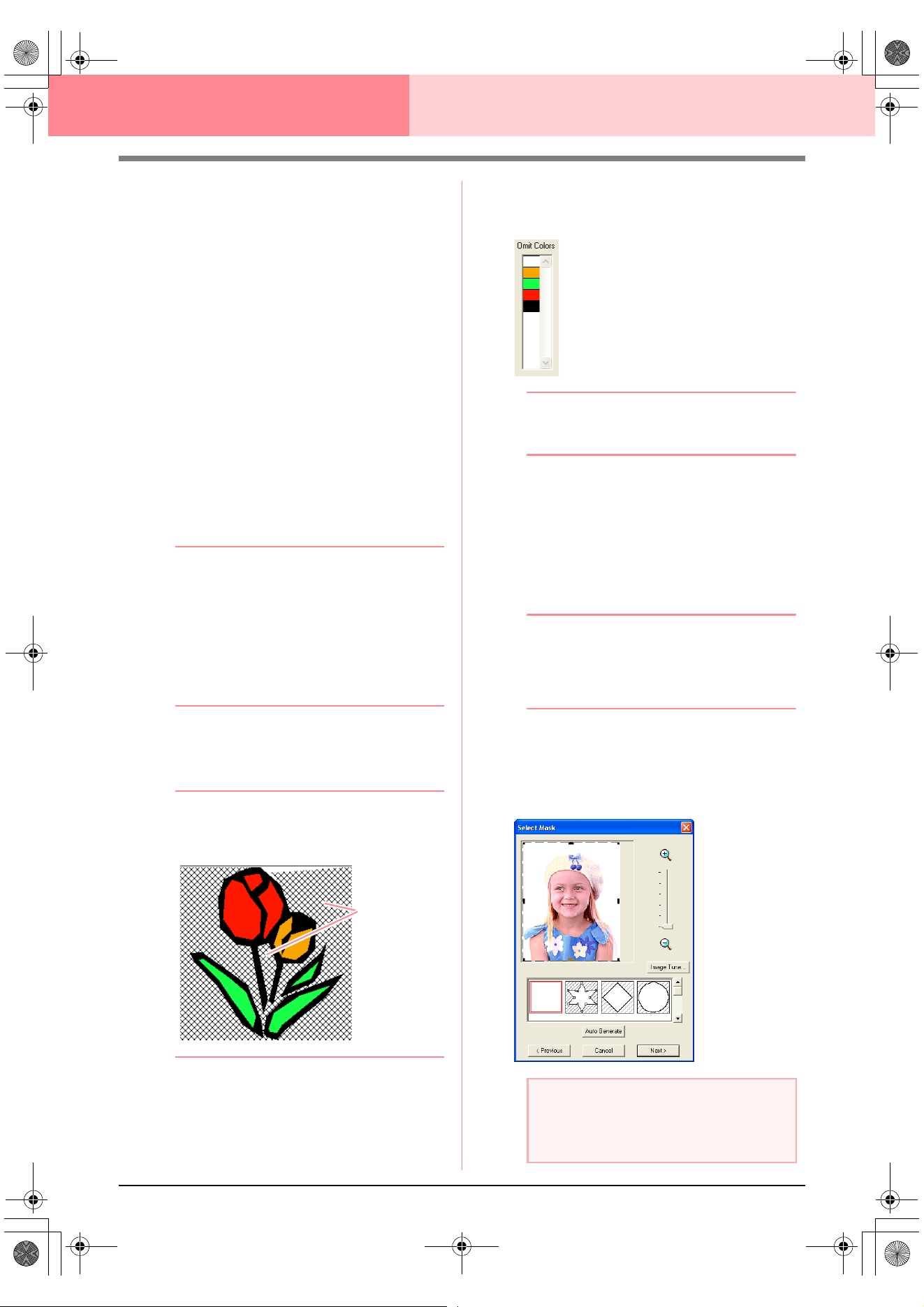
116
Layout & Editing Inputting Images and Embroidery Patterns
To display the outline extracted from the
analyzed image, select the Show Outline
check box.
Under Analysis Parameters, select the
desired image-analyzing settings.
Noise reduction: Sets the level of noise
(distortions) that is removed from the image.
Segmentation sensitivity: Sets the
sensitivity for the image analysis.
Outline smoothness: Sets the smoothness
of the extracted outline.
Max. Number of colors: Sets the number of
colors used.
From the Thread Chart selector, select the
desired thread color chart. The most
appropriate thread colors from the selected
thread chart are selected. A user thread chart
can also be selected.
To display the original image, click the
Original View tab.
b Memo:
• After changing the settings, click
Retry
to
display the image with the new settings
applied. If
Retry
is not clicked, the new
settings are not applied.
• To quit the operation and close the dialog
box, click
Cancel
.
• To return to the previous dialog box, click
Previous
.
2. On the Result View tab, click the areas of the
image to select whether or not they are to be
sewn.
b Memo:
Areas not set to be sewn are shown filled
with a crosshatch pattern.
3. If necessary, in the Omit Colors list, click the
colors to select whether or not they will be
sewn.
b Memo:
Colors that are crossed out are set to not be
sewn.
4. After selecting the desired settings, click
Finish.
→ An embroidery pattern is created from the
analyzed data, the appropriate thread col-
ors and sew type settings are applied, and
then the pattern is displayed in the Design
Page.
b Memo:
The sew type settings of the created
embroidery pattern can later be changed in
the same way as the settings for other
objects.
■ If Photo Stitch 1 (Color) is
selected
→ A Select Mask dialog box similar to the
one shown below appears.
These areas
will not be sewn.
a Note:
If the width or height of the image exceeds
500 mm, the Photo Stitch functions cannot
be used.
PeDesignV6Eng.book Page 116 Thursday, July 8, 2004 11:59 AM
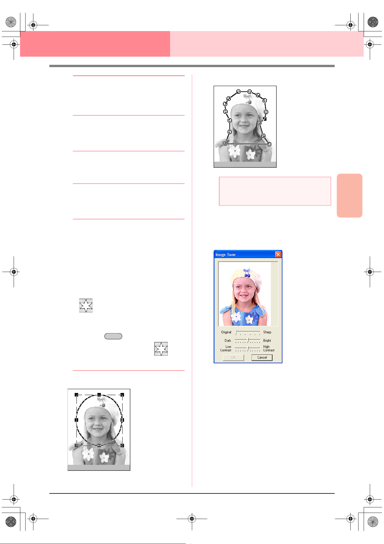
Advanced Opreation
Layout & Editing
117
Layout & Editing Inputting Images and Embroidery Patterns
b Memo:
• To quit the operation and close the dialog
box, click
Cancel
.
• To return to the previous dialog box, click
Previous
.
1. From the list at the bottom of the dialog box,
select the desired shape that the image will be
trimmed to (mask).
b Memo:
To automatically set a mask so that the
background is trimmed off, click
Auto
Generate
.
2. In the image preview box, move the handles of
the mask until it surrounds the desired part of
the image.
b Memo:
• To display the
Image Tune
dialog box,
where you can adjust the image, click
Image Tune
. (For more details, refer to
“Image Tune” on this page.)
• To display the image enlarged (or
reduced), move the
ZOOM
slider up (or
down).
• When the dialog box appears, the square
mask is selected.
•
To create any shape of mask, select
, and then move, enter or delete
points to adjust the mask shape. To add
points, click the outline of the mask. To
delete points, select the point, and the
n
press the key
.
•If
Auto Generate
was clicked, is
selected, and the points in the outline of
the mask can be moved, added or deleted.
Pattern edited with the round mask
Pattern edited with the adjustable mask
Image Tune
Clicking the Image Tune button in the Select
Mask dialog box displays an Image Tune
dialog box similar to the one shown below.
The image window displays the image
resulting from the current settings.
Move the Original – Sharp slider to adjust the
sharpness of the image’s outlines. A setting
more towards Sharp makes a more
noticeable boundary between bright and dark
areas.
Move the Dark – Bright slider to adjust the
brightness of the image.
Move the Contrast Low – High slider to
adjust the contrast of the image.
Click OK to display the adjusted image in the
Select Mask dialog box and to close this
dialog box.
Delete
a Note:
The mask size can be set in the range from
64
×
64 dots to the size of the image.
PeDesignV6Eng.book Page 117 Thursday, July 8, 2004 11:59 AM
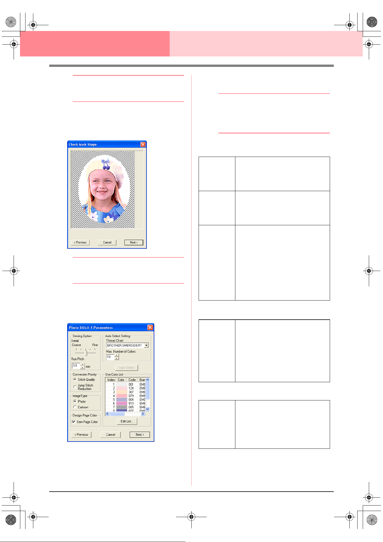
118
Layout & Editing Inputting Images and Embroidery Patterns
b Memo:
To close the dialog box without applying the
changes to the settings, click
Cancel
.
3. In the Select Mask dialog box, click Next.
→ The image is analyzed, and the Check
Mask Shape dialog box appears.
b Memo:
Areas not set to be sewn are shown filled
with a crosshatch pattern.
4. Click Next.
→ The Photo Stitch 1 Parameters dialog
box appears.
5. Specify the settings for creating the
embroidery pattern.
b Memo:
• To return to the previous dialog box, click
Previous
.
• To quit the operation and close the dialog
box, click
Cancel
.
Sewing Option
Image Type
Design Page Color
Detail
Specifies how detailed the created
embroidery pattern will be. Selecting a
setting closer to Fine creates more
details in the pattern and increases the
number of stitches.
Run pitch
Sets the sewing pitch. The pattern is
created with this setting value as the
minimum length.
Range: 2 to 10 mm (0.08 to 0.39 inch)
Default: 3 mm (0.12 inch)
Conversion
Priority
Select what parameter is given priority
when converting to embroidery pattern.
Stitch Quality: Creates a pattern while
giving priority to the stitching quality.
However, many jump stitches will result.
Jump Stitch Reduction: Creates a
pattern while giving priority to reducing
the number of jump stitches in order to
reduce complications during
embroidering. However, the stitching
quality will be slightly reduced.
Photo/
Cartoon
If Photo is selected, the thread colors
will be mixed together, which will result
in a more natural look.
If Cartoon is selected, the thread colors
will not be mixed together, which will
result in a more simply colored look.
Select Photo for image data from a
photograph, etc. Select Cartoon for
image data from an illustration, etc.
Sew Page
Color
If this check box is selected, the data for
the parts of the pattern that are the
same color as the Design Page will be
created. Clear the check box to keep
the fabric the same color as the Design
Page.
Default: Selected
PeDesignV6Eng.book Page 118 Thursday, July 8, 2004 11:59 AM
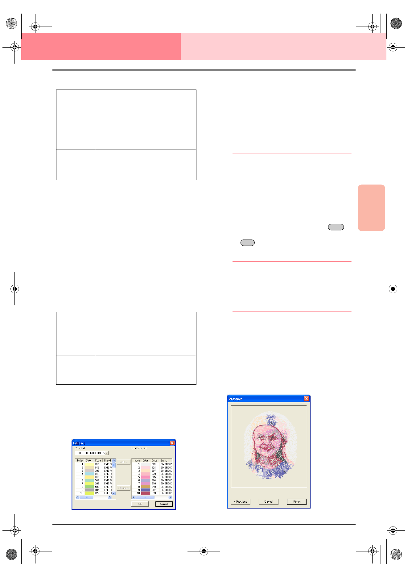
Advanced Opreation
Layout & Editing
119
Layout & Editing Inputting Images and Embroidery Patterns
Auto Select Setting
Auto Select
Click this button to use the settings specified
under Auto Select Setting and automatically
select from the selected thread chart the most
appropriate thread colors for creating the
photo embroidery. The selected thread colors
appear in the Use Color List mentioned
below.
This button can be clicked only if the settings
under Auto Select Setting have been
changed.
Use Color List
This list allows the selected thread colors to be
checked and edited.
Edit List
Click this button to display the Edit List dialog
box. In this dialog box, you can manually set
the thread colors to be used in the data
conversion.
To move the color selected in the Color List
to the Use Color List, click Add. If no color is
selected, or if the Use Color List already
contains 50 colors, this button cannot be
clicked.
To delete the color selected in the Use Color
List, click Remove. If no color is selected in
the Use Color List, this button cannot be
clicked.
b Memo:
• The thread colors in the
Color List
and
Use Color List
are listed, in order, starting
from the brightest. This order is the sewing
order and cannot be changed.
• The maximum number of colors that can
be added to the
Use Color List
is 50.
• Thread colors displayed in the
Use Color
List
are not displayed in the
Color List
.
• To select several colors, hold the
key (to select adjacent colors) or the
key (to select colors that are not
adjacent), and then select the desired
colors.
To apply the changes to the list and close the
dialog box, click OK. The edited settings will
appear in the Photo Stitch 1 Parameters
dialog box. This button cannot be clicked if the
Use Color List is empty.
b Memo:
To close the dialog box without applying the
changes, click
Cancel
.
6. In the Photo Stitch 1 Parameters dialog box,
click Next.
→ A Preview dialog box similar to the one
shown below appears, allowing the creat-
ed embroidery pattern to be previewed.
Thread Chart
Selects the thread chart for selecting
the thread color with the Auto Select
function.
The most appropriate thread colors
from the selected thread chart are
selected.
A user thread chart can also be
selected.
Color Count
Sets the number of colors selected by
the Auto Select function.
Range: 1 to 50
Default: 10
Use Color
List
Thread colors selected for creating the
pattern are displayed, in order, by their
level of brightness. This order is the
sewing order. The order cannot be
changed. The maximum number of
colors is 50.
Edit List
Click this button to open the Edit List
dialog box, which lets you manually set
the thread colors to be used when
creating the pattern (see below).
Shift
Ctrl
PeDesignV6Eng.book Page 119 Thursday, July 8, 2004 11:59 AM
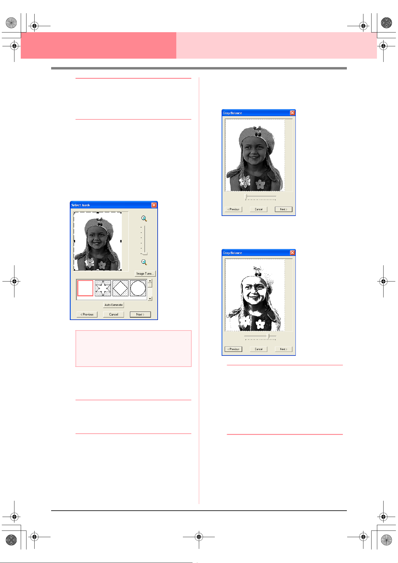
120
Layout & Editing Inputting Images and Embroidery Patterns
b Memo:
• To return to the previous dialog box, click
Previous
.
• To quit the operation and close the dialog
box, click
Cancel
.
7. Click Finish.
→ An embroidery pattern is created and dis-
played in the Design Page.
■ If Photo Stitch 1 (Mono) is
selected
→ A Select Mask dialog box similar to the
one shown below appears.
1. From the list at the bottom of the dialog box,
select the desired shape that the image will be
trimmed to (mask).
b Memo:
To automatically set a mask so that the
background is trimmed off, click
Auto
Generate
.
2. In the image preview box, move the handles of
the mask until it surrounds the desired part of
the image
c
For details on the settings, refer to
page 117.
3. In the Select Mask dialog box, click Next.
→ A Gray Balance dialog box similar to the
one shown below appears.
4. Move the slider to specify which parts of the
image to create the embroidery pattern for.
b Memo:
• Areas not set to be sewn are shown filled
with a crosshatch pattern.
• An embroidery pattern will be created from
any areas remaining in black.
• To return to the previous dialog box, click
Previous
.
• To quit the operation and close the dialog
box, click
Cancel
.
a Note:
If the width or height of the image exceeds
500 mm, the Photo Stitch functions cannot
be used.
PeDesignV6Eng.book Page 120 Thursday, July 8, 2004 11:59 AM
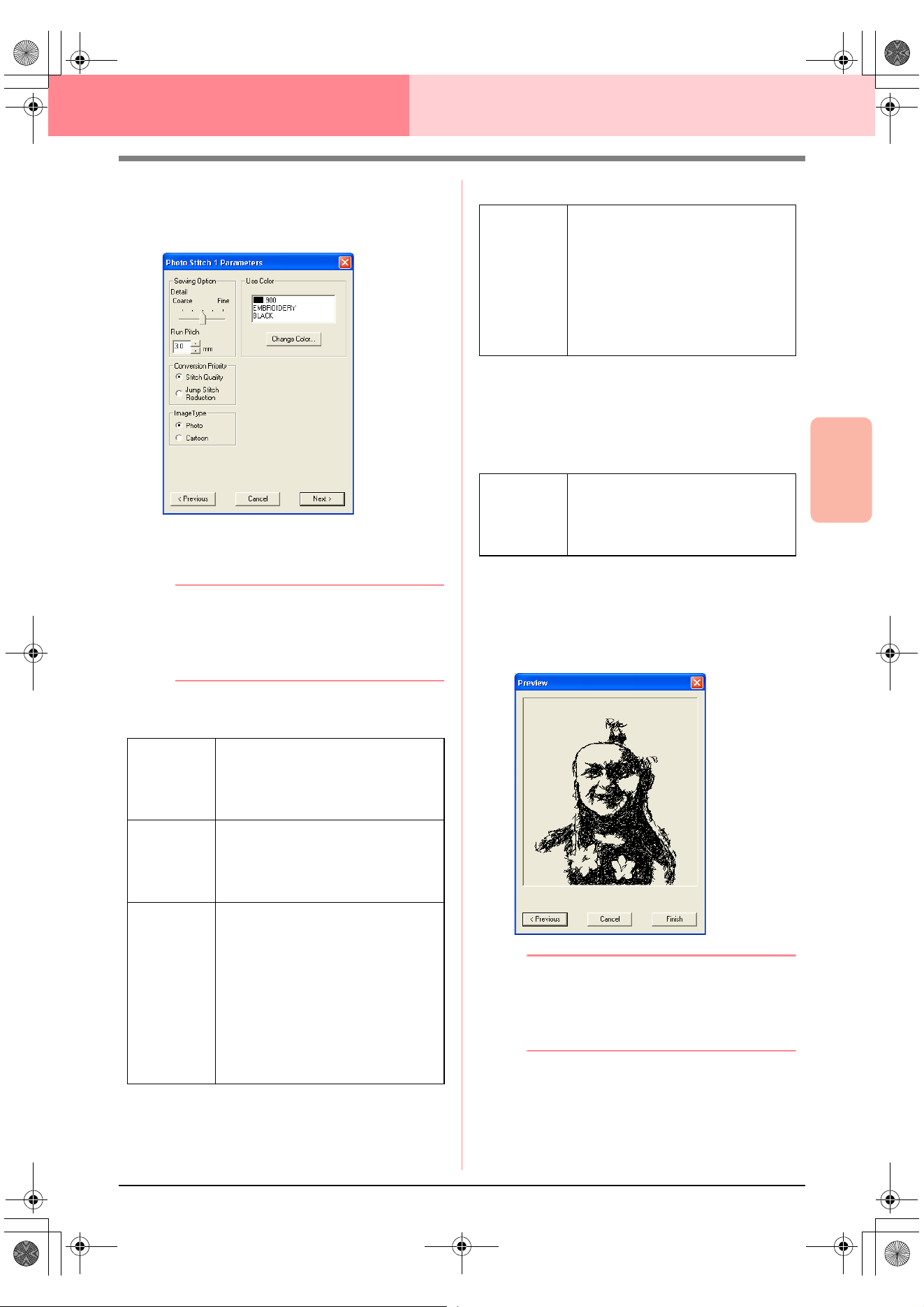
Advanced Opreation
Layout & Editing
121
Layout & Editing Inputting Images and Embroidery Patterns
5. In the Gray Balance dialog box, click Next.
→ The Photo Stitch 1 Parameters dialog
box appears.
6. Specify the settings for creating the
embroidery pattern.
b Memo:
• To return to the previous dialog box, click
Previous
.
• To quit the operation and close the dialog
box, click
Cancel
.
Sewing Option
Image Type
Use Color
Specifies the color of thread used to create the
embroidery pattern.
The default setting is the darkest color in the
current thread chart.
7. In the Photo Stitch 1 Parameters dialog box,
click Next.
→ A Preview dialog box similar to the one
shown below appears, allowing the creat-
ed embroidery pattern to be previewed.
b Memo:
• To return to the previous dialog box, click
Previous
.
• To quit the operation and close the dialog
box, click
Cancel
.
Detail
Specifies how detailed the created
embroidery pattern will be. Selecting a
setting closer to Fine creates more
details in the pattern and increases the
number of stitches.
Run pitch
Sets the sewing pitch. The pattern is
created with this setting value as the
minimum length.
Range: 2 to 10 mm (0.08 to 0.39 inch)
Default: 3 mm (0.12 inch)
Conversion
Priority
Select what parameter is given priority
when converting to embroidery pattern.
Stitch Quality: Creates a pattern while
giving priority to the stitching quality.
However, many jump stitches will result.
Jump Stitch Reduction: Creates a
pattern while giving priority to reducing
the number of jump stitches in order to
reduce complications during
embroidering. However, the stitching
quality will be slightly reduced.
Photo/
Cartoon
If Photo is selected, the thread colors
will be mixed together, which will result
in a more natural look.
If Cartoon is selected, the thread colors
will not be mixed together, which will
result in a more simply colored look.
Select Photo for image data from a
photograph, etc. Select Cartoon for
image data from an illustration, etc.
Change
Color
In the list, select the color that you want
to change, and then click this button to
open the Thread Color dialog box,
which lets you change the thread color
used in the embroidery pattern.
PeDesignV6Eng.book Page 121 Thursday, July 8, 2004 11:59 AM
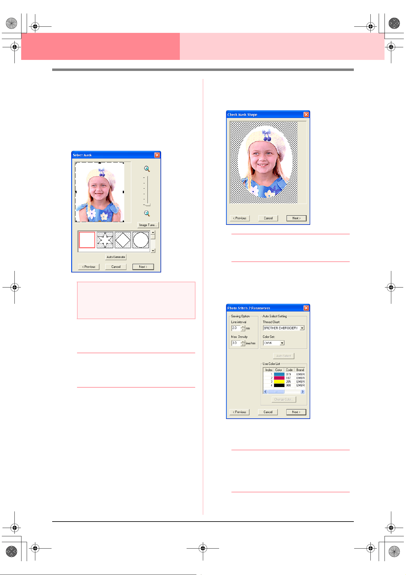
122
Layout & Editing Inputting Images and Embroidery Patterns
8. Click Finish.
→ An embroidery pattern is created and dis-
played in the Design Page.
■ If Photo Stitch 2 (Color) is
selected
→ A Select Mask dialog box similar to the
one shown below appears.
1. From the list at the bottom of the dialog box,
select the desired shape that the image will be
trimmed to (mask).
b Memo:
To automatically set a mask so that the
background is trimmed off, click
Auto
Generate
.
2. In the image preview box, move the handles of
the mask until it surrounds the desired part of
the image
c
For details on the settings, refer to
page 117.
3. In the Select Mask dialog box, click Next.
→ The image is analyzed, and the Check
Mask Shape dialog box appears.
b Memo:
Areas not set to be sewn are shown filled
with a crosshatch pattern.
4. Click Next.
→ The Photo Stitch 2 Parameters dialog
box appears.
5. Specify the settings for creating the
embroidery pattern.
b Memo:
• To return to the previous dialog box, click
Previous
.
• To quit the operation and close the dialog
box, click
Cancel
.
a Note:
If the width or height of the image exceeds
500 mm, the Photo Stitch functions cannot
be used.
PeDesignV6Eng.book Page 122 Thursday, July 8, 2004 11:59 AM
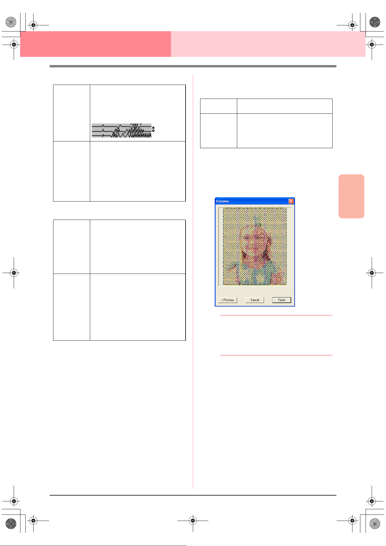
Advanced Opreation
Layout & Editing
123
Layout & Editing Inputting Images and Embroidery Patterns
Sewing Option
Auto Select Setting
Auto Select
Click this button to select from the selected
thread chart the thread colors closest to the
four colors in the selected color set. The
selected thread colors appear in the Use
Color List mentioned below.
This button can be clicked only if the settings
under Auto Select Setting have been
changed.
Use Color List
This list allows the selected thread colors to be
checked and edited.
6. In the Photo Stitch 2 Parameters dialog box,
click Next.
→ A Preview dialog box similar to the one
shown below appears, allowing the creat-
ed embroidery pattern to be previewed.
b Memo:
• To return to the previous dialog box, click
Previous
.
• To quit the operation and close the dialog
box, click
Cancel
.
7. Click Finish.
→ An embroidery pattern is created and dis-
played in the Design Page.
Line Interval
Specifies the interval between parallel
lines used to create the embroidery
pattern.
Range: 1.2 to 5 mm (0.05 to 0.2 inch)
Default: 2 mm (0.08 inch)
Max. Density
Specifies the maximum density for
areas of the created embroidery pattern
sewn with the zigzag stitch. The
embroidery pattern will be created with
a density smaller than that set here.
Range: 2.5 to 5 lines per mm (64 to 127
lines per inch)
Default: 3 lines per mm (76 lines per
inch)
Thread Chart
Selects the thread chart for selecting
the thread color with the Auto Select
function.
The most appropriate thread colors
from the selected thread chart are
selected.
A user thread chart can also be
selected.
Color Set
Sets the combination of four colors used
when creating the embroidery pattern.
The color choices are: cyan (C),
magenta (M), yellow (Y), black (K), red
(R), green (G) and blue (B). Select one
of the following combinations that
contains the colors most used in the
image.
Color combinations: CMYK, RGBK,
CRYK, BMYK
Line interval
Use Color
List
Displays the four selected thread colors.
Change
Color
In the list, select the color that you want
to change, and then click this button to
open the Thread Color dialog box,
which lets you change the thread color
used in the embroidery pattern.
PeDesignV6Eng.book Page 123 Thursday, July 8, 2004 11:59 AM
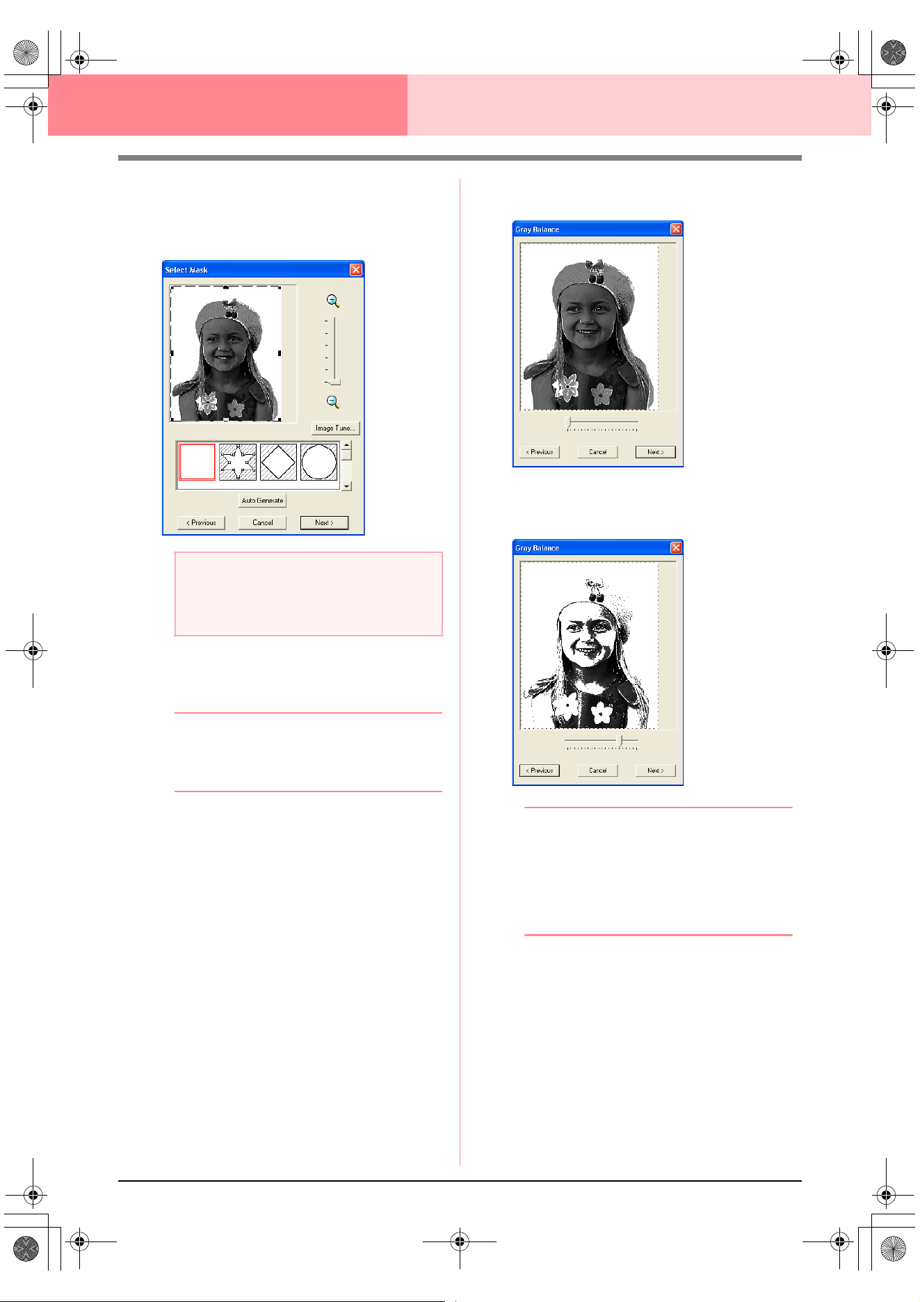
124
Layout & Editing Inputting Images and Embroidery Patterns
■ If Photo Stitch 2 (Mono) is
selected
→ A Select Mask dialog box similar to the
one shown below appears.
1. From the list at the bottom of the dialog box,
select the desired shape that the image will be
trimmed to (mask).
b Memo:
To automatically set a mask so that the
background is trimmed off, click
Auto
Generate
.
2. In the image preview box, move the handles of
the mask until it surrounds the desired part of
the image
c
For details on the settings, refer to
page 117.
3. In the Select Mask dialog box, click Next.
→ A Gray Balance dialog box similar to the
one shown below appears.
4. Move the slider to specify which parts of the
image to create the embroidery pattern for.
b Memo:
• An embroidery pattern will be created from
any areas remaining in black.
• To return to the previous dialog box, click
Previous
.
• To quit the operation and close the dialog
box, click
Cancel
.
a Note:
If the width or height of the image exceeds
500 mm, the Photo Stitch functions cannot
be used.
PeDesignV6Eng.book Page 124 Thursday, July 8, 2004 11:59 AM
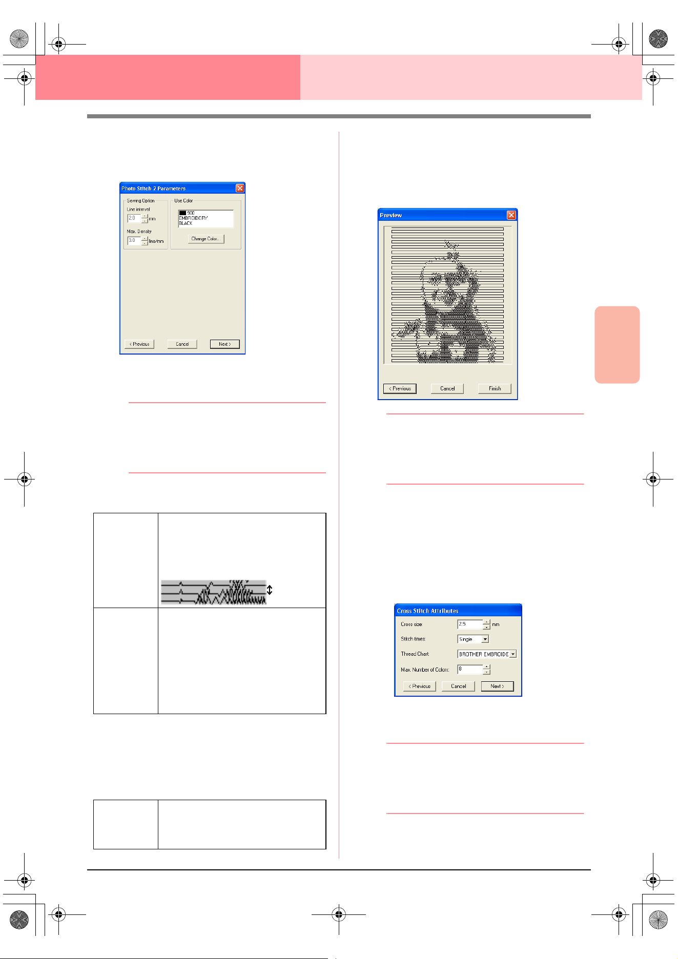
Advanced Opreation
Layout & Editing
125
Layout & Editing Inputting Images and Embroidery Patterns
5. In the Gray Balance dialog box, click Next.
→ The Photo Stitch 2 Parameters dialog
box appears.
6. Specify the settings for creating the
embroidery pattern.
b Memo:
• To return to the previous dialog box, click
Previous
.
• To quit the operation and close the dialog
box, click
Cancel
.
Sewing Option
Use Color
Specifies the color of thread used to create the
embroidery pattern.
The default setting is the darkest color in the
current thread chart.
7. In the Photo Stitch 2 Parameters dialog box,
click Next.
→ A Preview dialog box similar to the one
shown below appears, allowing the creat-
ed embroidery pattern to be previewed.
b Memo:
• To return to the previous dialog box, click
Previous
.
• To quit the operation and close the dialog
box, click
Cancel
.
8. Click Finish.
→ An embroidery pattern is created and dis-
played in the Design Page.
■ If Cross Stitch is selected
→ The Cross Stitch Attributes dialog box
appears.
1. Specify the settings for creating the
embroidery pattern.
b Memo:
• To return to the previous dialog box, click
Previous
.
• To quit the operation and close the dialog
box, click
Cancel
.
Line Interval
Specifies the interval between parallel
lines used to create the embroidery
pattern.
Range: 1.2 to 5 mm (0.05 to 0.2 inch)
Default: 2 mm (0.08 inch)
Max. Density
Specifies the maximum density for
areas of the created embroidery pattern
sewn with the zigzag stitch. The
embroidery pattern will be created with
a density smaller than that set here.
Range: 2.5 to 5 lines per mm (64 to 127
lines per inch)
Default: 3 lines per mm (76 lines per
inch)
Change
Color
Click this button to open the Thread
Color dialog box, which lets you select
the thread color used in the embroidery
pattern.
Line interval
PeDesignV6Eng.book Page 125 Thursday, July 8, 2004 11:59 AM
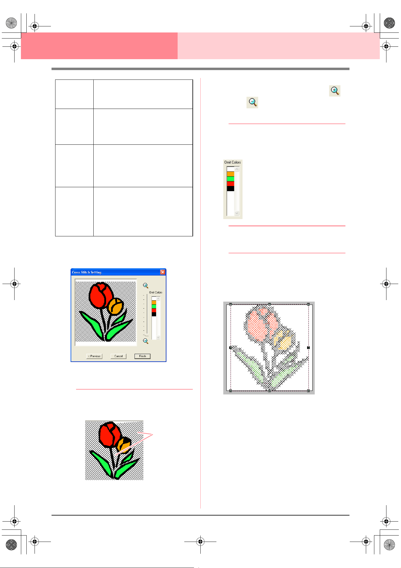
126
Layout & Editing Inputting Images and Embroidery Patterns
2. Click Next.
→ A Cross Stitch Setting dialog box similar
to the one shown below appears.
3. In the image in the dialog box, click the areas
to select whether or not they are to be sewn.
b Memo:
• Areas not set to be sewn are shown filled
with a crosshatch pattern.
• To adjust the zoom ratio that the image is
displayed in, move the slider between
and
.
• To return to the previous dialog box, click
Previous
.
4. If necessary, in the Omit Colors list, click the
colors to select whether or not they will be
sewn.
b Memo:
Colors that are crossed out are set to not be
sewn.
5. After selecting the desired settings, click
Finish.
→ The cross stitch pattern is created and
displayed in the Design Page.
■ If Design Center is selected
→ Design Center starts up, and a Design
Page is displayed with the image import-
ed into it. For details, refer to “Design
Center” on page 69.
Cross size
Sets the horizontal and vertical size of
the pattern.
Range: 1.5 to 5 mm (0.04 to 0.39 inch)
Default: 2.5 mm (0.08 inch)
Stitch times
Sets the number of times that the
pattern will be sewn. Sews twice per
time.
Range: Single, Double, Triple
Default: Single
Thread Chart
Selects the thread chart for selecting
the thread color.
The most appropriate thread color from
the selected thread chart is selected.
A user thread chart can also be
selected.
Max.
Number of
Colors
Sets the number of colors used in the
created pattern.
The embroidery pattern is created using
no more than the number of colors
specified.
Range: 2 to 50
Default: 8
These areas
will not be sewn.
!!scr146.bmp!!
PeDesignV6Eng.book Page 126 Thursday, July 8, 2004 11:59 AM
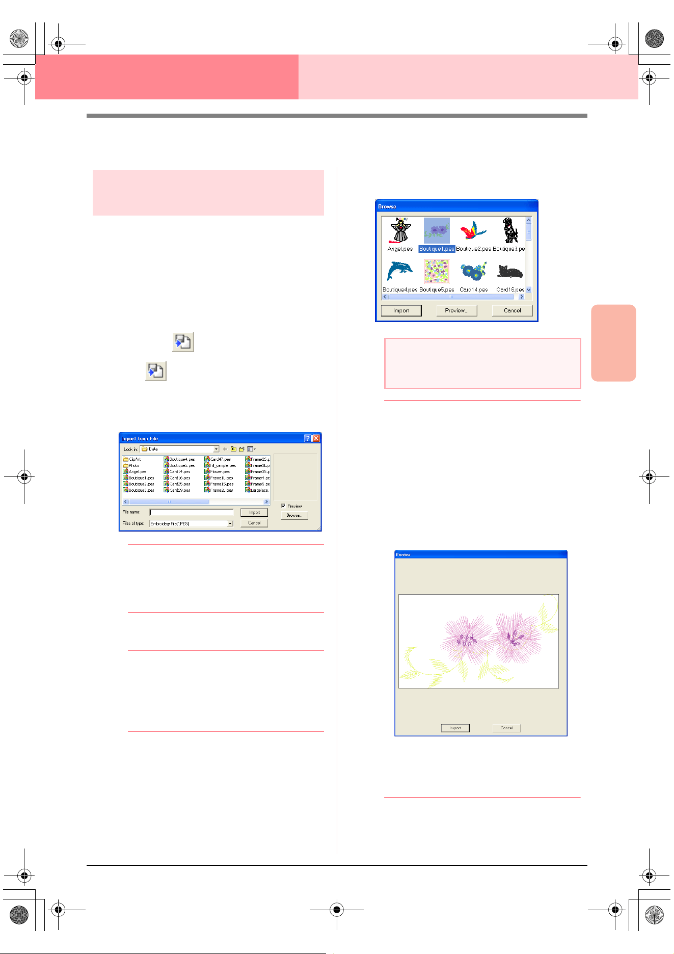
Advanced Opreation
Layout & Editing
127
Layout & Editing Inputting Images and Embroidery Patterns
Importing Embroidery Patterns
Importing embroidery
patterns from a file
Embroidery patterns from embroidery cards (.pec)
and files created in the Tajima (.dst), Melco (.exp),
Pfaff (.pcs), Husqvarna (.hus) and embroidery
sewing machine (.phc) formats can be imported and
added to the current Design Page.
With this function, you can also add .pes files to the
Design Page, allowing you to combine several files
created with this application.
Toolbar button:
1. Click , or click File, then Import, then
from File.
→ An Import from File dialog box similar to
the one shown below appears.
b Memo:
This dialog box can be resized so that the
folder contents can be viewed better. The
size of the dialog box is retained until it is
changed again.
2. Select the drive and the folder.
b Memo:
•If the
Preview
check box is selected, the
contents of the selected file will appear in
the
Preview
box.
• To quit the operation and close the dialog
box, click
Cancel
.
3. To view the contents of the files in the
currently selected folder, click Browse.
→ A Browse dialog box similar to the one
shown below appears.
b Memo:
• This dialog box can be resized so that the
folder contents can be viewed better. The
size of the dialog box is retained until it is
changed again.
• To return to the
Import from File
dialog
box, click
Cancel
.
• To see a more detailed image, select a file,
and then click
Preview
. A
Preview
dialog
box similar to the one shown below
appears.
• To import the displayed file, click
Import
.
• To return to the
Browse
dialog box,
click
Cancel
.
a Note:
Be sure to select the correct file name
extension from the
Files of type
box.
PeDesignV6Eng.book Page 127 Thursday, July 8, 2004 11:59 AM
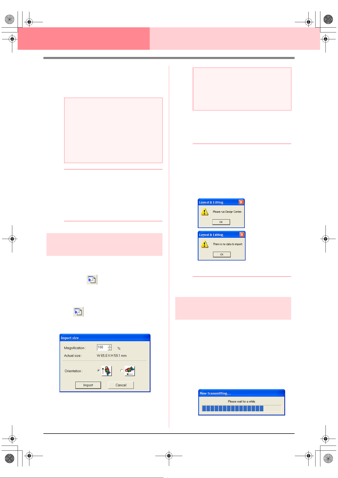
128
Layout & Editing Inputting Images and Embroidery Patterns
4. To import a pattern, select it, and then click
Import, or double-click the file’s icon.
→ The embroidery pattern is displayed in the
Design Page.
b Memo:
• When importing some .pec files from
embroidery cards, the
Select Import size
dialog box appears. If this happens, select
the desired import size, and then click
OK
to import the embroidery pattern.
• To quit the operation and close the dialog
box, click
Cancel
.
Importing embroidery
patterns from Design Center
An embroidery pattern in Design Center can be
imported directly into the Design Page.
Toolbar button:
1. Start up Design Center and open the file that
you want to import into Layout & Editing.
2. Click , or click File, then Import, then
from Design Center.
→ The Import size dialog box appears.
3. In the Magnification box, type or select the
magnification factor.
4. Under Orientation, select the desired
orientation.
5. Click Import to import the embroidery pattern.
b Memo:
• To quit the operation and close the dialog
box, click
Cancel
.
• If Design Center has not been started up,
if a .pem file has not been opened or if
Design Center is not in stage 4 (Sew
Setting stage), one of the following
messages appears.
Click
OK
, and then start up Design Center
and open a .pem file.
c
“Design Center” on page 69
Importing embroidery
patterns
from an embroidery card
An embroidery pattern from an embroidery card
inserted in the USB card writer module can be
imported into the Design Page.
1. Click File, then Import, then from Card.
→ If a card writer module is connected and if
an embroidery card is inserted into the
card writer module, the following mes-
sage appears and the embroidery pat-
terns are read from the card.
a Note:
• When importing patterns from other
makers, be sure to choose a pattern that
will fit in the Design Page.
• The colors of patterns imported from .dst
(Tajima), .exp (Melco), .pcs (Pfaff) and
.hus (Husqvarna) files will be slightly
different. If this happens, you can change
the color with the menu command
Sew
–
Sewing Order/Color
.
a Note:
• The embroidery pattern cannot be
magnified to a size larger than the Design
Page.
• The magnification factor cannot be set
below 25%.
PeDesignV6Eng.book Page 128 Thursday, July 8, 2004 11:59 AM
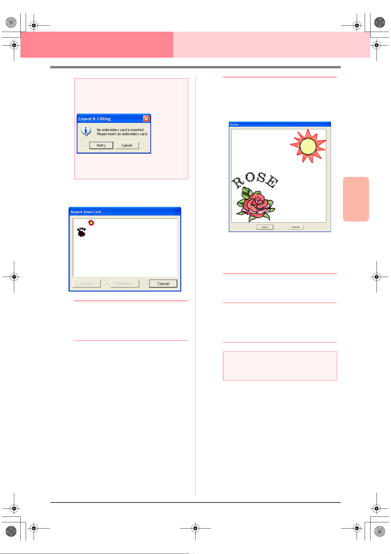
Advanced Opreation
Layout & Editing
129
Layout & Editing Inputting Images and Embroidery Patterns
2. After the card has been read, a dialog box
similar to the one shown below appears.
b Memo:
This dialog box can be resized so that the
patterns can be viewed better. The size of
the dialog box is retained until it is changed
again.
3. Click a pattern to select it.
b Memo:
• To see a more detailed image, select a
pattern, and then click
Preview
. A
Preview
dialog box similar to the one
shown below appears.
• To import the displayed pattern, click
Import
.
• To return to the
Browse
dialog box,
click
Cancel
.
• To quit the operation, click
Cancel
.
4. Click Import, or double-click the pattern to
import it.
b Memo:
When importing some patterns, the
Select
Import size
dialog box appears. If this
happens, select the desired import size, and
then click
OK
to import the pattern.
a Note:
If a card writer module is connected but an
embroidery card is not inserted, the following
message appears.
• Insert an embroidery card, and then click
Retry
.
• To quit the operation, click
Cancel
.
a Note:
Due to copyright issues, some embroidery
cards cannot be used with this function.
PeDesignV6Eng.book Page 129 Thursday, July 8, 2004 11:59 AM
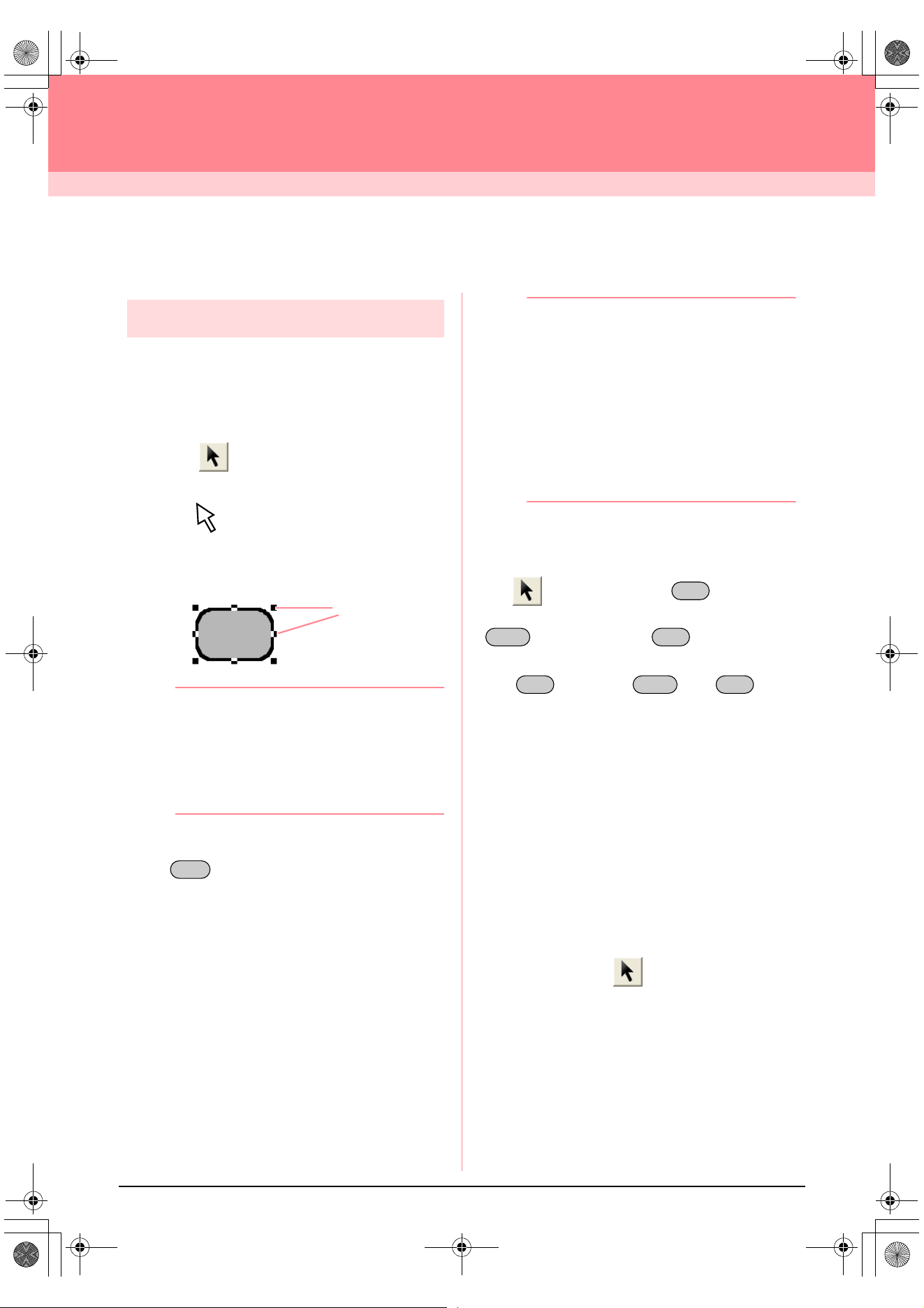
130
Layout & Editing
Editing Embroidery Patterns
Editing Embroidery Patterns
Selecting patterns
To apply settings to an existing pattern, you must
first select it. The Select Object tool is used to select
one or more patterns. Once a pattern is selected,
you can move it, scale it, and change its direction by
rotating it or inverting it.
1. Click on the Tool Box.
→ The shape of the pointer changes to
.
2. Click the pattern that you want to select.
→ Handles appear around the pattern.
b Memo:
• The status bar shows the dimensions
(width and height) of the pattern.
• To deselect the pattern, select a different
pattern, click a blank area of the Design
Page, or click any other button in the Tool
Box.
3. To select an additional pattern, hold down the
key and click the other pattern.
b Memo:
• You can also select patterns by dragging
the pointer across the pattern that you
want to select. As you drag the pointer, a
selection frame is drawn. All patterns that
are contained in that selection frame are
selected when the mouse button is
released.
• If you selected patterns that you did not
want, click a blank area of the Design
Page to deselect all patterns, and start
again.
■ Selecting patterns in the created
order
With selected, press the key to select
the next object that was created. Hold down the
key and press the key to select the
previous object that was created.
If the key (or the and keys)
are pressed:
• and no object is selected, the first object (or
the last object) that was created is selected.
• and multiple objects are selected, all objects
are deselected except the soonest (or latest)
object that was created.
• and the last (or first) object that was created
is selected, the first (or last) object is
selected.
■ Selecting all embroidery patterns
All patterns in the Design Page can easily be
selected.
1. Make sure that on the Tool Box is
selected.
2. Click Edit, then Select All.
Handles
Ctrl
Tab
Shift Tab
Tab Shift Tab
PeDesignV6Eng.book Page 130 Thursday, July 8, 2004 11:59 AM
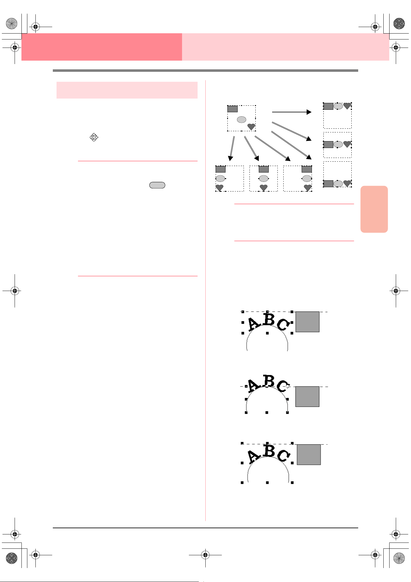
Advanced Opreation
Layout & Editing
131
Layout & Editing Editing Embroidery Patterns
Moving patterns
1. Move the pointer over a selected pattern or
group of selected patterns.
→ The shape of the pointer changes to
.
2. Drag the pattern to the desired location.
b Memo:
• To move the pattern horizontally or
vertically, hold down the key while
dragging it.
• Pressing the arrow keys moves the
selected pattern 0.5 mm (about 0.02 inch)
in the direction of the arrow on the key.
•If
Snap to Grid
is selected, each press of
an arrow key moves the pattern one grid
mark in the direction of the arrow on the
key.
• The arrow keys cannot be used to move
text on a path if just the text is selected.
The path must also be selected in order to
move using the arrow keys.
■ Moving embroidery patterns to
the center
The selected patterns can easily be moved to the
center of Design Page.
1. Select one or more patterns.
2. Click Edit, then Center.
→ All selected patterns move to the center of
Design Page.
■ Aligning embroidery patterns
The selected patterns can easily be aligned as
specified.
1. Select the patterns which you want to align.
2. Click Edit, then Align, then Left, Center,
Right, Top, Middle, or Bottom, depending on
how you want to align the patterns.
→ The selected patterns are aligned as
shown below.
b Memo:
To choose a different alignment, select the
menu command
Edit
–
Undo
, and then
repeat step
2.
Text on a path
Text on a path can be aligned by selecting other
objects on the Design Page together with the text,
the path, or both the text and the path. The selected
patterns are aligned on their outlines.
Shift
Bottom
RightCenterLeft
Middle
Top
1. Text is selected.
2. Path is selected.
3. Both the text and path
are selected.
PeDesignV6Eng.book Page 131 Thursday, July 8, 2004 11:59 AM
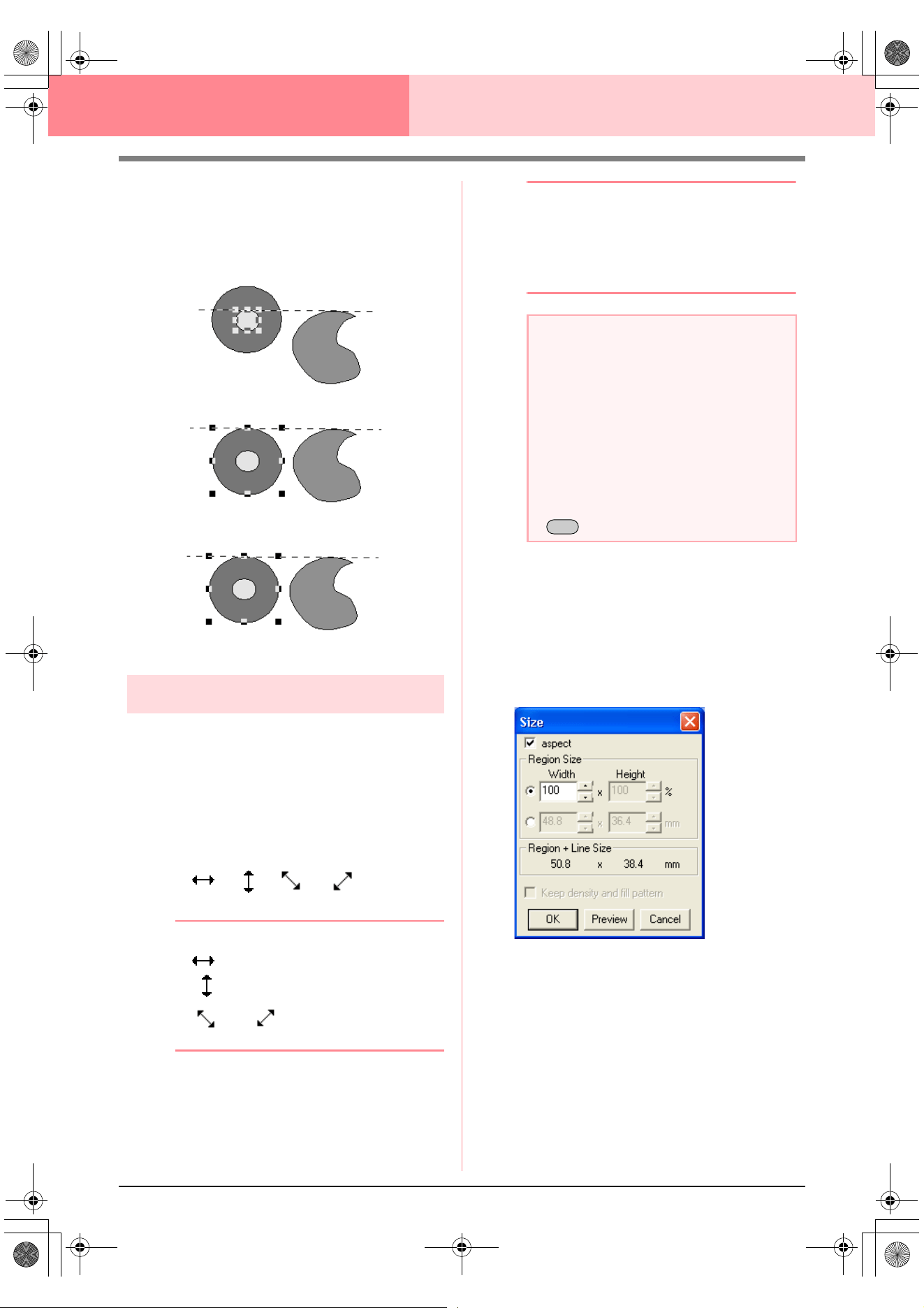
132
Layout & Editing Editing Embroidery Patterns
Patterns set for hole sewing
If just the inside pattern is selected, the pattern is
aligned on the outline of the inside area. If the
outside of the pattern is also selected, the pattern is
aligned on the outline of the outside area.
Scaling patterns
■ Scaling manually
1. Select the pattern or patterns that you want to
resize.
2. Move the pointer over one of the handles of a
selected pattern or group of patterns.
→ The shape of the pointer changes to
, , or , depending
on the handle that the pointer is over.
b Memo:
• is for scaling the width.
• is for scaling the height.
• and are for scaling both
dimensions at the same time.
3. Drag the handle to adjust the selected
pattern(s) to the desired size.
b Memo:
• As you drag the handle, the current size is
displayed on the status bar.
• For more precise resizing, select the menu
command
Edit
–
Numerical Setting
–
Size
, as described below.
■ Scaling numerically
1. Select the pattern or patterns that you want to
resize.
2. Click Edit, then Numerical Setting, then
Size.
→ The Size dialog box appears.
3. To change the width and height proportionally,
select the aspect check box.
4. Select the whether the width and height will be
set as a percentage (%) or a dimension
(millimeters or inches).
5. Type or select the desired width and height.
1. Inside area is selected.
2. Outside area is selected.
3. Both the inside and outside areas are selected.
a Note:
• Stamp settings remain independent from
the patterns that they are applied to. If a
pattern containing a stamp is edited, be
sure to check the stamp after editing is
finished.
• Some patterns imported from embroidery
cards cannot be scaled.
• When scaling stitch patterns, the number
of stitches remains the same, resulting in
a loss of quality. To maintain the quality of
the embroidery pattern, hold down the
key while scaling.
Ctrl
PeDesignV6Eng.book Page 132 Thursday, July 8, 2004 11:59 AM
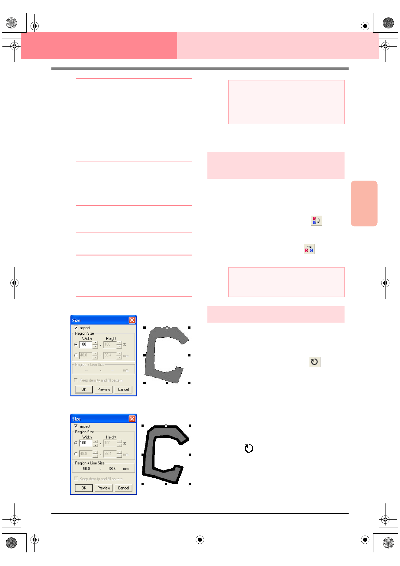
Advanced Opreation
Layout & Editing
133
Layout & Editing Editing Embroidery Patterns
b Memo:
•Select
100%
to leave the pattern
unchanged.
•If
aspect
is selected, changing one
dimension automatically changes the
other so that the proportion of the width
and height remains unchanged.
• The specified size is for the region. If the
pattern has a line, the size of the entire
pattern can be viewed under
Region +
Line
Size
at the bottom of the dialog box.
6. To resize the selected pattern while
maintaining the original density and fill pattern,
select the Keep density and fill pattern
check box.
b Memo:
The
Keep density and fill pattern
check
box is available only if stitch data is selected.
7. Click OK.
b Memo:
• To view the pattern at the new size in the
Design Page, click
Preview
.
• To close the dialog box without applying
the changes to the settings, click
Cancel
.
Region (without line)
Region + line
c
“Changing the measurement units” on
page 202
Flipping patterns
horizontally or vertically
1. Select the pattern that you want to flip (up/
down) or vertically (left/right).
2. To flip the pattern horizontally, click Edit, then
Mirror, then Horizontal, or click on the
Toolbar.
To flip the pattern vertically, click Edit, then
Mirror, then Vertical, or click on the
Toolbar.
Rotating patterns
■ Rotating manually
1. Select the pattern that you want to rotate.
2. Click Edit, then Rotate, or click on the
Toolbar.
→ The handles around the selected pattern
are replaced by smaller squares at the
four corners of the selected pattern.
3. Move the pointer over one of the four rotation
handles.
→ When the pointer is moved over a rotation
handle, the shape of the pointer changes
to .
4. Drag the rotation handle clockwise or
counterclockwise to rotate the pattern in 1°
increments.
a Note:
• You cannot enter a size that will cause the
pattern to exceed the size of the Design
Page.
• The minimum value is 1 mm (0.04 inch).
a Note:
Some patterns imported from embroidery
cards cannot be flipped.
PeDesignV6Eng.book Page 133 Thursday, July 8, 2004 11:59 AM
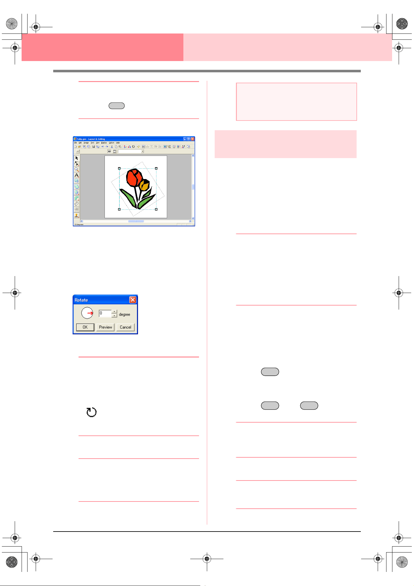
134
Layout & Editing Editing Embroidery Patterns
b Memo:
To rotate the pattern in 15° increments, hold
down the key while dragging the
rotation handle.
■ Rotating numerically
1. Select the pattern that you want to rotate.
2. Click Edit, then Numerical Setting, then
Rotate.
→ The Rotate dialog box appears.
3. Type or select the desired rotation angle.
b Memo:
• The angle can also be specified by moving
the pointer over the red arrow inside of the
circle, then dragging the red arrow to the
desired angle. When the pointer is moved
over the red arrow, its shape changes to
.
•Select
0 degree
to leave the pattern
unchanged.
4. Click OK.
b Memo:
• To view the pattern rotated the specified
angle in the Design Page, click
Preview
.
• To close the dialog box without applying
the changes to the settings, click
Cancel
.
Grouping embroidery
patterns
Several individual objects can be grouped so that
the same changes apply to all of the patterns within
the group. Grouped objects can however still be
edited independently.
1. Select several objects.
2. Click Edit, then Group.
→ The selected objects are grouped.
b Memo:
• If you select only the text fit to a path or
only the path, both the path and text will be
included in the group.
• When selecting an object set as part of a
hole sewing pattern, the entire hole sewing
pattern will be included in the group.
• To ungroup the objects, select the group,
and then click
Edit
, then
Ungroup
.
■ Editing grouped objects
individually
Even after patterns are grouped, they can be edited
individually.
1. To select a single object within a group, hold
down the key while clicking the
object.
To select multiple objects within a group, or to
select grouped and ungrouped objects, hold
down the and keys while
clicking the objects.
b Memo:
A light blue frame appears around the
grouped objects whenever the group or an
individual object is selected.
2. Edit the object as desired.
b Memo:
Grouping is cancelled if objects are deleted
to leave only one.
Shift
a Note:
The range of values that can be entered is
between 0 and 359 degrees, in 1-degree
increments.
Alt
Alt Ctrl
PeDesignV6Eng.book Page 134 Thursday, July 8, 2004 11:59 AM
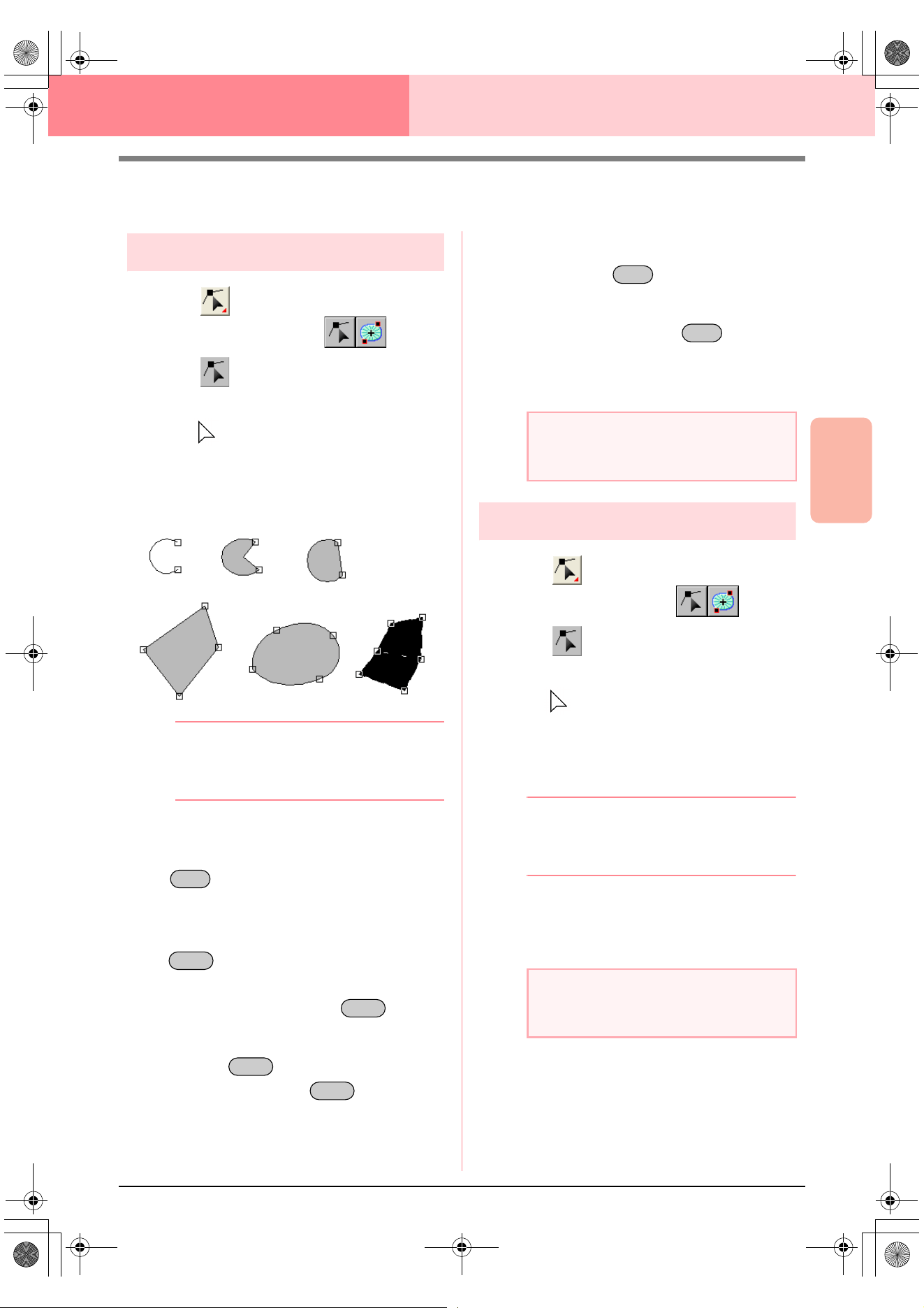
Advanced Opreation
Layout & Editing
135
Layout & Editing Editing Embroidery Patterns
Editing Points in Embroidery Patterns
Selecting points
1. Click on the Tool Box.
→ Two buttons appear: .
2. Click .
→ The shape of the pointer changes to
.
3. Click the pattern that you want to edit.
→ The points in the pattern appear as small
empty squares.
b Memo:
The pattern can be a broken line, a curve, an
arc, a fan shape, an arc & string, a manual
punching pattern, or stitch data.
4. To select a single point, click an empty square.
To select additional points, hold down the
key and click each point, or drag the
pointer over the points that you want to select.
To select all points between the selected point
and the next point selected, hold down the
key while clicking the next point.
To select an additional point in the direction of
the end point, hold down the key and
press the → or ↓ key. To select an additional
point in the direction of the start point, hold
down the key and press the ← or ↑
key. Holding down the key and
pressing the opposite arrow key deselects the
point.
To deselect the current point and select the
following point in the direction of the end point,
hold down the key and press the
→ or ↓ key. To deselect the current point and
select the following point in the direction of the
start point, hold down the key and
press the ← or ↑ key.
→ The selected point appears as a small
black square.
Moving points
1. Click on the Tool Box.
→ Two buttons appear: .
2. Click .
→ The shape of the pointer changes to
.
3. Click the pattern that you want to edit.
→ The points in the pattern appear as small
empty squares.
b Memo:
The pattern can be a broken line, a curve, an
arc, a fan shape, an arc & string, a manual
punching pattern, or stitch data.
4. Click the point that you want to move.
→ The selected point appears as a small
black square.
Ctrl
Shift
Shift
Shift
Shift
a Note:
The points of some patterns cannot be
selected.
a Note:
If you click the outline of the pattern instead
of a point, a new point is inserted.
Ctrl
Ctrl
PeDesignV6Eng.book Page 135 Thursday, July 8, 2004 11:59 AM
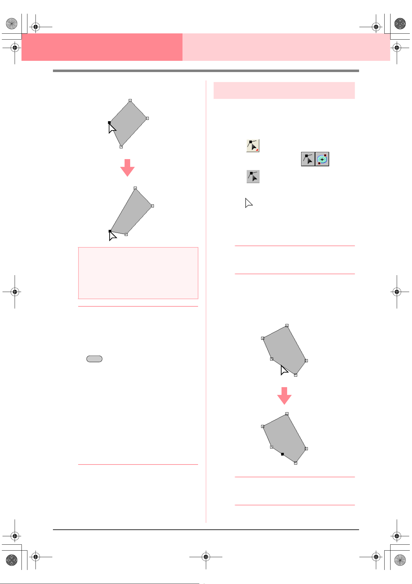
136
Layout & Editing Editing Embroidery Patterns
5. Drag the point to the new location.
b Memo:
• All of the selected points move in the same
direction.
• To move the point of a broken line, a curve,
a manual punching pattern, or stitch data
horizontally or vertically, hold down the
key while dragging it.
• Pressing the arrow keys moves the
selected point 0.5 mm (about 0.02 inch) in
the direction of the arrow on the key.
•If
Snap to Grid
is selected, each press of
an arrow key moves the point one grid
mark in the direction of the arrow on the
key.
• The arrow keys cannot be used to move
the end points of an arc.
• Points in patterns set for hole sewing can
also be moved. However, the point cannot
be moved to cross an outline. In order to
move the point in this way, cancel hole
sewing first.
Inserting points
New points can be inserted in order to change the
shape of a pattern. In the case of a new point on a
curve, you can also use the handle to reorient the
tangent to the new point.
1. Click on the Tool Box.
→ Two buttons appear: .
2. Click .
→ The shape of the pointer changes to
.
3. Click the pattern that you want to edit.
→ The points in the pattern appear as small
empty squares.
b Memo:
The pattern can be a broken line, a curve, a
manual punching pattern, or stitch data.
4. Click the outline to add a point.
→ A new point appears selected (as a small
black square and, in the case of a curve,
with a control handle).
b Memo:
If a manual punching block pattern was
selected, a pair of new points are inserted.
a Note:
You must drag a point that is selected. If you
start dragging by clicking elsewhere on the
outline of the pattern, a new point will be
inserted or the selected point(s) will be
deselected.
Shift
PeDesignV6Eng.book Page 136 Thursday, July 8, 2004 11:59 AM
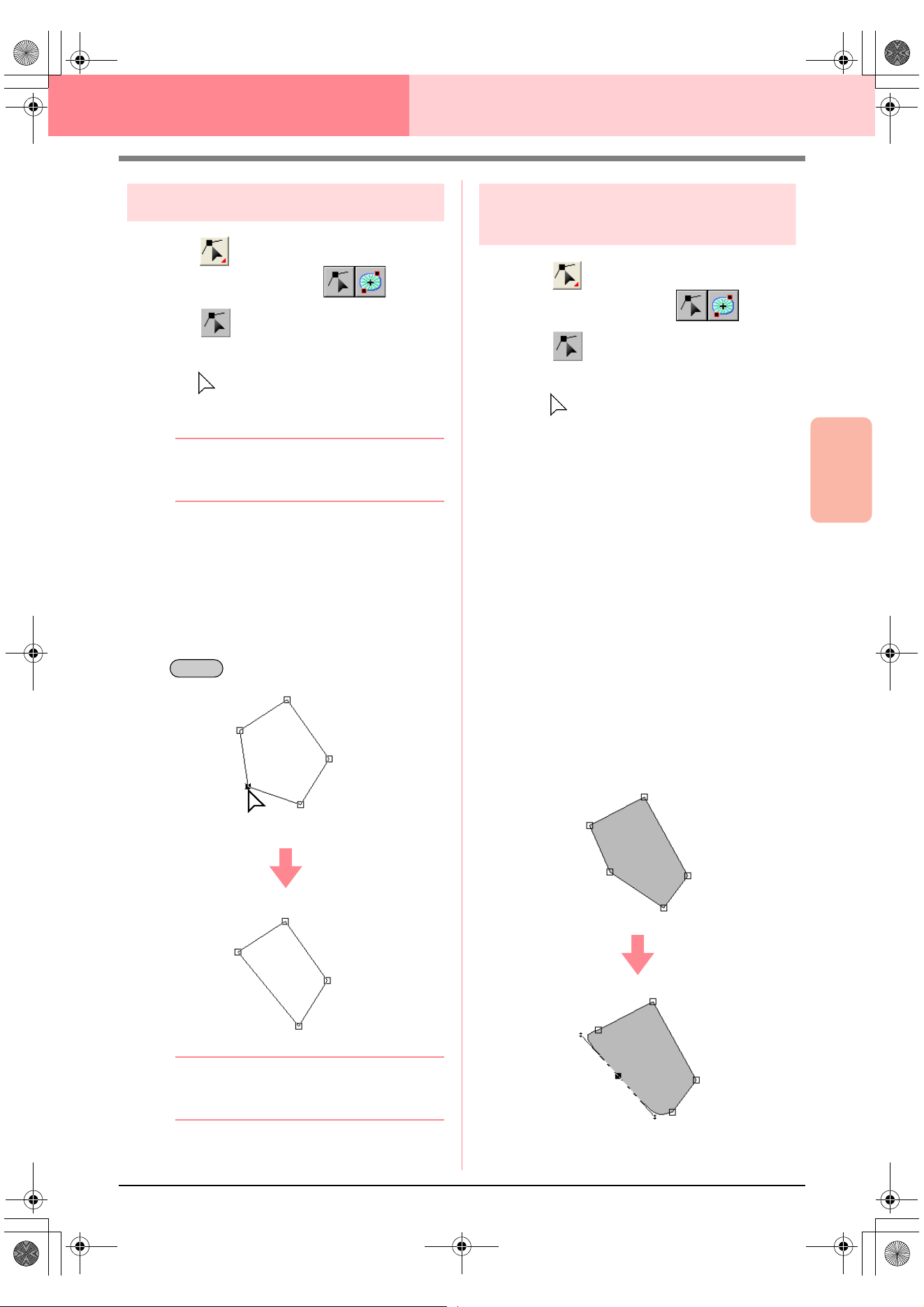
Advanced Opreation
Layout & Editing
137
Layout & Editing Editing Embroidery Patterns
Deleting points
1. Click on the Tool Box.
→ Two buttons appear: .
2. Click .
→ The shape of the pointer changes to
.
3. Click the pattern that you want to edit.
b Memo:
The pattern can be a broken line, a curve, a
manual punching pattern, or stitch data.
→ The points in the pattern appear as small
empty squares.
4. Click the point that you want to delete.
→ The selected point appears as a small
black square.
5. Click Edit, then Delete, or press the
key to remove the point.
b Memo:
If a point of a manual punching block pattern
was selected, the pair of points are deleted.
Transforming straight lines into
curves or curves into straight lines
1. Click on the Tool Box.
→ Two buttons appear: .
2. Click .
→ The shape of the pointer changes to
.
3. Click the pattern that you want to edit.
→ The points in the pattern appear as small
empty squares.
4. Click the point that you want to transform.
→ The selected point appears as a small
black square.
5. To transform a straight line to a curve, click
Edit, then Change To Curve, or right-click the
point, and then click To Curve on the menu
that appeared.
To transform a curve to a straight line, click
Edit, then Change To Straight, or right-click
the point, and then click To Straight on the
menu that appeared.
→ A point on curve is transformed to a cor-
ner, and a corner point is transformed to a
point on a curve.
Delete
PeDesignV6Eng.book Page 137 Thursday, July 8, 2004 11:59 AM
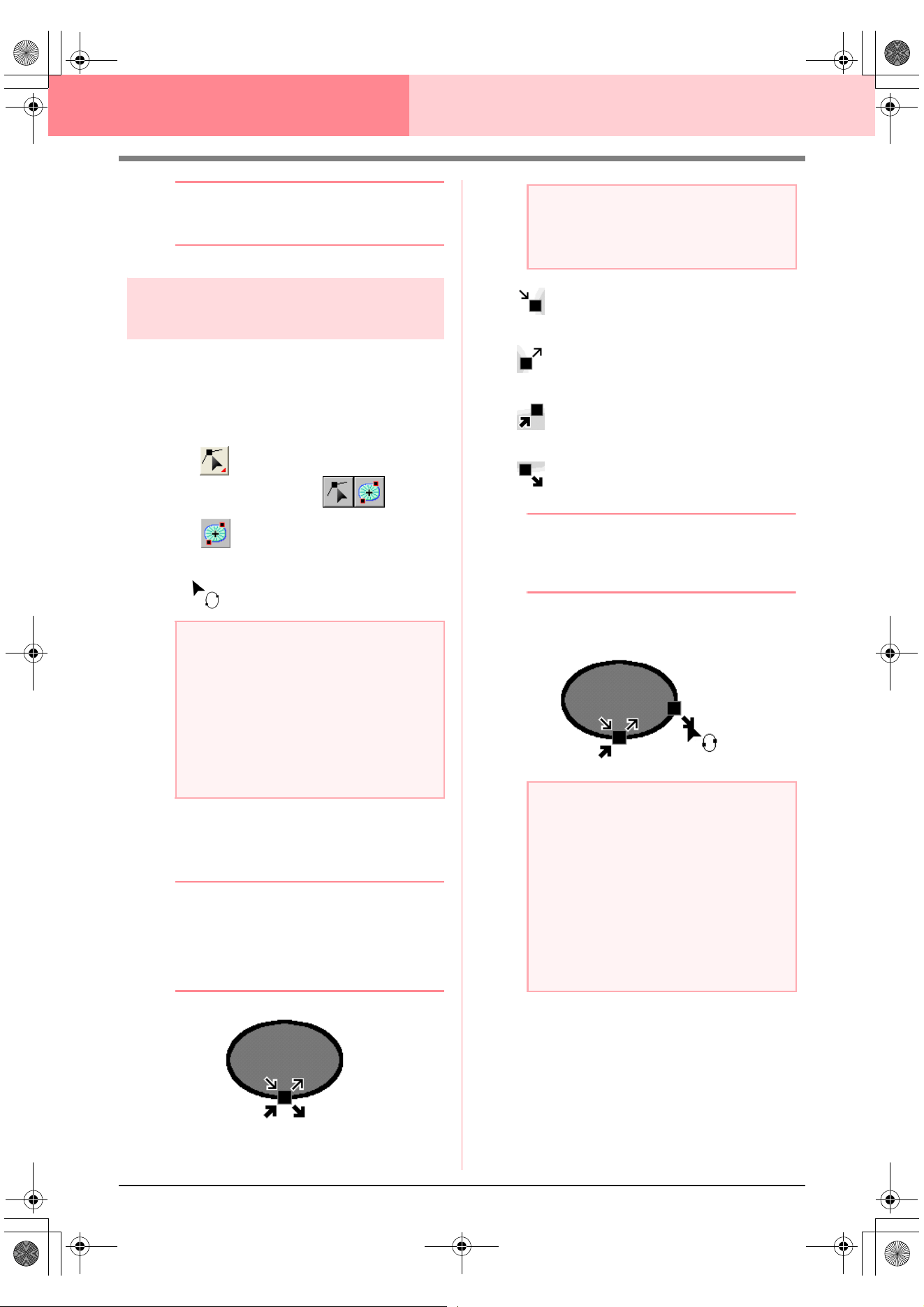
138
Layout & Editing Editing Embroidery Patterns
b Memo:
If the point is on a curve, you can use the
control handles to adjust the curve.
Moving entry/exit points and
the center point
■ Moving the entry/exit points
You can reposition the entry and exit points of
objects created with the tools on the Tool Box in
order to adjust the stitching.
1. Click on the Tool Box.
→ Two buttons appear: .
2. Click .
→ The shape of the pointer changes to
.
3. Click the object that you want to edit.
→ The entry and exit points of the object ap-
pear.
b Memo:
If the region has the concentric circle stitch or
radial stitch applied, the center point of the
stitching also appears. (For details on
moving the center point, refer to “Moving the
center point” on page 139.)
This is the entry point for the outline
stitching. The previous pattern is
connected to this point.
This is the exit point for the outline
stitching. Stitching continues from this
point to the next pattern.
This is the entry point for the inside
region stitching. The previous pattern
is connected to this point.
This is the exit point for the inside
region stitching. Stitching continues
from this point to the next pattern.
b Memo:
If the outline or the inside region are set to
not be sewn, the corresponding point does
not appear.
4. Drag the arrow for the point that you want to
move to the desired location on the outline.
a Note:
If the entry and exit points have been
optimized (a check mark appears in front of
the
Optimize Entry/Exit points
command
on the
Sew
menu), the entry and exit points
of the patterns cannot be edited. In order to
use this tool for editing the entry and exit
points, select the menu command
Sew
–
Optimize Entry/Exit points
to cancel the
setting.
a Note:
The entry and exit points of stitch data, text,
and manual punching patterns cannot be
edited.
a Note:
• Only entry and exit points for objects
created with the Circle or Arc, Rectangle
and Outline tools can be edited. Stitch
data or objects created with the Text tools
or Manual Punch tools cannot be edited.
• If the menu command
Sew
–
Optimize
Entry/Exit points
is selected to optimize
the entry and exit points, all manual
adjustments of the entry and exit points
will be lost, and the positions of the points
will be automatically optimized.
PeDesignV6Eng.book Page 138 Thursday, July 8, 2004 11:59 AM
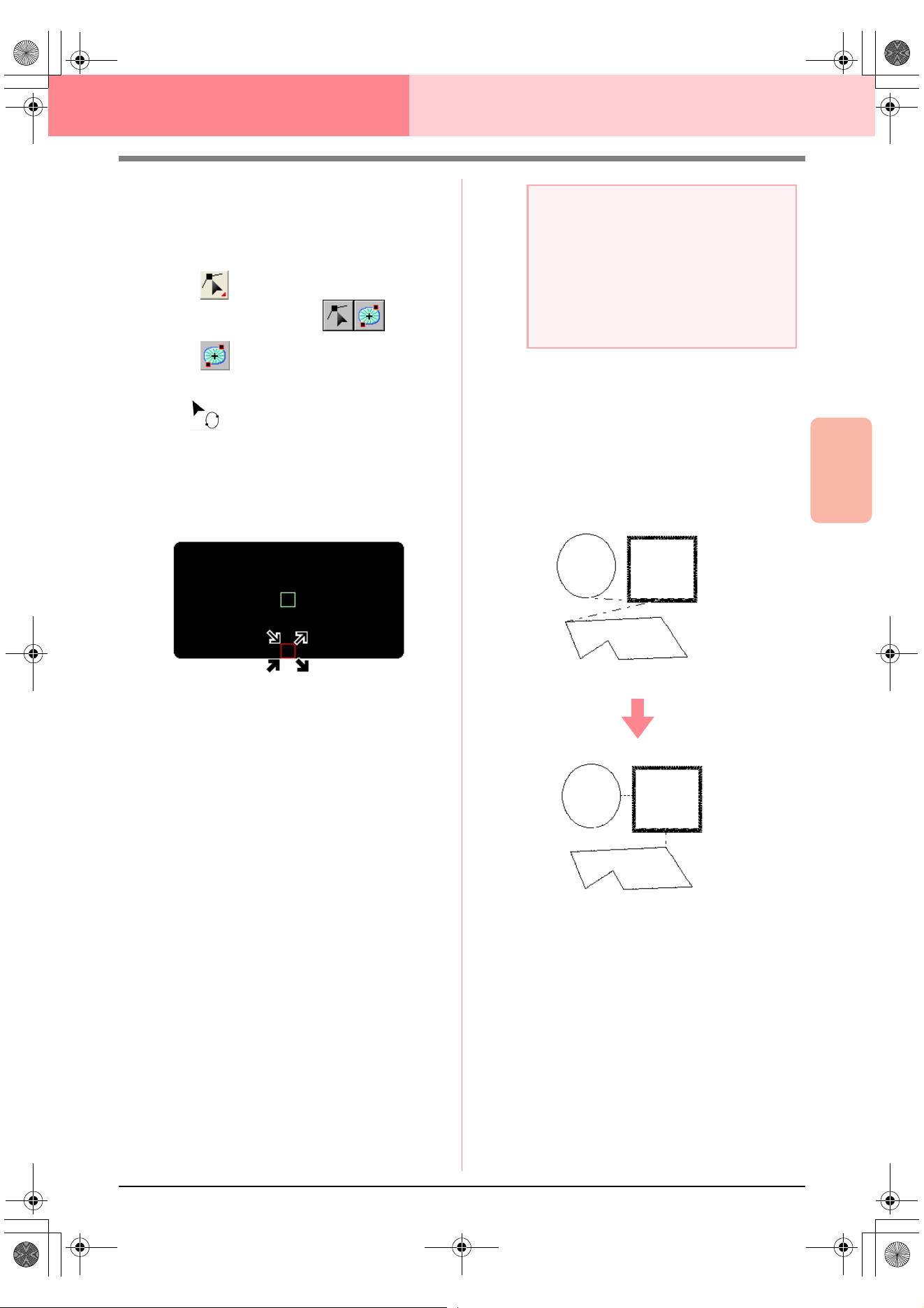
Advanced Opreation
Layout & Editing
139
Layout & Editing Editing Embroidery Patterns
■ Moving the center point
The center point for regions set to the concentric
circle stitch or radial stitch can be repositioned for a
more decorative effect.
1. Click on the Tool Box.
→ Two buttons appear: .
2. Click .
→ The shape of the pointer changes to
.
3. Click the region set to the concentric circle
stitch or radial stitch that you want to edit.
→ The entry and exit points and the center
point of the object appear.
4. Drag the center point to the desired location.
■ Optimizing the entry/exit points
The positions of the entry and the exit points for the
objects can be adjusted automatically in order to
optimize stitching.
1. Click Sew, then Optimize Entry/Exit points.
To optimize the entry and exit points, select
this command so that a check mark appears.
To cancel optimizing, select this command so
that no check mark appears.
→ If a check mark appears beside Optimize
Entry/Exit points, the entry and exit
points for the stitching of connected ob-
jects with the same color are optimized (in
other words, they are connected by the
shortest distance possible).
→ If the check mark does not appear beside
Optimize Entry/Exit points, the entry
and exit points are not optimized. If the
optimizing of the entry and exit points is
cancelled, the entry point and exit point
positions are retained. In addition, the po-
sitions of the entry and the exit points can
be manually changed with the Entry/Exit/
Center point tool.
a Note:
• Only entry and exit points for objects
created with the Circle or Arc, Rectangle
and Outline tools can be optimized.
• If the menu command
Sew
–
Optimize
Entry/Exit points
is selected to optimize
the entry and exit points, the entry and exit
points cannot be moved with the Entry/
Exit point tool.
Optimize Entry/Exit points not selected
Optimize Entry/Exit points selected
PeDesignV6Eng.book Page 139 Thursday, July 8, 2004 11:59 AM
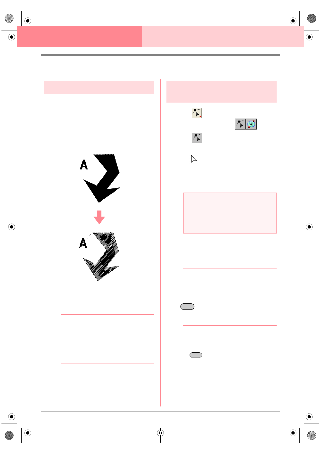
140
Layout & Editing Editing Embroidery Patterns
Editing Stitch Data
Converting objects to stitch data
Objects drawn with the tools in Layout & Editing can
be converted into stitch data, allowing you to make
detailed changes by modifying the position of
individual stitches.
1. Select the object that you want to convert.
2. Click Sew, then Convert to Stitch.
The selected object is converted to stitch data.
→ The dotted line around the converted data
indicates that it is stitch data. Each stitch
of the converted data can be edited with
the Edit Point tool.
b Memo:
• Related text, lines and patterns set for hole
sewing will all be converted to stitch data,
even if some of the objects are not
selected.
• Patterns that do not have sewing attributes
applied are deleted when the object is
converted to stitch data.
Editing stitch points of stitch
data
1. Click on the Tool Box.
→ Two buttons appear: .
2. Click .
→ The shape of the pointer changes to
.
3. Click the object that you want to edit.
→ The stitch points in the stitch data appear
as small empty squares.
4. To select a single stitch point, click an empty
square.
→ The selected stitch point appears as a
small black square.
b Memo:
If you click a feed, the points at both ends are
selected.
To select multiple stitch points, hold down the
key and click each of the other points
that you want to select, or drag the pointer
over the stitch points that you want to select.
b Memo:
• To select all stitch points (in the stitching
order) between the selected stitch point
and the next point selected, hold down the
key while clicking the next stitch
point.
a Note:
Stitch data are surrounded with a dotted line.
If the object is not surrounded by a dotted
line, it cannot be edited. Select the menu
command
Sew
–
Convert to Stitch
to
convert the object to stitch data.
Ctrl
Shift
Advanced_02.fm Page 140 Friday, July 9, 2004 1:45 PM
Advanced Opreation
Layout & Editing
141
Layout & Editing Editing Embroidery Patterns
• To select an additional stitch point in the
stitching order, hold down the key
and press the
→
or
↓
key. To select an
additional stitch point in the opposite
direction of the stitching order, hold down
the key and press the
←
or
↑
key. Holding down the key and
pressing the opposite arrow key deselects
the stitch point.
• To deselect the current stitch point and
select the following point in the stitching
direction, hold down the key and
press the
→
or
↓
key. To deselect the
current stitch point and select the previous
point in the stitching direction, hold down
the key and press the
←
or
↑
key.
• To select all stitch points in the next color,
press the key. To select all stitch
points in the previous color, hold down the
key and press the key.
→ Selected points appear as small black
squares.
■ Moving stitch points
1. Drag the selected stitch points to the new
location.
b Memo:
• To move the selected stitch point
horizontally or vertically, hold down the
key while dragging it.
• Pressing the arrow keys moves the
selected stitch point 0.1 mm in the
direction of the arrow on the key.
■ Inserting stitch points and feeds
1. Click a line between two stitch points to add a
new point at that position.
b Memo:
To insert a stitch point and change the
previous line into a feed, hold down the
and keys while clicking on
the line.
■ Deleting stitch points
1. Press the key to delete the
selected stitch point.
b Memo:
If the end point of a feed is deleted, that feed
segment is deleted and the stitches before
and after the feed are connected.
■ Editing entry/exit points for each
color of the stitch data
1. Click on the Tool Box.
→ Two buttons appear: .
2. Click .
→ The shape of the pointer changes to
.
3. Click the object that you want to edit.
→ The stitch points in the object appear as
small empty squares.
4. To select the entry point of the first thread
color, press the and keys.
To select the exit point of the last thread color,
press the and keys.
To select the entry point of a given color,
select at least one point in that color, and then
press the key.
To select the exit point of a given color, select
at least one point in that color, and then press
the key.
a Note
When selecting stitch points, be sure to click
the stitch point (do not click a blank area of
the Design Page), otherwise all of the
selected points will be deselected.
Shift
Shift
Shift
Ctrl
Ctrl
Tab
Shift Tab
Shift
Ctrl
Shift
Delete
Ctrl Home
Ctrl End
Home
End
PeDesignV6Eng.book Page 141 Thursday, July 8, 2004 11:59 AM
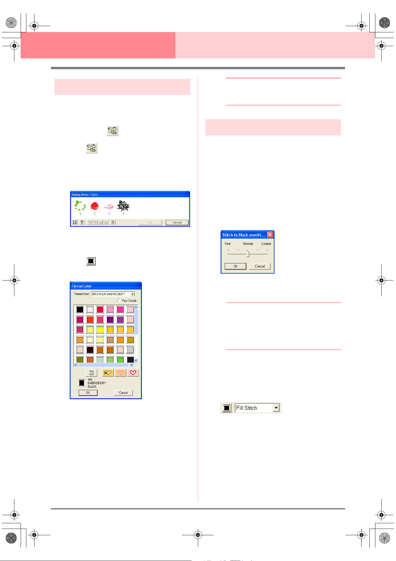
142
Layout & Editing Editing Embroidery Patterns
Changing colors of stitch data
The colors of imported stitch data or objects
converted to stitches can be changed in the following
way.
Toolbar button:
1. Click , or click Sew, then Sewing Order/
Color.
→ The Sewing Order/Color dialog box ap-
pears with each data in the pattern in a
separate frame.
2. Select the frame for the data whose color you
want to change.
3. Click .
→ The Thread Color dialog box appears.
4. Select the desired color, and then click OK.
→ The object appears in the new color in the
Sewing Order/Color dialog box and in
the Design Page.
5. Repeat steps 2. to 4. for each data whose
color you want to change.
6. Click OK.
→ The pattern is displayed with the new col-
ors.
b Memo:
To close the dialog box without applying the
changes to the settings, click
Cancel
.
Converting stitch data to blocks
Imported stitch data or patterns converted to stitch
data can be converted into blocks (manual punching
data), allowing you to change some of their sewing
attributes and to scale individual colors while keeping
their stitching quality.
1. Select the stitch data imported into the Design
Page where you want to apply the setting.
2. Click Sew, then Stitch to Block.
→ The Stitch to Block sensitivity dialog
box appears.
3. Move the slider to select the desired
sensitivity.
b Memo:
The
Normal
setting should provide
satisfactory results in most cases, but
depending on the complexity of the pattern,
you may need to select a setting more
towards
Coarse
or
Fine
.
4. Click OK.
→ The data in the blocks are grouped so that
any setting change will affect the whole
pattern, and the Sewing Attributes bar ap-
pears as shown below.
PeDesignV6Eng.book Page 142 Thursday, July 8, 2004 11:59 AM
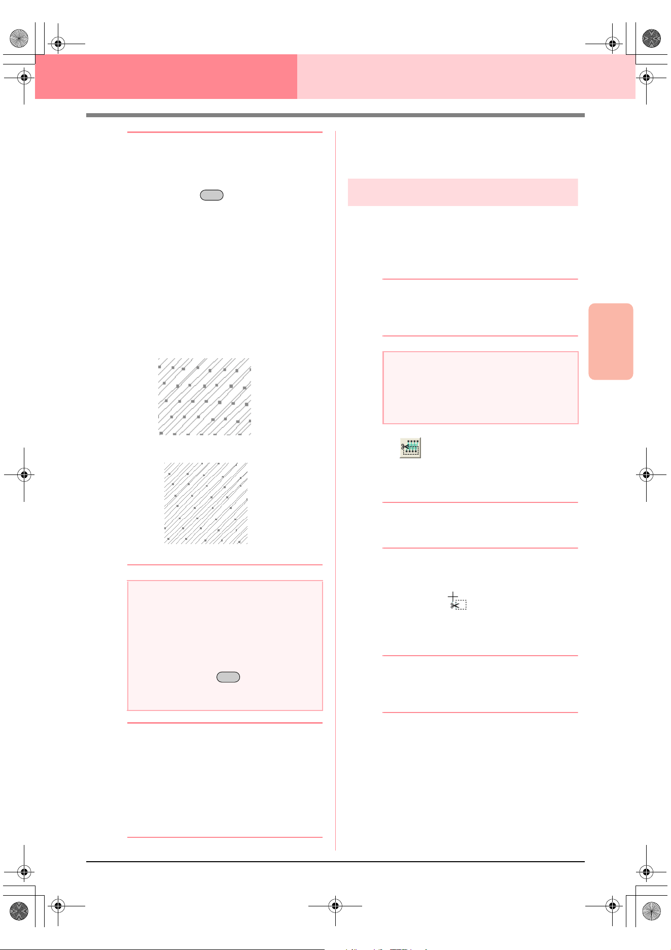
Advanced Opreation
Layout & Editing
143
Layout & Editing Editing Embroidery Patterns
b Memo:
• To quit the operation, click
Cancel
.
• To modify the sewing attributes of all
blocks of the same color within the pattern,
hold down the key while selecting a
block whose color or sew type settings you
want to change. (An alternate method is to
first ungroup the colors of the pattern by
selecting the menu command
Edit
–
Ungroup
.) Use the zoom tools to zoom
into the design to select the color more
easily. All blocks of that color are selected
and the block color and sew type appear in
the Sewing Attributes bar.
• When you scale blocks, the number of
stitches sewn automatically adapt to the
new size of the blocks, allowing you to
keep the original embroidery quality.
b Memo:
• The selected color blocks can be moved or
scaled individually, therefore, if you want
to move the whole pattern once it has been
ungrouped, be sure to carefully regroup
each individual color pattern by selecting
the menu command
Edit
–
Group
.
• You can further modify the pattern by
using the Point Edit tool.
c
“Specifying sewing attributes” on
page 171, “Scaling patterns” on page 132
and “Selecting points” on page 135
Splitting off parts of stitch data
The Split stitch tool in the Tool Box allows you to
split a pattern after tracing an enclosure around the
parts that you want to cut off. You can then move the
cutoff sections to rearrange the pattern, combine it
with other patterns or even delete it.
b Memo:
This tool is available only for stitch data, and
when the Text, Outline, and Manual Punch
tools are not selected.
1. Click on the Tool Box.
2. Click the stitch data that you want to cut a
section from.
b Memo:
You can also click the Split stitch tool after
selecting stitch data.
→ All other stitch data disappear from the
display, and the shape of the pointer
changes to .
3. Click in the Design Page at the point where
you want to start drawing the enclosing lines.
b Memo:
In the Tool Box, only the Zoom tool is
available, allowing you to zoom in on the
stitch data to better view the area.
4. Continue clicking in the Design Page to
specify each corner of the enclosure around
the area to be cut off.
a Note:
•The
Stitch to Block
command cannot be
used with some stitch data imported from
embroidery cards.
• Some fill patterns are lost when scaled
after setting the Stitch to Block function,
therefore it is recommended to scale while
holding down the key or by
selecting the menu command
Edit
–
Numerical Setting
–
Size
.
Alt
Without Stitch to Block
With Stitch to Block
Ctrl
a Note:
Patterns created with the drawing or Text
tools of Layout & Editing need to be
converted into stitches before they can be
cut with the Split stitch tool.
PeDesignV6Eng.book Page 143 Thursday, July 8, 2004 11:59 AM
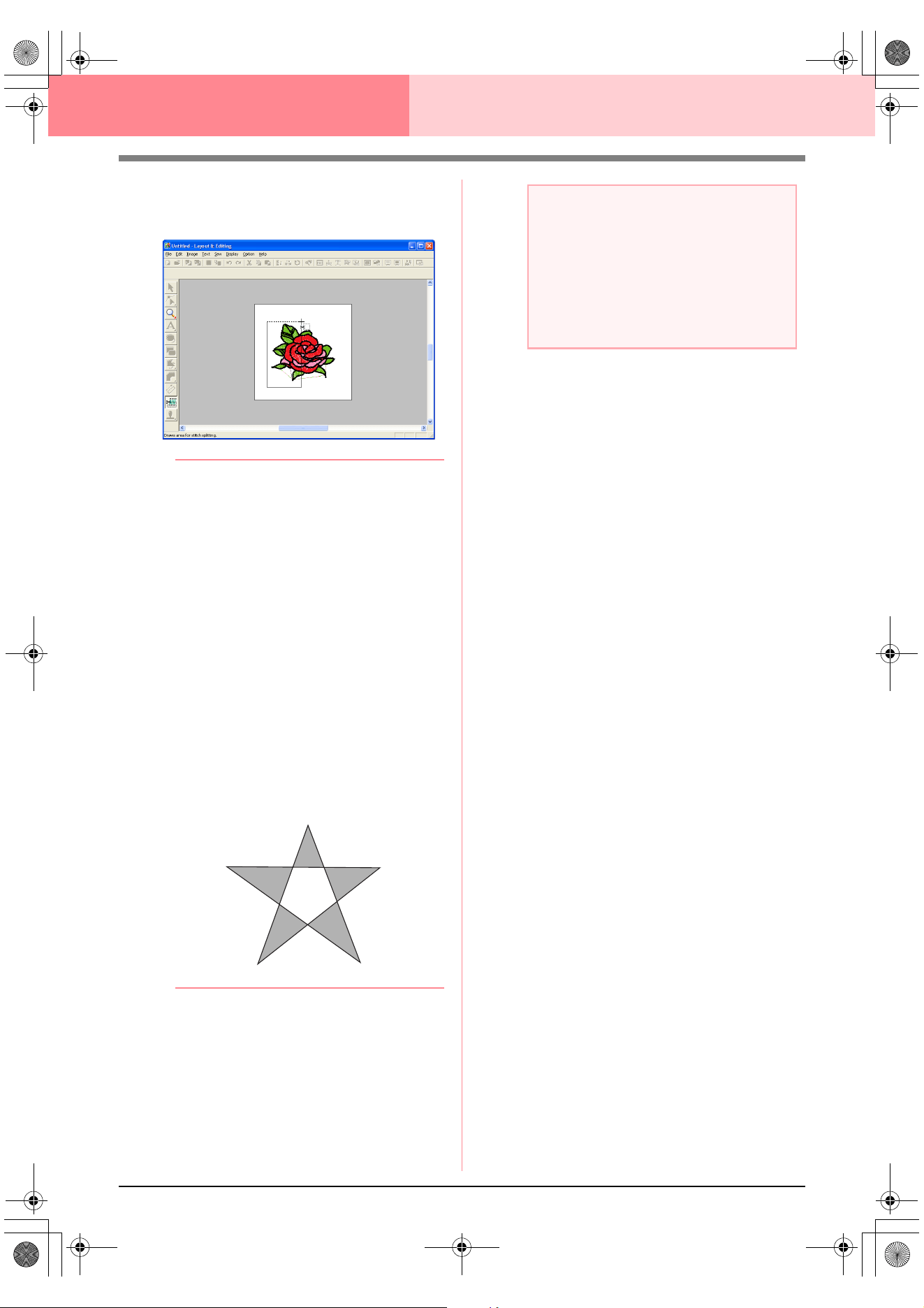
144
Layout & Editing Editing Embroidery Patterns
→ The dotted line that is drawn when you
move the pointer changes to a solid line
when the next point is specified.
b Memo:
• To remove the last point that was entered,
click the right mouse button. Each
successive right-click removes points, one
by one, in the opposite order that they
were entered.
Once all points are deleted,
the Tool Box buttons are available again,
however, the application remains in Split
stitch mode.
• An enclosure is valid only if it contains
stitch data. If it contains no stitch data, an
error message appears, and the enclosure
is erased, but the application remains in
Split stitch mode.
• Sections enclosed several times by lines
of an intricate figure alternate between
being selected and deselected. Therefore,
in a figure like a pentagram for instance,
only the points are selected, and the
center is deselected as it has been
enclosed twice.
5. Double-click in the Design Page to specify the
section to be split off.
6. Edit the cutoff section as desired.
a Note:
• Only one cutoff section can be specified
from the pattern at one time. Repeat the
procedure for each piece of the pattern
that you want to cut off.
• The cutoff piece moves to the end of the
sewing order and the thread color order
appears in the order selected for the
original pattern.
Advanced_02.fm Page 144 Friday, July 9, 2004 1:46 PM
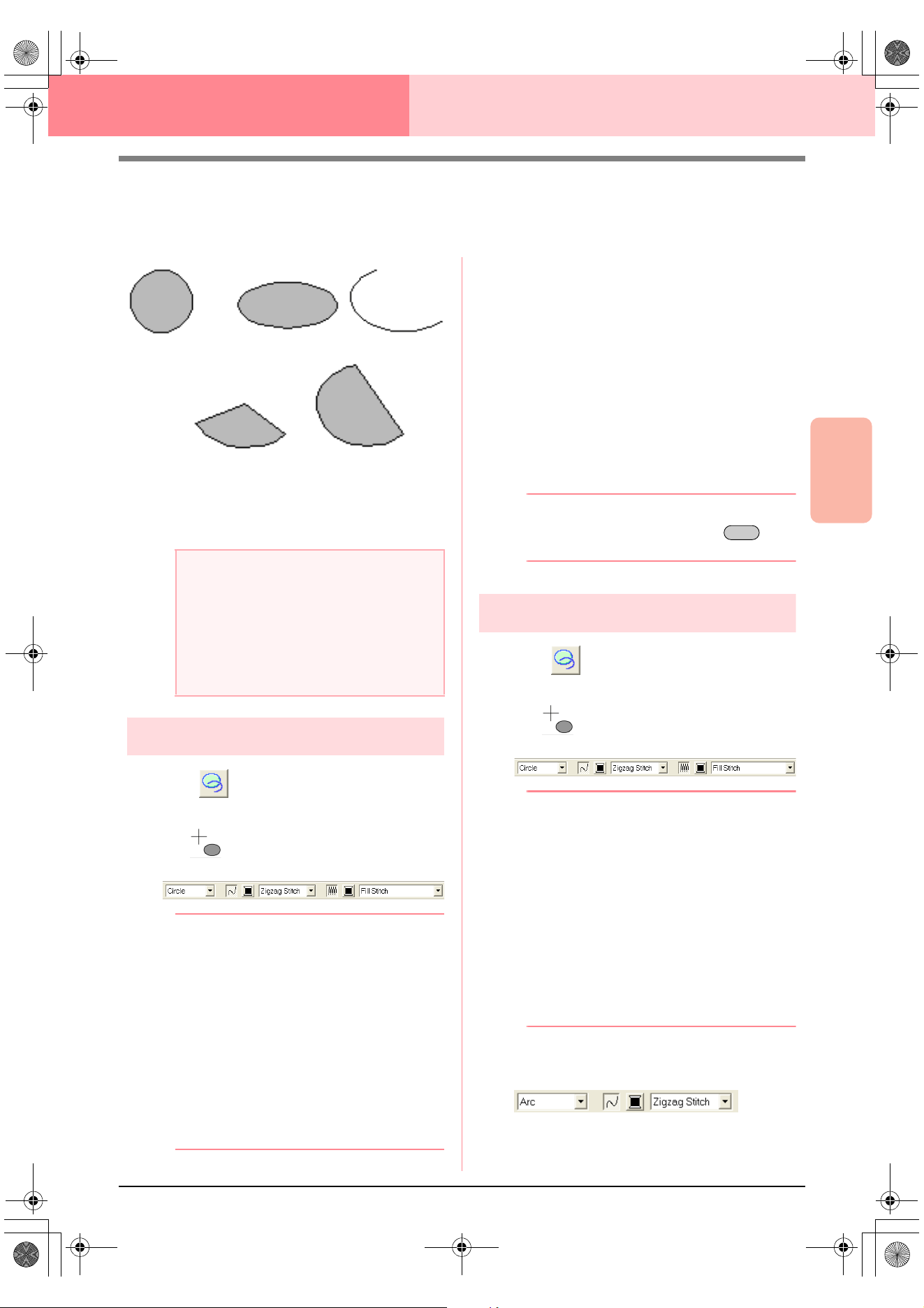
Advanced Opreation
Layout & Editing
145
Layout & Editing Editing Embroidery Patterns
Drawing Circles and Arcs
The Circle or Arc tool allows you to create several curved patterns: regular circles (or ovals), arcs, fan shapes
and arc & strings.
All of these patterns, except arcs have an outline
and a inside region, and can independently be
assigned different sewing attributes. Arcs are simple
outlines.
Drawing a circle or an oval
1. Click on the Tool Box.
→ The shape of the pointer changes to
, and the Sewing Attributes bar ap-
pears similar to the one shown below.
b Memo:
• You can change the color and sew type
either before or after drawing the shape.
For more details on changing these
settings, refer to “Color” on page 169 and
“Sew type” on page 170.
• You can also use the settings in the
Sewing Attribute Setting
dialog box to
define other attributes of the shape. (For
more details, refer to “Specifying sewing
attributes” on page 171.) If you do not
change these settings at this time, the
current settings will be applied, however
you can modify them later.
2. Click in the Arc shape selector, and then
select Circle.
3. Drag the pointer in the Design Page.
→ The point where you start dragging is con-
sidered a corner of an imaginary rectan-
gle around the oval. The point where you
release the mouse button is the diagonal-
ly opposite point of the rectangle. The
oval will fit inside this imaginary rectangle
(its greater axis is along the longer edge
of the rectangle, and its smaller axis is
along the smaller edge).
b Memo:
To draw a circle, hold down the key
while dragging the pointer.
Drawing an arc
1. Click on the Tool Box.
→ The shape of the pointer changes to
, and the Sewing Attributes bar ap-
pears similar to the one shown below.
b Memo:
• You can change the color and sew type
either before or after drawing the shape.
For more details on changing these
settings, refer to “Color” on page 169 and
“Sew type” on page 170.
• You can also use the settings in the
Sewing Attribute Setting
dialog box to
define other attributes of the shape. (For
more details, refer to “Specifying sewing
attributes” on page 171.) If you do not
change these settings at this time, the
current settings will be applied, however
you can modify them later.
2. Click in the Arc shape selector, and then click
Arc.
3. Proceed as you would to draw a circle or an
oval.
a Note:
When drawing a shape with this tool, select
the shape before drawing. You cannot, for
example, draw a circle, then change it to an
arc afterward.
The setting is applied to all patterns that you
will create with the Circle or Arc tool, until the
setting is changed.
Circle Oval Arc
Fan shape Arc & string
Shift
PeDesignV6Eng.book Page 145 Thursday, July 8, 2004 11:59 AM
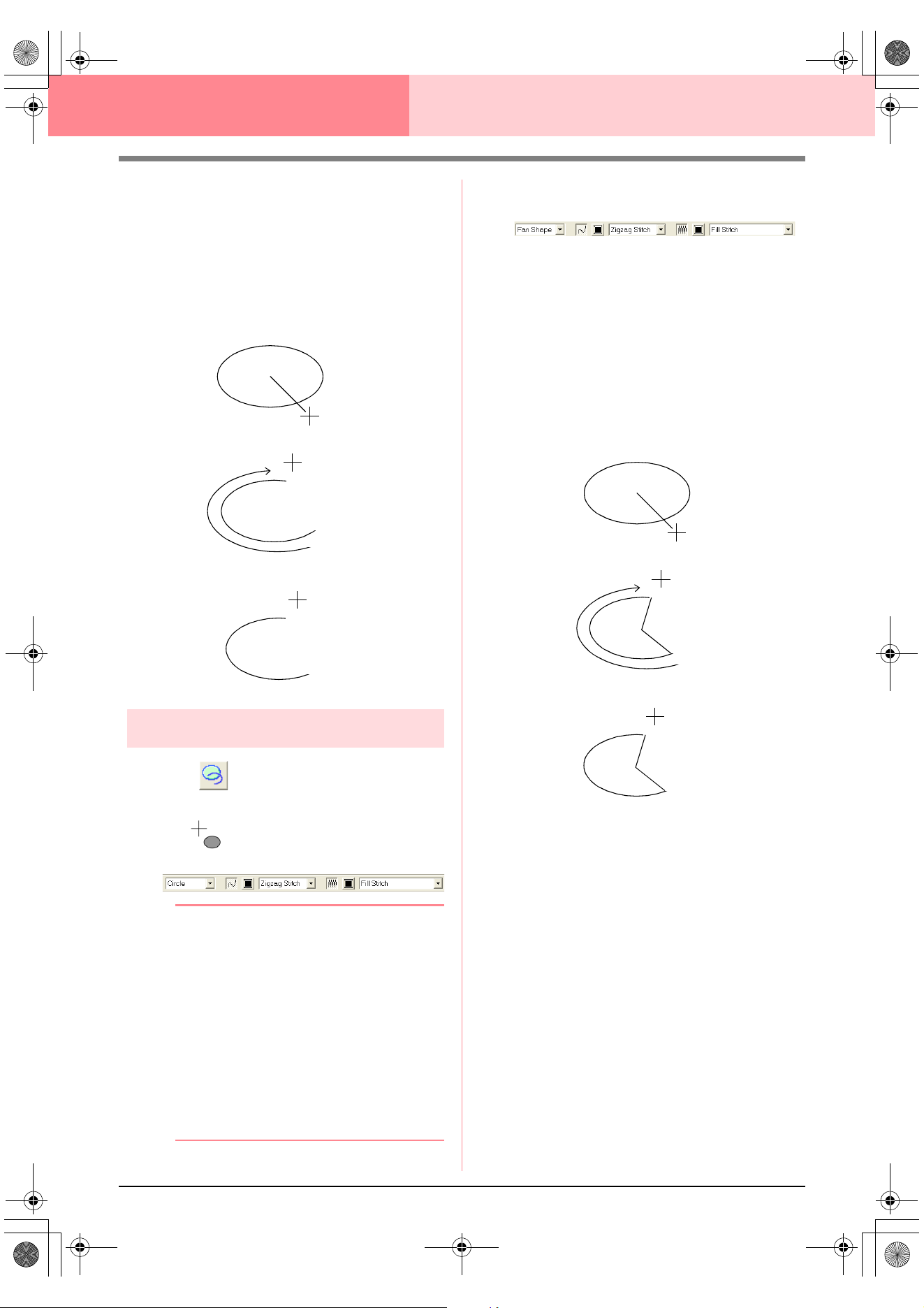
146
Layout & Editing Editing Embroidery Patterns
→ A radial line appears on the oval when the
mouse button is released.
4. Move the pointer to the start point of the arc,
and then click.
→ The radial line disappears.
5. Move the pointer until the arc has the desired
shape, and then click.
Drawing a fan shape
1. Click on the Tool Box.
→ The shape of the pointer changes to
, and the Sewing Attributes bar ap-
pears similar to the one shown below.
b Memo:
• You can change the color and sew type
either before or after drawing the shape.
For more details on changing these
settings, refer to “Color” on page 169 and
“Sew type” on page 170.
• You can also use the settings in the
Sewing Attribute Setting
dialog box to
define other attributes of the shape. (For
more details, refer to “Specifying sewing
attributes” on page 171.) If you do not
change these settings at this time, the
current settings will be applied, however
you can modify them later.
2. Click in the Arc shape selector, and then click
Fan Shape.
3. Proceed as you would to draw a circle or an
oval.
→ A radial line appears on the oval when the
mouse button is released.
4. Move the pointer to the start point of the fan
shape, and then click.
→ The radial line disappears.
5. Move the pointer until the fan has the desired
shape, and then click.
Click at start point.
Move to end point.
Click at end point.
Click at start point.
Move to end point.
Click at end point.
PeDesignV6Eng.book Page 146 Thursday, July 8, 2004 11:59 AM
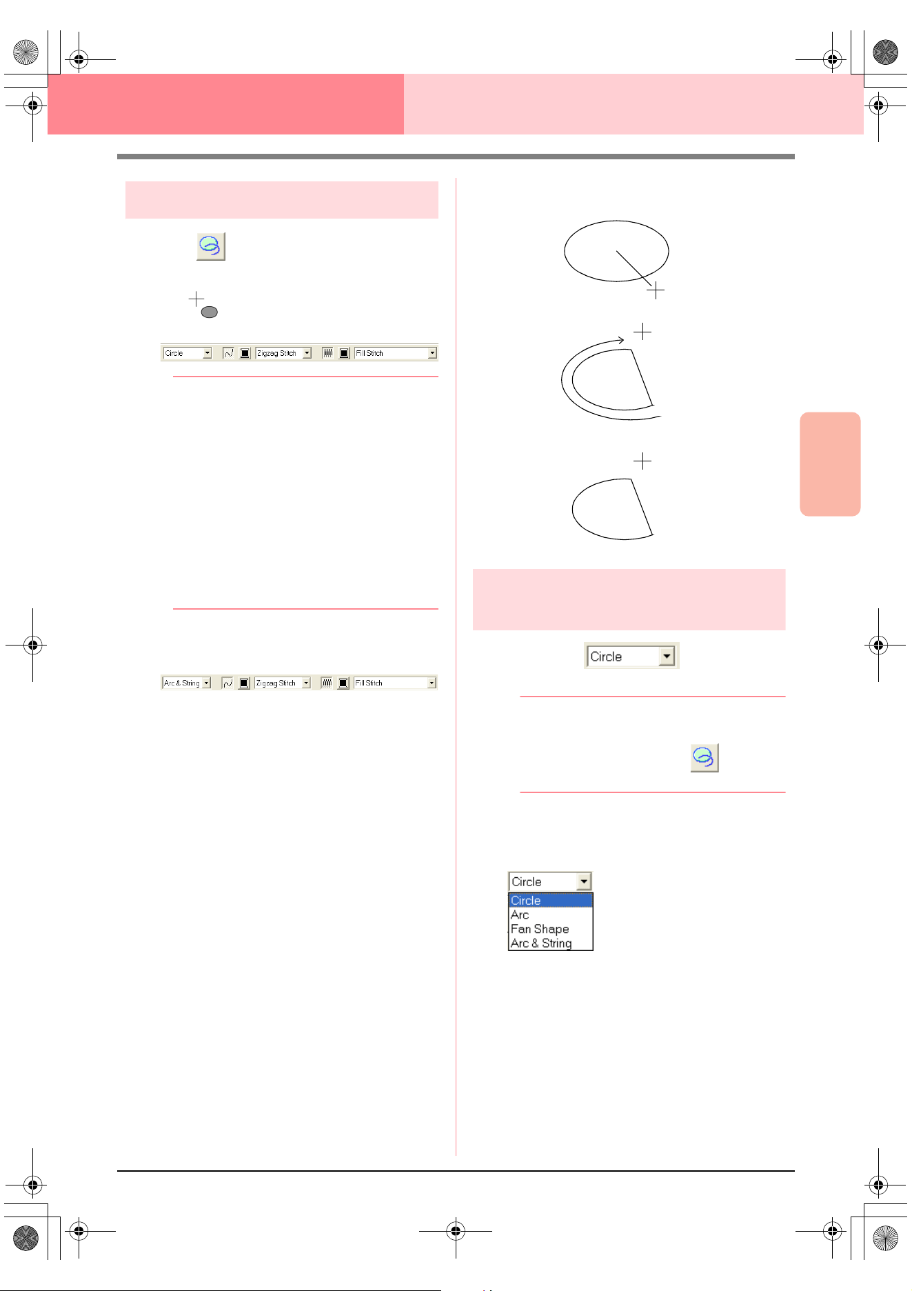
Advanced Opreation
Layout & Editing
147
Layout & Editing Editing Embroidery Patterns
Drawing an arc & string
1. Click on the Tool Box.
→ The shape of the pointer changes to
, and the Sewing Attributes bar ap-
pears similar to the one shown below.
b Memo:
• You can change the color and sew type
either before or after drawing the shape.
For more details on changing these
settings, refer to “Color” on page 169 and
“Sew type” on page 170.
• You can also use the settings in the
Sewing Attribute Setting
dialog box to
define other attributes of the shape. (For
more details, refer to “Specifying sewing
attributes” on page 171.) If you do not
change these settings at this time, the
current settings will be applied, however
you can modify them later.
2. Click in the Arc shape selector, and then click
Arc & String.
3. Proceed as you would to draw a circle or an
oval.
→ A radial line appears on the oval when the
mouse button is released.
4. Move the pointer to the start point of the arc &
string, and then click.
→ The radial line disappears.
5. Move the pointer until the arc & string has the
desired shape, and then click.
Specifying the geometric
attribute
■ Arc shape
Use this selector to select the type of arc.
b Memo:
The
Arc shape
selector appears in the
Sewing Attributes bar when on the
Tool Box is selected.
1. Click in the Arc shape selector.
→ The settings appear.
2. Click one of the settings.
→ The setting is applied to all patterns that
will be created with the Circle or Arc tool,
until the setting is changed.
Click at start point.
Move to end point.
Click at end point.
PeDesignV6Eng.book Page 147 Thursday, July 8, 2004 11:59 AM
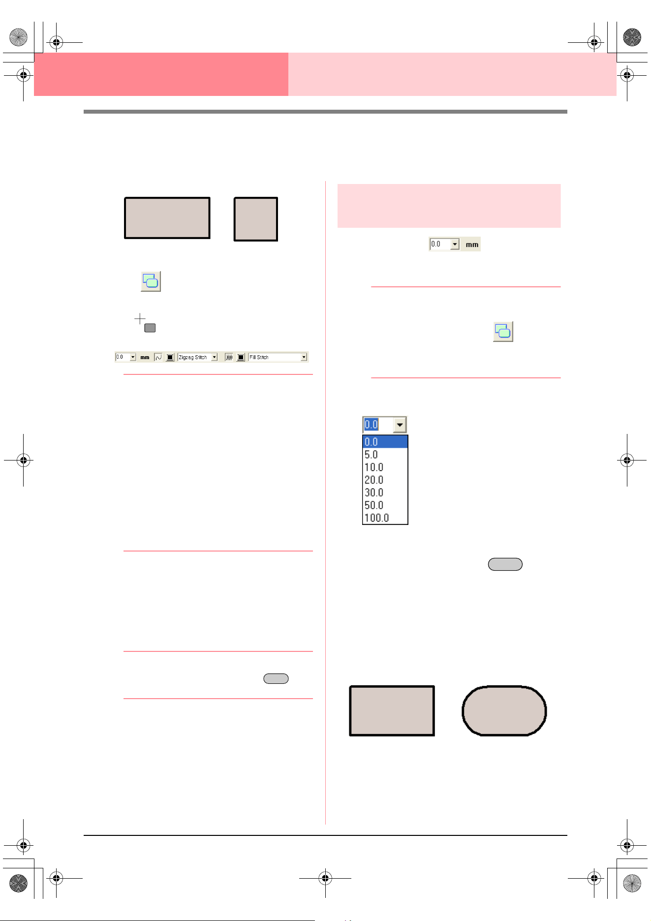
148
Layout & Editing Editing Embroidery Patterns
Drawing a Rectangle
With the Rectangle tool, you can draw rectangles with sharp or rounded corners. A rectangle will automatically
have an outline and an inside region that can independently be assigned different sewing attributes.
1. Click on the Tool Box.
→ The shape of the pointer changes to
, and the Sewing Attributes bar ap-
pears similar to the one shown below.
b Memo:
• You can change the edge radius, color and
sew type either before or after drawing the
shape. For more details on changing these
settings, refer to “Edge radius” on
page 148, “Color” on page 169 and “Sew
type” on page 170.
• You can also use the settings in the
Sewing Attribute Setting
dialog box to
define other attributes of the stitch. (For
more details, refer to “Specifying sewing
attributes” on page 171.) If you do not
change these settings at this time, the
current settings will be applied, however
you can modify them later.
2. Drag the pointer in the Design Page.
→ The point where you start dragging is con-
sidered a corner of the rectangle. The
point where the mouse button is released
is the diagonally opposite corner of the
rectangle.
b Memo:
To draw a square, hold down the key
while dragging the pointer.
Specifying the geometric
attribute
■ Edge radius
Use this selector to select the shape of the rectangle
corners.
b Memo:
The
Edge radius
selector appears in the
Sewing Attributes bar when on the
Tool Box is selected. It also appears when a
rectangle in the Design Page has been
selected.
1. Click in the Edge radius selector.
2. Type the desired radius (0 to 100 mm (0 to
3.93 inches)) and press the key, or
click the desired value.
→ The setting is applied to all patterns that
will be created with the Rectangle tool,
until the setting is changed.
→ If a rectangle was selected, the setting is
also applied to that rectangle.
Rectangle Square
Shift
Enter
Example 1
Edge radius: 0.0 mm
Example 2
Edge radius: 20.0 mm
PeDesignV6Eng.book Page 148 Thursday, July 8, 2004 11:59 AM
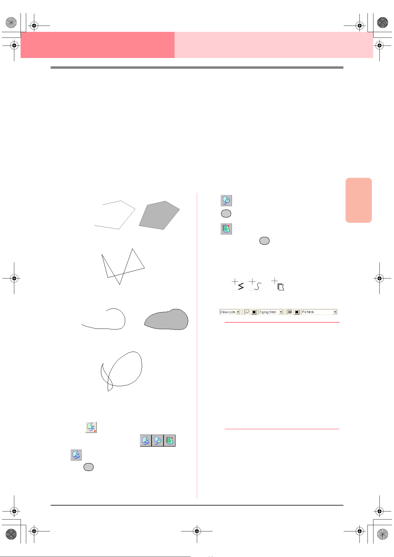
Advanced Opreation
Layout & Editing
149
Layout & Editing Editing Embroidery Patterns
Drawing Straight Lines and Curves
The Outline tools allow you to add straight lines and curves to your pattern.
If the straight line or curve is set to be open (Open Path), it will end at the last point entered. Since this type
of pattern is a simple outline and does not have an inside region, line sew type and color settings can only be
applied to the line itself.
If the straight line or curve is set to be closed (Close Path), the last point will automatically connect with the
first one. Since this type of pattern has an outline and an inside region, each part can be assigned different
sew types and colors. However, if the line of the pattern crosses itself, the inside region cannot be filled,
and the line must be uncrossed so that the fill can be applied.
While creating the pattern, you can freely switch between drawing straight lines or curves, and once they are
drawn, straight lines can be transformed into curves, and curves into straight lines.
Furthermore, if an image is used as a template, one tool can be used to semi-automatically extract the image
boundary.
1. Click on the Tool Box.
→
Three buttons appear:
is for drawing straight lines. (Shortcut
key: )
is for drawing curves. (Shortcut key:
)
is for semi-automatically drawing lines.
(Shortcut key: )
2. Click the button for the type of line that you
want to draw.
→ The shape of the pointer changes to
, or , and the Sewing At-
tributes bar appears similar to the one
shown below.
b Memo:
• You can change the path shape, color and
sew type either before or after creating the
shape. For more details on changing these
settings, refer to “Path shape” on
page 150, “Color” on page 169 and “Sew
type” on page 170.
• You can also use the settings in the
Sewing Attribute Setting
dialog box to
define other attributes of the shape. (For
more details, refer to “Specifying sewing
attributes” on page 171.) If you do not
change these settings at this time, the
current settings will be applied, however
you can modify them later.
3. Click in the Design Page to specify the start
point.
Open line
Closed line
Start point
End point
This closed line crosses itself,
so the regions will not be filled.
Open curve
Closed curve
Start point
End point
This closed curve crosses itself,
so the regions will not be filled.
Z
X
C
PeDesignV6Eng.book Page 149 Thursday, July 8, 2004 11:59 AM
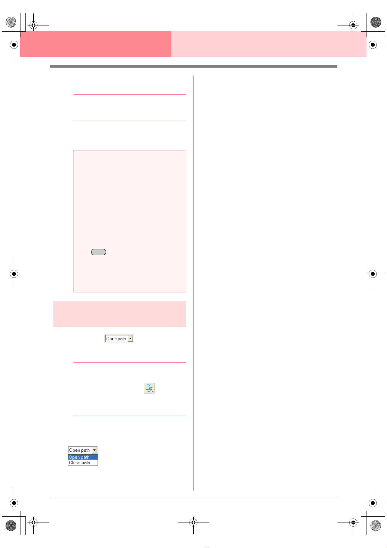
150
Layout & Editing Editing Embroidery Patterns
4. Click in the Design Page to specify the next
point.
b Memo:
To remove the last point that was entered,
click the right mouse button.
5. Continue clicking to specify every point, and
then double-click the last end point.
Specifying the geometric
attribute
■ Path shape
Use this selector to select whether the broken lines
and curves will be open or closed.
b Memo:
The
Path shape
selector appears in the
Sewing Attributes bar when on the Tool
Box is selected. It also appears when a
broken line or curve in the Design Page has
been selected.
1. Click the Path shape selector.
→ The settings appear.
2. Click the desired option.
→ The setting is applied to all patterns that
will be created with the Outline tools, until
the setting is changed.
→ If a broken line or curve was selected, the
setting is also applied to that broken line
or curve.
a Note:
• While drawing the pattern, you can freely
switch between the different line types
either by clicking a different button or by
pressing the shortcut key.
• Even after the pattern is drawn, you can
transform straight lines into curves and
vice versa. For more details, refer to
“Transforming straight lines into curves or
curves into straight lines” on page 137.
•If
Close Path
is set, double-clicking will
automatically draw a line between the last
and the first points of the line.
• When drawing a straight line, hold down
the key while moving the pointer
to draw vertically or horizontally.
• A template image is needed in order to
draw using the Semi-Automatic tool. If
there is no image, this tool will draw like
the Straight Line tool.
Shift
PeDesignV6Eng.book Page 150 Thursday, July 8, 2004 11:59 AM
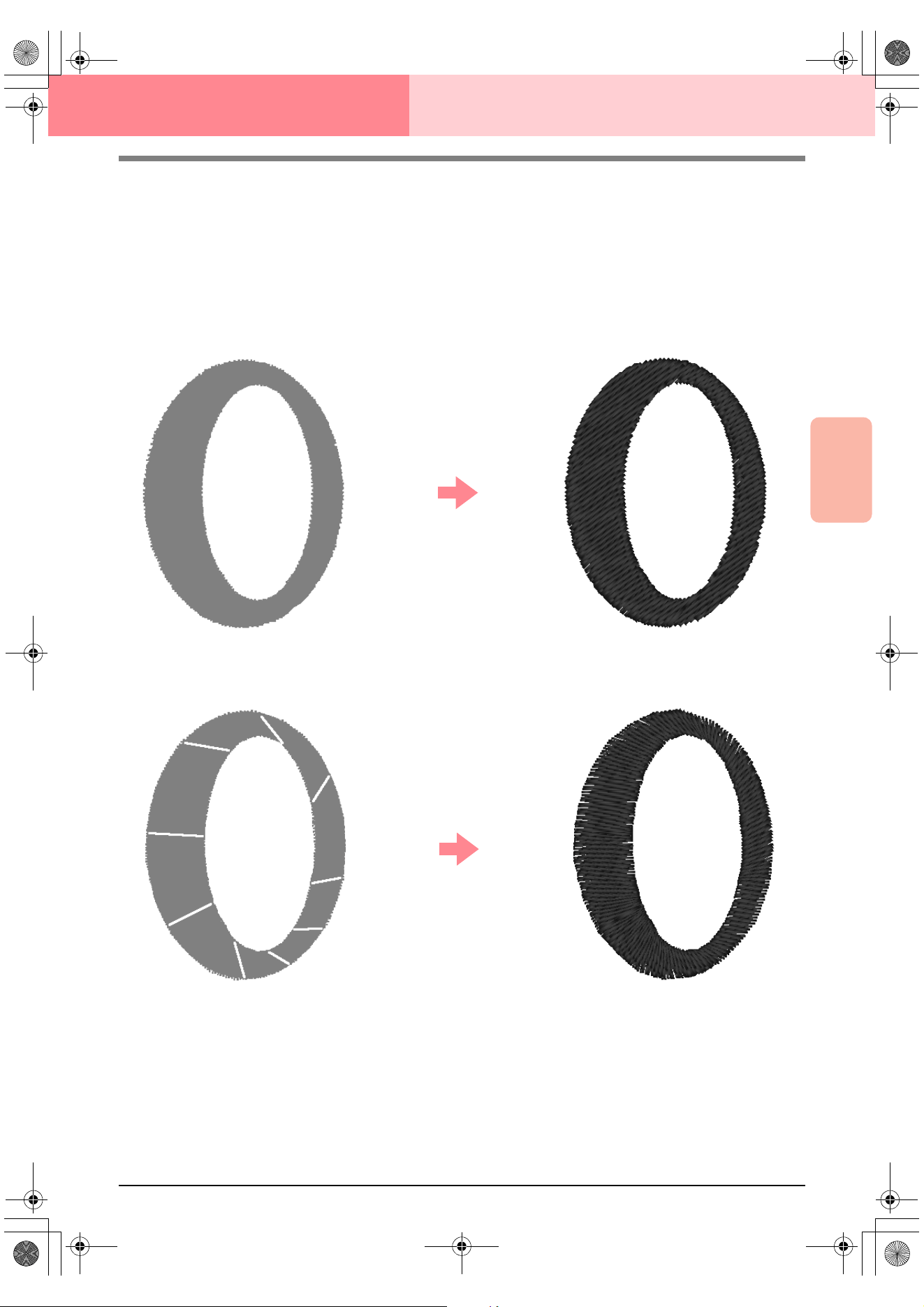
Advanced Opreation
Layout & Editing
151
Layout & Editing Editing Embroidery Patterns
Creating Manual Punching Data
The Manual Punch tools are used to create patterns that look like manual embroidery. With manual punching,
you can create data with any sewing order, direction and orientation that you want.
Letters that you design yourself constitute a typical example of patterns that look better using manual punching
patterns. The illustrations below show two previews of the letter “O”.
The one shown below has been designed using two concentric ovals without a line sewing attribute, filling the
larger oval with the fill stitch, and turning off the region sewing attribute inside the small oval. The pair was then
set for hole sewing.
The letter shown below has been drawn using the Manual Punch tools. To do this, we duplicated the letter
shown above, removed the inside region, and created a manual punching pattern using the outlines of the
ovals as guides. The ovals were then deleted.
The stitch density for both letters was set to a minimum in order to make it easier to see the difference between
the two patterns on the preview display.
When creating a manual punching pattern, it is easier to use an image in the background as a guide. In the
above example, we used two ovals that we removed after completing the manual punching pattern.
Fill stitch
(The stitching has a constant direction.)
Manual punching
(The direction of the stitching follows the curve.)
PeDesignV6Eng.book Page 151 Thursday, July 8, 2004 11:59 AM
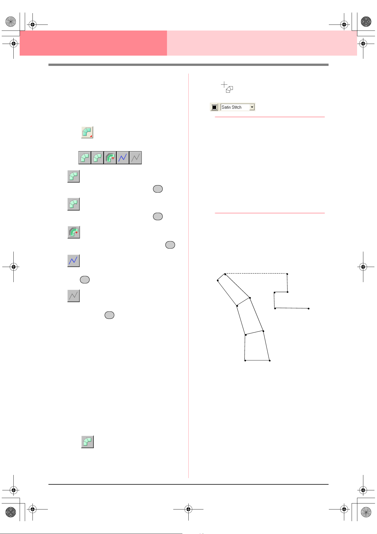
152
Layout & Editing Editing Embroidery Patterns
Another possibility is to load a template image and
redraw it using manual punching patterns. The
advantage of this method is that you have a better
control on the thread orientation.
1. Open a template or prepare an image that you
will use as a guide.
2. Click on the Tool Box.
→ Five buttons appear:
is for creating straight block-type
punching patterns. (Shortcut key: )
is for creating curved block-type
punching patterns. (Shortcut key: )
is for semi-automatically creating block-
type punching patterns. (Shortcut key: )
is for creating running-type punching
patterns (the broken line is sewn). (Shortcut
key: )
is for creating feed-type punching
patterns (the broken line is not sewn).
(Shortcut key: )
While creating a manual punching pattern,
you can alternate between the various types.
For example, you can start with a straight
block-type pattern, then switch to a running-
type pattern (to draw an outline of the block-
type pattern), then switch to the feed type to
move to the beginning of the next block-type
pattern. The whole pattern, consisting of
different types of punching patterns, will be
considered a single object (all parts will have
the same sew type and color).
In this example, we start with a straight block-
type pattern, use the feed-type pattern to
move the pointer, and then create a running-
type pattern.
3. Click to start creating a straight block-
type pattern.
→ The shape of the pointer changes to
, and the Sewing Attributes bar ap-
pears similar to the one shown below.
b Memo:
• You can change the color and sew type
either before or after creating the pattern.
For more details on changing these
settings, refer to “Color” on page 169 and
“Sew type” on page 170.
• You can also use the settings in the
Sewing Attribute Setting
dialog box to
define other attributes of the pattern. (For
more details, refer to “Specifying sewing
attributes” on page 171.) If you do not
change these settings at this time, the
current settings will be applied, however
you can modify them later.
4. Click in the Design Page to specify point 1
(start point).
5. Refer to the illustration below, and click in the
Design Page to specify points 2 through 8.
!!btn59.bmp!!
Z
X
C
V
B
1
2
3
4
5
6
7
8
9
10
11
12
13
PeDesignV6Eng.book Page 152 Thursday, July 8, 2004 11:59 AM
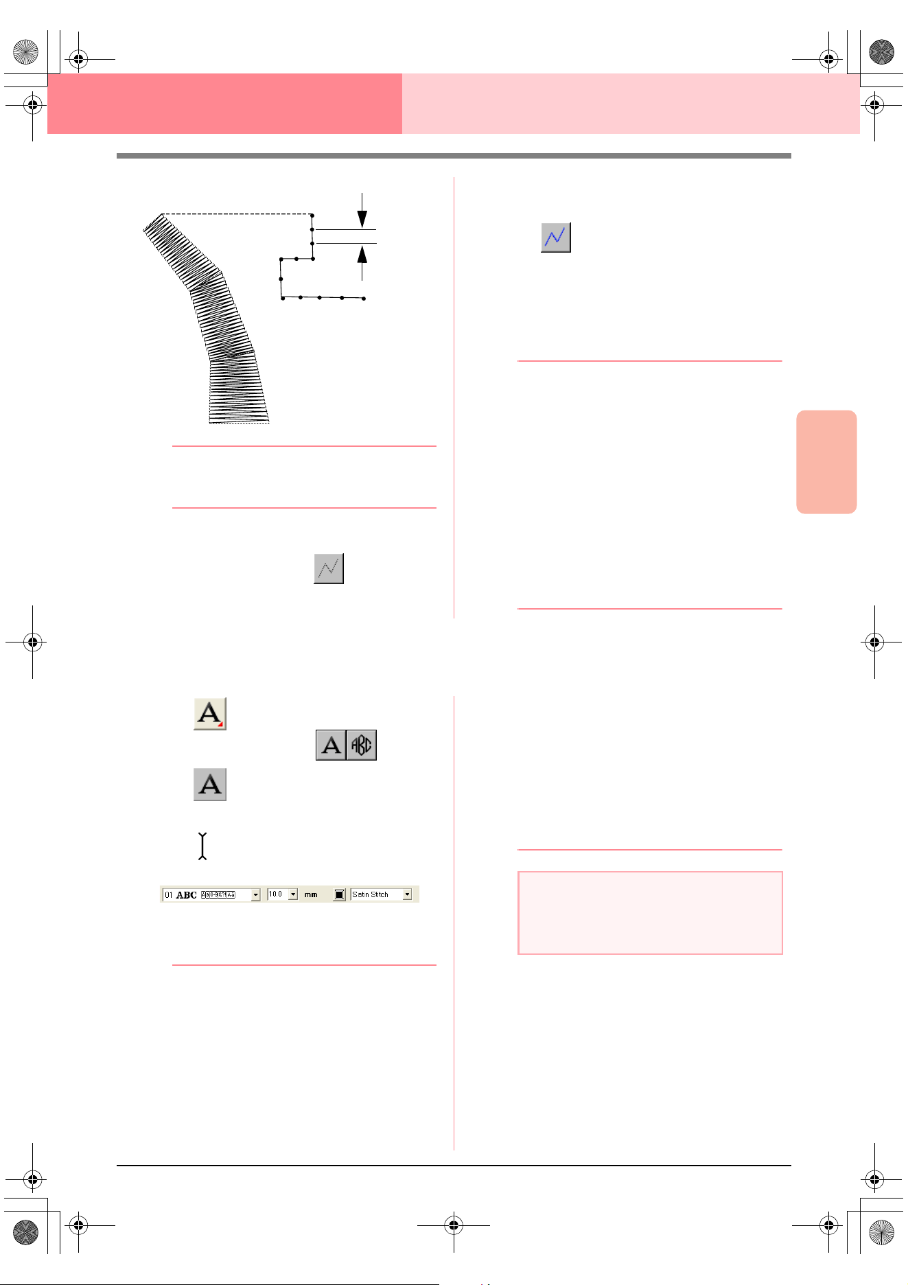
Advanced Opreation
Layout & Editing
153
Layout & Editing Editing Embroidery Patterns
b Memo:
To remove the last point that was entered,
click the right mouse button.
6. After clicking point 8 (the last point of the
block-type pattern), click (feed-type
pattern button), and then in the Design Page
to specify point 9 (the start point of the
running-type pattern).
7. Click (running-type pattern button), and
then click in the Design Page to specify points
10, 11, and 12, as shown in the above
illustration.
8. To complete the pattern, double-click point 13
(the last point of the entire pattern).
b Memo:
• When entering points, change the punch
type by pressing the appropriate shortcut
key.
• A template image is needed in order to use
the semi-automatic block-type punch tool.
If there is no image, this tool will create a
punching pattern like the straight block-
type punch tool.
• Once the pattern is drawn, you can still
transform straight block-type patterns into
curved block-type patterns and vice versa.
For details, refer to “Transforming straight
lines into curves or curves into straight
lines” on page 137.
Entering Text
1. Click on the Tool Box.
→ Two buttons appear: .
2. Click .
→ The shape of the pointer changes to
, and the Sewing Attributes bar ap-
pears similar to the one shown below.
3. If necessary, change the font, text size, color
and sew type.
b Memo:
• You can change the font, text size, color,
and sew type either before or after creating
the text. For more details on changing
these settings, refer to “Font” on page 154,
“Text Size” on page 156, “Color” on
page 169 and “Sew type” on page 170.
• You can also use the settings in the
Sewing Attribute Setting
dialog box and
the
Text Attribute Setting
dialog box to
define other attributes of the text. (For
more details, refer to “Specifying sewing
attributes” on page 171 and “Specifying
text attributes” on page 157.) If you do not
change these settings at this time, the
current settings will be applied, however
you can modify them later.
4. Click in the Design Page where you want the
text to appear.
→ The Edit Text Letters dialog box ap-
pears, containing a chart with all charac-
ters available with the selected font.
1
2
3
4
5
6
7
8
9
10
11
12
13
Run pitch
a Note:
• If one of the fonts provided with this
application (01 to 35) is selected, the line
sewing attributes cannot be changed.
PeDesignV6Eng.book Page 153 Thursday, July 8, 2004 11:59 AM
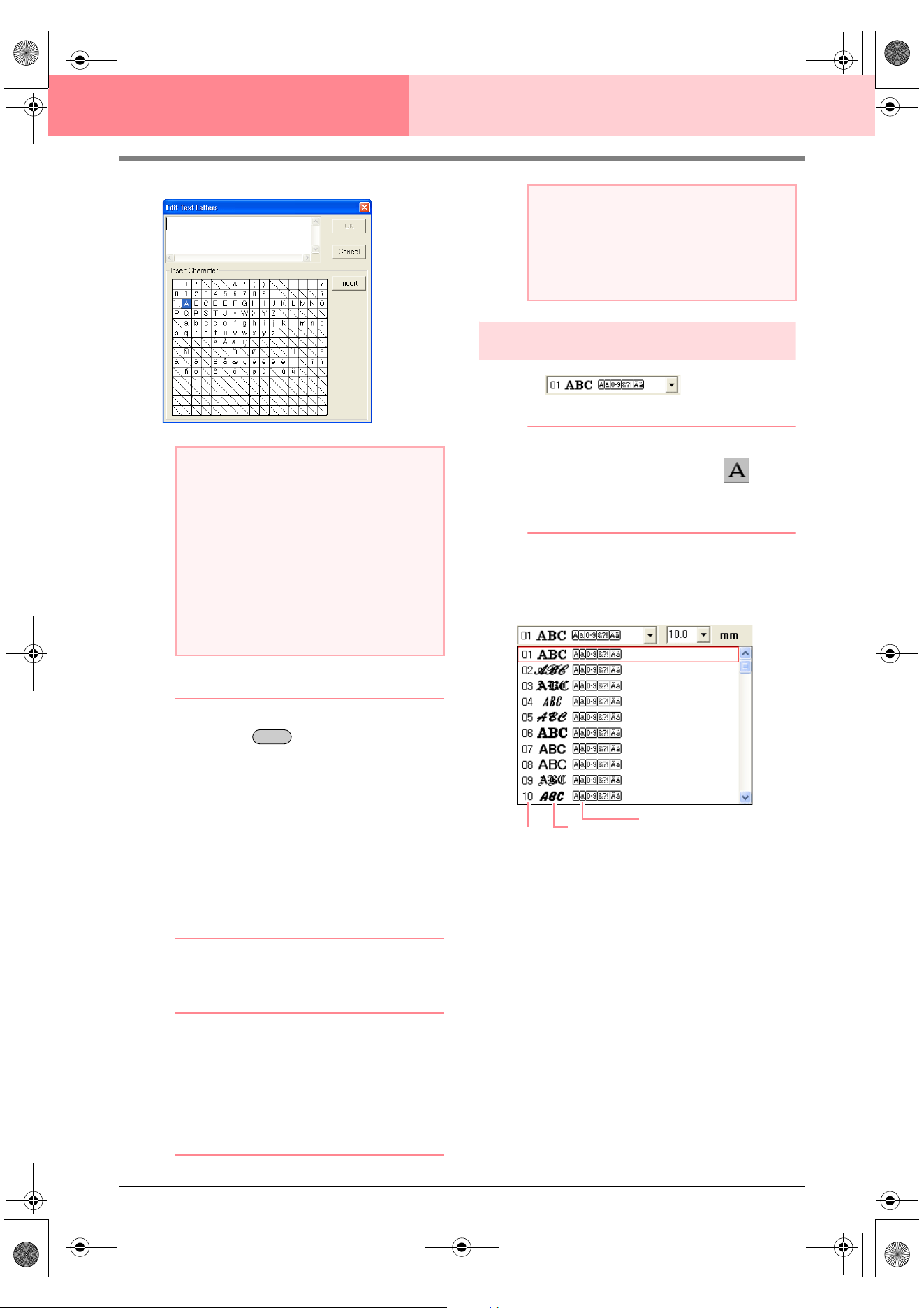
154
Layout & Editing Editing Embroidery Patterns
5. Type the text.
b Memo:
• Press the key to enter a new line
of text.
• You can also enter a character by
selecting it in the character table, then
clicking
Insert
, or simply by double-
clicking it. This is particularly useful if you
have to enter accented characters that are
not available on your keyboard.
• An enlarged image of the character
appears below the pointer when it is
moved over a character in the character
table, providing a better view of the
character.
6. Click OK.
→ The text is displayed in the Design Page.
b Memo:
• To quit the operation, click Cancel.
• If you want to edit the entered text,
select it, and then select the menu
command Text – Edit Letters. Edit the
text in the Edit Text Letters dialog box
that appears. (For more details, refer to
“Editing entered text” on page 156.)
Specifying text attributes
■ Font
Use this selector to select a font for the text.
b Memo:
The
Font
selector appears when on the
Tool Box is selected. It also appears when
text or a character in the Design Page has
been selected.
1. Click in the Font selector.
→ A list of fonts appears.
2. Click the desired font.
→ The setting is applied to all text patterns
that you will create, until the setting is
changed.
→ If text patterns or characters in a text pat-
tern were selected, the setting is also ap-
plied to the selected text.
a Note:
Text created using certain TrueType fonts
may not be converted correctly into an
embroidery pattern due to the shape of the
character. These characters cannot be
embroidered correctly. Before sewing your
project, embroider a trial piece of fabric.
In addition, text created using some
TrueType fonts cannot be converted at all. In
this case, the area containing the converted
text will be empty or a warning message will
appear.
Enter
a Note:
If you entered a character that is not
available for the selected font, an error
message appears. Click
OK
to close the
message and return to the
Edit Text
Letters
dialog box, where you can correct the text.
Font
Font sample
Types of characters
number
available
PeDesignV6Eng.book Page 154 Thursday, July 8, 2004 11:59 AM
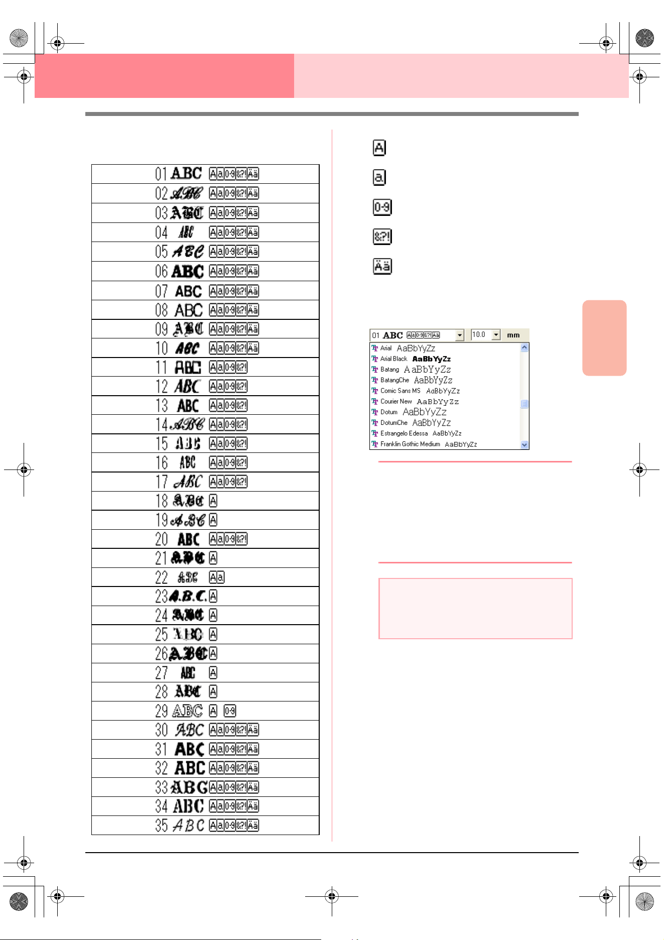
Advanced Opreation
Layout & Editing
155
Layout & Editing Editing Embroidery Patterns
The available fonts and the types of
characters available with each font are listed
below.
The names and samples of installed TrueType
fonts appear after the fonts listed in the table
above.
b Memo:
TrueType font settings can be changed in the
TrueType Font Attribute Setting
dialog
box, which is displayed by clicking the menu
command
Text
–
TrueType Font Attribute
Setting
. For more details, refer to
“Specifying TrueType text attributes” on
page 161.
c
“Entering Text” on page 153, “Editing
Points in Embroidery Patterns” on
page 135 and “Specifying TrueType text
attributes” on page 161
Uppercase letters of the English
alphabet
Lowercase letters of the English
alphabet
Numerals
Punctuation marks, brackets and
other symbols
Uppercase and lowercase accented
letters
a Note:
Some TrueType fonts may not convert well
into clean embroidery patterns due to their
design and shape.
PeDesignV6Eng.book Page 155 Thursday, July 8, 2004 11:59 AM
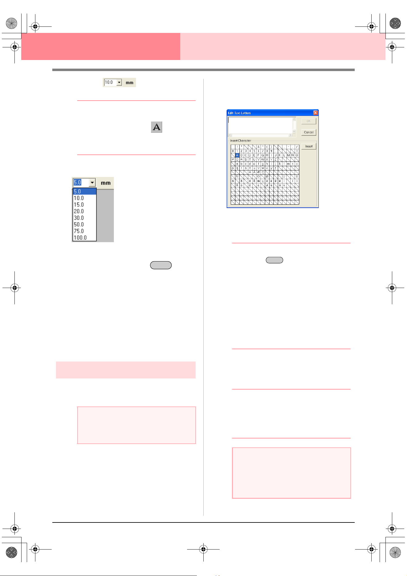
156
Layout & Editing Editing Embroidery Patterns
■ Text Size
Use this selector to select the size of the text.
b Memo:
The
Text Size
selector appears in the
Sewing Attributes bar when on the Tool
Box is selected. It also appears when text or
a character in the Design Page has been
selected.
1. Click in the Text Size selector.
2. Type the desired height (5 to 100 mm (0.20 to
3.93 inches)) and press the key, or
click the desired value.
→ The setting is applied to all text patterns
that you will create, until the setting is
changed.
→ If text patterns or characters in a text pat-
tern were selected, the setting is also ap-
plied to the selected text.
c
“Entering Text” on page 153 and “Editing
Points in Embroidery Patterns” on
page 135
Editing entered text
Text that has been entered can easily be edited.
1. Select the text that you want to edit.
2. Click Text, then Edit Letters.
→ The Edit Text Letters dialog box ap-
pears.
3. The selected text is displayed in the text field.
4. Edit the text as needed.
b Memo:
• Press the key to enter a new line
of text.
• You can also enter a character by
selecting it in the character table, then
clicking
Insert
, or simply by double-
clicking it. This is particularly useful if you
have to enter accented characters that are
not available on your keyboard.
• An enlarged image of the character
appears below the pointer when it is
moved over a character in the character
table, providing a better view of the
character.
5. Click OK.
→ The edited text is displayed in the Design
Page.
b Memo:
• To close the dialog box without applying
the changes, click
Cancel
.
• If text converted from a TrueType font is
selected, the list of characters displayed is
for the font of the first letter in the text.
c
“Entering Text” on page 153
a Note:
You cannot edit more than one text pattern
at a time. If you select more than one text
pattern, this menu command is not available.
Enter
a Note:
If you entered a character that is not
available for the selected font, an error
message appears. Click
OK
to close the
message and return to the
Edit Text
Letters
dialog box, where you can correct the text.
Enter
PeDesignV6Eng.book Page 156 Thursday, July 8, 2004 11:59 AM
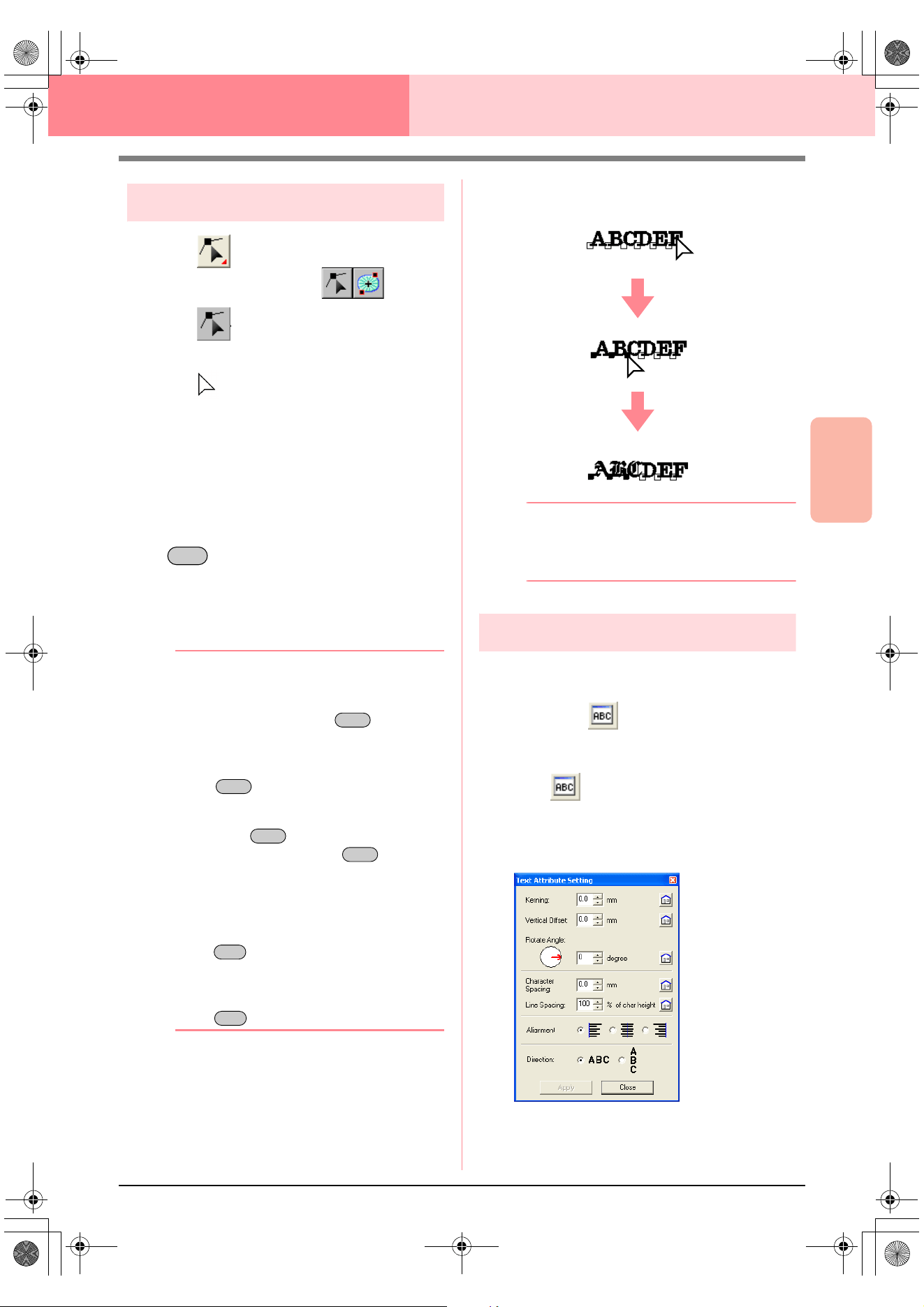
Advanced Opreation
Layout & Editing
157
Layout & Editing Editing Embroidery Patterns
Selecting characters
1. Click on the Tool Box.
→ Two buttons appear:
2. Click .
→ The shape of the pointer changes to
.
3. Click the text that you want to edit.
→ The points in the text appear as small
empty squares.
4. To select a single character, click the point for
the character that you want to select.
To select multiple characters, hold down the
key and click each point for the other
characters, or drag the pointer over the
characters that you want to select.
→ The points for the selected characters ap-
pear as a small black squares.
b Memo:
• To select all characters between the
selected character and the next character
selected, hold down the key while
clicking the next character.
• To select an additional character in the
direction of the last character, hold down
the key and press the
→
or
↓
key. To select an additional character in
the direction of the first character, hold
down the key and press the
←
or
↑
key. Holding down the key and
pressing the opposite arrow key deselects
the character.
• To deselect the current character and
select the following character in the
direction of the last character, hold down
the key and press the
→
or
↓
key.
To deselect the current character and
select the following character in the
direction of the first character, hold down
the key and press the
←
or
↑
key.
5. Change the font, size, color, sew type and
other attributes.
b Memo:
With TrueType fonts, the outline can be set
to be sewn or not, and settings can be
selected for the color and sew type.
Specifying text attributes
Various character attributes for text can be set in the
Text Attribute Setting dialog box.
Toolbar button:
1. Select the text that you want to edit.
2. Click , or click Text, then Text Attribute
Setting.
→ The Text Attribute Setting dialog box
appears.
!btn29
.
Ctrl
Shift
Shift
Shift
Shift
Ctrl
Ctrl
PeDesignV6Eng.book Page 157 Thursday, July 8, 2004 11:59 AM
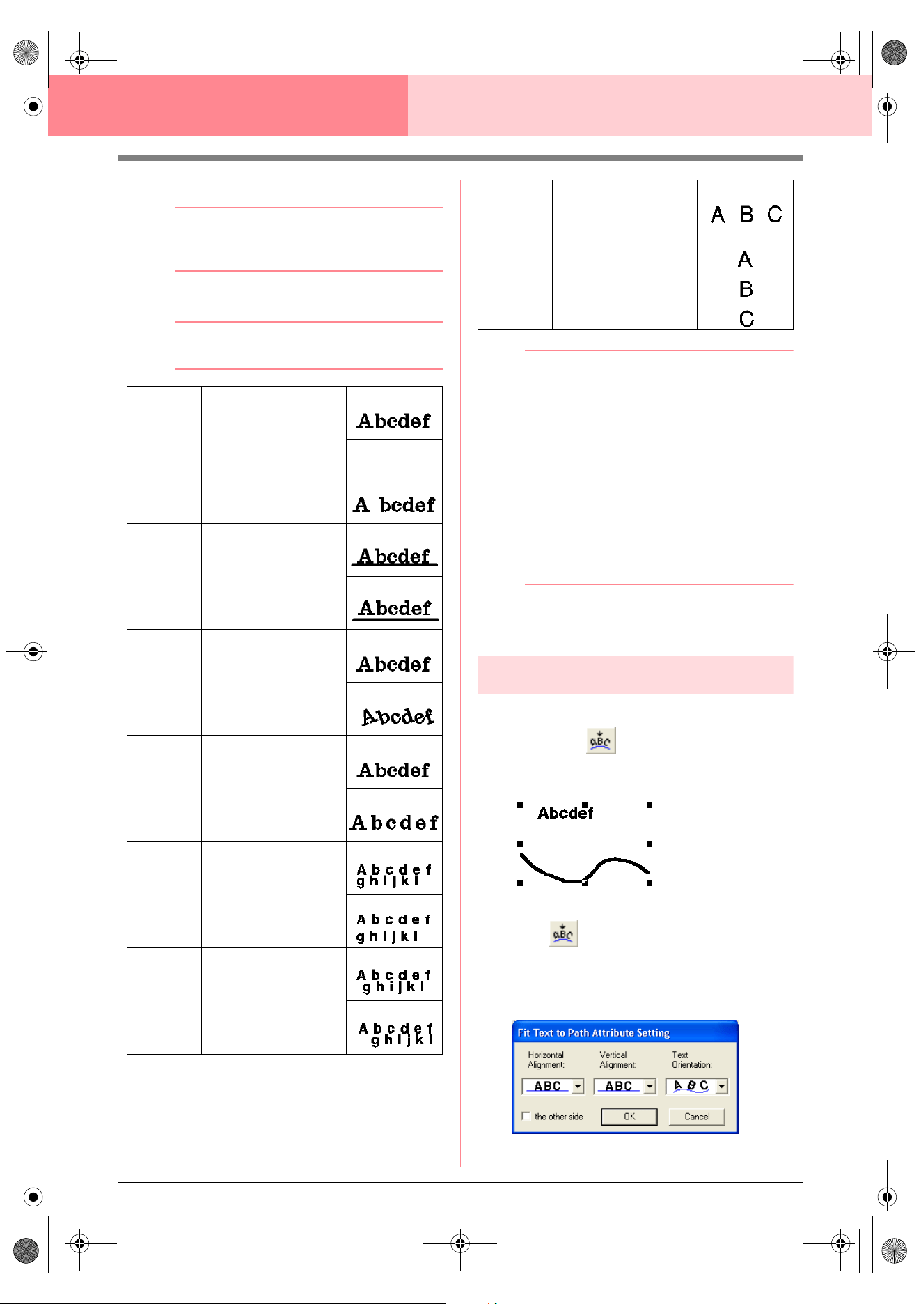
158
Layout & Editing Editing Embroidery Patterns
3. If necessary, change the text attributes.
b Memo:
To return a parameter to its default setting,
click
Default
beside it.
4. Click Apply to confirm the effect of the setting.
b Memo:
To close the dialog box, click
Close
.
b Memo:
• Vertical text will be displayed in vertically
on the Design Page.
• Both
Kerning
and
Character Spacing
set
the spacing between characters.
Character Spacing
is always applied to
the entire text pattern, while
Kerning
can
be applied to individual characters.
Applying
Kerning
to the entire text in the
pattern is the same as specifying
Character Spacing
. Refer to “Selecting
characters” on page 157 for more details
about selecting individual characters in a
text pattern.
c
“Specifying text arrangement” below and
“Transforming text” on page 160
Specifying text arrangement
A line of text can be arranged along a path.
Toolbar button:
1. Select the text and a path.
2. Click , or click Text, then Fit Text to
Path Setting.
→ The Fit Text to Path Attribute Setting di-
alog box appears.
Kerning
Sets the spacing
between individual
characters.
Range: -100 to 100 mm
(-3.94 to 3.94 inches)
Default: 0
0.0 mm
5.0 mm
(between “A”
and “b”)
Vertical
Offset
Moves the text vertically.
Range: -100 to 100 mm
(-3.94 to 3.94 inches)
Default: 0
0.0 mm
2.0 mm
Rotate
angle
Rotates the characters.
Range: 0 to 359 degrees
Default: 0
0 degree
20 degrees
Character
Spacing
Sets the spacing
between all characters.
Range: -100 to 100 mm
(-3.94 to 3.94 inches)
Default: 0
0.0 mm
2.0 mm
Line
Spacing
Sets the spacing
between lines as a per-
centage of the character
height.
Range: 0–1000%
Default: 0
100%
150%
Alignment
Aligns several lines of text
to the left, center or right.
Center
Right
Direction
Specifies whether
characters will be
positioned horizontally
or vertically.
Horizontal
Ver tical
PeDesignV6Eng.book Page 158 Thursday, July 8, 2004 11:59 AM
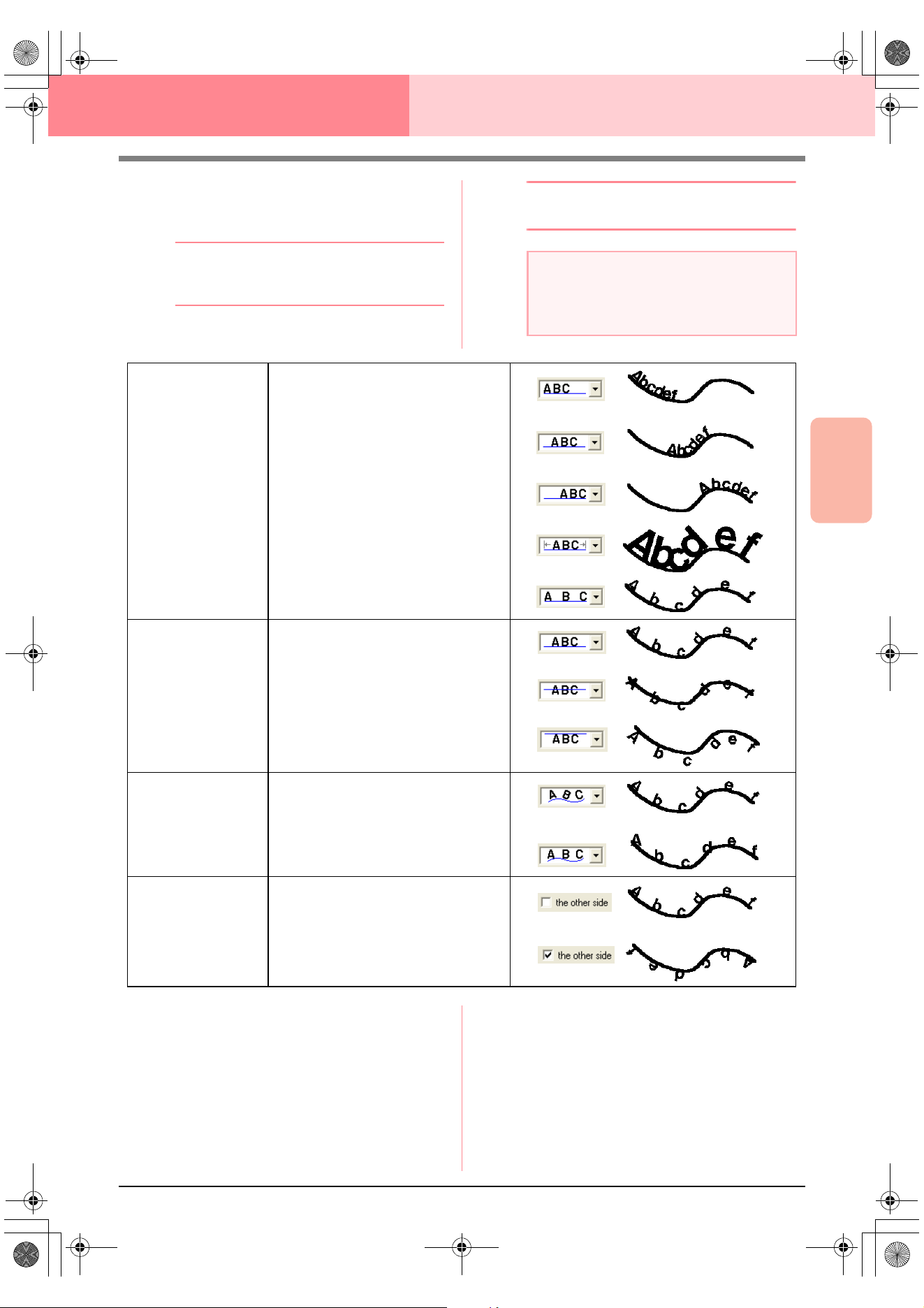
Advanced Opreation
Layout & Editing
159
Layout & Editing Editing Embroidery Patterns
3. From the Horizontal Alignment, Vertical
Alignment and Text Orientation selectors,
select the desired settings.
b Memo:
To position the text on the other side of the
path, select
the other side
check box.
4. Click OK to apply the settings.
b Memo:
To quit the operation, click
Cancel
.
c
“Canceling text arrangement” on
page 160
a Note:
When text arrangement is specified, the text
transformation is cancelled. Only one string of
text can be arranged on a single path.
Horizontal Alignment
Sets the distribution of characters along
the path.
Vertical Alignment
Sets the distance between the text and
the path.
Text Orientation
Sets the orientation of the characters
relative to the path.
The other side Reverses the characters.
PeDesignV6Eng.book Page 159 Thursday, July 8, 2004 11:59 AM
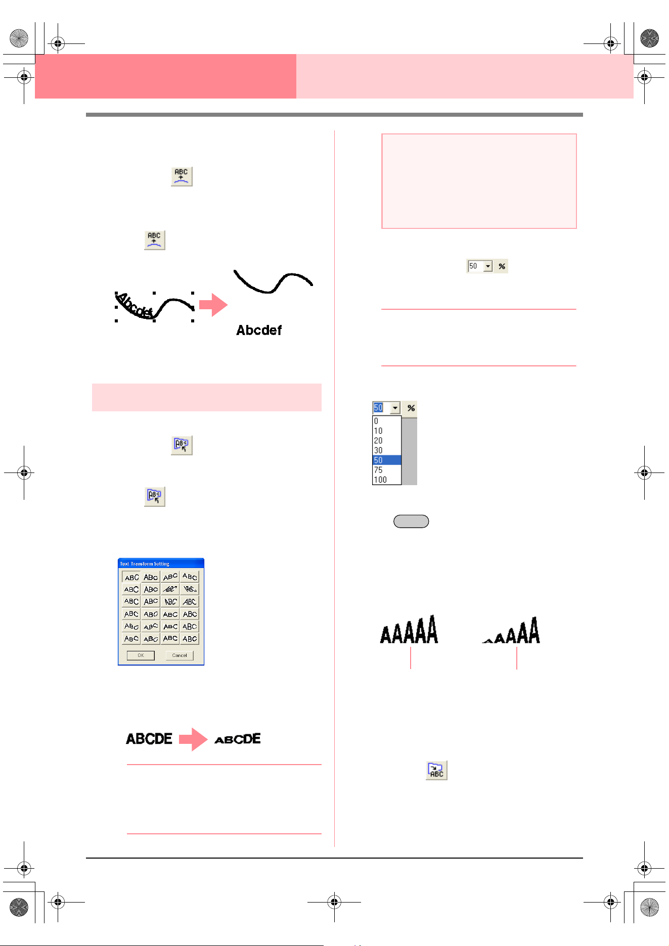
160
Layout & Editing Editing Embroidery Patterns
■ Canceling text arrangement
The text arrangement on a path can be cancelled.
Toolbar button:
1. Select text that is arranged on a path (Fit to
Path).
2. Click , or click Text, then Release Text
from Path.
c
“Specifying text arrangement” on
page 158
Transforming text
A preset transform shape can be applied to text.
Toolbar button:
1. Select the text that you want to transform.
2. Click , or click Text, then Transform
Text.
→ The Text Transform Setting dialog box
appears.
3. Select the desired transformation shape, and
then click OK, or double-click the shape to
apply the transformation.
b Memo:
• To quit the operation, click
Cancel
.
• If necessary, set the level of
transformation. For details, refer to
“Transform level” on this page.
c
“Canceling text transformation” below
■ Transform level
Use this selector to select the level of
transformation.
b Memo:
The
Transform level
selector appears in the
Sewing Attributes bar when transformed text
in the Design Page has been selected.
1. Click in the Transform level selector
2. Type the desired value (0 to 100%) and press
the key, or click the desired value.
→ The setting is applied to all transformed
text patterns that you will create, until the
setting is changed.
→ If a text pattern was selected, the setting
is applied to the selected text.
c
“Entering Text” on page 153 and
“Transforming text” on this page
■ Canceling text transformation
The original shape of the text can be restored.
Toolbar button:
1. Select the transformed text.
a Note:
A text pattern created from a TrueType font
contains data for both line and region
sewing. Therefore, if this command is
selected, depending on the form of the
TrueType font, there may be a gap between
the line and the region in the text.
Enter
50%
100%
PeDesignV6Eng.book Page 160 Thursday, July 8, 2004 11:59 AM
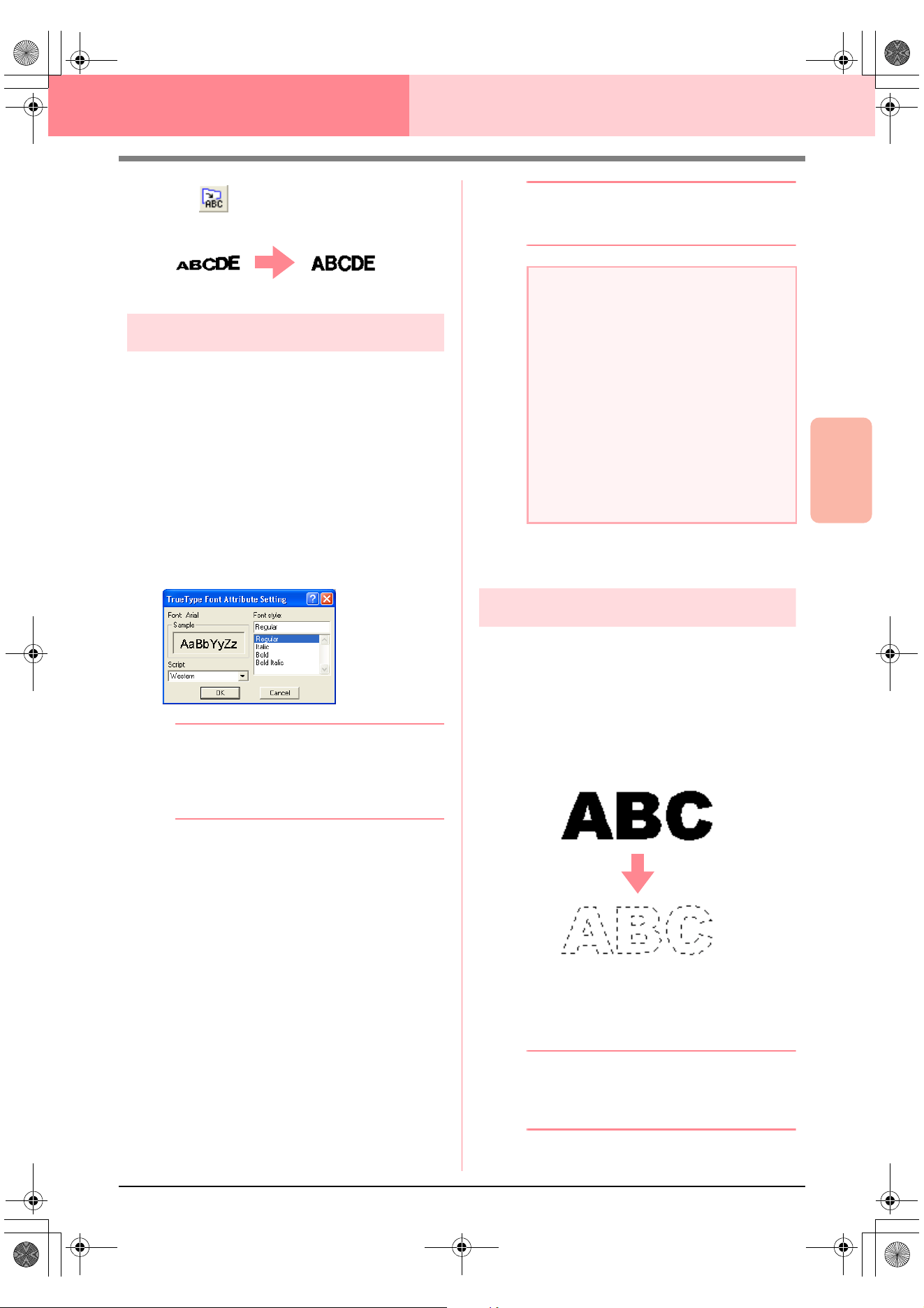
Advanced Opreation
Layout & Editing
161
Layout & Editing Editing Embroidery Patterns
2. Click , or click Text, then Clear
Transformation.
Specifying TrueType text attributes
Various character attributes, such as the style, can
be specified for TrueType fonts converted to an
embroidery pattern.
1. Select the TrueType text that you want to edit.
2. Click Text, then TrueType Font Attribute
Setting.
→ A dialog box similar to the one shown be-
low appears. If any characters converted
from a TrueType font are selected, the at-
tributes for the selected characters are
displayed.
b Memo:
• The name of the selected font appears
beside
Font
.
•The
Sample
box shows a sample of the
font with the selected attributes.
3. To change the font style, select the desired
style from the Font Style list.
4. To change the character set for the font, select
the desired character set from the Script
selector.
5. Click OK to set the attributes and to close the
dialog box.
→ The attribute settings are applied to all
text patterns that you will create from a
TrueType font, until the setting is
changed.
→ If a text pattern converted from a True-
Type font was selected, the attribute set-
tings are also applied to the selected text.
b Memo:
To close the dialog box without changing any
settings, click
Cancel
.
c
“Entering Text” on page 153 and
“Specifying text attributes” on page 157
Converting text to outline data
Outline data can be created from text converted to a
TrueType font.
1. Select the text pattern that has been
converted to a TrueType font.
2. Click Text, then Convert to Outline Object.
→ The selected text pattern is converted to
outlines.
No sewing attributes are specified for the
converted outline; therefore, it appears as
dotted lines. Specify the sewing attributes
as necessary.
b Memo:
In order to prevent the pattern from losing its
shape, group the objects or specify hole
sewing.
a Note:
• The settings for
Font Style
and
Script
differ depending on the TrueType font that
is selected.
• If text created from multiple TrueType
fonts is selected, this command is not
available.
In addition, if text of the same font but
different font styles or scripts is selected,
this dialog box appears with the attribute
settings for the first letter in the text.
In either case mentioned above, selecting
only one character from within text
displays a dialog box containing only that
character’s attributes.
PeDesignV6Eng.book Page 161 Thursday, July 8, 2004 11:59 AM
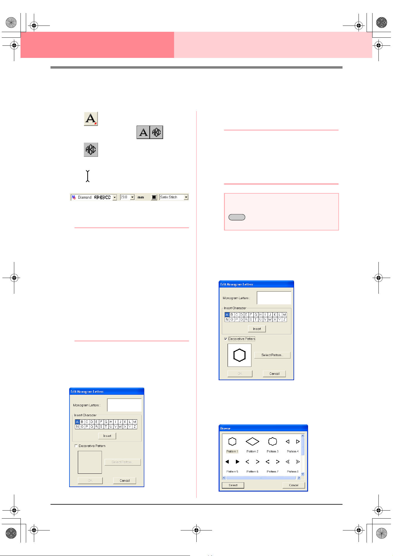
162
Layout & Editing Editing Embroidery Patterns
Entering Monograms
The monogram function allows you to create monograms composed of one to three uppercase letters and
arrange a decorative pattern around them.
1. Click on the Tool Box.
→ Two buttons appear: .
2. Click .
→ The shape of the pointer changes to
, and the Sewing Attributes bar ap-
pears similar to the one shown below.
3. If necessary, change the font, text size, color
and sew type.
b Memo:
• You can change the font, text size, color,
and sew type either before or after creating
the monogram. For more details on
changing these settings, refer to
“Monogram Font” on page 163,
“Monogram Size” on page 163, “Color” on
page 169 and “Sew type” on page 170.
• You can also use the settings in the
Sewing Attribute Setting
dialog box to
define other attributes of the monogram.
(For more details, refer to “Specifying
sewing attributes” on page 171.) If you do
not change these settings at this time, the
current settings will be applied, however
you can modify them later.
4. Click in the Design Page where you want the
monogram to appear.
→ The Edit Monogram Letters dialog box
appears.
5. Type the monogram text (uppercase
characters).
b Memo:
• You can also enter a character by
selecting it in the character table, then
clicking
Insert
, or simply by double-
clicking it.
• You can enter up to three uppercase
characters with the monogram function.
6. To add a decorative pattern around or at the
sides of the monogram, select the Decorative
Pattern check box.
→ The currently selected pattern appears in
the preview window.
7. To change the decorative pattern, click Select
Pattern.
→ The Browse dialog box appears. The
new decorative pattern can be selected.
a Note:
You cannot insert line feeds. If you press the
key, the dialog closes and the
monogram is displayed in the Design Page.
Enter
PeDesignV6Eng.book Page 162 Thursday, July 8, 2004 11:59 AM
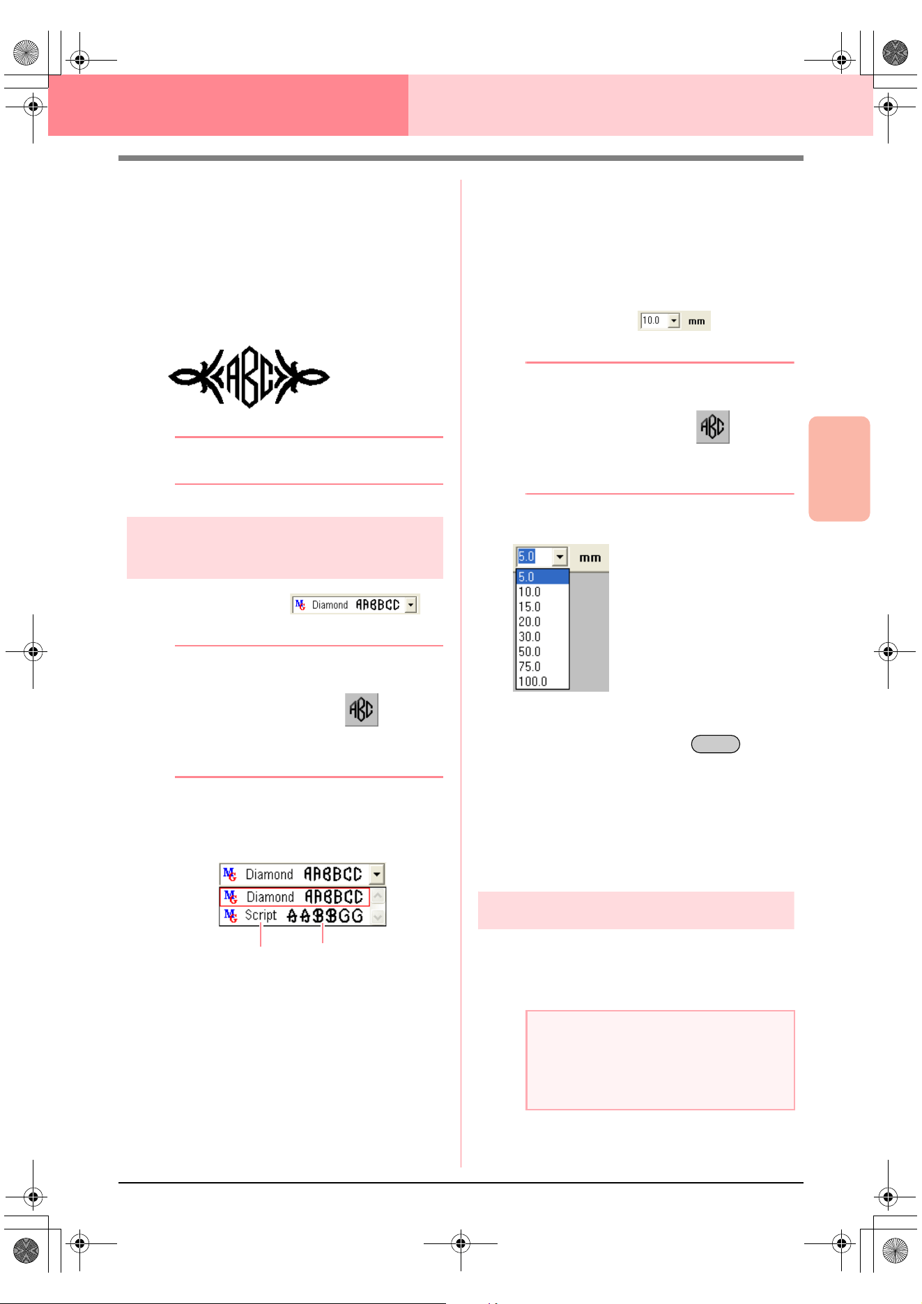
Advanced Opreation
Layout & Editing
163
Layout & Editing Editing Embroidery Patterns
8. Click a decorative pattern to select it, and then
click Select (or double-click the pattern) to
close the Browse dialog box and display the
pattern in the preview window.
9. After selecting the desired settings, click OK.
→ The monogram is displayed in the Design
Page with the selected decorative pattern.
b Memo:
To quit the operation, click
Cancel
.
Specifying monogram
attributes
■ Monogram Font
Use this selector to select a font for the monograms.
b Memo:
The
Monogram Font
selector appears in the
Sewing Attributes bar when on the
Tool Box is selected. It also appears when a
monogram in the Design Page has been
selected.
1. Click in the Font selector.
→ A list of monogram fonts appears.
2. Click the desired font.
→ The setting is applied to all monogram
patterns that you will create, until the set-
ting is changed.
→ If a monogram was selected, the setting is
also applied to the selected monogram.
■ Monogram Size
Use this selector to select the size of the monogram.
b Memo:
The
Monogram Size
selector appears in the
Sewing Attributes bar when on the
Tool Box is selected. It also appears when a
monogram in the Design Page has been
selected.
1. Click in the Monogram Size selector.
2. Type the desired height (5 to 100 mm (0.20 to
3.93 inches)) and press the key, or
click the desired value.
→ The setting is applied to all text patterns
that you will create, until the setting is
changed.
→ If a monogram was selected, the setting is
also applied to the selected monogram.
Editing monograms
A monogram that has been entered can easily be
edited.
1. Select the monogram that you want to edit.
!!sew37.bmp!!
Monogram font
Monogram font sample
name
a Note:
You cannot edit more than one monogram at
a time. If you select more than one
monogram, this menu command is not
available.
Enter
PeDesignV6Eng.book Page 163 Thursday, July 8, 2004 11:59 AM
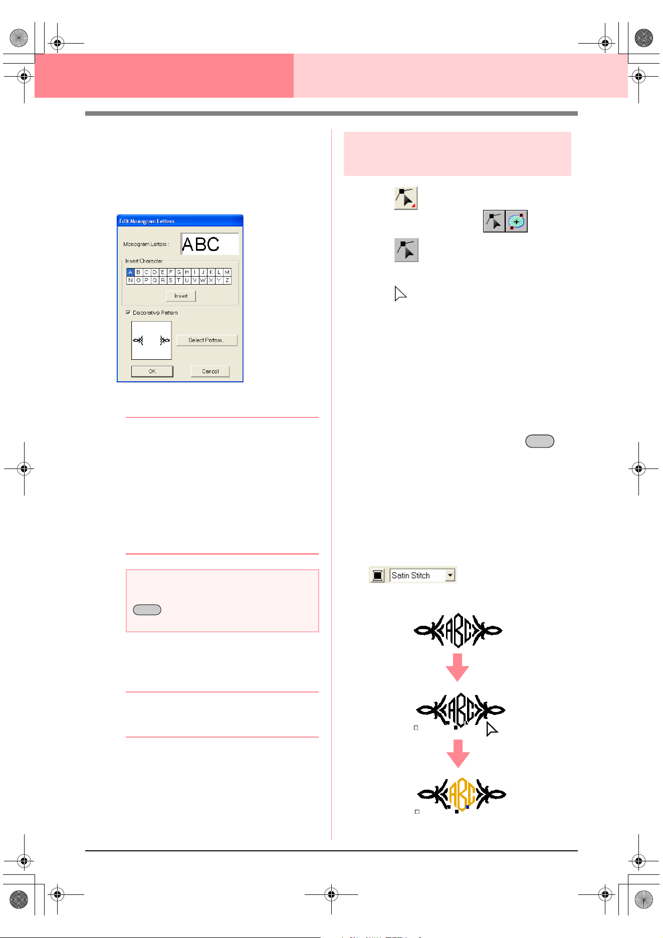
164
Layout & Editing Editing Embroidery Patterns
2. Click Text, then Edit Letters.
→ The Edit Monogram Letters dialog box
appears, where the characters of the se-
lected monogram are displayed in the text
field and the selected decorative pattern
is displayed in the preview window.
3. Edit the text as needed.
b Memo:
• You can also enter a character by
selecting it in the character table, then
clicking
Insert
, or simply by double-
clicking it.
• To change the decorative pattern, click
Select Pattern
, and then select the new
pattern in the
Browse
dialog box that
appeared.
• To remove the decorative pattern, clear
the
Decoration
check box.
4. Click OK.
→ The edited monogram is displayed in the
Design Page.
b Memo:
• To close the dialog box without applying
the changes, click
Cancel
.
c
“Entering Monograms” on page 162
Editing monogram characters
and the decorative pattern
1. Click on the Tool Box.
→ Two buttons appear: .
2. Click .
→ The shape of the pointer changes to
.
3. Click the monogram that you want to edit.
→ The points in the monogram appear as
small empty squares.
4. To select a single character or the decorative
pattern, click the point for the character that
you want to select or for the decorative
pattern.
To select multiple characters and the
decorative pattern, hold down the
key and click each point for the other
characters or decorative pattern, or drag the
pointer over the characters or the decorative
pattern that you want to select.
→ The points for the selected characters or
decorative pattern appear as a small
black squares, and the Sewing Attributes
bar appears similar to the one shown be-
low.
5. Change the color or sew type.
a Note:
You cannot insert line feeds. If you press the
key, the dialog closes and the
monogram is displayed in the Design Page.
Enter
Ctrl
Advanced_02.fm Page 164 Friday, July 9, 2004 1:50 PM
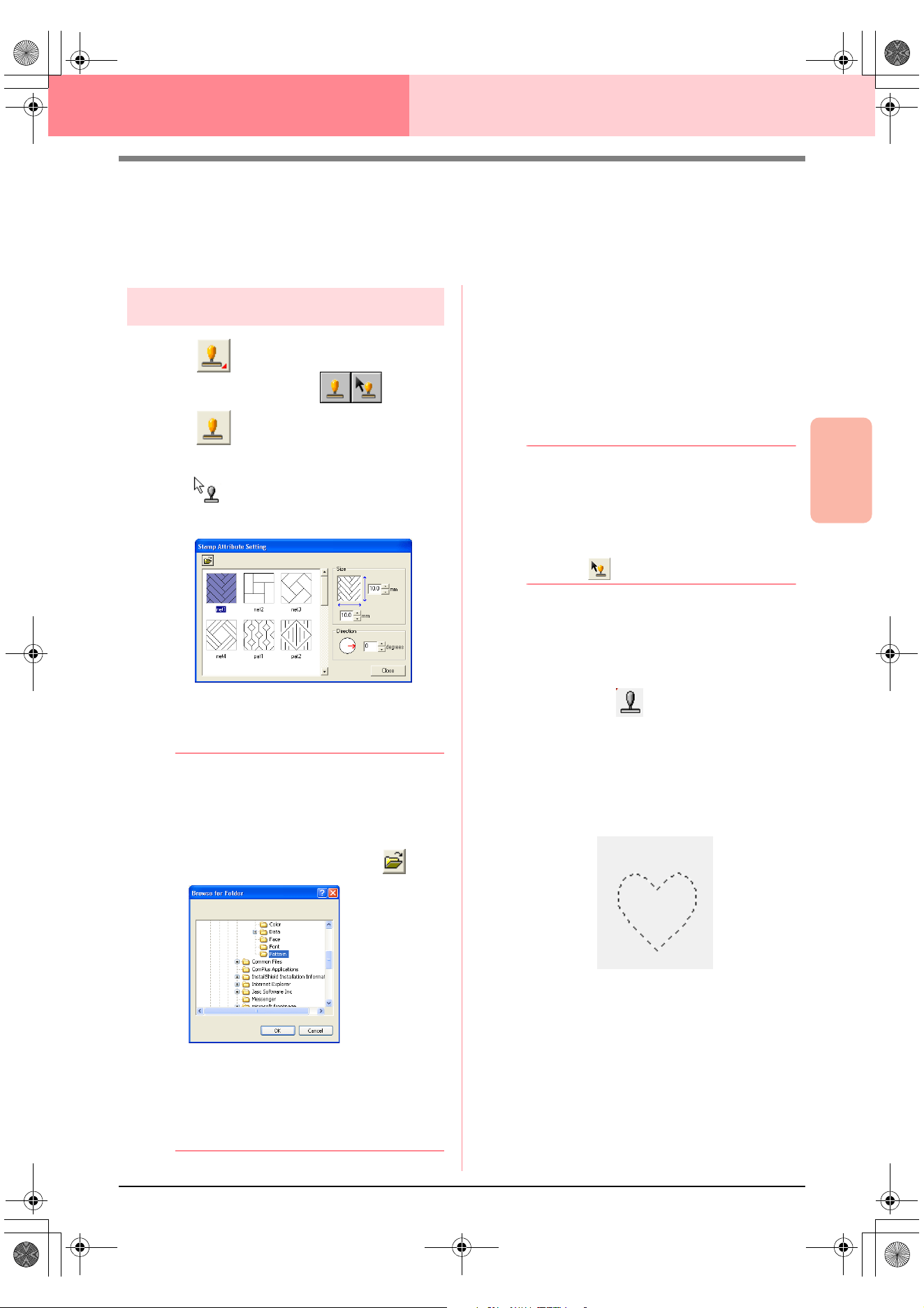
Advanced Opreation
Layout & Editing
165
Layout & Editing Editing Embroidery Patterns
Applying and Editing Stamps
Stamps can be applied to regions of objects drawn with the Circle or Arc tool, Rectangle tool, Outline tools,
Text tools and the Manual Punch tools. Some stamp patterns are provided with this application; however, by
using Programmable Stitch Creator, you can edit the patterns that are provided or you can create your own.
Applying a stamp
1. Click on the Tool Box.
→ Two buttons appear: .
2. Click .
→ The shape of the pointer changes to
, and the Stamp Attribute Setting
dialog box appears.
3. In the dialog box, select a stamp pattern (.pas
file with stamp settings applied).
b Memo:
• Engraving and embossing stamp settings
appear as red- and blue-filled areas.
• .pas files with no stamp settings are also
listed.
• To select a different folder, click .
In the
Browse for Folder
dialog box that
appeared, select the desired folder, and
then click
OK
(or double-click the folder) to
close the
Browse for Folder
dialog box
and display the stamp patterns from the
selected folder in the preview window.
4. To change the width and height of the stamp,
type or select the desired size (1 to 100 mm
(0.04 to 3.94 in.)) under Size in the Stamp
Attribute Setting dialog box.
5. To change the orientation of the stamp, move
the pointer over the red arrow inside of the
circle under Direction, and then drag the red
arrow to the desired angle.
b Memo:
• The dialog box remains displayed so that
the size and orientation of the stamp can
be adjusted at any time.
• To close the dialog box, click
Close
.
• To open the dialog box again after closing
it, click .
6. Click the object where you want to apply the
stamp to select it.
→ “Marching lines” appear around the se-
lected object, and the shape of the pointer
changes to whenever it is moved
over the selected object.
7. Click the desired locations within the object
where you want to apply the stamp.
→ The stamps appear as dotted lines in the
object.
PeDesignV6Eng.book Page 165 Thursday, July 8, 2004 11:59 AM
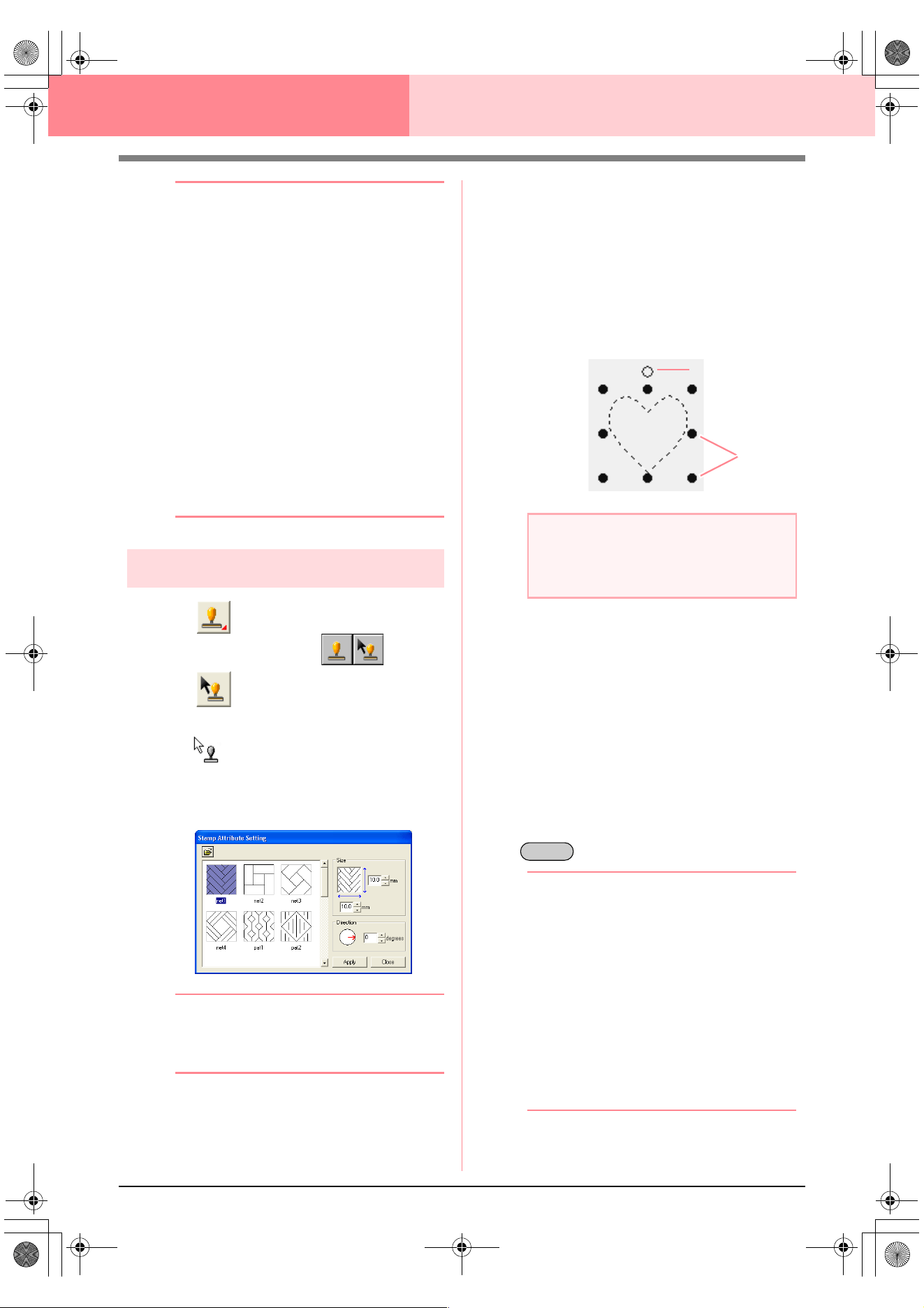
166
Layout & Editing Editing Embroidery Patterns
b Memo:
• The whole stamp appears, even if it is
larger than the object that it has been
applied to, however, only the parts that are
enclosed within the object will be sewn.
• Stamps can only be applied to objects
drawn with the Circle or Arc tool,
Rectangle tool, Outline tools, Text tools
and the Manual Punch tools and that have
the satin stitch, fill stitch and
programmable fill stitch applied.
• To apply several stamps within the same
object, continue clicking the object as often
as needed.
• If the pointer cannot fit within the selected
object, the stamp cannot be applied.
• The
Stamp Attribute Setting
dialog box
appears only after a stamp tool is selected.
• Stamps are only sewn within the object
that they have been applied to.
Editing a stamp
1. Click on the Tool Box.
→ Two buttons appear: .
2. Click .
→ The shape of the pointer changes to
, the Stamp Attribute Setting dia-
log box appears, and stamps that have
been applied are indicated by pink dotted
lines.
b Memo:
If an object was already selected, “marching
lines” appear around the region, and its
stamps are indicated by dotted lines.
3. Click the object with the stamp that you want
to edit.
→ “Marching lines” appear around the se-
lected object.
4. Click the stamp that you want to edit.
→ Round handles appear around the stamp,
and a rotation handle appears at the top of
the stamp.
5. To change the stamp pattern, select a
different pattern in the Stamp Attribute
Setting dialog box, and then click Apply.
To change the stamp size and orientation,
specify the desired settings in the Stamp
Attribute Setting dialog, or adjust it by
dragging the handles or rotation handle.
To move a stamp, drag it to another location
within the object or partially positioned on the
object.
To delete the stamp, select the menu
command Edit – Delete, or press the
key.
b Memo:
• When a pattern with a stamp applied is
moved, the stamp is moved together with
the pattern. However, changes to the size
and orientation of the pattern do not affect
the size and orientation of the stamps.
After editing the shape of an object, it may
be necessary to check the region and
adjust the stamps.
• Stamps appear only after a stamp tool is
selected.
• Stamps are only sewn within the region
that they have been applied to.
• To close the dialog box, click
Close
.
c
“Scaling patterns” on page 132 and
“Rotating patterns” on page 133
a Note:
Only one stamp can be selected at a time. If
you select another stamp, the previously
selected stamp becomes deselected.
Handles
Rotation handle
Delete
Advanced_02.fm Page 166 Friday, July 9, 2004 4:49 PM
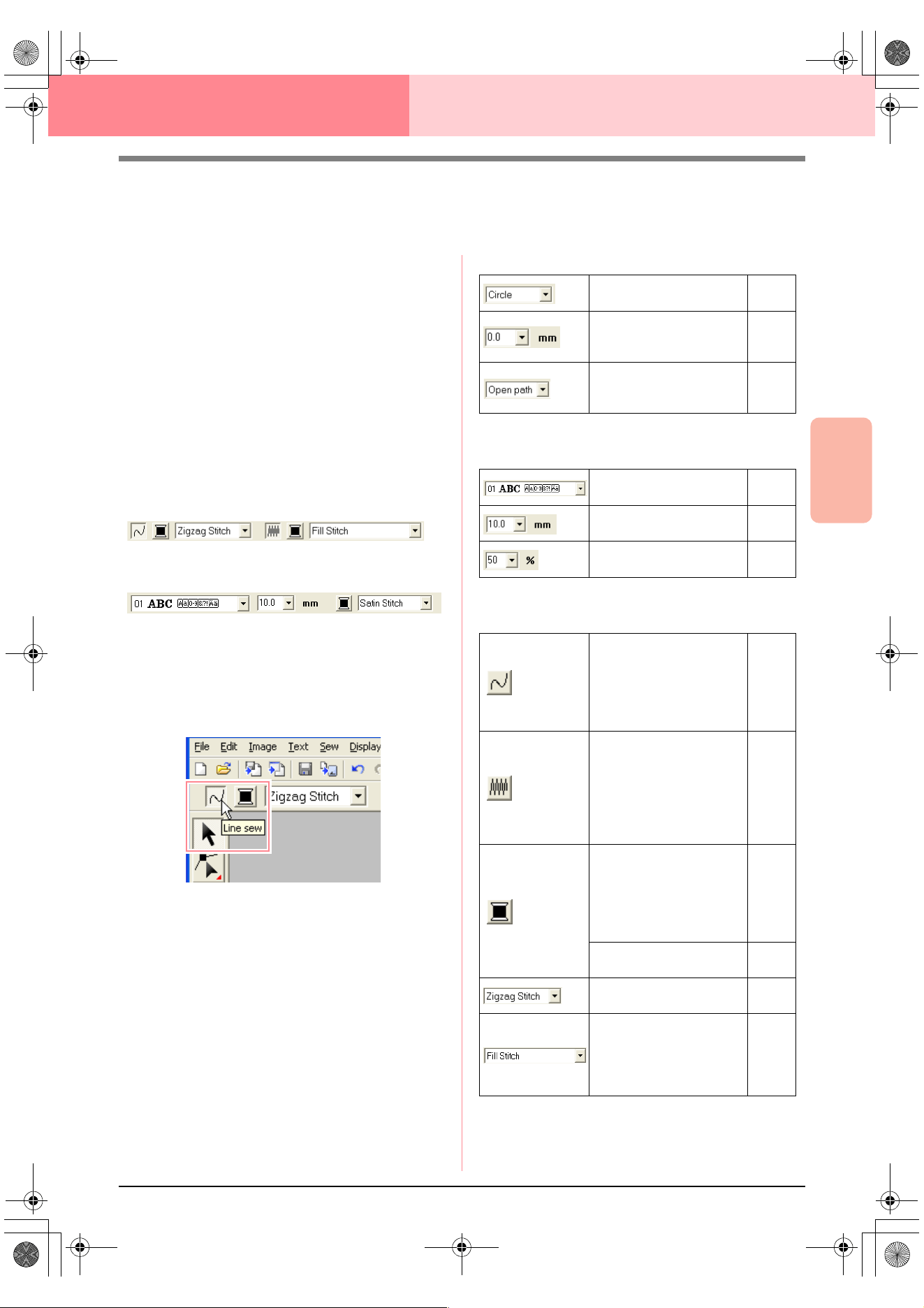
Advanced Opreation
Layout & Editing
167
Layout & Editing Editing Embroidery Patterns
Applying Sewing Attributes to Lines and
Regions
The Sewing Attributes bar allows you to set the
following attributes:
• geometric attributes (arc shape, rectangle
edge radius, and path shape)
• text attributes (font, size and transformation
level)
• embroidery attributes (thread color and sew
type, outline and inside region on/off)
The sewing attributes that are available depend on
the tool selected in Tool Box, and the type of
embroidery pattern selected.
Example 1: When the Select Object tool is selected,
but no object or pattern is selected
Example 2: When a text tool is selected, or text is
selected
When the pointer is positioned over a button or
selector in the Sewing Attributes bar, a label
indicating the name of that element appears. In the
following instructions, we will refer to the elements
of the Sewing Attributes bar according to these
labels.
As a general rule, the different characteristics
available for a given pattern can be set either just
before creating the pattern, or after the pattern is
created. For example, when drawing a rectangle,
you can set the colors and the corner radius just
after starting the rectangle drawing mode. When the
rectangle is created, you can select it and change its
characteristics.
The only exception to that rule is when you use the
circle and arc drawing mode: you must decide what
kind of pattern you want (circle, arc, etc.) before
actually creating it. In addition, you will not be able
to change the pattern type once the pattern is
created.
Geometric attributes
Text attributes
Embroidery attributes
Arc shape: Selects the
type of arc.
page
145
Edge radius: Sets the
corner radius of
rectangles.
page
148
Path shape: Opens and
closes broken lines and
curves.
page
150
Font: Selects a font for
text.
page
154
Text Size: Selects the
size for text.
page
156
Transform level: Selects
the level of transformation.
page
160
Line sew: Switches on/off
sewing for the line. When
sewing for the outline is
switched off, it is not sewn
(and you cannot set its
color or sew type).
page
168
Region sew: Switches
on/off sewing for the
region. When sewing for
the inside region is
switched off, it is not sewn
(and you cannot set its
color or sew type).
page
169
Line color, Region color,
Text color, Punch color:
Sets the thread color for
outlines, inside regions,
text and manual punching
patterns.
page
169
Special colors
page
170
Line sew type: Sets the
sew type for the outlines.
page
170
Region sew type: Sets
the sew type for an inside
region, text and manual
punching patterns.
page
170
!!sew4.bmp!!
PeDesignV6Eng.book Page 167 Thursday, July 8, 2004 11:59 AM
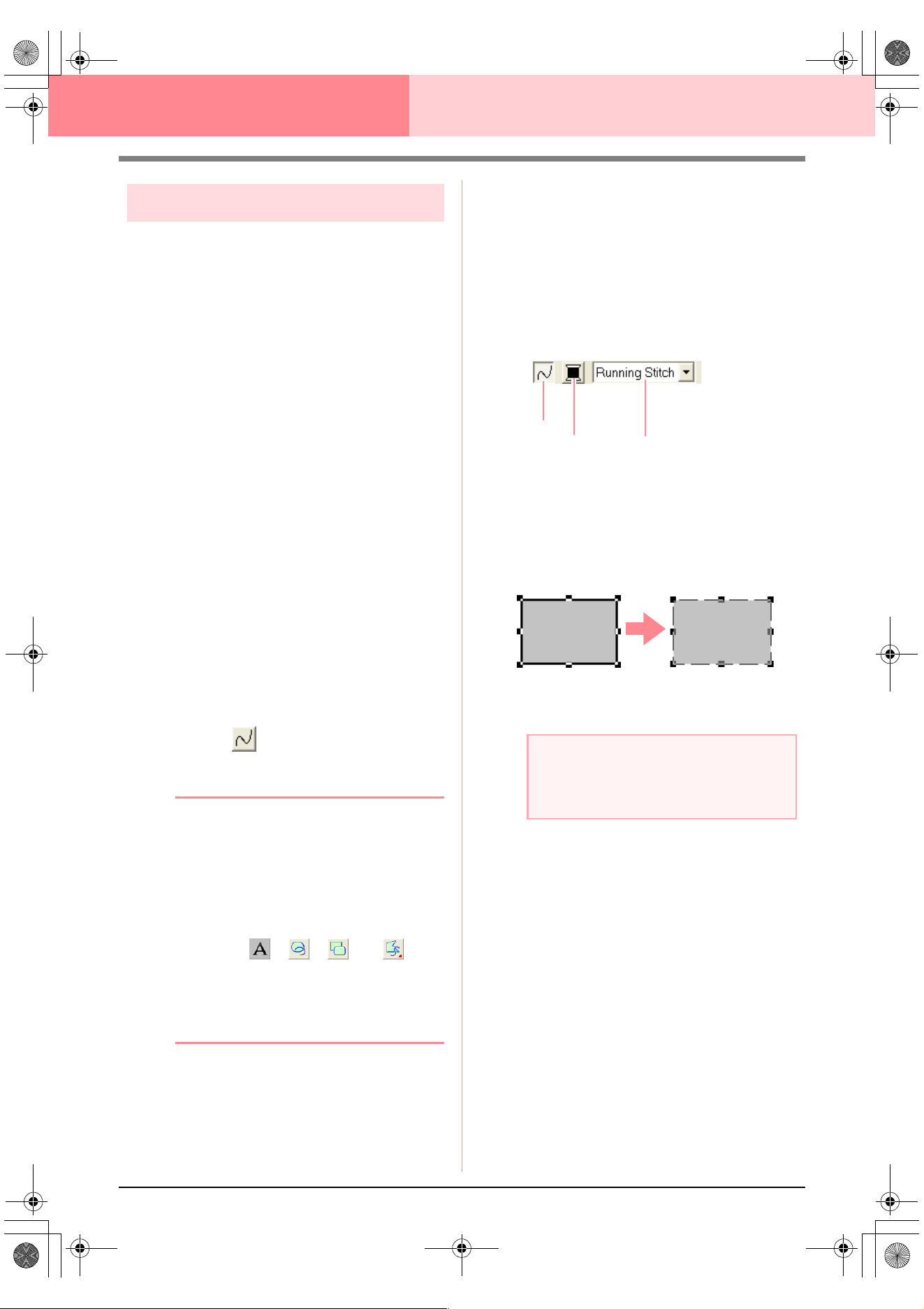
168
Layout & Editing Editing Embroidery Patterns
Setting the thread color and sew type
All patterns can be assigned at least one color and
sew type. Patterns with an outline and an inside
region can be assigned two different thread colors
and sew types. If a gradation is set, an additional
color can be added to the region. (For details on
gradations, refer to “Creating a gradation” on
page 179.) In addition, each character in a text
pattern can be assigned individual thread colors and
sew types.
Patterns with an outline and a inside region: text
converted from TrueType fonts, circles, fan shapes,
arcs & strings, rectangles, closed broken lines, and
closed curves. For these patterns, it is possible to
switch on and off sewing for the outline and the
regions.
Patterns with only an outline: arcs, open broken
lines, and open curves. For these patterns, it is still
possible to switch on and off sewing for the outline.
Patterns with only a region: text created with fonts
provided with this software and manual punching
patterns. For these two types of patterns, it is not
possible to switch on and off sewing of the inside
region.
Manual punching patterns: You can set a color for
three manual punching pattern types (block, semi-
automatic block and running), but you can only set a
sew type for manual punching block patterns.
■ Line sew
Clicking this button switches on/off sewing for an
outline.
b Memo:
•The
Line sew
button is available only
when the Select Object tool is selected
and no patterns are selected, when you
select a pattern that has an outline (text
converted from a TrueType font, circles,
arcs, fan shapes, arcs & strings,
rectangles, broken lines, curves), or when
you click , , , or on
the Tool Box to start drawing such a
pattern.
• When line sewing is switched off, the line
is not sewn (and you cannot set its color or
sew type).
1. Click the Line sew button.
This button has two settings:
On: The Line color button and the Line sew
type selector are displayed.
Off: The Line color button and the Line sew
type selector are not displayed.
Clicking the button switches between the two
settings.
→ The settings are applied to all patterns
that you will create with an outline, until
the setting is changed.
→ If a pattern is selected, the settings are
applied to the selected pattern.
Line sewing on: Line sewing off:
2. To switch on outline sewing, click the Line
sew button again.
c
“Color” on page 169 and “Sew type” on
page 170
a Note:
If one of the fonts included in this software
(font number 1 through 35) are selected, the
line sewing attributes cannot be changed.
Line sew
Line color
Line sew type
PeDesignV6Eng.book Page 168 Thursday, July 8, 2004 11:59 AM
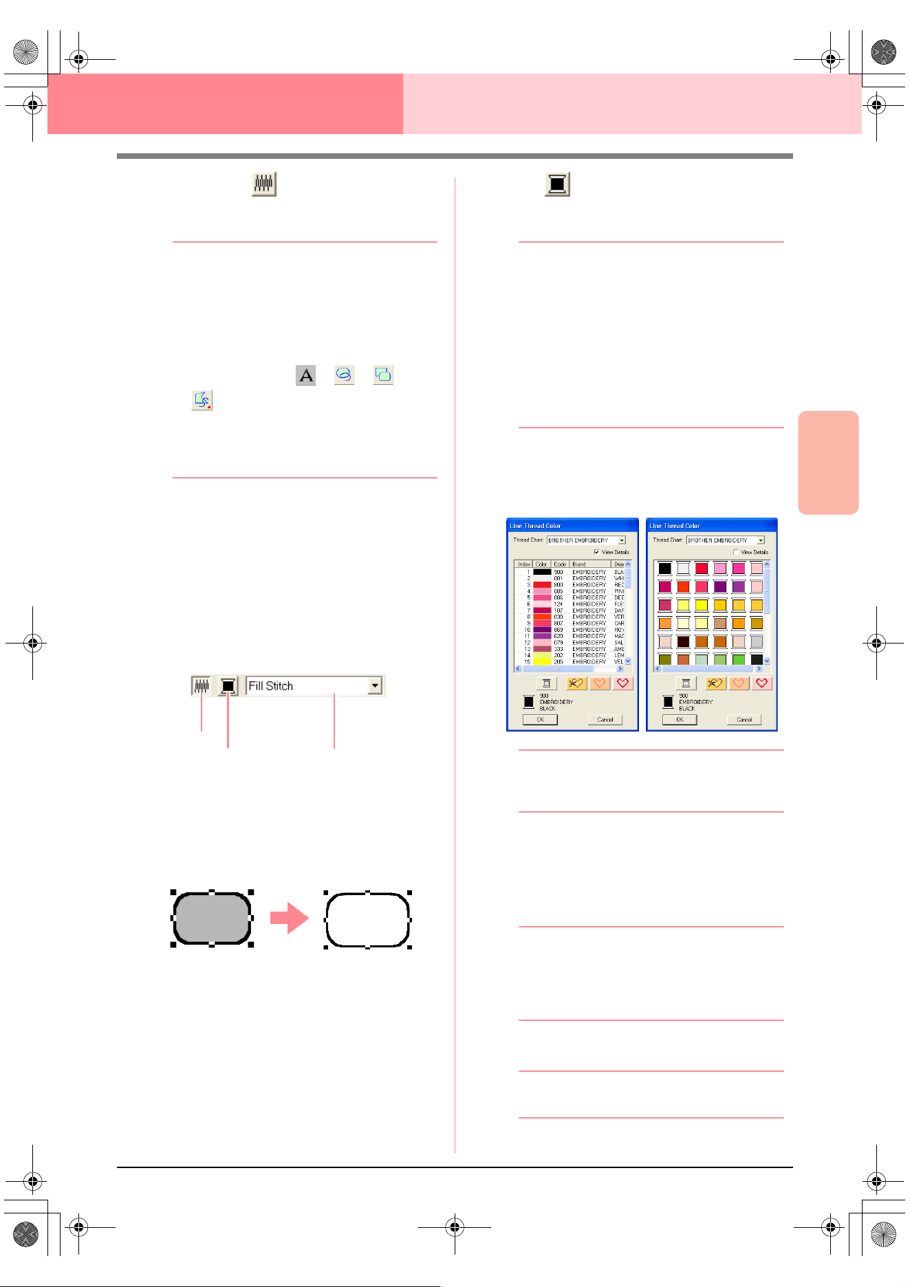
Advanced Opreation
Layout & Editing
169
Layout & Editing Editing Embroidery Patterns
■ Region sew
Clicking this button switches on/off sewing for an
inside region.
b Memo:
•The
Region sew
button is available only
when the Select Object tool is selected
and no patterns are selected, when you
select a pattern that has an inside region
(text, fan shapes, arcs & strings,
rectangles, closed broken lines, curves),
or when you click , , , or
on the Tool Box to start drawing
such a pattern.
• When region sewing is switched off, the
region is not sewn (and you cannot set its
color or sew type).
1. Click the Region sew button.
This button has two settings:
On: The Region color button and the Region
sew type selector are displayed.
Off: The Region color button and the Region
sew type selector are not displayed.
Clicking the button switches between the two
settings.
→ The settings are applied to all patterns
that you will create with an inside region,
until the setting is changed.
→ If a pattern is selected, the settings are
applied to the selected pattern.
2. To switch on region sewing, click the Region
sew button again.
c
“Color” on page 169 and “Sew type” on
page 170
■ Color
Click this button to set the thread color for outlines,
inside regions, texts and manual punching patterns.
b Memo:
•The
Line color
and
Region color
buttons
appear in the Sewing Attributes bar (if they
have not been switched off with the
Line
sew
or
Region sew
buttons) when the
Select Object tool is selected and no
patterns are selected.
• When you enter one of the drawing modes
or text input mode, or select an existing
pattern, the color button for the
corresponding pattern appears.
1. Click the Color button.
→ A Thread Color dialog box similar to the
one shown below appears.
b Memo:
To view a list of only the thread colors, clear
the
View Details
check box.
2. From the Thread Chart selector, select a
system chart or a user thread chart.
3. From the list of thread colors, select the
desired color.
b Memo:
• The color can also be selected by double-
clicking it.
• For details on the four buttons under the
list, refer to “Special colors” on page 170.
4. Click OK.
b Memo:
To quit the operation, click
Cancel
.
Region sew
Region color
Region sew type
PeDesignV6Eng.book Page 169 Thursday, July 8, 2004 11:59 AM
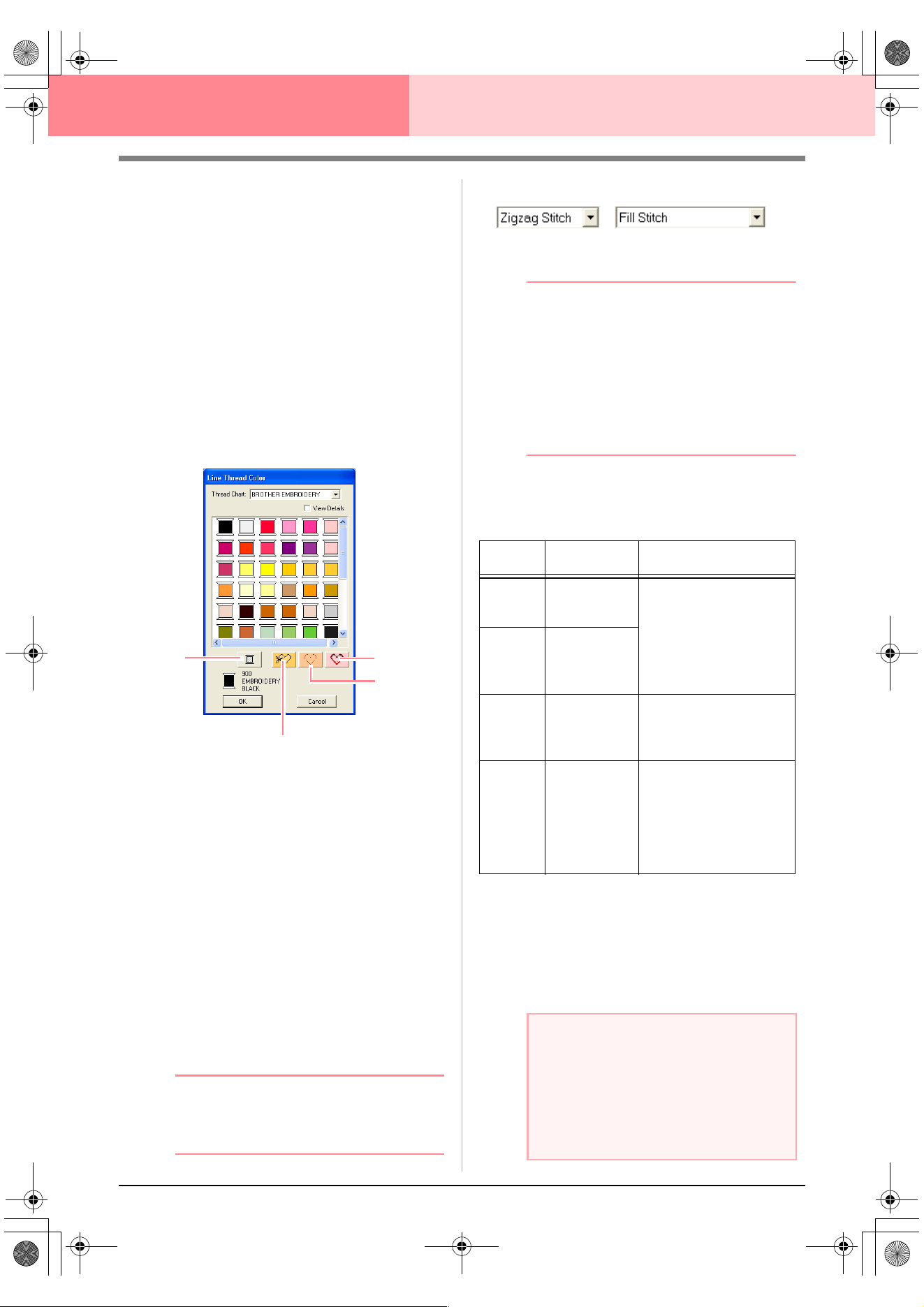
170
Layout & Editing Editing Embroidery Patterns
→ This setting is applied to all patterns of the
same type that you will create, until the
setting is changed. The color button of
each category shows the current color for
that category.
→ If a pattern is selected, the setting is ap-
plied to the selected pattern.
c
For details on specifying a user thread
chart or for information on how machines
handle thread colors, refer to “Editing
User Thread Color Lists” on page 190.
c
“Line sew” on page 168 and “Region sew”
on page 169
■ Special colors
• NOT DEFINED: Sewing machines that
feature automatic thread color display will
automatically switch the display to the
specified color. If you are using such a
machine and if you want to be able to select
manually the color for a monochrome
pattern, you can select NOT DEFINED.
• Colors for creating appliqués: You can
create appliqués using the three special
colors shown in the above illustration.
APPLIQUE MATERIAL marks the outline of
the region to cut from the appliqué material.
APPLIQUE POSITION marks the position
on the backing material where the appliqué
must be sewn.
APPLIQUE sews the appliqué on the back-
ing material.
b Memo:
By using the Applique Wizard, appliqués can
easily be created. For details, refer to “Using
the Applique Wizard” on page 181.
■ Sew type
Use these to set the sew type for outlines, inside
regions, text, and manual punching patterns.
b Memo:
•The
Line sew type
and
Region sew type
selectors appear in the Sewing Attributes
bar (if they have not been switched off with
the
Line sew
or
Region sew
buttons)
when the Select Object tool is selected.
• When you enter one of the drawing modes
or select an existing pattern, the sew type
selector for the corresponding pattern
appears.
1. Click in a sew type selector.
→ The available settings that appear differ
depending on the object that is selected.
2. Click the desired sew type.
→ This setting is applied to all patterns of the
same type that you will create, until the
setting is changed.
→ If a pattern is selected, the setting is ap-
plied to the selected pattern.
NOT
APPLIQUE MATERIAL
APPLIQUE
APPLIQUE
POSITION
DEFINED
Object
type
Line sew type
settings
Region sew type settings
Tex t
(built-in
fonts)
None
Satin Stitch, Fill Stitch,
and Prog. Fill Stitch
(programmable fill stitch)
Tex t
(TrueType
fonts)
Zigzag Stitch,
Running Stitch
Motif Stitch,
and E/V Stitch
Manual
punching
pattern
None
Satin Stitch, Fill Stitch,
and Prog. Fill Stitch
(programmable fill stitch),
Piping Stitch
Others
Zigzag Stitch,
Running Stitch
Motif Stitch,
and E/V Stitch
Satin Stitch, Fill Stitch,
Prog. Fill Stitch
(programmable fill stitch),
Motif Stitch, Cross Stitch,
Concentric Circle Stitch,
Radial Stitch and
Spiral Stitch
a Note:
You can set the sewing attributes for the
selected line and region sew types in the
Sewing Attribute Setting
dialog box.
When you select
Prog. Fill Stitch
or
Motif
Stitch
, you also need to select a pattern in
the
Sewing Attribute Setting
dialog box, as
there is no default pattern setting.
PeDesignV6Eng.book Page 170 Thursday, July 8, 2004 11:59 AM
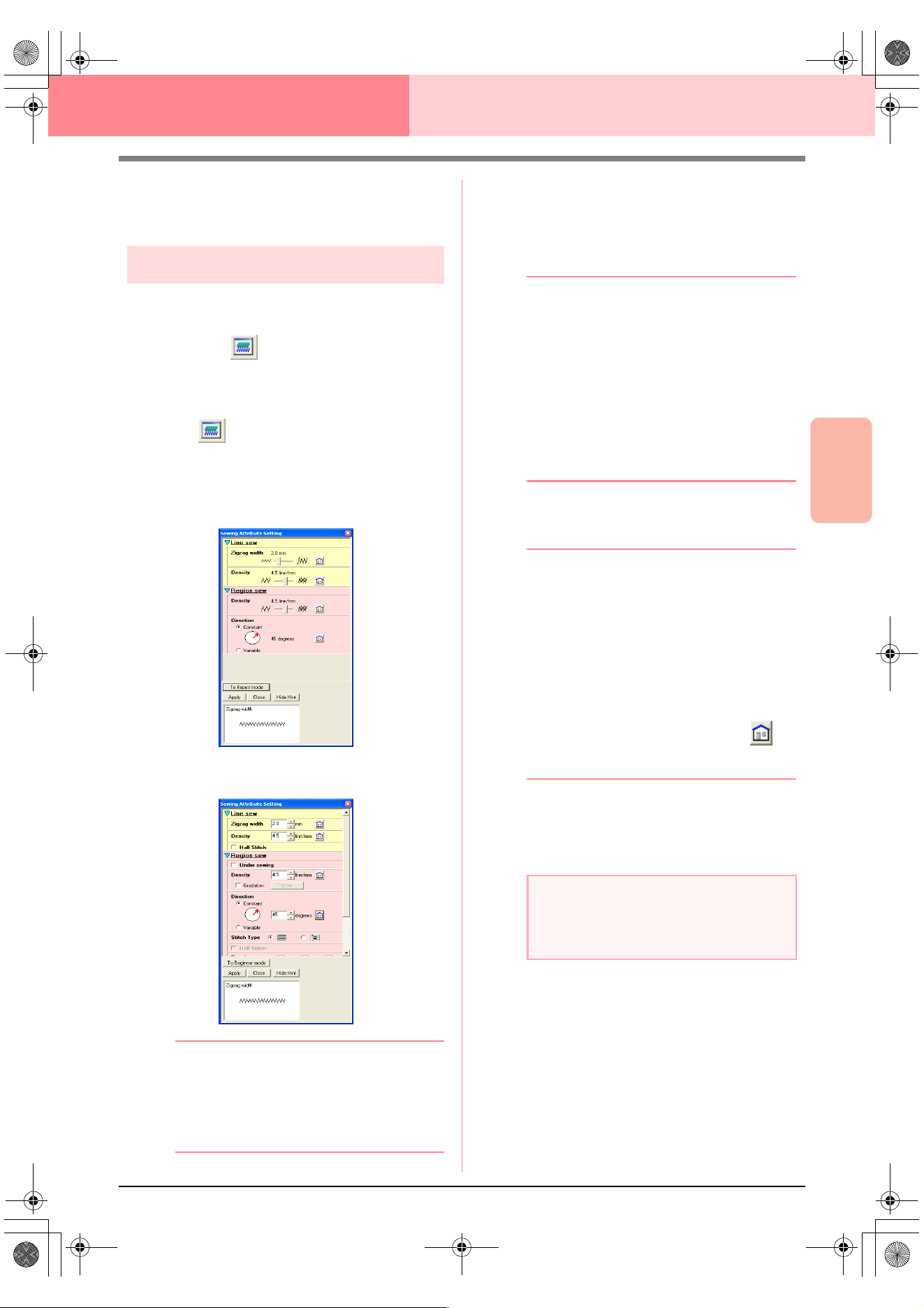
Advanced Opreation
Layout & Editing
171
Layout & Editing Editing Embroidery Patterns
c
“Line sew” on page 168, “Region sew” on
page 169 and “Specifying sewing
attributes” below
Specifying sewing attributes
Various sewing attributes for lines and regions can
be set in the Sewing Attribute Setting dialog box
Toolbar button:
1. Click one of the Tool Box buttons used to draw
or select objects.
2. Click in the Toolbar
→ The Sewing Attribute Setting dialog box
appears.
Beginner mode:
Expert mode:
b Memo:
• An alternate method is to select the menu
command
Sew
–
Setting Attribute
.
• The sewing attributes displayed in the
dialog box depend on the selected sew
type.
3. To display only basic sewing attributes and
simpler settings, click To Beginner mode.
To display all of the sewing attributes and
settings available for the selected sew type,
click To Expert mode.
b Memo:
• Settings that cannot be selected in
Beginner mode are retained from the
previous setting in Expert mode.
• To hide the preview box, click
Hide Hint
.
To display the preview box, click
Show
Hint
.
When the
Hide Hint
button is displayed,
the preview box is displayed, allowing you
to view a stitching sample when the pointer
is moved over the setting. The preview box
shows the setting changes that you make.
4. If necessary, change the sewing attributes
displayed under Line Sew or Region Sew.
b Memo:
• In some cases, you may need to scroll
through the settings, or resize the dialog
box by dragging one of its corners in order
to view all of the sewing attributes.
• The method for entering settings varies
according to the attribute. When entering
numerical values in Expert mode, click the
arrow buttons to select the value or enter
the value directly. In Beginner mode, use
the slider to change the settings. If
appears, click the button to return to the
default setting.
c
For details on the different sewing
attributes and settings, refer to “Line
sewing attributes” on page 172 and
“Region sewing attributes” on page 173.
5. Click the Apply button in the dialog box to
apply the new sewing attributes.
6. Click Close to close the dialog box.
a Note:
All settings made in the dialog box are
retained and will be applied regardless of the
mode, until they are changed.
PeDesignV6Eng.book Page 171 Thursday, July 8, 2004 11:59 AM
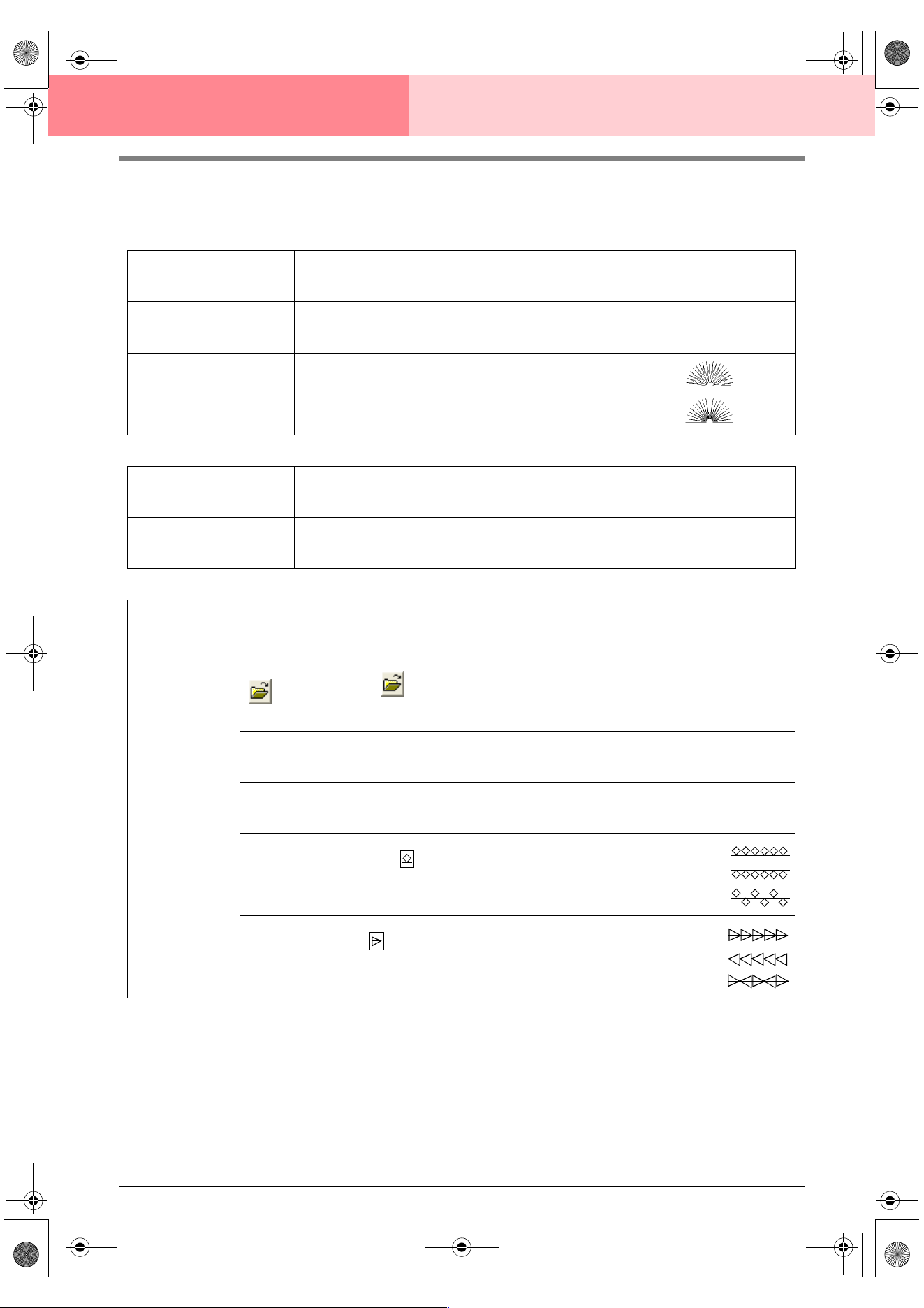
172
Layout & Editing Editing Embroidery Patterns
■ Line sewing attributes
The available attributes differ depending on the selected sew type.
Zigzag stitch
Running stitch
Motif stitch
Zigzag width
Sets the width of the zigzag.
Range: 1–10 mm (0.04–0.39 inch)
Default: 2.0 mm (0.08 inch)
Density
Sets the number of lines per millimeter (inch).
Range: 1–7 lines per mm (25–178 lines per inch)
Default: 4.5 lines per mm (114 lines per inch)
Half Stitch
Sets half stitching on or off.
If one side of the zigzag stitching is dense, a half stitch could
be sewn automatically to provide a more even density.
Available for text and objects created with the drawing tools.
Default: Off
On:
Off:
Run pitch
Sets the pitch of the line sewing.
Range: 1–10 mm (0.04–0.39 inch)
Default: 2.0 mm (0.08 inch)
Run times
Sets the number of times that the border will be sewn.
Range: 1–5
Default: 1
Run pitch
Sets the pitch of the line sewing.
Range: 1–10 mm (0.04–0.39 inch)
Default: 10.0 mm (0.39 inch)
Motif
Select a pattern for the motif stitch.
Click , and then, in the Browse dialog box that appeared, select the folder con-
taining the .pmf file that you want to use. Double-click the desired pattern, or select it,
and then click OK.
Width (horizontal
length)
Sets the pattern width (the direction along the line).
Range: 2–10 mm (0.08–0.39 inch)
Default: 5.0 mm (0.20 inch)
Height (vertical
length)
Sets the pattern height (the direction perpendicular to the line).
Range: 2–10 mm (0.08–0.39 inch)
Default: 5.0 mm (0.20 inch)
H-Arrange
(horizontal
arrangement)
Sets the horizontal arrangement of the pattern. For pat-
terns like , the patterns will be arranged along the line
as shown at the right.
V-Arrange
(vertical arrange-
ment)
Sets the vertical arrangement of the pattern. For patterns
like , the patterns will be arranged along the line as
shown at the right.
Normal:
Mirror:
Alternate:
Normal:
Mirror:
Alternate:
PeDesignV6Eng.book Page 172 Thursday, July 8, 2004 11:59 AM
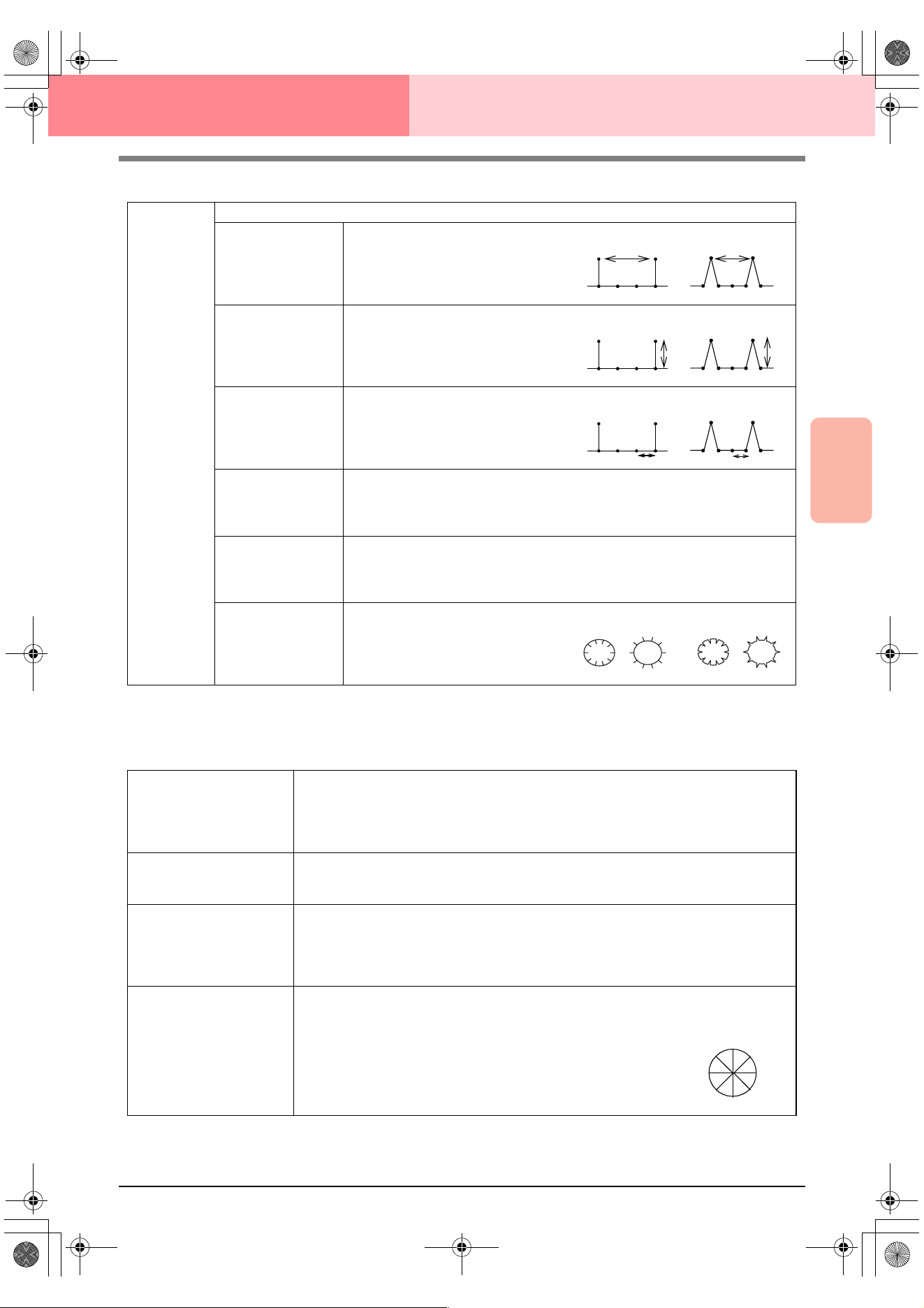
Advanced Opreation
Layout & Editing
173
Layout & Editing Editing Embroidery Patterns
E/V stitch
■ Region sewing attributes
The available attributes differ depending on the selected sew type.
Satin stitch
E Stitch
V Stitch
Selects the E stitch or V stitch.
Interval
Sets the distance between stitches.
Range: 1.0–20.0 mm (0.04–0.79 inch)
Default: 5.0 mm (0.20 inch)
Stroke width
Sets the pattern height (the direction per-
pendicular to the line).
Range: 1.0–10.0 mm (0.04–0.39 inch)
Default: 2.5 mm (0.10 inch)
Run pitch
Sets the pitch of the line sewing.
Range: 1.0–10.0 mm (0.04–0.39 inch)
Default: 2.0 mm (0.08 inch)
Run time(s)
Sets the reverse stitching for the running stitches. With the V stitch, the “V” is
included in the run times.
Range: 1, 3, 5
Default: 1
Stroke times
Sets the number of strokes of the yarn carrier.
Available only if E Stitch is selected.
Range: 1–3
Default: 1
Arrange
Sets the inside/outside arrangement of
the E stitch or V stitch.
E stitch V stitch
E stitch V stitch
E stitch V stitch
E stitch V stitch
Under sewing
Sets underlay stitching on or off. Try to use underlay stitching for wide areas, in order to pre-
vent shrinking during stitching. Depending on the shape of the region, however, it may not be
possible to select this setting.
On: Underlay stitching will be sewn.
Off: Underlay stitching will not be sewn.
Density
Sets the number of lines per millimeter.
Range: 1–7 lines per mm (25–178 lines per inch)
Default: 4.5 lines per mm (114 lines per inch)
Gradation
Sets the density gradation setting on or off.
Available when the type of sewing direction is set to Constant.
Click Pattern to set the gradation pattern.
Default: Off
For details on this attribute, refer to“Creating a gradation” on page 179.
Direction
[Type] Specifies the type of sewing direction.
Constant: Sews at a fixed angle. The angle is specified by the angle setting.
Variable: Varies the sewing direction according to the object being sewn.
[Angle] Specifies the sewing angle.
Available only when the sewing direction type is
set to Constant.
Range: 0–359 degrees
Default: 45 degrees
0°
45°
90°
135°
180°
225°
270°
315°
PeDesignV6Eng.book Page 173 Thursday, July 8, 2004 11:59 AM
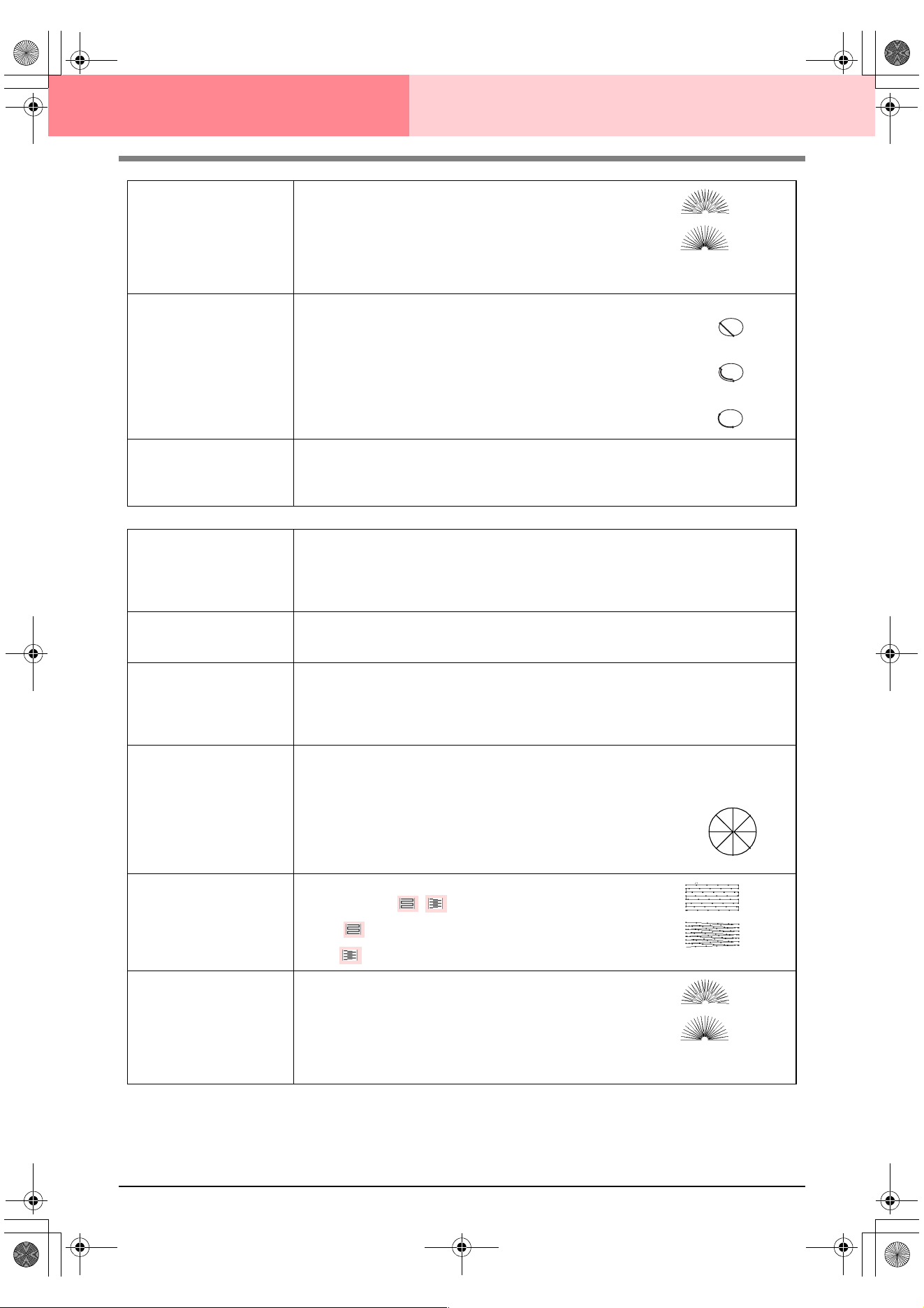
174
Layout & Editing Editing Embroidery Patterns
Half Stitch
Sets half stitching on or off.
Available for text, manual punching patterns and objects cre-
ated with the drawing tools, and for geometric shapes when
the type of sewing direction is set to Variable.
If one side of the satin stitching is dense, a half stitch could
be sewn automatically to provide a more even density.
Default: Off
Running Stitch Path
Sets the running path of the stitching.
Available when the type of sewing direction is set to Constant.
Available settings:
• Inside of region (shortest route)
• Along outline (along the inner side)
• Onto outline (on the outline)
The inside of region setting is available only when the Gradation
check box is cleared.
Default: Inside of region
Pull Compensation
Lengthens the sewing region in the stitch pattern’s sewing direction to prevent pattern shrink-
age during sewing.
Range: 0–2 mm (0.00–0.08 inch)
Default: 0.0 mm (0.00 inch)
Fill stitch
Under sewing
Sets underlay stitching on or off. Try to use underlay stitching for wide areas, in order to pre-
vent shrinking during stitching. Depending on the shape of the region, however, it may not be
possible to select this setting.
On: Underlay stitching will be sewn.
Off: Underlay stitching will not be sewn.
Density
Sets the number of lines per millimeter.
Range: 1–7 lines per mm (25–178 lines per inch)
Default: 4.5 lines per mm (114 lines per inch)
Gradation
Sets the density gradation setting on or off.
Available when the type of sewing direction is set to Constant.
Click Pattern to set the gradation pattern and its density.
Default: Off
For details on this attribute, refer to“Creating a gradation” on page 179.
Direction
[Type] Specifies the type of sewing direction.
Constant: Sews at a fixed angle. The angle is specified by the angle setting.
Variable: Varies the sewing direction according to the object being sewn.
[Angle] Specifies the sewing angle.
Available only when the sewing direction type is
set to Constant.
Range: 0–359 degrees
Default: 45 degrees
Stitch Type
Specifies the shape of stitching on the edges.
Available settings: ,
Default:
(for all objects other than text)
(for text)
Half Stitch
Sets half stitching on or off.
Available for text, manual punching patterns and objects cre-
ated with the drawing tools, and for geometric shapes when
the type of sewing direction is set to Variable.
If one side of the fill stitching is dense, a half stitch could be
sewn automatically to provide a more even density.
Default: Off
On:
Off:
Inside of region:
Along outline:
Onto outline:
0°
45°
90°
135°
180°
225°
270°
315°
On:
Off:
PeDesignV6Eng.book Page 174 Thursday, July 8, 2004 11:59 AM
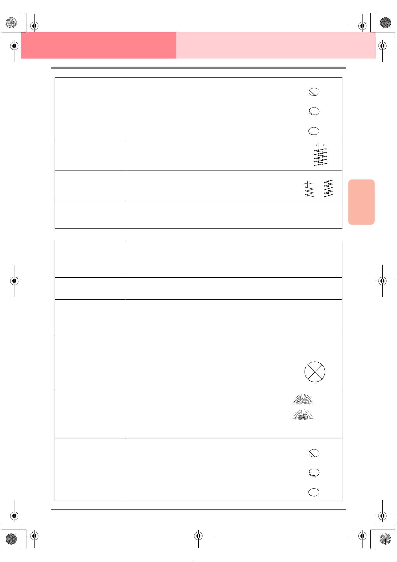
Advanced Opreation
Layout & Editing
175
Layout & Editing Editing Embroidery Patterns
Programmable fill stitch
Running Stitch Path
Sets the running path of the stitching.
Available when the type of sewing direction is set to Constant.
Available settings:
• Inside of region (shortest route)
• Along outline (along the inner side)
• Onto outline (on the outline)
The inside of region setting is available only when the Gradation
check box is cleared.
Default: Inside of region
Step Pitch
Sets the pitch of the stitching.
Range: 1–10 mm (0.04–0.39 inch)
Default: 4.0 mm (0.16 inch)
Frequency
Sets the spacial frequency steps.
Range: 0–99%
Default: 30%
Pull Compensation
Lengthens the sewing region in the stitch pattern’s sewing direction to prevent pattern shrink-
age during sewing.
Range: 0–2 mm (0.00–0.08 inch)
Default: 0.0 mm (0.00 inch)
Inside of region:
Along outline:
Onto outline:
Step pitch
0%
30%
Under sewing
Sets underlay stitching on or off. Try to use underlay stitching for wide areas, in order to pre-
vent shrinking during stitching. Depending on the shape of the region, however, it may not be
possible to select this setting.
On: Underlay stitching will be sewn.
Off: Underlay stitching will not be sewn.
Density
Sets the number of lines per millimeter.
Range: 1–7 lines per mm (25–178 lines per inch)
Default: 4.5 lines per mm (114 lines per inch)
Gradation
Sets the density gradation setting on or off.
Available when the type of sewing direction is set to Constant.
Click Pattern to set the gradation pattern and its density.
Default: Off
For details on this attribute, refer to“Creating a gradation” on page 179.
Direction
[Type] Specifies the type of sewing direction.
Constant: Sews at a fixed angle. The angle is specified by the angle setting.
Variable: Varies the sewing direction according to the object being sewn.
[Angle] Specifies the sewing angle.
Available only when the sewing direction type is
set to Constant.
Range: 0–359 degrees
Default: 45 degrees
Half Stitch
Sets half stitching on or off.
Available for text, manual punching patterns and objects cre-
ated with the drawing tools, and for geometric shapes when
the type of sewing direction is set to Variable.
If one side of the fill stitching is dense, a half stitch could be
sewn automatically to provide a more even density.
Default: Off
Running Stitch Path
Sets the running path of the stitching.
Available when the type of sewing direction is set to Constant.
Available settings:
• Inside of region (shortest route)
• Along outline (along the inner side)
• Onto outline (on the outline)
The inside of region setting is available only when the Gradation
check box is cleared.
Default: Inside of region
0°
45°
90°
135°
180°
225°
270°
315°
On:
Off:
Inside of region:
Along outline:
Onto outline:
PeDesignV6Eng.book Page 175 Thursday, July 8, 2004 11:59 AM
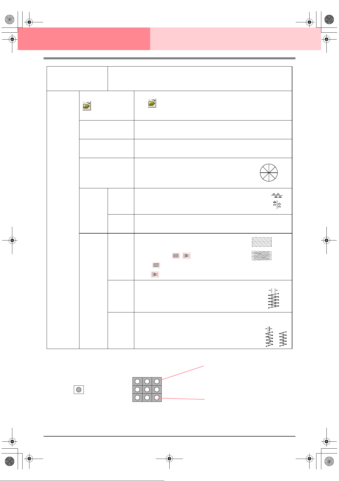
176
Layout & Editing Editing Embroidery Patterns
Pull Compensation
Lengthens the sewing region in the stitch pattern’s sewing direction to prevent pattern shrink-
age during sewing.
Range: 2–10 mm (0.08–0.39 inch)
Default: 0.0 mm (0.00 inch)
Programma-
ble fill
Select a pattern for programmable fill stitch.
Click , and then, in the Browse dialog box that appeared, select the folder
containing the .pas file that you want to use. Double-click the desired pattern, or
select it, and then click OK.
Width (horizontal length)
Sets the stitch pattern width.
Range: 2–10 mm (0.08–0.39 inch)
Default: 7.5 mm (0.30 inch)
Height (vertical length)
Sets the stitch pattern height.
Range: 5–10 mm (0.20–0.39 inch)
Default: 7.5 mm (0.30 inch)
Direction
Allows you to rotate the angle of the stitch patterns.
Range: 0–359 degrees
Default: 0 degrees
Offset
Direction
Sets the direction of the offset as row/column.
Value
When the pattern’s arrangement is offset, sets the amount of offset.
Range: 0–99%
Default: 0%
Base
Sew
Specifies
the base
stitching.
Stitch
Type
Specifies the shape of stitching on the edges.
Available only when the Base Sew check box is
selected.
Available settings: ,
Default:
(for all objects other than text)
(for text)
Step Pitch
Sets the pitch of the stitching for the base of a programmable fill stitch.
Available only when the Base Sew check box is
selected.
Range: 1–10 mm (0.04–0.39 inch)
Default: 4.0 mm (0.16 inch)
Frequency
Sets the spacial frequency steps of the stitching for the base of a programmable
fill stitch.
Available only when the Base Sew check box is
selected.
Range: 0–99%
Default: 30%
0°
45°
90°
135°
180°
225°
270°
315°
row
column
Step pitch
0%
30%
Pattern
The stitching for the base (area
other than the pattern indicated
by the diagonal lines) of the pro-
grammable fill stitch can be set.
The pattern is sewn with the
specified stitching.
PeDesignV6Eng.book Page 176 Thursday, July 8, 2004 11:59 AM
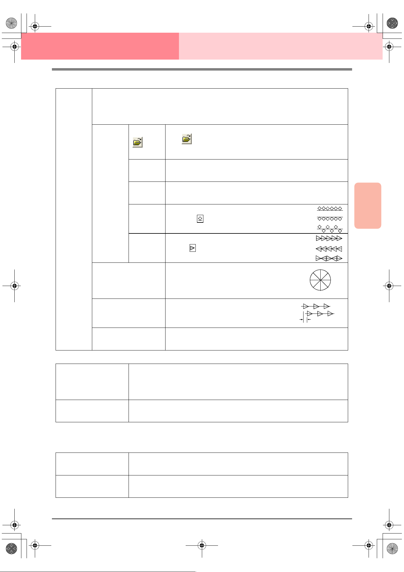
Advanced Opreation
Layout & Editing
177
Layout & Editing Editing Embroidery Patterns
Motif stitch
Cross stitch
Concentric circle stitch, radial stitch and spiral stitch
For details on moving the center point of the concentric circle stitch and the radial stitch, refer to “Moving the
center point” on page 139.
Motif
Selects whether to use pattern 1 or pattern 2 for the motif stitch. If you choose to use both patterns, the data
is created to sew alternating rows of the two.
Pattern1 only: Uses only pattern 1 (Default)
Pattern2 only: Uses only pattern 2
Pattern1 and 2: Uses pattern 1 and pattern 2
Pattern1
Pattern 2
Select a pattern for the motif stitch.
Click , and then, in the Browse dialog box that appeared, select the
folder containing the .pmf file that you want to use. Double-click the desired
pattern, or select it, and then click OK.
Width (hori-
zontal length)
Sets the pattern width (the direction along the line).
Range: 2–10 mm (0.08–0.39 inch)
Default: 5.0 mm (0.20 inch)
Height (verti-
cal length)
Sets the pattern height (the direction perpendicular to the line).
Range: 2–10 mm (0.08–0.39 inch)
Default: 5.0 mm (0.20 inch)
H-Arrange
(horizontal
arrange-
ment)
Sets the horizontal arrangement of the pattern. For
patterns like , the patterns will be arranged along
the line as shown at the right.
V-Arrange
(vertical
arrange-
ment)
Sets the vertical arrangement of the pattern. For pat-
terns like , the patterns will be arranged along the
line as shown at the right.
Direction
Allows you to rotate the angle of the motif stitch.
Range: 0–359 degrees
Default: 0 degrees
Row Offset
Sets the amount of offset for each row.
Range: 0–10 mm (0.00–0.39 inch)
Default: 0.0 mm (0.00 inch)
Run Pitch
Sets the pitch of the sewing.
Range: 1–10 mm (0.04–0.39 inch)
Default: 10.0 mm (0.39 inch)
Normal:
Mirror:
Alternate:
Normal:
Mirror:
Alternate:
0°
45°
90°
135°
180°
225°
270°
315°
Size
Sets the horizontal and vertical size of the pattern.
In Expert mode, the set value is converted automatically and displayed in the box for the other
measurement units.
Range: 1.5–5.0 mm (0.06–0.20 inch) or 5–17 counts
Default: 2.5 mm (0.10 inch) or 10 counts
Times
Sets the number of times that the pattern will be sewn. Sews twice per time.
Range: Single, Double, Triple
Default: Single
Density
Sets the number of lines per millimeter.
Range: 0.5–7.0 lines per mm (13–178 lines per inch)
Default: 2.0 lines per mm (51 lines per inch)
Run pitch
Sets the pitch of the line sewing.
Range: 1–10.0 mm (0.04–0.39 inch)
Default: 2.0 mm (0.08 inch)
PeDesignV6Eng.book Page 177 Thursday, July 8, 2004 11:59 AM
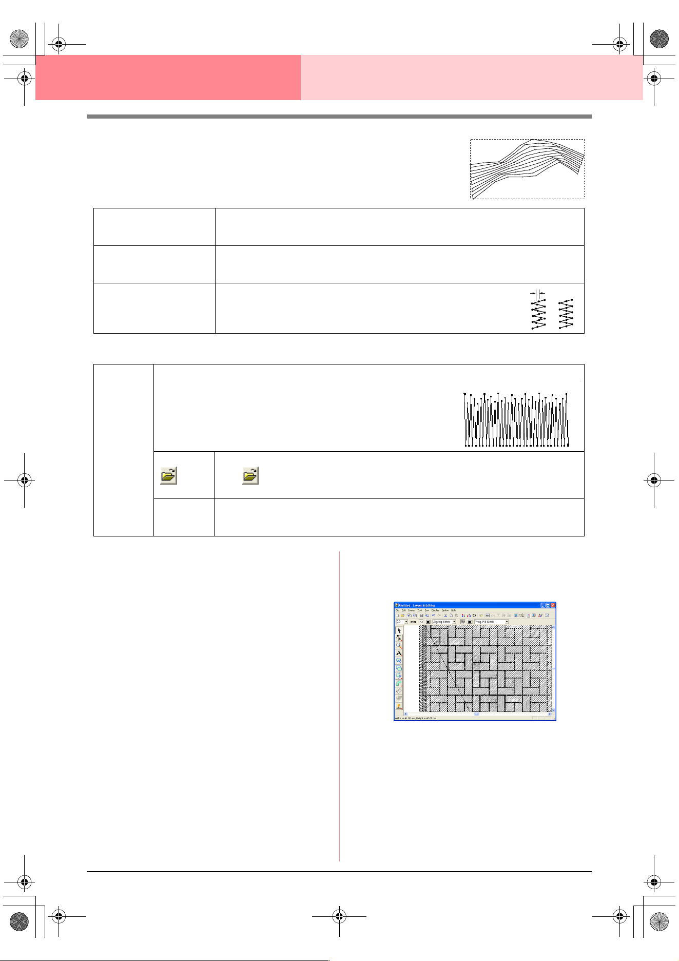
178
Layout & Editing Editing Embroidery Patterns
Piping stitch
Stitches run parallel through the length of adjacent blocks.
Available only for manual punching patterns.
Manual punch
Notes on programmable fill stitches and
stamps
When setting the sew type and pattern directions of
a programmable fill stitch or a stamp, lines will not
be sewn if the sew type and pattern direction
settings cause a stitch to be sewn in the same
direction as a line in the stitch pattern.
Use the Preview function to view exactly how the
stitch pattern will be sewn, and then set the stitch
direction and pattern direction according to the
selected sew type or to the effect that you want to
produce. To get an even better view, make test
samples of different settings.
Examples of programmable fill stitching:
Density
Sets the number of lines per millimeter.
Range: 0.5–7.0 lines per mm (13–178 lines per inch)
Default: 2.0 lines per mm (51 lines per inch)
Run pitch
Sets the pitch of the line sewing.
Range: 1–10.0 mm (0.04–0.39 inch)
Default: 4.0 mm (0.16 inch)
Frequency
Sets the spacial frequency steps.
Range: 0–99%
Default: 30%
0%
30%
Feathered
edge
Sets which edge of the stitching that the feathered edge is applied to.
Top: Feathered edge is sewn on the top edge.
Bottom: Feathered edge is sewn on the bottom edge.
When creating data with a Manual Punch tool, the top edge is the side
containing the first and third points, and the bottom edge is the side con-
taining the second and fourth points.
Select a pattern for the feathered edge.
Click , and then, in the Browse dialog box that appeared, double-click the desired pat-
tern, or select it, and then click OK.
Length
Sets the length of the feathered edge.
Range: 0.2–100 mm (0.01–3.94 inches)
Default: 3 mm (0.12 inch)
Feather edge applied to the top:
Example 1
Stitch direction: 45° (default)
PeDesignV6Eng.book Page 178 Thursday, July 8, 2004 11:59 AM
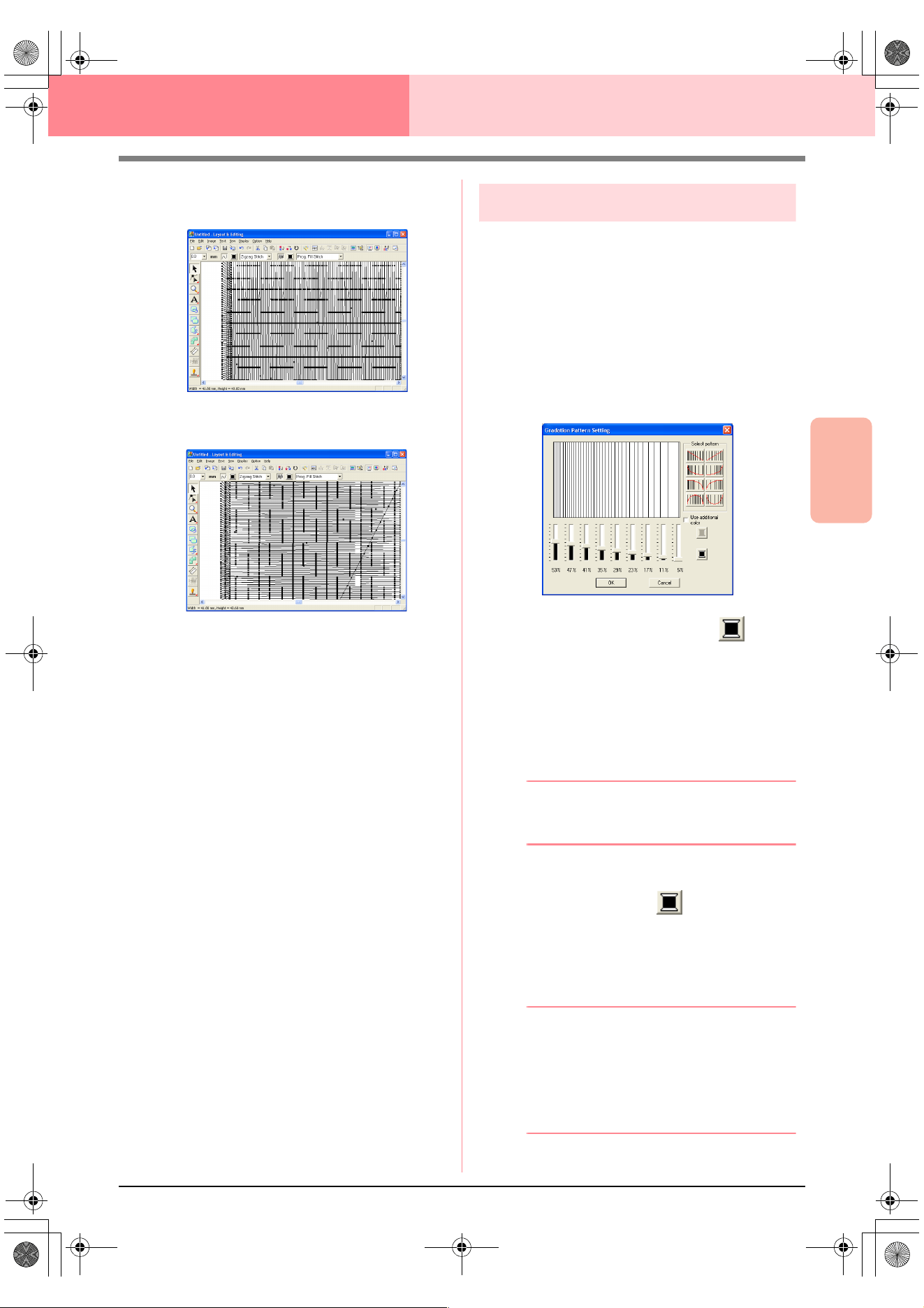
Advanced Opreation
Layout & Editing
179
Layout & Editing Editing Embroidery Patterns
c
“Previewing the Sewing Image” on
page 187 and “Programmable Stitch
Creator” on page 208
Creating a gradation
The density of one or two colors can be adjusted at
various locations to create a custom gradation
pattern.
1. In Expert mode of the Sewing Attribute
Setting dialog box, select the Gradation
check box under Region sew.
2. Click Pattern.
→ The Gradation Pattern Setting dialog
box appears.
3. To change the thread color, click . Select
a color in the Thread Color dialog box that
appeared, and then click OK.
4. To select a preset gradation pattern, click the
desired pattern under Select pattern.
5. Move the sliders to adjust the density of the
gradation pattern.
b Memo:
The preview area shows the setting changes
that you make.
6. To blend two colors, select the Use additional
color check box, click under Use
additional color. Select a color in the Thread
Color dialog box that appeared, and then click
OK.
7. Click OK.
b Memo:
• If the
Use additional color
check box is
cleared, the gradation settings are applied
to the remaining color.
• To close the dialog box without applying
the changes to the gradation pattern, click
Cancel
.
Example 2
Stitch direction: 90°
Example 3
Stitch direction: 0°
PeDesignV6Eng.book Page 179 Thursday, July 8, 2004 11:59 AM
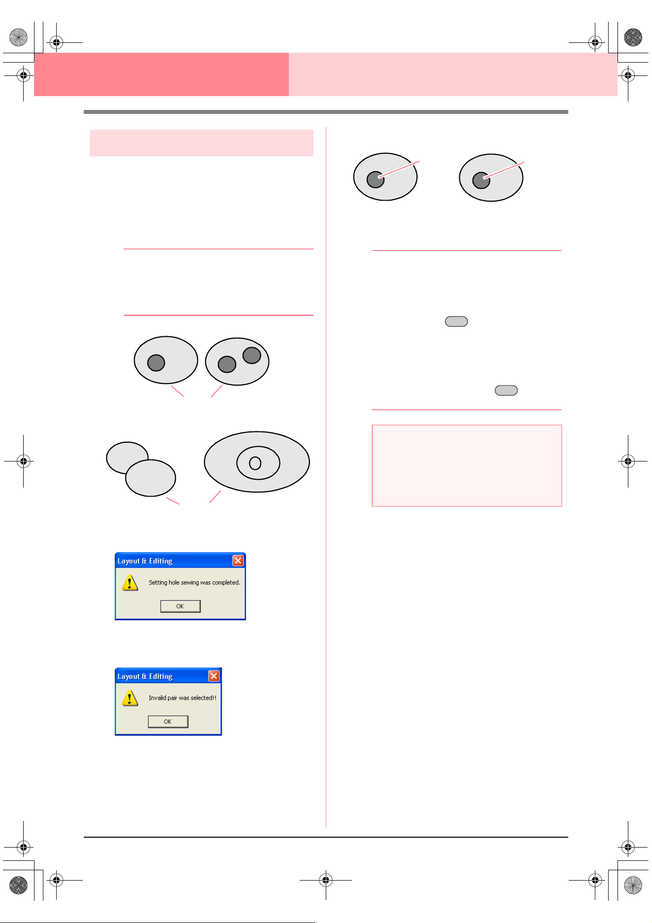
180
Layout & Editing Editing Embroidery Patterns
Specifying hole sewing
By specifying hole sewing, the stitching in
overlapping regions will not be sewn twice. Hole
sewing can be set only when one region completely
encloses another.
1. Select a pair of patterns, for example, a circle
included in an oval.
b Memo:
For a pair to be valid, one of the patterns
must be completely enclosed within the other
pattern, and not contain text, manual
punching patterns or stitch data.
2. Click Sew, then Set Hole Sewing.
→ If the selected pair can be set for hole
sewing, the following message appears.
→ If the selected pair cannot be set for hole
sewing, the following message appears.
3. Click OK to remove the message.
b Memo:
• Once a pair of patterns has been set for
hole sewing, they will move together if you
try to move one of the patterns. To select
only one pattern to be moved or resized,
hold down the key while selecting
it. (An alternate method is to cancel hole
sewing.)
• The outline of patterns created with the
Outline, Fan Shape and Arc & String tools
can be edited with the Point Edit tool if they
are first selected while the key is
held down.
■ Canceling hole sewing
1. Select a pattern that has been set for hole
sewing.
2. Click Sew, then Cancel Hole Sewing.
The pair of patterns can now be moved
independently.
Valid
Invalid
a Note:
To see better what the hole sewing setting
does, previewing the patterns before and
after setting hole sewing (For details, refer to
“Previewing the Sewing Image” on
page 187.)
Hole sewing not set
Hole sewing set
Sewn twice
Sewn once
Alt
Alt
PeDesignV6Eng.book Page 180 Thursday, July 8, 2004 11:59 AM
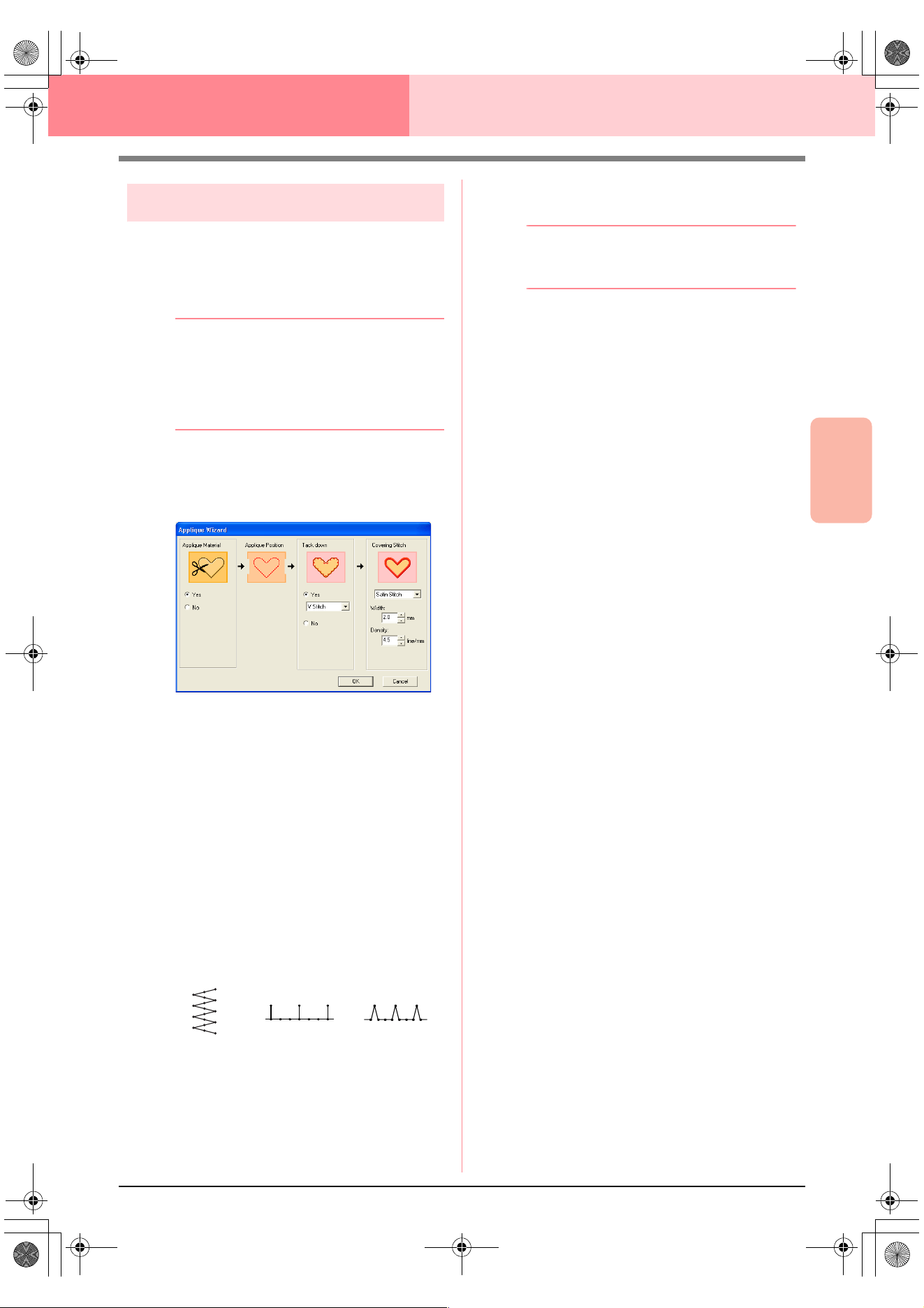
Advanced Opreation
Layout & Editing
181
Layout & Editing Editing Embroidery Patterns
Using the Applique Wizard
The Applique Wizard provides instructions for easily
creating appliqués.
1. Select a pattern with a closed shape, such as
a circle or square.
b Memo:
• A pattern with lines that cross over
themselves cannot be selected.
• The pattern selected for creating the
appliqué will be deleted after the Applique
Wizard is used.
2. Click Sew, then Applique Wizard.
→ The Applique Wizard dialog box ap-
pears.
3. Under Applique Material, select whether
(Yes) or not (No) the outline of the appliqué is
to be sewn onto the appliqué fabric as a guide
for cutting it out.
4. Under Applique Position, select whether or
not the outline of the appliqué positioning
outline is to be sewn onto the base fabric.
5. Under Tack down, select whether (Yes) or
not (No) the appliqué is to be basted onto the
base fabric. If Yes is selected, select the
basting stitch from the selector. You can also
select which stitch (satin stitch, E stitch or V
stitch) to use for the basting.
6. Under Covering Stitch, select the sew type
and other attributes for finishing the appliqué.
7. Click OK to finish the Applique Wizard and
display the design in the Design Page.
b Memo:
To quit the operation and close the dialog
box, click
Cancel
.
E stitch V stitch
Satin stitch
PeDesignV6Eng.book Page 181 Thursday, July 8, 2004 11:59 AM
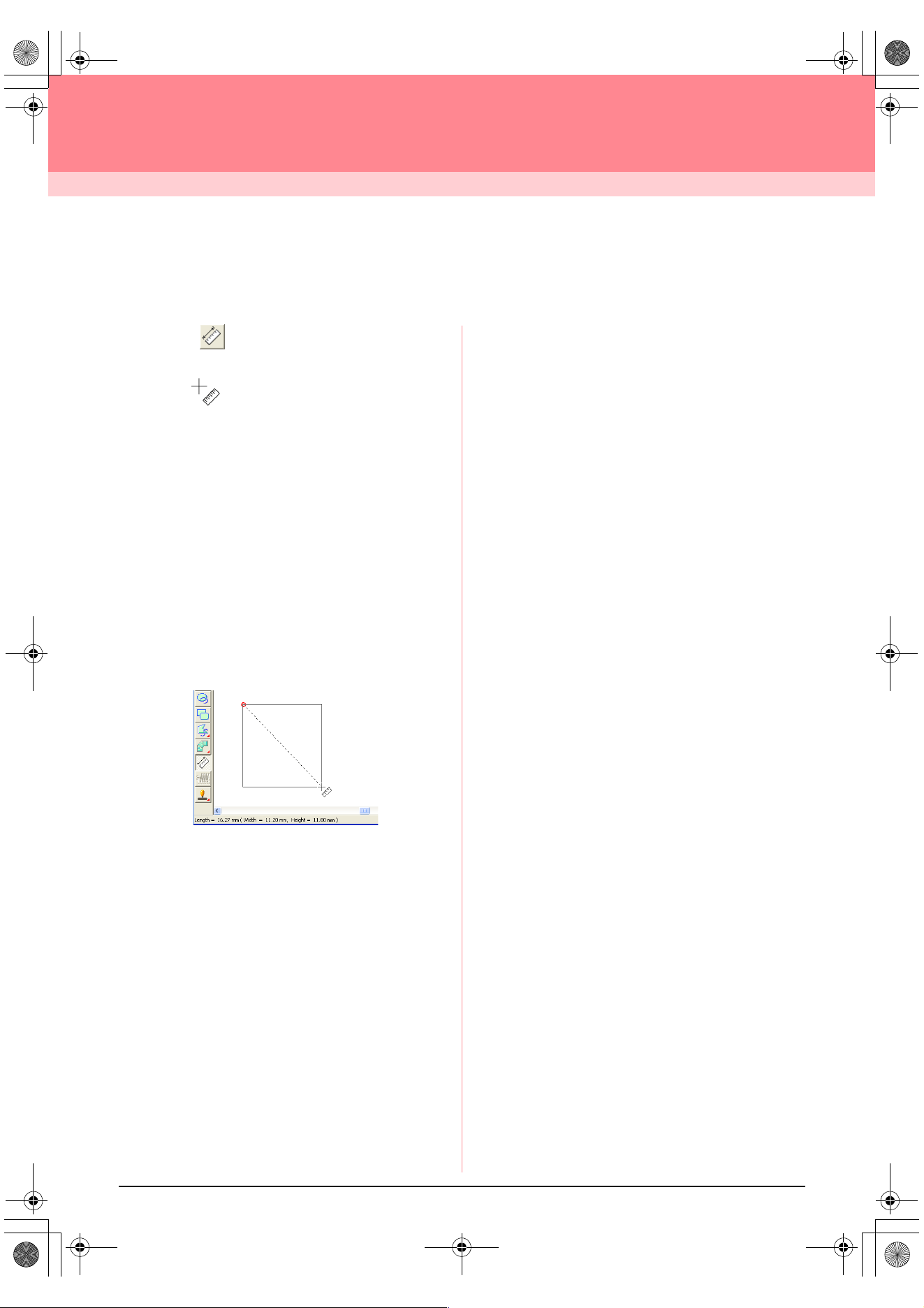
182
Layout & Editing
Checking Embroidery Patterns
Measuring the Distance Between Two
Points
1. Click on the Tool Box.
→ The shape of the pointer changes to
.
2. Move the pointer to the beginning of the part of
the object that you want to measure, and then
hold down the mouse button.
→ A small circle appears, indicating the start
point of the measurement.
3. Drag the pointer to view the measurement in
the status bar. The value beside Length
shows the length along a straight line between
the start point and the end point. The value
beside Width shows the horizontal distance
between the start point and the end point. The
value beside Height shows the vertical
distance between the start point and the end
point.
PeDesignV6Eng.book Page 182 Thursday, July 8, 2004 11:59 AM
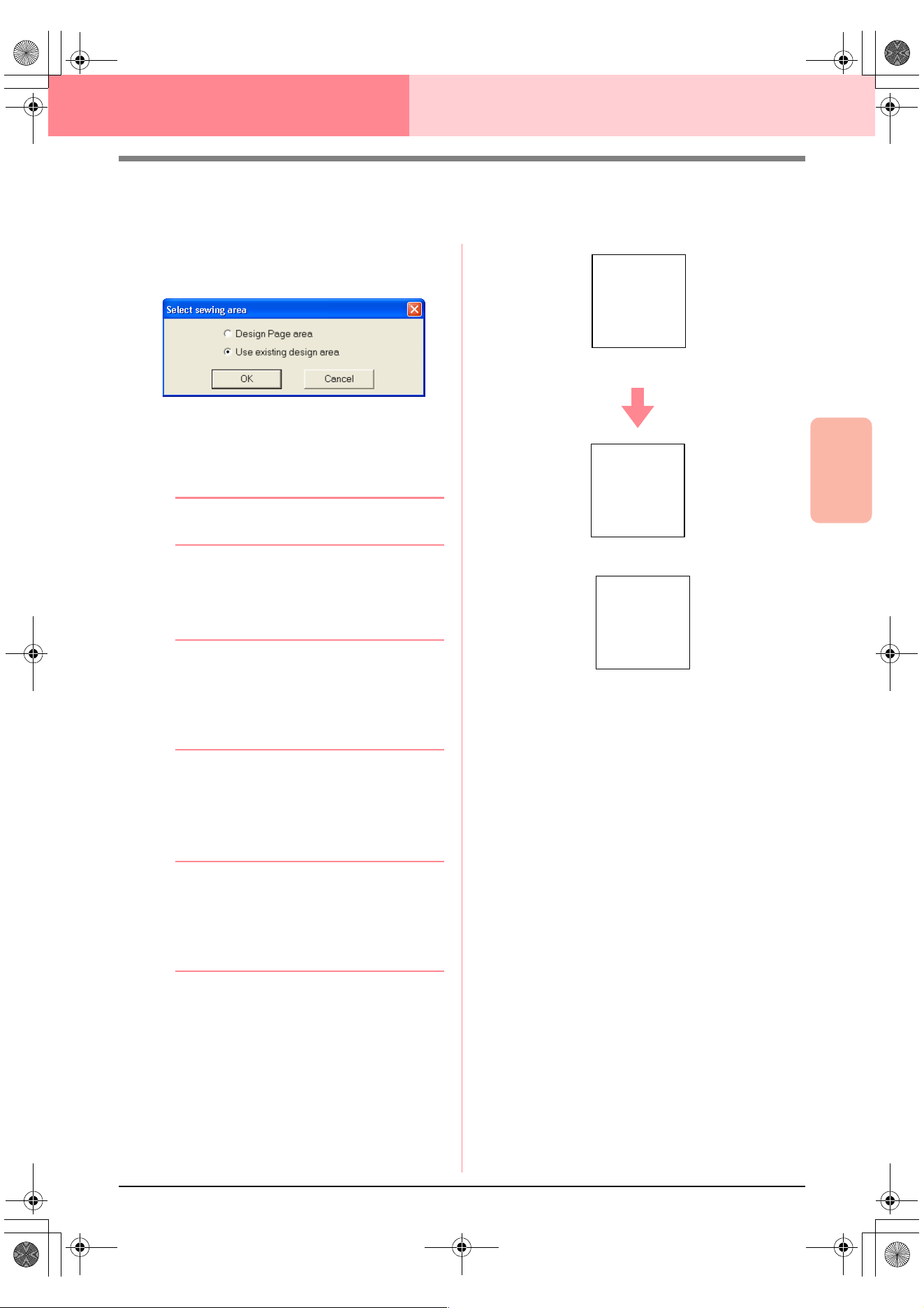
Advanced Opreation
Layout & Editing
183
Layout & Editing Checking Embroidery Patterns
Specifying the Sewing Area
The sewing area can be specified.
1. Click Sew, then Select Sewing Area.
→ The following dialog box appears.
2. Select the desired sewing area (Design Page
area or Use existing design area).
3. Click OK.
b Memo:
To quit the operation, click
Cancel
.
→ If Design Page area was selected, the
patterns will be sewn so that the needle
position when you start sewing is aligned
with the center of your Design Page.
b Memo:
When
Design Page area
is selected, the
dimension of the pattern matches the size of
the Design Page, therefore reducing the
ability to move a pattern around the layout
screen of your embroidering machine.
→ If Use existing design area was select-
ed, the patterns will be sewn so that the
needle position when you start sewing is
aligned with the center of the actual pat-
terns.
b Memo:
When
Use existing design area
is selected,
the actual pattern size is maintained,
therefore allowing greater mobility when
using the layout functions of your
embroidering machine.
c
“Specifying the Design Page” on
page 108
Design Page (on your screen)
A
Sewing area = Design Page area
A
Sewing area = Use existing design area
A
PeDesignV6Eng.book Page 183 Thursday, July 8, 2004 11:59 AM
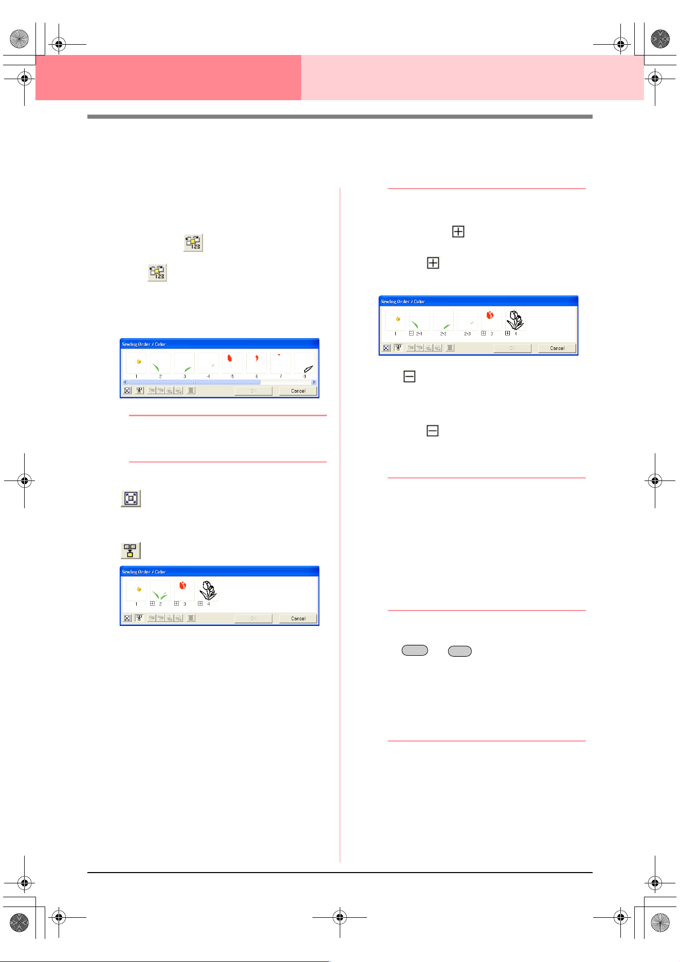
184
Layout & Editing Checking Embroidery Patterns
Checking and Editing the Sewing Order/
Color
The sewing order of pattern colors as well as the
sewing order of pattern objects of the same color
can be checked and modified as necessary.
Toolbar button:
1. Click , or click Sew, then Sewing Order/
Color.
→ A Sewing Order/Color dialog box similar
to the one shown below appears.
b Memo:
The dialog box can be made longer so that
all parts of the pattern can be viewed.
To enlarge each pattern to fill its frame, click
.
To display in one frame all patterns of the
same color that will be sewn together, click
.
2. Click OK to apply the settings and to close the
dialog box.
b Memo:
• When multiple patterns are combined into
one frame, appears to the left of the
number of that frame.
Click to display the combined
patterns in separate frames.
appears under the first frame, and
each frame is displayed with a subnumber
following the first, to indicate its sewing
order within the patterns of the same color.
Click
to recombine all of the patterns
back into one frame.
• To close the dialog box without applying
the changes to the settings, click
Cancel
.
Selecting data
1. Select a pattern in the Sewing Order/Color
dialog box.
→ The selected pattern has a pink line
around it, and “marching lines” appear
around the corresponding pattern in the
Design Page.
b Memo:
• To select multiple patterns, hold down the
or key while clicking the
frames for the desired patterns. In
addition, multiple frames can be selected
by dragging the pointer over them.
• When the
Sewing Order/Color
dialog box
is closed, the pattern that was selected in
the dialog box remains selected in the
Design Page, unless it is a locked pattern.
Shift
Ctrl
PeDesignV6Eng.book Page 184 Thursday, July 8, 2004 11:59 AM
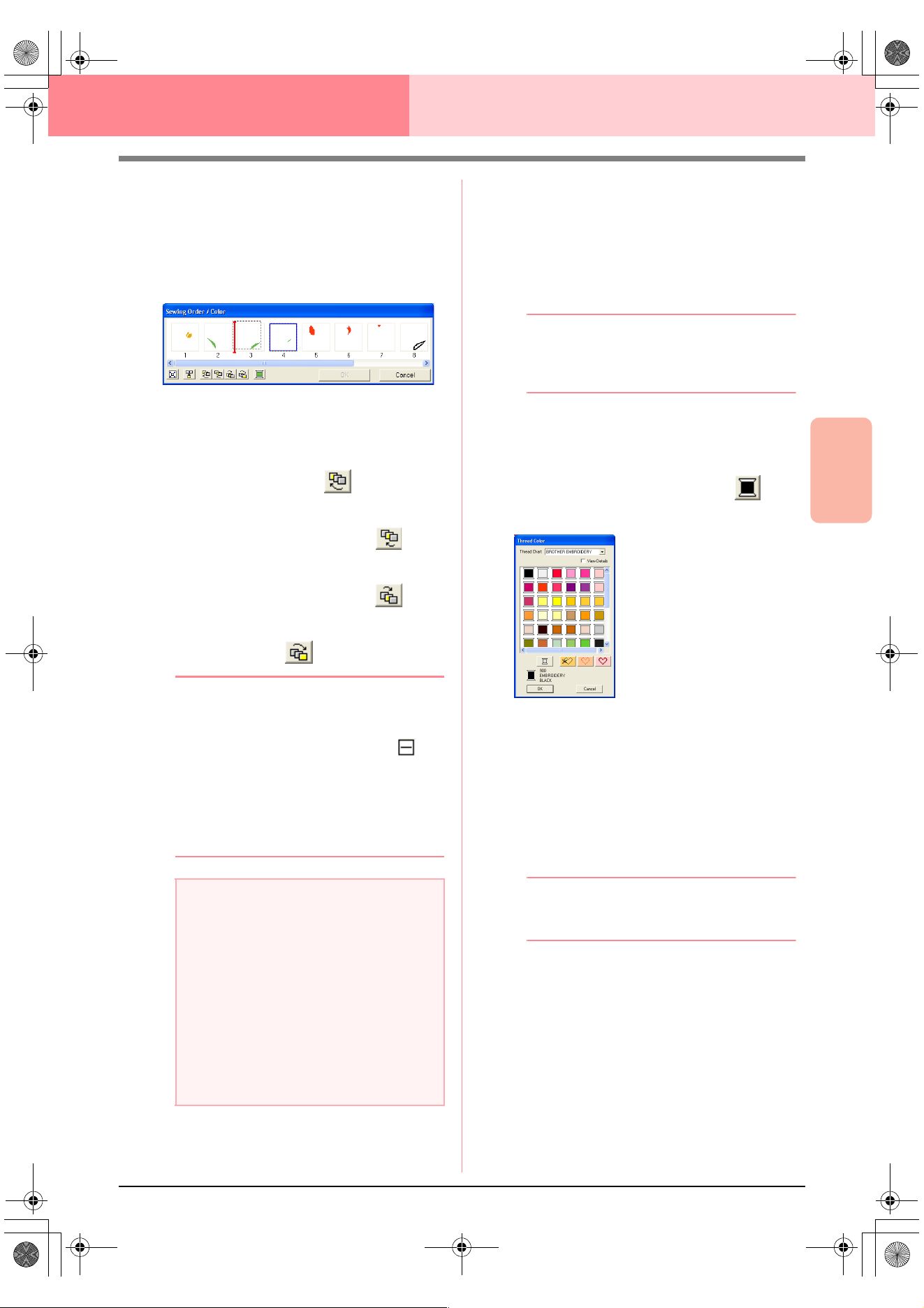
Advanced Opreation
Layout & Editing
185
Layout & Editing Checking Embroidery Patterns
Editing the sewing order
The sewing order can be changed by selecting the
frame containing the pattern that you want to move,
then dragging the frame to the new location. A
vertical red line appears, indicating the position
where the frame is being moved.
An alternative method for moving the frames is by
clicking the buttons at the bottom of the dialog box.
To move the selected pattern to the beginning
of the sewing order, click .
To move the selected pattern ahead one
position in the sewing order, click .
To move the selected pattern back one
position in the sewing order, click .
To move the selected pattern to the end of the
sewing order, click .
b Memo:
When dragging a frame containing combined
patterns, the patterns will display in separate
frames after you release them. Click to
the left of the first pattern for that color to
recombine them into one frame. Dropping a
frame containing combined patterns next to
another frame containing combined patterns
of the same color displays all patterns in
separate frames.
Combining patterns of the same color
When a Design Page contains a combination of
patterns, those patterns with the same color can be
grouped together from the Sewing Order/Color
dialog box. Simply drag the frame of the patterns
with the same color to position them beside each
other.
b Memo:
Check the stitching after changing the
sewing order to be sure that overlapping
patterns will not be sewn in the wrong order.
Editing the color
1. Select the frame for the pattern whose color
you want to change, and then click .
→ The Thread Color dialog box appears.
2. Select the desired color, and then click OK.
→ The object appears in the new color in the
Sewing Order/Color dialog box and in
the Design Page.
3. Click OK.
→ The pattern is displayed with the new col-
or.
b Memo:
To close the dialog box without applying the
changes to the settings, click
Cancel
.
a Note:
• Pieces of patterns that have been cut with
the Split stitch tool appear at the end of the
sewing order, depending on the sewing
order of the original pattern and can be
edited as any other pattern.
• The sewing order of the separate pattern
sections cannot be edited. It is
automatically determined by the order set
for the whole design.
• Objects with no sewing attributes appear
in a dotted frame, and there is no number
for the sewing order below the frame.
PeDesignV6Eng.book Page 185 Thursday, July 8, 2004 11:59 AM
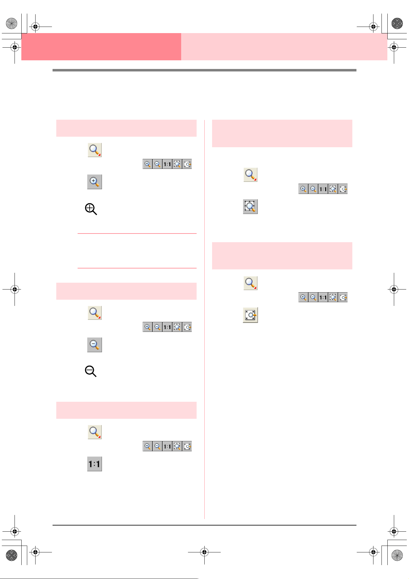
186
Layout & Editing Checking Embroidery Patterns
Zooming
You can zoom in to work on details of the embroidery pattern or you can zoom out to work on any part of the
embroidery pattern that cannot be viewed in the work area.
Zooming in
1. Click on the Tool Box.
→ Five buttons appear: .
2. Click .
→ The shape of the pointer changes to
.
3. Click the area that you want to view enlarged.
b Memo:
To zoom in on a specific area, move the
pointer near the desired area, and then drag
the pointer diagonally over the desired area.
Zooming out
1. Click on the Tool Box.
→ Five buttons appear: .
2. Click .
→ The shape of the pointer changes to
.
3. Click the area that you want to view reduced.
Zooming to actual size
1. Click on the Tool Box.
→ Five buttons appear: .
2. Click .
→ The Design Page is displayed at its actual
size.
Zooming on selected
objects
1. Select the objects that you want to zoom on.
2. Click on the Tool Box.
→ Five buttons appear: .
3. Click .
→ The Design Page is zoomed to display
only the selected objects.
Zooming Design Page to
window
1. Click on the Tool Box.
→ Five buttons appear: .
2. Click .
→ The entire Design Page is displayed to fit
within the window.
PeDesignV6Eng.book Page 186 Thursday, July 8, 2004 11:59 AM
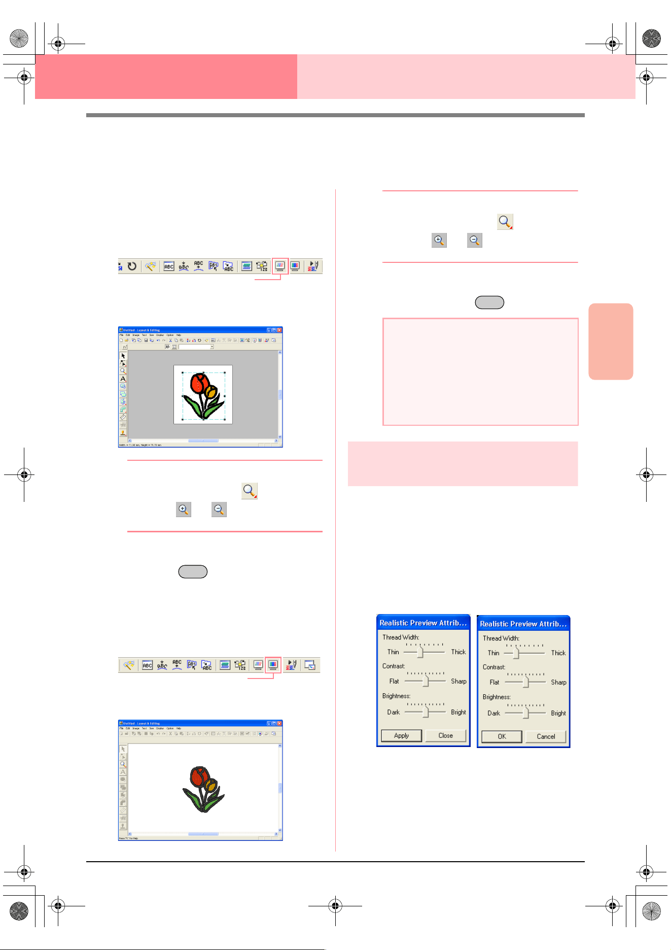
Advanced Opreation
Layout & Editing
187
Layout & Editing Checking Embroidery Patterns
Previewing the Sewing Image
Once the embroidery pattern is complete, you can display a preview of it in order to see how the stitching is
connected, or you can display a realistic preview of it in order to see how the pattern will appear once it is sewn.
1. To display a preview of the embroidery
pattern, click Display on the menu bar, and
then click Preview.
An alternate method is to click the Toolbar
button indicated below.
→ A preview of the embroidery pattern ap-
pears.
b Memo:
To zoom in (or out), click on the Tool
Box, click (or ), and then click the
desired area of the embroidery pattern.
2. To leave the preview display, repeat step 1.,
or press the key.
3. To display a realistic preview of the
embroidery pattern, click Display on the menu
bar, and then click Realistic Preview.
An alternate method is to click the Toolbar
button indicated below.
→ A realistic preview of the embroidery pat-
tern appears.
b Memo:
To zoom in (or out), click on the Tool
Box, click (or ), and then click the
desired area of the embroidery pattern.
4. To leave the realistic preview display, repeat
step
3., or press the key.
Changing realistic preview
settings
Set the realistic preview settings for the desired
realistic preview display.
1. Click Display, then Realistic Preview
Attribute Setting.
→ A Realistic Preview Attribute dialog box
similar to the ones shown below appears.
2. Use the Thread Width slider to set how wide
the thread will appear.
3. Use the Contrast slider to set the contrast.
4. Use the Brightness slider to set how bright
the display is.
Preview
Esc
Realistic Preview
a Note:
• The embroidery pattern cannot be edited
while the realistic preview is displayed.
• The Realistic Preview function cannot
display a clean preview of the pattern if the
monitor is set to 256 colors or less. The
monitor should be set to at least 16-bit
High Color (65536 colors).
Esc
When a realistic pre-
view is displayed
When a realistic pre-
view is not displayed
PeDesignV6Eng.book Page 187 Thursday, July 8, 2004 11:59 AM
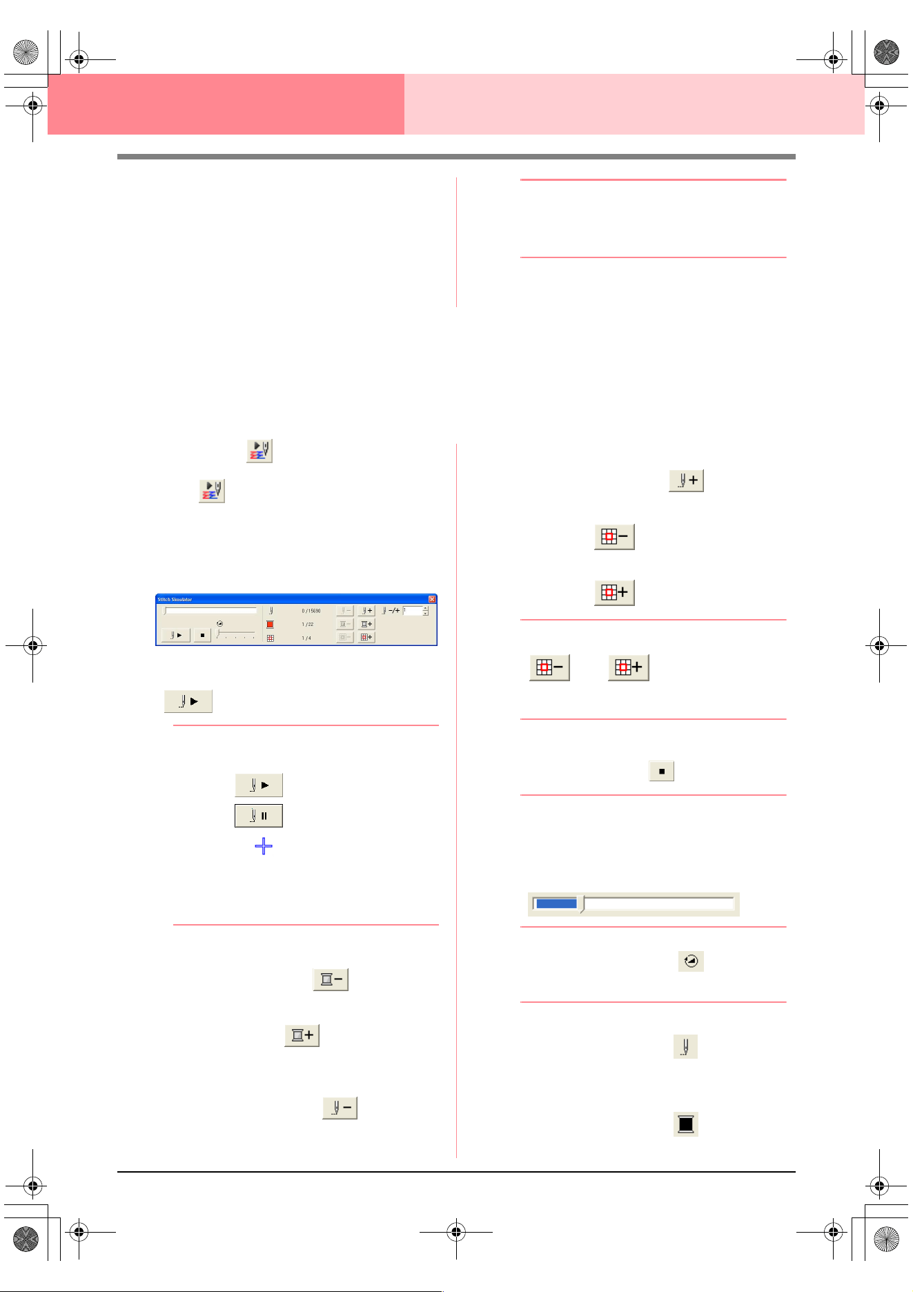
188
Layout & Editing Checking Embroidery Patterns
5. Click Apply to display a realistic preview of the
patterns with the new settings (when the
realistic preview is displayed).
Or, click OK to save the settings for the next
time that the Realistic Preview function is
select (when the realistic preview is not
displayed).
b Memo:
To close the dialog box without applying the
changes to the settings, click
Close
or
Cancel
.
c
“Previewing the Sewing Image” on
page 187
Checking the Stitching
The actual stitching as it will be performed by the sewing machine can be viewed using the stitch simulator.
You can choose to view the stitching simulation of whole designs or, for large patterns created on a custom-
sized Design Page, view it by pattern section.
Toolbar button:
1. Click , or click Display, then Stitch
Simulator.
The Stitch Simulator dialog box appears,
and the embroidery pattern is cleared from the
Design Page.
To begin the stitching simulation, click
.
b Memo:
• During the stitching simulation, the play
button ( ) changes to a pause
button ( ).
• A marker ( ) indicates the current
position in the simulation.
• To get a better view of the stitching, zoom
in on the design before opening the
Stitch
Simulator
dialog box.
To reverse the simulation to the beginning of
the previous color, click .
To advance the simulation to the beginning of
the next color, click .
To reverse the stitching by a specific number
of stitches, type or select the desired number
of stitches, and then click .
To advance the stitching by a specific number
of stitches, type or select the desired number
of stitches, and then click .
To reverse the stitching to the previous pattern
section, click .
To advance the stitching to the next pattern
section, click .
b Memo:
and
appear only for
patterns created on custom-sized Design
Pages.
To stop the simulation and return to the
previous display, click .
b Memo:
The slider shows the current location in the
simulation. In addition, the slider can be
moved to change the position in the
simulation.
Drag the slider indicated by to adjust the
simulation stitching speed.
b Memo:
• The first number beside indicates the
number of the current stitch, and the
second number indicates the total number
of stitches.
• The first number beside indicates the
number of the color being drawn, and the
PeDesignV6Eng.book Page 188 Thursday, July 8, 2004 11:59 AM
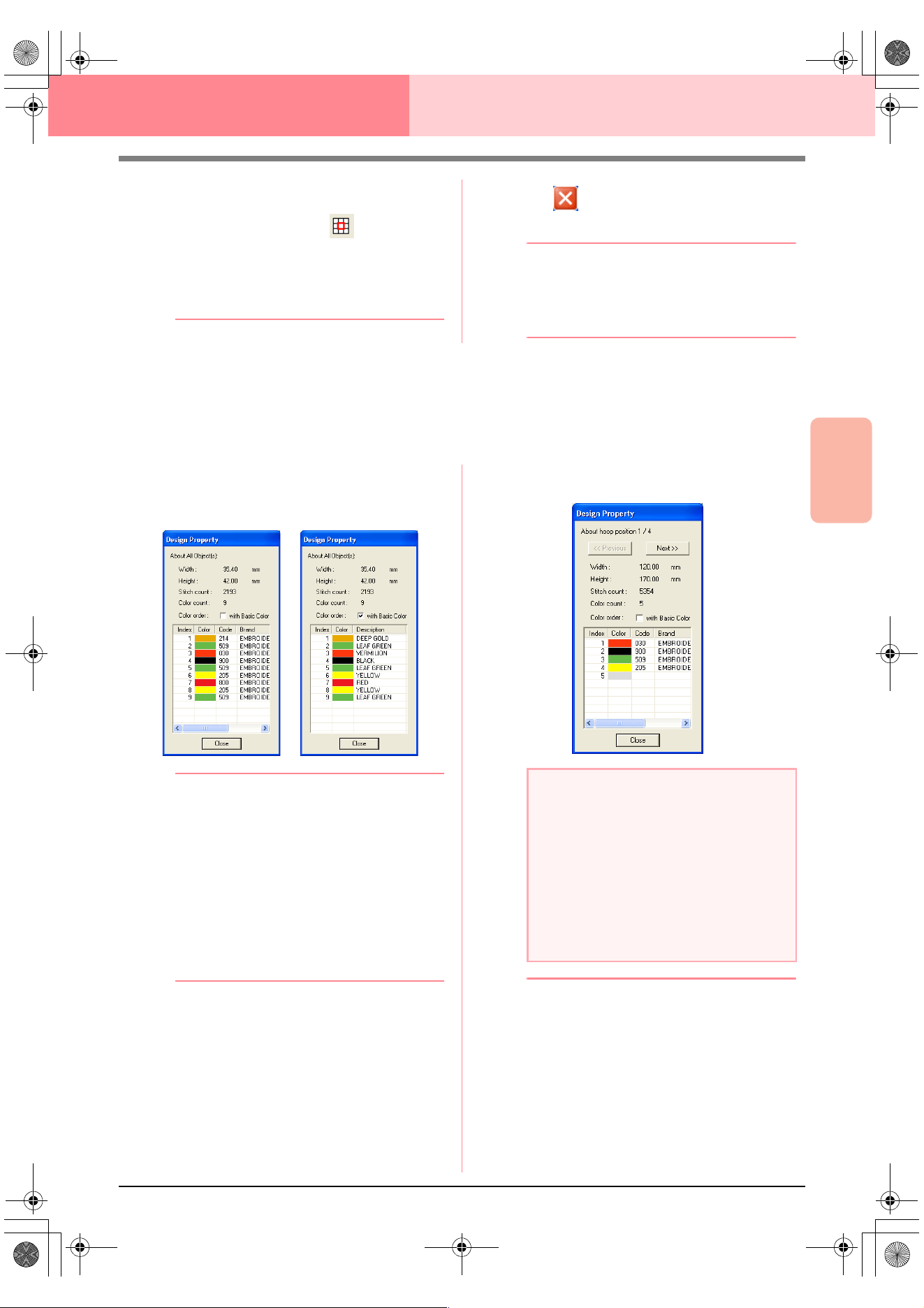
Advanced Opreation
Layout & Editing
189
Layout & Editing Checking Embroidery Patterns
second number indicates the total number
of colors used.
• The first number beside indicates the
pattern section that is displayed, and the
second number indicates the total number
of hoop sections in the pattern. This
indicator appears only for patterns created
on custom-sized Design Pages.
2. Click in the upper-right corner of the
dialog box to close the dialog box.
b Memo:
If a pattern was selected when the
Stitch
Simulator
dialog box was displayed, only
the selected pattern is drawn in the
simulation.
Checking Embroidery Pattern Information
Sewing information such as dimensions, needle count, color count and color order of patterns can be checked
in the Design Property dialog box.
1. Click Option, then Design Property.
→ The Design Property dialog box ap-
pears.
b Memo:
• You can select and check the properties of
individual objects within the embroidery
pattern by selecting the pattern before
opening this dialog box.
• To display the colors as the machine’s
preset color names, select the
With Basic
Color
check box.
• This dialog box can be resized. The size of
the dialog box is retained until it is changed
again.
• To close the dialog box, click
Close
.
→ If the Design Page was set to Custom
Size and no object in the Design Page is
selected, the sewing information for the
entire Design Page is displayed hoop by
hoop, and a Design Property dialog box
similar to the one shown below appears.
b Memo:
• The Design Page is automatically zoomed
in on or zoomed out from to fit in the entire
window.
• The first line of the dialog box shows the
position of the displayed pattern section
within the embroidery hoop installation
order.
• Only the patterns within the corresponding
section appear in the Design Page and are
outlined in red.
a Note:
If a pattern is larger than the Design Page or
if it is positioned so that it does not
completely fit within the Design Page, the
error message “Please change the object
size or position.” appears instead of this
dialog box. After the pattern causing the
error is displayed selected, change its size
or position. (If more than one pattern causes
the error message to appear, they will be
displayed in the sewing order.)
PeDesignV6Eng.book Page 189 Thursday, July 8, 2004 11:59 AM
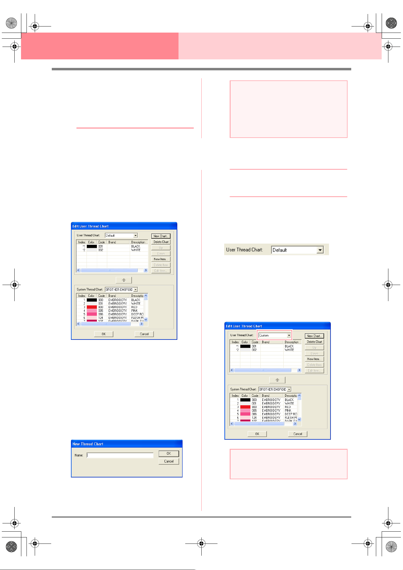
190
Layout & Editing Checking Embroidery Patterns
• To display information for other pattern
sections, click
Previous
or
Next
.
• The pattern sections are displayed in order
from left to right, top to bottom. Pattern
sections that do not contain any stitching
will not be displayed.
• To close the dialog box, click
Close
.
Editing User Thread Color Lists
Original thread color charts can be created and
edited.
1. Click Option, then Edit User Thread Chart.
→ A dialog box similar to the one shown be-
low appears.
User thread charts can be created and edited
to contain a list of threads that are used most
often or a list of all threads that you have.
Thread data from system thread charts can be
included or new thread data can be added.
Creating a new thread chart
1. Click New Chart.
→ The New Thread Chart dialog box ap-
pears.
2. Type in the name of the chart, and then click
OK to save the chart with the entered name.
b Memo:
A saved chart can be selected from the
User
Thread Chart
selector, then edited.
Deleting a chart
1. From the User Thread Chart selector, select
the chart that you want to delete.
2. Click Delete Chart to delete the selected
chart.
Editing a chart
1. From the User Thread Chart selector, select
the chart that you want to edit.
a Note:
The
Previous
button cannot be clicked
when the design corresponding to the first
hoop is already displayed. In addition, the
Next
button cannot be clicked when the
design corresponding to the last hoop is
already displayed.
a Note:
If no chart is selected, the editing operation
cannot be performed.
PeDesignV6Eng.book Page 190 Thursday, July 8, 2004 11:59 AM
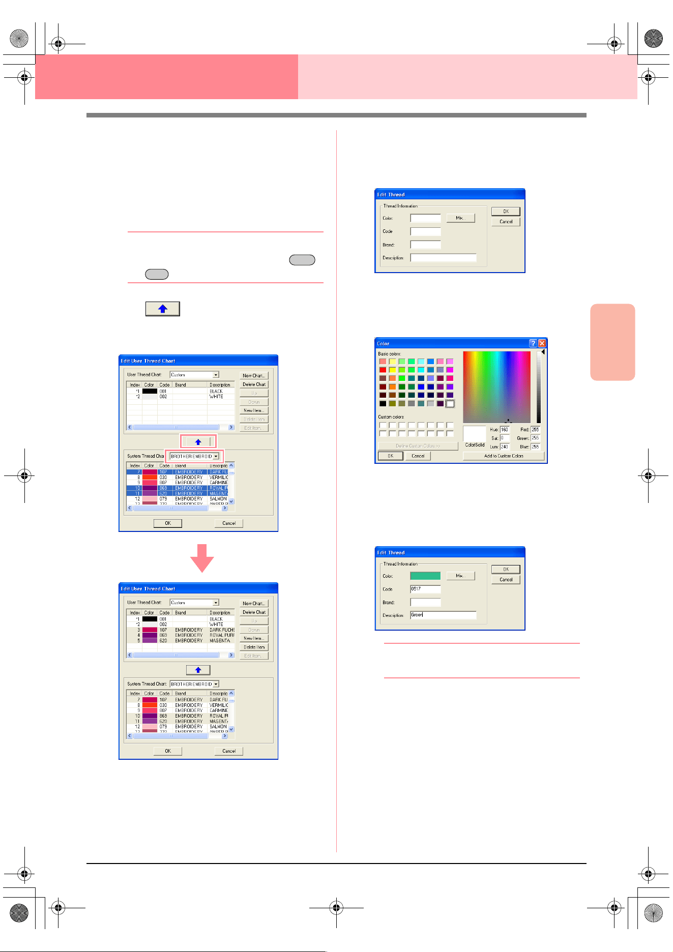
Advanced Opreation
Layout & Editing
191
Layout & Editing Checking Embroidery Patterns
Adding an item from a system thread chart
1. From the System Thread Chart selector,
select the brand of thread that you want to
add.
2. From the list at the bottom of the dialog box,
click the thread colors that you want to add.
b Memo:
To add multiple items, hold down the
or keys while selecting thread colors.
3. Click .
→ The selected items are added to the list in
the user thread chart.
Adding a new item
1. Click New Item.
→ The Edit Thread dialog box appears.
2. To create a new color, click Mix.
→ A dialog box similar to the one shown be-
low appears.
3. Specify the color, and then click OK to add the
specified color to the Edit Thread dialog box.
4. If necessary, type in the code, brand and
description into the appropriate boxes.
b Memo:
Only numbers can be entered for the code.
Shift
Ctrl
Advanced_02.fm Page 191 Friday, July 9, 2004 1:53 PM
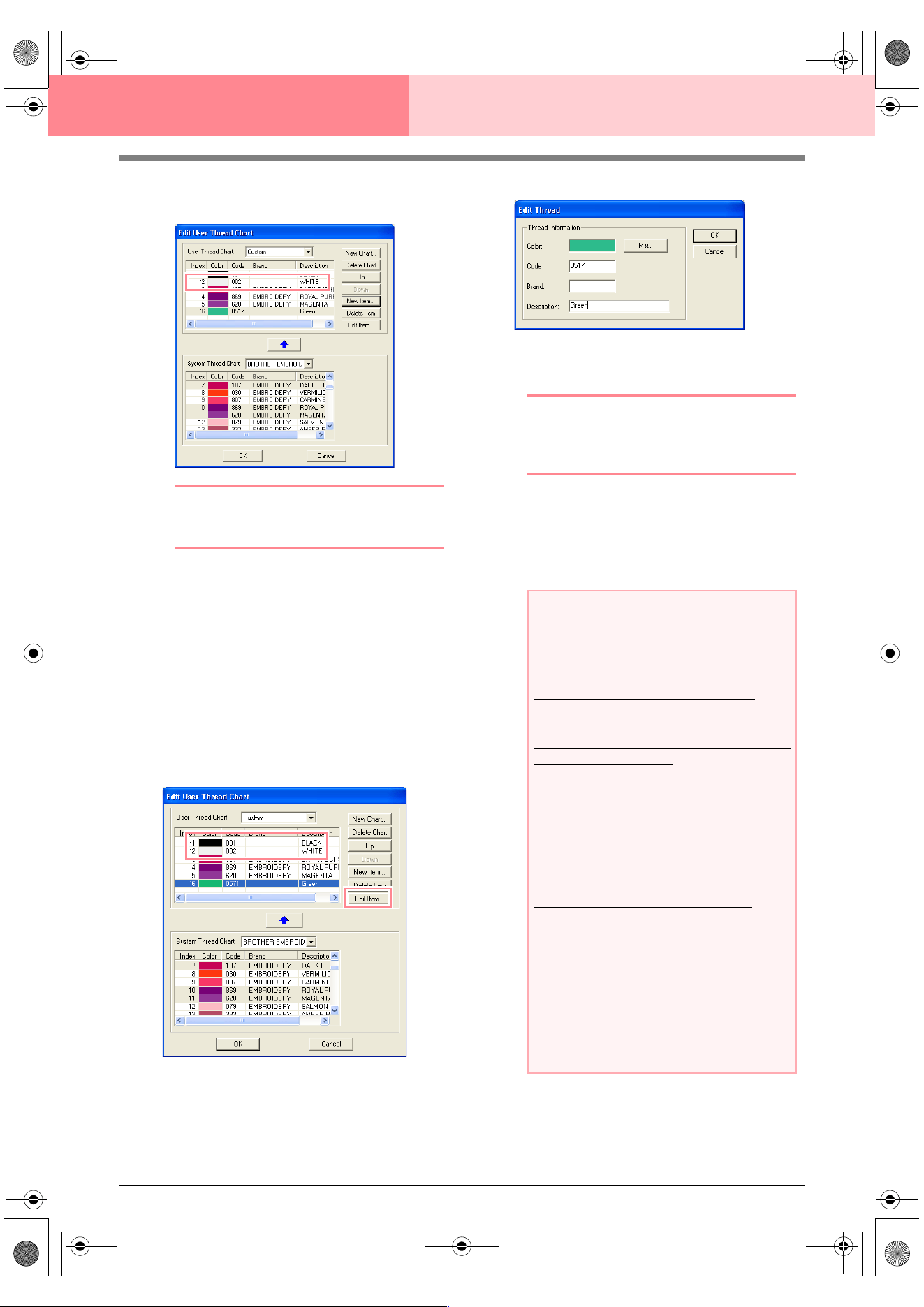
192
Layout & Editing Checking Embroidery Patterns
5. Click OK to add the new item to the user
thread chart.
b Memo:
An asterisk (*) appears in front of the index
number of newly added items.
Deleting an item
From the list for the user thread chart, select the
item to be deleted, and then click Delete Item to
delete the item from the user thread chart.
Editing an item
An item registered in the list for a user thread chart
can be edited to change the color or thread number.
1. From the list for the user thread chart, select
the item to be edited, and then click Edit Item.
→ The following dialog box appears.
2. Edit the item details in the same way as
adding an item.
b Memo:
As with newly added items, an asterisk (*)
appears in front of the index number of
edited items.
Changing the order of items
From the list for the user thread chart, select the
item to be moved, and then click up or down to
change the order of the item.
a Note:
Thread colors in embroidery patterns
created with this software may appear
differently on the embroidering machine.
1. Embroidering machines without a function
for displaying thread color information
The specified thread information cannot be
displayed on some machines.
2. Embroidering machines with a function for
displaying thread colors
Of the thread information specified in the
embroidery pattern, only the thread colors
are displayed on the machine. However, the
thread color names that are displayed are
limited to the machine’s preset thread color
names. Therefore, use thread color names
in the embroidery pattern that are closest to
the machine’s preset thread color names.
3. Machines with a thread color index
Some machines can display the thread
information (such as the color, the color
name as well as the brand name and thread
number) specified with this software. The
machines can display the color, the color
name as well as the brand name and thread
number.
However, for items edited or added by the
user (items marked with an asterisk (*)), only
the thread number is displayed.
Advanced_02.fm Page 192 Friday, July 9, 2004 1:53 PM
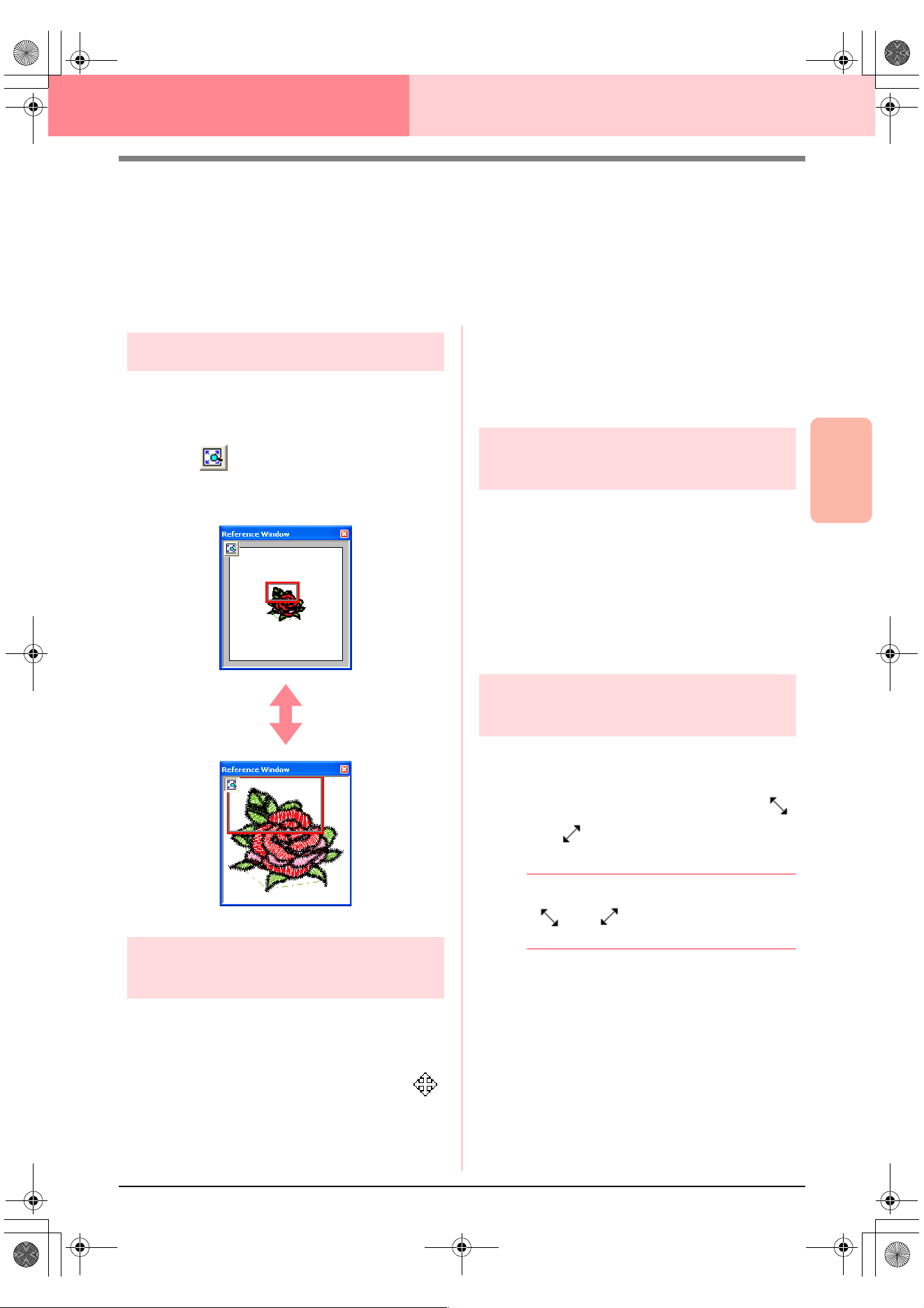
Advanced Opreation
Layout & Editing
193
Layout & Editing Checking Embroidery Patterns
Viewing Patterns in the Reference
Window
All outlines and patterns in the Design Page are displayed in the Reference Window, giving you an overall view
of the pattern while you work on a detailed area. The display area frame (red rectangle) indicates the part of
the pattern displayed in the Design Page.
Zooming
The pattern displayed in the Reference Window can
be reduced to fit completely within the Reference
Window or enlarged to display only the pattern.
1. Click .
→ The pattern is displayed so that it fills the
Reference Window.
Moving the display area
frame
The part of the pattern displayed in the Design Page
can be selected from the Reference Window.
1. Move the pointer over the display area frame.
→ The shape of the pointer changes to .
2. Drag the display area frame so that it
surrounds the desired part of the pattern.
→ The selected part of the pattern is dis-
played in the Design Page.
Redrawing the display area
frame
Instead of moving the display area frame, the frame
can be redrawn to display the desired part of the
pattern in the Design Page.
1. Drag the pointer over the desired part of the
pattern in the Reference Window.
→ The display area frame is redrawn, and
the selected part of the pattern is dis-
played in the Design Page.
Scaling the display area
frame
1. Move the pointer over a corner of the display
area frame.
→ The shape of the pointer changes to
or , depending on the corner that the
pointer is over.
b Memo:
and are for scaling the height
and width.
2. Drag the corner to adjust the display area
frame to the desired size.
PeDesignV6Eng.book Page 193 Thursday, July 8, 2004 11:59 AM
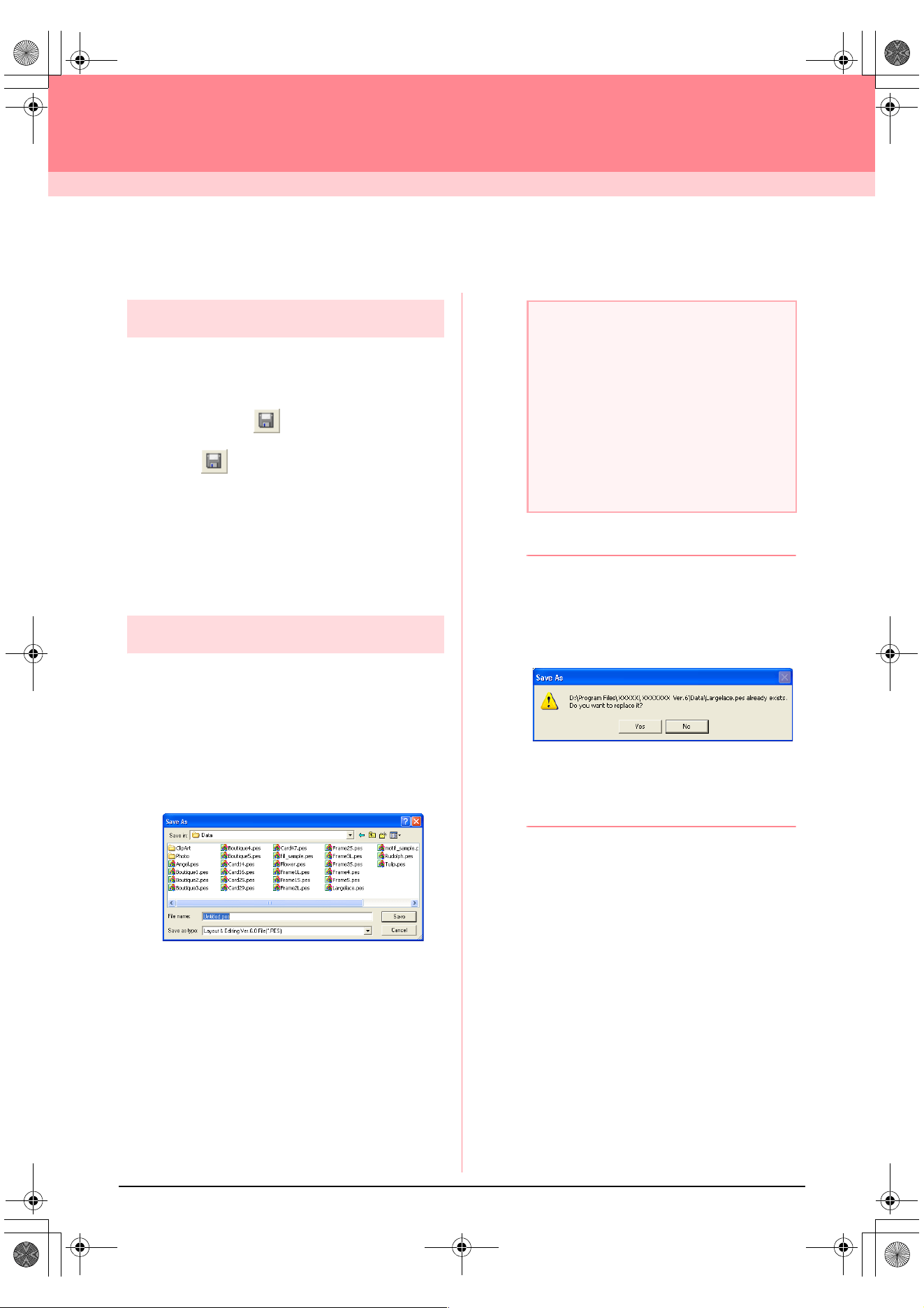
194
Layout & Editing
Saving and Printing
Saving
Overwriting
Once the image or pattern has been saved,
changes can easily be saved so that the latest
version can be retrieved later.
Toolbar button:
1. Click , or click File, then Save.
→ If the image or pattern has already been
saved at least once, the file is saved im-
mediately.
→ If no file name has been specified or if the
file cannot be found, the Save As dialog
box appears.
Saving with a new name
The current file can be saved with a different file
name in order to keep the original unchanged or to
keep various versions of the same image or pattern.
The files are saved as .pes files.
1. Click File, then Save As.
→ A Save As dialog box similar to the one
shown below appears.
2. Select the drive and the folder, and then type
in the file name.
3. Click Save to save the data.
b Memo:
• To quit the operation, click
Cancel
.
• If a file already exists with the name
specified in the
Save As
dialog box, the
following message appears.
• To overwrite the file, click
Yes
.
• If you do not want to overwrite the
existing file, click
No
. You can then
enter a different file name.
→ The new file name appears in the title bar
of the Layout & Editing window.
a Note:
• If you select a file type of a previous
software version, saved .pes files can be
opened with that version of the software;
however, all saved data will be converted
to stitch data.
• Custom-sized Design Pages cannot be
saved in a software version prior to
version 6.
• Custom-sized Design Pages will be saved
in one file, but the stitch data is saved
separately for all hoop sizes.
PeDesignV6Eng.book Page 194 Thursday, July 8, 2004 11:59 AM
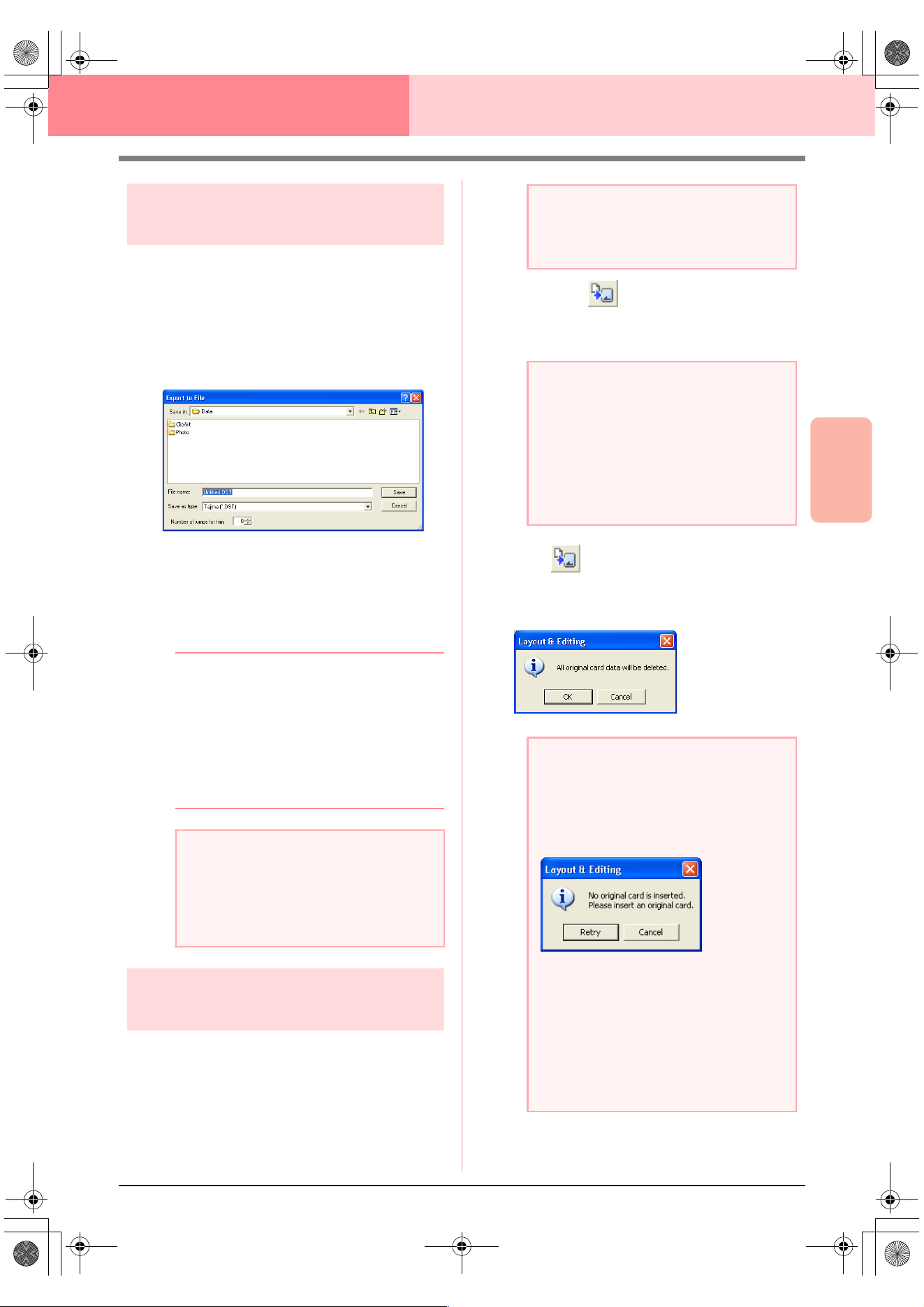
Advanced Opreation
Layout & Editing
195
Layout & Editing Saving and Printing
Outputting data in a
different format
The data shown in the Design Page can be exported
as a file of a different format (.dst, .hus, .exp, and
.pcs).
1. Click File, then Export.
→ A dialog box similar to the one shown be-
low appears.
2. Select the drive and the folder, and then type
in the file name.
3. Select the format (.dst, .exp, .pcs, or .hus) in
which you want to export the file.
b Memo:
With the DST format, jump codes are used to
indicate when the thread must be cut in order
to change the thread color. Since the number
of codes differ depending on the sewing
machine being used, type or select the
appropriate value in the
Number of jumps
for trim
box. (This setting can only be
specified if the .dst format is selected.)
Writing an embroidery
pattern to an original card
You can save a displayed embroidery pattern onto
an original card in order to transfer it to a sewing
machine.
Toolbar button:
1. Insert an original card into the USB card writer
module.
2. Click , or click File, then Write to Card,
then Current Design.
→ The following message appears.
a Note:
• Some patterns imported from embroidery
cards cannot be exported.
• Patterns designed on a custom-sized
Design Page will be exported as a simple
file, and will not be split into sections.
a Note:
Be sure that the hoop size of the pattern
does not exceed the hoop that will be used
on the embroidering machine.
a Note:
• The original card is inserted correctly
when you hear it snap into place.
• The sewing machine must be turned off
before original cards are inserted or
removed. However, it is not necessary to
turn off the computer when original cards
are inserted or removed from the USB
card writer module.
a Note:
• If the original card is not brand new, make
sure that the patterns already stored on
the card are no longer needed.
• If no original card is inserted, the following
message appears
• Correct the problem, and then click
Retry
.
• To quit the operation, click
Cancel
.
• If a .pes file is saved with objects
extending off the Design Page or with the
number of stitches or number of colors for
the objects exceeding the Design Page
limitations, the patterns cannot be saved
on an original card.
PeDesignV6Eng.book Page 195 Thursday, July 8, 2004 11:59 AM
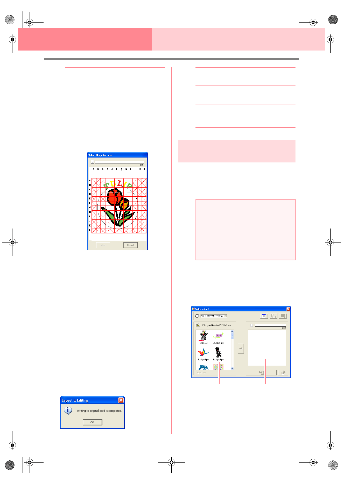
196
Layout & Editing Saving and Printing
b Memo:
Patterns created on a custom-sized Design
Page are written to cards split into their various
sections.
If the total size of the pattern exceeds the
capacity of the original card or if your Design
Page is set to a custom size of 90
×
90 cm (3.54”
×
3.54”), and is split into over 80 sections, you
will need to split the pattern into sections and
write them onto several original cards.
In this case, the
Select Hoop Sections
dialog
box appears to let you select the sections that
can be written in the available space on the card.
The progress bar at the top of the dialog box
shows the available space on the card as you
select pattern sections to be written to the card.
The space used by the selected pattern sections
appears in blue. If, however, you select a pattern
section that exceeds the size limit, the space
used appears in yellow, and if you select several
pattern sections which exceed the size limit, the
space used appears in red.
Click each pattern section to select it, and
then click
Write
to write the selected pattern
sections to the card. To deselect a pattern
section, simply click it again. (The
Write
button is available only when a section is
selected and the space on the card is
sufficient to receive the selected patterns.)
3. Click OK.
→ The message “Now writing” appears while
the current embroidery pattern is trans-
ferred to the original card, and then the
following message appears.
b Memo:
To quit the operation, click
Cancel
.
4. Click OK to close the message.
b Memo:
“Overwriting” on page 194 and “Saving with
a new name” on page 194
Writing multiple embroidery
files to an original card
You can save multiple .pes files to an original card
at the same time.
1. Insert an original card into the USB card writer
module.
2. Click File, then Write to Card, then Other
PES files.
→ The following dialog box appears with the
contents of the last folder accessed dis-
played in the available patterns list.
a Note:
• The original card is inserted correctly
when you hear it snap into place.
• The sewing machine must be turned off
before original cards are inserted or
removed. However, it is not necessary to
turn off the computer when original cards
are inserted or removed from the USB
card writer module.
Available patterns
Selected patterns
PeDesignV6Eng.book Page 196 Thursday, July 8, 2004 11:59 AM
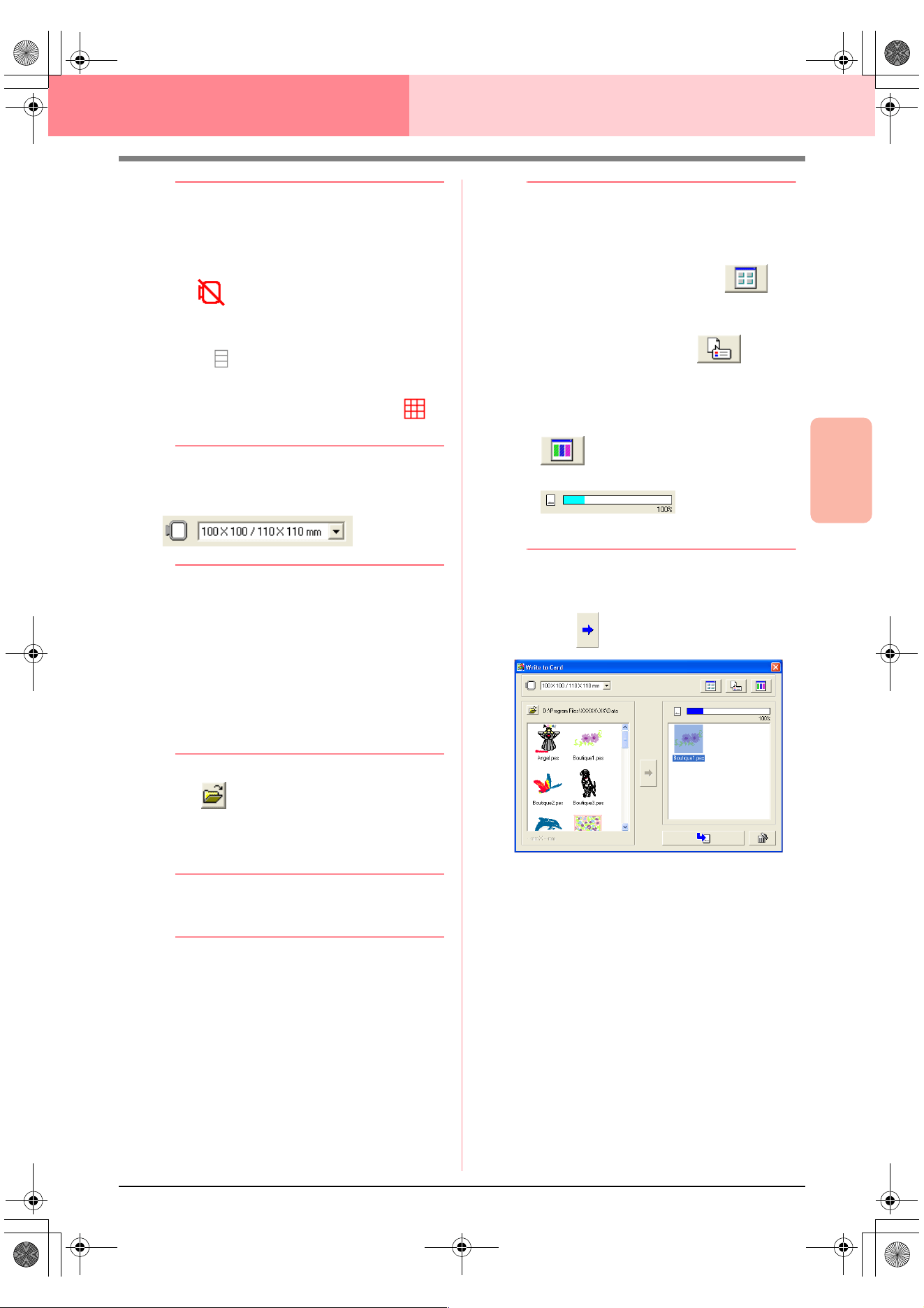
Advanced Opreation
Layout & Editing
197
Layout & Editing Saving and Printing
b Memo:
• Patterns that are either too large or have
too many stitches for the embroidery hoop
size selected with the Hoop size selector,
are displayed with a red crossed-out hoop
().
• Patterns created for the optional extra-
large embroidery hoop are displayed with
the symbol.
• Patterns created on a custom-sized
Design Page are displayed with the
symbol.
3. From the Hoop size selector, select the
appropriate size of embroidery hoop.
b Memo:
• Do not select a hoop size larger than the
embroidery hoop that can be used with
your embroidering machine. Otherwise,
the created original card will not work
correctly with the embroidering machine.
• Make sure to select a hoop size that is the
same or larger than the largest hoop size
of the files you want to write to the card,
otherwise the pattern cannot be written to
a card and “
×
” appears.
4. Click , and then select the folder where
the desired pattern file (.pes) is saved. The
available pattern list displays the image of the
embroidery pattern files (.pes).
b Memo:
If an original card was selected, the patterns
saved on the inserted card are displayed.
5. In the available patterns list, click the pattern
that you want to write onto a card to select it.
b Memo:
• To deselect a file, simply click it again.
• To switch between the large and small
display size of the embroidery pattern
images shown in the lists, click .
• To display the information (size, number of
stitches, and colors) for the pattern
selected in either list, click . (This
button is available only if a single pattern is
selected.)
• To display a three-dimensional image of
the pattern selected in either list, click
. (This button is available only if a
single pattern is selected.)
• shows the
capacity of the patterns selected in the
selected patterns list.
6. To add the embroidery pattern selected in the
available patterns list to the selected patterns
list, click .
PeDesignV6Eng.book Page 197 Thursday, July 8, 2004 11:59 AM
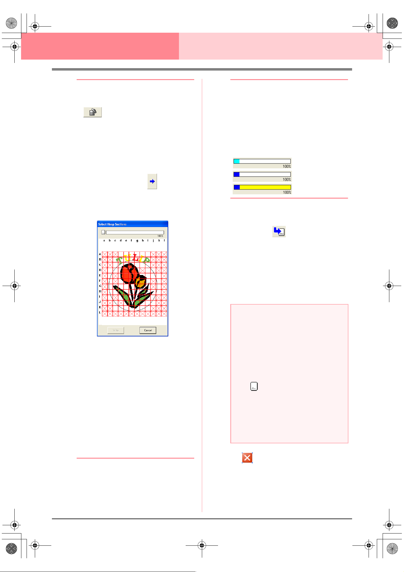
198
Layout & Editing Saving and Printing
b Memo:
• To remove the embroidery pattern
selected in the selected patterns list, click
.
• Patterns created on a custom-sized
Design Page are written to cards split into
their various hoop sections.
If the total size of the pattern exceeds the
capacity of the original card or if your hoop
size is 90
×
90 cm (3.54”
×
3.54”) and the
Design Page is split into over 80 sections,
the available space appears in yellow on
the progress bar. When is clicked,
the
Select Hoop Sections
dialog box
appears, allowing you to select the pattern
sections to be written in the available
space on the card.
The progress bar at the top of the dialog box
shows the available space on the card as
you select pattern sections to be written to
the card. The space used by the selected
pattern sections appears in blue. If, however,
you select a pattern section that exceeds the
size limit, the space used appears in yellow,
and if you select several pattern sections
which exceed the size limit, the space used
appears in red.
Click each pattern section to select it, and
then click
Write
to write the selected pattern
sections to the card. To deselect a pattern
section, simply click it again. (The
Write
button is available only when a section is
selected and the space on the card is
sufficient to receive the selected patterns.)
7. Continue until all embroidery patterns that you
want to write to an original card are selected.
b Memo:
During this process, the card capacity
indicator allows you to plan which patterns
you would like to save on an original card.
The space used by patterns in the selected
patterns list appears in blue. The space used
by the files selected in the available patterns
list appears in light blue. If several files
exceed the available space, the progress bar
appears in yellow.
8. After the embroidery patterns to be written to
the original card appear in the selected
patterns list, click to write the patterns to
the card.
→ The patterns are written to an original
card in the order that they are listed after
all data already on the card is erased.
After the patterns are written to the origi-
nal card, the card containing the patterns
can be used with the embroidery ma-
chine.
9. Click in the upper-right corner of the
dialog box to close the dialog box.
a Note:
• Since original cards are erased
completely before patterns are written to
it, it is useful to keep a copy with the
contents of each card in the card folder
that comes with the software so that you
can easily recover the files that were on
the card.
• To check the contents of the original card,
open the
Browse
dialog box, and then
click , which appears at the top of the
list in the
Browse
window. The patterns
saved on the inserted card appear in the
available patterns list.
• Do not remove the card or unplug the USB
cable while patterns are being written to
the card (while the LED indicator is
flashing).
PeDesignV6Eng.book Page 198 Thursday, July 8, 2004 11:59 AM
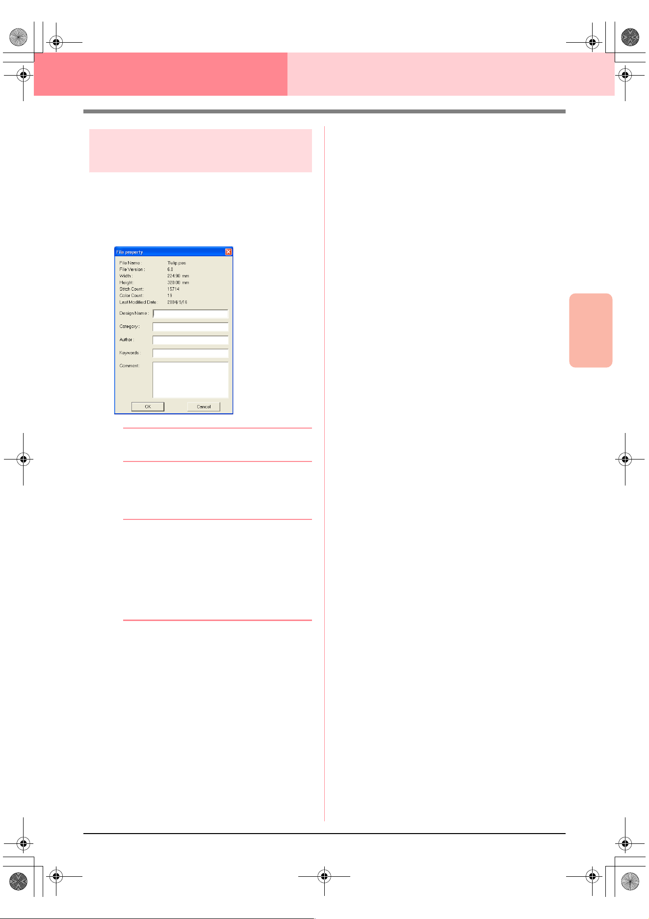
Advanced Opreation
Layout & Editing
199
Layout & Editing Saving and Printing
Adding comments to saved
.pes files
You can enter comments and information about the
pattern to a saved .pes file.
1. Click File, then Property.
→ The File Property dialog box appears.
b Memo:
The stitch count is the total of all stitches.
2. To enter or change the information, type it in.
3. Click OK to save the entered information.
b Memo:
• The entered information will be saved to
the file the next time that it is saved.
• To quit the operation and close the dialog
box, click
Cancel
.
• Files can be searched for in Design
Database according to the entered
information.
PeDesignV6Eng.book Page 199 Thursday, July 8, 2004 11:59 AM
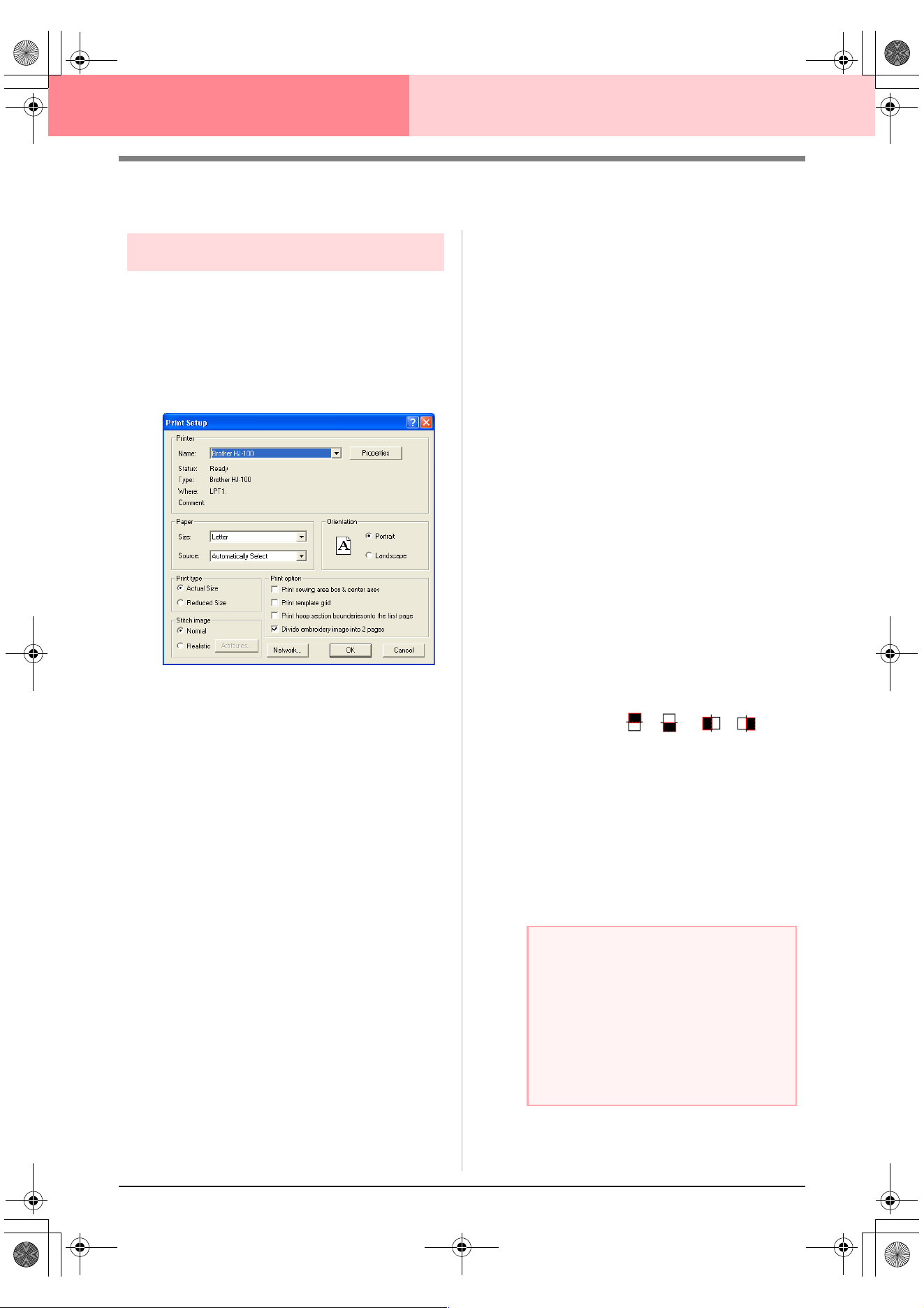
200
Layout & Editing Saving and Printing
Printing
Specifying print settings
Before printing, you may need to change the print
settings for the embroidery pattern files that you
want to print.
1. Click File, then Print Setup.
→ A Print Setup dialog box similar to the
one shown below appears.
2. Under Paper and Orientation, select the
appropriate settings.
3. Under Print type, Print Option and Stitch
image, select how the data is to be printed.
Print type
Actual Size: Select this option to print the
pattern in actual size and the sewing infor-
mation (dimensions of the embroidery, the
sewing color order and the stitch count, the
hoop position) on separate pages. If the pat-
tern size is larger than the paper size, de-
pending on the Design Page settings, a
reduced version of the large pattern and the
different pattern sections in actual size are
printed.
Reduced Size: Select this option to print a
reduced image together with all of the above-
mentioned information on a single page for
Design Pages set to Hoop Size, and on the
same page as the image for each hoop sec-
tion of custom-sized Design Pages.
Print option
Print sewing area box & center axes: Se-
lect this check box to print black lines to indi-
cate the sewing area (refer to “Specifying the
Sewing Area” on page 183) and the center
axes for the data. (This setting is only avail-
able when Actual Size is selected.)
Print template grid: Select this check box to
print green lines to represent the grid printed
on the embroidery sheet included with the
hoop.
Print hoop section boundaries onto the
first page: Select this check box to print the
pattern sections of a pattern for which the
Design Page has been set to a custom size
or to a multi-position hoop. The pattern sec-
tions are printed in red.
Divide embroidery image into 2 pages:
Select this check box to print in actual size
and on A4- or Letter-size paper patterns that
are larger than the paper size by dividing
them in two and printing each half on differ-
ent pages. (This setting is only available
when Actual size is selected in the Print
Setup dialog box and when the Design Page
is set to the larger hoop sizes [300 × 200 mm
(11 3/4" × 7 3/4"), 200 × 300 mm (7 3/4" × 11
3/4"), 180 × 300 mm (7" × 11 3/4"), 300 × 180
mm (11 3/4" × 7") when set to Hoop Size,
and 175 × 295 mm (180 × 300 mm) 6.89" ×
11.61" (7" × 11 3/4") or 295 × 195 mm (300 ×
200 mm) 11.61" × 7.68" (11 3/4" × 7 3/4")
when set to Custom Size].) With this split
printing feature, / or / is
printed in the lower-right corner of the paper
to indicate which half is printed.
Stitch image
Normal: Select this option to print the pat-
tern as lines and dots.
Realistic: Select this option to print a realis-
tic image of the pattern. To change the set-
tings of the realistic image, click Attributes.
(For details, refer to “Changing realistic pre-
view settings” on page 187.)
a Note:
• If the
Divide embroidery image into 2
pages
check box is cleared and you print
on a larger paper size, the pattern does
not print in two halves. Likewise, if you
print on a smaller paper size, the pattern
might be cut off.
• The stitch and hoop position information is
printed on a separate page, after the
image or pattern section halves.
PeDesignV6Eng.book Page 200 Thursday, July 8, 2004 11:59 AM
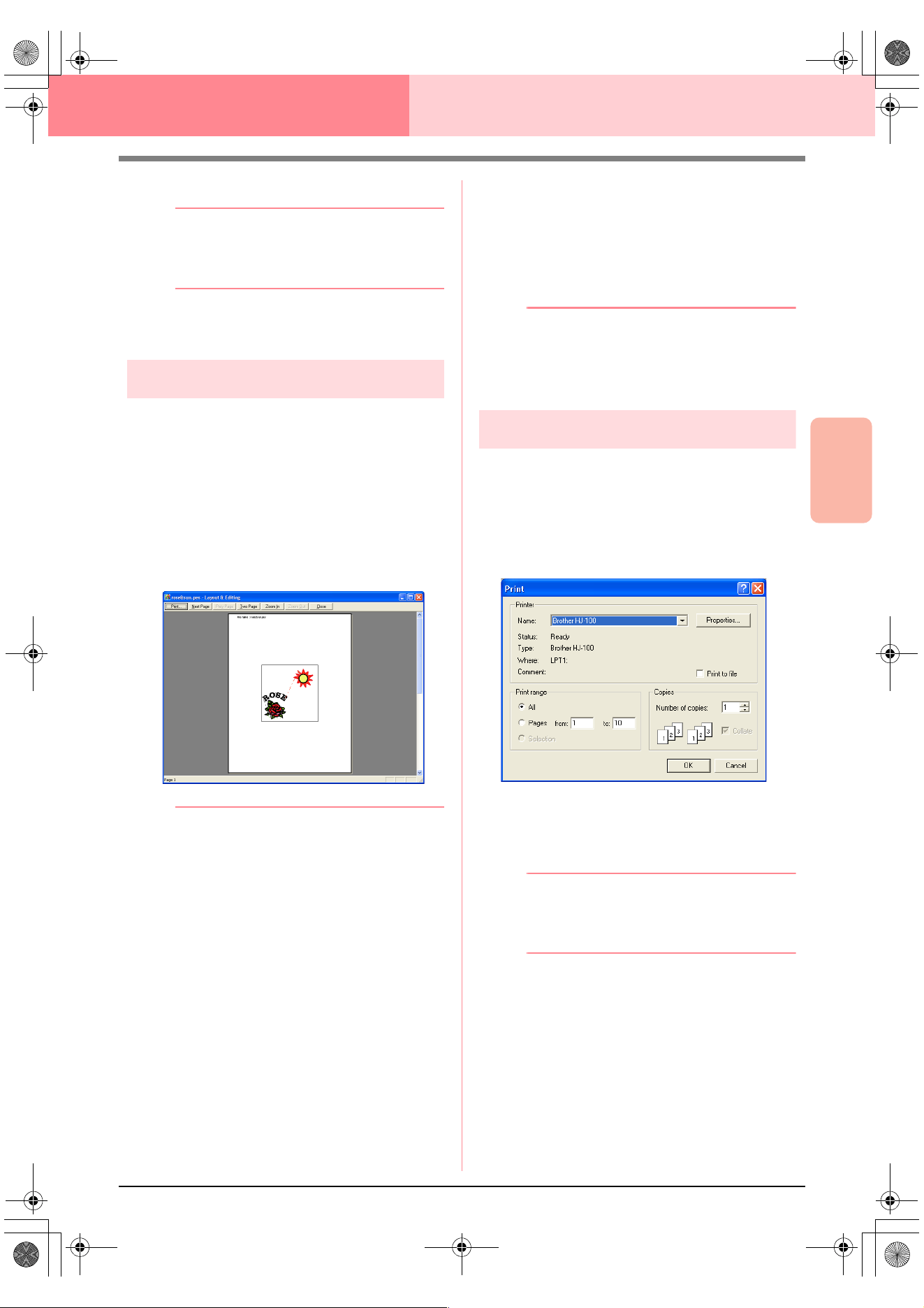
Advanced Opreation
Layout & Editing
201
Layout & Editing Saving and Printing
4. Click OK.
b Memo:
• To change the printer settings, click
Properties
.
• To quit the operation, click
Cancel
.
c
“Previewing the Sewing Image” on
page 187
Checking the print image
You can preview the contents of the Design Page,
including the separate hoop sections of large-size
embroidery patterns, and check the sewing color
order, the dimensions and the stitch count before
printing.
1. Click File, then Print Preview.
→ If Actual Size was selected in the Print
Setup dialog box, the Layout & Editing
window appears as shown below.
b Memo:
• To enlarge and reduce the page, click
Zoom In
or
Zoom Out
. Enlarge the image
either by clicking
Zoom In
, or by clicking
directly the location that you want to
enlarge. To reduce the size of the image,
click
Zoom Out
.
• To display the following page, click
Next
Page
. (For Design Pages set to
Hoop
Size
, this button is not available if
Reduced Size
was selected in the
Print
Setup
dialog box.)
• To go back to the display of the
embroidery, click
Prev Page
. (For Design
Pages set to
Hoop Size
, this button is not
available if
Reduced Size
was selected in
the
Print Setup
dialog.)
• To display two pages at the same time,
click
Two Page
. (The
Two Page
button
becomes the
One Page
button.)
• To display one page at a time, click
One
Page
.
• To open the
Print
dialog box, click
Print
.
• If you need to view an image in detail,
displaying only one page at a time allows
you to enlarge it more.
If you want to check the sewing
information for individual objects in your
embroidery pattern, select the menu
command
Option
–
Design Property
.
c
“Specifying print settings” on page 200,
“Printing” below and “Checking
Embroidery Pattern Information” on
page 189
Printing
You can print the Design Page together with its
sewing information.
1. Click File, then Print.
→ A Print dialog box similar to the one
shown below appears.
2. Select the necessary settings.
3. Click OK to begin printing.
b Memo:
• To change the printer settings, click
Properties
.
• To quit the operation, click
Cancel
.
4. Follow the instructions for the printer to finish
printing.
→ Depending on the Print Type setting, one
or two pages will be printed for one pat-
tern or one hoop position.
PeDesignV6Eng.book Page 201 Thursday, July 8, 2004 11:59 AM
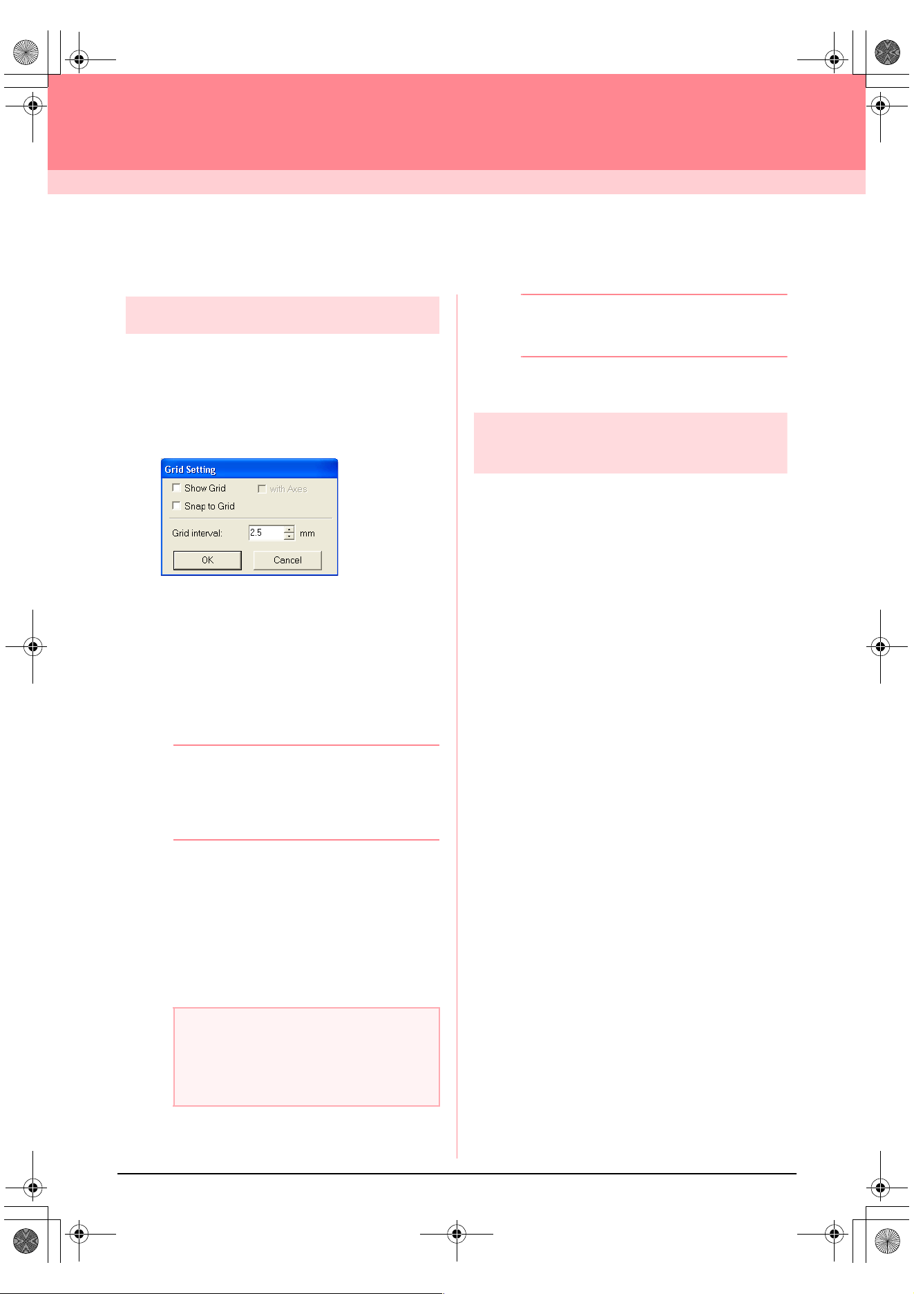
202
Layout & Editing
Changing Software Settings
Changing the Settings
Changing the grid settings
A grid of dotted lines or solid lines can be displayed
or hidden, and the spacing for the grid can be
adjusted.
1. Click Display, then Grid Setup.
→ The Grid Setting dialog box appears.
2. To display the grid, select the Show Grid
check box.
To hide the grid, clear the Show Grid check
box.
3. To use the grid for aligning patterns or creating
patterns of the same size, select the Snap to
Grid check box.
b Memo:
The pointer will move by the amount set in
Grid interval
.
The snap feature works whether or not the
grid is displayed.
4. To set the grid spacing, type or select a value
in the Grid interval box. (The setting range is
0.1 to 25.4 mm (0.04 to 1.0 inch).)
5. To display the grid as solid lines, select the
with Axes check box.
To display the grid as dotted lines, clear the
with Axes check box.
6. Click OK to apply the changes and to close the
dialog box.
b Memo:
To close the dialog box without applying the
changes to the grid, click
Cancel
.
c
“Changing the measurement units” below
Changing the measurement
units
The measurements for values displayed in the
application can be in either millimeters or inches.
1. Click Option, then Select System Unit, and
then select the desired measurement units
(mm or inch).
c
“Changing the grid settings” on this page
and “Specifying the Design Page” on
page 108.
a Note:
When the
Show grid
check box is selected
and the
with Axes
check box is cleared,
only the intersecting points of the grid will be
displayed.
PeDesignV6Eng.book Page 202 Thursday, July 8, 2004 11:59 AM
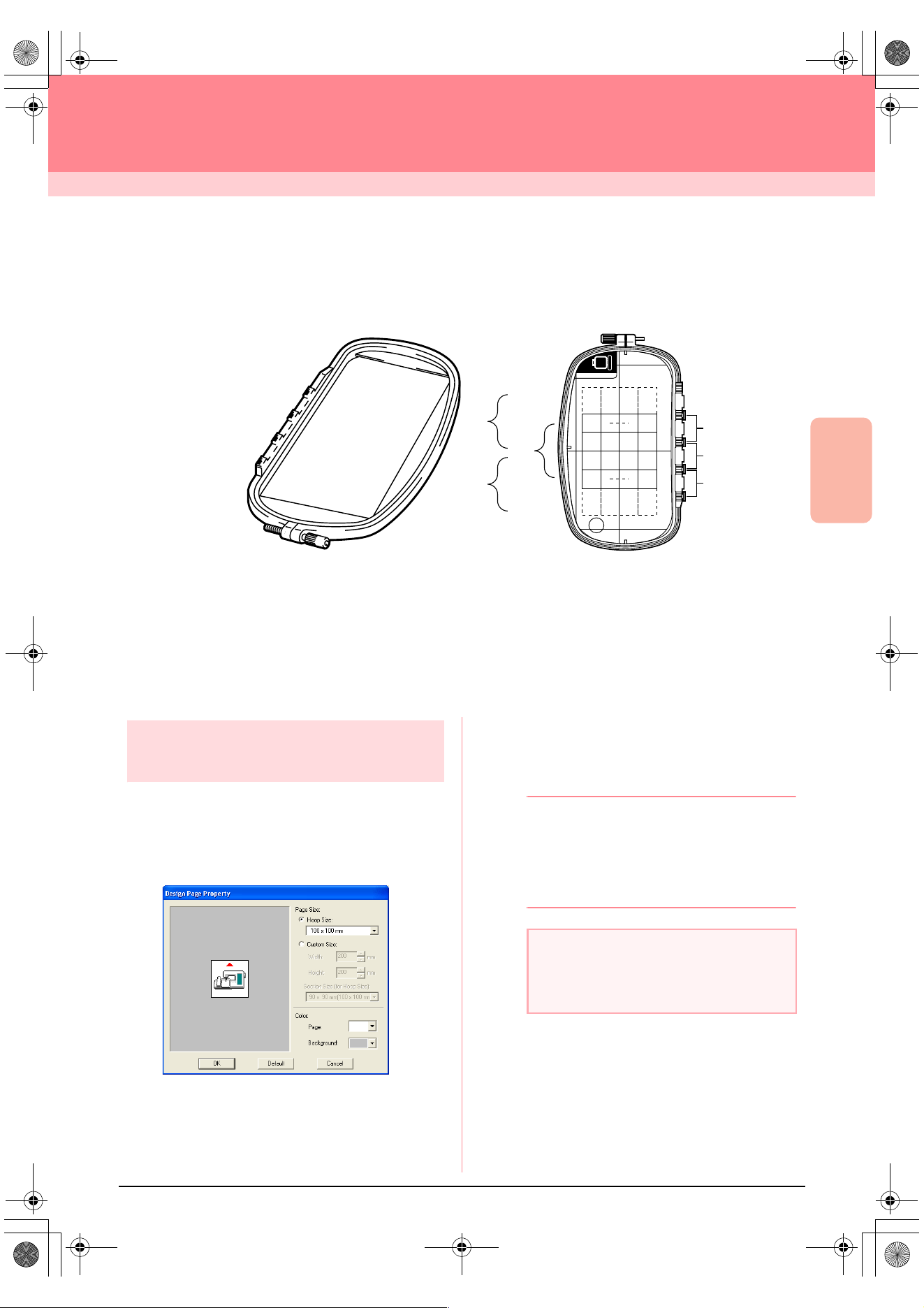
Advanced Opreation
Layout & Editing
203
Layout & Editing
Information for Optional Large-Size Hoop Users
Creating Patterns for Multi-Position Hoops
This program enables you to create multi-position patterns that you can stitch in any multi-position hoop
attached to your sewing machine.
Although the size of the pattern that can be embroidered using an multi-position hoop is 130 × 180 mm (or 100
× 100 mm, depending on the sewing area of the embroidering machine), first determine which of the three
installation positions (indicated as a, b, and c in the illustration above) the multi-position hoop will be installed
at and determine the orientation of the pattern.
When creating the pattern, each pattern section can only be as large as the sewing field of the machine.
Selecting the Design Page
size
1. In Layout & Editing, click Option, then Design
Page Property.
→ The Design Page Property dialog box
appears.
2. Select Hoop Size, and then choose a Design
Page size of 130 × 300 mm, 300 × 130 mm,
100 × 172 mm, or 172 × 100 mm from the
selector.
b Memo:
• Settings for multi-position hoops are
indicated by “*”.
• Choose the appropriate setting after
checking the size of the hoop available for
your machine.
a
b
c
a
b
c
ABC
Example of multi-position hoop: 100 × 172 mm hoop
a Note:
Multi-position hoop settings are not available
in the Design Page Property dialog box of
Design Center.
PeDesignV6Eng.book Page 203 Thursday, July 8, 2004 11:59 AM
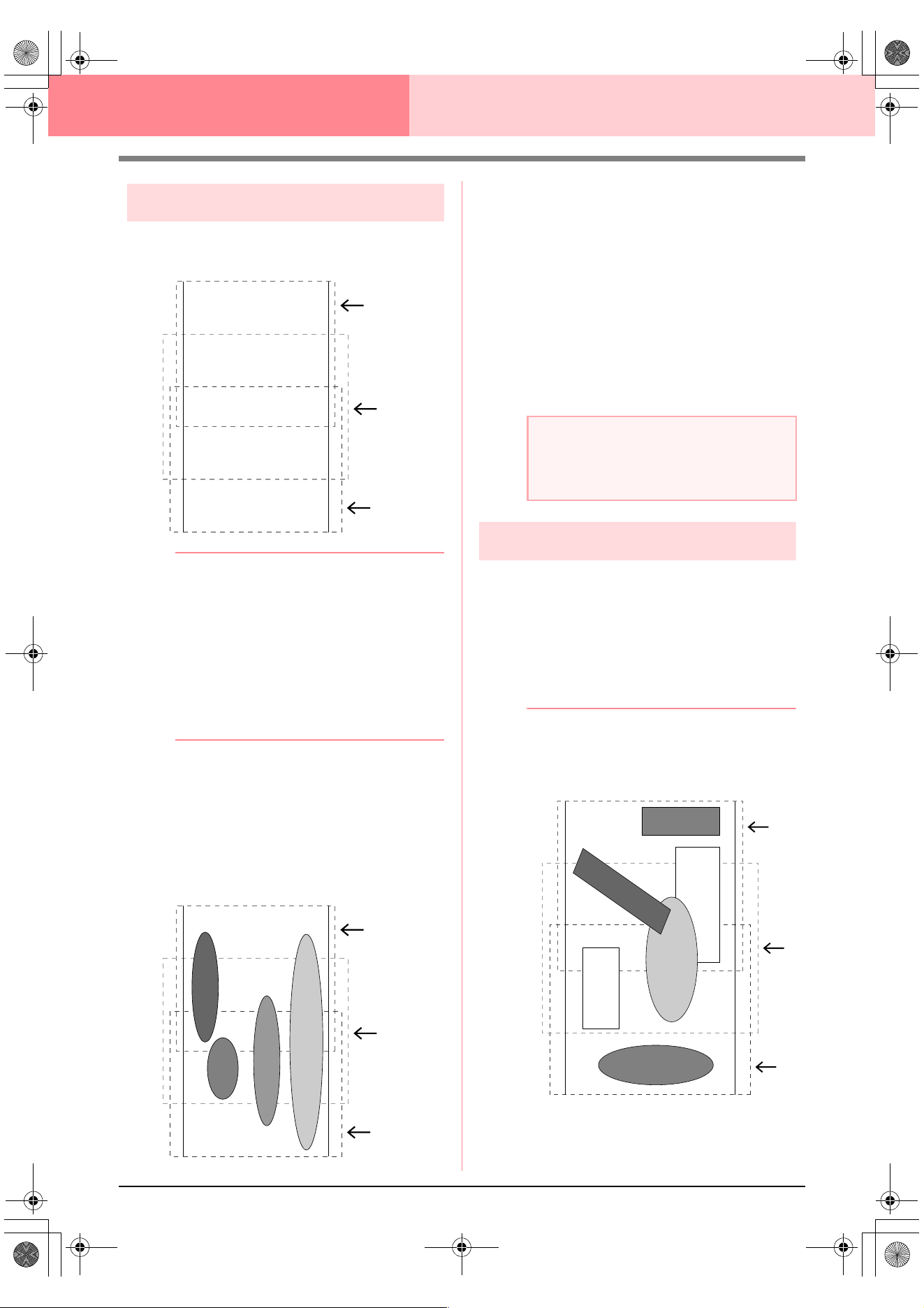
204
Layout & Editing Information for Optional Large-Size Hoop Users
Creating the pattern
1. The Design Page appears on the screen as
shown below.
b Memo:
Area a: Embroidering area when the multi-
position hoop is installed at the top
installation position.
Area b: Embroidering area when the multi-
position hoop is installed at the middle
installation position.
Area c: Embroidering area when the multi-
position hoop is installed at the bottom
installation position.
The dotted lines separate each area.
2. Create the pattern, making sure that it meets
the following conditions.
• The size of one pattern must be no larger
than 100 × 100 mm (or 130 × 180 mm).
(If the pattern is imported from Design
Center, only these size settings are
available.)
• Each pattern must completely fit within a
single area (a, b, or c).
1: The position of this pattern is correct since
it fits completely within area a.
2: The position of this pattern is correct since
it fits completely within either area b or
area c.
3: The size of this pattern is acceptable, but
its position must be corrected since it
does not fit completely within any of the
areas.
4: This pattern must be corrected since it is
too large.
Optimizing hoop changes
With the Optimize hoop change function, the sewing
order of patterns in a Design Page for multi-position
hoops is automatically optimized, therefore
reducing the risk of the embroidery being sewn
incorrectly or the fabric not feeding evenly when the
hoop position is changed too often.
1. Click Sew, then Optimize hoop change.
b Memo:
• A check mark appears when this function
is turned on; no check mark is displayed
when this function is turned off.
a
b
c
a
b
c
4
3
2
1
a Note:
If a pattern does not meet the conditions
mentioned above, a warning will appear
when continuing to the next step.
a
b
c
4
2
1
3
5
6
PeDesignV6Eng.book Page 204 Thursday, July 8, 2004 11:59 AM
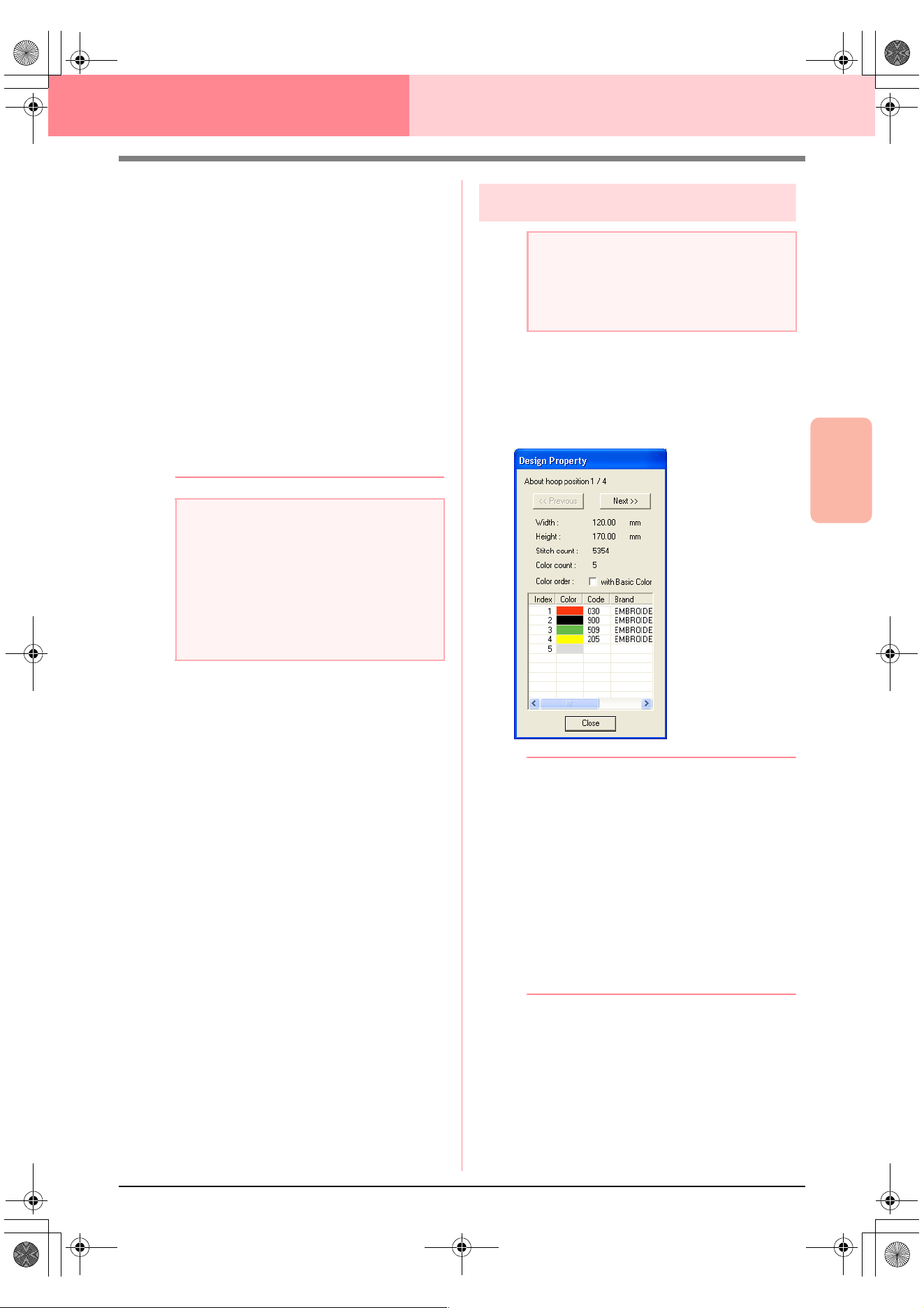
Advanced Opreation
Layout & Editing
205
Layout & Editing Information for Optional Large-Size Hoop Users
• When the Optimize hoop change function
is selected, the sewing order that you have
set is optimized to reduce the number of
times that the hoop installation position is
changed.
For the example shown on page 204, the
sewing order is: a (pattern 1)
→
b (pattern
2)
→
a (patterns 3 & 5)
→
c (patterns 4 & 6)
If the Optimize hoop change function is not
selected, each pattern is sewn according
to the sewing order that you have set.
Therefore, since the number of times for
changing the hoop installation position is
not optimized, it may be changed more
often than if it was optimized.
For the example shown on page 204, the
sewing order is: a (pattern 1)
→
b (pattern
2)
→
a (pattern 3)
→
c (pattern 4)
→
a
(pattern 5)
→
c (pattern 6)
Checking the pattern
1. Click Option, then Design Property.
→ At the same time that the Design Proper-
ty dialog box appears, the Design Page is
automatically enlarged or reduced to fit in
the entire window.
b Memo:
• The first line of the dialog box shows the
position in the hoop installation order for
the currently displayed pattern.
• Only the patterns that would be sewn at
the current position in the hoop installation
order appear in the Design Page, and the
embroidering area for the current hoop
position is outlined in red.
• To display information for patterns at other
positions in the hoop installation order,
click
Previous
or
Next
. At this time, the
corresponding pattern and hoop position
appear in the Design Page.
a Note:
Since the pattern may not be sewn correctly
or the fabric may not feed evenly if the hoop
installation position is changed too often, we
recommend selecting the Optimize hoop
change function. Selecting this function will
change the sewing order that you have set,
therefore, check the sewing order before you
begin embroidering.
a Note:
Make sure that no pattern has been selected
before clicking this command. If a pattern
has already been selected, only the
information for that pattern is displayed.
PeDesignV6Eng.book Page 205 Thursday, July 8, 2004 11:59 AM
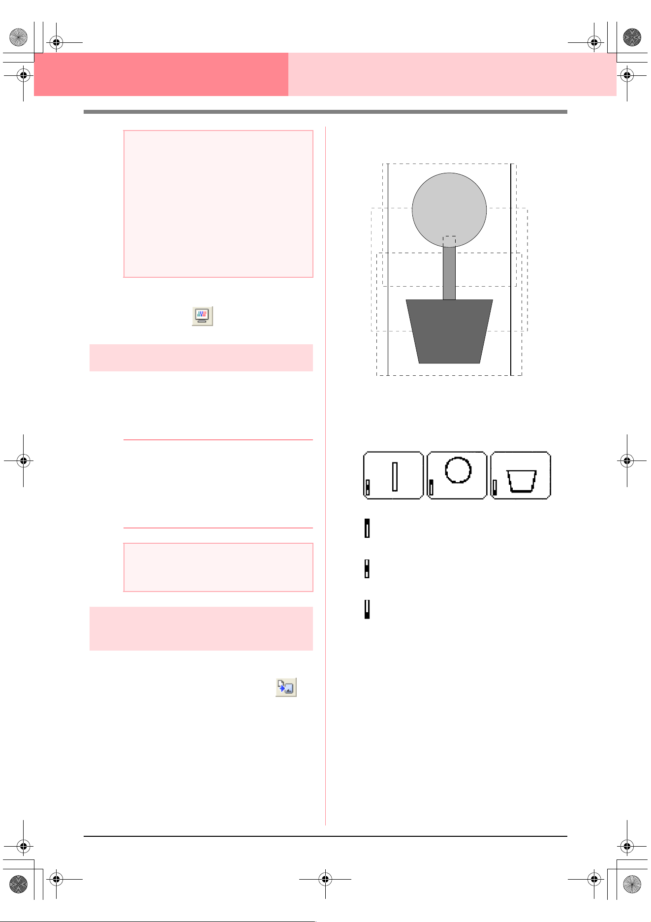
206
Layout & Editing Information for Optional Large-Size Hoop Users
2. To preview the image, click Display, then
Preview, or click on the Toolbar.
Saving the pattern
1. Click File, then Save or Save As, and then
save the pattern.
→ The entire pattern is saved as a single file
(.pes).
b Memo:
If the file size or the number of color changes
is larger than the specified number, or if one
of the patterns does not completely fit within
an embroidery area, the message “Please
change the object size or position. Do you
want to save the data anyway?” appears.
Writing the pattern to an
original card
1. If your pattern is displayed in the Design Page,
click File, then Write to Card, or click on
the Toolbar, and then write the pattern to an
original card.
A pattern for a multi-position hoop is created
by considering the pattern in each hoop
installation position as one pattern, then
combining them.
Therefore, when this type of pattern is written
to an original card, one multi-position hoop
pattern is saved as a combination of multiple
patterns.
If the pattern shown above is written to an
original card and the written pattern is
checked on the embroidery machine, it
appears as shown below.
: This pattern is sewn when the hoop is
installed at the top installation position
(position a).
: This pattern is sewn when the hoop is
installed at the middle installation position
(position b).
: This pattern is sewn when the hoop is
installed at the bottom installation position
(position c).
Therefore, the frame installation position
sewing order for the pattern shown above is b,
a, then c.
2. After the embroidery pattern is saved on the
computer, click File, then Write to Card, then
Other PES files to write the embroidery
pattern to an original card.
As with the Current Design command, all
embroidery patterns are written to the original
card at the same time.
Furthermore, if there is space on the original
card, other embroidery patterns can be written
to it at the same time.
a Note:
• If pattern is larger than the embroidery
area or if a pattern is positioned so that it
does not completely fit within an
embroidery area, the error message
“Please change the object size or
position.” appears instead of this dialog
box. After the pattern causing the error is
displayed selected, change its size or
position. (If more than one pattern causes
the error message to appear, they will be
displayed in the sewing order.)
a Note:
• The saved file cannot be opened in Layout
& Editing versions 1 and 2.0x.
PeDesignV6Eng.book Page 206 Thursday, July 8, 2004 11:59 AM
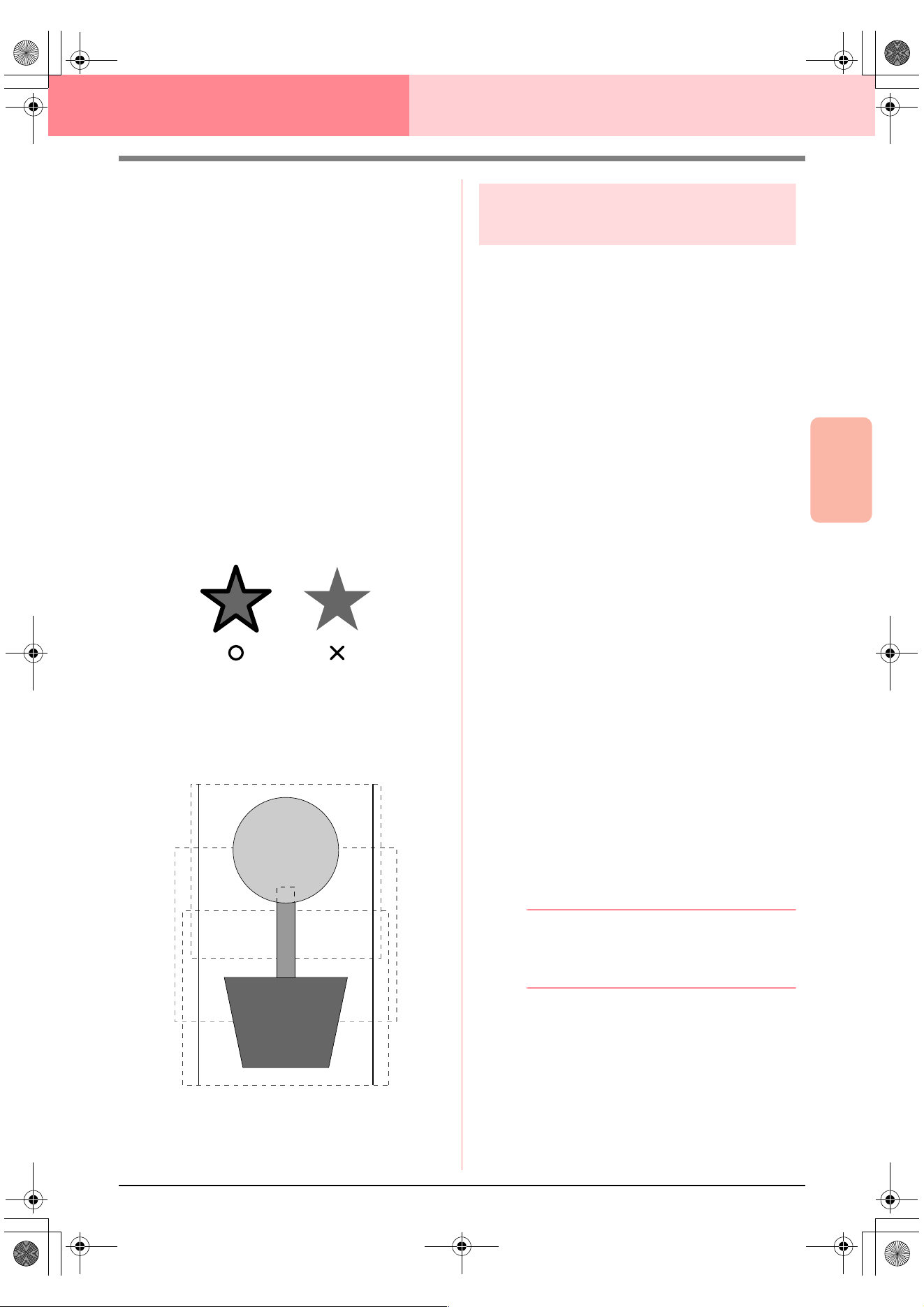
Advanced Opreation
Layout & Editing
207
Layout & Editing Information for Optional Large-Size Hoop Users
Notes on embroidering using the multi-
position hoop
• Before embroidering your project, sew a trial
sample of the pattern on a scrap piece of
fabric from your project, making sure to use
the same needle and thread.
• Be sure to affix stabilizer material to the back
of the fabric and tightly stretch the fabric
within the hoop. When embroidering on thin
or stretch fabrics, use two layers of stabilizer
material. If no stabilizer material is used, the
fabric may become over-stretched or
wrinkled or the embroidery may not be sewn
correctly.
• See page 63 “Attaching stabilizer to the
fabric” for more ways to stabilize large
designs.
• Use the zigzag stitch for sewing the outlines
in order to prevent embroidering outside the
outlines.
• For patterns that require the hoop to be
installed at different installation positions,
design the embroidery pattern so that the
various parts of the pattern overlap in order
to prevent misalignment while embroidering.
Printing a Design Page for a
multi-position hoop
If a Design Page for a multi-position hoop is
selected, a complete image of the Design Page is
printed on the first page, followed by an image of
each pattern section and its sewing information
(dimensions of the embroidery, the hoop position,
the sewing color order and the stitch count), so the
number of pages depends on your pattern.
• If a 130 × 300 mm or 300 × 130 mm Design
Page is selected, the pattern is divided into
sections of 130 × 180 mm or 180 × 130 mm
with each section printed on a separate
page.
• If a 100 × 172 mm or 172 × 100 mm Design
Page is selected, the pattern is divided into
sections of 100 × 100 mm with each section
printed on a separate page.
The Design Page is printed as described below.
When Actual Size is selected:
On the first page, the entire Design Page is print-
ed at actual size. (However, for a 130 × 300 mm
or 300 × 130 mm Design Page, a reduced image
of the Design Page is printed.) Afterwards, the
pattern in each section of the Design Page is
printed, starting with that sewn with the first hoop
installation position, and is followed by the sew-
ing information for that pattern on separate pag-
es.
When Reduced Size is selected:
On the first page, the entire Design Page is print-
ed at actual size. (However, for a 130 × 300 mm
or 300 × 130 mm Design Page, a reduced image
of the Design Page is printed.) Afterwards, the
pattern in each section of the Design Page is
printed, starting with that sewn with the first hoop
installation position, on the same page as the
sewing information for that pattern.
b Memo:
When the menu command
File
–
Print
Preview
is selected, each section of the
pattern is displayed as described above.
PeDesignV6Eng.book Page 207 Thursday, July 8, 2004 11:59 AM
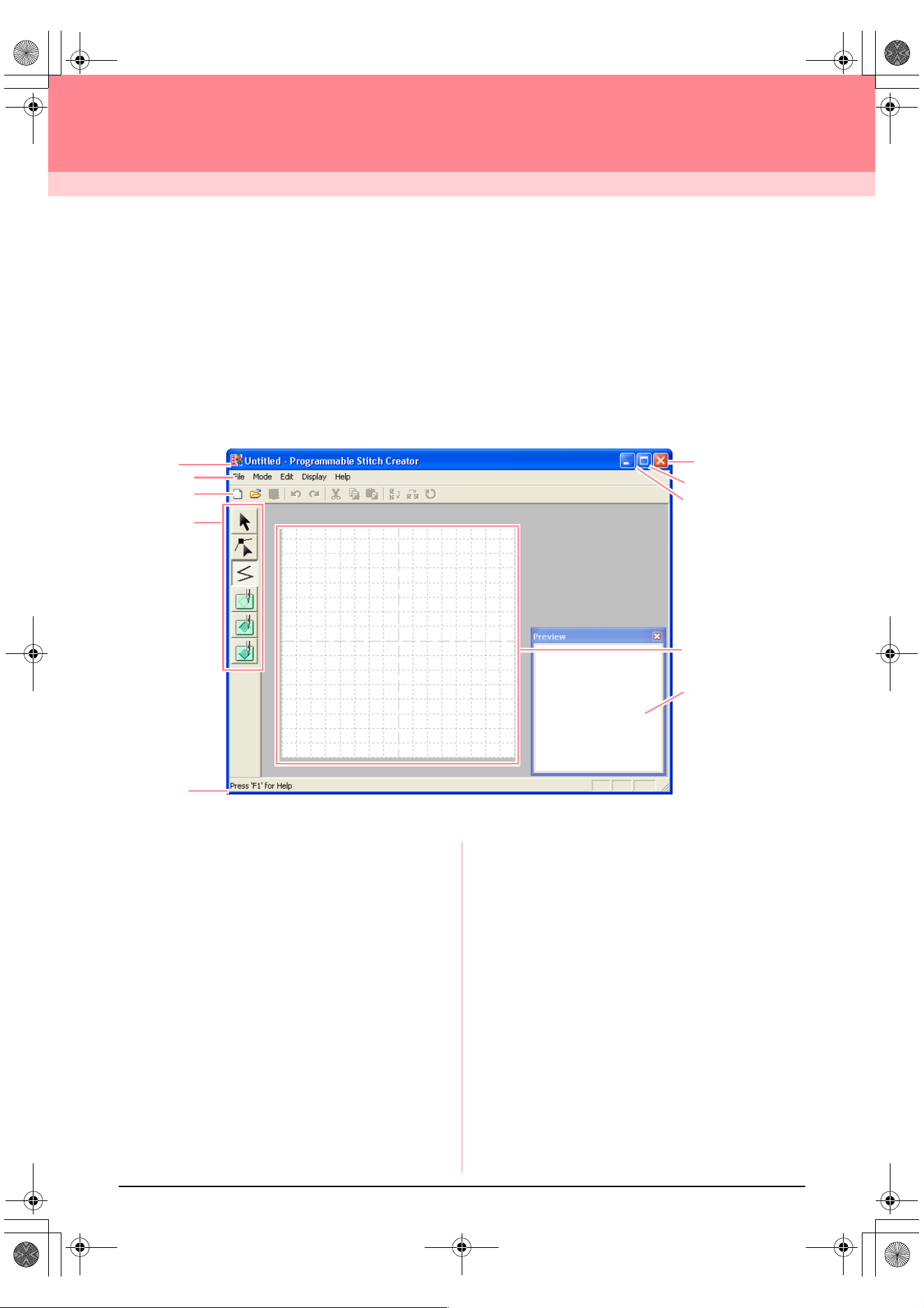
208
Programmable Stitch Creator
Programmable Stitch Creator allows you to design your own fill/stamp and motif stitch patterns that can be
applied to a programmable fill stitch or motif stitch, both in Design Center and Layout & Editing. When applied
to enclosed regions, the fill/stamp or motif stitch pattern fills the region in a tile-like manner, resulting in more
decorative embroidery patterns. In addition, the fill/stamp stitch patterns can be applied as an individual stamp
to enclosed regions in Design Center and Layout & Editing. You can create your own fill/stamp and motif stitch
patterns or use the many stitch patterns provided with this application, with or without editing them.
Main Window
1 Title bar
2 Menu bar
Provides access to the functions.
3 Toolbar
Provides shortcuts for the menu commands.
4 Tool Box
Used to select and create fill and motif stitch pat-
terns and stamps.
(The bottom four buttons do not appear in Motif
mode.)
5 Status bar
Provides helpful information.
6 Preview window
Shows how the stitch pattern will be sewn.
7 Work area
8 Minimize button
9 Maximize button
0 Close button
2
7
3
4
5
0
9
8
1
6
PeDesignV6Eng.book Page 208 Thursday, July 8, 2004 11:59 AM
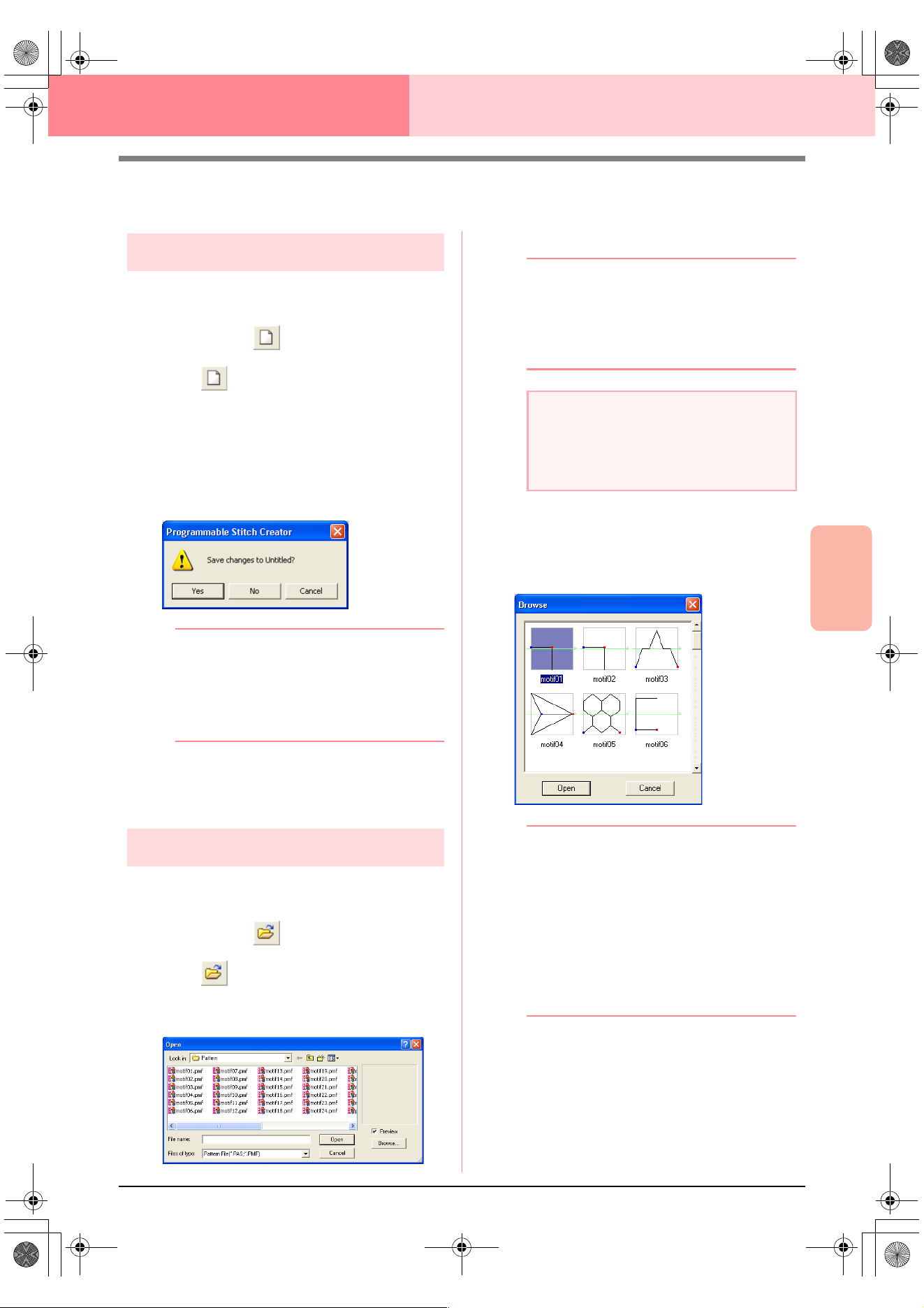
Advanced Opreation
Programmable
Stitch Creator
209
Programmable Stitch Creator
Opening a Pattern File
Creating a new pattern
You can begin with a blank work area in order to
design a new stitch pattern.
Toolbar button:
1. Click , or click File, then New.
→ If the current work area has already been
saved or has not been edited, a new work
area appears immediately.
→ If the current work area has not been
saved, you will be asked whether you
want to save the changes.
b Memo:
• To save the work area, click
Yes
.
• To abandon the work area, click
No
.
• To return to the work area, for example, to
modify it or save it with another file name,
click
Cancel
.
c
“Opening a pattern file” on this page,
“Overwriting” on page 221 and “Saving
with a new name” on page 221
Opening a pattern file
A previously saved programmable stitch file can be
opened to be edited.
Toolbar button:
1. Click , or click File, then Open.
→ An Open dialog box similar to the one
shown below appears.
2. Select the drive and the folder.
b Memo:
• If the
Preview
check box is selected, the
contents of the selected file will appear in
the
Preview
box.
• To quit the operation and close the dialog
box, click
Cancel
.
3. To view the contents of the .pas and .pmf files
in the currently selected folder, click Browse.
→ A Browse dialog box similar to the one
shown below appears.
b Memo:
• To return to the
Open
dialog box, click
Cancel
.
• A green arrow through the middle of the
stitch pattern indicates motif stitch patterns
(.pmf). Otherwise, the data is a fill/stamp
stitch pattern (.pas).
• Stamps are identified by the red-
(engraving effect sewn with the fill stitch)
and blue-filled areas (embossing effect
sewn with satin stitching).
4. To open a file, select it, and then click Open,
or double-click the file’s icon.
→ If the current work area has already been
saved or has not been edited, the con-
tents of the selected file immediately ap-
pear in the work area.
a Note:
To open a fill/stamp stitch pattern, be sure to
select a
folder that contains .pas file. To
open a motif stitch pattern, be sure to select
a folder that contains .pmf files.
PeDesignV6Eng.book Page 209 Thursday, July 8, 2004 11:59 AM
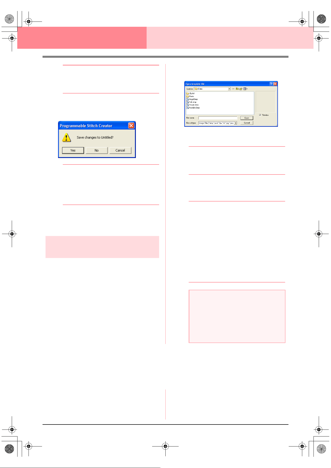
210
Programmable Stitch Creator
b Memo:
The mode will automatically change to match
that of the selected pattern (
Fill/Stamp
for
.pas files or
Motif
for .pmf files).
→ If the current work area has not been
saved, you will be asked whether you
want to save the changes.
b Memo:
• To save the work area, click
Yes
.
• To abandon the work area, click
No
.
• To return to the work area, for example, to
modify it or save it with another file name,
click
Cancel
.
c
“Creating a new pattern” on page 209,
“Overwriting” on page 221 and “Saving
with a new name” on page 221
Opening an image in the
background
You can open a background image that can be used
as a guide to draw a new fill/stamp and motif stitch
pattern. The file name extension must be one of the
following: Windows bitmap (.bmp), Exif (.tif, .jpg),
ZsoftPCX (.pcx), Windows Meta File (.wmf),
Portable Network Graphics (.png), Encapsulated
PostScript (.eps), Kodak PhotoCD (.pcd), FlashPix
(.fpx), JPEG2000 (.j2k).
1. Click File, then Template Open.
→ An Open template file dialog box similar
to the one shown below appears.
2. Select the drive, the folder and the desired file.
b Memo:
If the
Preview
check box is selected, the
contents of the selected file will appear in the
Preview
box.
3. Click Open to open the file.
→ The image fills the work area.
b Memo:
• Double-clicking the file name also opens
the file and closes the dialog box.
• To quit the operation, click
Cancel
.
• To display, hide, or display a faded copy of
the image that remains in the work area,
click
Image
, then
Display Image
, and
then click the desired display setting.
• To display the original image, click
On
.
• To display a faded copy of the image,
click
Faded
.
• To hide the original image, click
Off
.
Selecting a Pattern To Be Created
You can use Programmable Stitch Creator to create patterns for programmable fill stitches, stamps, motif fill
stitches, motif line stitches. The method and work area are slightly different for each. Use the commands on
the Mode menu to select the type of pattern that you want to create.
1. To enter Fill/Stamp mode, click Mode, then
Fill/Stamp.
To enter Motif mode, click Mode, then Motif.
→ If the current work area has already been
saved or has not been edited, a blank
work area immediately appears in the se-
lected mode.
a Note:
• With .pcd and .fpx files containing many
pages, only the first page can be opened.
Tiff files with LZW compression cannot be
opened.
• Only one image can be added to the work
area. If you try to display a different image,
it will replace the previous one.
PeDesignV6Eng.book Page 210 Thursday, July 8, 2004 11:59 AM
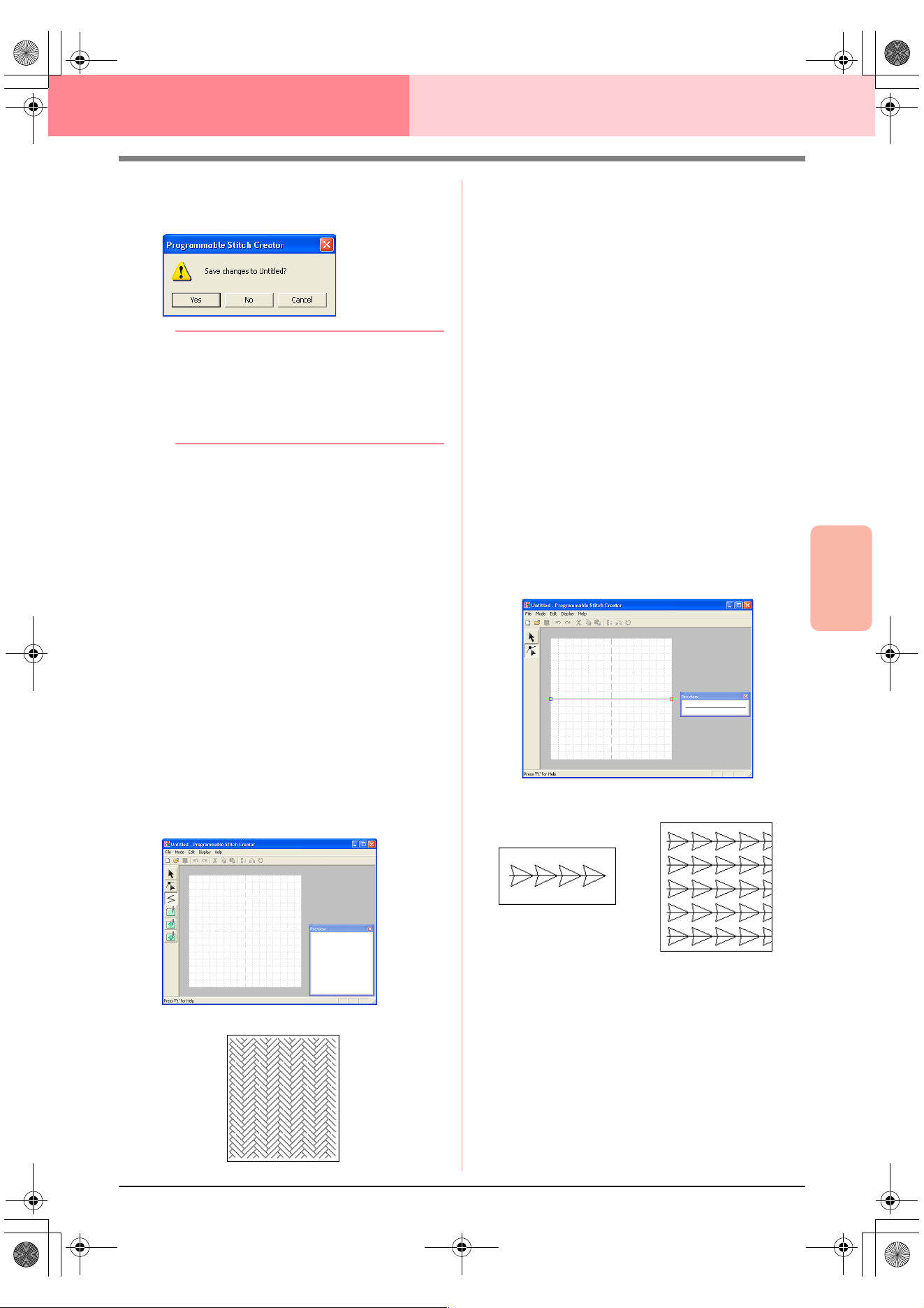
Advanced Opreation
Programmable
Stitch Creator
211
Programmable Stitch Creator
→ If the current work area has not been
saved, you will be asked whether you
want to save the changes.
b Memo:
• To save the work area, click
Yes
.
• To abandon the work area, click
No
.
• To return to the work area, for example, to
modify it or save it with another file name,
click
Cancel
.
■ Fill/Stamp mode
In Fill/Stamp mode, you can make a stitch pattern
out of a single line or sets of lines, and you can then
choose to fill the areas enclosed by the lines to
create an embossing/engraving effect. Both types of
stitch patterns can be set as a programmable fill
stitch in addition to being applied as individual
stamps to regions of patterns in Design Center as
well as Layout & Editing.
The Line tool in the Tool Box allows you to draw the
lines of a fill stitch pattern or a stamp, and the
Region (engrave), the Region (emboss) and the
Region (reset) tools allow you to fill and edit the
enclosed areas of the stitch or stamp that you draw.
The sewing method for a programmable fill stitch is
different from the regular fill stitch, where the thread
is constantly sewn in a set direction. Instead, the
pattern will be sewn in such a way that the needle
drops directly over the created pattern.
■ Motif mode
In Motif mode, you can create original stitch patterns
by changing the shape of a single line. These stitch
patterns can be applied in line sewing and region
sewing in Layout & Editing, and region sewing in
Design Center.
A green arrow appears at the center of the work
area, showing the direction that the pattern (stitch)
will be sewn.
A single pink line appears along with the green
arrow. This line indicates the base for the motif
stitch, which can be altered by inserting points with
the Edit Point tool, and then moving them to form
original designs.
The blue square at the left edge of the work area
indicates the start point of that line and the red
square at the right edge indicates the end point of
the stitch.
The start and end points cannot be deleted, and
they must be aligned vertically. Therefore, if you
move one point up or down, the other point will
automatically move in the same direction.
Example of a pattern
Example of a pattern
Line sewing
Region sewing
PeDesignV6Eng.book Page 211 Thursday, July 8, 2004 11:59 AM
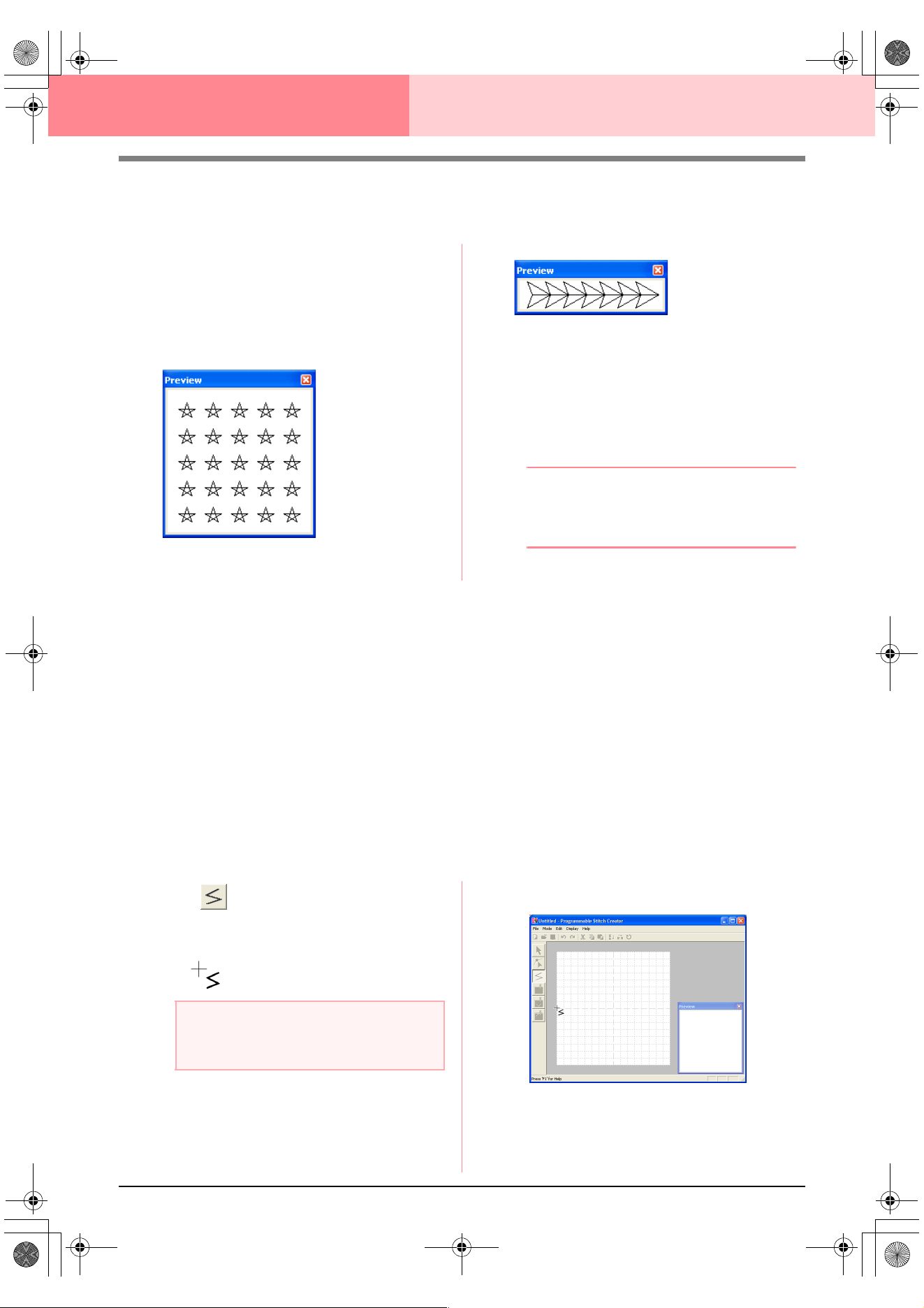
212
Programmable Stitch Creator
Viewing the Stitch Pattern While Creating It
You can display the Preview window to view a repeating image of the stitch pattern as you create it.
1. If the Preview window isn’t displayed, click
Display, then Preview.
The Preview window for the selected Mode
setting appears, as shown in the examples
below, and a check mark appears to the left of
the menu command Display – Preview.
The image in the Preview window is updated
as you enter the changes in the work area.
2. To close the Preview window, click its close
button, or click the menu command Display –
Preview to remove the check mark.
b Memo:
• The Preview window can be resized.
• The setting for displaying the Preview
window is retained, until it is changed.
Drawing a Stitch Pattern in Fill/Stamp
Mode
The Line tool allows you to draw broken lines to create your fill/stamp stitch pattern. A broken line is made of
one or more connected straight lines with the end point of one straight line being the start point of the next line.
The horizontal and vertical lines that you draw on the work area always follow the grid. The points that you
create by clicking the mouse button are inserted at the intersection of the horizontal and vertical lines of the
grid, enabling you to draw diagonal lines as well. Regardless of where you click, a point will automatically be
inserted at the nearest intersection.
Depending on the stitch pattern that you want to draw, you may need to select a grid of a different size. In
addition, by selecting None, the point will no longer be inserted at the nearest intersection, allowing you to
create curved patterns. For details on the grids and adjusting them, refer to “Changing the grid settings” on
page 222.
1. Click on the Tool Box.
→ When the pointer is moved over the work
area, the shape of the pointer changes to
.
2. Click in the work area to specify the start point.
Fill/Stamp mode
Motif mode
a Note:
This tool can only be used in Fill/Stamp
mode.
PeDesignV6Eng.book Page 212 Thursday, July 8, 2004 11:59 AM
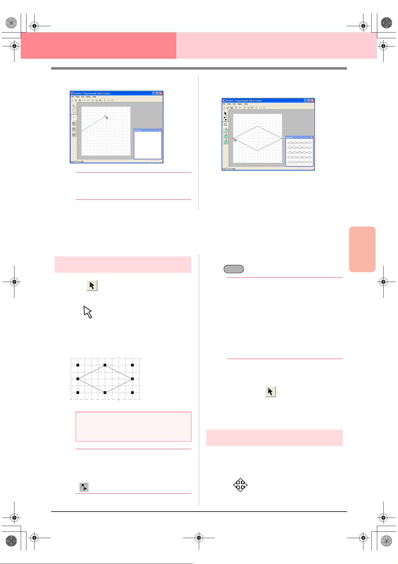
Advanced Opreation
Programmable
Stitch Creator
213
Programmable Stitch Creator
3. Click in the work area to specify the next point.
b Memo:
To remove the last point that was entered,
click the right mouse button.
4. Continue clicking to specify every point, and
then double-click the last point.
5. Repeat the entire procedure until the fill/stamp
stitch pattern is completed.
Editing a Stitch Pattern in Fill/Stamp
Mode
Selecting patterns
1. Click on the Tool Box.
→ The shape of the pointer changes to
.
2. Click the pattern that you want to select.
→ Handles appear around the pattern to show
that it is selected.
b Memo:
To deselect the pattern, select a different
one, click a blank area of the work area, or
click a button in the Tool Box other than
.
3. To select an additional pattern, hold down the
key and click the other pattern.
b Memo:
• You can also select patterns by dragging
the pointer across the pattern that you
want to select. As you drag the pointer, a
selection frame is drawn. All patterns that
are contained in that selection frame are
selected when the mouse button is
released.
• If you selected patterns that you did not
want, click a blank area of the work area to
deselect all patterns, and start again.
■ Selecting all patterns
1. Make sure that on the Tool Box is
selected.
2. Click Edit, then Select All.
Moving patterns
1. Move the pointer over a selected pattern or
group of selected patterns.
→ The shape of the pointer changes to
.
a Note:
A pattern will not be selected if you do not
click one of its lines.
Ctrl
PeDesignV6Eng.book Page 213 Thursday, July 8, 2004 11:59 AM
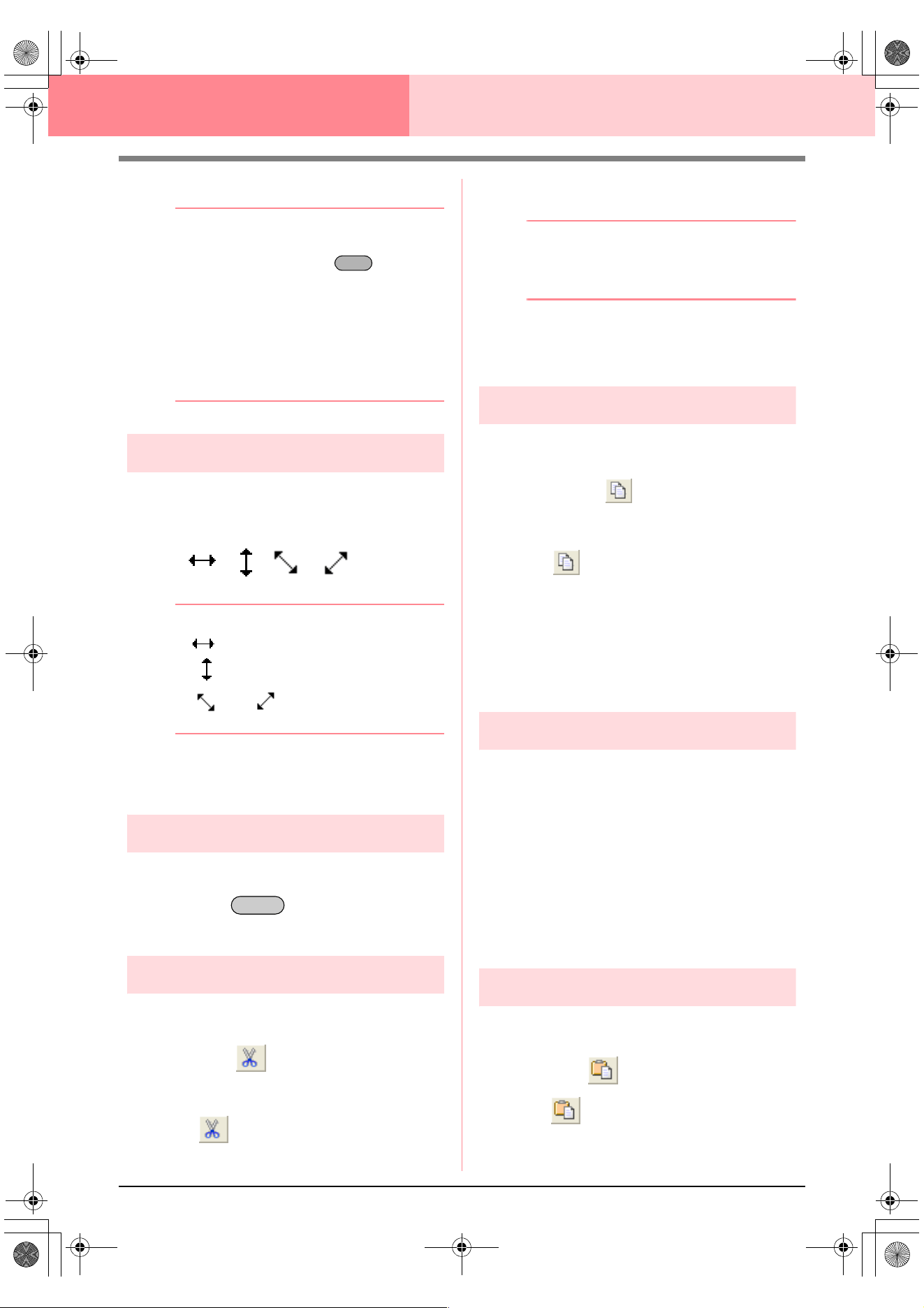
214
Programmable Stitch Creator
2. Drag the pattern to the desired location.
b Memo:
• To move the pattern horizontally or
vertically, hold down the key while
dragging it.
• Pressing the arrow keys moves the
selected pattern one grid mark in the
direction of the arrow on the key. If the grid
is not displayed, the pattern moves a
distance smaller than the smallest grid
interval in the direction of the arrow on the
key.
Scaling patterns
1. Move the pointer over one of the handles of a
selected pattern or group of patterns.
→ The shape of the pointer changes to
, , or , depending on
the handle that the pointer is over.
b Memo:
• is for scaling the width.
• is for scaling the height.
• and are for scaling both
dimensions at the same time.
2. Drag the handle to adjust the selected
pattern(s) to the desired size.
Deleting patterns
1. Select the pattern to be deleted.
2. Press the key, or click Edit, then
Delete.
Cutting out patterns
Selected pattern(s) can be removed from the screen
while saving a copy in the Clipboard.
Toolbar button:
1. Select one or more patterns.
2. Click , or click Edit, then Cut.
→ The selected patterns are removed from
the work area.
b Memo:
Since the removed patterns are saved on the
Clipboard, you can paste them back using
the menu command
Edit
–
Paste
.
c
“Copying patterns” on this page, “Pasting
a cut or copied pattern” on this page and
“Deleting patterns” on this page
Copying patterns
Selected pattern(s) can be saved on the Clipboard
without being removed from the work area.
Toolbar button:
1. Select one or more patterns.
2. Click , or click Edit, then Copy.
→ The selected patterns are copied onto the
Clipboard and are ready to be pasted.
c
“Cutting out patterns” on this page,
“Duplicating patterns” on this page and
“Pasting a cut or copied pattern” on this
page
Duplicating patterns
A copy of the selected pattern(s) can be added to
the work area.
1. Select one or more patterns.
2. Click Edit, then Duplicate.
→ A copy of the pattern(s) are added to the
work area.
c
“Copying patterns” on this page and
“Pasting a cut or copied pattern” on this
page
Pasting a cut or copied pattern
The patterns on the Clipboard can be pasted into
the work area.
Toolbar button:
1. Click , or click Edit, then Paste.
Shift
Delete
PeDesignV6Eng.book Page 214 Thursday, July 8, 2004 11:59 AM
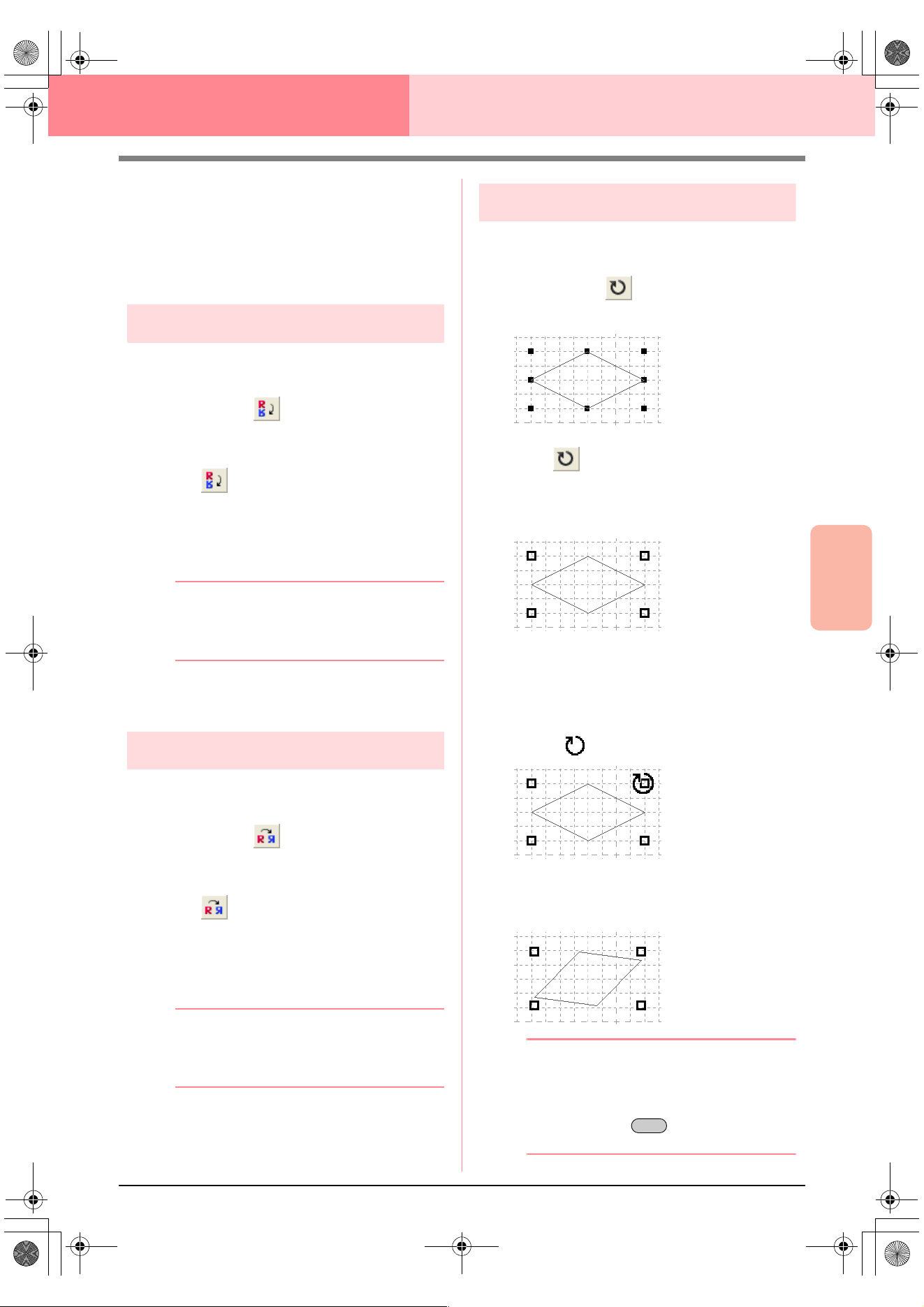
Advanced Opreation
Programmable
Stitch Creator
215
Programmable Stitch Creator
→ The patterns saved on the Clipboard (us-
ing the Cut or Copy command) are past-
ed into the work area.
c
“Cutting out patterns” on page 214,
“Copying patterns” on page 214 and
“Duplicating patterns” on page 214
Flipping patterns vertically
You can flip the selected pattern(s) vertically (up/
down).
Toolbar button:
1. Select one or more patterns.
2. Click , or click Edit, then Mirror, then
Horizontal.
→ The selected pattern(s) are replaced by
their horizontal mirror image (top and bot-
tom inverted).
b Memo:
To restore the image to its original
orientation, select the menu command
Edit
–
Mirror
–
Horizontal
again.
c
“Flipping patterns horizontally” on this
page and “Rotating patterns” on this page
Flipping patterns horizontally
You can flip the selected pattern(s) horizontally (left/
right).
Toolbar button:
1. Select one or more patterns.
2. Click , or click Edit, then Mirror, then
Vertical.
→ The selected pattern(s) are replaced by
their vertical mirror image (left and right
inverted).
b Memo:
To restore the image to its original
orientation, select the menu command
Edit
–
Mirror
–
Vertical
again.
c
“Flipping patterns vertically” on this page
and “Rotating patterns” on this page
Rotating patterns
You can manually rotate the selected pattern(s) by
an arbitrary angle.
Toolbar button:
1. Select one or more patterns.
2. Click , or click Edit, then Rotate.
→ The handles around the selected pattern
are replaced by empty squares at the four
corners of the selected pattern.
3. Move the pointer over one of the four rotation
handles.
→ When the pointer is moved over a rotation
handle, the shape of the pointer changes
to .
4. Drag the rotation handle clockwise or
counterclockwise to rotate the pattern to the
desired angle.
b Memo:
• Simply dragging the pointer rotates the
pattern in 1° increments.
• To rotate the pattern in 15° increments,
hold down the key while dragging
the rotation handle.
Shift
PeDesignV6Eng.book Page 215 Thursday, July 8, 2004 11:59 AM
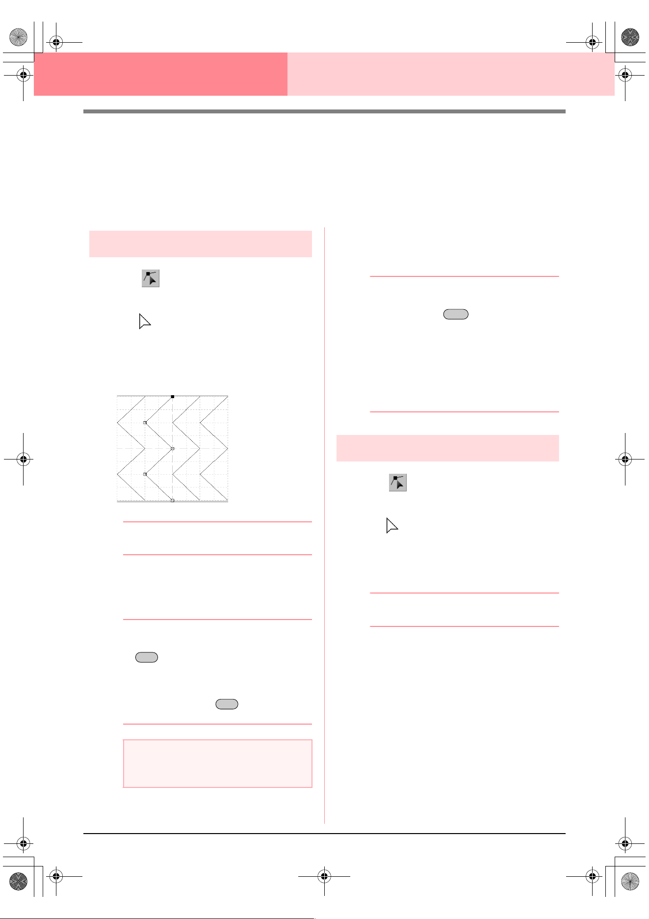
216
Programmable Stitch Creator
Editing Points in Fill/Stamp Mode
The points that you move or insert are positioned at the intersection of the horizontal and vertical lines of the
grid. Regardless of where you drag a point to or insert a point on the line, it will automatically be positioned at
the nearest intersection.
Depending on the stitch that you want to create, you may need to select a grid of a different size. For details
on the grids and adjusting them, refer to “Changing the grid settings” on page 222.
Moving points
1. Click on the Tool Box.
→ The shape of the pointer changes to
.
2. Click the broken line that you want to edit.
→ The points in the broken line appear as
small empty squares.
b Memo:
You can only select one broken line at a time.
3. Click the point that you want to move.
→ The selected point appears as a small
black square.
bMemo:
• To select additional points, hold down the
key and click each point, or drag
the pointer over the points that you want to
select.
• To select the previous (or next) point in the
line, hold down the key and press
the
→ (
or
←
) key.
4. Drag the point to the new location.
→ All of the selected points move in the
same direction.
bMemo:
• To move the point horizontally or vertically,
hold down the key while dragging
it.
• Pressing the arrow keys moves the
selected point one grid mark in the
direction of the arrow on the key. If the grid
is not displayed, the point moves a
distance smaller than the smallest grid
interval in the direction of the arrow on the
key.
Inserting points
1. Click on the Tool Box.
→ The shape of the pointer changes to
.
2. Click the broken line that you want to edit.
→ The points in the broken line appear as
small empty squares.
b Memo:
You can only select one broken line at a time.
3. Click the line to add a new point.
→ A new point appears selected (as a small
black square).
a Note:
If you click the line of the pattern instead of a
point, a new point is inserted.
Ctrl
Ctrl
Shift
PeDesignV6Eng.book Page 216 Thursday, July 8, 2004 11:59 AM
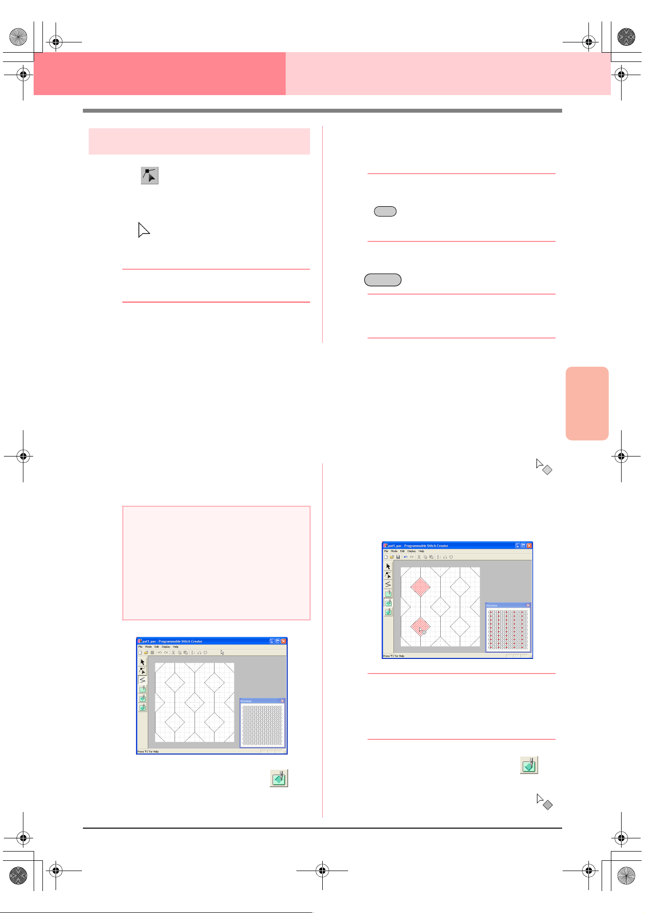
Advanced Opreation
Programmable
Stitch Creator
217
Programmable Stitch Creator
Deleting points
1. Click on the Tool Box.
→ When the pointer is moved over the work
area, the shape of the pointer changes to
.
2. Click the broken line that you want to edit.
b Memo:
You can only select one broken line at a time.
→ The points in the broken line appear as
small empty squares.
3. Click the point that you want to delete.
→ The selected point appears as a small
black square.
bMemo:
To select additional points, hold down the
key and click each point, or drag the
pointer over the points that you want to
select.
4. Click Edit, then Delete, or press the
key to remove the point.
bMemo:
If a line is composed of two points and you
delete one of them, the entire line is deleted.
Creating a Stamp
Stamps are composed of line stitches that, when they form enclosed areas or regions, the regions can be filled
with different types of stitching in order to create a pattern with an embossing/engraving effect. Stamps can be
applied to regions of patterns with the Stamp tool, and they can be used as a fill pattern for a programmable
fill stitch in both Design Center and Layout & Editing. In Layout & Editing, the regions of patterns where stamps
can be applied are those created with the Circle or Arc, Rectangle, Outline, Text or Manual Punch tools.
1. Open an existing fill/stamp pattern file (.pas
file) or draw a new stitch pattern with the Line
tool in the Fill/Stamp mode.
2. To create an engraving effect, click
(Region (engrave)).
→ The shape of the pointer changes to .
3. Click each region where you want to apply the
engraving setting.
→ The regions appear in red, which is the
color for the tool.
b Memo:
This type of region will be sewn with the fill
stitch set to a pitch of 2.0 mm (0.16 in) and a
frequency of 30%, and the needle drop point
will be set on the outline.
4. To create an embossing effect, click
(Region (emboss)).
→ The shape of the pointer changes to .
Ctrl
Delete
a Note:
In order to apply the stamp settings
(embossing/engraving effects), make sure
that the lines of the stitch pattern form an
enclosed area.
The edge of the work area does enclose
regions. In order to use the edge of the work
area as a limit for regions, lines must be
drawn over it first.
PeDesignV6Eng.book Page 217 Thursday, July 8, 2004 11:59 AM
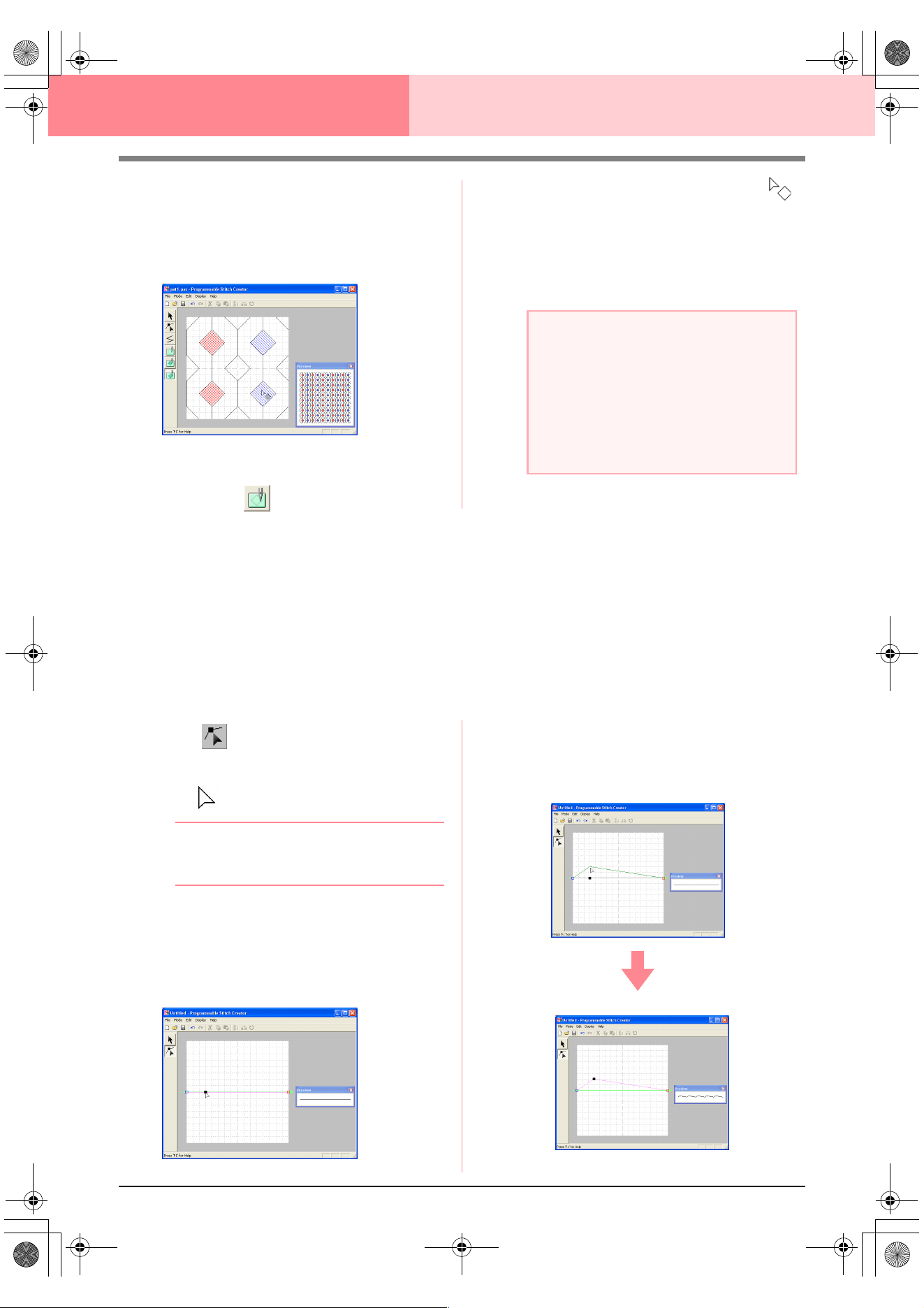
218
Programmable Stitch Creator
5. Click each region where you want to apply the
embossing setting.
→ The regions appear in blue, which is the
color for the tool, and will be sewn with
stitching that appears like satin stitching.
6. To remove the stamp effect applied to a
region, click (Region (reset)).
→ The shape of the pointer changes to .
7. Click each region where you want to remove
the engraving or embossing setting.
→ The region appears in white, which is the
color for the tool, and will be sewn in the
direction set for the base stitch.
Creating a Stitch Pattern in Motif Mode
In Motif mode, stitch patterns are created by inserting points on the base line of the motif stitch, then moving
them in order to change the shape of the stitch and give it the look of a single-stroke drawing.
The points you move or insert are positioned at the intersection of the horizontal and vertical lines of the grid.
Regardless of where you drag a point to or insert a point on the line, it will automatically be positioned at the
nearest intersection.
Depending on the stitch you want to create, you may need to select a grid of a different size. For details on the
grids and adjusting them, refer to “Changing the grid settings” on page 222.
1. Click on the Tool Box.
→ The shape of the pointer changes to
.
bMemo:
The Point Edit tool is selected automatically
when Motif mode is entered.
2. Click the base line between the start point
(blue square) and end point (red square).
→ A new point appears selected (as a small
black square). The new point can be edit-
ed.
3. Drag the point that you want to move to a new
position.
→ The stitch line moves with the newly cre-
ated point.
a Note:
• If you edit stitch lines after a region has been
filled, make sure that the lines still form a
region, otherwise the embossing/engraving
effects are canceled.
• Stamp files cannot be used with versions of
the software earlier than version 6, but .pas
files created with an earlier version can be
used as a base to create stamp files.
PeDesignV6Eng.book Page 218 Thursday, July 8, 2004 11:59 AM
Advanced Opreation
Programmable
Stitch Creator
219
Programmable Stitch Creator
b Memo:
• To move the point horizontally or vertically,
hold down the key while dragging
it.
• Pressing the arrow keys moves the
selected point one grid mark in the
direction of the arrow on the key. If the grid
is not displayed, the pattern moves a
distance smaller than the smallest grid
interval in the direction of the arrow on the
key.
• To delete a selected point, press the
key.
4. Repeat steps 2. and 3. until the motif stitch
pattern is completed.
bMemo:
• If you move the start point (blue square) or
the end point (red square), the other point
will automatically move in the same
direction.
• The start and end points cannot be moved
closer together than a certain fixed
distance.
Editing a Stitch Pattern in Motif Mode
After creating a stitch pattern, or after opening an existing motif file, you may want to change its shape or
position. To do so, you can proceed in the same way as described above, but in addition, you can select and
move or delete several points at the same time.
Moving and deleting
several points at a time
1. Click on the Tool Box.
→ The shape of the pointer changes to
.
bMemo:
The Point Edit tool is selected automatically
when Motif mode is entered.
2. Click the base line between the start point
(blue square) and end point (red square).
→ The selected point appears as a small
black square.
bMemo:
• To select additional points, hold down the
key and click each point, or drag
the pointer over the points that you want to
select.
• To select the previous (or next) point in the
line, hold down the key and press
the
→ (
or
←
) key.
3. To move the point(s), drag them to the desired
location.
→ All of the selected points move in the
same direction.
4. To delete the selected points, press the
key.
→ All of the selected points are deleted.
Shift
Delete
a Note:
If you click the line of the pattern instead of a
point, a new point is inserted.
Ctrl
Ctrl
a Note:
The start point (blue square) and end point
(red square) can not be deleted.
Delete
PeDesignV6Eng.book Page 219 Thursday, July 8, 2004 11:59 AM
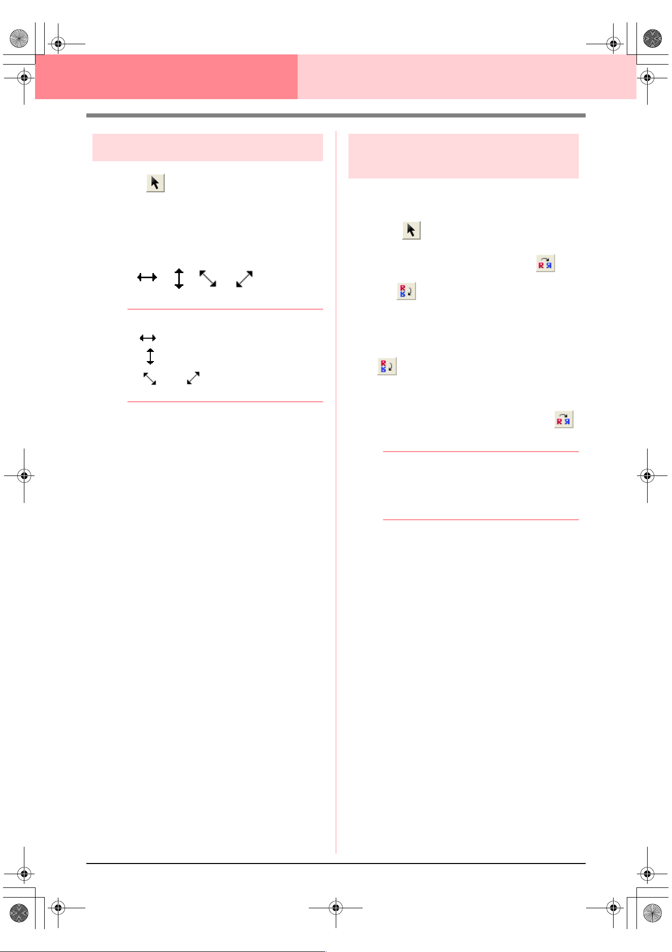
220
Programmable Stitch Creator
Scaling patterns
1. Click on the Tool Box.
→ The motif stitch is selected.
2. Move the pointer over one of the handles of
the pattern.
→ The shape of the pointer changes to
, , or , depending on
the handle that the pointer is over.
b Memo:
• is for scaling the width.
• is for scaling the height.
• and are for scaling both
dimensions at the same time.
3. Drag the handle to adjust the selected
pattern(s) to the desired size.
Flipping a pattern
horizontally or vertically
You can flip selected patterns horizontally (up/
down) or vertically (left/right).
1. Click on the Tool Box.
→ The motif stitch is selected, and and
are available in the Toolbar.
2. To replace the stitch pattern by its horizontal
mirror image (top and bottom inverted), select
Edit, then Mirror, then Horizontal, or click
in the Toolbar.
To replace the stitch pattern by its vertical
mirror image (left and right inverted), select
Edit, then Mirror, then Vertical, or click
in the Toolbar.
b Memo:
To restore the image to its original
orientation, select the same menu command
again, or select the menu command
Edit
–
Undo
.
PeDesignV6Eng.book Page 220 Thursday, July 8, 2004 11:59 AM
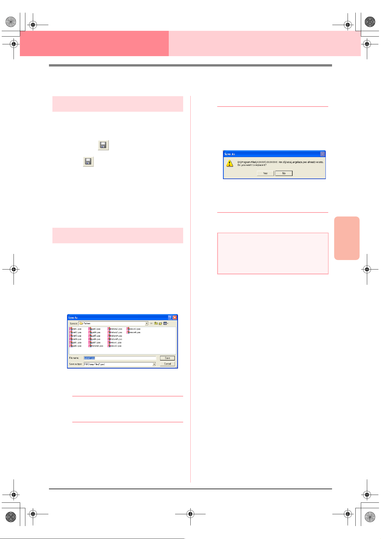
Advanced Opreation
Programmable
Stitch Creator
221
Programmable Stitch Creator
Saving
Overwriting
Once the stitch pattern has been saved, changes
can easily be saved so that the latest version can be
retrieved later.
Toolbar button:
1. Click , or click File, then Save.
→ If the pattern has already been saved at
least once, the file is saved immediately.
→ If no file name has been specified or if the
file cannot be found, the Save As dialog
box appears.
c
“Saving with a new name” on this page
Saving with a new name
The current file can be saved with a different file
name in order to keep the original unchanged or to
keep various versions of the same image or pattern.
The files are saved as.pas files in Fill/Stamp mode,
and as .pmf files in Motif mode.
1. Click File, then Save As.
→ A Save As dialog box similar to the one
shown below appears.
2. Select the drive and the folder, and then type
in the file name.
b Memo:
The correct extension is automatically
selected.
3. Click Save to save the pattern.
b Memo:
• To quit the operation, click
Cancel
.
• If a file already exists with the name
specified in the
Save As
dialog box, the
following message appears.
• To overwrite the file, click
Yes
.
• If you do not want to overwrite the
existing file, click
No
. You can then
enter a different file name.
c
“Overwriting” on this page
a Note:
Stamp files cannot be used with versions of
the software earlier than version 6, but .pas
files created with an earlier version can be
used as a base to create stamp files.
PeDesignV6Eng.book Page 221 Thursday, July 8, 2004 11:59 AM
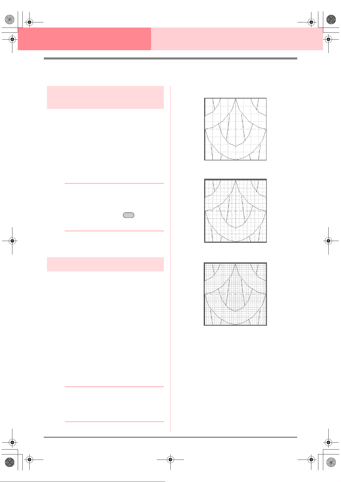
222
Programmable Stitch Creator
Changing the Settings
Changing the display of the
background image
The template image that remains in the work area
can be displayed or hidden, or a faded copy of the
image can be displayed.
1. Click Display, then Template, and then select
the desired setting.
To display the template image, click On.
To display a faded copy of the image, click
Faded.
To hide the template image, click Off.
b Memo:
• This function is not available if no template
image has been imported into the work
area.
• Press the shortcut key ( ) to switch
between displaying the image to
displaying it faded to hiding the image.
c
“Opening an image in the background” on
page 210
Changing the grid settings
The line spacing in the grid displayed in the work
area can be adjusted.
1. Click Display, then Grid.
→ A submenu showing the current grid set-
ting appears.
2. Click the grid setting that you need for the
stitch pattern that you are creating or editing.
To select a grid interval of 1/8 of a work area’s
edge, click Wide.
To select a grid interval of 1/16 of a work
area’s edge, click Medium.
To select a grid interval of 1/32 of a work
area’s edge, click Narrow.
To hide the grid, click None.
b Memo:
• You can also change the grid setting while
you are working on a stitch pattern.
• The setting for the grid setting is retained,
until it is changed.
The horizontal and vertical lines that you draw in the
work area always follow the grid. The points you
create by clicking in the work area are inserted at the
intersection of the horizontal and vertical lines of the
grid, enabling you to draw diagonal lines as well.
Regardless of where you click, a point will
automatically be inserted at the nearest intersection.
Select a different grid size according to the type of
stitch that you want to draw. Select a narrower grid
for drawing finer details or to give a curved or
circular appearance to your stitch lines, and select a
wider grid if you want to draw a simpler stitch
pattern. Select None to turn off the snap to grid
feature, allowing you to create curved patterns.
F6
Example 1: Wide grid
Example 2: Medium grid
Example 3: Narrow grid
PeDesignV6Eng.book Page 222 Thursday, July 8, 2004 11:59 AM
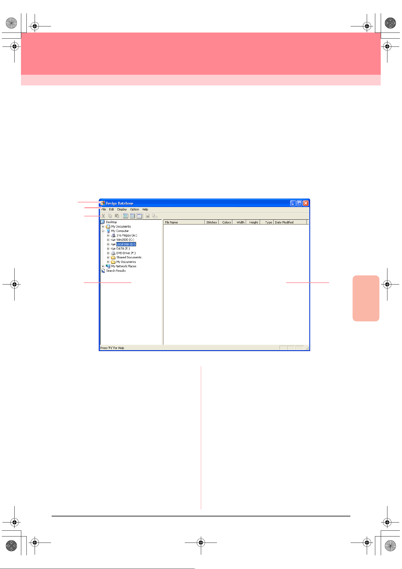
Advanced Opreation
Design Database
223
Design Database
Design Database is used to organize the embroidery pattern files on your computer so that you can easily
preview and search for the desired pattern. In addition, embroidery patterns can be opened with or imported
into Layout & Editing or converted into other file formats (.pes, .dst., .exp., .pcs or .hus). Images of the
embroidery patterns in a selected folder can be printed or outputted as an HTML file for quick reference. The
sewing information for the embroidery patterns in a selected folder can be outputted as a CSV file (the data in
each category is separated with a comma) for use in other database applications, such as Microsoft Excel.
Main Window
1 Title bar
2 Menu bar
Gives access to the functions.
3 Toolbar
Provides shortcuts for the menu commands.
4 Folder pane
Provides access to the folders on the computer
and the results of any searches that were per-
formed.
5 Contents pane
Displays thumbnails of all embroidery patterns in
the selected folder.
2
5
4
1
3
PeDesignV6Eng.book Page 223 Thursday, July 8, 2004 11:59 AM
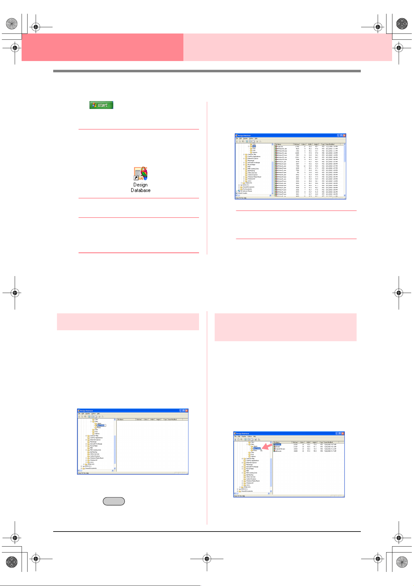
224
Design Database
Starting Up Design Database
1. Click , select All Programs, then
PE-DESIGN Ver 6. Select Design Database
to open the Design Database window.
b Memo:
If a shortcut for Design Database was
created, for example, on the desktop,
double-click it to start up the application.
→ The Design Database window appears.
b Memo:
To fill the entire screen with the Design
Database window, click the maximize button
on the right end of the title bar.
2. Click a folder in the folder pane.
→ All embroidery files in the folder are dis-
played in the contents pane.
b Memo:
Only .pes, .dst, .exp, .pcs, .hus and .phc files
are displayed.
Organizing Embroidery Patterns
You can move your embroidery patterns to different folders in order to organize them. In addition, you can
choose to display the embroidery patterns by thumbnails or by the pattern details.
Creating new folders
New folders can be created in order to better
organize the embroidery patterns.
1. In the folder pane, select the folder where you
want to create a new folder.
2. Click File, then Create New Folder.
→ A new folder appears as a sub-folder of
the one that was selected.
3. Type in the name of the new folder, and then
press the key.
→ The name of the folder changes to the one
that was typed in.
Moving/copying embroidery
patterns to a different folder
From Design Database, embroidery patterns can
easily be moved from one folder to another.
1. In the folder pane, display the folder where
you want to move the embroidery pattern.
2. In the folder pane, click the folder that contains
the embroidery pattern that you want to move.
3. Drag the embroidery pattern in the contents
pane to the desired folder in the folder pane.
Enter
PeDesignV6Eng.book Page 224 Thursday, July 8, 2004 11:59 AM
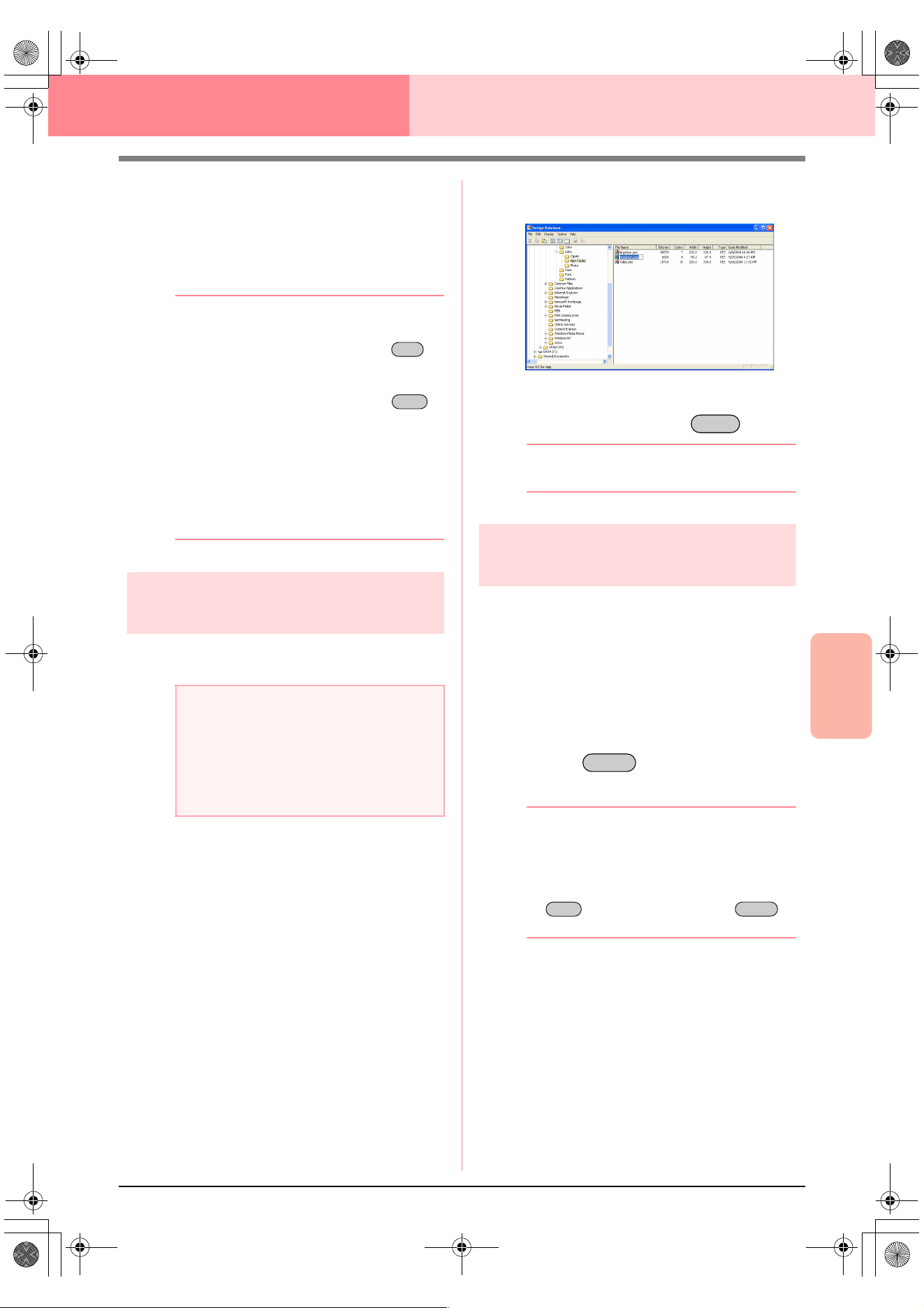
Advanced Opreation
Design Database
225
Design Database
→ If the two folders are on the same drive,
the selected embroidery pattern is moved
to the other folder.
→ If the two folders are on separate drives,
the selected embroidery pattern is copied
into the other folder.
b Memo:
• To copy the file from one folder to another
on the same drive, hold down the
key while dragging the embroidery pattern.
• To move the file from one folder to another
on different drives, hold down the
key while dragging the embroidery pattern.
• The file can also be removed from the
current folder (or copied) by selecting the
menu command
Edit
–
Cut
(or
Edit
–
Copy
).Then, the file can be added to the
new folder by selecting it in the folder
pane, then selecting the menu command
Edit
–
Paste
.
Changing the name of the
embroidery pattern
From Design Database, the names of embroidery
patterns can easily be changed.
1. In the folder pane, select the folder containing
the embroidery pattern that you want to
rename.
2. In the contents pane, select the embroidery
pattern that you want to rename.
→ The embroidery pattern is highlighted.
3. Click the name of the embroidery pattern that
you want to rename.
→ The name of the embroidery pattern is
highlighted.
4. Type in the new name of the embroidery
pattern, and then press the key.
b Memo:
The file extension cannot be changed.
Deleting an embroidery
pattern
From Design Database, embroidery patterns can
easily be deleted.
1. In the folder pane, select the folder containing
the embroidery pattern that you want to
delete.
2. In the contents pane, select the name of the
embroidery pattern that you want to delete.
3. Press the key.
→ The file is moved to the Recycle Bin.
b Memo:
• You can also delete embroidery pattern by
using the menu command
File
–
Delete
.
• To immediately remove the file without first
moving it to the Recycle Bin, hold down the
key before pressing the
key.
a Note:
The names of embroidery patterns can be
changed from Design Database only when
the sewing information (menu command
Display
–
Details
) is displayed. (Refer to
“Changing the contents pane display” on this
page.)
Ctrl
Shift
Enter
Delete
Shift Delete
PeDesignV6Eng.book Page 225 Thursday, July 8, 2004 11:59 AM
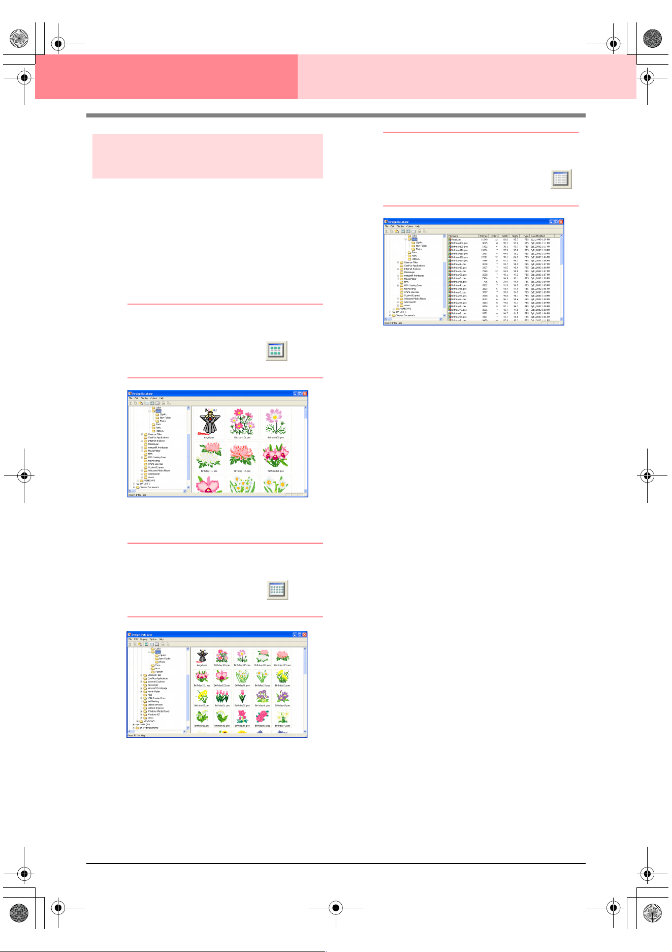
226
Design Database
Changing the contents pane
display
The embroidery patterns in the contents pane can
be displayed as large thumbnails or small
thumbnails, or they can be listed by their sewing
information.
1. Click Display, and then click the display
setting from the menu that appeared.
To display the embroidery patterns as large
images, click Large Thumbnails.
b Memo:
You can also display the embroidery patterns
as large thumbnails by clicking in the
Toolbar.
To display the embroidery patterns as small
images, click Small Thumbnails.
b Memo:
You can also display the embroidery patterns
as small thumbnails by clicking in the
Toolbar.
To display the sewing information for the
embroidery patterns, click Details.
b Memo:
You can also display the sewing information
for the embroidery patterns by clicking
in the Toolbar.
PeDesignV6Eng.book Page 226 Thursday, July 8, 2004 11:59 AM
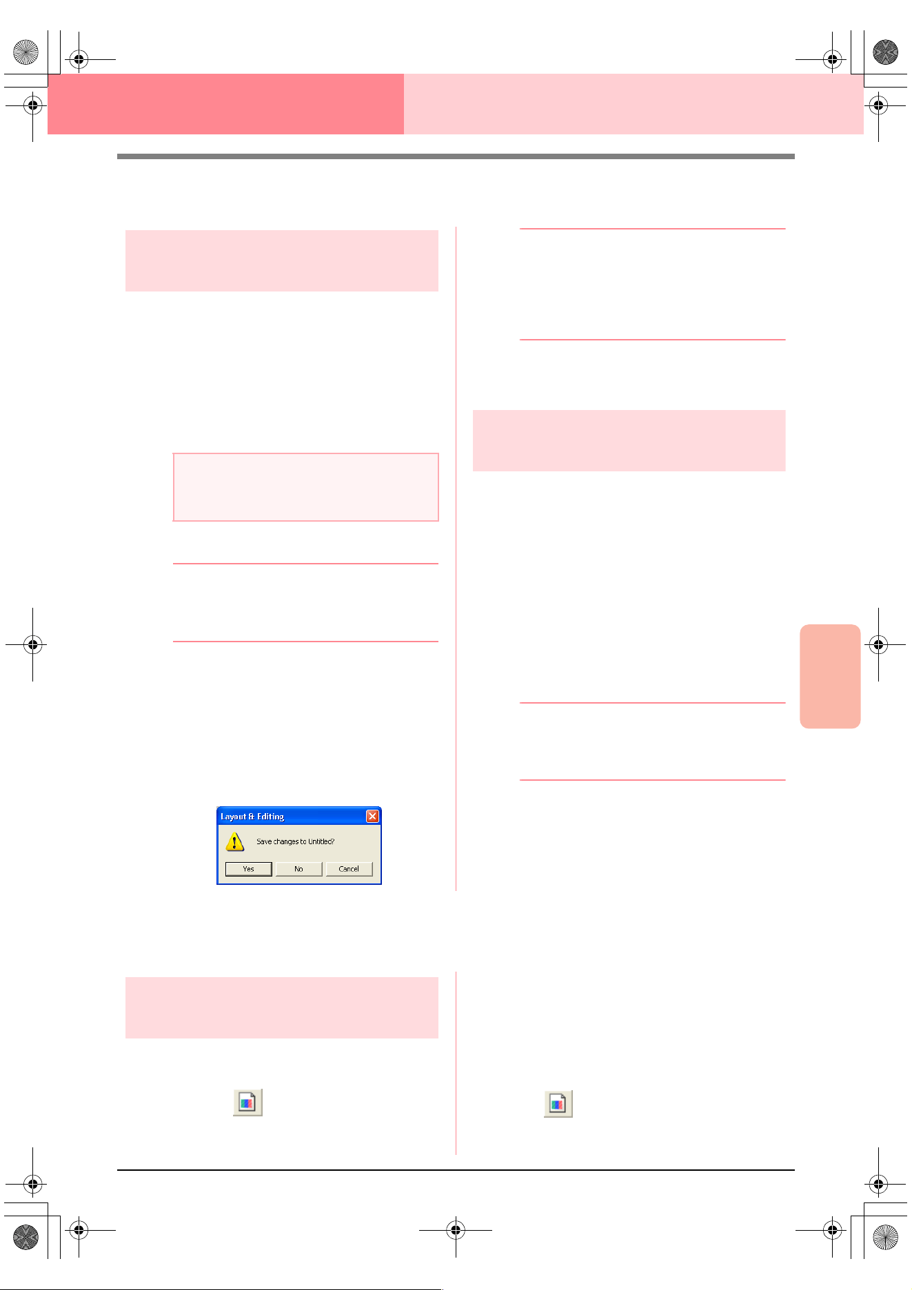
Advanced Opreation
Design Database
227
Design Database
Opening Embroidery Patterns
Opening embroidery patterns
with Layout & Editing
You can easily open any selected .pes file with
Layout & Editing.
1. In the folder pane, select the folder containing
the embroidery pattern that you want to open
in Layout & Editing.
2. In the contents pane, select the embroidery
pattern that you want to open.
3. Click File, then Open in Layout & Editing.
b Memo:
Double-clicking the file name also opens the
embroidery pattern in a new Design Page of
the Layout & Editing window.
→ If the current Layout & Editing work area
has already been saved or has not been
edited, the selected embroidery pattern
immediately appears in a new Design
Page of the Layout & Editing window.
→ If the current Layout & Editing work area
has not been saved, you will be asked
whether you want to save the changes.
b Memo:
• To save the work area, click
Yes
.
• To abandon the work area, click
No
.
• To return to the work area, for example, to
modify it or save it with another file name,
click
Cancel
.
c
“Overwriting” on page 194 and “Saving
with a new name” on page 194
Importing embroidery
patterns into Layout & Editing
You can easily import any selected embroidery
pattern into Layout & Editing.
1. In the folder pane, select the folder containing
the embroidery pattern that you want to import
into Layout & Editing.
2. In the contents pane, select the embroidery
pattern that you want to import.
3. Click File, then Import Into Layout & Editing.
→ The selected embroidery pattern appears
in the Layout & Editing window.
b Memo:
Double-clicking the file name also imports
the embroidery pattern into the Design Page
in the Layout & Editing window.
Checking Embroidery Patterns
Previewing embroidery
patterns
A preview of the embroidery pattern can be
displayed.
Toolbar button:
1. In the folder pane, select the folder containing
the embroidery pattern that you want to
preview.
2. In the contents pane, select the embroidery
pattern that you want to preview.
3. Click , or click Display, then Preview.
a Note:
Be sure to select a folder that contains .pes
files.
PeDesignV6Eng.book Page 227 Thursday, July 8, 2004 11:59 AM
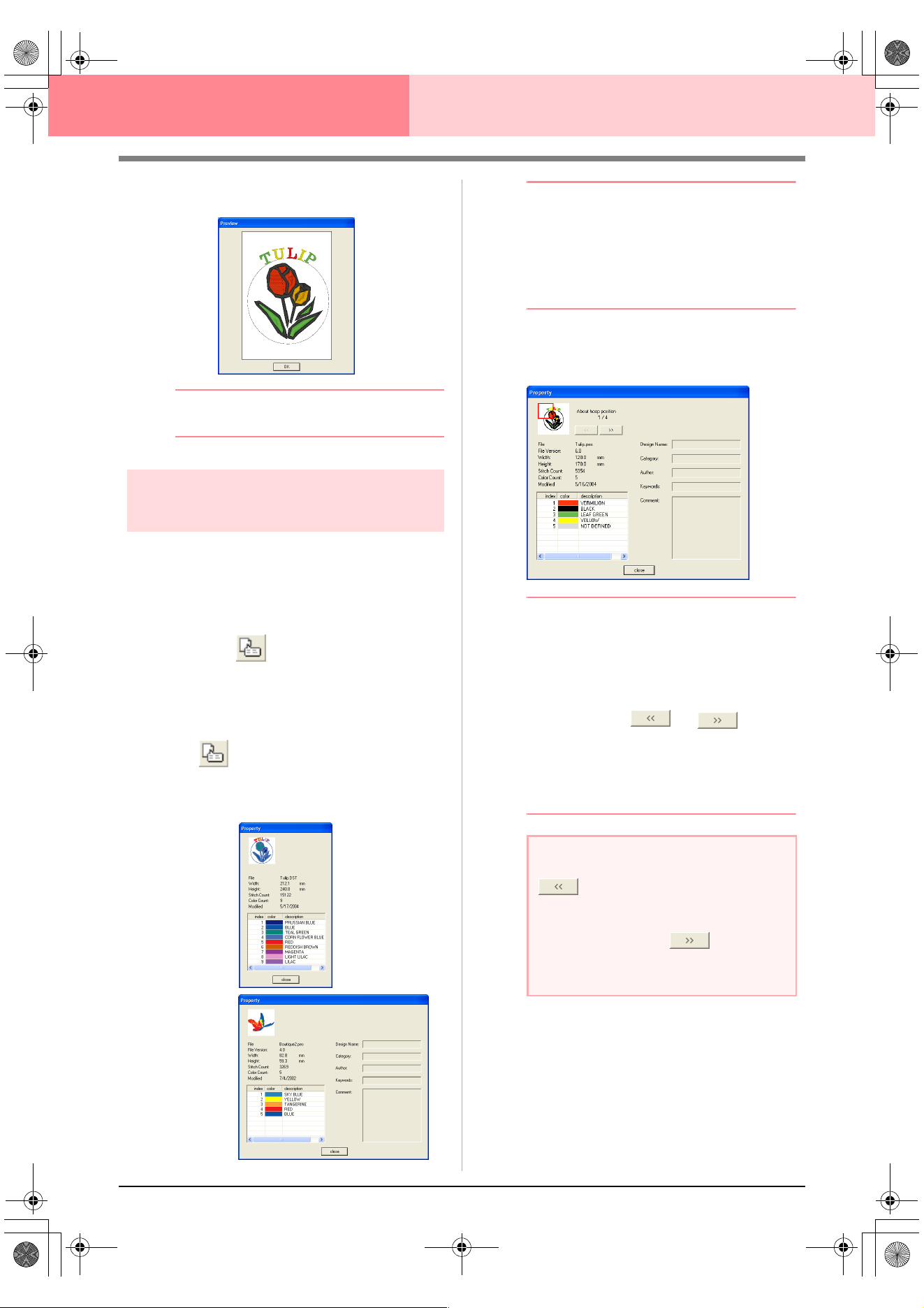
228
Design Database
→ A Preview dialog box similar to the one
shown below appears.
b Memo:
To close the dialog box, click
Close
.
Checking embroidery pattern
information
Sewing information such as the file name, size,
stitch count, color count and modification date can
be checked in the File Property dialog box. With
.pes file, additional information about the
embroidery pattern can be viewed.
Toolbar button:
1. In the contents pane, select the embroidery
pattern corresponding to the information that
you want to view.
2. Click , or click Display, then File
Property.
→ The Property dialog box appears.
b Memo:
• The thread colors are displayed as basic
colors. Thread colors in .pes files are
displayed according to the thread colors
set when the file was read by Layout &
Editing.
• To close the dialog box, click
Close
.
→ If the Design Page was set to Custom
Size, a Property dialog box similar to the
one shown below appears.
b Memo:
• The first line of the dialog box shows the
position of the displayed pattern section
within the embroidery hoop installation
order.
• To display information for other pattern
sections, click or .
• The pattern sections are displayed in order
from left to right, top to bottom. Pattern
sections that do not contain any stitching
will not be displayed.
• To close the dialog box, click
Close
.
Non-PES files
PES files
a Note:
cannot be clicked when the design
corresponding to the first hoop is already
displayed. In addition, cannot be
clicked when the design corresponding to
the last hoop is already displayed.
PeDesignV6Eng.book Page 228 Thursday, July 8, 2004 11:59 AM
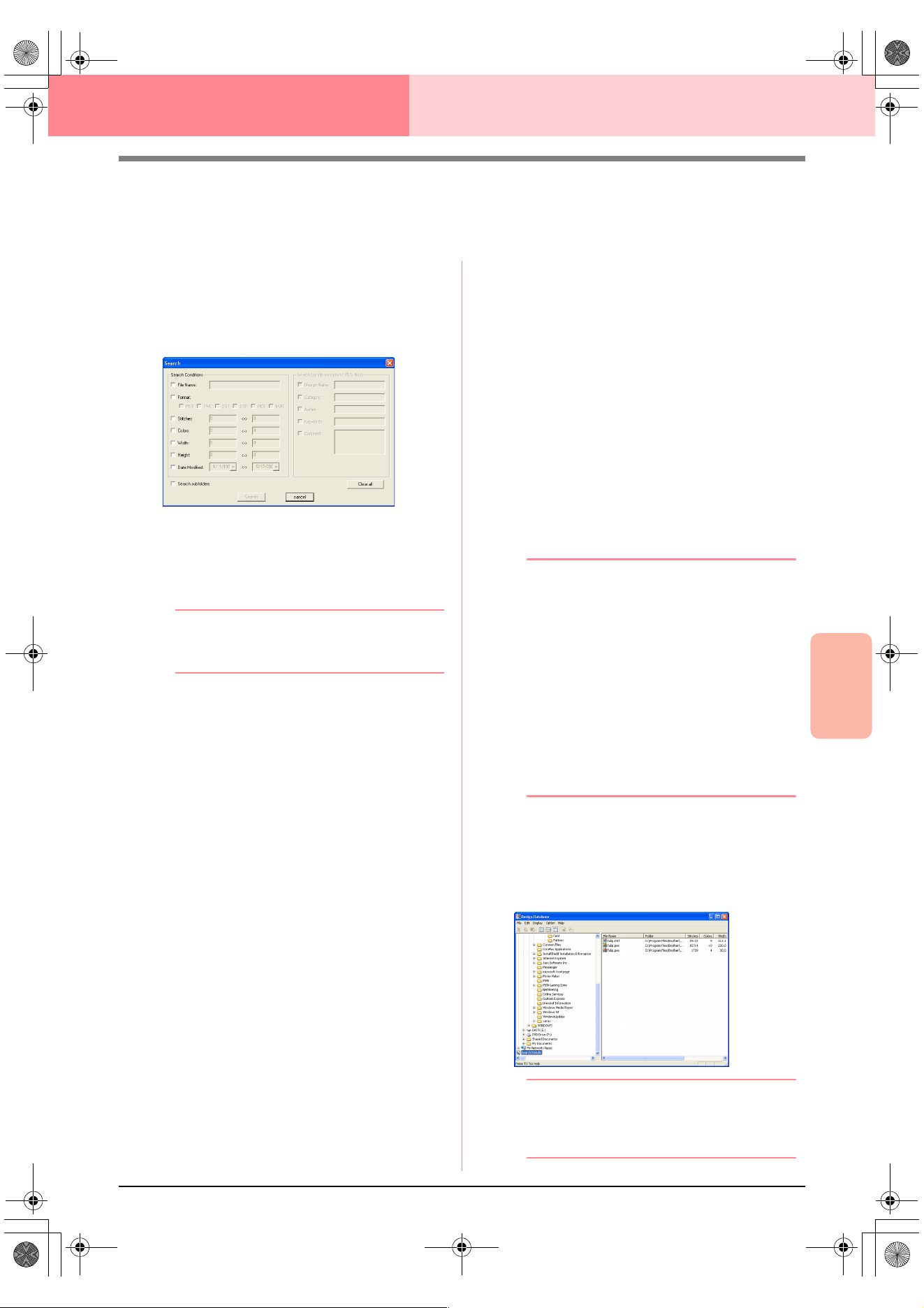
Advanced Opreation
Design Database
229
Design Database
Searching for an Embroidery Pattern
The Search function allows you to quickly search for the desired embroidery pattern (.pes, .phc, .dst., .exp.,
.pcs or .hus file) within the selected folder according to the various search conditions that you can specify.
1. In the folder pane, select the folder that you
want to search.
2. Click Edit, then Search.
→ The Search dialog box appears.
3. Specify the search conditions.
To search for a file with a specific file name,
select the File Name check box, and then type
the file name in the box beside File Name.
b Memo:
The wildcard characters “*” and “?” can be
used to represent one or multiple characters.
To search for a file with a specific format,
select the Format check box, and then select
the check box beside the desired format.
To search for a file with a number of stitches
within a specified range, select the Stitches
check box, and then type the range in the
boxes beside Stitches.
To search for a file with a number of colors
within a specified range, select the Colors
check box, and then type the range in the
boxes beside Colors.
To search for a file with a width within a specified
range, select the
Width
check box, and then type
the range in the boxes beside
Width
.
To search for a file with a height within a specified
range, select the
Height
check box, and then type
the range in the boxes beside
Height
.
To search for a file with a modification date
within a specified range, select the Date
Modified check box, and then type or select
the range in the boxes beside Date Modified.
To search for a .pes file with a design name that
contains specific characters, select the
Design
Name
check box, and then type the desired
characters in the box beside
Design Name
.
To search for a .pes file with a category that
contains specific characters, select the
Category
check box, and then type the desired
characters in the box beside
Category
.
To search for a .pes file with an author name
that contains specific characters, select the
Author check box, and then type the desired
characters in the box beside Author.
To search for a .pes file with a keyword that
contains specific characters, select the
Keywords
check box, and then type the desired
characters in the box beside
Keywords
.
To search for a .pes file with a comment that
contains specific characters, select the
Comment
check box, and then type the desired
characters in the box beside
Comment
.
b Memo:
• To also search through the subfolders
(folders within the selected folder), select
the
Search Subfolders
check box.
• All characters entered in the box beside
File Name
will be considered as a single
set of characters. However, you can
search for files matching multiple words in
the boxes below
Search Conditions
(only for PES files)
by separating the
words with a space.
• With search conditions that contain a
range, values must be entered for the start
and end of the range.
To clear the search conditions, click Clear all.
4. Click Search Now.
→ A list of files matching the specified
search conditions appears.
b Memo:
To quit the search, click
Search Cancel
in
the message box that appeared during the
search.
PeDesignV6Eng.book Page 229 Thursday, July 8, 2004 11:59 AM
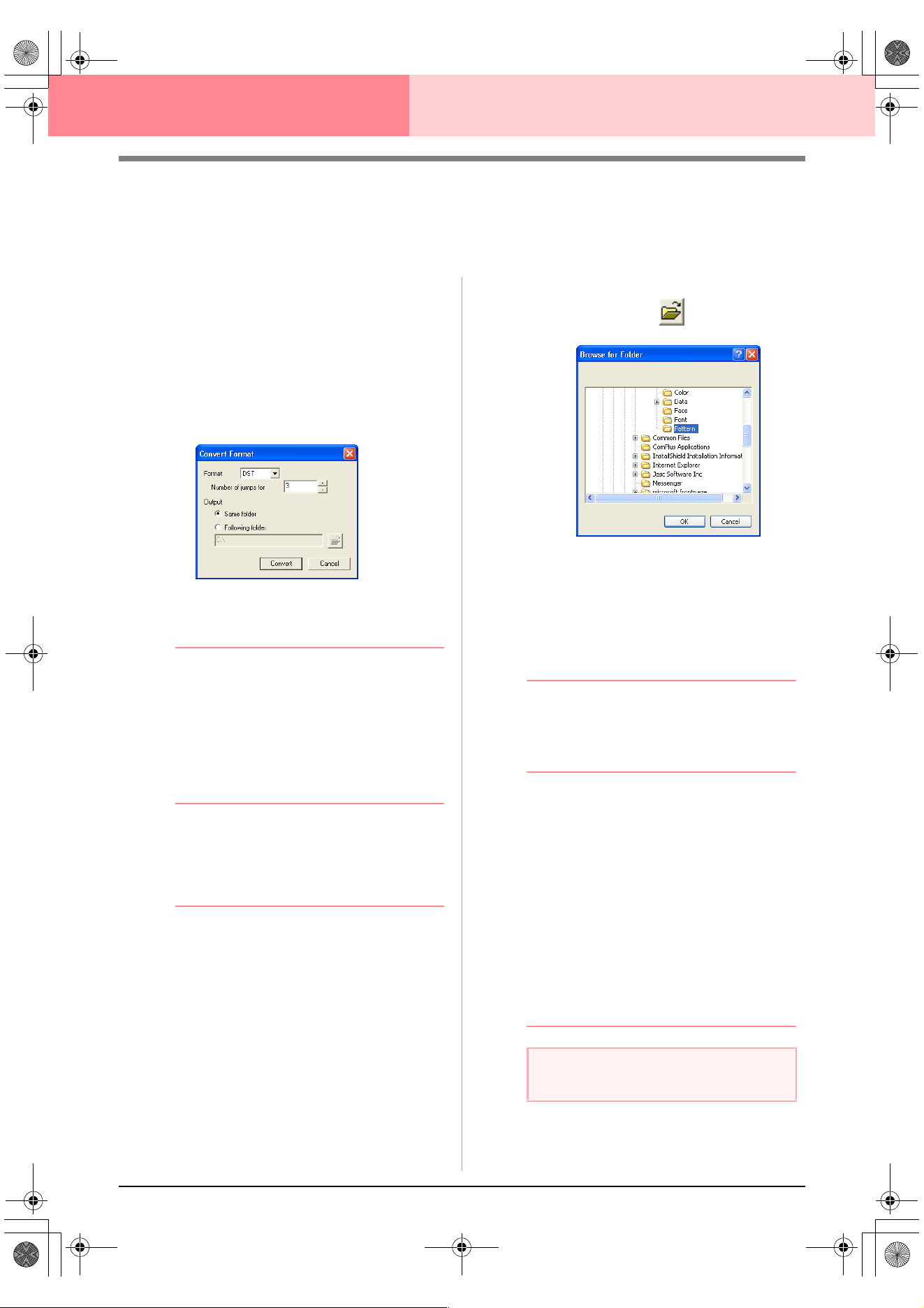
230
Design Database
Converting Embroidery Patterns to
Different Formats
Embroidery files can easily be converted to a file of one of the other formats (.pes, .dst., .exp., .pcs or .hus).
1. In the folder pane, select the folder containing
the embroidery pattern that you want to
convert.
2. In the contents pane, select the embroidery
file that you want to convert.
3. Click File, then Convert Format.
→ The Convert Format dialog box appears.
4. From the Format selector, select the format
that you want to convert the file to.
b Memo:
With the DST format, jump codes are used to
indicate when the thread must be cut in order
to change the thread color. Since the number
of codes differ depending on the sewing
machine being used, type or select the
appropriate value in the
Number of jumps
for trim
box. (This setting can only be
specified if the .dst format is selected.)
5. Under Output, select whether the new file is
added to the same folder as the original file
(Same folder) or to a specified folder
(Following folder).
b Memo:
• If multiple files with different formats are
selected to be converted while
Same
folder
is selected, any file with the same
format as the new one will not be
converted. However, if the files are being
added to a different folder than the original
one, any file with the same format as the
new one will be copied to the different
folder, instead of being converted.
• To change the folder where the new file
will be added, click .
In the
Browse for Folder
dialog box that
appeared, click the folder, and then click
OK
(or double-click the folder) to select it
and to close the
Browse for Folder
dialog
box.
• To create a new folder, click
New Folder
,
and then type in the name of the new
folder.
6. Click Convert.
→ The file is converted, and the new file is
added to the specified folder.
b Memo:
• If the file is converted to a .pes file, the
thread colors are converted as if the file
was imported into Layout & Editing.
• If the path to a folder that does not exist
was typed in, a message appears, asking
if you want to create the folder.
• If a file with the same name already exists,
a message appears, asking if you want to
overwrite the original file.
• The name of the file after the conversion is
the same as the name before the
conversion, except the extension is
changed to the one corresponding to the
selected file format.
a Note:
Files cannot be converted to the .phc format.
PeDesignV6Eng.book Page 230 Thursday, July 8, 2004 11:59 AM
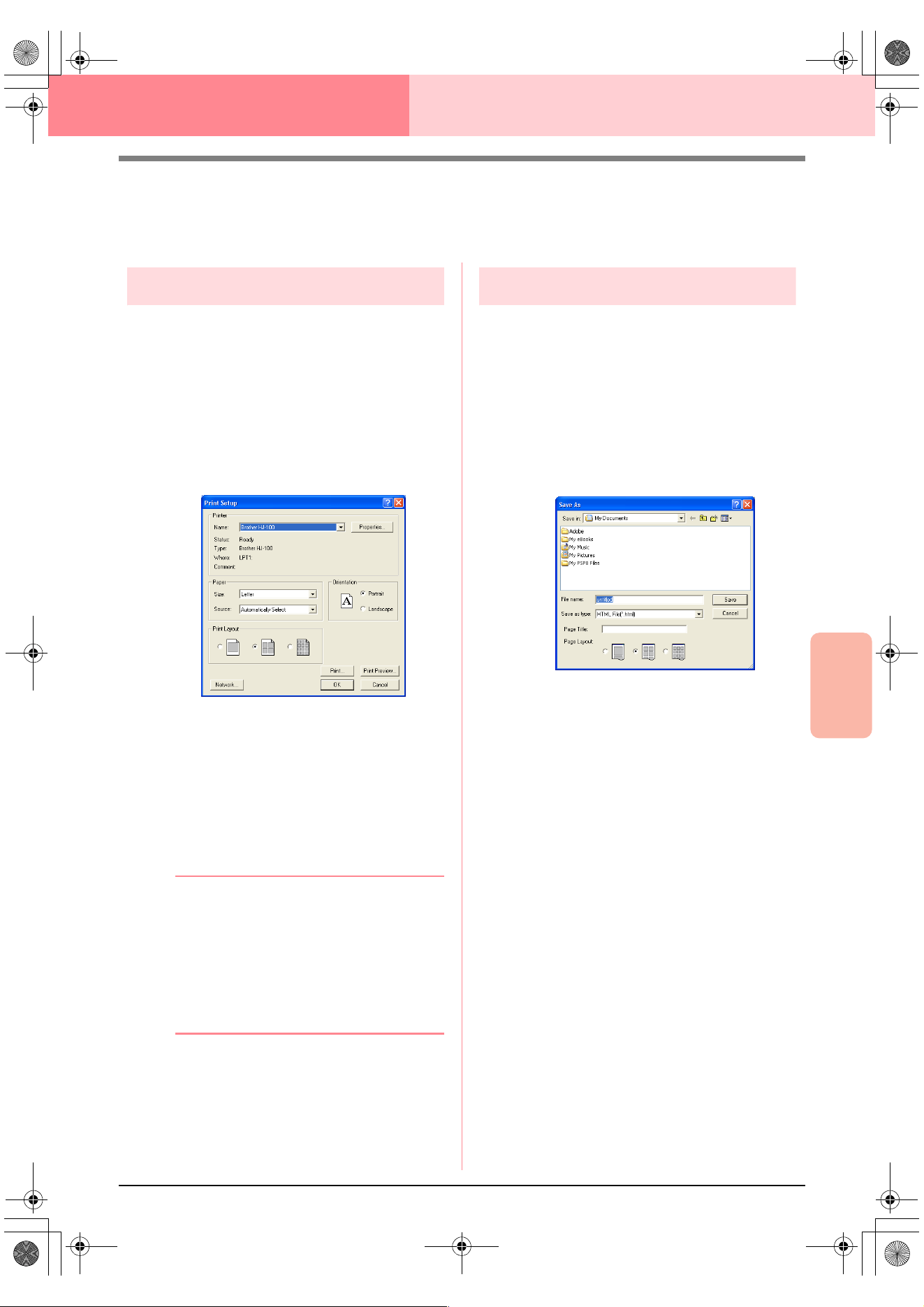
Advanced Opreation
Design Database
231
Design Database
Outputting a Catalog of Embroidery
Patterns
Printing
Images of all embroidery patterns in the selected
folder can be printed as a catalog.
1. In the folder pane, select the folder containing
the embroidery patterns that you want to
catalog.
2. Click File, then Print Setup.
→ A Print Setup dialog box similar to the
one shown below appears.
3. Under Print Layout, select whether each
pattern is printed on a separate page, 4
patterns are printed on a page or 12 patterns
are printed on a page.
4. Click Print.
→ Images of the selected patterns are print-
ed.
b Memo:
• If one or more embroidery patterns were
selected in the contents pane, only the
selected patterns are printed.
• The catalog can be printed immediately by
clicking the menu command
File
–
Print
.
The embroidery patterns are printed
according to the settings already selected
in the
Print Setup
dialog box.
Outputting as an HTML file
Instead of being printed, the catalog of embroidery
patterns can be outputted as an HTML file.
1. In the folder pane, select the folder containing
the embroidery patterns that you want to
catalog.
2. Click File, then Create HTML.
→ A Save As dialog box similar to the one
shown below appears.
3. Select the drive and the folder, and then type
in the name of the HTML file.
4. To add a title at the top of the file and in the title
bar, type the title in the Page Title box.
5. Under Page Layout, select how the patterns
appear on the page.
6. Click Save.
→ The HTML file and a folder containing im-
ages of the embroidery patterns are out-
putted to the selected folder.
PeDesignV6Eng.book Page 231 Thursday, July 8, 2004 11:59 AM
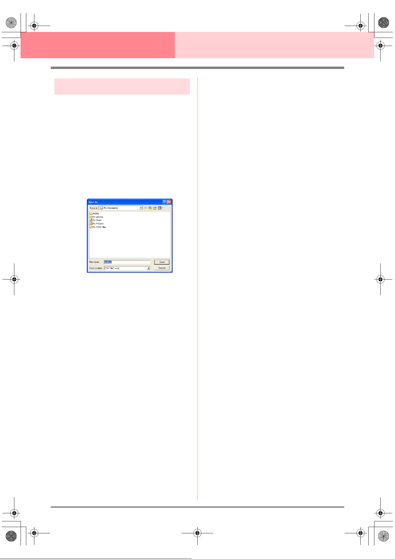
232
Design Database
Outputting as a CSV file
A .csv file containing the sewing information (file
name, dimensions, number of stitches, number of
colors, file path, file properties (.pes files only) and
the names of thread colors) for selected embroidery
patterns can be outputted.
1. In the folder pane, select the folder containing
the embroidery patterns that you want to
catalog.
2. Click File, then Create CSV.
→ A Save As dialog box similar to the one
shown below appears.
3. Select the drive and the folder, and then type
in the name of the .csv file.
4. Click Save.
→ A CSV file containing the sewing informa-
tion for the embroidery patterns is output-
ted to the selected folder.
PeDesignV6Eng.book Page 232 Thursday, July 8, 2004 11:59 AM
233
Chapter 3
Reference
PeDesignV6Eng.book Page 233 Thursday, July 8, 2004 11:59 AM
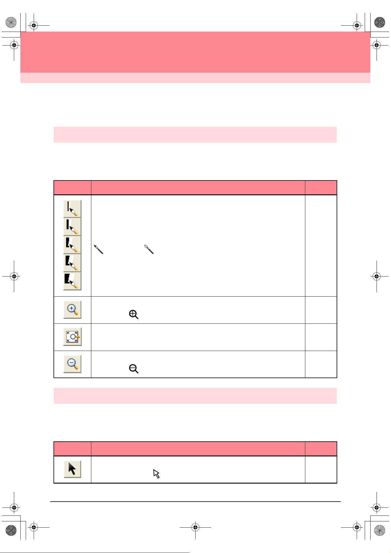
234
Design Center
List of Tool Box Buttons
Stage 2 (Line Image stage)
In stage 2 (Line Image stage), the Tool Box is used to modify the line image generated from the original image
or to create a line image from scratch.
Selecting a button on the Tool Box changes the pointer mode and shape. A description of each tool appears
at the left side of the status bar.
Stage 3 (Figure Handle stage)
In stage 3 (Figure Handle stage), outline data that has been generated automatically can be edited using the
Tool Box.
Selecting a button on the Tool Box changes the pointer mode and shape. A description of each tool appears
at the left side of the status bar.
Tool Box Purpose See page
The five first buttons are used as pens and erasers of different thicknesses.
Pointer shape when moved or dragged over the work area:
for the pens and for the erasers (when the right mouse button is held down).
When you start up the application, the second Pen tool is selected.
p. 32
Sets the pointer in zoom-in mode.
Pointer shape:
p. 102
Maximizes the selected Design Page to fit in the window.
p. 34
Sets the pointer in zoom-out mode.
Pointer shape:
p. 102
Tool Box Purpose See page
Sets the pointer in selection mode.When you start up the application, the selection mode is
selected. Pointer shape:
p. 78
PeDesignV6Eng.book Page 234 Thursday, July 8, 2004 11:59 AM
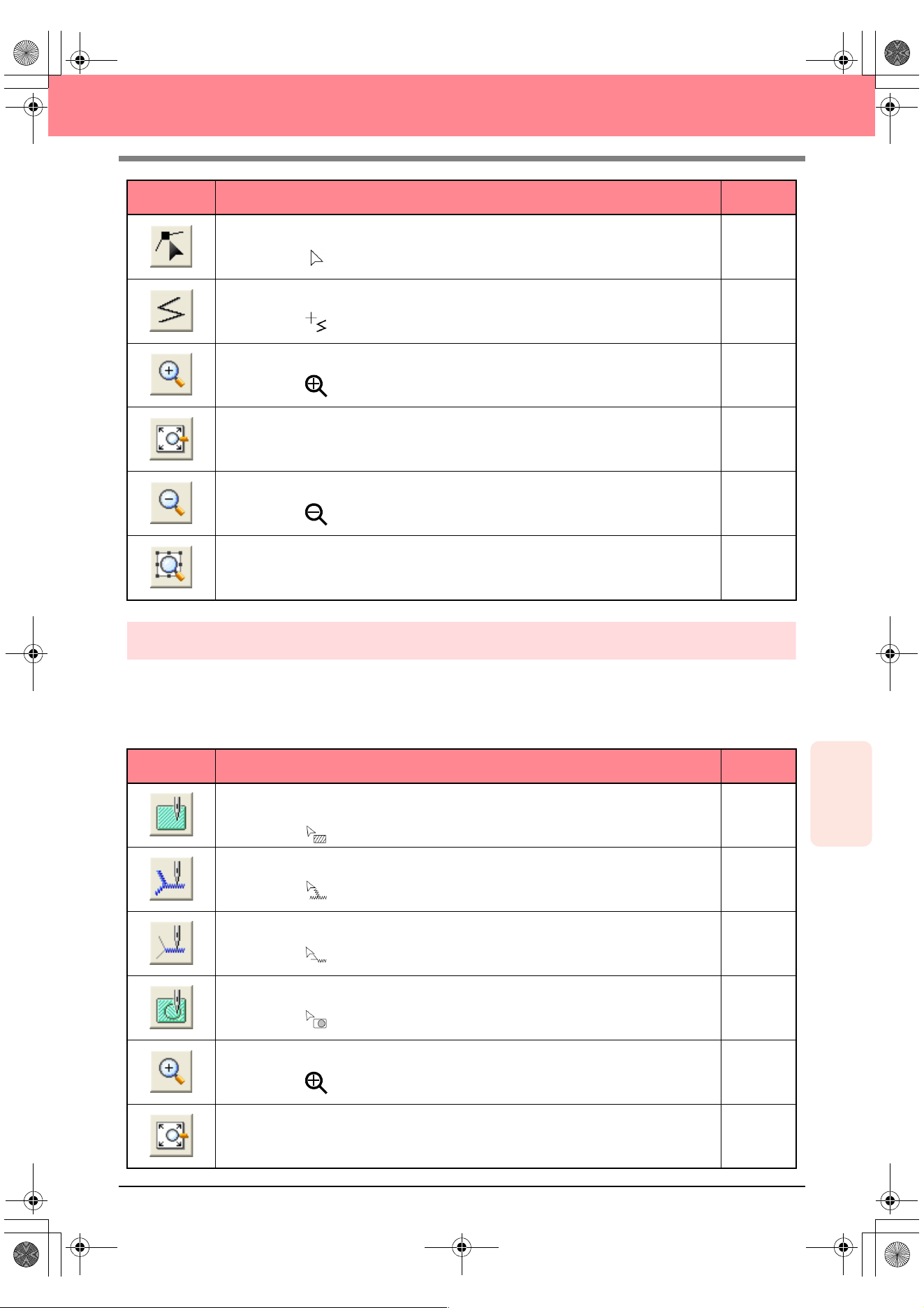
Reference
Design Center
235
Design Center
Stage 4 (Sew Setting stage)
In stage 4 (Sew Setting stage), outline data from stage 3 (Figure Handle stage) are assigned line and region
sewing attributes. This is done by using the Tool Box and the Sewing Attributes bar.
Selecting a button on the Tool Box changes the pointer mode and shape. A description of each tool appears
at the left side of the status bar.
Sets the pointer in point edit mode.
Pointer shape:
p. 81
Sets the pointer in line drawing mode.
Pointer shape:
p. 82
Sets the pointer in zoom-in mode.
Pointer shape:
p. 102
Maximizes the selected Design Page to fit in the window.
p. 32
Sets the pointer in zoom-out mode.
Pointer shape:
p. 102
Fills the display with the selected objects.
Tool Box Purpose See page
Sets the pointer in region sewing mode.
When you start up the application, this tool is selected.
Pointer shape:
p. 84
Sets the pointer in line (all) sewing mode.
Pointer shape:
p. 85
Sets the pointer in line (part) sewing mode.
Pointer shape:
p. 86
Sets the pointer in hole sewing mode.
Pointer shape:
p. 97
Sets the pointer in zoom-in mode.
Pointer shape:
p. 102
Maximizes the selected Design Page to fit in the window.
p. 32
Tool Box Purpose See page
PeDesignV6Eng.book Page 235 Thursday, July 8, 2004 11:59 AM
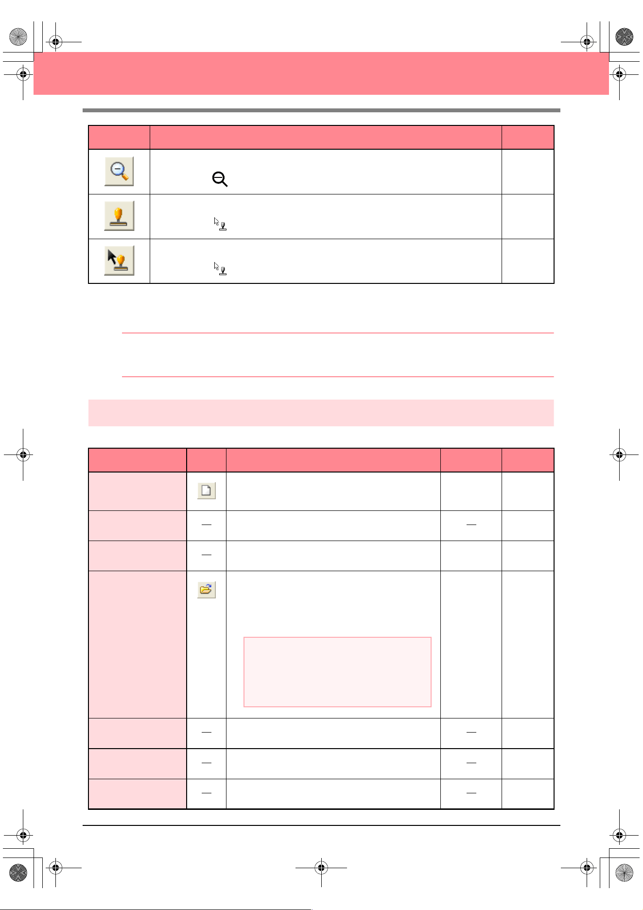
236
Design Center
List of Menus
b Memo:
Many menu commands are available as buttons on the Toolbar or in the menu that appears when the right
mouse button is clicked.
File menu
The File menu contains commands for handling file input/output, such as opening and saving.
Sets the pointer in zoom-out mode.
Pointer shape:
p. 102
Sets the pointer in stamp input mode.
Pointer shape:
p. 98
Sets the pointer in stamp edit mode.
Pointer shape:
p. 99
Menu Toolbar Purpose Shortcut key See page
New Line Image
Creates a new Design Page and switches to stage 2
(Line Image stage).
Ctrl + N p. 71
New Figure Data
Creates a new Design Page and switches to stage 3
(Figure Handle stage).
p. 71
Wizard
Gives a step-by-step guide for creating pattern data,
according the type of data you want to create.
F3 p. 71
Open
Opens a previously saved file (.pem, .pel) or image file
(Windows bitmap (.bmp), Exif (.tif, .jpg), ZSoftPCX (.pcx),
Windows Meta File (.wmf), Portable Network Graphics
(.png), Encapsulated PostScript (.eps), Kodak PhotoCD
(.pcd), FlashPix (.fpx), JPEG2000 (.j2k).
Ctrl + O p. 31
Select TWAIN device
Selects which TWAIN device installed in the computer
to use.
p. 72
Input from TWAIN
device
Operates a TWAIN standardized scanner or other
device to import an image.
p. 72
Input from Clipboard
Opens a new Design Page in stage 1 (Original Image
stage), and imports the image data on the Clipboard.
p. 72
Tool Box Purpose See page
a Note:
For .pcd and .fpx files containing many
pages, only the first page can be displayed.
Tiff files that have used LZW compression
cannot be opened.
PeDesignV6Eng.book Page 236 Thursday, July 8, 2004 11:59 AM
Reference
Design Center
237
Design Center
Edit menu
The Edit menu contains commands for performing simple actions on selected patterns, such as cutting and
pasting.
Output to Clipboard
Copies the stage 1 (Original Image stage) image data
to the Clipboard.
p. 114
Import Figure
Adds a .pem file to your Design Page (available only
in stage 3 (Figure Handle stage)).
F8
Save
Saves your Design Page on the disk as latest version
file (default).
Ctrl + S p. 104
Save As
Saves the current file under a new file name. Savable
files are: in stage 1 (Original Image stage), Bitmap
files (.bmp); in stage 2 (Line Image stage), .pel files;
and in stage 3 (Figure Handle stage) and stage 4
(Sew Setting stage), .pem files.
p. 104
Exit Exits the application.
Alt + F4
Menu Toolbar Purpose Shortcut key See page
Undo Undoes the last operation.
Ctrl + Z
Redo Cancels the effect of the last Undo.
Ctrl + A
Cut
Removes the selected data from the screen while
saving a copy in the Clipboard.
Ctrl + X p. 214
Copy
Saves the selected data in the Clipboard without
removing them from the screen.
Ctrl + C p. 214
Duplicate Makes a copy of the selected data.
Ctrl + D p. 214
Paste Pastes the contents of the Clipboard on the screen.
Ctrl + V p. 214
Delete
Removes the selected data from the screen without
saving them in the Clipboard.
Delete p. 214
Mirror
Horizon-
tal
Flips the selected data up/down.
Ctrl + H p. 79
Vertical Flips the selected data left/right.
Ctrl + J p. 79
Rotate Allows you to change the direction of the pattern.
Ctrl + Y p. 79
Menu Toolbar Purpose Shortcut key See page
PeDesignV6Eng.book Page 237 Thursday, July 8, 2004 11:59 AM
238
Design Center
Sew menu
The Sew menu contains commands for controlling the way the pattern will be sewn.
Display menu
The Display menu contains commands for modifying the appearance of the screen.
Numerical
Setting
Size Resizes the selection numerically.
p. 79
Rotate Rotates the selected pattern numerically.
p. 80
Select All Selects all of the data.
Ctrl + E p. 130
Menu Toolbar Purpose Shortcut key See page
Sewing Attributes Sets the sewing attributes for outlines and regions.
Ctrl + W p. 89
Sewing Order
Allows you to check and modify the sewing order of
the different colors of a pattern as well as the sewing
order of each color individually.
F10 p. 100
Menu Toolbar Purpose Shortcut key See page
Grid Setup
Allows you to set up the grid, to switch it on or off, and
to display it with or without the horizontal and vertical
lines.
p. 105
Preview
Specifies whether the patterns appear as stitches or
in the normal view.
F9 p. 102
Realistic Preview
Displays a realistic image of how the patterns will look
after being embroidered.
Shift + F9 p. 102
Refresh Window Updates the screen.
Ctrl + R
Stitch Simulator Displays a simulation of the machine stitching.
p. 101
Reference Window Hides/displays the Reference window.
F11 p. 103
Realistic Preview
Attribute Setting
Sets the preview attributes for Realistic Preview.
p. 102
Toolbar Hides/displays the Toolbar.
p. 70
Status Bar Hides/displays the status bar.
p. 70
Menu Toolbar Purpose Shortcut key See page
PeDesignV6Eng.book Page 238 Thursday, July 8, 2004 11:59 AM
Reference
Design Center
239
Design Center
Option menu
The Option menu contains commands for selecting the Design Page size and the unit system.
Stage menu
The Stage menu contains commands for moving from one stage to the next or to a previous one.
Menu Toolbar Purpose Shortcut key See page
Layout & Editing
Starts up Layout & Editing and displays its window up
front.
F5 p. 39
Programmable Stitch
Creator
Starts up Programmable Stitch Creator and displays
its window up front.
p. 54
Design Page Property
Allows you to change the size of the Design Page and
the color of the Design Page and the background.
p. 77
Select
System
Unit
mm Allows you to change the system units to millimeters.
p. 105
inch Allows you to change the system units to inches.
p. 105
Menu Toolbar Purpose Shortcut key See page
To Original Image
Moves back to stage 1 (Original Image stage).
p. 71
To Line Image
Moves to stage 2 (Line Image stage).
p. 73
To Figure Handle Moves to stage 3 (Figure Handle stage).
p. 76
To Sew Setting
Moves from stage 3 (Figure Handle stage) to stage 4
(Sew Setting stage).
p. 83
a Note:
This function can only be used if there is
image data in stage 1 (Original Image
stage), for example, if image data was
opened or if image data was pasted from the
Clipboard. If you have started with a new file
from stage 2 (Line Image stage), for
example, the function is not available.
a Note:
If you have started with a new figure handle
file from stage 3 (Figure Handle stage), this
function is not available.
PeDesignV6Eng.book Page 239 Thursday, July 8, 2004 11:59 AM
240
Design Center
Help menu
The Help menu contains commands for accessing the on-screen help information system.
Menu Toolbar Purpose Shortcut key See page
Contents
Starts up the on-screen help information for this
application.
F1
Customer Support
Opens the FAQ (Frequently Asked Questions) page
on our Web site.
About Design Center Gives information about the version of this application.
a Note:
This function cannot be used if there is no
Internet browser correctly installed in the
computer.
PeDesignV6Eng.book Page 240 Thursday, July 8, 2004 11:59 AM
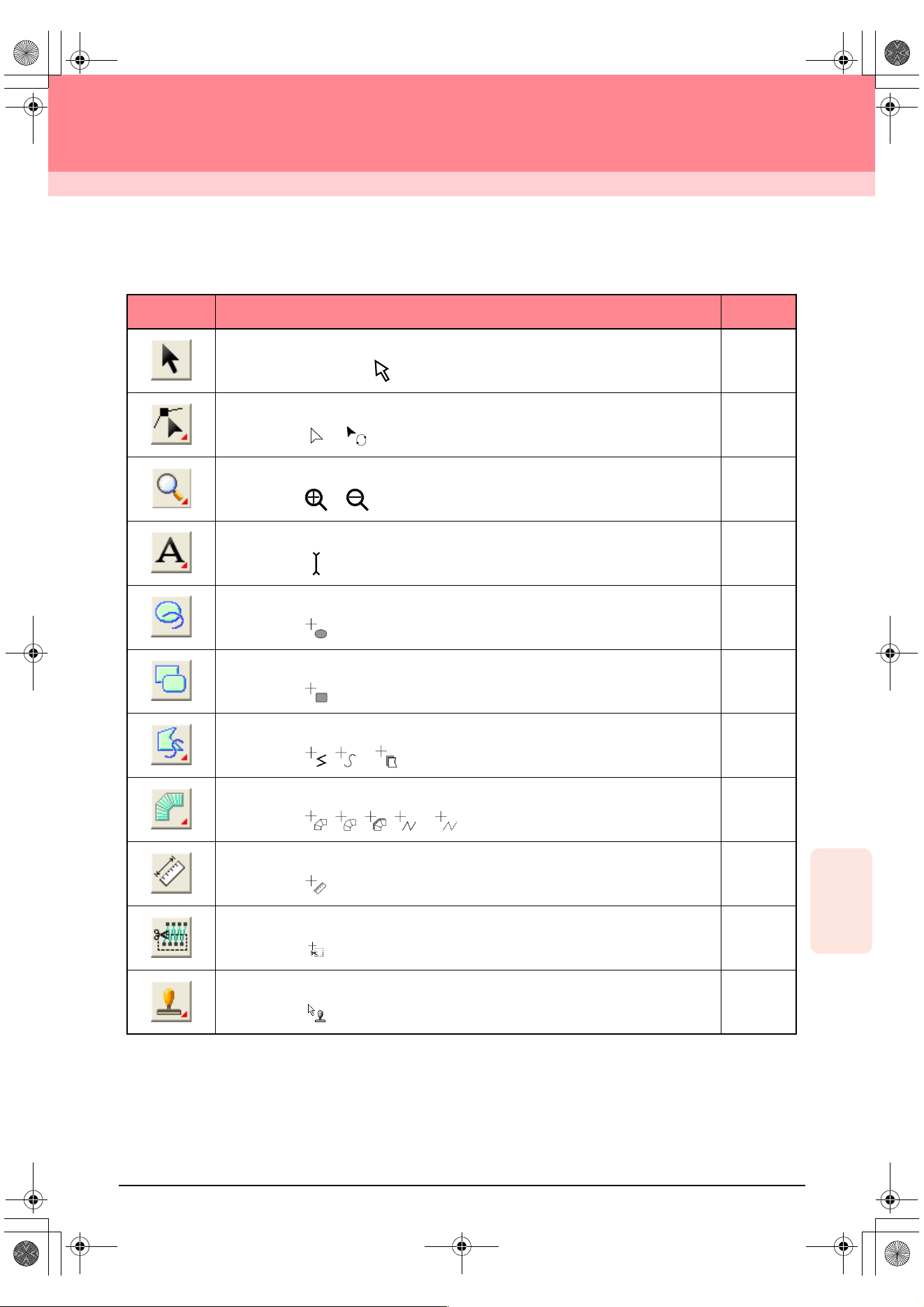
241
Reference
Layout & Editing
Layout & Editing
List of Tool Box Buttons
Tool Box Purpose See page
Sets the pointer in selection mode. When you start up the application, the selection mode
is selected. Pointer shape:
p. 130
Sets the pointer in point edit mode.
Pointer shape: or
p. 135
p. 139
Sets the pointer in zoom mode.
Pointer shape: or
p. 186
Sets the pointer in text and monogram input mode.
Pointer shape:
p. 153
Sets the pointer in circle, arc, fan shape and arc & string drawing mode.
Pointer shape:
p. 145
Sets the pointer in rectangle drawing mode.
Pointer shape:
p. 148
Sets the pointer in outline drawing mode.
Pointer shape: , or
p. 149
Sets the pointer in manual punching mode.
Pointer shape: , , , or
p. 152
Sets the pointer in measure mode.
Pointer shape:
p. 182
Sets the pointer in split stitch mode.
Pointer shape:
p. 143
Sets the pointer in stamp input or stamp edit mode.
Pointer shape:
p. 165
PeDesignV6Eng.book Page 241 Thursday, July 8, 2004 11:59 AM
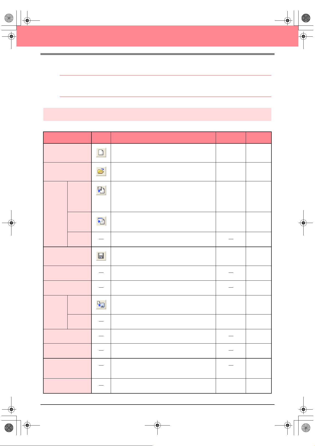
242
Layout & Editing
List of Menus
b Memo:
Many menu commands are available as buttons on the Toolbar or in the menu that appears when the right
mouse button is clicked.
File menu
The File menu contains commands for handling file input/output, such as opening, saving and printing.
Menu Toolbar Purpose Shortcut key See page
New Creates a new Design Page.
Ctrl + N p. 108
Open Opens a previously saved embroidery pattern.
Ctrl + O p. 109
Import
from File
Imports embroidery patterns from embroidery cards
(.pec), original cards (.pes) and files created in the
Tajima (.dst), Melco (.exp), Pfaff (.pcs), Husqvarna
(.hus) and embroidery sewing machine (.phc) formats
and adds them to your current Design Page.
F8 p. 127
from
Design
Center
Imports an embroidery pattern from Design Center.
F7 p. 128
from
Card
Imports an embroidery pattern from an embroidery
card.
p. 128
Save
Saves your embroidery pattern on the computer’s
hard disk as a latest version file (default).
Ctrl + S p. 194
Save As
Saves your embroidery pattern on the computer’s
hard disk under a new file name.
p. 194
Export
Exports the data shown in the Design Page as a file of
a different format (.dst, .hus, .exp, and .pcs).
p. 195
Write to
Card
Current
Design
Writes your embroidery pattern to an original card.
F4 p. 195
Other
PES files
Writes multiple .pes files to an original card at the
same time.
Shift + F4 p. 196
Property Used to enter comments in the .pes file being edited.
p. 199
Print Setup
Allows you to change the printing settings for
previewed embroidery.
p. 200
Print Preview
Allows you to preview the contents of the Design Page
and check the sewing color order, the dimensions and
the needle count before printing.
p. 201
Print
Prints your Design Page and some sewing
information.
Ctrl + P p. 201
PeDesignV6Eng.book Page 242 Thursday, July 8, 2004 11:59 AM
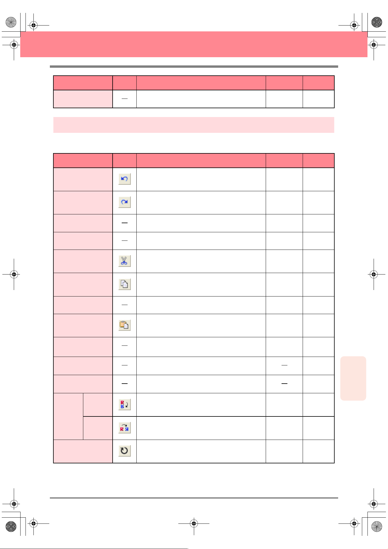
Reference
Layout & Editing
243
Layout & Editing
Edit menu
The Edit menu contains commands for performing simple actions on selected patterns, such as cutting and
pasting.
Exit Exits the application.
Alt + F4 p. 24
Menu Toolbar Purpose Shortcut key See page
Undo Undoes the last operation.
Ctrl + Z
Redo Cancels the effect of the last Undo.
Ctrl + A
Group Turns several selected objects into one object.
Ctrl + G p. 134
Ungroup Cancels the grouping for grouped objects.
Shift+ G p. 134
Cut
Removes the selected pattern(s) from the screen
while saving a copy in the Clipboard.
Ctrl + X
Copy
Saves the selected pattern(s) in the Clipboard without
removing them from the screen.
Ctrl + C
Duplicate Makes a copy of the selected pattern(s).
Ctrl + D
Paste Pastes the contents of the Clipboard on the screen.
Ctrl + V
Delete
Removes the selected pattern(s) from the screen
without saving them in the Clipboard.
Delete p. 114
p. 137
Change to Straight
Straightens the two rounded lines that meet at a
smooth point.
p. 137
Change to Curve
Rounds off the two straight lines that meet at a corner
point.
p. 137
Mirror
Horizon-
tal
Flips the selected pattern(s) up/down.
Ctrl + H p. 133
Vertical Flips the selected pattern(s) left/right.
Ctrl + J p. 133
Rotate
Allows you to manually rotate the selected pattern(s)
by an arbitrary angle.
Ctrl + Y p. 133
Menu Toolbar Purpose Shortcut key See page
PeDesignV6Eng.book Page 243 Thursday, July 8, 2004 11:59 AM
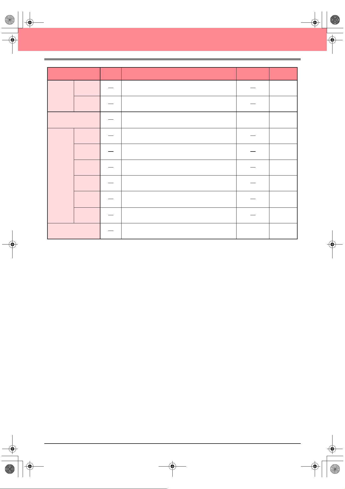
244
Layout & Editing
Numerical
Setting
Size Resizes the selected pattern numerically.
p. 132
Rotate Rotates the selected pattern numerically.
p. 134
Center
Moves the selected pattern to the center of the Design
Page.
Ctrl + M p. 131
Align
Left Aligns the selected patterns on their left sides.
p. 131
Center Aligns the selected patterns on their left/right centers.
p. 131
Right Aligns the selected patterns on their right sides.
p. 131
Top Aligns the selected patterns on their top edges.
p. 131
Middle
Aligns the selected patterns on their top/bottom
centers.
p. 131
Bottom Aligns the selected patterns on their bottom edges.
p. 131
Select All Selects all of the patterns.
Ctrl + E p. 130
Menu Toolbar Purpose Shortcut key See page
PeDesignV6Eng.book Page 244 Thursday, July 8, 2004 11:59 AM
Reference
Layout & Editing
245
Layout & Editing
Image menu
The Image menu contains commands for importing and exporting image data and creating embroidery data
from image data.
Menu Toolbar Purpose Shortcut key See page
Input
from File
Imports image data from an existing file so that it can be
used as a guide for creating embroidery data.
p. 111
from
TWAIN
device
Operates a TWAIN standardized scanner or other
device to import an image.
p. 111
from
Portrait
Combine images of facial features that are provided
with the application to create an original portrait.
p. 112
from
Clipboard
Import image data from the Clipboard.
p. 113
Output
to File Saves the image data as a file.
p. 114
to
Clipboard
Copies the image data onto the Clipboard.
p. 114
Select TWAIN device
Selects which TWAIN device installed in the computer
to use.
p. 111
Modify Adjusts the size and position of the image data.
p. 114
Image to Stitch Wiz-
ard
Gives step-by-step instruction for creating embroidery
data from image data.
p. 115
Display
Image
On Displays the template image.
F6 p. 113
Faded Displays a faded copy of the template image.
F6 p. 113
Off Hides the template image.
F6 p. 113
a Note:
The file name extension must be one of the
following: Windows bitmap (.bmp), Exif (.tif,
.jpg), ZSoftPCX (.pcx), Windows Meta File
(.wmf), Portable Network Graphics (.png),
Encapsulated PostScript (.eps), Kodak
PhotoCD (.pcd), FlashPix (.fpx), JPEG2000
(.j2k).
PeDesignV6Eng.book Page 245 Thursday, July 8, 2004 11:59 AM
246
Layout & Editing
Text menu
The Text menu contains commands for performing actions on text patterns, such as fitting text to a curved
path.
Sew menu
The Sew menu contains commands for controlling the way each pattern will be sewn.
Menu Toolbar Purpose Shortcut key See page
Edit Letters Allows you to edit entered text.
Ctrl + L p. 156
Text Attribute Setting Allows for precise control of character attributes.
Ctrl + K p. 157
Fit Text to Path
Setting
Fits a line of text along a path.
Ctrl + T p. 158
Release Text from
Path
Releases the text from the path.
Ctrl + Q p. 160
Transform Text Applies a preset transformation to text.
F2 p. 160
Clear Transformation Restores the original shape of the text.
F3 p. 160
TrueType Font
Attribute Setting
Sets the attributes, such as the style, for TrueType
fonts that are converted to embroidery data.
p. 161
Convert to Outline
Object
Creates outline data from text data converted from a
TrueType font.
p. 161
Menu Toolbar Purpose Shortcut key See page
Sewing Attribute
Setting
Sets the sewing attributes of the regions and the
outlines of a pattern.
Ctrl + W p. 171
Sewing Order/Color
Allows you to check and change the sewing order of
pattern colors and individual patterns.
F10 p. 184
Set hole sewing
Sets a pair of patterns for hole sewing (to avoid
sewing twice at the same place when a pattern
encloses another one).
p. 180
Cancel hole sewing Cancels hole sewing.
p. 180
Stitch to Block
Converts imported stitch patterns into blocks (manual
punching data), allowing you to set sewing attributes
and to keep the stitching quality when scaling.
p. 142
Convert to Stitch Converts a shape object to a stitch object.
p. 140
PeDesignV6Eng.book Page 246 Thursday, July 8, 2004 11:59 AM
Reference
Layout & Editing
247
Layout & Editing
Display menu
The Display menu contains commands for modifying the appearance of the screen.
Applique Wizard
Provides step-by-step instructions for easily creating
appliqués.
p. 181
Select Sewing Area Sets the sewing area.
p. 183
Optimize hoop
change
Optimizes the sewing order of patterns in a Design
Page for multi-position embroidery frames (100 × 172
mm, 172 × 100 mm, 130 × 300 mm, or 300 × 130
mm).
p. 204
Optimize Entry/
Exit points
Optimizes the positions of the entry points and the exit
points for the sewing data.
p. 139
Menu Toolbar Purpose Shortcut key See page
Grid Setup Controls the display and characteristics of the grid.
p. 202
Preview
Specifies whether the patterns appear as stitches or
in the normal view.
F9 p. 187
Realistic Preview
Displays a realistic image of how either selected patterns
or all patterns will look after being embroidered.
Shift + F9 p. 187
Realistic Preview
Attribute Setting
Sets the preview attributes for the Realistic Preview
function.
p. 187
Refresh Window Updates the screen.
Ctrl + R
Stitch Simulator Displays a simulation of the machine stitching.
p. 188
Reference Window Hides/displays the Reference window.
F11 p. 193
Toolbar Hides/displays the Toolbar.
p. 107
Status Bar Hides/displays the status bar.
p. 107
Menu Toolbar Purpose Shortcut key See page
a Note:
The Realistic Preview function cannot display a
clean preview of the pattern if the monitor is set
to 256 colors or less. The monitor should be set
to at least 16-bit High Color (65536 colors).
PeDesignV6Eng.book Page 247 Thursday, July 8, 2004 11:59 AM
248
Layout & Editing
Option menu
The Option menu contains commands for providing additional options.
Help menu
The Help menu contains commands for accessing the on-screen help information system.
Menu Toolbar Purpose Shortcut key See page
Design Center
Starts up Design Center and displays its window up
front.
F5 p. 30
Programmable Stitch
Creator
Starts up Programmable Stitch Creator and displays
its window up front.
p. 54
Design Property
Displays a dialog box containing sewing information
for the selected pattern(s).
p. 189
Design Page Property
Allows you to change the size of the Design Page, and
the color of the Design Page and the background.
p. 108
Edit User Thread
Chart
Allows original thread charts to be created and edited.
p. 190
Select
System
Unit
mm Allows you to change the system units to millimeters.
p. 202
inch Allows you to change the system units to inches.
p. 202
Menu Toolbar Purpose Shortcut key See page
Contents
Starts up the on-screen help information for this
application.
F1
Customer support
Opens the FAQ (Frequently Asked Questions) page
on our Web site.
Online Registration
Displays the online registration page from our Web
site.
p. 13
About
Layout & Editing
Gives information about the version of this application.
a Note:
This function cannot be used if there is no
Internet browser correctly installed in the
computer.
a Note:
This function is available only if the Internet
browser is correctly installed and an Internet
connection can be established. *Online
registration is not possible in certain
countries and regions.
PeDesignV6Eng.book Page 248 Thursday, July 8, 2004 11:59 AM
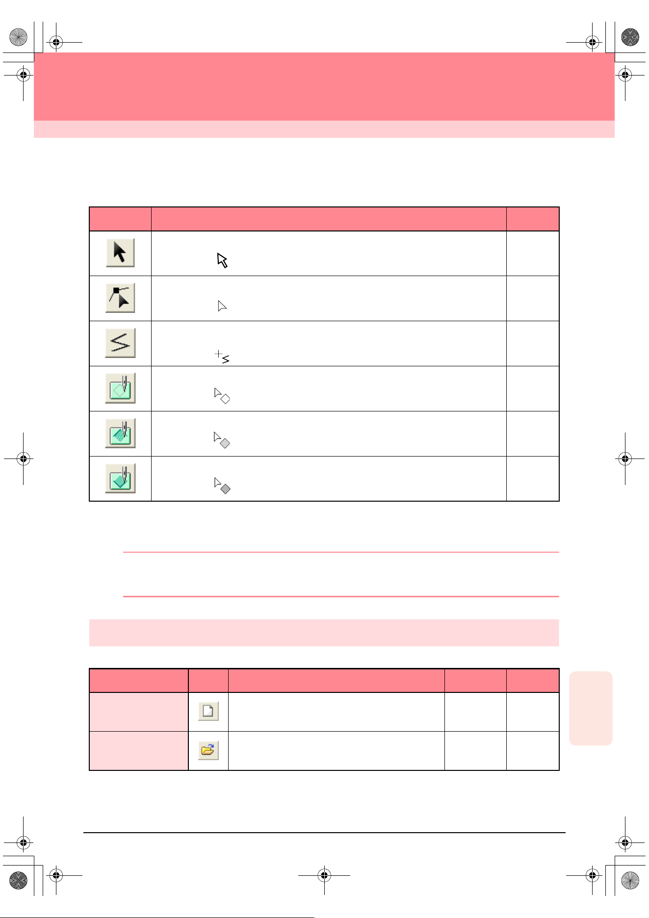
249
Reference
Programmable
Stitch Creator
Programmable Stitch Creator
List of Tool Box Buttons
List of Menus
b Memo:
Many menu commands are available as buttons on the Toolbar or in the menu that appears when the right
mouse button is clicked.
File menu
The File menu contains commands for handling files, such as opening and saving.
Tool Box Purpose See page
Sets the pointer in selection mode.
Pointer shape:
p. 213
Sets the pointer in point edit mode.
Pointer shape:
p. 216
Sets the pointer in line drawing mode. When you start up the application, the drawing
mode is selected.
Pointer shape:
p. 212
Sets the pointer in region (reset) mode.
Pointer shape:
p. 218
Sets the pointer in region (engrave) mode.
Pointer shape:
p. 217
Sets the pointer in region (emboss) mode.
Pointer shape:
p. 217
Menu Toolbar Purpose Shortcut key See page
New Creates a new work area.
Ctrl + N p. 209
Open Opens a previously saved programmable stitch file.
Ctrl + O p. 209
PeDesignV6Eng.book Page 249 Thursday, July 8, 2004 11:59 AM
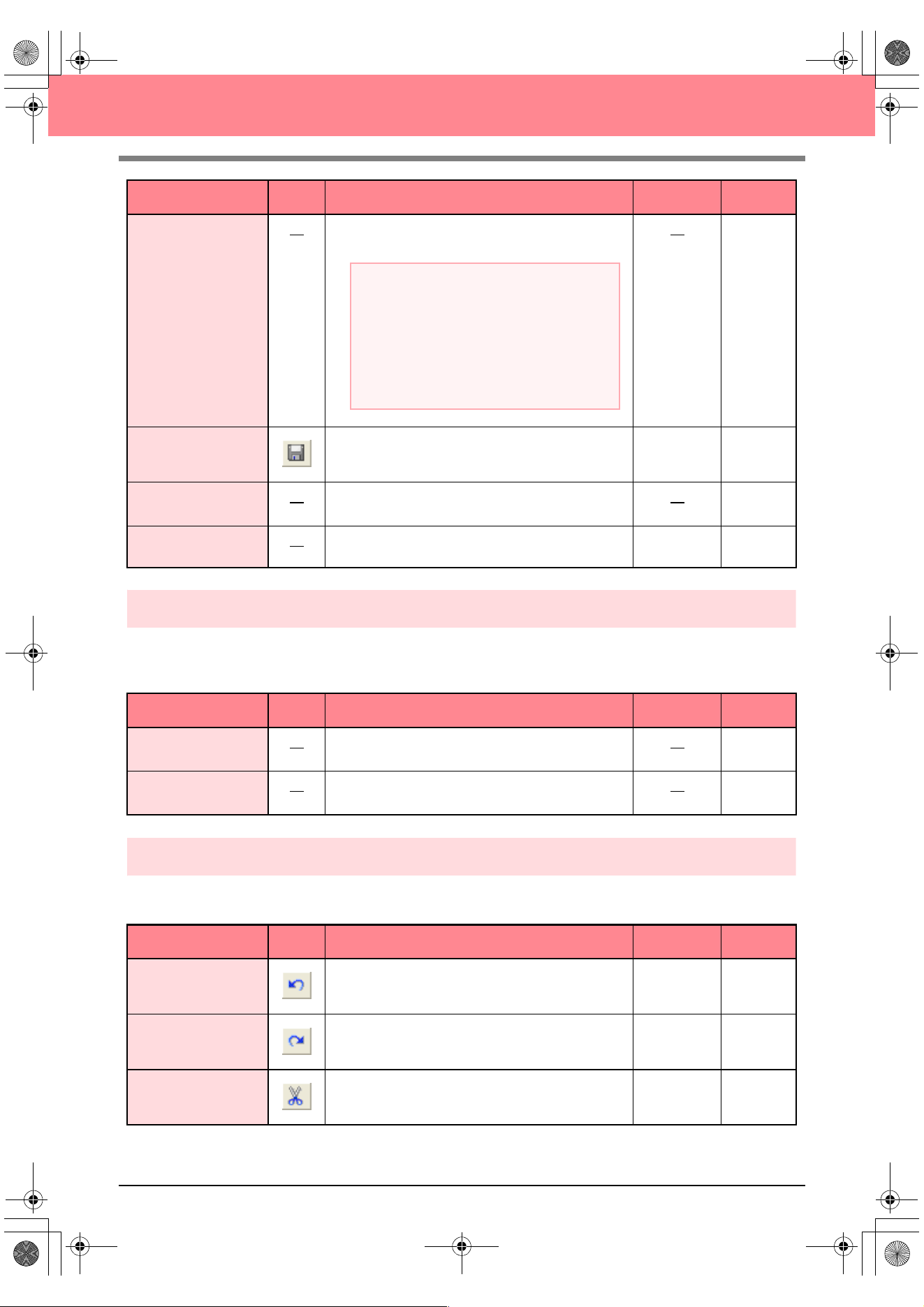
250
Programmable Stitch Creator
Mode menu
You can use Programmable Stitch Creator to create patterns for programmable fill stitches, motif fill or motif
line stitches, and stamps. However, the method and work area are different for each. Use the Mode menu to
select the mode for the pattern that you want to create.
Edit menu
The Edit menu contains commands for performing simple actions on selected lines and patterns, such as
cutting and pasting.
Template Open
Opens a background image file that can be used as a guide
to draw a new pattern for a programmable fill or motif stitch.
p. 210
Save Saves your work area on the disk.
Ctrl + S p. 221
Save As
Saves the current stitch pattern under a new file
name.
p. 221
Exit Exits the application.
Alt + F4 p. 58
Menu Toolbar Purpose Shortcut key See page
Fill/Stamp
Enters Fill/Stamp mode for creating stitch patterns for
programmable fill stitches and stamps.
p. 210
Motif
Enters Motif mode for creating stitch patterns for motif
stitches.
p. 210
Menu Toolbar Purpose Shortcut key See page
Undo Undoes the last operation.
Ctrl + Z
Redo Cancels the effect of the last Undo.
Ctrl + A
Cut
Removes the selected line(s) from the screen while
saving a copy in the Clipboard.
Ctrl + X p. 214
Menu Toolbar Purpose Shortcut key See page
a Note:
The following file formats can be opened:
Windows bitmap (.bmp), Exif (.tif, .jpg),
ZsoftPCX (.pcx), Windows Meta File (.wmf),
Portable Network Graphics (.png),
Encapsulated PostScript (.eps), Kodak
PhotoCD (.pcd), FlashPix (.fpx), JPEG2000
(.j2k).
PeDesignV6Eng.book Page 250 Thursday, July 8, 2004 11:59 AM
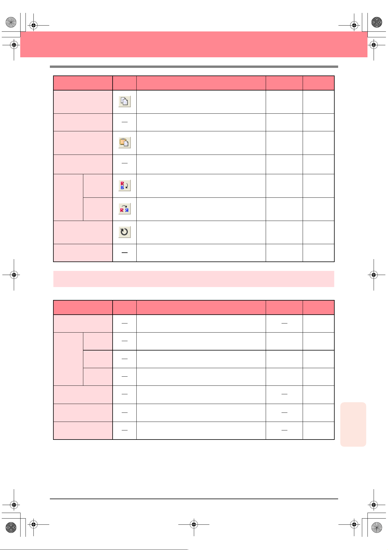
Reference
Programmable
Stitch Creator
251
Programmable Stitch Creator
Display menu
The Display menu contains commands for modifying the appearance of the screen.
Copy
Saves the selected line(s) in the Clipboard without
removing them from the screen.
Ctrl + C p. 214
Duplicate Adds a copy of the selected line(s) to the work area.
Ctrl + D p. 214
Paste Pastes the lines of the Clipboard on the screen.
Ctrl + V p. 214
Delete
Removes the selected line(s) from the screen without
saving them in the Clipboard.
Delete p. 214,
p. 217
Mirror
Horizon-
tal
Flips the selected line(s) up/down.
Ctrl + H p. 215
Vertical Flips the selected line(s) left/right.
Ctrl + J p. 215
Rotate
Allows you to manually rotate the selected line(s) by
an arbitrary angle.
Ctrl + Y p. 215
Select All Selects all of the patterns.
Ctrl + E p. 213
Menu Toolbar Purpose Shortcut key See page
Grid Selects the work grid.
p. 222
Template
On Displays the template image.
F6 p. 210
Faded Displays a faded copy of the template image.
F6 p. 210
Off Hides the template image.
F6 p. 210
Preview
Hides/displays the repeating image display of the
pattern being created.
p. 212
Toolbar Hides/displays the Toolbar.
p. 208
Status Bar Hides/displays the status bar.
p. 208
Menu Toolbar Purpose Shortcut key See page
PeDesignV6Eng.book Page 251 Thursday, July 8, 2004 11:59 AM

252
Programmable Stitch Creator
Help menu
The Help menu contains commands for accessing the on-screen help information system.
Menu Toolbar Purpose Shortcut key See page
Contents
Starts up the on-screen help information for this
application.
F1
Customer support
Opens the FAQ (Frequently Asked Questions) page
on our Web site.
About Programmable
Stitch Creator
Gives information about the version of this application.
a Note:
This function cannot be used if there is no
Internet browser correctly installed in the
computer.
PeDesignV6Eng.book Page 252 Thursday, July 8, 2004 11:59 AM
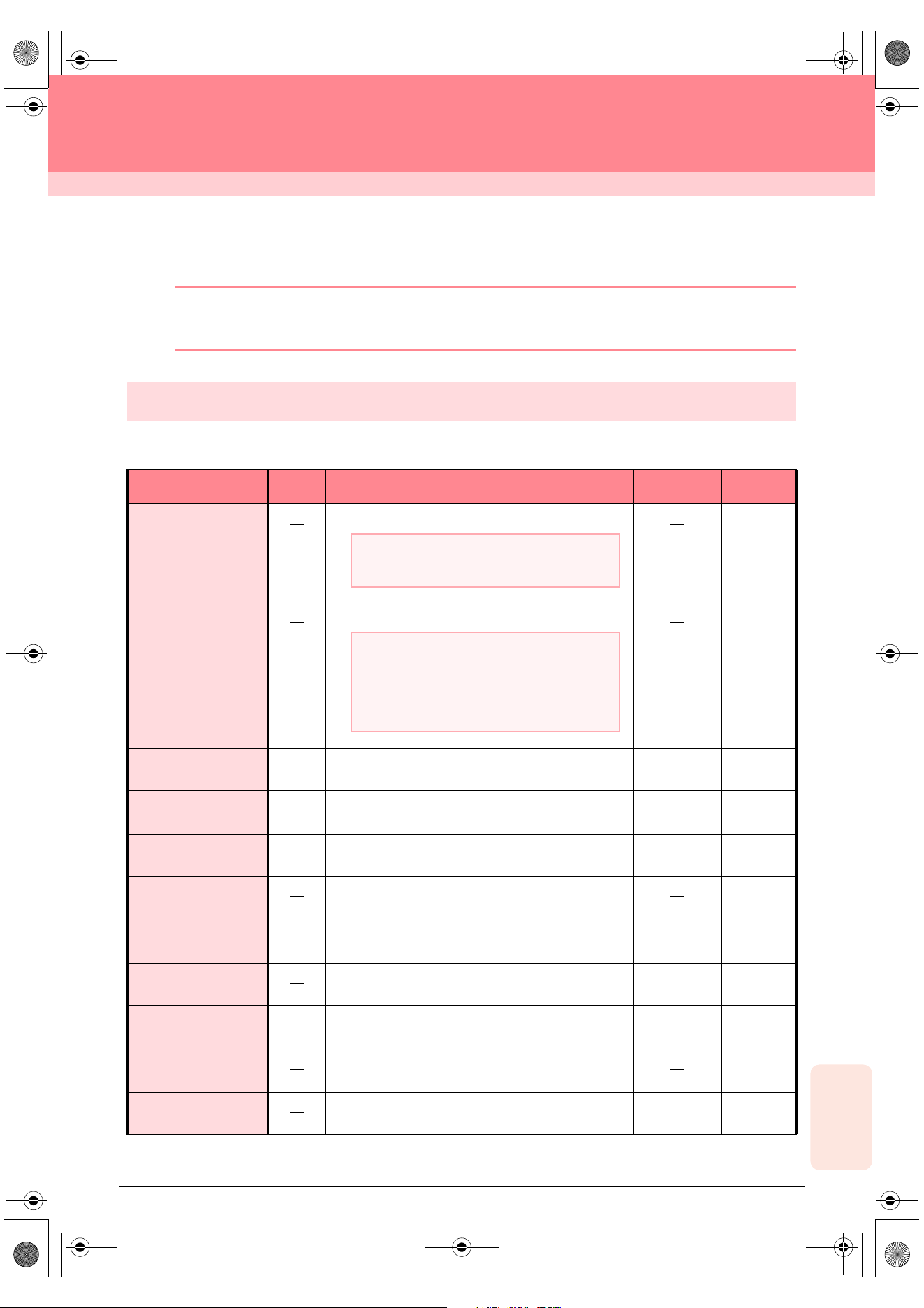
253
Reference
Design Database
Design Database
List of Menus
b Memo:
Many menu commands are available as buttons on the Toolbar or in the menu that appears when the right
mouse button is clicked.
File menu
The File menu contains commands for handling files, such as opening, importing and converting, and for
creating catalogs.
Menu Toolbar Purpose Shortcut key See page
Open in Layout &
Editing
Opens the embroidery file with Layout & Editing.
p. 227
Import into Layout &
Editing
Imports the embroidery pattern into Layout & Editing.
p. 227
Create Folder
Creates a new folder in the selected folder.
p. 224
Convert Files
Converts the embroidery file to one of a different
format.
p. 230
Delete Deletes the selected embroidery file.
p. 225
Print Setup
Allows you to change the printing settings for catalogs
of embroidery patterns.
p. 231
Print Preview
Allows you to preview the catalog of embroidery
patterns before printing.
Print Prints the catalog of embroidery patterns.
Ctrl + P p. 231
Create HTML
Outputs the catalog of embroidery patterns as an
HTML file.
p. 231
Create CSV
Outputs the catalog of embroidery pattern sewing
information as a CSV file.
p. 232
Exit Exits the application.
Alt + F4
a Note:
Only .pes files can be opened.
a Note:
The following file formats can be imported.: .pes,
Tajima (.dst), Melco (.exp), Pfaff (.pcs),
Husqvarna (.hus), and embroidery sewing
machine (.phc).
Ver6_Reference_04.fm Page 253 Friday, July 9, 2004 1:54 PM
254
Design Database
Edit menu
Display menu
Menu Toolbar Purpose Shortcut key See page
Cut
Removes the selected embroidery pattern(s) from the
folder while saving a copy in the Clipboard.
Ctrl + X p. 225
Copy
Saves the selected embroidery pattern(s) in the
Clipboard without removing them from the folder.
Ctrl + C p. 225
Paste
Pastes the embroidery patterns from the Clipboard
into the selected folder.
Ctrl + V p. 225
Search Allows the desired embroidery file to be searched for.
Ctrl + F p. 229
Menu Toolbar Purpose Shortcut key See page
Large Thumbnails
Lists the embroidery patterns in the contents pane as
large thumbnails.
p. 226
Small Thumbnails
Lists the embroidery patterns in the contents pane as
small thumbnails.
p. 226
Details
Lists the embroidery patterns in the contents pane by
their sewing information.
p. 226
Preview
Displays a preview of the selected embroidery
pattern.
p. 227
File Property
Displays the sewing information for the selected
embroidery pattern.
p. 228
Refresh
Refreshes the display of embroidery patterns in the
contents pane.
Ctrl + R
Toolbar Hides/displays the Toolbar.
p. 223
Status Bar Hides/displays the status bar.
p. 223
PeDesignV6Eng.book Page 254 Thursday, July 8, 2004 11:59 AM
Reference
Design Database
255
Design Database
Option menu
The Option menu contains a command for changing the units of measure.
Help menu
The Help menu contains commands for accessing the on-screen help information system.
Menu Toolbar Purpose Shortcut key See page
Select
System
Unit
mm Allows you to change the system units to millimeters.
p. 202
inch Allows you to change the system units to inches.
p. 202
Menu Toolbar Purpose Shortcut key See page
Contents
Starts up the on-screen help information for this
application.
F1
About Design Data-
base
Gives information about the version of this application.
PeDesignV6Eng.book Page 255 Thursday, July 8, 2004 11:59 AM
256
Index
A
adding
text ..............................................................43, 153
thread colors .....................................................191
thread colors to charts .......................................191
aligning
embroidery patterns ..........................................131
hole sewing .......................................................132
text ....................................................................131
Alignment ..................................................................158
applications ...................................................................4
APPLIQUE ................................................................170
APPLIQUE MATERIAL .............................................170
APPLIQUE POSITION ..............................................170
appliques ...................................................................181
Arc shape selector ...............................................41, 147
Arrange ......................................................................173
arranging text ............................................................158
attaching stabilizer .......................................................63
Auto Generate ...........................................120, 122, 124
Auto Punch function ............................................21, 115
Auto Select Setting ............................................119, 123
B
Base Sew ............................................................94, 176
Beginner mode ....................................................90, 171
blocks from stitch data ...............................................142
C
cancelling
hole sewing .......................................................180
text arrangement ...............................................160
text transformation ............................................160
card slot .........................................................................6
card writer ..................................................................5, 6
upgrading ............................................................12
catalogs
CSV files ...........................................................232
HTML files .........................................................231
printing ..............................................................231
CD-ROM ........................................................................8
center points ........................................................97, 139
centering ....................................................................131
Change Color ....................................................121, 125
changing
embroidery pattern names ................................225
stitch data colors ...............................................142
thread color order ..............................................192
Character Spacing .....................................................158
checking
line sewing attributes ...........................................86
region sewing attributes ......................................84
sewing order ................................................61, 184
stitching .....................................................101, 188
closed paths ................................................................48
Color button .........................................................89, 169
Color Count ...............................................................119
Color Set ...................................................................123
colors
stitch data ..........................................................142
user thread list ...................................................190
combining
pattern colors ....................................................185
commands
Design Center ...................................................236
Design Database ...............................................253
Layout & Editing ................................................242
Programmable Stitch Creator ............................249
computer .......................................................................8
concentric circle stitch .................................................16
center point .................................................97, 139
sewing attributes .........................................95, 177
Conversion Priority ............................................118, 121
converting
embroidery pattern formats ...............................230
image to embroidery pattern ...............................21
copying
embroidery patterns to folders ..........................224
images ...............................................................114
stitch patterns ....................................................214
creating
catalogs
CSV files ...................................................232
HTML files .................................................231
new folders ........................................................224
new thread color chart .......................................190
Cross size ..................................................................126
cross stitch ..................................................................16
sewing attributes .........................................95, 177
Cross Stitch function .................................................125
curves to straight lines ...............................................137
custom Design Page ...................................................60
cutting
patterns .............................................................143
stitch patterns ....................................................214
D
deleting
embroidery patterns ..........................................225
outlines ................................................................80
points ...........................................81, 137, 217, 219
stitch patterns ....................................................214
stitch points .......................................................141
thread color charts ............................................190
thread colors from charts ..................................192
Density ......91, 92, 93, 95, 172, 173, 174, 175, 177, 178
Design Center ...................................................4, 30, 69
commands .........................................................236
menus ...............................................................236
Tool Box buttons ...............................................234
window ................................................................70
Design Database ...................................................5, 223
commands .........................................................253
menus ...............................................................253
window ..............................................................223
Design Page Color ....................................................118
Design Page size ................................................77, 108
custom .................................................................60
multi-position hoops ..........................................203
Detail .................................................................118, 121
Direction ..........................................................................
.............91, 92, 93, 94, 95, 158, 173, 174, 175, 176, 177
direction of offset .................................................94, 176
PeDesignV6Eng.book Page 256 Thursday, July 8, 2004 11:59 AM
257
Index
Display
Details .......................................................226, 254
File Property ..............................................228, 254
Grid ...................................................................251
Grid Setup .........................105, 202, 222, 238, 247
Large Thumbnails .....................................226, 254
Preview ...................................................................
.22, 37, 51, 102, 187, 212, 227, 238, 247, 251, 254
Realistic Preview .....23, 38, 52, 102, 187, 238, 247
Realistic Preview Attribute Setting ..........................
...................................................102, 187, 238, 247
Reference Window ....................................238, 247
Refresh ..............................................................254
Refresh Window ........................................238, 247
Small Thumbnails ......................................226, 254
Status Bar .................................238, 247, 251, 254
Stitch Simulator .........................101, 188, 238, 247
Template ...........................................................222
Faded ........................................................251
Off .............................................................251
On .............................................................251
Toolbar ......................................238, 247, 251, 254
display ...........................................................................8
display area frame
enlarging ...........................................................193
moving .......................................................103, 193
redrawing ..................................................103, 193
reducing ............................................................193
resizing ......................................................104, 193
scaling .......................................................104, 193
zooming .....................................................103, 193
Display menu
Design Center ...................................................238
Design Database ...............................................254
Layout & Editing ................................................247
Programmable Stitch Creator ............................251
displaying
background images ...........................................222
embroidery patterns ..........................................226
images ...............................................................113
drawing
arc & string ........................................................147
arcs ...................................................................145
broken lines ...................................................48, 82
circles ..........................................................45, 145
closed paths ................................................48, 149
curves ................................................................149
display area frame .....................................103, 193
fan shapes .........................................................146
open paths ........................................................149
outlines ................................................................74
ovals ............................................................41, 145
portrait ...............................................................112
rectangles ..........................................................148
stitch patterns ..............................................56, 212
straight lines ......................................................149
duplicating stitch patterns ..........................................214
E
E stitch .......................................................................173
E/V stitch .....................................................................15
sewing attributes ...............................................173
Edge radius selector ..................................................148
Edit
Align
Bottom ...............................................131, 244
Center ...............................................131, 244
Left ....................................................131, 244
Middle ................................................131, 244
Right ..................................................131, 244
Top ....................................................131, 244
Center .......................................................131, 244
Change to Curve .......................................137, 243
Change to Straight ....................................137, 243
Copy ..................................214, 237, 243, 251, 254
Cut .....................................214, 237, 243, 250, 254
Delete ................................137, 214, 237, 243, 251
Duplicate ...................................214, 237, 243, 251
Group ........................................................134, 243
Mirror
Horizontal ....79, 133, 215, 220, 237, 243, 251
Vertical ........79, 133, 215, 220, 237, 243, 251
Numerical Setting
Rotate ..................................80, 134, 238, 244
Size .....................................79, 132, 238, 244
Paste .................................214, 237, 243, 251, 254
Redo ..................................................237, 243, 250
Rotate ..........................79, 133, 215, 237, 243, 251
Search ...............................................................229
Search Files ......................................................254
Select All ...................................130, 238, 244, 251
To Curve ...........................................................137
To Straight .........................................................137
Undo ..................................................237, 243, 250
Ungroup ....................................................134, 243
Edit List ..............................................................119, 123
Edit menu ..................................................................250
Design Center ...................................................237
Design Database ...............................................254
Layout & Editing ................................................243
editing
embroidery patterns ..........................................130
grouped objects .................................................134
images ...............................................................114
lines .....................................................................32
monogram characters .......................................164
monogram pattern .............................................164
monograms .......................................................163
outlines ................................................................78
pattern colors ....................................................185
points ...................................................81, 135, 216
sewing order ......................................................185
stamps .........................................................99, 166
stitch patterns ............................................213, 219
stitch points .......................................................140
text ....................................................................156
thread color charts ............................................190
thread colors .....................................................192
embossing effects .......................................................57
embroidering .........................................................63, 65
embroidery patterns
adding comments ..............................................199
aligning ..............................................................131
centering ...........................................................131
changing names ................................................225
converting formats .............................................230
copying to folders ..............................................224
deleting ..............................................................225
displaying ..........................................................226
editing ................................................................130
exporting ...........................................................195
flipping ...............................................................133
from images ....................................19, 25, 27, 115
grouping ............................................................134
importing ...........................................................227
information ................................................189, 228
moving ...............................................................131
moving to folders ...............................................224
multi-position hoops ..................................204, 205
PeDesignV6Eng.book Page 257 Thursday, July 8, 2004 11:59 AM

258
Index
printing ......................................................207
opening .............................................................227
organizing ..........................................................224
outputting catalogs
CSV files ...................................................232
HTML files .................................................231
previewing .........................................102, 187, 227
printing ..............................................................201
catalogs .....................................................231
resizing ..............................................................132
rotating ..............................................................133
saving ........................................................104, 194
scaling ...............................................................132
searching ...........................................................229
selecting ............................................................130
engraving effects .........................................................57
enlarging ..............................................................32, 186
display area frame .............................................193
tips .......................................................................14
entry/exit points
moving ...............................................................138
optimizing ..................................................138, 139
selecting ............................................................141
erasers ..................................................................32, 75
exiting
Layout & Editing ......................................24, 53, 63
Programmable Stitch Creator ..............................58
Expert mode ........................................................90, 171
exporting embroidery patterns ...................................195
F
Feathered edge .........................................................178
features .........................................................................1
Figure Handle stage ....................................4, 33, 69, 76
Tool Box buttons ...............................................234
File
Convert Files .....................................................253
Convert Format .................................................230
Create CSV .......................................................232
Create CSV File ................................................253
Create HTML .....................................................231
Create HTML File ..............................................253
Create New Folder ............................................224
Delete ................................................................253
Exit ....................24, 53, 58, 63, 237, 243, 250, 253
Export ........................................................195, 242
Import
from Card ..................................................128
from Design Center .....................40, 128, 242
from File ......................................60, 127, 242
Import Figure .....................................................237
Import into Layout & Editing ..............................253
Input from Clipboard ..........................................236
Input from TWAIN device ............................72, 236
New ...........................................108, 209, 242, 249
New Figure Data .........................................78, 236
New Line Image ..........................................74, 236
Open .....................40, 55, 109, 209, 236, 242, 249
Open in Layout & Editing ..................................227
Open with Layout & Editing ...............................253
Output to Clipboard ...........................................237
Print ...................................................201, 242, 253
Print Preview .....................................201, 242, 253
Print Setup ................................200, 231, 242, 253
Property .....................................................199, 242
Save ........................................................................
...23, 53, 58, 61, 104, 194, 206, 221, 237, 242, 250
Save As .......38, 104, 194, 206, 221, 237, 242, 250
Select TWAIN device ..................................72, 236
Template Open .........................................210, 250
Wizard .........................................................71, 236
Write to Card
Current Design ........24, 52, 62, 195, 206, 242
Other PES files ..........................196, 206, 242
File menu
Design Center ...................................................236
Design Database ...............................................253
Layout & Editing ................................................242
Programmable Stitch Creator ............................249
fill stitch ........................................................................15
sewing attributes .........................................92, 174
Fill/Stamp mode ........................................................211
fitting text to object ......................................................44
flipping
embroidery patterns ..........................................133
outlines ................................................................79
stitch patterns ............................................215, 220
folders ........................................................................224
Font selector ........................................................43, 154
Frequency .....................................93, 94, 175, 176, 178
G
geometric attributes ...................................................167
arc & string ........................................................147
arcs ...................................................................147
circles ................................................................147
closed paths ......................................................150
curves ................................................................149
fan shapes .........................................................146
open paths ........................................................150
ovals ..................................................................145
rectangles ..........................................................148
straight lines ......................................................149
Gradation ...................91, 92, 93, 96, 173, 174, 175, 179
grid ............................................................105, 202, 222
grouping embroidery patterns ...................................134
H
Half Stitch ................................91, 92, 93, 172, 174, 175
hard disk free space ......................................................8
H-Arrange ....................................................95, 172, 177
Help
About Design Center .........................................240
About Design Database ....................................255
About Layout & Editing ......................................248
About Programmable Stitch Creator .................252
Contents ....................................240, 248, 252, 255
Customer Support .............................................240
Customer support ......................................248, 252
Online Registration ......................................13, 248
Help menu .................................................................255
Design Center ...................................................240
Layout & Editing ................................................248
Programmable Stitch Creator ............................252
hole sewing ...................................................50, 97, 180
aligning ..............................................................132
hoop changes ............................................................204
hooping ........................................................................65
Horizontal Alignment .................................................159
I
Image
Display Image ...................................................113
Faded ........................................................245
PeDesignV6Eng.book Page 258 Thursday, July 8, 2004 11:59 AM

259
Index
Off .............................................................245
On .............................................................245
Image to Stitch Wizard ..................21, 27, 115, 245
Input
from Clipboard ...................................113, 245
from File ................................20, 26, 111, 245
from Portrait ......................................112, 245
from TWAIN device ...........................112, 245
Modify ............................................21, 27, 114, 245
Output
to Clipboard .......................................114, 245
to File ................................................114, 245
Select TWAIN device ................................111, 245
Image menu ..............................................................245
Image Tune .........................................................74, 117
Image Type .......................................................118, 121
images
converting to embroidery patterns ...19, 25, 27, 115
moving ...............................................................114
outputting ..........................................................114
resizing ..............................................................114
saving ................................................................114
scaling ...............................................................114
importing
.pem files .............................................................71
background images ...........................................210
Clipboard images ........................................72, 113
embroidery patterns ............................60, 127, 227
from Design Center ...............................39, 40, 128
from embroidery cards ......................................128
images .......................................20, 26, 71, 72, 111
TWAIN images ............................................72, 112
indicator .........................................................................6
inserting
points ...................................................81, 136, 216
stitch points .......................................................141
installing
driver ...................................................................10
overview ................................................................7
software .................................................................8
K
Kerning ......................................................................158
L
large-sized embroidery patterns ..................................59
Layout & Editing ..........................................4, 19, 25, 59
commands .........................................................242
menus ...............................................................242
Tool Box buttons ...............................................241
window ..............................................................107
LED ...............................................................................6
Line color button ................................35, 45, 48, 88, 168
Line Image stage .........................................4, 31, 69, 73
Tool Box buttons ...............................................234
Line Interval .......................................................123, 125
Line sew button .................................42, 45, 48, 88, 168
Line sew type selector .......................35, 45, 48, 88, 168
line sewing attributes .....................................86, 91, 172
Line Spacing ..............................................................158
M
manual punching ...............................................151, 178
marking embroidering position ....................................63
masks ........................................................120, 122, 124
Max. Density ......................................................123, 125
Max. Number of Colors .............................................126
maximize button ..........................19, 25, 30, 54, 59, 224
measurement units ............................................105, 202
measuring ..................................................................182
memory .........................................................................8
menus
Design Center ...................................................236
Design Database ...............................................253
Layout & Editing ................................................242
Programmable Stitch Creator ............................249
Mode
Fill/Stamp ..................................................210, 250
Motif ..........................................................210, 250
Mode menu ...............................................................250
monitor ..........................................................................8
monogram attributes .................................................163
Monogram Font selector ...........................................163
Monogram Size selector ............................................163
monograms ...............................................................162
Motif mode .................................................................211
motif stitch .............................................................15, 16
patterns ...............................................95, 172, 177
sewing attributes .................................95, 172, 177
moving
broken lines .........................................................50
center points ................................................97, 139
display area frame .....................................103, 193
embroidery patterns ....................................40, 131
embroidery patterns to center ...........................131
embroidery patterns to folders ..........................224
entry/exit points .................................................138
images ...................................................21, 27, 114
objects .................................................................41
outlines ................................................................78
points ...................................................81, 135, 216
stitch patterns ....................................................213
stitch points .......................................................141
text ......................................................................45
multi-position hoops ..................................................203
Design Page size ..............................................203
embroidery patterns ..........................................204
hoop changes ....................................................204
pattern information ............................................205
saving patterns ..................................................206
N
naming embroidery patterns ......................................225
NOT DEFINED ..........................................................170
O
objects converted to stitch data .................................140
Offset ...................................................................94, 176
opening
.pem files .............................................................71
.pes file ..............................................................109
background images ...........................................210
Clipboard images ........................................72, 113
embroidery patterns ............................40, 127, 227
images .................................20, 26, 31, 71, 72, 111
Layout & Editing file ..........................................109
new Design Page ..............................................108
new figure handle images .............................71, 78
new line images ............................................71, 74
new stitch pattern ..............................................209
stitch patterns ....................................................209
TWAIN images ............................................72, 112
PeDesignV6Eng.book Page 259 Thursday, July 8, 2004 11:59 AM

260
Index
operating system ...........................................................8
optimizing
entry/exit points .........................................138, 139
hoop changes ....................................................204
Option
Design Center ...................................................248
Design Page Property ...60, 77, 108, 203, 239, 248
Design Property ..........................61, 189, 205, 248
Edit User Thread Chart .............................190, 248
Layout & Editing ..........................................40, 239
Programmable Stitch Creator ..............54, 239, 248
Select System Unit ....................................105, 202
inch ............................................239, 248, 255
mm ............................................239, 248, 255
Option menu
Design Center .............................................30, 239
Design Database ...............................................255
Layout & Editing ................................................248
options ...........................................................................6
organizing embroidery patterns .................................224
Original Image stage ...............................................4, 69
outlines
converted from text ...........................................161
deleting ................................................................80
editing ..................................................................78
flipping .................................................................79
moving .................................................................78
resizing ................................................................79
rotating ................................................................79
scaling .................................................................79
selecting ..............................................................78
sewing attributes .................................................85
outputting
catalogs
CSV files ...................................................232
HTML files .................................................231
P
pasting stitch patterns ...............................................214
Path shape selector .............................................48, 150
pattern information ............................................189, 228
adding comments ..............................................199
multi-position hoops ..........................................205
patterns
colors .................................................................185
combining colors ...............................................185
selecting ............................................................184
PC .................................................................................8
pens .......................................................................32, 74
Photo Stitch 1 (Color) function ..................................116
Photo Stitch 1 (Mono) function ..................................120
Photo Stitch 2 (Color) function ..................................122
Photo Stitch 2 (Mono) function ..................................124
Photo Stitch function ...................................................27
Photo/Cartoon ...................................................118, 121
piping stitch .................................................................16
sewing attributes ...............................................178
points
deleting ........................................81, 137, 217, 219
editing ..................................................81, 135, 216
inserting ...............................................81, 136, 216
moving .................................................81, 135, 216
selecting ............................................................135
port ................................................................................8
portraits .....................................................................112
Preview window .........................................................212
previewing ...............................22, 37, 51, 102, 187, 227
stitch patterns ....................................................212
printer ............................................................................8
printing
catalogs .............................................................231
settings ......................................................231
embroidery patterns ..........................................201
multi-position hoops ..................................207
preview ..............................................................201
settings ..............................................................200
processor .......................................................................8
programmable fill stitch
patterns ...........................................47, 55, 94, 176
sewing attributes .........................................93, 175
Programmable Stitch Creator ..........................5, 54, 208
commands .........................................................249
menus ...............................................................249
Tool Box buttons ...............................................249
window ..............................................................208
Pull Compensation ........................92, 93, 174, 175, 176
Q
quitting
Layout & Editing ......................................24, 53, 63
Programmable Stitch Creator ..............................58
R
radial stitch ..................................................................16
center point .................................................97, 139
sewing attributes .........................................95, 177
realistic previewing ..........................23, 38, 52, 102, 187
settings ......................................................102, 187
reducing ...............................................................14, 186
display area frame .............................................193
Reference Window ............................................103, 193
Region color button ...........................36, 46, 48, 88, 169
Region sew button .............................42, 46, 48, 87, 169
Region sew type selector ..................36, 46, 48, 88, 169
region sewing attributes ................................84, 91, 173
registration ...................................................................13
resizing
display area frame .....................................104, 193
embroidery patterns ....................................40, 132
images ...................................................21, 27, 114
objects .................................................................42
outlines ................................................................79
stitch patterns ............................................214, 220
Rotate angle ..............................................................158
rotating
embroidery patterns ..........................................133
outlines ................................................................79
stitch patterns ....................................................215
Row Offset ...........................................................95, 177
Run Pitch ...............91, 95, 118, 121, 172, 173, 177, 178
Run times ............................................................91, 172
running stitch ...............................................................15
sewing attributes .........................................91, 172
Running Stitch Path ...............................92, 93, 174, 175
S
satin stitch ...................................................................15
sewing attributes .........................................91, 173
saving
different formats ................................................195
embroidery patterns ..........23, 38, 53, 61, 104, 194
multi-position hoops ..................................206
images ...............................................................114
PeDesignV6Eng.book Page 260 Thursday, July 8, 2004 11:59 AM

261
Index
on card ............................24, 52, 62, 195, 196, 206
stitch patterns ..............................................58, 221
scaling
display area frame .....................................104, 193
embroidery patterns ....................................40, 132
images ...................................................21, 27, 114
objects .................................................................42
outlines ................................................................79
stitch patterns ............................................214, 220
searching ...................................................................229
selecting
all embroidery patterns ......................................130
all stitch patterns ...............................................213
characters .........................................................157
colors .................................................................119
embroidery patterns ..........................................130
in sewing order ..........................................130
entry/exit points .................................................141
monogram characters .......................................164
outlines ................................................................78
patterns .............................................................184
points .................................................................135
sewing area .......................................................183
stitch patterns ....................................................213
Sew
Applique Wizard ........................................181, 247
Cancel Hole Sewing ....................................51, 180
Cancel hole sewing ...........................................246
Convert to Stitch ........................................140, 246
Optimize Entry/Exit points .................138, 139, 247
Optimize hoop change ..............................204, 247
Select Sewing Area ...................................183, 247
Set Hole Sewing ..........................................51, 180
Set hole sewing .................................................246
Setting Attribute ...........................................89, 171
Sewing Attribute Setting ..............................46, 246
Sewing Attributes ..............................................238
Sewing Order ......................................49, 100, 238
Sewing Order/Color ...........................142, 184, 246
Stitch to Block ...........................................142, 246
Sew menu
Design Center ...................................................238
Layout & Editing ................................................246
Sew Page Color ........................................................118
Sew Setting stage .............................................4, 34, 69
Tool Box buttons ...............................................235
Sew type selector ................................................89, 170
sew types ....................................................................15
sewing attributes .......................................................167
concentric circle stitch .................................95, 177
cross stitch ..................................................95, 177
E/V stitch ...........................................................173
fill stitch .......................................................92, 174
lines .....................................................................86
motif stitch ...........................................95, 172, 177
outline ..................................................................85
piping stitch .......................................................178
programmable fill stitch ...............................93, 175
radial stitch ..................................................95, 177
regions ................................................................84
running stitch ...............................................91, 172
satin stitch ...................................................91, 173
setting ....................................................34, 89, 171
spiral stitch ..................................................95, 177
zigzag stitch ................................................91, 172
Sewing Attributes bar ..................................................87
sewing direction .......................36, 47, 91, 92, 93, 94, 95
programmable fill stitch ...............................96, 178
stamp ................................................................178
tips .......................................................................14
Sewing Option ...................................118, 121, 123, 125
sewing order ..........................................49, 61, 100, 184
editing ................................................................185
tips .......................................................................14
sewing wide areas .......................................................14
Size .....................................................................95, 177
slot .................................................................................6
special colors .............................................................170
spiral stitch ..................................................................16
sewing attributes .........................................95, 177
splitting stitching ........................................................143
stabilizer ......................................................................63
Stage
To Figure Handle ..................................33, 76, 239
To Line Image .......................................31, 73, 239
To Original Image ..............................................239
To Sew Setting ............................................34, 239
stage 1 .....................................................................4, 69
stage 2 .........................................................4, 31, 69, 73
Tool Box buttons ...............................................234
stage 3 .........................................................4, 33, 69, 76
Tool Box buttons ...............................................234
stage 4 ...............................................................4, 34, 69
Tool Box buttons ...............................................235
Stage menu ...............................................................239
stamp attributes .........................................................165
stamps .........................................................98, 165, 217
editing ..................................................................99
starting
Design Center .....................................................30
Design Database ...............................................224
Layout & Editing ......................................19, 25, 59
Programmable Stitch Creator ..............................54
Step Pitch ..............................................92, 94, 175, 176
stitch
interval ...............................................................173
run pitch ............................................................173
stroke width .......................................................173
stitch data
from objects .......................................................140
to blocks ............................................................142
stitch patterns
copying ..............................................................214
creating .............................................................218
cutting ................................................................214
deleting ..............................................................214
drawing ..............................................................212
duplicating .........................................................214
editing ........................................................213, 219
feathered edge ..................................................178
flipping .......................................................215, 220
height ............................................94, 95, 172, 177
motif stitch ...........................................95, 172, 177
moving ...............................................................213
pasting ...............................................................214
previewing .........................................................212
programmable fill stitch ...................47, 55, 94, 176
resizing ......................................................214, 220
rotating ..............................................................215
saving ................................................................221
scaling .......................................................214, 220
selecting ............................................................213
width ......................................94, 95, 172, 176, 177
stitch points
deleting ..............................................................141
editing ................................................................140
inserting .............................................................141
moving ...............................................................141
stitch simulator ..................................................101, 188
PeDesignV6Eng.book Page 261 Thursday, July 8, 2004 11:59 AM

262
Index
Stitch times ................................................................126
Stitch Type ............................................92, 94, 174, 176
straight lines to curves ...............................................137
Stroke times ..............................................................173
support ........................................................................13
system requirements .....................................................8
T
technical support .........................................................13
techniques ...................................................................14
Text
Clear Transformation ................................161, 246
Convert to Outline Object ..........................161, 246
Edit Letters ................................................156, 246
Fit Text to Path Setting ........................44, 158, 246
Release Text from Path ............................160, 246
Text Attribute Setting .................................157, 246
Transform Text ..........................................160, 246
TrueType Font Attribute Setting ................161, 246
text .......................................................................43, 153
aligning ..............................................................131
arranging ...........................................................158
cancelling arrangement .....................................160
cancelling transformation ..................................161
convert to outlines .............................................161
fitting to object .....................................................44
transforming ......................................................160
text attributes .............................................154, 157, 167
Text body color button .................................................43
Text body sew type selector ........................................43
Text menu .................................................................246
Text Orientation .........................................................159
Text Size selector ................................................43, 156
The other side ...........................................................159
Thread Chart .............................................119, 123, 126
thread colors
adding to charts .................................................191
APPLIQUE ........................................................170
APPLIQUE MATERIAL .....................................170
APPLIQUE POSITION ......................................170
creating new colors ...........................................191
deleting charts ...................................................190
deleting from charts ...........................................192
editing ................................................................192
editing charts .....................................................190
new charts .........................................................190
NOT DEFINED ..................................................170
order ..................................................................192
user list ..............................................................190
Times ...................................................................95, 177
tips ...............................................................................14
Tool Box buttons
Design Center ...................................................234
Layout & Editing ................................................241
Programmable Stitch Creator ............................249
stage 2 (Line Image stage) ...............................234
stage 3 (Figure Handle stage) ...........................234
stage 4 (Sew Setting stage) ..............................235
transferring to card ..................24, 52, 62, 195, 196, 206
Transform level selector ............................................160
transforming
cancelling ..........................................................161
text ....................................................................160
TrueType text attributes ............................................161
U
Under sewing ..........................91, 92, 93, 173, 174, 175
uninstalling ..................................................................13
units of measure ................................................105, 202
USB card writer module ............................................5, 6
upgrading ............................................................12
USB port ........................................................................8
Use Color ..........................................................121, 125
Use Color List ....................................................119, 123
user thread color list ..................................................190
V
V-Arrange ....................................................95, 172, 177
Vertical Alignment .....................................................159
Vertical Offset ............................................................158
W
window
Design Center .....................................................70
Design Database ...............................................223
Layout & Editing ................................................107
Programmable Stitch Creator ............................208
Writing data to original card .......................................206
Z
zigzag stitch .................................................................15
sewing attributes .........................................91, 172
Zigzag width ........................................................91, 172
zooming .....................................................................186
Design Page ......................................................186
display area frame .....................................103, 193
out .....................................................................186
to actual size .....................................................186
to selected objects ............................................186
PeDesignV6Eng.book Page 262 Thursday, July 8, 2004 11:59 AM
Read the following before opening the
CD-ROM package
Thank you for purchasing this software. Before opening the CD-ROM package for this software, carefully read
the following Product Agreement, which has been provided for this product. Use this software only if you agree
to the terms of this agreement. By opening the CD-ROM package, you agree to the conditions of its use. This
product cannot be returned after it has been opened.
Product Agreement
Portions of this product were created using technology from Softfoundry International Pte. Ltd.
1) General terms
This is an agreement between you (the end-user) and our company for this product.
2) Use of this product
You may install and use this product on only one computer.
3) Limitations on duplications
You may not duplicate this product, except for backup purposes.
4) Limitations on modifications
You may not modify or disassemble this product in any way.
5) Limitations on transfer
This software may not be transferred to or used in any other way by a third party.
6) Warranty
We accept no responsibility for your choice or use of this product or for any damages that may arise
out of its use.
7) Others
This product is protected by copyright laws.
PeDesignV6Eng.book Page 1 Thursday, July 8, 2004 11:59 AM
ENGLISH
XC8871-001
Printed in Japan
<< PE-Design Ver.6.0 >> cover 1-4
Instruction Manual
Instruction Manual
Personal Embroidery Design Software System
PE-DESIGN
PE-DESIGN
Ver.6Ver.6
Instruction Manual
PE-DESIGN Ver.
6