

Hey, find us here:
www.vantrue.net/contact
facebook.com/vantrue.live

CONTENTS
VERZEICHNIS
CONTENU
ÍNDICE
SPIS TREŚCI
目次
目录
Product View
Packliste
Qu'y a-t-il dans le paquet
Visualización del producto
Widok produktu
梱包内容
包装清单
1.
Specifications
Spezifikationen
Spécification
Especificaciones
Specyfikacje
商品仕様
规格参数
2.
1
12
24
36
48
61
70
2
13
25
37
49
62
71

CONTENTS
VERZEICHNIS
CONTENU
ÍNDICE
SPIS TREŚCI
目次
目录
2
13
26
37
49
62
71
Installation
Installationshinweise
Notes d'installation
Instalación
Instalacja
取り付け
安装说明
3.
Warranty & Support
Kundendienst
Assistance et SAV
Garantía y soporte
Gwarancja i wsparcie!
保証について
售后服务
11
23
35
47
59
68
77
4.
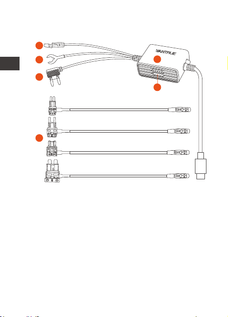
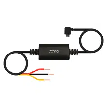
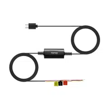
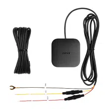
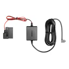
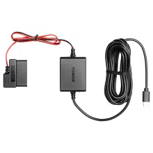
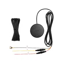
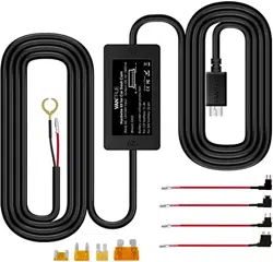
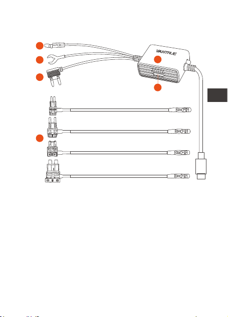
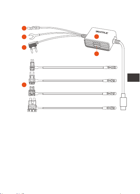
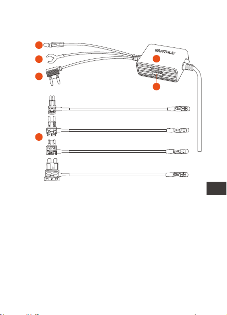
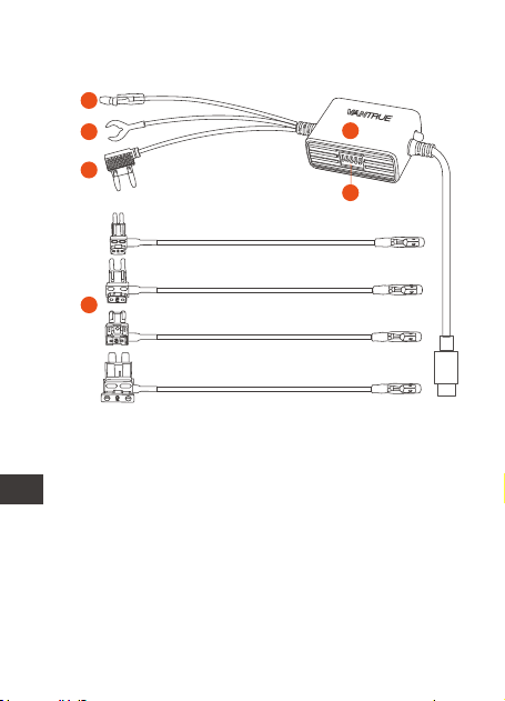
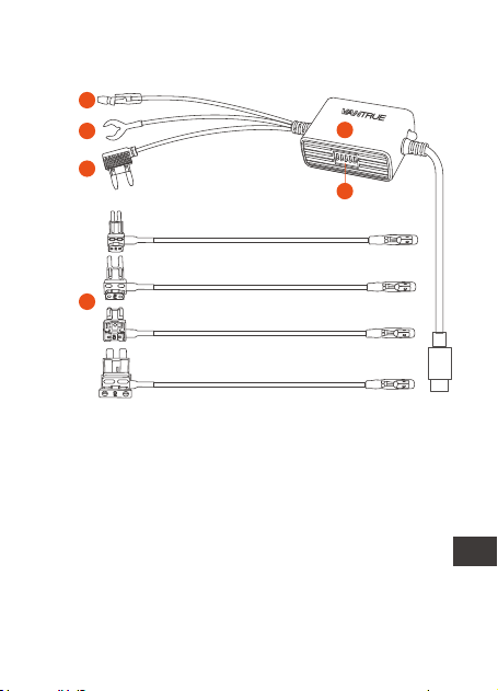
1. Product View
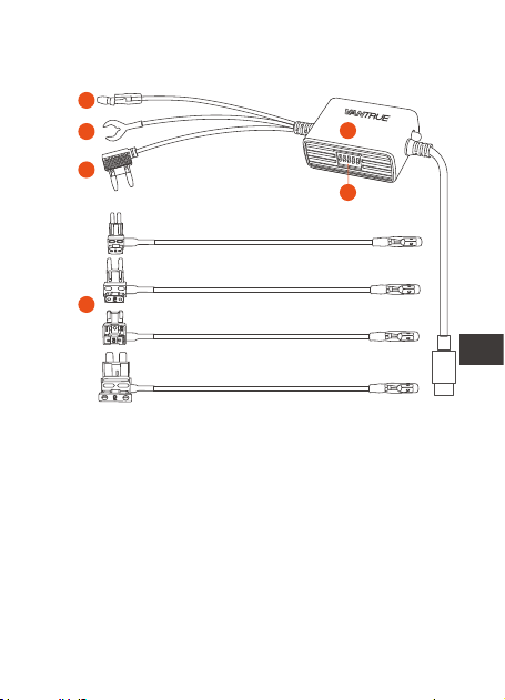
A.
B.
C.
D.
F.
Four Types of Fuses
Adapters (ATO, Mini,
ACN, Micro2)
Hardwire Kit Switch
Red Wire to Fuse
Box
Black Wire to the
Ground
E. Type C USB Dash
Cam Hardwire Kit
with 5 Gears
Yellow Wire to
ACC
A
B
C
E
F
D
- 1 -
ENEN

2. Specifications
3. Installation
Name
Connector
Input Voltage
Output Voltage
Output Current
Working Time
Cable Length
Working
Temperature
Storage
Temperature
Low Voltage
Protection
Description
Type C USB
DC 12V-24V
5V
2.8A
1 hour, 3 hours, 6 hours,
12 hours, 24 hours, always
14.8ft
-4°F to 140°F
-4°F to 158°F
12V vehicle: 11.6V, 11.9V,
12.2V, 12.5V
24V vehicle: 23.6V, 23.9V,
24.2V, 24.5V
Please check the packing list for complete-
ness and read this manual before installation.
The location and layout of the car fuse box
and the type of fuse used may vary
depending on the vehicle model and year of
manufacture. Please refer to your vehicle
manual for details.
- 2 -
EN
EN
EN
EN

Note: We recommend that you ask profes-
sional help to install to avoid installation errors.
Before you start the installation, please make
sure you have the following tools: owner's
manual, fuse adapter, fuse puller, trim
removal tool, double-sided tape, wire cutting
tool, stylus, multimeter, etc.
Please note: The items listed above are not
included in the packing list and need to be
purchased by yourself. Fuse adapters may
vary from vehicle to vehicle. Please consult
the original vehicle manufacturer or
professional auto parts installer for fuse types.
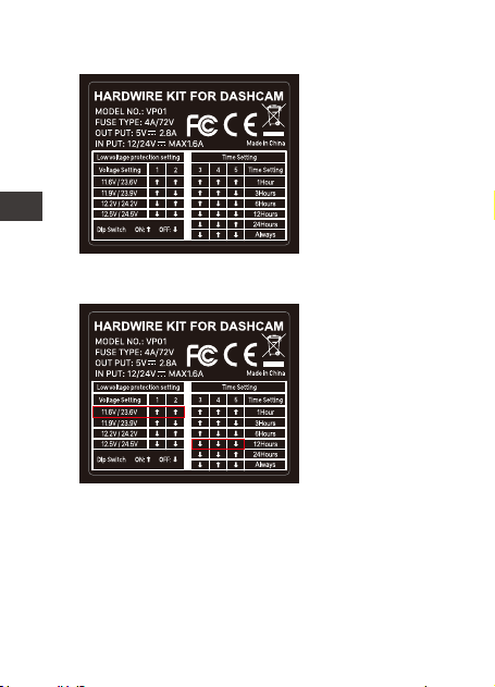
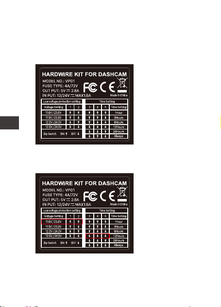
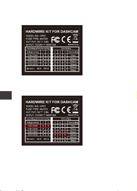
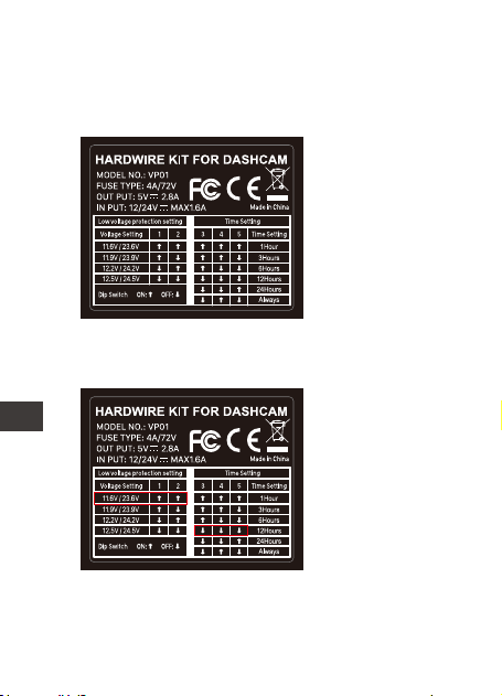
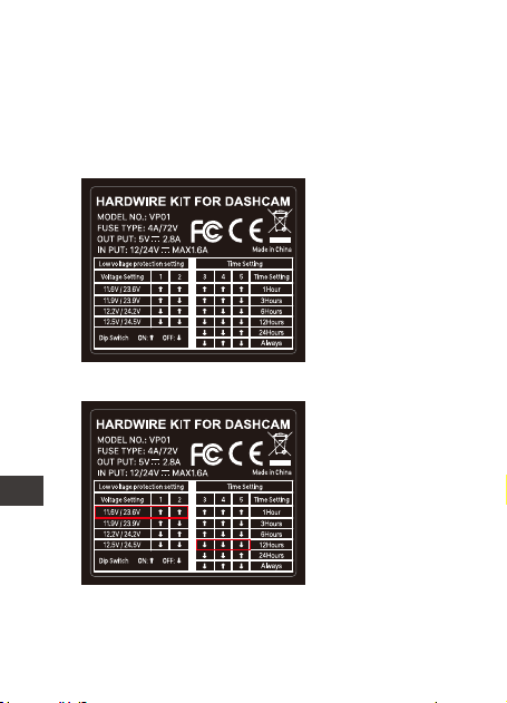
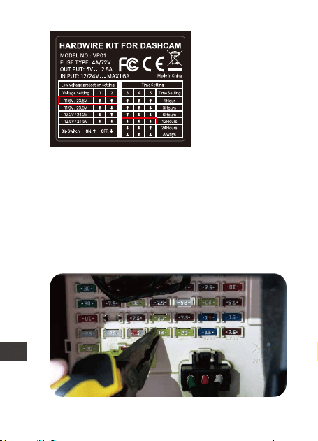
Default Setting:
11.9V/23.9V, 24
hours
Dip Switch: Gear
1-2 for low voltage
protection gears
setting, gear 3-5
for working time
setting.
3.1 Before Installing
3.2 Set the voltage and timer on and off
Please refer to the power setup label on the
product and set it on and off according to
your requirements.
- 3 -
ENEN
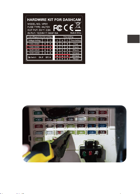
For example:
If your vehicle
battery voltage is
12V, the
protection
voltage to be set
is 11.6V, and the
hardwire kit
working time is 12
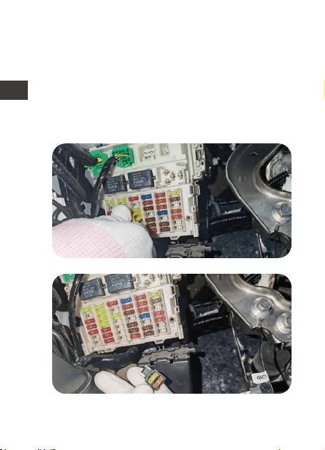
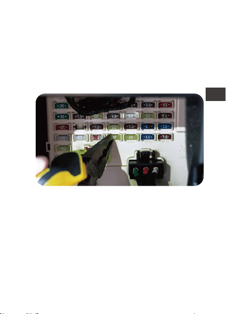
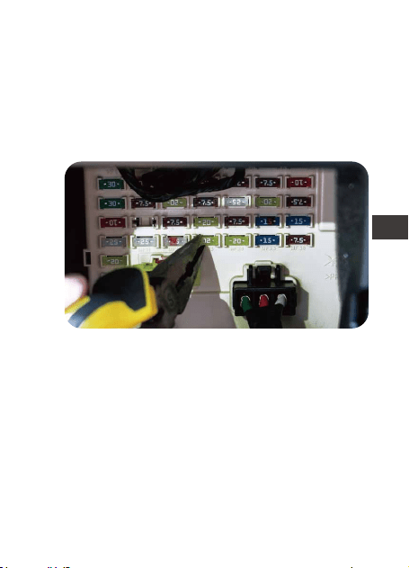
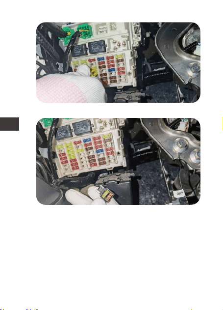
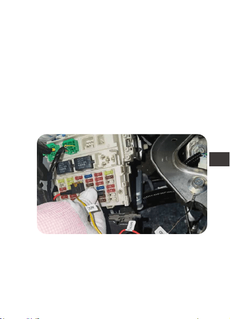
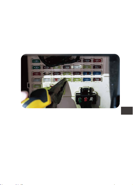
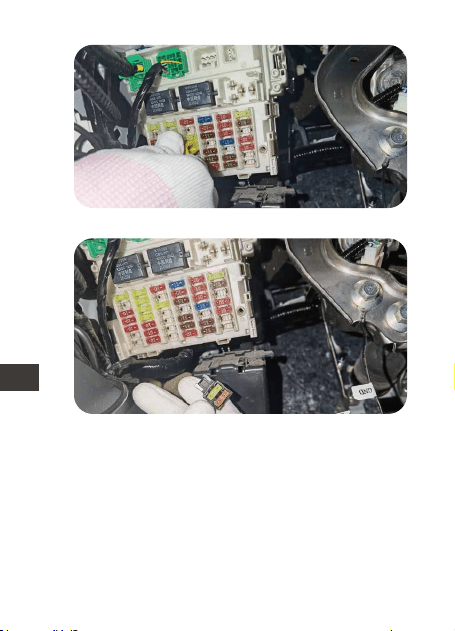
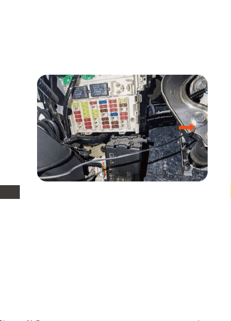
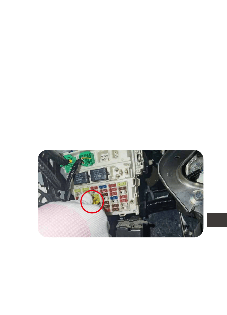
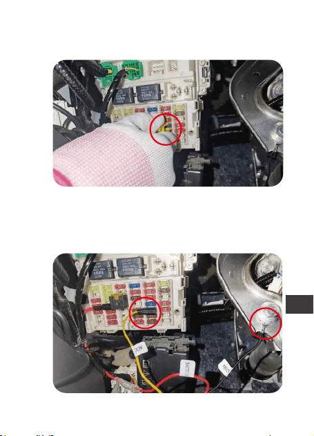
3.3 Find the fuse box
The fuse control box will contain many
different fuses, including cigarette lighter,
interior lights, car stereos, etc. Please refer to
your owner's manual to find the fuse box.
thours, please set he switch direction to ↑↑↓↓↓.
- 4 -
EN
EN
EN
EN
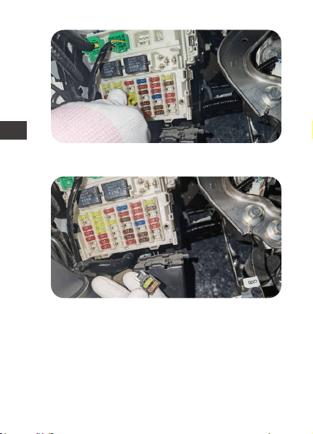
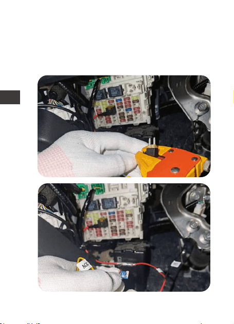
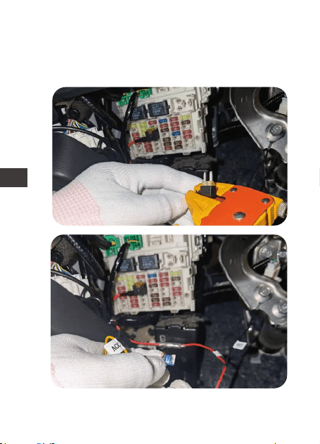
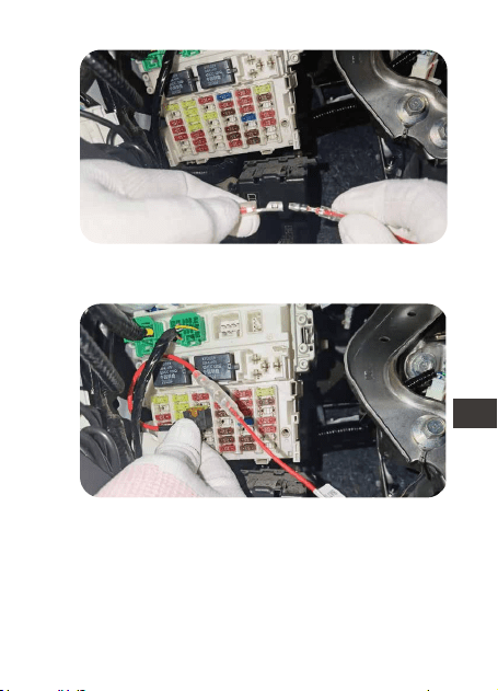
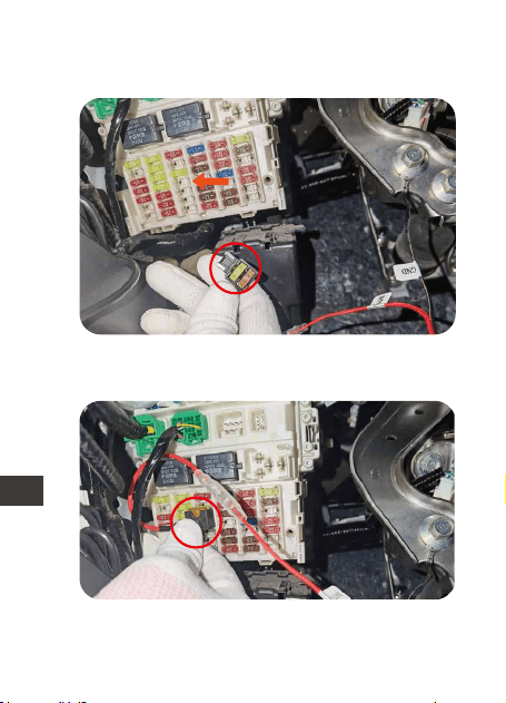
Select the correct fuse adapter based on
the fuse you removed, refer to the pictures
below, insert the fuse into the fuse adapter
and connect the fuse adapter to the red
wire of the hardwire kit. Make sure the fuse
adapter is firmly connected.
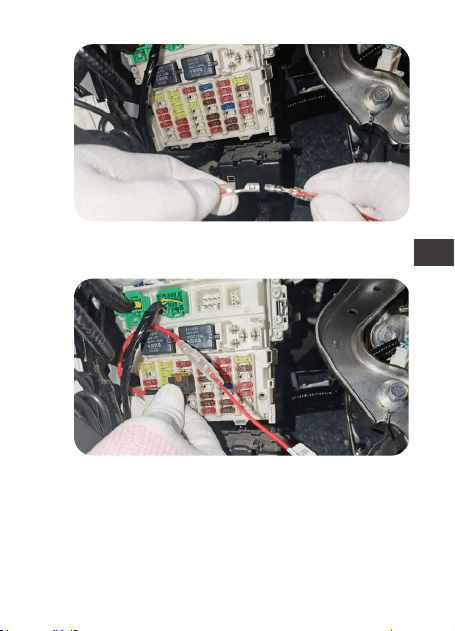
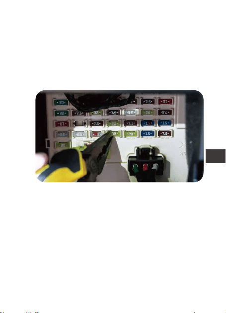
3.4 Connect the correct fuse adapter for the
hardwire kit
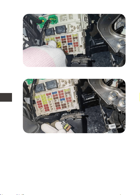
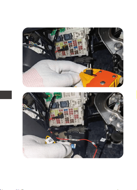
Remove fuse from the fuse box.
Insert the fuse into fuse adapter.
- 5 -
ENEN
4
Connect the hardwire kit with fuse adapter.
Insert the fuse adapter into fuse box.
- 6 -
EN
EN
EN
EN
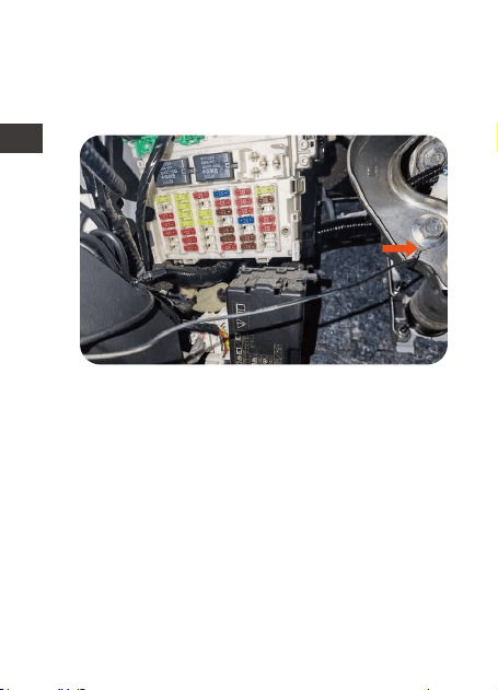
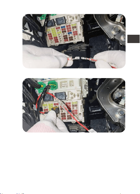
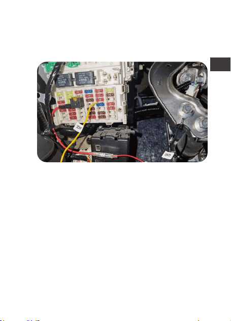
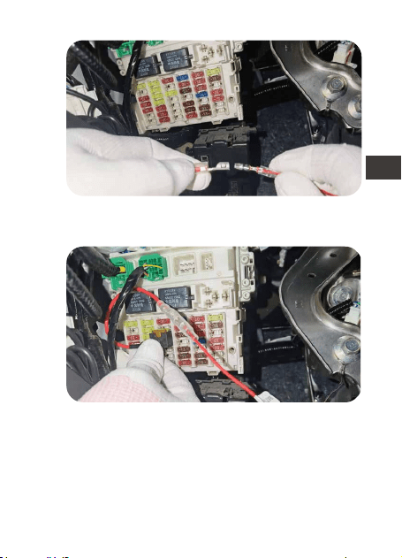
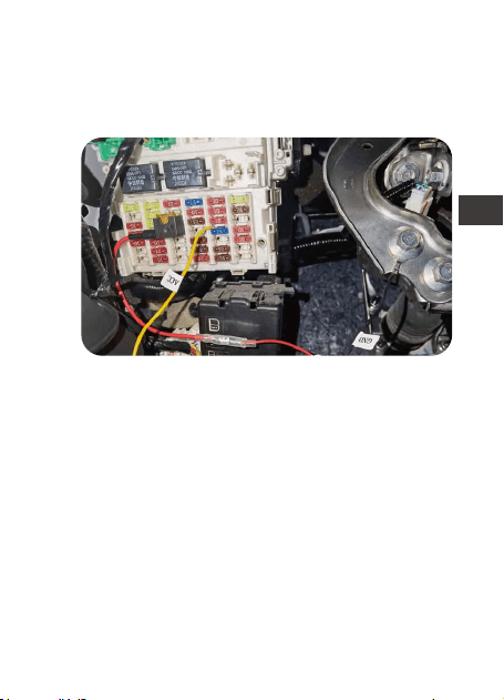
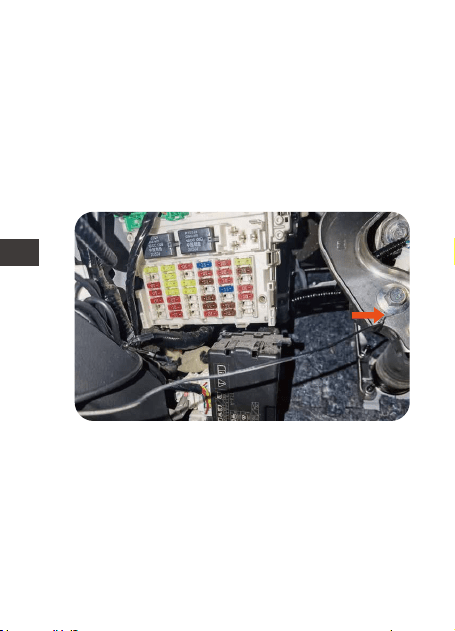
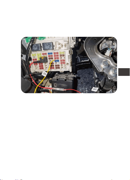
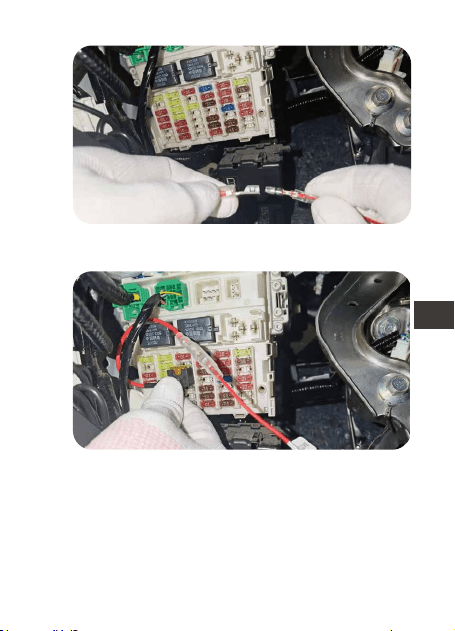
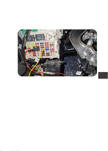
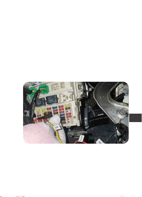
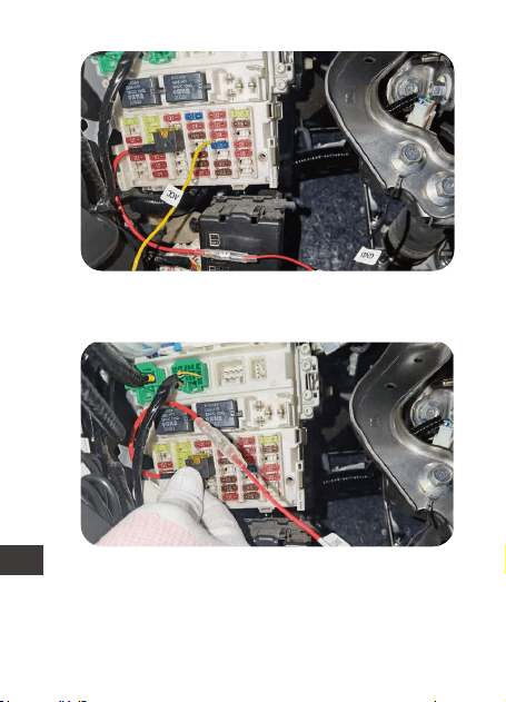
3.5 Connect the fuse wire to the fuse box
(1) Fix the black wire (GNC) under a metal
bolt or screw in your vehicle.
(2) Please identify the rated power fuse on
the fuse panel, such as the fuses for applianc-
es and reading lights. The power rated fuse
will remain energized when the ignition is off.
Once identified, connect the red wire to the
rated power fuse.
Note: Please connect the hazard light fuse if
your car has "power saving mode".
WARNING: Do not connect fuses for car
computer, AIR BAG, ABS or any other car
safety related circuits.
- 7 -
ENEN
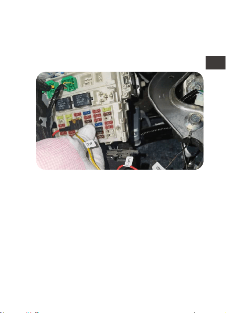
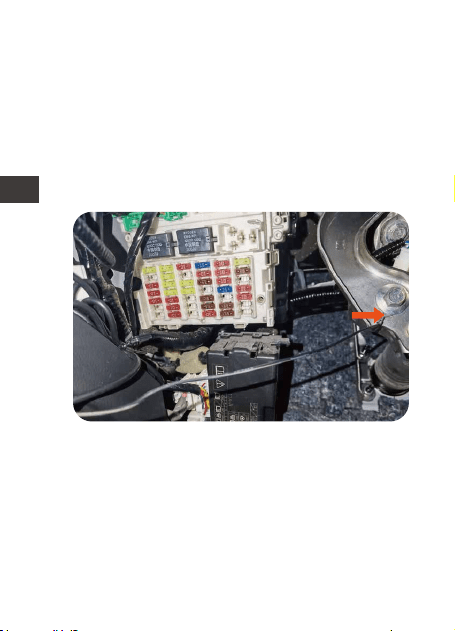
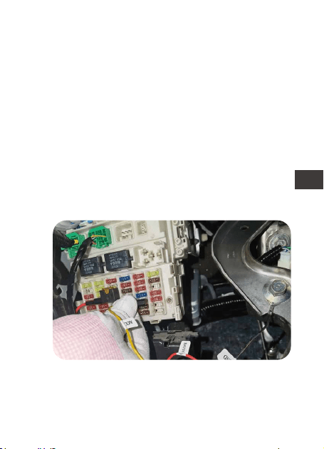
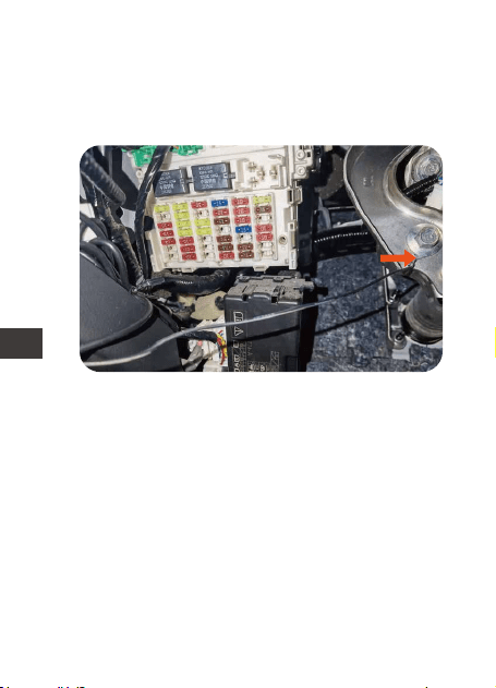
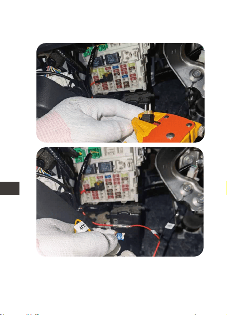
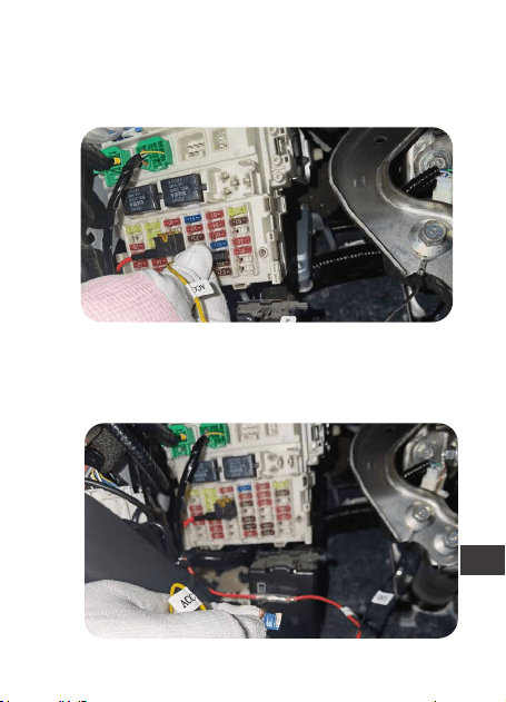
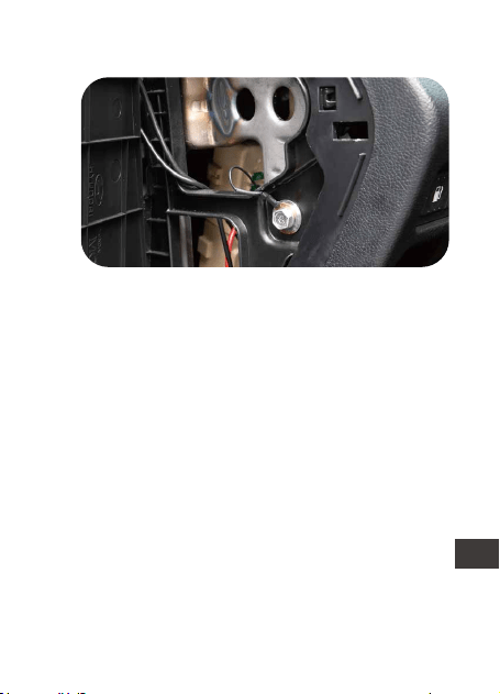
(3) Please identify the ACC fuse in the car
fuse panel refer to your car owner’s manual.
The ACC fuse only comes on when the
ignition switch is on. Once found, connect
the yellow wire to the ACC in the fuse box.
If your ACC fuse slot does not fit the ACC
fuse socket that comes with the hardwire kit,
you can cut off the fuse socket that comes
with it and wrap the yellow ACC wire around
your car’s ACC fuse socket, as shown below:
- 8 -
EN
EN
EN
EN
- 9 -
ENEN
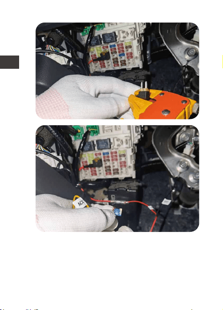
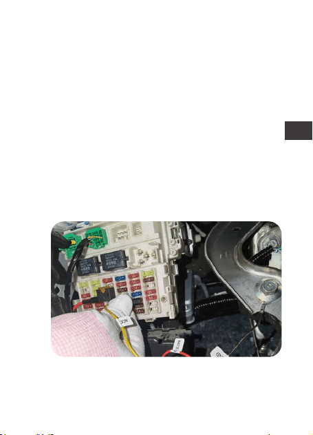
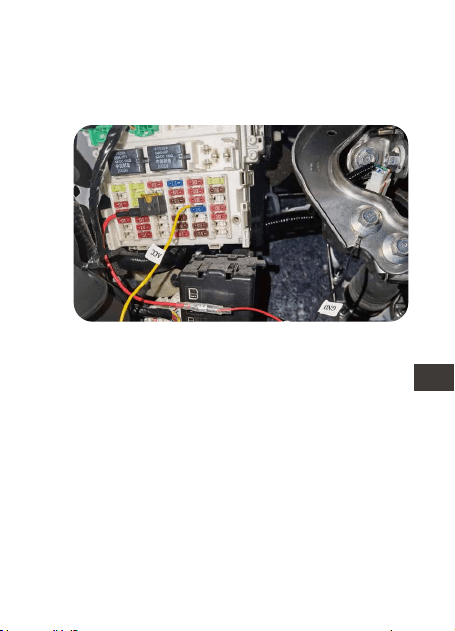
Note: When inserting the fuse socket into the
ACC slot, you need to insert the wire wrap
end into the uncharged position in the ACC
slot.
3.6 Plug the Type C connector to the dash cam,
start the car, and test if it works.
- 10 -
EN
EN
EN
EN

4. Warranty & Support
The Vantrue dash cam hardwire kit comes
with a full 12 months warranty. If you have
any questions regarding your product, please
do not hesitate to contact the customer
service staff of your purchase channel, or
contact us at [email protected]. Queries
are typically answered within 12-24 hours.
Your opinion matters
VANTRUE is firmly committed to always
improving our products, services, and user
experience. If you have any thoughts on how
we can do even better, we welcome your
constructive feedback and suggestions.
Connect with us today at support@vantrue.
net
Thank You for choosing Vantrue
- 11 -
ENEN
1. Packliste
A.
B.
C.
D.
F.
A
B
C
E
F
D
Hardwire-Kit-Schalter
Rotes Stromkabe
Schwarzes
Erdungskabel
E. USB-C 5Gang-An-
passung Hardwire Kit
Gelbe ACC-
Signalleitung
4 Arten von Sicherung-
sadaptern (klein, Mini,
mittel, Mini mit langen
Beinen)
- 12 -
DE

2. Spezifikationen
3. Installationshinweise
Name
Stromschnittstelle
Eingangsspannung
Ausgangsspannung
Ausgangsstrom
Schutzzeit
Linienlänge
Betriebstemperatur
Lagertemperatur
Schutzspannung
Parameter
USB-C
DC12V-24V
5V
2.8A
1 Stunde, 3 Stunden,
6 Stunden, 12 Stunden,
24 Stunden, immer
geöffnet (Immer)
4,5 Meter
-20℃ bis 60℃
-20℃ bis 70℃
12V Batterie: 11,6
V,11,9 V,12,2 V,12,5 V
24V Batterie: 23,6
V,23,9 V,24,2 V,24,5 V
Bitte überprüfen Sie vor der Installation, ob die
Packliste vollständig ist, und lesen Sie diese
Anleitung, bevor Sie beginnen. Die Position
und Anordnung des Kfz-Sicherungskastens
und die Art der verwendeten Sicherung
variieren je nach Fahrzeugmodell und
Baujahr. Einzelheiten entnehmen Sie bitte
- 13 -
DE

Bevor Sie mit der Installation beginnen,
vergewissern Sie sich, dass Sie über die
folgenden Werkzeuge verfügen: Bedienung-
sanleitung, Sicherungsadapter, Sicherungsa-
bzieher, Werkzeug zum Entfernen der
Verkleidung, doppelseitiges Klebeband,
Drahtschneidewerkzeug, Prüfstift, Multimeter
usw.
Bitte beachten Sie, dass die oben
aufgeführten Artikel nicht in der Packliste des
Hardwire-Kits enthalten sind und selbst
gekauft werden brauchen. Sicherungs-
adapter können von Fahrzeug zu Fahrzeug
variieren. Bitte wenden Sie sich an Ihren
Autohersteller oder professionellen
Autoteile-Installateur für Sicherungstypen.
3.1 Vor der Installation
dem Handbuch Ihres Fahrzeugs.
*Wir empfehlen Ihnen, professionelle Hilfe in
Anspruch zu nehmen, um Installationsfehler
zu vermeiden.
- 14 -
DE
Standardeinstel-
lung: 11,9 V/23,9
V, Immer
(Hinweis: Das
Immer-Getriebe
ist eigentlich ein
zeitlich
unbegrenztes
Getriebe.)
3.2 Spannung und Zeitschaltuhr einstellen
Beispiel: Wenn
Ihre Autobatter-
iespannung 12
V beträgt,
müssen Sie die
Schutzspannung
auf 11,6 V
einstellen, die
Arbeitszeit des
DIP-Schalter: 1~2 Gänge sind Niederspan-
nungsschutzgetriebe, 3~5 sind Arbeitsstunden.
Hardwire Kits beträgt 12 Stunden und die
Schalterrichtung muss auf ↑↑↓↓↓ eingestellt
werden.
- 15 -
DE
3.3 Finden Sie den Sicherungskasten
Wählen Sie den geeigneten Sicherungs-
adapter basierend auf der entfernten
Sicherung, setzen Sie die Sicherung in den
Sicherungsadapter ein und verbinden Sie
dann den Sicherungsadapter mit der roten
(BATT+) Stromleitung des Step-Down-Kabels.
Bevor Sie mit Schritt 3.5 fortfahren,
vergewissern Sie sich, dass der Sicherungs-
adapter sicher befestigt ist.
3.4 Anschließen des Sicherungsadapters
Schlagen Sie in Ihrem Benutzerhandbuch
nach, um den Sicherungskasten zu finden.
Im Sicherungskasten befinden sich viele
verschiedene Sicherungen, darunter:
Zigarettenanzünder, Innenbeleuchtung und
Autoradios, um nur einige zu nennen.
- 16 -
DE
Entfernen Sie die Sicherung aus dem
Sicherungskasten.
Setzen Sie die Sicherung in den Sicherungs-
adapter ein.
- 17 -
DE
Verbinden Sie das rote Netzkabel mit dem
Sicherungsadapter
Setzen Sie den Sicherungsadapter in den
Sicherungskasten ein.
- 18 -
DE
3.5 Schließen Sie die Sicherungsdrähte an den
Sicherungsschaltkasten an
(1) Finden Sie einen Erdungspunkt, z. B. eine
Schraube, der sich direkt am Metallteil des
Fahrzeugchassis befindet. Befestigen Sie das
schwarze (GNC) Kabel am Chassis (z. B.
durch Befestigen unter einer Schraube oder
einem Erdungspunkt).
(2) Bitte überprüfen Sie die Nennleistung
(Batterieleistung) der Sicherung im
Sicherungskasten. Schließen Sie die rote
Ader (BATT+) an diese Netzsicherung an, z.B.
Sicherung für Geräte, Leselampen. Dieser
Stromkreis muss bei ausgeschalteter
Zündung unter Spannung bleiben*.
- 19 -
DE
Wenn Ihr ACC-Sicherungssteckplatz nicht in
den ACC-Sicherungssockel passt, der mit
*Wenn Ihr Auto über einen „Energiesparmo-
dus“ verfügt, verwenden Sie bitte eine
Warnblinksicherung.
WARNUNG: Schließen Sie KEINE Sicherungen
an den Autocomputer, den AIRBAG, das
ABS oder andere Schaltkreise an, die die
Fahrzeugsicherheit betreffen.
(3) Schlagen Sie in Ihrem Benutzerhandbuch
nach, um die ACC-Sicherung in der inneren
Sicherungstafel zu identifizieren. Verbinden
Sie das gelbe (ACC+) Kabel mit dem
gekennzeichneten ACC-Sicherungssockel.
Dieser Stromkreis wird nur bei einges-
chalteter Zündung bestromt.
- 20 -
DE
dem Hardwire Kit geliefert wird, können Sie
den eingebauten Sicherungssockel
abschneiden und das gelbe ACC-Kabel um
den ACC-Sicherungssockel Ihres Autos
wickeln, wie in der Abbildung gezeigt unter:
- 21 -
DE
Hinweis: Beim Einsetzen des Sicherungssock-
els in den ACC-Steckplatz das
Wicklungsende in die ungeladene Position in
den ACC-Steckplatz einführen.
3.6 Stecken Sie den USB-C-Anschluss des
Hardwire-Kits in den Stromanschluss der
Dashcam, starten Sie das Auto und testen Sie,
ob es normal ist.
- 22 -
DE

4. Kundendienst
Die Garantiezeit von VANTRUE beträgt 12
Monate. Wenn Sie Fragen zum Produkt
haben, können Sie sich an die Kundendien-
stmitarbeiter Ihres Kaufkanals wenden oder
eine E-Mail an unsere offizielle E-Mail Adresse
[email protected] senden. Wir werden
engagierte Mitarbeiter haben, die innerhalb
von 12-24 Stunden auf Fragen antworten.
Die Marke VANTRUE
®
hat ein unerschütterli-
ches Engagement für die kontinuierliche
Verbesserung von Produkten, Dienstleistun-
gen und Benutzererfahrung. Wenn Sie Ideen
haben, wie wir es besser machen können,
können Sie gerne Ihre wertvollen Kommen-
tare und Vorschläge an unsere offizielle
E-Mail Adresse [email protected]
hinterlassen. Vielen Dank, dass Sie sich für
VANTRUE
®
entschieden haben.
- 23 -
DE
1. Qu'y a-t-il dans le paquet
A.
B.
C.
D.
F.
A
B
C
E
F
D
Interrupteur de réglage
de ligne Buck
Cordon
d'alimentation
rouge
Fil de terre noir E. USB C Kit de câblage
Ligne de signal
jaune ACC
4 types d'adaptateurs
de fusibles (petits,
mini, moyens, mini
longs pieds)
- 24 -
FR

2. Spécification
Nom
Interface
d'alimentation
Tension d'entrée
Tension de sortie
Courant de sortie
Temps de
fonctionnement
Spécification de fil
Température de
fonctionnement
Température de
stockage
Tension de
protection
Contenue
USB C
DC12V-24V
5V
2.8A
4,5 Mètre
-20℃ à 60℃
-20℃ à 70℃
Batterie 12V : 11.6V,
11.9V, 12.2V, 12.5V24V
Batterie 24 V : 23,6 V,
23,9 V, 24,2 V, 24,5 V
1 heure, 3 heures, 6
heures, 12 heures, 24
heures, toujours ouvert
(Toujours)
- 25 -
FR

- 26 -
3. Notes d'installation
Veuillez vérifier que la liste de colisage est
complète avant l'installation et lire ce manuel
avant de commencer.
L'emplacement et la disposition de la boîte à
fusibles et le type de fusible utilisé varient en
fonction du modèle de véhicule et de l'année
de fabrication. Veuillez vous référer au
manuel de votre voiture pour plus de détails.
*Nous vous suggérons de demander l'aide
d'un professionnel pour éviter les erreurs
d'installation.
Avant de commencer l'installation, assurez-
vous que vous disposez des outils suivants:
manuel du propriétaire, adaptateur de fusible,
extracteur de fusible, outil de suppression de
l'intérieur de la voiture, ruban adhésif double
face, outil de coupe de fil, stylo de test,
multimètre, etc.
Veuillez noter que les éléments énumérés
ci-dessus ne sont pas inclus dans la liste de
colisage du câble abaisseur et doivent être
achetés par vous-même. L'adaptateur de
fusible peut varier d'un véhicule à l'autre.
Veuillez consulter le fabricant du véhicule
3.1 Avant l'installation
FR
- 27 -
3.2 Régler la tension et le commutateur de
minuterie
Réglage par
défaut: 11,9
V/23,9V, Toujours
(Remarque: la
vitesse toujours
est en fait une
vitesse illimitée.)
Par exemple: si
la tension de la
batterie de
votre voiture est
de 12V, vous
devez régler la
tension de
protection sur
11,6V et régler
Commutateur DIP : 1 à 2 vitesses sont des
vitesses de protection basse tension, 3 à 5
sont des heures de travail.
le temps de fonctionnement de la ligne
abaisseur sur 12heures, puis le sens de
commutation doit être réglé sur: ↑↑↓ ↓↓
d'origine ou l'installateur professionnel de
pièces automobiles pour le type de fusible.
FR
3.3 Trouver le boîtier de contrôle des fusibles
Reportez-vous à votre manuel du propriétaire
pour localiser la boîte de contrôle des fusibles.
À l'intérieur du boîtier de commande de
fusibles se trouveront de nombreux fusibles
différents, notamment: des allume-cigares,
des éclairages intérieurs et des autoradios.
En vous référant au schéma ci-dessous,
sélectionnez et insérez l'adaptateur de fusible
approprié en fonction du fusible que vous
avez retiré. Connectez ensuite l'adaptateur
de fusible à la ligne d'alimentation rouge de
la【Hardwire Kit】(BATT+). Avant de passer à
l'étape suivante, assurez-vous que la
connexion de l'adaptateur de fusible est
sécurisée.
3.4 Connexion de l'adaptateur de fusible
- 28 -
FR
Retirez le fusible de la boîte à fusibles.
Insérez le fusible dans l'adaptateur de fusible.
- 29 -
FR
Connectez le kit de câblage avec l'adapta-
teur de fusible.
Insérez l'adaptateur de fusible dans la boîte
à fusibles.
- 30 -
FR
3.5 Connectez les fils de fusibles au boîtier de
commande de fusibles
(1) Trouvez un point de mise à la terre, tel
qu'un boulon, qui se trouve directement sur
la partie métallique du châssis du véhicule.
Fixez le fil noir (GNC) au châssis (par
exemple, le fixer sous un boulon ou un point
de masse).
(2) Déterminez le fusible de puissance
nominale (alimentation par batterie) dans le
panneau de fusibles. Connectez le fil rouge
(BATT+) à ce fusible secteur, par exemple
fusible pour appareils électroménagers,
lampes de lecture. Ce circuit doit rester sous
tension* lorsque le contact est coupé.
- 31 -
FR
Si votre emplacement de fusible ACC ne
correspond pas à la douille de fusible ACC
fournie avec le câble abaisseur, vous
* Si votre voiture est équipée d'un "mode
économie d'énergie", utilisez un fusible pour
feux de détresse.
AVERTISSEMENT: NE connectez PAS les
fusibles à l'ordinateur de la voiture, à
l'AIRBAG, à l'ABS ou à tout autre circuit lié à
la sécurité de la voiture.
(3) Reportez-vous au manuel de votre
véhicule pour déterminer le fusible ACC
dans le panneau de fusibles intérieur du
véhicule. Connectez le fil jaune (ACC+) à la
prise de fusible ACC. Ce circuit n'est
alimenté que lorsque le contact est mis.
- 32 -
FR
pouvez couper la douille de fusible fourni et
enrouler le fil jaune ACC autour de la
douille de fusible ACC de votre voiture,
comme indiqué dans la figure ci-dessous :
- 33 -
FR
Remarque : Lorsque vous insérez la douille
du fusible dans la fente ACC, vous devez
insérer l'extrémité du câble enroulé dans la
position non alimentée de la fente ACC.
3.6
Insérez l'interface USB C du câble abaisseur
dans le port d'alimentation de l'enregistreur
de conduite, démarrez la voiture et testez si
elle est normale.
- 34 -
FR

4. Assistance et SAV
Service Après-Vente
VANTRUE offre une période de service de
garantie de 12 mois, pendant laquelle vous
pouvez profiter de services tels que des
réparations rapides, le retour et l'échange de
marchandises endommagées, etc.
Si vous vous inscrivez en tant que membre sur
le site officiel de VANTRUE, votre période de
service de garantie peut être étendue à 18
mois.
Assistance
Si vous avez des questions sur le produit, vous
pouvez envoyer un e-mail à notre e-mail
officiel [email protected] pour nous
contacter. Le personnel spécialisé répondra
aux questions dans les 12 à 24 heures.
Votre opinion compte
VANTRUE
®
s'engage fermement à toujours
améliorer notre produits, services et expéri-
ence utilisateur. Si tu as quelque réflexions sur
la façon dont nous pouvons faire encore
mieux, nous apprécions vos commentaires et
suggestions constructifs. Connectez-vous
avec nous aujourd'hui à [email protected].
- 35 -
FR
1. Visualización del producto
A.
B.
C.
D.
F.
A
B
C
E
F
D
Conmutador de kit de
cableado
Cable rojo para
la caja de
fusibles
Cable negro
para tierra
E. Kit de cableado para
dashcam USB Tipo C
con 5 mecanismos
Cable amarillo
para ACC
Cuatro tipos de adapta-
dores de fusibles (ATO,
Mini, ACN, Micro2)
- 36 -
ES

2. Especificaciones
3. Instalación
Nombre
Conector
Voltaje de entrada
Voltaje de salida
Corriente de salida
Tiempo de
funcionamiento
Longitud del cable
Temperatura de
funcionamiento
Temperatura de
almacenamiento
Protección de
bajo voltaje
Descripción
USB Tipo C
DC 12V-24V
5V
2.8A
4.5m
De -4°F a 140°F
De -4°F a 158°F
Vehículo 12V: 11.6V,
11.9V, 12.2V, 12.5V
Vehículo 24V: 23.6V,
23.9V, 24.2V, 24.5V
Por favor revise la lista de embalaje para
verificar que todo esté incluido y lea este
manual antes de la instalación. La
ubicación y el diseño de la caja de fusibles
del automóvil y el tipo de fusible utilizado
pueden variar dependiendo del modelo del
vehículo y el año de fabricación. Por favor
1 hora, 3 horas, 6 horas,
12 horas, 24 horas,
siempre
- 37 -
ES

3.1 Antes de la instalación
refiérase al manual de su vehículo para
obtener más información.
Nota: Nosotros recomendamos que pida la
ayuda de un profesional con el fin de evitar
errores de instalación.
Antes de que comience la instalación, por
favor asegúrese de tener las siguientes
herramientas: manual de usuario, adaptador
de fusible, extractor de fusible, herramienta
para extraer panales, cinta doble faz,
herramienta cortadora de cables, stylus,
multímetro, etc.
Nota: Los elementos mencionados anterior-
mente no están incluidos en la lista de
empaque y deben ser comprados por usted.
Los adaptadores de fusibles pueden variar
dependiendo del vehículo. Por favor consulte
los tipos de fusibles con el fabricante original
del automóvil o un mecánico profesional.
- 38 -
ES
3.2 Encienda y apague el voltaje y el
temporizador
Réglage par
défaut: 11,9V/
23,9V, Toujours
(Remarque: la
vitesse toujours
est en fait une
vitesse illimitée.)
Par exemple: si
la tension de la
batterie de
votre voiture est
de 12V, vous
devez régler la
tension de
protection sur
11,6V et régler
Commutateur DIP : 1 à 2 vitesses sont des
vitesses de protection basse tension, 3 à 5
sont des heures de travail.
le temps de fonctionnement de la ligne
abaisseur sur 12heures, puis le sens de
commutation doit être réglé sur: ↑↑↓ ↓↓.
- 39 -
ES
La caja de fusibles contendrá muchos
diferentes fusibles, incluyendo encendedor
de cigarrillos, luces interiores, estéreo del
vehículo, etc. Por favor refiérase al manual
de usuario de su vehículo para encontrar la
caja de fusibles.
Seleccione el adaptador de fusible correcto
basado en el fusible que removió. Tome
como referencia las siguientes imágenes.
Inserte el fusible en el adaptador de fusible y
conecte el adaptador de fusible al cable
rojo en el kit de cableado. Asegúrese de que
el adaptador de fusible esté firmemente
conectado.
3.4 Conecte el adaptador de fusible correcto
para el kit de cableado
3.3 Encuentre la caja de fusibles
- 40 -
ES
Remueva el fusible de la caja de fusible.
Inserte el fusible en el adaptador de fusible.
- 41 -
ES
Conecte el kit de cableado con el adaptador
de fusible.
Inserte el adaptador de fusible en la caja de
fusible.
- 42 -
ES
3.5
(1) Fije el cable negro (GNC) bajo un perno
o tornillo de metal en su vehículo.
(2) Por favor identifique el fusible de
alimentación nominal en el panel de
fusibles, como por ejemplo los fusibles para
accesorios y luces de lectura. El fusible de
alimentación nominal seguirá con energía
cuando la ignición está apagada. Una vez
sea identificado, conecte el cable rojo al
fusible de alimentación nominal.
Nota: Por favor conecte el fusible de luz de
emergencia si su automóvil tiene un “modo
de ahorro de energía”.
Conecte el cable del fusible en la caja de
fusible
- 43 -
ES
Si su ranura de fusible ACC no es compati-
ble con la toma de fusible ACC que viene
con el kit de cableado, usted puede cortar
la toma de fusible que viene incluida y
puede enrollar el cable ACC amarillo
ADVERTENCIA: No conecte los fusibles para la
computadora del automóvil, bolsas de aire,
ABS o cualquier otro circuito del automóvil
relacionado a la seguridad.
(3) Por favor identifique el fusible ACC en el
panel de fusibles del vehículo. Tome como
referencia el manual de usuario del
automóvil. El fusible ACC solo se enciende
cuando el arranque es activado. Una vez
encontrado, conecte el cable amarillo en el
ACC en la caja de fusibles.
- 44 -
ES
alrededor de la toma de fusible ACC de su
auto como se muestra a continuación:
- 45 -
ES
Nota: Cuando inserte la toma de fusible en
la ranura ACC, debe insertar el extremo del
cable enrollado en la posición no cargada
de la ranura ACC.
3.6 Conecte el conector tipo C a la dashcam,
encienda el automóvil y vea si funciona.
- 46 -
ES

4. Garantía y soporte
El kit de cableado para dashcam de Vantrue
viene con una garantía completa de 12
meses. Si usted tiene alguna pregunta
relacionada a su producto, por favor no
dude en contactar al personal de atención
al cliente de su canal de compra, o
contactarnos a través de support@vantrue.
net. Las preguntas son normalmente
respondidas en 12-24 horas.
Su opinión importa
VANTRUE está firmemente comprometido a
siempre proveer nuestros productos, servicios
y experiencia de usuario. Si tiene alguna
opinión sobre cómo podemos mejorar,
recibimos con agrado sus sugerencias
constructivas. Contáctenos ahora a través
Gracias por elegir a Vantrue
- 47 -
ES
1. Widok produktu
A.
B.
C.
D.
F.
A
B
C
E
F
D
Przełącznik zestawu
przewodowego
Czerwony przewód
do skrzynki
bezpieczników
Czarny drut do
ziemi
E. Zestaw z przewo-
dem USB typu C USB
Dash Cam z 5
biegami
Żółty przewód
do ACC
Cztery typy adapt-
erów bezpieczników
(ATO, Mini, ACN,
Micro2)
- 48 -
PL

2. Specyfikacje
3. Instalacja
Nazwa
Złącze
Napięcie wejściowe
Napięcie wyjściowe
Prąd wyjściowy
Długość kabla
Temperatura pracy
Opis
Type C USB
DC 12V-24V
5V
2.8A
4.5m
-4°F to 140°F
-4°F to 158°F
Prosimy o sprawdzenie kompletności listy
przewozowej i przeczytanie niniejszej instrukcji
przed instalacją. Lokalizacja i układ
samochodowej skrzynki bezpieczników oraz
rodzaj zastosowanego bezpiecznika mogą
się różnić w zależności od modelu pojazdu i
1 hour, 3 hours, 6 hours,
12 hours, 24 hours,
always
12V pojazd: 11.6V,
11.9V, 12.2V, 12.5V
24V pojazd: 23.6V,
23.9V, 24.2V, 24.5V
Czas pracy
Ochrona przed
niskim napięciem
Temperatura
przechowywania
- 49 -
PL

3.1 Przed instalacją
roku produkcji. Aby uzyskać szczegółowe
informacje, zapoznaj się z instrukcją obsługi
pojazdu.
Uwaga: Zalecamy zwrócenie się do profesjo-
nalnej pomocy przy instalacji, aby uniknąć
błędów instalacji.
Przed przystąpieniem do montażu upewnij
się, że posiadasz następujące narzędzia:
instrukcję obsługi, adapter bezpiecznika,
ściągacz bezpieczników, narzędzie do
zdejmowania tapicerki, taśmę dwustronną,
narzędzie do cięcia drutu, rysik, multimetr itp.
Uwaga: pozycje wymienione powyżej nie
znajdują się na liście przewozowej i należy je
zakupić samodzielnie. Adaptery bezpiec-
zników mogą się różnić w zależności od
pojazdu. W sprawie typów bezpieczników
skonsultuj się z producentem oryginalnego
pojazdu lub profesjonalnym instalatorem
części samochodowych.
- 50 -
PL
3.2 Włącz i wyłącz napięcie i timer
Ustawienie
domyślne: 11,9
V/23,9 V, zawsze
(Uwaga: bieg
Always jest w
rzeczywistości
biegiem
nieograniczonym).
Na przykład: jeśli
napięcie
akumulatora
samochodowego
wynosi 12 V,
należy ustawić
napięcie ochrony
na 11,6 V, czas
Przełącznik DIP: 1 ~ 2 biegi to przekładnie
zabezpieczające przed niskim napięciem, 3
~ 5 to godziny pracy.
Zapoznaj się z etykietą konfiguracji zasilania
na produkcie i włącz ją i wyłącz zgodnie z
własnymi wymaganiami.
pracy linii obniżającej wynosi 12 godzin, a
kierunek przełączania należy ustawić na:
↑↑↓↓↓.
- 51 -
PL
3.3 Znajdź skrzynkę bezpieczników
Skrzynka kontrolna bezpieczników zawiera
wiele różnych bezpieczników, w tym
zapalniczkę, oświetlenie wewnętrzne,
radioodtwarzacz samochodowy itp. Aby
znaleźć skrzynkę bezpieczników, zapoznaj się
z instrukcją obsługi.
Wybierz odpowiednią przejściówkę bezpiec-
znika na podstawie wyjętego bezpiecznika,
zapoznaj się z poniższymi zdjęciami, włóż
bezpiecznik do przejściówki bezpiecznika i
podłącz przejściówkę bezpiecznika do
czerwonego przewodu zestawu przewodów.
Upewnij się, że adapter bezpiecznika jest
dobrze podłączony.
3.4 Podłącz odpowiedni adapter bezpiecznika
dla zestawu przewodów
- 52 -
PL
Wyjmij bezpiecznik ze skrzynki bezpieczników.
Włóż bezpiecznik do adaptera bezpiecznika.
- 53 -
PL
Połącz zestaw przewodów z adapterem
bezpiecznika.
Włóż adapter bezpiecznika do skrzynki
bezpieczników.
- 54 -
PL
3.5 Podłącz przewód bezpiecznika do skrzynki
bezpieczników
(1) Zamocuj czarny przewód (GNC) pod
metalową śrubą lub śrubą w pojeździe.
(2) Proszę określić bezpiecznik mocy
znamionowej na panelu bezpieczników, np.
bezpieczniki urządzeń i lampki do czytania.
Bezpiecznik mocy znamionowej pozostanie
pod napięciem po wyłączeniu zapłonu. Po
zidentyfikowaniu podłącz czerwony przewód
do bezpiecznika mocy znamionowej.
Uwaga: podłącz bezpiecznik świateł
awaryjnych, jeśli twój samochód ma „tryb
oszczędzania energii”.
- 55 -
PL
Jeśli gniazdo bezpiecznika ACC nie pasuje
do gniazda bezpiecznika ACC dostarczone-
go z zestawem przewodów, można odciąć
gniazdo bezpiecznika dołączone do niego i
owinąć żółty przewód ACC wokół gniazda
OSTRZEŻENIE: Nie podłączaj bezpieczników
komputera samochodowego, AIR BAG, ABS
ani żadnych innych obwodów związanych z
bezpieczeństwem samochodu.
(3) Proszę zidentyfikować bezpiecznik ACC w
panelu bezpieczników samochodu, zapoznaj
się z instrukcją obsługi samochodu.
Bezpiecznik ACC włącza się tylko po
włączeniu zapłonu. Po znalezieniu podłącz
żółty przewód do ACC w skrzynce bezpiec-
zników.
- 56 -
PL
bezpiecznika ACC w samochodzie, jak
pokazano poniżej:
- 57 -
PL
Uwaga: Wkładając gniazdo bezpiecznika do
gniazda ACC, musisz włożyć koniec owijki
drutu do pozycji rozładowanej w gnieździe
ACC.
3.6 Podłącz złącze typu c do krzywki na deskę
rozdzielczą, uruchom samochód i sprawdź,
czy działa.
- 58 -
PL

4. Gwarancja i wsparcie!
VANTRUE
®
S2 posiada 12 miesięcy gwarancji.
Zarejestruj swój produkt na (www.vantrue.net
/register) aby być na bieżąco z informacjami
o aktualizacjach.
Wsparcie
Jeśli masz jakiekolwiek pytania dotyczące
produktu, nie wahaj się skontaktować z nami
pod adresem [email protected] .
Zapytania są zazwyczaj udzielane w ciągu
12-24 godzin.
Twoja opinia ma znaczenie
Firma VANTRUE
®
jest mocno zaangażowana
w ciągłe ulepszanie naszych produktów,
usług i doświadczeń użytkowników. Jeśli masz
jakieś przemyślenia na temat tego, jak
możemy zrobić to jeszcze lepiej, czekamy na
Twoje konstruktywne opinie i sugestie.
Skontaktuj się z nami już dziś pod adresem
- 59 -
PL

www.vantrue.pl
facebook.com/vantruePolska
Skontaktuj się z nami:
- 60 -
PL
1.梱包内容
A.
B.
C.
D.
F.
A
B
C
E
F
D
切替スイッチ
電源端子(赤色)
アース線(ブラック)
E.
TYPE-C 電源直結コ
ード
ACC信号端子(黄色)
ヒューズホルダー
(4種類)
- 61 -
JP

2.商品仕様
3.取り付け
名称
電源端子
入力電圧
出力電圧
出力電流
オフタイマー設定
ケーブルの長さ
動作環境
保存環境
詳細
TYPE-C
DC12V-24V
DC5V
2.8A
電圧カットオフ値
設定
12V時:11.6V/11.9V/
12.2V/12.5V
24V時:23.6V/23.9V/
24.2V/24.5V
取り付ける前に、まずは欠品が無いことをご確
認ください。
取り付けに必要する各種のツールをご用意して
ください。
※車に詳しくない方は、取り付けを専門業者に
任せることを勧めます。
OFF/1時間/3時間/6時間
/12時間/24時間
4.5ⅿ
-20℃~60℃
-20℃~70℃
3.1取り付ける前に
- 62 -
JP
3.2保護電圧とタイマーを設定する
コントロールボックスに記載されている説明を
ご参照してスイッチを切り替えることによって
ご希望の録画時間、または電圧のカットオフ値
を設定してください。
例えば、電圧のカ
ットオフ値を11.6V
に設定し、タイマ
ーを12時間に設定
する場合はスイッ
チの設置は
↑↑↓↓↓になり
ます。
初期設定:
11.9V/23.9V、24時
間(無制限)
スイッチの働き:
1~2は電圧のカット
オフ値を設定するス
イッチで、3~5は
タイマーを設定する
スイッチです。
- 63 -
JP
車のマニュアールを参考して、適合するヒュズ
を選んでください。
①出力が12〜30Vの常時電源のヒュズ
②ACC電源のヒューズ
※ご注意:ヒュズボックスにある色んなヒューズ
がありますが、PC、AIR BAGやABSなど車の安全
に関わるヒューズを使用しないでください。
3.3適用なヒューズを選ぶ
1)ツールで選んだ常時電源のヒューズをヒュズ
ボックスから取り出してください。
3.4配線
- 64 -
JP
2)取り出したヒューズを直結電源ケーブルのヒ
ューズボルターに差込んでください。
3)ヒューズホルダーをステップ1で取り出したヒ
ューズのところに差し込んでください。
- 65 -
JP
4)ツールで選んだACC端子のヒューズをヒュズ
ボックスから取り出してください。
5)直結電源ケーブルのACC端子をヒュズボック
スのACC端子に差し込んでください。そして黒
色のアース線も隣のアースポイント(金属部分)に
接続してください。
- 66 -
JP

配線が完成しましたら、Type-Cの端子をドラレ
コ本体に差し込んで正常に起動して録画できる
かをご確認ください。またドラレコはエンジン
のON/OFFと連動して駐車監視モードにIN/OUT
になるかをご確認ください。すべての機能が正
常であれば配線は問題ないことを判断できま
す。配線が問題ないことを確認した後、また配
線を隠す作業を行ってください。
3.3配線をテストする
- 67 -
JP

VANTRUE®電源直結コードの保証期間は12ヶ月
となります。
サポートについて
製品に何のご質問・問題がございましたら、い
つでもお気軽にアマゾン経由でお問い合わせい
ただくか。或いは、[email protected]までご
連絡ください。すべてのお問い合わせは、営業
日に24時間以内にご返信を差し上げます。
ご意見
製品について何の意見がございますか?いつも
私たちの製品とサービスの品質とユーザーエク
スペリエンスを向上させるために全力で取り組
んでいます。製品を改善する上の意見やアドバ
イスを持っている場合は、ご遠慮なく弊社まで
ご連絡をお願いいたします(アマゾンンお問い合
わせ或いは[email protected]より)。お客様
からの声を期待しております。
VANTRUEをご利用いただき、誠にありがとうご
ざいます
4.保証について
- 68 -
JP

- 69 -
JP
製品をご購入頂き、誠にありがとうございます。
お問い合わせ:
www.vantrue.net/contact
facebook.com/vantrue.live
LINE ID:vantruecam
- 70 -
CN
1. 包装清单
A.
B.
C.
D.
F.
A
C
E
F
D
降压线设置开关
红色电源线
黑色地线
E.
TYPE-C五档调节降压线
黄色ACC信号线
4种规格保险丝适配器
(小号、mini、中号、
微型长脚)

- 71 -
CN
2. 规格参数
3. 安装说明
名称
电源接口
输入电压
输出电压
输出电流
工作时间
线材规格
工作温度
存储温度
内容
TYPE-C
DC12V-24V
5V
2.8A
保护电压 12V电瓶:11.6V、11.9V、12.2V、
12.5V
24V电瓶:23.6V、23.9V、24.2V、
24.5V
安装注意事项:
*安装之前请检查包装清单是否完整,并在安装之
前仔细阅读本说明书。
*汽车保险盒位置、布局、保险丝的类型会根据车
辆型号和制造年份不同有所差别,具体以车主手册
为准。
*我们建议您可以请专业人员帮助,避免安装错误。
1小时、3小时、6小时、12小时、
24小时、常开(Always)
4.5米
-20℃到60℃
-20℃到70℃

- 72 -
CN
3.1 安装前准备
在开始安装之前,请确保您有以下工具:车主手
册、保险丝适配器、保险丝拉拔器、装饰件拆卸
工具、双面胶带、线材切割工具、测电笔、万用
表等。
*上面列出的工具不包含在降压线包装清单内,需
自行购置,保险丝适配器可能因车辆而异,保险
丝类型请咨询原车制造商或专业汽车配件安装
商。
3.2 设置保护电压和使用时间
请参阅产品上的设置标签,并根据用电需求设置
对应的使用时间与保护电压。
默认设置:
11.9V/23.9V ,24
小时(注意:24小时
档位实际为无时间
限制档位,并不是
只工作24小时。)
拨码开关:1~2档为低电压保护档位,3~5为工作
时间。
- 73 -
CN
参考汽车的车主手册,在保险丝盒内选择存在以
下可接入的保险丝:
①输出电压为12-30V的常电保险丝;
②ACC电源保险丝。
*保险丝控制盒内将有许多不同的保险丝,切勿连
接汽车电脑、AIR BAG、ABS或任何其他与汽车安
全相关电路的保险丝。
3.3 选择合适的保险丝盒
举例:如您的车电
瓶电压值为12V,
需要设置保护电压
为11.6V,降压线
工作时间12小时,
开关方向需要设置
为:↑↑↓↓↓
- 74 -
CN
(1)参考车主手册,ACC信号线与保险盒内的ACC
电源保险丝连接
3.4 将保险丝线连接到保险丝控制盒
注意:
*ACC保险丝槽与降压线自带的ACC保险丝插座不
合适,可以剪掉自带的保险丝插座,将黄色ACC
线缠在您汽车的ACC保险丝插座上,如下图:
- 75 -
CN
(2)红色电源线与保险盒内输出电压为12-30V的常
电保险丝连接。
- 76 -
CN
3.5 测试电路与ACC信号
第一步:将Type-C连接线接口插入记录仪的电源
接口中,点火发动汽车,等待记录仪启动。
*点火发动汽车后,记录仪无法启动,红色电源线
是否已连接到正确的常电保险丝上。
第二步:记录仪启动后,将汽车熄火并拔掉钥
匙,查看记录仪是否关机,部分车辆需要熄火并
打开主驾驶位车门才会触发。
*ACC电源关闭信号,还有少部分车辆在熄火锁车
后段时间,才会触发ACC电源关闭信号。这两类
车辆,需要在ACC电源关闭后查看是否关机。
第三步:确认记录仪关机后,重新点火发动汽
车,查看记录仪是否自动启动。
*如果上述步骤均确认通过,表明电路与ACC信号
测试通过。
(3)黑色地线与保险盒负极或搭铁位置连接。

- 77 -
CN
VANTRUE品牌保修服务周期为12个月,如果您有
任何关于产品的问题,可以联系您购买渠道的客
服人员或者扫描下方微信二维码,添加专属售后
客服,VANTRUE®品牌一直坚定不移地致力于不
断改进产品,提高服务以及用户体验。如果您对
于我们如何能做的更好有任何的想法,欢迎您在
我们的官方邮箱[email protected]留下宝贵
的意见及建议。
感谢您选择VANTRUE®
4. 售后服务
*如果电路与ACC信号测试失败,请重新检查停车
监控线的各条子线是否连接了正确的保险丝或接
地位置。
*如果所有连接都正确,仍然无法通过测试,请与
售后服务人员联系。

- 78 -
京东旗舰店
https://vantrue.jd.com/
VANTRUE公众号
联系我们:
微信号: vantrue001