

Contents
English ...........................................................................................................01
简体中文
........................................................................................................08
Italiano ........................................................................................................... 14
Français. ........................................................................................................19
Deutsch .........................................................................................................24
Español. ......................................................................................................... 30
日本語
............................................................................................................35
ภาษาไทย ......................................................................................................... 39
Polski .............................................................................................................. 43

01
Note: Illustrations of the product, accessories, and user interface in the
user manual are for reference purposes only. The actual product and
functions may vary due to product enhancements.
Product overview
Please read this manual carefully before using the product and keep it
in a safe place.
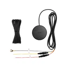
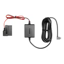
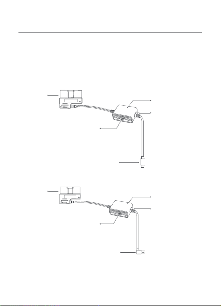
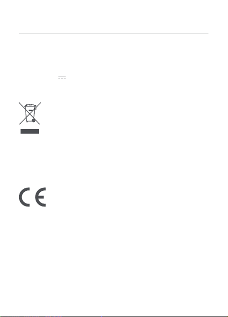
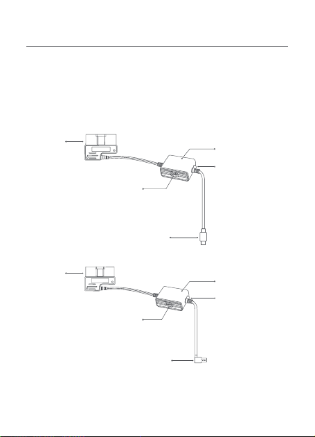
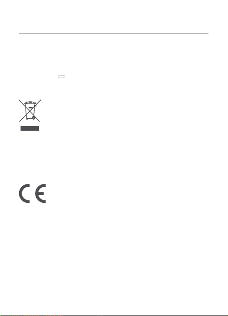
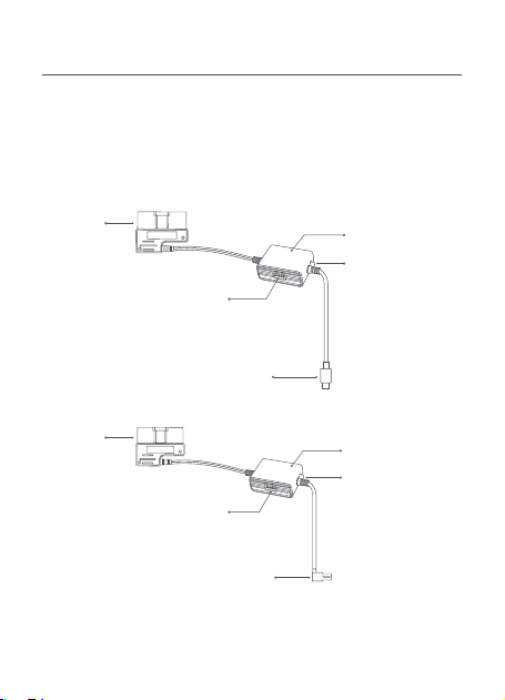
This manual applies to the model Midrive OBD01 and model Midrive
OBD02 of the 70mai OBD-
Ⅱ
Hardwire Kit.
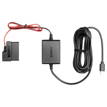
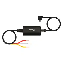
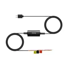
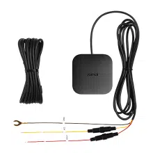
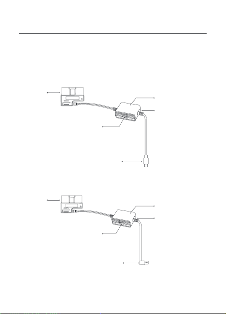
Midrive OBD01
Midrive OBD02
OBD
connector
OBD
connector
Hardwire kit box
Hardwire kit box
Hardwire kit switch
Hardwire kit switch
Type-C charging connector
USB charging connector
Indicator light
•
Green: Normal
•
Red: Low voltage
protection mode,
no power output
Indicator light
•
Green: Normal
•
Red: Low voltage
protection mode,
no power output

02
Step 1: Setting voltage and timer switches
Refer to the label on the hardwire kit box and set the low voltage
protection and time switches according to your needs.
Installation
Dip switch:
Position 1-2 for low voltage protection setting, position
3-5 for working time setting. For example, if the protection voltage
to be set is 11.6V and the working time is 12 hours, the switches
should be set to
↑↑↓↓↓
.
Always:
The hardwire kit will always work regardless of time.
Default settings:
11.9V/23.9V, 24H (After 24 hours, the hardwire kit
box will stop powering the dash cam)
70mai OBD-
Ⅱ
Hardwire Kit × 1
Adhesive sticker × 1
Packing list
User manual × 1
Low voltage protection
setting
Time setting
Voltage setting 1 2 3 4 5 Time setting
11.6V/23.6V
⬆ ⬆ ⬆ ⬆ ⬆
1 H
11.9V/23.9V
⬆ ⬇ ⬆ ⬆ ⬇
3 H
12.2V/24.2V
⬇ ⬆ ⬆ ⬇ ⬇
6 H
12.5V/24.5V
⬇ ⬇ ⬇ ⬇ ⬇
12 H
Dip switch
ON:
⬆
OFF:
⬇
⬇ ⬇ ⬆
24 H
⬇ ⬆ ⬇
Always

03
Step 2. Testing circuit and ACC signal
1. Ensure that the vehicle is turned off and the power is
disconnected. Locate the OBD-
Ⅱ
port of the vehicle and plug the
OBD connector into it.
2. Insert charging connector of the hardwire kit into the power port
of the dash cam.
3. Start the car engine and wait for the dash cam to turn on.
4. After the dash cam turns on, turn off the engine and remove the
key. Check if the dash cam powers off or enters sleep mode.
For some cars, the ACC power off signal will only be triggered
when the driver seat door is opened after the engine is turned
off. Some car models will only trigger the ACC power off signal
after the engine has been turned off for a certain period of time.
For such cars, check if the dash cam powers off or enters sleep
mode after the ACC power is turned off.
5. After the dash cam powers off or enters sleep mode, restart the
engine and check if the dash cam automatically turns on.
If the above steps can be proceed correctly, the circuit and ACC
signal test is passed.
If the test fails, please check cable connections. If the connections
are correct yet the test fails, contact after-sales service for
assistance.
Note: The OBD-
Ⅱ
port is usually located under the steering wheel or next
to the gear shift. If you cannot locate the OBD-
Ⅱ
port, refer to the vehicle’s
user manual or consult an automotive dealer.
Step 3: Routing the cable
1. Route the hardwire kit cable to the dash cam's location. Coil up
any excess cable length, but do not cut the cable. Cutting the
cable will prevent it from providing power and transmitting the
ACC signal to the dash cam.
2. Attach the adhesive sticker to the side of the hardwire kit box

04
Before using the device, please read all the precautions to ensure
correct and safe use.
•
Please ask a professional technician to perform the installation.
Our company is not liable for any short-circuiting of the car power
supply and damage to car battery or interior due to improper
installation.
•
The performance of this product is affected by the reliability of the
car power source, car battery and dash cam. Our company is not
liable for any losses from the malfunction of this product unless it
is caused by product quality issues.
•
Some cars cannot detect changes in ACC signals when the engine
is turned on or off. For such cars, the hardwire kit is unable to
transmit ACC signals to the main device. This may cause certain
functions to be unavailable.
•
Please only use this product for legal purposes.
Precautions
Product: 70mai OBD-
Ⅱ
Hardwire Kit
Model: Midrive OBD01, Midrive OBD02
Input: DC 12V to 30V
Output: DC 5V 2.4A
Specifications
labeled "POWER" and secure it in a position that allows for
adjustment.

05
All products bearing this symbol are waste electrical and
electronic equipment (WEEE as in directive 2012/19/
EU) which should not be mixed with unsorted household
waste. Instead, you should protect human health and the
environment by handing over your waste equipment to
a designated collection point for the recycling of waste electrical
and electronic equipment, appointed by the government or local
authorities. Correct disposal and recycling will help prevent potential
negative consequences to the environment and human health.
Please contact the installer or local authorities for more information
about the location as well as terms and conditions of such collection
points.
Regulatory compliance information
We 70mai Co., Ltd., hereby, declares that this equipment is
in compliance with the applicable Directives and UK Norms,
and amendments. The full text of the UKCA declaration of
conformity is available at the following internet address:
https://help.70mai.asia/2145.html
The manufacturer hereby, declares that this equipment
is in compliance with the applicable Directives and
European Norms, and amendments. The full text of the
EU declaration of conformity is available at the following
internet address: https://help.70mai.asia/1193.html

06
FCC Caution.
§ 15.19 Labelling requirements.
This device complies with part 15 of the FCC Rules. Operation is
subject to the following two conditions: (1) This device may not
cause harmful interference, and (2) this device must accept any
interference received, including interference that may cause
undesired operation.
§ 15.21 Information to user.
Any Changes or modifications not expressly approved by the party
responsible for compliance could void the user's authority to
operate the equipment.
§ 15.105 Information to the user.
Note: This equipment has been tested and found to comply with
the limits for a Class B digital device, pursuant to part 15 of the FCC
Rules. These limits are designed to provide reasonable protection
against harmful interference in a residential installation. This
equipment generates uses and can radiate radio frequency energy
and, if not installed and used in accordance with the instructions,
may cause harmful interference to radio communications. However,
there is no guarantee that interference will not occur in a particular
installation. If this equipment does cause harmful interference to
radio or television reception, which can be determined by turning
the equipment off and on, the user is encouraged to try to correct
the interference by one or more of the following measures:
-Reorient or relocate the receiving antenna.
-Increase the separation between the equipment and receiver.
-Connect the equipment into an outlet on a circuit different from
that to which the receiver is connected.
-Consult the dealer or an experienced radio/TV technician for help.

07
IC Caution.
RSS-Gen Issue 3 December 2010"&"CNR-Gen 3e édition Décembre
2010:
This device complies with Industry Canada licence-exempt RSS
standard(s).
Operation is subject to the following two conditions: (1) This device
may not cause inter-ference, and (2) This device must accept any
interference, including interference that may cause undesired
operation of the device.
Le présent appareil est conforme aux CNR d'Industrie Canada
applicables aux appareils radio exempts de licence. L'exploitation est
autorisée aux deux conditions suivantes:
(1) l'appareil ne doit pas produire de brouillage, et
(2) l'utilisateur de l'appareil doit accepter tout brouillage
radioélectrique subi, même si le
brouillage est susceptible d'en compromettre le fonctionnement.
IC:CAN ICES-3(B)/NMB-3(B)
Service: [email protected]
For further information, please go to www.70mai.com
Manufacturer: 70mai Co., Ltd.
Address: Room 2220, Building 2, No. 588 Zixing Road, Minhang
District, Shanghai, China
08
提示:说明书中的产品、配件、用户界面等插图均为示意图,仅供参考。由于
产品的更新与升级,产品实物与示意图可能略有差异,请以实物为准。
产品介绍
使用产品前请仔细阅读本说明书,并妥善保管。
本说明书适用于 70 迈 OBD-Ⅱ停车监控线的两款型号:Midrive OBD01
和 Midrive OBD02。
Midrive OBD01
Midrive OBD02
OBD 接头
监控线盒
监控线盒
监控线设置开关
Type-C 电源接头
OBD 接头
指示灯
•
绿色:正常使用
•
红色:电压保护状
态,停止给记录仪
供电
指示灯
•
绿色:正常使用
•
红色:电压保护状
态,停止给记录仪
供电
监控线设置开关
USB 电源接头

09
70 迈 OBD-Ⅱ停车监控线 × 1
耐高温胶× 1
低压保护设置 定时关闭设置
电压设置 1 2 3 4 5 时间设置
11.6V/23.6V ⬆ ⬆ ⬆ ⬆ ⬆ 1 H
11.9V/23.9V ⬆ ⬇ ⬆ ⬆ ⬇ 3 H
12.2V/24.2V ⬇ ⬆ ⬆ ⬇ ⬇ 6 H
12.5V/24.5V ⬇ ⬇ ⬇ ⬇ ⬇ 12 H
方向开关
ON: ⬆ OFF: ⬇
⬇ ⬇ ⬆ 24 H
⬇ ⬆ ⬇ 总是
第一步:设置保护电压和使用时间
参考监控盒上的标签,根据用电需求设置对应的使用时间和保护电压。
产品安装
拨码开关:1~2档为低压保护档位,3~5档为工作时间设置。例如:如
果需要设置保护电压为11.6V,监控线工作时间为12小时,拨码开关应
设置为↑↑↓↓↓
总是:指永久开启
默认设置:11.9V/23.9V,24小时(24小时后关闭输出,停止给记录仪
供电)
说明书(含三包凭证)× 1
包装清单

10
第二步:测试电路与ACC信号
1.
确保车辆熄火且电源关闭,找到车辆的 OBD-II 接口,并将 OBD 接
头插入到 OBD-II 接口中。
2.
将电源接头插入记录仪的电源接口(DC/IN)。
3.
后点火发动汽车,等待记录仪启动。
4.
记录仪启动后,将汽车熄火并拔掉钥匙,查看记录仪是否关机或进入
休眠。
部分车辆需要熄火并打开主驾驶位车门才会触发 ACC 电源关闭信号,
还有少部分车辆在熄火锁车后一段时间,才会触发 ACC电源关闭信号。
这两类车辆,需要在 ACC电源关闭后查看记录仪是否关机或进入休眠。
5.
确认记录仪关机或进入休眠后,重新点火发动汽车,查看记录仪是
否自动启动。
如果上述步骤均确认通过,表明电路与 ACC 信号测试通过。
如果测试失败,请重新线路是否牢固连接。如果接线牢固但仍无法通
过测试,请与售后服务人员联系。
提示:OBD-II接头通常位于方向盘下方或挡位旁边,如果无法找到 OBD-II接头,
可以参考车辆的用户手册或者咨询汽车经销商。
第三步 排线整理
1.
将监控线排布到记录仪位置,超出部分请收纳整理,切勿截断线材。
截断线材将会影响停车监控线为记录仪供电和传递 ACC 信号。
2.
将耐高温胶粘贴到监控线盒有 POWER 字样的一面,然后将其固定在
方便调节的地方。
基本参数
产品名称:70迈OBD-II停车监控线
产品型号:Midrive OBD01,Midrive OBD02
输入参数:12V~30V
输出参数:DC 5V 2.4A
11
注意事项
使用本产品前,请先阅读所有注意事项和操作指南,以确保正确和安
全使用。
•请由专业安装人员进行安装,如果因个人操作不当,造成汽车电源
短路、汽车蓄电池损坏、汽车内饰损坏等问题,本公司不承担责任。
•本产品的工作性能受汽车电源、汽车蓄电池、记录仪的可靠性的影响,
非本产品质量问题导致的本产品无法正常使用,本公司不承担责任。
•部分车辆在点火、熄火时无法获取 ACC 信号变动,这类车辆 70 迈停
车监控线无法向记录仪传递 ACC 信号,可能导致部分功能无法使用。
•请在法律允许的范围内使用本产品。
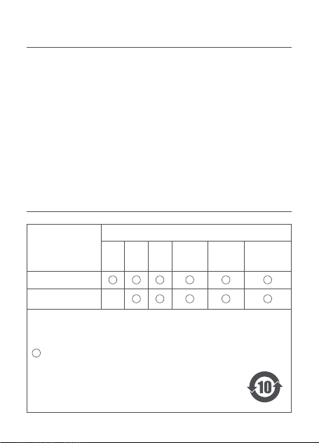
部件名称
有害物质
铅
(Pb)
汞
(Hg)
镉
(Cd)
六价铬
(Cr(VI))
多溴联苯
(PBB)
多溴二苯醚
(PBDE)
主机外壳及组件
主机内部电子组件
×
产品中有害物质的名称及含量
本表格依据 SJ/T 11364 的规定编制。
:表示该有害物质在该部件所有均质材料中的含量均在 GB/T 26572
规定的限量要求以下。
:表示该有害物质至少在该部件的某一均质材料中的含量超出了
GB/T 26572 规定的限量要求。
×
部件上的环保使用年限标识优先于产品上任何与之相冲突或
不同的环保使用期限标识。本产品所有环保使用期限是指在
产品说明书规定的使用条件下使用本产品不发生有毒有害物
质泄漏的安全年限。

12
电子邮件:
邮政编码:
3. 维修记录
受理日期 故障现象 处理方案 维修员签字
2. 产品资料
主机机身 SN 号:
三包凭证
1. 用户信息
姓 名:
联系地址:
电 话:

服务政策
本公司严格依据 《中华人民共和国消费者权益保护法》、《中华人民
共和国产品质量法》 为购买本公司产品的消费者提供三包服务。
详细的服务政策,请参考本公司官网售后服务政策栏内容:
http://www.70mai.com.cn/service/mainland
联系我们
官 网 :www.70mai.com.cn
电 话 :400-015-2399
制造商 :上海七十迈数字科技有限公司
地 址 :上海市闵行区紫星路 588 号 2 幢 2220 室
扫描右侧二维码关注 70 迈微信公众号
14
Nota: le figure del prodotto, degli accessori e dell’interfaccia utente
contenute nel manuale d’uso sono solo a scopo indicativo. A causa dei
miglioramenti , il prodotto effettivo e le funzioni del prodotto potrebbero
essere diverse.
Panoramica del prodotto
Prima di utilizzare il prodotto, leggere attentamente il presente
manuale e conservarlo in un posto sicuro.
Questo manuale si applica al modello Midrive OBD01 e al modello
Midrive OBD02 del 70mai OBD-
Ⅱ
Hardwire Kit.
Midrive OBD01
Midrive OBD02
Connettore
OBD
Connettore
OBD
Scatola del kit di
cablaggio
Scatola del kit di
cablaggio
Interruttore del kit di cablaggio
Interruttore del kit di cablaggio
Connettore di ricarica di tipo C
Connettore di ricarica USB
Luce spia
•
Verde: normale
•
Rosso: modalità
di protezione a
bassa tensione,
nessuna potenza
in uscita
Luce spia
•
Verde: normale
•
Rosso: modalità
di protezione a
bassa tensione,
nessuna potenza
in uscita

15
Passaggio 1: impostazione degli interruttori di tensione
e timer
Fare riferimento all’etichetta sulla scatola del kit di cablaggio e
impostare la protezione di bassa tensione e gli interruttori orari in
base alle proprie esigenze.
Installazione
Interruttore DIP:
posizione 1-2 per l’impostazione della protezione
di bassa tensione, posizione 3-5 per l’impostazione dell’orario di
lavoro. Ad esempio, se la tensione di protezione da impostare è
11,6 V e l’orario di lavoro è di 12 ore, gli interruttori devono essere
70mai OBD-
Ⅱ
Hardwire Kit × 1
Autoadesivo × 1
Elenco componenti
Manuale d’uso × 1
Impostazione della
protezione da bassa
tensione
Impostazioni orario
Impostazione della
tensione
1 2 3 4 5
Impostazioni
orario
11,6V/23,6 V
⬆ ⬆ ⬆ ⬆ ⬆
1 H
11,9 V/23,9 V
⬆ ⬇ ⬆ ⬆ ⬇
3 H
12,2 V/24,2 V
⬇ ⬆ ⬆ ⬇ ⬇
6 H
12,5 V/24,5 V
⬇ ⬇ ⬇ ⬇ ⬇
12 H
Interruttore DIP
ON:
⬆
OFF:
⬇
⬇ ⬇ ⬆
24 H
⬇ ⬆ ⬇
Sempre

16
Passaggio 2. Circuito di prova e segnale ACC
1. Assicurarsi che il veicolo sia spento e che l’alimentazione sia
scollegata. Individuare la porta OBD-
Ⅱ
del veicolo e collegare il
connettore OBD.
2. Inserire il connettore di ricarica del kit di cablaggio nella porta di
alimentazione della dash cam.
3. Avviare il motore dell’auto e attendere che la dash cam si
accenda.
4. Dopo l’accensione della dash cam, spegnere il motore e
rimuovere la chiave. Controllare se la dash cam si spegne o entra
in modalità di sospensione.
Per alcune auto, il segnale di spegnimento ACC verrà attivato
solo quando la portiera del conducente viene aperta dopo lo
spegnimento del motore. Alcuni modelli di auto attiveranno il
segnale di spegnimento ACC solo dopo che il motore è rimasto
spento per un determinato periodo di tempo.
Per tali auto, verificare se la dash cam si spegne o entra
in modalità di sospensione in seguito allo spegnimento
dell’alimentazione ACC.
5. Dopo che la dash cam si è spenta o è entrata in modalità di
sospensione, riavviare il motore e verificare se la dash cam si
accende automaticamente.
Se i passaggi precedenti possono essere eseguiti correttamente, il
test del circuito e del segnale ACC è superato.
Se il test non riesce, controllare i collegamenti dei cavi. Se i
collegamenti sono corretti ma il test non riesce, contattare il servizio
post-vendita per assistenza.
impostati su
↑↑↓↓↓
.
Sempre:
il kit di cablaggio sarà sempre in funzione,
indipendentemente dall’orario.
Impostazioni predefinite:
11,9 V/23,9 V, 24 H (dopo 24 ore, la
scatola del kit di cablaggio smetterà di alimentare la dash cam)

17
Prima di usare il dispositivo, leggere tutte le precauzioni per
garantire l’utilizzo corretto e in condizioni di sicurezza.
•
Chiedere a un tecnico professionista di eseguire l’installazione.
La nostra azienda non è responsabile per eventuali cortocircuiti
dell’alimentazione del veicolo e danni alla batteria o agli interni
del veicoli dovuti a un’installazione errata.
•
Le prestazioni di questo prodotto sono influenzate dall’affidabilità
della fonte di alimentazione del veicolo, della batteria del veicolo
e della dash cam. La nostra azienda non è responsabile per
eventuali perdite derivanti dal malfunzionamento di questo
prodotto a meno che non siano causate da problemi causati dalla
qualità del prodotto.
•
Alcuni veicoli non sono in grado di rilevare cambiamenti nei
segnali ACC quando il motore è acceso o spento. Per tali veicoli,
il kit di cablaggio non è in grado di trasmettere segnali ACC al
dispositivo principale. Ciò potrebbe causare la non disponibilità di
alcune funzioni.
•
Utilizzare questo prodotto solo per scopi legali.
Precauzioni
Passaggio 3: instradamento del cavo
1. Instradare il cavo del kit di cablaggio nella posizione della dash
cam. Avvolgere l’eventuale lunghezza in eccesso del cavo, ma non
tagliarlo. Tagliare il cavo gli impedirà di fornire alimentazione e di
trasmettere il segnale ACC alla dash cam.
2. Applicare l’adesivo al lato della scatola del kit di cablaggio
contrassegnato con “POWER” e fissalo in una posizione che
consenta la regolazione.
Nota: la porta OBD-
Ⅱ
si trova solitamente sotto il volante o accanto
alla leva del cambio. Se non si riesce a individuare la porta OBD-
Ⅱ
, fare
riferimento al manuale utente del veicolo o consultare un rivenditore
automobilistico.
18
Prodotto: 70mai OBD-
Ⅱ
Hardwire Kit
Modello: Midrive OBD01, Midrive OBD02
Ingresso: CC da 12 V a 30 V
Uscita: CC 5 V 2,4 A
Specifiche
Il produttore dichiara che la presente apparecchiatura è
conforme alle direttive e alle norme europee applicabili nonché
alle relative modifiche. Il testo completo della dichiarazione
di conformità UE è disponibile al seguente indirizzo Internet:
https://help.70mai.asia/1193.html
Informazioni sulla conformità a normative e standard
Tutti i prodotti contrassegnati da questo simbolo sono rifiuti di
apparecchiature elettriche ed elettroniche (RAEE in base alla
direttiva 2012/19/UE) che non devono essere smaltiti assieme
a rifiuti domestici non differenziati. Al contrario, è necessario
proteggere l’ambiente e la salute umana consegnando i rifiuti
a un punto di raccolta autorizzato al riciclaggio di rifiuti di
apparecchiature elettriche ed elettroniche, predisposto dalla pubblica
amministrazione o dalle autorità locali. Lo smaltimento e il riciclaggio
corretti aiutano a prevenire conseguenze potenzialmente negative per
l’ambiente e la salute umana. Contattare l’installatore o le autorità locali per
ulteriori informazioni sulla sede e per i termini e le condizioni di tali punti di
raccolta.
Assistenza: [email protected]
Per altre informazioni, andare su www.70mai.com
Produttore: 70mai Co., Ltd.
Indirizzo: Room 2220, Building 2, n. 588 Zixing Road, Minhang
District, Shanghai, China
19
Remarque : les illustrations du produit, des accessoires et de l’interface
utilisateur figurant dans le mode d’emploi sont fournies à titre indicatif
uniquement. Le produit et les fonctions réels peuvent varier en raison des
améliorations apportées au produit.
Présentation du produit
Lisez attentivement ce manuel avant d’utiliser le produit et
conservez-le en lieu sûr.
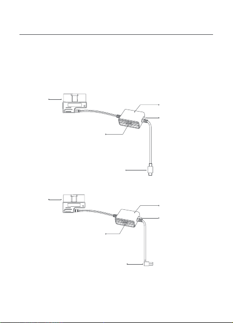
Ce manuel concerne les modèles Midrive OBD01 et Midrive OBD02
du kit de câblage 70mai OBD-
Ⅱ
.
Midrive OBD01
Midrive OBD02
Connecteur
OBD
Connecteur
OBD
Boîtier du kit de
câblage
Boîtier du kit de
câblage
Interrupteur du kit de câblage
Interrupteur du kit de câblage
Connecteur de charge de type C
Connecteur de charge USB
Témoin lumineux
•
Vert : Normal
•
Rouge : Mode de
protection basse
tension, pas de
puissance de
sortie
Témoin lumineux
•
Vert : Normal
•
Rouge : Mode de
protection basse
tension, pas de
puissance de
sortie

20
Étape 1 : Réglage des interrupteurs de tension et à
minuterie
Reportez-vous à l’étiquette apposée sur le boîtier du kit de câblage
et réglez la protection basse tension et les interrupteurs à minuterie
en fonction de vos besoins.
Installation
Commutateur DIP :
Positions 1-2 pour le réglage de la protection
basse tension, positions 3-5 pour le réglage de la durée de
fonctionnement. Par exemple, s’il faut définir une tension de
protection de 11,6 V et une durée de fonctionnement de 12 heures,
il convient de régler les interrupteurs sur
↑↑↓↓↓
.
Kit de câblage 70mai OBD-
Ⅱ
× 1
Autocollant adhésif × 1
Contenu de l’emballage
Mode d’emploi × 1
Réglage de la protection
basse tension
Réglage de la durée
Réglage de la
tension
1 2 3 4 5
Réglage de la
durée
11,6 V/23,6 V
⬆ ⬆ ⬆ ⬆ ⬆
1 H
11,9 V/23,9 V
⬆ ⬇ ⬆ ⬆ ⬇
3 H
12,2 V/24,2 V
⬇ ⬆ ⬆ ⬇ ⬇
6 H
12,5 V/24,5 V
⬇ ⬇ ⬇ ⬇ ⬇
12 H
Commutateur DIP
Activé :
⬆
Désactivé :
⬇
⬇ ⬇ ⬆
24 H
⬇ ⬆ ⬇
Toujours

21
Étape 2 : Test du circuit et du signal ACC
1. Assurez-vous que le véhicule est à l’arrêt et que le contact est
coupé. Localisez le port OBD-
Ⅱ
du véhicule et branchez-y le
connecteur OBD.
2. Insérez le connecteur de charge du kit de câblage dans le port
d’alimentation de la caméra embarquée.
3. Mettez le contact du véhicule et attendez que la caméra
embarquée s’allume.
4. Une fois la caméra embarquée allumée, coupez le moteur et
retirez la clé du contact. Vérifiez si la caméra embarquée s’éteint
ou se met en mode veille.
Pour certains véhicules, le signal de mise hors tension de l’ACC
ne se déclenche que lorsque la porte du siège du conducteur
s’ouvre après l’arrêt du moteur. Certains modèles de véhicule
ne déclenchent le signal de mise hors tension de l’ACC qu’après
l’arrêt prolongé du moteur.
Pour ces véhicules, vérifiez si la caméra embarquée s’éteint ou
passe en mode veille après la mise hors tension de l’ACC.
5. Lorsque la caméra embarquée s’éteint ou entre en mode veille,
remettez le contact du véhicule et vérifiez si la caméra embarquée
s’allume automatiquement.
Si les étapes ci-dessus peuvent être effectuées correctement, cela
signifie que le test du circuit et du signal ACC est réussi.
Si le test échoue, vérifiez les branchements des câbles. Si les
branchements sont corrects mais que le test échoue, contactez le
service après-vente pour obtenir de l’aide.
Toujours :
Le kit de câblage fonctionnera toujours
indépendamment de la durée.
Paramètres par défaut :
11,9 V/23,9 V, 24 H (après 24 heures, le
boîtier du kit de câblage cessera d’alimenter la caméra embarquée)

22
Avant d’utiliser cet appareil, lisez toutes les précautions pour
garantir une utilisation correcte et sûre.
•
Veuillez confier l’installation à un technicien professionnel.
Notre société n’est pas responsable des courts-circuits de
l’alimentation électrique du véhicule et des dommages causés
à la batterie ou à l’habitacle du véhicule dus à une installation
incorrecte.
•
Les performances de ce produit sont affectées par la fiabilité de
la source d’alimentation du véhicule, de la batterie du véhicule et
de la caméra embarquée. Notre société n’est pas responsable des
pertes résultant du dysfonctionnement de ce produit, sauf si elles
sont causées par des problèmes de qualité du produit.
•
Certains véhicules ne parviennent pas à détecter les
changements des signaux ACC lorsque le contact est mis ou
coupé. Pour ces véhicules, le kit de câblage n’est pas en mesure
de transmettre les signaux ACC à l’appareil principal. Cela peut
entraîner l’indisponibilité de certaines fonctions.
•
Veuillez utiliser ce produit à des fins légales uniquement.
Précautions
Étape 3 : Acheminement du câble
1. Acheminez le câble du kit de câblage jusqu’à l’emplacement
de la caméra embarquée. Enroulez toute longueur de câble
excédentaire, mais ne coupez pas le câble. Couper le câble
l’empêcherait de fournir l’alimentation et de transmettre le signal
ACC à la caméra embarquée.
2. Collez l’autocollant sur le côté du boîtier du kit de câblage
étiqueté « POWER » et fixez-le dans une position permettant un
réglage.
Remarque : Le port OBD-
Ⅱ
se situe généralement sous le volant ou à
côté du levier de vitesses. Si vous ne trouvez pas le port OBD, reportez-
vous au manuel d’utilisation du véhicule ou consultez un concessionnaire
automobile.
23
Produit : Kit de câblage 70mai OBD-
Ⅱ
Modèle : Midrive OBD01, Midrive OBD02
Entrée : 12 V à 30 V CC
Sortie : 5 V CC 2,4 A
Spécifications
Le fabriquant déclare par le présent document que le
présent équipement est conforme aux directives et normes
européennes applicables, ainsi qu’à leurs amendements.
L’intégralité de la déclaration de conformité pour l’UE est
disponible à l’adresse suivante: https://help.70mai.asia/1193.html
Informations sur la conformité et les réglementations
Tous les produits portant ce symbole deviennent des déchets
d’équipements électriques et électroniques (DEEE dans la
Directive européenne2012/19/UE) qui ne doivent pas être
mélangés aux déchets ménagers non triés. Vous devez
contribuer à la protection de l’environnement et de la santé
humaine en apportant l’équipement usagé à un point de
collecte dédié au recyclage des équipements électriques et électroniques,
agréé par le gouvernement ou les autorités locales. Le recyclage et la
destruction appropriés permettront d’éviter tout impact potentiellement
négatif sur l’environnement et la santé humaine. Contactez l’installateur
ou les autorités locales pour obtenir plus d’informations concernant
l’emplacement ainsi que les conditions d’utilisation de ce type de point de
collecte.
Service après-vente : [email protected]
Pour de plus amples informations, consultez le site www.70mai.com
Fabricant : 70mai Co., Ltd.
Adresse : Room 2220, Building 2, No. 588 Zixing Road, Minhang
District, Shanghai, Chine
24
Hinweis: Die Abbildungen des Produkts, des Zubehörs und der
Benutzeroberfläche im Benutzerhandbuch dienen nur als Referenz.
Das tatsächliche Produkt und die Funktionen können aufgrund von
Weiterentwicklungen des Produkts variieren.
Produktübersicht
Bitte lesen Sie dieses Handbuch sorgfältig durch, bevor Sie das
Produkt verwenden, und bewahren Sie es an einem sicheren Ort
auf.
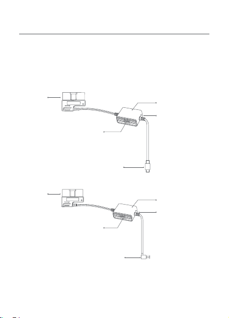
Diese Anleitung bezieht sich auf das Modell Midrive OBD01 und das
Modell Midrive OBD02 des 70mai OBD-
Ⅱ
Hardwire Kit.
Midrive OBD01
Midrive OBD02
OBD-
Anschluss
OBD-
Anschluss
Box des Hardwire
Kit
Box des Hardwire
Kit
Schalter am Hardwire Kit
Schalter am Hardwire Kit
Type-C-Ladestecker
USB-Ladestecker
Anzeige
•
Grün: Normal
•
Rot: Niederspan-
nungsschutzmo-
dus, keine
Leistungsabgabe
Anzeige
•
Grün: Normal
•
Rot: Niederspan-
nungsschutzmo-
dus, keine
Leistungsabgabe

25
Schritt 1: Einstellen der Spannung und Zeit-Schalter
Lesen Sie das Etikett auf der Box des Hardwire Kit und stellen Sie
den Niederspannungsschutz und die Zeit-Schalter nach Bedarf ein.
Installation
DIP-Schalter:
Mit Schalter 1-2 stellen Sie den
Niederspannungsschutz, mit 3-5 die Betriebsdauer ein. Für eine
Schutzspannung von 11,6 V und eine Betriebsdauer von 12 Stunden
müssen die Schalter auf
↑↑↓↓↓
eingestellt sein.
Immer:
Das Hardwire Kit ist unabhängig von der Dauer immer in
Betrieb.
Standardeinstellungen:
11,9 V/23,9 V, 24 Std. (Nach 24 Stunden
wird die Dashcam von der Box des Hardwire Kit nicht mehr mit
Strom versorgt)
70mai OBD-
Ⅱ
Hardwire Kit × 1
Aufkleber × 1
Lieferumfang
Benutzerhandbuch × 1
Einstellung für
Niederspannungsschutz
Zeiteinstellung
Spannungseinstellung 1 2 3 4 5 Zeiteinstellung
11,6 V/23,6 V
⬆ ⬆ ⬆ ⬆ ⬆
1 Std.
11,9 V/23,9 V
⬆ ⬇ ⬆ ⬆ ⬇
3 Std.
12,2 V/24,2 V
⬇ ⬆ ⬆ ⬇ ⬇
6 Std.
12,5 V/24,5 V
⬇ ⬇ ⬇ ⬇ ⬇
12 Std.
DIP-Schalter
EIN:
⬆
AUS:
⬇
⬇ ⬇ ⬆
24 Std.
⬇ ⬆ ⬇
Immer

26
Schritt 2: Testen von Stromkreis und ACC-Signal
1. Vergewissern Sie sich, dass das Fahrzeug ausgeschaltet und die
Stromversorgung unterbrochen ist. Suchen Sie den OBD-
Ⅱ
-
Anschluss am Fahrzeug und stecken Sie den OBD-Stecker hinein.
2. Stecken Sie den Ladestecker des Hardwire Kit in den
Stromversorgungsanschluss an der Dashcam ein.
3. Starten Sie den Motor des Fahrzeugs und warten Sie, bis sich die
Dashcam einschaltet.
4. Wenn die Dashcam eingeschaltet ist, schalten Sie den Motor aus
und ziehen den Schlüssel ab. Prüfen Sie, ob sich die Dashcam
ausschaltet oder in den Energiesparmodus schaltet.
Bei manchen Fahrzeugen wird das ACC-Ausschaltsignal nur
ausgelöst, wenn die Fahrertür nach dem Ausschalten des
Motors geöffnet wird. Bei manchen Fahrzeugen wird das ACC-
Ausschaltsignal nur ausgelöst, wenn der Motor eine bestimmte
Zeitlang ausgeschaltet ist.
Prüfen Sie bei solchen Fahrzeugen, ob sich die Dashcam
ausschaltet oder in den Energiesparmodus schaltet, nachdem die
ACC-Stromversorgung ausgeschaltet wurde.
5. Wenn sich die Dashcam ausgeschaltet hat oder in den
Energiesparmodus gewechselt ist, starten Sie den Motor wieder
und prüfen, ob sich die Dashcam automatisch einschaltet.
Wenn die obigen Schritte ordnungsgemäß verlaufen, ist der Test
von Stromkreis und ACC-Signal erfolgreich abgeschlossen.
Wenn der Test fehlschlägt, überprüfen Sie bitte die
Kabelverbindungen. Wenn die Verbindungen in Ordnung sind
und der Test dennoch fehlschlägt, wenden Sie sich bitte an den
Kundendienst.
Hinweis: Der OBD-
Ⅱ
-Anschluss befindet sich in der Regel unter dem
Lenkrad oder in der Nähe der Gangschaltung. Wenn Sie den OBD-
Ⅱ
-
Anschluss nicht finden können, ziehen Sie die Betriebsanleitung des
Fahrzeugs heran oder wenden sich an einen Autohändler.

27
Lesen Sie vor Inbetriebnahme des Geräts alle
Sicherheitsmaßnahmen durch, um den korrekten und sicheren
Gebrauch zu gewährleisten.
•
Wenden Sie sich für die Installation bitte an einen Fachmann.
Unser Unternehmen haftet nicht für Kurzschlüsse in der
Stromversorgung des Fahrzeugs oder Schäden an der
Fahrzeugbatterie oder im Innenraum, die auf eine unsachgemäße
Installation zurückzuführen sind.
•
Die Leistung dieses Produkts hängt von der Funktionstüchtigkeit
der Stromquelle, der Autobatterie und der Dashcam ab.
Unser Unternehmen haftet nicht für Schäden aufgrund einer
Fehlfunktion dieses Produkts, es sei denn, es handelt sich um
Probleme mit der Produktqualität.
•
Manche Fahrzeuge können ACC-Signaländerungen beim Ein-
oder Ausschalten des Motors nicht erkennen. Bei solchen
Fahrzeugen können mit dem Hardwire Kit keine ACC-Signale an
das Hauptgerät übertragen werden. Dadurch stehen bestimmte
Funktionen nicht zur Verfügung.
•
Bitte verwenden Sie dieses Produkt nur für gesetzlich zulässige
Zwecke.
Vorsichtsmaßnahmen
Schritt 3: Kabelführung
1. Verlegen Sie das Kabel des Hardwire Kit zur Position der
Dashcam. Wickeln Sie überschüssiges Kabel auf, aber schneiden
Sie das Kabel nicht ab. Wenn Sie das Kabel durchtrennen, liefert
es keinen Strom und überträgt das ACC-Signal nicht an die
Dashcam.
2. Bringen Sie den Aufkleber an der mit „POWER“ beschrifteten Seite
der Box des Hardwire Kit so an, dass Einstellungen möglich sind.

28
Produkt: 70mai OBD-
Ⅱ
Hardwire Kit
Modell: Midrive OBD01, Midrive OBD02
Eingang: 12 V bis 30 V Gleichstrom
Ausgang: 5 V Gleichstrom 2,4 A
Technische Daten
Informationen zur Einhaltung gesetzlicher
Vorschriften
Das Symbol auf dem Produkt oder der Verpackung bedeutet,
dass das Produkt einer getrennten Erfassung für elektrische
und elektronische Geräte zugeführt werden muss und nicht
über den normalen Haushaltsabfall entsorgt werden darf.
Bitte entnehmen Sie Batterien und Lampen, die nicht vom
Gerät umschlossen sind, vor der Abgabe aus dem Gerät und
entsorgen diese über die offiziellen Sammelstellen für Batterien und
Lampen.
Beim Kauf eines neuen Elektrogerätes können Sie beim Vertreiber ein
gleichartiges Altgerät unentgeltlich zurückgeben. Elektrogeräte mit einer
Kantenlänge von maximal 25 cm können unentgeltlich bei Vertreibern von
Elektro- und Elektronikgeräten mit einer Verkaufsfläche von mindestens
400 m² sowie größeren Supermärkten abgegeben werden, ohne dass
ein Neugerät erworben werden muss. Größere Elektrogeräte können
kostenlos bei kommunalen Wertstoffhöfen abgegeben werden.
Durch die korrekte Entsorgung tragen Sie dazu bei, negative
Auswirkungen auf die Umwelt und die menschliche Gesundheit zu
vermeiden, die durch unsachgemäße Erfassung und Behandlung von
Elektroaltgeräten entstehen können.
Bitte löschen Sie sämtliche personenbezogenen Daten auf dem Gerät,
bevor Sie es entsorgen.
Für weitere Informationen kontaktieren sie bitte Ihre
Kommunalverwaltung, Ihren örtlichen Abfallentsorger oder das Geschäft,
in dem Sie das Produkt erworben haben.

29
Der Hersteller erklärt hiermit, dass dieses Produkt den
betreffenden Bestimmungen und europäischen Normen sowie
deren überarbeiteten Fassungen entspricht. Der vollständige
Wortlaut der EU-Konformitätserklärung ist unter der folgenden
Internetadresse abrufbar: https://help.70mai.asia/1193.html
Service: [email protected]
Weitere Informationen finden Sie unter www.70mai.com.
Hersteller: 70mai Co., Ltd.
Adresse: Room 2220, Building 2, No. 588 Zixing Road, Minhang
District, Shanghai, China

30
Nota: las ilustraciones del producto, los accesorios y la interfaz del usuario
que aparecen en el manual del usuario solo sirven como referencia. El
producto actual y sus funciones pueden variar debido a mejoras de los
productos.
Descripción general del producto
Por favor, lea este manual con atención antes de utilizar el producto
y consérvelo en un lugar seguro.
Este manual se aplica al modelo Midrive OBD01 y al modelo Midrive
OBD02 del kit de cableado OBD-
Ⅱ
de 70mai.
Midrive OBD01
Midrive OBD02
Conector
OBD
Conector
OBD
Caja del kit de
cableado
Caja del kit de
cableado
Interruptor del kit de cableado
Interruptor del kit de cableado
Conector de carga de tipo C
Conector de carga USB
Indicador luminoso
•
Verde: Normal
•
Rojo: Modo de
protección de
baja tensión,
sin salida de
potencia
Indicador luminoso
•
Verde: Normal
•
Rojo: Modo de
protección de
baja tensión,
sin salida de
potencia

31
Paso 1: Ajuste de los interruptores de tensión y del
temporizador
Consulte la etiqueta de la caja del kit de cableado y ajuste la
protección contra baja tensión y los temporizadores según sus
necesidades.
Instalación
Interruptor DIP:
Posición 1-2 para el ajuste de la protección contra
baja tensión, posición 3-5 para el ajuste del tiempo de trabajo.
Por ejemplo, si la tensión de protección a ajustar es de 11,6 V y el
tiempo de trabajo es de 12 horas, los interruptores deben ajustarse
a
↑↑↓↓↓
.
Kit de cableado OBD-
Ⅱ
de 70mai × 1
Etiqueta adhesiva × 1
Volumen de suministro
Manual del usuario × 1
Ajuste de protección contra
baja tensión
Ajuste de la hora
Ajuste de la
tensión
1 2 3 4 5
Ajuste de la
hora
11,6 V/23,6 V
⬆ ⬆ ⬆ ⬆ ⬆
1 H
11,9 V/23,9 V
⬆ ⬇ ⬆ ⬆ ⬇
3 H
12,2 V/24,2 V
⬇ ⬆ ⬆ ⬇ ⬇
6 H
12,5 V/24,5 V
⬇ ⬇ ⬇ ⬇ ⬇
12 H
Interruptor DIP
ENCENDIDO:
⬆
APAGADO:
⬇
⬇ ⬇ ⬆
24 H
⬇ ⬆ ⬇
Siempre

32
Paso 2. Circuito de pruebas y señal ACC
1. Asegúrese de que el vehículo esté apagado y la alimentación
desconectada. Localice el puerto OBD-
Ⅱ
del vehículo y enchufe el
conector OBD en él.
2. Inserte el conector de carga del kit de cableado en el puerto de
alimentación de la cámara de salpicadero.
3. Arranque el motor del coche y espere a que se encienda la
cámara de salpicadero.
4. Cuando se encienda la cámara de salpicadero, apague el motor y
quite la llave. Compruebe si la cámara de salpicadero se apaga o
entra en modo reposo.
En algunos automóviles, la señal de apagado del ACC solo
se activa cuando se abre la puerta del asiento del conductor
después de apagar el motor. Algunos modelos de coche solo
activan la señal de apagado del ACC después de que el motor
haya estado apagado durante un cierto período de tiempo.
Para este tipo de coches, compruebe si la cámara de salpicadero
se apaga o entra en modo de reposo después de apagar el ACC.
5. Después de que la cámara de salpicadero se apague o entre en
modo de reposo, vuelva a arrancar el motor y compruebe si la
cámara de salpicadero se enciende automáticamente.
Si los pasos anteriores se pueden realizar correctamente, se supera
la comprobación de la señal ACC y del circuito.
Si la prueba falla, compruebe las conexiones de los cables. Si las
conexiones son correctas pero la prueba falla, póngase en contacto
con el servicio postventa.
Siempre:
El kit de cableado siempre funcionará
independientemente de la hora.
Ajustes por defecto:
11,9 V/23,9 V, 24 H (Después de 24 horas,
la caja del kit de cableado dejará de alimentar la cámara de
salpicadero)

33
Antes de usar el dispositivo, lea todas las precauciones para
garantizar un uso correcto y seguro.
•
Solicite a un técnico profesional que realice la instalación.
Nuestra empresa no se hace responsable de los cortocircuitos en
la fuente de alimentación del coche ni de los daños en la batería o
el interior del coche debidos a una instalación incorrecta.
•
El rendimiento de este producto depende de la fiabilidad de la
fuente de alimentación del coche, la batería del coche y la cámara
de salpicadero. Nuestra empresa no se hace responsable de las
pérdidas derivadas del mal funcionamiento de este producto, a
menos que se deba a problemas de calidad del producto.
•
Algunos coches no pueden detectar cambios en las señales ACC
cuando el motor está encendido o apagado. En estos coches, el
kit de cableado no puede transmitir señales ACC al dispositivo
principal. Esto puede provocar que algunas funciones no estén
disponibles.
•
Utilice este producto únicamente con fines legales.
Precauciones
Nota: El puerto OBD-
Ⅱ
suele estar situado debajo del volante o junto a
la palanca de cambios. Si no puede localizar el puerto OBD-
Ⅱ
, consulte
el manual de usuario del coche o consulte a un concesionario de
automóviles.
Paso 3: Enrutamiento del cable
1. Dirija el cable del kit de cableado hasta la ubicación de la cámara
de salpicadero. Enrolle el cable sobrante, pero no lo corte. Cortar
el cable impedirá que suministre corriente y transmita la señal
ACC a la cámara de salpicadero.
2. Coloque la etiqueta adhesiva en el lateral de la caja del kit de
cableado con la etiqueta “POWER” y fíjela en una posición que
permita el ajuste.
34
Producto: Kit de cableado OBD-
Ⅱ
de 70mai
Modelo: Midrive OBD01, Midrive OBD02
Entrada: CC 12 V a 30 V
Salida: CC 5 V 2,4 A
Especificaciones
El fabricante, por la presente, declara que el equipo cumple
con las Directivas y Normas Europeas aplicables y las
enmiendas. Encontrará el texto completo de la declaración de
conformidad de la UE en esta dirección de Internet: https://
help.70mai.asia/1193.html
Información sobre el cumplimiento de la normativa
Todos los productos que llevan este símbolo son residuos
de aparatos eléctricos y electrónicos (RAEE según la directiva
2012/19/UE) que no deben mezclarse con residuos domésticos
sin clasificar. En su lugar, debe proteger la salud humana y el
medio ambiente entregando sus equipos de desecho a un
punto de recogida para el reciclaje de residuos de equipos
eléctricos y electrónicos, designado por el gobierno o las autoridades
locales. La eliminación y el reciclado correctos ayudarán a evitar posibles
consecuencias negativas para el medio ambiente y la salud humana.
Póngase en contacto con el instalador o con las autoridades locales para
obtener más información sobre la ubicación y las condiciones de dichos
puntos de recogida.
Servicio: [email protected]
Para más información, vaya a www.70mai.com
Fabricante: 70mai Co., Ltd.
Dirección: Room 2220, Building 2, No. 588 Zixing Road, Minhang
District, Shanghai, China
35
ご注意:ユーザーマニュアルで使用されている製品、付属品、およびユーザ
ーインターフェイスの図は参照のみを目的としています。製品の機能および
仕様変更が行われた場合、実際の製品と機能および仕様が異なることがあり
ます。
製品概要
本製品を使用する前に、このマニュアルをよくお読みください。こ
のマニュアルは大切に保管してください。
このマニュアルは、70mai OBD-Ⅱ Hardwire Kit のモデル Midrive
OBD01、モデル Midrive OBD02 に適用されます。
Midrive OBD01
Midrive OBD02
OBD
コネクタ
Hardwire Kit
ボックス
Hardwire Kit
ボックス
Hardwire Kit スイッチ
Type-C 充電コネクタ
OBD
コネクタ
インジケータ―ラ
イト
•
緑:通常
•
赤:低電圧保護
モード、電源出
力なし
インジケータ―ラ
イト
•
緑:通常
•
赤:低電圧保護
モード、電源出
力なし
Hardwire Kit スイッチ
USB 充電コネクタ

36
70mai OBD-Ⅱ Hardwire Kit × 1
粘着シール× 1
低電圧保護設定 タイム設定
電圧設定 1 2 3 4 5 タイム設定
11.6V/23.6V ⬆ ⬆ ⬆ ⬆ ⬆ 1 時間
11.9V/23.9V ⬆ ⬇ ⬆ ⬆ ⬇ 3 時間
12.2V/24.2V ⬇ ⬆ ⬆ ⬇ ⬇ 6 時間
12.5V/24.5V ⬇ ⬇ ⬇ ⬇ ⬇ 12 時間
ディップスイッチ
オン:⬆ オフ:⬇
⬇ ⬇ ⬆ 24 時間
⬇ ⬆ ⬇ 常時
手順1:電圧とタイマースイッチの設定
Hardwire Kit ボックスのラベルを参照し、必要に応じて低電圧保護と
タイムスイッチを設定します。
取付方法
ディップスイッチ:低電圧保護の設定は位置1~2、動作時間設定は
位置3~5。たとえば、設定する保護電圧が11.6V、作動時間が12時間
の場合、スイッチは↑↑↓↓↓に設定してください。
常時:Hardwire Kitは時間に関わらず常に作動します。
デフォルト設定:11.9V/23.9V、24時間(24時間後、Hardwire Kitボッ
クスはドライブレコーダーへの電力供給を停止します)
ユーザーマニュアル× 1
梱包内容

37
手順2.回路とACC信号のテスト
1. 車両の電源がオフになっており、電源から切断されていることを
確認します。車両の OBD-Ⅱポートを探して、OBD コネクタを差し
込みます。
2. Hardwire Kit の充電コネクタをメドライブレコーダーの電源ポートに
差し込みます。
3. 車両のエンジンを始動し、ドライブレコーダーがオンになるまで待
ちます。
4. ドライブレコーダーの電源が入ったら、エンジンを停めてキーを抜
きます。ドライブレコーダーの電源がオフになっていること、また
はスリープモードになっていることを確認します。
一部の車両では、エンジンを停止した後に運転席のドアが開いたと
きに ACC 電源 OFF 信号が送信されます。一部の車両モデルでは、
ACC 電源 OFF 信号はエンジンが停止した後に一定時間が経過した後
にしか送信されません。
そのような車両の場合、ドライブレコーダーの電源がオフになって
いること、またはスリープモードになっていることを確認します。
5. ドライブレコーダーの電源がオフになるか、デバイスがスリープモ
ードになった後、エンジンを再度始動してドライブレコーダーが自
動的にオンになることを確認します。
上記の手順を正しく実施できる場合、回路と ACC 信号テストは完了
です。
テストが失敗した場合は、ケーブルの接続状況を確認してください。
接続が正しくても、正常に作動しない場合、アフターサービスにご
連絡ください。
ご注意:通常、OBD-Ⅱポートはハンドルの下、またはギアシフトの横にあ
ります。OBD-Ⅱポートが見つからない場合は、車両のユーザーマニュアル
を参照するか、自動車販売店にご相談ください。

38
手順3:ケーブルの配線
1. Hardwire Kit ケーブルをドライブレコーダーの位置まで配線しま
す。長くて余分なケーブルは、切断しないように巻いてください。
ケーブルを切断すると、電源供給とドライブレコーダーへの ACC
信号の送信ができなくなります。
2. 「電源」と記載された Hardwire Kit ボックスの側面に粘着シール
を貼り、調整できる位置に固定します。
ご使用になる前に、すべての注意事項を読み、正しく安全に使用で
きるようにしてください。
•取り付け作業は専門技術者に依頼してください。
弊社は、不適切な取り付けに起因する車両電源の短絡、車載バッ
テリーまたはインテリアの損傷に対する責任を追いません。
•本製品の性能は、車両電源、車載バッテリー、およびドライブレ
コーダーの信頼性に左右されます。弊社は、製品品質の問題によ
って生じた場合を除き、本製品の誤動作の結果として生じるいか
なる損害にも責任を追いません。
•一部の車両では、エンジンを停止または始動したときのACC信号
の変化を検出できないことがあります。そのような車両では、
Hardwire KitはACC信号をメインデバイスに送信できません。その
結果、特定の機能が使用できないことがあります。
•本製品を違法な目的で使用しないでください。
注意事項
製品: 70mai OBD-Ⅱ Hardwire Kit
モデル:Midrive OBD01、Midrive OBD02
入力:DC12V~30V
出力: DC5V 2.4A
カスタマーサポート: [email protected]
詳細情報は、www.70mai.com/ja/をご参照ください。
製造業者: 70mai Co., Ltd.
住所: 中国上海閔行区紫星路588号2号館2220室
仕様
39
หมายเหตุ: รูปภาพต่าง ๆ ของผลิตภัณฑ์ อุปกรณ์เสริม และอินเตอร์เฟสผู้ใช
้
งานท
ี
่
ปรากฏอยู่ในคู่มือการใช
้
งานฉบับนี
้
มีไว้เพื
่
อวัตถุประสงค์ด้านการอ้างอิงเท
่
านั
้
น
การเสริมประสิทธิภาพให้แก่ผลิตภัณฑ์ อาจจะทำาให้ผลิตภัณฑ์และฟังก์ช
ั
่
นการใช
้
งานจริง
มีลักษณะท
ี
่
แตกต่างออกไปได้
ภาพรวมของผลิตภัณฑ์
ก่อนท
ี
่
จะเริ
่
มใช
้
งานผลิตภัณฑ์ โปรดอ่านคู่มือฉบับนี
้
ด้วยความระมัดระวัง
และโปรดจัดเก็บคู่มือฉบับนี
้
ไว้ในสถานท
ี
่
ท
ี
่
มีความปลอดภัย
คู่มือฉบับนี
้
จะใช
้
กับรุ่น Midrive OBD01 และรุ่น Midrive OBD02 ของ 70mai
OBD-
Ⅱ
Hardwire Kit
Midrive OBD01
Midrive OBD02
ขั
้
วต่อ OBD
ขั
้
วต่อ OBD
กล่อง Hardwire Kit
กล่อง Hardwire Kit
สวิตช
์
Hardwire Kit
สวิตช
์
Hardwire Kit
ขั
้
วต่อสำาหรับชาร์จชนิด Type-C
ขั
้
วต่อสำาหรับชาร์จชนิด USB
ไฟแสดงสถานะ
•
สีเขียว: ปกติ
•
สีแดง: โหมด
ป้องกันแรงดัน
ไฟฟ้าต
่
ำา, ไม่มี
ไฟฟ้าขาออก
ไฟแสดงสถานะ
•
สีเขียว: ปกติ
•
สีแดง: โหมด
ป้องกันแรงดัน
ไฟฟ้าต
่
ำา, ไม่มี
ไฟฟ้าขาออก

40
ขั
้
นตอนที
่
1: การตั
้
งค่าสวิตช
์
แรงดันไฟฟ้าและตั
้
งเวลา
โปรดอ้างอิงป้ายบนกล่อง Hardwire Kit และตั
้
งค่าสวิตช
์
การป้องกันแรงดัน
ไฟฟ้าต
่
ำาและเวลาตามท
ี
่
ต้องการ
การติดตั
้
ง
สวิตช
์
DIP: ตำาแหน่ง 1-2 มีไว้สำาหรับการตั
้
งค่าป้องกันแรงดันไฟฟ้าต
่
ำา
ส่วนตำาแหน่ง 3-5 มีไว้สำาหรับการตั
้
งค่าเวลาการทำางาน ตัวอย่างเช
่
น หากตั
้
งค่า
การป้องกันแรงดันไฟฟ้าต
่
ำาไว้ท
ี
่
11.6 โวลต์ และเวลาการทำางานอยู่ท
ี
่
12 ช
ั
่
วโมง
ควรตั
้
งค่าสวิตช
์
นี
้
ไว้ที
่
↑↑↓↓↓
ตลอดเวลา: Hardwire Kit จะทำางานตลอดเวลา
ค่าเริ
่
มต้น: 11.9 โวลต์ / 23.9 โวลต์, 24 ชม. (หลังจากผ่านไป 24 ชม.
กล่อง Hardwire Kit จะหยุดจ่ายกระแสไฟฟ้าให้กับแดชแคม
70mai OBD-
Ⅱ
Hardwire Kit × 1 ชุด
สติกเกอร์กาว × 1
รายการช
ิ
้
นส่วน
คู่มือการใช
้
งาน 1 ฉบับ
การตั
้
งค่าป้ องกันแรงดันไฟฟ้าต
่
ำา การตั
้
งเวลา
การตั
้
งค่าแรงดันไฟฟ้า 1 2 3 4 5 การตั
้
งเวลา
11.6 โวลต์ / 23.6 โวลต์
⬆ ⬆ ⬆ ⬆ ⬆
1 ชม.
11.9 โวลต์ / 23.9 โวลต์
⬆ ⬇ ⬆ ⬆ ⬇
3 ชม.
12.2 โวลต์ / 24.2 โวลต์
⬇ ⬆ ⬆ ⬇ ⬇
6 ชม.
12.5 โวลต์ / 24.5 โวลต์
⬇ ⬇ ⬇ ⬇ ⬇
12 ชม.
สวิตช
์
DIP
เปิ ด:
⬆
ปิ ด:
⬇
⬇ ⬇ ⬆
24 ชม.
⬇ ⬆ ⬇
ตลอดเวลา

41
ขั
้
นตอนที
่
2 วงจรการทดสอบและสัญญาณ ACC
1. ตรวจสอบให้แน่ใจว่าดับเครื
่
องยนต์และตัดการเช
ื
่
อมต่อกระแสไฟฟ้าแล้ว
หาช
่
องเสียบ OBD-
Ⅱ
ของรถและเสียบขั
้
วต่อ OBD เข้าไป
2. เสียบขั
้
วต่อสำาหรับชาร์จของ Hardwire Kit เข้ากับช
่
องเสียบสายไฟของ
แดชแคม
3. สตาร์ทรถแล้วรอจนกระท
ั
่
งแดชแคมเปิดทำางาน
4. หลังจากแดชแคมเปิดทำางานแล้ว ให้ดับเครื
่
องยนต์และดึงกุญแจออก
ตรวจสอบว่าแดชแคมปิดทำางานหรือเข้าสู่โหมด Sleep หรือไม่
สำาหรับรถยนต์บางรุ่น สัญญาณการปิด ACC จะถูกกระตุ้นการทำางาน
เมื
่
อเปิดประตู ฝั
่
งคนขับหลังจากดับเครื
่
องยนต์แล้วเท
่
านั
้
น รถยนต์บางรุ่น
จะกระตุ้นสัญญาณการปิด ACC หลังจากท
ี
่
ดับเครื
่
องยนต์เป็นระยะเวลา
ตามท
ี
่
กำาหนดไว้แล้วเท
่
านั
้
น
สำาหรับรถรุ่นดังกล่าว ให้ตรวจสอบว่าแดชแคมปิดทำางานหรือเข้าสู่โหมด
Sleep หรือไม่หลังจากท
ี
่
ACC ปิดทำางาน
5. หลังจากท
ี
่
แดชแคมปิดเครื
่
องหรือเข้าสู่โหมด Sleep ให้สตาร์ทเครื
่
องยนต์
อีกครั
้
งแล้วตรวจสอบว่าแดชแคมเปิดเครื
่
องโดยอัตโนมัติหรือไม่
หากสามารถดำาเนินการขั
้
นตอนข้างต้นต่อได้อย่างถูกต้อง แสดงว่าการทดสอบ
วงจร และสัญญาณ ACC ผ่าน
หากการทดสอบล้มเหลว โปรดตรวจสอบการเช
ื
่
อมต่อสายต่างๆ
หากการเช
ื
่
อมต่อสายถูกต้องแล้วแต่การทดสอบยังล้มเหลวอยู่ โปรดติดต่อ
แผนกบริการหลังการขายเพื
่
อขอความช
่
วยเหลือ
หมายเหตุ: ช
่
องต่อ OBD-
Ⅱ
มักจะติดตั
้
งไว้ใต้พวงมาลัยหรือติดกับคันเกียร์
หากไม่สามารถติดตั
้
งช
่
องต่อ OBD-
Ⅱ
ได้ โปรดอ้างอิงจากคู่มือการใช
้
งานของรถยนต์
หรือขอคำาปรึกษาจากตัวแทนจำาหน่ายรถยนต์
ขั
้
นตอนที
่
3: การเดินสาย
1. เดินสายชุด Hardwire Kit ไปท
ี
่
ตำาแหน่งของแดชแคม หากสายมีความยาว
เกินไป ให้ม้วนสายขึ
้
นให้เรียบร้อยแต่ห้ามตัดสาย เพราะการตัดสายจะทำาให้
ไม่สามารถจ่ายกระแสไฟฟ้าและส่งสัญญาณ ACC ไปแดชแคม
2. ติดสติกเกอร์กาวท
ี
่
ด้านข้างของกล่อง Hardwire Kit ท
ี
่
มีป้าย “POWER”
กำากับและติดในตำาแหน่งท
ี
่
ไม่เป็นอุปสรรคต่อการปรับตั
้
ง

42
ก่อนท
ี
่
จะใช
้
งานอุปกรณ์นี
้
โปรดอ่านข้อควรระวังท
ั
้
งหมดอย่างละเอียด เพื
่
อให้
สามารถใช
้
งานได้อย่างถูกต้องและปลอดภัย
•
โปรดติดต่อให้ช
่
างเทคนิคดำาเนินการติดตั
้
งให้
บริษัทของเราจะไม่รับผิดชอบต่อการลัดวงจรของแหล่งจ่ายพลังงานไฟฟ้า
รถยนต์และความเสียหายท
ี
่
อาจเกิดกับแบตเตอรี
่
รถยนต์หรือภายในรถยนต์
เนื
่
องจากการติดตั
้
งท
ี
่
ไม่ถูกต้อง
•
ประสิทธิภาพของผลิตภัณฑ์นี
้
ขึ
้
นอยู่กับการทำางานท
ี
่
เช
ื
่
อถือได้ของแหล่งจ่าย
พลังงานไฟฟ้ารถยนต์ แบตเตอรี
่
รถยนต์ และแดชแคม บริษัทของเรา
จะไม่รับผิดชอบต่อความสูญเสียใดๆ ท
ี
่
เกิดขึ
้
นเนื
่
องจากความบกพร่อง
ของผลิตภัณฑ์นี
้
เว้นแต่ความเสียหายนั
้
นจะเกิดจากปัญหาด้านคุณภาพ
ของตัวผลิตภัณฑ์เอง
•
รถยนต์บางรุ่นไม่สามารถตรวจสอบความเปลี
่
ยนแปลงของสัญญาณ ACC ได้
เมื
่
อสตาร์ทหรือดับเครื
่
องยนต์ ด้วยเหตุนี
้
Hardwire Kit จึงไม่สามารถส่ง
สัญญาณ ACC ไปยังอุปกรณ์หลักของรถยนต์รุ่นดังกล่าวได้ ทำาให้ไม่สามารถ
ใช
้
งานบางฟังก์ช
ั
่
นได้
•
โปรดใช
้
งานผลิตภัณฑ์นี
้
เพื
่
อวัตถุประสงค์ทางกฎหมายเท
่
านั
้
น
ข้อควรระวัง
ผลิตภัณฑ์: 70mai OBD-
Ⅱ
Hardwire Kit
รุ่น: Midrive OBD01, Midrive OBD02
ไฟฟ้าจ่ายเข้า: DC 12 โวลต์ ถึง 30 โวลต์
ไฟฟ้าขาออก: DC 5 โวลต์ 2.4 แอมป์
ข้อมูลจำาเพาะ
ฝ่ายบริการ: [email protected]
สำาหรับข้อมูลเพิ
่
มเติม โปรดไปท
ี
่
www.70mai.com
ผู้ผลิต: 70mai Co., Ltd.
ท
ี
่
อยู่: Room 2220, Building 2, No. 588 Zixing Road, Minhang District,
Shanghai, China
43
Uwaga: Ilustracje produktu, akcesoriów i interfejsu użytkownika są zawarte
w tej instrukcji obsługi wyłącznie dla celów referencyjnych. Faktyczny
produkt i jego funkcje mogą różnić się w zależności od kolejnych wersji
urządzenia.
Przegl d produktu
Prosimy starannie zapoznać się z tą instrukcją przed rozpoczęciem
użytkowania produktu oraz przechowywać ją w bezpiecznym
miejscu.
Niniejsza instrukcja dotyczy modelu Midrive OBD01 i modelu
Midrive OBD02 zestawu okablowania 70mai OBD-
Ⅱ
.
Midrive OBD01
Midrive OBD02
Złącze
OBD
Złącze
OBD
Skrzynka zestawu
okablowania
Skrzynka zestawu
okablowania
Przełącznik zestawu
okablowania
Przełącznik zestawu
okablowania
Złącze ładowania Type-C
Złącze ładowania USB
Kontrolka
•
Zielony:
Normalne
•
Czerwony:
Tryb ochrony
przed niskim
napięciem, brak
zasilania na
wyjściu
Kontrolka
•
Zielony: Normalne
•
Czerwony: Tryb
ochrony przed
niskim napięciem,
brak zasilania na
wyjściu

44
Krok 1: Ustawianie napięcia i przełączników czasowych
Zapoznaj się z etykietą na skrzynce zestawu okablowania i ustaw
przełączniki ochrony przed niskim napięciem i czasowe stosownie
do potrzeb.
Instalacja
Przełącznik DIP:
Pozycja 1-2 dla ustawienia ochrony przed niskim
napięciem, pozycja 3-5 dla ustawienia czasu pracy. Na przykład, jeśli
napięcie ochronne do ustawienia wynosi 11,6 V, a czas pracy wynosi
12 godzin, przełączniki powinny być ustawione na
↑↑↓↓↓
.
Zawsze:
Zestaw okablowania zawsze będzie działał niezależnie od
czasu.
Zestaw okablowania 70mai OBD-
Ⅱ
× 1
Naklejka samoprzylepna × 1
Lista zawartości opakowania
Instrukcja obsługi × 1
Ustawienie ochrony przed
niskim napięciem
Ustawienie czasu
Ustawienie
napięcia
1 2 3 4 5
Ustawienie
czasu
11,6 V/23,6 V
⬆ ⬆ ⬆ ⬆ ⬆
1 godz.
11,9 V/23,9 V
⬆ ⬇ ⬆ ⬆ ⬇
3 godz.
12,2 V/24,2 V
⬇ ⬆ ⬆ ⬇ ⬇
6 godz.
12,5 V/24,5 V
⬇ ⬇ ⬇ ⬇ ⬇
12 godz.
Przełącznik DIP
WŁ.:
⬆
WYŁ.:
⬇
⬇ ⬇ ⬆
24 godz.
⬇ ⬆ ⬇
Zawsze

45
Krok 2. Testowanie obwodu i sygnału ACC
1. Upewnij się, że pojazd jest wyłączony, a zasilanie odłączone.
Zlokalizuj port OBD-
Ⅱ
pojazdu i podłącz do niego złącze OBD.
2. Włóż złącze ładowania zestawu okablowania do portu zasilania
kamery samochodowej.
3. Uruchom silnik samochodu i poczekaj, aż włączy się kamera
samochodowa.
4. Gdy kamera samochodowa się włączy, wyłącz silnik i wyjmij
kluczyk. Sprawdź, czy kamera samochodowa wyłącza się lub
przechodzi w tryb uśpienia.
W niektórych samochodach sygnał wyłączenia zasilania ACC
będzie wyzwalany tylko wtedy, gdy drzwi po stronie kierowcy
zostaną otwarte po wyłączeniu silnika. Niektóre modele
samochodów wyzwalają sygnał wyłączenia zasilania ACC dopiero
po wyłączeniu silnika na pewien czas.
W przypadku takich samochodów sprawdź, czy kamera
samochodowa wyłącza się lub przechodzi w tryb uśpienia po
wyłączeniu zasilania ACC.
5. Po wyłączeniu lub przejściu kamery samochodowej w tryb
uśpienia uruchom ponownie silnik i sprawdź, czy kamera
samochodowa włącza się automatycznie.
Jeśli powyższe kroki można wykonać prawidłowo, test obwodu i
sygnału ACC zostanie zaliczony.
Jeśli test nie powiedzie się, sprawdź połączenia kablowe. Jeśli
połączenia są prawidłowe, ale test nie powiedzie się, skontaktuj się z
serwisem posprzedażnym w celu uzyskania pomocy.
Uwaga: Port OBD-
Ⅱ
znajduje się zwykle pod kierownicą lub obok dźwigni
zmiany biegów. Jeśli nie możesz zlokalizować portu OBD-
Ⅱ
, zapoznaj się z
instrukcją obsługi pojazdu lub skonsultuj się ze sprzedawcą samochodów.
Ustawienia domyślne:
11,9 V/23,9 V, 24 godz. (Po 24 godzinach
skrzynka zestawu okablowania przestanie zasilać kamerę
samochodową)

46
Przed rozpoczęciem korzystania z urządzenia, prosimy o zapoznanie
się z wszystkimi środkami zapobiegawczymi dla zapewnienia
prawidłowego i bezpiecznego użytkowania.
•
Poproś profesjonalnego technika o wykonanie instalacji.
Nasza firma nie ponosi odpowiedzialności za jakiekolwiek
zwarcia w zasilaniu samochodu i uszkodzenia akumulatora
samochodowego lub wnętrza spowodowane nieprawidłową
instalacją.
•
Na wydajność tego produktu wpływa niezawodność źródła
zasilania samochodu, akumulatora samochodowego i kamery
samochodowej. Nasza firma nie ponosi odpowiedzialności za
jakiekolwiek straty wynikające z nieprawidłowego działania tego
produktu, chyba że są one spowodowane problemami z jakością
produktu.
•
Niektóre samochody nie mogą wykryć zmian w sygnałach ACC,
gdy silnik jest włączony lub wyłączony. W przypadku takich
samochodów zestaw okablowania nie jest w stanie przesyłać
sygnałów ACC do urządzenia głównego. Może to spowodować
niedostępność niektórych funkcji.
•
Należy używać tego produktu wyłącznie do celów zgodnych z
prawem.
Środki zapobiegawcze
Krok 3: Prowadzenie przewodu
1. Poprowadź przewód zestawu okablowania do kamery
samochodowej. Zwiń nadmiar przewodu, ale go nie przecinaj.
Przecięcie przewodu uniemożliwi mu dostarczenie zasilania i
przesłanie sygnału ACC do kamery samochodowej.
2. Przymocuj naklejkę samoprzylepną do boku skrzynki zestawu
okablowania oznaczonego „POWER” (Zasilanie) i zabezpiecz ją w
pozycji umożliwiającej regulację.
47
Niniejszym producent deklaruje zgodność produktu z
wymogami odpowiednich dyrektyw oraz norm europejskich
wraz ze zmianami. Pełny tekst deklaracji zgodności UE jest
dostępny na następującej stronie internetowej:
https://help.70mai.asia/1193.html
Produkt: Zestaw okablowania 70mai OBD-
Ⅱ
Model: Midrive OBD01, Midrive OBD02
Moc wejściowa: DC 12 V do 30 V
Wyjście: DC 5 V 2,4 A
Dane techniczne
Informacje dotyczące zgodności z przepisami
Wszystkie produkty oznaczone tym symbolem są uznane
za odpady sprzętu elektrycznego i elektronicznego (WEEE
zgodnie z Dyrektywą 2012/19/UE) i nie mogą być wyrzucane po
zakończeniu okresu użytkowania wraz z innymi odpadami. W
celu ochrony zdrowia ludzi oraz środowiska naturalnego należy
przekazać zużyty sprzęt do wyznaczonego punktu utylizacji
wyznaczonego przez instytucje rządowe lub lokalne. Prawidłowe usunięcie
zużytego produktu pomaga w zapobieganiu potencjalnym negatywnym
skutkom oddziaływania na środowisko naturalne i zdrowie ludzi. Więcej
informacji można uzyskać w urzędzie lokalnym lub od instalatora.
Serwis: [email protected]
Dalsze informacje znajdują się na stronie www.70mai.com
Producent: 70mai Co., Ltd.
Adres: Room 2220, Building 2, No. 588 Zixing Road, Minhang
District, Szanghaj, Chiny

V1.0-20240411