User Manual
GETTING TO KNOW YOUR VEHICLE
KEYS
KEY FOB
Your vehicle is equipped with a key fob which supports Passive Entry, Remote Keyless Entry (RKE), Keyless Enter-N-Go (if equipped), and Remote Start (if equipped). The key fob allows you to lock or unlock the doors and swing gate from distances up to approximately 66 ft m). The key fob does not need to be pointed at the vehicle to activate the system. The key fob also contains a mechanical key.
NOTE:
- The key fob’s wireless signal may be blocked if the key fob is located next to a mobile phone, laptop, or other electronic device. This may result in poor performance.
- With the ignition on and the vehicle moving at mph (4 km/h), all RKE commands are disabled.
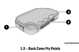
WARNING!: Push the Mechanical Key Release Button only with the key fob facing away from your body, especially your eyes and objects that may be damaged, such as clothing.
CAUTION!: The electrical components inside of the key fob may be damaged if the key fob is sub-jected to strong electrical shocks. In order to ensure complete efficiency of the electronic devices inside of the key fob, avoid exposing the key fob to direct sunlight.
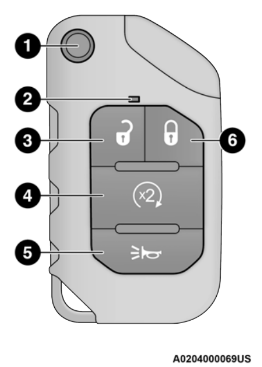
- Mechanical Key Release Button
- LED Indicator
- Unlock Button
- Remote Start Button
- Panic Button
- Lock Button
NOTE:
- In case the ignition switch does not change with the push of a button, the key fob may have a low or fully depleted battery. A low key fob battery condition may be indicated by a message in the instrument cluster display, or by the LED light on the key fob. If the LED key fob light no longer illuminates from key fob button pushes, then the key fob battery requires replacement.
- Improper disposal of key fob batteries may be harmful to the environment. Please see an authorized dealer for proper battery disposal ⇒ page 468.
To Lock/Unlock The Doors And Swing Gate
Push and release the unlock button on the key fob once to unlock the driver’s door, or twice to unlock all the doors and swing gate. To lock all the doors, push the lock button once.
When the doors are unlocked, the turn signals will flash and the illuminated entry system will be activated. When the doors are locked, the turn signals will flash and the horn will chirp.
NOTE:
All doors can be programmed to unlock on the first push of the unlock button through the Uconnect Settings page 217.
Replacing The Battery In The Key Fob
The recommended replacement battery is CR2450.
NOTE:
- Customers are recommended to use a battery obtained from Mopar®. Aftermarket coin battery dimensions may not meet the original OEM coin battery dimensions.
- Do not touch the battery terminals that are on the back housing or the printed circuit board.
- When a key fob battery is low, a warning will be indicated on the vehicle’s instrument cluster, and the fob LED will no longer illumi- nate with a button press.
1. Remove the back cover of the fob by inserting a flat-blade screw driver into the slot on the bottom of the fob. Pry until the cover unsnaps being careful not to damage the seal. Proceed counter- clockwise to pry the remaining snaps until the battery cover can be removed.
2. Remove the depleted battery by inserting a small flat-blade screwdriver into the battery removal slot and sliding the battery forward and up being careful not to damage the electronic board underneath.
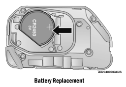
3. Install the new battery into the key fob, making sure the positive (+) side is facing up. Slide the battery until it is seated securely below the tabs.
4. Reassemble the back cover making sure it is properly aligned before snapping it back in place.
WARNING!
- The integrated key fob contains a coin cell battery. Do not ingest the battery; there is a chemical burn hazard. If the coin cell battery is swallowed, it can cause severe internal burns in just two hours and can lead to death.
- If you think a battery may have been swal- lowed or placed inside any part of the body, seek immediate medical attention.
- Keep new and used batteries away from children. If the battery compartment does not close securely, stop using the product and keep it away from children.
Programming And Requesting Additional Key Fobs
1. Programming the key fob may be performed by an authorized dealer.
NOTE:
- Once a key fob is programmed to a vehicle, it cannot be repurposed and reprogrammed to another vehicle.
- Only key fobs that are programmed to the vehicle electronics can be used to start and operate the vehicle.
WARNING!
- Always remove the key fobs from the vehicle and lock all doors when leaving the vehicle unattended.
- Always remember to place the ignition in the OFF position.
2. Duplication of key fobs may be performed at an authorized dealer. This procedure consists of programming a blank key fob to the vehicle electronics.
NOTE:
- When having the Sentry Key Immobilizer system serviced, bring all vehicle keys with you to an authorized dealer.
- Keys must be ordered to the correct key cut to match the vehicle locks.
SENTRY KEY
- The Sentry Key Immobilizer system prevents unauthorized vehicle operation by disabling the engine. The system does not need to be armed or activated. Operation is automatic, regardless of whether the vehicle is locked or unlocked.
- The system uses a key fob, keyless push button ignition and a Radio Frequency (RF) receiver to prevent unauthorized vehicle operation. Therefore, only key fobs that are programmed to the vehicle can be used to start and operate the vehicle. The system will shut the engine off in two seconds if an invalid key fob is used to start the engine.
- After placing the ignition switch in the ON/RUN position, the Vehicle Security Light will turn on for three seconds for a bulb check. If the light remains on after the bulb check, it indicates that there is a problem with the electronics. In addition, if the light begins to flash after the bulb check, it indicates that someone used an invalid key fob to start the engine. Either of these conditions will result in the engine being shut off after two seconds.
- If the Vehicle Security Light turns on during normal vehicle operation (vehicle running for longer than ten seconds), it indicates that there is a fault in the electronics. Should this occur, have the vehicle serviced as soon as possible by an authorized dealer.
CAUTION!: The Sentry Key Immobilizer system is not compatible with some aftermarket Remote Starting systems. Use of these systems may result in vehicle starting problems and loss of security protection.
5. All of the key fobs provided with your new vehicle have been programmed to the vehicle electronics.
NOTE:: A key fob that has not been programmed is also considered an invalid key page 468.
IGNITION SWITCH
KEYLESS ENTER-N-GO IGNITION
If applicable, refer to the “Hybrid Supplement” for additional information.
- This feature allows the driver to operate the ignition switch with the push of a button as long as the key fob is in the passenger compartment.
- The START/STOP ignition button has several operating modes that are labeled and will illuminate when in position. These modes are OFF, ACC, RUN, and START.
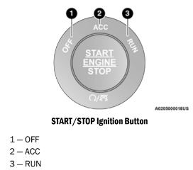
The push button ignition can be placed in the following modes:
OFF
- The engine is stopped.
- Some electrical devices (e.g. Central locking, alarm, etc.) are available.
ACC
- Engine is not started.
- Some electrical devices are available.
RUN
- Driving position.
- All electrical devices are available.
START
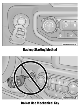
NOTE: In case the ignition switch does not change with the push of the START/STOP ignition button, the key fob may have a low or depleted battery. In this situation, a backup method can be used to operate the ignition switch. Put the nose side of the key fob (side with the mechanical flip key) against the START/STOP ignition button and push to operate the ignition switch.
CAUTION!
- Do not use the Mechanical Key against the START/STOP ignition button.
- Do not use sharp metal objects (e.g. screw driver etc.) to pry the button out of the igni- tion switch. This button comes as an assembly, and is not removable. This can damage the silicone shield.
WARNING!
- When exiting the vehicle, always remove the key fob from the vehicle and lock your vehicle.
- Never leave children alone in a vehicle, or with access to an unlocked vehicle.
- Allowing children to be in a vehicle unat- tended is dangerous for a number of reasons. A child or others could be seriously or fatally injured. Children should be warned not to touch the parking brake, brake pedal or the gear selector.
- Do not leave the key fob in or near the vehicle, or in a location accessible to chil- dren, and do not leave the ignition of a vehicle equipped with Keyless Enter-N-Go in the ON/RUN position. A child could operate power windows, other controls, or move the vehicle.
- Do not leave children or animals inside parked vehicles in hot weather. Interior heat build-up may cause serious injury or death.
CAUTION!: An unlocked vehicle is an invitation for thieves. Always remove key fob from the vehicle and lock all doors when leaving the vehicle unattended.
NOTE:
- Information on normal starting, see ⇒ page 138.
- When opening the driver's door with the igni- tion in the ON/RUN position (engine not running), a chime will sound to remind you to place the ignition in the OFF position. In addi- tion to the chime, the message will display " Ignition Or Accessory On” in the cluster.
REMOTE START — IF EQUIPPED (GASOLINE)
 This system uses the key fob to start the engine conveniently from outside the vehicle while still maintaining security. The system has a range of 328 ft (100 m).
Remote Start is used to defrost windows in cold weather, and to reach a comfortable climate in all ambient conditions before the driver enters the vehicle.
NOTE:
- The vehicle must be equipped with an auto- matic transmission to be equipped with Remote Start.
- Obstructions between the vehicle and key fob may reduce this range ⇒ page 468.
WARNING!
- Do not start or run an engine in a closed garage or confined area. Exhaust gas contains Carbon Monoxide (CO) which is odorless and colorless. Carbon Monoxide is poisonous and can cause serious injury or death when inhaled.
- Keep key fobs away from children. Opera- tion of the Remote Start system, windows, door locks or other controls could cause serious injury or death.
HOW TO USE REMOTE START
If applicable, refer to the “Hybrid Supplement” for additional information.
Push and release the Remote Start button on the key fob twice within five seconds. The vehicle doors and swing gate will lock, the turn signals will flash twice, and the horn will chirp twice. Pushing the Remote Start button again will shut the engine off.
NOTE:
- With Remote Start, the engine will only run for 15 minutes.
- Remote Start can only be used twice.
- If an engine fault is present or fuel level is low, the vehicle will start and then shut down in 10 seconds.
- The park lamps will turn on and remain on during Remote Start mode.
- For security, power window operation is disabled when the vehicle is in the Remote Start mode.
- The ignition must be placed in the ON/RUN position before the Remote Start sequence can be repeated for a third cycle.
All of the following conditions must be met before the engine will Remote Start:
- Gear selector in PARK
- Doors closed
- Hood closed
- Swing gate closed
- Hazard switch off
- Brake switch inactive (brake pedal not pressed)
- Battery at an acceptable charge level
- Panic button not pushed
- System not disabled from previous Remote
- Start event
- Vehicle Security system indicator flashing
- Ignition in OFF position
- Fuel level meets minimum requirement
- All removable doors must not be removed
- Malfunction Indicator Light (MIL) not illumi- nated
WARNING!
- Do not start or run an engine in a closed garage or confined area. Exhaust gas contains Carbon Monoxide (CO) which is odorless and colorless. Carbon Monoxide is poisonous and can cause serious injury or death when inhaled.
- Keep key fobs away from children. Opera- tion of the Remote Start system, windows, door locks or other controls could cause serious injury or death.
TO EXIT REMOTE START MODE
If applicable, refer to the “Hybrid Supplement” for additional information.
To drive the vehicle after starting the Remote Start system, either push and release the unlock button on the key fob to unlock the doors, or unlock the vehicle using Keyless Enter-N-Go — Passive Entry via the door handles, and disarm the Vehicle Security system (if equipped). Then, prior to the end of the 15 minute cycle, push and release the START/STOP ignition button.
The Remote Start system will turn the engine off with another push and release of the Remote Start button on the key fob, or if the engine is allowed to run for the entire 15 minute cycle. Once the ignition is placed in the ON/RUN position, the climate controls will resume the previously set operations (temperature, blower control, etc.).
NOTE:
- To avoid unintentional shutdowns, the system will disable for two seconds after receiving a valid Remote Start request.
- For vehicles equipped with the Keyless Enter-N-Go — Passive Entry feature, the message “Remote Start Active — Push Start Button” will display in the instrument cluster display until you push the START/STOP igni- tion button.
REMOTE START FRONT DEFROST ACTIVATION — IF EQUIPPED
When Remote Start is active, and the outside ambient temperature is 40°F (4.5°C) or below, the system will automatically activate front defrost for 15 minutes or less. The time is dependent on the ambient temperature. Once the timer expires, the system will automatically adjust the settings depending on ambient conditions. See “Remote Start Comfort Systems If Equipped” in the next section for detailed operation.
REMOTE START COMFORT SYSTEMS — IF EQUIPPED
When Remote Start is activated, the front and rear defrost will automatically turn on in cold weather. The heated steering wheel and driver heated seat feature will turn on if programmed in the comfort menu screen within Uconnect Settings ⇒ page 217. In warm weather, the driver vented seat feature will automatically turn on when the Remote Start is activated, if programmed in the comfort menu screen. The vehicle will adjust the climate control settings depending on the outside ambient temperature.
Automatic Temperature Control (ATC) — If Equipped
The climate controls automatically adjust to an optimal temperature and mode, dependent on the outside ambient temperature. When the ignition is placed in the ON/RUN position, the climate controls will resume their previous settings.
Manual Temperature Control (MTC) — If Equipped
- In ambient temperatures of 40°F (4.5°C) or below, the climate settings will default to maximum heat, with fresh air entering the cabin. If the front defrost timer expires, the vehicle will enter Mix mode.
- In ambient temperatures from 40°F (4.5°C) to 78°F (26°C), the climate settings will be based on the last settings selected by the driver.
- In ambient temperatures of 78°F (26°C) or above, the climate settings will default to MAX A/C, Bi-Level mode, with Recirculation on.
For more information on ATC, MTC, and climate control settings, see Ú page 56.
NOTE:
These features will stay on through the duration of Remote Start, or until the ignition is placed in the ON/RUN position. The climate control settings will change, and exit the automatic defaults, if manually adjusted by the driver while the vehicle is in Remote Start mode. This includes turning the climate controls off using the OFF button.
REMOTE START CANCEL MESSAGE
The following messages will display in the instrument cluster if the vehicle fails to Remote Start or exits Remote Start prematurely:
- Remote Start Cancelled — Door Open
- Remote Start Cancelled — Hood Open
- Remote Start Cancelled — Fuel Low
- Remote Start Cancelled — Swing Gate Open
- Remote Start Cancelled — Time Expired
- Remote Start Disabled — Start Vehicle To Reset
The message will stay active until the ignition is placed in the ON/RUN position.
REMOTE START — IF EQUIPPED (DIESEL)
This system uses the key fob to start the engine conveniently from outside the vehicle while still maintaining security. The system has a range of approximately 300 ft (91 m).
Remote Start is used to defrost windows in cold weather, and to reach a comfortable climate in all ambient conditions before the driver enters the vehicle.
NOTE:
- The vehicle must be equipped with an auto- matic transmission to be equipped with Remote Start.
- Obstructions between the vehicle and the key fob may reduce this range.
- The Remote Start system will wait for the Wait To Start Indicator Light Ú page 126 to extinguish before cranking the engine. This allows time for the engine pre-heat cycle to pre-heat the cylinder air, and is normal in cold weather.
WARNING!
- Do not start or run an engine in a closed garage or confined area. Exhaust gas contains Carbon Monoxide (CO) which is odorless and colorless. Carbon Monoxide is poisonous and can cause serious injury or death when inhaled.
- Keep key fobs away from children. Opera- tion of the Remote Start system, windows, door locks or other controls could cause serious injury or death.
HOW TO USE REMOTE START
Push and release the Remote Start button on the key fob twice within five seconds. The vehicle doors and swing gate will lock, the turn signals will flash twice, and the horn will chirp twice. Pushing the Remote Start button again will shut the engine off.
NOTE:
- With Remote Start, the engine will only run for 15 minutes.
- Remote Start can only be used twice.
- If an engine fault is present or fuel level is low, the vehicle will start and then shut down in 10 seconds.
- The park lamps will turn on and remain on during Remote Start mode.
- For security, power window operation is disabled when the vehicle is in the Remote Start mode.
- The ignition must be placed in the ON/RUN position before the Remote Start sequence can be repeated for a third cycle.
All of the following conditions must be met before the engine will Remote Start:
- Gear selector in PARK
- Doors closed
- Hood closed
- Swing gate closed
- Hazard switch off
- Brake switch inactive (brake pedal not pressed)
- Battery at an acceptable charge level
- Panic button not pushed
- Fuel meets minimum requirement
- System not disabled from previous Remote
- Start event
- Vehicle Security system not active
- Malfunction Indicator Light (MIL) is not illumi- nated
- Water In Fuel Indicator Light is not illumi- nated
- Wait To Start Indicator Light is not illuminated
WARNING!
- Do not start or run an engine in a closed garage or confined area. Exhaust gas contains Carbon Monoxide (CO) which is odorless and colorless. Carbon Monoxide is poisonous and can cause serious injury or death when inhaled.
- Keep key fobs away from children. Opera- tion of the Remote Start system, windows, door locks or other controls could cause serious injury or death.
For additional Remote Start information, ⇒ see page 23.
VEHICLE SECURITY SYSTEM — IF EQUIPPED
The Vehicle Security system monitors the vehicle doors for unauthorized entry and the ignition switch for unauthorized operation. When the alarm is activated, the interior switches for door locks are disabled. The Vehicle Security system provides both audible and visible signals. If something triggers the alarm, the Vehicle Security system will provide the following audible and visible signals: the horn will pulse, the park lamps and/or turn signals will flash, and the vehicle security light in the instrument cluster will flash.
TO ARM THE SYSTEM
Follow these steps to arm the Vehicle Security system:
1. Make sure the vehicle’s ignition is placed in the OFF position.
2. Perform one of the following methods to lock the vehicle:
- Push lock on the interior power door lock switch with the driver and/or passenger door open.
- Push the lock button on the exterior Passive Entry door handle with a valid key fob available in the same exterior zone ⇒ page 28.
- Push the lock button on the key fob.
3. If any doors are open, close them.
NOTE:
The Vehicle Security system will not arm if you lock the doors using the manual door lock.
TO DISARM THE SYSTEM
The Vehicle Security system can be disarmed using any of the following methods:
- Push the unlock button on the key fob.
- Grab the Passive Entry door handle (if equipped) ⇒ page 28.
- Cycle the vehicle ignition system out of the OFF position.
NOTE:
- The driver's door key cylinder cannot arm or disarm the Vehicle Security system.
- When the Vehicle Security system is armed, the interior power door lock switches will not unlock the doors.
The Vehicle Security system is designed to protect your vehicle. However, you can create conditions where the system will give you a false alarm. If one of the previously described arming sequences has occurred, the Vehicle Security system will arm regardless of whether you are in the vehicle or not. If you remain in the vehicle and open a door, the alarm will sound. If this occurs, disarm the Vehicle Security system.
If the Vehicle Security system is armed and the battery becomes disconnected, the Vehicle Security system will remain armed when the battery is reconnected; the exterior lights will flash, and the horn will sound. If this occurs, disarm the Vehicle Security system.
REARMING OF THE SYSTEM
If something triggers the alarm, and no action is taken to disarm it, the Vehicle Security system will turn the horn off after 29 seconds, seconds between cycles, up to 8 cycles if the trigger remains active and then the Vehicle Security system will rearm itself.
DOORS
CAUTION!: Careless handling and storage of the remov- able door panels may damage the seals, caus- ing water to leak into the vehicle’s interior.
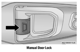
MANUAL DOOR LOCKS
All doors are equipped with an interior rocker-type door lock lever. To lock a door when leaving your vehicle, push the rocker lever forward to the lock position and close the door. To unlock the door, push the rocker lever rearward.
NOTE:
The mechanical flip key can be used to lock or unlock the doors, swing gate (if equipped with a lock), glove compartment, and console storage.
WARNING!
- For personal security reasons and safety in a collision, lock the vehicle doors when you drive, as well as when you park and exit the vehicle.
- When exiting the vehicle, always switch off the ignition and remove the key from the vehicle. Unsupervised use of vehicle equip- ment may cause severe personal injuries and death.
- Never leave children alone in a vehicle, or with access to an unlocked vehicle.
- Allowing children to be in a vehicle unat- tended is dangerous for a number of reasons. A child or others could be seriously or fatally injured. Children should be warned not to touch the parking brake, brake pedal or the gear selector.
- Do not leave the key fob in or near the vehicle or in a location accessible to chil- dren. A child could operate power windows, other controls, or move the vehicle.
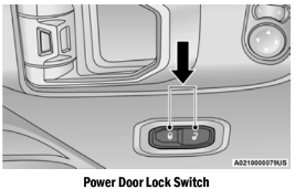
POWER DOOR LOCKS — IF EQUIPPED
The power door lock switch is located on each front door panel. Push the switch forward to unlock the doors, and rearward to lock the doors.
WARNING!
- For personal security reasons and safety in a collision, lock the vehicle doors when you drive, as well as when you park and exit the vehicle.
- When exiting the vehicle, always switch off the ignition and remove the key from the vehicle. Unsupervised use of vehicle equip- ment may cause severe personal injuries and death.
- Never leave children alone in a vehicle, or with access to an unlocked vehicle.
- Allowing children to be in a vehicle unat- tended is dangerous for a number of reasons. A child or others could be seriously or fatally injured. Children should be warned not to touch the parking brake, brake pedal or the gear selector.
- Do not leave the key fob in or near the vehicle or in a location accessible to chil- dren. A child could operate power windows, other controls, or move the vehicle.
KEYLESS ENTER-N-GO — PASSIVE ENTRY (IF EQUIPPED)
The Passive Entry system is a feature that allows you to lock and unlock the vehicle’s door(s) and swing gate without having to push the key fob lock or unlock buttons.
NOTE:
- Passive Entry may be programmed on/off within the Uconnect Settings Ú page 217.
- The key fob may not be detected by the vehicle Passive Entry system if it is located next to a mobile phone, laptop, or other elec- tronic device; these devices may interfere with the key fob’s wireless signal and prevent the Passive Entry system from locking/ unlocking the vehicle.
- Passive Entry Unlock initiates illuminated approach (low beams, license plate lamp, position lamps) for whichever time duration is set between 0, 30, 60 or 90 seconds. Passive Entry Unlock also initiates two flashes of the turn signal lamps.
- If wearing gloves, or if it has been raining/ snowing on the Passive Entry door handle, the unlock sensitivity can be affected, resulting in a slower response time.
- If the vehicle is unlocked by Passive Entry and no door is opened within 60 seconds, the vehicle will re-lock and if equipped will arm the Vehicle Security system.
To Unlock From The Driver or Passenger Side
With a valid Passive Entry key fob within 5 ft (1.5 m) of the door handle, grab the handle to unlock the vehicle. Grabbing the driver’s door handle will unlock the driver door automatically. Grabbing the passenger door handle will unlock all doors and the swing gate automatically.
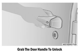
NOTE:: Either the driver door only or all doors will unlock when you grab hold of the front driver’s door handle, depending on the selected setting in the Uconnect system ⇒ page 217.
Frequency Operated Button Integrated Key (FOBIK-Safe)
To minimize the possibility of unintentionally locking a Passive Entry key fob inside your vehicle, the Passive Entry system is equipped with an automatic door unlock feature which will function only if the ignition switch is in the OFF position.
FOBIK-Safe only executes in vehicles with a START/STOP ignition. There are three situations that trigger a FOBIK-Safe search in any passive entry vehicle:
- A lock request is made by a valid Passive Entry key fob while a door is open.
- A lock request is made by the Passive Entry door handle while a door is open.
- A lock request is made by the door panel switch while the door is open.
When any of these situations occur, after all open doors are shut, the FOBIK-Safe search will be executed. If it finds a Passive Entry key fob inside the vehicle, the vehicle will unlock and alert the customer. If Passive Entry is disabled using Uconnect system, the key protection described in this section remains active/ functional.
NOTE:
The vehicle will only unlock the doors during a FOBIK-Safe operation when a valid Passive Entry key fob is detected inside the vehicle. The vehicle will not unlock the doors when any of the following conditions are true:
- A second valid passive entry key fob is detected outside of the vehicle (within 5 ft m) of a passive entry door handle).
- The doors are manually locked using the door lock knobs.
- Three attempts are made to lock the doors using the door panel switch, and then the doors are closed.
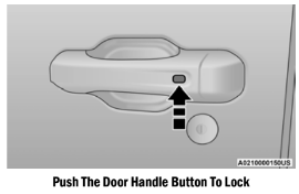
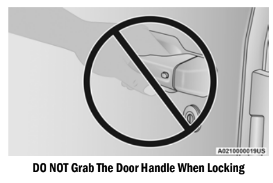
To Lock The Vehicle’s Doors And Swing Gate
With one of the vehicle’s Passive Entry key fobs within 5 ft (1.5 m) of the driver or passenger front door handles, pushing the passive entry lock button will lock the vehicle doors and the swing gate.
NOTE:
DO NOT grab the door handle when pushing the door handle lock button. This could unlock the door(s).
The vehicle doors can also be locked by using the lock button located on the vehicle’s interior door panel.
To Unlock/Enter The Swing Gate
The swing gate Passive Entry unlock feature is built into the swing gate handle. With a valid Passive Entry key fob within 5 ft (1.5 m) of the swing gate handle, grab the swing gate handle to unlock the swing gate automatically, and pull the swing gate to open.
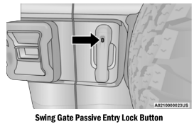
To Lock The Swing Gate
With a valid Passive Entry key fob within 5 ft (1.5 m) of the swing gate handle, pushing the Passive Entry lock button will lock the vehicle doors and the swing gate.
NOTE:
- After pushing the door handle button, you must wait two seconds before you can lock or unlock the doors, using any Passive Entry door handle. This is done to allow you to check if the vehicle is locked by pulling the door handle without the vehicle unlocking.
- If Passive Entry is disabled using the Uconnect Settings, the key protection described in "Frequency Operated Button Integrated Key (FOBIK-Safe)" remains active/ functional.
- The Passive Entry system will not operate if the key fob battery is depleted ⇒ page 468.
AUTOMATIC DOOR LOCKS — IF EQUIPPED
The Automatic Door Lock feature default condition is enabled. When enabled, the door locks will lock automatically when the vehicle's speed exceeds 15 mph (24 km/h). The Automatic Door Lock feature can be enabled or disabled by an authorized dealer per written request of the customer. Please see an authorized dealer for service.
CHILD-PROTECTION DOOR LOCK SYSTEM — REAR DOORS
To provide a safer environment for small children riding in the rear seats, the rear doors are equipped with a Child-Protection Door Lock system.
To use the system, open each rear door, use a flat blade screwdriver (or mechanical key) and rotate the dial to the lock or unlock position.
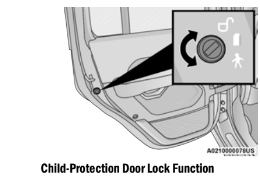
NOTE:
- When the Child-Protection Door Lock system is engaged, the door can be opened only by using the outside door handle even though the inside door lock is in the unlocked posi- tion.
- After disengaging the Child-Protection Door Lock system, always test the door from the inside to make certain it is in the unlocked position.
- After engaging the Child-Protection Door Lock system, always test the door from the inside to make certain it is in the locked position.
- For emergency exit with the system engaged, move the lock lever rearward (located on the door trim panel), roll down the window and open the door with the outside door handle.
WARNING! Avoid trapping anyone in a vehicle in a collision. Remember that the rear doors can only be opened from the outside when the Child-Protection locks are engaged (locked).
NOTE: Always use this device when carrying children. After engaging the child lock on both rear doors, check for effective engagement by trying to open a door with the internal handle. Once the Child-Protection Door Lock system is engaged,it is impossible to open the doors from inside the vehicle. Before getting out of the car, be sure to check that there is no one left inside.
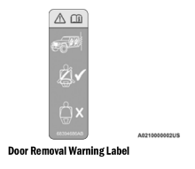
FRONT DOOR REMOVAL
WARNING!: Do not drive your vehicle on public roads with the doors removed as you will lose the protection they can provide. This procedure is furnished for use during off-road operation only.
WARNING!
- All occupants must wear seat belts during off-road operation with doors removed. For off-road driving tips, see ⇒ page 208.
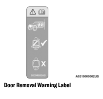
- Do not store detached doors inside of the vehicle, as they may cause personal injury in the event of an accident.
Outside rearview mirrors are mounted on the doors. If you choose to remove the doors, see an authorized dealer for a replacement cowl- mounted outside mirror. Federal law requires outside mirrors on vehicles for on-road use.
NOTE:
- Doors are heavy; use caution when removing them.
- Hinge pin can break if overtightened during door reinstall (Max Torque: 7.5 ft· lb / 10 N·m). For off-road driving tips, see Ú page 208.
- When front doors are removed, the message "Blind Spot Alert Temporarily Unavailable” will display in the instrument cluster display. Power Mirrors and Power Door Locks will also be unavailable.
1. Roll down the glass window to prevent any damage.
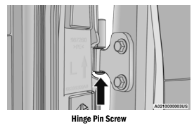
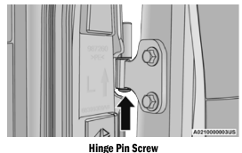
2. Remove the hinge pin screws from the upper and lower outside hinges (using a T50 Torx head driver).
NOTE: The hinge pin screws and nuts can be stowed in the rear cargo tray located under the rear load floor.
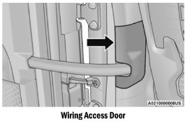
3. Remove the plastic wiring access door under the instrument panel by sliding the plastic panel along the door frame toward the seats until the tabs are detached.
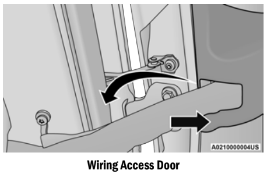
NOTE: Do not pry back to open, as this will break the plastic cover.
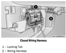
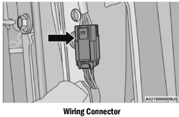
4. Pull up on the red locking tab to unlock the wiring harness.
5. Push and hold down the black security tab under the wiring harness, and lift the harness into the open position.
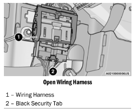
6. With the wiring harness open, pull downward on the wiring connector to unplug. Store the wiring connector in the lower door basket.
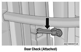
7. Remove the check screw from the center door check (using a #T40 Torx head driver).
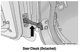
8. With the door open, lift the door with the help of another person, to clear the hinge pins from their hinges and remove the door.
To reinstall the door(s), perform the previous steps in the reverse order.
NOTE:
The upper hinge has a longer pin, which can be used to assist in guiding the door into place when reinstalling.
REAR DOOR REMOVAL (FOUR-DOOR MODELS)
WARNING!
Do not drive your vehicle on public roads with the doors removed as you will lose the protec- tion they can provide. This procedure is fur- nished for use during off-road operation only.
WARNING!
- All occupants must wear seat belts during off-road operation with doors removed. For off-road driving tips, see Ú page 208.
- Do not store detached doors inside of the vehicle, as they may cause personal injury in the event of an accident.
NOTE:
- Doors are heavy; use caution when removing them.
- Hinge pin can break if overtightened during door reinstall (Max Torque: 7.5 ft· lb /N·m). For off-road driving tips, see page 208.
1. Roll down the glass window to prevent any damage.
2. Remove the hinge pin screws from the upper and lower outside hinges (using a T50 Torx head driver).
NOTE:
The hinge pin screws and nuts can be stowed in the rear cargo tray located under the rear load floor.
3. Slide the front seat(s) fully forward.
4. Pry open and remove the plastic wiring access door from the bottom of the B-pillar.
5. Unplug the wiring connector.
NOTE:
Squeeze the tab on the base of the wiring harness. This will unlock the connector tab, allowing the wiring connector to be unplugged.
6. Remove the check screw from the center door check (using a #T40 Torx head driver).
7. With the door open, lift the door with the help of another person, to clear the hinge pins from their hinges and remove the door.
To reinstall the door(s), perform the previous steps in the reverse order.
NOTE: The upper hinge has a longer pin, which can be used to assist in guiding the door into place when reinstalling.
STEERING WHEEL
TILT/TELESCOPING STEERING COLUMN
This feature allows you to tilt the steering column upward or downward. It also allows you to lengthen or shorten the steering column. The tilt/telescoping lever is located on the steering column.
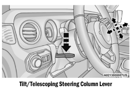
To unlock the steering column, push the control handle downward (toward the floor). To tilt the steering column, move the steering wheel upward or downward as desired. To lengthen or shorten the steering column, pull the steering wheel outward or push it inward as desired. To lock the steering column in position, push the control handle upward until fully engaged.
WARNING! Do not adjust the steering column while driving. Adjusting the steering column while driving or driving with the steering column unlocked, could cause the driver to lose control of the vehicle. Failure to follow this warning may result in serious injury or death.
HEATED STEERING WHEEL — IF EQUIPPED
The steering wheel contains a heating element that helps warm your hands in cold weather. The heated steering wheel has only one temperature setting. Once the heated steering wheel has been turned on, it will stay on until the operator turns it off. The heated steering wheel may not turn on when it is already warm.
The heated steering wheel control button is located within the climate or controls screen of the touchscreen.
- Push the heated steering wheel button once to turn the heating element on.
- Push the heated steering wheel button a second time to turn the heating element off.
NOTE:
The engine must be running for the heated steering wheel to operate.
For information on use with the Remote Start system, see ⇒ page 23.
WARNING!
- Persons who are unable to feel pain to the skin because of advanced age, chronic illness, diabetes, spinal cord injury, medica- tion, alcohol use, exhaustion, or other phys- ical conditions must exercise care when using the steering wheel heater. It may cause burns even at low temperatures, especially if used for long periods.
- Do not place anything on the steering wheel that insulates against heat, such as a blanket or steering wheel covers of any type and material. This may cause the steering wheel heater to overheat.
SEATS
Seats are a part of the Occupant Restraint system of the vehicle.
WARNING!
- It is dangerous to ride in a cargo area, inside or outside of a vehicle. In a collision, people riding in these areas are more likely to be seriously injured or killed.
- Do not allow people to ride in any area of your vehicle that is not equipped with seats and seat belts. In a collision, people riding in these areas are more likely to be seri- ously injured or killed.
- Be sure everyone in your vehicle is in a seat and using a seat belt properly.
MANUAL ADJUSTMENT FRONT SEATS
Manual Front Seat Forward/Rearward Adjustment
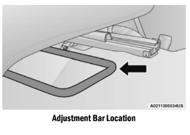
The seat can be adjusted forward or rearward by using a bar located by the front of the seat cushion, near the floor. While sitting in the seat, lift up on the bar located under the seat cushion and move the seat forward or rearward. Release the bar once you have reached the desired position. Then, using body pressure, move forward and rearward on the seat to be sure that the seat adjusters have latched.
WARNING!
- Adjusting a seat while driving may be dangerous. Moving a seat while driving could result in loss of control which could cause a collision and serious injury or death.
- Seats should be adjusted before fastening the seat belts and while the vehicle is parked. Serious injury or death could result from a poorly adjusted seat belt.
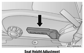
Manual Seat Height Adjustment
The driver's seat height can be raised or lowered by using the ratcheting handle, located on the outboard side of the seat. Pull upward on the handle to raise the seat, push downward on the handle to lower the seat. Several strokes may be necessary to achieve the desired position.
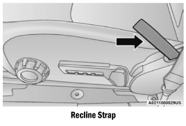
Manual Front Seat Recline Adjustment
To recline the seat, pull on the recline strap and lean forward or backward, depending on the direction you would like the seatback to move. Release the strap when the desired position is reached and the seatback will lock into place.
WARNING! Do not ride with the seatback reclined so that the shoulder belt is no longer resting against your chest. In a collision you could slide under the seat belt, which could result in serious injury or death.
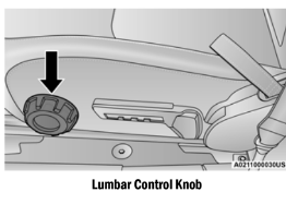
Lumbar Support
The lumbar control knob is located on the outboard side of the front driver seat. Rotate the control forward to increase and rearward to decrease the desired amount of lumbar support.
Front Passenger Easy Entry Seat — Two Door Models
Pull upward on the easy entry lever located on the outboard side of the seat back, and slide the entire seat forward.
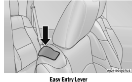
To return the seat to a sitting position, fold the seatback upright until it locks and push the seat rearward until the track locks.
NOTE:
- The front passenger seats have a track memory, which returns the seat to its original position.
- The recline strap and easy entry lever should not be used during the automatic returning of the seat to its sitting position.
60/40 SPLIT FOLDING REAR SEAT — FOUR DOOR MODELS
To provide additional storage area, each rear seat can be folded flat to allow for extended cargo space.
NOTE:
- Be sure that the front seats are fully upright and positioned forward. This will allow the rear seat to fold down easily.
- The center head restraints must be in the lowest position to avoid contact with the center console when folding the seat.
WARNING!
- It is extremely dangerous to ride in a cargo area, inside or outside of a vehicle. In a collision, people riding in these areas are more likely to be seriously injured or killed.
- Do not allow people to ride in any area of your vehicle that is not equipped with seats and seat belts.
- Be sure everyone in your vehicle is in a seat and using a seat belt properly.
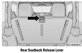
To Fold Down The Rear Seat
There are two release levers located on each upper outboard side of the rear seat. The larger of the two release levers folds down the seat and the head restraint simultaneously. The smaller lever folds down the head restraint independently for improved visibility.
To fold the seat, lift upward on the large release lever and slowly fold down the seatback. The head restraint will fold automatically with the seat when this lever is pulled.
NOTE:
You may experience deformation in the seat cushion from the seat belt buckles if the seats are left folded for an extended period of time. This is normal. By simply opening the seats to the open position, the seat cushion will return to its normal shape over time.
To Raise The Rear Seat
Raise the seatback and lock it into place. Then, raise the head restraint until it locks into place. If interference from the cargo area prevents the seatback from fully locking, you will have difficulty returning the seat to its proper position.
WARNING!
Be certain that the seatback is securely locked into position. If the seatback is not securely locked into position the seat will not provide the proper stability for child seats and/or passengers. An improperly latched seat could cause serious injury.
FOLD AND TUMBLE REAR SEAT — TWO DOOR MODELS
NOTE:
- Prior to folding the rear seat, it may be neces- sary to reposition the front seats.
- Be sure that the front seats are fully upright and positioned forward. This will allow the rear seat to fold down easily.
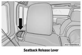
Folding The Rear Seat
1. Lift the seatback release lever and fold the seatback forward.
2. Slowly flip the entire seat forward.
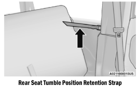
Using The Retention Straps
1. There are two retention straps located on the back of the rear seat and two corresponding wire loops located on the back of each B-pillar. Open the hook-and-loop fastener on the strap and thread through the wire loop. Fold the hook-and-loop fastener over to keep the seat in the folded position. This should be done on both sides.
2. To return the seat to its normal upright position, reverse these steps.
Removing The Rear Seat
1. Push down on the release bar on each side, and pull the seat out and away from the lower bracket.
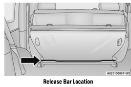
2. Remove the seat from the vehicle.
3. To reinstall the rear seat, just reverse these steps.
NOTE: Do not drive the vehicle without reattaching the rear seat latches.
WARNING!
- It is extremely dangerous to ride in a cargo area, inside or outside of a vehicle. In a collision, people riding in these areas are more likely to be seriously injured or killed.
- Do not allow people to ride in any area of your vehicle that is not equipped with seats and seat belts.
- Be sure everyone in your vehicle is in a seat and using a seat belt properly.
- In a collision, you or others in your vehicle could be injured if seats are not properly latched to their floor attachments. Always be sure that the seats are fully latched.
HEATED SEATS — IF EQUIPPED
The heated seat control buttons are located on the center instrument panel below the touchscreen and also in the Climate Control touchscreen menu.
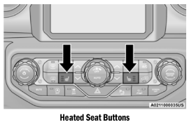
- Push the heated seat button
 once to turn the HI setting on.
- Push the heated seat button a second time to turn the MED setting on.
- Push the heated seat button a third time to turn the LO setting on.
- Push the heated seat button a fourth time to turn the heating elements off.
NOTE:
- The engine must be running for the heated seats to operate.
- The level of heat selected will stay on until the operator changes it.
For information on use with the Remote Start system, see ⇒ page 23.
WARNING!
- Persons who are unable to feel pain to the skin because of advanced age, chronic illness, diabetes, spinal cord injury, medica- tion, alcohol use, exhaustion or other phys- ical condition must exercise care when using the seat heater. It may cause burns even at low temperatures, especially if used for long periods of time.
- Do not place anything on the seat or seat- back that insulates against heat, such as a blanket or cushion. This may cause the seat heater to overheat. Sitting in a seat that has been overheated could cause serious burns due to the increased surface temperature of the seat.
REAR SEAT ARMREST — IF EQUIPPED
The center part of the rear seat can also be used as a rear armrest with cupholders. To unfold it, grab the pull strap under the head restraint and pull it forward.
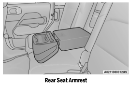
NOTE: The cupholder liner can be removed for cleaning.
WARNING!
Be certain that the seatback is securely locked into position. If the seatback is not securely locked into position the seat will not provide the proper stability for child seats and/or passengers. An improperly latched seat could cause serious injury.
HEAD RESTRAINTS
Head restraints are designed to reduce the risk of injury by restricting head movement in the event of a rear impact. Head restraints should be adjusted so that the top of the head restraint is located above the top of your ear.
WARNING!
- All occupants, including the driver, should not operate a vehicle or sit in a vehicle’s seat until the head restraints are placed in their proper positions in order to minimize the risk of neck injury in the event of a crash.
- Head restraints should never be adjusted while the vehicle is in motion. Driving a vehicle with the head restraints improperly adjusted or removed could cause serious injury or death in the event of a collision.
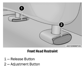
Front Head Restraints
To raise the head restraint, pull upward on the head restraint. To lower the head restraint, push the adjustment button located on the base of the head restraint, and push downward on the head restraint. The release button does not need to be pushed to adjust the head restraint.
To remove the head restraint, raise it as far as it can go then push the adjustment button and the release button at the base of each post while pulling the head restraint up. To reinstall the head restraint, put the head restraint posts into the holes and push downward. Then adjust it to the appropriate height.
WARNING!
- A loose head restraint thrown forward in a collision or hard stop could cause serious injury or death to occupants of the vehicle. Always securely stow removed head restraints in a location outside the occu- pant compartment.
- ALL the head restraints MUST be rein- stalled in the vehicle to properly protect the occupants. Follow the re-installation instructions above prior to operating the vehicle or occupying a seat.
NOTE:
Do not reposition the head restraint 180 degrees to the incorrect position in an attempt to gain additional clearance to the back of the head.
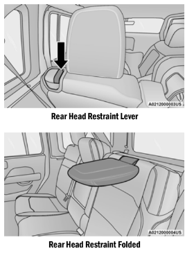
Rear Head Restraints — Two Door Models
The rear seat is equipped with non-adjustable, but foldable head restraints.
To fold the outboard head restraint, pull on the release strap located on the upper outboard side of each rear seat.
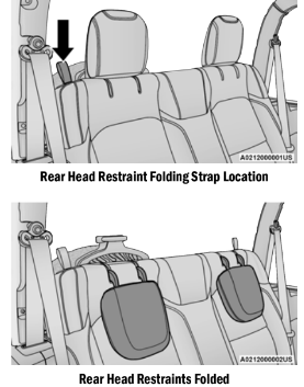
To return the head restraint to its upward position, lift up on the head restraint until it locks into place.
For information on child seat tether routing⇒ page 317.
WARNING!
- Do not drive the vehicle without the rear seat head restraints installed while passen gers are occupying the rear seat. In a colli sion, people riding in this area without the head restraints installed are more likely to be seriously injured or killed.
- A loose head restraint thrown forward in a collision or hard stop could cause serious injury or death to occupants of the vehicle. Always securely stow removed head restraints in a location outside the occu pant compartment.
- ALL the head restraints MUST be rein stalled in the vehicle to properly protect the occupants. Follow the reinstallation instruc tions above prior to operating the vehicle or occupying a seat.
Rear Head Restraints — Four Door Models
The rear seat is equipped with nonadjustable, but foldable, outboard head restraints, as well as an adjustable, removable center head restraint.
To fold the outboard head restraint, pull on the inner release lever, located on the upper part of the rear seat.
To return the head restraint to its upward position, lift up on the head restraint until it locks into place.
To raise the center head restraint, lift up on the head restraint. To lower the center head restraint, push the adjustment button, located at the base of the head restraint, and push down on the head restraint.
To remove the center head restraint, push the release button, located on the base of the head restraint, and pull upward on the head restraint.
To install the head restraint, hold the release button while pushing downward on the head restraint. For information on child seat tether routing, see page 317.
NOTE: Lower the center head restraint to avoid contact with the center console when folding the seat down.
WARNING!
- Do not drive the vehicle without the rear seat head restraints installed while passen gers are occupying the rear seat. In a colli sion, people riding in this area without the head restraints installed are more likely to be seriously injured or killed.
- A loose head restraint thrown forward in a collision or hard stop could cause serious injury or death to occupants of the vehicle. Always securely stow removed head restraints in a location outside the occu pant compartment.
- ALL the head restraints MUST be rein stalled in the vehicle to properly protect the occupants. Follow the reinstallation instruc tions above prior to operating the vehicle or occupying a seat.
UCONNECT VOICE RECOGNITION
INTRODUCING VOICE RECOGNITION
Start using Uconnect Voice Recognition with these helpful quick tips. It provides the key Voice Commands and tips you need to know to control your vehicle’s Voice Recognition (VR) system.
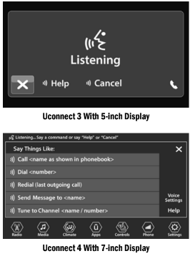
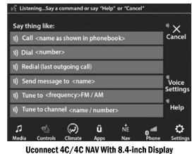
BASIC VOICE COMMANDS
The basic Voice Commands below can be given at any point while using your Uconnect system.
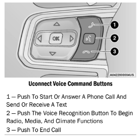
Push the VR button on the steering wheel. After the beep, say:
- “Cancel” to stop a current voice session.
- “Help” to hear a list of suggested Voice Commands.
- "Repeat” to listen to the system prompts again.
Notice the visual cues that inform you of your Voice Recognition system’s status.
GET STARTED
The VR button is used to activate /deactivate your Voice Recognition system.
Helpful hints for using Voice Recognition:
- Reduce background noise. Wind noise and passenger conversations are examples of noise that may impact recognition.
- Speak clearly at a normal pace and volume while facing straight ahead.
- Each time you give a Voice Command, first push the VR button, wait until after the beep, then say your Voice Command.
- You can interrupt the help message or system prompts by pushing the VR button and saying a Voice Command from the current category.
MIRRORS
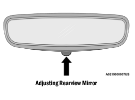
INSIDE REARVIEW MIRROR
Manual Mirror — If Equipped
The rearview mirror can be adjusted up, down, left, and right. The mirror should be adjusted to center on the view through the rear window.
Headlight glare from vehicles behind you can be reduced by moving the small control under the mirror to the night position (toward the rear of the vehicle). The mirror should be adjusted while set in the day position (toward the windshield).
Automatic Dimming Mirror — If Equipped
The rearview mirror can be adjusted up, down, left, and right. The mirror should be adjusted to center on the view through the rear window.
The mirror automatically adjusts to headlight glare from vehicles behind you.
NOTE:
The Automatic Dimming feature is disabled when the vehicle is in REVERSE to improve the driver’s view.
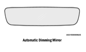
The Automatic Dimming feature can be turned on or off through Uconnect Settings page 217.
CAUTION! To avoid damage to the mirror during cleaning, never spray any cleaning solution directly onto the mirror. Apply the solution onto a clean cloth and wipe the mirror clean.
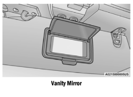
ILLUMINATED VANITY MIRRORS
To access an illuminated vanity mirror, flip down one of the visors and lift the cover.
OUTSIDE MIRRORS
The outside mirror(s) can be adjusted to the center of the adjacent lane of traffic to achieve the optimal view.
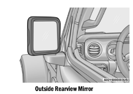
WARNING! Vehicles and other objects seen in the passenger side convex mirror will look smaller and farther away than they really are. Relying too much on your passenger side mirror could cause you to collide with another vehicle or other object. Use your inside mirror when judging the size or distance of a vehicle seen in the passenger side mirror.
HEATED MIRRORS — IF EQUIPPED
 These mirrors are heated to melt frost or ice. This feature will be activated whenever you turn on the rear window defroster (if equipped) Ú page 56.
POWER MIRRORS — IF EQUIPPED
The power mirror controls are located on the door panel next to the door handle.
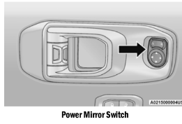
The power mirror controls consist of mirror select buttons and a four-way mirror control switch. To adjust a mirror, push either the L left) or R (right) button to select the mirror that you want to adjust.
Using the mirror control switch, push any of the four arrows for the direction that you want the mirror to move.
BEFORE YOU BEGIN PROGRAMMING HOMELINK®
For efficient programming and accurate transmission of the radio-frequency signal, it is recommended that a new battery be placed in the hand-held transmitter of the device that is being programmed to the HomeLink® system.
Make sure your hand-held transmitter is programmed to activate the device you are trying to program your HomeLink® button to.
Ensure that your vehicle is parked outside of the garage before you begin programming.
It is recommended that you erase all the channels of your HomeLink® before you use it for the first time.
ERASING ALL THE HOMELINK® CHANNELS
To erase the channels, follow this procedure:
- Place the ignition switch into the ON/RUN position.
- Push and hold the two outside HomeLink® buttons (I and III) for up to 20 seconds, or until the HomeLink® indicator light flashes.
NOTE:
Erasing all channels should only be performed when programming HomeLink® for the first time. Do not erase channels when programming additional buttons.
IDENTIFYING WHETHER YOU HAVE A ROLLING CODE OR NON-ROLLING CODE DEVICE
Before programming a device to one of your HomeLink® buttons, you must determine whether the device has a rolling code or non-rolling code.
Rolling Code Devices
To determine if your device has a rolling code, a good indicator is its manufacturing date. Typically, devices manufactured after 1995 have rolling codes. A device with a rolling code will also have a “LEARN” or “TRAIN” button located where the antenna is attached to the device. The button may not be immediately visible when looking at the device. The name and color of the button may vary slightly by manufacturer.
NOTE:
The “LEARN” or “TRAIN” button is not the button you normally use to operate the device.
Non-rolling Code Devices
Most devices manufactured before 1995 will not have a rolling code. These devices will also not have a “LEARN” or “TRAIN” button.
PROGRAMMING HOMELINK® TO A GARAGE DOOR OPENER
To program any of the HomeLink® buttons to activate your garage door opener motor, follow the steps below:
NOTE:
All HomeLink® buttons are programmed using this procedure. You do not need to erase all channels when programming additional buttons.
- Place the ignition switch into the ON/RUN position.
- Place the garage door opener transmitter to 3 inches (3 to 8 cm) away from the HomeLink® button you wish to program, while keeping the HomeLink® indicator light in view.
- Push and hold the HomeLink® button you want to program while you push and hold the garage door opener transmitter button you are trying to replicate.
- Continue to hold both buttons and observe the HomeLink® indicator light. The HomeLink® indicator light will flash slowly and then rapidly. Once this happens, release both buttons.
NOTE:
Make sure the garage door opener motor is plugged in before moving on to the rolling code/ non-rolling code final steps.
Rolling Code Garage Door Opener Final Steps
NOTE:
You have 30 seconds in which to initiate rolling code final step 2, after completing rolling code final step 1.
- At the garage door opener motor (in the garage), locate the “LEARN” or “TRAIN” button. This can usually be found where the hanging antenna wire is attached to the garage door opener motor. Firmly push and release the “LEARN” or “TRAIN” button.
- Return to the vehicle and push the programmed HomeLink® button three times (holding the button for two seconds each time). If the garage door opener motor operates, programming is complete.
- Push the programmed HomeLink® button to confirm that the garage door opener motor operates. If the garage door opener motor does not operate, repeat the final steps for the rolling code procedure.
Non-Rolling Code Garage Door Opener FinalnSteps
- Push and hold the programmed HomeLink® button and observe the HomeLink® indicator light. If the HomeLink® indicator light stays on constantly, programming is complete.
- Push the programmed HomeLink® button to confirm that the garage door opener motor operates. If the garage door opener motor does not operate, repeat the steps from the beginning.
WARNING!
- Your motorized door or gate will open and close while you are programming the universal transceiver. Do not program the transceiver if people or pets are in the path of the door or gate.
- Do not run your vehicle in a closed garage or confined area while programming the transceiver. Exhaust gas from your vehicle contains Carbon Monoxide (CO) which is odorless and colorless. Carbon Monoxide is poisonous when inhaled and can cause you and others to be severely injured or killed.
PROGRAMMING HOMELINK® TO A MISCELLANEOUS DEVICE
The procedure on how to program HomeLink® to a miscellaneous device follows the same procedure as programming to a garage door opener ⇒ page 48.
Be sure to determine if the device has a rolling code, or non-rolling code before beginning the programming process.
NOTE:
Canadian radio frequency laws require trans- mitter signals to time-out (or quit) after several seconds of transmission, which may not be long enough for HomeLink® to pick up the signal during programming. Similar to this Canadian law, some US gate operators are designed to time-out in the same manner. The procedure may need to be performed multiple times to successfully pair the device to your HomeLink® buttons.
REPROGRAMMING A SINGLE HOMELINK® BUTTON
To reprogram a single HomeLink® button that has been previously trained, without erasing all the channels, follow the procedure below. Be sure to determine if the new device you want to program the HomeLink® button to has a rolling code or a non-rolling code.
- Place the ignition in the ON/RUN position, without starting the engine.
- Push and hold the desired HomeLink® button until the HomeLink® Indicator light begins to flash after 20 seconds. Do not release the button.
- Without releasing the button, proceed with Step 2 in “Programming HomeLink® To A Garage Door Opener” and follow all remaining steps.
CANADIAN/GATE OPERATOR PROGRAMMING
For programming transmitters in Canada/ United States that require the transmitter signals to “time-out” after several seconds of transmission.
Canadian radio frequency laws require transmitter signals to time-out (or quit) after several seconds of transmission – which may not be long enough for HomeLink® to pick up the signal during programming. Similar to this Canadian law, some U.S. gate operators are designed to time-out in the same manner.
It may be helpful to unplug the device during the cycling process to prevent possible overheating of the garage door or gate motor.
- Place the ignition in the ON/RUN position.
- Place the hand-held transmitter 1 to inches (3 to 8 cm) away from the HomeLink® button you wish to program while keeping the HomeLink® indicator light in view.
- Continue to press and hold the HomeLink® button, while you press and release cycle”) your hand-held transmitter every two seconds until HomeLink® has successfully accepted the frequency signal. The indicator light will flash slowly and then rapidly when fully trained.
- Watch for the HomeLink® indicator to change flash rates. When it changes, it is programmed. It may take up to 30 seconds or longer in rare cases. The garage door may open and close while you are programming.
- Press and hold the programmed HomeLink® button and observe the indicator light.
NOTE:
- If the indicator light stays on constantly, programming is complete and the garage door/device should activate when the HomeLink® button is pressed.
- To program the two remaining HomeLink® buttons, repeat each step for each remaining button. DO NOT erase the channels.
If you unplugged the garage door opener/ device for programming, plug it back in at this time.
Reprogramming A Single HomeLink® Button (Canadian/Gate Operator)
To reprogram a channel that has been previously trained, follow these steps:
- Place the ignition in the ON/RUN position.
- Press and hold the desired HomeLink® button until the indicator light begins to flash after 20 seconds. Do not release the button.
- Without releasing the button, proceed with "Canadian/Gate Operator Programming” step 2 and follow all remaining steps.
EXTERIOR LIGHTS
HEADLIGHT SWITCH
The headlight switch is located on the left side of the instrument panel. This switch controls the operation of the headlights, parking lights, automatic headlights (if equipped), instrument panel lights, interior lights, and fog lights (if equipped).
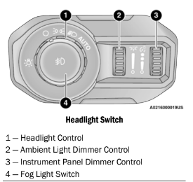
Rotate the headlight switch clockwise to the first detent for parking light and instrument panel light operation. Rotate the headlight switch to the second detent for headlight, parking light, and instrument panel light operation.
DAYTIME RUNNING LIGHTS (DRLS) — IF EQUIPPED
The Daytime Running Lights are in a dedicated position below the headlight assembly. DRLs are active when the low beams are not on, and the engine is running. DRLs may be deactivated by applying the parking brake.
NOTE:
- For vehicles sold in Canada, the Daytime Running Lights will automatically deactivate when the front fog lights are turned on.
- On some vehicles, the Daytime Running Lights may deactivate, or reduce intensity, on one side of the vehicle (when a turn signal is activated on that side), or on both sides of the vehicle (when the hazard warning lights are activated).
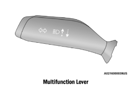
HIGH/LOW BEAM SWITCH
Push the multifunction lever toward the instrument panel to switch the headlights to high beams. The lever will return to the centered position. To return the headlights to low beam, pull the lever toward the steering wheel, or push the lever toward the instrument panel.
AUTOMATIC HIGH BEAM HEADLAMP CONTROL — IF EQUIPPED
The Automatic High Beam Headlamp Control system provides increased forward lighting at night by automatically controlling the high beams through the use of a camera mounted on the vehicle’s header. This camera detects vehicle specific light and automatically switches from high beams to low beams until the approaching vehicle is out of view.
NOTE:
- The Automatic High Beam Headlamp Control can be turned on or off by selecting “ON” under “Auto High Beam” within your Uconnect Settings Ú page 217, as well as turning the headlight switch to the AUTO posi- tion and placing the multifunction lever in the high beam position.
- Broken, muddy, or obstructed headlights and taillights of vehicles in the field of view will cause headlights to remain on longer (closer to the vehicle). Also, dirt, film, and other obstructions on the windshield or camera lens will cause the system to function improp- erly.
FLASH-TO-PASS
You can signal another vehicle with your headlights by lightly pulling the multifunction lever toward you. This will cause the high beam headlights to turn on, and remain on, until the lever is released.
AUTOMATIC HEADLIGHTS — IF EQUIPPED
This system automatically turns the headlights on or off according to ambient light levels. To turn the system on, rotate the headlight switch clockwise to the last detent for automatic headlight operation. When the system is on, the headlight time delay feature is also on. This means the headlights will stay on for up to seconds after you place the ignition into the OFF position. To turn the automatic system off, move the headlight switch out of the AUTO position.
NOTE: The engine must be running before the head- lights will come on in the automatic mode.
LIGHTS-ON REMINDER
If the headlights, parking lights, or cargo lights are left on after the ignition is placed in the OFF position, a chime will sound when the driver’s door is opened.
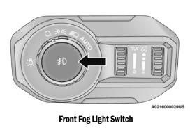
FRONT FOG LIGHTS — IF EQUIPPED
To activate the Front Fog Lights, turn on the parking lights or low beam headlights and push the fog light switch. Pushing the fog light switch a second time will turn the front fog lights off.
TURN SIGNALS
Move the multifunction lever up or down to activate the turn signals. The arrows on each side of the instrument cluster flash to show proper operation.
NOTE: If either light remains on and does not flash, or there is a very fast flash rate, check for a defec- tive outside light bulb.
LANE CHANGE ASSIST — IF EQUIPPED
Lightly push the multifunction lever up or down, without moving beyond the detent, and the turn signal will flash three times then automatically turn off.
INTERIOR LIGHTS
INTERIOR COURTESY LIGHTS
The courtesy lights will turn on when the front doors are opened, by rotating the dimmer controls on the headlight switch fully upward, or, if equipped, when the unlock button is pushed on the key fob.
The interior courtesy lights are located in the center of the vehicle’s sport bar, and consist of one large center light and four smaller reading lights. Each reading light can be turned on by pushing the lens. Pushing the lens a second time will turn the light off.
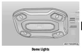
When a door is open and the interior lights are on, rotating the dimmer control to the extreme bottom position will cause all the interior lights to turn off. This is also known as “Party” mode because it allows the doors to stay open for extended periods of time without discharging the vehicle’s battery.
DIMMER CONTROLS
The dimmer controls are part of the headlight switch and are located on the left side of the instrument panel.
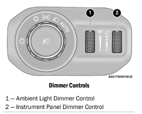
With the parking lights or headlights on, rotating the right dimmer control upward will increase the brightness of the instrument panel lights. Rotating the left dimmer control will adjust the interior and ambient light levels (e.g. courtesy lights in the footwell and front door handles).
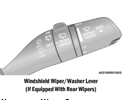
WINDSHIELD WIPERS AND WASHERS
The windshield wiper/washer control lever is located on the right side of the steering column. The front wipers are operated by rotating a switch, located at the end of the lever.
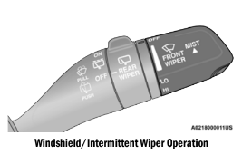
WINDSHIELD WIPER OPERATION
Rotate the end of the lever upward to the first detent past the intermittent settings for low-speed wiper operation. Rotate the end of the lever upward to the second detent past the intermittent settings for high-speed wiper operation.
CAUTION!
In cold weather, always turn off the wiper switch and allow the wipers to return to the park position before turning off the engine. If the wiper switch is left on and the wipers freeze to the windshield, damage to the wiper motor may occur when the vehicle is restarted.
Intermittent Wipers
Use the intermittent wiper when weather conditions make a single wiping cycle, with a variable pause between cycles, desirable. Rotate the end of the lever to the first detent position for one of four intermittent settings. The delay cycle can be set anywhere between to 18 seconds.
NOTE:
The wiper delay times depend on vehicle speed. If the vehicle is moving less than 10 mph km/h), delay times will be doubled.
Windshield Washers
To use the washer, pull the lever toward you and hold while spray is desired. If the lever is pulled while in the delay range, the wiper will start and continue to operate for two or three wipe cycles after the lever is released. Then, the intermittent interval previously selected will resume.
If the lever is pulled while in the off position, the wipers will operate for two or three wipe cycles. Then, the wipers will turn off.
NOTE:
As a protective measure, the washer will stop if the switch is held for more than 20 seconds.
Once the switch is released the washer will resume normal operation.
WARNING!
Sudden loss of visibility through the windshield could lead to a collision. You might not see other vehicles or other obstacles. To avoid sud- den icing of the windshield during freezing weather, warm the windshield with the defroster before and during windshield washer use.
Mist
Push upward on the wiper lever to activate a single wipe to clear off-road mist or spray from a passing vehicle. As long as the lever is held up, the wipers will continue to operate.
NOTE:
The mist feature does not activate the washer pump; therefore, no washer fluid will be sprayed on the windshield. The wash function must be used in order to spray the windshield with washer fluid.
For information on wiper care and replacement, see Ú page 401.
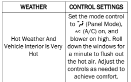
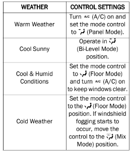
OPERATING TIPS
NOTE:
Refer to the chart at the end of this section for suggested control settings for various weather conditions.
Summer Operation
The engine cooling system must be protected with a high-quality antifreeze coolant to provide proper corrosion protection and to protect against engine overheating. OAT coolant conforming to MS.90032) is recommended.
Winter Operation
To ensure the best possible heater and defroster performance, make sure the engine cooling system is functioning properly and the proper amount, type, and concentration of coolant is used. Use of the Air Recirculation mode during Winter months is not recommended, because it may cause window fogging.
Vacation/Storage
For information on maintaining the Climate Control system when the vehicle is being stored for an extended period of time, see page 441.
Window Fogging
Vehicle windows tend to fog on the inside in mild, rainy, and/or humid weather. To clear the windows, select Defrost or Mix mode and increase the front blower speed. Do not use the Recirculation mode without A/C for long periods, as fogging may occur.
Outside Air Intake
Make sure the air intake, located directly in front of the windshield, is free of obstructions, such as leaves. Leaves collected in the air intake may reduce airflow, and if they enter the plenum, they could plug the water drains. In Winter months, make sure the air intake is clear of ice, slush, and snow.
Cabin Air Filter
The climate control system filters out dust and pollen from the air. Contact an authorized dealer to service your cabin air filter, and to have it replaced when needed.
Stop/Start System — If Equipped
While in an Autostop, the Climate Control system may automatically adjust airflow to maintain cabin comfort. Customer settings will be maintained upon return to an engine running condition.
Windshield Wiper De-Icer — If Equipped
The windshield wiper de-icer is a heating element located at the base of the windshield.
It operates automatically once the following conditions are met:
- Activation By Front Defrost
The wiper de-icer activates automatically during a cold weather manual start with full defrost, and when the ambient temperature is below 33°F (0.6°C).
- Activation By Rear Defrost
The wiper de-icer activates automatically when the Rear Defrost is operating and the ambient temperature is below 33°F (0.6°C).
- Activation By Remote Start Operation
When the Remote Start is activated and the outside ambient temperature is less than 33 °F (0.6°C) the windshield wiper de-icer is activated. Exiting remote start will resume its previous operation, except if the Windshield Wiper De-Icer is active. If the Windshield Wiper De-Icer is active, the timer and opera- tion will continue.
Operating Tips Chart
NOTE: The below chart is for Manual Override Opera- tion.
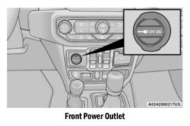
POWER OUTLETS
There are two 12 Volt (13 Amp) auxiliary power outlets that can provide power for accessories designed for use with the standard power outlet adapters.
The front power outlet is located in the center of the instrument panel below the climate controls, and is powered from the ignition switch. Power is available when the ignition switch is in the ON/RUN or ACC position.
On vehicles equipped with a rear subwoofer, there is a second power outlet located in the rear cargo area and is powered directly from the vehicle battery.
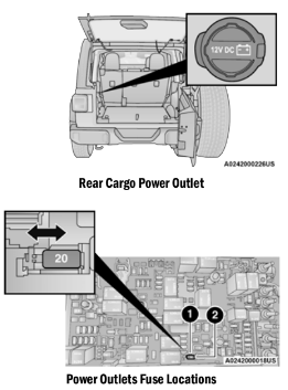
1 - F43 Fuse 20A Yellow Rear Power Outlet (battery powered at all times)
2- F45 Fuse 20A Yellow Rear Power Outlet (powered when the ignition switch is in the ON/ RUN or ACC position)
CAUTION!
- Do not exceed the maximum power of 160 Watts (13 Amps) at 12 Volts. If the 160 Watt (13 Amp) power rating is exceeded the fuse protecting the system will need to be replaced.
- Power outlets are designed for accessory plugs only. Do not insert any other object in the power outlets as this will damage the outlet and blow the fuse. Improper use of the power outlet can cause damage not covered by your New Vehicle Limited Warranty.
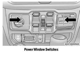
POWER WINDOWS — IF EQUIPPED
The power window switches are located on the instrument panel below the climate controls. Push the switch downward to open the window and upward to close the window.
The top left switch controls the left front window and the top right switch controls the right front window.
WARNING!
Never leave children unattended in a vehicle, and do not let children play with power windows. Do not leave the key fob in or near the vehicle, or in a location accessible to children. Occupants, particularly unattended children, can become entrapped by the windows while operating the power window switches. Such entrapment may result in serious injury or death.
To open the window part way (manually), push the window switch down briefly and release.
NOTE:
The power window switches will remain active for up to 10 minutes after ignition is placed in the OFF position. Opening either front door will cancel this feature.
Four-Door Models
The lower left switch controls the left rear passenger window, and the lower right switch controls the right rear passenger window.
NOTE: There are window switches located on the rear of the center console for the rear passenger windows in the four-door model.
AUTO-DOWN FEATURE
The driver door power and the passenger door power window switches have an Auto-Down feature. Push the window switch down to the second detent and release, and the window will go down automatically.
To stop the window from going all the way down during the Auto-Down operation, pull up on the switch briefly.
WINDOW LOCKOUT SWITCH
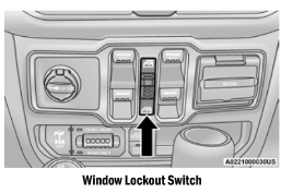
The window lockout switch allows you to disable the window controls on the rear passenger doors. To disable the window controls, rotate the switch downward. To enable the window controls, rotate the switch upward.
WIND BUFFETING
Wind buffeting can be described as the perception of pressure on the ears or a helicopter-type sound in the ears. Your vehicle may exhibit wind buffeting with the windows down in certain open or partially open positions. This is a normal occurrence and can be minimized by adjusting the window opening.
WRANGLER TOPS
PROVIDED TOOLS
For your convenience, a tool kit is provided with your vehicle located in the center console. This kit includes the necessary tools required for the operations described in the following sections. All pieces fit into the ratchet for easy use.
NOTE:
The soft top and the hard top are to be used independently. Your vehicle warranty will not cover damage resulting from both tops being installed at the same time.
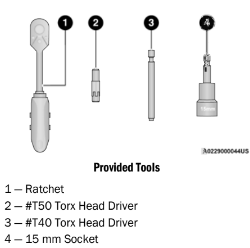
If your vehicle is equipped with a Dual Top (four door models only), the soft top system will be provided in a separate box located in the rear of the vehicle for shipping purposes only.
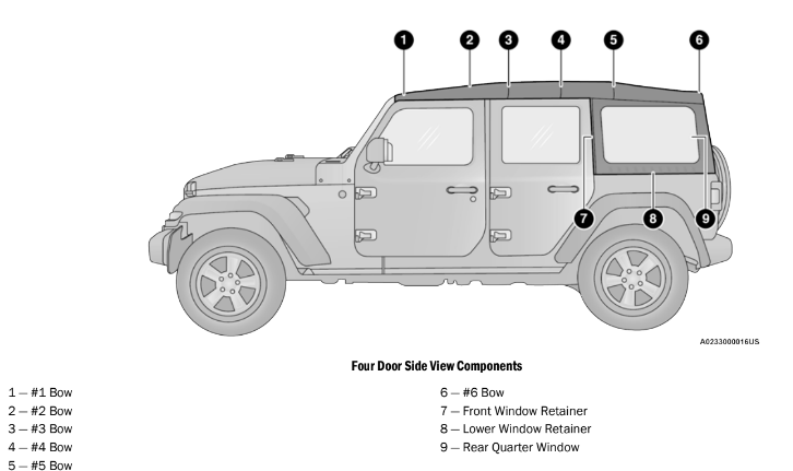
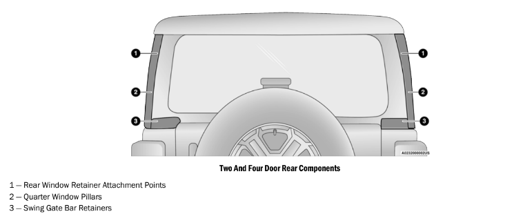
NOTE:
- All lowering and raising the soft top instruc- tions are applicable to both two and four door model vehicles.
- Images shown are of four door models, and appearance of two door model components may differ.
The following options are available to you when lowering your vehicle’s soft top:
- Sunrider® position with rear and quarter windows installed
- Sunrider® position with rear and quarter panels removed
- Sunrider® position with rear window installed and quarter panels removed
- Fully lowered position with rear and quarter windows removed
Both quarter windows should be removed and installed together.
Lowering The Soft Top Into Sunrider® Position
1. Fold both sun visors forward against the windshield.
2. Release the header latches from the crossbar by pulling the handle downward. Make sure the hook is disengaged from its receiver.
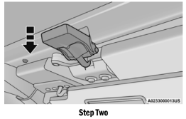
3. From both the left and right sides, lift up on the #1 Bow of the soft top to start the operation.
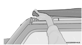
4. Move to the side of the vehicle and use the side link to fold the soft top rearward into the Sunrider® position.
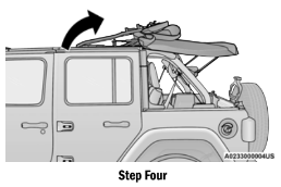
NOTE:
If leaving the soft top in the Sunrider® position, secure the top by using the two hook-and-loop fasteners provided in the center console.
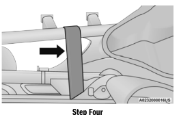
NOTE:
- The vehicle can be driven in the Sunrider® position with the rear window and quarter panel assemblies fully installed or completely removed.
- The rear window and rear quarter windows must be removed before fully lowering the soft top to prevent damage to the top. Clean the side and rear windows before removal to assist in preventing scratching during removal of the soft top. If the plastic retainers are difficult to operate due to road dust, etc., clean them with a mild soap solution and a small brush. Cleaning products are available through an authorized dealer.
Removing The Soft Top Windows
NOTE: Before fully lowering the soft top, the rear window and rear quarter windows must be removed.
Remove The Rear Window:
1. With the swing gate open, remove the rear window’s plastic retainers from the lower right and left corners.
2. Grab the swing gate bar, rotate it outward and upward releasing it from both the right and left retainers.
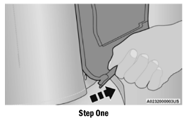
3. While holding the window in place, slide the swing gate bar to the left separating it from the rear window. Store in soft window bag (if equipped), or a safe location.
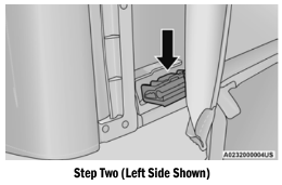
4. Remove the plastic retainers from both quarter window pillars.
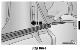
5. While keeping the rear window level, slide to the left until it is completely separate from its retainer. Do not pull downward while removing the rear window. Damage to the retainer could result.
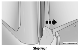
INSTALLING THE SOFT TOP
1. If currently installed, remove the hard top ⇒ page 94.
2. Install the door rails, starting with the front, followed by the rear on each side. For instructions and appropriate torque specifi- cations for the door rail Torx screws ⇒ page 102.
3. Install the rear retainers on each side of the rear of the vehicle using the provided #50 Torx head driver and ratchet. Refer to the table below for recommended torque specifications.
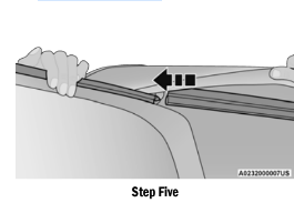
CAUTION! Do not over tighten Torx screws. Damage to the retainers will occur.
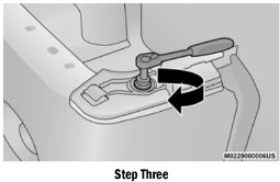
4. Making sure the lift assist mechanism is in the “lock” position, lift the soft top into the rear of the vehicle with the side links pointing toward the front. Lower the lift assist mechanisms onto its retainers on both sides (on the inside of the sport bar).
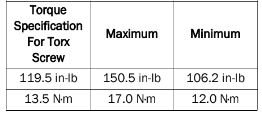
5. Using the provided #40 Torx head driver and ratchet, tighten the Torx screws by turning them clockwise. Secure them until they are snug (refer to the table below for recommended torque specifications), being careful not to cross-thread the screws or overtighten. Repeat on the opposite side.
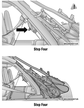
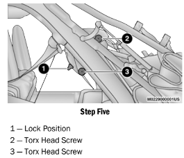
6. While pulling the release lever on the top of the rail rearward, place the side link into the guide track on the top of the rail then release the lever.
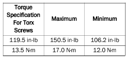
7. Unsnap and remove the black boot cover. This cover should be discarded. It was intended as a protective cover for shipping only.
8. Raise the soft top page 82.
NOTE: Be sure the wire harness in the left rear corner is not tangled in the soft top bows before you lift the top.
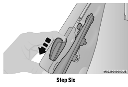
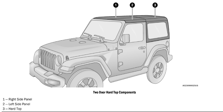
NOTE:
- All hard top removal and installation instruc- tions are applicable to both two and four door model vehicles.
- Images shown are of four door models, and appearance of two door model components may differ.
- The left side panel must be removed before removing the right side panel.
To remove the hard top front panel(s), proceed as follows:
1. Fold down the sun visor against the windshield.
2. Turn the three L-shaped locks on the left side panel (one at the front, the rear, and outside), unlocking them from the roof.
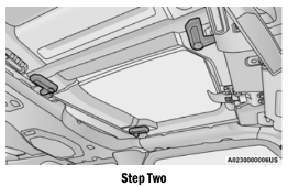
3. Unlatch the left side header panel latch located at the top of the windshield.
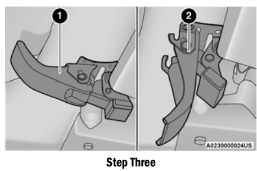
4. Remove the left side panel.
5. Repeat the steps above to remove the right side panel.
Hard Top Panel(s) Storage Bag — If Equipped
The Freedom Top panels storage bag allows you to store your hard top panels. The storage bag contains two compartments.
Lay the bag for the Freedom Top panels down so the loops and hooks are facing upward. Unzip the bag and fold back the outer flap.
NOTE:
Ensure the front panel latch is closed prior to inserting the panel into the panels bag.
- Insert the left side hard top panel into the bag with the latches facing upward.
- Unfold the black panel divider (ensure the divider is laying flat).
- Insert the right side Freedom Top panel into the bag with the latches facing downward.
NOTE:
Ensure the front panel latch is closed prior to
4. Unfold the outer flap and zip the hard top bag closed.
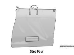
5. Lift the Freedom Top bag into the vehicle with the hooks and straps facing the back of the rear seat. Attach the clip at the bottom of the bag to the child restraint anchorage, located at the base of the rear seat.
6. Wrap the upper strap around the rear head restraints and loop the strap through the buckle. Pull on the strap to tighten the Freedom Top bag securely against the rear seat.
POWER SLIDING TOP — IF EQUIPPED
CAUTION! Lowering of the windshield is NOT recom- mended in vehicles equipped with a Power Sliding Top. Damage will occur to the top as well as the header seal.
If your vehicle is equipped with a Power Sliding Top, the control switch can be found on the front trim panel, to the right of the driver’s side sun visor.
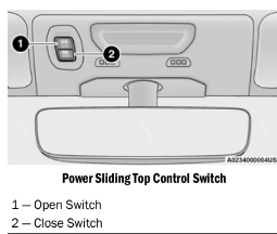
NOTE:
- The Power Top is non-removable. If desired, the rear quarter windows can be removed and stored in the provided storage bag ⇒ page 99.
- The Power Top will not open in temperatures below -4°F (-20°C). However, if it is opened at a higher temperature, it can be closed at temperatures above -40°F (-40°C).
- The Power Top will not operate at vehicle speeds above 60 mph (96 km/h).
NOTE: A slight pause in audio may be heard when opening and closing the Power Sliding Top as a result of the Uconnect system switching between Power Top Closed and Power Top Open audio modes.
Power Top Maintenance
Use only a non-abrasive cleaner and a soft cloth to clean the quarter window glass panel. For important information on cleaning and caring for your vehicle Ú page 442.
Ignition Off Operation
The power top switch can remain active in Accessory Delay for up to approximately minutes after the vehicle’s ignition is placed to the OFF position. Opening either front door will cancel this feature.
NOTE: Ignition Off time is programmable through the Uconnect system Ú page 217.
Relearn Procedure
For vehicles equipped with a power top, there is a relearn procedure that allows you to calibrate the power top when the “Express Mode” stops working. To reset the power top, follow these steps:
1. Place the ignition in the RUN position, and start the vehicle.
NOTE: The engine must be running to perform the relearn procedure.
2. Ensure the power top is in the fully closed position.
3. Push and hold the Close switch for 10 seconds. This will put the power top into calibration mode.
4. Continue holding down the close button while the top goes fully open and then back to fully close.
5. Once the power top has stopped in the fully closed position, release the close button. The power top is now reset and ready to use.
NOTE:
If the close button is released anytime during the relearning process, the relearn may not be complete, and the procedure must be repeated.
Rear Quarter Window Removal
On vehicles equipped with a Power Sliding Top, the rear quarter windows can be removed. To remove these windows, follow the procedure below:
1. Open the swing gate, and lift the rear window.
2. Open both side doors nearest the quarter windows.
3. Locate the rear quarter window latches (two on each window) on the interior of the windows.
4. Rotate the left hand side latch clockwise to release.
5. Rotate the right hand side latch counter- clockwise to release.
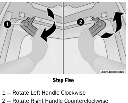
6. From the outside of the vehicle, lift each window upward and away from the vehicle.
NOTE:
Do not pull down or apply any weight to the windows after the latches are released.
Damage could result to the pins holding the windows in place.
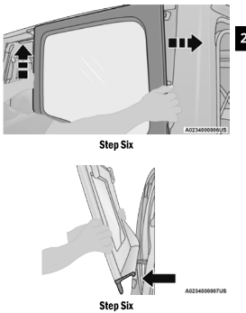
7. Store the rear quarter windows in the provided storage bag and keep in a safe location, or securely fasten the bag to the rear seat.
FOLDING WINDSHIELD
The fold-down windshield on your vehicle is a structural element that can provide some protection in some accidents. The windshield also provides some protection against weather, road debris and intrusion of small branches and other objects.
Do not drive your vehicle on-road with the windshield down, as you lose the protection this structural element can provide.
If required for certain off-road uses, the windshield can be folded down. However, the protection afforded by the windshield is then lost. If you fold down the windshield, drive slowly and cautiously. It is recommended that the speed of the vehicle be limited to 10 mph (16 km/h), with low range operation preferred if you are driving off-road with the windshield folded down.
Raise the windshield as soon as the task that required its removal is completed and before you return to on-road driving. Both you and your passengers should wear seat belts at all times, on-road and off-road, regardless of whether the windshield is raised or folded down.
RAISING THE WINDSHIELD
1. Release the strap that secured the windshield in the lowered position.
2. Raise the windshield.
3. Using the provided #40 Torx head driver, reinstall the four Torx screws located along the interior of the windshield. Secure them until they are snug, being careful not to cross-thread the screws or overtighten.
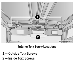
4. Reinstall the windshield wiper arms using the provided 15 mm socket. First, align the tips of the blade to the “T” mark in the glass. Then, while holding the arm in that position, reinstall the hex nut and tighten until snug. Be careful not to over-tighten. Repeat for the other arm.
5. Reinstall the protective caps over the wiper arm hex bolts and push gently until they snap into place.
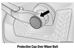
6. After completing the steps above:
- If your vehicle is equipped with a Soft Top, reinstall the Door Rails and raise the top.
- If your vehicle is equipped with a Hard Top, reinstall the Freedom Panels.
CARGO AREA FEATURES
Trail Rail Cargo Organizer — If Equipped
If your vehicle is equipped with the Trail Rail system, a rail will be found built into the floor on either side of the cargo area. Each rail contains an adjustable anchor loop that can be used to secure cargo. The position of the adjustable anchor loop can be adjusted by sliding the loop along the rail.
To adjust the anchor loop, push down on the center button while sliding the loop along the rail to the desired position. Release the button and move the loop slightly to the next fixed position in the notches of the rail.
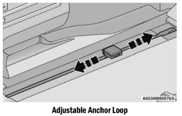
Lift the loop to use.
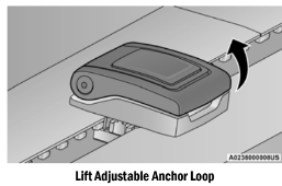
ROOF LUGGAGE RACK — IF EQUIPPED
NOTE: Roof rack applications are for Hard Top models
ONLY.
The load carried on the roof, when equipped with a luggage rack, must not exceed 100 lb (45 kg), this includes the weight of the crossbars, and it should be uniformly distributed over the cargo area.
Crossbars should always be used whenever cargo is placed on the roof rack. Check the straps frequently to be sure that the load remains securely attached.
NOTE:
Crossbars can be purchased at an authorized dealer through Mopar® parts.
External racks do not increase the total load carrying capacity of the vehicle. Be sure that the total occupant and luggage load inside the vehicle, plus the load on the luggage rack, do not exceed the maximum vehicle load capacity.
STARTING AND OPERATING
STARTING THE ENGINE — GASOLINE ENGINE (IF EQUIPPED)
Before starting your vehicle, adjust your seat, adjust both inside and outside mirrors, and fasten your seat belts.
WARNING!
- When exiting the vehicle, always remove the key fob from the ignition and lock your vehicle.
- Never leave children alone in a vehicle, or with access to an unlocked vehicle.
- Allowing children to be in a vehicle unat- tended is dangerous for a number of reasons. A child or others could be seriously or fatally injured. Children should be warned not to touch the parking brake, brake pedal or the gear selector.
- Do not leave the key fob in or near the vehicle, or in a location accessible to chil- dren. A child could operate power windows, other controls, or move the vehicle.
- Do not leave children or animals inside parked vehicles in hot weather. Interior heat build-up may cause serious injury or death.
MANUAL TRANSMISSION — IF EQUIPPED
Apply the parking brake, place the gear selector in NEUTRAL, and press the clutch pedal before starting the vehicle. This vehicle is equipped with a clutch interlocking ignition system. It will not start unless the clutch pedal is pressed to the floor.
Four-Wheel Drive Models Only
In 4WD Low mode, if the vehicle is stalled, the engine will start regardless of whether or not the clutch pedal is pressed to the floor. This feature enhances off-road performance by allowing the vehicle to start when in 4WD Low without having to press the clutch pedal. The WD Low Indicator Light” will illuminate when the transfer case has been shifted into this mode.
AUTOMATIC TRANSMISSION — IF EQUIPPED
Start the vehicle with the gear selector in the PARK position (vehicle can also be started in NEUTRAL). Apply the brake before shifting to any driving range.
NORMAL STARTING
To Turn On The Engine Using The ENGINE START/STOP Button
- The transmission must be in PARK or NEUTRAL.
- Press and hold the brake pedal while pushing the ENGINE START/STOP button once.
- The system takes over and attempts to start the vehicle. If the vehicle fails to start, the starter will disengage automatically after 10 seconds.
- If you wish to stop the cranking of the engine prior to the engine starting, push the button again.
NOTE:
Normal starting of either a cold or a warm engine is obtained without pumping or pressing the accelerator pedal.
To Turn Off The Engine Using ENGINE START/ STOP Button
- Place the gear selector in PARK, then push and release the ENGINE START/STOP button.
- The ignition will return to the OFF mode.
- If the gear selector is not in PARK (with vehicle stopped) and the ENGINE START/ STOP button is pushed once, the transmission will automatically select PARK and the engine will turn off while the ignition will remain in the ACC mode (NOT the OFF mode). Never leave a vehicle out of the PARK position, or it could roll.
- If the gear selector is in NEUTRAL, and the vehicle speed is below 5 mph (8 km/h), pushing the START/STOP button once will turn the engine off. The ignition will remain in the ACC mode.
- If the vehicle speed is above 5 mph (8 km/h), the ENGINE START/STOP button must be held for two seconds (or three short pushes in a row) to turn the engine off. The ignition will remain in the ACC mode (NOT the OFF mode) if the engine is turned off when the transmission is not in PARK.
NOTE:
The system will automatically time out and the ignition will cycle to the OFF mode after minutes of inactivity if the ignition is left in the ACC or RUN (engine not running) mode and the transmission is in PARK.
ENGINE START/STOP Button Functions — With Driver’s Foot OFF The Brake Pedal (In PARK Or NEUTRAL Position)
The ENGINE START/STOP button operates similar to an ignition switch. It has three modes: OFF, ACC, and RUN. To change the ignition modes without starting the vehicle and use the accessories, follow these steps:
- Start with the ignition in the OFF mode.
- Push the ENGINE START/STOP button once to place the ignition to the ACC mode instrument cluster will display “ACC”).
- Push the ENGINE START/STOP button a second time to place the ignition to the RUN mode (instrument cluster will display “ON/ RUN”).
- Push the ENGINE START/STOP button a third time to return the ignition to the OFF mode (instrument cluster will display OFF”).
AUTOPARK
AutoPark is a supplemental feature to assist in placing the vehicle in PARK should the situations on the following pages occur. It is a back up system and should not be relied upon as the primary method by which the driver shifts the vehicle into PARK.
The conditions under which AutoPark will engage are outlined on the following pages.
If the vehicle is not in PARK and the driver turns off the engine, the vehicle may AutoPark.
AutoPark will engage when all of these conditions are met:
- Vehicle is equipped with an eight-speed transmission
- Driver’s door is ajar or if the driver’s door is removed and the driver is not on the seat seat pad sensor detects driver missing)
- Vehicle is not in PARK
- Vehicle speed is 0 mph (0 km/h)
- Ignition switched from RUN to OFF
NOTE:
For Keyless Enter-N-Go equipped vehicles, the engine will turn off and the ignition switch will change to ACC mode.
EXTREME COLD WEATHER (BELOW –22°F OR −30°C)
To ensure reliable starting at these temperatures, use of an externally powered electric engine block heater (available from an authorized dealer) is recommended.
IF ENGINE FAILS TO START
If the engine fails to start after you have followed the “Normal Starting” or “Extreme Cold Weather” procedure, it may be flooded. Push the accelerator pedal all the way to the floor and hold it there. Crank the engine for no more than 15 seconds. This should clear any excess fuel in case the engine is flooded. Leave the ignition in the RUN position, release the accelerator pedal and repeat the “Normal Starting” procedure.
AFTER STARTING
The idle speed is controlled automatically and will decrease as the engine warms up.
STARTING THE ENGINE — DIESEL ENGINE (IF EQUIPPED)
Before starting your vehicle, adjust your seat, both inside and outside mirrors, and fasten your seat belts.
The starter is allowed to crank for up to 30-second intervals. Waiting a few minutes between such intervals will protect the starter from overheating.
WARNING!
- Before exiting a vehicle, always come to a complete stop, then shift the automatic transmission into PARK and apply the parking brake.
- Always make sure the wireless ignition node is in the OFF mode, key fob is removed from the vehicle and vehicle is locked.
- Never leave children alone in a vehicle, or with access to an unlocked vehicle. Leaving children in a vehicle unattended is dangerous for a number of reasons. A child or others could be seriously or fatally injured. Children should be warned not to touch the parking brake, brake pedal or the gear selector.
- Do not leave the key fob in or near the vehicle, or in a location accessible to chil- dren, and do not leave the ignition of a vehicle equipped with Keyless Enter-N-Go in the ACC or ON/RUN mode. A child could operate power windows, other controls, or move the vehicle.
- Do not leave children or animals inside parked vehicles in hot weather. Interior heat build-up may cause serious injury or death.
NOTE:
Engine start up in very low ambient temperature could result in evident white smoke. This condi- tion will disappear as the engine warms up.
AUTOMATIC TRANSMISSION
Start the engine with the transmission gear selector in the PARK (P) position. Apply the brake before shifting to any driving range.
EXTREME COLD WEATHER
The engine block heater is a resistance heater installed in the water jacket of the engine. It requires a 110–115 Volt AC electrical outlet with a grounded, three-wire extension cord. Its use is recommended for environments that routinely fall below -10°F (-23°C). It should be used when the vehicle has not been running overnight or longer periods and should be plugged in two hours prior to start. Its use is required for cold starts with temperatures under -20°F (-28°C).
NOTE:
The engine block heater cord is a factory installed option. If your vehicle is not equipped, heater cords are available from an authorized Mopar® dealer.
- A 12 Volt heater built into the fuel filter housing aids in preventing fuel gelling. It is controlled by a built-in thermostat.
- A Diesel Pre-Heat system both improves engine starting and reduces the amount of white smoke generated by a warming engine.
NORMAL STARTING
Observe the instrument cluster lights when starting the engine.
NOTE:
Normal starting of either a cold or a warm engine is obtained without pumping or pressing the accelerator pedal.
- Always apply the parking brake.
- Press and hold the brake pedal while pushing the ENGINE START/STOP button once.
NOTE:
A delay of the start of up to five seconds is possible under very cold conditions. The "Wait to Start" telltale will be illuminated during the pre-heat process. When the engine “Wait To Start” telltale goes off the engine will automati- cally crank.
3. The system will automatically engage the starter to crank the engine. If the vehicle fails to start, the starter will disengage automatically after 25 seconds.
4. If you wish to stop the cranking of the engine prior to the engine starting, push the ENGINE START/STOP button again.
5. Check that the Oil Pressure Warning Light has turned off.
6. Release the parking brake.
STARTING FLUIDS
The engine is equipped with a glow plug preheating system. If the instructions in this manual are followed, the engine should start in all conditions and no type of starting fluid should be used.
WARNING!
- Do not leave children or animals inside parked vehicles in hot weather. Interior heat build-up may cause serious injury or death.
- When leaving the vehicle, always make sure the keyless ignition node is in the "OFF” mode, remove the key fob from the vehicle and lock the vehicle.
- Never leave children alone in a vehicle, or with access to an unlocked vehicle.
- Allowing children to be in a vehicle unat- tended is dangerous for a number of reasons. A child or others could be seriously or fatally injured. Children should be warned not to touch the parking brake, brake pedal or the gear selector.
- Do not leave the key fob in or near the vehicle, or in a location accessible to chil- dren, and do not leave the ignition of a vehicle equipped with Keyless Enter-N-Go in the ACC or ON/RUN mode. A child could operate power windows, other controls, or move the vehicle.
NORMAL OPERATION — DIESEL ENGINE
Observe the following when the diesel engine is operating:
- All message center lights are off.
- Malfunction Indicator Light (MIL) is off.
- Engine Oil Pressure telltale is not illuminated.
- Voltmeter operation.
The voltmeter may show a gauge fluctuation at various engine temperatures. This is caused by the glow plug heating system. The number of cycles and the length of the cycling operation is controlled by the engine control module. Glow plug heater operation can run for several minutes. Once the heater operation is complete, the voltmeter needle will stabilize.
COLD WEATHER PRECAUTIONS
Operation in ambient temperature below 32°F (0°C) may require special considerations. The following charts suggest these options:
Fuel Operating Range
NOTE:
Use “Ultra Low Sulfur Diesel Fuels (ULSD)” ONLY.
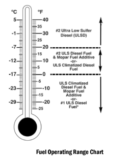
Winter Front Cover
A Winter front or cold weather cover can be used in ambient temperatures below 32°F (C), especially during extended idle conditions. This cover is equipped with four flaps for managing total grille opening in varying ambient temperatures. If a Winter front or cold weather cover is to be used, the flaps should be in the full open position to allow air flow to the cooling module and automatic transmission oil cooler. When ambient temperatures drop below F (-17°C) the four flaps need to be closed. A suitable cold weather cover is available from a Mopar® dealer.
Engine Warm-Up
Avoid full throttle operation when the engine is cold. When starting a cold engine, bring the engine up to operating speed slowly to allow the oil pressure to stabilize as the engine warms up.
If temperatures are below 32°F (0°C), operate the engine at moderate speeds for five minutes before full loads are applied.
ENGINE IDLING
Avoid prolonged idling, long periods of idling may be harmful to your engine because combustion chamber temperatures can drop so low that the fuel may not burn completely.
Incomplete combustion allows carbon and varnish to form on piston rings, cylinder head valves, and injector nozzles. Also, the unburned fuel can enter the crankcase, diluting the oil and causing rapid wear to the engine.
STOPPING THE ENGINE
After full load operation, idle the engine for a few minutes before shutting it down. This idle period will allow the lubricating oil and coolant to carry excess heat away from the turbocharger.
NOTE:
Refer to the following chart for proper engine shutdown.
COOLING SYSTEM TIPS — AUTOMATIC TRANSMISSION
To reduce the potential for engine and transmission overheating in high ambient temperature conditions, take the following actions:
- City Driving — When stopped, shift the trans- mission into NEUTRAL (N) and increase engine idle speed.
- Highway Driving — Reduce your speed.
- Up Steep Hills — Select a lower transmission gear.
- Air Conditioning — Turn it off temporarily.
NOTE:
If the coolant temperature is too high, the A/C will automatically turn off.
Do Not Operate The Engine With Low Oil Pressure
If the low oil pressure warning light turns on while driving, stop the vehicle and shut down the engine as soon as possible. A chime will sound when the light turns on.
NOTE:
Do not operate the vehicle until the cause is corrected. This light does not show how much oil is in the engine. The engine oil level must be checked under the hood.
ENGINE BLOCK HEATER — IF EQUIPPED
The engine block heater warms the engine, and permits quicker starts in cold weather. Connect the cord to a standard 110-115 Volt AC electrical outlet with a grounded, three-wire extension cord.
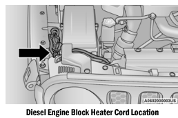
The engine block heater cord is found under the hood bundled up next to the Power Distribution Center (PDC).
For diesel engines, its use is recommended for environments that routinely fall below -10°F (-23°C). It should be used when the vehicle has not been running for long periods of time and should be plugged in two hours prior to start. Its use is required for cold starts with temperatures under -20°F (-28°C).
The engine block heater cord is found under the hood bundled in front of the battery tray.
ENGINE BREAK-IN RECOMMENDATIONS — DIESEL ENGINE (IF EQUIPPED)
The diesel engine does not require a break-in period due to its construction. Normal operation is allowed, providing the following recommendations are followed:
- Warm up the engine before placing it under load.
- Do not operate the engine at idle for prolonged periods.
- Use the appropriate transmission gear to prevent engine lugging.
- Observe vehicle oil pressure and tempera- ture indicators.
- Check the coolant and oil levels frequently.
- Vary throttle position at highway speeds when carrying or towing significant weight.
NOTE:
Light duty operation such as light trailer towing or no load operation will extend the time before the engine is at full efficiency. Reduced fuel economy and power may be seen at this time.
The engine oil installed in the engine at the factory is a high-quality energy conserving type lubricant. Oil changes should be consistent with anticipated climate conditions under which vehicle operations will occur. For recommended viscosity and quality grades see Ú page 459. NON-DETERGENT OR STRAIGHT MINERAL OILS MUST NEVER BE USED.
PARKING BRAKE
Before exiting the vehicle, make sure that the parking brake is fully applied. Also, be certain to leave an automatic transmission in PARK, or manual transmission in REVERSE or FIRST gear.
The parking brake lever is located in the center console. To apply the parking brake, pull the lever up as firmly as possible. To release the parking brake, pull the lever up slightly, push the center button, then lower the lever completely.
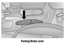
When the parking brake is applied with the ignition switch ON, the “Brake Warning Light” in the instrument cluster will illuminate.
NOTE:
- When the parking brake is applied and the automatic transmission is placed in gear, the Brake Warning Light” will flash. If vehicle speed is detected, a chime will sound to alert the driver. Fully release the parking brake before attempting to move the vehicle.
- This light only shows that the parking brake is applied. It does not show the degree of brake application.
When parking on a hill, it is important to turn the front wheels toward the curb on a downhill grade and away from the curb on an uphill grade. For vehicles equipped with an automatic transmission, apply the parking brake before placing the gear selector in PARK, otherwise the load on the transmission locking mechanism may make it difficult to move the gear selector out of PARK.
WARNING!
- Never use the PARK position on an auto- matic transmission as a substitute for the parking brake. Always apply the parking brake fully when parked to guard against vehicle movement and possible injury or damage.
- When exiting the vehicle, always remove the key fob from the ignition and lock your vehicle.
- Never leave children alone in a vehicle, or with access to an unlocked vehicle.
- Allowing children to be in a vehicle unat- tended is dangerous for a number of reasons. A child or others could be seriously or fatally injured. Children should be warned not to touch the parking brake, brake pedal or the gear selector.
- Do not leave the key fob in or near the vehicle, or in a location accessible to chil- dren. A child could operate power windows, other controls, or move the vehicle.
- Be sure the parking brake is fully disen- gaged before driving; failure to do so can lead to brake failure and a collision.
- Always fully apply the parking brake when leaving your vehicle or it may roll and cause damage or injury. Also, be certain to leave an automatic transmission in PARK, a manual transmission in REVERSE or FIRST gear. Failure to do so may cause the vehicle to roll and cause damage or injury.
MANUAL TRANSMISSION — IF EQUIPPED
WARNING!
You or others could be injured if you leave the vehicle unattended without having the parking brake fully applied. The parking brake should always be applied when the driver is not in the vehicle, especially on an incline.
NOTE: During cold weather, you may experience increased effort in shifting until the transmis- sion fluid warms up. This is normal.
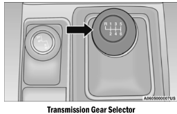
To shift the gears, fully press the clutch pedal and place the gear selector into the desired gear position (the diagram for the engagement of the gears is displayed on the handle of the selector).
To engage REVERSE gear from the NEUTRAL position, lift the REVERSE ring, located below the knob and move the gear selector all the way left and then forward.
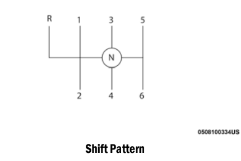
SHIFTING
Fully press the clutch pedal before shifting gears. As you release the clutch pedal, lightly press the accelerator pedal.
You should always use FIRST gear when starting from a standing position.
NOTE:
A certain amount of noise from the transmis- sion is normal. This noise can be most notice- able when the vehicle is idling in NEUTRAL with the clutch engaged (clutch pedal released), but it may also be heard when driving. The noise may also be more noticeable when the trans- mission is warm. This noise is normal and is not an indication of a problem with your clutch or transmission.
DOWNSHIFTING
Moving from a high gear down to a lower gear is recommended to preserve brakes when driving down steep hills. In addition, downshifting at the right time provides better acceleration when you desire to resume speed. Downshift progressively. Do not skip gears to avoid overspeeding the engine and clutch.
NOTE: The manual transmission shift system is equipped with gear blockers, which will prevent downshifts into FIRST or SECOND gear above certain vehicle speeds.
WARNING!
Do not downshift for additional engine braking on a slippery surface. The drive wheels could lose their grip, and the vehicle could skid.
CAUTION!
- Skipping gears and downshifting into lower gears at higher vehicle speeds can damage the engine and clutch systems. Any attempt to shift into lower gear with clutch pedal pressed may result damage to the clutch system. Shifting into lower gear and releasing the clutch may result in engine damage.
- When descending a hill, be very careful to downshift one gear at a time to prevent overspeeding the engine which can cause engine damage, and/or clutch damage, even if the clutch pedal is pressed. If transfer case is in low range the vehicle speeds to cause engine and clutch damage are significantly lower.
- Failure to follow the maximum recom- mended downshifting speeds may cause the engine damage and/or damage the clutch, even if the clutch pedal is pressed.
- Descending a hill in low range with clutch pedal pressed could result in clutch damage.
AUTOMATIC TRANSMISSION — IF EQUIPPED
You must press and hold the brake pedal while shifting out of PARK.
CAUTION!
- Shift into or out of PARK or REVERSE only after the vehicle has come to a complete stop.
- Do not shift between PARK, REVERSE, NEUTRAL, or DRIVE when the engine is above idle speed.
- Before shifting into any gear, make sure your foot is firmly pressing the brake pedal.
WARNING!
- Never use the PARK position as a substi- tute for the parking brake. Always apply the parking brake fully when exiting the vehicle to guard against vehicle movement and possible injury or damage.
- Your vehicle could move and injure you and others if it is not in PARK. Check by trying to move the transmission gear selector out of PARK with the brake pedal released. Make sure the transmission is in PARK before exiting the vehicle.
- The transmission may not engage PARK if the vehicle is moving. Always bring the vehicle to a complete stop before shifting to PARK, and verify that the transmission gear position indicator solidly indicates PARK (P) without blinking. Ensure that the vehicle is completely stopped, and the PARK position is properly indicated, before exiting the vehicle.
- It is dangerous to shift out of PARK or NEUTRAL if the engine speed is higher than idle speed. If your foot is not firmly pressing the brake pedal, the vehicle could accel- erate quickly forward or in reverse. You could lose control of the vehicle and hit someone or something. Only shift into gear when the engine is idling normally and your foot is firmly pressing the brake pedal.
- Unintended movement of a vehicle could injure those in or near the vehicle. As with all vehicles, you should never exit a vehicle while the engine is running. Before exiting a vehicle, always come to a complete stop, then apply the parking brake, shift the transmission into PARK, and turn the igni- tion OFF. When the ignition is in the OFF mode, the transmission is locked in PARK, securing the vehicle against unwanted movement.
- When exiting the vehicle, always make sure the ignition is in the OFF mode, remove the key fob from the vehicle, and lock the vehicle.
- Never leave children alone in a vehicle, or with access to an unlocked vehicle.
- Allowing children to be in a vehicle unat- tended is dangerous for a number of reasons. A child or others could be seriously or fatally injured. Children should be warned not to touch the parking brake, brake pedal or the transmission gear selector.
- Do not leave the key fob in or near the vehicle (or in a location accessible to chil- dren), and do not leave the ignition in the ACC or ON/RUN mode. A child could operate power windows, other controls, or move the vehicle.
IGNITION PARK INTERLOCK
This vehicle is equipped with an Ignition Park Interlock which requires the transmission to be in PARK before the ignition can be turned to the OFF mode. This helps the driver avoid inadvertently leaving the vehicle without placing the transmission in PARK. This system also locks the transmission in PARK whenever the ignition is in the OFF mode.
NOTE:
The transmission is NOT locked in PARK when the ignition is in the ACC mode (even though the engine will be off). Ensure that the transmission is in PARK, and the ignition is OFF (not in ACC mode) before exiting the vehicle.
BRAKE/TRANSMISSION SHIFT INTERLOCK SYSTEM
This vehicle is equipped with a BTSI system that holds the transmission gear selector in PARK unless the brakes are applied. To shift the transmission out of PARK, the engine must be running and the brake pedal must be pressed. The brake pedal must also be pressed to shift from NEUTRAL into DRIVE or REVERSE when the vehicle is stopped or moving at low speeds.
EIGHT–SPEED AUTOMATIC TRANSMISSION
The transmission gear range (PRNDM) is displayed both beside the gear selector and in the instrument cluster. To select a gear range, push the lock button on the gear selector and move the selector rearward or forward. To shift the transmission out of PARK, the engine must be running and the brake pedal must be shift from NEUTRAL into DRIVE or REVERSE when the vehicle is stopped or moving at low speeds. Select the DRIVE range for normal driving.
NOTE:
In the event of a mismatch between the gear selector position and the actual transmission gear (for example, driver selects PARK while driving), the position indicator will blink continu- ously until the selector is returned to the proper position, or the requested shift can be completed.
The electronically-controlled transmission adapts its shift schedule based on driver inputs, along with environmental and road conditions.
The transmission electronics are self- calibrating; therefore, the first few shifts on a new vehicle may be somewhat abrupt. This is a normal condition, and precision shifts will develop within a few hundred miles kilometers).
Only shift from DRIVE to PARK or REVERSE when the accelerator pedal is released and the vehicle is stopped. Be sure to keep your foot on the brake pedal when shifting between these gears.
The transmission gear selector provides PARK, REVERSE, NEUTRAL, DRIVE and MANUAL
AutoStick) shift positions. Manual shifts can be made using the AutoStick shift control. Toggling the gear selector forward (-) or rearward (+) while in the MANUAL (AutoStick) position beside the DRIVE position) will manually select the transmission gear, and will display the current gear in the instrument cluster page 158.
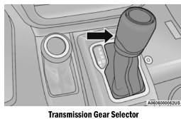
DRIVE (D)
This range should be used for most city and highway driving. It provides the smoothest upshifts and downshifts, and the best fuel economy. The transmission automatically upshifts through all forward gears. The DRIVE position should be used for all normal operating conditions.
When frequent transmission shifting occurs such as when operating the vehicle under heavy loading conditions, in hilly terrain, traveling into strong head winds, or while towing a heavy trailer), use the AutoStick shift control to select a lower gear Ú page 158. Under these conditions, using a lower gear will improve performance and extend transmission life by reducing excessive shifting and heat build-up.
During extremely cold temperatures (-22°F [-30°C] or below), transmission operation may be modified depending on engine and transmission temperature as well as vehicle speed. Normal operation will resume once the transmission temperature has risen to a suitable level.
MANUAL (M)
The MANUAL (M, +/-) position (beside the DRIVE position) enables full manual control of transmission shifting also known as AutoStick mode. Toggling the gear selector forward (-) or rearward (+) while in the MANUAL (AutoStick) position will manually select the transmission gear, and will display the current gear in the instrument cluster Ú page 158.
Transmission Limp Home Mode
Transmission function is monitored electronically for abnormal conditions. If a condition is detected that could result in transmission damage, Transmission Limp
Home Mode is activated. In this mode, the transmission may operate only in certain gears, or may not shift at all. Vehicle performance may be severely degraded and the engine may stall.
In some situations, the transmission may not re-engage if the engine is turned off and restarted. The Malfunction Indicator Light (MIL) may be illuminated. A message in the instrument cluster will inform the driver of the more serious conditions, and indicate what actions may be necessary.
In the event of a momentary problem, the transmission can be reset to regain all forward gears by performing the following steps:
NOTE:
- In cases where the instrument cluster message indicates the transmission may not re-engage after engine shutdown, perform this procedure only in a desired location preferably, at an authorized dealer).
- Even if the transmission can be reset, we recommend that you visit an authorized dealer at your earliest possible convenience. An authorized dealer has diagnostic equipment to assess the condition of your transmission.
- If the transmission cannot be reset, autho- rized dealer service is required.
- Stop the vehicle.
- Shift the transmission into PARK, if possible. If not, shift the transmission to NEUTRAL.
- Push and hold the ignition switch until the engine turns off.
- Wait approximately 30 seconds.
- Restart the engine.
- Shift into the desired gear range. If the problem is no longer detected, the transmission will return to normal operation.
AutoStick
AutoStick is a driver-interactive transmission feature providing manual shift control, giving you more control of the vehicle. AutoStick allows you to maximize engine braking, eliminate undesirable upshifts and downshifts, and improve overall vehicle performance. This system can also provide you with more control during passing, city driving, cold slippery conditions, mountain driving, trailer towing, and many other situations.
Operation
To activate AutoStick mode, move the gear selector into the MANUAL (M) position (beside the DRIVE position). The current transmission gear will be displayed in the instrument cluster.
In AutoStick mode, you can use the gear selector (in the MANUAL position) to manually shift the transmission.
AutoStick mode has the following operational benefits:
- The transmission will automatically down- shift as the vehicle slows (to prevent engine lugging) and will display the current gear.
- The transmission will automatically down- shift to FIRST gear when coming to a stop.
- After a stop, the driver should manually upshift (+) the transmission as the vehicle is accelerated.
- You can start out, from a stop, in FIRST or SECOND gear (or THIRD gear, in 4WD Low range). Tapping (+) (at a stop) will allow starting in SECOND gear. Starting out in SECOND or THIRD gear can be helpful in snowy or icy conditions.
- If a requested downshift would cause the engine to over-speed, that shift will not occur.
- The system will ignore attempts to upshift at too low of a vehicle speed.
- Holding the gear selector in the (-) position will downshift the transmission to the lowest gear possible at the current speed.
- Transmission shifting will be more noticeable when AutoStick is enabled.
- The system may revert to automatic shift mode if a fault or overheat condition is detected.
NOTE:
When Hill Descent Control is enabled, AutoStick is not active.
To disengage AutoStick mode, return the gear selector to the DRIVE position. You can shift in or out of the AutoStick position at any time without taking your foot off the accelerator pedal.
AXLE LOCK (TRU-LOK) FRONT AND REAR — IF EQUIPPED
The AXLE LOCK switch is located on the instrument panel (to the right of the steering column).
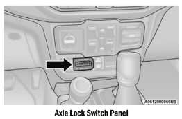
This feature will only activate when the following conditions are met:
- Ignition in RUN position, vehicle in 4WD Low.
- Vehicle speed should be 10 mph (16 km/h) or less.
- Both right and left wheels on axle are at the same speed.
To activate the system, push the AXLE LOCK switch down to lock the rear axle only (the REAR ONLY” will illuminate), push the switch up to lock the front axle and rear axle (the FRONT + REAR” will illuminate). When the rear axle is locked, pushing the bottom of switch again will lock or unlock the front axle.
NOTE:
The indicator lights will flash until the axles are fully locked or unlocked.
To unlock the axles, push the AXLE LOCK OFF button.
Axle lock will disengage if the vehicle is taken out of 4WD Low, or the ignition switch is turned to the OFF position.
The axle lock disengages at speeds above mph (48 km/h), and will automatically re-lock once vehicle speed is less than 10 mph (16 km/h).
AXLE LOCK (TRU-LOK) REAR ONLY — IF EQUIPPED
The rear axle may be locked in 4WD High if the proper conditions are met.
The AXLE LOCK switch is located on the instrument panel (to the right of the steering column).
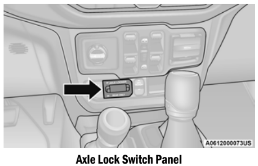
This feature will only activate when the following conditions are met:
- Ignition in RUN position, vehicle in 4WD High.
- The vehicle must be in Off Road+ active page 167.
- Vehicle must be in ESC “Full Off” mode page 298.
- Vehicle must not be actively in a high wheel slip or tight cornering condition.
To activate the system, push the AXLE LOCK switch down to lock the rear axle only (“REAR ONLY” will illuminate).
To unlock the rear axle, push the AXLE LOCK OFF button.
Axle lock will disengage if the vehicle is taken out of 4WD High, Off Road+ is turned off by the driver, ESC “Full Off” is exited, or the ignition switch is turned to the OFF position.
NOTE:
The indicator lights will flash until the rear axle is fully locked or unlocked.
The rear axle lock system may temporarily disengage the rear locker under some conditions.
If this occurs, the rear axle will automatically re-lock as soon as the system allows.
ELECTRONIC SWAY BAR DISCONNECT — IF EQUIPPED
Your vehicle may be equipped with an electronic disconnecting stabilizer/sway bar.
This system allows greater front suspension travel in off-road situations.
This system is controlled by the SWAY BAR switch located on the instrument panel (to the right of the steering column).
Push the SWAY BAR switch to activate the system. Push the switch again to deactivate the system. The “Sway Bar Indicator Light” (located in the instrument cluster) will illuminate when the bar is disconnected. The “Sway Bar Indicator Light” will flash during activation transition, or when activation conditions are not met. The stabilizer/sway bar should remain in on-road mode during normal driving conditions.
STOP/START SYSTEM — AUTOMATIC TRANSMISSION (IF EQUIPPED)
The Engine Stop/Start (ESS) function is developed to reduce fuel consumption. The system will stop the engine automatically during a vehicle stop if the required conditions are met. Releasing the brake pedal or pressing the accelerator pedal will automatically re-start the engine.
ESS vehicles have been upgraded with a heavy duty starter, enhanced battery, and other upgraded engine parts, to handle the additional engine starts. Vehicles equipped with eTorque contain a heavy duty motor generator and an additional hybrid electric battery to store energy from vehicle deceleration for use on engine startup after a stop as well as providing launch torque assist.
NOTE:
It is recommended that Stop/Start system be disabled during off-road use.
Secondary Battery
Your vehicle may be equipped with a secondary battery used to power the Stop/Start system and the 12 Volt vehicle electrical system. The secondary battery is located behind the wheel well for the front passenger wheel.
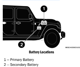
POSSIBLE REASONS THE ENGINE DOES NOT AUTOSTOP
Prior to engine shut down, the system will check many safety and comfort conditions to see if they are fulfilled. Detailed information about the operation of the Stop/Start system may be viewed in the instrument cluster display Stop/
Start Screen. Situations when the engine will not stop include (but not limited to):
- Driver’s seat belt is not buckled.
- Driver’s door is not closed.
- Battery temperature is too warm or cold.
- Battery charge is low.
- The vehicle is on a steep grade.
- Cabin heating or cooling is in process and an acceptable cabin temperature has not been achieved.
- Gear selector in MANUAL (M) mode.
- HVAC is set to full defrost mode at a high blower speed.
- HVAC set to MAX A/C.
- Engine has not reached normal operating temperature.
- Engine temperature too high.
- The transmission is not in a forward gear.
- Hood is open.
- Transfer case is in 4WD Low or N (Neutral).
- Brake pedal is not pressed with sufficient pressure.
- Accelerator pedal input.
- Vehicle speed threshold not achieved from previous Autostop.
- Steering angle beyond threshold (ESS Models Only).
- ACC is on and speed is set.
- Vehicle is at high altitude.
- System fault present.
It may be possible for the vehicle to be driven several times without the Stop/Start system going into a STOP/START READY state under more extreme conditions of the items listed above.
TO START THE ENGINE WHILE IN AUTOSTOP MODE
While in a forward gear, the engine will start when the brake pedal is released or the throttle pedal is pressed. The transmission will automatically re-engage upon engine restart.
Conditions That Will Cause The Engine To Start Automatically While In Autostop Mode:
- The transmission selector is moved out of DRIVE.
- To maintain cabin temperature comfort.
- Actual cabin temperature is significantly different than temperature set on Auto HVAC.
- HVAC is set to full defrost mode.
- HVAC system temperature or fan speed is manually adjusted higher.
- Battery voltage drops too low.
- Stop/Start OFF switch is pushed.
- A Stop/Start system error occurs.
- STOP/START AUTO STOP ACTIVE time exceeds 5 minutes.
- Transfer case is in 4WD Low or N (Neutral).
- Steering wheel is turned beyond threshold (ESS Models Only).
TO MANUALLY TURN ON THE STOP/ START SYSTEM
Push the Stop/Start OFF switch (located on the switch bank). The light on the switch will turn off.
SYSTEM MALFUNCTION
If there is a malfunction in the Stop/Start system, the system will not shut down the engine. A “SERVICE STOP/START SYSTEM” message will appear in the instrument cluster display ⇒ page 114.
If the “SERVICE STOP/START SYSTEM” message appears in the instrument cluster display, have the system checked by an authorized dealer.
If a malfunction occurs during an autostop, the vehicle may not auto start and will need a key start.
STOP/START SYSTEM — MANUAL TRANSMISSION (IF EQUIPPED)
The Engine Stop/Start (ESS) function is developed to reduce fuel consumption. The system will stop the engine automatically during a vehicle stop if the required conditions are met. Pressing the clutch pedal will automatically restart the vehicle.
ESS vehicles have been upgraded with a heavy duty starter, enhanced battery, and other upgraded engine parts, to handle the additional engine starts. Vehicles equipped with eTorque contain a heavy duty motor generator and an additional hybrid electric battery to store energy from vehicle deceleration for use on engine startup after a stop as well as providing launch torque assist.
NOTE:
It is recommended that Stop/Start be disabled during off-road use.
Secondary Battery
Your vehicle may be equipped with a secondary battery used to power the Stop/Start system and the 12 Volt vehicle electrical system. The secondary battery is located behind the wheel well for the front passenger wheel.
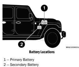
POSSIBLE REASONS THE ENGINE DOES NOT AUTOSTOP
Prior to engine shut down, the system will check many safety and comfort conditions to see if they are fulfilled. Situations when the engine will not stop include (but not limited to):
- Driver’s seat belt is not buckled.
- Outside temperature is less than 10°F (–12°C) or greater than 109°F (43°C).
- Actual cabin temperature is significantly different than temperature set on Auto HVAC.
- HVAC is set to full defrost mode.
- Engine has not reached normal operating temperature.
- Battery discharged.
- When driving in REVERSE.
- Hood is open.
- Transfer case is in 4WD Low or N (Neutral).
- Driver's seat is not occupied or driver’s door is open.
- Vehicle is at high altitude.
- The vehicle is on a steep grade.
- Forward Gear is engaged.
- Steering angle beyond threshold. (ESS
- Models Only).
- System fault is present.
- HVAC set to MAX A/C.
It may be possible for the vehicle to be driven several times without the Stop/Start system going into a STOP/START READY state under more extreme conditions of the items listed above.
TO MANUALLY TURN ON THE STOP/ START SYSTEM
Push the Stop/Start OFF switch (located on the switch bank). The light on the switch will turn off.
SYSTEM MALFUNCTION
If there is a malfunction in the Stop/Start system, the system will not shut down the engine. A “SERVICE STOP/START SYSTEM” message will appear in the instrument cluster display ⇒ page 114.
If the “SERVICE STOP/START SYSTEM” message appears in the instrument cluster display, have the system checked by an authorized dealer.
If a malfunction occurs during an autostop, the vehicle may not auto start and will need a key start.
CRUISE CONTROL SYSTEMS — IF EQUIPPED
Your vehicle may be equipped with the Cruise Control system, or the Adaptive Cruise Control (ACC) system:
- Cruise Control for cruising at a constant preset speed.
- Adaptive Cruise Control (ACC) for maintaining a set distance between you and the vehicle ahead using Fixed Speed Cruise Control to automatically adjust the preset speed.
NOTE:
In vehicles equipped with ACC, if an ACC distance is not set, Fixed Speed Cruise Control will not detect vehicles directly ahead of you.
Always be aware of the mode selected.
CRUISE CONTROL — IF EQUIPPED
When engaged, the Cruise Control takes over accelerator operations at speeds greater than 20 mph (32 km/h).
The Cruise Control buttons are located on the right side of the steering wheel.
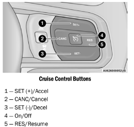
NOTE:
In order to ensure proper operation, the Cruise Control system has been designed to shut down if multiple Cruise Control functions are operated at the same time. If this occurs, the Cruise Control system can be reactivated by pushing the Cruise Control on/off button and resetting the desired vehicle set speed.
PARKSENSE SENSORS
The four ParkSense sensors, located in the rear fascia/bumper, monitor the area behind the vehicle that is within the sensors’ field of view.
The sensors can detect obstacles from approximately 12 inches (30 cm) up to inches (200 cm) from the rear fascia/ bumper in the horizontal direction, depending on the location, type and orientation of the obstacle.
PARKSENSE WARNING DISPLAY
The ParkSense Warning screen is located within the instrument cluster display Ú page 114. It provides visual warnings to indicate the distance between the rear fascia/bumper and the detected obstacle.
PARKSENSE DISPLAY
When the vehicle is in REVERSE, the instrument cluster display will show the park assist ready system status.
The system will indicate a detected obstacle by showing a single arc in one or more regions based on the obstacle’s distance and location relative to the vehicle.
If an obstacle is detected in the center rear region, the display will show a single solid arc in the center rear region and will produce a one-half second tone. As the vehicle moves closer to the obstacle, the display will show the single arc moving closer to the vehicle and the sound tone will change from slow, to fast, to continuous.
If an obstacle is detected in the left and/or right rear region, the display will show a single flashing arc in the left and/or right rear region and will produce a fast sound tone. As the vehicle moves closer to the obstacle, the display will show the single arc moving closer to the vehicle and the tone will change from fast to continuous.
SERVICE THE PARKSENSE REAR PARK ASSIST SYSTEM
During vehicle start up, when the ParkSense Rear Park Assist System has detected a faulted condition, the instrument cluster display will actuate a single chime, once per ignition cycle, and it will display the “PARKSENSE UNAVAILABLE WIPE REAR SENSORS” or the PARKSENSE UNAVAILABLE SERVICE REQUIRED” message.
When the gear selector is moved to REVERSE and the system has detected a faulted condition, the instrument cluster display will show the "PARKSENSE UNAVAILABLE WIPE REAR SENSORS" or "PARKSENSE UNAVAILABLE SERVICE REQUIRED" message for as long as the vehicle is in REVERSE. Under this condition, ParkSense will not operate.
If “PARKSENSE UNAVAILABLE WIPE REAR SENSORS” appears in the instrument cluster display, make sure the outer surface and the underside of the rear fascia/bumper is clean and clear of snow, ice, mud, dirt or other obstruction and then cycle the ignition. If the message continues to appear, see an authorized dealer.
If “PARKSENSE UNAVAILABLE SERVICE REQUIRED” appears in the instrument cluster display, see an authorized dealer.
CLEANING THE PARKSENSE SYSTEM
Clean the Rear Park Assist sensors with water, car wash soap and a soft cloth. Do not use rough or hard cloths. In washing stations, clean sensors quickly keeping the vapor jet/high pressure washing nozzles at least 4 inches (10 cm) from the sensors. Do not scratch or poke the sensors.
PARKSENSE SYSTEM USAGE PRECAUTIONS
NOTE:
- Ensure that the rear fascia/bumper is free of snow, ice, mud, dirt and debris to keep the ParkSense system operating properly.
- Jackhammers, large trucks, and other vibra- tions could affect the performance of Park- Sense.
- When you turn ParkSense off, the instrument cluster display will read “PARKSENSE OFF.”
- Furthermore, once you turn ParkSense off, it remains off until you turn it on again, even if you cycle the ignition.
- ParkSense, when on, will reduce the volume of the radio when it is sounding a tone.
- Clean the ParkSense sensors regularly, taking care not to scratch or damage them.
- The sensors must not be covered with ice, snow, slush, mud, dirt or debris. Failure to do so can result in the system not working prop- erly. The ParkSense system might not detect an obstacle behind the fascia/bumper, or it could provide a false indication that an obstacle is behind the fascia/bumper.
- Use the ParkSense switch to turn the Park- Sense system off if objects such as bicycle carriers, trailer hitches, etc. are placed within 12 inches (30 cm) from the rear fascia/ bumper. Failure to do so can result in the system misinterpreting a close object as a sensor problem, causing the “PARKSENSE UNAVAILABLE SERVICE REQUIRED” message to be displayed in the instrument cluster display.
PARKVIEW REAR BACK UP CAMERA
The ParkView Rear Back Up Camera allows you to see an on-screen image of the rear surroundings of your vehicle whenever the gear selector is put into REVERSE. The image will be displayed in the touchscreen display along with a caution note to “Check Entire Surroundings” across the top of the screen. After five seconds this note will disappear. The ParkView camera is located on the rear of the vehicle in the center of the spare tire.
Manual Activation Of The Rear View Camera
- Press the “Controls” button located on the bottom of the Uconnect display.
- Press the “Backup Camera” button to turn the Rear View Camera system on.
When the vehicle is shifted out of REVERSE (with Camera delay turned off), the rear Camera mode is exited and the previous screen appears again.
When the vehicle is shifted out of REVERSE with Camera delay turned on), the rear Camera image will be displayed for up to 10 seconds unless the vehicle speed exceeds 8 mph km/h), the transmission is shifted into PARK, the ignition is placed in the OFF position, or the touchscreen button “X” to disable display of the Rear View Camera image is pressed.
Whenever the Rear View Camera image is activated through the “Backup Camera” button in the “Controls” menu, and the vehicle speed is greater than, or equal to, 8 mph (13 km/h), a display timer for the image is initiated. The image will continue to be displayed until the display timer exceeds 10 seconds.
NOTE:
- If the vehicle speed remains below 8 mph km/h), the Rear View Camera image will be displayed continuously until deactivated via the touchscreen button “X”, the transmis- sion is shifted into PARK, or the ignition is placed in the OFF position.
- The touchscreen button “X” to disable display of the camera image is made available ONLY when the vehicle is not in REVERSE.
When enabled, active guidelines are overlaid on the image to illustrate the width of the vehicle and its projected backup path based on the steering wheel position. A dashed center line overlay indicates the center of the vehicle to assist with parking or aligning to a hitch/ receiver.
When enabled, fixed guidelines are overlaid on the image to illustrate the width of the vehicle.
Different colored zones indicate the distance to the rear of the vehicle.
REFUELING THE VEHICLE — GASOLINE ENGINE (IF EQUIPPED)
FUEL FILLER CAP
The fuel filler cap is located on the driver's side of the vehicle. If the fuel filler cap is lost or damaged, be sure the replacement cap is the correct one for this vehicle.
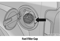
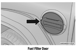
WARNING!
- Never have any smoking materials lit in or near the vehicle when the fuel door is open or the tank is being filled.
- Never add fuel when the engine is running.
- This is in violation of most state and federal fire regulations and may cause the Malfunction Indicator Light” to turn on.
- A fire may result if fuel is pumped into a portable container that is inside of a vehicle. You could be burned. Always place fuel containers on the ground while filling.
CAUTION!
- Damage to the fuel system or emission control system could result from using an improper fuel filler cap. A poorly fitting cap could let impurities into the fuel system. Also, a poorly fitting aftermarket cap can cause the “Malfunction Indicator Light (MIL)” to illuminate, due to fuel vapors escaping from the system.
- To avoid fuel spillage and overfilling, do not top off” the fuel tank after filling.
NOTE:
- When the fuel nozzle “clicks” or shuts off, the fuel tank is full.
- Tighten the fuel filler cap about a quarter turn until you hear one click. This is an indication that the cap is properly tightened.
- If the fuel filler cap is not tightened properly, the MIL will come on. Be sure the cap is tight- ened every time the vehicle is refueled.
LOOSE FUEL FILLER CAP MESSAGE
After fuel has been added, the vehicle diagnostic system can determine if the fuel filler cap is possibly loose, improperly installed, or damaged. If the system detects a malfunction, the “gASCAP” message will display in the odometer display. Tighten the gas cap until a clicking" sound is heard. This is an indication that the gas cap is properly tightened. Push the odometer reset button to turn the message off.
If the problem persists, the message will appear the next time the vehicle is started. This might indicate a damaged cap. If the problem is detected twice in a row, the system will turn on the MIL. Resolving the problem will turn the MIL off.
REFUELING THE VEHICLE — DIESEL ENGINE (IF EQUIPPED)
The fuel filler cap is located on the driver's side of the vehicle. If the fuel filler cap is lost or damaged, be sure the replacement cap is the correct one for this vehicle.
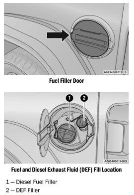
NOTE:
- When the fuel nozzle “clicks” or shuts off, the fuel tank is full.
- Tighten the fuel filler cap about a quarter turn until you hear one click. This is an indication that the cap is properly tightened.
CAUTION!
For diesel engines, only use diesel fuel for motor vehicles in accordance with EN 590 European specifications. The use of other products or mixtures may damage the engine beyond repair and consequently void the warranty, due to the damage caused. If you accidentally introduce other types of fuel into the tank, do not start the engine. Empty the tank. If the engine has been run for even an extremely limited amount of time, you must not only drain the fuel tank, but the rest of the supply circuit as well.
AVOID USING CONTAMINATED FUEL
Fuel that is contaminated by water or dirt can cause severe damage to the engine fuel system. Proper maintenance of the engine fuel filter and fuel tank is essential see Ú page 395.
BULK FUEL STORAGE — DIESEL FUEL
If you store quantities of fuel, good maintenance of the stored fuel is also essential. Fuel contaminated with water will promote the growth of “microbes.” These microbes form slime” that will clog the fuel filtration system and lines. Drain condensation from the supply tank and change the line filter on a regular basis.
NOTE:
When a diesel engine is allowed to run out of fuel, air is pulled into the fuel system.
If the vehicle will not start see Ú page 397.
VEHICLE LOADING
CERTIFICATION LABEL
As required by National Highway Traffic Safety
Administration regulations, your vehicle has a certification label affixed to the driver's side door or pillar.
This label contains the month and year of manufacture, Gross Vehicle Weight Rating (GVWR), Gross Axle Weight Rating (GAWR) front and rear, and Vehicle Identification Number (VIN). A Month-Day-Hour (MDH) number is included on this label and indicates the Month, Day and Hour of manufacture. The bar code that appears on the bottom of the label is your VIN.
Gross Vehicle Weight Rating (GVWR)
The GVWR is the total permissible weight of your vehicle including driver, passengers, vehicle, options and cargo. The label also specifies maximum capacities of front and rear axle systems (GAWR). Total load must be limited so GVWR and front and rear GAWR are not exceeded.
Payload
The payload of a vehicle is defined as the allowable load weight a truck can carry, including the weight of the driver, all passengers, options and cargo.
Gross Axle Weight Rating (GAWR)
The GAWR is the maximum permissible load on the front and rear axles. The load must be distributed in the cargo area so that the GAWR of each axle is not exceeded.
Each axle GAWR is determined by the components in the system with the lowest load carrying capacity (axle, springs, tires or wheels). Heavier axles or suspension components sometimes specified by purchasers for increased durability does not necessarily increase the vehicle's GVWR.
Tire Size
The tire size on the Vehicle Certification Label represents the actual tire size on your vehicle. Replacement tires must be equal to the load capacity of this tire size.
Rim Size
This is the rim size that is appropriate for the tire size listed.
Inflation Pressure
This is the cold tire inflation pressure for your vehicle for all loading conditions up to full GAWR.
Curb Weight
The curb weight of a vehicle is defined as the total weight of the vehicle with all fluids, including vehicle fuel, at full capacity conditions, and with no occupants or cargo loaded into the vehicle. The front and rear curb weight values are determined by weighing your vehicle on a commercial scale before any occupants or cargo are added.
Loading
The actual total weight and the weight of the front and rear of your vehicle at the ground can best be determined by weighing it when it is loaded and ready for operation.
TRAILER AND TONGUE WEIGHT
Never exceed the maximum tongue weight stamped on your bumper or trailer hitch.
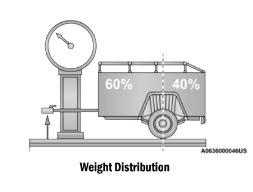
Consider the following items when computing the weight on the rear axle of the vehicle:
- The tongue weight of the trailer.
- The weight of any other type of cargo or equipment put in or on your vehicle.
- The weight of the driver and all passengers.
NOTE:
Remember that everything put into or on the trailer adds to the load on your vehicle. Also, additional factory-installed options or dealer-installed options must be considered as part of the total load on your vehicle. Refer to the “Tire And Loading Information” placard for the maximum combined weight of occupants and cargo for your vehicle.
TOWING REQUIREMENTS
To promote proper break-in of your new vehicle drivetrain components, the following guidelines are recommended:
DRIVING TIPS
ON-ROAD DRIVING TIPS
Utility vehicles have higher ground clearance and a narrower track to make them capable of performing in a wide variety of off-road applications. Specific design characteristics give them a higher center of gravity than conventional passenger cars.
An advantage of the higher ground clearance is a better view of the road, allowing you to anticipate problems. They are not designed for cornering at the same speeds as conventional passenger cars any more than low-slung sports cars are designed to perform satisfactorily in
OFF-ROAD DRIVING TIPS
Side Step Removal — If Equipped
NOTE:
Prior to off-road usage, the side steps should be removed to prevent damage if so equipped.
1. Remove both nuts and bolt from the underside of the vehicle for each bracket.
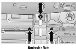
2. Remove the side step assembly.
Bumper End Cap Removal
The end caps on your vehicle’s front fascia/ bumper can be removed by following the steps below:
NOTE:
Bumper end caps are removable on steel fascia/bumper only.
1. Loosen the two bolts that retain the GAWR bracket (Bolts #1 and #2) to the end cap using a T45 torx bit screw driver. Do not remove the bolts.
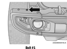
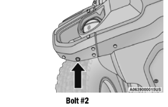
2. Remove the remaining 8 bolts.
3. Gently remove the end cap from the vehicle and store it where it will not get damaged.
4. Repeat this procedure on the other side.
The Basics Of Off-Road Driving
You will encounter many types of terrain driving off-road. You should be familiar with the terrain and area before proceeding. There are many types of surface conditions: hard-packed dirt, gravel, rocks, grass, sand, mud, snow and ice. Every surface has a different effect on your vehicle's steering, handling and traction. Controlling your vehicle is one of the keys to successful off-road driving, so always keep a firm grip on the steering wheel and maintain a good driving posture. Avoid sudden accelerations, turns or braking. In most cases, there are no road signs, posted speed limits or signal lights. Therefore, you will need to use your own good judgment on what is safe and what is not. When on a trail, you should always be looking ahead for surface obstacles and changes in terrain. The key is to plan your future driving route while remembering what you are currently driving over.
NOTE:
It is recommended that the Stop/Start System be disabled during off-road use.
When To Use 4WD Low Range
When off-road driving, shift into 4WD Low for additional traction and control on slippery or difficult terrain, ascending or descending steep hills, and to increase low speed pulling power. This range should be limited to extreme situations such as deep snow, mud, steep inclines, or sand where additional low speed pulling power is needed. Vehicle speeds in excess of 25 mph (40 km/h) should be avoided when in 4WD Low.
Driving In Snow, Mud And Sand
Snow
In heavy snow or for additional control and traction at slower speeds, shift the transmission into a low gear and the transfer case into 4WD Low if necessary. Do not shift to a lower gear than necessary to maintain headway. Over-revving the engine can spin the wheels and traction will be lost. If you start to slow to a stop, try turning your steering wheel no more than a 1/4 turn quickly back and forth, while still applying throttle. This will allow the tires to get a fresh "bite" and help maintain your momentum.
MAINTENANCE
CHECKING OIL LEVEL
To ensure proper engine lubrication, the engine oil must be maintained at the correct level.
Check the oil level at regular intervals, such as every fuel stop. The best time to check the engine oil level is about five minutes after a fully warmed up engine is shut off.
Checking the oil while the vehicle is on level ground will improve the accuracy of the oil level readings.
There are four possible dipstick types:
- Crosshatched zone.
- Crosshatched zone marked SAFE.
- Crosshatched zone marked with MIN at the low end of the range and MAX at the high end of the range.
- Crosshatched zone marked with dimples at the MIN and the MAX ends of the range.
NOTE:
Always maintain the oil level within the cross- hatch markings on the dipstick.
Adding 1 quart (1 liter) of oil when the reading is at the low end of the dipstick range will raise the oil level to the high end of the range marking.
ADDING WASHER FLUID
The fluid reservoir for the windshield washers and the rear window washer (if equipped) is shared. The fluid reservoir is located in the engine compartment. Be sure to check the fluid level at regular intervals. Fill the reservoir with windshield washer solvent only (not radiator antifreeze). When refilling the washer fluid reservoir, take some washer fluid and apply it to a cloth or towel and wipe clean the wiper blades; this will help blade performance.
To prevent freeze-up of your windshield washer system in cold weather, select a solution or mixture that meets or exceeds the temperature range of your climate. This rating information can be found on most washer fluid containers.
MAINTENANCE-FREE BATTERY
Your vehicle is equipped with a maintenance-free battery. You will never have to add water, and periodic maintenance is not required.
WARNING!
- Battery fluid is a corrosive acid solution and can burn or even blind you. Do not allow battery fluid to contact your eyes, skin, or clothing. Do not lean over a battery when attaching clamps. If acid splashes in eyes or on skin, flush the area immediately with large amounts of water ⇒ page 368.
- Battery gas is flammable and explosive. Keep flame or sparks away from the battery. Do not use a booster battery or any other booster source with an output greater than 12 Volts. Do not allow cable clamps to touch each other.
- Battery posts, terminals, and related acces- sories contain lead and lead compounds. Wash hands after handling.
- Vehicles with the Stop/Start system will be equipped with two batteries. Both the main and the supplemental batteries must be disconnected to completely de-energize the Volt electrical system.
- Serious injury or death could result if you do not disconnect both batteries. To learn how to properly disconnect, see an authorized dealer.
CAUTION!
- It is essential when replacing the cables on the battery that the positive cable is attached to the positive post and the nega- tive cable is attached to the negative post. Battery posts are marked positive (+) and negative (-) and are identified on the battery case. Cable clamps should be tight on the terminal posts and free of corrosion.
- If a “fast charger” is used while the battery is in the vehicle, disconnect both vehicle battery cables before connecting the charger to the battery. Do not use a “fast charger” to provide starting voltage.
- Vehicles with the Stop/Start system will be equipped with two batteries. Both the main and the supplemental batteries must be disconnected to completely de-energize the 12 Volt electrical system.
- If the negative battery cables are not isolated properly it can cause a potential power spike or surge in the system, resulting in damage to essential electrical components.
PRESSURE WASHING
Cleaning the engine compartment with a high pressure washer is not recommended.
CAUTION!
Precautions have been taken to safeguard all parts and connections however, the pressures generated by these machines is such that complete protection against water ingress cannot be guaranteed.
VEHICLE MAINTENANCE
An authorized dealer has the qualified service personnel, special tools, and equipment to perform all service operations in an expert manner. Service Manuals are available which include detailed service information for your vehicle. Refer to these Service Manuals before attempting any procedure yourself.
NOTE:
Intentional tampering with emissions control systems may void your warranty and could result in civil penalties being assessed against you.
WARNING!
You can be badly injured working on or around a motor vehicle. Only do service work for which you have the knowledge and the proper equipment. If you have any doubt about your ability to perform a service job, take your vehicle to a competent mechanic.
ENGINE OIL
Engine Oil Selection — 2.0L Engine (If Equipped)
For best performance and maximum protection under all types of operating conditions, the manufacturer only recommend engine oils that are API SP/GF-6A certified and meet the requirements of the manufacturer Material Standard MS-13340. An equivalent full synthetic engine oil can be used if it meets API SP/GF-6A Certification. If API SP/GF-6A or equivalent oil is unavailable then please contact your local dealership for recommendation.
Engine Oil Selection — 3.6L Engine (If Equipped)
For best performance and maximum protection under all types of operating conditions, the manufacturer only recommends engine oils that are API Certified and meet the requirements of the manufacturer Material Standard MS-6395.
Engine Oil Selection — Diesel Engine
For best performance and maximum protection under all types of operating conditions, FCA recommends engine oils that meet the requirements of the manufacturer Material Standard MS-12991, and that are API SN certified and meet the requirements of the manufacturer.
American Petroleum Institute (API) Engine Oil Identification Symbol
 This symbol means that the oil has been certified by the American Petroleum Institute (API). The manufacturer only recommends API Certified engine oils. This symbol certifies 0W-20, 5W-20, 0W-30, 5W-30 and 10W-30 engine oils.
CAUTION!
Do not use chemical flushes in your engine oil as the chemicals can damage your engine. Such damage is not covered by the New Vehicle Limited Warranty.
Synthetic Engine Oils
You may use synthetic engine oils provided the recommended oil quality requirements are met, and the recommended maintenance intervals for oil and filter changes are followed.
Synthetic engine oils which do not have both the engine oil certification mark and the correct SAE viscosity grade number should not be used.
Materials Added To Engine Oil
The manufacturer strongly recommends against the addition of any additives (other than leak detection dyes) to the engine oil. Engine oil is an engineered product and its performance may be impaired by supplemental additives.
Disposing Of Used Engine Oil And Oil Filters
Care should be taken in disposing of used engine oil and oil filters from your vehicle. Used oil and oil filters, indiscriminately discarded, can present a problem to the environment. Contact an authorized dealer, service station or governmental agency for advice on how and where used oil and oil filters can be safely discarded in your area.
ENGINE OIL FILTER
The engine oil filter should be replaced with a new filter at every engine oil change.
Engine Oil Filter Selection
A full-flow type disposable oil filter should be used for replacement. The quality of replacement filters varies considerably. Only high quality Mopar® filters should be used.
ENGINE AIR CLEANER FILTER
For the proper maintenance intervals
⇒ page 378 for gasoline engines or
⇒ page 383 for diesel engines.
NOTE:
Be sure to follow the “Severe Duty Conditions” maintenance interval if applicable.
WARNING!
The air induction system (air cleaner, hoses, etc.) can provide a measure of protection in the case of engine backfire. Do not remove the air induction system (air cleaner, hoses, etc.) unless such removal is necessary for repair or maintenance. Make sure that no one is near the engine compartment before starting the vehicle with the air induction system (air cleaner, hoses, etc.) removed. Failure to do so can result in serious personal injury.
Engine Air Cleaner Filter Selection
The quality of replacement engine air cleaner filters varies considerably. Only high quality Mopar® filters should be used.
Engine Air Cleaner Filter Inspection and Replacement — Gasoline Engine
Follow the recommended maintenance intervals as shown in the Maintenance Schedule in this section.
Engine Air Cleaner Filter Removal
1. Loosen the fasteners from the engine air cleaner filter cover using a suitable tool.
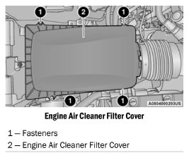
2. Lift the engine air cleaner filter cover to access the engine air cleaner filter.
3. Remove the engine air cleaner filter from the housing assembly.
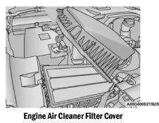
Engine Air Cleaner Filter Installation
NOTE:
Inspect and clean the housing if dirt or debris is present before replacing the engine air cleaner filter.
- Install the engine air cleaner filter into the housing assembly with the engine air cleaner filter inspection surface facing downward.
- Tighten engine air cleaner filter cover fasteners using a suitable tool.
Engine Air Cleaner Filter Inspection and Replacement — Diesel Engine
Follow the recommended maintenance intervals as shown in the Maintenance Schedule in this section.
Engine Air Cleaner Filter Removal
1. Loosen the fasteners from the engine air cleaner filter cover using a suitable tool.
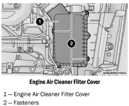
2. Lift the engine air cleaner filter cover to access the engine air cleaner filter.
3. Remove the engine air cleaner filter from the housing assembly.
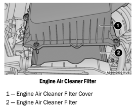
Engine Air Cleaner Filter Installation
NOTE:
Inspect and clean the housing if dirt or debris is present before replacing the engine air cleaner filter.
- Install the engine air cleaner filter into the housing assembly with the engine air cleaner filter inspection surface facing downward.
- Tighten engine air cleaner filter cover fasteners using a suitable tool.
DRAINING FUEL/WATER SEPARATOR FILTER — DIESEL ENGINE
The fuel/water separator housing is located inside the left frame rail in front of the fuel tank. The best access to this water drain valve is from under the vehicle.
CAUTION!
- Do not drain the fuel/water separator filter when the engine is running.
- Diesel fuel will damage blacktop paving surfaces. Drain the filter into an appro- priate container.
If necessary remove the fuel filter protective cover to access the water drain valve.
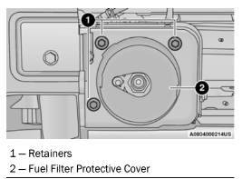
If water is detected in the water separator while the engine is running, or while the ignition switch is in the ON position, the “Water In Fuel Indicator Light” will illuminate and an audible chime will be heard. At this point you should stop the engine and drain the water from the filter housing.
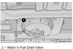
Within 10 minutes of vehicle shutdown, turn the filter drain valve (located on the bottom of the filter housing) counterclockwise to drain fuel/ water; allow the accumulated water to drain. Leave the drain valve open until all water and contaminants have been removed. When clear fuel is visible, close the drain valve by turning it clockwise.
Upon proper draining of the water from fuel filter assembly, the “Water In Fuel Indicator Light” will remain illuminated for approximately 10 seconds. If the water was drained while the engine was running, the “Water In Fuel Indicator Light” may remain on for approximately three minutes.
NOTE:
Care should be taken in disposing of used fluids from your vehicle. Used fluids, indiscriminately discarded, can present a problem to the envi- ronment. Contact an authorized dealer, service station, or government agency for advice on recycling programs and for where used fluids and filters can be properly disposed of in your area.
If more than two ounces or 60 ml of fuel have been drained, follow the directions for Priming If The Engine Has Run Out Of Fuel Ú page 397.
FUEL FILTER REPLACEMENT — DIESEL ENGINE
NOTE:
Using a fuel filter that does not meet the manu- facturer’s filtration and water separating requirements can severely impact fuel system life and reliability. We recommend you use Mopar® Fuel Filter. Must meet 3 micron rating.
CAUTION!
- Diesel fuel will damage blacktop paving surfaces. Drain the filter into an appro- priate container.
- Do not prefill the fuel filter when installing a new fuel filter. There is a possibility debris could be introduced into the fuel filter during this action. It is best to install the filter dry and allow the in-tank lift pump to prime the fuel system.
1. Ensure engine is turned off.
2. Remove the fuel filter protective cover to access the fuel filter assembly.
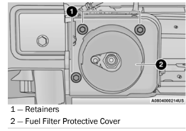
3. Place drain pan under the fuel filter assembly.
4. Open the water drain valve, and let any accumulated water and fuel drain.
5. Close the water drain valve.
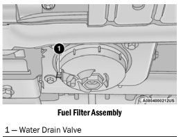
6. Wipe clean the underside of the filter housing to prevent contamination from entering fuel system during service.
7. Remove the fuel filter cap and filter from the housing using a socket. Rotate counter- clockwise for removal.
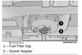
8. Remove the used fuel filter cartridge from the cap and dispose of according to your local regulations.
9. Wipe clean the sealing surfaces of the cap and housing.
10. ubricate o-ring on the cap with clean engine oil.
11. Install the new fuel filter cartridge onto the cap.
12. Insert the cap and filter into the housing with clockwise rotation, use a socket to tighten.
13. After engine start, verify the fuel filter cap does not leak.
PRIMING IF THE ENGINE HAS RUN OUT OF FUEL — DIESEL ENGINE
WARNING!
Do not open the high pressure fuel system with the engine running. Engine operation causes high fuel pressure. High pressure fuel spray can cause serious injury or death.
- Add a substantial amount of fuel to the tank, approximately 2 to 5 gal (8L to 19L).
- Push ignition switch twice without your foot on brake to put vehicle in RUN position. This will activate the in tank fuel pump for approximately 30 seconds. Repeat this process twice.
- Start the engine using the Normal Starting procedure ⇒ page 143.
CAUTION! The starter motor will engage for approximately 30 seconds at a time. Allow two minutes between cranking intervals.
NOTE: The engine may run rough until the air is forced from all the fuel lines.
WARNING!
Do not use alcohol or gasoline as a fuel blending agent. They can be unstable under certain conditions and be hazardous or explosive when mixed with diesel fuel.
CAUTION!
Due to lack of lubricants in alcohol or gasoline, the use of these fuels can cause damage to the fuel system.
NOTE:
Use of biodiesel mixture in excess of 20% can negatively impact the fuel filter's ability to separate water from the fuel, resulting in high pressure fuel system corrosion or damage.
In addition, commercially available fuel addi- tives are not necessary for the proper opera- tion of your diesel engine.
For extreme cold conditions, "Mopar®
Premium Diesel Fuel Treatment" is recom- mended to assist with cold starting.
INTERVENTION REGENERATION STRATEGY — MESSAGE PROCESS FLOW
This engine meets all required diesel engine emissions standards. To achieve these emissions standards, your vehicle is equipped with a state-of-the-art engine and exhaust system. These systems are seamlessly integrated into your vehicle and managed by the Powertrain Control Module (PCM). The PCM manages engine combustion to allow the exhaust system’s catalyst to trap and burn Particulate Matter (PM) pollutants, with no input or interaction on your part.
Additionally, your vehicle has the ability to alert you to additional maintenance required on your vehicle or engine.
Refer to Instrument Cluster Display for further information ⇒ page 114.
WARNING!
A hot exhaust system can start a fire if you park over materials that can burn. Such materials might be grass or leaves coming into contact with your exhaust system. Do not park or operate your vehicle in areas where your exhaust system can contact anything that can burn.
DIESEL EXHAUST FLUID
Diesel Exhaust Fluid (DEF) sometimes known simply by the name of its active component, UREA—is a key component of Selective Catalytic Reduction (SCR) systems, which help diesel vehicles meet stringent emission regulations. DEF is a liquid reducing agent that reacts with engine exhaust in the presence of a catalyst to convert smog-forming nitrogen oxides (NOx) into harmless nitrogen and water vapor.
For further information ⇒ page 459.
ACCESSORY DRIVE BELT INSPECTION
WARNING!
- Do not attempt to inspect an accessory drive belt with vehicle running.
- When working near the radiator cooling fan, disconnect the fan motor lead. The fan is temperature controlled and can start at any time regardless of ignition mode. You could be injured by the moving fan blades.
- You can be badly injured working on or around a motor vehicle. Only do service work for which you have the knowledge and the proper equipment. If you have any doubt about your ability to perform a service job, take your vehicle to a compe- tent mechanic.
When inspecting accessory drive belts, small cracks that run across the ribbed surface of the belt, from rib to rib, are considered normal. These are not a reason to replace a belt. However, cracks running along a rib (not across) are not normal. Any belt with cracks running along a rib must be replaced. Also have the belt replaced if it has excessive wear, frayed cords, or severe glazing.
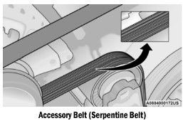
Conditions that would require replacement:
- Rib chunking (one or more ribs has sepa- rated from belt body)
- Rib or belt wear
- Longitudinal belt cracking (cracks between two ribs)
- Belt slips
- "Groove jumping" (belt does not maintain correct position on pulley)
- Belt broken
- Noise (objectionable squeal, squeak, or rumble is heard or felt while drive belt is in operation)
NOTE:
Identify and correct problem before new belt is installed.
Some conditions can be caused by a faulty component such as a belt pulley. Belt pulleys should be carefully inspected for damage and proper alignment.
Belt replacement on some models requires the use of special tools, we recommend having your vehicle serviced at an authorized dealer.
AIR CONDITIONER MAINTENANCE
For best possible performance, your air conditioner should be checked and serviced by an authorized dealer at the start of each warm season. This service should include cleaning of the condenser fins and a performance test. Drive belt tension should also be checked at this time.
WARNING!
- Use only refrigerants and compressor lubri- cants approved by the manufacturer for your air conditioning system. Some unap- proved refrigerants are flammable and can explode, injuring you. Other unapproved refrigerants or lubricants can cause the system to fail, requiring costly repairs. Refer to Warranty Information Book, located in your owner’s information kit, for further warranty information.
- The air conditioning system contains refrig- erant under high pressure. To avoid risk of personal injury or damage to the system, adding refrigerant or any repair requiring lines to be disconnected should be done by an experienced technician.
CAUTION!
Do not use chemical flushes in your air conditioning system as the chemicals can damage your air conditioning components. Such damage is not covered by the New Vehicle Limited Warranty.
Refrigerant Recovery And Recycling — R–1234yf
R–1234yf Air Conditioning Refrigerant is a hydrofluoroolefin (HFO) that is endorsed by the Environmental Protection Agency and is an ozone-friendly substance with a low global-warming potential. The manufacturer recommends that air conditioning service be performed by an authorized dealer using recovery and recycling equipment.
NOTE:
Use only the manufacturer approved A/C system PAG compressor oil, and refrigerants.
Cabin Air Filter
WARNING!
Do not remove the cabin air filter while the vehicle is running, or while the ignition is in the ACC or ON/RUN mode. With the cabin air filter removed and the blower operating, the blower can contact hands and may propel dirt and debris into your eyes, resulting in per- sonal injury.
The cabin air filter is located in the fresh air inlet behind the glove compartment. Perform the following procedure to replace the filter:
1. Open the glove compartment and remove all contents.
2. Push up on the glove compartment travel stop and lower the door.
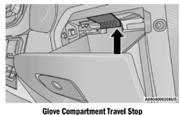
3. Pivot the glove compartment downward.
4. Disengage the two retaining tabs that secure the air filter access door to the HVAC housing.
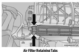
5. Remove the air filter from the HVAC air inlet housing. Pull the filter elements out pinching them to the right for clearance.
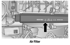
6. Install the cabin air filter with the air filter position indicators pointing in the same direction as removal.
CAUTION! The cabin air filter is identified with an arrow to indicate airflow direction through the filter. Failure to properly install the filter will result in the need to replace it more often.
7. Close cabin air filter access door and secure retaining tabs.
8. Rotate the glove compartment door back into position ensuring you have properly engaged the travel damper.
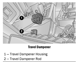
For the proper maintenance intervals, see
⇒ page 378 for gasoline engines or
⇒ page 383 for diesel engines.
BODY LUBRICATION
Locks and all body pivot points, including such items as seat tracks, door hinge pivot points and rollers, liftgate, tailgate, decklid, sliding doors and hood hinges, should be lubricated periodically with a lithium based grease, such as Mopar® Spray White Lube to ensure quiet, easy operation and to protect against rust and wear. Prior to the application of any lubricant, the parts concerned should be wiped clean to remove dust and grit; after lubricating excess oil and grease should be removed. Particular attention should also be given to hood latching components to ensure proper function. When performing other underhood services, the hood latch release mechanism, and safety catch should be cleaned and lubricated.
The external lock cylinders should be lubricated twice a year, preferably in the Fall and Spring.
Apply a small amount of a high quality lubricant, such as Mopar® Lock Cylinder Lubricant directly into the lock cylinder.
WINDSHIELD WIPER BLADES
Clean the rubber edges of the wiper blades and the windshield periodically with a sponge or soft cloth and a mild nonabrasive cleaner. This will remove accumulations of salt or road film.
Operation of the wipers on dry glass for long periods may cause deterioration of the wiper blades. Always use washer fluid when using the wipers to remove salt or dirt from a dry windshield.
Avoid using the wiper blades to remove frost or ice from the windshield. Keep the blade rubber out of contact with petroleum products such as engine oil, gasoline, etc.
NOTE:
Life expectancy of wiper blades varies depending on geographical area and frequency of use. Poor performance of blades may be present with chattering, marks, water lines or wet spots. If any of these conditions are present, clean the wiper blades or replace as necessary.
The wiper blades and wiper arms should be inspected periodically, not just when wiper performance problems are experienced. This inspection should include the following points:
- Wear or uneven edges
- Foreign material
- Hardening or cracking
- Deformation or fatigue
If a wiper blade or wiper arm is damaged, replace the affected wiper arm or blade with a new unit. Do not attempt to repair a wiper arm or blade that is damaged.
EXHAUST SYSTEM
The best protection against carbon monoxide entry into the vehicle body is a properly maintained engine exhaust system.
If you notice a change in the sound of the exhaust system; or if the exhaust fumes can be detected inside the vehicle; or when the underside or rear of the vehicle is damaged; have an authorized technician inspect the complete exhaust system and adjacent body areas for broken, damaged, deteriorated, or mispositioned parts. Open seams or loose connections could permit exhaust fumes to seep into the passenger compartment. In addition, have the exhaust system inspected each time the vehicle is raised for lubrication or oil change. Replace as required.
CAUTION!
- The catalytic converter requires the use of unleaded fuel only. Leaded gasoline will destroy the effectiveness of the catalyst as an emissions control device and may seri- ously reduce engine performance and cause serious damage to the engine.
- Damage to the catalytic converter can result if your vehicle is not kept in proper operating condition. In the event of engine malfunc- tion, particularly involving engine misfire or other apparent loss of performance, have your vehicle serviced promptly. Continued operation of your vehicle with a severe malfunction could cause the converter to overheat, resulting in possible damage to the converter and vehicle.
Under normal operating conditions, the catalytic converter will not require maintenance. However, it is important to keep the engine properly tuned to ensure proper catalyst operation and prevent possible catalyst damage.
NOTE:
Intentional tampering with emissions control systems can result in civil penalties being assessed against you.
In unusual situations involving grossly malfunctioning engine operation, a scorching odor may suggest severe and abnormal catalyst overheating. If this occurs, stop the vehicle, turn off the engine and allow it to cool. Service, including a tune-up to manufacturer's specifications, should be obtained immediately.
To minimize the possibility of catalytic converter damage:
- Do not interrupt the ignition when the trans- mission is in gear and the vehicle is in motion.
- Do not try to start the vehicle by pushing or towing the vehicle.
- Do not idle the engine with any ignition components disconnected or removed, such as when diagnostic testing, or for prolonged periods during very rough idle or malfunc- tioning operating conditions.
COOLING SYSTEM
WARNING!
- You or others can be badly burned by hot engine coolant (antifreeze) or steam from your radiator. If you see or hear steam coming from under the hood, do not open the hood until the radiator has had time to cool. Never open a cooling system pressure cap when the radiator or coolant bottle is hot.
- Keep hands, tools, clothing, and jewelry away from the radiator cooling fan when the hood is raised. The fan starts automati- cally and may start at any time, whether the engine is running or not.
- When working near the radiator cooling fan, disconnect the fan motor lead or turn the ignition to the OFF mode. The fan is temperature controlled and can start at any time the ignition is in the ON mode.
Coolant Checks
Check the engine, battery (if equipped), intercooler (if equipped), and Motor Generator Unit (MGU) (if equipped) coolant (antifreeze) protection every 12 months (before the onset of freezing weather, where applicable). If the engine, battery (if equipped), intercooler (if equipped), and MGU (if equipped) coolant is dirty or rusty in appearance, the system should be drained, flushed and refilled with fresh OAT coolant (conforming to MS.90032) by an authorized dealer. Check the front of the A/C condenser (if equipped) or radiator for any accumulation of bugs, leaves, etc. If dirty, clean by gently spraying water from a garden hose vertically down the face of the A/C condenser (if equipped) or the back of the radiator core.
Check the engine, battery (if equipped), intercooler (if equipped), and MGU (if equipped) cooling system hoses for brittle rubber, cracking, tears, cuts, and tightness of the connection at the coolant recovery bottle and radiator. Inspect the entire system for leaks. DO NOT REMOVE THE COOLANT PRESSURE CAP WHEN THE COOLING SYSTEM IS HOT.
Cooling System — Drain, Flush And Refill
NOTE:
Some vehicles require special tools to add coolant properly. Failure to fill these systems properly could lead to severe internal engine damage. If any coolant is needed to be added to the system please contact an authorized dealer.
If the engine coolant (antifreeze) is dirty or contains visible sediment, have an authorized dealer clean and flush with OAT coolant conforming to MS.90032).
For the proper maintenance intervals, see
⇒ page 378 for gasoline engines or
⇒ page 383 for diesel engines.
Selection Of Coolant
For further information ⇒ page 459.
NOTE:
- Mixing of engine coolant (antifreeze) other than specified Organic Additive Technology OAT) engine coolant, may result in engine damage and may decrease corrosion protec- tion. OAT engine coolant is different and should not be mixed with Hybrid Organic Additive Technology (HOAT) engine coolant or any “globally compatible” coolant. If a non-OAT engine coolant is introduced into the cooling system in an emergency, the cooling system will need to be drained, flushed, and refilled with fresh OAT coolant (conforming to MS.90032), by an authorized dealer as soon as possible.
- Do not use water alone or alcohol-based engine coolant (antifreeze) products. Do not use additional rust inhibitors or anti-rust products, as they may not be compatible with the radiator engine coolant and may plug the radiator.
- This vehicle has not been designed for use with propylene glycol-based engine coolant. Use of propylene glycol-based engine coolant is not recommended.
- Some vehicles require special tools to add coolant properly. Failure to fill these systems properly could lead to severe internal engine damage. If any coolant is needed to be added to the system please contact an authorized dealer.
Adding Coolant
Your vehicle has been built with an improved engine coolant (OAT coolant conforming to MS.90032) that allows extended maintenance intervals. This engine coolant (antifreeze) can be used up to 10 years or 150,000 miles km) before replacement. To prevent reducing this extended maintenance period, it is important that you use the same engine coolant (OAT coolant conforming to MS.90032) throughout the life of your vehicle.
Please review these recommendations for using Organic Additive Technology (OAT) engine coolant that meets the requirements of the manufacturer Material Standard MS.90032. When adding engine coolant (antifreeze):
- We recommend using Mopar® Antifreeze/ Coolant 10 Year/150,000 Mile (240,000 km) Formula OAT (Organic Additive Technology) that meets the requirements of the manufac- turer Material Standard MS.90032.
- Mix a minimum solution of 50% OAT engine coolant that meets the requirements of the manufacturer Material Standard MS.90032 and distilled water. Use higher concentra- tions (not to exceed 70%) if temperatures below −34°F (−37°C) are anticipated.
- Please contact an authorized dealer for assistance.
- Use only high purity water such as distilled or deionized water when mixing the water/ engine coolant solution. The use of lower quality water will reduce the amount of corro- sion protection in the engine cooling system.
NOTE:
- It is the owner's responsibility to maintain the proper level of protection against freezing according to the temperatures occurring in the area where the vehicle is operated.
- Some vehicles require special tools to add coolant properly. Failure to fill these systems properly could lead to severe internal engine damage. If any coolant is needed to be added to the system, please contact an authorized dealer.
- Mixing engine coolant types is not recom- mended and can result in cooling system damage. If HOAT and OAT coolant are mixed in an emergency, have an authorized dealer drain, flush, and refill with OAT coolant conforming to MS.90032) as soon as possible.
Cooling System Pressure Cap
The cap must be fully tightened to prevent loss of engine coolant (antifreeze), and to ensure that engine coolant will return to the radiator from the coolant expansion bottle/recovery tank if so equipped.
The cap should be inspected and cleaned if there is any accumulation of foreign material on the sealing surfaces.
Disposal Of Used Coolant
Used ethylene glycol-based coolant (antifreeze) OAT or HOAT, is a regulated substance requiring proper disposal. Check with your local authorities to determine the disposal rules for your community. To prevent ingestion by animals or children, do not store ethylene glycol-based coolant in open containers or allow it to remain in puddles on the ground, clean up any ground spills immediately. If ingested, seek emergency assistance immediately.
Coolant Level
The coolant bottle provides a quick visual method for determining that the coolant level is adequate. With the engine OFF and cold, the level of the engine coolant (antifreeze) in the bottle should be between the ranges indicated on the bottle.
The radiator normally remains completely full, so there is no need to remove the radiator/ coolant pressure cap unless checking for engine coolant freeze point or replacing coolant. Advise your service attendant of this.
As long as the engine operating temperature is satisfactory, the coolant bottle need only be checked once a month.
When additional engine coolant is needed to maintain the proper level, only OAT coolant that meets the requirements of the manufacturer Material Standard MS.90032 should be added to the coolant bottle. Do not overfill.
Engine Coolant Level — 2.0L
With the engine OFF and cold, the level of the engine coolant should be within the OK range between the ADD and FULL range on the dipstick.
- Remove the cap with level dipstick from the engine coolant bottle.
- Clean off the coolant from the dipstick.
- Rest the cap on the opening of the coolant bottle without tightening the cap.
- Remove the cap with dipstick and check the coolant level on the dipstick.
The radiator normally remains completely full, so there is no need to remove the radiator/ coolant pressure cap unless checking for engine coolant freeze point or replacing coolant. Advise your service attendant of this. As long as the engine operating temperature is satisfactory, the coolant bottle need only be checked once a month.
When additional engine coolant is needed to maintain the proper level, only OAT coolant that meets the requirements of the manufacturer Material Standard MS.90032 should be added to the coolant bottle. Do not overfill.
Cooling System Notes
NOTE:
- When the vehicle is stopped after a few miles/ kilometers of operation, you may observe vapor coming from the front of the engine compart- ment. This is normally a result of moisture from rain, snow, or high humidity accumulating on the radiator and being vaporized when the ther- mostat opens, allowing hot engine coolant (anti- freeze) to enter the radiator.
- If an examination of your engine compartment shows no evidence of radiator or hose leaks, the vehicle may be safely driven. The vapor will soon dissipate.
- Do not overfill the coolant expansion bottle.
- Check the coolant freeze point in the radiator and in the coolant expansion bottle. If engine coolant needs to be added, the contents of the coolant expansion bottle must also be protected against freezing.
- If frequent engine coolant additions are required, the cooling system should be pres- sure tested for leaks.
- Maintain engine coolant concentration at a minimum of 50% OAT coolant (conforming toMS.90032) and distilled water for proper corrosion protection of your engine which contains aluminum components.
- Make sure that the coolant expansion bottle overflow hoses are not kinked or obstructed.
- Keep the front of the radiator clean. If your vehicle is equipped with air conditioning, keep the front of the condenser clean.
- Do not change the thermostat for Summer or Winter operation. If replacement is ever necessary, install ONLY the correct type ther- mostat. Other designs may result in unsatis- factory engine cooling performance, poor gas mileage, and increased emissions.
BRAKE SYSTEM
In order to ensure brake system performance, all brake system components should be inspected periodically. For the proper maintenance intervals Ú page 378.
Fluid Level Check — Brake Master Cylinder
The fluid level of the master cylinder should be checked whenever the vehicle is serviced, or immediately if the brake system warning light is on. If necessary, add fluid to bring level within the designated marks on the side of the reservoir of the brake master cylinder. Be sure to clean the top of the master cylinder area before removing cap. With disc brakes, fluid level can be expected to fall as the brake pads wear. Brake fluid level should be checked when pads are replaced. If the brake fluid is abnormally low, check the system for leaks page 463.
FRONT/REAR AXLE FLUID
For normal service, periodic fluid level checks are not required. When the vehicle is serviced for other reasons the exterior surfaces of the axle assembly should be inspected. If gear oil leakage is suspected inspect the fluid level.
Fluid Level Check
Lubricant should be approximately 1/8 inch mm) below the bottom edge of the oil fill hole.
NOTE: Make sure that the vehicle is level and supported by the axles.
Adding Fluid
Add lubricant only at the fill hole and only to the level specified above.
Selection Of Lubricant
Use only FCA recommended fluid Ú page 463.
TRANSFER CASE
Fluid Level Check
The fluid level should be to the bottom edge of the fill hole when the vehicle is in a level position.
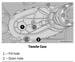
Drain And Refill
For the proper maintenance intervals ⇒ page 378.
Selection Of Lubricant
Use only the manufacturer recommended fluid ⇒ page 463.
MANUAL TRANSMISSION — IF EQUIPPED
Fluid Level Check
Check the fluid level by removing the fill plug. The fluid level should be between the bottom of the fill hole and a point not more than 3/16 of an inch (4.76 mm) below the bottom of the hole.
Add fluid, if necessary, to maintain the proper level.
Frequency Of Fluid Change
Under normal operating conditions, the fluid installed at the factory will give satisfactory lubrication for the life of the vehicle. If the fluid becomes contaminated with water, it should be changed immediately. Otherwise, change the fluid as recommended in the Maintenance Plan. Refer to the Maintenance Plan for the proper maintenance intervals Ú page 378.
Selection Of Lubricant
Use only the manufacturer recommended manual transmission fluid Ú page 463.
AUTOMATIC TRANSMISSION — IF EQUIPPED
Special Additives
FCA strongly recommends against using any special additives in the transmission. Automatic Transmission Fluid (ATF) is an engineered product and its performance may be impaired by supplemental additives. Therefore, do not add any fluid additives to the transmission. Avoid using transmission sealers as they may adversely affect seals.
Fluid Level Check
The fluid level is preset at the factory and does not require adjustment under normal operating conditions. Routine fluid level checks are not required; therefore the transmission has no dipstick. An authorized dealer can check your transmission fluid level using special service tools. If you notice fluid leakage or transmission malfunction, visit an authorized dealer immediately to have the transmission fluid level checked. Operating the vehicle with an improper fluid level can cause severe transmission damage.
Selection Of Lubricant
It is important to use the proper transmission fluid to ensure optimum transmission performance and life. Use only the manufacturer specified transmission fluid page 463. It is important to maintain the transmission fluid at the correct level using the recommended fluid.
NOTE: No chemical flushes should be used in any transmission; only the approved lubricant should be used.
TIRES
TIRE SAFETY INFORMATION
Tire safety information will cover aspects of the following information: Tire Markings, Tire Identification Numbers, Tire Terminology and Definitions, Tire Pressures, and Tire Loading.
Tire Markings
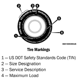
NOTE:
The proper cold tire inflation pressure is listed on the driver’s side B-pillar or the rear edge of the driver's side door.
Check the inflation pressure of each tire, including the spare tire (if equipped), at least monthly and inflate to the recommended pressure for your vehicle.
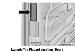
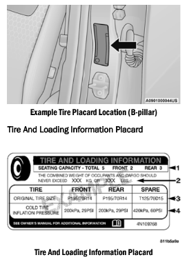
This placard tells you important information about the:
- Number of people that can be carried in the vehicle.
- Total weight your vehicle can carry.
- Tire size designed for your vehicle.
- Cold tire inflation pressures for the front, rear, and spare tires.
Loading
The vehicle maximum load on the tire must not exceed the load carrying capacity of the tire on your vehicle. You will not exceed the tire's load carrying capacity if you adhere to the loading conditions, tire size, and cold tire inflation pressures specified on the Tire and Loading Information placard ⇒ page 198.
NOTE:
Under a maximum loaded vehicle condition, Gross Axle Weight Rating (GAWR) for the front and rear axles must not be exceeded.
For further information on GAWR, vehicle loading, and trailer towing Ú page 198.
To determine the maximum loading conditions of your vehicle, locate the statement “The combined weight of occupants and cargo should never exceed XXX kg or XXX lb” on the Tire and Loading Information placard. The combined weight of occupants, cargo/luggage and trailer tongue weight (if applicable) should never exceed the weight referenced here. Steps For Determining Correct Load Limit—
- Locate the statement “The combined weight of occupants and cargo should never exceed XXX kg or XXX lb.” on your vehicle's placard.
- Determine the combined weight of the driver and passengers that will be riding in your vehicle.
- Subtract the combined weight of the driver and passengers from XXX kg or XXX lb.
- The resulting figure equals the available amount of cargo and luggage load capacity. For example, if “XXX” amount equals 1400 lb. and there will be five 150 lb passengers in your vehicle, the amount of available cargo and luggage load capacity is 650 lbs. (1400-750 (5x150) = 650 lb.)
- Determine the combined weight of luggage and cargo being loaded on the vehicle. That weight may not safely exceed the available cargo and luggage load capacity calculated in Step 4.
- If your vehicle will be towing a trailer, load from your trailer will be transferred to your vehicle. Consult this manual to determine how this reduces the available cargo and luggage load capacity of your vehicle.
Metric Example For Load Limit
For example, if “XXX” amount equals 635 kg and there will be five 68 kg passengers in your vehicle, the amount of available cargo and luggage load capacity is 295 kg (635-340 (5x68) = 295 kg) as shown in step 4.
NOTE:
- If your vehicle will be towing a trailer, load from your trailer will be transferred to your vehicle. The following table shows examples on how to calculate total load, cargo/ luggage, and towing capacities of your vehicle with varying seating configurations and number and size of occupants. This table is for illustration purposes only and may not be accurate for the seating and load carry capacity of your vehicle.
- For the following example, the combined weight of occupants and cargo should never exceed 865 lb (392 kg).
TIRE TYPES
All Season Tires — If Equipped
All Season tires provide traction for all seasons (Spring, Summer, Autumn, and Winter). Traction levels may vary between different all season tires. All season tires can be identified by the M+S, M&S, M/S or MS designation on the tire sidewall. Use all season tires only in sets of four; failure to do so may adversely affect the safety and handling of your vehicle.
Summer Or Three Season Tires — If Equipped
Summer tires provide traction in both wet and dry conditions, and are not intended to be driven in snow or on ice. If your vehicle is equipped with Summer tires, be aware these tires are not designed for Winter or cold driving conditions. Install Winter tires on your vehicle when ambient temperatures are less than 40°F (C) or if roads are covered with ice or snow.
For more information, contact an authorized dealer.
Summer tires do not contain the all season designation or mountain/snowflake symbol on the tire sidewall. Use Summer tires only in sets of four; failure to do so may adversely affect the safety and handling of your vehicle.
SPARE TIRES — IF EQUIPPED
NOTE:
For vehicles equipped with Tire Service Kit instead of a spare tire, please refer to “Tire Service Kit” in “In Case Of Emergency” for further information.
For restrictions when towing with a spare tire designated for temporary emergency use ⇒ page 203. Spare Tire Matching Original Equipped Tire
And Wheel — If Equipped
Your vehicle may be equipped with a spare tire and wheel equivalent in look and function to the original equipment tire and wheel found on the front or rear axle of your vehicle. This spare tire may be used in the tire rotation for your vehicle.
If your vehicle has this option, refer to an authorized tire dealer for the recommended tire rotation pattern.
Compact Spare Tire — If Equipped
The compact spare is for temporary emergency use only. You can identify if your vehicle is equipped with a compact spare by looking at the spare tire description on the Tire and
Loading Information Placard located on the driver’s side door opening or on the sidewall of the tire. Compact spare tire descriptions begin with the letter “T” or “S” preceding the size designation. Example: T145/80D18 103M. T, S = Temporary Spare Tire
Since this tire has limited tread life, the original equipment tire should be repaired (or replaced) and reinstalled on your vehicle at the first opportunity.
Do not install a wheel cover or attempt to mount a conventional tire on the compact spare wheel, since the wheel is designed specifically for the compact spare tire. Do not install more than one compact spare tire and wheel on the vehicle at any given time.
WHEEL AND WHEEL TRIM CARE
All wheels and wheel trim, especially aluminum and chrome plated wheels, should be cleaned regularly using mild (neutral Ph) soap and water to maintain their luster and to prevent corrosion. Wash wheels with the same soap solution recommended for the body of the vehicle and remember to always wash when the surfaces are not hot to the touch.
Your wheels are susceptible to deterioration caused by salt, sodium chloride, magnesium chloride, calcium chloride, etc., and other road chemicals used to melt ice or control dust on dirt roads. Use a soft cloth or sponge and mild soap to wipe away promptly. Do not use harsh chemicals or a stiff brush. They can damage the wheel’s protective coating that helps keep them from corroding and tarnishing.
TIRE ROTATION RECOMMENDATIONS
The tires on the front and rear of your vehicle operate at different loads and perform different steering, handling, and braking functions. For these reasons, they wear at unequal rates.
These effects can be reduced by timely rotation of tires. The benefits of rotation are especially worthwhile with aggressive tread designs such as those on On/Off Road type tires. Rotation will increase tread life, help to maintain mud, snow, and wet traction levels, and contribute to a smooth, quiet ride.
For the proper maintenance intervals page 378. The reasons for any rapid or unusual wear should be corrected prior to rotation being performed.
The suggested rotation method is the “rearward cross” shown in the following diagram.
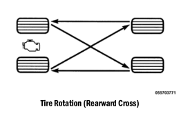
DEPARTMENT OF TRANSPORTATION UNIFORM TIRE QUALITY GRADES
The following tire grading categories were established by the National Highway Traffic Safety Administration. The specific grade rating assigned by the tire's manufacturer in each category is shown on the sidewall of the tires on your vehicle.
All passenger vehicle tires must conform to Federal safety requirements in addition to these grades.
TREADWEAR
The Treadwear grade is a comparative rating, based on the wear rate of the tire when tested under controlled conditions on a specified government test course. For example, a tire graded 150 would wear one and one-half times as well on the government course as a tire graded 100. The relative performance of tires depends upon the actual conditions of their use, however, and may depart significantly from the norm due to variations in driving habits, service practices, and differences in road characteristics and climate.
TRACTION GRADES
The Traction grades, from highest to lowest, are AA, A, B, and C. These grades represent the tire's ability to stop on wet pavement, as measured under controlled conditions on specified government test surfaces of asphalt and concrete. A tire marked C may have poor traction performance.
TEMPERATURE GRADES
The Temperature grades are A (the highest), B, and C, representing the tire's resistance to the generation of heat and its ability to dissipate heat, when tested under controlled conditions on a specified indoor laboratory test wheel.
Sustained high temperature can cause the material of the tire to degenerate and reduce tire life, and excessive temperature can lead to sudden tire failure. The grade C corresponds to a level of performance, which all passenger vehicle tires must meet under the Federal Motor Vehicle Safety Standard No. 109. Grades B and A represent higher levels of performance on the laboratory test wheel, than the minimum required by law.
STORING THE VEHICLE
If you are storing your vehicle for more than 3 weeks, we recommend that you take the following steps to minimize the drain on your vehicle's battery:
- Disconnect the negative cable from battery.
- If your vehicle is equipped with Stop/Start system then disconnect both the main and supplemental negative battery cables.
- Any time you store your vehicle or keep it out of service (i.e., vacation) for two weeks or more, run the air conditioning system at idle for about five minutes in the fresh air and high blower setting. This will ensure adequate system lubrication to minimize the possibility of compressor damage when the system is started again.
- If assistance is needed to disconnect the battery system, see an authorized dealer.
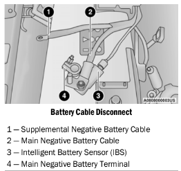
NOTE:
- You must isolate the supplemental battery connection point, as well as the main battery terminal from the post, as shown in the image, to fully de-energize both batteries for storage. If assistance is needed to disconnect the battery system, see an authorized dealer.
- Do not disconnect the Intelligent Battery Sensor (IBS), or your Stop/Start system may not function for up to 24 hours, due to the IBS being set into learn mode.
BODYWORK
PROTECTION FROM ATMOSPHERIC AGENTS
Vehicle body care requirements vary according to geographic locations and usage. Chemicals that make roads passable in snow and ice and those that are sprayed on trees and road surfaces during other seasons are highly corrosive to the metal in your vehicle. Outside parking, which exposes your vehicle to airborne contaminants, road surfaces on which the vehicle is operated, extreme hot or cold weather and other extreme conditions will have an adverse effect on paint, metal trim, and underbody protection.
The following maintenance recommendations will enable you to obtain maximum benefit from the corrosion resistance built into your vehicle.
What Causes Corrosion?
Corrosion is the result of deterioration or removal of paint and protective coatings from your vehicle.
The most common causes are:
- Road salt, dirt and moisture accumulation
- Stone and gravel impact
- Insects, tree sap and tar
- Salt in the air near seacoast localities
- Atmospheric fallout/industrial pollutants
BODY AND UNDERBODY MAINTENANCE
Cleaning Headlights
Your vehicle is equipped with plastic headlights and fog lights that are lighter and less susceptible to stone breakage than glass headlights.
Plastic is not as scratch resistant as glass and therefore different lens cleaning procedures must be followed.
To minimize the possibility of scratching the lenses and reducing light output, avoid wiping with a dry cloth. To remove road dirt, wash with a mild soap solution followed by rinsing.
Do not use abrasive cleaning components, solvents, steel wool or other aggressive
PRESERVING THE BODYWORK
Washing
- Wash your vehicle regularly. Always wash your vehicle in the shade using Mopar® Car
- Wash, or a mild car wash soap, and rinse the panels completely with water.
- If insects, tar, or other similar deposits have accumulated on your vehicle, use Mopar®
- Super Kleen Bug and Tar Remover to remove.
- Use a high quality cleaner wax, such as
- Mopar® Cleaner Wax to remove road film, stains and to protect your paint finish. Use precautions to not scratch the paint.
- Avoid using abrasive compounds and power buffing that may diminish the gloss or thin out the paint finish.
Special Care
- If you drive on salted or dusty roads or if you drive near the ocean, hose off the undercar- riage at least once a month.
- It is important that the drain holes in the lower edges of the doors, rocker panels, and trunk be kept clear and open.
- If you detect any stone chips or scratches in the paint, touch them up immediately. The cost of such repairs is considered the respon- sibility of the owner.
- If your vehicle is damaged due to a collision or similar cause that destroys the paint and protective coating, have your vehicle repaired as soon as possible. The cost of such repairs is considered the responsibility of the owner.
- If you carry special cargo such as chemicals, fertilizers, de-icer salt, etc., be sure that such materials are well packaged and sealed.
- If a lot of driving is done on gravel roads, consider mud or stone shields behind each wheel.
- Use Mopar® Touch Up Paint on scratches as soon as possible. An authorized dealer has touch up paint to match the color of your vehicle.
Appearance Care For Fabric Top Models
- To maintain the appearance of your vehicle's interior trim and top, follow these precautions:
- Do not run a fabric top through an automatic car wash. Window scratches and wax build-up may result.
- Avoid leaving your vehicle unattended with the top down, as exposure to sun or rain may damage interior trim.
- Do not use harsh cleaners or bleaching agents on top material, as damage may result.
- Do not allow any vinyl cleaner to run down and dry on the paint, leaving a streak.
- After cleaning your vehicle's fabric top, always make sure it is completely dry before lowering.
- Be especially careful when washing the windows by following the directions for “Care of Fabric Top Windows.”
- Washing – Use Mopar® Car Wash or equivalent, or mild soap suds, lukewarm water, and a brush with soft bristles. If extra cleaning is required, use Mopar® Convertible Cloth Top
- Cleaner or equivalent, or a mild foaming cleaner on the entire top, but support the top from underneath.
- Rinsing – Be sure to remove all traces of cleaner by rinsing the top thoroughly with clean water. Remember to allow the top to dry before lowering it.
CARPET REMOVAL
Front Carpets (Two And Four Door Models):
1. Remove the front grommets.
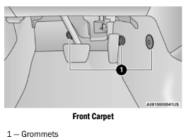
2. Pull the carpet out from the front to the rear.
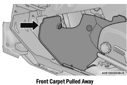
3. Remove the grommets under the front seat. First for the rear carpet and then the front carpet.
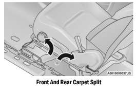
4. Under the back of the front seat, open the carpet split and then pull out the rear edge
and slide the carpet to the front (do not remove the harness).
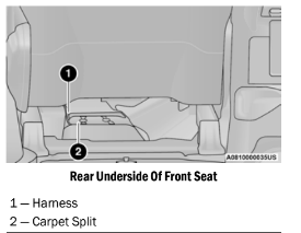
5. Finally open the carpet split around seat bracket and then remove the last two grommets.
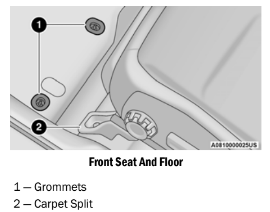
6. When reinstalling carpet please perform these steps in reverse order making sure that the carpet is tucked under the scuffs, B-pillar, console, and refasten grommets.
Rear Carpet (Four Door Models):
1. Remove the grommets under the front seat one left and one right).
2. Then pull the carpet out, to the rear and open the carpet split around the front seats brackets.
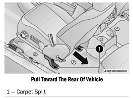
3. Remove the grommets under the rear seat (one left and one right). First the grommet for the cargo carpet and then the rear carpet.
4. Pull the carpet out to the front and open the carpet split around the rear seats brackets.
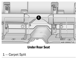
5. When reinstalling carpet please perform these steps in reverse order making sure that the carpet is tucked under the scuffs, B-pillar, console, and refasten grommets.
SEATS AND FABRIC PARTS
Use Mopar® Total Clean to clean fabric upholstery and carpeting.
Seat Belt Maintenance
Do not bleach, dye or clean the belts with chemical solvents or abrasive cleaners. This will weaken the fabric. Sun damage can also weaken the fabric.
If the belts need cleaning, use a mild soap solution or lukewarm water. Do not remove the belts from the vehicle to wash them. Dry with a soft cloth.
Replace the belts if they appear frayed or worn or if the buckles do not work properly.