The data contained in this publication is intended merely as a guide. FCA Italy S.p.A. reserves the right to modify
the models and versions described in this booklet at any time for technical and commercial reasons.
If you have any further questions please consult your JEEP dealer.
ENGLISH
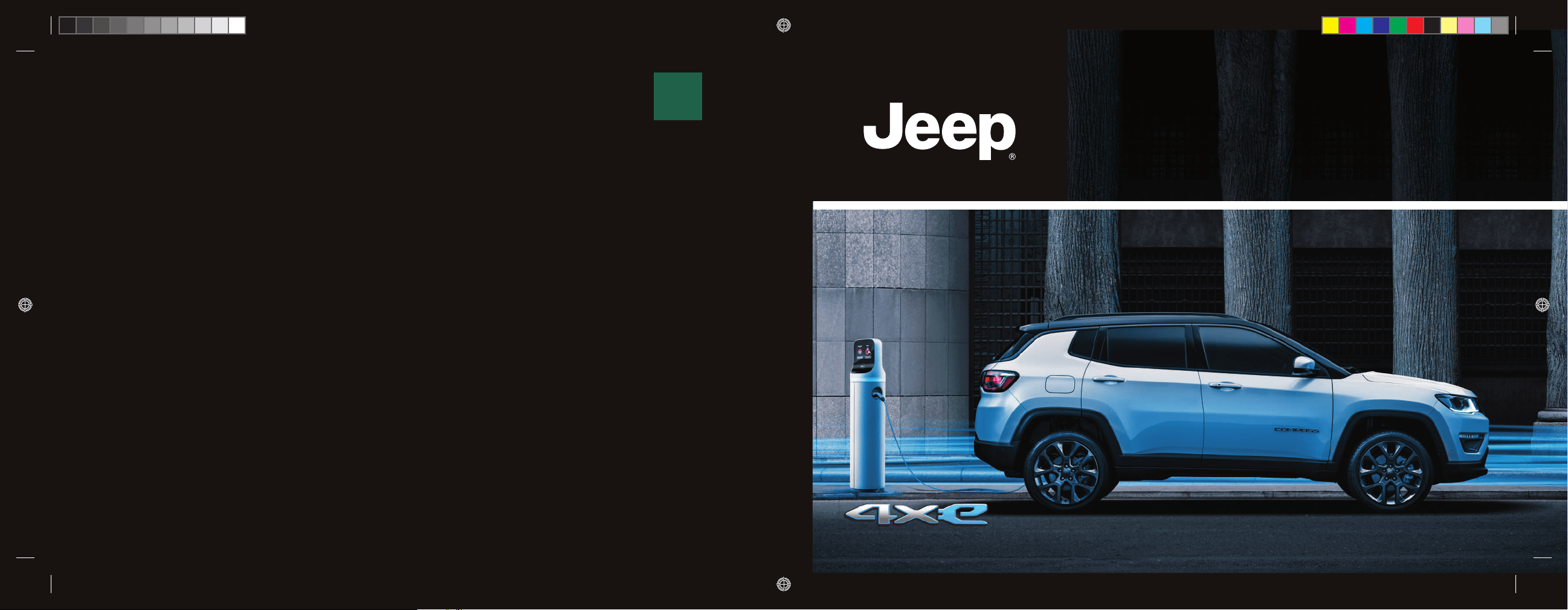
COMPASS

Dear Customer,
We would like to congratulate and thank you for choosing a Jeep.
This supplement illustrates the specifi c features of your hybrid car and has been produced with the support of specialists to enable you to
know how it works.
You are advised to read through the User Guide before taking it on the road for the fi rst time. It is important to become comfortable with
the controls of your vehicle especially with those related to driving in electric mode.
This document also provides a description of special features and tips, as well as essential information for the safe driving, care and
maintenance of your Jeep over time.
After reading this manual, we recommend that you store it inside the vehicle, so that you can consult it easily and make sure that it
remains on board the vehicle in the event of sale.
In case of need, we remind you that the Jeep Dealership knows your car at its best, has trained technicians and uses genuine spare parts
in order to satisfy your every need.
WARNING
The data contained in this publication is intended to help you use your vehicle in the best possible way.
FCA Italy S.p.A. aims at a constant improvement of the vehicles produced. For this reason it reserves the right to make changes to the model
described for technical and/or commercial reasons. For further information, contact a Jeep Dealership.

HOW TO USE THE SUPPLEMENT
OPERATING INSTRUCTIONS
Each time an instruction is given that concerns direction (left/right or forward/backward), it is written to be read from the perspective of
an occupant in the driver's seat. If a direction is written from a different perspective, it will be specifi ed as such in the text as appropriate.
The fi gures in this supplement are only examples: this might imply that some details of the image do not correspond to the actual
arrangement of your vehicle. In addition, the supplement has been conceived considering vehicles with steering wheel on the left side;
it is therefore possible that on vehicles with steering wheel on the right side, the position or construction of some controls is not exactly
mirror-like with respect to the fi gure.
To identify the section with the information needed you can consult the alphabetical table of content at the end of this Supplement.
The sections themselves are quickly identifi able by means of a specifi c graphic tab at the edge of all the odd-numbered pages. There is
also a key for becoming familiar with the chapter order and the relevant symbols in the tabs. Additionally, there is a textual indication of
each current section at the side of each even page.
WARNINGS AND CAUTIONS
While reading this supplement you will fi nd a series of WARNINGS to prevent procedures that could damage your vehicle.
There are also CAUTIONS that must be carefully followed to prevent incorrect use of the components of the vehicle, which could cause
accidents or injuries.
Therefore, all WARNINGS and CAUTIONS must always be carefully followed.
WARNINGS and CAUTIONS are recalled in the text with the following symbols:
personal safety;
vehicle safety;
environmental protection.
These symbols, when necessary, are indicated besides the title or at the end of the line and are followed by a number. That number
recalls the corresponding warning at the end of the relevant chapter.
SYMBOLS
Some car components have colored labels with symbols indicating precautions to be observed when using this component.
High voltage components
On the high-voltage components of the vehicle, there are plates with specifi c symbols. For more information see the descriptions in this
document.

Blank page
KNOWING YOUR VEHICLE
KNOWING THE INSTRUMENT PANEL AND MULTIMEDIA
SAFETY
STARTING AND DRIVING
IN CASE OF EMERGENCY
SERVICING AND MAINTENANCE
TECHNICAL SPECIFICATIONS
CONTENTS

Blank page
7
In-depth knowledge of your
new car starts here.
The publication you are reading
tells you how it is made and how it
works in simple, directly manner.
For this reason, we advise you to read
it sitting comfortably onboard to check
the illustrated topics straight away.
For anything not included, refer to
the "Knowing your vehicle" section
in the Owner Handbook.
KNOWING YOUR VEHICLE
OPERATING PRINCIPLE ....................8
HYBRID SYSTEM
FUNCTIONAL SCHEME .....................9
HIGH-VOLTAGE BATTERY ...............10
OPERATING MODE ..........................13
POWER SOURCES THAT CAN
BE USED .........................................16
VEHICLE .......................................... 32
CHARGING FUNCTIONS .................45
"eCoasting" MODE
(ENERGY SAVING) ...........................48
"eBraking" MODE
(HIGH-VOLTAGE BATTERY
CHARGING) .....................................49
KNOWING YOUR VEHICLE

KNOWING YOUR VEHICLE
8
OPERATING PRINCIPLE
HYBRID SYSTEM EQUIPMENT
Compass 4xe is a P-HEV (Plug-in Hybrid
Electric Vehicle).
The car is equipped with:
in the front with the conventional heat
engine, to which is coupled an electric
motor that performs the function of
alternator;
in the rear with an electric motor
(powered by a high-voltage lithium ion
battery) on the rear axle, for motion
transmission.
GENERAL INFORMATION
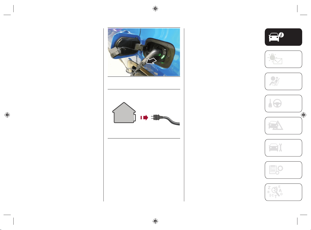
The vehicle can be charged with
alternating current (AC) using:
a domestic power socket. Charging
via the domestic power socket is
permitted with voltage values ranging
from 100 to 230 Volts depending
on the country and depending on
the charging cable connected to the
vehicle (e.g. 110 Volts cannot be
charged via the 230 Volt cable);
a domestic charging station (wallbox);
a public charging station.
Depending on the driving and operating
conditions of the vehicle, the hybrid
system can move the vehicle in purely
electric mode or support the heat engine.
Thanks to the "E-SAVE" mode, the heat
engine can help to charge the high-
voltage battery or keep its state of charge.
During operation in electric mode
("ELECTRIC") the car uses only the
electric motor for a certain distance as
long as the high-voltage battery permits it.
For more information on the "E-SAVE" and
"ELECTRIC" operating modes, refer to the
"Operating Modes" chapter in this section.
The high-voltage battery is also
charged during regenerative braking
("eBraking"/"eCoasting").
In purely electric driving mode the car
does not consume fuel, but uses the
energy stored in the battery. This is
useful for quiet driving or for access to
urban areas where there are special
restrictions for cars equipped with internal
combustion engine only.
When operating in ”HYBRID" mode, the
rear electric motor supports the heat
engine by reducing fuel consumption.
MOPAR
®
, as an original accessory, offers
the "smart" wallbox dedicated to effi cient
car charging in a domestic installation.
For more information on domestic
charging stations (wallbox) contact the
Jeep Dealership.
9
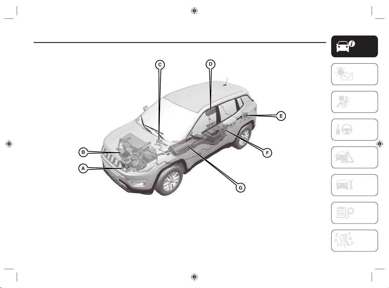
HYBRID SYSTEM FUNCTIONAL SCHEME
1 J0B6040E
A. High-voltage electric compressor - B. Electric motor connected to the internal combustion engine for the production of electric energy for
battery charging - C. High-voltage heater - D. Charging control module - E. Charging socket - F. Electric motor for rear wheel drive - G. High-
voltage battery
KNOWING YOUR VEHICLE
10
HIGH-VOLTAGE BATTERY
1) 2) 3) 4) 5) 6)
1)
1) 2)
The car is equipped with a sealed high-
voltage lithium ion battery and has the
function of energy storage for the car. The
battery is used to power the electric motor
and the car's 12 Volt electrical system
power source.
The high-voltage battery is partially
charged by recovering the kinetic energy
of the car during slowing down and
braking while driving. The battery can be
completely charged only by connecting
the car to the electric network using the
charge outlet.
For optimal use of the high-voltage
battery, it is advisable to charge the
vehicle regularly using a suitable charging
device.
The high-voltage battery is located at the
bottom of the vehicle in a central area and
is maintenance-free.
Lithium-ion batteries provide the following
benefi ts:
are much lighter than other types of
chargeable batteries of the same size;
keep the charge longer;
can be charged/discharged thousands
of times.
The high voltage components on the
vehicle are cooled by an auxiliary circuit
located inside the engine compartment
(for more information refer to the
"Checking levels" paragraph in the
"Servicing and maintenance" section).
NOTE In case the battery set needs to
be cooled, the electric compressor is
automatically activated even when the
passenger compartment cooling function
is not engaged. The high-voltage battery
is cooled by the refrigerant gas also
used by the passenger compartment air
conditioning system.
WARNING The high-voltage battery has
a limited life duration. Its capacity to hold
charge decreases with time and use, as
for any rechargeable battery.
The amount by which the battery
capacity decreases varies with the outside
conditions (ambient temperature, etc.)
and usage conditions, e.g. driving habits
and the high-voltage battery (traction
battery) charging methods. This is a
natural characteristic of lithium ion
batteries and is not a sign of malfunction.
In addition, although the distance that can
be traveled in electrical mode decreases
as the capacity of the high-voltage battery
decreases, the performance of the car is
not signifi cantly affected.
11
To ensure that the lithium ion battery is
maintained properly over time, the vehicle
must not be exposed to temperatures
below -10°C and above 40°C for extended
periods of time, as some vehicle functions
may change or become deactivated as the
battery capacity decreases outside this
temperature range.
The high-voltage battery is equipped with
conditioning systems that ensure that
it operates under the best temperature
conditions appropriate to its operation.
WARNING
1) Do not resell, give away or modify
the high-voltage battery. The high-
voltage battery must only be used on
the vehicle on which it is supplied. If
used outside the vehicle or modified,
accidents such as electric shock, heat
or smoke generation, explosion or
electrolyte leakage may occur. If the
vehicle is scrapped without removing
the high-voltage battery, contact with
high-voltage components, cables and
connectors could cause very dangerous
electric shock. If the high-voltage battery
is not disposed of properly, it may cause
electric shock, resulting in serious injury
or death.
2) The mains power supply and the high-
voltage battery are potentially dangerous:
they can cause injury, burns and risk of
electrocution. Always take great care.
3) Never touch or tamper with the cables
and components of the high-voltage
battery in any way: do not allow the high-
voltage battery components to come into
contact with bracelets, necklaces or any
metal objects worn.
4) Do not open, modify or remove the
high-voltage battery cover: any gases
released may be harmful and flammable:
avoid inhaling the gases.
5) Damage to the vehicle or the high-
voltage battery may cause harmful gases
to escape, which could cause a fire. In
the event of a fire, move away from the
vehicle, wear a reflective vest (if required
by the regulations in force), position
yourself in a safe place, and immediately
contact the rescuers, police or fire
brigade informing them that this is a
vehicle with a high voltage system.
6) The electrolyte inside the battery is a
polluting and flammable material. If the
high-voltage battery is not disposed of
properly, it may cause fire and pollute the
environment.
KNOWING YOUR VEHICLE
12
WARNING
1) If, as a result of a violent impact or
accident, the car has hit the bottom
(underbody), have the battery and the
high-voltage system checked by qualified
technicians.
WARNING
1) Live parts of the vehicle are marked
with safety warning labels. The high-
voltage battery bears a label indicating
this danger.
2) Do not dispose of the high-voltage
battery privately: for more information
contact a Jeep Dealership.
13
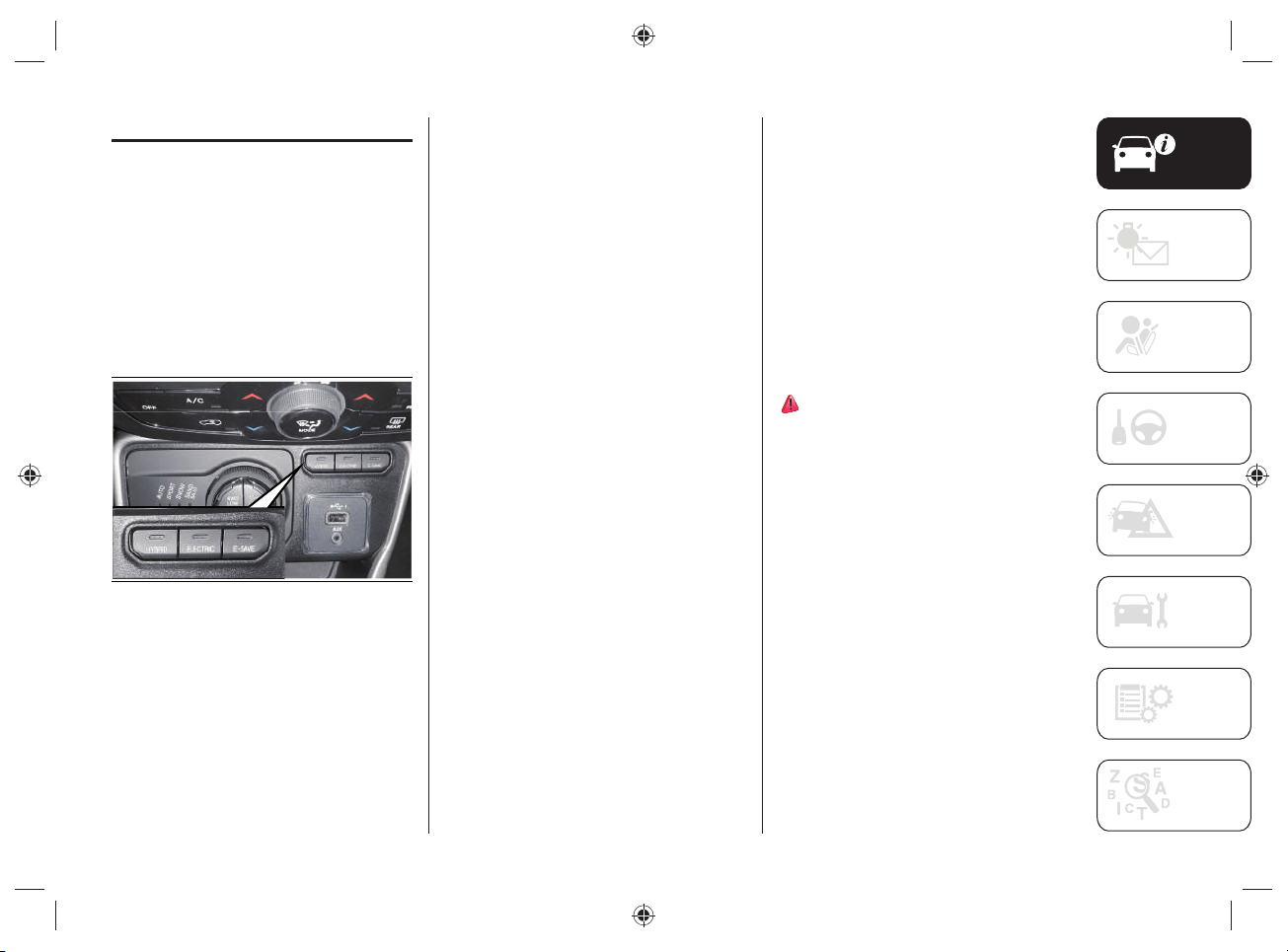
OPERATING MODE
While driving, by pressing the buttons
located on the central tunnel, fi g.2
you can select three different operating
modes:
HYBRID
ELECTRIC
E-SAVE
The standard operating mode is
"HYBRID".
2 J0B6036E
When the ignition device is positioned to
MAR, the engine starts in electric mode
("ELECTRIC") if:
the charge status of the high-voltage
battery is above 0%;
the temperature of the high-voltage
battery is not high;
the outside temperature is higher than
-10°C;
the car's engine lid is closed correctly.
When driving on urban routes, driving
always continues in fully electric mode: if
the driver requests an increase in power
and the electrical system is not able to
satisfy the request, the heat engine will be
automatically activated.
"HYBRID" MODE
Activating the "HYBRID" operating mode
optimizes fuel consumption.
Activation
The mode is activated by pressing the
HYBRID button located on the central
tunnel.
With "HYBRID" mode active:
the LED on the HYBRID fig.2 button
is on;
"HYBRID" is shown on the instrument
panel display.
7)

KNOWING YOUR VEHICLE
14
"ELECTRIC" MODE
The activation of the "ELECTRIC"
operating mode is only possible if the
high-voltage battery charge status is not
less than 1% or until the driver requires
the intervention of the heat engine (fully
depressing the accelerator pedal until it
hardens in the last part of the stroke -
"Kick-down" function).
Activation
The mode is activated by pressing the
ELECTRIC button located on the central
tunnel.
With "ELECTRIC" mode active:
the LED located on the ELECTRIC
fig.2 button is on;
the display of the instrument panel
shows "ELECTRIC".
When the "ELECTRIC" mode is activated,
the vehicle will proceed exclusively in
electric operation mode, up to a maximum
speed of 135km/h and until the battery
charge is exhausted. Depending if the
accelerator pedal is fully depressed and/
or the battery is discharged, the system
will automatically switch to the "HYBRID"
operating mode.
8)
This mode of operation can be activated
with the Selec-Terrain
TM
system dial
rotated to "AUTO" (default setting) or
"SPORT".
Even when the high-voltage battery
charge level is high and the electric mode
is available, the heat engine may start
under certain conditions to protect the
hybrid system.
WARNING You cannot start the engine if
the battery temperature is too low or too
high. If, under these conditions, the fully
electric operating mode is selected, the
heat motor is started.
"E-SAVE" MODE
Activating the "E-SAVE" operating mode
allows to maintain the charge status
or charge the high-voltage battery,
depending on the setting done on the
display of the UConnect™ 8.4” system (for
more information see "UConnect™ 8.4
NAV DAB Radio / UConnect™ 8.4” DAB
Radio” in the "Knowing the instrument
panel and Multimedia" section).
The electrical autonomy of the high-
voltage battery is thus safeguarded,
allowing it to be used, for example, for
a route in urban areas where the heat
engine use is prohibited.
Activation
The mode is activated by pressing the
E-SAVE button located on the central
tunnel.
With "E-SAVE" mode active:
the LED located on the E-SAVE button
fig.2 is on;
the display on the instrument panel
shows "E-SAVE".
The "E-SAVE" mode cannot be activated
if the state of charge of the high-voltage
battery is higher than 70%; in this case,
the LED located on the button fi g.2
fl ashes 3 times then turns off.
The "E-SAVE" mode is never activated
independently.
15
Using the UConnect™ system display it
is possible to change the features of the
function (see "Knowing the instrument
panel and Multimedia").
There are two features related to the
"E-SAVE" mode:
"Battery save" (high-voltage battery
charge status safeguard) (preset
setting).
"Battery charge" (high-voltage battery
charge).
NOTE The activation of“E-SAVE” mode
permits charging the high voltage battery
up to a value close to 70% based on the
driving style and the method of using the
car.
Battery save
This maintains the high-voltage battery
charge status at about the same constant
charge level as when "E-SAVE" mode is
activated on the car.
Battery charge
The high-voltage battery is charged
through the control electronics thanks to
the operation of the heat engine.
NOTE Driving with the "E-SAVE" mode
active may result in an increase in
average fuel consumption and a limitation
of the accelerator pedal response in case
of engine performance request.
NOTE The "E-SAVE" mode can be used
only if the fuel level inside the tank is not
at the minimum level.
WARNING
7) With "HYBRID" mode active, car
stopped and the ignition device RUN,
opening the engine boot automatically
activates the heat engine.
8) With "ELECTRIC" mode active, car
stopped and the ignition device RUN,
opening the engine lid automatically
activates the heat engine.

KNOWING YOUR VEHICLE
16
POWER SOURCES
THAT CAN BE USED
9) 10) 11) 12) 13) 14) 15) 16) 17) 18) 19) 20) 21) 22) 23)
24) 25) 26) 27) 28) 29) 30) 31) 32)
GENERAL INFORMATION
The vehicle's high-voltage battery can be
charged not only through the heat engine
operation , but also using special charging
cables that allow:
the connection of the charging socket
located on the rear left side of the
vehicle to the charging sockets in
public charging stations;
or
to the domestic socket.
Regular and complete charging of
the high-voltage battery reduces fuel
consumption by using electrical energy
thanks to the operation of the electric
motor.
The charging procedure control and
monitoring takes place in a fully automatic
way.
NOTE The vehicle is not able to
automatically recognize the maximum
allowable current intensity depending
on the type of domestic socket/public
charging stations used and the regulations
in force in the country in which you are
located (e.g. overloads). Reduce the
maximum charge current required by
using the "Charge setting" option on the
display of the Uconnect™ system (for
more information refer to "UConnect™
8.4 NAV DAB Radio / Uconnect™ 8.4”
DAB Radio” chapter in the “Knowing
the instrument panel and Multimedia”
section). Before charging in your own
home, or elsewhere, check the allowable
current intensity by contacting a
specialized technician: it is advisable to
contact the Jeep Dealership.
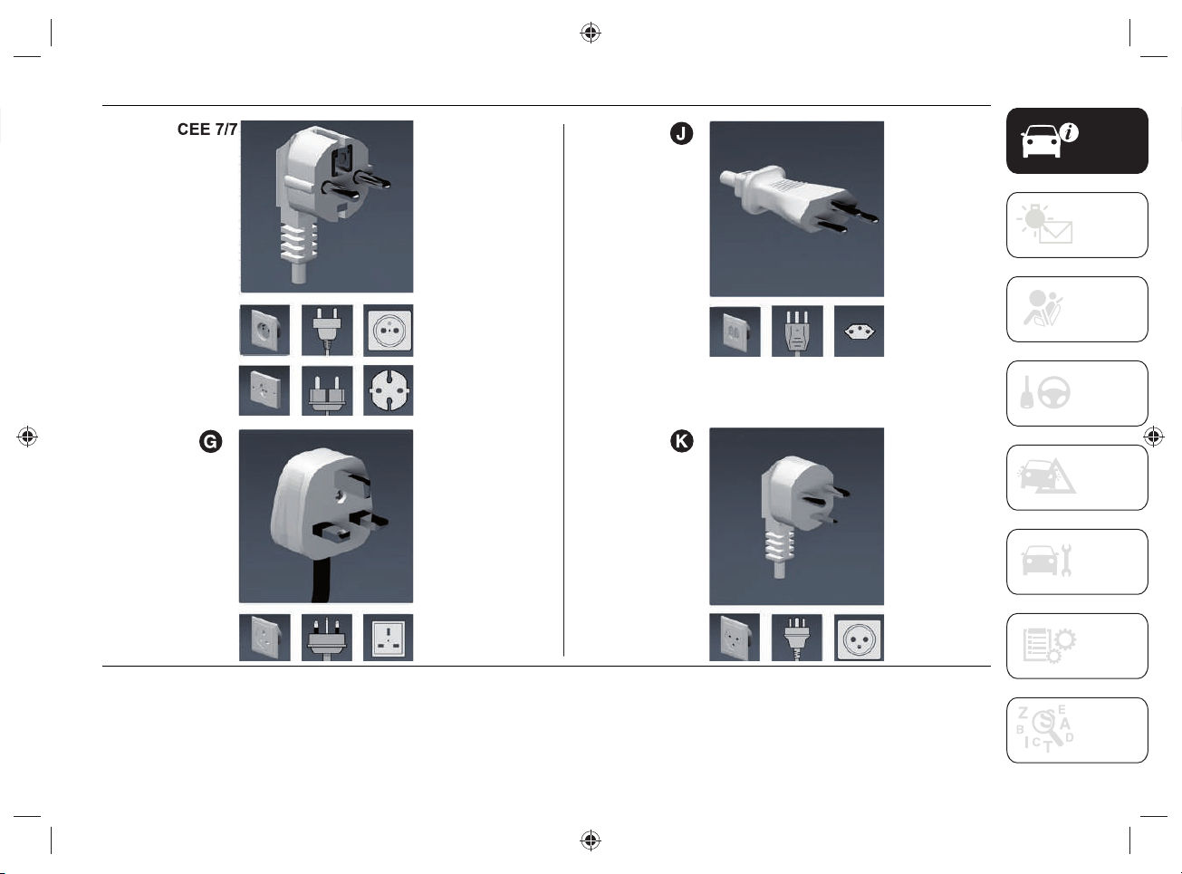
TYPES OF CHARGING CABLES
Two different types of cables can be used
for charging:
"Mode 2" Afig.3 charging cable
(standard): allows charging from an
earthed domestic power socket. This
type of socket is used for charging
with alternating current. The "Mode
2" charging cable complies with IEC
61851, IEC 62752 and SAE J1772
standards.
"Mode3" Bfig.4 charging cable
(optional): allows charging from
a public charging station and a
domestic AC (alternating current)
charging station (wallbox). The
charging speed may be faster than
charging through a domestic power
socket.
17
3 J0B6062
4 J0B6063
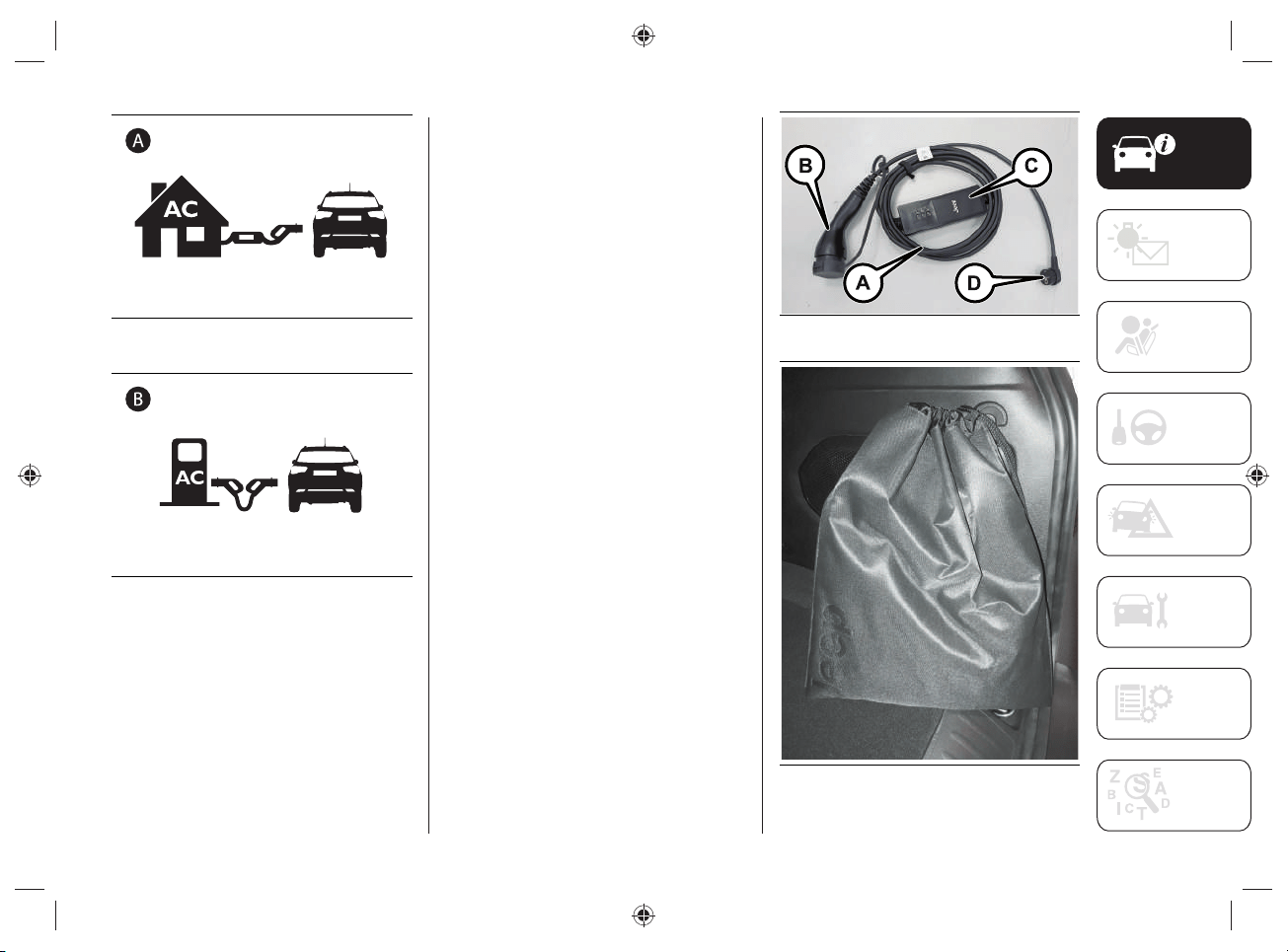
"MODE2" CHARGING CABLE
The car is equipped with a "Mode 2" 230
Volt AC (A)fi g.5 charging cable located
inside a special bag, fi g.6, placed in the
boot.
The cable consists of:
specific charge connector (B) for
connection to the vehicle;
a charge status control unit (C)
equipped with LEDs, able to provide
indications on any anomalies present
during the charging phase;
a connection plug (D) to a domestic
power socket.
NOTE After use, remember to correctly
replace the protective cover (where
provided) on the specifi c charging
connector (B) to prevent moisture and/or
dust from getting inside.
5 J0B6048E
6 J0B6059E
KNOWING YOUR VEHICLE
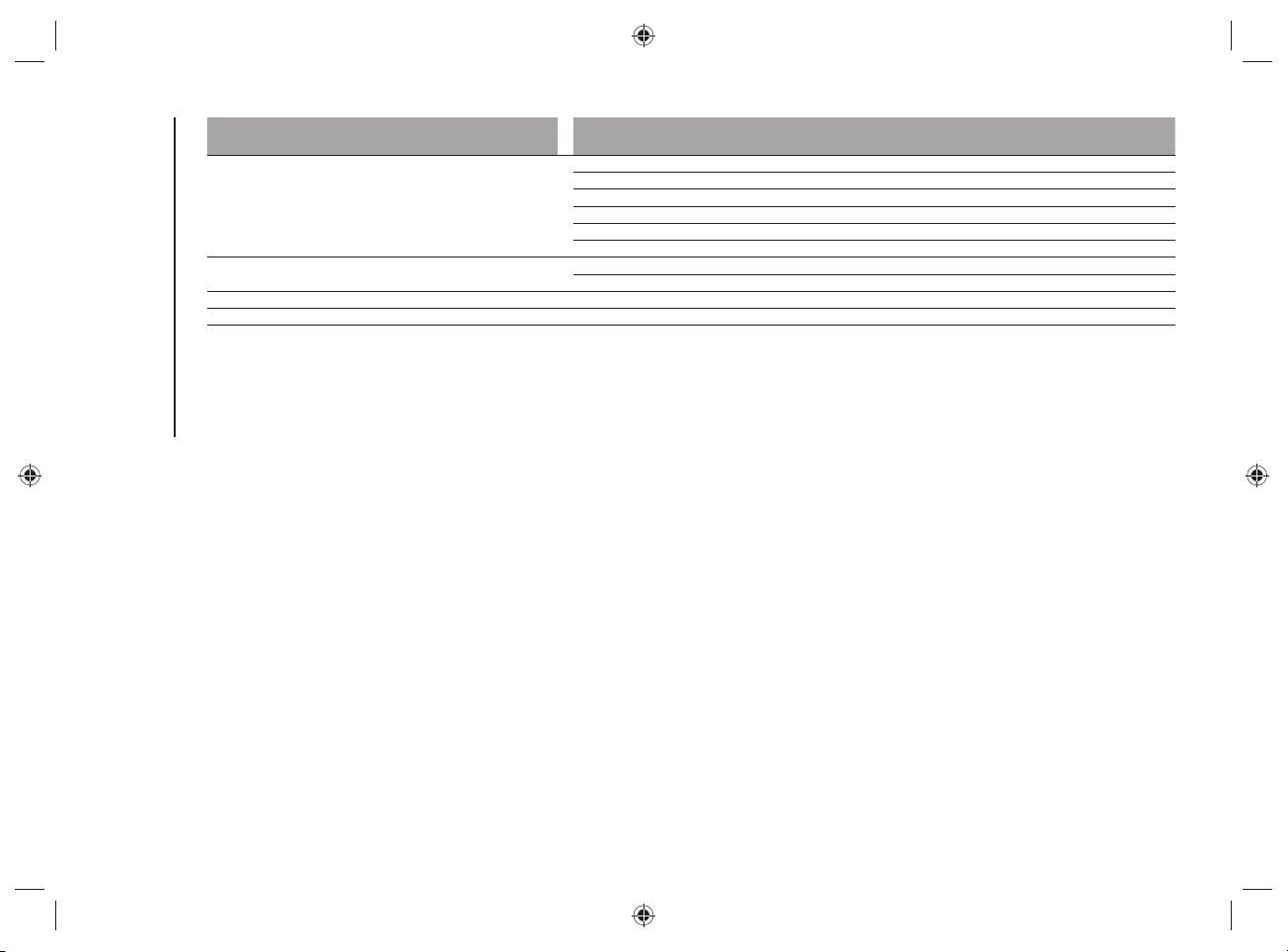
18
"Mode2" cable variants table
The following table shows the list of the specifi c cable types and the amperages allowed for each country where the car is sold. This
amperage is the limit allowed when the charging power is set to the highest level.
Country group (*)
Electric vehicle
charging connector
type
Electric current
intensity (Ampere)
Type of domestic
power outlet/plug
(**)
Cable length
(meters)
Notes
1
Type 2
13 CEE 7/7
6
–
210G –
3 8 CEE 7/7 –
48J–
56K–
6 10 CEE 7/7
Specific cable for
Norway market
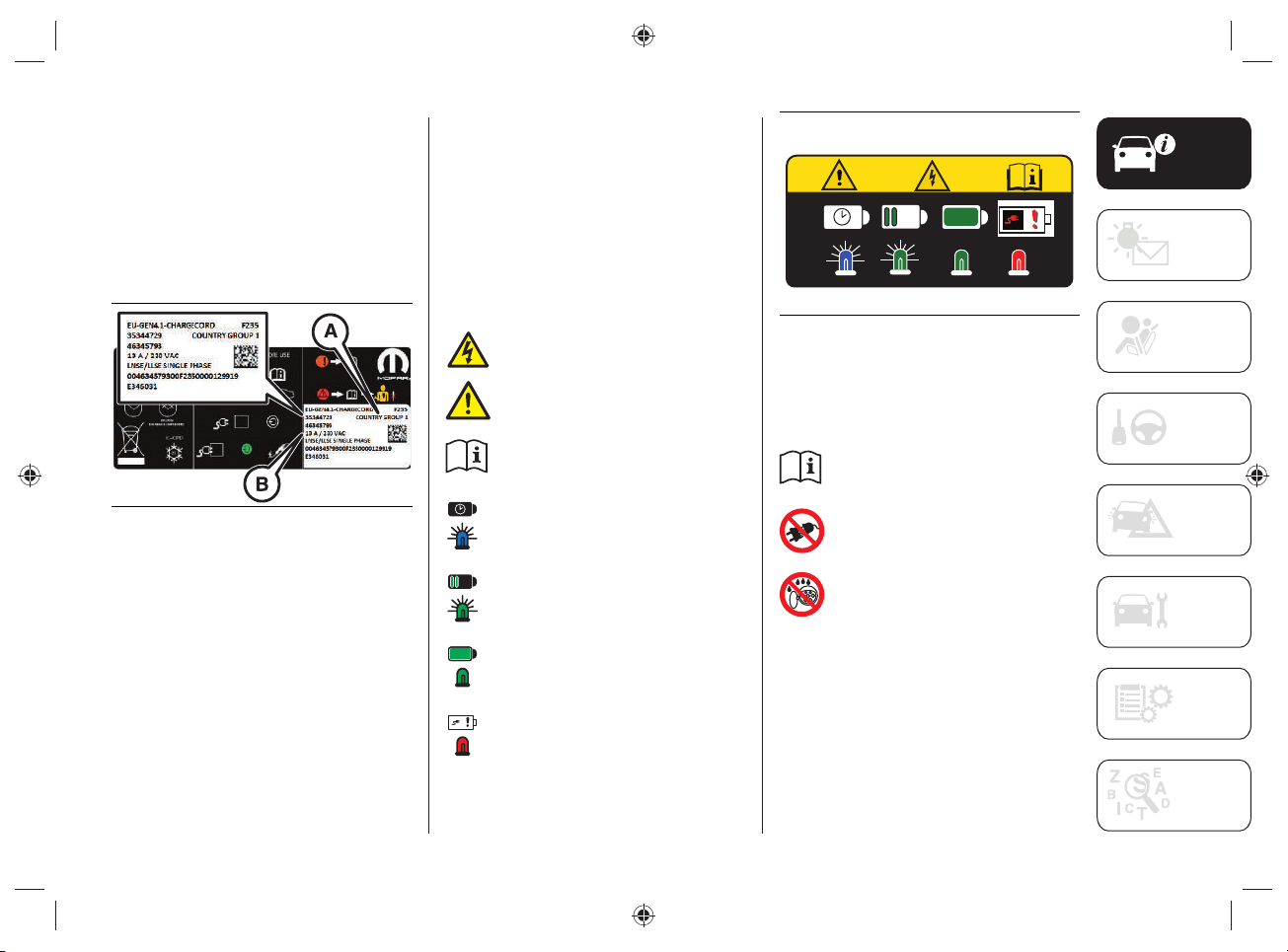
(*) The Country Group is indicated by the message "COUNTRY GROUP" on the label located on the rear of the control unit (see the
indications in fig.14).
(**) Refer to the following pages for the type of power outlet/plug.
NOTE To check the maximum electric current (Ampere) that can be consumed, refer to the label located on the back of the control unit
(see what is described and illustrated in the "”Charge status control unit”" paragraph).
19
Country group table for "Mode2" cable
The following table shows the list of countries contained in each "Country Group" associated with the "Mode2" cable.
Country Group Country
1
Albania
Austria
Belgium
Bulgaria
Croatia
Czech Republic
Estonia
Germany
Greece
Hungary
Iceland
Latvia
Lithuania
Luxembourg
Macedonia
Morocco
Netherlands
Poland
Portugal
Romania
Serbia
Slovakia
Slovenia
Spain
Sweden
Italy
Ukraine
Turkey
2
Cyprus
Gibraltar
Malta
United Kingdom, Ireland
KNOWING YOUR VEHICLE
20
Country Group Country
3
France
Finland
Guadeloupe
French Guiana
Martinique
Reunion
4
Liechtenstein
Switzerland
5 Denmark
6 Norway
NOTE For more information on the type of socket in use in the various countries, refer to the following website:
https://www.iec.ch/worldplugs/list_bylocation.htm.
21
7 J0B6056E
KNOWING YOUR VEHICLE
22
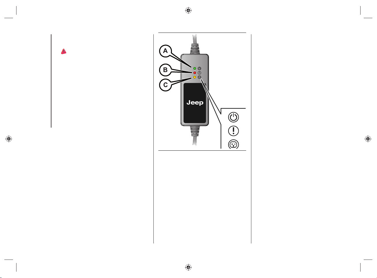
CHARGE STATUS CONTROL
UNIT
33) 34)
Signal LED
There are three LEDs on the front of the
charge status control unit:
GREEN LED on (A fig.8): indicates
correct operation in the domestic
power distribution system: it is
therefore possible to proceed with the
high-voltage battery charging.
RED LED on (B fig.8): indicates a fault
in the charging system.
YELLOW LED on (C fig.8): indicates a
possible failure in the domestic mains
power supply.
WARNING Never carry out any repair
work on your own: always contact the
Jeep Dealership.
8 J0B6003E
For the type of failure, refer to the
description under "Charging system
failure" on the following pages.
23
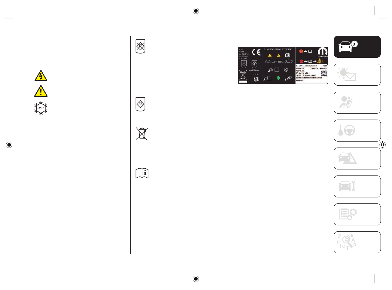
Symbol label
On the back of the charging status control
unit there is a summary label, fi g.9,
which shows some symbols.
The main ones are listed below:
this symbol indicates a risk of
electric shock.
this symbol indicates a general
dangerous situation.
This symbol shows the minimum
operating temperature of the
charging status control unit in
accordance with IEC 61851 and
IEC 62752 certifi cation.
NOTE FCA guarantees that the
device has been tested for use
from -40°C to +50°C.
If the device is not used and must
be stored, the temperature must
be between -40°C and +80°C.
Exceeding these temperature
values may damage the device.
The presence of this symbol
on the label indicates that the
specifi c "Mode2" charge cable
cannot be used for domestic
power distribution networks
where the earthing cable is not
present. For specifi c markets,
without the grounding cable,
check for "COUNTRY GROUP" on
the label (fi g.9).
the presence of this symbol
on the label indicates that the
charging status control unit
does not have the function of
disconnecting the earthing cable.
the symbol indicates that the
charging unit should not be
placed in the waste if it no longer
works: for disposal refer to the
environmental regulations in
force in the country in which it
circulates.
the symbol prompts you to read
the instructions in this publication
carefully before using the
charging cable.
9 J0B6002E
KNOWING YOUR VEHICLE
24
CHARGING SYSTEM FAILURE
Any faults during charging are displayed by the LEDs, either steady or fl ashing, located on the front of the charging status control unit.
Refer to the table below.
GREEN LED RED LED YELLOW LED Description Action/Consequence
1
OFF OFF OFF
Charging cable not
connected to the domestic
charging socket or power
failure in the domestic
power distribution system
–
2
ON OFF OFF
There are no faults in the
domestic power supply
mains, so the charging
cable can be connected to
the charging socket on the
vehicle
–
3
ON ON (Flashing) ON
Overheating at the charging
socket in the domestic
power distribution system
When the normal temperature is reached,
the system will make a new charge
attempt at a lower current level
4
ON OFF ON (Flashing)
Charging to a lower current
level due to overheating
of the charging port of
the domestic electricity
distribution mains (see
point 3)
–
25
GREEN LED RED LED YELLOW LED Description Action/Consequence
5
ON ON ON (Flashing)
Overheating at the charging
socket in the domestic
power distribution system
Overheating during charging at a lower
current level
(see point 4)
Proceed as follows:
disconnect the charge cable from
the car and from the domestic
power socket with care (the
domestic power plug may be hot);
please wait for the domestic power
plug and socket to reach a normal
temperature;
reconnect the cable to the domestic
power socket and to the car’s
charge socket, then try to charge
again.
In case of a new anomaly, contact a
certified electrician
6
ON ON (2 blinks) ON (2 blinks)
Lack of earthing cable in
the charging port of the
domestic mains power
supply
The system will make a new charge
attempt after 30 seconds
(6 attempts in total)
7
ON ON ON (2 blinks)
Lack of earthing cable in
the charging port of the
domestic mains power
supply
New charge attempt (see point 6) failed.
Disconnect the charge cable from the car
and/or the domestic socket and reconnect
it, then try to charge again
In case of a new anomaly, contact a
certified electrician.
26
KNOWING YOUR VEHICLE
GREEN LED RED LED YELLOW LED Description Action/Consequence
8
ON (flashing) OFF OFF
Domestic mains power
incorrectly supplied
The system will make a new charge
attempt after 30 seconds
(6 attempts in total)
If the fault persists, disconnect the charge
cable from the car and the domestic
socket and reconnect it, then try to charge
again
In case of a new anomaly, contact a
certified electrician
9
ON ON OFF
Dispersion of electricity on
the car
Disconnect the charge cable from the car
and the domestic socket and reconnect it,
then try to charge again
In case of a new anomaly, contact a Jeep
Dealership
10
ON ON (flashing) OFF
Electric charging current
too high
The system will make a new charge
attempt after 30 seconds
(6 attempts in total)
11
ON ON (7 blinks) OFF
Electric charging current
too high
New charge attempt (see point 10) failed.
Disconnect the charge cable from the car
and the domestic socket and reconnect it,
then try to charge again
In case of a new anomaly, contact a Jeep
Dealership
27
GREEN LED RED LED YELLOW LED Description Action/Consequence
12
ON ON (2 blinks) OFF Charge anomaly on the car
The system will make a new charge
attempt after 30 seconds
(6 attempts in total)
If the fault persists, disconnect the charge
cable from the car and the domestic
power socket and reconnect it, then try to
charge again
In case of a new anomaly, contact a Jeep
Dealership
13
ON ON (3 blinks) OFF
Charging cable failure
14
ON ON (4 blinks) OFF
15
ON ON (5 blinks) OFF
16
ON ON (6 blinks) OFF
Key
ON = LED on
OFF = LED off
BLINK = 0.5 seconds ON / 0.5 seconds OFF / 3 seconds pause
FLASHING = 0.5 seconds ON / 0.5 seconds OFF

KNOWING YOUR VEHICLE
28
MAINTENANCE/ CLEANING OF
THE CHARGING SYSTEM
The device is maintenance-free.
If you need to clean the device, use a
soft cloth slightly dampened with a mild
detergent solution, then wipe dry with a
dry cloth. Do not use abrasive products or
fl ammable substances (e.g. alcohol, petrol
or their derivatives). Do not wash the
device with water, hazard of fi re or electric
shock with the risk of serious injury or
death.
WARNING Only clean the device when
it is DISCONNECTED from both the
domestic charging socket and the
charging socket located on the vehicle.
FCC SPECIFICATIONS
(Federal Communications Commission)
The Charge Status Control Unit complies
with Section 15 of the FCC Regulation.
The use of the device meets the following
two requirements:
1. This device does not cause harmful
interference.
2. Correct operation of the device may
be affected by interference from
nearby electrical/electronic devices.
This device is designed to withstand radio
frequency interference (RFI), however,
some factors (e.g., high intensity radio
signals or radio transmitters in the
vicinity of the device) may cause it to
malfunction. If you fi nd an anomaly in the
operation of the device, contact the Jeep
Dealership.
WARNING Modifi cations and/or repairs
made incorrectly and NOT carried out
by the Jeep Dealership will invalidate the
Warranty and the above requirements.
29
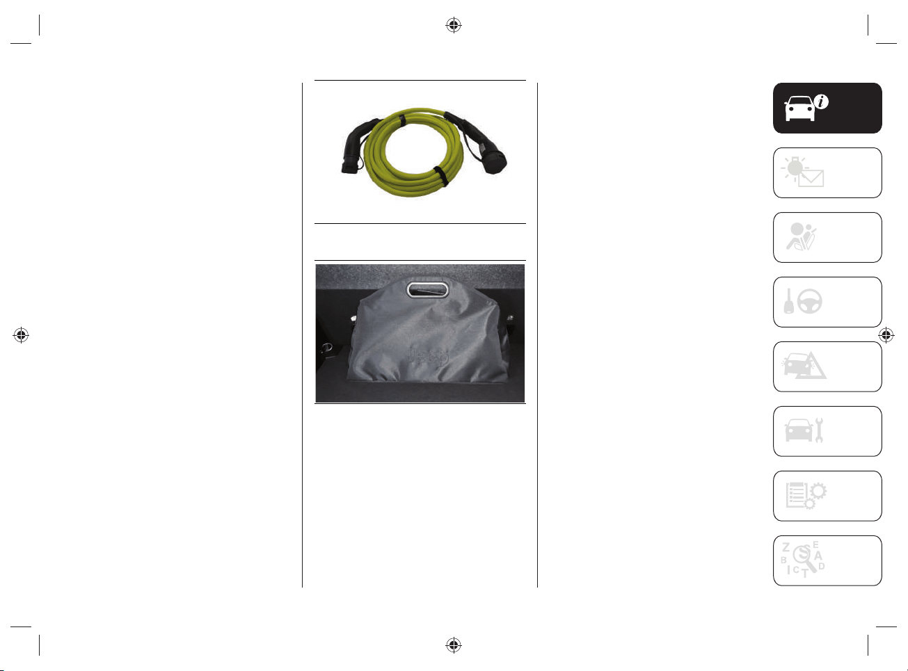
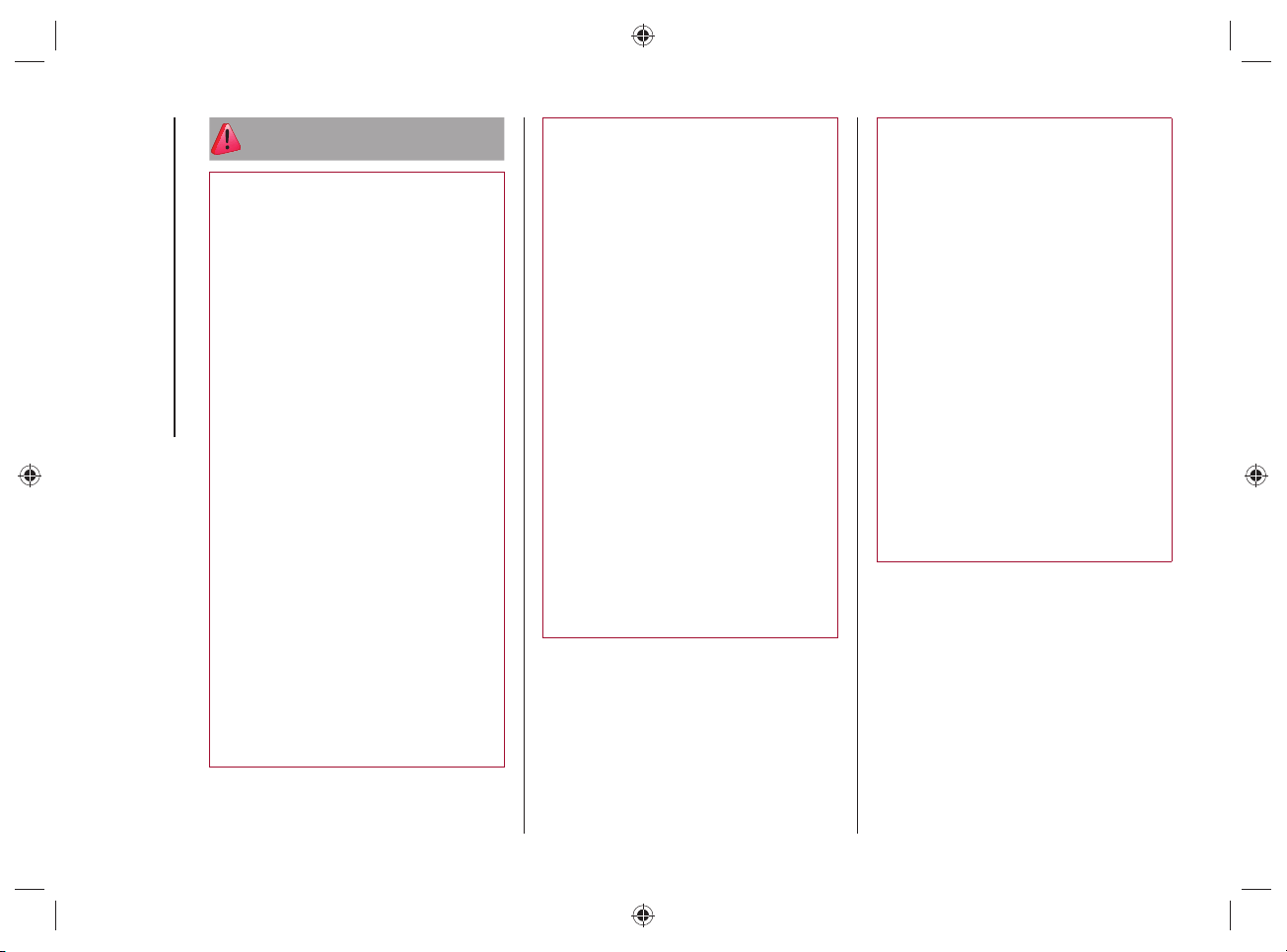
"MODE3" CHARGING CABLE
(optional)
The car can be equipped with a "Mode3"
charging cable fi g.10, located inside a
special bag fi g.11, placed in the boot.
The "Mode3" charging cable:
complies with EN 61851- 1,
EN 62196- 1 and EN 62196- 2
standards;
can be used for a minimum
temperature of -40°C up to a
maximum temperature of +50°C.
This type of cable allows you to connect
to public alternating current (AC) charging
stations. The charging speed may be
faster than charging through a domestic
power socket.
Using this type of cable it is possible to
charge the car with a current of up to
32A.
NOTE After use, remember to replace
the protective covers on both sides of
the charging cable correctly to prevent
moisture and/or dust from entering the
cable charging socket connections.
10 J0B6140E
11 J0B6080E
Maintenance/ cleaning of the charging
system
The device is maintenance-free.
If you need to clean the device, use a
soft cloth slightly dampened with a mild
detergent solution, then wipe dry with a
dry cloth. Do not use abrasive products or
fl ammable substances (e.g. alcohol, petrol
or their derivatives). Do not wash the
device with water, hazard of fi re or electric
shock with the risk of serious injury or
death.
WARNING Only clean the cable when it
is DISCONNECTED from both the public
charging station and the charging socket
located on the vehicle.
KNOWING YOUR VEHICLE
30
WARNING
9) Always turn off the engine before
recharging the high-voltage battery. Even
with the engine switched off, the cooling
fan inside the engine compartment can
start automatically during charging.
Do not approach the cooling fan while
charging.
10) The safety and suitability of the
domestic system for charging through
the domestic mains are primary and are
under the Customer’s responsibility.
11) Do not connect the charging cable
connector if there is dust and/or water
on the charging socket. Making the
connection in the presence of water or
dust on the connector/charging cable
and the plug may cause a fire or electric
shock. Use of worn-out electrical sockets
may result in fire and injury.
12) If you use electrical medical devices
(e.g., cardiac pacemakers), make sure in
advance that charging the high-voltage
battery does not affect the operation
of these devices. In some cases,
electromagnetic waves generated by the
charger may affect the operation of such
medical devices.
13) Stop the charge immediately if you
notice any abnormal symptoms (e.g.
smell, smoke, etc.).
14) Replace the charging cable if the
cable jacket is damaged to prevent risk of
electrocution.
15) When connecting or removing the
charging cable, be sure to grasp the
handle of the charging connector and
the charging plug. If you pull the cable
directly (without using the handle) the
internal conductors may disconnect or
damage: this may cause a shock or fire.
16) The charging cable is a high voltage
conductor. Contact with high voltage can
cause serious personal injury or death.
Similarly, do not touch the orange high-
voltage cables.
17) It is strictly forbidden to use any plug
adapter or similar devices when charging.
Never use the charging cable together
with an extension cord.
18) Never connect the charging cable to
an extension cord or multi-plug. Multiple
sockets, extension cables, overvoltage
protection or similar units cannot be used
together with the charging cable as they
may present a risk of fire, electrocution,
etc...
19) The charging cable supplied as
standard is watertight and is guaranteed
by the Manufacturer: do not use other
cables not supplied by FCA.
20) Be sure not to touch the charging
connector and charging plug with wet
hands.
21) Do not charge when the connector
and charging plug are wet.
22) Do not charge in adverse weather
conditions (e.g. during thunderstorms) at
charging stations.
23) Always keep charging connector and
charging plug clean and dry. Take care
to keep the charging cable away from
water or moisture. Do not use chemicals
or solvents.
24) Be sure to use the designated
charging cable to charge the vehicle.
Using any other charging cable may
cause personal injury or damage to the
vehicle.
31
25) How to use the charging cables:
– Treat the charging cable with care:
avoid folding and/or bending it on
sharp surfaces.
– After using the charging cable,
replace the protective covers (if
present) on both sides of the cable
correctly.
– Avoid prolonged exposure of the
charging cable to sunlight.
– Avoid dropping the charging cable
from above: violent shocks could
damage the cable.
– Do not immerse the charging cables
in liquids.
26) Do not leave children unattended in
the vicinity of the charging cable when it
is connected.
27) Position the charging cable in such
a way that it is not crushed by other
vehicles, trampled on by people, or
positioned in way that people in the
vicinity of the vehicle may stumble,
resulting in damage or personal injury.
28) Disconnect the charging cable from
the domestic socket or charging station
before cleaning it.
29) Do not use the charging cable if it
has damaged parts.
30) Never disconnect the charging cable
from the domestic power socket or public
charging station during charging. Always
interrupt charging, then disconnect the
cable, first from the car-side charging
socket and then from the domestic
socket or public charging station.
31) Never use a visibly worn or damaged
electrical socket. It could cause fire or
serious damage.
32) The high-voltage battery should only
be charged with the maximum allowable
current or other lower current specified in
local and national recommendations for
charging high-voltage batteries.
33) The device is to be used exclusively
for charging the vehicle.
34) Never attempt to make a repair and/
or perform maintenance on the charge
cables, this may result in serious personal
injury or even death. Always contact a
Jeep Dealership.
KNOWING YOUR VEHICLE
32
VEHICLE
35) 36)
2) 3) 4) 5) 6)
Before charging the high voltage battery,
it is recommended to turn the ignition
device OFF in order to obtain a charge
until full in the shortest period possible.
WARNING The brake caliper lock is
activated during the charging procedure:
unlocking will be carried out automatically
at the end of the charging procedure.
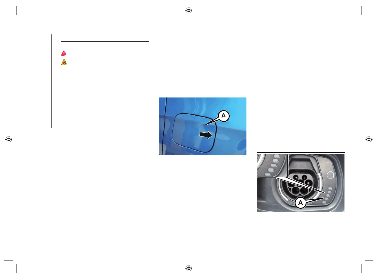
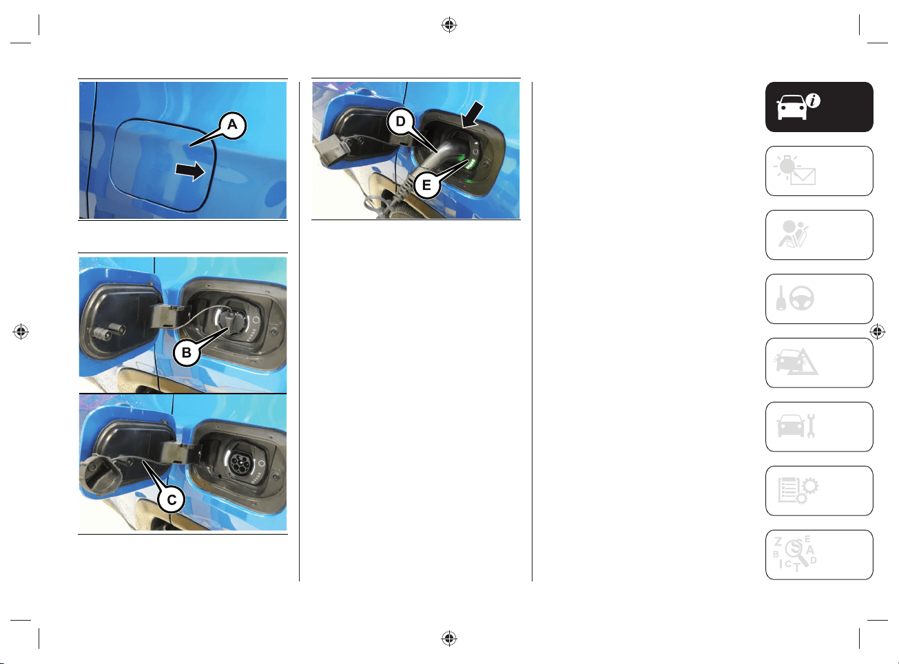
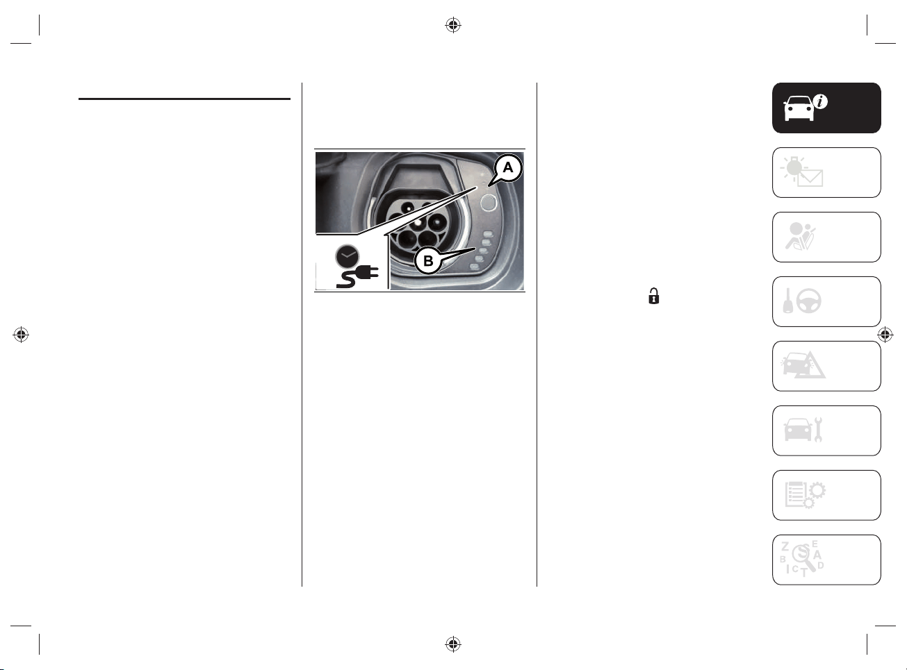
CHARGING SOCKET ON THE
VEHICLE
To access the charging socket, open the
charging fl ap (A)fi g.12 located on the left
side by pressing on the area indicated by
the arrow.
WARNING The courtesy lights on the
charging port fl ap remain on for a few
seconds and turn off while charging.
12 J0B6030E
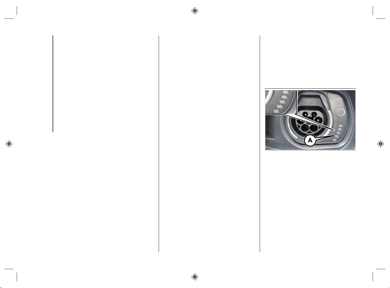
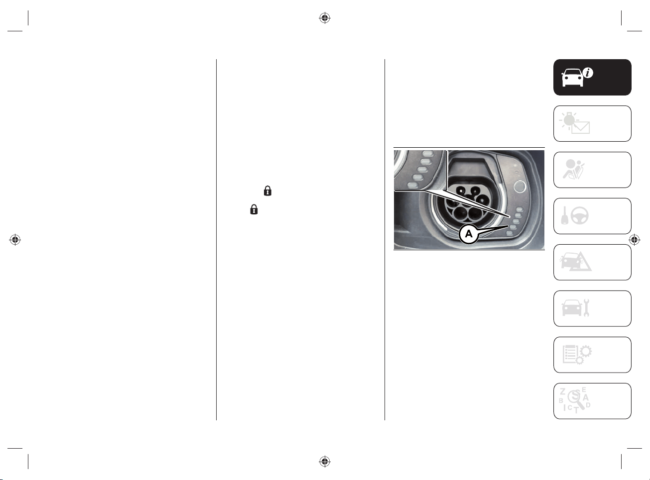
Charging port LED
Next to the charging socket there are
some LEDs (A)fi g.13 that indicate the
charging status by means of four different
colors and related fl ashing types:
Blue: to indicate that the system is
waiting for a charging schedule.
Flashing green: during the charging
process.
Steady green: to indicate that the
charging process is complete.
Blinking red: to indicate a fault in
the charging system or when there
is a fault in the charging procedure
(e.g. when the charging connector
is connected to the charging socket
located on the vehicle and the cable
has not been previously connected to
the power socket).
13 J0B6035E
33
WARNING Use only the charging cable
supplied with your vehicle: refer to the
label on the control unit, which indicates
the "Country Group" (A)fi g.14 and the
electrical current intensity (Ampere) (B)
and the table "Mode2" Cable Variants
in the "Power sources that can be
used" chapter) or a replacement cable
recommended by FCA.
14 J0B6069E
Symbol labels
On the inside of the charging socket
fl ap there are labels with the following
warnings and indications that must be
checked and observed when charging the
high-voltage battery.
Symbols label
(charging information)
On the label, fi g.15, there are the
following symbols:
indicates a risk of electric shock.
indicates a general dangerous
situation.
indicates to refer to the
descriptions and fi gures in this
supplement.
indicates that a charging timer
has been set.
indicates that the charging
procedure is in progress.
indicates that the charging
procedure is complete.
indicates that there is a fault in
the charging procedure.
15 J0B6004E
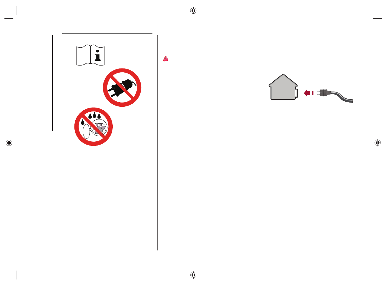
Symbols label
(charging information)
On the label, fi g.16, there are the
following symbols:
indicates to refer to the
descriptions and fi gures in this
supplement.
indicates to not use extension
cords and/or adapters to carry
out the charging procedure.
indicates that water should
not come into contact with the
charging socket on the vehicle.
KNOWING YOUR VEHICLE
34
16 J0B6005E
CHARGING FROM DOMESTIC
POWER SUPPLY (AC) SOCKET
PROCEDURE
37) 38) 39) 40) 41)
WARNING Always connect the cable to the
charging socket of the domestic mains fi rst
and only then to the vehicle.
The vehicle's high-voltage battery is
charged by connecting the "Mode 2"
charging cable, supplied with the vehicle,
to an AC charging socket.
For the characteristics of the "Mode2"
cable, refer to the "Power sources that
can be used - Mode2 cable" chapter.
To charge, proceed as follows:
park the car safely (automatic
transmission lever in position "P" -
Park);
engage the electric park brake;
switch off the engine;
take the kit located in the boot;
unroll the charge cable and connect it
to an AC charging socket, fig.17.
NOTE From the moment the plug
is connected to the domestic mains
charging port, the 3 LEDs on the control
unit of the cable will fl ash for approx. 6
seconds (control unit switching on phase);
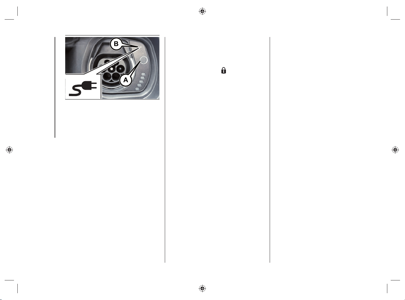
open the charging flap (A)fig.18
located on the left side by pressing on
the area indicated by the arrow;
remove any dust that may have
accumulated on the charging
connector and charging socket;
17 J0B6000E
35
18 J0B6030E
19 J0B6031E
20 J0B6032E
remove the protective cover (B)fig.19
of the charging socket and attach it to
the device (C);
grasp the charging connector
(D)fig.20 by the handle, remove the
protective cover (where provided) and
insert it into the charging socket (E),
until you hear the click indicating that
it has been locked
if no scheduled charging has
been set (see the "Charging
functions" chapter), charging starts
automatically;
check by turning on the LEDs on
the cable control unit that there are
no faults in the charging system (for
more information see "Charging status
control unit" in the "Power sources
that can be used - Mode2 cable"
chapter). If there are no anomalies,
the green LEDs located next to the
charging socket will light up. In case
of anomalies, refer to the description
under "Charging system failure" in the
chapter "Power sources that can be
used - Mode2 cable".
NOTE The charge procedure is
interrupted when opening the bonnet: a
dedicated message will be shown on the
instrument panel display. The charge
will be reactivated when the engine lid is
closed correctly.
KNOWING YOUR VEHICLE
36
The time required to charge the high-
voltage battery depends on several
factors: for more information see the
description in the "Charging time"
paragraph in the "Knowing the instrument
panel and multimedia" section.
If the passenger compartment
preconditioning is activated, the high-
voltage battery charging time will be
extended. The time required for heating/
cooling the car is mainly determined by
the outside temperature.
WARNING The maximum power
consumption of the charging socket
depends on the type of contract to which
the user is subscribed, the type of cable
used and the charge level set in the
UConnect™ 8.4” Radio system menu.
WARNING Use only the charging cable
supplied with the car or a replacement
cable recommended by FCA.
WARNING The high-voltage battery
must be charged in accordance with the
maximum amperage rating allowed by
local and national recommendations for
charging electric/hybrid vehicles.
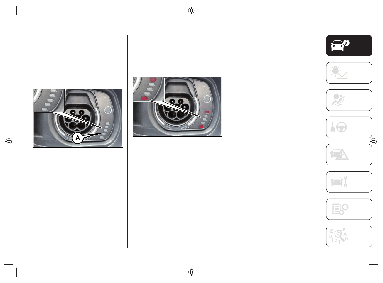
END OF CHARGING
PROCEDURE
The charging procedure ends when all
the LEDs (A)fi g.21, located next to the
charging socket, will light up in green with
a steady light (during the charging phase
the fi rst LED will fl ash, while the other
LEDs will be on with a steady light).
21 J0B6035E
37
DISCONNECTING THE "MODE2"
CHARGING CABLE
During the charging procedure the cable
is automatically locked on the charging
socket in the car.
To complete the charging, proceed as
follows:
unlock the doors of the vehicle
allowing the charging cable to unlock;
disconnect the cable from the vehicle
charging socket by grasping the
handle of the charging connector and
avoiding to pull the cable directly,
fig.22;
disconnect the cable from the
charging socket, fig.23;
replace the protective cover of the
charging socket;
close the charging flap, making sure it
locks properly;
roll up the charging cable correctly,
repositioning the protective cover
correctly on the charging connector
(where provided). When rolling up,
take care not to damage the cable.
Then place the cable, together with
the charging kit, inside the bag
located inside the boot.
22 J0B6065E
23 J0B6001E
WARNING Before disconnecting the
charging connector, make sure that the
doors are unlocked. If the door is locked,
the charging connector locking system
does not allow disconnection.
KNOWING YOUR VEHICLE
38
CHARGING PROCEDURE FROM
WALLBOX CHARGING STATION
("SMART" WALLBOX)
WARNING The "smart" wallbox domestic
charging station must be installed by
qualifi ed personnel after checking
the domestic electrical system. For
information on available "smart" wallbox
charging stations, contact a Jeep
Dealership.
The high-voltage battery of the car can
be charged by directly connecting the
charging cable on the wallbox charging
station or using the "Mode3" cable
(optional).
For the characteristics of the "Mode3"
cable, refer to the "Power sources that
can be used - Mode3 cable" chapter.
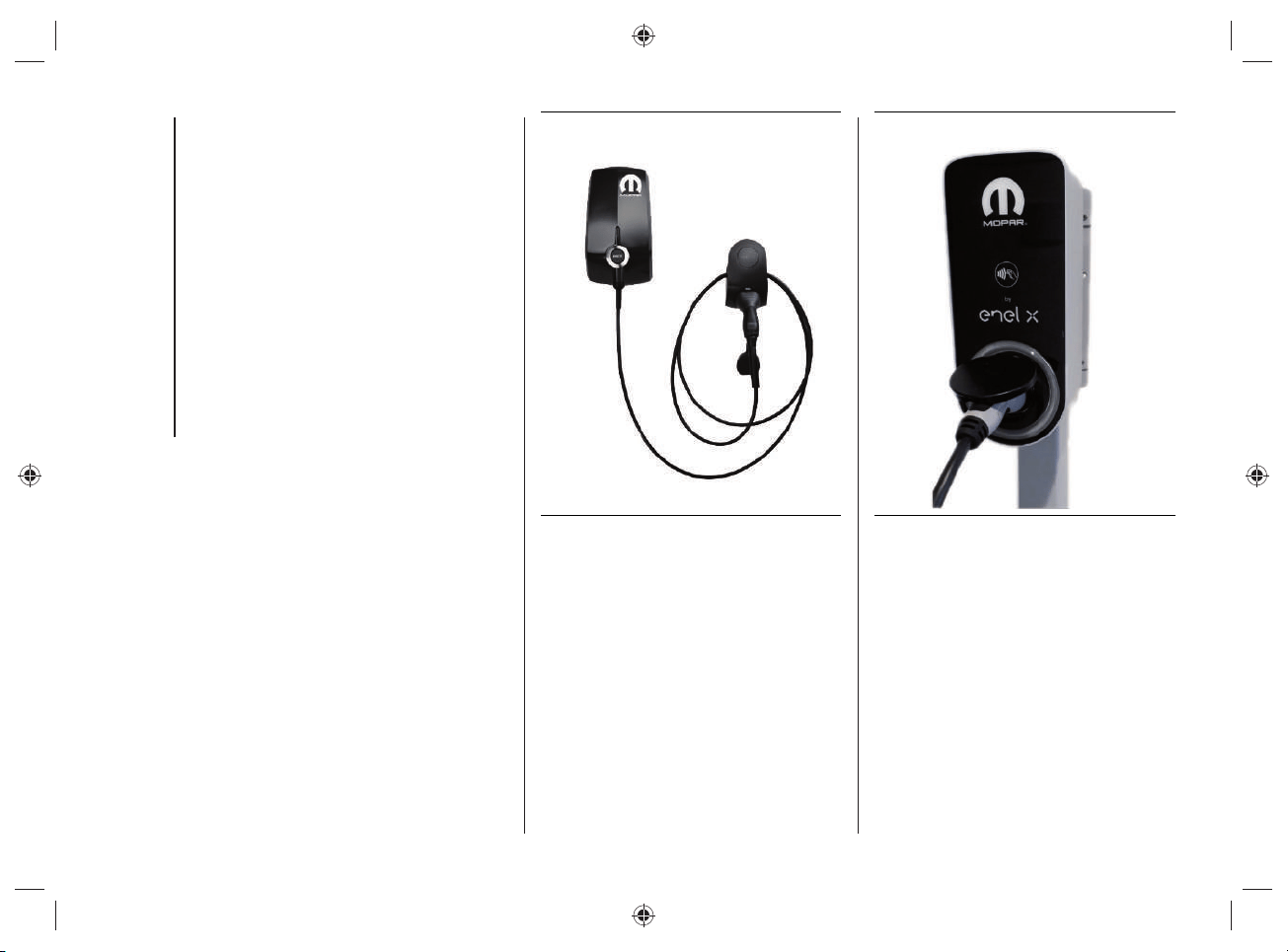
Charging with "smart" wallbox charging
station, fi g.24 or fi g.25, allows to reach,
from a domestic user, a higher charge
power than the charge achieved using a
domestic socket: the charging time, as a
consequence, is signifi cantly reduced.
Some "smart" wallboxes can be
programmed from the mobile app.
WARNING If programming is present
both on the "small" wallbox and on the
car UConnect
TM
8.4” or mobile app),
the charging system gives priority to
programming of the wallbox (excluding
the programming of the car).
24 J0B6070E
NOTE The "smart" wallbox confi guration
may vary depending on the country where
the car is sold.
NOTE The electrical system of the house
must be checked regularly by qualifi ed
personnel.
25 J0B6081E
The maximum charging current value
is automatically set by the device,
depending on the building's electrical
system.
For the charging procedure, refer to the
"Charging from domestic power supply
(AC) socket procedure".
39
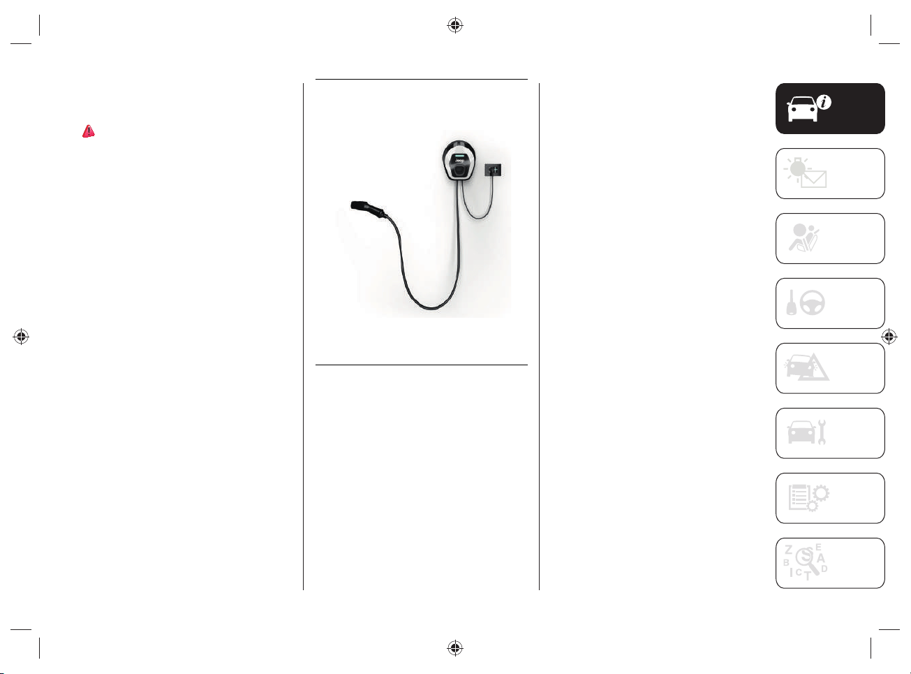
JEEP easyWallbox
(for versions/markets where provided)
42)
The easyWallbox home charging station
(for versions/markets, where provided)
can be confi gured either as a "Plug&Play"
device that can be plugged into a normal,
earthed single-phase domestic power
socket (*) (fi g.26 - "Mode2" charging)
with power up to 2.3kW and current
up to 10A (*) (where permitted by the
conditions of the domestic electrical
system) or permanently connected to the
single-phase electrical network ("Mode3"
charging).
(*) Except for France and Switzerland
(current up to 8A) and Denmark (current
up to 6A).
NOTE The maximum current that
can be drawn in "Mode2" is limited
in accordance with the regulations in
force in the various countries so that the
easyWallbox can be used safely.
26 J0A6149E
Only if confi gured in "Mode3",
easyWallbox can recharge the car (single-
phase only) with a maximum power of
7.4kW and a maximum current of 32A
(actual power and charging current will
depend on the limits of the electricity
supply contract and the maximum current
constraints resulting from the regulations
in force, country by country, for this
type of recharging and for single-phase
alternating current). The easyWallbox
home charging station for use as a
Wallbox in "Mode3" must be installed by
qualifi ed personnel.
In case of charging with easyWallbox
connected in "Mode2", as for charging
with the "Mode2" charging cable supplied
with the car, note that the electrical
system to which you plug in must be in
compliance with standards and certifi ed
(as required by law). Do not install
adapters, multi-socket power strips or
extensions between the plug (**) and the
domestic power socket. "Mode2" can only
be recharged in a private environment
in Italy. If in doubt, consult a certifi ed
electrician to assess the suitability of the
socket you want to use.
(**) For the type of socket/plug on
the domestic network side, refer to
what that shown in the "MODE2"
CHARGING CABLE paragraph in the "4xe"
Supplement. Use only Schuko plugs/
sockets in Italy.
KNOWING YOUR VEHICLE
40
CHARGING FROM PUBLIC
CHARGING STATION (AC)
PROCEDURE
43) 44)
The vehicle's high-voltage battery can
be charged by directly connecting the
charging cable of the public charging
stations or using the "Mode3" cable
(optional).
For the characteristics of the "Mode3"
cable, refer to the "Power sources that
can be used - Mode3 cable" chapter.
To charge, proceed as follows:
park the car safely (automatic
transmission lever in position "P" -
Park);
engage the electric park brake;
switch off the engine;
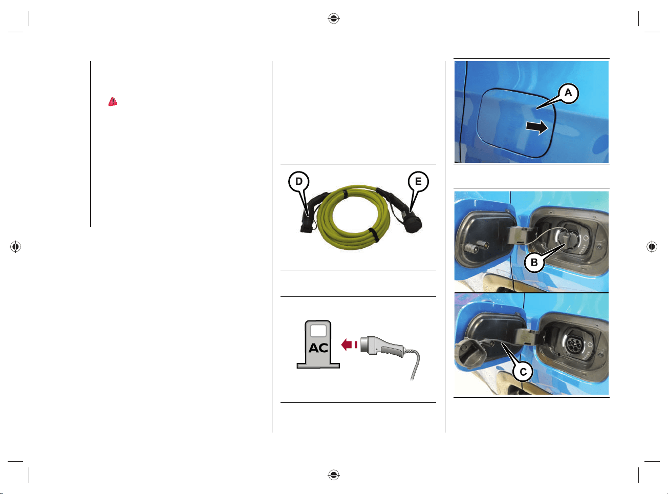
remove the charging cable (optional)
fig.27 from the boot (inside a special
bag), remove the protective cover
(where present) on the two-colour
connector connector (D) and plug it
into the socket of the public charging
station, fig.28;
open the charging flap (A)fig.29
located on the left side by pressing on
the area indicated by the arrow;
remove any dust that may have
accumulated on the charging
connector and charging socket;
remove the protective cover (B)fig.30
of the charging socket and attach it to
the device (C)fig.30;
27 J0B6064E
28 J0B6067E
29 J0B6030E
30 J0B6031E
41
grasp the charging cable, remove the
protective cover (where provided) on
the connector (E)fig.27 and plug it
into the charging port on the vehicle
until you hear the click indicating that
it has been locked;
charging starts automatically. If
necessary, the public charging
station must be enabled; follow the
manufacturer's instructions and
warnings when using the charging
station;
during the charging phase, the first
LED located next to the charging
socket on the vehicle flashes green
while the remaining LEDs are on with
steady light.
NOTE The charge procedure is
interrupted when opening the bonnet: a
dedicated message will be shown on the
instrument panel display. The charge
will be reactivated when the engine lid is
closed correctly.
WARNING In some countries the
"Mode3" cable is not available.
WARNING Always connect the connector
fi rst to the socket on the public charging
station and then to the vehicle.
WARNING Unlocking the door locks
during the charging procedure will cause
it to stop. Charging resumes automatically
after about 60 seconds.
WARNING Before leaving the vehicle, it
is advisable to lock the doors by pressing
the button
on the key. If it is not
possible to lock the doors by pressing the
button on the key, lock the doors by
pressing the button on the driver's side
door handle.
END OF CHARGING
PROCEDURE
The charging procedure ends when all
the LEDs (A)fi g.31, located next to the
charging socket, will light up in green with
a steady light (during the charging phase
the fi rst LED will fl ash, while the other
LEDs will be on with a steady light).
31 J0B6035E
KNOWING YOUR VEHICLE
42
DISCONNECTING THE "MODE3"
CHARGING CABLE
To complete the charging, proceed as
follows:
unlock the doors of the vehicle;
disconnect the cable from the
charging port of the vehicle and put
the protective cover (where provided)
back on the connector (E)fig.27;
unplug the cable from the charging
socket on the public charging station
and put the protective cover (where
provided) back correctly on the two-
colour connector (D)fig.27;
replace the protective cover of the
charging socket;
close the charging flap, making sure it
locks properly;
roll up the charging cable correctly,
repositioning the protective covers on
both sides of the cable correctly (take
care not to damage the cable when
rolling it up). Then place the cable
inside the bag located inside the boot.
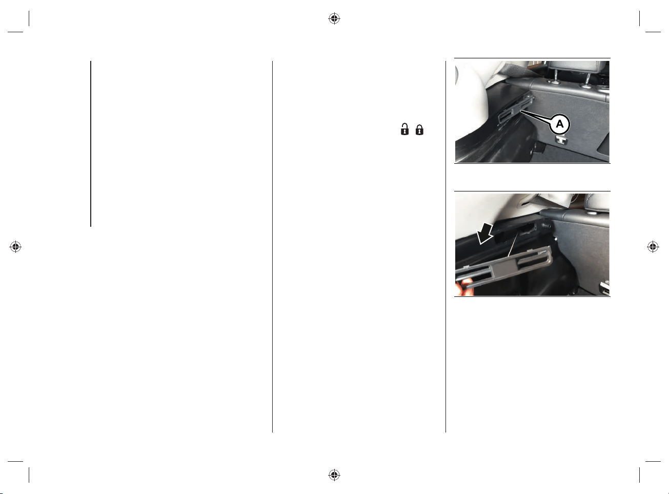
CHARGE CABLE EMERGENCY
UNLOCK
If the charging cable does not unlock at
the end of the charging procedure, you
can unlock it manually.
If, after closing and opening the doors
by pressing the relevant buttons
/
located on the key, it is still not possible
to remove the charging cable from the
socket on the vehicle, it is possible to
act manually by operating a special
emergency unlocking device located on
the left side of the boot and performing
the operations described below:
open the tailgate;
remove the parcel shelf from the load
platform (if provided);
use the tip of the ignition key to
remove the access flap Afig.32,
located on the trim panel on the left
inside the boot, in order to release the
cable;
grip the release cable retainer and
gently pull it to manually release the
charging port actuator, fig.33;
32 J0B6491E
33 J0B6492E
pull the charging connector out of the
charging port located on the vehicle;
put the charging cable and cable
retainer back correctly.
43
NOTE Excessive force may break the
cable retainer.
NOTE To restore correct operation of the
system, contact the Jeep Dealership.
WARNING
35) The charge current level (“Level 1”
/ “Level 2” / “Level 3”, etc.) can only
be changed using the display of the
UConnect™ system (for more information
see the “UConnect™ 8.4 NAV DAB
Radio / UConnect™ 8.4" DAB Radio”
chapter in the "Knowing the instrument
panel and multimedia" section of this
supplement). The default charge level set
is "Level 3". For countries in which the
13A "Mode2" charge cable can be used,
if the domestic power socket IS NOT
CERTIFIED, it is recommended to set
"Level 4" charge to the maximum, which
corresponds to approx. 10A. For the list
of country-specific cable types refer to
what is indicated in the "Mode2” cable
variant table”.
36) In order to reduce the risk of electric
shock or damage to the device, special
care should be taken when cleaning:
ALWAYS unplug the device from the
domestic power supply socket and car
ports.
37) Incorrect setting of the charge
current intensity can overload or overheat
the mains power supply of the domestic
socket. Fire hazard. Before charging
from other domestic sockets, adjust the
charge current intensity to the mains. If
you do not know the mains, set to the
lowest level. Never use extension cords
for charging.
38) Incorrect connection between
connector and charging terminals
constitutes a fire hazard!
39) During normal operation, the
domestic power socket can overheat.
In the case of extreme overheating, the
charge is interrupted and the warning
LED on the front of the cable control
unit will turn on. Refer to the table in
the paragraph "Charge system failure" in
chapter "Usable power sources”.
40) The "Mode2" charge cable must be
connected to a dedicated circuit that is
not shared with other devices that absorb
electrical energy.
41) Do not insert fingers or objects in the
cable charge connector.
KNOWING YOUR VEHICLE
44
42) Carefully follow the instructions in the
installation and operation manuals of the
device.
43) The high-voltage battery must only
be charged through approved, earthed
domestic sockets or from a public
charging station using the charging cable
supplied separately as an option by FCA
(” Mode3“ charging cable).
44) Keep the charging flap closed when
the charging socket is not in use.
WARNING
2) Do not charge if the outside
temperature is -30°C or lower, as
charging is likely to take longer and the
charging device may be damaged.
3) Do not leave the car or the charging
cable in areas where the outside
temperature is below -40°C as they may
be damaged.
4) In cold temperatures, the charging
cable may become stiff. Therefore, be
careful not to apply excessive force to the
charging cable as it may be damaged.
5) Do not use personal generators to
charge the high-voltage battery. This may
cause fluctuations in charging and the
voltage may be insufficient, resulting in
damage to the car system.
6) Charging the high-voltage battery
using incorrect or damaged sockets, or
charging cables and not following the
prescribed charging procedures may
cause short circuits, fire and potential risk
of damage to the vehicle's hybrid system.
45
CHARGING FUNCTIONS
CHARGING SCHEDULE
By acting on the UConnect™ system
display and selecting the "Charging
Schedule" function you can set the start
and end time at which the high-voltage
battery is to be charged.
For more information see the section
"Knowing the instrument panel and
multimedia" in this supplement.
If the vehicle is charging, but it is outside
the charging range set via the UConnect™
system, the LED (A)fi g.34 (located near
the charging socket) will light up and the
LED (B) will turn on with blue light.
If charging is in progress, the LEDs will
light on with green fl ashing/green steady
light depending on the charge status of
the battery portion indicated by the LED.
34 J0B6034E
INTERRUPTING THE CHARGING
PROCEDURE
By inserting the charging connector of
the cable into the charging socket on the
vehicle, charging starts automatically.
By pressing the immediate charge
button (A)fi g.35 it is possible to”- pass"
a possible charge schedule already set
through the display of the UConnect™
system (for further information refer to
the chapter "UConnect™ 8.4” NAV DAB
Radio/ UConnect™ 8.4” DAB Radio" in
the section "Knowing the instrument panel
and Multimedia".
To stop charging, unlock the doors by
pressing the button
on the key or the
similar button on the driver's side door
panel trim.
LED (B)fi g.35 illuminates when the
vehicle is charging without a set interval
or in the case of an immediate charging
operation.
If charging is interrupted, the LED (B)
turns off.
KNOWING YOUR VEHICLE
46
35 J0B6033E
If, approximately 60 seconds after the
doors are unlocked, the system detects
that the charging cable is still connected
inside the charging socket, charging will
restart automatically and the cable will
be locked inside the charging socket. A
dedicated message will appear on the
UConnect™ system display.
NOTE The charging procedure can
be interrupted either while using the
"Mode2" charging cable or while using
the "Mode3" charging cable.
CONTINUING THE CHARGING
PROCEDURE
After interrupting the charging procedure,
if you wish to resume the procedure, you
can either perform the door lock operation
by pressing the button on the key or
wait approximately 60 seconds after the
door unlocking operation.
In this case, closing the doors with the
charging cable connected will resume
charging and the cable will be locked
inside the charging socket.
Once the charging procedure is resumed,
the LED (B) next to the charging socket
will turn off.
INSTANT CHARGING
MANAGEMENT
Instant charging is performed by pressing
the button (A)fi g.35 located next to the
charging socket or through the dedicated
App installed on your smartphone.
NOTE Button (A)fi g.35 is only active
when the doors are unlocked.
47
END OF CHARGING
PROCEDURE
The charging procedure ends when all
the LEDs (A)fi g.36, located next to the
charging socket, will light up in green with
a steady light (during the charging phase
the fi rst LED will fl ash, while the other
LEDs will be on with a steady light).
36 J0B6035E
FAILURE DURING CHARGING
PROCEDURE
If a fault is detected during the charging
procedure, the fi rst and last LED located
next to the charging socket will light up
fl ashing red, fi g.37.
37 J0B6093E
KNOWING YOUR VEHICLE
48
"eCoasting" MODE
(ENERGY SAVING)
It is a mode that, when the accelerator
pedal is released, recovers energy during
the slowing down phase of the car.
The "eCoasting" mode, always active
regardless of the selected operating
mode (use of the heat engine or electric
motor), maximizes energy recovery when
the accelerator and brake pedals are
released.
Driving in "eCoasting" mode is possible
if the automatic transmission lever is in
position "D" (Drive).
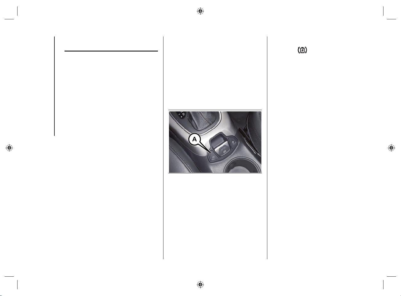
INTERVENTION TYPE
SELECTION
You can select the type of intervention
of the "eCoasting" mode by pressing the
button (A)fi g.38 located on the central
tunnel.
Pressing button (A)fi g.38 activates
the "
Plus" mode, which differs from
the "Normal" mode for an increased
deceleration when the accelerator pedal
is released.
38 J0B6027E
By pressing button (A)fi g.38 the LED
located on the button will light up and
the symbol
will be shown on the
instrument panel display, which will be:
white if the “
Plus” function has been
selected but is not active (e.g. battery
too charged, too cold/hot, etc.);
green if the “
Plus” function has been
selected and is active.
When switching from "Plus" to "Normal"
and vice versa, a dedicated message will
appear on the instrument panel display.
49
"eBraking" MODE
(HIGH-VOLTAGE
BATTERY CHARGING)
The "eBraking" mode, which is always
active regardless of the selected operating
mode (heat engine or electric motor
operation), activates the high-voltage
battery charging when the brake pedal is
pressed, thereby recovering energy during
braking.
The electric motors work like alternators,
converting the kinetic energy of the car
into electrical energy.
Using this mode is particularly useful
when driving in the city, where there are
continuous stops and starts.
NOTE In order to make the most effi cient
use of the system, the braking phase
should, where possible, be modulated by
applying gradual pressure on the brake
pedal so as to allow maximum energy
recovery.
NOTE In the event of an emergency,
maximum braking effi ciency is always
guaranteed by the conventional braking
system.

50
Blank page
KNOWING YOUR VEHICLE
51
This section gives you all the information
you need to understand, interpret and
use the instrument panel correctly. It also
describes the features related only to the
hybrid system present on the UConnect™
8.4” NAV DAB Radio/ UConnect™ 8.4"
DAB Radio.
For anything not included, refer
to the "Knowing the instrument
panel" and "Multimedia" sections
in the Owner Handbook.
KNOWING THE INSTRUMENT PANEL
AND MULTIMEDIA
INSTRUMENT PANEL FEATURES ...52
DISPLAY .......................................... 56
WARNING LIGHTS AND
MESSAGES ...................................... 61
UCONNECT™8.4”NAV DAB Radio/
UCONNECT™8.4”DAB Radio ........67
KNOWING THE INSTRUMENT PANEL AND MULTIMEDIA
KNOWING THE INSTRUMENT PANEL AND MULTIMEDIA
52
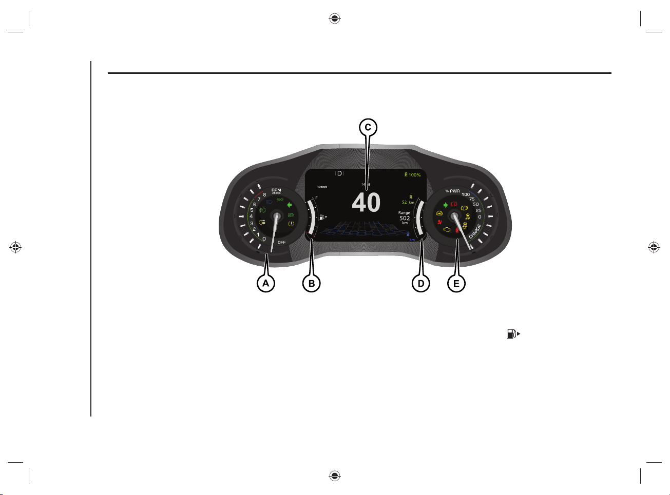
INSTRUMENT PANEL FEATURES
RECONFIGURABLE MULTIFUNCTION DISPLAY
km/h
km
450
5299
READY
39 J0B6026E
A.Tachometer - B.Digital fuel level gage with fuel reserve warning light (the triangle on the right side of the symbol indicates the side of the
vehicle where the fuel filler neck is located) - C.Reconfigurable 7" multifunction display - D.Digital vehicle range indicator (this indicator is not
fixed but can be selected from several others in the instrument panel menu) - E.Power meter (expressed as percentage %)
WARNING The illumination of the instrument panel graphics may vary according to version.
53
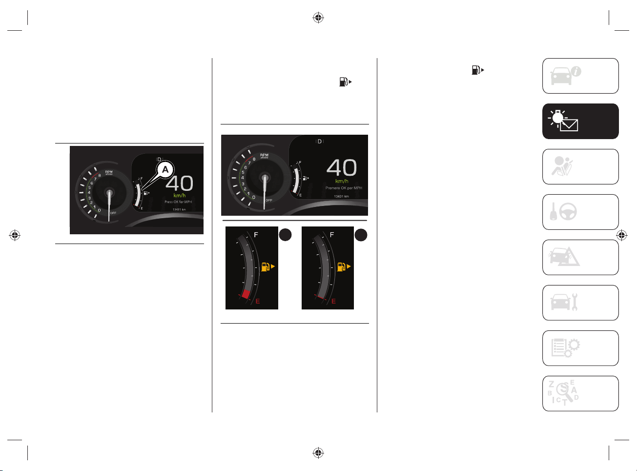
DIGITAL FUEL LEVEL GAUGE
The digital gage on the display shows the
amount of fuel (A)fi g.40 inside the tank.
The indications next to the graphic scale
indicate the amount of fuel:
F (Full) = full tank
E (Empty) = empty tank.
40 J0B6021E
FUEL RESERVE DISPLAY
When the fuel reserve level is left inside
the tank, (A)fi g.41, the indicator
turns yellow and the indication of the fuel
quantity and the letter "E" are displayed
in red.
B
A
41 J0B6022E
When the tank is completely empty
(B)fi g.41, the indicator turns yellow
and the last graphic notch on the digital
indicator and the letter "E" are displayed
in red.
The instrument panel display shows
a message and an acoustic signal is
emitted.
WARNING If the reserve warning light
switches on, refuel at the earliest
opportunity.
WARNING Do not travel with the fuel tank
almost empty: possible gaps in fuel supply
could damage the catalytic converter.
KNOWING THE INSTRUMENT PANEL AND MULTIMEDIA
54
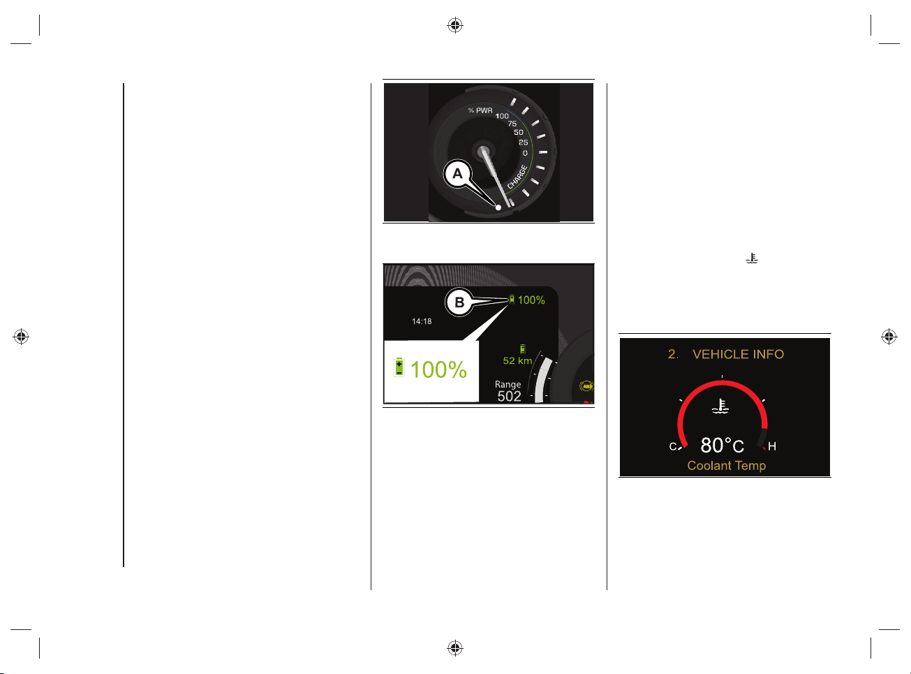
POWER METER
The analogue indicator displays the
percentage (%) of power output/
consumed by the hybrid vehicle's
drive system, referred to the maximum
available power.
The top half of the indicator refers to the
output power.
The lower half refers instead to the power
consumed via regenerative braking, while
the vehicle decelerates.
The symbol (B)fi g.43 displays, in
percentage, the high voltage battery
charge status.
NOTE The screen shown in fi g.43 is only
one of the possible selectable screens for
this portion of the instrument panel, so it
is not necessarily always present.
Brightness sensor
Inside the power meter there is a light
sensor (A)fi g.42 capable of detecting
ambient light conditions.
The brightness of the instrument panel is
adjusted depending on what the sensor
detects.
42 J0B6020E
43 J0B6038E
DIGITAL HEAT ENGINE
COOLANT TEMPERATURE
GAUGE
The digital gage on the display fi g.44
shows the temperature of the engine
coolant and starts supplying indications
when the fl uid temperature exceeds
approximately 50 °C.
Under normal usage, the temperature
should remain around the middle of the
digital scale according to the working
conditions.
The graphic scale on the
symbol on
the display becomes red to signal an
excessive engine coolant temperature
increase. In this case, switch off the
engine and contact a Jeep Dealership.
44 J0B6024E
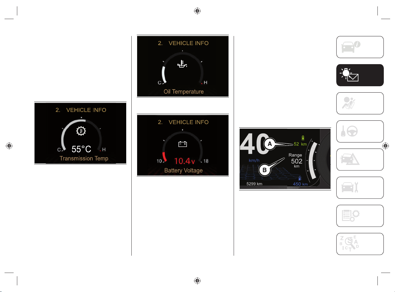
55
Automatic transmission temperature / Oil
temperature / Battery charge status
The same mode and graphic scale are
also used to display the information
related to:
automatic transmission fig.45
temperature;
oil temperature fig.46;
vehicle battery charge status fig.47.
45 J0B6092E
46 J0B6090E
47 J0B6091E
DIGITAL RANGE INDICATOR
The digital indicator (A)fi g.48 displays
the range value for "ELECTRIC" (electric
motor) operation.
The digital indicator (B)fi g.48 displays
the range during the "HYBRID" operating
mode (heat engine + electric motor). This
indication cannot be selected from the
various others available in the instrument
panel menu.
The range values can also be displayed
by selecting "DRIVER ASSIST" on the
menu and then "HYBRID INFO" (see the
description in the "Display" chapter).
48 J0B6025E
KNOWING THE INSTRUMENT PANEL AND MULTIMEDIA
56
DISPLAY
The car is equipped with a 7"
reconfi gurable multifunction display that
can show useful information to the driver
while driving.
The central area of the display shows the
Main Menu.
MAIN MENU
The Main Menu, shown on the display, is
composed of the following items:
SPEEDOMETER
VEHICLE INFO
DRIVER ASSIST
FUEL ECO
HYBRID INFO
TRIP
AUDIO
ALERTS
DISPLAY SETUP
VEHICLE SETUP
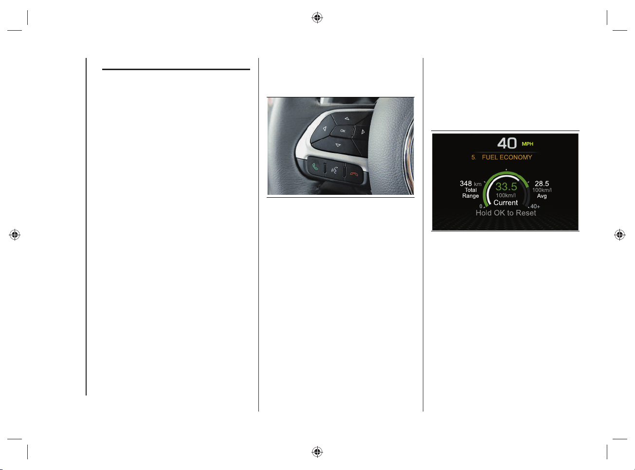
The different Menu items are selected
using the control buttons located on the
left side of the steering wheel fi g.49.
49 J0B0189C
FUEL ECO
(fuel consumption)
This menu option displays quantities "Fuel
consumption" ("Average Consumption"
and "Current Consumption") and "Range"
fi g.50.
50 J0B6068E
57
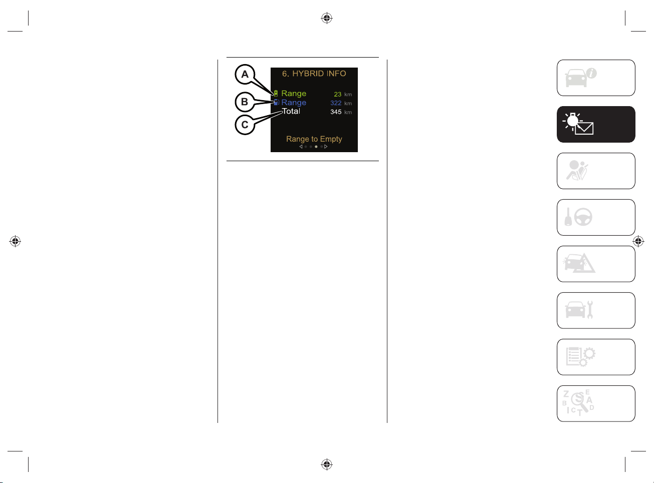
HYBRID INFO
(hybrid system information)
This Menu item allows you to view
information on the instrument panel
display concerning:
"Range to Empty";
"Efficiency Coach";
"Charge / Power";
"E-Drive Mode".
Range to Empty
The "Range" value shown on the
instrument panel display refers to:
operation with the electric motor
(A)fig.51;
operation with heat engine (B)fig.51;
total "Range" value in "HYBRID"
(C)fig.51 operating mode (consisting
of the sum of the "Range" value with
electric motor operation and the value
with heat engine operation).
51 J0B6018E
NOTE Only the variants specifi c to this
version are shown below: for anything not
included, refer to the Owner Handbook.
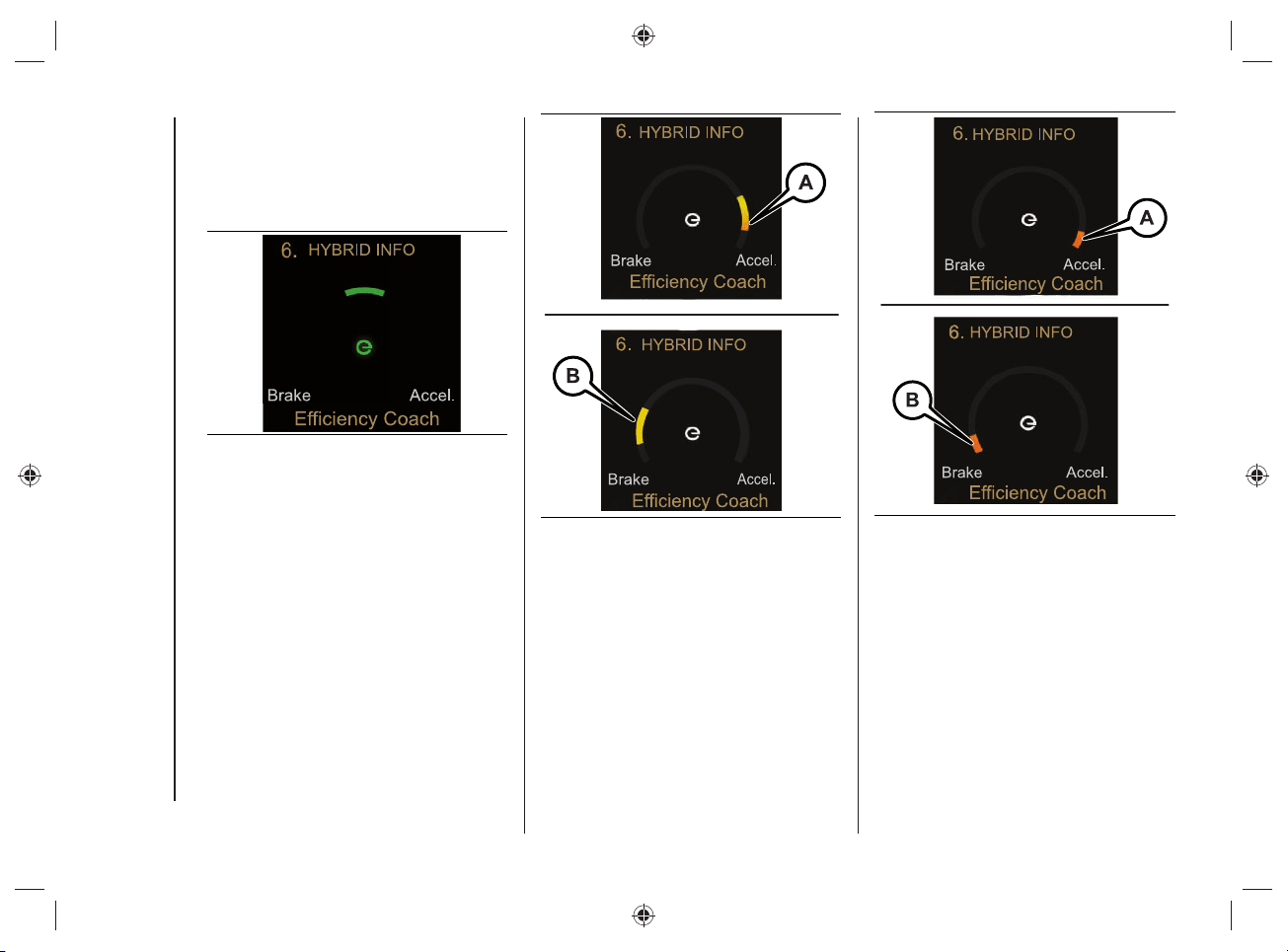
Effi ciency Coach
The "Effi ciency Coach" function provides
the driver with "visual awareness" through
the indications on the instrument panel
display on how to achieve maximum
energy effi ciency while driving.
The display varies according to the
following conditions:
if the driver accelerates/brakes
efficiently or, after reaching a certain
speed, he does not act on the
accelerator and/or brake pedal, the
following screen will appear on the
display, fig.52;
during acceleration and braking,
the most efficient operation will be
represented by the green indicator
(fig.52), while the least efficient
operation will be represented by the
yellow indicator (fig.53), followed by
orange one, when the efficiency level
decreases (fig.54).
KNOWING THE INSTRUMENT PANEL AND MULTIMEDIA
58
Driving the car in optimal conditions is
achieved when the letter "e" and the
graphic indication on the graphic bar
are shown in green in the middle of the
display screen.
52 J0B6041E
53 J0B6042E
54 J0B6043E
59
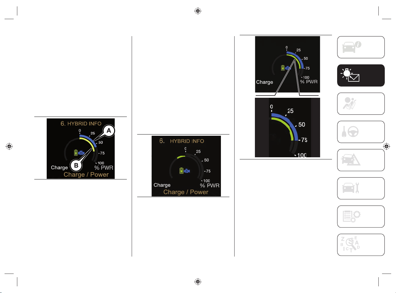
Charge / Power
The "Charge / Power" function shows
the instantaneously available on the
instrument panel display.
The light blue outer graphic ring
(A)fi g.55 displays the power available at
that moment from the heat engine.
The green inner graphic ring (B)fi g.55,
represents the electric motor power
output available during the acceleration
phase and the input power during the
regeneration phase.
55 J0B6044E
The charge/power indications are only
displayed when the vehicle is ready for
driving.
The display on the instrument panel varies
according to the following conditions:
if the high voltage battery is not
charging, only one graphic notch will
be shown on the display for each
sector ("Charge" and "Power"), fig.55;
if the high voltage battery is charging,
the left side of the screen will be
highlighted on the display, fig.56;
if the high voltage battery is"Power"
the right side of the screen will be
highlighted on the display, fig.57.
56 J0B6045E
HYBRID INFO
Charge / Power
6.
57 J0B6046E
KNOWING THE INSTRUMENT PANEL AND MULTIMEDIA
60
"Load" display
The green charging indicator grows
towards the left when the regeneration
phase is in progress or when the heat
engine is charging the high-voltage
battery.
"Power" display
The power is shown on the instrument
panel display by fi lling the engine and/or
battery section (when both are operating
in "HYBRID" mode) from the top right
center, depending on the power source
used. The two indicators will move
independently.
"E-Drive Mode"
The "E-Drive Mode" function informs the
driver of the selected operating mode
("HYBRID" or "ELECTRIC" or "E-SAVE")
by showing dedicated messages on the
display.
TRIP (Trip A/Trip B)
This menu option allows you to view "Trip
computer" information.
The information shown on the instrument
panel display (for "Trip A" and "Trip B") is
as follows:
Distance Traveled (in
"ELECTRIC" mode) (expressed in "km"
or "mi") (Afig.58);
Distance Traveled (in
"HYBRID" mode) (expressed in "km"
or "mi") (Bfig.58);
Total: Total distance traveled relative
to 'Trip A' (expressed in 'km' or 'mi')
(Cfig.58);
Average Consumption (expressed
in "mpg", or "l/100km" or "km/l")
(Dfig.58);
Travel Time (hours/minutes/
seconds) (Efig.58).
58 J0B6047E
NOTE The 'Average consumption' value
can only be considered reliable during the
operation of the heat engine.
61
WARNING LIGHTS AND MESSAGES
WARNING The warning light switches on in the instrument panel together with a dedicated message and/or chime when applicable.
These indications are precautionary and as such must not be considered as exhaustive and/or alternative to the information contained
in the Supplement, which you are advised to read carefully in all cases. Always refer to the information in this section in the event of a
failure indication.
WARNING Failure indications displayed are divided into two categories: very serious and less serious failures. Serious faults are indicated
by a repeated and prolonged warning "cycle". Less serious faults are indicated by a warning "cycle" with a shorter duration. The display
cycle of both categories can be interrupted. The instrument panel warning light will stay on until the cause of the failure is eliminated.
WARNING LIGHTS ON INSTRUMENT PANEL
Green Telltale Indicator Lights
Message What it means
READY
CAR READY TO GO
This warning light displayed indicates to the driver that the car is ready to move. As long as the "READY light is displayed
on the instrument panel, it does not matter whether the heat engine is started or not, the vehicle's propulsion is always
available. When the vehicle is moving, the warning light goes out: if the warning light remains on with steady light or
flashing light, contact the Jeep Dealership.
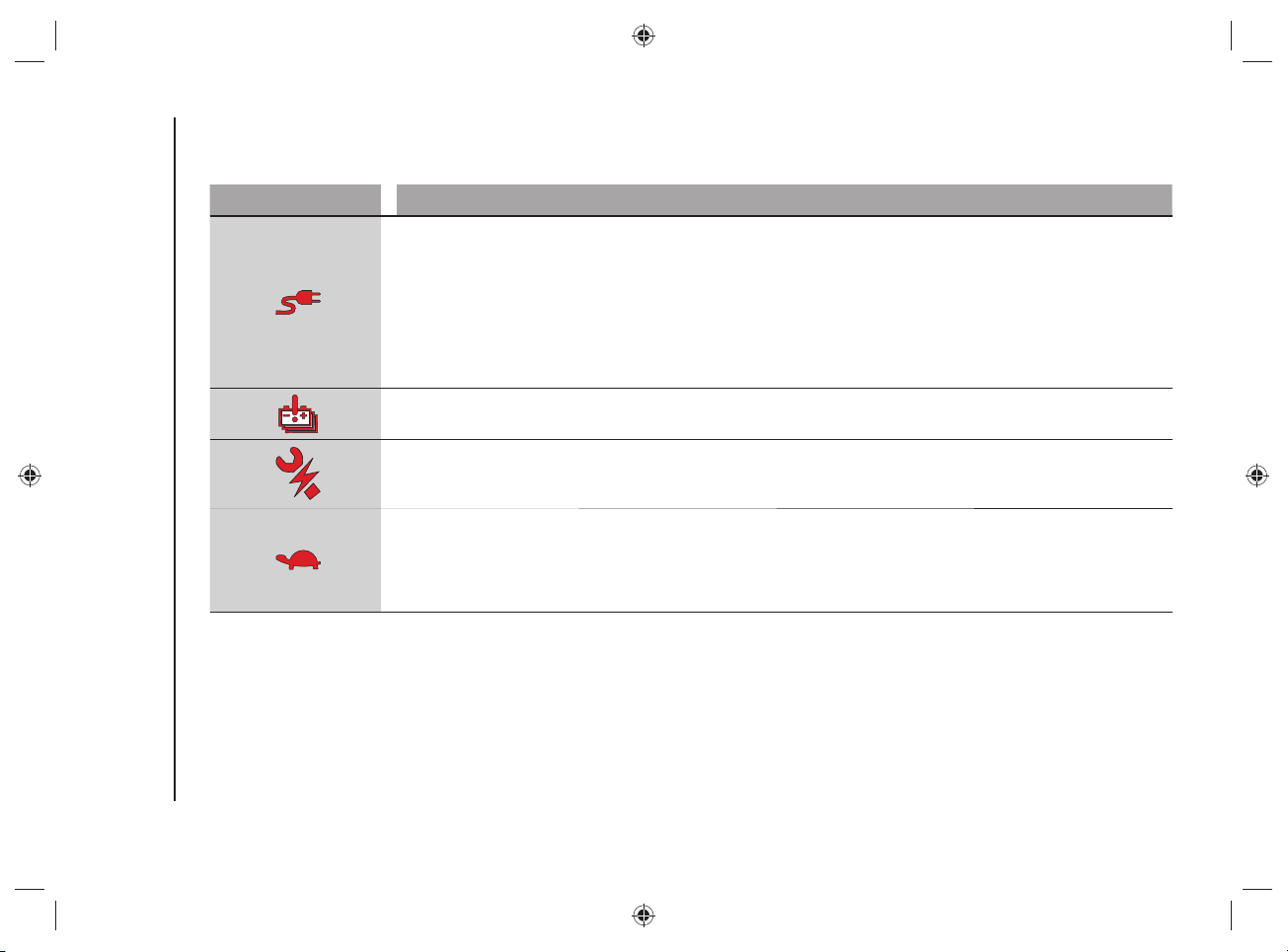
KNOWING THE INSTRUMENT PANEL AND MULTIMEDIA
62
SYMBOLS ON THE DISPLAY
Red Symbols
Symbol What it means
VEHICLE CHARGING PROCEDURE FAILURE
This symbol is shown on the instrument panel display, with the vehicle stationary, in the case of a fault during the high-
voltage battery charging procedure.
failures in the charging system, in this case disconnect and then reconnect the charging cable to the charging socket
or, in the case of charging at a public charging station, look for another power supply point. If the symbol and the message
on the display continue to be displayed, contact the Jeep Dealership.
failures in the public charging station (because it may have been deactivated or there may be a failure). We
recommend that you try charging your car at another public charging station. If the symbol and the message on the display
continue to be displayed, contact the Jeep Dealership.
TRACTION BATTERY FAILURE
The symbol appears on the instrument panel display in case of traction battery failure. Contact a Jeep Dealership.
HYBRID-ELECTRIC SYSTEM FAILURE
The symbol appears on display of the instrument panel in case of hybrid-electrical system failure. The display will also
show a dedicated message. Contact a Jeep Dealership.
PERFORMANCE LIMITATION
The symbol is shown on the instrument panel display if the acceleration of the car is limited due to a reduction in
performance of the heat engine (e.g. including if there is no fuel) or the electric motor. If the symbol remains on while
driving, contact a Jeep Dealership.
NOTE If the automatic dual-zone climate control system is turned on, it will be turned off automatically.
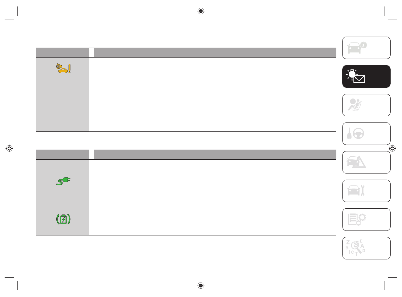
63
Amber symbols
Symbol What it means
PEDESTRIAN ACOUSTIC SIGNALLING SYSTEM FAILURE
This symbol is shown on the instrument panel display in case of failure of the pedestrian acoustic warning. Contact a Jeep
Dealership.
4WD
4WD
LOW
LOW
4WD LOW MODE ENGAGEMENT
The message appears on the instrument panel display in case of 4WD LOW mode engagement.
4WD
4WD
LOCK
LOCK
4WD LOCK MODE ENGAGEMENT
The message appears on the instrument panel display in case of 4WD LOCK mode engagement.
Green Symbols
Symbol What it means
CHARGING CABLE CONNECTED
When this symbol is displayed it indicates that the cable is connected to the vehicle's charging socket, not that the
charging procedure is in progress.
The symbol can also be displayed together with dedicated messages. These messages will indicate the connection status
to the charging socket until fully charged.
WARNING Starting the engine is not allowed until the charging procedure is complete.
MAXIMUM BATTERY REGENERATION SYSTEM INTERVENTION ("eCoasting")
This symbol appears on the instrument panel display when the button located on the left side of the central tunnel is
pressed and indicates that the system is active and is operating-regeneration in progress.
If the green or white symbol does not turn on after pushing the relative button on the central tunnel, this indicates a system
failure: in this case contact a Jeep Dealership.
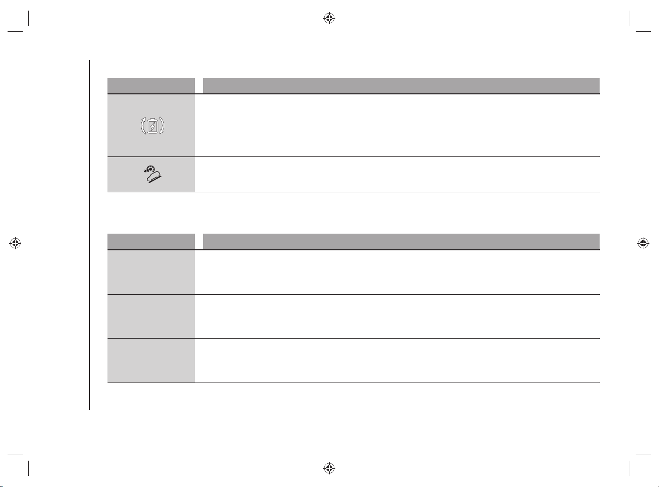
KNOWING THE INSTRUMENT PANEL AND MULTIMEDIA
64
White symbols
Symbol What it means
BATTERY REGENERATION MODE ("eCoasting")
The symbol is shown on the instrument panel display after pressing the relevant button located on the central tunnel and
indicates the activation of the battery regeneration mode (the symbol will turn green if the maximum battery regeneration
system is activated).
If the green or white symbol does not turn on after pushing the relative button on the central tunnel, this indicates a system
failure: in this case contact a Jeep Dealership.
HILL DESCENT CONTROL
System activation: symbol switched on continuously along with the display of a dedicated message.
System not activated: LED located on the button on the central tunnel switched on.
Message in white
The following message can be shown on the instrument panel display, relating to the vehicle's operating mode:
Message What it means
ELECTRIC
"ELECTRIC" MODE
The message is shown on the instrument panel display when the fully electric operating mode is activated by pressing the
relevant button located on the central tunnel.
Activating this mode allows fuel saving for later use.
E-SAVE
"E-SAVE" MODE
The message is shown on the instrument panel display when the "E-SAVE" mode is activated by pressing the relevant
button on the central tunnel.
Activating this mode allows fuel saving for later use.
HYBRID
"HYBRID" MODE
This message is shown on the instrument panel display when the "HYBRID" mode is activated by pressing the relevant
button on the central tunnel.
Activating this mode allows the system to automatically adapt to the most efficient driving style.
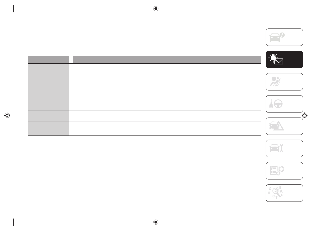
65
Messages shown on the instrument panel display
Some messages (related to the high-voltage battery charging or generic warning messages) may be displayed on the instrument panel
display.
Messages related to the high-voltage battery charging phase
Message on the display What it means
Charging procedure in
progress
This message appears on the instrument panel display during the charging procedure. The display also shows a graphic
bar indicating the loading percentage.
Charging schedule in
progress
This message appears on the instrument panel display during the charging schedule procedure. The display also shows a
graphic bar indicating the percentage to reach full charge (100%).
Charging procedure
completed
This message appears on the instrument panel display when the charging procedure is complete. The display also shows
the graphic outline of the car.
Charge Until Full times
displaying
With the key removed from the ignition device, the instrument panel display shows the times ("Maximum" and "Minimum")
necessary to obtain the complete charge of the high-voltage battery. The display also shows a message indicating whether
the "charge schedule" procedure is set or deactivated.
Vehicle charging
procedure failure
This message appears on the instrument panel display if there is a fault in the charging procedure.
SERV 4WD
The message is shown on the instrument panel display to indicate that 4WD is not available (e.g. including if there is no
fuel) or to indicate an all-wheel drive system failure.
If the fault persists, contact a Jeep Dealership.
KNOWING THE INSTRUMENT PANEL AND MULTIMEDIA
66
Warning messages
Message on the display What it means
Issue Detected Check
External Charging Station
This message appears on the instrument panel display during the charging procedure when there is a fault in the external
charging socket.
In case of charging with "smart" wallbox, the message informs the driver that the external charging port is temporarily not
powered because scheduled charging has been programmed but has not started yet.
Charge port Door open
The message appears on the instrument panel display during the charging procedure when the car's charging flap is open.
Close the flap before driving again.
Fuel flap locked
This message appears on the instrument panel display when the fuel flap is locked.
The fuel flap will unlock when the car is ready to start again.
Charging cable plugged
in - charging not in
progress
This message appears on the instrument panel display when the charging cable is plugged in but the charging procedure
is not in progress. Lock the doors to resume the charging procedure.
Engine lid opening
- charge procedure
interruption
The message is shown on the dashboard display if interrupting the charge procedure for the high-voltage battery and the
low voltage battery (12 V) or high-voltage battery conditioning by opening the engine lid. By closing the engine lid correctly:
the charge procedure and conditioning will restart.
Hybrid-electric system
failure
This message appears on the instrument panel display if there is a fault in the hybrid-electric system. Contact a Jeep
Dealership.
Operating Mode
The display of the instrument panel shows messages related to the operating mode selected ("HYBRID" or "ELECTRIC" or
"E-SAVE").
eCoasting mode
The instrument panel display shows dedicated messages when the "Plus" or "Normal" function is selected for the
"eCoasting" mode.
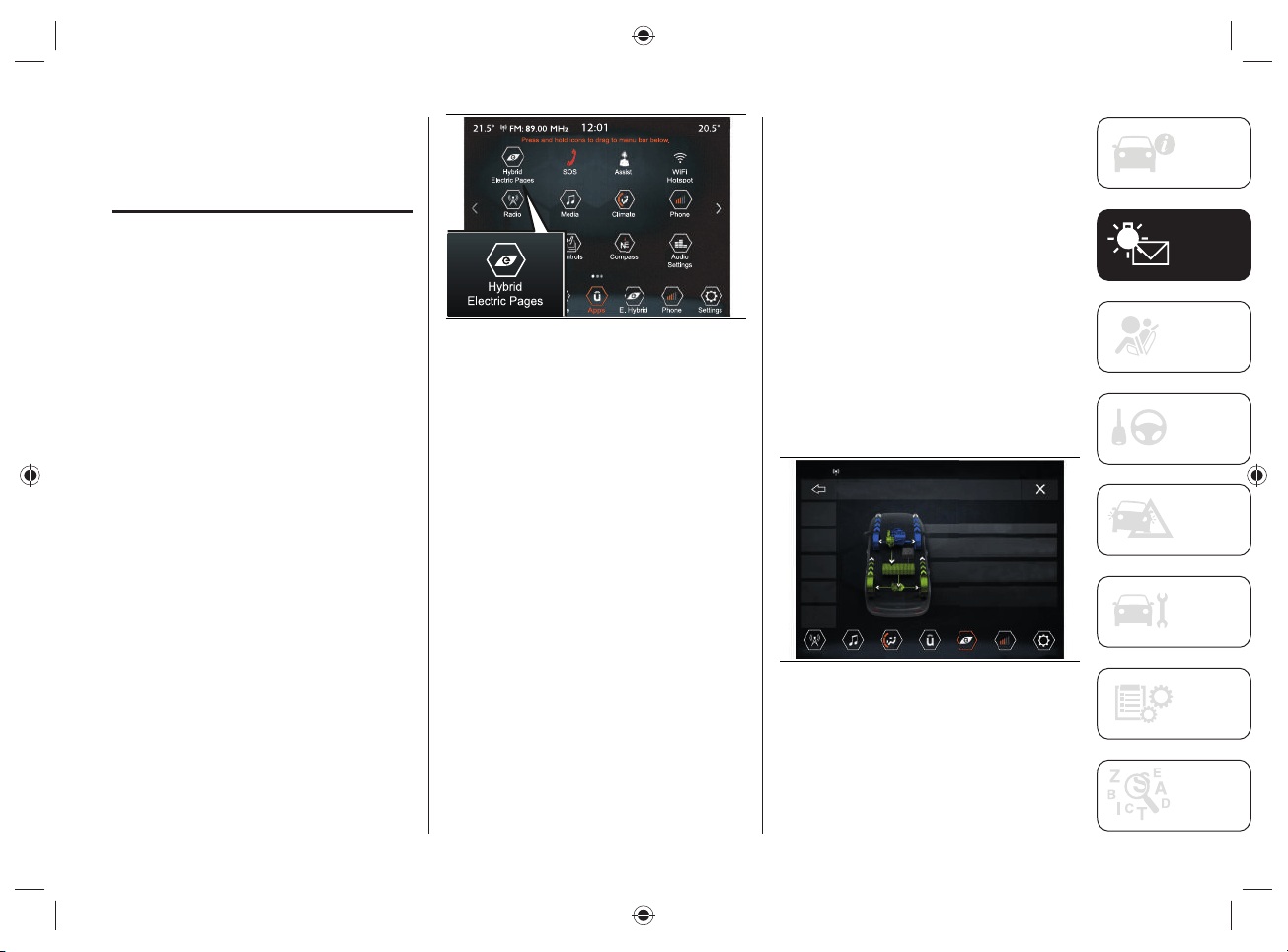
67
UCONNECT™8.4”NAV
DAB Radio/
UCONNECT™8.4”DAB
Radio
Using the display of the UConnect™
system on your vehicle, you can activate/
deactivate some of the Hybrid mode
functions, see below for more information.
HYBRID ELECTRIC PAGES
Proceed as follows:
press the “Apps” button on the
display to access the UConnect™
menu containing all the system
application functions;
press the "Hybrid/Electric Pages"
button fig.59 to display the menus for
the following modes:
• "Power Flow";
• "Driving History";
• "Schedules";
• "E-Save";
• "Charge Setting";
59 J0B6007
Power Flow
Through the "Power Flow" function it is
possible to see on the display information
related to the distribution of the power
consumed/supplied by the systems:
"Engine" (power value, expressed
in kW, that the heat engine is
generating). Based on the car
operating conditions, this power is
used for car movement, to heat the
passenger compartment, supply the
electric loads and charge the high-
voltage battery. The operation of the
heat engine is monitored in order to
minimize fuel consumption.
"Battery" (peak power value,
expressed in kW, that the high voltage
battery is able to supply/absorb. This
power supplies the front and rear
electric motors and car loads);
"Climate" (power value, expressed
in kW, that the automatic dual-zone
climate control system is using to
maintain the set air temperature value
inside the passenger compartment).
Proceed as follows:
press the "Hybrid/Electric Pages"
button, fig.59;
press the "Power Flow" button, fig.60:
the display will show the information
previously described.
21.5° 20.5°
12:01
FM: 89.00 MHz
Radio Media
Climate
Apps
Phone
Settings
E. Hybrid
Hybrid Electric Pages > Power Flow
Power
Flow
Driving
History
Schedules
e-Save
Charge
Setting
Hybrid Mode
Engine:
Battery:
Climate:
50
50
kW
kW
30
30
kW
kW
2
kW
kW
60 5520544D
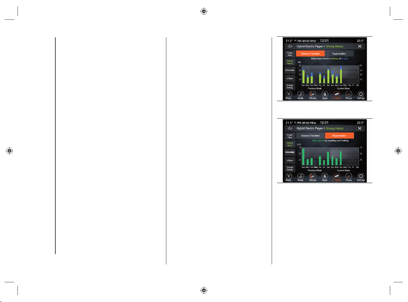
KNOWING THE INSTRUMENT PANEL AND MULTIMEDIA
68
NOTE During deceleration energy
recovery operations ("eBraking" or
"eCoasting") the power value of the
high-voltage battery displayed on the
UConnect™ system display may be
negative.
NOTE The distribution of the power fl ows
is shown graphically using arrows on the
UConnect™ system display.
Driving History
Using the "Driving History" function,
you can see the graphs (relating to the
"Previous Week" and "Current Week") on
the display with information regarding:
"Distance Travelled" (values expressed
inkm or mi);
"Regeneration" (energy value,
expressed in kWh).
Proceed as follows:
press the "Hybrid/Electric Pages"
button, fig.59;
pressing the "Driving History"
button on the display will show the
information related to the "Distance
Traveled", fig.61 or "Regeneration",
fig.62 (display of information related
to the regeneration of the high voltage
battery).
61 J0B6009
62 J0B6010
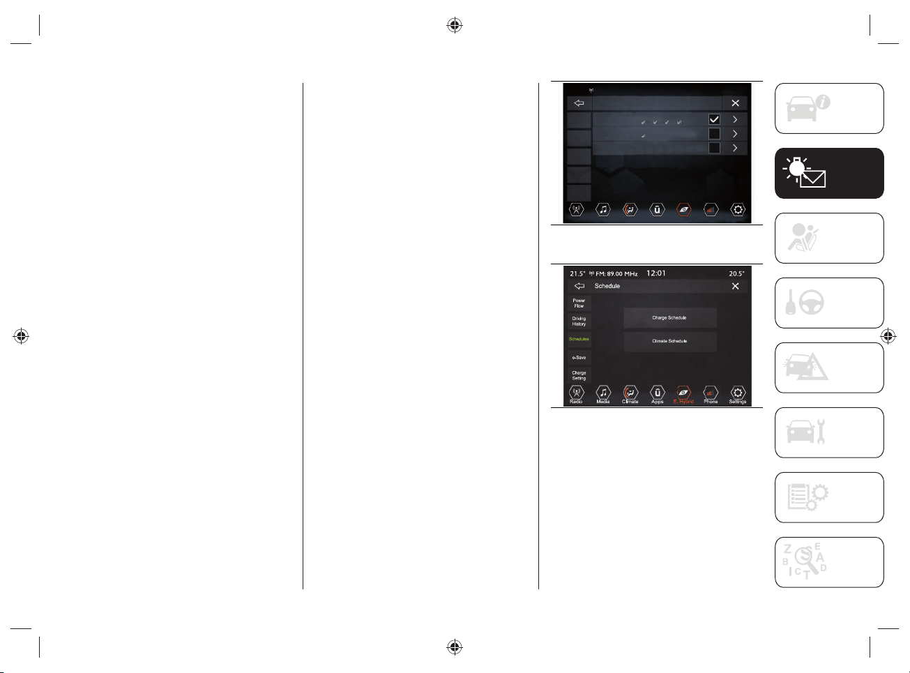
69
Distance Travelled
The graphic bars on the display (regarding
the "Previous Week" and the "Current
Week") indicate the distance traveled
(expressed in km or mi) in one day in
electric operating mode ("ELECTRIC") or
in hybrid operating mode ("HYBRID").
The green bars are referred to the
operation with electric motor.
The blue bars are referred to the operation
with heat engine.
Regeneration
The graphic bars on the display show
the value of energy recovered from the
high-voltage battery (expressed in kWh)
during "eCoasting" and "eBraking" energy
recovery operations.
Schedules
Using the "Schedules" feature, you can
schedule the automatic dual-zone climate
control system and/or the high voltage
battery charging.
When charging the vehicle, or if the high-
voltage battery is suffi ciently charged, you
can activate the preconditioning of the
passenger compartment before driving.
Proceed as follows:
press the "Hybrid/Electric Pages"
button, fig.59;
press the "Schedules" graphic button,
fig.63;
select one of the items related to
"Schedules" and press the graphic
button >;
press the "Charge Schedule" or
"Climate Schedule" button”, fig.64.
The charge schedule and the climate
schedule cannot be entered at the
same time in the same schedule line
as one excludes the other. If you want
to activate both the charge schedule
as well as the climate schedule, they
must be entered in multiple schedule
lines.
21.5°
Power
Flow
Driving
History
Schedules
e-Save
Charge
Setting
Radio
20.5°
12:01
FM: 89.00 MHz
Media
Climate
Apps
Phone
Settings
E. Hybrid
Schedule
Schedule 1: Charge, 11:00 PM - 05:30 AM
Days
Schedule 2: Climate, 5:30 AM
Days
Schedule 3: Climate, 11:00 PM
Days
Next schedules
Climate: No schedules
Estimated Time to Complete Charge
Maximum: 2 Hr 15 Min
Minimum: 1 Hr 15 Min
S — F — S —
M T W T
S — T — W — T — F — S —
M
S — M — T — W — T — F — S —
63 J0B6011
64 J0B6012
The display also shows information about
"Next Schedules" ("Charge" and "Climate")
and "Estimated Time to Complete Charge"
("Maximum" and "Minimum" time).
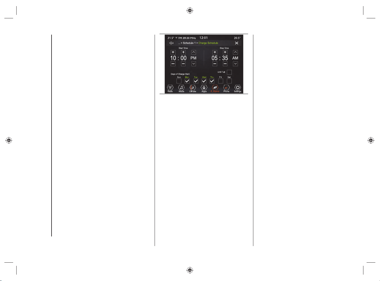
KNOWING THE INSTRUMENT PANEL AND MULTIMEDIA
70
Charging Schedule
Using this function you can set the high
voltage battery charging by selecting the
following settings fi g.65:
"Start Time": time at which to activate
the charging procedure. Through
this function you can choose the
time interval at which to activate the
charging procedure.
"Stop Time": time when the charging
process ends;
"Days of Charge Start": day(s) on
which to start charging;
"Until Full": the charge continues
until the high voltage battery is fully
charged;
NOTE when this is selected, the
charge procedure cannot be
interrupted. Charging will stop
automatically when 100% is reached.
65 J0B6013
NOTE If the charge schedule was not set,
to charge the high-voltage battery simply
connect the cable to the power outlet (the
charge schedule operation does not need
to be set).
NOTE If the "Until Full" setting is selected
and the charge cable is connected after
the schedule start time, the high voltage
battery charge procedure will start the
next day (at the same time). If you want to
start to charge immediately and continue
to charge until the high voltage battery is
fully charged, select the setting "Charge
Now".
For the charging cable connection, see
the description in the "Charging" chapter
in the "Knowing your vehicle" section.
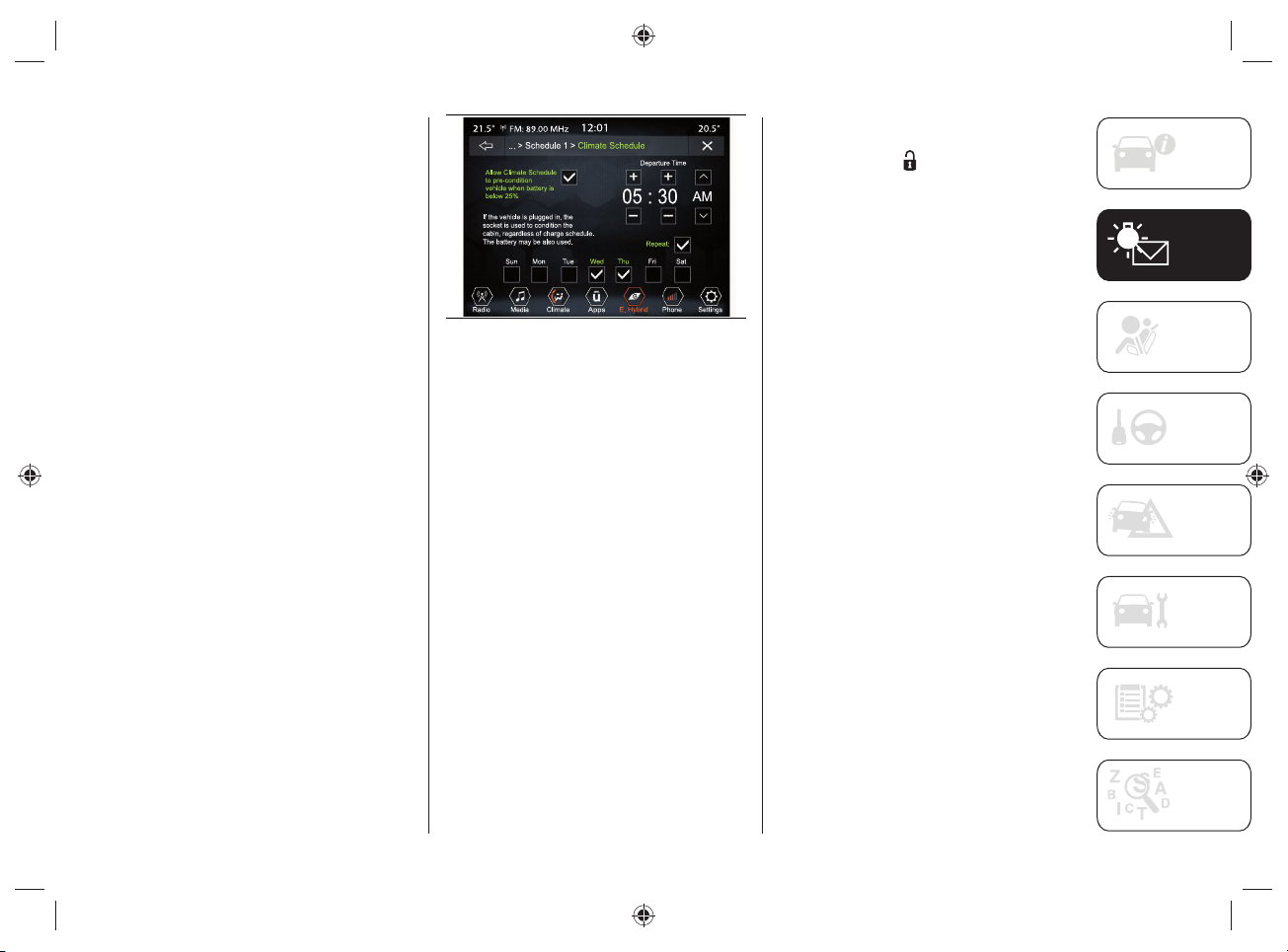
71
Climate Schedule
This function is used to set the ignition of
the automatic dual-zone climate control
system when the engine is turned off by
selecting the following settings, fi g.66:
"Departure Time": time you wish
to leave. The car preconditioning
activation time will be managed
autonomously by the car;
"Allow Climate Schedule to pre-
condition vehicle when battery
level is below 25%": enables the air
conditioning system of the passenger
compartment when the high-voltage
battery charge status is below 25%.
The preconditioning is active even if
the charging cable is not connected to
the charging socket;
"Repeat": allows you to repeat the
function for the selected days of the
week (the days are at the bottom of
the screen).
66 J0B6014
NOTE The temperature set by the
automatic dual-zone climate control
system is the temperature selected before
the engine or climate control system is
turned off.
NOTE To stop the "Climate Schedule"
procedure, either start the engine or press
the OFF button on the automatic dual-
zone climate control system panel.
NOTE Before the comfort temperature
is reached, press and release the door
unlocking button
located on the key
with remote control, or on the handle
of the driver's door (for versions with
the Passive Entry system) to unlock the
doors and turn off the alarm (where
provided). Afterwards, before the comfort
temperature is reached, press and release
the ignition device.
NOTE "Allow Climate Schedule to pre-
condition vehicle when battery level is
below 25%" the high voltage battery
charge function will be temporarily
suspended. This depends on the power
consumption of the automatic dual-zone
climate control system compared to that
provided by the public charging station: in
case of redundancy, the air conditioning
will be activated and charging will be
carried out.

KNOWING THE INSTRUMENT PANEL AND MULTIMEDIA
72
NOTE The schedule of the automatic
dual-zone climate control system can
be activated only under the following
conditions:
Doors closed correctly;
Engine lid closed correctly;
Liftgate closed correctly;
Brake pedal not pressed;
Hazard warning lights on button not
pressed;
Alarm (where provided) not active;
Battery voltage at an acceptable
charge level;
Ignition device in the OFF position;
Automatic transmission gear lever in
"Park" (P);
Vehicle speed below 5km/h.
NOTES
If a problem occurs with the electric
motor, the automatic dual-zone
climate control system schedule will
be deactivated in approx. 3 seconds.
Fore safety reasons, windscreen
wiper operation is disabled when the
automatic dual-zone climate control
system schedule is active.
E-Save
The "E-Save" function makes it is possible
to safeguard the high voltage battery
charge status or use the heat engine to
charge the high voltage battery.
Proceed as follows:
press the "Hybrid/Electric Pages"
button, fig.59;
press the "e-Save" graphic button,
fig.67;
activate one of the following functions:
"Battery Save" (battery charge status
saving) or "Battery charge" (battery
charging).
67 J0B6015
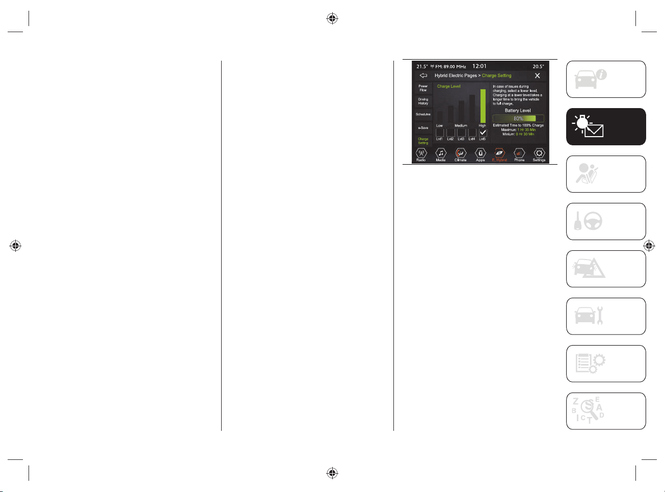
73
Charge Settings
Using the "Charge Setting" function,
you can set the power level / current
consumption during charging. Select
the displayed level on the display, which
ranges from a minimum level ("Lvl"1') up
to a maximum level ('Lvl5").
The high voltage battery charge level
(expressed as a percentage) is shown
graphically on the display fi g.68.
Proceed as follows:
press the "Hybrid/Electric Pages"
button, fig.59;
press the "Charge Setting" button
fig.68, and select one of the levels
shown on the display.
The display also shows information related
to:
"Battery Level": the graphic bar
shown on the display indicates, in
percentage, the high voltage battery
charge status.
"Estimated time to 100%":
corresponds to the time required
to obtain full recharging of the high
voltage battery.
If problems occur during the charging
procedure, a dedicated message will
appear on the display suggesting the
driver to select a lower level (selecting a
lower level will take longer to charge).
68 J0B6016
NOTE To get an estimate of the time
needed for full charge (100%) refer to
what is shown on the display and updated
in real time.
KNOWING THE INSTRUMENT PANEL AND MULTIMEDIA
74
Charging time
The charging time varies depending on:
the high-voltage battery load capacity;
the age of the high-voltage battery and
its temperature;
the type of cable used ("Mode 2"
cable or "Mode 3" cable) and,
consequently, the selected charging
mode (connection to a domestic
socket, a domestic charging station
(wallbox) or a public charging station);
any external or environmental factors
such as, for example, activation
of the air conditioner, the outside
temperature, the temperature of the
high-voltage battery, the country
where charging is carried out.
Charging times can be longer if there is a
thermal protection device in the system,
which reduces the charging current to the
socket to which the vehicle is connected.
NOTE Charging times and currents refer
to systems powered at 230V and 50Hz
under nominal conditions and ambient
temperature of 20°C +/- 5°C.
NOTES
The following information refers to the use of the "Mode 2" charging cables supplied
with the vehicle and "Mode 3" supplied separately as optional equipment by FCA. For
connections with Jeep Easy Wallboxes, refer to the "JEEP easyWallbox" section in the
"Knowing your vehicle" chapter.
The charging times shown in the table below are estimates based on charging the high-
voltage battery having a state of charge lower than 1%.
Type of charging cable used
Standard charge time
("Level 5")
Estimated maximum charge
time ("Level 1")
"Mode 2" charging cable (*) About 4 Hours About 22 Hours
"Mode 3" charging cable (**) About 1 hour 45 minutes About 9 Hours
(*) The specified standard charge time is calculated for the maximum level (5) “high” set on the
UConnect
TM
system display, which corresponds to a maximum current consumption of 13 A. Selecting
a lower power level will increase the charging time in a non-linear manner, up to a maximum of 22
hours with level (1) “low” set on the Uconnect
TM
system display, which corresponds to a current
consumption of 2.7 A.
NOTE According to the country where the vehicle is sold and the "Charging level"
("Level 1" low or "Level 5" high) set on the display of the Uconnect
TM
system, the current
consumption values (from a minimum of 2.7 A to a maximum of 13A) and the related
charging times may vary as the "Mode 2" charging cable may have maximum permissible
values below 13 A.
(**) The specified standard charge time is calculated for the maximum level (5) “high” set on the
UConnect
TM
system display, which corresponds to a maximum current consumption of 32 A. Selecting
a lower power level will increase the charging time in a non-linear manner, up to a maximum of 9
hours with level (1) “low” set on the Uconnect
TM
system display, which corresponds to a current
consumption of 6.4 A.
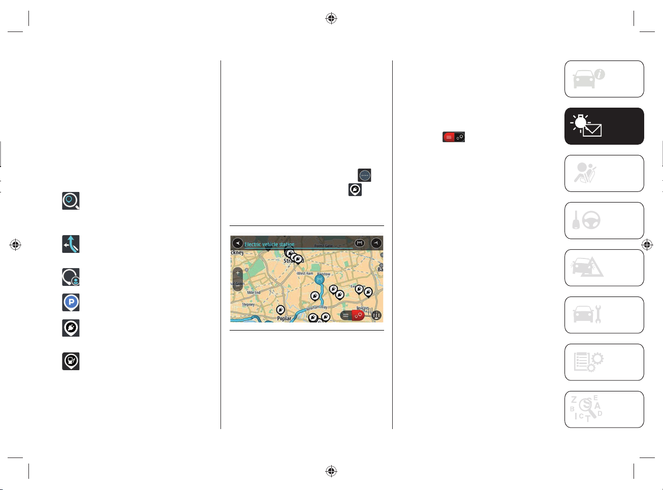
75
NAVIGATION
(only for versions with
UConnect™8.4”NAVDAB Radio)
Content on the screen
Navigation buttons
In the map display or navigation view,
tap the "Main menu" button to open the
menu.
The following navigation buttons are
available in the Main Menu:
"Search": select this button to
search for an address, a place
or a point of interest, then plan a
route toward the location.
"Current Route": select this
button to cancel or change the
planned route.
"Favorites": Select this button to
show the saved places.
"Parking": select this button to
search for a car park.
"Charging station": select this
button to search for public
charging stations.
"Gas Station": select this button
to search for gas stations.
Planning a route
Finding a public charging station
WARNING In the interest of safety and
to avoid being distracted while you are
driving, you should always plan a route
before you start driving.
To fi nd a charging station, do the
following:
Select the "Main menu" button to
open the corresponding menu
Select "EV Charging Station"
. The
map opens showing the locations of
charging stations, fig.69.
69 J0A4033
If a route is planned, the map shows
charging stations near your destination.
If a route isn't planned, the map shows
charging stations near your current
location.
You can change the screen to display a
list of the charging stations by pressing
this button
.
You can select a charging station from the
list to fi nd it on the map.
Tip: You can scroll down the list of results
using the scroll bar on the right side of the
screen.
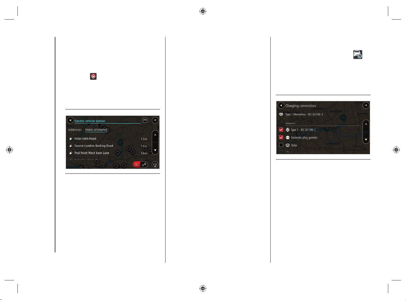
KNOWING THE INSTRUMENT PANEL AND MULTIMEDIA
76
Select a charging station from the
map or list, fig.70. A pop-up menu
opens on the map showing the name
of the charging station.
To plan a route towards the selected
charging station, select the "Drive"
button
.
A route is planned and the indications
to get to your destination start.
As soon as you start driving, the
guidance view is shown automatically.
70 J0A4034
Tip: You can add a charging station as a
stop on your route by using the pop-up
menu. The charging stations that are set
as a stop on your route have a blue icon.
Charging connectors
Select "Settings" in the "Main Menu" and
then select "Charging Connectors"
.
You can choose the correct charging
connector to be used when searching
for a charging station. The charging
connector supplied with the car is already
selected, fi g.71.
71 J0A4047
77
The following section is very important:
it describes the safety systems supplied
with the car’s hybrid system. The
necessary instructions on how to
use them correctly are also given.
For anything not included, refer to the
"Safety" section in the Owner Handbook.
SAFETY
PRECAUTIONS RELATING TO
THE HYBRID SYSTEM ..................... 78
ACTIVE SAFETY SYSTEMS ...............81
PEDESTRIAN ACOUSTIC
SIGNALLING SYSTEM ...................... 84
SAFETY

SAFETY
78
PRECAUTIONS RELATING
TO THE HYBRID SYSTEM
45) 46) 47) 48) 49) 50)
WORKS ON THE HYBRID
SYSTEM
The vehicle's hybrid system:
is isolated from the vehicle and is
secured by protective equipment;
is protected from the outside
environment;
is only accessible for maintenance
work by qualified personnel.
The vehicle monitors the integrity of the
hybrid system: if a fault is detected, a
dedicated message will appear on the
instrument panel display together with the
relevant icon.
Warnings
In case of fault, damage or fi re to the
vehicle:
the components of the hybrid system
can be live and the high-voltage
battery can be charged;
the high-voltage battery, cables
and electrical components may be
exposed and pose a potential risk of
electrocution;
vapors released during handling or
disconnection of the high-voltage
battery from the system are potentially
toxic and flammable;
damage to the vehicle or high-
voltage battery may cause immediate
or delayed release of toxic and/or
flammable gases or a fire;
The high-voltage components are orange
(see the information in fi g.72).
WARNING Non-insulated cables or
wires may be visible inside or outside
the vehicle. Never touch cables and/
or connectors: electric shock could
occur, resulting in injury or death by
electrocution.
WARNING Do not touch / disassemble
/ remove the electric climate control
compressor.
WARNING Do not touch / disassemble /
remove the high voltage battery.
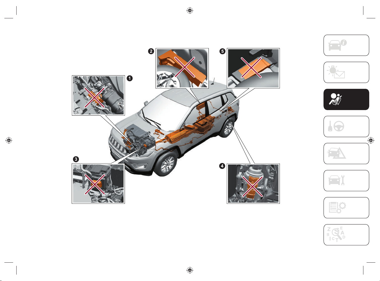
79
HYBRID SYSTEM COMPONENTS ON CAR NOT TO TOUCH
72 J0B6061E
Do not touch, disassemble, remove or replace the following components:
1. Front electric motor - 2. Charging control module - 3. High voltage system specific components fusebox - 4. Rear electric motor - 5. Charge
module
SAFETY
80
ELECTROMAGNETIC WAVES
High voltage components and cables on
hybrid vehicles are electromagnetically
shielded.
If non-certifi ed electrical/electronic
devices are installed, electromagnetic
interference with some components may
occur.
WARNING
45) Improperly performed work, in
particular maintenance and repair work
on the high-voltage system, can result
in current leakage: risk of injury, burns
or death. Any maintenance, repair or
modification work must usually be carried
out by qualified technicians.
46) According to ECE100 standard, the
label
is affixed to the vehicle's high-
voltage components with which the driver
may come into direct or indirect contact.
47) The components of the hybrid system
are not repairable. All high voltage wiring
harness is orange. If necessary, contact
the Jeep Dealership for servicing or repair
work. NEVER touch the orange wiring
harness. Severe injury or death by electric
shock could result if the high-voltage
system components are damaged.
48) Do not pour water or any other kind
of liquid into the boot. Even if insulated
by specific protections, high voltage
components are mounted. Risk of death
by electrocution.
49) Never perform any operation on high
voltage components.
In case of need, contact a Jeep
Dealership.
50) Even if the high-voltage battery is
flat, the hybrid system will still remain
live - danger of fire or fatal injury. Do not
touch or modify live parts in any way (e.g.
orange cables, even with discharged
high-voltage batteries).
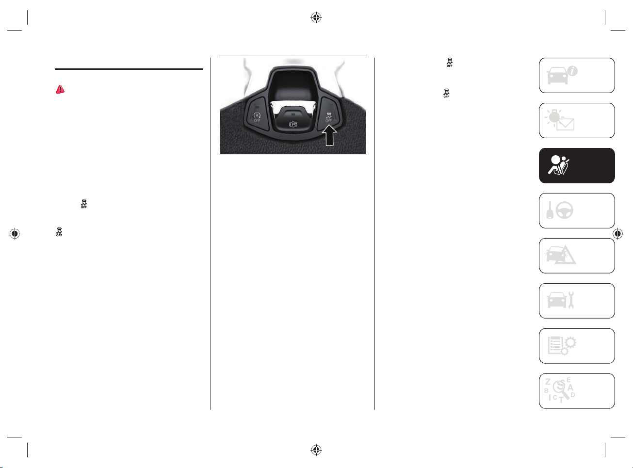
81
ACTIVE SAFETY SYSTEMS
51) 52) 53)
ESC (ELECTRONIC STABILITY
CONTROL) SYSTEM
Complete disengagement mode
This mode was created exclusively for use
on unpaved roads and for driving off-road
when the ESC stability functions could
inhibit car maneuverability due to the
conditions of the path.
To activate this mode, hold down the
button
fi g.73 for 5 seconds with the
car stopped and the engine on. After 5
seconds have passed, the warning light
appears on the instrument panel and
a dedicated message appears on the
display.
73 J0B6150E
In this mode, the ESC system and the
TCS are deactivated, with exception of
the “limited slip” function, until the car
reaches a speed of 64 km/h. When this
speed is reached, the ESC system returns
to the partial disengagement mode while
the TCS remains deactivated.
When the car speed drops down below
64 km/h, the ESC systems turns off.
At a reduced speed, the ESC system is
deactivated so that it does not interfere
with off-road driving, but is restored to
guarantee the stability function at speeds
above 64 km/h.
The warning light
is always on when
the ESC system is deactivated.
To activate the ESC system again, briefl y
press the button
fi g.73. In this way,
normal ESC operation is restored.
NOTE The message “ESC OFF” will
appear on the display of the instrument
panel and an acoustic warning will sound
when the automatic transmission lever
is moved to P (“Park”) from any other
position and therefore moved from P
(“Park”). This also occurs even if the
message “ESC OFF” does not appear on
the display of the instrument panel.
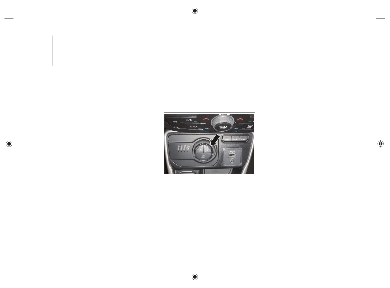
SAFETY
82
HDC (HILL DESCENT CONTROL)
SYSTEM
The HDC (Hill Descent Control) system
was designed for off-road driving at low
speeds with the 4WD LOW operating
mode selected.
The HDC system keeps the speed of the
car constant when driving down hill in
different driving conditions and controls
the car speed by actively operating the
brakes.
The HDC system has three different
states:
“Off” (the system is not enabled and
will not activate);
“Enabled” (the system is enabled and
ready, but the activation conditions
are not satisfied, or the driver is
pressing the brake pedal or the
accelerator);
“Active” (the system is enabled and
actively controls the car speed).
Enabling the system
The system is enabled by pressing the
button located on the central tunnel
fi g.74, and if the following conditions are
satisfi ed:
the Selec-Terrain™ device is in 4WD
LOW mode;
the vehicle speed is below 12km/h;
the electric parking brake (EPB) is
deactivated;
the driver side door is closed.
74 J0B6135E
System Activation
Once enabled, the HDC system will
activate automatically if the car is driven
downhill on a steep slope, higher than
4%.
The speed set for the HDC system can
be selected by the driver and can be
adjusted within the thresholds by pressing
down on the accelerator pedal or the
brake pedal.
Manual driver control
The driver can cancel the activation speed
of the HDC system at any moment by
pressing down on the accelerator pedal or
the brake pedal.
83
Deactivating the system
The HDC system is deactivated, but
remains available, if one of the following
conditions occurs:
the speed set for the HDC system is
canceled with 12 km/h, but set to
speeds below 40 km/h;
the vehicle is on a descent with
insufficient gradient, that is below 4%
or a level surface, or is going uphill;
the automatic transmission lever is in
P (“Park”) position.
Disabling the system
The HDC system is deactivated and
disabled if one of the following conditions
is met:
the button shown in fig.74 is pressed;
activation of mode other than 4WD
LOW;
driver side door open;
speed of 40km/h exceeded
(immediate deactivation of the HDC
system).
Warnings for the driver
The appearance of the symbol
on the
instrument panel display and the turning
on of the LED on the button shown in
fi g.74 warn the driver of the status of the
HDC system:
the symbol
on the display of the
instrument panel and the LED on the
button turn on and remain on with
a fixed light when the HDC system
is enabled or activated. This is the
normal operating condition of the
HDC system;
the LED on the button flashes for a
few seconds, then turns off, when the
driver presses the button shown in
fig.74 if the enabling conditions are
not satisfied.
ATTENTION
51) In “Full Off” mode, the engine
torque reduction and stability functions
are deactivated. During emergency
maneuvers, the ESC system will not
engage to help maintain car stability. The
ESC disengagement mode was designed
exclusive for use on unpaved roads and
off-road.
52) A prolonged use of the system could
cause the braking system to overheat. If
the brakes overheat, the HDC system will
be gradually deactivated, if active, after
warning the driver (the LED on the button
will turn off); it can be reactivated only
when the brake temperature has gone
down enough. The distance that can be
covered depends on the temperature of
the brakes and therefore on the gradient,
load and speed of the car.
53) The capabilities of an HDC-equipped
vehicle must never be exploited in a
reckless or dangerous manner which
could jeopardize the driver’s safety or the
safety of others.
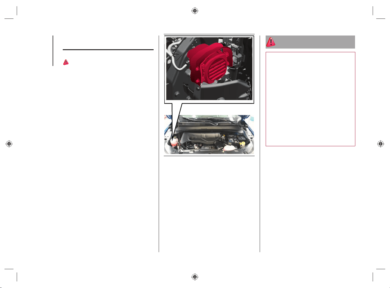
SAFETY
84
PEDESTRIAN ACOUSTIC
SIGNALLING SYSTEM
54)
During electric operation mode
("ELECTRIC"), children, pedestrians,
cyclists, animals and other road users
may not perceive the car, as the usual
noise produced by the heat engine is
absent: this constitutes an accident
hazard, particularly at low speeds, such
as in parking lots. Adapt your driving
style to traffi c conditions. Observe
traffi c conditions and actively intervene
according to the situation.
The car is equipped with an acoustic
pedestrian signaling system, located on
the right side of the engine compartment,
fi g.75, capable of reproducing the noise
of the heat engine while driving in electric
mode, thus alerting people in the vicinity
of the car that it is approaching.
The intensity of the acoustic signal varies
depending on the speed.
75 J0B6039E
WARNING The warning is deactivated
when the vehicle is stationary or when
the automatic transmission lever is in the
“Park” (P) position.
NOTE The system, operating only at
vehicle speeds below 20km/h, is always
active and cannot be deactivated.
WARNING
54) The pedestrian acoustic warning
system is a driving aid and was not
designed to avoid collisions. The driver
must never reduce their level of attention
while driving. Driving is always the
responsibility of the driver, who must take
into consideration the traffic conditions
to drive in complete safety. The driver
is always required to maintain a safe
distance from the vehicle in front and
from any persons and/or animals located
near the car. Failure to observe what
is described could cause a collision or
serious injuries to persons and/or animals
located near the car.

85
STARTING AND DRIVING
STARTING THE ENGINE ................. 86
AUTOMATIC TRANSMISSION
(6 GEARS) ....................................... 88
ADAPTIVE CRUISE CONTROL
(ACC) ...............................................94
FOUR WHEEL DRIVE - JEEP
ACTIVE DRIVE (4WD) AND
JEEP ACTIVE DRIVE LOW
(4WD LOW) ......................................95
SELEC-TERRAIN™ .........................96
REFUELING THE VEHICLE ...............99
DRIVING TIPS ................................102
We have now reached the "heart"
of the car: let's see how to use
the vehicle to its full potential.
We’ll look at how to drive safely in any
situation, making it a welcome companion
with our comfort and wallets in mind.
For anything not included, refer to
the "Starting and driving" section
in the Owner Handbook.
STARTING AND DRIVING

STARTING AND DRIVING
86
STARTING THE ENGINE
The motor is normally started in
"ELECTRIC" operating mode.
Under the following conditions, however,
the heat engine may be used:
when the temperature of the hybrid
system is too high (approx. 50°C) or
too low (approx. -10°C);
when the high-voltage battery charge
level is too low.
ENGINE STARTING PROCEDURE
Proceed as follows:
turn the ignition device to the RUN
position;
engage the electric parking brake and
place the automatic transmission lever
in neutral (N) or "Park" (P);
fully depress brake pedal and hold it
down;
move the ignition device to the START
position: if the procedure has been
carried out correctly, you can start
driving;
the READY warning light will be
displayed on the instrument panel
when the car is ready to move. As
long as the READY light is displayed
on the instrument panel, it does not
matter whether the heat engine is
started or not, the vehicle's propulsion
is always available;
while holding down the brake pedal,
position the automatic transmission
lever to the gear position (D);
release the brake pedal and press the
accelerator pedal;
press the accelerator pedal to start
driving.
NOTE With the car stationary or when the
automatic transmission lever is in neutral
(N), the electric motor is running while the
heat engine is off.
NOTE No noise will be generated by the
electric motor while driving in electric
mode;

87
ENGINE SWITCH OFF
PROCEDURE
55) 56)
Proceed as follows:
with the car stationary, press the
brake pedal;
bring the automatic transmission lever
to "Park" (P);
release the brake pedal;
move the ignition device to the OFF
position (versions equipped with
mechanical key) or press the START/
STOP ENGINE button fully to switch
off the engine (versions equipped with
Keyless Enter-N-Go system);
engage the electric park brake.
NOTE When the engine is switched on
and off, a metallic noise may be heard
due to the opening/closing of the electrical
contacts. This noise is normal and is not
intended to be an anomaly.
WARNING
55) Do not leave the vehicle in a poorly
ventilated area with electrical operating
mode on and heat engine switched off, as
the heat engine may start automatically
if the residual charge level of the high-
voltage battery is insufficient. The exhaust
gases generated can cause serious
damage to people and animals.
56) When leaving the vehicle, you must
set the automatic transmission lever to
"Park" (P). If you unintentionally press the
accelerator pedal or when the automatic
transmission lever is in a position other
than "Park" (P) the vehicle can move
abruptly, resulting in serious injury or
death.
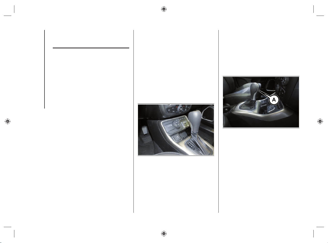
STARTING AND DRIVING
88
AUTOMATIC
TRANSMISSION
(6 GEARS)
The car is equipped with an electronically
controlled 6-speed automatic transmission
where gear shifting automatically takes
place, depending on the vehicle usage
instantaneous parameters (vehicle speed,
gradient, and accelerator pedal position).
Manual gear shifting can still occur thanks
to the "sequential mode" position for the
gear lever.
DISPLAY
The instrument panel display shows:
in automatic mode: the selected gear
(P, R, N, D);
in manual (sequential) driving mode:
the manual engagement of a (higher
or lower) gear, with the relevant
number.
GEAR LEVER
The gear lever fi g.76 can be moved to the
following positions:
P = Park
R = Reverse
N = Neutral
D = Drive
AutoStick":
• + shifting to a higher gear in
manual (sequential) driving mode;
• – shifting to a lower gear in
sequential driving mode.
76 J0B6130E
The diagram for gear engagement is
shown on the panel to the side of the gear
lever.
The gear engaged is shown on the
instrument panel display.
The lever has a button (A) fi g.77 that
must be pressed to move the lever to P
(“Park”) or R.
77 J0B6131E
If the transmission is used in "sequential"
mode, which is activated moving the lever
from D (Drive) to the left, the positions
+ (higher gear) or – (lower gear) can be
reached. These positions are unstable:
the lever always returns to central
position.
89
To exit position P (“Park”), or to pass from
position N (Neutral) to position D (Drive)
or R (Reverse) when the car is stopped
or is moving at a low speed, in addition to
pressing the button (A) fi g.77 the brake
pedal must also be pressed (see "Gear
engagement disabling system with brake
engaged" in this chapter).
WARNING DO NOT accelerate while
shifting from position P (or N) to another
position.
WARNING After selecting a gear, please
wait a few seconds before accelerating.
This precaution is particularly important
with engine cold.
LEVER POSITIONS
Park (P)
57) 58)
7)
This position integrates the electric
parking brake, blocking the transmission.
The engine can be started with the gear
lever in this position.
WARNING Never try to select the P
("Park") position when the car is moving.
Before leaving the car, always bring the
gear lever in this position and engage the
parking brake.
When parking on a fl at surface, fi rst of all
bring the gear lever to position P ("Park")
and then engage the electric parking
brake.
Parking uphill, before bringing the gear
lever to P ("Park") engage the electric
parking brake, otherwise moving the gear
lever from P ("Park") might be diffi cult.
To check the actual engagement of the
position P ("Park"):
move the gear lever completely
forwards, to end of travel position;
make sure that letter P is displayed on
the instrument panel;
with the brake pedal released, make
sure that the gear lever does not move
from position P ("Park").

STARTING AND DRIVING
90
Reverse (R)
8)
Select this position only with the car at a
standstill.
Neutral (N)
59)
It corresponds to neutral for a manual
transmission. The engine can be started
with the lever in position N. Engage N in
the case of prolonged stops with engine
running.
Also engage the electric parking brake.
Drive (D) - Automatic forward gear
Use this position in normal driving
conditions.
The accelerator must be released,
with car at a standstill and brake pedal
pressed to shift from position D to position
P ("Park") or R (Reverse).
This position ensures the automatic
engagement of the most suitable gears
for driving needs and maximum fuel
economy in terms of consumption.
In this position, the transmission shifts
the gears automatically, selecting the
most suitable for forward driving among
those available as you go. In this way, the
optimal driving characteristics of the car
are guaranteed in all the typical conditions
of use.
"AutoStick "- Manual (sequential) shifting
mode
In the case of frequent shifting (e.g. when
the car is driven with a heavy load, on
gradients, with strong headwind or when
towing heavy trailers), it is recommended
to use the "AutoStick (sequential shifting)
mode, which permits the driver to decide
when to shift, to select and keep a lower
fi xed ratio.
In these conditions, using a lower gear
improves car performance and prolongs
the life of the transmission, limiting gear
shifting and preventing overheating.
It is possible to shift from position D
(Drive) to the sequential mode regardless
of car speed.
91
Activation
With gear lever in position D (Drive), to
activate the sequential drive mode, move
the lever to the left (– and + indication of
the panel). The gear engaged will appear
on the instrument panel display.
Tip the gear lever forwards, towards
symbol – or backwards, towards
symbol+, to shift gears.
Deactivation
To deactivate the sequential driving mode,
bring the gear lever back in position D
(Drive) ("automatic" drive mode).
WARNINGS
Do not downshift on slippery surfaces: the
drive wheels might lose grip with resulting
risk of the car slipping. This could cause
accidents or personal injuries.
To select the correct gear for maximum
deceleration (engine brake), simply keep
the gear lever pressed forward, towards
the indication – on the panel.
The vehicle will keep the gear selected
by the driver until the safety conditions
allow it. This means, for example, that the
system will try to prevent the engine from
switching off, automatically downshifting if
the engine speed is too low.
AUTOMATIC TRANSMISSION
"LIMP HOME MODE"
Transmission function is monitored
electronically for abnormal conditions.
If a condition that might damage the
transmission is detected, the "limp home"
mode is activated.
In this condition, regardless of the gear
selected, the transmission remains in
3
rd
gear, unless car speed is not high: in
this case the 5
th
gear will be engaged,
when speed decreases the 3
rd
gear will
be engaged. Positions P ("Park"), R
(Reverse) and N (Neutral) still work.
The symbol
might be shown on the
instrument panel display.
In the event of "limp home" mode
immediately contact the nearest Jeep
Dealership.

STARTING AND DRIVING
92
Temporary failure
In the event of a temporary failure correct
transmission operation can be restored
for all the forwards gears by proceeding
as follows:
stop the car;
move the gear lever to P ("Park");
turn the ignition device to the OFF
position;
please wait for about 10 seconds,
then restart the engine;
shift into the desired gear range. If
the problem is no longer detected,
the transmission will return to normal
operation.
WARNING In the event of a temporary
failure it is still recommended to contact a
Jeep Dealership as soon as possible.
IGNITION LOCK AND PARK
POSITION
Versions with Keyless
Enter-N-Go system
This function requires the gear lever to be
positioned in P (“Park”); then bring the
ignition device to OFF.
Versions with mechanical key
This function requires the gear lever to be
positioned at P (Park) before extracting
the key from the ignition device.
In the case of faults or if the battery is fl at
and the ignition key is engaged, the latter
is locked in position.
In this case of faults or a discharged
battery, to remove the key manually see
the "Automatic transmission lever release"
chapter in the "In case of emergency"
section.
GEAR ENGAGEMENT
DISABLING SYSTEM WITHOUT
BRAKE PEDAL PRESSED
This system prevents you from moving
the gear lever from position P ("Park") if
the brake pedal has not been previously
depressed.
To bring the transmission to a position
other than P (“Park”), the ignition device
must be in position START and the brake
pedal must be depressed.
GENERAL WARNINGS
Failure to comply with what is reported
below may damage the transmission:
select position P ("Park") only with the
car at a complete standstill;
select position R (Reverse), or pass
from R to another position only with
the car at a complete standstill and
engine idling;
do not shift gears between positions P
("Park"), R (Reverse), N (Neutral) or D
(Drive) with engine running at a speed
above idling;
before engaging any gear, fully
depress the brake pedal.
WARNING Press and hold the brake
pedal pressed while moving the gear lever
to a position other than P ("Park") and
"AutoStick".
93
Unexpected movement of the car
can injure the occupants or people
nearby. Do not leave the car with
engine running: before getting out of
the passenger compartment always
engage the electric parking brake,
bring the gear lever to P ("Park"),
switch off the car and extract the key
from the ignition device (for versions
with mechanical key). With ignition
device OFF (key extraction allowed),
the transmission is locked in position
P (“Park”), to prevent any accidental
movement of the car;
when getting out of the car, always
remove the mechanical key from the
ignition device and close all doors. Do
not leave children unattended inside
the car;
on versions equipped with Keyless
Enter-N-Go, do not leave the
electronic key near the car (or in
a place that can be accessed by
children) and do not leave the ignition
device activated. A child could
activate the electric windows, other
controls or inadvertently start the
engine;
bringing the transmission to a
position different from P ("Park") or N
(Neutral) at an engine speed higher
than idling is dangerous. If the brake
pedal is not fully depressed the car
could rapidly accelerate. Only engage
the gear with engine at idling, fully
depressing the brake pedal;
if the transmission overheats,
the symbol
appears on the
instrument panel display. In this
case the transmission could operate
incorrectly until it cools down;
if the transmission temperature
exceeds the normal operating limits,
the transmission control unit may
change the gear engagement order
and reduce the drive torque;
when using the car with extremely low
external temperatures, transmission
operation may change depending
on the engine and transmission
temperature, as well as car speed.
STARTING AND DRIVING
94
WARNING
57) Never use position P ("Park") instead
of the electric parking brake. Always
engage the electric parking brake when
parking the car to avoid the accidental
movement of the vehicle.
58) If the P ("Park") position is not
engaged, the car could move and injure
people. Before leaving the car, make sure
that the gear lever is in position P ("Park")
and that the electric parking brake is
engaged.
59) Do not shift the gear selector to N
(Neutral) and do not stop the engine
when driving on a downhill road. This
type of driving is dangerous and reduces
the possibility of intervening in the case of
variation of the road traffic or surface. You
risk losing control of your car and causing
accidents.
WARNING
7) Before moving the gear lever from
position P ("Park"), bring the ignition
device to RUN position and press the
brake pedal. Otherwise, the gear selector
may get damaged.
8) Engage reverse gear only with the car
stationary, engine at idling speed and
accelerator fully released.
ADAPTIVE CRUISE
CONTROL (ACC)
ACC SYSTEM ENABLING /
DISABLING
Activation
It is not possible to turn on the Adaptive
Cruise Control (ACC) when the 4WDLOW
operating mode is on.
Deactivation
The device is deactivated and the set
speed is canceled from the memory if the
4WD LOW operating mode is selected.
ACC SYSTEM DISENGAGEMENT
The device is disengaged and the set
speed is canceled from the memory if the
4WD LOW operating mode is selected.
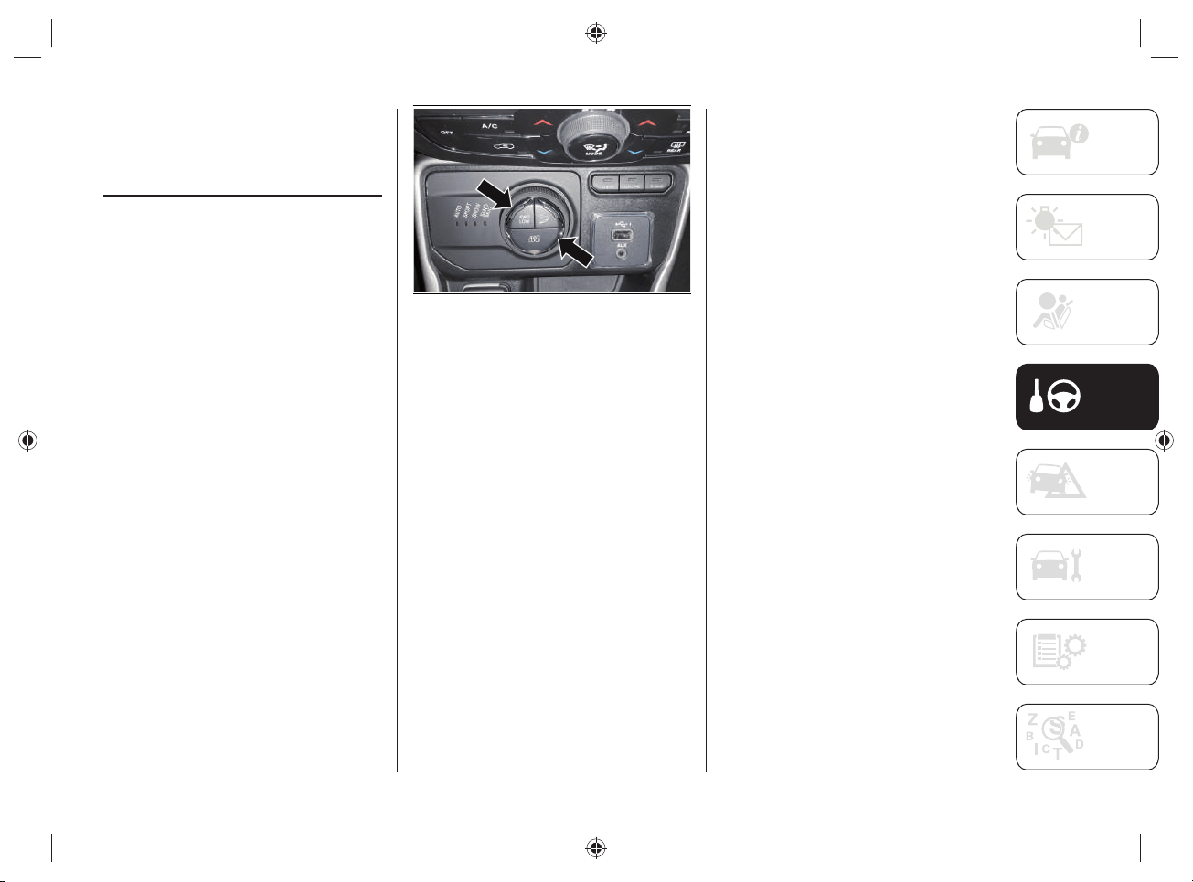
95
FOUR WHEEL DRIVE -
JEEP ACTIVE DRIVE
(4WD) AND JEEP ACTIVE
DRIVE LOW (4WD LOW)
FOUR-WHEEL DRIVE
The four wheel drive (4WD) is fully
automatic in standard driving mode.
Four-wheel-drive activation
The buttons to activate the four-wheel
drive are located on the Selec-Terrain™
device, fi g.78 and allow to select:
4WD LOCK: with "HYBRID" operating
mode, it forces activation of the
heat engine and rear electric motor
together, ensuring four-wheel drive.
This function can be selected in
AUTO mode and is automatic in the
other driving modes.
4WD LOW: it enhances the "off-road"
performance of the vehicle in all
driving modes.
78 J0B6082E
WARNING With 4WD LOCK or 4WD LOW
function active the ELECTRIC operating
mode is automatically deactivated: the
heat engine operation is activated.
WARNING Changing mode is not possible
when the vehicle speed is over 130km/h.
Follow the procedure described below to
enable the 4WD LOW mode.
Enabling the 4WD LOW mode
With the car stopped, the ignition device
to RUN or with the engine running, move
the gear lever to the neutral position /ì(N)
and press the 4WD LOW button. The
message “4WD LOW” appears on the
instrument panel display after changing
the operating mode.
NOTE The LEDs on the 4WD LOW
and 4WD LOCK buttons fl ash until
the changing of the operating mode is
completed.
NOTE The “4WD LOW” icon appears on
the instrument panel display.
Disabling the 4WD LOW mode
To disable the 4WD LOW mode, the car
must be stopped and the automatic
transmission lever must be in neutral (N).
Press the 4WD LOW button.
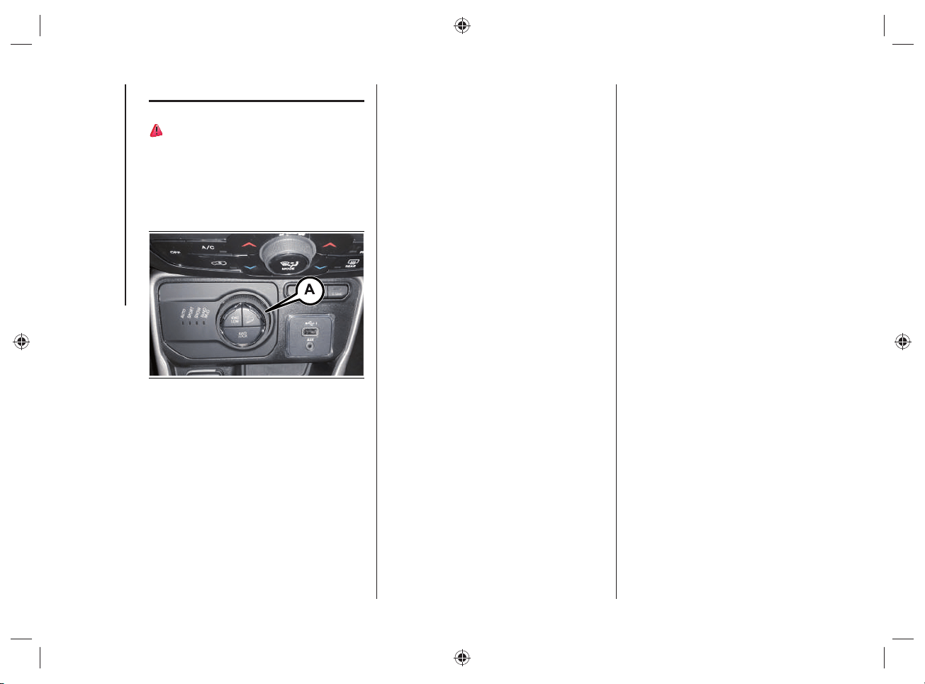
STARTING AND DRIVING
96
SELEC-TERRAIN™
60)
The Selec-Terrain™ system combines
the characteristics of the car control
systems with the possibility of intervention
by the driver, in order to provide the best
performance on all types of terrain.
79 J0B6028E
DRIVING MODE SELECTION
Turn knob (A)fi g.79 to select the desired
mode.
AUTO (Automatic): the traction mode
with continuous and automatic
operation can be used while driving
on road and off-road. With "AUTO"
mode active, the "ELECTRIC"
operating mode can be activated.
SPORT: this mode allows you to use
the electric motor and the heat engine
to maximize the sporty driving of the
car.
SNOW: this mode can achieve more
stability on slippery or snow-covered
grounds. To be used for driving
on-road and off-road in the case of
grounds with poor grip, such as roads
covered by snow.
SAND/MUD:
• SAND: off-road driving mode to
be used on surfaces with poor
grip, such as sandy surfaces.
The transmission is set to offer a
maximum traction.
• MUD: off-road driving mode for
surfaces with poor grip, such
as mud-covered grounds or wet
grass.
ROCK (where provided, for Trailhawk
versions only): this mode is only
available if the 4WD LOW mode is
activated. The device sets the car
to maximize traction and give the
highest steering capacity on off-road
surfaces featuring a high grip. This
mode guarantees the best "off-road"
performance. This mode must be
used to pass over obstacles at slow
speed, such as large rocks, deep
cracks, etc.
The selected driving mode is shown on
the instrument panel display by a graphic
icon and by the message that indicates
the active mode.
WARNING Changing mode is not possible
when the vehicle speed is over 130km/h.
WARNING With the SAND/MUD or ROCK
driving mode is selected, the thermal
motor tends to increase the engine speed
in order to permit charging of the high-
voltage battery.
97
When the engine is started, the AUTO
mode is automatically selected (LED on
close to the AUTO message).
Turning the knob Afi g.79 the LED close
to the AUTO message comes on solid.
The other LEDs switch on sequentially,
depending on the clicks set on the knob,
so that the driver can understand which is
the new required mode.
Once the desired mode has been reached
(LED on next to the message), the Selec-
Terrain™ system knob returns to the
starting position.
NOTE Activate the HDC system to control
the vehicle when driving down steep
paths. For more information, refer to what
is described in paragraph “HDC system”
in the “Safety” section).
“Energy Management" system (operating mode selection)
The Selec-Terrain™ system is able to interact with the different operating modes
("HYBRID" / "ELECTRIC" / "E-SAVE" of the car) according to the following table:
Operating Mode AUTO SPORT SNOW SAND/MUD ROCK
HYBRID
XXXXX
E-SAVE
X
ELECTRIC
XX
WARNING If you try to select an operating mode and the operating mode selection
system does not allow it, a dedicated message will appear on the instrument panel
display.
STARTING AND DRIVING
98
Energy Management" system operating
mode
The "Energy Management" system allows
you to select the following operating
modes:
"HYBRID" mode ("
Charge-depleting
mode"): this operating mode mainly
uses the electric motor. The heat
engine will only start if the driver
presses the accelerator pedal and
then it will switch off when it is no
longer needed (accelerator pedal
release).
"E-SAVE" mode
• "
Battery hold": this operating
mode allows you to safeguard the
high-voltage battery charge status
maintaining its current charge
status, so that it can be used at
a later time (e.g. when driving on
traffic restricted city streets).
• "Battery charge": this operating
mode activates the heat engine
operation for driving and charging
the high-voltage battery so that it
can be used at a later time (e.g.
when driving on traffic restricted
city streets). In this operating
mode, fuel consumption will
increase in order to provide the
energy needed to charge the high-
voltage battery.
"ELECTRIC mode": this operating mode
activates the operation of the electric
motor only. If high performance is
required (pressing on the accelerator
pedal) the electric motor and the
heat engine will run simultaneously.
A continuous acoustic warning will
sound in this case to warn the driver.
WARNING
60) If the vehicle is accidentally partially
immersed in water, switch off the engine
and leave the vehicle immediately. Avoid
physical contact with the flooded vehicle.
Immediately contact the rescuers, police
or fire brigade and inform them that this
is a vehicle with a high voltage system.
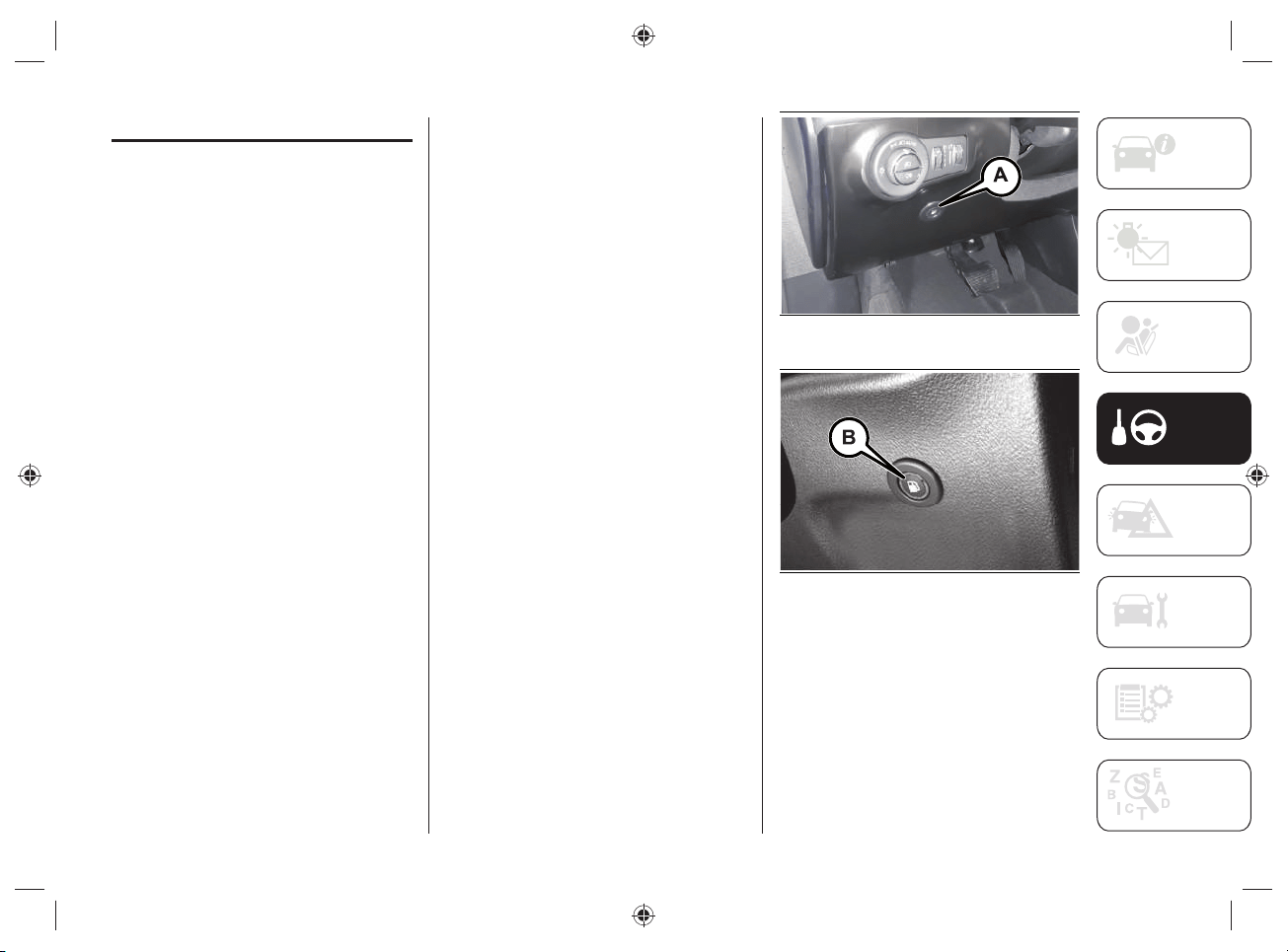
99
REFUELING THE VEHICLE
Always stop the engine before refueling.
REFUELING PROCEDURE
To refuel proceed as follows:
switch off the engine and set the
automatic transmission lever to "Park"
("P");
as soon as the fuel flap unlock button
(A)fig.80 (left-hand drive versions) or
(B)fig.81 (right-hand drive versions)
is pressed, with the automatic
transmission lever in "Park" ("P"),
actions are taken to depressurize the
fuel tank (during this procedure a
dedicated message will appear on the
instrument panel display);
when the depressurization operations
are completed, it will be possible
to refuel (during this procedure a
dedicated message will appear on
the instrument panel display). The
depressurisation procedure is usually
quite fast. it could last up to 15-20
seconds in case of high ambient
temperatures. The fuel flap is then
unlocked and opened (if necessary,
finish opening manually and then
refuel);
when refueling is complete, close the
fuel flap. If the flap is not closed, a
dedicated message will appear on the
instrument panel display indicating
the need to close the flap;
insert the fuel nozzle into the fuel
inlet and proceed with refueling: a
dedicated message will appear on
the instrument panel display when
refueling is possible;
when the fuel nozzle "clicks" or shuts
off, before removing the nozzle, wait
for at least 10 seconds in order for the
fuel to flow inside the tank;
then remove the nozzle from the filler
and close the fuel flap.
80 J0B6049E
81 J0B6074E
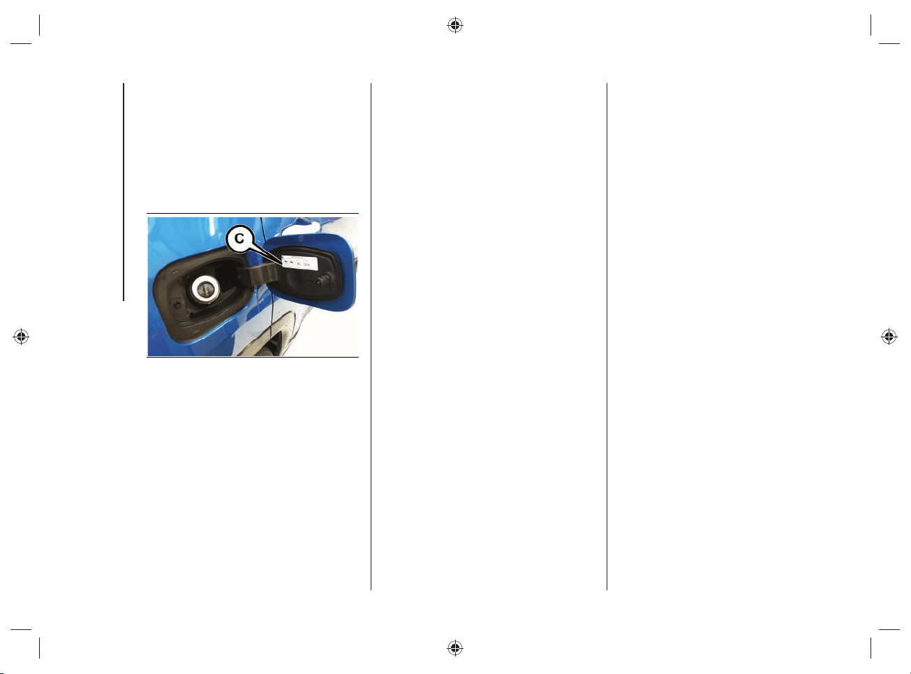
STARTING AND DRIVING
100
The refueling procedure described
previously is illustrated on the label
(C)fi g.82 applied inside the fuel fi ller
fl ap.
NOTE After pressing button (A)fi g.80 or
(B)fi g.81, you have 20 minutes to refuel.
After this time you will need to press the
button again to refuel.
82 J0B0182E
Warnings
In plug-in hybrid vehicles, depending
on the type of use, the fuel may
remain inside the tank for extended
periods of time and its characteristics
may vary. In order to avoid damage
to the fuel feed system it is
recommended to consume at least
one full tank of fuel every 6 months of
use of the vehicle.
Never attempt to start the engine if
there is no fuel inside the tank. In this
case the heat engine is not able to
charge the high-voltage battery.
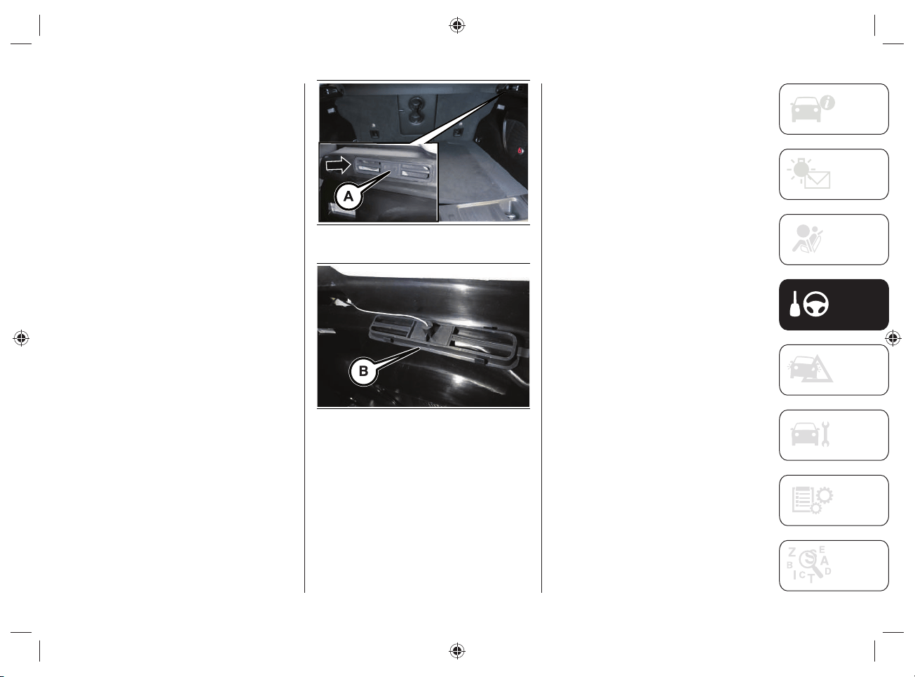
101
EMERGENCY FUEL FLAP
OPENING
(where provided)
If the fuel fl ap is not unlocked due to
faults in the electrical unlocking system,
the fuel fl ap can be unlocked manually
using a cord located on the right side of
the boot, on the side panel near the fuel
fl ap.
Proceed as follows:
working inside the boot, remove the
cover mask (A)fig.83 removing it
toward the inside of the boot;
pull the cover mask (B)fig.84 to
unlock the fuel filler flap;
correctly reposition the cover mask in
its housing.
83 J0B0934E
84 J0B6136E
NOTE If refuelling is performed by
manually unlocking the fuel fl ap, special
attention must be paid to the reference
operation as the fuel may fl ow back.

STARTING AND DRIVING
102
DRIVING TIPS
9)
This chapter contains the main tips for
driving hybrid cars.
For anything not included, refer to
the "Driving tips" section in the Owner
Handbook.
OFF-ROAD DRIVING TIPS
Using the 4WD LOW operating mode
During off-road driving, select the 4WD
LOW operating mode in order to obtain
greater traction and control on slippery or
tough surfaces and downhill or uphill on
gradients and to increase traction power
at low speeds.
The use of this operating mode must be
limited to extreme situations, such as high
snow, mud or sand, when greater towing
power is required at low speed.
When the 4WD LOW mode is used, avoid
driving the car at speeds above 40 km/h.
Driving on snow, mud or sand
In heavy snow, when pulling a load,
or for additional control of the car at
slower speeds, shift to a low gear and,
if necessary, select the 4WD operating
mode suitable for the terrain.
Do not shift to a lower gear than
necessary to maintain headway.
Over-revving the engine can spin the
wheels and traction will be lost.
Avoid abrupt downwards gear changes
on icy or slippery roads, since the engine
braking action may make the vehicle slip,
resulting in loss of control.
Driving uphill
Before tackling a very steep climb, shift
the transmission to a lower gear and
select 4WD LOW operating mode. On
particularly steep climbs, engage the 1
st
gear and select the 4WD LOW operating
mode.
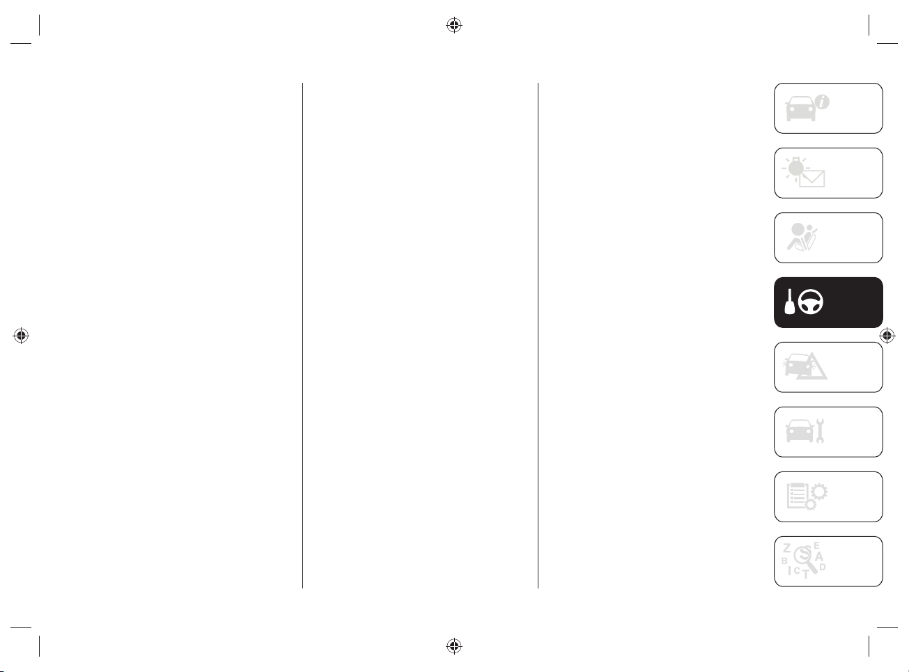
103
ENVIRONMENTAL PROTECTION
Environmental protection is one of the key
values pursued in all FCA activities.
Attention to the environment covers the
entire life cycle of the car and takes into
account its overall environmental impact,
from design to component reuse.
FCA applies the basic principle that any
new product developed must have a lower
environmental impact than the product it
replaces.
An energy-effi cient, fuel-effi cient car
not only helps to reduce environmental
impact, but also allows the driver to keep
running costs down, saving money and
contributing to a better environment.
Here are some tips:
Plan your route for effective average
speed. Speeds above about 80km/h
and below 50km/h lead to higher
energy consumption.
Observe the service and maintenance
intervals of the vehicle as stated in the
Service and Warranty Booklet.
Avoid running the engine at idle and
switch it off during long queues.
Comply with the regulations of the
country where you are driving.
Planning the route: many
unnecessary stops and an irregular
speed contribute to increase fuel
consumption.
NOTE Dispose of any potentially polluting
waste materials (e.g. batteries and
used oil) respecting the environment.
In case of doubt about the disposal of
waste materials, please contact a Jeep
Dealership.
FUEL CONSUMPTION
To limit fuel consumption, try to make
maximum use of the car's electric drive,
depending on the driving needs and the
route.
Since much of a car's total environmental
impact is generated by its use, one of
FCA's main objectives is to reduce fuel
consumption, carbon dioxide and other
pollutants emissions.
The lower the fuel consumption, the lower
the emissions of carbon dioxide, a gas
that contributes to the creation of the
greenhouse effect.

STARTING AND DRIVING
104
TIPS FOR DRIVING
HYBRID CARS
Drive the car avoiding abrupt acceleration
and adapting the driving style and speed
to each situation.
To ensure maximum autonomy and
minimize energy consumption, observe
the precautions below.
High-voltage battery charging
Charge the car regularly from the mains.
It is recommended to always travel with a
fully charged high-voltage battery.
Check where the public charging stations
are located (for more information see
the "Navigation" chapter in the section
"Knowing the instrument panel and
multimedia".
Park, if possible, in a parking lot provided
with public charging stations.
Regular recharging of the high-voltage
battery increases the range of the car.
Passenger compartment heating
If possible, warm up the passenger
compartment before driving.
If you are driving for a short time after
air conditioning in the passenger
compartment, switch off the automatic
dual-zone climate control system
compressor or turn off the fan.
The passenger compartment air
conditioning, both during cooling and
heating, is carried out by high voltage
electrical components, which, therefore,
have an impact on the range of the car
in electric operation mode. In order to
maximize the energy effi ciency of the
car, it is suggested to use the passenger
compartment air conditioning function
only when strictly necessary.
During the summer season, avoid parking
the car in a way that overheats the
passenger compartment during parking.
Park, if possible, in suitably ventilated
indoor areas or outside in the shade.
Unnecessary loads
Do not travel with an overloaded luggage
compartment. The weight of the vehicle
and its arrangement greatly affect fuel
consumption and stability.
Guide
Drive at a constant speed and anticipate
obstacles in order to brake the less
possible. This driving style avoids
excessive energy consumption.
Dose the pressure on the accelerator
pedal: the electric motor is more effi cient
than the heat engine, especially at low
speeds. High speed leads to higher
energy consumption.
As far as possible, do not use the heat
engine to charge the high-voltage
battery. Recharging with the heat engine
increases fuel consumption.

105
Tires
Check the tire pressures at least once
every four weeks: if the pressure is too
low, consumption levels increase as
resistance to rolling is higher.
The type of tires can infl uence energy
consumption. For information on
the correct type of tires to use and
infl ation pressure, see the "Technical
Specifi cations" section.
Exploitation of inertia force
At a traffi c light, release the accelerator
pedal, allowing the car to decelerate.
On downhill stretches, release the
accelerator pedal, letting the car proceed
by inertia.
The hybrid system is able to recover
energy from braking and slowing down:
making effective use of these driving
phases emphasizes the peculiarities of a
hybrid car and its effi ciency.
Switching off superfl uous functions
Functions such as seat heating or
activating the heated rear window require
high energy consumption, especially
when driving in urban traffi c or when
queuing or stopping for long periods of
time. If not strictly necessary, remember
to disable these functions.
Effi cient use of the hybrid system
The car's hybrid system operates
automatically, however, adopting an
appropriate driving style allows to take
advantage of the system's features,
optimizing fuel consumption and energy
recovery.
Energy recovery optimization
Energy recovery is a feature of hybrid
cars and allows to effi ciently exploit the
"passive" driving phases (slowing down
and braking), recovering energy and
recharging the high-voltage battery,
allowing to use the energy recovered
during subsequent accelerations.
This feature is useful for powering
electrical components, thus representing
a fuel saving condition.
The energy recovery optimization, during
acceleration and braking, is carried out in
three phases:
Light energy recover during
deceleration without pressing the
brake pedal.
Medium energy recovery during slight
deceleration slightly pressing the
brake pedal.
Maximum energy recovery: if the brake
pedal is depressed deeper, provided
that the indicator located on the
power meter on the instrument panel
still moves in the charge indication
middle space.

STARTING AND DRIVING
106
Optimal energy recovery
Optimizing energy recovery is possible by
adopting an appropriate driving style.
As soon as the indicator on the instrument
panel display shows the maximum energy
recovery, press the brake pedal deeper,
only if the driving conditions require it.
Examples of fuel-saving driving
The hybrid system allows particularly
effi cient energy management under
different driving conditions.
Constant speed driving: the electric motor
removes load from the heat engine at
intervals, by automatic activation.
Fuel consumption optimization
Charge the vehicle regularly using a
charging device.
This reduces fuel consumption from the
electricity use by using the "ELECTRIC"
operating mode.
WARNING If the car has to be stored for
a long time (more than 1 month), the
high-voltage battery charge level can be
reduced. It is therefore recommended to
leave the high-voltage battery status over
50%.
Electrical operating mode
The range of the car in electric mode is
infl uenced by several factors (including
electrical devices such as air conditioning,
UConnect™ system, lighting, etc.) and
varies depending on driving conditions
and/or traffi c.
107
SERVICING AND MAINTENANCE
Environmental protection through
regular maintenance makes it possible
to extend the life of the car and optimize
fuel consumption, also contributing to a
cleaner environment.
Contact the Jeep Dealership for repair
and maintenance work. FCA's qualifi ed
personnel have the best knowledge and
equipment to ensure maximum protection
of the car and the environment.
WARNING
9) Frequent restarts, sudden
accelerations and braking, long distances
traveled at high speed, heavy loads, high
power consumption in the passenger
compartment, low outside temperature
and uphill gradients can reduce the
driving range.
TRANSPORTING THE VEHICLE
If the vehicle has to be transported on a
ship or an airplane, it is not necessary to
request any authorization from a public
authority (ref. IATA-DGR standard and
IMDG code 01.01.2018) because the
high-voltage battery installed on the
vehicle has passed all the safety tests
required by the regulations in force and
complies with the safety systems.

108
Blank page
STARTING AND DRIVING
109
Have a fl at tire or a burnt-out bulb?
At times, a problem such as these may
interfere with your driving experience.
The pages on emergencies can help
you to deal with critical situations
independently and with calm.
In an emergency, we recommend that
you call the phone number found in the
Warranty Book.
It is also possible to call the national or
international universal freephone number
to search for the nearest Dealership.
For anything not included, refer to the "In
case of emergency" section in the Owner
Handbook.
IN CASE OF EMERGENCY
IN CASE OF ACCIDENT ..................110
FUSES ........................................... 111
CHANGING A WHEEL ....................111
JUMP-STARTING ..........................112
AUTOMATIC TRANSMISSION
LEVER RELEASE ............................113
TOWING A DISABLED VEHICLE .....115
IN CASE OF EMERGENCY
IN CASE OF EMERGENCY
110
IN CASE OF ACCIDENT
AUTOMATIC HIGH-VOLTAGE
BATTERY DISCONNECTION
In the case of an accident, with the
intervention of the fuel cut-off system
and air bags, the high-voltage battery
is disconnected automatically, to
avoid possible fi re risks that could
put passengers and any other people
involved in traffi c and/or near the car in a
dangerous condition.
To reactivate the high-voltage battery,
contact a Jeep Dealership.
PRECAUTIONS IN CASE OF
ACCIDENT
To minimise the risk of serious injury,
observe the following precautions:
park safely at the roadside, apply
the electric parking brake, turn the
automatic transmission gear lever to P
(Park) and switch off the engine;
contact rescue immediately, warning
that it is a electric hybrid vehicle
equipped with a high voltage system;
do not touch the high voltage
components (identified by the yellow
triangular label with the symbol
or because they are connected to
orange cables) or any components
that came into contact with uncovered
high voltage cables. NEVER touch
exposed electric cables: danger of
ELECTROCUTION;
if you notice any electrolyte leakage
from the high-voltage battery, do not
go near the vehicle. If the electrolyte
from the high-voltage battery comes
into contact with the eyes or skin,
blindness or skin lesions may
occur. Any vapors released from
the electrolyte, if inhaled, may also
cause a risk of intoxication. In case
of contact with the electrolyte, rinse
immediately with plenty of water and
seek medical attention;
do not go near the high-voltage
battery with naked flames: danger
of FIRE. In the event of a fire, move
away from the area surrounding the
car and call emergency services
promptly;
if the car has been seriously
damaged, maintain a safe distance
between the car and the other cars /
flammable materials.
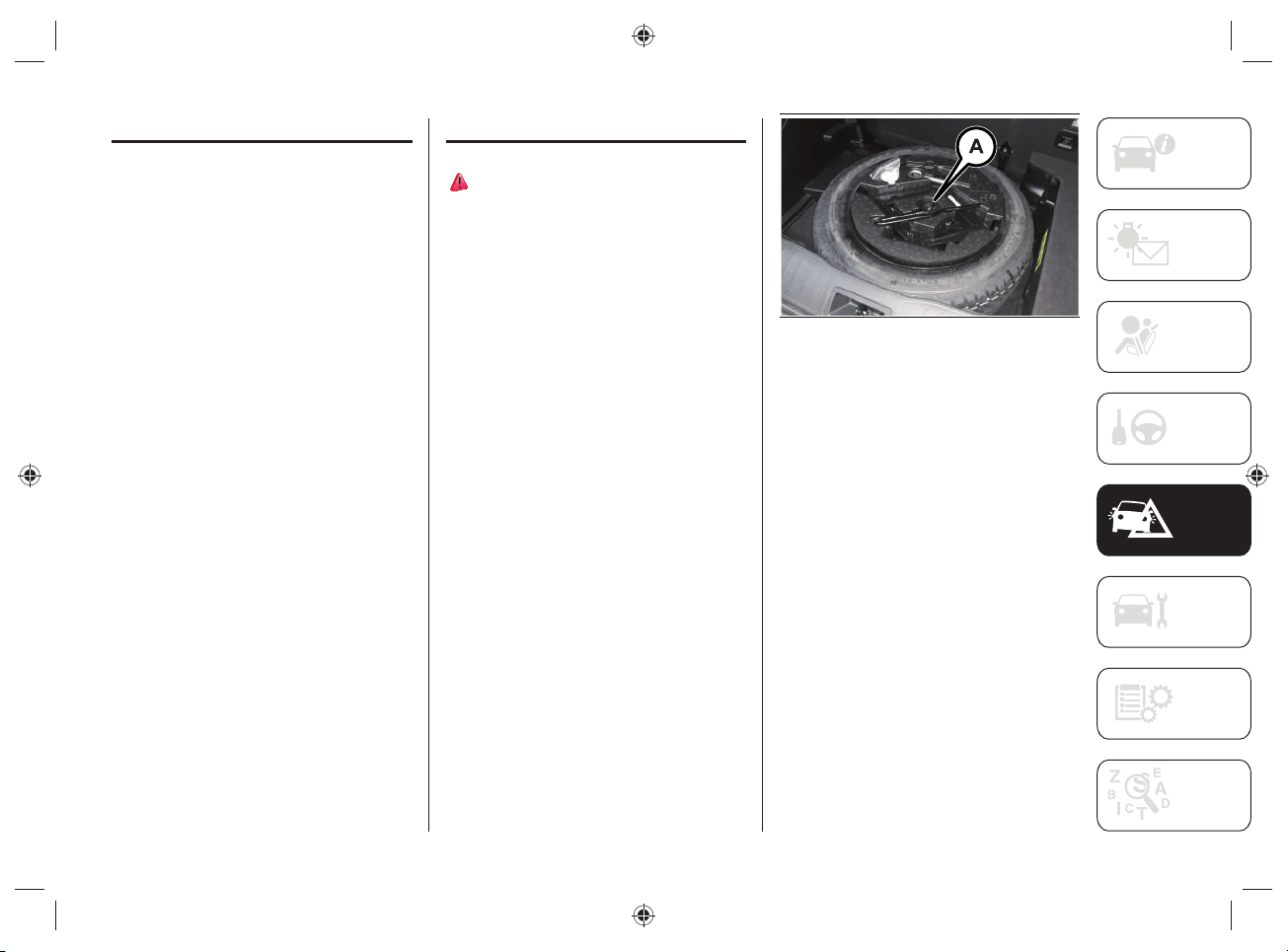
111
FUSES
The specifi c fuses for this version are
located in a control unit located inside the
engine compartment.
WARNING Contact a Jeep Dealership to
replace the specifi c fuses for this version.
CHANGING A WHEEL
61) 62)
The spare wheel (where provided) fi g.85
is located under the boot load platform.
ACCESS TO THE SPARE
WHEEL
To access the spare wheel, proceed as
follows:
open the liftgate and then remove the
load platform;
remove the jack and spare wheel
fastener Afig.85;
remove the jack unit and the wrench
for removing the fixing bolts from the
spare wheel, fig.85. Turn the screw
of the jack to loosen the wrench and
separate it from the jack assembly;
take the spare wheel out of the boot.
85 J0B6101E
Follow the instructions in the Owner
Handbook for the replacement procedure.
IN CASE OF EMERGENCY
112
WARNING
61) The spare wheel (where provided)
is specific to the vehicle: do not use it
on vehicles of a different model, nor
use wheels from other models on your
vehicle. The spare wheel must only be
used in an emergency. Never use it for
more than strictly necessary and never
exceed a speed of 80km/h. "Warning!
For temporary use only! 80km/h max!".
Replace with standard wheel as soon
as possible. Never remove or cover
the sticker on the spare wheel. Never
apply a hub cap to the spare wheel. The
driving characteristics of the vehicle will
be modified with the spare wheel fitted.
Avoid violent acceleration and braking,
abrupt steering and fast cornering.
62) With the spare wheel fitted avoid
violent acceleration and braking, abrupt
steering and fast cornering. The total life
of a space-saver wheel is approximately
3000km (1865 miles), after which it
must be replaced by another wheel of
the same type. Never install a standard
tire on a rim that is designed for use with
a spare wheel. Have the wheel repaired
and refitted as soon as possible. Using
two or more spare wheels at the same
time is forbidden. Do not grease the
threads of the stud bolts before fitting
them: they might slip out when driving!
JUMP-STARTING
LOW VOLTAGE BATTERY
(12 VOLT) FLAT
If the low-voltage battery (12 Volt) battery
of the car is fl at, it can be jump started
or a portable booster can be used with
nominal voltage of 12 volts.
For the procedure to be carried out, refer
to the description in the "Jump starting"
chapter in the "In case of emergency"
section of the Owner Handbook.
When using a portable booster with a
nominal voltage of 12V/24V, make sure
that the selector is correctly positioned on
12 Volt.
Pay attention to the dedicated label,
fi g.86, located on the cover of the low-
voltage (12 Volt) battery.
WARNING DO NOT apply a voltage higher
than 15 Volts under any circumstances in
case of emergency starting.
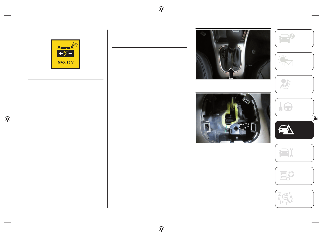
113
86 J0A6167E
If both the low-voltage battery and the
high-voltage battery are fl at, charge the
low-voltage battery fi rst, in order to start
the system and allow the heat engine to
start in order to move the car. We suggest
then, to also charge the high voltage
battery.
AUTOMATIC
TRANSMISSION
LEVER RELEASE
In the event of a failure, to move the gear
lever from P ("Park"), proceed as follows:
switch off the engine;
engage the electric park brake;
working carefully in the point
indicated by the arrow, fig.87, remove
the transmission trim (complete with
shift lever gaiter) lifting it upwards;
depress the brake pedal and keep it
fully depressed;
Insert the supplied screwdriver
perpendicular into the release access
hole in the rear right corner of the
gear lever assembly, fig.88 and press
down on the release lever;
87 5520413D
88 5520414D
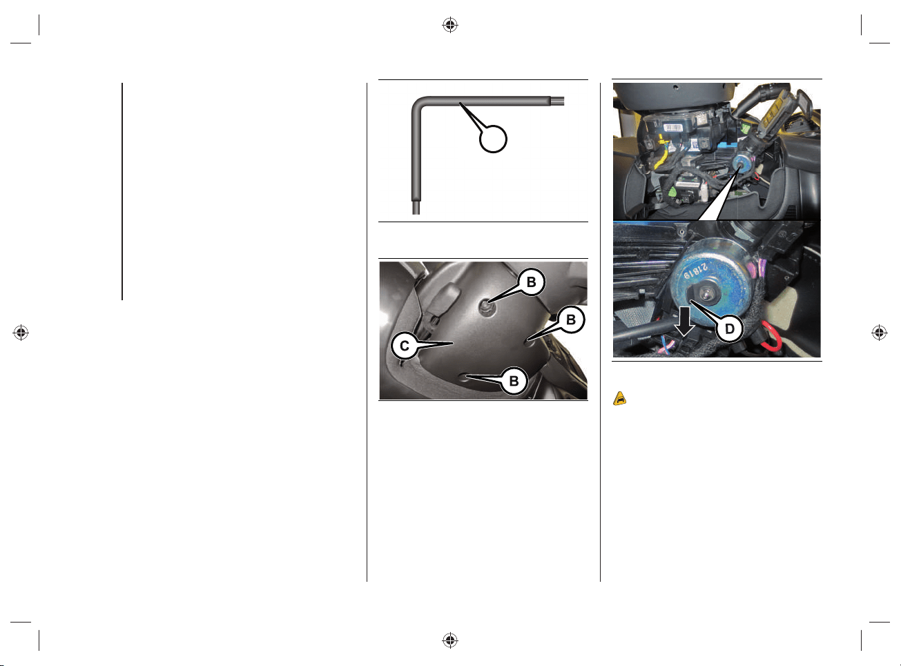
IN CASE OF EMERGENCY
114
IGNITION KEY EMERGENCY
REMOVAL
The ignition key (for versions with a
mechanical key) can be removed only if
the gear lever is in position P ("Park").
If the car's battery is discharged, the
ignition key, if inserted, remains locked in
its seat.
Proceed as follows to extract the key fob
manually:
stop the car in safety conditions,
engage a gear and the electric parking
brake;
using the provided key (A) fig.89
(located in the casing containing the
handbook) undo the fixing screws (B)
fig.90 for the lower upholstery (C);
remove the lower steering column
upholstery (C) by releasing it from its
housing;
use one hand to pull down the tab (D)
fig.91 and use the other to remove
the key, sliding it outward;
once the key has been removed, refit
lower upholstery (C) fig.90, make
sure it locks correctly and tighten the
fixing screws (B) firmly.
A
89 J0B6132E
90 J0B6133E
91 J0B6134E
10)
115
WARNING
10) It is advisable to contact a Jeep
Dealership to have the refitting procedure
carried out. If you would like to proceed
autonomously, special attention must
be paid to the correct coupling of the
retaining clips. Otherwise, noises might
be heard due to an incorrect fastening
of the lower upholstery with the upper
upholstery.
TOWING A DISABLED
VEHICLE
63) 64) 65)
This chapter describes the procedures for
towing a broken-down car.
WARNING Comply with the regulations
regarding vehicle towing in force in each
country.
WARNING Do not tow using lifting
harnesses. When securing the vehicle to a
fl atbed truck, do not attach to front or rear
suspension components. Damage to your
vehicle may result from improper towing.
TOWING METHOD
It is recommended to tow the car with all
the four wheels LIFTED from the ground.
It is therefore possible to tow the car on
the fl atbed of a rescue vehicle.
If this is not possible, towing is allowed
with the two front wheels raised off the
ground but only for short distances and at
low speed.
Before towing, make sure that the
automatic transmission is in neutral
(N), checking that the car moves when
pushed.
WARNING If the transmission cannot
be put in neutral (N), do not tow the car
and contact a Jeep Dealership. Should
the automatic transmission lever be in
"Park" (P), release it before towing (see
paragraph "Positions of the lever" in the
Owner Handbook).
WARNING If a vehicle is towed without
complying with the above requirements,
the transmission and/or the transfer unit
might be seriously damaged. Damage
due to incorrect towing is not covered by
warranty.
IN CASE OF EMERGENCY
116
WARNING
63) For versions with mechanical key fob,
turn the ignition key to the RUN position
and then to OFF without removing it
before towing. The steering column
will automatically lock when the key
is removed and the wheels cannot be
steered. Check that the gear lever is in
neutral (N). For versions with electronic
key fob, turn the ignition device to the
RUN position and then to OFF, without
opening the door.
64) The brake servo and the
electromechanical power steering will
not work while being towed. You will
therefore need to apply more force on
the brake pedal and steering wheel. Do
not use flexible ropes when towing, and
avoid jerky movements. During towing,
make sure that the trailer hitch does not
damage any components it is touching.
When towing the car, you must comply
with all specific traffic regulations and
adopt an appropriate driving behavior.
Do not start the engine while towing the
car. Before tightening the ring, clean the
threaded housing thoroughly. Make sure
that the ring is fully screwed in before
towing the vehicle.
65) The front and rear tow hooks should
be used only for emergencies on the
road. You are allowed to tow the vehicle
for short distances using an appropriate
device in accordance with the rules of
the road (a rigid bar), to move the vehicle
on the road in readiness for towing or
transport via a breakdown vehicle. The
tow hooks MUST NOT be used to tow the
vehicle off the road or where there are
obstacles and/or for towing operations
using cables or other non-rigid devices.
In compliance with the above conditions,
towing must take place with the two
vehicles (one towing, the other towed)
aligned as much as possible along the
same center line.
117
SERVICING AND MAINTENANCE
SCHEDULED SERVICING ...............118
ENGINE COMPARTMENT ..............123
CAR INACTIVITY ........................... 125
BODYWORK ..................................125
Correct servicing permits the
performance of the vehicle to be
maintained over time, as well as limited
running costs and safeguarding the
effi ciency of the safety systems.
This section explains how.
For anything not included, refer to
the "Servicing and maintenance"
section in the Owner Handbook.
SERVICING AND MAINTENANCE

SERVICING AND MAINTENANCE
118
SCHEDULED SERVICING
Correct servicing is crucial for
guaranteeing a long life for the vehicle
under the best conditions. For this reason,
Jeep has planned a series of checks and
services at fi xed distance intervals and,
where provided, at fi xed time intervals, as
described on the Service Schedule.
Before each service, it is always necessary
to carefully follow the instructions in
the Scheduled Servicing Plan (e.g.
periodically check level of fl uids, tire
pressure, etc.).
The Scheduled Servicing is carried out
by the Jeep Dealership at pre-set times.
If, during each operation, in addition to
the ones scheduled, the need arises for
further replacements or repairs, these
may be carried out with the owner's
explicit agreement only. If your car is used
frequently for towing, the interval between
one scheduled servicing operation and
the next should be reduced.
WARNING Scheduled Servicing
operations are required by the
Manufacturer. Failure to have them
carried out may invalidate the New
Vehicle Limited Warranty. It is advisable
to inform a Jeep Dealership of any small
operating irregularities without waiting for
the next service.
PERIODIC CHECKS
Every 1,000km or before long trips check
and, if necessary, top up:
the coolant levels of the two systems
of the car (heat engine cooling and
high voltage components cooling);
brake fluid level;
windscreen washer fluid level;
tire inflation pressure and condition;
operation of lighting system
(headlights, direction indicators,
hazard warning lights, etc.);
operation of windscreen washer/wiper
system and positioning/wear of rear
window wiper blades.
Every 3,000km check and top off if
required: engine oil level.
119
DEMANDING USE OF THE CAR
If the vehicle is used in one of the
following conditions:
law enforcement (or security service),
taxi service;
towing a trailer or caravan;
dusty roads;
short, repeated journeys (less
than 7-8km) at sub-zero external
temperatures;
engine often idling or driving long
distances at low speeds or long
periods of inactivity;
the following checks must be carried
out more often than indicated in the
Scheduled Servicing Plan:
check front disc brake pad condition
and wear;
check cleanliness of bonnet and
luggage compartment locks,
cleanliness and lubrication of linkage;
visually inspect conditions of: engine,
gearbox, transmission, pipes and
hoses (exhaust/fuel system/brakes)
and rubber elements (gaiters/sleeves/
bushes, etc.);
check the low voltage battery
(12V) charge status and fluid level
(electrolyte);
visually inspect conditions of the
accessory drive belts;
check and, if necessary, change
engine oil and replace oil filter;
check and, if necessary, replace
cabin air filter;
check and, if necessary, replace air
cleaner.
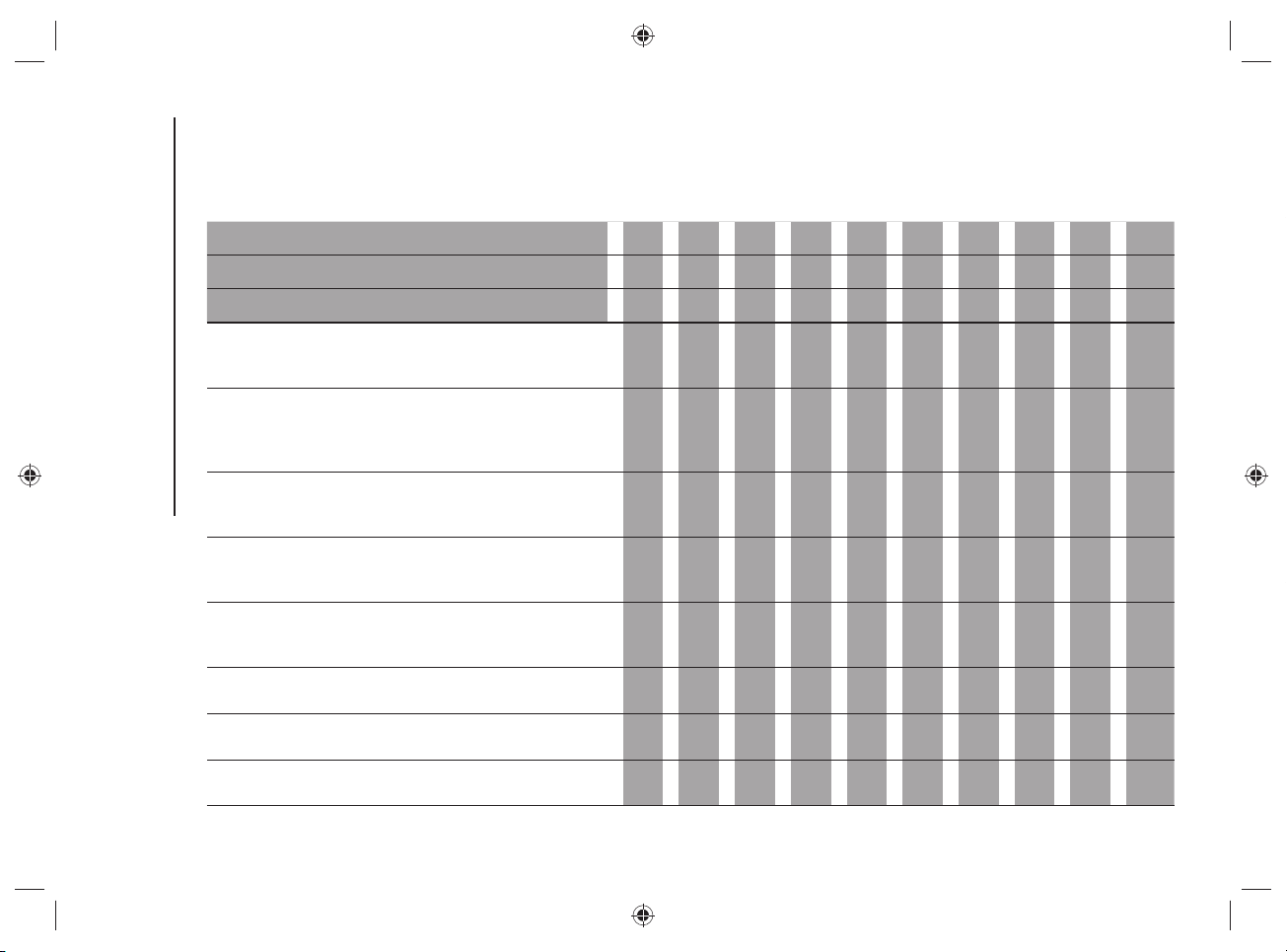
SERVICING AND MAINTENANCE
120
SERVICE SCHEDULE
WARNING Once you have carried out the last intervention in the table, continue with the scheduled servicing, maintaining the frequency
indicated in the plan by marking each operation with a dot or dedicated note. Warning: simply restarting the maintenance from the start
of the plan may cause the allowed interval to be exceeded for some operations!
Thousands of miles 9 18 27 36 45 54 63 72 81 90
Thousands of kilometres 15 30 45 60 75 90 105 120 135 150
Years 1 2 3 4 5 6 7 8 9 10
Check tyre condition/wear and adjust pressure, if
necessary; check "TireKit” rapid repair kit charge expiry
date (for versions/markets, where provided)
●●●●●●●●●●
Check operation of lighting system (headlights, direction
indicators, hazard warning lights, boot, passenger
compartment, glove compartment, instrument panel
warning lights, etc.)
●●●●●●●●●●
Check and, if necessary, restore the engine compartment
liquid level (heat engine cooling, high-voltage system
cooling, brakes, windscreen washers, etc.) (1)
●●●●●●●●●●
Check the fuel/engine management systems operation,
emissions, high voltage battery and engine oil deterioration
using the diagnosis equipment (where provided) (2)
●●●●●●●●●●
Visually inspect condition of: exterior bodywork, underbody
protection, pipes and hoses (exhaust, fuel system, brakes),
rubber elements (gaiters, sleeves, bushes, etc.)
●●●●●
Check the position/wear of the windscreen wiper and rear
window wiper blades (where provided)
●●●●●
Check operation of the windscreen wiper/washer system
and adjust nozzles, if necessary
●●●●●
Check cleanliness of hood and boot locks, cleanliness and
lubrication of linkage
●●●●●
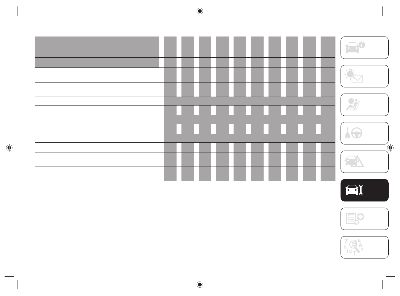
121
Thousands of miles 9 18 27 36 45 54 63 72 81 90
Thousands of kilometres 15 30 45 60 75 90 105 120 135 150
Years 1 2 3 4 5 6 7 8 9 10
Visually inspect conditions and wear of front and rear disc
brake pads and integrity of pad wear indicator
●●●●●●●●●●
Visually inspect the condition of the accessory
drive belt(s) (3)
●
Change engine oil and replace oil filter (4)
Spark plug replacement(5)
●●
Replace accessory drive belt/s (3)
Replace air cleaner cartridge (6)
●●●●●
Change the brake fluid (7)
Replace passenger compartment filter (6) (O) (●)
O
●
O
●
O
●
O
●
O
●
UConnect Box system battery replacement (where
provided) (8)
●●
Visual inspection of electrical charging socket condition
and integrity
●●●●●●●●●●
(1) Only use the fluids shown in the handbook for topping up, and only after checking that the system is intact.
(2) If the engine oil quality detected by the vehicle diagnostics is lower than 20%, it is advisable to replace the engine oil and engine filter in order to avoid another
service operation after a short time.
(3) The maximum mileage is 120,000km. The belt must be replaced every 6 years, regardless of distance traveled. If the vehicle is used in heavy conditions
(dusty areas, particularly harsh weather conditions, very low or very high temperatures for extended periods, urban driving, long periods of idling), the
maximum mileage is 60,000km. The belt must be replaced every 4 years regardless of the mileage. Furthermore, in the above demanding use conditions, the
dual effect tensioner must be replaced at 120,000Km or after 6 years regardless of the distance driven.
(4) The actual interval for changing engine oil and replacing the engine oil filter depends on the car usage conditions and is signaled by the warning light or
message on the instrument panel. In any cases, never exceed 1 year.

SERVICING AND MAINTENANCE
122
(5) To guarantee correct operation and prevent serious damage to the engine, it is essential to proceed as follows: only use spark plugs specifically certified for
these engines; all spark plugs should be of the same type and brand (see the "Engine" paragraph in the "Technical data" chapter); strictly comply with the
spark plugs replacement intervals in the Service Schedule. It is advisable to contact a Jeep Dealership for plug replacement.
(6) If the vehicle is used in dusty areas, this filter should be replaced every 15,000km.
(7) Brake fluid is to be replaced every 2 years or every 75,000km.
(8) The UConnect Box battery must be replaced every 5 years, regardless of mileage.
(o) Recommended operations.
(
●) Mandatory operations.
NOTE change automatic transmission oil and replace oil filter every 240,000km.
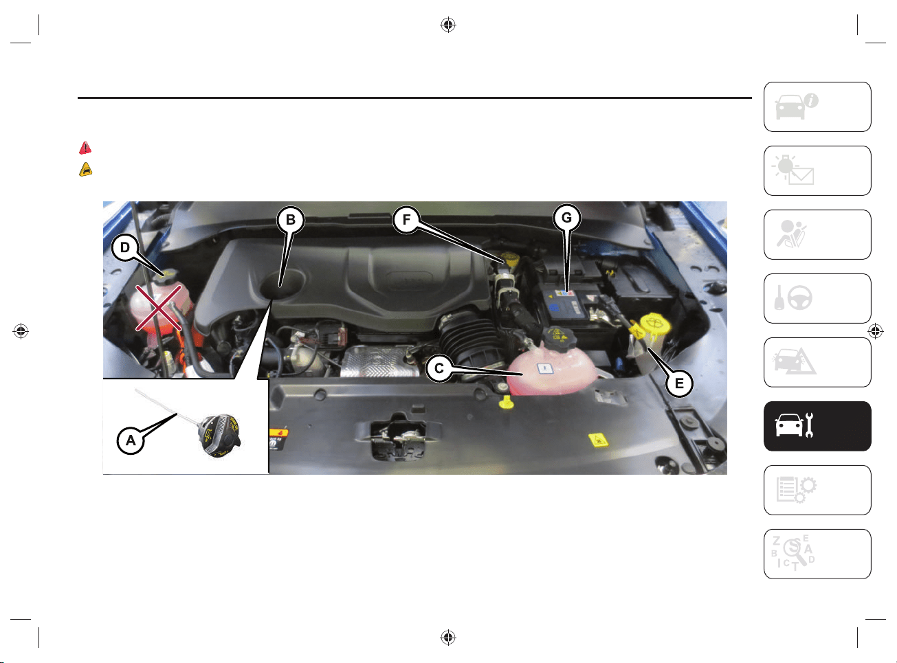
123
ENGINE COMPARTMENT
CHECKING LEVELS
66) 67) 68) 69) 70)
11)
92 J0B6037E
A.Engine oil dipstick - B.Engine oil filler cap - C.Heat engine coolant fluid - D.High voltage system coolant - E.Windscreen/rear window washer
fluid - F.Brake fluid - G.Low voltage battery (12V)
NOTE The cooling tank of the high voltage system cannot be refi lled by the driver. If it is necessary to top up the fl uids, contact a Jeep
Dealership.
SERVICING AND MAINTENANCE
124
WARNING
66) Never smoke while working in the engine compartment: gas and inflammable vapors may be present, with the risk of fire.
67) Be very careful when working in the engine compartment when the engine is hot: you may get burned. Do not get too close to the radiator
cooling fan: the electric fan may start: injury hazard. Scarves, ties and other loose clothing might be pulled by moving parts.
68) When working in the engine compartment pay special attention to mechanical components that can move suddenly, pressurized or very
hot liquids and live electrical parts.
69) NEVER touch the high-voltage system components (identified by the orange color), as this could result in serious injury or death from
electric shock.
70) Do not pour water or any other type of liquid onto the high voltage system components inside the engine compartment. Risk of death by
electric shock and/or damage to the system.
WARNING
11) Be careful not to confuse the various types of fluids while topping up: they are not compatible with each other! Topping up with an
unsuitable fluid could severely damage your vehicle.
125
CAR INACTIVITY
If the car is stopped for more than one
month, in addition to the instructions
below, observe the same precautions
as described in the "Prolonged Car
Inactivity" section in the "Servicing and
maintenance" section of the online Owner
Handbook.
If the car is stopped for several weeks,
park the car with the high-voltage battery
charged more than 50%.
If over-discharged, the high-voltage
battery may be damaged.
The Jeep Dealership can provide further
advice on what to do if the vehicle should
be stopped for more than three months.
BODYWORK
UNDERBODY WASHING
If it is necessary to wash the underbody,
do not directly pressurize with a high-
pressure jet.
EXTERNAL CAR WASHING
Washing with closed hybrid system
charging fl ap
The hybrid system is safe, even if the
following situations occur:
presence of water in the foot area;
when the car is in water at a level that
allows it to cross a ford;
liquids entering the boot.
12)
ENGINE COMPARTMENT
WASHING
13)
It is not recommended to wash the engine
compartment with water.
PAINTING
When painting the car in the oven, take
care not to exceed:
30 minutes at 70°C;
20 minutes at 80°C.
WARNING
12) If it is necessary to wash the vehicle
from the outside, take care not to insist
directly with the water jet onto the
charging flap of the hybrid system.
13) A high pressure jet cleaner should
not be used for cleaning the engine
compartment. The appropriate
precautions have been taken to protect
all parts and connections, but the
pressures generated by these devices are
so high that complete protection against
water seepages cannot be guaranteed.

126
Blank page
SERVICING AND MAINTENANCE
127
TECHNICAL SPECIFICATIONS
ENGINE CODES - BODYWORK
VERSIONS .....................................128
ENGINE ......................................... 129
HIGH-VOLTAGE BATTERY .............130
TRANSMISSION ............................131
BRAKES ........................................131
TIRES AND WHEELS ......................132
DIMENSIONS .................................135
WEIGHTS .......................................139
REFUELLING ................................. 140
FLUIDS AND LUBRICANTS ...........141
PERFORMANCE ............................143
FUEL CONSUMPTION AND
CO
2
EMISSIONS ............................144
PRESCRIPTIONS FOR
HANDLING THE CAR AT THE
END OF ITS LIFE ...........................145
Everything you may fi nd useful for
understanding how your vehicle is made
and works is contained in this section
and illustrated with data, tables and
graphics. For the enthusiasts and the
technician, but also just for those who
want to know every detail of their vehicle.
For anything not included, refer
to the "Technical Data" section
in the Owner Handbook.
TECHNICAL SPECIFICATIONS
TECHNICAL SPECIFICATIONS
128
ENGINE CODES - BODYWORK VERSIONS
Versions Engine codes Bodywork versions
1.3 190HP
46337540 MPJHPFP NL1BAH1
1.3 240HP
46337540 MPJHPFP NN1BAH1
1.3 240HP Trailhawk
46337540 MPJHPFP TN1BAH1
129
ENGINE
HEAT ENGINE
Versions 1.3 190HP (*) 1.3 240HP (*)
Engine code 46337540 46337540
Cycle Otto Otto
Number and position of cylinders 4 in line 4 in line
Piston bore and stroke (mm) 70 x 86.5 70 x 86.5
Total displacement (cm
3
) 1332 1332
Compression ratio 10.5 +/- 0.2 10.5 +/- 0.2
Maximum power (CEE) (kW) 96 132
Maximum power (CEE) (HP) 130 180
Corresponding engine speed (rpm) 5500 5750
Maximum torque (CEE) (Nm) 270 270
Maximum torque (CEE) (kgm) 27.5 27.5
Corresponding engine speed (rpm) 1850 1850
Spark plugs NGK ILKFR7A8 NGK ILKFR7A8
Fuel
Unleaded gasoline
95 R.O.N. (EN228 specifications)
Unleaded gasoline
95 R.O.N. (EN228 specifications)
(*) Total engine power: 60 HP is supplied by the rear electric motor.
REAR ELECTRIC MOTOR
Features
Technology Three-phase "induction" electric motor
Continuous power (kW) 44 (*)
Maximum torque (Nm) 250
(*) The peak power that the electric motor can supply may be higher than the continuous power, depending on various factors such as the charge state of the
high-voltage battery and the environmental conditions.
TECHNICAL SPECIFICATIONS
130
HIGH-VOLTAGE BATTERY
Features
Battery type Lithium ions
Voltage (Volts) 380
Energy capacity (kWh/Ah) 11.4 / 33
Range (km) (*) 50
(*) The range value varies according to the energy consumption of the devices installed on the vehicle (e.g. automatic dual-zone climate control system).
131
TRANSMISSION
Model Transmission Traction
1.3 190HP/1.3 240HP
Automatic transmission with six
forward gears plus reverse
Integral Electrified
(Front traction
Heat engine + electric motor rear)
The front and rear axles of the car are connected by a rear electric motor, capable of providing "eAWD" electric traction. This provides
more torque on the rear wheels.
BRAKES
Model Front brakes Rear brakes Parking brake
1.3 190HP/1.3 240HP
Disc Disc Electric
On the vehicle, in addition to the conventional braking system, the rear electric motor can, under certain conditions, slow down the
vehicle and also allow the high-voltage battery to be charged (for more information, refer to the chapter "eBraking mode" in the "Knowing
your vehicle" section).
WARNING Water, ice and salt spread on the roads may deposit on the brake discs, reducing braking effi ciency the fi rst time the brakes
are applied.
TECHNICAL SPECIFICATIONS
132
TIRES AND WHEELS
Alloy rims. Tubeless radial carcass tires.
All approved tires are listed in the
Registration Certifi cate.
WARNING If there are any discrepancies
between the Owner Handbook and
the Registration Document, take the
information only from the latter. For safe
driving, the car must be fi tted with tires of
the same make and type on all wheels.
WARNING Do not use inner tubes with
tubeless tires.
SNOW CHAINS
14)
7mm snow chains can only be used
on the 215/60 R17 96H tire (where
provided).
Warnings
The use of snow chains should be in
compliance with local regulations. In
certain countries, tires marked with code
M+S (Mud and Snow) are considered as
winter equipment; therefore their use is
equivalent to that of the snow chains.
The snow chains may be applied only to
the front axle.
If the vehicle is moving with the snow
chains fi tted, the "SNOW" drive mode
must be set using the Selec-Terrain
TM
system knob (for more information see the
Selec-Terrain
TM
chapter in the "Starting
and driving" section).
Check the tension of the snow chains
after the fi rst few feet/meters have been
driven.
Using snow chains with tires with non-
original dimensions may damage the
vehicle.
Using different size or type (M+S, snow,
etc.) tires between front and rear axle may
adversely affect vehicle driveability, with
the risk of losing control of the vehicle and
causing accidents.
WARNING
14) Keep the speed down when snow
chains are fitted; never exceed 50km/h.
Avoid potholes, steps and curbs and
avoid driving long distances on roads not
covered with snow to avoid damaging the
vehicle and the road surface.
133
RIMS AND TYRES PROVIDED
Versions Rims Tires Snow tires
1.3 190HP
1.3 240HP
7J x 17 H2 ET 37.5 215/60 R1796H (*) 215/60 R1796H (M+S) (*)
7J x 17 H2 ET 37.5 235/60 R17 102H 235/60 R17 XL 102H (M+S)
7J x 18 H2 ET 37.5 235/55 R18100H 235/55 R18100H (M+S)
7.5J x 19 H2ET40 235/45 R19 XL99H 235/45 R19 XL99H (M+S)
1.3 240HP Trailhawk
7J x 17 H2 ET 37.5 235/60 R17 102H M+S 235/60 R17 XL 102H (M+S)
Spare wheel (optional)
6.5J x17 H2 ET40 215/65 R17 99S (M+S)
(*) Only for using 7 mm snow chains
WARNING With the spare wheel fi tted the speed of the vehicle must not exceed 80km/h: for more information refer to the on "Changing
a wheel" chapter in the "In case of emergency" section.
TECHNICAL SPECIFICATIONS
134
COLD TYRE INFLATION PRESSURE (bar)
When the tyres are warm, the infl ation pressure should be + 0.3 bar in relation to the recommended fi gure. However, recheck the
correct value when the tyre is cold.
With snow tires, add +0.2 bar to the pressure value prescribed for standard tires.
If it is necessary to jack the vehicle, refer to the "Jacking the Vehicle" chapter in the "In case of emergency" section of the Owner
Handbook.
Tires
Unladen/medium load Full load
Front Rear Front Rear
215/60 R17 96H (*) 2.4 2.4 2.6 2.6
235/60 R17 102H (***) 2.4 2.4 2.6 2.6
235/55 R18 100H (***) 2.4 2.4 2.6 2.6
235/45 R19 XL 99H (***) 2.4 2.4 2.6 2.6
215/65 R17 99S (**) 2.4
(*) Non original tire: it must only be fitted if 7 mm snow chains are to be used.
(**) Spare wheel (optional)
(***) The specified pressure is aimed at comfort. To promote fuel efficiency, the tyre pressure can be increased to a maximum of 3.0 bar on all tyres (except for
215/60 R17 96H and 215/65 R17 99S tyres).
NOTE The indicated pressure is aimed at comfort. To privilege fuel effi ciency, the tyre pressure can be increased to a maximum of 3.0
bar for all tyres.
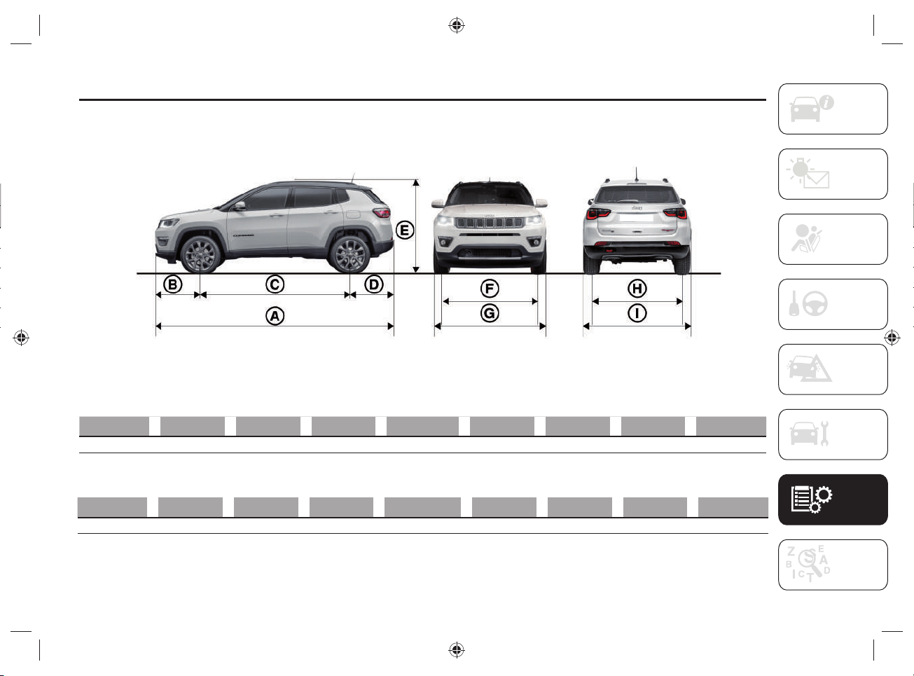
135
DIMENSIONS
Dimensions are expressed in mm and refer to the car equipped with its original tires. Small variations with respect to the reported values
are possible depending on the dimensions of the rims. Height is measured with vehicle unladen.
93 J0B6490E
Limited / Longitude / Sport versions
A B C D E (*) F G H I
4394 905 2636 853 1638/1644 (**) 1547 2033 1542 1819
Trailhawk versions
A B C D E (*) F G H I
4398 908 2636 854 1651/1657 (**) 1546 2033 1538 1819
(*) Small variations with respect to the reported values are possible depending on the dimensions of the rims.
(**) With roof rack bars.
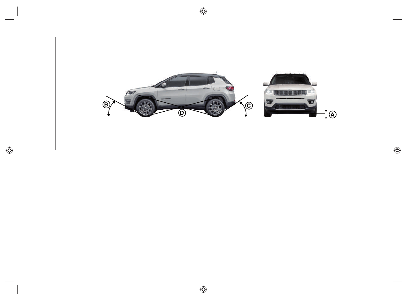
TECHNICAL SPECIFICATIONS
136
MINIMUM GROUND CLEARANCE/TYPICAL ANGLES
94 J0B0667C
"Minimum ground clearance" - reference A
The height value is measured near the lower edge of the rear electric motor. The height above ground also determines the values of
"Approach angle", "Departure angle" and "Breakover angle".
Dimensions are expressed in mm and refer to the car equipped with its original tires and empty car.
Four-wheel drive (eAWD) versions: 201 mm
Trailhawk versions with four wheel drive (eAWD LOW): 213 mm
137
"Approach angle" - reference B
The approach angle is determined by the horizontal line of the road surface and by the tangent line passing between the front wheel and
the most projecting low point of the car.
The wider the angle, the lower the chance to hit an obstacle with the body or chassis, climbing a steep slope or overcoming an obstacle.
Four-wheel drive (eAWD) versions: 16°
Trailhawk versions with four wheel drive (eAWD LOW): 30.4°
"Departure angle" - reference C
The departure angle is determined by the same lines of the "Approach angle", and refers to the rear part of the car.
Four-wheel drive (eAWD) versions: 32°
Trailhawk versions with four wheel drive (eAWD LOW): 33.3°
"Breakover angle" - reference D
The value of the "Breakover angle" is linked to the ground clearance of the car and indicates the attitude of the car to overcome a
wedge, more or less steep, preventing the car from resting on the ground with the body or chassis after touching the wedge with its
lowest and most projecting parts (usually the underbody), because this would highly reduce wheel grip.
The wheels, without a suitable grip to the ground, will not have suffi cient hold to move the vehicle, and will surge.
The higher the ground clearance, the wider the breakover angle. Always bear in mind that the higher the ground clearance, the lower
the stability, due to a higher center of gravity which reduces the side rollover angle.
Four-wheel drive (eAWD) versions: 18°
Trailhawk versions with four wheel drive (eAWD LOW): 20.9°
TECHNICAL SPECIFICATIONS
138
BOOT CAPACITY (Capacity - VDA standards )
LUGGAGE COMPARTMENT CAPACITY Liters
Capacity with the TireKit device 420
Capacity with the spare wheel (where provided) 350
Cargo with the rear seats not folded down with the TireKit device
(capacity measured at shelf level)
1230
Cargo with the rear seats not folded down with the spare wheel (where provided)
(capacity measured at shelf level)
1239
139
WEIGHTS
Weights (kg) 1.3 190HP 1.3 240HP
Unladen weight (with all fluids, fuel tank filled to 90% and without
optional equipment)
1860 1860
Payload including the driver (*) 540 540
Maximum permitted loads (**)
– front axle 1200 1200
– rear axle 1250 1250
– total: 2400 2400
Maximum combined vehicle load (vehicle + trailer) (***) 3400 3400
Towable loads
– braked trailer 1250 1250
– trailer without brakes 600 600
Maximum load on roof (****) 50 50
Maximum load on tow hitch (trailer with brakes) 60 60
(*) If special equipment is fitted (sun roof, trailer towing equipment, etc.) the unladen weight will increase and consequently the payload will decrease in relation to
the maximum permitted loads.
(**) Loads not to be exceeded. The user is responsible for arranging goods in the boot and/or load platform within the maximum permitted loads.
(***) Never exceed the maximum combined vehicle load value: the maximum towable load is only allowed if it does not exceed the maximum combined vehicle
load.
(****) Versions with roof rack bars.
TECHNICAL SPECIFICATIONS
140
REFUELLING
1.3 190HP/1.3 240HP Prescribed fuels and original lubricants
Fuel tank (liters): 36.5
Unleaded petrol with at least 95 R.O.N.
(EN228 specifications)
Engine cooling system (liters): 5.4
Mixture of demineralized water
and 50% PARAFLU
UP
(*)
Cooling system (high voltage) (liters) (**) 7.0
Engine sump (liters): 4.2
SELENIA DIGITEK P.E.
Engine sump and filter (liters): 4.5
Gearbox/differential casing (liters): 6.5 TUTELA TRANSMISSION GI/VI
Hydraulic brake circuit (liters): 1.14 TUTELA TOP EVO
Windscreen and rear window
washer fluid tank (liters):
2.5
Mixture of water and liquid
PETRONAS DURANCE SC 35
(*) When the vehicle is used in particularly harsh climate conditions, we recommend using a 60% mixture of PARAFLU
UP
and 40% demineralized water.
(**) NOTE The cooling tank of the high voltage system cannot be refilled by the driver. If it is necessary to top up the fluids, contact a Jeep Dealership.
141
FLUIDS AND LUBRICANTS
Your vehicle is equipped with an engine oil that has been thoroughly developed and tested in order to meet the requirements of the
Maintenance Plan.
Constant use of the prescribed lubricants guarantees the fuel consumption and emission specifi cations. Lubricant quality is crucial for
engine operation and duration.
15)
PRODUCT SPECIFICATIONS
Use Features Specifi cation
Original liquids and
lubricants
Replacement interval
Lubricant for petrol
engines
SAE 0W-30
ACEA C2 / API SN
9.55535-GS1
SELENIA DIGITEK P.E.
Contractual Technical
Reference N° F020.B12
According to Scheduled
Servicing Plan
If lubricants conforming to the specifi c request are not available, products that meet the indicated specifi cations can be used to top up;
in this case optimal performance of the engine is not guaranteed.
WARNING
15) The use of products with different specifications than those indicated above could cause damage to the engine not covered by the
warranty.
TECHNICAL SPECIFICATIONS
142
Use Features Specifi cation
Original liquids and
lubricants
Applications
Lubricants and
greases for drive
transmission
Synthetic lubricant.
9.55550-AV2
TUTELA TRANSMISSION GI/VI
Contractual Technical
Reference N° F336.G05
ATF AW-1 automatic
transmission lubricant
SAE 75W API GL4 grade synthetic
lubricant
Electrified axle
Molybdenum disulphide grease,
for use at high temperatures.
N.L.G.I. consistency 1-2.
9.55580-GRAS II
TUTELA ALL STAR
Contractual Technical
Reference N° F702.G07
Wheel side constant
velocity joints
Low friction coefficient grease for
constant velocity joints. N.L.G.I.
consistency 0-1.
9.55580-GRAS II
TUTELA STAR 700
Contractual Technical
Reference N° F701.C07
Differential side constant
velocity joints
Brake fluid
Synthetic fluid for brake and
clutch systems.
Exceeds specifications:
FMVSS no. 116 DOT 4,
ISO 4925 Class 6,
SAE J1704.
9.55597 or MS.90039
TUTELA TOP EVO
Contractual Technical
Reference N° F002.L18
Hydraulic brakes and
hydraulic clutch controls
Protective agent for
radiators
Red protective with antifreeze
action, based on inhibited
monoethyl glycol with organic
formula. Exceeds CUNA NC
956-16,
ASTM D 3306 specifications.
9.55523 or MS.90032
PARAFLU
UP
Contractual Technical
Reference N° F101.M01
Cooling circuits
proportions of use: 50%
water 50% protective
fluid (*)
Windscreen/rear
window washer fluid
Mixture of spirits and surfactants.
Exceeds CUNA NC 956-11
specifications.
9.55522 or MS.90043
PETRONAS DURANCE SC 35
Contractual Technical
Reference N° F001.D16
To be used diluted or
undiluted in windscreen
washer/wiper systems
(*) For particularly harsh climate conditions, a mixture of 60% protective fluid and 40% distilled water is recommended.
143
PERFORMANCE
Top speed reachable after the initial period of usage of the car.
Operating Mode km/h
Hybrid mode 184 (*) / 200 (**)
Electric mode 135
(*) 1.3 190HP versions
(**) 1.3 240HP versions

TECHNICAL SPECIFICATIONS
144
FUEL CONSUMPTION AND CO
2
EMISSIONS
The fuel consumption and CO
2
emission fi gures declared by the manufacturer are determined on the basis of the type-approval tests
laid down by the applicable standards in the country where the vehicle is registered.
The type of route, traffi c conditions, weather conditions, driving style, general condition of the car, trim level/equipment/accessories,
use of the climate control system, car load, presence of roof racks and other situations that adversely affect the aerodynamics or wind
resistance lead to different fuel consumption values than those measured.
The fuel consumption will only become more regular after driving the fi rst 3000km.
To fi nd the specifi c fuel consumption and CO
2
emission fi gures for this car, please refer to the data in the Certifi cate of Conformity, and
the related documentation that accompanies the vehicle.
145
PRESCRIPTIONS FOR HANDLING THE CAR AT THE END OF ITS LIFE
FCA has been committed for many years to safeguarding the environment through the constant improvement of its production processes
and manufacturing products that are increasingly "eco-compatible". To grant customers the best possible service in terms of respecting
environmental laws and in response to European Directive 2000/53/EC governing vehicles at the end of their life, FCA is offering its
customers the chance to hand over their vehicle at the end of its life without incurring any additional costs. The European Directive
sets out that when the vehicle is handed over, the last keeper or owner should not incur any expenses as a result of it having a zero or
negative market value.
To hand your vehicle over at the end of its life without extra cost, contact one of our dealerships if you are purchasing another vehicle
or an FCA-authorized collection and scrapping center. These centers have been carefully chosen to offer high quality service for the
collection, treatment and recycling of vehicles at their end of life, respecting the surrounding environment.
Similarly, to meet its obligations under European Directive 2006/66/EC on batteries, FCA requires you to comply with the national
regulations on handling both low-voltage and high-voltage lithium ion batteries (12V and 48V) at all times. This includes consigning
vehicles complete with their batteries to one of the collection and demolition centers authorized by FCA to handle such batteries, and not
disposing of them improperly, which could lead to personal injuries and/or harm to the environment.
You can fi nd further information on these collection and scrapping centers either from an FCA dealership or by calling the number in the
Warranty Booklet or by consulting the websites of the various FCA brands.

146
Blank page
TECHNICAL SPECIFICATIONS
147
CONTENTS
Access to the spare
wheel .........................................111
ACC system disengagement .............94
ACC system enabling / disabling ....... 94
Active safety systems .......................81
Adaptive Cruise Control
(ACC) ...........................................94
Automatic high-voltage battery
disconnection ............................. 110
Automatic transmission
(6 gears) .......................................88
Automatic transmission lever
release .......................................113
Automatic transmission "limp
home mode" ................................. 91
Bodywork ......................................125
Car inactivity ................................125
Changing a wheel ...........................111
Charge cable emergency unlock .......42
Charge status control unit .................22
Charging from domestic power
supply (AC) socket procedure .......34
Charging from public charging
station (AC) procedure .................. 40
Charging functions ...........................45
Charging procedure from
wallbox charging station
("smart" wallbox) ...........................38
Charging schedule ........................... 45
Charging socket on the vehicle .........32
Continuing the charging procedure ...46
Demanding use of the car ..............119
Digital fuel level gauge ......................53
Digital heat engine coolant
temperature gauge .......................54
Digital range indicator ......................55
Disconnecting the "mode2"
charging cable .............................. 37
Disconnecting the "mode3"
charging cable .............................. 42
Display .............................................56
Driving mode selection .....................96
Driving tips .....................................102
"
Ebraking" mode
(high-voltage battery charging) ...... 49
"eCoasting" mode
(energy saving) .............................48
"ELECTRIC" mode ............................14
Electromagnetic waves .....................80
Emergency fuel fl ap opening .......... 101
End of charging procedure ...............36
End of charging procedure ...............41
End of charging procedure ...............47
Engine compartment washing ........125
Engine starting procedure ................86
Engine switch off
procedure .....................................87
Environmental protection ................103
"E-SAVE" mode ................................ 14
ESC (Electronic Stability
Control) system .............................81
External car washing ......................125
Failure during charging
procedure .....................................47
FCC specifi cations ...........................28
Four-wheel drive .............................. 95
Four wheel drive - Jeep Active
Drive (4WD) and Jeep Active
Drive Low (4WD LOW) ..................95
Fuel consumption .......................... 103
Fuel eco ..........................................56
Fuel reserve display .........................53
Fuses .............................................111
Gear engagement disabling
system without brake pedal
pressed ........................................92
Gear lever ........................................ 88
General information ............................8
General information ..........................16

CONTENTS
148
HDC (Hill Descent Control)
system ..........................................82
High-voltage battery ..................10-130
Hybrid electric pages .......................67
Hybrid info ....................................... 57
"HYBRID" mode .............................. 13
Hybrid system equipment ..................8
Hybrid system functional scheme ....... 9
Ignition key emergency removal .....114
Ignition lock and park position .......... 92
In case of accident ......................... 110
Instant charging management ..........46
Instrument panel features ................52
Interrupting the charging
procedure .....................................45
Intervention type selection ............... 48
Jeep easyWallbox ............................. 39
Jump-starting .................................112
Lever positions ................................89
Low voltage battery (12 volt) fl at .....112
Main menu .....................................56
Maintenance/ cleaning of the
charging system ...........................28
"Mode2" charging cable ..................17
"Mode3" charging cable .................29
Navigation ....................................... 75
Off-road driving tips .......................102
Operating mode ............................... 13
Operating principle .............................8
Painting ........................................125
Pedestrian acoustic
signalling system ..........................84
Periodic checks .............................118
Power meter ...................................54
Power sources that can be used ....... 16
Precautions in case of accident ......110
Precautions relating to the
hybrid system ...............................78
Reconfi gurable
multifunction display .....................52
Refueling procedure .........................99
Refueling the vehicle ........................ 99
Scheduled servicing ......................118
Selec-Terrain™ ...............................96
Servicing and maintenance ............107
Snow chains ..................................132
Starting the engine ..........................86
Tips for driving
hybrid cars ................................. 104
Tires and wheels ............................132
Towing a disabled vehicle ...............115
Towing method .............................. 115
Transporting the vehicle .................107
Types of charging cables .................. 16
U
connect™8.4”Nav DAB
Radio/Uconnect™8.4”DAB
Radio
............................................67
Underbody washing ....................... 125
Vehicle ............................................32
Works on the hybrid system ............ 78

NOTES
.................................................................................................................................................................................................................................................................................................................................
.................................................................................................................................................................................................................................................................................................................................
.................................................................................................................................................................................................................................................................................................................................
.................................................................................................................................................................................................................................................................................................................................
.................................................................................................................................................................................................................................................................................................................................
.................................................................................................................................................................................................................................................................................................................................
.................................................................................................................................................................................................................................................................................................................................
.................................................................................................................................................................................................................................................................................................................................
.................................................................................................................................................................................................................................................................................................................................
.................................................................................................................................................................................................................................................................................................................................
.................................................................................................................................................................................................................................................................................................................................
.................................................................................................................................................................................................................................................................................................................................
.................................................................................................................................................................................................................................................................................................................................
.................................................................................................................................................................................................................................................................................................................................
.................................................................................................................................................................................................................................................................................................................................
.................................................................................................................................................................................................................................................................................................................................

.................................................................................................................................................................................................................................................................................................................................
.................................................................................................................................................................................................................................................................................................................................
.................................................................................................................................................................................................................................................................................................................................
.................................................................................................................................................................................................................................................................................................................................
.................................................................................................................................................................................................................................................................................................................................
.................................................................................................................................................................................................................................................................................................................................
.................................................................................................................................................................................................................................................................................................................................
.................................................................................................................................................................................................................................................................................................................................
.................................................................................................................................................................................................................................................................................................................................
.................................................................................................................................................................................................................................................................................................................................
.................................................................................................................................................................................................................................................................................................................................
.................................................................................................................................................................................................................................................................................................................................
.................................................................................................................................................................................................................................................................................................................................
.................................................................................................................................................................................................................................................................................................................................
.................................................................................................................................................................................................................................................................................................................................
.................................................................................................................................................................................................................................................................................................................................
.................................................................................................................................................................................................................................................................................................................................
.................................................................................................................................................................................................................................................................................................................................

.................................................................................................................................................................................................................................................................................................................................
.................................................................................................................................................................................................................................................................................................................................
.................................................................................................................................................................................................................................................................................................................................
.................................................................................................................................................................................................................................................................................................................................
.................................................................................................................................................................................................................................................................................................................................
.................................................................................................................................................................................................................................................................................................................................
.................................................................................................................................................................................................................................................................................................................................
.................................................................................................................................................................................................................................................................................................................................
.................................................................................................................................................................................................................................................................................................................................
.................................................................................................................................................................................................................................................................................................................................
.................................................................................................................................................................................................................................................................................................................................
.................................................................................................................................................................................................................................................................................................................................
.................................................................................................................................................................................................................................................................................................................................
.................................................................................................................................................................................................................................................................................................................................
.................................................................................................................................................................................................................................................................................................................................
.................................................................................................................................................................................................................................................................................................................................
.................................................................................................................................................................................................................................................................................................................................
.................................................................................................................................................................................................................................................................................................................................

FCA Italy S.p.A. – MOPAR – Technical Service Operations – Service Library
Largo Senatore G. Agnelli 3 – 10040 Volvera – Torino (Italy)
Print n. 530.10.343 – 11/2020 – 1 Edition
Printed on recycled paper