

HEV (HYBRID ELECTRIC VEHICLE) SYSTEM / H2
PHEV (PLUG-IN ELECTRIC VEHICLE) SYSTEM / H3
CHARGING THE PLUG-IN HYBRID VEHICLE / H4
DRIVING THE HYBRID/PLUG-IN HYBRID VEHICLE / H28
ENERGY FLOW / H36
PLUG-IN HYBRID ENERGY FLOW / H38
STARTING THE HYBRID/PLUG-IN HYBRID VEHICLE (SMART KEY) / H40
COMPONENTS OF THE HYBRID/PLUG-IN HYBRID VEHICLE / H42
Hybrid System Overview
H2
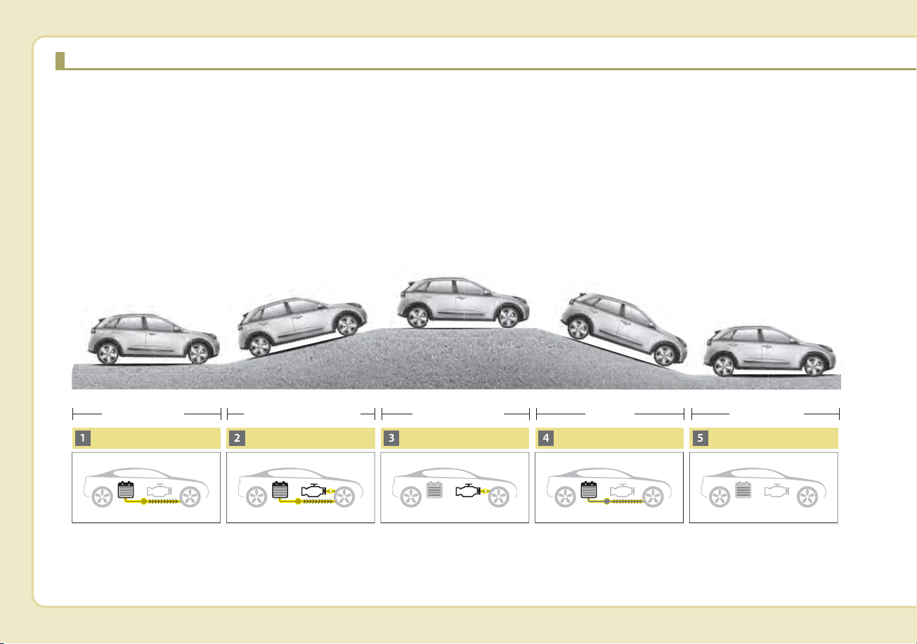
HEV (HYBRID ELECTRIC VEHICLE) SYSTEM
The Kia Hybrid Electric Vehicle (HEV) uses both the gasoline engine and the electric motor for power. The electric
motor is run by a 240V high-voltage HEV battery.
Depending on the driving conditions, the HEV computer selectively operates between the engine and the electric
motor or even both at the same time.
Fuel efficiency increases when the engine is at idle, or when the vehicle is driven by the electric motor with the HEV
battery.
The HEV battery charge must be maintained because, at times, the engine may come on even at idle to act as a gen-
erator. Charging also occurs when decelerating or by regenerative braking.
ODEP057140L
Startup/Low speed
cruise
Acceleration High speed cruise
Deceleration
Stop
Electric motor
Electric motor+Engine
Engine+
Motor or Motor
Charging
Engine OFF
H3
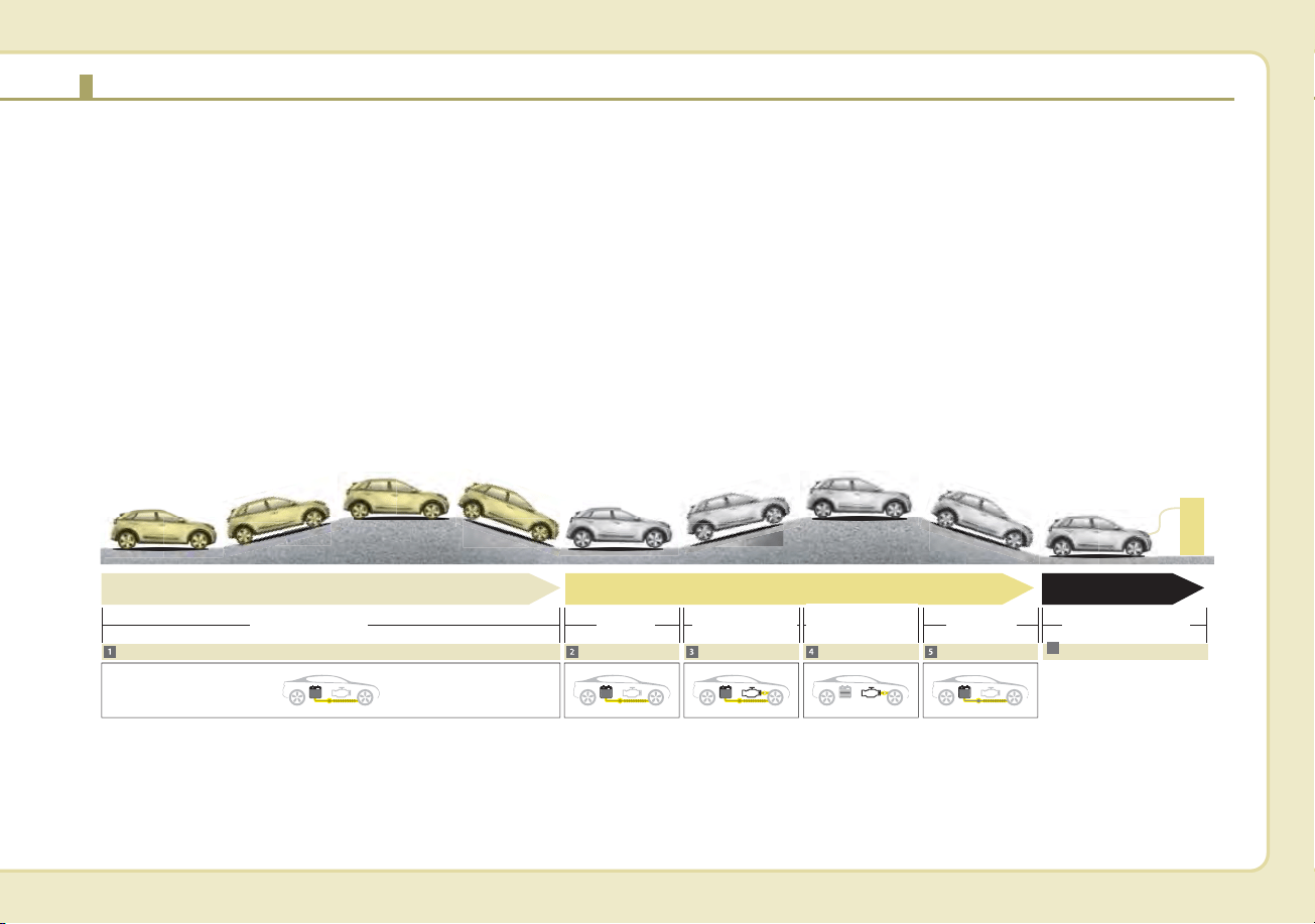
PHEV (PLUG-IN ELECTRIC VEHICLE) SYSTEM
The Kia Plug-in Hybrid Electric Vehicle (PHEV) shares the characteristics of both a conventional hybrid electric vehi-
cle and an all-electric vehicle.
When used as a conventional hybrid electric vehicle, the HEV computer selectively operates between the engine and
the electric motor or even both at the same time.
When it is operating in the electric vehicle mode, the vehicle is driven only using the electric motor over a certain dis-
tance until the hybrid battery becomes low. The driving distance in EV mode depends on customer driving style and road
conditions. Aggressive driving maneuvers may at times temporarily enable the engine to operate for maximum power.
The hybrid battery can be fully charged by connecting a plug to an external electric power source.
The engine can be turned on based on a number of factors such as heater usage and a frequent operation of the
accelerator pedal by a driver in Charge Depleting mode.
ODEP057141L
Electric Vehicle Mode
Start up/Low speed
Acceleration High speed
Deceleration
External charging
Electric motor
CD (Charge Depleting) Mode
CS (Charge Sustaining) Mode
Charging
Motor
Engine+Motor
Engine+Motor
or Motor
Charging
Battery charging
6
H4
Charging Information
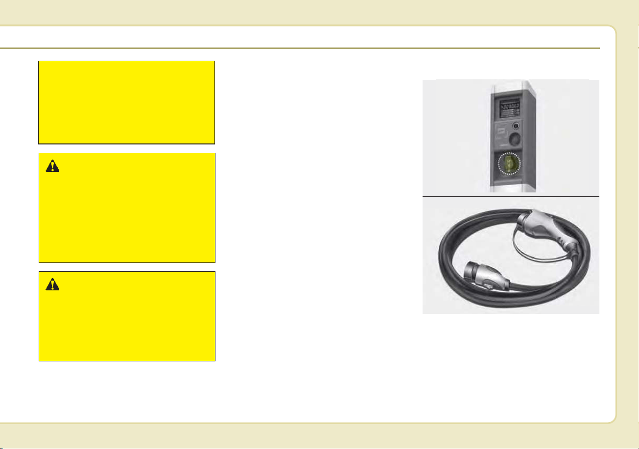
• AC Charger: The plug-in hybrid
vehicle is charged by plugging into
a AC Charger installed in your
home or a public charging station.
(For further details, refer to the 'AC
Charge'.)
• Trickle Charger: The plug-in hybrid
vehicle can be charged by using
household electricity.
The electrical outlet in your home
must comply with regulations and
can safely accommodate the
Voltage / Current (Amps) / Power
(Watts) ratings specified on the
trickle charge. Use only as a back-
up charger.
Charging Time
• AC Charger: Takes about 2 hours
15 minutes at room temperature
(Can be charged to 100%.).
Depending on the condition and
durability of the high-voltage bat-
tery, charger specifications, and
ambient temperature, the time
required for charging the high-volt-
age battery may vary.
• Trickle Charger: For charging at
home. Please note that the Trickle
Charger is slower than the AC
Charger.
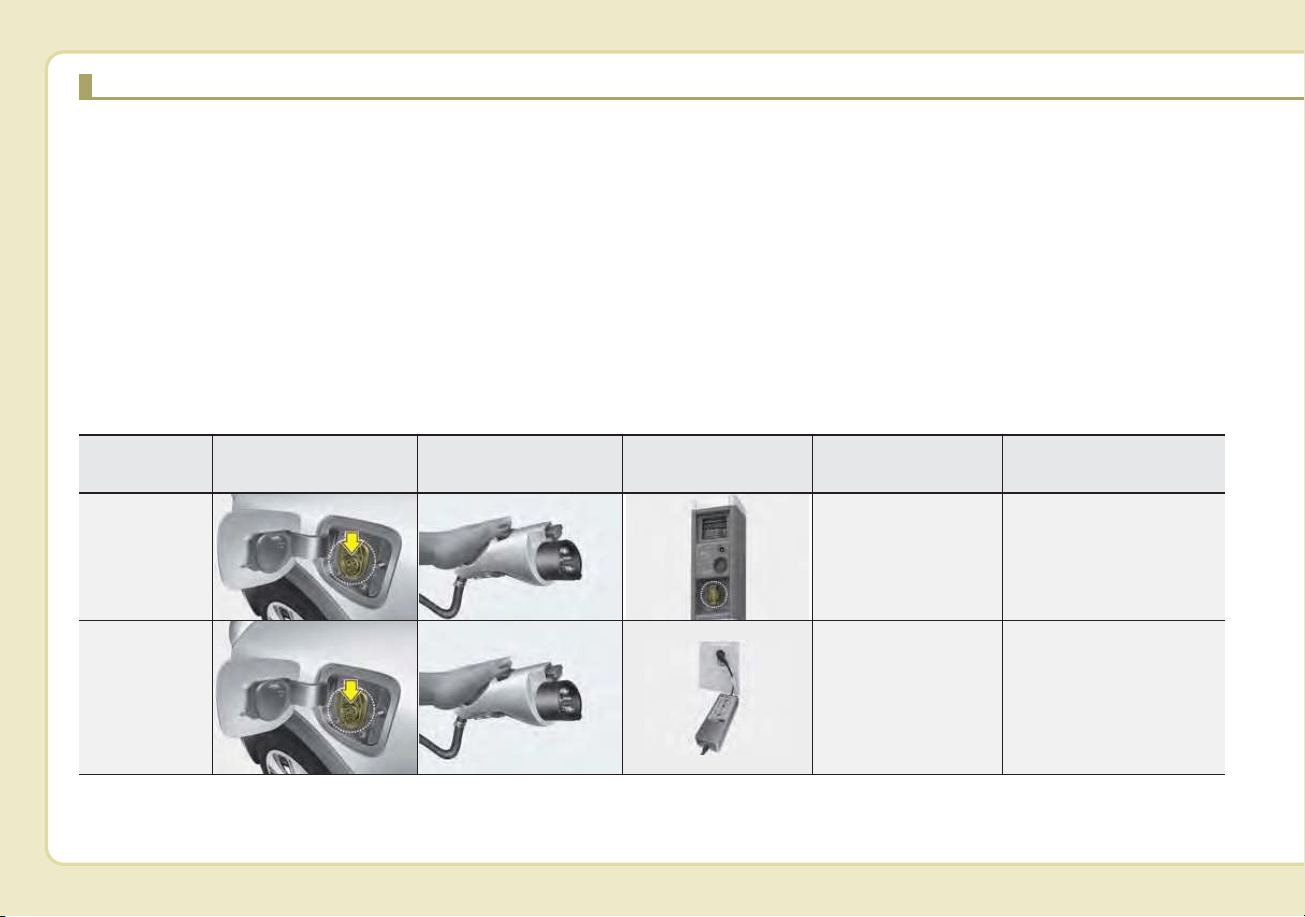
CHARGING THE PLUG-IN HYBRID VEHICLE
Charging Types
• Depending on the condition and durability of the high voltage battery, charger specifications, and ambient temper-
ature, the time required for charging the high voltage battery may vary.
• Actual charger image and charging method may vary in accordance with the charger manufacturer.
Category
Charging Inlet
(Vehicle)
Charging Connector Charging Outlet Charging Method Charging Time
AC Charger
AC Charger
installed in homes
or public charging
stations
Approximately 2 hours
15 minutes (to fully
charge the plug-in
hybrid,100%)
Trickle
Charger
Household current
For charging at home.
The included Trickle
charger takes about 9
hours at room tempera-
ture (Can be charged to
100%.).
ODEPQ017018
ODEPQ017019
ODEPQ017019
OAEEQ016024
OJFHPQ016021L
ODEPQ017018
H5
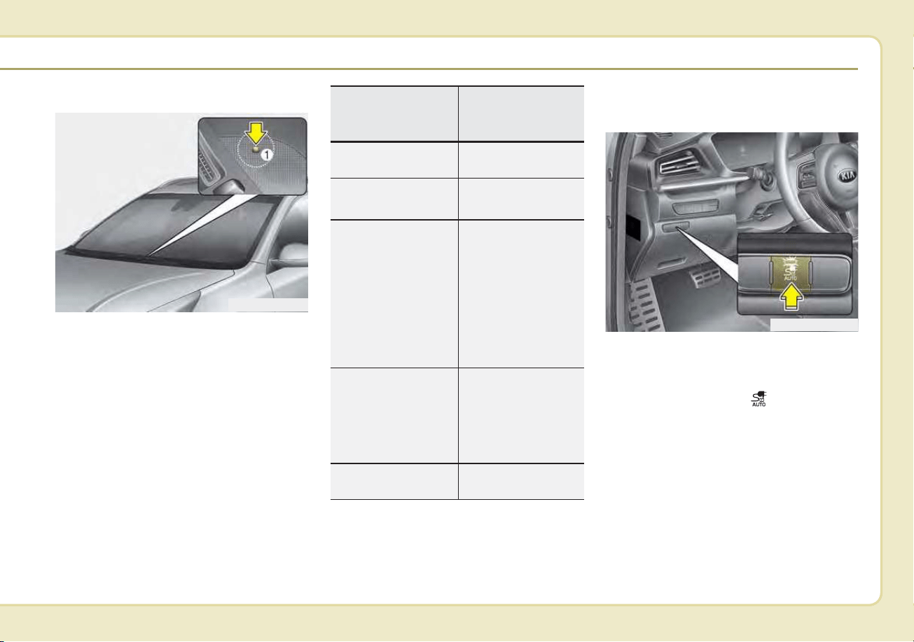
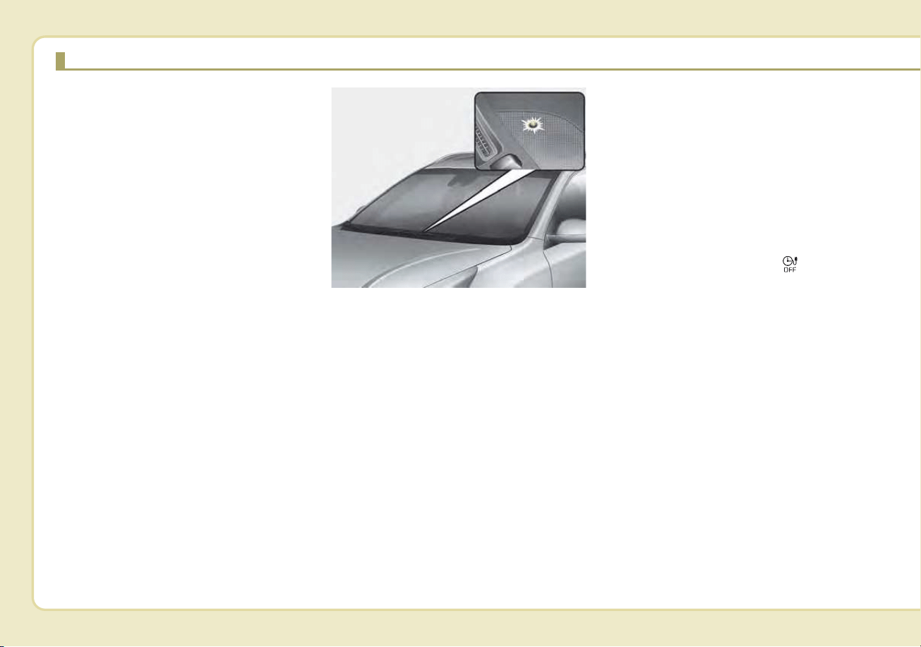
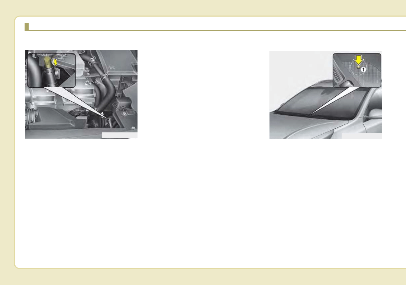
Charging Status
You can check the charging status
from the outside of vehicle when
charging or using (it is not driving
status) the high-voltage battery.
➀ : Charging indicator lamp
Charging Connector
AUTO/LOCK Mode
You may select when the charging
connector can be locked and
unlocked in the charging inlet.
Press the button to change
between AUTO mode and LOCK
mode.
ODEP047020N
ODEPQ019021L
Operation of
Charging Indicator
Lamp (1)
Charging Status
Turns on (Green)
Charging in
progress
Turns off
Not Charging or
fully charged
Slowly blinks
(Green) and then
turns off (repeat
for 3 minutes)
Reserved charging
is operating (turns
OFF after 3 min-
utes) or interrup-
tions that temporari-
ly prevent charging
(e.g. power failure)
Quickly
blinks(Green) and
then turns off
(repeats during
operation)
Aux. Battery Saver
+ operating in
progress
Slowly blinks (Red) Malfunction
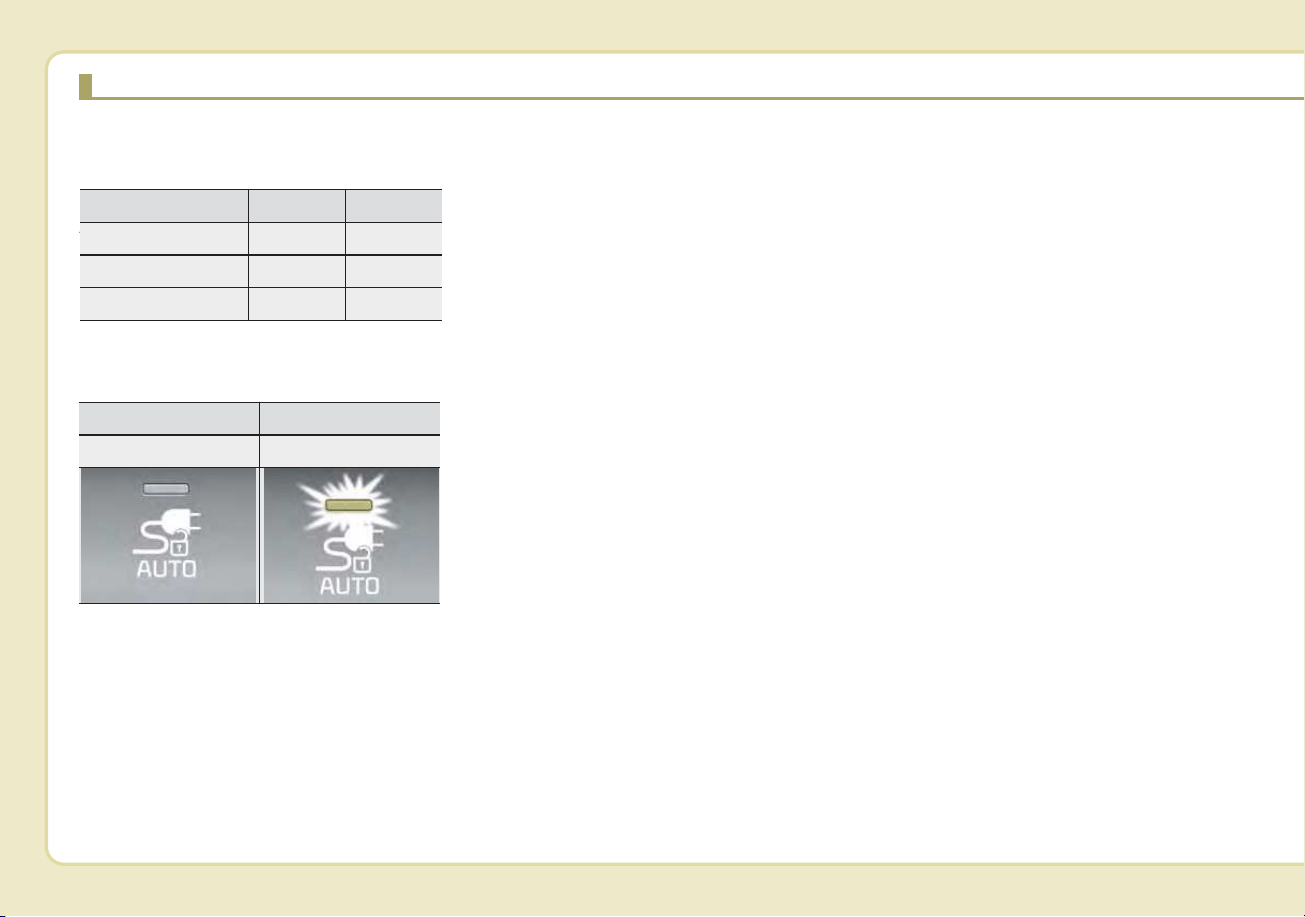
H6
When the Charging Connector
is Locked
AUTO/LOCK mode button indi-
cator
AUTO/LOCK mode button indica-
tor
• LOCK mode (button indicator off) :
The connector locks when the
charging connector is plugged into
the charging inlet. The connector is
locked until all doors are unlocked
by the driver.This mode can be used
to prevent charging cable theft.
- If the charging connector is
unlocked when all doors are
unlocked, but the charging cable
is not disconnected within 15 sec-
onds, the connector will be auto-
matically locked again.
- If the charging connector is
unlocked when all doors are
unlocked, but all doors are locked
again, immediately, the connector
will be automatically locked again.
• AUTO mode (button indicator on) :
The connector locks when charg-
ing starts. The connector unlocks
when charging is complete. This
mode can be used when charging
in a public charging station.
If the connector does not unlock
automatically after the charging is
completed in AUTO mode, the con-
nector will unlock when all the
doors are unlocked.
❈
❈
Charging connector
AUTO/LOCK mode
When the charging connector is
plugged into the charging inlet, the
connector lock timing varies with the
modes selected by pressing the but-
ton.
• LOCK mode : The connector locks
automatically when the charging
connector is connected normally.
• AUTO mode : The connector locks
when charging and automatically
unlocks when charging is complet-
ed.
❈For more details, refer to the
“Charging connector AUTO/LOCK
mode”.
❈ Locking/unlocking the charging
door
CHARGING THE PLUG-IN HYBRID VEHICLE (CONT.)
LOCK AUTO
Before charging O X
While charging O O
Finished charging O X
LAMP OFF LAMP ON
LOCK mode AUTO mode

H7
The charging door lock/unlock func-
tion works only when the following
conditions are satisfied with the
charging door closed.
If the unlock function does not work,
use the emergency charging door
unlock method to unlock the charg-
ing door. (For more details, refer to
the “Unlock charging door in emer-
gency”)
1. Conditions for lock :
➀ : When locking doors from out-
side the vehicle with the
charging door closed.
➁ : When locking the driver’s door
using a mechanical key
➂ : When locking doors using a
smart key
➃ : When pressing the door
lock/unlock button on the front
door outside handle while the
smart key is detected and
doors are unlocked
➄ : When locking all vehicle doors
with the charging door closed.
(When locking doors with
functions such as spare key,
smart key, door lock button on
the outside door handle, cen-
tral door lock switch, auto door
lock.)
2. Conditions for unlock :
➀ : When unlocking doors from
outside the vehicle with the
charging door closed.
➁ : When unlocking the driver’s
door using a mechanical key
➂ : When unlocking doors using a
smart key
➃ : When pressing the door
lock/unlock button on the front
door outside handle while the
smart key is detected and
doors are locked
➄ : When unlocking all vehicle
doors with the charging door
closed. (When unlocking doors
with functions such as spare
key, smart key, door lock but-
ton on the outside door han-
dle, central door lock switch,
auto door lock.)
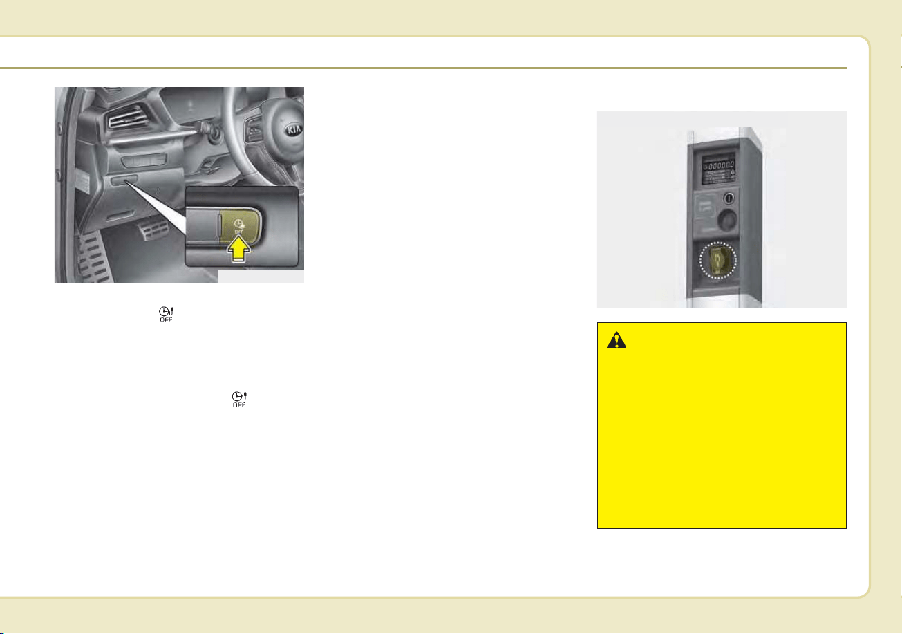
H8
Scheduled Charging
(if equipped)
• You can set reserved charging
using the Infotainment System.
Refer to the Infotainment System
for detailed information about set-
ting reserved charging.
• Scheduled charging can only be
done when using a AC Charger or
the portable charging cable (ICCB:
In-Cable Control Box).
• When scheduled charging is set
and the AC Charger or the portable
charging cable (ICCB: In-Cable
Control Box) is connected for
charging, the indicator lamp blinks
(for 3 minutes) to indicate that
scheduled charging is set.
• When scheduled charging is set,
charging is not initiated immediate-
ly when the AC Charger or
portable charging cable (ICCB: In-
Cable Control Box) is connected.
• If charging is required immediately,
turn off the scheduled charge
using the Infotainment System or
UVO eco smartphone application
or press the vehicle's scheduled
charge release button( ).
• When the scheduled charge is set,
the charge start time is calculated
by itself. In some cases, charging
may start immediately after con-
necting the charger.
CHARGING THE PLUG-IN HYBRID VEHICLE (CONT.)
ODEPQ017023
H9
• If you press the scheduled charging
deactivation ( ) button to immedi-
ately charge the battery, charging
must be initiated 3 minutes after the
charging cable has been connected.
When you press the scheduled
charging deactivation ( ) button
for immediate charging, the sched-
uled charge setting is not com-
pletely deactivated. If you need to
completely deactivate the sched-
uled charge setting, use the
Infotainment System to finalize the
deactivation.
Refer to "AC Charge or Trickle
Charge" for details about connect-
ing the AC Charger and the
portable charger (ICCB: In-Cable
Control Box).
Charging Precautions
ODEPQ019022
OJFHPQ016021L
■ AC Charger
WARNING
-
Fires caused by dust or
water
Do not connect the charging
cable connector plug to the vehi-
cle if there is water or dust on the
charging inlet. Connecting while
there is water or dust on the
charging cable connector and
plug may cause a fire or electric
shock.
H10
• Comply with the following in order
to prevent electrical shock when
charging:
- Use a waterproof charger
- Make sure to not touch the charg-
ing connector and charging plug
when your hand is wet
- Do not charge when there is light-
ning
- Do not charge when the charging
connector and plug is wet
WARNING
-
Interference with electron-
ic medical devices
When using medical electric
devices such as an implantable
cardiac pacemaker, make sure to
ask the medical team and manu-
facturer whether charging your
electric vehicle will impact the
operation of the medical
devices. In some instances, elec-
tromagnetic waves that are gen-
erated from the charger can seri-
ously impact medical electric
devices such as an implantable
cardiac pacemaker.
WARNING
-
Touching the charging
connector
Do not to touch the charging
connector, charging plug, or the
charging inlet when connecting
the charger connecting cable to
the charging outlet and the
charging inlet on the vehicle.
Doing so may result in electro-
cution.
WARNING
-
Old or Worn out Electric
Outlets
Do not use old or worn out elec-
tric outlets to charge your vehi-
cle. There may be a risk of fire
and injury when using old worn
out public electrical outlets.
CHARGING THE PLUG-IN HYBRID VEHICLE (CONT.)
WARNING - Charging
cable
• Immediately stop charging
when you discover abnormal
symptoms (smell, smoke).
• Replace the charging cable if
the cable coating is damaged
to prevent electrical shock.
• When connecting or removing
the charging cable, make sure
to hold the charging connec-
tor handle.
(Continued)
H11
• Always keep the charging connec-
tor and charging plug clean and
dry. Be sure to keep the charging
cable in a condition where there is
no water or moisture.
• Before charging the battery, turn
the vehicle OFF.
• Be careful not to drop the charging
connector. The charging connector
can be damaged.
• Always inspect the charging con-
nector terminals for damage or
overheating. Do not use if dam-
aged, as this may damage the
vehicle side charge connector and
is not a warrantable repair.
AC Charge
You can charge your vehicle by plug-
ging into a public charger at a charg-
ing station.
WARNING - Cooling fan
Do not touch the cooling fan
while vehicle is charging. When
the vehicle is switched OFF
while charging, the cooling fan
inside the engine compartment
or interior rear seat may auto-
matically operate.
OJFHPQ016021L
OAEEQ016028
■ AC Charger
■ AC Charger cable
WARNING
Make sure to use the designat-
ed charger for charging the
vehicle.Using any other charger
may cause failure or lead to
electric shock or fire.
(Continued)
If you pull the cable itself
(without using the handle), the
internal wires may disconnect
or get damaged.This may lead
to electric shock or fire.
H12
How to Connect to an AC charger
1. Depress the brake pedal and
apply the parking brake.
2. Turn OFF all switches, move the
shift lever to P (Park), and turn
OFF the vehicle.
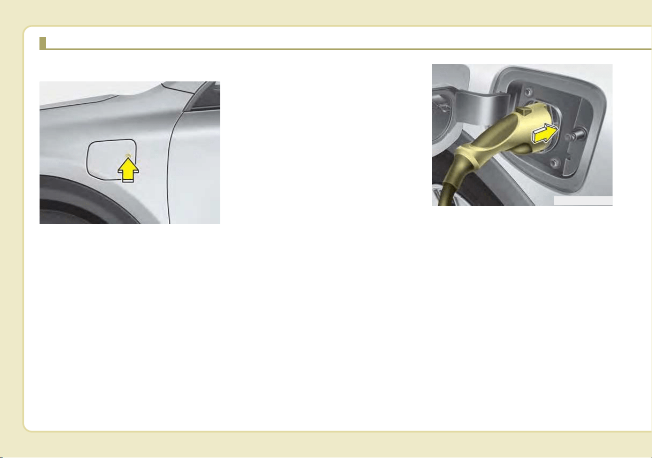
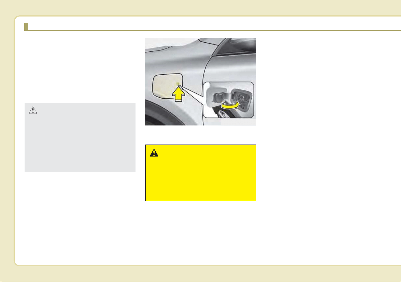
3. After unlocking doors, open the
charging door by pressing it.
4. Open the charging door by press-
ing circle mark (o) area on the
right edge of the charging door.
If the vehicle doors are locked, the
charging door will not open.
✽✽
NOTICE
The charging door does not open if
the door are locked/theft alarm sys-
tem is armed.
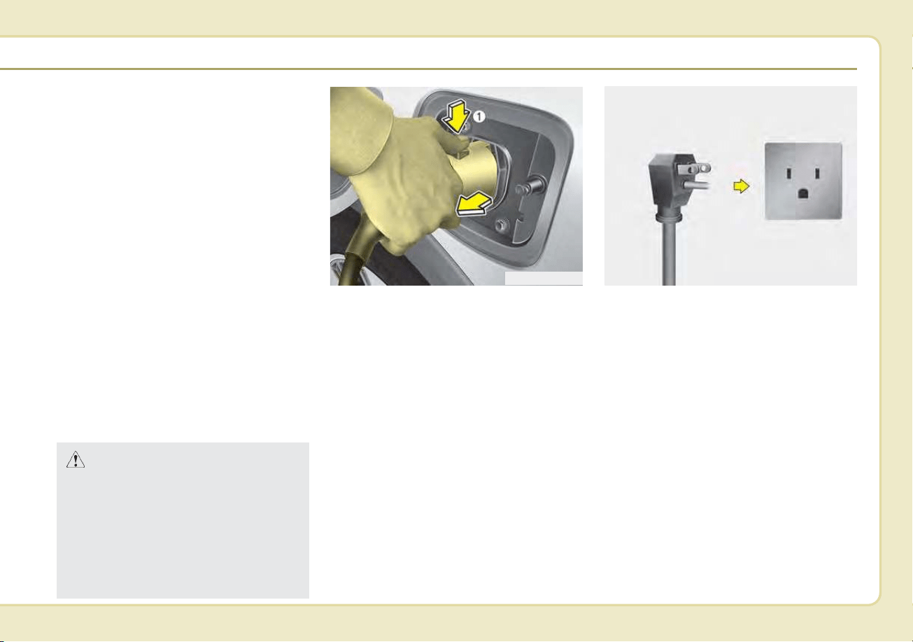
5. Remove any dust on the charging
connector and charging inlet.
6. Hold the charging connector han-
dle. Then, insert it into the charg-
ing inlet, until you hear a click
sound. If it is not fully connected, a
bad connection between the
charging connector and the charg-
ing terminals may cause a fire.
CHARGING THE PLUG-IN HYBRID VEHICLE (CONT.)
ODEPQ019025
ODEPQ017026

H13
7. Check if the charging cable con-
nection indicator of the high volt-
age battery in the instrument clus-
ter is turned ON.
Charging does not occur when the
indicator is OFF. When the charg-
ing connector is not connected
properly, reconnect the charging
cable to charge.
✽✽
NOTICE
• Charging is in progress only when
the shift lever is in P (Park).
Charging the battery with the
Engine Start/Stop button in the
ACC position is possible. However,
it may discharge the 12-V battery.
Thus, if possible, charge the bat-
tery with the Engine Start/Stop
button in the OFF position.
• The charging process is interrupt-
ed temporarily when the shift lever
is moved from P (Park) to Not P(R
(Reverse)/N (Neutral)/D (Drive))
during charging. To resume(restart)
charging, move the shift lever to the
P (park) position. Then, the charging
process is resumed(restarted).
8. After charging has started, the
estimated charging time is dis-
played on the instrument cluster
for about 1 minute. It is also dis-
played, when the driver’s door is
opened with charging in progress.
When scheduled charging is set,
the estimated charging time is dis-
played as “--” .
ODEPQ017028L
ODEPQ019027
ODEPQ019125
■ Type A
■ Type B
H14
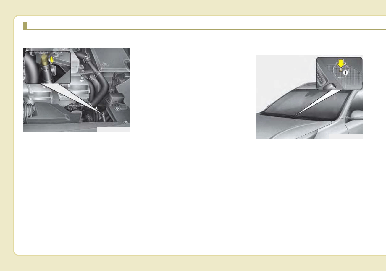
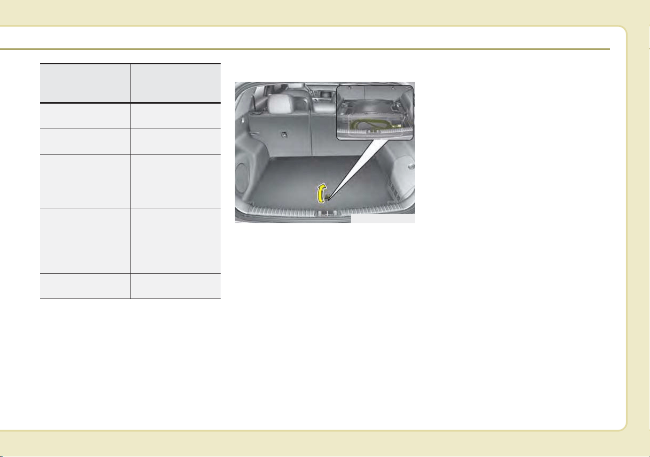
Unlock Connector in Emergency
If the charging connector does not
unlock for some reason, open the
hood and slightly pull the emergency
cable as shown above. The charging
door will then open.
If the charging door does not opened
immediately after pulling the emer-
gency cable in, press the charging
door lightly and pull the emergency
cable again.
The charging cable lock may not
work properly when foreign materials
such as dust enter the cable or the
cable is encrusted with ice.
In that case, the charging cable may
not be disconnected or locked, or the
vehicle may not be charged. If this
happens, open the hood and pull the
emergency cable lightly 2 to 3 times
and then try to disconnect the charg-
ing cable or start recharging.
Charging Status
Checking Charging Status
You can check the charging status
from outside of vehicle when charg-
ing the high-voltage battery.
CHARGING THE PLUG-IN HYBRID VEHICLE (CONT.)
ODEPQ017029
ODEP047020N
H15
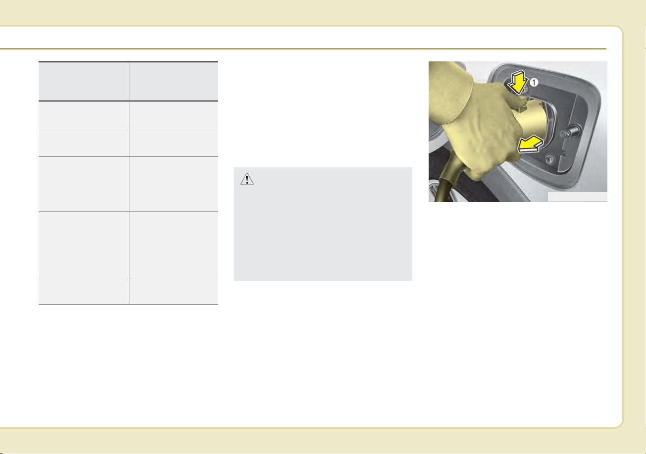
How to Disconnect an AC charger
1.The vehicle must be in the AUTO
mode or the doors must be
unlocked in order to be able to dis-
connect the charging connector. A
lock system prevents charger
cable disconnection when the vehi-
cle's doors are locked.
2.While holding the charging con-
nector, pressing the locking
release button (1) and then pull it
out.
To prevent charging cable theft, the
charging connector cannot be dis-
connected from the inlet when the
doors are locked. Unlock all doors
to disconnect the charging connec-
tor from the inlet.
However, if the vehicle is in the
charging connector AUTO mode,
the charging connector automati-
cally unlocks from the inlet when
charging is completed.
ODEPQ017031
CAUTION
In order to disconnect the
charging connector, unlock the
doors to unlatch the charging
connector lock system. If not,
the charging connector and the
vehicle's charging inlet may be
damaged.
Operation of
Charging Indicator
Lamp (1)
Charging Status
Turns on (Green)
Charging in
progress
Turns off
Not Charging or
fully charged
Slowly blinks
(Green) and then
turns off (repeat
for 3 minutes)
Waiting for sched-
uled charging
(turns off after 3
minutes)
Quickly
blinks(Green) and
then turns off
(repeats during
operation)
Aux. Battery Saver
+ operating in
progress
Slowly blinks (Red) Malfunction
H16
If the connector does not unlock
automatically after the charging is
completed in AUTO mode, the con-
nector will unlock when all the
doors are unlocked.
For more details, refer to “Charging
Connector AUTO/ LOCK Mode” in
this chapter.
3. Make sure to securely close the
charging door.
✽✽
NOTICE
• Keep the charging connector and
the charging plug clean and dry.
The charging cable should also be
kept dry.
• Use an air gun to blow any foreign
substances from the charging con-
nector and the charging plug.
ODEPQ019032
WARNING
Do not modify or disassemble
the charging cable compo-
nents. Doing so may cause a
fire or electric shock resulting
in personal injuries.
CAUTION
When disconnecting the charg-
ing connector, do not try to dis-
connect it by force while not
pressing the release button.
This may damage the charging
connector and vehicle charging
inlet.
CHARGING THE PLUG-IN HYBRID VEHICLE (CONT.)
H17
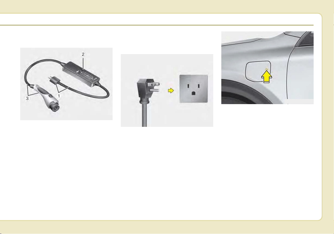
Trickle Charger
(Portable Charging Cable)
Trickle charger can be used if AC
Charger is unavailable.
❈➀: Plug and cable
➁ : Control box (ICCB)
➂ : Charging connector/cable
How to Connect Portable
Charging Cable
(ICCB: In-Cable Control Box)
1. Turn OFF all switches, move the
shift lever to P (Park), and turn
OFF the vehicle.
2. Depress the brake pedal and
apply the parking brake.
3. After unlocking doors, open the
charging door by pressing it.
4. Open the charging door by press-
ing circle mark (o) area on the
right edge of the charging door.
If the vehicle doors are locked, the
charging door will not open.
OAEEQ016042
ODEPQ019025
OJFHPQ016015N
H18
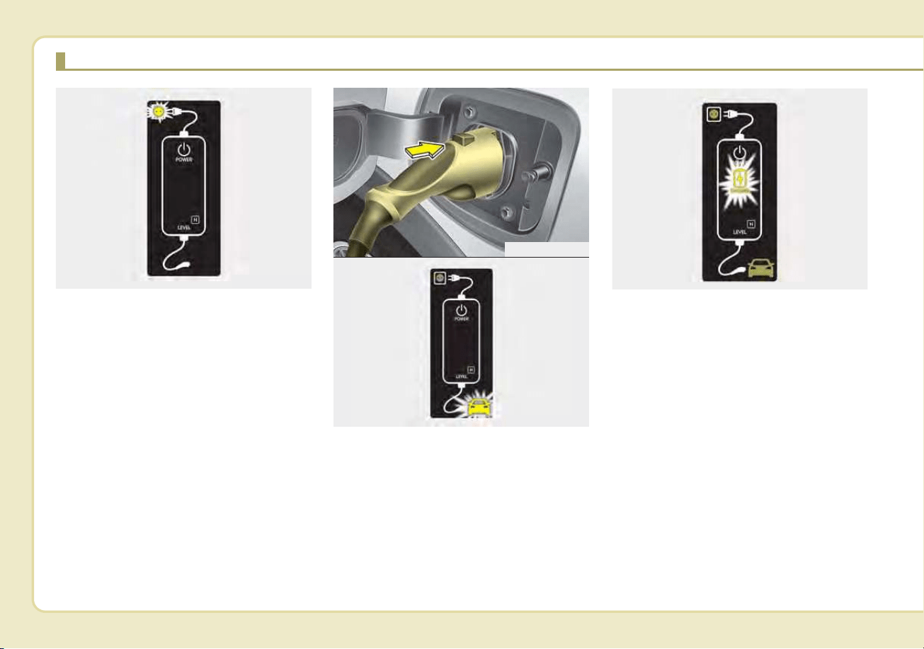
5. Connect the plug to a household
electric outlet.
6. Make sure that the power connec-
tion indicator (green) lights in the
control box.
✽✽
NOTICE
The charging door does not open
when the theft alarm system is
armed.
7. Remove any dust on the charging
connector and charging inlet.
8. Hold the charging connector han-
dle.Then, insert it into the charging
inlet, until you hear a click sound. If
it is not fully connected, improper
connection between the charging
connector and the charging termi-
nals are a potential fire hazard.
9. Charging starts automatically and
the charging light blinks.
ODEPQ017047
CHARGING THE PLUG-IN HYBRID VEHICLE (CONT.)
ODEPQ017049
ODEPQ017048
■ Vehicle connection
ODEPQ017035
■ Charge
H19
10. Check if the charging cable con-
nection indicator of the high volt-
age battery in the instrument
cluster is turned ON.
Charging does not occur when the
indicator is OFF. When the charg-
ing connector is not connected
properly, reconnect the charging
cable to charge.
✽✽
NOTICE
• The charging is in progress only
with the shift lever is in P (Park).
Charging the battery with the
Engine Start/Stop button in the
ACC position is possible. However,
it may discharge the 12-V battery.
Thus, if possible, charge the bat-
tery with the Engine Start/Stop
button in the OFF position.
• Moving the shift lever from P
(Park) to R (Reverse)/N(Neutral)/D
(Drive) stops the charging process.
To restart the charging process,
move the shift lever to P (Park),
press the Engine Start/Stop button
to the OFF position, and discon-
nect the charging cable. Then,
connect the charging cable and
restart the vehicle again.
11. After charging has started, the
estimated charging time is dis-
played on the instrument cluster
for about 1 minute. It is also dis-
played, when the driver’s door is
opened with charging in progress.
When scheduled charging is set,
the estimated charging time is dis-
played as "--".
ODEPQ019027
ODEPQ019125
■ Type A
■ Type B
ODEPQ017028L
H20
Unlock Connector in Emergency
If the charging connector does not
unlock for some reason, open the
hood and slightly pull the emergency
cable as shown above. The charging
door will then open.
If the charging door does not opened
immediately after pulling the emer-
gency cable, press the charging door
lightly and pull the emergency cable
again.
The charging cable lock may not
work properly when foreign materials
such as dust enter the cable or the
cable is encrusted with ice.
In that case, the charging cable may
not be disconnected or locked, or the
vehicle may not be charged. If this
happens, open the hood and pull the
emergency cable lightly 2 to 3 times
and then try to disconnect the charg-
ing cable or start recharging.
Charging Status
You can check the charging status
from outside of vehicle when charg-
ing the high-voltage battery.
ODEPQ017029
CHARGING THE PLUG-IN HYBRID VEHICLE (CONT.)
ODEP047020N
H21
Charge cable storage
We recommend that the trickle
charger cable be put in a storage box
after use.
ODEPQ017033
Operation of
Charging Indicator
Lamp (1)
Charging Status
Turns on (Green)
Charging in
progress
Turns off
Not charged or
fully charged
Slowly blinks
(Green) and then
turns off (repeat
for 3 minutes)
Waiting for sched-
uled charging
(turns off after 3
minutes)
Quickly
blinks(Green) and
then turns off
(repeat during
operation)
Aux. Battery Saver
+ operating in
progress
Slowly blinks (Red) Malfunction
H22
CHARGING THE PLUG-IN HYBRID VEHICLE (CONT.)
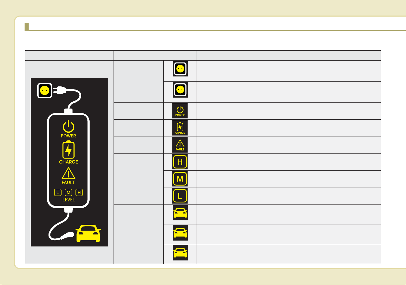
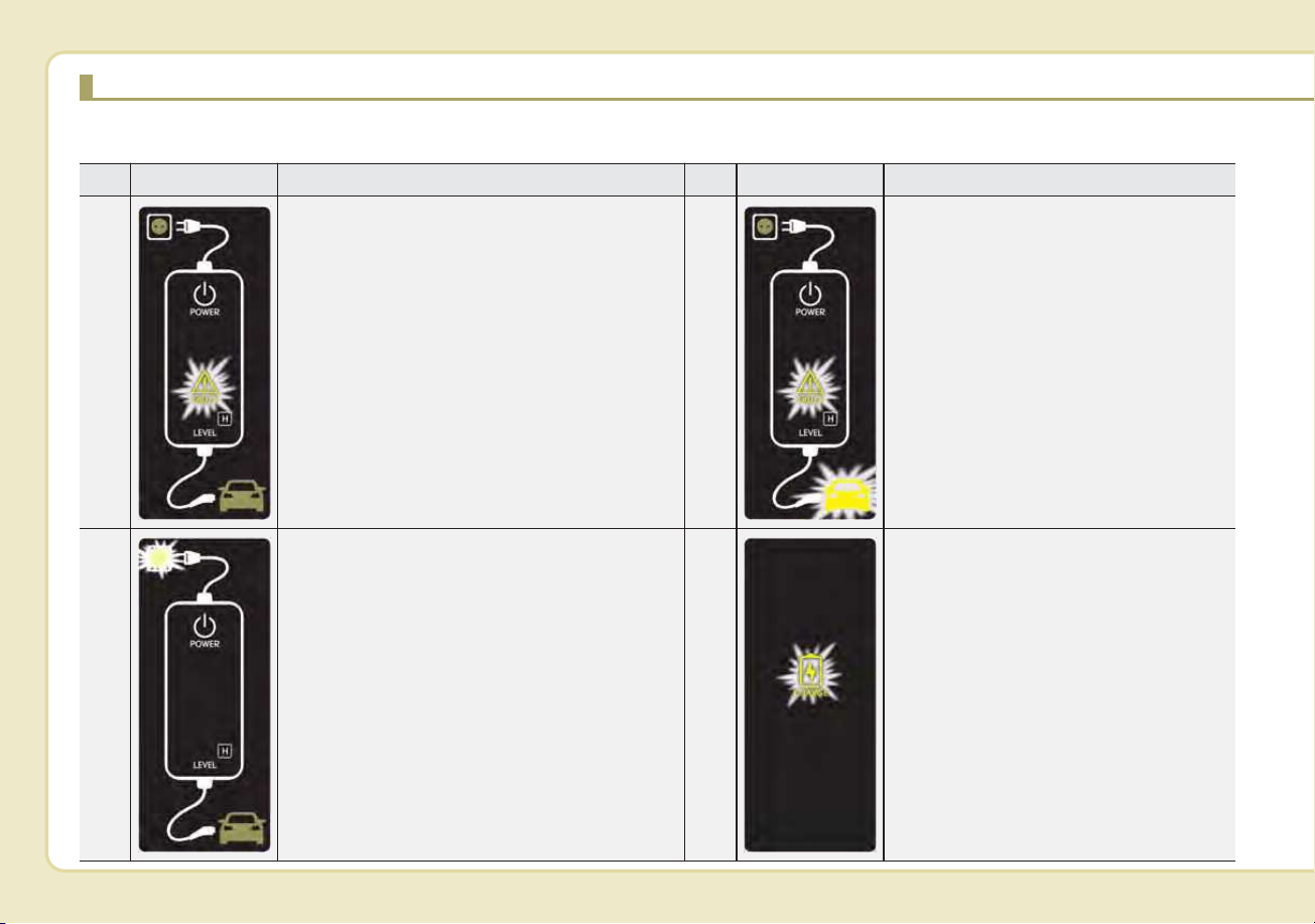
Charging Status Indicator Lamp for Portable Charging Cable
Control Box Indicator Details
PLUG
On : Power on
Blink : Plug temperature sensor failure
On : Plug high temperature protection
Blink : Plug high temperature warning
POWER On : Power on
CHARGE
Blink : Charging In power saving mode, only the CHARGE
indicator is illuminated.
FAULT Blink : Charging interrupted
CHARGE LEVEL
Charging current 12A
Charging current 10A
Charging current 8A
VEHICLE
Charging connector plugged
Charging
Blink : Not charging
(Green)
(Red)
(Green)
(Blue)
(Red)
H23
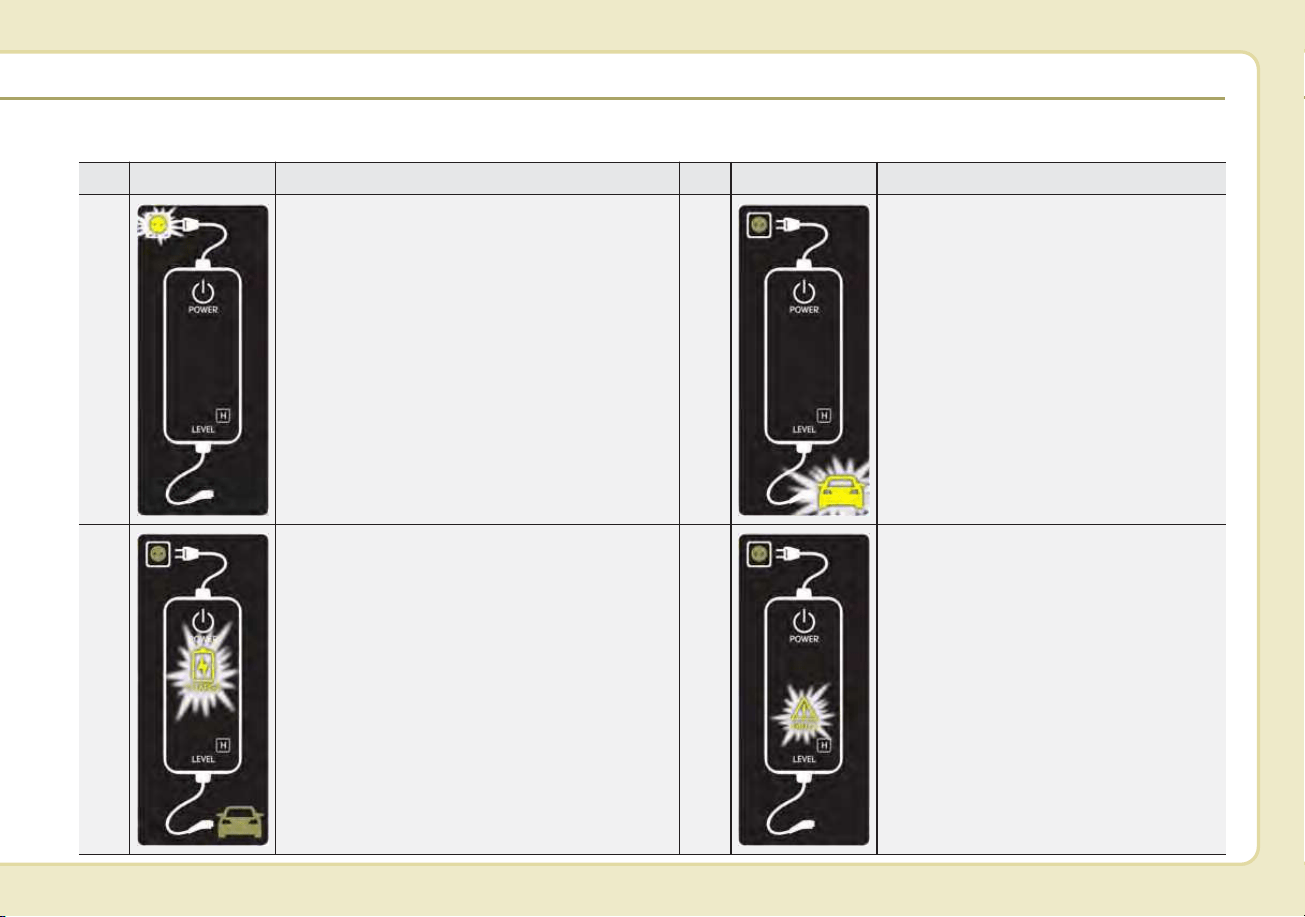
Charging Status Indicator Lamp for Portable Charging Cable
NO Control Box Status / Diagnosis / Countermeasure NO Control Box Status / Diagnosis / Countermeasure
1
Have your vehicle inspected by an authorized
Kia dealer if any of the following occur:
• Charging connector plugged into vehicle
(Green ON)
• Plug temperature sensor failure
(Green blink)
• Plug high temperature protection
(Red blink)
• Plug high temperature warning (Red ON)
2
- Charging connector plugged into the
vehicle (Green ON)
3
- While charging
• Charge indicator (Green blink)
• Vehicle indicator (Blue ON)
4
Have your vehicle inspected by an
authorized Kia dealer if any of the fol-
lowing occur:
- Before plugging charging connector
into the vehicle (Red blink)
• Abnormal temperature
• ICCB (In-Cable Control Box) failure
H24
CHARGING THE PLUG-IN HYBRID VEHICLE (CONT.)
NO Control Box Status / Diagnosis / Countermeasure NO Control Box Status / Diagnosis / Countermeasure
5
Have your vehicle inspected by an authorized
Kia dealer if any of the following occur:
- Plugged into the vehicle (Red blink)
• Diagnostic device failure
• Current leakage
• Abnormal temperature
6
- After plugging charging connector
into vehicle (Red blink)
• Communication failure
Have your vehicle inspected by an
authorized Kia dealer.
7
Have your vehicle inspected by an authorized
Kia dealer if any of the following occur:
• Plug temperature sensor failure
(Green blink)
• Plug high temperature protection
(Red blink)
• Plug high temperature warning (Red ON)
8
- Power saving mode
• 3 minutes after charging starts
(Green blink)
H25
How to Disconnect the Portable
Charging Cable (ICCB: In-Cable
Control Box)
1. Before disconnecting the charging
connector, make sure the doors are
unlocked. When the door is locked,
the charging connector lock system
will not allow disconnection. To pre-
vent charging cable theft, the
charging connector cannot be dis-
connected from the inlet when the
doors are locked. Unlock all doors
to disconnect the charging connec-
tor from the inlet. However, if the
vehicle is in the charging connector
AUTO mode, the charging connec-
tor automatically unlocks from the
inlet when charging is completed.
For more details, refer to “Charging
Connector AUTO/LOCK Mode” in
this chapter.
2. While holding the charging con-
nector, pressing the locking
release button(1) and then pull it
out.
3. Make sure to securely close the
charging door.
4. Disconnect the plug from the
household electric outlet. Do not
pull the cable when disconnecting
the plug.
5. Close the protective cover for the
charging connector so that foreign
material cannot get into the terminal.
6. Put the charging cable inside the
storage bag to protect it.
ODEPQ017031 OJFHPQ016015N
CAUTION
In order to disconnect the
charging connector, unlock the
doors to release the charging
connector lock system. If not,
the charging connector and the
vehicle's charging inlet may be
damaged.

H26
Precautions for Portable
Charging Cable
(ICCB: In-Cable Control Box)
• Use a portable charging cable that
is certified by Kia.
• Do not try to repair, disassemble, or
adjust the portable charging cable.
• Do not use an extension cord or
adapter.
• Stop using immediately if failure
warning light occurs.
• Do not touch the plug and charging
connector with wet hands.
• Do not touch the terminal part of the
AC Charging connector and the AC
Charging inlet on the vehicle.
• Do not connect the charging con-
nector to voltage that does not
comply with regulations.
• Do not use the portable charging
cable if it is worn out, exposed, or
there exists any type of damage on
the portable charging cable.
• If the ICCB case and AC Charging
connector is damaged, cracked, or
the wires are exposed in any way,
do not use the portable charging
cable.
• Do not let children operate or touch
the portable charging cable.
• Keep the control box free of water.
• Keep the AC Charging connector or
plug terminal free of foreign sub-
stances.
• Do not step on the cable or cord.
Do not pull the cable or cord and
do not twist or bend it.
• Do not charge when there is light-
ning.
• Do not drop the control box, charg-
ing connector, or place a heavy
object on the control box.
• Do not place an object that can
generate high temperatures near
the charger when charging.
• Charging with a worn out or dam-
aged household electric outlet can
result in a risk of electric shock. If
you are unsure about the condition
of a household electric outlet, have
it checked by a licensed electri-
cian.
• Stop using the portable charging
cable immediately if the household
electric outlet or any components
are overheating or you smell burn-
ing.
CHARGING THE PLUG-IN HYBRID VEHICLE (CONT.)

H27
Action to be taken when
charging stops abruptly
When the high voltage battery does
not charge, check the followings:
1. Check the charging setting for the
vehicle.
(e.g. When scheduled charging is
set, charging is not initiated imme-
diately when the AC charger or
portable charger (ICCB: In-Cable
Control Box) is connected.)
2. Check the operation status of AC
charger, portable charger.
(Charging Status Indicator Lamp
for Portable Charger, refer to
“Checking Charging Status” for
trickle charge in this chapter.)
❈ Actual method for indicating the
charging status may vary in accor-
dance with the charger manufac-
turer.
3. When the vehicle does not charge
and a warning message appears
on the cluster, check the corre-
sponding message. Refer to “LCD
Display Messages”, in this chap-
ter.
4. If the vehicle is properly charged
when charged with another nor-
mally working charger, contact the
charger manufacturer.
5. If the vehicle does not charge
when charged with another nor-
mally working charger, we recom-
mend that you contact an author-
ized Kia dealer.
H28
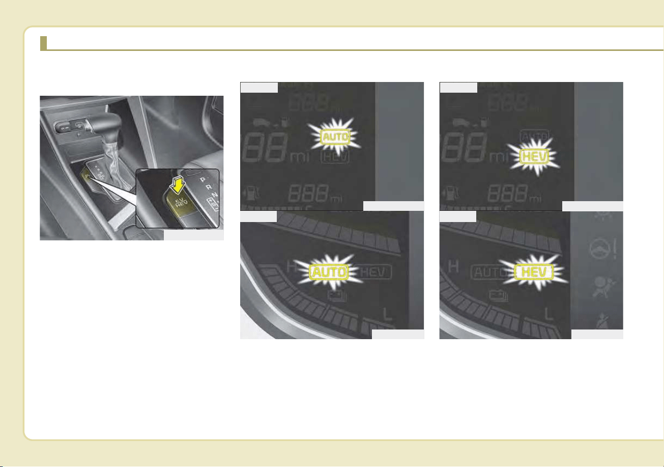
Changing plug-in hybrid mode
(Plug-in hybrid vehicle)
■ EV/HEV Button
Whenever you press the [EV/HEV]
button, Plug-in hybrid system drive
mode will be changed as follows:
Electric (CD) mode - Automatic
(AUTO) mode - Hybrid (CS) mode.
Each time the mode is changed a
corresponding LED is displayed on
the instrument cluster as follows;
Automatic (AUTO) mode Hybrid (CS) mode
DRIVING THE HYBRID/PLUG-IN HYBRID VEHICLE
ODEP059110N
ODEP059302
ODEP059301N
■ Type A
■ Type B
ODEP059304
ODEP059303N
■ Type A
■ Type B
H29
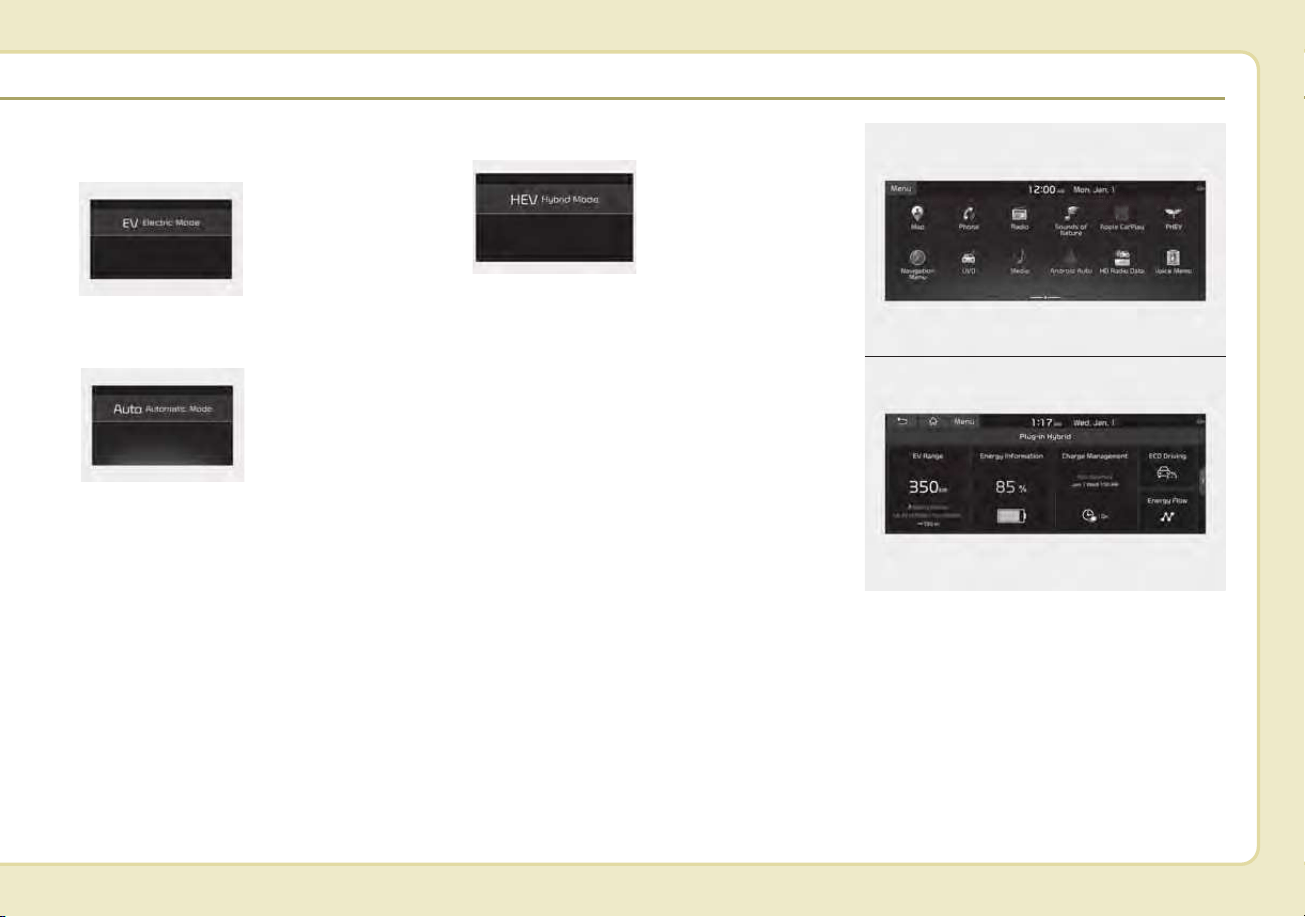
Plug-in hybrid mode message
• CD (Charge Depleting, Electric) mode
: The high-voltage
(hybrid) battery is
used to drive the
vehicle.
• AUTO (Automatic) mode
: The drive mode
will be automati-
cally selected
from either Electric
(CD) mode or
Hybrid (CS) mode
by the system
according to the
driving condition.
• CS (Charge Sustaining, Hybrid) mode
: The high-voltage
(hybrid) battery
and gasoline
engine are used to
drive the vehicle.
A corresponding message is dis-
played to indicate the selected mode.
■ ‘Infotainment System’ screen
Press [PHEV] on the [Home screen].
The Plug-in Hybrid menu consists of
five sections: [EV range], [Energy
information], [Charge management],
[ECO driving], [Energy flow].
For more information, please refer to
the Multimedia System Manual that
was separately supplied with your
vehicle.
ODEP049189L
ODEP049190L
ODEP049541L
ODEPQ019129C
ODEPQ019128C
H30
Warning and indicator lights
Ready Indicator
This indicator illuminates :
When the vehicle is ready to be driven.
- ON : Normal driving is possible.
- OFF : Normal driving is not possible,
or a problem has occurred.
- Blinking : Emergency driving.
When the ready indicator goes OFF
or blinks, there is a problem with the
system. In this case, have your vehi-
cle inspected by an authorized Kia
dealer.
Hybrid system warning
light
This warning light illuminates:
When there is a malfunction with the
hybrid system.
In this case, have your vehicle
inspected by an authorized Kia deal-
er.
When the warning light illuminates
while driving, or does not go OFF
after starting the vehicle, have the
system inspected by an authorized
Kia dealer.
EV Mode Indicator
This indicator illuminates when the
vehicle is driven by the electric motor.
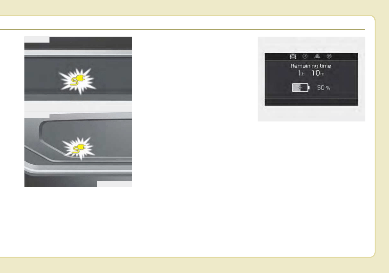
Charging Cable
Connection Indicator
(Plug-in hybrid vehicle)
This indicator illuminates in red when
the charging cable is connected.
EV
DRIVING THE HYBRID/PLUG-IN HYBRID VEHICLE (CONT.)

H31
Coasting guide (if equipped)
A chime will sound and the coasting
guide indicator will blink four times to
inform the driver when to take the foot
off from the accelerator by anticipat-
ing a decelerating event* based on
the analysis of driving routes and
road conditions according to the nav-
igation system. It encourages the
driver to remove foot from accelerator
pedal and allow coasting down the
road with EV motor only. This helps
prevent unnecessary fuel consump-
tion and increases fuel efficiency.
❈ Examples of a deceleration events
is going down an extended hill,
slowing down while approaching a
toll booth, and approaching
reduced speed zones.
• User settings
Press the Engine Start/Stop button
and put the shift lever in P(Park). In
the User Settings Mode, select
Driving Assist, Coasting Guide, and
then On to turn on the system.
Cancel the selection of coasting
guide to turn off the system. For the
explanation of the system, press and
hold the [OK] button.
• Operation conditions
To activate the system, take the fol-
lowing procedures. Enter your desti-
nation information on the navigation
and select the driving route. Then,
satisfy the following.
- The driving speed should be
between 37 mph (60 km/h) and 99
mph (160 km/h).
❈ The operating speed may vary due
to difference between instrument
cluster and navigation effected by
tire inflation level.
✽✽
NOTICE
Coasting guide is only a supplemen-
tal system to assist with fuel-efficient
driving. Thus, the operating condi-
tions may be different in accordance
with traffic/road conditions (i.e.
driving in a traffic jam, driving on a
slope, driving on a curve). Thus,
take the actual driving conditions
into consideration, such as distances
from the vehicles ahead/ behind,
while referring to the coasting guide
system as guidance.

H32
LCD Display Messages
Check Hybrid system
This message is displayed when
there is a problem with the hybrid
control system.
Refrain from driving when the warn-
ing message is displayed.
In this case, have your vehicle inspect-
ed by an authorized Kia dealer.
Check Hybrid system.
Turn off engine
This message is displayed when
there is a problem with the hybrid
system. The " " indicator will blink
and a warning chime will sound until
the problem is solved.
In this case, have your vehicle inspect-
ed by an authorized Kia dealer.
Check Hybrid system.
Do not start engine.
This message is displayed when the
hybrid battery power (SOC) level is
low. A warning chime will sound until
the problem is solved.
In this case, park the vehicle in a safe
location and have your vehicle
inspected by an authorized Kia dealer.
Stop vehicle and check power
Supply
This message is displayed when a
failure occurs in the power supply
system.
In this case, park the vehicle in a safe
location and have your vehicle
inspected by an authorized Kia dealer.
Refill inverter coolant
This message is displayed when the
inverter coolant is nearly empty.
You should refill the inverter coolant.
In this case, have your vehicle inspect-
ed by an authorized Kia dealer.
Stop vehicle and check brakes
This message is displayed when a
failure occurs in the brake system.
In this case, park the vehicle in a safe
location and have your vehicle
inspected by an authorized Kia dealer.
Check brakes
This message is displayed when the
brake performance is low or the
regenerative brake does not work
properly due to a failure in the brake
system.
In this case, it may take longer for the
brake pedal to operate and the brak-
ing distance may become longer.
DRIVING THE HYBRID/PLUG-IN HYBRID VEHICLE (CONT.)

H33
Refuel to prevent Hybrid battery
Damage
This message is displayed when the
fuel tank is nearly empty.
You should refill the fuel tank to pre-
vent hybrid battery damage.
Check Virtual Engine Sound
System
This message is displayed when
there is a problem with the Virtual
Engine Sound System (VESS).
In this case, have the system
inspected by an authorized Kia deal-
er.
Charging stopped. Check the
cable connection
This warning message is displayed
when charging is stopped because
the charging connector is not cor-
rectly connected to the charging inlet
In this case, separate the charging
connector and re-connect it and
check whether there is any problem
(external damage, foreign sub-
stances, etc.) with the charging con-
nector and charging inlet.
Remaining charge time
(Plug-in hybrid vehicle)
The message is displayed to notify
the remaining time to fully charge the
battery.
Charging stopped. Please check
the AC charger (Plug-in hybrid
vehicle)
This message is displayed when
there is a problem with the charger.
Low/High System Temp.
Maintaining Hybrid mode
(Plug-in hybrid vehicle)
This message is displayed when the
temperature of the high-voltage
(hybrid) battery is too low or too high.
This warning message is to protect
the battery and the hybrid system.
Low/High System Temp.
Switching to Hybrid mode
(Plug-in hybrid vehicle)
This message is displayed when the
temperature of the high-voltage
(hybrid) battery is too low or high.
This warning message is to protect
the battery and the hybrid system.

H34
Switching to Hybrid mode to allow
heating (Plug-in hybrid vehicle)
• When the coolant temperature is
lower than 57 °F (-14 °C), and you
turn the climate control On for
heating, this message will be dis-
played in the cluster. Then, the
vehicle will automatically switch to
HEV mode.
• When the coolant temperature is
higher than 57 °F (-14 °C), or you
turn the climate control Off, the
vehicle will automatically return to
EV mode.
Wait until fuel door opens
(Plug-in hybrid vehicle)
This message is displayed when you
attempt to open the fuel filler lid with
the fuel tank pressurized. Wait until
the fuel tank is depressurized.
✽✽
NOTICE
• It may take up to 20 seconds to
open fuel filler lid.
• When the fuel filler lid is frozen
and does not open after 20 seconds
at freezing temperature, slightly
tap the fuel filler lid and then
attempt to open it.
Fuel door open
(Plug-in hybrid vehicle)
This message is displayed when the
fuel filler lid is opened.
Also means "Ready to refuel".
Check fuel door
(Plug-in hybrid vehicle)
This message is displayed when the
fuel filler lid is open or an abnormal-
ity has occurred.
Charging Door Open
(Plug-in hybrid vehicle)
This message indicates that the
charging door is open.
(Driving with the charging door open
may result in moisture inflow or dam-
age.This message is used to prevent
such occurrences.)
DRIVING THE HYBRID/PLUG-IN HYBRID VEHICLE (CONT.)

H35
Unplug vehicle to start
(Plug-in hybrid vehicle)
This message is displayed when you
start the engine without unplugging
the charging cable. Unplug the
charging cable, and then start the
vehicle.
Maintaining Hybrid mode to con-
tinue heating
(Plug-in hybrid vehicle)
This message is displayed when
heat-ng is in operation and the HEV
mode is maintained to meet the
heating operating conditions when
attempting to switch to EV mode by
pressing the [EV/HEV] button.
EV / HEV modes
(Plug-in hybrid vehicle)
A corresponding message is dis-
played when a mode is selected by
pressing the [EV/HEV] button.
H36
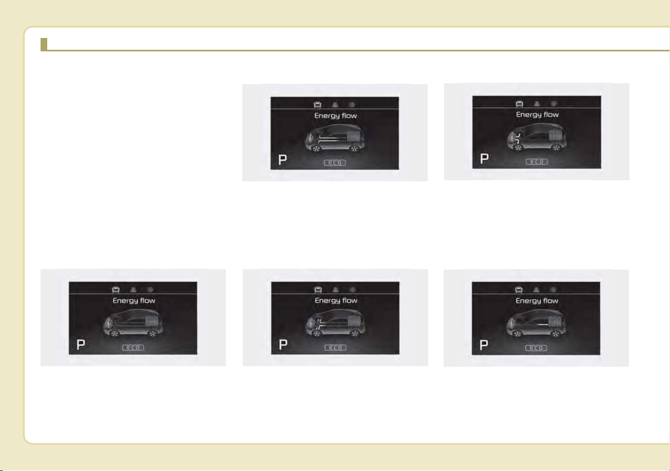
Kia hybrid system notifies the drivers
of energy flow in various operating
modes. Eleven Modes show drivers
the current operating condition.
Vehicle Stop
This mode means the vehicle is at a
stop. (There is no energy flow.)
EV Propulsion
Electric power is used to move the
vehicle.
(Battery ➞ Wheel)
Power Assist
Electric and Engine power are used
to move the vehicle.
(Battery & Engine ➞ Wheel)
Engine Only Propulsion
Engine power is used to move the
vehicle.
(Engine ➞ Wheel)
Engine Generation
Vehicle is stopped with the Engine
charging the hybrid battery.
(Engine ➞ Battery)
ENERGY FLOW
ODEP047202N
ODEP047203N
ODEP047204N
ODEP047205N
ODEP047201N
H37
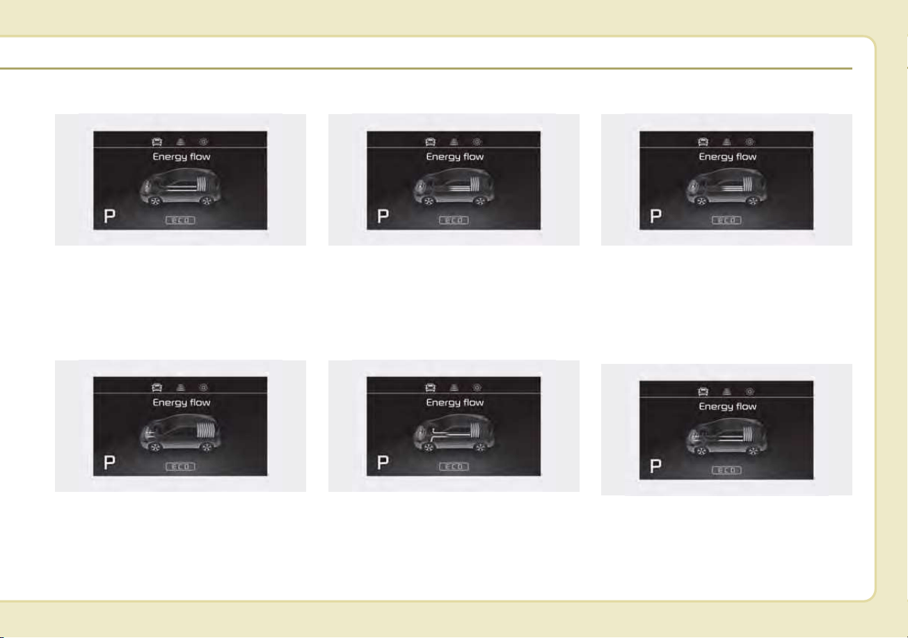
Regeneration
Hybrid battery is being charged by
regenerative braking.
(Wheel ➞ Battery)
Engine Brake
The vehicle is being slowed by
engine compression.
(Wheel ➞ Engine)
Power Reserve
Engine is both driving the vehicle
and charging the hybrid battery.
(Engine ➞ Wheel & Battery)
Engine Generation/Motor Drive
The vehicle is being slowed by engine
compression and regenerative brak-
ing. The hybrid battery is being
charged by regenerative braking.
(Engine ➞ Battery ➞ Wheel)
Engine Generation/Regeneration
The engine and regenerative braking
system charge the hybrid battery
driving deceleration.
(Engine & Wheel ➞ Battery)
Engine Brake/Regeneration
The engine compression can be
used to slow the vehicle. The regen-
erative braking system can be used
to charge the hybrid system.
(Wheel ➞ Engine & Battery)
ODEP047207N
ODEP047209N
ODEP047207N
ODEP047210N
ODEP047206N
ODEP047208N
H38
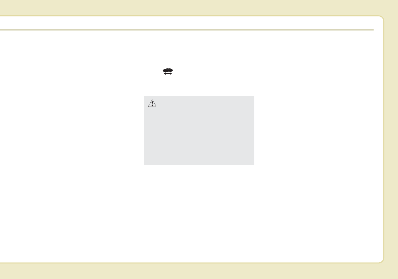
AUX. BATTERY SAVER+ (For
Plug-in Hybrid, if equipped)
The Aux. Battery Saver+ is a function
that monitors the charging status of
the 12V auxiliary battery.
If the auxiliary battery level is low, the
main high voltage battery charges
the auxiliary battery.
✽✽
NOTICE
The Aux. Battery Saver+ function will
be ON when the vehicle is delivered. If
the function is not needed, you may
turn it off in the Users Settings mode
on the LCD display. For more infor-
mation, refer to the "System setting"
on the following page.
Mode
• Cycle Mode :
When the vehicle is OFF with all
doors, hood and liftgate closed, the
Aux. Battery Saver+ periodically acti-
vates according to the auxiliary bat-
tery status.
• Automatic Mode :
When the engine start/stop button is
in the ON position with the charging
connector plugged in, this function
activates according to the auxiliary
battery status to prevent over-dis-
charge of the auxiliary battery.
✽✽
NOTICE
The Aux. Battery Saver+ activates
for a maximum of 20 minutes. If the
Aux. Battery Saver+ function acti-
vates more than 10 times consecu-
tively, in the Automatic Mode, this
function will stop activating, judg-
ing that there is a problem with the
auxiliary battery. In this case, drive
the vehicle for some period of time.
The function will start activating if
the auxiliary battery returns to nor-
mal.
✽
✽
NOTICE
If the Aux. Battery Saver+ function
was activated, the high voltage bat-
tery level may have decreased.
CAUTION
The Aux. Battery Saver+ func-
tion cannot prevent battery dis-
charge if the auxiliary battery is
damaged, worn out, used as a
power supply or if unauthorized
electronic devices are used.
PLUG-IN HYBRID ENERGY FLOW
H39
System setting
The driver can activate the Aux.
Battery Saver+ function by placing
the engine start/stop button to the
ON position and by selecting:
"User Settings ➞ Other Features ➞
Aux. Battery Saver+"
WARNING
The Aux. Battery Saver+ relies
on the high voltage battery to
charge the 12V battery. The
charging indicator lamp will blink
rapidly when this is occurring.
To reduce the risk of electrical
shock, do not touch any high
voltage components (orange-
colored) or other electrical
devices while charging is occur-
ring.
ODEPQ017051

H40
Starting the Hybrid System
1.Carry the smart key into the vehicle.
2.Make sure the parking brake is
firmly applied.
3.Place the shift lever in the P(Park)
position.
In N (neutral) position, you cannot
start the vehicle.
4.Depress the brake pedal.
5.Press the engine start/stop button.
6.The engine should be started with-
out pressing the accelerator. In
extremely cold weather or after the
vehicle has not been operated for
several days, let the engine warm up
without depressing the accelerator.
• Even if the smart key is in the
vehicle, if it is far away from you,
the engine may not start.
• When the engine start/stop but-
ton is in the ACC or ON position
and if any door is open, the sys-
tem checks for the smart key. If
the smart key is not in the vehicle,
the warning, "Key is not in vehi-
cle" will come on, and if all doors
are closed, the chime will also
sound for about 5 seconds. The
indicator will turn off while the
vehicle is moving. Keep the smart
key in the vehicle when using the
ACC position or if the vehicle
engine is on.
If the starting procedure is fol-
lowed, the " " symbol on the
instrument cluster will turn on. For
more details, Please check chap-
ter 4.
STARTING THE HYBRID/PLUG-IN HYBRID VEHICLE (SMART KEY)
H41
ECONOMICAL and SAFE
OPERATION of Hybrid system
• Drive smoothly. Accelerate at a
moderate rate and maintain a
steady cruising speed. Don't make
"jack-rabbit" starts. Don't race
between stoplights.
Avoid heavy traffic whenever pos-
sible. Always maintain a safe dis-
tance from other vehicles so you
can avoid unnecessary braking.
This also reduces brake wear.
• The regenerative brake generates
energy when the vehicle deceler-
ates.
• When the hybrid battery power is
low, the hybrid system automatical-
ly recharges the hybrid battery.
• When the engine runs in "N" posi-
tion, the hybrid system cannot gen-
erate electricity. The hybrid battery
cannot recharge in "N" position.
Please refer to chapter 6.
✽✽
NOTICE
When the hybrid system is in ready
mode, the engine will automatically
start and stop as needed.
The " " symbol will illuminate in
the cluster when the system is oper-
ational.
CAUTION - Extended
cranking
Do not crank the engine for a
prolonged period of time with-
out the engine starting. This
could result in damage to the
HEV battery and result in total
discharge.
H42
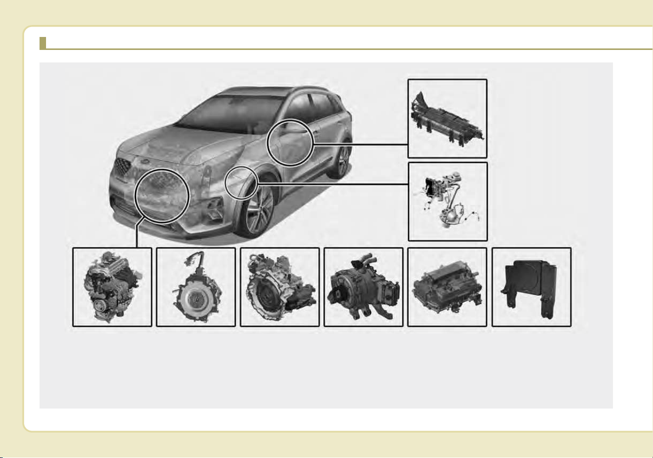
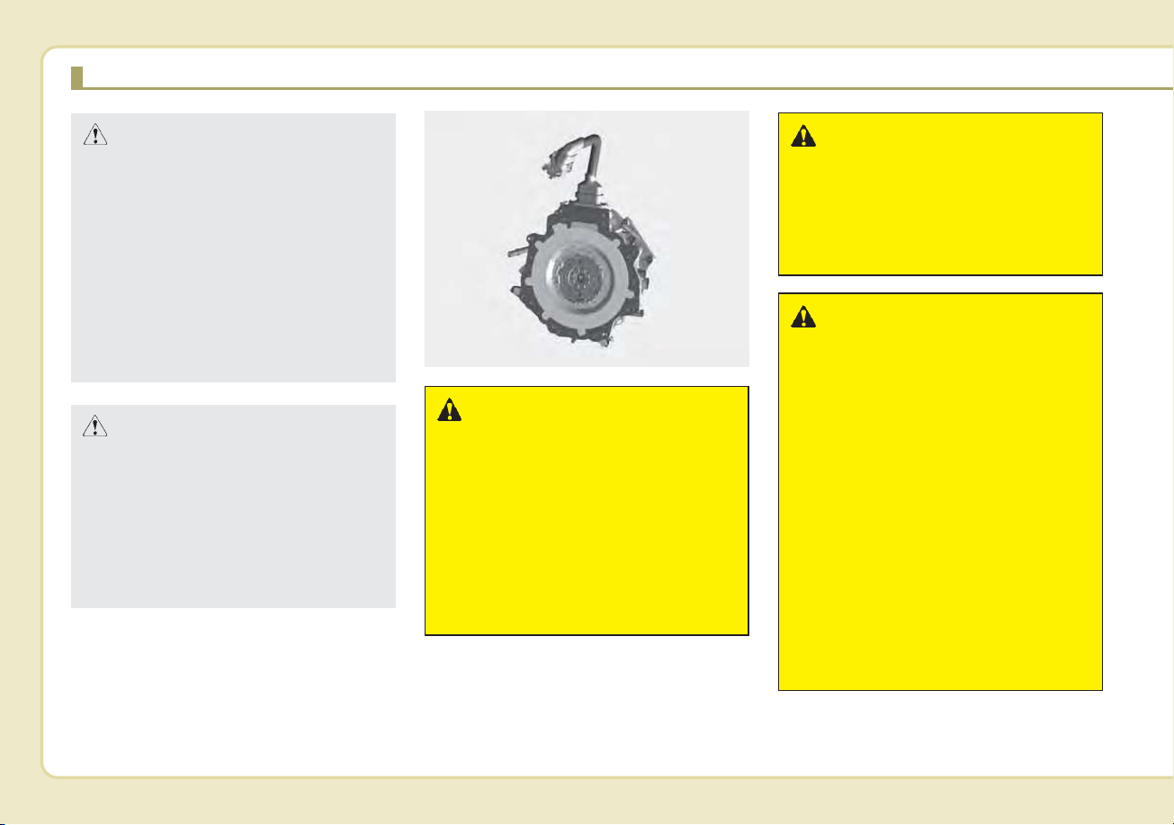
COMPONENTS OF THE HYBRID/PLUG-IN HYBRID VEHICLE
1. Engine : 1.6L
2. Motor : 32kW (HEV)/ 44.5kW (PHEV)
3. Transmission : 6DCT
4. Hybrid starter generator (HSG)
5. HPCU (Hybrid Power Control Unit)
6. High voltage battery system
7. Generative brake system
8. Virtual Engine Sound System (VESS)
ODEPQ019001L
❈ The actual shape may differ from the illustration.
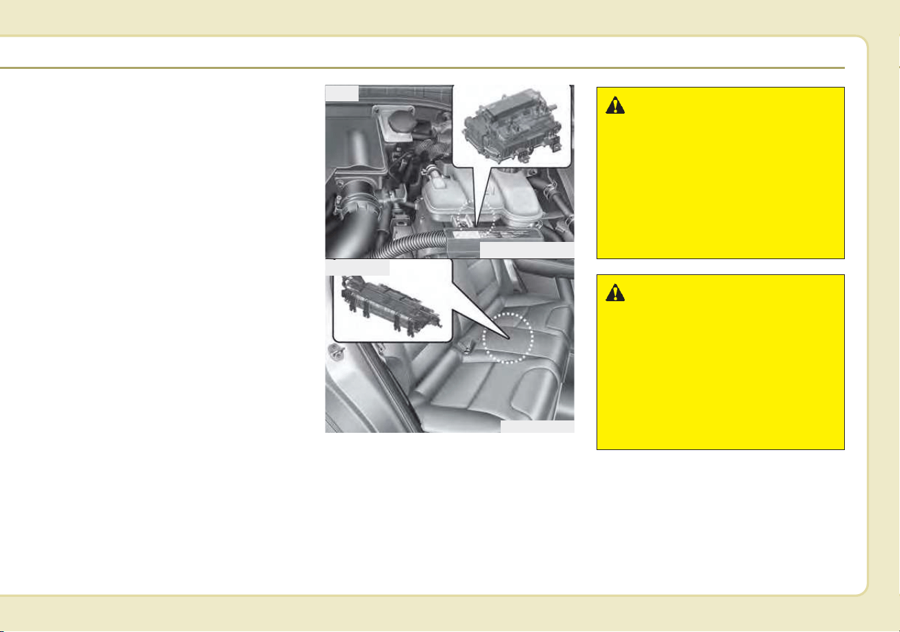
H43
The Hybrid battery uses high voltage
to operate the electric motor and
other components. High voltage is
dangerous if touched.
Your vehicle is equipped with orange
colored insulation which covers over
the high voltage components to pro-
tect people from electric shock. High
voltage warning labels are attached
to some system components as addi-
tional warnings. Have your vehicle
serviced by an authorized Kia dealer.
WARNING - High voltage
components
Never touch orange-colored or
high voltage labeled compo-
nents including wires, cables,
and connectors. If the insula-
tors or covers are damaged or
removed, severe injury or death
from electrocution may occur.
WARNING - Avoid
Touching Hybrid Power
Control Unit
When replacing the fuses in the
engine compartment, never
touch the HPCU. The HPCU car-
ries high voltage. Touching the
HPCU could result in electrocu-
tion, serious injury, or death.
ODEPQ019002L
ODEQ016003
HPCU
HEV Battery
H44
WARNING - Battery elec-
trolyte
As with all batteries, avoid fluid
contact with the Hybrid battery.
If the battery is damaged and if
electrolyte comes in contact
with your body, clothes or eyes,
immediately flush with a large
quantity of fresh water and seek
medical attention.
WARNING - After market
battery charger
Do not use an after-market bat-
tery charger to charge the
Hybrid battery. Doing so may
result in death or serious injury.
WARNING - High Waters
• Avoid high waters as this may
result in your vehicle becom-
ing saturated with water and
could compromise the high
voltage components.
• Do not touch any of the high
voltage components within
your vehicle if your vehicle
has been submerged in water
equal to half of the vehicle
height. Touching high voltage
components once submerged
in water could result in severe
burns or electric shock that
could result in death or seri-
ous injury.
ODEQ016004
Motor
CAUTION - High Voltage
Battery Damage
When loading your vehicle, be
careful of transporting items in
a manner that could damage the
high voltage battery. Do not
store items on top of the high
voltage battery or overload the
trunk area. Such actions may
ultimately damage the high volt-
age battery unit.
CAUTION - Carrying
Liquids in Trunk
Do not load large amounts of
liquid in open containers in the
vehicle. If spilled onto the HEV
battery, the liquid may cause a
short or further damage to the
battery.
COMPONENTS OF THE HYBRID/PLUG-IN HYBRID VEHICLE (CONT.)
H45
✽✽
NOTICE - Prolonged parking
Prolonged parking might cause bat-
tery discharge and operation failure
due to natural discharge. Driving
the vehicle approximately once
every 2 months, more than 9 miles
(15 km) is recommended. The bat-
tery will be charged automatically
when driving the vehicle.
WARNING - Exposure to
High Voltage
• High voltage in the hybrid bat-
tery system is very dangerous
and can cause severe burns
and electric shock. This may
result in serious injury or death.
• For your safety, never touch,
replace, dismantle or remove
any portion of the hybrid bat-
tery system including compo-
nents, cables and connectors.
WARNING - Use of Water
or Liquids
If water or liquids come into
contact with the hybrid system
components, and you are also
in contact with the water, severe
injury or death due to electrocu-
tion may occur.
WARNING - Hot
Components
When the hybrid battery system
operates, the HEV battery system
can be hot. Heat burns may result
from touching even insulated
components of the HEV system.
CAUTION - Cleaning
Engine
When you clean the engine com-
partment, do not wash using
water. Water may cause electric
arcing to occur and damage elec-
tronic parts and components.
H46
Safety plug
Some Special Features of the
Hybrid Vehicle.
Hybrid vehicles sound different than
gasoline engine vehicles. When the
hybrid system operates, you may
hear a sound from the hybrid battery
system behind the rear seat. If you
apply the accelerator pedal rapidly,
you may hear a sound. When you
apply the brake pedal, you may hear
a sound from the regenerative brake
system. When the hybrid system is
turned off or on, you may hear a
sound in the engine compartment. If
you depress the brake pedal repeat-
edly when the hybrid system is
turned on, you may hear a sound in
the engine compartment. None of
these sounds indicate a problem.
They are characteristics of hybrid
vehicles.
When the hybrid system is turned on,
the engine may run. This does not
indicate a malfunction. If the " "
symbol is on, the hybrid system is
operating. Even if the gasoline engine
is off, you can operate the vehicle.
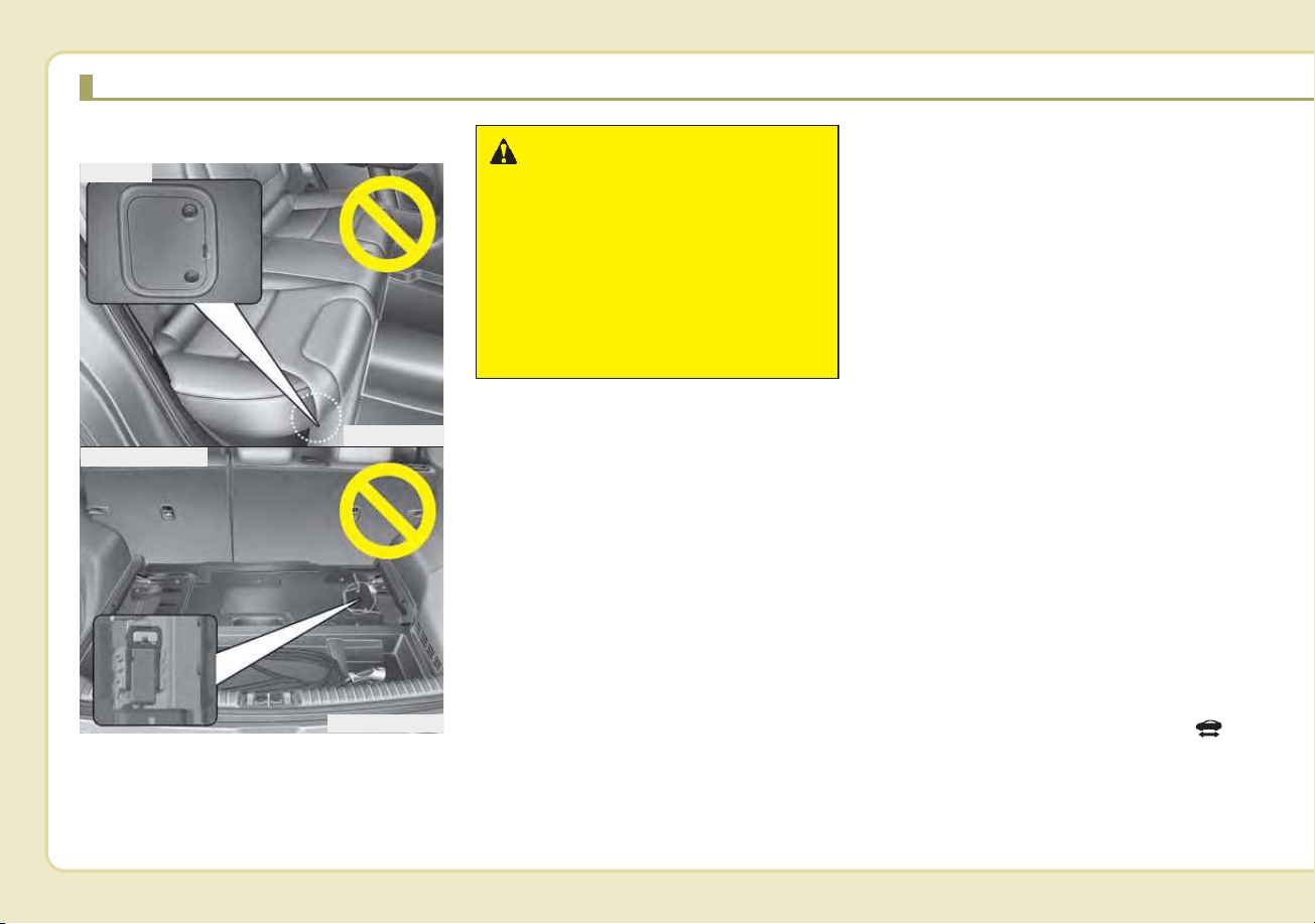
WARNING - Safety Plug
Never touch the safety plug.
The safety plug is attached to
the high voltage hybrid battery
system. Touching the safety
plug may result in death.
Service personnel should fol-
low the appropriate procedures
in the service manual.
ODEQ016006
■ Hybrid
ODEPQ017038
■ Plug-in Hybrid
COMPONENTS OF THE HYBRID/PLUG-IN HYBRID VEHICLE (CONT.)
H47
The HEV system may emit electro-
magnetic waves which can affect the
performance of electronic devices
appliances, such as laptop comput-
ers, which are not part of the vehicle
design.
If you park the vehicle for a long time,
the hybrid system will discharge. You
need to drive the vehicle approximate-
ly once every 2 months, more than 9
miles (15 km) is recommended.
When you start the hybrid system in
the "P" transmission position, the
" " symbol is illuminated in the
cluster. The driver can drive the vehi-
cle even if the engine is stopped.
Virtual Engine Sound System
(VESS)
The Virtual Engine Sound System
generates engine sound for pedestri-
ans to hear vehicle sound because
there is limited sound while electric
motor power is used.
• If the vehicle is moving at low
speed, the VESS will operate.
• When the gear is shifted to R
(Reverse), an additional warning
sound will be heard.
WARNING - Turning off
HEV system
When you leave the vehicle, you
should turn off the hybrid sys-
tem. If you depress the acceler-
ator pedal by mistake and the
vehicle is not in the "P" posi-
tion, the vehicle will accelerate.
This may result in serious injury
or death.
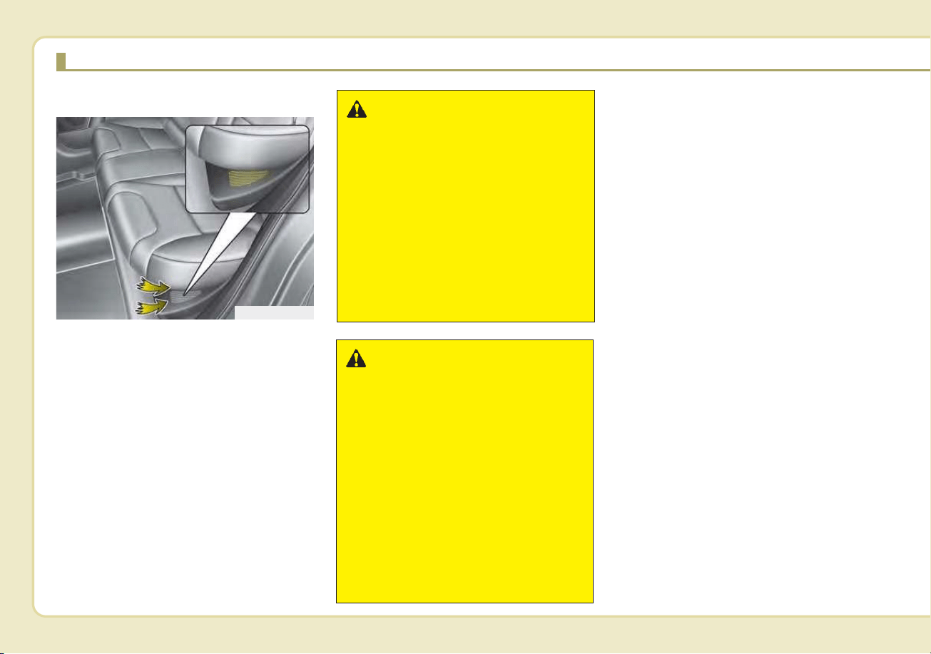
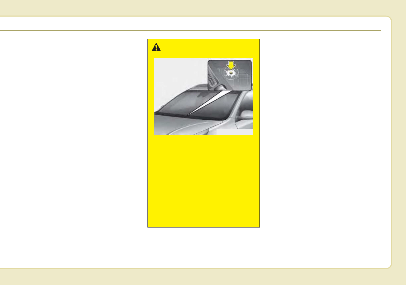
H48
High Voltage Battery Air Intake
The hybrid battery air intake is locat-
ed on bottom and side of the rear
seats. The air intake cools down the
hybrid battery. When the hybrid bat-
tery air intake is blocked, the hybrid
battery may be overheated. Do not
obstruct the air intake with any other
objects.
If An Accident Occurs
• Avoid the engine compartment.
• Avoid making contact with any
orange or high voltage wires,
cables, or components.
• Assume that a high voltage compo-
nent is exposed and move away from
the vehicle as promptly as possible.
• Refer to Chapter 7 for towing infor-
mation.
WARNING - Air Intake
• Blocking the air intake behind
the rear seats may damage
the HEV battery.
• Do not allow any water into
the air intake even when
cleaning. If any water enters
the air intake, the Hybrid bat-
tery may cause an electric
shock which can cause seri-
ous injury or death due to
electrocution.
ODEQ016007
WARNING
-
Interference with electron-
ic medical devices
Electromagnetic waves that are
generated from the charger can
impact medical electric devices
such as an implantable cardiac
pacemaker. When using such
medical electric devices, ask
your medical professional and
the device manufacturer
whether charging your electric
vehicle will impact the operation
of the medical electric devices.
COMPONENTS OF THE HYBRID/PLUG-IN HYBRID VEHICLE (CONT.)
H49
• After parking the vehicle, shift the
transmission into "P" position. Turn
off the hybrid system by pushing
the Engine Start/Stop button.
• For your safety, do not touch high
voltage cables, connectors and
package modules. High Voltage
components are orange in color.
• Exposed cables or wires may be
visible inside or outside of the vehi-
cle. Never touch the wires or
cables, because an electrical
shock may occur causing injury or
death.
If a vehicle accident occurs:
1.Stop the vehicle and shift the trans-
mission into "P" position and then
depress the parking brake.
2.Turn off the Hybrid system by
pushing the Engine Start/Stop
Button.
3.Step away from the vehicle and go
to a safe place.
4.Call emergency services for help
and let them know the vehicle is a
Hybrid vehicle.
Do not touch high voltage cables,
connectors and package modules.
High voltage components are
orange in color.
Exposed cables or wires may be vis-
ible inside or outside of the vehicle.
Never touch the wires or cables,
because an electrical shock may
occur causing injury or death.
WARNING
• If a small scale fire occurs,
use a fire extinguisher (ABC,
BC) that is meant for electrical
fires.
If it is impossible to extin-
guish the fire in the early
stage, remain a safe distance
from the vehicle and immedi-
ately call your local fire emer-
gency responders. Also,
advise them that a hybrid
vehicle is involved.
If the fire spreads to the high
voltage battery, large amount
of water is needed to put out
the fire.
Using small amount of water
or fire extinguishers not
meant for electrical fires
could cause serious injury or
death from electrical shocks.
• If you need towing, refer to
chapter 6.
H50
When the hybrid vehicle shuts
off
When the high voltage battery or 12-
volt battery discharges, or fuel tank is
empty, the hybrid system may not
operate.
If the Hybrid system stops operating
while the vehicle is moving, reduce
the vehicle speed gradually, pull your
vehicle off the road to a safe area,
and shift the transmission in to Park
(P) position and;
1. Turn on the hazard warning flashers.
2. Set the start button at OFF, and try
to start the Hybrid system by
applying the brake pedal and
pushing the start button.
3. If the Hybrid system will not oper-
ate, refer to "EMERGENCY
STARTING" in chapter 6.
Before you try to jump start the vehi-
cle, confirm the fuel level. If the fuel
level is low add more fuel before
attempting as emergency start.
WARNING
If submersion in water occurs:
If your vehicle was flooded and
has soaked carpeting or water
on the flooring, you should not
try to start the Hybrid system.
Never touch the high voltage
cables, connectors or package
modules, because an electrical
shock may occur causing injury
or death. High Voltage cables
are orange in color.
If this occurs. have the vehicle
towed to and inspected by an
authorized Kia dealer.
WARNING - Vehicle
Accident
Never touch electric wires or
cable. If exposed electric wires
or cables are visible inside or
outside of your vehicle, an elec-
tric shock may occur.
WARNING - Putting out
fire
Never use a small quantity of
water to put out a fire in your
vehicle. If a fire occurs, evacu-
ate the car immediately and
contact the fire department.
COMPONENTS OF THE HYBRID/PLUG-IN HYBRID VEHICLE (CONT.)

Introduction
Fuel requirements . . . . . . . . . . . . . . . . . . . . . . . . . . 1-2
• Gasoline containing alcohol and methanol . . . . . . . . . 1-2
• Do not use methanol . . . . . . . . . . . . . . . . . . . . . . . . . . . 1-3
• Fuel additives . . . . . . . . . . . . . . . . . . . . . . . . . . . . . . . . . 1-4
• Operation in foreign countries. . . . . . . . . . . . . . . . . . . 1-4
Vehicle modifications . . . . . . . . . . . . . . . . . . . . . . . . 1-5
Vehicle break-in process . . . . . . . . . . . . . . . . . . . . . 1-5
HEV/PHEV powertrain. . . . . . . . . . . . . . . . . . . . . . 1-5
Vehicle data collection and event data recorders. . 1-6
1
Introduction
21
Your new vehicle is designed to use
only unleaded fuel having a pump
octane number ((R+M)/2) of 87
(Research Octane Number 91) or
higher. (Do not use methanol blend-
ed fuels.)
Your new vehicle is designed to
obtain maximum performance with
UNLEADED FUEL, as well as mini-
mize exhaust emissions and spark
plug fouling.
Never add any fuel system cleaning
agents to the fuel tank other than
what has been specified. (Consult an
authorized Kia dealer for details.)
• Tighten the cap until it clicks one
time, otherwise the Check Engine
light will illuminate.
Gasoline containing alcohol and
methanol
Gasohol, a mixture of gasoline and
ethanol (also known as grain alco-
hol), and gasoline or gasohol con-
taining methanol (also known as
wood alcohol) are being marketed
along with or instead of leaded or
unleaded gasoline.
Pursuant to EPA regulations, ethanol
may be used in your vehicle.
Do not use gasohol containing more
than 15% ethanol, and do not use
gasoline or gasohol containing any
methanol. Ethanol provides less
energy than gasoline and it attracts
water, and it is thus likely to reduce
your fuel efficiency and could lower
your MPG results.
Methanol may cause drivability prob-
lems and damage to the fuel system,
engine control system and emission
control system.
Discontinue using gasohol of any
kind if drivability problems occur.
Vehicle damage or drivability prob-
lems may not be covered by the
manufacturer’s warranty if they result
from the use of:
1. Gasoline or gasohol containing
methanol.
2. Leaded fuel or leaded gasohol.
3. Gasohol containing more than
15% ethanol.
WARNING - Refueling
• Do not “top off” after the noz-
zle automatically shuts off.
Attempts to force more fuel
into the tank can cause fuel
overflow onto you and the
ground, causing a risk of fire.
• Always check that the fuel cap
is installed securely to pre-
vent fuel spillage, especially
in the event of an accident.
FUEL REQUIREMENTS

13
Introduction
"E85" fuel is an alternative fuel com-
prised of 85 percent ethanol and 15
percent gasoline, and is manufac-
tured exclusively for use in Flexible
Fuel Vehicles. “E85” is not compati-
ble with your vehicle. Use of “E85”
may result in poor engine perform-
ance and damage to your vehicle's
engine and fuel system. Kia recom-
mends that customers do not use
fuel with an ethanol content exceed-
ing 15 percent.
✽✽
NOTICE
Your New Vehicle Limited Warranty
does not cover damage to the fuel sys-
tem or any performance problems
caused by the use of “E85” fuel.
✽
✽
NOTICE
Never use any fuel containing
methanol. Discontinue use of any
methanol containing product which
may inhibit proper drivability.
Other fuels
Using fuels that contain Silicone (Si),
MMT (Manganese, Mn), Ferrocene
(Fe), and Other metalic additives,
may cause vehicle and engine dam-
age or cause misfiring, poor acceler-
ation, engine stalling, catalyst melt-
ing, clogging, abnormal corrosion,
life cycle reduction, etc.
Also, the Malfunction Indicator Lamp
(MIL) may illuminate.
✽✽
NOTICE
Damage to the fuel system or per-
formance problem caused by the use
of these fuels may not be covered by
your New Vehicle Limited
Warranty.
Gasoline containing MMT
Some gasoline contains harmful man-
ganese-based fuel additives Such as
MMT(Methylcyclopentadienyl
Manganese Tricarbonyl). Kia does not
recommend the use of gasoline con-
taining MMT. This type of fuel can
reduce vehicle performance and affect
your emission control system. The
Malfunction Indicator Lamp on the
cluster may come on.
Do not use methanol
Fuels containing methanol (wood
alcohol) should not be used in your
vehicle. This type of fuel can reduce
vehicle performance and damage
components of the fuel system,
engine control system and emission
control system.

Introduction
41
Fuel Additives
Kia recommends that you use good
quality gasolines treated with deter-
gent additives such as TOP TIER
Detergent Gasoline, which help pre-
vent deposit formation in the engine.
These gasolines will help the engine
run cleaner and enhance perform-
ance of the Emission Control System.
For more information on TOP TIER
Detergent Gasoline, please go to the
website (www.toptiergas.com)
For customers who do not use TOP
TIER Detergent Gasoline regularly,
and have problems starting or the
engine does not run smoothly, addi-
tives that can be purchased sepa-
rately may be added to the gasoline.
If TOP TIER Detergent Gasoline is
not available, one bottle of additive
should be added to the fuel tank at
every 7,500 miles (12,000 km) or
every engine oil change is recom-
mended. Additives are available from
your authorized Kia dealer along with
information on how to use them. Do
not mix other additives.
Operation in foreign countries
If you are going to drive your vehicle
in another country, be sure to:
• Observe all regulations regarding
registration and insurance.
• Determine that acceptable fuel is
available.

15
Introduction
This vehicle should not be modified.
Modification of your vehicle could
affect its performance, safety or
durability and may even violate gov-
ernmental safety and emissions reg-
ulations.
In addition, damage or performance
problems resulting from any modifi-
cation may not be covered under
warranty.
• If you use unauthorized electronic
devices, it may cause the vehicle to
operate abnormally, wire damage,
battery discharge and fire. For your
safety, do not use unauthorized
electronic devices.
No special break-in period is needed.
By following a few simple precautions
for the first 600 miles (1,000 km) you
may add to the performance, econo-
my and life of your vehicle.
• Do not race the engine.
• While driving, keep your engine
speed (rpm, or revolutions per
minute) between 2,000 rpm and
4,000 rpm.
• Do not maintain a single speed for
long periods of time, either fast or
slow. Varying engine speed is
needed to properly break-in the
engine.
• Avoid hard stops, except in emer-
gencies, to allow the brakes to seat
properly.
• Don't tow a trailer during the first
1,200 miles (2,000 km) of opera-
tion.
By following a few simple precautions
for the first 600 miles (1,000 km) you
may add to the performance, econo-
my and life of your vehicle.
• Do not race the engine.
• Avoid hard stops, except in emer-
gencies, to allow the brakes to seat
properly.
VEHICLE MODIFICATIONS
HEV/PHEV POWERTRAIN
VEHICLE BREAK-IN
PROCESS

Introduction
61
This vehicle is equipped with an
event data recorder (EDR). The
main purpose of an EDR is to
record, in certain crash or near
crash-like situations, such as an
air bag deployment or hitting a
road obstacle, data that will assist
in understanding how a vehicle's
systems performed. The EDR is
designed to record data related to
vehicle dynamics and safety sys-
tems for a short period of time,
typically 30 seconds or less. The
EDR in this vehicle is designed to
record such data as:
• How various systems in your
vehicle were operating;
• Whether or not the driver and
passenger safety belts were
buckled/ fastened;
• How far (if at all) the driver was
depressing the accelerator
and/or brake pedal; and,
• How fast the vehicle was travel-
ing.
These data can help provide a bet-
ter understanding of the circum-
stances in which crashes and
injuries occur. NOTE: EDR data
are recorded by your vehicle only
if a non-trivial crash situation
occurs; no data are recorded by
the EDR under normal driving
conditions and no personal data
(e.g., name, gender, age, and
crash location) are recorded.
However, other parties, such as
law enforcement, could combine
the EDR data with the type of per-
sonally identifying data routinely
acquired during a crash investiga-
tion.
To read data recorded by an EDR,
special equipment is required, and
access to the vehicle or the EDR is
needed. In addition to the vehicle
manufacturer, other parties, such
as law enforcement, that have the
special equipment, can read the
information if they have access to
the vehicle or the EDR.
VEHICLE DATA COLLECTION AND EVENT DATA RECORDERS

Your vehicle at a glance
Exterior overview . . . . . . . . . . . . . . . . . . . . . . . . . . . 2-2
Interior overview . . . . . . . . . . . . . . . . . . . . . . . . . . . 2-4
Instrument panel overview . . . . . . . . . . . . . . . . . . . 2-5
Engine compartment . . . . . . . . . . . . . . . . . . . . . . . . 2-6
2
Your vehicle at a glance
22
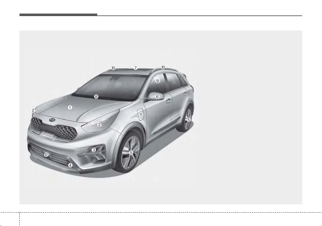
EXTERIOR OVERVIEW
1. Hood......................................................4-34
2. Head lamp (Features of your vehicle) ...4-116
Head lamp (Maintenance).....................7-87
3. Daytime running lamp (Features of your
vehicle) ................................................4-115
Daytime running lamp (Maintenance) ...7-88
4. Fog lamp (Features of your vehicle) ...4-121
Fog lamp (Maintenance) .......................7-88
5. Wheel and tire (Maintenance) ...............7-42
Wheel and tire (Specifications) ...............8-5
6. Outside rearview mirror.........................4-53
7. Sunroof..................................................4-42
8. Front windshield wiper blades
(Features of your vehicle)....................4-122
Front windshield wiper blades
(Maintenance) .......................................7-37
9. Windows ................................................4-29
10. Roof rack...........................................4-166
11. Charging door (plug-in).......Hybrid System
Overview
12. Front radar...........................................5-69
ODEP019001N
■ Front view
❈ The actual shape may differ from the illustration.
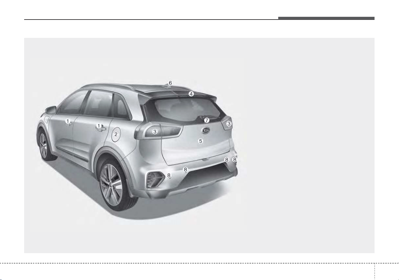
23
Your vehicle at a glance
1. Door locks .............................................4-21
2. Fuel filler door ..............................4-36, 4-37
3. Rear combination lamp
(Maintenance) .......................................7-88
4. High mounted stop lamp
(Maintenance) .......................................7-89
5. Liftgate...................................................4-26
6. Antenna ...............................................4-168
7. Rear wiper and Rear view
camera (Features of your
vehicle).....................................4-122, 4-111
Rear window wiper blade (Maintenance)...7-38
8. Rear ultrasonic sensors ......................4-112
ODEP019002
■ Rear view
❈ The actual shape may differ from the illustration.
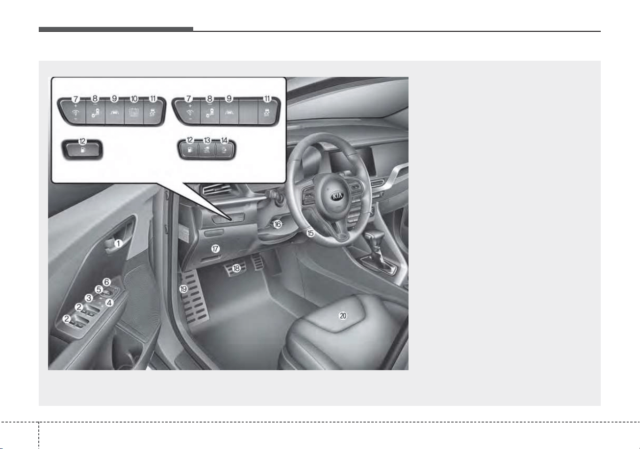
Your vehicle at a glance
42
INTERIOR OVERVIEW
1. Inside door handle.................................4-22
2. Power window switch ............................4-29
3. Central door lock switch ........................4-23
4. Power window lock button.....................4-32
5. Outside rearview mirror control.............4-54
6. Outside rearview mirror folding .............4-55
7. Instrument panel illumination control ....4-59
8. Blind-Spot Collision Warning system On/Off
button ....................................................5-97
9. Lane Keeping Assist system On/Off
button ....................................................5-89
10. 12V Battery Reset switch (For Hybrid)..6-5
11. ESC off button.....................................5-46
12. Fuel filler door open button........4-36, 4-37
13. Auto Lock mode button
(For Plug-in Hybrid) .............Hybrid System
Overview
14. Scheduled charging deactivation button
(For Plug-in Hybrid).............Hybrid System
Overview
15. Steering wheel ....................................4-47
16. Tilt and telescopic steering control
lever.....................................................4-48
17. Inner fuse panel ..................................7-59
18. Brake pedal .........................................5-30
19. Hood release lever ..............................4-34
20. Seat .......................................................3-4
ODEP019003N
❈ The actual shape may differ from the illustration.
• HEV
• PHEV
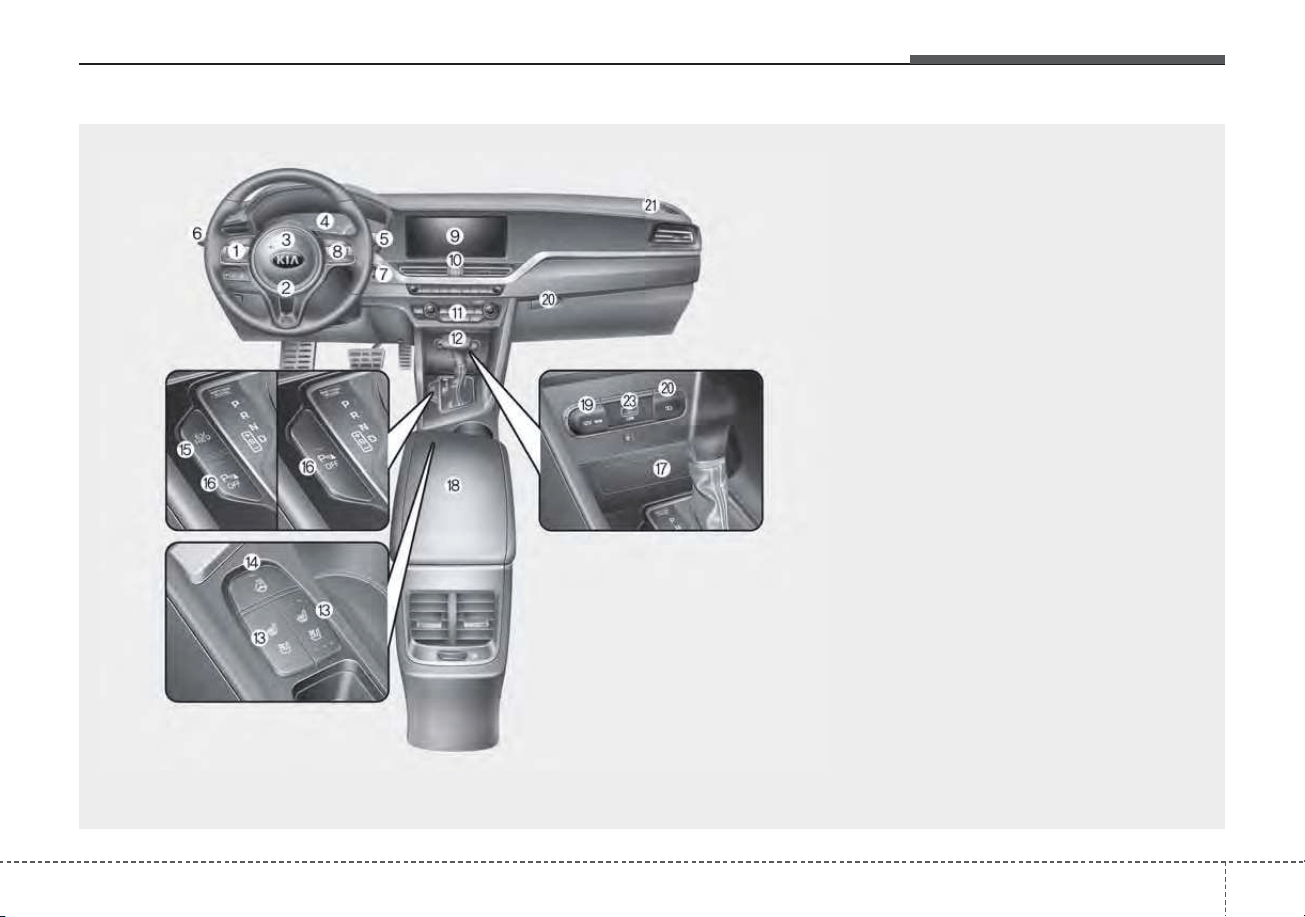
25
Your vehicle at a glance
INSTRUMENT PANEL OVERVIEW
1. Steering wheel audio controls .......Refer to
"Car Infotainment System Quick Reference
Guide".
2. Driver`s front air bag ...........................3-62
3. Horn.....................................................4-50
4. Instrument cluster................................4-57
5. Wiper and washer control lever
(Right)................................................4-122
6. Lighting control lever (Left)................4-116
7. Ignition switch........................................5-7
ENGINE START/STOP button.............5-11
8. Cruise control ....................................5-115
Smart Cruise Control system button..5-120
9. Infotainment system...............Refer to "Car
Infotainment System Quick Reference
Guide".
10. Hazard warning flasher .......................6-2
11. Climate control system....................4-131
12. Shift lever DCT ..................................5-16
13. Front seat warmer ...........................4-154
Front air ventilation seat ..................4-156
14. Heated steering wheel button ...........4-49
15. Changing plug-in hybrid mode
button..................Hybrid System Overview
16. Reverse Parking Distance Warning system
OFF button .....................................4-112
17. Smart phone wireless charger ........4-159
18. Center console storage box ............4-151
19. Power outlet.....................................4-157
20. USB charger....................................4-158
21. Glove box ........................................4-151
22. Passenger`s front air bag..................3-62
23. USB port..........................................4-168
ODEP019004N
❈ The actual shape may differ from the illustration.
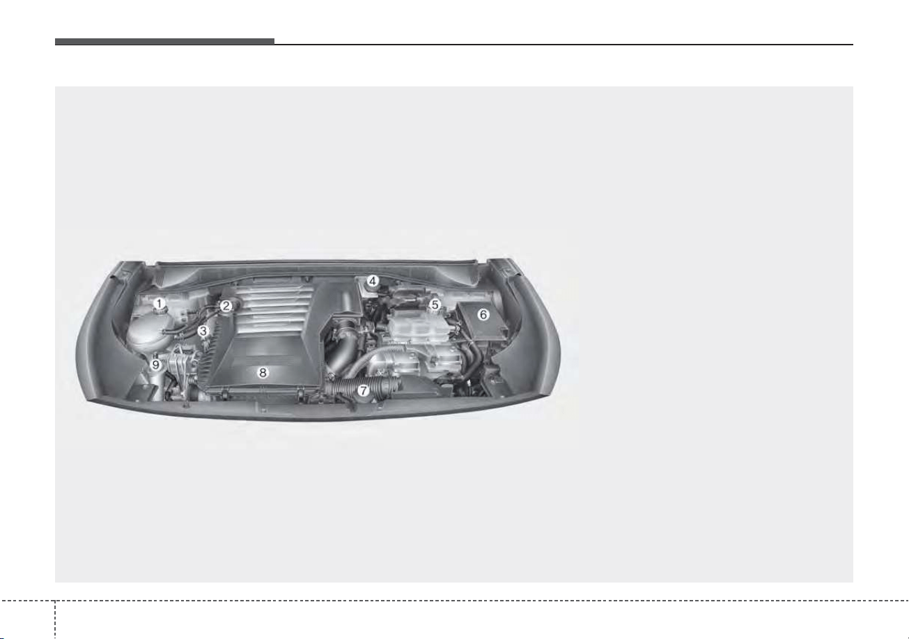
Your vehicle at a glance
62
ENGINE COMPARTMENT
ODEP079115
■■
Gasoline engine (Kappa 1.6L GDI)
❈ The actual engine room in the vehicle may differ from the illustration.
1. Engine coolant reservoir...................7-22
2. Engine oil filler cap ...........................7-19
3. Engine oil dipstick .............................7-19
4. Brake fluid reservoir..........................7-26
5. Inverter coolant reservoir..................7-22
6. Fuse box ...........................................7-61
7. Engine clutch actuator reservoir tank.7-28
8. Air cleaner.........................................7-32
9. Windshield washer fluid reservoir .....7-30

Safety features of your vehicle
Important safety precautions . . . . . . . . . . . . . . . . . 3-2
• Always wear your seat belt. . . . . . . . . . . . . . . . . . . . . . 3-2
• Restrain all children . . . . . . . . . . . . . . . . . . . . . . . . . . . 3-2
• Air bag hazards . . . . . . . . . . . . . . . . . . . . . . . . . . . . . . . 3-2
• Driver distraction . . . . . . . . . . . . . . . . . . . . . . . . . . . . . 3-2
• Control your speed . . . . . . . . . . . . . . . . . . . . . . . . . . . . 3-3
• Keep your vehicle in safe condition . . . . . . . . . . . . . . . 3-3
Seat. . . . . . . . . . . . . . . . . . . . . . . . . . . . . . . . . . . . . . . 3-4
• Front seat adjustment - manual. . . . . . . . . . . . . . . . . . 3-7
• Front seat adjustment - power (for driver’s seat) . . . 3-8
• Driver position memory system (for power seat). . . 3-10
• Headrest (for front seat) . . . . . . . . . . . . . . . . . . . . . . . 3-12
• Seatback pocket . . . . . . . . . . . . . . . . . . . . . . . . . . . . . . 3-15
• Rear seat adjustment . . . . . . . . . . . . . . . . . . . . . . . . . 3-15
Seat belts . . . . . . . . . . . . . . . . . . . . . . . . . . . . . . . . . 3-21
• Seat belt restraint system . . . . . . . . . . . . . . . . . . . . . . 3-21
• Pre-tensioner seat belt. . . . . . . . . . . . . . . . . . . . . . . . . 3-29
• Seat belt precautions . . . . . . . . . . . . . . . . . . . . . . . . . . 3-31
• Care of seat belts . . . . . . . . . . . . . . . . . . . . . . . . . . . . . 3-33
Child Restraint System (CRS) . . . . . . . . . . . . . . . 3-35
• Children always in the rear . . . . . . . . . . . . . . . . . . . . 3-35
• Selecting a Child Restraint System (CRS) . . . . . . . . 3-36
• Installing a Child Restraint System (CRS). . . . . . . . 3-39
Air bag - advanced supplemental restraint
system . . . . . . . . . . . . . . . . . . . . . . . . . . . . . . . . . . 3-47
• How does the air bag system operate? . . . . . . . . . . . 3-48
• Air bag warning light . . . . . . . . . . . . . . . . . . . . . . . . . 3-50
• SRS components and functions . . . . . . . . . . . . . . . . . 3-51
• Occupant Detection System (ODS) . . . . . . . . . . . . . . 3-54
• Driver's and passenger's front air bag . . . . . . . . . . . 3-62
• Side air bag . . . . . . . . . . . . . . . . . . . . . . . . . . . . . . . . . 3-65
• Curtain air bag . . . . . . . . . . . . . . . . . . . . . . . . . . . . . . 3-67
• SRS Care . . . . . . . . . . . . . . . . . . . . . . . . . . . . . . . . . . . 3-72
• Adding equipment to or modifying your
air bag-equipped vehicle. . . . . . . . . . . . . . . . . . . . . . 3-73
• Air bag warning label . . . . . . . . . . . . . . . . . . . . . . . . . 3-73
3

Safety features of your vehicle
23
You will find many safety precautions
and recommendations throughout
this section, and throughout this man-
ual.The safety precautions in this sec-
tion are among the most important.
Always wear your seat belt
A seat belt is your best protection in
all types of accidents. Air bags are
designed to supplement seat belts,
not replace them. So even though
your vehicle is equipped with air
bags, ALWAYS make sure you and
your passengers wear your seat
belts, and wear them properly.
Restrain all children
All children under age 13 should ride
in your vehicle properly restrained in
a rear seat, not the front seat. Infants
and small children should be
restrained in an appropriate child
restraint. Larger children should use
a booster seat with the lap/shoulder
belt until they can use the seat belt
properly without a booster seat.
Air bag hazards
While air bags can save lives, they
can also cause serious or fatal
injuries to occupants who sit too
close to them, or who are not prop-
erly restrained. Infants, young chil-
dren, and shorter adults are at the
greatest risk of being injured by an
inflating air bag. Follow all instruc-
tions and warnings in this manual.
Driver distraction
Driver distraction presents a serious
and potentially deadly danger, espe-
cially for inexperienced drivers.
Safety should be the first concern
when behind the wheel and drivers
need to be aware of the wide array of
potential distractions, such as drowsi-
ness, reaching for objects, eating,
personal grooming, other passen-
gers, and using cellular phones.
Drivers can become distracted when
they take their eyes and attention off
the road or their hands off the wheel
to focus on activities other than driv-
ing. To reduce your risk of distraction
or getting into an accident:
• ALWAYS set up your mobile
devices (i.e., MP3 players, phones,
navigation units, etc.) when your
vehicle is parked or safely stopped.
IMPORTANT SAFETY PRECAUTIONS

33
Safety features of your vehicle
• ONLY use your mobile device
when allowed by laws and when
conditions permit safe use. NEVER
text or email while driving. Most
states have laws prohibiting drivers
from texting. Some states and
cities also prohibit drivers from
using handheld phones.
• NEVER let the use of a mobile
device distract you from driving.
You have a responsibility to your
passengers and others on the road
to always drive safely, with your
hands on the wheel as well as your
eyes and attention on the road.
Control your speed
Excessive speed is a major factor in
crash injuries and deaths. Generally,
the higher the speed, the greater the
risk, but serious injuries can also
occur at lower speeds. Never drive
faster than is safe for current condi-
tions, regardless of the maximum
speed posted.
Keep your vehicle in safe con-
dition
Having a tire blowout or a mechani-
cal failure can be extremely haz-
ardous. To reduce the possibility of
such problems, check your tire pres-
sures and condition frequently, and
perform all regularly scheduled
maintenance.
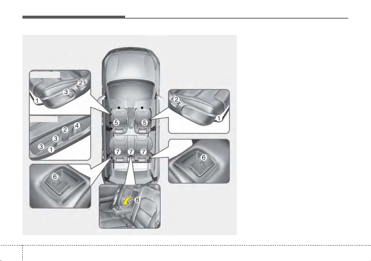
Safety features of your vehicle
43
Front seat
(1) Forward and backward
(2) Seatback angle
(3) Seat cushion height
(Driver`s seat)
(4) Lumbar support (Driver’s seat)*
(5) Head rest
Rear seat
(6) Seatback folding
(7) Headrest
* : if equipped
SEAT
ODE036001L
■ Manual seat
■ Power seat
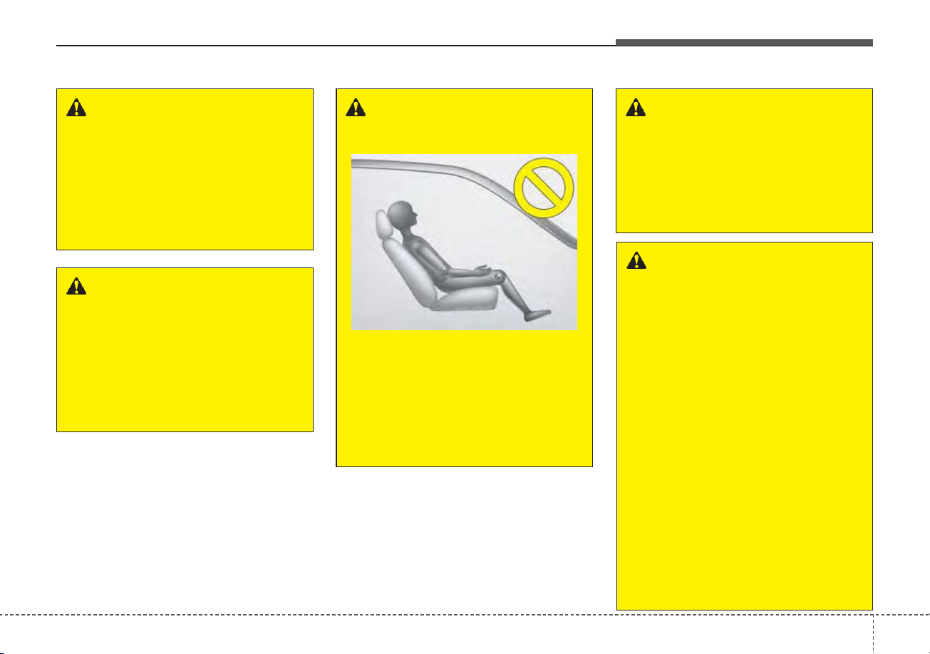
35
Safety features of your vehicle
WARNING - Uprighting
seat
Do not press the release lever on
a manual seatback without hold-
ing and controlling the seatback.
The seatback will spring upright,
possibly impacting you or other
passengers.
WARNING - Loose
objects
Do not place anything in the dri-
ver's foot well or under the front
seats. Loose objects in the dri-
ver's foot area could interfere
with the operation of the foot
pedals.
WARNING - Driver respon-
sibility for passengers
The driver must advise the pas-
sengers to keep the seatback in
an upright position whenever
the vehicle is in motion. If a seat
is reclined during an accident,
the restraint system's ability to
restrain will be greatly reduced.
1KMN3662
WARNING - Seat cushion
Occupants should never sit on
aftermarket seat cushions or sit-
ting cushions. The passenger's
hips may slide under the lap por-
tion of the seat belt during an
accident or a sudden stop.
WARNING - Driver’s seat
• Never attempt to adjust the
seat while the vehicle is mov-
ing. This could result in loss
of control of your vehicle.
• Do not allow anything to inter-
fere with the normal position
of the seatback. Storing items
against the seatback could
result in serious or fatal injury
in a sudden stop or collision.
• Sit as far back as possible from
the steering wheel while still
maintaining comfortable con-
trol of the your vehicle. A dis-
tance of at least 10 in (25 cm)
from your chest to the steering
wheel is recommended. Failure
to do so can result in air bag
inflation injuries to the driver.
Safety features of your vehicle
63
Feature of Seat Leather
• Leather is made from the outer
skin of an animal, which goes
through a special process to be
available for use. Since it is a nat-
ural substance, each part differs in
thickness or density.
Wrinkles may appear as a natural
result of stretching and shrinking
depending on the temperature and
humidity.
• The seat cover is made of stretch-
able material to improve comfort of
passengers.
• The parts contacting the body are
curved and the side supporting
area is high which provides driving
comfort and stability.
• Wrinkles may appear naturally
from usage. It is not a fault of the
product.
WARNING - Unexpected
Seat Movement
After adjusting a manual seat,
always check that it is locked by
shifting your weight to the front
and back. Sudden or unexpect-
ed movement of the driver's
seat could cause you to lose
control of the vehicle.
WARNING - Rear seatbacks
Always lock the rear seatback
before driving. Failure to do so
could result in passengers or
objects being thrown forward,
injuring vehicle occupants.
WARNING - Seat
adjustment
• Do not adjust the seat while
wearing seat belts. Moving the
seat forward will cause strong
pressure on the abdomen.
• Do not place your hand near
the seat bottom or seat track
while adjusting the seat. Your
hand could get caught in the
seat mechanism.
WARNING - Small
Objects
Use extreme caution when pick-
ing up small objects trapped
under the seats or between the
seat and the center console.
Your hands might be cut or
injured by the sharp edges of
the seats mechanism.
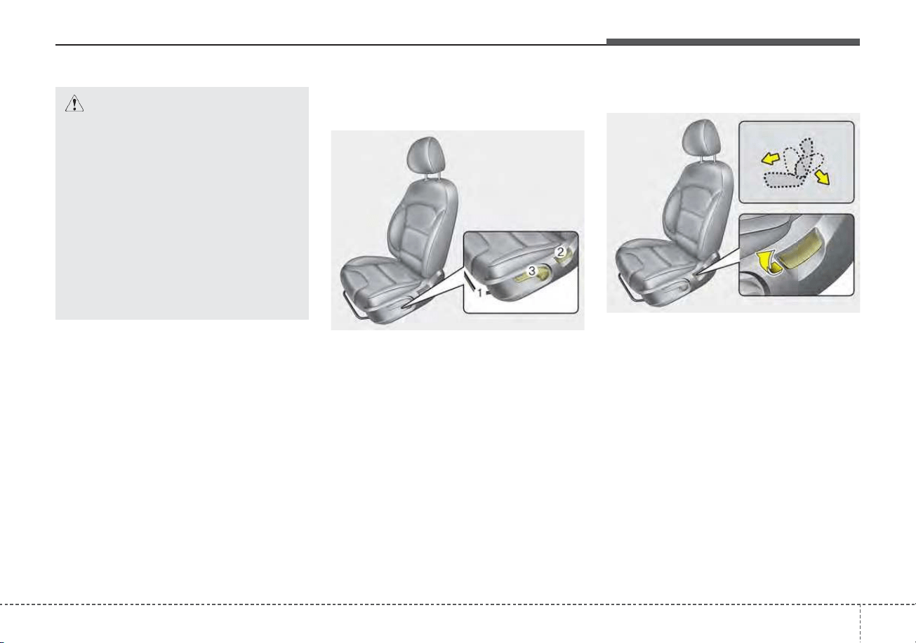
37
Safety features of your vehicle
✽✽
NOTICE
Wrinkles or abrasions which appear
naturally from usage are not cov-
ered by warranty.
Front seat adjustment - manual
Forward and backward
To move the seat forward or backward:
1. Pull the seat slide adjustment
lever up and hold it.
2. Slide the seat to the position you
desire.
3. Release the lever and make sure
the seat is locked in place.
Adjust the seat before driving, and
make sure the seat is locked securely
by trying to move forward and back-
ward without using the lever. If the
seat moves, it is not locked properly.
Seatback angle
To recline the seatback:
1. Lean forward slightly and lift up the
seatback recline lever.
2. Carefully lean back on the seat
and adjust the seatback of the
seat to the position you desire.
3. Release the lever and make sure
the seatback is locked in place. (The
lever MUST return to its original
position for the seatback to lock.)
ODEP039062
CAUTION
• Belts with metallic acces-
sories, zippers or keys inside
the back pocket may damage
the seat fabric.
• Make sure not to wet the seat.
It may change the nature of
natural leather.
• Jeans or clothes which could
bleach may contaminate the
surface of the seat covering
fabric.
ODEP039105N
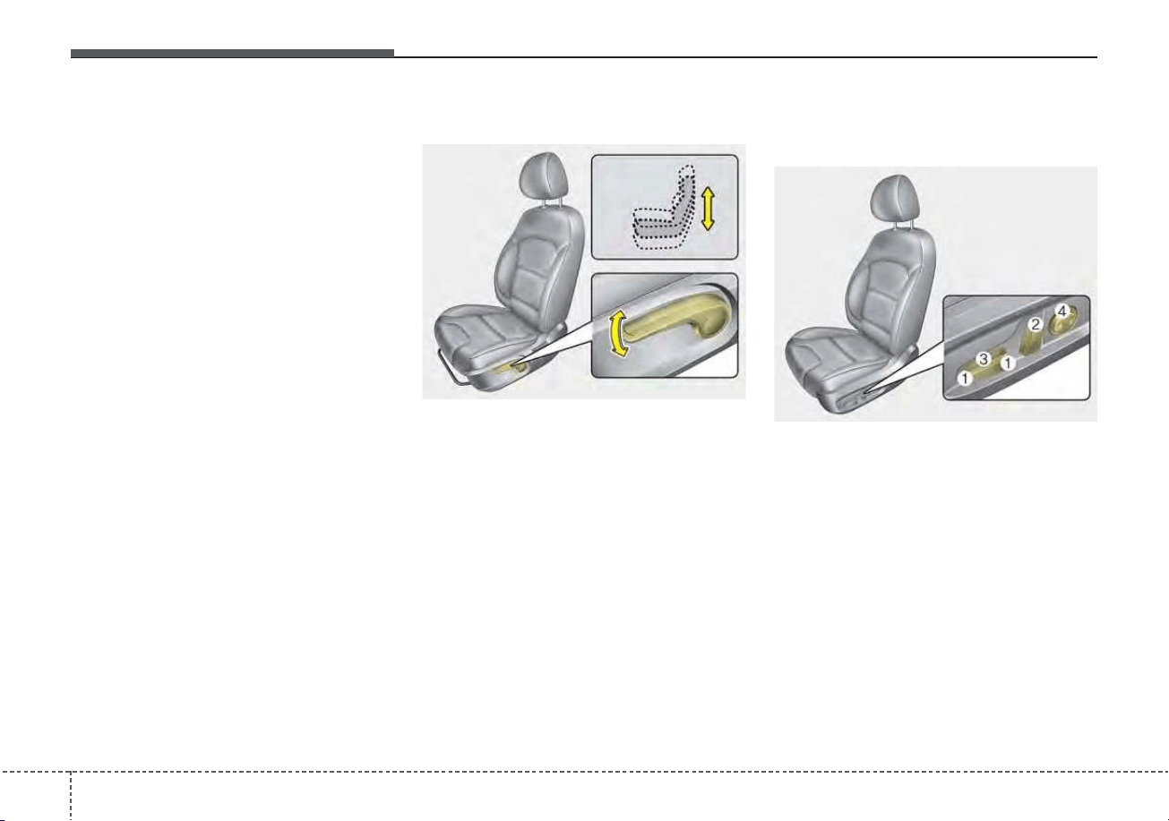
Safety features of your vehicle
83
Reclining seatback
Sitting in a reclined position when
the vehicle is in motion can be dan-
gerous. Even when buckled up, the
protections of your restraint system
(seat belts and/or air bags) is greatly
reduced by reclining your seatback.
Seat belts must be snug against your
hips and chest to work properly.
When the seatback is reclined, the
shoulder belt cannot do its job
because it will not be snug against
your chest. Instead, it will be in front
of you. During an accident, you could
be thrown into the seat belt, causing
neck or other injuries.
The more the seatback is reclined,
the greater chance the passenger’s
hips will slide under the lap belt or
the passenger’s neck will strike the
shoulder belt.
Seat height
To change the height of the seat, push
the lever upwards or downwards.
• To lower the seat cushion, push the
lever down several times.
• To raise the seat cushion, pull the
lever up several times.
Front seat adjustment - power
(for driver’s seat, if equipped)
The driver’s seat can be adjusted by
using the control switches located on
the outside of the seat cushion.
Before driving, adjust the seat to the
proper position so you can easily
control the steering wheel, pedals
and switches on the instrument
panel.
ODEP039061
ODEP039106N
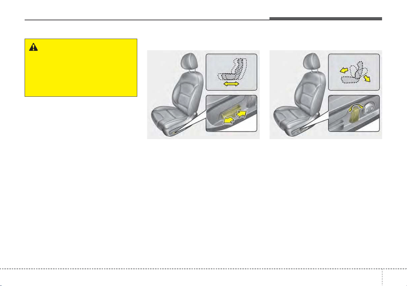
39
Safety features of your vehicle
Forward and backward
Push the control switch forward or
backward to move the seat to the
desired position. Release the switch
once the seat reaches the desired
position.
Seatback angle
Push the control switch forward or
backward to move the seatback to
the desired angle. Release the
switch once the seat reaches the
desired position.
WARNING - Unattended
children
Do not leave children unattend-
ed in the vehicle. Children might
operate features of the vehicle
that could injure them.
ODEP039107N ODEP039108N
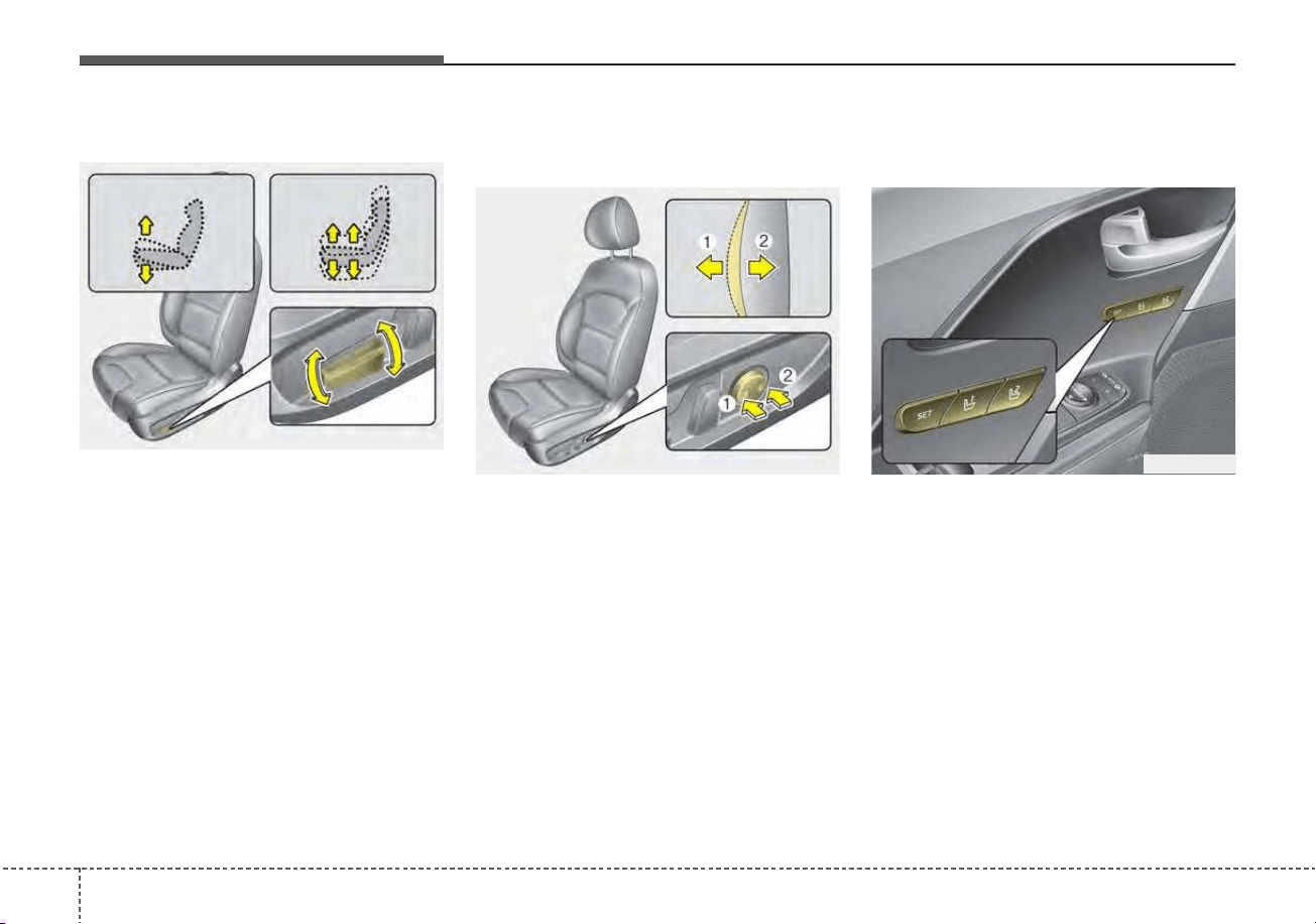
Safety features of your vehicle
103
Seat height
Pull the front portion of the control
switch up to raise or press down to
lower the front part of the seat cush-
ion. Pull the rear portion of the con-
trol switch up to raise or press down
to lower the seat cushion. Release
the switch once the seat reaches the
desired position.
Lumbar support (for power seat,
if equipped)
The lumbar support can be adjusted
by pressing the lumbar support
switch on the side of the seat.
1. Press the front portion of the
switch to increase support, or the
rear portion of the switch, to
decrease support.
2. Release the switch once it reach-
es the desired position.
Driver position memory system
(if equipped, for power seat)
A driver position memory system is
provided to store and recall the driv-
er seat and outside rearview mirror
position with a simple button opera-
tion. By saving the desired position
into the system memory, different
drivers can reposition the driver seat
based upon their driving preference.
If the battery is disconnected, the
desired seat position memory will
need to be re-saved.
ODE036023
ODEP039109N
ODEP039110N
311
Safety features of your vehicle
Storing positions into memory
using the buttons on the door
Storing driver’s seat positions
1. Shift the shift lever into P while the
engine start/stop button is ON or
ignition switch is ON.
2. Adjust the driver’s seat and out-
side rearview mirror comfortable
for the driver.
3. Press SET button on the control
panel. The system will beep once.
4. Press one of the memory buttons
(1 or 2) within 4 seconds after
pressing the SET button. The sys-
tem will beep twice when memory
has been successfully stored.
When recalling an adjustment mem-
ory button while sitting in the vehicle,
you can be surprised by the setting
chosen if the memory has been
adjusted by someone else. If that
occurs, immediately push the seat
position control knob in the direction
of the desired position to stop further
undesired movement.
Recalling positions from memory
1. Shift the shift lever into P.
2. To recall the position in the memo-
ry, press the desired memory but-
ton (1 or 2). The system will beep
once, then the driver’s seat will
automatically adjust to the stored
position.
Adjusting the control switch for the
driver’s seat while the system is
recalling the stored position will
cause the movement to stop and
move in the direction that the control
switch is moved.
WARNING - Driver
Position Memory System
Never attempt to operate the
driver position memory system
while the vehicle is moving.
This could result in loss of con-
trol, and an accident causing
death or serious injury.
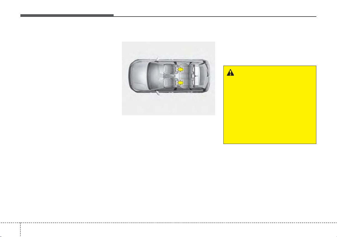
Safety features of your vehicle
123
Easy access function (if equipped)
The system will move the driver's
seat automatically as follows:
• Without smart key system
- It will move the driver’s seat rear-
ward when the ignition key is
removed and front driver’s door is
opened.
- It will move the driver’s seat forward
when the ignition key is inserted.
• With smart key system
- It will move the driver’s seat rear-
ward when the engine start/stop
button is changed to the OFF
position.
- It will move the driver’s seat for-
ward when the engine start/stop
button is changed to the ACC or
START position.
- It will move the driver's seat for-
ward when you get in your vehicle
with the smart key after closing
the driver's door.
You can activate or deactivate this
feature. Refer to "User settings" in
chapter 4.
Headrest (for front seat)
The driver's and front passenger's
seats are equipped with a headrest
for the occupant's safety and comfort.
The headrest not only provides com-
fort for the driver and front passenger,
but also helps protect the head and
neck in the event of a rear collision.
For maximum effectiveness in case
of an accident, the headrest should
be adjusted so the middle of the
headrest is at the same height of the
center of gravity of an occupant's
head. Generally, the center of gravity
of most people's head is similar with
the height of the top of their eyes.
Also, adjust the headrest as close to
your head as possible. For this rea-
son, the use of a cushion that holds
the body away from the seatback is
not recommended.
WARNING - Headrest
removal/adjustment
• Do not operate the vehicle
with the headrests removed.
Headrests can provide critical
neck and head support in a
crash.
• Do not adjust the headrest
height while the vehicle is in
motion. Driver may lose con-
trol of the vehicle.
ODE036074L
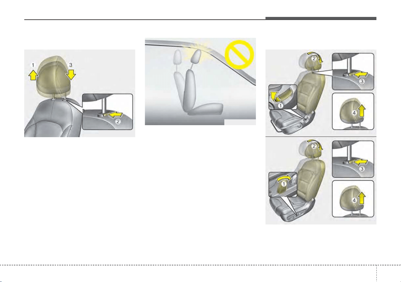
313
Safety features of your vehicle
Adjusting the height up and down
To raise the headrest, pull it up to the
desired position (1). To lower the
headrest, push and hold the release
button (2) on the headrest support
and lower the headrest to the desired
position (3).
✽✽
NOTICE
If you recline the seatback towards
the front with the headrest and seat
cushion raised, the headrest may
come in contact with the sunvisor or
other parts of the vehicle.
Removal and reinstallation
ODEP039009
ODEP039011
ODEP039012
■ Type B
■ Type A
OYFH034205
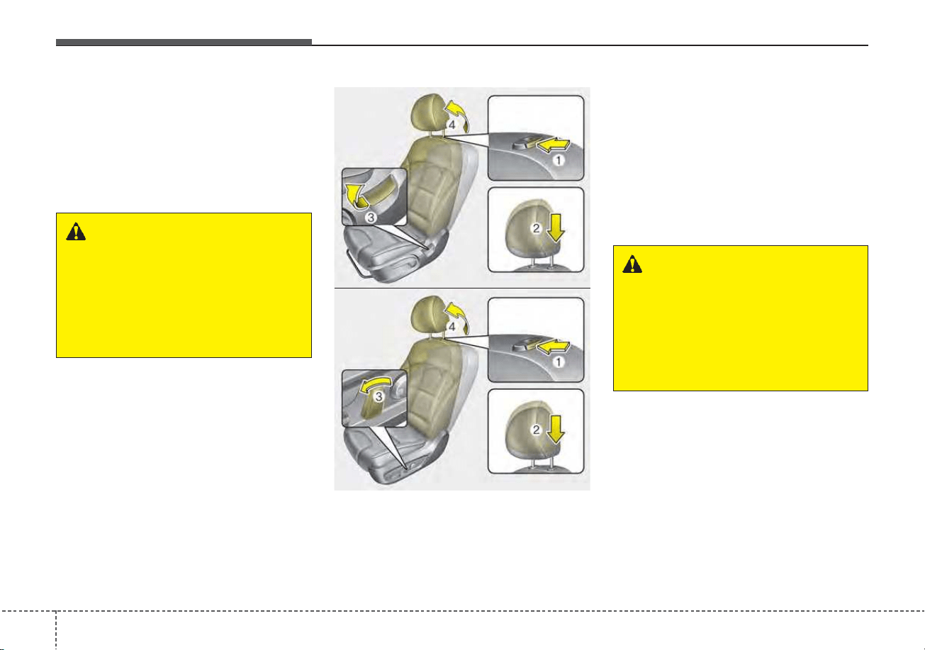
Safety features of your vehicle
143
To remove the headrest:
1. Recline the seatback (2) with the
recline lever or switch (1).
2. Raise headrest as far as it can go.
3. Press the headrest release button
(3) while pulling the headrest up (4).
To reinstall the headrest :
1. Put the headrest poles (2) into the
holes while pressing the release
button (1).
2. Recline the seatback (4) with the
recline lever or switch (3).
3. Adjust the headrest to the appro-
priate height.
WARNING - Headrest
Removal
NEVER allow anyone to ride in a
seat with the headrest removed
or reserved. Headrests can pro-
vide critical neck and head sup-
port in a crash.
ODEP039013
ODEP039014
■ Type B
■ Type A
WARNING - Headrest
Reinstallation
To reduce the risk of injury to
the head or neck, always make
sure the headrest is locked into
position and adjusted properly
after reinstalling.
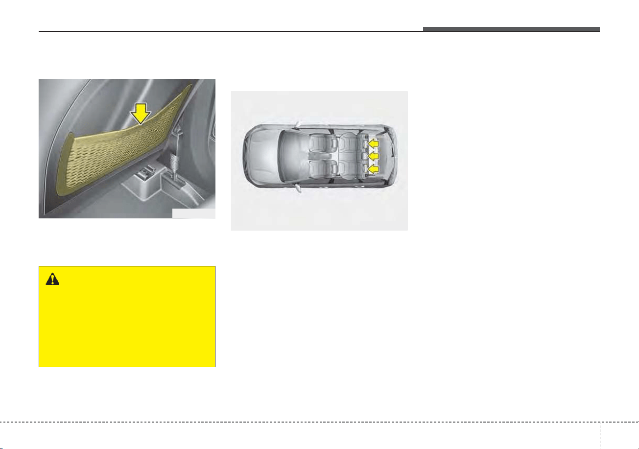
315
Safety features of your vehicle
Seatback pocket (if equipped)
The seatback pocket is provided on
the back of the front passenger’s and
driver’s seatbacks.
Rear seat adjustment
Headrest
The rear seat is equipped with head-
rests in all the seating positions for
the occupant's safety and comfort.
The headrest not only provides com-
fort for passengers, but also helps
protect the head and neck in the
event of a collision.
For maximum effectiveness in case
of an accident, the headrest should
be adjusted so the middle of the
headrest is at the same height of the
center of gravity of an occupant's
head. Generally, the center of gravity
of most people's heads is similar with
the height as the top of their eyes.
Also, adjust the headrest as close to
your head as possible. For this rea-
son, the use of a cushion that holds
the body away from the seatback is
not recommended.
ODE036015
WARNING - Seatback
pockets
Do not put heavy or sharp
objects in the seatback pockets.
In an accident, they could come
loose from the pocket and
injure vehicle occupants.
ODE036075L
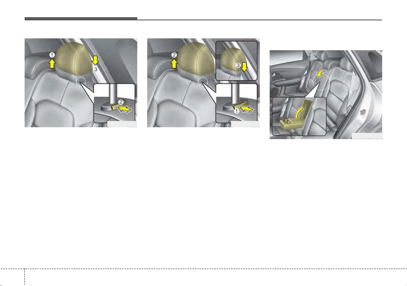
Safety features of your vehicle
163
Adjusting the height up and down
To raise the headrest, pull it up to the
desired position (1). To lower the
headrest, push and hold the release
button (2) on the headrest support
and lower the headrest to the desired
position (3).
Removal and reinstallation
To remove the headrest, raise it as
far as it can go then press the
release button (1) while pulling the
headrest upward (2).
To reinstall the headrest, put the
headrest poles (3) into the holes
while pressing the release button (1).
Then adjust it to the appropriate
height and ensure that it locks in
position.
Armrest (if equipped)
To use the armrest, pull it forward
from the seatback.
ODE036016 ODE036017
ODE036018
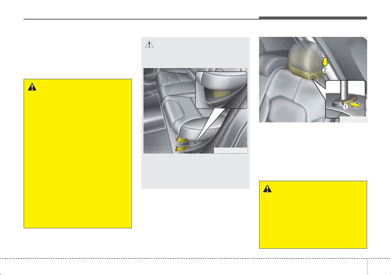
317
Safety features of your vehicle
Folding the rear seat
The rear seatbacks may be folded to
facilitate carrying long items or to
increase the luggage capacity of the
vehicle.
To fold down the rear seatback
1. Set the front seatback to the
upright position and if necessary,
slide the front seat forward.
2. Lower the rear headrests to the
lowest position as above the pic-
ture.
WARNING - Folded
Seatback
The purpose of the fold-down
rear seatbacks is to allow you to
carry longer objects than could
not otherwise be accommodated.
• Never allow a passenger to sit
on top of the folded down
seatback while the car is mov-
ing. This is not a proper seat-
ing position since no seat
belts are available for use.
• To reduce the risk of injury
caused by sliding cargo within
the passenger compartment
of the vehicle, objects carried
on the folded down seatback
should not extend higher than
the top of the front seats.
CAUTION
-
Blocked Hybrid battery
duct
Do not put objects on the left
side of rear seats. This could
block the battery cooling duct
causing battery degradation.
ODEQ016007
WARNING - Objects
Objects carried on the folded
down seatback should not
extend higher than the top of
the front seatbacks. This could
allow cargo to slide forward and
cause injury or damage during
sudden stops.
ODE036019
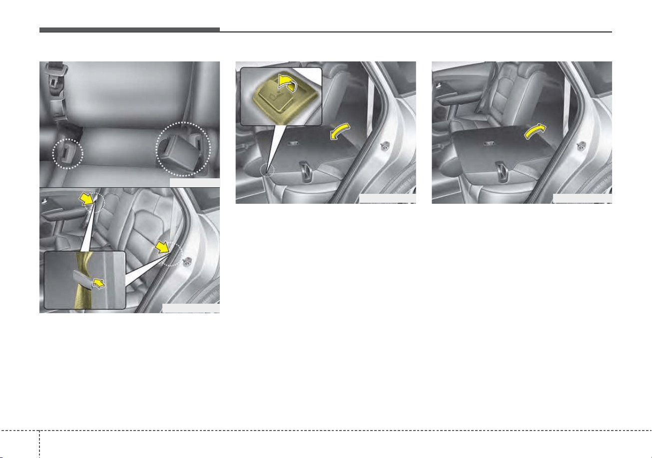
Safety features of your vehicle
183
3. When folding the seat back, insert
the rear seat belt buckle in the
pocket between the rear seatback
and cushion then make sure both
seatbelts do not interfere with
stowed luggage and cargo. Then
insert the seat belt into the two
webbing guide (or holder) located
on both sides.
4. Pull on the seatback folding lever,
then fold the seat toward the front
of the vehicle. When you return the
seatback to its upright position,
always be sure it has locked into
position by pushing on the top of
the seatback.
5. To use the rear seat, lift and pull the
seatback backward by lifting up
seat back. Pull the seatback firmly
until it clicks into place. Make sure
the seatback is locked in place.
6. Return the rear seat belt to the
proper position.
ODEP039020N
ODE036029L
ODEP039022NODEP039021N
319
Safety features of your vehicle
When returning the rear seatbacks to
the upright position, remember to
return the rear shoulder belts to their
proper position.
CAUTION - Damaging
rear seat belt buckles
When you fold the rear seat-
back, insert the buckle between
the rear seatback and cushion.
Doing so can prevent the buckle
from being damaged by the rear
seatback.
WARNING - Rear
Seatback
To ensure maximum protection
in the event of an accident or
sudden stop, when returning the
rear seat to the upright position:
• Be careful not to damage the
seat belt webbing or buckle.
• Do not allow the seat belt
webbing or buckle to become
pinched or caught in the rear
seat.
• Ensure the seatback is com-
pletely locked into its upright
position by pushing on the
top of the seatback.
Failure to adhere to any of
these instructions could
result in serious injury or
death in the event of a crash.
WARNING - Uprighting
seat
When you return the seatback
to its upright position, hold the
seatback and return it slowly. If
the seatback is returned with-
out holding it, the back of the
seat could spring forward,
resulting in injury caused by
being struck by the seatback.
Safety features of your vehicle
203
WARNING - Cargo loading
Make sure the engine is off, the
dual clutch transmission is in P
(Park) and the parking brake is
securely applied whenever load-
ing or unloading cargo. Failure
to take these steps may allow
the vehicle to move if the shift
lever is inadvertently moved to
another position.
WARNING - Cargo
Cargo should always be
secured to prevent it from being
thrown about the vehicle in a
collision and causing injury to
the vehicle occupants. Do not
place objects on the rear seats,
since they cannot be properly
secured and may hit the front
seat occupants in a collision.
321
Safety features of your vehicle
SEAT BELTS
Seat belt restraint system
• For maximum restraint system pro-
tection, the seat belts must always
be used whenever the vehicle is
moving. A properly positioned
shoulder belt should be positioned
midway over your shoulder across
your collarbone.
• Never allow children to ride in the
front passenger seat. See child
restraint system section for further
discussion.
Seat belts are designed to bear upon
the bony structure of the body, and
should be worn low across the front
of the pelvis, chest and shoulders, as
applicable; wearing the lap section of
the belt across the abdominal area
must be avoided.
Seat belts should be adjusted as
firmly as possible, consistent with
comfort, to provide the protection for
which they have been designed.
A slack belt will greatly reduce the
protection afforded to the wearer.
Care should be taken to avoid con-
tamination of the webbing with pol-
ishes, oils and chemicals, and partic-
ularly battery acid. Cleaning may
safely be carried out using mild soap
and water. The belt should be
replaced if webbing becomes frayed,
contaminated or damaged.
WARNING - Damaged
seat belt
Replace the entire seat belt
assembly if any part of the web-
bing or hardware is damaged as
you can no longer be sure that a
damaged seat belt will provide
protection in a crash.
WARNING - Twisted seat
belt
Make sure your seat belt is not
twisted when worn. A twisted
seat belt may not properly pro-
tect you in an accident and
could even cut into your body.
WARNING - Shoulder Belt
• Never wear the shoulder belt
under your arm or behind
your back. An improperly
positioned shoulder belt can-
not protect the occupant in a
crash.
• Always wear both the shoul-
der portion and lap portion of
the lap/shoulder belt.
Safety features of your vehicle
223
• No modifications or additions
should be made by the user which
would either prevent the seat belt
adjusting devices from operating to
remove slack, or prevent the seat
belt assembly from being adjusted
to remove slack.
• When you fasten the seat belt, be
careful not to latch the seat belt in
buckles of other seat. It's very dan-
gerous and you may not be pro-
tected by the seat belt properly.
• Do not unfasten the seat belt and
do not fasten and unfasten the seat
belt repeatedly while driving. This
could result in loss of control, and
an accident causing death, serious
injury, or property damage.
• When fastening the seat belt,
make sure that the seat belt does
not pass over objects that are hard
or can break easily.
WARNING - Seat belt
buckle
Do not allow foreign material
(gum, crumbs, coins, liquids,
etc.) to obstruct the seat belt
buckle. This may prevent the
seat belt from fastening securely.
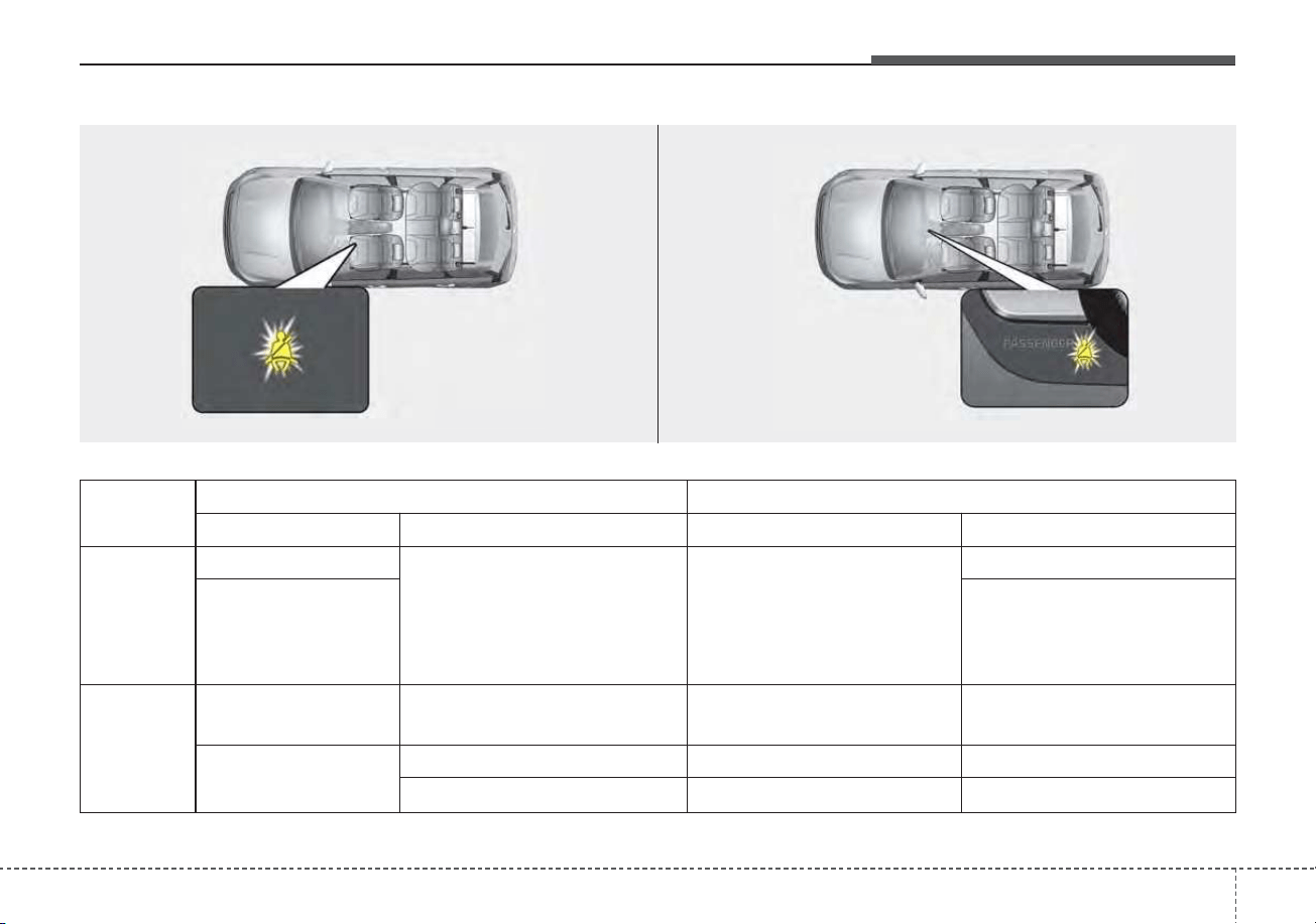
323
Safety features of your vehicle
Front seat belt warning
Driving
conditions
Conditions Warning pattern
Seat belt Vehicle speed Light Sound
While
parked
(Ignition
switch ON)
Buckled
0 mph (0 km/h)
Illuminates
(for 6 seconds)
No sound
Unbuckled
- Sounds
(for 6 seconds, driver`s seat)
- No sound
(for passenger’s seat)
While
driving
Unbuckled
6 mph (9 km/h) or more but
less than 12mph (20 km/h)
Continuously Illuminates No sound
When the seatbelt is
unbuckled after use
Less than 12 mph (20km/h) Continuously Illuminates No sound
12 mph (20 km/hr) or more Blinks continuously Alarm sounds for 100 seconds
ODEP039083N
ODEP039084N
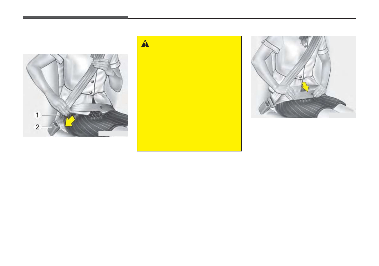
Safety features of your vehicle
243
Seat belt - Driver's 3-point system
with emergency locking retractor
To fasten your seat belt:
To fasten your seat belt, pull it out of
the retractor and insert the metal tab
(1) into the buckle (2). There will be
an audible "click" when the tab locks
into the buckle.
The seat belt automatically adjusts to
the proper length only after the lap
belt portion is adjusted manually so
that it fits snugly around your hips. If
you lean forward in a slow, easy
motion, the belt will extend and let
you move around. If there is a sud-
den stop or impact, however, the belt
will lock into position. It will also lock
if you try to lean forward too quickly.
✽✽
NOTICE
If you are not able to pull out the
seat belt from the retractor, firmly
pull the belt out and release it. Then
you will be able to pull the belt out
smoothly.
B180A01NF-1
B200A02NF
WARNING
You should place the lap belt
portion as low as possible and
snugly across your hips, not on
your waist. If the lap belt is
located too high on your waist,
it may increase the chance of
injury in the event of a collision.
Both arms should not be under
or over the belt. Rather, one
should be over and the other
under, as shown in the illustra-
tion.
Never wear the seat belt under
the arm near the door.
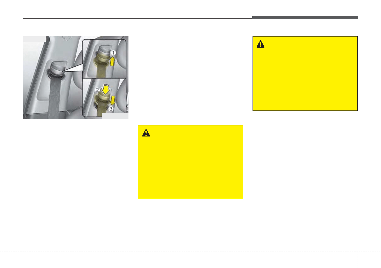
325
Safety features of your vehicle
Height adjustment (For Front seat)
You can adjust the height of the
shoulder belt anchor to one of the 4
positions for maximum comfort and
safety.
The height of the adjusting seat belt
should not be too close to your neck.
The shoulder portion should be
adjusted so that it lies across your
chest and midway over your shoulder
near the door and not your neck.
To adjust the height of the seat belt
anchor, lower or raise the height
adjuster into an appropriate position.
To raise the height adjuster, pull it up
(1). To lower it, push it down (3) while
pressing the height adjuster button (2).
Release the button to lock the
anchor into position. Try sliding the
height adjuster to make sure that it
has locked into position.
Improperly positioned seat belts can
cause serious injuries in an accident.
WARNING - Shoulder belt
positioning
Verify the shoulder belt anchor
is locked into position at the
appropriate height. Never posi-
tion the shoulder belt across
your neck or face. Improperly
positioned seat belts can cause
serious injuries in an accident.
WARNING - Seat belt
replacement
Replace your seat belts after
being in an accident. Failure to
replace seat belts after an acci-
dent could leave you with dam-
aged seat belts that will not pro-
vide protection in the event of
another collision.
ODE036030
Front seat
Safety features of your vehicle
263
Seat belts - Front passenger and
rear seat 3-point system with
combination locking retractor
To fasten your seat belt:
Combination retractor type seat belts
are installed in the rear seat posi-
tions to help accommodate the
installation of child restraint systems.
Although a combination retractor is
also installed in the front passenger
seat position, it is strongly recom-
mended that children always be
seated in the rear seat. NEVER
place any infant restraint system in
the front seat of the vehicle.
This type of seat belt combines the
features of both an emergency lock-
ing retractor seat belt and an auto-
matic locking retractor seat belt. To
fasten your seat belt, pull it out of the
retractor and insert the metal tab into
the buckle. There will be an audible
"click" when the tab locks into the
buckle. When not securing a child
restraint, the seat belt operates in the
same way as the driver's seat belt
(Emergency Locking Retractor Type).
It automatically adjusts to the proper
length only after the lap belt portion
of the seat belt is adjusted manually
so that it fits snugly around your hips.
When the seat belt is fully extended
from the retractor to allow the instal-
lation of a child restraint system, the
seat belt operation changes to allow
the belt to retract, but not to extend
(Automatic Locking Retractor Type).
Refer to “Using a child restraint sys-
tem” in this section.
✽✽
NOTICE
Although the combination retractor
provides the same level of protection
for seated passengers in either emer-
gency or automatic locking modes,
have the seated passengers use the
emergency locking feature for improv-
ed convenience. The automatic locking
function is intended to facilitate child
restraint installation. To convert from
the automatic locking feature to the
emergency locking operation mode,
allow the unbuckled seat belt to fully
retract.
CAUTION
Do NOT fold down the left por-
tion of the rear seat back when
the rear center seat belt is buck-
led. ALWAYS UNBUCKLE the
rear center seat belt before fold-
ing down the left portion of the
rear seat back. If the rear center
seat belt is buckled when the
left portion of the rear seat back
is folded down, distortion and
damage to the top portion of the
seat back and seat belt garnish
may result, causing the seat
back to lock into the folded
down position.
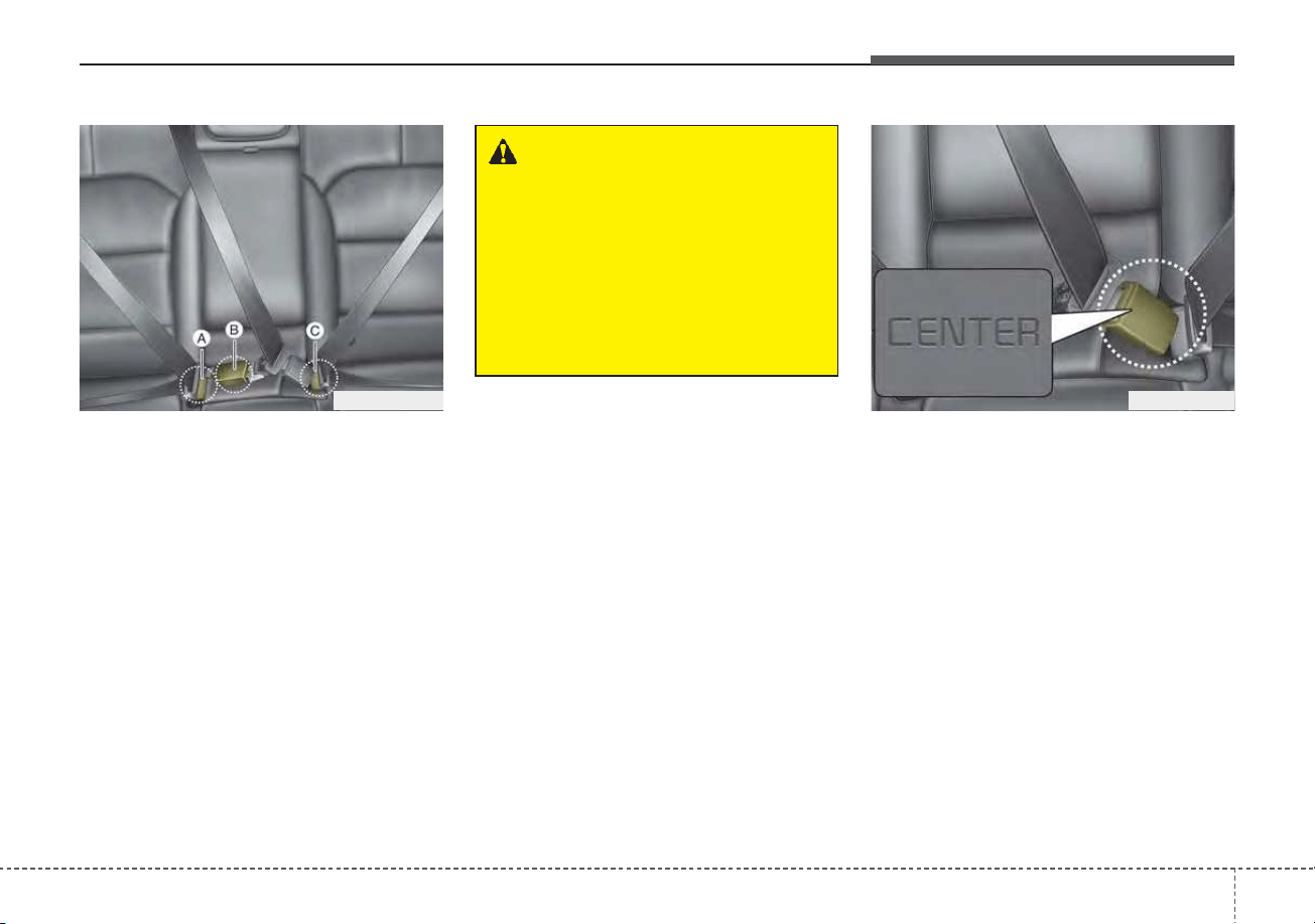
327
Safety features of your vehicle
The seat belt should be locked into
the buckle on each seat cushion to
be properly fastened.
❈ A : Rear right seat belt fastening
buckle
B : Rear center seat belt fastening
buckle
C : Rear left seat belt fastening
buckle
When using the rear center seat belt,
the buckle with the “CENTER” mark
must be used.
ODEP037091L
WARNING
Prior to fastening the rear seat
belts, ensure the latch matches
the seat belt buckle. Forcefully
fastening the left or right seat
belt to the center buckle can
result in an improper fastening
scenario that will not protect
you in an accident.
ODEP037092L
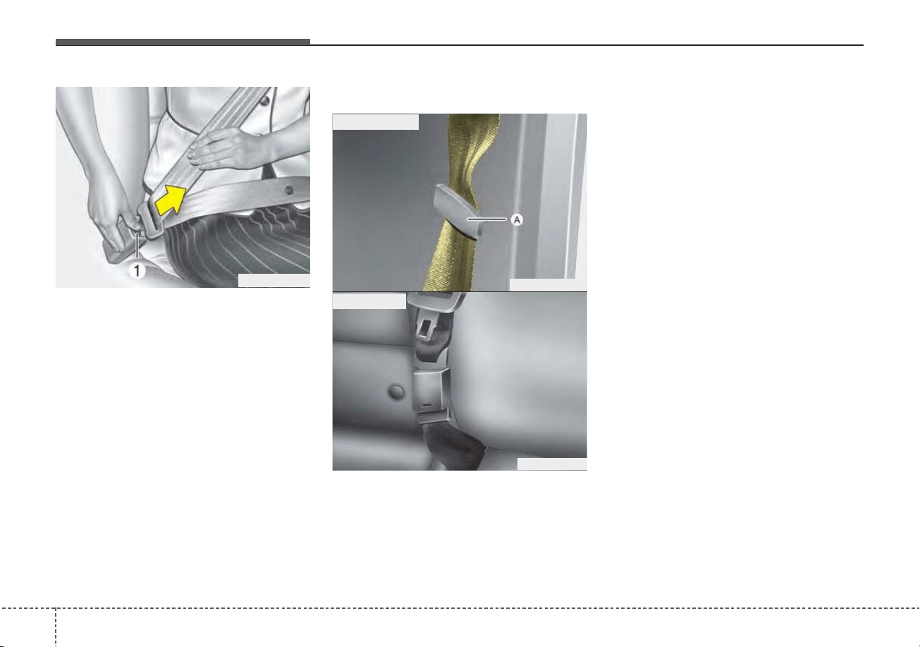
Safety features of your vehicle
283
To release the seat belt:
The seat belt is released by pressing
the release button (1) on the locking
buckle. When it is released, the belt
should automatically draw back into
the retractor.
If this does not happen, check the
belt to be sure it is not twisted, then
try again.
Stowing the rear seat belt
• If the center seat belt is not in use,
always lock the latch plate into the
buckle as above illustration.
• The rear seat belt buckles can be
stowed in the pocket between the
rear seatback and cushion when
not in use.
• Then insert the seat belt into the
two webbing guide (or holder)(A)
located on both sides. It will help
keep the belts from being trapped
behind or under the seats.
After inserting the seat belt, tighten
the belt webbing by pulling it up.
B210A01NF-1
ODEP039111N
■ Outboard belt
ODE036027L
■ Center belt
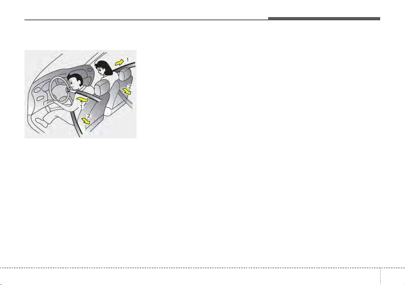
329
Safety features of your vehicle
Pre-tensioner seat belt
Your vehicle is equipped with driver's
and front passenger's pre-tensioner
seat belts (retractor pretensioner and
EFD (Emergency Fastening Device)).
The pre-tensioner seat belts may be
activated, when a frontal collision is
severe enough, together with the air
bags.
When the vehicle stops suddenly, or
if the occupant tries to lean forward
too quickly, the seat belt retractor
may lock into position. In certain
frontal collisions, the pre-tensioner
will activate and pull the seat belt into
tighter contact against the occu-
pant's body.
(1) Retractor Pretensioner
The purpose of the retractor pre-
tensioner is to make sure that the
shoulder belts fit in tightly against
the occupant's upper body in cer-
tain frontal collisions.
(2) EFD (Emergency Fastening Device)
The purpose of the EFD is to
make sure that the pelvis belts fit
in tightly against the occupant's
lower body in certain frontal colli-
sions.
If the system senses excessive ten-
sion on the driver or passenger's
seat belt when the pre-tensioner sys-
tem activates, the load limiter inside
the retractor pre-tensioner will release
some of the pressure on the affected
seat belt.
✽✽
NOTICE
When the pre-tensioner seat belts
are activated, a loud noise may be
heard and fine dust, which may
appear to be smoke, may be visible
in the passenger compartment.
These are normal operating condi-
tions and are not hazardous.
OQL035065
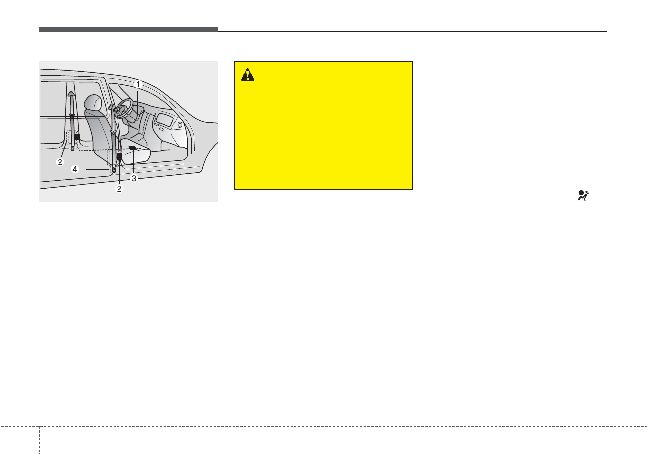
Safety features of your vehicle
303
❈ The actual position of seat belt pre-
tensioner system components may dif-
fer from the illustration.
The seat belt pre-tensioner system
consists mainly of the following com-
ponents.Their locations are shown in
the illustration:
(1) SRS air bag warning light
(2) Retractor pre-tensioner assembly
(3) SRS control module
(4) Emergency fastening device (EFD)
✽✽
NOTICE
• Both the driver's and front pas-
senger's seat belt pre-tensioner sys-
tem may be activated not only in
certain frontal collisions but also in
certain side collisions or rollovers,
if the vehicle is equipped with a
side or curtain air bag.
• Because the sensor that activates
the SRS air bag is connected with
the pre-tensioner seat belt, the
SRS air bag warning light on
the instrument panel will illumi-
nate for approximately 6 seconds
after engine start/stop button has
been changed to ON position, and
then it should turn off.
WARNING - Skin Irritation
Wash all exposed skin areas
thoroughly after an accident in
which the pre-tensioner seat
belts were activated. The fine
dust from the pre-tensioner
activation may cause skin irrita-
tion and should not be breathed
for prolonged periods.
ODMESA2024
331
Safety features of your vehicle
If the pre-tensioner seat belt system
is not working properly, this warning
light will illuminate even if there is not
a malfunction with the SRS air bag. If
the SRS air bag warning light does
not illuminate when engine start/stop
button has been changed to ON, or if
it remains illuminated after illuminat-
ing for approximately 6 seconds, or if
it illuminates while the vehicle is
being driven, have an authorized Kia
dealer inspect the pre-tensioner seat
belt and SRS air bag system as soon
as possible.
✽✽
NOTICE
Do not attempt to service or repair
the pre-tensioner seat belt system in
any manner. Do not attempt to
inspect or replace the pre-tensioner
seat belts yourself. This must be
done by an authorized Kia dealer.
Pre-tensioners are designed to oper-
ate only one time. After activation,
pre-tensioner seat belts must be
replaced. If the pre-tensioner must
be replaced, contact an authorized
Kia dealer.
Seat belt precautions
Infant or small child
All 50 states have child restraint laws.
You should be aware of the specific
requirements in your state. Child
and/or infant seats must be properly
placed and installed in the rear seat.
For more information about the use of
these restraints, refer to “Child
restraint system” in this section.
✽✽
NOTICE
Small children are best protected
from injury in an accident when
properly restrained in the rear seat
by a child restraint system that meets
the requirements of the Federal
Motor Vehicle Safety Standards.
Before buying any child restraint sys-
tem, make sure that it has a label cer-
tifying that it meets Federal Motor
Vehicle Safety Standard 213. The
restraint must be appropriate for
your child's height and weight.
Check the label on the child restraint
for this information. Refer to “Child
restraint system” in this section.
WARNING - Hot preten-
sioner
Do not touch the pre-tensioner
seat belt assemblies for several
minutes after they have been
activated. When the pre-ten-
sioner seat belt mechanism
fires during a collision, the pre-
tensioner becomes hot and can
burn you.
Safety features of your vehicle
323
Larger children
Children who are too large for child
restraint systems should always
occupy the rear seat and use the
available lap/shoulder belts. The lap
portion should be fastened and
snugged on the hips as low as possi-
ble. Check periodically to insure that
the belt fits. A child's squirming could
put the belt out of position. Children
are given the most safety in the event
of an accident when they are
restrained by a proper restraint sys-
tem in the rear seat. If a larger child
(over age 13) must be seated in the
front seat, the child should be
securely restrained by the available
lap/shoulder belt and the seat should
be placed in the rearmost position.
Children age 13 and under should be
restrained securely in the rear seat.
NEVER place a child age 13 and
under in the front seat. NEVER place
a rear facing child seat in the front
seat of a vehicle.
If the shoulder belt portion slightly
touches the child’s neck or face, try
placing the child closer to the center of
the vehicle. If the shoulder belt still
touches their face or neck they need to
be returned to a child restraint system.
Restraint of pregnant women
Pregnant women should wear
lap/shoulder belt assemblies when-
ever possible according to specific
recommendations by their doctors.
The lap portion of the belt should be
worn AS SECURELY AND LOW AS
POSSIBLE.
WARNING - Small children
Do not allow small children to
ride in the vehicle without an
appropriate child restraint sys-
tem. If the shoulder belt comes
in contact with your child's neck
or face, your child is too small to
ride in the vehicle. In a crash the
seat belt will inflict injury to your
child's neck, throat and face.
WARNING - Pregnant
women
Pregnant women must never
place the lap portion of the seat
belt above or on the abdomen
where the fetus is located. The
force of the seat belt during a
collision and may crush and
injure the fetus.
333
Safety features of your vehicle
Injured person
A seat belt should be used when an
injured person is being transported.
When this is necessary, you should
consult a physician for recommenda-
tions.
One person per belt
Two people (including children)
should never attempt to use a single
seat belt. This could increase the
severity of injuries in case of an acci-
dent.
Do not lie down
To reduce the chance of injuries in
the event of an accident and to
achieve maximum effectiveness of
the restraint system, all passengers
should be sitting up and the front and
rear seats should be in an upright
position when the vehicle is moving.
A seat belt cannot provide proper
protection if the person is lying down
in the rear seat or if the front and rear
seats are in a reclined position.
Care of seat belts
Seat belt systems should never be
disassembled or modified. In addi-
tion, care should be taken to assure
that seat belts and belt hardware are
not damaged by seat hinges, doors
or other abuse.
WARNING - Pinched seat
belt
Make sure that the webbing
and/or buckle does not get
caught or pinched in the rear
seat when returning the rear
seatback to its upright position.
A caught or pinched webbing/
buckle may become damaged
and could fail during a collision
or sudden stop.
WARNING
Seatbelts can become hot in a
vehicle that has been closed up
in sunny weather. They could
burn infants and children.

Safety features of your vehicle
343
Periodic inspection
All seat belts should be inspected
periodically for wear or damage of
any kind. Any damaged parts should
be replaced as soon as possible.
Keep belts clean and dry
Seat belts should be kept clean and
dry. If belts become dirty, they can be
cleaned by using a mild soap solu-
tion and warm water. Bleach, dye,
strong detergents or abrasives
should not be used because they
may damage and weaken the fabric.
When to replace seat belts
The entire in-use seat belt assembly
or assemblies should be replaced if
the vehicle has been involved in an
accident. This should be done even if
no damage is visible. Additional
questions concerning seat belt oper-
ation should be directed to an
authorized Kia dealer.
335
Safety features of your vehicle
CHILD RESTRAINT SYSTEM (CRS)
Children Always in the Rear
Children under age 13 must always
ride in the rear seats and must always
be properly restrained to minimize the
risk of injury in an accident, sudden
stop or sudden maneuver. According
to accident statistics, children are
safer when properly restrained in the
rear seats than in the front seat. Even
with air bags, children can be serious-
ly injured or killed. Children too large
for a child restraint must use the seat
belts provided.
All 50 states have child restraint laws
which require children to travel in
approved child restraint devices. The
laws governing the age or
height/weight restrictions at which
seat belts can be used instead of
child restraints differs among states,
so you should be aware of the spe-
cific requirements in your state, and
where you are travelling.
Child restraint systems must be
properly placed and installed in the
rear seat. You must use a commer-
cially available child restraint system
that meets the requirements of the
Federal Motor Vehicle Safety
Standards (FMVSS).
Child restraint systems are generally
designed to be secured in a vehicle
seat by lap belt portion of a
lap/shoulder belt, or by a LATCH sys-
tem in the rear seats of the vehicle.
WARNING - Restraint
Location
Never install a child or infant
seat on the front passenger's
seat. A child riding in the front
passenger seat can be forceful-
ly struck by an inflating airbag
and seriously injured.
WARNING - Hot Child
Restraint
A child restraint system can
become very hot if it is left in a
closed vehicle on a sunny day.
Be sure to check the seat cover,
buckles and latches before
placing a child in the restraint
system.

Safety features of your vehicle
363
Child restraint system (CRS)
Infants and younger children must be
restrained in an appropriate rear-fac-
ing or forward-facing CRS that has
first been properly secured to the
rear seat of the vehicle. Read and
comply with the instructions for
installation and use provided by the
manufacturer of the child restraint.
✽✽
NOTICE
After an accident, have a Kia dealer
check the child restraint system, seat
belts, tether anchors and lower
anchors.
Selecting a Child Restraint
System (CRS)
When selecting a CRS for your child,
always:
• Make sure the CRS has a label
certifying that it meets applicable
Federal Motor Vehicle Safety
Standards (FMVSS 213).
• Select a child restraint based on
your child’s height and weight. The
required label or the instructions
for use typically provide this infor-
mation.
• Select a child restraint that fits the
vehicle seating position where it
will be used.
• Read and comply with the warn-
ings and instructions for installation
and use provided with the child
restraint system.
WARNING
-
Child Restraint Installation
An improperly secured child
restraint can increase the risk
of serious injury or death in an
accident. Always take the fol-
lowing precautions when using
a child restraint system:
• Always follow the child
restraint system manufactur-
er’s instructions for installa-
tion and use.
(Continued)
(Continued)
• Always properly restrain your
child in the child restraint.
• If the vehicle head restraint
prevents proper installation of
a child seat (as described in
the child restraint system
manual), the head restraint of
the respective seating posi-
tion shall be readjusted or
entirely removed.
• Do not use an infant carrier or
a child safety seat that
"hooks" over a seatback, it
may not provide adequate
protection in an accident.
337
Safety features of your vehicle
Child restraint system types
There are three main types of child
restraint systems: rear-facing seats,
forward-facing seats, and booster
seats. They are classified according
to the child’s age, height and weight.
WARNING - Holding
Children
Never hold a child in your arms
or lap when riding in a vehicle.
The violent forces created dur-
ing a crash could tear the child
from your arms and throw the
child against the car’s interior.
Always use a child restraint
system which is appropriate for
your child's height and weight.
WARNING - Unattended
Children
Never leave children unattended
in a vehicle. The car can heat up
very quickly, resulting in injuries
to the child in the vehicle.
WARNING - Seat Belt Use
Do not use one seat belt for two
occupants at the same time.
This may eliminate any safety
benefit provided by the seat belt
to the occupants.
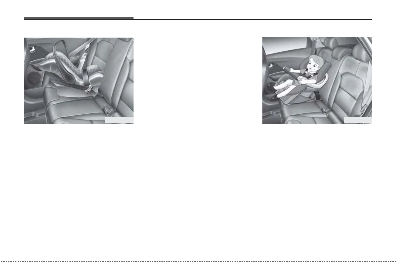
Safety features of your vehicle
383
Rear-facing child seats
A rear-facing child seat provides
restraint with the seating surface
against the back of the child. The
harness system holds the child in
place, and in an accident, acts to
keep the child positioned in the seat
and reduces the stress to the neck
and spinal cord.
All children under age one must
always ride in a rear-facing infant
child restraint.
Convertible and 3-in-1 child seats
typically have higher height and
weight limits for the rear-facing posi-
tion, allowing you to keep your child
rear-facing for a longer period of time.
Continue to use a rear-facing child
seat for as long as your child will fit
within the height and weight limits
allowed by the child seat manufactur-
er. It’s the best way to keep them
safe. Once your child has outgrown
the rear-facing child restraint, your
child is ready for a forward-facing
child restraint with a harness.
Forward-facing child restraints
A forward-facing child seat provides
restraint for the child’s body with a
harness. Keep children in a forward-
facing child seat with a harness until
they reach the top height or weight
limit allowed by your child restraint’s
manufacturer.
Once your child outgrows the for-
ward-facing child restraint, your child
is ready for a booster seat.
ODE036031 ODE026007

339
Safety features of your vehicle
Booster seats
A booster seat is a restraint designed
to improve the fit of the vehicle’s seat
belt system. A booster seat positions
the seat belt so that it fits properly
over the lap of your child.
Keep your child in a booster seat
until they are big enough to sit in the
seat without a booster and still have
the seat belt fit properly. For a seat
belt to fit properly, the lap belt must
lie snugly across the upper thighs,
not the stomach. The shoulder belt
should lie snug across the shoulder
and chest and not across the neck or
face. Children under age 13 must
always ride in the rear seats and
must always be properly restrained
to minimize the risk of injury.
Installing a Child Restraint
System (CRS)
After selecting a proper child seat for
your child, check to make sure it fits
properly in your vehicle. Follow the
instructions provided by the manu-
facturer when installing the child
seat. Note these general steps when
installing the seat to your vehicle:
• Properly secure the child
restraint to the vehicle. All child
restraints must be secured to the
vehicle with the lap part of a
lap/shoulder belt or with the
LATCH system.
• Make sure the child restraint is
firmly secured. After installing a
child restraint to the vehicle, push
and pull the seat forward and from
side-to-side to verify that it is
securely attached to the seat. A
child restraint secured with a seat
belt should be installed as firmly as
possible. However, some side-to-
side movement can be expected.
• Secure the child in the child
restraint. Make sure the child is
properly strapped in the child
restraint according to the manufac-
turer instructions.
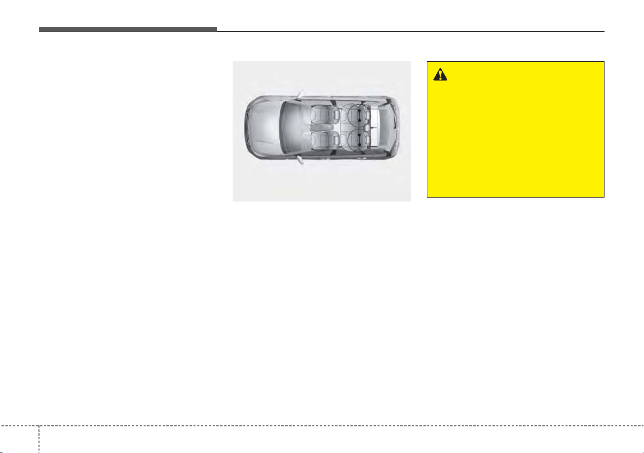
Safety features of your vehicle
403
Lower Anchors and Tether for
Children (LATCH) System
The LATCH system holds a child
restraint during driving and in an
accident. This system is designed to
make installation of the child restraint
easier and reduce the possibility of
improperly installing your child
restraint. The LATCH system uses
anchors in the vehicle and attach-
ments on the child restraint. The
LATCH system eliminates the need
to use seat belts to secure the child
restraint to the rear seats.
Lower anchors are metal bars built
into the vehicle. There are two lower
anchors for each LATCH seating
position that will accommodate a
child restraint with lower attach-
ments.
To use the LATCH system in your
vehicle, you must have a child
restraint with LATCH attachments.
The child seat manufacturer will pro-
vide you with instructions on how to
use the child seat with its attach-
ments for the LATCH lower anchors.
LATCH anchors have been provided
in the left and right outboard rear
seating positions. Their locations are
shown in the illustration. There are
no LATCH anchors provided for the
center rear seating position.
ODE036077L
WARNING - LATCH Lower
Anchors
Never attempt to attach a LATCH
equipped seat in the center
seating position. LATCH lower
anchors are only to be used in
the left and right rear outboard
seating positions.You may dam-
age the anchors or the anchors
may fail and break in a collision.
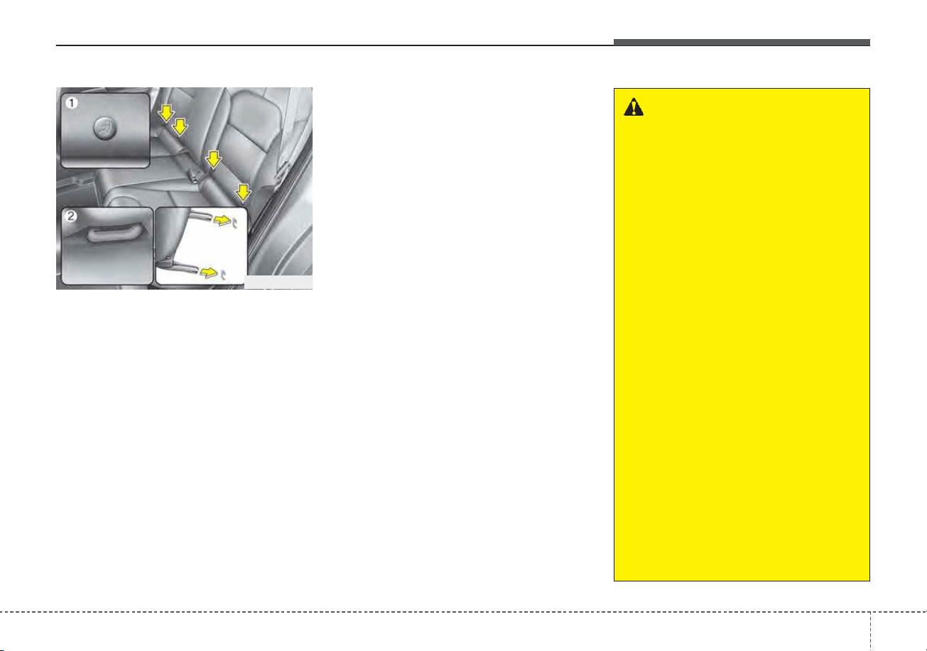
341
Safety features of your vehicle
The lower anchor position indicator
symbols are located on the left and
right rear seat backs to identify the
position of the lower anchors in your
vehicle (see arrows in illustration).
The LATCH anchors are located
between the seatback and the seat
cushion of the rear seat left and right
outboard seating positions.
To use the lower anchor, push the
upper portion of the lower anchor
cover.
❈ (1) : Lower Anchor position indicator
(2) : Lower Anchor
Securing a child restraint with
the LATCH anchors system
To install a LATCH-compatible child
restraint in either of the rear outboard
seating positions:
1. Move the seat belt buckle away
from the lower anchors.
2. Move any other objects away from
the anchors that could prevent a
secure connection between the
child restraint and the lower
anchors.
3. Place the child restraint on the
vehicle seat, then attach the seat
to the lower anchors according to
the instructions provided by the
child restraint manufacturer.
4. Follow the child restraint instruc-
tions for properly adjusting and
tightening the lower attachments
on the child restraint to the lower
anchors.
ODE036035
WARNING
Take the following precautions
when using the LATCH system:
• Read and follow all installation
instructions provided with
your child restraint system.
• To prevent the child from
reaching and taking hold of
unretracted seat belts, buckle
all unused rear seat belts and
retract the seat belt webbing
behind the child. Children can
be strangled if a shoulder belt
becomes wrapped around their
neck and the seat belt tightens.
• NEVER attach more than one
child restraint to a single
anchor. This could cause the
anchor or attachment to come
loose or break.
• Always have the LATCH sys-
tem inspected by your author-
ized Kia dealer after an acci-
dent. An accident can damage
the LATCH system and may
not properly secure the child
restraint.
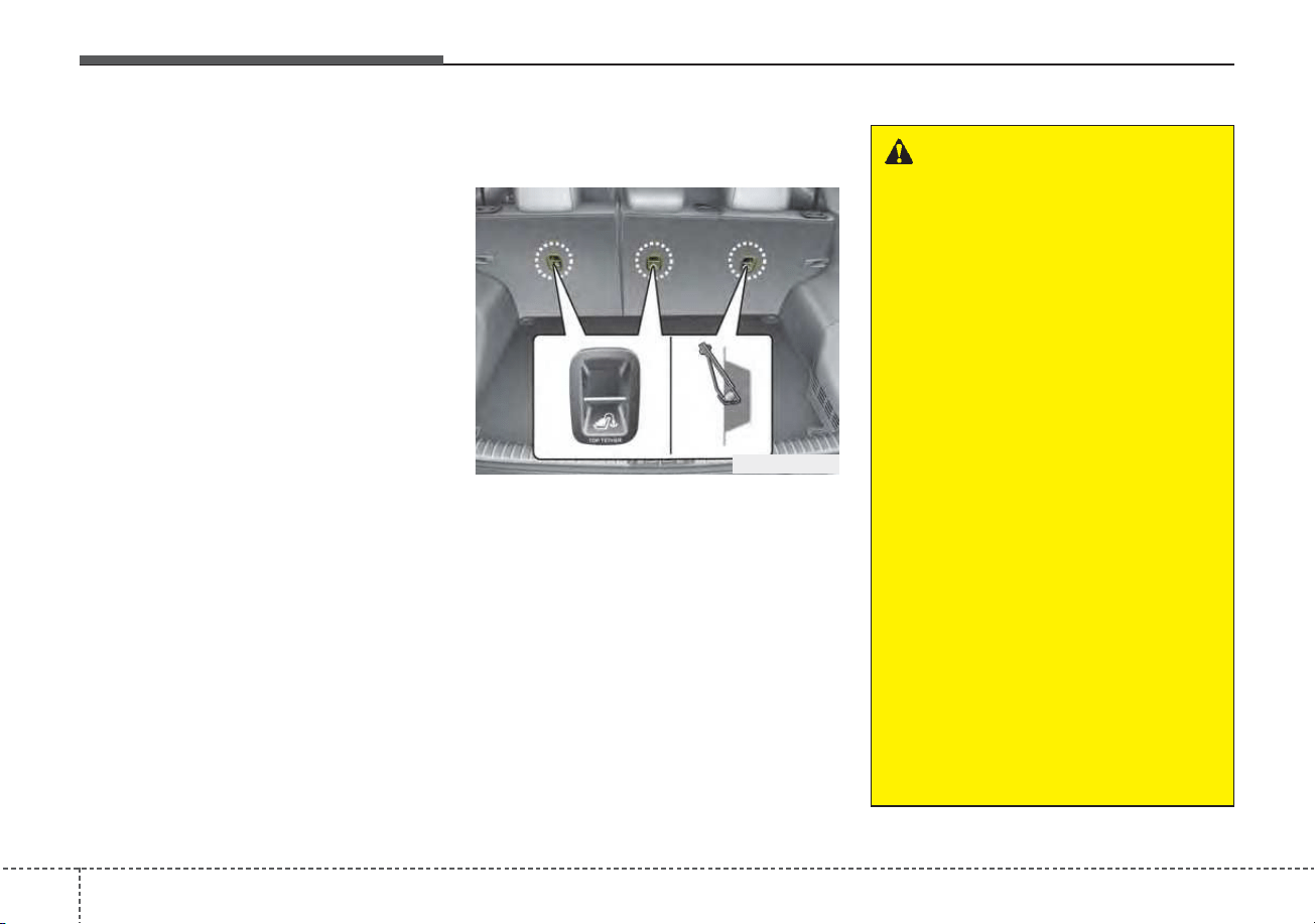
Safety features of your vehicle
423
✽✽
NOTICE
The recommended maximum
weight for the LATCH system is 65
lbs. (30 kg). When selecting a proper
child restraint, consider that the
maximum total weight of the child
plus the child restraint should be
less than 65 lbs (30 kg).
As a guide, the MAX child restraint
weight should be determined by the
following calculation:
Child Restraint Weight =
65 - (child's total weight in lbs.)
Securing a child restraint seat
with "Tether Anchor" system
First secure the child restraint with
the LATCH lower anchors or the seat
belt. If the child restraint manufactur-
er recommends that the top tether
strap be attached, attach and tighten
the top tether strap to the top tether
strap anchor.
Child restraint hook holders are
located on the shelf behind the rear
seats.
ODE036032R
WARNING
Take the following precautions
when installing the tether strap:
• Read and follow all installation
instructions provided with
your child restraint system.
• NEVER attach more than one
child restraint to a single teth-
er anchor. This could cause
the anchor or attachment to
come loose or break.
• Do not attach the tether strap
to anything other than the cor-
rect tether anchor. It may not
work properly if attached to
something else.
• Do not use the tether anchors
for adult seat belts or harness-
es, or for attaching other items
or equipment to the vehicle.
• Always fasten the seat belts
behind the child restraint seat
when they are not used to
secure the child seat. Failure
to do so may result in child
strangulation.
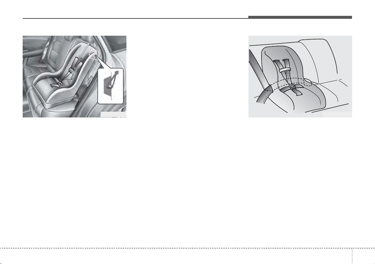
343
Safety features of your vehicle
To install the tether anchor:
1. Route the child restraint tether
strap over the child restraint seat-
back. Route the tether strap under
the head restraint and between
the head restraint posts, or route
the tether strap over the top of the
vehicle seatback. Make sure the
strap is not twisted.
2. Connect the tether strap hook to
the tether anchor, then tighten the
tether strap according to the child
seat manufacturer’s instructions to
firmly secure the child restraint to
the seat.
3. Check that the child restraint is
securely attached to the seat by
pushing and pulling the seat for-
ward and from side-to-side.
Securing a child restraint with a
lap/shoulder belt
When not using the LATCH system,
all child restraints must be secured to
a vehicle rear seat with the lap part
of a lap/shoulder belt.
Automatic locking mode
Since all passenger seat belts move
freely under normal conditions and
only lock under extreme or emer-
gency conditions (emergency locking
mode), you must manually pull the
seat belt all the way out to shift the
retractor to the “Automatic Locking”
mode to secure a child restraint.
The “Automatic Locking” mode will
help prevent the normal movement
of the child in the vehicle from caus-
ing the seat belt to loosen and com-
promise the child restraint system. To
secure a child restraint system, use
the following procedure.
ODE036033 OLMB033044
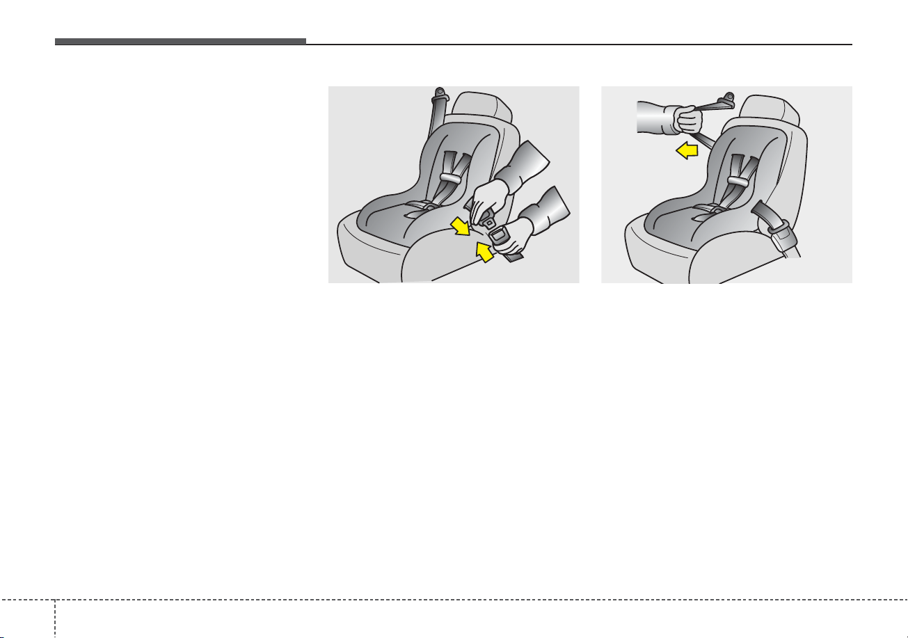
Safety features of your vehicle
443
To install a child restraint system on
the rear seats, do the following:
1.Place the child restraint system on
a rear seat and route the lap/ shoul-
der belt around or through the child
restraint, following the restraint
manufacturer’s instructions.
Be sure the seat belt webbing is
not twisted.
2. Fasten the lap/shoulder belt latch
into the buckle. Listen for the dis-
tinct “click” sound.
Position the release button so that
it is easy to access in case of an
emergency.
3. Pull the shoulder portion of the
seat belt all the way out. When the
shoulder portion of the seat belt is
fully extended, it will shift the
retractor to the “Automatic
Locking” (child restraint) mode.
OEN036101 OEN036102
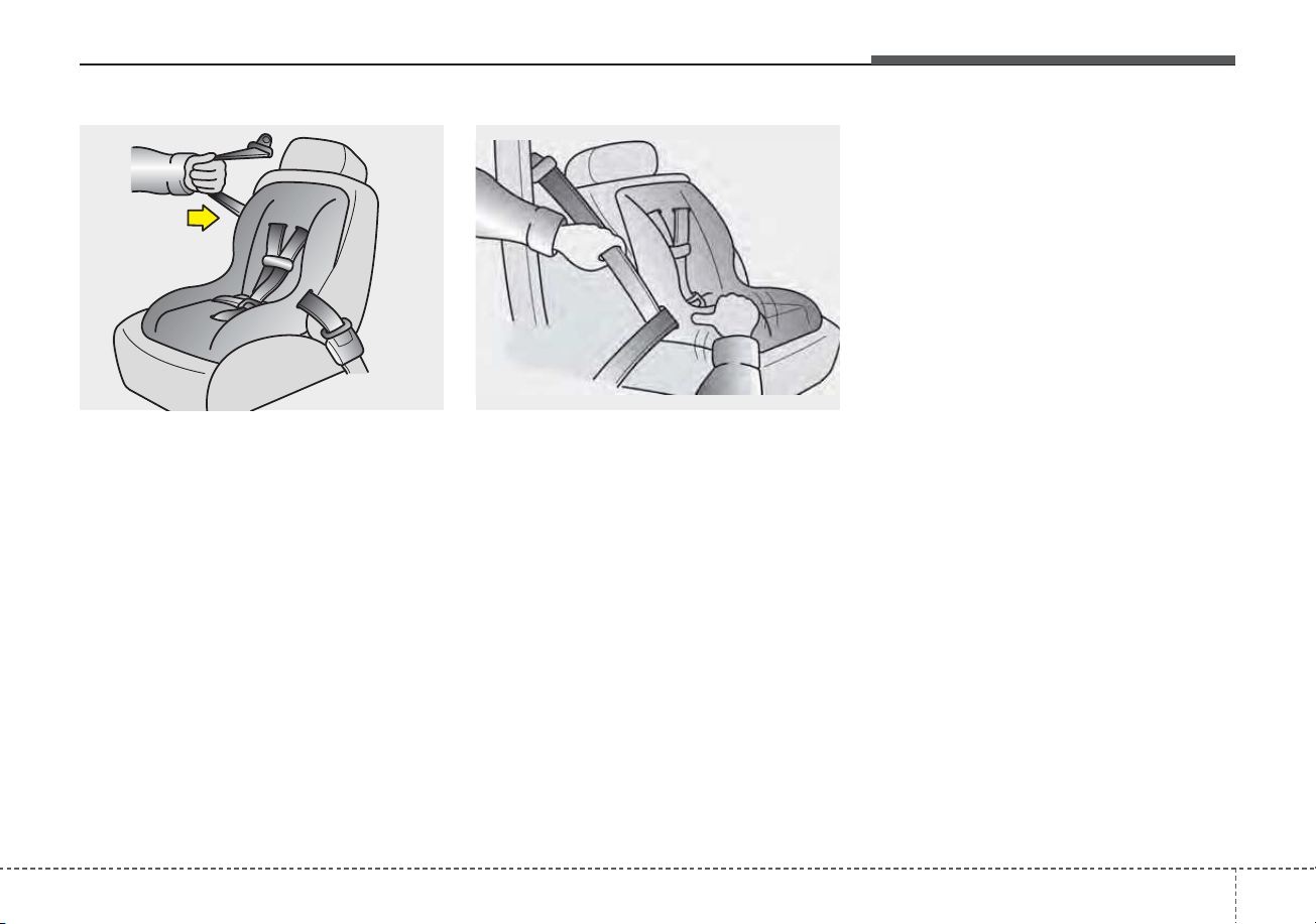
345
Safety features of your vehicle
4. Slowly allow the shoulder portion
of the seat belt to retract and listen
for an audible "clicking" or "ratchet-
ing" sound. This indicates that the
retractor is in the "Automatic
Locking" mode. If no distinct sound
is heard, repeat steps 3 and 4.
5. Remove as much slack from the
belt as possible by pushing down
on the child restraint system while
feeding the shoulder belt back into
the retractor.
6. Push and pull on the child restraint
system to confirm that the seat
belt is holding it firmly in place. If it
is not, release the seat belt and
repeat steps 2 through 6.
7. Double check that the retractor is
in the "Automatic Locking" mode
by attempting to pull more of the
seat belt out of the retractor. If you
cannot, the retractor is in the
"Automatic Locking" mode.
If your CRS manufacturer instructs or
recommends you to use a tether
anchor with the lap/shoulder belt,
refer to the previous pages for more
information.
✽✽
NOTICE
When the seat belt is allowed to
retract to its fully stowed position,
the retractor will automatically
switch from the "Automatic
Locking" mode to the emergency
lock mode for normal adult usage.
OEN036103 OHI038183L
Safety features of your vehicle
463
To remove the child restraint, press
the release button on the buckle and
then pull the lap/shoulder belt out of
the restraint and allow the seat belt
to retract fully.
WARNING - Auto lock
mode
Set the retractor to Automatic
Lock mode when installing any
child restraint system. If the
retractor is not in the Automatic
Locking mode, the child restraint
can move when your vehicle
turns or stops suddenly.
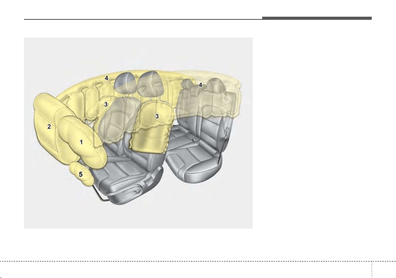
347
Safety features of your vehicle
(1) Driver’s front air bag
(2) Passenger’s front air bag
(3) Side air bag
(4) Curtain air bag
(5) Driver’s knee air bag
Even in vehicles with air bags, you
and your passengers must always
wear the safety belts provided in
order to minimize the risk and sever-
ity of injury in the event of a collision
or rollover.
AIR BAG - ADVANCED SUPPLEMENTAL RESTRAINT SYSTEM
The actual air bags in the vehicle may differ from the illustration.
ODEP039036N

Safety features of your vehicle
483
How does the air bag system
operate?
• Air bags are activated (able to
inflate if necessary) only when the
ignition switch is turned to the ON
or START position or when engine
start/stop button has been
changed to ON position.
• The appropriate air bags inflate
instantly in the event of a serious
frontal collision or side collision in
order to help protect the occupants
from serious physical injury.
• There is no single speed at which
the air bags will inflate.
Generally, air bags are designed to
inflate based upon the severity of a
collision and its direction. These
two factors determine whether the
sensors produce an electronic
deployment/ inflation signal.
• Air bag deployment depends on a
number of factors including vehicle
speed, angles of impact, and, the
density and stiffness of the vehi-
cles or objects which your vehicle
hits in the collision. The determin-
ing factors are not limited to those
mentioned above.
• The front air bags will completely
inflate and deflate in an instant.
It is virtually impossible for you to
see the air bags inflate during an
accident.
It is much more likely that you will
simply see the deflated air bags
hanging out of their storage com-
partments after the collision.
• In addition to inflating in serious
side collisions, side and/or curtain
air bags will inflate if the sensing
system detects a rollover.
• When a rollover is detected, side
and/or curtain air bags will remain
inflated longer to help provide pro-
tection from ejection, especially
when used in conjunction with the
seat belts.
• In order to help provide protection,
the air bags must inflate rapidly.
The speed of the air bag inflation is
a consequence of extremely short
time in which to inflate the air bag
between the occupant and the
vehicle structures before the occu-
pant impacts those structures. This
speed of inflation reduces the risk
of serious or life-threatening
injuries and is thus a necessary
part of the air bag design.
However, air bag inflation can also
cause injuries which can include
facial abrasions, bruises and bro-
ken bones because the inflation
speed also causes the air bags to
expand with a great deal of force.
• There are even circumstances
under which contact with the
steering wheel or passenger air
bag can cause fatal injuries,
especially if the occupant is
positioned excessively close to
the steering wheel or passenger
air bag.
349
Safety features of your vehicle
Noise and smoke
When inflated, the air bags make a
loud noise and leave smoke and
powder in the air inside the vehicle.
This is normal and is a result of the
ignition of the air bag inflator. After
the air bag inflates, you may feel sub-
stantial discomfort in breathing due
to the contact of your chest with both
the seat belt and the air bag, as well
as from breathing the smoke and
powder. Open your doors and/or
windows as soon as possible after
impact in order to reduce discom-
fort and prevent prolonged expo-
sure to the smoke and powder.
Though smoke and powder are non-
toxic, it may cause irritation to the
skin (eyes, nose and throat, etc). If
this is the case, wash and rinse with
cold water immediately and consult a
doctor if the symptom persists.
WARNING - Hot compo-
nents
Do not touch the air bag storage
area's internal components
immediately after airbag infla-
tion. The air bag related parts in
the steering wheel, instrument
panel and the roof rails above
the front and rear doors are
very hot. Hot components can
result in burn injuries.
WARNING
Do not install or place any
accessories near air bag
deployment areas, such as the
instrument panel, windows, pil-
lars, and roof rails.
WARNING - Airbag infla-
tion
Sit as far back as possible from
the steering wheel while still
maintaining comfortable con-
trol of your vehicle. A distance
of at least 10" from your chest
to the steering wheel is recom-
mended. Failure to do so can
result in airbag inflation injuries
to the driver.
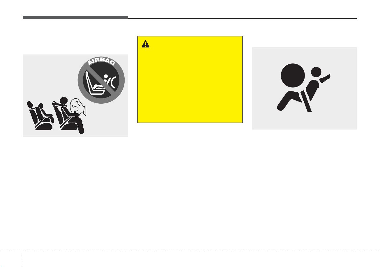
Safety features of your vehicle
503
Do not install a child restraint on
the front passenger’s seat
Never place a rear-facing child
restraint in the front passenger’s
seat. If the air bag deploys, it would
impact the rear-facing child restraint,
causing serious or fatal injury.
In addition, do not place front-facing
child restraints in the front passen-
ger’s seat. If the front passenger air
bag inflates, it could cause serious or
fatal injuries to the child.
Air bag warning light
The purpose of air bag warning light
in your instrument panel is to alert
you of a potential problem with your
air bag system, which could include
your side and/or curtain air bags
used for rollover protection.
1JBH3051
W7-147
WARNING - Air bag
deployment
When children are seated in the
rear outboard seats of a vehicle
equipped with side and/or cur-
tain air bags, install the child
restraint system as far away
from the door side as possible.
Inflation of the side and/or cur-
tain air bags could impact the
child.
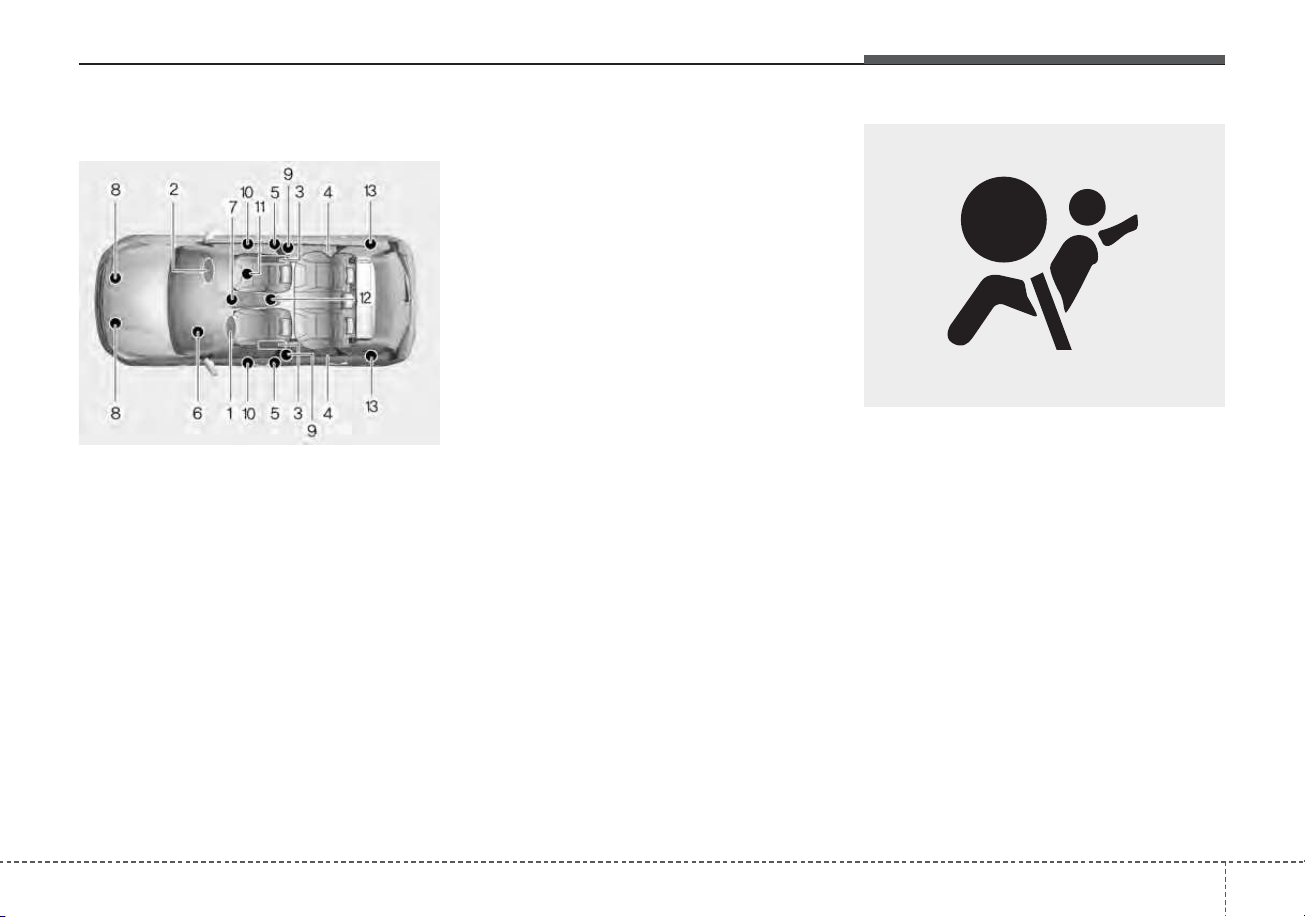
351
Safety features of your vehicle
SRS components and functions
❈ The actual position of SRS compo-
nents may differ from the illustration.
The SRS consists of the following
components:
1. Driver's front air bag module
2. Passenger's front air bag module
3. Side air bag modules
4. Curtain air bag modules
5. Retractor pre-tensioner assemblies
6. Air bag warning light
7. SRS control module (SRSCM)
8. Front impact sensors
9. Side impact sensors
10. Side pressure sensors
11. Occupant detection system
(Front passenger’s seat only)
12. Front passenger’s seat belt
buckle sensor
13. Retractor pre-tensioner assem-
blies*
*: if equipped
If the air bag warning light is illumi-
nated for more than 6 seconds after
engine start/stop button has been
changed to ON, or of it illuminates
during vehicle operation, an SRS
component may not be functioning
properly and you should have your
vehicle checked by an authorized Kia
dealer.
W7-147
ODE036078N
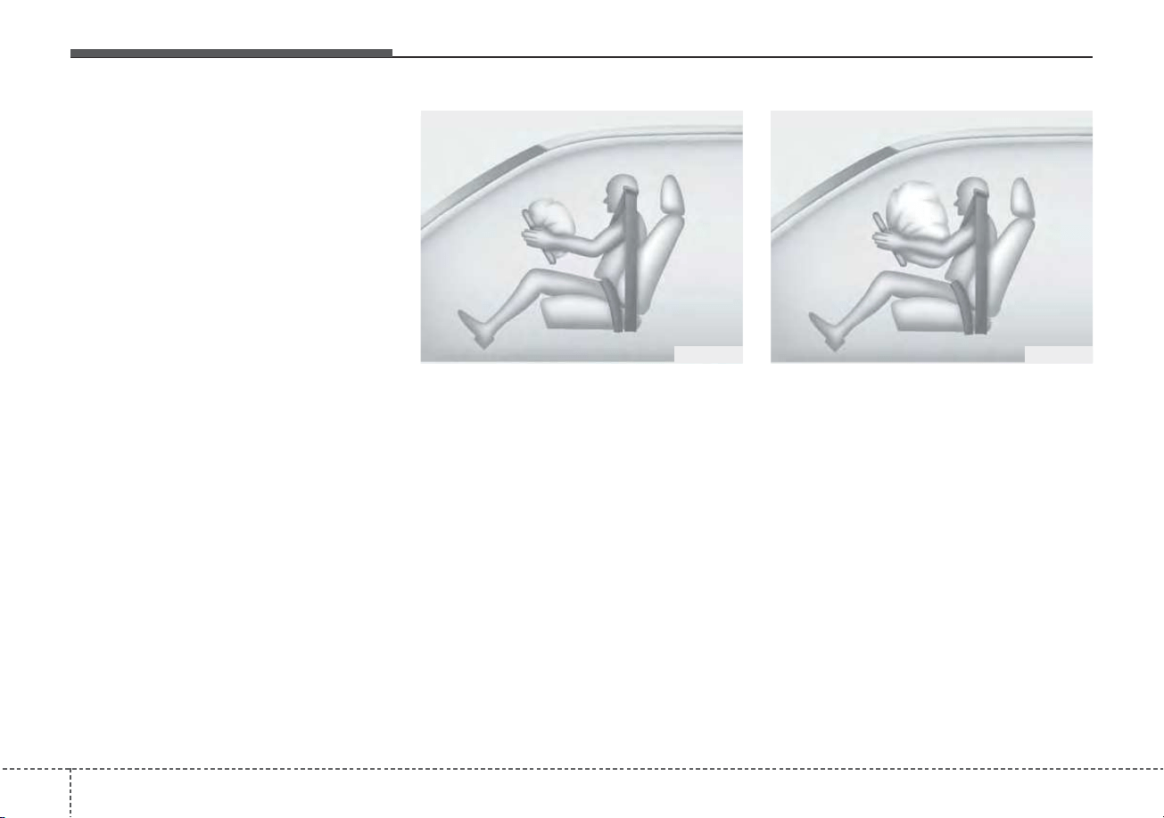
Safety features of your vehicle
523
If any of the following conditions
occur, this indicates a malfunction in
the air bag system. Have an author-
ized Kia dealer inspect the air bag
system as soon as possible.
• The light does not turn on briefly
when you change engine start/stop
button to ON.
• The light stays on after illuminating
for approximately 6 seconds.
• The light comes on while the vehi-
cle is in motion.
• The light blinks when engine
start/stop button is ON position.
The front air bag modules are locat-
ed both in the center of the steering
wheel and in the front passenger's
panel above the glove box. When the
SRSCM detects a sufficiently severe
impact to the front of the vehicle, it
will automatically deploy the front air
bags.
Upon deployment, tear seams mold-
ed directly into the pad covers will
separate under pressure from the
expansion of the air bags. Further
opening of the covers then allows full
inflation of the air bags.
B240B01L
Driver’s front air bag (1)
B240B02L
Driver’s front air bag (2)
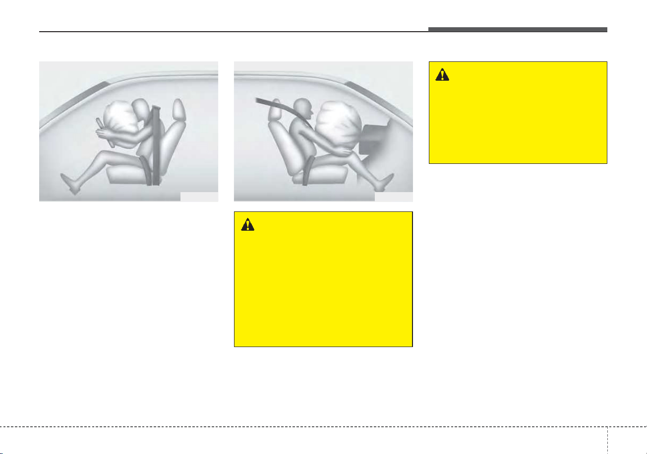
353
Safety features of your vehicle
A fully inflated air bag, in combina-
tion with a properly worn seat belt,
slows the driver's or the passenger's
forward motion, reducing the risk of
head and chest injury.
After complete inflation, the air bag
immediately starts deflating, enabling
the driver to maintain forward visibility
and the ability to steer or operate
other controls.
• If an air bag deploys, there may be
a loud noise followed by a fine dust
released in the vehicle. These con-
ditions are normal and are not haz-
ardous - the air bags are packed in
this fine powder. The dust generat-
ed during air bag deployment may
cause skin or eye irritation as well
as aggravate asthma for some per-
sons. Always wash all exposed
skin areas thoroughly with cold
water and a mild soap after an
accident in which the air bags were
deployed.
B240B03L
Driver’s front air bag (3)
B240B05L
Passenger’s front air bag
WARNING - Air bag
obstructions
Do not install or place any
accessories on the steering
wheel, instrument panel, or on
the front passenger's panel
above the glove box in a vehi-
cle. Such objects may become
dangerous projectiles if the air
bag deploys.
WARNING - Flying objects
Do not place any objects (an
umbrella, bag, etc.) between the
front door and the front seat.
Such objects may become dan-
gerous projectiles if the side
airbag inflates.
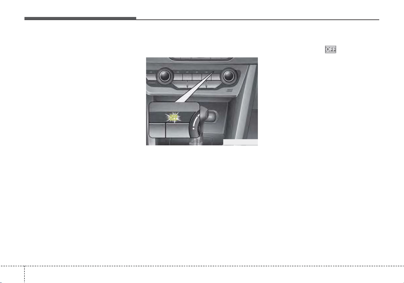
Safety features of your vehicle
543
• The SRS can function only when
engine start/stop button is ON
position. If the SRS air bag warning
light does not illuminate, or contin-
uously remains on after illuminat-
ing for about 6 seconds when
engine start/stop button is ON
position, or after the engine is
started, comes on while driving,
the SRS is not working properly. If
this occurs, have your vehicle
immediately inspected by an
authorized Kia dealer.
✽✽
NOTICE
Before you replace a fuse or discon-
nect a battery terminal, change
Engine Start/Stop button to the OFF
position. Never remove or replace
the air bag related fuse(s) when
engine start/stop button is ON posi-
tion. Failure to heed this warning
will cause the SRS air bag warning
light to illuminate.
Occupant Detection System
(ODS)
Your vehicle is equipped with an
occupant detection system in the
front passenger's seat.
The occupant detection system is
designed to detect the presence of a
properly-seated front passenger and
determine if the passenger's front air
bag should be enabled (may inflate)
or not. Only the front passenger front
air bag is controlled by the Occupant
Detection System.
Do not put anything in front of the
passenger air bag indicator.
ODEP039039N

355
Safety features of your vehicle
Main components of the occu-
pant detection system
• A detection device located within
the front passenger seat cushion.
• An electronic system which deter-
mines whether the passenger air
bag systems should be activated
or deactivated.
• An indicator light located on the
instrument panel which illuminates
the words PASSENGER AIR BAG
“OFF” indicates the front passen-
ger air bag system is deactivated.
• The instrument panel air bag warn-
ing light is interconnected with the
occupant detection system.
If the front passenger seat is occu-
pied by a person that the system
determines to be of appropriate size,
and he/she sits properly (sitting
upright with the seatback in an
upright position, centered on the
seat cushion with their seat belt on,
legs comfortably extended and their
feet on the floor), the PASSENGER
AIR BAG “OFF” indicator will turn off
and the front passenger's air bag will
be able to inflate, if necessary, in
frontal crashes.
You will find the PASSENGER AIR
BAG “OFF” indicator on the center
facia panel. This system detects the
conditions 1~4 in the following table
and activates or deactivates the front
passenger air bag based on these
conditions.
Always be sure that you and all vehicle
occupants are seated and restrained
properly (sitting upright with the seat in
an upright position, centered on the
seat cushion, with the person’s legs
comfortably extended, feet on the
floor, and wearing the safety belt prop-
erly) for the most effective protection
by the air bag and the safety belt.
• The ODS (Occupant Detection
System) may not function properly if
the passenger takes actions which
can defeat the detection system.
These include:
(1) Failing to sit in an upright position.
(2) Leaning against the door or cen-
ter console.
(3) Sitting towards the sides or the
front of the seat.
(4) Putting legs on the dashboard or
resting them on other locations
which reduce the passenger
weight on the front seat.
(5) Improperly wearing the safety belt.
(6) Reclining the seat back.
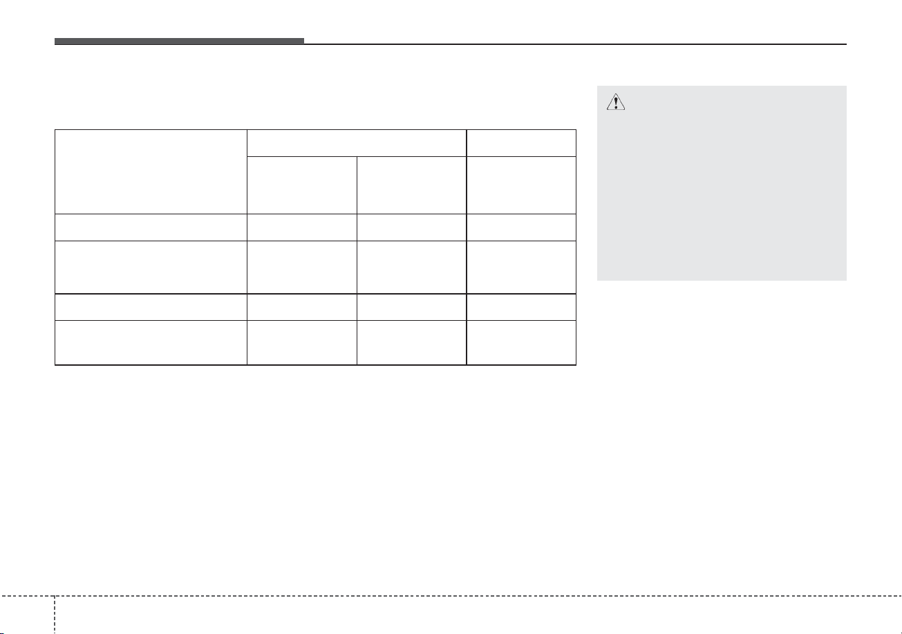
Safety features of your vehicle
563
Condition and operation in the front passenger occupant detection
system
*
1
The system judges a person of adult size as an adult. When a smaller adult sits in
the front passenger seat, the system may recognize him/her as a child depending
on his/her physique and posture.
*
2
Do not allow children to ride in the front passenger seat. When a larger child who has
outgrown a child restraint system sits in the front passenger seat, the system may rec-
ognize him/her as an adult depending upon his/her physique or sitting position.
*
3
Never install a child restraint system on the front passenger seat.
*
4
The PASSENGER AIR BAG “OFF” indicator may turn on or off when a child above
12 months to 12 years old (with or without child restraint system) sits in the front
passenger seat. This is a normal condition.
Condition detected by the
occupant classification system
Indicator/Warning light Devices
“PASSENGER
AIR BAG OFF”
indicator light
SRS warning
light
Front passenger
air bag
1. Adult*
1
Off Off Activated
2. Child restraint system with
child under 12 months old
*
2
*
3
*
4
On Off Deactivated
3. Unoccupied On Off Deactivated
4. Malfunction in the system Off On Activated
CAUTION
• Do not install a child restraint
seat in the passenger seat
when the seat is heavily
soaked with any type of liquid.
• Do not alter or remodel the
ODS (Occupant Detection
System). This may damage the
system and prevent its proper
function in a collision.

357
Safety features of your vehicle
✽✽
NOTICE
• Do not use car seat cushions that
cover up the surface of the seat
and aftermarket manufactured
passenger seat heaters.
• After conducting car interior
cleaning using steam or detergent,
the seat should be dried properly.
Afterward, check for normal
operation of the PASS AIR BAG
“OFF” and air bag warning lights.
• Any service related to the passen-
ger seat and the ODS must be
done at Kia service center.
• After the passenger seat has been
removed or installed for repair
purposes, check for normal opera-
tion of the PASS AIR BAG “OFF”
and air bag warning lights with a
person seated or not seated in the
passenger seat.
✽
✽
NOTICE
When the PASS AIR BAG “OFF”
symbol is illuminated, the passenger
air bag system will not operate. The
passenger air bag system will oper-
ate when necessary if the symbol is
not illuminated.
✽
✽
NOTICE
Do not modify or replace the front
passenger seat. Don't place anything
on or attach anything such as a blan-
ket, front seat cover or after market
seat heater to the front passenger
seat. This can adversely affect the
occupant detection system.
WARNING - ODS system
Riding in an improper position or
placing items on or under the
passenger seat may interfere
with the normal operation of the
ODS (Occupant Detection
System). It is important for the
driver to instruct the passenger
as to the proper seating instruc-
tions as contained in this manual.
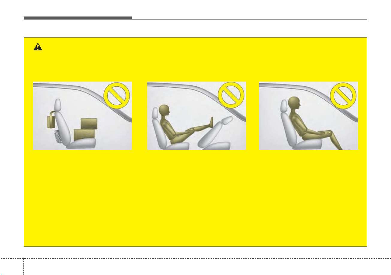
Safety features of your vehicle
583
OJFA035106
- Never sit with hips shifted
towards the front of the seat.
OJFA035104
- Do not place a heavy load in
the front passenger seatback
pocket or on the front passen-
ger seat.
OJFA035105
- Do not place feet on the front
passenger seatback.
WARNING - ODS System
Riding in an improper position adversely affects the Occupant Detection System and may result in the
deactivation of the front passenger airbag. It is important for the driver to instruct the passenger as to
the proper seating instructions as contained in this manual.
(Continued)
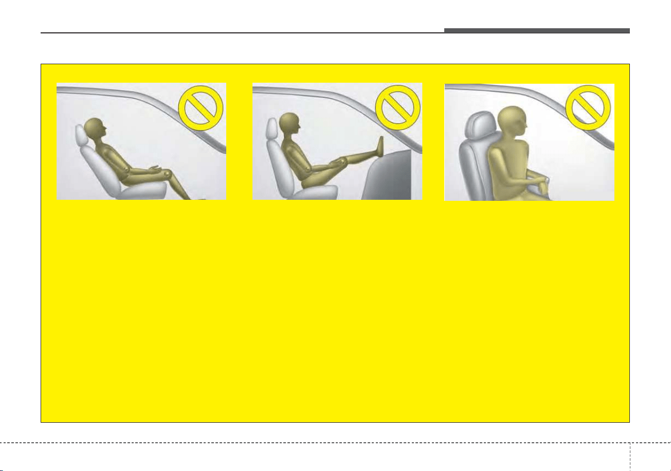
359
Safety features of your vehicle
OJFA035109
- Never lean on the door or cen-
ter console.
- Never sit on one side of the
front passenger seat.
OJFA035107
- Never excessively recline the
front passenger seatback.
OJFA035108
- Never place feet on the dash-
board.
(Continued)
(Continued)
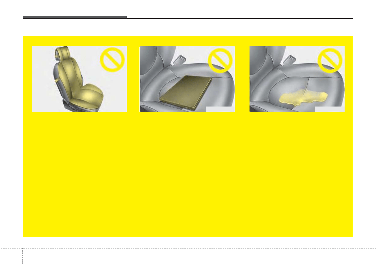
Safety features of your vehicle
603
OJFA035102
- Do not place electronic
devices such as laptops, DVD
player, or conductive materi-
als such as water bottles on
the passenger seat.
- Do not use electronic devices
such as laptops and satellite
radios which use inverter
chargers.
OJFA035103
- Wet Passenger Seat
Do not spill liquid on the pas-
senger seat. Spilled liquid on
the passenger seat may cause
the air bag warning light to illu-
minate or malfunction. If any
liquid is spilled, make sure the
seat has been completely dried
before driving the vehicle.
(Continued)
OJFA035101
- Do not use car seat acces-
sories such as thick blankets
and cushions which cover up
the car seat surface.
- Do not sit on the passenger
seat wearing heavily padded
clothes such as ski wear and
hip protector.
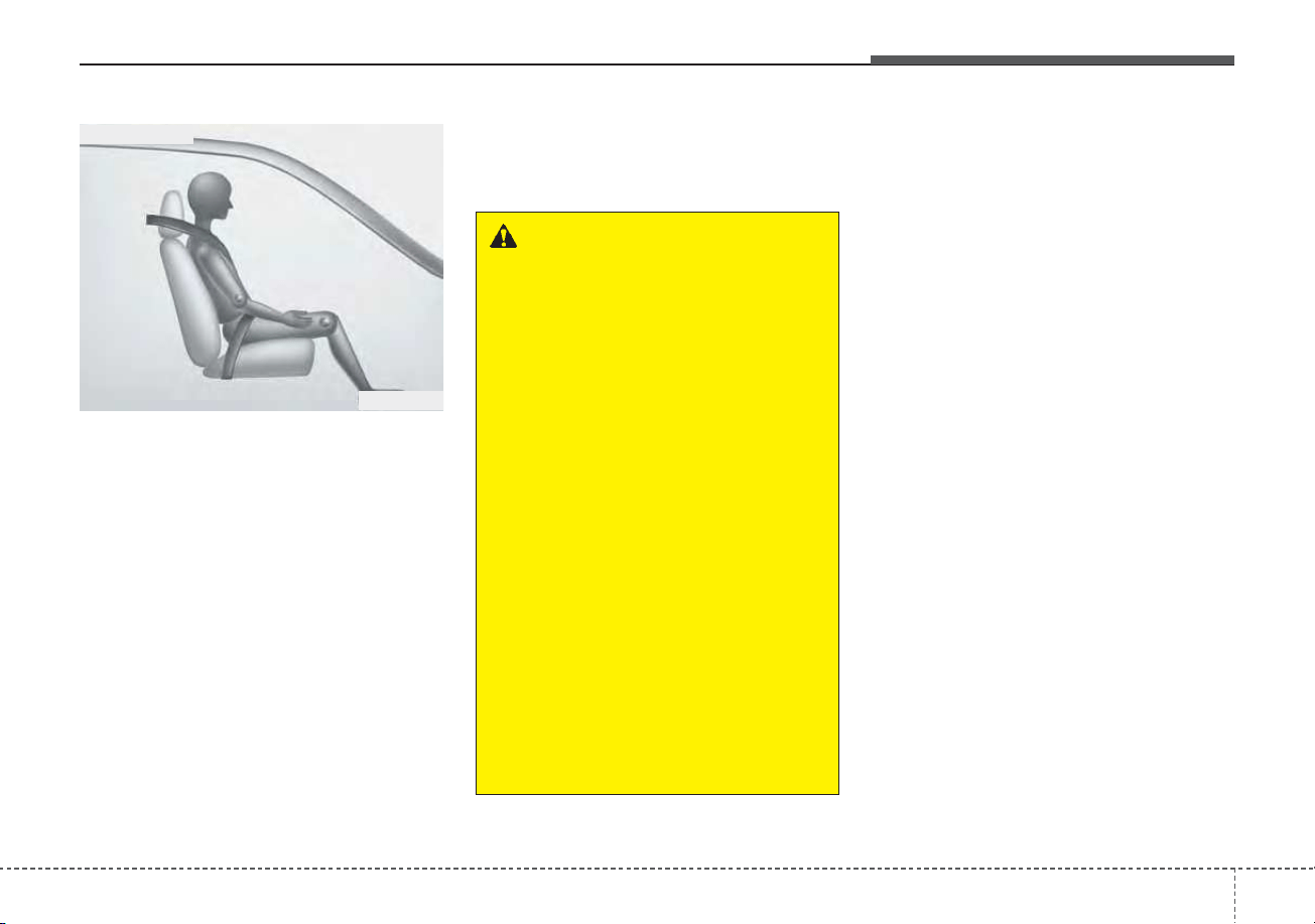
361
Safety features of your vehicle
When an adult is seated in the front
passenger seat, if the PASSENGER
AIR BAG “OFF” indicator is on,
change Engine Start/Stop button to
the OFF position and ask the pas-
senger to sit properly (sitting upright
with the seat back in an upright posi-
tion, centered on the seat cushion
with their seat belt on, legs comfort-
ably extended and their feet on the
floor). Restart the engine and have
the person remain in that position.
This will allow the system to detect
the person and to enable the pas-
senger air bag.
If the PASSENGER AIR BAG “OFF”
indicator is still on, ask the passen-
ger to move to the rear seat.
✽✽
NOTICE
The PASSENGER AIR BAG “OFF”
indicator illuminates for about 4 sec-
onds after Engine Start/Stop button
is turned to the ON position after the
engine is started. If the front passen-
ger seat is occupied, the occupant
detection sensor will then classify
the front passenger after several
more seconds.
B990A01O
Proper position
WARNING - “AIR BAG
OFF” light
Do not allow an adult passenger
to ride in the front seat when the
PASSENGER AIR BAG “OFF”
indicator is illuminated,
because the air bag will not
deploy in the event of a crash.
The driver must instruct the
passenger to reposition himself
in the seat. Failure to properly
position yourself may lead to air
bag deactivation resulting in air
bag non-deployment in a colli-
sion. If the PASSENGER AIR
BAG “OFF” indicator remains
illuminated after the passenger
repositions themselves proper-
ly and the car is restarted, it is
recommended that the passen-
ger move to the rear seat
because the passenger's front
air bag will not deploy.
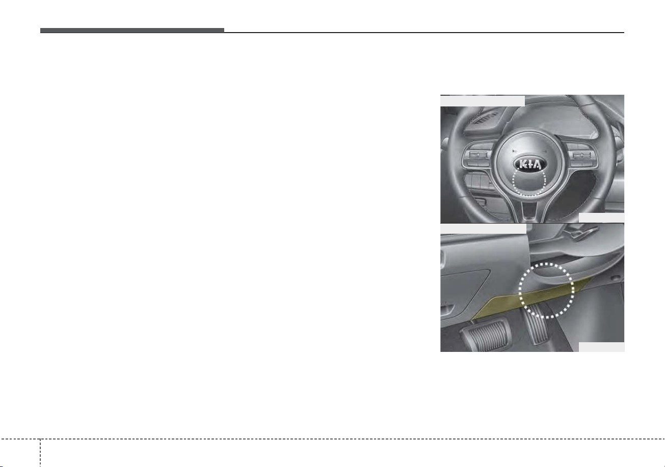
Safety features of your vehicle
623
• Even though your vehicle is
equipped with the occupant detec-
tion system, never install a child
restraint system in the front pas-
senger's seat. A deploying air bag
can forcefully strike a child result-
ing in serious injuries or death. Any
child age 13 and under should ride
in the rear seat. Children too large
for child restraints should use the
available lap/shoulder belts. No
matter what type of crash, children
of all ages are safer when
restrained in the rear seat.
• If the PASSENGER AIR BAG
“OFF” indicator is illuminated when
the front passenger's seat is occu-
pied by an adult and he/she sits
properly (sitting upright with the
seatback in an upright position,
centered on the seat cushion with
their seat belt on, legs comfortably
extended and their feet on the
floor), have that person sit in the
rear seat.
Any child age 13 and under should
ride in the rear seat. Children too
large for child restraints should use
the available lap/shoulder belts. No
matter what type of crash, children of
all ages are safer when restrained in
the rear seat.
If the occupant detection system is
not working properly, the SRS air
bag warning light on the instrument
panel will illuminate because the
passenger's front air bag is connect-
ed with the occupant detection sys-
tem. If there is a malfunction of the
occupant detection system, the PAS-
SENGER AIR BAG “OFF” indicator
will not illuminate and the passen-
ger's front air bag will inflate in frontal
impact crashes even if there is no
occupant in the front passenger's
seat.
Driver's and passenger's front
air bag
ODE036063
■ Driver’s front air bag
■ Driver’s knee air bag
ODE036037
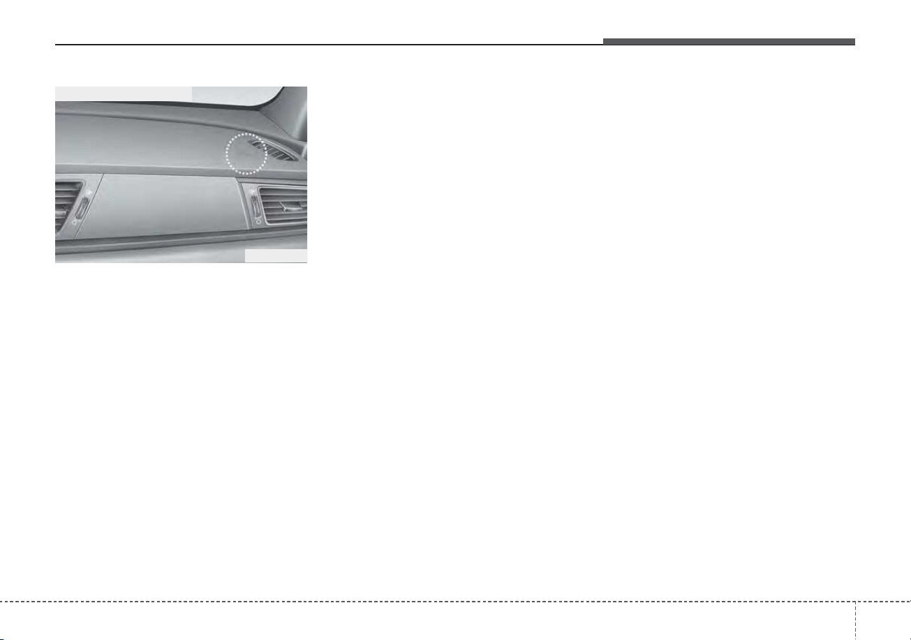
363
Safety features of your vehicle
Your vehicle is equipped with an
Advanced Supplemental Restraint
(Air Bag) System and lap/shoulder
belts at both the driver and passen-
ger seating position.
The indication of the system's pres-
ence are the letters "AIR BAG" locat-
ed on the air bag pad cover on the
steering wheel and the passenger's
side front panel pad above the glove
box.
The SRS consists of air bags
installed under the pad covers in the
center of the steering wheel and the
passenger's side front panel above
the glove box.
The purpose of the SRS is to provide
the vehicle's driver and/or the front
passenger with additional protection
than that offered by the seat belt sys-
tem alone in case of a frontal impact
of sufficient severity. The SRS uses
sensors to gather information about
the driver's and front passenger's
seat belt usage and impact severity.
The seat belt buckle sensor deter-
mines if the front passenger's seat
belt is fastened.
These sensors provide the ability to
control the SRS deployment based on
whether or not the seat belts are fas-
tened, and how severe the impact is.
The advanced SRS offers the ability
to control the air bag inflation with
two levels. A first stage level is pro-
vided for moderate-severity impacts.
A second stage level is provided for
more severe impacts.
The passenger’s front air bag is
designed to help reduce the injury of
children sitting close to the instru-
ment panel in low speed collisions.
However, children are safer if they
are restrained in the rear seat.
According to the impact severity and
seat belt usage, the SRSCM (SRS
Control Module) controls the air bag
inflation. Failure to properly wear
seat belts can increase the risk or
severity of injury in an accident.
ODE036038
■ Passenger’s front air bag
Safety features of your vehicle
643
Additionally, your vehicle is equipped
with an occupant detection system in
the front passenger's seat. The occu-
pant detection system detects the
presence of a passenger in the front
passenger's seat and will turn off the
front passenger's air bag under cer-
tain conditions. For more detail, see
"Occupant detection system" in this
chapter.
Modification to the seat structure can
cause the air bag to deploy at a dif-
ferent level than should be provided.
Manufacturers are required by gov-
ernment regulations to provide a
contact point concerning modifica-
tions to the vehicle for persons with
disabilities, which modifications may
affect the vehicle’s advanced air bag
system. That contact is Kia’s toll-free
Customer Assistance center at 1-
800-333-4Kia. However, Kia does
not endorse nor will it support any
changes to any part or structure of
the vehicle that could affect the
advanced air bag system, including
the occupant detection system.
Advanced air bags are combined with
pre-tensioner seat belts to help pro-
vide enhanced occupant protection in
frontal crashes. Front air bags are not
intended to deploy in collisions in
which sufficient protection can be pro-
vided by the pre-tensioner seat belt.
✽✽
NOTICE
Air bags can only be used once –
have an authorized Kia dealer
replace the air bag immediately
after deployment.
Front air bags are not intended to
deploy in side-impact, rear-impact or
rollover crashes. However, when
frontal deployment threshold is satis-
fied at side-impact, front air bags
may deploy. In addition, front air bags
will not deploy in frontal crashes
below the deployment threshold.
WARNING - Replacement /
modifications
The front passenger seat, dash-
board or door should not be
replaced except by an author-
ized Kia dealer using original
Kia parts designed for this vehi-
cle and model. Any other such
replacement or modification
could adversely affect the oper-
ation of the occupant detection
system and your advanced air
bags.
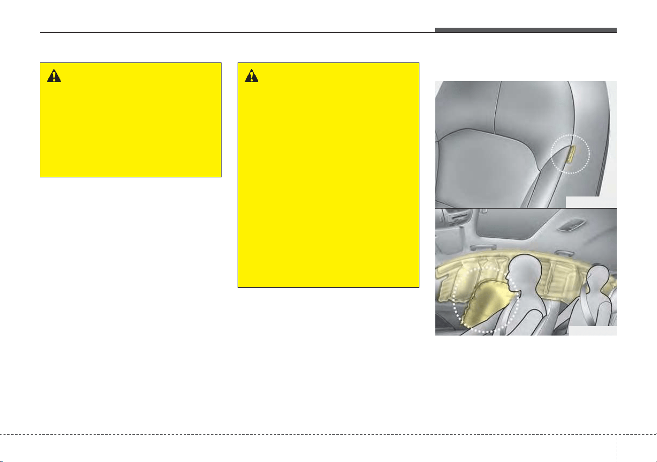
365
Safety features of your vehicle
Side air bag
❈ The actual air bags in the vehicle may differ
from the illustration.
Your vehicle is equipped with a side
air bag in each front seat.
WARNING - SRS Wiring
Do not tamper with or discon-
nect SRS wiring or other com-
ponents of the SRS system.
Doing so could result in injury,
due to accidental deployment of
the air bags or by rendering the
SRS inoperative.
WARNING - No attaching
objects
No objects (such as crash pad
cover, cellular phone holder,
cup holder, perfume or stickers)
should be placed over or near
the air bag modules on the
steering wheel, instrument
panel, windshield glass, and the
front passenger's panel above
the glove box. Such objects
could cause harm if the vehicle
is in a crash severe enough to
cause the air bags to deploy.
Do not place any objects over
the air bag or between the air
bag and yourself.
ODE036041
ODEP039040
Safety features of your vehicle
663
The purpose of the air bag is to pro-
vide the vehicle's driver and/or the
front passenger with additional pro-
tection than that offered by the seat
belt alone.
• The side air bags are designed to
deploy during certain side-impact
collisions, depending on the crash
severity, angle, speed and point of
impact. However, when side deploy-
ment threshold is satisfied at front-
impact, side air bags may deploy.
• The side air bags may deploy on the
side of the impact or on both sides.
• The side and/or curtain air bags on
both sides of the vehicle will deploy
if a rollover or possible rollover is
detected.
• The side air bags are not designed
to deploy in all side impact or
rollover situations.
• The side air bag is supplemental to
the driver's and the passenger's
seat belt systems and is not a sub-
stitute for them. Therefore your
seat belts must be worn at all times
while the vehicle is in operation.
• For best protection from the side
air bag system and to avoid being
injured by the deploying side air
bag, both front seat occupants
should sit in an upright position
with the seat belt properly fas-
tened. The driver's hands should
be placed on the steering wheel at
the 9:00 and 3:00 positions. The
passenger's arms and hands
should be placed on their laps.
WARNING - Unexpected
deployment
Avoid impact to the side impact
airbag sensor when Engine
Start/Stop button is ON to pre-
vent unexpected deployment of
the side air bag.
WARNING - Deployment
Do not install any accessories
including seat covers, on the
side or near the side air bag as
this may affect the deployment
of the side air bags.
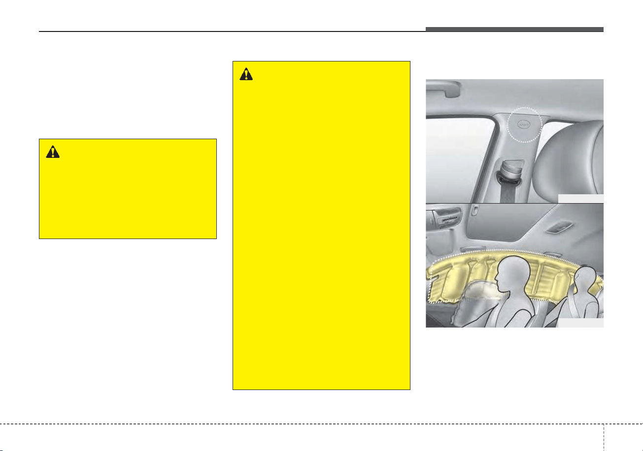
367
Safety features of your vehicle
• If seat or seat cover is damaged,
have the vehicle checked and
repaired by an authorized Kia deal-
er. Inform the dealer that your vehi-
cle is equipped with side air bags
and an occupant detection system.
Curtain air bag
❈ The actual air bags in the vehicle may differ
from the illustration.
WARNING - No attaching
objects
• Do not place any objects over
the air bag or between the air
bag and yourself. Also, do not
attach any objects around the
area the air bag inflates such
as the door, side door glass,
front and rear pillar.
• Do not put any objects
between the side airbag label
and seat cushion. It could
cause harm if the vehicle is in
a crash severe enough to
cause the air bags to deploy.
• Never place or insert any
object into any small opening
near side airbag labels
attached to the vehicle seats.
When the air bag deploys, the
object may affect the deploy-
ment and result in unexpected
accident or bodily harm.
• Do not install any accessories
on the side or near the side air
bags.
WARNING - Flying objects
Do not place any objects (an
umbrella, bag, etc.) between the
front door and the front seat.
Such objects may become dan-
gerous projectiles if the side
airbag inflates.
ODE036042
ODE036043
Safety features of your vehicle
683
Curtain air bags are located along
both sides of the roof rails above the
front and rear doors.
They are designed to help protect
occupants in certain side impacts
and to help prevent them from eject-
ing out of the vehicle as a result of a
rollover, especially when the seat-
belts are also in use.
• The curtain air bags are designed to
deploy during certain side impact
collisions, depending on the crash
severity, angle, speed and point of
impact. However, when side deploy-
ment threshold is satisfied at front-
impact, side air bags may deploy.
• The curtain air bags may deploy on
the side of the impact or on both
sides.
• Also, the curtain air bags on both
sides of the vehicle will deploy in
certain rollover situations.
• The curtain air bags are not
designed to deploy in all side
impact or rollover situations.
Do not allow the passengers to lean
their heads or bodies against the
doors, put their arms on the doors,
stretch their arms out of the window
or place objects between the doors
and passengers when they are seat-
ed on seats equipped with side
impact and/or curtain air bags.
✽✽
NOTICE
Never try to open or repair any com-
ponents of the side and curtain air
bag system. This should only be
done by an authorized Kia dealer.
WARNING - No attaching
objects
• Do not place any objects over
the air bag. Also, do not attach
any objects around the area
the air bag inflates such as the
door, side door glass, front
and rear pillar, roof side rail.
• Do not hang hard, breakable,
or heavy objects on the coat
hooks for safety reasons.
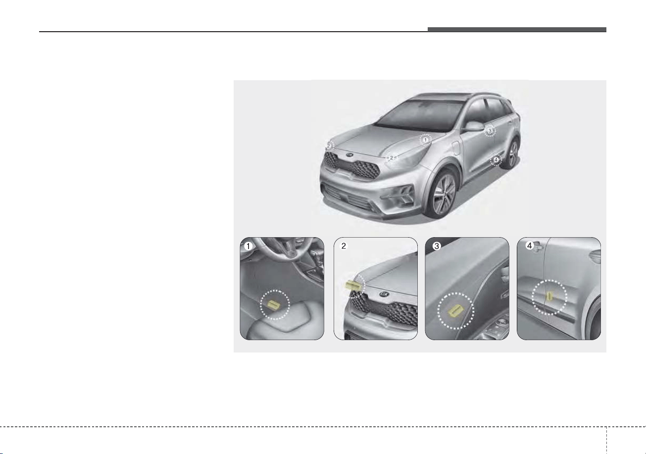
369
Safety features of your vehicle
Why didn’t my air bag go off in a
collision? (Inflation and non-infla-
tion conditions of the air bag)
There are many types of accidents in
which the air bag would not be
expected to provide additional pro-
tection.
These include rear impacts, second
or third collisions in multiple impact
accidents, as well as low speed
impacts.
Air bag collision sensors
(1) SRS control module/
Rollover sensor
(2) Front impact sensor
(3) Side pressure sensor
(4) Side impact sensor
ODEP039044/ODE036045/ODEP039046/ODE036047/ODE036048
❈ The actual shape and position of sensors may differ from the illustration.
Safety features of your vehicle
703
Problems may arise if the sensor
installation angles are changed due
to the deformation of the front
bumper, front end module, body or
front doors where side collision sen-
sors are installed. Have the vehicle
checked and repaired by an author-
ized Kia dealer.
Installing bumper guards (or side
step or running board) or replacing a
bumper (or front door module) with
non-genuine parts may adversely
affect your vehicle’s collision and air
bag deployment performance.
Air bag inflation conditions
Front air bags
Front air bags are designed to inflate
in a frontal collision depending on
the severity of impact of the front col-
lision.
Side and/or curtain air bags
Side and/or curtain air bags are
designed to inflate when an impact is
detected by side collision sensors
depending on the severity of impact
resulting from a side impact collision.
Also, the side and curtain air bags are
designed to inflate when a rollover is
detected by a rollover sensor.
Although the front air bags (driver’s
and front passenger’s air bags) are
designed to inflate in frontal collisions,
they also may inflate in other types of
collisions if the front impact sensors
detect a sufficient frontal force in
another type of impact. Side and cur-
tain air bags are designed to inflate in
certain side impact collisions.
WARNING - Air bag sen-
sors
• Do not hit or allow any objects
to impact the locations where
air bags or sensors are
installed.
This may cause unexpected
air bag deployment, which
could result in serious per-
sonal injury or death.
• If the installation location or
angle of the sensors is altered
in any way, the air bags may
deploy when they should not
or they may not deploy when
they should.
Therefore, do not try to per-
form maintenance on or
around the air bag sensors.
Have the vehicle checked and
repaired by an authorized Kia
dealer.

371
Safety features of your vehicle
They may inflate in other types of
collisions where a side force is
detected by the sensors. Side air bag
and/or curtain air bags may also
inflate where rollover sensors indi-
cate the possibility of a rollover
occurring (even if none actually
occurs) or in other situations, includ-
ing when the vehicle is tilted while
being towed.
Even where side and/or curtain air
bags would not provide impact pro-
tection in a rollover, however, they
will deploy to prevent ejection of
occupants, especially those who are
restrained with seat belts.
If the vehicle chassis is impacted by
bumps or objects on unimproved
roads, the air bags may deploy. Drive
carefully on unimproved roads or on
surfaces not designed for vehicle
traffic to prevent unintended air bag
deployment.
Air bag non-inflation conditions
• In certain low-speed collisions the
air bags may not deploy. The air
bags are designed not to deploy in
such cases because they may not
provide benefits beyond the pro-
tection of the seat belts in such col-
lisions.
• Air bags are not designed to inflate
in rear collisions, because occu-
pants are moved backward by the
force of the impact. In this case,
inflated air bags would not be able
to provide any additional benefit.
• Front air bags may not inflate in
side impact collisions, because
occupants move to the direction of
the collision, and thus in side
impacts, frontal air bag deployment
would not provide additional occu-
pant protection.
• In an angled collision, the force of
impact may direct the occupants in
a direction where the air bags would
not be able to provide any addition-
al benefit, and thus the sensors may
not deploy any air bags.
• Just before impact, drivers often
brake heavily. Such heavy braking
lowers the front portion of the vehi-
cle causing it to “ride” under a vehi-
cle with a higher ground clearance.
Air bags may not inflate in this
"under-ride" situation because
deceleration forces that are detect-
ed by sensors may be significantly
reduced by such “under-ride” colli-
sions.
• Front air bags may not inflate in all
rollover accidents where the
SRSCM indicates that the front air
bag deployment would not provide
additional occupant protection.
• Air bags may not inflate if the vehi-
cle collides with objects such as util-
ity poles or trees, where the point of
impact is concentrated to one area
and the full force of the impact is not
delivered to the sensors.
Safety features of your vehicle
723
SRS Care
The SRS is virtually maintenance-
free and so there are no parts you can
safely service by yourself. If the SRS
air bag warning light does not illumi-
nate, or continuously remains on, have
your vehicle immediately inspected by
an authorized Kia dealer.
Any work on the SRS system, such
as removing, installing, repairing, or
any work on the steering wheel, the
front passenger’s panel, front seats
and roof rails must be performed by
an authorized Kia dealer. Improper
handling of the SRS system may
result in serious personal injury.
For cleaning the air bag pad covers,
use only a soft, dry cloth or one which
has been moistened with plain water.
Solvents or cleaners could adversely
affect the air bag covers and proper
deployment of the system.
If components of the air bag system
must be discarded, or if the vehicle
must be scrapped, certain safety
precautions must be observed. An
authorized Kia dealer knows these
precautions and can give you the
necessary information. Failure to fol-
low these precautions and proce-
dures could increase the risk of per-
sonal injury.
WARNING - Tampering
with SRS
Do not tamper with or discon-
nect SRS wiring, or other com-
ponents of the SRS system.
Doing so could result in the
accidental inflation of the air
bags or render the SRS inoper-
ative.
WARNING - Towing Vehicle
Always have the ignition off
when your vehicle is being
towed. The side air bags may
inflate if the vehicle is tilted
such as when being towed
because of the rollover sensors
in the vehicle.
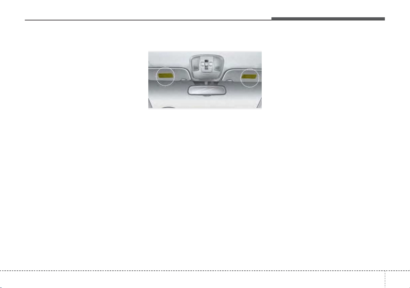
373
Safety features of your vehicle
Adding equipment to or modi-
fying your air bag-equipped
vehicle
If you modify your vehicle by chang-
ing your vehicle's frame, bumper sys-
tem, front end or side sheet metal or
ride height, this may affect the opera-
tion of your vehicle's air bag system.
Air bag warning label
Air bag warning labels, some
required by the U.S. National
Highway Traffic Safety Administration
(NHTSA), are attached to the sunvi-
sor to alert the driver and passen-
gers of potential risks of the air bag
system.
ODE036090N

Features of your vehicle
Folding key . . . . . . . . . . . . . . . . . . . . . . . . . . . . . . . . 4-4
• Record your key number . . . . . . . . . . . . . . . . . . . . . . . 4-4
• Key operations . . . . . . . . . . . . . . . . . . . . . . . . . . . . . . . . 4-4
• Transmitter precautions . . . . . . . . . . . . . . . . . . . . . . . . 4-6
• Battery replacement . . . . . . . . . . . . . . . . . . . . . . . . . . . 4-7
• Immobilizer system . . . . . . . . . . . . . . . . . . . . . . . . . . . . 4-8
Smart key . . . . . . . . . . . . . . . . . . . . . . . . . . . . . . . . 4-11
• Record your key number . . . . . . . . . . . . . . . . . . . . . . 4-11
• Smart key function . . . . . . . . . . . . . . . . . . . . . . . . . . . 4-11
• Mechanical key . . . . . . . . . . . . . . . . . . . . . . . . . . . . . . 4-14
• Loss of the smart key . . . . . . . . . . . . . . . . . . . . . . . . . 4-14
• Smart key precautions . . . . . . . . . . . . . . . . . . . . . . . . 4-14
• Battery replacement . . . . . . . . . . . . . . . . . . . . . . . . . . 4-15
• Smart key immobilizer system. . . . . . . . . . . . . . . . . . 4-16
Theft-alarm system . . . . . . . . . . . . . . . . . . . . . . . . 4-18
• Armed stage . . . . . . . . . . . . . . . . . . . . . . . . . . . . . . . . . 4-18
• Theft-alarm stage . . . . . . . . . . . . . . . . . . . . . . . . . . . . 4-19
• Disarmed stage. . . . . . . . . . . . . . . . . . . . . . . . . . . . . . . 4-20
Door locks . . . . . . . . . . . . . . . . . . . . . . . . . . . . . . . . 4-21
• Operating door locks from outside the vehicle . . . . 4-21
• Operating door locks from inside the vehicle. . . . . . 4-22
• Child-protector rear door lock . . . . . . . . . . . . . . . . . 4-25
Liftgate . . . . . . . . . . . . . . . . . . . . . . . . . . . . . . . . . . 4-26
• Opening the liftgate. . . . . . . . . . . . . . . . . . . . . . . . . . . 4-26
• Closing the liftgate. . . . . . . . . . . . . . . . . . . . . . . . . . . . 4-26
• Emergency liftgate safety release. . . . . . . . . . . . . . . . 4-27
Windows . . . . . . . . . . . . . . . . . . . . . . . . . . . . . . . . . 4-29
• Power windows . . . . . . . . . . . . . . . . . . . . . . . . . . . . . . 4-30
Hood. . . . . . . . . . . . . . . . . . . . . . . . . . . . . . . . . . . . . 4-34
• Opening the hood . . . . . . . . . . . . . . . . . . . . . . . . . . . . 4-34
• Closing the hood . . . . . . . . . . . . . . . . . . . . . . . . . . . . . 4-35
Fuel filler door (Hybrid) . . . . . . . . . . . . . . . . . . . . 4-36
• Opening the fuel filler door . . . . . . . . . . . . . . . . . . . . 4-36
• Closing the fuel filler door . . . . . . . . . . . . . . . . . . . . . 4-36
fuel filler door (Plug-in hybrid) . . . . . . . . . . . . . . 4-37
• Opening the fuel filler door . . . . . . . . . . . . . . . . . . . . 4-37
• Closing the fuel filler door . . . . . . . . . . . . . . . . . . . . . 4-38
Sunroof . . . . . . . . . . . . . . . . . . . . . . . . . . . . . . . . . . 4-42
• Sliding the sunroof . . . . . . . . . . . . . . . . . . . . . . . . . . . 4-43
• Tilting the sunroof. . . . . . . . . . . . . . . . . . . . . . . . . . . . 4-44
• Sunshade . . . . . . . . . . . . . . . . . . . . . . . . . . . . . . . . . . . 4-45
• Resetting the sunroof . . . . . . . . . . . . . . . . . . . . . . . . . 4-45
• Sunroof open warning. . . . . . . . . . . . . . . . . . . . . . . . . 4-46
Steering wheel. . . . . . . . . . . . . . . . . . . . . . . . . . . . . 4-47
• Electric Power Steering (EPS) . . . . . . . . . . . . . . . . . . 4-47
• Tilt and telescopic steering . . . . . . . . . . . . . . . . . . . . . 4-48
4

• Heated steering wheel . . . . . . . . . . . . . . . . . . . . . . . . . 4-49
• Horn . . . . . . . . . . . . . . . . . . . . . . . . . . . . . . . . . . . . . . . 4-50
Mirrors . . . . . . . . . . . . . . . . . . . . . . . . . . . . . . . . . . 4-51
• Inside rearview mirror . . . . . . . . . . . . . . . . . . . . . . . . 4-51
• Outside rearview mirror. . . . . . . . . . . . . . . . . . . . . . . 4-53
Instrument cluster . . . . . . . . . . . . . . . . . . . . . . . . . 4-57
• Instrument cluster control . . . . . . . . . . . . . . . . . . . . . 4-59
• Gauges . . . . . . . . . . . . . . . . . . . . . . . . . . . . . . . . . . . . . 4-59
• Dual clutch transmission shift indicator . . . . . . . . . . 4-65
LCD display . . . . . . . . . . . . . . . . . . . . . . . . . . . . . . 4-67
• LCD display control . . . . . . . . . . . . . . . . . . . . . . . . . . 4-67
• LCD display modes . . . . . . . . . . . . . . . . . . . . . . . . . . . 4-68
• Trip modes (Trip computer). . . . . . . . . . . . . . . . . . . . 4-80
• Warning messages . . . . . . . . . . . . . . . . . . . . . . . . . . . . 4-85
Warning and indicator lights . . . . . . . . . . . . . . . . 4-96
• Warning lights . . . . . . . . . . . . . . . . . . . . . . . . . . . . . . . 4-96
• Indicator lights. . . . . . . . . . . . . . . . . . . . . . . . . . . . . . 4-105
Rear View Monitor (RVM) . . . . . . . . . . . . . . . . . 4-111
Reverse Parking Distance Warning (PDW). . . . 4-112
• Operation of Reverse Parking Distance
Warning system . . . . . . . . . . . . . . . . . . . . . . . . . . . . 4-112
• Non-operational conditions of Reverse Parking
Distance Warning system . . . . . . . . . . . . . . . . . . . . 4-113
• Reverse Parking Distance Warning system
precautions. . . . . . . . . . . . . . . . . . . . . . . . . . . . . . . . 4-114
• Self-diagnosis . . . . . . . . . . . . . . . . . . . . . . . . . . . . . . . 4-114
Lighting . . . . . . . . . . . . . . . . . . . . . . . . . . . . . . . . . 4-115
• Battery saver function. . . . . . . . . . . . . . . . . . . . . . . . 4-115
• Headlight escort function . . . . . . . . . . . . . . . . . . . . . 4-115
• Daytime running light. . . . . . . . . . . . . . . . . . . . . . . . 4-115
• Lighting control . . . . . . . . . . . . . . . . . . . . . . . . . . . . . 4-116
• High beam operation. . . . . . . . . . . . . . . . . . . . . . . . . 4-117
• High Beam Assist (HBA) . . . . . . . . . . . . . . . . . . . . . 4-118
• Turn signals and lane change signals . . . . . . . . . . . 4-120
• Check headlight . . . . . . . . . . . . . . . . . . . . . . . . . . . . . 4-121
• Front fog light . . . . . . . . . . . . . . . . . . . . . . . . . . . . . . 4-121
Wipers and washers . . . . . . . . . . . . . . . . . . . . . . . 4-122
• Windshield wipers . . . . . . . . . . . . . . . . . . . . . . . . . . . 4-122
• Front windshield washers. . . . . . . . . . . . . . . . . . . . . 4-123
• Rear window wiper and washer switch . . . . . . . . . 4-124
Interior lights . . . . . . . . . . . . . . . . . . . . . . . . . . . . 4-126
• Automatic turn off function . . . . . . . . . . . . . . . . . . . 4-126
• Map lamp . . . . . . . . . . . . . . . . . . . . . . . . . . . . . . . . . . 4-126
• Room lamp . . . . . . . . . . . . . . . . . . . . . . . . . . . . . . . . . 4-127
• Liftgate room lamp . . . . . . . . . . . . . . . . . . . . . . . . . . 4-128
• Vanity mirror lamp . . . . . . . . . . . . . . . . . . . . . . . . . . 4-128
4

Welcome system . . . . . . . . . . . . . . . . . . . . . . . . . . 4-129
• Headlight (Headlamp) escort function . . . . . . . . . . 4-129
• Interior light. . . . . . . . . . . . . . . . . . . . . . . . . . . . . . . . 4-129
• Pocket lamp . . . . . . . . . . . . . . . . . . . . . . . . . . . . . . . . 4-129
Defroster . . . . . . . . . . . . . . . . . . . . . . . . . . . . . . . . 4-130
• Rear window defroster . . . . . . . . . . . . . . . . . . . . . . . 4-130
Automatic climate control system. . . . . . . . . . . . 4-131
• Automatic heating and air conditioning . . . . . . . . . 4-132
• Manual heating and air conditioning . . . . . . . . . . . 4-134
• System operation . . . . . . . . . . . . . . . . . . . . . . . . . . . . 4-140
• Automatic ventilation . . . . . . . . . . . . . . . . . . . . . . . . 4-142
• Sunroof inside air recirculation . . . . . . . . . . . . . . . . 4-143
• Recirculated air at washer fluid spray . . . . . . . . . . 4-143
• Climate control air filter. . . . . . . . . . . . . . . . . . . . . . 4-144
• Air Conditioning refrigerant label. . . . . . . . . . . . . . 4-144
• Checking the amount of air conditioner
refrigerant and compressor lubricant. . . . . . . . . . 4-145
Windshield defrosting and defogging. . . . . . . . . 4-147
• Automatic climate control system . . . . . . . . . . . . . . 4-147
• Defogging logic. . . . . . . . . . . . . . . . . . . . . . . . . . . . . . 4-148
Storage compartments . . . . . . . . . . . . . . . . . . . . . 4-151
• Center console storage . . . . . . . . . . . . . . . . . . . . . . . 4-151
• Glove box . . . . . . . . . . . . . . . . . . . . . . . . . . . . . . . . . . 4-151
• Sunglass holder . . . . . . . . . . . . . . . . . . . . . . . . . . . . . 4-152
• Luggage box . . . . . . . . . . . . . . . . . . . . . . . . . . . . . . . . 4-153
Interior features . . . . . . . . . . . . . . . . . . . . . . . . . . 4-154
• Cup holder . . . . . . . . . . . . . . . . . . . . . . . . . . . . . . . . . 4-154
• Seat warmer . . . . . . . . . . . . . . . . . . . . . . . . . . . . . . . . 4-154
• Air ventilation seat . . . . . . . . . . . . . . . . . . . . . . . . . . 4-156
• Sunvisor . . . . . . . . . . . . . . . . . . . . . . . . . . . . . . . . . . . 4-157
• Power outlet . . . . . . . . . . . . . . . . . . . . . . . . . . . . . . . . 4-157
• USB charger. . . . . . . . . . . . . . . . . . . . . . . . . . . . . . . . 4-158
• Wireless smart phone charging system . . . . . . . . . . 4-159
• Clothes hanger . . . . . . . . . . . . . . . . . . . . . . . . . . . . . . 4-162
• Floor mat anchor(s). . . . . . . . . . . . . . . . . . . . . . . . . . 4-163
• Luggage net holder . . . . . . . . . . . . . . . . . . . . . . . . . . 4-164
• Cargo security screen . . . . . . . . . . . . . . . . . . . . . . . . 4-164
Exterior features. . . . . . . . . . . . . . . . . . . . . . . . . . 4-166
• Roof rack . . . . . . . . . . . . . . . . . . . . . . . . . . . . . . . . . . 4-166
Infotainment system. . . . . . . . . . . . . . . . . . . . . . . 4-168
• Antenna . . . . . . . . . . . . . . . . . . . . . . . . . . . . . . . . . . . 4-168
• USB port. . . . . . . . . . . . . . . . . . . . . . . . . . . . . . . . . . . 4-168
• How vehicle radio works . . . . . . . . . . . . . . . . . . . . . 4-169
Declaration of Conformity . . . . . . . . . . . . . . . . . 4-172
• FCC. . . . . . . . . . . . . . . . . . . . . . . . . . . . . . . . . . . . . . . 4-172
4
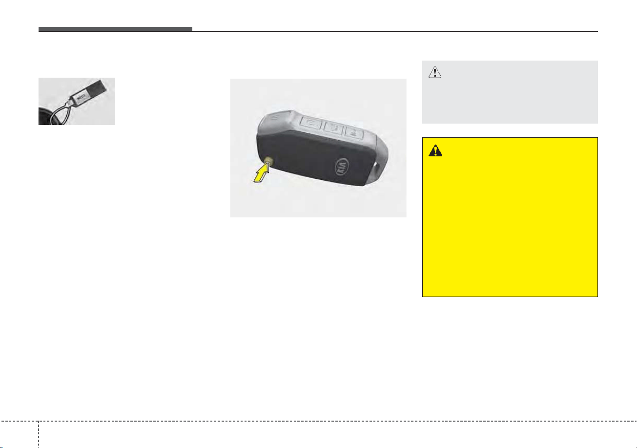
Features of your vehicle
44
Record your key number
The key code num-
ber is stamped on
the key code tag
attached to the key
set. Should you
lose your keys, this number will
enable an authorized Kia dealer to
duplicate the keys easily. Remove
the key code tag and store it in a safe
place. Also, record the key code
number and keep it in a safe place,
but not in the vehicle.
Key operations
• Used to start the engine.
• Used to lock and unlock the doors.
• To unfold the key, press the release
button then the key will unfold auto-
matically. To fold the key, fold the
key manually while pressing the
release button.
FOLDING KEY (IF EQUIPPED)
CAUTION
Do not fold the key without
pressing the release button.
This may damage the key.
WARNING - Aftermarket
key
Use only Kia original parts for
the ignition key in your vehicle.
If an aftermarket key is used,
the ignition switch may not
return to ON after START. If this
happens, the starter will contin-
ue to operate causing damage
to the starter motor and possi-
ble fire due to excessive current
in the wiring.
OBD048028
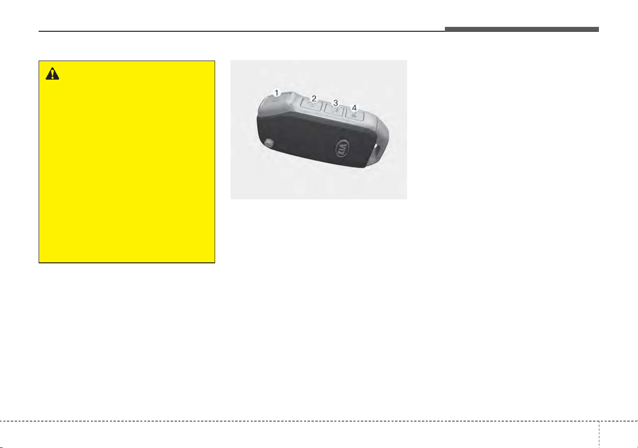
45
Features of your vehicle
Door Lock (1)
1. Close all doors, engine hood and
liftgate.
2. Press the lock button(1).
3. All doors and liftgate will lock. The
hazard warning lights will blink
once.
4. If the lock button is pressed once
more within 4 seconds, the hazard
warning lights will blink and the
horn will sound once.
5. Make sure that doors are locked by
checking the door lock button inside
or pulling the outside door handle.
Door Unlock (2)
1. Press the unlock button(2).
2. The driver's door will unlock. The
hazard warning lights will blink two
times.
3. Press the unlock button(2) twice
within 4 seconds and all doors and
liftgate will unlock. The hazard
warning lights will blink two times.
✽✽
NOTICE
You can active or deactivate the Two
Press Unlock function from the User
Settings mode in the LCD display.
Refer to “User Settings” in this
chapter.
WARNING - Ignition key
(smart key)
Never leave the keys in your
vehicle with unsupervised chil-
dren. Leaving children unat-
tended in a vehicle with a man-
ual ignition key or a smart key
is dangerous. Children copy
adults and they could place the
key in the ignition switch or
press the start button. The key
would enable children to oper-
ate power windows or other
controls, or even make the vehi-
cle move, which could result in
serious bodily injury or death.
OBD048030

Features of your vehicle
64
Liftgate unlock (3)
The liftgate is unlocked if the button
is pressed for more than 1 second.
Also, once the liftgate is opened and
then closed, the liftgate will be locked
automatically.
Panic (4)
The horn sounds and hazard warn-
ing lights flash for about 27 seconds
if this button is pressed for more than
0.5 seconds. To stop the horn and
lights, press any button on the trans-
mitter.
Transmitter precautions
• The transmitter will not work if any
of following occur:
- The ignition key is in the ignition
switch.
- You exceed the operating dis-
tance limit (about 30 feet [10 m]).
- The battery in the transmitter is
weak.
- Other vehicles or objects are
blocking the signal.
- The weather is extremely cold.
- The transmitter is close to a radio
transmitter such as a radio sub-
station or an airport which can
interfere with normal operation of
the transmitter.
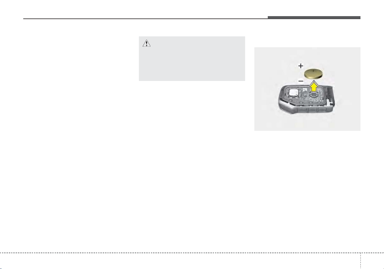
47
Features of your vehicle
• When the transmitter does not work
correctly, open and close the door
with the ignition key. If you have a
problem with the transmitter, con-
tact an authorized Kia dealer.
• If the transmitter is in close proxim-
ity to your mobile phone, the signal
could be blocked by your mobile
phones normal operational signals.
This is especially important when
the phone is active such as making
and receiving calls, text messag-
ing, and/or sending/receiving
emails. Avoid placing the transmit-
ter and your mobile phone in the
same pants or jacket pocket and
always try to maintain an adequate
distance between the two devices.
✽✽
NOTICE
If the keyless entry system is inoper-
ative due to exposure to water or liq-
uids, it will not be covered by your
manufacturer’s vehicle warranty.
Battery replacement
The transmitter uses a 3 volt lithium
battery which will normally last for
several years. When replacement is
necessary, use the following proce-
dure.
1. Insert a slim tool into the slot and
gently pry open the transmitter
center cover.
2. Replace the battery with a new
battery (CR2032). When replacing
the battery, make sure the battery
is positioned correctly.
3. Install the battery in the reverse
order of removal.
CAUTION - Transmitter
Keep the transmitter away from
water or any liquid as it can
become damaged and not func-
tion properly if wet.
OBD048032
Features of your vehicle
84
For replacement transmitters, see an
authorized Kia dealer for transmitter
reprogramming.
• The transmitter is designed to give
you years of trouble-free use.
However, it can malfunction if
exposed to moisture or static elec-
tricity. If you are unsure how to use
your transmitter or replace the bat-
tery, contact an authorized Kia
dealer.
• Using the wrong battery can cause
the transmitter to malfunction. Be
sure to use the correct battery.
• To avoid damaging the transmitter,
don't drop it, get it wet, or expose it
to heat or sunlight.
• An inappropriately dis-
posed battery can be
harmful to the environment
and may cause harm to
human health. Dispose the
battery according to your
local law(s) or regulation.
Immobilizer system
Your vehicle is equipped with an
electronic engine immobilizer system
to reduce the risk of unauthorized
vehicle use.
Your immobilizer system is com-
prised of a small transponder in the
ignition key and electronic devices
inside the vehicle.
With the immobilizer system, when-
ever you insert your ignition key into
the ignition switch and turn it to ON,
verifies if the ignition key is valid.
If the key is determined to be valid,
the engine will start.
If the key is determined to be invalid,
the engine will not start.
CAUTION - Transmitter
damage
Do not drop, wet or expose the
keyless entry system transmit-
ter to heat or sunlight.
49
Features of your vehicle
To activate the immobilizer sys-
tem:
Turn the ignition key to the OFF posi-
tion. The immobilizer system acti-
vates automatically. Without a valid
ignition key for your vehicle, the
engine will not start.
To deactivate the immobilizer
system:
Insert the ignition key into the key
cylinder and turn it to the ON position.
In order to prevent theft of your vehi-
cle, do not leave spare keys anywhere
in your vehicle.Your Immobilizer pass-
word is a customer unique password
and should be kept confidential. Do
not leave this number anywhere in
your vehicle.
✽✽
NOTICE
When starting the engine, do not use
the key with other immobilizer keys
around. Otherwise the engine may
not start or may stop soon after it
starts. Keep each key separate in
order to avoid a starting malfunction.
Do not put metal accessories near
the ignition switch.
Metal accessories may interrupt the
transponder signal and may prevent
the engine from being started.
✽✽
NOTICE
If you need additional keys or lose
your keys, contact an authorized
Kia dealer.
CAUTION - Immobilizer
damage
Do not expose your immobilizer
system to moisture, static elec-
tricity or rough handling. This
may damage your immobilizer.
CAUTION - Immobilizer
alterations
Do not change, alter or adjust
the immobilizer system because
it could cause the immobilizer
system to malfunction.

Features of your vehicle
104
This device complies with Part 15
of the FCC rules.
Operation is subject to the following
two conditions:
1. This device may not cause harmful
interference, and
2. This device must accept any inter-
ference received, including inter-
ference that may cause undesired
operation.
✽✽
NOTICE
Changes or modifications not
expressly approved by the party
responsible for compliance could
void the user’s authority to operate
the equipment. If the keyless entry
system is inoperative due to changes
or modifications not approved by
the party responsible for compli-
ance, it will not be covered by your
manufacturer’s vehicle warranty.
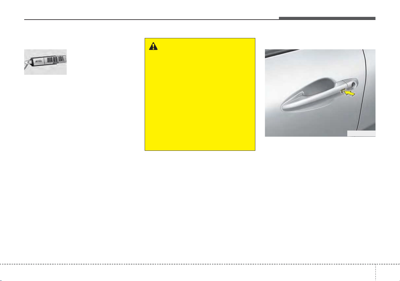
411
Features of your vehicle
Record your key number
The key code number
is stamped on the bar
code tag attached to
the key set. Should
you lose your keys,
this number will enable an author-
ized Kia dealer to duplicate the keys
easily. Remove the bar code tag and
store it in a safe place. Also, record
the code number and keep it in a
safe and handy place, but not in the
vehicle.
Smart key function
With a smart key, you can lock or
unlock a door (and liftgate) and start
the engine.
Refer to the following for more details.
SMART KEY (IF EQUIPPED)
ODE046001
WARNING - Smart key
Never leave the keys in your
vehicle with unsupervised chil-
dren. Leaving children unat-
tended in a vehicle with a man-
ual a smart key is dangerous.
Children copy adults and they
could press the start button.
The key would enable children
to operate power windows or
other controls, or even make
the vehicle move, which could
result in serious bodily injury or
death.
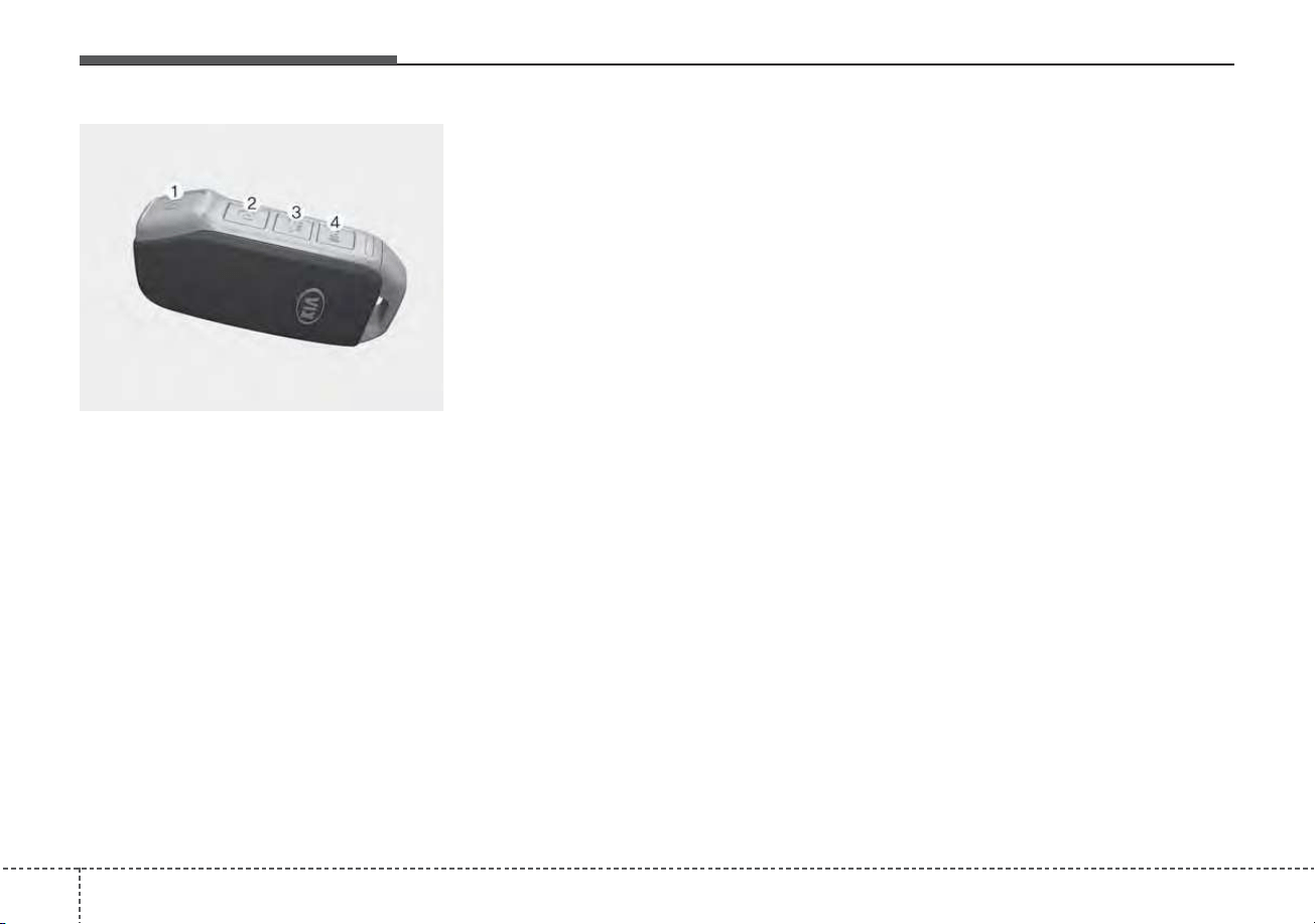
Features of your vehicle
124
Locking (1)
Pressing the button of the front out-
side door handles with all doors (and
liftgate) closed and any door
unlocked, locks all the doors (and lift-
gate).
The hazard warning lights will blink
once to indicate that all doors (and
liftgate) are locked. The button will
only operate when the smart key is
within 28 ~ 40 in (0.7 ~ 1 m) from the
outside door handle. If you want to
make sure that a door has locked or
not, you should check the door lock
button inside the vehicle or pull the
outside door handle.
Even though you press the button,
the doors will not lock and an audible
chime will sound if any of the follow-
ing occurs:
• The smart key is in the vehicle.
• The ENGINE START/STOP button
is in the ACC or ON position.
• Any door except the liftgate is
opened.
Unlocking (2)
Pressing the button of the front out-
side door handles with all doors (and
liftgate) closed and locked, unlocks
all the doors (and liftgate). The haz-
ard warning lights will blink twice to
indicate that all doors (and liftgate)
are unlocked. The button will only
operate when the smart key is within
28 ~ 40 in (0.7 ~ 1 m) from the out-
side door handle.
When Two Press Unlock function is
activated,
• If you press the Door Unlock but-
ton(2) on the smart key, driver’s
door will unlock.
• If you press the Door Unlock but-
ton(2) on the smart key within four
seconds again, then all the doors
will unlock.
• If you press the driver's outside
door handle button, driver’s door
will unlock.
• If you press the driver's outside
door handle button within four sec-
onds again, then all the doors will
unlock.
OBD048031

413
Features of your vehicle
✽✽
NOTICE
You can active or deactivate the Two
Press Unlock function from the User
Settings mode in the LCD display.
Refer to “User Settings” in this
chapter.
Liftgate unlocking (3)
If you are within 28 ~ 40 in (0.7 ~ 1 m)
from the outside liftgate handle, with
your smart key in possession, the lift-
gate will unlock and open when you
press the liftgate handle switch.
The hazard warning lights will blink
twice to indicate that the liftgate is
unlocked.
Also, once the liftgate is opened and
then closed, the liftgate will lock
automatically.
Panic (4)
1. Press the panic button (4) for more
than 1 second.
2. The horn sounds and hazard
warning light flash for about 27
seconds.
✽✽
NOTICE
To stop the horn and lights, press
any button on the smart key.
Engine start
You can start the engine without insert-
ing the key. For detailed information
refer to the “ENGINE START/STOP
button” in chapter 5.
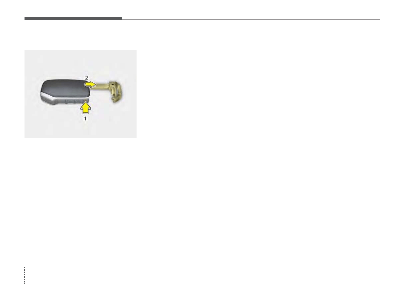
Features of your vehicle
144
Mechanical key
To remove the mechanical key, press
and hold the release button (1) and
remove the mechanical key (2).
To reinstall the mechanical key, put
the key into the hole and push it until
a click sound is heard.
Loss of the smart key
A maximum of 2 smart keys can be
registered to a single vehicle.
If you happen to lose your smart key,
you will not be able to start the
engine. You should immediately take
the vehicle and remaining key to your
authorized Kia dealer (tow the vehi-
cle, if necessary) to protect it from
potential theft.
Smart key precautions
• The smart key will not work if any
of the following occur:
- The smart key is close to a radio
transmitter such as a radio sta-
tion or an airport which can inter-
fere with normal operation of the
smart key.
- The smart key is near a mobile
two way radio system or a cellu-
lar phone.
- Another vehicle’s smart key is
being operated close to your
vehicle.
• When the smart key does not work
correctly, open and close the door
with the mechanical key and contact
an authorized Kia dealer.
OBD048029
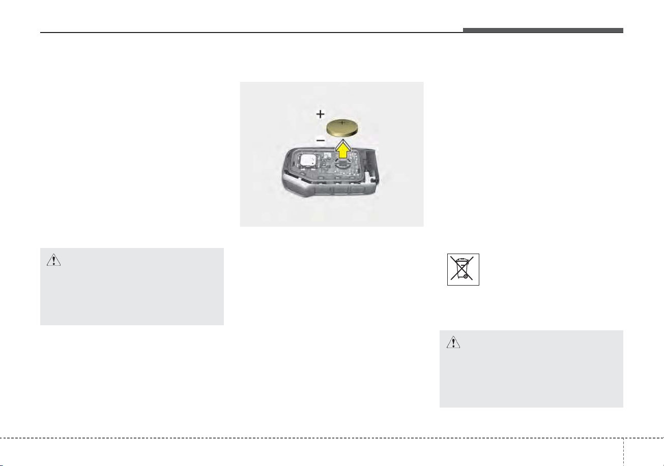
415
Features of your vehicle
• If the smart key is in close proximi-
ty to your cell phone or smart
phone, the signal from the smart
key could be blocked by normal
operation of your cell phone or
smart phone. This is especially
important when the phone is active
such as making a call, receiving
calls, text messaging, and/or send-
ing/receiving emails. Avoid placing
the smart key and your cell phone
or smart phone in the same pants
or jacket pocket and maintain ade-
quate distance between the two
devices.
✽✽
NOTICE
If the keyless entry system is inoper-
ative due to exposure to water or liq-
uids, it will not be covered by your
manufacturer’s vehicle warranty.
Battery replacement
A smart key battery should last for
several years, but if the smart key is
not working properly, try replacing
the battery with a new one. If you are
unsure how to use your smart key or
replace the battery, contact an
authorized Kia dealer.
1. Remove the mechanical key.
2. Pry open the rear cover.
3. Replace the battery with a new
battery (CR2032). When replacing
the battery, make sure the battery
is in the correct position.
4. Install the battery in the reverse
order of removal.
• The smart key is designed to give
you years of trouble-free use, how-
ever it can malfunction if exposed
to moisture or static electricity. If
you are unsure how to use or
replace the battery, contact an
authorized Kia dealer.
• Using the wrong battery can cause
the smart key to malfunction. Be
sure to use the correct battery.
• To avoid damaging the smart key,
don't drop it, get it wet, or expose it
to heat or sunlight.
• An inappropriately dis-
posed battery can be harm-
ful to the environment and
human health. Dispose the
battery according to your
local law(s) or regulations.
CAUTION - Smart key
damage
Do not drop, get wet or expose
the smart key to heat or sun-
light, or it will be damaged.
CAUTION - Transmitter
Keep the transmitter away from
water or any liquid, as it can
become damaged and not func-
tion properly if wet.
OBD048032
Features of your vehicle
164
Smart key immobilizer system
Your vehicle is equipped with an
electronic engine immobilizer system
to reduce the risk of unauthorized
vehicle use.
Your immobilizer system is com-
prised of a small transponder in the
smart key and electronic devices
inside the vehicle.
With the immobilizer system, whenev-
er you turn the ENGINE START/STOP
button to the ON position by pressing
the button while carrying the smart
key, it verifies if the smart key is valid.
If the key is determined to be valid,
the engine will start.
If the key is determined to be invalid,
the engine will not start.
✽✽
NOTICE
Do not put metal accessories near
the ignition switch.
Metal accessories may interrupt the
transponder signal and may prevent
the engine from being started.
To deactivate the immobilizer
system:
Turn the ENGINE START/STOP but-
ton to the ON position by pressing
the button while carrying the smart
key.
In order to prevent theft of your vehi-
cle, do not leave spare keys any-
where in your vehicle.
To activate the immobilizer system:
Turn the ENGINE START/STOP but-
ton to the OFF position. The immobi-
lizer system activates automatically.
Without a valid smart key for your
vehicle, the engine will not start.
✽✽
NOTICE
When starting the engine, do not use
the key with other immobilizer keys
around. Otherwise the engine may
not start or may stop soon after it
starts. Keep each key separate in
order to avoid a starting malfunction.
✽
✽
NOTICE
If you need additional keys or lose
your keys, contact an authorized
Kia dealer.
✽
✽
NOTICE - Immobilizer alter-
ations
Do not change, alter or adjust the
immobilizer system because it could
cause the immobilizer system to
malfunction.
CAUTION - Immobilizer
damage
Do not expose your immobilizer
system to moisture, static elec-
tricity or rough handling. This
may damage your immobilizer.

417
Features of your vehicle
This device complies with Part 15
of the FCC rules.
Operation is subject to the following
two conditions:
1. This device may not cause harmful
interference, and
2. This device must accept any inter-
ference received, including inter-
ference that may cause undesired
operation.
✽✽
NOTICE
Changes or modifications not
expressly approved by the party
responsible for compliance could
void the user’s authority to operate
the equipment. If the keyless entry
system is inoperative due to changes
or modifications not expressly
approved by the party responsible
for compliance, it will not be cov-
ered by your manufacturer’s vehicle
warranty.
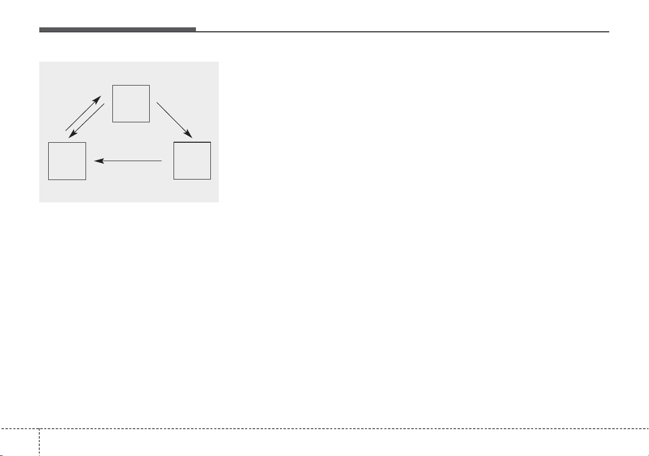
Features of your vehicle
184
This system is designed to provide
protection from unauthorized entry
into the vehicle. This system is oper-
ated in three stages: the first is the
“Armed” stage, the second is the
“Theft-alarm” stage, and the third is
the “Disarmed” stage. If triggered,
the system provides an audible
alarm with blinking of the hazard
warning lights.
Armed stage
Park the vehicle and stop the engine.
Arm the system as described below.
Using the folding key
1. Turn off the engine and remove the
ignition key from the ignition
switch.
2. Make sure that all doors, the
engine hood and liftgate are
closed and latched.
3. Lock the doors by pressing the
lock button on the transmitter.
After completion of the steps
above, the hazard warning lights
will blink once to indicate that the
system is armed.
If the liftgate or engine hood
remains opened, the hazard warn-
ing lights will not operate and
theft-alarm will not arm. After this,
if the liftgate and engine hood are
closed, the hazard warning lights
will blink once and the theft-alarm
will arm.
Using the smart key
1. Turn off the engine.
2. Make sure that all doors, the
engine hood and liftgate are
closed and latched.
3.• Lock the doors by pressing the
button of the front outside door
handle with the smart key in your
possession.
After completion of the steps
above, the hazard warning lights
will operate once to indicate that
the system is armed.
If the liftgate or engine hood
remains opened, the hazard
warning lights will not operate
and theft-alarm will not arm. After
this, if the liftgate and engine
hood are closed, the hazard
warning lights will blink once and
the theft-alarm will arm.
THEFT-ALARM SYSTEM
Armed
stage
Theft-alarm
stage
Disarmed
stage

419
Features of your vehicle
• Lock the doors by pressing the
lock button on the smart key.
After completion of the steps
above, the hazard warning lights
will operate once to indicate that
the system is armed.
If the liftgate or engine hood
remains opened, the hazard
warning lights will not operate
and theft-alarm will not arm. After
this, if the liftgate and engine
hood are closed, the hazard
warning lights will blink once and
the theft-alarm will arm.
Do not arm the system until all
passengers have left the vehicle. If
the system is armed while a pas-
senger(s) remains in the vehicle,
the alarm may be activated when
the remaining passenger(s)
leaves the vehicle. If any door (or
liftgate) or engine hood is opened
within 30 seconds after the sys-
tem enters the armed stage, the
system will be disarmed to pre-
vent unnecessary alarm.
Theft-alarm stage
The alarm will be activated if any of
the following occurs while the system
is armed.
• A front or rear door is opened with-
out using the transmitter (or smart
key).
• The liftgate is opened without
using the transmitter (or smart
key).
• The engine hood is opened.
The horn will sound and the hazard
warning lights will blink continuously
for approximately 27 seconds. To
turn off the system, unlock the doors
with the transmitter (or smart key).
Features of your vehicle
204
Disarmed stage
The system will be disarmed when:
Folding key
- The door unlock button is pressed.
- The engine is started. (within 3
seconds)
- The ignition switch is in the “ON”
position for 30 seconds or more.
Smart key
- The door unlock button is pressed.
- The button of the front outside door
is pressed while carrying the smart
key.
- The engine is started. (within 3
seconds)
After the doors are unlocked, the
hazard warning lights will blink twice
to indicate that the system is dis-
armed.
After pressing the unlock button, if
any door (or liftgate) is not opened
within 30 seconds, the system will be
rearmed.
✽✽
NOTICE
• Without smart key system
If the system is not disarmed with
the transmitter, insert the key into
the ignition switch and start the
engine. Then the system will be
disarmed.
• With smart key system
If the system is not disarmed with
the smart key, open the door with
the mechanical key and start the
engine. Then the system will be
disarmed.
• If you lose your keys, Kia recom-
mends to visit an authorized Kia
dealer/service partner.
CAUTION
Do not change, alter or adjust the
theft-alarm system because it
could cause the theft-alarm sys-
tem to malfunction have the sys-
tem serviced by a professional
workshop. Kia recommends to
visit an authorized Kia
dealer/service partner.
Malfunctions caused by improp-
er alterations, adjustments or
modifications to the theft-alarm
system are not covered by your
vehicle manufacturer warranty.
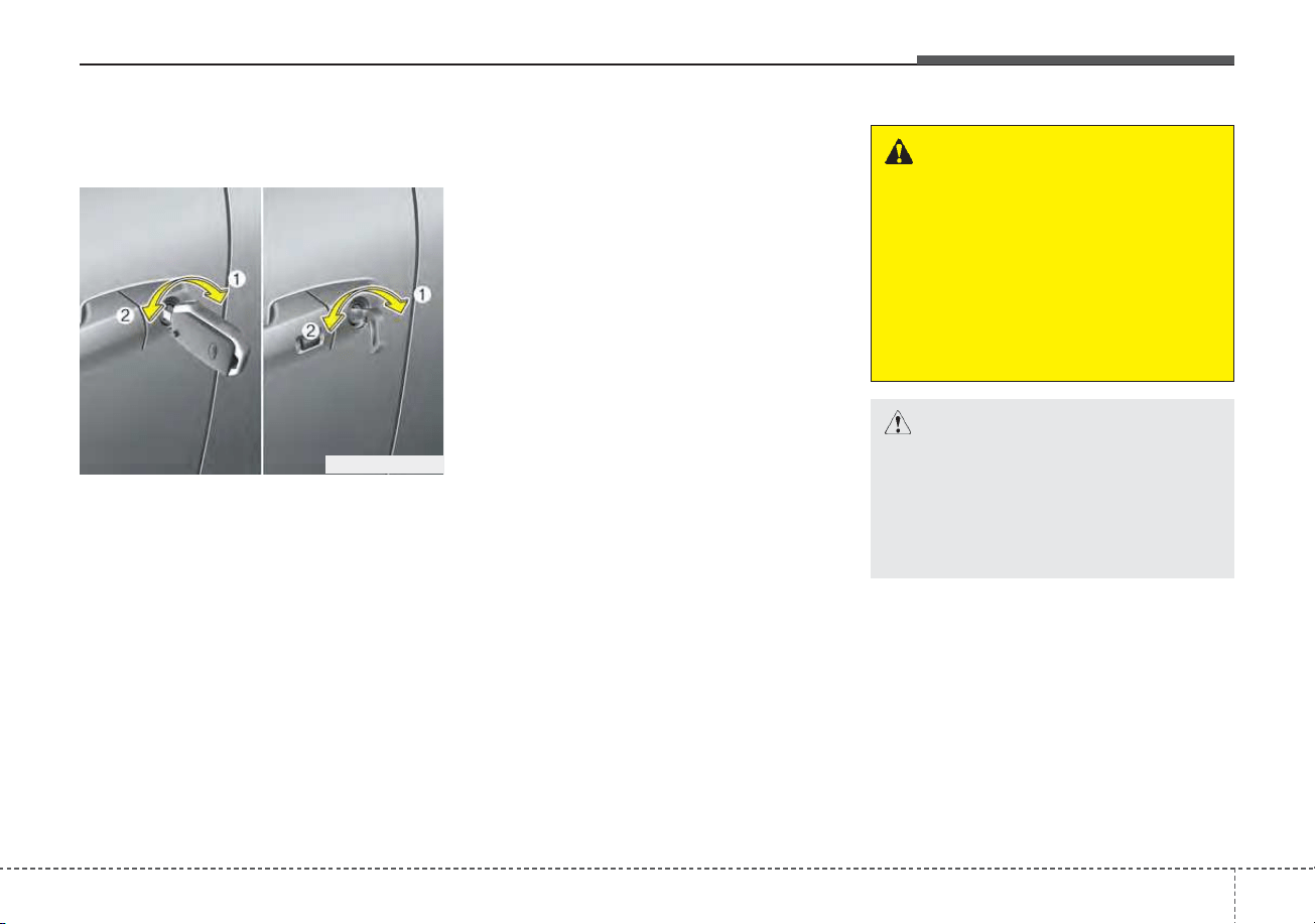
421
Features of your vehicle
DOOR LOCKS
Operating door locks from
outside the vehicle
• Turn the key clockwise (1) to lock
and counterclockwise (2) to unlock.
• If you lock the driver’s door with a
key, if you lock/unlock the driver’s
door with a key, only the driver’s
door will lock/unlock.
• Doors can also be locked and
unlocked with the transmitter (or
smart key).
• Once the doors are unlocked, they
may be opened by pulling the door
handle.
• When closing the door, push the
door by hand. Make sure the doors
are closed securely.
✽✽
NOTICE
• In cold and wet climates, door lock
and door mechanisms may not
work properly due to freezing con-
ditions.
• If the door is locked/unlocked
multiple times in rapid succession
with either the vehicle key or door
lock switch, the system may stop
operating temporarily in order to
protect the circuit and prevent
damage to system components.
ODEP049002N
WARNING
• Securely close your door
before you begin driving.
Failure to fully close your door
may cause it to open during
vehicle operation.
• Keep your body out of the way
of the closing door to prevent
injuries.
CAUTION
Do not unnecessarily open and
close the door repeatedly or
with excessive force. Such
action can damage the vehicle
door.
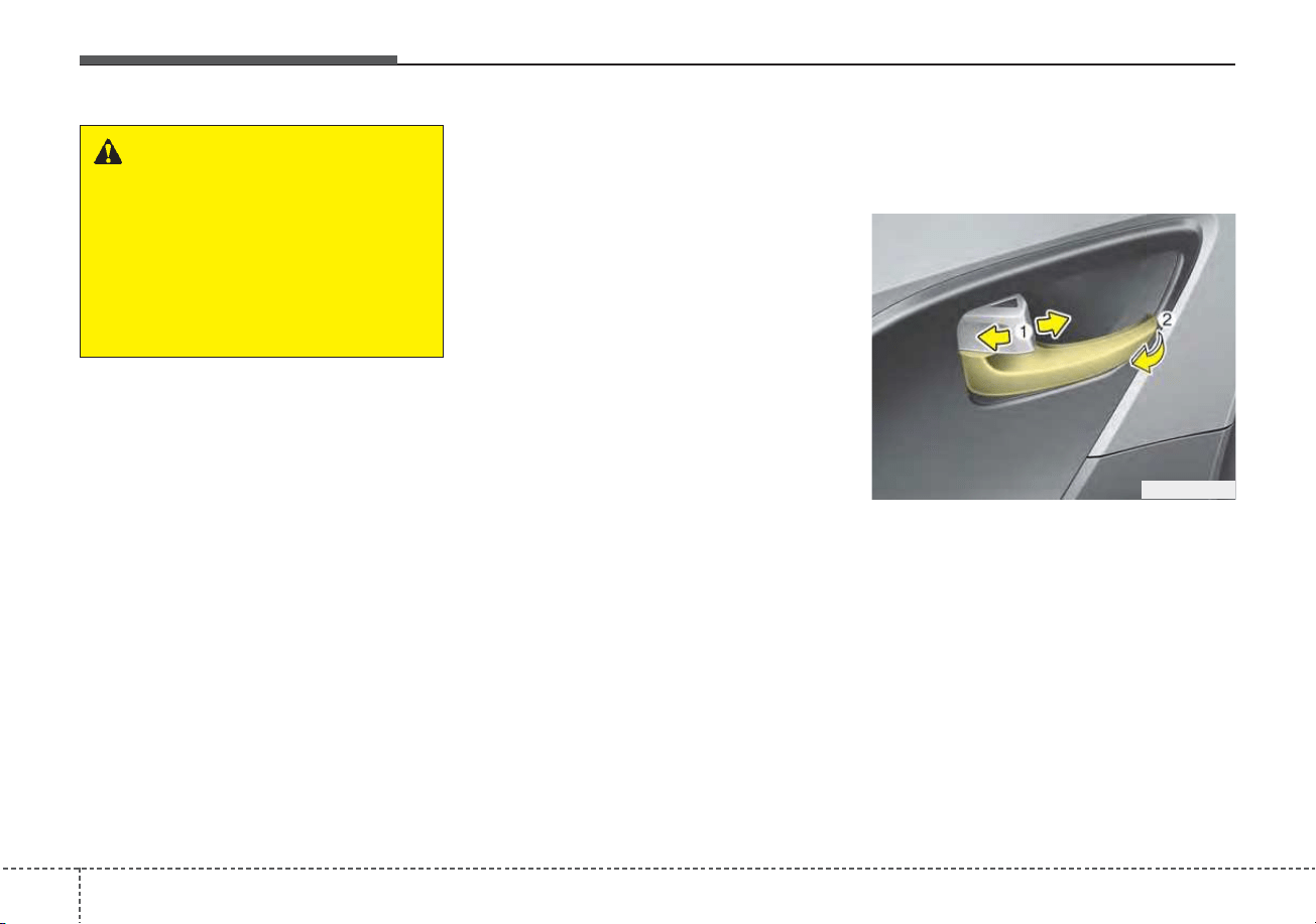
Features of your vehicle
224
✽✽
NOTICE
Always turn off the engine, engage
the parking brake, close all win-
dows, and lock all doors when leav-
ing your vehicle unattended.
Operating door locks from
inside the vehicle
With the door lock button
• To unlock a door, pull the door lock
button (1) to the “Unlock” position.
The red mark on the button will be
visible.
• To lock a door, push the door lock
button (1) to the “Lock” position. If
the door is locked properly, the red
mark on the door lock button will
not be visible.
• To open a door, pull the door handle
(2) outward.
ODE046004
WARNING
If adult passengers must remain
in the vehicle while it is very hot
or cold outside, there is risk of
injuries or danger to life. Do not
lock the vehicle from the out-
side when there are adult pas-
sengers in the vehicle.
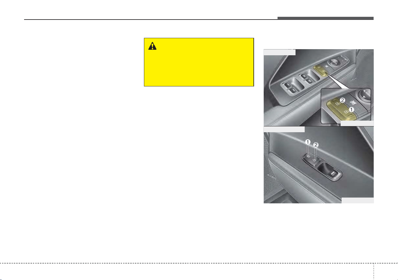
423
Features of your vehicle
• If the inner door handle of the dri-
ver’s (or front passenger’s) door is
pulled when the door lock button is
in the lock position, the button will
unlock and the door will open.
• Doors cannot be locked if the
smart key is in the vehicle and a
door is open.
If a power door lock ever fails to func-
tion while you are in the vehicle, try
one or more of the following tech-
niques to exit:
• Operate the door unlock feature
repeatedly (both electronic and
manual) while simultaneously
pulling on the door handle.
• Operate the other door locks and
handles, front and rear.
• Lower a front window and use the
key to unlock the door from out-
side.
With central door lock switch
Operate by pressing the central door
lock switch.
• When pressing the door lock but-
ton (1), all vehicle doors will lock.
ODEP049005
ODE046041N
■ Driver side
■ Passenger side
WARNING
Do not pull the inner door han-
dle of driver’s(or passenger’s)
door while the vehicle is mov-
ing.
Features of your vehicle
244
• When pressing the door unlock
button (2), all vehicle doors will
unlock.
• If the key is in the ignition switch or
the smart key in the vehicle and
any front door is opened, the doors
will not lock even though the door
lock button (1) is pressed.
Impact sensing door unlock
system
In the event of air bag deployment
resulting from a vehicle impact, all
doors will automatically unlock.
Speed sensing door lock system
All doors will automatically lock after
the vehicle speed exceeds 10 mph
(15 km/h).
✽✽
NOTICE
You can select some auto door
lock/unlock features from the User
Settings mode in the LCD display. For
more information, refer to “User
Settings” in this chapter.
WARNING - Unattended
children/animals
Never leave children or animals
unattended in your vehicle. An
enclosed vehicle can become
extremely hot, causing death or
severe injury to unattended
children or animals who cannot
escape the vehicle.
WARNING - Doors
• The doors should always be
fully closed and locked while
the vehicle is in motion to pre-
vent accidental opening of the
door.
• Be careful when opening doors
and watch for vehicles, motor-
cycles, bicycles or pedestrians
approaching the vehicle in the
path of the door. Opening a
door when something is
approaching can cause injury.
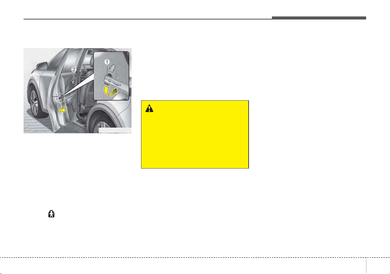
425
Features of your vehicle
Child-protector rear door lock
The child safety lock is provided to
help prevent children from acciden-
tally opening the rear doors from
inside the vehicle. The rear door
safety locks should be used whenev-
er children are in the vehicle.
1. Open the rear door.
2. Insert a key (or screwdriver) (1)
into the slot located on the rear
edge of the door and turn it to the
lock ( ) position. When the child
safety lock is in the lock position,
the rear door will not open even
when the inner door handle (2) is
pulled.
3. Close the rear door.
To open the rear door, pull the out-
side door handle.
Even though the doors may be
unlocked, the rear door will not open
by pulling the inner door handle (2)
until the rear door child safety lock is
unlocked.
WARNING - Rear door
locks
Use the rear door safety locks
whenever children are in the
vehicle. If a child accidently
opens the rear doors while the
vehicle is moving, they may fall
out.
ODEP049006L
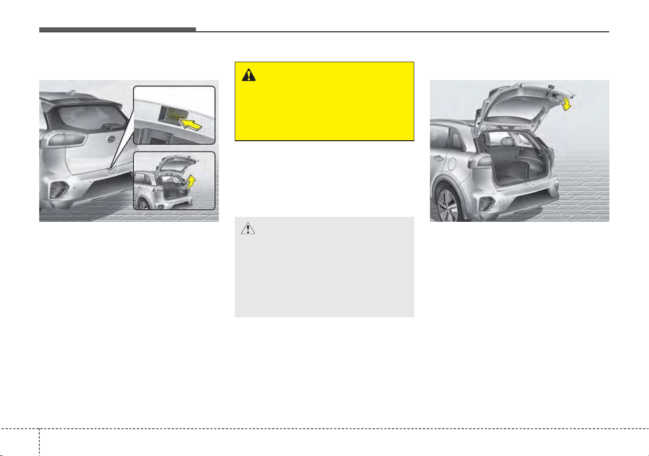
Features of your vehicle
264
Opening the liftgate
• The liftgate is locked or unlocked
when all doors are locked or
unlocked with the transmitter (or
smart key) or central door lock
switch.
• If unlocked, the liftgate can be
opened by pressing the handle
switch and then pulling the handle
up.
• Only the liftgate is unlocked if the
liftgate unlock button on the trans-
mitter or smart key is pressed for
approximately 1 second.
• Once the liftgate is opened and
then closed, the liftgate locks auto-
matically.
✽✽
NOTICE
In cold and wet climates, door lock
and door mechanisms may not work
properly due to freezing conditions.
Closing the liftgate
To close the liftgate, lower and push
down the liftgate firmly. Make sure
that the liftgate is securely latched.
Make sure your hands, feet and other
parts of your body are safely out of
the way before closing the liftgate.
LIFTGATE
ODEP049007 ODEP049008
CAUTION - Liftgate lift
Make certain that you close the
liftgate before driving your vehi-
cle. Possible damage may occur
to the liftgate gas lifters and
attached hardware if the liftgate
is not closed prior to driving.
WARNING
The liftgate swings upward.
Make sure no objects or people
are near the rear of the vehicle
when opening the liftgate.
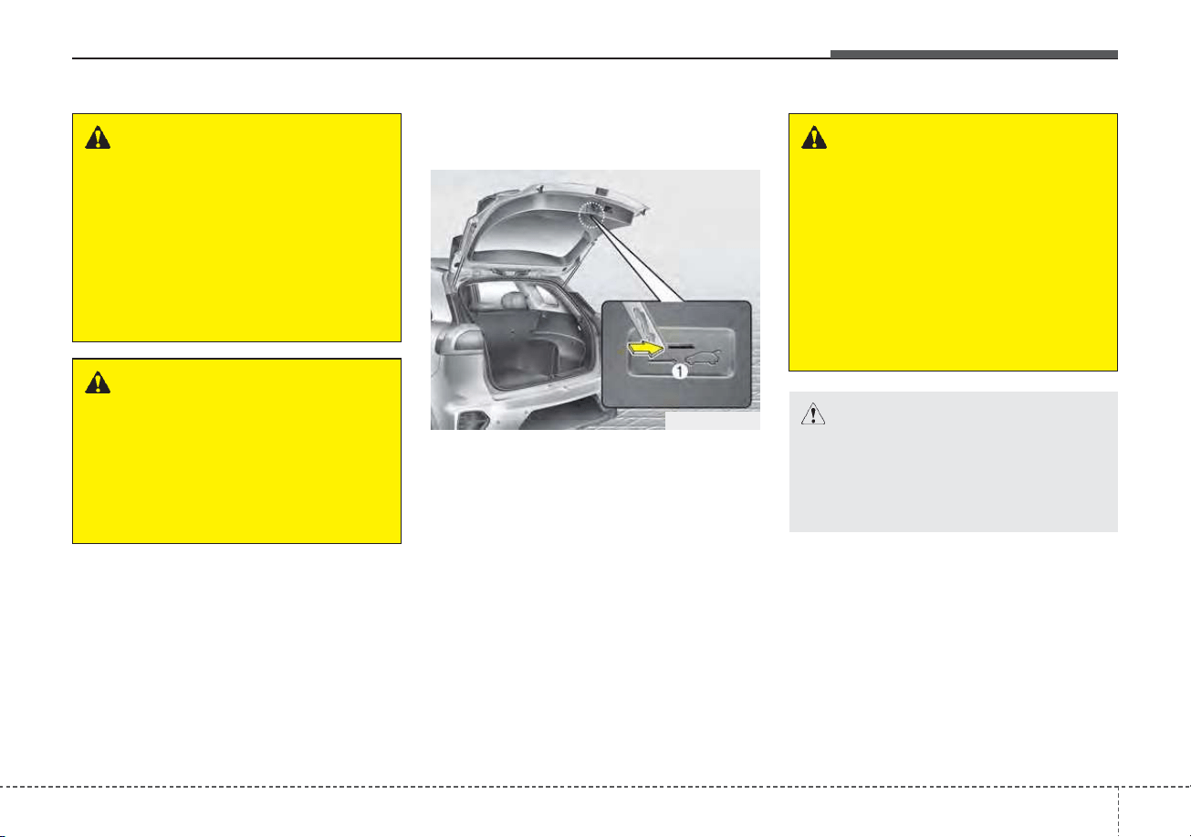
427
Features of your vehicle
Emergency liftgate safety
release
Your vehicle is equipped with the
emergency liftgate safety release
lever located on the bottom of the lift-
gate. When someone is inadvertent-
ly locked in the luggage compart-
ment, the liftgate can be opened by
doing as follows:
1. Input the mechanical key into the
hole.
2. Push the mechanical key to the
right (1).
3. Push up the liftgate.
WARNING - Rear cargo
area
Occupants should never ride in
the rear cargo area where no
restraints are available.
Occupants should always be
properly restrained.
WARNING - Exhaust
fumes
The liftgate should always be
kept completely closed while
the vehicle is in motion. If it is
left open or ajar, poisonous
exhaust gases may enter the
vehicle and serious illness or
death may result.
WARNING
• No one should be allowed to
occupy the cargo area of the
vehicle at any time. The cargo
area is a very dangerous loca-
tion in the event of a crash.
• Use the release lever for
emergencies only. Use with
extreme caution, especially
while the vehicle is in motion.
ODEP049009
CAUTION
Make sure nothing is near the
liftgate latch and striker while
closing the liftgate. It may dam-
age the liftgate's latch.
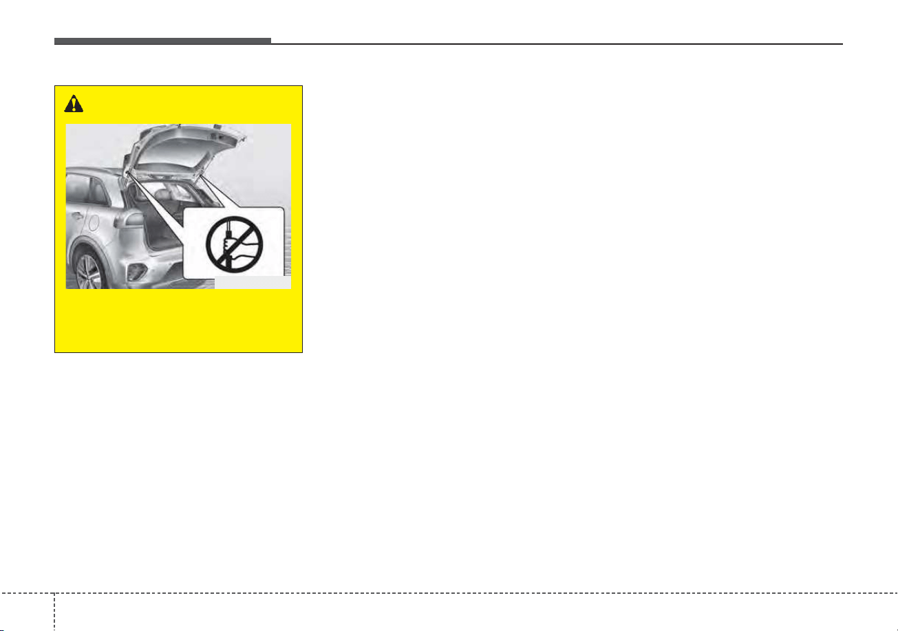
Features of your vehicle
284
WARNING
Do not grasp the part support-
ing the liftgate (gas lifter), as
this may cause serious injury.
ODEP049531
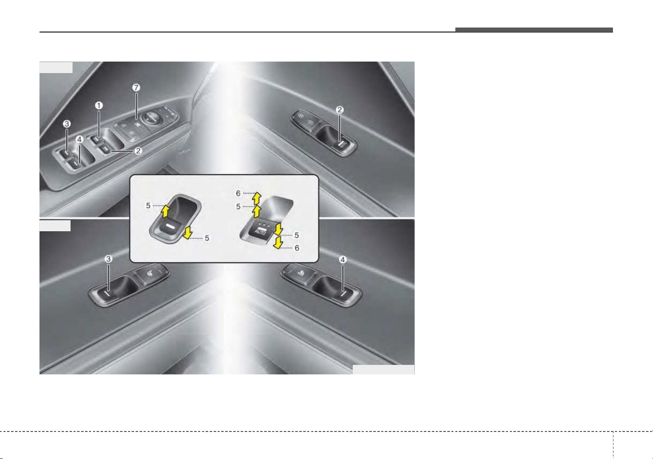
429
Features of your vehicle
(1) Driver’s door power window
switch
(2) Front passenger’s door power
window switch
(3) Rear door (left) power window
switch
(4) Rear door (right) power window
switch
(5) Window opening and closing
(6) Automatic power window
up/down* (Driver's and
Passenger's window)
(7) Power window lock button
* if equipped
In cold and wet climates, power win-
dows may not work properly due to
freezing conditions.
WINDOWS
ODEP049010N
■■
Front
■■
Rear
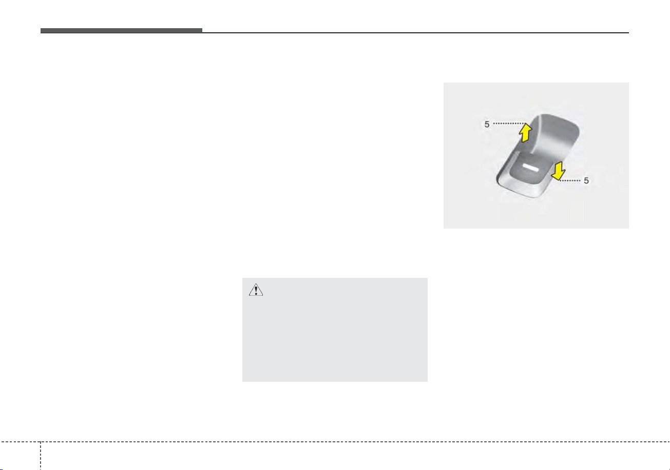
Features of your vehicle
304
Power windows
The ignition switch or ENGINE
START/STOP button must be in the
ON position for power windows to
operate.
Each door has a power window
switch that controls the door's win-
dow. The driver has a power window
lock button which can block the oper-
ation of rear passenger windows.
The power windows can be operated
for approximately 30 seconds after
the engine is turned off.
However, if the front doors are
opened, the power windows cannot
be operated even within the 30 sec-
ond period.
The driver’s door has a master power
window switch that controls all the
windows in the vehicle.
If the window cannot be closed
because it is blocked by objects,
remove the objects and close the
window.
✽✽
NOTICE
While driving with the rear windows
down or with the sunroof (if
equipped) in an open (or partially
open) position, your vehicle may
demonstrate a wind buffeting or
pulsation noise. This noise is a nor-
mal occurrence and can be reduced
or eliminated by taking the follow-
ing actions. If the noise occurs with
one or both of the rear windows
down, partially lower both front
windows approximately one inch
(2.5 cm). If you experience the noise
with the sunroof open, slightly
reduce the size of the sunroof open-
ing.
Window opening and closing
To open or close a window, press
down or pull up the front portion of
the corresponding switch to the first
detent position (5).
OJF045016
CAUTION
Do not install any accessories
in the vehicle that extend into
the open window area. Such
objects will impact the proper
function of the Automatic rever-
sal “jam protection” feature.
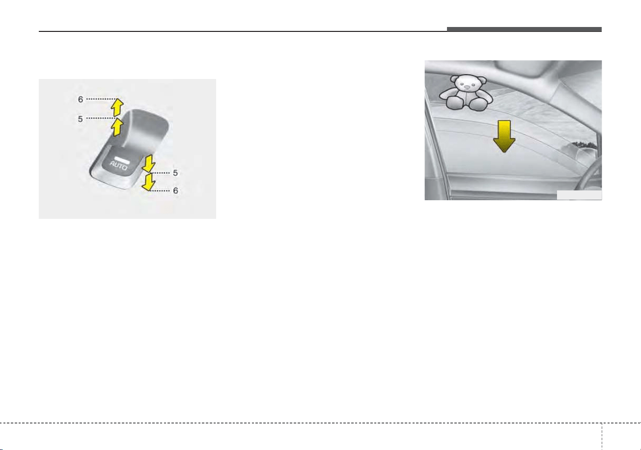
431
Features of your vehicle
Auto up/down window (if equipped)
Pressing or pulling up the power win-
dow switch momentarily to the second
detent position (6) completely lowers
or raises the window even when the
switch is released. To stop the window
at the desired position while the win-
dow is in operation, pull up or press
down and release the switch.
If the power window does not operate
normally, the automatic power win-
dow system must be reset as follows:
1. Turn the ignition switch or ENGINE
START/STOP button to the ON
position.
2. Close the driver's and passenger's
window and continue pulling up
the driver’s power window switch
for at least 1 second after the win-
dow is completely closed.
Automatic reversal
(for Auto up/down window)
If the upward movement of the win-
dow is blocked by an object or part of
the body, the window will detect the
resistance and will stop upward
movement. The window will then
lower approximately 11.8 in. (30 cm)
to allow the object to be cleared.
The distance may vary based on the
size or position of the window. If the
window detects the resistance while
the power window switch is pulled up
continuously, the window will stop
upward movement then lower
approximately 1 in. (2.5 cm).
OUN026013
OJF045017L
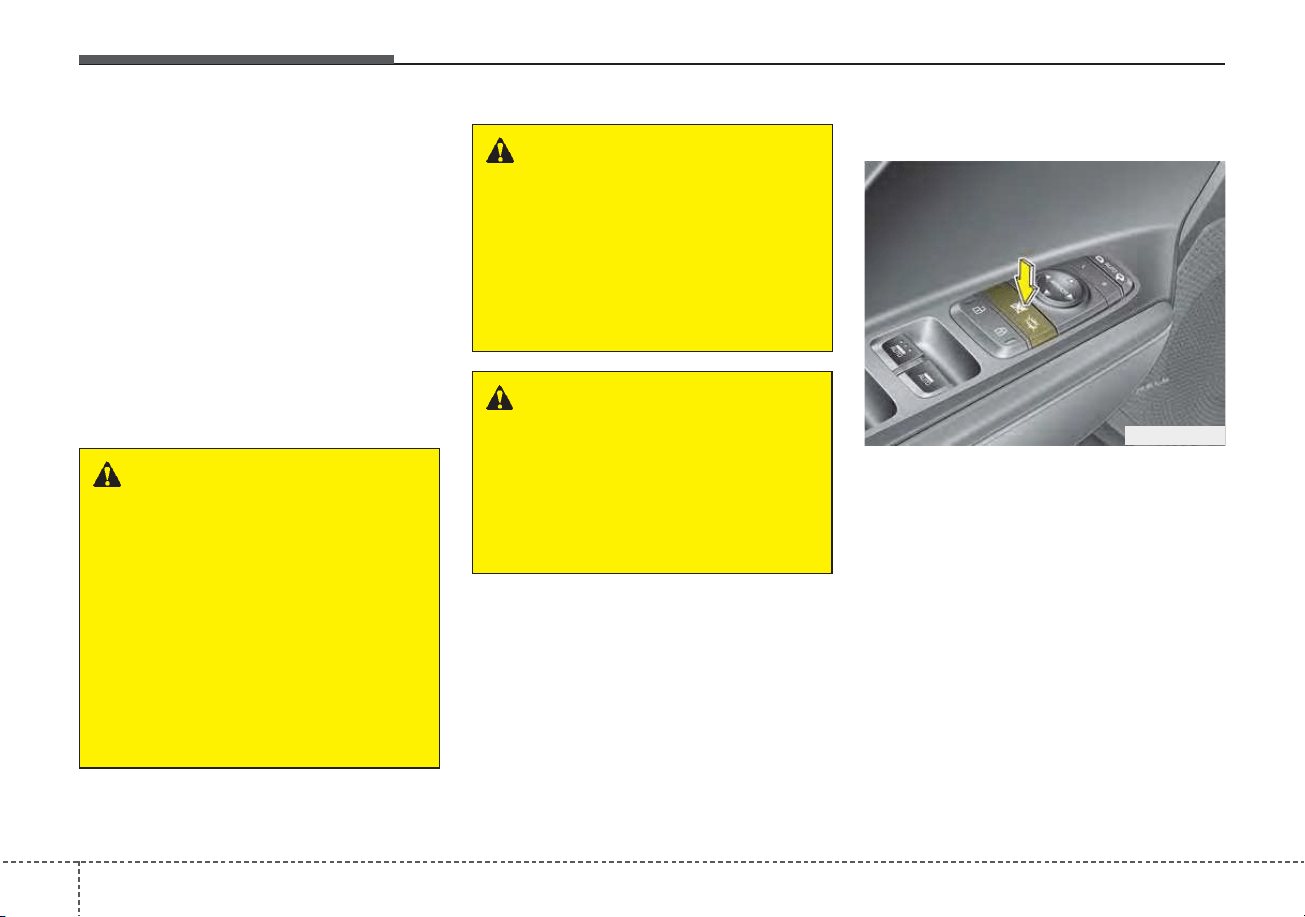
Features of your vehicle
324
If the power window switch is pulled
up continuously again within 5 sec-
onds after the window is lowered by
the automatic window reversal fea-
ture, the automatic window reversal
will not operate.
The automatic reverse feature for the
driver’s window is only active when
the “auto up” feature is used by fully
pulling up the switch. The automatic
reverse feature will not operate if the
window is raised using the halfway
position on the power window switch.
Power window lock button
• The driver can disable the power
window switches on the rear pas-
senger doors by pressing the
power window lock button located
on the driver’s door to the LOCK
position (pressed).
ODEP047013
WARNING
Always check for obstructions
before raising any window to
avoid injuries or vehicle dam-
age. If an object less than 0.16
in. (4 mm) in diameter is caught
between the window glass and
the upper window channel, the
automatic reverse window may
not detect the resistance and
may not stop and reverse direc-
tion.
WARNING
The automatic reverse feature
doesn’t activate while resetting
power window system. Make
sure body parts or other objects
are safely out of the way before
closing the windows to avoid
injuries.
WARNING
Do not install any accessories
in the vehicle that extend into
the open window area. Such
objects could prevent the auto-
matic reverse feature from func-
tioning.
433
Features of your vehicle
• When the power window lock
button is pressed :
- The driver's master control can
operate all the power windows.
- The front passenger's control can
operate the front passenger's
power window.
- The rear passenger's control can-
not operate the rear passenger's
power window.
Always double check to make sure
all arms, hands, head and other
obstructions are safely out of the way
before closing a window.
If the window cannot be closed
because it is blocked by objects,
remove the objects and close the
window.
CAUTION - Opening /clos-
ing Window
To prevent possible damage to
the power window system, do
not open or close two windows
or more at the same time. This
will also ensure the longevity of
the fuse.
WARNING - Power win-
dows
• Do not allow children to play
with the power windows. Keep
the power window lock button
(on the driver's door) in the
LOCK (pressed) position.
• Do not extend a face or arms
outside through the window
opening while driving.
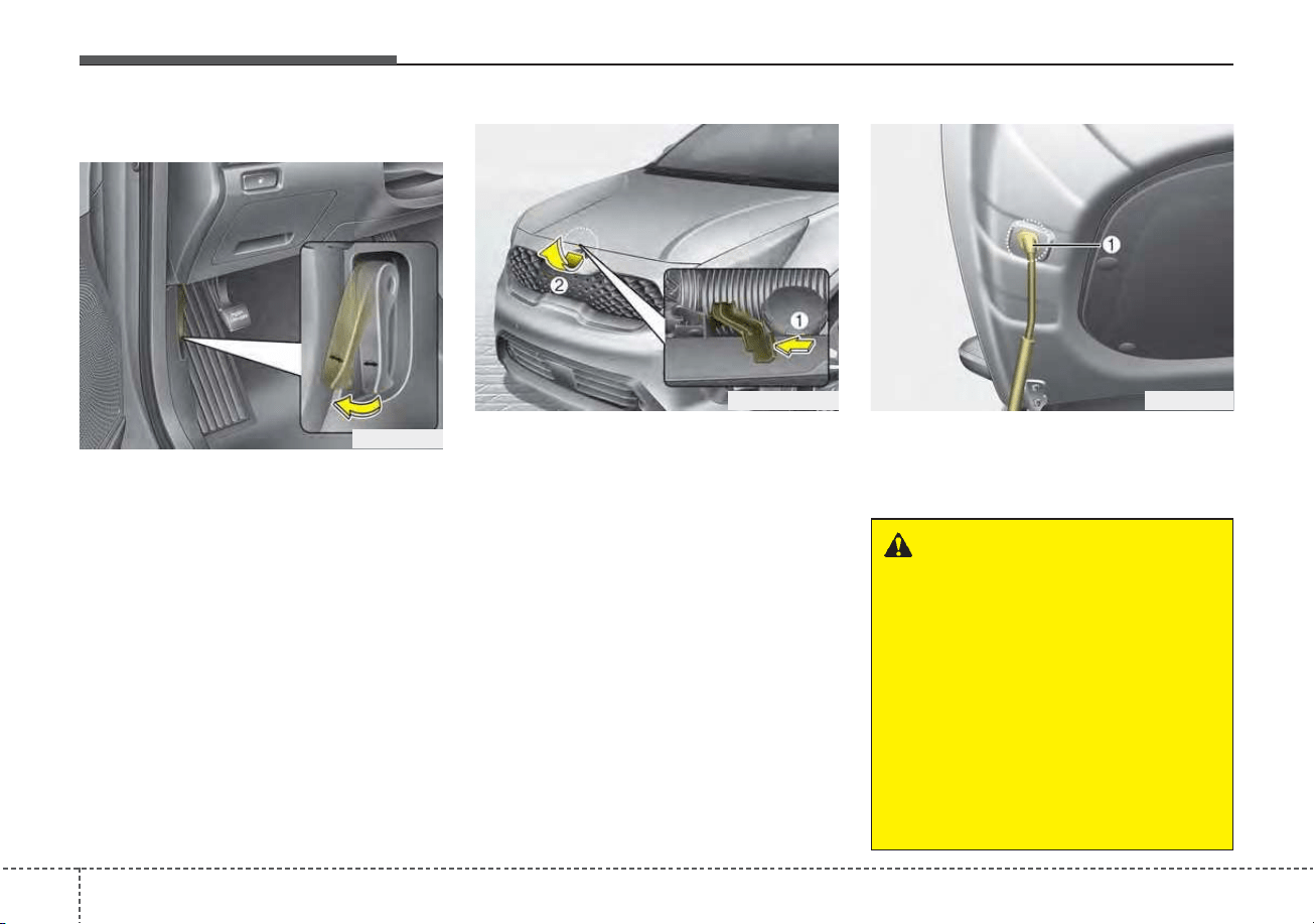
Features of your vehicle
344
Opening the hood
1. Pull the release lever to unlatch
the hood. The hood should pop
open slightly.
Open the hood after turning off the
engine on a flat surface, shifting the
shift lever to the P (Park) position
and setting the parking brake.
2. Go to the front of the vehicle, raise
the hood slightly, push the second-
ary latch (1) upward inside of the
hood center and lift the hood (2).
3. Raise the hood. It will completely
rise by itself after it has been
raised about halfway.
4. Pull out the stay rod.
5. Hold the hood opened with the
stay rod (1).
HOOD
ODE046014
ODEP049015 ODE046016
WARNING - Stay Rod
• To prevent injuries from being
burned by hot metal, grab the
stay rod in the area wrapped in
rubber.
• Ensure that the stay rod is
completely inserted into the
hole on the hood whenever you
inspect the engine compart-
ment. This will prevent the
hood from falling and possibly
injuring you.
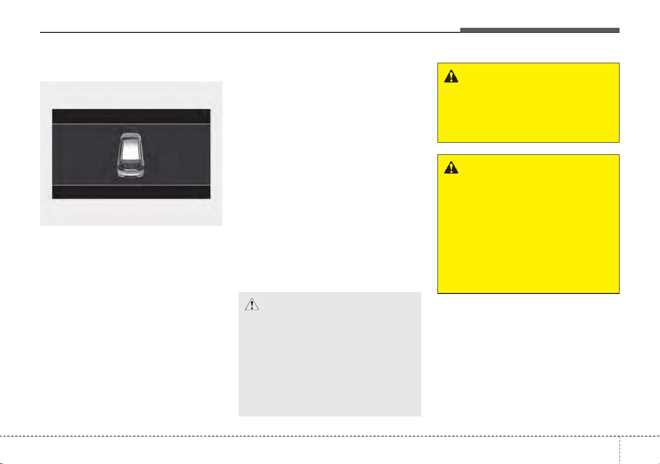
435
Features of your vehicle
Hood open warning
The warning message will appear on
the LCD display when hood is open.
The warning chime will operate when
the vehicle is being driven at or
above 2 mph (3 km/h) with the hood
open.
Closing the hood
1. Before closing the hood, check the
following:
• All filler caps in the engine com-
partment must be correctly
installed.
• Gloves, rags or any other com-
bustible material must be
removed from the engine com-
partment.
2. Lower the hood halfway and push
down to securely lock in place.
• Then double check to be sure the
hood is secure.
• If the hood can be lifted with a
slight force, open the hood again
and close it more firmly.
WARNING - Fire risk
Do not leave gloves, rags or any
other combustible material in the
engine compartment. Doing so
may cause a heat-induced fire.
WARNING - Unsecured
engine hood
Always double check to be sure
that the hood is firmly latched
before driving away. If it is not
latched, the hood could fly open
while the vehicle is being driv-
en, causing a total loss of visi-
bility, which might result in an
accident.
CAUTION - Hood obstruc-
tion
Before closing the hood, ensure
that all obstructions are
removed from the hood open-
ing. Closing the hood with an
obstruction present in the hood
opening may result in property
damage.
ODEP049118
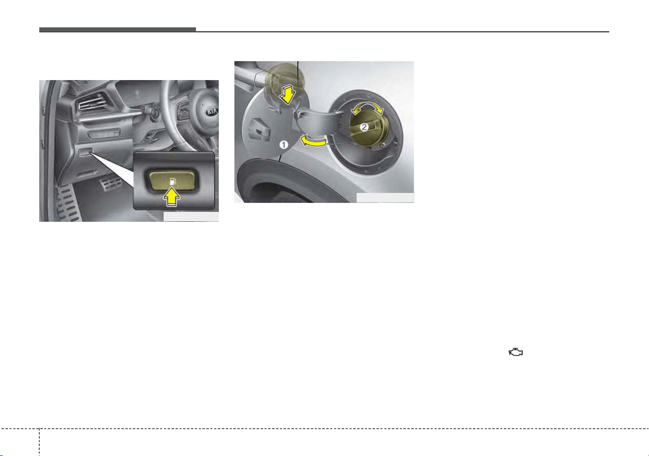
Features of your vehicle
364
Opening the fuel filler door
The fuel filler door must be opened
from inside the vehicle by pressing
the fuel filler door opener button.
If the fuel filler door does not open
because ice has formed around it,
tap lightly or push on the lid to break
the ice and release the lid. Do not pry
on the lid. If necessary, spray around
the lid with an approved de-icer fluid
(do not use radiator anti-freeze) or
move the vehicle to a warm place
and allow the ice to melt.
1. Stop the engine.
2. To open the fuel filler door, push
the fuel filler door opener button.
3. Pull open the fuel filler door (1).
4. To remove the cap, turn the fuel
filler cap (2) counterclockwise.
5. Refuel as needed.
Closing the fuel filler door
1. To install the cap, turn it clockwise
until it “clicks” once. This indicates
that the cap is securely tightened.
2. Close the fuel filler door and push
it in lightly making sure that it is
securely closed.
✽✽
NOTICE
• There may be an intermittent
noise near the refueling hole while
the engine is idling if the fuel cap is
not closed securely. This occurs
normally with the OBD system.
• When refueling on unlevel
ground, the fuel gauge may not
point to the F position.
It is not a malfunction. If you
move your vehicle to a level
ground, the fuel gauge will move
to the full position.
• Tighten the cap until it clicks once,
otherwise the fuel cap open warn-
ing indicator light will illumi-
nate.
FUEL FILLER DOOR (HYBRID)
ODEP049017L
ODEP049585L
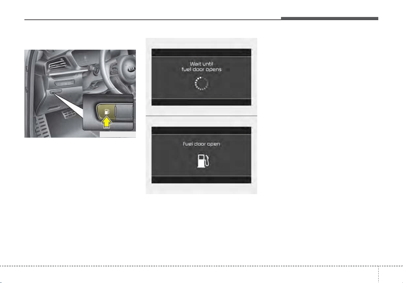
437
Features of your vehicle
Opening the fuel filler door
The fuel filler door must be opened
from inside the vehicle by pushing
the fuel filler door button.
✽✽
NOTICE
If the fuel filler door does not open
because ice has formed around it,
tap lightly or push on the lid to break
the ice and release the lid. Do not pry
on the lid. If necessary, spray around
the lid with an approved de-icer fluid
(do not use radiator anti-freeze) or
move the vehicle to a warm place
and allow the ice to melt.
Wait until the fuel tank is depressur-
ized.The message is displayed when
the fuel filler door opens after the fuel
tank is depressurized.
✽✽
NOTICE
• It may take up to 20 seconds to
open fuel filler door.
• When the fuel filler door is frozen
and does not open after 20 seconds
at freezing temperature, slightly
tap the fuel filler door and then
attempt to open it.
FUEL FILLER DOOR (PLUG-IN HYBRID)
ODEP049523L
OJFHP048601L
OJFHP048602L
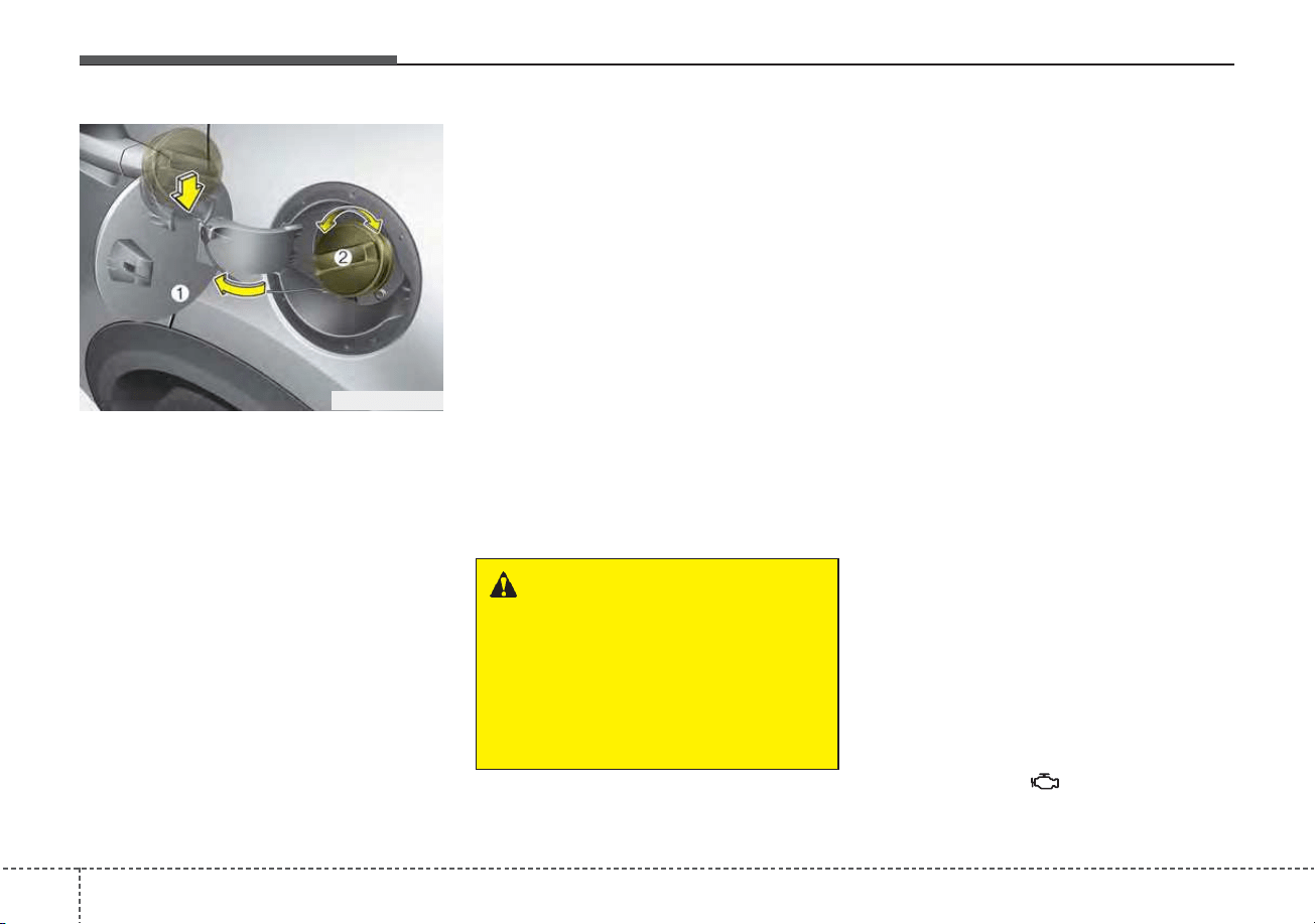
Features of your vehicle
384
1. Stop the engine.
2. To open the fuel filler door, push
the fuel filler door opener button.
3. Pull open the fuel filler door (1).
4. To remove the cap, turn the fuel
filler cap (2) counterclockwise.
5. Refuel as needed.
✽✽
NOTICE
• Add fuel into the fuel tank within
20 minutes after opening the fuel
filler door. After 20 minutes, the
fuel tank may shut off, causing
fuel to overflow. In this case, re-
press the fuel filler door opening
button.
• Do not leave the fuel filler door
opened for an extended period of
time. It may discharge the battery.
• Close the fuel filler door after fuel-
ing the vehicle. If you start the
vehicle with the fuel filler door
opened, the message, “Check fuel
door”, illuminates on the LCD dis-
play.
Closing the fuel filler door
1. To install the cap, turn it clockwise
until it “clicks”. This indicates that
the cap is securely tightened.
2. Close the fuel filler door and push
it lightly and make sure that it is
securely closed.
Always check that the fuel cap is
installed securely to prevent fuel
spillage in the event of an accident.
✽✽
NOTICE
• There may be an intermittent
noise near the refueling hole while
the engine is idling if the fuel cap is
not closed securely. This occurs
normally with the OBD system.
• When refueling on unlevel
ground, the fuel gauge may not
point to the F position.
It is not a malfunction. If you
move your vehicle to a level
ground, the fuel gauge will move
to the full position.
• Tighten the cap until it clicks once,
otherwise the fuel cap open warn-
ing indicator light will illumi-
nate.
WARNING - For Plug-in
Hybrid
Avoid refueling the vehicle
while charging the (high-volt-
age) hybrid battery. It may
cause a fire or an explosion due
to static electricity.
ODEP049585L
439
Features of your vehicle
Always check that the fuel cap is
installed securely to prevent fuel
spillage in the event of an accident.
WARNING - Fire/explo-
sion risk
Read and follow all warnings
posted at the gas station facili-
ty. Failure to follow all warnings
may result in severe personal
injury, severe burns or death
due to fire or explosion.
WARNING - Static
electricity
• Before touching the fuel noz-
zle, you should eliminate
potentially dangerous static
electricity discharge by touch-
ing another metal part of the
vehicle, a safe distance away
from the fuel filler neck, noz-
zle, or other gas source.
• Do not get back into a vehicle
once you have begun refueling
since you can generate static
electricity by touching, rubbing
or sliding against any item or
fabric (polyester, satin, nylon,
etc.) capable of producing stat-
ic electricity. Static electricity
discharge can ignite fuel
vapors resulting in rapid burn-
ing. If you must reenter the
vehicle, you should once again
eliminate potentially danger-
ous static electricity discharge
by touching a metal part of the
vehicle, away from the fuel filler
neck, nozzle or other gasoline
source.
WARNING - Refueling
Always remove the fuel cap
carefully and slowly. If the cap
is venting fuel or if you hear a
hissing sound, wait until the
condition stops before com-
pletely removing the cap. If
pressurized fuel sprays out, it
can cover your clothes or skin
and subject you to the risk of
fire and burns.
Features of your vehicle
404
WARNING - Cell phone
fires
Do not use cellular phones
while refueling. Electric current
and/or electronic interference
from cellular phones can poten-
tially ignite fuel vapors causing
a fire.
WARNING - Smoking
DO NOT use matches or a
lighter and DO NOT SMOKE or
leave a lit cigarette in your vehi-
cle while at a gas station espe-
cially during refueling.
Automotive fuel is highly flam-
mable and can, when ignited,
result in fire.
WARNING - Refueling &
Vehicle fires
When refueling, always shut the
engine off. Sparks produced by
electrical components related
to the engine can ignite fuel
vapors causing a fire. Once
refueling is complete, check to
make sure the filler cap and
filler door are securely closed,
before starting the engine.
WARNING - Portable fuel
container
When using an approved
portable fuel container, be sure
to place the container on the
ground prior to refueling. Static
electricity discharge from the
container can ignite fuel vapors
causing a fire. Once refueling
has begun, contact with the
vehicle should be maintained
until the filling is complete. Use
only approved portable plastic
fuel containers designed to
carry and store gasoline.
WARNING
In case of using EV drive mode
for a certain time without run-
ning Engine, EMM(Engine
Maintenance Mode) will auto-
matically activate by the system
to protect fuel system and the
engine.
Therefore, even though if it is
possible to use EV drive mode
with enough battery power, the
engine may run by the system
to protect fuel system and the
engine.
If you leave the fuel without
refueling or using for over 6
months, the remained fuel in the
fuel system may be deteriorat-
ed. From this, corrosion or
blocking problem may occur.
It is recommended using mini-
mum 40% of remained fuel at
least every 6 months by select-
ing Hybrid (CS) mode and refu-
el the vehicle with new fuel.

441
Features of your vehicle
Make sure to refuel your vehicle
according to the “Fuel requirements”
suggested in chapter 1.
If the fuel filler cap requires replace-
ment, use only a genuine Kia cap or
the equivalent specified for your vehi-
cle. An incorrect fuel filler cap can
result in a serious malfunction of the
fuel system or emission control sys-
tem.
CAUTION - Exterior paint
Do not spill fuel on the exterior
surfaces of the vehicle. Any
type of fuel spilled on painted
surfaces may damage the paint.
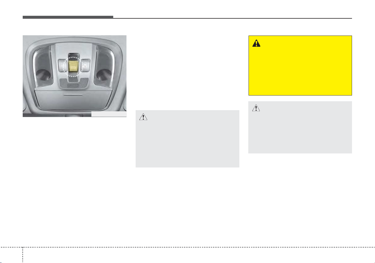
Features of your vehicle
424
If your vehicle is equipped with a
sunroof, you can slide or tilt your
sunroof with the sunroof control lever
located on the overhead console.
The sunroof can only be opened,
closed, or tilted when the ignition
switch is in the ON position.
The sunroof can be operated for
approximately 30 seconds after the
ignition key is removed or turned to
the ACC or LOCK (or OFF) position.
However, if the front door is opened,
the sunroof cannot be operated even
within the 30 seconds period.
In cold and wet climates, the sunroof
may not work properly due to freez-
ing conditions.
After the vehicle is washed or in a
rainstorm, be sure to wipe off any
water that is on the sunroof before
operating it.
The sunroof cannot slide when it is in
the tilt position nor can it be tilted
while in an open or slide position.
SUNROOF (IF EQUIPPED)
ODEEV048035N
CAUTION - Sunroof
control lever
Do not continue to press the sun-
roof control lever after the sun-
roof is fully opened, closed, or
tilted. Damage to the motor or
system components could occur.
CAUTION
Make sure the sunroof is fully
closed when leaving your vehi-
cle. If the sunroof is open, rain
or snow may leak through the
sunroof and wet the interior.
WARNING
Never adjust the sunroof or
sunshade while driving. This
could result in loss of control
and an accident that may cause
death, serious injury, or proper-
ty damage.
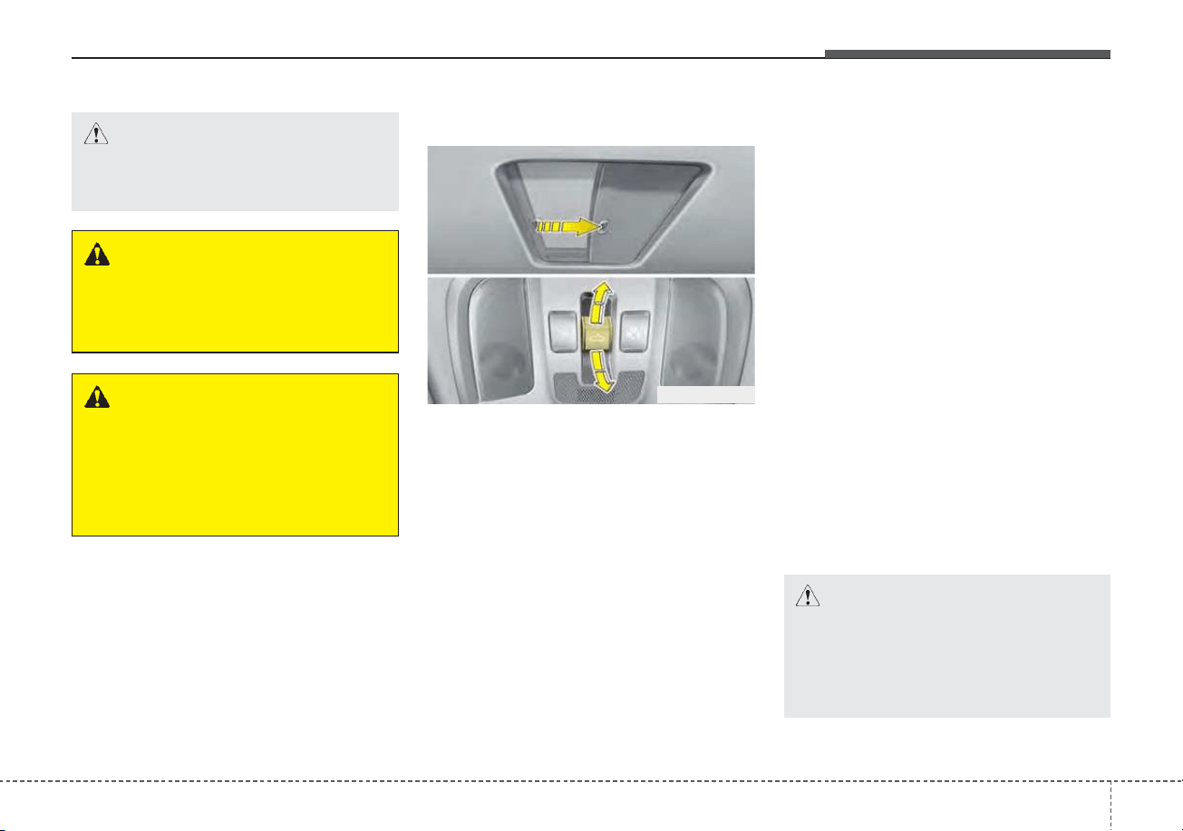
443
Features of your vehicle
Sliding the sunroof
To open or close the sunroof (manu-
al slide feature), push the sunroof
control lever backward or forward to
the first detent position.
To open the sunroof (autoslide fea-
ture), push the sunroof control switch
backward to the second detent posi-
tion.
The sunroof will slide to the recom-
mended open position before the
maximum slide open position.
To stop the sunroof sliding at any
point, push the sunroof control
switch briefly.
To open the sunroof to the maximum
slide open position, press the switch
towards the rear of the vehicle once
again and hold it until the sunroof
slides all the way open.
✽✽
NOTICE
To reduce wind noise while driving,
we recommend you to drive at the
recommended position before the
maximum slide open position.
To close the sunroof (autoslide fea-
ture), move the sunroof control
switch forward to the second detent
position.
The sunroof will close all the way. To
stop the sunroof sliding at any point,
pull or push the sunroof control
switch briefly.
ODEEV048020
WARNING
To avoid accidental injury, do
not let children operate the sun-
roof without adult supervision.
CAUTION
Do not extend any luggage out-
side the sunroof while driving.
WARNING - Roof cargo
Do not operate the sun roof
while using the roof rack to
transport cargo. This may cause
the cargo to come loose and
distract the driver.
CAUTION
To prevent damage to the sun-
roof, periodically remove any
dirt that may accumulate on the
guide rail.
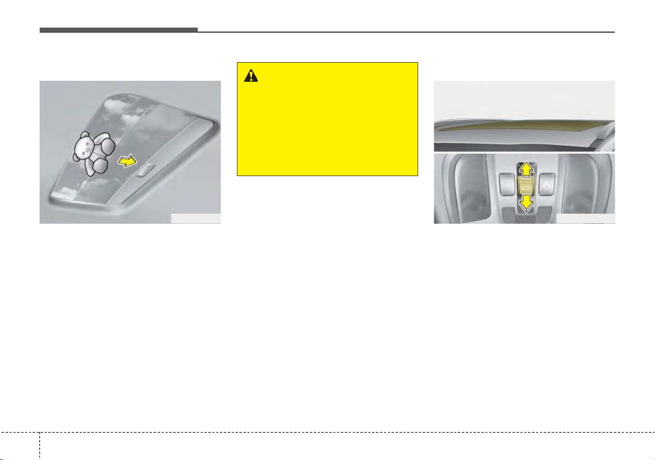
Features of your vehicle
444
Automatic reversal
If an object or part of the body is
detected while the sunroof is closing
automatically, it will reverse the direc-
tion, and then stop.
The auto reverse function does not
work if a tiny obstacle is between the
sliding glass and the sunroof sash.
You should always check that all pas-
sengers and objects are away from
the sunroof before closing it.
Tilting the sunroof
To tilt open the sunroof, push the
sunroof control lever upward until the
sunroof moves to the desired posi-
tion.
To close the sunroof, push the sun-
roof lever forward until the sunroof
moves to the desired position.
OBK049018
WARNING - Sunroof
operation
When closing the sunroof, make
sure there are no body parts in
the movement range of the slid-
ing glass. Parts of the body
could become trapped or
crushed.
ODEEV048021
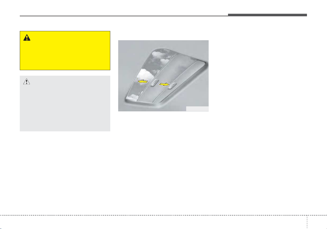
445
Features of your vehicle
Sunshade
When opening the sunroof, the sun-
shade will also open. Once the sun-
roof is closed, the sunshade can be
manually closed.
Resetting the sunroof
Whenever the vehicle battery is dis-
connected or discharged, or related
fuse is blown, you must reset your
sunroof system as follows:
1.Turn the ignition switch to the ON
position or start the engine. We
recommend resetting the sunroof
while the engine is running.
2.Close the sunroof completely if
opened.
3.Release the sunroof control lever.
4.Move the sunroof control lever for-
ward in the direction of close until
the sunroof moves tilt up. Then,
release the lever.
5.Move the sunroof control lever for-
ward in the direction of close, until
the sunroof operates as follows
again:
Tilt down → Slide Open → Slide
Close.
OBK049019
CAUTION - Sunroof
motor damage
If you try to open the sunroof
when the temperature is below
freezing or when the sunroof is
covered with snow or ice, the
glass or the motor could be
damaged.
WARNING - Sunroof
Do not extend the face, neck,
arms or body outside through
the sunroof opening while driv-
ing or operating the sunroof.
Features of your vehicle
464
✽✽
NOTICE
Do not release the lever until the
operation is completed.
If you release the lever during oper-
ation, try again from step 2.
6. Release the sunroof control lever
after all operation has completed.
(The sunroof system has been
reset.)
❈ For more detailed information,
contact an authorized Kia dealer.
✽✽
NOTICE
If the sunroof is not reset when the
vehicle battery is disconnected or
discharged, or related fuse is blown,
the sunroof may operate improper-
ly.
Sunroof open warning
If the driver removes the ignition key
(smart key: turns off the engine)
when the sunroof is not fully closed,
the warning chime will sound for a
few seconds and a warning image
will appear on the LCD display.
Close the sunroof securely when
leaving your vehicle.
ODEP049119

447
Features of your vehicle
Electric Power Steering
(EPS)
The power steering uses a motor to
assist you in steering the vehicle. If
the engine is off or if the power steer-
ing system becomes inoperative, the
vehicle may still be steered, but it will
require increased steering effort.
The EPS is controlled by a power
steering control unit which senses
the steering wheel torque and vehi-
cle speed to command the motor.
The steering becomes heavier as the
vehicle’s speed increases and
becomes lighter as the vehicle’s
speed decreases for optimum steer-
ing control.
Should you notice any change in the
effort required to steer during normal
vehicle operation, have the power
steering checked by an authorized
Kia dealer.
• If the Electric Power Steering
System does not operate normally,
the warning light will illuminate on
the instrument cluster. The steering
wheel may require increased
steering effort. Take your vehicle to
an authorized Kia dealer and have
the vehicle checked as soon as
possible.
• When you operate the steering
wheel in low temperature, noise
may occur. If temperature rises, the
noise will likely disappear. This is a
normal condition.
• When the vehicle is stationary, and
the steering wheel is turned all the
way to the left or right continuous-
ly, the steering wheel becomes
harder to turn. The power assist is
limited to protect the motor from
overheating.
As time passes, the steering wheel
will return to its normal condition.
✽✽
NOTICE
The following symptoms may occur
during normal vehicle operation:
• The EPS warning light does not
illuminate.
• The steering gets heavy immedi-
ately after turning the ENGINE
START/STOP button is ON posi-
tion. This happens as the system
performs the EPS system diagnos-
tics. When the diagnostics are
completed, the steering wheel will
return to its normal condition.
• A click noise may be heard from
the EPS relay after turning the
ENGINE START/STOP button is
ON or OFF position.
• A motor noise may be heard when
the vehicle is at a stop or at a low
driving speed.
• If the Electric Power Steering
System does not operate normally,
the warning light will illuminate on
the instrument cluster. The steer-
ing wheel may become difficult to
control or operate abnormally.
Take your vehicle to an authorized
Kia dealer and have the vehicle
checked as soon as possible.
(Continued)
STEERING WHEEL
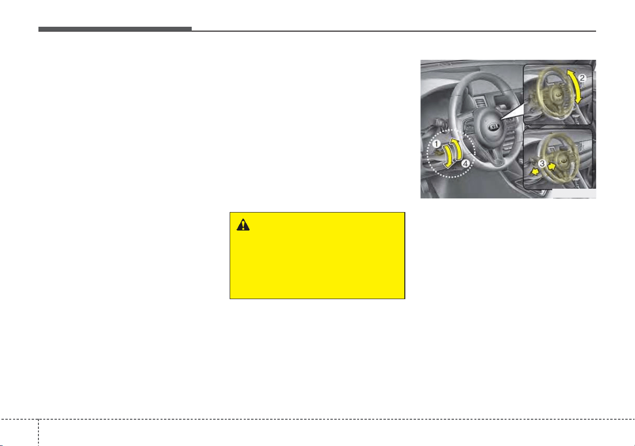
Features of your vehicle
484
(Continued)
• When the charging system warning
light comes on due to low voltage
(when the alternator or battery
does not operate normally or mal-
function), the steering wheel may
require increased steering effort.
Tilt and telescopic steering
Tilt and telescopic steering allows
you to adjust the steering wheel
before you drive.You can also raise it
to give your legs more space when
you get on or off the vehicle.
The steering wheel should be posi-
tioned so that it is comfortable for
you to drive, while permitting you to
see the instrument panel warning
lights and gauges.
To change the steering wheel angle,
pull down the lock-release lever (1),
adjust the steering wheel to the
desired angle (2) and height (3) then
pull up the lock-release lever to lock
(4) the steering wheel in place. Be
sure to adjust the steering wheel to
the desired position before driving.
✽✽
NOTICE
After adjustment, sometimes the
lock release lever may not lock the
steering wheel. It is not a malfunc-
tion. This occurs when two gears are
not engaged correctly. In this case,
adjust the steering wheel again and
then lock the steering wheel.
WARNING - Steering
wheel adjustment
Never adjust the angle and
height of the steering wheel
while driving. You may lose
steering control.
ODE046022
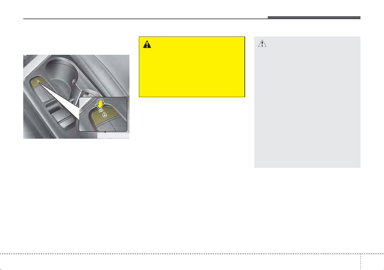
449
Features of your vehicle
Heated steering wheel
(if equipped)
With the ignition switch or ENGINE
START/STOP button is ON position,
pressing the heated steering wheel
button warms the steering wheel.
The indicator on the button will illumi-
nate.
To turn the heated steering wheel off,
press the button once again. The
indicator on the button will turn off.
✽✽
NOTICE
The heated steering wheel will turn
off automatically approximately 30
minutes after the heated steering
wheel is turned on.
CAUTION
• Do not install any type of grip
cover for the steering wheel, it
may impair the function of the
heated steering wheel system.
• When cleaning the heated
steering wheel, do not use an
organic solvent such as paint
thinner, benzene, alcohol and
gasoline. Doing so may dam-
age the surface of the steering
wheel.
• If the surface of steering
wheel is damaged by sharp
object, damage to the heated
steering wheel components
could occur.
ODEP049023
WARNING
If the steering wheel becomes
too warm, turn the system off.
The heated steering wheel may
cause burns even at low tem-
peratures, especially if used for
long periods of time.
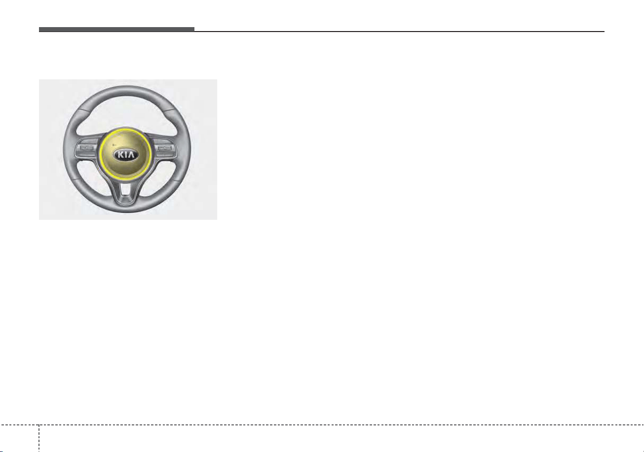
Features of your vehicle
504
Horn
To sound the horn, press the horn
symbols on your steering wheel.
Check the horn regularly to be sure it
operates properly.
✽✽
NOTICE
To sound the horn, press the area
indicated by the horn symbol on
your steering wheel (see illustra-
tion). The horn will operate only
when this area is pressed.
ODE046024
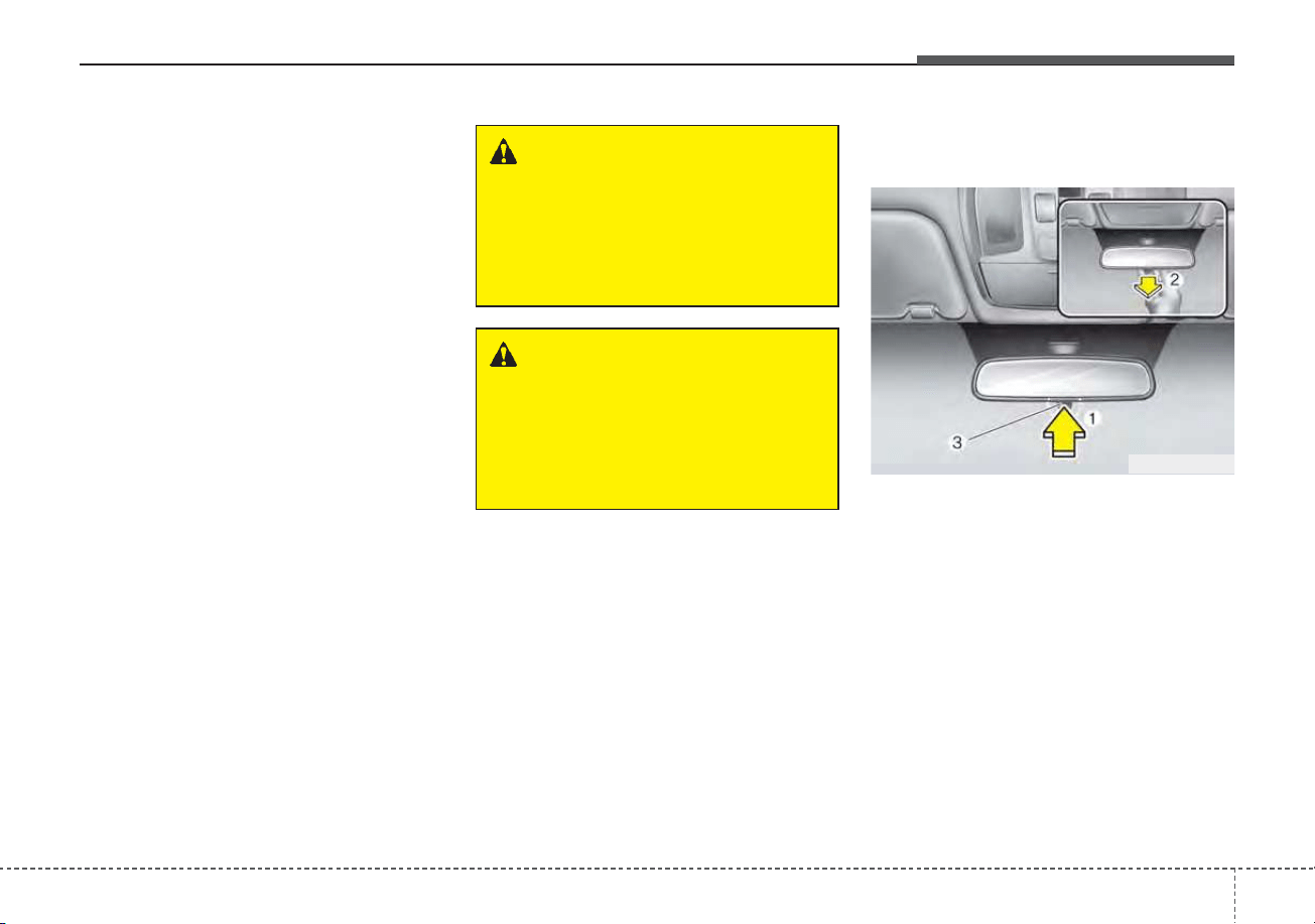
451
Features of your vehicle
MIRRORS
Inside rearview mirror
Adjust the rearview mirror so that the
center view through the rear window
is seen. Make this adjustment before
you start driving.
Do not place objects in the rear seat
or cargo area which would interfere
with your vision through the rear win-
dow.
Day/night rearview mirror
(if equipped)
Make this adjustment before you
start driving and while the day/night
lever (3) is in the day position.
Pull the day/night lever (3) toward
you to reduce the glare from the
headlights of the vehicles behind you
during night driving.
Remember that you lose some
rearview clarity in the night position.
❈(1) : Day, (2) : Night
WARNING - Mirror adjust-
ment
Do not adjust the rearview mir-
ror while the vehicle is moving.
This could result in loss of con-
trol.
WARNING
Do not modify the inside mirror
and don’t install a wide mirror. It
could result in injury during an
accident or deployment of the
air bag.
ODE046025L
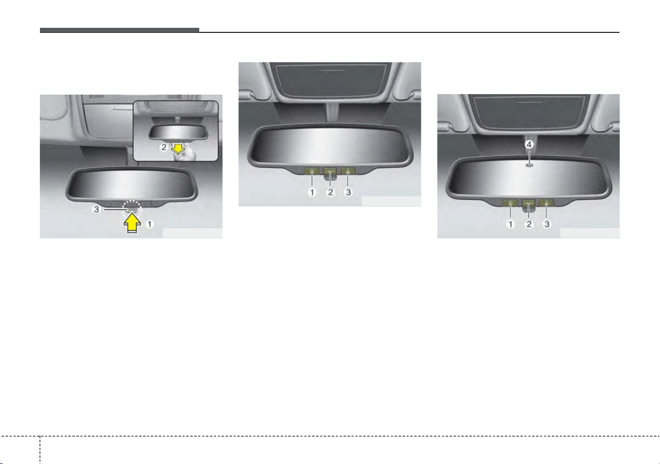
Features of your vehicle
524
Day/night rearview mirror with
Telematics function (if equipped)
For day and night function:
Make this adjustment before you
start driving and while the day/night
lever (3) is in the day position.
Pull the day/night lever (3) toward
you to reduce the glare from the
headlights of the vehicles behind you
during night driving.
Remember that you lose some
rearview clarity in the night position.
❈ (1) : Day, (2) : Night
For Telematics button function:
1. Virtual Assist button
2. UVO (Voice local search) button
3. Roadside Assist button
Telematics buttons are also located
on the mirror.
Electric Chromic Mirror (ECM)
with MTS service (if equipped)
1. Virtual Assist button
2. UVO (Voice local search) button
3. Roadside Assist button
The electric rearview mirror automat-
ically controls the glare from the
headlights of the vehicles behind you
in nighttime or low light driving condi-
tions.
ODEP049608N
ODEP049588N
ODEP049589N
453
Features of your vehicle
The sensor (4) mounted in the mirror
senses the light level around the
vehicle, and automatically controls
the headlight glare from the vehicles
behind you.
When the engine is running, the
glare is automatically controlled by
the sensor mounted in the rearview
mirror.
Telematics buttons are also located
on the mirror.
Outside rearview mirror
Be sure to adjust the mirror angles
before driving.
Your vehicle is equipped with both
left-hand and right-hand outside
rearview mirrors. The mirrors can be
adjusted remotely with the remote
switch. The mirror heads can be fold-
ed back to prevent damage during an
automatic vehicle wash or when
passing through a narrow street.
The right outside rearview mirror is
convex. Objects seen in the mirror
are closer than they appear.
Use your interior rearview mirror or
direct observation to determine the
actual distance of following vehicles
when changing lanes.
If the mirror is jammed with ice, do
not adjust the mirror by force. Use an
approved spray de-icer (not radiator
antifreeze) to release the frozen
mechanism or move the vehicle to a
warm place and allow the ice to melt.
WARNING - Mirror
adjustment
Do not adjust or fold the outside
rearview mirrors while the vehi-
cle is moving. This could result
in loss of control.
CAUTION - Rearview
mirror
Do not scrape ice off the mirror
face; this may damage the sur-
face of the glass. If ice should
restrict the movement of the mir-
ror, do not force the mirror for
adjustment. To remove ice, use a
deicer spray, a sponge or soft
cloth with very warm water.
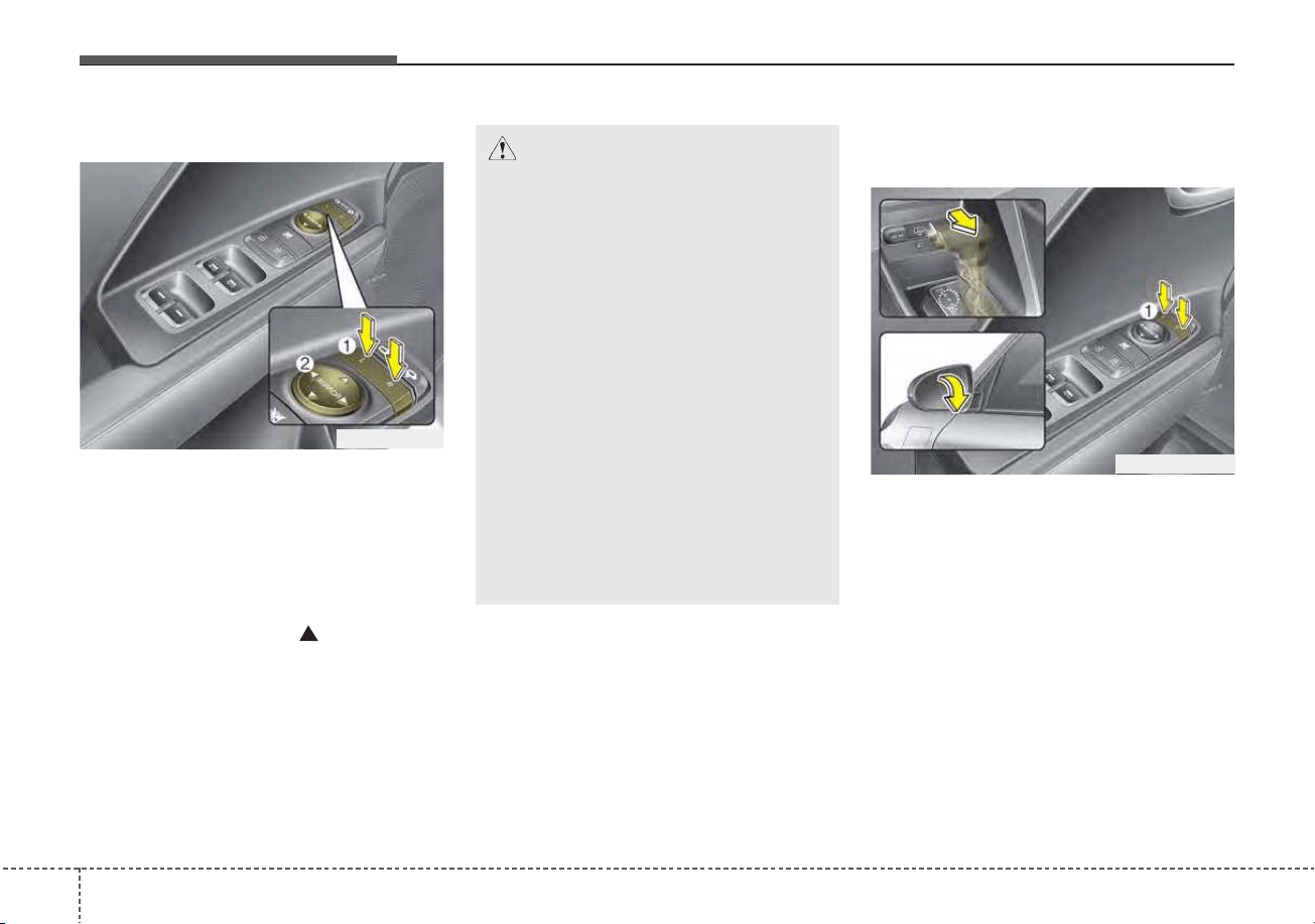
Features of your vehicle
544
Adjusting outside rearview mirror
The electric remote control mirror
switch allows you to adjust the posi-
tion of the left and right outside
rearview mirrors. To adjust the posi-
tion of either mirror, press the R or L
button (1) to select the right side mir-
ror or the left side mirror, then press a
corresponding point “ ” (2) on the
mirror adjustment control to position
the selected mirror up, down, left or
right.
After adjustment, press the R or L
button again to prevent the inadver-
tent adjustment.
Reverse parking aid function
(if equipped)
When you shift the shift lever to the R
(Reverse) position, the outside
rearview mirror(s) will move down-
ward to aid reverse parking.
According to the position of the out-
side rearview mirror switch (1), the
outside rearview mirror(s) will oper-
ate as follows:
Left or Right : When the remote con-
trol outside rearview mirror switch is in
the left or right position, both outside
rearview mirrors will move downward.
Neutral : When neither switch is
selected, the outside rearview mir-
rors will not move.
CAUTION - Outside mirror
• The mirrors stop moving when
they reach the maximum
adjusting angles, but the
motor continues to operate
while the switch is pressed.
Do not press the switch longer
than necessary, the motor
may be damaged.
• Do not attempt to adjust the
outside rearview mirror by
hand. Doing so may damage
the parts.
• When the mirror control, press
exactly “
”(2) marking area.
Otherwise, the mirror will
move to unintended direction
or malfunction.
ODEP049028
ODEP049609N
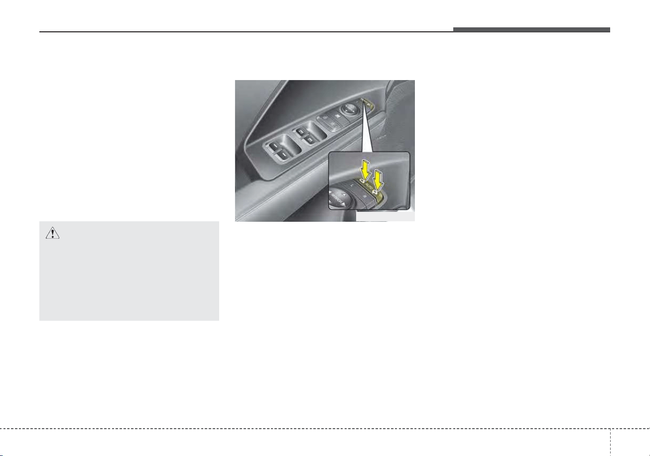
455
Features of your vehicle
✽✽
NOTICE
The outside rearview mirrors will
automatically revert to their original
positions under the following condi-
tions:
1. ENGINE START/STOP button or
ignition switch is changed to the
ACC or OFF position.
2. Shift lever is moved to any posi-
tion except R.
3. Remote control outside rearview
mirror switch is placed in the
middle position.
Folding the outside rearview mirror
Electric type (if equipped)
The outside rearview mirror can be
folded or unfolded by pressing the
switch when the ENGINE
START/STOP button is in the ON posi-
tion as below.
Left : The mirror will unfold.
Right : The mirror will fold.
Center (AUTO) :
The mirror will fold or unfold automat-
ically as follows:
• Without smart key system
- The mirror will fold or unfold when
the door is locked or unlocked by
the transmitter. (if equipped)
• With smart key system
- The mirror will fold or unfold when
the door is locked or unlocked by
the smart key.
- The mirror will fold or unfold when
the door is locked or unlocked by
the button on the outside door
handle.
- The mirror will unfold when you
approach the vehicle (all doors
closed and locked) with a smart
key in possession. (if equipped)
CAUTION
If outside rearview mirror is
positioned at the outermost
(left/right/bottom), the automat-
ic mirror control function may
not properly work while vehicle
move backward.
ODEP049030L
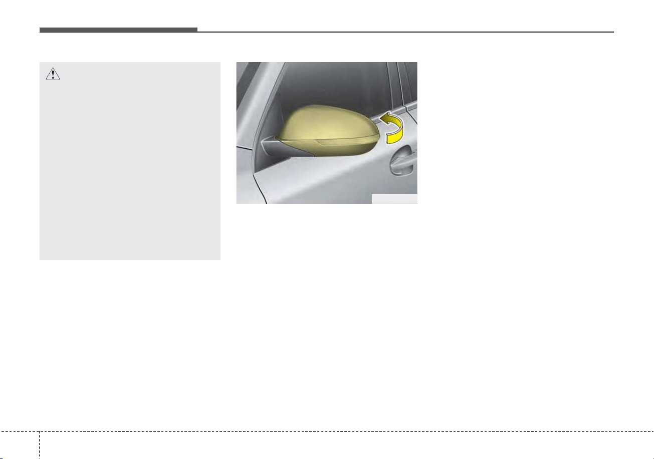
Features of your vehicle
564
Manual type (if equipped)
To fold the outside rearview mirror,
grasp the housing of the mirror and
then fold it toward the rear of the
vehicle.
CAUTION - Electric type
outside rearview mirror
The electric type outside
rearview mirror operates even
though the ignition switch is in
the LOCK position or the
ENGINE START/STOP button is
in the OFF position. However, to
prevent unnecessary battery
discharge, do not adjust the
mirrors longer than necessary
while the engine is not running.
Do not fold an electric type out-
side rearview mirror by hand as
this could cause motor failure.
ODE046029
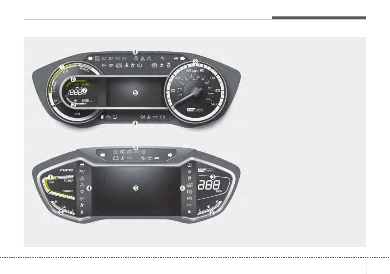
457
Features of your vehicle
INSTRUMENT CLUSTER
1. Hybrid system gauge
2. Fuel gauge
3. Speedometer
4. Warning and indicator lights
5. LCD display
6. Battery SOC (State of Charge) gauge
7. Distance To Empty
ODEP049100N/ODEP049538N
■■
Type A for Hybrid
❈ For more details, refer to the “Gauges” in
this chapter.
■■
Type B for Hybrid
❈ The actual cluster and contents of the LCD display in the vehicle may differ from the illustration.
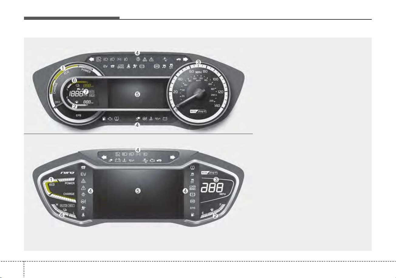
Features of your vehicle
584
1. Hybrid system gauge
2. Fuel gauge
3. Speedometer
4. Warning and indicator lights
5. LCD display
6. Battery SOC (State of Charge) gauge
7. Distance To Empty
ODEP049182N/ODEP049183N
■■
Type A for Plug-in Hybrid
❈ For more details, refer to the “Gauges” in
this chapter.
■■
Type B for Plug-in Hybrid
❈ The actual cluster and contents of the LCD display in the vehicle may differ from the illustration.
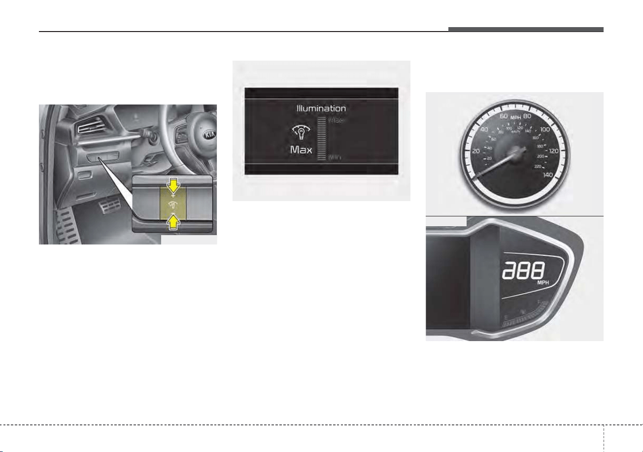
459
Features of your vehicle
Instrument Cluster Control
Adjusting Instrument Cluster
Illumination
The brightness of the instrument
panel illumination is changed by
pressing the illumination control but-
ton (“+” or “-”) when the ignition
switch or ENGINE START/STOP but-
ton is ON, or the taillights are turned
on.
• If you hold the illumination control
button (“+” or “-”), the brightness
will be changed continuously.
• If the brightness reaches to the
maximum or minimum level, an
alarm will sound.
Gauges
Speedometer
The speedometer indicates the
speed of the vehicle and is calibrated
in miles per hour (mph) and/or kilo-
meters per hour (km/h).
ODEP049545L
ODEP049543L
ODEP049105N
ODEP049539N
■ Type A
■ Type B
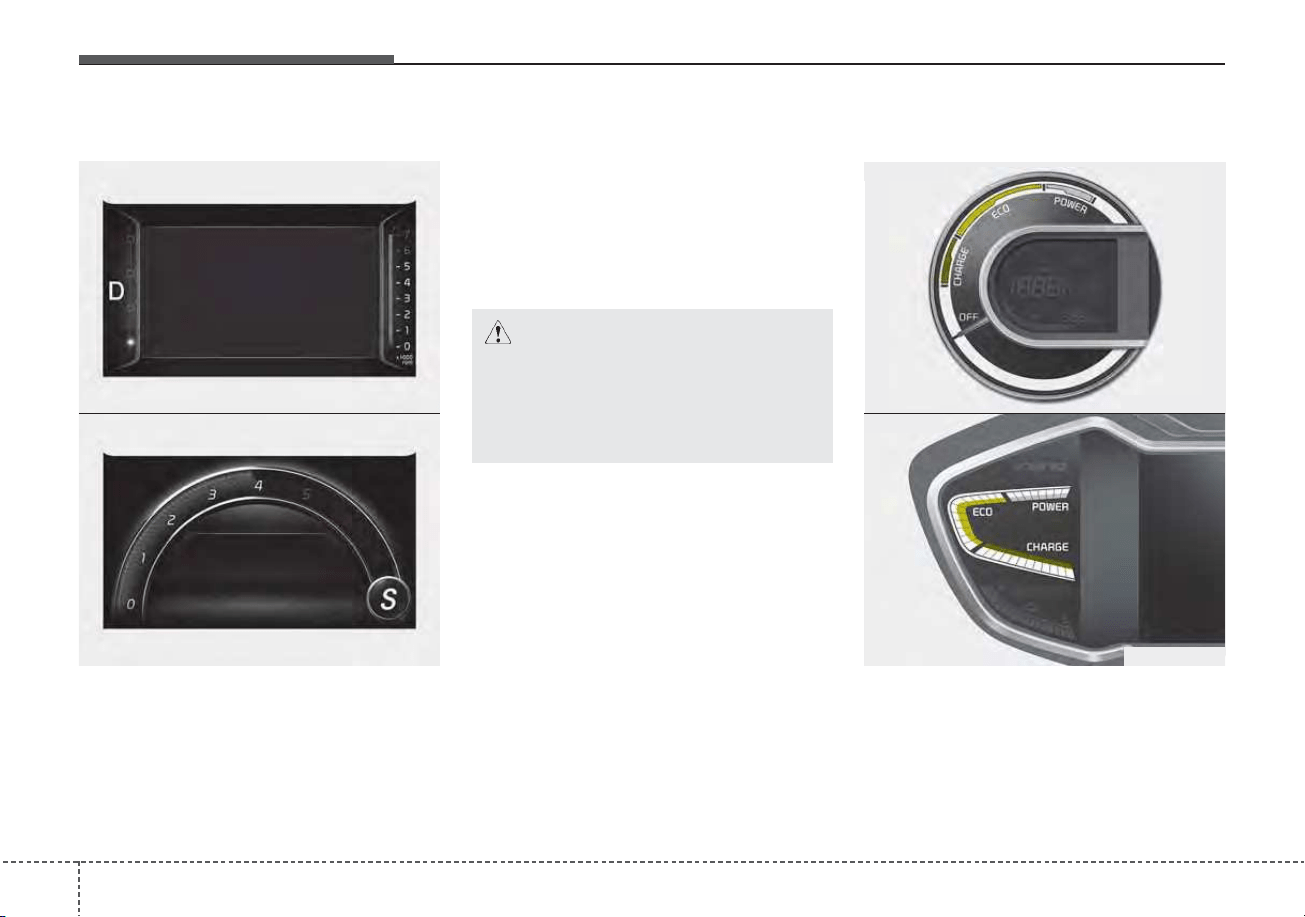
Features of your vehicle
604
Tachometer (if equipped)
The tachometer indicates the
approximate number of engine revo-
lutions per minute (rpm).
When moving the shift lever to the
“S” (SPORT) mode, the engine
tachometer is displayed while switch-
ing to SPORT mode.
Use the tachometer to select the cor-
rect shift points and to prevent lug-
ging and/or over-revving the engine.
Hybrid System Gauge
The hybrid system gauge indicates
whether the current driving condition
is fuel efficient or not.
ODEP049529L
ODEP049215N
■ Type B - ECO mode selected
■ Type B - SPORT mode selected
CAUTION
Do not operate the engine with-
in the tachometer's RED ZONE.
This may cause severe engine
damage.
ODEP049106
ODEP049186
■ Type A
■ Type B
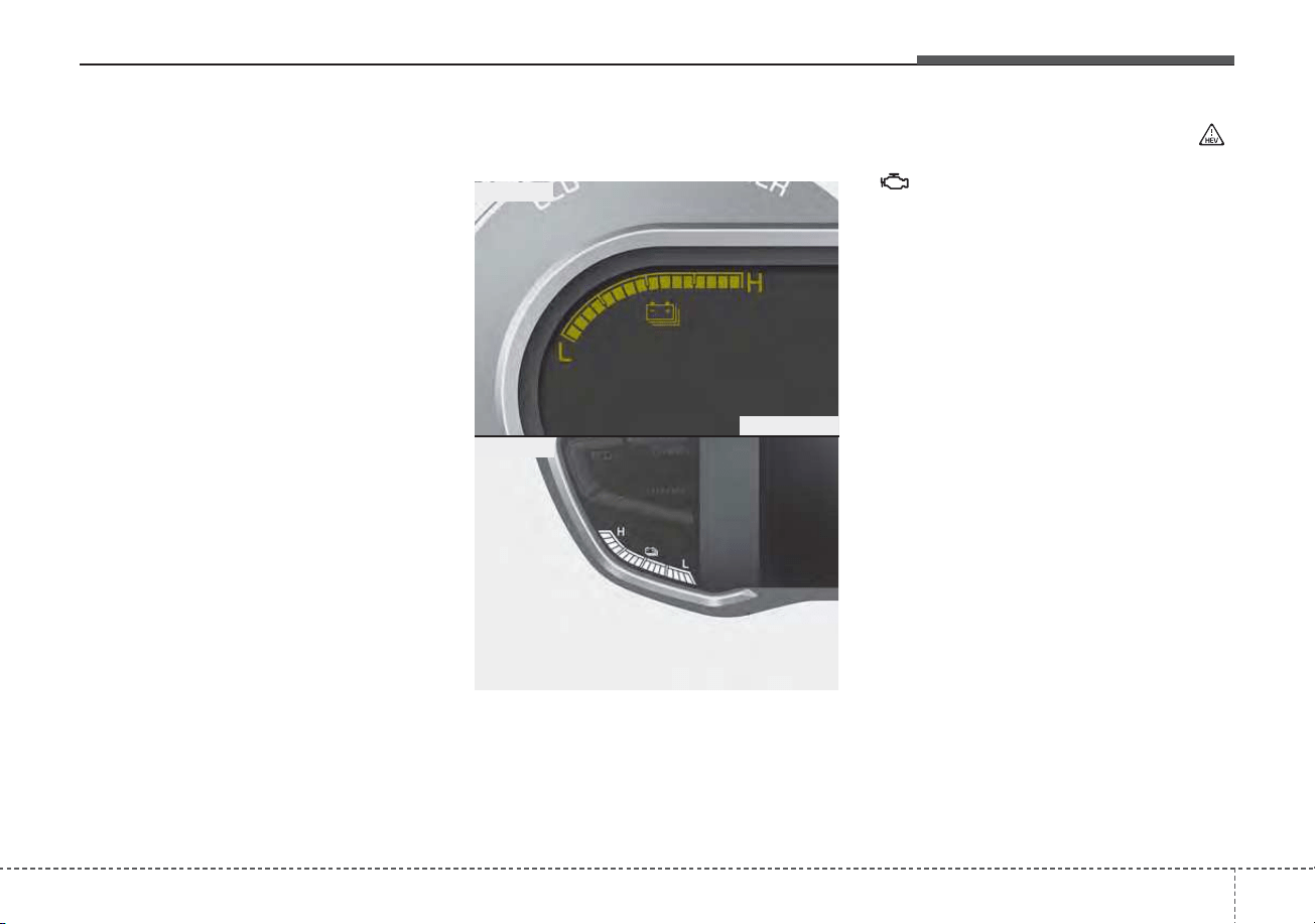
461
Features of your vehicle
• CHARGE : Shows that the energy
made by the vehicle is
being converted to
electrical energy.
(Regenerated energy)
• ECO : Shows that the vehicle is
being driven in an Eco-
friendly manner.
• POWER : Shows that the vehicle is
exceeding the Eco-
friendly range.
✽✽
NOTICE
The "EV" indicator comes on or off
based on the hybrid system gauge.
• “EV” indicator ON : Vehicle is
using the electric motor or the
gasoline engine is stopped.
• “EV” indicator OFF : Vehicle is
using the gasoline engine.
Hybrid Battery SOC
(State of Charge) Gauge
This gauge indicates the remaining
hybrid battery power. If the SOC is
near the “L (Low)” level, the vehicle
automatically operates the engine to
charge the battery.
However, if the Service Indicator ( )
and Malfunction Indicator Lamp (MIL)
( ) turn on when the SOC gauge is
near the “L (Low)” level, have your
vehicle inspected by an authorized
Kia dealer.
✽✽
NOTICE
Never try to start the vehicle if the
fuel tank is empty. In this condition,
the engine cannot charge the high
voltage battery of the hybrid system.
If you try to start the vehicle when
the fuel is empty, the high voltage
battery will become discharged and
be damaged.
ODE046107
ODEP049530L
■ Type B
■ Type A
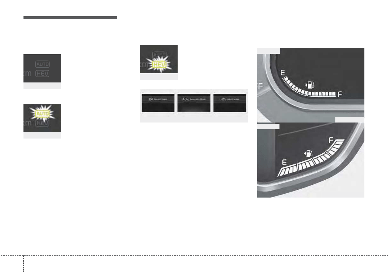
Features of your vehicle
624
Plug-in hybrid mode indicator
• CD (Charge Depleting, Electric) mode
: The high-voltage
(hybrid) battery is used
to drive the vehicle.
• AUTO mode
: The AUTO mode will
be automatically
selected from either
from Electric (CD)
mode or Hybrid (CS)
mode by the system
according to the driv-
ing condition.
• CS (Charge Sustaining, Hybrid) mode
:
The high-voltage
(hybrid) battery and
gasoline engine is
used to drive the vehi-
cle.
A corresponding message is displayed
to indicate the selected mode.
Fuel Gauge
This gauge indicates the approxi-
mate amount of fuel remaining in the
fuel tank.
ODE046108
ODEP049188L
■ Type B
■ Type A
ODEP049550L
ODEP049548L
ODEP049549L
ODEP049189L/ODEP049541L/ODEP049190L
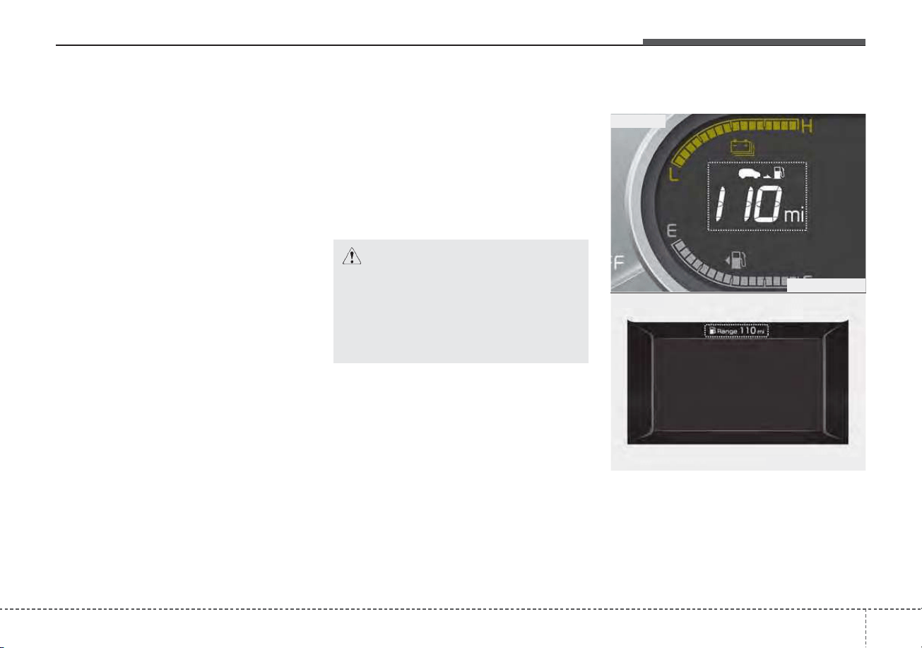
463
Features of your vehicle
✽✽
NOTICE
• The fuel tank capacity is given in
chapter 8.
• The fuel gauge is supplemented by
a low fuel warning light which will
illuminate when the fuel tank is
nearly empty.
• On inclines or curves, the fuel
gauge pointer may fluctuate or the
low fuel warning light may come
on earlier than usual due to the
movement of fuel in the tank.
✽
✽
NOTICE - Fuel gauge
Running out of fuel can expose vehi-
cle occupants to danger. You must
obtain additional fuel as soon as pos-
sible after the warning light comes
on or when the gauge indicator
comes close to the “E (Empty)”
level.
✽
✽
NOTICE
Fuel display may not be accurate if
vehicle is being fueled while in an
incline.
Distance to empty
• The distance to empty is the esti-
mated distance the vehicle can be
driven with the remaining fuel.
- Distance range : 1 ~ 9,999 mi. or
1 ~ 9,999 km
CAUTION - Low fuel
Avoid driving with an extremely
low fuel level. Running out of
fuel could cause the engine to
misfire, damaging the catalytic
converter.
ODEP049142N
ODEP049561N
■ Type B
■ Type A
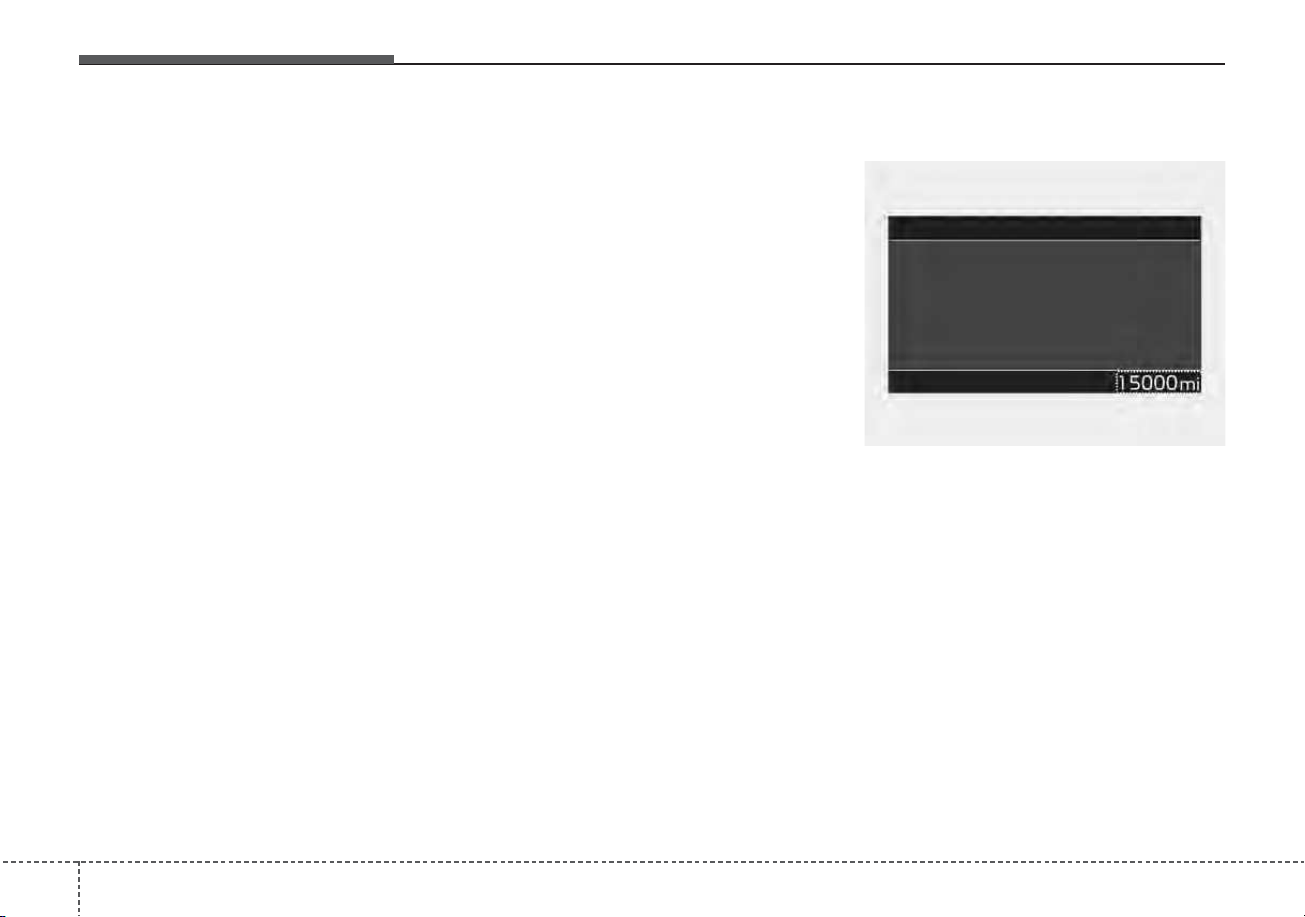
Features of your vehicle
644
• If the estimated distance is below 1
mi.(1 km), the trip computer will
display “----” as distance to empty.
• If the level of the remaining fuel is
more than three-quarters, more
than 0.8 gallons (3 liters) of fuel
must be refilled for the fuel gauge
to change. In other cases, more
than 1.6 gallons (6 liters) of fuel
must be refilled for the vehicle to
change the fuel gauge.
✽✽
NOTICE
• If the vehicle is not on level ground
or the battery power has been
interrupted, the distance to empty
function may not operate correct-
ly.
• The distance to empty may differ
from the actual driving distance as
it is an estimate of the available
driving distance.
• The fuel economy and distance to
empty may vary significantly
based on driving conditions, driv-
ing habits, and condition of the
vehicle.
Odometer
The odometer Indicates the total dis-
tance that the vehicle has been driv-
en and should be used to determine
when periodic maintenance should
be performed.
- Odometer range : 0 ~ 999,999
miles or 1,599,999 kilometers.
ODEP049597N
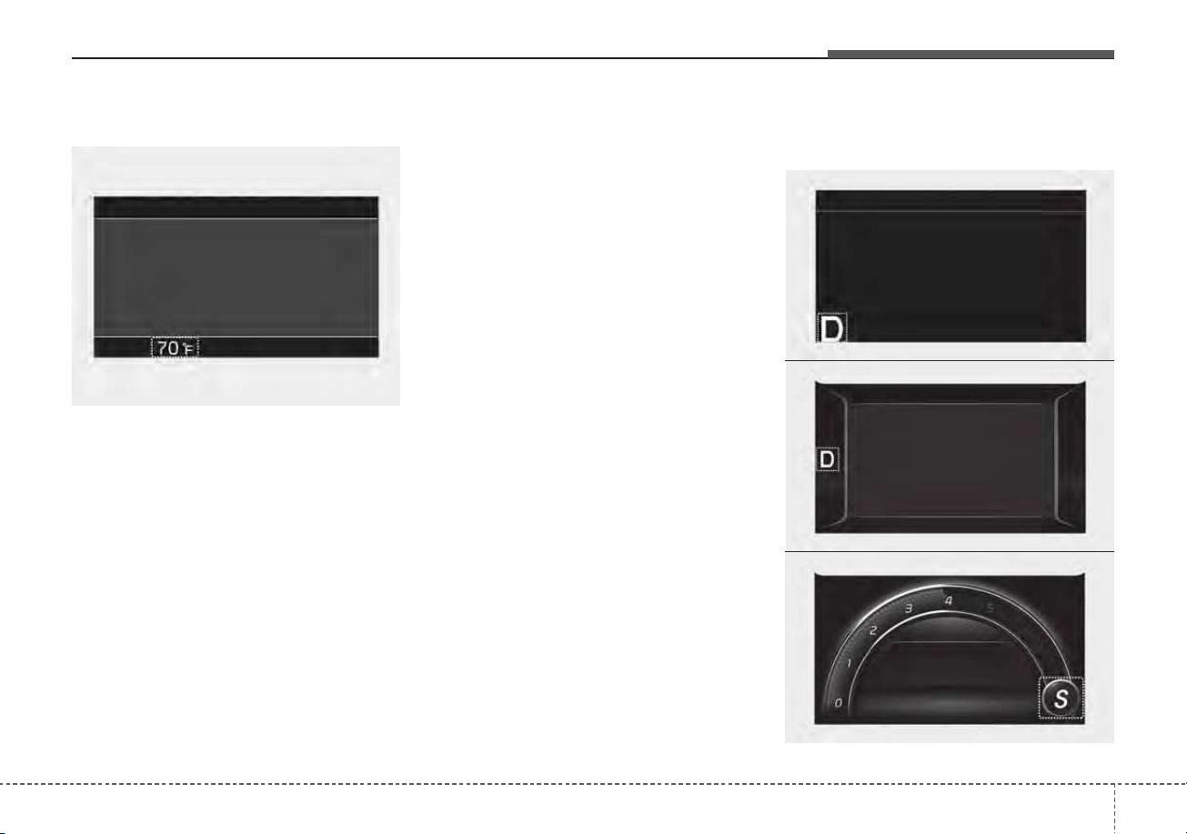
465
Features of your vehicle
Outside Temperature Gauge
This gauge indicates the current out-
side air temperatures by 1°F (1°C).
- Temperature range : -40 ~ 140°F (-40
~ 60°C)
The outside temperature on the dis-
play may not change immediately
like a general thermometer to pre-
vent the driver from being distracted.
The temperature unit (from °C to °F
or from °F to °C) can be changed by
using the “User Settings” mode of the
LCD display.
❈ For more details, refer to “LCD dis-
play” in this chapter.
Dual clutch transmission shift
indicator
ODEP049598N
ODEP049557L
ODEP049191N
■ Type A
■ Type B - ECO mode selected
■ Type B - SPORT mode select
ODEP049558L

Features of your vehicle
664
This indicator displays which shift
lever is selected.
•Park :P
• Reverse : R
• Neutral : N
•Drive :D
• Sport mode : S
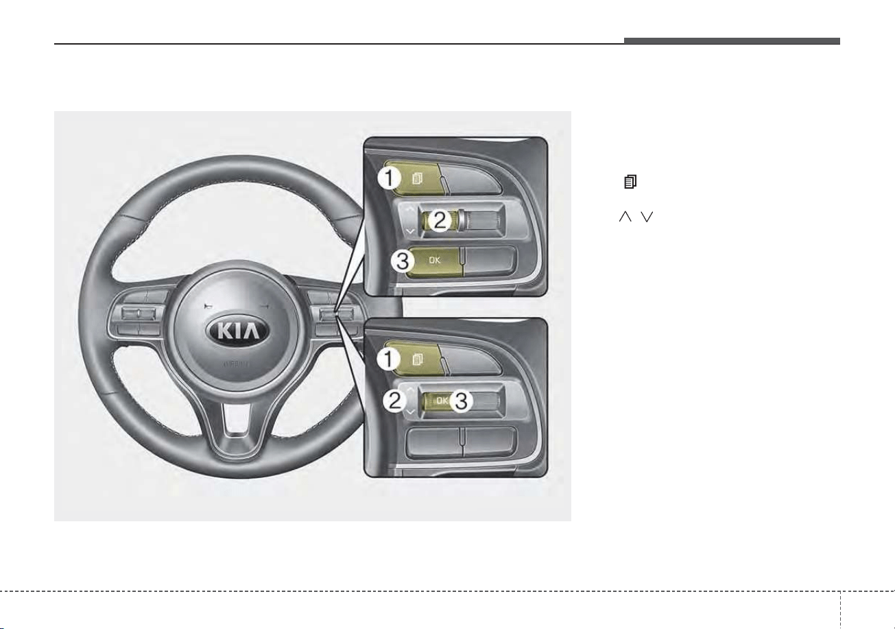
467
Features of your vehicle
LCD Display Control
The LCD display modes can be
changed by using the control but-
tons.
(1) : MODE button for changing
modes
(2) / : MOVE switch for changing
items
(3) OK : SELECT/RESET button for
setting or resetting the select-
ed item
LCD DISPLAY
ODEP049103L
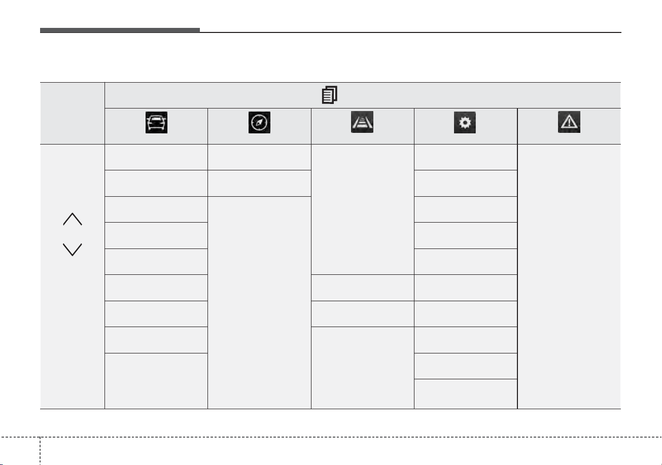
Features of your vehicle
684
LCD Display Modes
Range Route Guidance
• Smart Cruise
Control
• Lane Following
Assist
• Lane Departure
Warning
• Lane Keeping Assist
• Highway Driving
Assist
Driver Assistance
The Master Warning
mode displays warn-
ing messages related
to the vehicle when
one or more systems
is not operating nor-
mally.
Fuel Economy Destination Info Door
Accumulated Info Lights
Drive Info Sound
Digital Speedometer Convenience
Driving Style
Driver Attention
Warning
Service Interval
Energy Flow TPMS Other
Engine Temperature Language
Reset
Mode
Trip Computer TBT Driving Assist User Settings
Master warning
Up/Down
❈
❈
The information provided may differ depending on which functions are applicable to your vehicle.
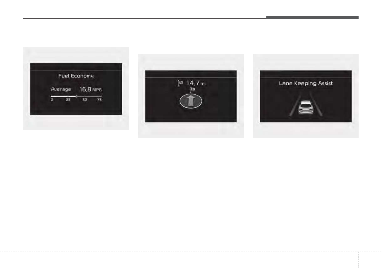
469
Features of your vehicle
Trip computer mode
The trip computer mode displays
information related to vehicle driving
parameters including fuel economy,
tripmeter information and vehicle
speed.
❈ For more details, refer to “Trip
Computer” in this chapter.
Turn By Turn (TBT) mode
(if equipped)
This mode displays the state of the
navigation.
Driving Assist mode
(if equipped)
This mode displays the state of :
• - Smart Cruise Control
- Lane Following Assist
- Lane Departure Warning
- Lane Keeping Assist
- Highway Driving Assist
• Driver Attention Warning
❈For more details, refer to each sys-
tem information in chapter 5.
ODEP049599N
ODEP049574LODEP049573N
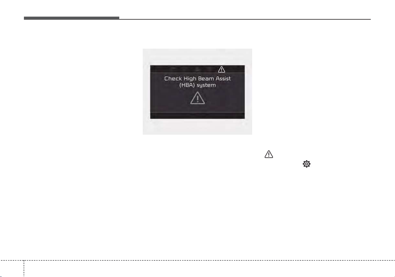
Features of your vehicle
704
• Tire Pressure
❈For more details, refer to “Tire
Pressure Monitoring System
(TPMS)” in chapter 6.
Master warning mode
This warning light informs the driver
the following situations.
- Forward Collision-Avoidance Assist
system malfunction (if equipped)
- Forward Collision-Avoidance Assist
radar blocked (if equipped)
- Blind-Spot Collision Warning system
malfunction (if equipped)
- Blind-Spot Collision Warning radar
blocked (if equipped)
- Lamp malfunction
- LED headlamp malfunction (if
equipped)
- High Beam Assist malfunction (if
equipped)
- Tire Pressure Monitoring System
(TPMS) malfunction
- Smart Cruise Control system mal-
function (if equipped)
- Smart Cruise Control system radar
blocked (if equipped)
- Highway Driving Assist system mal-
function (if equipped)
- Lane Following Assist system mal-
function (if equipped), etc.
At this time, a Master Warning icon
( ) will appear beside the User
Settings icon ( ), on the LCD display.
If the warning situation is solved, the
master warning light will be turned
off and the Master Warning icon will
disappear.
ODEP049575L
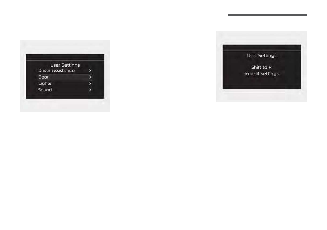
471
Features of your vehicle
User settings mode (if equipped)
In this mode, you can change the
settings of the instrument cluster,
doors, lamps, etc.
1. Driver Assistance
2. Door
3. Lights
4. Sound
5. Convenience
6. Service Interval
7. Other
8. Language
9. Reset
The information provided may differ
depending on which functions are
applicable to your vehicle.
Shift to P to edit settings
This warning message appears if
you try to adjust the User Settings
while driving.
For your safety, change the User
Settings after parking the vehicle,
applying the parking brake and mov-
ing the shift lever to P (Park).
ODEP049584L
ODEP049586L

Features of your vehicle
724
1. Driver Assistance (if equipped)
Items Explanation
SCC Reaction
• Fast/Normal/Slow
To adjust the sensitivity of Smart Cruise Control system.
❈ For more details, refer to “Smart Cruise Control (SCC)” in chapter 5.
Driving Assist
• Lane Following Assist
To select the function.
❈ For more details, refer to “Lane Following Assist (LFA)” in chapter 5.
• Highway Driving Assist
To select the function.
❈ For more details, refer to “Highway Driving Assist (HDA)” in chapter 5.
Driver Attention Warning
• Leading Vehicle Departure Alert
To select the function.
❈ For more details, refer to “Leading vehicle departure alert” in chapter 5.
• Low Activity Warning
To select the function.
❈ For more details, refer to “Driver Attention Warning (DAW)” in chapter 5.
Warning Timing
• Normal/Later
To select when to provide a warning for all driver assistance system.
❈ The information provided may differ depending on which functions are applicable to your vehicle.

473
Features of your vehicle
Items Explanation
Forward Safety
• Active Assist/Warning Only/Off
To select the function.
❈ For more details, refer to “Forward Collision-Avoidance Assist (FCA)” in chapter 5.
Lane Safety
• Lane Keeping Assist / Lane Departure Warning / Off
To select the function.
❈ For more details, refer to “Lane Keeping Assist (LKA)” in chapter 5.
Blind-Spot Safety
• Warning Only/Off
To select the function.
❈ For more details, refer to “Blind-spot Collision Warning (BCW)” in chapter 5.
Parking Safety
• Rear Cross-Traffic Safety
To select the function.
❈ For more details, refer to “Rear Cross-traffic Collision Warning (RCCW)” in chapter 5.
❈ The information provided may differ depending on which functions are applicable to your vehicle.

Features of your vehicle
744
Items Explanation
Automatically Lock
• Enable on shift: All doors will be automatically locked if the vehicle is shifted from the P (Park)
position to the R (Reverse), N (Neutral), or D (Drive) position.
• Enable on speed: All doors will be automatically locked when the vehicle speed exceeds 9.3 mph
(15 km/h).
Automatically Unlock
• On shift to P: All doors will be automatically unlocked if the gear is shifted to the P (Park) posi-
tion.
• Vehicle off/On key out : All doors will be automatically unlocked when the ENGINE START/STOP
button is set to the OFF position or the ignition key is removed from the
ignition switch.
• Off : The auto door unlock operation will be canceled.
Two Press Unlock
• If this item is checked, the two press unlock will be activated.
The driver's door will unlock if the door unlock button is pressed.
When the door unlock button is pressed again within 4 seconds, the remaining doors will unlock.
Horn Feedback
(if equipped)
• If this item is checked, the horn feedback will be activated.
After locking the door by pressing the lock button on the transmitter, if you press the lock button
again within 4 seconds, the warning sound will operate once to indicate that all doors are locked.
2. Door
❈ The information provided may differ depending on which functions are applicable to your vehicle.

475
Features of your vehicle
Items Explanation
One Touch Turn Signal
• Off : The one touch turn signal function will be deactivated.
• 3, 5, 7 Flashes : The turn signal indicator will blink 3, 5, or 7 times when the turn signal lever is
moved slightly.
❈ For more details, refer to “Lighting” in this chapter.
Ambient Light Brightness
• Adjust the brightness of the Ambient light.
- Off/Level 1,2,3,4
Ambient Light Color
• Select the color of the ambient light.
- White, Gray, Blue, Eco Green, Bronze, Red
Headlight Delay To activate or deactivate the headlight delay function.
High Beam Assist To activate or deactivate High Beam Assist function.
3. Lights (if equipped)
❈ The information provided may differ depending on which functions are applicable to your vehicle.
Items Explanation
Parking Distance Warning
Volume
• Adjust the Park Distance Warning system volume (High/Low).
4. Sound
❈ The information provided may differ depending on which functions are applicable to your vehicle.

Features of your vehicle
764
Items Explanation
Seat Easy Access
• Off : The seat easy access function will be deactivated.
• Normal/Extended: When you turn off the engine, the driver's seat will automatically move rear-
ward short (Normal) or long (Extended) for you to enter or exit the vehicle more comfortably.
If you change the ignition key or ENGINE START/STOP button from OFF to ACC position, the
driver’s seat will return to the original position.
❈ For more details, refer to “Driver Position Memory System” in chapter 3.
Welcome Mirror/Light • If this item checked, the Welcome Mirror/Light will be activated.
Wireless Charging System • If this item checked, the wireless charging system in the front seat will be activated.
Wiper/Lights Display • If this item checked, the Wiper/Lights Display will be activated.
Auto Rear Wiper (in R) • If this item checked, the Auto rear wiper will be activated.
Gear Position Pop-up • If this item is checked, the Gear position pop-up display will be activated.
Coasting Guide
• Enable Coasting Guide : To activate or deactivate the Coasting guide.
• Sound : To activate or deactivate the Coasting guide sound.
Start Coasting • Choose the initial guiding time for Coasting guide. (Early/Normal/Late)
Icy road warning • If this item is checked, the Icy road warning display will be activated.
5. Convenience (if equipped)
❈ The information provided may differ depending on which functions are applicable to your vehicle.

477
Features of your vehicle
Items Explanation
Enable Service Interval If this item is checked, the Service Interval function will be activated.
Adjust Interval If the service interval menu is activated, you may adjust the time and distance.
Reset To reset the service interval function.
6. Service Interval (if equipped)
✽✽
NOTICE
To use the service interval menu, consult an authorized Kia dealer.
If the service interval is activated and the time and distance is adjusted, messages are displayed in the following sit-
uations each time the vehicle is turned on.
- Service in: Displayed to inform the driver the remaining mileage and days to service.
- Service required: Displayed when the mileage and days to service has been reached or passed.
If any of the following conditions occur, the mileage and number of days to service may be incorrect.
- The battery cable is disconnected.
- The battery is discharged.
- The fuse switch is turned off.

Features of your vehicle
784
Items Explanation
AUX. Battery Saver+
(if equipped)
• If this item is checked, the Aux. Battery Saver+ function will be activated.
Fuel Economy Reset
• If this item checked, the average fuel economy will reset automatically after refueling or after igni-
tion.
❈ For more details, refer to “Trip Computer” in this chapter.
Speed Unit
• MPH, km/h
To select Speed unit.
Fuel Economy Unit
• US gallon, UK gallon, km/L, L/100km,
To select the Fuel economy unit.
Temperature Unit
•°F, °C
To select the Temperature unit.
Tire Pressure Unit
• psi, kPa, bar
To select the Tire Pressure Unit.
7. Other (if equipped)
❈ The information provided may differ depending on which functions are applicable to your vehicle.

479
Features of your vehicle
Items Explanation
Reset
You can reset the menus in the User Settings mode. All menus in the User Settings mode are reset
to factory settings, except language and service interval.
9. Reset
Items Explanation
Language • To select language.
8. Language (if equipped)
Features of your vehicle
804
Trip modes (Trip computer)
The trip computer is a microcomput-
er-controlled driver information sys-
tem that displays information related
to driving.
✽✽
NOTICE
Some driving information stored in
the trip computer (for example
Average Vehicle Speed) resets if the
battery is disconnected.
Trip modes
• Tripmeter
• Fuel Economy
• Timer
Accumulated Info
• Tripmeter
• Fuel Economy
• Timer
Drive Info
Digital Speedometer
2)
Driving style
• Average Fuel Economy
• Instant Fuel Economy
Fuel Economy
Energy flow
Engine Temperature
• Electric
• Gasoline
Range
1)
1) : for Plug-in hybrid
2) : for Type A cluster
To change the trip mode, scroll the
MOVE scroll switch ( / ) in the
trip computer mode.
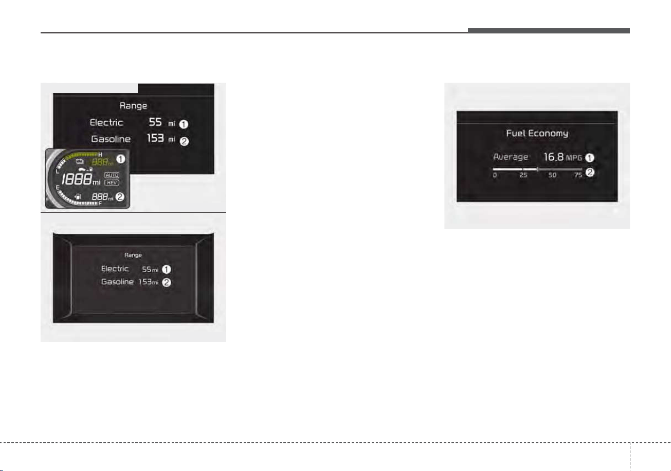
481
Features of your vehicle
Range (Plug-in hybrid)
• The range is the estimated dis-
tance the vehicle can be driven
with the remaining high-voltage
(hybrid) battery (1, Electric) and
fuel in the fuel tank (2, Gasoline).
• If the estimated distance is below
1 mi. (1 km), the trip computer will
display “---” as distance to empty.
- Distance range: 1 ~ 510 mi. or 1 ~
510 km
✽✽
NOTICE
• If the vehicle is not on level ground
or the battery power has been
interrupted, the range function
may not operate correctly.
• The range may differ from the
actual driving distance as it is an
estimate of the available driving
distance.
• The trip computer may not register
additional fuel if less than 1.6 gal-
lons (6 liters) of fuel are added to
the vehicle.
• The range may vary significantly
based on driving conditions, driv-
ing habits, and condition of the
vehicle.
Fuel Economy
Average Fuel Economy (1)
• The average fuel economy is calcu-
lated by the total driving distance
and fuel consumption since the last
average fuel economy reset.
- Fuel economy range : 0.0 ~ 99.9,
100 ~ 999 MPG, L/100km or
km/L
• The average fuel economy can be
reset both manually and automati-
cally.
ODEP049192N
ODEP049562N
■ Type A - Plug-in hybrid
■ Type B - Plug-in hybrid
ODEP049600N

Features of your vehicle
824
Manual reset
To clear the average fuel economy
manually, press the OK button
(reset) on the steering wheel for
more than 1 second when the aver-
age fuel economy is displayed.
Automatic reset
To make the average fuel economy
be reset automatically whenever
refueling, select the “Fuel Economy
Reset” mode in User Setting menu of
the LCD display (Refer to “LCD dis-
play”).
• OFF - You may set to default man-
ually by using the trip switch reset
button.
• After ignition - The vehicle will
automatically set to default once 4
hours pass after the ignition switch
or ENGINE START/STOP button is
turned to the OFF position.
• After refueling - After refueling
more than 1.6 gallons (6 liters) and
driving over 1 mph (1 km/h), the
vehicle will reset to default auto-
matically.
✽✽
NOTICE
The average vehicle speed is not dis-
played, when the vehicle drives
shorter than 0.2 miles(300 meters)
or less than 10 seconds after turning
ON the ignition switch or ENGINE
START/STOP button.
Instant Fuel Economy (2)
• This mode displays the instant fuel
economy while driving.
- Fuel economy range : 0.0 ~ 75
MPG or 0.0 ~ 30 L/100km, km/L
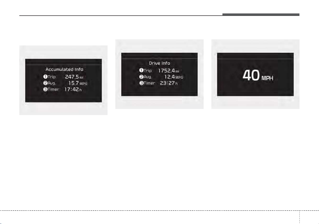
483
Features of your vehicle
Accumulated driving information
mode
This display shows the accumulated
trip distance (1), the average fuel
efficiency (2), and the total driving
time (3).
• Accumulated information is calcu-
lated after the vehicle has run for
more than 0.2 miles (300 meters).
• If you press “OK” button for more
than 1 second after the Cumulative
Information is displayed, the infor-
mation will be reset.
• If the engine is running, even when
the vehicle is not in motion, the
information will be accumulated.
One time driving information mode
This display shows the trip distance
(1), the average fuel efficiency (2),
and the total driving time (3) informa-
tion once per one ignition cycle.
- Fuel efficiency is calculated after
the vehicle has run for more than
0.2 miles (300 meters).
- The Driving Information will be
reset 4 hours after ignition has
been turned off. So, when the vehi-
cle ignition is turned on within 4
hours, the information will not be
reset.
- If the engine is running, even when
the vehicle is not in motion, the infor-
mation will be accumulated.
Digital speedometer (if equipped)
This mode displays the current
speed of the vehicle.
ODEP049602N
ODEP049601N
ODEP049578N
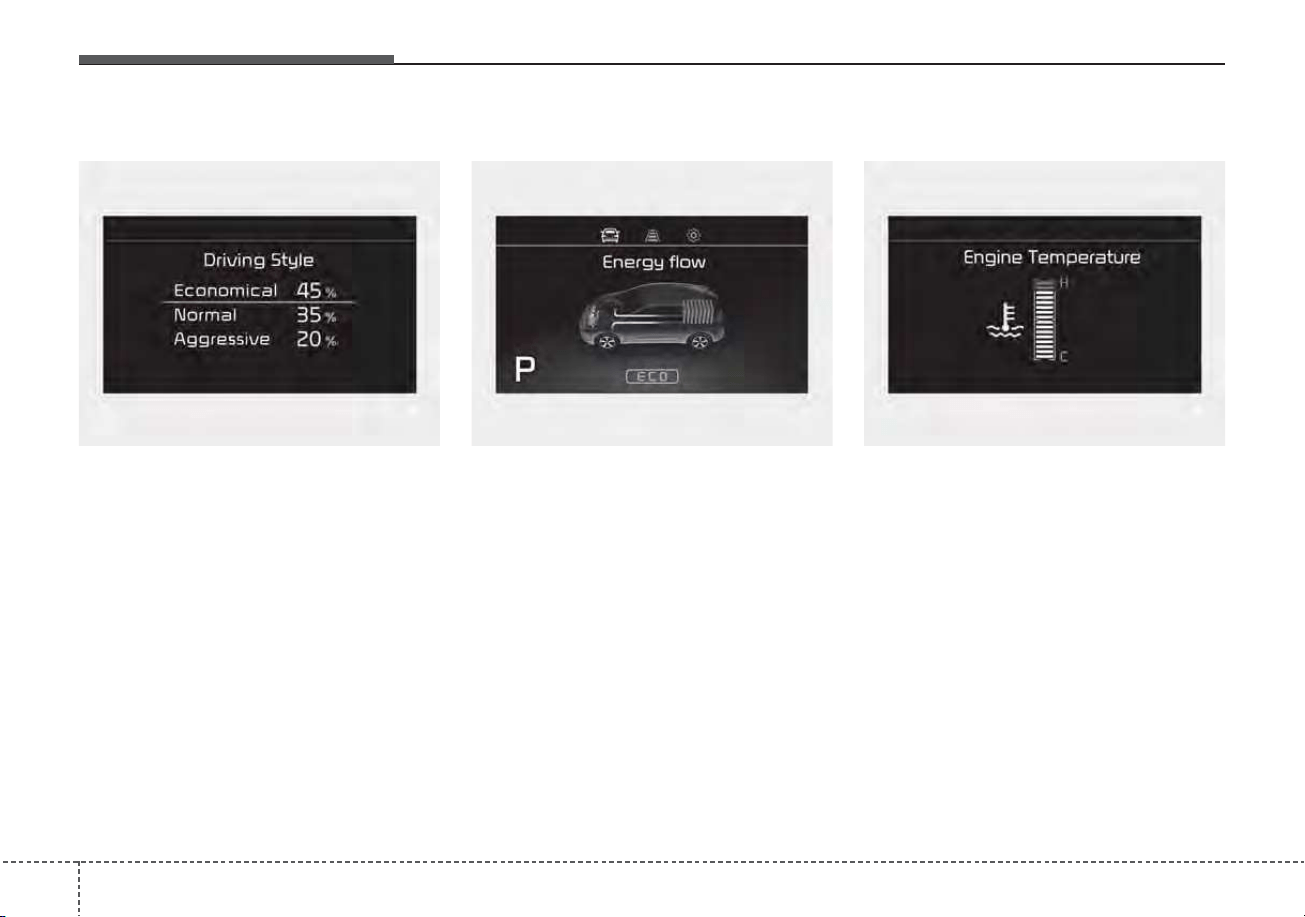
Features of your vehicle
844
Driving Style
The driving style is displayed when
you are driving in ECO mode.
When you drive in SPORT mode,
each driving category will be dis-
played with “--”.
Energy Flow
The hybrid system informs the driv-
ers its energy flow in various operat-
ing modes. While driving, the current
energy flow is specified in 11 modes.
❈ For more details, refer to “Energy
Flow” in Hybrid System Overview
chapter.
Engine coolant temperature
This gauge indicates the tempera-
ture of the engine coolant when the
engine is running.
✽✽
NOTICE
When the gauge indicator gets out of
the normal range, toward the “H
(Hot)” position, it indicates over-
heating of the engine. It may dam-
age the engine.
Do not continue driving with the
overheated engine.
❈
❈
For further information, refer to
“If the Engine Overheats” in the
chapter 6.
ODEP049579L ODEP047202N ODEP049603N
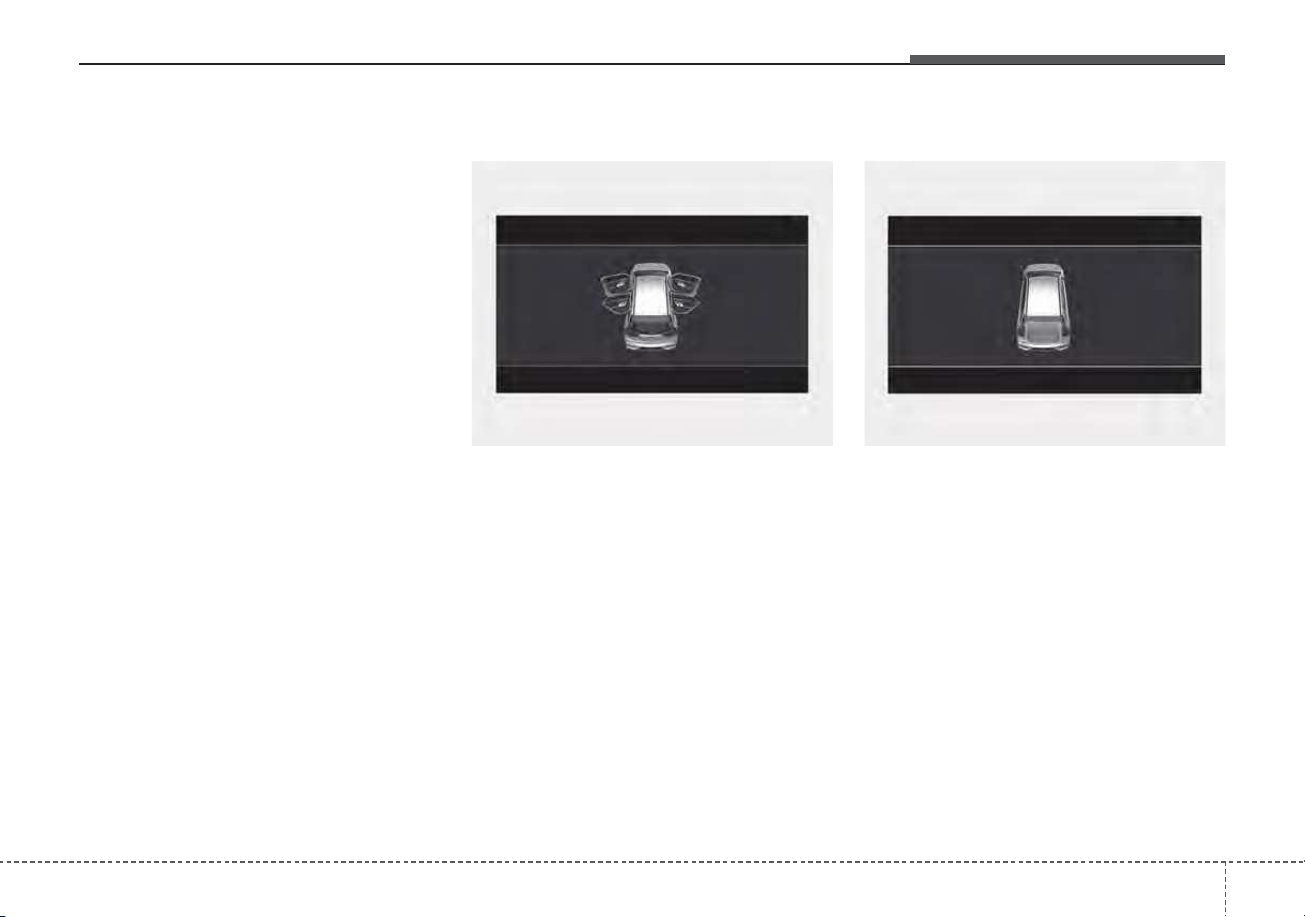
485
Features of your vehicle
Warning messages
Warning messages appear on the
LCD to warn the driver. It is located in
the center of the instrument cluster.
The warning message may appear
differently depending on the type of
instrument cluster and some may not
show the warning message at all.
The warning message is shown in
either symbol, symbol and text, or
text type only. You can choose the
preferred language by selecting the
User setting menu in LCD mode.
Door Open
• It means that any door is open.
Liftgate Open
• It means that the liftgate is open.
ODEP049116 ODEP049117
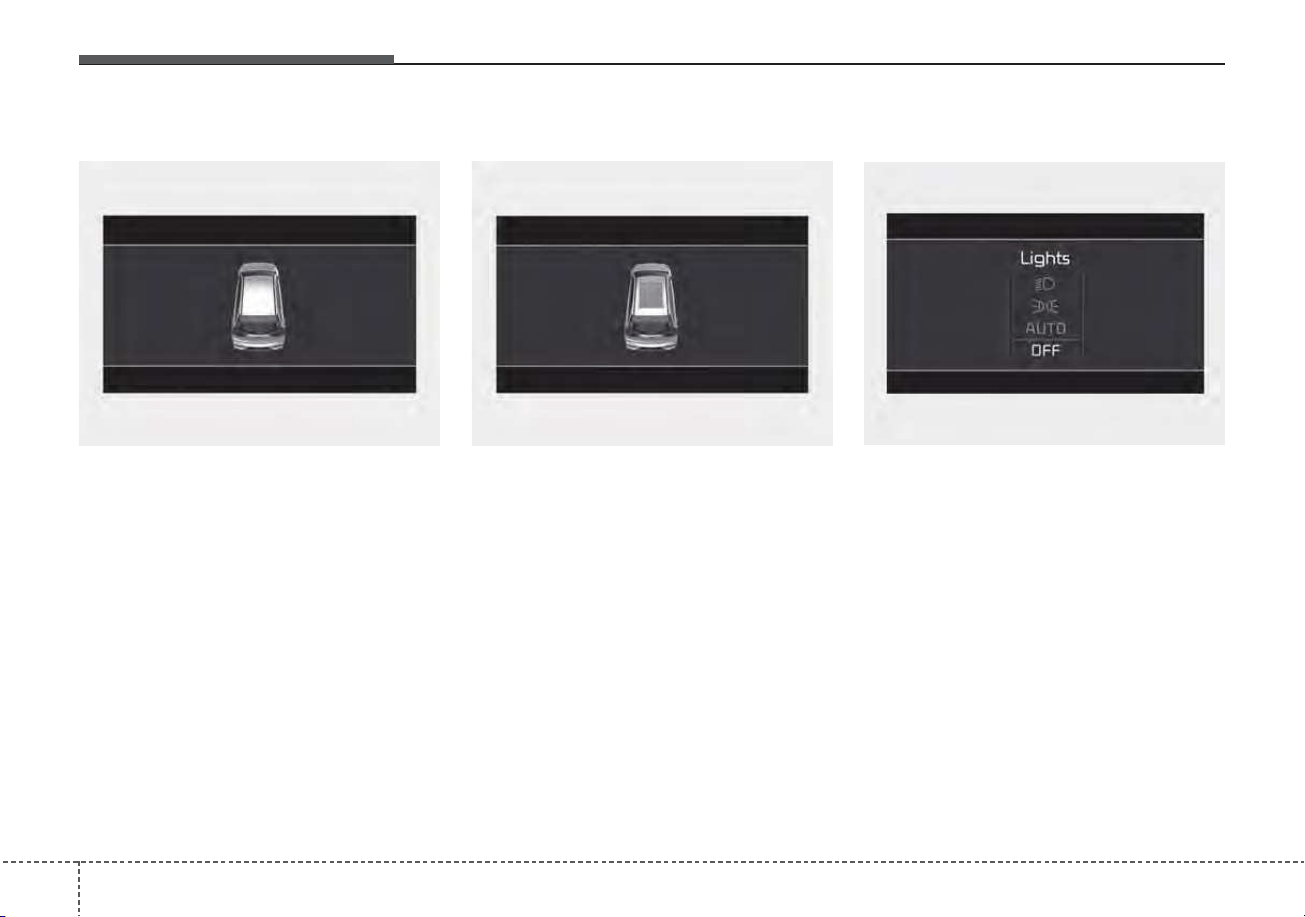
Features of your vehicle
864
Hood Open
• It means that hood is open.
Sunroof Open (if equipped)
• This warning is displayed if you
turn off the engine when the sun-
roof is open.
Lights mode
This indicator displays which exterior
light is selected using the lighting
control.
You can activate or deactivate
Wiper/Lights Display function from
the User Settings mode in the cluster
LCD display.
ODEP049118 ODEP049119 OYG049582L
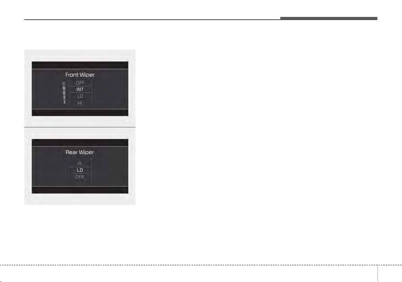
487
Features of your vehicle
Wiper mode
This indicator displays which wiper
speed is selected using the wiper
control.
You can activate or deactivate
Wiper/Lights Display function from
the User Settings mode in the cluster
LCD display.
Turn FUSE SWITCH on
• This warning message illuminates
if the fuse switch under the steer-
ing wheel is OFF.
• It means that you should turn the
fuse switch on.
❈ For more details, refer to “Fuses”
in chapter 7.
Engine has Overheated
This warning message illuminates
when the engine coolant tempera-
ture is above 248°F (120°C). This
means that the engine is overheated
and may be damaged.
If your vehicle is overheated, refer to
“Overheating” in chapter 6.
Shift to P (for smart key system)
• This warning message illuminates
if you try to turn off the engine with-
out the shift lever in P (Park) posi-
tion.
• At this time, the ENGINE
START/STOP button turns to the
ACC position (If you press the
ENGINE START/STOP button once
more, it will turn to the ON position).
Low key battery
(for smart key system)
• This warning message illuminates
if the battery of the smart key is
discharged when the ENGINE
START/STOP button changes to
the OFF position.
ODEP049604N
ODEP049605N
■ Front
■ Rear

Features of your vehicle
884
Press START button while turning
wheel (for smart key system)
• This warning message illuminates
if the steering wheel does not
unlock normally when the ENGINE
START/STOP button is pressed.
• It means that you should press the
ENGINE START/STOP button
while turning the steering wheel
right and left.
Steering wheel not locked
(for smart key system)
• This warning message illuminates
if the steering wheel does not lock
when the ENGINE START/STOP
button changes to the OFF posi-
tion.
Check Steering Wheel Lock
System (for smart key system)
• This warning message illuminates
if the steering wheel does not lock
normally when the ENGINE
START/STOP button changes to
the OFF position.
Press brake pedal to start engine
(for smart key system)
• This warning message illuminates
if the ENGINE START/STOP button
changes to the ACC position twice
by pressing the button repeatedly
without depressing the brake pedal.
• It means that you should depress
the brake pedal to start the engine.
Key not in vehicle (for smart key
system)
• This warning message illuminates
if the smart key is not in the vehicle
when you press the ENGINE
START/STOP button.
• It means that you should always
have the smart key with you.
Key not detected (for smart key
system)
• This warning message illuminates
if the smart key is not detected
when you press the ENGINE
START/STOP button.

489
Features of your vehicle
Press START button again
(for smart key system)
• This warning message illuminates
if you can not operate the ENGINE
START/STOP button when there is
a problem with the ENGINE
START/STOP button system.
• It means that you could start the
engine by pressing the ENGINE
START/STOP button once more.
• If the warning illuminates each
time you press the ENGINE
START/STOP button, have your
vehicle inspected by an authorized
Kia dealer.
Press START button with key (for
smart key system)
• This warning message illuminates
if you press the ENGINE
START/STOP button while the
warning message “Key not detect-
ed” is illuminating.
• At this time, the immobilizer indica-
tor light blinks.
Check BRAKE SWITH fuse
(for smart key system)
• This warning message illuminates
if the brake switch fuse is discon-
nected.
• It means that you should replace
the fuse with a new one. If that is
not possible, you can start the
engine by pressing the ENGINE
START/STOP button for 10 sec-
onds in the ACC position.
Shift to P or N to start engine
(for smart key system)
• This warning message illuminates
if you try to start the engine with
the shift lever not in the P (Park) or
N (Neutral) position.
✽✽
NOTICE
You can start the engine with the
shift lever in the N (Neutral) posi-
tion. But, for your safety, we recom-
mend that you start the engine with
the shift lever in the P (Park) posi-
tion.
Low washer fluid
• This warning message illuminates
on the service reminder mode if
the washer fluid level in the reser-
voir is nearly empty.
• It means that you should refill the
washer fluid.
Low fuel
• This warning message illuminates
if the fuel tank is nearly empty.
- When the low fuel level warning
light is illuminates.
Add fuel as soon as possible.

Features of your vehicle
904
Device in wireless charger
(if equipped)
If a smart phone is still left on the wire-
less charging pad unattended, even
when the ENGINE START/STOP but-
ton is turned to the ACC or OFF posi-
tion. And the instrument panel's one
time driving information mode has fin-
ished, a warning message will lit up on
the instrument panel.
❈ For more details, refer to “Wireless
smart phone charging system” in
this chapter.
Check Hybrid system
This warning message illuminates
when there is a problem with the
hybrid control system.
Refrain from driving when the warn-
ing message is displayed.
In this case, have your vehicle inspect-
ed by an authorized Kia dealer.
Check Hybrid system. Turn
engine off
This warning message illuminates
when there is a problem with the
hybrid system. The “ ” indicator
will blink and a warning chime will
sound until the problem is solved.
In this case, have your vehicle inspect-
ed by an authorized Kia dealer.
Check Hybrid system. Do not start
engine
This warning message illuminates
when the hybrid battery power
(SOC) level is low. A warning chime
will sound until the problem is solved.
In this case, have your vehicle inspect-
ed by an authorized Kia dealer.
Stop vehicle and check power
supply
This warning message illuminates
when a failure occurs in the power
supply system.
In this case, park the vehicle in a
safe location and tow your vehicle to
the nearest authorized Kia dealer
and have the vehicle inspected.
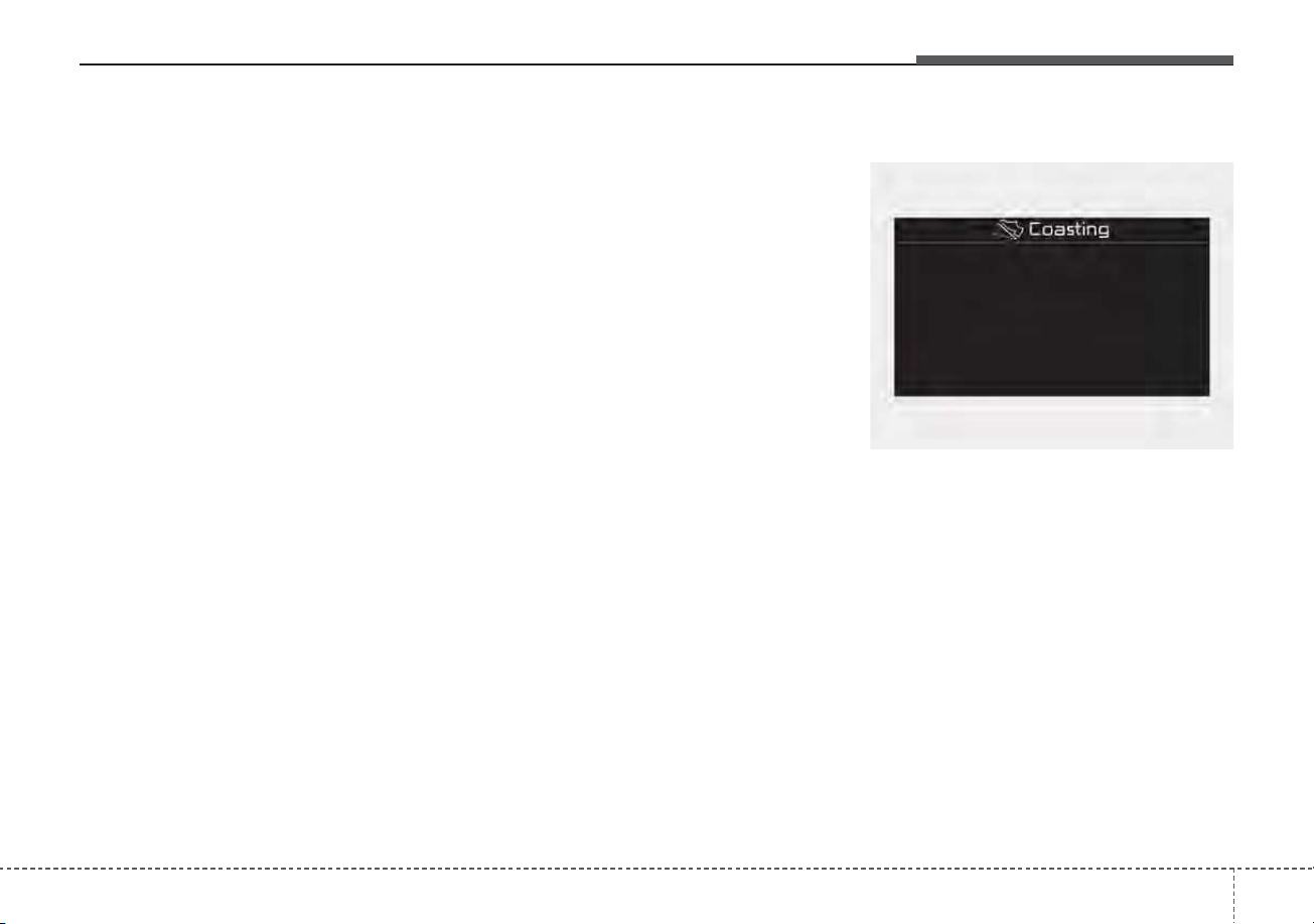
491
Features of your vehicle
Park with engine On to charge
battery
This warning message illuminates
when the hybrid battery power
(SOC) level is low.
In this case, park the vehicle in a
safe location and wait until the hybrid
battery is charged.
Refuel to prevent Hybrid battery
damage
This warning message illuminates
when the fuel tank is nearly empty.
You should refill the fuel tank to pre-
vent hybrid battery damage.
Refill inverter coolant
This warning message illuminates
when the inverter coolant is nearly
empty.
You should refill the inverter coolant.
Check brake system
This warning message illuminates
when the brake performance is low
or the regenerative brake does not
work properly due to a failure in the
brake system.
In this case, it may take longer for the
brake pedal to operate and the brak-
ing distance may become longer.
Stop vehicle and check brake
system
This warning message is displayed
when a failure occurs in the brake
system.
In this case, park the vehicle in a
safe location and tow your vehicle to
the nearest authorized Kia dealer
and have the vehicle inspected.
Coasting guide (if equipped)
A chime will sound and the coasting
guide indicator will blink four times to
inform the driver when to take the
foot off the accelerator by anticipat-
ing a decelerating event* based on
an analysis of driving routes and
road conditions based on the naviga-
tion. It encourages the driver to
remove foot from the pedal and allow
coasting down the road with EV
motor only. This helps prevent
unnecessary fuel consumption and
may increases fuel efficiency.
ODEP049583L

Features of your vehicle
924
❈ Example of a deceleration event is
going down an extended hill, slow-
ing down approaching a toll booth,
and approaching reduced speed
zones.
• User settings
The driver can activate or deactivate
the Coasting Guide by placing the igni-
tion switch or ENGINE START/STOP
in the ON position and by selecting
“User Settings → Convenience →
Coasting Guide → Enable Coasting
Guide”.
For the explanation of the system,
press and hold the [OK] button.
• Operation conditions
To activate the system, take the fol-
lowing procedures. Enter your desti-
nation information on the navigation
and select the driving route. Select
the ECO mode by driving the vehicle
in D (Drive). Then, satisfy the follow-
ing.
- The driving speed should be
between 37 mph (60 km/h) and 99
mph (160km/h).
❈ The operating speed may vary due
to difference between instrument
cluster and navigation effected by
tire inflation level.
Unplug vehicle to start
(Plug-in hybrid)
The message is displayed when you
start the engine without unplugging
the charging cable. Unplug the
charging cable, and then start the
vehicle.
Remaining Time (Plug-in hybrid)
The message is displayed to notify
the remaining time to fully charge the
battery.

493
Features of your vehicle
Shift to P to charge
(Plug-in hybrid)
The message is displayed when the
charging connector is plugged with
the shift lever in R (Reverse), N
(Neutral) or D (Drive). Move the shift
lever to P (Park) and re-start the
charging process.
Electric Mode/Automatic
Mode/Hybrid Mode
(Plug-in hybrid)
A corresponding message is dis-
played when a mode is selected by
pressing the EV/HEV button.
Low battery. Maintaining Hybrid
mode (Plug-in hybrid)
This message is displayed when
unable to convert to EV mode even
when pressing the EV/HEV button
during HEV mode driving due to
insufficient high-voltage (hybrid) bat-
tery level.
Low system temperature.
Switching to Hybrid mode/High
system temperature. Switching to
Hybrid mode (Plug-in hybrid)
This message is displayed when the
temperature of the high-voltage
(hybrid) battery is too low or high.
This warning message is to protect
the battery and the hybrid system.
Low system temperature.
Maintaining Hybrid mode/High
system temperature. Maintaining
Hybrid mode (Plug-in hybrid)
This message is displayed when the
temperature of the high-voltage
(hybrid) battery is too low or too high.
This warning message is to protect
the battery and the hybrid system.
Wait until fuel door opens
(Plug-in hybrid)
This message is displayed when you
attempt to open the fuel filler door
with the fuel tank pressurized. Wait
until the fuel tank is depressurized.

Features of your vehicle
944
Fuel door open (Plug-in hybrid)
This message is displayed when the
fuel filler door opens after the fuel
tank is depressurized. If this mes-
sage is displayed, you can refuel the
fuel tank.
Charging stopped. Check the AC
charger (Plug-in hybrid)
This messages is displayed when
the charging failed by external charg-
er error.
The purpose of this message is to let
you know the error has occurred in
the charger itself, not in the vehicle.
Charging stopped. Check the
cable connection (Plug-in hybrid)
This messages is displayed when
charging is stopped because the
charging connector is not correctly
connected to the charging inlet. If this
occur, separate the charging con-
nector and re-connect it and check
whether there is any problem (exter-
nal damage, foreign substances,
etc.) with the charging connector and
charging inlet. If the same problem
occurs when charging the vehicle
with a replaced charging cable or
genuine Kia portable charger, have
your vehicle inspected by an author-
ized Kia dealer.
Charging Door Open
(Plug-in hybrid)
This message indicates that the
charging door is open while in driv-
ing-ready state to encourage you to
inspect and close the door.(Driving
with the charging door open may
result in moisture inflow or damage.
This message is used to prevent
such occurrences.)

495
Features of your vehicle
Switching to Hybrid mode to
allow heating or air conditioning
(Plug-in hybrid)
• When the coolant temperature is
lower than 57°F (-14°C), and you
turn the climate control On for
heating, the above message will be
displayed in the cluster. Then, the
vehicle will automatically switch to
HEV mode.
• When the coolant temperature is
higher than 57°F (-14°C), or you
turn the climate control Off, the
vehicle will automatically return to
EV mode.
Switching to Hybrid mode for
self-diagnosis (Plug-in hybrid)
• This message is displayed for self-
diagnosis of the hybrid mode sys-
tem.
Features of your vehicle
964
Warning lights
✽✽
NOTICE - Warning lights
Make sure that all warning lights
are OFF after starting the engine. If
any light is still ON, this indicates a
situation that needs attention.
Hybrid system warning
light
This warning light illuminates:
• When there is a malfunction with
the hybrid system.
In this case, have the vehicle
inspected by an authorized Kia
dealer.
Air bag Warning Light
This warning light illuminates:
• Once you set the ignition switch or
ENGINE START/STOP button to
the ON position.
- It illuminates for approximately 6
seconds and then goes off.
• When there is a malfunction with
the SRS.
In this case, have your vehicle
inspected by an authorized Kia
dealer.
Seat Belt Warning Light
This warning light informs the driver
that the seat belt is not fastened.
❈ For more details, refer to the “Seat
Belts” in chapter 3.
WARNING AND INDICATOR LIGHTS

497
Features of your vehicle
Parking Brake & Brake
Fluid Warning Light
This warning light illuminates:
• Once you set the ignition switch or
ENGINE START/STOP button to
the ON position.
- It illuminates for approximately 3
seconds
- It remains on if the parking brake
is applied.
• When the parking brake is applied.
• When the brake fluid level in the
reservoir is low.
- If the warning light illuminates
with the parking brake released, it
indicates the brake fluid level in
reservoir is low.
If the brake fluid level in the reservoir
is low:
1. Drive carefully to the nearest safe
location and stop your vehicle.
2. With the engine stopped, check
the brake fluid level immediately
and add fluid as required (For
more details, refer to “Brake Fluid”
in chapter 7).
Then check all brake components
for fluid leaks. If any leaks in the
brake system are still found, the
warning light remains on, or the
brakes do not operate properly, do
not drive the vehicle.
In this case, have your vehicle
towed to an authorized Kia dealer
and inspected.
Dual-diagonal braking system
Your vehicle is equipped with dual-
diagonal braking systems. This
means you still have braking on two
wheels even if one of the dual sys-
tems should fail.
With only one of the dual systems
working, greater pedal pressure is
required to stop the vehicle.
Also, the vehicle will require
increased stopping distance with
only a portion of the brake system
working.
If the brakes fail while you are driv-
ing, shift to a lower gear for addition-
al engine braking and stop the vehi-
cle as soon as it is safe to do so.
Driving the vehicle with a warning
light ON is dangerous. If the Parking
Brake & Brake Fluid Warning Light
illuminate with the parking brake
released, it indicates that the brake
fluid level is low.
In this case, have your vehicle
inspected by an authorized Kia deal-
er.
Features of your vehicle
984
Anti-lock Brake System
(ABS) Warning Light
This warning light illuminates:
• Once you set the ignition switch or
ENGINE START/STOP button to
the ON position.
- It illuminates for approximately 3
seconds and then goes off.
• When there is a malfunction with
the ABS (The normal braking sys-
tem will still be operational without
the assistance of the anti-lock
brake system).
In this case, have your vehicle
inspected by an authorized Kia
dealer.
Electronic
Brake force
Distribution
(EBD) System
Warning Light
These two warning lights illuminate at
the same time while driving:
• When the ABS and regular brake
system may not work normally.
In this case, have your vehicle
inspected by an authorized Kia
dealer.
WARNING - Electronic
Brake force Distribution
(EBD) System Warning Light
When both ABS and Parking
Brake & Brake Fluid Warning
Lights are on, the brake system
will not work normally and you
may experience an unexpected
and dangerous situation during
sudden braking thereby
increasing the risk of a crash
and injury. In this case, avoid
high speed driving and abrupt
braking. Have your vehicle
inspected by an authorized Kia
dealer as soon as possible.
499
Features of your vehicle
✽✽
NOTICE
- Electronic Brake
force Distribution (EBD)
System Warning Light
When the ABS Warning Light is on
or both ABS and Parking Brake &
Brake Fluid Warning Lights are on,
the speedometer, odometer, or trip-
meter may not work. Also, the EPS
Warning Light may illuminate and
the steering effort may increase or
decrease.
In this case, have your vehicle inspect-
ed by an authorized Kia dealer as
soon as possible.
Regenerative Brake
Warning Light
This warning light illuminates :
When the regenerative brake does
not operate and the brake does not
perform well. This causes the Brake
Warning light (red) and Regenerative
Brake Warning Light (yellow) to illu-
minate simultaneously.
In this case, drive safely and have
your vehicle inspected by an author-
ized Kia dealer.
Electric Power Steering
(EPS) Warning Light
This warning light illuminates:
• Once you set the ignition switch or
ENGINE START/STOP button to
the ON position.
- It remains on until the engine is
started.
• When there is a malfunction with
the EPS.
In this case, have your vehicle
inspected by an authorized Kia
dealer.
(yellow color)
(red color)
Features of your vehicle
1004
Malfunction Indicator
Lamp (MIL)
This warning light illuminates:
• Once you set the ignition switch or
ENGINE START/STOP button to
the ON position.
- It remains on until the engine is
started.
• When there is a malfunction with
the emission control system.
In this case, have your vehicle
inspected by an authorized Kia
dealer.
Charging System
Warning Light
This warning light illuminates:
• Once you set the ignition switch or
ENGINE START/STOP button to
the ON position.
- It remains on until the engine is
started.
• When there is a malfunction with
either the alternator or electrical
charging system.
If there is a malfunction with either
the alternator or electrical charging
system:
1.Drive carefully to the nearest safe
location and stop your vehicle.
2.Turn the engine off and check the
alternator drive belt for looseness
or breakage.
If the belt is adjusted properly,
there may be a problem in the elec-
trical charging system.
In this case, have your vehicle
inspected by an authorized Kia
dealer as soon as possible.
CAUTION - Catalytic
Converter Damage
If the Malfunction Indicator
Lamp (MIL) illuminates, poten-
tial catalytic converter damage
is possible which could result in
loss of engine power.
In this case, have your vehicle
inspected by an authorized Kia
dealer as soon as possible.
CAUTION - Malfunction
Indicator Lamp (MIL)
Driving with the Malfunction
Indicator Lamp (MIL) on may
cause damage to the emission
control systems which could
affect drivability and/or fuel
economy.
4101
Features of your vehicle
Engine Oil Pressure
Warning Light
This warning light illuminates:
• Once you set the ignition switch or
ENGINE START/STOP button to
the ON position.
- It remains on until the engine is
started.
• When the engine oil pressure is low.
If the engine oil pressure is low:
1.Drive carefully to the nearest safe
location and stop your vehicle.
2.Turn the engine off and check the
engine oil level (For more details,
refer to “Engine Oil” in chapter 7). If
the level is low, add oil as required.
If the warning light remains on after
adding oil or if oil is not available,
have your vehicle inspected by an
authorized Kia dealer as soon as
possible.
If the warning light stays on while the
engine is running, it indicates that
there may be serious engine dam-
age or malfunction. In this case,
1. Stop the vehicle as soon as it is
safe to do so.
2. Turn off the engine and check the
oil level. If the oil level is low, fill the
engine oil to the proper level.
3. Start the engine again. If the warn-
ing light stays on after the engine
is started, turn the engine off
immediately. In this case, have
your vehicle inspected by an
authorized Kia dealer.
Low Fuel Level Warning
Light
This warning light illuminates:
When the fuel tank is nearly empty.
Add fuel as soon as possible.
CAUTION - Engine
damage
If the engine is not stopped
immediately after the engine oil
pressure warning light is illumi-
nated and stays on while the
engine is running, serious
engine damage may result.
CAUTION - Low Fuel
Level
Driving with the Low Fuel Level
warning light on or with the fuel
level below “E” can cause the
engine to misfire and damage
the catalytic converter (if
equipped).
Features of your vehicle
1024
Low Tire Pressure
Warning Light
This warning light illuminates:
• Once you set the ignition switch or
ENGINE START/STOP button to
the ON position.
- It illuminates for approximately 3
seconds and then goes off.
• When one or more of your tires are
significantly underinflated.
❈For more details, refer to “Tire
Pressure Monitoring System
(TPMS)” in chapter 6.
This warning light remains on after
blinking for approximately 70 seconds
or repeats blinking on and off at the
intervals of approximately 4 seconds:
• When there is a malfunction with
the TPMS.
In this case, have your vehicle
inspected by an authorized Kia
dealer as soon as possible.
❈For more details, refer to “Tire
Pressure Monitoring System
(TPMS)” in chapter 6.
• The TPMS cannot alert you to
severe and sudden tire damage
caused by external factors.
• If you notice any vehicle instability,
immediately take your foot off the
accelerator pedal, apply the brakes
gradually with light force, and slow-
ly move to a safe position off the
road.
WARNING - Low tire
pressure
• Significantly low tire pressure
makes the vehicle unstable
and can contribute to loss of
vehicle control and increased
braking distances.
• Continued driving on low pres-
sure tires may cause the tires
to overheat and fail.
4103
Features of your vehicle
Master Warning light
(if equipped)
• This warning light informs the driv-
er the following situations.
- Forward Collision-Avoidance Assist
system malfunction (if equipped)
- Forward Collision-Avoidance Assist
radar blocked (if equipped)
- Blind-Spot Collision Warning system
malfunction (if equipped)
- Blind-Spot Collision Warning radar
blocked (if equipped)
- Lamp malfunction
- LED headlamp malfunction (if
equipped)
- High Beam Assist malfunction (if
equipped)
- Tire Pressure Monitoring System
(TPMS) malfunction
- Smart Cruise Control system mal-
function (if equipped)
- Smart Cruise Control system radar
blocked (if equipped)
- Highway Driving Assist system mal-
function (if equipped)
- Lane Following Assist system mal-
function (if equipped), etc.
The Master Warning Light illuminates
when one or more of the above warn-
ing situations occur. If the warning situ-
ation is resolved, the master warning
light will turn off.
Engine Coolant
Temperature Warning
Light
This warning light illuminates:
• When the engine coolant tempera-
ture is above 248°F (120°C). This
means that the engine is overheat-
ed and may be damaged.
If your vehicle is overheated, refer
to “If the engine overheats” in
chapter 6.
CAUTION - Engine
Overheating
Do not continue driving with the
engine overheated. Otherwise
the engine may be damaged.
Features of your vehicle
1044
Electronic Parking Brake
(EPB) Warning Light
(if equipped)
This warning light illuminates:
• Once you set the ignition switch or
ENGINE START/STOP button to
the ON position.
- It illuminates for approximately 3
seconds and then goes off.
• When there is a malfunction with
the EPB.
In this case, have your vehicle
inspected by an authorized Kia
dealer.
✽✽
NOTICE - Electronic Parking
Brake (EPB) Warning Light
The Electronic Parking Brake
(EPB) Warning Light may illumi-
nate when the Electronic Stability
control (ESC) Indicator Light comes
on to indicate that the ESC is not
working properly (This does not
indicate malfunction of the EPB).
LED Headlamp Warning
Light (if equipped)
This warning light illuminates:
• Once you set the ignition switch or
ENGINE START/STOP button to
the ON position.
- It illuminates for approximately 3
seconds and then goes off.
• When there is a malfunction with
the LED headlamp.
In this case, have your vehicle inspect-
ed by an authorized Kia dealer.
Forward Collision-
Avoidance Assist
System Warning Light
(if equipped)
This warning light illuminates:
• Once you set the ignition switch or
ENGINE START/STOP button to
the ON position.
- The FCA warning light illuminates
for approximately 3 seconds and
then turns off.
• When there is a malfunction with
FCA.
If this occurs, have your vehicle
inspected by an authorized Kia
dealer.
❈ For more details, refer to “Forward
Collision-Avoidance Assist (FCA)”
in chapter 5.
CAUTION - LED
Headlamp Warning Light
Continuous driving with the
LED Headlamp Warning Light
on can reduce LED headlamp
(low beam) life.
EPB
4105
Features of your vehicle
Icy Road Warning Light
• This warning light is to warn the
driver the road may be icy.
• When the temperature on the out-
side temperature gauge is approx-
imately below 39°F (4°C), the Icy
Road Warning Light and Outside
Temperature Gauge blinks and
then illuminates. Also, the warning
chime sounds 1 time.
✽✽
NOTICE
If the icy road warning light appears
while driving, you should drive
more attentively and safely, refrain-
ing from over-speeding, rapid accel-
eration, sudden braking or sharp
turning, etc.
Indicator Lights
Charging Cable
Connection Indicator
(Plug-in hybrid)
This indicator illuminates in red when
the charging cable is connected.
Electronic Stability Control (ESC)
Indicator Light
This indicator light illumi-
nates:
• Once you set the ignition switch or
ENGINE START/STOP button to
the ON position.
- It illuminates for approximately 3
seconds and then goes off.
• When there is a malfunction with
the ESC system.
In this case, have your vehicle
inspected by an authorized Kia
dealer.
This indicator light blinks:
While the ESC is operating.
❈For more details, refer to
“Electronic Stability Control (ESC)”
in chapter 5.
Features of your vehicle
1064
Electronic Stability
Control (ESC) OFF
Indicator Light
This indicator light illuminates:
• Once you set the ignition switch or
ENGINE START/STOP button to
the ON position.
- It illuminates for approximately 3
seconds and then goes off.
• When you deactivate the ESC sys-
tem by pressing the ESC OFF but-
ton.
❈For more details, refer to
“Electronic Stability Control (ESC)”
in chapter 5.
Immobilizer Indicator
Light (Without Smart Key)
This indicator light illuminates:
• When the vehicle detects the
immobilizer in your key properly
while the ignition switch is ON.
- At this time, you can start the
engine.
- The indicator light goes off after
starting the engine.
This indicator light blinks:
• When there is a malfunction with
the immobilizer system.
In this case, have your vehicle
inspected by an authorized Kia
dealer.
Immobilizer Indicator
Light (With Smart Key)
This indicator light illuminates for up
to 30 seconds:
• When the vehicle detects the
smart key in the vehicle properly
while the ENGINE START/STOP
button is ACC or ON.
- At this time, you can start the
engine.
- The indicator light goes off after
starting the engine.
This indicator light blinks for a few
seconds:
• When the smart key is not in the
vehicle.
- At this time, you can not start the
engine.
4107
Features of your vehicle
This indicator light illuminates for 2
seconds and goes off:
• When the vehicle cannot detect the
smart key which is in the vehicle
while the ENGINE START/STOP
button is ON.
In this case, have your vehicle
inspected by an authorized Kia
dealer.
This indicator light blinks:
• When the battery of the smart key
is weak.
- At this time, you cannot start the
engine. However, you can start
the engine if you press the
ENGINE START/STOP button
with the smart key. (For more
details, refer to “Starting the
hybrid system” in chapter 5.)
• When there is a malfunction with
the immobilizer system.
In this case, have your vehicle
inspected by an authorized Kia
dealer.
Turn Signal Indicator
Light
This indicator light blinks:
• When you turn the turn signal light
on.
If any of the following occurs, there
may be a malfunction with the turn
signal system. In this case, have your
vehicle inspected by an authorized
Kia dealer.
- The indicator light does not blink
but illuminates.
- The indicator light blinks more
rapidly.
- The indicator light does not illumi-
nate at all.
High Beam Indicator
Light
This indicator light illuminates:
• When the headlights are on and in
the high beam position
• When the turn signal lever is pulled
into the Flash-to-Pass position.
Front Fog Indicator
Light (if equipped)
This indicator light illuminates:
• When the front fog lights are on.
Features of your vehicle
1084
Low Beam Indicator
Light (if equipped)
This indicator light illuminates:
• When the headlights are on.
Light ON Indicator Light
This indicator light illuminates:
• When the tail lights or headlights
are on.
High Beam Assist
indicator (if equipped)
This warning light illuminates :
• When the High-Beam is on with
the light switch in the AUTO light
position.
• If your vehicle detects oncoming or
preceding vehicles, High Beam
Assist system will switch the high
beam to low beam automatically.
❈For more details, refer to “High
Beam Assist (HBA)” in chapter 4.
EV Mode Indicator
This indicator illuminates when the
vehicle is driven by the electric
motor.
EV
4109
Features of your vehicle
Ready Indicator
This indicator illuminates :
When the vehicle is ready to be driv-
en.
- ON : Normal driving is possible.
- OFF : Normal driving is not possi-
ble, or a problem has occurred.
- Blinking : Emergency driving.
When the ready indicator goes OFF
or blinks, there is a problem with the
system. In this case, have your vehi-
cle inspected by an authorized Kia
dealer.
AUTO HOLD Indicator
Light (if equipped)
This indicator light illuminates:
• [White] When you activate the auto
hold system by pressing the AUTO
HOLD button.
• [Green] When you stop the vehicle
completely by depressing the
brake pedal with the auto hold sys-
tem activated.
• [Yellow] When there is a malfunc-
tion with the auto hold system.
In this case, have your vehicle
inspected by an authorized Kia
dealer.
❈For more details, refer to “Auto
Hold” in chapter 5.
Lane Keeping Assist
System Indicator
(if equipped)
This indicator light illuminates :
• [Green] When the system operat-
ing conditions are satisfied.
• [White] The system operating con-
ditions are not satisfied.
• [Yellow] When there is a malfunc-
tion with Lane Keeping Assist sys-
tem.
In this case, have your vehicle
inspected as soon as possible by
an authorized Kia dealer.
❈For more details, refer to “Lane
Keeping Assist (LKA)” in chapter 5.
AUTO
HOLD
Features of your vehicle
1104
SPORT Mode Indicator
Light
This indicator light illuminates:
• When the driver moves the shift
lever to S (Sport).
❈ For more information, refer to
"Dual Clutch Transmission" in
chapter 5.
ECO Mode Indicator
Light
This indicator light illuminates:
• When the driver moves the shift
lever to D (Drive).
❈ Formore information, refer to
"Dual Clutch Transmission" in
chapter 5.
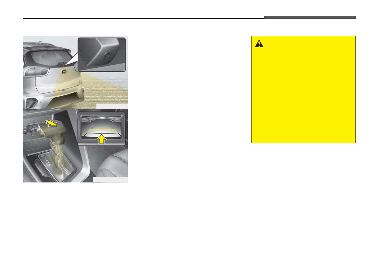
4111
Features of your vehicle
Rear View Monitor system will acti-
vate with the ignition switch ON and
the shift lever in the R (Reverse) posi-
tion.
• This system is a supplemental sys-
tem only. It is the responsibility of
the driver to always check the
inside/outside rearview mirrors and
the area behind the vehicle before
and while backing up because
there is a dead zone that can't be
seen by the camera.
• Always keep the camera lens
clean. If lens is covered with for-
eign matter, the camera may not
operate normally.
❈ If your vehicle is equipped with
Infotainment System, rearview dis-
play image will show behind the
vehicle through the Infotainment
System monitor while backing-up.
For detailed information, scan the
QR code in a separately supplied
Car Infotainment System Quick
Reference Guide.
REAR VIEW MONITOR (RVM)
WARNING - Backing &
using camera
Never rely solely on the rear view
camera when backing up. You
must always look over both
shoulders and continuously
check all three rear view mirrors.
Due to the difficulty of ensuring
that the area behind you remains
clear, always back up slowly and
stop immediately if you even
suspect that a person, and espe-
cially a child, might be behind
you.
ODEP049403
ODEP049404L
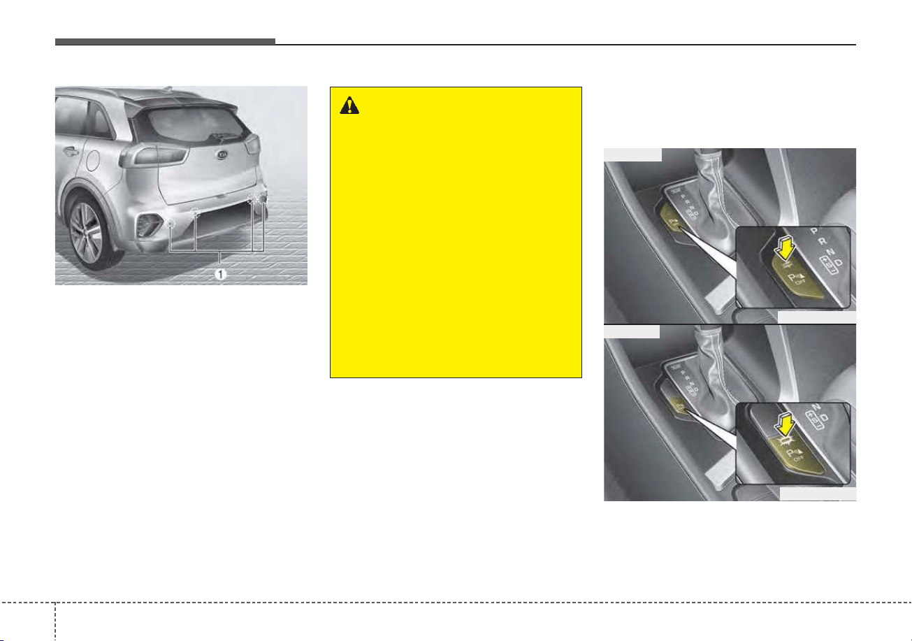
Features of your vehicle
1124
Reverse Parking Distance Warning
system assists the driver during back-
ward movement of the vehicle by
chiming if any object is sensed within
a distance of 48 in (120 cm) behind
the vehicle.
This system is a supplemental system
and it is not intended to nor does it
replace the need for extreme care and
attention of the driver. The sensing
range and objects detectable by rear
ultrasonic sensors (➀) are limited.
Whenever backing-up, pay as much
attention to what is behind you as you
would in a vehicle without a Reverse
Parking Distance Warning system.
Operation of Reverse Parking
Distance Warning system
Operating condition
Push the button to turn off the
Parking Distance Warning (Reverse)
system. The indicator light on the
button will turn on.
REVERSE PARKING DISTANCE WARNING (PDW) (IF EQUIPPED)
WARNING
-
Reverse Parking Distance
Warning system
Never rely solely on the Reverse
Parking Distance Warning sys-
tem. Always perform a visual
inspection to make sure the
vehicle is clear of all obstruc-
tions before moving the vehicle
in any direction. Stop immedi-
ately if you are aware of a child
or other person anywhere near
your vehicle. Some objects may
not be detected by the sensors,
due to the object's size or mate-
rial.
ODEP049400
ODEP049610N
ODEP049607N
■ Type A
■ Type B

4113
Features of your vehicle
• This system will activate when
backing up with the ignition switch
or ENGINE START/STOP button to
the ON position.
If the vehicle is moving at a speed
over 3 mph (5 km/h), the system
may not be activated correctly.
• The sensing distance while the
back-up warning system is in oper-
ation is approximately 48 in (120
cm) at the rear bumper center
area, 24 in (60 cm) at the rear
bumper both side area.
• When more than two objects are
sensed at the same time, the clos-
est one will be recognized first.
Types of warning sound
• When an object is 24 in to 48 in (60
cm to 120 cm) from the rear
bumper: Buzzer beeps intermit-
tently.
• When an object is 12 in to 24 in (30
cm to 60 cm) from the rear
bumper: Buzzer beeps more fre-
quently.
• When an object is within 12 in (30
cm) of the rear bumper:
Buzzer sounds continuously.
Non-operational conditions of
Reverse Parking Distance
Warning system
Reverse Parking Distance
Warning system may not operate
properly when:
1. Moisture is frozen to the sensor. (It
will operate normally once the
moisture clears.
2. The sensor is covered with foreign
matter, such as snow or water, or
the sensor cover is blocked. (It will
operate normally when the materi-
al is removed or the sensor is no
longer blocked.)
3. Driving on uneven road surfaces
(unpaved roads, gravel, bumps,
gradient).
4. Objects generating excessive
noise (vehicle horns, loud motor-
cycle engines, or truck air brakes)
are within range of the sensor.
5. Heavy rain or water spray exists.
6. Wireless transmitters or mobile
phones are within range of the
sensor.
7. The sensor is covered with snow.
8. Trailer towing
The detecting range may decrease
when:
1. The sensor is covered with foreign
matter such as snow or water.
(The sensing range will return to
normal when removed.)
2. Outside air temperature is
extremely hot or cold.
The following objects may not be
recognized by the sensor:
1. Sharp or slim objects such as
ropes, chains or small poles.
2. Objects which tend to absorb the
sensor frequency such as clothes,
sound absorbent material or snow.
3. Undetectable objects smaller than
4 in (100 cm) in height and nar-
rower than 6 in (14 cm) in diame-
ter.

Features of your vehicle
1144
Reverse Parking Distance
Warning system precautions
• Reverse Parking Distance Warning
system may not sound consistently
depending on the speed and
shapes of the objects detected.
• Reverse Parking Distance Warning
system may malfunction if the vehi-
cle bumper height or sensor instal-
lation has been modified or dam-
aged. Any non-factory installed
equipment or accessories may also
interfere with the sensor perform-
ance.
• The sensor may not recognize
objects less than 12 in (30 cm)
from the sensor, or it may sense an
incorrect distance. Use caution.
• When the sensor is frozen or cov-
ered with snow, dirt, or water, the
sensor may be inoperative until the
material is removed using a soft
cloth.
• To prevent damage, do not push,
scratch or strike the sensor.
✽✽
NOTICE
This system can only sense objects
within the range and location of the
sensors. It cannot detect objects in
other areas where sensors are not
installed. Also, small or slim objects,
such as poles or objects located
between sensors may not be detected
by the sensors.
Always visually check behind the
vehicle when backing up.
Be sure to inform any drivers of the
vehicle that may be unfamiliar with
the system regarding the system's
capabilities and limitations.
Self-diagnosis
If you don’t hear an audible warning
sound or if the buzzer sounds inter-
mittently when shifting the gear to
the R (Reverse) position, this may
indicate a malfunction in Reverse
Parking Distance Warning system. If
this occurs, have your vehicle
checked by an authorized Kia dealer
as soon as possible.
✽✽
NOTICE
Your new vehicle warranty does not
cover any accidents or damage to
the vehicle or injuries to its occu-
pants due to a Reverse Parking
Distance Warning system malfunc-
tion. Always drive safely and cau-
tiously.

4115
Features of your vehicle
Battery saver function
• The purpose of this feature is to
prevent the battery from being dis-
charged if the lights are left in the
ON position. The system automati-
cally shuts off the parking lights 30
seconds after the ignition key is
removed and the driver’s door is
opened and closed.
• With this feature, the parking lights
will turn off automatically if the driver
parks on the side of the road at night
and opens the driver’s side door.
If necessary, to keep the parking
lights on when the ignition key is
removed, perform the following:
1) Open the driver-side door.
2) Turn the parking lights OFF and
ON again using the light switch
on the steering column.
Headlight escort function
(if equipped)
If you turn the ignition switch to the
ACC or OFF position with the head-
lights ON, the headlights remain on
for about 5 minutes. However, if the
driver's door is opened and closed,
the headlights are turned off after 15
seconds.
The headlights can be turned off by
pressing the lock button on the trans-
mitter (or smart key) one more or
turning the light switch to the OFF
position.
Daytime running light
The Daytime Running Lights (DRL)
can make it easier for others to see the
front of your vehicle during the day.
DRL can be helpful in many different
driving conditions, and it is especially
helpful after dawn and before sunset.
The DRL system will turn the dedi-
cated lamp OFF when:
1. The headlight switch is on
2. The engine is off
3. The front fog light is on.
4. Engaging the Parking Brake
LIGHTING
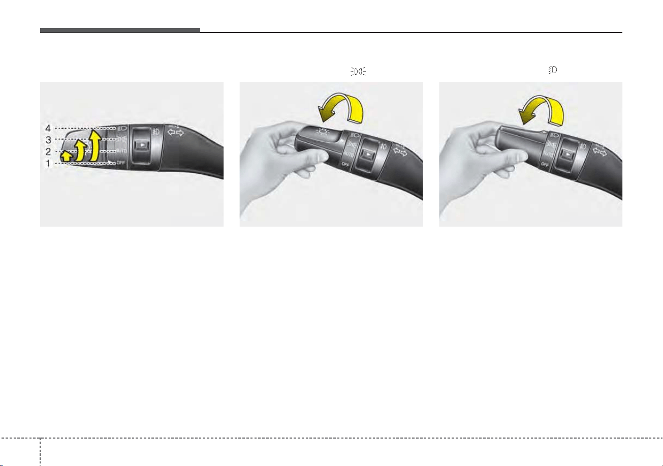
Features of your vehicle
1164
Lighting control
The light switch has a Headlight and
a Parking light position.
To operate the lights, turn the knob at
the end of the control lever to one of
the following positions:
(1) OFF position
(2) Auto light position
(3) Parking & Tail light
(4) Headlight position
Parking & Tail light ( )
When the light switch is in the park-
ing light position, the tail, license and
instrument panel lights will turn ON.
Headlight position ( )
When the light switch is in the head-
light position, the head, tail, license
lights will turn ON.
✽✽
NOTICE
The ignition switch must be in the ON
position to turn on the headlights.
OUM044055
OUMA046056 OUMA046054
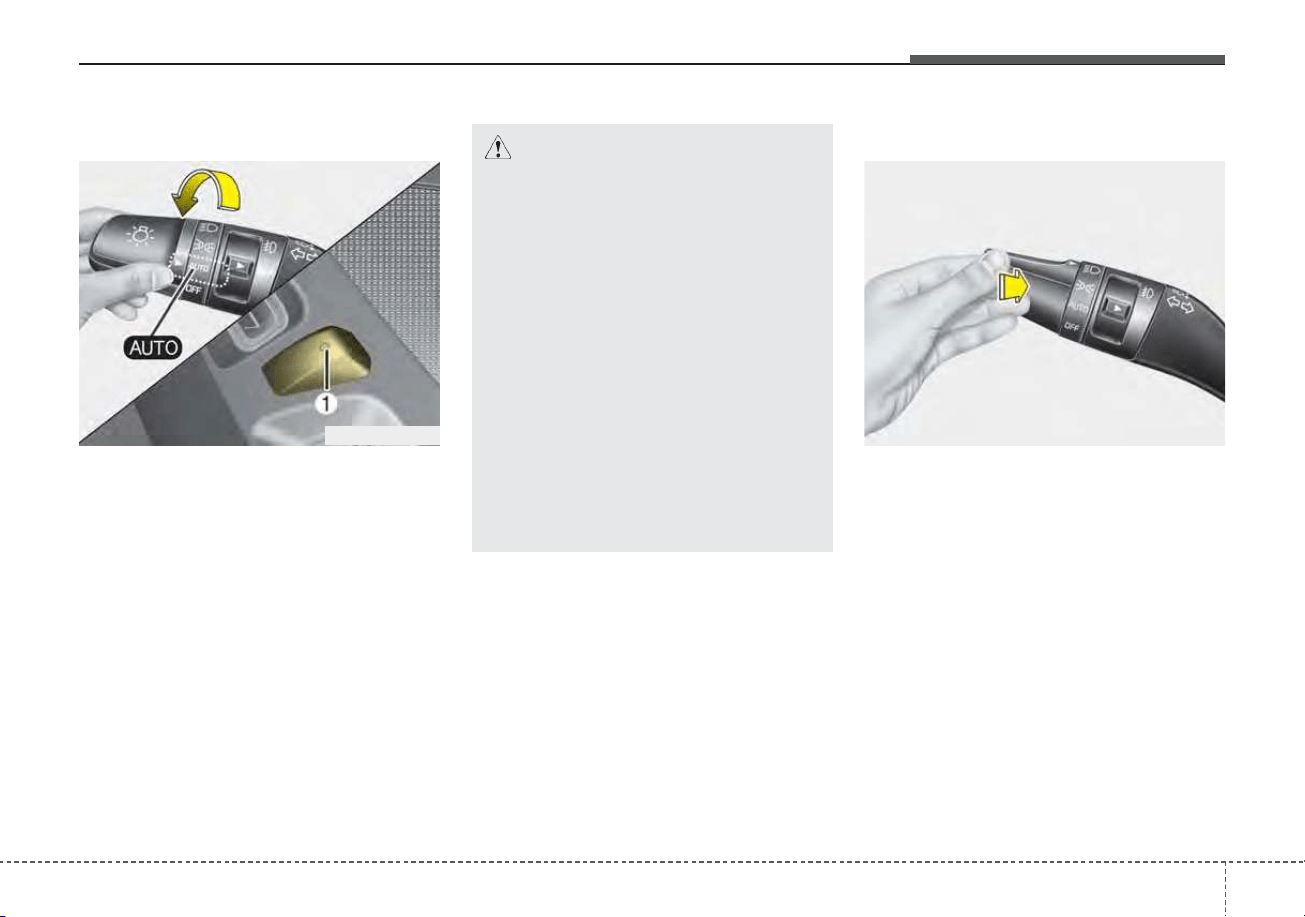
4117
Features of your vehicle
Auto light position
When the light switch is in the AUTO
light position, the taillights and head-
lights will turn ON or OFF automati-
cally depending on the amount of
light outside the vehicle.
When the light switch is positioned at
an auto light position, at first, the
wiper will turn on and then, after 5
seconds the head lamp will turn on
automatically.
If the head lamp has been turned on
due to this function of the vehicle, the
head lamp will turn off 60 seconds
after the wiper has been turned off.
High beam operation
To turn on the high beam headlamp,
push the lever away from you. The
lever will return to its original position.
The high beam indicator will light
when the headlight high beams are
switched on.
To prevent the battery from being
discharged, do not leave the lights
on for a prolonged time while the
engine is not running.
ODEP049408N OUM044059
CAUTION
• Never place anything over the
sensor (1) located on the
instrument panel as this will
ensure better auto-light sys-
tem control.
• Don’t clean the sensor using a
window cleaner, the cleaner
may leave a light film which
could interfere with sensor
operation.
• If your vehicle has window tint
or other types of metallic coat-
ing on the front windshield,
the Auto light system may not
work properly.
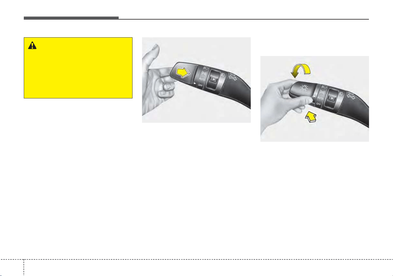
Features of your vehicle
1184
To flash the headlights, pull the lever
towards you. It will return to the nor-
mal (low beam) position when
released. The headlight switch does
not need to be on to use this flashing
feature.
High Beam Assist (HBA)
(if equipped)
The High Beam Assist is a system
that automatically adjusts the head-
lamp range (switches between high
beam and low beam) according to
the brightness of other vehicles and
road conditions.
OUM044058
WARNING - High beams
Do not use high beams when
there are other vehicles in front
of or approaching your vehicle.
Using high beams could
obstruct the other driver’s
vision.
OUMA048554

4119
Features of your vehicle
Operating condition
1.Place the light switch in the AUTO
position.
2.Turn on the high beam by pushing
the lever away from you.
The High Beam Assist ( ) indica-
tor will illuminate.
3.High Beam Assist will turn on when
vehicle speed is above 25 mph (40
km/h).
• If the lever is pushed away when
High Beam Assist is operating,
High Beam Assist will turn off and
the high beam will be on continu-
ously. The High Beam Assist (
) indicator will turn off.
• If the lever is pulled towards you
when High Beam Assist is oper-
ating, High Beam Assist will turn
off.
4.If the light switch is placed to the
headlamp position, High Beam
Assist will turn off and the low
beam will be on continuously.
The high beam switches to low beam
in the below conditions.
- When High Beam Assist is off.
- When the light switch is not in the
AUTO position.
- When the headlamp is detected
from the on-coming vehicle.
- When the tail lamp is detected
from the front vehicle.
- When the surrounding is bright
enough high beams are not need-
ed.
- When streetlights or other lights
are detected.
- When vehicle speed is below 15
mph (24 km/h).
- When headlamp / taillamp of bicy-
cle/motorcycle is detected
The system may not operate normal-
ly in the below conditions.
• When the light from the on-coming
or front vehicle is not detected
because of lamp damage, hidden
from sight, etc.
• When the lamp of the on-coming or
front vehicle is covered with dust,
snow or water.
• When the light from the on-coming
or front vehicle is not detected
because of exhaust fume, smoke,
fog, snow, etc.
• When the front window is covered
with foreign matters such as ice,
dust, fog, or is damaged.
• When there is a similar shape lamp
with the front vehicle’s lamps.
• When it is hard to see because of
fog, heavy rain or snow.
• When the headlamp is not repaired
or replaced at an authorized deal-
er.
• When headlamp aiming is not
properly adjusted.
• When driving on a narrow curved
road or rough road.
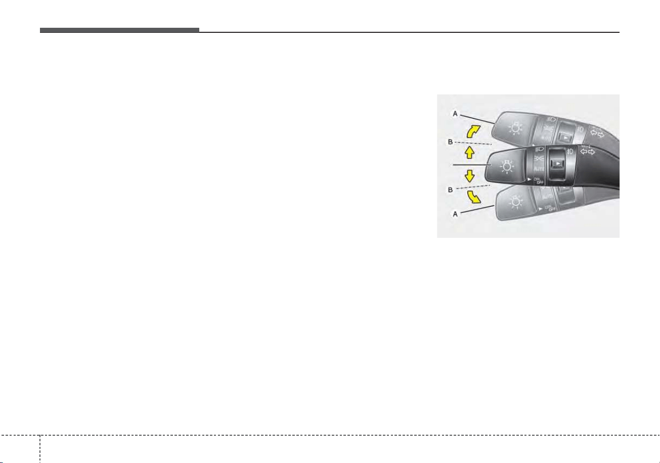
Features of your vehicle
1204
• When driving downhill or uphill.
• When only part of the vehicle in
front is visible on a crossroad or
curved road.
• When there is a traffic light, reflect-
ing sign, flashing sign or mirror.
• When the road conditions are bad
such as being wet or covered with
snow.
• When the front vehicle’s head-
lamps are off but the fog lamps on.
• When a vehicle suddenly appears
from a curve.
• When the vehicle is tilted from a
flat tire or being towed.
• When the Lane Keeping Assist
system warning light illuminates. (if
equipped)
✽✽
NOTICE
• Do not place any accessories,
stickers or tint the windshield.
• Have the windshield glass replaced
from an authorized dealer.
• Do not remove or damage related
parts of High Beam Assist system.
• Be careful that water doesn’t get
into the High Beam Assist unit.
• Do not place objects on the dash-
board that reflect light such as
mirrors, white paper, etc. The sys-
tem may malfunction if sunlight is
reflected.
• At times, High Beam Assist sys-
tem may not work properly,
always check the road conditions
for your safety. When the system
does not operate normally, manu-
ally change between the high
beam and low beam.
Turn signals and lane change
signals
The ignition switch must be on for the
turn signals to function. To turn on
the turn signals, move the lever up or
down (A). The green arrow indicators
on the instrument panel indicate
which turn signal is operating.
They will self-cancel after a turn is
completed. If the indicator continues
to flash after a turn, manually return
the lever to the OFF position.
To signal a lane change, move the
turn signal lever slightly and hold it in
position (B). The lever will return to
the OFF position when released.
ODE046461N
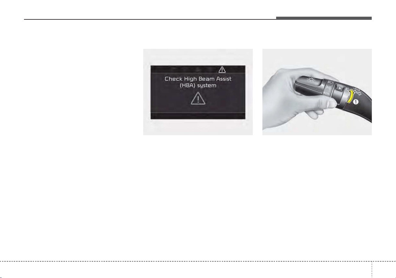
4121
Features of your vehicle
If an indicator stays on and does not
flash or if it flashes abnormally, one of
the turn signal bulbs may be burned
out and will require replacement.
✽✽
NOTICE
If an indicator flash is abnormally
quick or slow, a bulb may be burned
out or have a poor electrical connec-
tion in the circuit.
Check headlight
This warning message illuminates if
there is a malfunction (burned-out
bulb except LED lamp or circuit mal-
function) with the headlamp. In this
case, have your vehicle inspected by
an authorized Kia dealer.
✽✽
NOTICE
• When replacing the bulb, use the
same wattage bulb.
For more information, refer to
“BULB WATTAGE” in chapter 9.
• If a different wattage bulb is
installed on the vehicle, this warn-
ing message is not displayed.
Front fog light (if equipped)
Fog lights are designed to provide
improved visibility when visibility is
poor due to fog, rain or snow, etc. The
fog lights will turn on when the fog light
switch (1) is turned to the on position
after the headlight is turned on.
To turn off the fog lights, turn the fog
light switch (1) to the ON position
again.
When in operation, the fog lights
consume large amounts of vehicle
electrical power. Only use the fog
lights when visibility is poor.
ODE046458NODEP049575L
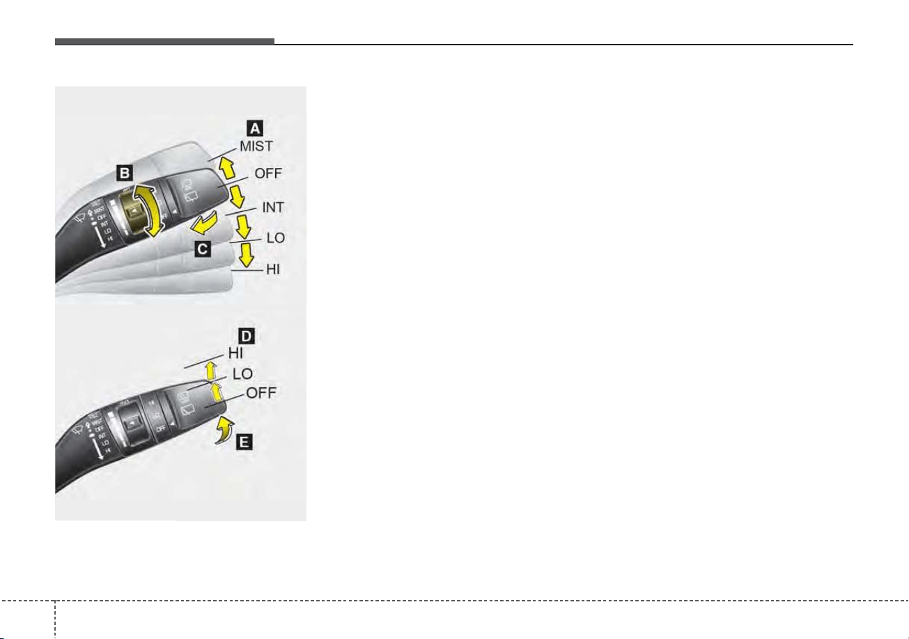
Features of your vehicle
1224
A : Wiper speed control (front)
· MIST – Single wipe
· OFF – Off
· INT – Intermittent wipe
· LO – Low wiper speed
· HI – High wiper speed
B : Intermittent control wipe time
adjustment
C : Wash with brief wipes (front)*
D : Rear wiper/washer control*
· HI – Continuous wipe
· LO – Intermittent wipe*
· OFF – Off
E : Wash with brief wipes (rear)*
* if equipped
Windshield wipers
Operates as follows when the igni-
tion switch is turned ON.
MIST : For a single wiping cycle,
move the lever to this (MIST)
position and release it. The
wipers will operate continu-
ously if the lever is held in this
position.
OFF : Wiper is not in operation
INT : Wiper operates intermittently at
the same wiping intervals. Use
this mode in light rain or mist.
To vary the speed setting, turn
the speed control knob.
LO : Normal wiper speed
HI : Fast wiper speed
WIPERS AND WASHERS
Windshield wiper/washer
OQL045407/OQL045464
Rear window wiper/washer
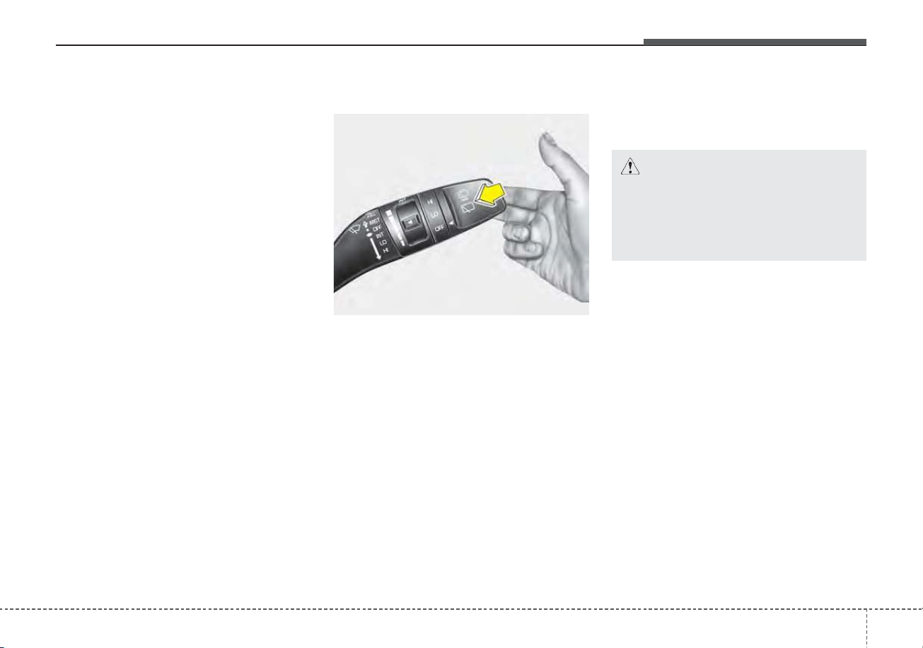
4123
Features of your vehicle
✽✽
NOTICE
If there is heavy accumulation of
snow or ice on the windshield, defrost
the windshield for about 10 minutes,
or until the snow and/or ice is
removed before using the windshield
wipers to ensure proper operation.
If you do not remove the snow
and/or ice before using the wiper
and washer, it may damage the
wiper and washer system.
Front windshield washers
In the OFF position, pull the lever
gently toward you to spray washer
fluid on the windshield and to run the
wipers 1-3 cycles.
Use this function when the wind-
shield is dirty.
The spray and wiper operation will
continue until you release the lever.
If the washer does not work, check
the washer fluid level. If the fluid level
is not sufficient, you will need to add
appropriate non-abrasive windshield
washer fluid to the washer reservoir.
The reservoir filler neck is located in
the front of the engine compartment
on the passenger side.
OQL045409
CAUTION - Washer pump
To prevent possible damage to
the washer pump, do not oper-
ate the washer when the fluid
reservoir is empty.
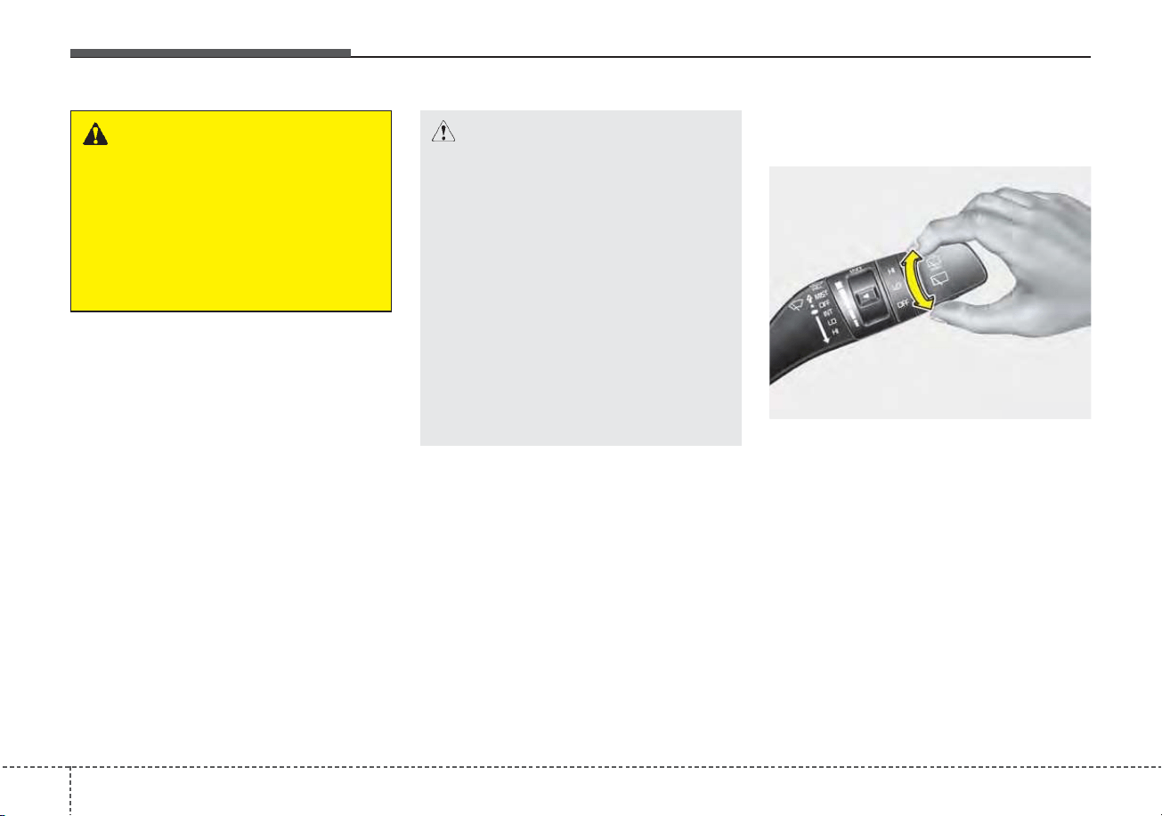
Features of your vehicle
1244
Rear window wiper and wash-
er switch
The rear window wiper and washer
switch is located at the end of the
wiper and washer switch lever. Turn
the switch to the desired position to
operate the rear wiper and washer.
HI : Continuous wipe
LO : Intermittent wipe
OFF : OFF
WARNING - Obscured
visibility
Do not use the washer in freez-
ing temperatures without first
warming the windshield with
the defrosters; the washer solu-
tion could freeze on the wind-
shield and obscure your vision.
OQL045465
CAUTION - Wipers &
windshields
• To prevent possible damage
to the wipers or windshield,
do not operate the wipers
when the windshield is dry.
• To prevent damage to the wiper
blades, do not use gasoline,
kerosene, paint thinner, or
other solvents on or near them.
• To prevent damage to the
wiper arms and other compo-
nents, do not attempt to move
the wipers manually.
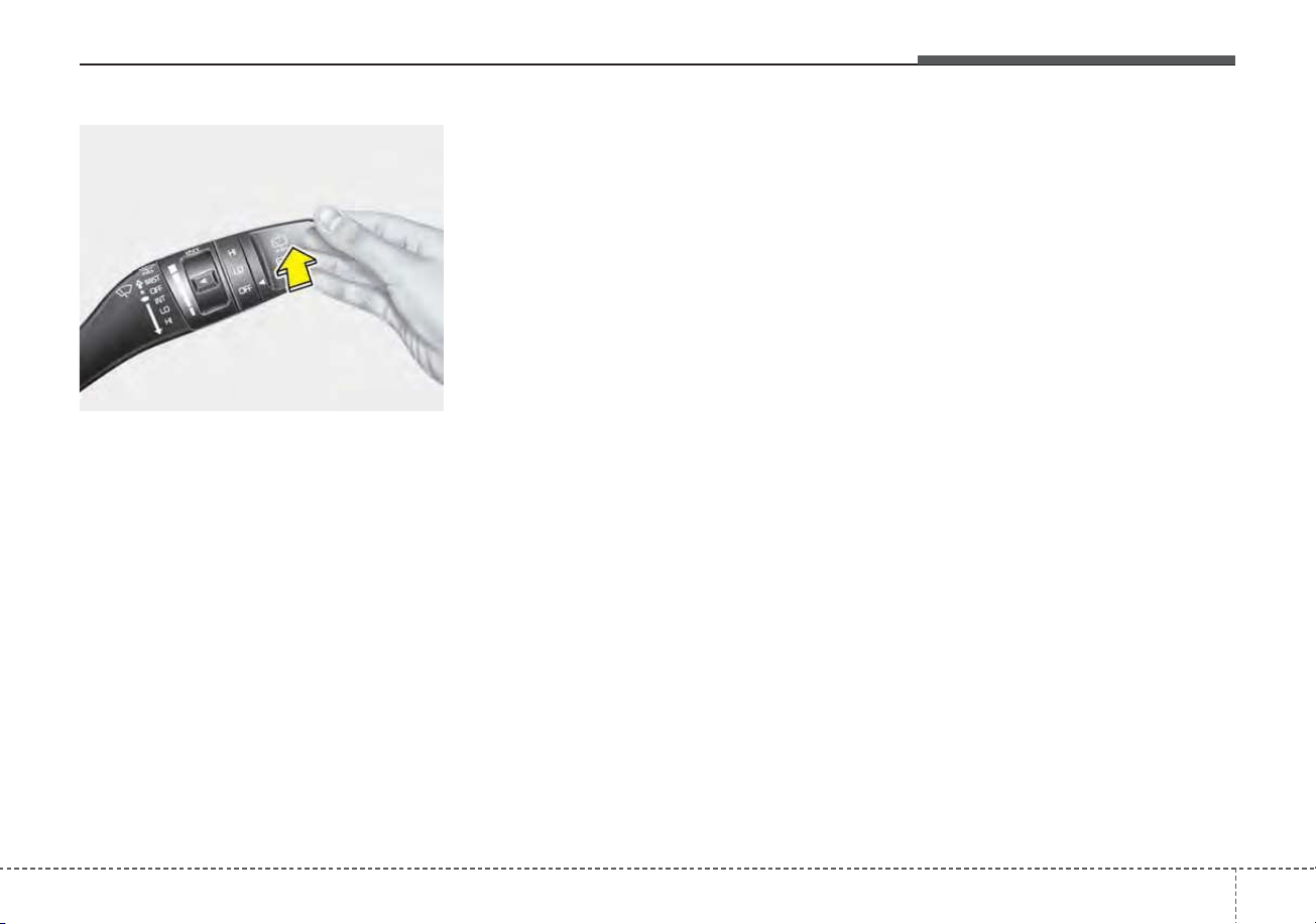
4125
Features of your vehicle
Push the lever away from you to
spray rear washer fluid and to run the
rear wipers 1 ~ 3 cycles. The spray
and wiper operation will continue
until you release the lever
OQL045466
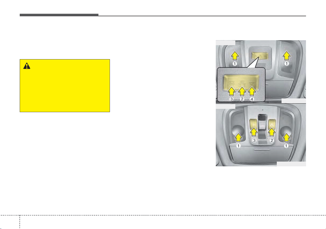
Features of your vehicle
1264
Do not use the interior lights for
extended periods when the engine is
not running.
It may cause battery discharge.
Automatic turn off function
The interior lights automatically turn
off approximately 20 minutes after
the ignition switch is turned off, if the
lights are in the ON position.
If your vehicle is equipped with the
theft alarm system, the interior lights
automatically turn off approximately
5 seconds after the system is armed.
Map lamp
• Press the lens (1) to turn ON the
map lamp.
To turn the map lamp OFF press
the lens (1) again.
INTERIOR LIGHTS
WARNING - Interior
Lights
Do not use the interior lights
when driving in the dark.
Accidents can occur because
your review may be obscured
by the interior lights.
ODE046409L
ODEP049410
■ Type B
■ Type A
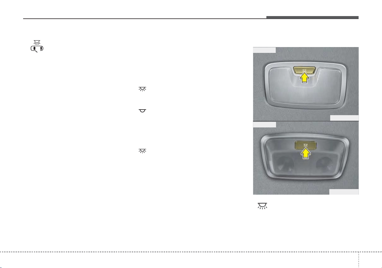
4127
Features of your vehicle
• (2) : DOOR mode
- The map lamp and room lamp
come on when a door is opened.
The lamps go out after approxi-
mately 30 seconds.
- The map lamp and room lamp
come on for approximately 30 sec-
onds when doors are unlocked
with a transmitter or smart key as
long as the doors are not opened.
- The map lamp and room lamp will
stay on for approximately 20 min-
utes if a door is opened with the
ignition switch in the ACC or
LOCK/OFF position.
- The map lamp and room lamp will
stay on continuously if the door is
opened with the ignition switch in
the ON position.
- The map lamp and room lamp will
go out immediately if the ignition
switch is changed to the ON posi-
tion or all doors are locked.
- To turn off the DOOR mode, press
the DOOR button (2) once again
(not pressed).
✽✽
NOTICE
The DOOR mode and ROOM mode
can not be selected at the same time.
Front Room Lamp:
• Type A
(3): Press this switch to turn the
front and rear room lamps
on.
(4): Press this switch to turn the
front and rear room lamps
off.
• Type B
(3): Press this switch to turn the
front and rear room lamps on
and off.
Room lamp
• : The light stays on at all times.
ODE046411
ODEP047468
■ Type B
■ Type A

Features of your vehicle
1284
Liftgate room lamp
The liftgate room lamp comes on
when the liftgate is opened.
✽✽
NOTICE
The liftgate lamp comes on as long
as the liftgate lid is open. To prevent
unnecessary charging system drain,
close the liftgate lid securely after
using the liftgate.
Vanity mirror lamp
Push the switch to turn the light on or
off.
• : The lamp will turn on if this
button is pressed.
• : The lamp will turn off if this
button is pressed.
OQL045416ODEP049412
CAUTION - Vanity mirror
lamp
Always have the switch in the
off position when the vanity mir-
ror lamp is not in use. If the sun-
visor is closed without the lamp
off, it may discharge the battery
or damage the sunvisor.

4129
Features of your vehicle
WELCOME SYSTEM (IF EQUIPPED)
Headlight (Headlamp) escort
function
The headlights (and/or taillights)
remain on for approximately 5 min-
utes after the ignition key is removed
or turned to the ACC or LOCK posi-
tion. However, if the driver’s door is
opened and closed, the headlights
are turned off after 15 seconds.
The headlights can be turned off by
pressing the lock button on the trans-
mitter or smart key twice or turning
off the light switch from the headlight
or Auto light position.
Interior light
When the interior light switch is in the
DOOR position and all doors (and lift-
gate) are locked and closed, the
room lamp will come on for 30 sec-
onds if any of the below is performed.
• With the smart key system
- When the door unlock button is
pressed on the smart key.
- When the button of the outside
door handle is pressed.
At this time, if you press the door lock
button, the lamps will turn off imme-
diately.
Pocket lamp (if equipped)
When all doors are locked and
closed, the pocket lamp will come on
for 15 seconds if any of the below is
performed.
• With the smart key system
- When the door unlock button is
pressed on the smart key.
- When the button of the outside
door handle is pressed.
At this time, if you press the door lock
button, the lamps will turn off imme-
diately.
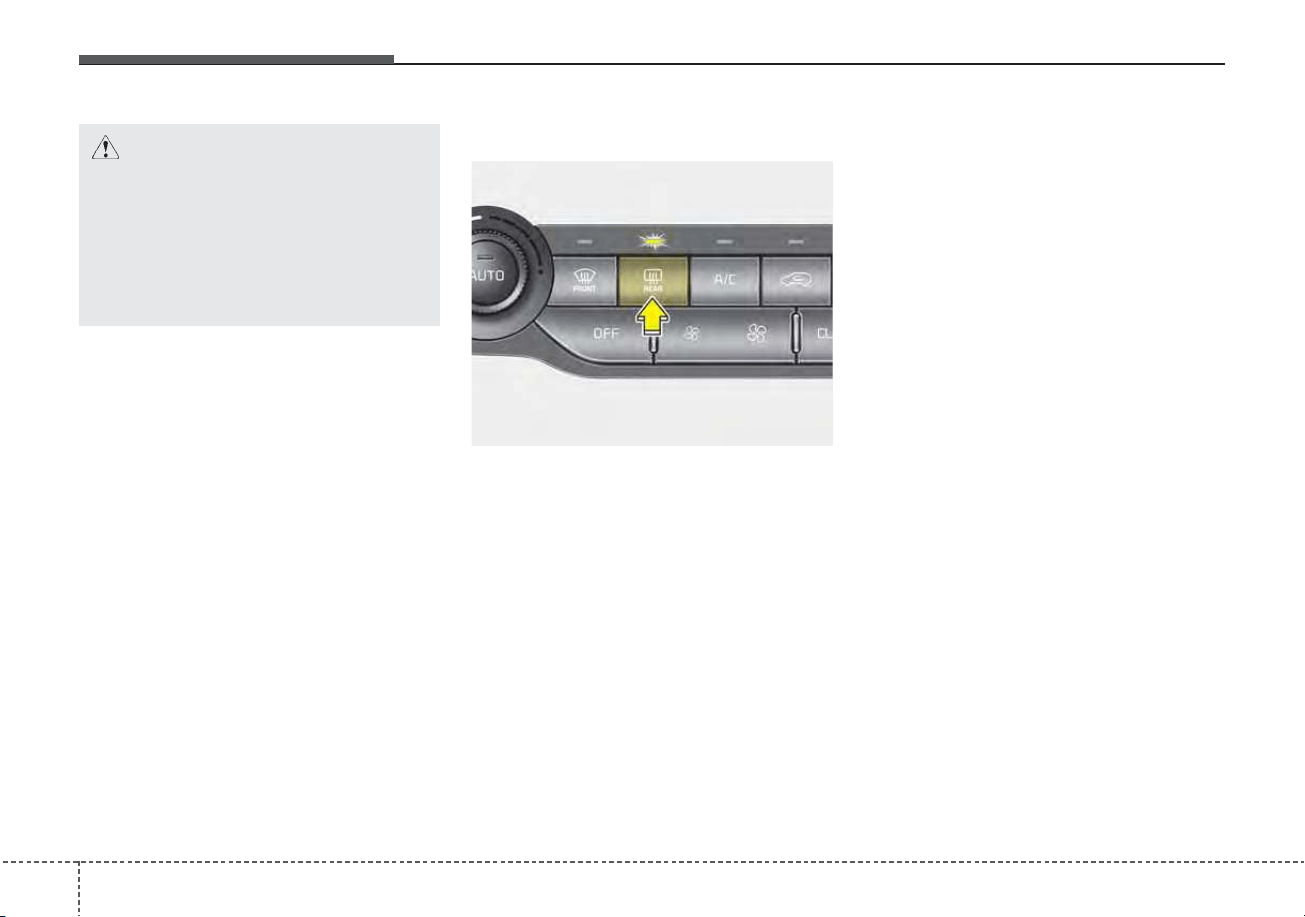
Features of your vehicle
1304
If you want to defrost and defog the
front windshield, refer to “Windshield
defrosting and defogging” in this sec-
tion.
Rear window defroster
The defroster heats the window to
remove frost, fog and thin ice from
the rear window, while the engine is
running.
To activate the rear window
defroster, press the rear window
defroster button located in the center
facia switch panel. The indicator on
the rear window defroster button illu-
minates when the defroster is ON.
If there is heavy accumulation of
snow on the rear window, brush it off
before operating the rear defroster.
The rear window defroster automati-
cally turns off after approximately 20
minutes or when the ignition switch is
turned off. To turn off the defroster,
press the rear window defroster but-
ton again.
Outside rearview mirror defroster
(if equipped)
If your vehicle is equipped with the
outside rearview mirror defrosters,
they will operate at the same time
you turn on the rear window
defroster.
DEFROSTER
CAUTION - Conductors
To prevent damage to the con-
ductors bonded to the inside
surface of the rear window,
never use sharp instruments or
window cleaners containing
abrasives to clean the window.
ODE046301
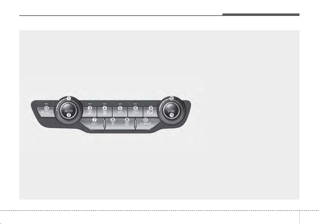
4131
Features of your vehicle
AUTOMATIC CLIMATE CONTROL SYSTEM
ODEP049300N
1. Driver’s temperature control knob
2. AUTO (automatic control) button
3. Front windshield defroster button
4. Rear window defroster button
5. Air conditioning button
6. Air intake control button
7. OFF button
8. Fan speed control button
9. Mode selection button
10. Passenger's temperature control knob
11. SYNC temperature control selection but-
ton
12. Climate button
13. Driver only select button
✽✽
NOTICE
Operating the blower when the
ignition switch is in the ON posi-
tion could cause the battery to dis-
charge. Operate the blower when
the engine is running.
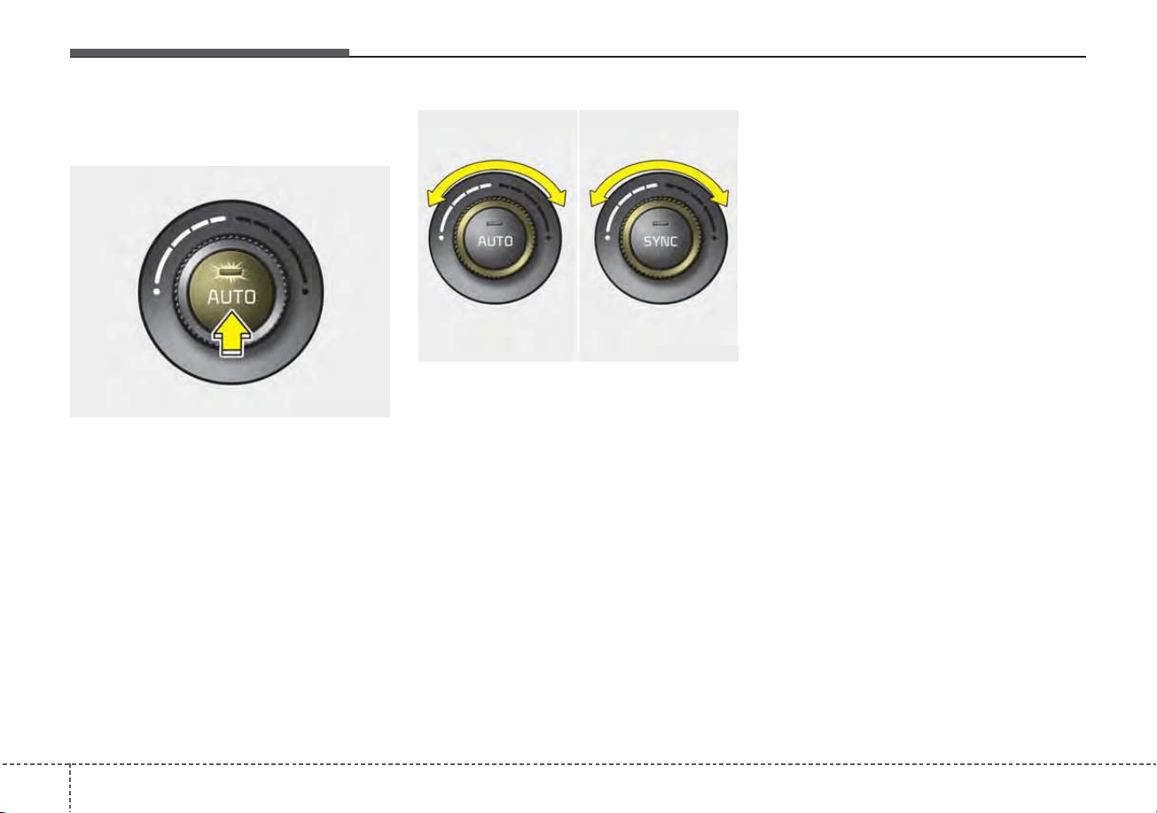
Features of your vehicle
1324
Automatic heating and air con-
ditioning
1. Press the AUTO button. The
modes, fan speeds, air intake and
air-conditioning will be controlled
automatically by setting the tem-
perature.
2. Turn the temperature control knob
to the desired temperature.
✽✽
NOTICE
• To turn the automatic operation
off, select any button or switch of
the following:
- Mode selection button
- Air conditioning button
- Front windshield defroster button
(Press the button one more time
to deselect the front windshield
defroster function. The ‘AUTO’
sign will illuminate on the infor-
mation display once again.)
- Air intake control button
- Fan speed control switch
The selected function will be con-
trolled manually while other func-
tions operate automatically.
• For your convenience and to
improve the effectiveness of the
climate control, use the AUTO
button and set the temperature to
73°F (23°C).
ODE046302
■ Driver’s side ■ Passenger’s side
ODE046305
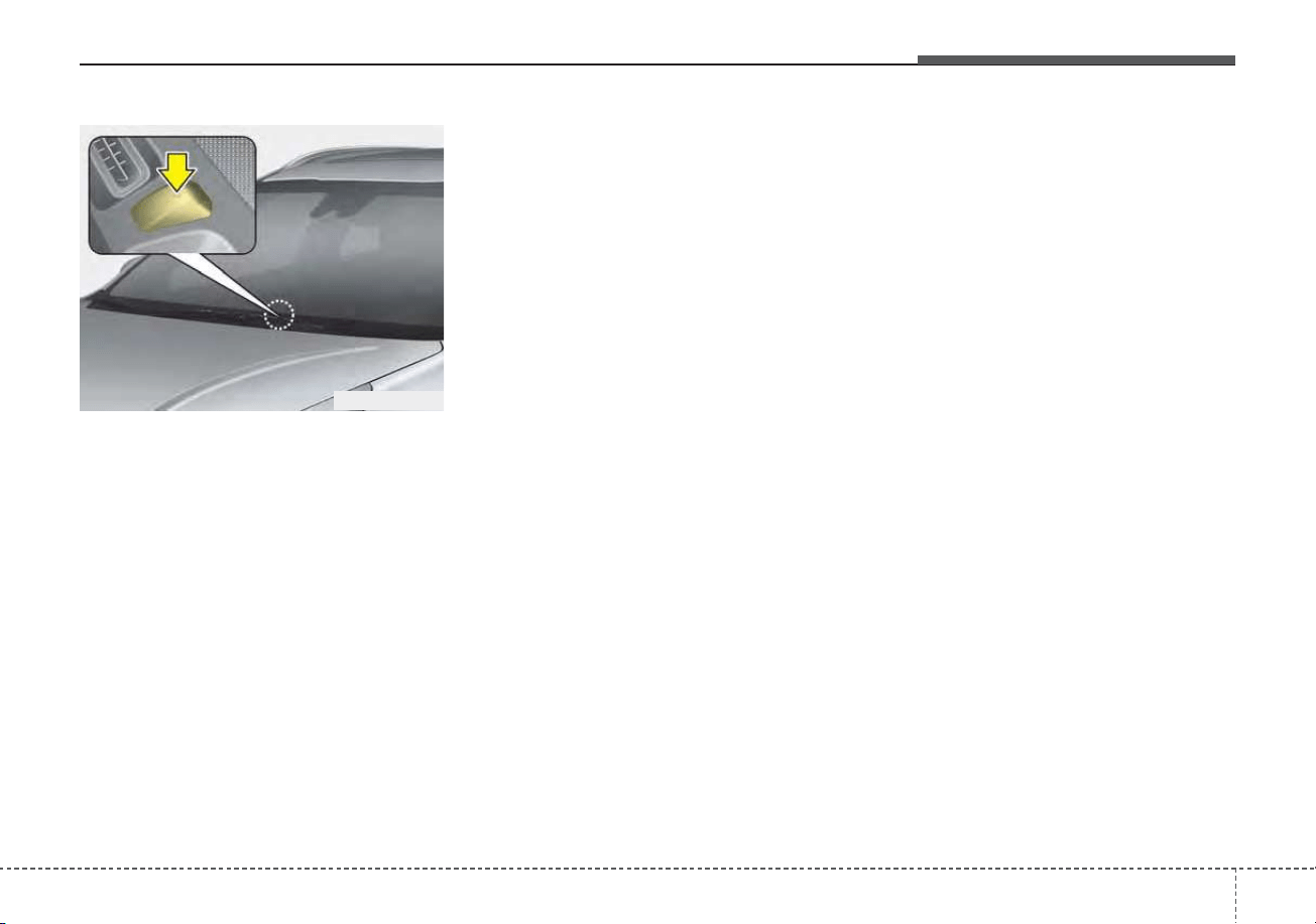
4133
Features of your vehicle
✽✽
NOTICE
Never place anything over the sensor
located on the instrument panel to
ensure better control of the heating
and cooling system.
ODEP049414
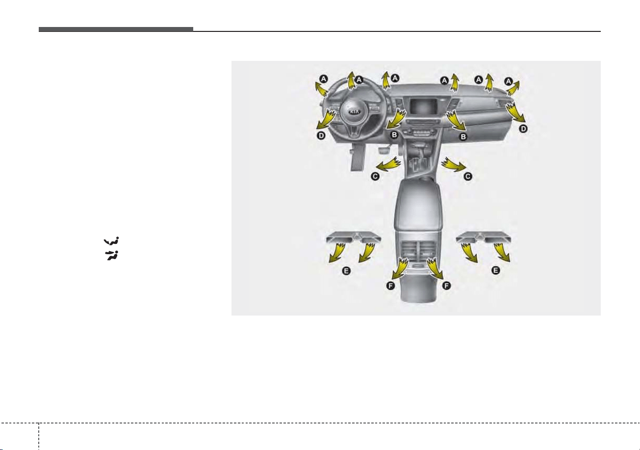
Features of your vehicle
1344
Manual heating and air condi-
tioning
The heating and cooling system can
be controlled manually by pressing
buttons or turning knob(s) other than
the AUTO button. In this case, the
system works sequentially according
to the order of buttons or knob(s)
selected.
1. Start the engine.
2. Set the mode to the desired posi-
tion.
For improving the effectiveness of
heating and cooling;
- Heating:
- Cooling:
3. Set the temperature control to the
desired position.
4. Set the air intake control to the
outside (fresh) air position.
5. Set the fan speed control to the
desired speed.
6. If air conditioning is desired, turn
the air conditioning system on.
Press the AUTO button in order to
convert to full automatic control of
the system.
ODE046318
(if equipped)
(if equipped)
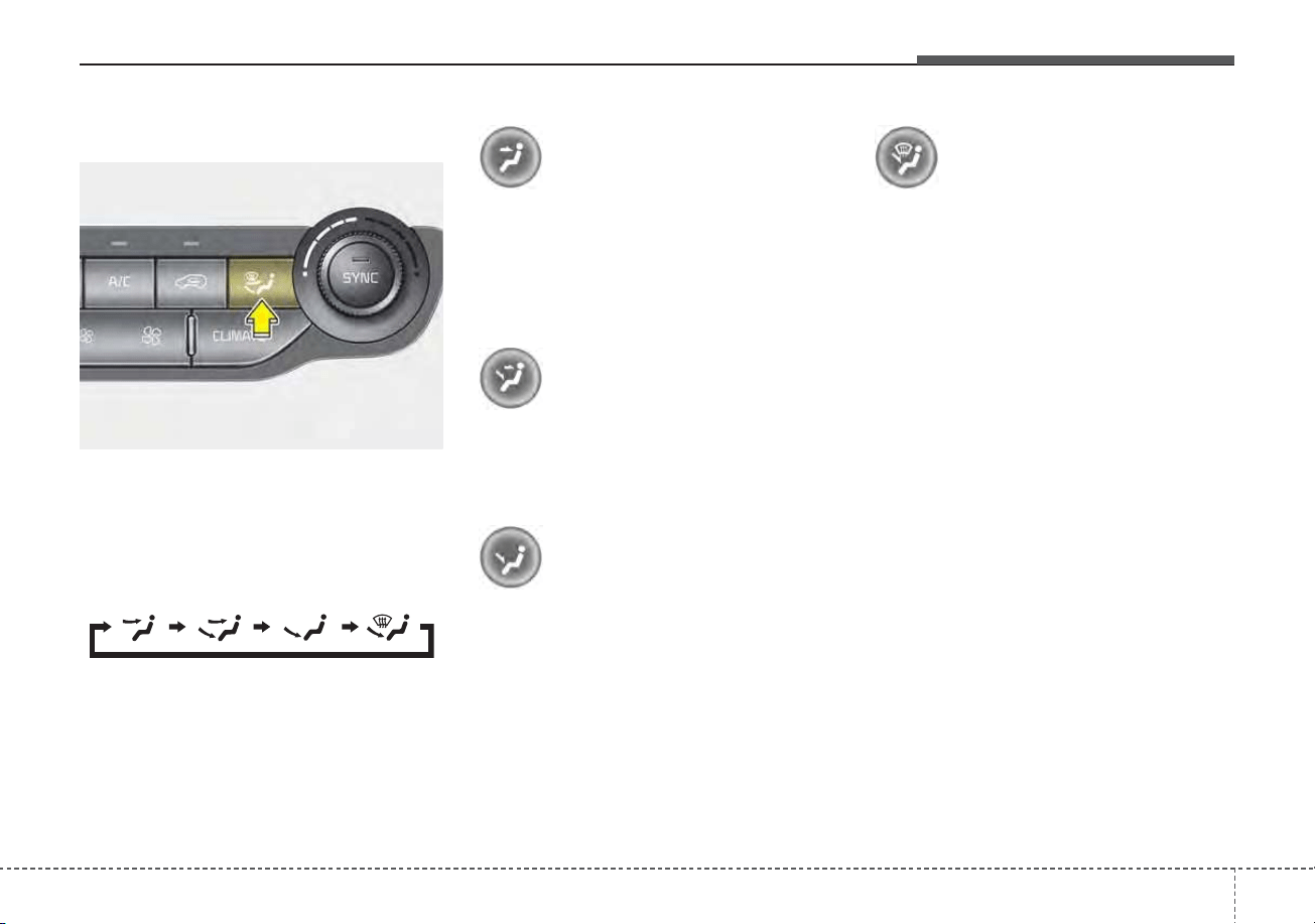
4135
Features of your vehicle
Mode selection
The mode selection button controls
the direction of the air flow through
the ventilation system.
The air flow outlet port is converted
as follows:
Face-Level (B, D)
Air flow is directed toward the upper
body and face. Additionally, each
outlet can be controlled to direct the
air discharged from the outlet.
Bi-Level (B, C, D, E, F)
Air flow is directed towards the face
and the floor.
Floor-Level (A, C, D, E, F)
Most of the air flow is directed to the
floor, with a small amount of the air
being directed to the windshield and
side window defrosters.
Floor/Defrost-Level
(A, C, D, E, F)
Most of the air flow is directed to the
floor and the windshield with a small
amount directed to the side window
defrosters.
✽✽
NOTICE - 2nd row outlet
vents (E,F)
(if equipped)
• The air flow of the 2nd row outlet
vents is controlled by the front cli-
mate control system and delivered
through the inside air duct of the
floor (E, F).
• The air flow of the 2nd row outlet
vents (E, F) may be weaker than
the instrument panel vents for the
long air duct.
ODE046304
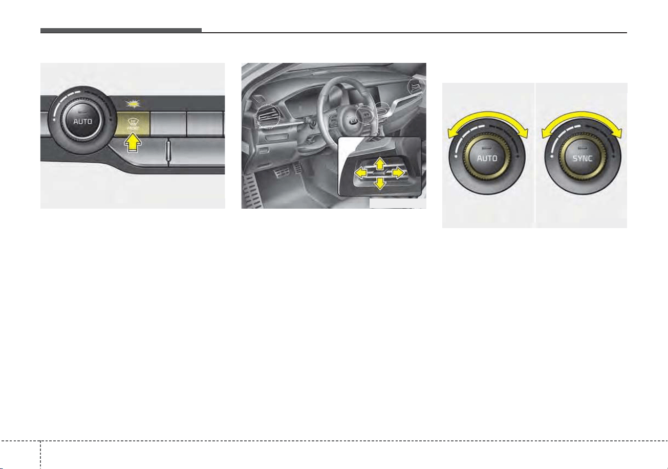
Features of your vehicle
1364
Defrost-Level (A, D)
Most of the air flow is directed to the
windshield with a small amount of air
directed to the side window defrosters.
Instrument panel vents
The outlet vents can be opened or
closed separately using the thumb-
wheel (if equipped).
Also, you can adjust the direction of
air delivery from these vents using
the vent control lever as shown.
Temperature control
The temperature will increase to the
maximum (HI) by turning the knob to
the extreme right.
The temperature will decrease to the
minimum (Lo) by turning the knob to
the extreme left.
When turning the knob, the tempera-
ture will increase or decrease by
1°F/0.5°C. When set to the lowest
temperature setting, the air condi-
tioning will operate continuously.
ODEP049319
■ Driver’s side ■ Passenger’s side
ODE046305
ODEP049303
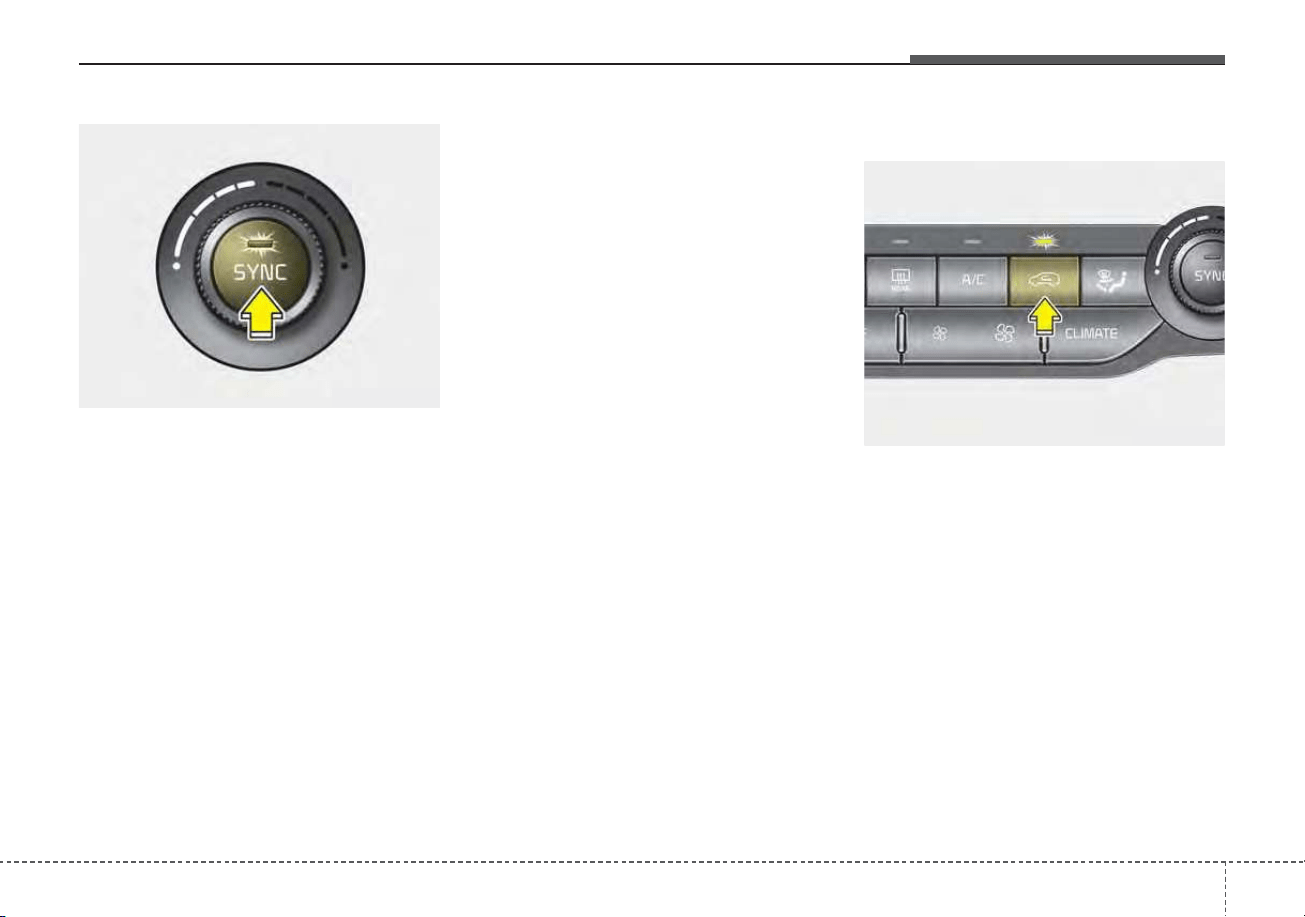
4137
Features of your vehicle
Adjusting the driver and passenger
side temperature equally
• Press the “SYNC” button to adjust
the driver and passenger side tem-
perature equally.
The passenger side temperature
will be set to the same temperature
as the driver side temperature.
• Turn the driver side temperature
control knob. The driver and pas-
senger side temperature will be
adjusted equally.
Adjusting the driver and passenger
side temperature individually
• Press the “SYNC” button again to
adjust the driver and passenger
side temperature individually. The
illumination of button turns off.
• Operate the driver side tempera-
ture control knob to adjust the driv-
er side temperature.
• Operate the passenger side tem-
perature control knob to adjust the
passenger side temperature.
Temperature conversion
You can switch the temperature
mode from Centigrade to Fahrenheit
as follows:
While pressing the OFF button,
press the AUTO button for 3 seconds
or more.The display will change from
Centigrade to Fahrenheit, or from
Fahrenheit to Centigrade. If the bat-
tery has been discharged or discon-
nected, the temperature mode dis-
play will reset to Fahrenheit.
Air intake control
This is used to select the outside
(fresh) air position or recirculated air
position.
To change the air intake control posi-
tion, push the control button.
ODE046307
ODE046306
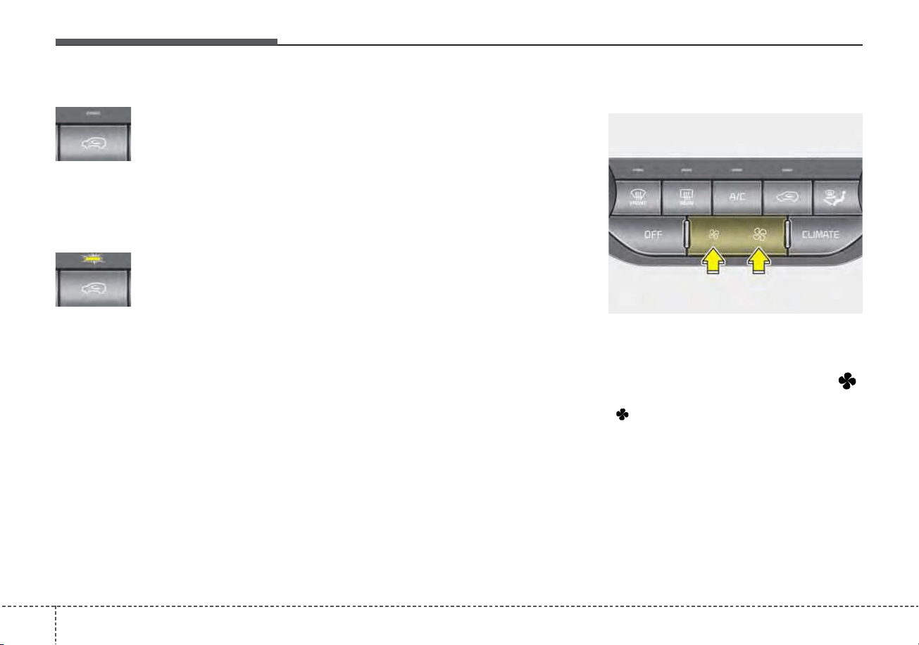
Features of your vehicle
1384
Outside (fresh) air position
With the outside (fresh)
air position selected, air
enters the vehicle from
outside and is heated or
cooled according to the
function selected.
Recirculated air position
With the recirculated air
position selected, air
from the passenger com-
partment will be drawn
through the heating sys-
tem and heated or
cooled according to the
function selected.
Prolonged operation of the heater in
the recirculated air position (without
air conditioning selected) may cause
fogging of the windshield and side
windows and the air within the pas-
senger compartment may become
stale.
In addition, prolonged use of the air
conditioning with the recirculated air
position selected will result in exces-
sively dry air in the passenger com-
partment.
Fan speed control
The fan speed can be set to the
desired speed by operating the fan
speed control button.
To change the fan speed, press ( )
the button for higher speed, or push
( ) the button for lower speed. To
turn the fan speed control off, press
the front blower OFF button.
ODE046308
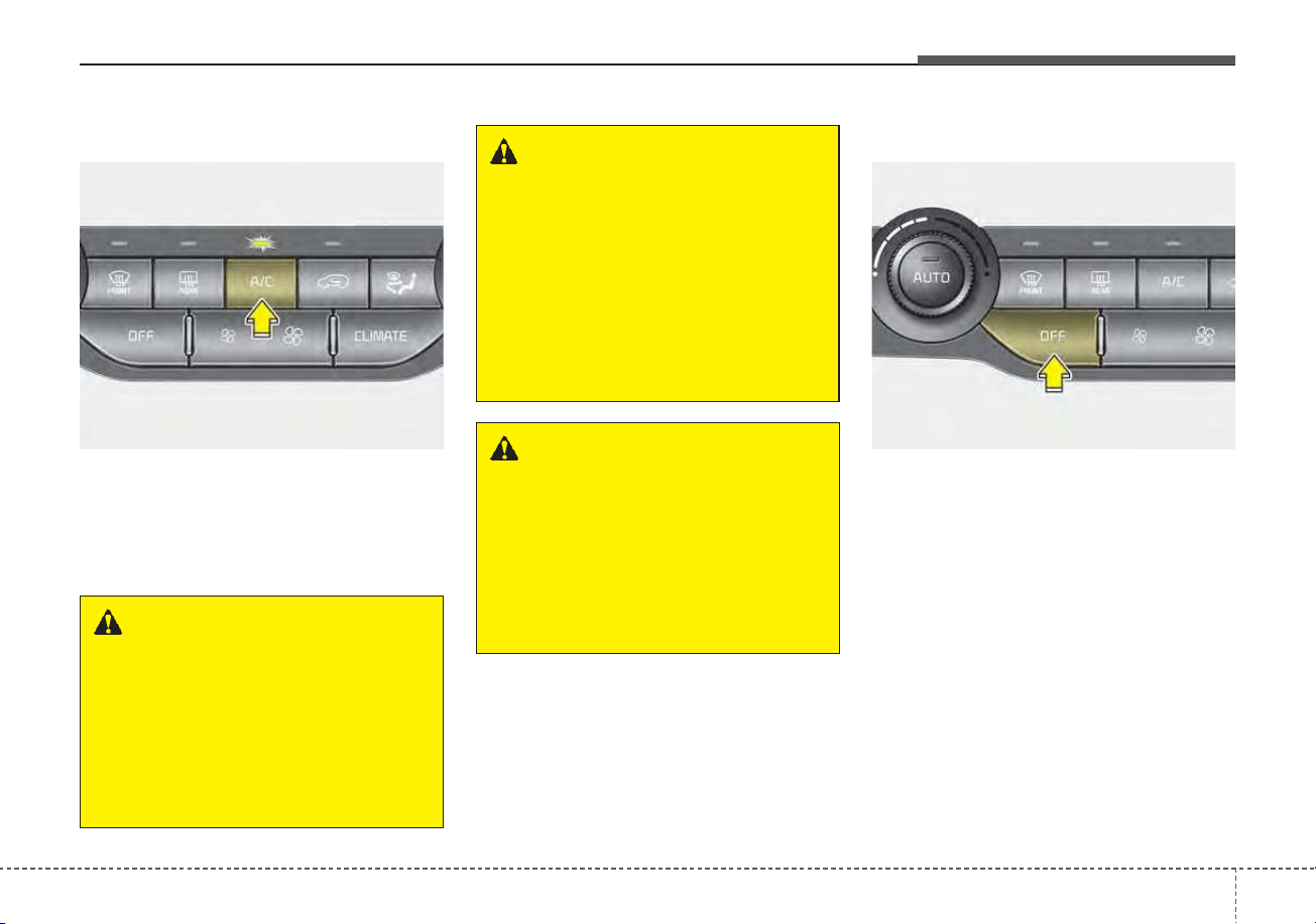
4139
Features of your vehicle
Air conditioning
Press the A/C button to turn the air
conditioning system on (indicator
light will illuminate).
Press the button again to turn the air
conditioning system off.
OFF mode
Press the front blower OFF button to
turn off the front air climate control
system. However, you can still oper-
ate the mode and air intake buttons
as long as the ignition switch is in the
ON position.
WARNING - Recirculated
Air
Continued use of the climate
control system in the recirculat-
ed air position can cause
drowsiness or sleepiness, and
loss of vehicle control. Set the
air intake control to the outside
(fresh) air position as much as
possible while driving.
WARNING - Sleeping with
A/C on
Do not sleep in a vehicle with
the air conditioning or heating
on as this may cause serious
harm or death due to a drop in
your oxygen level and/or body
temperature.
WARNING - Reduced
Visibility
Continuous use of the climate
control system in the recirculat-
ed air position may allow
humidity to increase inside the
vehicle which may fog the glass
and obscure visibility.
ODE046309 ODE046310
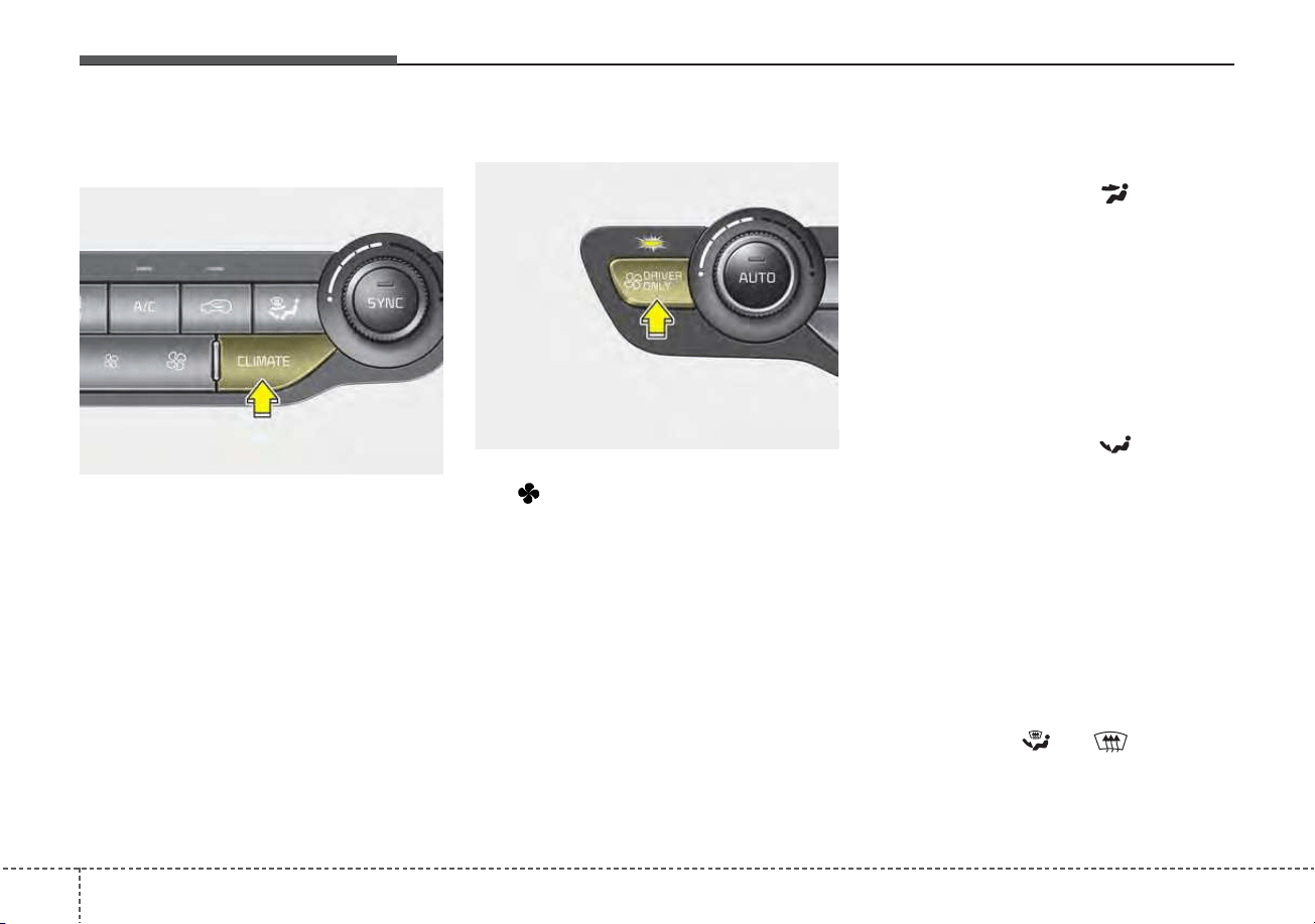
Features of your vehicle
1404
Climate information screen
selection (if equipped)
Press the climate information screen
selection button to display climate
information on the screen.
Driver Only
If you press the DRIVER ONLY but-
ton( ) and the indicator light illumi-
nates, cold air mostly blows in the
direction of the driver’s seat.
However, some of the cold air may
come out of other seats’ ducts to
keep indoor air pleasant.
If you use the button with no passen-
ger in the front passenger seat, ener-
gy consumption will be reduced.
System operation
Ventilation
1.Set the mode to the position.
2.Set the air intake control to the out-
side (fresh) air position.
3.Set the temperature control to the
desired position.
4.Set the fan speed control to the
desired speed.
Heating
1.Set the mode to the position.
2.Set the air intake control to the out-
side (fresh) air position.
3.Set the temperature control to the
desired position.
4.Set the fan speed control to the
desired speed.
5.If dehumidified heating is desired,
turn the air conditioning system (if
equipped) on.
• If the windshield fogs up, set the
mode to the
or position.
ODEP049312
ODE046311
4141
Features of your vehicle
Operation Tips
• To keep dust or unpleasant fumes
from entering the vehicle through
the ventilation system, temporarily
set the air intake control to the
recirculated air position. Be sure to
return the control to the fresh air
position when the irritation has
passed to keep fresh air in the
vehicle. This will help keep the driv-
er alert and comfortable.
• Air for the heating/cooling system
is drawn in through the grilles just
ahead of the windshield. Care
should be taken that these are not
blocked by leaves, snow, ice or
other obstructions.
• To prevent interior fog on the wind-
shield, set the air intake control to
the fresh air position and fan speed
to the desired position, turn on the
air conditioning system, and adjust
the temperature control to desired
temperature.
Air conditioning (if equipped)
All Kia Air Conditioning Systems are
filled with R-1234yf refrigerant.
1.Start the engine. Press the air con-
ditioning button.
2.Set the mode to the position.
3.Set the air intake control to the out-
side air or recirculated air position.
4.Adjust the fan speed control and
temperature control to maintain
maximum comfort.
• When maximum cooling is desired,
set the temperature control to the
extreme left position, set the mode
control to the MAX A/C position,
then set the fan speed control to
the highest speed.
CAUTION - Excessive A/C
Use
When using the air conditioning
system, monitor the tempera-
ture gauge closely while driving
up hills or in heavy traffic when
outside temperatures are high.
Air conditioning system opera-
tion may cause engine over-
heating. Continue to use the
blower fan but turn the air con-
ditioning system off if the tem-
perature gauge indicates engine
overheating.
CAUTION
When opening the windows in
humid weather, air conditioning
may create water droplets
inside the vehicle. Since exces-
sive water droplets may cause
damage to electrical equipment,
air conditioning should only be
used with the windows closed.

Features of your vehicle
1424
Air conditioning system operation tips
• If the vehicle has been parked in
direct sunlight during hot weather,
open the windows for a short time
to let the hot air inside the vehicle
escape.
• To help reduce moisture inside of
the windows on rainy or humid
days, decrease the humidity inside
the vehicle by operating the air
conditioning system.
• During air conditioning system
operation, you may occasionally
notice a slight change in engine
speed as the air conditioning com-
pressor cycles. This is a normal
system operation characteristic.
• Use the air conditioning system
every month only for a few minutes
to ensure maximum system per-
formance.
• When using the air conditioning
system, you may notice clear water
dripping (or even puddling) on the
ground under the passenger side
of the vehicle. This is a normal sys-
tem operation characteristic.
• Operating the air conditioning sys-
tem in the recirculated air position
provides maximum cooling; howev-
er, continual operation in this mode
may cause the air inside the vehi-
cle to become stale.
• During cooling operation, you may
occasionally notice a misty air flow
because of rapid cooling and
humid air intake. This is a normal
system operation characteristic.
Automatic ventilation
The system automatically selects the
outside (fresh) air position when the
climate control system operates over
a certain period of time (5 minutes)
in low temperature with the recircu-
lated air position selected. (when
floor mode or bi-level mode)
To cancel or reset the Automatic
Ventilation
When the air conditioning system is
on, select Face Level ( ) mode
and while pressing the A/C button,
press the air intake control button 5
times within 3 seconds.
When the automatic ventilation func-
tion is canceled, the indicator light
blinks 3 times at an interval of 0.5
seconds.
The air intake will be automatically
controlled to the fresh air position,
and the flow and air conditioning will
be automatically controlled.
When the automatic ventilation func-
tion is selected, the indicator light
blinks 6 times at an interval of 0.25
seconds.
The air intake will be automatically
controlled to the fresh air position,
and the flow and air conditioning will
be automatically controlled.
After the battery has been dis-
charged or separated, the automatic
ventilation function will be reset, so
please selected, according to you
preference.

4143
Features of your vehicle
Sunroof inside air recircula-
tion (if equipped)
The outside (fresh) air position is
automatically selected when the sun-
roof is opened.
When you select the recirculated air
position, the system maintains the
recirculated air position for 3 minutes
and then automatically converts to
the outside (fresh) air position.
When the sunroof is closed, the air
intake position will return to the orig-
inal position that was selected.
Recirculated air at washer
fluid spray
To prevent the odor from entering to
inside the vehicle, the ventilation sys-
tem changes to Recirculated Air
Mode for a while when the wind-
shield washer fluid sprayed.
However, at low outside temperature,
to prevent from windshield fogging,
the system continues to outside air
mode.
System setting
1. ENGINE START/STOP button is
On or ignition switch ON.
2. Select Floor-Level ( ) air flow
direction by pressing
Mode Selection button.
3. With pressing Air Conditioning but-
ton, press the Recirculated Air but-
ton more than 4 times within 2
seconds.
4. If the system is set up, the indica-
tor on Recirculated Air button will
blinks 6 times.
System cancellation
1. ENGINE START/STOP button is
On or ignition switch ON.
2. Select Floor-Level ( ) air flow
direction by pressing
Mode Selection button.
3. With pressing Air Conditioning but-
ton, press the Recirculated Air but-
ton more than 4 times within 2
seconds.
4. If the system is cancelled, the indi-
cator on Recirculated Air button
will blinks 3 times.
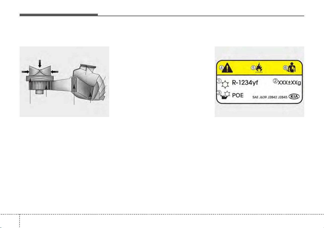
Features of your vehicle
1444
Climate control air filter
(if equipped)
The climate control air filter installed
behind the glove box filters the dust
or other pollutants that come into the
vehicle from the outside through the
heating and air conditioning system.
If dust or other pollutants accumulate
in the filter over a period of time, the
air flow from the air vents may
decrease, resulting in moisture accu-
mulation on the inside of the wind-
shield even when the outside (fresh)
air position is selected. If this hap-
pens, have the climate control air fil-
ter replaced by an authorized Kia
dealer.
✽✽
NOTICE
• Replace the filter according to the
Maintenance Schedule.
If the vehicle is being driven in
severe conditions such as dusty or
rough roads, more frequent air
conditioner filter inspections and
changes are required.
• When the air flow rate suddenly
decreases, the system should be
checked at an authorized Kia
dealer.
Air Conditioning refrigerant
label
❈ The actual Air Conditioning refrig-
erant label in the vehicle may differ
from the illustration.
1LDA5047
Outside air
Recirculated
air
Climate control
air filter
Blower
Evaporator
core
Heater core
ODEP069032N
■ Example
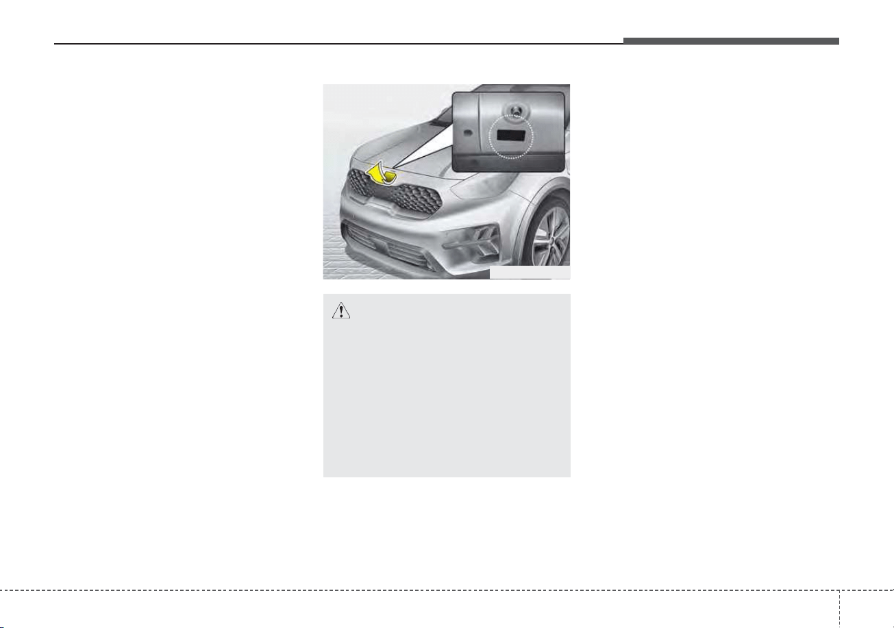
4145
Features of your vehicle
Each symbol and specification on
the air conditioning refrigerant label
is represented below :
1. Classification of refrigerant
2. Amount of refrigerant
3. Classification of Compressor lubri-
cant
4. Caution
5. Flammable Refrigerant
6. To requires Registered Technician
to Service Air Conditioning system
Refer to chapter 8 for more detail on
the location of air conditioning refrig-
erant label.
Checking the amount of air
conditioner refrigerant and
compressor lubricant
When the amount of refrigerant is
low, the performance of the air condi-
tioning is reduced. Overfilling also
has a negative impact on the air con-
ditioning system.
Therefore, if abnormal operation is
found, have the system inspected by
an authorized Kia dealer.
ODEP089004L
CAUTION - AC Repair
It is important that the correct
type and amount of oil and
refrigerant is used, otherwise
damage to the vehicle may
occur. To prevent damage, the
air conditioning system in your
vehicle should only be serviced
by trained and certified techni-
cians.
Features of your vehicle
1464
WARNING - Vehicles
equipped with R-1234yf
Since the refrigerant
is mildly flammable
and operated at high
pressure, the air con-
ditioning system
should only be serv-
iced by trained and
certified technicians.
(Refer to the SAE
J2845)
It is important that the correct
type and amount of oil and
refrigerant are used.
All refrigerants should be
reclaimed with proper equip-
ment.
Venting refrigerants directly to
the atmosphere is harmful to
individuals and environment.
Failure to heed these warnings
can lead to serious injuries.
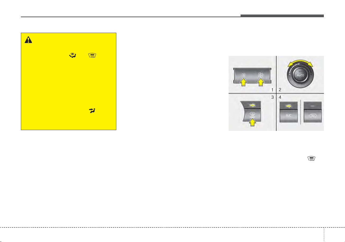
4147
Features of your vehicle
• For maximum defrosting, set the
temperature control to the extreme
right/hot position and the fan speed
control to the highest speed.
• If warm air to the floor is desired
while defrosting or defogging, set
the mode to the floor-defrost posi-
tion.
• Before driving, clear all snow and
ice from the windshield, rear win-
dow, outside rear view mirrors, and
all side windows.
• Clear all snow and ice from the
hood and air inlet in the cowl grill to
improve heater and defroster effi-
ciency and to reduce the probabili-
ty of fogging up the inside of the
windshield.
Automatic climate control
system
To defog inside windshield
1. Set the fan speed to the desired
position.
2. Select desired temperature.
3. Press the defroster button ( ).
4. The outside (fresh) air position will
be selected automatically and the
air conditioning will turn on accord-
ing to the detected ambient tem-
perature.
WINDSHIELD DEFROSTING AND DEFOGGING
WARNING - Windshield
heating
Do not use the or posi-
tion during cooling operation in
extremely humid weather. The
difference between the temper-
ature of the outside air and the
windshield could cause the
outer surface of the windshield
to fog up, causing loss of visi-
bility. If this occurs, set the
mode selection to the posi-
tion and fan speed control to
the lower speed.
ODE046314
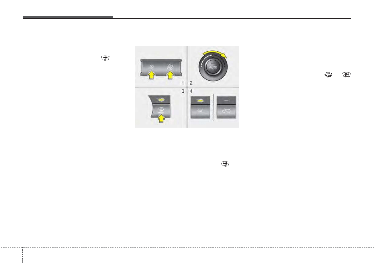
Features of your vehicle
1484
If the air conditioning and outside
(fresh) air position are not selected
automatically, adjust the correspon-
ding button manually. If the posi-
tion is selected, lower fan speed is
adjusted to a higher fan speed.
To defrost outside windshield
1. Set the fan speed to the highest
position.
2. Set the temperature to the
extreme hot (HI) position.
3. Press the defroster button ( ).
4. The outside (fresh) air position will
be selected automatically and the
air conditioning will turn on
according to the detected ambient
temperature.
Defogging logic
To reduce the possibility of fogging
up the inside of the windshield, the
air intake or air conditioning is con-
trolled automatically according to
certain conditions such as or
position. To cancel automatic defog-
ging logic or return to the automatic
defogging logic, do the following.
ODE046315
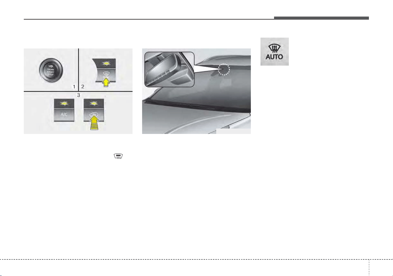
4149
Features of your vehicle
Automatic climate control system
1. Turn the ignition switch to the ON
position.
2. Press the defroster button ( ).
3. While pressing the air conditioning
button (A/C), press the air intake
control button at least 5 times with-
in 3 seconds.
The recirculation indicator blinks 3
times with 0.5 second of interval. It
indicates that the defogging logic is
canceled or returned to the pro-
grammed status.
If the battery has been discharged or
disconnected, it resets to the defog
logic status.
Auto defogging system
Auto defogging reduces the probabil-
ity of fogging up the inside of the
windshield by automatically sensing
the moisture of inside the windshield.
The auto defogging system operates
when the heater or air conditioning is
on.
This indicator illuminates
when the auto defogging
system senses the mois-
ture on the inside of the
windshield and operates.
If more moisture is in the vehicle,
higher steps operate as follow. For
example if auto defogging does not
defog inside the windshield at step 1
Outside air position, it tries to defog
again at step 2 Operating the air con-
ditioning.
Step 1 : Outside air position
Step 2 : Operating the air condition-
ing
Step 3 : Blowing air flow toward the
windshield
Step 4 : Increasing air flow toward
the windshield
ODEP049433 ODE046316
Features of your vehicle
1504
To cancel or reset the Auto Defogging
System
Press the front windshield defroster
button for 3 seconds when the igni-
tion switch is in the ON position.
When the ADS system is canceled,
ADS OFF symbol will blink 3 times
per 0.5 sec and ADS OFF will be dis-
played on the climate control infor-
mation screen.
When the ADS system is reset, ADS
OFF symbol will blink 6 times per
0.25 sec and ADS OFF will be disap-
pear on the climate control informa-
tion screen.
CAUTION
Do not remove the sensor cover
located on the upper end of the
passenger side windshield
glass. Damage to the system
parts could occur and may not
be covered by your vehicle war-
ranty.
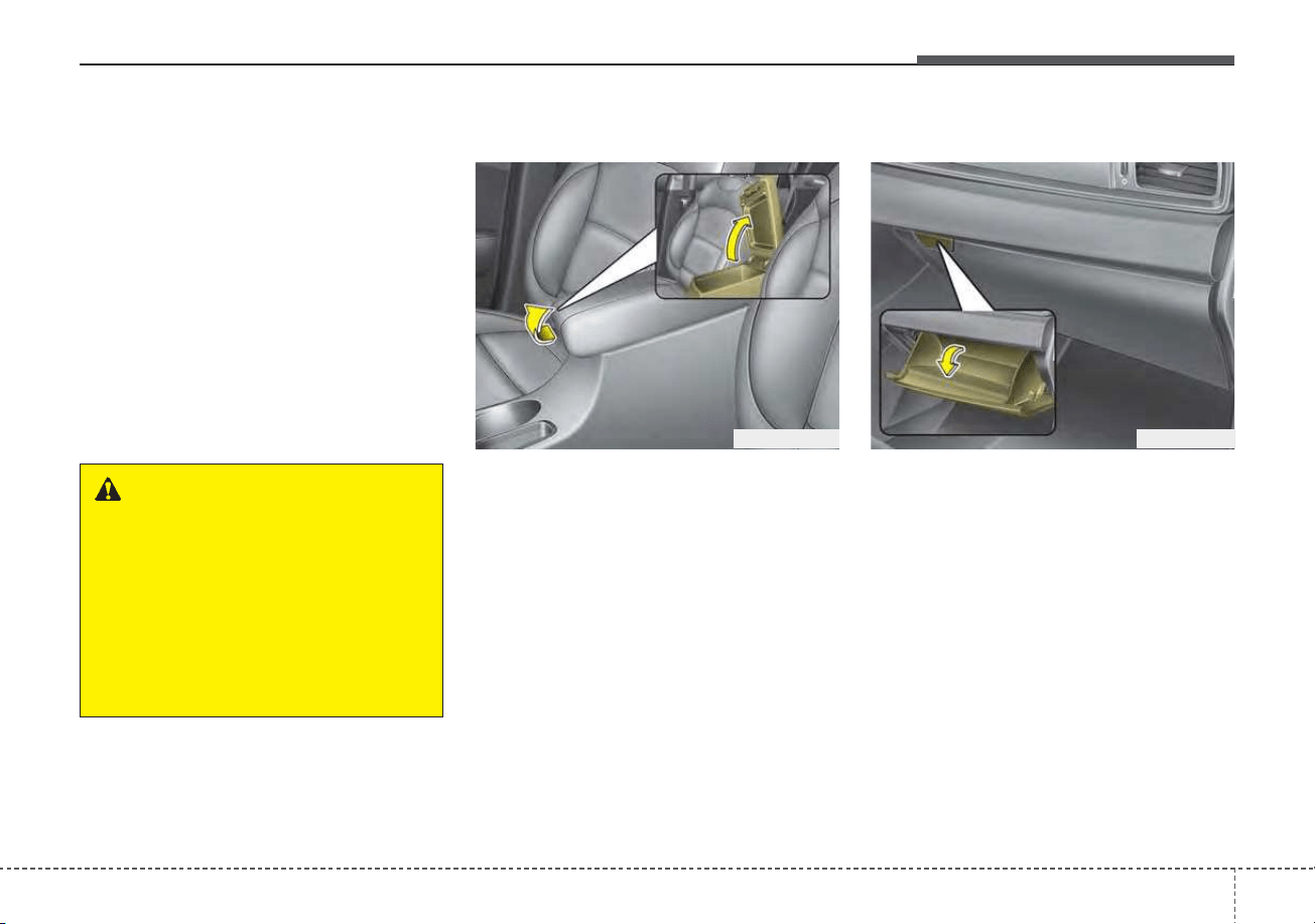
4151
Features of your vehicle
STORAGE COMPARTMENTS
These compartments can be used to
store small items required by the
driver or passengers.
• To avoid possible theft, do not
leave valuables in the storage
compartment.
• Always keep the storage compart-
ment covers closed while driving.
Do not attempt to place so many
items in the storage compartment
that the storage compartment
cover can not close securely.
Center console storage
To open the center console storage,
pull up the lever.
Glove box
To open the glove box, push the lever
and the glove box will automatically
open. Close the glove box after use.
WARNING - Flammable
materials
Do not store propane cylinders
or other flammable/explosive
materials in the vehicle. These
items may catch fire and/or
explode if the vehicle is
exposed to hot temperatures for
extended periods.
ODE046416ODE046415
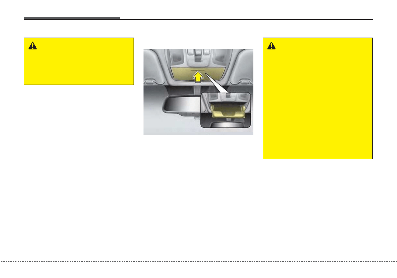
Features of your vehicle
1524
✽✽
NOTICE
If the temperature control knob is in
the warm or hot position, warm or
hot air will flow into the glove box.
Sunglass holder
To open the sunglass holder, press
the cover and the holder will slowly
open. Place your sunglasses with the
lenses facing out.
To close the sunglass holder push it
up.
WARNING - Glove Box
To reduce the risk of injury in an
accident or sudden stop, always
keep the glove box door closed
while driving.
WARNING - Sunglass
holder
• Do not keep objects except
sunglasses inside the sun-
glass holder. Such objects
can be thrown from the holder
in the event of a sudden stop
or an accident, possibly injur-
ing the passengers in the
vehicle.
• Do not open the sunglass
holder while the vehicle is
moving. The rear view mirror
of the vehicle can be blocked
by an opened sunglass holder.
ODEP049417N
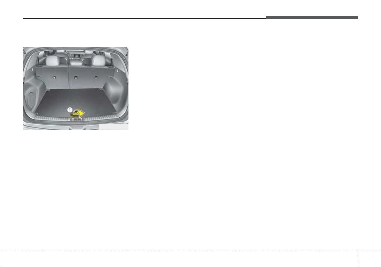
4153
Features of your vehicle
Luggage box (if equipped)
You can place tools, etc. in the box
for easy access.
Grasp the handle (1) on the edge of
the cover and lift it.
ODE046428N
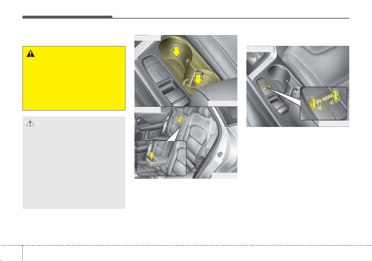
Features of your vehicle
1544
Cup holder
Cups or small beverage cans may be
placed in the cup holders.
Seat warmer (if equipped)
The seat warmer is provided to warm
the front seats during cold weather.
With the ignition switch in the ON
position, push either of the switches
to warm the driver's seat or the front
passenger's seat.
During mild weather or under condi-
tions where the operation of the seat
warmer is not needed, keep the
switches in the “OFF” position.
INTERIOR FEATURES
WARNING - Hot liquids
Do not place uncovered cups
with hot liquid in the cup holder
while the vehicle is in motion. If
the hot liquid spills, you may
burn yourself. Such a burn to
the driver could lead to loss of
control of the vehicle.
ODEP049418
■ Front seat
■ Rear seat
ODE046444
CAUTION
• Keep your drinks sealed while
driving to prevent spilling
your drink. If liquid spills, it
may get into the vehicle's
electrical/electronic system
and damage electrical/elec-
tronic parts.
• When cleaning spilled liquids,
do not use heat to dry the cup
holders. This may damage the
cup holder.
ODEP049422
■ Front seat
4155
Features of your vehicle
Temperature control (Manual)
• Each time you press the switch,
the temperature setting of the seat
will change as follows :
■ Front seat
• The seat warmer defaults to the
OFF position whenever the ignition
switch is turned on.
Temperature control(Automatic)
The seat warmer starts to automati-
cally control the seat temperature in
order to prevent low-temperature
burns after being manually turned
ON.
■ Front seat
You may manually press the button
to increase the seat temperature.
However, it soon returns to the auto-
matic mode again when pressing the
switch for more than 1.5 seconds
with the seat warmer operating, the
seat warmer will turn OFF. The seat
warmer defaults to the OFF position
whenever the Engine Start/Stop but-
ton is in the ON position.
✽✽
NOTICE
With the seat warmer switch in the
ON position, the heating system in
the seat turns off or on automatical-
ly depending on the seat tempera-
ture.
▼
▼
OFF→HIGH( )→MIDDLE( )→LOW( )
→
OFF→HIGH( )→MIDDLE( )→LOW( )
→
→
30min
60min
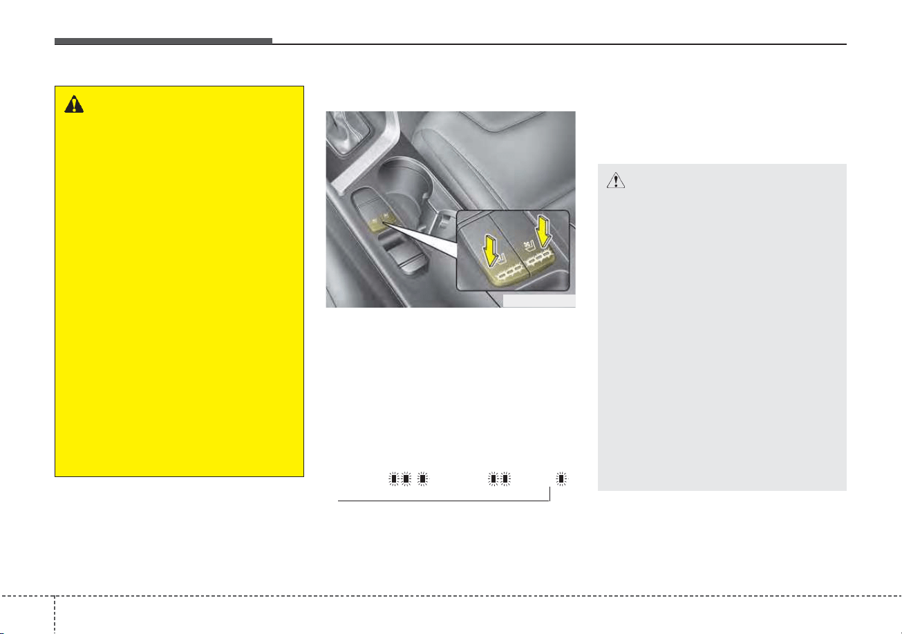
Features of your vehicle
1564
Air ventilation seat (if equipped)
The temperature setting of the seat
changes according to the switch
position.
• If you want to ventilate your seat
cushion, press the switch (blue
color).
• Each time you press the button,
the airflow will change as follows:
• The seat warmer (with air ventila-
tion) defaults to the OFF position
whenever the ignition switch is
turned on.
OFF→HIGH( )→MIDDLE( )→LOW( )
→
CAUTION - Seat damage
• When cleaning the seats, do
not use an organic solvent
such as paint thinner, ben-
zene, alcohol and gasoline.
Doing so may damage the air
ventilation seat.
• Do not place heavy or sharp
objects on the seat. Those
things may damage the air
ventilation seat.
• Be careful not to spill liquid
such as water or beverages on
the seat. If you spill some liq-
uid, wipe the seat with a dry
towel. Before using the air
ventilation seat, dry the seat
completely.
ODEP049423
WARNING - Seat warmer
burns
The seat warmer may cause
burns, even at low tempera-
tures, if used over a long period
of time. Never allow passengers
who may not be able to take
care of themselves to be
exposed to the risk of seat
heater burns. These include:
1. Infants, children, elderly or
disabled persons, or hospital
outpatients
2. Persons with sensitive skin
or those that burn easily
3. Fatigued individuals
4. Intoxicated individuals
5. Individuals taking medication
that can cause drowsiness or
sleepiness (sleeping pills,
cold tablets, etc.)
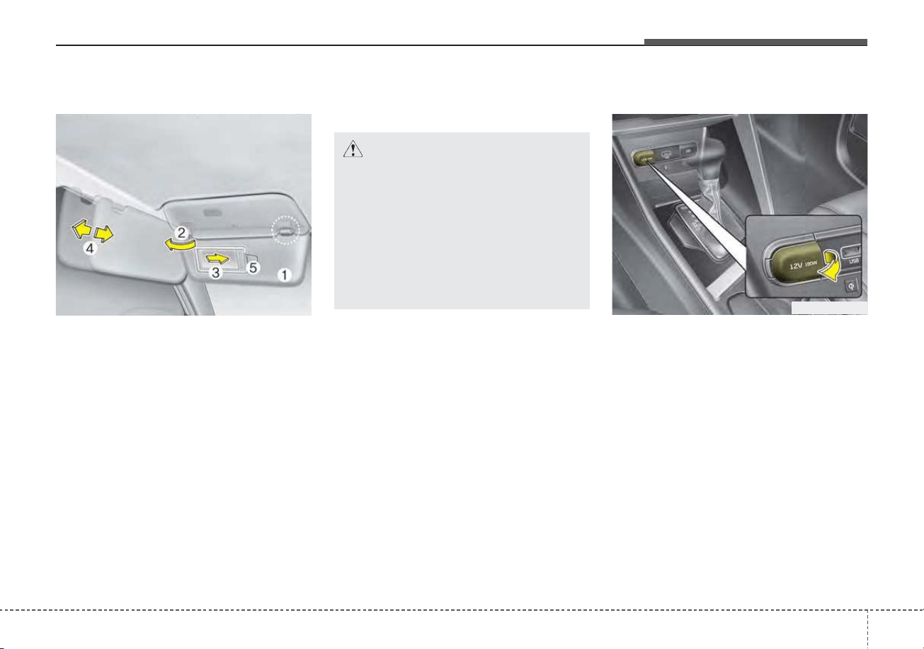
4157
Features of your vehicle
Sunvisor
Use the sunvisor to shield direct light
through the front or side windows.
To use the sunvisor, pull it downward.
To use the sunvisor for the side win-
dow, pull it downward, unsnap it from
the bracket (1) and swing it to the
side (2).
To use the vanity mirror, pull down the
visor and slide the mirror cover (3).
Adjust the sunvisor extension for-
ward or backward (4).
The ticket holder (5) is provided for
holding a tollgate ticket.
* The actual sunvisor lamp in the vehi-
cle may differ from the illustration.
Power outlet (if equipped)
The power outlet is designed to pro-
vide power for mobile telephones or
other devices designed to operate
with vehicle electrical systems. The
devices should draw less than 10
amps with the engine running.
• Use the power outlet only when the
engine is running and remove the
accessory plug after use. Using the
accessory plug for prolonged peri-
ods of time with the engine off could
cause the battery to discharge.
CAUTION - Vanity mirror
lamp
If you use the vanity mirror
lamp, turn off the lamp before
returning the sunvisor to its
original position, otherwise it
could result in battery dis-
charge and possible sunvisor
damage.
ODEP049421
OJF045121
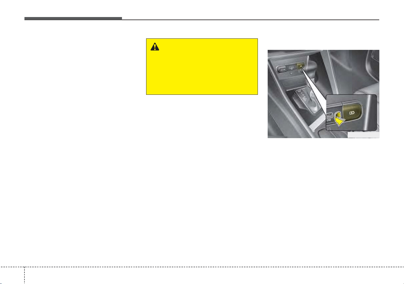
Features of your vehicle
1584
• Only use 12V electric accessories
which are less than 10A in electric
capacity.
• Adjust the air-conditioner or heater
to the lowest operating level when
using the power outlet.
• Close the cover when not in use.
• Some electronic devices can cause
electronic interference when
plugged into a vehicle’s power out-
let. These devices may cause
excessive audio static and malfunc-
tions in other electronic systems or
devices used in your vehicle.
• Push the plug in as far as it will go.
If good contact is not made, the
plug may overheat and the fuse
may open.
• Plug in battery equipped electronic
devices with reverse current pro-
tection. The current from the bat-
tery may flow into the vehicle’s
electri cal/electronic system and
cause system malfunction.
USB charger (if equipped)
The USB charger is designed to
recharge batteries of small size elec-
trical devices using a USB cable. The
electrical devices can be recharged
when the Engine Start/Stop button is
in ACC/ON/START position.
The battery charging state may be
monitored on the electrical device.
Disconnect the USB cable from the
USB port after use.
• Some devices are not supported
for fast charging but will be
charged with normal speed.
WARNING - Electric shock
Do not put a finger or a foreign
object (pen, etc.) into a power
outlet and do not touch with a
wet hand. You may receive an
electric shock.
ODEP049532
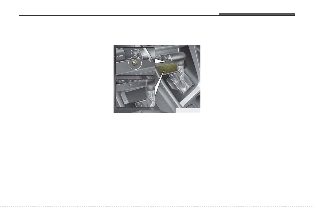
4159
Features of your vehicle
• Use the USB charger when the
engine is running to prevent bat-
tery discharge.
• Only devices that fit the USB port
can be used.
• The USB charger can be used only
for battery charging purposes.
• Battery chargers cannot be
charged.
Wireless smart phone charg-
ing system (if equipped)
A wireless smart phone charging
system is located in front of the cen-
ter console
Firmly close all doors, and turn the
ignition to ACC or IGN ON. To start
wireless charging, place the smart
phone equipped with wireless charg-
ing function on the wireless charging
pad.
For best wireless charging results,
place the smart phone on the center
of the charging pad.
The wireless charging system is
designed for one smart phone
equipped with QI per single usage
only. Please refer to the smart phone
accessory cover or the smart phone
manufacturer homepage to check
whether your smart phone supports
QI function.
ODEP049424
Features of your vehicle
1604
Wireless smart phone charging
1. Remove any object on the smart
phone charging pad including the
smart key. If there is any foreign
object on the pad other than a
smart phone, the wireless charging
function may not operate properly.
2. Place the smart phone on the cen-
ter of the wireless charging pad.
3. The indicator light will change to
orange once the wireless charging
begins. After the charging is com-
plete, the orange light will change
to green.
4. You can choose to turn the wireless
charging function to either ON or
OFF by selecting the USM on the
instrument cluster. (Please refer to
“Instrument Cluster” for details).
If the wireless charging does not
work, gently move your smart phone
around the pad until the charging
indicator light turns orange.
Depending on the smart phone, the
charging indicator light may not turn
green even after the charging is com-
plete.
If the wireless charging is not func-
tioning properly, the orange light will
blink and flash for ten seconds then
turn off. In such cases, remove the
smart phone from the pad and
replace it on the pad again, or double
check the charging status.
If you leave the smart phone on the
charging pad when the vehicle igni-
tion is in OFF, the vehicle will alert
you through warning messages and
sound (applicable for vehicles with
voice guidance function) after the
‘Good bye’ function on the instru-
ment cluster ends.
WARNING - Distracted
driving
Driving while distracted can
result in a loss of vehicle con-
trol that may lead to an acci-
dent, severe personal injury,
and death. The driver’s primary
responsibility is in the safe and
legal operation of a vehicle, and
any handheld devices, other
equipment, or vehicle systems
which take the driver’s eyes,
attention and focus away from
the safe operation of a vehicle
or which are not permissible by
law should never be used dur-
ing operation of the vehicle.

4161
Features of your vehicle
✽✽
NOTICE
• When the interior temperature of
the wireless charging system rises
above a set temperature, the wire-
less charging will cease to func-
tion. After the interior tempera-
ture drops below the threshold,
the wireless charging function will
resume.
• The wireless charging may not
function properly when there is a
heavy accessory cover on the
smart phone.
• The wireless charging will stop
when using the wireless smart key
search function to prevent radio
wave disruption.
• The wireless charging will stop
when the smart key is moved out
of the vehicle with the ignition in
ON.
• The wireless charging will stop
when any of the doors is opened
(applicable for vehicles equipped
with smart keys).
(Continued)
(Continued)
• The wireless charging will stop
when the vehicle is turned OFF.
• The wireless charging will stop
when the smart phone is not in
complete contact with the wireless
charging pad.
• Items equipped with magnetic
components such as credit card,
telephone card, bankbook or any
transportation ticket may become
damaged during wireless charg-
ing.
• Place the smart phone on the cen-
ter of the charge pad for best
results. The smart phone may not
charge when placed near the rim
of the charging pad. When the
smart phone does get charged, it
may heat up excessively.
• For smart phones without built-in
wireless charging system, an
appropriate accessory has to be
equipped in order to use the vehi-
cle's wireless charging system.
(Continued)
CAUTION - Liquid in
Wireless Smart Phone
Charger
To prevent liquid from damag-
ing the wireless smart phone
charging system in your vehi-
cle, be sure not to spill liquid
over the charging system when
charging your phone.
CAUTION - Metal in
Wireless Charging System
If any metallic object such as a
coin is located between the
wireless charging system and
the smart phone, the charging
may be disrupted. Also, the
metallic object may heat up and
potentially damage the charging
system. If there is any metallic
object between the smart phone
and the charging pad, immedi-
ately remove the smart phone.
Remove the metallic object after
it has cooled down.
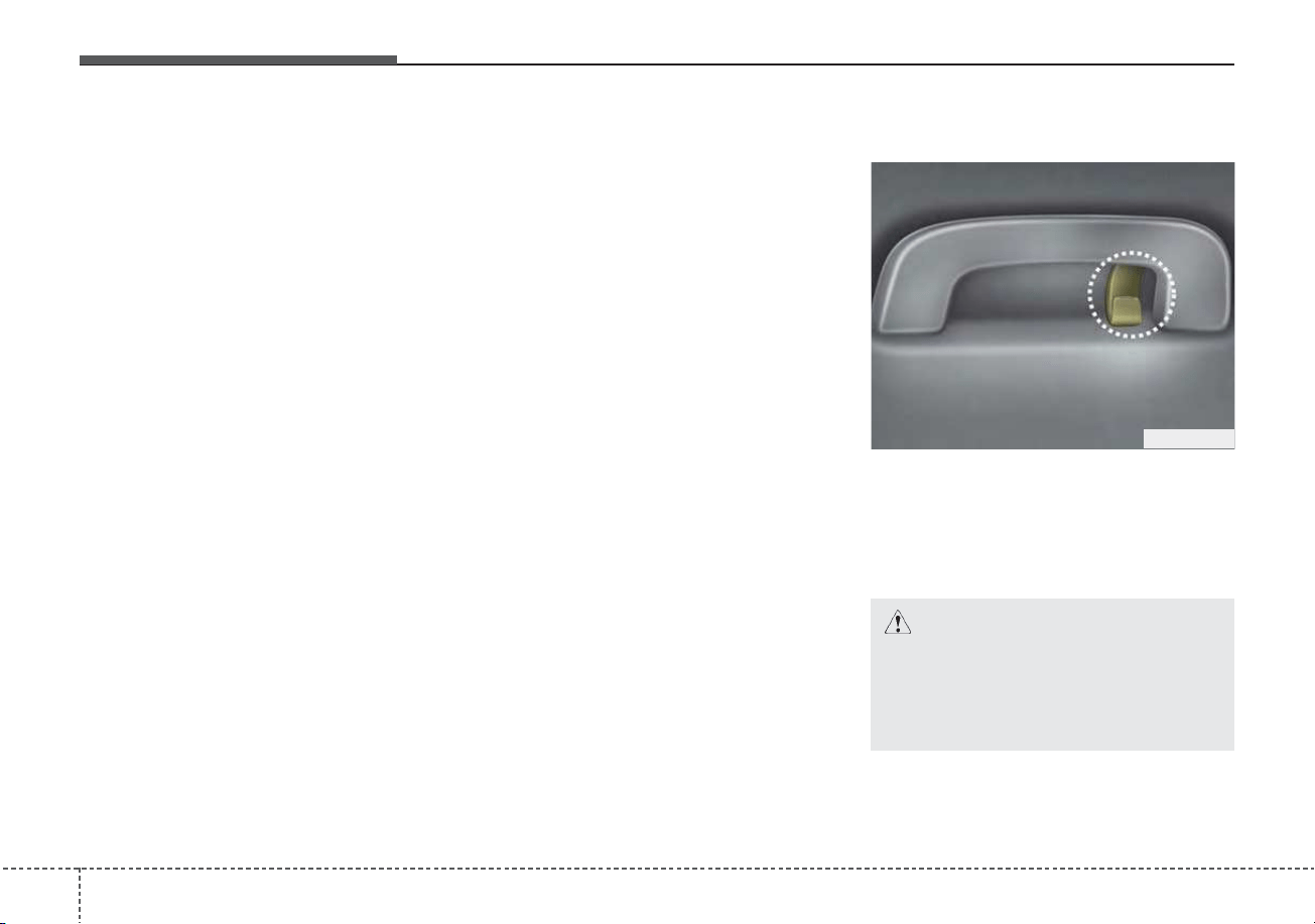
Features of your vehicle
1624
(Continued)
• Smart phones of some manufac-
turers may display messages on
weak current. This is due to the
particular characteristic of the
smart phone and does not imply a
malfunction on wireless charging
function.
• The indicator light of some manu-
facturers’ smart phones may still
be orange after the smart phone is
fully charged. This is due to the
particular characteristic of the
smart phone and not a malfunc-
tion of the wireless charging.
• When any smart phone without a
wireless charging function or a
metallic object is placed on the
charging pad, a small noise may
sound. This small sound is due to
the vehicle discerning compatibili-
ty of the object placed on the
charging pad. It does not affect
your vehicle or the smart phone in
any way.
This device complies with part 15
of the FCC Rules
Operation is subject to the follow-
ing two conditions:
(1) This device may not cause harm-
ful interference, and
(2) this device must accept any inter-
ference received, including inter-
ference that may cause unde-
sired operation.
Clothes hanger
❈ This actual feature may differ from the illus-
tration.
A Coat hook is next to the rear grab
handle.
ODE046425
CAUTION - Hanging
clothing
Do not hang heavy clothes,
since they may damage the
hook.
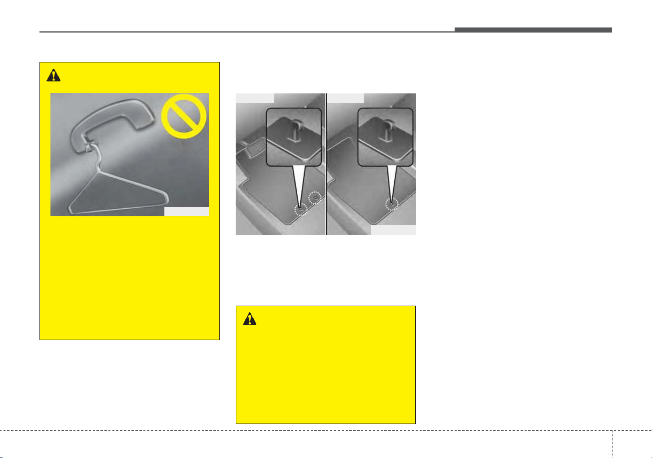
4163
Features of your vehicle
Floor mat anchor(s)
(if equipped)
When using a floor mat on the front
floor carpet, make sure it attaches to
the floor mat anchor(s) in your vehi-
cle. This keeps the floor mat from
sliding forward.
The following must be observed
when installing ANY floor mat to the
vehicle.
• Ensure that the floor mats are
securely attached to the vehicle's
floor mat anchor(s) before driving
the vehicle.
• Do not use ANY floor mat that can-
not be firmly attached to the vehi-
cle's floor mat anchors.
• Do not stack floor mats on top of
one another (e.g. all-weather rub-
ber mat on top of a carpeted floor
mat). Only a single floor mat should
be installed in each position.
✽✽
NOTICE
Your vehicle was manufactured with
driver's side floor mat anchors that
are designed to securely hold the
floor mat in place. To avoid any
interference with pedal operation,
Kia recommends that only the Kia
floor mat designed for use in your
vehicle be installed.
OXM043309
■ Type A
■ Type B
WARNING - After market
floor mat
Do not install aftermarket floor
mats that are not capable of
being securely attached to the
vehicle's floor mat anchors.
Unsecured floor mats can inter-
fere with pedal operation.
WARNING
Do not hang other objects such
as hangers or hard objects from
the clothes hanger. Also, do not
put heavy, sharp or breakable
objects in the clothing’s pock-
ets. In an accident or when the
curtain air bag is inflated, it may
cause vehicle damage or per-
sonal injury.
OPS046500
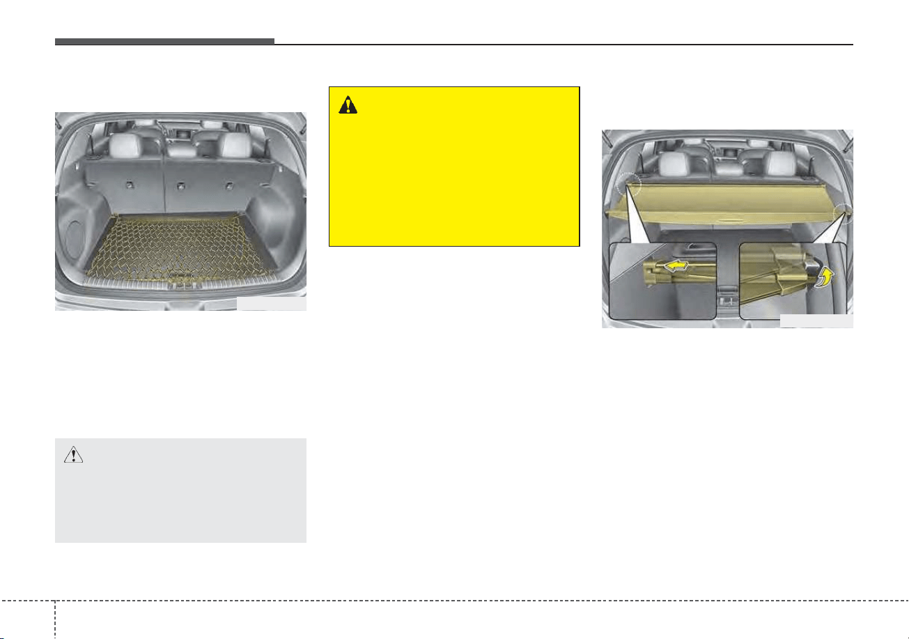
Features of your vehicle
1644
Luggage net holder
To keep items from shifting in the
cargo area, you can use the holders
located in the cargo area to attach
the luggage net.
If necessary, we recommend that
you contact an authorized Kia dealer.
Cargo security screen
(if equipped)
Use the cargo security screen to
hide items stored in the cargo area.
To use the cargo security screen,
pull the handle backward and insert
the edges into the slots.
WARNING - Luggage net
Always keep your face and
body out of the luggage net
recoil path and avoid using the
luggage net when the straps
have visible signs of wear or
damage. The luggage net can
snap and cause injuries.
CAUTION
To prevent damage to the vehi-
cle, care should be taken when
carrying fragile or bulky objects
in the luggage compartment.
ODE046426N
ODE046429L
4165
Features of your vehicle
WARNING - Cargo
Security Screen
Do not place objects on the
cargo security screen. Such
objects may be thrown about
inside the vehicle and possibly
injure vehicle occupants during
an accident or when braking.
CAUTION
Do not place luggage on the
cargo security screen. This may
cause the security screen to
become damaged or malformed.
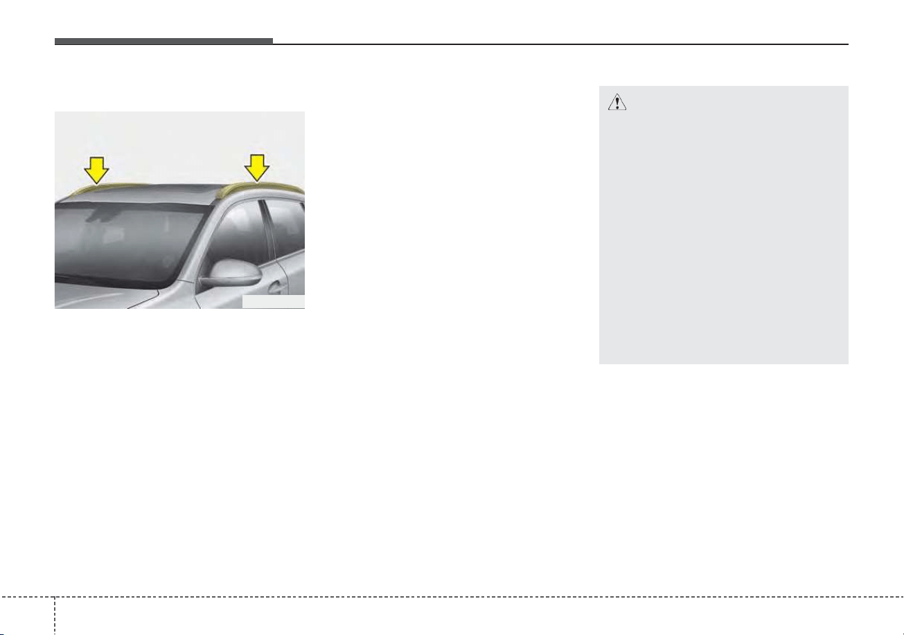
Features of your vehicle
1664
Roof rack
If the vehicle has a roof rack, you can
load cargo on top of your vehicle.
Crossbars and fixing components
can be installed on the roof rack
when carrying cargo. Those may be
obtained from an authorized Kia
dealer.
✽✽
NOTICE
• The crossbars (if equipped) should
be placed in the proper load carry-
ing positions prior to placing items
onto the roof rack.
• If the vehicle is equipped with a
sunroof, be sure not to position
cargo onto the roof rack in such a
way that it could interfere with
sunroof operation.
• When the roof rack is not being
used to carry cargo, the crossbars
may need to be repositioned if
wind noise is detected.
EXTERIOR FEATURES
CAUTION - Loading Roof
Rack
• When carrying cargo on the
roof rack, take the necessary
precautions to make sure the
cargo does not damage the
roof of the vehicle.
• When carrying large objects
on the roof rack, make sure
they do not exceed the overall
roof length or width.
• When you are carrying cargo
on the roof rack, do not oper-
ate the sunroof (if equipped).
This can damage the sunroof.
ODE046432
4167
Features of your vehicle
• The following specification is the
maximum weight that can be loaded
onto the roof rack. Distribute the
load as evenly as possible across
the crossbars (if equipped) and roof
rack and secure the load firmly.
Loading cargo or luggage in excess
of the specified weight limit on the
roof rack may damage your vehicle.
• The vehicle center of gravity will be
higher when items are loaded onto
the roof rack. Avoid sudden starts,
braking, sharp turns, abrupt maneu-
vers or high speeds that may result
in loss of vehicle control or rollover
resulting in an accident.
• Always drive slowly and turn corners
carefully when carrying items on the
roof rack. Severe wind updrafts,
caused by passing vehicles or natu-
ral causes, can cause sudden
upward pressure on items loaded on
the roof rack. This is especially true
when carrying large, flat items such
as wood panels or mattresses. This
could cause the items to fall off the
roof rack and cause damage to your
vehicle or others around you.
• To prevent damage or loss of cargo
while driving, check frequently
before or while driving to make sure
the items on the roof rack are
securely fastened.
ROOF 100 kg (220 lbs.)
RACK EVENLY DISTRIBUTED
WARNING - Driving with
roof load
Always drive slowly and turn
corners carefully when carrying
items on the roof rack. The vehi-
cle's center of gravity will be
higher when items are loaded
onto the roof rack.
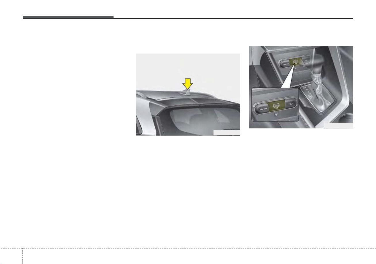
Features of your vehicle
1684
✽✽
NOTICE
If you install an after market HID
head lamp, your vehicle’s audio and
electronic device may malfunction.
❈ If your vehicle is equipped with
Infotainment system, refer to a
separately supplied manual for
detailed information.
Antenna
Shark fin antenna
The shark fin antenna will receive the
transmit data.
USB port
You can use an USB port to plug in
an USB.
✽✽
NOTICE
When using a portable audio device
connected to the power outlet, noise
may occur during playback. If this
happens, use the power source of the
portable audio device.
INFOTAINMENT SYSTEM
ODE046438
ODEP049439
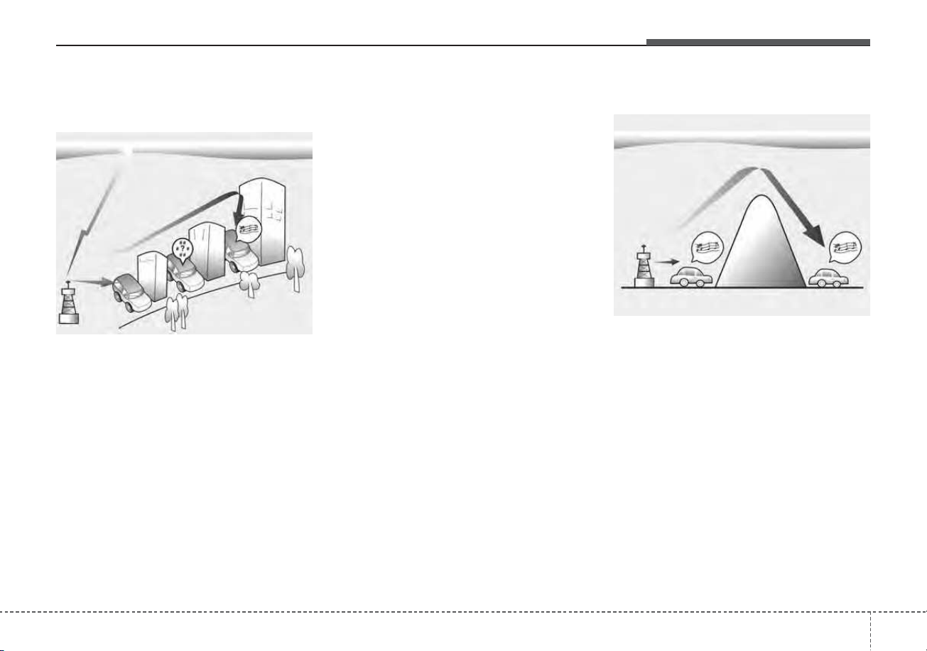
4169
Features of your vehicle
How vehicle radio works
FM reception
AM and FM radio signals are broad-
cast from transmitter towers located
around your city. They are intercept-
ed by the radio antenna on your vehi-
cle. This signal is then processed by
the radio and sent to your vehicle
speakers.
However, in some cases the signal
coming to your vehicle may not be
strong and clear.
This can be due to factors such as
the distance from the radio station,
closeness of other strong radio sta-
tions or the presence of buildings,
bridges or other large obstructions in
the area.
AM reception
AM broadcasts can be received at
greater distances than FM broad-
casts. This is because AM radio
waves are transmitted at low fre-
quencies. These long distance,low
frequency radio waves can follow the
curvature of the earth rather than
travelling straight. In addition, they
curve around obstructions resulting
in better signal coverage.
OJF045308L
OJF045309L
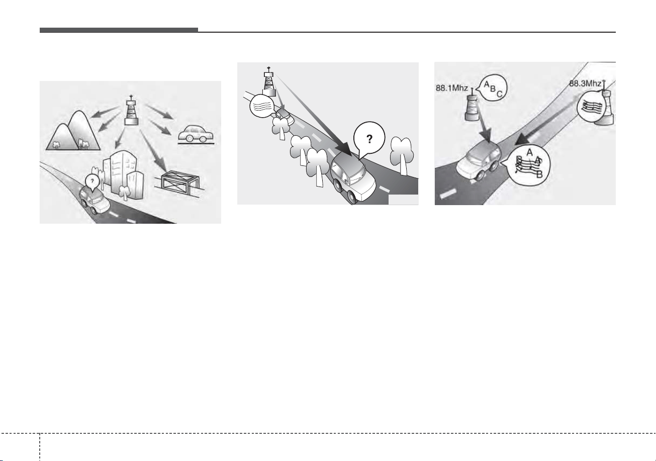
Features of your vehicle
1704
FM radio station
FM broadcasts are transmitted at
high frequencies and do not bend to
follow the earth's surface. Because
of this, FM broadcasts generally
begin to fade within short distances
from the station. Also, FM signals are
easily affected by buildings, moun-
tains, and obstructions. This can lead
to undesirable or unpleasant listen-
ing conditions which might lead you
to believe a problem exists with your
radio. The following conditions are
normal and do not indicate radio
trouble:
• Fading - As your vehicle moves
away from the radio station, the
signal will weaken and sound will
begin to fade. When this occurs,
we suggest that you select another
station with a stronger signal.
• Flutter/Static - Weak FM signals or
large obstructions between the
transmitter and your radio can dis-
turb the signal causing static or
fluttering noises to occur. Reducing
the treble level may lessen this
effect until the disturbance clears.
• Station Swapping - As an FM sig-
nal weakens, another more power-
ful signal near the same frequency
may begin to play. This is because
your radio is designed to lock onto
the clearest signal. If this occurs,
select another station with a
stronger signal.
• Multi-Path Cancellation - Radio sig-
nals being received from several
directions can cause distortion or
fluttering. This can be caused by a
direct and reflected signal from the
same station, or by signals from
two stations with close frequencies.
If this occurs, select another station
until the condition has passed.
OJF045310L
JBM004 OJF045311L
4171
Features of your vehicle
Using a cellular phone or a two-
way radio
When a cellular phone is used inside
the vehicle, noise may be produced
from the audio system. This does not
mean that something is wrong with
the audio equipment. In such a case,
try to operate mobile devices as far
from the audio equipment as possible.
When using a communication sys-
tem such as a cellular phone or a
radio set inside the vehicle, a sepa-
rate external antenna must be fitted.
When a cellular phone or a radio set
is used with an internal antenna
alone, it may interfere with the vehi-
cle's electrical system and adversely
affect safe operation of the vehicle.
WARNING - Cell phone use
Do not use a cellular phone
while driving. Stop at a safe
location to use a cellular phone.
WARNING - Distracted
driving
Driving while distracted can
result in a loss of vehicle control
that may lead to an accident,
severe personal injury, and death.
The driver's primary responsibili-
ty is in the safe and legal opera-
tion of a vehicle, and use of any
handheld devices, other equip-
ment, or vehicle systems which
take the driver's eyes, attention
and focus away from the safe
operation of a vehicle or which
are not permissible by law should
never be used during operation
of the vehicle.

Features of your vehicle
1724
Declaration of Conformity
FCC
This equipment has been tested and found to comply with the limits for a Class B digital device, pursuant to part 15
of the FCC Rules. These limits are designed to provide reasonable protection against harmful interference in a resi-
dential installation.
This equipment generates, uses and can radiate radio frequency energy and, if not installed and used in accordance
with the instructions,may cause harmful interference to radio communications. However, there is no guarantee that
interference will not occur in a particular installation. If this equipment does cause harmful interference to radio or tel-
evision reception, which can be determined by turning the equipment off and on, the user is encouraged to try to cor-
rect the interference by one or more of the following measures :
• Reorient or relocate the receiving antenna.
• Increase the separation between the equipment and receiver.
• Connect the equipment into an outlet on a circuit different from that to which the receiver is connected.
• Consult the dealer or an experienced radio/TV technician for help.
Caution: Any changes or modifications to this device not explicitly approved by manufacturer could void
your authority to operate this equipment.

4173
Features of your vehicle
This device complies with part 15 of the FCC Rules. Operation is subject to the following two conditions :
(1) This device may not cause harmful interference, and (2) this device must accept any interference received, includ-
ing interference that may cause undesired operation.
This equipment complies with FCC radiation exposure limits set forth for an uncontrolled environment.
This equipment should be installed and operated with minimum 20cm between the radiator and your body. This trans-
mitter must not be collocated or operating in conjunction with any other antenna or transmitter unless authorized to
do so by the FCC.

Driving your vehicle
Before driving . . . . . . . . . . . . . . . . . . . . . . . . . . . . . . 5-5
• Before entering vehicle . . . . . . . . . . . . . . . . . . . . . . . . . 5-5
• Necessary inspections . . . . . . . . . . . . . . . . . . . . . . . . . . 5-5
• Before starting . . . . . . . . . . . . . . . . . . . . . . . . . . . . . . . . 5-5
Key positions. . . . . . . . . . . . . . . . . . . . . . . . . . . . . . . 5-7
• Illuminated ignition switch. . . . . . . . . . . . . . . . . . . . . . 5-7
• Ignition switch position. . . . . . . . . . . . . . . . . . . . . . . . . 5-7
• Starting the hybrid system . . . . . . . . . . . . . . . . . . . . . . 5-9
ENGINE START/STOP button . . . . . . . . . . . . . . 5-11
• Illuminated ENGINE START/STOP button . . . . . . 5-11
• ENGINE START/STOP button position. . . . . . . . . . 5-11
• Starting the hybrid system . . . . . . . . . . . . . . . . . . . . . 5-13
Dual Clutch Transmission (DCT) . . . . . . . . . . . . . 5-16
• Dual clutch transmission operation. . . . . . . . . . . . . . 5-16
• Good driving practices . . . . . . . . . . . . . . . . . . . . . . . . 5-25
Regenerative braking system . . . . . . . . . . . . . . . . 5-27
• Regenerative Braking (Paddle Shifter) . . . . . . . . . . . 5-27
Brake system. . . . . . . . . . . . . . . . . . . . . . . . . . . . . . 5-30
• Power brakes . . . . . . . . . . . . . . . . . . . . . . . . . . . . . . . . 5-30
• Parking brake – Foot type . . . . . . . . . . . . . . . . . . . . . 5-32
• Electronic Parking Brake (EPB) . . . . . . . . . . . . . . . . 5-34
• Auto hold . . . . . . . . . . . . . . . . . . . . . . . . . . . . . . . . . . . 5-40
• Warning messages . . . . . . . . . . . . . . . . . . . . . . . . . . . . 5-42
• Anti-lock Brake System (ABS). . . . . . . . . . . . . . . . . . 5-44
• Electronic Stability Control (ESC) . . . . . . . . . . . . . . 5-46
• Vehicle Stability Management (VSM) . . . . . . . . . . . . 5-50
• Hill-start Assist Control (HAC) . . . . . . . . . . . . . . . . . 5-51
• Good braking practices. . . . . . . . . . . . . . . . . . . . . . . . 5-52
Forward Collision-Avoidance Assist (FCA)
(front view camera only) . . . . . . . . . . . . . . . . . . . 5-53
• System setting and activation. . . . . . . . . . . . . . . . . . . 5-53
• FCA warning message and system control. . . . . . . . 5-56
• Brake operation . . . . . . . . . . . . . . . . . . . . . . . . . . . . . . 5-57
• Detecting sensor (front view camera) . . . . . . . . . . . . 5-58
• System malfunction . . . . . . . . . . . . . . . . . . . . . . . . . . . 5-60
• Limitation of the system . . . . . . . . . . . . . . . . . . . . . . . 5-62
Forward Collision-Avoidance Assist (FCA)
(sensor fusion). . . . . . . . . . . . . . . . . . . . . . . . . . . . 5-69
• System setting and activation. . . . . . . . . . . . . . . . . . . 5-69
• FCA warning message and system control. . . . . . . . 5-72
• Brake operation . . . . . . . . . . . . . . . . . . . . . . . . . . . . . . 5-74
• Detecting sensors (front view camera/front radar) . 5-74
• System malfunction . . . . . . . . . . . . . . . . . . . . . . . . . . . 5-76
• Limitation of the system . . . . . . . . . . . . . . . . . . . . . . . 5-78
Lane Keeping Assist (LKA). . . . . . . . . . . . . . . . . . 5-87
• LKA system operation . . . . . . . . . . . . . . . . . . . . . . . . 5-89
• System setting . . . . . . . . . . . . . . . . . . . . . . . . . . . . . . . 5-89
5

• LKA activation . . . . . . . . . . . . . . . . . . . . . . . . . . . . . . 5-90
• Lane Keeping Assist system malfunction . . . . . . . . . 5-93
Blind-Spot Collision Warning (BCW) . . . . . . . . . 5-96
• System description. . . . . . . . . . . . . . . . . . . . . . . . . . . . 5-96
• System setting and activation. . . . . . . . . . . . . . . . . . . 5-97
• Warning message and system control . . . . . . . . . . . . 5-99
Driver Attention Warning (DAW). . . . . . . . . . . . 5-107
• Low activity warning . . . . . . . . . . . . . . . . . . . . . . . . 5-107
• Leading vehicle departure alert. . . . . . . . . . . . . . . . 5-112
Cruise Control (CC). . . . . . . . . . . . . . . . . . . . . . . 5-115
• Cruise control switch . . . . . . . . . . . . . . . . . . . . . . . . 5-116
• To set cruise control speed . . . . . . . . . . . . . . . . . . . . 5-116
• To increase cruise control set speed. . . . . . . . . . . . . 5-117
• To decrease the cruising speed . . . . . . . . . . . . . . . . . 5-117
• To temporarily accelerate with the cruise control on. 5-118
• To cancel cruise control . . . . . . . . . . . . . . . . . . . . . . 5-118
• To resume cruising speed at more than
approximately 20 mph (30 km/h) . . . . . . . . . . . . . 5-119
• To turn cruise control off . . . . . . . . . . . . . . . . . . . . . 5-119
Smart Cruise Control (SCC). . . . . . . . . . . . . . . . 5-120
• Smart cruise control switch . . . . . . . . . . . . . . . . . . . 5-120
• Set SCC Reaction . . . . . . . . . . . . . . . . . . . . . . . . . . . 5-128
• Vehicle to vehicle distance setting . . . . . . . . . . . . . . 5-128
• When the lane ahead is clear . . . . . . . . . . . . . . . . . . 5-129
• When there is a vehicle ahead of you in your lane. 5-130
• Detecting Sensor (front view camera/front radar). 5-133
• To convert to cruise control mode . . . . . . . . . . . . . . 5-135
• Limitations of the system . . . . . . . . . . . . . . . . . . . . . 5-136
Lane Following Assist (LFA) . . . . . . . . . . . . . . . . 5-142
• LFA system operation . . . . . . . . . . . . . . . . . . . . . . . . 5-143
• LFA system malfunction. . . . . . . . . . . . . . . . . . . . . . 5-146
• Limitation of the system . . . . . . . . . . . . . . . . . . . . . . 5-147
Highway Driving Assist (HDA). . . . . . . . . . . . . . 5-149
• Setting and activating HDA system . . . . . . . . . . . . . 5-150
• Operating conditions. . . . . . . . . . . . . . . . . . . . . . . . . 5-150
• HDA system operation . . . . . . . . . . . . . . . . . . . . . . . 5-150
• Warning related to steering wheel . . . . . . . . . . . . . . 5-151
• When the hands-off warning lasts for a certain
period of time. . . . . . . . . . . . . . . . . . . . . . . . . . . . . . 5-152
• HDA malfunction . . . . . . . . . . . . . . . . . . . . . . . . . . . 5-154
Rear Cross-Traffic Collision Warning (RCCW). 5-157
• System description. . . . . . . . . . . . . . . . . . . . . . . . . . . 5-157
• System setting and activation. . . . . . . . . . . . . . . . . . 5-157
• Warning message and system control . . . . . . . . . . . 5-159
Economical operation . . . . . . . . . . . . . . . . . . . . . 5-167
5

Special driving conditions . . . . . . . . . . . . . . . . . . 5-169
• Hazardous driving conditions . . . . . . . . . . . . . . . . . 5-169
• Reducing the risk of a rollover . . . . . . . . . . . . . . . . 5-169
• Rocking the vehicle . . . . . . . . . . . . . . . . . . . . . . . . . . 5-171
• Smooth cornering . . . . . . . . . . . . . . . . . . . . . . . . . . . 5-171
• Driving at night . . . . . . . . . . . . . . . . . . . . . . . . . . . . . 5-172
• Driving in the rain. . . . . . . . . . . . . . . . . . . . . . . . . . . 5-172
• Driving in flooded areas . . . . . . . . . . . . . . . . . . . . . . 5-173
• Driving off-road. . . . . . . . . . . . . . . . . . . . . . . . . . . . . 5-173
• Highway driving . . . . . . . . . . . . . . . . . . . . . . . . . . . . 5-173
Winter driving . . . . . . . . . . . . . . . . . . . . . . . . . . . 5-174
• Snowy or icy conditions . . . . . . . . . . . . . . . . . . . . . . 5-174
• Use high quality ethylene glycol coolant . . . . . . . . . 5-176
• Check battery and cables . . . . . . . . . . . . . . . . . . . . . 5-176
• Change to "winter weight" oil if necessary . . . . . . 5-176
• Check spark plugs and ignition system. . . . . . . . . . 5-176
• To keep locks from freezing . . . . . . . . . . . . . . . . . . . 5-177
• Use approved window washer anti-freeze in
system . . . . . . . . . . . . . . . . . . . . . . . . . . . . . . . . . . . . 5-177
• Don't let your parking brake freeze . . . . . . . . . . . . 5-177
• Don't let ice and snow accumulate underneath . . . 5-177
• Carry emergency equipment . . . . . . . . . . . . . . . . . . 5-177
Trailer towing . . . . . . . . . . . . . . . . . . . . . . . . . . . . 5-178
Vehicle load limit . . . . . . . . . . . . . . . . . . . . . . . . . 5-178
• Tire and loading information label . . . . . . . . . . . . . 5-178
• Certification label . . . . . . . . . . . . . . . . . . . . . . . . . . . 5-181
Vehicle weight . . . . . . . . . . . . . . . . . . . . . . . . . . . . 5-182
• Base curb weight . . . . . . . . . . . . . . . . . . . . . . . . . . . . 5-182
• Vehicle curb weight . . . . . . . . . . . . . . . . . . . . . . . . . . 5-182
• Cargo weight . . . . . . . . . . . . . . . . . . . . . . . . . . . . . . . 5-182
• GAW (Gross Axle Weight) . . . . . . . . . . . . . . . . . . . . 5-182
• GAWR (Gross Axle Weight Rating) . . . . . . . . . . . . 5-182
• GVW (Gross Vehicle Weight). . . . . . . . . . . . . . . . . . 5-182
• GVWR (Gross Vehicle Weight Rating) . . . . . . . . . . 5-182
5
Driving your vehicle
45
Be sure the exhaust system does
not leak.
The exhaust system should be
checked whenever the vehicle is
raised to change the oil or for any
other purpose. If you hear a change in
the sound of the exhaust or if you drive
over something that strikes the under-
neath side of the vehicle, have the
exhaust system checked as soon as
possible by an authorized Kia dealer.
WARNING - Engine
exhaust
Do not inhale exhaust fumes or
leave your engine running in a
enclosed area for a prolonged
time. Exhaust fumes contain
carbon monoxide, a colorless,
odorless gas that can cause
unconsciousness and death by
asphyxiation.
WARNING - Open liftgate
Do not drive with the liftgate
open. Poisonous exhaust gases
can enter the passenger com-
partment. If you must drive with
the liftgate open proceed as fol-
lows:
1. Close all windows.
2. Open side vents.
3. Set the air intake control at
“Fresh”, the air flow control
at “Floor” or “Face” and the
fan at the highest speed.
55
Driving your vehicle
Before entering vehicle
• Be sure that all windows, outside
mirror(s), and outside lights are
clean.
• Check the condition of the tires.
• Check under the vehicle for any
sign of leaks.
• Be sure there are no obstacles
behind you if you intend to back up.
Necessary inspections
Fluid levels, such as engine oil,
engine coolant, brake fluid, and
washer fluid should be checked on a
regular basis, at the exact interval
depending on the fluid. Further
details are provided in chapter 7,
“Maintenance”.
Before starting
• Close and lock all doors.
• Position the seat so that all con-
trols are easily reached.
• Buckle your seat belt.
• Adjust the inside and outside
rearview mirrors.
• Be sure that all lights work.
• Check all gauges.
• Check the operation of warning
lights when the ignition switch or
ENGINE START/STOP button is in
the ON position.
• Release the parking brake and
make sure the brake warning light
goes out.
For safe operation, be sure you are
familiar with your vehicle and its
equipment.
BEFORE DRIVING
WARNING - Distracted
driving
Focus on the road while driving.
The driver's primary responsi-
bility is in the safe and legal
operation of the vehicle. Any
handled devices, other equip-
ment or vehicle systems that
distract the driver should not be
used during vehicle operation.
Driving your vehicle
65
WARNING - Check sur-
roundings
Always check the surrounding
areas near your vehicle for peo-
ple, especially children, before
putting a vehicle into D (Drive)
or R (Reverse).
WARNING - Fire risk
When you intend to park or stop
the vehicle with the engine on,
be careful not to depress the
accelerator pedal for a long
period of time. It may overheat
the engine or exhaust system
and cause fire.
WARNING - Loose
objects
Securely store items in your
vehicle. When you make a sud-
den stop or turn the steering
wheel rapidly, loose objects
may drop on the floor and it
could interfere with the opera-
tion of the foot pedals, possibly
causing an accident.
WARNING - Driving while
intoxicated
Do not drive while intoxicated.
Drinking and driving is danger-
ous. Even a small amount of
alcohol will affect your reflexes,
perceptions and judgment.
Driving while under the influ-
ence of drugs is as dangerous
as or more dangerous than driv-
ing drunk.
WARNING - Proper
footwear
Always wear appropriate shoes
when operating your vehicle.
Unsuitable shows (high heels,
ski boots, sandals, etc.) may
interfere with your ability to use
the brake and accelerator ped-
als.
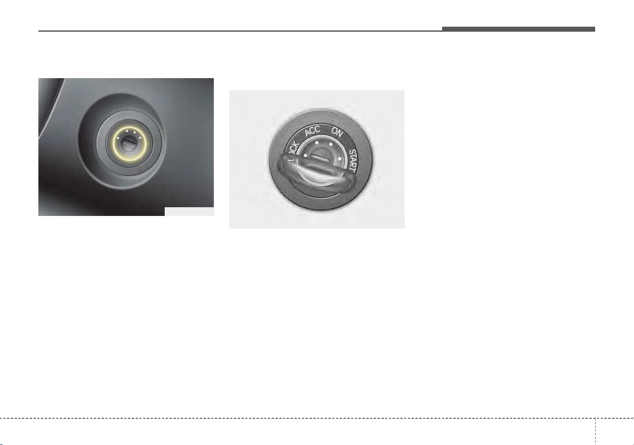
57
Driving your vehicle
Illuminated ignition switch
Whenever a front door is opened, the
ignition switch will illuminate for your
convenience, provided the ignition
switch is not in the ON position. The
light will go off immediately when the
ignition switch is turned on. It will
also go off after about 30 seconds
when the door is closed.
Ignition switch position
LOCK
From the left dot, dot sequence is
LOCK-ACC-ON-START.
The ignition key can be removed only
in the LOCK position.
ACC (Accessory)
The steering wheel is unlocked and
electrical accessories are operative.
✽✽
NOTICE
If difficulty is experienced turning
the ignition switch to the ACC posi-
tion, turn the key while turning the
steering wheel right and left to
release the tension.
KEY POSITIONS (IF EQUIPPED)
OQLE055065
OJF055172
Driving your vehicle
85
ON
The warning lights can be checked
before the engine is started. This is
the normal running position after the
engine is started.
Do not leave the ignition switch ON if
the engine is not running to prevent
battery discharge.
START
Turn the ignition switch to the START
position to start the engine. The
engine will crank until you release
the key; then it returns to the ON
position. The brake warning light can
be checked in this position.
The anti-theft steering column lock (if
equipped) is not a substitute for the
parking brake. Before leaving the dri-
ver’s seat, always make sure the shift
lever is engaged in P (Park) for dual
clutch transmission, set the parking
brake fully and shut the engine off.
Unexpected and sudden vehicle
movement may occur if these pre-
cautions are not taken.
WARNING - Key holder
Do not place small purses, mul-
tiple keys, or other heavy acces-
sories on your vehicle key ring.
The driver can accidently push
these objects causing the ACC
position to change while in
motion and disrupt the proper
operation of some of the vehi-
cle's safety features.
WARNING - Ignition switch
Never turn the ignition switch to
LOCK or ACC while the vehicle
is moving. This would result in
loss of directional control and
braking function, which could
cause an accident.
59
Driving your vehicle
Starting the hybrid system
1.Make sure the parking brake is
applied.
2.Place the transaxle shift lever in P
(Park). Depress the brake pedal
fully.
3. Turn the ignition switch to START.
If the hybrid system starts, the
“ ” indicator will come on.
WARNING - Leaving the
Vehicle
To avoid unexpected or sudden
vehicle movement, never leave
your vehicle if the transmission
is not locked in the P (Park)
position and the parking brake
is fully engaged. Before leaving
the driver's seat, always make
sure the shift lever is engaged in
P (Park), set the parking brake
fully and shut the engine off.
WARNING - Proper
footwear
Always wear appropriate shoes
when operating your vehicle.
Unsuitable shoes (high heels,
ski boots, sandals, etc.) may
interfere with your ability to use
the brake and accelerator pedal.
WARNING - Steering
wheel
Never reach for any controls
through the steering wheel
while the vehicle is in motion.
The presence of your hand or
arm in this area could cause a
loss of vehicle control.

Driving your vehicle
105
✽✽
NOTICE
• Do not wait for the engine to warm
up while the vehicle remains sta-
tionary.
Start driving at moderate engine
speeds. (Steep accelerating and
decelerating should be avoided.)
• Always start the vehicle with your
foot on the brake pedal. Do not
depress the accelerator while
starting the vehicle. Do not race
the engine while warming it up.
• If ambient temperature is low, the
“ ” indicator may remain illu-
minated longer than the normal
amount of time.
✽
✽
NOTICE
To prevent damage to the vehicle:
• If the “ ” indicator turns off
while you are in motion, do not
attempt to move the shift lever to
the P (Park) position.
If traffic and road conditions per-
mit, you may put the shift lever in
the N (Neutral) position while the
vehicle is still moving and turn the
ignition switch to START in an
attempt to restart the hybrid sys-
tem.
• Do not push or tow your vehicle to
start the hybrid system.
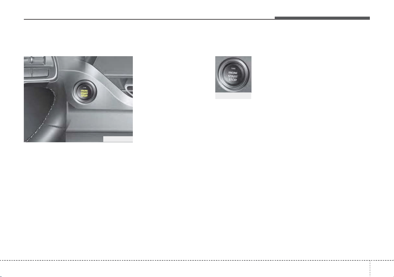
511
Driving your vehicle
Illuminated ENGINE
START/STOP button
Whenever the front door is opened,
the ENGINE START/STOP button
will illuminate for your convenience.
The light will go off after about 30
seconds when the door is closed.
When all entrances are closed, if you
lock the vehicle by using the trans-
mitter or the smart key, the light will
go off immediately.
ENGINE START/STOP button
position
OFF
To turn off the engine (START/RUN
position) or vehicle power (ON posi-
tion), press the ENGINE
START/STOP button with the shift
lever in the P (Park) position. When
you press the ENGINE
START/STOP button without the shift
lever in the P (Park) position, the
ENGINE START/STOP button will
not change to the OFF position but to
the ACC position.
In an emergency situation while the
vehicle is in motion, you are able to
turn the engine off and to the ACC
position by pressing the ENGINE
START/STOP button for more than 2
seconds or 3 times successively
within 3 seconds. If the vehicle is still
moving, you can restart the engine
without depressing the brake pedal
by pressing the ENGINE
START/STOP button with the shift
lever in the N (Neutral) position.
ENGINE START/STOP BUTTON (IF EQUIPPED)
ODEP059004
Not illuminated
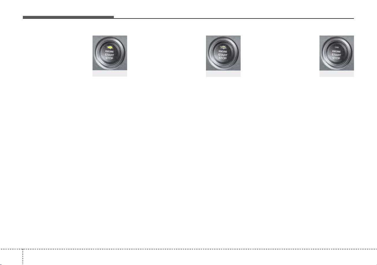
Driving your vehicle
125
ACC(Accessory)
Press the ENGINE START/STOP
button while it is in the OFF position
without depressing the brake pedal.
If the ENGINE START/STOP button
is in the ACC position for more than
1 hour, the button is turned off auto-
matically to prevent battery dis-
charge.
ON
Press the ENGINE START/STOP
button while it is in the ACC position
without depressing the brake pedal.
The warning lights can be checked
before the engine is started. Do not
leave the ENGINE START/STOP
button in the ON position for a long
time. The battery may discharge,
because the engine is not running.
START/RUN
To start the engine, depress the
brake pedal and press the ENGINE
START/ STOP button with the shift
lever in the P (Park) position. For
your safety, start the engine with the
shift lever in the P (Park) position.
If you press the ENGINE START/STOP
button without depressing the brake
pedal for dual clutch transmission vehi-
cles, the engine will not start and the
ENGINE START/STOP button
changes as follow:
OFF ➔ ACC ➔ ON ➔ OFF or ACC
Not illuminated
Amber
Red
513
Driving your vehicle
✽✽
NOTICE
If you leave the ENGINE START/
STOP button in the ACC or ON
position for a long time, the battery
will discharge.
Starting the hybrid system
✽✽
NOTICE
• The hybrid system will start by
pressing the Engine Start/Stop
button, only when the smart key is
in the vehicle.
• Even when the smart key is in the
vehicle, if it is far away from the
driver, the hybrid system may not
start.
• When the Engine Start/Stop but-
ton is in the ACC or ON position,
and any door is open, the system
checks for the smart key. When
the smart key is not in the vehicle,
the “ ” indicator will blink and
the warning “Key not in vehicle”
will come on. When all doors are
closed, the chime will also sound
for about 5 seconds. Keep the
smart key in the vehicle when in
the ACC position or if the hybrid
system is ON.
WARNING - Starting
vehicle
Never press the ENGINE
START/STOP button while the
vehicle is in motion except in an
emergency. This would result in
loss of directional control and
braking function, which could
cause an accident.
WARNING
• Always wear appropriate
shoes when operating your
vehicle. Unsuitable shoes,
such as high heels, ski boots,
sandals, flip-flops, etc., may
interfere with your ability to
use the brake and accelerator
pedals.
• Do not start the vehicle with the
accelerator pedal depressed.
The vehicle can move and
lead to an accident.

Driving your vehicle
145
1. Always carry the smart key with
you.
2. Make sure the parking brake is
applied.
3. Make sure the shift lever is in P
(Park).
4. Depress the brake pedal.
5. Press the Engine Start/Stop but-
ton. If the hybrid system starts, the
“ ” indicator will come on.
✽✽
NOTICE
• Do not wait for the engine to warm
up while the vehicle remains sta-
tionary.
Start driving at moderate engine
speeds. (Steep accelerating and
decelerating should be avoided.)
• Always start the vehicle with your
foot on the brake pedal. Do not
depress the accelerator while
starting the vehicle. Do not race
the engine while warming it up.
• If ambient temperature is low, the
“ ” indicator may remain illu-
minated longer than the normal
amount of time.
✽
✽
NOTICE
To prevent damage to the vehicle:
• If the “ ” indicator turns off
while you are in motion, do not
attempt to move the shift lever to
the P (Park) position.
If traffic and road conditions per-
mit, you may put the shift lever in
the N (Neutral) position while the
vehicle is still moving and press
the Engine Start/Stop button in an
attempt to restart the hybrid sys-
tem.
• Do not push or tow your vehicle to
start the hybrid system.
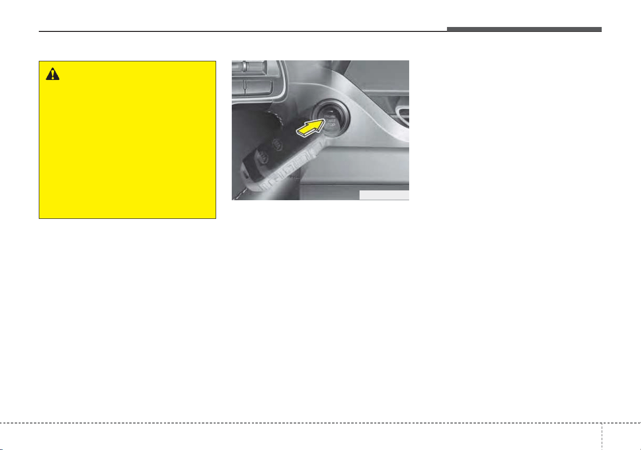
515
Driving your vehicle
• If the battery is weak or the smart
key does not work correctly, you
can start the engine by pressing
the engine start/stop button with
the smart key.
The side with the lock button
should contact the engine
start/stop button directly.
When you press the engine
start/stop button directly with the
smart key, the smart key should
contact the button at a right angle.
• When the stop lamp fuse is blown,
you can't start the engine normally.
Replace the fuse with a new one. If
it is not possible, you can start the
engine by pressing the ENGINE
START/STOP button for 10 sec-
onds while it is in the ACC posi-
tion. The engine can start without
depressing the brake pedal. But for
your safety always depress the
brake pedal before starting the
engine.
Do not press the ENGINE START/
STOP button for more than 10 sec-
onds except when the stop lamp fuse
is blown.
WARNING - Unintended
vehicle movement
Never leave the smart key in the
vehicle with children or vehicle
occupants who are unfamiliar
with the vehicle operation.
Pushing the ENGINE
START/STOP button while the
smart key is in the vehicle may
result in unintended engine
activation and/or unintended
vehicle movement.
ODEP059008
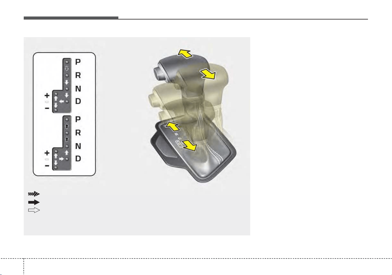
Driving your vehicle
165
Dual clutch transmission oper-
ation
The dual clutch transmission has six
forward speeds and one reverse
speed.
The individual speeds are selected
automatically in the D (Drive) posi-
tion.
DUAL CLUTCH TRANSMISSION (DCT)
ODE056010
The shift lever can freely operate.
Press the shift button while moving the shift lever.
Depress the brake pedal and press the shift button while moving the shift lever.
❈ To move the shift lever from/to P (Parking) or between R (Reverse) and D (Drive), you
must depress the brake pedal for the vehicle to stand still.
517
Driving your vehicle
• The dual Clutch Transmission
gives the driving feel of a manual
transmission, yet provides the
ease of a fully automatic transmis-
sion. Unlike a traditional automatic
transmission, the gear shifting can
be felt (and heard) on the dual
clutch transmission
- Think of it as an automatically
shifting manual transmission.
- Shift into Drive range and get fully
automatic shifting, similar to a con-
ventional automatic transmission.
• Dual clutch transmission adopts
dry-type dual clutch, which is dif-
ferent from torque converter of
automatic transmission, and
shows better acceleration perform-
ance during driving. But, initial
launch might be little bit slower
than Automatic Transmission.
• The dry-type clutch transfers torque
and provides a direct driving feeling
which may feel different from a con-
ventional automatic transmission
with a torque converter.This may be
more noticeable when starting from
a stop or low vehicle speed.
• When rapidly accelerating at low
vehicle speed, engine could rev at
high rpm depending on vehicle
drive condition.
• For smooth launch uphill, press
down the accelerator pedal
smoothly depending on the current
conditions.
• If you release your foot from the
accelerator pedal at low vehicle
speed, you may feel strong engine
brake, which is similar to manual
transmission.
• When driving downhill, you may
use Sports Mode to downshift to a
lower gear in order to control your
speed without using the brake
pedal excessively.
• When you turn the engine on and
off, you may hear clicking sounds
as the system goes through a self
test. This is a normal sound for the
dual Clutch Transmission.
WARNING
To reduce the risk of serious
injury or death:
• ALWAYS check the surround-
ing areas near your vehicle for
people, especially children,
before shifting a vehicle into
D (Drive) or R (Reverse).
• Before leaving the driver’s
seat, always make sure the
shift lever is in the P (Park)
position, then set the parking
brake, and place the ignition
switch or ENGINE START/
STOP button in the OFF posi-
tion. Unexpected and sudden
vehicle movement can occur
if these precautions are not
followed.
• Do not use engine braking
(shifting from a high gear to
lower gear) rapidly on slip-
pery roads. The vehicle may
slip, causing an accident.

Driving your vehicle
185
• To hold the vehicle on a hill use the
foot brake or the parking brake. If
the vehicle is held by applying the
accelerator pedal on a hill the
clutch and transmission will be
overheated resulting in damage.
At this time, a warning message
(“Steep grade! Press brake pedal”)
will appear on the LCD display.
• If the clutch becomes overheated
by excessive use of the clutch to
hold on a hill, you may notice a
shudder feeling and a blinking dis-
play on the instrument cluster.
When this occurs, the clutch is dis-
abled until the clutch cools to nor-
mal temperatures. If this occurs,
pull over to a safe location, shift
into P (Park) and apply the foot
brake for a certain time on the LCD
warning until it disappears.
• If the LCD warning is active, the
foot brake must be applied.
• Ignoring the warnings can lead to
damage to the transmission.
• If the display continues to blink, for
your safety, we recommend that you
contact an authorized Kia dealer.
• Under certain conditions such as
repeated launch on steep grades,
the clutch in the transmission could
overheat.
When the clutch is overheated, the
safe protection mode engages. If
the safe protection mode engages,
the gear position indicator on the
cluster blinks with a chime sound.
At this time, one of these warning
messages (“Transmission temp. is
high! Stop safely”, “Trans hot! Park
with engine on”, “Trans Cooling.
Remain parked for 00 min.”, “Trans
Cooled. Resume driving”) will
appear on the LCD display and driv-
ing may not be smooth.
If you ignore this warning, the driv-
ing condition may become worse.
To return the normal driving condi-
tion, stop the vehicle and apply the
foot brake for a few minutes before
driving off.
• Gear shifts may be more notice-
able than a conventional automatic
transmission. This is a normal
characteristic of this type of dual
clutch transmission.
• During the first 1,500 km (1,000
miles), you may feel that the vehi-
cle may not be smooth when accel-
erating at low speed. During this
break-in period, the shift quality
and performance of your new vehi-
cle is continuously optimized.
• Always come to a complete stop
before shifting into D (Drive) or R
(Reverse).
• Do not put the shift lever in N
(Neutral) while driving.
519
Driving your vehicle
The indicator in the instrument clus-
ter displays the shift lever position
when the ignition switch or ENGINE
START/STOP button is in the ON
position.
P (Park)
Always come to a complete stop
before shifting into P (Park).
To shift from P (Park), you must
depress firmly on the brake pedal
and make sure your foot is off the
accelerator pedal.
The shift lever must be in P (Park)
before turning the engine off.
R (Reverse)
Use this position to drive the vehicle
backward.
WARNING
• Shifting into P (Park) while the
vehicle is in motion may
cause you to lose control of
the vehicle.
• After the vehicle has stopped,
always make sure the shift
lever is in P (Park), apply the
parking brake, and turn the
engine off.
• Do not use the P (Park) position
in place of the parking brake.
CAUTION
Always come to a complete stop
before shifting into or out of R
(Reverse); you may damage the
transmission if you shift into R
(Reverse) while the vehicle is in
motion.
CAUTION
• To avoid damage to your
transaxle, do not try to accel-
erate in R (Reverse) or any for-
ward gear position with the
brakes on.
• When stopped on slope, do
not hold the vehicle with
accelerator pedal. Use the
service brake or the parking
brake.
Driving your vehicle
205
N (Neutral)
The wheels and transmission are not
engaged.
- Parking in N (Neutral) gear
Follow below steps when parking
and you want the vehicle to move
when pushed.
1.After parking your vehicle, step on
the brake pedal and move the shift
lever to [P] with the ignition switch or
ENGINE START/STOP button in
[ON] or while the engine is running.
2.If the parking brake is applied
unlock the parking brake.
- For EPB (Electronic Parking
Brake) equipped vehicles, push
the brake pedal with the ignition
switch or ENGINE START/STOP
button in [ON] or while the engine
is running to disengage the park-
ing brake. If [AUTO HOLD] func-
tion is used while driving (If
[AUTO HOLD] indicator is on in
the cluster), press [AUTO HOLD]
switch and [AUTO HOLD] func-
tion should be turn off.
3.While pressing the brake pedal,
turn the ignition switch or ENGINE
START/STOP button [OFF].
- For smart key equipped vehicles,
the ignition switch or ENGINE
START/STOP button can be
moved to [OFF] only when the
shift lever is in [P].
4.Change the gear shift lever to [N]
(Neutral) while pressing the brake
pedal and pushing [SHIFT LOCK
RELEASE] button or inserting,
pressing down a tool (e.g. flathead
screw-driver) into the [SHIFT LOCK
RELEASE] access hole at the same
time. Then, the vehicle will move
when external force is applied.
WARNING
Do not shift into gear unless
your foot is firmly on the brake
pedal. Shifting into gear when
the engine is running at high
speed can cause the vehicle to
move very rapidly. You could
lose control of the vehicle and
hit people or objects.
WARNING
Do not drive with the shift lever
in N (Neutral).
The engine brake may not work
and lead to an accident.

521
Driving your vehicle
D (Drive)
This is the normal driving position.
The transmission will automatically
shift through a six-gear sequence,
providing the best fuel economy and
power.
For extra power when passing anoth-
er vehicle or driving uphill depress
the accelerator pedal further until
you feel the transmission downshift
to a lower gear.
To stop the vehicle during driving,
please press brake pedal fully to pre-
vent unintended movement.
WARNING - Parking In
Neutral
• With the exception of parking
in neutral gear, always park the
vehicle in [P] (Park) for safety
and apply the parking brake.
• Before parking in [N] (Neutral)
gear, make sure the parking
ground is level and flat. Do not
park in [N] gear on any slopes
or gradients. If parked and left
in [N], the vehicle may move
and cause serious damage or
injury.
• After the ignition switch or
ENGINE START/STOP button
has been turned off, the
Electronic Parking Brake can-
not be disengaged.
(Continued)
(Continued)
• For EPB (Electronic Parking
Brake) equipped vehicles with
[AUTO HOLD] function used
while driving, if the ignition
switch or ENGINE
START/STOP button has been
turned [OFF], the Electronic
Parking Brake will be engaged
automatically. Therefore,
[AUTO HOLD] function should
be turned off before the igni-
tion button is turned off.
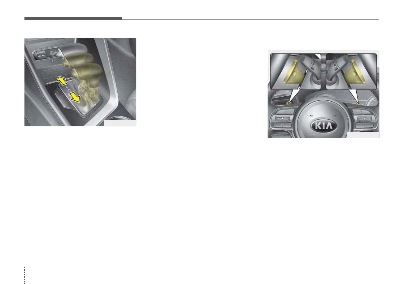
Driving your vehicle
225
Manual mode
Whether the vehicle is stationary or
in motion, manual mode is selected
by pushing the shift lever from the D
(Drive) position into the manual gate.
To return to D (Drive) range opera-
tion, push the shift lever back into the
main gate.
In manual mode, moving the shift lever
backwards and forwards will allow you
to select the desired range of gears for
the current driving conditions.
+ (Up) : Push the lever forward once
to shift up one gear.
- (Down) : Pull the lever backwards
once to shift down one gear.
✽✽
NOTICE
• Only the six forward gears can be
selected. To reverse or park the
vehicle, move the shift lever to the
R (Reverse) or P (Park) position as
required.
• Downshifts are made automatical-
ly when the vehicle slows down.
When the vehicle stops, 1st gear is
automatically selected.
• When the engine rpm approaches
the red zone the transmission will
upshift automatically.
• If the driver presses the lever to +
(Up) or - (Down) position, the trans-
mission may not make the request-
ed gear change if the next gear is
outside of the allowable rpm range.
Paddle shifter (if equipped)
The paddle shift function is available
when the shift lever is in the
sport/manual mode.
ODEP059012
ODEP059294

523
Driving your vehicle
With the shift lever in the manual mode
Pull the [+] or [-] paddle shifter once
to shift up or down one gear.
✽✽
NOTICE
If you pull the [+] and [-] paddle
shifters at the same time, you cannot
shift the gear.
SPORT Mode / ECO Mode
When you drive after changing the
gear shift lever to manual mode, the
vehicle will automatically shift to
SPORT mode. When you drive the
vehicle after putting the gear shift
lever to ‘D’, the vehicle will automati-
cally shift to ECO mode. Each auto-
matic change in shift will be dis-
played on the instrument cluster.
• ECO mode
This driving mode increases fuel effi-
ciency. The actual fuel mileage will
depend on your driving habits and
road conditions.
• SPORT mode
This driving mode provides sporty
driving experience. Be aware that fuel
efficiency may decrease in this mode.
Shift lock system
For your safety, the dual clutch trans-
mission has a shift lock system which
prevents shifting the transaxle from P
(Park) into R (Reverse) unless the
brake pedal is depressed.
To shift the transaxle from P (Park)
into R (Reverse):
1. Depress and hold the brake pedal.
2. Start the engine or turn the ignition
switch or ENGINE START/STOP
button to the ON position.
3. Move the shift lever.
If the brake pedal is repeatedly
depressed and released with the shift
lever in the P (Park) position, a chat-
tering noise & vibration near the shift
lever may be heard. This is a normal
condition.
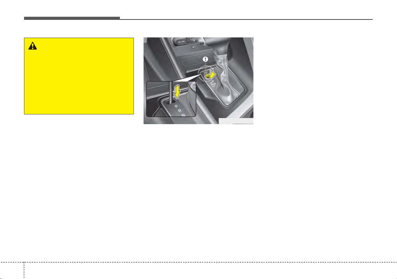
Driving your vehicle
245
Shift-lock override
If the shift lever cannot be moved
from the P (Park) position into R
(Reverse) position with the brake
pedal depressed, continue depress-
ing the brake, then do the following:
1. Place the ignition switch or
ENGINE START/STOP button in
the LOCK/OFF position.
2. Apply the parking brake.
3. Carefully remove the cap (1) cov-
ering the shift-lock release access
hole.
4. Insert a tool (e.g. flathead screw-
driver) into the access hole and
press down on the tool.
5. Move the shift lever.
6. Remove the tool from the shiftlock
override access hole then install
the cap.
7. We recommend that the system
be inspected by an authorized Kia
dealer.
ODEP059013L
WARNING - Shifting from
park
Always fully depress the brake
pedal before and while shifting
out of the P (park) position into
another position to avoid inad-
vertent motion of the vehicle
which could injure persons in or
around the vehicle.
525
Driving your vehicle
Ignition key interlock system
(if equipped)
The ignition key cannot be removed
unless the shift lever is in the P
(Park) position.
ENGINE START/STOP button inter-
lock system (if equipped)
The ENGINE START/STOP button
will not change to the OFF position
unless the shift lever is in the P
(Park) position.
Good driving practices
• Never move the shift lever from P
(Park) or N (Neutral) to any other
position with the accelerator pedal
depressed.
• Never move the shift lever into P
(Park) when the vehicle is in motion.
• Be sure the car is completely
stopped before you attempt to shift
into R (Reverse) or D (Drive).
• Never take the car out of gear and
coast down a hill. This may be
extremely hazardous. Always leave
the car in gear when moving.
• Do not "ride" the brakes. This can
cause them to overheat and mal-
function. Instead, when you are
driving down a long hill, slow down
and shift to a lower gear. When you
do this, engine braking will help
slow the car.
• Slow down before shifting to a
lower gear. Otherwise, the lower
gear may not be engaged.
• Always use the parking brake. Do
not depend on placing the
transaxle in P (Park) to keep the
car from moving.
• Exercise extreme caution when
driving on a slippery surface. Be
especially careful when braking,
accelerating or shifting gears. On a
slippery surface, an abrupt change
in vehicle speed can cause the
drive wheels to lose traction and
the vehicle to go out of control.
• Optimum vehicle performance and
economy is obtained by smoothly
depressing and releasing the
accelerator pedal.
CAUTION
- Holding the Vehicle Using
Accelerator Pedal
Do not attempt to hold your
vehicle on a hill by applying the
accelerator pedal. This can
cause your clutch and transmis-
sion to be damaged as a result
of overheating.

Driving your vehicle
265
WARNING
If your vehicle becomes stuck in
snow, mud, sand, etc., then you
may attempt to rock the vehicle
free by moving it forward and
backward. Do not attempt this
procedure if people or objects
are anywhere near the vehicle.
During the rocking operation the
vehicle may suddenly move for-
ward of backward as it becomes
unstuck, causing injury or dam-
age to nearby people or objects.
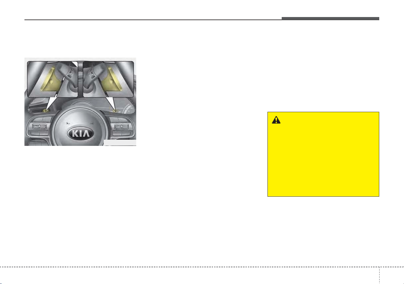
527
Driving your vehicle
Regenerative Braking
(Paddle Shifter)
The paddle shifter is used to adjust
the regenerative braking level from 0
to 3 during decelerating or braking.
• Left side [-] : Increases regenera-
tive braking and deceleration.
• Right side [+] : Decreases regener-
ative braking and deceleration.
✽✽
NOTICE
• The control level will be started at
0 when the engine start. It will
activate only in D (Drive) range.
• If you operate the shift lever (to P,
R, N/Sport), Regen B mode will be
cancelled and if you return to D
(Drive) range, the Regen B mode
will be returned to 0 level.
• Regen B mode will be cancelled
when ABS, ESC operate.
• The speed decrement may differ-
ent depends on the vehicle speed
even in the same Regen B level.
(The speed decrement in each level
is bigger in the city driving than
that of highway driving.)
✽
✽
NOTICE
The vehicle does not completely stop
by using paddle shifter lever. When
the Regen B power reduced, the
vehicle slowly moves about 10 km/h.
In order to stop the vehicle, depress
the brake pedal.
✽
✽
NOTICE
The paddle shifter does not operate
when:
• The [-] and [+] paddle shifters are
pulled at the same time.
• The vehicle is decelerating by
depressing the brake pedal.
• Cruise Control system or Cruise
Control system is activated.
REGENERATIVE BRAKING SYSTEM
ODEP059294
WARNING
Usage of the regenerative brak-
ing function may be limited
according to the battery and
motor’s condition. (over charge,
high and low temperature)
Check traffic and driving condi-
tions. If necessary, control the
vehicle speed by using the
brake pedal.
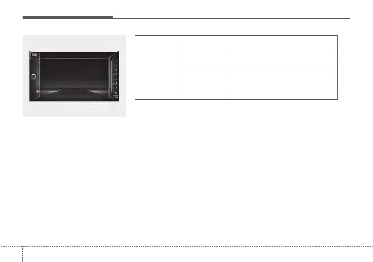
Driving your vehicle
285
The selected regenerative braking
level is displayed on the instrument
cluster.
ODEP059298
Drive mode
Paddle shifter
lever operation
Paddle shift lever function
ECO
+ Reduction regenerative braking level
- Increase of regenerative braking level
SPORT
+ manual shift (+)
- manual shift (-)
❈ The paddle shifter function changed by selection of Drive mode.
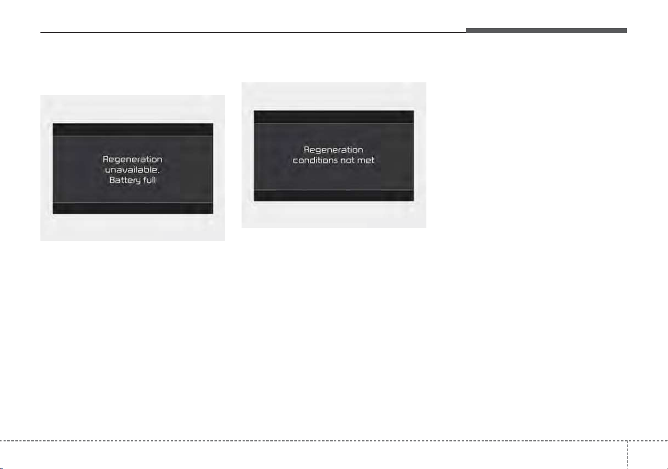
529
Driving your vehicle
Regeneration unavailable. Battery
full
If SOC(State of High voltage battery
Charge) is high, it is not possible to
enable Regen B mode. Use the func-
tion again after normal driving.
Regeneration conditions not met
• If the motor and battery is in
high/low temperature status or if
there is a malfunction on battery
and transmission, the warning
message will be displayed.
• If the vehicle entering the Regen B
mode during the activation of
ABS/Cruise Control/Smart Cruise
Control, the warning message will
be displayed.
Once the warning message is dis-
played, the usage of function will be
temporarily limited. Use the function
again after normal driving.
ODEP059296L
ODEP059295L
Driving your vehicle
305
Power brakes
Your vehicle has power-assisted
brakes that adjust automatically
through normal usage.
If the hybrid system is not on or is
turned off while driving, the power
assist for the brakes will not work.
You can still stop your vehicle by
applying greater force to the brake
pedal than typical. The stopping dis-
tance, however, will be longer than
with power brakes.
When the hybrid system is not on,
the reserve brake power is partially
depleted each time the brake pedal
is applied. Do not pump the brake
pedal when the power assist has
been interrupted.
Pump the brake pedal only when
necessary to maintain steering con-
trol on slippery surfaces.
BRAKE SYSTEM
WARNING - Steep hill
braking
Avoid continuous application of
the brakes when descending a
long or steep hill by shifting to a
lower gear. Continuous brake
application may cause the
brakes to overheat and could
result in a temporary loss of
braking performance.
WARNING - HEV driving
down hill
Do not turn off the Hybrid sys-
tem while going down a hill.The
brake booster may not work
sufficiently and the braking dis-
tance may be longer.
CAUTION - Brake Pedal
Do not drive with your foot rest-
ing on the brake pedal. This will
create abnormally high brake
temperatures which can cause
excessive brake lining and pad
wear.
531
Driving your vehicle
Wet brakes may impair the vehicle’s
ability to safely slow down; the vehi-
cle may also pull to one side when
the brakes are applied. Applying the
brakes lightly will indicate whether
they have been affected in this way.
Always test your brakes in this fash-
ion after driving through deep water.
To dry the brakes, apply them lightly
while maintaining a safe forward
speed until brake performance
returns to normal.
✽✽
NOTICE
Do not depress the brake pedal con-
tinuously without the “ ” indica-
tor ON. The battery may be dis-
charged.
In the event of brake failure
If service brakes fail to operate while
the vehicle is in motion, you can
make an emergency stop with the
parking brake. The stopping dis-
tance, however, will be much greater
than normal.
Disc brakes wear indicator
When your brake pads are worn and
new pads are required, you will hear
a high-pitched warning sound from
your front brakes or rear brakes. You
may hear this sound come and go or
it may occur whenever you depress
the brake pedal.
Please remember that some driving
conditions or climates may cause a
brake squeal when you first apply (or
lightly apply) the brakes. This is nor-
mal and does not indicate a problem
with your brakes.
Always replace the front or rear
brake pads as pairs.
WARNING - Parking
brake
Avoid applying the parking
brake to stop the vehicle while it
is moving except in an emer-
gency situation. Applying the
parking brake while the vehicle
is moving at normal speeds can
cause a sudden loss of control
of the vehicle. If you must use
the parking brake to stop the
vehicle, use great caution in
applying the brake.
CAUTION - Replace brake
pads
Do not continue to drive with
worn brake pads. Continuing to
drive with worn brake pads can
damage the braking system and
result in costly brake repairs.
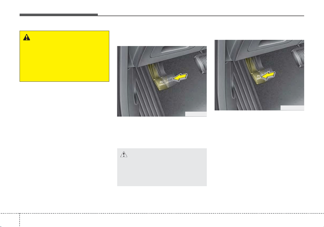
Driving your vehicle
325
Parking brake – Foot type
Applying the parking brake
To engage the parking brake, first
apply the foot brake and then
depress the parking brake pedal
down as far as possible.
Releasing the parking brake
To release the parking brake,
depress the parking brake pedal a
second time while applying the foot
brake. The pedal will automatically
extend to the fully released position.
WARNING - Brake wear
Do not ignore high pitched wear
sounds from your brakes. If you
ignore this audible warning, you
may eventually lose braking
performance, which could lead
to a serious accident.
ODE056015
ODE056014
CAUTION - Parking brake
Driving with the parking brake
applied will cause excessive
brake pad (or lining) and brake
rotor wear.
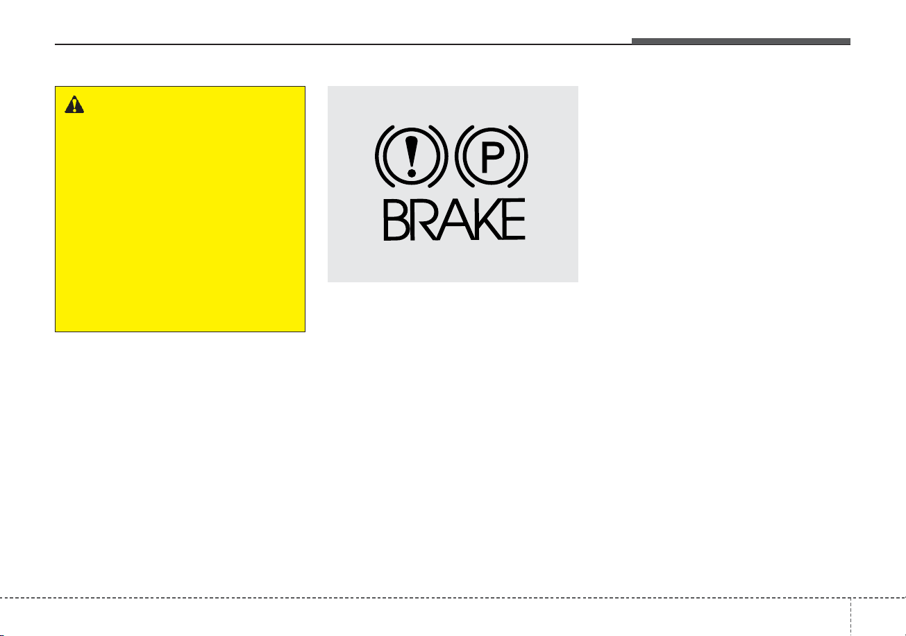
533
Driving your vehicle
Check the brake warning light by turn-
ing the ignition switch or ENGINE
START/STOP button ON (do not start
the engine). This light will be illuminat-
ed when the parking brake is applied
with the ignition switch or ENGINE
START/STOP button in the START or
ON position.
Before driving, be sure the parking
brake is fully released and the brake
warning light is off.
If the brake warning light remains on
after the parking brake is released
while the engine is running, there may
be a malfunction in the brake system.
Immediate attention is necessary.
If at all possible, cease driving the
vehicle immediately. If that is not pos-
sible, use extreme caution while
operating the vehicle and only contin-
ue to drive the vehicle until you can
reach a safe location or repair shop.
WARNING - Parking brake
use
• Never allow a passenger to
touch the parking brake. If the
parking brake is released
unintentionally, serious injury
may occur.
• All vehicles should always
have the parking brake fully
engaged when parked to avoid
inadvertent movement of the
vehicles which can injure
occupants or pedestrians.
W-75
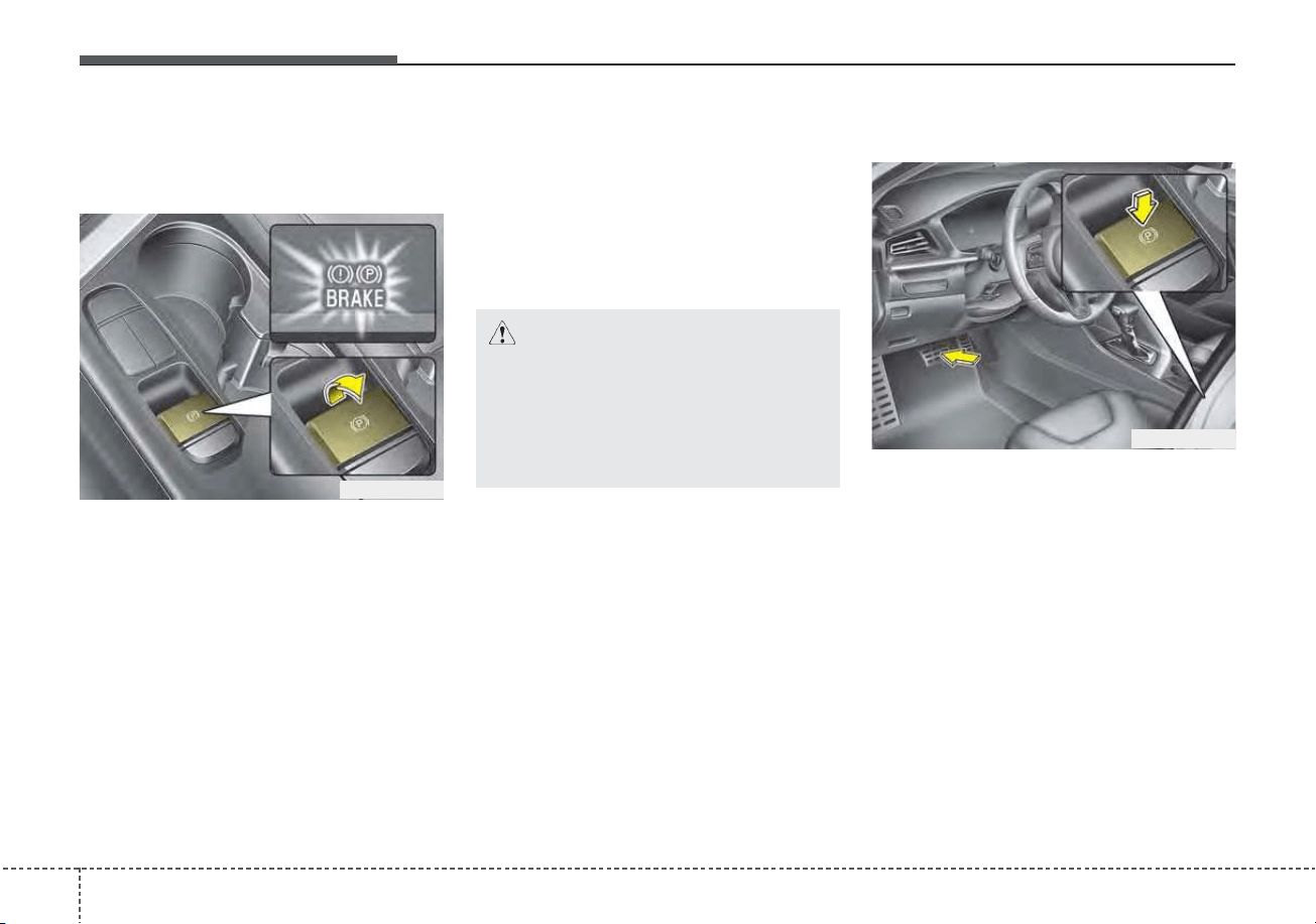
Driving your vehicle
345
Electronic Parking Brake
(EPB) (if equipped)
Applying the parking brake
To apply the EPB (Electronic Parking
Brake):
1. Press the brake pedal.
2. Pull up the EPB switch.
3. Make sure the warning light comes
on. Also, the EPB is applied auto-
matically if the Auto Hold button is
on when the engine is turned off.
However, if you keep pressing the
EPB switch till the engine is turned
off, the EPB will not be applied.
✽✽
NOTICE
On a steep incline or when pulling a
trailer if the vehicle does not stand
still, do as follows:
1. Apply the EPB.
2. Pull up the EPB switch for more
than 3 seconds.
Releasing the parking brake
To release the EPB (Electronic
Parking Brake), press the EPB switch
in the following condition:
1. Place the ENGINE START/STOP
button in the ON position.
2. Press the brake pedal.
3. The shift lever must be in P (Park).
4. Make sure the brake warning light
goes off.
ODEP059284
ODEP059285
CAUTION
Do not operate the EPB while
the vehicle is moving except in
an emergency situation. It could
damage the vehicle system and
endanger driving safety.
535
Driving your vehicle
To release EPB (Electronic Parking
Brake) automatically:
• Shift lever in P (Park)
With the engine running depress
the brake pedal and shift out of P
(Park) to R (Reverse) or D (Drive).
• Shift lever in N (Neutral)
With the engine running depress
the brake pedal and shift out of N
(Neutral) to R (Reverse) or D
(Drive).
• Depress the accelerator pedal
slowly when the following condi-
tions are satisfied:
1. Start the engine.
2. Fasten the driver's seat belt.
3. Close the driver's door, engine
hood and liftgate.
4. The shift lever is in R (Rear), D
(Drive) or manual mode.
Make sure the brake warning light
goes off.
✽✽
NOTICE
• For your safety, you can engage
the EPB even though the ignition
switch or ENGINE START/STOP
button is in the OFF position, but
you cannot release it.
• For your safety, depress the brake
pedal and release the parking
brake manually with the EPB
switch when you drive downhill or
when backing up the vehicle.
EPB (Electronic Parking Brake) may
be automatically applied when:
• The EPB is overheated
• Requested by other systems
• The hybrid system is turned off
with the EPB applied
✽✽
NOTICE
• If Auto Hold is operating (Green
light), EPB is applied automatical-
ly when the hybrid system is
turned off.
• If Auto Hold is in ready position
(White light), EPB is applied auto-
matically after 1 second from the
hybrid system off timing. In this
case, if the EPB switch is pressed
within 1 second, the EPB will not
be applied.
CAUTION
• If the parking brake warning
light is still on even though
the EPB has been released,
have the system checked by
an authorized Kia dealer.
• Do not drive your vehicle with
the EPB applied. It may cause
excessive brake pad and
brake rotor wear.
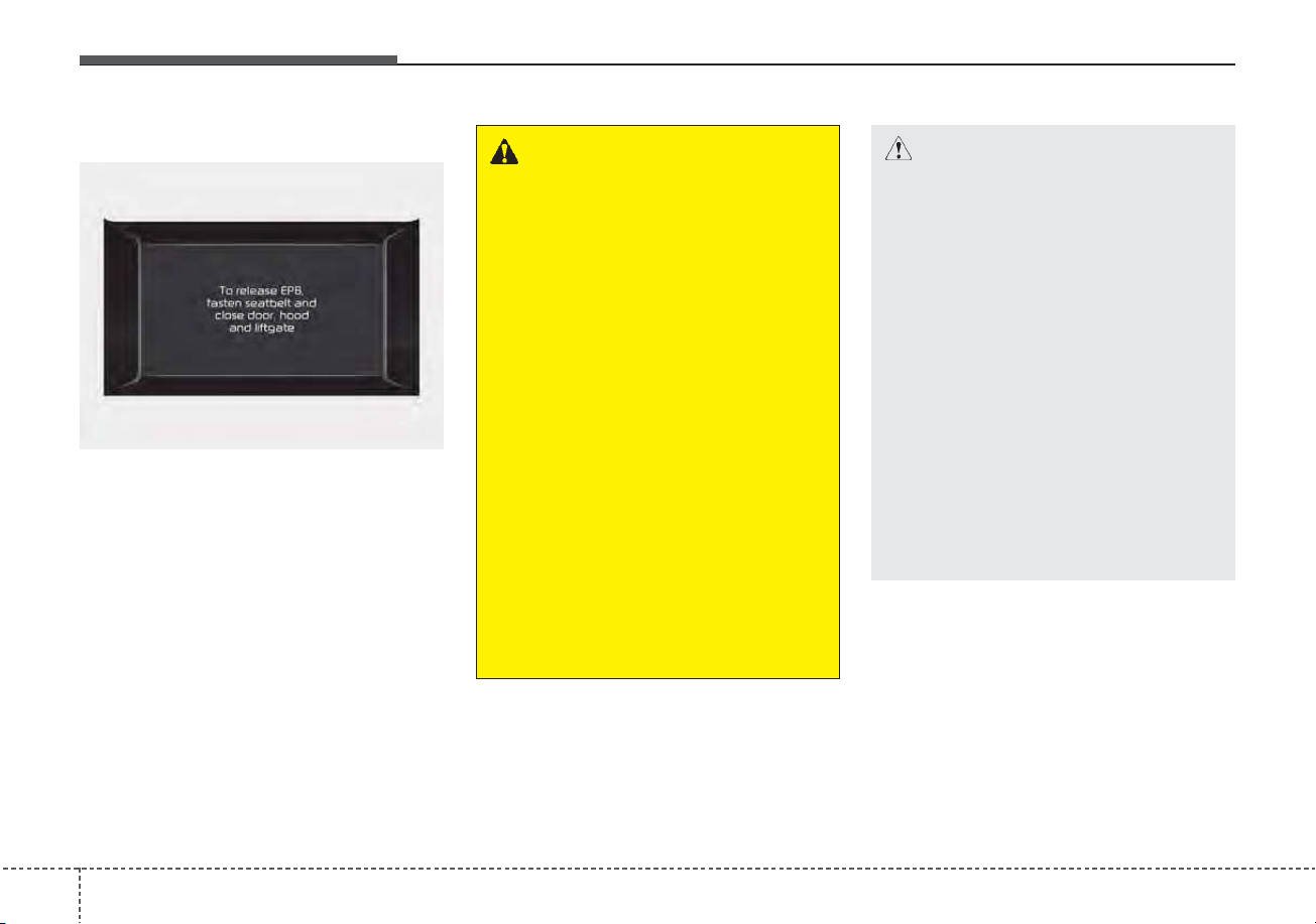
Driving your vehicle
365
System warning
• If you try to drive off depressing the
accelerator pedal with the EPB
applied, but doesn't release auto-
matically, a warning will sound and
a message will appear.
• If the driver's seat belt is not fastened
and the door, hood and liftgate is
opened, a warning will sound and a
message will appear.
• If there is a problem with the vehi-
cle, a warning may sound and a
message may appear.
If the above situation occurs,
depress the brake pedal and release
EPB by pressing the EPB switch.
ODEP059326N
WARNING
• To prevent unintentional
movement when stopped and
leaving the vehicle, do not use
the shift lever in place of the
parking brake. Set the parking
brake and make sure the shift
lever is securely positioned in
P (Park).
• Never allow anyone who is
unfamiliar with the vehicle to
touch the parking brake. If the
parking brake is released
unintentionally, serious injury
may occur.
• All vehicles should always
have the parking brake fully
engaged when parking to
avoid inadvertent movement
of the car which can injure
occupants or pedestrians.
CAUTION
• A click or electric brake motor
whine sound may be heard
while operating or releasing the
EPB, but these conditions are
normal and indicate that the
EPB is functioning properly.
• When leaving your keys with a
parking lot attendant or valet,
make sure to inform him/her
how to operate the EPB.
• The EPB may malfunction if
you drive with the EPB applied.
• When you automatically
release EPB by depressing
the accelerator pedal, depress
it slowly.
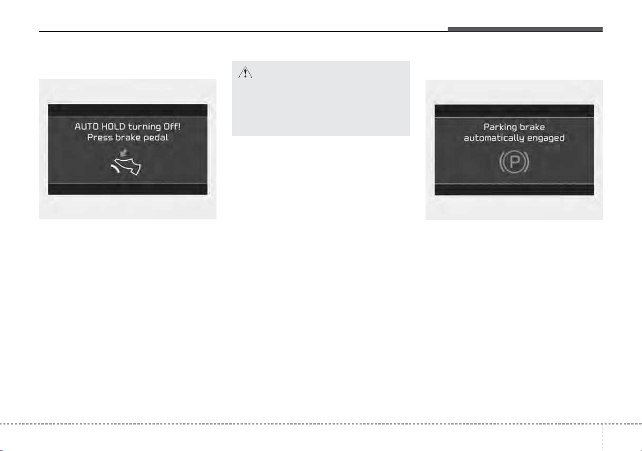
537
Driving your vehicle
System warning
When the conversion from Auto Hold
to EPB is not working properly a
warning will sound and a message
will appear.
System warning
If the EPB is applied while Auto Hold
is activated because of ESC
(Electronic Stability Control) signal, a
warning will sound and a message
will appear.
CAUTION
Engage the brake pedal when
the above message appears for
the Auto Hold and EPB may not
activate.
OJF058375L
OJF058377L
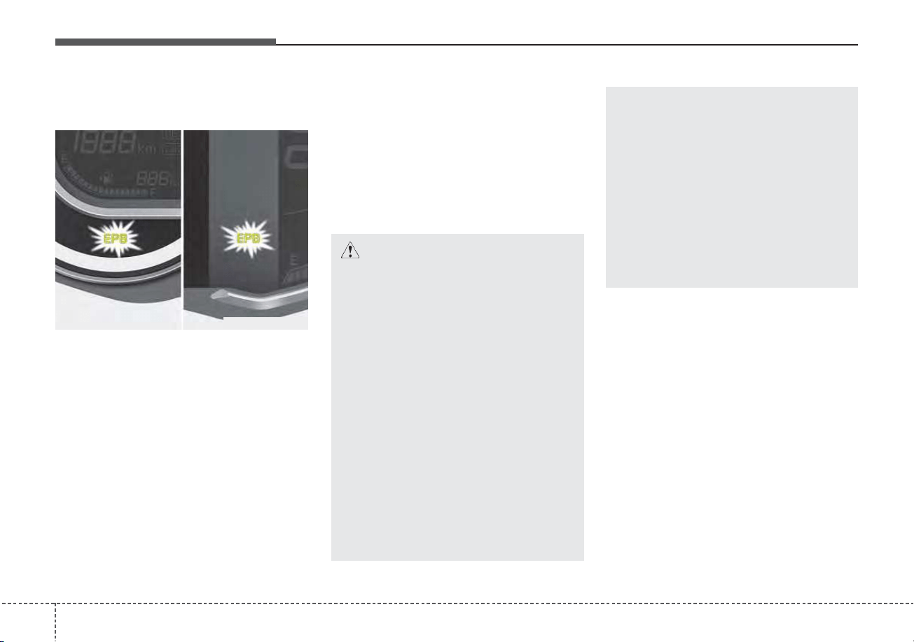
Driving your vehicle
385
EPB malfunction indicator
(if equipped)
This warning light illuminates if the
ignition switch or ENGINE START/
STOP button is changed to the ON
position and goes off in approximately
3 seconds if the system is operation
normally.
If the EPB malfunction indicator
remains on, comes on while driving,
or does not come on when the igni-
tion switch or ENGINE START/STOP
button is changed to the ON position,
this indicates that the EPB may have
malfunctioned.
If this occurs, have your vehicle
checked by an authorized Kia dealer
as soon as possible.
The EPB malfunction indicator may
illuminate when the ESC indicator
comes on to indicate that the ESC is
not working properly, but it does not
indicate a malfunction of the EPB.
ODEP059286
CAUTION
• The EPB warning light may
illuminate if the EPB switch
operates abnormally. Shut the
engine off and turn it on again
after a few minutes. The warn-
ing light will go off and the
EPB switch will operate nor-
mally. However, if the EPB
warning light is still on, have
the system checked by an
authorized Kia dealer.
• If the parking brake warning
light does not illuminate or
blinks even though the EPB
switch was pulled up, the EPB
is not applied.
(Continued)
(Continued)
• If the parking brake warning
light blinks when the EPB
warning light is on, press the
switch, then pull it up. Once
more press it back to its origi-
nal position and pull it back
up. If the EPB warning does
not go off, have the system
checked by an authorized Kia
dealer.
539
Driving your vehicle
Emergency braking
If there is a problem with the brake
pedal while driving, emergency brak-
ing is possible by pulling up and
holding the EPB switch. Braking is
possible only while you are holding
the EPB switch.
✽✽
NOTICE
During emergency braking by the
EPB, the parking brake warning
light will illuminate to indicate that
the system is operating.
When the EPB (Electronic Parking
Brake) does not release
If the EPB does not release normal-
ly, take your vehicle to an authorized
Kia dealer by loading the vehicle on
a flatbed tow truck and have the sys-
tem checked.
WARNING
Do not operate the parking
brake while the vehicle is mov-
ing except in an emergency sit-
uation.
CAUTION
If you continuously notice a
noise or burning smell when the
EPB is used for emergency brak-
ing, have your vehicle checked
by an authorized Kia dealer.
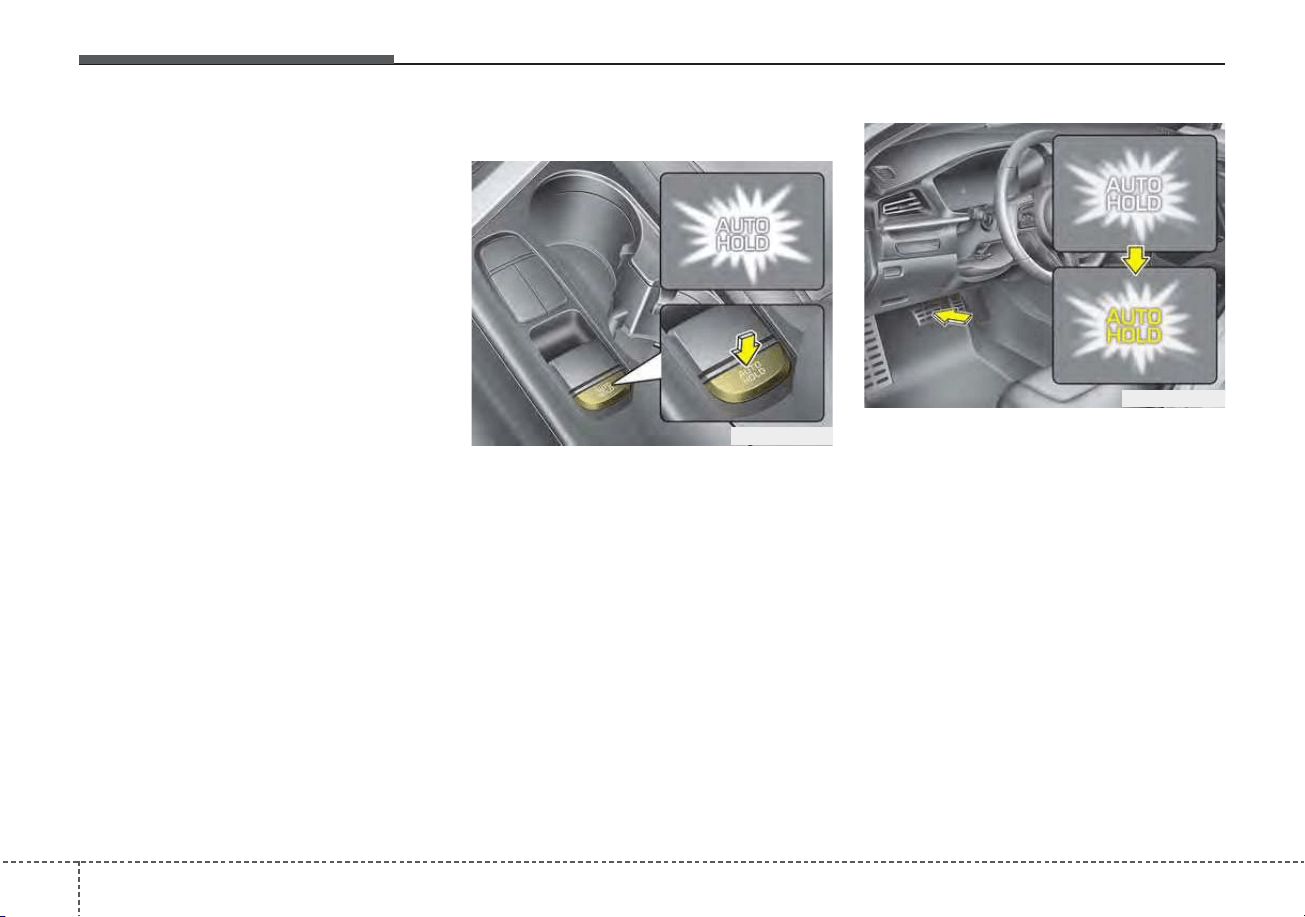
Driving your vehicle
405
AUTO HOLD (if equipped)
The Auto Hold maintains the vehicle
in a standstill even though the brake
pedal is not depressed after the driv-
er brings the vehicle to a complete
stop by depressing the brake pedal.
Set up
1. With the driver's door, engine
hood closed, fasten the driver's
seat belt or depress the brake
pedal and then press the Auto
Hold button. The white AUTO
HOLD indicator will come on and
the system will be in the standby
position.
2. When you stop the vehicle com-
pletely by depressing the brake
pedal, the AUTO HOLD indicator
changes from white to green.
3. The vehicle will remain stationary
even if you release the brake pedal.
4. If EPB is applied, Auto Hold will be
released.
ODEP059287
ODEP059288
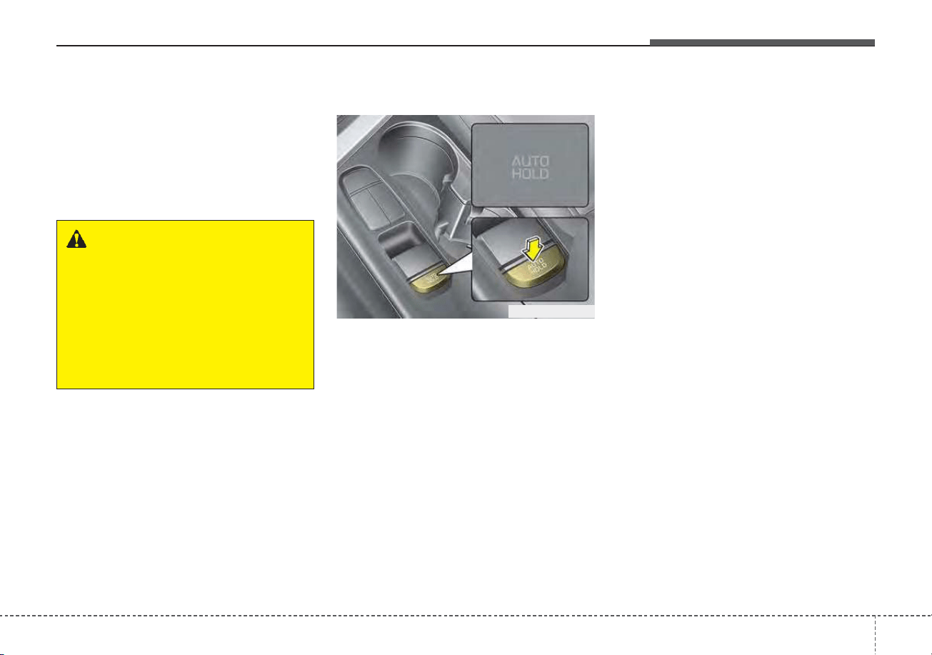
541
Driving your vehicle
Leaving
If you press the accelerator pedal
with the shift lever in D (Drive) or
manual mode, the Auto Hold will be
released automatically and the vehi-
cle will start to move. The indicator
changes from green to white.
Cancel
To cancel the Auto Hold operation,
press the Auto Hold switch. The
AUTO HOLD indicator will go out.
To cancel the Auto Hold operation
when the vehicle is at a standstill,
press the Auto Hold switch while
depressing the brake pedal.
✽✽
NOTICE
• The Auto Hold does not operate
when:
- The driver's door is opened
- The engine hood is opened
- The shift lever is in P (Park) or R
(Reverse)
- The EPB is applied
• For your safety, the Auto Hold
automatically switches to EPB in
such cases:
- The driver's door is opened
- The engine hood is opened
- The vehicle is in a standstill for
more than 10 minutes
- The vehicle is standing on a steep
slope
- The vehicle moved several times
(Continued)
ODEP059289
WARNING
When driving off from Auto
Hold by depressing the acceler-
ator pedal, always check the
surrounding area near your
vehicle.
Slowly depress the accelerator
pedal for a smooth launch.
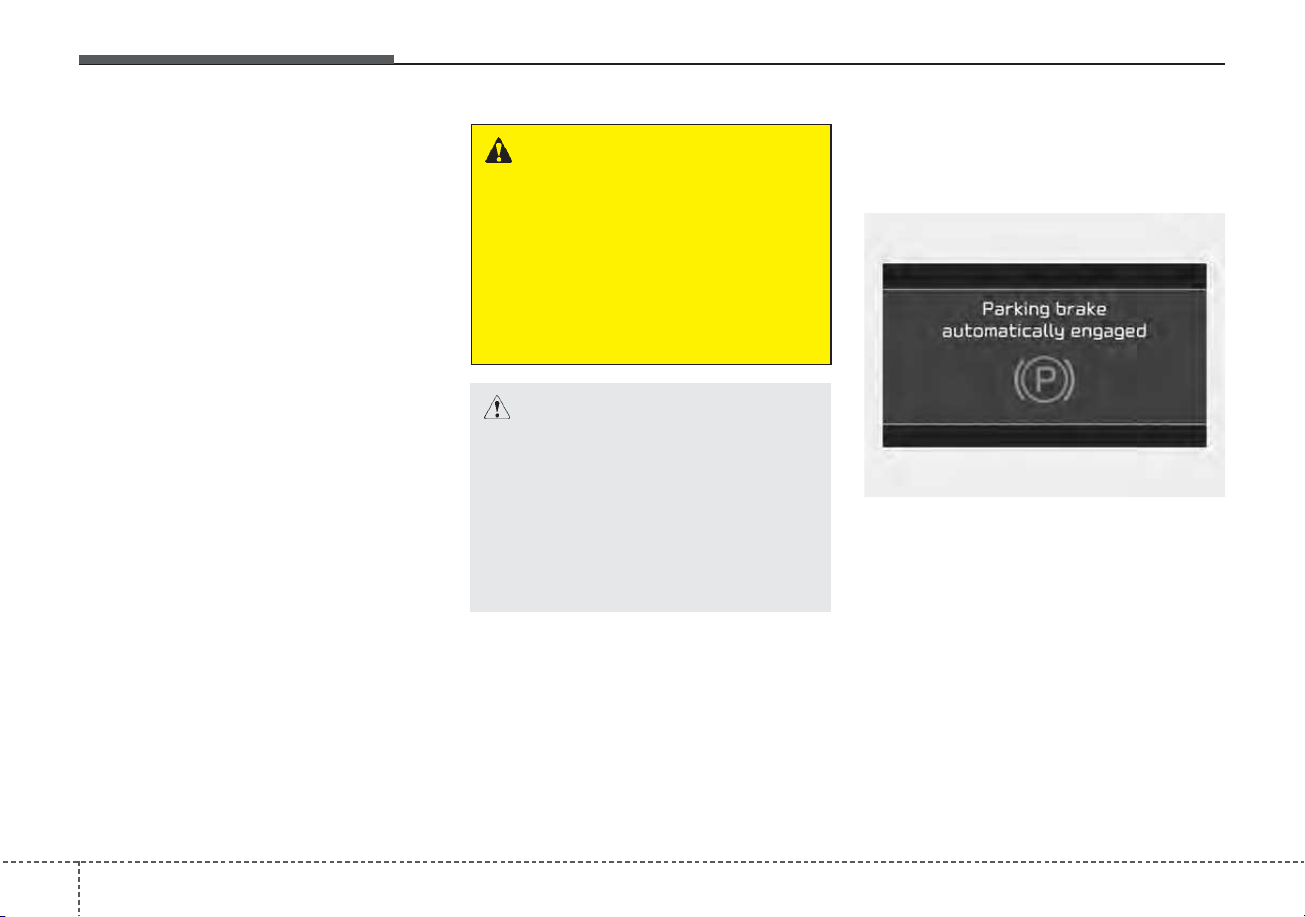
Driving your vehicle
425
(Continued)
In these cases, the brake warning
light comes on, the AUTO HOLD
indicator changes from green to
white, and a warning sounds and a
message will appear to inform you
that EPB has been automatically
engaged. Before driving off again,
press foot brake pedal, check the
surrounding area near your vehi-
cle and release parking brake
manually with the EPB switch.
• If the AUTO HOLD indicator
lights up yellow, the Auto Hold is
not working properly. Take your
vehicle to an authorized Kia deal-
er and have the system checked.
• While operating Auto Hold, you
may hear mechanical noise.
However, it is normal operation
noise.
Warning messages
Parking brake automatically
engaged
When the EPB is applied from Auto
Hold, a warning will sound and a
message will appear.
WARNING
• Press the accelerator pedal
slowly when you start the
vehicle.
• For your safety, cancel the
Auto Hold when you drive
downhill or back up or park
the vehicle.
CAUTION
If there is a malfunction with the
driver’s door, engine hood open
detection system, the Auto Hold
may not work properly.
Take your vehicle to an author-
ized Kia dealer and have the sys-
tem checked.
OJF058377L
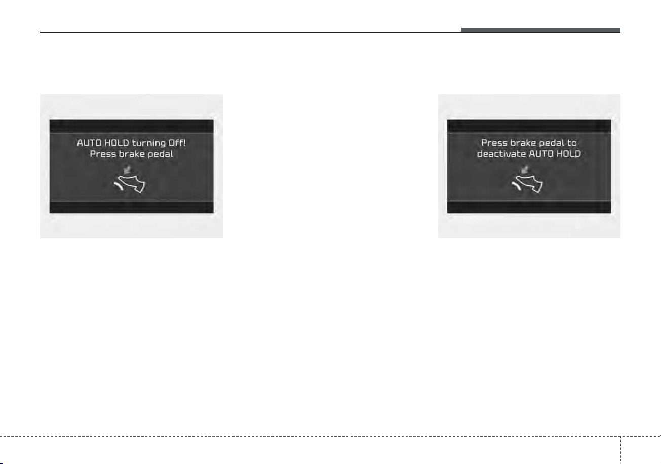
543
Driving your vehicle
AUTO HOLD turning Off!
Press brake pedal
When the conversion from Auto Hold
to EPB is not working properly a
warning will sound and a message
will appear.
✽✽
NOTICE
When this message is displayed, the
Auto Hold and EPB may not oper-
ate. For your safety, depress the
brake pedal.
Press brake pedal to deactivate
AUTO HOLD
If you did not apply the brake pedal
when you release the Auto Hold by
pressing the [AUTO HOLD] switch, a
warning will sound and a message
will appear.
OJF058375L OJF058381L
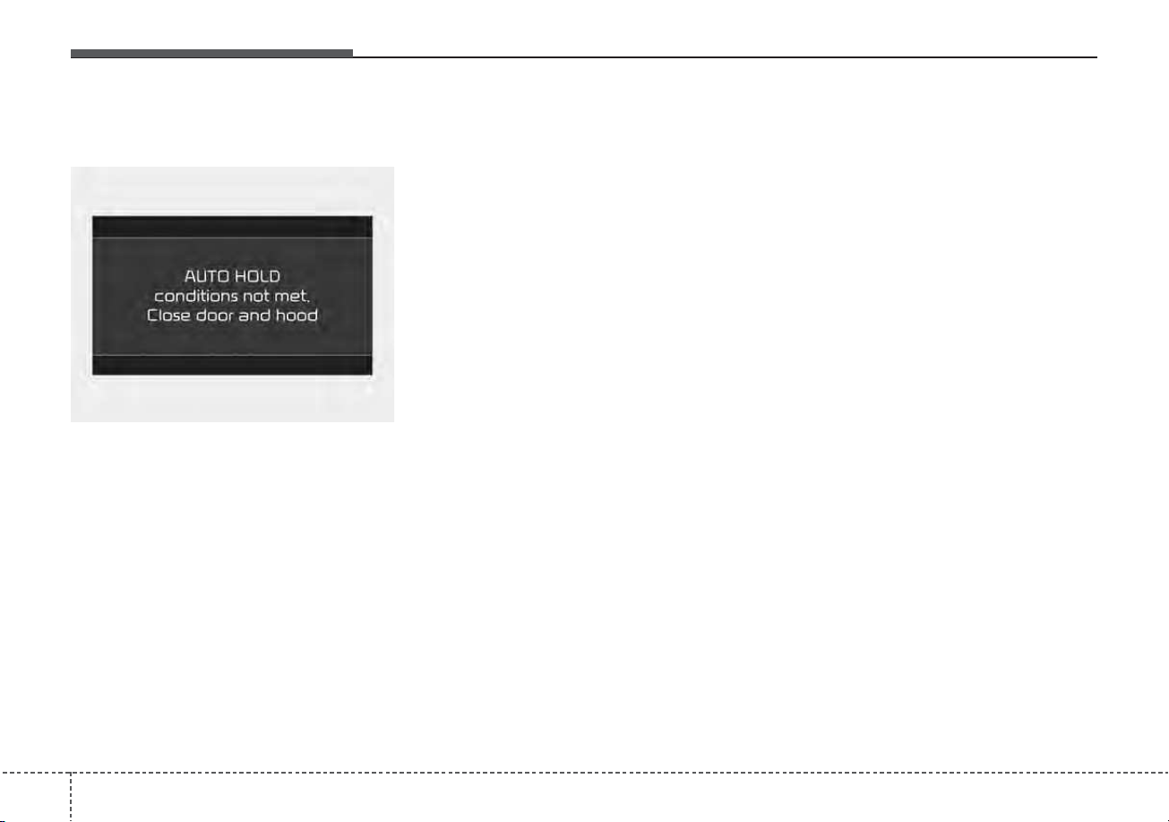
Driving your vehicle
445
AUTO HOLD conditions not met.
Close door and hood
When you press the [AUTO HOLD]
switch, if the driver’s door, engine
hood are not closed, a warning will
sound and a message will appear on
the LCD display. At this moment,
press the [AUTO HOLD] button after
closing the driver’s door and hood.
Anti-lock brake system (ABS)
ABS (or ESC) will not prevent acci-
dents due to improper or dangerous
driving maneuvers. Even though
vehicle control is improved during
emergency braking, always maintain
a safe distance between you and
objects ahead. Vehicle speeds
should always be reduced during
extreme road conditions. The vehicle
should be driven at reduced speeds
in the following circumstances:
• When driving on rough, gravel or
snow-covered roads
• When driving with tire chains
installed
• When driving on roads where the
road surface is pitted or has differ-
ent surface heights.
Driving in these conditions increases
the stopping distance for your vehicle.
The ABS continuously senses the
speed of the wheels. If the wheels
are going to lock, the ABS system
repeatedly modulates the hydraulic
brake pressure to the wheels.
When you apply your brakes under
conditions which may lock the
wheels, you may hear a “tik-tik’’
sound from the brakes, or feel a cor-
responding sensation in the brake
pedal. This is normal and it means
your ABS is active.
In order to obtain the maximum benefit
from your ABS in an emergency situa-
tion, do not attempt to modulate your
brake pressure and do not try to pump
your brakes. Press your brake pedal as
hard as possible to allow the ABS to
control the force being delivered to the
brakes.
✽✽
NOTICE
A click sound may be heard in the
engine compartment when the vehi-
cle begins to move after the engine is
started. These conditions are normal
and indicate that the anti-lock brake
system is functioning properly.
ODEP059313L
545
Driving your vehicle
• Even with the anti-lock brake sys-
tem, your vehicle still requires suf-
ficient stopping distance. Always
maintain a safe distance from the
vehicle in front of you.
• Always slow down when cornering.
The anti-lock brake system cannot
prevent accidents resulting from
excessive speeds.
• On loose or uneven road surfaces,
operation of the anti-lock brake
system may result in a longer stop-
ping distance than for vehicles
equipped with a conventional
brake system.
The ABS warning light will stay on for
approximately 3 seconds after the
ignition switch or the ENGINE
START/STOP button is ON. During
that time, the ABS will go through
self-diagnosis and the light will go off
if everything is normal. If the light
stays on, you may have a problem
with your ABS. Contact an author-
ized Kia dealer as soon as possible.
• When you drive on a road having
poor traction, such as an icy road,
and have operated your brakes
continuously, the ABS will be active
continuously and the ABS warning
light may illuminate. Pull your vehi-
cle over to a safe place and stop
the engine.
• Restart the engine. If the ABS
warning light goes off, then your
ABS system is normal. Otherwise,
you may have a problem with the
ABS. Contact an authorized Kia
dealer as soon as possible.
W-78
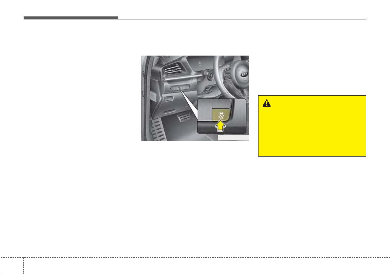
Driving your vehicle
465
✽✽
NOTICE
When you jump start your vehicle
because of a drained battery, the
engine may not run as smoothly and
the ABS warning light may turn on at
the same time. This happens because
of low battery voltage. It does not
mean your ABS has malfunctioned.
• Do not pump your brakes!
• Have the battery recharged before
driving the vehicle.
Electronic Stability Control
(ESC)
The Electronic Stability Control
(ESC) system is designed to stabi-
lize the vehicle during cornering
maneuvers. ESC checks where you
are steering and where the vehicle is
actually going. ESC applies the
brakes on individual wheels and
intervenes with the engine manage-
ment system to stabilize the vehicle.
Electronic stability control (ESC) will
not prevent accidents. Excessive
speed in turns, abrupt maneuvers
and hydroplaning on wet surfaces
can still result in serious accidents.
Only a safe and attentive driver can
prevent accidents by avoiding
maneuvers that cause the vehicle to
lose traction. Even with ESC
installed, always follow all the normal
precautions for driving - including
driving at safe speeds for the condi-
tions.
ODEP059016
WARNING
For maximum protection, always
wear your seat belt. No system,
no matter how advanced, can
compensate for all driver error
and/or driving conditions.
Always drive responsibly.
547
Driving your vehicle
The Electronic Stability Control (ESC)
system is an electronic system
designed to help the driver maintain
vehicle control under adverse condi-
tions. It is not a substitute for safe driv-
ing practices. Factors including speed,
road conditions and driver steering
input can all affect whether ESC will be
effective in preventing a loss of control.
It is still your responsibility to drive and
corner at reasonable speeds and to
leave a sufficient margin of safety.
When you apply your brakes under
conditions which may lock the wheels,
you may hear a “tik-tik’’ sound from the
brakes, or feel a corresponding sensa-
tion in the brake pedal. This is normal
and it means your ESC is active.
✽✽
NOTICE
A click sound may be heard in the
engine compartment when the vehi-
cle begins to move after the engine is
started. These conditions are normal
and indicate that the Electronic
Stability Control System is function-
ing properly.
ESC operation
ESC ON condition
• When the ignition switch or
the ENGINE START/STOP
button is turned ON, ESC
and ESC OFF indicator
lights illuminate for approxi-
mately 3 seconds, then
ESC is turned on.
• Press the ESC OFF but-
ton for at least half a sec-
ond after turning the igni-
tion switch or the ENGINE
START/STOP button ON
to turn ESC off. (ESC OFF
indicator will illuminate). To
turn the ESC on, press the
ESC OFF button (ESC
OFF indicator light will go
off).
• When starting the engine,
you may hear a slight tick-
ing sound. This is the ESC
performing an automatic
system self-check and does
not indicate a problem.
When operating
When the ESC is in opera-
tion, the ESC indicator light
blinks.
• When the Electronic
Stability Control is operat-
ing properly, you can feel a
slight pulsation in the vehi-
cle. This is only the effect
of brake control and indi-
cates nothing unusual.
• When moving out of the
mud or driving on a slip-
pery road, pressing the
accelerator pedal may not
cause the engine rpm
(revolutions per minute) to
increase.
-
Driving your vehicle
485
ESC operation off
ESC OFF state
This car has 2 kinds of ESC
off states.
If the engine stops when
ESC is off, ESC remains off.
Upon restarting the engine,
the ESC will automatically
turn on again.
“Traction Control disabled”
• ESC off state 1
To cancel ESC operation, press the
ESC OFF button (ESC OFF ) for
less than 3 seconds and the ESC
OFF indicator light (ESC OFF ) will
illuminate. At this state, the engine
control function does not operate. It
means the traction control function
does not operate. Only the brake con-
trol function will operate.
“Traction & Stability Control disabled”
• ESC off state 2
To cancel ESC operation, press the
ESC OFF button (ESC OFF ) for
more than 3 seconds. ESC OFF indi-
cator light (ESC OFF ) will illumi-
nate and ESC OFF warning chime
will sound. At this state, the engine
control function and brake control
function do not operate. It means the
car stability control function will not
operate any more.
Indicator light
When ignition switch or the ENGINE
START/STOP button is turned to ON,
the indicator light illuminates, then
goes off if the ESC system is operat-
ing normally.
The ESC indicator light blinks when-
ever ESC is operating or illuminates
when ESC fails to operate.
The ESC OFF indicator light comes
on when the ESC is turned off with
the button.
■ ESC indicator light
■ ESC OFF indicator light
549
Driving your vehicle
ESC OFF usage
When driving
• ESC should be turned on for daily
driving whenever possible.
• To turn ESC off while driving, press
the ESC OFF button while driving
on a flat road surface.
✽✽
NOTICE
• When operating the vehicle on a
dynamometer, ensure that the
ESC is turned off (ESC OFF light
illuminated). If the ESC is left on,
it may prevent the vehicle speed
from increasing, and result in false
diagnosis.
• Turning the ESC off does not
affect ABS or brake system opera-
tion.
WARNING - Electronic sta-
bility control
Drive carefully even though your
vehicle has Electronic Stability
Control. It can only assist you in
maintaining control under cer-
tain circumstances.
WARNING - Operating
ESC
Never press the ESC OFF but-
ton while ESC is operating (ESC
indicator light blinks).
If ESC is turned off while ESC is
operating, the vehicle may slip
out of control.
Driving your vehicle
505
Vehicle Stability Management
(VSM)
This system provides further
enhancements to vehicle stability
and steering responses when a vehi-
cle is driving on a slippery road or a
vehicle detects changes in coeffi-
cient of friction between right wheels
and left wheels when braking.
VSM operation
When the VSM is in operation, ESC
indicator light ( ) blinks.
When the vehicle stability manage-
ment is operating properly, you can
feel a slight pulsation in the vehicle
and/or abnormal steering responses
(EPS- Electronic Power Steering).
This is only the effect of brake and
EPS control and indicates nothing
unusual.
The VSM does not operate when:
• Driving on a sloping road such as a
gradient or incline
• Driving in reverse
• ESC OFF indicator light ( )
remains on the instrument cluster
• EPS indicator light remains on the
instrument cluster
VSM operation off
If you press the ESC OFF button to
turn off the ESC, the VSM will also
cancel and the ESC OFF indicator
light ( ) illuminates.
To turn on the VSM, press the button
again. The ESC OFF indicator light
goes out.
WARNING - Tire/
Wheel size
When replacing tires and wheels,
make sure they are the same size
as the original tires and wheels
installed. Driving with varying
tire or wheel sizes may diminish
any supplemental safety benefits
of the VSM system.
WARNING
- Vehicle stability manage-
ment
Drive carefully even though your
vehicle has vehicle stability
management. It can only assist
you in maintaining control of the
vehicle under certain circum-
stances.
551
Driving your vehicle
Malfunction indicator
The VSM can be deactivated even if
you don’t cancel the VSM operation
by pressing the ESC OFF button. It
indicates that a malfunction has
been detected somewhere in the
Electric Power Steering system or
VSM system. If the ESC indicator
light ( ) or EPS warning light
remains on, take your vehicle to an
authorized Kia dealer and have the
system checked.
✽✽
NOTICE
• The VSM is designed to function
above approximately 13 mph (22
km/h) on curves.
• The VSM is designed to function
above approximately 6 mph (10
km/h) when a vehicle is braking on
a split-mu surface. A split-mu sur-
face is made of two surfaces which
have different friction forces.
• The Vehicle Stability Management
system is not a substitute for safe
driving practices but a supplemen-
tary function only. It is the responsi-
bility of the driver to always check
the speed and the distance to the
vehicle ahead. Always hold the
steering wheel firmly while driving.
• Your vehicle is designed to activate
according to the driver’s intention,
even with installed VSM. Always fol-
low all the normal precautions for
driving at safe speeds for the condi-
tions – including driving in inclement
weather and on a slippery road.
Hill-start Assist Control (HAC)
A vehicle has the tendency to roll
back on a steep hill when it starts to
go after stopping. The Hill-start
Assist Control (HAC) prevents the
vehicle from rolling back by applying
the brakes automatically for about 2
seconds. The brakes are released
when the accelerator pedal is
depressed or after about 2 seconds.
The HAC is activated only for about 2
seconds, so when the vehicle is
starting off always depress the accel-
erator pedal.
WARNING
For maximum protection,
always wear your seat belt. No
system, no matter how
advanced, can compensate for
all driver error and/or driving
conditions. Always drive
responsibly.
WARNING - Maintaining
Brake Pressure on Incline
HAC does not replace the need
to apply brakes while stopped on
an incline. While stopped, make
sure you maintain brake pres-
sure sufficient to prevent your
vehicle from rolling backward
and causing an accident. Don’t
release the brake pedal until you
are ready to accelerate forward.

Driving your vehicle
525
Good braking practices
• Check to be sure the parking brake
is not engaged and the parking
brake indicator light is out before
driving away.
• Driving through water may get the
brakes wet. They can also get wet
when the vehicle is washed. Wet
brakes can be dangerous! Your
vehicle will not stop as quickly if the
brakes are wet. Wet brakes may
cause the vehicle to pull to one side.
To dry the brakes, apply the brakes
lightly until the braking action
returns to normal, taking care to
keep the vehicle under control at all
times. If the braking action does not
return to normal, stop as soon as it
is safe to do so and call an author-
ized Kia dealer for assistance.
• Don't coast down hills with the
vehicle out of gear. This is extreme-
ly hazardous. Keep the vehicle in
gear at all times, use the brakes to
slow down, then shift to a lower
gear so that engine braking will
help you maintain a safe speed.
• Don't "ride" the brake pedal.
Resting your foot on the brake
pedal while driving can be danger-
ous because the brakes might
overheat and lose their effective-
ness. It also increases the wear of
the brake components.
• If a tire goes flat while you are driv-
ing, apply the brakes gently and
keep the vehicle pointed straight
ahead while you slow down. When
you are moving slowly enough for it
to be safe to do so, pull off the road
and stop in a safe place.
• If your vehicle is equipped with a
dual clutch transmission, don't let
your vehicle creep forward. To
avoid creeping forward, keep your
foot firmly on the brake pedal when
the vehicle is stopped.
• Be cautious when parking on a hill.
Firmly engage the parking brake
and place the shift lever in P (Dual
clutch transmission). If your vehicle
is facing downhill, turn the front
wheels into the curb to help keep
the vehicle from rolling.
If your vehicle is facing uphill, turn
the front wheels away from the
curb to help keep the vehicle from
rolling. If there is no curb or if it is
required by other conditions to
keep the vehicle from rolling, block
the wheels.
• Under some conditions your park-
ing brake can freeze in the
engaged position. This is most like-
ly to happen when there is an
accumulation of snow or ice
around or near the rear brakes or if
the brakes are wet. If there is a risk
that the parking brake may freeze,
apply it only temporarily while you
put the shift lever in P (Dual clutch
transmission) and block the rear
wheels so the vehicle cannot roll.
Then release the parking brake.
• Do not hold the vehicle on an
incline with the accelerator pedal.
This can cause the transaxle to
overheat. Always use the brake
pedal or parking brake.
553
Driving your vehicle
FCA system is designed to detect
the vehicle ahead or pedestrians
ahead in the roadway through front
view camera recognition to warn the
driver that a collision is imminent,
and if necessary, apply emergency
braking.
❈ FCA stands for Forward Collision-
Avoidance Assist
System setting and activation
Forward safety
The driver can activate FCA system
by placing the ignition switch or
ENGINE START/STOP button to the
ON position and by selecting:
“User Settings → Driver Assistance
→ Forward Safety”
- If you select “Active Assist”, FCA
system activates. FCA produces
warning messages and warning
alarms in accordance with the col-
lision risk levels. Also, it controls
the brakes in accordance with the
collision risk levels.
- If you select “Warning Only”, FCA
system activates and produces
only warning alarms in accordance
with the collision risk levels. You
should control the brake directly
because FCA system do not con-
trol the brake.
- If you select “Off”, FCA system
deactivates,
FORWARD COLLISION-AVOIDANCE ASSIST (FCA) (FRONT VIEW CAMERA ONLY)
(IF EQUIPPED)
WARNING
Take the following precautions
when using Forward Collision-
Avoidance Assist system:
• This system is only a supple-
mental system and it is not
intended to, nor does it replace
the need for extreme care and
attention of the driver. The
sensing range and objects
detectable by the sensors are
limited. Pay attention to the
road conditions at all times.
• NEVER drive too fast in accor-
dance with the road condi-
tions or while cornering.
• Always drive cautiously to
prevent unexpected and sud-
den situations from occur-
ring. FCA system does not
stop the vehicle completely
and is only intended to help
mitigate an imminent colli-
sion.

Driving your vehicle
545
The warning light illumi-
nates on the LCD display,
when you cancel FCA
system.
The driver can monitor the FCA
ON/OFF status on the LCD display.
Also, the warning light illuminates
when the ESC (Electronic Stability
Control) is turned off. When the warn-
ing light remains ON with FCA acti-
vated, have your vehicle inspected by
an authorized Kia dealer.
Warning Timing
The driver can select the initial warn-
ing activation time on the LCD dis-
play.
Go to the “User Settings → Driver
Assistance → Warning Timing →
Normal/Later”
The options for the initial Forward
Collision Warning includes the fol-
lowing:
- Normal:
When this condition is selected, the
initial Forward Collision Warning sys-
tem is activated normally. This setting
allows for a nominal amount of dis-
tance between the vehicle ahead
before the initial warning occurs.
- Later:
When this condition is selected, the
initial Forward Collision Warning sys-
tem is activated later than normal.
This setting reduces the amount of
distance between the vehicle or
pedestrian before the initial warning
occurs.
Select 'Later' when traffic is light and
when driving speed is slow.
OYG059344L
555
Driving your vehicle
✽✽
NOTICE
If you change the warning timing,
the warning timing of other systems
may change. Always be aware of
warning timing before changing the
warning timing.
Prerequisite for activation
FCA system gets ready to be activat-
ed, when the “Active Assist”, or
“Warning Only”, under the Forward
Safety is selected on the LCD dis-
play, and when the following prereq-
uisites are satisfied.
- The ESC is activated.
- The driving speed is over 5 mph (8
km/h). (However, FCA is activated
within certain driving speed.)
- The system detects a vehicle or a
pedestrian in front, which may col-
lide with your vehicle. (FCA may
not be activated or may sound a
warning alarm in accordance with
the driving situation or vehicle con-
dition.)
❈FCA may not operate properly
according to the frontal situation,
the direction and speed of pedes-
trian.
WARNING
• Completely stop the vehicle
on a safe location before oper-
ating the switch on the steer-
ing wheel to activate/deacti-
vate FCA system.
• FCA system automatically
activates upon placing the
ignition switch to the ON posi-
tion. The driver can deactivate
FCA system by canceling the
system setting on the LCD
display or Infotainment
System screen.
• FCA system automatically
deactivates upon canceling
the ESC. When the ESC is
canceled, FCA system cannot
be activated on the LCD dis-
play or Infotainment System
screen.
The FCA system warning light
will illuminate, which is nor-
mal.
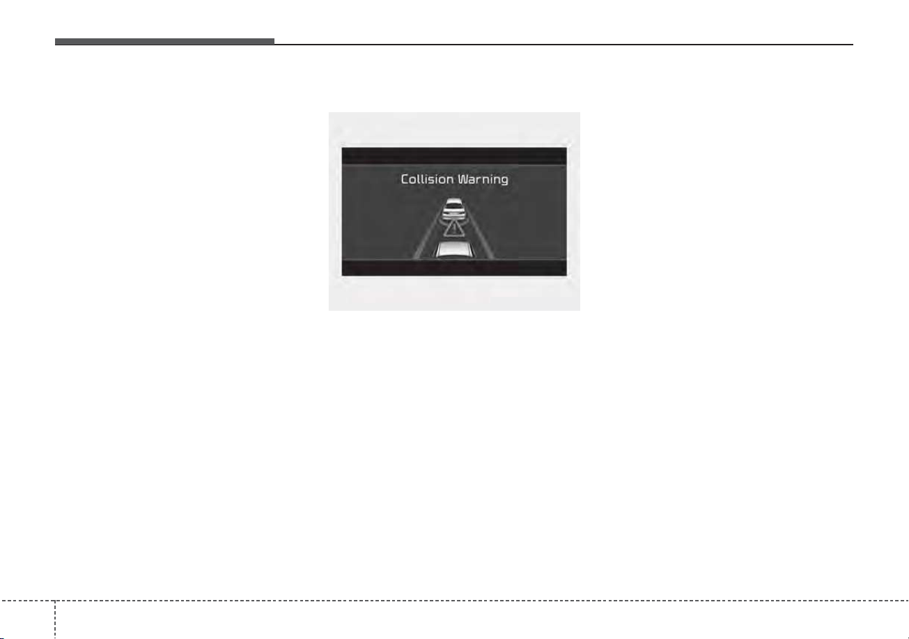
Driving your vehicle
565
FCA warning message and
system control
FCA produces warning messages
and warning alarms in accordance
with the collision risk levels, such as
abrupt stopping of the vehicle in
front, insufficient braking distance,
pedestrian detection. Also, it controls
the brakes in accordance with the
collision risk levels.
The driver can select the initial warn-
ing activation time in the ‘Settings’ on
the LCD display or Infotainment
System screen. The options for the
initial Forward Collision Warning
include Normal or Late initial warning
time.
Collision Warning (1st warning)
• The warning message appears on
the LCD display with the warning
alarms.
• The Vehicle may slow down slightly
- It will operate if the vehicle speed
is greater than 5 mph (8 km/h)
and less than or equal to 40 mph
(60 km/h) on a forward vehicle.
(Depending on the condition of
the vehicle ahead and the envi-
ronment surrounding it, the possi-
ble maximum operating speed
may be reduced.)
- For pedestrians, the vehicle
speed is greater than or equal to
5 mph (8 km/h) and less than 40
mph (60 km/h). (Depending on
the condition of pedestrians and
the surrounding environment the
possible maximum operating
speed may be reduced.)
• FCA system controls the brakes
within certain limit to release shock
from the collision.
- If you select “Warning Only”, FCA
system activates and produces
only warning alarms in accor-
dance with the collision risk lev-
els. You should control the brake
directly because FCA system do
not control the brake.
OJF058389L
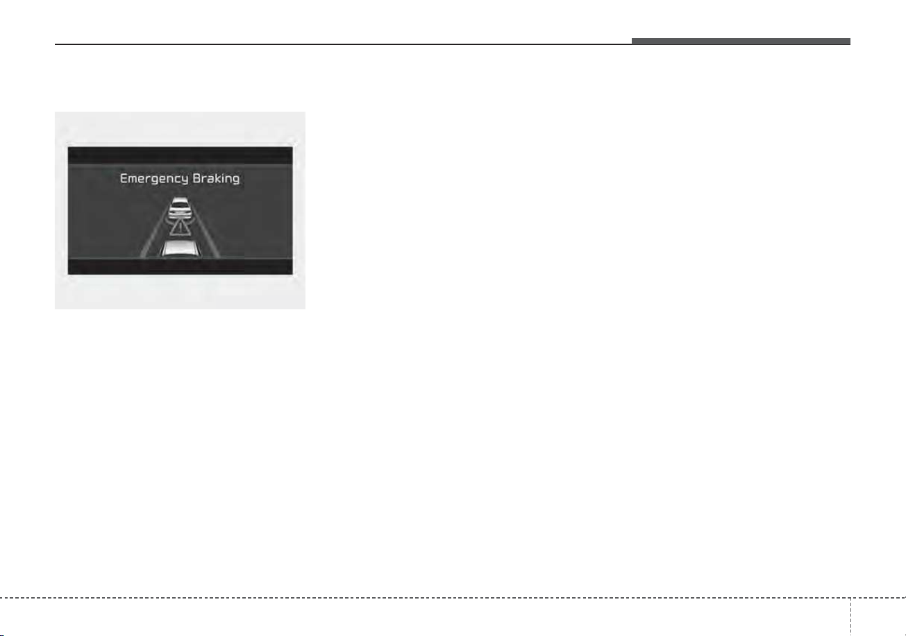
557
Driving your vehicle
Emergency braking (2nd warning)
• The warning message appears on
the LCD display with the warning
alarms.
• The brake control is maximized
just before a collision, reducing
impact when it strikes a forward
vehicle.
- It will operate if the vehicle speed
is greater than 5 mph (8 km/h)
and less than or equal to 40 mph
(60 km/h) on a forward vehicle.
(Depending on the condition of
the vehicle ahead and the envi-
ronment surrounding it, the possi-
ble maximum operating speed
may be reduced.)
- For pedestrians, the vehicle
speed is greater than or equal to
5 mph (8 km/h) and less than 40
mph (60 km/h). (Depending on
the condition of pedestrians and
the surrounding environment the
possible maximum operating
speed may be reduced.)
• FCA system controls the brakes
within certain limit to release shock
from the collision.
FCA system controls the maximum
brakes just before the collision.
- If you select “Warning Only”, FCA
system activates and produces
only warning alarms in accor-
dance with the collision risk lev-
els. You should control the brake
directly because FCA system do
not control the brake.
Brake operation
• In an urgent situation, the braking
system enters into the ready status
for prompt reaction to assist the driv-
er in depressing the brake pedal.
• FCA system provides additional
braking power for optimum braking
performance, when the driver
depresses the brake pedal.
• The braking control is automatical-
ly deactivated, when the driver
sharply depresses the accelerator
pedal, or when the driver abruptly
operates the steering wheel.
• The braking control is automatical-
ly canceled, when risk factors dis-
appear.
OJF058390L
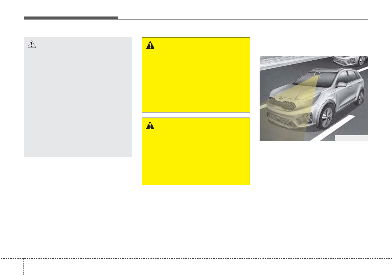
Driving your vehicle
585
Detecting sensor (front view
camera)
It is a sensor that decide the risk of a
collision by detecting the distance to
vehicles ahead or pedestrians.
In bad weather conditions such as
heavy rain, heavy snow, and fog, or
when the front camera is covered by
foreign material, dust, tec., the front
view camera will be degraded and
the system will be temporarily dis-
abled.
Always keep the front view camera
sensor clean.
WARNING
FCA system cannot avoid all
collisions. FCA system might
not completely stop the vehicle
before a collision, due to ambi-
ent, weather and road condi-
tions. The driver has the
responsibility to drive safely
and control the vehicle.
WARNING
FCA system operates in accor-
dance with certain risk factors,
such as the distance from the
vehicle/pedestrians in front, the
speed of the vehicle/pedestri-
ans in front, and the driver's
vehicle operation.
CAUTION
• The driver should always pay
great caution to vehicle opera-
tion, even though there is no
warning message or warning
alarm.
• If any other warning sound
such as seat belt warning
chime is already generated,
Forward Collision-Avoidance
Assist system warning may
not sound.
• Excessive audio volume may
disturb the sound of the sys-
tem warning alarm.
ODEP059029
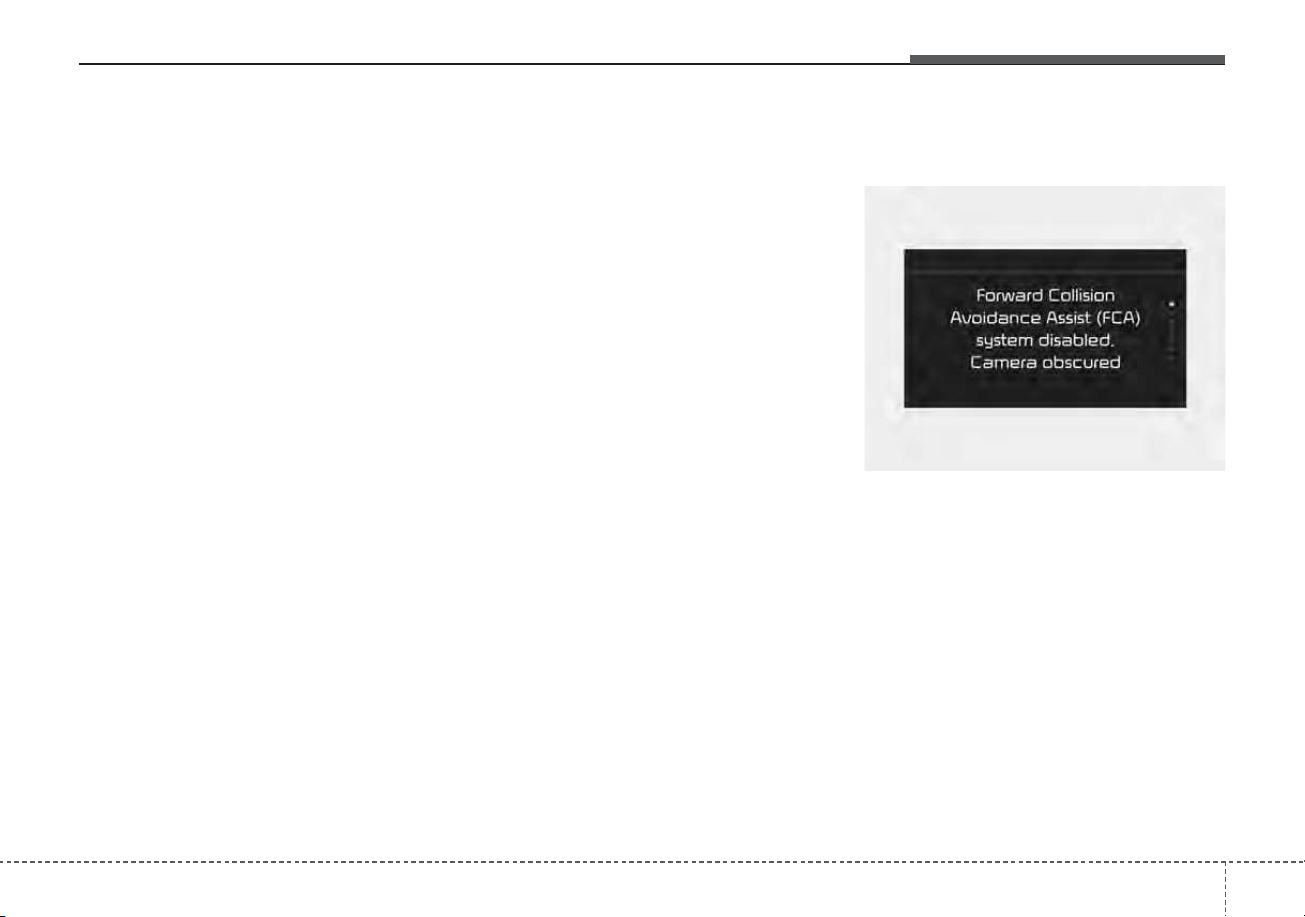
559
Driving your vehicle
✽✽
NOTICE
• Be careful not to apply unneces-
sary force on the frontal sensor
area. When the sensor moves out
of the correct position due to
external force, FCA system may
not normally operate even without
the warning light or message. In
this case, have your vehicle
inspected by an authorized Kia
dealer.
• Keep the sensor and sensor area
clean.
• Be careful not to force to shock on
sensor or area. If the sensor is out
of the position by the shock, FCA
system may not normally operate
even without the warning light ON
or message. In this case, have your
vehicle inspected by an authorized
Kia dealer.
• Do not tint the window or install
stickers, accessories around the
inside mirror where the camera is
installed.
• Make sure the frontal camera
installation point does not get wet.
(Continued)
(Continued)
• Do not impact or arbitrarily
remove any camera components.
• Do not place reflective
objects(white paper or mirror etc.)
on the crash pad.
FCA system may activate unneces-
sarily due to reflect of the sunlight.
• For more cautions for the camera
sensor, refer to Lane Keeping
Assist (LKA) in this chapter.
Warning message and warning
light
If the front view camera is covered by
bad weather or foreign objects, dust,
etc., FCA system operation may stop
temporarily. If this occurs, a warning
message will appear on the LCD dis-
play.
FCA system will operate normally
when debris is removed.
OBDM058129N
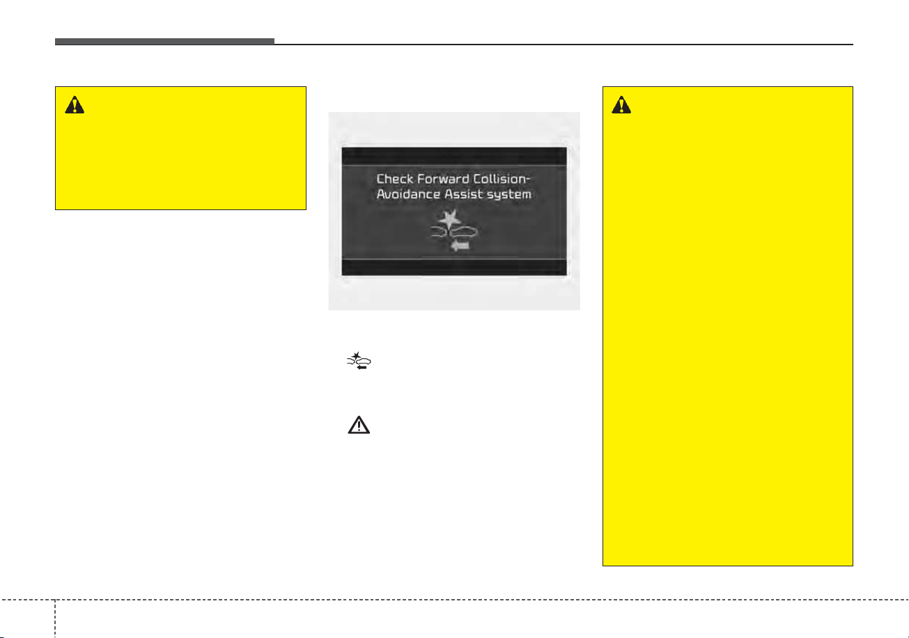
Driving your vehicle
605
System malfunction
• When FCA system is not working
properly, the FCA warning light
( ) will illuminate and the warn-
ing message will appear for a few
seconds. After the message disap-
pears, the master warning light
( ) will illuminate. In this case,
have your vehicle inspected by an
authorized Kia dealer.
• The FCA warning message may
appear along with the illumination
of the ESC warning light.
WARNING
FCA system may not activate
without any warning messeges
according to driving condition,
traffic on the road, weather,
road condition, etc.
OJF058394L
WARNING
• FCA system is only a supple-
mental system for the driver’s
convenience.The driver should
hold the responsibility to con-
trol the vehicle operation. Do
not solely depend on FCA sys-
tem. Rather, maintain a safe
braking distance, and, if neces-
sary, depress the brake pedal
to lower the driving speed.
• In certain instances and
under certain driving condi-
tions, FCA system may acti-
vate unintentionally. This ini-
tial warning message appears
on the LCD display with a
warning chime.
Also, in certain instances the
front radar sensor or camera
recognition system may not
detect the vehicle or pedestri-
an ahead. FCA system may
not activate and the warning
message will not be dis-
played.
(Continued)

561
Driving your vehicle
(Continued)
• If there is a malfunction with
FCA system, the autonomous
emergency braking may not
be applied even through the
braking system is operating
normally.
• If the vehicle in front stops
suddenly, you may have less
control of the brake system.
Therefore, always keep a safe
distance between your vehicle
and the vehicle in front of you.
• FCA system may activate dur-
ing braking and the vehicle
may stop, suddenly shifting
loose objects toward the pas-
sengers. Always keep loose
objects secured.
• FCA system may not activate
if the driver applies the brake
pedal to avoid a collision.
(Continued)
(Continued)
• Even if there is any problem
with the brake control func-
tion of FCA system, the vehi-
cle's basic braking perform-
ance will operate normally.
However, brake control func-
tion for avoiding collisions
may not activate.
• FCA system operates only to
detect vehicles, pedestrians
in front of the vehicle.
• FCA system does not operate
when the vehicle is in reverse.
• FCA system is not designed
to detect other objects on the
road such as animals.
• FCA system does not detect
vehicles in the opposite lane.
• FCA system does not detect
cross traffic vehicles that are
approaching.
(Continued)
(Continued)
• FCA system cannot detect the
driver approaching the side
view of a parked vehicle (for
example on a dead end
street.) In these situations,
you must maintain a safe
braking distance, and if nec-
essary, depress the brake
pedal to reduce the driving
speed in order to maintain a
safe distance.
• FCA system may not activate
as a result of the road condi-
tions, inclement weather, driv-
ing conditions or traffic condi-
tions.
• FCA system does not operate
for all vehicles and pedestri-
ans.

Driving your vehicle
625
Limitation of the system
Forward Collision-Avoidance Assist
system is designed to monitor the
vehicle ahead in the roadway
through camera recognition to warn
the driver that a collision is imminent,
and if necessary, apply emergency
braking. In certain situations, the
camera may not be able to detect the
vehicle ahead or pedestrian ahead.
In these cases, FCA system may not
operate normally. The driver must
pay careful attention in the following
situations where FCA operation may
be limited.
Recognizing vehicles
The sensor may be limited when:
• The system may not work around
15 seconds after starting the vehi-
cle or the initialization or rebooting
of the front view camera.
• The camera is blocked with a for-
eign object or debris
• The camera lens is contaminated
due to tinted, filmed or coated
windshield, damaged glass, or
stuck of foreign matter (sticker,
bug, etc.) on the glass
• Inclement weather such as heavy
rain or snow obscures the field of
view of the camera
• There is interference by electro-
magnetic waves
• The camera recognition is limited
• The vehicle in front is too small to
be detected (for example a motor
cycle or bicycle etc.)
• The vehicle in front is an oversize
vehicle or trailer that is too big to
be detected by the camera recog-
nition system (for example a tractor
trailer, etc.)
• The driver's field of view is not well
illuminated (either too dark or too
much reflection or too much back-
light that obscures the field of view)
• The vehicle in front does not have
their rear lights properly turned
ON.
• The outside brightness changes
suddenly, for example when enter-
ing or exiting a tunnel
• The vehicle in front is driving errat-
ically
• The vehicle is on unpaved or
uneven rough surfaces, or road
with sudden gradient changes.
• The vehicle is under ground level
or inside a building.
• The vehicle is driven near areas
containing metal substances as a
construction zone, railroad, etc.
• The sensor recognition changes
suddenly when passing over a
speed bump
• The vehicle shakes heavily.
• You are on a roundabout and the
vehicle in front circles

563
Driving your vehicle
• The front view or camera is broken.
• The headlamps are not on at night
or in a tunnel, or light level is low.
• The light of street, sun, oncoming
vehicle and so on reflects from the
water on the road.
• When light shines brightly in the
reverse direction you drive.
• The shadow is on the lane marker
by a median strip, trees, etc.
• The windshield glass is fogged up;
a clear view of the road is obstruct-
ed
• The front view camera sensor
recognition is limited
• When only a part of vehicle image
does not cover the entire vehicle.
• When the front view camera is
blocked by continuous washer
spray and wiper operation.
• The vehicle in front is a special
purpose vehicle, a trailer, or a truck
loading with unusual shape of lug-
gage.
• The ambient light is too high or low.
• The vehicle is passing a tunnel, a
tollgate, or partially paved road.
• The windshield glass is fogged up;
• It is hard to see the rear side of the
vehicle in front.
• When it is hard to see the rear side
of the front vehicle. (The front vehi-
cle is turning or is overturned.)
• When the rear part of the front
vehicle is small or low.
• When a trailer or other vehicle is
towing the front vehicle.
• When the ground clearance of the
front vehicle is high.
• When a front vehicle makes sud-
den lane changes unexpectedly.
Detecting pedestrians
The sensor may be limited when:
• The pedestrian is not fully detected
by the camera recognition system,
for example, if the pedestrian is
leaning over or is not fully walking
upright.
• The pedestrian is moving very
quickly or appears abruptly in the
camera detection area.
• The pedestrian is wearing clothing
that easily blends into the back-
ground, making it difficult to be
detected by the camera recogni-
tion system.
• The outside lighting is too bright
(e.g. when driving in bright sunlight
or in sun glare) or too dark (e.g.
when driving on a dark rural road
at night).
• It is difficult to detect and distin-
guish the pedestrian from other
objects in the surroundings, for
example, when there is a group of
pedestrians or a large crowd.
• There is an item similar to a per-
son's body structure.
• The pedestrian is small.
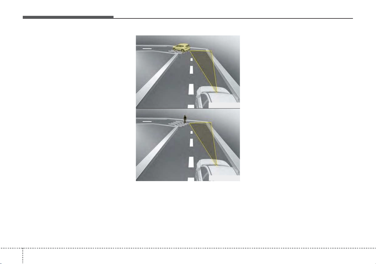
Driving your vehicle
645
• The pedestrian has impaired
mobility.
• When the pedestrian suddenly
interrupts in front of the vehicle.
- Driving on a curve
The performance of Forward
Collision-Avoidance Assist system
may be limited when driving on a
curved road. The front view camera
recognition system may not detect
the vehicle or pedestrian traveling in
front on a curved road.
This may result in no alarm and
braking when necessary. Always pay
attention to road and driving condi-
tions, and if necessary, depress the
brake pedal to reduce your driving
speed in order to maintain a safe dis-
tance.
OHM059342L
OHM059343L
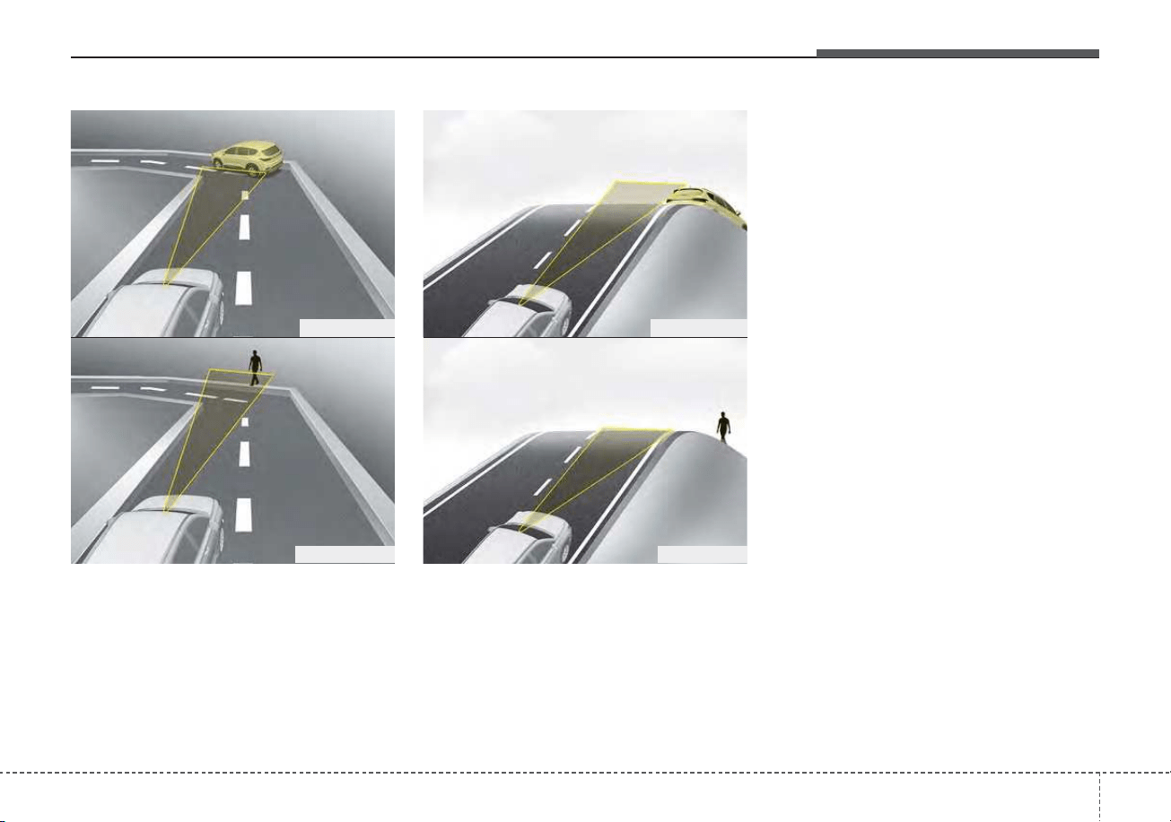
565
Driving your vehicle
Forward Collision-Avoidance Assist
system may recognize a vehicle or
pedestrian in the next lane or outside
the lane when driving on a curved
road. If this occurs, the system may
unnecessarily alarm the driver and
apply the brake. Always pay attention
to road and driving conditions, while
driving.
- Driving on a slope
The performance of Forward
Collision-Avoidance Assist system
may be decreased while driving
upward or downward on a slope.
The front view camera recognition
may not detect the vehicle or pedes-
trian in front.
This may result in unnecessary
alarm and braking or no alarm and
braking when necessary. When the
system suddenly recognizes the
vehicle or pedestrian in front while
passing over a slope, you may expe-
rience sharp deceleration. Always
keep your eyes forward while driving
upward or downward on a slope,
and, if necessary, depress the brake
pedal to reduce your driving speed in
order to maintain distance.
OHM059346L
OHM059347L
OHM059344L
OHM059345L
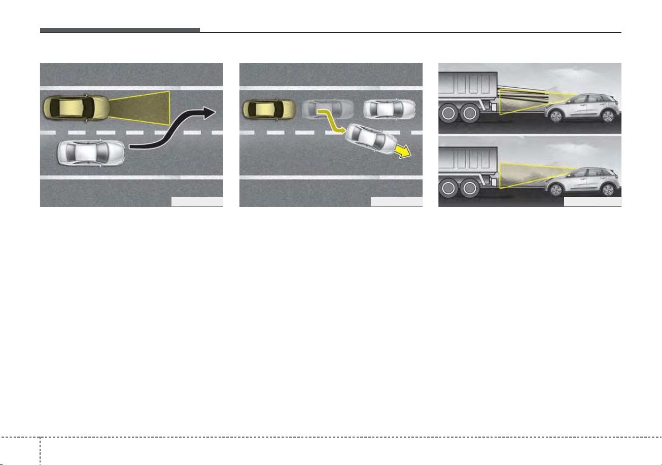
Driving your vehicle
665
- Changing lanes
When a vehicle changes lanes in
front of you, Forward Collision-
Avoidance Assist system may not
immediately detect the vehicle, espe-
cially if the vehicle changes lanes
abruptly. In this case, you must main-
tain a safe braking distance, and if
necessary, depress the brake pedal
to reduce your driving speed in order
to maintain a safe distance.
When driving in stop-and-go traffic,
and a stopped vehicle in front of you
merges out of the lane, Forward
Collision-Avoidance Assist system
may not immediately detect the new
vehicle that is now in front of you. In
this case, you must maintain a safe
braking distance, and if necessary,
depress the brake pedal to reduce
your driving speed in order to main-
tain a safe distance.
- Recognizing the vehicle
When the vehicle in front has heavy
loading extended rearward, or when
the vehicle in front has higher ground
clearance, it may induce a haz-
ardous situation. Always pay atten-
tion to road and driving conditions,
while driving and, if necessary,
depress the brake pedal to reduce
your driving speed in order to main-
tain distance.
OYG056048OYG056045 ODEP059327N
567
Driving your vehicle
Detecting pedestrians
The sensor may be limited when:
• The pedestrian is not fully detected
by the front view camera recogni-
tion system, for example, if the
pedestrian is leaning over or is not
fully walking upright.
• The pedestrian is moving very
quickly or appears abruptly in the
camera detection area.
• The pedestrian is wearing clothing
that easily blends into the back-
ground, making it difficult to be
detected by the camera recogni-
tion system.
• The outside lighting is too bright
(e.g. when driving in bright sunlight
or in sun glare) or too dark (e.g.
when driving on a dark rural road
at night).
• It is difficult to detect and distin-
guish the pedestrian from other
objects in the surroundings, for
example, when there is a group of
pedestrians, or a large crowd.
• There is an item similar to a per-
son's body structure.
• The pedestrian is small.
• The pedestrian has impaired
mobility.
• In case of camera sensor recogni-
tion is in a marginal state.
• When the pedestrian suddenly
interrupts in front of the vehicle.
• When there is any other electro-
magnetic interference.
• When the construction area, rail or
other metal object is near the
pedestrian.
• In case of a large number of
pedestrians are gathered.
• When it is difficult to distinguish
between surroundings and pedes-
trians.
• When it is at night or in dark sur-
roundings.
WARNING
• Do not use Forward Collision-
Avoidance Assist system
when towing a vehicle.
Application of FCA system
while towing may adversely
affect the safety of your vehi-
cle or the towing vehicle.
• Use extreme caution when the
vehicle in front of you has
cargo that extends rearward
from the cab, or when the
vehicle in front of you has
higher ground clearance.
• FCA system is designed to
detect and monitor the vehicle
ahead in the roadway through
camera recognition. It is not
designed to detect bicycles,
motorcycles, or smaller
wheeled objects such as lug-
gage bags, shopping carts, or
strollers.
(Continued)

Driving your vehicle
685
✽✽
NOTICE
In some instances, FCA system may
be cancelled when subjected to elec-
tromagnetic interference.
This device complies with Part 15
of the FCC rules.
Operation is subject to the following
three conditions:
1. This device may not cause harmful
interference.
2. This device must accept any inter-
ference received, including inter-
ference that may cause undesired
operation.
3. Changes or modifications not
expressly approved by the party
responsible for compliance could
void the user's authority to operate
the device.
Radio frequency radiation exposure
information:
This equipment complies with FCC
radiation exposure limits set forth for
uncontrolled environment.
This equipment should be installed
and operated with minimum distance
of 8 in. (20 cm) between the radiator
(antenna) and your body.
This transmitter must not be co-
located or operating in conjunction
with any other antenna or transmit-
ter.
(Continued)
• Never try to test the operation
of FCA system. Doing so may
cause severe injury or death.
• If the front glass or front view
camera have been replaced or
repaired, have your vehicle
inspected by an authorized
Kia dealer.
• If the system detects an
object that has a similar
shape or characteristics of a
vehicle or a pedestrian, FCA
system may operate.
569
Driving your vehicle
FCA system is to reduce or to avoid
accident risk. It recognizes the dis-
tance from the vehicle ahead, the
pedestrian or the cyclist through the
sensors (i.e. front view camera and
front radar), and, if necessary, warns
the driver of accident risk with the
warning message or the warning
alarms and apply emergency brak-
ing.
❈ FCA stands for Forward Collision-
Avoidance Assist.
❈ Sensor fusion (front view camera
+ front radar) FCA system oper-
ates for the vehicle ahead, the
pedestrian or the cyclist in front.
System setting and activation
Forward safety
The driver can activate FCA system
by placing the ignition switch or
ENGINE START/STOP button to the
ON position and by selecting:
“User Settings → Driver Assistance
→ Forward Safety”
- If you select “Active Assist”, FCA
system activates. FCA produces
warning messages and warning
alarms in accordance with the col-
lision risk levels. Also, it controls
the brakes in accordance with the
collision risk levels.
- If you select “Warning Only”, FCA
system activates and produces
only warning alarms in accordance
with the collision risk levels. You
should control the brake directly
because FCA system do not con-
trol the brake.
- If you select “Off”, FCA system
deactivates,
FORWARD COLLISION-AVOIDANCE ASSIST (FCA) (SENSOR FUSION) (IF EQUIPPED)
WARNING
Take the following precautions
when using Forward Collision-
Avoidance Assist system:
• This system is only a supple-
mental system and it is not
intended to, nor does it replace
the need for the extreme care
and attention of the driver. The
sensing range and objects
detectable by the sensors are
limited. Pay attention to the
road conditions at all times.
• NEVER drive too fast in accor-
dance with the road condi-
tions or while cornering.
• Always drive cautiously to
prevent unexpected and sud-
den situations from occur-
ring. FCA system does not
stop the vehicle completely
and is only intended to help
mitigate an imminent colli-
sion.
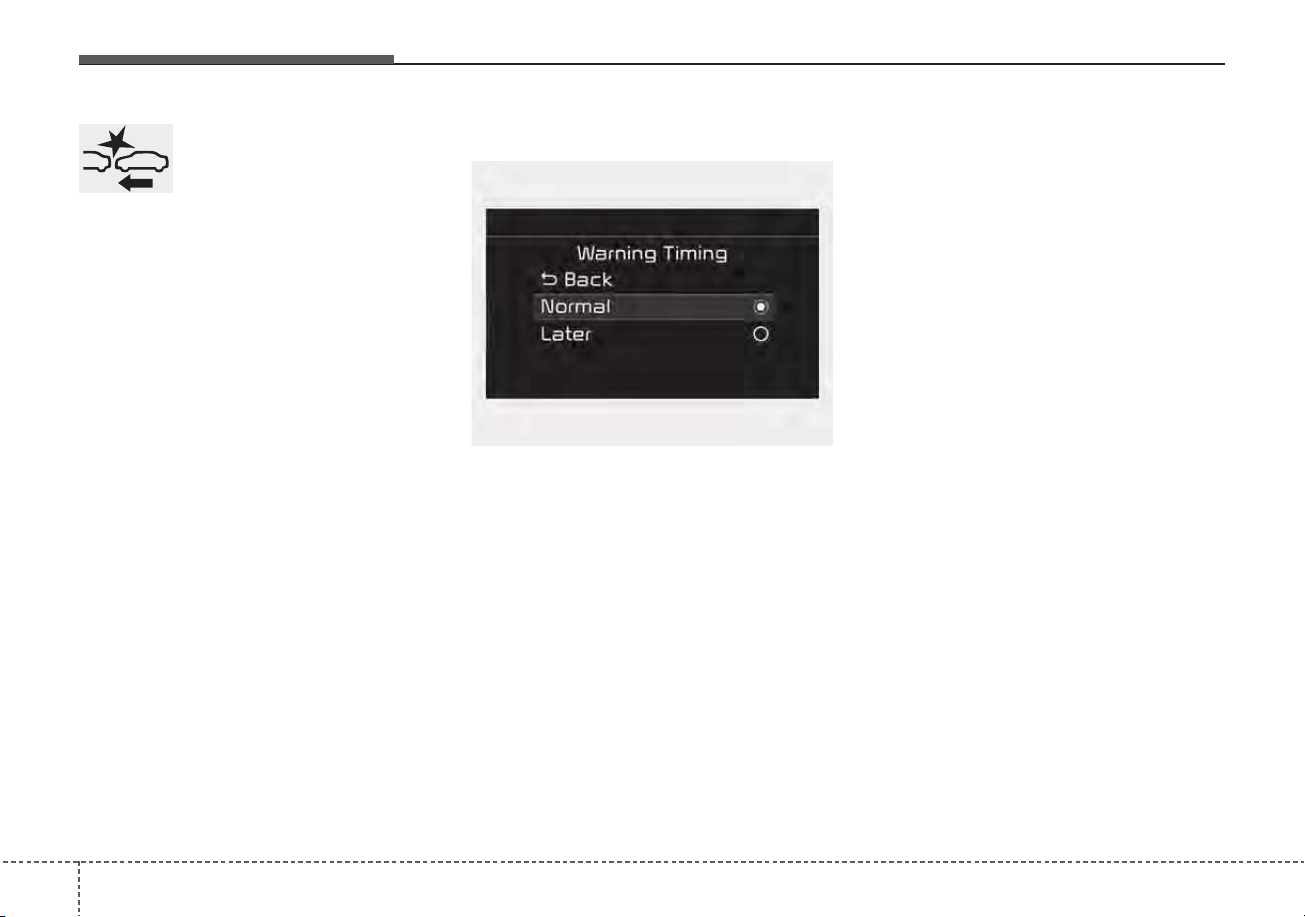
Driving your vehicle
705
The warning light illumi-
nates on the LCD display,
when you cancel FCA sys-
tem. The driver can moni-
tor the FCA ON/OFF status on the
LCD display. Also, the warning light
illuminates when the ESC (Electronic
Stability Control) is turned off. When
the warning light remains ON with
FCA activated, have your vehicle
inspected by an authorized Kia deal-
er.
Warning Timing
The driver can select the initial warn-
ing activation time on the LCD dis-
play.
Go to the “User Settings → Driver
Assistance → Warning Timing →
Normal/Later”
The options for the initial Forward
Collision Warning includes the fol-
lowing:
- Normal:
When this condition is selected, the
initial Forward Collision Warning sys-
tem is activated normally. This setting
allows for a nominal amount of dis-
tance between the vehicle ahead
before the initial warning occurs.
- Later:
When this condition is selected, the
initial Forward Collision Warning sys-
tem is activated later than normal.
This setting reduces the amount of
distance between the vehicle ahead,
the pedestrian or the cyclist before
the initial warning occurs.
Select 'Later' when traffic is light and
when driving speed is slow.
If the vehicle in front puts on a burst
of speed, the driver can notice the
warning alarm is early even though
the later option is selected.
OYG059344L

571
Driving your vehicle
✽✽
NOTICE
If you change the warning timing,
the warning timing of other systems
may change. Always be aware of
warning timing before changing the
warning timing.
Prerequisite for activation
FCA system gets ready to be activat-
ed, when the “Active assist” or
“Warning only” under the Forward
Safety is selected on the LCD dis-
play, and when the following prereq-
uisites are satisfied.
- The ESC is activated.
- The driving speed is over 5 mph (8
km/h). (However, FCA is activated
within certain driving speed.)
- When recognizing the vehicle or
the pedestrian or the cyclist in
front. (However, FCA does not acti-
vate according to conditions in
front and vehicle systems, but it
notices only certain warnings.)
- FCA does not operate properly or it
only produces a warning alarms in
accordance with the driving or
vehicle condition.
- If the warning only under the
Forward Safety is selected, FCA
produces only warning alarms in
accordance with the collision risk
levels.
✽✽
NOTICE
FCA may not operate properly
according to the frontal situation,
the direction of pedestrian or cyclist
and speed.
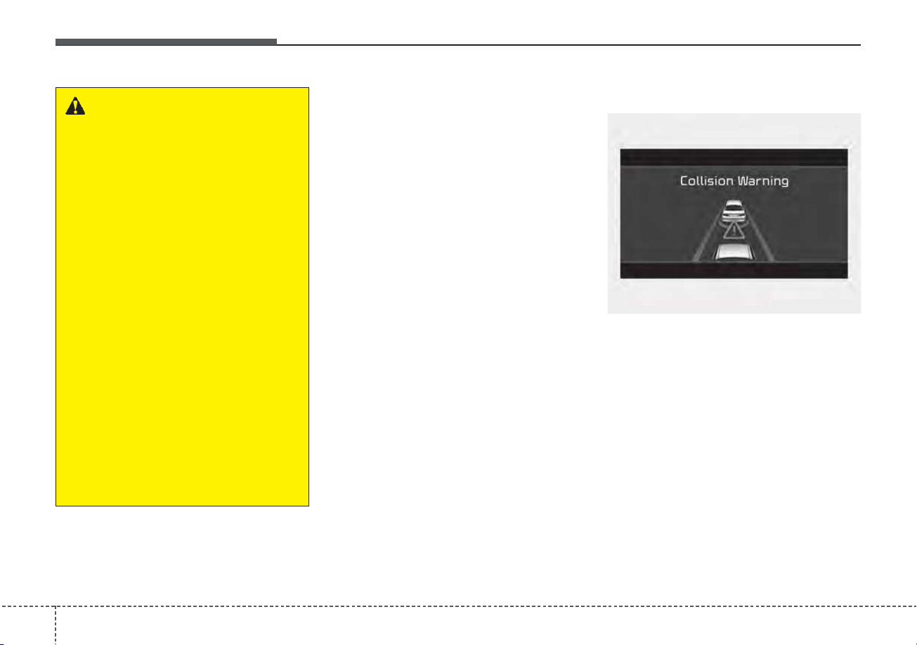
Driving your vehicle
725
FCA warning message and
system control
FCA system produces warning mes-
sages and warning alarms in accor-
dance with the collision risk levels of
followings like vehicle’s sudden brak-
ing in front or lack of vehicle to vehi-
cle distance or collision to pedestri-
ans or cyclist. Also, it controls the
brakes in accordance with the colli-
sion risk levels.
The driver can select the initial warn-
ing activation time in the User set-
tings in the LCD display. The
options for the initial Forward
Collision Warning include Normal or
Late initial warning time.
Collision Warning (1st warning)
• The warning message appears on
the LCD display with the warning
alarms.
• The Vehicle may slow down slightly
- It will operate if the vehicle speed
is greater than 5 mph (8 km/h)
and less than or equal to 110
mph (180 km/h) on a forward
vehicle. (Depending on the condi-
tion of the vehicle ahead and the
environment surrounding it, the
possible maximum operating
speed may be reduced.)
WARNING
• Completely stop the vehicle in
a safe location before operat-
ing the switch on the steering
wheel to activate/deactivate
FCA system.
• FCA system automatically
activates upon placing the
ignition switch to the ON posi-
tion. The driver can deactivate
FCA system by canceling the
system setting on the LCD
display or Infotainment
System screen.
• FCA system automatically
deactivates upon canceling
the ESC. When the ESC is
canceled, FCA system cannot
be activated on the LCD dis-
play or Infotainment System
screen.
FCA system warning light will
illuminate, which is normal.
OJF058389L
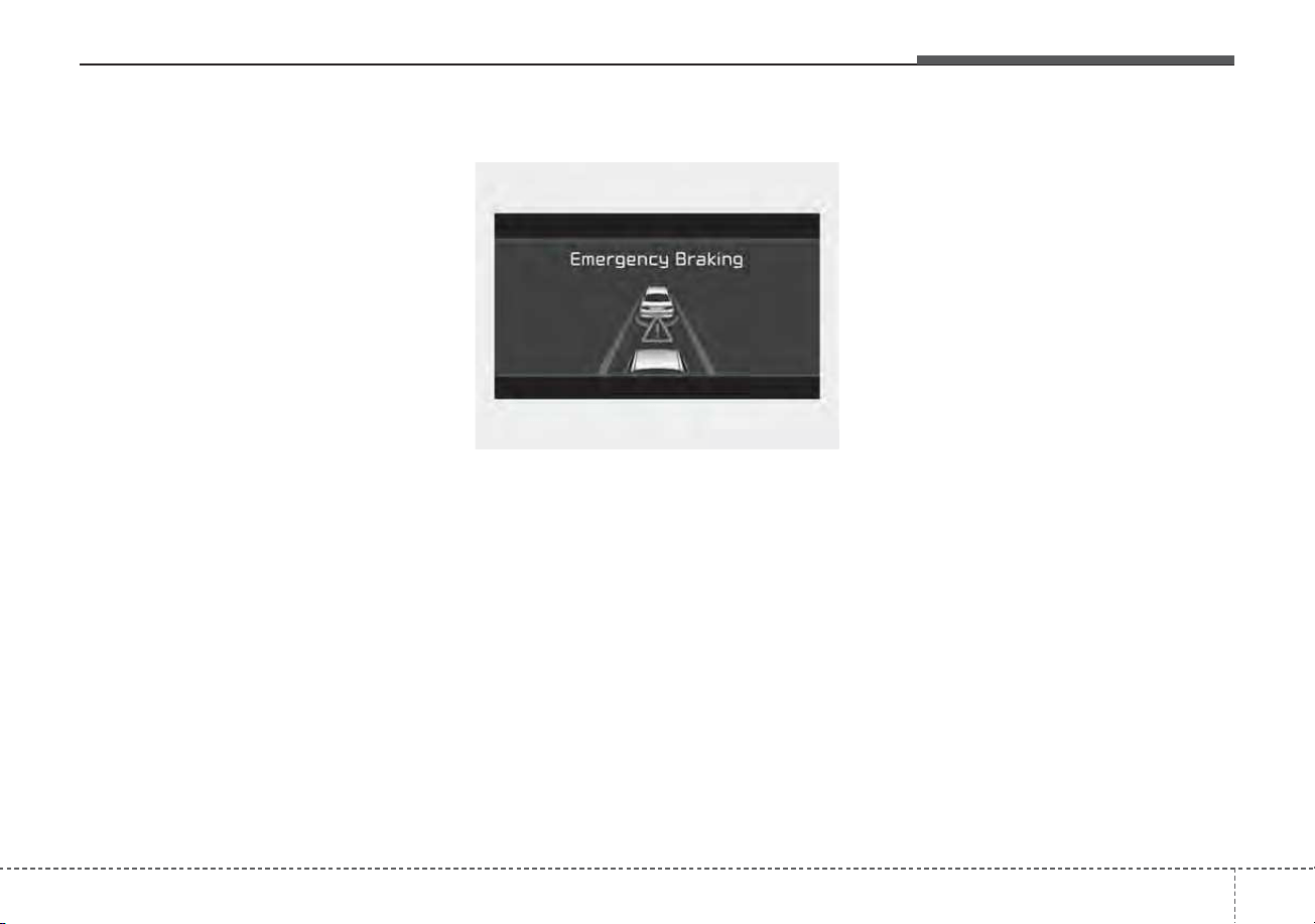
573
Driving your vehicle
- For pedestrians and cyclists, the
vehicle speed is greater than or
equal to 5 mph (8 km/h) and less
than 45 mph (70 km/h).
(Depending on the condition of
pedestrians and bike riders and
the surrounding environment the
possible maximum operating
speed may be reduced.)
• FCA system controls the brakes
within certain limit to release shock
from the collision.
- If you select “Warning Only”, FCA
system activates and produces
only warning alarms in accor-
dance with the collision risk lev-
els. You should control the brake
directly because FCA system do
not control the brake.
Emergency braking (2nd warning)
• The warning message appears on
the LCD display with the warning
alarms.
• The brake control is maximized
just before a collision, reducing
impact when it strikes a forward
vehicle.
- It will operate if the vehicle speed
is greater than 5 mph (8 km/h)
and less than or equal to 50 mph
(80 km/h) on a forward vehicle.
(Depending on the condition of
the vehicle ahead and the envi-
ronment surrounding it, the possi-
ble maximum operating speed
may be reduced.)
- For pedestrians and cyclists, the
vehicle speed is greater than or
equal to 5 mph (8 km/h) and less
than 45 mph (70 km/h).
(Depending on the condition of
pedestrians and bike riders and
the surrounding environment the
possible maximum operating
speed may be reduced.)
• FCA system controls the brakes
within certain limit to release shock
from the collision.
FCA system controls the maximum
brakes just before the collision.
- If you select “Warning Only”,
FCA system activates and pro-
duces only warning alarms in
accordance with the collision risk
levels. You should control the
brake directly because FCA sys-
tem do not control the brake.
OJF058390L
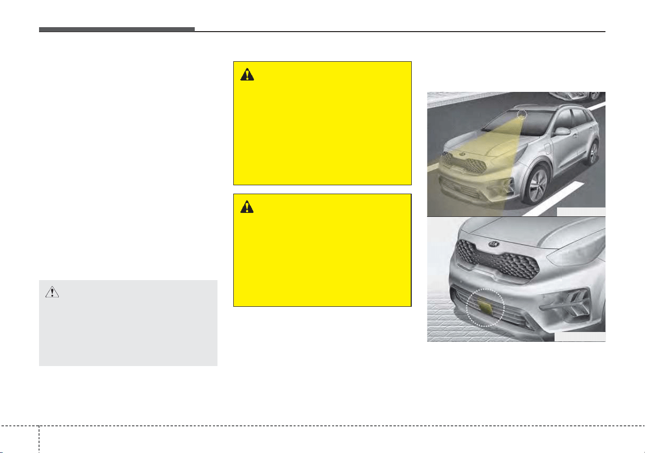
Driving your vehicle
745
Brake operation
• In an urgent situation, the braking
system enters into the ready status
for prompt reaction to assist the driv-
er in depressing the brake pedal.
• FCA system provides additional
braking power for optimum braking
performance, when the driver
depresses the brake pedal.
• The braking control is automatical-
ly deactivated, when the driver
sharply depresses the accelerator
pedal, or when the driver abruptly
operates the steering wheel.
• The braking control is automatical-
ly canceled, when risk factors dis-
appear.
Detecting sensors (front view
camera/front radar)
The sensors are that detecting the
distance to vehicles ahead, pedestri-
an or cyclist.
CAUTION
The driver should always pay
great caution to vehicle opera-
tion, even though there is no
warning message or warning
alarm.
WARNING
FCA system cannot avoid all
collisions. FCA system might
not completely stop the vehicle
before a collision, due to ambi-
ent, weather and road condi-
tions. The driver has the
responsibility to drive safely
and control the vehicle.
WARNING
FCA system operates in accor-
dance with certain risk factors,
such as the distance from the
vehicle/passer-by in front, the
speed of the vehicle/passer-by in
front, and the driver's vehicle
operation.
ODEP059029
ODEP059017

575
Driving your vehicle
In bad weather conditions such as
heavy rain, heavy snow, and fog, or
when sensor is covered by foreign
material, dust, tec., the sensors will
be degraded and the system will be
temporarily disabled.
Always keep the sensor clean.
✽✽
NOTICE
• Do not install any accessories,
such as license plate molding or
sticker, on the sensor area. Nor
arbitrarily replace the bumper.
Those may adversely affect the
sensing performance.
• Always keep the sensor/bumper
area clean.
• Use only soft cloths to wash the
vehicle. Also, do not spray highly-
pressurized water on the sensor
installed on the bumper.
• Be careful not to apply unneces-
sary force on the frontal sensor
area. When the sensor moves out
of the correct position due to
external force, the system may not
normally operate even without the
warning light or message. In this
case, have your vehicle inspected
by an authorized Kia dealer.
• Use only the genuine Kia sensor
cover. Do not arbitrarily apply
paint on the sensor cover.
(Continued)
(Continued)
• Do not tint the window or install
stickers, accessories around the
inside mirror where the camera is
installed.
• Make sure the frontal camera
installation point does not get wet.
• Do not impact or arbitrarily
remove any radar/camera compo-
nents.
• Do not place reflective
objects(white paper or mirror etc.)
on the crash pad.
The system may activate unneces-
sarily due to reflect of the sunlight.
• Excessive audio volume may dis-
turb the sound of the system warn-
ing alarm.
• For more cautions for the camera
sensor, refer to the “Lane Keeping
Assist (LKA)” in this chapter.
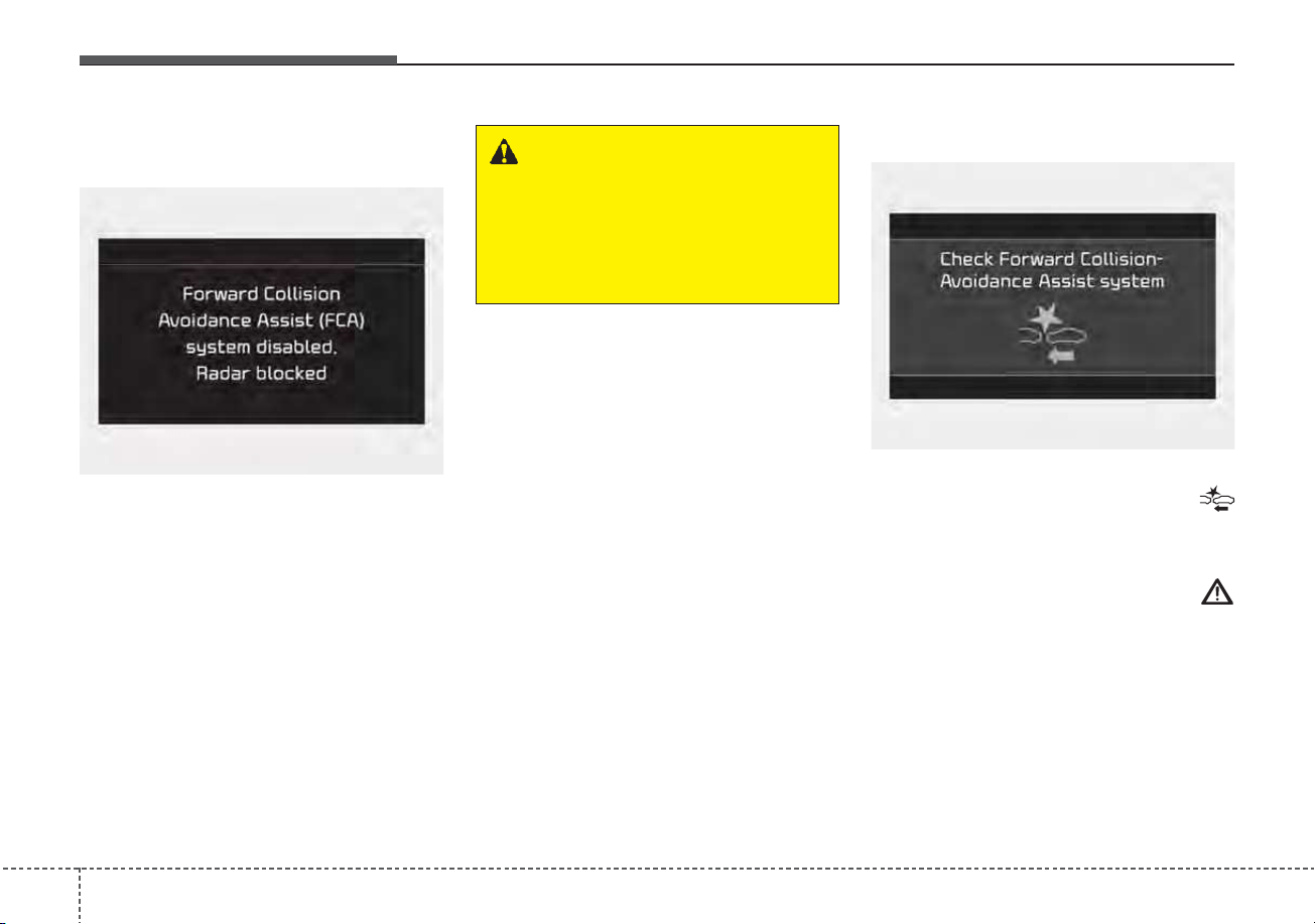
Driving your vehicle
765
Warning message and warning
light
If the sensor or sensor cover is cov-
ered by bad weather or foreign
objects, dust, etc., FCA system oper-
ation may temporarily stop. In this
case, the warning message appears
to warn the driver.
This is not a malfunction with FCA
system.To operate FCA system again,
remove the foreign substances.
FCA system may not properly oper-
ate when the front radar is contami-
nated or an object such as an open
area is not existed after engine start.
System malfunction
• When FCA system is not working
properly, the FCA warning light (
) will illuminate and the warning
message will appear for a few sec-
onds. After the message disap-
pears, the master warning light (
) will illuminate. In this case, have
your vehicle inspected by an author-
ized Kia dealer.
• The FCA warning message may
appear along with the illumination
of the ESC warning light.
WARNING
FCA system may not activate
without any warning messages
according to driving condition,
traffic on the road, weather,
road condition, etc.
OJF058394L
OJF058392L

577
Driving your vehicle
WARNING
• FCA system is only a supple-
mental system for the driver’s
convenience. The driver has
the ultimate responsibility to
control and operate the vehi-
cle safely. Do not solely
depend on FCA system.
Rather, maintain a safe brak-
ing distance, and, if neces-
sary, depress the brake pedal
to lower the driving speed.
• In certain instances and
under certain driving condi-
tions, FCA system may acti-
vate unintentionally. This ini-
tial warning message appears
on the LCD display with a
warning chime.
(Continued)
(Continued)
Also, in certain instances the
front radar sensor or camera
recognition system may not
detect the vehicle, pedestrian
or cyclist (if equipped) ahead.
FCA system may not activate
and the warning message will
not be displayed.
• FCA system may unnecessar-
ily produce the warning mes-
sage and the warning alarms.
Also, due to the sensing limi-
tation, FCA system may not
produce the warning message
and the warning alarm at all.
• When there is a malfunction
with FCA system, the braking
control does not operate upon
detecting a collision risk even
with other braking systems
normally operating.
(Continued)
(Continued)
• FCA system operates only for
the vehicle/pedestrian in
front, while driving forward. It
does not operate for any ani-
mals or vehicles in the oppo-
site direction.
• FCA system does not recog-
nize the vehicle, which trans-
versally drives across the
crossroad, or the vehicle,
which is parked in the trans-
versal direction.
• If the vehicle in front stops
suddenly, you may have less
control of the brake system.
Therefore, always keep safe
distance between your vehicle
and the vehicle in front of you.
• FCA system may activate dur-
ing braking and the vehicle
may stop suddenly. And the
load in the vehicle may endan-
ger passengers. Therefore,
always be mindful of the load
volume in the vehicle.
(Continued)

Driving your vehicle
785
Limitation of the system
FCA system is an assistant system
for a driver in a certain risky driving
condition and it does not take every
responsibility for all risks from driving
condition.
FCA system monitors the driving sit-
uations through the radar and the
camera sensor. Thus, for a situation
out of the sensing range, FCA sys-
tem may not normally operate. The
driver should pay great caution in the
following situations. FCA system
operation may be limited.
(Continued)
• FCA system may not activate
if the driver applies the brake
pedal to avoid risk of colli-
sion.
• FCA system does not operate
when the vehicle is in reverse.
In these circumstances, you
must maintain a safe braking
distance, and if necessary,
depress the brake pedal to
reduce the driving speed in
order to maintain a safe dis
tance.
• The regular braking function
will operate normally even if
There is a problem with the
FCA brake control system or
other functions. In this case,
the braking control will not
operate in an imminent colli-
sion.
(Continued)
(Continued)
• FCA system may not activate
according to driving condi-
tion, traffic on the road,
weather, road condition, etc.
• FCA system may not activate
in response to all types of
vehicles.

579
Driving your vehicle
Recognizing vehicles
The sensor may be limited when:
• The front view camera or front
radar sensor is blocked with a for-
eign object or debris
• The camera lens is contaminated
due to tinted, filmed or coated
windshield, damaged glass, or
stuck of foreign matter (sticker,
bug, etc.) on the glass
• Inclement weather such as heavy
rain or snow obscures the field of
view of the radar sensor or camera
• There is interference by electro-
magnetic waves
• There is severe irregular reflection
from the radar sensor
• The front view camera/front radar
sensor recognition is limited
• The vehicle in front is too small to
be detected (for example a motor-
cycle etc.)
• The vehicle in front is an oversize
vehicle or trailer that is too big to
be detected by the camera recog-
nition system (for example a tractor
trailer, etc.)
• The camera's field of view is not
well illuminated (either too dark or
too much reflection or too much
backlight that obscures the field of
view)
• The vehicle in front does not have
their rear lights or their rear lights
does not turned ON or their rear
lights are located unusually.
• The outside brightness changes
suddenly, for example when enter-
ing or exiting a tunnel
• When light coming from a street
light or an oncoming vehicle is
reflected on a wet road surface
such as a puddle in the road
• The field of view in front is
obstructed by sun glare
• The vehicle in front is driving errat-
ically
• The vehicle is on unpaved or
uneven rough surfaces, or road
with sudden gradient changes.
• The vehicle is driven near areas
containing metal substances as a
construction zone, railroad, etc.
• The vehicle drives inside a build-
ing, such as a basement parking
lot
• The front view camera does not
recognize the entire vehicle in
front.
• The front view camera is damaged.
• The brightness outside is too low
such as when the headlamps are
not on at night or the vehicle is
going through a tunnel.
• The shadow is on the road by a
median strip, trees, etc.
• The vehicle drives through a toll-
gate.
• The windshield glass is fogged up;
a clear view of the road is obstruct-
ed.
• The rear part of the vehicle in front
is not normally visible. (the vehicle
turns in other direction or the vehi-
cle is overturned.)
• The adverse road conditions cause
excessive vehicle vibrations while
driving
• The sensor recognition changes
suddenly when passing over a
speed bump
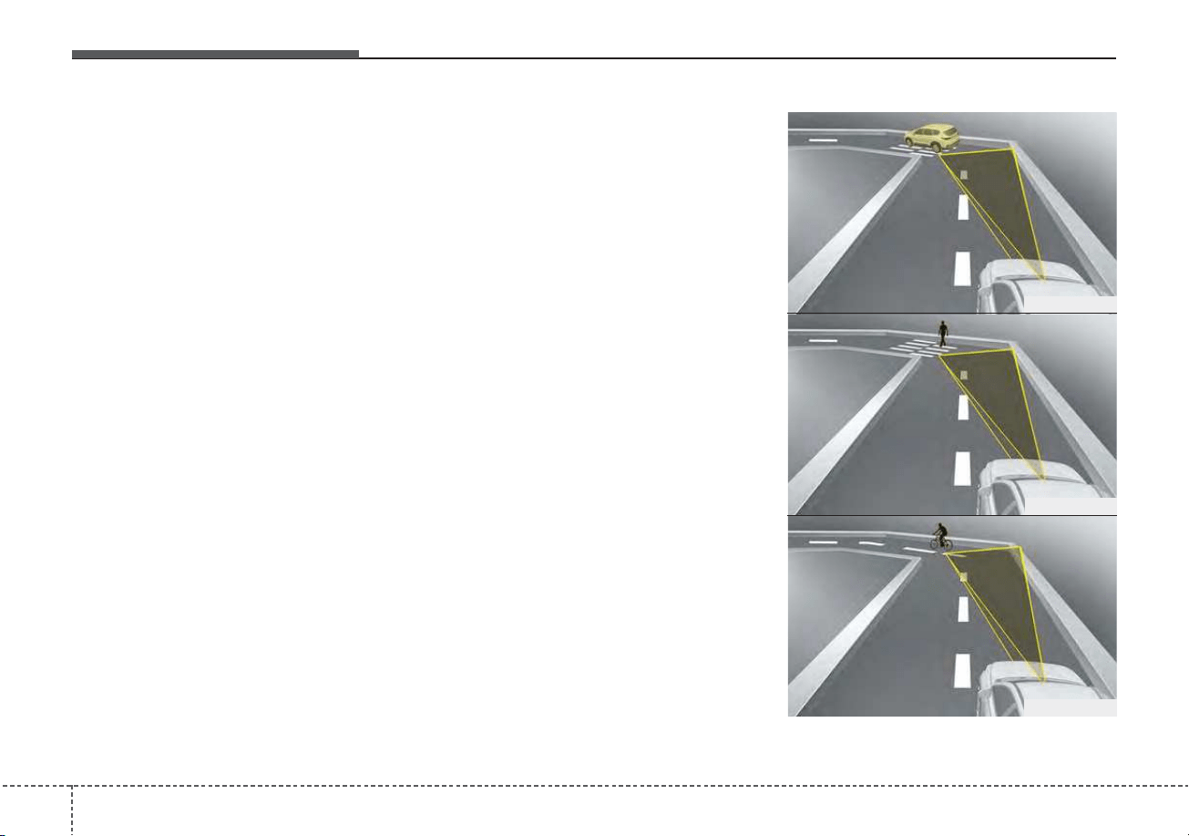
Driving your vehicle
805
• The vehicle in front is moving lon-
gitudinally to the driving direction
• The vehicle in front is stopped lon-
gitudinally
• The vehicle in front is driving
towards your vehicle or reversing
• You are on a roundabout and the
vehicle in front circles
• It is difficult to secure the field of
view of the front view camera such
as backlight, reflected light, and
darkness.
• When the front camera is blocked
by continuous washer spray and
wiper operation.
• The vehicle in front is a special
purpose vehicle, a trailer, or a truck
loading with unusual shape of lug-
gage.
• The ambient light is too high or low.
• The front view camera is contami-
nated by front glass tinting, attach-
ing film, water proof coating, dam-
aged, foreign material such as a
sticker, worm, etc.
• When the front view camera
(including lens) or front radar is
damaged.
• If not using headlamp or using
weak light in the night or in a tun-
nel.
• Backlight is shining in the driving
direction of the vehicle. (Including
oncoming vehicle headlights.)
• When the rear part of the front
vehicle is small or low.
• When a trailer or other vehicle is
towing the front vehicle.
• When the ground clearance of the
front vehicle is high.
• When a front vehicle makes sud-
den lane changes unexpectedly.
OHM059350L
OHM059349L
OHM059351L
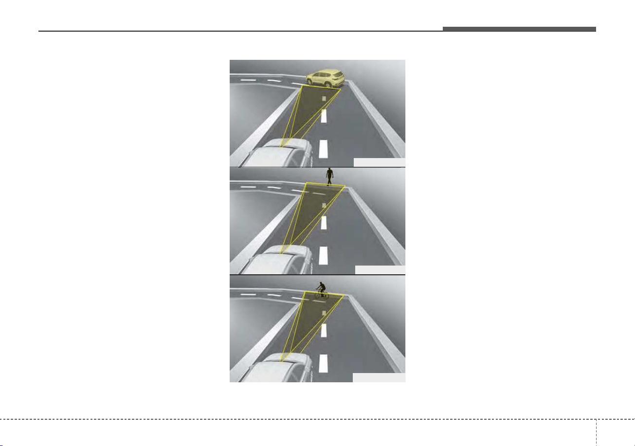
581
Driving your vehicle
- Driving on a curve
The performance of Forward
Collision-Avoidance Assist system
may be limited when driving on a
curved road.
The front view camera or front radar
sensor recognition system may not
detect the vehicle, pedestrian or
cyclist traveling in front on a curved
road.
This may result in no alarm and brak-
ing when necessary.
Always pay attention to road and
driving conditions, and if necessary,
depress the brake pedal to reduce
your driving speed in order to main-
tain a safe distance.
Forward Collision-Avoidance Assist
system may recognize a vehicle or
pedestrian or cyclist in the next lane
or outside the lane when driving on a
curved road.
If this occurs, the system may unnec-
essarily alarm the driver and apply
the brake. Always pay attention to
road and driving conditions, while
driving.
OHM059353L
OHM059352L
OHM059354L
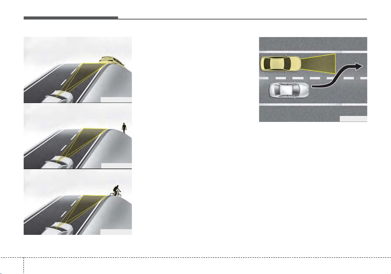
Driving your vehicle
825
- Driving on a slope
The performance of Forward
Collision-Avoidance Assist system
may be decreased while driving
upward or downward on a slope. The
front view camera or front radar sen-
sor recognition may not detect the
vehicle, pedestrian or cyclist in front.
This may result in unnecessary
alarm and braking or no alarm and
braking when necessary.
When the system suddenly recog-
nizes the vehicle, pedestrian or
cyclist in front while passing over a
slope, you may experience sharp
deceleration.
Always keep your eyes forward while
driving upward or downward on a
slope, and, if necessary, depress the
brake pedal to reduce your driving
speed in order to maintain distance.
- Changing lanes
When a vehicle changes lanes in
front of you, Forward Collision-
Avoidance Assist system may not
immediately detect the vehicle, espe-
cially if the vehicle changes lanes
abruptly. In this case, you must main-
tain a safe braking distance, and if
necessary, depress the brake pedal
to reduce your driving speed in order
to maintain a safe distance.
OJF055028
OHM059356L
OHM059355L
OHM059357L
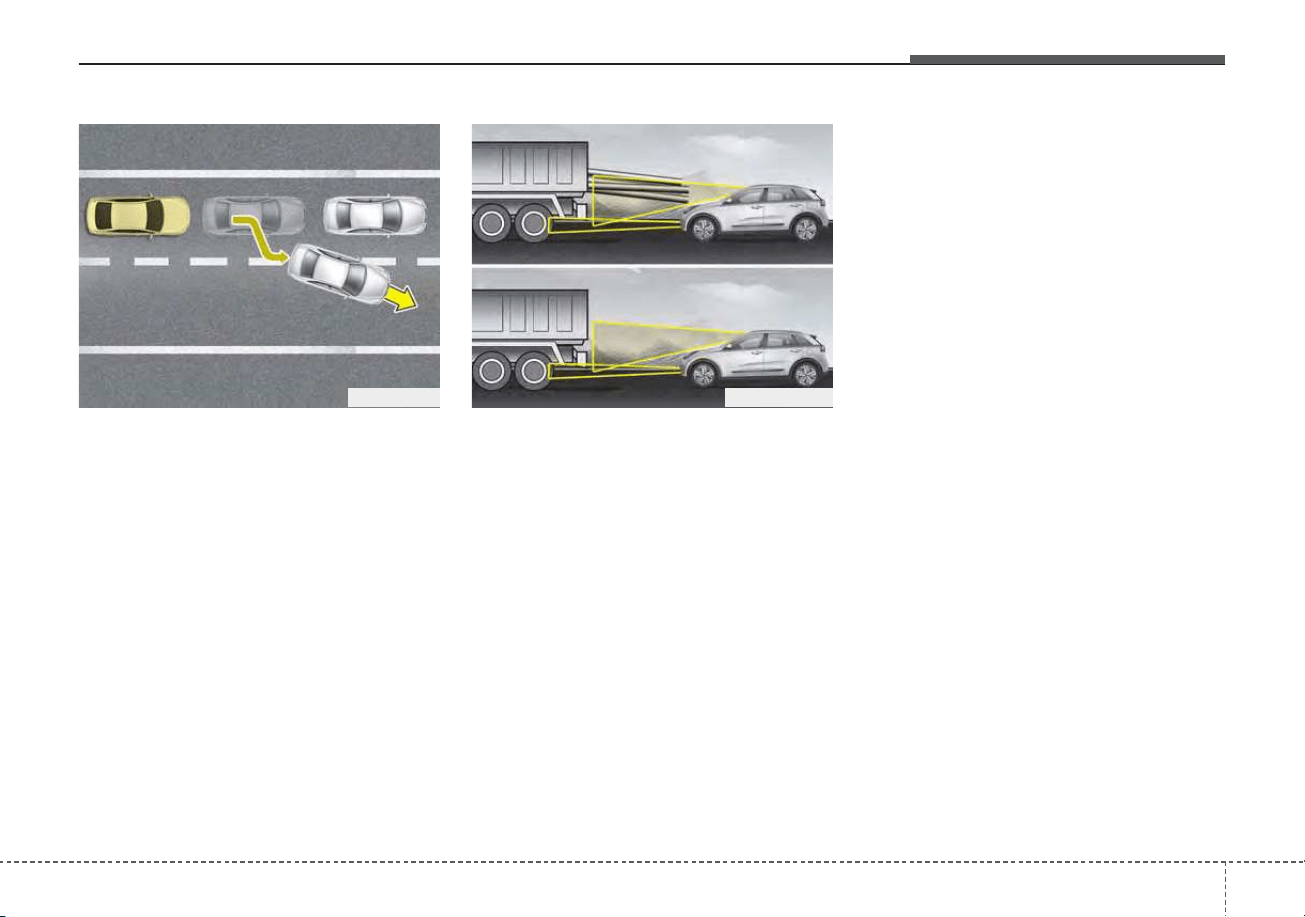
583
Driving your vehicle
When driving in stop-and-go traffic,
and a stopped vehicle in front of you
merges out of the lane, Forward
Collision-Avoidance Assist system
may not immediately detect the new
vehicle that is now in front of you. In
this case, you must maintain a safe
braking distance, and if necessary,
depress the brake pedal to reduce
your driving speed in order to main-
tain a safe distance.
- Recognizing the vehicle
When the vehicle in front has heavy
loading extended rearward, or when
the vehicle in front has higher ground
clearance, it may induce a haz-
ardous situation. Always pay atten-
tion to road and driving conditions,
while driving and, if necessary,
depress the brake pedal to reduce
your driving speed in order to main-
tain distance.
Detecting pedestrian or cyclist
The sensor may be limited when:
• The pedestrian or cyclist is not fully
detected by the camera recogni-
tion system, for example, if the
pedestrian is leaning over or is not
fully walking upright
• The pedestrian or cyclist is moving
very quickly or appears abruptly in
the front view camera detection
area
• The pedestrian or cyclist is wear-
ing clothing that easily blends into
the background, making it difficult
to be detected by the front view
camera recognition system
• The outside lighting is too bright
(e.g. when driving in bright sunlight
or in sun glare) or too dark (e.g.
when driving on a dark rural road
at night)
ODEP059328NOJF055029

Driving your vehicle
845
• It is difficult to detect and distin-
guish the pedestrian or cyclist from
other objects in the surroundings,
for example, when there is a group
of pedestrians, cyclists or a large
crowd
• There is an item similar in shape or
appearance to a person
• The pedestrian or cyclist is below
the sensor's viewing range
• The sensor can not identify the
pedestrian's outline because of
other items changing their profile,
such as mobility assistance devices
• The front view camera or front
radar is obstructed by a foreign
object or debris
• Inclement weather such as heavy
rain or snow obscures the field of
view of the radar sensor or camera
• When light coming from a street
light or an oncoming vehicle is
reflected on a wet road surface
such as a puddle in the road
• The field of view in front is
obstructed by sun glare
• The windshield glass is fogged up;
a clear view of the road is obstruct-
ed
• The adverse road conditions cause
excessive vehicle vibrations while
driving
• When the pedestrian or cyclist
suddenly enters the path of travel
of the vehicle
• When the cyclist in front is riding
perpendicular to the direction of
travel
• When there is any electromagnetic
interference
• When the cyclist is near areas con-
taining metal objects such as a
construction zone, railroad, etc.
• If the bicycle material is not reflect-
ed well on the radar
• When a pedestrian or cyclist’s
height is small.
• When a pedestrian or cyclist’s
behavior is unstable.
• When a pedestrian or cyclist sud-
denly interrupts in front of the vehi-
cle.
• When there are many pedestrians
or cyclists.
• When there is an object that
reflects radar well. (such as a
guardrail or a nearby vehicle)

585
Driving your vehicle
✽✽
NOTICE
In some instances, FCA system may
be cancelled when subjected to elec-
tromagnetic interference.
This device complies with Part 15
of the FCC rules.
Operation is subject to the following
three conditions:
1. This device may not cause harmful
interference.
2. This device must accept any inter-
ference received, including inter-
ference that may cause undesired
operation.
3. Changes or modifications not
expressly approved by the party
responsible for compliance could
void the user's authority to operate
the device.
(Continued)
• Never try to test the operation
of FCA system. Doing so may
cause severe injury or death.
• If the front bumper, front glass,
front view camera or front
radar have been replaced or
repaired, have your vehicle
inspected by an authorized Kia
dealer.
• If the system detects an
object that has a similar
shape or characteristics of a
vehicle or a pedestrian, FCA
system may operate.
WARNING
• Do not use Forward Collision
avoidance Assist system
when towing a vehicle.
Application of FCA system
while towing may adversely
affect the safety of your vehi-
cle or the towing vehicle.
• Use extreme caution when the
vehicle in front of you has
cargo that extends rearward
from the cab, or when the
vehicle in front of you has
higher ground clearance.
• FCA system is designed to
detect and monitor the vehicle
ahead or detect a pedestrian
or cyclist in the roadway
through front view camera
recognition and front radar
signals. It may not always
detect bicycles, motorcycles,
or smaller wheeled objects
such as luggage bags, shop-
ping carts, or strollers.
(Continued)

Driving your vehicle
865
Radio frequency radiation exposure
information:
This equipment complies with FCC
radiation exposure limits set forth for
uncontrolled environment.
This equipment should be installed
and operated with minimum distance
of 8 in. (20 cm) between the radiator
(antenna) and your body.
This transmitter must not be co-
located or operating in conjunction
with any other antenna or transmit-
ter.
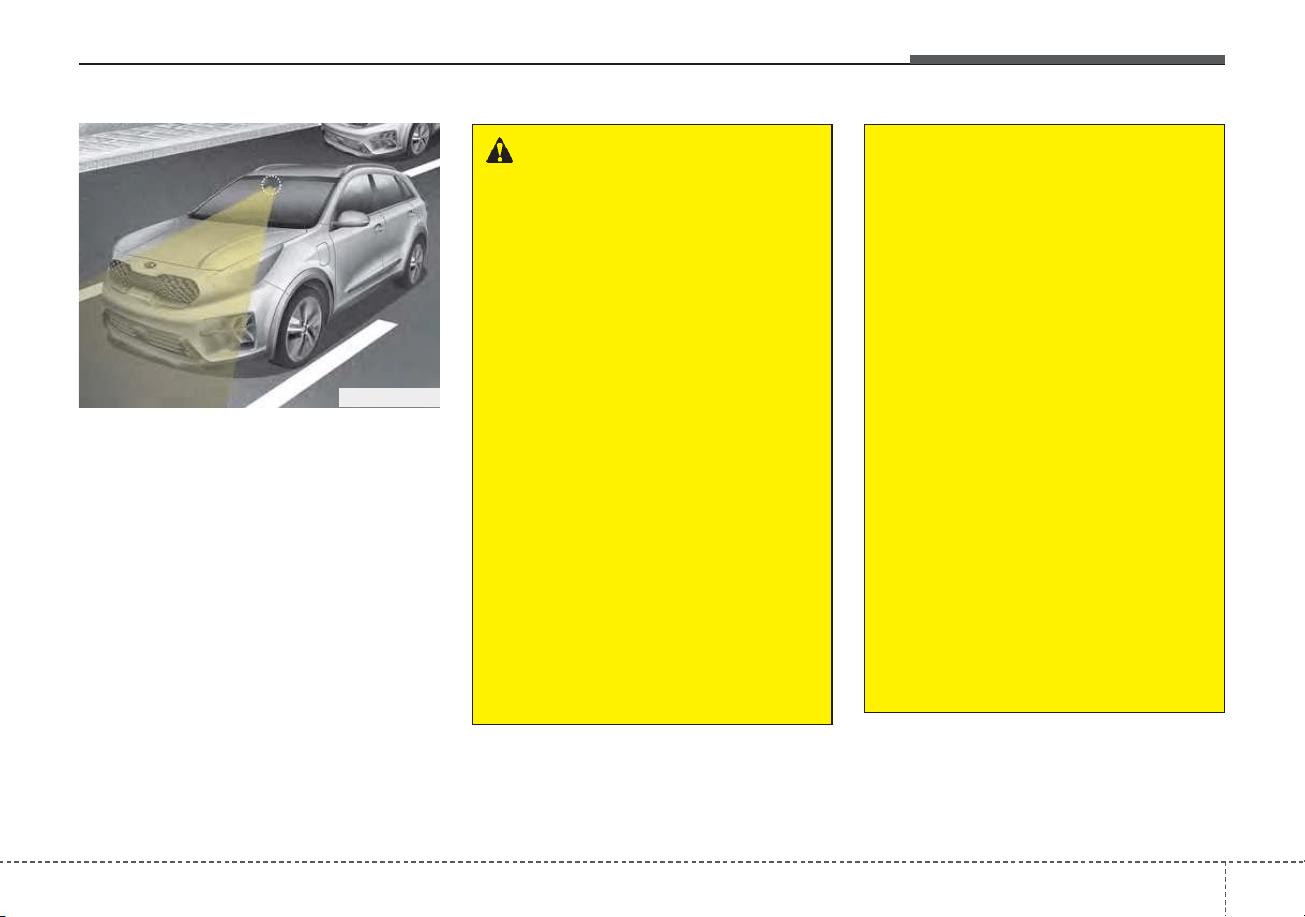
587
Driving your vehicle
Lane Keeping Assist system detects
the lane markers on the road with a
front view camera at the front wind-
shield, and assists the driver’s steer-
ing to help keep the vehicle in the
lanes. When the system detects the
vehicle straying from its lane, it alerts
the driver with a visual and audible
warning, while applying a slight
counter-steering torque, trying to
prevent the vehicle from moving out
of its lane.
LANE KEEPING ASSIST (LKA) (IF EQUIPPED)
WARNING
• Driver is responsible for being
aware of surroundings and
steering the vehicle safely.
• Do not steer the steering
wheel suddenly when the
steering wheel is being assist-
ed by the system.
• LKA system helps prevent the
driver from moving out of the
lane unintentionally by assist-
ing the driver’s steering. If the
driver intentionally drives on
one side of the driving lane, a
continuous steering force
may occur. However, the sys-
tem is just a convenience
function and the steering
wheel is not always con-
trolled. While driving, the driv-
er should pay attention to the
steering wheel.
(Continued)
(Continued)
• The operation of LKA system
can be canceled or not work
properly depending on road
condition and surroundings.
Always be cautious when
driving.
• Do not disassemble the front
view camera or attached any
type of coating or accessories
to it. If you disassemble the
front view camera, take your
vehicle to an authorized Kia
dealer to check if the system
needs a calibration.
• When you replace the wind-
shield glass, front view cam-
era or related parts of the
steering, take your vehicle to
an authorized Kia dealer to
check if the system needs a
calibration.
(Continued)
ODEP059029

Driving your vehicle
885
(Continued)
• The system detects lane
markers and controls the
steering wheel by a front view
camera, therefore, if the lane
markers are hard to detect,
the system may not work
properly. Always be cautious
when using the system.
• When the lane markers are
hard to detect, please refer to
“DRIVER’S ATTENTION”.
• Do not remove or damage the
related parts of the front view
camera system.
• Do not place objects on the
crash pad that reflect light
such as mirrors, white paper,
etc. it may cause malfunction
of LKA system if sunlight is
reflected.
(Continued)
(Continued)
• You may not hear warning
sound of LKA system because
of the excessive audio sound.
• If other beeps such as the
seat belt warning sound are in
operation and override LKA
alarming system, LKA beeps
may not occur.
• At high vehicle speeds, the
steering torque needed for
assistance may not be suffi-
cient to keep your vehicle
within the lane. If so, the vehi-
cle may move out of its lane.
Always obey the speed limit
when using LKA system.
(Continued)
(Continued)
• If you attach objects to the
steering wheel, the system
may not assist steering.
• If you attach objects to the
steering wheel, hands off
alarm may not work properly.
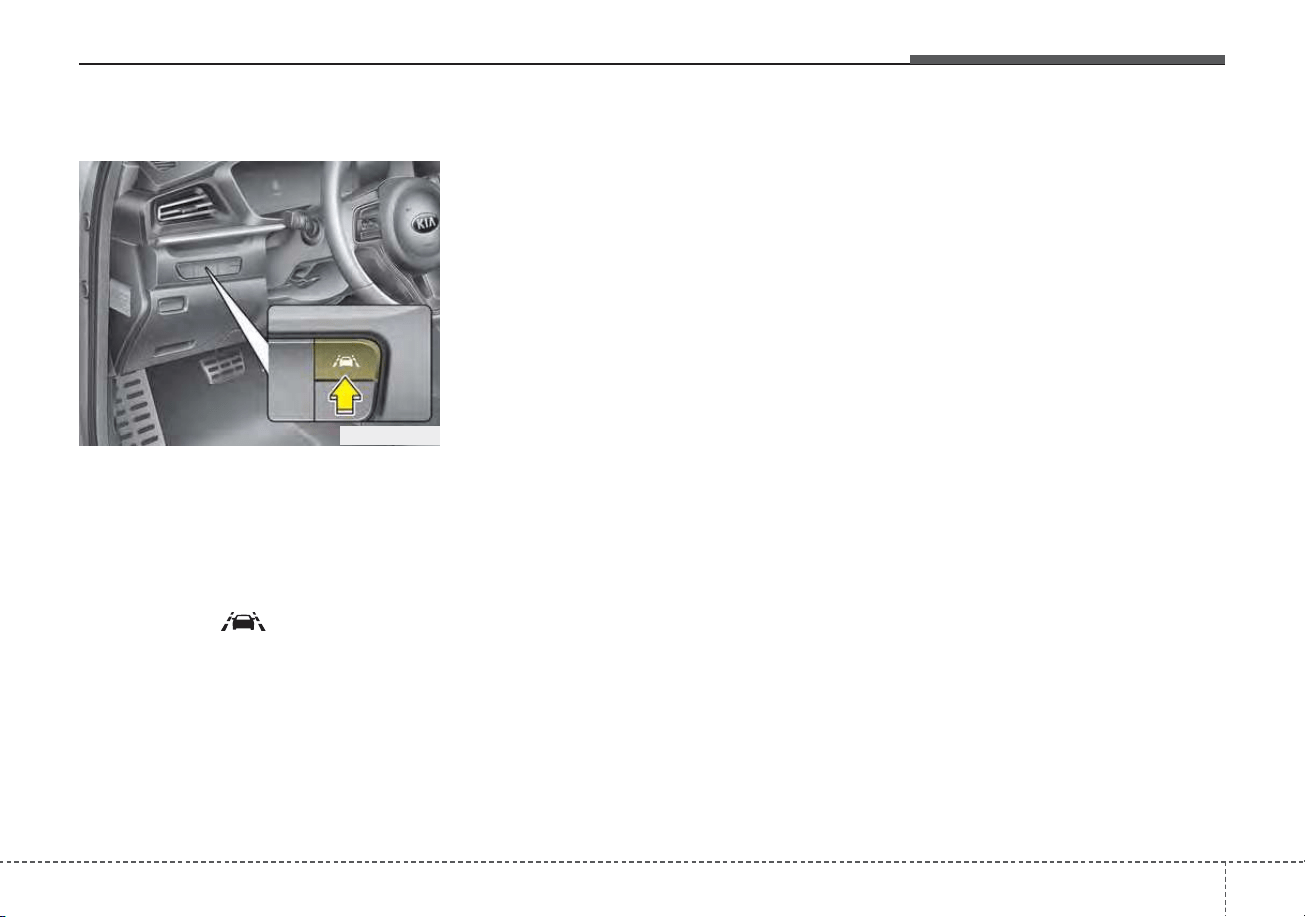
589
Driving your vehicle
LKA system operation
To activate/deactivate LKA system:
With the ignition switch or ENGINE
START/STOP button in the ON posi-
tion, press the LKA system button
located on the instrument panel on
the lower left hand side of the driver.
The indicator ( )in the cluster dis-
play will initially illuminate white.
When the indicator(white) was acti-
vated in the previous ignition cycle,
the system turns on without any con-
trol. If you press the LKA system but-
ton again, the indicator on the cluster
display will go off.
The color of indicator will change
depend on the condition of LKA sys-
tem.
- White : Sensor does not detect
the lane marker or vehicle
speed is less than 40 mph
(60 km/h).
- Green : Sensor detects the lane
marker and system is
able to control the steer-
ing.
System setting
The driver can change LKA to Lane
Departure Warning (LDW) or change
the LKA mode from the LCD display.
“User Settings → Driver Assistance →
Lane Safety → Lane Keeping
Assist/Lane Departure Warning/Off”
Lane Keeping Assist
LKA mode guides the driver to keep
the vehicle within the lanes. It rarely
controls the steering wheel, when
the vehicle drives well inside the
lanes. However, it starts to control
the steering wheel, when the vehicle
is about to deviate from the lanes.
ODEP059113
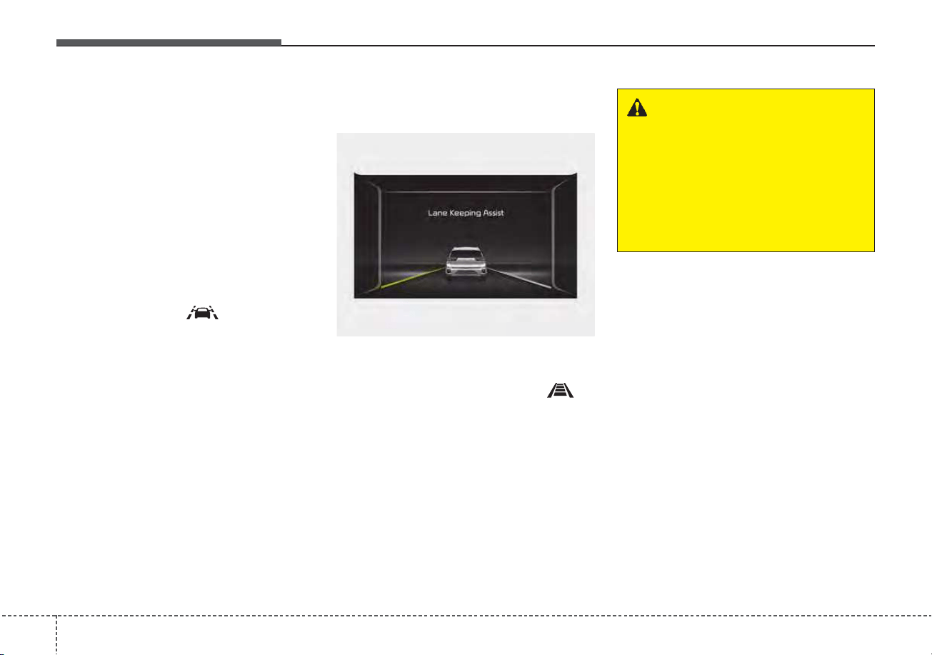
Driving your vehicle
905
Lane Departure Warning
LDW alerts the driver with a visual
and acoustic warning when the sys-
tem detects the vehicle leaving the
lane. In this mode, the steering wheel
will not be controlled. When the vehi-
cle’s front wheel contacts the inside
edge of lane line, the contacted line
will be displayed on the LCD display.
Off
If you select ‘Off’, it is the same with
pressing LKA ( ) button to
release.
LKA activation
LKA system activation
• To see the LKA system screen on
the LCD display in the cluster, Tab
to the Driving Assist mode ( ).
• After LKA system is activated, if
both lane markers are detected,
vehicle speed is over 40 mph (60
km/h) and all the activation condi-
tions are satisfied, a green steering
wheel indicator will illuminate and
the steering wheel will be con-
trolled.
ODEP059112L
WARNING
LKA system is a system to help
prevent the driver from leaving
the lane. However, the driver
should not solely rely on the
system and should always
check road conditions wen driv-
ing.
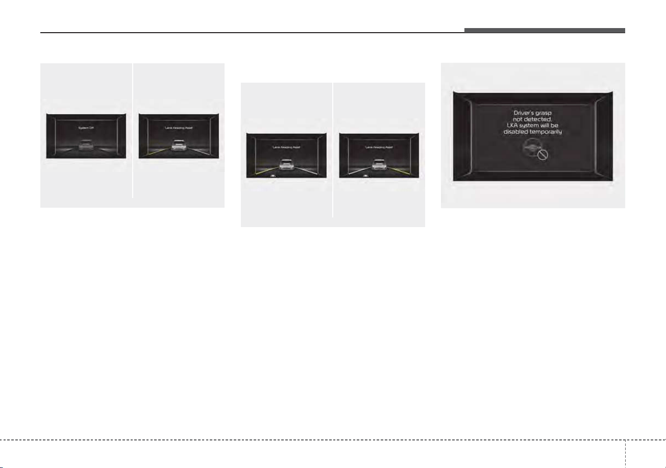
591
Driving your vehicle
If the speed of the vehicle is over 40
mph (60 km/h) and the system
detects lane markers, the color
changes from gray to white.
Warning
If the vehicle leaves a lane, the lane
marker you cross will blink on the
LCD display and the warning sound
is provided.
❈ Haptic specification
If the vehicle leaves a lane, the lane
marker you cross will blink on the
LCD display with steering wheel
vibration warning.
If the driver takes hands off the steer-
ing wheel for several seconds while
LKA system is activated, the system
will warn the driver.
ODEP059114L/ODEP059112L
■ Lane undetected
■ Lane detected
ODEP059118L/ODEP059119L
■ Left lane
■ Right lane
ODEP059122L
■ Hands off warning message while LKA system
is activated
Driving your vehicle
925
✽✽
NOTICE
• Even though the steering is assist-
ed by the system, the driver may
control the steering.
• The steering wheel may feel heav-
ier when the steering wheel is
assisted by the system than when it
is not.
WARNING
• The hands-off warning mes-
sage may be delayed accord-
ing to road conditions.
Therefore, always have your
hands on the steering wheel
while driving.
• If you hold the steering wheel
lightly, the system may dis-
play the hands off warning
because LKA system may
believe you are not grabbing
the wheel.
WARNING
• The driver is responsible for
accurate steering.
• Even though the steering is
assisted by the system, the
driver may control the steer-
ing wheel.
• Turn off the system and drive
the vehicle in the below situa-
tions:
- In bad weather
- In bad road conditions
- When the steering wheel
needs to be controlled by the
driver frequently.
- When towing a vehicle or
trailer.
• The steering wheel may feel
heavier when the steering
wheel is assisted by the sys-
tem than when it is not.
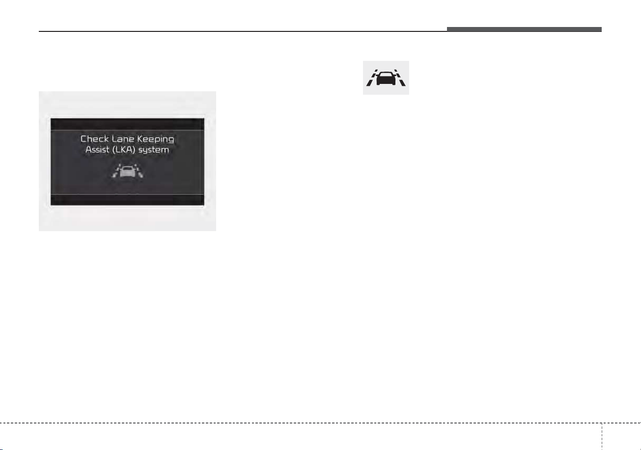
593
Driving your vehicle
Lane Keeping Assist system
malfunction
• If there is a problem with the sys-
tem a message will appear. If the
problem continues the LKA failure
indicator will illuminate.
LKA failure indicator
LKA failure indicator (yellow) will illu-
minate if LKA is not working properly.
If this occurs, have the system
checked by an authorized Kia dealer.
LKA system will be canceled when:
• You change lanes with the turn sig-
nal.
- Using the turn signal to change
lanes.
- If you change lanes without the
turn signal on, the steering wheel
might be controlled.
• LKA system can transit to steering
assist mode when the car is near
to middle of the lane after system
on or the lane was changed. LKA
system can not assist steering if
the vehicle follows lane marker too
close continuously before transi-
tion to steering assist mode.
• The control of ESC (Electronic
Stability Control) or VSM (Vehicle
Stability Management) is activated.
• The steering will not be assisted
when your drive fast on a sharp
curve.
ODEP059310L

Driving your vehicle
945
• The steering will not be assisted
when vehicle speed is below 34
mph (55 km/h) and over 125 mph
(200 km/h).
• The steering will not be assisted
when you change lanes fast.
• The steering will not be assisted
when you brake suddenly.
• The steering will not be assisted
when the lane is very wide or nar-
row.
• The steering will not be assisted
when only one side lane marker is
detected.
• There are more than two lane
markers such as a construction
area.
• Radius of a curve is too small.
• When you turn steering wheel sud-
denly, LKA system will be disabled
temporarily.
• Driving on a steep slope or hill.
DRIVER’S ATTENTION
The driver must be cautious in the
below situations as the system may
not work properly when recognition
of the lane marker is poor or limited
:
When lane and road condition is
poor
• It is difficult to distinguish the lane
marker from road when the lane
marker is covered with dust or
sand.
• It is difficult to distinguish the
color of the lane marker from
road.
• There is something looks like a
lane marker.
• The lane marker is indistinct or
damaged.
• The number of lanes increases/
decreases or the lane lines are
crossing (Driving through a toll
plaza/toll gate, merged/divided
lane).
• There are more than two lane
markers.
• The lane marker is very thick or
thin.
(Continued)
(Continued)
• The lane marker is not visible due
to snow, rain, stain, a puddle or
other factors.
• A shadow is on the lane marker
because of a median strip,
guardrail, noise barriers and oth-
ers.
• When the lane markers are com-
plicated or a structure substitutes
for the lines such as a construc-
tion area.
• There are crosswalk signs or other
symbols on the road.
• The lane suddenly disappears
such as at the intersection.
• The lane marker in a tunnel is cov-
ered with dirt or oil and etc.
• The lane is very wide or narrow.
When external condition is inter-
vened
• The brightness of outside changes
suddenly when entering/existing a
tunnel or passing under a bridge.
• The headlamps are not on at night
or in a tunnel, or light level is low.
(Continued)
595
Driving your vehicle
(Continued)
• There is a boundary structure in
the roadway.
• The light of street, sun, or oncom-
ing vehicle reflects from the water
on the road.
• When light shines brightly in the
reverse direction you drive.
• Road surface is not even.
• The distance from the vehicle
ahead is very short or the vehicle
ahead drives hiding the lane line.
• You drive on a steep grade or a
sharp curve.
• The vehicle vibrates heavily.
• The temperature near inside mir-
ror is very high due to direct sun
light and etc.
when front visibility is poor
• The lens or windshield is covered
by strange materials.
• The sensor cannot detect the lane
because of fog, heavy rain or snow.
• The windshield is fogged by
humid air in the vehicle.
• Putting something on the crash
pad and etc.
WARNING
LKA system is a system to help
prevent the driver from leaving
the lane. However, the driver
should not solely rely on the
system and should always drive
safely and exercise safe driving
practices.
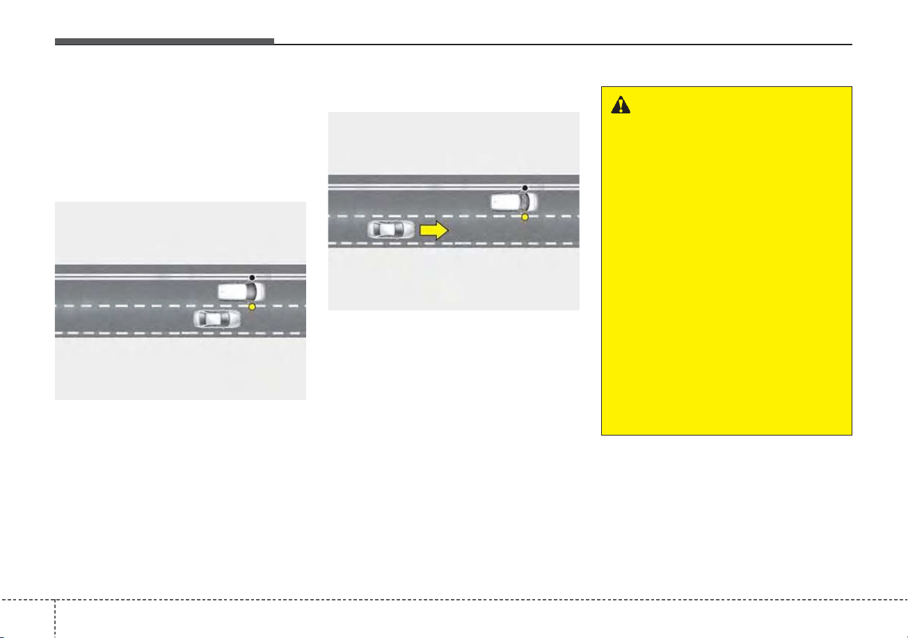
Driving your vehicle
965
System description
BCW system uses radar sensors in
the rear bumper to monitor and warn
the driver of an approaching vehicle
in the driver's blind spot area.
1) Blind-Spot Area
It warns by detecting the vehicles in
the blind spots.
The blind spot detection range varies
relative to vehicle speed.
Note that if your vehicle is traveling
much faster than the vehicles around
you, the warning will not occur.
2) Closing at high speed
BCW system feature will alert you
when a vehicle is approaching in an
adjacent lane at a high rate of speed.
If the driver activates the turn signal
when the system detects an oncom-
ing vehicle, the system sounds an
audible alert.
BLIND-SPOT COLLISION WARNING (BCW) (IF EQUIPPED)
OSK3058089L
OSK3058090L
WARNING
• BCW system is a supplemen-
tal system to assist you. Do
not entirely rely on the sys-
tem.
Always pay attention, while
driving, for your safety.
• Always be aware of road con-
ditions while driving and be
alert for unexpected situa-
tions even though BCW sys-
tem is operating.
• BCW system is not a substi-
tute for proper and safe driv-
ing. Always drive safely and
use caution when changing
lanes or backing up the vehi-
cle. BCW may not detect every
object alongside the vehicle.
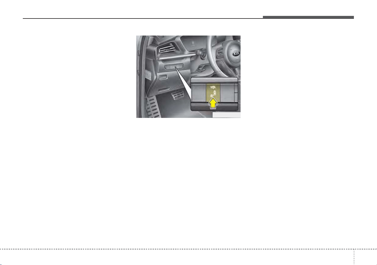
597
Driving your vehicle
System setting and activation
System setting
• The driver can activate the system
by placing the ignition switch or
ENGINE START/STOP button to the
ON position and by selecting “User
Settings → Driver Assistance →
Blind-Spot Safety”
- BCW system turns on and gets
ready to be activated when
“Warning Only” is selected. Then,
if a vehicle approaches the dri-
ver's blind spot area a warning
sounds.
- The system is deactivated and
the indicator on the BCW button
is extinguished when 'Off' is
selected.
• If you press BCW button while
“Warning Only” is selected the indi-
cator on the button extinguishes
and the system deactivates.
• If you press BCW button while the
system is cancelled the indicator
on the button illuminates and the
system activates. In this case, the
system returns to the state before
the vehicle turned off. When the
system is initially turned on and
when the motor is turned off then
on again while the system is in
activation, the warning light will illu-
minate for 3 seconds on the out-
side rearview mirror.
• If the vehicle is turned off then on
again, the system maintains the
previous state.
ODEP059293
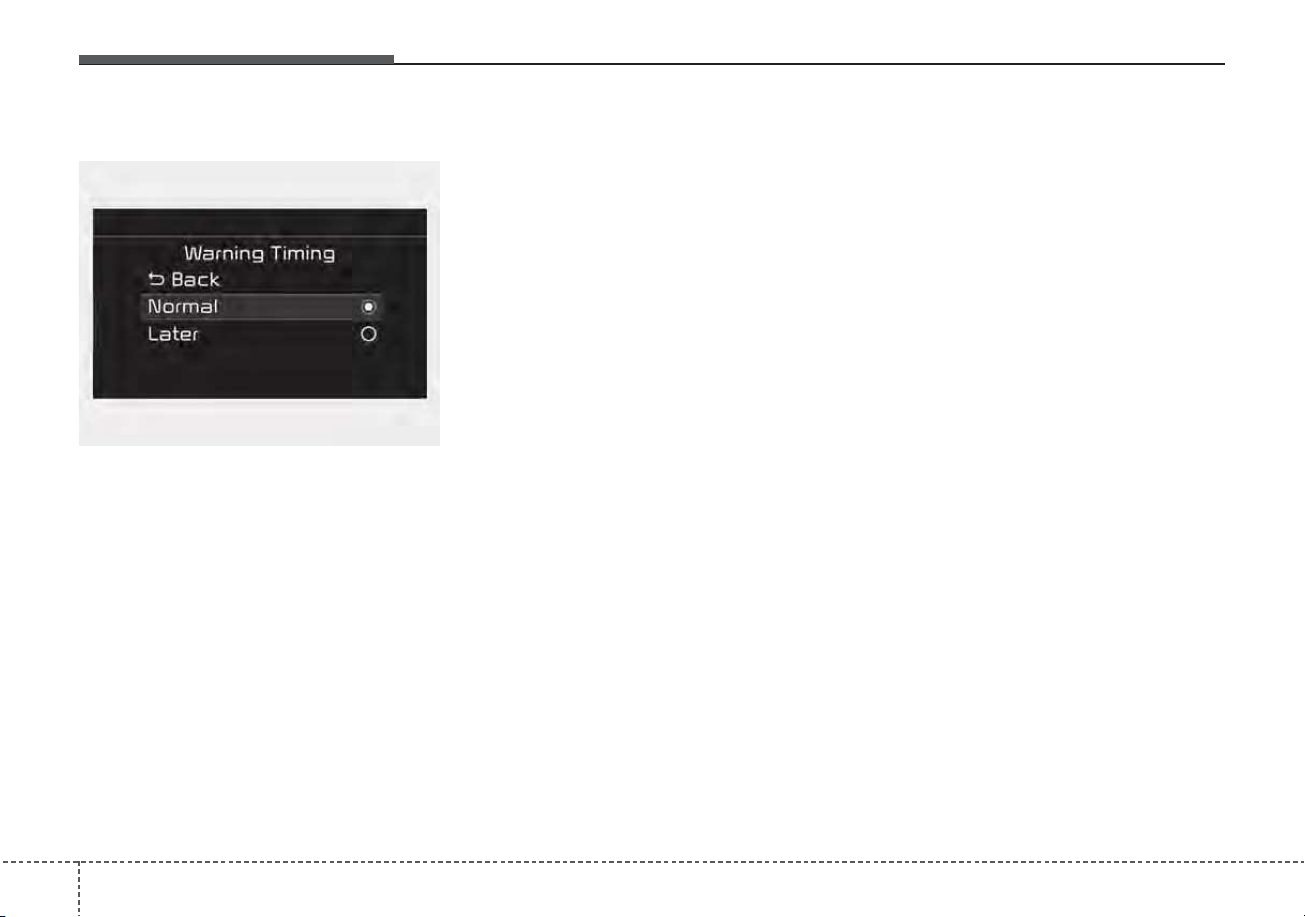
Driving your vehicle
985
Warning Timing
• The driver can select the initial
warning activation time select “User
Settings → Driver Assistance →
Warning Timing”
• The options for the initial Blind-
Spot Collision Warning includes
the following:
- Normal:
When this condition is selected,
the initial Blind-Spot Collision
Warning is activated normally. If
this setting feels too sensitive
change the option to ‘Normal’.
The warning activation time may
feel late if the side/rear vehicle
abruptly accelerates.
- Later:
Select this warning activation
time when the traffic is light and
you are driving in a low speed.
✽✽
NOTICE
If you change the warning timing,
the warning time of other systems
may change. Always be aware
before changing the warning timing.
OYG059344L
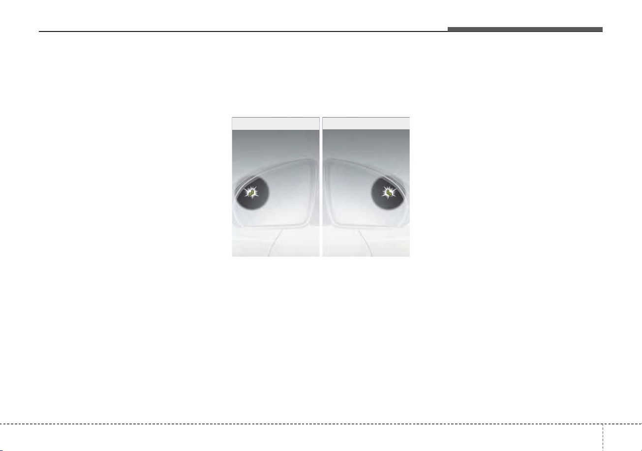
599
Driving your vehicle
Operating conditions
The system enters the ready status,
when ‘Warning Only’ is selected and
the following conditions are satisfied:
• Warning Only
(1) Blind-Spot Collision Warning sys-
tem will activate when:
- The vehicle speed above approxi-
mately 20 mph (30 km/h).
Warning message and system
control
Blind-Spot Collision Warning sys-
tem
First stage alert
If a vehicle is detected within the
boundary of the system, a warning
light will illuminate on the outside
rearview mirror and the head up dis-
play (if equipped).
Once the detected vehicle is no
longer within the blind spot area, the
warning will turn off according to the
driving conditions of the vehicle.
OJF055213
■ First stage alert (left)
■ First stage alert (right)
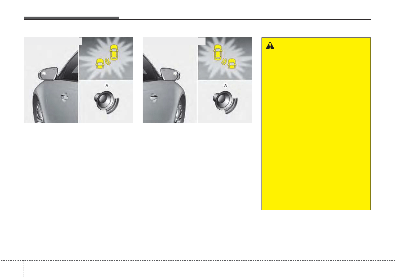
Driving your vehicle
1005
ORJ058128 ORJ058129
[A] : Warning sound
Second stage alert
A warning chime to alert the driver will activate when:
1. At the First stage alert (the warning light illuminate on the outside review
mirror and the head up display (if equipped) AND
2. The turn signal is applied (same side as where the vehicle is being detect-
ed).
When this alert is activated, the warning light on the outside rearview mirror and
the head up display (if equipped) will also blink. And a warning chime will sound.
If you turn off the turn signal indicator, the second stage alert will be deactivated.
Once the detected vehicle is no longer within the blind spot area, the warn-
ing will turn off according to the driving conditions of the vehicle.
■ Second stage alert (left)
■ Second stage alert (right)
WARNING
• The warning light on the out-
side rearview mirror will illu-
minate whenever a vehicle is
detected at the rear side by
the system.
To avoid accidents, do not
focus only on the warning
light and neglect to check the
vehicle surroundings.
• Drive safely even though the
vehicle is equipped with
Blind-Spot Collision Warning
system. Do not solely rely on
the system but check your
surroundings before chang-
ing lanes or backing the vehi-
cle up.
• The system may not alert the
driver in some situations so
always check your surround-
ings while driving.
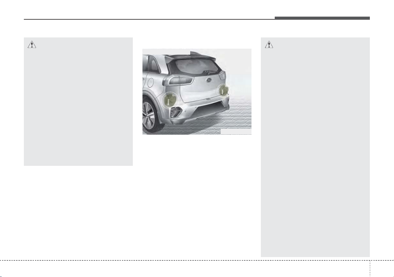
5101
Driving your vehicle
Detecting Sensor
The rear corner radars are the sen-
sors inside the rear bumper for
detecting the side/rear areas. Always
keep the rear bumper clean for prop-
er operation of the system.
CAUTION
• The driver should always use
extreme caution while operat-
ing the vehicle, whether or not
the warning light on the out-
side rearview mirror illumi-
nates or there is a warning
alarm.
• Playing the vehicle audio sys-
tem at high volume may offset
Blind-Spot Collision Warning
system warning sounds.
• The warning of the Blind-Spot
Collision Warning system may
not sound while other sys-
tem's warning sounds.
ODEP059158
■ Rear corner radars
CAUTION
• The system may not work
properly when the bumper has
been damaged, or if the rear
bumper has been replaced or
repaired.
• The sensing range differs some-
what according to the width of
the road. When the road is nar-
row, the system may detect
other vehicles in the next lane.
• The system may turn off due to
strong electromagnetic waves.
• Always keep the sensor or near
the sensor clean.
• NEVER arbitrarily disassem-
ble the sensor component nor
apply any impact on the sen-
sor component.
• Be careful not to apply unnec-
essary force on the radar sen-
sor or sensor cover. If the sen-
sor is forcibly moved out of
proper alignment, the system
may not operate correctly. In
this case, a warning message
may not be displayed.
(Continued)
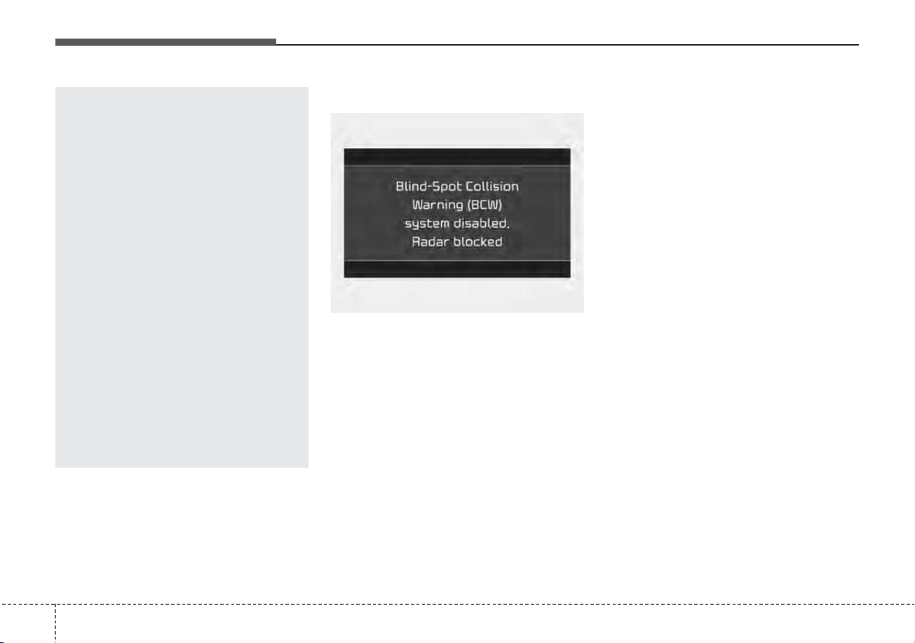
Driving your vehicle
1025
Warning message
Blind-Spot Collision Warning system
disabled. Radar blocked
• This warning message may appear
when :
- One or both of the sensors on the
rear bumper is blocked by dirt or
snow or a foreign object.
- Driving in rural areas where the
sensor does not detect another
vehicle for an extended period of
time.
- When there is inclement weather
such as heavy snow or rain.
If any of these conditions occur, the
light on the BCW button and the sys-
tem will turn off automatically.
Turn off BCW system (if equipped)
when a trailer or carrier is installed.
- Press the BCW button (the indicator
on the button extinguish) or “User
Settings → Driver Assistance →
Blind-Spot Safety → Off”.
- Deactivate RCCW system by des-
electing
“User Settings → Driver Assistance
→ Blind-Spot Safety → Rear Cross-
Traffic Safety”.
If you use BCW system, remove a
trailer or carrier.
When the BCW canceled warning
message is displayed in the cluster,
check to make sure that the rear
bumper is free from any dirt or snow
in the areas where the sensor is
located. Remove any dirt, snow, or
foreign material that could interfere
with the radar sensors.
(Continued)
Have the vehicle inspected by
an authorized Kia dealer.
• Do not apply foreign objects
such as a bumper sticker or a
bumper guard near the radar
sensor or apply paint to the
sensor area. Doing so may
adversely affect the perform-
ance of the sensor.
• NEVER install any acces-
sories or stickers on the front
windshield, nor tint the front
windshield.
• Pay extreme caution to keep
the camera sensor out of water.
• NEVER locate any reflective
objects (i.e. white paper, mir-
ror) over the crash pad. Any
light reflection may cause a
malfunction of the system.
OJF058433L
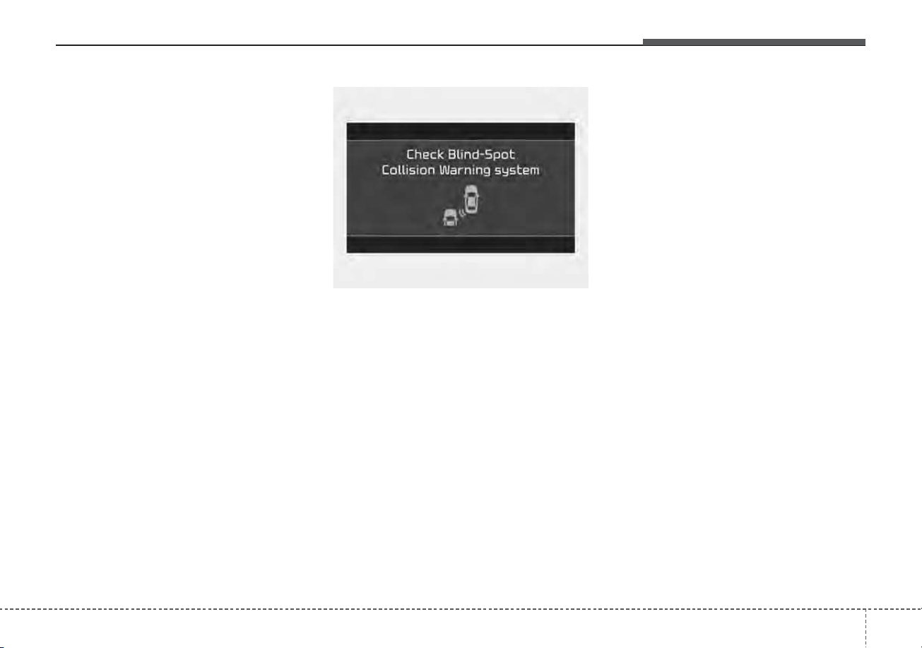
5103
Driving your vehicle
After any dirt or debris is removed,
BCW should operate normally after
about 10 minutes of driving the vehi-
cle.
If the system still does not operate
normally, have your vehicle inspect-
ed by an authorized Kia dealer.
Check Blind-Spot Collision Warning
system
If there is a problem with BCW sys-
tem, a warning message will appear
and the light on the switch will turn off.
The system will turn off automatically.
We recommend that you have your
vehicle inspected by an authorized Kia
dealer.
Limitations of the system
The driver must be cautious in the
below situations, because the sys-
tem may not detect other vehicles or
objects in certain circumstances.
• When a trailer or carrier is installed.
• The vehicle drives in inclement
weather such as heavy rain or
snow.
• The sensor is polluted with rain,
snow, mud, etc.
• The rear bumper where the sensor
is located is covered with a foreign
object such as a bumper sticker, a
bumper guard, a bike rack, etc.
• The rear bumper is damaged, or
the sensor is out of the original
default position.
• The vehicle height gets lower or
higher due to heavy loading in a
liftgate, abnormal tire pressure,
etc.
• When the temperature of the rear
bumper is high.
• When the sensors are blocked by
other vehicles, walls or parking-lot
pillars.
OJF058435L

Driving your vehicle
1045
• The vehicle drives on a curved road.
• The vehicle drives through a tollgate.
• The road pavement (or the periph-
eral ground) abnormally contains
metallic components (i.e. possibly
due to subway construction).
• There is a fixed object near the
vehicle, such as a guardrail.
• While going down or up a steep
road where the height of the lane is
different.
• Driving on a narrow road where
trees or grass or overgrown.
• Driving in rural areas where the
sensor does not detect another
vehicle or structure for an extended
period of time.
• Driving on a wet road.
• Driving on a road where the guardrail
or wall is in double structure.
• A big vehicle is near such as a bus
or truck.
• When the other vehicle approach-
es very close.
• When the other vehicle passes at a
very fast speed.
• While changing lanes.
• If the vehicle has started at the
same time as the vehicle next to
you and has accelerated.
• When the vehicle in the next lane
moves two lanes away from you
OR when the vehicle two lanes
away moves to the next lane from
you.
• A motorcycle or bicycle is near.
• A flat trailer is near.
• If there are small objects in the
detecting area such as a shopping
cart or a baby stroller.
• If there is a low height vehicle such
as a sports car.
• The brake pedal is depressed.
• ESC (Electronic Stability Control)
is activated.
• ESC (Electronic Stability Control)
malfunctions.
• The tire pressure is low or a tire is
damaged.
• The brake is reworked.
• The vehicle abruptly changes driv-
ing direction.
• The vehicle makes sharp lane
changes.
• The vehicle sharply stops.
• Temperature is extremely low
around the vehicle.
• The vehicle severely vibrates while
driving over a bumpy road,
uneven/bumpy road, or concrete
patch.
• The vehicle drives on a slippery
surface due to snow, water puddle,
or ice.
• Lane Departure Warning system or
Lane Keeping Assist system do not
operate normally.
For more information refer to “Lane
Keeping Assist (LKA)” in this chap-
ter.
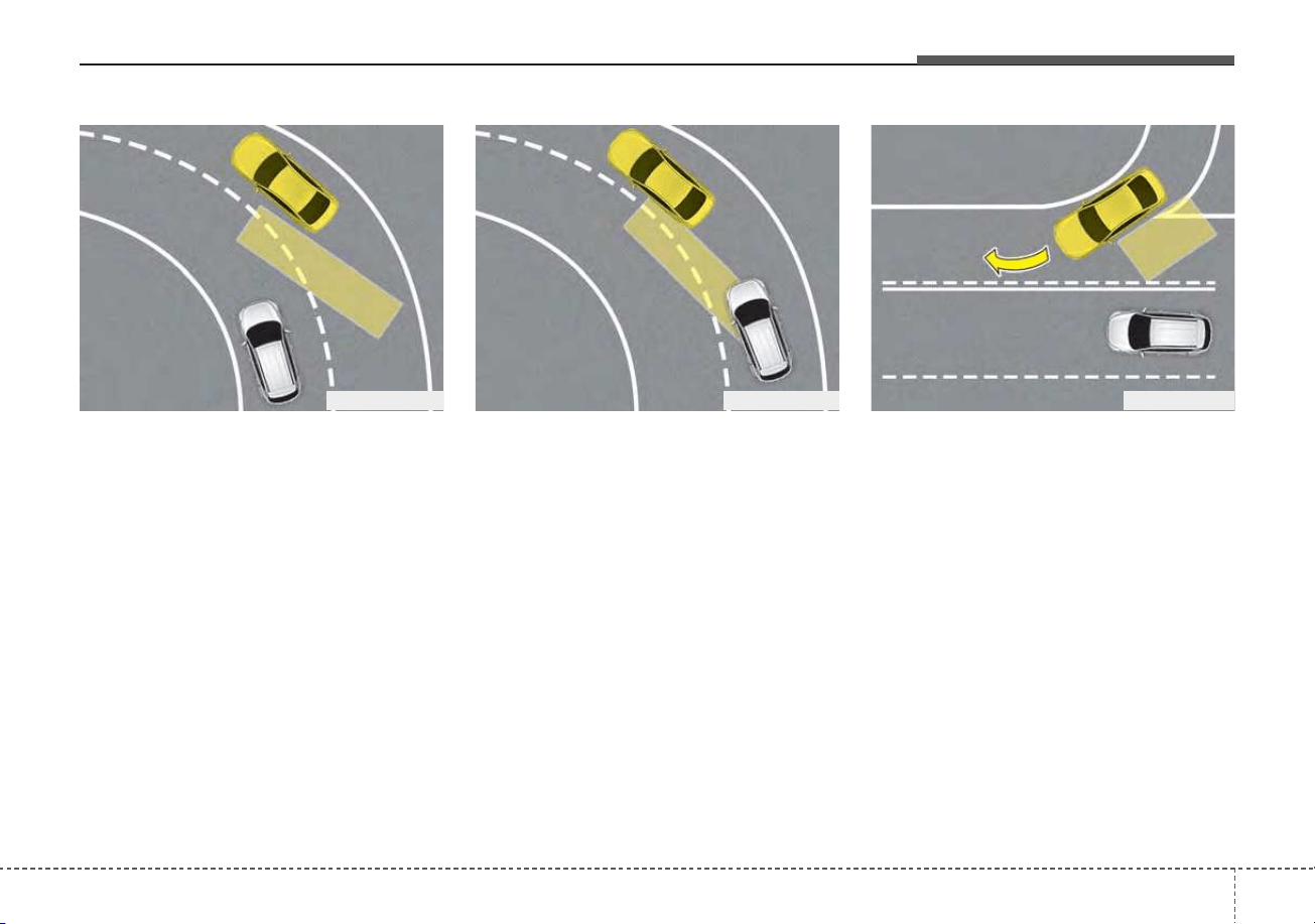
5105
Driving your vehicle
• Driving on a curve
BCW system may not operate prop-
erly when driving on a curved road.
In certain instances the system may
not detect the vehicle in the next
lane.
Always pay attention to road and
driving conditions, while driving.
BCW system may not operate prop-
erly when driving on a curved road.
In certain instances the system may
recognize a vehicle in the same lane.
Always pay attention to road and
driving conditions, while driving.
• Driving where the road is merg-
ing/dividing
BCW system may not operate prop-
erly when driving where the road is
merging/dividing. In certain
instances the system may not detect
the vehicle in the next lane.
Always pay attention to road and
driving conditions, while driving.
OJFHP058458 OJFHP058459 OJFHP058460
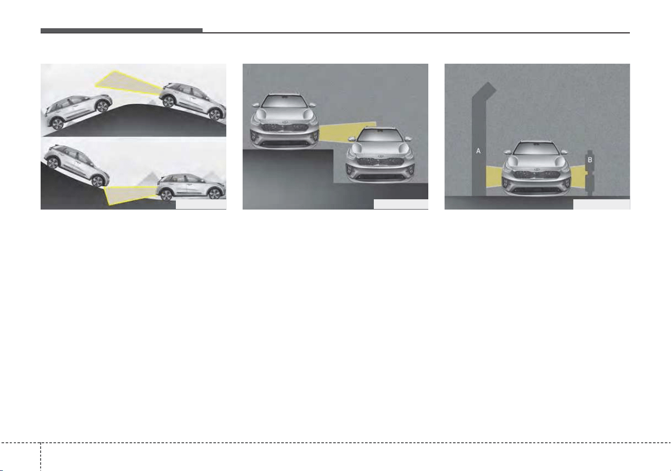
Driving your vehicle
1065
• Driving on a slope
BCW system may not operate prop-
erly when driving on a slope. In cer-
tain instances the system may not
detect the vehicle in the next lane.
Also, in certain instances the system
may wrongly recognize the ground or
structures.
Always pay attention to road and
driving conditions, while driving.
• Driving where the heights of the
lanes are different
BCW system may not operate prop-
erly when driving where the heights
of the lanes are different.
In certain instances, the system may
not detect the vehicle on a road with
different lane heights (underpass
joining section, grade separated
intersections, etc.).
Always pay attention to road and
driving conditions, while driving.
[A] : noise barrier, [B] : guardrail
• Driving where there is a structure
beside the road
BCW system may not operate prop-
erly when driving where there is
structure beside the road.
In certain instances, the system may
wrongly recognize the structures
(noise barriers, guardrail, double
guardrail, median strip, bollard,
street light, road sign, tunnel wall,
etc.) beside the road.
Always pay attention to road and
driving conditions, while driving.
ODEP059161L
ODEP059159 ODEP059160

5107
Driving your vehicle
DAW system displays the driver’s
attention level by integrating driving
pattern and informs the driver when
the vehicle ahead depart while stop-
ping
Low Activity Warning
Display the driver's attention level
and advise taking a break if the
attention level is below a certain
level.
System setting
• To turn ON Driver Attention
Warning system, turn on the
engine, and then selecting “User
Settings → Driver Assistance →
Driver Attention Warning → Low
Activity Warning” on the LCD dis-
play.
DRIVER ATTENTION WARNING (DAW) (IF EQUIPPED)
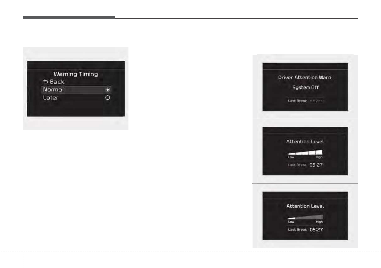
Driving your vehicle
1085
Warning Timing
• The driver can select the initial
warning activation time select
“User Settings → Driver
Assistance →Warning Timing” on
the LCD display. The options for
the initial Inattentive Driving
Warning includes the following:
- Normal :
Driver Attention Warning system
helps alert the driver of his/her
fatigue level or inattentive driving
practices faster than ‘Later’ mode.
- Later :
Driver Attention Warning system
helps alert the driver of his/her
fatigue level or inattentive driving
practices later than Normal mode.
• The set-up of Driver Attention
Warning system will be main-
tained, as selected, when the
engine is re-started.
✽✽
NOTICE
Other driver assistance systems like
Forward Collision-Avoidance Assist,
etc. can be changed when warning
time setting is changed.
Display of the driver's attention
level
OJF058423L
OJF058422L
OJF058424L
OYG059344L
■ System off
■ Attentive driving
■ Inattentive driving
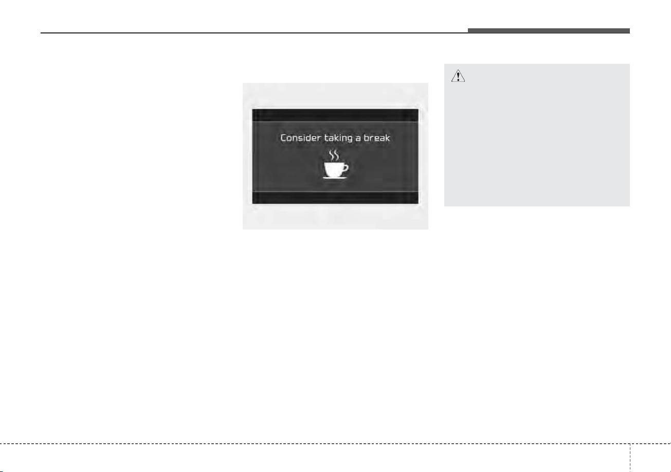
5109
Driving your vehicle
• The driver can monitor their driving
conditions on the LCD display.
- Select ‘Driving Assist’ mode and
then “Driver Attention Warning”
(For more information, refer to
“LCD Display” in chapter 4.)
If your vehicle is equipped with
additional Infotainment System,
please scan the QR code in a sep-
arately supplied Car Infotainment
System Quick Reference Guide.
• The driver's attention level is dis-
played on the scale of 1 to 5. The
lower the level is, the more inatten-
tive the driver is.
• The level decreases when the driv-
er does not take a break for a cer-
tain period of time.
Take a break
• The "Consider taking a break"
message appears on the LCD dis-
play and a warning sounds in order
to suggest the driver to take a
break, when the driver's attention
level is below 1.
• If the total driving time is less than
10 minutes, Driver Attention
Warning system does not suggest
the driver take a break. And the
system does not repeat break sug-
gestion within 10 minutes after
sending warning message.
OJF058426L
CAUTION
• It may suggest a break accord-
ing to the driver’s driving pat-
tern or habits even if the driver
doesn’t feel fatigued.
• The warning of Driver
Attention Warning system may
not sound while other sys-
tem's warning sounds such as
the seatbelt warning sound.
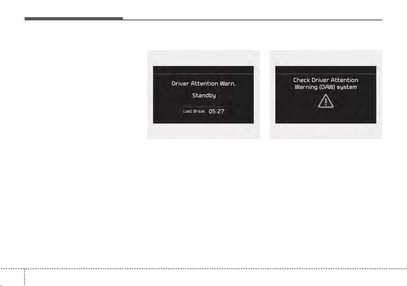
Driving your vehicle
1105
Resetting the function
• The last break time is set to 00:00
and the driver's attention level is
set to 5 (very attentive) when the
driver resets the Inattentive driving
warning function.
• Inattentive driving warning function
resets in the following situations.
- The engine is turned OFF.
- The driver unfastens the seat belt
and then opens the driver’s door.
- The vehicle is stopped for more
than 10 minutes.
System standby
Driver Attention Warning system
enters the ready status and displays
the ‘Standby’ screen in the following
situations.
- Driving speed is over 110 mph
(180 km/h).
System malfunction
When the “Check Driver Attention
Warning (DAW) system” warning
message appears, the system is not
working properly. If this occurs, have
the system checked by an authorized
Kia dealer.
OJF058429LOJF058427L

5111
Driving your vehicle
✽✽
NOTICE
Driver Attention Warning system
utilizes the front view camera sensor
on the front windshield for its oper-
ation. To keep the front view camera
sensor in the best condition, you
should observe the followings:
- Do not disassemble camera tem-
porarily for tinted window or
attaching any types of coatings and
accessories. If you disassemble a
camera and assemble it again, take
your vehicle to an authorized Kia
dealer and have the system
checked.
- Do not locate any reflective
objects (i.e. white paper, mirror)
over the dashboard. Any light
reflection may cause a mal-func-
tion of Driver Attention Warning
system.
(Continued)
(Continued)
- Pay extreme caution to keep the
front view camera out of water.
- Do not arbitrarily disassemble the
camera assembly, nor apply any
impact on the camera assembly.
• Playing the vehicle audio system
at high volume may offset the
Driver Attention Warning system
warning sounds.
For more information of front
view camera, refer to “Lane
Keeping Assist (LKA)”.
WARNING
• Driver Attention Warning sys-
tem is not a substitute for safe
driving practices, but a con-
venience function only. It is
the driver's responsibility to
always drive cautiously and
safely.
• A fatigued driver should take
a break, even if there is no
suggestion to do so by the
Driver Attention Warning sys-
tem.

Driving your vehicle
1125
Leading Vehicle Departure
Alert
This function reminds the driver the
leading vehicle’s driving departure
after stopping.
CAUTION
Driver Attention Warning sys-
tem may not properly operate
with limited alerting in the fol-
lowing situations:
• The system will not operate
for about 15 seconds when
restarting the engine or initial-
izing the front camera such as
rebooting, etc.
• The lane detection perform-
ance is limited. (For more
information, refer to "Lane
Keeping Assist (LKA)" in this
chapter.)
• The vehicle is violently driven
or is abruptly turned for obsta-
cle avoidance (e.g. construc-
tion area, other vehicles, fallen
objects, bumpy road).
• Intentionally frequent lane
cut-in
(Continued)
(Continued)
• The vehicle drives on a curvy
road.
• The vehicle drives on a bumpy
road.
• The vehicle drives through a
windy area.
• The vehicle is controlled by
the other driver assistance
systems such as Lane
Keeping Assist system.
5113
Driving your vehicle
Function setting
With the vehicle ON, Leading Vehicle
Departure Alert function turns on and
gets ready to be activated when the
“User Settings → Driver Assistance →
Driver Attention Warning → Leading
Vehicle Departure Alert” is selected on
the cluster. The function stops opera-
tion when the setting is deactivated.
However, if the vehicle is turned off
then on again, the function maintains
the previous state.
Operating conditions
If the driver does not take action for a
certain period of time after the vehi-
cle in front departs, the “Leading
vehicle is driving away” message is
displayed on the cluster.
WARNING
• This function is a driver assis-
tance device and may not
alert the driver even after the
leading vehicle's departure.
• Even if you are alerted of the
leading vehicle's departure,
always check the traffic condi-
tions yourself before safely
moving the vehicle.

Driving your vehicle
1145
✽✽
NOTICE
The function may not alert or may
not work properly when:
• A pedestrian or a bicycle is ahead
• A car cut in ahead.
• Meet a traffic jam during the
curve or right turn driving.
• Busy road such as reducing lanes.
• Stopping at a shoulder, rest area
or a parking lot.
• If the vehicle head makes a sudden
start or the U-turn.
• If the vehicle is stopped at the
speed bumps or a slope.
CAUTION
• Leading Vehicle Departure
Alert function utilizes the front
camera on the front wind-
shield for its operation. To
keep the front camera in the
best condition.
For more information of front
view camera, refer to “Lane
Keeping Assist (LKA)”.
• The function may not operate
for 15 seconds after the
engine is started or the front
view camera is initialized.
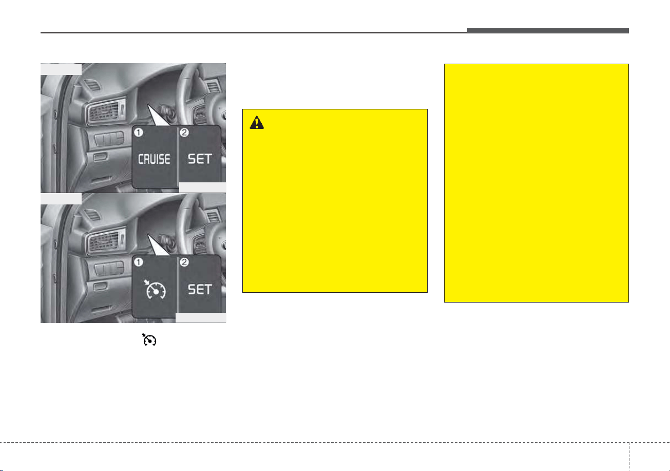
5115
Driving your vehicle
1. Cruise indicator ( CRUISE)
2. Cruise set indicator
Cruise Control system allows you to
program the vehicle to maintain a
constant speed without pressing the
accelerator pedal.
This system is designed to function
above approximately 20 mph (30
km/h ).
CRUISE CONTROL (CC) (IF EQUIPPED)
WARNING
• If the cruise control is left on,
(cruise indicator light is illu-
minated), the cruise control
can be switched on acciden-
tally. Keep the cruise control
system off when the cruise
control is not in use, to avoid
inadvertently setting a speed.
• Use the cruise control system
only when traveling on open
highways in good weather.
(Continued)
(Continued)
• Do not use the cruise control
when it may not be safe to
keep the vehicle at a constant
speed, for instance, driving in
heavy or varying traffic, or on
slippery (rainy, icy or snow-
covered) or winding roads or
over 6% up-hill or down-hill
roads.
• Pay particular attention to the
driving conditions whenever
using the cruise control sys-
tem.
• Be careful when driving
downhill using the cruise con-
trol system, which may
increase the vehicle speed.
ODE056018
■ Type A
■ Type B
ODE056018L
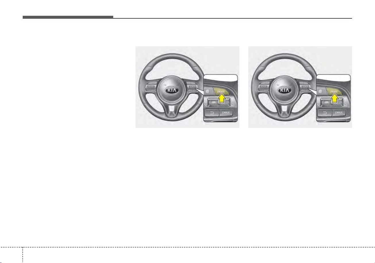
Driving your vehicle
1165
✽✽
NOTICE
• During normal cruise control oper-
ation, when the SET switch is acti-
vated or reactivated after applying
the brakes, the cruise control will
energize after approximately 3 sec-
onds. This delay is normal.
• To activate cruise control, depress
the brake pedal at least once after
placing the ignition switch or
ENGINE START/STOP button to
the ON position or starting the
engine. This is to check if the brake
switch which is important part to
cancel cruise control is in normal
condition.
Cruise control switch
CANCEL : Cancels cruise control
operation.
CRUISE : Turns cruise control sys-
tem on or off.
RES+ : Resumes or increases cruise
control speed.
SET- : Sets or decreases cruise con-
trol speed.
To set cruise control speed:
1. Press the CRUISE button on the
steering wheel, to turn the system
on. The cruise indicator light will
illuminate.
2. Accelerate to the desired speed,
which must be more than approxi-
mately 20 mph (30 km/h).
ODE056019 ODE056019
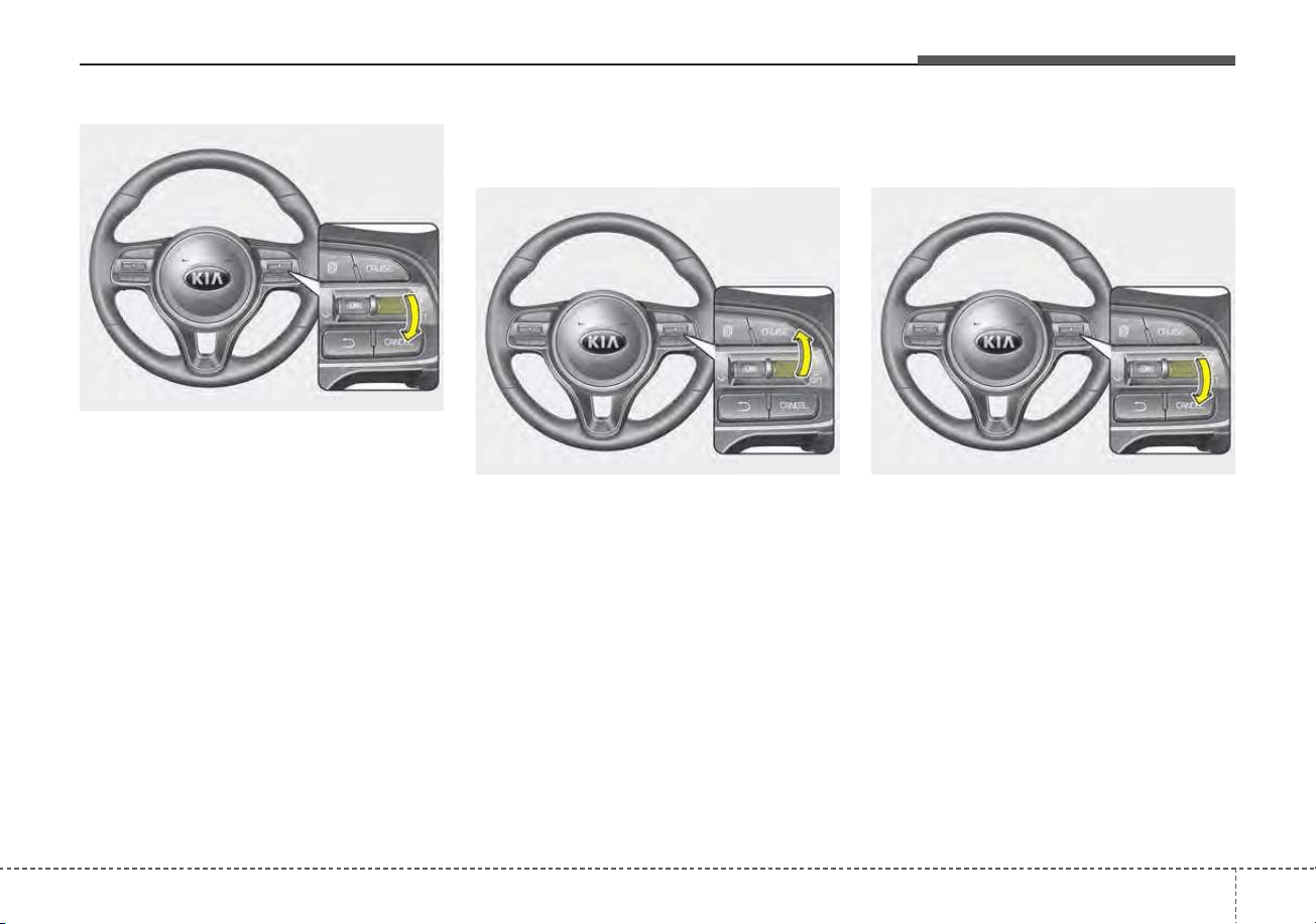
5117
Driving your vehicle
3. Move the switch down (to SET-),
and release it at the desired
speed. The cruise set indicator
light will illuminate. Release the
accelerator pedal at the same
time. The desired speed will auto-
matically be maintained.
On a steep grade, the vehicle may
slow down or speed up slightly while
going downhill.
To increase cruise control set
speed:
Follow either of these procedures:
• Move the switch up (to RES+) and
hold it. Your vehicle will accelerate.
Release the switch at the speed
you want.
• Move the switch up (to RES+) and
release it immediately. The cruising
speed will increase by 1 mph (or 1
km/h ) each time you move the
switch up (to RES+) in this manner.
To decrease the cruising
speed:
Follow either of these procedures:
• Move the switch down (to SET-)
and hold it. Your vehicle will gradu-
ally slow down. Release the switch
at the speed you want to maintain.
• Move the switch down (to SET-)
and release it immediately. The
cruising speed will decrease by 1
mph (or 1 km/h) each time you
move the switch down (to SET-) in
this manner.
ODE056020
ODE056021 ODE056020
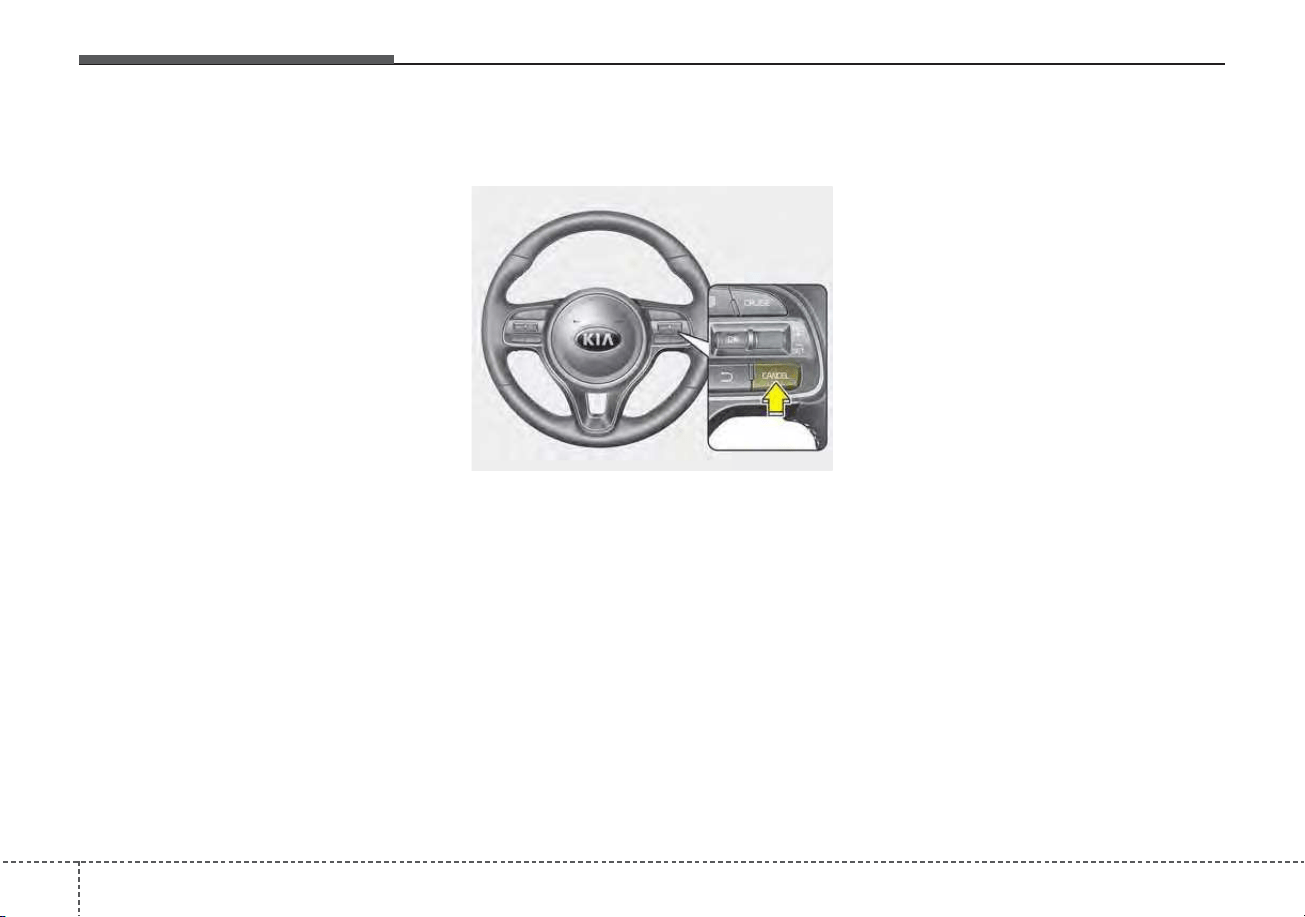
Driving your vehicle
1185
To temporarily accelerate with
the cruise control on:
If you want to speed up temporarily
when the cruise control is on,
depress the accelerator pedal.
Increased speed will not interfere
with cruise control operation or
change the set speed.
To return to the set speed, take your
foot off the accelerator pedal.
To cancel cruise control, do
one of the following:
• Depress the brake pedal.
• Shift into N (Neutral) if equipped
with an Dual clutch transmission.
• Press the CANCEL button located
on the steering wheel.
• Decrease the vehicle speed lower
than the memory speed by approx-
imately 12 mph (20 km/h).
• Decrease the vehicle speed to less
than approximately 15 mph (25 km/h).
Each of these actions will cancel
cruise control operation (the
cruise
set
indicator light will go off), but it
will not turn the system off. If you
wish to resume cruise control opera-
tion, move up the switch (to RES+)
located on your steering wheel. You
will return to your previously preset
speed.
ODE056022
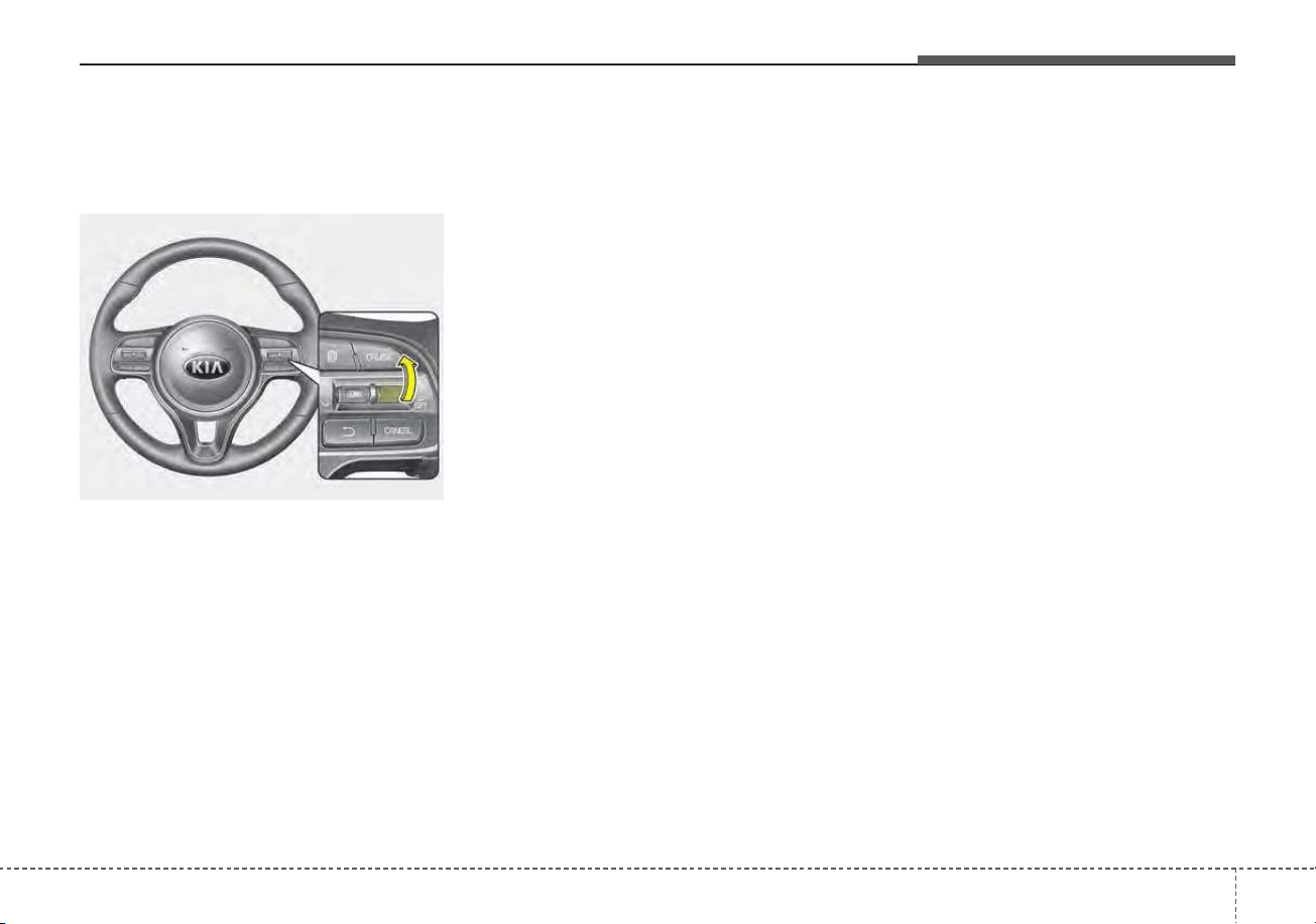
5119
Driving your vehicle
To resume cruising speed at
more than approximately 20
mph (30 km/h).
If any method other than the
CRUISE button was used to cancel
cruising speed and the system is still
activated, the most recent set speed
will automatically resume when the
RES+ switch is pushed.
It will not resume, however, if the
vehicle speed has dropped below
approximately 20 mph (30 km/h).
To turn cruise control off, do
one of the following:
• Press the CRUISE button (the
cruise indicator light will be turn off).
• If your vehicle equipped the speed
limit system, press the CRUISE
button twice. (The cruise indicator
light will be turn off.)
• Turn the ignition off.
Both of these actions cancel cruise
control operation. If you want to
resume cruise control operation,
repeat the steps provided in “To set
cruise control speed” on the previous
page.
ODE056021
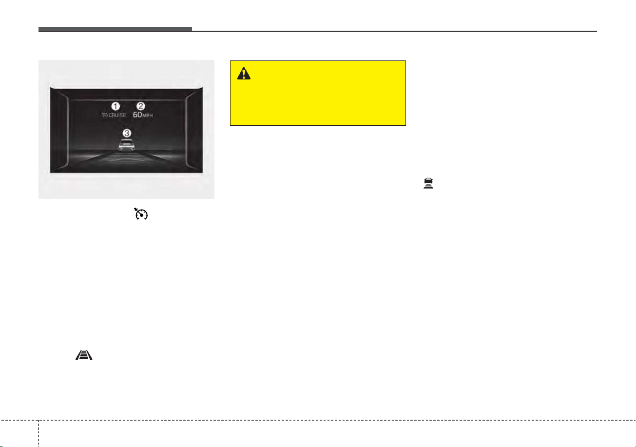
Driving your vehicle
1205
➀ Cruise indicator ( CRUISE)
➁ Set speed
➂ Vehicle-to-vehicle distance
Smart Cruise Control system allows
you to program the vehicle to maintain
constant speed and distance detect-
ing the vehicle ahead without depress-
ing the accelerator or brake pedal.
To see SCC screen on the LCD dis-
play on the cluster, select Driving
Assist ( ). For more informations,
refer to “LCD Display Modes” in
chapter 4.
✽✽
NOTICE
To activate Smart Cruise Control,
depress the brake pedal at least once
after placing the ignition switch or
ENGINE START/STOP button to
the ON position or starting the
engine. This is to check if the brake
switch which is important part to
cancel smart cruise control is in nor-
mal condition.
Smart Cruise Control switch
CANCEL : Cancels cruise control
operation.
CRUISE : Turns cruise control sys-
tem on or off.
RES + : Sets or increases cruise
control speed.
SET - : Sets or decreases cruise
control speed.
: Sets vehicle-to-vehicle distance
SMART CRUISE CONTROL (SCC) (IF EQUIPPED)
WARNING
For your safety, please read the
owner's manual before using
Smart Cruise Control system.
ODEP059080N
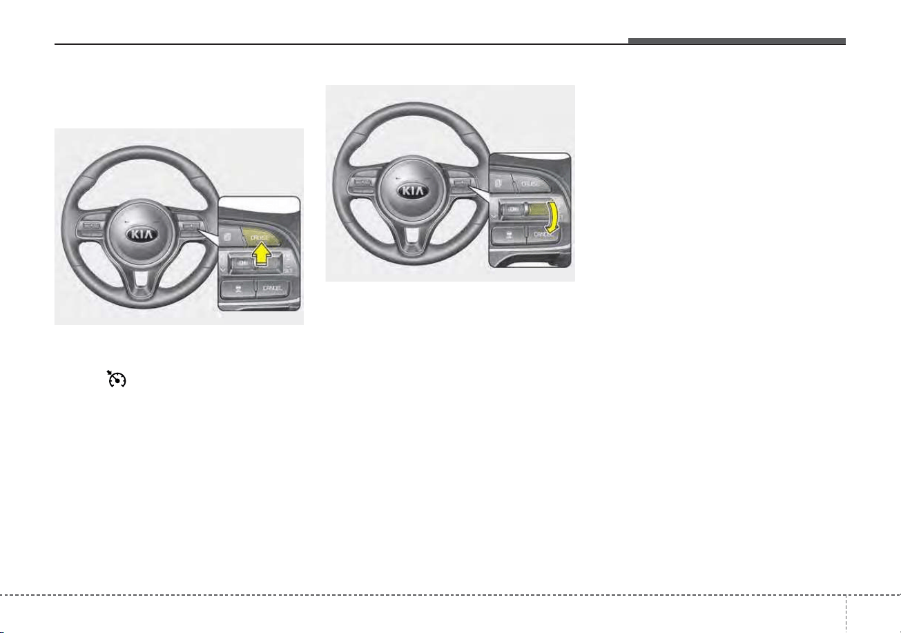
5121
Driving your vehicle
Smart Cruise Control speed To
set Smart Cruise Control Speed :
1. Press the CRUISE button, to turn
the system on. The Cruise indica-
tor ( CRUISE) in the instru-
ment cluster will illuminate.
2. Accelerate to the desired speed.
Smart Cruise Control speed can
be set as follows:
• 5 mph (10 km/h) ~ 110 mph (180
km/h) : when there is no vehicle
in front
• 0 mph (0 km/h) ~ 110 mph (180
km/h) : when there is a vehicle in
front
3. Move the switch down (to SET-),
and release it at the desired
speed. The set speed and vehicle
to vehicle distance on the LCD
screen will illuminate.
4. Release the accelerator pedal.
The desired speed will automati-
cally be maintained.
If there is a vehicle in front of you, the
speed may decrease to maintain the
distance to the vehicle ahead.
On a steep grade, the vehicle may
slow down or speed up slightly while
going uphill or downhill.
Vehicle speed may decrease on an
upward slope and increase on a
downward slope.
The speed will be set to 0 ~ 20 mph
(0 ~30 km/h) when there is a vehicle
ahead and your vehicle speed is 0 ~
20 mph (0 ~30 km/h).
ODE056023
ODE056024
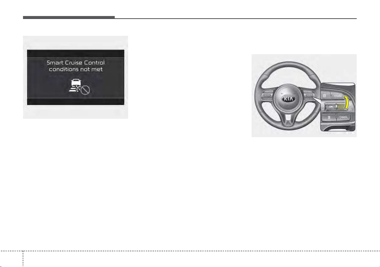
Driving your vehicle
1225
SCC system Not Operating
Conditions
• The driver’s door is opened.
• The vehicle is shifted to N (Neutral)
/ R (Reverse) / P (Parking).
• The parking brake is applied.
• The vehicle speed is not within the
specified SCC range.
• The ESC (Electronic Stability
Control), TCS (Traction Control
System)or ABS is operating.
• The ESC (Electronic Stability
Control), TCS (Traction Control
System)or ABS is off.
The ESC (Electronic Stability
Control), TCS (Traction Control
System)or ABS is operating.
• The sensor cover is extremely con-
taminated.
• The engine performance is abnor-
mal.
• The Forward Collision-Avoidance
Assist system is activated.
• The engine RPM is in the red zone.
• The front radar is abnormal.
To increase Smart Cruise Control
system set speed:
Follow either of these procedures:
• Move the switch up (to RES+), and
hold it. Your vehicle set speed will
increase by 5 mph (10 km/h).
Release the switch at the speed
you want.
• Move the switch up (to RES+), and
release it immediately. The cruising
speed will increase by 1.0 mph (1.0
km/h) each time you move the
switch up (to RES+) in this manner.
OYG059346L
ODE056025
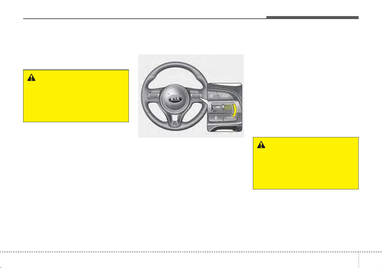
5123
Driving your vehicle
• Although SCC will operate to a
maximum setting of up to 110 mph
(180km/h), all local speed limit
laws must always be followed.
To decrease Smart Cruise Control
system set speed:
Follow either of these procedures:
• Move the switch down (to SET-), and
hold it. Your vehicle set speed will
decrease by 5 mph (10 km/h).
Release the switch at the speed
you want.
• Move the switch down (to SET-),
and release it immediately. The
cruising speed will decrease by 1.0
mph (1.0 km/h) each time you
move the switch down (to SET-) in
this manner.
• You can set the speed to 20 mph
(30 km/h).
To temporarily accelerate with
Smart Cruise Control system on :
If you want to speed up temporarily
when the cruise control is on,
depress the accelerator pedal.
Increased speed will not interfere
with SCC system operation or
change the set speed.
To return to the set speed, take your
foot off the accelerator.
If you move the switch down (to SET-)
at increased speed, the cruising
speed will be set again.
WARNING
Check driving conditions before
using the switch as driving
speed increases rapidly when
you push up and hold the
switch.
ODE056024
WARNING
Be careful when accelerating
temporarily, because the speed
is not controlled automatically
at this time even if there is a
vehicle in front of you.
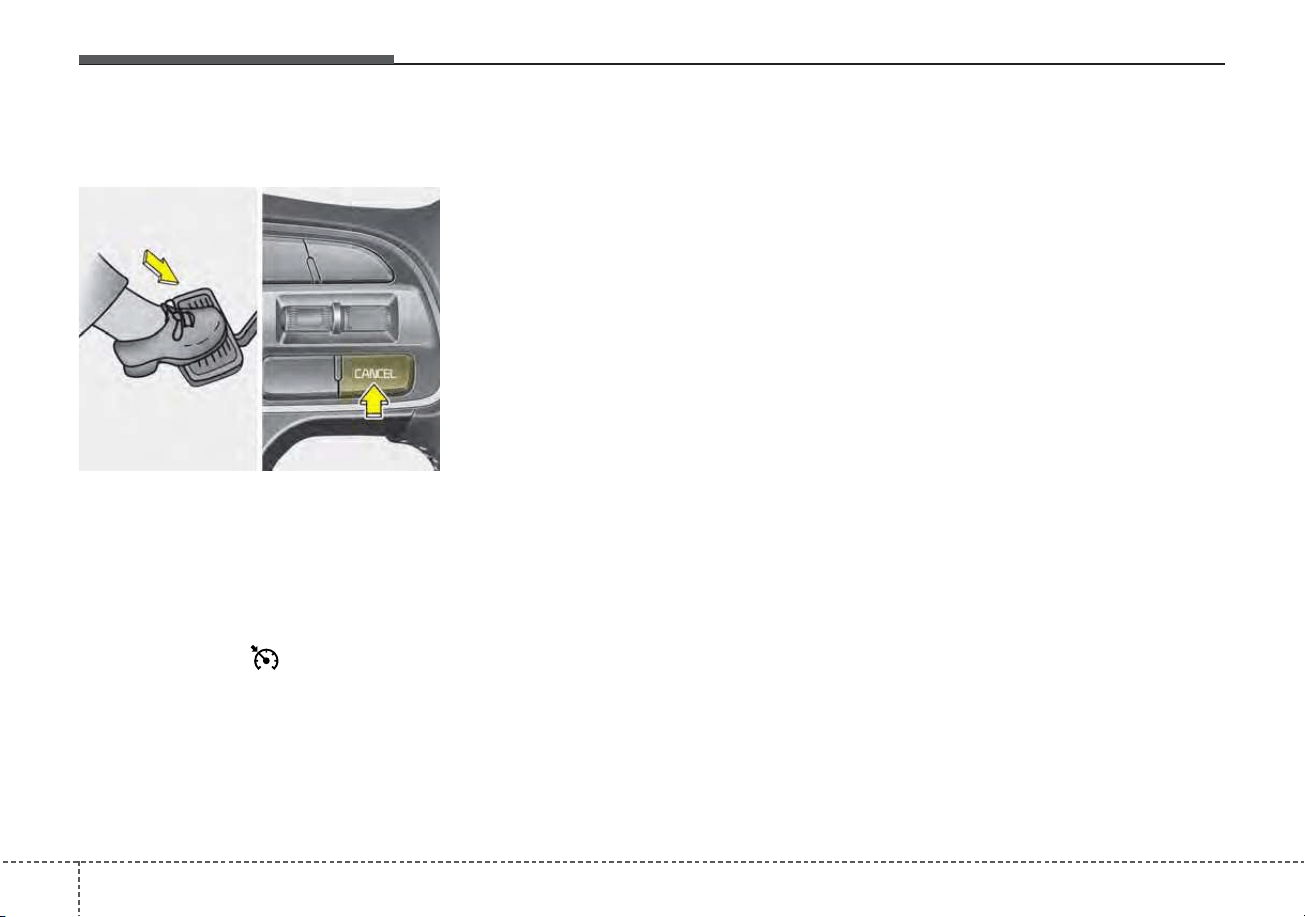
Driving your vehicle
1245
Smart Cruise Control system will
be temporarily canceled when:
Canceled manually
Smart Cruise Control system is tem-
porarily canceled when the brake
pedal is depressed or the CANCEL
button is pressed. The speed and
vehicle to vehicle distance indicator
on the cluster is disappeared and the
cruise indicator ( CRUISE) is illu-
minated continuously.
Canceled automatically
SCC system will automatically can-
cel in the following situations:
• The driver's door is opened.
• The shift lever is shifted to N
(Neutral), R (Reverse) or P (Paking).
• The EPB (Electronic Parking
Brake) is applied.
• The vehicle speed is over 120 mph
(190 km/h)
• The ESC, ABS or TCS is operating.
• The ESC is turned off.
• The sensor or the cover is dirty or
blocked with foreign matter.
• The accelerator pedal is continu-
ously depressed for long time.
• The engine speed is in dangerous
range.
• SCC system has malfunctioned.
• When the braking control is operat-
ed for Forward Collision-Avoidance
Assist system
• The vehicle stops and goes repeat-
edly for a long period of time.
• When the parking brake is locked
• Speed of the vehicle has been
decreased to less than 5 mph (10
km/h)
• Engine has some problems
Each of these actions will cancel SCC
system operation. (The set speed of
the cluster is displayed in gray shades
and the distance indicator with the
vehicle ahead is disappeared.)
In a condition the smart cruise con-
trol is cancelled automatically, Smart
Cruise Control system will not oper-
ate even though the RES+ or SET-
switch is moved.
The EPB (Electronic Parking Brake)
is applied when SCC auto release
condition occurs while SCC is in use.
ODE056026
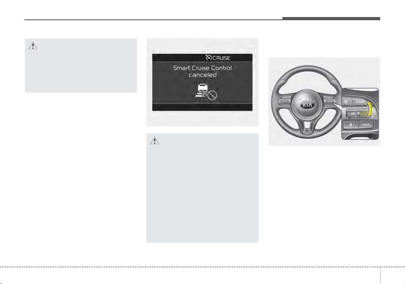
5125
Driving your vehicle
To restart Smart Cruise Control
system :
If any method other than the
CRUISE button was used to cancel
cruising speed and the system is still
activated, the cruising speed will
automatically resume when you
move the switch up (to RES+).
If you move the switch up (to RES+),
the speed will resume to the recently
set speed. However, if vehicle speed
drops below 5 mph (10 km/h), it will
resume when there is a vehicle in
front of your vehicle.
CAUTION
If Smart Cruise Control system
is cancelled by other than the
reasons mentioned, have the
system checked by an author-
ized Kia dealer.
CAUTION
If the system is automatically
cancelled, the warning chime
will sound and a message will
appear for a few seconds.
You must adjust the vehicle
speed by depressing the accel-
erator or brake pedal according
to the road condition ahead and
driving condition.
Always check the road condi-
tions. Do not rely on the warning
chime.
OJF058397L
ODE056025
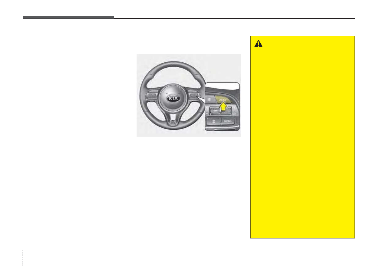
Driving your vehicle
1265
✽✽
NOTICE
To reduce the risk of an accident,
always check the road conditions
when reactivating the smart cruise
control using the RES+ switch to
ensure the road conditions permit
safe use of the cruise control.
To turn Smart Cruise Control sys-
tem off:
Press the CRUISE button. (the
CRUISE indicator in the instrument
cluster will go off).
When Smart Cruise Control system
is not needed, press the [CRUISE]
switch and deactivate the system.
ODE056023
WARNING
Take the following precautions :
• If Smart Cruise Control sys-
tem is left on, (cruise indicator
in the instrument cluster illu-
minated) Smart Cruise
Control system can be acti-
vated unintentionally. Keep
Smart Cruise Control system
off (cruise indicator turn off)
when Smart Cruise Control
system is not used.
• Do not leave the vehicle when
it is stopped by SCC system.
If it is necessary to leave the
vehicle, turn off SCC system
and move the gear shift to P
(Parking), engage the parking
brake, and turn off the engine
while depressing the brake
pedal.
• Use SCC system only on roads
with good traffic conditions.
Do not use SCC system in the
following situations because
of the high risk of an accident.
(Continued)

5127
Driving your vehicle
(Continued)
- Highway interchange and
tollgate
- Road surrounded by multi-
ple steel constructions (sub-
way construction, steel tun-
nel, etc)
- Parking lot
- Lanes beside guard rail on a
road
- Slippery road with rain, ice,
or snow covered
- Abrupt curved road
- Steep hills
- Windy roads
- Off roads
- Rods under construction
- Rumble strip
- When driving near crash bar-
riers
(Continued)
(Continued)
- When the vehicle sensing
ability decreases due to
vehicle modification that
causes a difference in the
level of the vehicle's front
and rear
- When driving with limited
view (possibly due to bad
weather, such as fog, snow,
rain or sandstorm)
• Pay particular attention to the
driving conditions whenever
using the smart cruise control
system.
• Smart Cruise Control system
is not a substitute for safe
driving. It is the responsibility
of the driver to always check
the speed and distance of the
vehicle ahead.
• Be careful when driving
downhill using SCC system.
(Continued)
(Continued)
• Smart Cruise Control system
should not be used when the
vehicle is being towed.
• Always set the vehicle speed
under the applicable speed
limit.
• Unexpected situations may
lead to accidents. Pay contin-
uous attention to road condi-
tions and your surroundings
even when the Smart Cruise
Control System is operating.
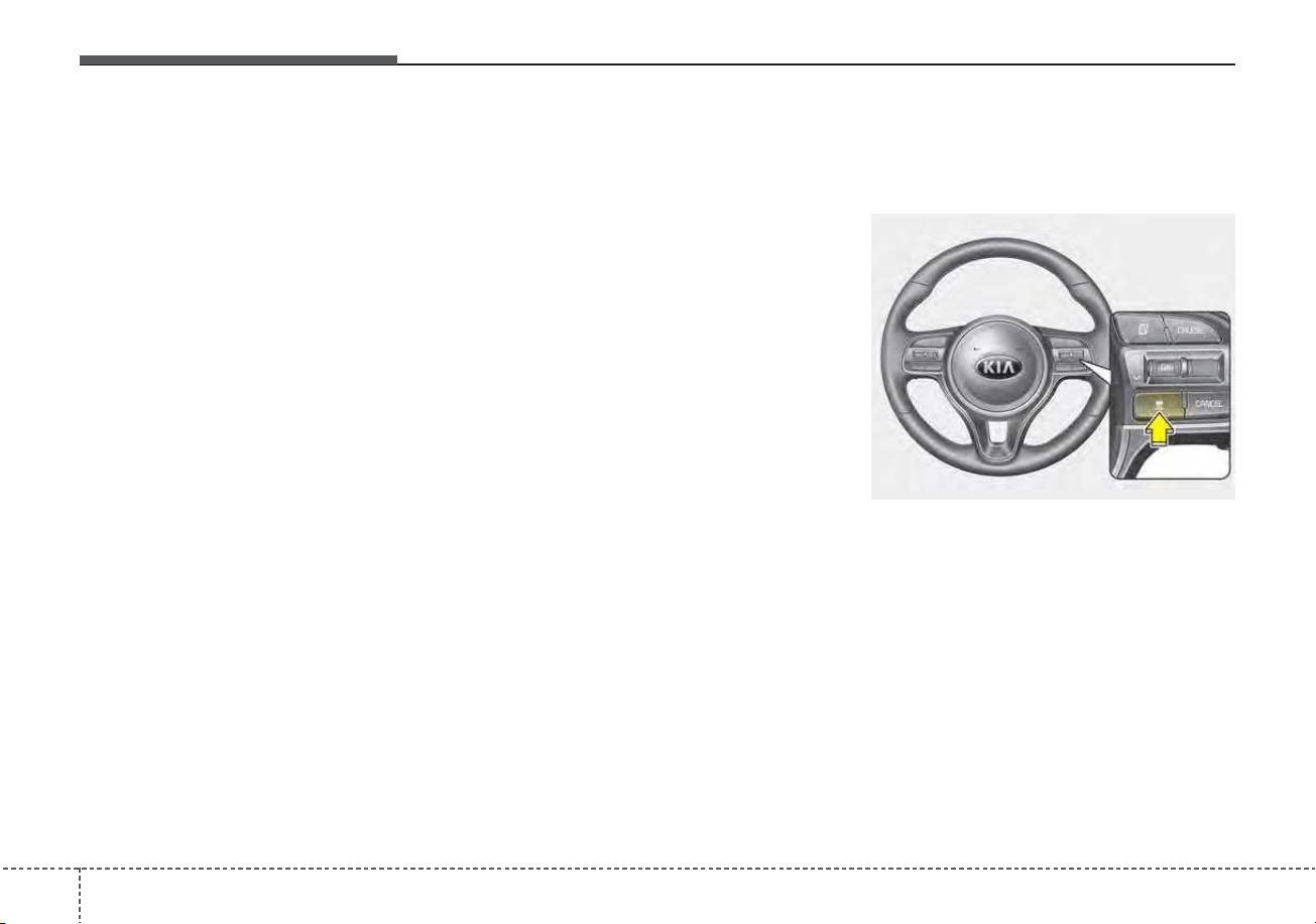
Driving your vehicle
1285
Set SCC Reaction
The sensitivity of vehicle speed
when following the front vehicle to
maintain the set distance can be
adjusted.
The acceleration speed (reaction) for
following the front vehicle is set in
conjunction with the DRIVE MODE
button.
SCC Reaction
• Fast:
Vehicle speed following the front
vehicle to maintain the set distance
is faster than normal speed.
• Normal:
Vehicle speed following the front
vehicle to maintain the set distance
is normal
• Slow:
Vehicle speed following the front
vehicle to maintain the set distance
is slower than normal speed.
Vehicle to vehicle distance
setting
To set vehicle to vehicle distance:
This function allows you to program
the vehicle to maintain relative dis-
tance to the vehicle ahead without
depressing the accelerator pedal or
brake pedal.
The vehicle to vehicle distance will
automatically activate when Smart
Cruise Control system is on.
Select the appropriate distance
according to road conditions and
vehicle speed.
ODE056027
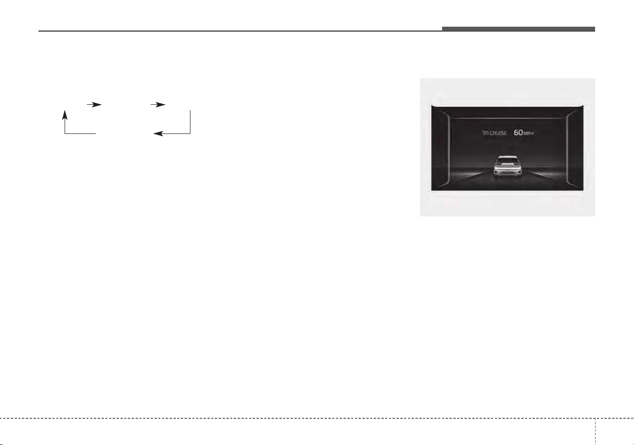
5129
Driving your vehicle
Each time the button is pressed, the
vehicle to vehicle distance changes
as follows:
For example, if you drive at 56 mph
(90 km/h), the distance maintain as
follows;
Distance 4 - approximately 172 feet
(52.5 m)
Distance 3 - approximately 130 feet
(40 m)
Distance 2 - approximately 106 feet
(32.5 m)
Distance 1 - approximately 82 feet
(25 m)
✽✽
NOTICE
The distance is set to the last set dis-
tance when the system is used for the
first time after starting the engine.
When the lane ahead is clear :
The vehicle speed will maintain the
set speed.
Distance 4 Distance 3 Distance 2
Distance 1
ODEP059093N
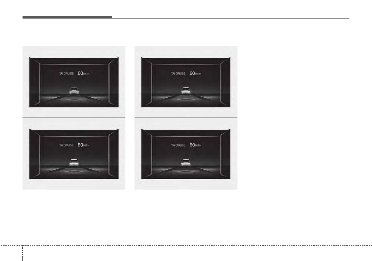
Driving your vehicle
1305
• The vehicle will maintain the set
speed, when the lane ahead is
clear.
• The vehicle will slow down or
speed up to maintain the selected
distance, when there is a vehicle
ahead of you in the lane. (A vehicle
will appear in front of your vehicle
in the LCD display only when there
is an actual vehicle in front of you)
• If the vehicle ahead speeds up,
your vehicle will travel at a steady
cruising speed after accelerating to
the selected speed.
• If you turn on the driver’s side turn
signal when there is a vehicle
ahead, your vehicle may temporar-
ily accelerate to assist you in
changing lanes.
ODEP059319N
ODEP059082N
ODEP059081N
ODEP059083N
When there is a vehicle ahead of you in your lane :
• Level 4
• Level 2
• Level 3
• Level 1
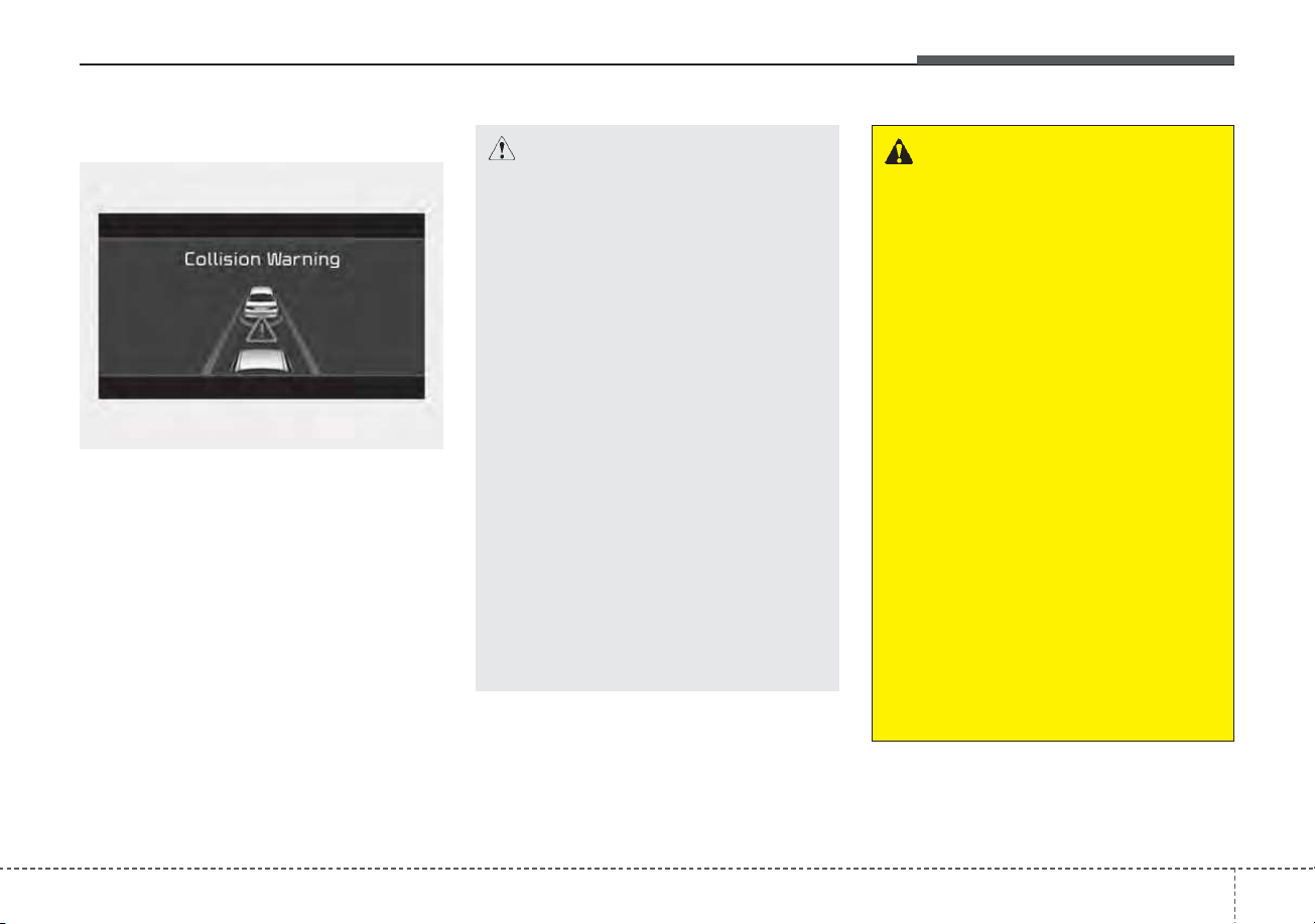
5131
Driving your vehicle
Collision Warning
If there is a high risk of collision due
to sudden braking of the front vehicle
or lack of safety distance with the
vehicle ahead during SCC driving, so
that if the driver's brake or steering
wheel operation is required, the
Distance Step with the vehicle ahead
will blink on the cluster and a colli-
sion warning will sound.
In this case, immediately reduce the
speed.
OJF058389L
CAUTION
• Even if the warning message
does not appear and warning
chime does not sound, always
pay attention to driving condi-
tions to prevent dangerous
situations from occurring.
• Playing the vehicle audio sys-
tem at high volume may cause
the occupants to not hear the
system warning sounds.
• If the vehicle cannot keep the
enough set distance, the
warning will sound and blink
on the cluster. If a warning
sounds, check the nearby traf-
fic condition and if necessary,
control the speed by depress-
ing the brake. Always pay
attention in case of danger,
even if there are no warning
sound.
WARNING
• If the speed of the vehicle
ahead is similar to or faster
than your vehicle, the system
may not warn you as you do
not maintain enough set dis-
tance. Always pay attention in
case of danger, even if there is
no warning sound.
• If the speed of the vehicle
ahead is too slow, the system
may not warn you as you do
not maintain enough set dis-
tance. Always pay attention in
case of danger, even if there is
no warning sound.
• If you set SCC speed and
depress the accelerator pedal,
the system may not warn you
as you do not maintain
enough set distance. Always
pay attention in case of dan-
ger, even if there is no warn-
ing sound.
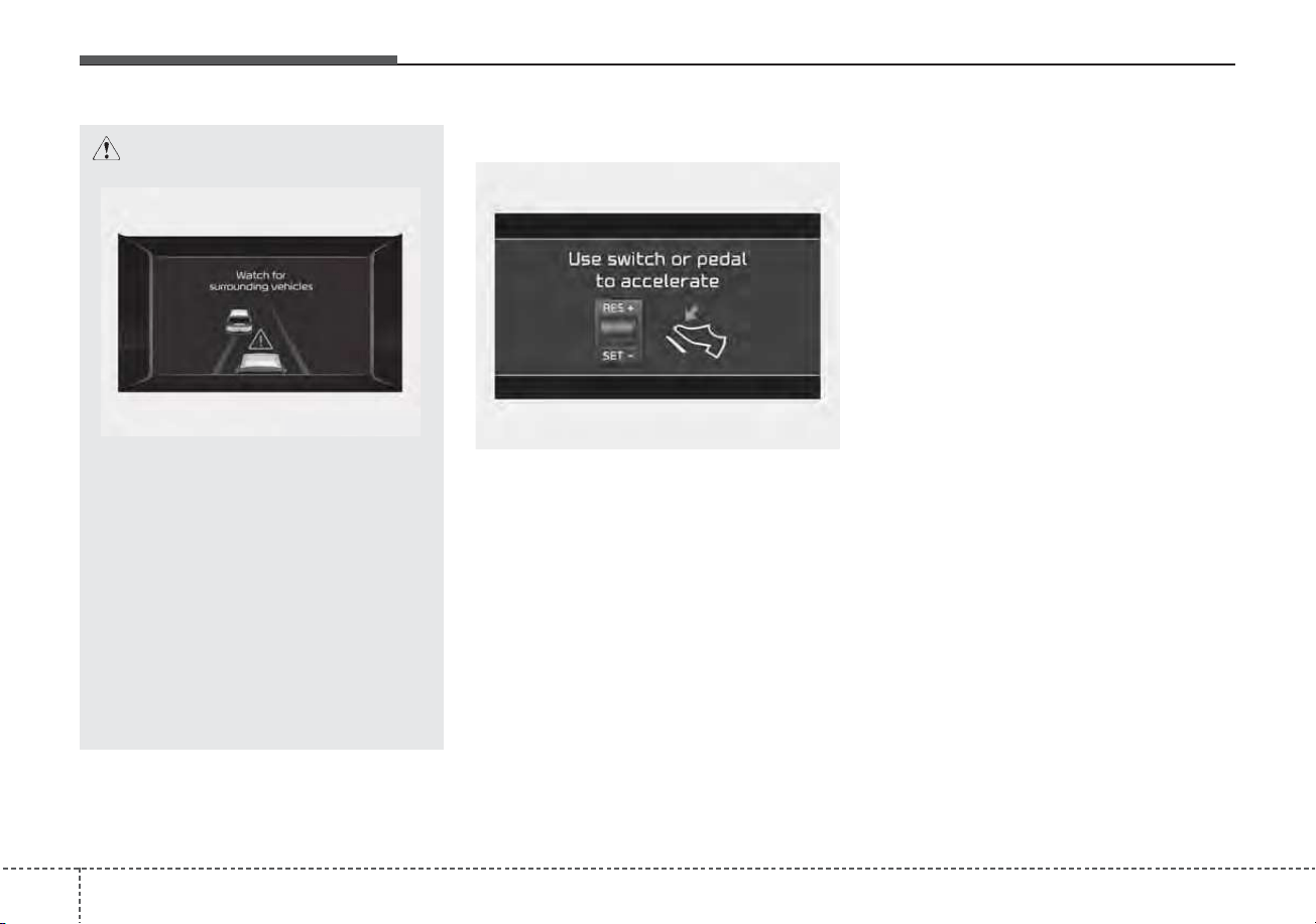
Driving your vehicle
1325
In traffic situation
Use switch or pedal to accelerate
• In traffic, your vehicle will stop if the
vehicle ahead of you stops. Also, if
the vehicle ahead of you starts
moving, your vehicle will start as
well. However, if the vehicle stops
you must depress the accelerator
pedal or push up the switch
(RES+) to start driving.
• If you push the smart cruise control
switch (RES+ or SET-) while Auto
Hold and smart cruise control is
operating the Auto Hold will be
released regardless of accelerator
pedal operation and the vehicle will
start to move. The AUTO HOLD
indicator changes from green to
white. (if equipped with EPB
(Electronic Parking Brake))
CAUTION
If the vehicle ahead (vehicle
speed: less than 20 mph (30
km/h) disappears to the next
lane, the warning chime will
sound and a message will
appear. Adjust your vehicle
speed for vehicles or objects
that can suddenly appear in
front of you by depressing the
brake pedal according to the
road condition ahead and driv-
ing condition.
ODEP059084L
OJF058402L
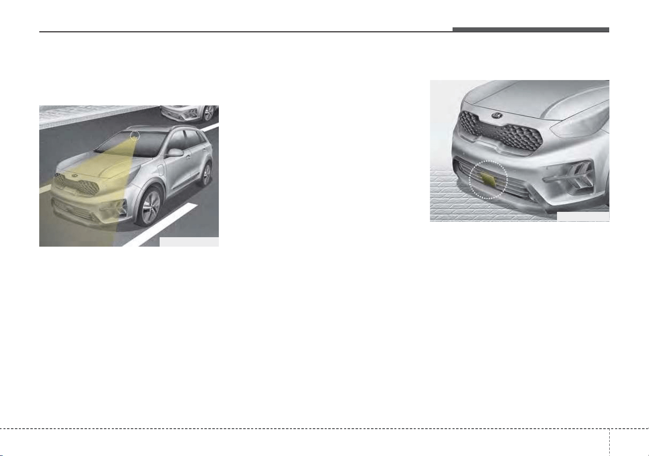
5133
Driving your vehicle
Detecting Sensor (front view
camera/front radar)
Front view camera
Front view camera is a sensor for
detecting lanes and the front vehi-
cles.
If the sensor is covered with dirt,
snow or other foreign matter, the
sensor’s detection performance will
be degraded and SCC system will be
temporarily cancelled so that it does
not properly work.
Always keep the area in front of the
sensor clean.
For more information of front view
camera, refer to "Lane Keeping
Assist (LKA)"
Front radar
Front radar detects the distance to
the vehicle ahead.
If the sensor or sensor cover is cov-
ered with dirt, snow or other foreign
matter, the sensor’s detection per-
formance will be degraded and SCC
system will be temporarily cancelled
so that it does not properly work.
Always keep the area in front of the
sensor clean.
ODEP059029
ODEP059017
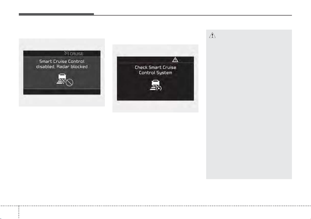
Driving your vehicle
1345
Warning message
When the sensor lens cover is
blocked with dirt, snow, or debris,
Smart Cruise Control system opera-
tion may stop temporarily. If this
occurs, a warning message will
appear on the LCD display. Remove
any dirt, snow, or debris and clean
the radar sensor lens cover before
operating Smart Cruise Control sys-
tem. Smart Cruise Control system
may not properly activate, if the radar
is totally contaminated, or if any sub-
stance is detected after turning ON
the engine (e.g. in an open terrain).
Smart Cruise Control system mal-
function message
The message will appear when the
vehicle to vehicle distance control
system is not functioning normally.
Take your vehicle to an authorized
Kia dealer and have the system
checked.
OJF058404L
OJF058406L
CAUTION
• Do not install accessories
around the sensor and do not
replace the bumper by your-
self. It may interfere with the
sensor performance.
• Always keep the sensor and
bumper clean.
• Use only a soft cloth to wash
the vehicle. Do not spray pres-
surized water directly on the
sensor or sensor cover.
• Be careful not to apply unnec-
essary force on the radar sen-
sor or sensor cover. If the sen-
sor is forcibly moved out of
proper alignment, Smart
Cruise Control system may
not operate correctly. In this
case, a warning message may
not be displayed.
Have the system checked by
an authorized Kia dealer.
(Continued)
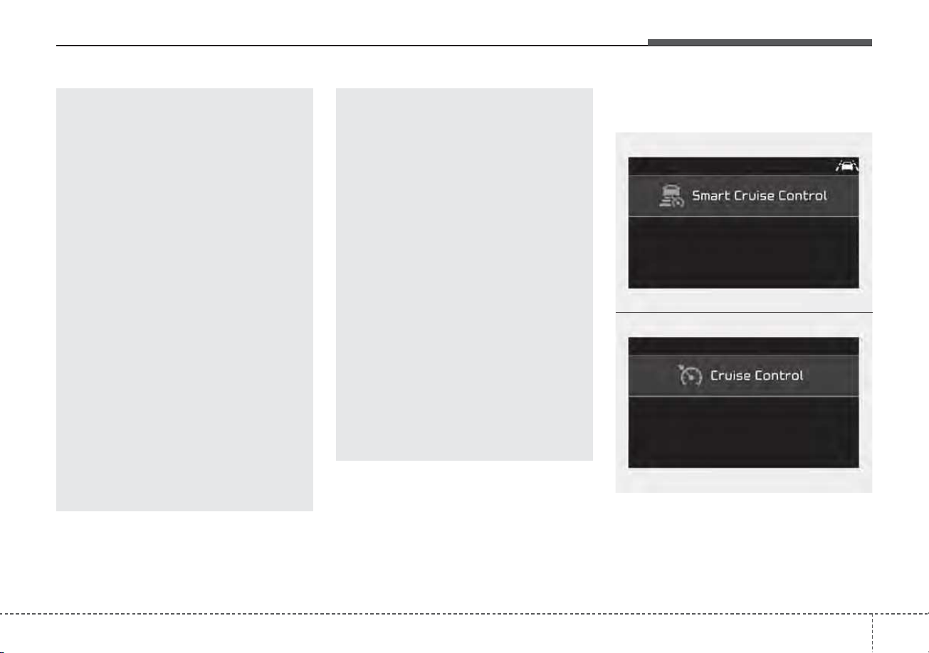
5135
Driving your vehicle
To convert to cruise control
mode:
The driver may choose to only use
the cruise control mode (speed con-
trol function) by doing as follows:
(Continued)
• Do not damage the sensor or
sensor area by a strong
impact. If the sensor moves
slightly off position, Smart
Cruise Control system will not
operate correctly without any
warning or indicator from the
cluster.
If this occurs, have your vehi-
cle checked by an authorized
Kia dealer as soon as possi-
ble.
• Use only a genuine Kia sensor
cover for your vehicle. Do not
paint anything on the sensor
cover.
• If the front bumper becomes
damaged in the area around
the radar sensor, Smart Cruise
Control system may not oper-
ate properly.
(Continued)
(Continued)
• To prevent sensor cover dam-
age from occurring, wash the
car with a soft cloth.
• Do not tint the window or
install stickers, accessories
around the inside mirror
where the camera is installed.
• Make sure the frontal camera
installation point does not get
wet.
• Do not place reflective
objects(white paper or mirror
etc.) on the crash pad. FCA
system may activate unneces-
sarily due to reflect of the sun-
light.
• Do not impact or arbitrarily
remove any front view camera
components.
OJF058400L
OJF058399L
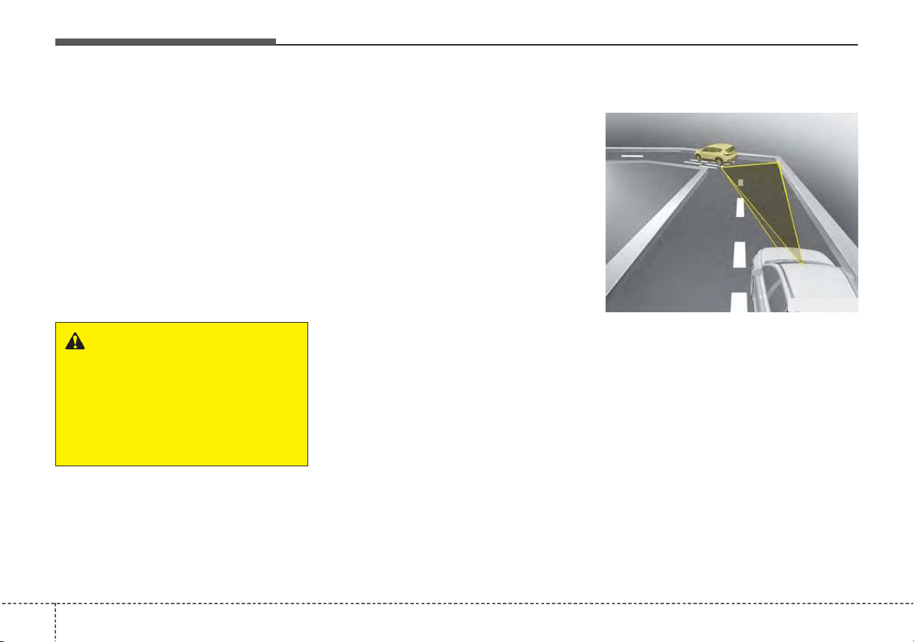
Driving your vehicle
1365
1. Turn Smart Cruise Control system
on (the cruise indicator light will be
on but the system will not be acti-
vated).
2. Push the distance to distance
switch for more than 2 seconds.
3. Choose between "Smart Cruise
Control" and "Cruise Control".
When the system is canceled using
the CRUISE button or the CRUISE
button is used after the engine is
turned on, the Smart Cruise Control
mode will turn on.
Limitations of the system
Smart Cruise Control system may
have limits to its ability to detect dis-
tance to the vehicle ahead due to
road and traffic conditions.
On curves
• On curves, Smart Cruise Control
system may not detect a moving
vehicle in your lane, and then your
vehicle could accelerate to the set
speed. Also, the vehicle speed will
rapidly down when the vehicle
ahead is recognized suddenly.
• Select the appropriate set speed
on curves and adjust your vehicle
speed by depressing the accelera-
tor or brake pedal according to the
road condition ahead and driving
condition.
WARNING
When using the cruise control
mode, you must manually
adjust the distance to other
vehicles as the system will not
automatically brake to slow
down for other vehicles.
OHM059349L
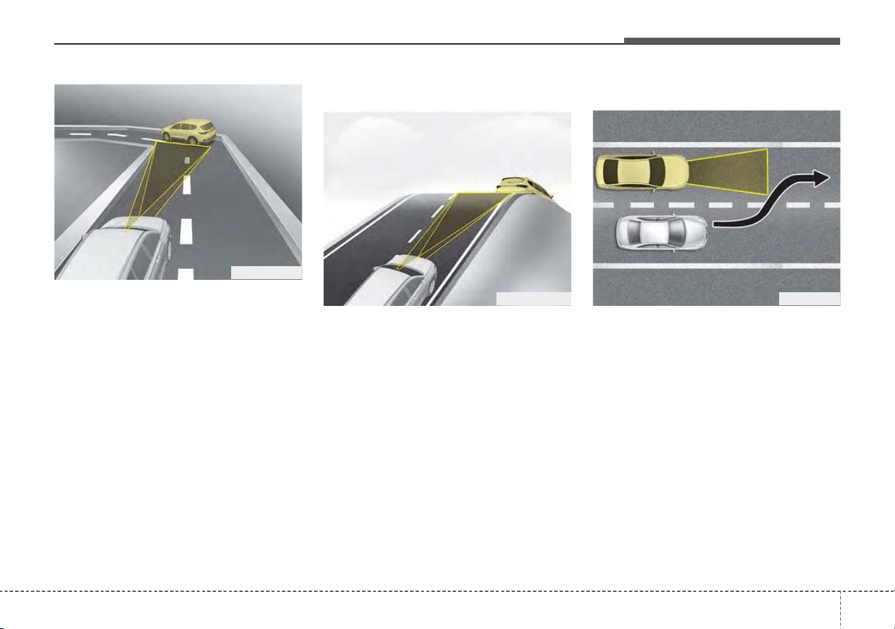
5137
Driving your vehicle
• Your vehicle speed can be reduced
due to a vehicle in the adjacent
lane. Adjust your vehicle speed by
depressing the brake pedal
according to the road condition
ahead and driving condition. Apply
the accelerator pedal and select
the appropriate set speed. Check
to be sure that the road conditions
permit safe operation of the smart
cruise control.
On inclines
• During uphill or downhill driving,
Smart Cruise Control system may
not detect a moving vehicle in your
lane, and cause your vehicle to
accelerate to the set speed. Also,
the vehicle speed will rapidly down
when the vehicle ahead is recog-
nized suddenly.
• Select the appropriate set speed
on inclines and adjust your vehicle
speed by depressing the accelera-
tor or brake pedal according to the
road condition ahead and driving
condition.
Lane changing
• A vehicle which moves into your
lane from an adjacent lane cannot
be recognized by the sensor until it
is in the sensor's detection range.
• The sensor may not detect imme-
diately when a vehicle cuts in sud-
denly. Always pay attention to the
traffic, road and driving conditions.
• If a vehicle which moves into your
lane is slower than your vehicle,
your speed may decrease to main-
tain the distance to the vehicle
ahead.
OHM059355L OJF055028
OHM059352L
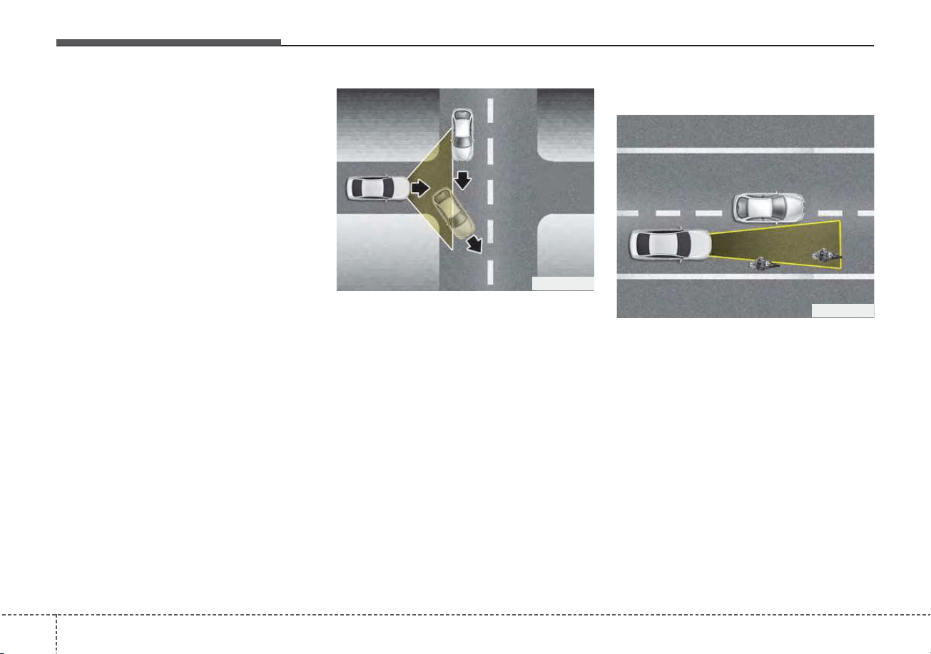
Driving your vehicle
1385
• If a vehicle which moves into your
lane is faster than your vehicle,
your vehicle will accelerate to the
selected speed.
• Your vehicle may accelerate when
a vehicle ahead of you disappears.
• When you are warned that the
vehicle ahead of you is not detect-
ed, drive with caution.
Vehicle recognition
Some vehicles ahead in your lane
cannot be recognized by the sensor
as follows:
- Narrow vehicles such as motorcy-
cles or bicycles
- Vehicles offset to one side
- Slow-moving vehicles or sudden-
decelerating vehicles
- Stopped vehicles
- Vehicles with small rear profiles
such as trailers with no loads
OJF055049
OJF055048
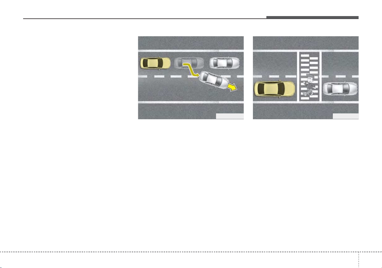
5139
Driving your vehicle
A vehicle ahead cannot be recog-
nized correctly by the sensor if any of
following occurs:
- When the vehicle is pointing
upwards due to overloading in the
liftgate (tailgate)
- While making turns by steering
- When driving to one side of the lane
- When driving on narrow lanes or on
curves
Adjust your vehicle speed by
depressing the brake pedal accord-
ing to the road condition ahead and
driving condition.
• When vehicles are at a standstill
and the vehicle in front of you
changes to the next lane, be care-
ful when your vehicle starts to
move because it may not recognize
the stopped vehicle in front of you.
In this case, you must maintain a
safe braking distance, and if nec-
essary, depress the brake pedal to
reduce your driving speed in order
to maintain a safe distance.
• Always look out for pedestrians
when your vehicle is maintaining a
distance with the vehicle ahead.
OJF055029 OJF055050
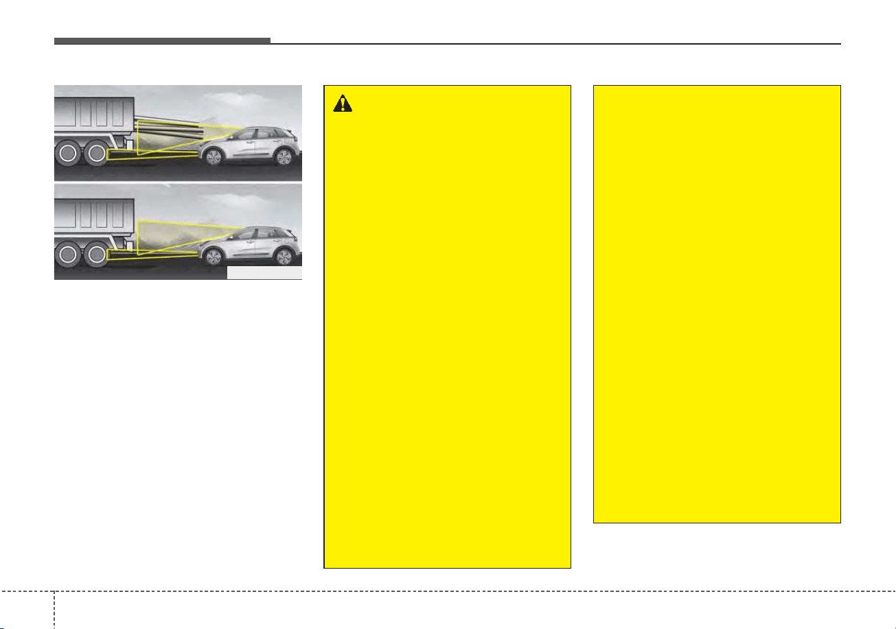
Driving your vehicle
1405
• Always be cautious for vehicles
with higher height or vehicles car-
rying loads that sticks out to the
back of the vehicle.
WARNING
• Smart Cruise Control system
cannot guarantee stopping
for every emergency situa-
tion.
If an emergency stop is nec-
essary, you must apply the
brakes.
• Keep a safe distance accord-
ing to road conditions and
vehicle speed. If the vehicle to
vehicle distance is too close
during high-speed driving, a
serious collision may result.
• Smart Cruise Control system
cannot recognize a stopped
vehicle, pedestrians or an
oncoming vehicle. Always
look ahead cautiously to react
to unexpected and sudden sit-
uations.
• SCC system may have diffi-
culty in maintaining the cor-
rect distance or speed, if the
vehicle is driving on a steep
incline or towing a trailer.
(Continued)
ODEP059328N
(Continued)
• When other vehicles are
changing lanes in front of you
frequently, Smart Cruise
Control system may not oper-
ate appropriately. Always look
ahead cautiously to react to
unexpected and sudden situa-
tions.
• Smart Cruise Control system
is not a substitute for safe
driving practices but a con-
venience function only. It is
the responsibility of the driver
to always check the speed
and the distance to the vehi-
cle ahead.
• Always be aware of the select-
ed speed and vehicle to vehi-
cle distance.
• Always maintain sufficient
braking distance and deceler-
ate your vehicle by applying
the brakes if necessary.
(Continued)

5141
Driving your vehicle
CAUTION
Smart Cruise Control system
may not operate temporarily
due to electrical interference.
(Continued)
• As Smart Cruise Control sys-
tem may not recognize com-
plex driving situations, always
pay attention to driving condi-
tions and control your vehicle
speed.
• For safe operation, carefully
read and follow the instruc-
tions in this manual before
use.
• If another warning sound,
such as the fasten seat belt
warning, is played, the SCC
system warning sound may
not occur.
• When driving with SCC set,
the system may not detect
parked vehicles ahead. Be
careful if this occurs and do
not rely solely on SCC func-
tion.
• Please turn off SCC system
when the vehicle is being
towed.
(Continued)
(Continued)
• If the vehicle ahead is no
longer detected while you are
driving with the set distance,
the vehicle may accelerate
until it reached the set speed.
If this occurs, be cautious and
control your vehicle speed if
needed.
• Be cautious and be careful of
dangerous situations when
driving on a slippery road.
• Beware of dangerous situa-
tions as you may quickly pass
the vehicle driving in the next
lane.
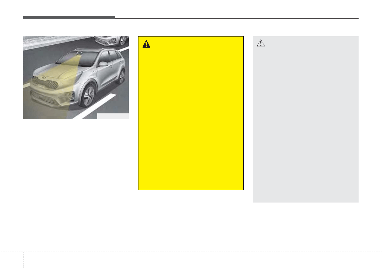
Driving your vehicle
1425
Lane Following Assist system is
designed to center the vehicle in the
chosen lane by using a front mount-
ed camera on top of the windshield.
It can only become active in combi-
nation with Smart Cruise Control
and therefore assists the driver in his
task to control the lateral movement
of the vehicle.
* LFA stands for Lane Following
Assist.
LANE FOLLOWING ASSIST (LFA) (IF EQUIPPED)
ODEP059029
WARNING
• It is the driver's responsibility
to operate the steering wheel
for safe driving.
• Do not turn the steering wheel
hastily if LFA is operating.
• LFA system assists the steer-
ing wheel control so that the
vehicle can stay in the center
of the lane. LFA system does
not automatically control the
steering wheel at all times,
which means the driver must
keep hands on the wheel at all
times while driving.
• When using LFA system,
always be aware of surround-
ings and road conditions that
may interrupt or stop LFA sys-
tem.
CAUTION
- Do not attach glass tinting,
stickers, accessories to the
windshield where the front
camera near the indoor mirror
is placed.
- The removal or re-assembly of
the front camera to attach tint-
ing, stickers, accessories may
require LFA system to be thor-
oughly inspected and modi-
fied. In such case, have your
vehicle inspected by an
authorized Kia dealer.
- Inspection or modification
may be required when replac-
ing parts related to the wind-
shield or front camera, steer-
ing. we recommend that the
system be checked by an
authorized Kia dealer.
(Continued)

5143
Driving your vehicle
LFA system operation
To use Lane Following Assist two
steps are necessary:
(1) LFA system has to be enabled,
and
(2) SCC system has to be activated
With the ignition switch or ENGINE
START/STOP button in the [ON],
select or release the setting from
“User setting → Driver Assistance →
Driving Assist → Lane Following
Assist”.
Select LFA system in the user setting
of the instrument panel.
The LFA system status is remem-
bered by the system and therefore
does not need to be enabled again
for each new journey.
(Continued)
- Depending on your surround-
ings and road conditions, LFA
system could fail to recognize
the lane and stop working. In
turn, extra caution is required
while driving with LFA system
on.
- Be sure to check the non-
operating conditions and cau-
tions for the driver before
using LFA system.
- Do not place reflective materi-
als such as white paper or
mirror on the crash pad.
Sunlight reflections can cause
a malfunction in LFA system.
- Too big sound from the sound
system can interrupt the
alarming sound from LFA sys-
tem.
(Continued)
(Continued)
- Keeping your hands off the
wheel while driving will trigger
the hands-off warning and
deactivate the steering-assist
system. Put your hands back
on the wheel, then the steer-
ing-assist system will be re-
activated.
- When driving at a high speed,
the steering assist force can
become weak and the vehicle
can drive out of its lane. Extra
caution is required, and com-
ply with the speed limit.
- Attaching an object to the
steering wheel could deter
steering assistance.
- Attaching an object to the
steering wheel could deter the
hands-off alarming system.
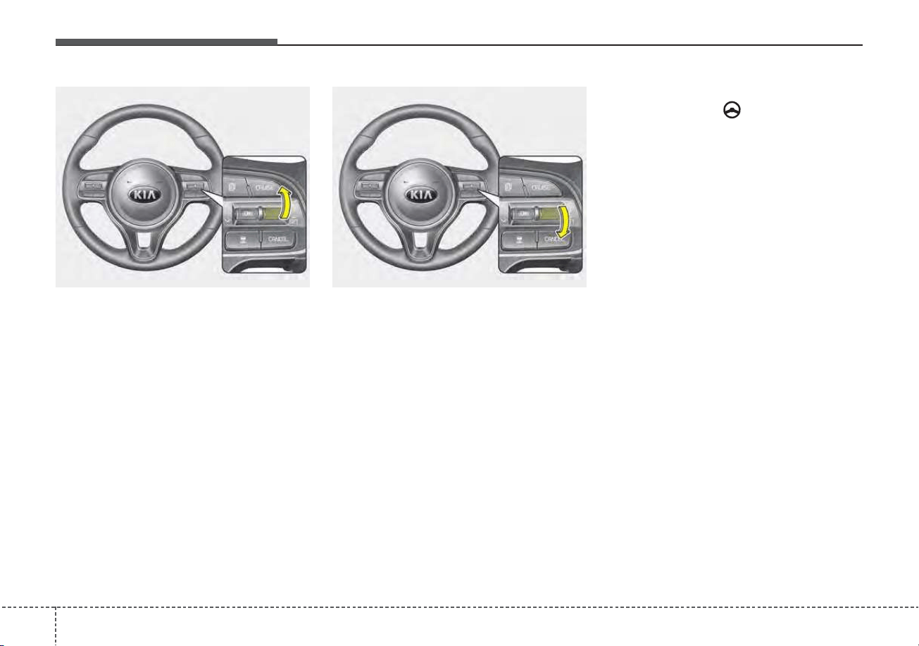
Driving your vehicle
1445
1. Press the CRUISE button, to turn
the system on. The CRUISE indi-
cator in the instrument cluster will
illuminate.
2. Accelerate to the desired speed.
The smart cruise control speed
can be set as follows:
• 5 mph (10 km/h) ~ 100 mph (160
km/h): when there is no vehicle
in front
• 0 mph (0 km/h) ~ 100 mph (160
km/h): when there is a vehicle in
front
3. Move the switch down (to SET-),
and release it at the desired
speed. The set speed and vehicle
to vehicle distance on the LCD
screen will illuminate.
4. Release the accelerator pedal.
The desired speed will automati-
cally be maintained.
Once the system starts working, the
indicator light ( ) comes on the
instrument panel.
The indicator light colors according
to the system status are as follows.
Green: Active
White: Standby
For more SCC settings and details
refer to “Smart Cruise Control
(SCC)” in this chapter.
ODE056025 ODE056024
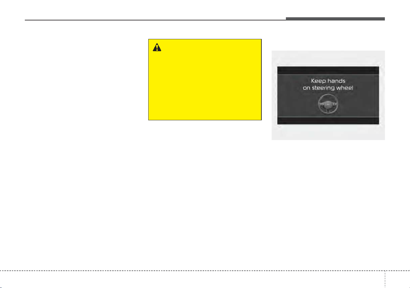
5145
Driving your vehicle
LFA system activation
If the vehicle is inside the lane with
both lanes recognized by the sys-
tem, and there is no steep steering
made by the driver, LFA system
changes into steering assist mode.
The indicator light will come on
green, and the system helps the
vehicle stay in line by controlling the
steering wheel.
When the steering wheel is not con-
trolled temporarily, the indicator light
will flash green and changes to
white.
When the both lanes are not recog-
nized by the system, the system con-
trols the steering wheel limitedly
whether there is a vehicle in front or
not.
Warning
If you keep your hands off the wheel
while driving with LFA system assist-
ing the steering, the hands-off warn-
ing will be triggered.
If the driver keeps hands off the
wheel even with the hands-off warn-
ing on, the steering assist is tem-
porarily released automatically.
If you put your hands back on the
wheel with LFA system released, the
steering assist will re-start.
WARNING
LFA system ensures the vehicle
stays in its lane. LFA system
does not guarantee 100% safe-
ty. Make sure you always check
road conditions and drive safe-
ly at all times.
Never completely rely on your
LFA system.
OJF058416L
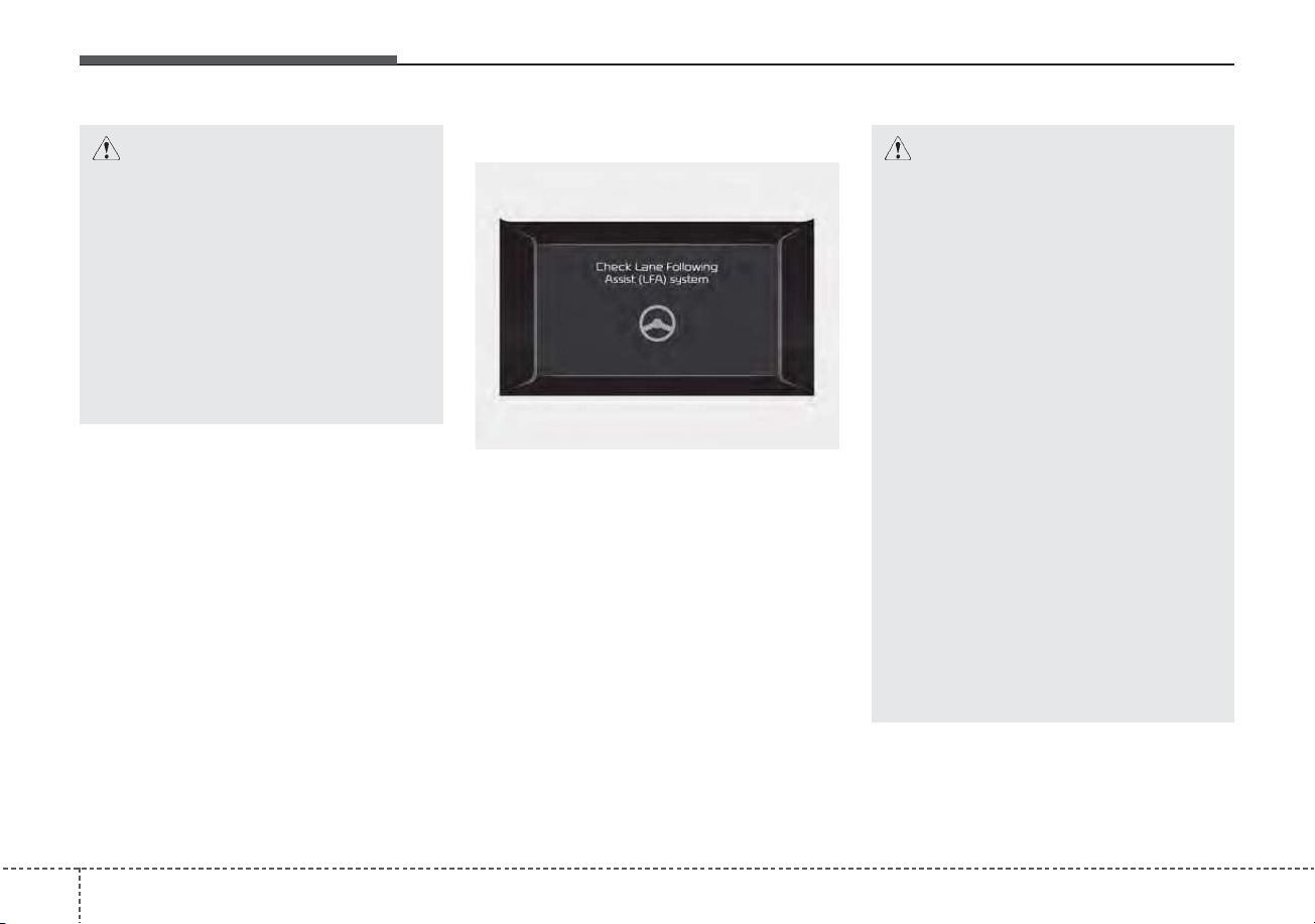
Driving your vehicle
1465
LFA system malfunction
The warning message popped up
(turned off after a certain period of
time)means a problem with LFA sys-
tem. If this occurs, we recommend
that the system be checked by an
authorized Kia dealer.
CAUTION
• Hands-off warnings may be
delayed depending on road
conditions. Always keep your
hands on the steering wheel
while driving.
• Hold the steering wheel tight.
Otherwise, LFA system could
misjudge that the driver
hands off the wheel, and a
hands-off warning may occur.
CAUTION
• It is the driver’s responsibility
to operate the steering wheel
while driving.
• With LFA system on, the driv-
er can steer the vehicle by
operating the wheel on his
own.
• We recommend that the driver
turns off LFA system and
operates the steering wheel
by himself in the following
cases
- bad weather
- bad road conditions
- when frequent operation of
the steering wheel is required
- when towing other vehicle or
trailers
• The steering wheel can feel
heavy or light if LFA system is
assisting the steering.
ODEP059265L

5147
Driving your vehicle
Limitation of the system
• If the driver turns on the turn signal
light or the emergency warning
light to change the lane
- Operate the turn signal light
switch before changing the lane
- If you change the lane without
operating the turn signal lights,
steering reaction force of the
wheel may occur.
• Once LFA system is turned on or
the lane is changed, the vehicle
should be in the center of the road
to switch to the steering assist
mode. If the driver keeps driving
along the lane, LFA system will not
assist the steering.
• When the ESC or VSM is activat-
ed, the system does not assist
steering.
• When driving on a curved road at a
high speed, steering assist mode
may not work.
• When driving at a speed faster
than 110 mph (180 km/h), steering
assist mode may not work.
• When sudden steering is made,
the system could be temporarily
deactivated.
• If you change the lane in a hurry,
the system does not assist the
steering.
• If the vehicle suddenly stops, it
does not assist the steering.
• If the lane is too narrow or too
wide, steering is not assisted.
• If the system is not able to recog-
nize a vehicle in front and either of
the lanes is not recognized, the
steering is not assisted
• If the radius is too small for the
curve
Cautions for the driver
If the lane recognition is difficult or
limited for the LFA system as shown
below, the driver may need to be
careful because it may not operate or
may cause unnecessary operation.
• Roads or lane markings in bad con-
dition
- When The lane is tainted or invisible
- When the driver cannot see the
lane due to rain, snow, dust,
sand, oil, puddles, etc
- When roads are set or the colors
of the lane and road are not dis-
tinctive
- If there is a sign other than the
lane near the lane or a mark sim-
ilar to the lane
- When the lane is not clear or
damaged
- If the road is covered in the shad-
ows of objects around the road,
such as medians, guard rails,
noise walls, and trees

Driving your vehicle
1485
- If the number of lanes increases
or decreases, or if the lanes inter-
sect with each other more
intensely (tollgate entry section,
road section / joining section,
etc.)
- When there are two or more lane
markings such as a construction
section, a designated lane, etc.
- When the lane is crowded such
as the construction section or the
lane is replaced by some struc-
tures
- If there is a road marking such as
a zigzag lane, crosswalk mark, or
road surface milestone
- When a lane suddenly becomes
invisible or disappears from an
intersection
• The external environment affecting
the system
- If the outside brightness of the vehi-
cle suddenly changes, such as
when entering or exiting the tunnel
or passing under the bridge
- If the vehicle's headlights are not
used at night or in the tunnel, or the
brightness of the headlights is too
weak
- If there are boundary structures
such as tollgate booths and side-
walk blocks
- If it is difficult to distinguish lanes
due to the reflection on the wet road
made by sunlight, streetlight, and
oncoming traffic.
- When the backlight is strongly reflect-
ed in the direction of the vehicle
- When Driving to the left or right lane
by bus lane or on the bus lane
- If there is no enough distance
between the front car or if the lane
is covered by the car ahead of me
- When the lane change is large,
such as a steep curve or a continu-
ous curve
- When passing through speed
bump, sudden up / down or left /
right slope
- If the vehicle is severely shaken
- When the temperature around the
mirror is very high due to direct sun-
light
• When the front camera has poor vis-
ibility
- If the windshield of the vehicle
and the camera lens are covered
with dust, fingerprints, or tinting.
- If the camera has poor visibility
due to bad weather such as fog,
heavy rain, heavy snow.
- If moisture is not completely
removed from the windscreen.
- When placing objects on the
dashboard, etc.
5149
Driving your vehicle
HDA system is designed to control
the vehicle distance and speed of the
vehicle when driving on a highway.
The system assists drivers by receiv-
ing information about the speed limit
of the highway that the vehicle is on
and automatically changing the set
speed of Smart Cruise Control sys-
tem when needed.
✽✽
NOTICE
• HDA system is available only on
controlled access road of certain
highways.
❈
❈
Controlled access road indi-
cates roads with limited
entrances and exits that allow
uninterrupted high speed traf-
fic flow. Only passenger cars
and motorcycles are allowed on
controlled access roads.
• Additional highways may be
expanded by navigation updates.
HIGHWAY DRIVING ASSIST (HDA) (IF EQUIPPED)
WARNING
• HDA system is not a substi-
tute for safe driving practices,
but a convenience function. It
is the responsibility of the
driver to always be aware of
the surroundings and drive
safely.
• HDA system relies entirely on
the road information provided
by the navigation system. It is
the responsibility of the driver
to follow traffic laws and avoid
accidents.
• Turn off the Highway driving
assist system when the vehi-
cle is being towed.
• For your safety, please read
the owner's manual before
using the system.
Available highway
(Controlled access road)
USA Select Interstate Highways
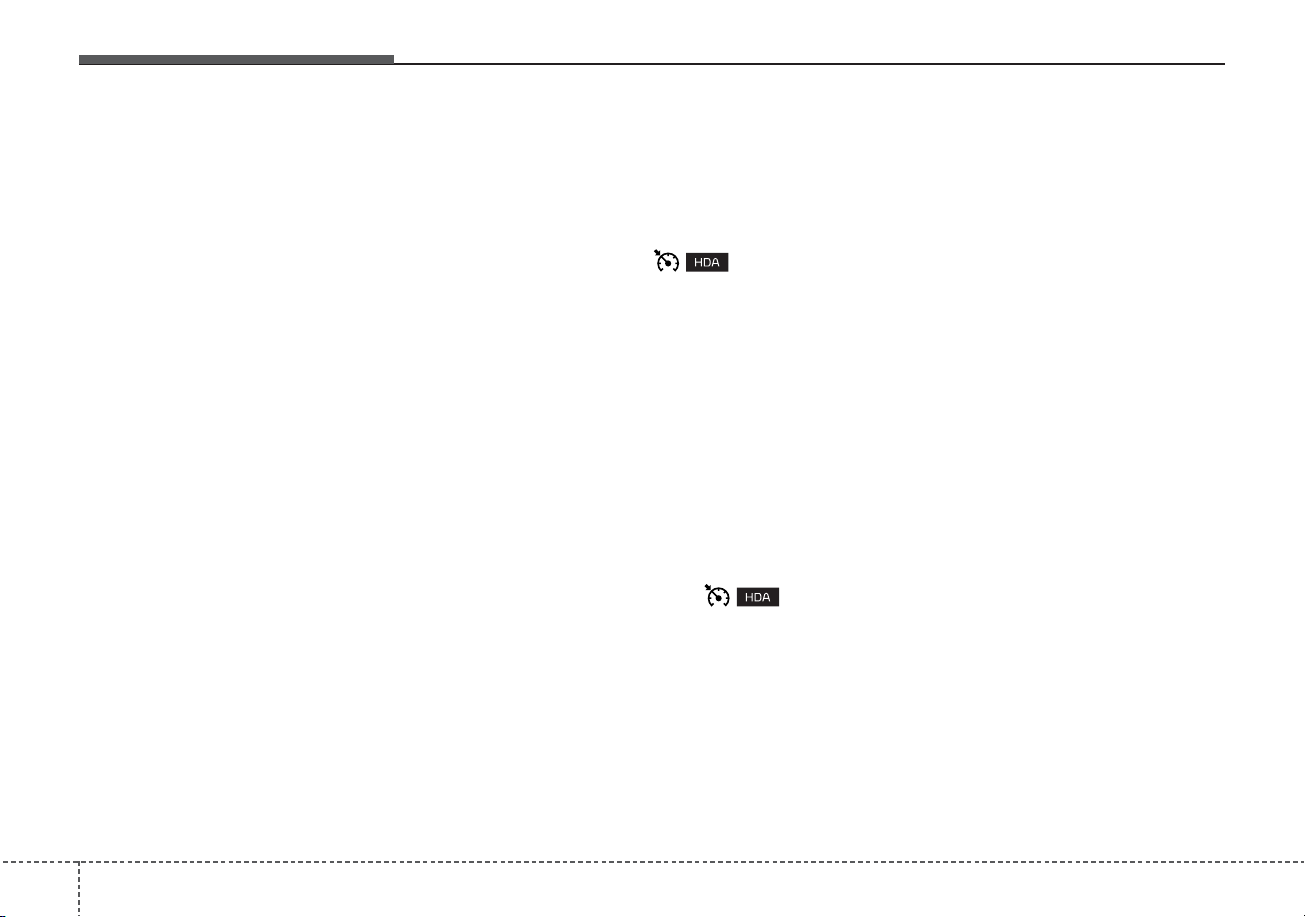
Driving your vehicle
1505
Setting and activating HDA
system
With the ignition switch or ENGINE
START/STOP button in the [ON],
select or release the setting from
“User Setting → Driver Assistance
→Driving Assist → Highway Driving
Assist”.
Select HDA system in the User set-
ting of the instrument panel. and the
system will operate if the following
conditions are met :
If the engine is turned off then on
again, the system maintains the last
setting.
Operating conditions
If you activate HDA in the User set-
ting of the instrument panel. and the
following conditions are met, HDA
system will be ready to operate, and
the indicator light ( ) will come
on green in the cluster.
• When driving on the highway main
line.
• When Smart Cruise Control is in
operation (Vehicle deceleration
and acceleration control)
- Refer to “Smart Cruise Control
(SCC)” in this chapter.
- If SCC is in standby mode (SCC
is on but speed is not set), HDA
system will be in the same mode.
The white indicator ( ) light
will be turned on.
• When the vehicle speed is below
95 mph (153 km/h)
HDA system operation
The speed is automatically set in
accordance with the steering control
and the highway speed limit when all
the operating conditions are met.
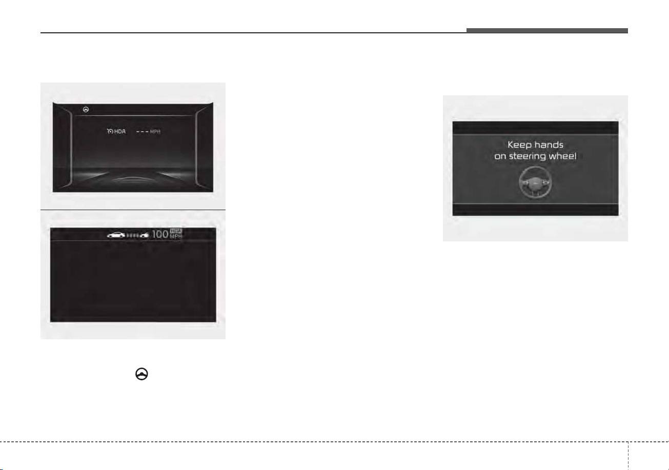
5151
Driving your vehicle
Steering control
If both lanes are recognized properly
(lane color: white), the steering
wheel indicator ( ) lights up in
green and then the steering control
is initiated.
When the system cannot provide
temporary steering inputs, the indi-
cator flashes green and then
changes to white. Even when HDA
system cannot provide temporary
steering inputs, it still controls the
distance from other vehicles.
(For information on non-operating
conditions of steering wheel control,
please refer to “Limitations of LFA
system” in this chapter.
Warning related to steering
wheel
The hands-off warning appears
when the system detects that the dri-
ver's hands are not on the steering
wheel while HDA system is in work.
(First warning: warning message,
Second warning: warning message
with warning sound)
OJF058416L
ODEP059290N
ODEP059330N
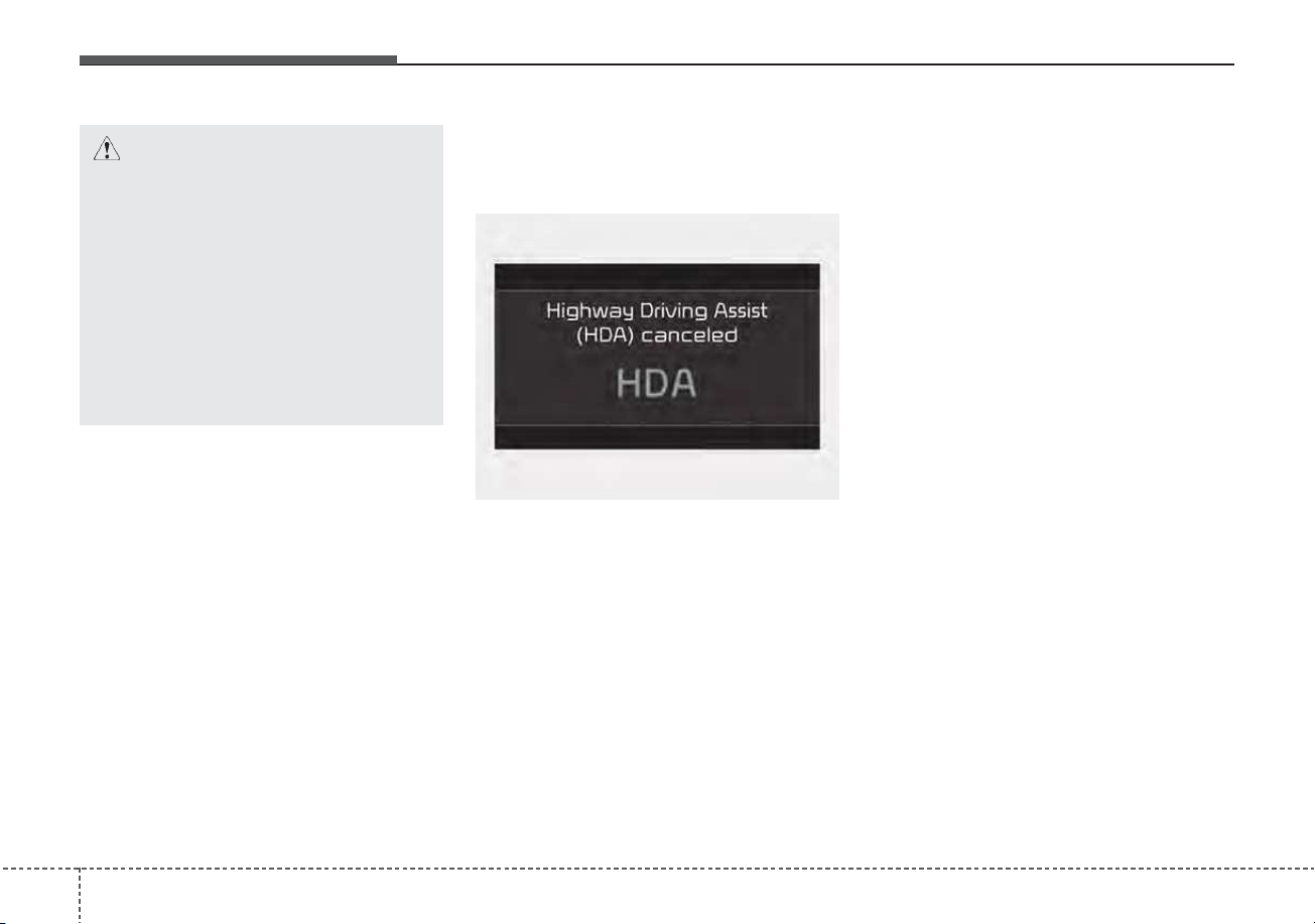
Driving your vehicle
1525
When the hands-off warning
lasts for a certain period of
time
If the driver still does not have their
hands on the steering wheel after the
message "Keep hands on steering
wheel", HDA system will be can-
celed. However, if Smart Cruise
Control is reactivated manually by
the driver, Highway Driving Assist
system will reactivate.
To activate Smart Cruise control
refer to "Smart Cruise Control
(SCC)" in this chapter.
HDA system will not be in the
ENABLED state and/or the steering
wheel will not be assisted when:
• The turn signal is turned on before
changing a lane. If you change
lanes without the turn signal on,
the steering wheel might be con-
trolled.
• The vehicle is not driven in the mid-
dle of the lane when the system is
turned on or right after changing a
lane.
• ESC (Electronic Stability Control or
VSM (Vehicle Stability
Management) is activated.
• The vehicle is driven on a sharp
curve.
• Vehicle speed is over 95 mph (153
km/h)
• The vehicle makes sharp lane
changes.
CAUTION
• The hands-off warning may be
delayed depending on road
conditions. Always keep your
hands on the steering wheel
while driving.
• If you hold the steering wheel
lightly, it may be perceived
that the steering wheel is not
held at all and trigger the
hands-off warning.
ODEP059332N
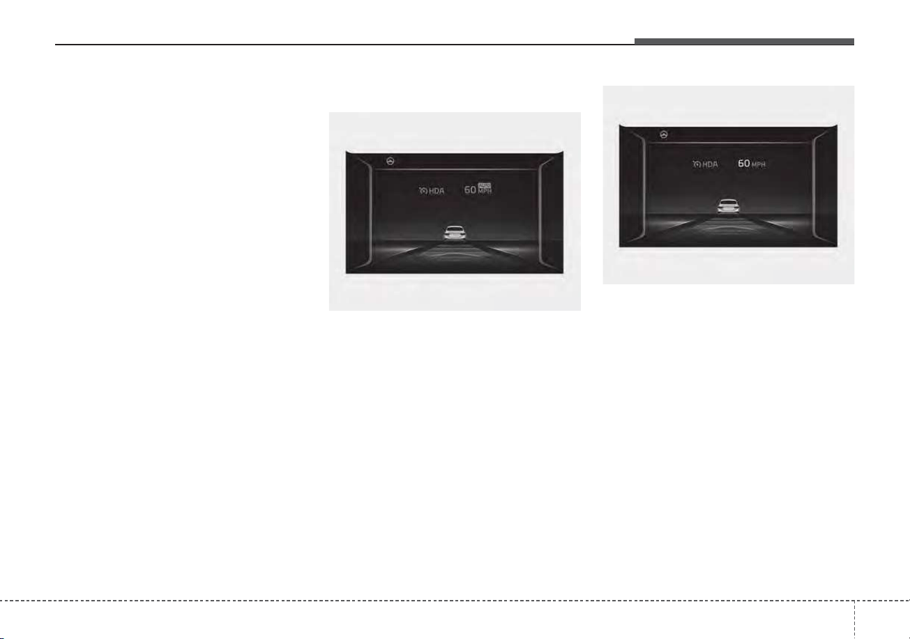
5153
Driving your vehicle
• The vehicle brakes suddenly.
• Only one lane marker is detected.
• The lane is very wide or narrow.
• There are more than two lane
markers on the road (e.g. construc-
tion area).
• Radius of a curve is too small.
• The vehicle is driven on a steep
incline.
• The steering wheel is turned sud-
denly.
Automatic speed setting
If HDA system operating conditions
are all met and setting speed match-
es with the legal highway speed limit,
HDA system will enter the automatic
speed setting mode. (The set speed
and the "AUTO" symbol will be dis-
played in green with an indicative
sound) In the automatic speed set-
ting mode, the set speed is automat-
ically adjusted to the changing speed
limits of highway sections.
If the driver directly changes the
speed, it enters the manual speed
setting mode and the set speed is
displayed in white and the “AUTO”
symbol will disappear.
ODEP059291N
ODEP059292N
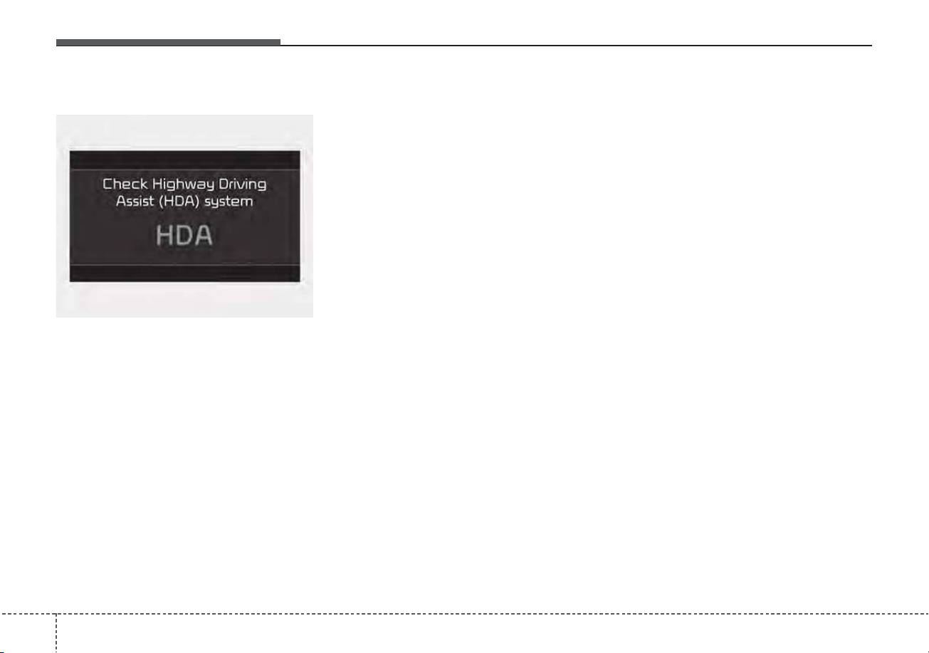
Driving your vehicle
1545
HDA malfunction
This message shows that there is a
problem with HDA system, so have
your vehicle inspected by an author-
ized Kia dealer.
✽✽
NOTICE
• High Driving Assist is limited in
other countries.
• High Driving Assist only operates
based on the speed limits of the
highway but it does not work with
the speed cameras.
• The time gap could occur between
the navigation speed warning and
system operation.
• The system is not designed to work
on highways other than mentioned
as a controlled access road. The
system automatically cancels
when you leave the highway.
• If there is a problem with
Highway Driving Assist, the sys-
tem cannot be activated in the
Infotainment System screen.
• If your vehicle is 1640 ft. (500 m)
ahead and behind of an open toll-
gate, the system is automatically
canceled. Also, it is converted to
Smart Cruise Control automati-
cally with a pop-up message on the
navigation.
(Continued)
(Continued)
• In the automatic speed setting
mode, the vehicle automatically
accelerates or decelerates when
the highway speed limit changes.
• If your vehicle speed exceeds 95
mph (153 km/h), Highway Driving
Assist is automatically canceled.
Also, it is converted to Smart
Cruise Control automatically with
a pop-up message on the naviga-
tion.
• If you enter a rest area on the
highway or a IC/JC
(intersection/junction) without a
destination set, the system is can-
celed later than when the vehicle
actually leaves the highway.
ODEP059331N

5155
Driving your vehicle
* Refer to “Smart Cruise Control
(SCC)” in this chapter. for cautions
and warnings about vehicle to
vehicle distance control and front
radar.
* Refer to “Lane Following Assist
(LFA) “ in this chapter. for cautions
and warnings about steering con-
trol and front camera.
CAUTION
Highway Driving Assist system
may not function properly in the
following situations:
• The navigation is not working
properly.
• The navigation is not updated.
• The real-time GPS or map
information provided has
errors.
• The navigation is overloaded
by performing functions such
as route search, video play-
back, voice recognition, etc.
are performing simultaneously.
• The navigation is recalculat-
ing the route while driving.
• GPS signals are blocked in
areas such as a tunnel.
• The driver goes off course or
the route to the destination is
changed or canceled by reset-
ting the navigation.
• The vehicle enters a service
station or rest area
(Continued)
(Continued)
• The speed limit of selected
highway section is changed
due to road conditions.
• Android Auto or Car Play is
operating.
• The navigation cannot detect
the current vehicle position
(ex: elevated roads including
overpass adjacent to general
roads or nearby roads exist in
a parallel way).
• The navigation is being updat-
ed while driving.
• The navigation is being reset
while driving.
• The road is slippery due to
bad weather such as rain or
snow.
• If your vehicle tows a trailer or
another vehicle, you should
release Highway Driving
Assist system. Operating the
brake system or steering sys-
tem while towing may
adversely affect the safety.

Driving your vehicle
1565
This device complies with Part 15
of the FCC rules.
Operation is subject to the following
three conditions:
1. This device may not cause harmful
interference, and
2. This device must accept any inter-
ference received, including inter-
ference that may cause undesired
operation.
3. Changes or modifications not
expressly approved by the party
responsible for compliance could
void the user's authority to operate
the device.
Radio frequency radiation
exposure information:
This equipment complies with FCC
radiation exposure limits set forth for
an uncontrolled environment.
This equipment should be installed
and operated with a minimum dis-
tance of 8 in (20 cm) between the
radio (antenna) and your body.
This transmitter must not be colocat-
ed or operating in conjunction with
any other antenna or transmitter.
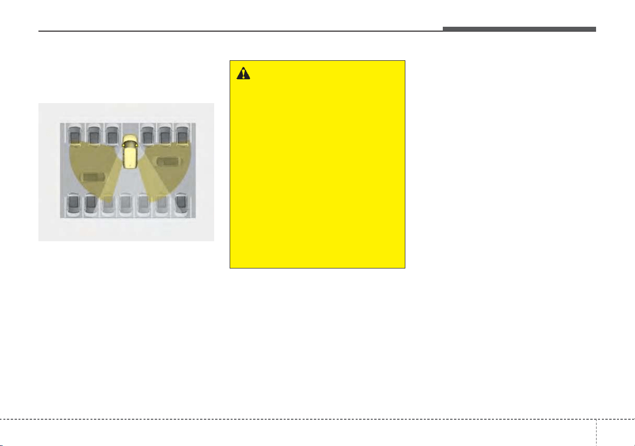
5157
Driving your vehicle
System description
Rear Cross-Traffic Collision
Warning system
Rear Cross-Traffic Collision Warning
system uses radar sensors to moni-
tor the approaching cross traffic from
the left and right side of the vehicle
when your vehicle is in reverse.
The blind spot detection range varies
relative to the approaching vehicle
speed.
System setting and activation
System setting
• The driver can activate the sys-
tems by placing the START/STOP
button to the ON position and by
selecting ‘User Settings → Driver
Assistance → Parking Safety →
Rear Cross-Traffic Safety’. The
RCCW turn on and get activated.
• When the vehicle is turned off then
on again, the systems always get
ready to be activated.
• When the system is initially turned
on and when the vehicle is turned
off then on again, the warning light
will illuminate for 3 seconds on the
outside rearview mirror.
REAR CROSS-TRAFFIC COLLISION WARNING (RCCW) (IF EQUIPPED)
OSK3058092L
WARNING
• Always be aware of road con-
ditions while driving and be
alert for unexpected situations
even though RCCW system is
operating.
• RCCW system is supplemen-
tal systems to assist you. Do
not entirely rely on the sys-
tems. Always pay attention,
while driving, for your safety.
• RCCW system is not substi-
tutes for proper and safe driv-
ing. Always drive safely and
use caution when backing up
the vehicle.

Driving your vehicle
1585
Warning Timing
The driver can select the initial warn-
ing activation time in the Cluster by
selecting “User Settings → Driver
Assistance → Warning Timing”. The
options for the initial Rear Cross-
Traffic Collision Warning includes the
following:
- Normal:
When this condition is selected, the
initial RCCW is activated normally. If
this setting feels too sensitive
change the option to ‘Later’.
The warning activation time may feel
late if the side/rear vehicle abruptly
accelerates.
- Later:
Select this warning activation time
when the traffic is light and you are
driving in a low speed. However, if
you change the warning activation
time, the warning activation time of
vehicle's other system may also
change. Check the warning activa-
tion time before changing it.
Operating conditions
The system will activate when vehi-
cle speed is below 7 mph (10 km/h)
and with the shift lever in R
(Reverse).
* The system will not activate when
the vehicle speed exceeds 7 mph
(10 km/h). The system will activate
again when the speed is below 5
mph (8 km/h).
The system's detecting range is
approximately 0 ~ 82 ft. (0.5 ~ 20 m)
An approaching vehicle will be
detected if their vehicle speed is with-
in 5 ~ 22.5 mph (8 km/h ~ 36 km/h)
Note that the detecting range may
vary under certain conditions. As
always, use caution and pay close
attention to your surroundings when
backing up your vehicle.
OYG059344L
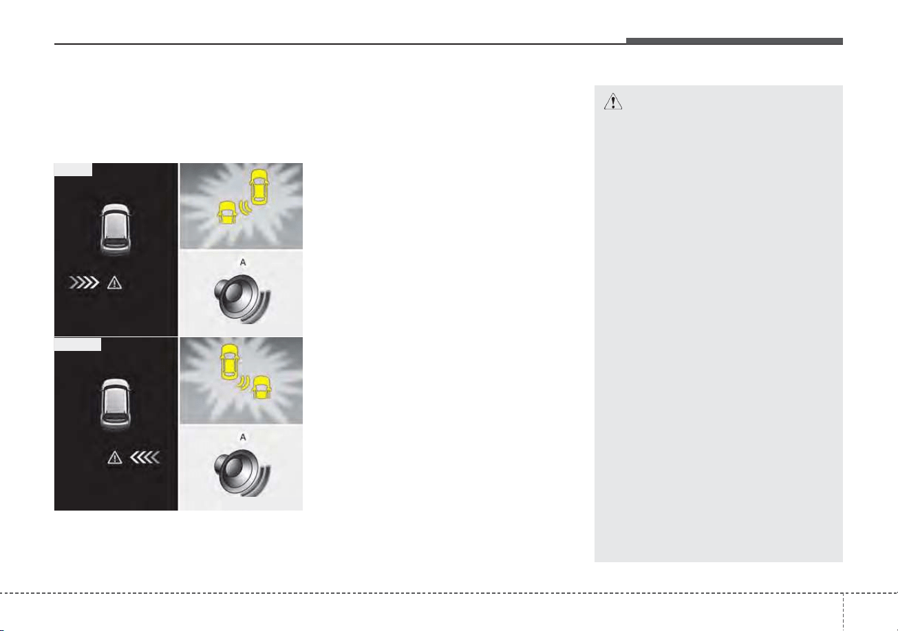
5159
Driving your vehicle
Warning message and system
control
Rear Cross-Traffic Collision
Warning system
If the vehicle detected by the sensors
approaches from the rear left/right
side of your vehicle, the warning
chime will sound, the warning light
on the outside rearview mirror will
blink and a message will appear on
the LCD display. If the rear view mon-
itor system is in activation, a mes-
sage will also appear on the
‘Infortainment System’.
The warning will stop when:
- The vehicle moving at the rear
left/right side of your vehicle is not
in the detection range.
- The vehicle is right behind your
vehicle.
- The vehicle is not driving towards
your vehicle.
- The vehicle’s approaching speed is
decreased.
CAUTION
• When the operation condition
of RCCW is met, the warning
will occur every time a vehicle
approaches the side or rear of
your stopped (0 mph (0 km/h)
vehicle speed) vehicle.
• The system's warning or brake
may not operate properly if the
left or right of your vehicle's
rear bumper is blocked by a
vehicle or obstacle.
• The driver should always use
extreme caution while operat-
ing the vehicle, whether or not
the warning light on the outer
side view mirror illuminates or
there is a warning alarm.
• Playing the vehicle audio sys-
tem at high volume may pre-
vent occupants from hearing
the system's warning sounds.
• If any other warning sound
such as seat belt warning
chime is already generated,
the RCCW warning may not
sound.
OSK3058093L
OSK3058094L
■ Left
■ Right
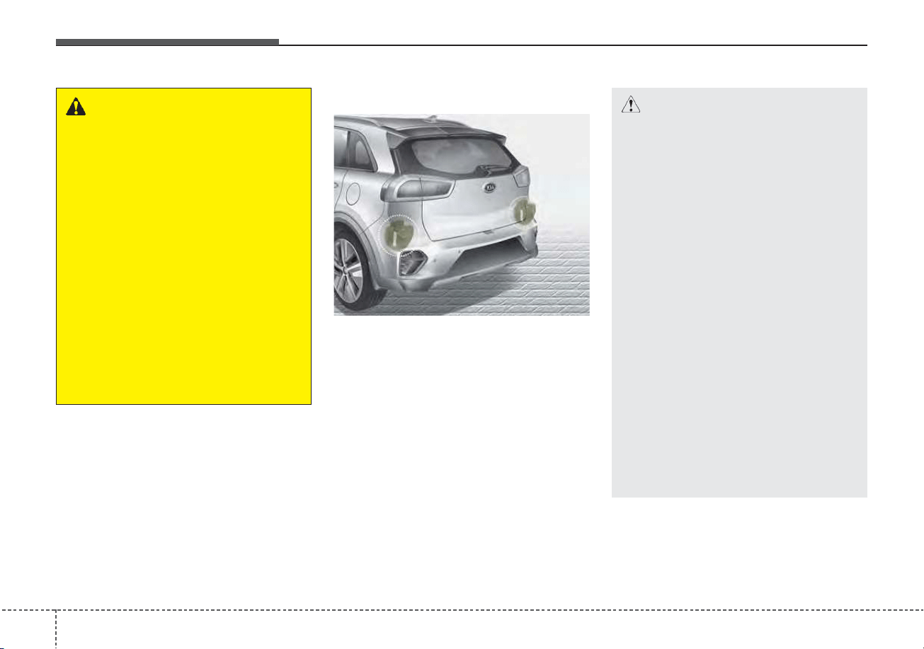
Driving your vehicle
1605
Detecting Sensor
The rear radars are located inside
the rear bumper for detecting the
side and rear areas.
Always keep the rear bumper clean
for proper operation of the system.
ODEP059158
CAUTION
• The system may not work
properly when the bumper has
been damaged, or if the rear
bumper has been replaced or
repaired.
• The system may turn off due to
strong electromagnetic waves.
• Always keep the sensors clean.
• NEVER arbitrarily disassem-
ble the sensor component nor
apply any impact on the sen-
sor component.
• Be careful not to apply unnec-
essary force on the radar sen-
sor or sensor cover. If the sen-
sor is forcibly moved out of
proper alignment, the system
may not operate correctly. In
this case, a warning message
may not be displayed.
(Continued)
WARNING
• Drive safely even though the
vehicle is equipped with Rear
Cross-Traffic Collision
Warning system. Do not sole-
ly rely on the system but
check your surrounding when
backing the vehicle up.
• The driver is responsible for
accurate brake control.
• Always pay extreme caution
while driving. Rear Cross-
Traffic Collision Warning sys-
tem may not operate properly
or unnecessarily operate
depending on traffic and driv-
ing conditions.
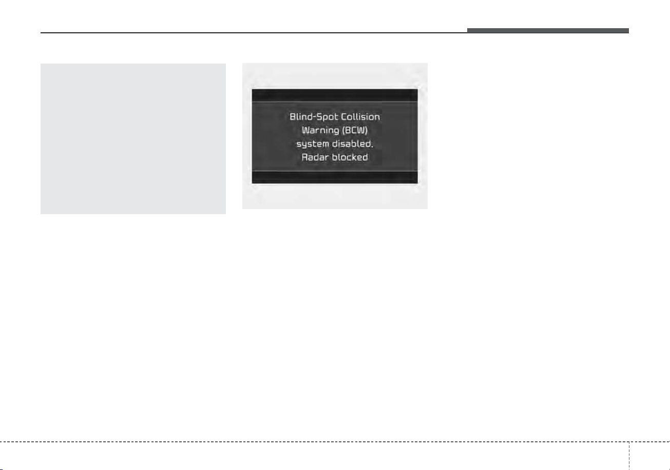
5161
Driving your vehicle
Blind-Spot Collision Warning (BCW)
system disabled. Radar blocked
• This warning message may appear
when:
- One or both of the sensors on the
rear bumper is blocked by dirt or
snow or a foreign object.
- Driving in rural areas where the
sensor does not detect another
vehicle for an extended period of
time.
- When there is inclement weather
such as heavy snow or rain.
A trailer or carrier is installed. (To use
BCW system, remove the trailer or
carrier from your vehicle.)
If any of these conditions occur, the
light on BCW button and the system
will turn off automatically.
When BCW canceled warning mes-
sage is displayed in the cluster,
check to make sure that the rear
bumper is free from any dirt or snow
in the areas where the sensor is
located. Remove any dirt, snow, or
foreign material that could interfere
with the radar sensors.
After any dirt or debris is removed,
BCW system should operate normal-
ly after about 10 minutes of driving
the vehicle.
If the system does not work normally
even though the foreign substance,
trailer or carrier, or other equipment
is removed, have the system
checked by an authorized Kia dealer.
OJF058433L
(Continued)
Take your vehicle to an author-
ized Kia dealer and have the
system checked.
• Do not apply foreign objects
such as a bumper sticker or a
bumper guard near the radar
sensor or apply paint to the
sensor area. Doing so may
adversely affect the perform-
ance of the sensor.
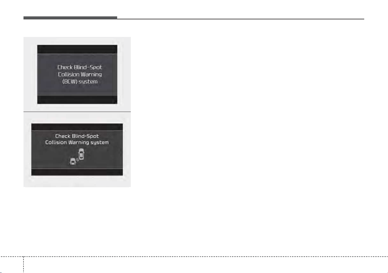
Driving your vehicle
1625
If there is a problem with BCW sys-
tem, a warning message will appear
and the light on the switch will turn
off. The system will turn off automat-
ically.
In this case, have the system
checked by an authorized Kia dealer.
Non-operating condition
Outside rearview mirror may not
alert the driver when:
- The outside rearview mirror housing
is damaged or covered with debris.
- The window is covered with debris.
- The windows are severely tinted.
- The mirror is covered with dirt,
snow, or debris.
OJF058434L
■ Type A
■ Type B
OJF058435L

5163
Driving your vehicle
Limitations of the system
The driver must be cautious in the
below situations, because the sys-
tem may not detect other vehicles or
objects in certain circumstances.
• When a trailer or carrier is
installed.
• The vehicle drives in inclement
weather such as heavy rain or
snow.
• The sensor is polluted with rain,
snow, mud, etc.
• The rear bumper where the sensor
is located is covered with a foreign
object such as a bumper sticker, a
bumper guard, a bike rack, etc.
• The rear bumper is damaged, or
the sensor is out of the original
default position.
• The vehicle height gets lower or
higher due to heavy loading in a
liftgate, abnormal tire pressure,
etc.
• When the temperature of the rear
bumper is high.
• When the sensors are blocked by
other vehicles, walls or parking-lot
pillars.
• The vehicle drives on a curved road.
• The road pavement (or the periph-
eral ground) abnormally contains
metallic components (i.e. possibly
due to subway construction).
• There is a fixed object near the
vehicle, such as a guardrail.
• While going down or up a steep
road where the height of the lane is
different.
• Driving on a narrow road where
trees or grass or overgrown.
• Driving in rural areas where the sen-
sor does not detect another vehicle
for an extended period of time.
• Driving on a wet road.
• Driving on a road where the guardrail
or wall is in double structure.
• A big vehicle is near such as a bus
or truck.
• When the other vehicle approaches
very close.
• When the other vehicle passes at a
very fast speed.
• While changing lanes.
• If the vehicle has started at the
same time as the vehicle next to
you and has accelerated.
• When the vehicle in the next lane
moves two lanes away from you OR
when the vehicle two lanes away
moves to the next lane from you.
• A motorcycle or bicycle is near.
• A flat trailer is near.
• If there are small objects in the
detecting area such as a shopping
cart or a baby stroller.
• If there is a low height vehicle such
as a sports car.
• The brake pedal is depressed.
• ESC (Electronic Stability Control)
is activated.
• ESC (Electronic Stability Control)
malfunctions.
• The tire pressure is low or a tire is
damaged.
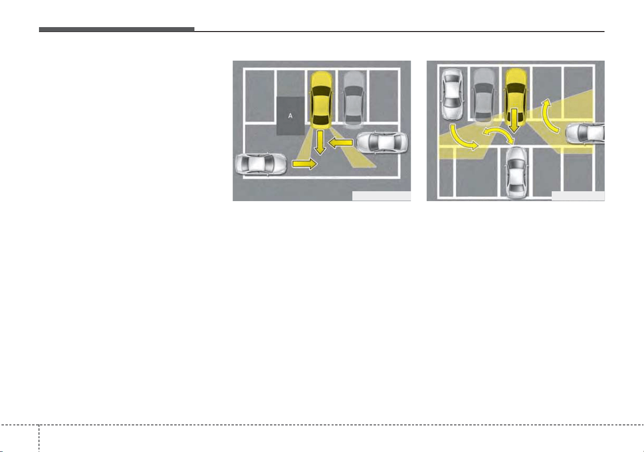
Driving your vehicle
1645
• The brake is reworked.
• The vehicle sharply stops.
• Temperature is extremely low
around the vehicle.
• The vehicle severely vibrates while
driving over a bumpy road,
uneven/bumpy road, or concrete
patch.
• The vehicle drives on a slippery
surface due to snow, water puddle,
or ice.
[A] : Structure
• Driving where there is a vehicle or
structure near
The system may not operate proper-
ly when driving where there is a vehi-
cle or structure near.
In certain instances, the system may
not detect the vehicle approaching
from behind and the warning or
brake may not operate properly.
Always pay attention to your sur-
rounding while driving.
• When the vehicle is in a complex
parking environment
The system may not operate prop-
erly when the vehicle is in a com-
plex parking environment.
In certain instances, the system
may not be able to exactly deter-
mine the risk of collision for the
vehicles which are parking or
pulling out near your vehicle (e.g. a
vehicle escaping beside your vehi-
cle, a vehicle parking or pulling out
in the rear area, a vehicle
approaching your vehicle making a
turn, etc.).
In this case, the warning or brake
may not operate properly.
OJFHP058462N OJFHP058463
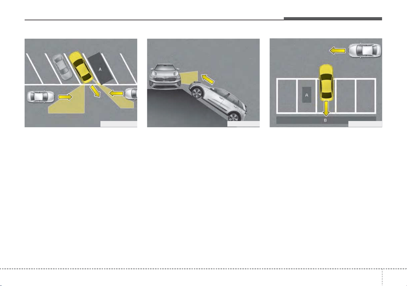
5165
Driving your vehicle
[A] : Vehicle
• When the vehicle is parked diago-
nally
The system may not operate proper-
ly when the vehicle is parked diago-
nally.
In certain instances, when the diago-
nally parked vehicle is pulled out of
the parking space, the system may
not detect the vehicle approaching
from the rear left/right of your vehi-
cle. In this case, the warning or brake
may not operate properly.
Always pay attention to your sur-
rounding while driving.
• When the vehicle is on/near a
slope
The system may not operate proper-
ly when the vehicle is on/near a
slope.
In certain instances, the system may
not detect the vehicle approaching
from the rear left/right and the warning
or brake may not operate properly.
Always pay attention to your sur-
rounding while driving.
[A] : Structure, [B] : Wall
• Pulling into the parking space
where there is a structure
The system may not operate properly
when pulling in the vehicle to the park-
ing space where there is a structure at
the back or side of your vehicle.
In certain instances, when backing
into the parking space, the system
may not detect the vehicle moving in
front of your vehicle. In this case, the
warning or brake may not operate
properly.
Always pay attention to the parking
space while driving.
ODEP059162
ODEP059309LOJFHP058464N
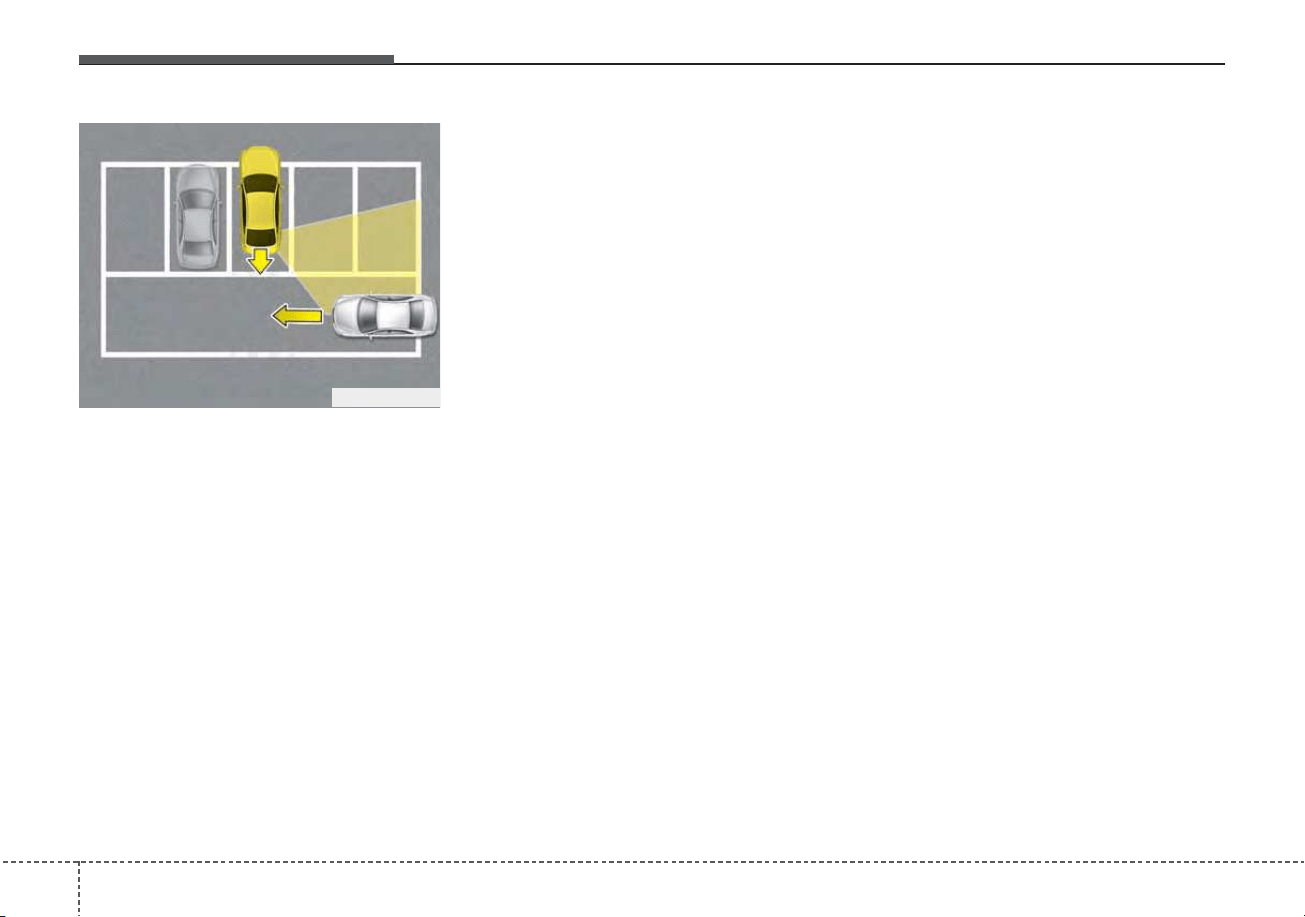
Driving your vehicle
1665
• When the vehicle is parked rear-
ward
If the vehicle is parked rearward and
the sensor detects the another vehi-
cle in the rear area of the parking
space, the system can warn or con-
trol braking. Always pay attention to
the parking space while driving.
OJFHP058466

5167
Driving your vehicle
Your vehicle's fuel economy depends
mainly on your style of driving, where
you drive and when you drive.
Each of these factors affects how
many miles (kilometers) you can get
from a gallon (liter) of fuel. To operate
your vehicle as economically as pos-
sible, use the following driving sug-
gestions to help save money in both
fuel and repairs:
• Drive smoothly. Accelerate at a
moderate rate. Don't make "jack-
rabbit" starts or full-throttle shifts
and maintain a steady cruising
speed. Don't race between stop-
lights. Try to adjust your speed to
the traffic so you don't have to
change speeds unnecessarily.
• Avoid heavy traffic whenever pos-
sible. Always maintain a safe dis-
tance from other vehicles so you
can avoid unnecessary braking.
This also reduces brake wear.
• Drive at a moderate speed. The
faster you drive, the more fuel your
vehicle uses. Driving at a moderate
speed, especially on the highway,
is one of the most effective ways to
reduce fuel consumption.
• Don't "ride" the brake pedal. This
can increase fuel consumption and
also increase wear on these com-
ponents. In addition, driving with
your foot resting on the brake pedal
may cause the brakes to overheat,
which reduces their effectiveness
and may lead to more serious con-
sequences.
• Take care of your tires. Keep them
inflated to the recommended pres-
sure. Incorrect inflation, either too
much or too little, results in unnec-
essary tire wear. Check the tire
pressures at least once a month.
• Be sure that the wheels are
aligned correctly. Improper align-
ment can result from hitting curbs
or driving too fast over irregular
surfaces. Poor alignment causes
faster tire wear and may also result
in other problems as well as
greater fuel consumption.
• Keep your vehicle in good condi-
tion. For better fuel economy and
reduced maintenance costs, main-
tain your vehicle in accordance
with the maintenance schedule in
chapter 8. If you drive your vehicle
in severe conditions, more frequent
maintenance is required (see
chapter 8 for details).
• Keep your vehicle clean. For maxi-
mum service, your vehicle should
be kept clean and free of corrosive
materials. It is especially important
that mud, dirt, ice, etc. not be
allowed to accumulate on the
underside of the vehicle. This extra
weight can result in increased fuel
consumption and also contribute to
corrosion.
• Travel lightly. Don't carry unneces-
sary weight in your vehicle. Weight
reduces fuel economy.
• Don't let the engine idle longer
than necessary. If you are waiting
(and not in traffic), turn off your
engine and restart only when
you're ready to go.
ECONOMICAL OPERATION
Driving your vehicle
1685
• Remember, your vehicle does not
require extended warm-up. After
the engine has started, allow the
engine to run for 10 to 20 seconds
prior to placing the vehicle in gear.
In very cold weather, however, give
your engine a slightly longer warm-
up period.
• Don't "lug" or "over-rev" the engine.
Lugging is driving too slowly in a
very high gear resulting in engine
bucking. If this happens, shift to a
lower gear. Over-revving is racing
the engine beyond its safe limit.
This can be avoided by shifting at
the recommended speed.
• Use your air conditioning sparingly.
The air conditioning system is
operated by engine power so your
fuel economy is reduced when you
use it.
• Opening windows at high speeds
can reduce fuel economy.
• Fuel economy is less in crosswinds
and headwinds. To help offset
some of this loss, slow down when
driving in these conditions.
Keeping a vehicle in good operating
condition is important both for econ-
omy and safety. Therefore, have an
authorized Kia dealer perform
scheduled inspections and mainte-
nance.
WARNING - Engine off
during motion
Never turn the engine off to
coast down hills or anytime the
vehicle is in motion. The power
steering and power brakes will
not function properly without
the engine running.
In addition, turning off the
engine start/stop button while
driving could engage the steer-
ing wheel lock, resulting in loss
of vehicle steering. Keep the
engine on and downshift to an
appropriate gear for an engine
braking effect.
5169
Driving your vehicle
Hazardous driving conditions
When hazardous driving conditions
are encountered such as water,
snow, ice, mud, sand, or similar haz-
ards, follow these suggestions:
• Drive cautiously and allow extra
distance for braking.
• Avoid sudden braking or steering.
• When braking with non-ABS
brakes pump the brake pedal with
a light up-and-down motion until
the vehicle is stopped.
Do not pump the brake pedal on a
vehicle equipped with ABS.
• If stalled in snow, mud, or sand,
use the second gear. Accelerate
slowly to avoid spinning the drive
wheels.
• Use sand, rock salt, or other non-
slip material under the drive
wheels to provide traction when
stalled in ice, snow, or mud.
Reducing the risk of a rollover
This multi-purpose passenger vehi-
cle is defined as a Sports Utility
Vehicle (SUV). Utility vehicles have a
significantly higher rollover rate than
other types of vehicles. SUV's have
higher ground clearance and a nar-
rower track to make them capable of
performing in a wide variety of off-
road applications. Specific design
characteristics give them a higher
center of gravity than ordinary vehi-
cles. An advantage of the higher
ground clearance is a better view of
the road, which allows you to antici-
pate problems. They are not
designed for cornering at the same
speeds as conventional passenger
vehicles, any more than low-slung
sports vehicles are designed to per-
form satisfactorily in off-road condi-
tions. Due to this risk, driver and pas-
sengers are strongly recommended
to buckle their seat belts. In a rollover
crash, an unbelted person is signifi-
cantly more likely to die than a per-
son wearing a seat belt. There are
steps that a driver can make to
reduce the risk of a rollover.
SPECIAL DRIVING CONDITIONS
WARNING - Downshifting
Do not downshift with a dual
clutch transmission while driv-
ing on slippery surfaces. The
sudden change in tire speed
could cause the tires to skid
and result in an accident.
Driving your vehicle
1705
If at all possible, avoid sharp turns or
abrupt maneuvers, do not load your
roof rack with heavy cargo, and
never modify your vehicle in any way.
WARNING
Your vehicle is equipped with
tires designed to provide safe
ride and handling capability. Do
not use a size and type of tire
and wheel that is different from
the one that is originally
installed on your vehicle. It can
affect the safety and perform-
ance of your vehicle, which
could lead to steering failure or
rollover and serious injury.
When replacing the tires, be
sure to equip all four tires with
the tire and wheel of the same
size, type, tread, brand and
load-carrying capacity. If you
nevertheless decide to equip
your vehicle with any tire/wheel
combination not recommended
by Kia for off road driving, you
should not use these tires for
highway driving.
WARNING - Rollover
As with other Sports Utility
Vehicles (SUV), failure to oper-
ate this vehicle correctly may
result in loss of control, an acci-
dent or vehicle rollover.
• Utility vehicles have a signifi-
cantly higher rollover rate
than other types of vehicles.
• Specific design characteris-
tics (higher ground clearance,
narrower track, etc.) give this
vehicle a higher center of
gravity than ordinary vehicles.
• A SUV is not designed for cor-
nering at the same speeds as
conventional vehicles.
• Avoid sharp turns or abrupt
maneuvers.
(Continued)
(Continued)
• In a rollover crash, an unbelt-
ed person is significantly
more likely to die than a per-
son wearing a seat belt. Make
sure everyone in the vehicle is
properly buckled up.
5171
Driving your vehicle
Rocking the vehicle
If it is necessary to rock the vehicle
to free it from snow, sand, or mud,
first turn the steering wheel right and
left to clear the area around your
front wheels. Then, shift back and
forth between R (Reverse) and any
forward gear in vehicles equipped
with a dual clutch transmission. Do
not race the engine, and spin the
wheels as little as possible. If you are
still stuck after a few tries, have the
vehicle pulled out by a tow vehicle to
avoid engine overheating and possi-
ble damage to the transaxle.
The ESC system should be turned
OFF prior to rocking the vehicle.
Smooth cornering
Avoid braking or gear changing in
corners, especially when roads are
wet. Ideally, corners should always
be taken under gentle acceleration. If
you follow these suggestions, tire
wear will be held to a minimum.
CAUTION - Vehicle rocking
Prolonged rocking may cause
engine overheating, transaxle
damage or failure, and tire dam-
age.
CAUTION - Spinning tires
Do not spin the wheels, espe-
cially at speeds more than 35
mph (56 km/h). Spinning the
wheels at high speeds when the
vehicle is stationary could
cause a tire to overheat which
could result in tire damage that
may injure bystanders.
WARNING - Sudden
Vehicle Movement
Do not attempt to rock the vehi-
cle if people or objects are near-
by. The vehicle may suddenly
move forward or backwards as it
becomes unstuck.

Driving your vehicle
1725
Driving at night
Because night driving presents more
hazards than driving in the daylight,
here are some important tips to
remember:
• Slow down and keep more dis-
tance between you and other vehi-
cles, as it may be more difficult to
see at night, especially in areas
where there may not be any street
lights.
• Adjust your mirrors to reduce the
glare from other driver's head-
lights.
• Keep your headlights clean and
properly aimed. (On vehicles not
equipped with the automatic head-
light aiming feature.) Dirty or
improperly aimed headlights will
make it much more difficult to see
at night.
• Avoid staring directly at the head-
lights of oncoming vehicles. You
could be temporarily blinded, and it
will take several seconds for your
eyes to readjust to the darkness.
Driving in the rain
Rain and wet roads can make driving
dangerous, especially if you’re not
prepared for the slick pavement.
Here are a few things to consider
when driving in the rain:
• A heavy rainfall will make it harder
to see and will increase the dis-
tance needed to stop your vehicle,
so slow down.
• Keep your windshield wiping
equipment in good shape. Replace
your windshield wiper blades when
they show signs of streaking or
missing areas on the windshield.
• If your tires are not in good condi-
tion, making a quick stop on wet
pavement can cause a skid and
possibly lead to an accident. Be
sure your tires are in good shape.
• Turn on your headlights to make it
easier for others to see you.
• Driving too fast through large pud-
dles can affect your brakes. If you
must go through puddles, try to
drive through them slowly.
• If you believe you may have gotten
your brakes wet, apply them lightly
while driving until normal braking
operation returns.
5173
Driving your vehicle
Driving in flooded areas
Avoid driving through flooded areas
unless you are sure the water is no
higher than the bottom of the wheel
hub. Drive through any water slowly.
Allow adequate stopping distance
because brake performance may be
affected.
After driving through water, dry the
brakes by gently applying them sev-
eral times while the vehicle is moving
slowly.
Driving off-road
Drive carefully off-road because your
vehicle may be damaged by rocks or
roots of trees. Become familiar with
the off-road conditions where you
are going to drive before you begin
driving.
Highway driving
Tires
Adjust the tire inflation pressures to
specification. Low tire inflation pres-
sures will result in overheating and
possible failure of the tires.
Avoid using worn or damaged tires
which may result in reduced traction
or tire failure.
Never exceed the maximum tire
inflation pressure shown on the tires.
Fuel, engine coolant and engine oil
High speed travel consumes more
fuel than urban motoring. Do not for-
get to check both the engine coolant
and engine oil.
Drive belt
A loose or damaged drive belt may
result in overheating of the engine.
WARNING - Under/over
inflated tires
Always check the tires for proper
inflation before driving.
Underinflated or overinflated
tires can cause poor handling,
loss of vehicle control, and sud-
den tire failure leading to acci-
dents, injuries, and even death.
For proper tire pressures, refer to
“Tires and wheels” in chapter 9.
WARNING - Tire tread
Always check the tire tread
before driving your vehicle.
Worn-out tires can result in loss
of vehicle control. Worn-out tires
should be replaced as soon as
possible. For further information
and tread limits, refer to "Tires
and wheels" in chapter 8.

Driving your vehicle
1745
Severe weather conditions in the
winter result in greater wear and
other problems. To minimize the
problems of winter driving, you
should follow these suggestions:
Snowy or icy conditions
To drive your vehicle in deep snow, it
may be necessary to use snow tires
or to install tire chains on your tires.
If snow tires are needed, it is neces-
sary to select tires equivalent in size
and type of the original equipment
tires. Failure to do so may adversely
affect the safety and handling of your
vehicle. Furthermore, speeding,
rapid acceleration, sudden brake
applications, and sharp turns are
potentially very hazardous practices.
During deceleration, use engine
braking to the fullest extent. Sudden
brake applications on snowy or icy
roads may cause skids to occur. You
need to keep sufficient distance
between the vehicle in operation in
front of your vehicle. Also, apply the
brake gently. It should be noted that
installing tire chains on the tire will
provide a greater driving force, but
will not prevent side skids.
Tire chains are not legal in all states.
Check state laws before fitting tire
chains.
Snow tires
If you mount snow tires on your vehi-
cle, make sure they are radial tires of
the same size and load range as the
original tires. Mount snow tires on all
four wheels to balance your vehicle’s
handling in all weather conditions.
Keep in mind that the traction provid-
ed by snow tires on dry roads may
not be as high as your vehicle's orig-
inal equipment tires.You should drive
cautiously even when the roads are
clear. Check with the tire dealer for
maximum speed recommendations.
Do not install studded tires without
first checking local, state and munic-
ipal regulations for possible restric-
tions against their use.
WINTER DRIVING
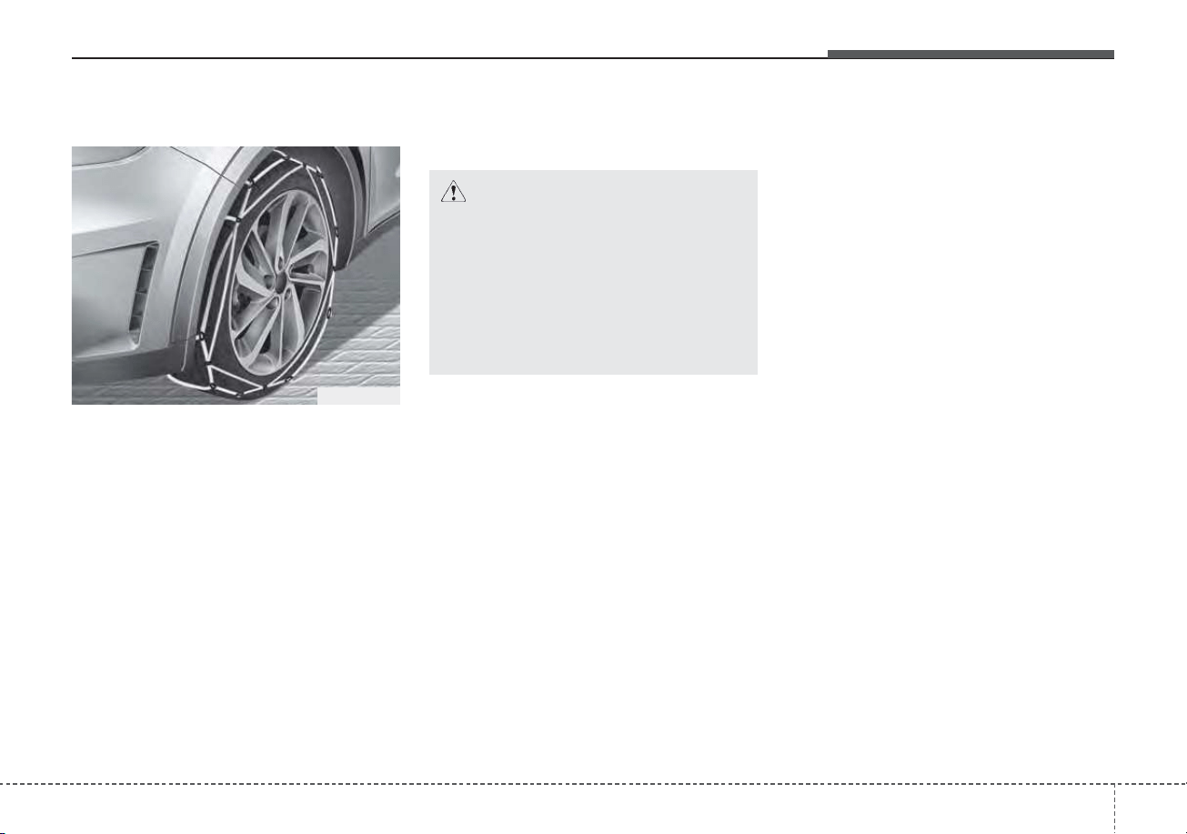
5175
Driving your vehicle
Tire chains
Since the sidewalls of radial tires are
thinner, they can be damaged by
mounting some types of snow chains
on them. Therefore, the use of snow
tires is recommended instead of
snow chains. Do not mount tire
chains on vehicles equipped with
aluminum wheels; snow chains may
cause damage to the wheels. If snow
chains must be used, use wire-type
chains with a thickness of less than
0.47 in (12 mm). Damage to your
vehicle caused by improper snow
chain use is not covered by your
vehicle manufacturers warranty.
When using tire chains, install tire
chains only on the front tires.
The snow chain connecting hooks
may be damaged from contacting
vehicle components causing the
snow chains to come loose from the
tire. Make sure the snow chains are
SAE class “S” certified.
Always check chain installation for
proper mounting after driving
approximately 0.3 to 0.6 miles (0.5 to
1 km) to ensure safe mounting.
Retighten or remount the chains if
they are loose.
If your vehicle has 18 inch tires, do
not use tire chains.
They can damage your vehicle
(wheel, suspension and body).
Chain installation
When installing chains, follow the
manufacturer's instructions and
mount them as tightly as you can.
Drive slowly with chains installed. If
you hear the chains contacting the
body or chassis, stop and tighten
them. If they still make contact, slow
down until it stops. Remove the
chains as soon as you begin driving
on cleared roads.
When mounting snow chains, park
the vehicle on level ground away
from traffic. Turn on the vehicle
Hazard Warning flashers and place a
triangular emergency warning device
behind the vehicle if available.
Always place the vehicle in P (Park),
apply the parking brake and turn off
the engine before installing snow
chains.
CAUTION - Snow chains
Make sure the snow chains are
the correct size and type for
your tires. Incorrect snow
chains can cause damage to the
vehicle body and suspension
and may not be covered by your
vehicle manufacturer warranty.
ODE056062

Driving your vehicle
1765
• The use of chains may adversely
affect vehicle handling.
• Do not exceed 20 mph (30 km/h)
or the chain manufacturer’s recom-
mended speed limit, whichever is
lower.
• Drive carefully and avoid bumps,
holes, sharp turns, and other road
hazards, which may cause the
vehicle to bounce.
• Avoid sharp turns or locked-wheel
braking.
Use high quality ethylene gly-
col coolant
Your vehicle is delivered with high
quality ethylene glycol coolant in the
cooling system. It is the only type of
coolant that should be used because
it helps prevent corrosion in the cool-
ing system, lubricates the water
pump and prevents freezing. Be sure
to replace or replenish your coolant
in accordance with the maintenance
schedule in chapter 8. Before winter,
have your coolant tested to assure
that its freezing point is sufficient for
the temperatures anticipated during
the winter.
Check battery and cables
Winter puts additional burdens on
the battery system. Visually inspect
the battery and cables as described
in chapter 8. The level of charge in
your battery can be checked by an
authorized Kia dealer or a service
station.
Change to "winter weight" oil
if necessary
In some climates it is recommended
that a lower viscosity "winter weight"
oil be used during cold weather. See
chapter 9 for recommendations. If
you aren't sure what weight oil you
should use, consult an authorized
Kia dealer.
Check spark plugs and ignition
system
Inspect your spark plugs as
described in chapter 8 and replace
them if necessary. Also check all
ignition wiring and components to be
sure they are not cracked, worn or
damaged in any way.
CAUTION - Snow chains
• Chains that are the wrong size
or improperly installed can
damage your vehicle's brake
lines, suspension, body and
wheels.
• Stop driving and retighten the
chains any time you hear them
hitting the vehicle.

5177
Driving your vehicle
To keep locks from freezing
To keep the locks from freezing,
squirt an approved de-icer fluid or
glycerine into the key opening. If a
lock is covered with ice, squirt it with
an approved de-icing fluid to remove
the ice. If the lock is frozen internally,
you may be able to thaw it out by
using a heated key. Handle the heat-
ed key with care to avoid injury.
Use approved window washer
anti-freeze in system
To keep the water in the window
washer system from freezing, add an
approved window washer anti-freeze
solution in accordance with instruc-
tions on the container. Window wash-
er anti-freeze is available from an
authorized Kia dealer and most auto
parts outlets. Do not use engine
coolant or other types of anti-freeze
as these may damage the paint fin-
ish.
Don’t let your parking brake
freeze
Under some conditions your parking
brake can freeze in the engaged
position. This is most likely to happen
when there is an accumulation of
snow or ice around or near the rear
brakes or if the brakes are wet. If
there is a risk the parking brake may
freeze, apply it only temporarily while
you put the gear shift lever in P (Park,
Dual clutch transmission) and block
the rear wheels so the vehicle cannot
roll. Then release the parking brake.
Don't let ice and snow accu-
mulate underneath
Under some conditions, snow and
ice can build up under the fenders
and interfere with the steering. When
driving in severe winter conditions
where this may happen, you should
periodically check underneath the
vehicle to be sure the movement of
the front wheels and the steering
components are not obstructed.
Carry emergency equipment
Depending on the severity of the
weather, you should carry appropri-
ate emergency equipment. Some of
the items you may want to carry
include tow straps or chains, flash-
light, emergency flares, sand, shov-
el, jumper cables, window scraper,
gloves, ground cloth, coveralls, blan-
ket, etc.
TRAILER TOWING
We do not recommend using this
vehicle for trailer towing.
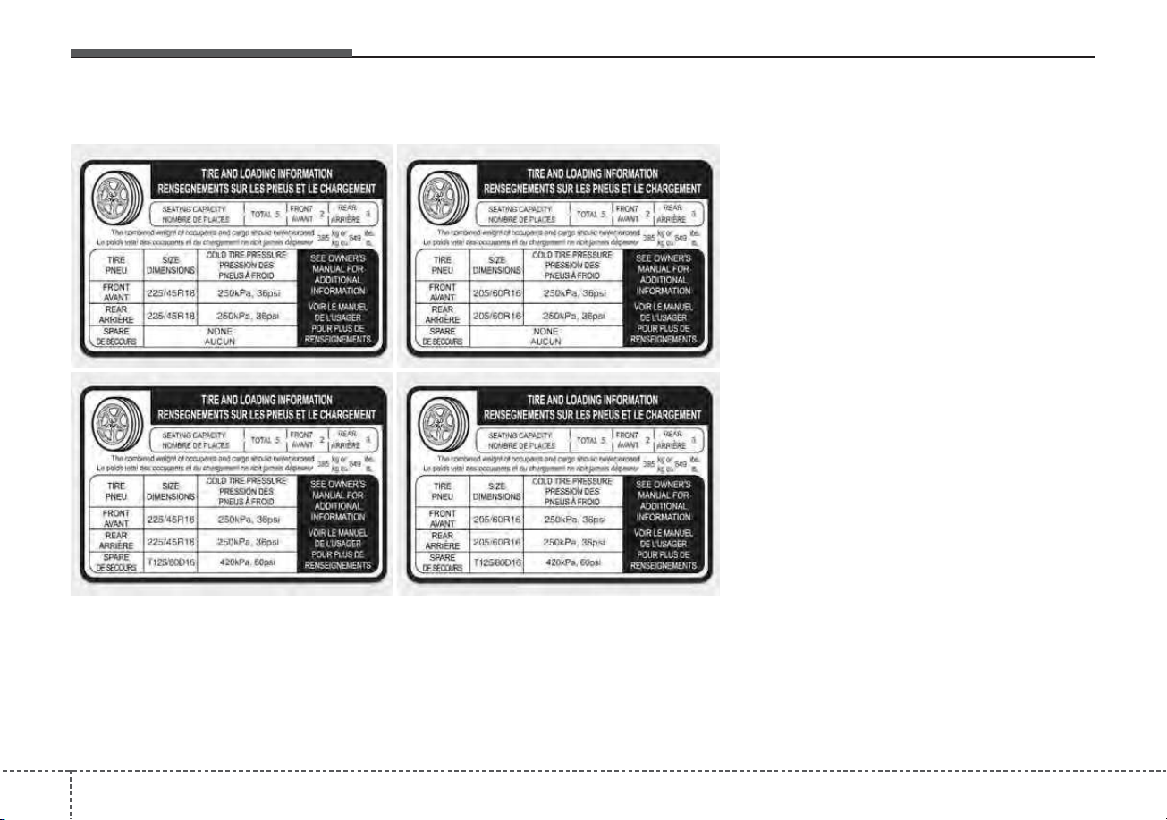
Driving your vehicle
1785
Vehicle capacity weight:
849 lbs. (385 kg)
Vehicle capacity weight is the maxi-
mum combined weight of occupants
and cargo. If your vehicle is equipped
with a trailer, the combined weight
includes the tongue load.
Seating capacity:
Total : 5 persons
(Front seat : 2 persons,
Rear seat : 3 persons)
Seating capacity is the maximum
number of occupants including a
driver, your vehicle may carry.
However, the seating capacity may
be reduced based upon the weight of
all of the occupants, and the weight
of the cargo being carried or towed.
Do not overload the vehicle as there
is a limit to the total weight, or load
limit including occupants and cargo,
the vehicle can carry.
VEHICLE LOAD LIMIT
ODE067042N/ODE067043N/ODE067055N/ODE067056N
The label located on the driver's door sill gives the original tire size, cold tire
pressures recommended for your vehicle, the number of people that can be
in your vehicle and vehicle capacity weight.
Tire and loading information label
5179
Driving your vehicle
Towing capacity:
We do not recommend using this
vehicle for trailer towing.
Cargo capacity:
The cargo capacity of your vehicle
will increase or decrease depending
on the weight and the number of
occupants.
Steps For Determining Correct
Load Limit -
1. Locate the statement "The com-
bined weight of occupants and
cargo should never exceed XXX
kg or XXX lbs.'' on your vehicle's
placard.
2. Determine the combined weight of
the driver and passengers that will
be riding in your vehicle.
3. Subtract the combined weight of
the driver and passengers from
XXX kg or XXX lbs.
4. The resulting figure equals the
available amount of cargo and lug-
gage load capacity. For example, if
the "XXX" amount equals 1400
lbs. and there will be five 150 lb
passengers in your vehicle, the
amount of available cargo and lug-
gage load capacity is 650 lbs.
(1400-750 (5 x 150) = 650 lbs.)
5. Determine the combined weight of
luggage and cargo being loaded
on the vehicle. That weight may
not safely exceed the available
cargo and luggage load capacity
calculated in Step 4.
6. If your vehicle will be towing a trail-
er, load from your trailer will be
transferred to your vehicle. Consult
this manual to determine how this
reduces the available cargo and
luggage load capacity of your
vehicle.
WARNING - Loose cargo
Do not travel with unsecured
objects in the passenger com-
partment of your vehicle (e.g.
suit cases or unsecured child
seats). These items may strike
occupants during a sudden
stop or crash.
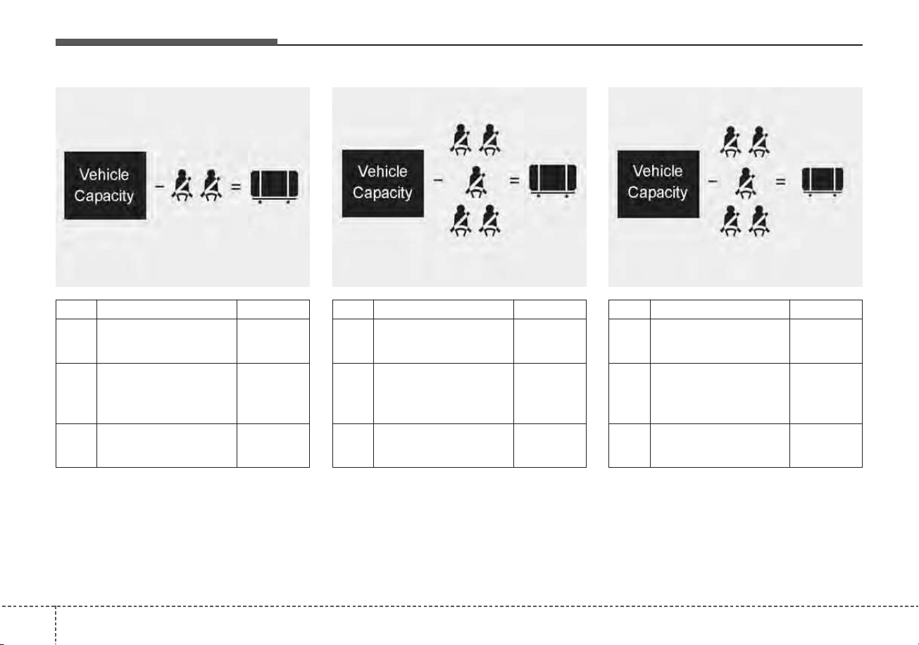
Driving your vehicle
1805
C190F03JM
Item Description Total
A
Vehicle Capacity 849 lbs
Weight (385 kg)
Subtract Occupant
B Weight
805 lbs
161 lbs (73 kg) × 5
(365 kg)
C
Available Cargo and
44 lbs
Luggage weight (20 kg)
ABC
Example 3
C190F02JM
Item Description Total
A
Vehicle Capacity 849 lbs
Weight (385 kg)
Subtract Occupant
B Weight
750 lbs
150 lbs (68 kg) × 5
(340 kg)
C
Available Cargo and
99 lbs
Luggage weight (45 kg)
ABC
Example 2
C190F01JM
Item Description Total
A
Vehicle Capacity 849 lbs
Weight (385 kg)
Subtract Occupant
B Weight
300 lbs
150 lbs (68 kg) × 2
(136 kg)
C
Available Cargo and
549 lbs
Luggage weight (249 kg)
Example 1
ABC
Refer to your vehicle’s tire and loading information label for specific information about your vehicle's capacity weight
and seating positions. The combined weight of the driver, passengers and cargo should never exceed your vehicle's
capacity weight.
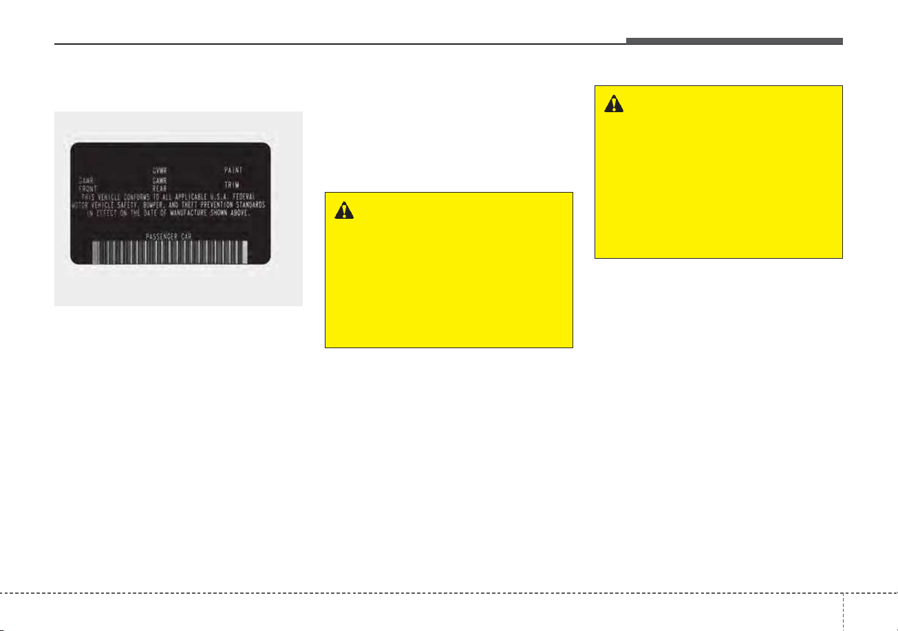
5181
Driving your vehicle
Certification label
The certification label is located on
the driver's door sill at the center pillar.
This label shows the maximum allow-
able weight of the fully loaded vehi-
cle. This is called the GVWR (Gross
Vehicle Weight Rating). The GVWR
includes the weight of the vehicle, all
occupants, fuel and cargo.
This label also tells you the maxi-
mum weight that can be supported
by the front and rear axles, called
Gross Axle Weight Rating (GAWR).
To find out the actual loads on your
front and rear axles, you need to go to
a weigh station and weigh your vehi-
cle.Your dealer can help you with this.
Be sure to spread out your load equal-
ly on both sides of the centerline.
The label will help you decide how
much cargo and installed equipment
your vehicle can carry.
If you carry items inside your vehicle
- like suitcases, tools, packages, or
anything else - they are moving as
fast as the vehicle. If you have to stop
or turn quickly, or if there is a crash,
the items will keep going and can
cause an injury if they strike the driv-
er or a passenger.
✽✽
NOTICE
Overloading your vehicle may cause
damage. Repairs would not be cov-
ered by your warranty. Do not over-
load your vehicle.
OJFA055280
WARNING - Over loading
Never exceed the GVWR for
your vehicle, the GAWR for
either the front or rear axle and
vehicle capacity weight.
Exceeding these ratings can
affect your vehicle’s handling
and braking ability.
WARNING - Over loading
Do not overload your vehicle.
Overloading your vehicle can
cause heat buildup in your vehi-
cle's tires and possible tire fail-
ure, increased stopping dis-
tances and poor vehicle han-
dling--all of which may result in
a crash.

VEHICLE WEIGHT
This chapter will guide you in the
proper loading of your vehicle and/or
trailer, to keep your loaded vehicle
weight within its design rating capa-
bility, with or without a trailer. Properly
loading your vehicle will provide max-
imum return of the vehicle design
performance. Before loading your
vehicle, familiarize yourself with the
following terms for determining your
vehicle's weight ratings, with or with-
out a trailer, from the vehicle's speci-
fications and the compliance label:
Base curb weight
This is the weight of the vehicle
including a full tank of fuel and all
standard equipment. It does not
include passengers, cargo, or option-
al equipment.
Vehicle curb weight
This is the weight of your new vehicle
when you picked it up from your deal-
er plus any aftermarket equipment.
Cargo weight
This figure includes all weight added
to the Base Curb Weight, including
cargo and optional equipment.
GAW (Gross axle weight)
This is the total weight placed on
each axle (front and rear) - including
vehicle curb weight and all payload.
GAWR
(Gross axle weight rating)
This is the maximum allowable
weight that can be carried by a single
axle (front or rear). These numbers
are shown on the compliance label.
The total load on each axle must
never exceed its GAWR.
GVW (Gross vehicle weight)
This is the Base Curb Weight plus
actual Cargo Weight plus passen-
gers.
GVWR
(Gross vehicle weight rating)
This is the maximum allowable
weight of the fully loaded vehicle
(including all options, equipment,
passengers and cargo). The GVWR
is shown on the certification label
located on the driver’s door sill.
5 182
Driving your vehicle

What to do in an emergency
Road warning . . . . . . . . . . . . . . . . . . . . . . . . . . . . . . 6-2
• Hazard warning flasher . . . . . . . . . . . . . . . . . . . . . . . . 6-2
In case of an emergency while driving. . . . . . . . . . 6-3
• If the engine stalls at a crossroad or crossing. . . . . . . 6-3
• If you have a flat tire while driving. . . . . . . . . . . . . . . 6-3
• If the engine stalls while driving . . . . . . . . . . . . . . . . . 6-3
If the engine will not start . . . . . . . . . . . . . . . . . . . . 6-4
• If engine doesn't turn over or turns over slowly . . . . 6-4
• If engine turns over normally but does not start . . . . 6-4
Emergency starting . . . . . . . . . . . . . . . . . . . . . . . . . 6-5
• Before Jump Starting (For Hybrid) . . . . . . . . . . . . . . 6-5
• Method to disconnect the (-) cable for regular
maintenance (For Hybrid) . . . . . . . . . . . . . . . . . . . . . 6-7
• Jump starting. . . . . . . . . . . . . . . . . . . . . . . . . . . . . . . . . 6-8
• Push-starting . . . . . . . . . . . . . . . . . . . . . . . . . . . . . . . . 6-10
If the engine overheats . . . . . . . . . . . . . . . . . . . . . . 6-11
Tire Pressure Monitoring System (TPMS) . . . . . 6-13
• Check tire pressure . . . . . . . . . . . . . . . . . . . . . . . . . . . 6-13
• Low tire pressure telltale . . . . . . . . . . . . . . . . . . . . . . 6-15
• Low tire pressure position telltale . . . . . . . . . . . . . . . 6-15
• Changing a tire with TPMS . . . . . . . . . . . . . . . . . . . . 6-17
If you have a flat tire (with spare tire). . . . . . . . . 6-19
• Jack and tools . . . . . . . . . . . . . . . . . . . . . . . . . . . . . . . 6-19
• Removing and storing the spare tire . . . . . . . . . . . . . 6-20
• Changing tires . . . . . . . . . . . . . . . . . . . . . . . . . . . . . . . 6-20
If you have a flat tire (with Tire Mobility Kit) . . 6-28
• Introduction . . . . . . . . . . . . . . . . . . . . . . . . . . . . . . . . . 6-29
• Notes on the safe use of the Tire Mobility Kit . . . . . 6-30
• Components of the Tire Mobility Kit . . . . . . . . . . . . 6-32
• Using the Tire Mobility Kit . . . . . . . . . . . . . . . . . . . . 6-33
• Distributing the sealant. . . . . . . . . . . . . . . . . . . . . . . . 6-35
• Checking the tire inflation pressure . . . . . . . . . . . . . 6-36
• Technical Data . . . . . . . . . . . . . . . . . . . . . . . . . . . . . . . 6-38
Towing . . . . . . . . . . . . . . . . . . . . . . . . . . . . . . . . . . . 6-39
• Towing service . . . . . . . . . . . . . . . . . . . . . . . . . . . . . . . 6-39
• Removable towing hook . . . . . . . . . . . . . . . . . . . . . . . 6-40
• Emergency towing . . . . . . . . . . . . . . . . . . . . . . . . . . . . 6-41
If An Accident Occurs . . . . . . . . . . . . . . . . . . . . . . 6-44
6
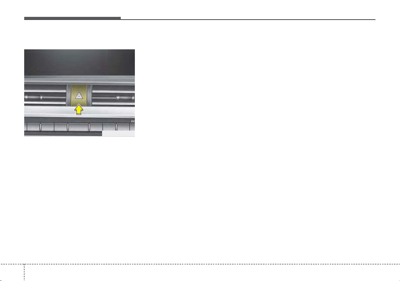
What to do in an emergency
26
ROAD WARNING
Hazard warning flasher
The hazard warning flasher serves
as a warning to other drivers to exer-
cise extreme caution when
approaching, overtaking, or passing
your vehicle.
It should be used whenever emer-
gency repairs are being made or
when the vehicle is stopped near the
edge of a roadway.
Depress the flasher switch with the
ignition switch in any position. The
flasher switch is located in the center
facia panel. All turn signal lights will
flash simultaneously.
• The hazard warning flasher oper-
ates whether your vehicle is run-
ning or not.
• The turn signals do not work when
the hazard flasher is on.
• Care must be taken when using
the hazard warning flasher while
the vehicle is being towed.
ODEP069001

63
What to do in an emergency
If the engine stalls at a cross-
road or crossing
If the engine stalls at a crossroad or
crossing, set the shift lever in the N
(Neutral) position and then push the
vehicle to a safe place.
If you have a flat tire while
driving
If a tire goes flat while you are driv-
ing:
1. Take your foot off the accelerator
pedal and let the vehicle slow
down while driving straight ahead.
Do not apply the brakes immedi-
ately or attempt to pull off the road
as this may cause a loss of con-
trol. When the vehicle has slowed
to such a speed that it is safe to do
so, brake carefully and pull off the
road. Drive off the road as far as
possible and park on firm level
ground. If you are on a divided
highway, do not park in the median
area between the two traffic lanes.
2. When the vehicle is stopped, turn
on your emergency hazard flash-
ers, set the parking brake and put
the transmission in P (Park).
3. Have all passengers get out of the
vehicle. Be sure they all get out on
the side of the vehicle that is away
from traffic.
4. When changing a flat tire, follow
the instruction provided later in
this section.
If the engine stalls while driv-
ing
1. Reduce your speed gradually,
keeping a straight line. Move cau-
tiously off the road to a safe place.
2. Turn on your emergency flashers.
3. Try to start the hybrid system
again. If your vehicle will not start,
contact an authorized Kia dealer
or seek other qualified assistance.
✽✽
NOTICE
If there was a check engine light and
loss of power or stall and if safe to do
so, wait at least 10 seconds to restart
the vehicle after it stalls. This may
reset the car so it will no longer run
at low power (limp home) condition.
IN CASE OF AN EMERGENCY WHILE DRIVING
What to do in an emergency
46
IF THE ENGINE WILL NOT START
If engine doesn't turn over or
turns over slowly
1. Be sure the shift lever is in N
(Neutral) or P (Park) and the
emergency brake is set.
2. Check the battery connections to
be sure they are clean and tight.
3. Turn on the interior light. If the light
dims or goes out when you oper-
ate the starter, the battery is dis-
charged.
4. Check the starter connections to
be sure they are securely tight-
ened.
5. Do not push or pull the vehicle to
start it. See instructions for "Jump
starting".
If engine turns over normally
but does not start
1. Check the fuel level.
2. With the ignition switch in the
LOCK position, check all connec-
tors at the ignition coils and spark
plugs. Reconnect any that may be
disconnected or loose.
3. Check the fuel line in the engine
compartment.
4. If the engine still does not start,
call an authorized Kia dealer or
seek other qualified assistance.
WARNING - Push/
pull start
Do not push or pull the vehicle
to start it. Push or pull starting
may cause the catalytic con-
verter to overload and create a
fire hazard.
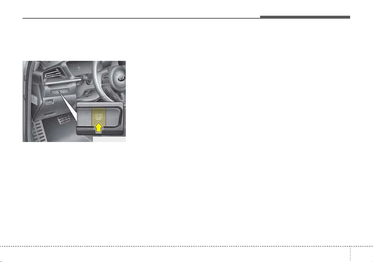
65
What to do in an emergency
EMERGENCY STARTING
Before Jump Starting
(For Hybrid)
Over discharge of 12V battery
- Press the reconnection
(“12V Batt Reset”) switch (1) :
This car has a reconnection switch
which can reset the over discharged
12V battery and enable getting the
car started without jump-start.
• Press the “12V Batt Reset” switch
(1) located on the lower left dash.
• Immediately start car by stepping
on the brake pedal and pressing
the Start switch within few seconds.
• To charge 12V battery, keep driving
or idling the car more than 30 min-
utes.
If you do not start the vehicle imme-
diately after pressing the “12V Batt
Reset” switch (1), the power of 12V
battery is automatically disconnected
after few seconds to save the 12V
battery from additional discharge. If
the 12V battery is disconnected prior
to starting the vehicle, press “12V
Batt Reset” switch (1) again and then
immediately start the car as
explained above.
Repeated use of the “12V Batt
Reset” switch (1) without a sufficient
engine ON cycle (30 Min+) may
cause over discharge of the 12V bat-
tery, which will prevent car starting. If
the 12V battery is over discharged to
a point that the reset does not work,
try to jump-start the vehicle. (refer to
jump-starting)
After starting the vehicle (HEV
Ready), the 12V battery is being
charged whether the engine is run-
ning or not. Although there is no
engine-sound, it is not necessary to
step on the accelerator pedal.
Once the 12V battery is fully dis-
charged and reconnected, the 12V
battery is initialized.
ODEP049042N
What to do in an emergency
66
The following items should be reset
after the battery has been discharged
or the battery has been disconnected.
• Auto up/down window
• Sunroof
• Trip computer
• Climate control system
• Driver position Memory System
• Audio
As explained above, if the vehicle
cannot be started after pressing the
“12V Batt Reset” switch (1) due to
over discharge, try to jump-start
(refer to Jump-starting).
Charging method for 12V battery
(A) It is recommended to charge the
12V battery by starting and run-
ning the vehicle (HEV Ready
Mode) for a minimum of 30 min-
utes if a 12V reset, or jump start
has been used.
(B) If you cannot start the vehicle :
• After connecting the jumper cables
at the recommended locations, you
should press “12V batt Reset”
switch (1) to charge the battery.
• The voltage range of the charger
should be 13.3~14V and its current
range should be less than 60A.
(13.8V is recommended).
CAUTION
• The use of an improper charg-
er with a voltage and current
range higher than specified
may cause overheating and
damage to the 12V battery.
• The use of an incorrect charg-
er will lead to a power shut-off
to save the 12V battery. Stop
using the incorrect charger
once the power of the vehicle
is shut off.
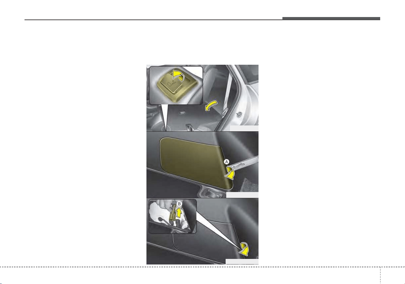
67
What to do in an emergency
External power source using 12V
battery
(Except the use of dash cameras)
The use of external power acces-
sories may reduce performance and
function of the vehicle. Especially,
the use of dash cameras may cause
a shut off the power of the vehicle
prior to the dash camera’s automatic
shut-down.
If the power of the car is shut off,
start the vehicle as explained above
(refer to “Over discharge of 12V bat-
tery”).
Method to disconnect the (-)
cable for regular maintenance
(For Hybrid)
When the vehicle is under regular
maintenance, make sure to separate
the (-) cable inside the luggage room
before maintenance.
Procedures to separate the (-) cable
is as below :
• Fold the rear left side seat.
• Using the key or (-) screwdriver,
remove the service cover (A) on
the luggage trim.
• Separate the (-) cable (B).
Reassemble in the reverse order of
disassembly.
ODE036021
ODE046170N
ODE046171N
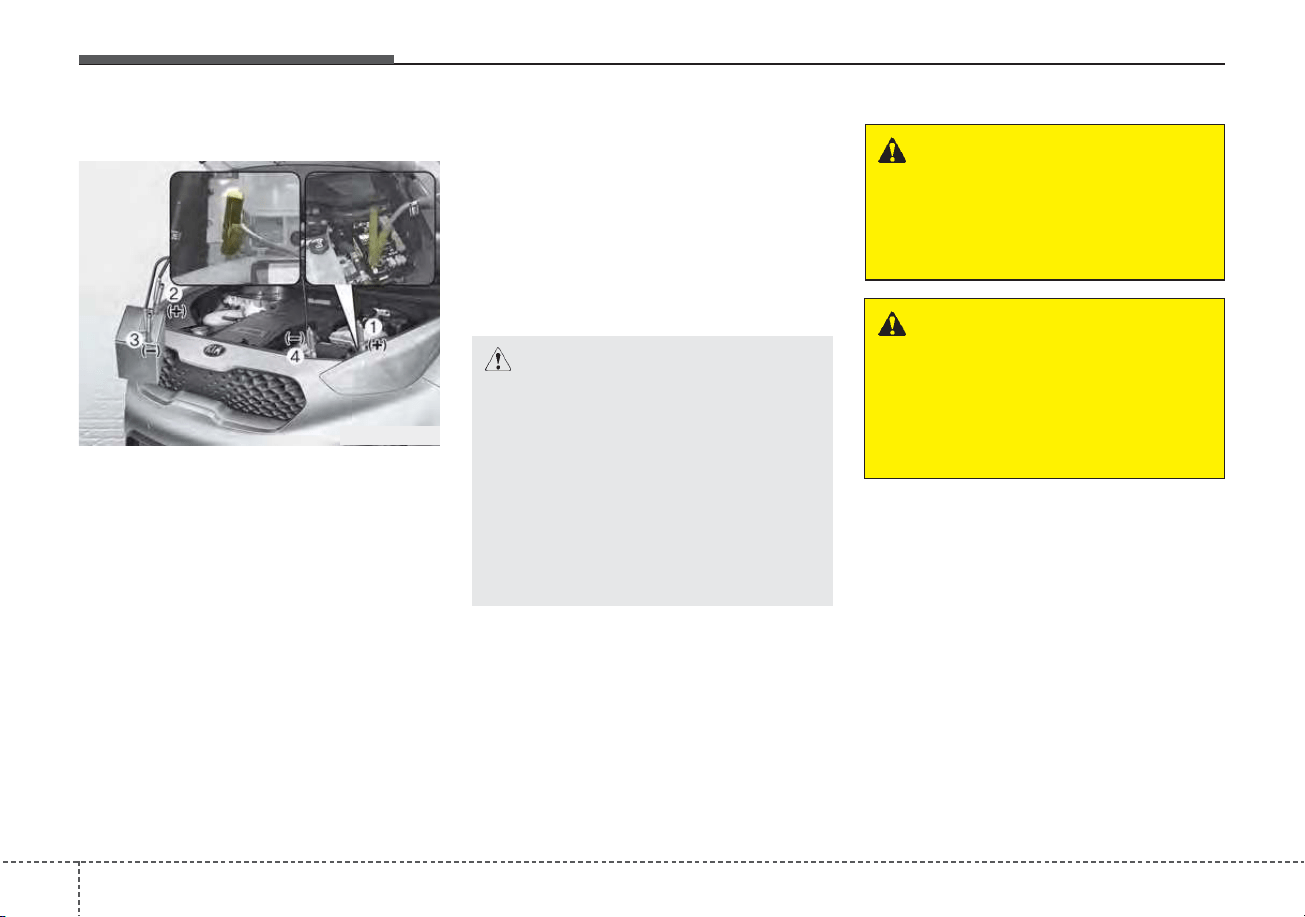
What to do in an emergency
86
Jump starting
Connect cables in numerical order
and disconnect in reverse order.
Remove the air filter cover before
connecting the cable to part (4).
Jump starting can be dangerous if
done incorrectly. Therefore, to avoid
harm to yourself or damage to your
vehicle or battery, follow these jump
starting procedures. If in doubt, we
strongly recommend that you have a
competent technician or towing serv-
ice jump start your vehicle.
ODEP069002
CAUTION - Push/pull start
to 12 Volt Battery
Use only a 12-volt jumper sys-
tem. You can damage a 12-volt
starting motor, ignition system,
and other electrical parts
beyond repair by use of a 24-
volt power supply (either two
12-volt batteries in series or a
24-volt motor generator set).
WARNING - Battery
Never attempt to check the elec-
trolyte level of the battery as
this may cause the battery to
rupture or explode.
WARNING - Frozen
batteries
Do not attempt to jump start the
vehicle if the discharged battery
is frozen as the battery may
rupture or explode.
69
What to do in an emergency
Jump starting procedure
1. Make sure the booster battery is
12-volt and that its negative termi-
nal is grounded.
2. If the booster battery is in another
vehicle, do not allow the vehicles
to come in contact.
3. Turn off all unnecessary electrical
loads.
4. Connect the jumper cables in the
exact sequence shown in the illus-
tration. First connect one end of a
jumper cable to the positive termi-
nal of the discharged battery (1),
then connect the other end to the
positive terminal of the booster
battery (2).
Proceed to connect one end of the
other jumper cable to the negative
terminal of the booster battery (3),
then the other end to a solid, sta-
tionary, metallic point (for example,
the engine lifting bracket) away
from the battery (4). Do not con-
nect it to or near any part that
moves when the engine is cranked.
WARNING - Battery
cables
Do not connect the jumper cable
from the negative terminal of the
booster battery to the negative
terminal of the discharged bat-
tery, directly. This can cause the
discharged battery to overheat
and crack and/or cause degra-
dation.
Connect the jumper cable from
the negative terminal of the
booster battery to the chassis
ground in the engine room.
WARNING - Electrolyte
• Do not charge or discharge
arbitrarily. It may lead to fault,
electric shock or burns.
• Do not damage the battery in
any way, including dropping it,
impacting it, or piercing it with
a sharp object. It may cause
electrolyte leakage or fire.
• Breakdown of the unit may
lead to electrolyte leakage or
flammable gas generation. If
this occurs, contact an author-
ized Kia dealer immediately.
• If electrolyte leaks out, avoid
contact with eyes, skin or
clothes. In event of accident,
flush with water and get med-
ical help immediately.
• Do not place near open flame
or incinerate. It may lead to
fire or explosion.
• Keep battery out of reach of
children or animals.
• Keep the battery away from
moisture and liquid. Do not
touch or use if liquids have
been spilled on the battery.
WARNING - Sulfuric acid
risk
Automobile batteries contain
sulfuric acid. When jump start-
ing your vehicle, be careful not
to get sulfuric acid on yourself,
your clothing, or on the vehicle.
This acid is poisonous and
highly corrosive.
What to do in an emergency
106
Do not allow the jumper cables to
contact anything except the cor-
rect battery terminals or the cor-
rect ground. Do not lean over the
battery when making connections.
5. Start the engine of the vehicle with
the booster battery and let it run at
2,000 rpm, then start the engine
of the vehicle with the discharged
battery.
If the cause of your battery discharg-
ing is not apparent, you should have
your vehicle checked by an author-
ized Kia dealer.
Push-starting
Vehicles equipped with dual clutch
transmission lock system cannot be
push-started.
Follow the directions in this section
for jump-starting.
WARNING - Tow starting
vehicle
Never tow a vehicle to start it.
When the engine starts, the
vehicle can suddenly surge for-
ward and could cause a colli-
sion with the tow vehicle.
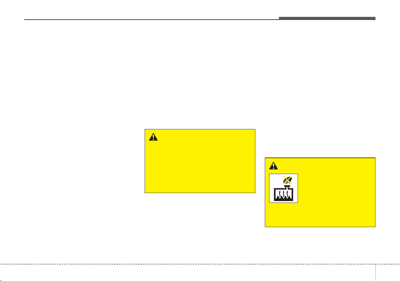
611
What to do in an emergency
IF THE ENGINE OVERHEATS
If your temperature gauge indicates
overheating, you will experience a
loss of power, or hear loud pinging or
knocking, the engine is probably too
hot. If this happens, you should:
1. Turn on the emergency warning
flasher and stop in a safe place.
Move the shift lever to P (Park)
and engage the parking brake.
2. If hot steam does not come out
from the engine room, carefully
open the engine room and check
whether the water pump connec-
tor is properly engaged. If the con-
nector is not properly engaged,
stop the engine immediately and
properly engage the connector.
Then, turn the engine on.
3. Turn on the air conditioner.
4. If the “HEV Warning” light turns on
in the driver instrument cluster, or
engine coolant or hot steam emits
from the engine coolant filler, stop
the engine immediately. Then, call
the nearest authorized Kia dealer
for assistance. If the “Engine
Warning” light remains illuminated
or the engine coolant is not flowing
out, keep the engine running.
Open the engine hood for ventila-
tion to help cool down the engine.
5. Check whether the engine coolant
temperature is low enough by
checking its temperature. If the
engine coolant level is low, please
check the connecting parts
between the radiator hose, heater
hose, and water pump for any signs
of leakage. When there is no sign of
leakage, please refill the engine
coolant. If causes and signs of
engine overheating such as warn-
ing light illumination, engine coolant
leakage, or cooling fan malfunction
are found, stop the vehicle the ear-
liest. Then, call the nearest author-
ized Kia dealer for assistance.
WARNING - Under the
Hood
While the engine is running,
keep hair, hands and clothing
away from moving parts such
as the fan and drive belts to pre-
vent injury.
WARNING - Radiator Cap
Do not remove the
radiator cap when the
engine is hot. This
can allow coolant to
blow out of the open-
ing and cause seri-
ous burns.
What to do in an emergency
126
6. If you cannot find the cause of the
overheating, wait until the engine
temperature has returned to nor-
mal. Then, if coolant has been lost,
carefully add coolant to the reser-
voir to bring the fluid level in the
reservoir up to the halfway mark.
7. Proceed with caution, keeping
alert for further signs of overheat-
ing. If over heating happens again,
call the nearest authorized Kia
dealer for assistance.
✽✽
NOTICE
Serious loss of coolant indicates
there is a leak in the cooling system
and should be checked as soon as
possible by an authorized Kia dealer.
CAUTION
When the engine overheats from
low engine coolant, suddenly
adding engine coolant may
cause cracks in the engine. To
prevent damage, add engine
coolant slowly in small quantities
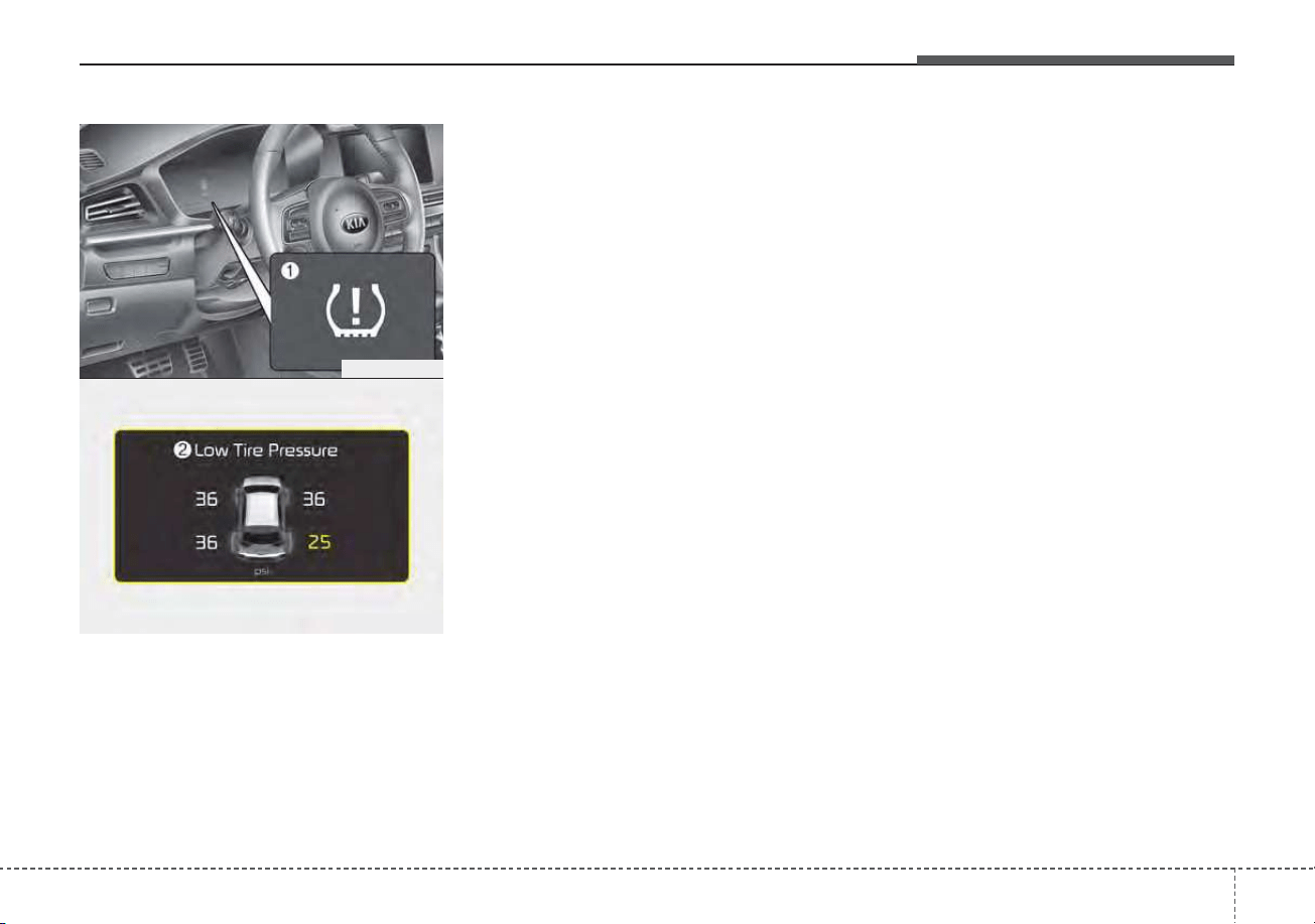
613
What to do in an emergency
TIRE PRESSURE MONITORING SYSTEM (TPMS)
(1) Low tire pressure telltale /
TPMS malfunction indicator
(2) Low tire pressure position telltale
(Shown on the LCD display)
Check tire pressure
• You can check the tire pressure in
the information mode on the clus-
ter.
- Refer to “Assist mode” in chapter
4.
• Tire pressure is displayed 1~2 min-
utes later after driving.
• If tire pressure is not displayed
when the vehicle is stopped, “Drive
to display” message displays. After
driving, check the tire pressure.
• You can change the tire pressure
unit in the user settings mode on
the cluster.
- psi, kpa, bar (Refer to “User set-
tings mode” in chapter 4).
✽✽
NOTICE
• The tire pressure may change due
to factors such as parking condi-
tion, driving style, and altitude
above sea level.
• Low tire pressure warning may
sound when a tire’s pressure unit is
equal or higher than nearby tires.
This is a normal occurrence, which
is due to the change in tire pressure
along with tire temperature.
• The tire pressure shown on the
dashboard may differ from the
tire pressure measured by tire
pressure gauge.
ODEP069003
ODEP069047L

What to do in an emergency
146
Each tire, including the spare (if pro-
vided), should be checked monthly
when cold and inflated to the inflation
pressure recommended by the vehi-
cle manufacturer on the vehicle plac-
ard or tire inflation pressure label. (If
your vehicle has tires of a different
size than the size indicated on the
vehicle placard or tire inflation pres-
sure label, you should determine the
proper tire inflation pressure for
those tires.)
As an added safety feature, your
vehicle has been equipped with a tire
pressure monitoring system (TPMS)
that illuminates a low tire pressure
telltale when one or more of your
tires is significantly under-inflated.
Accordingly, when the low tire pres-
sure telltale illuminates, you should
stop and check your tires as soon as
possible, and inflate them to the
proper pressure. Driving on a signifi-
cantly under-inflated tire causes the
tire to overheat and can lead to tire
failure. Under-inflation also reduces
fuel efficiency and tire tread life, and
may affect the vehicle’s handling and
stopping ability.
Please note that the TPMS is not a
substitute for proper tire maintenance,
and it is the driver’s responsibility to
maintain correct tire pressure, even if
under-inflation has not reached the
level to trigger illumination of the
TPMS low tire pressure telltale.
Your vehicle has also been equipped
with a TPMS malfunction indicator to
indicate when the system is not
operating properly. The TPMS mal-
function indicator is combined with
the low tire pressure telltale. When
the system detects a malfunction,
the telltale will flash for approximate-
ly one minute and then remain con-
tinuously illuminated. This sequence
will continue upon subsequent vehi-
cle start-ups as long as the malfunc-
tion exists. When the malfunction
indicator is illuminated, the system
may not be able to detect or signal
low tire pressure as intended. TPMS
malfunctions may occur for a variety
of reasons, including the installation
of replacement or alternate tires or
wheels on the vehicle that prevent
the TPMS from functioning properly.
Always check the TPMS malfunction
telltale after replacing one or more
tires or wheels on your vehicle to
ensure that the replacement or alter-
nate tires and wheels allow the TPMS
to continue to function properly.
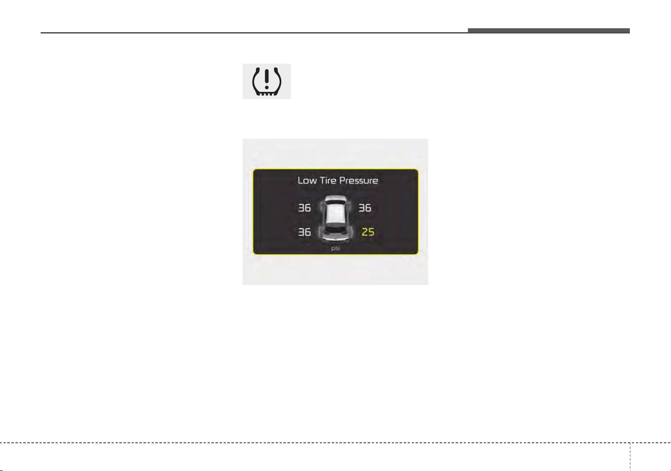
615
What to do in an emergency
✽✽
NOTICE
If the TPMS, Low Tire Pressure
indicator does not illuminate for 3
seconds when the ignition switch is
turned to the ON position or engine
is running, or if they remain illumi-
nated after coming on for approxi-
mately 3 seconds, take your vehicle
to your nearest authorized Kia deal-
er and have the system checked.
Low tire pressure
telltale
Low tire pressure position tell-
tale
When the tire pressure monitoring
system warning indicators are illumi-
nated, one or more of your tires is
significantly under-inflated.
If the telltale illuminates, immediately
reduce your speed, avoid hard cor-
nering and anticipate increased stop-
ping distances. You should stop and
check your tires as soon as possible.
Inflate the tires to the Proper pres-
sure as indicated on the vehicle’s
placard or tire inflation pressure label
located on the driver’s side center pil-
lar outer panel. If you cannot reach a
service station or if the tire cannot
hold the newly added air, replace the
low pressure tire with the spare tire.
Then the TPMS malfunction indicator
and the Low Tire Pressure telltale
may turn on and illuminate after
restarting and about 20 minutes of
continuous driving before you have
the low pressure tire repaired and
replaced on the vehicle.
In winter or cold weather, the low tire
pressure telltale may be illuminated if
the tire pressure was adjusted to the
recommended tire inflation pressure
in warm weather. It does not mean
your TPMS is malfunctioning
because the decreased temperature
leads to a proportional lowering of
tire pressure.
ODEP069064L
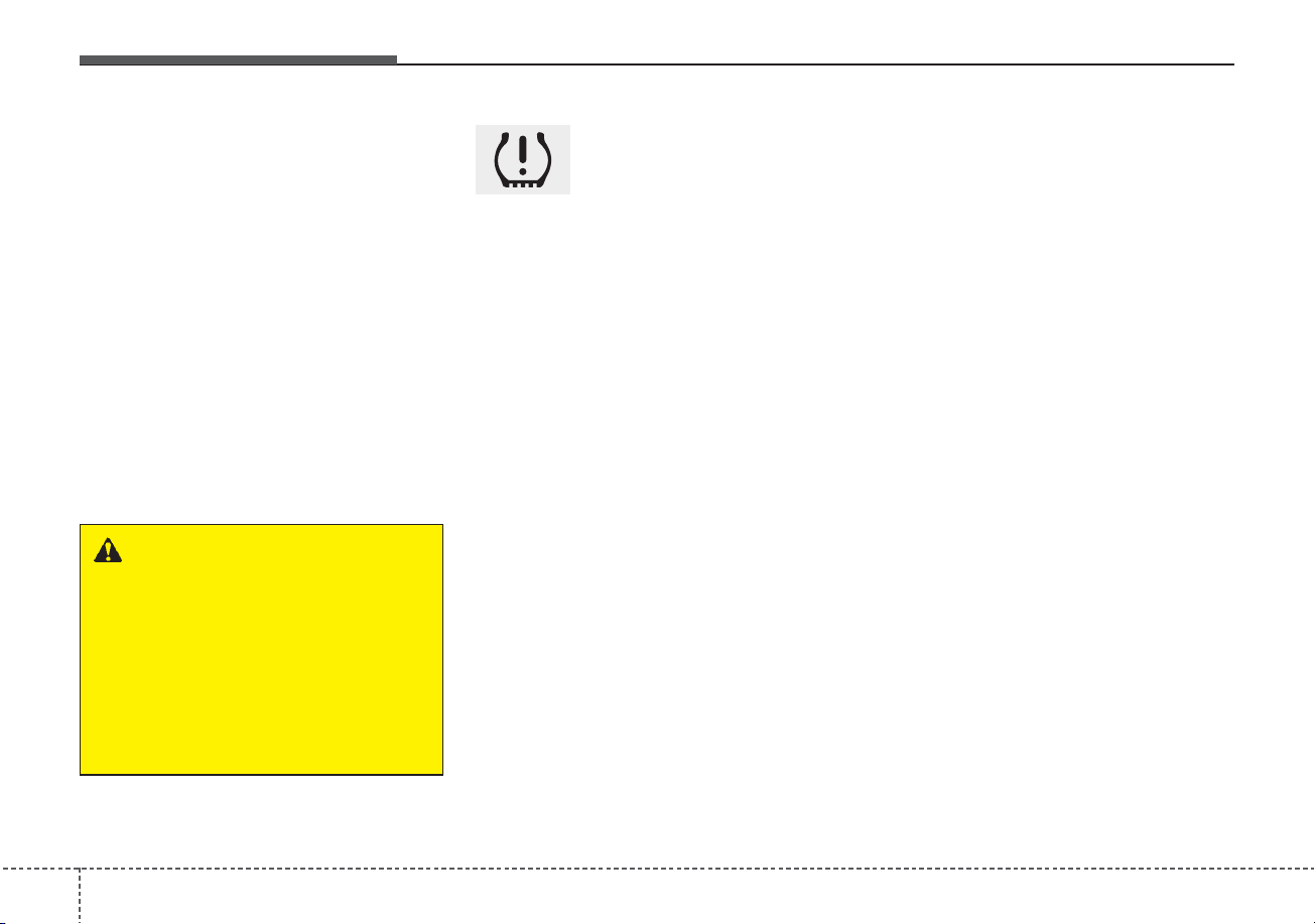
What to do in an emergency
166
When you drive your vehicle from a
warm area to a cold area or from a
cold area to a warm area, or the out-
side temperature is greatly higher or
lower, you should check the tire infla-
tion pressure and adjust the tires to
the recommended tire inflation pres-
sure.
When filling tires with more air, con-
ditions to turn off the low tire pres-
sure telltale may not be met. This is
because a tire inflator has a margin
of error in performance. The low tire
pressure telltale will be turned off if
the tire pressure is above the recom-
mended tire inflation pressure.
TPMS (Tire Pressure
Monitoring System)
malfunction indicator
The low tire pressure telltale will illu-
minate after it blinks for approximate-
ly one minute when there is a prob-
lem with the Tire Pressure
Monitoring System. If the system is
able to correctly detect an underinfla-
tion warning at the same time as sys-
tem failure then it will illuminate both
the TPMS malfunction and low tire
pressure position telltales e.g. if
Front Left sensor fails, the TPMS
malfunction indicator illuminates, but
if the Front Right, Rear Left, or Rear
Right tire is under-inflated, the low
tire pressure position telltales may
illuminate together with the TPMS
malfunction indicator.
Have the system checked by an
authorized Kia dealer as soon as
possible to determine the cause of
the problem.
• The TPMS malfunction indicator
may be illuminated if the vehicle is
moving around electric power sup-
ply cables or radios transmitters
such as at police stations, govern-
ment and public offices, broadcast-
ing stations, military installations,
airports, or transmitting towers,
etc. This can interfere with normal
operation of the Tire Pressure
Monitoring System (TPMS).
• The TPMS malfunction indicator
may be illuminated if snow chains
are used or some separate elec-
tronic devices such as notebook
computer, mobile charger, remote
starter or navigation etc., are used
in the vehicle. This can interfere
with normal operation of the Tire
Pressure Monitoring System
(TPMS).
WARNING - Low pressure
damage
Do not drive on low pressure
tires. Significantly low tire pres-
sure can cause the tires to over-
heat and fail, making the vehicle
unstable resulting in increased
braking distances and a loss of
vehicle control.

617
What to do in an emergency
Changing a tire with TPMS
If you have a flat tire, the Low Tire
Pressure telltale will come on. Have
the flat tire repaired by an authorized
Kia dealer as soon as possible or
replace the flat tire with the spare
tire.
Each wheel is equipped with a tire
pressure sensor mounted inside the
tire behind the valve stem. You must
use TPMS specific wheels. It is rec-
ommended that you always have
your tires serviced by an authorized
Kia dealer.
Even if you replace the low pressure
tire with the spare tire, the Low Tire
Pressure telltale will remain on until
the low pressure tire is repaired and
placed on the vehicle.
After you replace the low pressure
tire with the spare tire, the TPMS
malfunction indicator may illuminate
after a few minutes because the
TPMS sensor mounted on the spare
wheel is not initiated.
Once the low pressure tire is inflated
again to the recommended pressure
and installed on the vehicle or the
TPMS sensor mounted on the
replaced spare wheel is initiated by
an authorized Kia dealer, the TPMS
malfunction indicator and the low tire
pressure telltale will turn off within a
few minutes of driving.
If the indicator has not disappeared
after a few minutes of driving, please
visit an authorized Kia dealer.
If an original mounted tire is replaced
with the spare tire, the TPMS sensor
on the replaced spare wheel should
be initiated and the TPMS sensor on
the original mounted wheel should be
deactivated. If the TPMS sensor on
the original mounted wheel located in
the spare tire carrier still activates,
the tire pressure monitoring system
may not operate properly. Have the
tire with TPMS serviced or replaced
by an authorized Kia dealer.
CAUTION - Repair
Agents
Never use a puncture-repairing
agent not approved by Kia to
repair and/or inflate a low pres-
sure tire. The sealant not
approved by Kia may damage
the tire pressure sensor.

What to do in an emergency
186
You may not be able to identify a low
tire by simply looking at it. Always
use a good quality tire pressure
gauge to measure the tire's inflation
pressure. Please note that a tire that
is hot (from being driven) will have a
higher pressure measurement than a
tire that is cold (from sitting station-
ary for at least 3 hours and driven
less than 1 mile (1.6 km) during that
3 hour period).
Allow the tire to cool before measur-
ing the inflation pressure. Always be
sure the tire is cold before inflating to
the recommended pressure.
A cold tire means the vehicle has
been sitting for 3 hours and driven for
less than 1 mile (1.6 km) in that 3
hour period.
Never use tire sealant if your vehicle
is equipped with a Tire Pressure
Monitoring System. The liquid
sealant can damage the tire pres-
sure sensors.
• The TPMS cannot alert you to
severe and sudden tire damage
caused by external factors such as
nails or road debris.
• If you feel any vehicle instability,
immediately take your foot off the
accelerator, apply the brakes grad-
ually and with light force, and slow-
ly move to a safe position off the
road.
✽✽
NOTICE - Protecting TPMS
Tampering with, modifying, or dis-
abling the Tire Pressure Monitoring
System (TPMS) components may
interfere with the system's ability to
warn the driver of low tire pressure
conditions and/or TPMS malfunc-
tions. Tampering with, modifying,
or disabling the Tire Pressure
Monitoring System (TPMS) compo-
nents may void the warranty for
that portion of the vehicle.
This device complies with Part
15 of the FCC rules.
Operation is subject to the following
two conditions:
1. This device may not cause harm-
ful interference, and
2. This device must accept any inter-
ference received, including inter-
ference that may cause undesired
operation.
3. Changes or modifications not
expressly approved by the party
responsible for compliance could
void the user’s authority to operate
the device.
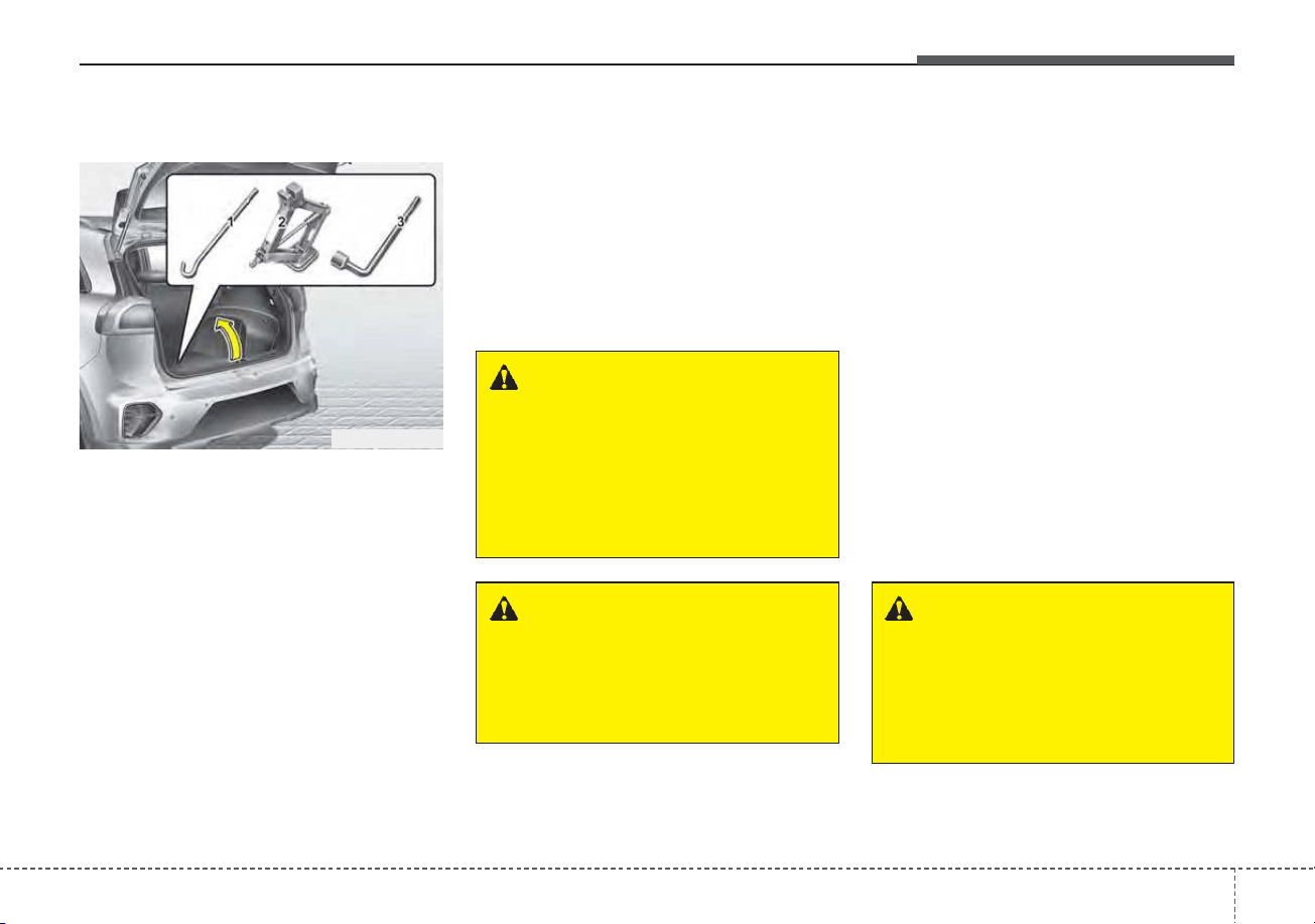
619
What to do in an emergency
IF YOU HAVE A FLAT TIRE (WITH SPARE TIRE) (IF EQUIPPED)
Jack and tools
The jack and wheel lug nut wrench
are stored in the luggage compart-
ment.
Remove the panel indicated in the
illustration.
(1) Jack handle
(2) Jack
(3) Wheel lug nut wrench
Jacking instructions
The jack is provided for emergency
tire changing only.
To prevent the jack from “rattling”
while the vehicle is in motion, store it
properly.
Follow jacking instructions to reduce
the possibility of personal injury.
• Always move the vehicle complete-
ly off the road and onto the shoulder
before trying to change a tire. The
jack should be used on a firm level
ground. If you cannot find a firm,
level place off the road, call a towing
service company for assistance.
• Be sure to use the correct front and
rear jacking positions on the vehi-
cle; never use the bumpers or any
other part of the vehicle for jack
support.
• Do not allow anyone to remain in
the vehicle while it is on the jack.
• Make sure any children present
are in a secure place away from
the road and from the vehicle to be
raised with the jack.
WARNING - Changing
tires
Never attempt vehicle repairs in
the traffic lanes of a public road
or highway.
ODEP069004L
WARNING - Tire Jack
Do not place any portion of your
body under a vehicle that is
only supported by a jack since
the vehicle can easily roll off the
jack. Use vehicle support
stands.
WARNING - Running vehi-
cle on jack
Do not start or run the engine of
the vehicle while the vehicle is
on the jack as this may cause
the vehicle to fall off the jack.
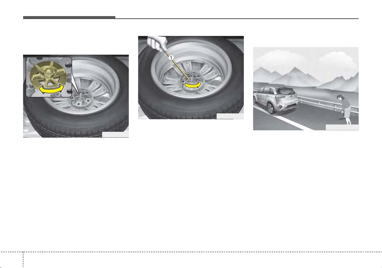
What to do in an emergency
206
Removing and storing the
spare tire
Turn the tire hold-down wing bolt
counterclockwise.
Store the tire in the reverse order of
removal.
To prevent the spare tire and tools
from “rattling” while the vehicle is in
motion, store them properly.
If it is hard to loosen the tire hold-
down wing bolt by hand, you can
loosen it easily using the jack handle.
1. Put the jack handle (1) inside of
the tire hold-down wing bolt.
2. Turn the tire hold-down wing bolt
counterclockwise with the jack
handle.
Use caution when utilizing the sharp
jack handle.
Changing tires
1. Park on a level surface and apply
the parking brake firmly.
2. Shift the shift lever into P (Park)
with dual clutch transmission.
3. Activate the hazard warning flash-
ers.
OQL065031
OQL065032
ODEP069065N
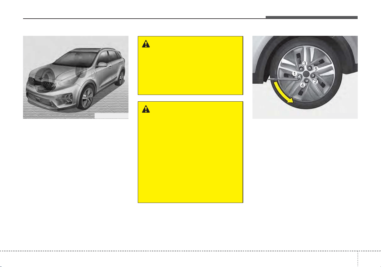
621
What to do in an emergency
4. Remove the wheel lug nut wrench,
jack and spare tire from the vehi-
cle.
5. Block both the front and rear of the
wheel that is diagonally opposite
from the jack position.
6. Loosen the wheel lug nuts coun-
terclockwise one turn each, but do
not remove any nut until the tire
has been raised off the ground.
WARNING - Jack location
To reduce the possibility of
injury, be sure to use only the
jack provided with the vehicle in
the correct jack position; never
use any other part of the vehicle
for jack support.
WARNING - Changing a
tire
• To prevent vehicle movement
while changing a tire, always
set the parking brake fully,
and always chock the wheel
diagonally opposite the wheel
being changed.
• We recommend that the
wheels of the vehicle be
chocked, and that no person
remain in a vehicle that is
being jacked.
ODEP069066N ODEP069025L
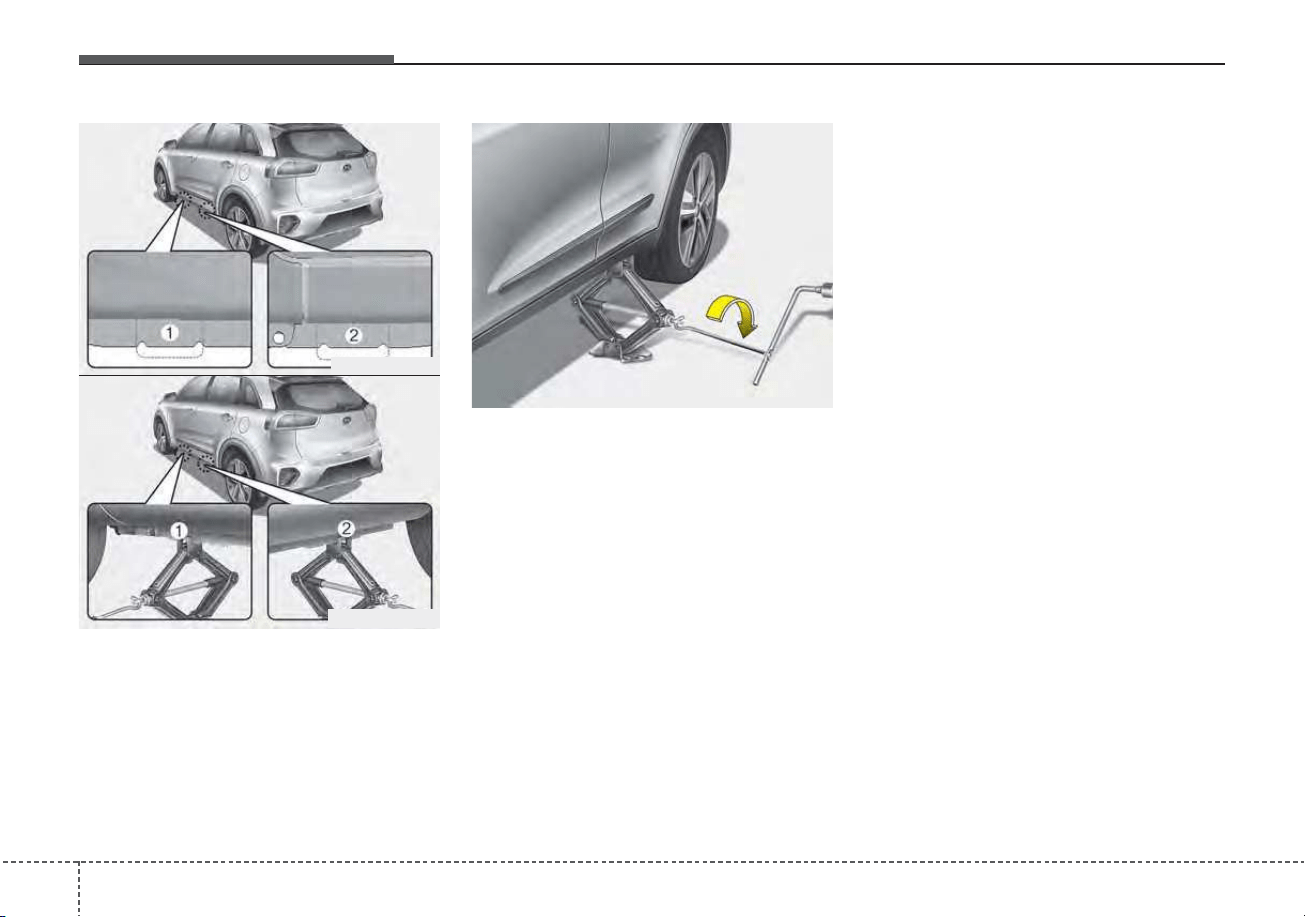
What to do in an emergency
226
7. Place the jack at the front (1) or
rear (2) jacking position closest to
the tire you are changing. Place
the jack at the designated loca-
tions under the frame. The jacking
positions are plates welded to the
frame with two tabs and a raised
dot to line up with the jack.
8. Insert the wheel lug nut wrench
into the jack and turn it clockwise,
raising the vehicle until the tire just
clears the ground. This measure-
ment is approximately 1 in. (30
mm).
Before removing the wheel lug
nuts, make sure the vehicle is sta-
ble and that there is no chance for
movement or slippage.
9. Loosen the wheel nuts and
remove them with your fingers.
Slide the wheel off the studs and
lay it flat so it cannot roll away. To
put the wheel on the hub, pick up
the spare tire, line up the holes
with the studs and slide the wheel
onto them. If this is difficult, tip the
wheel slightly and get the top hole
in the wheel lined up with the top
stud. Jiggle the wheel back and
forth until the wheel can slide over
the other studs.
ODEP069028L
ODEP069026L
ODEP069027L
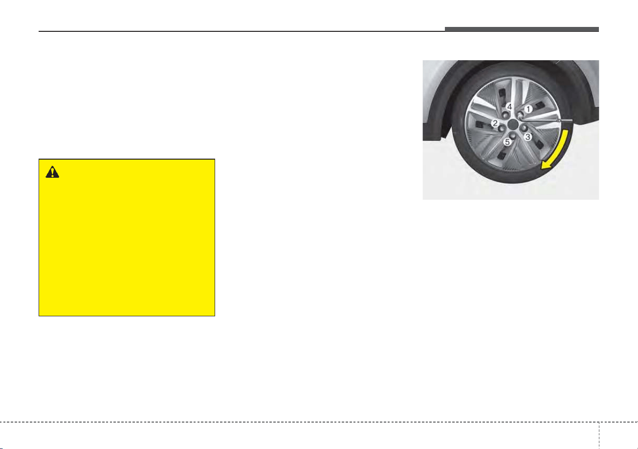
623
What to do in an emergency
Wheels may have sharp edges.
Handle them carefully to avoid possi-
ble severe injury. Before putting the
wheel into place, be sure that there
is nothing on the hub or wheel (such
as mud, tar, gravel, etc.) that pre-
vents the wheel from fitting solidly
against the hub.
10. To install the wheel, hold it on the
studs, put the wheel nuts on the
studs and tighten them finger
tight. Jiggle the tire to be sure it is
completely seated, then tighten
the nuts as much as possible
with your fingers again.
11. Insert the wrench into the jack
and lower the vehicle to the
ground by turning the wheel nut
wrench counterclockwise.
Position the wrench as shown in the
drawing and tighten the wheel nuts.
Be sure the socket is seated com-
pletely over the nut. Do not stand on
the wrench handle or use an exten-
sion pipe over the wrench handle. Go
around the wheel, tightening every
nut following the numerical sequence
shown in the image until they are all
tight. Double-check each nut for
tightness. After changing wheels,
have an authorized Kia dealer tight-
en the wheel nuts to their proper
torque as soon as possible.
WARNING - Installing a
wheel
Make sure the wheel makes
good contact with the hub when
installed. If the contact of the
mounting surface between the
wheel and hub is insufficient,
the wheel nuts could come
loose and cause the loss of a
wheel. Loss of a wheel may
result in loss of control of the
vehicle.
ODEP069029L
What to do in an emergency
246
Wheel nut tightening torque:
79~94 lbf·ft
(11~13 kgf·m, 107~127 N·m)
If you have a tire gauge, remove the
valve cap and check the air pressure.
If the pressure is lower than recom-
mended, drive slowly to the nearest
service station and inflate to the cor-
rect pressure. If it is too high, adjust
it until it is correct. Always reinstall
the valve cap after checking or
adjusting the tire pressure. If the cap
is not replaced, dust and dirt may get
into the tire valve and air may leak
from the tire. If you lose a valve cap,
buy another and install it as soon as
possible.
After you have changed the wheels,
always secure the flat tire in its place
and return the jack and tools to their
proper storage locations.
Note that most lug nuts do not have
metric threads. Be sure to use
extreme care in checking for thread
style before installing aftermarket lug
nuts or wheels. If in doubt, consult an
authorized Kia dealer.
To prevent the jack, wheel lug nut
wrench and spare tire from rattling
while the vehicle is in motion, store
them properly.
Check the inflation pressures as
soon as possible after installing the
spare tire. Adjust it to the specified
pressure, if necessary. Refer to
“Tires and wheels” in chapter 8.
CAUTION - Reusing lug
nuts
Make certain during wheel
removal that the same nuts that
were removed are reinstalled -
or, if replaced, that nuts with
metric threads and the same
chamfer configuration are used.
Your vehicle has metric threads
on the wheel studs and nuts.
Installation of a non-metric
thread nut on a metric stud will
not secure the wheel to the hub
properly and will damage the
stud so that it must be replaced.
WARNING - Wheel studs
If the studs are damaged, they
may lose their ability to retain
the wheel. This could lead to the
loss of the wheel and a collision
resulting in serious injuries.
625
What to do in an emergency
Important - use of compact spare
tire
Your vehicle is equipped with a com-
pact spare tire. This compact spare
tire takes up less space than a regu-
lar-size tire. This tire is smaller than a
conventional tire and is designed for
temporary use only.
• You should drive carefully when
the compact spare is in use. The
compact spare should be replaced
by the proper conventional tire and
rim at the first opportunity.
• The operation of this vehicle is not
recommended with more than one
compact spare tire in use at the
same time.
The compact spare should be inflat-
ed to 60 psi (420 kPa).
✽✽
NOTICE
Check the inflation pressure after
installing the spare tire. Adjust it to
the specified pressure, as necessary.
When using a compact spare tire,
observe the following precautions:
• Under no circumstances should
you exceed 50 mph (80 km/h); a
higher speed could damage the
tire.
• Ensure that you drive slowly
enough for the road conditions to
avoid all hazards. Any road hazard,
such as a pothole or debris, could
seriously damage the compact
spare.
• Any continuous road use of this tire
could result in tire failure, loss of
vehicle control, and possible per-
sonal injury.
• Do not exceed the vehicle’s maxi-
mum load rating or the load-carry-
ing capacity shown on the sidewall
of the compact spare tire.
WARNING - Spare tire
The compact spare tire is for
emergency use only. Do not
operate your vehicle on this
compact spare at speeds over
50 mph (80 km/h). The original
tire should be repaired or
replaced as soon as possible to
avoid failure of the spare, possi-
bly leading to personal injury or
death.

What to do in an emergency
266
• Avoid driving over obstacles. The
compact spare tire diameter is
smaller than the diameter of a con-
ventional tire and reduces the
ground clearance approximately 1
inch (25 mm), which could result in
damage to the vehicle.
• Do not take this vehicle through an
automatic vehicle wash while the
compact spare tire is installed.
• Do not use tire chains on the com-
pact spare tire. Because of the
smaller size, a tire chain will not fit
properly. This could damage the
vehicle and result in loss of the
chain.
• Do not use the compact spare tire
on any other vehicle because this
tire has been designed especially
for your vehicle.
• The compact spare tire’s tread life
is shorter than a regular tire.
Inspect your compact spare tire
regularly and replace worn com-
pact spare tires with the same size
and design, mounted on the same
wheel.
• The compact spare tire should not
be used on any other wheels, nor
should standard tires, snow tires,
wheel covers or trim rings be used
with the compact spare wheel. If
such use is attempted, damage to
these items or other vehicle com-
ponents may occur.
• Do not use more than one compact
spare tire at a time.
• Do not tow a trailer while the com-
pact spare tire is installed.
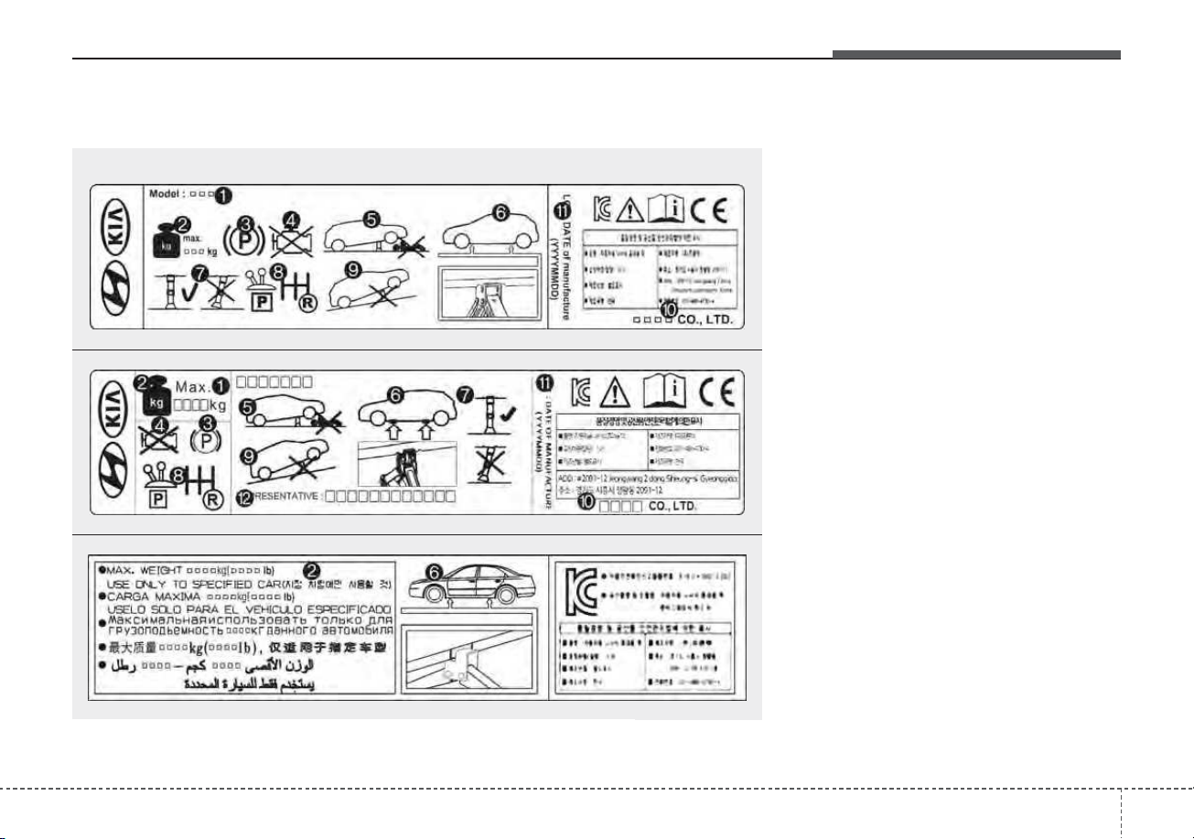
627
What to do in an emergency
Jack label
1. Model Name
2. Maximum allowable load
3. When using the jack, set your
parking brake.
4. When using the jack, stop the
engine.
5. Do not get under a vehicle that is
supported by a jack.
6. The designated locations under
the frame.
7. When supporting the vehicle, the
base plate of jack must be vertical
under the lifting point.
8. Move the shift lever to the P posi-
tion on vehicles with dual clutch
transmission.
9. The jack should be used on firm
level ground.
10. Jack manufacturer
11. Production date
12. Representative company and
address
OHYK064001
OHYK064005
OHYK064002
• Type A
■ Example
• Type B
• Type C
❈ The actual Jack label in the vehicle may differ from the illustration. For
more detailed specifications, refer to the label attached to the jack.
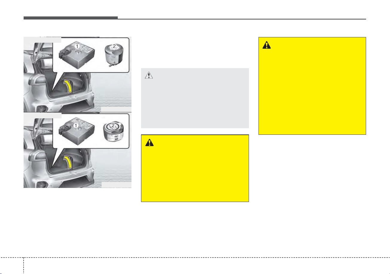
What to do in an emergency
286
IF YOU HAVE A FLAT TIRE (WITH TIRE MOBILITY KIT) (IF EQUIPPED)
For safe operation, carefully read
and follow the instructions in this
manual before use.
(1) Compressor
(2) Sealant bottle
The Tire Mobility Kit is a temporary
fix to the tire and the tire should be
inspected by an authorized Kia deal-
er as soon as possible.
Have your tire repaired as soon as
possible. The tire may loose air pres-
sure at any time after inflating with
the Tire Mobility Kit.
ODEP069004
ODEP069020
■ for 18 inch tire
■ for 16 inch tire
WARNING - Tire wall
Do not use the Tire Mobility Kit
to repair large punctures or
damage to the tire sidewalls. In
these situations, the tire cannot
be sealed completely and air
will leak from the tire. This can
result in tire failure.
CAUTION
When two or more tires are flat,
do not use the tire mobility kit
because the one supplied canis-
ter of sealant in the Tire Mobility
Kit is to only enough sealant for
one flat tire.
WARNING
-
Speed with temporary fix
Do not exceed a speed of 50
mph (80 km/h) when driving
with a tire sealed with the Tire
Mobility Kit.
While driving, if you experience
any unusual vibration, ride dis-
turbance, or noise, reduce your
speed and drive with caution
until you can safely pull off to
the side of the road.
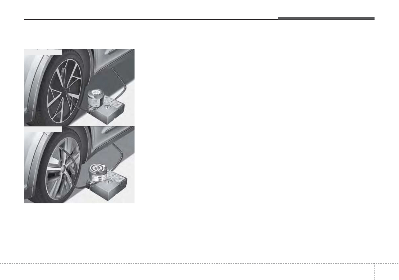
629
What to do in an emergency
Introduction
With the Tire Mobility Kit you stay
mobile even after experiencing a tire
puncture.
The system of compressor and seal-
ing compound effectively and com-
fortably seals most punctures in a
passenger car tire caused by nails or
similar objects and reinflates the tire.
After you ensured that the tire is prop-
erly sealed you can drive cautiously
on the tire (up to 120 miles (200 km))
at a max. speed of 50 mph (80 km/h)
in order to reach a service station or
tire dealer to have the tire replace-
ment.
It is possible that some tires, espe-
cially with larger punctures or damage
to the sidewall, cannot be sealed
completely.
Air pressure loss in the tire may
adversely affect tire performance.
For this reason, you should avoid
abrupt steering or other driving
maneuvers, especially if the vehicle is
heavily loaded or if a trailer is in use.
The Tire Mobility Kit is not designed
or intended as a permanent tire
repair method and is to be used for
one tire only.
This instruction shows you step by
step procedure to temporarily seal
the puncture.
Read the section “Notes on the safe
use of the Tire Mobility Kit”.
ODEP069005
ODEP069021
■ for 18 inch tire
■ for 16 inch tire
What to do in an emergency
306
Notes on the safe use of the
Tire Mobility Kit
• Park your car at the side of the
road so that you can work with the
Tire Mobility Kit away from moving
traffic.
• To be sure your vehicle will not
move, even when you're on fairly
level ground, always set your park-
ing brake.
• Only use the Tire Mobility Kit for
sealing/inflation passenger car
tires. Only punctured areas located
within the tread region of the tire
can be sealed using the Tire
Mobility Kit.
• Do not use on motorcycles, bicy-
cles or any other type of tires.
• When the tire and wheel are dam-
aged, do not use Tire Mobility Kit
for your safety.
• Use of the Tire Mobility Kit may not
be effective for tire damage larger
than approximately 0.16 in. (4
mm).
Please contact the nearest Kia
dealership if the tire cannot be
made roadworthy with the Tire
Mobility Kit.
• Do not use the Tire Mobility Kit if a
tire is severely damaged by driving
run flat or with insufficient air pres-
sure.
• Do not remove any foreign objects
such as nails or screws that have
penetrated the tire.
• Provided the car is outdoors, leave
the engine running. Otherwise
operating the compressor may
eventually drain the car battery.
• Never leave the Tire Mobility Kit
unattended while it is being used.
• Do not leave the compressor run-
ning for more than 10 min. at a time
or it may overheat.
• Do not use the Tire Mobility Kit if
the ambient temperature is below -
22°F (-30°C).
WARNING
Do not use the Tire sealant after
the sealant has expired (i.e.
past the expiration date on the
sealant container). This can
increase the risk of tire failure.
CAUTION
When repairing a flat tire with
the Tire Mobility Kit (TMK),
quickly remove the sealant on
the tire pressure sensor and
wheel. When installing the
repaired tire and wheel, tighten
the wheel nut to a torque value
of 11 ~ 13 kgf·m.
WARNING - Sealant
• Keep out of reach of children.
• Avoid contact with eyes.
• Do not swallow.
631
What to do in an emergency
✽✽
NOTICE
The sealant container and insert
hose (3) cannot be reused. Purchase
an extra after use.
WARNING
• If the sealant gets on your
skin, wash it with a large
amount of water. If skin irrita-
tion continues, seek medical
attention.
• If the sealant gets into your
eyes, raise your eyelid and
wash for at least 15 minutes. If
eye irritation continues, seek
medical attention.
• If you have ingested the
sealant, wash your mouth and
drink a large amount of water.
However, do not give anything
to an unconscious person and
see the doctor immediately.
Exposure to the sealant for a
long time may cause damage
to your body.
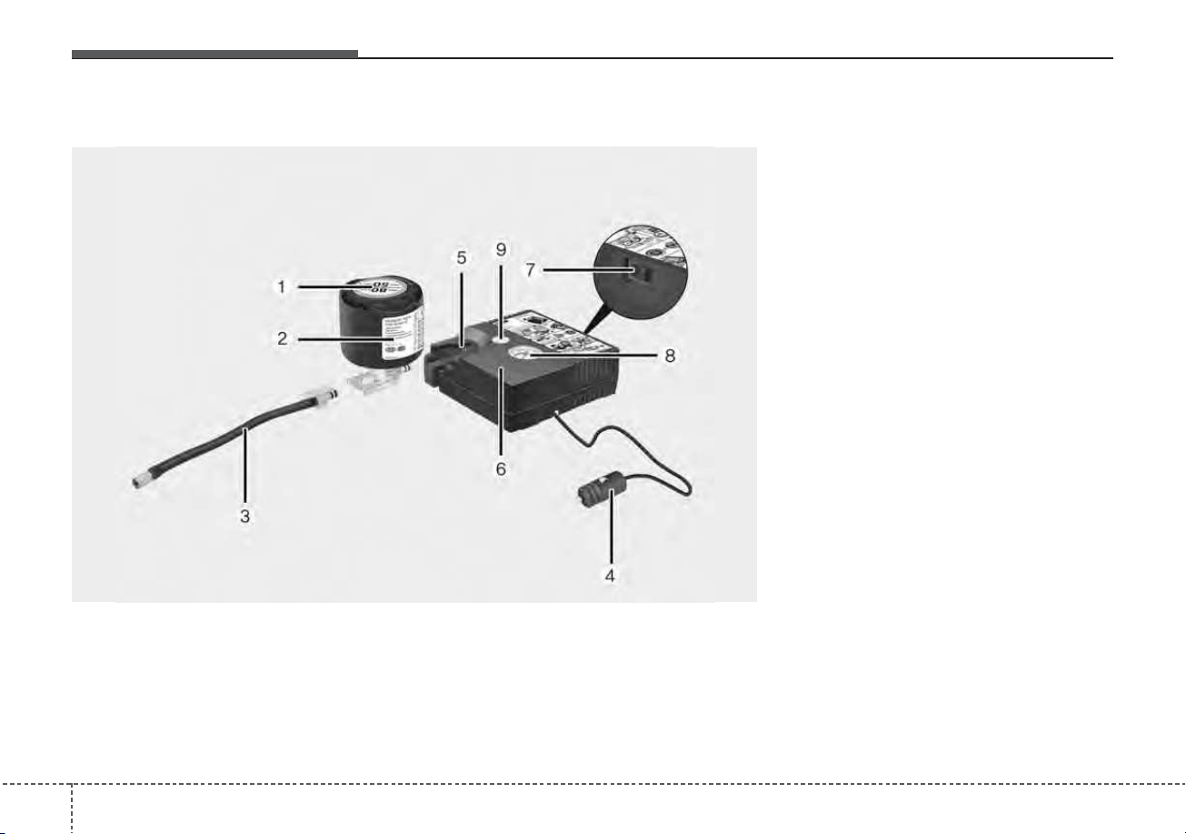
What to do in an emergency
326
1. Speed restriction label
2. Sealant bottle and label with
speed restriction
3. Filling hose from sealant bottle to
wheel
4. Connectors and cable for the
power outlet direct connection
5. Holder for the sealant bottle
6. Compressor
7. On/off switch
8. Pressure gauge for displaying the
tire inflation pressure
9. Button for reducing tire inflation
pressure
Connectors, cable and connection
hose are stored in the compressor
housing.
Components of the Tire Mobility Kit
ODE067044
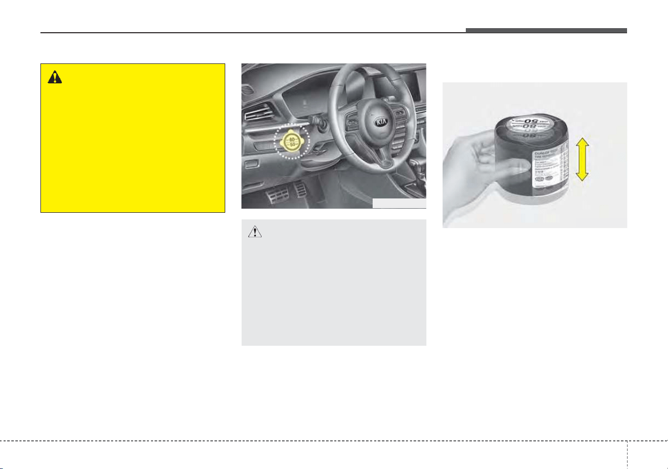
633
What to do in an emergency
Using the Tire Mobility Kit
Carefully follow below steps.
1. Shake the sealant bottle.
ODEP069006
ODEP067048
WARNING
Before using the Tire Mobility
Kit, follow the instructions on
the sealant bottle.
Remove the label with the
speed restriction from the
sealant bottle and apply it to the
steering wheel.
Please note the expiration date
on the sealant bottle.
CAUTION
Before using the tire repair kit,
please read carefully the
instruction attached on the
sealant bottle. Detach the speed
limit label on the sealant case
and put it on a highly visible
place. Always drive within the
speed limit.
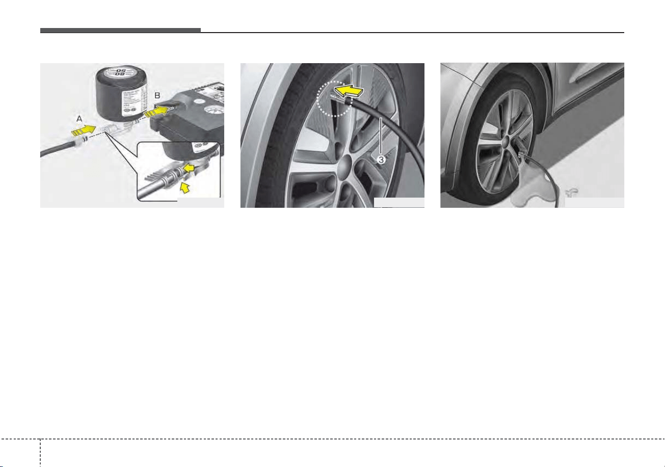
What to do in an emergency
346
2. Connect the filling hose (3) onto
the connector of the sealant bottle
(A).
3. Ensure that button (9) on the com-
pressor is not pressed.
4. Unscrew the valve cap from the
valve of the defective wheel and
screw filling hose (3) of the sealant
bottle onto the valve.
5. Insert the sealant bottle into the
housing of the compressor (5) so
that the bottle is upright.
✽✽
NOTICE
If a visable foreign object has punc-
tured the tire, do not remove it
before using Tire Mobility Kit.
✽
✽
NOTICE
If the sealant is injected when the
tire air pressure injection valve and
sealant injection hose are not fully
interlocked, the sealant may over-
flow and clog the valve.
ODEP069007OKIA067011 ODEP069041N
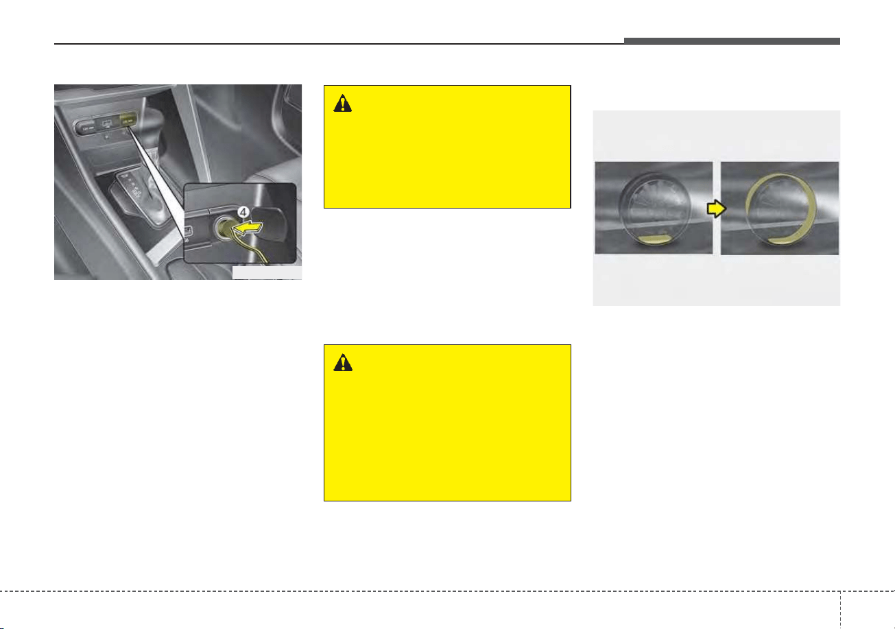
635
What to do in an emergency
6. Ensure that the compressor is
switched off, position 0.
7. Connect between compressor and
the vehicle power outlet using the
cable and connectors (4).
8. With the engine start/stop button
position on or ignition switch posi-
tion on, switch on the compressor
and let it run for approximately 5 ~
7 minutes to fill the sealant up to
cold tire recommended pressure.
(Refer to “Tires and wheels” in
chapter 8.). Be careful not to over-
inflate the tire and stay away from
the tire when filling it. When the tire
and wheel are damaged, do not
use Tire Mobility Kit for your safety.
9. Switch off the compressor.
10. Detach the hoses from the
sealant bottle connector and
from the tire valve.
Return the Tire Mobility Kit to its stor-
age location in the vehicle.
Distributing the sealant
11. Immediately drive approximately
4 ~ 6 miles (7 ~ 10 km or, about
10 min) to evenly distribute the
sealant in the tire.
Do not exceed a speed of 50 mph
(80 km/h). If possible, do not fall
below a speed of 12 mph (20 km/h).
While driving, if you experience any
unusual vibration, ride disturbance or
noise, reduce your speed and drive
with caution until you can safely pull
off of the side of the road.
ODEP069008
WARNING - Carbon
monoxide
Carbon monoxide poisoning
and suffocation is possible if
the engine is left running in a
poorly ventilated or unventilat-
ed location (such as inside a
building).
ODE066040N
WARNING - Tire pressure
Do not attempt to drive your
vehicle if the tire pressure is
below 29 psi (200 kPa). This
could result in an accident due
to sudden tire failure.
What to do in an emergency
366
Checking the tire inflation
pressure
1. After driving approximately 4 ~ 6
miles (7 ~ 10 km or about 10 min),
stop at a safe location.
2. Connect the filling hose (3) of the
compressor (clip mounted side)
directly and then connect the fill
ing hose (3) (opposite side) to the
tire valve.
3. Connect between compressor and
the vehicle power outlet using the
cable and connectors.
4. Adjust the tire inflation pressure to
the cold tire recommended pres-
sure as indicated on the vehicle’s
placard or tire inflation pressure
label located on the driver’s side
center pillar outer panel. (Refer to
“Tires and wheels” in chapter 8.)
- To increase the inflation pres-
sure : Switch on the compres-
sor, position I. To check the cur-
rent inflation pressure setting,
briefly switch off the compressor.
✽✽
NOTICE
The pressure gauge may show high-
er than actual reading when the
compressor is running. To get an
accurate tire reading, the compres-
sor needs to be turned off.
CAUTION
When you use the Tire Mobility
Kit, the tire pressure sensors
and wheel may be stained by
sealant. Therefore, remove the
tire pressure sensors and wheel
stained by sealant and have
your vehicle inspected by an
authorized Kia dealer.
WARNING
Do not let the compressor run
for more than 10 minutes; other-
wise, the device may overheat
and be damaged.

637
What to do in an emergency
- To reduce the inflation pres-
sure: Press the button (9) on the
compressor.
CAUTION - Tire pressure
sensor
When you use the Tire Mobility
Kit with sealant not approved by
Kia, the tire pressure sensors
may be damaged by sealant.The
sealant on the tire pressure sen-
sor and wheel should be
removed when you replace the
tire with a new one and inspect
the tire pressure sensors at an
authorized dealer.

Technical Data
18 inch tire 16 inch tire
System Voltage DC 12 V DC 12 V
Working Voltage DC 10 – 15 V DC 10 – 15 V
Amperage rating
MAX. 10 ± 1 A
(at DC 12V operation)
MAX. 10 ± 1 A
(at DC 12V operation)
Suitable for use at temperatures
- 22 ~ + 158 °F
(- 30 ~ + 70 °C)
- 22 ~ + 158 °F
(- 30 ~ + 70 °C)
Max. working pressure 87 psi (6 bar) 87 psi (6 bar)
Size
Compressor
6.3 X 5.9 X 2.2 in.
(161 X 150 X 55.8 mm)
6.3 X 5.9 X 2.2 in.
(161 X 150 X 55.8 mm)
Sealant bottle
ø 3.3 X 4.1 in.
(ø 85 X 104 mm)
ø 3.3 X 3.2 in.
(ø 85 X 81 mm)
Compressor weight
1.43 ± 0.07 lbs
(650 ± 30 g)
1.43 ± 0.07 lbs
(650 ± 30 g)
Sealant volume 18.3 cu. in (300 ml) 12.2 cu. in. (200 ml)
❈ Sealant and spare parts can be obtained and replaced at an authorized vehicle or tire
dealer. Empty sealant bottles may be disposed of at home. Liquid residue from the
sealant should be disposed of by your vehicle or tire dealer or in accordance with local
waste disposal regulations.
638
What to do in an emergency
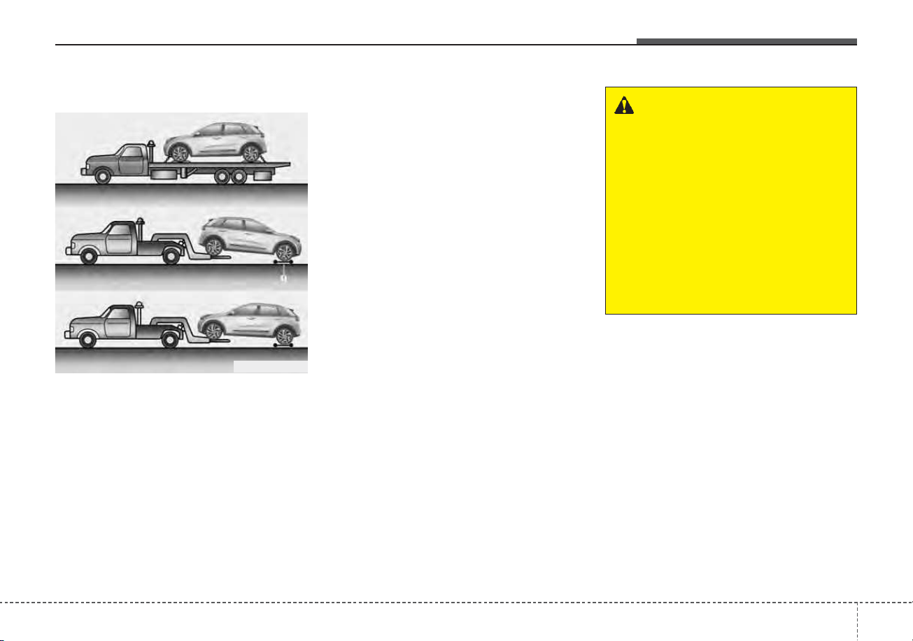
TOWING
Towing service
If emergency towing is necessary,
we recommend having it done by an
authorized Kia dealer or a commer-
cial tow-truck service. Proper lifting
and towing procedures are neces-
sary to prevent damage to the vehi-
cle. The use of wheel dollies (1) or
flatbed is recommended.
On FWD vehicles, it is acceptable to
tow the vehicle with the rear wheels
on the ground (without dollies) and
the front wheels off the ground. If any
of the loaded wheels or suspension
components are damaged or the
vehicle is being towed with the front
wheels on the ground, use a towing
dolly under the front wheels. When
being towed by a commercial tow
truck and wheel dollies are not used,
the front of the vehicle should always
be lifted, not the rear.
WARNING - Side and
curtain Air bag
If your vehicle is equipped with
side and curtain air bag, set the
ignition switch to LOCK or ACC
position when the vehicle is
being towed.
The side and curtain air bag
may deploy when the ignition is
ON, and the rollover sensor
detects the situation as a
rollover.
ODE066010L
What to do in an emergency
396
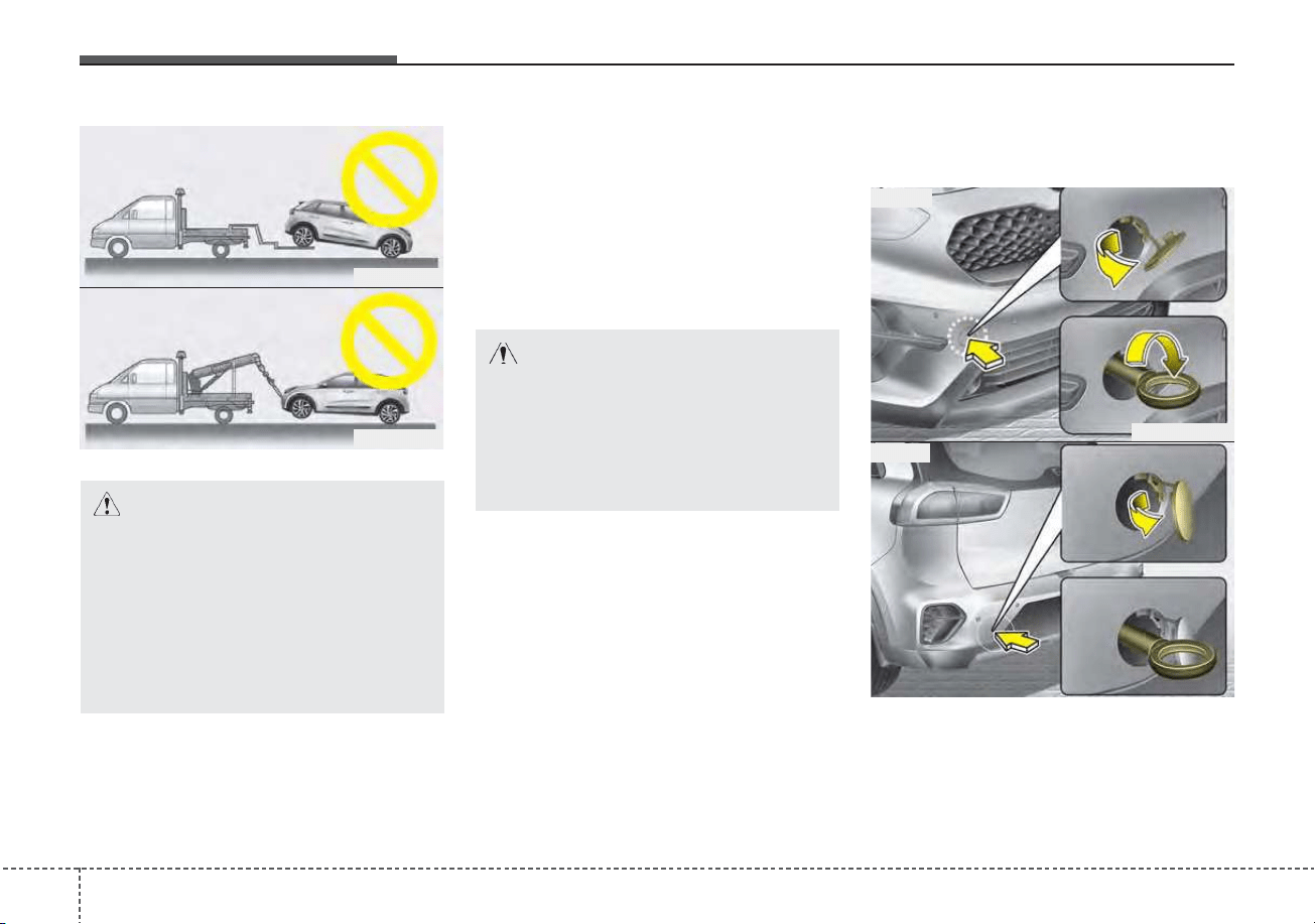
When towing your vehicle in an
emergency without wheel dollies :
1. Set the ignition switch in the ACC
position.
2. Place the transmission shift lever
in N (Neutral).
3. Release the parking brake.
Removable towing hook
(if equipped)
1. Open the liftgate, and remove the
towing hook from the tool case.
2. Remove the hole cover pressing
the lower part of the cover on the
bumper.
CAUTION - Towing gear
position
Failure to place the transmis-
sion shift lever in N (Neutral)
may cause internal damage to
the transmission.
CAUTION - Towing
• Do not tow the vehicle back-
wards with the front wheels on
the ground as this may cause
damage to the vehicle.
• Do not tow with sling-type
equipment. Use wheel lift or
flatbed equipment.
ODE066012
ODE066011
ODEP069014
ODEP069015
■ Front
■ Rear
640
What to do in an emergency
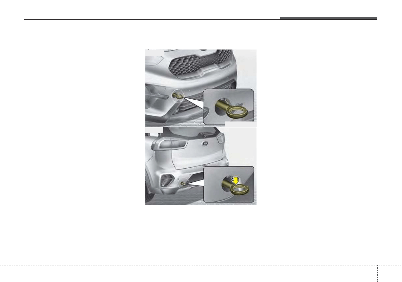
3. Install the towing hook by turning it
clockwise into the hole until it is
fully secured.
4. Remove the towing hook and
install the cover after use.
Emergency towing
If towing is necessary, have it
done by an authorized Kia dealer
or a commercial tow truck service.
If towing service is not available in an
emergency, your vehicle may be
temporarily towed using a cable or
chain secured to the emergency tow-
ing hook under the front (or rear) of
the vehicle. Use extreme caution
when towing the vehicle. A driver
must be in the vehicle to steer it and
operate the brakes.
Towing in this manner may be done
only on hard-surfaced roads for a
short distance and at low speed.
Also, the wheels, axles, power train,
steering and brakes must all be in
good condition.
• Do not use the tow hooks to pull a
vehicle out of mud, sand or other
conditions from which the vehicle
cannot be driven out under its own
power.
• Avoid towing a vehicle heavier than
the vehicle doing the towing.
• The drivers of both vehicles should
communicate with each other fre-
quently.
ODEP069016
ODEP069017
■ Front
■ Rear
What to do in an emergency
416
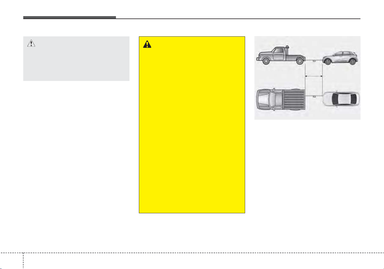
• Attach a towing strap to the tow
hook.
• Use only a cable or chain specifical-
ly intended for use in towing vehi-
cles. Securely fasten the cable or
chain to the towing hook provided.
• Accelerate or decelerate the vehicle
in a slow and gradual manner while
maintaining tension on the tow rope
or chain to start or drive the vehicle,
otherwise tow hooks and the vehi-
cle may be damaged.
• Before emergency towing, check if
the hook is not broken or damaged.
• Fasten the towing cable or chain
securely to the hook.
• Do not jerk the hook. Apply it
steadily and with even force.
• To avoid damaging the hook, do not
pull from the side or at a vertical
angle. Always pull straight ahead.
• Use a towing strap less than 16
feet (5 m) long. Attach a white or
red cloth (about 12 inches (30 cm)
wide) in the middle of the strap for
easy visibility.
• Drive carefully so that the towing
strap is not loosened during tow-
ing.
• The driver must be in the vehicle
for steering and braking operations
when the vehicle is towed and pas-
sengers other than the driver must
not be allowed to be on board.
CAUTION
Using a portion of the vehicle
other than the tow hooks for
towing may damage the body of
your vehicle.
WARNING - Emergency
Towing Precautions
Use extreme caution when tow-
ing the vehicle.
• Avoid sudden starts or erratic
driving maneuvers which
would place excessive stress
on the emergency towing hook
and towing cable or chain. The
hook and towing cable or
chain may break and cause
serious injury or damage.
• If the disabled vehicle is
unable to be moved, do not
forcibly continue the towing.
We recommend that you con-
tact an authorized Kia dealer
or a commercial tow truck
service for assistance.
• Tow the vehicle as straight
ahead as possible.
• Keep away from the vehicle
during towing.
ODE066018
642
What to do in an emergency
Emergency towing precautions
• Turn the ignition switch to ACC so
the steering wheel isn’t locked.
• Place the transmission shift lever in
N (Neutral).
• Release the parking bake.
• Press the brake pedal with more
force than normal since you will
have reduced brake performance.
• More steering effort will be
required because the power steer-
ing system will be disabled.
• If you are driving down a long hill,
the brakes may overheat and brake
performance will be reduced. Stop
often and let the brakes cool off.
• The vehicle should be towed at a
speed of 15 mph (25 km/h) or less
within the distance of 12 miles (20
km).
• If the car is being towed with all
four wheels on the ground, it can
be towed only from the front. Be
sure that the transmission is in N
(Neutral). Be sure the steering is
unlocked by placing the ignition
switch in the ACC position. A driver
must be in the towed vehicle to
operate the steering and brakes.
CAUTION - Dual clutch
transmission
• To avoid serious damage to the
dual clutch transmission, limit
the vehicle speed to 10 mph
(15 km/h) and drive less than 1
mile (1.5 km) when towing.
• Before towing, check the dual
clutch transmission for fluid
leaks under your vehicle. If the
dual clutch transmission fluid
is leaking, flatbed equipment
or a towing dolly must be
used.
What to do in an emergency
436
IF AN ACCIDENT OCCURS
✽✽
NOTICE
Any gas or electrolyte leakage from
your vehicle is not only poisonous but
also flammable. Upon witnessing one
of those, make sure your car is parked
in a safe area away from any roads,
open the windows, and maintain a
safe distance away from the vehicle.
Immediately contact an authorized
Kia dealer and advise them that a
hybrid vehicle is involved.
• If you need towing, refer to
"Towing" in the previous pages.
• When the vehicle is severely dam-
aged, remain a safe distance of 50
feet (15 meter) or more between
your vehicle and other
vehicles/flammables.
If a fire occurs :
Immediately call emergency services
(911) and advise the emergency
responders that a hybrid vehicle is
involved.
WARNING - High voltage
components
• For your safety, do not touch
high voltage cables, connec-
tors and package modules.
High voltage components are
orange in color.
• Exposed cables or wires may
be visible inside or outside of
the vehicle. Never touch the
wires or cables, because an
electric shock, serious injury,
or death may occur.
WARNING - Submersion
in water
Do not touch your vehicle if it
has been submerged in water.
The high-voltage battery may
cause shock or may catch fire.
Immediately contact the author-
ities and advise them of the
condition of your vehicle and
that a hybrid vehicle is involved.
644
What to do in an emergency

Maintenance
7
Engine compartment . . . . . . . . . . . . . . . . . . . . . . . . 7-4
Maintenance services . . . . . . . . . . . . . . . . . . . . . . . . 7-5
• Owner’s responsibility . . . . . . . . . . . . . . . . . . . . . . . . . 7-5
• Owner maintenance precautions . . . . . . . . . . . . . . . . . 7-6
Owner maintenance . . . . . . . . . . . . . . . . . . . . . . . . . 7-7
• Owner maintenance schedule . . . . . . . . . . . . . . . . . . . 7-7
Scheduled maintenance service. . . . . . . . . . . . . . . . 7-9
Explanation of scheduled maintenance items . . . 7-15
Checking fluid levels . . . . . . . . . . . . . . . . . . . . . . . 7-18
Engine oil. . . . . . . . . . . . . . . . . . . . . . . . . . . . . . . . . 7-19
• Checking the engine oil level . . . . . . . . . . . . . . . . . . . 7-19
• Changing the engine oil and filter . . . . . . . . . . . . . . . 7-20
Coolant . . . . . . . . . . . . . . . . . . . . . . . . . . . . . . . . . . 7-21
• Checking the coolant level . . . . . . . . . . . . . . . . . . . . . 7-21
• Engine coolant . . . . . . . . . . . . . . . . . . . . . . . . . . . . . . 7-22
• Inverter coolant . . . . . . . . . . . . . . . . . . . . . . . . . . . . . . 7-22
• Recommended coolant . . . . . . . . . . . . . . . . . . . . . . . . 7-23
• Changing the coolant . . . . . . . . . . . . . . . . . . . . . . . . . 7-25
Brake fluid . . . . . . . . . . . . . . . . . . . . . . . . . . . . . . . 7-26
• Checking the brake fluid level . . . . . . . . . . . . . . . . . . 7-26
Engine clutch actuator fluid . . . . . . . . . . . . . . . . . 7-28
• Checking the engine clutch actuator fluid level . . . . 7-28
Washer fluid . . . . . . . . . . . . . . . . . . . . . . . . . . . . . . 7-30
• Checking the washer fluid level . . . . . . . . . . . . . . . . . 7-30
Parking brake . . . . . . . . . . . . . . . . . . . . . . . . . . . . . 7-31
• Checking the parking brake. . . . . . . . . . . . . . . . . . . . 7-31
Air cleaner. . . . . . . . . . . . . . . . . . . . . . . . . . . . . . . . 7-32
• Filter replacement . . . . . . . . . . . . . . . . . . . . . . . . . . . . 7-32
Climate control air filter . . . . . . . . . . . . . . . . . . . . 7-34
• Filter inspection . . . . . . . . . . . . . . . . . . . . . . . . . . . . . . 7-34
Wiper blades . . . . . . . . . . . . . . . . . . . . . . . . . . . . . . 7-36
• Blade inspection. . . . . . . . . . . . . . . . . . . . . . . . . . . . . . 7-36
• Blade replacement . . . . . . . . . . . . . . . . . . . . . . . . . . . . 7-36
Battery (Plug-in Hybrid) . . . . . . . . . . . . . . . . . . . . 7-39
• For best battery service . . . . . . . . . . . . . . . . . . . . . . . 7-39
• Recharging the battery . . . . . . . . . . . . . . . . . . . . . . . . 7-40
• Reset items . . . . . . . . . . . . . . . . . . . . . . . . . . . . . . . . . . 7-41
Tires and wheels . . . . . . . . . . . . . . . . . . . . . . . . . . . 7-42
• Tire care . . . . . . . . . . . . . . . . . . . . . . . . . . . . . . . . . . . . 7-42
• Recommended cold tire inflation pressures . . . . . . . 7-42
• Tire pressure . . . . . . . . . . . . . . . . . . . . . . . . . . . . . . . . 7-43
• Checking tire inflation pressure. . . . . . . . . . . . . . . . . 7-43
• Tire rotation. . . . . . . . . . . . . . . . . . . . . . . . . . . . . . . . . 7-44
• Wheel alignment and tire balance . . . . . . . . . . . . . . . 7-45
• Tire replacement . . . . . . . . . . . . . . . . . . . . . . . . . . . . . 7-46
• Wheel replacement . . . . . . . . . . . . . . . . . . . . . . . . . . . 7-46
• Tire traction . . . . . . . . . . . . . . . . . . . . . . . . . . . . . . . . . 7-47
• Tire maintenance . . . . . . . . . . . . . . . . . . . . . . . . . . . . 7-47
• Tire sidewall labeling . . . . . . . . . . . . . . . . . . . . . . . . . 7-47

• Tire terminology and definitions . . . . . . . . . . . . . . . . 7-51
• All season tires . . . . . . . . . . . . . . . . . . . . . . . . . . . . . . 7-54
• Summer tires . . . . . . . . . . . . . . . . . . . . . . . . . . . . . . . . 7-54
• Snow tires . . . . . . . . . . . . . . . . . . . . . . . . . . . . . . . . . . . 7-55
• Tire chains . . . . . . . . . . . . . . . . . . . . . . . . . . . . . . . . . . 7-55
• Radial-ply tires . . . . . . . . . . . . . . . . . . . . . . . . . . . . . . 7-55
• Low aspect ratio tire . . . . . . . . . . . . . . . . . . . . . . . . . . 7-56
Fuses . . . . . . . . . . . . . . . . . . . . . . . . . . . . . . . . . . . . 7-58
• Inner panel fuse replacement. . . . . . . . . . . . . . . . . . . 7-59
• Engine compartment fuse replacement. . . . . . . . . . . 7-61
• Fuse/relay panel description. . . . . . . . . . . . . . . . . . . . 7-64
Light bulbs . . . . . . . . . . . . . . . . . . . . . . . . . . . . . . . 7-86
• Bulb replacement precaution . . . . . . . . . . . . . . . . . . 7-86
• Light bulb position (Front). . . . . . . . . . . . . . . . . . . . . 7-87
• Light bulb position (Rear) . . . . . . . . . . . . . . . . . . . . . 7-88
• Light bulb position (Side) . . . . . . . . . . . . . . . . . . . . . . 7-89
• Headlamp (High/Low beam) (Bulb type) bulb
replacement (Headlamp type A) . . . . . . . . . . . . . . . 7-90
• Front turn signal lamp (Bulb type) bulb
replacement (Headlamp type A) . . . . . . . . . . . . . . . 7-91
• Front side marker (Bulb type) bulb replacement
(Headlamp type A) . . . . . . . . . . . . . . . . . . . . . . . . . . 7-92
• Headlamp (High/Low beam) (LED type) bulb
replacement (Headlamp type B) . . . . . . . . . . . . . . . 7-92
• Front turn signal (LED type) bulb replacement
(Headlamp type B) . . . . . . . . . . . . . . . . . . . . . . . . . . 7-93
• Front side marker (LED type) bulb replacement
(Headlamp type B) . . . . . . . . . . . . . . . . . . . . . . . . . . 7-93
• Daytime running lamp/Position lamp (LED type)
bulb replacement. . . . . . . . . . . . . . . . . . . . . . . . . . . . 7-93
• Front fog lamp (Bulb/LED type) bulb
replacement . . . . . . . . . . . . . . . . . . . . . . . . . . . . . . . . 7-94
• Stop and tail lamp, Rear turn signal lamp
(Bulb type) bulb replacement . . . . . . . . . . . . . . . . . 7-94
• Tail lamp (inside) (Bulb type) bulb replacement . . . 7-95
• Rear side marker (Bulb type) bulb replacement . . . 7-96
• Stop and tail lamp (LED type) bulb replacement . . 7-98
• Rear side marker (LED type) bulb replacement . . . 7-98
• Back-up lamp (Bulb type) bulb replacement . . . . . . 7-98
• License plate lamp (Bulb type) bulb replacement . . 7-99
• High mounted stop lamp (LED type) bulb
replacement . . . . . . . . . . . . . . . . . . . . . . . . . . . . . . . . 7-99
• Side repeater lamp (LED type) bulb replacement. . 7-100
• Map lamp (Bulb type) bulb replacement . . . . . . . . 7-100
• Map lamp (LED type) bulb replacement . . . . . . . . 7-101
• Vanity mirror lamp (Bulb type) bulb replacement. . 7-101
• Room lamp (Bulb type) bulb replacement . . . . . . . 7-102
• Room lamp (LED type) bulb replacement . . . . . . . 7-102
• Liftgate room lamp (Bulb type) bulb replacement. . 7-103
7

• Liftgate room lamp (LED type) bulb replacement. . 7-103
Appearance care. . . . . . . . . . . . . . . . . . . . . . . . . . 7-104
• Exterior care . . . . . . . . . . . . . . . . . . . . . . . . . . . . . . . 7-104
• Interior care . . . . . . . . . . . . . . . . . . . . . . . . . . . . . . . . 7-110
Emission control system. . . . . . . . . . . . . . . . . . . . 7-114
• Crankcase emission control system . . . . . . . . . . . . . 7-114
• Evaporative emission control (including ORVR:
Onboard Refueling Vapor Recovery) system . . . . 7-114
• Exhaust emission control system . . . . . . . . . . . . . . . 7-115
California perchlorate notice . . . . . . . . . . . . . . . 7-117
7
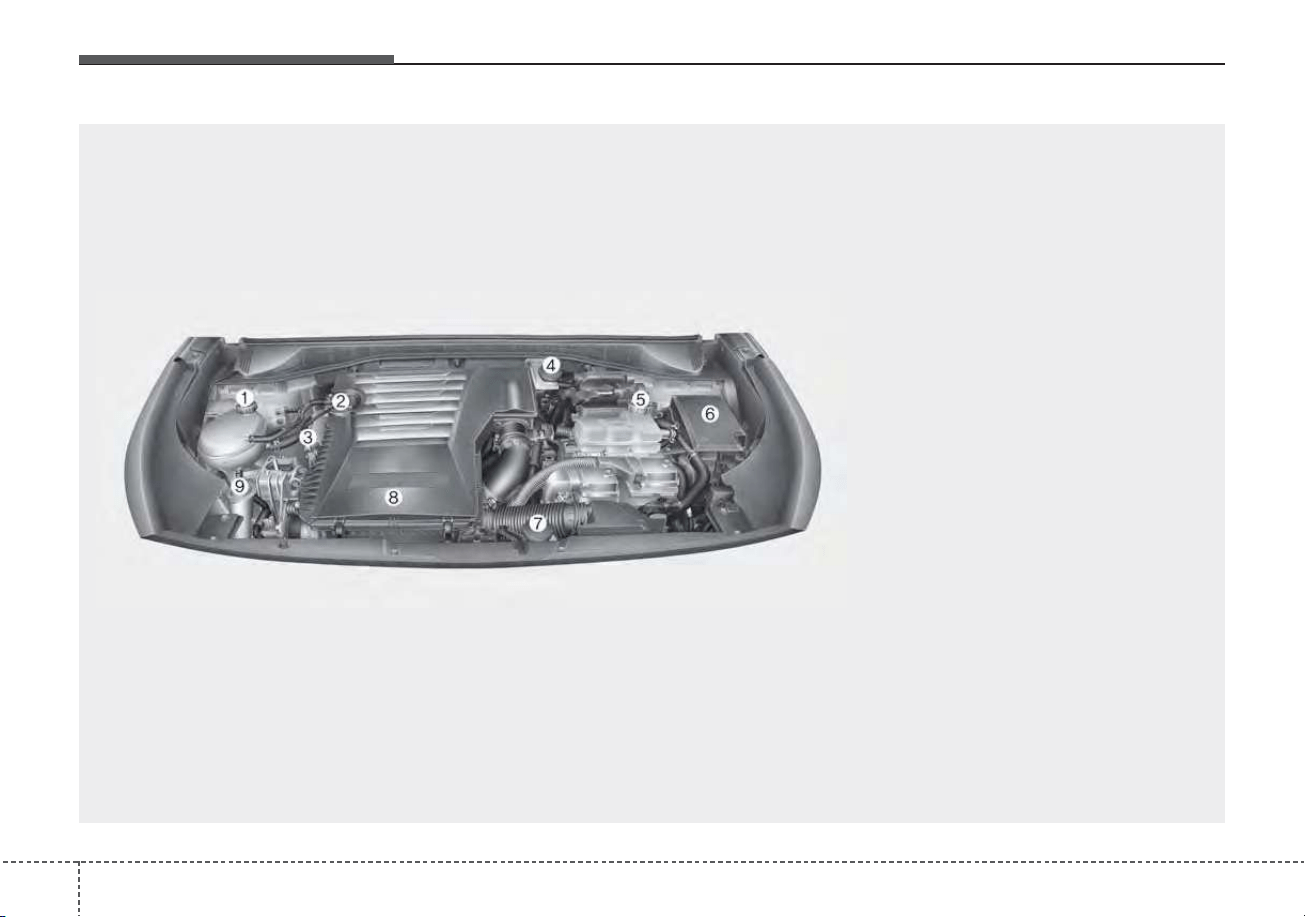
Maintenance
47
ENGINE COMPARTMENT
ODEP079115
■■
Gasoline engine (Kappa 1.6L GDI)
❈ The actual engine room in the vehicle may differ from the illustration.
1. Engine coolant reservoir
2. Engine oil filler cap
3. Engine oil dipstick
4. Brake fluid reservoir
5. Inverter coolant reservoir
6. Fuse box
7. Engine clutch actuator reservoir tank
8. Air cleaner
9. Windshield washer fluid reservoir

75
Maintenance
MAINTENANCE SERVICES
You should exercise the utmost care
to prevent damage to your vehicle
and injury to yourself whenever per-
forming any maintenance or inspec-
tion procedures.
Should you have any doubts con-
cerning the inspection or servicing of
your vehicle, we strongly recom-
mend that you have an authorized
Kia dealer perform this work.
An authorized Kia dealer has factory-
trained technicians and genuine Kia
parts to service your vehicle proper-
ly. For expert advice and quality serv-
ice, see an authorized Kia dealer.
Inadequate, incomplete or insuffi-
cient servicing may result in opera-
tional problems with your vehicle that
could lead to vehicle damage, an
accident, or personal injury.
Owner’s responsibility
✽✽
NOTICE
Maintenance Service and Record
Retention are the owner's responsi-
bility.
You should retain documents that
show proper maintenance has been
performed on your vehicle in accor-
dance with the scheduled mainte-
nance service charts shown on the
following pages. You need this infor-
mation to establish your compliance
with the servicing and maintenance
requirements of your vehicle war-
ranties.
Detailed warranty information is
provided in your Warranty &
Consumer Information manual.
Repairs and adjustments required as
a result of improper maintenance or
a lack of required maintenance are
not covered.
We recommend you have your vehi-
cle maintained and repaired by an
authorized Kia dealer. An authorized
Kia dealer meets Kia’s high service
quality standards and receives tech-
nical support from Kia in order to pro-
vide you with a high level of service
satisfaction.
✽✽
NOTICE - NHTSA Safety
Corrosion Alert
The National Highway Traffic
Safety Administration (NHTSA) has
issued a general warning to all vehi-
cle owners of all brands regarding
the risks associated with vehicle
underbody corrosion. From your
initial purchase, take the following
steps to prevent unsafe corrosion
damage to your vehicle:
(Continued)
Maintenance
67
(Continued)
• Wash the undercarriage of your
vehicle regularly during the win-
ter and whenever your vehicle has
been exposed to such salts or
chemicals.
• Do a thorough washing of the
undercarriage at the end of the
winter.
• Use professional service techni-
cians or governmental inspection
stations to annually inspect for
corrosion.
• Immediately seek an inspection of
your vehicle if you become visual-
ly aware of corrosion flaking or
scaling or if you become aware of
a change in vehicle performance,
such as soft or spongy brakes, flu-
ids leaking, impairment of direc-
tional control, suspension noises
or rattling metal straps.
NHTSA further advises that after
a vehicle is 7 years old, it is essen-
tial that you take these indicated
maintenance steps to ensure that
you protect yourself from unsafe
corrosion conditions.
Owner maintenance precau-
tions
Improper or incomplete service may
result in problems. This section gives
instructions only for the maintenance
items that are easy to perform.
As explained earlier in this section,
several procedures can be done only
by an authorized Kia dealer with spe-
cial tools.
✽✽
NOTICE
Improper owner maintenance dur-
ing the warranty period may affect
warranty coverage. For details, read
the separate Warranty & Consumer
Information manual provided with
the vehicle. If you're unsure about
any servicing or maintenance proce-
dure, have it done by an authorized
Kia dealer.
WARNING - Maintenance
work
Do not wear jewelry or loose
clothing while working under
the hood of your vehicle with
the engine running. These can
become entangled in moving
parts, if you must run the
engine while working under the
hood, make certain that you
remove all jewelry (especially
rings, bracelets, watches, and
necklaces) and all neckties,
scarves, and similar loose
clothing before getting near the
engine or cooling fans.
WARNING - Touching
metal parts
Do not touch metal parts
(including strut bars) while the
engine is operating or hot.
Doing so could result in serious
bodily injury. Turn the engine off
and wait until the metal parts
cool down to perform any main-
tenance work on the vehicle.
77
Maintenance
OWNER MAINTENANCE
The following lists are vehicle checks
and inspections that should be per-
formed by the owner or an author-
ized Kia dealer at the frequencies
indicated to help ensure safe,
dependable operation of your vehi-
cle.
Any adverse conditions should be
brought to the attention of your deal-
er as soon as possible.
These Owner Maintenance Checks
are generally not covered by war-
ranties and you may be charged for
labor, parts and lubricants used.
Owner maintenance schedule
When you stop for fuel:
• Check the engine oil level.
• Check the coolant level in coolant
reservoir.
• Check the windshield washer fluid
level.
• Look for low or under-inflated tires.
While operating your vehicle:
• Note any changes in the sound of
the exhaust or any smell of
exhaust fumes in the vehicle.
• Check for vibrations in the steering
wheel. Notice any increased steer-
ing effort or looseness in the steer-
ing wheel, or change in its straight-
ahead position.
• Notice if your vehicle constantly
turns slightly or “pulls” to one side
when traveling on smooth, level
road.
• When stopping, listen and check
for unusual sounds, pulling to one
side, increased brake pedal travel
or “hard-to-push” brake pedal.
• If any slipping or changes in the
operation of your transmission
occurs, check the transmission
fluid level.
• Check the dual clutch transmission
P (Park) function.
• Check the parking brake.
• Check for fluid leaks under your
vehicle (water dripping from the air
conditioning system during or after
use is normal).
WARNING - Hot coolant
Be careful when checking your
engine coolant level when the
engine is hot. Scalding hot
coolant and steam may blow
out under pressure.
WARNING
When you open the engine
hood, turn the Hybrid system
off. If not, it may result in death
or serious injury because of the
high voltage flow.

Maintenance
87
At least monthly:
• Check the coolant level in the
engine coolant reservoir.
• Check the operation of all exterior
lights, including the stoplights, turn
signals and hazard warning flash-
ers.
• Check the inflation pressures of all
tires including the spare for tires
that are worn, show uneven wear,
or are damaged.
• Check for loose wheel lug nuts.
At least twice a year
(i.e., every Spring and Fall) :
• Check the radiator, heater and air
conditioning hoses for leaks or
damage.
• Check the windshield washer
spray and wiper operation. Clean
the wiper blades with clean cloth
dampened with washer fluid.
• Check the headlight alignment.
• Check the muffler, exhaust pipes,
shields and clamps.
• Check the lap/shoulder belts for
wear and function.
At least once a year :
• Clean the body and door drain
holes.
• Lubricate the door hinges and
check the hood hinges.
• Lubricate the door and hood locks
and latches.
• Lubricate the door rubber weather-
strips.
• Check the air conditioning system.
• Inspect and lubricate dual clutch
transmission linkage and controls.
• Clean the battery and terminals.
• Check the brake fluid level.

79
Maintenance
SCHEDULED MAINTENANCE SERVICE
Follow the Normal Maintenance
Schedule if the vehicle is usually
operated where none of the following
conditions apply. If any of the following
conditions apply, follow the
Maintenance Under Severe Usage
Conditions.
• Repeatedly driving short distance
of less than 5 miles (8 km) in nor-
mal temperature or less than 10
miles (16 km) in freezing tempera-
ture.
• Extensive engine idling or low
speed driving for long distances.
• Driving on rough, dusty, muddy,
unpaved, graveled or salt-spread
roads.
• Driving in areas using salt or other
corrosive materials or in very cold
weather.
• Driving in heavy dust condition.
• Driving in heavy traffic area.
• Driving on uphill, downhill, or
mountain roads repeatedly.
• Towing a trailer or using a camper
on roof rack.
• Driving for patrol car, taxi, other
commercial use of vehicle towing.
• Driving over 106 mph (170 km/h).
• Frequently driving in stop-and-go
conditions.
If your vehicle is operated under the
above conditions, you should
inspect, replace or refill more fre-
quently than the following Normal
Maintenance Schedule. After 120
months or 150,000 miles continue to
follow the prescribed maintenance
intervals.

Maintenance
107
Normal Maintenance Schedule - Non Turbo Models
The following maintenance services must be performed to ensure good emission control and performance.
Keep receipts for all vehicle emission services to protect your warranty. Where both mileage and time are shown, the
frequency of service is determined by whichever occurs first.
Number of months or driving distance, whichever comes first
Months 12 24 36 48 60 72 84 96 108 120 132 144 156 168 180
Miles×1,000 7.5 15 22.5 30 37.5 45 52.5 60 67.5 75 82.5 90 97.5 105 112.5
Km×1,000 12 24 36 48 60 72 84 96 108 120 132 144 156 168 180
Engine oil and engine oil
filter
Kappa 1.6L GDI R R R R R R R R R R R R R R R
Fuel additives *
1
Add every 7,500 miles (12,000 km) or 12 months
Air cleaner filter I I I R I I I R I I I R I I I
Spark plugs Kappa 1.6L GDI Replace every 100,000 miles (150,000 km) or 120 months
HSG belt *
2
I I I R I I I R I I I R I I I
Rotate tires Rotate every 7,500 miles (12,000 km)
Climate control air filter R R R R R R R R R R R R R R R
MAINTENANCE
INTERVALS
MAINTENANCE
ITEM
I : Inspect and if necessary, adjust, correct, clean or replace.
R : Replace or change.
*
1
: If TOP TIER Detergent Gasoline is not available, one bottle of additive is recommended. Additives are available from your
authorized Kia dealer along with information on how to use them. Do not mix other additives.
*
2
: Inspect HSG belt for evidence of cuts, cracks, excessive wear or oil saturation and replace if necessary. If HSG belt noise
occurred, readjust HSG belt tension before replace.
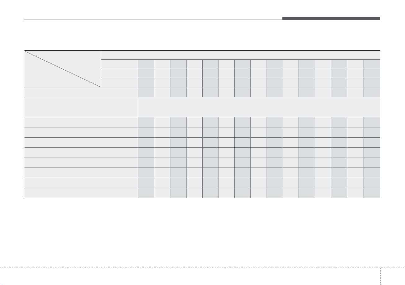
711
Maintenance
Number of months or driving distance, whichever comes first
Months 12 24 36 48 60 72 84 96 108 120 132 144 156 168 180
Miles×1,000 7.5 15 22.5 30 37.5 45 52.5 60 67.5 75 82.5 90 97.5 105 112.5
Km×1,000 12 24 36 48 60 72 84 96 108 120 132 144 156 168 180
Vacuum hose I I I I I I I I I I I I I I I
Coolant (Engine)
At first, replace at 120,000 miles (192,000 km) or 10 years,
after that, replace every 30,000 miles (48,000 km) or 24 months
Battery condition I I I I I I I I I I I I I I I
Brake lines, hoses and connections I I I I I I I I I I I I I I I
Brake discs and pads I I I I I I I I I I I I I I I
Steering gear rack, linkage and boots I I I I I I I I I I I I I I I
Driveshaft and boots I I I I I I I I I I I I I I I
Suspension ball joints I I I I I I I I I I I I I I I
Air conditioner compressor/refrigerant I I I I I I I I I I I I I I I
Exhaust system I I I I I I I I I I I I I I I
MAINTENANCE
INTERVALS
MAINTENANCE
ITEM
Normal Maintenance Schedule - Non Turbo Models(CONT.)
I : Inspect and if necessary, adjust, correct, clean or replace.
R : Replace or change.

Maintenance
127
Number of months or driving distance, whichever comes first
Months 12 24 36 48 60 72 84 96 108 120 132 144 156 168 180
Miles×1,000 7.5 15 22.5 30 37.5 45 52.5 60 67.5 75 82.5 90 97.5 105 112.5
Km×1,000 12 24 36 48 60 72 84 96 108 120 132 144 156 168 180
Cooling system - - - I - I - I - I - I - I -
Dual clutch transmission fluid - - - - I - - - - I - - - - I
Replace engine clutch actuator fluid I R I R I R I R I R I R I R I
Engine clutch actuator hose and lines I I I I I I I I I I I I I I I
Vapor hose and fuel filler cap - I - I - I - I - I - I - I -
Fuel tank air filter *
3
- I - I - I - I - I - I - I -
Fuel lines, hoses and connections - - - I - - - I - - - I - - -
Parking brake - I - I - I - I - I - I - I -
Brake fluid I I I R I I I R I I I R I I I
MAINTENANCE
INTERVALS
MAINTENANCE
ITEM
Normal Maintenance Schedule - Non Turbo Models (CONT.)
I : Inspect and if necessary, adjust, correct, clean or replace.
R : Replace or change.
*
3
: Fuel tank air filter are considered to be maintenance free but periodic inspection is recommended for this maintenance sched-
ule depends on fuel quality.

713
Maintenance
Maintenance Under Severe Usage Conditions - Non Turbo Models
The following items must be serviced more frequently on cars normally used under severe driving conditions. Refer
to the chart below for the appropriate maintenance intervals.
R : Replace I : Inspect and, after inspection, clean, adjust, repair or replace if necessary
MAINTENANCE ITEM
MAINTENANCE
OPERATION
MAINTENANCE INTERVALS
DRIVING
CONDITION
Engine oil and engine oil filter
R
Every 3,750 miles (6,000 km)
or 6 months
A, B, C, D, E,
F, G, H, I, J, K
Air cleaner filter R More frequently C, E
Spark plugs
R
More frequently A, B, F, G, H, I, K
Dual clutch transmission fluid
R
Every 75,000 miles (120,000 km) C, D, E, F, G, H, I, J
HSG (Hybrid Starter & Generator) belt
R
Every 30,000 miles (48,000 km)
or 24 months
C, D, E, K
I
Every 3,750 miles (6,000 km)
or 6 months
C, D, E, K
Brake discs and pads, calipers and rotors I More frequently C, D, E, G, H
Parking brake I More frequently C, D, G, H
Steering gear rack, linkage and boots I More frequently C, D, E, F, G
Suspension ball joints I More frequently C, D, E, F, G

Maintenance
147
Severe driving conditions
A- Repeatedly driving short distance of less than 5 miles (8 km)
in normal temperature or less than 10 miles (16 km) in freez-
ing temperature
B- Extensive engine idling or low speed driving for long dis-
tances
C- Driving on rough, dusty, muddy, unpaved, graveled or salt-
spread roads
D- Driving in areas using salt or other corrosive materials or in
very cold weather
E- Driving in heavy dust condition
F - Driving in heavy traffic area
G- Driving on uphill, downhill, or mountain road repeatedly
H- Towing a Trailer, or using a camper, or roof rack
I - Driving as a patrol car, taxi, other commercial use or vehicle
towing
J -Driving over 106 mph (170 km/h)
K- Frequently driving in stop-and-go conditions
MAINTENANCE ITEM
MAINTENANCE
OPERATION
MAINTENANCE INTERVALS
DRIVING
CONDITION
Drive shafts and boots I More frequently
C, D, E, F,
G, H, I, J
Climate control air filter
R
More frequently C, E, G

715
Maintenance
EXPLANATION OF SCHEDULED MAINTENANCE ITEMS
Engine oil and filter
The engine oil and filter should be
changed at the intervals specified in
the maintenance schedule. If the
vehicle is being driven in severe con-
ditions, more frequent oil and filter
changes are required.
HSG (Hybrid starter & genera-
tor) belt
The HSG belt should be changed at
the intervals specified in the mainte-
nance schedule.
Fuel filter (for gasoline)
Kia gasoline vehicle is equipped a
lifetime fuel filter that integrated with
the fuel tank. Regular maintenance
or replacement is not needed but
depends on fuel quality. If there are
some important safety matters like
fuel flow restriction, surging, loss of
power, hard starting problem etc, fuel
filter inspection or replace is needed.
The fuel filter be Inspected or
replaced by an authorized Kia dealer.
Fuel lines, fuel hoses and con-
nections
Check the fuel lines, fuel hoses and
connections for leakage and dam-
age. Have an authorized Kia dealer
replace any damaged or leaking
parts immediately.
Vapor hose and fuel filler cap
The vapor hose and fuel filler cap
should be inspected at those inter-
vals specified in the maintenance
schedule. Make sure that a new
vapor hose or fuel filler cap is cor-
rectly replaced.

Maintenance
167
Vacuum crankcase ventilation
hoses
Inspect the surface of hoses for evi-
dence of heat and/or mechanical
damage. Hard and brittle rubber,
cracking, tears, cuts, abrasions, and
excessive swelling indicate deterio-
ration. Particular attention should be
paid to examine those hose surfaces
nearest to high heat sources, such
as the exhaust manifold.
Inspect the hose routing to assure
that the hoses do not come in con-
tact with any heat source, sharp
edges or moving component which
might cause heat damage or
mechanical wear. Inspect all hose
connections, such as clamps and
couplings, to make sure they are
secure, and that no leaks are pres-
ent. Hoses should be replaced
immediately if there is any evidence
of deterioration or damage.
Air cleaner filter
A Genuine Kia air cleaner filter is
recommended when the filter is
replaced.
Spark plugs
Make sure to install new spark plugs
of the correct heat range.
Cooling system
Check the cooling system compo-
nents, such as the radiator, coolant
reservoir, hoses and connections for
leakage and damage. Replace any
damaged parts.
Coolant (Engine / Inverter)
The coolant should be changed at
the intervals specified in the mainte-
nance schedule.
Dual clutch transmission Fluid
Inspect the dual clutch transmission
fluid according to the maintenance
schedule.
Brake hoses and lines
Visually check for proper installation,
chafing, cracks, deterioration and
any leakage. Replace any deteriorat-
ed or damaged parts immediately.

717
Maintenance
✽✽
NOTICE - NHTSA Safety
Corrosion Alert
NHTSA has warned all vehicle own-
ers of all brands that they must main-
tain their vehicles in a manner which
will prevent brake hose and brake line
failures due to corrosion when such
vehicles are exposed to winter road
salt and related chemicals. While seri-
ous corrosion conditions typically only
manifest themselves as safety issues
after 7 years of vehicle use, the corro-
sion process starts immediately and
thus underbody cleaning maintenance
must commence from your vehicle's
first exposure to road salts and chem-
icals. NHTSA urges vehicle owners to
take the following steps to prevent
corrosion:
(Continued)
(Continued)
1. Wash the undercarriage of your
vehicle regularly throughout the
winter and do a thorough washing
in the spring to remove road salt
and other de-icing chemicals.
2. Monitor the brake system for
signs of corrosion by having regu-
lar professional inspections and
watching for signs of problems,
including loss of brake fluid,
unusual leaks and soft or spongy
feel in the brake pedal.
3. Replace the entire brake pipe
assembly if you find severe corro-
sion that causes scaling or flaking
of brake components.
Brake fluid
Check the brake fluid level in the
brake fluid reservoir. The level should
be between “MIN” and “MAX” marks
on the side of the reservoir. Use only
hydraulic brake fluid conforming to
DOT 3 or DOT 4 specification.
Parking brake
Inspect the parking brake system
including the parking brake pedal
and cables.
Brake discs, pads, calipers
and rotors
Check the pads for excessive wear,
discs for run out and wear, and
calipers for fluid leakage.

Maintenance
187
Exhaust pipe and muffler
Visually inspect the exhaust pipes,
muffler and hangers for cracks, dete-
rioration, or damage. Start the
engine and listen carefully for any
exhaust gas leakage. Tighten con-
nections or replace parts as neces-
sary.
Suspension mounting bolts
Check the suspension connections
for looseness or damage. Retighten
to the specified torque.
Steering gear box, linkage &
boots/lower arm ball joint
With the vehicle stopped and engine
off, check for excessive free-play in
the steering wheel.
Check the linkage for bends or dam-
age. Check the dust boots and ball
joints for deterioration, cracks, or
damage. Replace any damaged
parts.
Drive shafts and boots
Check the drive shafts, boots and
clamps for cracks, deterioration, or
damage. Replace any damaged
parts and, if necessary, repack the
grease.
Air conditioning refrigerant
Check the air conditioning lines and
connections for leakage and dam-
age.
When checking engine oil, engine
coolant, brake fluid, and washer fluid,
always be sure to clean the area
around any filler plug, drain plug, or
dipstick before checking or draining
any lubricant or fluid. This is espe-
cially important in dusty or sandy
areas and when the vehicle is used
on unpaved roads. Cleaning the plug
and dipstick areas will prevent dirt
and grit from entering the engine and
other mechanisms that could be
damaged.
CHECKING FLUID LEVELS
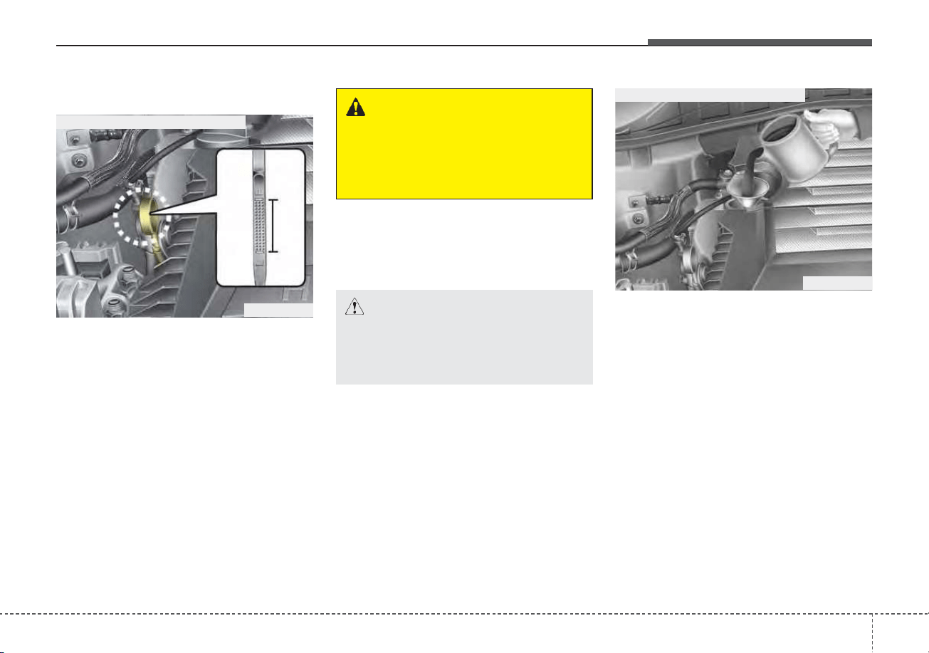
719
Maintenance
ENGINE OIL
Checking the engine oil level
1. Be sure the vehicle is on level
ground.
2. Start the engine and allow it to
reach normal operating tempera-
ture.
3. Turn the engine off and wait for a
few minutes (about 5 minutes) for
the oil to return to the oil pan.
4. Pull the dipstick out, wipe it clean,
and reinsert it fully.
5. Pull the dipstick out again and
check the level. The level should
be between F and L.
If it is near or at L, add enough oil to
bring the level to F. Do not overfill.
Use a funnel to help prevent oil
from being spilled on engine com-
ponents.
Use only the specified engine oil.
(Refer to “Recommended lubricants
and capacities” in chapter 8.)
CAUTION - Replacing
engine oil
Do not overfill the engine oil. It
may damage the engine.
WARNING - Radiator hose
Be very careful not to touch the
radiator hose when checking or
adding engine oil as it may be
hot enough to burn you.
ODE076002
■ Gasoline Engine (Kappa 1.6L GDI)
ODE076003
■ Gasoline Engine (Kappa 1.6L GDI)
Maintenance
207
Changing the engine oil and
filter
Have engine oil and filter changed by
an authorized Kia dealer according
to the Maintenance Schedule at the
beginning of this chapter.
WARNING - Used engine
oil
Used engine oil may cause irrita-
tion or cancer of the skin if left in
contact with the skin for pro-
longed periods of time. Always
protect your skin by washing
your hands thoroughly with
soap and warm water as soon as
possible after handling used oil.
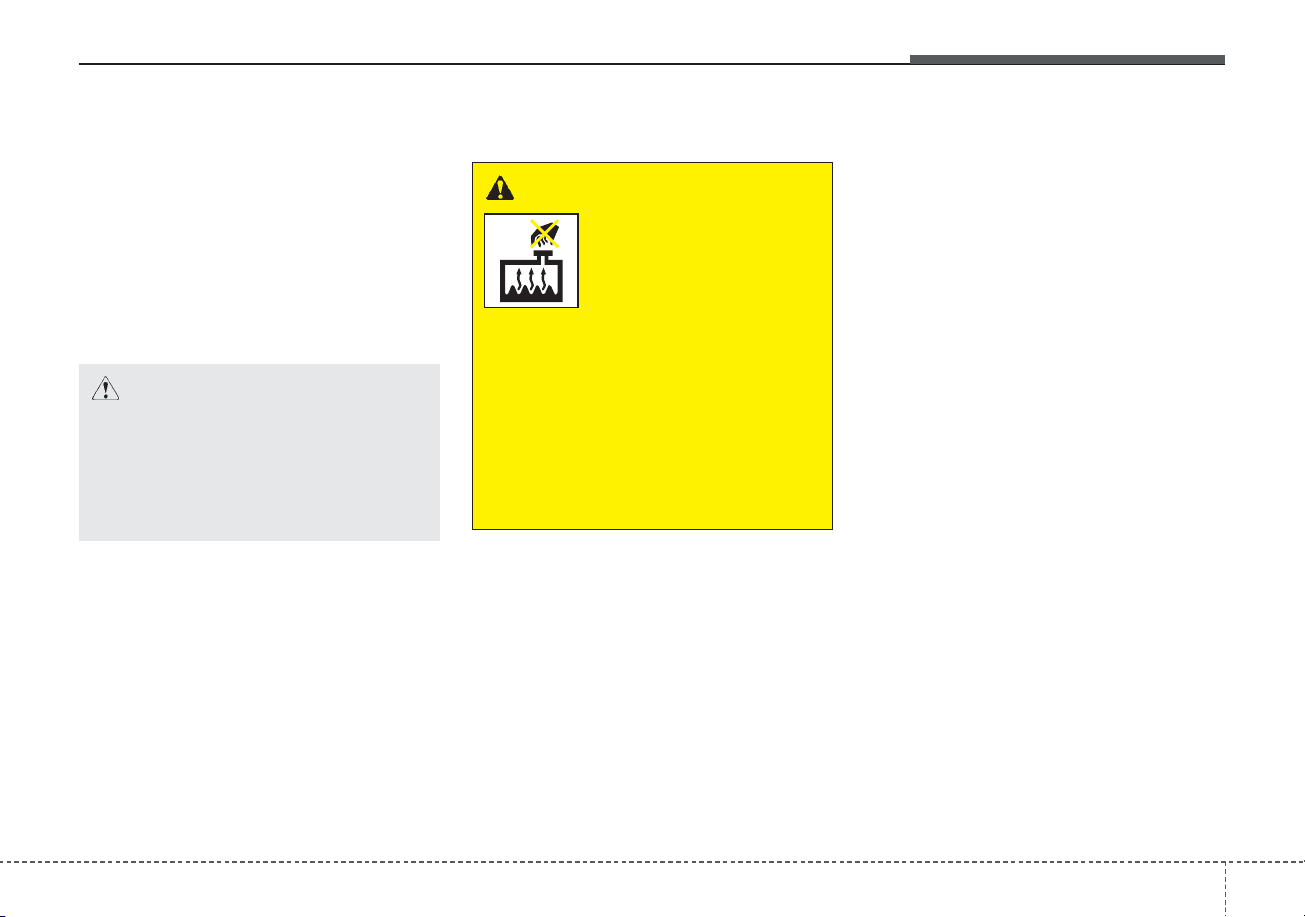
721
Maintenance
COOLANT
The high-pressure cooling system
has a reservoir filled with year round
antifreeze coolant. The reservoir is
filled at the factory.
Check the antifreeze protection and
coolant level at least once a year: at
the beginning of the winter season,
and before traveling to a colder cli-
mate.
Checking the coolant level
• Turn the engine off and wait until it
cools down. Use extreme care
when removing the radiator cap.
Wrap a thick towel around it, and
turn it counterclockwise slowly to
the first stop. Step back while the
pressure is released from the cool-
ing system.
When you are sure all the pressure
has been released, press down on
the cap, using a thick towel, and
continue turning counterclockwise
to remove it.
• Even if the engine is not operating,
do not remove the radiator cap or
the drain plug while the engine and
radiator are hot. Hot coolant and
steam may still blow out under
pressure, causing serious injury.
The engine coolant and/or inverter
coolant level is influenced by the
hybrid system temperature. Before
checking or refilling the engine
coolant and/or inverter coolant,
turn the hybrid vehicle off.
WARNING
Removing radiator
cap
Never attempt to remove the
radiator cap while the engine is
operating or hot. Doing so
might lead to cooling system
and engine damage and could
result in serious personal injury
from escaping hot coolant or
steam.
CAUTION - Radiator cap
Never attempt to remove the
radiator cap while the engine is
operating or hot. Doing so
might lead to cooling system
and engine damage.
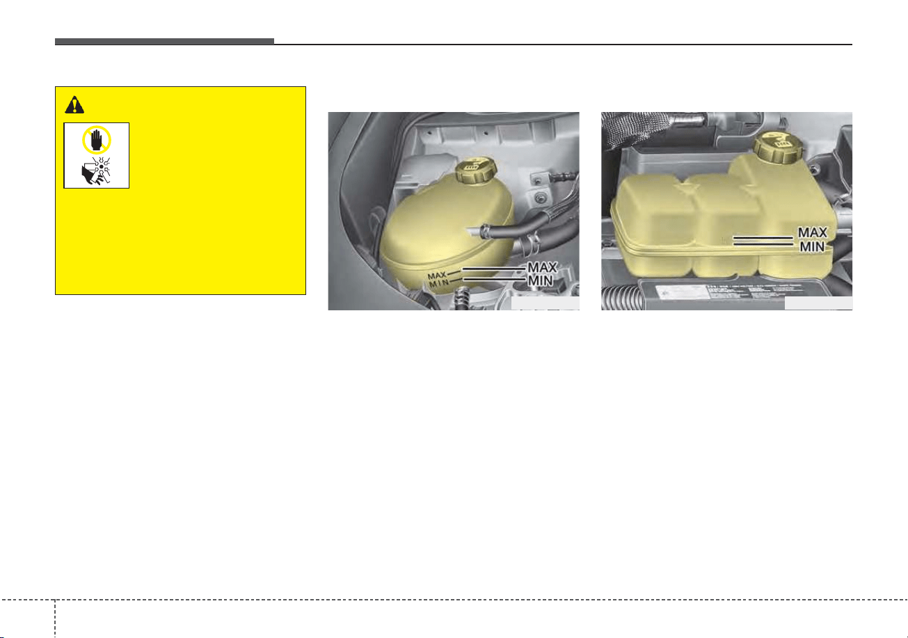
Maintenance
227
Engine coolant
Check the condition and connections
of all cooling system hoses and
heater hoses. Replace any swollen
or deteriorated hoses.
The coolant level should be filled
between MAX and MIN marks on the
side of the coolant reservoir when
the engine is cool.
If the coolant level is low, add enough
specified coolant to provide protec-
tion against freezing and corrosion.
Bring the level to MAX, but do not
overfill. If frequent additions are
required, see an authorized Kia deal-
er for a cooling system inspection.
Inverter coolant
The coolant level should be filled
between MAX and MIN marks on the
side of the coolant reservoir when
the engine is cool.
If the coolant level is low, add enough
specified coolant to provide protec-
tion against freezing and corrosion.
Bring the level to MAX, but do not
overfill. If frequent additions are
required, see an authorized Kia deal-
er for a cooling system inspection.
WARNING - Cooling fan
Use caution when
working near the
blade of the cooling
fan. The electric
motor (cooling fan) is
controlled by engine coolant
temperature, refrigerant pres-
sure and vehicle speed. it may
sometimes operate even when
the engine is not running.
ODE076005 ODEP079053
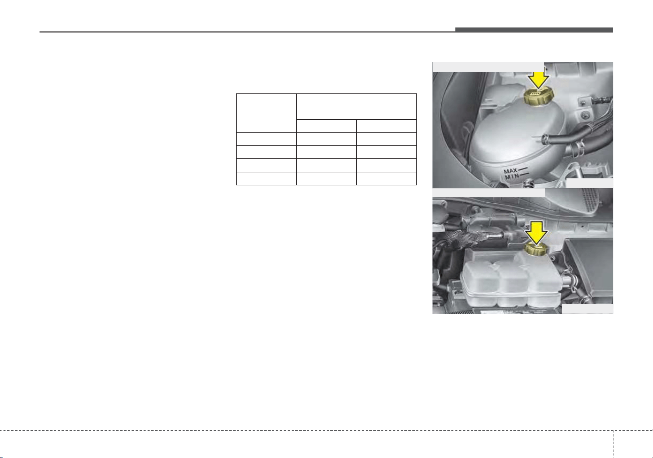
723
Maintenance
Recommended coolant
• When adding coolant, use only
deionized water or soft water for
your vehicle and never mix hard
water in the coolant filled at the fac-
tory. An improper coolant mixture
can result in serious malfunction or
engine damage.
• The engine in your vehicle has alu-
minum engine parts and must be
protected by an ethylene-glycol
with phosphate based coolant to
prevent corrosion and freezing.
• DO NOT USE alcohol or methanol
coolant or mix them with the spec-
ified coolant.
• Do not use a solution that contains
more than 60% antifreeze or less
than 35% antifreeze. This would
reduce the effectiveness of the
solution.
For mixture percentage, refer to the
following table.
Ambient
Temperature
Mixture Percentage
(volume)
Antifreeze Water
5°F (-15°C)
35 65
-13°F (-25°C)
40 60
-31°F (-35°C)
50 50
-49°F (-45°C)
60 40
ODE076006
ODEP079004
■ Inverter coolant reservoir cap
■ Engine coolant reservoir cap
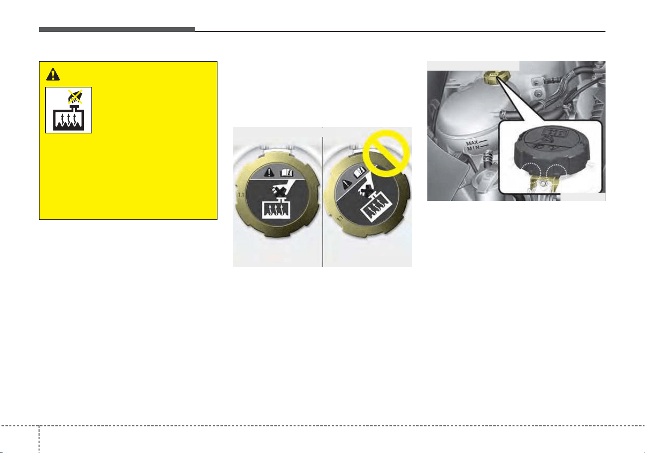
Maintenance
247
✽✽
NOTICE
Make sure the coolant cap is proper-
ly closed after refill of coolant.
Otherwise the engine could be over-
heated while driving.
1. Check if the radiator cap label is
straight front.
2. Make sure that the tiny protru-
sions inside the coolant cap
should be securely interlocked.
WARNING
Radiator cap
Do not remove the radiator cap
when the engine and radiator
are hot. Scalding hot coolant
and steam may blow out under
pressure which may result in
serious injury.
OQL075072
■ Engine room front view
ODE076007
■ Engine room rear view

725
Maintenance
Changing the coolant
Have the coolant changed by an
authorized Kia dealer according to
the Maintenance Schedule at the
beginning of this chapter.
CAUTION
Put a thick cloth or fabric
around the radiator cap before
refilling the coolant in order to
prevent the coolant from over-
flowing into engine parts such
as the generator.
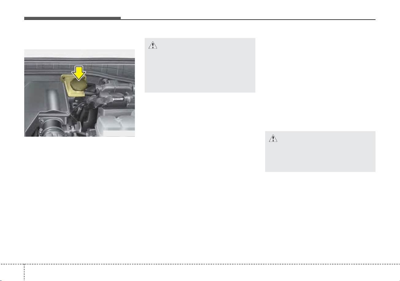
Maintenance
267
BRAKE FLUID
Checking the brake fluid level
Check the fluid level in the reservoir
periodically. The fluid level should be
between MAX (Maximum) and MIN
(Minimum) marks on the side of the
reservoir.
Before removing the reservoir cap
and adding brake fluid, clean the
area around the reservoir cap thor-
oughly to prevent brake fluid contam-
ination.
If the level is low, add fluid to the
MAX (Maximum) level. The level will
fall with accumulated mileage. This is
a normal condition associated with
the wear of brake linings. If the fluid
level is excessively low, have the
brake system checked by an author-
ized Kia dealer.
Use only the specified brake fluid.
(Refer to “Recommended lubricants
and capacities” in chapter 8.)
Never mix different types of fluid.
In the event the brake system
requires frequent additions of fluid,
the vehicle should be inspected by
an authorized Kia dealer.
When changing and adding brake
fluid, handle it carefully. Do not let it
come in contact with your eyes. If
brake fluid should come in contact
with your eyes, immediately flush
them with a large quantity of fresh
tap water. Have your eyes examined
by a doctor as soon as possible.
Brake fluid, which has been exposed
to open air for an extended time
should never be used as its quality
cannot be guaranteed. It should be
disposed of properly.
CAUTION - Brake fluid
Do not allow brake fluid to con-
tact the vehicle's body paint, as
paint damage will result.
CAUTION - Proper fluid
Only use brake fluid in brake
system. Small amounts of
improper fluids (such as engine
oil) can cause damage to the
brake system.
ODEP079008

727
Maintenance
CAUTION
To maintain your vehicle’s best
brake and ABS/ESC perform-
ance, use Kia genuine brake
fluid as in the specification.
(Classification : SAE J1704 DOT-
4 LV, ISO4925 CLASS-6,
FMVSS116 DOT-4)
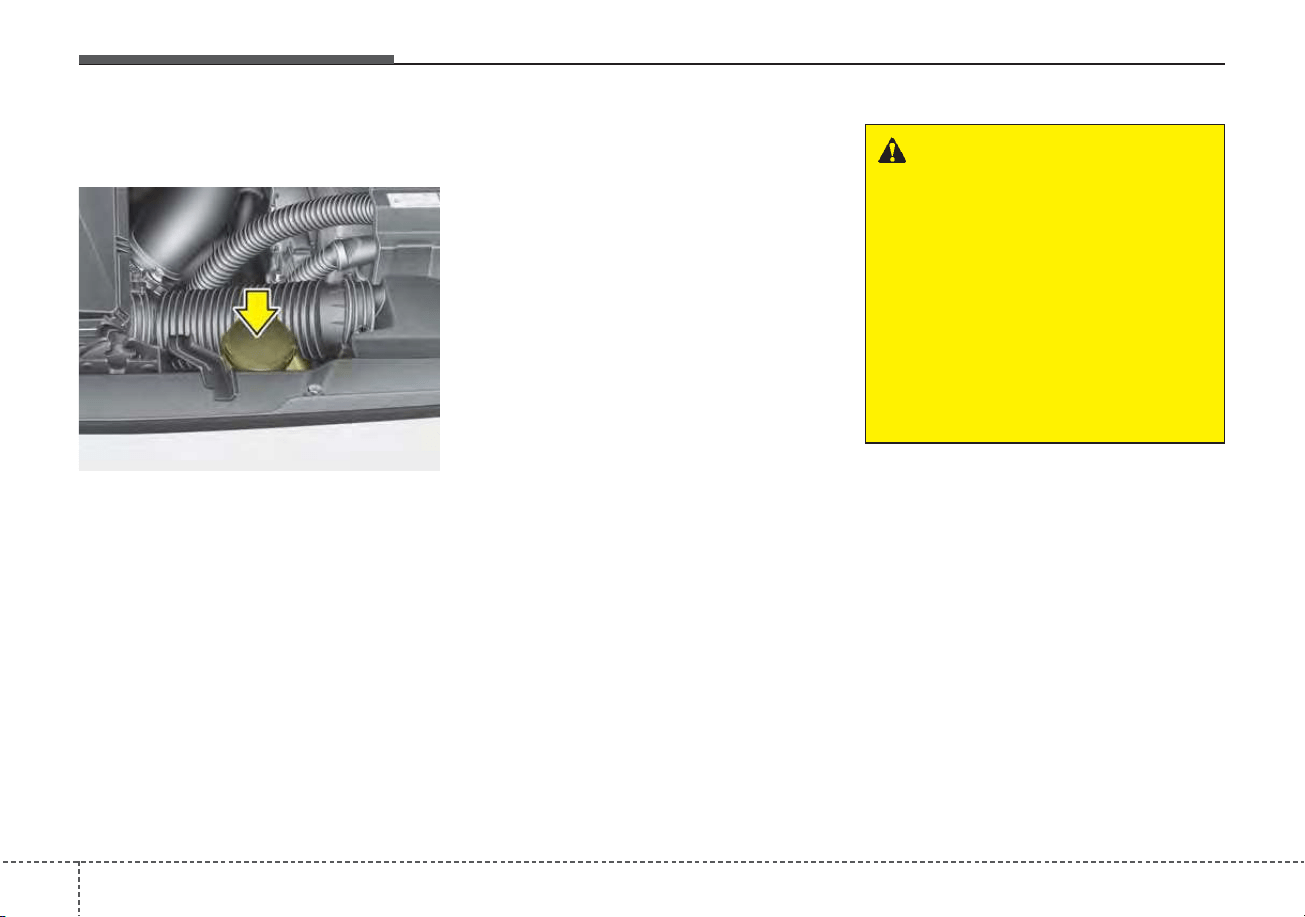
Maintenance
287
ENGINE CLUTCH ACTUATOR FLUID
Checking the engine clutch
actuator fluid level
In normal driving conditions, the
actuator fluid level does not go down
rapidly. However, oil consumption
rate may rise as vehicle mileage
increases, and leakage in actuator
related parts may result in increased
consumption of the engine clutch
actuator oil. Regularly check and
make sure the engine clutch actuator
oil fluid level is between [MIN] and
[MAX] marks.
If the oil level is below [MIN] mark,
we recommend that your vehicle be
checked by an authorized Kia dealer.
If the fluid level is excessively low, we
recommend that the system be
checked by an authorized Kia dealer.
Use only the specified engine clutch
actuator fluid.
(Refer to “Recommended lubricants
or capacities” in chapter 8.)
Never mix different types of fluid.
✽✽
NOTICE - Loss of engine
clutch actuator fluid
In the event the engine clutch actua-
tor requires frequent additions of
fluid, we recommend that the system
be inspected by an authorized Kia
dealer.
WARNING - Engine clutch
actuator fluid
When changing and adding
engine clutch actuator fluid,
handle it carefully. Do not let it
come in contact with your eyes.
If engine clutch actuator fluid
should come in contact with
your eyes, immediately flush
them with a large quantity of
fresh water, and seek medical
attention as soon as possible.
ODE076057

729
Maintenance
CAUTION
Do not allow engine clutch actu-
ator fluid to contact the vehi-
cle's body paint, as paint dam-
age will result. The engine
clutch actuator fluid that has
been exposed to open air for an
extended time should never be
used as its quality cannot be
guaranteed. It should be proper-
ly disposed. Do not put in the
wrong kind of fluid. A few drops
of mineral-based oil, such as
engine oil, in your engine clutch
actuator system can damage
engine clutch actuator system
parts.
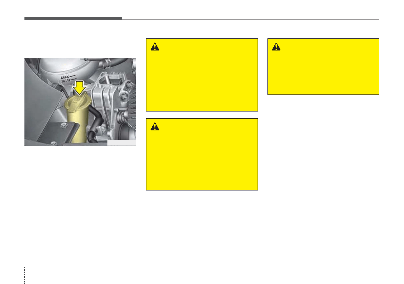
Maintenance
307
WASHER FLUID
Checking the washer fluid
level
The reservoir is translucent so that
you can check the level with a quick
visual inspection.
Check the fluid level in the washer
fluid reservoir and add fluid if neces-
sary. Plain water may be used if
washer fluid is not available.
However, use washer solvent with
antifreeze characteristics in cold cli-
mates to prevent freezing.
WARNING - Flammable
fluid
Do not allow the washer fluid to
come in contact with open
flames or sparks.The windshield
washer fluid reservoir is flamma-
ble under certain circumstances.
This can result in a fire.
WARNING - Windshield
fluid
Do not drink the windshield
washer fluid. The windshield
washer fluid is poisonous to
humans and animals.
WARNING - Coolant
• Do not use radiator coolant or
antifreeze in the washer fluid
reservoir.
• Radiator coolant can severely
obscure visibility when sprayed
on the windshield and may
cause loss of vehicle control.
ODE076009
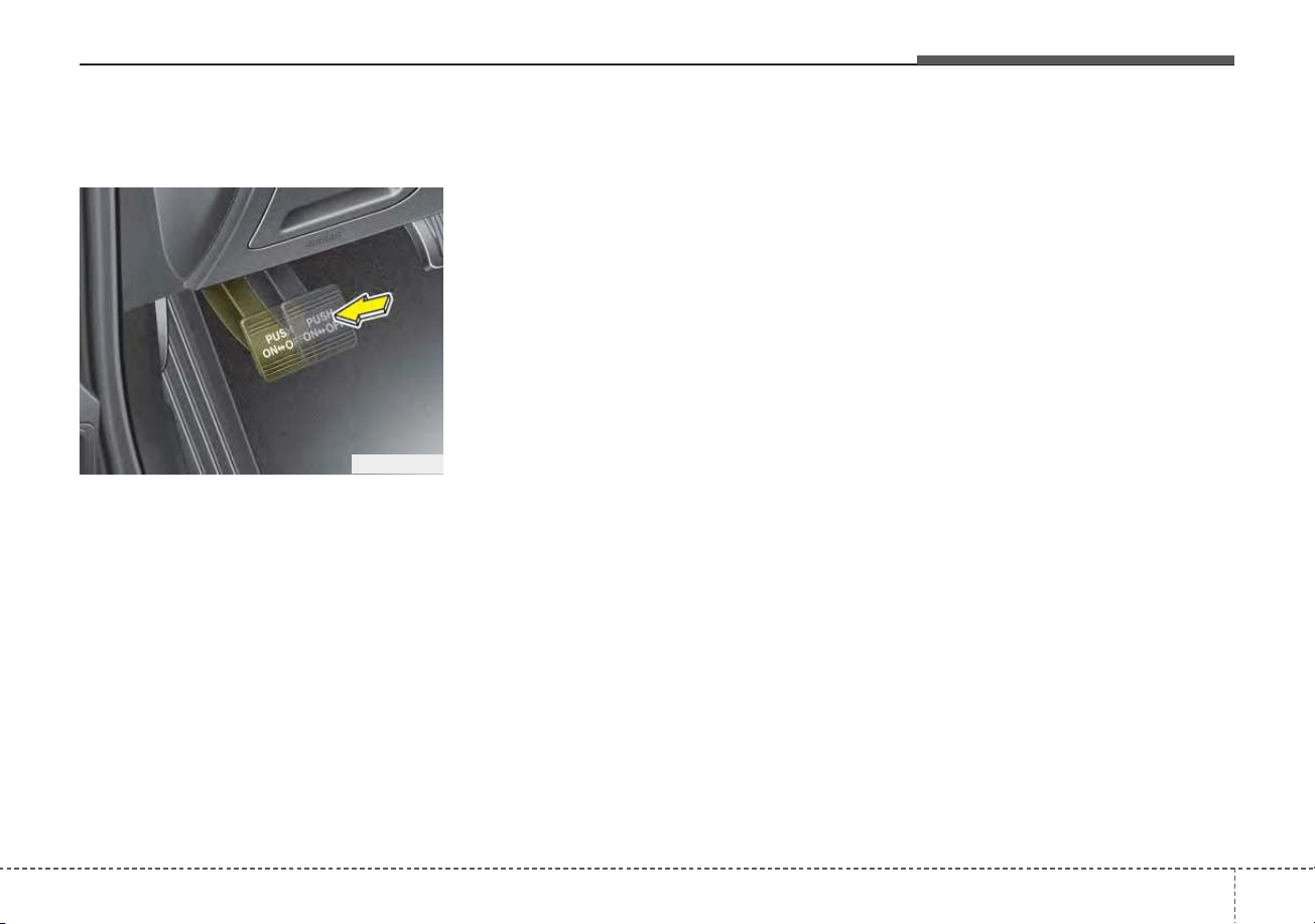
731
Maintenance
Checking the parking brake
(if equipped)
Check whether the stroke is within
specification when the parking brake
pedal is depressed with 66 lb, 294 N
(30 kg) of force. Also, the parking
brake alone should securely hold the
vehicle on a fairly steep grade. If the
stroke is more or less than specified,
have the parking brake adjusted by
an authorized Kia dealer.
Stroke : 6~7 notch
PARKING BRAKE
OJF055017
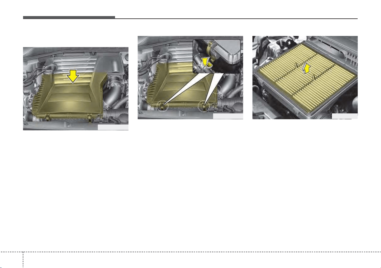
Maintenance
327
AIR CLEANER
Filter replacement
The filter must be replaced when
necessary, and should not be
washed.
You can clean the filter when inspect-
ing the air cleaner element.
Clean the filter by using compressed
air.
1. Loosen the air cleaner cover
attaching clips and open the cover.
2. Wipe the inside of the air cleaner.
3. Replace the air cleaner filter.
4. Lock the cover with the cover
attaching clips.
ODEP079011
ODEP079012 ODE076013
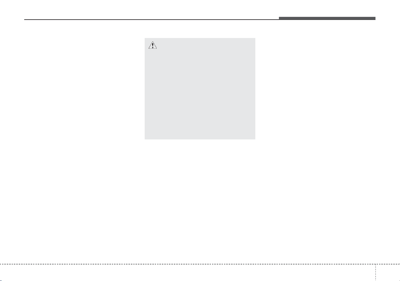
733
Maintenance
Replace the filter according to the
Maintenance Schedule.
If the vehicle is operated in extreme-
ly dusty or sandy areas, replace the
element more often than the usual
recommended intervals. (Refer to
“Maintenance under severe usage
conditions” in this chapter.)
CAUTION - Air filter
maintenance
• Do not drive with the air clean-
er removed; this will result in
excessive engine wear.
• When removing the air cleaner
filter, be careful that dust or
dirt does not enter the air
intake, or damage may result.
• Use a Kia genuine part. Use of
a non-genuine part could
damage the air flow sensor.
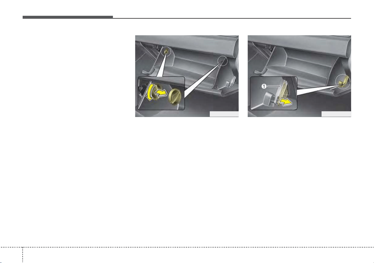
Maintenance
347
CLIMATE CONTROL AIR FILTER (IF EQUIPPED)
Filter inspection
The climate control air filter should
be replaced according to the
Maintenance Schedule. If the vehicle
is operated in severely air-polluted
cities or on dusty rough roads for a
long period, it should be inspected
more frequently and replaced earlier.
When you replace the climate control
air filter, replace it performing the fol-
lowing procedure, and be careful to
avoid damaging other components.
1. Open the glove box and remove
the stoppers on both sides.
2. With the glove box open, pull the
support strap (1).
ODEP079014ODEP079015
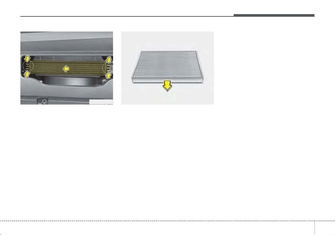
735
Maintenance
3. Remove the climate control air fil-
ter cover while pressing the lock
on both sides of the cover.
4. Replace the climate control air fil-
ter.
5. Reassemble in the reverse order
of disassembly.
When replacing the climate control
air filter install it properly. Otherwise,
the system may produce noise and
the effectiveness of the filter may be
reduced.
ODE076054 OQL075021
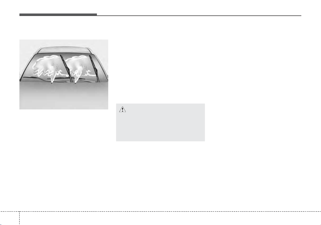
Maintenance
367
WIPER BLADES
Blade inspection
Commercial hot waxes applied by
automatic car washes have been
known to make the windshield diffi-
cult to clean.
Contamination of either the wind-
shield or the wiper blades with for-
eign matter can reduce the effective-
ness of the windshield wipers.
Common sources of contamination
are insects, tree sap, and hot wax
treatments used by some commer-
cial car washes. If the blades are not
wiping properly, clean both the win-
dow and the blades with a good
cleaner or mild detergent, and rinse
thoroughly with clean water.
Blade replacement
When the wipers no longer clean
adequately, the blades may be worn
or cracked, and require replacement.
To prevent damage to the wiper arms
or other components, do not attempt
to move the wipers manually.
The use of a non-specified wiper
blade could result in wiper malfunc-
tion and failure.
1JBA5122
CAUTION - Wiper blades
To prevent damage to the wiper
blades, do not use gasoline,
kerosene, paint thinner, or other
solvents on or near them.
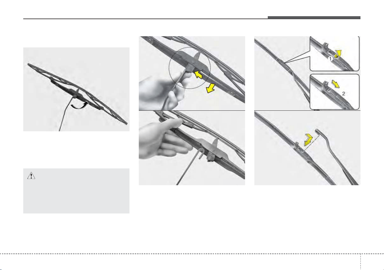
737
Maintenance
Front windshield wiper blade
Type A
1. Raise the wiper arm and turn the
wiper blade assembly to expose
the plastic locking clip.
2. Compress the clip and slide the
blade assembly downward.
3. Lift it off the arm.
4. Install the blade assembly in the
reverse order of removal.
Type B
1. Raise the wiper arm.
1LDA5023
CAUTION - Wiper arms
Do not allow the wiper arm to
fall against the windshield,
since it may chip or crack the
windshield.
1JBA7037
1JBA7038
OHM078060
OHM078061
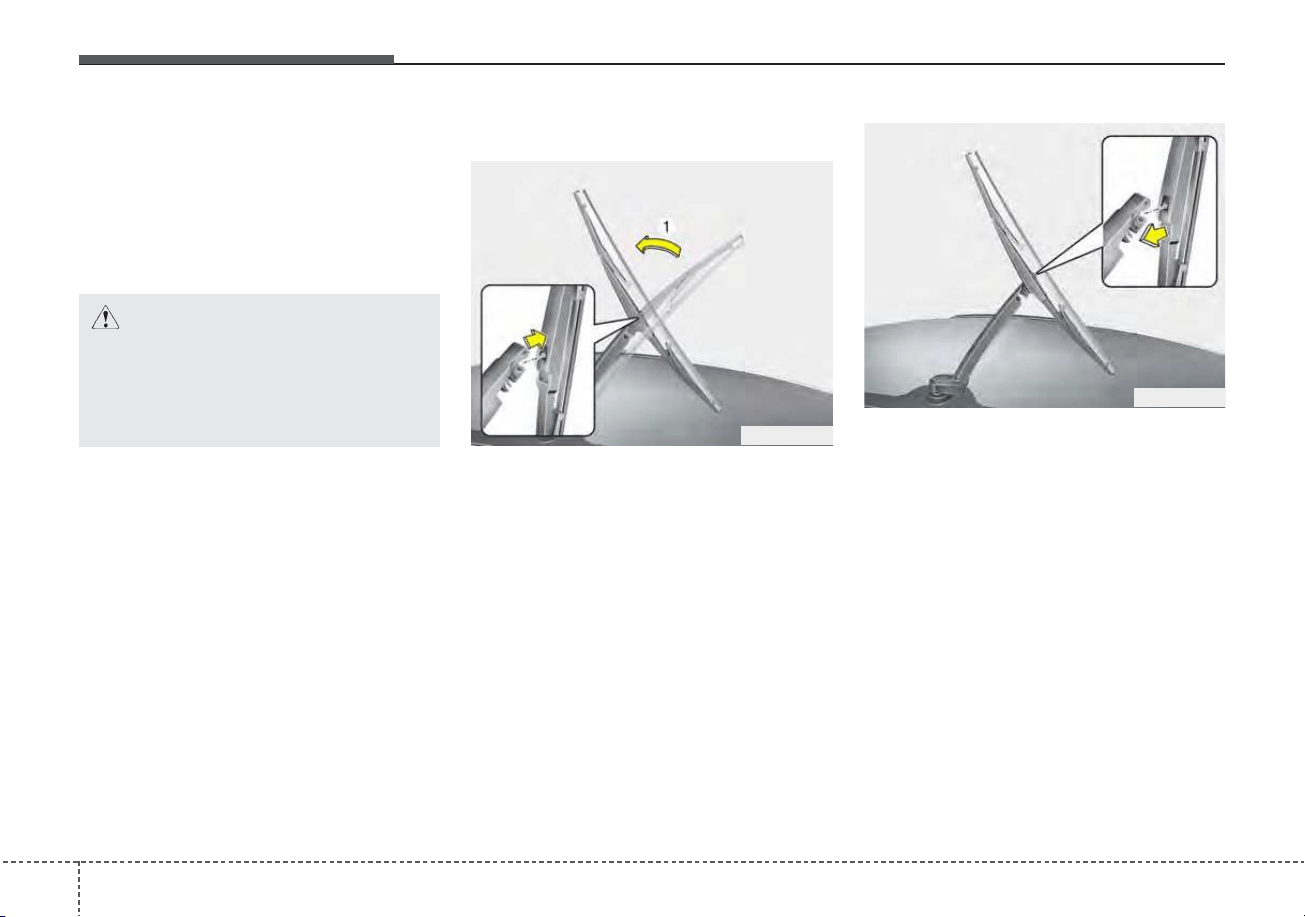
Maintenance
387
2. Lift up the wiper blade clip. Then
pull down the blade assembly and
remove it.
3. Install the new blade assembly.
4. Return the wiper arm on the wind-
shield.
Rear window wiper blade
1. Raise the wiper arm and pull out
the wiper blade assembly.
2. Install the new blade assembly by
inserting the center part into the
slot in the wiper arm until it clicks
into place.
3. Make sure the blade assembly is
installed firmly by trying to pull it
slightly.
To prevent damage to the wiper arms
or other components, have an
authorized Kia dealer replace the
wiper blade.
OHM078062
OHM078063
CAUTION - Wiper arms
Do not allow the wiper arm to
fall against the windshield,
since it may chip or crack the
windshield.
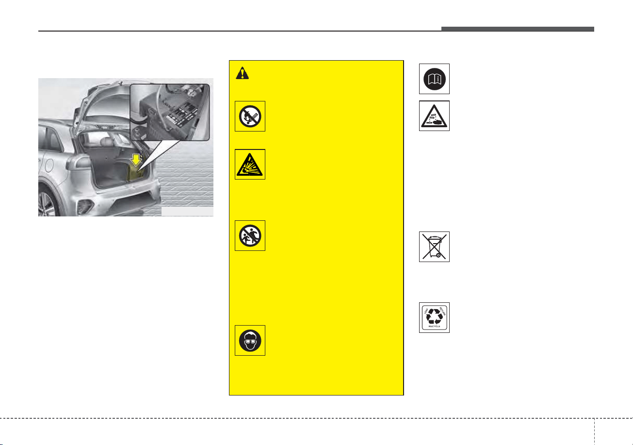
739
Maintenance
BATTERY (PLUG-IN HYBRID)
For best battery service
• Keep the battery securely mount-
ed.
• Keep the battery top clean and dry.
• Keep the terminals and connec-
tions clean, tight, and coated with
petroleum jelly or terminal grease.
• Rinse any spilled electrolyte from
the battery immediately with a
solution of water and baking soda.
• If the vehicle is not going to be
used for an extended time, discon-
nect the battery cables.
Always read the following
instructions carefully when
handling a battery.
If any electrolyte gets into
your eyes, flush your eyes
with clean water for at least
15 minutes and get immedi-
ate medical attention.
If electrolyte gets on your
skin, thoroughly wash the
contacted area. If you feel
pain or burning sensation,
get medical attention imme-
diately.
An inappropriately disposed
battery can be harmful to the
environment and human
health. Dispose the battery
according to your local law(s)
or regulation.
The battery contains lead. Do
not dispose of it after use.
Please return the battery to
an authorized Kia dealer to
be recycled.
Never attempt to recharge the bat-
tery when the battery cables are con-
nected.
WARNING - Risk of
explosion
Keep lit cigarettes and
all other flames or
sparks away from the
battery.
The battery contains
hydrogen -- a highly
combustible gas which
will explode if it comes
in contact with a flame or
spark.
Keep batteries out of the
reach of children
because batteries con-
tain highly corrosive
SULFURIC ACID and
electrolytes. Do not
allow battery acid to
contact your skin, eyes,
clothing or paint finish.
Wear eye protection
when charging or work-
ing near a battery.
Always provide ventila-
tion when working in an
enclosed space.
ODEP079016
Maintenance
407
✽✽
NOTICE
If you connect unauthorized elec-
tronic devices to the battery, the bat-
tery may be discharged. Never use
unauthorized devices.
Recharging the battery
Your vehicle has a maintenance-free,
calcium-based battery.
• If the battery becomes discharged
in a short time (because, for exam-
ple, the headlamps or interior
lamps were left on while the vehi-
cle was not in use), recharge it by
slow charging (trickle) for 10 hours.
• If the battery gradually discharges
because of high electric load while
the vehicle is being used, recharge
it at 20-30A for two hours.
WARNING - Risk of elec-
trocution
Never touch the electrical igni-
tion system while the vehicle is
running. This system works
with high voltage which can
shock you.
WARNING - Recharging
Battery
Never attempt to recharge the
battery when the battery cables
are connected.
WARNING - Battery lead
compound
Battery posts, terminals, and
related accessories contain
lead and lead compounds.
Wash hands after handling.

741
Maintenance
When recharging the battery,
observe the following precautions:
• The battery must be removed from
the vehicle and placed in an area
with good ventilation.
• Do not allow cigarettes, sparks, or
flame near the battery.
• Watch the battery during charging,
and stop or reduce the charging
rate if the battery cells begin
gassing (boiling) violently or if the
temperature of the electrolyte of
any cell exceeds 120°F (49°C).
• Wear eye protection when check-
ing the battery during charging.
• Disconnect the battery charger in
the following order.
1. Turn off the battery charger main
switch.
2. Unhook the negative clamp from
the negative battery terminal.
3. Unhook the positive clamp from
the positive battery terminal.
• Before performing maintenance or
recharging the battery, turn off all
accessories and stop the engine.
• The negative battery cable must be
removed first and installed last
when the battery is disconnected.
Reset items
The following items should be reset
after the battery has been dis-
charged or the battery has been dis-
connected.
• Auto up/down window
• Sunroof
• Trip computer
• Climate control system
• Driver position memory system
• Audio
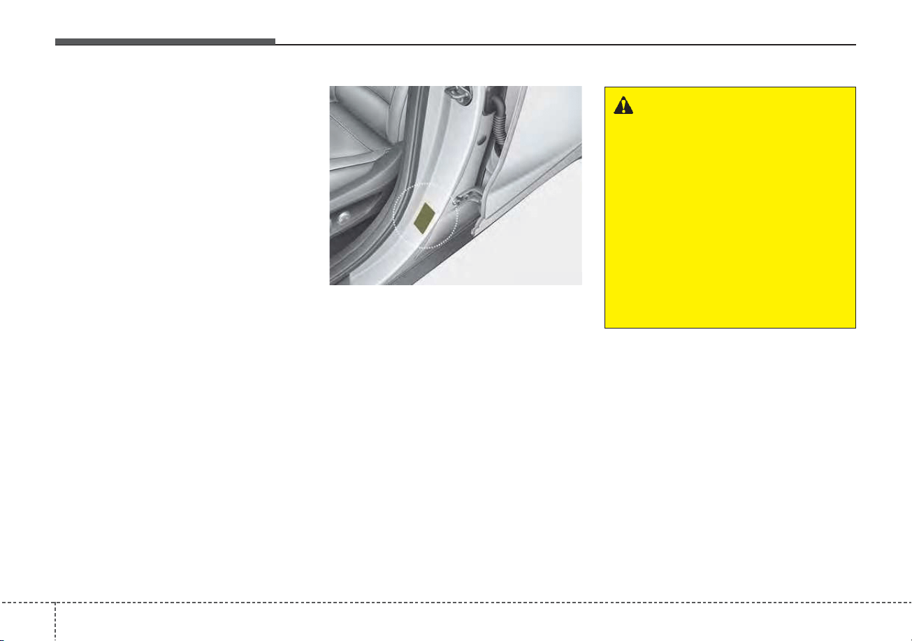
Maintenance
427
TIRES AND WHEELS
Tire care
For proper maintenance, safety, and
maximum fuel economy, you must
always maintain recommended tire
inflation pressures and stay within
the load limits and weight distribution
recommended for your vehicle.
Recommended cold tire infla-
tion pressures
All tire pressures (including the
spare) should be checked when the
tires are cold. “Cold Tires” means the
vehicle has not been driven for at
least three hours or driven less than
1 mile (1.6 km).
Recommended pressures must be
maintained for the best ride, top vehi-
cle handling, and minimum tire wear.
For recommended inflation pressure
refer to “Tires and wheels” in chapter
8.
All specifications (sizes and pres-
sures) can be found on a label
attached to the driver’s side center
pillar.
WARNING - Tire underin-
flation
Inflate your tires consistent with
the instructions provided in this
manual. Severe underinflation
(10 psi (70 kPa) or more) can
lead to severe heat build-up,
causing blowouts, tread separa-
tion and other tire failures that
can result in the loss of vehicle
control.This risk is much higher
on hot days and when driving
for long periods at high speeds.
ODE086006L
743
Maintenance
• Underinflation also results in
excessive wear, poor handling and
reduced fuel economy. Wheel
deformation also is possible. Keep
your tire pressures at the proper
levels. If a tire frequently needs
refilling, have it checked by an
authorized Kia dealer.
• Overinflation produces a harsh
ride, excessive wear at the center
of the tire tread, and a greater pos-
sibility of damage from road haz-
ards.
• Warm tires normally exceed rec-
ommended cold tire pressures by 4
to 6 psi (28 to 41 kPa). Do not
release air from warm tires to
adjust the pressure or the tires will
be underinflated.
• Be sure to reinstall the tire inflation
valve caps. Without the valve cap,
dirt or moisture could get into the
valve core and cause air leakage. If
a valve cap is missing, install a
new one as soon as possible.
Tire pressure
Always observe the following:
• Check tire pressure when the tires
are cold. (After vehicle has been
parked for at least three hours or
hasn't been driven more than 1
mile (1.6 km) since startup.)
• Check the pressure of your spare
tire each time you check the pres-
sure of other tires.
• Never overload your vehicle. Be
careful not to overload a vehicle
luggage rack if your vehicle is
equipped with one.
Checking tire inflation pres-
sure
Check your tires once a month or
more.
Also, check the tire pressure of the
spare tire.
How to check
Use a good quality gauge to check
tire pressure. You cannot tell if your
tires are properly inflated simply by
looking at them. Radial tires may
look properly inflated even when
they're underinflated.
Check the tire's inflation pressure
when the tires are cold. - "Cold"
means your vehicle has been sitting
for at least three hours or driven no
more than 1 mile (1.6 km).
WARNING - Tire Inflation
Overinflation or underinflation
can reduce tire life, adversely
affect vehicle handling, and
lead to sudden tire failure. This
could result in loss of vehicle
control and potential injury.

Maintenance
447
Remove the valve cap from the tire
valve stem. Press the tire gauge firm-
ly onto the valve to get a pressure
measurement. If the cold tire inflation
pressure matches the recommended
pressure on the tire and loading
information label, no further adjust-
ment is necessary. If the pressure is
low, add air until you reach the rec-
ommended amount.
If you overfill the tire, release air by
pushing on the metal stem in the
center of the tire valve. Recheck the
tire pressure with the tire gauge. Be
sure to put the valve caps back on
the valve stems. They help prevent
leaks by keeping out dirt and mois-
ture.
• Inspect your tires frequently for
proper inflation as well as wear and
damage. Always use a tire pres-
sure gauge.
• Tires with too much or too little
pressure wear unevenly causing
poor handling, loss of vehicle con-
trol, and sudden tire failure leading
to accidents, injuries, and even
death. The recommended cold tire
pressure for your vehicle can be
found in this manual and on the tire
label located on the driver's side
center pillar.
• Remember to check the pressure
of your spare tire. Kia recommends
that you check the spare every
time you check the pressure of the
other tires on your vehicle.
Tire rotation
To equalize tread wear, it is recom-
mended that the tires be rotated
every 7,500 miles (12,000 km) or
sooner if irregular wear develops.
During rotation, check the tires for
correct balance.
When rotating tires, check for uneven
wear and damage. Abnormal wear is
usually caused by incorrect tire pres-
sure, improper wheel alignment, out-
of-balance wheels, severe braking or
severe cornering. Look for bumps or
bulges in the tread or side of tire.
Replace the tire if you find either of
these conditions. Replace the tire if
fabric or cord is visible. After rotation,
be sure to bring the front and rear tire
pressures to specification and check
lug nut tightness.
Refer to “Tires and wheels” in chap-
ter 8.
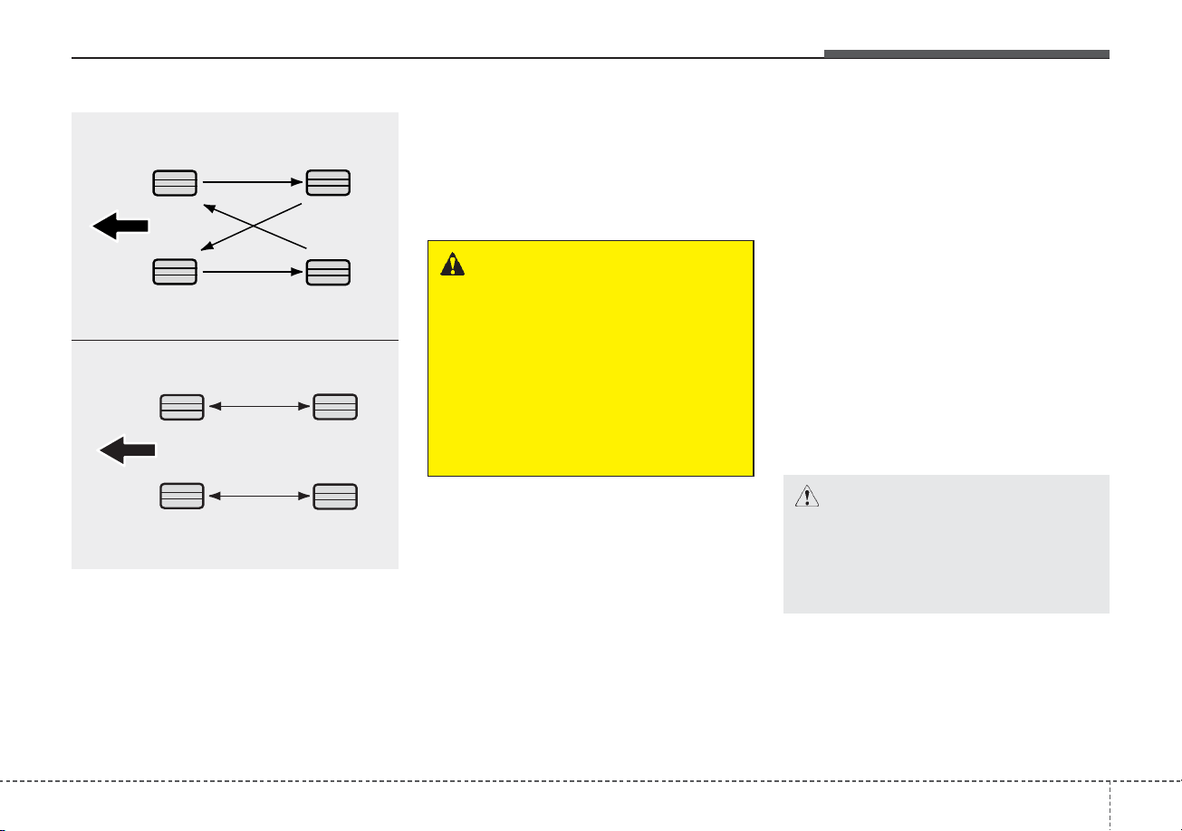
745
Maintenance
Disc brake pads should be inspected
for wear whenever tires are rotated.
Rotate radial tires that have an
asymmetric tread pattern only from
front to rear and not from right to left.
Wheel alignment and tire bal-
ance
The wheels on your vehicle were
aligned and balanced carefully at the
factory to give you the longest tire life
and best overall performance.
In most cases, you will not need to
have your wheels aligned again.
However, if you notice unusual tire
wear or your vehicle pulling one way
or the other, the alignment may need
to be reset.
If you notice your vehicle vibrating
when driving on a smooth road, your
wheels may need to be rebalanced.
WARNING - Mixing tires
• Do not use the compact spare
tire (if equipped) for tire rota-
tion.
• Do not mix bias ply and radial
ply tires under any circum-
stances. This may cause
unusual handling characteris-
tics.
CAUTION - Wheel weight
Improper wheel weights can
damage your vehicle's alu-
minum wheels. Use only
approved wheel weights.
S2BLA790A
CBGQ0707A
Without a spare tire
Directional tires (if equipped)
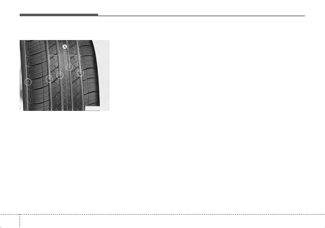
Maintenance
467
Tire replacement
If the tire is worn evenly, a tread wear
Indicator (A) will appear as a solid
band across the tread. This shows
there is less than 1/16 inch (1.6 mm)
of tread left on the tire. Replace the
tire when this happens.
Do not wait for the band to appear
across the entire tread before replac-
ing the tire.
The ABS works by comparing the
speed of the wheels. The tire size
affects wheel speed. When replacing
tires, all 4 tires must use the same
size originally supplied with the vehi-
cle. Using tires of a different size can
cause the ABS (Anti-lock Brake
System) and ESC (Electronic
Stability Control) to work irregularly.
✽✽
NOTICE
• We recommend that when replac-
ing tires, use the same which were
originally supplied with the vehi-
cle. If not, driving performance
could be altered.
• When replacing tires (or wheels),
it is recommended to replace the
two front or two rear tires (or
wheels) as a pair.
Replacing just one tire can serious-
ly affect your vehicle's handling.
Wheel replacement
When replacing the metal wheels for
any reason, make sure the new
wheels are equivalent to the original
factory units in diameter, rim width
and offset.
A wheel that is not the correct size
may adversely affect wheel and
bearing life, braking and stopping
abilities, handling characteristics,
ground clearance, body-to-tire clear-
ance, snow chain clearance,
speedometer and odometer calibra-
tion, headlight aim and bumper
height.
OUM076204L
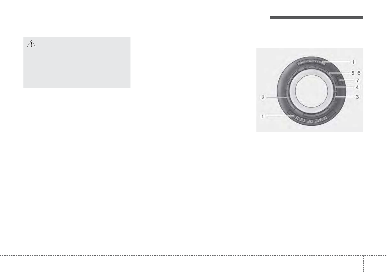
747
Maintenance
Tire traction
Tire traction can be reduced if you
drive on worn tires, tires that are
improperly inflated or on slippery
road surfaces. Tires should be
replaced when tread wear indicators
appear. Slow down whenever there
is rain, snow or ice on the road, to
reduce the possibility of losing con-
trol of the vehicle.
Tire maintenance
In addition to proper inflation, correct
wheel alignment helps to decrease
tire wear. If you find a tire is worn
unevenly, have your dealer check the
wheel alignment.
When you have new tires installed,
make sure they are balanced. This
will increase vehicle ride comfort and
tire life. Additionally, a tire should
always be rebalanced if it is removed
from the wheel.
Tire sidewall labeling
This information identifies and
describes the fundamental charac-
teristics of the tire and also provides
the tire identification number (TIN)
for safety standard certification. The
TIN can be used to identify the tire in
case of a recall.
1. Manufacturer or brand name
Manufacturer or Brand name is
shown.
CAUTION - Wheel
Wheels that do not meet Kia's
specifications may fit poorly
and result in damage to the
vehicle or unusual handling and
poor vehicle control.
OJF085008L

Maintenance
487
2. Tire size designation
A tire’s sidewall is marked with a tire
size designation. You will need this
information when selecting replace-
ment tires for your car. The following
explains what the letters and num-
bers in the tire size designation
mean.
Example tire size designation:
(These numbers are provided as an
example only; your tire size designa-
tor could vary depending on your
vehicle.)
P205/55R16 89H
P - Applicable vehicle type (tires
marked with the prefix “P’’ are
intended for use on passenger
vehicles or light trucks; however,
not all tires have this marking).
205 - Tire width in millimeters.
55 - Aspect ratio. The tire’s section
height as a percentage of its
width.
R - Tire construction code (Radial).
16 - Rim diameter in inches.
89 - Load Index, a numerical code
associated with the maximum
load the tire can carry.
H - Speed Rating Symbol. See the
speed rating chart in this section
for additional information.
Wheel size designation
Wheels are also marked with impor-
tant information that you need if you
ever have to replace one. The follow-
ing explains what the letters and
numbers in the wheel size designa-
tion mean.
Example wheel size designation:
6.0JX16
6.0 - Rim width in inches.
J - Rim contour designation.
16 - Rim diameter in inches.
749
Maintenance
Tire speed ratings
The chart below lists many of the dif-
ferent speed ratings currently being
used for passenger vehicles. The
speed rating is part of the tire size
designation on the sidewall of the
tire. This symbol corresponds to that
tire's designed maximum safe oper-
ating speed.
3. Checking tire life (TIN : Tire
Identification Number)
Any tires that are over 6 years old,
based on the manufacturing date,
(including the spare tire) should be
replaced by new ones. You can find
the manufacturing date on the tire
sidewall (possibly on the inside of the
wheel), displaying the DOT Code.
The DOT Code is a series of num-
bers on a tire consisting of numbers
and English letters. The manufactur-
ing date is designated by the last four
digits (characters) of the DOT code.
DOT : XXXX XXXX OOOO
The front part of the DOT means a
plant code number, tire size and
tread pattern and the last four num-
bers indicate week and year manu-
factured.
For example:
DOT XXXX XXXX 1620 represents
that the tire was produced in the 16th
week of 2020.
4. Tire ply composition and mate-
rial
The number of layers or plies of rub-
ber-coated fabric in the tire. Tire
manufacturers also must indicate the
materials in the tire, which include
steel, nylon, polyester, and others.
The letter "R" means radial ply con-
struction; the letter "D" means diago-
nal or bias ply construction; and the
letter "B" means belted-bias ply con-
struction.
S 112 mph (180 km/h)
T 118 mph (190 km/h)
H 130 mph (210 km/h)
V 149 mph (240 km/h)
Z Above 149 mph (240 km/h)
Maximum Speed
Speed
Rating
Symbol
WARNING - Tire age
Replace tires within the recom-
mended time frame. Failure to
replace tires as recommended
can result in sudden tire failure,
which could lead to a loss of
control and an accident.

Maintenance
507
5. Maximum permissible inflation
pressure
This number is the greatest amount of
air pressure that should be put in the
tire. Do not exceed the maximum per-
missible inflation pressure. Refer to
the Tire and Loading Information label
for recommended inflation pressure.
6. Maximum load rating
This number indicates the maximum
load in kilograms and pounds that can
be carried by the tire. When replacing
the tires on the vehicle, always use a
tire that has the same load rating as
the factory installed tire.
7. Uniform tire quality grading
Quality grades can be found where
applicable on the tire sidewall
between tread shoulder and maxi-
mum section width.
For example:
TREADWEAR 440
TRACTION A
TEMPERATURE A
Tread wear
The tread wear grade is a compara-
tive rating based on the wear rate of
the tire when tested under controlled
conditions on a specified govern-
ment test course. For example, a tire
graded 150 would wear one-and-a-
half times (1½) as well on the gov-
ernment course as a tire graded 100.
The relative performance of tires
depends upon the actual conditions
of their use, however, and may
depart significantly from the norm
due to variations in driving habits,
service practices and differences in
road characteristics and climate.
Tires degrade over time, even when
they are not being used. Regardless
of the remaining tread, we recom-
mend that tires be replaced after
approximately six (6) years of normal
service. Heat caused by hot climates
or frequent high loading conditions
can accelerate the aging process.
These grades are molded on the
side-walls of passenger vehicle tires.
The tires available as standard or
optional equipment on your vehicles
may vary with respect to grade.

751
Maintenance
Traction - AA, A, B & C
The traction grades, from highest to
lowest, are AA, A, B and C. Those
grades represent the tires ability to
stop on wet pavement as measured
under controlled conditions on spec-
ified government test surfaces of
asphalt and concrete. A tire marked
C may have poor traction perform-
ance.
The traction grade assigned to this
tire is based on straight-ahead brak-
ing traction tests, and does not
include acceleration, cornering,
hydroplaning, or peak traction char-
acteristics.
Temperature -A, B & C
The temperature grades are A (the
highest), B and C representing the
tire’s resistance to the generation of
heat and its ability to dissipate heat
when tested under controlled condi-
tions on a specified indoor laboratory
test wheel.
Sustained high temperature can
cause the material of the tire to
degenerate and reduce tire life, and
excessive temperature can lead to
sudden tire failure. The grade C cor-
responds to a level of performance
which all passenger car tires must
meet under the Federal Motor
Vehicle Safety Standard No. 109.
Grades B and A represent higher
levels of performance on the labora-
tory test wheel than the minimum
required by law.
Tire terminology and defini-
tions
Air Pressure: The amount of air
inside the tire pressing outward on
the tire. Air pressure is expressed in
kilopascal (kPa) or pounds per
square inch (psi).
Accessory Weight: This means the
combined weight of optional acces-
sories. Some examples of optional
accessories are, dual clutch trans-
mission, power seats, and air condi-
tioning.
Aspect Ratio: The relationship of a
tire's height to its width.
Belt: A rubber coated layer of cords
that is located between the plies and
the tread. Cords may be made from
steel or other reinforcing materials.
Bead: The tire bead contains steel
wires wrapped by steel cords that
hold the tire onto the rim.
Bias Ply Tire: A pneumatic tire in
which the plies are laid at alternate
angles less than 90 degrees to the
centerline of the tread.

Maintenance
527
Cold Tire Pressure: The amount of
air pressure in a tire, measured in
kilopascals (kPa) or pounds per
square inch (psi) before a tire has
built up heat from driving.
Curb Weight: This means the weight
of a motor vehicle with standard and
optional equipment including the
maximum capacity of fuel, oil and
coolant, but without passengers and
cargo.
DOT Markings: A code molded into
the sidewall of a tire signifying that
the tire is in compliance with the U.S.
Department of Transportation motor
vehicle safety standards. The DOT
code includes the Tire Identification
Number (TIN), an alphanumeric des-
ignator which can also identify the
tire manufacturer, production plant,
brand and date of production.
GVWR: Gross Vehicle Weight Rating
GAWR FRT: Gross Axle Weight
Rating for the Front Axle.
GAWR RR: Gross Axle Weight
Rating for the Rear axle.
Intended Outboard Sidewall: The
side of an asymmetrical tire, that
must always face outward when
mounted on a vehicle.
Kilopascal (kPa): The metric unit for
air pressure.
Light truck(LT) tire: A tire designat-
ed by its manufacturer as primarily
intended for use on lightweight trucks
or multipurpose passenger vehicles.
Load Index: An assigned number
ranging from 1 to 279 that corre-
sponds to the load carrying capacity
of a tire.
Load ratings: The maximum load
that a tire is rated to carry for a given
inflation pressure.
Maximum Inflation Pressure: The
maximum air pressure to which a
cold tire may be inflated. The maxi-
mum air pressure is molded onto the
sidewall.
Maximum Load Rating: The load
rating for a tire at the maximum per-
missible inflation pressure for that
tire.
Maximum Loaded Vehicle Weight:
The sum of curb weight; accessory
weight; vehicle capacity weight; and
production options weight.
Normal Occupant Weight: The
number of occupants a vehicle is
designed to seat multiplied by 150
lbs. (68kg).

753
Maintenance
Occupant Distribution: Designated
seating positions.
Outward Facing Sidewall: The side
of a asymmetrical tire that has a par-
ticular side that faces outward when
mounted on a vehicle. The outward
facing sidewall bears white lettering
or bears manufacturer, brand, and/or
model name molding that is higher or
deeper than the same moldings on
the inner facing sidewall.
Passenger (P-Metric) Tire: A tire
used on passenger cars and some
light duty trucks and multipurpose
vehicles.
Ply: A layer of rubber-coated parallel
cords
Pneumatic tire: A mechanical
device made of rubber, chemicals,
fabric and steel or other materials,
that, when mounted on an automo-
tive wheel, provides the traction and
contains the gas or fluid that sustains
the load.
Production options weight: The
combined weight of installed regular
production options weighing over 5
lb.(2.3 kg) in excess of the standard
items which they replace, not previ-
ously considered in curb weight or
accessory weight, including heavy
duty brakes, ride levelers, roof rack,
heavy duty battery, and special trim.
Recommended Inflation Pressure:
Vehicle manufacturer's recommend-
ed tire inflation pressure and shown
on the tire placard.
Radial Ply Tire: A pneumatic tire in
which the ply cords that extend to the
beads are laid at 90 degrees to the
centerline of the tread.
Rim: A metal support for a tire and
upon which the tire beads are seat-
ed.
Sidewall: The portion of a tire
between the tread and the bead.
Speed Rating: An alphanumeric
code assigned to a tire indicating the
maximum speed at which a tire can
operate.
Traction: The friction between the
tire and the road surface. The
amount of grip provided.
Tread: The portion of a tire that
comes into contact with the road.
Treadwear Indicators: Narrow
bands, sometimes called "wear
bars," that show across the tread of a
tire when only 1/16 inch of tread
remains.
UTQGS: Uniform Tire Quality
Grading Standards, a tire information
system that provides consumers with
ratings for a tire's traction, tempera-
ture and treadwear. Ratings are
determined by tire manufacturers
using government testing proce-
dures. The ratings are molded into
the sidewall of the tire.
Vehicle Capacity Weight: The num-
ber of designated seating positions
multiplied by 150 lbs. (68kg) plus the
rated cargo and luggage load.

Maintenance
547
Vehicle Maximum Load on the
Tire: Load on an individual tire due
to curb and accessory weight plus
maximum occupant and cargo
weight.
Vehicle Normal Load on the Tire:
Load on an individual tire that is
determined by distributing to each
axle its share of the curb weight,
accessory weight, and normal occu-
pant weight and driving by 2.
Vehicle Placard: A label permanent-
ly attached to a vehicle showing the
original equipment tire size and rec-
ommended inflation pressure.
All season tires
Kia specifies all season tires on
some models to provide good per-
formance for use all year round,
including snowy and icy road condi-
tions. All season tires are identified
by ALL SEASON and/or M+S (Mud
and Snow) on the tire sidewall. Snow
tires have better snow traction than
all season tires and may be more
appropriate in some areas.
Summer tires
Kia specifies summer tires on some
models to provide superior perform-
ance on dry roads. Summer tire per-
formance is substantially reduced in
snow and ice. Summer tires do not
have the tire traction rating M+S
(Mud and Snow) on the tire side wall.
If you plan to operate your vehicle in
snowy or icy conditions, Kia recom-
mends the use of snow tires or all
season tires on all four wheels.
WARNING
Do not use summer tires at tem-
peratures below 45°F (7°C) or
when driving on snow or ice. At
temperatures below 45°F (7°C),
summer tires can lose elastici-
ty, and therefore traction and
braking power as well. Change
the tires on your vehicle to win-
ter or all-weather tires of the
same size as the standard tires
of the vehicle. Both types of
tires are identified by the M+S
(Mud and Snow) marking. Using
summer tires at very cold tem-
peratures could cause cracks to
form, thereby damaging the
tires permanently.

755
Maintenance
Snow tires
If you equip your car with snow tires,
they should be the same size and
have the same load capacity as the
original tires. Snow tires should be
installed on all four wheels; other-
wise, poor handling may result.
Snow tires should carry 4 psi (28
kPa) more air pressure than the
pressure recommended for the stan-
dard tires on the tire label on the dri-
ver's side of the center pillar, or up to
the maximum pressure shown on the
tire sidewall, whichever is less.
Do not drive faster than 75 mph (120
km/h) when your vehicle is equipped
with snow tires.
Tire chains
Tire chains, if necessary, should be
installed on the front wheels.
Be sure that the chains are installed
in accordance with the manufactur-
er's instructions.
To minimize tire and chain wear, do
not continue to use tire chains when
they are no longer needed.
• When driving on roads covered
with snow or ice, drive at less than
20 mph (30 km/h).
• Use the SAE “S” class or wire
chains.
• If you hear noise caused by chains
contacting the body, retighten the
chain to avoid contact with the
vehicle body.
• To prevent body damage, retighten
the chains after driving 0.3~0.6
miles (0.5~1.0 km).
• Do not use tire chains on vehicles
equipped with aluminum wheels.
In unavoidable circumstances, use
a wire type chain.
• Use wire chains less than 0.47
inches (12 mm) to prevent damage
to the chain’s connection.
Radial-ply tires
Radial-ply tires provide improved
tread life, road hazard resistance and
smoother high speed ride. The radi-
al-ply tires used on this vehicle are
of belted construction and are select-
ed to complement the ride and han-
dling characteristics of your vehicle.
Radial-ply tires have the same load
carrying capacity as bias-ply or bias
belted tires of the same size and use
the same recommended inflation
pressure. Mixing of radial-ply tires
with bias-ply or bias belted tires is
not recommended. Any combina-
tions of radial-ply and bias-ply or bias
belted tires when used on the same
vehicle will seriously deteriorate
vehicle handling. The best rule to fol-
low is: identical radial-ply tires should
always be used as a set of four.
Maintenance
567
Longer wearing tires can be more
susceptible to irregular tread wear. It
is very important to follow the tire
rotation interval shown in this section
to achieve the tread life potential of
these tires. Cuts and punctures in
radial-ply tires are repairable only in
the tread area, because of sidewall
flexing. Consult your tire dealer for
radial-ply tire repairs.
Low aspect ratio tire
(if equipped)
Low aspect ratio tires, whose aspect
ratio is lower than 50, are provided
for sporty looks.
Because the low aspect ratio tires
are optimized for handling and brak-
ing, it may be more uncomfortable to
ride in and there is more noise com-
pare with normal tires.
CAUTION
Because the sidewall of the low
aspect ratio tire is shorter than
the normal, the wheel and tire of
the low aspect ratio tire is easi-
er to be damaged. So, follow the
instructions below.
• When driving on a rough road
or off road, drive cautiously
because tires and wheels may
be damaged. And after driv-
ing, inspect tires and wheels.
• When passing over a pothole,
speed bump, manhole, or curb
stone, drive slowly so that the
tires and wheels are not dam-
aged.
• If the tire is impacted, we rec-
ommend that you inspect the
tire condition or contact an
authorized Kia dealer.
• To prevent damage to the tire,
inspect the tire condition and
pressure every 1,900 miles
(3,000 km).

757
Maintenance
• It is not easy to recognize the tire
damage with your own eyes. But if
there is the slightest hint of tire
damage, even though you cannot
see it, have the tire checked or
replaced because the tire damage
may cause air leakage from the tire.
• If the tire is damaged by driving on
a rough road, off road, pothole,
manhole, or curb stone, it will not
be covered by the warranty.
• You can find out the tire information
on the tire sidewall.
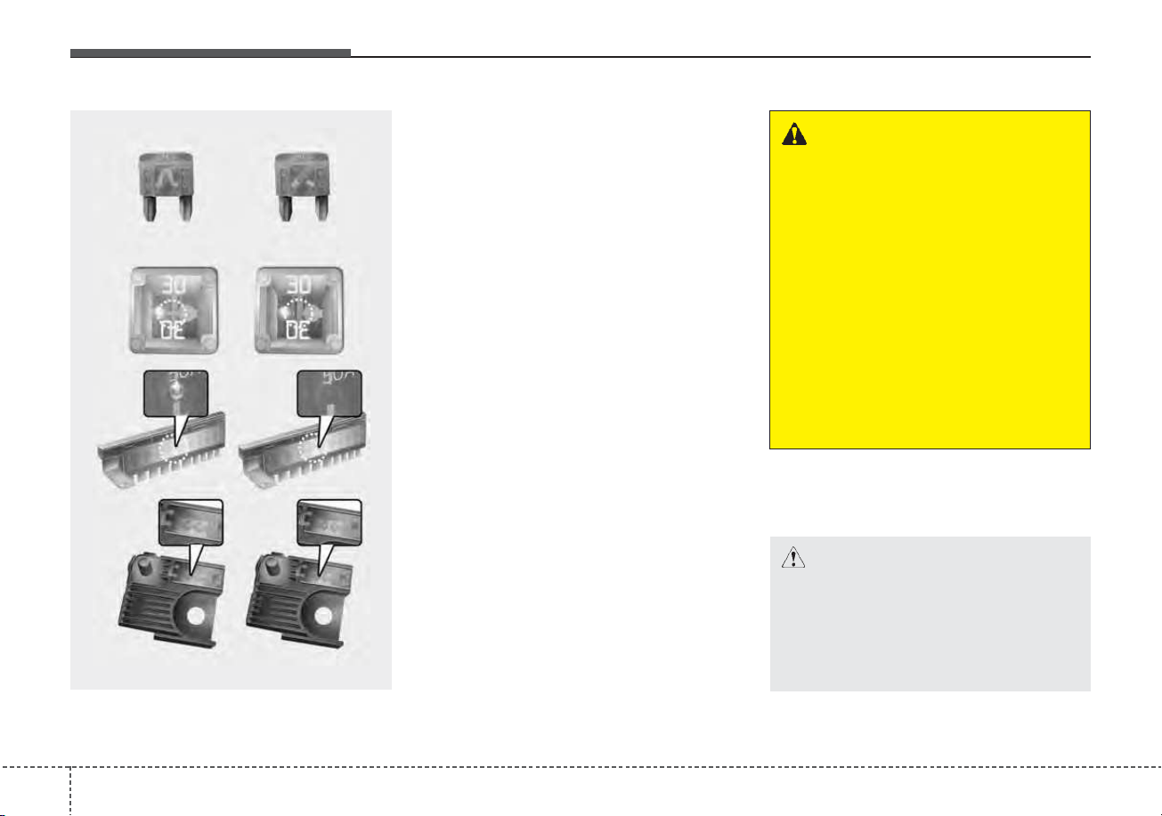
Maintenance
587
FUSES
❈ Left side : Normal , Right side : Blown
A vehicle’s electrical system is pro-
tected from electrical overload dam-
age by fuses.
This vehicle has 2 (or 3) fuse panels,
one located in the driver’s side panel
bolster, the other in the engine com-
partment near the battery.
If any of your vehicle’s lights, acces-
sories, or controls do not work, check
the appropriate circuit fuse. If a fuse
has blown, the element inside the
fuse will melt.
If the electrical system does not
work, first check the driver’s side
fuse panel.
Always replace a blown fuse with
one of the same rating.
If the replacement fuse blows, this
indicates an electrical problem. Avoid
using the system involved and imme-
diately consult an authorized Kia
dealer.
Three kinds of fuses are used: blade
type for lower amperage rating, car-
tridge type, and multi fuse for higher
amperage ratings.
• Do not arbitrarily modify or add-on
electric wiring to the vehicle.
WARNING - Fuse replace-
ment
• Never replace a fuse with any-
thing but another fuse of the
same rating.
• A higher capacity fuse could
cause damage and possibly a
fire.
• Never install a wire or alu-
minum foil instead of the
proper fuse - even as a tem-
porary repair. It may cause
extensive wiring damage and
a possible fire.
CAUTION
Do not use a screwdriver or any
other metal object to remove
fuses because it may cause a
short circuit and damage the
system.
OJF075021
■ Blade type
■ Cartridge type
■ Multi fuse
■ BFT
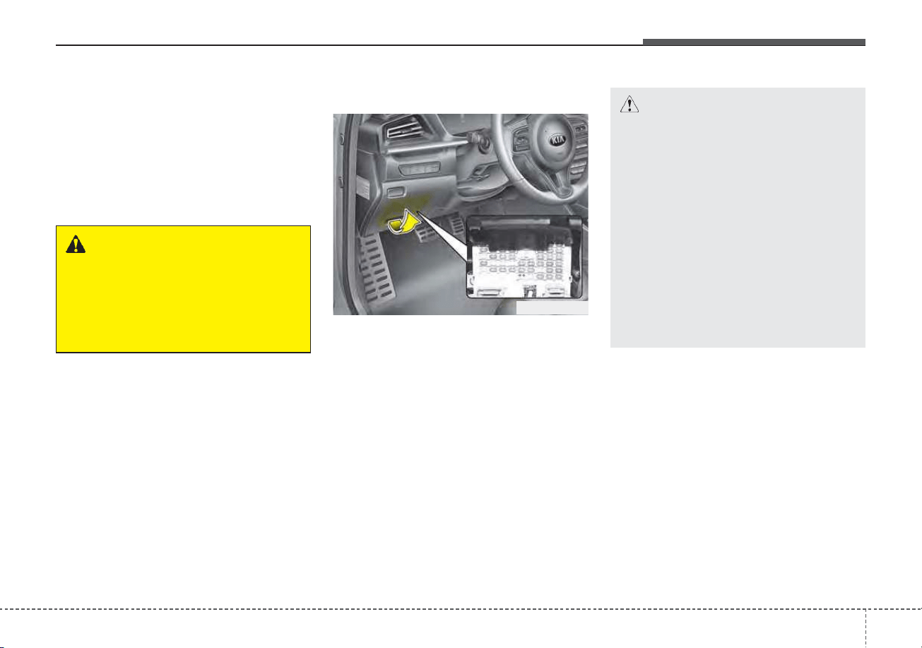
759
Maintenance
✽✽
NOTICE
• When replacing fuse, turn the
ignition “OFF” and turn off
switches of all electrical devices
then remove battery (-) terminal.
• The actual fuse/relay panel label
may differ from equipped items.
Inner panel fuse replacement
1. Turn the engine start/stop button
to the OFF position and all other
switches off.
2. Open the fuse panel cover.
If the switch is located in the “OFF”
position, a caution indicator will be
displayed in the cluster.
WARNING - Electrical Fire
Always ensure replacements
fuses and relays are securely
fastened when installed. Failure
to do so can result in a vehicle
fire.
CAUTION
• When replacing a blown fuse
or relay, make sure the new
fuse or relay fits tightly into
the clips. Failure to tightly
install the fuse or relay may
cause damage to the wiring
and electric systems.
• Do not remove fuses, relays
and terminals fastened with
bolts or nuts.The fuses, relays
and terminals may not be fas-
tened correctly which may
cause vehicle damage.
ODEP079017
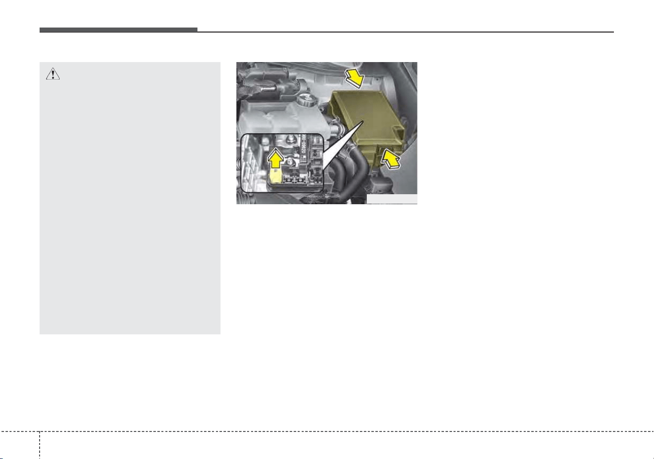
Maintenance
607
3. Pull the suspected fuse straight
out. Use the removal tool provided
on the engine compartment fuse
panel cover.
4. Check the removed fuse; replace it
if it is blown.
Spare fuses are provided in the
engine compartment fuse panel.
5. Push in a new fuse of the same
rating, and make sure it fits tightly
in the clips.
If it fits loosely, consult an authorized
Kia dealer.
If you do not have a spare, use a
fuse of the same rating from a circuit
you may not need for operating the
vehicle, such as the power outlet
fuse.
If the head lamp, turn signal lamp,
stop signal lamp, fog lamp, DRL, tail
lamp, HMSL do not work and the
fuses are OK, check the fuse panel
in the engine compartment. If a fuse
is blown, it must be replaced.
✽✽
NOTICE
If the headlamp, fog lamp, turn sig-
nal lamp, or tail lamp malfunction
even without any problem to the
lamps, have the vehicle checked by
an authorized Kia dealer for assis-
tance.
ODEP079020
CAUTION
• Do not input any other objects
except fuses or relays into
fuse/relay terminals, such as a
driver or wiring. It may cause
contact failure and system
malfunction.
• Do not plug in screwdrivers or
aftermarket wiring into the ter-
minal originally designed for
fuse and relays only. The elec-
trical system and wiring of the
vehicle interior may be dam-
aged or burned due to contact
failure.
• If you directly connect the
wire on the taillight or replace
the bulb which is over the reg-
ulated capacity to install trail-
ers, etc., the inner junction
block can get burned.
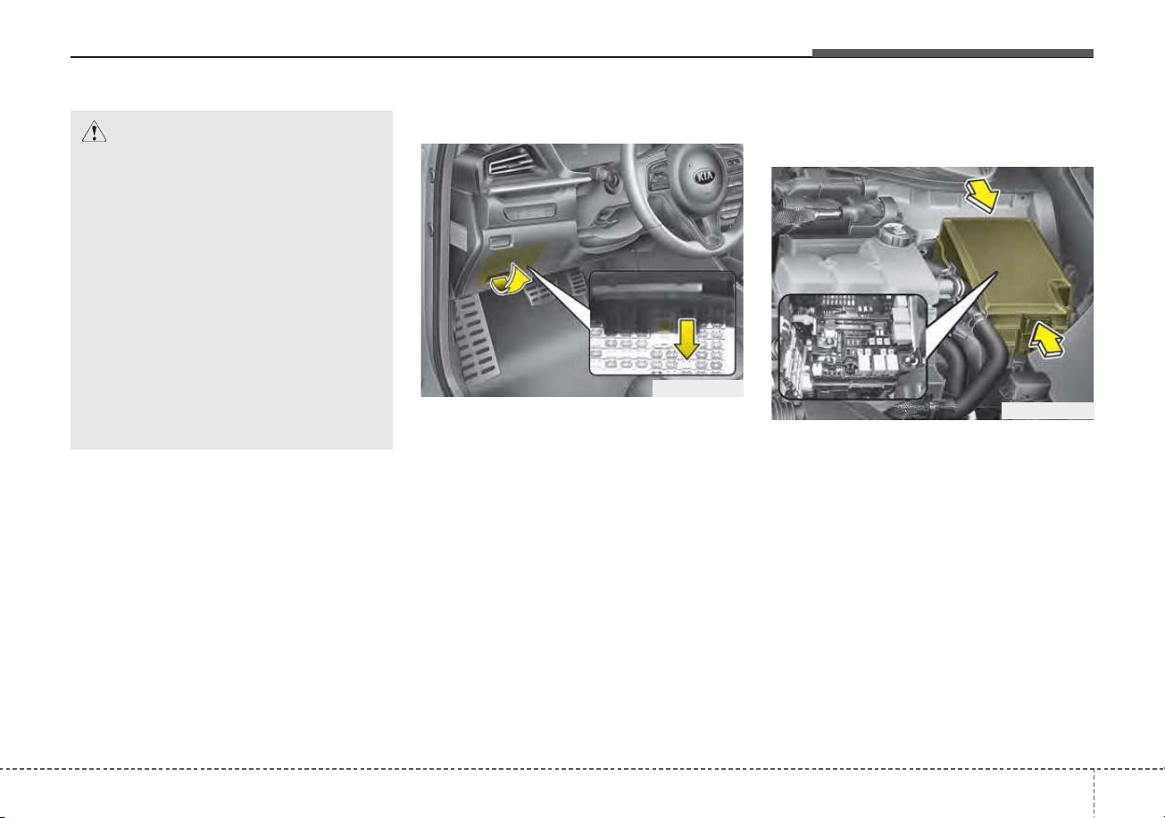
761
Maintenance
Fuse switch
Always set the fuse switch to the ON
position before using the vehicle.
If you move the switch to the OFF
position, some items such as audio
and digital clock must be reset and
transmitter (or smart key) may not
work properly. When the switch is
Off, the caution indicator will be dis-
played on the instrument cluster.
Always place the fuse switch in the
ON position while driving the vehicle.
If the switch is located in the “OFF”
position, a caution indicator will be
displayed in the cluster.
Engine compartment fuse
replacement
1. Turn the engine start/stop button
to the OFF position and all other
switches off.
2. Remove the fuse panel cover by
pressing the tab and pulling the
cover up. When the blade type
fuse is disconnected, remove it by
using the clip designed for chang-
ing fuses located in the engine
compartment fuse box. Upon
removal, securely insert reserve
fuse of the same rating.
ODEP079018
ODEP079021
CAUTION - Fuse Panel
Covers
• Set all switches to ON before
driving.
• If the vehicle is going to be
unused for over 1 month, set
all switches to OFF to prevent
the batteries from draining.
• The contact points of the
switches may wear out with
excessive use. Please refrain
from excessive use of the
switches (except for long-term
parking for over 1 month).
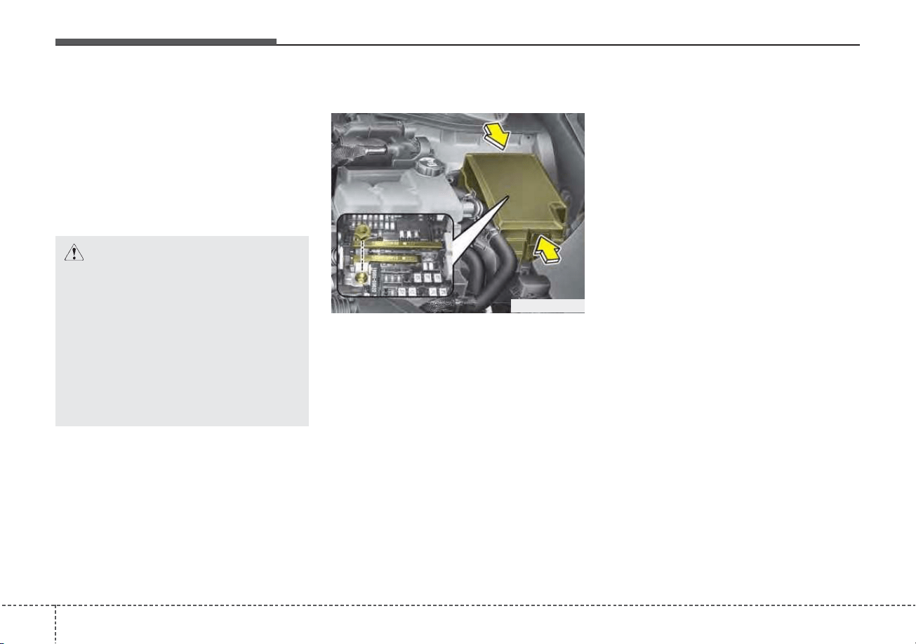
Maintenance
627
3. Check the removed fuse; replace it
if it is blown. To remove or insert
the fuse, use the fuse puller in the
engine compartment fuse panel.
4. Push in a new fuse of the same
rating, and make sure it fits tightly
in the clips. If it fits loosely, consult
an authorized Kia dealer.
Multi fuse
If the multi fuse is blown, it must be
removed as follows:
1. Turn off the engine.
2. Disconnect the negative battery
cable.
3. Remove the nuts shown in the pic-
ture above.
4. Replace the fuse with a new one
of the same rating.
5. Reverse these steps to reinstall
the multi fuse.
✽✽
NOTICE
Do not disassemble nor assemble the
multi fuse when it is secured with
nuts and bolts. Incorrect or partial
assembly torque may cause a fire.
Have the vehicle checked by an
authorized Kia dealer.
ODEP079022
CAUTION
After checking the fuse panel in
the engine compartment,
securely install the fuse panel
cover to protect against any
electrical failure which may
occur from water contact. Listen
for the audible clicking sound to
ensure the fuse panel cover is
securely fastened.
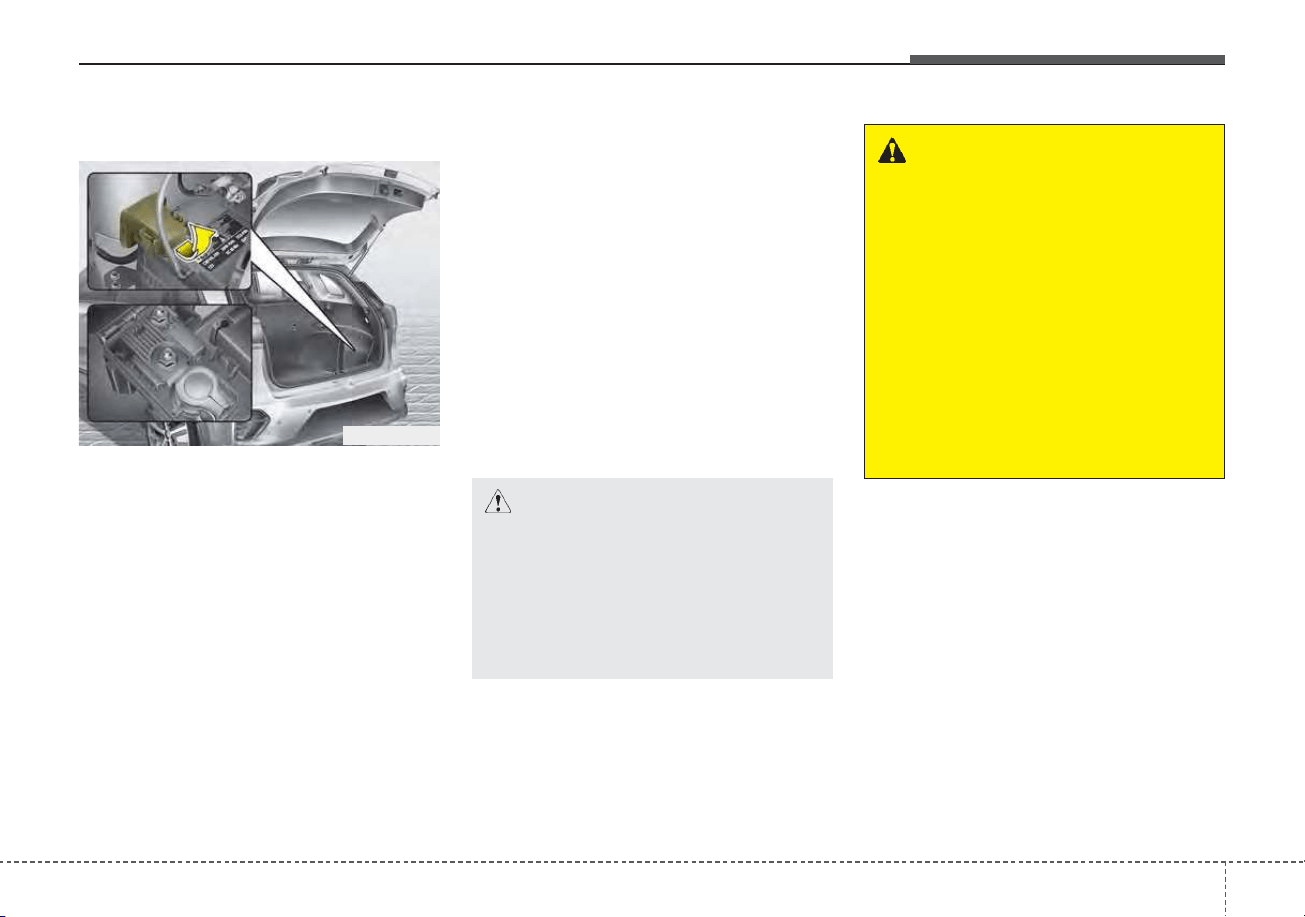
763
Maintenance
Main fuse (Plug-in Hybrid)
If the multi fuse is blown, it must be
removed as follows:
1. Turn off the engine.
2. Disconnect the negative battery
cable.
3. Remove the nuts shown in the pic-
ture above.
4. Replace the fuse with a new one
of the same rating.
5. Reverse these steps to reinstall
the multi fuse.
✽✽
NOTICE
The electronic system may not func-
tion correctly even when the engine
compartment and internal fuse
box’s individual fuses are not dis-
connected. In such case the cause of
the problem may be disconnection
of the main fuse (BFT type), which is
located inside the positive battery
terminal (+) cap.
Since the main fuse is designed more
intricately than other parts, have the
vehicle checked by an authorized
Kia dealer.
✽
✽
NOTICE - Remodeling
Prohibited
Do not rewire your vehicle in any
way as doing so may affect the per-
formance of several safety features
in your vehicle. Rewiring your vehi-
cle may also void your warranty and
cause you to be responsible for any
subsequent vehicle damage which
may result.
CAUTION
Visually inspect the battery cap
to ensure it is securely closed.
If the battery cap is not securely
closed, moisture may enter the
system and damage the electri-
cal components.
WARNING - Random
wiring prohibited when
retrofitting equipment
Use of random wiring in the
vehicle might cause danger due
to failure and damage of the
vehicle’s performance.
Using random wires especially
when retrofitting AVN or theft
alarm system, remote engine
control, car phone or radio
might damage the vehicle or
cause fire.
ODEP079023
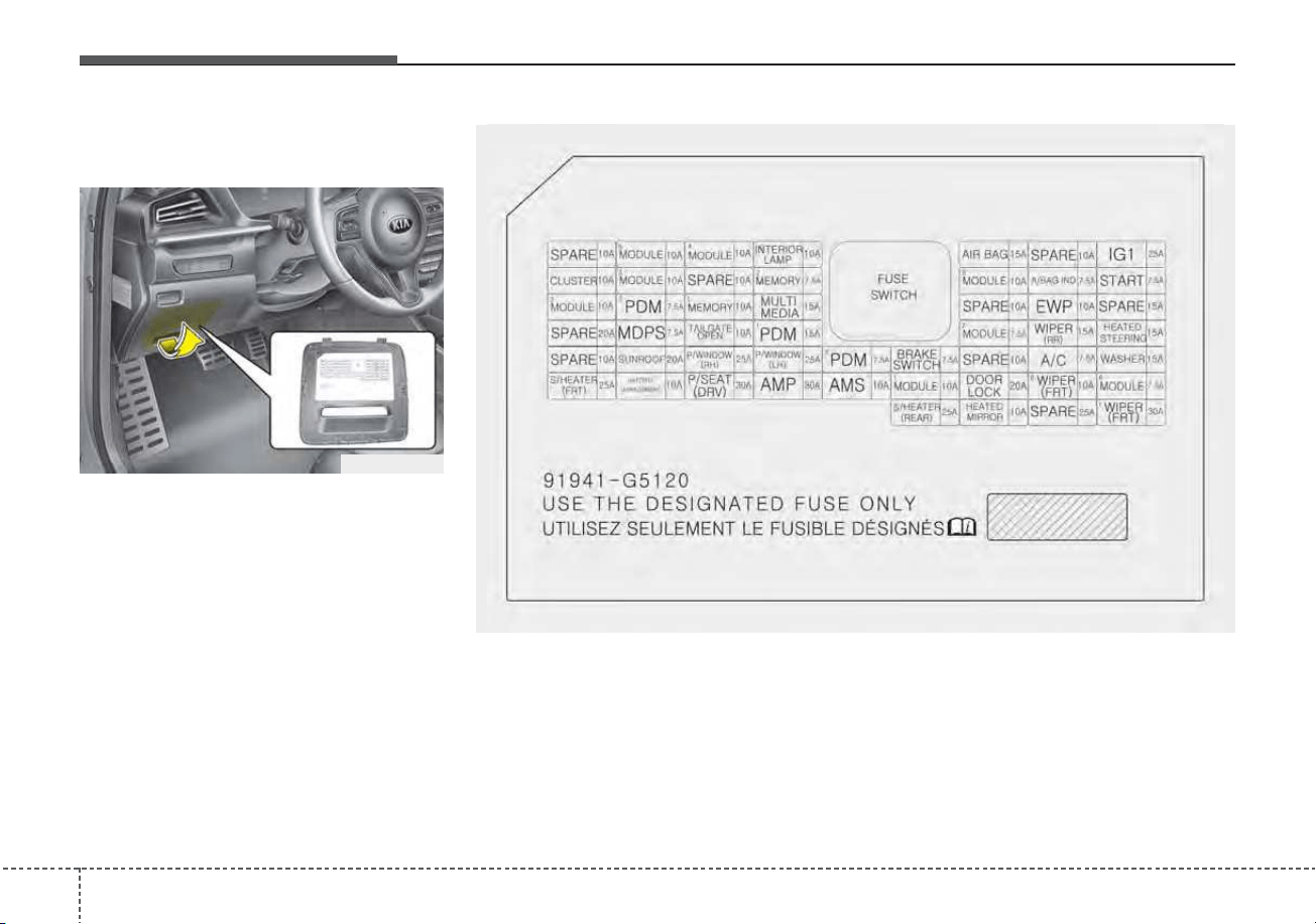
Maintenance
647
Fuse/relay panel description
Driver’s side fuse panel
Inside the fuse/relay panel covers,
you can find the fuse/relay label
describing fuse/relay name and
capacity.
✽✽
NOTICE
Not all fuse panel descriptions in
this manual may be applicable to
your vehicle. It is accurate at the
time of printing. When you inspect
the fuse panel in your vehicle, refer
to the fuse panel label.
ODEP079117N
ODEP079024
■ Driver’s side fuse panel (Hybrid)
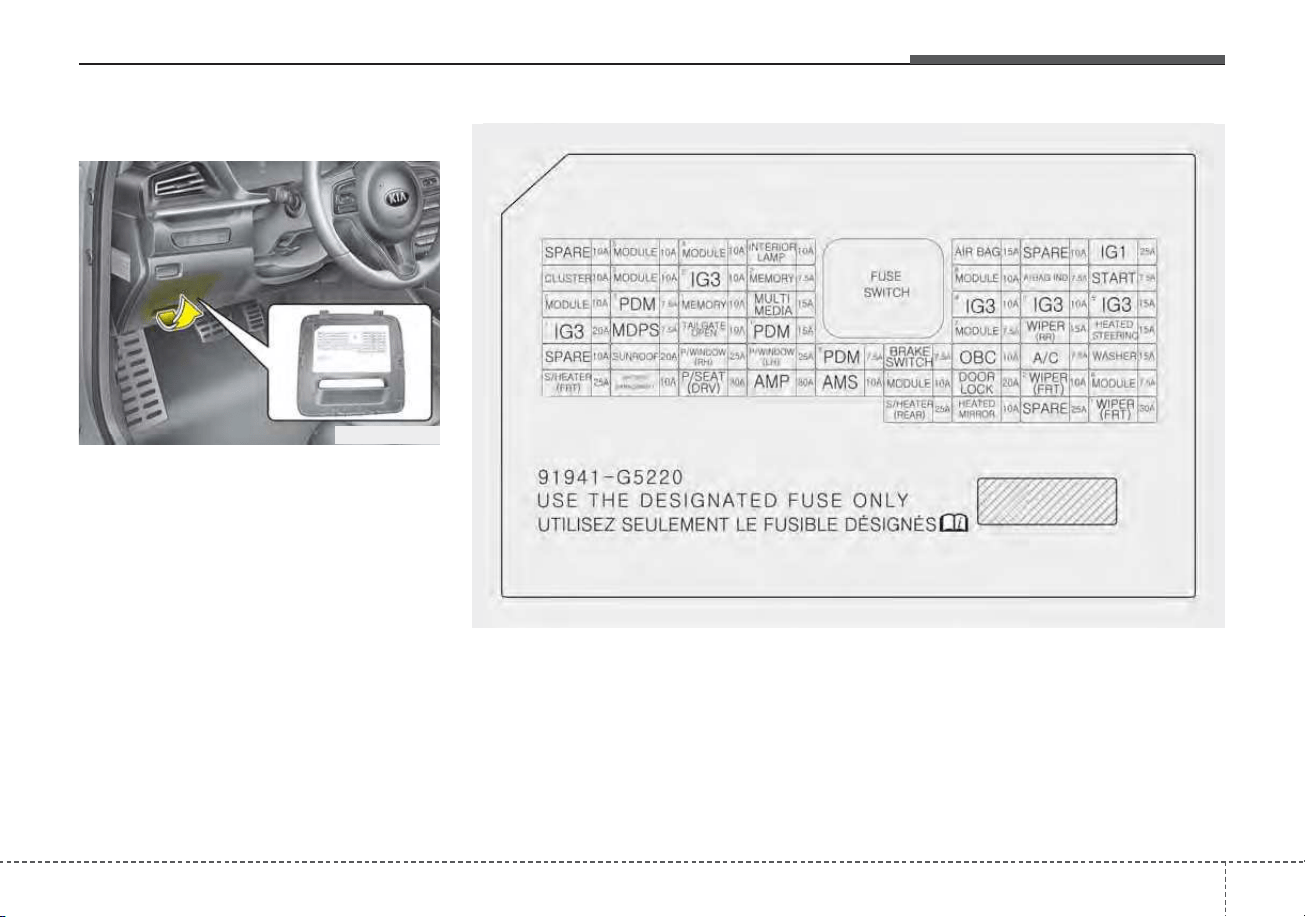
765
Maintenance
Driver’s side fuse panel
Inside the fuse/relay panel covers,
you can find the fuse/relay label
describing fuse/relay name and
capacity.
✽✽
NOTICE
Not all fuse panel descriptions in
this manual may be applicable to
your vehicle. It is accurate at the
time of printing. When you inspect
the fuse panel in your vehicle, refer
to the fuse panel label.
ODEP079118N
■ Driver’s side fuse panel (Plug-in Hybrid)
ODEP079024

Maintenance
667
Instrument panel (Driver’s side fuse panel) (Hybrid)
Fuse Name Fuse rating Circuit Protected
MODULE 5 10A
Electro Chromic Mirror, Audio/Video & Navigation Head Unit, Audio, Shift Lever Indicator, Air Conditioner
Control Module, Rear Seat Warmer Control Module, Front Air Ventilation Seat Control Module, Front Seat
Warmer Control Module, Head Lamp Leveling Device Actuator LH/RH, Crash Pad Switch, AMP (Amplifier)
MODULE 4 10A
Lane Keeping Assist Control Module, Crash Pad Switch, Blind-Spot Collision Warning (BCW) Radar Left
Handle side/Right Handle side, EPB, VESS, Front Seat Warmer Control Module
INTERIOR
LAMP
10A
Front Vanity Lamp LH/RH, Room Lamp, Overhead Console Lamp, Luggage Lamp, Mood Lamp, BCM,
Wireless Charger
A/BAG 15A Passenger Occupant Detection Sensor, ACU
IG 1 25A Engine Room Junction Block (Fuse - DCT4, HPCU2, ACTIVE HYDRAULIC BOOSTER3, ECU3)
CLUSTER 10A Instrument Cluster
MODULE 3 10A
BCM (Body Control Module), DCT (Dual Clutch Transmission) Shift Lever, Stop Lamp Switch, Driver Door
Module, Passenger Door Module
MEMORY 2 7.5A Active Air Flap Unit, VESS
MODULE 8 10A
Active Air Flap Unit, Electric Water Pump (Engine), Engine Room Junction Block (Battery C/Fan Relay),
BMS (Battery Management System) Control Module
A/BAG IND 7.5A Air Conditioner Control Module, Instrument Cluster
START 7.5A [With Smart Key/With Immobilizer] Inhibitor Switch

767
Maintenance
Fuse Name Fuse rating Circuit Protected
MODULE 2 10A
Engine Room Junction Block (Power Outlet Relay), Wireless Charger, BCM (Body Control Module), USB
Charger, Smart Key Control Module, Audio, BMS (Battery Management System) Control Module,
Audio/Video & Navigation Head Unit, Driver Power Outside Mirror Switch, AMP (Amplifier)
PDM 3 7.5A
[Without Smart Key] Immobilizer Module
[With Smart Key] Smart Key Control Module
MEMORY 1 10A
Instrument Cluster, Driver IMS (Integrated memory system) Module, BCM (Body Control Module), Air
Conditioner Control Module, Auto Light & Photo Sensor, Driver Door Module, Passenger Door Module,
ECM (Electric Chromic Mirror)
MULTI MEDIA 15A Audio, Audio/Video & Navigation Head Unit
EWP 10A Electric Water Pump (HEV)
MDPS 7.5A MDPS (Motor Driven Power Steering) Unit
TAIL GATE 10A Tail Gate Relay, ICM Relay Box (Fuel Filler Door Relay), Fuel Filler Switch
PDM 1 15A Smart Key Control Module
MODULE 7 7.5A
Front Seat Warmer Control Module, AC Inverter (110V), Front Air Ventilation Seat Control Module, Rear
Seat Warmer Module, AC Inverter Module
WIPER (RR) 15A Engine Room Junction Block (Wiper RR Relay), Rear Wiper Motor
HEATED
STEERING
15A BCM (Body Control Module)
SUNROOF 20A Sunroof Motor

Maintenance
687
Fuse Name Fuse rating Circuit Protected
P/WINDOW RH 25A Power Window (RH) Relay, Passenger Safety Power Window Module
P/WINDOW LH 25A Power Window (LH) Relay, Driver Safety Power Window Module
PDM 2 7.5A
[Without Smart Key] Immobilizer Module
[With Smart Key] Smart Key Control Module, Start/Stop Button Switch
BRAKE SWITCH 7.5A Stop Lamp Switch, Smart Key Control Module
A/CON 7.5A
Air Conditioner Control Module, Electronic Air Conditioner Compressor, Engine Room Junction Block
(Blower Relay, PTC Heater1 Relay, PTC Heater2 Relay)
WASHER 15A Multifunction Switch
S/HEATER (FRT) 25A Front Seat Warmer Control Module, Front Air Ventilation Seat Control Module
BATTERY
MANAGEMENT
10A BMS (Battery Management System) Control Module
P/SEAT (DRV) 30A
[Without IMS] Driver Seat Manual Switch
[With IMS] Driver Seat Manual Switch, Driver IMS (Integrated memory system) Module
AMP 30A AMP (Amplifier)
AMS 10A Not Used
MODULE 1 10A
Data Link Connector, Forward Collision-Avoidance Assist (FCA) Module, Hazard Switch, Driver/Passenger
Smart Key Outside Handle, Key Interlock, Natural Vacuum Leak Detection, Outside Mirror Folding/Unfolding
Relay, Mood Lamp, Outside Mirror Switch

769
Maintenance
Fuse Name Fuse rating Circuit Protected
DOOR LOCK 20A Door Lock/Unlock Relay, ICM Relay Box (Two Turn Unlock Relay)
WIPER 2 (FRT) 10A
Wiper Motor, Engine Room Junction Block (Front Wiper (Low) Relay), ECM (Engine Control Module),
BCM (Body Control Module)
MODULE 6 7.5A BCM (Body Control Module), Smart Key Control Module
S/HEATER
(REAR)
25A Rear Seat Warmer Control Module
HEATED
MIRROR
10A Driver Power Outside Mirror, Passenger Power Outside Mirror, Air Conditioner Control Module
WIPER1 (FRT) 30A Wiper Motor, Engine Room Junction Block (Front Wiper (Low) Relay)

Maintenance
707
Instrument panel (Driver’s side fuse panel) (Plug-in Hybrid)
Fuse Name Fuse rating Circuit Protected
MODULE 5 10A
Electro Chromic Mirror, Audio/Video & Navigation Head Unit, Audio, VESS (Virtual Engine Sound System)
Unit, Air Conditioner Control Module, Rear Seat Warmer Control Module, Front Air Ventilation Seat Control
Module, Front Seat Warmer Control Module, Head Lamp Leveling Device Actuator LH/RH, Crash Pad
Switch, AMP (Amplifier)
MODULE 4 10A
Lane Keeping Assist Control Module, Crash Pad Switch, Blind-Spot Collision Warning (BCW) Radar Left
Handle side/Right Handle side, EPB, VESS, Front Seat Warmer Control Module
INTERIOR
LAMP
10A
Front Vanity Lamp LH/RH, Room Lamp, Overhead Console Lamp, Door Warning Switch, Luggage Lamp,
Wireless Charger, Mood Lamp, BCM
A/BAG 15A Passenger Occupant Detection Sensor, ACU
IG 1 25A Engine Room Junction Block (Fuse - DCT4, HPCU2, ACTIVE HYDRAULIC BOOSTER3)
CLUSTER 10A Instrument Cluster
MODULE 3 10A
BCM (Body Control Module), DCT (Dual Clutch Transmission) Shift Lever, Stop Lamp Switch, Driver Door
Module, Passenger Door Module
IG3 2 10A
Fuel Filler Door & Battery Charger Switch, Instument Cluster, Audio, Charger Indicator, Integrated Gateway
Power control Module, Audio/Video & Navigation Head Unit
MEMORY 2 7.5A Active Air Flap Unit, VESS
MODULE 8 10A Active Air Flap Unit, Electric Water Pump (Engine)
A/BAG IND 7.5A Air Conditioner Control Module, Instrument Cluster

771
Maintenance
Fuse Name Fuse rating Circuit Protected
START 7.5A INHIBITOR SW
MODULE 2 10A
Engine Room Junction Block (Power Outlet Relay), Wireless Charger, BCM (Body Control Module), USB
Charger, Smart Key Control Module, Audio, Audio / Video & Navigation Head Unit, Power Outside Mirror
Switch, AMP (Amplifier)
PDM3 7.5A Immobilizer Module, Smart Key Control Module
MEMORY 1 10A
Instrument Cluster, Driver IMS (Integrated memory system) Module, BCM (Body Control Module), Air
Conditioner Control Module, Auto Light & Photo Sensor, Driver Door Module, Passenger Door Module,
ECM (Electric Chromic Mirror)
MULTI MEDIA 15A Audio, Audio / Video & Navigation Head Unit
IG3 4 10A
OBC (On-Board Charger) Unit, TCM (Transmission Control Module), ECM (Engine Control Module), HPCU
(Hybrid Power Control Unit)
IG3 3 10A Electric Water Pump (PHEV)
IG3 5 15A
Transmission Range Switch, BMS (Battery Management System) Control Module, Engine Room Junction
Block (Battery C/Fan Relay)
IG3 1 20A ICM Relay Box (IG3 #1, IG3 #2, IG3 #3 Relay)
MDPS 7.5A MDPS (Motor Driven Power Steering) Unit
TAIL GATE
OPEN
10A
Tail Gate Relay, ICM Relay Box (Fuel Filler Door Relay, Charger Connector Lock/Unlock Relay), Fuel Filler
& Battery Charger Switch, Charge Connector Lamp
PDM 1 15A Smart Key Control Module

Maintenance
727
Fuse Name Fuse rating Circuit Protected
MODULE 7 7.5A
Front Seat Warmer Control Module, AC Inverter (110V), Front Air Ventilation Seat Control Module, Rear
Seat Warmer Module, AC Inverter Module
WIPER (RR) 15A Engine Room Junction Block (Wiper RR Relay), Rear Wiper Motor
HEATED
STEERING
15A BCM (Body Control Module)
SUNROOF 20A Sunroof Motor
P/WINDOW RH 25A
Power Window (RH) Relay, Power Window Main Switch, Passenger Power Window Switch, Rear Power
Window Switch RH, Passenger Safety Power Window Module
P/WINDOW LH 25A
Power Window (LH) Relay, Power Window Main Switch, Rear Power Window Switch LH, Driver Safety
Power Window Module
PDM 2 7.5A Immobilizer Module, Smart Key Control Module, Start/Stop Button Switch
BRAKE SWITCH 7.5A Stop Lamp Switch, Smart Key Control Module
OBC 10A OBC (On-Board Charger) Unit
A/CON 7.5A
Air Conditioner Control Module, Electronic Air Conditioner Compressor, Engine Room Junction Block
(Blower Relay, PTC Heater1 Relay, PTC Heater2 Relay)
WASHER 15A Multifunction Switch
S/HEATER (FRT) 25A Front Seat Warmer Control Module, Front Air Ventilation Seat Control Module

773
Maintenance
Fuse Name Fuse rating Circuit Protected
BATTERY
MANAGEMENT
10A BMS (Battery Management System) Control Module
P/SEAT (DRV) 30A Driver Seat Manual Switch, Driver IMS (Integrated memory system) Module
AMP 30A AMP (Amplifier)
AMS 10A Battery Sensor
MODULE 1 10A
Data Link Connector, Forward Collision-Avoidance Assist (FCA) Module, Hazard Switch, Driver/Passenger
Door Module, Driver/Passenger Smart Key Outside Handle, Outside Mirror Folding/Unfolding Relay, Mood
Lamp, Outside Mirror Switch
DOOR LOCK 20A Door Lock/Unlock Relay, ICM Relay Box (Two Turn Unlock Relay)
WIPER2 (FRT) 10A
Wiper Motor, Engine Room Junction Block (Front Wiper (Low) Relay), ECM (Engine Control Module), BCM
(Body Control Module)
MODULE 6 7.5A BCM (Body Control Module), Smart Key Control Module
S/HEATER
(REAR)
25A Rear Seat Warmer Control Module
HEATED
MIRROR
10A Driver Power Outside Mirror, Passenger Power Outside Mirror, Air Conditioner Control Module
WIPER 1 (FRT) 30A Wiper Motor, Engine Room Junction Block (Front Wiper (Low) Relay)
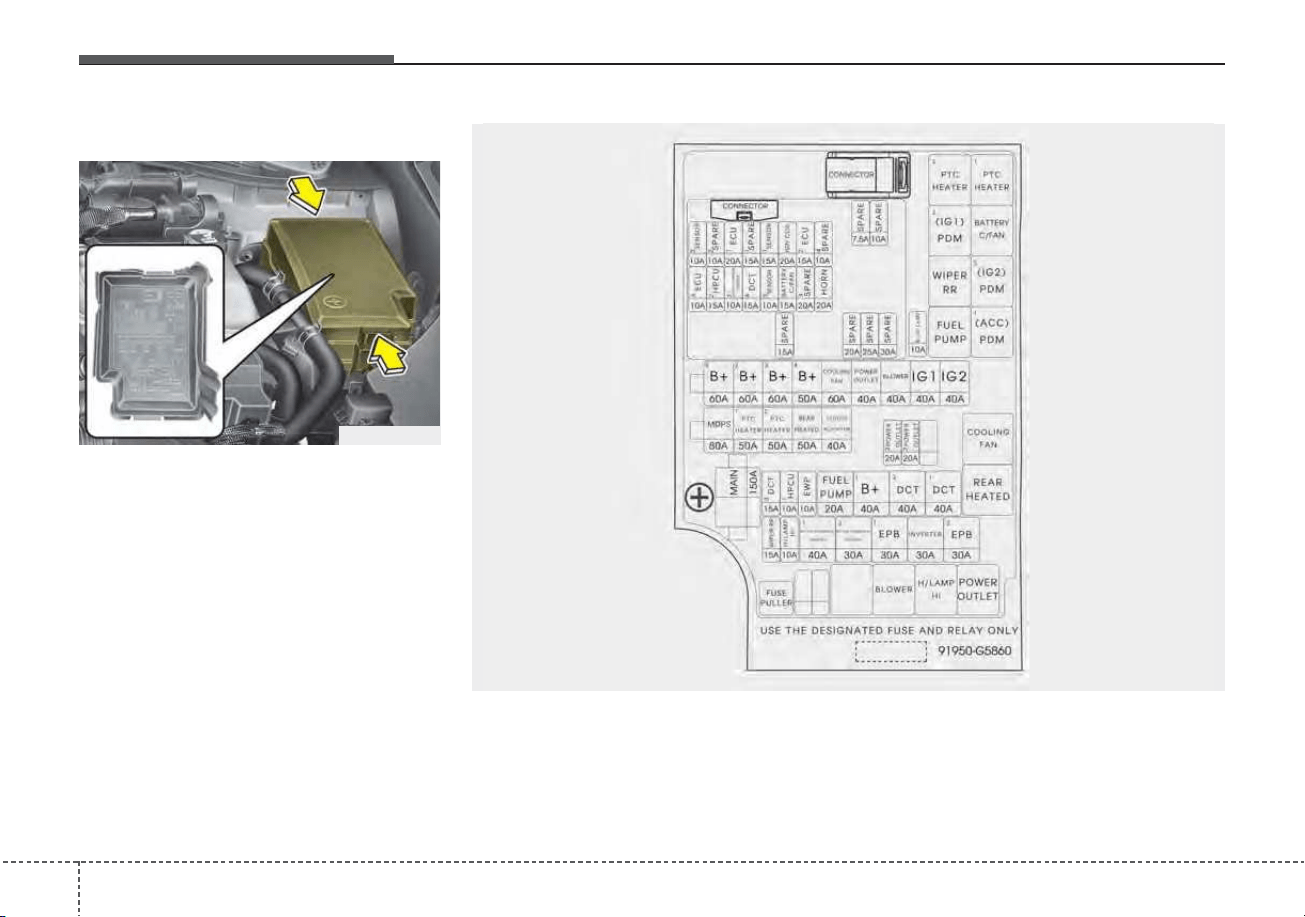
Maintenance
747
Engine compartment fuse panel
ODEP079119N
ODE076027N

775
Maintenance
Engine room compartment fuse panel (Hybrid)
Fuse Name Fuse rating Circuit Protected
MULTI FUSE
B+ 5 60A Fuse - BATTERY C/FAN, HORN, ECU2, Engine Control Relay
B+ 2 60A Instrument Panel Junction Block (Fuse - S/HEATER (REAR))
B+ 3 60A Instrument Panel Junction Block
B+ 4 50A
Instrument Panel Junction Block (Fuse - BATTERY MANAGEMENT, P/WINDOW (LH), P/WIN-
DOW (RH), TAIL GATE OPEN, SUNROOF, AMP, S/HEATER (FRT), P/SEAT (DRV))
COOLING FAN 60A Cooling Fan Relay
REAR HEATED 50A Rear Heated Relay
BLOWER 40A Blower Relay
IG 1 40A [Without Smart Key] Ignition Switch, [With Smart Key] PDM1 (ACC) Relay, PDM2 (IG1) Relay
IG 2 40A [Without Smart Key] Ignition Switch, [With Smart Key] PDM3 (IG2) Relay
MDPS 80A MDPS (Motor Driven Power Steering) Unit
PTC
HEATER 1
50A PTC Heater 1 Relay
PTC
HEATER 2
50A PTC Heater 2 Relay
CLUTCH
ACTUATOR
40A Clutch Actuator (HEV)
MAIN 150A
Fuse - H/LAMP HI, INVERTER, ACTIVE HYDRAULIC BOOSTER1, ACTIVE HYDRAULIC
BOOSTER2, WIPER RR, EPB1, EPB2

Maintenance
767
Fuse Name Fuse rating Circuit Protected
FUSE
POWER
OUTLET 3
20A Power Outlet #2
POWER
OUTLET 2
20A Power Outlet #1
DCT 3 15A TCM (Transmission Control Module)
HPCU 1 10A HPCU (Hybrid Power Control Unit)
EWP 10A Electric Water Pump (Engine)
FUEL PUMP 20A Fuel Pump Relay
B + 1 40A
Instrument Panel Junction Block (Fuse - BRAKE SWITCH, PDM1, PDM2, MODULE1, DOOR
LOCK, Leak Current Autocut Device)
DCT 2 40A TCM (Transmission Control Module)
DCT 1 40A TCM (Transmission Control Module)
WIPER RR 15A Wiper RR Relay
H/LAMP HI 10A H/Lamp HI Relay
ACTIVE
HYDRAULIC
BOOTER 1
40A Integrated Brake Actuation Unit, Multipurpose Check Connector

777
Maintenance
Fuse Name Fuse rating Circuit Protected
FUSE
ACTIVE
HYDRAULIC
BOOTER 2
30A Integrated Brake Actuation Unit
INVERTER 30A AC Inverter Module
POWER
OUTLET 1
40A Power Outlet Relay
B/UP LAMP 10A Electro Chromic Mirror, Back-Up Lamp LH/RH, INHIBITOR SW
ECU 3 10A ECM (Engine Control Module)
HPCU 2 15A HPCU (Hybrid Power Control Unit), Clutch Actuator (HEV)
ACTIVE
HYDRAULIC
BOOTER 3
10A Integrated Brake Actuation Unit, Multipurpose Check Connector
DCT 4 15A
DCT (Dual clutch transmission) Shift Lever, TCM (Transmission Control Module), Inhibitor
Switch
SENSOR 3 10A
Fuel Pump Relay, Oil Control Valve #1/#2 (Intake/Exhaust), Camshaft Position Sensor #1/#2
(Intake/Exhaust)
BATTERY C/FAN 15A Battery C/Fan Relay
HORN 20A Horn Relay
SENSOR 2 10A Purge Control Solenoid Valve, Cooling Fan Relay, Canister Close Valve, Mass Air Flow Sensor
ECU 1 20A ECM (Engine Control Module)

Maintenance
787
Fuse Name Fuse rating Circuit Protected
FUSE
SENSOR 1 15A Oxygen Sensor (Up), Oxygen Sensor (Down)
IGN COIL 20A Ignition Coil #1/#2/#3/#4
ECU 2 15A ECM (Engine Control Module)

779
Maintenance
Engine room compartment fuse panel (Plug-in Hybrid)
Fuse Name Fuse rating Circuit Protected
MULTI FUSE
B+ 5 60A Fuse - BATTERY C/FAN, HORN, ECU2, Engine Control Relay
B+ 2 60A Instrument Panel Junction Block (Fuse - S/HEATER (REAR))
B+ 3 60A Instrument Panel Junction Block
B+ 4 50A
Instrument Panel Junction Block (Fuse - BATTERY MANAGEMENT, P/WINDOW (LH), P/WIN-
DOW (RH), TAIL GATE OPEN, SUNROOF, AMP, S/HEATER (FRT), P/SEAT (DRV), IG3 1,
OBC, AMS)
COOLING FAN 60A Cooling Fan Relay
REAR HEATED 50A Rear Heated Relay
BLOWER 40A Blower Relay
IG 1 40A [Without Smart Key] Ignition Switch, [With Smart Key] PDM1 (ACC) Relay, PDM2 (IG1) Relay
IG 2 40A [Without Smart Key] Ignition Switch, [With Smart Key] PDM3 (IG2) Relay
MDPS 80A MDPS (Motor Driven Power Steering) Unit
PTC
HEATER 1
50A PTC Heater 1 Relay
PTC
HEATER 2
50A PTC Heater 2 Relay
CLUTCH
ACTUATOR
40A Clutch Actuator (PHEV)
MAIN 150A
Fuse - H/LAMP HI, INVERTER, ACTIVE HYDRAULIC BOOSTER1, ACTIVE HYDRAULIC
BOOSTER2, WIPER RR, EPB1, EPB2

Maintenance
807
Fuse Name Fuse rating Circuit Protected
FUSE
POWER
OUTLET 3
20A Power Outlet #2
POWER
OUTLET 2
20A Power Outlet #1
DCT 3 15A TCM (Transmission Control Module)
HPCU 1 10A HPCU (Hybrid Power Control Unit)
EWP 10A Electric Water Pump (Engine)
FUEL PUMP 20A Fuel Pump Relay
B + 1 40A
Instrument Panel Junction Block (Fuse - BRAKE SWITCH, PDM1, PDM2, MODULE1, DOOR
LOCK, Leak Current Autocut Device)
DCT 2 40A TCM (Transmission Control Module)
DCT 1 40A TCM (Transmission Control Module)
WIPER RR 15A Wiper RR Relay
H/LAMP HI 10A H/Lamp HI Relay
ACTIVE
HYDRAULIC
BOOTER 1
40A Integrated Brake Actuation Unit, Multipurpose Check Connector

781
Maintenance
Fuse Name Fuse rating Circuit Protected
FUSE
ACTIVE
HYDRAULIC
BOOTER 2
30A Integrated Brake Actuation Unit
INVERTER 30A AC Inverter Module
POWER
OUTLET 1
40A Power Outlet Relay
B/UP LAMP 10A Electro Chromic Mirror, Back-Up Lamp LH/RH, INHIBITOR SW
ECU 3 10A ECM (Engine Control Module)
HPCU 2 15A HPCU (Hybrid Power Control Unit), Clutch Actuator (PHEV)
ACTIVE
HYDRAULIC
BOOTER 3
10A Integrated Brake Actuation Unit, Multipurpose Check Connector
DCT 4 15A
DCT(Dual clutch transmission) Shift Lever, TCM (Transmission Control Module), Inhibitor
Switch
SENSOR 3 10A
Fuel Pump Relay, Oil Control Valve #1/#2 (Intake/Exhaust), Camshaft Position Sensor #1/#2
(Intake/Exhaust)
BATTERY C/FAN 15A Battery C/Fan Relay
HORN 20A Horn Relay
SENSOR 2 10A Purge Control Solenoid Valve, Cooling Fan Relay, Mass Air Flow Sensor, ELCM
ECU 1 20A ECM (Engine Control Module)

Maintenance
827
Fuse Name Fuse rating Circuit Protected
FUSE
SENSOR 1 15A Oxygen Sensor (Up), Oxygen Sensor (Down)
IGN COIL 20A Ignition Coil #1/#2/#3/#4
ECU 2 15A ECM (Engine Control Module)

783
Maintenance
Relay (Hybrid)
Relay Name Type
PTC Heater #2 Relay MICRO
PTC Heater #1 Relay MICRO
PDM2 (IG1) Relay MICRO
Battery C/FAN Relay MICRO
Rear Wiper Relay MICRO
PDM3 (IG2) Relay MICRO
Fuel Pump Relay MICRO
PDM1 (ACC) Relay MICRO
Cooling Fan Relay MINI
Rear Heated Relay MINI
Blower Relay MICRO
H/LAMP HI RELAY MICRO
Power Outlet Relay MICRO

Maintenance
847
Relay (Plug-in Hybrid)
Relay Name Type
PTC Heater #2 Relay MICRO
PTC Heater #1 Relay MICRO
PDM2 (IG1) Relay MICRO
Battery C/FAN Relay MICRO
Rear Wiper Relay MICRO
PDM3 (IG2) Relay MICRO
Fuel Pump Relay MICRO
PDM1 (ACC) Relay MICRO
Cooling Fan Relay MINI
Rear Heated Relay MINI
Blower Relay MICRO
H/LAMP HI RELAY MICRO
Power Outlet Relay MICRO
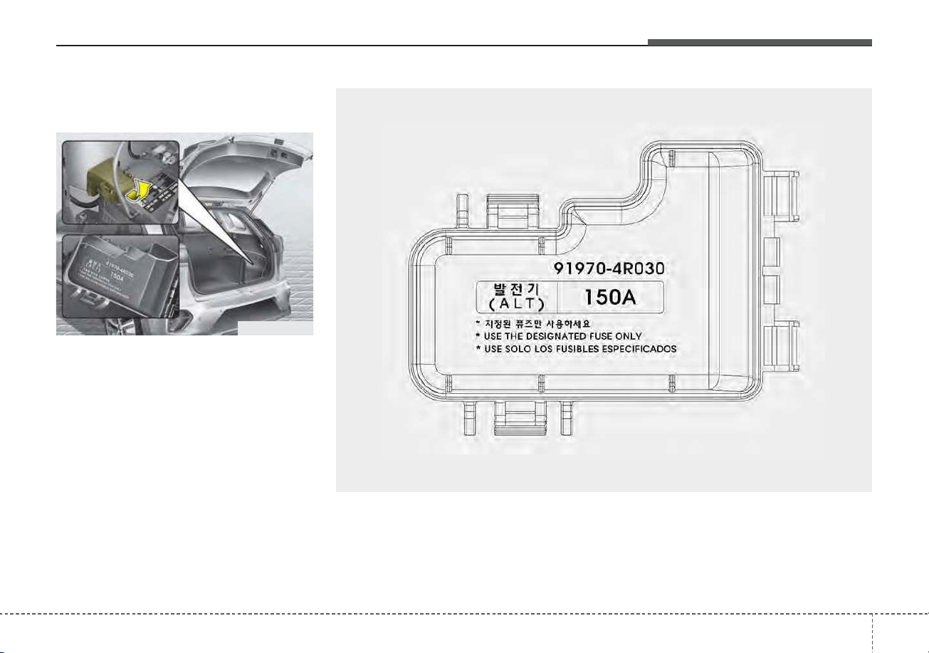
785
Maintenance
Battery terminal cover
(Plug-in Hybrid)
✽✽
NOTICE
Not all fuse panel descriptions in
this manual may be applicable to
your vehicle. It is accurate at the
time of printing. When you inspect
the fuse panel in your vehicle, refer
to the fuse panel label.
ODEP079028
OJFH075171
Maintenance
867
LIGHT BULBS
Bulb replacement precaution
Please keep extra bulbs on hand
with appropriate wattage ratings in
case of emergencies.
Refer to “Bulb Wattage” in chapter 8.
When changing lamps, first turn off
the engine at a safe place, firmly
apply the parking brake and detach
the battery’s negative (-) terminal.
Use only bulbs of the specified
wattage.
✽✽
NOTICE
• If the light bulb or lamp connector
is removed while the lamp is still
on, the fuse box's electronic sys-
tem may log it as a malfunction.
Therefore, a lamp malfunction
incident may be recorded as a
Diagnostic Trouble Code (DTC) in
the fuse box.
• It is normal for an operating lamp
to flicker momentarily. This is due
to a stabilization function of the
vehicle’s electronic control device.
If the lamp lights up normally
after momentarily blinking, then
it is functioning as normal.
However, if the lamp continues to
flicker several times or turns off
completely, there may be an error
in the vehicle’s electronic control
device. Please have the vehicle
checked by an authorized Kia
dealer immediately.
✽
✽
NOTICE
We recommend that the headlight
aiming be adjusted by an authorized
Kia dealer after an accident or after
the headlight assembly is reinstalled.
WARNING - Working on
the lights
Prior to working on the light,
firmly apply the parking brake,
ensure that the engine
start/stop button is in OFF posi-
tion and turn off the lights to
avoid sudden movement of the
vehicle and burning your fingers
or receiving an electric shock.
CAUTION - Light replace-
ment
Be sure to replace the burned-
out bulb with one of the same
wattage rating. Otherwise, it
may cause damage to the fuse
or electric wiring system.
CAUTION - Headlamp
Lens
To prevent damage, do not
clean the headlamp lens with
chemical solvents or strong
detergents.
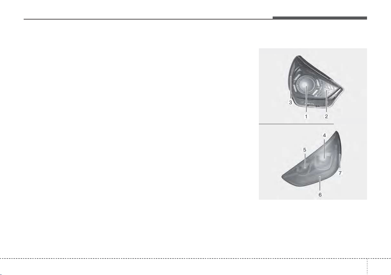
787
Maintenance
✽✽
NOTICE
You can find moisture inside the lens
of lamps after a car wash or driving
in the rain. It is a natural event
caused by the temperature differ-
ence between the inside and the out-
side of the lamp and does not mean a
problem with its functions. The
moisture inside the lamp would dis-
appear if you drive the vehicle with
the headlamp turned on, however,
the level at which the moisture is
removed may differ depending on
the size/location/condition of the
lamp. If the moisture continues to
stay inside the lamp, we recommend
that you have the vehicle checked by
an authorized Kia dealer.
If you don’t have the necessary tools,
the correct bulbs and the expertise,
consult an authorized Kia dealer. In
many cases, it is difficult to replace
vehicle light bulbs because other
parts of the vehicle must be removed
before you can get to the bulb. This is
especially true if you have to remove
the headlamp assembly to get to the
bulb(s).
Removing/installing the headlamp
assembly can result in damage to
the vehicle.
If non-genuine parts or substandard
bulbs are used, it may lead to blow-
ing a fuse or other wiring damages.
Do not install extra lamps or LEDs to
the vehicle. If additional lights are
installed, it may lead to lamp mal-
functions and flickering. Additionally,
the fuse box and other writing may
be damaged.
Light bulb position (Front)
(1) Headlamp (Low/High) (Bulb type)
(2) Front turn signal lamp (Bulb type)
(3) Front side marker (Bulb type)
(4) Headlamp (Low/High) (LED type)
ODEP079029N
ODEP079099N
■ Head lamp - Type A
■ Head lamp - Type B
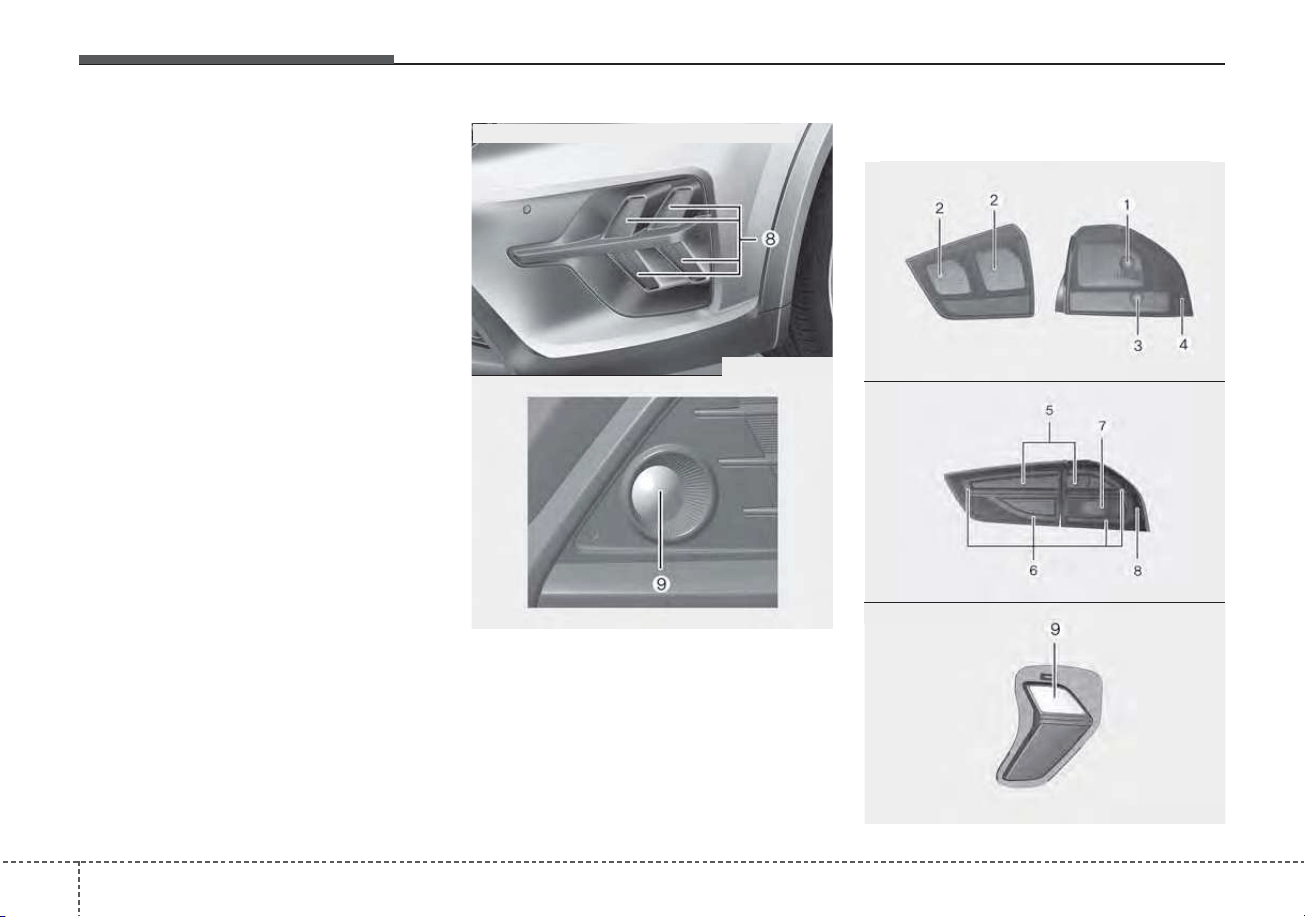
Maintenance
887
(5) Headlamp (Low) (LED type)
(6) Front turn signal lamp (LED type)
(7) Front side marker (LED type)
(8) Daytime running lamp/Position
lamp (LED type)
(9) Front fog lamp (Bulb/LED type)
Light bulb position (Rear)
ODEP079100N
ODEP079107N
■ Daytime running lamp & Position lamp
■ Fog lamp
ODEP079102N
ODE076031N
ODEP079104N
■ Rear combination lamp - Type A
■ Rear combination lamp - Type B
■ Back-up lamp
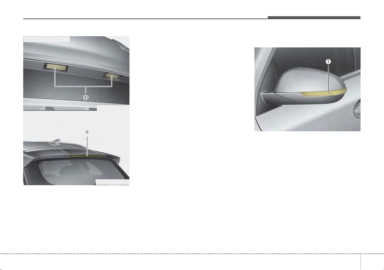
789
Maintenance
(1) Stop/tail lamp (Bulb type)
(2) Tail lamp (Bulb type)
(3) Rear turn signal lamp (Bulb type)
(4) Rear side marker (Bulb type)
(5) Stop lamp (LED type)
(6) Stop/tail lamp (LED type)
(7) Rear turn signal lamp (Bulb type)
(8) Rear side marker (LED type)
(9) Back-up lamp (Bulb type)
(10) License plate lamp (Bulb type)
(11) High mounted stop lamp (LED
type)
Light bulb position (Side)
(1) Side repeater lamp (LED type)
ODEP079055N
ODEP079056N
■ License plate lamp
■ High mounted stop lamp
ODE076034
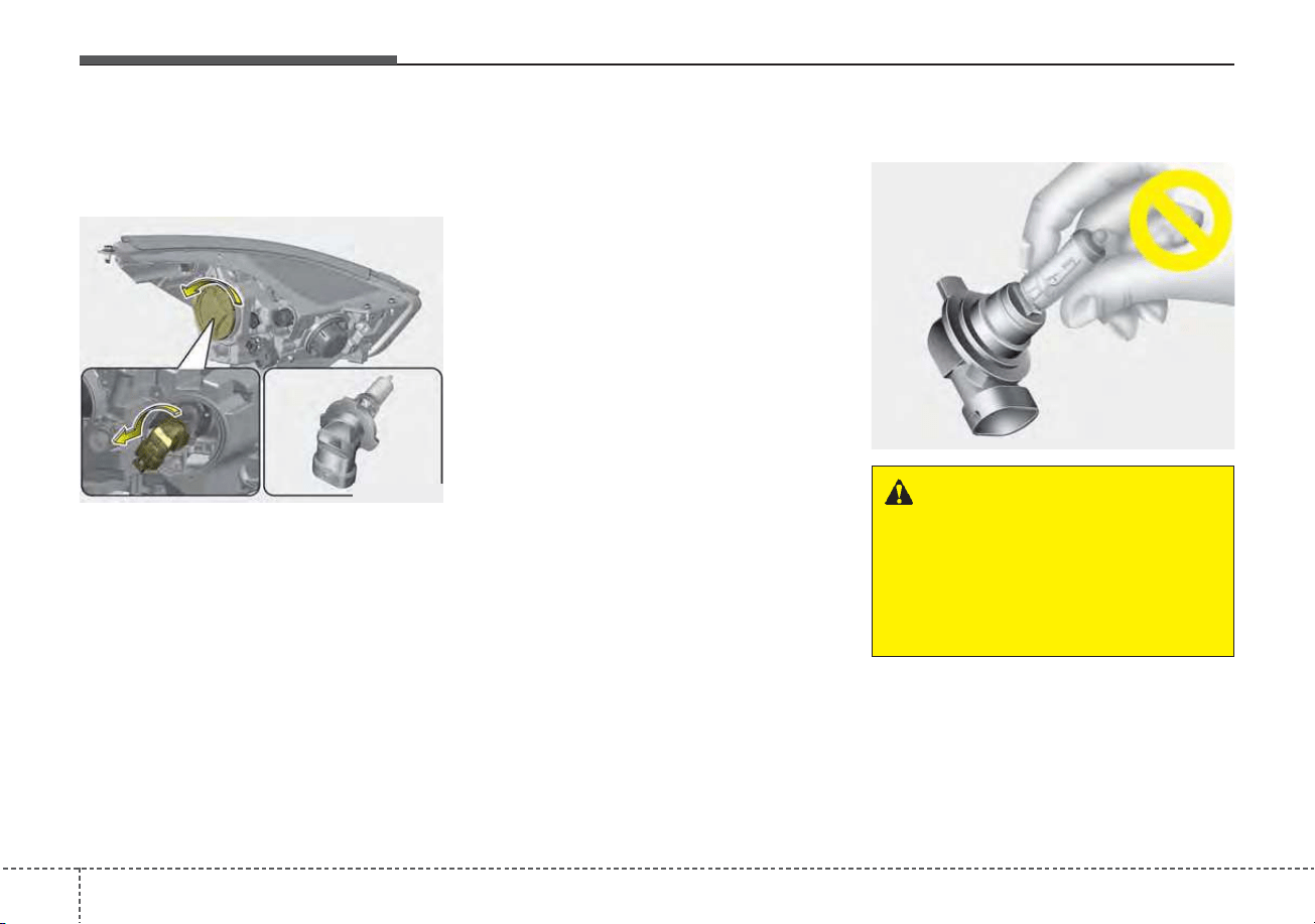
Maintenance
907
Headlamp (High/Low beam)
(Bulb type) bulb replacement
(Headlamp type A)
1. Open the hood.
2. Remove the headlamp bulb cover
by turning it counterclockwise.
3. Disconnect the headlamp bulb
socket-connector.
4. Remove the bulb-socket from the
headlamp assembly by turning the
bulb-socket counterclockwise until
the tabs on the bulb-socket align
with the slots on the headlamp
assembly.
5. Install a new bulb-socket assem-
bly in the headlamp assembly by
aligning the tabs on the bulb-sock-
et with the slots in the headlamp
assembly. Push the bulb-socket
into the headlamp assembly and
turn the bulb-socket clockwise.
6. Install the headlamp bulb cover by
turning it clockwise.
Headlamp bulb
ODE076035
OQL075058
WARNING - Halogen
bulbs
• Halogen bulbs contain pres-
surized gas that will produce
flying pieces of glass if broken.
(Continued)
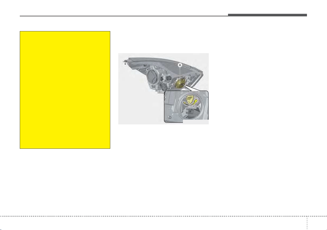
791
Maintenance
Front turn signal lamp (Bulb
type) bulb replacement
(Headlamp type A)
1. Open the hood.
2. Remove the dust cover (A) from
the headlamp assembly then bulb-
socket by turning the counter-
clockwise until the tabs on the
bulb-socket align with the slots on
the headlamp assembly.
3. Remove the bulb from the bulb-
socket by pressing it in and rotat-
ing it counterclockwise until the
tabs on the bulb align with the
slots in the bulb-socket. Pull the
bulb out of the bulb-socket.
4. Insert a new bulb by inserting it
into the bulb-socket and rotating it
until it locks into place.
5. Install the socket in the headlamp
assembly by aligning the tabs on
the bulb-socket with the slots in
the assembly. Push the bulb-sock-
et into the headlamp assembly
and turn the socket clockwise.
(Continued)
• Always handle them carefully,
and avoid scratches and abra-
sions. If the bulbs are lit, avoid
contact with liquids. Never
touch the glass with bare
hands. Residual oil may cause
the bulb to overheat and burst
when lit.
A bulb should be operated
only when installed in a head-
light.
• If a bulb becomes damaged or
cracked, replace it immediate-
ly and carefully dispose of it.
• Wear eye protection when
changing a bulb. Allow the bulb
to cool down before handling it.
ODE076058L
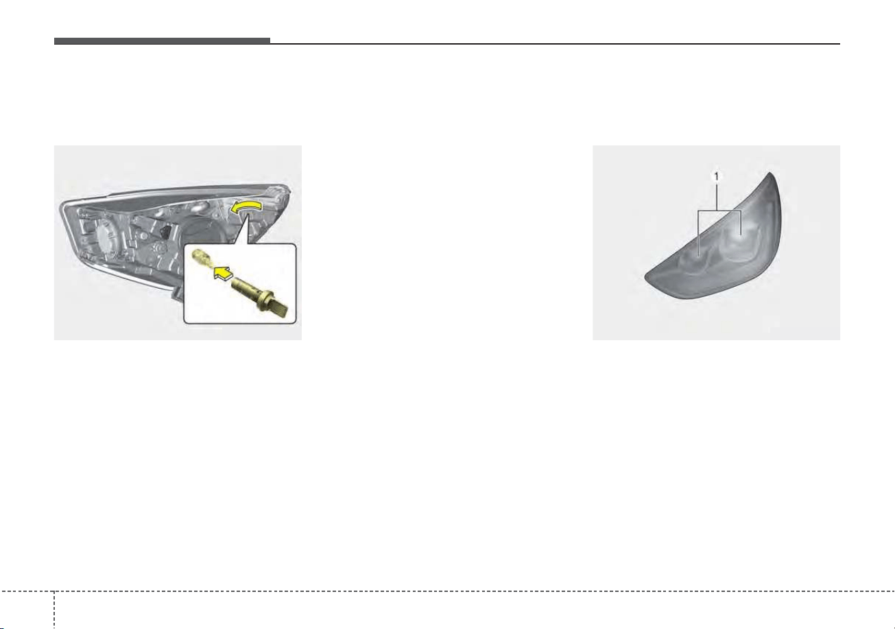
Maintenance
927
Front side marker (Bulb type)
bulb replacement (Headlamp
type A)
1. Open the hood.
2. Remove the bulb-socket from the
headlamp assembly by turning the
bulb-socket counterclockwise until
the tabs on the bulb-socket align
with the slots on the headlamp
assembly.
3. Remove the bulb from the bulb-
socket by pulling it out.
4. Insert a new bulb by inserting it
into the bulb-socket.
5. Install the socket in the headlamp
assembly by aligning the tabs on
the bulb-socket with the slots in
the assembly. Push the bulb-sock-
et into the headlamp assembly
and turn the socket clockwise.
Headlamp (High/Low beam)
(LED type) bulb replacement
(Headlamp type B)
If the headlamp (LED type) (1) does
not operate, have the vehicle
checked by an authorized Kia dealer.
The LED lamp cannot be replaced
as a single component because it is
an integrated unit.The LED lamp has
to be replaced with the unit.
A skilled technician should check or
repair the headlamp (LED type), for it
may damage related parts of the
vehicle.
ODEP079124N ODEP077068
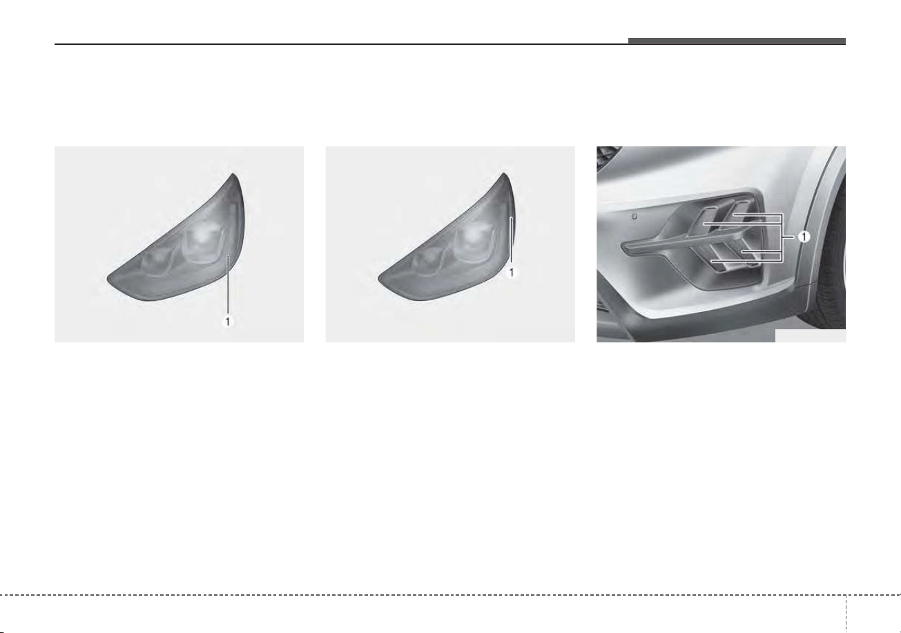
793
Maintenance
Front turn signal (LED type)
bulb replacement (Headlamp
type B)
If the front turn signal lamp (LED type)
(1) does not operate, have the vehicle
checked by an authorized Kia dealer.
The LED lamp cannot be replaced
as a single component because it is
an integrated unit.The LED lamp has
to be replaced with the unit.
A skilled technician should check or
repair the front turn signal lamp (LED
type), for it may damage related
parts of the vehicle.
Front side marker (LED type)
bulb replacement (Headlamp
type B)
If the front side marker (LED type)
(1) does not operate, have the vehi-
cle checked by an authorized Kia
dealer.
The LED lamp cannot be replaced
as a single component because it is
an integrated unit.The LED lamp has
to be replaced with the unit.
A skilled technician should check or
repair the front side marker (LED
type), for it may damage related
parts of the vehicle.
Daytime running lamp/Position
lamp (LED type) bulb replace-
ment
If the daytime running lamp/position
lamp (LED type) (1) does not oper-
ate, have the vehicle checked by an
authorized Kia dealer.
The LED lamp cannot be replaced
as a single component because it is
an integrated unit.The LED lamp has
to be replaced with the unit.
A skilled technician should check or
repair the daytime running
lamp/position lamp (LED type), for it
may damage related parts of the
vehicle.
ODEP077069 ODEP079121N ODEP079108
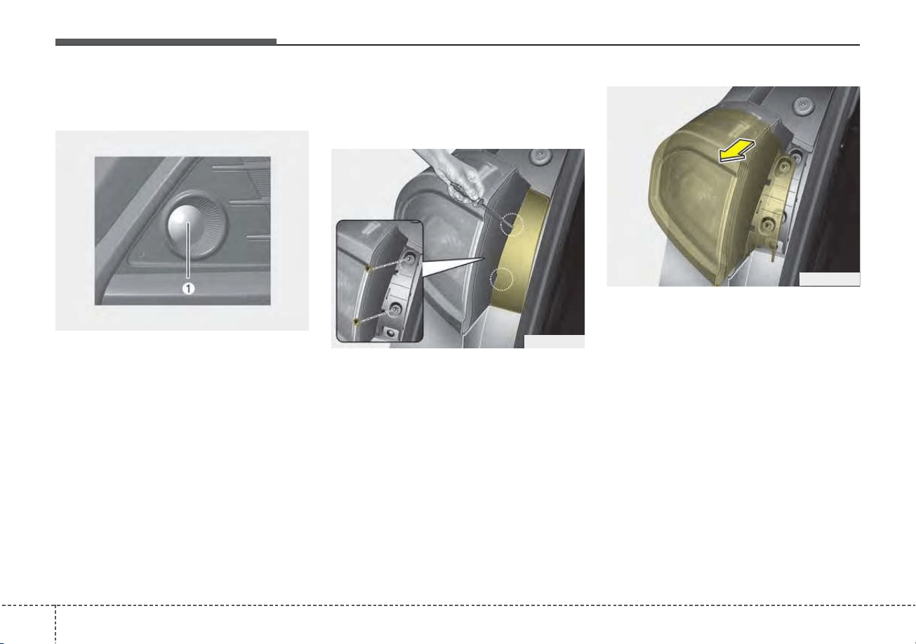
Maintenance
947
Front fog lamp (Bulb/LED
type) bulb replacement
If the front fog lamp (Bulb/LED type)
(1) does not operate, have the vehicle
checked by an authorized Kia dealer.
Stop and tail lamp, Rear turn
signal lamp (Bulb type) bulb
replacement
1. Open the liftgate.
2. Open the service cover.
3. Loosen the light assembly retain-
ing screws with a cross-tip screw-
driver.
4. Remove the rear combination
lamp assembly from the body of
the vehicle.
5. Disconnect the rear combination
lamp connector.
ODE076037
ODE076038
ODEP079101
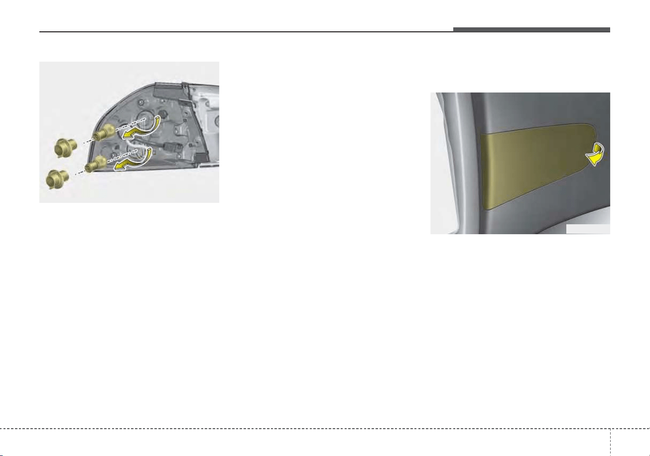
795
Maintenance
6. Remove the socket from the
assembly by turning the socket
counterclockwise until the tabs on
the socket align with the slots on
the assembly.
7. Remove the bulb from the socket by
pressing it in and rotating it counter-
clockwise until the tabs on the bulb
align with the slots in the socket.
Pull the bulb out of the socket.
8. Insert a new bulb by inserting it
into the socket and rotating it until
it locks into place.
9. Install the socket in the assembly
by aligning the tabs on the socket
with the slots in the assembly.
Push the socket into the assembly
and turn the socket clockwise.
10. Install the rear combination lamp
assembly to the body of the vehi-
cle.
11. Install the service cover.
Tail lamp (inside) (Bulb type)
bulb replacement
1. Open the liftgate.
2. Remove the service cover.
ODE076039
ODE076040
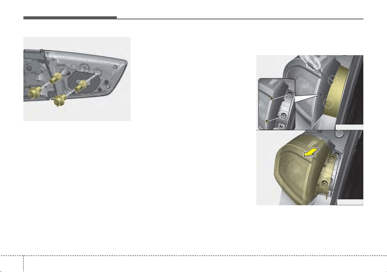
Maintenance
967
3. Remove the socket from the
assembly by turning the socket
counterclockwise until the tabs on
the socket align with the slots on
the assembly.
4. Remove the bulb from the socket
by pressing it in and rotating it
counter-clockwise until the tabs on
the bulb align with the slots in the
socket. Pull the bulb out of the
socket.
5. Insert a new bulb by inserting it
into the socket and rotating it until
it locks into place.
6. Install the socket in the assembly
by aligning the tabs on the socket
with the slots in the assembly.
Push the socket into the assembly
and turn the socket clockwise.
7. Install the service cover by putting
it into the service hole.
Rear side marker (Bulb type)
bulb replacement
1. Open the liftgate.
2. Remove the service cover.
3. Loosen the light assembly retain-
ing screws with a cross-tip screw-
driver.
ODE076041
ODE076037
ODE076038
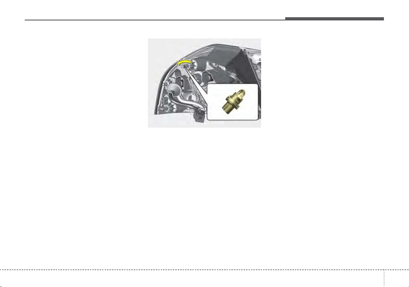
797
Maintenance
4. Remove the rear combination
lamp assembly from the body of
the vehicle.
5. Disconnect the rear combination
lamp connector.
6. Remove the socket from the
assembly by turning the socket
counterclockwise until the tabs on
the socket align with the slots on
the assembly.
7. Remove the bulb from bulb-socket
by pulling it out.
8. Insert a new bulb by inserting it
into the bulb-socket.
9. Install the socket in the assembly
by aligning the tabs on the socket
with the slots in the assembly.
Push the socket into the assembly
and turn the socket clockwise.
10. Connect the rear combination
lamp connector.
11. Install the rear combination lamp
assembly to the body of the vehi-
cle.
12. Install the service cover.
ODEP079123N
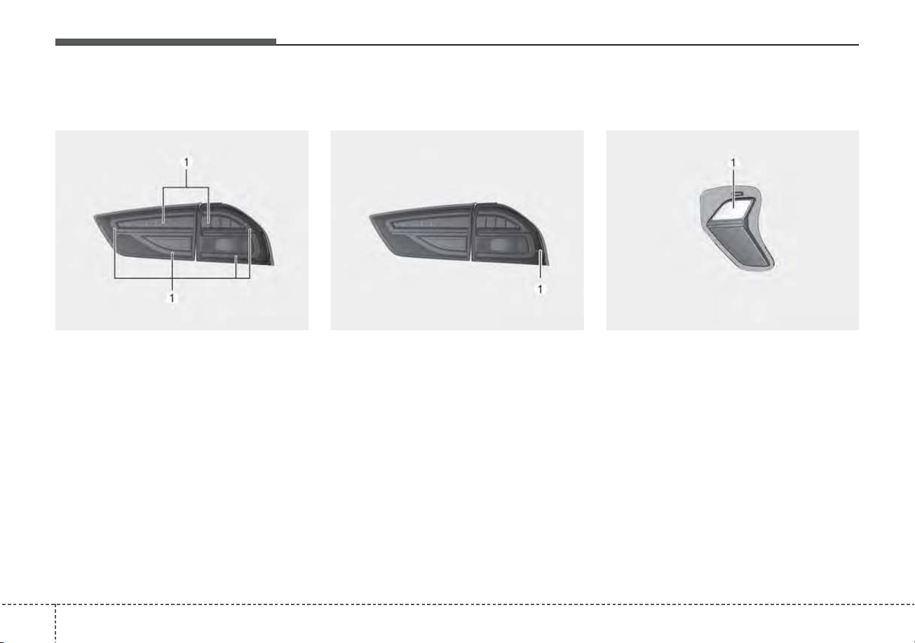
Maintenance
987
Stop and tail lamp (LED type)
bulb replacement
If the stop and tail lamp (LED type) (1)
does not operate, have the vehicle
checked by an authorized Kia dealer.
The LED lamp cannot be replaced
as a single component because it is
an integrated unit.The LED lamp has
to be replaced with the unit.
A skilled technician should check or
repair the stop and tail lamp (LED
type), for it may damage related
parts of the vehicle.
Rear side marker (LED type)
bulb replacement
If the rear side marker (LED type) (1)
does not operate, have the vehicle
checked by an authorized Kia dealer.
The LED lamp cannot be replaced
as a single component because it is
an integrated unit.The LED lamp has
to be replaced with the unit.
A skilled technician should check or
repair the rear side marker (LED
type), for it may damage related
parts of the vehicle.
Back-up lamp (Bulb type) bulb
replacement
If the back-up lamp (Bulb type) (1)
does not operate, have the vehicle
checked by an authorized Kia dealer.
ODEP079103 ODEP079122N ODEP079111L
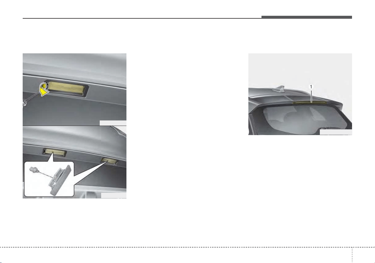
799
Maintenance
License plate lamp (Bulb type)
bulb replacement
1. Using a flat-blade screwdriver,
gently pry the lens cover from
lamp housing.
2. Remove the socket from the
assembly by turning the socket
counterclockwise until the tabs on
the socket align with the slots on
the assembly.
3. Remove the bulb from bulb-socket
by pulling it out.
4. Insert a new bulb by inserting it
into the bulb-socket.
5. Install the socket in the assembly
by aligning the tabs on the socket
with the slots in the assembly.
Push the socket into the assembly
and turn the socket clockwise.
6. Align the lens cover tabs with the
lamp housing notches and snap
the lens into place.
High mounted stop lamp (LED
type) bulb replacement
If the high mounted stop lamp (LED
type) (1) does not operate, have the
vehicle checked by an authorized Kia
dealer.
The LED lamp cannot be replaced
as a single component because it is
an integrated unit.The LED lamp has
to be replaced with the unit.
A skilled technician should check or
repair the high mounted stop lamp
(LED type), for it may damage relat-
ed parts of the vehicle.
ODE076045
ODE076046
ODEP079044
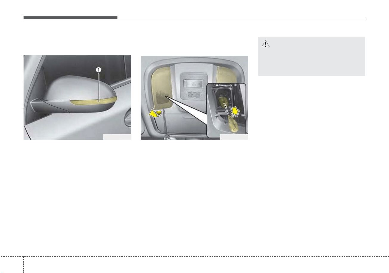
Maintenance
1007
Side repeater lamp (LED type)
bulb replacement
If the side repeater lamp (LED type)
(1) does not operate, have the vehicle
checked by an authorized Kia dealer.
The LED lamp cannot be replaced
as a single component because it is
an integrated unit.The LED lamp has
to be replaced with the unit.
A skilled technician should check or
repair the side repeater lamp (LED
type), for it may damage related
parts of the vehicle.
Map lamp (Bulb type) bulb
replacement
1. Using a flat-blade screwdriver,
gently pry the lens cover from
lamp housing.
2. Remove the bulb by pulling it
straight out.
3. Install a new bulb in the socket.
4. Align the lens cover tabs with the
lamp housing notches and snap
the lens into place.
ODE076034 ODE076047
CAUTION
Be careful not to dirty or dam-
age the lens, lens tab, and plas-
tic housings.
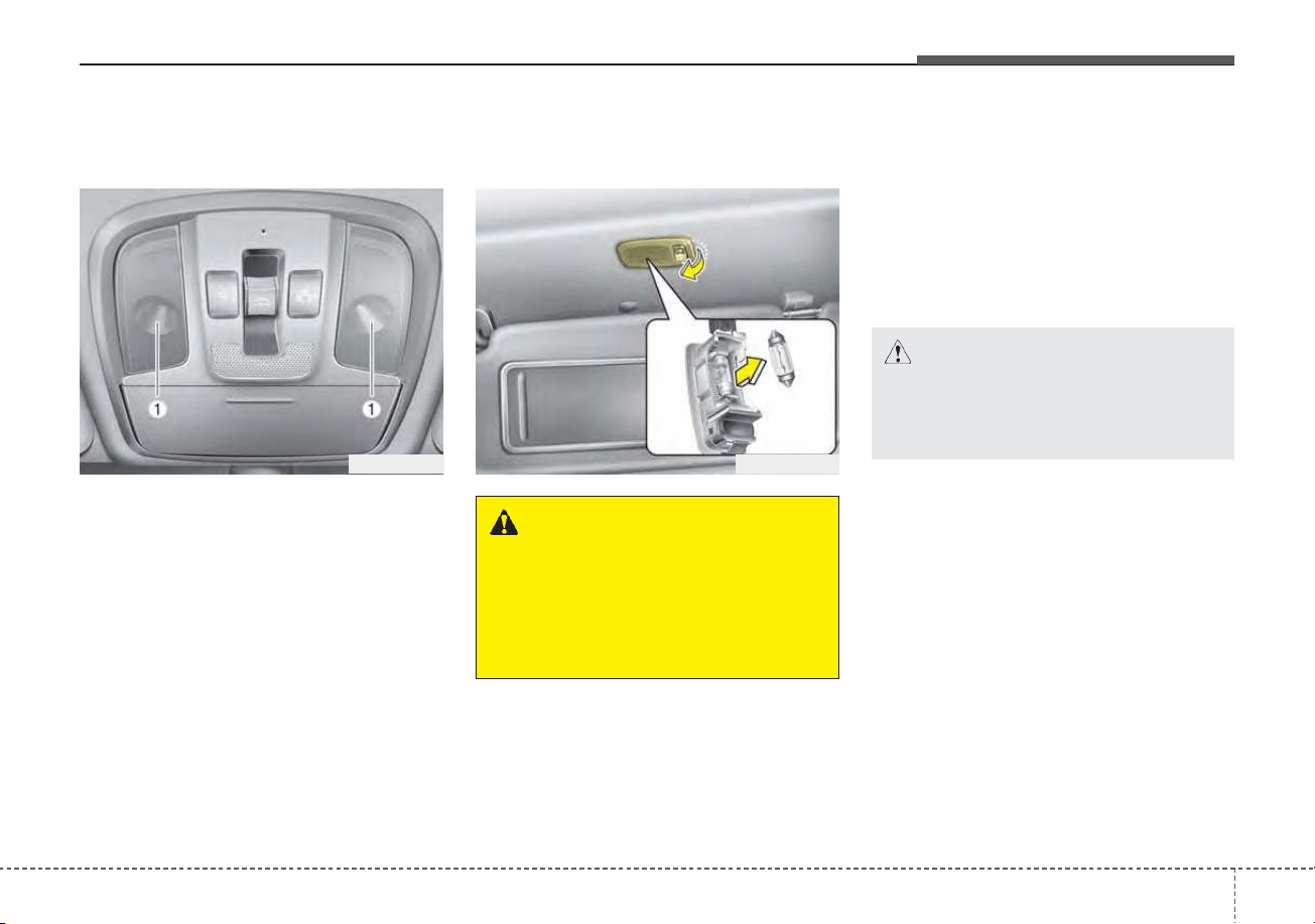
7101
Maintenance
Map lamp (LED type) bulb
replacement
If the map lamp (LED type) (1) does
not operate, have the vehicle
checked by an authorized Kia dealer.
The LED lamp cannot be replaced
as a single component because it is
an integrated unit.The LED lamp has
to be replaced with the unit.
A skilled technician should check or
repair the map lamp (LED type), for it
may damage related parts of the
vehicle.
Vanity mirror lamp (Bulb type)
bulb replacement
1. Using a flat-blade screwdriver,
gently pry the lamp assembly from
interior.
2. Remove the bulb by pulling it
straight out.
3. Install a new bulb in the socket.
4. Install the lamp assembly to interior.
OQM076063
CAUTION
Be careful not to dirty or dam-
age the lens, lens tab, and plas-
tic housings.
ODE076048
WARNING
Prior to working on the Interior
lamps, ensure that the “OFF”
button is depressed to avoid
burning your fingers or receiv-
ing an electric shock.
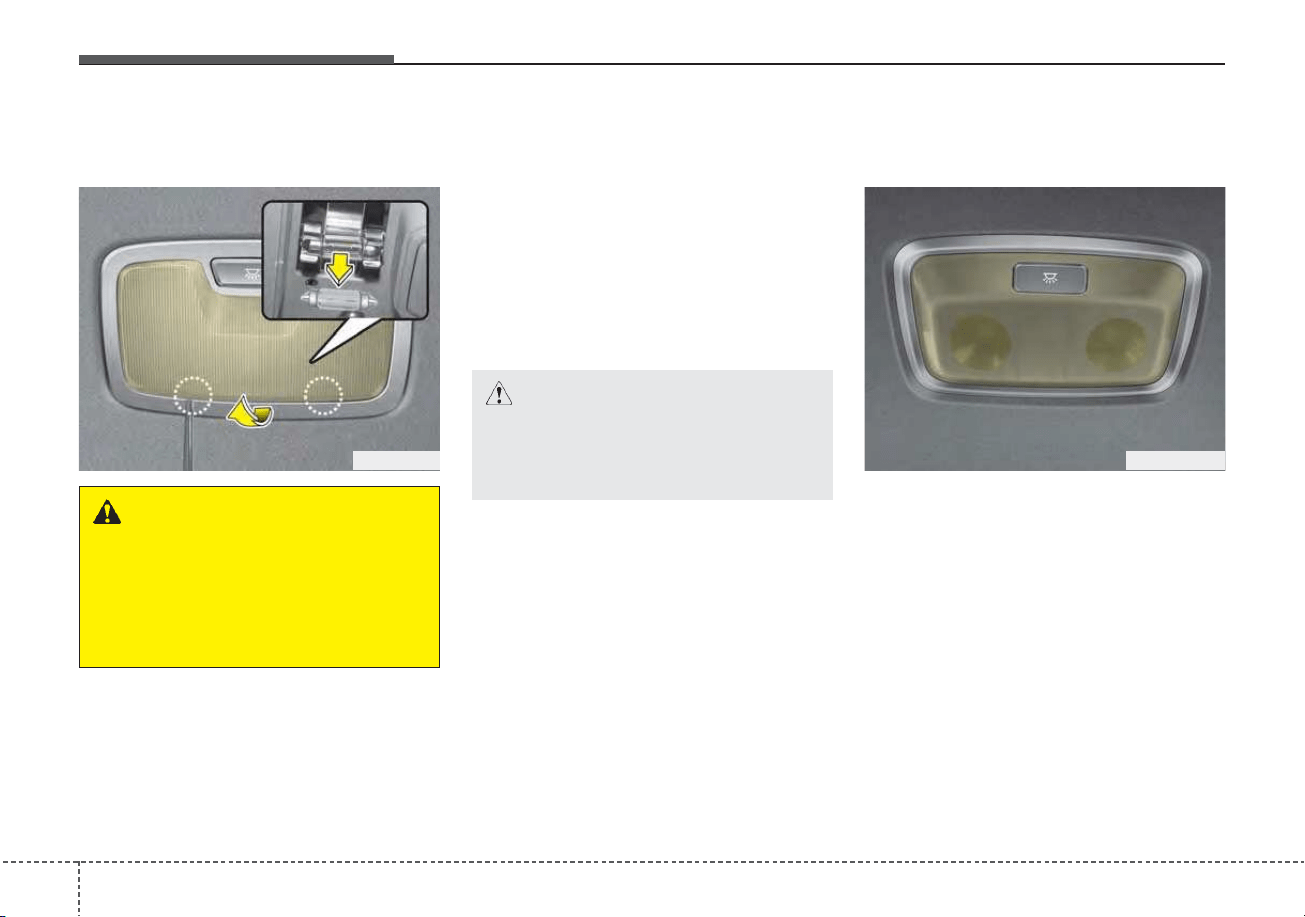
Maintenance
1027
Room lamp (Bulb type) bulb
replacement
1. Using a flat-blade screwdriver,
gently pry the lens cover from
lamp housing.
2. Remove the bulb by pulling it
straight out.
3. Install a new bulb in the socket.
4. Align the lens cover tabs with the
lamp housing notches and snap
the lens into place.
Room lamp (LED type) bulb
replacement
If the room lamp (LED type) (1) does
not operate, have the vehicle
checked by an authorized Kia dealer.
The LED lamp cannot be replaced
as a single component because it is
an integrated unit.The LED lamp has
to be replaced with the unit.
A skilled technician should check or
repair the room lamp (LED type), for
it may damage related parts of the
vehicle.
WARNING
Prior to working on the Interior
lamps, ensure that the “OFF”
button is depressed to avoid
burning your fingers or receiv-
ing an electric shock.
ODE076049
CAUTION
Be careful not to dirty or dam-
age the lens, lens tab, and plas-
tic housings.
ODEP077070
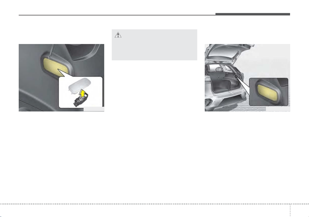
7103
Maintenance
Liftgate room lamp (Bulb type)
bulb replacement
1. Using a flat-blade screwdriver,
gently pry the lens cover from
lamp housing.
2. Remove the bulb by pulling it
straight out.
3. Install a new bulb in the socket.
4. Align the lens cover tabs with the
lamp housing notches and snap
the lens into place.
Liftgate room lamp (LED type)
bulb replacement
If the liftgate room lamp (LED type)
(1) does not operate, have the vehicle
checked by an authorized Kia dealer.
The LED lamp cannot be replaced
as a single component because it is
an integrated unit.The LED lamp has
to be replaced with the unit.
A skilled technician should check or
repair the liftgate room lamp (LED
type), for it may damage related
parts of the vehicle.
ODE076050
CAUTION
Be careful not to dirty or dam-
age the lens, lens tab, and plas-
tic housings.
ODEP079109

Maintenance
1047
APPEARANCE CARE
Exterior care
Exterior general caution
It is very important to follow the label
directions when using any chemical
cleaner or polish. Read all warning
and caution statements that appear
on the label.
Finish maintenance
Washing
To help protect your vehicle’s finish
from rust and deterioration, wash it
thoroughly and frequently at least
once a month with lukewarm or cold
water.
If you use your vehicle for off-road
driving, you should wash it after each
off-road trip. Pay special attention to
the removal of any accumulation of
salt, dirt, mud, and other foreign mate-
rials. Make sure the drain holes in the
lower edges of the doors and rocker
panels are kept clear and clean.
Insects, tar, tree sap, bird droppings,
industrial pollution and similar
deposits can damage your vehicle’s
finish if not removed immediately.
Even prompt washing with plain water
may not completely remove all these
deposits. A mild soap, safe for use on
painted surfaces, may be used.
After washing, rinse the vehicle thor-
oughly with lukewarm or cold water.
Do not allow soap to dry on the finish.
After washing the vehicle, test the
brakes while driving slowly to see if
they have been affected by water. If
braking performance is impaired, dry
the brakes by applying them lightly
while maintaining a slow forward
speed.
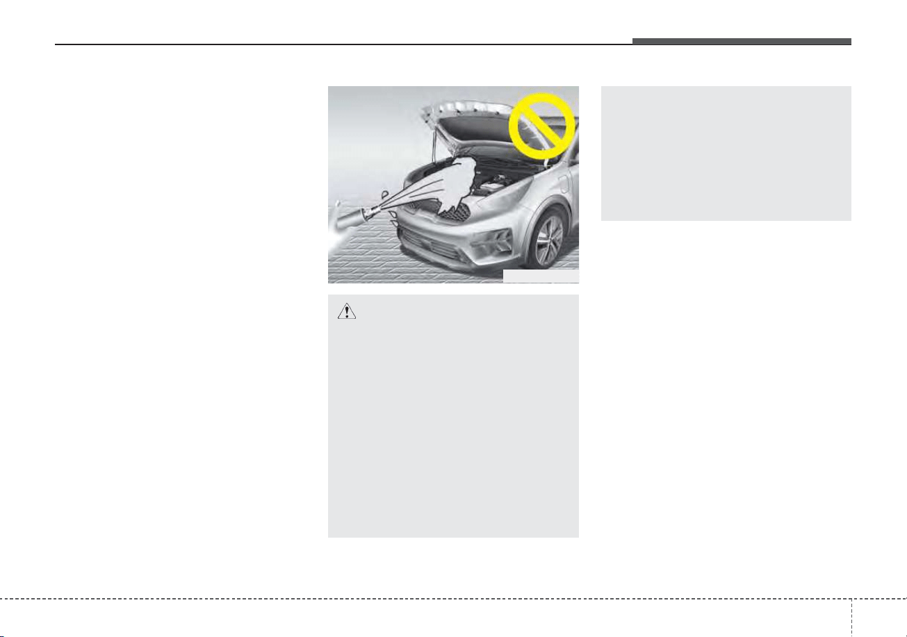
7105
Maintenance
High-pressure washing
• When using high-pressure wash-
ers, make sure to maintain suffi-
cient distance from the vehicle.
Insufficient clearance or excessive
pressure can lead to component
damage or water penetration.
• Do not spray the camera, sensors
or its surrounding area directly with
a high pressure washer. Shock
applied from high pressure water
may cause the device to not oper-
ate normally.
• Do not bring the nozzle tip close to
boots (rubber or plastic covers) or
connectors as they may be dam-
aged if they come into contact with
high pressure water.
ODEP079071L
CAUTION - Wet engine
• Water washing in the engine
compartment including high
pressure water washing may
cause the failure of electrical
circuits located in the engine
compartment.
• Never allow water or other liq-
uids to come in contact with
electrical/electronic compo-
nents inside the vehicle as
this may damage them.
(Continued)
(Continued)
• To prevent damage to the
charging door, make sure to
close and lock the vehicle
doors when washing (high-
pressure washing, automatic
car washing, etc.) the vehicle.
Maintenance
1067
Waxing
Wax the vehicle when water will no
longer bead on the paint.
Always wash and dry the vehicle
before waxing. Use a good quality
liquid or paste wax, and follow the
manufacturer’s instructions. Wax all
metal trim to protect it and to main-
tain its luster.
Removing oil, tar, and similar materi-
als with a spot remover will usually
strip the wax from the finish. Be sure
to re-wax these areas even if the rest
of the vehicle does not yet need wax-
ing.
Do not apply wax on embossed
unpainted unit, as it may tarnish the
unit.
Finish damage repair
Deep scratches or stone chips in the
painted surface must be repaired
promptly. Exposed metal will quickly
rust and may develop into a major
repair expense.
If your vehicle is damaged and
requires any metal repair or replace-
ment, be sure the body shop applies
anti-corrosion materials to the parts
repaired or replaced.
CAUTION - Drying vehicle
• Wiping dust or dirt off the
body with a dry cloth will
scratch the finish.
• Do not use steel wool, abra-
sive cleaners, acid detergents
or strong detergents contain-
ing high alkaline or caustic
agents on chrome-plated or
anodized aluminum parts.
This may result in damage to
the protective coating and
cause discoloration or paint
deterioration.

7107
Maintenance
Bright-metal maintenance
• To remove road tar and insects,
use a tar remover, not a scraper or
other sharp object.
• To protect the surfaces of bright-
metal parts from corrosion, apply a
coating of wax or chrome preser-
vative and rub to a high luster.
• During winter weather or in coastal
areas, cover the bright metal parts
with a heavier coating of wax or
preservative. If necessary, coat the
parts with non-corrosive petroleum
jelly or other protective compound.
Underbody maintenance
Road salt and other corrosive chemi-
cals are used in cold weather states to
melt snow and prevent ice accumula-
tion. If these chemicals are not regu-
larly removed, they will corrode the
vehicle underbody and over time dam-
age fuel lines, the fuel tank retention
system, the vehicle suspension, the
exhaust system, and even the body
frame. The National Highway Traffic
Safety Administration has warned all
vehicle owners of all brands of the
need to take the following steps:
• Wash the undercarriage of your
vehicle regularly during the winter
and whenever your vehicle has
been exposed to such salts or
chemicals.
• Do a thorough washing of the
undercarriage at the end of the
winter.
• Use professional service techni-
cians or governmental inspection
stations to annually inspect for cor-
rosion.
• Immediately seek an inspection of
your vehicle if you become visually
aware of corrosion flaking or scal-
ing or if you become aware of a
change in vehicle performance,
such as soft or spongey brakes,
fluids leaking, impairment of direc-
tional control, suspension noises
or rattling metal straps.
Maintenance
1087
Aluminum wheel maintenance
The aluminum wheels are coated with
a clear protective finish.
• Do not use any abrasive cleaner,
polishing compound, solvent, or wire
brushes on aluminum wheels. They
may scratch the finish.
• Clean the wheel when it has cooled.
• Use only a mild soap or neutral
detergent, and rinse thoroughly with
water. Also, be sure to clean the
wheels after driving on salted roads.
This helps prevent corrosion.
• Avoid washing the wheels with high-
speed vehicle wash brushes.
• Do not use any alkaline or acid
detergents It may damage and cor-
rode the aluminum wheels coated
with a clear protective finish.
Corrosion protection
Protecting your vehicle from corrosion
By using the most advanced design
and construction practices to combat
corrosion, we produce vehicles of
the highest quality. However, this is
only part of the job. To achieve the
long-term corrosion resistance your
vehicle can deliver, the owner's
cooperation and assistance is also
required.
Common causes of corrosion
The most common causes of corro-
sion on your vehicle are:
• Road salt, dirt and moisture that is
allowed to accumulate underneath
the vehicle.
• Removal of paint or protective
coatings by stones, gravel, abra-
sion or minor scrapes and dents
which leave unprotected metal
exposed to corrosion.
WARNING
After washing the vehicle, test
the brakes while driving slowly
to see if they have been affected
by water. If braking performance
is impaired, dry the brakes by
applying them lightly while
maintaining a slow forward
speed.

7109
Maintenance
High-corrosion areas
If you live in an area where your vehi-
cle is regularly exposed to corrosive
materials, corrosion protection is
particularly important. Some of the
common causes of accelerated cor-
rosion are road salts, dust control
chemicals, ocean air and industrial
pollution.
Moisture breeds corrosion
Moisture creates the conditions in
which corrosion is most likely to
occur. For example, corrosion is
accelerated by high humidity, partic-
ularly when temperatures are just
above freezing. In such conditions,
the corrosive material is kept in con-
tact with the vehicle’s surface by
moisture that evaporates slowly.
Mud is particularly corrosive
because it dries slowly and holds
moisture in contact with the vehicle.
Although the mud appears to be dry,
it can still retain the moisture and
promote corrosion.
High temperatures can also acceler-
ate corrosion of parts that are not
properly ventilated so the moisture
can be dispersed. For all these rea-
sons, it is particularly important to
keep your vehicle clean and free of
mud or accumulations of other mate-
rials. This applies not only to the vis-
ible surfaces but particularly to the
underside of the vehicle.
To help prevent corrosion
You can help prevent corrosion from
beginning by observing the following:
Keep your vehicle clean
The best way to prevent corrosion is
to keep your vehicle clean and free
of corrosive materials. Attention to
the underside of the vehicle is partic-
ularly important.
• If you live in a high-corrosion area
— where road salts are used, near
the ocean, areas with industrial
pollution, acid rain, etc.—, you
should take extra care to prevent
corrosion. In winter, hose off the
underside of your vehicle at least
once a month and be sure to clean
the underside thoroughly when
winter is over.
• When cleaning underneath the
vehicle, give particular attention to
the components under the fenders
and other areas that are hidden
from view. Do a thorough job; just
dampening the accumulated mud
rather than washing it away will
accelerate corrosion rather than
prevent it. Water under high pres-
sure and steam are particularly
effective in removing accumulated
mud and corrosive materials.

Maintenance
1107
• When cleaning lower door panels,
rocker panels and frame members,
be sure that drain holes are kept
open so that moisture can escape
and not be trapped inside to accel-
erate corrosion.
Keep your garage dry
Don't park your vehicle in a damp,
poorly ventilated garage. This cre-
ates a favorable environment for cor-
rosion. This is particularly true if you
wash your vehicle in the garage or
drive it into the garage when it is still
wet or covered with snow, ice or
mud. Even a heated garage can con-
tribute to corrosion unless it is well
ventilated so moisture is dispersed.
Keep paint and trim in good con-
dition
Scratches or chips in the finish
should be covered with "touch-up"
paint as soon as possible to reduce
the possibility of corrosion. If bare
metal is showing through, the atten-
tion of a qualified body and paint
shop is recommended.
Bird droppings : Bird droppings are
highly corrosive and may damage
painted surfaces in just a few hours.
Always remove bird droppings as
soon as possible.
Don't neglect the interior
Moisture can collect under the floor
mats and carpeting and cause corro-
sion. Check under the mats periodi-
cally to be sure the carpeting is dry.
Use particular care if you carry fertil-
izers, cleaning materials or chemi-
cals in the vehicle.
These should be carried only in prop-
er containers and any spills or leaks
should be cleaned up, flushed with
clean water and thoroughly dried.
Interior care
Interior general precautions
Prevent chemicals such as perfume,
cosmetic oil, sun cream, hand clean-
er, and air freshener from contacting
the interior parts because they may
cause damage or discoloration. If
they do contact the interior parts,
wipe them off immediately. If neces-
sary, use a vinyl cleaner, see product
instructions for correct usage.

7111
Maintenance
Taking care of leather seats
• Vacuum the seat periodically to
remove dust and sand on the seat.
It will prevent abrasion or damage of
the leather and maintain its quality.
• Wipe the natural leather seat cover
often with dry or soft cloth.
• Sufficient use of a leather protec-
tive may prevent abrasion of the
cover and helps maintain the color.
Be sure to read the instructions
and consult a specialist when
using leather coating or protective
agents.
• Leather with bright colors(beige,
cream beige) is easily contaminat-
ed and clear in appearance. Clean
the seats frequently.
• Avoid wiping with wet cloth. It may
cause the surface to crack.
Cleaning the leather seats
• Remove all contaminations instant-
ly. Refer to instructions below for
removal of each contaminant.
• Cosmetic products(sunscreen,
foundation, etc.)
- Apply cleansing cream on a cloth
and wipe the contaminated point.
Wipe off the cream with a wet
cloth and remove water with a dry
cloth.
• Beverages(coffee, soft drink, etc.)
- Apply a small amount of neutral
detergent and wipe until contami-
nations do not smear.
• Oil
- Remove oil instantly with
absorbable cloth and wipe with
stain remover for natural leather
only.
• Chewing gum
- Harden the gum with ice and
remove gradually.
CAUTION - Electrical
components
Never allow water or other liq-
uids to come in contact with
electrical/electronic compo-
nents inside the vehicle as this
may damage them.
CAUTION - Leather
When cleaning leather products
(steering wheel, seats etc.), use
neutral detergents or low alco-
hol content solutions. If you use
high alcohol content solutions
or acid/alkaline detergents, the
color of the leather may fade or
the surface may get stripped off.
Maintenance
1127
Fabric seat cover using precau-
tions (If equipped)
Please clean the fabric seats regu-
larly with a vacuum cleaner in con-
sideration of fabric material charac-
teristics. If they are heavily soiled
with beverage stains, etc., use a suit-
able interior cleaner. To prevent dam-
age to seat covers, wipe off the seat
covers down to the seams with a
large wiping motion and moderate
pressure using a soft sponge or
microfiber cloth.
Velcro closures on clothing or sharp
objects may cause snagging or
scratches on the surface of the
seats. Make sure not to rub such
objects against the surface.
Cleaning the upholstery and inte-
rior trim
Vinyl
Remove dust and loose dirt from
vinyl with a whisk broom or vacuum
cleaner. Clean vinyl surfaces with a
vinyl cleaner.
Fabric
Remove dust and loose dirt from fab-
ric with a whisk broom or vacuum
cleaner. Clean with a mild soap solu-
tion recommended for upholstery or
carpets. Remove fresh spots imme-
diately with a fabric spot cleaner. If
fresh spots do not receive immediate
attention, the fabric can be stained
and its color can be affected. Also, its
fire-resistant properties can be
reduced if the material is not proper-
ly maintained.
Using anything but recommended
cleaners and procedures may affect
the fabric’s appearance and fire-
resistant properties.
Cleaning the lap/shoulder belt
webbing
Clean the belt webbing with any mild
soap solution recommended for
cleaning upholstery or carpet. Follow
the instructions provided with the
soap. Do not bleach or re-dye the
webbing because this may weaken it.
Cleaning the interior window
glass
If the interior glass surfaces of the
vehicle become fogged (that is, cov-
ered with an oily, greasy or waxy
film), they should be cleaned with a
glass cleaner. Follow the directions
on the glass cleaner container.
CAUTION - Rear window
Do not scrape or scratch the
inside of the rear window. This
may result in damage of the rear
window defroster grid.

7113
Maintenance
Window tinting precaution
Window tint(especially metallic film)
might cause communication disorder
or poor radio reception, and malfunc-
tion of the automatic lighting system
due to excessive change of illumina-
tion inside the vehicle. The solution
used might also flow into electric,
electronic devices causing disorder
and failure.

Maintenance
1147
EMISSION CONTROL SYSTEM
The emission control system of your
vehicle is covered by a written limited
warranty. Please see the warranty
information contained in the
Warranty & Consumer Information
manual in your vehicle.
Your vehicle is equipped with an
emission control system to meet all
applicable emission regulations.
There are three emission control
systems, as follows.
(1) Crankcase emission control sys-
tem
(2) Evaporative emission control sys-
tem
(3) Exhaust emission control system
In order to assure the proper function
of the emission control systems, it is
recommended that you have your
vehicle inspected and maintained by
an authorized Kia dealer in accor-
dance with the maintenance sched-
ule in this manual.
Caution for the Inspection and
Maintenance Test (With Electronic
Stability Control (ESC) system)
• To prevent the vehicle from mis-
firing during dynamometer test-
ing, turn the Electronic Stability
Control (ESC) system off by
pressing the ESC switch.
• After dynamometer testing is
completed, turn the ESC system
back on by pressing the ESC
switch again.
1. Crankcase emission control
system
The positive crankcase ventilation
system is employed to prevent air
pollution caused by blow-by gases
being emitted from the crankcase.
This system supplies fresh filtered air
to the crankcase through the air
intake hose. Inside the crankcase,
the fresh air mixes with blow-by
gases, which then pass through the
PCV valve into the induction system.
2. Evaporative emission con-
trol (including ORVR:
Onboard Refueling Vapor
Recovery) system
The Evaporative Emission Control
System is designed to prevent fuel
vapors from escaping into the atmos-
phere.
(The ORVR system is designed to
allow the vapors from the fuel tank to
be loaded into a canister while refu-
eling at the gas station, preventing
the escape of fuel vapors into the
atmosphere.)

7115
Maintenance
Canister
Fuel vapors generated inside the fuel
tank are absorbed and stored in the
onboard canister. When the engine is
running, the fuel vapors absorbed in
the canister are drawn into the surge
tank through the purge control sole-
noid valve.
Purge Control Solenoid Valve
(PCSV)
The purge control solenoid valve is
controlled by the Engine Control
Module (ECM); when the engine
coolant temperature is low during
idling, the PCSV closes so that evap-
orated fuel is not taken into the
engine. After the engine warms up
during ordinary driving, the PCSV
opens to introduce evaporated fuel to
the engine.
3. Exhaust emission control
system
The Exhaust Emission Control
System is a highly effective system
which controls exhaust emissions
while maintaining good vehicle per-
formance.
Engine exhaust gas precautions
(carbon monoxide)
• Carbon monoxide can be present
with other exhaust fumes.
Therefore, if you smell exhaust
fumes of any kind inside your vehi-
cle, have it inspected and repaired
immediately. If you ever suspect
exhaust fumes are coming into
your vehicle, drive it only with all
the windows fully open. Have your
vehicle checked and repaired
immediately.
WARNING - Exhaust
Engine exhaust gases contain
carbon monoxide (CO). Though
colorless and odorless, it is
dangerous and could be lethal if
inhaled. Follow the instructions
on this page to avoid CO poi-
soning.
Maintenance
1167
• Do not operate the engine in con-
fined or closed areas (such as
garages) any more than what is
necessary to move the vehicle in or
out of the area.
• When the vehicle is stopped in an
open area for more than a short
time with the engine running,
adjust the ventilation system (as
needed) to draw outside air into the
vehicle.
• Never sit in a parked or stopped
vehicle for any extended time with
the engine running.
• When the engine stalls or fails to
start, excessive attempts to restart
the engine may cause damage to
the emission control system.
Operating precautions for catalyt-
ic converters (if equipped)
WARNING - Catalytic
converter
Keep away from the catalytic
converter and exhaust system
while the vehicle is running or
immediately thereafter. The
exhaust and catalytic systems
are very hot and may burn you.
WARNING - Fire
• Do not park, idle or drive the
vehicle over or near flamma-
ble objects, such as grass,
vegetation, paper, leaves, etc.
A hot exhaust system can
ignite flammable items under
your vehicle.
• Also, do not remove the heat
sink around the exhaust sys-
tem, do not seal the bottom of
the vehicle and do not coat
the vehicle for corrosion con-
trol. It may present a fire risk
under certain conditions.

7117
Maintenance
Your vehicle is equipped with a cat-
alytic converter emission control
device.
Therefore, the following precautions
must be observed:
• Use only UNLEADED FUEL for
gasoline engines.
• Do not operate the vehicle when
there are signs of engine malfunc-
tion, such as misfire or a noticeable
loss of performance.
• Do not misuse or abuse the
engine. Examples of misuse are
coasting with the ignition off and
descending steep grades in gear
with the ignition off.
• Do not operate the engine at high
idle speed for extended periods (5
minutes or more).
• Do not modify or tamper with any
part of the engine or emission con-
trol system. All inspections and
adjustments must be made by an
authorized Kia dealer.
• Avoid driving with an extremely low
fuel level. Running out of fuel could
cause the engine to misfire, dam-
aging the catalytic converter.
Failure to observe these precautions
could result in damage to the catalyt-
ic converter and to your vehicle.
Additionally, such actions could void
your warranties.
Perchlorate Material-special handling
may apply, See www.dtsc.ca.gov/haz-
ardouswaste/ perchlorate.
Notice to California Vehicle Dismantlers:
Perchlorate containing materials,
such as air bag inflators, seatbelt
pretensioners and keyless remote
entry batteries, must be disposed of
according to Title 22 California Code
of Regulations Chapter 67384.10
(a).
CALIFORNIA
PERCHLORATE NOTICE

Specifications, Consumer information and Reporting safety defects
Dimensions . . . . . . . . . . . . . . . . . . . . . . . . . . . . . . . . 8-2
Engine . . . . . . . . . . . . . . . . . . . . . . . . . . . . . . . . . . . . 8-2
Bulb wattage . . . . . . . . . . . . . . . . . . . . . . . . . . . . . . . 8-3
Tires and wheels . . . . . . . . . . . . . . . . . . . . . . . . . . . . 8-5
Gross vehicle weight. . . . . . . . . . . . . . . . . . . . . . . . . 8-6
Luggage volume . . . . . . . . . . . . . . . . . . . . . . . . . . . . 8-7
Air conditioning system . . . . . . . . . . . . . . . . . . . . . . 8-7
Recommended lubricants and capacities. . . . . . . . 8-8
• Recommended SAE viscosity number. . . . . . . . . . . . . 8-9
Vehicle identification number (VIN) . . . . . . . . . . 8-10
Vehicle certification label. . . . . . . . . . . . . . . . . . . . 8-11
Tire specification and pressure label . . . . . . . . . . 8-11
Engine number . . . . . . . . . . . . . . . . . . . . . . . . . . . . 8-11
Air conditioner compressor label . . . . . . . . . . . . . 8-12
Refrigerant label. . . . . . . . . . . . . . . . . . . . . . . . . . . 8-12
Consumer assistance (U.S. only) . . . . . . . . . . . . . . 8-13
• Toll free consumer assistance . . . . . . . . . . . . . . . . . . . 8-13
• Emergency roadside assistance . . . . . . . . . . . . . . . . . 8-13
• Trip interruption . . . . . . . . . . . . . . . . . . . . . . . . . . . . . 8-14
• Registering your vehicle in a foreign country . . . . . 8-15
Electrical Equipment (U.S. only) . . . . . . . . . . . . . 8-16
• Installation of a mobile two-way radio system. . . . . 8-16
Reporting Safety Defects (U.S. only) . . . . . . . . . . 8-17
Online factory authorized manuals (U.S. only). . 8-17
• Service manual. . . . . . . . . . . . . . . . . . . . . . . . . . . . . . . 8-17
• Electrical troubleshooting manual. . . . . . . . . . . . . . . 8-17
• Owner's manual. . . . . . . . . . . . . . . . . . . . . . . . . . . . . . 8-17
8

Specifications, Consumer information, Reporting safety defects
28
DIMENSIONS
ENGINE
Item Unit : in (mm)
Overall length 171.4 (4,355)
Overall width 71.0 (1,805)
Overall height
Without Roof rack 60.4 (1,535)
With Roof rack 60.8 (1,545)
Tread
Front
205/60R16 61.6 (1,565)
225/45R18 * 61.2 (1,555)
Rear
205/60R16 62.2(1,579)
225/45R18 * 61.8 (1,569)
Wheelbase 106.3 (2,700)
Item
Gasoline
Kappa 1.6L GDI
Displacement
[cu. in (cc)]
96.4 (1,580)
Bore x Stroke
[in. (mm)]
2.8 X 3.8 (72 X 97)
Firing order
1-3-4-2
No. of cylinders
4 In-line, DOHC
* This tire is only for the HEV (Hybrid Electric Vehicle) system

83
Specifications, Consumer information, Reporting safety defects
BULB WATTAGE
(Continued)
Light Bulb Wattage (W) Bulb type
Front
Headlamps (Low/High)
Bulb type 60 HB3
LED type LED LED
Headlamps (Low) LED LED
Turn signal lamps
Bulb type 28 PY28/8W
LED type LED LED
Front side marker
Bulb type 5 W5W
LED type LED LED
Position lamps LED LED
Daytime running lamps LED LED
Fog lamps
Bulb type 51 HB4
LED type LED LED
Side repeater lamps LED LED
Rear
Stop/Tail lamps
Bulb type 28/8 P28/8W
LED type LED LED
Stop lamps LED LED
Tail lamps
Bulb type 5 W5W
LED type LED LED
Turn signal lamps 27 PY27W
Rear side marker
Bulb type 5 W5W
LED type LED LED
Back-up lamp 16 W16W
License plate lamp 5 W5W
High mounted stop lamp LED LED

Specifications, Consumer information, Reporting safety defects
48
Light Bulb Wattage (W) Bulb type
Interior
Map lamp
Bulb type 10 WEDGE
LED type LED LED
Vanity mirror lamps 5 FESTOON
Room lamp
Bulb type 10 FESTOON
LED type LED LED
Tailgate lamp
Bulb type 10 FESTOON
LED type LED LED
(Continued)
85
Specifications, Consumer information, Reporting safety defects
TIRES AND WHEELS
*
1
: Load Index
*
2
: Speed Symbol
*
3
: Normal load : Up to 3 persons
*
4
: Only for Hybrid Electric Vehicle (HEV)
CAUTION
When replacing tires, use the same size originally supplied with the vehicle.
Using tires of a different size can damage the related parts or make them work irregularly.
✽✽
NOTICE
• It is permissible to add 3psi to the standard tire pressure specification if colder temperatures are expected soon.
Tires typically loose 1psi for every 12°F temperature drop. If extreme temperature variations are expected, re-
check your tire pressure as necessary to keep them properly inflated.
• We recommend that when replacing tires, use the same originally supplied with the vehicles. If not, that affects
driving performance.
• When driving in high altitude grades, it is natural for the atmospheric pressure to decrease. Therefore, please
check the tire pressure and add more air when necessary.
Additionally required tire air pressure per km above sea level: 1.5psi/km
Item Tire size Wheel size
Load
Capacity
Speed
capacity
Inflation pressure [bar(psi, kPa)]
Wheel lug nut
torque
[Kgf·m
(lbf·ft, N·m)]
Normal load *
3
Maximum load
LI *
1
Kg SS *
2
Km/h Front Rear Front Rear
Full size tire
205/60 R16 6.5J X 16 92 630 H 210 2.5 (36, 250) 2.5 (36, 250)
11~13
(79 ~ 94,
107 ~ 127)
225/45 R18 *
4
7.5J X 18 91 615 V 240 2.5 (36, 250) 2.5 (36, 250)
Compact
Spare tire
T125/80 D16 *
4
4T X 16 97 730 M 130 4.2 (60, 420) 4.2 (60, 420)

Specifications, Consumer information, Reporting safety defects
68
GROSS VEHICLE WEIGHT
Item
Gasoline
Kappa 1.6L GDI
DCT
NIRO FE NIRO NIRO Touring
GVW
4,079 lb.
(1,850 kg)
4,189 lb.
(1,900 kg)
4,255 lb.
(1,930 kg)
For Hybrid
For Plug-in Hybrid
Item
Gasoline
Kappa 1.6L GDI
DCT
GVW
4,409 lb.
(2,000kg)

87
Specifications, Consumer information, Reporting safety defects
LUGGAGE VOLUME
Have your vehicle inspected by an authorized Kia dealer.
Item Weight of volume Classification
Refrigerant 550 ± 10g R-1234yf
Compressor lubricant 130 ± 10g POE
AIR CONDITIONING SYSTEM
Min : Behind rear seat to roof.
Max : Behind front seat to roof.
Item Volume
SAE
MIN. 635 liter
MAX. 1,789 liter
Item Volume
SAE
MIN. 548 liter
MAX. 1,543 liter
For Plug-in Hybrid
For Hybrid

Specifications, Consumer information, Reporting safety defects
88
RECOMMENDED LUBRICANTS AND CAPACITIES
To help achieve proper engine and powertrain performance and durability, use only lubricants of the proper quality.
The correct lubricants also help promote engine efficiency that results in improved fuel economy.
These lubricants and fluids are recommended for use in your vehicle.
*
1
: Refer to the recommended SAE viscosity numbers on the next page.
*
2
: Engine oils labeled Energy Conserving Oil are now available. Along with other additional benefits, they contribute to fuel economy by reducing
the amount of fuel necessary to overcome engine friction. Often, these improvements are difficult to measure in everyday driving, but in a year’s
time, they can offer significant cost and energy savings.
*
3
: To maintain your vehicle’s best brake and ABS/ESC performance, use Kia genuine brake fluid as in the specification.
Lubricant Volume Classification
Engine oil *
1
*
2
(drain and refill)
Recommends
4.01 US qt. (3.8 liter) ACEA C5 or API Latest
Dual Clutch Transmission Fluid
1.69 ~ 1.79 US qt.
(1.6 ~ 1.7 liter)
SAE 70W, API GL-4
(Recommended HK D DCTF TGO-10 (SK), SPIRAX S6 GHDE
70W DCTF (H.K.SHELL), 7 DCTF HKM (S-OIL))
Coolant 6.31 US qt. (5.98 liter)
Mixture of antifreeze and water
(Ethylene glycol base coolant for aluminum radiator)
Inverter coolant 2.56 US qt. (2.43 liter)
Mixture of antifreeze and water
(Ethylene glycol base coolant for aluminum radiator)
Brake fluid *
3
0.425 ± 0.025 US qt.
(402.6 ± 24.4 cc)
SAE J1704 DOT-4 LV, ISO4925 CLASS-6, FMVSS116 DOT-4
Engine clutch actuator fluid
0.105 ± 0.021 US qt.
(100 ± 20 cc)
DOT 3 or DOT 4
Fuel
HEV 47.5 US qt. (45 liter)
Refer to Fuel requirements in chapter 1.
PHEV 45.4 US qt. (43 liter)
89
Specifications, Consumer information, Reporting safety defects
Recommended SAE viscosity
number
Engine oil viscosity (thickness) has an
effect on fuel economy and cold
weather operating (engine start and
engine oil flowability). Lower viscosity
engine oils can provide better fuel
economy and cold weather perform-
ance; however, higher viscosity
engine oils are required for satisfacto-
ry lubrication in hot weather. Using
oils of any viscosity other than those
recommended could result in engine
damage. When choosing an oil, con-
sider the range of temperature your
vehicle will be operated in before the
next oil change. Proceed to select the
recommended oil viscosity from the
chart.
Temperature Range for SAE Viscosity Numbers
Temperature
°C
(°F)
-30 -20 -10 0 10 20 30 40 50
-10 0 20 40 60 80 100 120
Gasoline engine oil
(Kappa 1.6L GDI)
10W-30
0/5W-20, 5W-30
An engine oil displaying this API Certification Mark conforms
to the international Lubricant Specification Advisory
Committee (ILSAC). It is recommended to only use engine oils
that uphold this API Certification Mark.
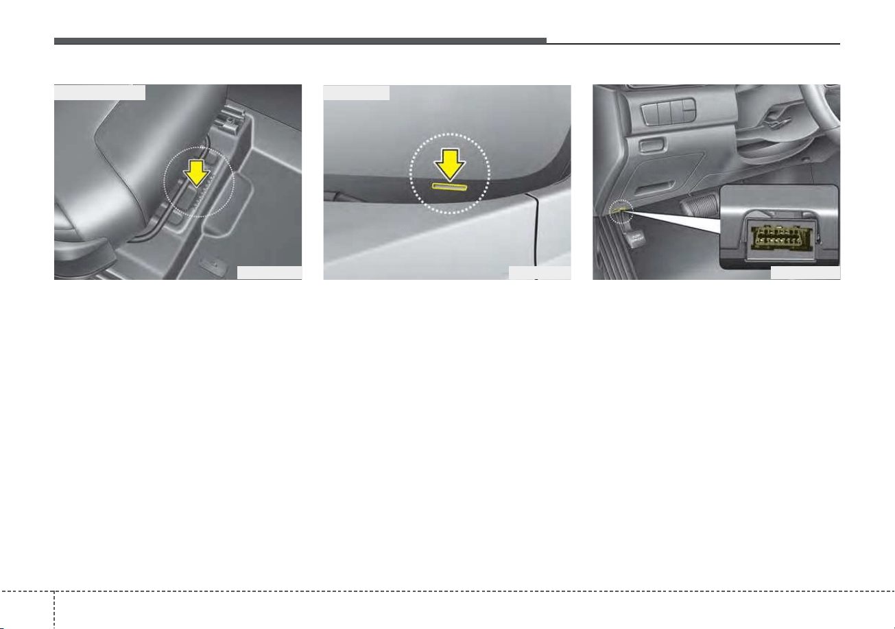
Specifications, Consumer information, Reporting safety defects
108
VEHICLE IDENTIFICATION NUMBER (VIN)
The vehicle identification number
(VIN) is the number used in register-
ing your vehicle and in all legal mat-
ters pertaining to its ownership, etc.
The number is punched on the floor
under the passenger seat. To check
the number, open the cover.
The VIN is also on a plate attached
to the top of the dashboard. The
number on the plate can easily be
seen through the windshield from
outside.
The VIN is able to be found by a pro-
fessional diagnostic equipment from
the ECU. The diagnostic equipment
is connected to OBD connector on
the inner fuse panel. For more infor-
mation, we recommend that you con-
tact an authorized Kia dealer.
ODE086001
■ Frame number
OUM084005
■ VIN label
ODE078018N
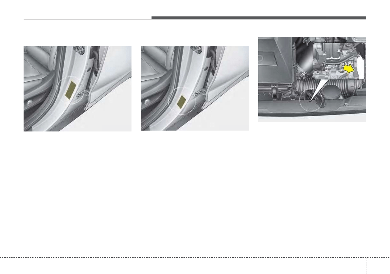
811
Specifications, Consumer information, Reporting safety defects
The vehicle certification label
attached on the driver’s side center
pillar gives the vehicle identification
number (VIN).
The tires supplied on your new vehi-
cle are chosen to provide the best
performance for normal driving.
The tire label located on the driver's
side center pillar gives the tire pres-
sures recommended for your vehicle.
The engine number is stamped on the
engine block as shown in the drawing.
ENGINE NUMBERTIRE SPECIFICATION AND
PRESSURE LABEL
ODE086006L
ODE086003
ODE086002
VEHICLE CERTIFICATION
LABEL
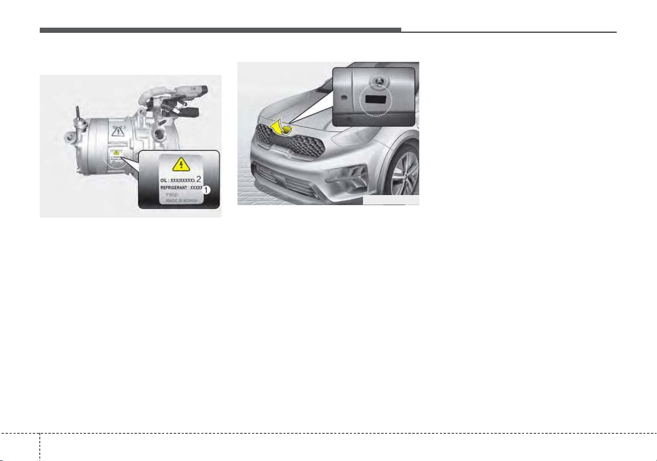
Specifications, Consumer information, Reporting safety defects
128
A compressor label informs you the
type of compressor your vehicle is
equipped with such as model, suppli-
er part number, production number,
refrigerant (1) and refrigerant oil (2).
The refrigerant label is located on
the underside of the hood.
❈ For more details, refer to “Air
Conditioning refrigerant label” in
chapter 4.
REFRIGERANT LABEL
ODEP089004L
AIR CONDITIONER
COMPRESSOR LABEL
ODE086005L

813
Specifications, Consumer information, Reporting safety defects
Roadside Assistance is provided on all new current
model year Kia Vehicles from the date the vehicle is deliv-
ered to the first retail buyer or otherwise put into use (in-
service date), whichever is earlier, for a period of 60
months or 60,000 miles, whichever is earlier, subject to
the terms, conditions and exclusions set forth in the Kia
Warranty and Consumer Information Manual applicable
to your model year vehicle.
KMA reserves the right to limit or deny services or other
benefits to any owner or driver when, in KMA's judgment,
the claims and/or service requests are excessive in fre-
quency or type of occurrence.
Toll free consumer assistance
Kia's toll-free Consumer Assistance hot line is staffed
from 5:00 AM to 6:00 PM PST, Monday through Friday
and is accessible by dialing 1-800-333-4Kia (4542).
For more information regarding assistance available,
please refer to your Kia Warranty & Consumer
Information Manual.
Emergency roadside assistance
Kia's toll free Roadside Assistance hot line is staffed 24
hours a day, 365 days a year and is accessible by dialing
1-800-333-4Kia (4542).
Please note that you must provide your Vehicle
Identification Number (VIN) to verify coverage at the time
of your call. The VIN can be found on the dash of your
vehicle on the driver’s side, on the door jamb of the dri-
ver’s door, your vehicle’s registration or proof of insur-
ance card.
Kia utilizes a network of over 30,000 roadside assistance
providers. Should you accidentally run out of fuel, require
a battery jump, or need help changing a tire, a Kia
Roadside Assistance Representative will dispatch some-
one to deliver a small quantity of gas, change a flat tire
with your inflated spare, or arrange a battery jump to
allow you to proceed to your destination. We have access
to a network of over 10,000 locksmiths to help you should
you become locked out of your Kia.
In the event that mechanical difficulty renders your vehi-
cle undriveable due to a warranty-related concern, Kia’s
Roadside Assistance Representative will arrange to
transport your vehicle to the nearest Kia dealer or to an
authorized Kia alternative service location.
CONSUMER ASSISTANCE (U.S. ONLY)

Specifications, Consumer information, Reporting safety defects
148
Your vehicle must be accessible to our dispatch transport
vehicle, as determined by our driver, to receive this serv-
ice.
✽✽
NOTICE
Roadside Assistance benefits are not available for any
Kia vehicle that has ever been or should be issued a “sal-
vage” title or similar “branded” title under any state’s
law or has been declared a “total loss” or equivalent by
a financial institution or insurance company.
Trip interruption
Trip interruption expense benefits are provided in the
event that a warranty-related disablement occurs more
than 150 miles from your home, and the repairs require
more than 24 hours to complete. Reasonable reimburse-
ment is included for meals, lodging, or rental vehicle
expenses. Trip interruption coverage is limited to $100
per day subject to a three day maximum limit per incident.
You must contact the Kia Roadside Assistance Center to
obtain pre-authorization of expenses. Once the Kia
Roadside Assistance Center gives authorization for trip
interruption benefits, they will assist you in making the
necessary arrangements. Insurance deductibles,
expenses, and claims paid by your insurance company or
other providers are not eligible for reimbursement.
Fleet vehicles are excluded from reimbursement under
Kia’s Trip Interruption Policy.

815
Specifications, Consumer information, Reporting safety defects
Registering your vehicle in a foreign country
If you plan to register your vehicle in a foreign country,
you should confirm that it conforms to the regulations in
that country. Even if you successfully register the vehicle
in a foreign country, you may experience the following
problems and should therefore consider the possibility of
having to deal with them:
1. The fuel specified for your vehicle may be unavailable.
If other than the specified fuel is used, it could cause
damage to the engine, the fuel injection system, and
other fuel-related parts which may not be covered
under your New Vehicle Emissions Limited Warranty.
2. We must, therefore, clearly state that when you leave
the country in which you purchased your Kia new and
register it in another country, problems arising from the
use of fuel other than the specified fuel are not subject
to manufacturer’s warranty. Because vehicles like
yours may not be marketed in the new country of reg-
istration, parts, servicing techniques and tools neces-
sary to maintain and repair your vehicle may be
unavailable.
Even if vehicles like yours are sold there, mechanical
specifications required by the government may vary
enough from the country of purchase to cause addi-
tional problems.
3. There may not be an Authorized Kia Dealer in the area
in which you plan to register your vehicle. You may
additionally experience difficulty in obtaining services
in a foreign country for any number of reasons.
Further, we cannot assume any responsibility for prob-
lems that result from unsatisfactory service or lack of
service outside of the United States.

Specifications, Consumer information, Reporting safety defects
168
The electrical system of your vehicle is designed to per-
form under all reasonably expected operating conditions.
However, before any additional electrical equipment is
installed in your vehicle, consult an Authorized Kia
Dealer, in order to ensure that you do not void your war-
ranty.
Certain electrical equipment, or the way in which it is
installed, may adversely affect the operation of your vehi-
cle, including such systems as the engine control system,
the audio system and the electrical charging system and
thus potentially void all or part of your warranty.
We assume no responsibility for any expense you may
incur or for any malfunction of your vehicle or any of its
components or systems that may result from the installa-
tion of additional electrical equipment that is not supplied,
or recommended for installation by, Kia.
Installation of a mobile two-way radio system
If a mobile two-way radio system is installed improperly,
or if an excessively powerful type of system is used, other
electronic systems may be adversely affected. To avoid
damage to your vehicle, consult an Authorized Kia Dealer
concerning the proper equipment and installation.
Kia motor vehicles are designed and manufactured to
meet or exceed all applicable safety standards.
For your safety, however, we strongly urge you to read
and follow all directions in this Owner's Manual, particu-
larly the information under the headings "NOTICE",
"CAUTION" and "WARNING".
If, after reading this manual, you have any questions
regarding the operation of your vehicle, safety issues and
defects please contact your Kia's toll-free Consumer
Assistance hot line as below:
National Consumer Affairs Manager
Kia Motors America, Inc.
P.O. Box 52410
Irvine, CA 92619-2410
1-800-333-4Kia (4542)
ELECTRICAL EQUIPMENT (U.S. ONLY)

817
Specifications, Consumer information, Reporting safety defects
If you believe that your vehicle has a defect which could
cause a crash or could cause injury or death, you should
immediately inform the National Highway Traffic Safety
Administration (NHTSA) in addition to notifying Kia
Motors America, Inc.
If NHTSA receives similar complaints, it may open an
investigation, and if it finds that a safety defect exists in a
group of vehicles, it may order a recall and remedy cam-
paign. However, NHTSA cannot become involved in indi-
vidual problems between you, your dealer, or Kia Motors
America, Inc.
To contact NHTSA, you may call the Vehicle Safety
Hotline toll-free at 1-888-327-4236 (TTY: 1-800-424-
9153); go to http://www.safercar.gov; download the
SaferCar mobile application; or write to: Administrator,
NHTSA, 1200 New Jersey Ave. SE., Washington, DC
20590. You can also obtain other information about
motor vehicle safety from http://www.safercar.gov.
The following publications are available on
www.KiaTechinfo.com
Service manual:
This manual covers maintenance and recommended pro-
cedures for repair to engine and chassis components. It
is written for the Journeyman mechanic, but is simple
enough for most mechanically inclined owners to under-
stand.
Electrical troubleshooting manual:
This manual complements the Service Manual by provid-
ing indepth troubleshooting information for each electrical
circuit in your vehicle.
Owner's manual:
This manual describes the overall features and operating
procedures for the vehicle.
REPORTING SAFETY DEFECTS
(U.S. ONLY)
ONLINE FACTORY AUTHORIZED MANUALS
(U.S. ONLY)

Kia, THE COMPANY
Thank you for becoming the owner of a new Kia vehicle.
As a global car manufacturer focused on building high-quality vehi-
cles with exceptional value, Kia Motors is dedicated to providing you
with a customer service experience that exceeds your expectations.
All information contained in this Owner’s Manual was accurate at the
time of publication. However, Kia reserves the right to make changes
at any time so that our policy of continual product improvement can
be carried out.
This manual applies to all trims of this vehicle and includes images,
descriptions, and explanations of optional as well as standard equip-
ment. As a result, some material in this manual may not be applicable
to your specific Kia vehicle. Some images are shown for illustration
only and may show features that differ from those on your vehicle.
Drive safely and enjoy your Kia!

i
Thank you for choosing a Kia vehicle.
When you require service, remember that your Kia dealer
knows your vehicle best. Your dealer has factory-trained tech-
nicians, recommended special tools and genuine Kia replace-
ment parts. It is dedicated to your complete customer satisfac-
tion.
Because subsequent owners require this important information
as well, this publication should remain with the vehicle if it is
sold.
This manual will familiarize you with operational, mainte-
nance and safety information about your new vehicle. It is sup-
plemented by a Warranty and Consumer Information manual
that provides important information on all warranties regarding
your vehicle.
We urge you to read these publications carefully and follow the
recommendations to help assure enjoyable and safe operation
of your new vehicle.
Kia offers a great variety of options, components and features
for its various models. Therefore, some of the equipment
described in this manual, along with the various illustrations,
may not be applicable to your particular vehicle.
The information and specifications provided in this manual
were accurate at the time of printing. Kia reserves the right to
discontinue or change specifications or design at any time
without notice and without incurring any obligation. If you
have questions, always check with your Kia dealer.
We assure you of our continuing interest in your motoring
pleasure and satisfaction in your Kia vehicle.
© 2020 Kia MOTORS AMERICA, Inc.
All rights reserved. May not be reproduced or translated in
whole or in part without the written consent of Kia Motors
America, Inc.
Printed in Korea
Foreword
ii
Foreword
We want to help you get the greatest
possible driving pleasure from your
vehicle. Your Owner’s Manual can
assist you in many ways. We strong-
ly recommend that you read the
entire manual. In order to minimize
the chance of death or injury, you
must read the WARNING and CAU-
TION sections in the manual.
Illustrations complement the words
in this manual to best explain how to
enjoy your vehicle. By reading your
manual, you will learn about fea-
tures, important safety information,
and driving tips under various road
conditions.
The general layout of the manual is
provided in the Table of Contents.
Use the index when looking for a
specific area or subject; it has an
alphabetical listing of all information
in your manual.
Sections: This manual has nine sec-
tions plus an index. Each section
begins with a brief list of contents so
you can tell at a glance if that section
has the information you want.
You will find various WARNINGs,
CAUTIONs, and NOTICEs in this
manual. These WARNINGs were pre-
pared to enhance your personal safe-
ty.You should carefully read and follow
ALL procedures and recommenda-
tions provided in these WARNINGs,
CAUTIONs and NOTICEs.
✽✽
NOTICE
A NOTICE indicates interesting or
helpful information is being provided.
HOW TO USE THIS MANUAL
WARNING
A WARNING indicates a situa-
tion in which harm, serious bod-
ily injury or death could result if
the warning is ignored.
CAUTION
A CAUTION indicates a situation
in which damage to your vehicle
could result if the caution is
ignored.


table of contents
1
2
3
4
5
6
7
8
I
Introduction
Your vehicle at a glance
Safety features of your vehicle
Features of your vehicle
Driving your vehicle
What to do in an emergency
Maintenance
Specifications, Consumer information and Reporting safety defects
Index

Index
I

Index
2
I
Air bag - advanced supplemental restraint system. . . . 3-47
Adding equipment to or modifying your
air bag-equipped vehicle . . . . . . . . . . . . . . . . . . . . 3-73
Air bag warning label. . . . . . . . . . . . . . . . . . . . . . . . 3-73
Air bag warning light . . . . . . . . . . . . . . . . . . . . . . . . 3-50
Curtain air bag . . . . . . . . . . . . . . . . . . . . . . . . . . . . . 3-67
Driver's and passenger's front air bag . . . . . . . . . . . 3-62
How does the air bag system operate?. . . . . . . . . . . 3-48
Occupant Detection System (ODS) . . . . . . . . . . . . . 3-54
Side air bag. . . . . . . . . . . . . . . . . . . . . . . . . . . . . . . . 3-65
SRS Care . . . . . . . . . . . . . . . . . . . . . . . . . . . . . . . . . 3-72
SRS components and functions . . . . . . . . . . . . . . . . 3-51
Air cleaner . . . . . . . . . . . . . . . . . . . . . . . . . . . . . . . . . . 7-32
Filter replacement. . . . . . . . . . . . . . . . . . . . . . . . . . . 7-32
Air conditioner compressor label . . . . . . . . . . . . . . . . . 8-12
Air conditioning system . . . . . . . . . . . . . . . . . . . . . . . . . 8-7
Appearance care . . . . . . . . . . . . . . . . . . . . . . . . . . . . . 7-104
Exterior care . . . . . . . . . . . . . . . . . . . . . . . . . . . . . . 7-104
Interior care . . . . . . . . . . . . . . . . . . . . . . . . . . . . . . 7-110
Automatic climate control system . . . . . . . . . . . . . . . 4-131
Air Conditioning refrigerant label . . . . . . . . . . . . . 4-144
Automatic heating and air conditioning. . . . . . . . . 4-132
Automatic ventilation. . . . . . . . . . . . . . . . . . . . . . . 4-142
Checking the amount of air conditioner
refrigerant and compressor lubricant . . . . . . . . . . 4-145
Climate control air filter. . . . . . . . . . . . . . . . . . . . . 4-144
Manual heating and air conditioning . . . . . . . . . . . 4-134
Recirculated air at washer fluid spray . . . . . . . . . . 4-143
Sunroof inside air recirculation . . . . . . . . . . . . . . . 4-143
System operation . . . . . . . . . . . . . . . . . . . . . . . . . . 4-140
Battery (Plug-in Hybrid). . . . . . . . . . . . . . . . . . . . . . . . 7-39
For best battery service . . . . . . . . . . . . . . . . . . . . . . 7-39
Recharging the battery . . . . . . . . . . . . . . . . . . . . . . . 7-40
Reset items . . . . . . . . . . . . . . . . . . . . . . . . . . . . . . . . 7-41
Before driving . . . . . . . . . . . . . . . . . . . . . . . . . . . . . . . . . 5-5
Before entering vehicle . . . . . . . . . . . . . . . . . . . . . . . 5-5
Before starting . . . . . . . . . . . . . . . . . . . . . . . . . . . . . . 5-5
Necessary inspections . . . . . . . . . . . . . . . . . . . . . . . . 5-5
Blind-Spot Collision Warning (BCW) . . . . . . . . . . . . . 5-96
System description . . . . . . . . . . . . . . . . . . . . . . . . . . 5-96
System setting and activation. . . . . . . . . . . . . . . . . . 5-97
Warning message and system control . . . . . . . . . . . 5-99
Brake fluid . . . . . . . . . . . . . . . . . . . . . . . . . . . . . . . . . . 7-26
Checking the brake fluid level . . . . . . . . . . . . . . . . . 7-26
Brake system. . . . . . . . . . . . . . . . . . . . . . . . . . . . . . . . . 5-30
Anti-lock Brake System (ABS) . . . . . . . . . . . . . . . . 5-44
Auto hold . . . . . . . . . . . . . . . . . . . . . . . . . . . . . . . . . 5-40
Electronic Parking Brake (EPB) . . . . . . . . . . . . . . . 5-34
Electronic Stability Control (ESC) . . . . . . . . . . . . . 5-46
Good braking practices . . . . . . . . . . . . . . . . . . . . . . 5-52
Hill-start Assist Control (HAC) . . . . . . . . . . . . . . . . 5-51
A
B

I
3
Index
Parking brake – Foot type . . . . . . . . . . . . . . . . . . . . 5-32
Power brakes . . . . . . . . . . . . . . . . . . . . . . . . . . . . . . 5-30
Vehicle Stability Management (VSM). . . . . . . . . . . 5-50
Warning messages . . . . . . . . . . . . . . . . . . . . . . . . . . 5-42
Bulb wattage . . . . . . . . . . . . . . . . . . . . . . . . . . . . . . . . . . 8-3
California perchlorate notice . . . . . . . . . . . . . . . . . . . 7-117
Checking fluid levels . . . . . . . . . . . . . . . . . . . . . . . . . . 7-18
Child Restraint System (CRS) . . . . . . . . . . . . . . . . . . . 3-35
Children always in the rear . . . . . . . . . . . . . . . . . . . 3-35
Installing a Child Restraint System (CRS) . . . . . . . 3-39
Selecting a Child Restraint System (CRS) . . . . . . . 3-36
Climate control air filter . . . . . . . . . . . . . . . . . . . . . . . . 7-34
Filter inspection . . . . . . . . . . . . . . . . . . . . . . . . . . . . 7-34
Consumer assistance (U.S. only) . . . . . . . . . . . . . . . . . 8-13
Emergency roadside assistance . . . . . . . . . . . . . . . . 8-13
Registering your vehicle in a foreign country . . . . . 8-15
Toll free consumer assistance . . . . . . . . . . . . . . . . . 8-13
Trip interruption . . . . . . . . . . . . . . . . . . . . . . . . . . . . 8-14
Coolant . . . . . . . . . . . . . . . . . . . . . . . . . . . . . . . . . . . . . 7-21
Changing the coolant . . . . . . . . . . . . . . . . . . . . . . . . 7-25
Checking the coolant level . . . . . . . . . . . . . . . . . . . . 7-21
Engine coolant . . . . . . . . . . . . . . . . . . . . . . . . . . . . . 7-22
Inverter coolant. . . . . . . . . . . . . . . . . . . . . . . . . . . . . 7-22
Recommended coolant . . . . . . . . . . . . . . . . . . . . . . . 7-23
Cruise Control (CC) . . . . . . . . . . . . . . . . . . . . . . . . . . 5-115
Cruise control switch . . . . . . . . . . . . . . . . . . . . . . . 5-116
To cancel cruise control . . . . . . . . . . . . . . . . . . . . . 5-118
To decrease the cruising speed. . . . . . . . . . . . . . . . 5-117
To increase cruise control set speed. . . . . . . . . . . . 5-117
To resume cruising speed at more than approximately
20 mph (30 km/h) . . . . . . . . . . . . . . . . . . . . . . . . 5-119
To set cruise control speed. . . . . . . . . . . . . . . . . . . 5-116
To temporarily accelerate with the cruise control on. 5-118
To turn cruise control off . . . . . . . . . . . . . . . . . . . . 5-119
Declaration of Conformity . . . . . . . . . . . . . . . . . . . . . 4-172
FCC . . . . . . . . . . . . . . . . . . . . . . . . . . . . . . . . . . . . 4-172
Defroster . . . . . . . . . . . . . . . . . . . . . . . . . . . . . . . . . . . 4-130
Rear window defroster . . . . . . . . . . . . . . . . . . . . . . 4-130
Dimensions . . . . . . . . . . . . . . . . . . . . . . . . . . . . . . . . . . . 8-2
Door locks. . . . . . . . . . . . . . . . . . . . . . . . . . . . . . . . . . . 4-21
Child-protector rear door lock . . . . . . . . . . . . . . . . . 4-25
Operating door locks from inside the vehicle . . . . . 4-22
Operating door locks from outside the vehicle . . . . 4-21
Driver Attention Warning (DAW). . . . . . . . . . . . . . . . 5-107
Leading vehicle departure alert . . . . . . . . . . . . . . . 5-112
Low activity warning . . . . . . . . . . . . . . . . . . . . . . . 5-107
Dual Clutch Transmission (DCT). . . . . . . . . . . . . . . . . 5-16
Dual clutch transmission operation . . . . . . . . . . . . . 5-16
Good driving practices . . . . . . . . . . . . . . . . . . . . . . . 5-25
C
D
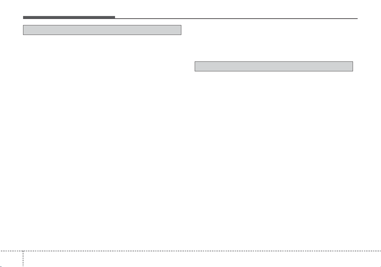
Index
4
I
Economical operation . . . . . . . . . . . . . . . . . . . . . . . . . 5-167
Electrical Equipment (U.S. only) . . . . . . . . . . . . . . . . . 8-16
Installation of a mobile two-way radio system . . . . 8-16
Emergency starting . . . . . . . . . . . . . . . . . . . . . . . . . . . . . 6-5
Before Jump Starting (For Hybrid) . . . . . . . . . . . . . . 6-5
Jump starting . . . . . . . . . . . . . . . . . . . . . . . . . . . . . . . 6-8
Method to disconnect the (-) cable for regular
maintenance (For Hybrid) . . . . . . . . . . . . . . . . . . . . 6-7
Push-starting. . . . . . . . . . . . . . . . . . . . . . . . . . . . . . . 6-10
Emission control system . . . . . . . . . . . . . . . . . . . . . . . 7-114
Crankcase emission control system . . . . . . . . . . . . 7-114
Evaporative emission control (including ORVR:
Onboard Refueling Vapor Recovery) system. . . . 7-114
Exhaust emission control system . . . . . . . . . . . . . . 7-115
Engine . . . . . . . . . . . . . . . . . . . . . . . . . . . . . . . . . . . . . . 8-2
Engine clutch actuator fluid . . . . . . . . . . . . . . . . . . . . . 7-28
Checking the engine clutch actuator fluid level. . . . 7-28
Engine compartment . . . . . . . . . . . . . . . . . . . . . . . . 2-6, 7-4
Engine number . . . . . . . . . . . . . . . . . . . . . . . . . . . . . . . 8-11
Engine oil . . . . . . . . . . . . . . . . . . . . . . . . . . . . . . . . . . . 7-19
Changing the engine oil and filter . . . . . . . . . . . . . . 7-20
Checking the engine oil level. . . . . . . . . . . . . . . . . . 7-19
ENGINE START/STOP button . . . . . . . . . . . . . . . . . . 5-11
ENGINE START/STOP button position . . . . . . . . . 5-11
Illuminated ENGINE START/STOP button . . . . . . 5-11
Starting the hybrid system . . . . . . . . . . . . . . . . . . . . 5-13
Explanation of scheduled maintenance items . . . . . . . 7-15
Exterior features . . . . . . . . . . . . . . . . . . . . . . . . . . . . . 4-166
Roof rack . . . . . . . . . . . . . . . . . . . . . . . . . . . . . . . . 4-166
Exterior overview . . . . . . . . . . . . . . . . . . . . . . . . . . . . . . 2-2
Folding key . . . . . . . . . . . . . . . . . . . . . . . . . . . . . . . . . . . 4-4
Battery replacement . . . . . . . . . . . . . . . . . . . . . . . . . . 4-7
Immobilizer system . . . . . . . . . . . . . . . . . . . . . . . . . . 4-8
Key operations . . . . . . . . . . . . . . . . . . . . . . . . . . . . . . 4-4
Record your key number . . . . . . . . . . . . . . . . . . . . . . 4-4
Transmitter precautions . . . . . . . . . . . . . . . . . . . . . . . 4-6
Forward Collision-Avoidance Assist (FCA)
(front view camera only) . . . . . . . . . . . . . . . . . . . . . 5-53
Brake operation . . . . . . . . . . . . . . . . . . . . . . . . . . . . 5-57
Detecting sensor (front view camera) . . . . . . . . . . . 5-58
FCA warning message and system control . . . . . . . 5-56
Limitation of the system . . . . . . . . . . . . . . . . . . . . . 5-62
System malfunction . . . . . . . . . . . . . . . . . . . . . . . . . 5-60
System setting and activation. . . . . . . . . . . . . . . . . . 5-53
Forward Collision-Avoidance Assist (FCA)
(sensor fusion) . . . . . . . . . . . . . . . . . . . . . . . . . . . . . 5-69
Brake operation . . . . . . . . . . . . . . . . . . . . . . . . . . . . 5-74
Detecting sensors (front view camera/front radar) . 5-74
FCA warning message and system control . . . . . . . 5-72
Limitation of the system . . . . . . . . . . . . . . . . . . . . . 5-78
E
F

I
5
Index
System malfunction . . . . . . . . . . . . . . . . . . . . . . . . . 5-76
System setting and activation. . . . . . . . . . . . . . . . . . 5-69
Fuel filler door (Hybrid) . . . . . . . . . . . . . . . . . . . . . . . . 4-36
Closing the fuel filler door . . . . . . . . . . . . . . . . . . . . 4-36
Opening the fuel filler door . . . . . . . . . . . . . . . . . . . 4-36
Fuel filler door (Plug-in hybrid) . . . . . . . . . . . . . . . . . . 4-37
Closing the fuel filler door . . . . . . . . . . . . . . . . . . . . 4-38
Opening the fuel filler door . . . . . . . . . . . . . . . . . . . 4-37
Fuel requirements . . . . . . . . . . . . . . . . . . . . . . . . . . . . . . 1-2
Do not use methanol . . . . . . . . . . . . . . . . . . . . . . . . . 1-3
Fuel additives . . . . . . . . . . . . . . . . . . . . . . . . . . . . . . . 1-4
Gasoline containing alcohol and methanol . . . . . . . . 1-2
Operation in foreign countries . . . . . . . . . . . . . . . . . . 1-4
Fuses . . . . . . . . . . . . . . . . . . . . . . . . . . . . . . . . . . . . . . . 7-58
Engine compartment fuse replacement . . . . . . . . . . 7-61
Fuse/relay panel description. . . . . . . . . . . . . . . . . . . 7-64
Inner panel fuse replacement . . . . . . . . . . . . . . . . . . 7-59
Gross vehicle weight. . . . . . . . . . . . . . . . . . . . . . . . . . . . 8-6
HEV/PHEV powertrain . . . . . . . . . . . . . . . . . . . . . . . . . 1-5
Highway Driving Assist (HDA) . . . . . . . . . . . . . . . . . 5-149
HDA malfunction . . . . . . . . . . . . . . . . . . . . . . . . . . 5-154
HDA system operation . . . . . . . . . . . . . . . . . . . . . . 5-150
Operating conditions . . . . . . . . . . . . . . . . . . . . . . . 5-150
Setting and activating HDA system . . . . . . . . . . . . 5-150
Warning related to steering wheel . . . . . . . . . . . . . 5-151
When the hands-off warning lasts for
a certain period of time . . . . . . . . . . . . . . . . . . . . 5-152
Hood . . . . . . . . . . . . . . . . . . . . . . . . . . . . . . . . . . . . . . . 4-34
Closing the hood . . . . . . . . . . . . . . . . . . . . . . . . . . . 4-35
Opening the hood . . . . . . . . . . . . . . . . . . . . . . . . . . . 4-34
If An Accident Occurs . . . . . . . . . . . . . . . . . . . . . . . . . 6-44
If the engine overheats . . . . . . . . . . . . . . . . . . . . . . . . . 6-11
If the engine will not start . . . . . . . . . . . . . . . . . . . . . . . 6-4
If engine doesn't turn over or turns over slowly . . . . 6-4
If engine turns over normally but does not start . . . . 6-4
If you have a flat tire (with spare tire) . . . . . . . . . . . . . 6-19
Changing tires . . . . . . . . . . . . . . . . . . . . . . . . . . . . . 6-20
Jack and tools . . . . . . . . . . . . . . . . . . . . . . . . . . . . . . 6-19
Removing and storing the spare tire . . . . . . . . . . . . 6-20
If you have a flat tire (with Tire Mobility Kit). . . . . . . 6-28
Checking the tire inflation pressure . . . . . . . . . . . . . 6-36
Components of the Tire Mobility Kit . . . . . . . . . . . 6-32
Distributing the sealant . . . . . . . . . . . . . . . . . . . . . . 6-35
Introduction . . . . . . . . . . . . . . . . . . . . . . . . . . . . . . . 6-29
Notes on the safe use of the Tire Mobility Kit . . . . 6-30
Technical Data . . . . . . . . . . . . . . . . . . . . . . . . . . . . . 6-38
Using the Tire Mobility Kit . . . . . . . . . . . . . . . . . . . 6-33
H
I
G

Index
6
I
Important safety precautions . . . . . . . . . . . . . . . . . . . . . 3-2
Air bag hazards . . . . . . . . . . . . . . . . . . . . . . . . . . . . . 3-2
Always wear your seat belt . . . . . . . . . . . . . . . . . . . . 3-2
Control your speed . . . . . . . . . . . . . . . . . . . . . . . . . . . 3-3
Driver distraction . . . . . . . . . . . . . . . . . . . . . . . . . . . . 3-2
Keep your vehicle in safe condition. . . . . . . . . . . . . . 3-3
Restrain all children . . . . . . . . . . . . . . . . . . . . . . . . . . 3-2
In case of an emergency while driving. . . . . . . . . . . . . . 6-3
If the engine stalls at a crossroad or crossing . . . . . . 6-3
If the engine stalls while driving . . . . . . . . . . . . . . . . 6-3
If you have a flat tire while driving . . . . . . . . . . . . . . 6-3
Infotainment system . . . . . . . . . . . . . . . . . . . . . . . . . . 4-168
Antenna . . . . . . . . . . . . . . . . . . . . . . . . . . . . . . . . . 4-168
How vehicle radio works . . . . . . . . . . . . . . . . . . . . 4-169
USB port. . . . . . . . . . . . . . . . . . . . . . . . . . . . . . . . . 4-168
Instrument cluster . . . . . . . . . . . . . . . . . . . . . . . . . . . . . 4-57
Dual clutch transmission shift indicator . . . . . . . . . 4-65
Gauges . . . . . . . . . . . . . . . . . . . . . . . . . . . . . . . . . . . 4-59
Instrument cluster control . . . . . . . . . . . . . . . . . . . . 4-59
Instrument panel overview . . . . . . . . . . . . . . . . . . . . . . . 2-5
Interior features. . . . . . . . . . . . . . . . . . . . . . . . . . . . . . 4-154
Air ventilation seat . . . . . . . . . . . . . . . . . . . . . . . . . 4-156
Cargo security screen . . . . . . . . . . . . . . . . . . . . . . . 4-164
Clothes hanger . . . . . . . . . . . . . . . . . . . . . . . . . . . . 4-162
Cup holder . . . . . . . . . . . . . . . . . . . . . . . . . . . . . . . 4-154
Floor mat anchor(s) . . . . . . . . . . . . . . . . . . . . . . . . 4-163
Luggage net holder. . . . . . . . . . . . . . . . . . . . . . . . . 4-164
Power outlet . . . . . . . . . . . . . . . . . . . . . . . . . . . . . . 4-157
Seat warmer . . . . . . . . . . . . . . . . . . . . . . . . . . . . . . 4-154
Sunvisor . . . . . . . . . . . . . . . . . . . . . . . . . . . . . . . . . 4-157
USB charger . . . . . . . . . . . . . . . . . . . . . . . . . . . . . . 4-158
Wireless smart phone charging system . . . . . . . . . 4-159
Interior lights . . . . . . . . . . . . . . . . . . . . . . . . . . . . . . . 4-126
Automatic turn off function . . . . . . . . . . . . . . . . . . 4-126
Liftgate room lamp. . . . . . . . . . . . . . . . . . . . . . . . . 4-128
Map lamp . . . . . . . . . . . . . . . . . . . . . . . . . . . . . . . . 4-126
Room lamp . . . . . . . . . . . . . . . . . . . . . . . . . . . . . . . 4-127
Vanity mirror lamp . . . . . . . . . . . . . . . . . . . . . . . . . 4-128
Interior overview. . . . . . . . . . . . . . . . . . . . . . . . . . . . . . . 2-4
Key positions . . . . . . . . . . . . . . . . . . . . . . . . . . . . . . . . . 5-7
Ignition switch position . . . . . . . . . . . . . . . . . . . . . . . 5-7
Illuminated ignition switch . . . . . . . . . . . . . . . . . . . . 5-7
Starting the hybrid system . . . . . . . . . . . . . . . . . . . . . 5-9
Lane Following Assist (LFA) . . . . . . . . . . . . . . . . . . . 5-142
LFA system malfunction . . . . . . . . . . . . . . . . . . . . 5-146
LFA system operation . . . . . . . . . . . . . . . . . . . . . . 5-143
Limitation of the system . . . . . . . . . . . . . . . . . . . . 5-147
Lane Keeping Assist (LKA) . . . . . . . . . . . . . . . . . . . . . 5-87
Lane Keeping Assist system malfunction . . . . . . . . 5-93
LKA activation. . . . . . . . . . . . . . . . . . . . . . . . . . . . . 5-90
K
L

I
7
Index
LKA system operation . . . . . . . . . . . . . . . . . . . . . . . 5-89
System setting . . . . . . . . . . . . . . . . . . . . . . . . . . . . . 5-89
LCD display . . . . . . . . . . . . . . . . . . . . . . . . . . . . . . . . . 4-67
LCD display control. . . . . . . . . . . . . . . . . . . . . . . . . 4-67
LCD display modes . . . . . . . . . . . . . . . . . . . . . . . . . 4-68
Trip modes (Trip computer). . . . . . . . . . . . . . . . . . . 4-80
Warning messages . . . . . . . . . . . . . . . . . . . . . . . . . . 4-85
Liftgate . . . . . . . . . . . . . . . . . . . . . . . . . . . . . . . . . . . . . 4-26
Closing the liftgate . . . . . . . . . . . . . . . . . . . . . . . . . . 4-26
Emergency liftgate safety release. . . . . . . . . . . . . . . 4-27
Opening the liftgate . . . . . . . . . . . . . . . . . . . . . . . . . 4-26
Light bulbs . . . . . . . . . . . . . . . . . . . . . . . . . . . . . . . . . . 7-86
Back-up lamp (Bulb type) bulb replacement . . . . . . 7-98
Bulb replacement precaution . . . . . . . . . . . . . . . . . 7-86
Daytime running lamp/Position lamp (LED type)
bulb replacement . . . . . . . . . . . . . . . . . . . . . . . . . . 7-93
Front fog lamp (Bulb/LED type) bulb replacement . 7-94
Front side marker (Bulb type) bulb replacement
(Headlamp type A) . . . . . . . . . . . . . . . . . . . . . . . . . . 7-92
Front side marker (LED type) bulb replacement
(Headlamp type B) . . . . . . . . . . . . . . . . . . . . . . . . . . 7-93
Front turn signal (LED type) bulb replacement
(Headlamp type B). . . . . . . . . . . . . . . . . . . . . . . . . 7-93
Front turn signal lamp (Bulb type) bulb replacement
(Headlamp type A). . . . . . . . . . . . . . . . . . . . . . . . . 7-91
Headlamp (High/Low beam) (Bulb type) bulb
replacement (Headlamp type A) . . . . . . . . . . . . . . 7-90
Headlamp (High/Low beam) (LED type) bulb
replacement (Headlamp type B) . . . . . . . . . . . . . . 7-92
High mounted stop lamp (LED type) bulb
replacement . . . . . . . . . . . . . . . . . . . . . . . . . . . . . . 7-99
License plate lamp (Bulb type) bulb replacement . . 7-99
Liftgate room lamp (Bulb type) bulb replacement . 7-103
Liftgate room lamp (LED type) bulb replacement . 7-103
Light bulb position (Front). . . . . . . . . . . . . . . . . . . . 7-87
Light bulb position (Rear) . . . . . . . . . . . . . . . . . . . . 7-88
Light bulb position (Side) . . . . . . . . . . . . . . . . . . . . 7-89
Map lamp (Bulb type) bulb replacement . . . . . . . . 7-100
Map lamp (LED type) bulb replacement . . . . . . . . 7-101
Rear side marker (Bulb type) bulb replacement . . . 7-96
Rear side marker (LED type) bulb replacement . . . 7-98
Room lamp (Bulb type) bulb replacement. . . . . . . 7-102
Room lamp (LED type) bulb replacement. . . . . . . 7-102
Side repeater lamp (LED type) bulb replacement . 7-100
Stop and tail lamp (LED type) bulb replacement . . 7-98
Stop and tail lamp, Rear turn signal lamp
(Bulb type) bulb replacement . . . . . . . . . . . . . . . . 7-94
Tail lamp (inside) (Bulb type) bulb replacement . . . 7-95
Vanity mirror lamp (Bulb type) bulb replacement. 7-101
Lighting. . . . . . . . . . . . . . . . . . . . . . . . . . . . . . . . . . . . 4-115
Battery saver function . . . . . . . . . . . . . . . . . . . . . . 4-115
Check headlight . . . . . . . . . . . . . . . . . . . . . . . . . . . 4-121
Daytime running light . . . . . . . . . . . . . . . . . . . . . . 4-115
Front fog light . . . . . . . . . . . . . . . . . . . . . . . . . . . . 4-121
Headlight escort function . . . . . . . . . . . . . . . . . . . . 4-115
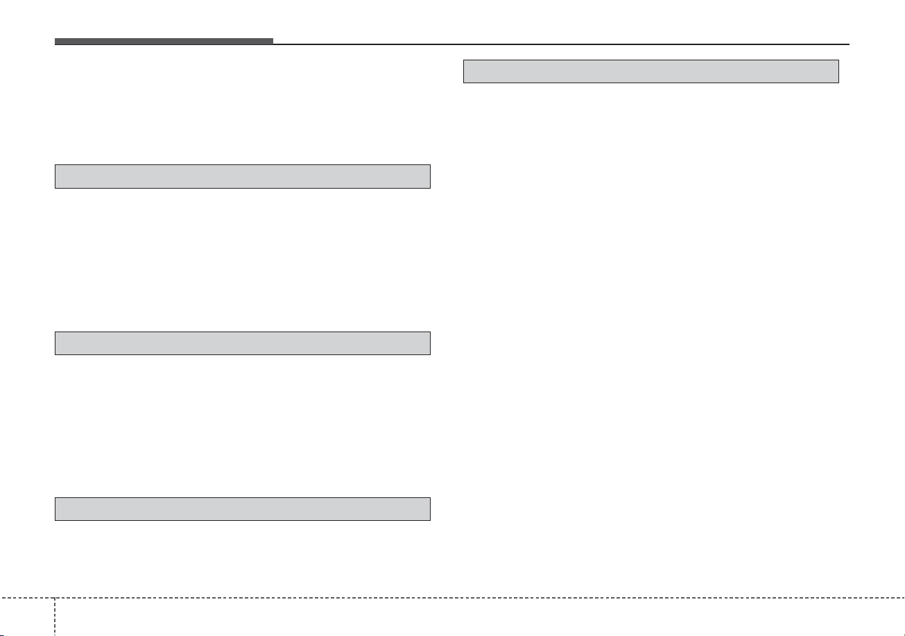
Index
8
I
High Beam Assist (HBA). . . . . . . . . . . . . . . . . . . . 4-118
High beam operation . . . . . . . . . . . . . . . . . . . . . . . 4-117
Lighting control . . . . . . . . . . . . . . . . . . . . . . . . . . . 4-116
Turn signals and lane change signals. . . . . . . . . . . 4-120
Luggage volume . . . . . . . . . . . . . . . . . . . . . . . . . . . . . . . 8-7
Maintenance services . . . . . . . . . . . . . . . . . . . . . . . . . . . 7-5
Owner maintenance precautions . . . . . . . . . . . . . . . . 7-6
Owner’s responsibility . . . . . . . . . . . . . . . . . . . . . . . . 7-5
Mirrors . . . . . . . . . . . . . . . . . . . . . . . . . . . . . . . . . . . . . 4-51
Inside rearview mirror . . . . . . . . . . . . . . . . . . . . . . . 4-51
Outside rearview mirror . . . . . . . . . . . . . . . . . . . . . . 4-53
Online factory authorized manuals (U.S. only) . . . . . . 8-17
Electrical troubleshooting manual . . . . . . . . . . . . . . 8-17
Owner's manual . . . . . . . . . . . . . . . . . . . . . . . . . . . . 8-17
Service manual . . . . . . . . . . . . . . . . . . . . . . . . . . . . . 8-17
Owner maintenance . . . . . . . . . . . . . . . . . . . . . . . . . . . . 7-7
Owner maintenance schedule. . . . . . . . . . . . . . . . . . . 7-7
Parking brake . . . . . . . . . . . . . . . . . . . . . . . . . . . . . . . . 7-31
Checking the parking brake . . . . . . . . . . . . . . . . . . . 7-31
Rear Cross-Traffic Collision Warning (RCCW). . . . . 5-157
System description . . . . . . . . . . . . . . . . . . . . . . . . . 5-157
System setting and activation. . . . . . . . . . . . . . . . . 5-157
Warning message and system control . . . . . . . . . . 5-159
Rear View Monitor (RVM). . . . . . . . . . . . . . . . . . . . . 4-111
Recommended lubricants and capacities . . . . . . . . . . . . 8-8
Recommended SAE viscosity number. . . . . . . . . . . . 8-9
Refrigerant label . . . . . . . . . . . . . . . . . . . . . . . . . . . . . . 8-12
Regenerative Braking (Paddle Shifter) . . . . . . . . . . 5-27
Regenerative braking system . . . . . . . . . . . . . . . . . . . . 5-27
Reporting Safety Defects (U.S. only). . . . . . . . . . . . . . 8-17
Reverse Parking Distance Warning (PDW) . . . . . . . . 4-112
Non-operational conditions of Reverse Parking
Distance Warning system. . . . . . . . . . . . . . . . . . . 4-113
Operation of Reverse Parking Distance
Warning system . . . . . . . . . . . . . . . . . . . . . . . . . . 4-112
Reverse Parking Distance Warning system
precautions . . . . . . . . . . . . . . . . . . . . . . . . . . . . . . 4-114
Self-diagnosis . . . . . . . . . . . . . . . . . . . . . . . . . . . . . 4-114
Road warning . . . . . . . . . . . . . . . . . . . . . . . . . . . . . . . . . 6-2
Hazard warning flasher . . . . . . . . . . . . . . . . . . . . . . . 6-2
M
P
O
R

I
9
Index
Scheduled maintenance service . . . . . . . . . . . . . . . . . . . 7-9
Seat . . . . . . . . . . . . . . . . . . . . . . . . . . . . . . . . . . . . . . . . . 3-4
Driver position memory system (for power seat) . . 3-10
Front seat adjustment - manual . . . . . . . . . . . . . . . . . 3-7
Front seat adjustment - power (for driver’s seat). . . . 3-8
Headrest (for front seat) . . . . . . . . . . . . . . . . . . . . . . 3-12
Rear seat adjustment . . . . . . . . . . . . . . . . . . . . . . . . 3-15
Seatback pocket . . . . . . . . . . . . . . . . . . . . . . . . . . . . 3-15
Seat belts . . . . . . . . . . . . . . . . . . . . . . . . . . . . . . . . . . . . 3-21
Care of seat belts . . . . . . . . . . . . . . . . . . . . . . . . . . . 3-33
Pre-tensioner seat belt . . . . . . . . . . . . . . . . . . . . . . . 3-29
Seat belt precautions . . . . . . . . . . . . . . . . . . . . . . . . 3-31
Seat belt restraint system . . . . . . . . . . . . . . . . . . . . . 3-21
Smart Cruise Control (SCC). . . . . . . . . . . . . . . . . . . . 5-120
Detecting Sensor (front view camera/front radar) . 5-133
Limitations of the system. . . . . . . . . . . . . . . . . . . . 5-136
Set SCC Reaction. . . . . . . . . . . . . . . . . . . . . . . . . . 5-128
Smart cruise control switch . . . . . . . . . . . . . . . . . . 5-120
To convert to cruise control mode . . . . . . . . . . . . . 5-135
Vehicle to vehicle distance setting . . . . . . . . . . . . . 5-128
When the lane ahead is clear . . . . . . . . . . . . . . . . . 5-129
When there is a vehicle ahead of you in your lane . 5-130
Smart key . . . . . . . . . . . . . . . . . . . . . . . . . . . . . . . . . . . 4-11
Battery replacement . . . . . . . . . . . . . . . . . . . . . . . . . 4-15
Loss of the smart key . . . . . . . . . . . . . . . . . . . . . . . . 4-14
Mechanical key . . . . . . . . . . . . . . . . . . . . . . . . . . . . 4-14
Record your key number . . . . . . . . . . . . . . . . . . . . . 4-11
Smart key function . . . . . . . . . . . . . . . . . . . . . . . . . . 4-11
Smart key immobilizer system. . . . . . . . . . . . . . . . . 4-16
Smart key precautions . . . . . . . . . . . . . . . . . . . . . . . 4-14
Special driving conditions . . . . . . . . . . . . . . . . . . . . . 5-169
Driving at night . . . . . . . . . . . . . . . . . . . . . . . . . . . 5-172
Driving in flooded areas. . . . . . . . . . . . . . . . . . . . . 5-173
Driving in the rain . . . . . . . . . . . . . . . . . . . . . . . . . 5-172
Driving off-road . . . . . . . . . . . . . . . . . . . . . . . . . . . 5-173
Hazardous driving conditions . . . . . . . . . . . . . . . . 5-169
Highway driving. . . . . . . . . . . . . . . . . . . . . . . . . . . 5-173
Reducing the risk of a rollover. . . . . . . . . . . . . . . . 5-169
Rocking the vehicle . . . . . . . . . . . . . . . . . . . . . . . . 5-171
Smooth cornering . . . . . . . . . . . . . . . . . . . . . . . . . . 5-171
Steering wheel . . . . . . . . . . . . . . . . . . . . . . . . . . . . . . . 4-47
Electric Power Steering (EPS) . . . . . . . . . . . . . . . . . 4-47
Heated steering wheel . . . . . . . . . . . . . . . . . . . . . . . 4-49
Horn . . . . . . . . . . . . . . . . . . . . . . . . . . . . . . . . . . . . . 4-50
Tilt and telescopic steering. . . . . . . . . . . . . . . . . . . . 4-48
Storage compartments . . . . . . . . . . . . . . . . . . . . . . . . 4-151
Center console storage . . . . . . . . . . . . . . . . . . . . . . 4-151
Glove box . . . . . . . . . . . . . . . . . . . . . . . . . . . . . . . . 4-151
Luggage box. . . . . . . . . . . . . . . . . . . . . . . . . . . . . . 4-153
Sunglass holder . . . . . . . . . . . . . . . . . . . . . . . . . . . 4-152
Sunroof . . . . . . . . . . . . . . . . . . . . . . . . . . . . . . . . . . . . . 4-42
Resetting the sunroof . . . . . . . . . . . . . . . . . . . . . . . . 4-45
Sliding the sunroof . . . . . . . . . . . . . . . . . . . . . . . . . . 4-43
S
Index
10
I
Sunroof open warning . . . . . . . . . . . . . . . . . . . . . . . 4-46
Sunshade. . . . . . . . . . . . . . . . . . . . . . . . . . . . . . . . . . 4-45
Tilting the sunroof . . . . . . . . . . . . . . . . . . . . . . . . . . 4-44
Theft-alarm system . . . . . . . . . . . . . . . . . . . . . . . . . . . . 4-18
Armed stage . . . . . . . . . . . . . . . . . . . . . . . . . . . . . . . 4-18
Disarmed stage . . . . . . . . . . . . . . . . . . . . . . . . . . . . . 4-20
Theft-alarm stage . . . . . . . . . . . . . . . . . . . . . . . . . . . 4-19
Tire Pressure Monitoring System (TPMS). . . . . . . . . . 6-13
Changing a tire with TPMS . . . . . . . . . . . . . . . . . . . 6-17
Check tire pressure. . . . . . . . . . . . . . . . . . . . . . . . . . 6-13
Low tire pressure position telltale . . . . . . . . . . . . . . 6-15
Low tire pressure telltale . . . . . . . . . . . . . . . . . . . . . 6-15
Tire specification and pressure label . . . . . . . . . . . . . . 8-11
Tires and wheels . . . . . . . . . . . . . . . . . . . . . . . . . . 7-42, 8-5
All season tires . . . . . . . . . . . . . . . . . . . . . . . . . . . . 7-54
Checking tire inflation pressure . . . . . . . . . . . . . . . . 7-43
Low aspect ratio tire. . . . . . . . . . . . . . . . . . . . . . . . . 7-56
Radial-ply tires . . . . . . . . . . . . . . . . . . . . . . . . . . . . . 7-55
Recommended cold tire inflation pressures. . . . . . . 7-42
Snow tires. . . . . . . . . . . . . . . . . . . . . . . . . . . . . . . . . 7-55
Summer tires . . . . . . . . . . . . . . . . . . . . . . . . . . . . . . 7-54
Tire care . . . . . . . . . . . . . . . . . . . . . . . . . . . . . . . . . . 7-42
Tire chains . . . . . . . . . . . . . . . . . . . . . . . . . . . . . . . . 7-55
Tire maintenance . . . . . . . . . . . . . . . . . . . . . . . . . . . 7-47
Tire pressure. . . . . . . . . . . . . . . . . . . . . . . . . . . . . . . 7-43
Tire replacement. . . . . . . . . . . . . . . . . . . . . . . . . . . . 7-46
Tire rotation . . . . . . . . . . . . . . . . . . . . . . . . . . . . . . . 7-44
Tire sidewall labeling . . . . . . . . . . . . . . . . . . . . . . . . 7-47
Tire terminology and definitions . . . . . . . . . . . . . . . 7-51
Tire traction . . . . . . . . . . . . . . . . . . . . . . . . . . . . . . . 7-47
Wheel alignment and tire balance . . . . . . . . . . . . . . 7-45
Wheel replacement. . . . . . . . . . . . . . . . . . . . . . . . . . 7-46
Towing . . . . . . . . . . . . . . . . . . . . . . . . . . . . . . . . . . . . . 6-39
Emergency towing . . . . . . . . . . . . . . . . . . . . . . . . . . 6-41
Removable towing hook. . . . . . . . . . . . . . . . . . . . . . 6-40
Towing service . . . . . . . . . . . . . . . . . . . . . . . . . . . . . 6-39
Trailer towing . . . . . . . . . . . . . . . . . . . . . . . . . . . . . . . 5-178
Vehicle break-in process. . . . . . . . . . . . . . . . . . . . . . . . . 1-5
Vehicle certification label . . . . . . . . . . . . . . . . . . . . . . . 8-11
Vehicle data collection and event data recorders . . . . . . 1-6
Vehicle identification number (VIN) . . . . . . . . . . . . . . 8-10
Vehicle load limit . . . . . . . . . . . . . . . . . . . . . . . . . . . . 5-178
Certification label. . . . . . . . . . . . . . . . . . . . . . . . . . 5-181
Tire and loading information label. . . . . . . . . . . . . 5-178
Vehicle modifications . . . . . . . . . . . . . . . . . . . . . . . . . . . 1-5
Vehicle weight . . . . . . . . . . . . . . . . . . . . . . . . . . . . . . 5-182
Base curb weight . . . . . . . . . . . . . . . . . . . . . . . . . . 5-182
Cargo weight . . . . . . . . . . . . . . . . . . . . . . . . . . . . . 5-182
GAW (Gross Axle Weight). . . . . . . . . . . . . . . . . . . 5-182
GAWR (Gross Axle Weight Rating) . . . . . . . . . . . 5-182
T
V

I
11
Index
GVW (Gross Vehicle Weight) . . . . . . . . . . . . . . . . 5-182
GVWR (Gross Vehicle Weight Rating) . . . . . . . . . 5-182
Vehicle curb weight . . . . . . . . . . . . . . . . . . . . . . . . 5-182
Warning and indicator lights. . . . . . . . . . . . . . . . . . . . . 4-96
Indicator lights . . . . . . . . . . . . . . . . . . . . . . . . . . . . 4-105
Warning lights . . . . . . . . . . . . . . . . . . . . . . . . . . . . . 4-96
Washer fluid . . . . . . . . . . . . . . . . . . . . . . . . . . . . . . . . . 7-30
Checking the washer fluid level. . . . . . . . . . . . . . . . 7-30
Welcome system . . . . . . . . . . . . . . . . . . . . . . . . . . . . . 4-129
Headlight (Headlamp) escort function. . . . . . . . . . 4-129
Interior light . . . . . . . . . . . . . . . . . . . . . . . . . . . . . . 4-129
Pocket lamp . . . . . . . . . . . . . . . . . . . . . . . . . . . . . . 4-129
Windows . . . . . . . . . . . . . . . . . . . . . . . . . . . . . . . . . . . . 4-29
Power windows . . . . . . . . . . . . . . . . . . . . . . . . . . . . 4-30
Windshield defrosting and defogging. . . . . . . . . . . . . 4-147
Automatic climate control system . . . . . . . . . . . . . 4-147
Defogging logic . . . . . . . . . . . . . . . . . . . . . . . . . . . 4-148
Winter driving. . . . . . . . . . . . . . . . . . . . . . . . . . . . . . . 5-174
Carry emergency equipment . . . . . . . . . . . . . . . . . 5-177
Change to "winter weight" oil if necessary . . . . . . 5-176
Check battery and cables . . . . . . . . . . . . . . . . . . . . 5-176
Check spark plugs and ignition system . . . . . . . . . 5-176
Don't let ice and snow accumulate underneath . . . 5-177
Don't let your parking brake freeze . . . . . . . . . . . . 5-177
Snowy or icy conditions. . . . . . . . . . . . . . . . . . . . . 5-174
To keep locks from freezing. . . . . . . . . . . . . . . . . . 5-177
Use approved window washer anti-freeze in
system. . . . . . . . . . . . . . . . . . . . . . . . . . . . . . . . . . 5-177
Use high quality ethylene glycol coolant. . . . . . . . 5-176
Wiper blades . . . . . . . . . . . . . . . . . . . . . . . . . . . . . . . . . 7-36
Blade inspection . . . . . . . . . . . . . . . . . . . . . . . . . . . . 7-36
Blade replacement . . . . . . . . . . . . . . . . . . . . . . . . . . 7-36
Wipers and washers . . . . . . . . . . . . . . . . . . . . . . . . . . 4-122
Front windshield washers. . . . . . . . . . . . . . . . . . . . 4-123
Rear window wiper and washer switch . . . . . . . . . 4-124
Windshield wipers . . . . . . . . . . . . . . . . . . . . . . . . . 4-122
W