

Owner’s Manual
Supplement
This supplement has information on changed items for the Owner’s Manual.
HA8O-EE65A (L2)

1
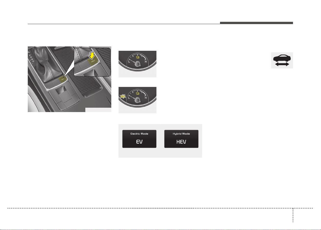
Changing plug-in hybrid mode
Pressing the HEV button changes
the plug-in hybrid system modes, as
below.
• Shortly pressed:
EV mode ↔ HEV mode
Plug-in hybrid mode indicator
• CD (Charge Depleting, Electric) mode
: The high-voltage
(hybrid) battery is
used to drive the
vehicle.
• CS (Charge Sustaining, Hybrid) mode
: The high-voltage
(hybrid) battery
and gasoline
engine is used to
drive the vehicle.
A corresponding message is displayed
to indicate the selected mode.
Warning and indicator lights
Ready Indicator
This indicator illuminates :
When the vehicle is ready to be driven.
- ON : Normal driving is possible.
- OFF : Normal driving is not possible,
or a problem has occurred.
- Blinking : Emergency driving.
When the ready indicator goes OFF
or blinks, there is a problem with the
system. In this case, we recommend
that you have your vehicle inspected
by an authorized Kia dealer.
DRIVING THE HYBRID/PLUG-IN HYBRID VEHICLE
OJFHP056292L
OJFHP046420L
OJFHP046421L
OJFHP046425L/OJFHP046426L
❖ Please see this page instead of page 1-19 in owner's manual.
2
(continued)
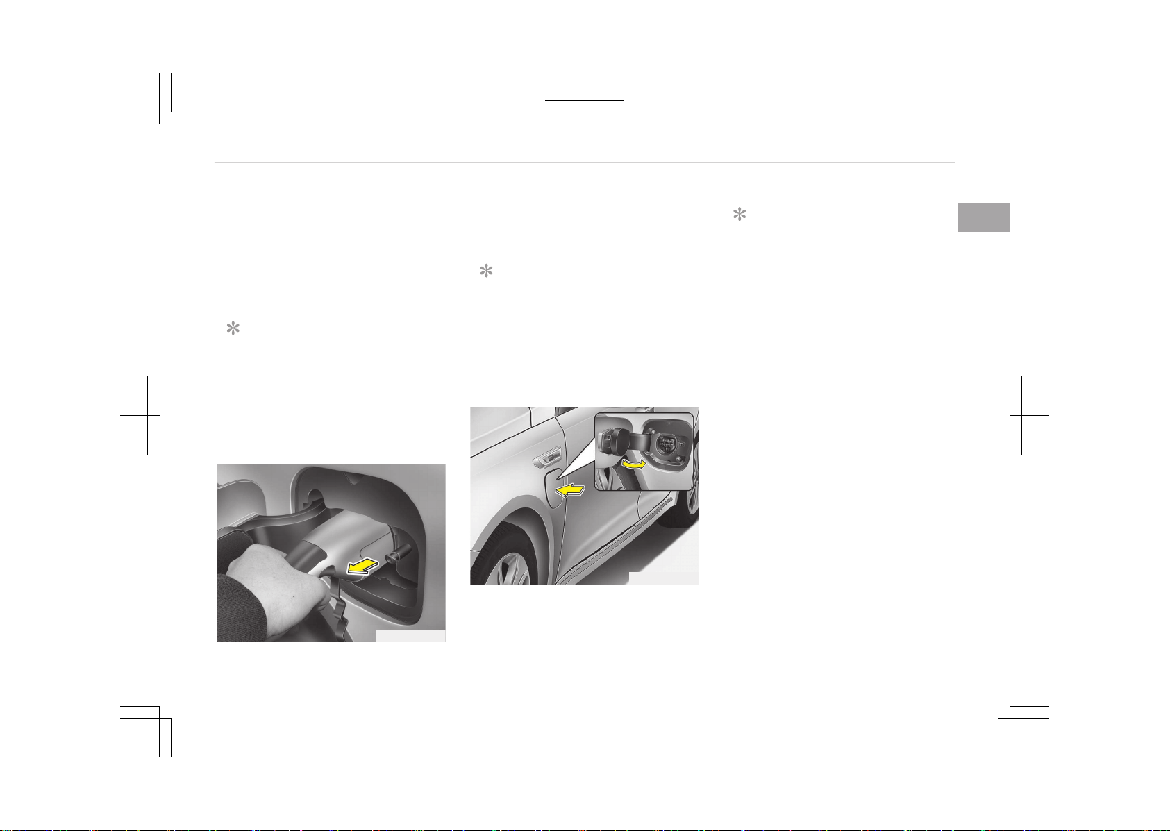
• When the fuel filler lid is frozen
and does not open after 20 seconds
at freezing temperature, slightly
tap the fuel filler lid and then
attempt to open it.
Fuel door open (Plug-in hybrid)
This message is displayed when the
fuel filler lid is opened.
Also means "Ready to refuel".
Check fuel door (Plug-in hybrid)
This message is displayed when the
fuel filler lid is open or an abnormal-
ity has occurred.
Refuel after stopping
(Plug-in hybrid)
This message is displayed when the
fuel filler lid open button is pressed
when a vehicle equipped with a plug-
in hybrid seal-type fuel tank is in
motion (vehicle speed is greater than
0 km/h(mi/h)).
Open fuel door after disconnecting
charging cable (Plug-in hybrid)
This message is displayed when you
press fuel filler lid open button while
charging.
This message explains that refueling
is allowed to finish charging.
Fuel lid is not opened when charging
cable is connected to vehicle.
Charging Door Open
(Plug-in hybrid)
This message indicates that the
charging door is open while in driv-
ing-ready state to encourage you to
inspect and close the door.
(Driving with the charging door open
may result in moisture inflow or dam-
age. This message is used to prevent
such occurrences.)
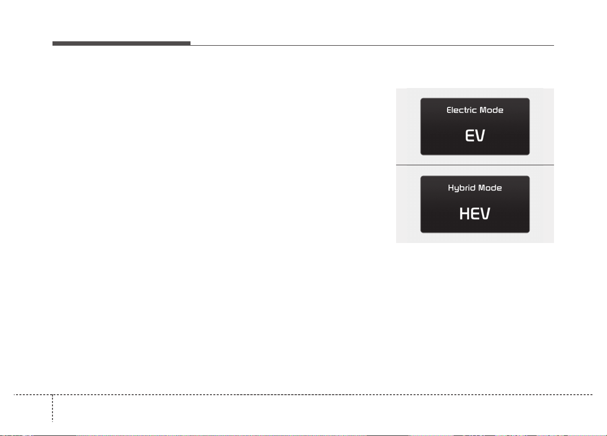
EV / HEV modes (Plug-in hybrid)
A corresponding message is dis-
played when a mode is selected by
pressing the HEV button.
OJFHP046426L
OJFHP046425L
❖ Please see this page instead of page 1-22~1-23 in owner's manual.
3
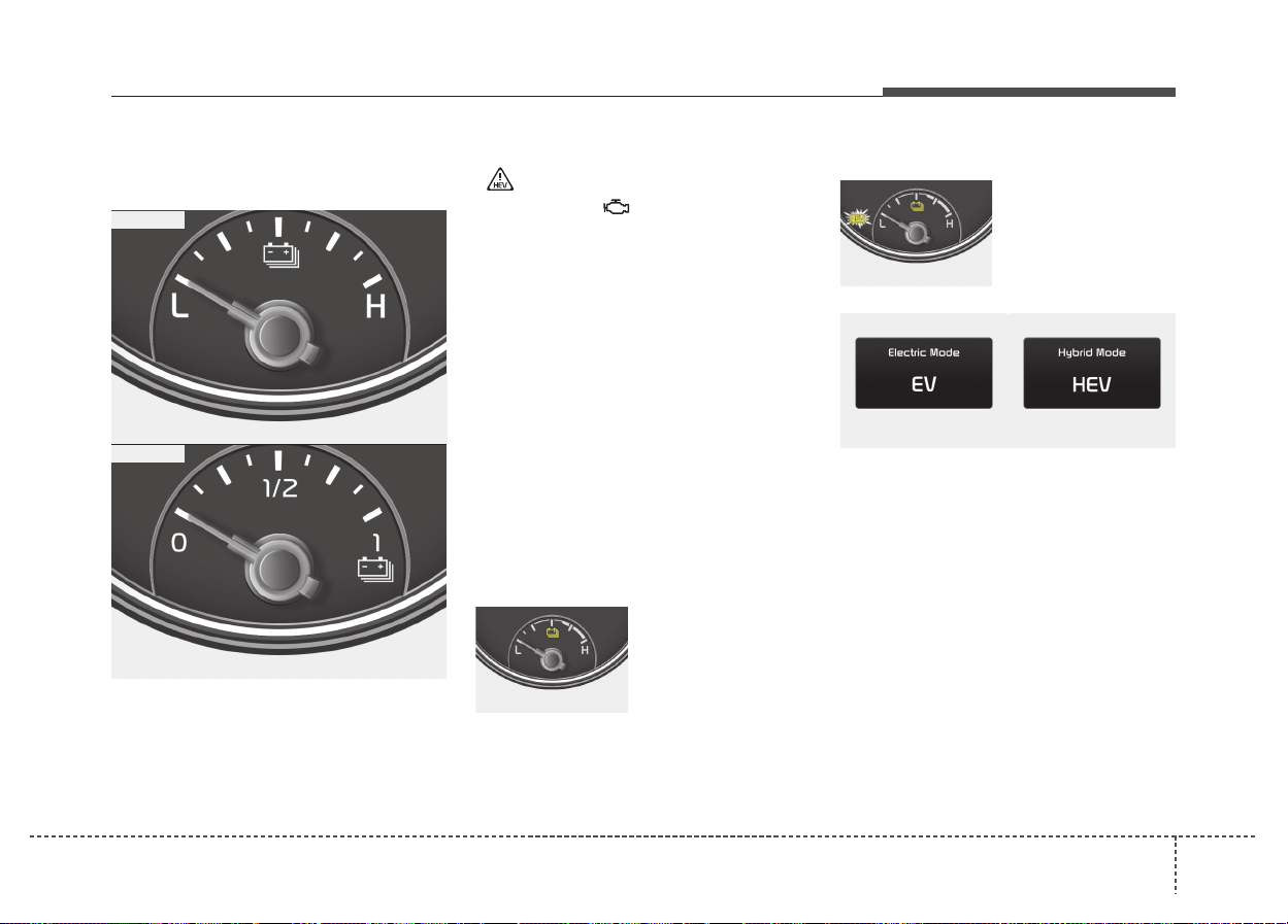
Hybrid Battery SOC
(State of Charge) Gauge
This gauge indicates the remaining
hybrid battery power. If the SOC is
near the “L (Low) or 0” level, the vehi-
cle automatically operates the
engine to charge the battery.
However, if the Service Indicator
( ) and Malfunction Indicator
Lamp (MIL) ( ) turn on when the
SOC gauge is near the “L (Low) or 0”
level, we recommend the vehicle be
checked by an authorized Kia dealer.
✽✽
NOTICE
Never try to start the vehicle if the
fuel tank is empty. In this condition,
the engine cannot charge the high
voltage battery of the hybrid system.
If you try to start the vehicle when
the fuel is empty, the high voltage
battery will become discharged and
be damaged.
Plug-in hybrid mode indicator
• CD (Charge Depleting, Electric) mode
: The high-voltage
(hybrid) battery is
used to drive the
vehicle.
• CS (Charge Sustaining, Hybrid) mode
: The high-voltage
(hybrid) battery
and gasoline
engine is used to
drive the vehicle.
A corresponding message is displayed
to indicate the selected mode.
OJFH045375
OJFH045375L
■ Type A
■ Type B
OJFHP046420L
OJFHP046421L
OJFHP046425L/OJFHP046426L
❖ Please see this page instead of page 5-52 in owner's manual.

Kia, THE COMPANY
Thank you for becoming the owner of a new Kia vehicle.
As a global car manufacturer focused on building high-quality, value
for money prices, Kia Motors is dedicated to providing you with a
customer service experience that exceeds your expectations.
At all of our Kia dealerships you will be treated with warmth, hospi‐
tality and professionalism by people who care based on our
Family-
like Care promise.
All information contained in this Owner’s Manual was accurate at the
time of publication. However, Kia reserves the right to make changes
at any time so that our policy of continual product improvement can
be carried out.
This manual applies to all models of this vehicle and includes descrip‐
tions and explanations of optional as well as standard equipment. As
a result, you may encounter material in this manual that is not appli‐
cable to your specific Kia vehicle.
Enjoy your vehicle and Kia’s Family-like Care experience!

Thank you for choosing a Kia vehicle.
This manual will familiarize you with operational, maintenance and safety information about your new vehicle. It
is supplemented by a Warranty and Maintenance book that provides important information on all warranties re‐
garding your vehicle. Kia urges you to read these publications carefully and follow the recommendations to help
assure an enjoyable and safe operation of your new vehicle.
Kia offers a great variety of options, components and features for its various models. Therefore, some of the
equipment described in this manual, along with the various illustrations, may not be applicable to your particular
vehicle.
The information and specifications provided in this manual were accurate at the time of printing. Kia reserves the
right to discontinue or change specifications or design at any time without notice and without incurring any obli‐
gation. If you have questions, always check with your authorized Kia dealer.
Kia assures you of our continuing interest in your motoring pleasure and satisfaction in your Kia vehicle.
© 2016 Kia MOTORS Corp.
All rights reserved. Reproduction by any means, elec‐
tronic or mechanical, including photocopying, record‐
ing, or by any information storage and retrieval sys‐
tem or translation in whole or part is not permitted
without written authorization from Kia MOTORS Cor‐
poration.
Printed in Korea
Foreword
ii
Table of contents
Hybrid system overview
1
Introduction
2
Your vehicle at a glance
3
Safety features of your vehicle
4
Features of your vehicle
5
Audio system
6
Driving your vehicle
7
What to do in an emergency
8
Maintenance
9
Specifications & Consumer information
10
Appendix
11
Alphabetical index
I
iii

iv

HEV (Hybrid Electric Vehicle) system.................................... 1-02
PHEV (Plug-in Electric Vehicle) system.................................1-03
Charging the plug-in hybrid vehicle....................................... 1-04
Charging information............................................................1-04
Charging time........................................................................ 1-04
Charging types.......................................................................1-05
Charging status..................................................................... 1-06
Scheduled charging ..............................................................1-06
Charging precautions............................................................1-06
Normal charge....................................................................... 1-08
Charging status..................................................................... 1-10
Trickle charger....................................................................... 1-12
Driving the hybrid/plug-in hybrid vehicle..............................1-19
Changing plug-in hybrid mode............................................1-19
Warning and indicator lights............................................... 1-19
Energy flow hybrid/plug-in hybrid vehicle............................1-24
Vehicle stop............................................................................ 1-24
EV propulsion......................................................................... 1-24
Power assist.......................................................................... 1-24
Engine only propulsion......................................................... 1-25
Engine generation.................................................................1-25
Regeneration......................................................................... 1-25
Engine brake.......................................................................... 1-26
Power reserve....................................................................... 1-26
Engine generation/regeneration........................................ 1-26
Engine generation/motor drive.......................................... 1-27
Engine brake/regeneration..................................................1-27
Starting the hybrid/plug-in hybrid vehicle (Smart key).....1-28
Starting the hybrid system.................................................1-28
Economical and safe operation of hybrid system...........1-28
Components of the hybrid/plug-in hybrid vehicle...............1-30
Safety plug.............................................................................1-33
Some special features of the hybrid vehicle.................... 1-33
Virtual Engine Sound System (VESS)................................ 1-34
High voltage battery air intake...........................................1-34
If an accident occurs.............................................................1-34
When the hybrid vehicle shuts off.....................................1-36
Hybrid system overview
1
HEV (HYBRID ELECTRIC VEHICLE) SYSTEM
The Kia Hybrid Electric Vehicle (HEV) uses both the gasoline engine and the electric motor for power. The electric motor is run
by a 270V high-voltage HEV battery.
Depending on the driving conditions, the HEV computer selectively operates between the engine and the electric motor or
even both at the same time.
Fuel efficiency increases when the engine is at idle, or when the vehicle is driven by the electric motor with the HEV battery.
The HEV battery charge must be maintained for the times when the engine acts as a generator, such as when stopped at idle.
Charging also occurs when decelerating or by regenerative braking.
Hybrid system overview
1-02
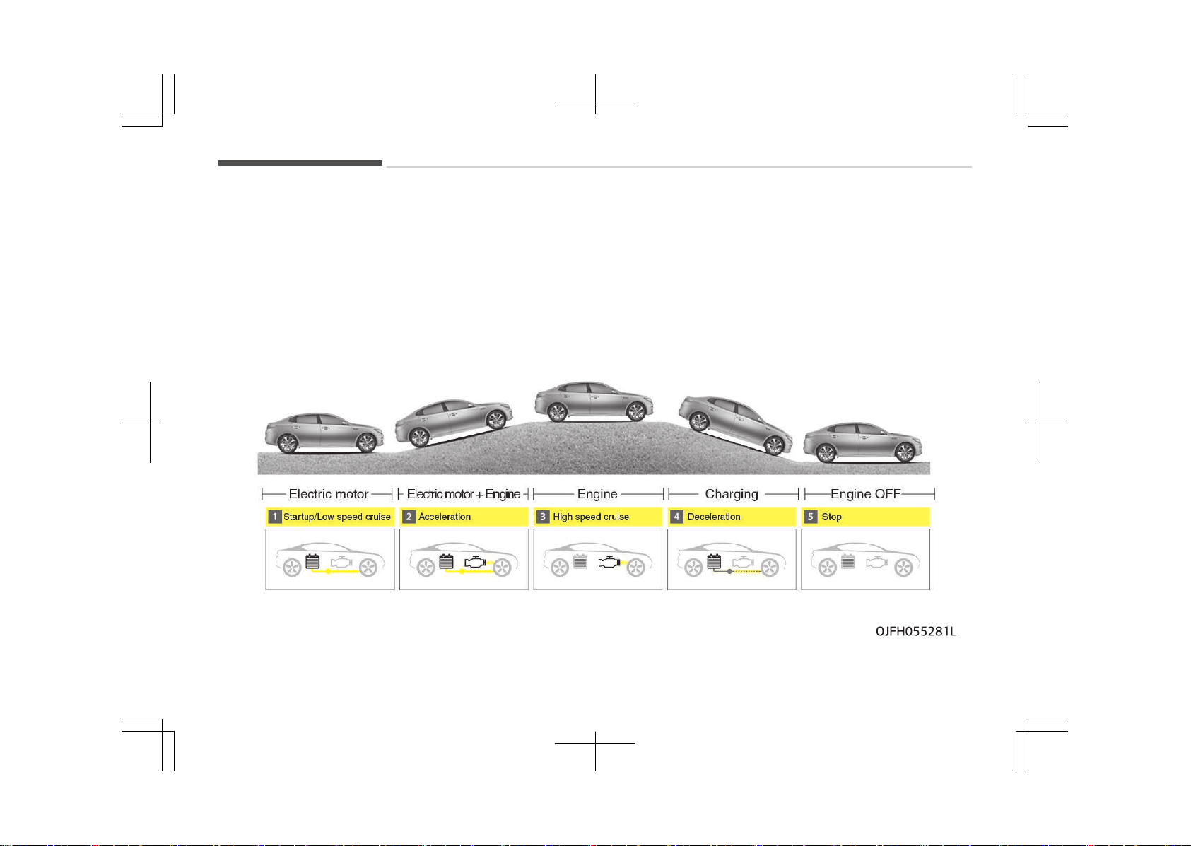
PHEV (PLUG-IN ELECTRIC VEHICLE) SYSTEM
The Kia Plug-in Hybrid Electric Vehicle (PHEV) shares the characteristics of both a conventional hybrid electric vehicle and an
all-electric vehicle.
When used as a conventional hybrid electric vehicle, the HEV computer selectively operates between the engine and the elec‐
tric motor or even both at the same time.
When it is operating in the electric vehicle mode, the vehicle is driven only using the electric motor over a certain distance until
the hybrid battery becomes low. The driving distance in EV mode depends on customer driving style and road conditions. Ag‐
gressive driving maneuvers may at times temporarily enable the engine to operate for maximum power.
The hybrid battery can be fully charged by connecting a plug to an external electric power source.
OJFHP056290L
CD (Charge Depleting) Mode
Electric motor
CS (Charge Sustaining) Mode
Motor
Engine+Motor
EngineCharging
Charging
Battery charging
Electric Vehicle Mode
Start up/Low speed
AccelerationHigh speedDecelerationExternal charging
1-03
1
Hybrid system overview

CHARGING THE PLUG-IN HYBRID VEHICLE
Charging information
• Normal Charger: The plug-in hybrid
vehicle is charged by plugging into a
normal charger installed in your
home or a public charging station.
(For further details, refer to Normal
charge on page 1-08.)
• Trickle Charger: The plug-in hybrid
vehicle can be charged by using
household electricity.
The electrical outlet in your home
must comply with regulations and
can safely accommodate the Volt‐
age / Current (Amps) / Power (Watts)
ratings specified on the trickle
charge.
Charging time
• Normal Charger:
Takes about 2-3 hours at room tem‐
perature (Can be charged to 100%).
Depending on the condition and dura‐
bility of the high-voltage battery,
charger specifications, and ambient
temperature, the time required for
charging the high-voltage battery
may vary.
Hybrid system overview
1-04
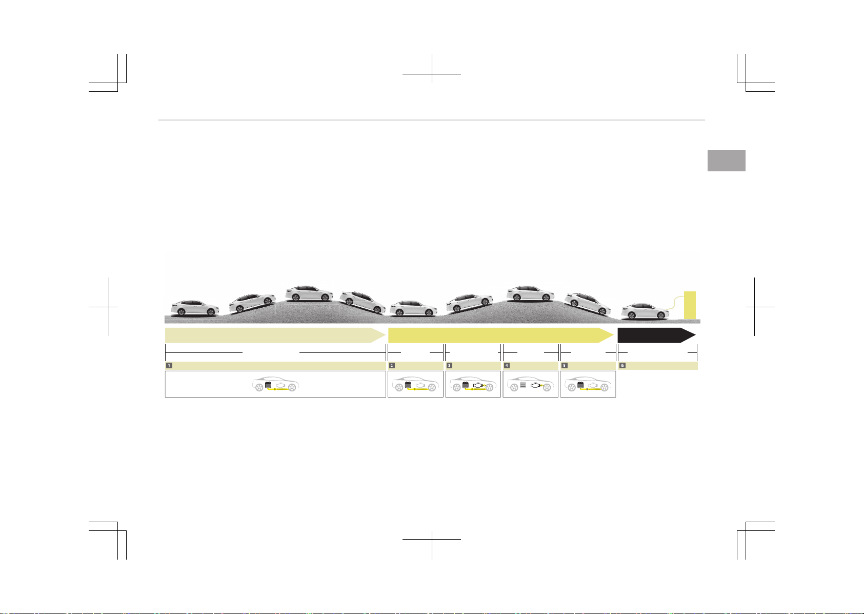
Charging types
Category
Charging Inlet (Ve‐
hicle)
Charging Connec‐
tor
Charging Outlet Charging Method Charging Time
Normal Charger
OJFHPQ016006L
OJFHPQ016007L
OJFHPQ016021L
Normal charger in‐
stalled in homes or
public charging sta‐
tions
Approximately 2-3
hours (to fully
charge the plug-in
hybrid vehicle,
100%)
Trickle Charger
OJFHPQ016006L
OJFHPQ016007L
OJFHPQ016008L
Household current
An actual charger image and a charging method may vary in accordance with the charger manufacturers.
1-05
1
Hybrid system overview
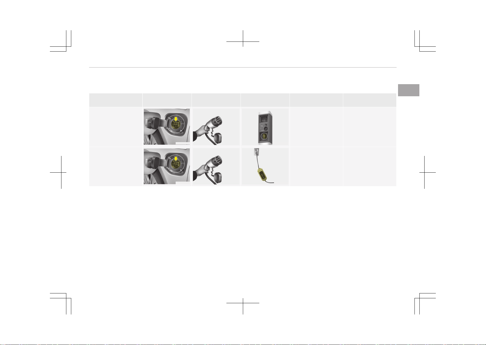
Charging status
OJFHPQ016009L
You can monitor the charging status
outside of the vehicle when charging
the high-voltage battery.
Charging Status Indicator
Charging in pro‐
gress
Illuminates (green)
Fully charged Off
Scheduled charg‐
ing
Blinks (green) and
then turns off
Malfunction Blinks (red)
Scheduled charging (if equipped)
• You can set reserved charging using
the AVN.
Refer to the AVN for detailed infor‐
mation about setting reserved charg‐
ing.
• Scheduled charging can only be done
when using a normal charger or the
portable charging cable (ICCB: In-Ca‐
ble Control Box).
OJFHPQ016009L
• When scheduled charging is set and
the normal charger or the portable
charging cable (ICCB: In-Cable Control
Box) is connected for charging, the
indicator lamp blinks (for 3 minutes)
to indicate that scheduled charging is
set.
• When scheduled charging is set,
charging is not initiated immediately
when the normal charger or portable
charging cable (ICCB: In-Cable Control
Box) is connected. When immediate
charging is required, use the AVN to
deactivate the scheduled charge set‐
ting.
Charging precautions
■ Normal Charger
OJFHPQ016021LB
WARNING
n
Fires caused by dust or water
(Continued)
Hybrid system overview
1-06
(Continued)
Do not connect the charging cable
connector plug to the vehicle if there
is water or dust on the charging in‐
let. Connecting while there is water
or dust on the charging cable con‐
nector and plug may cause a fire or
electric shock. There may be a risk
of fire and injury when using old
worn out public electrical outlets.
WARNING
n
Interference with electronic
medical devices
When using medical electric devices
such as an implantable cardiac pace‐
maker, make sure to ask the medical
team and manufacturer whether
charging your electric vehicle will im‐
pact the operation of the medical
devices. In some instances, electro‐
magnetic waves that are generated
from the charger can seriously im‐
pact medical electric devices such as
an implantable cardiac pacemaker.
WARNING
n
Touching the charging connec‐
tor
Do not touch the charging connector,
charging plug, and the charging inlet
when connecting the cable to the
charger and the charging inlet on the
vehicle. Doing so may result in elec‐
trocution.
• Comply with the following in order to
prevent electrical shock when charg‐
ing:
- Use a waterproof charger
- Make sure to not touch the charg‐
ing connector and charging plug
when your hand is wet
- Do not charge when there is light‐
ning
- Do not charge when the charging
connector and plug is wet
WARNING
n
Charging cable
(Continued)
(Continued)
• Immediately stop charging when
you find abnormal symptoms
(smell, smoke).
• Replace the charging cable if the
cable coating is damaged to pre‐
vent electrical shock.
• When connecting or removing the
charging cable, make sure to hold
the charging connector handle and
charging plug.
If you pull the cable itself (without
using the handle), the internal
wires may disconnect or get dam‐
aged. This may lead to electric
shock or fire.
WARNING
n
Cooling fan
Do not touch the cooling fan while
vehicle is charging. When the vehicle
is switched OFF while charging, the
cooling fan inside the motor com‐
partment may automatically oper‐
ate.
1-07
1
Hybrid system overview
• Always keep the charging connector
and charging plug in clean and dry
condition. Be sure to keep the charg‐
ing cable in a condition where there is
no water or moisture.
• Make sure to use the designated
charger for charging the vehicle. Us‐
ing any other charger may cause fail‐
ure.
• Before charging the battery, turn the
vehicle OFF.
• Be careful not to drop the charging
connector. The charging connector
can be damaged.
Normal charge
■ Normal Charger
OJFHPQ016021LB
You can charge your vehicle by plugging
into a public charger at a charging sta‐
tion.
How to connect normal charger
OJFHPQ016010L
1. Depress the brake pedal and apply
the parking brake.
2. Turn OFF all switches, move the
shift lever to P (Park), and turn OFF
the vehicle.
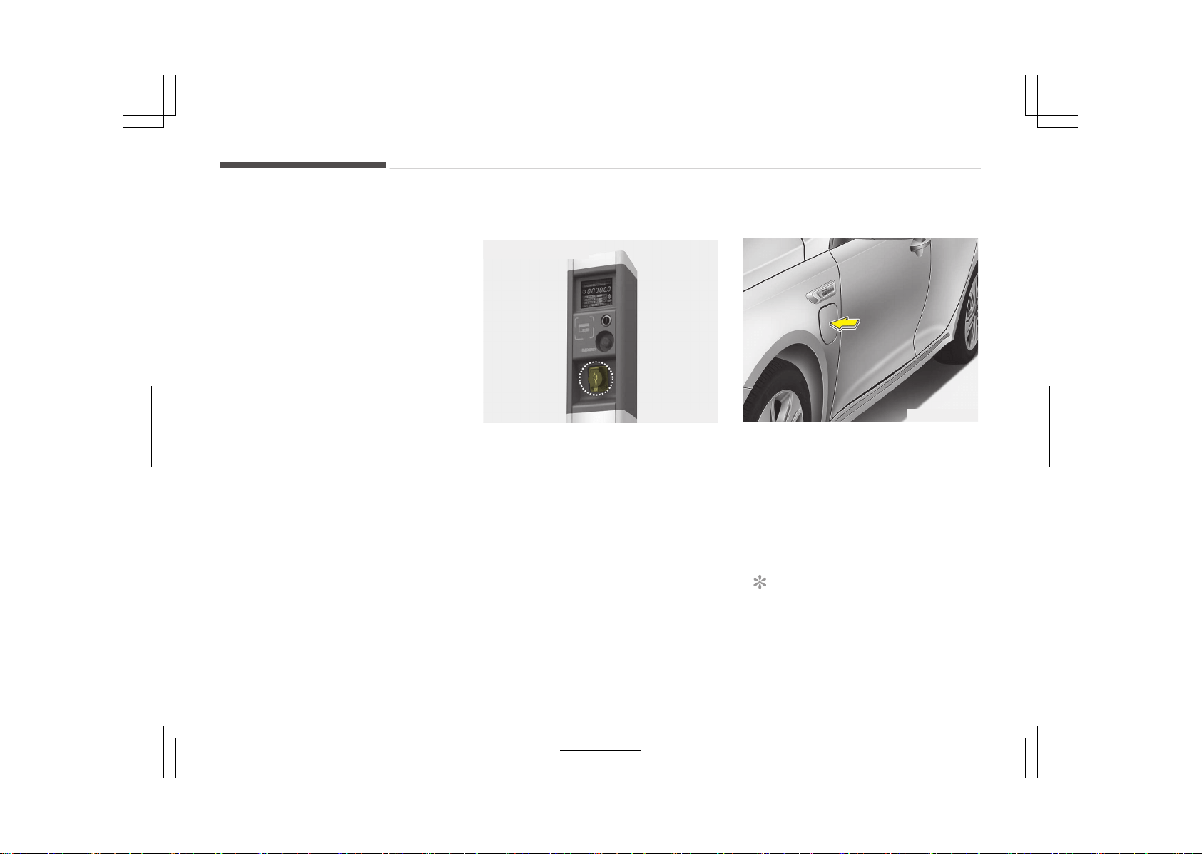
3. After unlocking doors, open the
charging door by pressing it.
NOTICE
The charging door does not open
when the theft alarm system is
armed.
Hybrid system overview
1-08
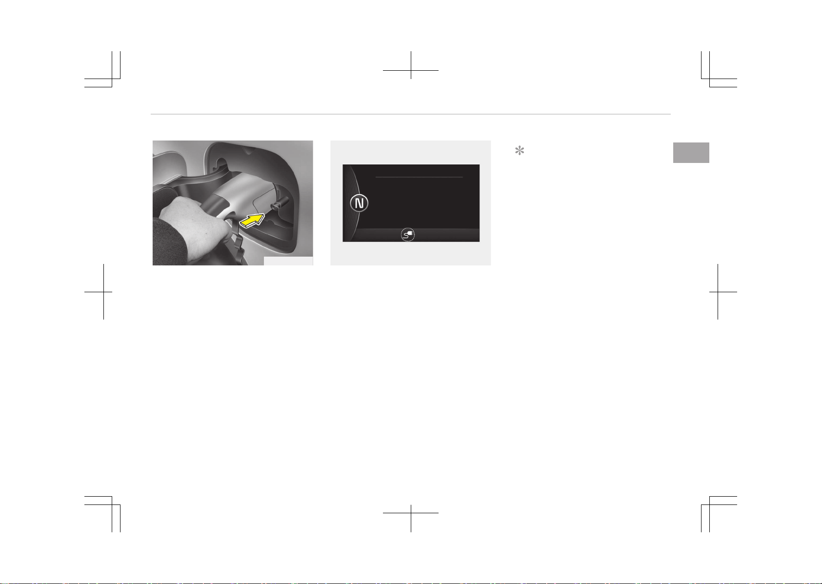
OJFHPQ016012L
4. Remove any dust on the charging
connector and charging inlet.
5. Hold the charging connector handle.
Then, insert it into the charging in‐
let, until you hear a click sound. If it
is not fully connected, a bad con‐
nection between the charging con‐
nector and the charging terminals
may cause a fire.
OJFHP046428L
6. Check if the charging cable connec‐
tion indicator of the high voltage
battery in the instrument cluster is
turned ON.
Charging does not occur when the
indicator is OFF. When the charging
connector is not connected proper‐
ly, reconnect the charging cable to
charge.
NOTICE
• The charging is in progress only
with the shift lever is in P (Park).
Charging the battery with the
Engine Start/Stop button in the
ACC position is possible. Howev‐
er, it may discharge the 12-V
battery. Thus, if possible, charge
the battery with the Engine
Start/Stop button in the OFF po‐
sition.
• Moving the shift lever from P
(Park) to R (Reverse)/
N(Neutral)/D (Drive) stops the
charging process. To restart the
charging process, move the shift
lever to P (Park), press the En‐
gine Start/Stop button to the
OFF position, and disconnect the
charging cable. Then, connect
the charging cable.
1-09
1
Hybrid system overview
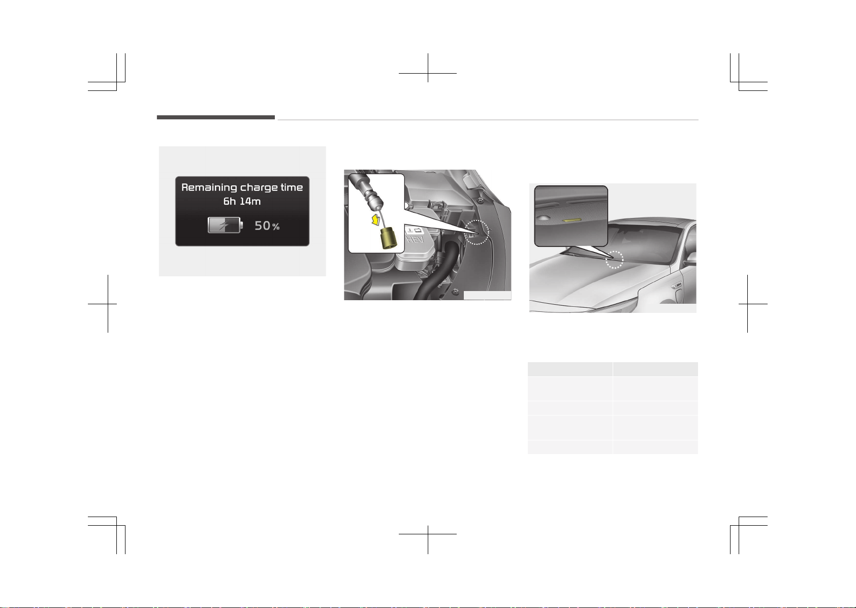
OJFHP046429L
7. After charging has started, the es‐
timated charging time is displayed
on the instrument cluster for about
1 minute. It is also displayed, when
the driver’s door is opened with
charging in progress. When sched‐
uled charging is set, the estimated
charging time is displayed as --" .
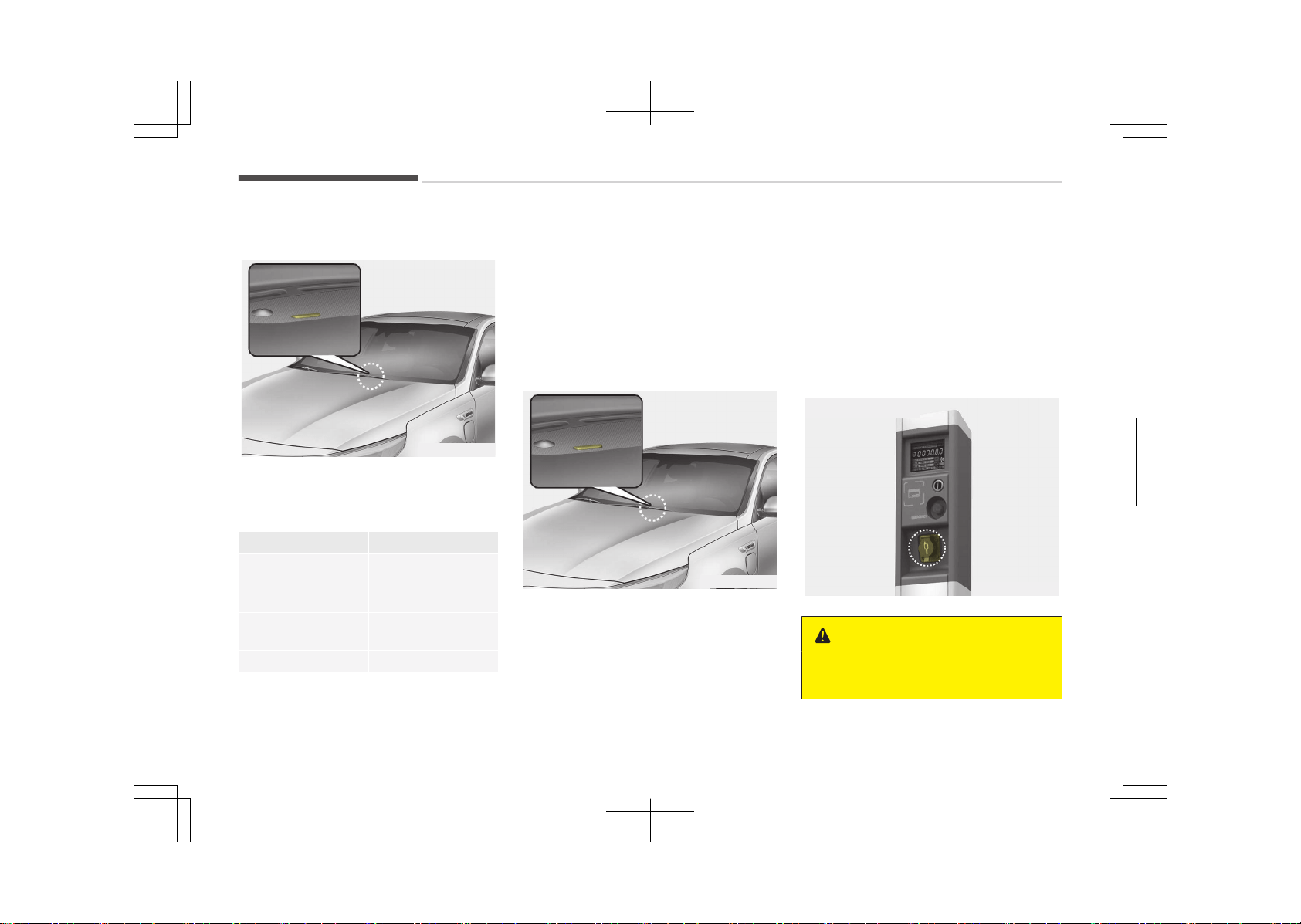
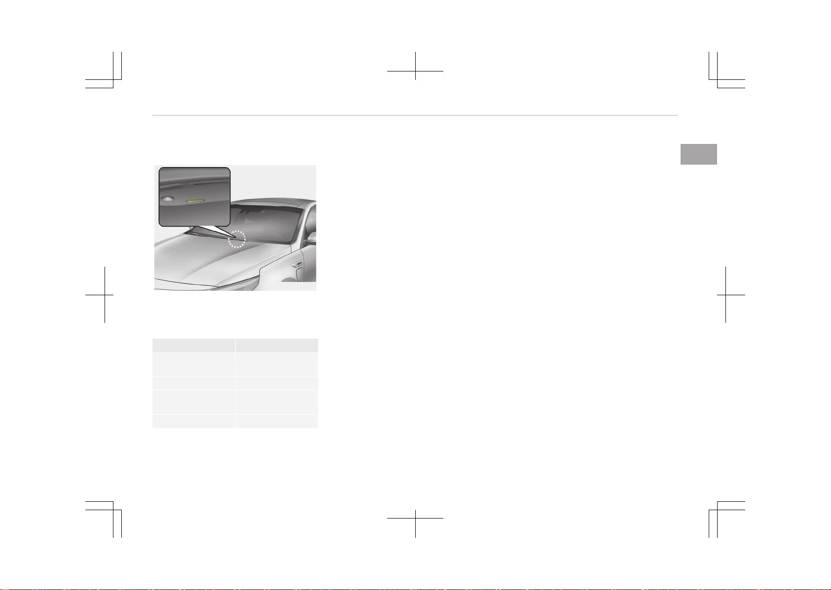
Unlock charging door in emergency
OJFHP046430L
If the charging door does not open due
to battery discharge, open the hood
and slightly pull the emergency cable as
shown above. The charging door will
then open.
Charging status
Checking charging status
OJFHPQ016009L
You can monitor the charging status
outside of the vehicle when charging
the high-voltage battery.
Charging Status Indicator
Charging in pro‐
gress
Illuminates (green)
Fully charged Off
Scheduled charg‐
ing
Blinks (green) and
then turns off
Malfunction Blinks (red)
Hybrid system overview
1-10
How to disconnect normal charger
1. The vehicle doors must be unlocked
in order to be able to disconnect
the charging connector. A lock sys‐
tem prevents charger cable discon‐
nection when the vehicle's doors
are locked.
NOTICE
In order to disconnect the charging
connector, unlock the doors to un‐
latch the charging connector lock
system. If not, the charging connec‐
tor and the vehicle's charging inlet
may be damaged.
OJFHPQ016022L
2. Press the door unlock button on
the smart key then pull out charg‐
ing connector.
NOTICE
When disconnecting the charging
connector, do not try to disconnect
it by force while not pressing the re‐
lease button. This may damage the
charging connector and vehicle
charging inlet.
OJFHPQ016013L
3. Make sure to securely close the
charging door.
NOTICE
• Do not modify or disassemble
the charging cable components.
It may cause a fire or an electric
shock with personal injury.
• Keep the charging connector and
the charging plug clean and dry.
The charging cable should be al‐
so kept dry.
• Use an air gun to blow any for‐
eign substances from the charg‐
ing connector and the charging
plug.
1-11
1
Hybrid system overview
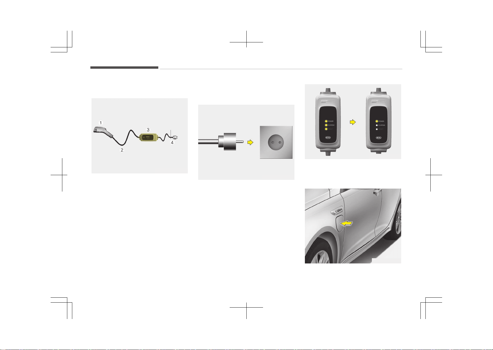
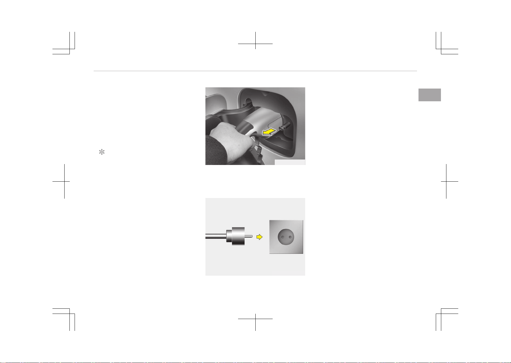
Trickle charger
OJFHPQ016014L
Trickle charger can be used if Normal
Charger is unavailable.
❈ 1. Charging connector
2. Charging cable
3. Control box
4. Cord and plug (cord set)
How to connect portable charging
cable (ICCB: In-Cable Control Box)
OJFHPQ016015L
1. Turn OFF all switches, move the
shift lever to P (Park), and turn OFF
the vehicle.
2. Connect the plug to a household
electric outlet.
OJFHPQ016016L
3. Check if all LED lamps on the con‐
trol box blinks for 0.5 seconds.
Then, check if the power lamp
(green) turns ON.
OJFHPQ016010L
Hybrid system overview
1-12
4. Depress the brake pedal and apply
the parking brake.
5. After unlocking doors, open the
charging door by pressing it.
NOTICE
The charging door does not open
when the theft alarm system is
armed.
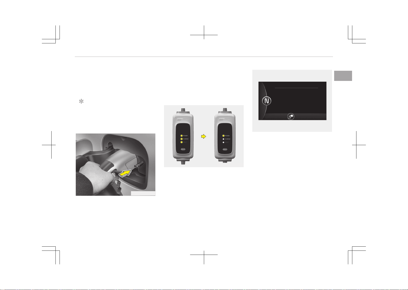
OJFHPQ016012L
6. Remove any dust on the charging
connector and charging inlet.
7. Hold the charging connector handle.
Then, insert it into the charging in‐
let, until you hear a click sound. If it
is not fully connected, improper
connection between the charging
connector and the charging termi‐
nals are a potential fire hazard.
OJFHPQ016016L
8. Charging starts automatically.
Check if the power lamp and charg‐
ing lamp (orange) are ON.
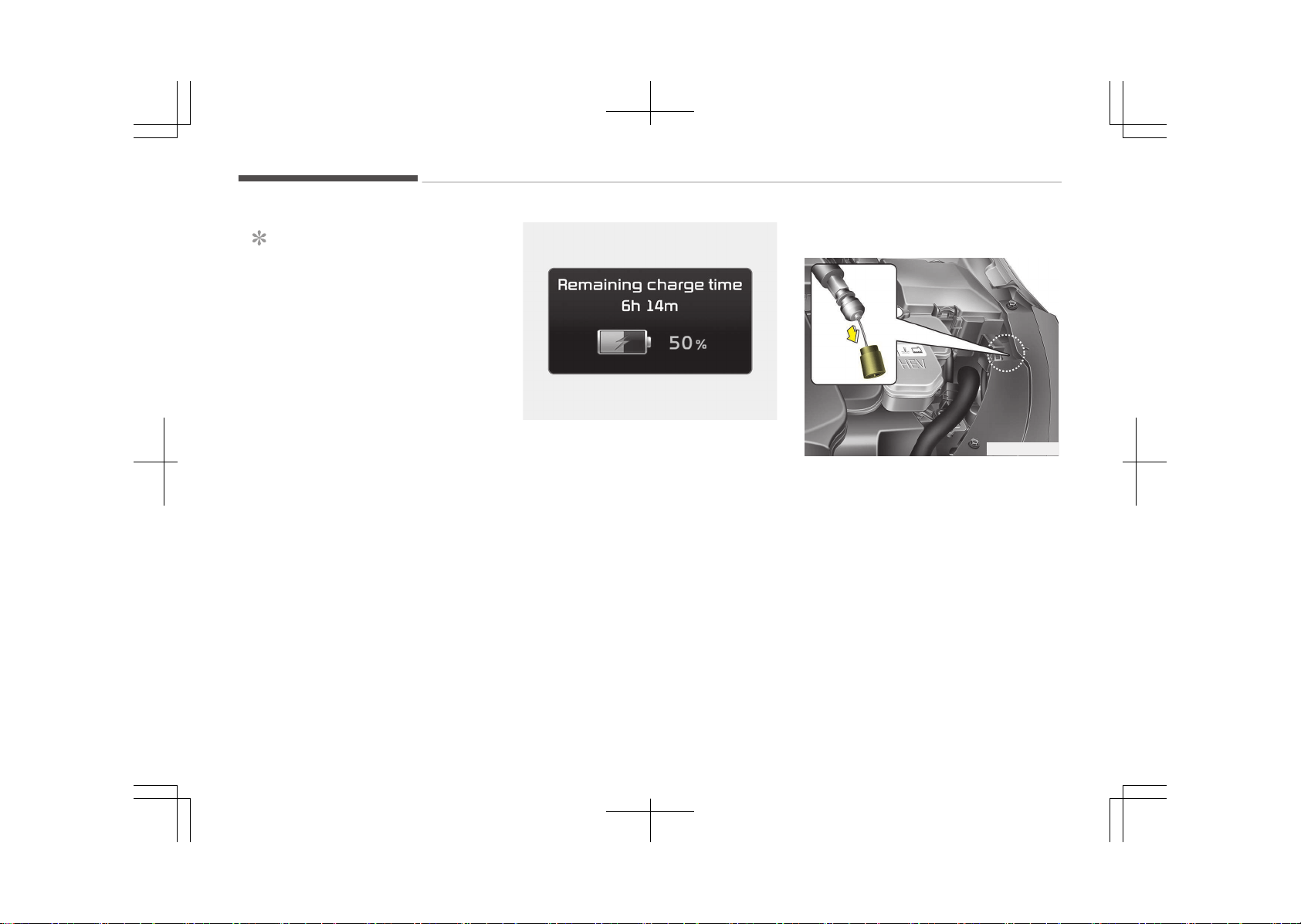
OJFHP046428L
9. Check if the charging cable connec‐
tion indicator of the high voltage
battery in the instrument cluster is
turned ON.
Charging does not occur when the
indicator is OFF. When the charging
connector is not connected proper‐
ly, reconnect the charging cable to
charge.
1-13
1
Hybrid system overview
NOTICE
• The charging is in progress only
with the shift lever is in P (Park).
Charging the battery with the
Engine Start/Stop button in the
ACC position is possible. Howev‐
er, it may discharge the 12-V
battery. Thus, if possible, charge
the battery with the Engine
Start/Stop button in the OFF po‐
sition.
• Moving the shift lever from P
(Park) to R (Reverse)/
N(Neutral)/D (Drive) stops the
charging process. To restart the
charging process, move the shift
lever to P (Park), press the En‐
gine Start/Stop button to the
OFF position, and disconnect the
charging cable. Then, connect
the charging cable and restart
the vehicle again.
OJFHP046429L
10. After charging has started, the es‐
timated charging time is displayed
on the instrument cluster for about
1 minute. It is also displayed, when
the driver’s door is opened with
charging in progress. When sched‐
uled charging is set, the estimated
charging time is displayed as "--".
Unlock charging door in emergency
OJFHP046430L
If the charging door does not open due
to battery discharge, open the hood
and slightly pull the emergency cable as
shown above. The charging door will
then open.
Hybrid system overview
1-14
Checking charging status
OJFHPQ016009L
You can monitor the charging status
outside of the vehicle when charging
the high-voltage battery.
Charging Status Indicator
Charging in pro‐
gress
Illuminates (green)
Fully charged Off
Scheduled charg‐
ing
Blinks (green) and
then turns off
Malfunction Blinks (red)
1-15
1
Hybrid system overview
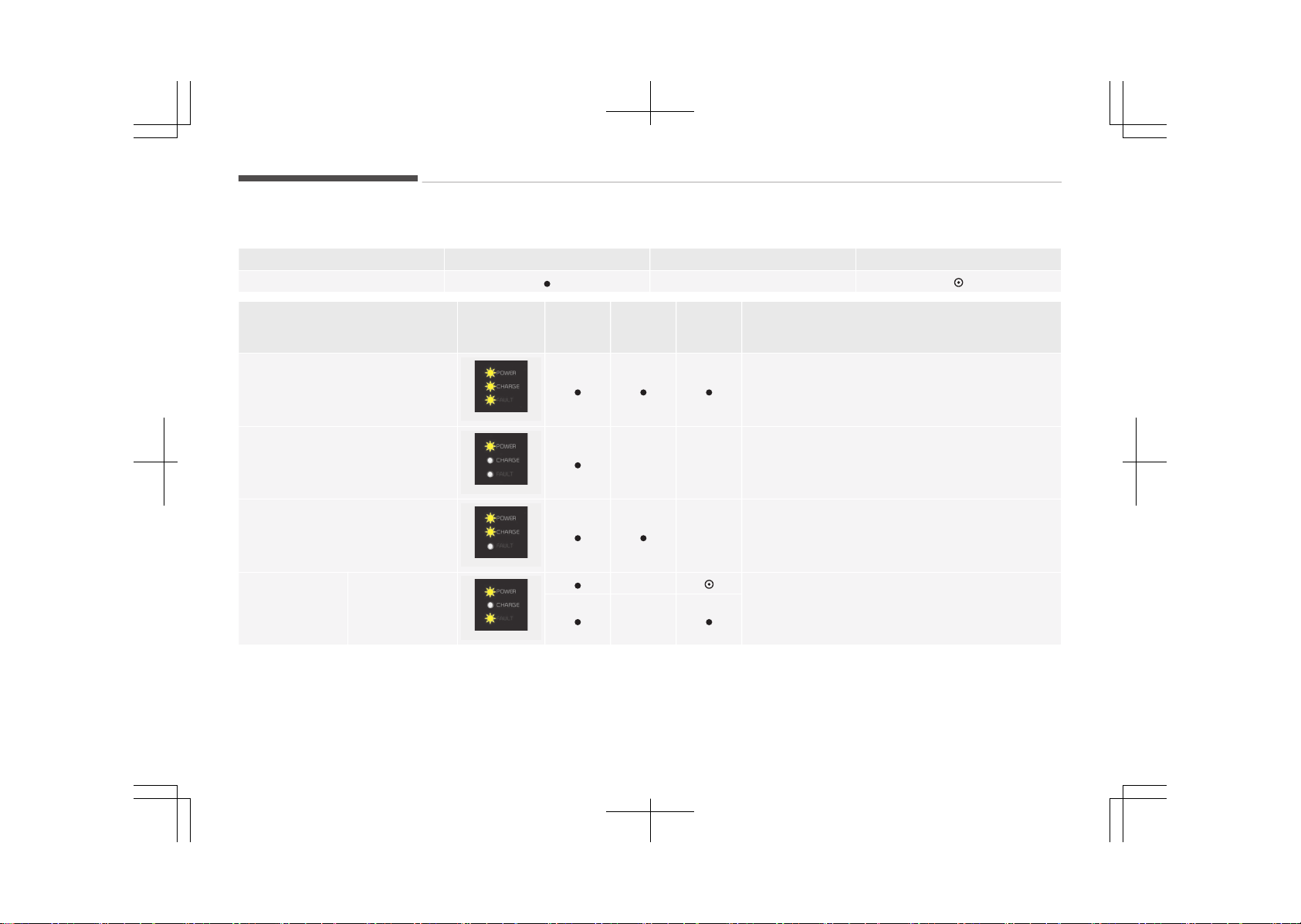
Charging status indicator lamp for portable charging cable
Category Lamp ON Lamp OFF Blinking
LED Status -
Charger Status
Control Box
ON/OFF
Status
Power Charge Fault Status / Diagnosis / Countermeasure
Initial Preparation Mode
OJFHPQ016017L
When applying power to the initial ICCB wall
Charging Preparation Mode
OJFHPQ016018L
- -
When ICCB charging connector is not connected
to the vehicle, or connected but charging status
is in Standby mode
Charging Mode
OJFHPQ016019L
- Charging
Failure
ICCCB failure or
electrical leak‐
age detected
OJFHPQ016020L
-
Stop charging immediately and we recommend
you contact an authorized Kia dealer for ICCB
check.
-
Hybrid system overview
1-16
How to disconnect portable
charging cable (ICCB: In-Cable
Control Box)
1. Before disconnecting the charging
connector, make sure the doors are
unlocked. When the door is locked,
the charging connector lock system
will not allow disconnection.
NOTICE
In order to disconnect the charging
connector, unlock the doors to un‐
latch the charging connector lock
system. If not, the charging connec‐
tor and the vehicle's charging inlet
may be damaged.
OJFHPQ016022L
2. Hold the charging connector handle
and pull it out.
3. Make sure to securely close the
charging door.
OJFHPQ016015L
4. Disconnect the plug from the
household electric outlet. Do not
pull the cable when disconnecting
the plug.
5. Close the protective cover for the
charging connector so that foreign
material cannot get into the termi‐
nal.
6. Put the charging cable inside the
cable compartment to protect it.
Precautions for portable charging
cable (ICCB: In-Cable Control Box)
• Use the portable charging cable that
is certified by Kia.
• Do not try to repair, disassemble, or
adjust the portable charging cable.
• Do not use an extension cord or
adapter.
• Stop using immediately if failure
warning light occurs.
• Do not touch the plug and charging
connector with wet hands.
• Do not touch the terminal part of the
normal charging connector and the
normal charging inlet on the vehicle.
• Do not connect the charging connec‐
tor to voltage that does not comply
with regulations.
1-17
1
Hybrid system overview

• Do not use the portable charging ca‐
ble if it is worn out, exposed, or there
exists any type of damage on the
portable charging cable.
• If the ICCB case and normal charging
connector is damaged, cracked, or
the wires are exposed in any way, do
not use the portable charging cable.
• Do not let children operate or touch
the portable charging cable.
• Keep the control box free of water.
• Keep the normal charging connector
or plug terminal free of foreign sub‐
stances.
• Do not step on the cable or cord. Do
not pull the cable or cord and do not
twist or bend it.
• Do not charge when there is light‐
ning.
• Do not drop the control box or place a
heavy object on the control box.
• Do not place an object that can gen‐
erate high temperatures near the
charger when charging.
• Charging with the worn out or dam‐
aged household electric outlet can re‐
sult in a risk of electric shock. If you
are in doubt to the household electric
outlet condition, have it checked by a
licensed electrician.
• Stop using the portable charging ca‐
ble immediately if the household
electric outlet or any components is
overheated or you notice burnt
odors.
Hybrid system overview
1-18
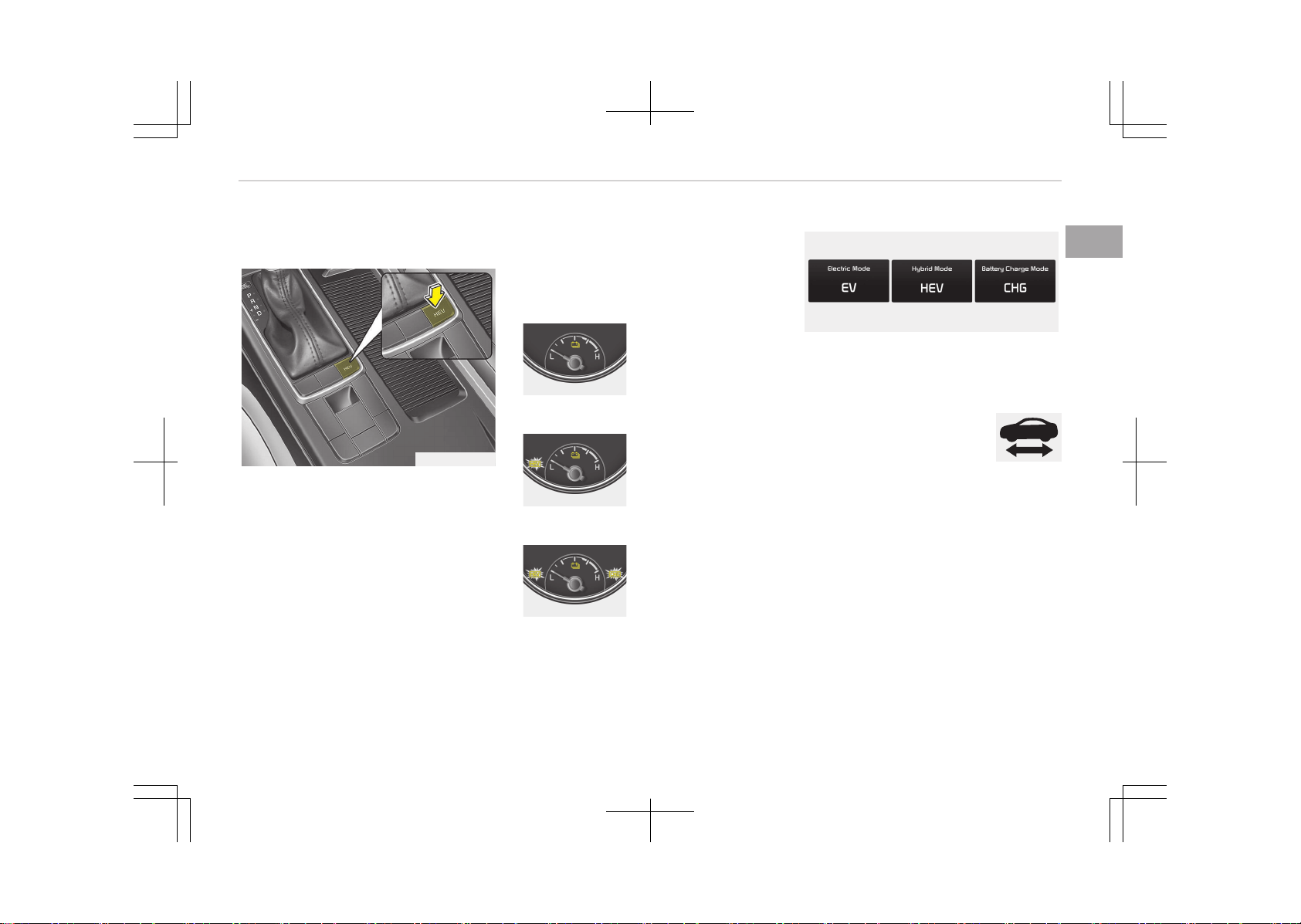
DRIVING THE HYBRID/PLUG-IN HYBRID VEHICLE
Changing plug-in hybrid mode
OJFHP056292L
Pressing the HEV button changes the
plug-in hybrid system modes, as below.
• Shortly pressed:
EV mode ↔ HEV mode
• Press and hold:
It changes to the HEV-charging
mode.
When the HEV button is pressed in the
HEV-charging mode, the mode changes
as below.
-
Shortly pressed : It changes to the CS
mode.
-
Press and hold: It remains in the
HEV-charging mode.
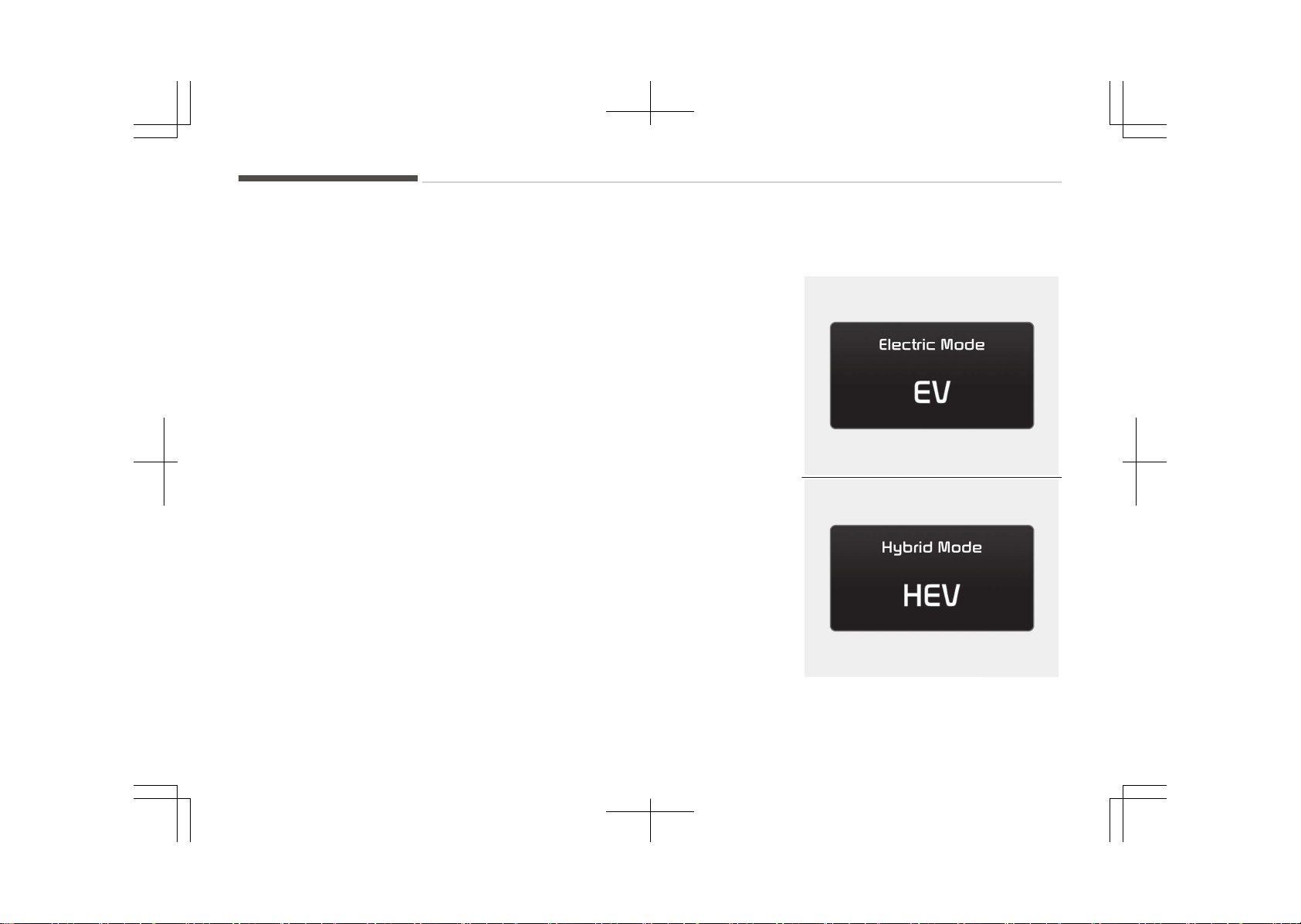
Plug-in hybrid mode indicator
• CD (Charge Depleting, Electric) mode
OJFHP046420L
The high-voltage (hy‐
brid) battery is used
to drive the vehicle.
• CS (Charge Sustaining, Hybrid) mode
OJFHP046421L
The high-voltage (hy‐
brid) battery and gas‐
oline engine is used to
drive the vehicle.
• HEV-charging mode
OJFHP046422L
Gasoline engine is
used to drive the ve‐
hicle and charge the
high-voltage (hybrid)
battery.
OJFHP046425L/OJFHP046426L/OJFHP046427L
A corresponding message is displayed
to indicate the selected mode.
Warning and indicator lights
Ready indicator
This indicator illuminates:
When the vehicle is ready to
be driven.
- ON: Normal driving is possi‐
ble.
- OFF: Normal driving is not
possible, or a problem
has occurred.
- Blinking: Emergency driving.
When the ready indicator goes OFF or
blinks, there is a problem with the sys‐
tem. In this case, we recommend that
you have your vehicle inspected by an
authorized Kia dealer.
1-19
1
Hybrid system overview
Hybrid system warning
light
This warning light illumi‐
nates:
When there is a malfunction with the
hybrid system.
In this case, we recommend that you
have the vehicle inspected by an au‐
thorized Kia dealer.
When the warning light illuminates
while driving, or does not go OFF after
starting the vehicle, have your vehicle
inspected by an authorized Kia dealer.
EV mode indicator
This indicator illuminates
when the vehicle is driven
by the electric motor.
EV
Charging cable
connection indicator
(Plug-in hybrid)
This indicator illuminates in
red when the charging cable is connec‐
ted.
❈ Example of a deceleration event is
going down an extended hill, slow‐
ing down approaching a toll booth,
and approaching reduced speed
zones.
• User settings
Press the Engine Start/Stop button
and put the shift lever in P (Park). In
the User Settings Mode, select Driv‐
ing Assist, Coasting Guide, and then
On to turn on the system. Cancel the
selection of coasting guide to turn off
the system. For the explanation of
the system, press and hold the [OK]
button.
• Operation conditions
To activate the system, take the fol‐
lowing procedures. Enter your desti‐
nation information on the navigation
and select the driving route. Select
the ECO mode in the Integrated Driv‐
ing Control System. Then, satisfy the
following.
- The driving speed should be be‐
tween 60 km/h (37 mph) and
160 km/h (99 mph).
❈ The operating speed may vary due
to difference between instrument
cluster and navigation effected by
tire inflation level.
NOTICE
Coasting guide is only a supplemen‐
tal system to assist with fuel-effi‐
cient driving. Thus, the operating
conditions may be different in ac‐
cordance with traffic/road condi‐
tions (i.e. driving in a traffic jam,
driving on a slope, driving on a
curve). Thus, take the actual driving
conditions into consideration, such
as distances from the vehicles
ahead/ behind, while referring to the
coasting guide system as guidance.
Unplug vehicle to start (Plug-in
hybrid)
The message is displayed when you
start the engine without unplugging
the charging cable. Unplug the charging
cable, and then start the vehicle.
Shift to P to charge (Plug-in hybrid)
The message is displayed when the
charging connector is plugged with the
shift lever in R (Reverse), N (Neutral) or
D (Drive). Move the shift lever to P
(Park) and re-start the charging proc‐
ess.
Hybrid system overview
1-20

Remaining charge time (Plug-in
hybrid)
The message is displayed to notify the
remaining time to fully charge the bat‐
tery.
EV/HEV/CHG modes (Plug-in
hybrid)
A corresponding message is displayed
when a mode is selected by pressing
the HEV button.
Battery charged. Maintaining
current (Plug-in hybrid)
This message is displayed when unable
to convert to charging mode even when
pressing and holding the HEV button
during EV/HEV mode driving because
the high-voltage (hybrid) battery is al‐
ready fully charged.
Low battery. Maintaining hybrid
(Plug-in hybrid)
This message is displayed when unable
to convert to EV mode even when
pressing the HEV button during HEV
mode driving due to insufficient high-
voltage (hybrid) battery level.
Low battery temp. Maintaining
current (Plug-in hybrid)
This message is displayed when unable
to convert to EV mode even when
pressing the HEV button during HEV
mode driving due to low battery tem‐
perature.
Charging complete. Switching to
hybrid (Plug-in hybrid)
This message is displayed automatical‐
ly converting to HEV mode due to com‐
pleted battery charging during charging
mode driving.
Charger error! (Plug-in hybrid)
This messages is displayed when the
charging failed by external charger er‐
ror.
This message is for Normal charger.
The purpose of this message is to let
you know the error has occurred in
charger itself not in vehicle.
Low/high system temp.
Maintaining hybrid (Plug-in hybrid)
This message is displayed when unable
to convert to EV mode even when
pressing the HEV button during HEV
mode driving due to low/high system
temperature.
Switching to hybrid mode to allow
heating (Plug-in hybrid)
• When the coolant temperature is
lower than -14 °C (57 °F), and you
turn the climate control On for heat‐
ing, the above message will be dis‐
played in the cluster. Then, the vehi‐
cle will automatically switch to HEV
mode.
• When the coolant temperature is
higher than -14 °C (57 °F), or you
turn the climate control Off, the vehi‐
cle will automatically return to EV
mode.
Wait until fuel door opens (Plug-in
hybrid)
The message is displayed when you at‐
tempt to open the fuel filler lid with the
fuel tank pressurized. Wait until the
fuel tank is depressurized.
NOTICE
• It may take up to 20 seconds to
open fuel filler lid.
(Continued)
1-21
1
Hybrid system overview
(Continued)
• When the fuel filler lid is frozen
and does not open after 20 sec‐
onds at freezing temperature,
slightly tap the fuel filler lid and
then attempt to open it.
Fuel door open (Plug-in hybrid)
This message is displayed when the
fuel filler lid is opened.
Also means "Ready to refuel".
Check fuel door (Plug-in hybrid)
This message is displayed when the
fuel filler lid is open or an abnormality
has occurred.
Refuel after stopping (Plug-in
hybrid)
This message is displayed when the
fuel filler lid open button is pressed
when a vehicle equipped with a plug-in
hybrid seal-type fuel tank is in motion
(vehicle speed is greater than 0 km/h
(mi/h)).
Open fuel door after disconnecting
charging cable (Plug-in hybrid)
This message is displayed when you
press fuel filler lid open button while
charging.
This message explains that refueling is
not allowed to finish charging.
Fuel lid is not opened when charging
cable is connected to vehicle.
Charging door open (Plug-in hybrid)
This message indicates that the charg‐
ing door is open while in driving- ready
state to encourage you to inspect and
close the door.
(Driving with the charging door open
may result in moisture inflow or dam‐
age. This message is used to prevent
such occurrences.)
EV/HEV/CHG modes (Plug-in
hybrid)
OJFHP046425L
OJFHP046426L
Hybrid system overview
1-22

OJFHP046427L
A corresponding message is displayed
when a mode is selected by pressing
the HEV button.
1-23
1
Hybrid system overview
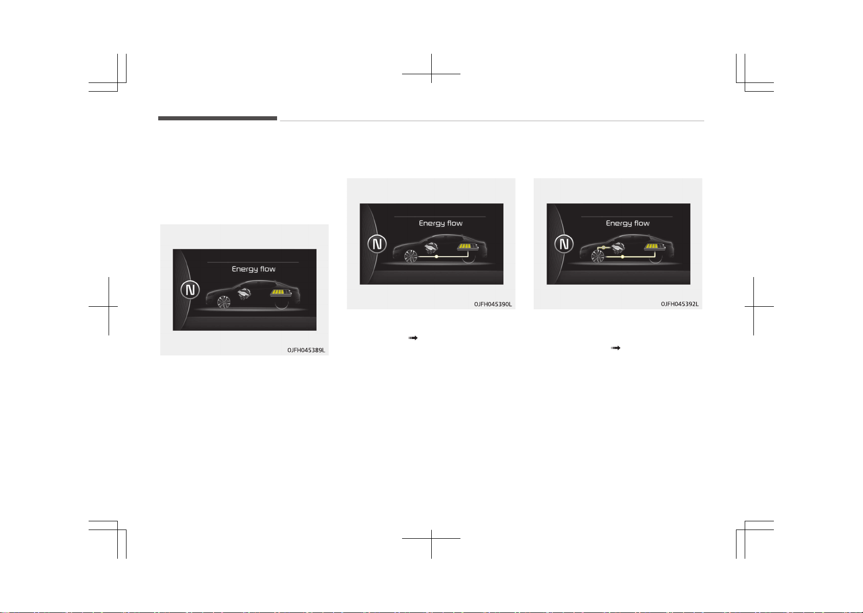
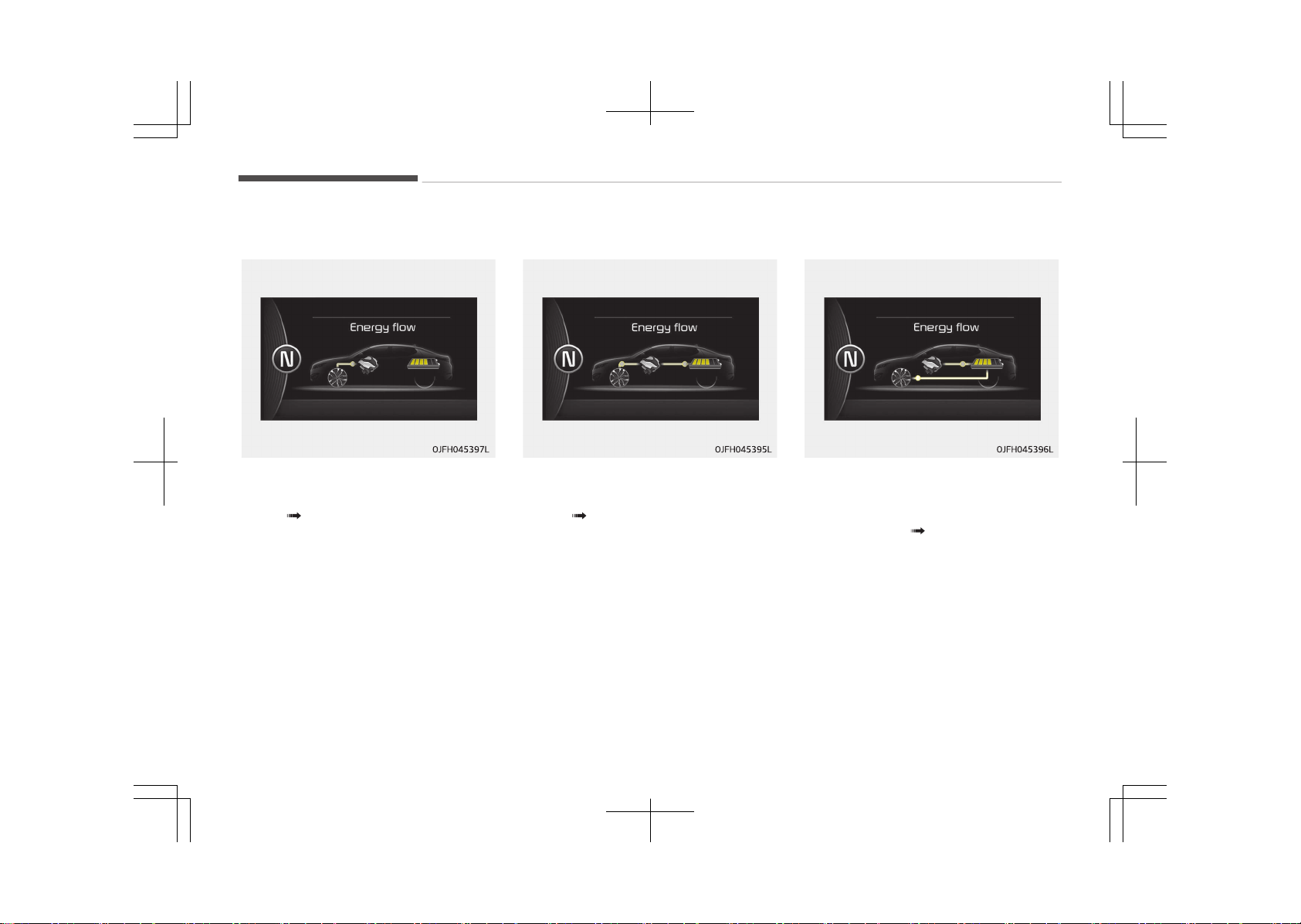
ENERGY FLOW HYBRID/PLUG-IN HYBRID VEHICLE
Kia hybrid system notifies the drivers
of energy flow in various operating
modes. Eleven Modes show drivers the
current operating condition.
Vehicle stop
The mode means the vehicle at stop.
(There is no energy flow.)
EV propulsion
Electric power is used to move the ve‐
hicle. (Battery Wheel)
Power assist
Electric and Engine power are used to
move the vehicle.
(Battery & Engine Wheel)
Hybrid system overview
1-24
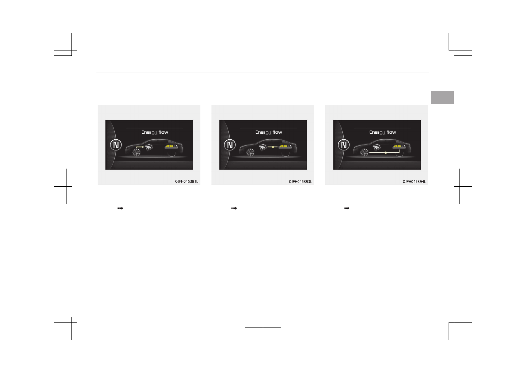
Engine only propulsion
Engine power is used to move the vehi‐
cle.
(Engine Wheel)
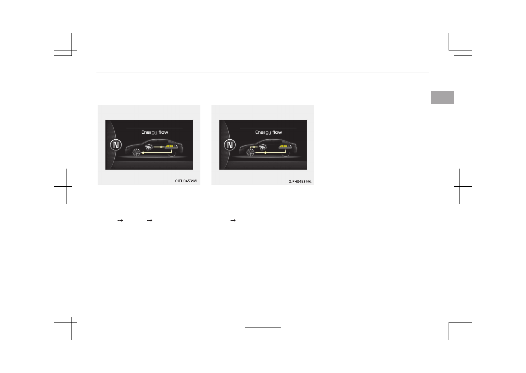
Engine generation
Vehicle is stopped with the Engine
charging the hybrid battery.
(Engine Battery)
Regeneration
Hybrid battery is being charged by re‐
generative braking.
(Wheel Battery)
1-25
1
Hybrid system overview
Engine brake
The vehicle is being slowed by engine
compression.
(Wheel Engine)
Power reserve
Engine is both driving the vehicle and
charging the hybrid battery.
(Engine Wheel & Battery)
Engine generation/regeneration
The engine and regenerative braking
system charge the hybrid battery driv‐
ing deceleration.
(Engine & Wheel Battery)
Hybrid system overview
1-26
Engine generation/motor drive
The vehicle is being slowed by engine
compression and regenerative braking.
The hybrid battery is being charged by
regenerative braking.
(Engine Battery Wheel)
Engine brake/regeneration
The engine compression can be used to
slow the vehicle. The regenerative
braking system can be used to charge
the hybrid system.
(Wheel Engine & Battery)
1-27
1
Hybrid system overview

STARTING THE HYBRID/PLUG-IN HYBRID VEHICLE (SMART KEY)
Starting the hybrid system
1. Carry the smart key into the vehi‐
cle.
2. Make sure the parking brake is
firmly applied.
3. Place the shift lever in the P (Park)
position.
In N (neutral) position, you cannot
start the vehicle.
4. Depress the brake pedal.
5. Press the engine start/stop button.
6. The engine should be started with‐
out pressing the accelerator. In ex‐
tremely cold weather or after the
vehicle has not been operated for
several days, let the engine warm
up without depressing the acceler‐
ator.
• Even if the smart key is in the ve‐
hicle, if it is far away from you,
the engine may not start.
• When the engine start/stop but‐
ton is in the ACC or ON position, if
any door is open, the system
checks for the smart key. If the
smart key is not in the vehicle,
the warning, "Key is not in vehi‐
cle" will come on, and if all doors
are closed, the chime will also
sound for about 5 seconds. The
indicator will turn off while the
vehicle is moving. Keep the smart
key in the vehicle when using the
ACC position or if the vehicle en‐
gine is on.
If the starting procedure is followed,
the "READY" symbol on the instrument
cluster will turn on. For more details,
please refer to Ready indicator on
page 5-86.
Economical and safe operation
of hybrid system
• Drive smoothly. Accelerate at a mod‐
erate rate and maintain a steady
cruising speed. Don't make "jack-rab‐
bit" starts. Don't race between stop‐
lights.
Avoid heavy traffic whenever possi‐
ble. Always maintain a safe distance
from other vehicles so you can avoid
unnecessary braking. This also re‐
duces brake wear.
• The regenerative brake generates
energy when the vehicle decelerates.
• When the hybrid battery power is
low, the hybrid system automatically
recharges the hybrid battery.
• When the engine runs in "N" position,
the hybrid system cannot generate
electricity. The hybrid battery cannot
recharge in "N" position. Please refer
to Chapter 7, Driving your vehicle.
Hybrid system overview
1-28

NOTICE
When the hybrid system is in READY
mode, the engine will automatically
start and stop as needed. The
"READY" symbol will illuminate in the
cluster when the system is opera‐
tional.
1-29
1
Hybrid system overview
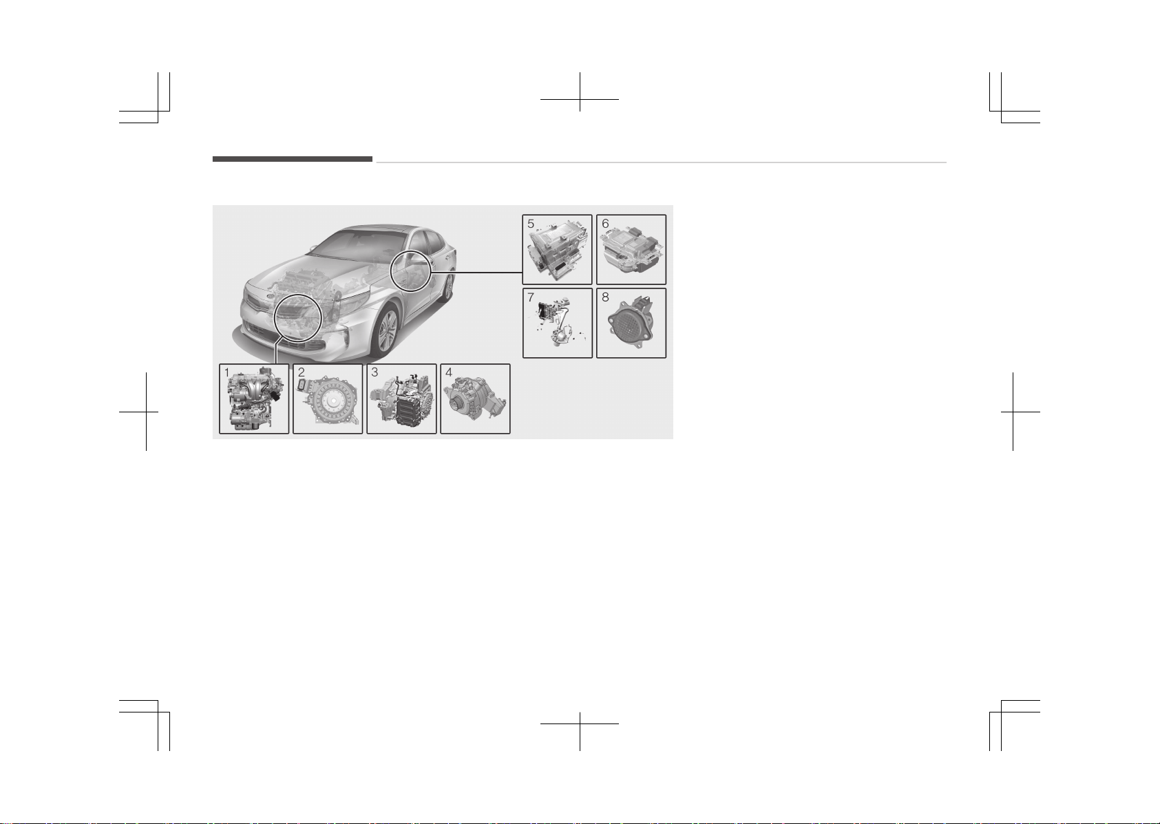
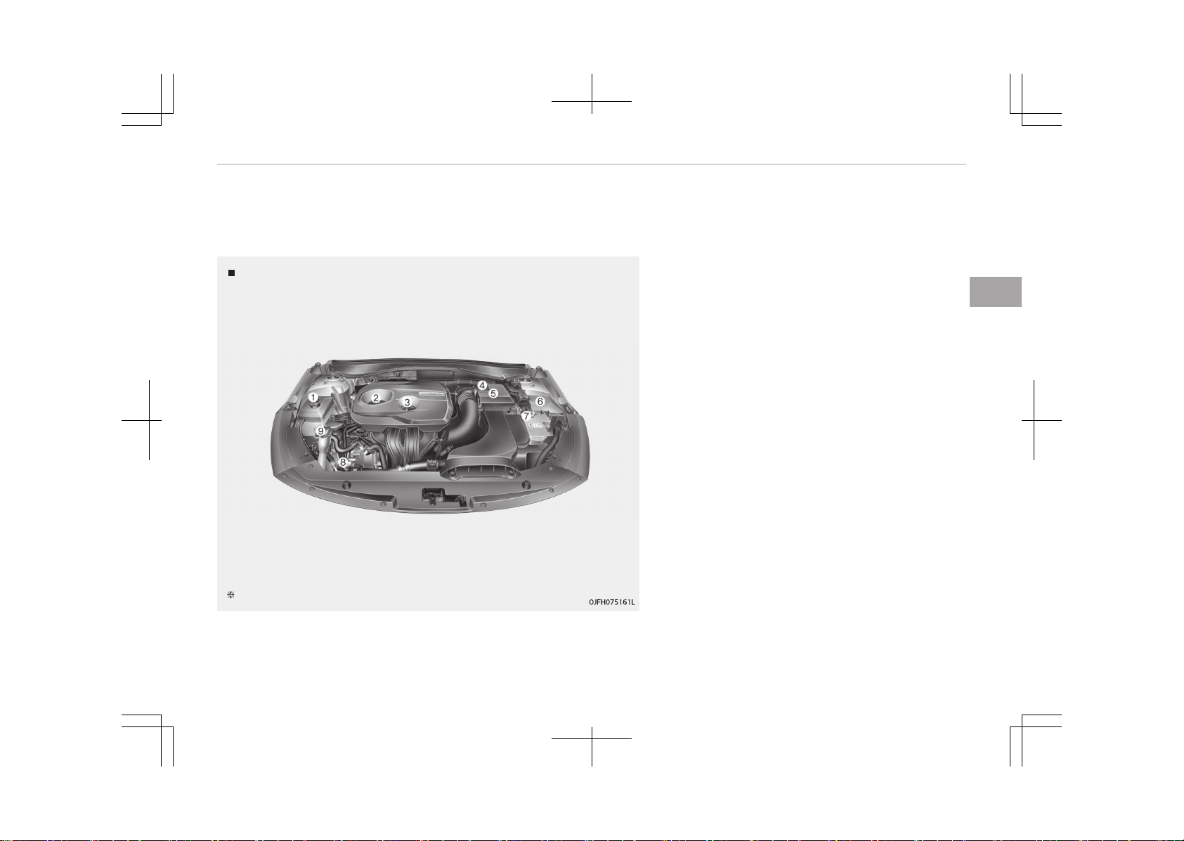
COMPONENTS OF THE HYBRID/PLUG-IN HYBRID VEHICLE
OJFHPQ016001L
1. Engine: 2.0L
2. Motor: 35 kW
3. Transmission: 6AT
4. Hybrid starter generator (HSG)
5. HPCU (Hybrid Power Control Unit)
6. High-voltage battery system
7. Regenerative brake system
8. Virtual Engine Sound System
(VESS)
❈ The actual shape may differ from
the illustration.
The Hybrid battery uses high voltage to
operate the electric motor and other
components. High voltage is dangerous
if touched.
Your vehicle is equipped with orange
colored insulation and covers over the
high voltage components to protect
people from electric shock. High voltage
warning labels are attached to some
system components as additional
warnings. Your vehicle is recommended
to be serviced by an authorized Kia
dealer.
Hybrid system overview
1-30
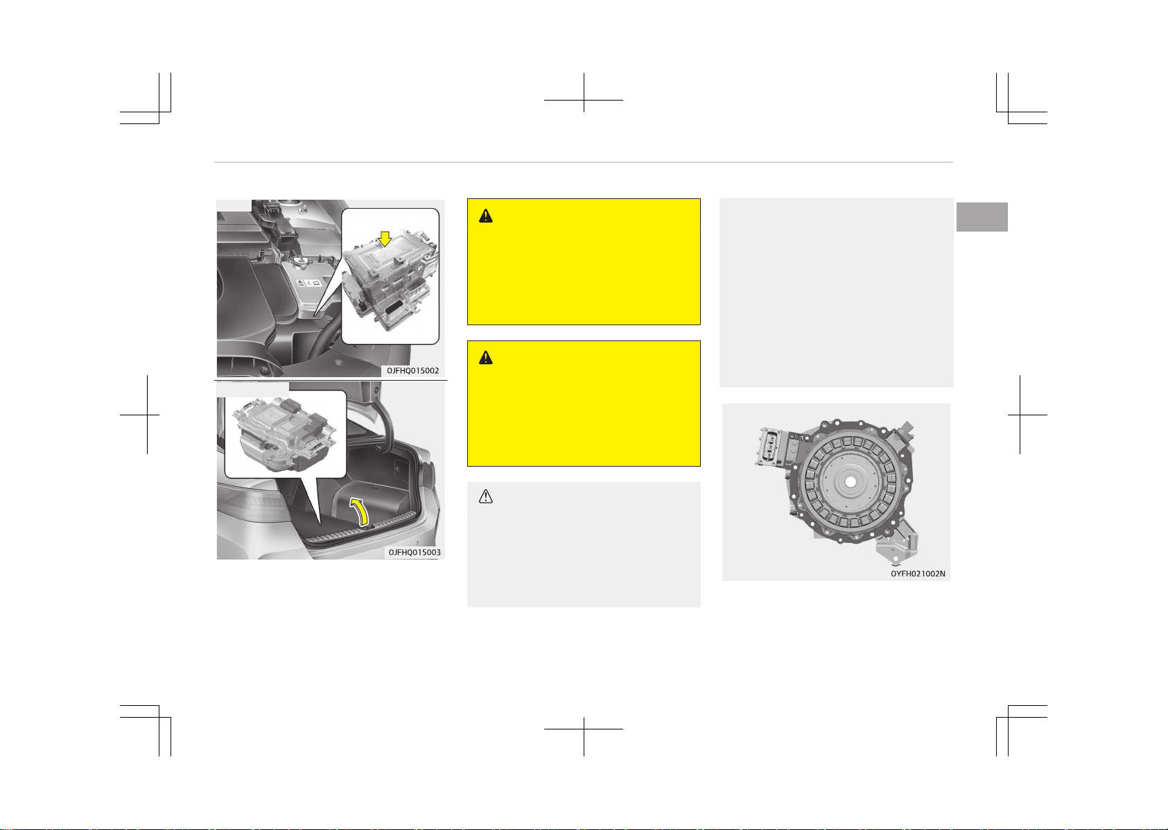
HPCU
HEV Battery
WARNING
Never touch orange or high voltage
labeled components including wires,
cables, and connections. If the insu‐
lators or covers are damaged or re‐
moved, severe injury or death from
electrocution may occur.
WARNING
When replacing the fuses in the en‐
gine compartment, never touch the
HPCU. The HPCU carries high volt‐
age. Touching the HPCU could result
in electrocution, serious injury, or
death.
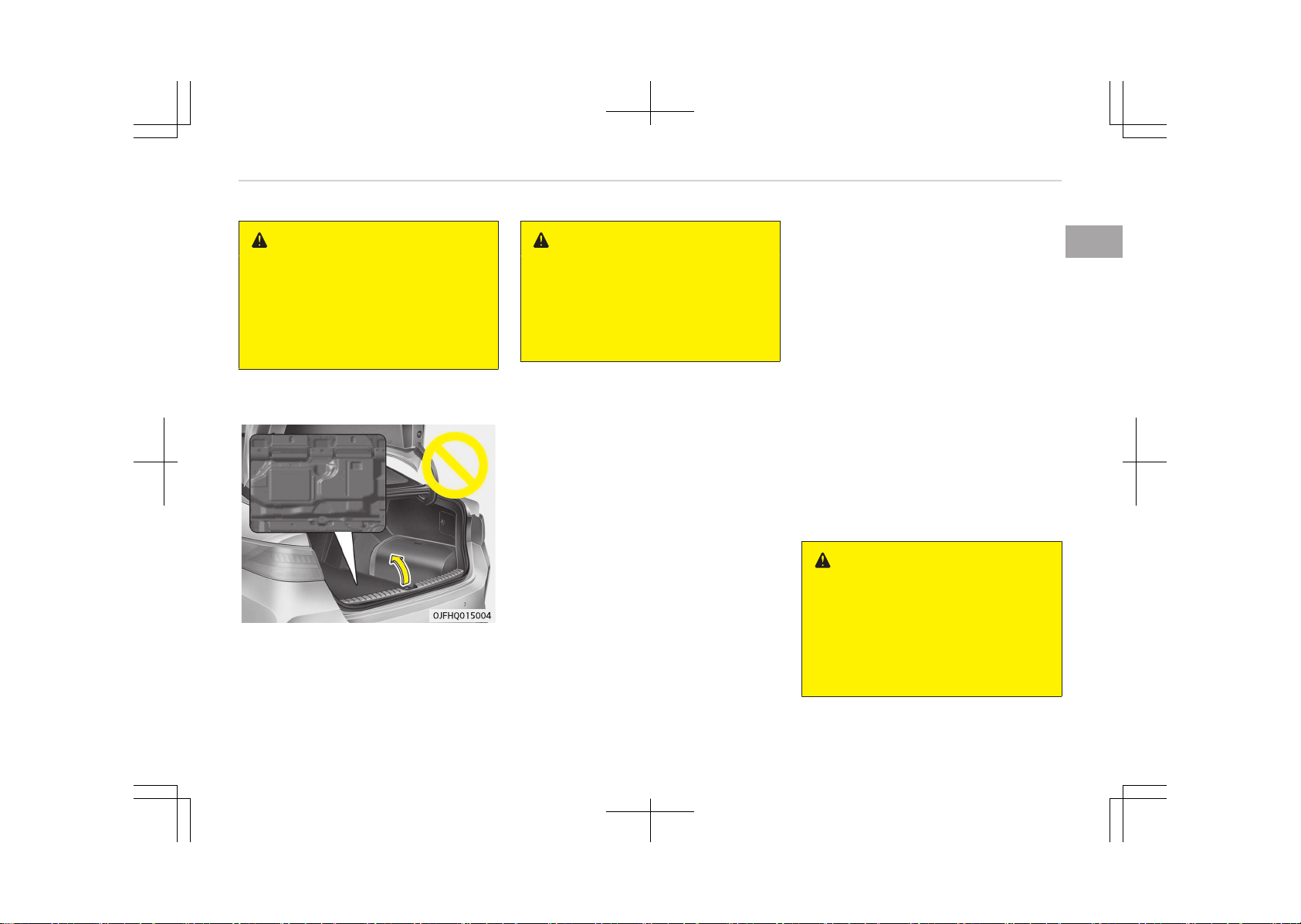
CAUTION
• Do not pile up any items in an area
behind the high voltage battery. In
a crash, the battery may become
unstable, or its performance may
degrade.
(Continued)
(Continued)
• Do not apply strong force nor pile
up any items above the trunk.
Such an attempt may distort the
high voltage battery case, causing
a safety problem or degrading the
performance.
• Be careful when loading inflamma‐
ble liquid in trunk. It could cause
operational and safety degrada‐
tion if the liquid leaks and flows in
high voltage battery.
Motor
1-31
1
Hybrid system overview
WARNING
As with all batteries, avoid fluid con‐
tact with the Hybrid battery. If the
battery is damaged and if electro‐
lyte comes in contact with your
body, clothes or eyes, immediately
flush with a large quantity of fresh
water.
WARNING
Do not use an after-market battery
charger to charge the Hybrid bat‐
tery. Doing so may result in death or
serious injury.
WARNING
n
High Waters
• Avoid high waters as this may re‐
sult in your vehicle becoming satu‐
rated with water and could com‐
promise the high voltage compo‐
nents.
(Continued)
(Continued)
• Do not touch any of the high volt‐
age components within your vehi‐
cle if your vehicle has been sub‐
merged in water equal to half of
the vehicle height. Touching high
voltage components once sub‐
merged in water could result in se‐
vere burns or electric shock that
could result in death or serious in‐
jury.
WARNING
n
Carrying Liquids in Trunk
Do not load large amounts of water
in open containers into the vehicle. If
the water spills onto the HEV bat‐
tery, it may cause a short and dam‐
age the battery.
CAUTION
n
Cleaning Engine
When you clean the engine compart‐
ment, do not wash using water. Wa‐
ter may cause electric arcing to oc‐
(Continued)
(Continued)
cur and damage electronic parts and
components.
WARNING
n
Exposure to High Voltage
• High voltage in the hybrid battery
system is very dangerous and can
cause severe burns and electric
shock. This may result in serious
injury or death.
• For your safety, never touch, re‐
place, dismantle or remove any
portion of the hybrid battery sys‐
tem including components, cables
and connectors.
WARNING
n
Use of Water or Liquids
If water or liquids come into contact
with the hybrid system components,
and you are also in contact with the
water, severe injury or death due to
electrocution may occur.
Hybrid system overview
1-32
WARNING
n
Hot Components
When the hybrid battery system op‐
erates, the HEV battery system can
be hot. Heat burns may result from
touching even insulated components
of the HEV system.
Safety plug
DANGER
Never touch the safety plug. Safety
plug is attached to high voltage hy‐
brid battery system. Touching safe‐
ty plug will result in death or serious
injury. Service personnel should fol‐
low procedure in service manual.
Some special features of the
hybrid vehicle
Hybrid vehicles sound different than
gasoline engine vehicles. When the hy‐
brid system operates, you may hear a
sound from the hybrid battery system
behind the rear seat. If you apply the
accelerator pedal rapidly, you may hear
a sound. When you apply the brake
pedal, you may hear a sound from the
regenerative brake system. When the
hybrid system is turned off or on, you
may hear a sound in the engine com‐
partment. If you depress the brake
pedal repeatedly when the hybrid sys‐
tem is turned on, you may hear a
sound in the engine compartment.
None of these sounds indicate a prob‐
lem.
They are characteristics of hybrid vehi‐
cles.
When the hybrid system is turned on,
the engine may run. This does not indi‐
cate a malfunction. If the "READY"
symbol is on, the hybrid system is op‐
erating. Even if the gasoline engine is
off, you can operate the vehicle.
The HEV system may emit electromag‐
netic waves which can affect the per‐
formance of electronic devices applian‐
ces, such as laptop computers, which
are not part of the vehicle design.
If you park the vehicle for a long time,
the hybrid system will discharge. You
need to drive the vehicle several times
per month to maintain a charge.
When you start the hybrid system in
the "P" transmission position, the
"READY" symbol is illuminated in the
cluster. The driver can drive the vehicle
even if the engine is stopped.
WARNING
When you leave the vehicle, you
should turn off the hybrid system. If
you depress the accelerator pedal by
mistake and the vehicle is not in the
"P" position, the vehicle will acceler‐
ate. This may result in serious injury
or death.
1-33
1
Hybrid system overview
Virtual Engine Sound System
(VESS)
The Virtual Engine Sound System gen‐
erates an engine sound for pedestrians
to hear vehicle while at low speeds in
EV mode.
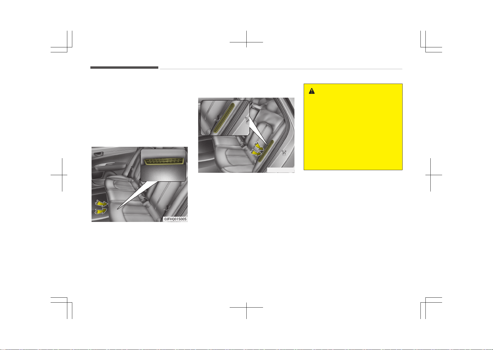
High voltage battery air intake
Hybrid battery air intake
The hybrid battery air intake is located
on the bottom of the rear seats. The
air intake cools down the hybrid bat‐
tery. When the hybrid battery air in‐
take is blocked, the hybrid battery may
be overheated. Do not obstruct the air
intake with any other objects.
Plug-in Hybrid Vehicle
OJFHP036114L
The high-voltage battery air intake is
located on the left side of the rear
seats. The air intake cools down the
high-voltage battery.
When the high-voltage battery air in‐
take is blocked, the high-voltage bat‐
tery may be overheated and the vehicle
performance may become limited and
set a hybrid warning lamp. Do not ob‐
struct the air intake with any other ob‐
jects.
WARNING
n
Air Intake
• Blocking the air intake behind the
rear seats may damage the HEV
battery.
• Do not allow any water into the air
intake even when cleaning. If any
water enters the air intake, the
Hybrid battery may cause an elec‐
tric shock which can cause serious
injury or death due to electrocu‐
tion.
If an accident occurs
• Avoid the engine compartment.
• Avoid any orange or high voltage
wires, cables, or components.
• Assume that a high voltage compo‐
nent is exposed and move away from
the vehicle as promptly as possible.
• Refer to Towing on page 8-21 for
towing information.
Hybrid system overview
1-34
WARNING
• After parking the vehicle, shift the
transmission into "P" position. Turn
off the hybrid system by pushing
the Engine Start/Stop button.
• For your safety, do not touch high
voltage cables, connectors and
package modules. High Voltage
components are orange in color.
• Exposed cables or wires may be
visible inside or outside of the ve‐
hicle. Never touch the wires or ca‐
bles, because an electrical shock
may occur causing injury or death.
• If a fire occurs, to extinguish a
small high-voltage battery fire,
the following techniques can be
used:
- Dry chemical
- CO2
- Large amounts of water
- Regular foam
For a large high-voltage battery
fire, use these types of extin‐
guishing methods:
- Large amounts of water
- Fog
(Continued)
(Continued)
- Regular foam
• If you need towing, refer to Tow‐
ing on page 8-21.
WARNING
If a vehicle accident occurs:
1. Stop the vehicle and shift the
transmission into "P" position
and then depress the parking
brake.
2. Turn off the Hybrid system by
pushing the Engine Start/Stop
Button.
3. Evacuate to the safety place.
(Continued)
(Continued)
4. Call emergency services for help
and let them know the vehicle is
a Hybrid vehicle.
Do not touch high voltage cables,
connectors and package mod‐
ules. High voltage components
are orange in color.
Exposed cables or wires may be
visible inside or outside of the
vehicle. Never touch the wires or
cables, because an electrical
shock may occur causing injury
or death.
WARNING
If a fire occurs:
1. Stop the vehicle and shift the
transmission in to "P" position,
and then depress the parking
brake. To ventilate smoke from a
fire, open the windows if possi‐
ble.
2. Turn off the Hybrid system by
pushing the Engine Start/Stop
Button.
(Continued)
1-35
1
Hybrid system overview
(Continued)
3. Leave the vehicle and evacuate
to the safety place.
4. Call emergency services for help
and let them know the vehicle is
a Hybrid vehicle.
If you have an extinguisher, extin‐
guish a fire carefully.
Do not touch high voltage cables,
connectors and package modules.
High voltage components are orange
in color.
Exposed cables or wires may be visi‐
ble inside or outside of the vehicle.
Never touch the wires or cables, be‐
cause an electrical shock may occur
causing injury or death.
WARNING
If a submersion in water occurs:
If your vehicle was flooded and has
soaked carpeting or water on the
flooring, you should not try to start
the Hybrid system. Never touch the
high voltage cables, connectors and
package modules, because an elec‐
(Continued)
(Continued)
trical shock may occur causing injury
or death. High Voltage cables are or‐
ange in color.
We recommend that the car towed
to an authorized Kia dealer.
When the hybrid vehicle shuts
off
When the high voltage battery or 12-
volt battery discharges, or fuel tank is
empty, the hybrid system may not op‐
erate.
If the Hybrid system stops operating
while the vehicle is moving, reduce the
vehicle speed gradually. Pull your vehi‐
cle off the road in a safe area, and shift
the transmission in to Park (P) position
and:
1. Turn on the hazard warning flash‐
ers.
2. Set the start button at OFF, and try
to start the Hybrid system by ap‐
plying the brake pedal and pushing
the start button.
3. If the Hybrid system will not oper‐
ate, refer to Emergency starting
on page 8-05.
Before you try to jump start the vehi‐
cle, confirm the fuel level. If the fuel
level is low add more fuel before at‐
tempting as emergency start.
WARNING
n
Accident Vehicle
Never touch electric wires or cable. If
exposed electric wires or cables are
visible inside or outside of your vehi‐
cle, an electric shock may occur.
WARNING
n
Putting out fire
Never use a small quantity of water
to put out a fire in your vehicle. If a
fire occurs, evacuate the car imme‐
diately and contact the fire depart‐
ment.
Hybrid system overview
1-36

How to use this manual........................................................... 2-02
Fuel requirements.....................................................................2-03
Gasoline engine..................................................................... 2-03
Vehicle break-in process..........................................................2-06
HEV powertrain......................................................................... 2-07
Introduction
2
HOW TO USE THIS MANUAL
We want to help you get the greatest
possible driving pleasure from your ve‐
hicle. Your Owner’s Manual can assist
you in many ways. We strongly recom‐
mend that you read the entire manual.
In order to minimize the chance of
death or injury, you must read the
WARNING and CAUTION sections in the
manual.
Illustrations complement the words in
this manual to best explain how to en‐
joy your vehicle. By reading your man‐
ual, you learn about features, impor‐
tant safety information, and driving
tips under various road conditions.
The general layout of the manual is
provided in the Table of Contents. Use
the index when looking for a specific
area or subject; it has an alphabetical
listing of all information in your manual.
Sections: This manual has ten chapters
plus an index. Each section begins with
a brief list of contents so you can tell at
a glance if that section has the infor‐
mation you want.
You will find various WARNINGs, CAU‐
TIONs, and NOTICEs in this manual.
These WARNINGs were prepared to en‐
hance your personal safety. You should
carefully read and follow ALL proce‐
dures and recommendations provided
in these WARNINGs, CAUTIONs and NO‐
TICEs.
WARNING
A WARNING indicates a situation in
which
harm, serious bodily injury or
death could result if the warning is
ignored.
CAUTION
A CAUTION indicates a situation in
which
damage to your vehicle could
result if the caution is ignored.
NOTICE
A NOTICE indicates interesting or
helpful
information is being provi‐
ded.
Introduction
2-02
FUEL REQUIREMENTS
Gasoline engine
Unleaded
For Europe
For the optimal vehicle performance,
we recommend you to use unleaded
gasoline with an octane rating of RON
(Research Octane Number) 95 / AKI
(Antiknock Index) 91 or higher.
You may use unleaded gasoline with an
octane rating of RON 91~94 / AKI 87~90
but it may result in slight performance
reduction of the vehicle. (Do not use
methanol blended fuels.)
Except Europe
Your new Kia vehicle is designed to use
only unleaded fuel having an Octane
Rating of RON (Research Octane Num‐
ber) 91 / AKI (Antiknock Index) 87 or
higher. (Do not use methanol blended
fuels.)
Your new vehicle is designed to obtain
maximum performance with UNLEA‐
DED FUEL, as well as minimize exhaust
emissions and spark plug fouling.
CAUTION
NEVER USE LEADED FUEL. The use
of
leaded fuel is detrimental to the
catalytic converter and will damage
the engine control system’s oxygen
sensor and affect emission control.
Never add any fuel system cleaning
agents to the fuel tank other than
what has been specified. (We recom‐
mend that you consult an authorized
Kia dealer for details.)
WARNING
• Do not "top off" after the nozzle
automatically shuts off when re‐
fueling.
• Always check that the fuel cap is
installed securely to prevent fuel
spillage in the event of an acci‐
dent.
Leaded (if equipped)
For some countries, your vehicle is de‐
signed to use leaded gasoline. When
you are going to use leaded gasoline,
we recommend that you ask an au‐
thorized Kia dealer whether leaded
gasoline in your vehicle is available or
not.
Octane Rating of leaded gasoline is
same with unleaded one.
Gasoline containing alcohol and
methanol
Gasohol, a mixture of gasoline and
ethanol (also known as grain alcohol),
and gasoline or gasohol containing
methanol (also known as wood alcohol)
are being marketed along with or in‐
stead of leaded or unleaded gasoline.
Do not use gasohol containing more
than 10% ethanol, and do not use gas‐
oline or gasohol containing any metha‐
nol. Either of these fuels may cause
drivability problems and damage to the
fuel system, engine control system and
emission control system.
Discontinue using gasohol of any kind if
drivability problems occur.
Vehicle damage or drivability problems
may not be covered by the manufac‐
turer’s warranty if they result from the
use of:
2-03
2
Introduction

1. Gasohol containing more than 10%
ethanol.
2. Gasoline or gasohol containing
methanol.
3. Leaded fuel or leaded gasohol.
CAUTION
Never use gasohol which contains
methanol. Discontinue use of any
gasohol product which impairs driva‐
bility.
Other fuels
Using fuels such as
-
Silicone (Si) contained fuel,
-
MMT (Manganese, Mn) contained
fuel,
-
Ferrocene (Fe) contained fuel, and
-
Other metalic additives contained
fuels, may cause vehicle and engine
damage or cause plugging, misfiring,
poor acceleration, engine stalling,
catalyst melting, abnormal corrosion,
life cycle reduction, etc.
Also, the Malfunction Indicator Lamp
(MIL) may illuminate.
NOTICE
Damage to the fuel system or per‐
formance problem
caused by the
use of these fuels may not be cov‐
ered by your New Vehicle Limited
Warranty.
Use of MTBE
Kia recommends avoiding fuels contain‐
ing MTBE (Methyl Tertiary Butyl Ether)
over 15.0% vol. (Oxygen Content 2.7%
weight) in your vehicle.
Fuel containing MTBE over 15.0% vol.
(Oxygen Content 2.7% weight) may re‐
duce vehicle performance and produce
vapor lock or hard starting.
CAUTION
Your New Vehicle Limited Warranty
may not cover damage to the fuel
system and any performance prob‐
lems that are caused by the use of
fuels containing methanol or fuels
containing MTBE (Methyl Tertiary
Butyl Ether) over 15.0% vol. (Oxygen
Content 2.7% weight.)
Do not use methanol
Fuels containing methanol (wood alco‐
hol) should not be used in your vehicle.
This type of fuel can reduce vehicle
performance and damage components
of the fuel system, engine control sys‐
tem and emission control system.
Fuel Additives
Kia recommends that you use unleaded
gasoline which has an octane rating of
RON (Research Octane Number) 95 /
AKI (Antiknock Index) 91 or higher (for
Europe) or Octane Rating of RON (Rea‐
search Octane Number) 91 / AKI (Anti‐
knock Index) 87 or higher (except Eu‐
rope).
For customers who do not use good
quality gasolines including fuel additives
regularly, and have problems starting
or the engine does not run smoothly,
one bottle of additives added to the
fuel tank at every 15,000 km (For Eu‐
rope)/10,000 km (Except Europe). Addi‐
tives are available from your authorized
Kia dealer along with information on
how to use them. Do not mix other ad‐
ditives.
Operation in foreign countries
If you are going to drive your vehicle in
another country, be sure to:
Introduction
2-04

• Observe all regulations regarding reg‐
istration and insurance.
• Determine that acceptable fuel is
available.
2-05
2
Introduction

VEHICLE BREAK-IN PROCESS
No special break-in period is needed. By
following a few simple precautions for
the first 1,000 km (600 miles) you may
add to the performance, economy and
life of your vehicle.
• Do not race the engine.
• While driving, keep your engine speed
(rpm, or revolutions per minute)
within 3,000 rpm.
• Do not maintain a single speed for
long periods of time, either fast or
slow. Varying engine speed is needed
to properly break-in the engine.
• Avoid hard stops, except in emergen‐
cies, to allow the brakes to seat
properly.
Introduction
2-06

HEV POWERTRAIN
By following a few simple precautions
for the first 1,000 km (600 miles) you
may add to the performance, economy
and life of your vehicle.
• Do not race the engine.
• Avoid hard stops, except in emergen‐
cies, to allow the brakes to seat
properly.
2-07
2
Introduction


Exterior overview......................................................................3-02
Interior overview....................................................................... 3-04
Instrument panel overview......................................................3-05
Engine compartment................................................................3-07
Your vehicle at a glance
3
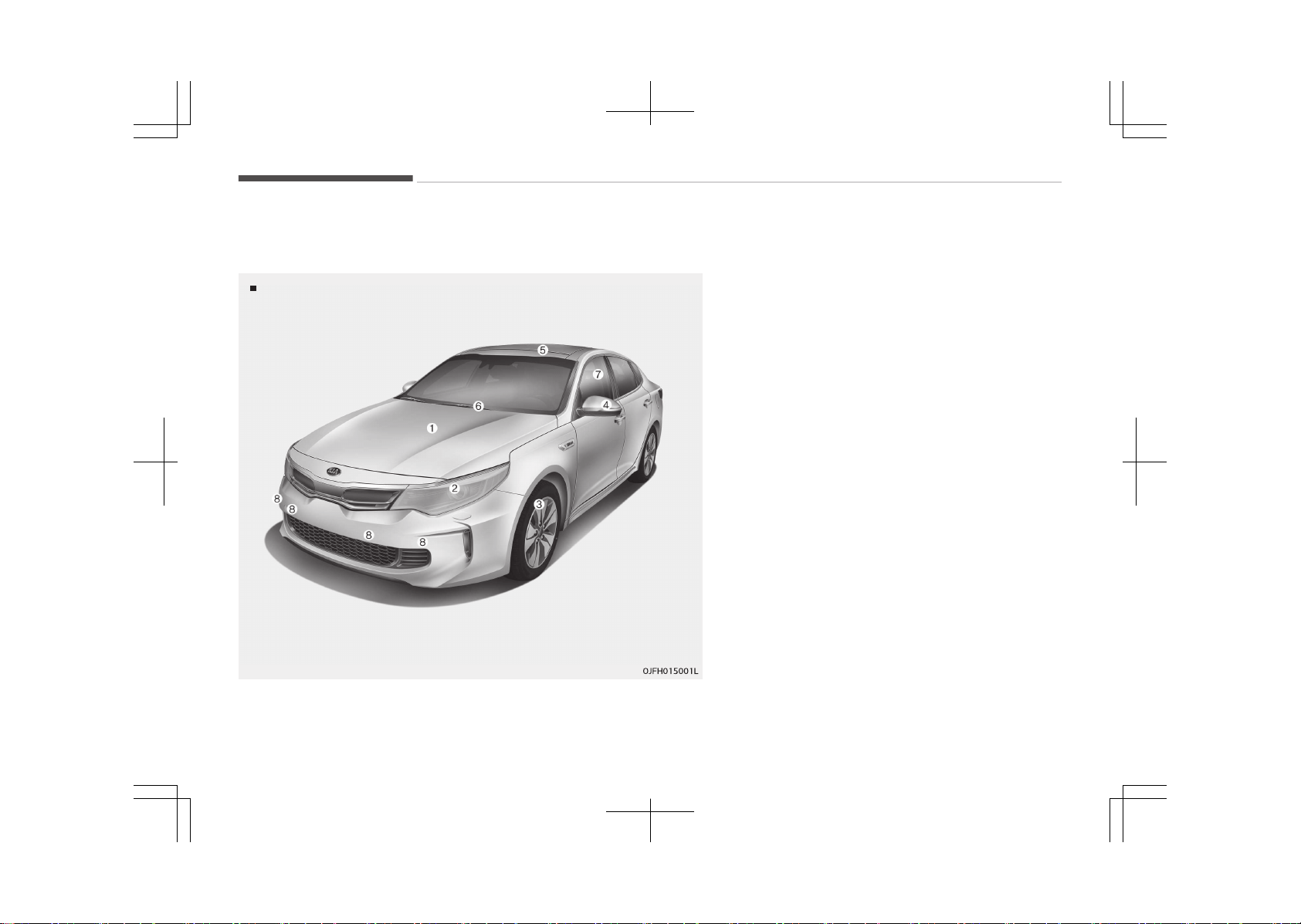
EXTERIOR OVERVIEW
Front view
❈ The actual shape may differ from the illustration.
1. Hood...................................... ...................................... p. 5-27
2. Headlamp (Features of your vehicle)......... ......... p. 5-115
Headlamp (Maintenance).................... .................... p. 9-74
3. Wheel and tire (Maintenance)................ ................ p. 9-43
Wheel and tire (Specifications).............. .............. p. 10-09
4. Outside rearview mirror..................... ..................... p. 5-45
5. Panorama sunroof.................................................... p. 5-35
6. Front windshield wiper blades (Features of your ve‐
hicle).......................................................................... p. 5-122
Front windshield wiper blades (Maintenance)...... p. 9-36
7. Windows...................................................................... p. 5-23
8. Parking assist system.............................................. p. 5-89
Your vehicle at a glance
3-02
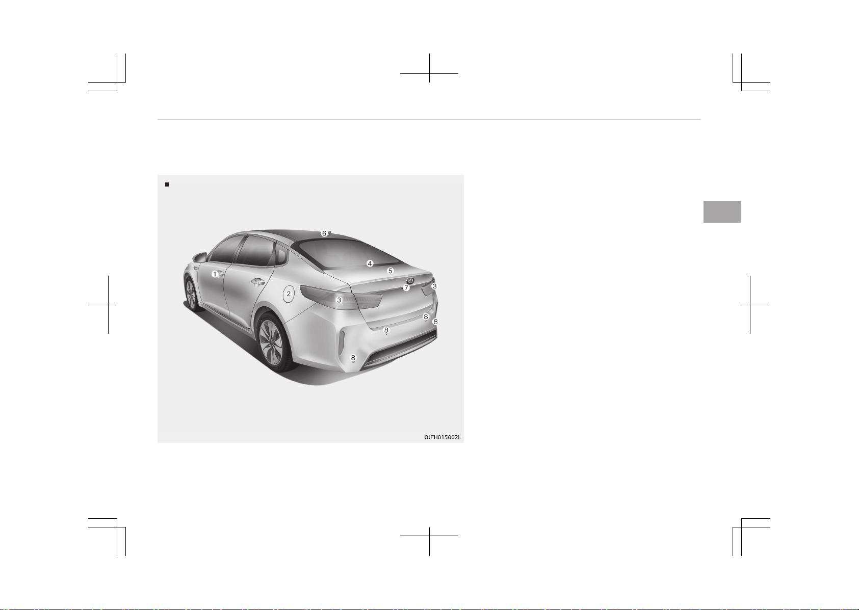
Rear view
❈ The actual shape may differ from the illustration.
1. Door locks.................................................................... p. 5-12
2. Fuel filler lid (Hybrid)........................ ........................ p. 5-29
Fuel filler lid (Plug-in hybrid)................. ................. p. 5-31
3. Rear combination lamp (Maintenance).................. p. 9-73
4. High mounted stop lamp (Maintenance)....... ....... p. 9-81
5. Trunk............................................................................ p. 5-16
6. Antenna................................... ................................... p. 6-02
7. Rearview camera.......................... .......................... p. 5-112
Surround view monitoring system........... ........... p. 5-113
8. Parking assist system (Rear).................................. p. 5-89
3-03
3
Your vehicle at a glance
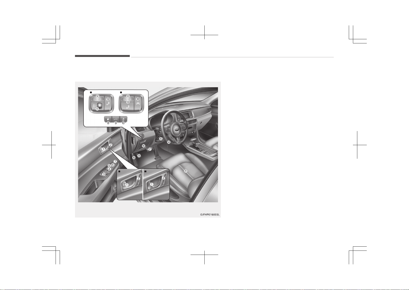
INTERIOR OVERVIEW
❈ The actual shape may differ from the illustration.
Type A
Type B
Type AType B
1. Inside door handle.......................... .......................... p. 5-13
2. Driver position memory button.............................. p. 4-08
3. Power window switch....................... ....................... p. 5-23
4. Central door lock switch..................... ..................... p. 5-14
5. Power window lock button...................................... p. 5-25
6. Outside rearview mirror control.............. .............. p. 5-45
7. Outside rearview mirror folding.............................. p. 5-45
8. Fuel filler lid open button.................... .................... p. 5-29
9. Trunk open button.......................... .......................... p. 5-16
10. ESC off button............................................................ p. 7-30
11. Headlight leveling device........................................ p. 5-120
12. Instrument panel illumination control.................... p. 5-49
13. BSD On/Off button.................................................... p. 7-91
14. Steering wheel............................. ............................. p. 5-40
15. Tilt and telescopic steering control lever.............. p. 5-41
16. Inner fuse panel............................ ............................ p. 9-53
17. Brake pedal................................ ................................ p. 7-17
18. Parking brake pedal......................... ......................... p. 7-18
19. Hood release lever.......................... .......................... p. 5-27
20. LKAS On/Off button.................................................. p. 7-84
21. Seat.............................................................................. p. 4-02
Your vehicle at a glance
3-04
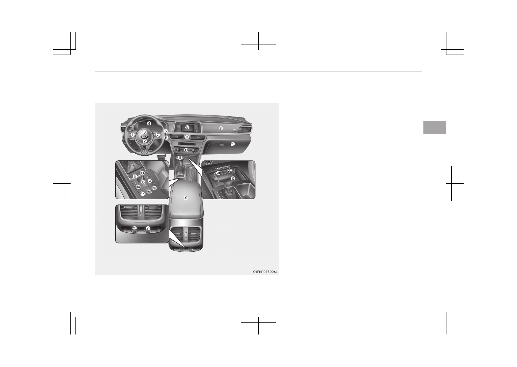
INSTRUMENT PANEL OVERVIEW
❈ The actual shape may differ from the illustration.
1. Steering wheel audio controls................ ................ p. 6-03
2. Driver’s front air bag........................ ........................ p. 4-51
3. Horn...................................... ...................................... p. 5-42
4. Instrument cluster.......................... .......................... p. 5-48
5. Wiper and washer control lever............................ p. 5-122
6. Engine start/stop button.................... .................... p. 7-06
7. Cruise control.............................. .............................. p. 7-47
Speed limit control.................................................... p. 7-55
Advanced smart cruise control system........ ........ p. 7-59
8. Audio............................................................................ p. 6-02
9. Hazard warning flasher............................................ p. 8-02
10. Automatic climate control system........... ........... p. 5-137
11. Shift lever A/T............................................................ p. 7-11
12. Heated steering wheel button................................ p. 5-42
13. Drive mode button.................................................... p. 7-75
Active Eco button........................... ........................... p. 7-75
14. Seat warmer............................................................ p. 5-155
Air ventilation seat.................................................. p. 5-156
15. Electronic parking brake (EPB) switch......... ......... p. 7-19
16. Auto Hold On/Off button.......................................... p. 7-24
3-05
3
Your vehicle at a glance
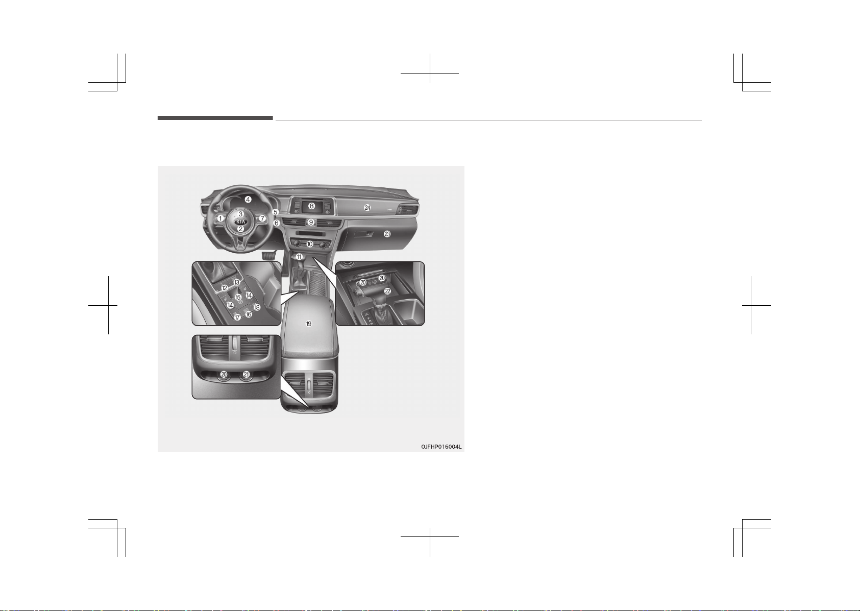
❈ The actual shape may differ from the illustration.
17. Surround view monitoring system On/Off button......
.................................................................................... p. 5-113
Smart parking assist system.................................. p. 7-59
18. Parking assist system On/Off button.................... p. 5-89
19. Center console storage box................. ................. p. 5-150
20. Power outlet............................................................ p. 5-157
21. USB charger.............................................................. p. 5-158
22. Smart phone wireless charger.............................. p. 5-158
23. Glove box.................................................................. p. 5-150
24. Passenger’s front air bag.................... .................... p. 4-51
Your vehicle at a glance
3-06
ENGINE COMPARTMENT
Gasoline Engine (Nu 2.0L - GDI)
The actual engine room in the vehicle may differ from the illustration.
1. Engine coolant reservoir..................... ..................... p. 9-28
2. Engine oil filler cap.......................... .......................... p. 9-24
3. Engine oil dipstick...................................................... p. 9-24
4. Brake fluid reservoir.................................................. p. 9-30
5. Air cleaner................................. ................................. p. 9-33
6. Fuse box...................................................................... p. 9-52
7. Inverter coolant reservoir........................................ p. 9-27
8. Radiator cap............................... ............................... p. 9-28
9. Windshield washer fluid reservoir.......................... p. 9-31
3-07
3
Your vehicle at a glance


Seats............................................................................................4-02
Front seat adjustment - manual....................................... 4-05
Front seat adjustment - power ........................................ 4-06
Driver position memory system ....................................... 4-08
Headrest (for front seat).....................................................4-09
Seatback pocket.................................................................... 4-12
Rear seat adjustment.......................................................... 4-12
Seat belts....................................................................................4-18
Seat belt restraint system..................................................4-18
Pre-tensioner seat belt....................................................... 4-23
Seat belt precautions........................................................... 4-26
Care of seat belts..................................................................4-28
Child Restraint System (CRS)..................................................4-30
Selecting a Child Restraint System (CRS)......................... 4-30
Installing a Child Restraint System (CRS)......................... 4-32
ISOFIX anchorage and top-tether anchorage
(ISOFIX anchorage system) for children............................4-33
Air bag - Supplemental Restraint System .......................... 4-43
How does the air bag system operate..............................4-44
Air bag warning light............................................................ 4-47
SRS components and functions..........................................4-48
Driver's and passenger's front air bag.............................. 4-51
Side air bag.............................................................................4-56
Curtain air bag....................................................................... 4-58
SRS Care................................................................................. 4-65
Additional safety precautions.............................................4-65
Adding equipment to or modifying your air bag-
equipped vehicle.................................................................... 4-66
Air bag warning label............................................................4-67
Safety features of your vehicle
4
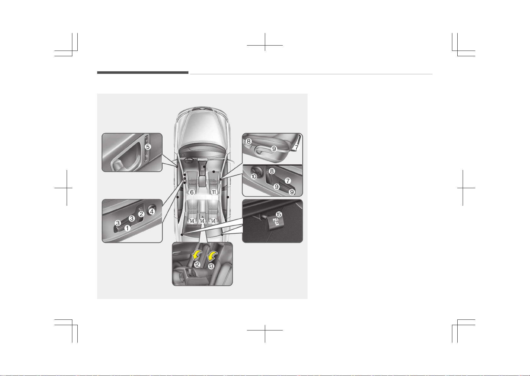
SEATS
❈ The actual shape may differ from the illustration.
OJFH035001LB
Driver’s seat
1. Forward and backward
2. Seatback angle
3. Seat cushion height
4.
Lumbar support
*
5.
Driver position memory system
*
6. Headrest
Front passenger’s seat
7. Forward and backward
8. Seatback angle
9. Seat cushion height
10.
Lumbar support
*
11. Headrest
Rear seat
12. Armrest
13.
Ski pass-through
*
14. Headrest
15.
Seatback folding lever
*
*
: if equipped
Safety features of your vehicle
4-02
WARNING
n
Loose objects
Loose objects in the driver’s foot
area could interfere with the opera‐
tion of the foot pedals, possibly
causing an accident. Do not place
anything under the front seats.
WARNING
n
Uprighting seat
When you return the seatback to its
upright position, hold the seatback
and return it slowly and be sure
there are no other occupants around
the seat. If the seatback is returned
without being held and controlled,
the back of the seat could spring
forward resulting in accidental injury
to a person struck by the seatback.
WARNING
n
Driver responsibility for pas‐
sengers
(Continued)
(Continued)
Riding in a vehicle with the seatback
reclined could lead to serious or fatal
injury in an accident. If a seat is re‐
clined during an accident, the occu‐
pant’s hips may slide under the lap
portion of the seat belt applying
great force to the unprotected abdo‐
men. Serious or fatal internal injuries
could result. The driver must advise
the passenger to keep the seatback
in an upright position whenever the
vehicle is in motion.
WARNING
Do not use a sitting cushion that re‐
duces friction between the seat and
passenger. The passenger’s hips
may slide under the lap portion of
the seat belt during an accident or a
sudden stop. Serious or fatal internal
injuries could result because the seat
belt cannot operate normally.
WARNING
n
Driver’s seat
• Never attempt to adjust the seat
while the vehicle is moving. This
could result in loss of control, and
an accident causing death, serious
injury, or property damage.
• Do not allow anything to interfere
with the normal position of the
seatback. Storing items against a
seatback or in any other way in‐
terfering with proper locking of a
seatback could result in serious or
fatal injury in a sudden stop or col‐
lision.
• Always drive and ride with your
seatback upright and the lap por‐
tion of the seat belt snug and low
across the hips. This is the best
position to protect you in case of
an accident.
(Continued)
4-03
4
Safety features of your vehicle
(Continued)
• In order to avoid unnecessary and
perhaps severe air bag injuries, al‐
ways sit as far back as possible
from the steering wheel while
maintaining comfortable control of
the vehicle. We recommend that
your chest be at least 25 cm
(10 inches) away from the steer‐
ing wheel.
WARNING
n
Rear seatbacks
• The rear seatback must be secure‐
ly latched. If not, passengers and
objects could be thrown forward
resulting in serious injury or death
in the event of a sudden stop or
collision.
(Continued)
(Continued)
• Luggage and other cargo should be
laid flat in the cargo area. If ob‐
jects are large, heavy, or must be
piled, they must be secured.
Under no circumstances should
cargo be piled higher than the
seatbacks. Failure to follow these
warnings could result in serious in‐
jury or death in the event of a sud‐
den stop, collision or rollover.
• No passenger should ride in the
cargo area or sit or lie on folded
seatbacks while the vehicle is
moving. All passengers must be
properly seated in seats and re‐
strained properly while riding.
• When resetting the seatback to
the upright position, make sure it
is securely latched by pushing it
forward and backwards.
• To avoid the possibility of burns,
do not remove the carpet in the
cargo area.
Emission control devices beneath
this floor generate high tempera‐
tures.
WARNING
After adjusting the seat, always
check that it is securely locked into
place by attempting to move the
seat forward or backward without
using the lock release lever. Sudden
or unexpected movement of the
driver's seat could cause you to lose
control of the vehicle resulting in an
accident.
WARNING
• Do not adjust the seat while wear‐
ing seat belts. Moving the seat
cushion forward may cause strong
pressure on the abdomen.
• Use extreme caution so that hands
or other objects are not caught in
the seat mechanisms while the
seat is moving.
• Do not put a cigarette lighter on
the floor or seat. When you oper‐
ate the seat, gas may gush out of
the lighter and cause fire.
(Continued)
Safety features of your vehicle
4-04
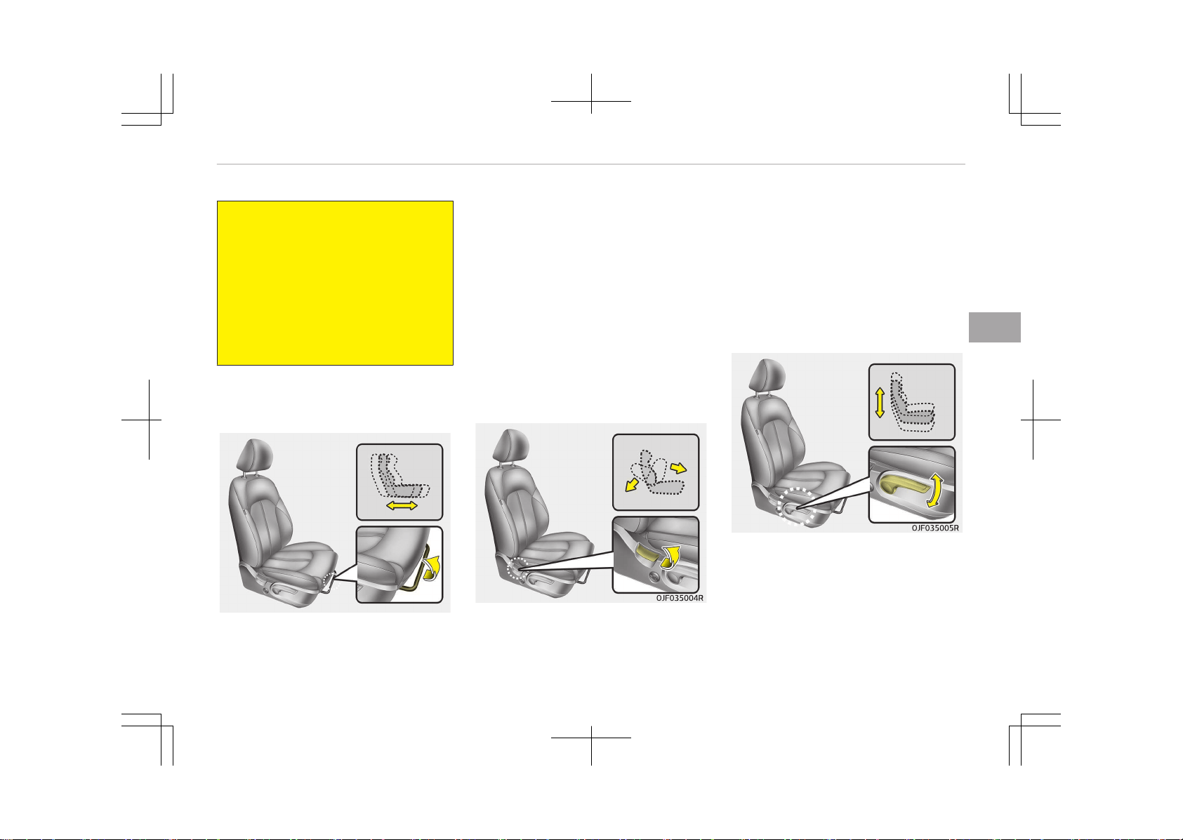
(Continued)
• If there are occupants in the rear
seats, be careful while adjusting
the front seat position.
• Use extreme caution when picking
small objects trapped under the
seats or between the seat and the
center console. Your hands might
be cut or injured by the sharp
edges of the seat mechanism.
Front seat adjustment - manual
Forward and backward
OJF035003R
To move the seat forward or backward:
1. Pull the seat slide adjustment lever
up and hold it.
2. Slide the seat to the position you
desire.
3. Release the lever and make sure
the seat is locked in place.
Adjust the seat before driving, and
make sure the seat is locked securely
by trying to move forward and back‐
ward without using the lever. If the
seat moves, it is not locked properly.
Seatback angle
To recline the seatback:
1. Lean forward slightly and lift up
the seatback recline lever.
2. Carefully lean back on the seat and
adjust the seatback of the seat to
the position you desire.
3. Release the lever and make sure
the seatback is locked in place. (The
lever MUST return to its original
position for the seatback to lock.)
Seat height
To change the height of the seat, push
the lever upwards or downwards.
• To lower the seat cushion, push the
lever down several times.
• To raise the seat cushion, pull the lev‐
er up several times.
4-05
4
Safety features of your vehicle
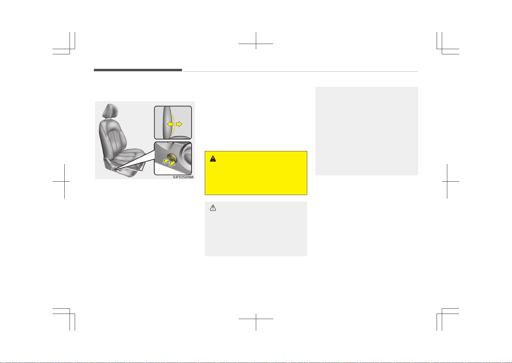
Lumbar support (if equipped)
The lumbar support can be adjusted by
pressing the lumbar support switch on
the side of the Driver's seat.
1. Press the front portion of the
switch to increase support, or the
rear portion of the switch, to de‐
crease support.
2. Release the switch once it reaches
the desired position.
Front seat adjustment - power
(if equipped)
The front seat can be adjusted by using
the control switches located on the
outside of the seat cushion. Before
driving, adjust the seat to the proper
position so you can easily control the
steering wheel, pedals and switches on
the instrument panel.
WARNING
The power seat is operable with the
engine start/stop button in OFF.
Therefore, children should never be
left unattended in the vehicle.
CAUTION
• The power seat is driven by an
electric motor. Stop operating once
the adjustment is completed. Ex‐
cessive operation may damage the
electrical equipment.
(Continued)
(Continued)
• When in operation, the power seat
consumes a large amount of elec‐
trical power. To prevent unneces‐
sary charging system drain, don’t
adjust the power seat longer than
necessary while the engine is not
running.
• Do not operate two or more power
seat control switches at the same
time. Doing so may result in power
seat motor or electrical compo‐
nent malfunction.
Safety features of your vehicle
4-06
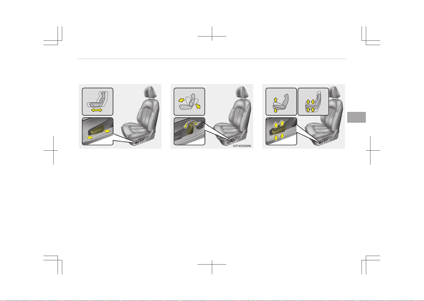
Forward and backward
OJF035008
Push the control switch forward or
backward to move the seat to the de‐
sired position. Release the switch once
the seat reaches the desired position.
Seatback angle
Push the control switch forward or
backward to move the seatback to the
desired angle. Release the switch once
the seat reaches the desired position.
Seat height
OJF035010L
Pull the front portion of the control
switch up to raise or press down to
lower the front part of the seat cush‐
ion. Pull the rear portion of the control
switch up to raise or press down to
lower the seat cushion. Release the
switch once the seat reaches the de‐
sired position.
4-07
4
Safety features of your vehicle
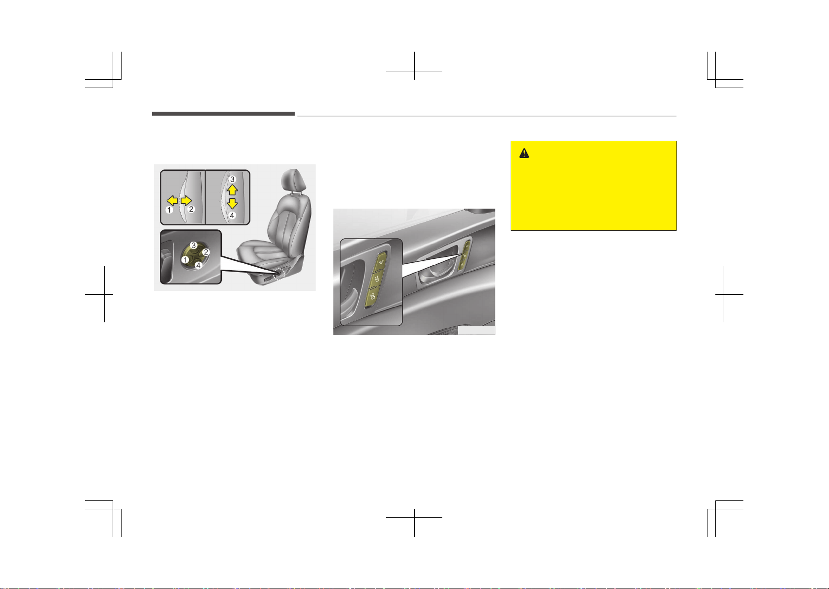
Lumbar support (if equipped)
OJF035075L
The lumbar support can be adjusted by
pressing the lumbar support switch on
the side of the seat.
1. Press the front portion (1) of the
switch to increase support, or the
rear portion (2) of the switch, to
decrease support.
2. Release the switch once it reaches
the desired position.
3. Press the upper portion (3) of the
switch to move the support posi‐
tion up, or press the lower portion
(4) of the switch, to move the sup‐
port position down.
4. Release the switch once it reaches
the desired position.
Driver position memory system
(if equipped, for power seat)
OJF035065L
A driver position memory system is
provided to store and recall the driver
seat and outside rearview mirror posi‐
tion with a simple button operation. By
saving the desired position into the
system memory, different drivers can
reposition the driver seat based upon
their driving preference. If the battery
is disconnected, the position memory
will be erased and the driving position
should be restored in the system.
WARNING
Never attempt to operate the driver
position memory system while the
vehicle is moving.
This could result in loss of control,
and an accident causing death, seri‐
ous injury, or property damage.
Storing positions into memory
using the buttons on the door
Storing driver's seat positions
1. Shift the shift lever into P (for Au‐
tomatic transaxle) while the engine
start/stop button is ON.
2. Adjust the driver’s seat and outside
rearview mirror comfortable for
the driver.
3. Press SET button on the control
panel. The system will beep once.
4. Press one of the memory buttons
(1 or 2) within 5 seconds after
pressing the SET button. The sys‐
tem will beep twice when memory
has been successfully stored.
Safety features of your vehicle
4-08
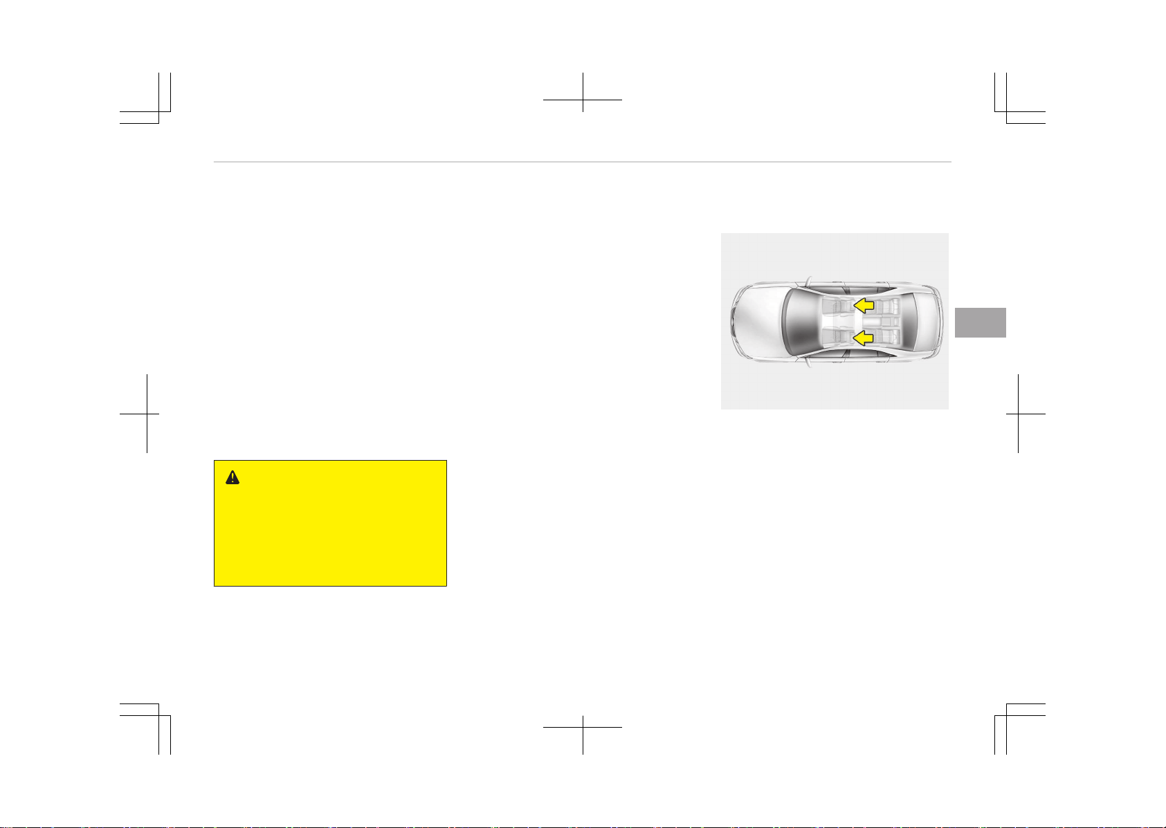
Recalling positions from memory
1. Shift the shift lever into P (for Au‐
tomatic transaxle) while the engine
start/stop button is ON.
2. To recall the position in the memo‐
ry, press the desired memory but‐
ton (1 or 2). The system will beep
once, then the driver’s seat will au‐
tomatically adjust to the stored po‐
sition.
Adjusting the control switch for the
driver’s seat while the system is recall‐
ing the stored position will cause the
movement to stop and move in the di‐
rection that the control switch is
moved.
WARNING
Use caution when recalling the ad‐
justment memory while sitting in
the vehicle. Push the seat position
control switch to the desired position
immediately if the seat moves too
far in any direction.
Easy access function (if equipped)
The system will move the driver's seat
automatically as follows:
• With smart key system
- It will move the driver’s seat rear‐
ward when the engine start/stop
button is changed to the OFF posi‐
tion and front driver’s door is
opened.
- It will move the driver’s seat for‐
ward when the engine start/stop
button is changed to the ACC or
START position.
- It will move the driver's seat for‐
ward when you get in your vehicle
with the smart key after closing
the driver's door.
You can activate or deactivate this fea‐
ture. Refer to User settings on page
5-58.
Headrest (for front seat)
OMG038400
The driver's and front passenger's
seats are equipped with a headrest for
the occupant's safety and comfort.
The headrest not only provides comfort
for the driver and front passenger, but
also helps protect the head and neck in
the event of a collision.
4-09
4
Safety features of your vehicle
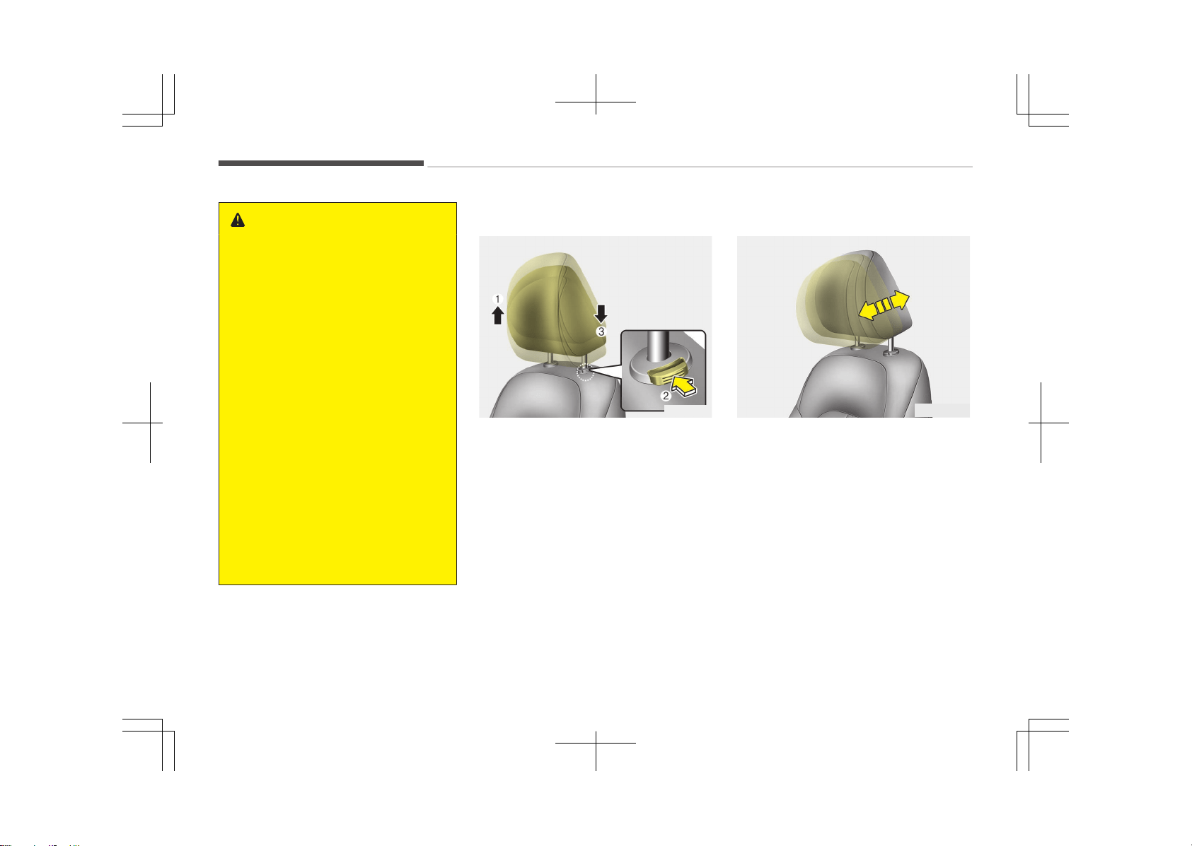
WARNING
• For maximum effectiveness in
case of an accident, the headrest
should be adjusted so the middle
of the headrest is at the same
height of the center of gravity of
an occupant's head. Generally, the
center of gravity of most people's
head is similar with the height of
the top of their eyes. Also, adjust
the headrest as close to your head
as possible. For this reason, the
use of a cushion that holds the
body away from the seatback is
not recommended.
• Do not operate the vehicle with
the headrests removed. Severe in‐
jury to the occupants may occur in
the event of an accident. Headr‐
ests may provide protection
against neck injuries when proper‐
ly adjusted.
• Do not adjust the headrest posi‐
tion of the driver’s seat while the
vehicle is in motion.
Adjusting the height up and down
OJF035013
To raise the headrest, pull it up to the
desired position (1). To lower the head‐
rest, push and hold the release button
(2) and lower the headrest to the de‐
sired position (3).
Forward and backward adjustment
OJF035076L
The headrest may be adjusted forward
to 4 different positions by pulling the
headrest forward to the desired de‐
tent.
To adjust the headrest to its furthest
backwards position,
Pull the headrest fully forward to the
farthest position and release it.
Adjust the headrest so that it properly
supports the head and neck.
Safety features of your vehicle
4-10
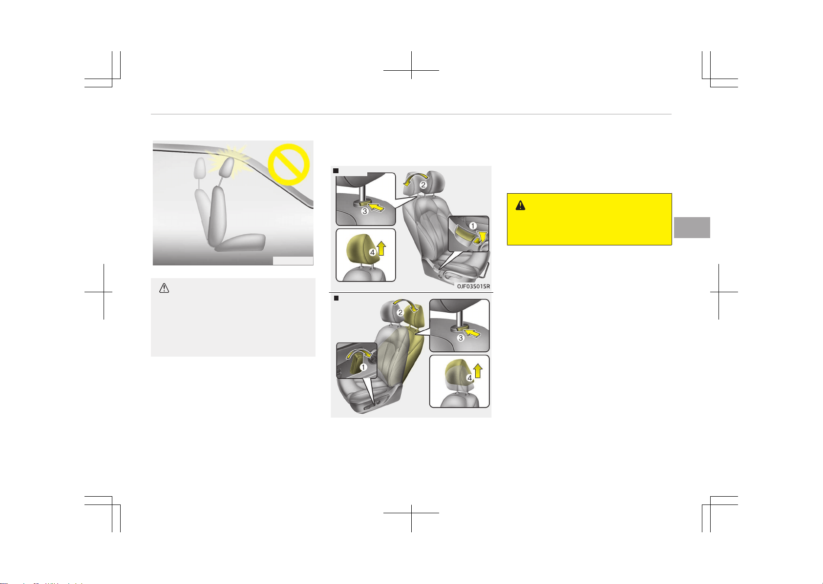
OYFH034205
CAUTION
If you recline the seatback towards
the front with the headrest and seat
cushion raised, the headrest may
come in contact with the sunvisor or
other parts of the vehicle.
Removal/Reinstall
Type A
Type B
OJF035016L
To remove the headrest:
1. Recline the seatback (2) with the
recline lever or switch (1).
2. Raise headrest as far as it can go.
3. Press the headrest release button
(3) while pulling the headrest up
(4).
WARNING
NEVER allow anyone to ride in a seat
with the headrest removed.
4-11
4
Safety features of your vehicle
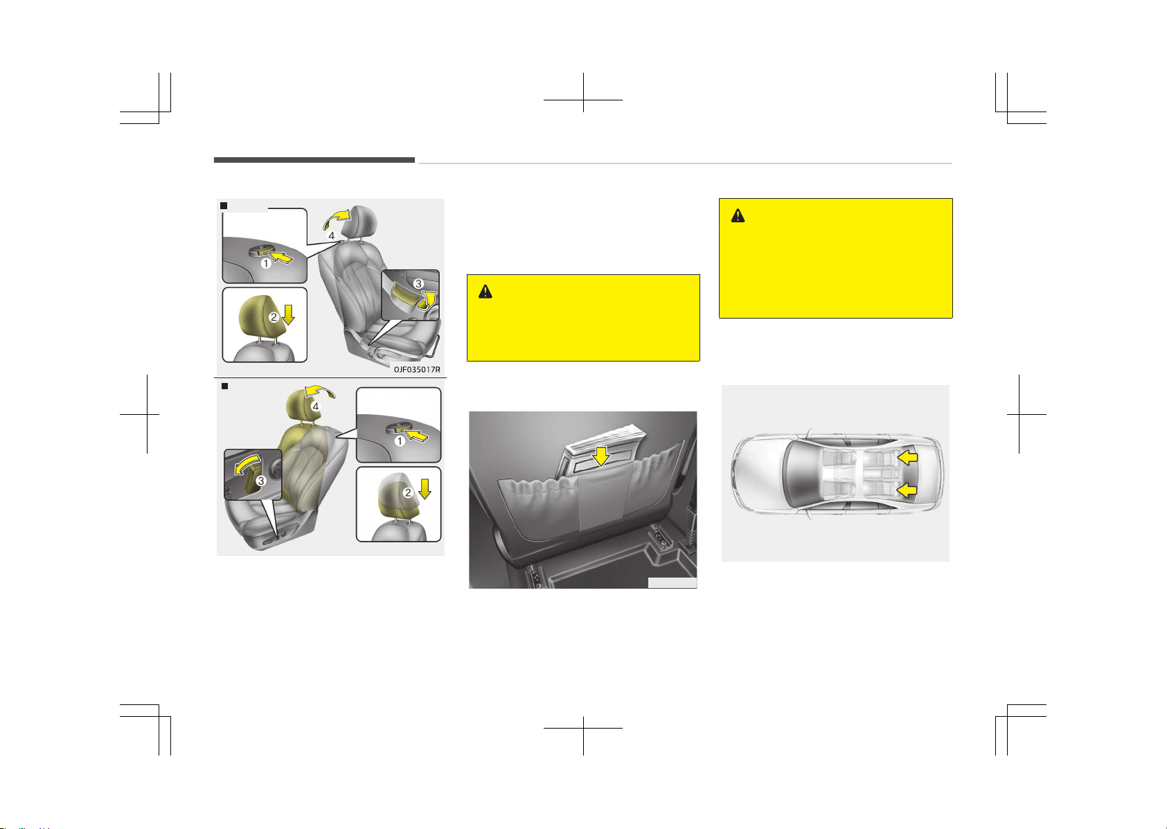
Type A
Type B
OJF035018L
To reinstall the headrest:
1. Put the headrest poles (2) into the
holes while pressing the release
button or switch (1).
2. Recline the seatback(4) with the
recline lever or switch (3).
3. Adjust the headrest to the appro‐
priate height.
WARNING
Always make sure the headrest
locks into position after reinstalling
and adjusting it properly.
Seatback pocket
OJF035020
The seatback pocket is provided on the
back of the front passenger’s and driv‐
er’s seatbacks.
WARNING
n
Seatback pockets
Do not put heavy or sharp objects in
the seatback pockets. In an accident
they could come loose from the
pocket and injure vehicle occupants.
Rear seat adjustment
Headrest (if equipped)
OMG038401
The rear seat is equipped with headr‐
ests for the occupant's safety and
comfort.
Safety features of your vehicle
4-12
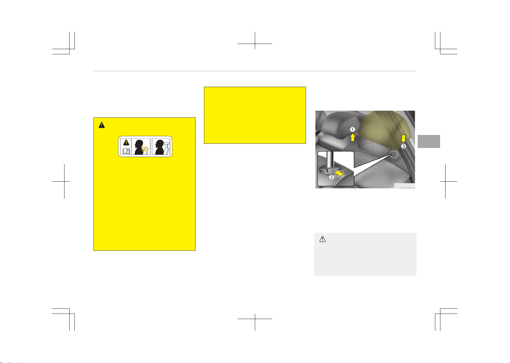
The headrest not only provides comfort
for passengers, but also helps to pro‐
tect the head and neck in the event of
a collision.
WARNING
• For maximum effectiveness in
case of an accident, the headrest
should be adjusted so the middle
of the headrest is at the same
height of the center of gravity of
an occupant's head. Generally, the
center of gravity of most people's
head is similar with the height of
the top of their eyes. Also adjust
the headrest as close to your head
as possible. For this reason, the
use of a cushion that holds the
body away from the seatback is
not recommended.
(Continued)
(Continued)
• Do not operate the vehicle with
the headrests removed. Severe in‐
jury to an occupant may occur in
the event of an accident. Headr‐
ests may provide protection
against severe neck injuries when
properly adjusted.
Adjusting the height up and down
(if equipped)
OJF035021
To raise the headrest, pull it up to the
desired position (1). To lower the head‐
rest, push and hold the release button
(2) on the headrest support and lower
the headrest to the desired position (3).
CAUTION
When there is no occupant in the
rear seats, adjust the height of the
headrest to the lowest position. The
(Continued)
4-13
4
Safety features of your vehicle
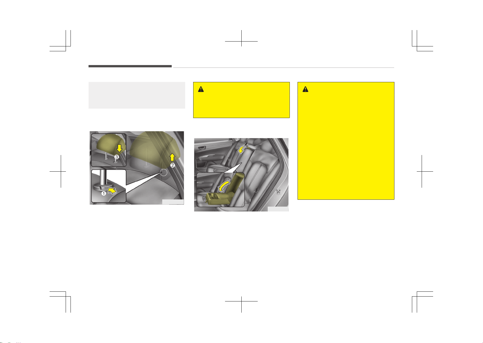
(Continued)
rear seat headrest can reduce the
visibility of the rear area.
Removal and installation (if equipped)
OJF035077L
To remove the headrest, raise it as far
as it can go then press the release but‐
ton (1) while pulling upward (2).
To reinstall the headrest, put the head‐
rest poles (3) into the holes while
pressing the release button (1). Then
adjust it to the appropriate height.
WARNING
Make sure the headrest locks in po‐
sition after adjusting it to properly
protect the occupants.
Armrest
OJF035026
To use the armrest, pull it forward
from the seatback.
Folding the rear seat (if equipped)
The rear seatbacks may be folded to
facilitate carrying long items or to in‐
crease the luggage capacity of the ve‐
hicle.
WARNING
The purpose of the fold-down rear
seatbacks is to allow you to carry
longer objects than could not other‐
wise be accommodated.
Never allow passengers to sit on top
of the folded down seatback while
the car is moving as this is not a
proper seating position and no seat
belts are available for use. This could
result in serious injury or death in
case of an accident or sudden stop.
Objects carried on the folded down
seatback should not extend higher
than the top of the front seats. This
could allow cargo to slide forward
and cause injury or damage during
sudden stops.
(Continued)
Safety features of your vehicle
4-14
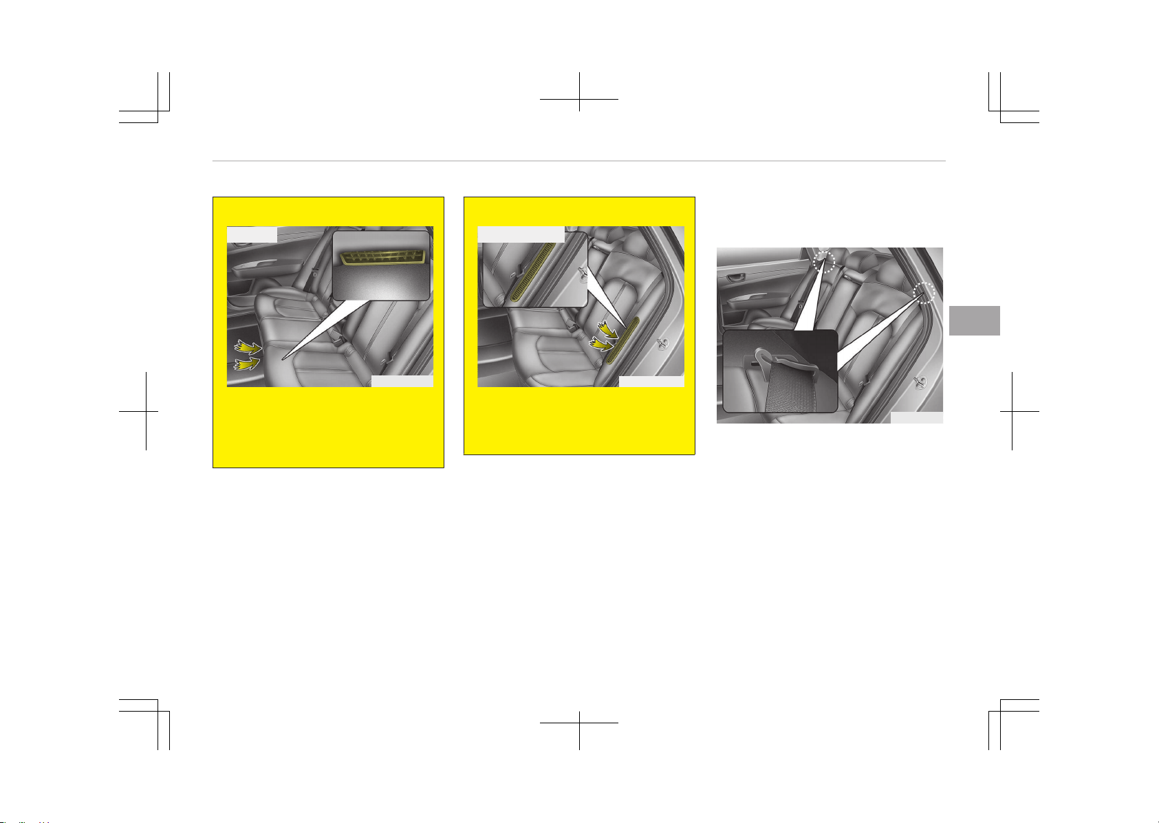
(Continued)
■ Hybrid
OJFHQ015005B
• Do not put objects in the center
lower part of rear seats. This could
block the battery cooling duct
causing battery degradation.
(Continued)
(Continued)
OJFHP036114LB
■ Plug-in hybrid
• Do not put objects on the left side
of rear seat. This could block the
battery cooling duct causing bat‐
tery degradation.
To fold down the rear seatback (for Hy‐
brid, if equipped):
OJF035081L
1. Make sure the rear seat belt web‐
bing is in the guide to prevent the
seat belt from being damaged.
2. Set the front seatback to the up‐
right position and if necessary, slide
the front seat forward.
3. Lower the rear headrests to the
lowest position.
4-15
4
Safety features of your vehicle
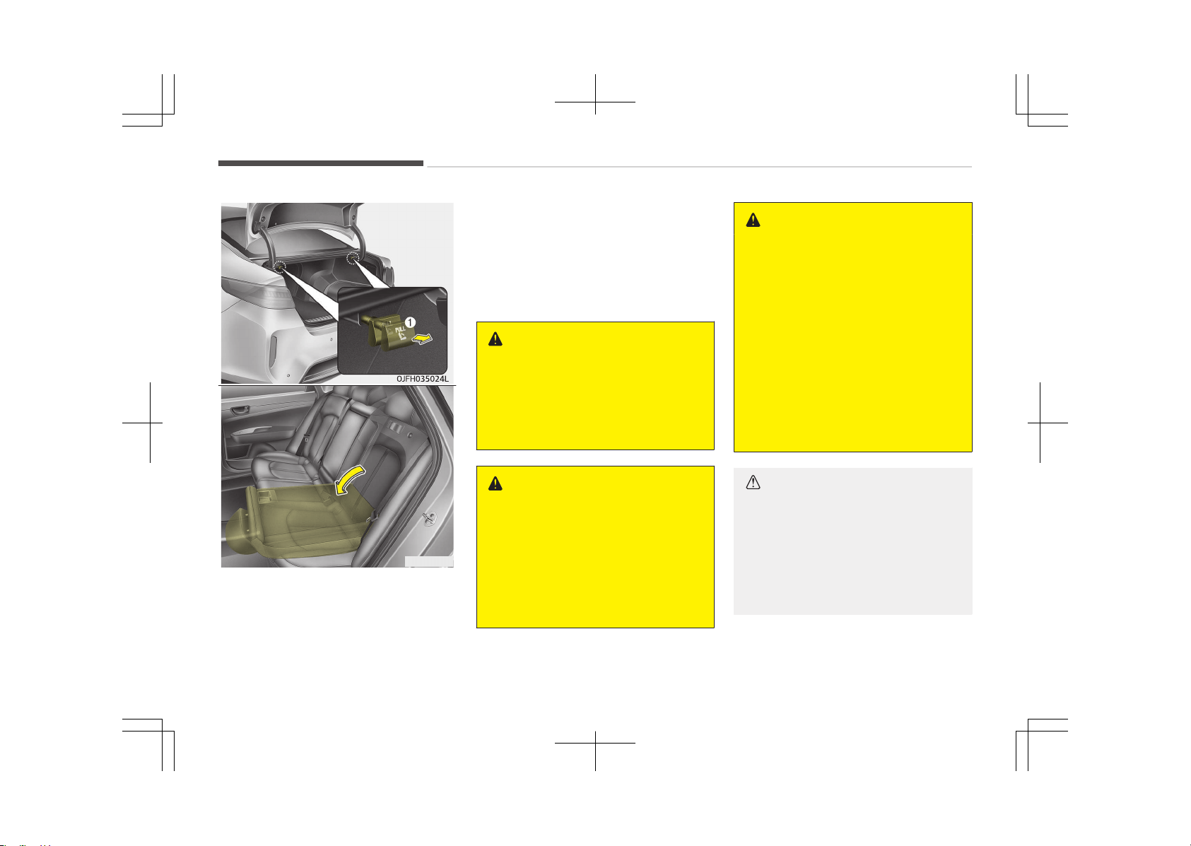
OJF035025
4. Pull out the seatback locking knob
(1) in the trunk, then fold the seat
toward the front of the vehicle.
5. To use the rear seat, lift and pull
the seatback backward. Pull the
seatback firmly until it clicks into
place. Make sure the seatback is
locked in place.
6. Return the rear seat belt to the
proper position.
WARNING
After folding the rear seat, unless
the driver’s position is properly set
according to the driver’s physical fig‐
ure, do not fold the rear seat. It may
increase body injuries in a sudden
stop or collision.
WARNING
n
Uprighting seat
When you return the seatback to its
upright position, hold the seatback
and return it slowly. If the seatback
is returned without holding it, the
back of the seat could spring for‐
ward resulting in injury caused by
being struck by the seatback.
WARNING
When you return the rear seatback
to its upright position after being
folded down:
Be careful not to damage the seat
belt webbing or buckle. Do not allow
the seat belt webbing or buckle to
get caught or pinched in the rear
seat. Ensure that the seatback is
completely locked into its upright
position by pushing on the top of the
seatback. Otherwise, in an accident
or sudden stop, the seat could fold
down and allow cargo enter the pas‐
senger compartment, which could
result in serious injury or death.
CAUTION
n
Damaging rear seat belt buck‐
les
When you fold the rear seatback, in‐
sert the buckle between the rear
seatback and cushion. Doing so can
prevent the buckle from being dam‐
aged by the rear seatback.
Safety features of your vehicle
4-16
CAUTION
n
Rear seat belts
When returning the rear seatbacks
to the upright position, remember to
return the rear shoulder belts to
their proper position.
WARNING
n
Cargo
Cargo should always be secured to
prevent it from being thrown about
the vehicle in a collision and causing
injury to the vehicle occupants. Do
not place objects in the rear seats,
since they cannot be properly se‐
cured and may hit the front seat oc‐
cupants in a collision.
WARNING
n
Cargo loading
Make sure the engine is off, the au‐
tomatic transaxle is in P (Park) and
(Continued)
(Continued)
the parking brake is securely applied
whenever loading or unloading cargo.
Failure to take these steps may al‐
low the vehicle to move if the shift
lever is inadvertently moved to an‐
other position.
4-17
4
Safety features of your vehicle
SEAT BELTS
Seat belt restraint system
WARNING
• For maximum restraint system
protection, the seat belts must al‐
ways be used whenever the vehi‐
cle is moving.
• Seat belts are most effective when
seatbacks are in the upright posi‐
tion.
• Children age 12 and under must al‐
ways be properly restrained in the
rear seat. Never allow children to
ride in the front passenger seat. If
a child over 12 must be seated in
the front seat, he/she must be
properly belted and the seat
should be moved as far back as
possible.
• Never wear the shoulder belt un‐
der your arm or behind your back.
An improperly positioned shoulder
belt can cause serious injuries in a
crash.
The shoulder belt should be posi‐
tioned midway over your shoulder
across your collarbone.
(Continued)
(Continued)
• Never wear a seat belt over fragile
objects. If there is a sudden stop
or impact, the seat belt can dam‐
age it.
• Avoid wearing twisted seat belts.
A twisted belt can't do its job well.
In a collision, it could even cut into
you. Be sure the belt webbing is
straight and not twisted.
• Be careful not to damage the belt
webbing or hardware. If the belt
webbing or hardware is damaged,
replace it.
WARNING
Seat belts are designed to bear upon
the bony structure of the body, and
should be worn low across the front
of the pelvis or the pelvis, chest and
shoulders, as applicable; wearing the
lap section of the belt across the ab‐
dominal area must be avoided.
Seat belts should be adjusted as
firmly as possible, consistent with
comfort, to provide the protection
for which they have been designed.
(Continued)
(Continued)
A slack belt will greatly reduce the
protection afforded to the wearer.
Care should be taken to avoid con‐
tamination of the webbing with pol‐
ishes, oils and chemicals, and partic‐
ularly battery acid. Cleaning may
safely be carried out using mild soap
and water. The belt should be re‐
placed if webbing becomes frayed,
contaminated or damaged. It is es‐
sential to replace the entire assem‐
bly after it has been worn in a se‐
vere impact even if damage to the
assembly is not obvious. Belts should
not be worn with straps twisted.
Each belt assembly must only be
used by one occupant; it is danger‐
ous to put a belt around a child being
carried on the occupant's lap.
Safety features of your vehicle
4-18
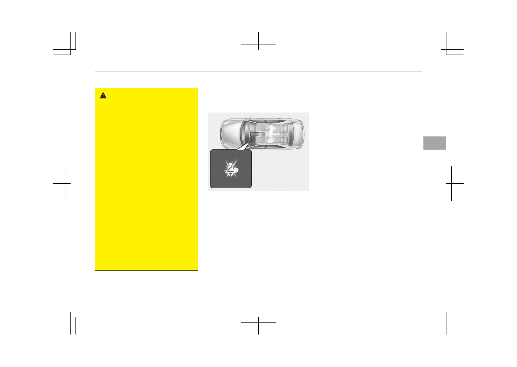
WARNING
• No modifications or additions
should be made by the user which
will either prevent the seat belt
adjusting devices from operating
to remove slack, or prevent the
seat belt assembly from being ad‐
justed to remove slack.
• When you fasten the seat belt, be
careful not to latch the seat belt in
buckles of other seat. It's very
dangerous and you may not be
protected by the seat belt proper‐
ly.
• Do not unfasten the seat belt and
do not fasten and unfasten the
seat belt repeatedly while driving.
This could result in loss of control,
and an accident causing death, se‐
rious injury, or property damage.
• When fastening the seat belt,
make sure that the seat belt does
not pass over objects that are hard
or can break easily.
• Make sure there is nothing in the
buckle. The seat belt may not be
fastened securely.
Seat belt warning
Driver's seat belt warning
OJF035091L
As a reminder to the driver, the seat
belt warning light will illuminate and
warning chime will sound for approxi‐
mately 6 seconds each time you turn
the Engine Start/Stop button ON if the
seat belt is unfastened.
If you continue not to fasten the seat
belt and you drive over 9 km/h, the
warning light will stay illuminated until
you drive under 6 km/h. (if equipped)
If you continue not to fasten the seat
belt and you drive over 20 km/h the
seat belt warning chime will sound for
approximately 100 seconds and the
corresponding warning light will blink.
(if equipped)
If you unfasten the seat belt while driv‐
ing under 20 km/h, the seat belt warn‐
ing light will illuminate until the seat
belt is fastened.
If you unfasten the seat belt while driv‐
ing over 20 km/h, the seat belt warning
chime will sound for approximately 100
seconds and the corresponding warning
light will blink.
4-19
4
Safety features of your vehicle
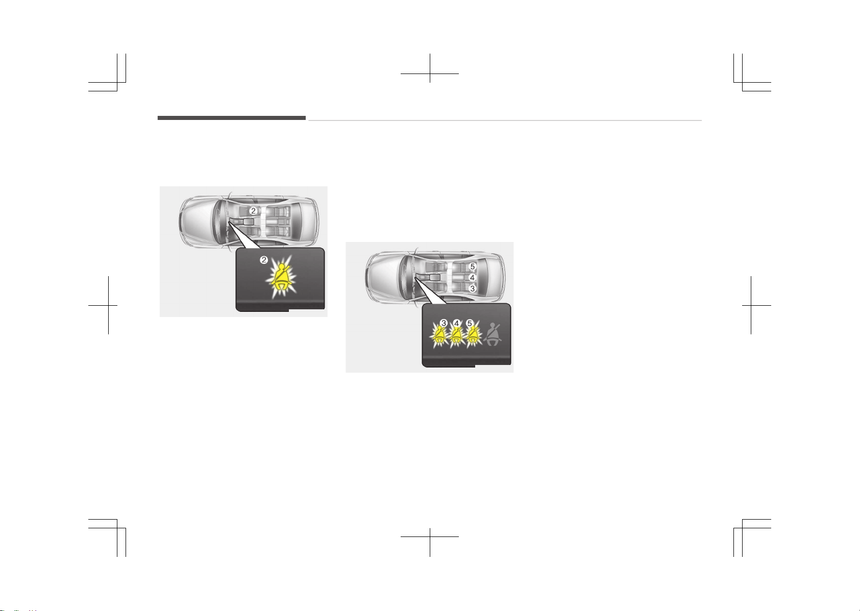
Front passenger's seat belt warning (if
equipped)
OJF035092L
As a reminder to the front passenger,
the front passenger’s seat belt warning
lights will illuminate for approximately
6 seconds each time you turn the En‐
gine Start/Stop button ON regardless
of belt fastening.
If you continue not to fasten the seat
belt and you drive over 9 km/h, the
warning light the warning light will stay
illuminated.
If you unfasten the seat belt while driv‐
ing in case of under 20 km/h the seat
belt warning light will illuminate until
the seat belt is fastened.
If you unfasten the seat belt while driv‐
ing over 20 km/h, the seat belt warning
chime will sound for approximately 100
seconds and the corresponding warning
light will blink.
Rear passenger's seat belt warning (if
equipped)
OJF035093L
When the IGN is in ON, or the engine is
running, the seat belt warning light will
illuminate for approximately 6 seconds.
The light will illuminate regardless of
whether the seat belt is worn or not.
And then, the rear corresponding seat
belt warning light will illuminate for ap‐
proximately 35 seconds, if you drive
over 9 km/h when the rear belt is not
fastened.
This warning operates only once from
start to off the vehicle.
However, the seat belt warning light
will illuminate again for approximately
35 seconds, if you drive under 9 km/h
for about 29 minutes more.
If you unfasten the seat belt while driv‐
ing under 20 km/h the seat belt warn‐
ing light will illuminate for approxi‐
mately 35 seconds.
If you unfasten the seat belt while driv‐
ing over 20 km/h, the seat belt warning
chime will sound for approximately 35
seconds and the corresponding warning
light will blink.
Safety features of your vehicle
4-20
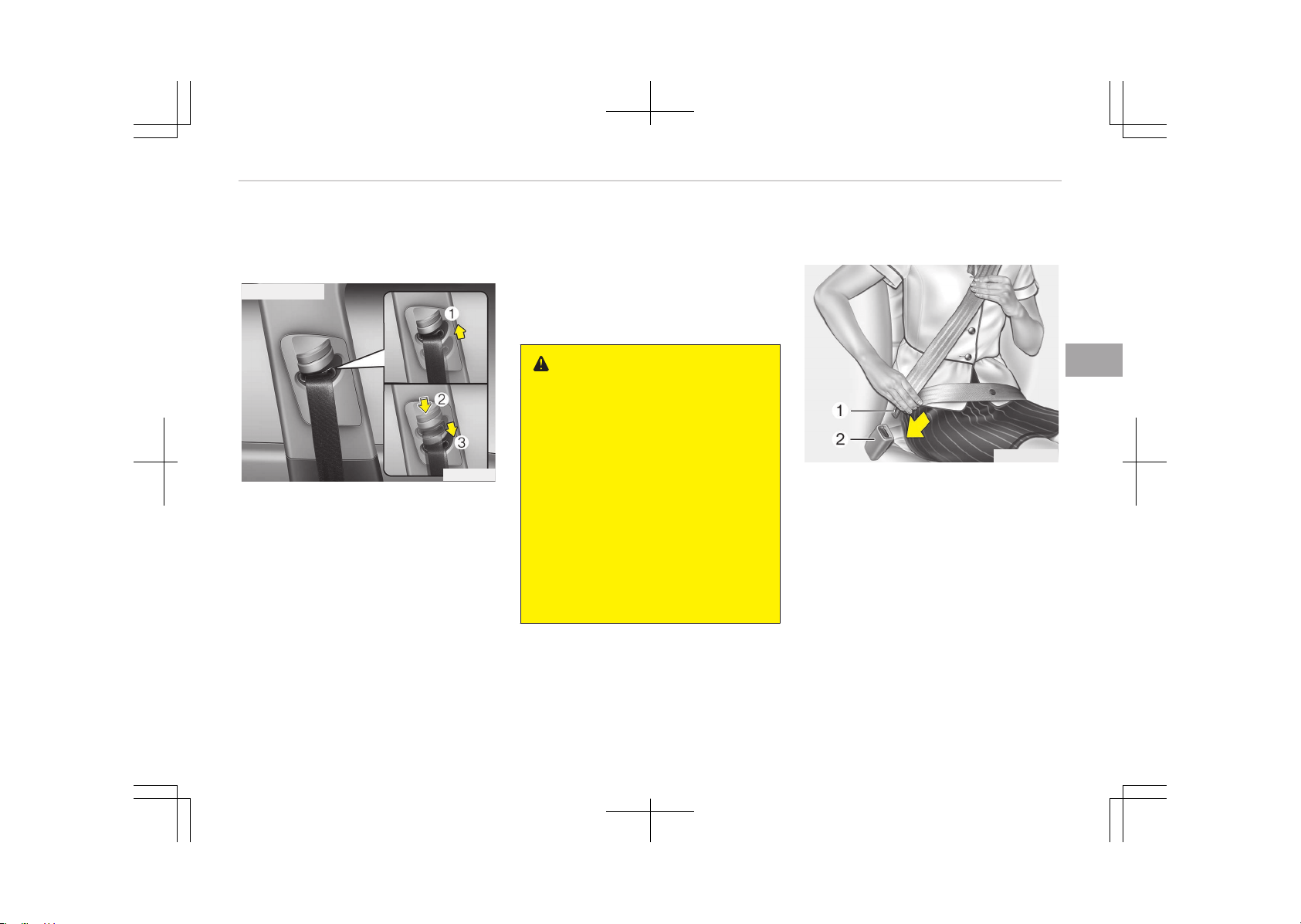
Lap/shoulder belt
Height adjustment
■ Front seat
OJF035031
You can adjust the height of the shoul‐
der belt anchor to one of 4 positions for
maximum comfort and safety.
The height of the adjusting seat belt
should not be too close to your neck.
You will not be getting the most effec‐
tive protection. The shoulder portion
should be adjusted so that it lies across
your chest and midway over your
shoulder near the door and not your
neck.
To adjust the height of the seat belt
anchor, lower or raise the height ad‐
juster into an appropriate position.
To raise the height adjuster, pull it up
(1). To lower it, push it down (3) while
pressing the height adjuster button (2).
Release the button to lock the anchor
into position. Try sliding the height ad‐
juster to make sure that it has locked
into position.
WARNING
• Verify the shoulder belt anchor is
locked into position at the appro‐
priate height. Never position the
shoulder belt across your neck or
face. Improperly positioned seat
belts can cause serious injuries in
an accident.
• Failure to replace seat belts after
an accident could leave you with
damaged seat belts that will not
provide protection in the event of
another collision leading to person‐
al injury or death. Replace your
seat belts after being in an acci‐
dent as soon as possible.
To fasten your seat belt:
B180A01NF-1
To fasten your seat belt, pull it out of
the retractor and insert the metal tab
(1) into the buckle (2). There will be an
audible "click" when the tab locks into
the buckle.
The seat belt automatically adjusts to
the proper length only after the lap
belt portion is adjusted manually so
that it fits snugly around your hips. If
you lean forward in a slow, easy mo‐
tion, the belt will extend and let you
move around. If there is a sudden stop
or impact, however, the belt will lock in‐
to position. It will also lock if you try to
lean forward too quickly.
4-21
4
Safety features of your vehicle
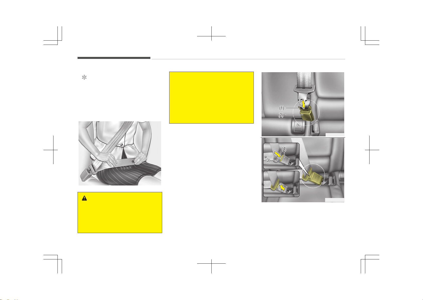
NOTICE
If you are not able to pull out the
seat belt from the retractor, firmly
pull the belt out and release it. Then
you will be able to pull the belt out
smoothly.
B200A01NF
WARNING
You should place the lap belt portion
as low as possible and snugly across
your hips, not on your waist. If the
lap belt is located too high on your
(Continued)
(Continued)
waist, it may increase the chance of
injury in the event of a collision. Both
arms should not be under or over
the belt. Rather, one should be over
and the other under, as shown in the
illustration.
Never wear the seat belt under the
arm near the door.
OJF035096L
OJF035094L
Pull the metal tab (3) and insert it (3)
into the buckle (4). There will be an au‐
dible click when the tab locks into the
buckle. Make sure the belt is not twis‐
ted.
Safety features of your vehicle
4-22
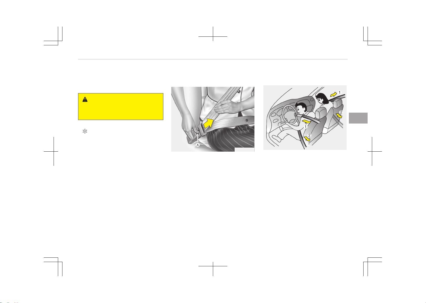
When using the rear center seat belt
the buckle with the CENTER mark
must be used.
WARNING
Always have the metal tab (1) inser‐
ted into the buckle (2).
NOTICE
If you are not able to pull out the
safety belt from the retractor, firm‐
ly pull the belt out and release it. Af‐
ter release, you will be able to pull
the belt out smoothly.
To release the seat belt:
OUM036100L
The seat belt is released by pressing
the release button (A) in the locking
buckle. When it is released, the belt
should automatically draw back into
the retractor.
If this does not happen, check the belt
to be sure it is not twisted, then try
again.
Pre-tensioner seat belt
ODMESA2023
Your vehicle is equipped with driver’s
and front passenger’s pre-tensioner
seat belts (retractor pretensioner).
The pre-tensioner seat belts can be ac‐
tivated, where the frontal collision is
severe enough, together with the air
bags.
When the vehicle stops suddenly, or if
the occupant tries to lean forward too
quickly, the seat belt retractor will lock
into position. In certain frontal colli‐
sions, the pre-tensioner will activate
and pull the seat belt into tighter con‐
tact against the occupant's body.
4-23
4
Safety features of your vehicle
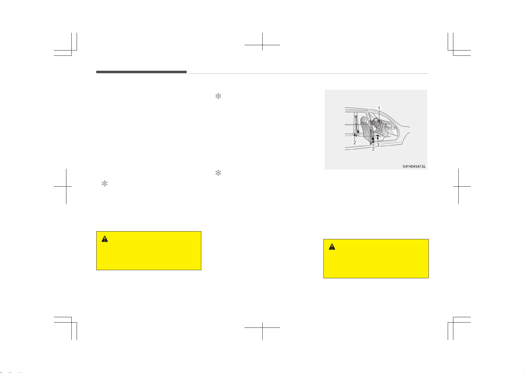
-
Retractor Pretensioner
The purpose of the retractor preten‐
sioner is to make sure that the shoul‐
der belts fit in tightly against the oc‐
cupant's upper body in certain frontal
collisions.
If the system senses excessive tension
on the driver seat belt when the pre-
tensioner system activates, the load
limiter inside the retractor pretensioner
will release some of the pressure on
the affected seat belt. (if equipped)
NOTICE
The pre-tensioner will activate not
only in a frontal collision but also in a
side collision, if the vehicle is equip‐
ped with a side or curtain air bag.
WARNING
For your safety, be sure that the
belt webbing is not loose or twisted
and always sit properly on your seat.
NOTICE
n
if equipped with rollover sen‐
sor
The pre-tensioner will activate not
only in a frontal collision but also in a
side collision or rollover, if the vehicle
is equipped with a side or curtain air
bag.
NOTICE
n
without rollover sensor
The pre-tensioner will activate not
only in a frontal collision but also in a
side collision, if the vehicle is equip‐
ped with a side or curtain air bag.
The seat belt pre-tensioner system
consists mainly of the following compo‐
nents. Their locations are shown in the
illustration:
1. SRS air bag warning light
2. Front retractor pre-tensioner as‐
sembly
3. SRS control module
WARNING
To obtain maximum benefit from a
pre-tensioner seat belt:
(Continued)
Safety features of your vehicle
4-24
(Continued)
1. The seatbelt must be worn cor‐
rectly and adjusted to the proper
position. Please read and follow
all of the important information
and precautions about your vehi‐
cle’s occupant safety features –
including seat belts and air bags
– that are provided in this man‐
ual.
2. Be sure you and your passen‐
gers always wear seat belts
properly.
NOTICE
• Pre-tensioner seat belts will be
activated in certain frontal colli‐
sions. The pre-tensioner seat
belts can be activated, where the
frontal collision is severe enough,
together with the air bags.
(Continued)
(Continued)
• When the pre-tensioner seat belts
are activated, a loud noise may be
heard and fine dust, which may
appear to be smoke, may be visi‐
ble in the passenger compart‐
ment. These are normal operating
conditions and are not hazardous.
• Although it is harmless, the fine
dust may cause skin irritation and
should not be breathed for pro‐
longed periods. Wash all exposed
skin areas thoroughly after an ac‐
cident in which the pre-tensioner
seat belts were activated.
• Because the sensor that activates
the SRS air bag is connected with
the pre-tensioner seat belt, the
SRS air bag warning light on the
instrument panel will illuminate for
approximately 6 seconds after the
Engine Start/Stop button has been
turned to the "ON" position, and
then it should turn off.
CAUTION
If the pre-tensioner seat belt is not
working properly, the SRS air bag
warning light will illuminate even if
there is no malfunction of the SRS
air bag. If the SRS air bag warning
light does not illuminate when the
Engine Start/Stop button is turned
to ON, or if it remains illuminated af‐
ter illuminating for approximately 6
seconds, or if it illuminates while the
vehicle is being driven, we recom‐
mend that the system be inspected
by an authorized Kia dealer.
WARNING
• Pre-tensioners are designed to op‐
erate only one time. After activa‐
tion, pre-tensioner seat belts
must be replaced. All seat belts, of
any type, should always be re‐
placed after they have been worn
during a collision.
(Continued)
4-25
4
Safety features of your vehicle
(Continued)
• The pre-tensioner seat belt as‐
sembly mechanisms become hot
during activation. Do not touch the
pre-tensioner seat belt assemblies
for several minutes after they
have been activated.
• Do not attempt to inspect or re‐
place the pre-tensioner seat belts
yourself. We recommend that the
system be inspected by an author‐
ized Kia dealer.
• Do not strike the pre-tensioner
seat belt assemblies.
• Do not attempt to service or repair
the pre-tensioner seat belt sys‐
tem in any manner.
• Improper handling of the preten‐
sioner seat belt assemblies, and
failure to heed the warnings not to
strike, modify, inspect, replace,
service or repair the pre-tensioner
seat belt assemblies may lead to
improper operation or inadvertent
activation and serious injury.
• Always wear the seat belts when
driving or riding in a motor vehicle.
(Continued)
(Continued)
• If the vehicle or pre-tensioner seat
belt must be discarded, we recom‐
mend that you contact an author‐
ized Kia dealer.
CAUTION
Body work on the front area of the
vehicle may damage the pretension‐
er seat belt system. Therefore, we
recommend that the system be
serviced by an authorized Kia dealer.
Seat belt precautions
WARNING
All occupants of the vehicle must
wear their seat belts at all times.
Seat belts and child restraints re‐
duce the risk of serious or fatal inju‐
ries for all occupants in the event of
a collision or sudden stop. Without a
seat belt, occupants could be shifted
too close to a deploying air bag,
strike the interior structure or be
(Continued)
(Continued)
thrown from the vehicle. Properly
worn seat belts greatly reduce these
hazards.
Always follow the precautions about
seat belts, air bags and occupant
seating contained in this manual.
Infant or small child
You should be aware of the specific re‐
quirements in your country. Child
and/or infant seats must be properly
placed and installed in the rear seat.
For more information about the use of
these restraints, refer toChild restraint
system on page 4-30.
WARNING
Every person in your vehicle needs
to be properly restrained at all
times, including infants and children.
Never hold a child in your arms or lap
when riding in a vehicle. The violent
forces created during a crash will
tear the child from your arms and
throw the child against the interior.
Always use a child restraint appro‐
(Continued)
Safety features of your vehicle
4-26
(Continued)
priate for your child's height and
weight.
NOTICE
Small children are best protected
from injury in an accident when
properly restrained in the rear seat
by a child restraint system that
meets the requirements of the
Safety Standards of your country.
Before buying any child restraint
system, make sure that it has a la‐
bel certifying that it meets Safety
Standards of your country. The re‐
straint must be appropriate for your
child's height and weight. Check the
label on the child restraint for this
information. Refer to Child restraint
system on page 4-30.
Larger children
Children who are too large for child re‐
straint systems should always occupy
the rear seat and use the available lap/
shoulder belts. The lap portion should
be fastened and snugged on the hips
and as low as possible. Check if the belt
fits periodically. A child's squirming
could put the belt out of position. Chil‐
dren are given the most safety in the
event of an accident when they are re‐
strained by a proper restraint system
in the rear seat. If a larger child (over
age 12) must be seated in the front
seat, the child should be securely re‐
strained by the available lap/shoulder
belt and the seat should be placed in
the rearmost position.
Children age 12 and under should be re‐
strained securely in the rear seat. NEV‐
ER place a child age 12 and under in the
front seat. NEVER place a rear facing
child seat in the front seat of a vehicle.
If the shoulder belt portion slightly
touches the child’s neck or face, try
placing the child closer to the center of
the vehicle. If the shoulder belt still
touches their face or neck they need to
be returned to a child restraint system.
WARNING
n
Shoulder belts on small chil‐
dren
• Never allow a shoulder belt to be in
contact with a child’s neck or face
while the vehicle is in motion.
• If seat belts are not properly worn
and adjusted on children, there is a
risk of death or serious injury.
Pregnant women
The use of a seat belt is recommended
for pregnant women to lessen the
chance of injury in an accident. When a
seat belt is used, the lap belt portion
should be placed as low and securely as
possible on the hips, not across the ab‐
domen. For specific recommendations,
consult a physician.
WARNING
n
Pregnant women
Pregnant women must never place
the lap portion of the safety belt
over the area of the abdomen where
the fetus is located or above the ab‐
(Continued)
4-27
4
Safety features of your vehicle
(Continued)
domen where the belt could crush
the fetus during an impact.
Injured person
A seat belt should be used when an in‐
jured person is being transported.
When this is necessary, you should con‐
sult a physician for recommendations.
One person per belt
Two people (including children) should
never attempt to use a single seat belt.
This could increase the severity of inju‐
ries in case of an accident.
Do not lie down
To reduce the chance of injuries in the
event of an accident and to achieve
maximum effectiveness of the re‐
straint system, all passengers should
be sitting up and the front and rear
seats should be in an upright position
when the vehicle is moving. A seat belt
cannot provide proper protection if the
person is lying down in the rear seat or
if the front and rear seats are in a re‐
clined position.
WARNING
Riding with a reclined seatback in‐
creases your chance of serious or fa‐
tal injuries in the event of a collision
or sudden stop. The protection of
your restraint system (seat belts
and air bags) is greatly reduced by
reclining your seat. Seat belts must
be secured against your hips and
chest to work properly. The more
the seatback is reclined, the greater
the chance an occupant's hips will
slide under the lap belt causing seri‐
ous internal injuries. Also, the shoul‐
der belt may strike the occupant's
neck. Drivers and passengers should
always sit well back in their seats,
properly belted, and with the seat‐
backs upright.
Care of seat belts
Seat belt systems should never be dis‐
assembled or modified. In addition, care
should be taken to assure that seat
belts and belt hardware are not dam‐
aged by seat hinges, doors or other
abuse.
WARNING
When you return the rear seatback
to its upright position after the rear
seatback has been folded down, be
careful not to damage the seat belt
webbing or buckle. Be sure that the
webbing or buckle does not get
caught or pinched in the rear seat. A
seat belt with damaged webbing or
buckle could possibly fail during a
collision or sudden stop, resulting in
serious injury. If the webbing or
buckles are damaged, get them re‐
placed immediately.
Periodic inspection
All seat belts should be inspected peri‐
odically for wear or damage of any
kind. Any damaged parts should be re‐
placed as soon as possible.
Keep belts clean and dry
Seat belts should be kept clean and dry.
If belts become dirty, they can be
cleaned by using a mild soap solution
and warm water. Bleach, dye, strong
detergents or abrasives should not be
used because they may damage and
weaken the fabric.
Safety features of your vehicle
4-28

When to replace seat belts
Entire in-use seat belt assembly or as‐
semblies should be replaced if the vehi‐
cle has been involved in an accident.
This should be done even if no damage
is visible. We recommend that you con‐
sult an authorized Kia dealer.
4-29
4
Safety features of your vehicle
CHILD RESTRAINT SYSTEM (CRS)
Our recommendation: Children
always in the rear
WARNING
Always properly restrain children in
the vehicle. Children of all ages are
safer when riding in the rear seats.
Never place a rearward-facing Child
Restraint System on the front pas‐
senger seat, unless the air bag is de‐
activated.
Children under age 13 should always
ride in the rear seats and must always
be properly restrained to minimize the
risk of injury in an accident, sudden
stop or sudden maneuver.
According to accident statistics, chil‐
dren are safer when properly restrain‐
ed in the rear seats than in the front
seat. Children too large for a Child Re‐
straint System must use the seat belts
provided.
Most countries have regulations which
require children to travel in approved
Child Restraint Systems.
The laws governing the age or height/
weight restrictions at which seat belts
can be used instead of Child Restraint
System differ among countries, so you
should be aware of the specific require‐
ments in your country, and where you
are travelling.
Child Restraint Systems must be prop‐
erly installed in the vehicle seat. Always
use a commercially available Child Re‐
straint System that meets the require‐
ments of your country.
Child Restraint System (CRS)
Infants and younger children must be
restrained in an appropriate rearward
facing or forward-facing CRS that has
first been properly secured to the seat
of the vehicle. Read and comply with
the instructions for installation and use
provided by the manufacturer of the
Child Restraint System.
WARNING
• Always follow the Child Restraint
System manufacturer’s instruc‐
tions for installation and use.
(Continued)
(Continued)
• Always properly restrain your child
in the Child Restraint System.
• Do not use an infant carrier or a
child safety seat that hooks over
a seatback, it may not provide ad‐
equate protection in an accident.
• After an accident, we recommend
a Kia dealer to check the Child Re‐
straint System, seat belts, ISOFIX
anchorages and top-tether ancho‐
rages.
Selecting a Child Restraint
System (CRS)
When selecting a Child Restraint Sys‐
tem for your child, always:
• Make sure the Child Restraint System
has a label certifying that it meets
applicable Safety Standards of your
country.
A Child Restraint System may only be
installed if it was approved in accord‐
ance with the requirements of ECE-
R44 or ECE-R129.
• Select a Child Restraint System based
on your child’s height and weight. The
required label or the instructions for
use typically provide this information.
Safety features of your vehicle
4-30
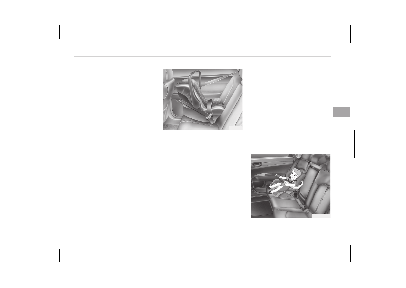
• Select a Child Restraint System that
fits the vehicle seating position where
it will be used.
For the suitability of Child Restraint
Systems on the vehicle's seating po‐
sitions, please refer to the installa‐
tion tables on pages 4-36 and
4-39 to 4-41.
• Read and comply with the warnings
and instructions for installation and
use provided with the Child Restraint
System.
Child Restraint System types
There are three main types of Child Re‐
straint Systems: rearward-facing, for‐
ward-facing and booster Child Re‐
straint Systems.
They are classified according to the
child’s age, height and weight.
CRS09B
Rearward-facing Child Restraint Sys‐
tem
A rearward-facing Child Restraint Sys‐
tem provides restraint with the seating
surface against the back of the child.
The harness system holds the child in
place, and in an accident, acts to keep
the child positioned in the Child Re‐
straint Systems and reduce the stress
to the fragile neck and spinal cord.
All children under the age of one year
must always ride in a rearward facing
Child Restraint System. There are dif‐
ferent types of rearward-facing Child
Restraint Systems: infant-only Child
Restraint Systems can only be used
rearward-facing. Convertible and 3-
in-1 Child Restraint Systems typically
have higher height and weight limits for
the rearward-facing position, allowing
you to keep your child rearward-facing
for a longer period of time.
Keep using Child Restraint Systems in
the rearward-facing position as long as
children fit within the height and
weight limits allowed by the Child Re‐
straint System's manufacturer.
OJF035032B
4-31
4
Safety features of your vehicle
Forward-facing Child Restraint System
A forward-facing Child Restraint Sys‐
tem provides restraint for the child’s
body with a harness. Keep children in a
forward-facing Child Restraint System
with a harness until they reach the top
height or weight limit allowed by your
Child Restraint System’s manufacturer.
Once your child outgrows the forward-
facing Child Restraint System, your
child is ready for a booster seat.
Booster seats
A booster seat is a Child Restraint Sys‐
tem designed to improve the fit of the
vehicle’s seat belt system. A booster
seat positions the seat belt so that it
fits properly over the stronger parts of
your child’s body. Keep your children in
booster seats until they are big enough
to fit in a seat belt properly.
For a seat belt to fit properly, the lap
belt must lie comfortable across the
upper thighs, not the stomach. The
shoulder belt should lie comfortable
across the shoulder and chest and not
across the neck or face. Children under
age 13 must always be properly re‐
strained to minimize the risk of injury
in an accident, sudden stop or sudden
maneuver.
Installing a Child Restraint
System (CRS)
WARNING
Before installing your Child Restraint
System always:
Read and follow the instructions
provided by the manufacturer of the
Child Restraint System.
Failure to follow all warnings and in‐
structions could increase the risk of
the SERIOUS INJURY or DEATH if an
accident occurs.
WARNING
If the vehicle headrest prevents
proper installation of a Child Re‐
straint System, the headrest of the
respective seating position shall be
readjusted or entirely removed.
After selecting a proper Child Restraint
System for your child and checking that
the Child Restraint System fits properly
on the seating position, there are three
general steps for a proper installation:
•
Properly secure the Child Restraint
System to the vehicle. All Child Re‐
straint Systems must be secured to
the vehicle with the lap belt or lap
part of a lap/shoulder belt or with the
ISOFIX toptether and/or ISOFIX an‐
chorage and/or with the support leg.
• Make sure the Child Restraint System
is firmly secured. After installing a
Child Restraint System to the vehicle,
push and pull the seat forward and
from side-to-side to verify that it is
securely attached to the seat. A Child
Restraint System secured with a seat
belt should be installed as firmly as
possible. However, some side-to-side
movement can be expected. When in‐
stalling a Child Restraint System, ad‐
just the vehicle seat and seatback (up
and down, forward and rearward) so
that your child fits in the Child Re‐
straint System in a confortable man‐
ner.
•
Secure the child in the Child Restraint
System. Make sure the child is prop‐
erly strapped in the Child Restraint
System according to the Child Re‐
straint System manufacturer’s in‐
structions.
Safety features of your vehicle
4-32
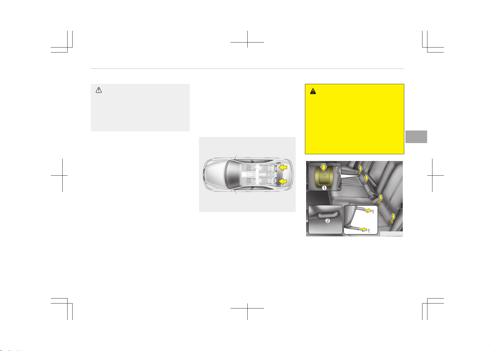
CAUTION
A Child Restraint System in a closed
vehicle can become very hot. To pre‐
vent burns, check the seating sur‐
face and buckles before placing your
child in the Child Restraint System.
ISOFIX anchorage and top-
tether anchorage (ISOFIX
anchorage system) for children
The ISOFIX system holds a Child Re‐
straint System during driving and in an
accident. This system is designed to
make installation of the Child Restraint
System easier and reduce the possibili‐
ty of improperly installing your Child
Restraint System. The ISOFIX system
uses anchors in the vehicle and attach‐
ments on the Child Restraint System.
The ISOFIX system eliminates the need
to use seat belts to secure the Child
Restraint System to the rear seats.
ISOFIX anchorages are metal bars built
into the vehicle. There are two lower
anchors for each ISOFIX seating posi‐
tion that will accommodate a Child Re‐
straint System with lower attach‐
ments.
To use the ISOFIX system in your vehi‐
cle, you must have a Child Restraint
System with ISOFIX attachments.
The Child Restraint System manufac‐
turer will provide you with instructions
on how to use the Child Restraint Sys‐
tem with its attachments for the ISO‐
FIX anchorages.
B230D01NF
ISOFIX anchorages have been provided
in the left and right outboard rear seat‐
ing positions. Their locations are shown
in the illustration.
WARNING
Do not attempt to install a Child Re‐
straint System using ISOFIX ancho‐
rages in the rear center seating po‐
sition. There are no ISOFIX anchorag‐
es provided for this seat. Using the
outboard seat anchorages, for the
CRS installation on the rear center
seating position, can damage the an‐
chorages.
OJF035035L
ISOFIX anchorages are located between
the seatback and the seat cushion of
the rear seat left and right outboard
seating positions, indicated by the
symbols.
4-33
4
Safety features of your vehicle
To use the ISOFIX anchorages, push the
upper portion of the ISOFIX anchorage
cover.
1. ISOFIX Anchor Position Indicator
( )
2. ISOFIX Anchor
Securing a Child Restraint System
with the ISOFIX Anchorage
System
To install an ISOFIX-compatible Child
Restraint System in either of the rear
outboard seating positions:
1. Move the seat belt buckle away
from the ISOFIX anchorages.
2. Move any other objects away from
the anchorages that could prevent
a secure connection between the
Child Restraint System and the ISO‐
FIX anchorages.
3. Place the Child Restraint System on
the vehicle seat, then attach the
seat to the ISOFIX anchorages ac‐
cording to the instructions provided
by the Child Restraint System man‐
ufacturer.
4. Follow the instructions of the Child
Restraint System's manufacturer
for proper installation and connec‐
tion of the ISOFIX attachments on
the Child Restraint System to the
ISOFIX anchorages.
WARNING
Take the following precautions when
using the ISOFIX system:
• Read and follow all installation in‐
structions provided with your Child
Restraint System.
• To prevent the child from reaching
and taking hold of unretracted
seat belts, buckle all unused rear
seat belts and retract the seat belt
webbing behind the child. Children
can be strangled if a shoulder belt
becomes wrapped around their
neck and the seat belt tightens.
• NEVER attach more than one Child
Restraint System to a single an‐
chorage. This could cause the an‐
chor or attachment to come loose
or break.
(Continued)
(Continued)
• Always have the ISOFIX system in‐
spected by your dealer after an
accident. An accident can damage
the ISOFIX system and may not
properly secure the Child Restraint
System.
Safety features of your vehicle
4-34
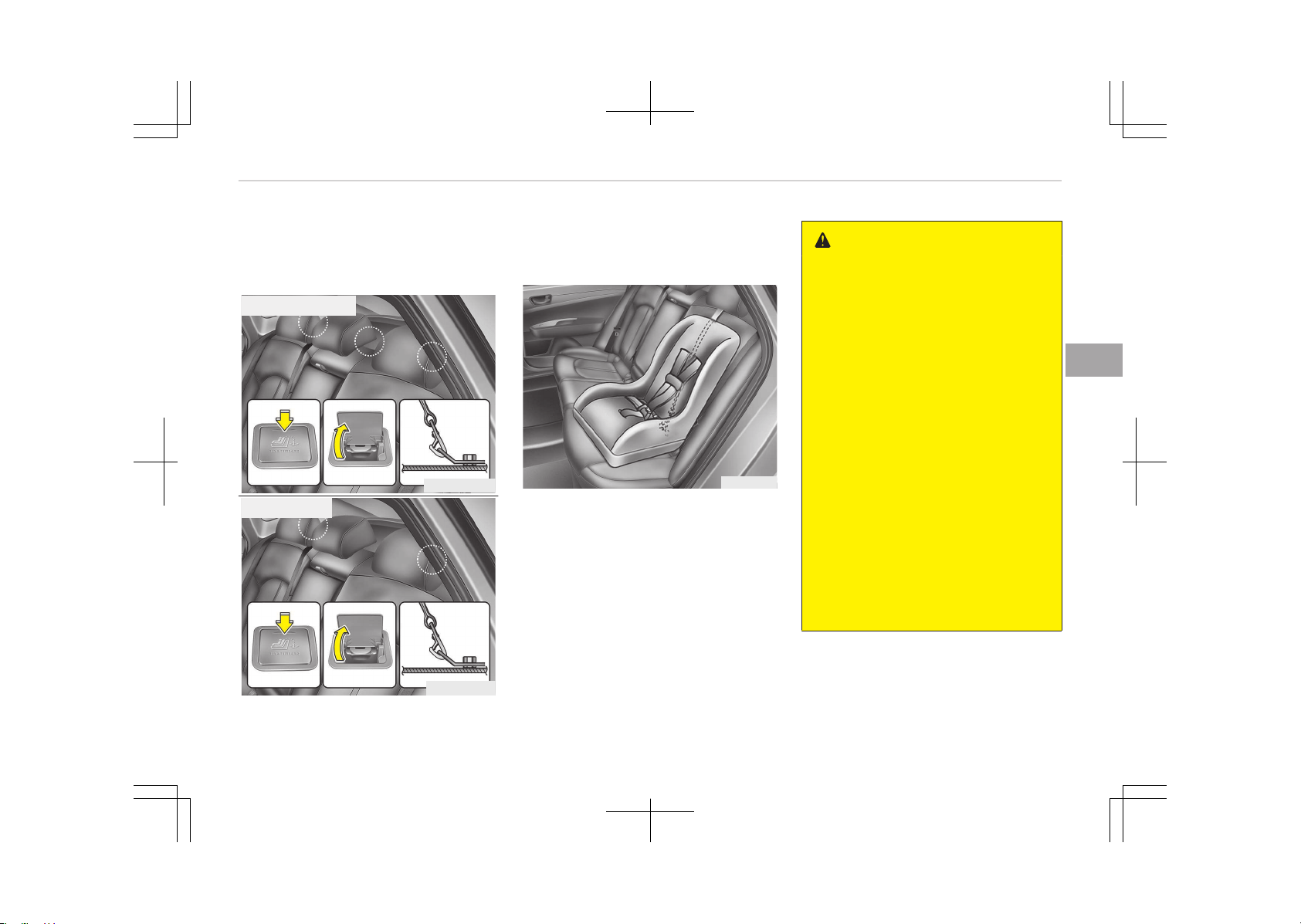
Securing a Child Restraint System
seat with Top-tether Anchorage
system (if equipped)
OJFH035095LB
■ Except Europe
■ For Europe
OJF035095LB
Top-tether anchorages for Child Re‐
straint Systems are located on the
shelf behind the rear seats.
OJF035034
1. Route the Child Restraint System
top-tether strap over the seatback.
Placing the top tether strap, please
follow the instructions of the Child
Restraint System manufacturer.
2. Connect the top-tether strap to
the top-tether anchorage, then
tighten the top-tether strap ac‐
cording to the instructions of your
Child Restraint System's manufac‐
turer to firmly attach the Child Re‐
straint System to the seat.
WARNING
Take the following precautions when
installing the top-tether:
• Read and follow all installation in‐
structions provided with your Child
Restraint System.
• NEVER attach more than one Child
Restraint System to a single ISO‐
FIX top-tether anchorage. This
could cause the anchorage or at‐
tachment to come loose or break.
• Do not attach the top-tether to
anything other than the correct
top-tether anchorage. It may not
work properly if attached to
something else.
• Child Restraint System anchorages
are designed to withstand only
those loads imposed by correctly
fitted Child Restraint System.
Under no circumstances are they
to be used for adult seat belts or
harnesses or for attaching other
items or equipment to the vehicle.
4-35
4
Safety features of your vehicle

Suitability of each seating position for ISOFIX Child Restraint Systems according to ECE regulations
Mass Group Size Class Fixture
vehicle ISOFIX positions
Front Passenger
Rear Outboard
(Driver Side)
Rear Outboard
(Passenger Side)
Rear Center
Carrycot
F ISO/L1 - X X -
G ISO/L2 - X X -
0: Up to 10 kg E ISO/R1 - IL IL -
0+: Up to 13 kg
E ISO/R1 - IL IL -
D ISO/R2 - IL IL -
C ISO/R3 - IL IL -
I: 9 to 18 kg
D ISO/R2 - IL IL -
C ISO/R3 - IL IL -
B ISO/F2 - IUF, IL IUF, IL -
B1 ISO/F2X - IUF, IL IUF, IL -
A ISO/F3 - IUF, IL IUF, IL -
IUF = Suitable for ISOFIX forward-facing Child Restraint Systems of universal category approved for use in the mass group.
IL =
Suitable for particular ISOFIX Child Restraint Systems given in the attached list.
These ISOFIX CRS are those of the "specific vehicle", "restricted" or "semi-universal" categories.
X = ISOFIX position not suitable for ISOFIX Child Restraint System in this mass group and/or this size class.
Safety features of your vehicle
4-36
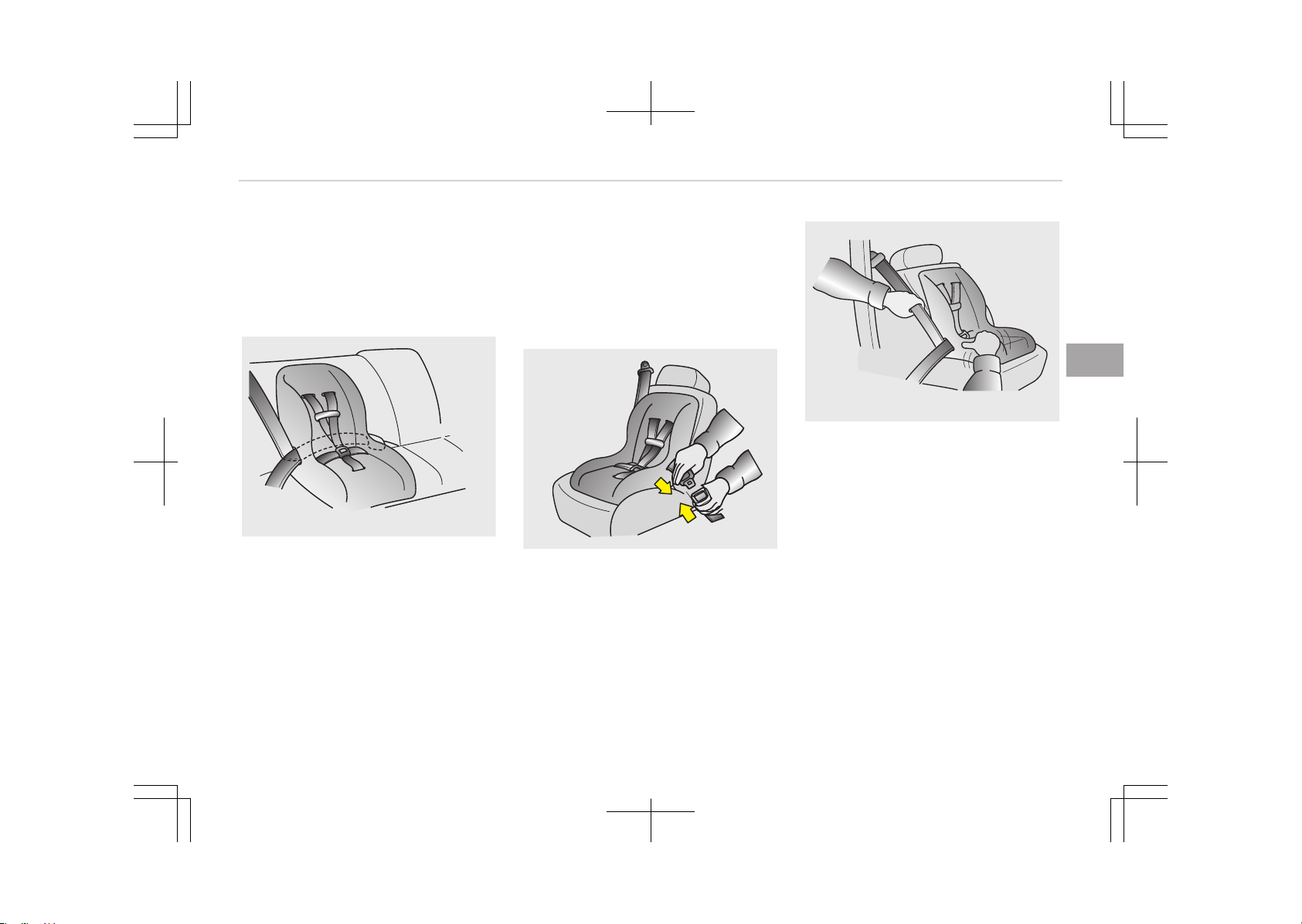
Securing a Child Restraint System
with a lap/shoulder belt
When not using the ISOFIX system, all
Child Restraint Systems must be se‐
cured to a rear seat with the lap part of
a lap/shoulder belt.
E2MS103005
Installing a Child Restraint System with
a lap/shoulder belt
To install a Child Restraint System on
the rear seats, do the following:
1. Place the Child Restraint System on
a rear seat and route the lap/shoul‐
der belt around or through the
Child Restraint System, following
the Child Restraint System manu‐
facturer’s instructions.
Make sure the seat belt webbing is
not twisted.
OEN036101
2. Fasten the lap/shoulder belt latch
into the buckle. Listen for the dis‐
tinct click sound. Position the re‐
lease button so that it is easy to
access in case of an emergency.
OEN036104
3. Remove as much slack from the
belt as possible by pushing down on
the Child Restraint System while
feeding the shoulder belt back into
the retractor.
4. Push and pull on the Child Restraint
System to confirm that the seat
belt is holding it firmly in place.
If your Child Restraint System manu‐
facturer recommends the use of a top-
tether with the lap/shoulder belt, see
Securing a Child Restraint System with
the ISOFIX Anchorage System on
page 4-34.
4-37
4
Safety features of your vehicle

To remove the Child Restraint System,
press the release button on the buckle
and then pull the lap/shoulder belt out
of the Child Restraint System and allow
the seat belt to retract fully.
Safety features of your vehicle
4-38

Suitability of each seating position for "universal" category belted Child Restraint Systems according to ECE
regulations (For Europe)
Use child safety seats that have been officially approved and are appropriate for your children. When using the child safety
seats, refer to the following table.
Mass Group
Seating Position
Front passenger Rear outboard Rear centre
0: Up to 10 kg
U U U
(0-9 months)
0+: Up to 13 kg
U U U
(0 - 2 years)
I: 9 kg to 18 kg
U U U
(9 months - 4 years)
II & III: 15 kg to 36 kg
U U U
(4 - 12 years)
U = Suitable for "universal" category restraints approved for use in this mass group (When you install the child seat on
Front Passenger seat, you should move the seat position to upward properly, to restrain child seat)
UF =
Suitable for forward-facing "universal" category restraints approved for use in this mass group
X = Seat position not suitable for children in this mass group
4-39
4
Safety features of your vehicle

Suitability of each seating position for "universal" category belted Child Restraint Systems according to ECE
regulations (Except Europe)
Use child safety seats that have been officially approved and are appropriate for your children. When using the child safety
seats, refer to the following table.
Mass Group
Seating Position
Front passenger Rear outboard Rear centre
0: Up to 10 kg
UF U U
(0-9 months)
0+: Up to 13 kg
UF U U
(0 - 2 years)
I: 9 kg to 18 kg
UF U U
(9 months - 4 years)
II & III: 15 kg to 36 kg
UF U U
(4 - 12 years)
U = Suitable for "universal" category restraints approved for use in this mass group
UF =
Suitable for forward-facing "universal" category restraints approved for use in this mass group (When you install the
child seat on Front Passenger seat, you should move the seat position to upward properly, to restrain child seat)
X = Seat position not suitable for children in this mass group
Safety features of your vehicle
4-40

Recommended child restraint systems – For Europe
Mass Group Size Class Fixture Name Manufacturer Type of Fixation
ECE-R44 Ap‐
proval No.
Group 0-1
(0 ~ 13 kg)
E ISO/R1 Baby Safe Plus Britax Römer
Reward facing with ISOFIX
base
E1 04301146
Group 1
(9 ~ 18 kg)
B1 ISO/F2X Duo Plus Britax Römer
Forward facing with vehicle
ISOFIX lower anchorage +
Top tether
E1 04301133
4-41
4
Safety features of your vehicle

CRS Manufacturer information
Britax Römer http://www.britax.com
Safety features of your vehicle
4-42
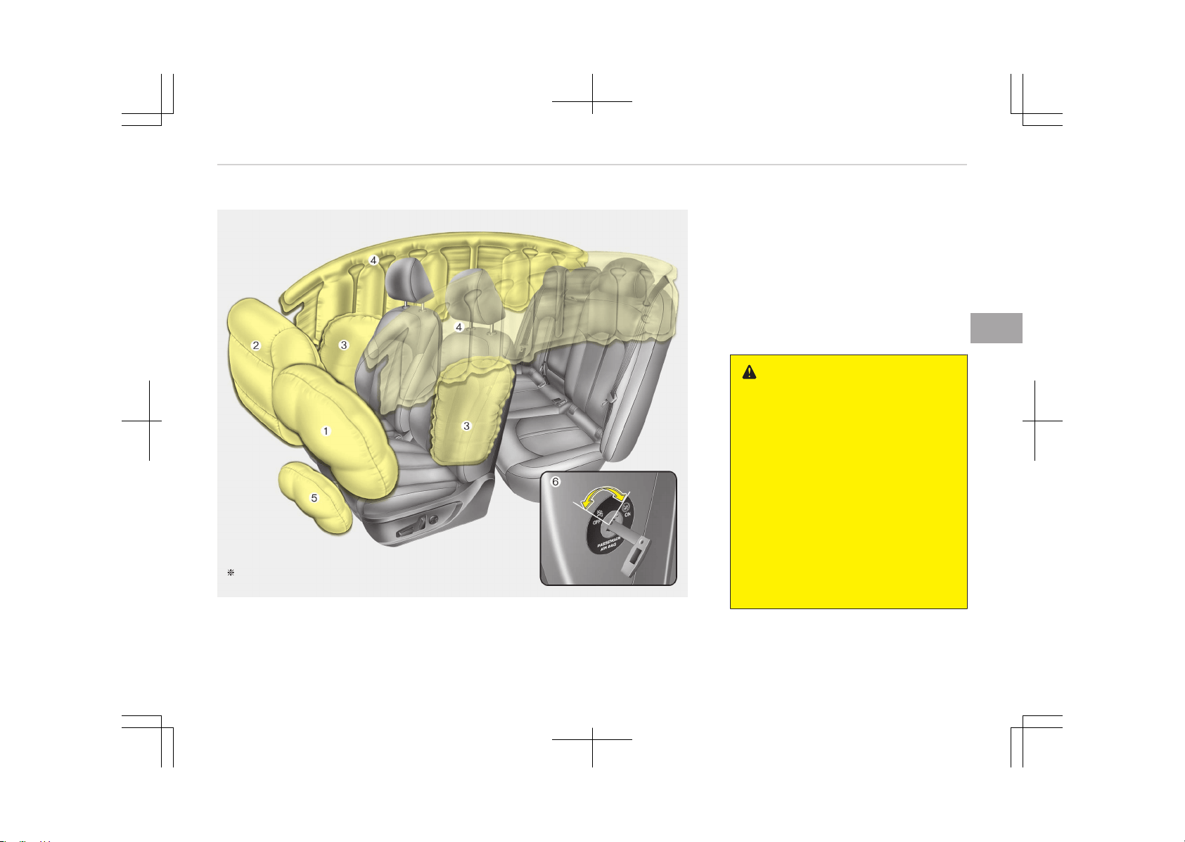
AIR BAG - SUPPLEMENTAL RESTRAINT SYSTEM (IF EQUIPPED)
The actual air bags in the vehicle may differ
from the illustration.
OJF035099L
1. Driver’s front air bag
2. Passenger’s front air bag
3. Side air bag
4. Curtain air bag
5.
Driver’s knee air bag
*
6. Passenger’s front air bag ON/OFF
switch
*
WARNING
• Even in vehicles with air bags, you
and your passengers must always
wear the safety belts provided in
order to minimize the risk and se‐
verity of injury in the event of a
collision or rollover.
• SRS and pretensioners contain ex‐
plosive chemicals.
If scraping a vehicle without re‐
moving SRS and pretensioners
from a vehicle, it may cause fire.
Before scraping a vehicle, we rec‐
ommend that you contact an au‐
thorized Kia dealer.
(Continued)
*
: if equipped
4-43
4
Safety features of your vehicle

(Continued)
• Keep the SRS parts and wirings
away from water or any liquid. If
the SRS components are inopera‐
tive due to exposure to water or
liquids, it may cause fire or severe
injury.
How does the air bag system
operate
• Air bags are activated (able to inflate
if necessary) only when the engine
start/stop button is turned to the ON
or START position.
• Air bags inflate instantly in the event
of a serious frontal collision or side
collision (if equipped with a side air
bag or curtain air bag) in order to
help protect the occupants from seri‐
ous physical injury.
• There is no single speed at which the
air bags will inflate.
Generally, air bags are designed to in‐
flate based upon the severity of a
collision and its direction. These two
factors determine whether the sen‐
sors produce an electronic deploy‐
ment/inflation signal.
• Air bag deployment depends on a
number of factors including vehicle
speed, angles of impact and the den‐
sity and stiffness of the vehicles or
objects which your vehicle hits in the
collision. The determining factors are
not limited to those mentioned
above.
• The front air bags will completely in‐
flate and deflate in an instant.
It is virtually impossible for you to
see the air bags inflate during an ac‐
cident.
It is much more likely that you will
simply see the deflated air bags
hanging out of their storage com‐
partments after the collision.
NOTICE
n
If equipped with rollover sen‐
sor
Air bags inflate instantly in the
event of a rollover (if equipped with
a side air bag or curtain air bag) in
order to help protect the occupants
from serious physical injury.
• In order to help provide protection in
a severe collision, the air bags must
inflate rapidly. The speed of the air
bag inflation is a consequence of ex‐
tremely short time in which a collision
occurs and the need to inflate the air
bag between the occupant and the
vehicle structures before the occu‐
pant impacts those structures.
This speed of inflation reduces the
risk of serious or life-threatening in‐
juries in a severe collision and is thus
a necessary part of the air bag de‐
sign.
However, air bag inflation can also
cause injuries which can include facial
abrasions, bruises and broken bones
because the inflation speed also cau‐
ses the air bags to expand with a
great deal of force.
• There are even circumstances under
which contact with the steering
wheel air bag can cause fatal injuries,
especially if the occupant is posi‐
tioned excessively close to the steer‐
ing wheel.
Safety features of your vehicle
4-44
WARNING
• To avoid severe personal injury or
death caused by deploying air bags
in a collision, the driver should sit
as far back from the steering
wheel air bag as possible (at least
250 mm (10 inches) away). The
front passengers should always
move their seats as far back as
possible and sit back in their seat.
• Air bags inflate instantly in the
event of a collision, and passen‐
gers may be injured by the air bag
expansion force if they are not in a
proper position.
• Air bag inflation may cause injuries
including facial or bodily abrasions,
injuries from broken glasses or
burns.
Noise and smoke
When the air bags inflate, they make a
loud noise and they leave smoke and
powder in the air inside of the vehicle.
This is normal and is a result of the ig‐
nition of the air bag inflator. After the
air bag inflates, you may feel substan‐
tial discomfort in breathing due to the
contact of your chest with both the
seat belt and the air bag, as well as
from breathing the smoke and powder.
Open your doors and/or windows as
soon as possible after the impact in or‐
der to reduce discomfort and prevent
prolonged exposure to smoke and pow‐
der.
Though the smoke and powder are
non-toxic, they may cause irritation to
the skin (eyes, nose and throat, etc). If
this is the case, wash and rinse with
cold water immediately and consult a
doctor if the symptom persists.
WARNING
When the air bags deploy, the air
bag related parts in the steering
wheel, instrument panel, front seats
and/or in both sides of the roof rails
(Continued)
(Continued)
above the front and rear doors are
very hot. To prevent injury, do not
touch the air bag storage area’s in‐
ternal components immediately af‐
ter an air bag has inflated.
4-45
4
Safety features of your vehicle
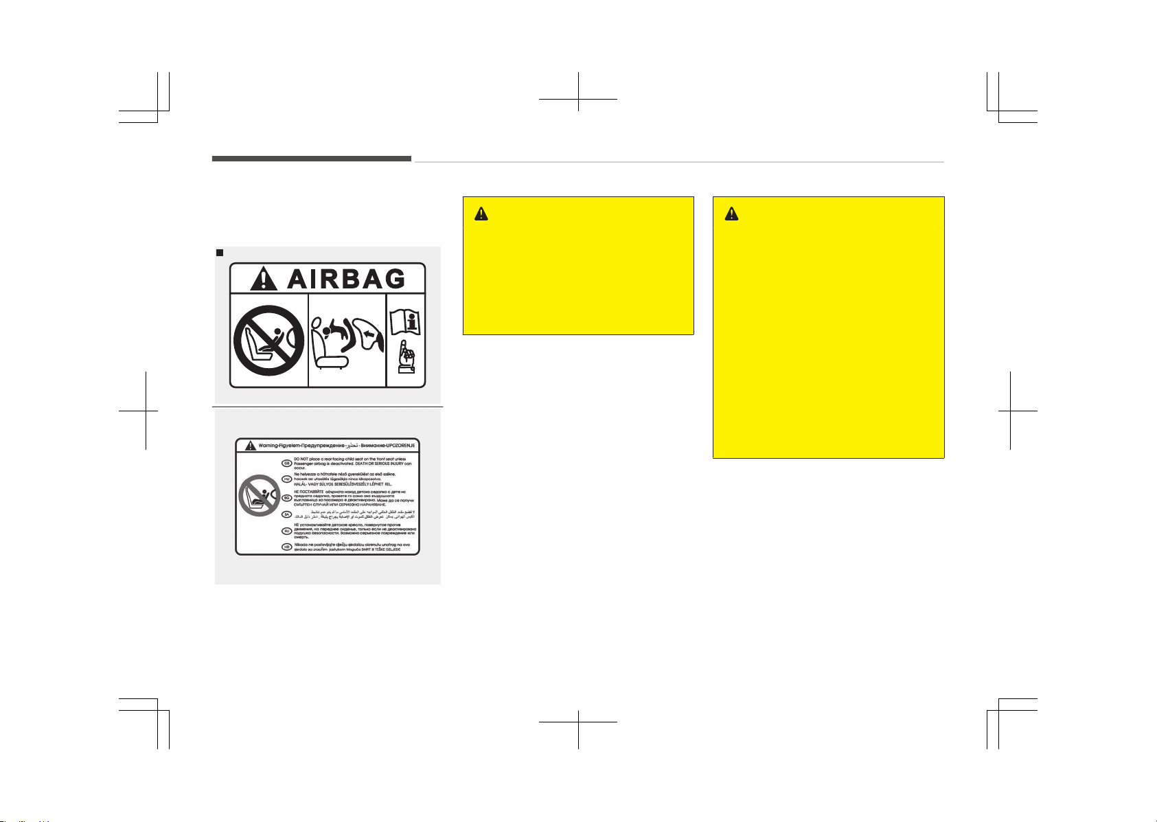
Front passenger's air bag warning
label for child restraint system
Type A
OYDESA2042
OHM036053L
■ Type B
WARNING
Never place a rear facing child re‐
straint in the front passenger seat,
unless the passenger-side air bag is
deactivated. An inflating passenger-
side air bag could impact the rear-
facing child restraint and kill the
child.
In addition, we recommend that you do
not place front-facing child restraints
in the front passenger’s seat either. If
the front passenger's air bag inflates, it
could cause serious or fatal injuries to
the child.
If your vehicle is equipped with the pas‐
senger’s front air bag ON/OFF switch,
you can activate or deactivate the
front passenger’s air bag when neces‐
sary.
For more details, please refer to Pas‐
senger’s front air bag ON/OFF switch
on page 4-54 (if equipped).
WARNING
• NEVER use a rearward facing child
restraint on a seat protected by an
ACTIVE AIR BAG in front of it,
DEATH or SERIOUS INJURY to the
CHILD can occur.
• When children are seated in the
rear outboard seats of a vehicle
equipped with side and/or curtain
air bags, be sure to install the child
restraint system as far away from
the door side as possible, and se‐
curely lock the child restraint sys‐
tem in position.
Inflation of side and/or curtain air
bags could cause serious injury or
death to an infant or child.
Safety features of your vehicle
4-46
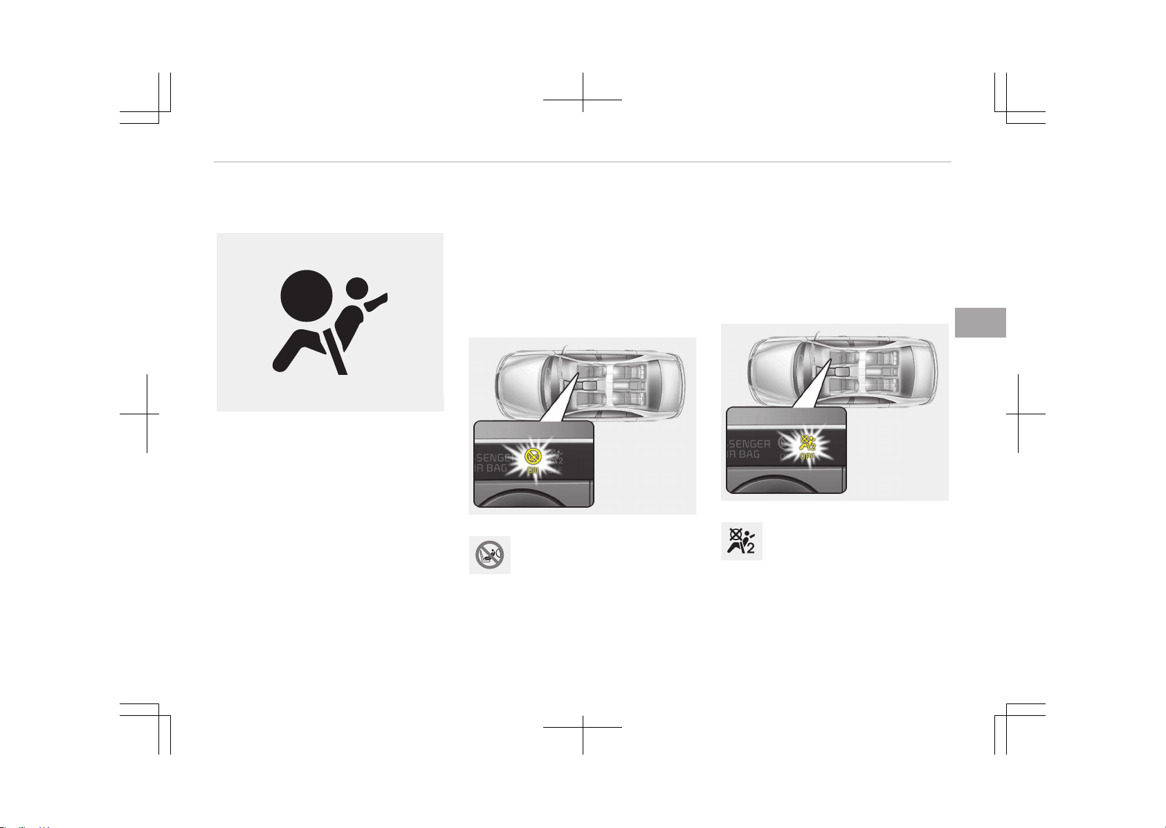
Air bag warning light
W7-147
The purpose of the air bag warning
light in your instrument panel is to alert
you of a potential problem with your
air bag - Supplemental Restraint Sys‐
tem (SRS).
When the Engine Start/Stop button is
turned ON, the warning light should illu‐
minate for approximately 6 seconds,
then go off.
Have the system checked if:
• The light does not turn on briefly
when you turn the Engine Start/Stop
button to the ON position.
• The light stays on after illuminating
for approximately 6 seconds.
• The light comes on while the vehicle
is in motion.
• The light blinks when the engine
start/stop button is in the ON posi‐
tion.
Passenger’s front air bag ON
indicator (if equipped)
OJFHP036115L
The passenger's front air bag
ON indicator illuminates for
approximately 4 seconds after
the engine start/stop button
is turned to the ON position.
The passenger's front air bag ON indi‐
cator also comes on when the passeng‐
er's front air bag ON/OFF switch is set
to the ON position and goes off after
approximately 60 seconds.
Passenger’s front air bag OFF
indicator (if equipped)
OJFHP036116L
The passenger’s front air bag
OFF indicator illuminates for
about 4 seconds after the en‐
gine start/stop button is
turned to the ON position.
4-47
4
Safety features of your vehicle
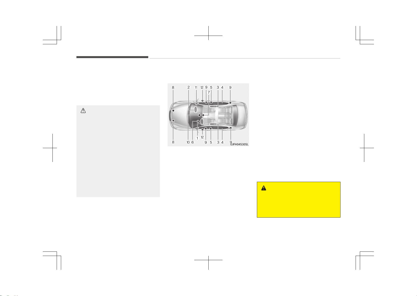
The passenger’s front air bag OFF indi‐
cator also comes on when the passeng‐
er’s front air bag ON/OFF switch is set
to the OFF position and goes off when
the passenger’s front air bag ON/OFF
switch is set to the ON position.
CAUTION
If the passenger’s front air bag
ON/OFF switch malfunctions, the
passenger’s front air bag OFF indica‐
tor will not illuminate (the passeng‐
er's front air bag ON indicator comes
on and goes off after approximately
60 seconds) and the passenger’s
front air bag will inflate in a frontal
impact even if the passenger’s front
air bag ON/OFF switch is set to the
OFF position.
If this occurs, we recommend that
the passenger’s front air bag
ON/OFF switch and the SRS air bag
system be inspected by an author‐
ized Kia dealer.
SRS components and functions
The SRS consists of the following com‐
ponents:
1. Driver's front air bag module
2. Passenger's front air bag module
3. Side air bag modules
4. Curtain air bag modules
5. Retractor pre-tensioner assem‐
blies
*
6. Air bag warning light
7. SRS control module (SRSCM)/Roll‐
over sensor
*
8. Front impact sensors
*
: if equipped
9.
Side impact sensors
*
10. Passenger’s front air bag ON/OFF
indicator (front passenger's seat
only)
*
11. Passenger’s front air bag ON/OFF
switch
*
12. Side pressure sensors
The SRSCM continually monitors all SRS
components while the Engine Start/
Stop button is ON to determine if a
crash impact is severe enough to re‐
quire air bag deployment or pretension‐
er seat belt deployment.
The SRS air bag warning light on the in‐
strument panel will illuminate for about
6 seconds after the Engine Start/Stop
button is set to the ON position, after
which the SRS air bag warning light
should go out.
WARNING
If any of the following conditions oc‐
curs, this indicates a malfunction of
the SRS. We recommend that the
(Continued)
*
: if equipped
Safety features of your vehicle
4-48
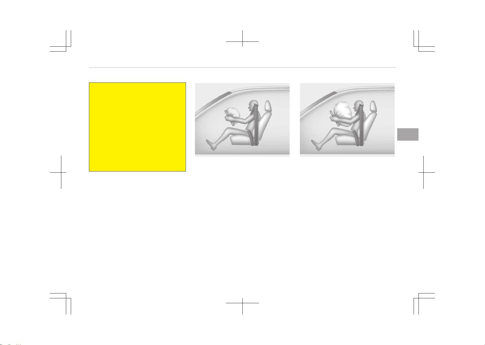
(Continued)
system be inspected by an author‐
ized Kia dealer.
• The light does not turn on briefly
when you turn the engine start/
stop button is ON.
• The light stays on after illuminat‐
ing for approximately 6 seconds.
• The light comes on while the vehi‐
cle is in motion.
• The light blinks when the engine
start/stop button to the ON posi‐
tion.
Drivers front air bag (1)
B240B01L
The front air bag modules are located
in the center of the steering wheel, in
the front passenger's panel above the
glove box and/or in the driver’s side
knee bolster. When the SRSCM detects
a sufficiently severe impact to the
front of the vehicle, it will automatically
deploy the front air bags.
Drivers front air bag (2)
B240B02L
Upon deployment, tear seams molded
directly into the pad covers will sepa‐
rate under pressure from the expan‐
sion of the air bags. Further opening of
the covers then allows full inflation of
the air bags.
4-49
4
Safety features of your vehicle
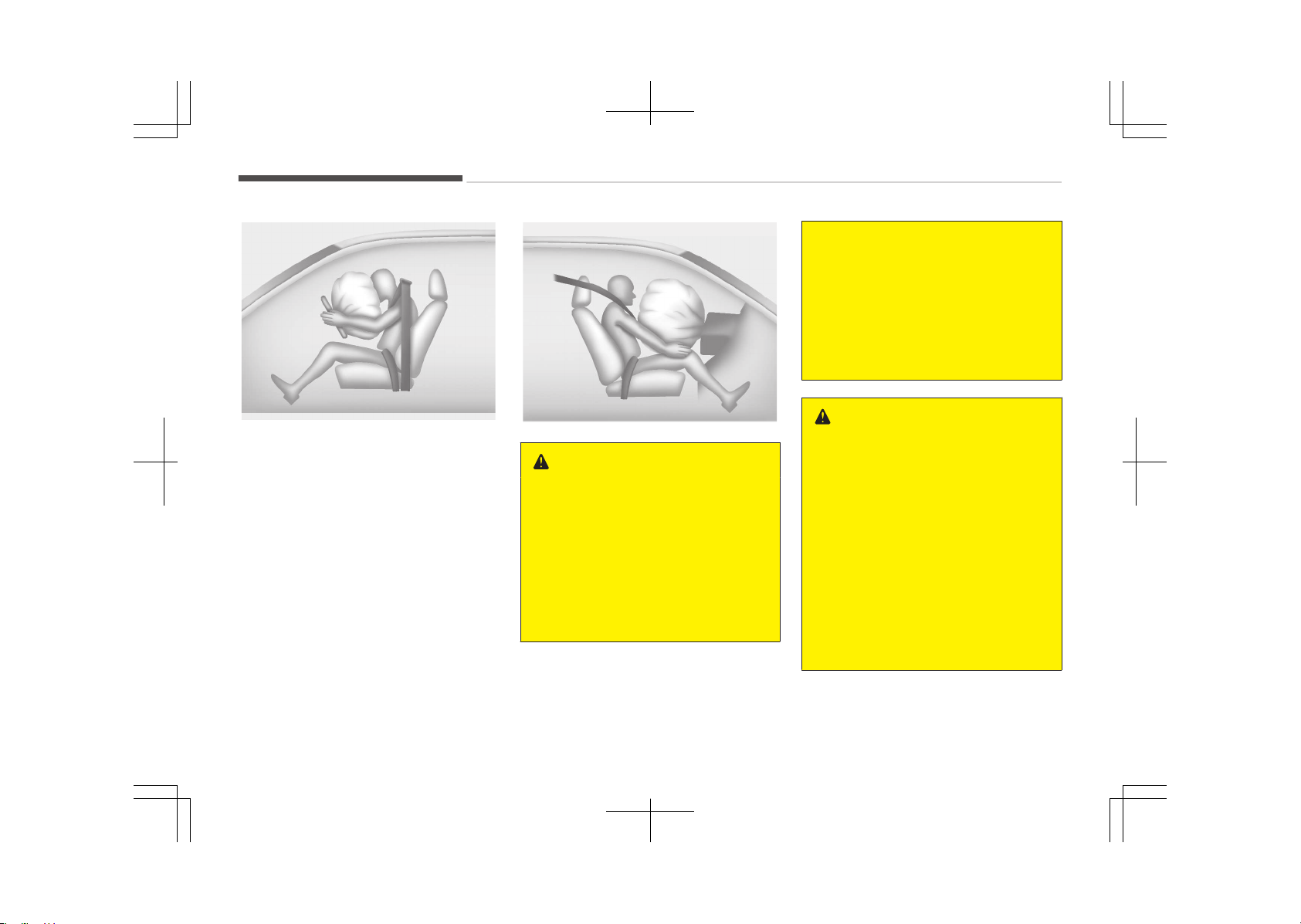
Drivers front air bag (3)
B240B03L
A fully inflated air bag, in combination
with a properly worn seat belt, slows
the driver's or the passenger's forward
motion, reducing the risk of head and
chest injury.
After complete inflation, the air bag im‐
mediately starts deflating, enabling the
driver to maintain forward visibility and
the ability to steer or operate other
controls.
Passengers front air bag
B240B05LB
WARNING
• Do not install or place any acces‐
sories (drink holder, cassette hold‐
er, sticker, etc.) on the front pas‐
senger's panel above the glove box
in a vehicle with a passenger's air
bag. Such objects may become
dangerous projectiles and cause
injury if the passenger's air bag in‐
flates.
(Continued)
(Continued)
• When installing a container of liq‐
uid air freshener inside the vehicle,
do not place it near the instrument
cluster nor on the instrument pan‐
el surface.
It may become a dangerous pro‐
jectile and cause injury if the pas‐
senger's air bag inflates.
WARNING
• If an air bag deploys, there may be
a loud noise followed by a fine
dust released in the vehicle. These
conditions are normal and are not
hazardous - the air bags are
packed in this fine powder. The
dust generated during air bag de‐
ployment may cause skin or eye
irritation as well as aggravate
asthma for some persons. Always
wash all exposed skin areas thor‐
oughly with cold water and mild
soap after an accident in which the
air bags were deployed.
(Continued)
Safety features of your vehicle
4-50
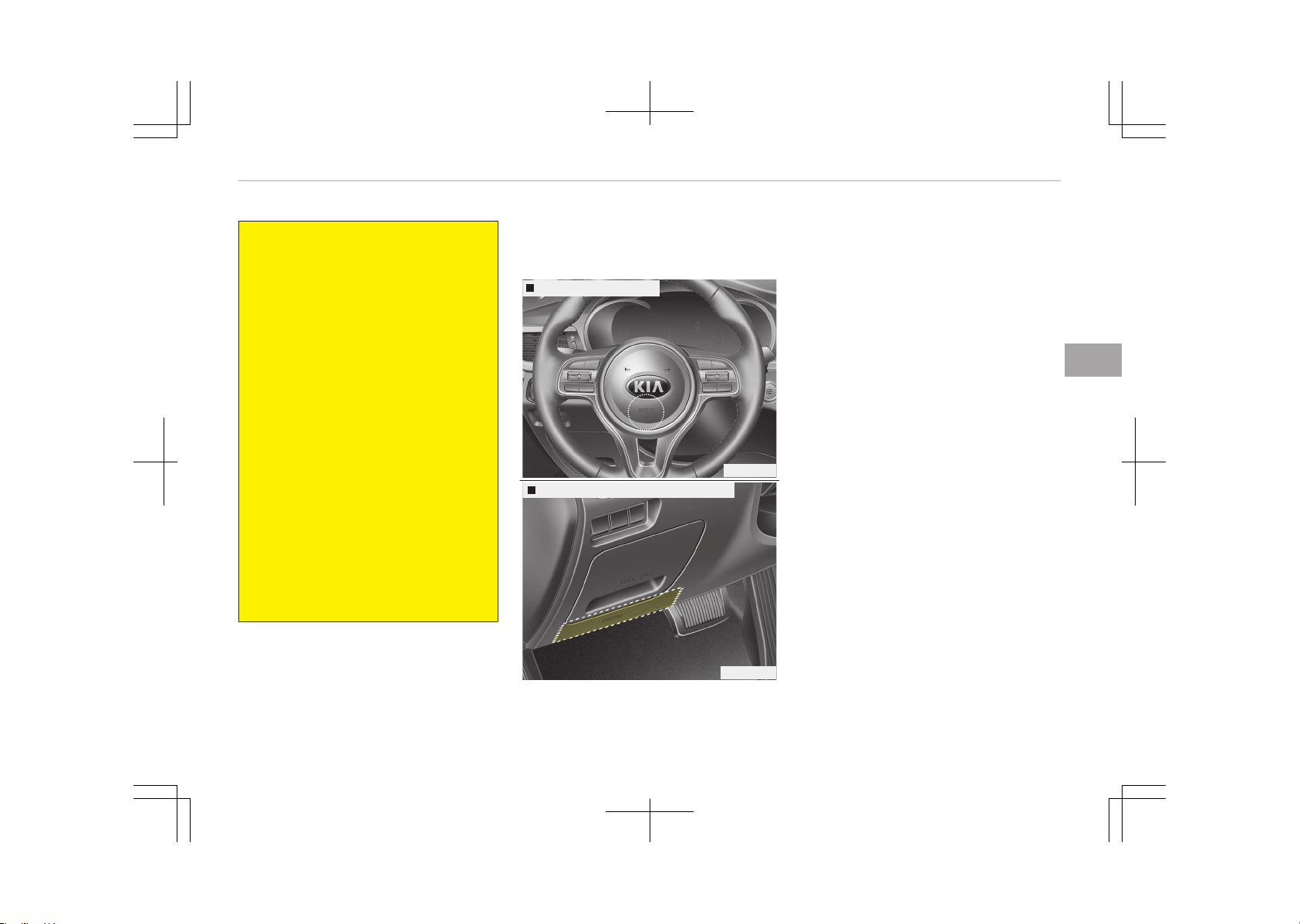
(Continued)
• The SRS can function only when
the Engine Start/Stop is set to the
ON position. If the SRS air bag
warning light does not illuminate,
or continuously remains on after
illuminating for about 6 seconds
when the Engine Start/Stop but‐
ton is turned to the ON position, or
after the engine is started, comes
on while driving, the SRS is not
working properly. If this occurs, we
recommend that the system be in‐
spected by an authorized Kia deal‐
er.
• Before you replace a fuse or dis‐
connect a battery terminal, turn
the Engine Start/Stop button to
the OFF position. Never remove or
replace the air bag related fuse(s)
when the Engine Start/Stop but‐
ton is in the ON position. Failure to
heed this warning will cause the
SRS air bag warning light to illumi‐
nate.
Driver's and passenger's front
air bag
Drivers front air bag
OJF035037
Drivers knee air bag (if equipped)
OJF035038
Your vehicle is equipped with a Supple‐
mental Restraint (Air Bag) System and
lap/shoulder belts at both the driver
and passenger seating positions.
The indications of the system's pres‐
ence are the letters "AIR BAG" em‐
bossed on the air bag pad cover in the
steering wheel and/or on the cover of
the driver's side knee bolster located
below the steering wheel and the pas‐
senger's side front panel pad above the
glove box.
4-51
4
Safety features of your vehicle
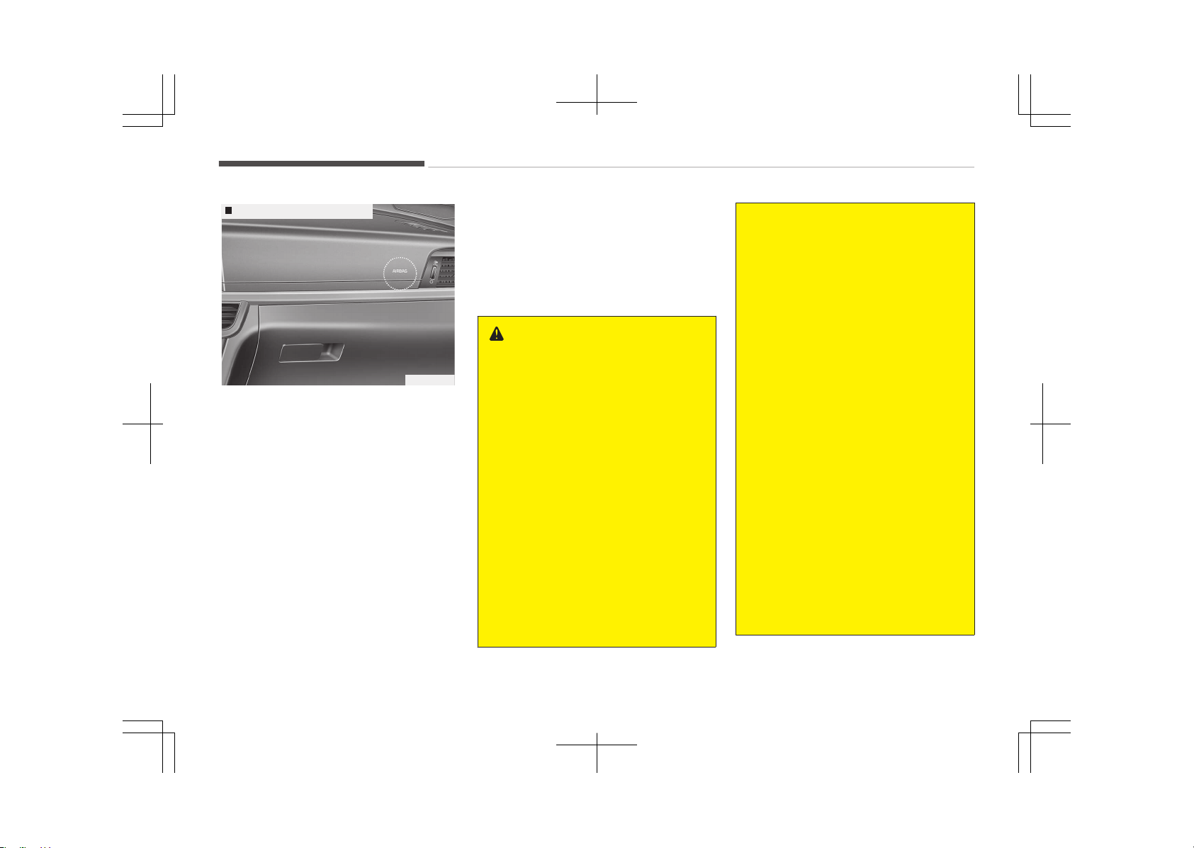
Passengers front air bag
OJF035039
The SRS consists of air bags installed
under the pad covers in the center of
the steering wheel, in the knee bolster
below the steering wheel column and
the passenger's side front panel above
the glove box.
The purpose of the SRS is to provide
the vehicle's driver and/or the front
passenger with additional protection to
that offered by the seat belt system
alone in case of a frontal impact of suf‐
ficient severity. The SRS uses sensors
to gather information about the driv‐
er's seat position, the driver's and front
passenger's seat belt usage and the
impact severity.
The seat belt buckle sensors (if equip‐
ped) determine if the driver and front
passenger's seat belts are fastened.
These sensors provide the ability to
control the SRS deployment based on
whether or not the seat belts are fas‐
tened, and how severe the impact is.
WARNING
Always use seat belts and child re‐
straints – every trip, every time, ev‐
eryone! Air bags inflate with consid‐
erable force and in the blink of an
eye. Seat belts help keep occupants
in proper position to obtain maxi‐
mum benefit from the air bag. Even
with air bags, improperly positioned
and unbelted occupants can be se‐
verely injured when the air bag in‐
flates. Always follow the precautions
about seat belts, air bags and occu‐
pant safety contained in this man‐
ual.
To reduce the chance of serious or
fatal injuries and receive the maxi‐
mum safety benefit from your re‐
straint system:
• Never place a child in any child or
booster seat in the front seat.
(Continued)
(Continued)
• ABC – Always Buckle Children in
the 2nd row seat. It is the safest
place for children of any age to
ride.
• Front and side air bags can injure
occupants improperly positioned in
the front seats.
• Move your seat as far back as
practical from the front air bags,
while still maintaining control of
the vehicle.
• You and your passengers should
never sit or lean unnecessarily
close to the air bags. Improperly
positioned drivers and passengers
can be severely injured by inflating
air bags.
• Never lean against the door or
center console – always sit in an
upright position.
• Do not allow a passenger to ride in
the front seat when the passeng‐
er’s front air bag OFF indicator is
illuminated, because the air bag
will not deploy in the event of a
moderate or severe frontal crash.
(Continued)
Safety features of your vehicle
4-52
(Continued)
• No objects should be placed over
or near the air bag modules on the
steering wheel, instrument panel
or the front passenger's panel
above the glove box, because any
such object could cause harm if
the vehicle is in a crash severe
enough to cause the air bags to
deploy.
• Do not tamper with or disconnect
SRS wiring or other components of
the SRS system. Doing so could re‐
sult in injury, due to accidental de‐
ployment of the air bags or by
rendering the SRS inoperative.
• If the SRS air bag warning light re‐
mains illuminated while the vehicle
is being driven, we recommend
that the system be inspected by
an authorized Kia dealer.
• Air bags can only be used once –
we recommend that the system
be replaced by an authorized Kia
dealer.
(Continued)
(Continued)
• The SRS is designed to deploy the
front air bags only when an impact
is sufficiently severe and when the
impact angle is less than 30° from
the forward longitudinal axis of
the vehicle. Additionally, the air
bags will only deploy once. Seat
belts must be worn at all times.
• Front air bags are not intended to
deploy in side-impact, rear-impact
or rollover crashes. In addition,
front air bags will not deploy in
frontal crashes below the deploy‐
ment threshold.
• A child restraint system must nev‐
er be placed in the front seat. The
infant or child could be severely in‐
jured or killed by an air bag deploy‐
ment in case of an accident.
(Continued)
(Continued)
• Children age 12 and under must al‐
ways be properly restrained in the
rear seat. Never allow children to
ride in the front passenger seat. If
a child over 12 must be seated in
the front seat, he or she must be
properly belted and the seat
should be moved as far back as
possible.
• For maximum safety protection in
all types of crashes, all occupants
including the driver should always
wear their seat belts whether or
not an air bag is also provided at
their seating position to minimize
the risk of severe injury or death in
the event of a crash.
Do not sit or lean unnecessarily
close to the air bag while the vehi‐
cle is in motion.
(Continued)
4-53
4
Safety features of your vehicle
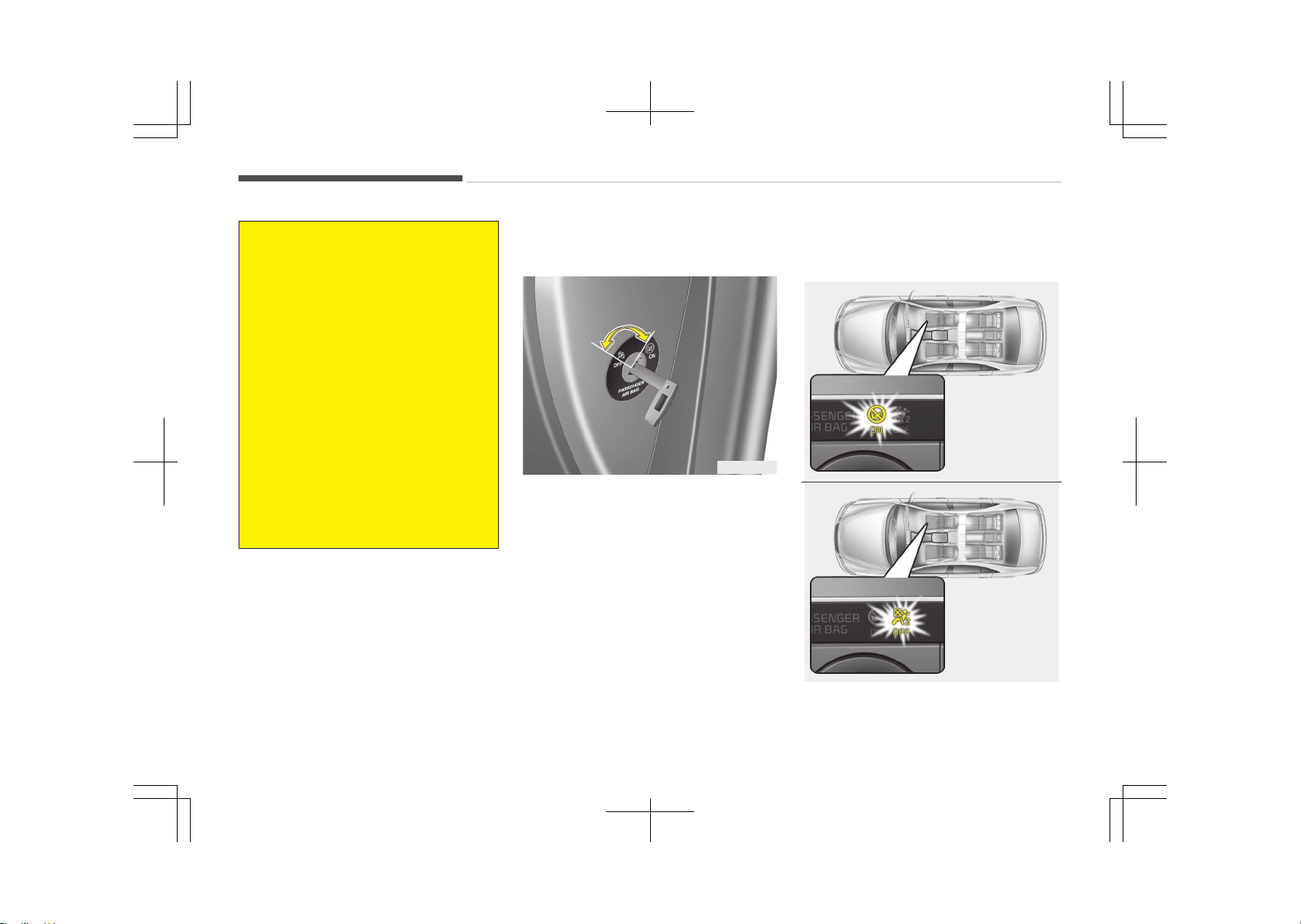
(Continued)
• Sitting improperly or out of posi‐
tion can result in serious or fatal
injury in a crash. All occupants
should sit upright with the seat
back in an upright position, cen‐
tered on the seat cushion with
their seat belt on, legs comforta‐
bly extended and their feet on the
floor until the vehicle is parked and
the Engine Start/Stop button is in
the OFF position.
• The SRS air bag system must de‐
ploy very rapidly to provide pro‐
tection in a crash. If an occupant is
out of position because of not
wearing a seat belt, the air bag
may forcefully contact the occu‐
pant causing serious or fatal inju‐
ries.
Passenger’s front air bag ON/OFF
switch (if equipped)
OJF035080L
The passenger’s front air bag can be
deactivated by the passenger’s front
air bag ON/OFF switch if a child re‐
straint is installed on the front pas‐
senger's seat or if the front passeng‐
er's seat is unoccupied by a person.
To ensure the safety of your child, the
passenger’s front air bag must be de‐
activated when it should be necessary
to install a rearward facing child seat
on the front passenger seat in excep‐
tional circumstances.
To deactivate or reactivate the pas‐
senger’s front air bag:
OJFHP036115L
OJFHP036116L
Safety features of your vehicle
4-54
To deactivate the passenger’s front air
bag, insert the master key into the
passenger’s front air bag ON/OFF
switch and turn it to the OFF position.
The passenger’s front air bag OFF indi‐
cator will illuminate and stay on until
the passenger’s front air bag is reacti‐
vated.
To reactivate the passenger’s front air
bag, insert the master key into the
passenger’s front air bag ON/OFF
switch and turn it to the ON position.
The passenger’s front air bag OFF indi‐
cator will go out.
WARNING
The front air bag ON/OFF switch
could turn by using a similar small
rigid device. Always check the status
of the front air bag ON/OFF switch
and passenger's front air bag OFF in‐
dicator.
NOTICE
• When the passenger’s front air
bag ON/OFF switch is set to the
ON position, the passenger’s front
air bag is activated and a child or
infant seat should not be installed
on the front passenger seat.
• When the passenger’s front air
bag ON/OFF switch is set to the
OFF position, the passenger’s
front air bag is deactivated.
CAUTION
• If the passenger’s front air bag
ON/OFF switch is not working
properly, the air bag warning light
( ) on the instrument panel will
illuminate and the passenger's
front air bag OFF indicator ( ) will
not illuminate. (The passenger's
front air bag ON indicator comes
on and goes off after approxi‐
mately 60 seconds.) The SRS Con‐
trol Module reactivates the pas‐
senger’s front air bag and the pas‐
senger’s front air bag will inflate in
frontal impact crashes even if the
passenger’s front air bag ON/OFF
switch is set to the OFF position.
If this occurs, we recommend that
the system be inspected by an au‐
thorized Kia dealer.
• If the SRS air bag warning light
blinks or does not illuminate when
the engine start/stop button is in
the ON position, or if it illuminates
while the vehicle is being driven,
we recommend that the system
be inspected by an authorized Kia
dealer.
4-55
4
Safety features of your vehicle
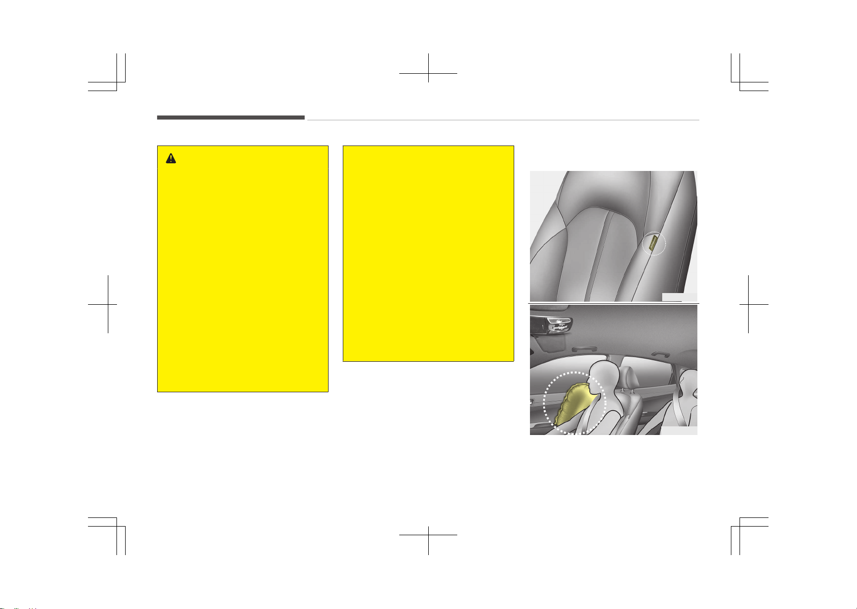
WARNING
• The driver is responsible for the
proper position of the passenger’s
front air bag ON/OFF switch.
• Deactivate the passenger's front
air bag only when the Engine
Start/Stop button is in the OFF po‐
sition, or the malfunction may oc‐
cur in the SRS Control Module. And
there may be a danger that the
driver's and/or front passenger’s
and/or side and curtain air bag
may fail to trigger, or not trigger
correctly during a collision.
• Never install a rearward facing
child seat on the front passenger's
seat unless the passenger's front
air bag has been deactivated. The
infant or child could be severely in‐
jured or killed by an air bag deploy‐
ment in case of an accident.
(Continued)
(Continued)
• Even though your vehicle is equip‐
ped with the passenger's front air
bag ON/OFF switch, do not install a
child restraint system in the front
passenger's seat. A child restraint
system must never be placed in
the front seat. Children who are
too large for child restraint sys‐
tems should always occupy the
rear seat and use the available lap/
shoulder belts. Children are affor‐
ded the most safety in the event
of an accident when they are re‐
strained by a proper restraint sys‐
tem in the rear seat.
• As soon as the child seat is no lon‐
ger needed on the front passeng‐
er's seat, reactivate the front pas‐
senger's air bag.
Side air bag
OJF035040
OJF035041
❈ The actual air bags in the vehicle
may differ from the illustration.
Safety features of your vehicle
4-56
Your vehicle is equipped with a side air
bag in each front seat.
The purpose of the air bag is to provide
the vehicle's driver and/or the front
passenger with additional protection to
that offered by the seat belt alone.
The side air bags are designed to de‐
ploy only during certain side impact col‐
lisions, depending on the crash severity,
angle, speed and point of impact. How‐
ever, when the side deployment
threshold is satisfied at front-impact,
the side air bags may deploy. The side
air bags are not designed to deploy in
all side impact or rollover situations.
The side air bags may deploy on the
side of the impact or on both sides.
WARNING
Do not allow the passengers to lean
their heads or bodies onto doors, put
their arms on the doors, stretch
their arms out of the window, or
place objects between the doors and
passengers when they are seated on
seats equipped with side and/or cur‐
tain air bags.
NOTICE
n
if equipped with rollover sen‐
sor
• Both sides of the side air bags de‐
ploy in certain rollover situations.
• The side air bag may deploy when
the rollover sensor detects the sit‐
uation as a rollover.
WARNING
• The side air bag is supplemental to
the driver's and the passenger's
seat belt systems and is not a
substitute for them. Therefore,
your seat belts must be worn at all
times while the vehicle is in mo‐
tion. The air bags deploy only in
certain side impact or rollover
*
conditions severe enough to cause
significant injury to the vehicle oc‐
cupants.
(Continued)
*
: Only vehicles equipped with rollover
sensor.
(Continued)
• For best protection from the side
air bag system and to avoid being
injured by the deploying side air
bag, both front seat occupants
should sit in an upright position
with the seat belt properly fas‐
tened. The driver's hands should
be placed on the steering wheel at
the 9:00 and 3:00 positions.
The passenger's arms and hands
should be placed on their laps.
• Do not use any accessory seat
covers.
• Use of seat covers could reduce or
prevent the effectiveness of the
system.
• Do not install any accessories on
the side or near the side air bag.
• Do not place any objects over the
air bag or between the air bag and
yourself.
• Do not place any objects (an um‐
brella, bag, etc.) between the front
door and the front seat. Such ob‐
jects may become dangerous pro‐
jectiles and cause injury if the sup‐
plemental side air bag inflates.
(Continued)
4-57
4
Safety features of your vehicle
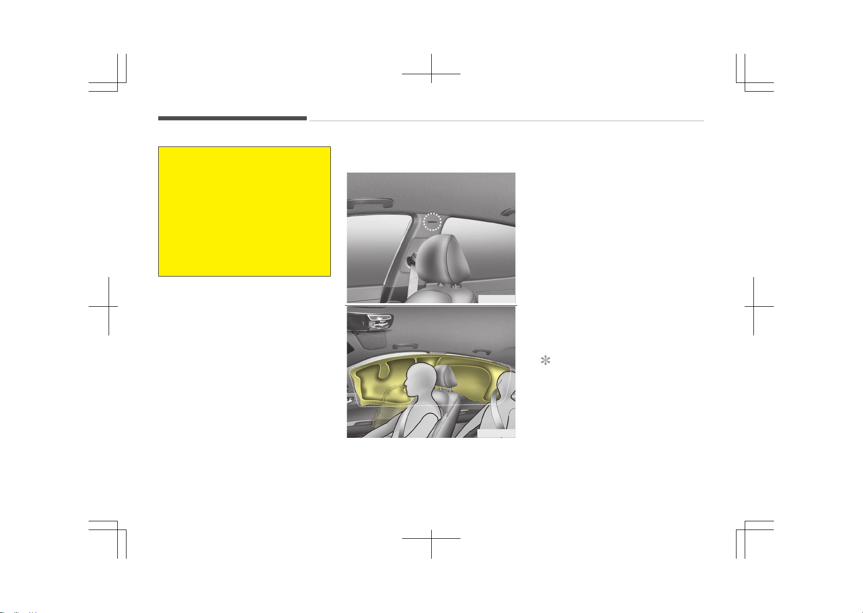
(Continued)
• To prevent unexpected deploy‐
ment of the side air bag that may
result in personal injury, avoid im‐
pact to the side impact sensor
when the engine start/stop button
is in the ON position.
• If the seat or seat cover is dam‐
aged, we recommend that the
system be serviced by an author‐
ized Kia dealer.
Curtain air bag
OJF035042
OJF035043
❈ The actual air bags in the vehicle
may differ from the illustration.
Curtain air bags are located along both
sides of the roof rails above the front
and rear doors.
They are designed to help protect the
heads of the front seat occupants and
the rear outboard seat occupants in
certain side impact collisions.
The curtain air bags are designed to
deploy during certain side impact colli‐
sions, depending on the crash severity,
angle, speed and point of impact. How‐
ever, when the side deployment
threshold is satisfied at front impact,
the side air bags may deploy.
The curtain air bags may deploy on the
side of the impact side.
The curtain air bags are not designed
to deploy in all side impacts or rollover
situations.
NOTICE
n
if equipped with rollover sen‐
sor
• Both sides of the curtain air bags
deploy in certain rollover situa‐
tions.
(Continued)
Safety features of your vehicle
4-58

(Continued)
• The curtain air bag may deploy
when the rollover sensor detects
the situation as a rollover.
WARNING
• In order for side and curtain air
bags to provide the best protec‐
tion, front seat occupants and
outboard rear occupants should sit
in an upright position with the seat
belts properly fastened. Impor‐
tantly, children should sit in a
proper child restraint system in
the rear seat.
• When children are seated in the
rear outboard seats, they must be
seated in the proper child restraint
system. Make sure to position the
child restraint system as far away
from the door side as possible, and
secure the child restraint system
in a locked position.
(Continued)
(Continued)
• Do not allow the passengers to
lean their heads or bodies against
doors, put their arms on the
doors, stretch their arms out of
the window or place objects be‐
tween the doors and passengers
when they are seated on seats
equipped with side and curtain air
bags.
• Never try to open or repair any
components of the side curtain air
bag system. We recommend that
the system be serviced by an au‐
thorized Kia dealer.
Failure to follow the above instruc‐
tions can result in injury or death to
the vehicle occupants in an accident.
4-59
4
Safety features of your vehicle
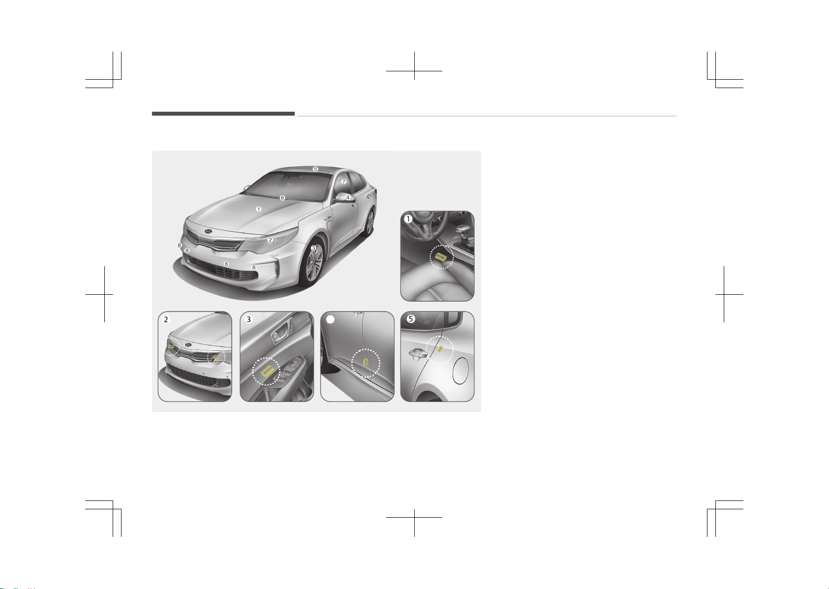
Why didn’t my air bag go off in a collision?
4
OJF035064/OJFH035047L/OJF035048/OJF035049/OJF035084
❈ The actual shape may differ from
the illustration.
Inflation and non-inflation conditions of
the air bag
There are many types of accidents in
which the air bag would not be expec‐
ted to provide additional protection.
These include rear impacts, second or
third collisions in multiple impact acci‐
dents, as well as low speed impacts.
Air bag collision sensors
1. SRS control module / Rollover sen‐
sor (if equipped)
2. Front impact sensor
3. Side impact sensor (if equipped)
4. Side impact sensor (if equipped)
5. Side impact sensor (if equipped)
Safety features of your vehicle
4-60
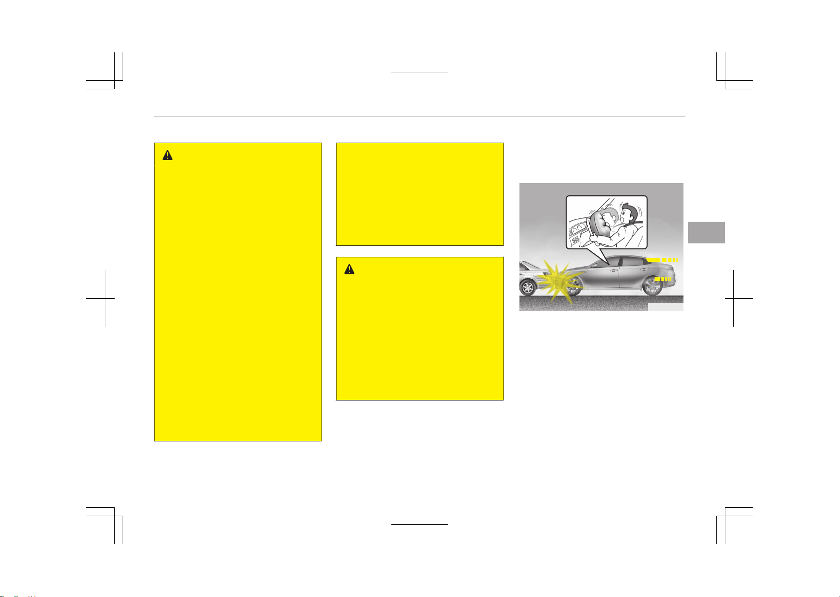
WARNING
• Do not hit or allow any objects to
impact the locations where air
bags or sensors are installed.
This may cause unexpected air
bag deployment, which could re‐
sult in serious personal injury or
death.
• If the installation location or angle
of the sensors is altered in any
way, the air bags may deploy
when they should not or they may
not deploy when they should,
causing severe injury or death.
Therefore, do not try to perform
maintenance on or around the air
bag sensors. We recommend that
the system be serviced by an au‐
thorized Kia dealer.
• Problems may arise if the sensor
installation angles are changed due
to the deformation of the front
bumper, body or front door and C
pillars where side collision sensors
are installed. We recommend that
the system be serviced by an au‐
thorized Kia dealer.
(Continued)
(Continued)
• Your vehicle has been designed to
absorb impact and deploy the air
bag(s) in certain collisions. Instal‐
ling bumper guards or replacing a
bumper with non-genuine parts
may adversely affect your vehi‐
cle's collision and air bag deploy‐
ment performance.
WARNING
n
if equipped with rollover sen‐
sor
If your vehicle is equipped with side
and curtain air bags, set the Engine
Start/Stop button in the OFF posi‐
tion when the vehicle is being towed.
The side and curtain air bags may
deploy when the engine start/stop
button is in the ON position, and the
rollover sensor detects the situation
as a rollover.
Air bag inflation conditions
Front air bags
OJF035050
Front air bags are designed to inflate in
a frontal collision depending on the in‐
tensity, speed or angles of impact of
the front collision.
4-61
4
Safety features of your vehicle
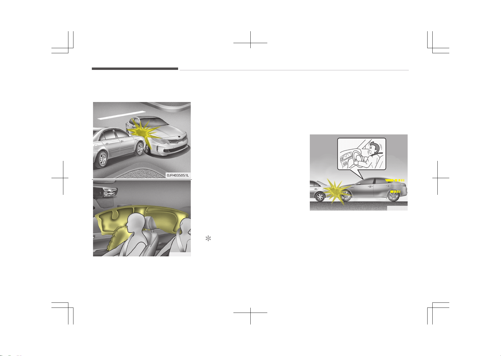
Side and curtain air bags
OJF035052
❈ The actual air bags in the vehicle
may differ from the illustration.
Side and curtain air bags are designed
to inflate when an impact is detected
by the side collision sensors depending
on the strength, speed or angles of im‐
pact resulting from a side impact colli‐
sion.
Although the front air bags (driver’s
and front passenger’s air bags) are de‐
signed to inflate only in frontal colli‐
sions, they also may inflate in other
types of collisions if the front impact
sensors detect a sufficient impact. Side
air bags (side and/or curtain air bags)
are designed to inflate only in side im‐
pact collisions, but they may inflate in
other collisions if the side impact sen‐
sors detect a sufficient impact.
If the vehicle chassis is impacted by
bumps or objects on unimproved roads
or sidewalks, the air bags may deploy.
Drive carefully on unimproved roads or
on surfaces not designed for vehicle
traffic to prevent unintended air bag
deployment.
NOTICE
n
if equipped with a rollover
sensor
(Continued)
(Continued)
The side and curtain air bags are de‐
signed to inflate when a rollover is
detected by a rollover sensor.
Air bag non-inflation conditions
OJF035053
• In certain low-speed collisions the air
bags may not deploy. The air bags
are designed not to deploy in such
cases because they may not provide
benefits beyond the protection of the
seat belts in such collisions.
Safety features of your vehicle
4-62
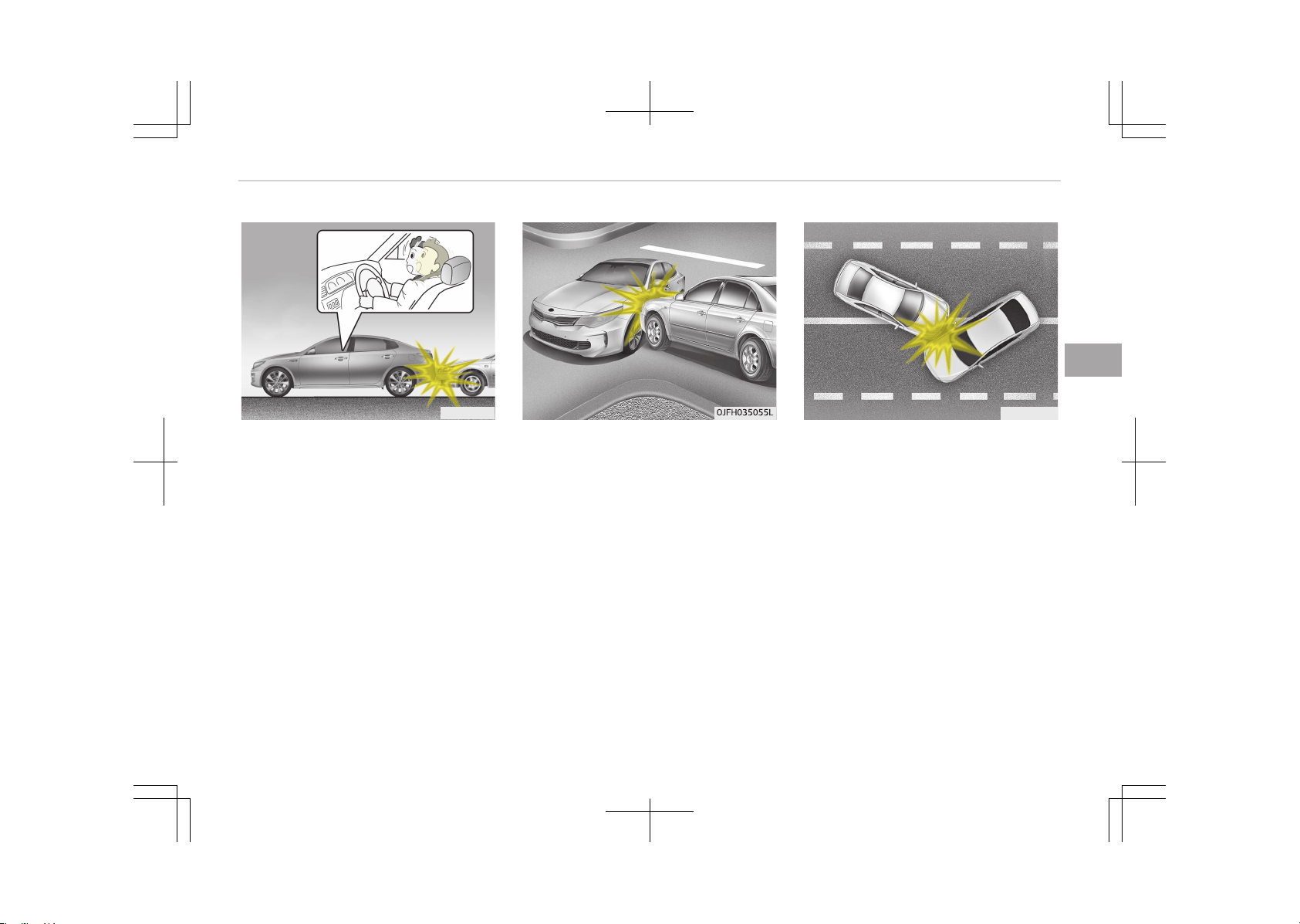
OJF035054
• Air bags are not designed to inflate in
rear collisions, because occupants are
moved backward by the force of the
impact. In this case, inflated air bags
would not be able to provide any ad‐
ditional benefit.
• Front air bags may not inflate in side
impact collisions, because occupants
move to the direction of the collision,
and thus in side impacts, front air
bag deployment would not provide
additional occupant protection.
However, if equipped with side and
curtain air bags, the air bags may in‐
flate depending on the intensity, ve‐
hicle speed and angles of impact.
OJF035056
• In an angled collision, the force of im‐
pact may direct the occupants in a di‐
rection where the air bags would not
be able to provide any additional ben‐
efit, and thus the sensors may not
deploy any air bags.
4-63
4
Safety features of your vehicle
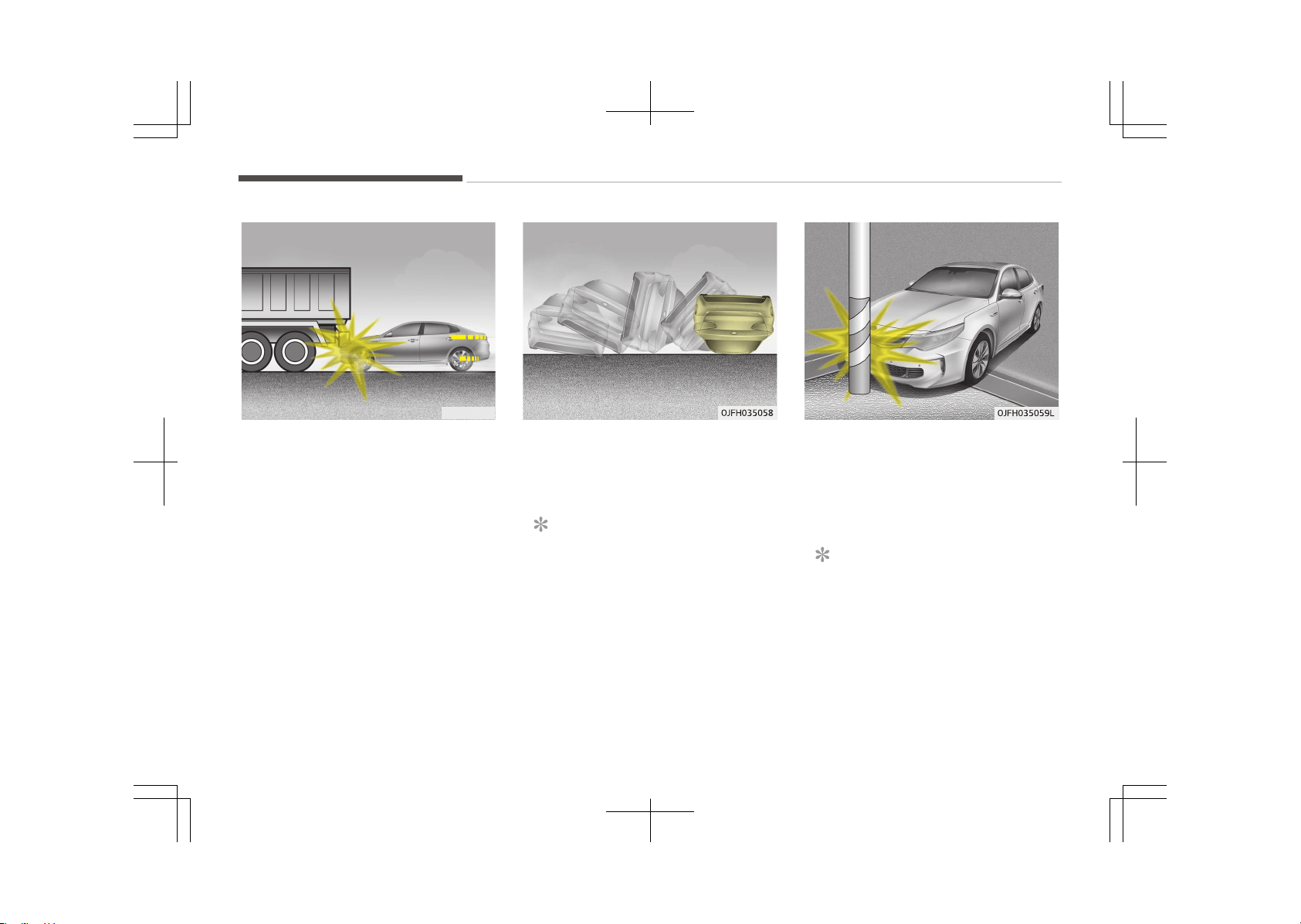
OJF035057
• Just before impact, drivers often
brake heavily. Such heavy braking
lowers the front portion of the vehi‐
cle causing it to ride under a vehicle
with a higher ground clearance. Air
bags may not inflate in this "under-
ride" situation because deceleration
forces that are detected by sensors
may be significantly reduced by such
under-ride collisions.
• Front air bags may not inflate in roll‐
over accidents because front air bag
deployment would not provide addi‐
tional occupant protection.
NOTICE
Side and/or curtain air bags may in‐
flate when the vehicle is rolled over
by a side impact collision, if the vehi‐
cle is equipped with side air bags and
curtain air bags.
• Air bags may not inflate if the vehicle
collides with objects such as utility
poles or trees, where the point of im‐
pact is concentrated to one area and
the full force of the impact is not de‐
livered to the sensors.
NOTICE
n
if equipped with rollover sen‐
sor
However, if equipped with side and
curtain air bags, the air bags may in‐
flate in a rollover, when it is detec‐
ted by the rollover sensor.
Safety features of your vehicle
4-64
NOTICE
n
without rollover sensor
However, side and/or curtain air
bags may inflate when the vehicle is
rolled over by a side impact collision,
if the vehicle is equipped with side
air bags and curtain air bags.
SRS Care
The SRS is virtually maintenance-free
and so there are no parts you can safe‐
ly service by yourself. If the SRS air bag
warning light does not illuminate, or
continuously remains on, we recom‐
mend that the system be inspected by
an authorized Kia dealer.
WARNING
• Modification to SRS components or
wiring, including the addition of
any kind of badges to the pad cov‐
ers or modifications to the body
structure, can adversely affect
SRS performance and lead to pos‐
sible injury.
• For cleaning the air bag pad cov‐
ers, use only a soft, dry cloth or
one which has been moistened
with plain water. Solvents or clean‐
ers could adversely affect the air
bag covers and proper deployment
of the system.
• No objects should be placed over
or near the air bag modules on the
steering wheel, instrument panel,
and the front passenger's panel
above the glove box, because any
such object could cause harm if
the vehicle is in a crash severe
enough to cause the air bags to in‐
flate.
• If the air bags inflate, we recom‐
mend that the system be replaced
by an authorized Kia dealer.
(Continued)
(Continued)
• Do not tamper with or disconnect
SRS wiring, or other components
of the SRS system. Doing so could
result in injury, due to accidental
inflation of the air bags or by ren‐
dering the SRS inoperative.
• If components of the air bag sys‐
tem must be discarded, or if the
vehicle must be scrapped, certain
safety precautions must be ob‐
served. An authorized Kia dealer
knows these precautions and can
give you the necessary informa‐
tion. Failure to follow these pre‐
cautions and procedures could in‐
crease the risk of personal injury.
• If your car was flooded and has
soaked carpeting or water on the
flooring, you shouldn't try to start
the engine; we recommend that
you contact an authorized Kia
dealer.
Additional safety precautions
• Never let passengers ride in the cargo
area or on top of a folded down back
seat. All occupants should sit upright,
fully back in their seats with their
seat belts on and their feet on the
floor.
4-65
4
Safety features of your vehicle
• Passengers should not move out of
or change seats while the vehicle is
moving. A passenger who is not
wearing a seat belt during a crash or
emergency stop can be thrown
against the inside of the vehicle,
against other occupants, or out of
the vehicle.
• Each seat belt is designed to restrain
one occupant. If more than one per‐
son uses the same seat belt, they
could be seriously injured or killed in a
collision.
• Do not use any accessories on seat
belts. Devices claiming to improve oc‐
cupant comfort or reposition the seat
belt can reduce the protection provi‐
ded by the seat belt and increase the
chance of serious injury in a crash.
• Passengers should not place hard or
sharp objects between themselves
and the air bags. Carrying hard or
sharp objects on your lap or in your
mouth can result in injuries if an air
bag inflates.
•
Keep occupants away from the air
bag covers. All occupants should sit
upright, fully back in their seats with
their seat belts on and their feet on
the floor. If occupants are too close
to the air bag covers, they could be
injured if the air bags inflate.
• Do not attach or place objects on or
near the air bag covers. Any object
attached to or placed on the front or
side air bag covers could interfere
with the proper operation of the air
bags.
• Do not modify the front seats. Modi‐
fication of the front seats could in‐
terfere with the operation of the
supplemental restraint system sens‐
ing components or side air bags.
• Do not place items under the front
seats. Placing items under the front
seats could interfere with the opera‐
tion of the supplemental restraint
system sensing components and wir‐
ing harnesses.
• Never hold an infant or child on your
lap. The infant or child could be seri‐
ously injured or killed in the event of
a crash. All infants and children
should be properly restrained in ap‐
propriate child safety seats or seat
belts in the rear seat.
WARNING
• Sitting improperly or out of posi‐
tion can cause occupants to be
shifted too close to a deploying air
bag, strike the interior structure
or be thrown from the vehicle re‐
sulting in serious injury or death.
• Always sit upright with the seat‐
back in an upright position, cen‐
tered on the seat cushion with
your seat belt on, legs comfortably
extended and your feet on the
floor.
Adding equipment to or
modifying your air bag-
equipped vehicle
If you modify your vehicle by changing
your vehicle's frame, bumper system,
front end or side sheet metal or ride
height, the operation of your vehicle's
air bag system may be affected.
Safety features of your vehicle
4-66
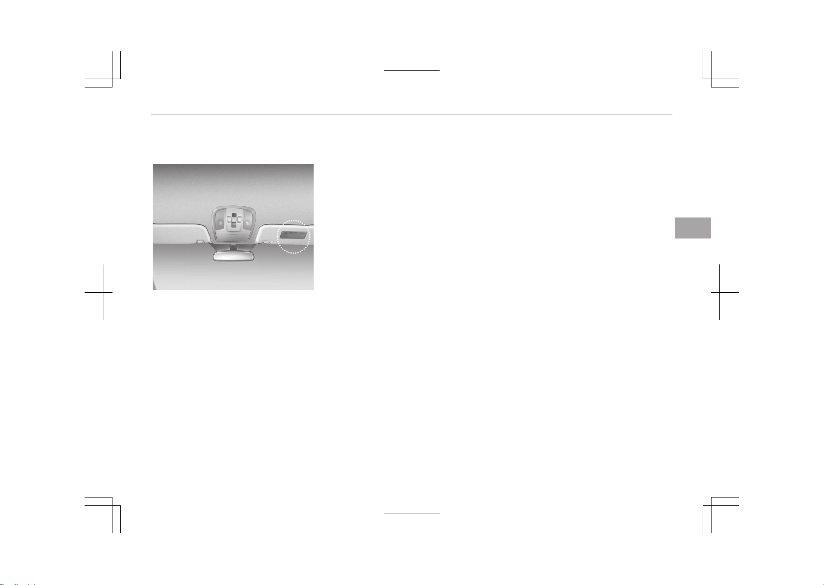
Air bag warning label
OJFC035098
Air bag warning labels are attached to
alert the passengers of the potential
risk of the air bag system.
Note that these government warnings
focus on the risk of children. We also
want you to be aware of the risks
which adults are exposed to and that
have been described in Additional safe‐
ty precautions on page 4-65.
4-67
4
Safety features of your vehicle


Smart key...................................................................................5-04
Record your key number..................................................... 5-04
Key operations...................................................................... 5-04
Immobilizer system.............................................................. 5-04
Smart key function...............................................................5-06
Smart key system operation..............................................5-06
Transmitter precautions......................................................5-08
Battery replacement............................................................5-09
Theft-alarm system ............................................................... 5-10
Armed stage.......................................................................... 5-10
Theft-alarm stage................................................................5-10
Disarmed stage..................................................................... 5-11
Door locks................................................................................... 5-12
Operating door locks from outside the vehicle................5-12
Operating door locks from inside the vehicle...................5-13
Door lock/unlock features................................................... 5-15
Child-protector rear door lock............................................ 5-15
Trunk........................................................................................... 5-16
Opening the trunk.................................................................5-16
Closing the trunk...................................................................5-16
Emergency trunk safety release .......................................5-17
Smart Trunk .............................................................................. 5-19
How to use the Smart Trunk.............................................. 5-19
How to deactivate the Smart Trunk function
using the smart key............................................................. 5-21
Detecting area....................................................................... 5-21
Windows..................................................................................... 5-23
Power windows..................................................................... 5-23
Hood............................................................................................ 5-27
Opening the hood..................................................................5-27
Closing the hood....................................................................5-27
Fuel filler lid (Hybrid)................................................................ 5-29
Opening the fuel filler lid......................................................5-29
Closing the fuel filler lid........................................................5-29
Emergency fuel filler lid release......................................... 5-30
Fuel filler lid (Plug-In Hybrid).................................................. 5-31
Opening the fuel filler lid......................................................5-31
Closing the fuel filler lid........................................................5-32
Emergency fuel filler lid release......................................... 5-33
Panorama sunroof ................................................................... 5-35
Sunroof open warning..........................................................5-35
Sunshade................................................................................ 5-36
Sliding the sunroof................................................................5-37
Tilting the sunroof................................................................ 5-37
Closing the sunroof...............................................................5-37
Resetting the sunroof..........................................................5-38
Steering wheel...........................................................................5-40
Electric power steering........................................................ 5-40
Tilt & telescopic steering..................................................... 5-41
Heated steering wheel ........................................................5-42
Horn.........................................................................................5-42
Mirrors........................................................................................ 5-44
Inside rearview mirror..........................................................5-44
Outside rearview mirror.......................................................5-45
Reverse parking aid function ............................................. 5-47
Instrument cluster....................................................................5-48
Instrument cluster control.................................................. 5-49
LCD display control............................................................... 5-50
Gauges.................................................................................... 5-51
Transaxle shift indicator...................................................... 5-54
Features of your vehicle
5

LCD display ................................................................................ 5-56
LCD modes..............................................................................5-56
Service mode......................................................................... 5-57
User settings mode.............................................................. 5-58
Trip modes (Trip computer)................................................ 5-63
Turn by turn mode ...............................................................5-71
LDWS/LKAS ........................................................................... 5-71
A/V mode ...............................................................................5-71
Warning messages ...............................................................5-71
Warning and indicator lights................................................... 5-79
Warning lights........................................................................5-79
Indicator lights.......................................................................5-84
Parking assist system ............................................................. 5-89
Operation of the parking assist system........................... 5-89
Non-operational conditions of parking assist system.... 5-92
Self-diagnosis........................................................................ 5-93
Smart Parking Assist System (SPAS) ................................... 5-95
Operating condition.............................................................. 5-96
Non-operating condition......................................................5-96
How the system works (Parking Mode)......................... 5-100
Additional instructions (messages) ................................ 5-105
System malfunction...........................................................5-106
How the system works (Exit mode)................................5-106
Additional instructions (messages)................................. 5-110
System malfunction...........................................................5-111
Rearview camera ................................................................... 5-112
Surround view monitoring system ..................................... 5-113
Lighting.....................................................................................5-114
Battery saver function...................................................... 5-114
Headlight escort function .................................................5-114
Daytime running light ....................................................... 5-114
Lighting control................................................................... 5-114
High beam operation..........................................................5-116
High Beam Assist ...............................................................5-117
Turn signals and lane change signals.............................. 5-119
Rear fog light ......................................................................5-119
Headlight leveling device .................................................. 5-120
AFLS (Adaptive Front Lighting System) ........................ 5-121
Wipers and washers............................................................... 5-122
Windshield wipers...............................................................5-122
Windshield washers............................................................5-124
Interior light............................................................................. 5-126
Automatic turn off function ............................................ 5-126
Map lamp..............................................................................5-126
Room lamp...........................................................................5-127
Trunk room lamp ............................................................... 5-127
Glove box lamp ...................................................................5-128
Vanity mirror lamp ............................................................ 5-128
Door courtesy lamp ...........................................................5-129
Welcome system ................................................................... 5-130
Welcome light .....................................................................5-130
Escort welcome ..................................................................5-130
Interior light.........................................................................5-130
Defroster..................................................................................5-131
Rear window defroster......................................................5-131
Climate control system..........................................................5-132
System operation............................................................... 5-132
Air conditioning................................................................... 5-132
Climate control air filter.................................................... 5-134
Air conditioning refrigerant label..................................... 5-135
5

Checking the amount of air conditioner refriger‐
ant and compressor lubricant...........................................5-135
Automatic climate control system ................................. 5-137
Automatic heating and air conditioning..........................5-138
Windshield defrosting and defogging..................................5-146
Automatic climate control system.................................. 5-146
Operation tips......................................................................5-146
Defogging logic ...................................................................5-147
Auto defogging system (Only for automatic cli‐
mate control system)........................................................ 5-147
Clean air ...................................................................................5-149
Storage compartment........................................................... 5-150
Center console storage......................................................5-150
Glove box..............................................................................5-150
Sunglass holder................................................................... 5-151
Interior features......................................................................5-152
Cigarette lighter .................................................................5-152
Ashtray ................................................................................5-152
Cup holder............................................................................ 5-153
Sunvisor................................................................................5-154
Seat warmer .......................................................................5-155
Air ventilation seat ............................................................ 5-156
Power outlet........................................................................5-157
USB charger ........................................................................5-158
Wireless smart phone charging system ........................ 5-158
Clothes hanger ................................................................... 5-160
Floor mat anchor(s) ...........................................................5-161
Side curtain .........................................................................5-162
5
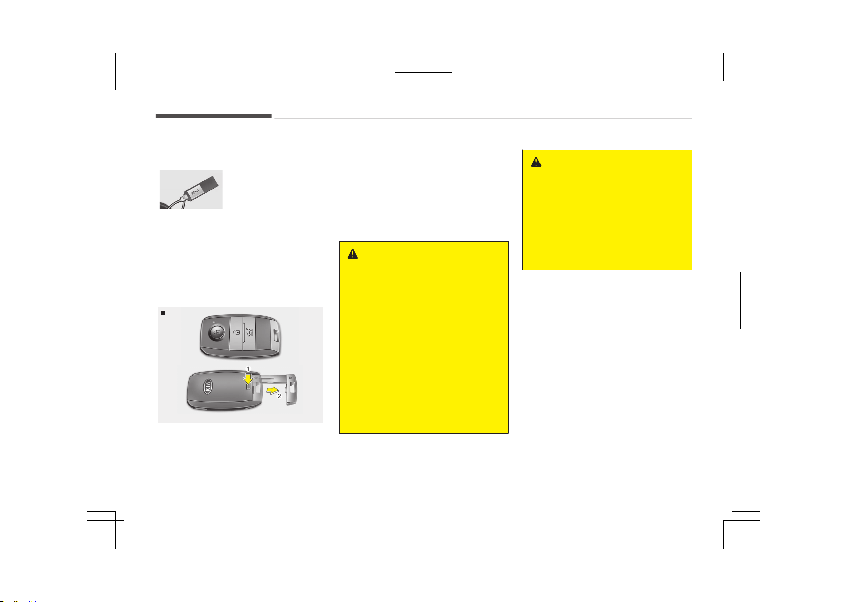
SMART KEY
Record your key number
The key code number
is stamped on the
key code tag attach‐
ed to the key set.
Should you lose your keys, we recom‐
mend that you contact an authorized
Kia dealer. Remove the key code tag
and store it in a safe place. Also, record
the key code number and keep it in a
safe place (not in the vehicle).
Key operations
Smart Key
OXM043002/OXM043003
• Used to start the engine.
• Used to lock and unlock the doors.
• Used to lock and unlock the glove box.
• Used to lock and unlock the trunk.
To remove the mechanical key, press
and hold the release button (1) and re‐
move the mechanical key (2).
To reinstall the mechanical key, put the
key into the hole and push it until a
click sound is heard.
WARNING
n
Ignition key (smart key)
Leaving children unattended in a ve‐
hicle with the ignition key (smart
key) is dangerous even if the key is
not in the ignition or the start but‐
ton is in the ACC or ON position. Chil‐
dren copy adults and they could
place the key in the ignition or press
the start button. The smart key
would enable children to operate
power windows or other controls, or
even make the vehicle move, which
could result in serious bodily injury
or even death. Never leave the keys
in your vehicle with unsupervised
children, when the engine is running.
WARNING
We recommend that you use parts
for replacement from an authorized
Kia dealer. If an aftermarket key is
used, the ignition switch may not re‐
turn to ON after START. If this hap‐
pens, the starter will continue to op‐
erate causing damage to the starter
motor and possible fire due to ex‐
cessive current in the wiring.
Immobilizer system
Your vehicle may be equipped with an
electronic engine immobilizer system to
reduce the risk of unauthorized vehicle
use.
Your immobilizer system is comprised
of a small transponder in the ignition
key and electronic devices inside the
vehicle.
With the immobilizer system, whenever
the engine start/stop button is
changed to the ON position, it checks
and determines and verifies if the igni‐
tion key is valid or not.
If the key is determined to be valid, the
engine will start.
If the key is determined to be invalid,
the engine will not start.
Features of your vehicle
5-04
To activate the immobilizer system:
Change the engine start/stop button to
the OFF position. The immobilizer sys‐
tem activates automatically. Without a
valid ignition key for your vehicle, the
engine will not start.
To deactivate the immobilizer
system:
Change the engine start/stop button to
the ON position.
WARNING
In order to prevent theft of your ve‐
hicle, do not leave spare keys any‐
where in your vehicle. Your immobil‐
izer password is a customer unique
password and should be kept confi‐
dential. Do not leave this number
anywhere in your vehicle.
NOTICE
When starting the engine, do not
use the key with other immobilizer
keys around. Otherwise the engine
may not start or may stop soon af‐
(Continued)
(Continued)
ter it starts. Keep each key sepa‐
rately in order to avoid a starting
malfunction.
CAUTION
Do not put metal accessories near
the ignition switch. Metal accesso‐
ries may interrupt the transponder
signal and may prevent the engine
from being started.
NOTICE
If you need additional keys or lose
your keys, we recommend that you
consult an authorized Kia dealer.
CAUTION
The transponder in your ignition key
is an important part of the immobil‐
izer system. It is designed to give
years of trouble-free service. How‐
(Continued)
(Continued)
ever, you should avoid exposure to
moisture, static electricity and rough
handling. Immobilizer system mal‐
function could occur.
CAUTION
Do not change, alter or adjust the
immobilizer system because it could
cause the immobilizer system to
malfunction. We recommend that
the system be serviced by an au‐
thorized Kia dealer. Malfunctions
caused by improper alterations, ad‐
justments or modifications to the
immobilizer system are not covered
by your vehicle manufacturer war‐
ranty.
5-05
5
Features of your vehicle
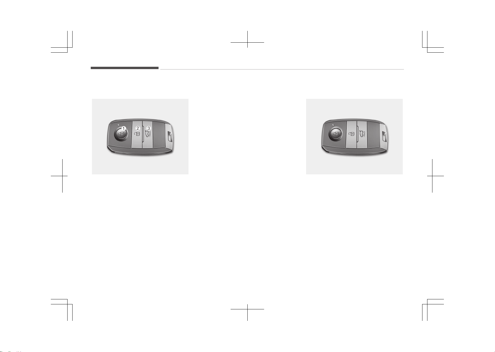
Smart key function
OUM046433LC
Lock (1)
All doors (and trunk) are locked if the
lock button is pressed.
If all doors (and trunk) are closed, the
hazard warning lights will blink once to
indicate that all doors (and trunk) are
locked.
Unlock (2)
All doors (and trunk) are unlocked if the
unlock button is pressed.
The hazard warning lights will blink
twice to indicate that all doors (and
trunk) are unlocked.
However, after pressing this button,
the doors (and trunk) will lock automat‐
ically unless you open any door within
30 seconds.
Trunk unlock (3)
The trunk is unlocked if the button is
pressed for more than 1 second.
The hazard warning lights will blink
twice to indicate that the trunk is un‐
locked.
However, after pressing this button,
the trunk will lock automatically unless
you open the trunk within 30 seconds.
Also, once the trunk is opened and then
closed, the trunk will lock automatically.
Smart key system operation
OXM043002
With a smart key, you can lock or un‐
lock a door (and trunk) and even start
the engine without inserting the key.
Carrying the smart key, you may lock
and unlock the vehicle doors (and
trunk). Also, you may start the engine.
Refer to the following for more details.
Features of your vehicle
5-06
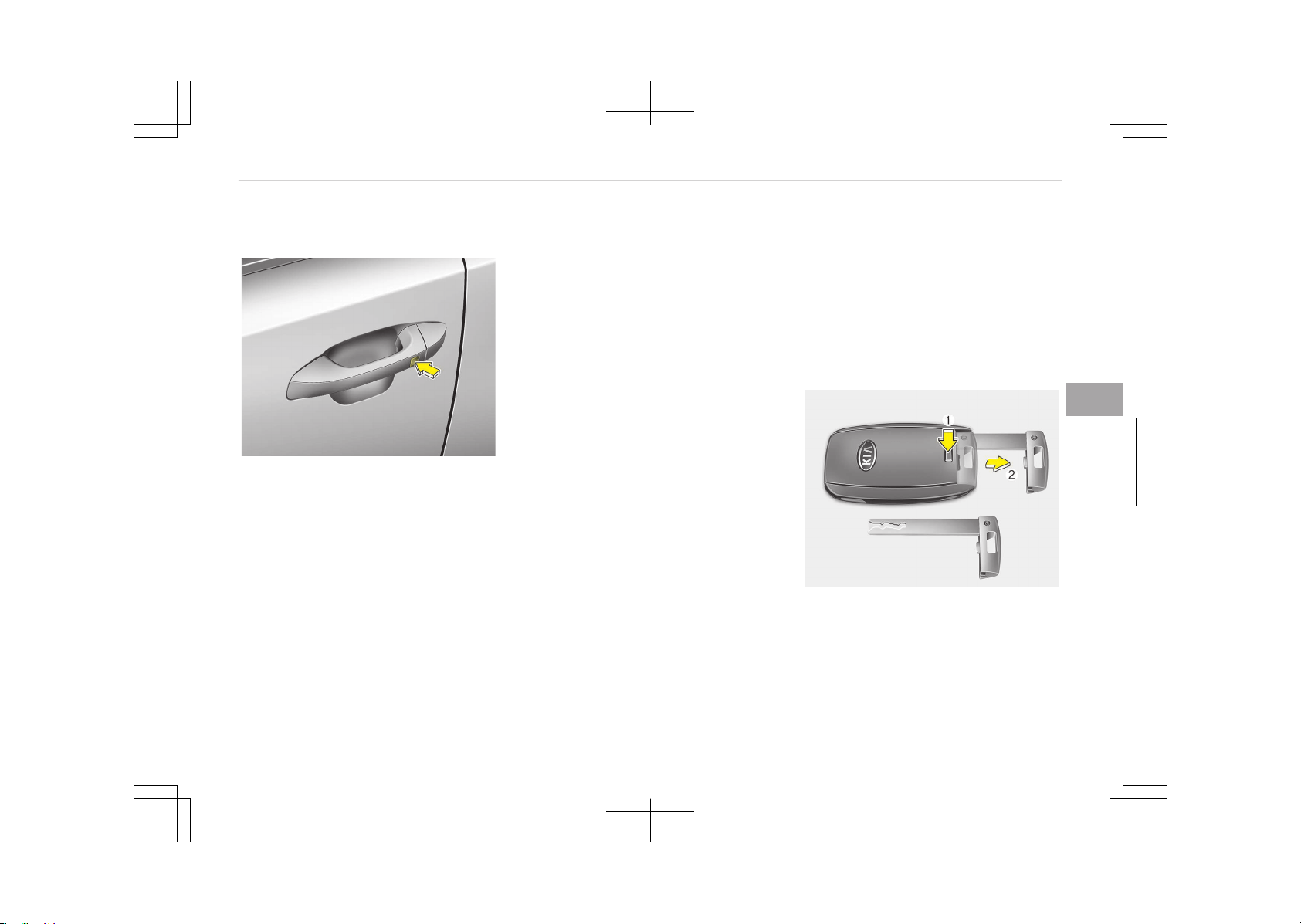
Locking
OJF045003
Pressing the button of the front out‐
side door handles with all doors (and
trunk) closed and any door unlocked,
locks all the doors (and trunk). The haz‐
ard warning lights will blink once to in‐
dicate that all doors (and trunk) are
locked. The button will only operate
when the smart key is within 0.7 ~ 1 m
(28 ~ 40 in) from the outside door han‐
dle. If you want to make sure that a
door has locked or not, you should
check the door lock button inside the
vehicle or pull the outside door handle.
Even though you press the button, the
doors will not lock and the chime
sounds if any of the following occurs:
• The smart key is in the vehicle.
• The ENGINE START/STOP button is in
the ACC or ON position.
• Any door except the trunk is opened.
Unlocking
Pressing the button of the front out‐
side door handles with all doors (and
trunk) closed and locked, unlocks all the
doors (and trunk). The hazard warning
lights will blink twice to indicate that all
doors (and trunk) are unlocked. The
button will only operate when the
smart key is within 0.7 ~ 1 m
(28 ~ 40 in) from the outside door han‐
dle.
When the smart key is recognized in
the area of 0.7 ~ 1 m (28 ~ 40 in) from
the front outside door handle, other
people can also open a door without
possession of the smart key.
Trunk unlocking
If you are within 0.7 ~ 1 m (28 ~ 40 in)
from the outside trunk handle, with
your smart key in possession, the trunk
will unlock and open when you press
the trunk handle switch.
The hazard warning lights will blink
twice to indicate that the trunk is un‐
locked.
Also, once the trunk is opened and then
closed, the trunk will lock automatically.
Start-up
You can start the engine without in‐
serting the key. For detailed informa‐
tion refer to Starting the engine with a
smart key on page 7-08.
Restrictions in handling keys
OJF045325L
When leaving keys with parking lot and
valet attendants, the following proce‐
dures will ensure that your vehicles
glove box compartment can not be
opened in your absence.
1. Press and hold the release button
(1) and remove the mechanical key
(2).
5-07
5
Features of your vehicle
2. Close and then lock the glove box
using the mechanical key.
3. Leave the smart key with the at‐
tendant. The glove box can not be
opened without the mechanical
key.
Transmitter precautions
The smart key will not work if any of
the following occurs:
• Another vehicles smart key is being
operated close to your vehicle.
• You exceed the operating distance
limit (about 10 m [30 feet]).
• The battery in the transmitter is
weak.
• Other vehicles or objects may be
blocking the signal.
• The weather is extremely cold.
• The smart key is close to a radio
transmitter such as a radio station or
an airport which can interfere with
normal operation of the transmitter.
• If the smart key is in close proximity
to your cell phone or smart phone,
the signal from the smart key could
be blocked by normal operation of
your cell phone or smart phone. This
is especially important when the
phone is active such as when making
calls, receiving calls, text messaging,
and/or sending/receiving emails.
Avoid placing the smart key and your
cell phone or smart phone in the
same pants or jacket pocket and
maintain adequate distance between
the two devices.
When the smart key does not work
correctly, open and close the door with
the mechanical key. If you have a prob‐
lem with the smart key, we recom‐
mend that you contact an authorized
Kia dealer.
CAUTION
Keep the smart key away from wa‐
ter or any liquid. If the smart key is
inoperative due to exposure to water
or other liquids, it will not be covered
by your manufacturer’s vehicle war‐
ranty.
CAUTION
Changes or modifications not ex‐
pressly approved by the party re‐
sponsible for compliance could void
the user’s authority to operate the
equipment. If the keyless entry sys‐
tem is inoperative due to changes or
modifications not expressly ap‐
proved by the party responsible for
compliance, it will not be covered by
your manufacturer’s vehicle warran‐
ty.
Features of your vehicle
5-08
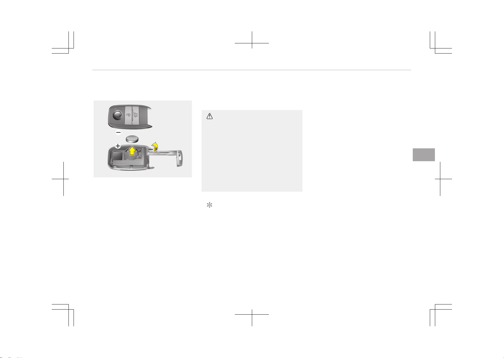
Battery replacement
OXM043005C
A smart key uses a 3 volt lithium bat‐
tery which will normally last for several
years. When replacement is necessary,
use the following procedure.
1. Pry open the rear cover of the
smart key.
2. Replace the battery with a new
battery (CR2032). When replacing
the battery, pay attention to the
battery position.
3. Install the battery in the reverse
order of removal.
For smart key replacement, we recom‐
mend that you contact an authorized
Kia dealer.
CAUTION
• If you are unsure how to use or re‐
place the battery, we recommend
that you contact an authorized Kia
dealer.
• Using the wrong battery can cause
the smart key to malfunction. Be
sure to use the correct battery.
• To avoid damaging the transmit‐
ter, don't drop it, get it wet, or ex‐
pose it to heat or sunlight.
NOTICE
An inappropriately disposed battery
can be harmful to the environment
and human health.
Dispose the battery according to
your local law(s) or regulation.
5-09
5
Features of your vehicle
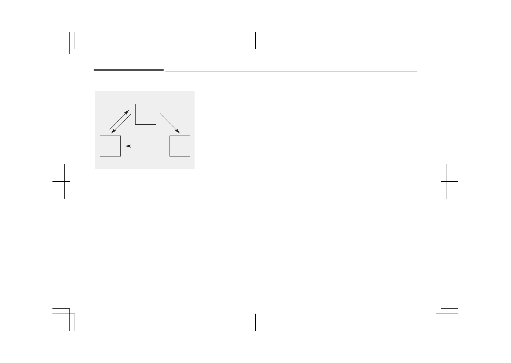
THEFT-ALARM SYSTEM (IF EQUIPPED)
Armed
stage
Disarmed
stage
Theft-alarm
stage
This system is designed to provide pro‐
tection from unauthorized entry into
the vehicle. This system is operated in
three stages: the first is the "Armed"
stage, the second is the "Theft-alarm"
stage, and the third is the "Disarmed"
stage. If triggered, the system provides
an audible alarm with blinking of the
hazard warning lights.
Armed stage
Park the vehicle and stop the engine.
Arm the system as described below.
1. Turn off the engine.
2. Make sure that all doors, the en‐
gine hood and trunk are closed and
latched.
3. • Lock the doors by pressing the
button of the front outside door
handle with the smart key in
your possession.
After completion of the steps
above, the hazard warning lights
will operate once to indicate that
the system is armed.
If the trunk or engine hood re‐
mains opened, the hazard warn‐
ing lights will not operate and
theft-alarm will not arm. After
this, if the trunk and engine hood
are closed, the hazard warning
lights will blink once and the
theft-alarm will arm.
• Lock the doors by pressing the
lock button on the smart key.
After completion of the steps
above, the hazard warning lights
will operate once to indicate that
the system is armed.
If the trunk or engine hood re‐
mains opened, the hazard warn‐
ing lights will not operate and
theft-alarm will not arm. After
this, if the trunk and engine hood
are closed, the hazard warning
lights will blink once and the
theft-alarm will arm.
Do not arm the system until all passen‐
gers have left the vehicle. If the system
is armed while a passenger(s) remains
in the vehicle, the alarm may be activa‐
ted when the remaining passenger(s)
leaves the vehicle. If any door (or trunk)
or engine hood is opened within 30 sec‐
onds after the system enters the
armed stage, the system will be dis‐
armed to prevent unnecessary alarm.
Theft-alarm stage
The alarm will be activated if any of the
following occurs while the system is
armed.
• A front or rear door is opened with‐
out using the smart key.
• The trunk is opened without using
the smart key.
• The engine hood is opened.
The horn will sound and the hazard
warning lights will blink continuously
for approximately 27 seconds. Then, an
alarm will sound two times with 10
seconds interval. If the alarm situation
does not change after the alarm has
sounded, it will go off again. To turn off
the system, unlock the doors with the
smart key.
Features of your vehicle
5-10

Disarmed stage
The system will be disarmed when:
-
The door unlock button is pressed.
-
The button of the front outside door
is pressed while carrying the smart
key.
-
The engine is started (within 3 sec‐
onds).
After the doors are unlocked, the haz‐
ard warning lights will blink twice to in‐
dicate that the system is disarmed.
After pressing the unlock button, if any
door (or trunk) is not opened within 30
seconds, the system will be rearmed.
NOTICE
• If the system is not disarmed with
the smart key, open the door with
the mechanical key and start the
engine. Then the system will be
disarmed.
• If you lose your keys, we recom‐
mend that you consult an author‐
ized Kia dealer.
CAUTION
Do not change, alter or adjust the
theft-alarm system because it could
cause the theft-alarm system to
malfunction and we recommend that
the system be serviced by an au‐
thorized Kia dealer.
Malfunctions caused by improper al‐
terations, adjustments or modifica‐
tions to the theft-alarm system are
not covered by your vehicle manu‐
facturer warranty.
5-11
5
Features of your vehicle
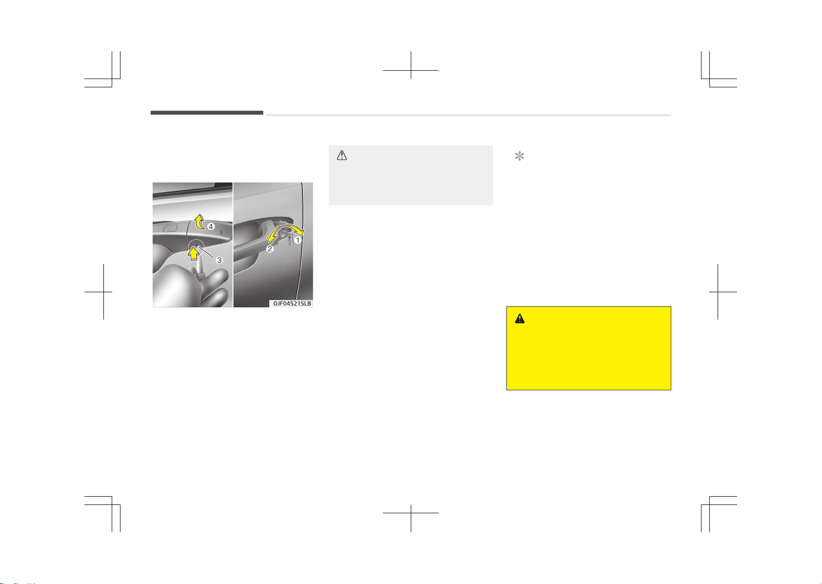
DOOR LOCKS
Operating door locks from
outside the vehicle
To remove the cover
1. Pull out the door handle.
2. Press the lever (3) located inside
the bottom part of the cover with a
key or flat-head screwdriver.
3. Push out the cover (4) while press‐
ing the lever.
CAUTION
Be careful not to damage the cover
while removing it or to misplace it
after removing it.
• Turn the key toward the rear of the
vehicle to unlock and toward the
front of the vehicle to lock.
• If you Lock (1)/Unlock (2) the drivers
door with a key, all vehicle doors will
lock/unlock automatically.
• Doors can also be locked and un‐
locked with the smart key.
• Once the doors are unlocked, they
may be opened by pulling the door
handle.
• When closing the door, push the door
by hand. Make sure the doors are
closed securely.
NOTICE
• In cold and wet climates, door lock
and door mechanisms may not
work properly due to freezing con‐
ditions.
• If the door is locked/unlocked mul‐
tiple times in rapid succession with
either the vehicle key or door lock
switch, the system may stop op‐
erating temporarily in order to
protect the circuit and prevent
damage to system components.
WARNING
• If you don’t close the door secure‐
ly, the door may open again.
• Be careful that someone’s body
and hands are not trapped when
closing the door.
Features of your vehicle
5-12
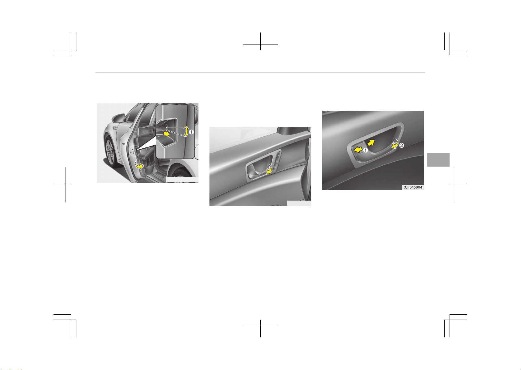
In case of an emergency
OJFHP046432L
If the power door lock switch does not
operate electrically, the only way to
lock the door(s) is with the mechanical
key from the outside key hole.
You can lock the doors without the out‐
side key hole as follows:
1. Open the door.
2. Insert the key into the emergency
door lock hole and turn the key
horizontally to lock (1).
3. Close the door securely.
Operating door locks from inside
the vehicle
With the door inner door handle
(for Type A)
OJF045306L
Drivers door and front passengers
door
If the inner door handle is pulled when
the door is locked, the door will unlock
and open.
Rear door
If the inner door handle is pulled once
when the door is locked, the door will
unlock.
If the inner door handle is pulled once
more, the door will open.
With the door lock button (for Type
B)
• To unlock a door, pull the door lock
button (1) to the Unlock position.
The red mark on the button will be
visible.
• To lock a door, push the door lock
button (1) to the Lock position. If
the door is locked properly, the red
mark on the door lock button will not
be visible.
• To open a door, pull the door handle
(2) outward.
5-13
5
Features of your vehicle
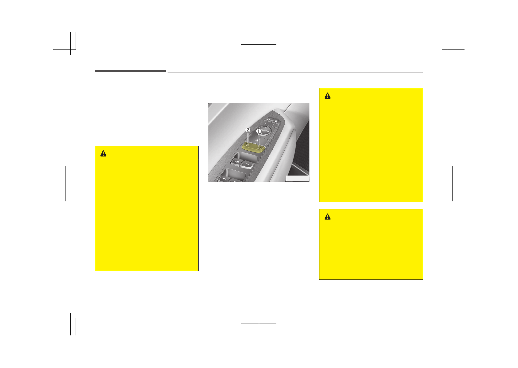
• If the inner door handle of the front
door/all doors (if equipped) is pulled
when the door lock button is in the
lock position, the button is unlocked
and the door will open. (if equipped)
• Doors cannot be locked if the smart
key is in the vehicle and any door is
opened.
WARNING
n
Door lock malfunction
If a power door lock ever fails to
function while you are in the vehicle,
try one or more of the following
techniques to exit:
• Operate the door unlock feature
repeatedly (both electronic and
manual) while simultaneously pull‐
ing on the door handle.
• Operate the other door locks and
handles, front and rear.
• Lower a front window and use the
key to unlock the door from out‐
side.
• Move to the cargo area and open
the trunk.
With central door lock switch
OJF045005
Operate by pressing the central door
lock switch.
• When pressing the right portion (1) of
the switch, all vehicle doors will lock.
• When pressing the left portion (2) of
the switch, all vehicle doors will un‐
lock.
• If the smart key is in the vehicle and
any door is opened, the doors will not
lock even though the right portion (1)
of the central door lock switch is
pressed.
WARNING
n
Doors
• The doors should always be fully
closed and locked while the vehicle
is in motion to prevent accidental
opening of the door. Locked doors
will also discourage potential in‐
truders when the vehicle stops or
slows down.
• Be careful when opening doors and
watch for vehicles, motorcycles,
bicycles or pedestrians approach‐
ing the vehicle in the path of the
door. Opening a door when some‐
thing is approaching can cause
damage or injury.
WARNING
n
Unlocked vehicles
Leaving your vehicle unlocked can in‐
vite theft or possible harm to you or
others from someone hiding in your
vehicle while you are gone. Always
press the engine start/stop button
to the OFF position, engage the
(Continued)
Features of your vehicle
5-14
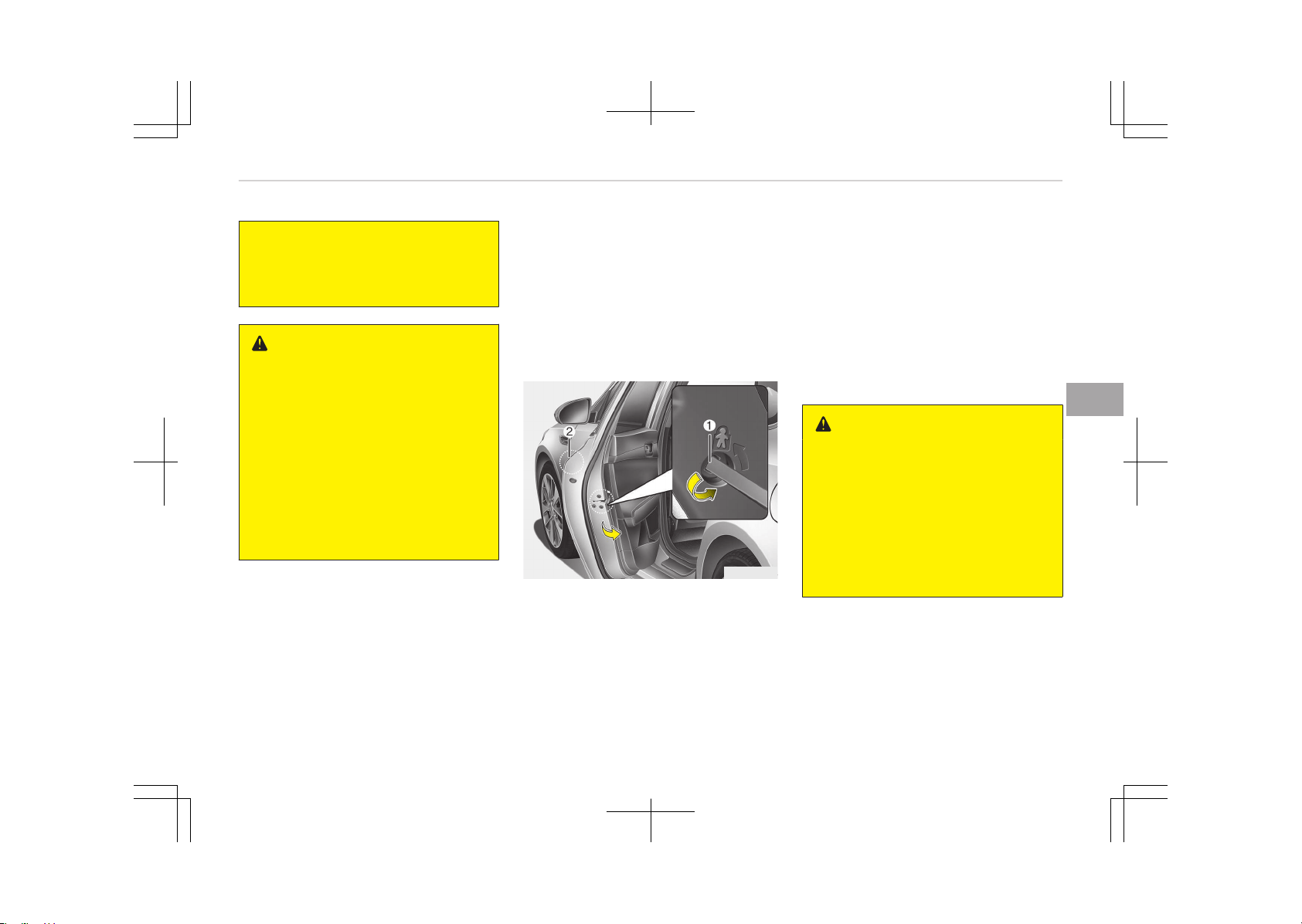
(Continued)
parking brake, close all windows and
lock all doors when leaving your ve‐
hicle unattended.
WARNING
n
Unattended children
An enclosed vehicle can become ex‐
tremely hot, causing death or severe
injury to unattended children or ani‐
mals who cannot escape the vehicle.
Furthermore, children might operate
features of the vehicle that could in‐
jure them, or they could encounter
other harm, possibly from someone
gaining entry to the vehicle. Never
leave children or animals unattended
in your vehicle.
Door lock/unlock features
Impact sensing door unlock system
(if equipped)
All doors will automatically unlock when
an impact causes the air bags to de‐
ploy.
Speed sensing door lock system (if
equipped)
All doors will automatically lock after
the vehicle speed exceeds 15 km/h.
You can activate or deactivate the auto
door lock/unlock features in the vehicle.
Refer to User setting on page 5-58.
Child-protector rear door lock
OJF045006
The child safety lock is provided to help
prevent children from accidentally
opening the rear doors from inside the
vehicle. The rear door safety locks
should be used whenever children are in
the vehicle.
The child safety lock is located on the
edge of each rear door. When the child
safety lock is in the lock position (1),
the rear door will not open if the inner
door handle (2) is pulled.
To lock the child safety lock, insert a
key (or screwdriver) into the hole and
turn it to the lock position.
To allow a rear door to be opened from
inside the vehicle, unlock the child safe‐
ty lock.
WARNING
n
Rear door locks
If children accidentally open the rear
doors while the vehicle is in motion,
they could fall out and be severely
injured or killed. To prevent children
from opening the rear doors from
the inside, the rear door safety locks
should be used whenever children
are in the vehicle.
5-15
5
Features of your vehicle
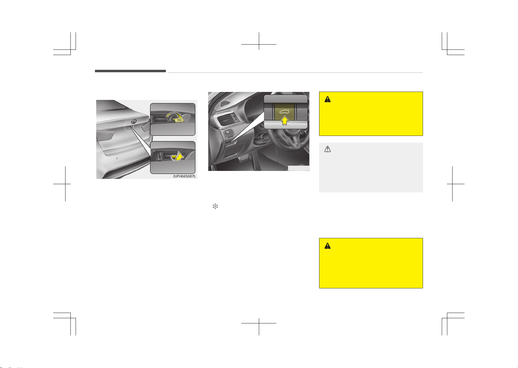
TRUNK
Opening the trunk
1. Make sure the shift lever is in P and
set the parking brake.
2. Then do one of the following:
- Press the Remote key or Smart
Key Trunk Unlock button for
more than one second.
- Press the button on the trunk it‐
self with the Smart Key in your
possession.
- Use the mechanical key.
OJF045008
• To open the trunk from inside the ve‐
hicle, push the trunk lid release but‐
ton.
NOTICE
In cold and wet climates, trunk lock
and trunk mechanisms may not
work properly due to freezing condi‐
tions.
WARNING
The trunk swings upward. Make sure
no objects or people are near the
rear of the vehicle when opening the
trunk.
CAUTION
Make certain that you close the
trunk before driving your vehicle.
Possible damage may occur to the
attached hardware if the trunk is
not closed prior to driving.
Closing the trunk
To close, lower the trunk lid, then press
down on it until it locks. To be sure the
trunk lid is securely fastened, always
check by trying to pull it up again.
WARNING
The trunk lid should always be kept
completely closed while the vehicle is
in motion. If it is left open or ajar,
poisonous exhaust gases may enter
(Continued)
Features of your vehicle
5-16
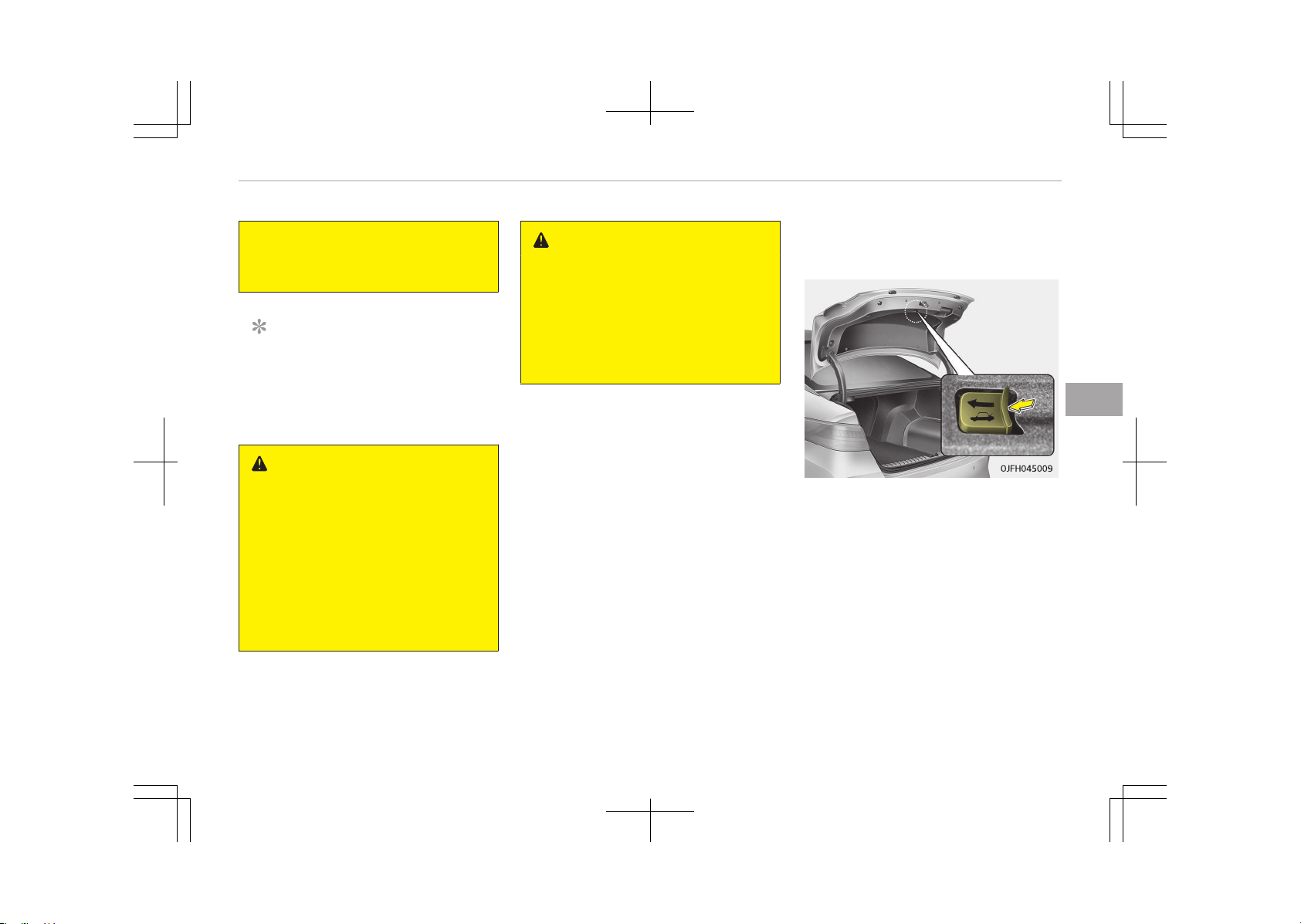
(Continued)
the car and serious illness or death
may result.
NOTICE
If the trunk is closed with the smart
key in it, the chime will sound for ap‐
proximately 3 seconds and the trunk
will reopen.
WARNING
n
Exhaust fumes
If you drive with the trunk open, you
will draw dangerous exhaust fumes
into your vehicle which can cause se‐
rious injury or death to vehicle occu‐
pants.
If you must drive with the trunk
open, keep the air vents and all win‐
dows open so that additional outside
air comes into the vehicle.
WARNING
n
Rear cargo area
Occupants should never ride in the
rear cargo area where no restraints
are available. To avoid injury in the
event of an accident or sudden
stops, occupants should always be
properly restrained.
Emergency trunk safety release
(if equipped)
Your vehicle is equipped with an emer‐
gency trunk release lever located inside
the trunk. If someone is inadvertently
locked in the trunk, moving the handle
in the direction of the arrow will release
the trunk latch mechanism and open
the trunk.
5-17
5
Features of your vehicle

WARNING
• For emergencies, be fully aware of
the location of the emergency
trunk safety release lever in this
vehicle and how to open the trunk
if you are accidentally locked in the
trunk.
• No one should be allowed to occu‐
py the trunk at any time. The
trunk is a very dangerous location
in the event of a crash.
• Use the release lever for emergen‐
cies only. Use extreme caution, es‐
pecially while the vehicle is in mo‐
tion.
Features of your vehicle
5-18
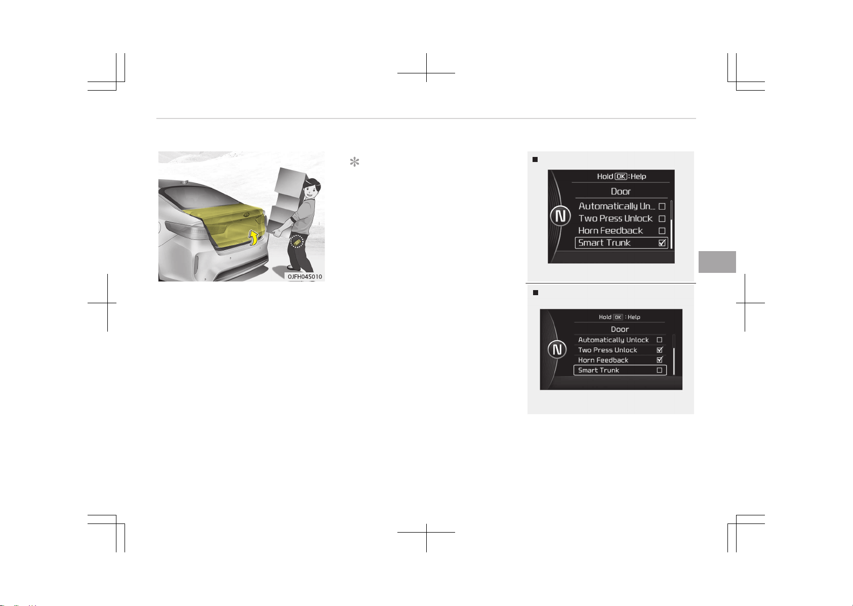
SMART TRUNK (IF EQUIPPED)
On a vehicle equipped with a smart key,
the trunk can be opened with no-touch
activation using the Smart Trunk sys‐
tem.
How to use the Smart Trunk
The trunk can be opened with no-touch
activation satisfying all the conditions
below.
• After 15 seconds when all doors are
closed and locked.
• Positioned in the detecting area for
more than 3 seconds.
NOTICE
• The Smart Trunk does not operate
when:
- The smart key is detected with‐
in 15 seconds after the doors
are closed and locked, and is
continuously detected.
- The smart key is detected with‐
in 15 seconds after the doors
are closed and locked, and
1.5 m from the front door han‐
dles (for vehicles equipped with
Welcome Light).
- A door is not locked or closed.
- The smart key is in the vehicle.
Type A
OJF045282L
Type B
OJF045283L
1. Setting
To activate the Smart Trunk, go to
User Settings Mode and select
Smart Trunk on the LCD display.
5-19
5
Features of your vehicle
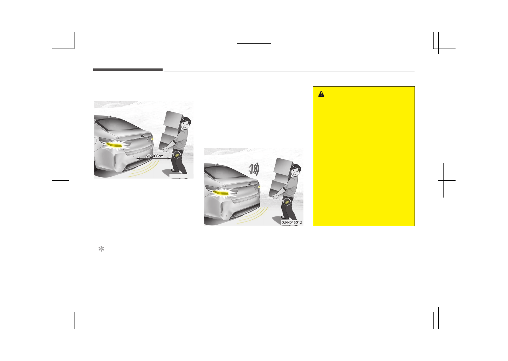
For more details, refer to LCD Dis‐
play on page 5-56.
OJFH045011
2. Detect and Alert
If you are positioned in the detect‐
ing area (50 ~ 100 cm behind the
vehicle) carrying a smart key, the
hazard warning lights will blink and
the chime will sound for about 3
seconds to alert you the smart key
has been detected and the trunk
will open.
NOTICE
Do not approach the detecting area
if you do not want the trunk to
(Continued)
(Continued)
open. If you have unintentionally en‐
tered the detecting area and the
hazard warning lights and chime
start to operate, leave the detecting
area with the smart key. The trunk
will stay closed.
3. Automatic opening
The hazard warning lights will blink
and the chime will sound 2 times
and then the trunk will slowly open.
WARNING
• Make certain that you close the
trunk before driving your vehicle.
• Make sure there are no people or
objects around the trunk before
opening or closing the trunk.
• Make sure objects in the rear cargo
area do not come out when open‐
ing the trunk on a slope way. It
may cause serious injury.
• Make sure to deactivate the Smart
Trunk function when washing your
vehicle.
Otherwise, the trunk may open in‐
advertently.
• The key should be kept out of
reach of children. Children may in‐
advertently open the Smart Trunk
while playing around the rear area
of the vehicle.
Features of your vehicle
5-20
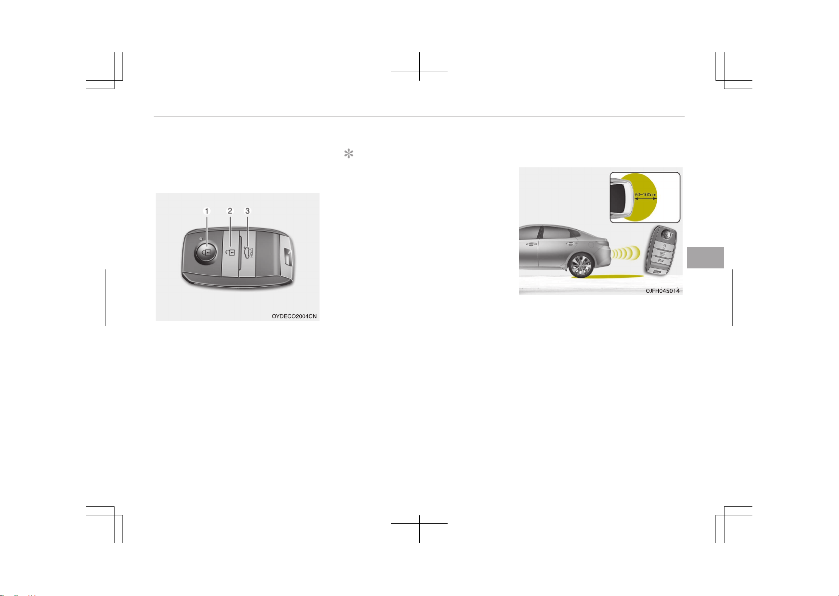
How to deactivate the Smart
Trunk function using the smart
key
1. Door lock
2. Door unlock
3. Trunk open
If you press any button of the smart
key during the Detect and Alert stage,
the Smart Trunk function will be deacti‐
vated.
Make sure to be aware of how to deac‐
tivate the Smart Trunk function for
emergency situations.
NOTICE
• If you press the door unlock but‐
ton (2), the Smart Trunk function
will be deactivated temporarily.
But, if you do not open any door
for 30 seconds, the Smart Trunk
function will be activated again.
• If you press the trunk open button
(3) for more than 1 second, the
trunk opens.
• If you press the door lock button
(1) or trunk open button (3) when
the Smart Trunk function is not in
the Detect and Alert stage, the
Smart Trunk function will not be
deactivated.
• In case you have deactivated the
Smart Trunk function by pressing
the smart key button and opened
a door, the Smart Trunk function
can be activated again by closing
and locking all doors.
Detecting area
• The Smart Trunk operates with a
welcome alert if the smart key is de‐
tected within 50~100 cm from the
trunk.
• The alert stops at once if the smart
key is positioned outside the detect‐
ing area during the Detect and Alert
stage.
5-21
5
Features of your vehicle

NOTICE
• The Smart Trunk function will not
work if any of the following oc‐
curs:
- The smart key is close to a ra‐
dio transmitter such as a radio
station or an airport which can
interfere with normal operation
of the transmitter.
- The smart key is near a mobile
two way radio system or a cel‐
lular phone.
- An other vehicle's smart key is
being operated close to your
vehicle.
• The detecting range may decrease
or increase when:
- One side of the vehicle is raised
to replace a tire or to inspect
the vehicle.
- The vehicle is slantingly parked
on a slope or unpaved road, etc.
Features of your vehicle
5-22
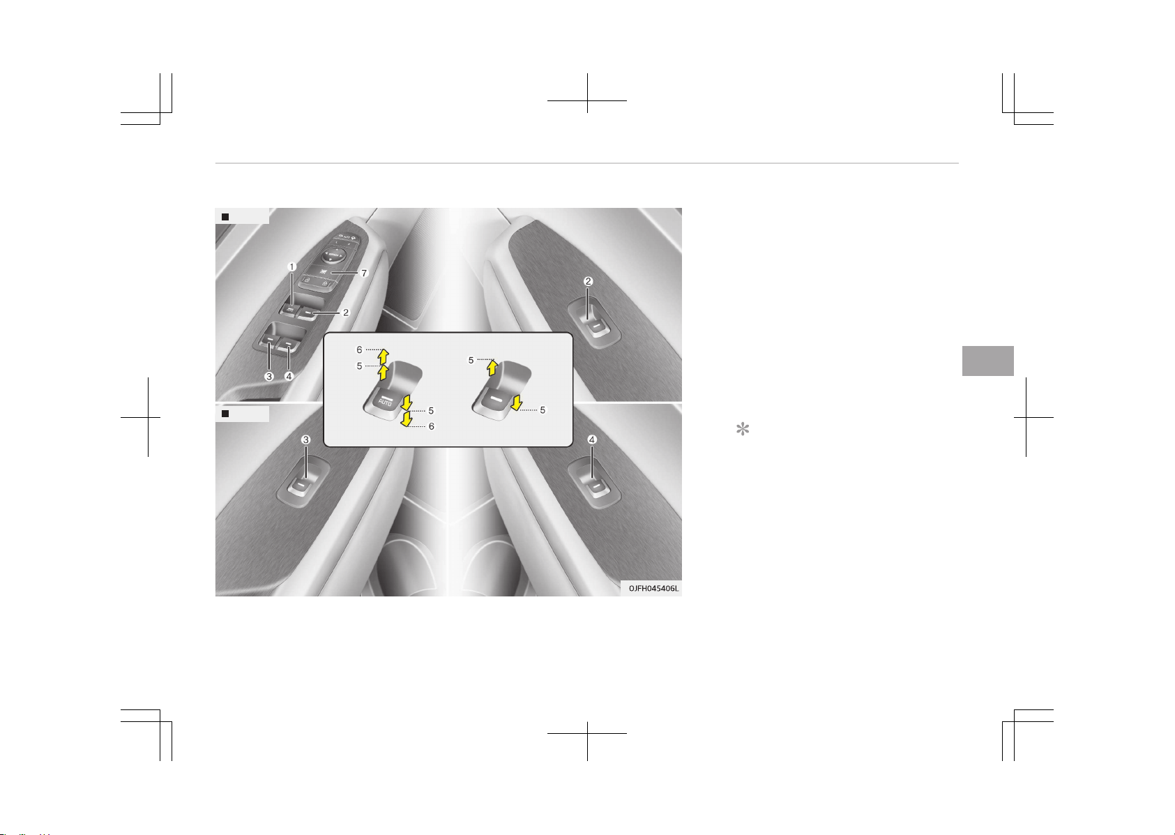
WINDOWS
Front
Rear
1. Drivers door power window switch
2. Front passenger's door power win‐
dow switch
3. Rear door (left) power window
switch
4. Rear door (right) power window
switch
5.
Window opening and closing
*
6.
Automatic power window up
*
/
down
*
7. Power window lock button
NOTICE
In cold and wet climates, power win‐
dows may not work properly due to
freezing conditions.
Power windows
The engine start/stop button must be
in the ON position for power windows
to operate.
*
: if equipped
5-23
5
Features of your vehicle
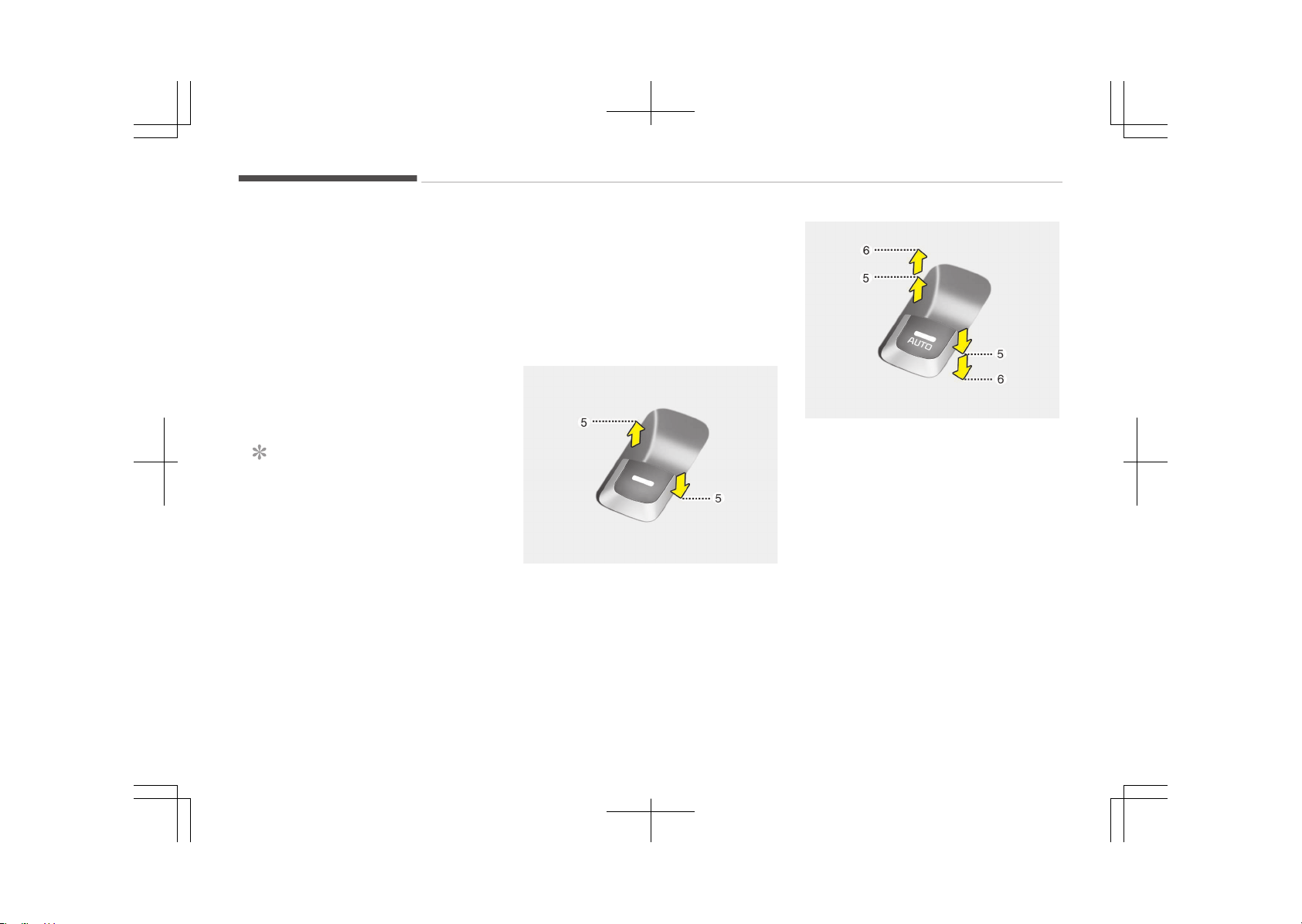
Each door has a power window switch
that controls the door's window. The
driver has a power window lock button
which can block the operation of pas‐
senger windows. The power windows
can be operated for approximately 30
seconds after engine is turned off.
However, if the front doors are opened,
the power windows cannot be operated
even within the 30 second period.
The drivers door has a master power
window switch that controls all the
windows in the vehicle.
NOTICE
While driving with the rear windows
down or with the sunroof (if equip‐
ped) in an open (or partially open po‐
sition), your vehicle may demon‐
strate a wind buffeting or pulsation
noise. This noise is a normal occur‐
rence and can be reduced or elimina‐
ted by taking the following actions.
If the noise occurs with one or both
of the rear windows down, partially
lower both front windows approxi‐
mately one centimeter (one inch). If
(Continued)
(Continued)
you experience the noise with the
sunroof open, slightly reduce the
size of the sunroof opening.
Window opening and closing
OJF045016
Type A
To open or close a window, press down
or pull up the front portion of the cor‐
responding switch to the first detent
position (5).
OJF045017L
Type B - Auto up/down window (if
equipped)
Pressing or pulling up the power win‐
dow switch momentarily to the second
detent position (6) completely lowers
or raises the window even when the
switch is released. To stop the window
at the desired position while the win‐
dow is in operation, pull up or press
down and release the switch.
If the power window does not operate
normally, the automatic power window
system must be reset as follows:
1. Place the engine start/stop button
to the ON position.
Features of your vehicle
5-24
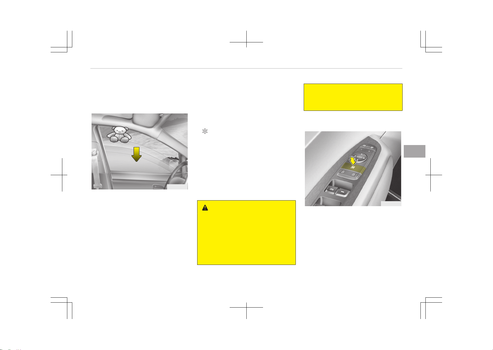
2. Close the window and continue
pulling up the power window switch
for at least 1 second after the win‐
dow is completely closed.
OUN026013
Automatic reversal (For Type B)
If the upward movement of the window
is blocked by an object or part of the
body, the window will detect the resist‐
ance and will stop the upward move‐
ment. The window will then lower ap‐
proximately 30 cm (11.8 in.) to allow
the object to be cleared.
If the window detects the resistance
while the power window switch is
pulled up continuously, the window will
stop the upward movement then lower
approximately 2.5 cm (1 in.).
And if the power window switch is
pulled up continuously again within 5
seconds after the window is lowered by
the automatic window reversal feature,
the automatic window reversal will not
operate.
NOTICE
The automatic reverse feature for
the window is only active when the
auto up feature is used by fully
pulling up the switch. The automatic
reverse feature will not operate if
the window is raised using the half‐
way position on the power window
switch.
WARNING
Always check for obstructions be‐
fore raising any window to avoid in‐
juries or vehicle damage. If an object
less than 4 mm (0.16 in.) in diameter
is caught between the window glass
and the upper window channel, the
automatic reverse window may not
(Continued)
(Continued)
detect the resistance and will not
stop and reverse direction.
Power window lock button
OJF045018
The driver can disable the power win‐
dow switches on the rear passengers
doors by pressing the power window
lock button to the lock position (press‐
ed).
When the power window lock button is
pressed:
5-25
5
Features of your vehicle
• The drivers master control can oper‐
ate the front passengers power win‐
dow but cannot operate the rear pas‐
sengers' power windows.
• The front passengers control can op‐
erate the front passengers' power
window.
• The rear passengers control cannot
operate the rear passengers' power
window.
CAUTION
• To prevent possible damage to the
power window system, do not
open or close two windows or
more at the same time. This will
also ensure the longevity of the
fuse.
• Never try to operate the main
switch on the driver's door and the
individual door window switch in
opposite directions at the same
time. If this is done, the window
will stop and cannot be opened or
closed.
WARNING
n
Windows
• NEVER leave the keys in your vehi‐
cle with unsupervised children,
when the engine is running.
• NEVER leave any child unattended
in the vehicle. Even very young
children may inadvertently cause
the vehicle to move, entangle
themselves in the windows, or
otherwise injure themselves or
others.
• Always double check to make sure
all arms, hands, head and other
obstructions are safely out of the
way before closing a window.
• Do not allow children to play with
the power windows. Keep the driv‐
er’s door power window lock but‐
ton in the LOCK position (pressed).
Serious injury can result from un‐
intentional window operation by
the child.
• Do not extend heads or any limbs
outside the window while the vehi‐
cle is in motion.
Features of your vehicle
5-26
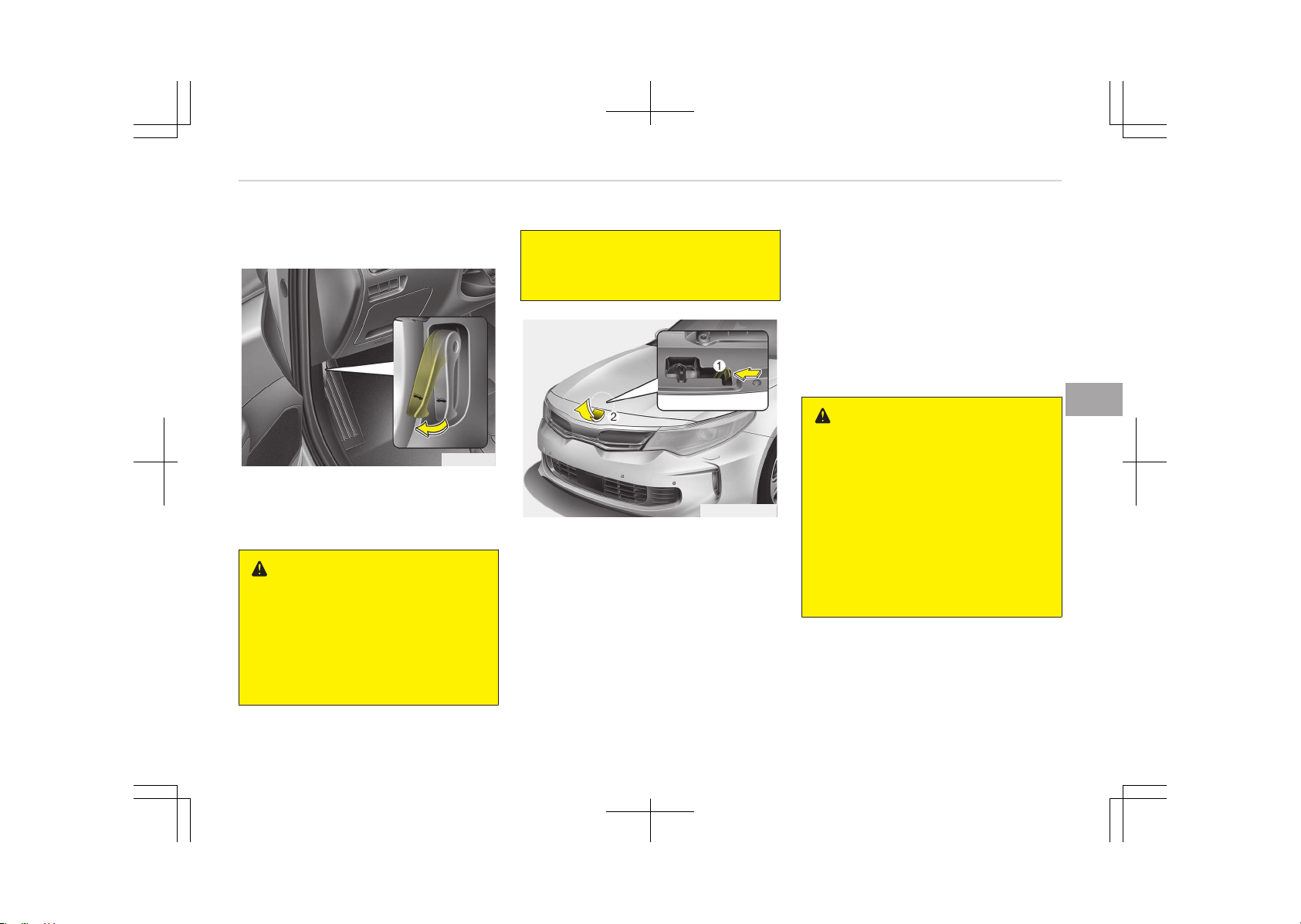
HOOD
Opening the hood
OJF045019
1. Pull the release lever to unlatch the
hood. The hood should pop open
slightly.
WARNING
Open the hood after turning off the
engine on a flat surface, shifting the
shift lever to the P (Park) position
for automatic transaxle/dual clutch
transmission and to the 1st (First)
gear or R (Reverse) for manual
(Continued)
(Continued)
transaxle, and setting the parking
brake.
OJFHP046407L
2. Go to the front of the vehicle, raise
the hood slightly, push the secon‐
dary latch (1) left side and lift the
hood (2).
3. Raise the hood. It will completely
rise by itself after it has been
raised about halfway.
Closing the hood
1. Before closing the hood, check the
following:
• All filler caps in the engine com‐
partment must be correctly in‐
stalled.
• Gloves, rags or any other com‐
bustible material must be re‐
moved from the engine compart‐
ment.
2. Lower the hood halfway and push
down to securely lock in place.
WARNING
• Before closing the hood, ensure
that all obstructions are removed
from the hood opening. Closing the
hood with an obstruction present
in the hood opening may result in
property damage or severe per‐
sonal injury.
• Do not leave gloves, rags or any
other combustible material in the
engine compartment. Doing so
may cause a heat-induced fire.
5-27
5
Features of your vehicle

WARNING
• Always double check to be sure
that the hood is firmly latched be‐
fore driving away. If it is not latch‐
ed, the hood could open while the
vehicle is being driven, causing to‐
tal loss of visibility, which might
result in an accident.
• Do not move the vehicle with the
hood raised. The view will be
blocked and the hood could fall or
be damaged.
Features of your vehicle
5-28
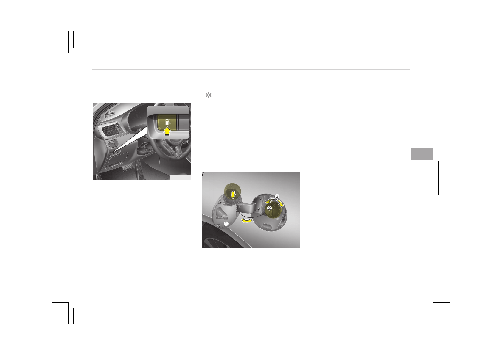
FUEL FILLER LID (HYBRID)
Opening the fuel filler lid
OJF045021
The fuel filler lid must be opened from
inside the vehicle by pushing the fuel
filler lid button.
NOTICE
If the fuel filler lid does not open be‐
cause ice has formed around it, tap
lightly or push on the lid to break the
ice and release the lid. Do not pry on
the lid. If necessary, spray around
the lid with an approved de-icer fluid
(do not use radiator antifreeze) or
move the vehicle to a warm place
and allow the ice to melt.
OJF045022L
1. Stop the engine.
2. To open the fuel filler lid, push the
fuel filler lid opener button.
3. Pull open the fuel filler lid (1).
4. To remove the cap, turn the fuel
filler cap (2) counterclockwise (3).
5. Refuel as needed.
Closing the fuel filler lid
1. To install the cap, turn it clockwise
until it clicks. This indicates that
the cap is securely tightened.
2. Close the fuel filler lid and push it
lightly and make sure that it is se‐
curely closed.
5-29
5
Features of your vehicle
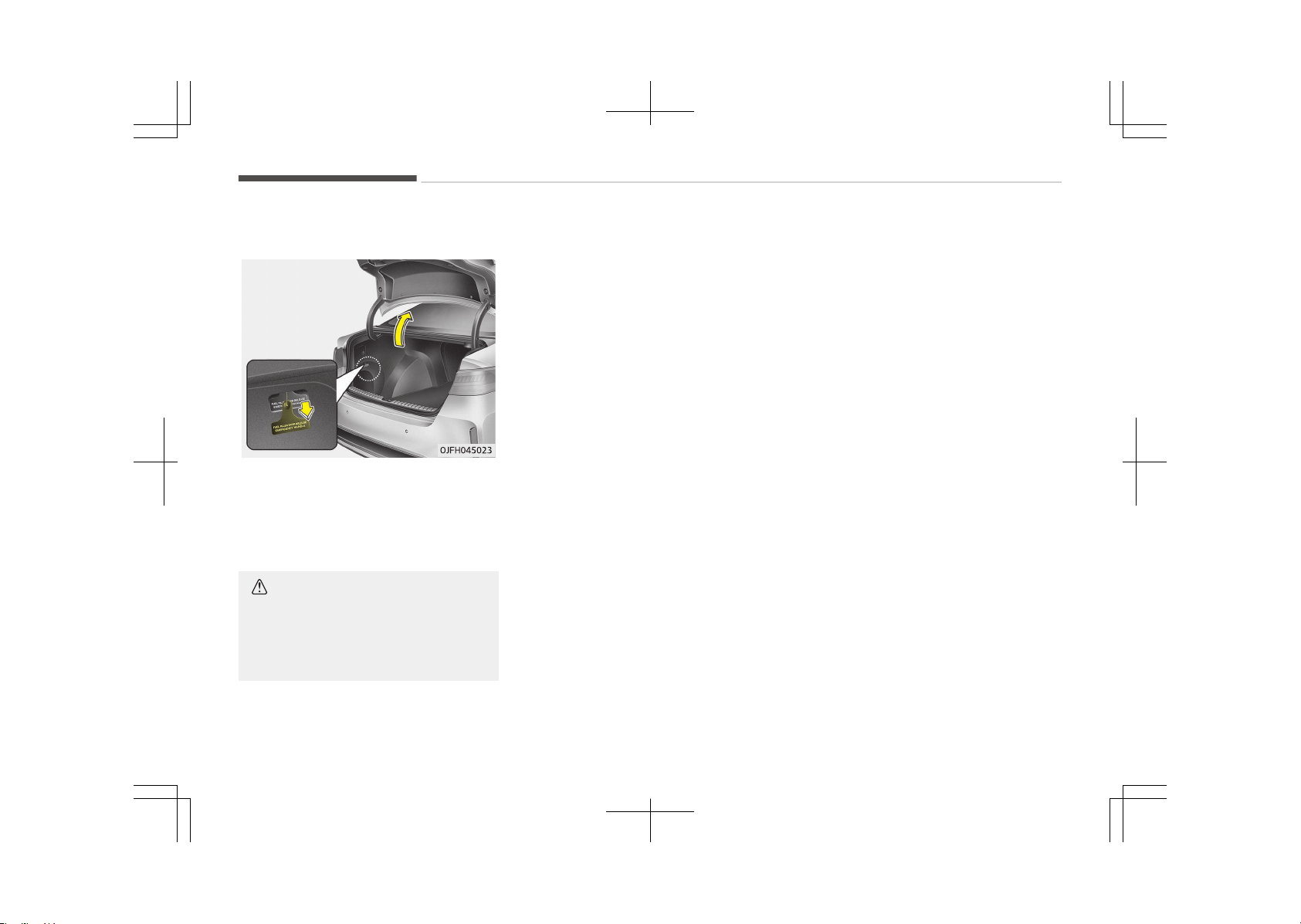
Emergency fuel filler lid release
If the fuel filler lid does not open using
the remote fuel filler lid release, you
can open it manually. Remove the panel
in the cargo area. Pull the handle out
slightly.
CAUTION
Do not pull the handle excessively,
otherwise the luggage compartment
area trim or release handle may be
damaged.
Features of your vehicle
5-30
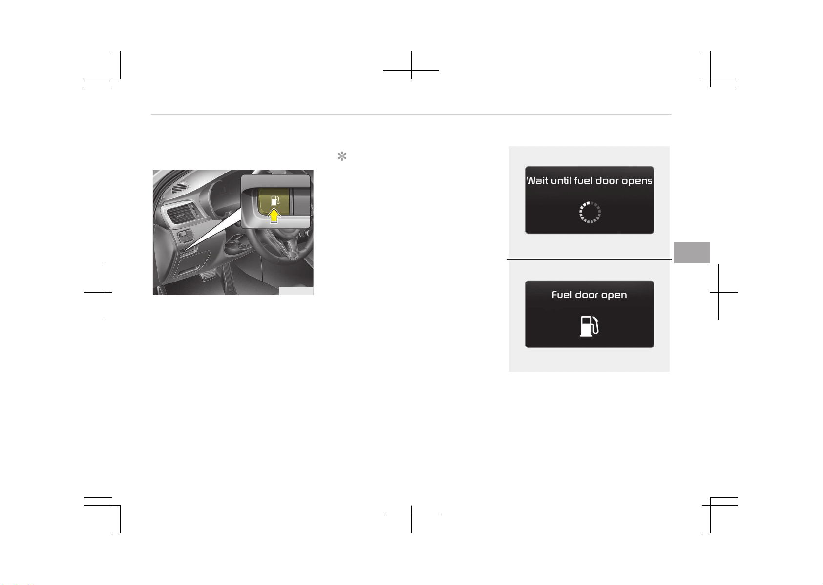
FUEL FILLER LID (PLUG-IN HYBRID)
Opening the fuel filler lid
OJF045021
The fuel filler lid must be opened from
inside the vehicle by pushing the fuel
filler lid button.
NOTICE
If the fuel filler lid does not open be‐
cause ice has formed around it, tap
lightly or push on the lid to break the
ice and release the lid. Do not pry on
the lid. If necessary, spray around
the lid with an approved de-icer fluid
(do not use radiator antifreeze) or
move the vehicle to a warm place
and allow the ice to melt.
OJFHP046424L
OJFHP046423L
5-31
5
Features of your vehicle
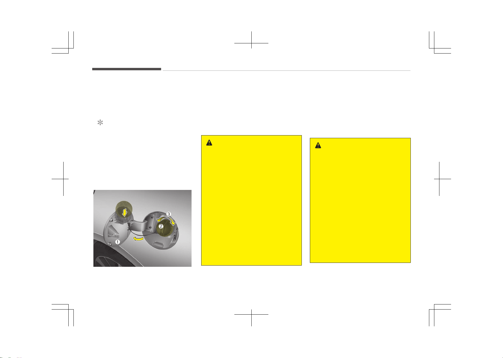
Wait until the fuel tank is depressur‐
ized. The message is displayed when
the fuel filler lid opens after the fuel
tank is depressurized.
NOTICE
• It may take up to 20 seconds to
open fuel filler door.
• When the fuel filler door is frozen
and does not open after 20 sec‐
onds at freezing temperature,
slightly tap the fuel filler door and
then attempt to open it.
OJF045022L
1. Stop the engine.
2. To open the fuel filler lid, push the
fuel filler lid opener button.
3. Pull open the fuel filler lid (1).
4. To remove the cap, turn the fuel
filler cap (2) counterclockwise (3).
5. Refuel as needed.
WARNING
• Add fuel into the fuel tank within
20 minutes after opening the fuel
filler lid. After 20 minutes, the fuel
tank may shut off, causing fuel to
overflow. In this case, re-press the
fuel filler lid opening button.
• Do not leave the fuel filler door
opened for an extended period of
time. It may discharge the battery.
• Close the fuel filler lid after fueling
the vehicle. If you start the vehicle
with the fuel filler lid opened, the
message Check fuel door illumi‐
nates on the LCD display.
• Avoid refueling the vehicle while
charging the (high-voltage) hybrid
battery. It may cause a fire or an
explosion due to static electricity.
Closing the fuel filler lid
1. To install the cap, turn it clockwise
until it clicks. This indicates that
the cap is securely tightened.
2. Close the fuel filler lid and push it
lightly and make sure that it is se‐
curely closed.
WARNING
n
Refueling
• If pressurized fuel sprays out, it
can cover your clothes or skin and
subject you to the risk of fire and
burns. Always remove the fuel cap
carefully and slowly. If the cap is
venting fuel or if you hear a hiss‐
ing sound, wait until the condition
stops before completely removing
the cap.
• Do not "top off" after the nozzle
automatically shuts off when re‐
fueling.
• Always check that the fuel cap is
installed securely to prevent fuel
spillage in the event of an acci‐
dent.
Features of your vehicle
5-32
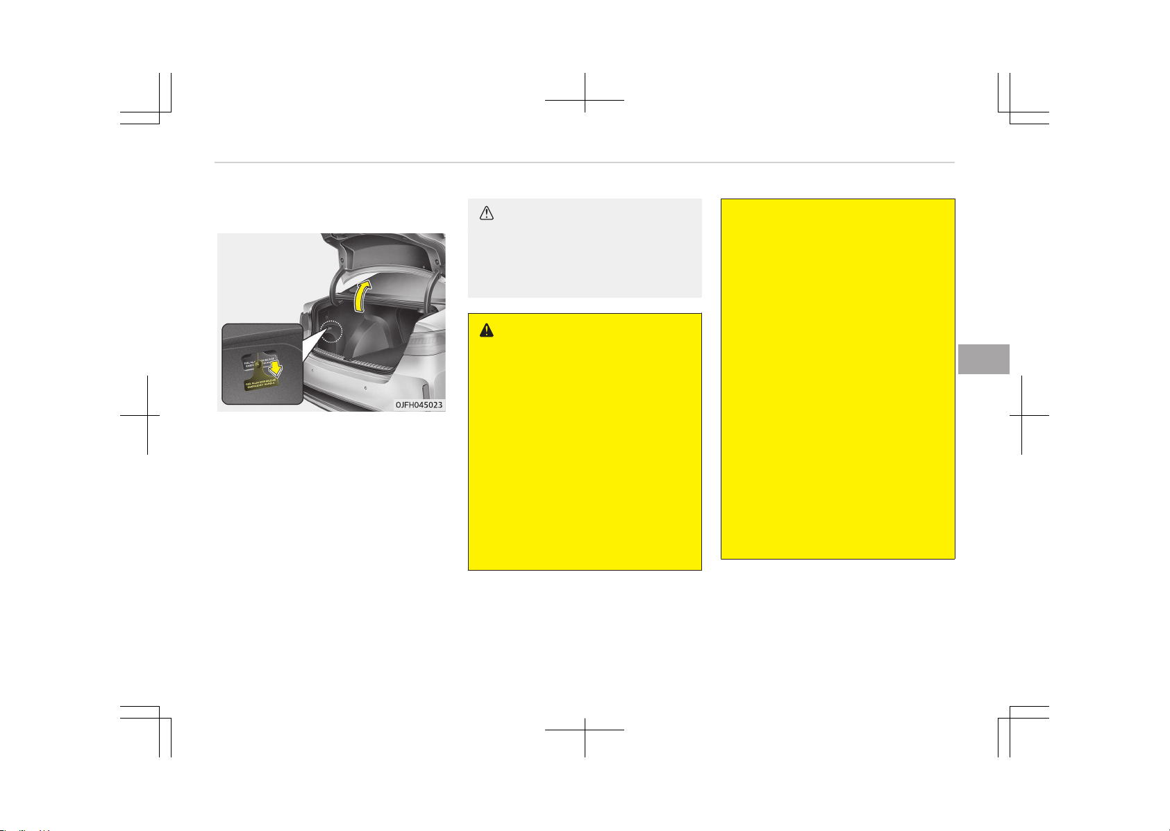
Emergency fuel filler lid release
If the fuel filler lid does not open using
the remote fuel filler lid release, you
can open it manually. Remove the panel
in the cargo area. Pull the handle out
slightly.
In this case, slowly open the fuel tank
cap, because the fuel tank may be
highly pressurized. If fuel leaks out, or
if air hisses out, wait until it disappears,
open the fuel tank cap, and slowly re‐
fuel the vehicle. If you quickly pour fuel
into the fuel tank, the fuel may over‐
flow out of the fuel tank.
CAUTION
Do not pull the handle excessively,
otherwise the luggage compartment
area trim or release handle may be
damaged.
WARNING
n
Refueling dangers
Automotive fuels are flammable ma‐
terials. When refueling, please note
the following guidelines carefully.
Failure to follow these guidelines
may result in severe personal injury,
severe burns or death by fire or ex‐
plosion.
• Read and follow all warnings pos‐
ted at the gas station facility.
• Before refueling note the location
of the Emergency Gasoline Shut-
Off, if available, at the gas station
facility.
(Continued)
(Continued)
• Before touching the fuel nozzle,
you should eliminate potentially
dangerous static electricity dis‐
charge by touching another metal
part of the vehicle, a safe distance
away from the fuel filler neck,
nozzle, or other gas source.
• Do not get back into a vehicle once
you have begun refueling since you
can generate static electricity by
touching, rubbing or sliding against
any item or fabric (polyester, sat‐
in, nylon, etc.) capable of produc‐
ing static electricity. Static elec‐
tricity discharge can ignite fuel va‐
pors resulting in rapid burning. If
you must reenter the vehicle, you
should once again eliminate poten‐
tially dangerous static electricity
discharge by touching a metal part
of the vehicle, away from the fuel
filler neck, nozzle or other gasoline
source.
(Continued)
5-33
5
Features of your vehicle
(Continued)
• When using an approved portable
fuel container, be sure to place the
container on the ground prior to
refueling. Static electricity dis‐
charge from the container can ig‐
nite fuel vapors causing a fire.
Once refueling has begun, contact
with the vehicle should be main‐
tained until the filling is complete.
Use only approved portable plastic
fuel containers designed to carry
and store gasoline.
• Do not use cellular phones while
refueling. Electric current and/or
electronic interference from cellu‐
lar phones can potentially ignite
fuel vapors causing a fire.
• When refueling, always shut the
engine off. Sparks produced by
electrical components related to
the engine can ignite fuel vapors
causing a fire. Once refueling is
complete, check to make sure the
filler cap and filler door are secure‐
ly closed, before starting the en‐
gine.
(Continued)
(Continued)
• DO NOT use matches or a lighter
and DO NOT SMOKE or leave a lit
cigarette in your vehicle while at a
gas station especially during refu‐
eling. Automotive fuel is highly
flammable and can, when ignited,
result in fire.
• If a fire breaks out during refuel‐
ing, leave the vicinity of the vehi‐
cle, and immediately contact the
manager of the gas station and
then contact the local fire depart‐
ment. Follow any safety instruc‐
tions they provide.
CAUTION
• Make sure to refuel your vehicle
according to Fuel requirements
on page 2-03.
(Continued)
(Continued)
• If the fuel filler cap requires re‐
placement, please make sure that
you use parts designed for re‐
placement in your vehicle. An in‐
correct fuel filler cap can result in
a serious malfunction of the fuel
system or emission control sys‐
tem. For more detailed informa‐
tion, we recommend that you con‐
tact an authorized Kia dealer.
• Do not spill fuel on the exterior
surfaces of the vehicle. Any type
of fuel spilled on painted surfaces
may damage the paint.
• After refueling, make sure the fuel
cap is installed securely to prevent
fuel spillage in the event of an ac‐
cident.
Features of your vehicle
5-34
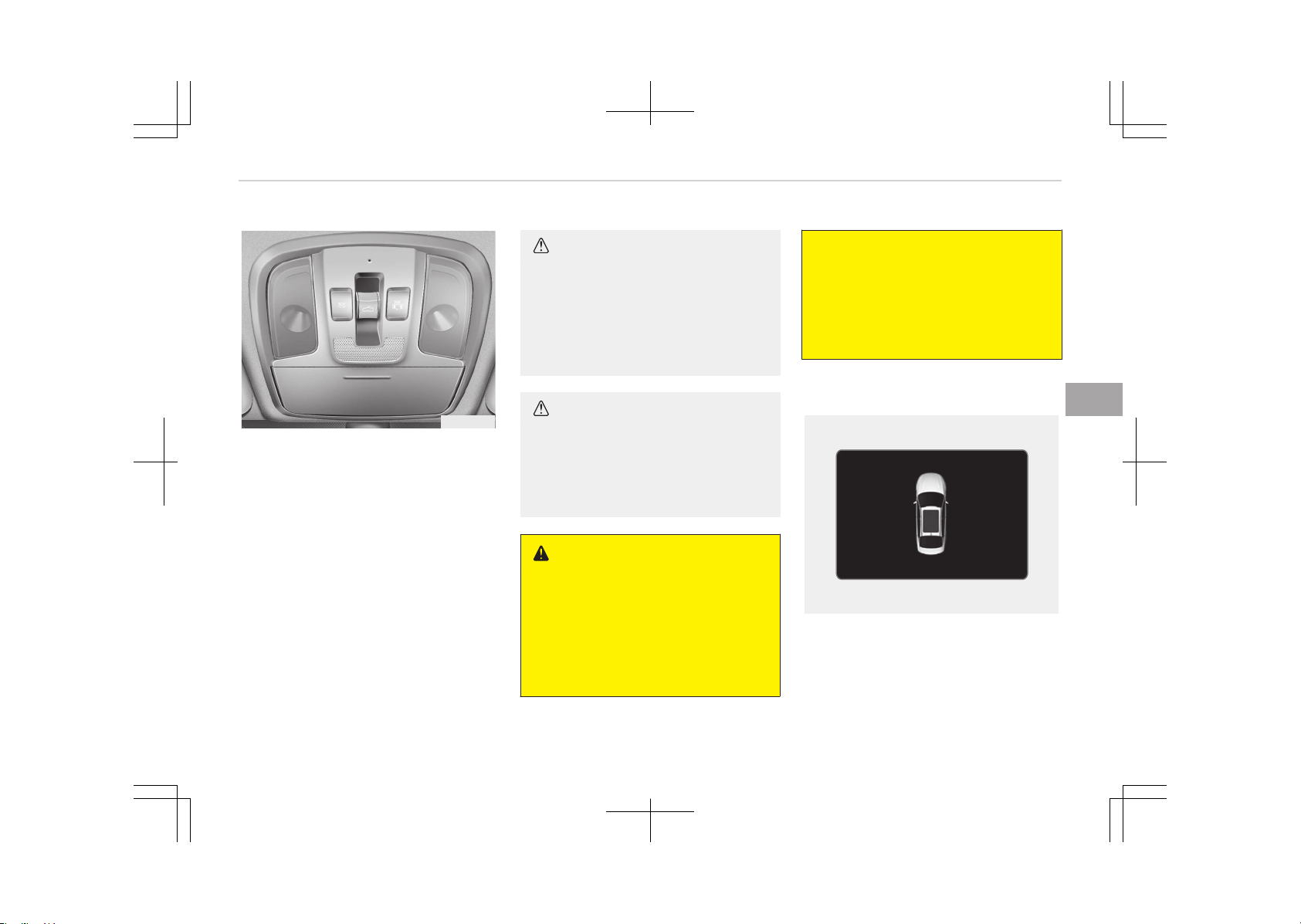
PANORAMA SUNROOF (IF EQUIPPED)
OJF045024
If your vehicle is equipped with a sun‐
roof, you can slide or tilt your sunroof
with the sunroof control lever located
on the overhead console.
The sunroof can be operated for ap‐
proximately 30 seconds when the en‐
gine start/stop button is in the ON po‐
sition. However, if the front doors are
opened, the sunroof cannot be opened
even within the 30 seconds period.
• In cold and wet climates, the sunroof
may not work properly due to freez‐
ing conditions.
• After the vehicle is washed or in a
rainstorm, be sure to wipe off any
water that is on the sunroof before
operating it.
CAUTION
n
Sunroof control lever
Do not continue to move the sunroof
control lever after the sunroof is
fully opened, closed, or tilted. Dam‐
age to the motor or system compo‐
nents could occur.
CAUTION
Make sure the sunroof is fully closed
when leaving your vehicle. If the
sunroof is opened, rain or snow may
leak through the sunroof and wet
the interior as well as cause theft.
WARNING
n
Sunroof break
The sunroof, which is made of glass,
may break if a sufficient impact is
applied. In this case, in an accident,
any improperly belted occupant may
be tossed out of the vehicle through
(Continued)
(Continued)
the sunroof, possibly resulting into
injury. To minimize all the possible
accident risks, all occupants must be
properly belted and, in case of a
child, be fastened in a proper child
restraint.
Sunroof open warning
OJF045216L
If the driver turns off the engine when
the sunroof is not fully closed, the
warning chime will sound for approxi‐
mately 7 seconds and a message will
appear on the LCD display.
5-35
5
Features of your vehicle
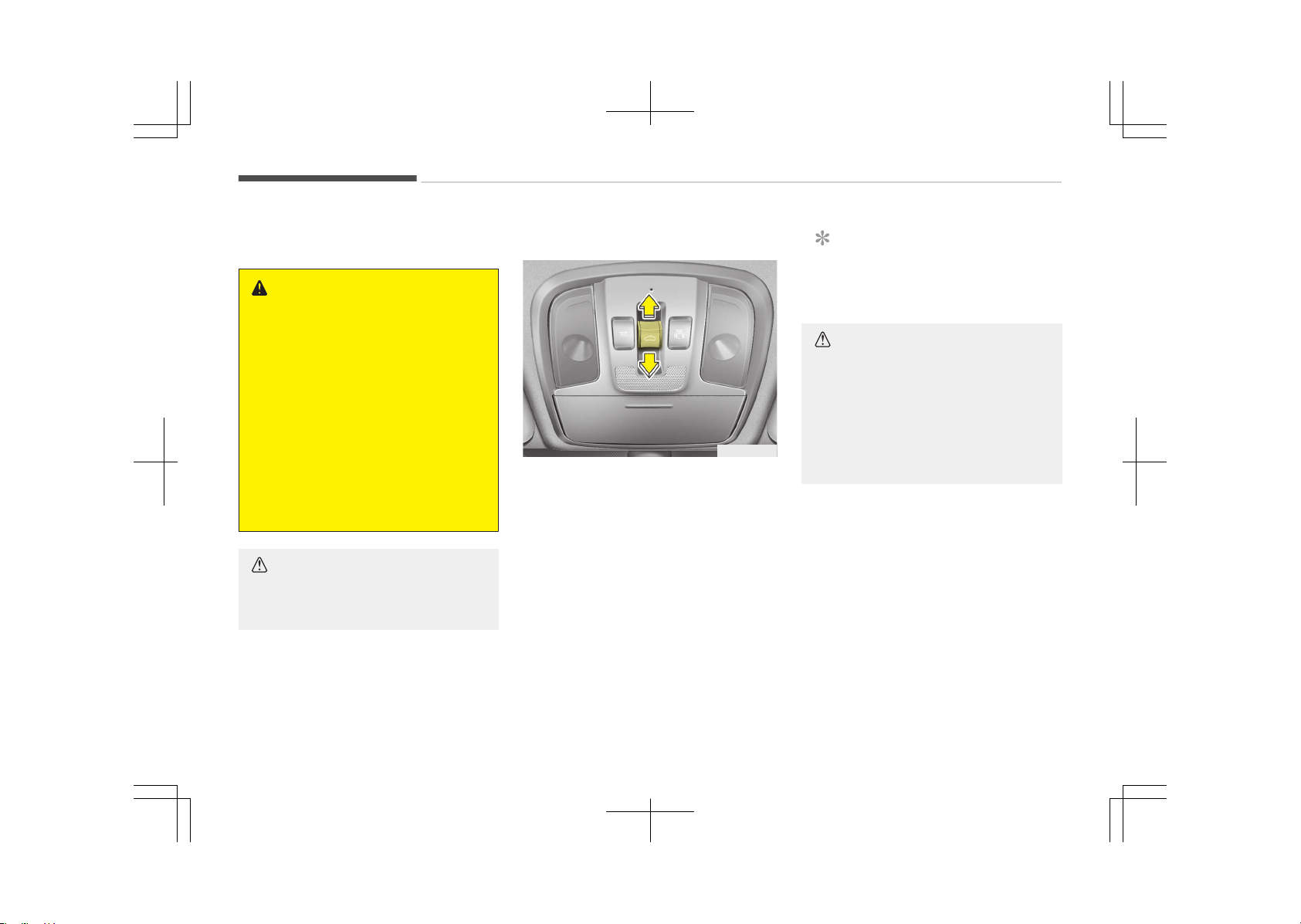
Close the sunroof securely when leav‐
ing your vehicle.
WARNING
• Never adjust the sunroof or sun‐
shade while driving. This could re‐
sult in loss of control and an acci‐
dent that may cause death, seri‐
ous injury, or property damage.
• If you would like to carry items on
the roof using a cross bar, do not
operate the sunroof.
• When carrying cargo on the roof,
do not load heavy items above the
sunroof or glass roof.
• Do not allow children to operate
the sunroof.
CAUTION
Do not extend any luggage outside
the sunroof while driving.
Sunshade
OJF045217L
To open the sunshade
Pull the sunroof control lever backward
to the 1st detent position.
To close the sunshade when the
sunroof glass is closed
Push the sunroof control lever forward
or pull it down to the 1st detent posi‐
tion.
To stop the sliding at any point, press
the sunshade control switch momen‐
tarily.
NOTICE
Wrinkles formed on the sunshade as
material characteristic are normal.
CAUTION
• Do not pull or push the sunshade
by hand. It could cause sunshade
failure.
• Close the sunroof when driving
through dusty roads. Dust may
cause a malfunction of the vehicle
system.
Features of your vehicle
5-36
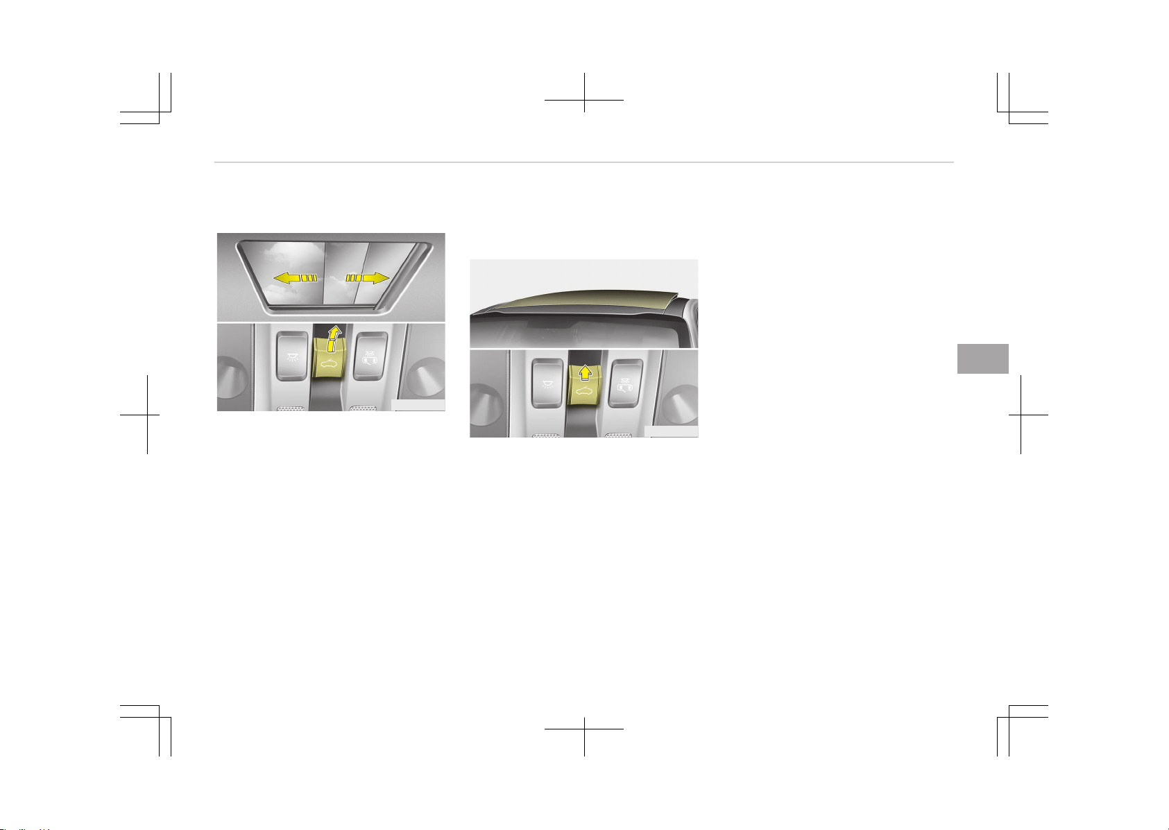
Sliding the sunroof
OJF045025L
When the sunshade is closed
Pull the sunroof control lever backward
to the 2nd detent position, the sun‐
shade and sunroof glass will slide all the
way open. To stop the sunroof move‐
ment at any point, push the sunroof
control lever momentarily.
When the sunshade is opened
Pull the sunroof control lever backward
to the 1st or 2nd detent position, the
sunroof glass will slide all the way open.
To stop the sunroof movement at any
point, push the sunroof control lever
momentarily.
❈ The front part of the sunroof glass
can only be opened and closed.
Tilting the sunroof
OJF045026L
When the sunshade is closed
Push the sunroof control lever upward,
the sunshade will slide halfway open,
then the sunroof glass will tilt.
To stop the sunroof movement at any
point, push the sunroof control lever
momentarily.
When the sunshade is opened
Push the sunroof control lever upward,
the sunroof glass will tilt.
To stop the sunroof movement at any
point, push the sunroof control lever
momentarily.
Closing the sunroof
To close the sunroof glass with the
sunshade
Push the sunroof control lever forward
or downward to the 2nd detent posi‐
tion. The sunroof glass and sunshade
will close automatically.
To stop the sunroof movement at any
point, push the sunroof control lever
momentarily.
To close the sunroof glass only
Push the sunroof control lever forward.
The sunroof glass will close automati‐
cally.
To stop the sunroof movement at any
point, push the sunroof control lever
momentarily.
5-37
5
Features of your vehicle
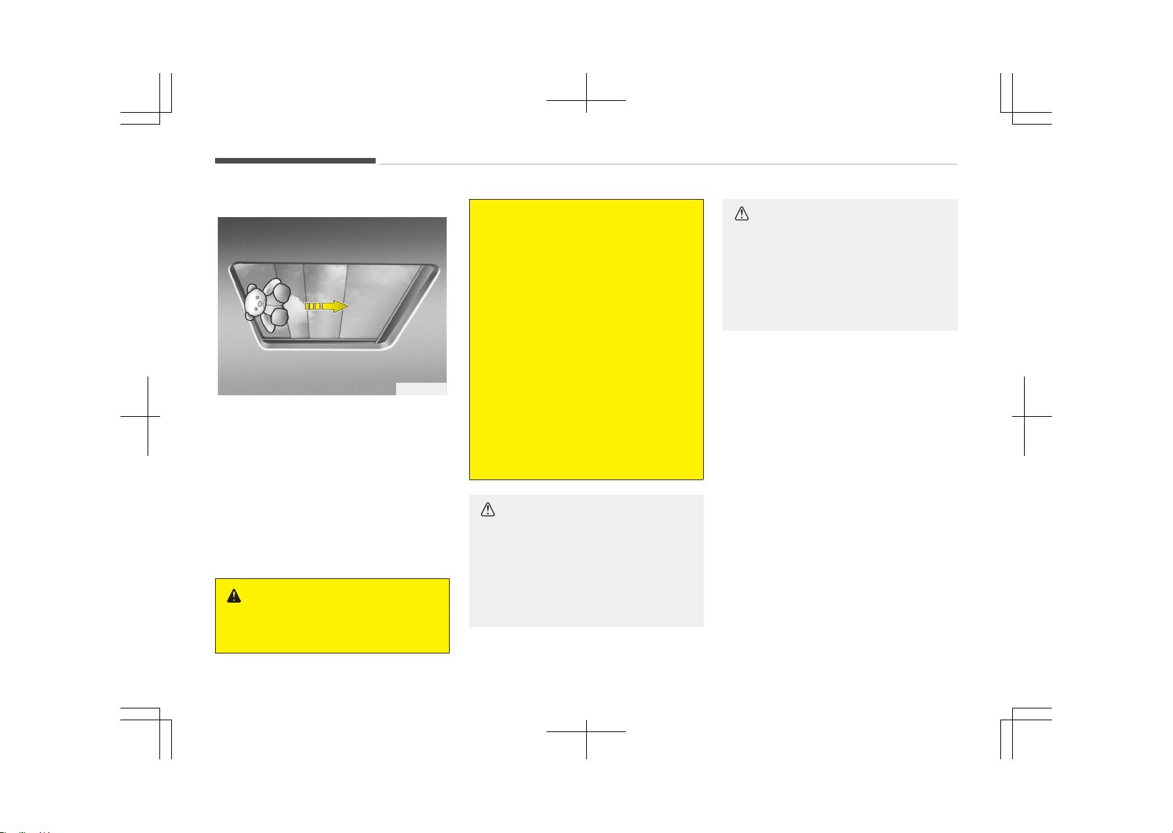
Automatic reversal
OYF049215
If an object or part of the body is de‐
tected while the sunroof glass or sun‐
shade is closing automatically, it will re‐
verse the direction, and then stop.
The auto reverse function does not
work if a tiny obstacle is between the
sliding glass or sunshade and the sun‐
roof sash. You should always check
that all passengers and objects are
away from the sunroof before closing
it.
WARNING
n
Sunroof
(Continued)
(Continued)
• Be careful that no head, hands and
body parts are obstructed by a
closing sunroof.
• Do not extend the face, neck,
arms or body outside the sunroof
while driving.
• Make sure your hands and head
are safely out of the way before
closing a sunroof.
• A panorama sunroof is made of
glass, therefore it may break in an
accident. If you do not have your
seat belt on, you may stick out of
the broken glass and get injured or
killed. For all passengers' safety,
have an appropriate protection on
(ex. seat belt, CRS, etc.).
CAUTION
• Periodically remove any dirt that
may accumulate on the guide rail.
• If you drive with the sunroof
opened right after a car wash or
rain, water may get inside the ve‐
hicle.
CAUTION
n
Sunroof motor damage
If you try to open the sunroof when
the temperature is below freezing or
when the sunroof is covered with
snow or ice, the glass or the motor
could be damaged.
Resetting the sunroof
Whenever the vehicle battery is discon‐
nected or discharged, you must reset
your sunroof system as follows:
1. Start the engine.
2. Close the sunshade and sunroof
completely if opened.
3. Release the sunroof control lever.
4. Push the sunroof control lever for‐
ward in the direction of close
(about 10 seconds) until the sun‐
shade slightly moves. Then, release
the lever.
Features of your vehicle
5-38

5. Push the sunroof control lever for‐
ward in the direction of close, until
the sunroof operates as follows
again:
Sunshade Open Glass Slide Open
Glass Slide Close Sunshade
Close
Then, release the lever.
When this is complete, the sunroof sys‐
tem has been reset.
NOTICE
If you do not reset the sunroof, it
may not work properly.
5-39
5
Features of your vehicle

STEERING WHEEL
Electric power steering
Power steering uses the motor to as‐
sist you in steering the vehicle. If the
engine is off or if the power steering
system becomes inoperative, the vehi‐
cle may still be steered, but it will re‐
quire increased steering effort.
The motor driven power steering is
controlled by the power steering con‐
trol unit which senses the steering
wheel torque and vehicle speed to com‐
mand the motor.
The steering effort becomes heavier as
the vehicles speed increases and be‐
comes lighter as the vehicles speed de‐
creases for better control of the steer‐
ing wheel.
Should you notice any change in the ef‐
fort required to steer during normal ve‐
hicle operation, we recommend that
the system be checked by an author‐
ized Kia dealer.
NOTICE
The following symptoms may occur
during normal vehicle operation:
(Continued)
(Continued)
• The EPS warning light does not il‐
luminate.
• The steering effort is high imme‐
diately after turning the engine
start/stop button to the ON posi‐
tion.
This happens as the EPS system
performs the diagnostics. When
the diagnostics is completed, the
steering effort will return to its
normal condition.
• A click noise may be heard from
the EPS relay after the engine
start/stop button is in the ON po‐
sition.
• Motor noise may be heard when
the vehicle is at a stop or at a low
driving speed.
(Continued)
(Continued)
• The steering effort can suddenly
increase if the operation of the
EPS system is stopped to prevent
serious accidents when the EPS
control unit detects a malfunction
of the EPS system by self-diagno‐
sis.
• The steering effort increases if
the steering wheel is rotated con‐
tinuously when the vehicle is not
in motion. However, after a few
minutes, it will return to its normal
conditions.
• If the Electronic Power Steering
System does not operate normal‐
ly, the warning light will illuminate
on the instrument cluster. The
steering wheel may become diffi‐
cult to control or operate abnor‐
mally. We recommend that you
contact an authorized Kia dealer.
(Continued)
Features of your vehicle
5-40
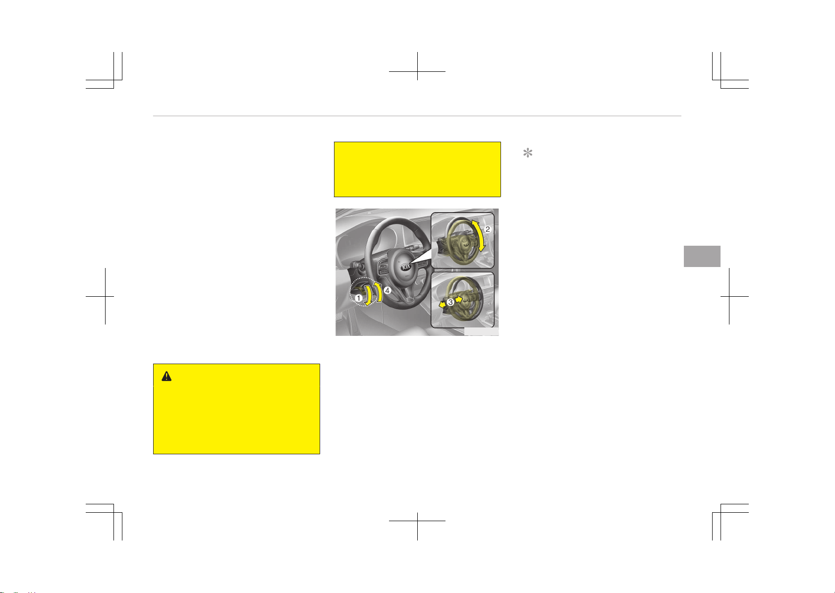
(Continued)
• When you operate the steering
wheel in a low temperature, ab‐
normal noise could occur. If the
temperature rises, the noise will
disappear. This is a normal condi‐
tion.
Tilt & telescopic steering
A tilt and telescopic steering wheel al‐
lows you to adjust the steering wheel
before you drive. You can also raise it
to give your legs more room when you
exit and enter the vehicle.
The steering wheel should be posi‐
tioned so that it is comfortable for you
to drive, while permitting you to see
the instrument panel warning lights
and gauges.
WARNING
• Never adjust the angle of the
steering wheel while driving. You
may lose steering control and
cause severe personal injury,
death or accidents.
(Continued)
(Continued)
• After adjusting, push the steering
wheel both up and down to be cer‐
tain it is locked in position.
OJF045028
To change the steering wheel angle,
pull down the lock release lever (1), ad‐
just the steering wheel to the desired
angle (2) and height (3), then pull up
the lock-release lever (4) to lock the
steering wheel in place. Be sure to ad‐
just the steering wheel to the desired
position before driving.
NOTICE
After adjustment, sometimes the
lock-release lever may not lock the
steering wheel.
It is not a malfunction. This occurs
when two gears engage. In this case,
adjust the steering wheel again and
then lock the steering wheel.
5-41
5
Features of your vehicle
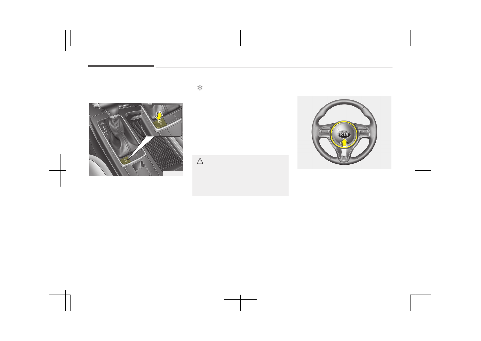
Heated steering wheel (if
equipped)
OJF045029
With the engine start/stop button in
the ON position, pressing the heated
steering wheel button warms the
steering wheel. The indicator on the
button will illuminate.
To turn the heated steering wheel off,
press the button once again. The indi‐
cator on the button will turn off.
NOTICE
The heated steering wheel will turn
off automatically approximately 30
minutes after the heated steering
wheel is turned on.
If you turn off the ignition within 30
minutes after pressing the steering
wheel heater button, from next igni‐
tion ON, the heater will be off.
CAUTION
Do not install any grip to operate the
steering wheel. This causes damage
to the heated steering wheel sys‐
tem.
Horn
OJF045030
To sound the horn, press the area indi‐
cated by the horn symbol on your
steering wheel (see illustration). The
horn will operate only when this area is
pressed. Check the horn regularly to be
sure it operates properly.
Features of your vehicle
5-42

CAUTION
• Do not strike the horn severely to
operate it, or hit it with your fist.
Do not press on the horn with a
sharp-pointed object.
• When cleaning the steering wheel,
do not use an organic solvent such
as thinner, benzene, alcohol and
gasoline. Doing so may damage
the steering wheel.
5-43
5
Features of your vehicle
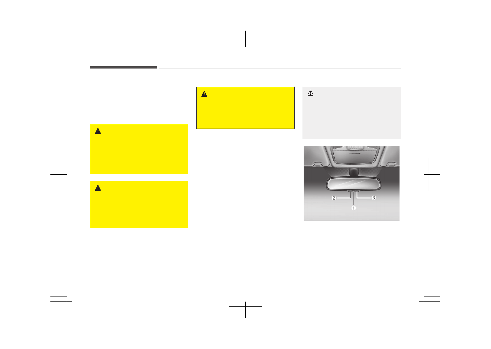
MIRRORS
Inside rearview mirror
Adjust the rearview mirror so that the
center view through the rear window is
seen. Make this adjustment before you
start driving.
WARNING
n
Rear visibility
Do not place objects in the rear seat
or cargo area which would interfere
with your vision through the rear
window.
WARNING
Do not adjust the rearview mirror
while the vehicle is moving. This
could result in loss of control, and an
accident which could cause death,
serious injury or property damage.
WARNING
Do not modify the inside mirror and
don’t install a wide mirror. It could
result in injury, during an accident or
deployment of the air bag.
Electrochromic mirror (ECM)
The electric rearview mirror automati‐
cally controls the glare from the head‐
lights of the vehicles behind you in
nighttime or low light driving condi‐
tions. The sensor mounted in the mir‐
ror senses the light level around the ve‐
hicle, and automatically controls the
headlight glare from the vehicles be‐
hind you.
When the engine is running, the glare is
automatically controlled by the sensor
mounted in the rearview mirror.
Whenever the shift lever is shifted into
reverse (R), the mirror will automatical‐
ly go to the brightest setting in order
to improve the driver's view behind the
vehicle.
CAUTION
When cleaning the mirror, use a pa‐
per towel or similar material damp‐
ened with glass cleaner. Do not
spray glass cleaner directly on the
mirror. It may cause the liquid clean‐
er to enter the mirror housing.
OJF045227L
To operate the electric rearview mirror:
• The mirror defaults to the ON posi‐
tion whenever the engine start/stop
button is in the ON position.
Features of your vehicle
5-44
• Press the ON/OFF button (1) to turn
the automatic dimming function off.
The mirror indicator light (2) will turn
off.
Press the ON/OFF button (1) to turn
the automatic dimming function on.
The mirror indicator light (2) will illu‐
minate.
❈ (2): Indicator, (3): Sensor
Outside rearview mirror
Be sure to adjust the mirror angles be‐
fore driving.
Your vehicle is equipped with both left-
hand and right-hand outside rearview
mirrors. The mirrors can be adjusted
remotely with the remote switch. The
mirror heads can be folded back to pre‐
vent damage during an automatic car
wash or when passing through a nar‐
row street.
WARNING
n
Rearview mirrors
• The outside rearview mirror is
convex. Objects seen in the mirror
are closer than they appear.
(Continued)
(Continued)
• Use your interior rearview mirror
or direct observation to determine
the actual distance of following
vehicles when changing lanes.
CAUTION
Do not scrape ice off the mirror face;
this may damage the surface of the
glass. If ice should restrict the move‐
ment of the mirror, do not force the
mirror for adjustment. To remove
ice, use a deicer spray, or a sponge
or soft cloth with warm water.
CAUTION
If the mirror is jammed with ice, do
not adjust the mirror by force. Use
an approved de-icer spray (not radi‐
ator antifreeze) to release the fro‐
zen mechanism or move the vehicle
to a warm place and allow the ice to
melt.
WARNING
Do not adjust or fold the outside
rearview mirrors while the vehicle is
moving. This could result in loss of
control and an accident which could
cause death, serious injury or prop‐
erty damage.
5-45
5
Features of your vehicle
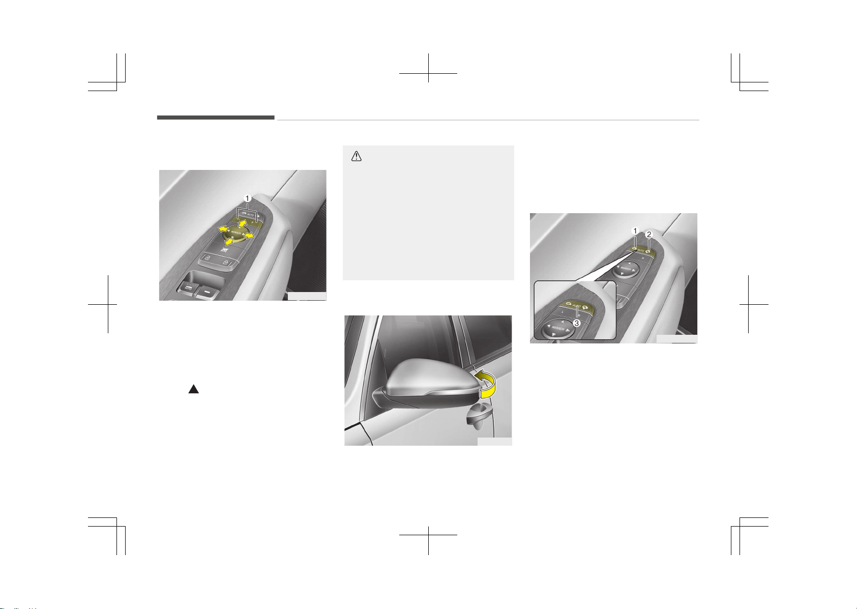
Remote control
OJF045033L
The electric remote control mirror
switch allows you to adjust the position
of the left and right outside rearview
mirrors. To adjust the position of either
mirror, press the R or L button (1) to
select the right side mirror or the left
side mirror, then press a corresponding
point ( ) on the mirror adjustment
control to position the selected mirror
up, down, left or right.
After adjustment, press the R or L but‐
ton again to prevent inadvertent ad‐
justment.
CAUTION
• The mirrors stop moving when
they reach the maximum adjusting
angles, but the motor continues to
operate while the switch is press‐
ed. Do not press the switch longer
than necessary, the motor may be
damaged.
• Do not attempt to adjust the out‐
side rearview mirror by hand. Do‐
ing so may damage the parts.
Folding the outside rearview mirror
OJF045034
Manual type
To fold the outside rearview mirror,
grasp the housing of the mirror and
then fold it toward the rear of the vehi‐
cle.
OJF045035L
Electric type
The outside rearview mirror can be fol‐
ded or unfolded by pressing the switch
as below.
Left (1): The mirror will unfold.
Right (2): The mirror will fold.
Center (AUTO, 3): The mirror will fold or
unfold automatically as follows:
• Without smart key system
- The mirror will fold or unfold when
the door is locked or unlocked by
the smart key.
Features of your vehicle
5-46
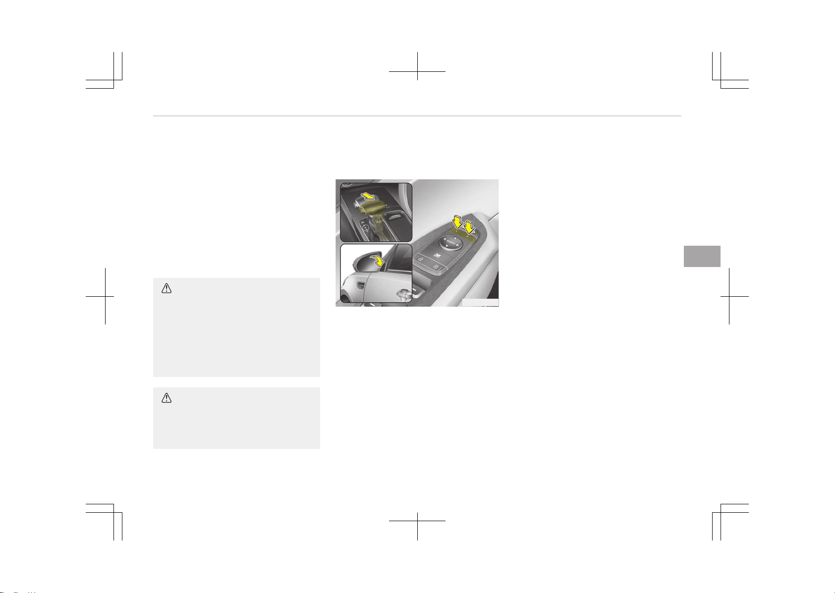
• With smart key system
- The mirror will fold or unfold when
the door is locked or unlocked by
the smart key.
- The mirror will fold or unfold when
the door is locked or unlocked by
the button on the outside door
handle.
- The mirror will unfold when you
approach the vehicle (all doors
closed and locked) with a smart
key in possession (if equipped).
CAUTION
The electric type outside rearview
mirror operates even though the En‐
gine Start/Stop button is in the OFF
position. However, to prevent unnec‐
essary battery discharge, do not ad‐
just the mirrors longer than neces‐
sary while the engine is not running.
CAUTION
In case it is an electric type outside
rearview mirror, don’t fold it by
hand. It could cause motor failure.
Reverse parking aid function (if
equipped)
OJF045110
When you shift the shift lever to the R
(Reverse) position, the outside rearview
mirror(s) will move downward to aid re‐
verse parking.
According to the position of the outside
rearview mirror switch, the outside
rearview mirror(s) will operate as fol‐
lows:
Left or Right
When the remote control outside rear‐
view mirror switch is in the left or right
position, both outside rearview mirrors
will move downward.
Neutral
When neither switch is selected, the
outside rearview mirrors will not move.
The outside rearview mirrors will auto‐
matically revert to their original posi‐
tion under the following conditions:
1. The Engine Start/Stop button is
turned to the ACC or OFF position.
2. The shift lever is moved to any po‐
sition except R (Reverse).
3. The remote control outside rear‐
view mirror switch is not selected.
5-47
5
Features of your vehicle
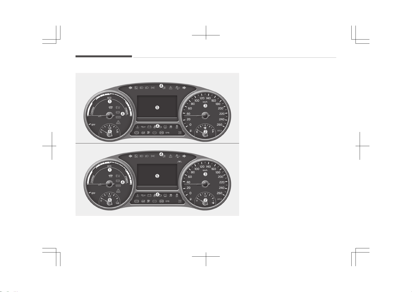
INSTRUMENT CLUSTER
■ Type A for Hybrid
■ Type B for Hybrid
OJFH045101LB/OJFH045405LB
1. Hybrid system gauge
2. Fuel gauge
3. Speedometer
4. Warning and indicator lights
5. LCD display (including Trip comput‐
er)
6. Battery SOC (State of Charge)
gauge
❈ The actual cluster in the vehicle
may differ from the illustration.
For more details, refer to the
Gauges on page 5-51.
Features of your vehicle
5-48
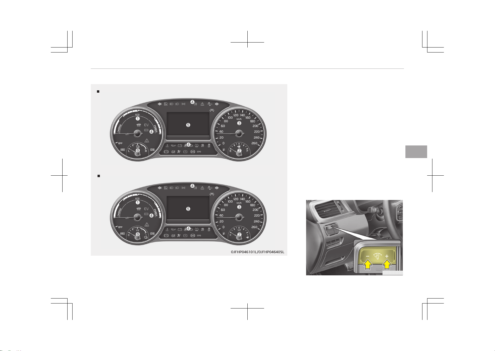
Type A for Plug in Hybrid
Type B for Plug in Hybrid
1. Hybrid system gauge
2. Fuel gauge
3. Speedometer
4. Warning and indicator lights
5. LCD display (including Trip comput‐
er)
6. Battery SOC (State of Charge)
gauge
❈ The actual cluster in the vehicle
may differ from the illustration.
For more details, refer to the
Gauges on page 5-51.
Instrument cluster control
Adjusting instrument cluster
illumination (if equipped)
OJF045036
5-49
5
Features of your vehicle
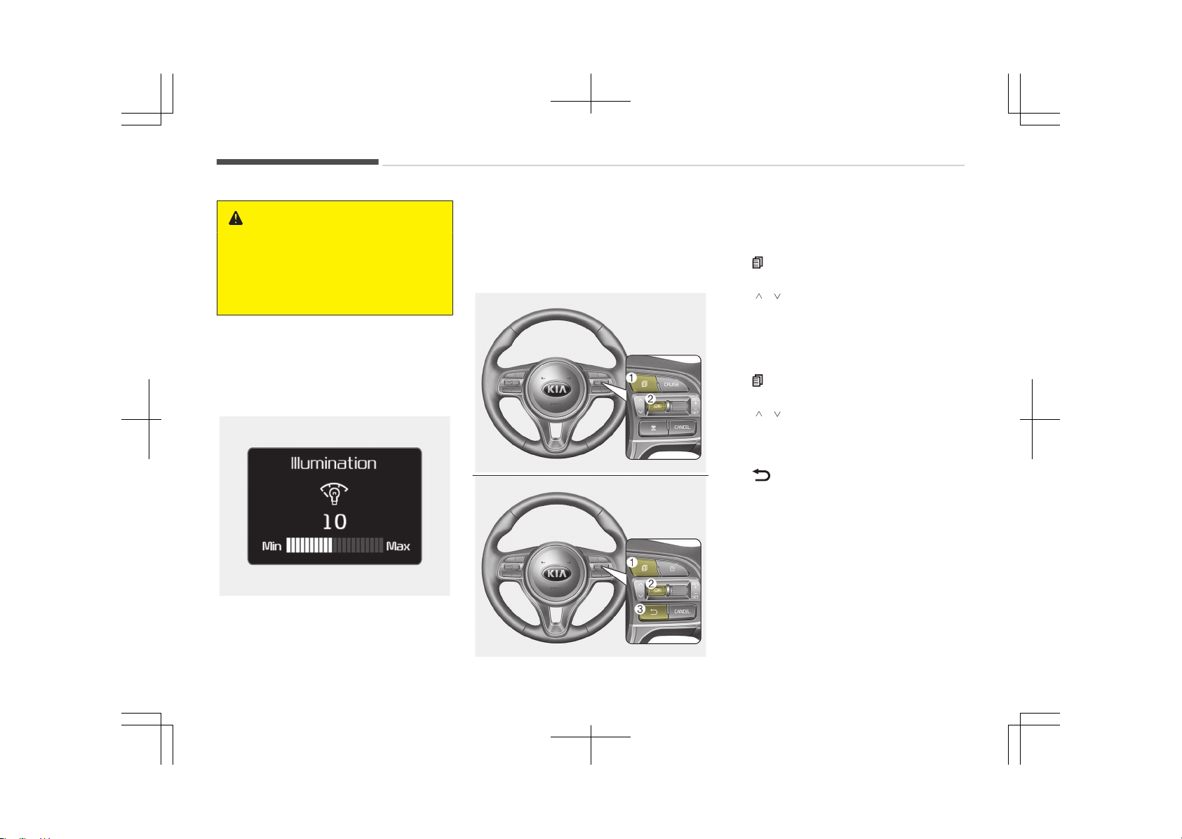
WARNING
Never adjust the instrument cluster
while driving. This could result in loss
of control and lead to an accident
that may cause death, serious in‐
jury, or property damage.
The brightness of the instrument panel
illumination is changed by pressing the
illumination control button (+ or -)
when the Engine Start/Stop button is
ON, or the tail lights are turned on.
OJF045131L
• If you hold the illumination control
button (+ or -), the brightness will
be changed continuously.
• If the brightness reaches to the max‐
imum or minimum level, an alarm will
sound.
LCD display control
■ Type A
OJF045037L
■ Type B
OJF045038L
The LCD display modes can be changed
by using the control buttons on the
steering wheel.
[Type A]
1. : MODE button for changing
modes
2. / /OK: SELECT scroll switch for
setting the selected item and RE‐
SET scroll switch for resetting
items
[Type B]
1.
: MODE button for changing
modes
2. / /OK: SELECT scroll switch for
setting the selected item and RE‐
SET scroll switch for resetting
items
3. : RETURN button to move to the
previous mode or item (if equipped)
❈ For the LCD modes, refer to LCD
display on page 5-56.
Features of your vehicle
5-50
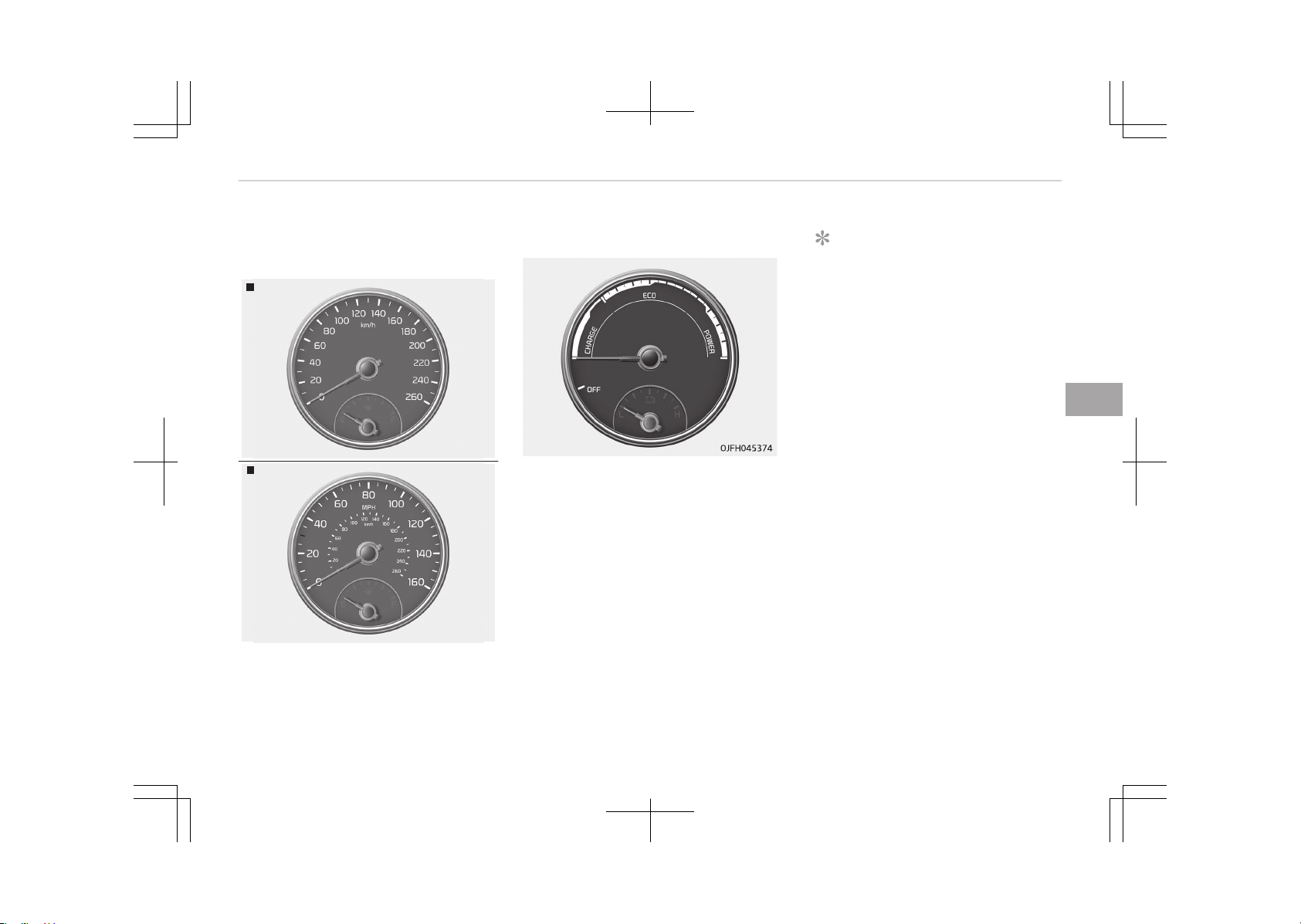
Gauges
Speedometer
Type A (km/h)
OJF045102
Type B (MPH,
km/h)
OJF045102L
The speedometer indicates the speed
of the vehicle and is calibrated in miles
per hour (mph) and/or kilometers per
hour (km/h).
Hybrid system gauge
The hybrid system gauge indicates
whether the current driving condition is
fuel efficient or not.
• CHARGE:
Shows that the energy
made by the vehicle is be‐
ing converted to electrical
energy. (Regenerated en‐
ergy)
• ECO: Shows that the vehicle is
being driven in an Eco-
friendly manner.
• POWER: Shows that the vehicle is
exceeding the Eco-friend‐
ly range.
NOTICE
Accordance to the hybrid system
gauge area the EV indicator comes
on or off.
- EV indicator ON: Vehicle is driven
using the electric motor or the
gasoline engine is stopped.
- EV indicator OFF: Vehicle is driv‐
en using the gasoline engine.
5-51
5
Features of your vehicle
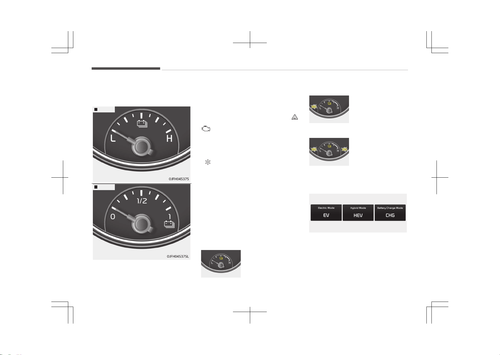
Hybrid battery SOC (state of
charge) gauge
Type A
Type B
This gauge indicates the remaining hy‐
brid battery power. If the SOC is near
the L (Low) or 0 level, the vehicle au‐
tomatically operates the engine to
charge the battery.
However, if the Service Indicator ( )
and Malfunction Indicator Lamp (MIL)
( ) turn on when the SOC gauge is
near the L (Low) or 0 level, we recom‐
mend the vehicle be checked by an au‐
thorized Kia dealer.
NOTICE
Never try to start the vehicle if the
fuel tank is empty. In this condition,
the engine cannot charge the high
voltage battery of the hybrid sys‐
tem. If you try to start the vehicle
when the fuel is empty, the high
voltage battery will become dis‐
charged and be damaged.
Plug-in hybrid mode indicator
• CD (Charge Depleting, Electric) mode
OJFHP046420L
The high-voltage (hy‐
brid) battery is used
to drive the vehicle.
• CS (Charge Sustaining, Hybrid) mode
OJFHP046421L
The high-voltage (hy‐
brid) battery and gas‐
oline engine is used to
drive the vehicle.
• HEV-charging mode
OJFHP046422L
Gasoline engine is
used to drive the ve‐
hicle and charge the
high-voltage (hybrid)
battery
A corresponding message is displayed
to indicate the selected mode.
OJFHP046425L/OJFHP046426L/OJFHP046427L
Features of your vehicle
5-52
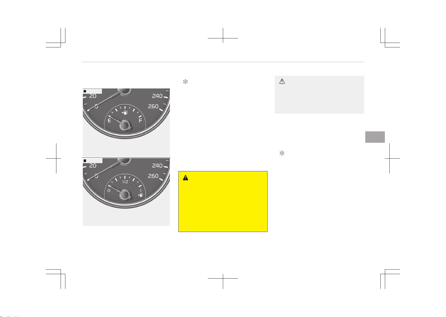
Fuel gauge
Type A
OJF045105B
Type B
OJF045105L
This gauge indicates the approximate
amount of fuel remaining in the fuel
tank.
NOTICE
• The fuel tank capacity is given in
Recommended lubricants and ca‐
pacities on page 10-11.
• The fuel gauge is supplemented by
a low fuel warning light, which will
illuminate when the fuel tank is
nearly empty.
• On inclines or curves, the fuel
gauge pointer may fluctuate or
the low fuel warning light may
come on earlier than usual due to
the movement of fuel in the tank.
WARNING
n
Fuel Gauge
Running out of fuel can expose vehi‐
cle occupants to danger.
You must stop and obtain additional
fuel as soon as possible after the
warning light comes on or when the
gauge indicator comes close to the
0 or E (Empty) level.
CAUTION
Avoid driving with an extremely low
fuel level. Running out of fuel could
cause the engine to misfire damag‐
ing the catalytic converter.
Engine coolant temperature gauge
This gauge indicates the temperature
of the engine coolant when the engine
is running.
NOTICE
When the gauge indicator gets out
of the normal range, toward the H
position, it indicates overheating of
the engine. It may damage the en‐
gine.
Do not continue driving with the
overheated engine. For further in‐
formation, refer to If the engine
overheats on page 8-07.
5-53
5
Features of your vehicle
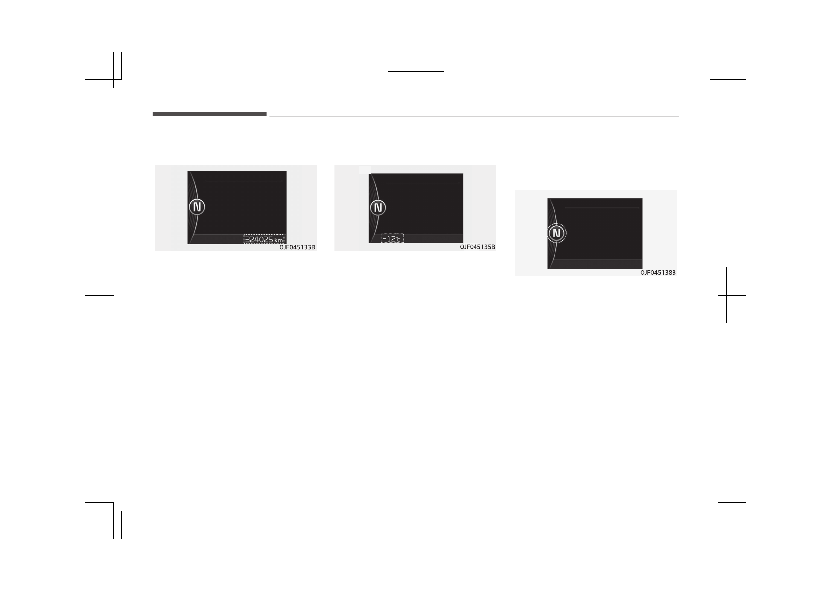
Odometer
The odometer indicates the total dis‐
tance that the vehicle has been driven
and should be used to determine when
periodic maintenance should be per‐
formed.
- Odometer range : 0 ~ 999999 kilome‐
ters or miles.
Outside temperature
This gauge indicates the current out‐
side air temperatures by 1°C (1°F).
- Temperature range : -40°C ~ 60°C
(-40°F ~ 140°F)
The outside temperature on the display
may not change immediately like a
general thermometer to prevent the
driver from being inattentive.
The temperature unit can be changed
by using the "User Settings" mode of
the LCD display.
❈ For more details, refer to LCD dis‐
play on page 5-56.
Transaxle shift indicator
Automatic transaxle shift indicator
(if equipped)
This indicator displays which automatic
transaxle shift lever is selected.
• Park : P
• Reverse : R
• Neutral : N
• Drive :D
• Sports Mode : 1, 2, 3, 4, 5, 6
Features of your vehicle
5-54

Automatic Transaxle Shift Indicator in
Sports Mode (if equipped)
In
the Sports Mode, this indicator in‐
forms which gear is desired while driv‐
ing to save fuel.
• Shifting up :
1, 2, 3, 4, 5
• Shifting down :
2, 3, 4, 5, 6
For example
3:
Display means the current gear
is in 3 and needs to be changed
to 4.
3:
Display means the current gear
is in 3 and needs to be changed
to 2.
When the system is not working prop‐
erly, the indicator is not displayed.
5-55
5
Features of your vehicle
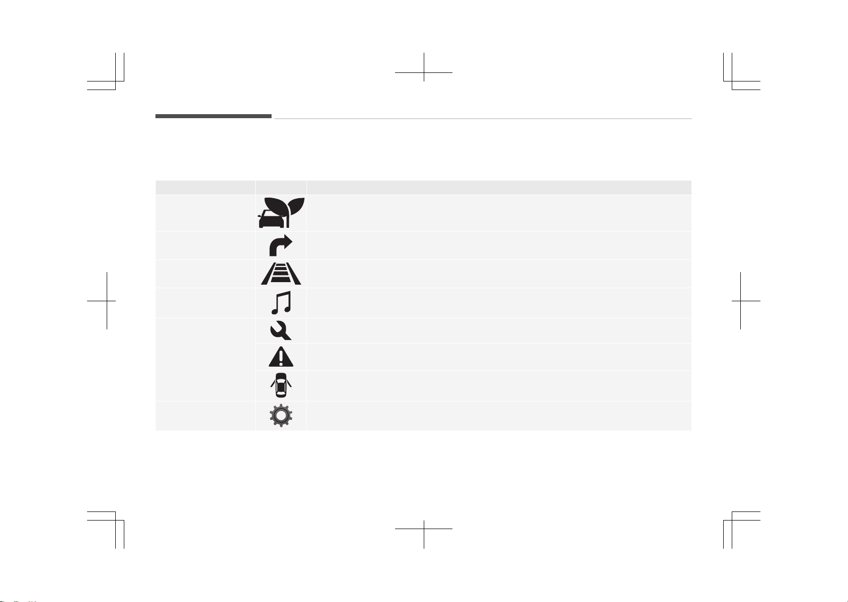
LCD DISPLAY (IF EQUIPPED)
LCD modes
Modes Symbol Explanation
Trip Computer
This mode displays driving information like the tripmeter, fuel economy, and so on.
For more details, refer to Trip Computer on page 5-63.
Turn By Turn
(if equipped)
This mode displays the state of the navigation.
LDWS
(if equipped)
This mode displays the state of Lane Departure Warning System (LDWS).
For more details, refer to Lane Departure Warning System (LDWS) on page 7-79.
A/V
(if equipped)
This mode displays the state of the A/V system.
Service
This mode informs of service interval (mileage or days) and pressure status of each tire.
This mode informs of warning messages related to Low tire pressure or malfunction of
Blind Spot Detection system (BSD) and so on.
When any door is not closed securely, this symbol illuminates.
User Settings
On this mode, you can change settings of the doors, lamps and so on.
❈ For controlling the LCD modes, refer to LCD display control on page 5-50.
Features of your vehicle
5-56
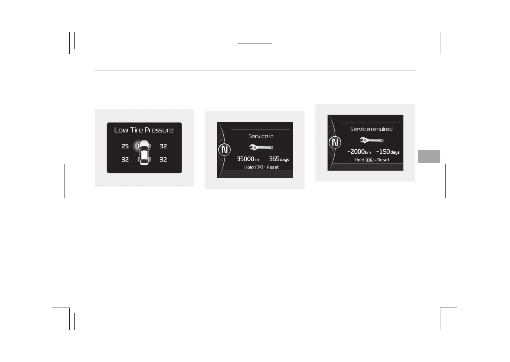
Service mode
Tire pressure (if equipped)
OJF045292L
This mode displays the pressure status
of each tire.
You can change the tire pressure unit in
"User settings" mode.
❈ For more details, refer to User
Settings mode on page 5-58.
Service interval
Service in
OJF045144L
It displays when you need a scheduled
maintenance service (mileage or days).
If the remaining mileage or time rea‐
ches 1,500 km (1,500 mi.) or 30 days,
"Service in" message is displayed for
several seconds each time you set the
Engine Start/Stop Button to the ON po‐
sition.
Service required
OJF045294L
If you do not have your vehicle serviced
according to the already inputted serv‐
ice interval, "Service required" message
is displayed for several seconds each
time you set the Engine Start/Stop
Button to the ON position.
To reset the service interval to the
mileage and days you inputted before:
-
Activate the reset mode by pressing
the OK button (reset) for more than
5 seconds, then press the OK button
(reset) again for more than 1 second
(Europe).
-
Press the OK button (reset) for more
than 1 second (Except Europe).
5-57
5
Features of your vehicle
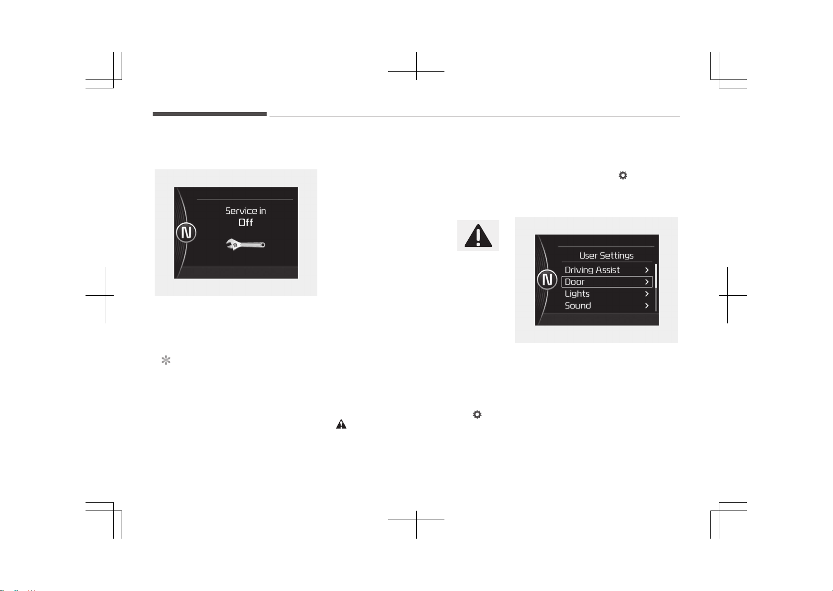
Service in OFF
OJF045295L
If the service interval is not set, "Serv‐
ice in OFF" message is displayed on the
LCD display.
NOTICE
If any of the following conditions oc‐
curs, the mileage and days may be
incorrect.
(Continued)
(Continued)
- The battery cable is disconnected.
- The fuse switch is turned off.
- The battery is discharged.
Master warning mode (if
equipped)
• This warning light informs
the driver of the following
situations:
- Blind Spot Detection (BSD) mal‐
function (if equipped)
- Tire Pressure Monitoring System
(TPMS) malfunction (if equipped)
- High Beam Assist (HBA) malfunc‐
tion (if equipped)
- Lamp malfunction
- Service reminder and so on.
The Master Warning Light illuminates if
one or more of the above warning sit‐
uations occur. At this time, the LCD
Modes Icon will change from (
) to
( ).
If the warning situation is solved, the
master warning light will be turned off
and the LCD Modes Icon will be changed
back to its previous icon ( ).
User settings mode
Description
OJF045148L
On this mode, you can change setting
of the doors, lamps, and so on.
Features of your vehicle
5-58

Driving assist (if equipped)
Items Explanation
Rear Cross Traffic Alert
(if equipped)
If this item is checked, the rear cross traffic alert function will be activated.
For more details, refer to Blind Spot Detection System on page 7-91.
LKAS (Lane Keeping Assist System)
(if equipped)
• Lane Departure Warning: To activate the lane departure warning function.
• Standard LKA: To activate the standard LKA mode of LKAS function.
• Active LKA: To activate the active LKA mode of LKAS function
For more details, refer to LKAS (Lane Keeping Assist System) on page 7-83.
Smart Cruise Control Response
(if equipped)
Choose the sensitivity of the smart cruise control.
For more details, refer to Smart Cruise Control System on page 7-59.
AEB (Autonomous Emergency Braking)
(if equipped)
To activate or deactivate the AEB system.
For more details, refer to Autonomous Emergency Braking (AEB) on page 7-37.
FCW (Forward Collosion Warning)
(if equipped)
Choose the sensitivity of the forward collosion warning.
- Late/Normal/Early
For more details, refer to Autonomous Emergency Braking (AEB) on page 7-39.
Speed Limit Information Function
(if equipped)
If this item is checked, the speed limit information function will be activated.
For more details, refer to Speed Limit Information Function on page 7-55.
Coasting Guide
(if equipped)
To activate or deactivate the Coasting Guide system and sound.
For more information, refer to Coasting Guide on page 5-76.
5-59
5
Features of your vehicle

Door/trunk
Items Explanation
Automatically Lock
• Disable: The auto door lock operation will be deactivated.
• Enable on Speed: All doors will be automatically locked when the vehicle speed ex‐
ceeds 15 km/h (9.3 mph).
• Enable on Shift: All doors will be automatically locked if the automatic transaxle/
dual clutch transmission shift lever is shifted from the P (Park) position to the R
(Reverse), N (Neutral), or D (Drive) position.
Automatically Unlock
• Disable: The auto door unlock operation will be canceled.
• Vehicle Off/On key out: All doors will be automatically unlocked when the Engine
Start/Stop button is set to the OFF position.
• Driver Door Unlock: All doors will be automatically unlocked if the driver's door is
unlocked.
On Shift to P: All doors will be automatically unlocked if the automatic transaxle/
dual clutch transmission shift lever is shifted to the P (Park) position.
Door Lock Sound
(if equipped)
If this item checked, the door lock sound function will be activated when locking
doors.
Smart Trunk
(if equipped)
To activate or deactivate the Smart Trunk system.
For more details, refer to Smart Trunk on page 5-19.
Features of your vehicle
5-60

Light
Items Explanation
One Touch Turn Signal
• Off: The one touch turn signal function will be deactivated.
• 3, 5, 7 Flashes: The lane change signals will blink 3, 5, or 7 times when the turn
signal lever is moved slightly.
For more details, refer to Light on page 5-114.
Head Lamp Delay • If this item is checked, the head lamp delay function will be activated.
Welcome Light
(If equipped)
• If this item is checked, the welcome light function will be activated.
Sound
Items Explanation
Park Assist System Vol.
(if equipped)
• Adjust the Park Assist System volume. (Level 1~3)
For more details, refer to Parking Assist System on page 5-89.
BSD (Blind Spot Detection) Sound
(if equipped)
• If this item is checked, the blind spot detection sound will be activated
For more details, refer to Blind Spot Detection System on page 7-91.
Welcome Sound
(if equipped)
• If this item is checked, the welcome sound function will be activated.
5-61
5
Features of your vehicle

Convenience (if equipped)
Items Explanation
Seat Easy Access
(if equipped)
• Off: The seat easy access function will be deactivated.
• Normal/Enhanced: When you turn off the engine, the drivers seat will automati‐
cally move rearwards 6 cm (Enhanced) for you to enter or exit the vehicle more
comfortably.
If you change the Engine Start/Stop Button from OFF position to the AC function,
the drivers seat will return to the original position.
For more details, refer to Driver position memory system on page 4-08.
Steering Position
(if equipped)
• If this item is checked, the warning function regarding the steering wheel align‐
ment will be activated.
Wireless charging system
(if equipped)
• If this item checked, the Wireless smart phone charging system will be activated.
Service interval (if equipped)
Items Explanation
Service Interval
On this mode, you can activate the service interval function with mileage (km or mi.)
and period (months).
• Off: The service interval function will be deactivated.
• On: You can set the service interval (mileage and months).
For more details, refer to Service mode on page 5-57.
Features of your vehicle
5-62

Other features
Items Explanation
Fuel Economy Auto Reset
If this item is checked, the average fuel economy will reset automatically when refu‐
eling.
Fuel Economy Unit
Choose the fuel economy unit. (Km/L, L/100)
- Speedometer is km/h type: Km/L or L/100km
- Speedometer is MPH type: US gallon or UK gallon
Temperature Unit Choose the temperature unit. (°C, °F)
Tire Pressure Unit
(if equipped)
Choose the tire pressure unit. (psi, kPa, Bar)
Language
(if equipped)
Choose the language.
Trip modes (Trip computer)
The trip computer is a microcomputer-
controlled driver information system
that displays information related to
driving.
NOTICE
Some driving information stored in
the trip computer (for example
Average Vehicle Speed) resets if the
battery is disconnected.
5-63
5
Features of your vehicle

Trip modes
Tripmeter [A/B]
Average Vehicle Speed [A/B]
Elapsed Time [A/B]
TRIP A/B
Distance To Empty
Average Fuel Economy
Instant Fuel Economy
FUEL ECONOMY
Digital Speedometer
Driving style
Energy flow
To change the trip mode, scroll the
MOVE scroll switch ( / ) in the trip
computer mode.
Fuel economy
Distance to empty (1, hybrid)
OJF045220LB
■ Hybrid
• The distance to empty is the estima‐
ted distance the vehicle can be driven
with the remaining fuel.
- Distance range: 1 ~ 9,999 km or 1 ~
9,999 mi.
• If the estimated distance is below 1
km (1 mi.), the trip computer will dis‐
play --- as distance to empty.
Distance to empty (Plug-in hybrid)
Plug-in hybrid
• Total range (a)
Electric distance to empty (b) + Gaso‐
line distance to empty (c)
• Electric range (b)
The distance to empty is the estima‐
ted distance the vehicle can be driven
with the remaining high voltage bat‐
tery.
• Gasoline range (c)
The distance to empty is the estima‐
ted distance the vehicle can be driven
with the remaining fuel.
• If the estimated distance is below 1
km (1 mi.), the trip computer will dis‐
play --- as distance to empty.
Features of your vehicle
5-64

- Distance range: 1 ~ 9,999 km or 1 ~
9,999 mi.
NOTICE
• If the vehicle is not on level ground
or the battery power has been in‐
terrupted, the distance to empty
function may not operate correct‐
ly.
• The distance to empty may differ
from the actual driving distance as
it is an estimate of the available
driving distance.
• The trip computer may not regis‐
ter additional fuel if less than
6 liters (1.6 gallons) of fuel are
added to the vehicle.
• The fuel economy and distance to
empty may vary significantly
based on driving conditions, driving
habits, and condition of the vehi‐
cle.
Average Fuel Economy (2)
• The average fuel economy is calcula‐
ted by the total driving distance and
fuel consumption since the last aver‐
age fuel economy reset.
- Fuel economy range: 0.0 ~ 99.9
km/L, L/100 km or MPG
• The average fuel economy can be re‐
set both manually and automatically.
Manual reset
To clear the average fuel economy
manually, press the OK button (reset)
on the steering wheel for more than 1
second when the average fuel economy
is displayed.
Automatic reset
To make the average fuel economy be
reset automatically whenever refueling,
select the Fuel economy auto reset
mode in User Setting menu of the LCD
display (Refer to LCD display on page
5-56).
• OFF - You may set to default man‐
ually by using the trip switch reset
button.
• When driving - The vehicle will auto‐
matically set to default once 4 hours
pass after the Engine start/stop but‐
ton is turned to the OFF position.
• When refueling - After refueling
more than 6 liters and driving over
1 km/h, the vehicle will reset to de‐
fault automatically.
NOTICE
The average vehicle speed is not dis‐
played, when the vehicle drives
shorter than 300 meters
(0.19 miles) or less than 10 seconds
after turning ON the Engine Start/
Stop button.
Instant Fuel Economy (3)
• This mode displays the instant fuel
economy during the last few seconds
when the vehicle speed is more than
10 km/h (6.2 mph).
- Fuel economy range: 0.0 ~ 30
L/100 km or 0.0 ~ 50.0 MPG
5-65
5
Features of your vehicle
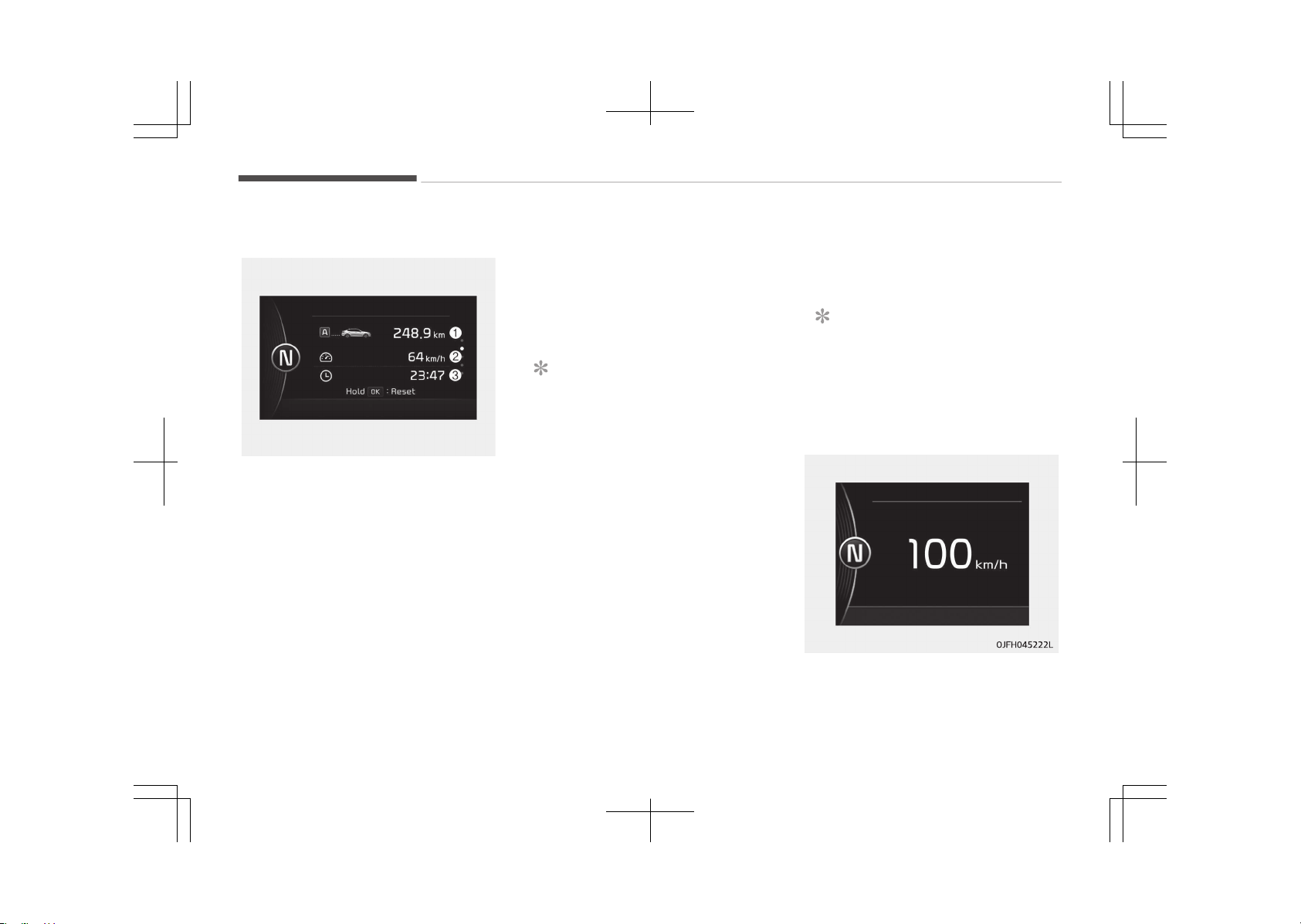
Trip A/B
OJF045221L
Tripmeter (1)
• The tripmeter is the total driving dis‐
tance since the last tripmeter reset.
- Distance range: 0.0 ~ 9999.9 km or
mi.
• To reset the tripmeter, press the OK
button (reset) on the steering wheel
for more than 1 second when the
tripmeter is displayed.
Average Vehicle Speed (2)
• The average vehicle speed is calcula‐
ted by the total driving distance and
driving time since the last average
vehicle speed reset.
- Speed range: 0 ~ 260 km/h or 0 ~
160 mph
• To reset the average vehicle speed,
press the OK button (reset) on the
steering wheel for more than 1 sec‐
ond when the average vehicle speed
is displayed.
NOTICE
• The average vehicle speed is not
displayed if the driving distance
has been less than 50 meters
(0.03 miles) or the driving time
has been less than 10 seconds
since the ignition switch or Engine
Start/Stop button was turned to
ON.
• Even if the vehicle is not in motion,
the average vehicle speed keeps
calculating, as long as while the
engine is running.
Elapsed Time (3)
• The elapsed time is the total driving
time since the last elapsed time re‐
set.
- Time range (hh:mm): 00:00 ~
99:59
• To reset the elapsed time, press the
OK button (reset) on the steering
wheel for more than 1 second when
the elapsed time is displayed.
NOTICE
Even if the vehicle is not in motion,
the elapsed time keeps calculating,
as long as the engine is running.
Digital speedometer
This mode displays the current speed
of the vehicle.
Features of your vehicle
5-66
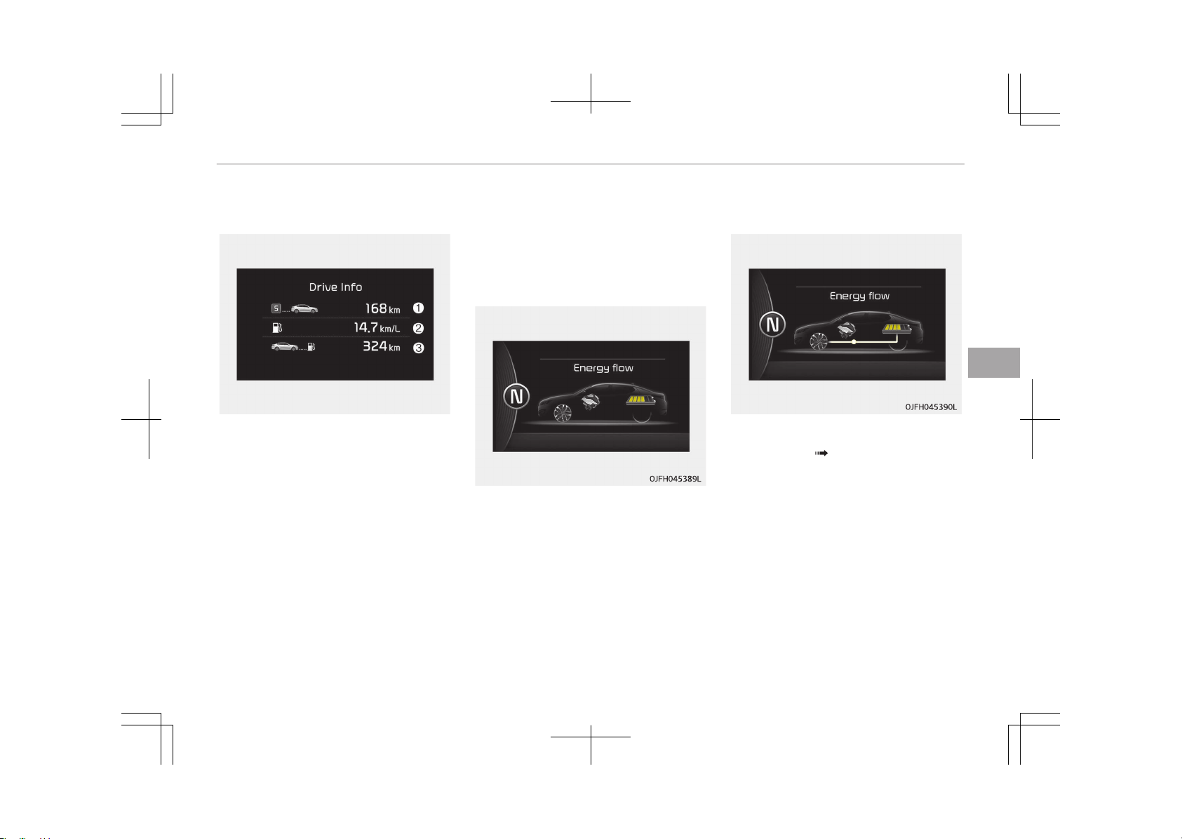
One time driving information mode
OJFHP046435L
This display shows trip distance (1),
average fuel economy (2) and the vehi‐
cle can be driven with the remaining
fuel (3).
This information is displayed for a few
seconds when you turn off the engine
and then goes off automatically. The
information provided is calculated ac‐
cording to each trip.
If the estimated distance is below 1 km
(1 mi.), the distance to empty (3) will
display as ---.
When low fuel warning light illuminates
in the cluster, the refuel message will
appear.
Hybrid system energy flow
Kia hybrid system notifies the drivers
of energy flow in various operating
modes. Eleven Modes show drivers the
current operating condition.
Vehicle stop
The mode means the vehicle at stop.
(There is no energy flow.)
EV propulsion
Electric power is used to move the ve‐
hicle. (Battery Wheel)
5-67
5
Features of your vehicle
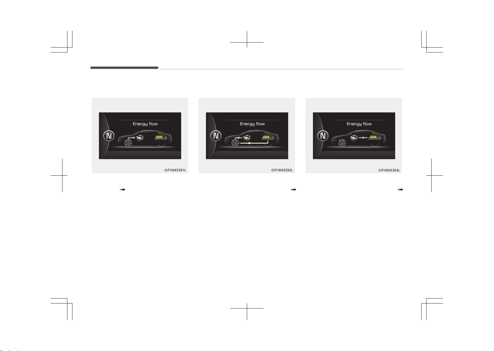
Engine-only propulsion
Engine power is used to move the vehi‐
cle. (Engine Wheel)
Power assist
Electric and Engine power are used to
move the vehicle. (Battery & Engine
Wheel)
Engine generation
Vehicle is stopped with the Engine
charging the hybrid battery. (Engine
Battery)
Features of your vehicle
5-68
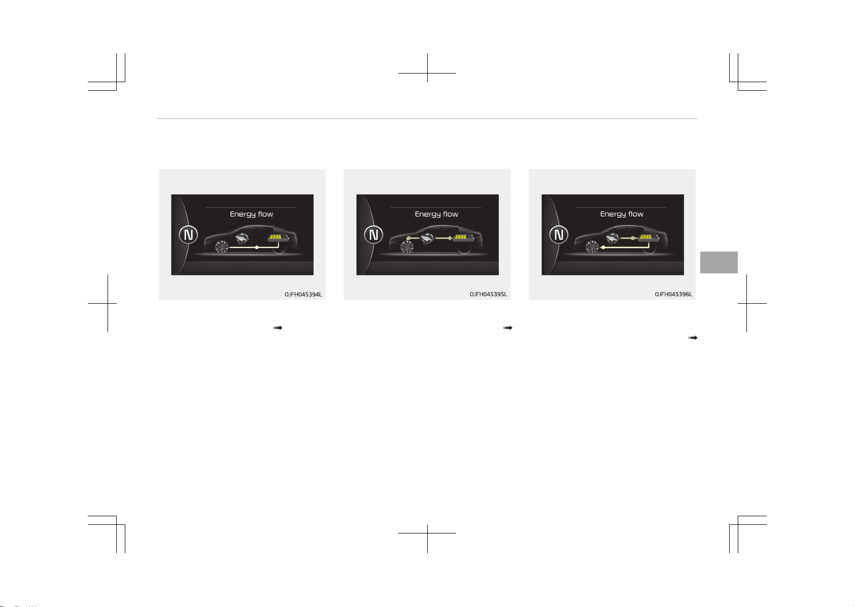
Regeneration
Hybrid battery is being charged by re‐
generative braking. (Wheel Battery)
Power reserve
Engine is both driving the vehicle and
charging the hybrid battery. (Engine
Wheel & Battery)
Engine generation/regeneration
The engine and regenerative braking
system charge the hybrid battery driv‐
ing deceleration. (Engine & Wheel
Battery)
5-69
5
Features of your vehicle
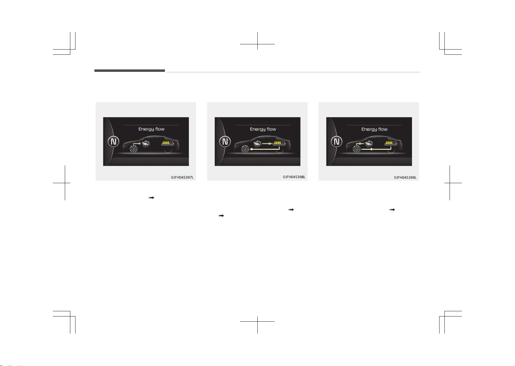
Engine brake
The vehicle is being slowed by engine
compression. (Wheel Engine)
Engine generation/motor drive
The vehicle is being slowed by engine
compression and regenerative braking.
The hybrid battery is being charged by
regenerative braking. (Engine Bat‐
tery Wheel)
Engine brake/regeneration
The engine compression can be used to
slow the vehicle. The regenerative
braking system can be used to charge
the hybrid system. (Wheel Engine &
Battery)
Features of your vehicle
5-70
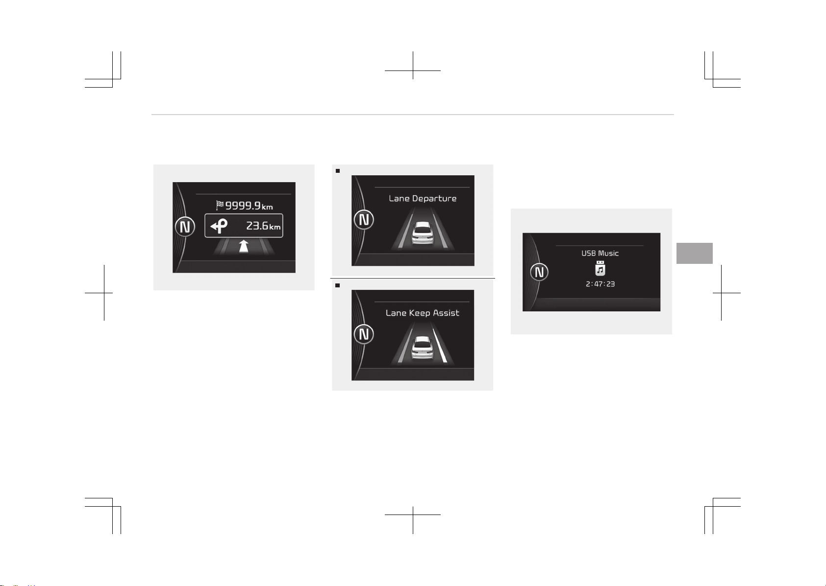
Turn by turn mode (if equipped)
OJF045223L
This mode displays the state of the
navigation.
LDWS/LKAS (if equipped)
LDWS
OJFHP046434L
LKAS
OJFHP046433L
This mode displays the state of the
Lane Departure Warning System
(LDWS) and Lane Keeping Assist Sys‐
tem (LKAS).
For more information, refer to Lane
Departure Warning System (LDWS) on
page 7-79 and Lane Keeping Assist
System (LKAS) on page 7-83.
A/V mode (if equipped)
OJF045142L
This mode displays the state of the A/V
system.
Warning messages (if equipped)
Shift to P (for smart key system)
• This warning message illuminates if
you try to turn off the engine with‐
out the shift lever in P (Park) position.
5-71
5
Features of your vehicle

• At this time, the Engine Start/Stop
Button turns to the ACC position (If
you press the Engine Start/Stop But‐
ton once more, it will turn to the ON
position).
Low key battery (for smart key
system)
• This warning message illuminates if
the battery of the smart key is dis‐
charged when the Engine Start/Stop
Button changes to the OFF position.
Press START button while turning
wheel (for smart key system)
• This warning message illuminates if
the steering wheel does not unlock
normally when the Engine Start/Stop
Button is pressed.
• It means that you should press the
Engine Start/Stop Button while turn‐
ing the steering wheel right and left.
Steering wheel unlocked (for smart
key system)
• This warning message illuminates if
the steering wheel does not lock
when the Engine Start/Stop Button
changes to the OFF position.
Check steering wheel lock system
(for smart key system)
• This warning message illuminates if
the steering wheel does not lock nor‐
mally when the Engine Start/Stop
Button changes to the OFF position.
Press brake pedal to start engine
(for smart key system)
• This warning message illuminates if
the Engine Start/Stop Button
changes to the ACC position twice by
pressing the button repeatedly with‐
out depressing the brake pedal.
• It means that you should depress the
brake pedal to start the engine.
Key not in vehicle (for smart key
system)
• This warning message illuminates if
the smart key is not in the vehicle
when you press the Engine Start/
Stop Button.
• It means that you should always have
the smart key with you.
Key not detected (for smart key
system)
• This warning message illuminates if
the smart key is not detected when
you press the Engine Start/Stop But‐
ton.
Press start button again (for smart
key system)
• This warning message illuminates if
you cannot operate the Engine Start/
Stop Button when there is a problem
with the Engine Start/Stop Button
system.
• It means that you could start the en‐
gine by pressing the Engine Start/
Stop Button once more.
• If the warning illuminates each time
you press the Engine Start/Stop But‐
ton, we recommend that you have
the vehicle inspected by an author‐
ized Kia dealer.
Press start button with key (for
smart key system)
• This warning message illuminates if
you press the Engine Start/Stop But‐
ton while the warning message Key
not detected is illuminating.
Features of your vehicle
5-72
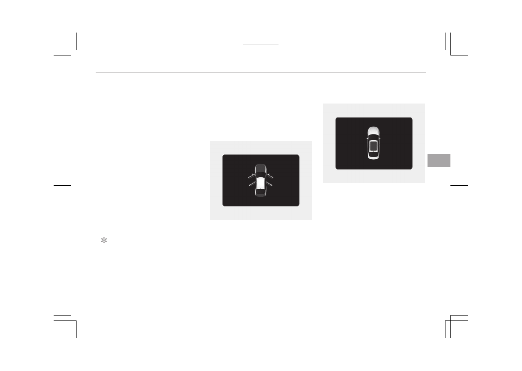
• At this time, the immobilizer indicator
light blinks.
Check BRAKE SWITCH fuse (for
smart key system)
• This warning message illuminates if
the brake switch fuse is disconnec‐
ted.
• It means that you should replace the
fuse with a new one. If that is not
possible, you can start the engine by
pressing the Engine Start/Stop But‐
ton for 10 seconds in the ACC posi‐
tion.
Shift to P or N to start engine (for
smart key system)
• This warning message illuminates if
you try to start the engine with the
shift lever not in the P (Park) or N
(Neutral) position.
NOTICE
You can start the engine with the
shift lever in the N (Neutral) position.
But, for your safety, we recommend
(Continued)
(Continued)
that you start the engine with the
shift lever in the P (Park) position.
Door, hood, trunk open
OJF045224L
• It means that any door, hood, or
trunk is open.
Sunroof open (if equipped)
OJF045216L
• This warning message illuminates if
you turn off the engine when the
sunroof is open.
5-73
5
Features of your vehicle

Icy road warning light (if equipped)
OJF045226L
This warning light is to warn the driver
the road may be icy.
When the following conditions occur,
the warning light (including Outside
Temperature Gauge) blinks 5 times and
then illuminates, and also warning
chime sounds once.
-
The temperature on the Outside
Temperature Gauge is below approxi‐
mately 4°C (40°F).
NOTICE
If the icy road warning light appears
while driving, you should drive more
attentively and safely refraining
from over-speeding, rapid accelera‐
tion, sudden braking or sharp turn‐
ing, etc.
Align steering wheel
• This warning message illuminates if
you start the engine when the steer‐
ing wheel is turned to more than 90
degrees to the left or right.
• It means that you should turn the
steering wheel and make the angle of
the steering wheel be less than 30
degrees.
Low washer fluid (if equipped)
• This warning message illuminates on
the service reminder mode if the
washer fluid level in the reservoir is
nearly empty.
• It means that you should refill the
washer fluid.
Turn on FUSE SWITCH (if equipped)
• This warning message illuminates if
the fuse switch under the steering
wheel is OFF.
• It means that you should turn the
fuse switch on.
For more details, refer to Fuses on
page 9-52.
Check headlights (if equipped)
This warning message illuminates if
there is a malfunction (burned-out bulb
or circuit malfunction) with the head
lights (high and low beam). In this case,
we recommend that you have the vehi‐
cle inspected by an authorized Kia deal‐
er.
NOTICE
• When replacing the bulb, use the
same wattage bulb.
For more information, refer to
Bulb wattage on page 10-07.
• If the different wattage bulb is
equipped with the vehicle, this
warning message is not displayed.
Features of your vehicle
5-74

Check high beam assist system (if
equipped)
• This warning message illuminates if
the high beam assist system has a
malfunction.
In this case, we recommend that you
have the vehicle inspected by an au‐
thorized Kia dealer.
Low fuel
• This warning message illuminates if
the fuel tank is nearly empty.
- When the low fuel level warning
light is illuminated.
Add fuel as soon as possible.
Device in wireless charger (if
equipped)
If a smart phone is still left on the wire‐
less charging pad unattended, even
when the Engine Start/Stop button is
turned to the ACC or OFF position, and
the instrument panel's one time driving
information mode has finished, a warn‐
ing message will light up on the instru‐
ment panel.
For more details, refer to Smart Phone
Wireless Charger on page 5-158.
Check active air flap system
This warning message illuminates in
the following situations:
-
There is a malfunction with the ac‐
tuator flap
-
There is a malfunction with the ac‐
tuator air flap controller
-
The air flap does not open
When all of the above conditions are
fixed, the warning will disappear.
Check hybrid system
This warning message illuminates when
there is a problem with the hybrid con‐
trol system.
Refrain from driving when the warning
message is displayed.
In this case, we recommend that you
have your vehicle inspected by an au‐
thorized Kia dealer.
Check hybrid system. Turn off
engine.
This warning message illuminates when
there is a problem with the hybrid sys‐
tem. The " " indicator will blink and a
warning chime will sound until the
problem is solved.
In this case, we recommend that you
have your vehicle inspected by an au‐
thorized Kia dealer.
Check hybrid system. Do not start
engine.
This warning message illuminates when
the hybrid battery power (SOC) level is
low. A warning chime will sound until
the problem is solved.
In this case, we recommend that you
have your vehicle inspected by an au‐
thorized Kia dealer.
Stop vehicle and check power
supply
This warning message illuminates when
a failure occurs in the power supply
system.
In this case, park the vehicle in a safe
location and recommend that you tow
your vehicle to the nearest authorized
Kia dealer and have the vehicle inspec‐
ted.
Stop vehicle to charge battery
This warning message illuminates when
the hybrid battery power (SOC) level is
low.
In this case, park the vehicle in a safe
location and wait until the hybrid bat‐
tery is charged.
Refuel to prevent hybrid battery
damage
This warning message illuminates when
the fuel tank is nearly empty.
5-75
5
Features of your vehicle

You should refill the fuel tank to pre‐
vent hybrid battery damage.
Refill inverter coolant
This warning message illuminates when
the inverter coolant is nearly empty.
You should refill the inverter coolant.
Check brakes
This warning message illuminates when
the brake performance is low or the re‐
generative brake does not work prop‐
erly due to a failure in the brake sys‐
tem.
In this case, it may take longer for the
brake pedal to operate and the braking
distance may become longer.
Stop vehicle and check brakes
This warning message is displayed
when a failure occurs in the brake sys‐
tem.
In this case, park the vehicle in a safe
location and we recommend you to tow
your vehicle to the nearest authorized
Kia dealer and have the vehicle inspec‐
ted.
Coasting guide (if equipped)
A chime will sound and the coasting
guide indicator will blink four times to
inform the driver when to take the foot
off from the accelerator by anticipating
a decelerating event* based on the
analysis of driving routes and road con‐
ditions of the navigation. It encourages
the driver to remove foot from the
pedal and allow coasting down the road
with EV motor only. This helps prevent
unnecessary fuel consumption and in‐
creases fuel efficiency.
❈ Example of a deceleration event is
going down an extended hill, slow‐
ing down approaching a toll booth,
and approaching reduced speed
zones.
• User settings
Press the Engine Start/Stop button
and put the shift lever in P (Park). In
the User Settings Mode, select Driv‐
ing Assist, Coasting Guide, and then
On to turn on the system. Cancel the
selection of coasting guide to turn off
the system. For the explanation of
the system, press and hold the [OK]
button.
• Operation conditions
To activate the system, take the fol‐
lowing procedures. Enter your desti‐
nation information on the navigation
and select the driving route. Select
the ECO mode in the Integrated Driv‐
ing Control System. Then, satisfy the
following.
- The driving speed should be be‐
tween 60 km/h (37 mph) and
160 km/h (99 mph).
❈ The operating speed may vary due
to difference between instrument
cluster and navigation effected by
tire inflation level.
Unplug vehicle to start (Plug-in
Hybrid)
The message is displayed when you
start the engine without unplugging
the charging cable. Unplug the charging
cable, and then start the vehicle.
Remaining charge time (Plug-in
Hybrid)
The message is displayed to notify the
remaining time to fully charge the bat‐
tery.
Shift to P to charge (Plug-in
Hybrid)
The message is displayed when the
charging connector is plugged with the
shift lever in R (Reverse), N (Neutral) or
D (Drive). Move the shift lever to P
(Park) and re-start the charging proc‐
ess.
Features of your vehicle
5-76

EV/HEV/CHG modes (Plug-in
Hybrid)
A corresponding message is displayed
when a mode is selected by pressing
the HEV button.
Battery charged. Maintaining
current (Plug-in Hybrid)
This message is displayed when unable
to convert to charging mode even when
pressing and holding the HEV button
during EV/HEV mode driving because
the high-voltage (hybrid) battery is al‐
ready fully charged.
Low battery. Maintaining hybrid
(Plug-in Hybrid)
This message is displayed when unable
to convert to EV mode even when
pressing the HEV button during HEV
mode driving due to insufficient high-
voltage (hybrid) battery level.
Low battery temp. Maintaining
current (Plug-in Hybrid)
This message is displayed when unable
to convert to EV mode even when
pressing the HEV button during HEV
mode driving due to low battery tem‐
perature.
Charging complete. Switching to
hybrid (Plug-in Hybrid)
This message is displayed automatical‐
ly converting to HEV mode due to com‐
pleted battery charging during charging
mode driving.
Charger error! (Plug-in Hybrid)
This message is displayed when the
charging failed by external charger er‐
ror.
The purpose of this message is to let
you know the error has occurred in
charger itself not in vehicle.
Low/high system temp.
Maintaining hybrid (Plug-in Hybrid)
This message is displayed when unable
to convert to EV mode even when
pressing the HEV button during HEV
mode driving due to low/high system
temperature.
Switching to hybrid mode to allow
heating (Plug-in Hybrid)
• When the coolant temperature is
lower than -14°C (57°F), and you
turn the climate control On for heat‐
ing, the above message will be dis‐
played in the cluster. Then, the vehi‐
cle will automatically switch to HEV
mode.
• When the coolant temperature is
higher than -14°C (57°F), or you turn
the climate control Off, the vehicle
will automatically return to EV mode.
Wait until fuel door opens (Plug-in
Hybrid)
The message is displayed when you at‐
tempt to open the fuel filler lid with the
fuel tank pressurized. Wait until the
fuel tank is depressurized.
NOTICE
• It may take up to 20 seconds to
open fuel filler lid.
• When the fuel filler lid is frozen
and does not open after 20 sec‐
onds at freezing temperature,
slightly tap the fuel filler lid and
then attempt to open it.
Fuel door open (Plug-in Hybrid)
This message is displayed when the
fuel filler lid is opened.
Also means "Ready to refuel".
5-77
5
Features of your vehicle

Check fuel door (Plug-in Hybrid)
This message is displayed when the
fuel filler lid is open or an abnormality
has occurred.
Refuel after stopping (Plug-in
Hybrid)
This message is displayed when the
fuel filler lid open button is pressed
when a vehicle equipped with a plugin
hybrid seal-type fuel tank is in motion
(vehicle speed is greater than 0 km/h
(mi/h)).
Open fuel door after disconnecting
charging cable (Plug-in Hybrid)
This message is displayed when you
press fuel filler lid open button while
charging.
This message explains that refueling is
not allowed to finish charging.
Fuel lid is not opened when charging
cable is connected to vehicle.
Charging door open (Plug-in Hybrid)
This message indicates that the charg‐
ing door is open while in driving-ready
state to encourage you to inspect and
close the door.
(Driving with the charging door open
may result in moisture inflow or dam‐
age. This message is used to prevent
such occurrences.)
Features of your vehicle
5-78
WARNING AND INDICATOR LIGHTS
Warning lights
NOTICE
n
Warning lights
Make sure that all warning lights are
OFF after starting the engine. If any
light is still ON, this indicates a situa‐
tion that needs attention.
Hybrid system warning
light
This warning light illumi‐
nates:
When there is a malfunction with the
hybrid system.
In this case, we recommend that you
have the vehicle inspected by an au‐
thorized Kia dealer.
Air bag warning light
This warning light illumi‐
nates:
• Once you set the Engine
Start/Stop Button to the ON position.
- It illuminates for approximately 6
seconds and then goes off.
• When there is a malfunction with the
SRS.
In this case, we recommend that you
have the vehicle inspected by an au‐
thorized Kia dealer.
Seat belt warning light
This warning light informs
the driver that the seat belt
is not fastened.
For more details, refer to the Seat
belts on page 4-18.
Parking brake & Brake
fluid warning light
This warning light illumi‐
nates:
• Once you set the Engine Start/Stop
Button to the ON position.
- It illuminates for approximately 3
seconds
- It remains on if the parking brake
is applied.
• When the parking brake is applied.
• When the brake fluid level in the res‐
ervoir is low.
- If the warning light illuminates
with the parking brake released, it
indicates the brake fluid level in
reservoir is low.
If the brake fluid level in the reservoir is
low:
1. Drive carefully to the nearest safe
location and stop your vehicle.
2. With the engine stopped, check the
brake fluid level immediately and
add fluid as required (For more de‐
tails, refer to Brake fluid on page
9-30). Then check all brake com‐
ponents for fluid leaks. If any leak
on the brake system is still found,
the warning light remains on, or the
brakes do not operate properly, do
not drive the vehicle.
In this case, we recommend that
you have the vehicle towed to an
authorized Kia dealer and inspec‐
ted.
Dual-diagonal braking system
Your vehicle is equipped with dual-diag‐
onal braking systems. This means you
still have braking on two wheels even if
one of the dual systems should fail.
With only one of the dual systems
working, more than normal pedal travel
and greater pedal pressure are required
to stop the vehicle.
Also, the vehicle will not stop in as
short a distance with only a portion of
the brake system working.
5-79
5
Features of your vehicle
If the brakes fail while you are driving,
shift to a lower gear for additional en‐
gine braking and stop the vehicle as
soon as it is safe to do so.
WARNING
n
Parking Brake & Brake Fluid
Warning Light
Driving the vehicle with a warning
light ON is dangerous. If the Parking
Brake & Brake Fluid Warning Light il‐
luminates with the parking brake re‐
leased, it indicates that the brake
fluid level is low.
In this case, we recommend that you
have the vehicle inspected by an au‐
thorized Kia dealer.
Regenerative brake
warning light
This warning light illumi‐
nates:
When the regenerative
brake does not operate and
the brake does not perform
well. This causes the Brake
Warning light (red) and Regenerative
Brake Warning Light (yellow) to illumi‐
nate simultaneously.
(red color)
(yellow color)
In this case, drive safely and we recom‐
mend that you have your vehicle in‐
spected by an authorized Kia dealer.
The operation of the brake pedal may
be more difficult than normal and the
braking distance can increase.
Anti-lock brake system
(ABS) warning light
This warning light illumi‐
nates:
• Once you set the Engine Start/Stop
Button to the ON position.
- It illuminates for approximately 3
seconds and then goes off.
• When there is a malfunction with the
ABS (The normal braking system will
still be operational without the assis‐
tance of the anti-lock brake system).
In this case, we recommend that you
have the vehicle inspected by an au‐
thorized Kia dealer.
Electronic brake force
distribution (EBD)
system warning light
These two warning lights il‐
luminate at the same time
while driving:
• When the ABS and regular
brake system may not
work normally.
In this case, we recommend that you
have the vehicle inspected by an au‐
thorized Kia dealer.
NOTICE
n
Electronic Brake force Distri‐
bution (EBD) System Warning
Light
When the ABS Warning Light is on or
both ABS and Parking Brake & Brake
Fluid Warning Lights are on, the
speedometer, odometer, or tripme‐
ter may not work. Also, the EPS
Warning Light may illuminate and
the steering effort may increase or
decrease.
(Continued)
Features of your vehicle
5-80
(Continued)
In this case, we recommend you
have the vehicle inspected by an au‐
thorized Kia dealer as soon as possi‐
ble.
WARNING
n
Electronic Brake force Distri‐
bution (EBD) System Warning
Light
When both ABS and Parking Brake &
Brake Fluid Warning Lights are on,
the brake system will not work nor‐
mally and you may experience an
unexpected and dangerous situation
during sudden braking.
In this case, avoid high speed driving
and abrupt braking.
We recommend you have the vehicle
inspected by an authorized Kia deal‐
er as soon as possible.
Electronic power steering
(EPS) warning light (if
equipped)
This warning light illumi‐
nates:
• Once you set the Engine Start/Stop
Button to the ON position.
- It remains on until the engine is
started.
• When there is a malfunction with the
EPS.
In this case, we recommend that you
have the vehicle inspected by an au‐
thorized Kia dealer.
Malfunction indicator
lamp (MIL)
This warning light illumi‐
nates:
• Once you set the Engine Start/Stop
Button to the ON position.
- It remains on until the engine is
started.
• When there is a malfunction with the
emission control system.
In this case, we recommend that you
have the vehicle inspected by an au‐
thorized Kia dealer.
CAUTION
n
Malfunction Indicator Lamp
(MIL)
Driving with the Malfunction Indica‐
tor Lamp (MIL) on may cause dam‐
age to the emission control systems
which could effect drivability and/or
fuel economy.
CAUTION
n
Gasoline Engine
If the Malfunction Indicator Lamp
(MIL) illuminates, potential catalytic
converter damage is possible which
could result in loss of engine power.
In this case, we recommend that you
have the vehicle inspected by an au‐
thorized Kia dealer as soon as possi‐
ble.
Charging system warning
light
This warning light illumi‐
nates:
• Once you set the Engine Start/Stop
Button to the ON position.
5-81
5
Features of your vehicle
- It remains on until the engine is
started.
• When there is a malfunction with ei‐
ther the alternator or electrical
charging system.
If there is a malfunction with either the
alternator or electrical charging sys‐
tem:
1. Drive carefully to the nearest safe
location and stop your vehicle.
2. Turn the engine off and check the
alternator drive belt for looseness
or breakage.
If the belt is adjusted properly,
there may be a problem in the elec‐
trical charging system.
In every case, we recommend that
you have the vehicle inspected by
an authorized Kia dealer as soon as
possible.
Engine oil pressure
warning light
This warning light illumi‐
nates:
• Once you set the Engine Start/Stop
Button to the ON position.
- It remains on until the engine is
started.
• When the engine oil pressure is low.
If the engine oil pressure is low:
1. Drive carefully to the nearest safe
location and stop your vehicle.
2. Turn the engine off and check the
engine oil level (For more details,
refer to Engine oil on page
9-24). If the level is low, add oil as
required.
If the warning light remains on af‐
ter adding oil or if oil is not availa‐
ble, we recommend that you have
the vehicle inspected by an author‐
ized Kia dealer as soon as possible.
CAUTION
n
Engine Oil Pressure Warning
Light
• If the engine does not stop imme‐
diately after the Engine Oil Pres‐
sure Warning Light is illuminated,
severe damage could result.
• If the warning light stays on while
the engine is running, it indicates
that there may be serious engine
damage or malfunction. In this
case,
(Continued)
(Continued)
1. Stop the vehicle as soon as it is
safe to do so.
2. Turn off the engine and check
the oil level. If the oil level is
low, fill the engine oil to the
proper level.
3. Start the engine again. If the
warning light stays on after the
engine is started, turn the en‐
gine off immediately. In this
case, we recommend that you
have the vehicle inspected by an
authorized Kia dealer.
Low fuel level warning
light
This warning light illumi‐
nates:
When the fuel tank is nearly empty.
If the fuel tank is nearly empty:
Add fuel as soon as possible.
Features of your vehicle
5-82
CAUTION
n
Low Fuel Level
Driving with the Low Fuel Level
warning light on or with the fuel lev‐
el below 0 or E can cause the en‐
gine to misfire and damage the cat‐
alytic converter (if equipped).
Low tire pressure
warning light (if
equipped)
This warning light illumi‐
nates:
• Once you set the Engine Start/Stop
Button to the ON position.
- It illuminates for approximately 3
seconds and then goes off.
• When one or more of your tires are
significantly underinflated (The loca‐
tion of the underinflated tires are
displayed on the LCD display).
For more details, refer to Tire Pres‐
sure Monitoring System (TPMS) on
page 8-09.
This warning light remains on after
blinking for approximately 60 seconds
or repeats blinking and off at the inter‐
vals of approximately 3 seconds:
• When there is a malfunction with the
TPMS.
In this case, we recommend that you
have the vehicle inspected by an au‐
thorized Kia dealer as soon as possi‐
ble.
For more details, refer to Tire Pres‐
sure Monitoring System (TPMS) on
page 8-09.
WARNING
n
Safe Stopping
• The TPMS cannot alert you to se‐
vere and sudden tire damage
caused by external factors.
• If you notice any vehicle instability,
immediately take your foot off the
accelerator pedal, apply the brakes
gradually with light force, and
slowly move to a safe position off
the road.
Engine coolant
temperature warning
light
This warning light illumi‐
nates:
• When the engine coolant tempera‐
ture is above 120 °C (248 °F). This
means that the engine is overheated
and may be damaged.
If your vehicle is overheated, refer to
If the engine overheats on page
8-07.
CAUTION
n
Engine Overheating
Do not continue driving with the en‐
gine overheated. Otherwise engine
may be damaged.
Overspeed warning light
(if equipped)
This warning light blinks:
• When you drive the vehi‐
cle more than 120 km/h.
- This is to prevent you from driving
your vehicle with overspeed.
120
km/h
5-83
5
Features of your vehicle
- The overspeed warning chime also
sound for approximately 5 sec‐
onds.
Autonomous emergency
braking (AEB) warning
light (if equipped)
This indicator light illumi‐
nates:
• When there is a malfunction with the
AEB.
In this case, we recommend that you
have the vehicle inspected by an au‐
thorized Kia dealer.
Master warning light
This indicator light illumi‐
nates:
• When there is a malfunc‐
tion on the pre-safe seat belt, elec‐
tronic control suspension, or ad‐
vanced smart cruise control or other
systems etc. To identify the details
of the warning, look at the LCD dis‐
play.
Electronic parking brake
(EPB) warning light (if
equipped)
This warning light illumi‐
nates:
• Once you set the Engine Start/Stop
Button to the ON position.
- It illuminates for approximately 3
seconds and then goes off.
• When there is a malfunction with the
EPB.
In this case, we recommend that you
have the vehicle inspected by an au‐
thorized Kia dealer.
NOTICE
n
Electronic Parking Brake (EPB)
Warning Light
The Electronic Parking Brake (EPB)
Warning Light may illuminates when
the Electronic Stability control (ESC)
Indicator Light comes on to indicates
that the ESC is not working properly
(This does not indicate malfunction
of the EPB).
EPB
Adaptive front lighting
system (AFLS) warning
light (if equipped)
This warning light blinks:
• When there is a malfunction with the
AFLS.
If there is a malfunction with the AFLS:
1. Drive carefully to the nearest safe
location and stop your vehicle.
2. Turn the engine off and restart the
engine. If the warning light remains
on, we recommend that you have
the vehicle inspected by an author‐
ized Kia dealer.
AFLS
Indicator lights
Charging cable
connection indicator
(Plug-in Hybrid)
This indicator illuminates in
red when the charging cable is connec‐
ted.
Features of your vehicle
5-84
Electronic stability
control (ESC) indicator
light (if equipped)
This indicator light illumi‐
nates:
• Once you set the Engine Start/Stop
Button to the ON position.
- It illuminates for approximately 3
seconds and then goes off.
• When there is a malfunction with the
ESC system.
In this case, we recommend that you
have the vehicle inspected by an au‐
thorized Kia dealer.
This indicator light blinks:
While the ESC is operating.
For more details, refer to Electronic
Stability Control (ESC) on page 7-30.
Electronic stability
control (ESC) OFF
indicator light (if
equipped)
This indicator light illuminates:
• Once you set the Engine Start/Stop
Button to the ON position.
- It illuminates for approximately 3
seconds and then goes off.
• When you deactivate the ESC system
by pressing the ESC OFF button.
For more details, refer to Electronic
Stability Control (ESC) on page 7-30.
Immobilizer indicator
light (without smart key)
(if equipped)
This indicator light illumi‐
nates:
• When the vehicle detects the immo‐
bilizer in your key properly while the
Engine start/stop button is turned to
the ACC or ON position.
- At this time, you can start the en‐
gine.
- The indicator light goes off after
starting the engine.
This indicator light blinks:
• When there is a malfunction with the
immobilizer system.
In this case, we recommend that you
have the vehicle inspected by an au‐
thorized Kia dealer.
Immobilizer indicator
light (with smart key) (if
equipped)
This indicator light illumi‐
nates for up to 30 seconds:
• When the vehicle detects the smart
key in the vehicle properly while the
Engine Start/Stop Button is ACC or
ON.
- At this time, you can start the en‐
gine.
- The indicator light goes off after
starting the engine.
This indicator light blinks for a few sec‐
onds:
• When the smart key is not in the ve‐
hicle.
- At this time, you can not start the
engine.
This indicator light illuminates for 2
seconds and goes off:
• When the vehicle can not detect the
smart key which is in the vehicle
while the Engine Start/Stop Button is
ON.
In this case, we recommend that you
have the vehicle inspected by an au‐
thorized Kia dealer.
5-85
5
Features of your vehicle
This indicator light blinks:
• When the battery of the smart key is
weak.
- At this time, you can not start the
engine. However, you can start the
engine if you press the Engine
Start/Stop Button with the smart
key. (For more details, refer to
Starting the engine on page
7-08).
• When there is a malfunction with the
immobilizer system.
In this case, we recommend that you
have the vehicle inspected by an au‐
thorized Kia dealer.
Turn signal indicator light
(if equipped)
This indicator light blinks:
• When you switch on the
turn signal light on.
If any of the following occurs, there
may a malfunction with the turn signal
system. In this case, we recommend
that you have the vehicle inspected by
an authorized Kia dealer.
- The indicator light does not blink but
illuminates.
- The indicator light blinks more rapid‐
ly.
- The indicator light does not illuminate
at all.
Low beam indicator light
(if equipped)
This indicator light illumi‐
nates:
• When the headlights are on.
High beam indicator light
This indicator light illumi‐
nates:
• When the headlights are
on and in the high beam position
• When the turn signal lever is pulled
into the Flash-to-Pass position.
Light ON indicator light
This indicator light illumi‐
nates:
• When the tail lights or
headlights are on.
Rear fog indicator light
(if equipped)
This indicator light illumi‐
nates:
• When the rear fog lights are on.
High beam assist
indicator (if equipped)
This warning light illumi‐
nates:
• When the high-Beam is on with the
light switch in the AUTO light position.
• If your vehicle detects oncoming or
preceding vehicles, the high beam as‐
sist system will switch the high beam
to low beam automatically.
For more details, refer to High beam
assist on page 5-117.
EV mode indicator
This indicator illuminates
when the vehicle is driven
by the electric motor.
EV
Ready indicator
This indicator illuminates:
When the vehicle is ready to
be driven.
- ON : Normal driving is possible.
- OFF : Normal driving is not possible,
or a problem has occurred.
- Blinking : Emergency driving.
Features of your vehicle
5-86
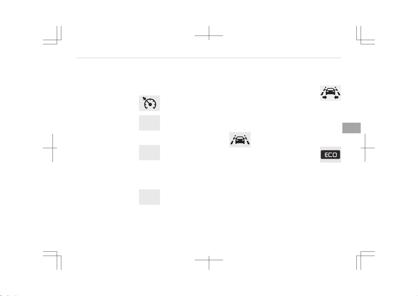
When the ready indicator goes OFF or
blinks, there is a problem with the sys‐
tem. In this case, we recommend that
you have your vehicle inspected by an
authorized Kia dealer.
Cruise indicator light (if
equipped)
This indicator light illumi‐
nates:
• When the cruise control
system is enabled.
For more details, refer to Cruise con‐
trol system on page 7-47.
C R U I S E
Cruise SET indicator light
(if equipped)
This indicator light illumi‐
nates:
• When the cruise control speed is set.
For more details, refer to Cruise con‐
trol system on page 7-47.
SET
AUTO HOLD indicator
light (if equipped)
This indicator light illumi‐
nates:
• [White] When you activate the auto
hold system by pressing the AUTO
HOLD button.
A UTO
HOLD
• [Green] When you stop the vehicle
completely by depressing the brake
pedal with the auto hold system acti‐
vated.
• [Yellow] When there is a malfunction
with the auto hold system.
In this case, we recommend that you
have the vehicle inspected by an au‐
thorized Kia dealer.
❈ For more details, refer to Auto
Hold on page 7-24.
Lane departure warning
system (LDWS) indicator
light (if equipped)
This indicator light illumi‐
nates:
• [White] When the lane departure
warning system does not detect the
lane line.
• [Green] When you activate the lane
departure warning system by press‐
ing the LDWS button.
• [Yellow] When there is a malfunction
with the lane departure warning sys‐
tem.
In this case, we recommend that you
have the vehicle inspected by an au‐
thorized Kia dealer.
❈ For more details, refer to Lane De‐
parture Warning System (LDWS)
on page 7-79.
LKAS (Lane Keeping
Assistant System)
indicator (if equipped)
The LKAS indicator will illu‐
minate when you turn the lane keeping
assistant system on by pressing the
LKAS button.
If there is a problem with the system,
the yellow LKAS indicator will illumi‐
nate.
For more details, refer to LKAS on
page 7-83.
ECO indicator light (if
equipped)
This indicator light illumi‐
nates:
• When the Active ECO system is acti‐
vated by pressing the DRIVE mode
button.
• The ECO indicator (green) will illumi‐
nate to show that the Active ECO is
operating.
For more details, refer to Drive Mode
Integrated Control System on page
7-75.
5-87
5
Features of your vehicle

SPORT mode indicator
light (if equipped)
This indicator light illumi‐
nates:
• When you select SPORT mode as
drive mode.
For more details, refer to Drive mode
on page 7-75.
Features of your vehicle
5-88
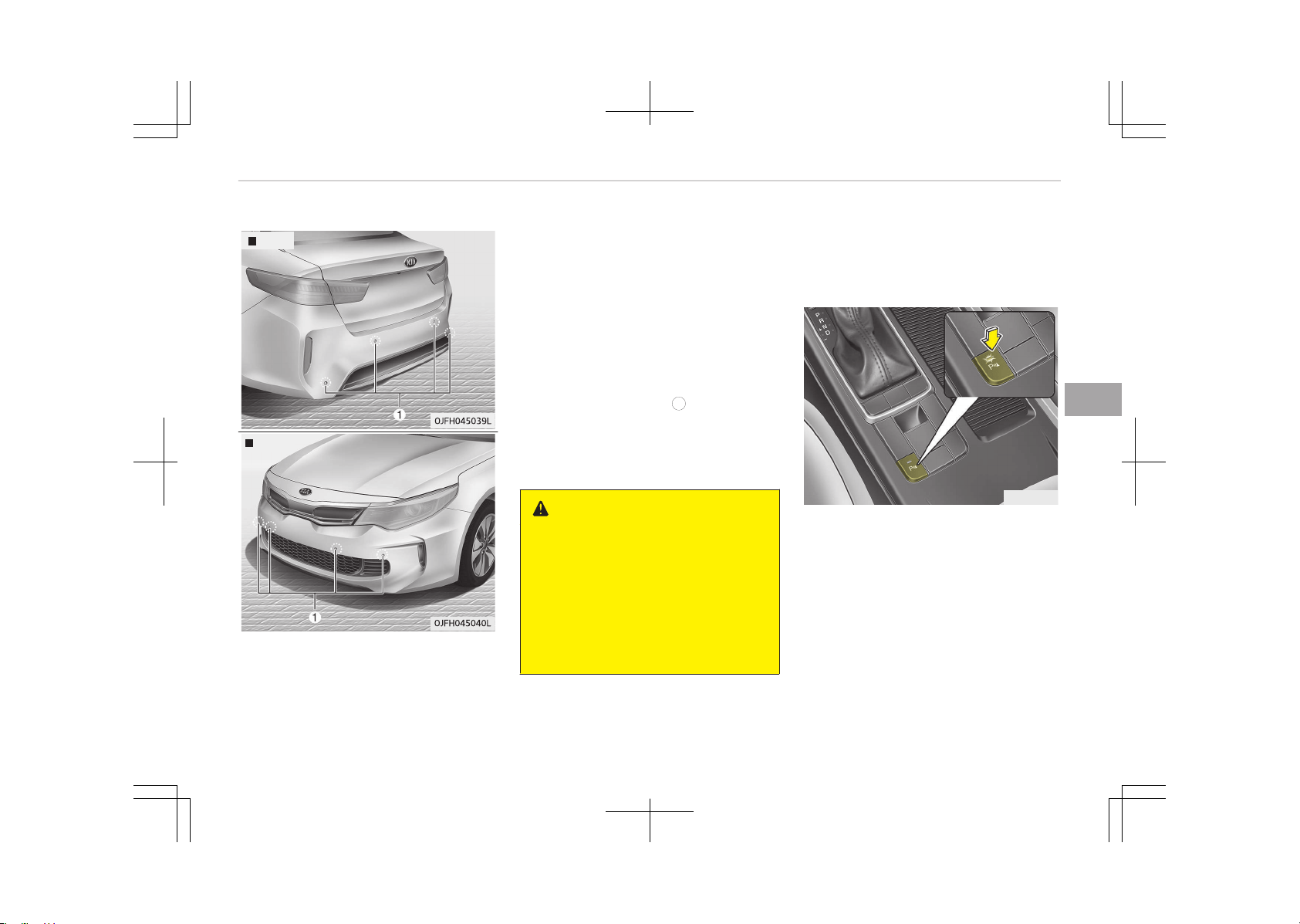
PARKING ASSIST SYSTEM (IF EQUIPPED)
Rear
Front
The parking assist system assists the
driver during movement of the vehicle
by chiming if any object is sensed with‐
in the distance of 100 cm (39 in.) in
front and 120 cm (47 in.) behind the
vehicle.
This system is a supplemental system
and it is not intended to nor does it re‐
place the need for extreme care and
attention of the driver.
The sensing range and objects detecta‐
ble by the sensors (
1
) are limited.
Whenever moving pay as much atten‐
tion to what is in front and behind of
you as you would in a vehicle without a
parking assist system.
WARNING
The parking assist system should
only be considered as a supplemen‐
tary function. The driver must check
the front and rear view. The opera‐
tional function of the parking assist
system can be affected by many
factors and conditions of the sur‐
roundings, so the responsibility rests
always with the driver.
Operation of the parking assist
system
Operating condition
OJF045041
• This system activates when the
parking assist system button is
pressed with the ignition switch ON.
• The indicator of the parking assist
system button turns on automatical‐
ly and activates the parking assist
system when you shift the gear to
the R (Reverse) position. It will turn
off automatically when you drive
above 30 km/h (18.6 mph) (If SPAS
equipped)
5-89
5
Features of your vehicle

• The sensing distance while backing
up is approximately 120 cm (47 in.)
when you are driving less than 10
km/h (6.2 mph).
• The sensing distance while moving
forward is approximately 100 cm
(39 in.) when you are driving less
than 10 km/h (6.2 mph).
• When more than two objects are
sensed at the same time, the closest
one will be recognized first.
• The side sensors are activated when
you shift the gear to the R (Reverse)
position.
• If the vehicle speed is above 20 km/h,
the system automatically turns off.
To activate again, push the button.
NOTICE
It may not operate if its distance
from the object is already less than
approximately 25 cm when the sys‐
tem is ON.
Features of your vehicle
5-90
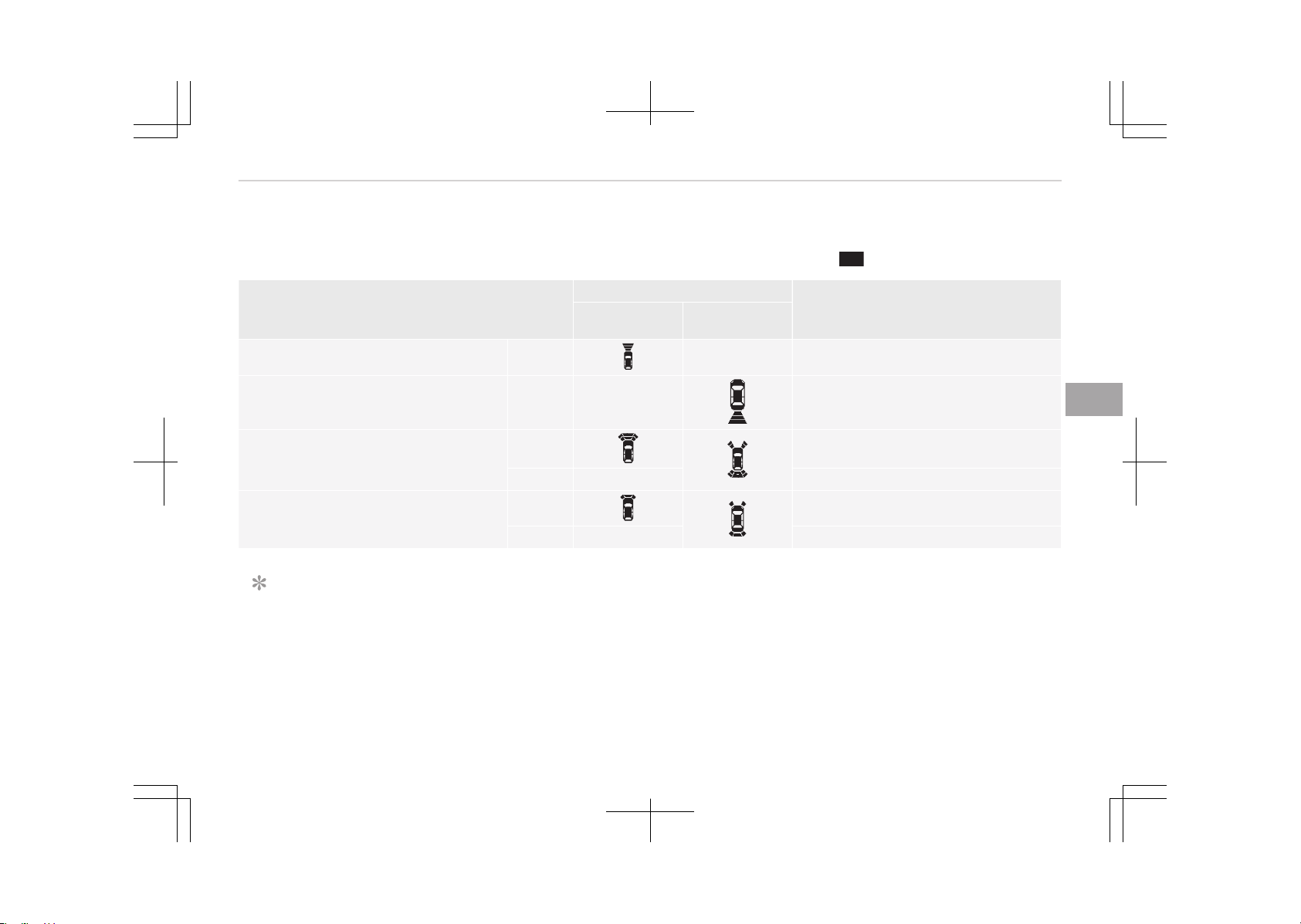
Type of warning indicator and sound
: with warning sound
Distance from object
Warning indicator
Warning sound
When driving
forward
When driving
rearward
100 cm~61 cm Front
- Buzzer beeps intermittently
120 cm~61 cm Rear -
Buzzer beeps intermittently
60 cm~31 cm
Front Buzzer beeps frequently
Rear - Buzzer beeps frequently
30 cm
Front
Buzzer sounds continuously
Rear - Buzzer sounds continuously
NOTICE
• The actual warning sound and indicator may differ from the illustration according to objects or sensor status.
• Do not wash the vehicle's sensor with high pressure water.
5-91
5
Features of your vehicle

CAUTION
• This system can only sense objects within the range and location of the sensors.
It cannot detect objects in other areas where sensors are not installed. Also, small or slim objects, such as poles or ob‐
jects located between sensors may not be detected by the sensors.
Always visually check behind the vehicle when backing up.
• Be sure to inform any drivers of the vehicle that may be unfamiliar with the system regarding the systems capabilities
and limitations.
Non-operational conditions of
parking assist system
Parking assist system may not
operate normally when:
1. Moisture is frozen to the sensor. (It
will operate normally when mois‐
ture melts.)
2. Sensor is covered with foreign mat‐
ter, such as snow or water, or the
sensor cover is blocked. (It will op‐
erate normally when the material
is removed or the sensor is no lon‐
ger blocked.)
3. The parking assist button is off.
There is a possibility of parking
assist system malfunction when:
1. Driving on uneven road surfaces
such as unpaved roads, gravel,
bumps, or gradient.
2. Objects generating excessive noise
such as vehicle horns, loud motor‐
cycle engines, or truck air brakes
can interfere with the sensor.
3. Heavy rain or water spray.
4. Wireless transmitters or mobile
phones present near the sensor.
5. Sensor is covered with snow.
Detecting range may decrease
when:
1. Outside air temperature is ex‐
tremely hot or cold.
2. Undetectable objects smaller than
1 m and narrower than 14 cm in di‐
ameter.
The following objects may not be
recognized by the sensor:
1. Sharp or slim objects such as ropes,
chains or small poles.
2. Objects, which tend to absorb sen‐
sor frequency such as clothes,
spongy material or snow.
Features of your vehicle
5-92
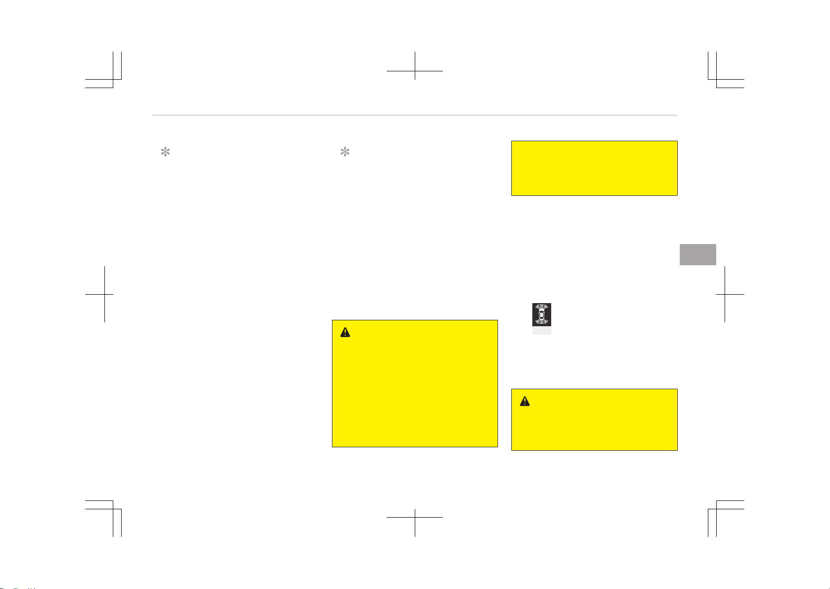
NOTICE
1. The warning may not sound se‐
quentially depending on the
speed and shapes of the objects
detected.
2. The parking assist system may
malfunction if the vehicle bump‐
er height or sensor installation
has been modified. Any non-fac‐
tory installed equipment or ac‐
cessories may also interfere
with the sensor performance.
3. Sensor may not recognize ob‐
jects less than 30 cm from the
sensor, or it may sense an incor‐
rect distance. Use with caution.
4. When the sensor is frozen or
stained with snow or water, the
sensor may be inoperative until
the stains are removed using a
soft cloth.
5. Do not push, scratch or strike
the sensor with any hard objects
that could damage the surface
of the sensor. Sensor damage
could occur.
NOTICE
This system can only sense objects
within the range and location of the
sensors, it can not detect objects in
other areas where sensors are not
installed. Also, small or slim objects,
or objects located between sensors
may not be detected.
Always visually check in front and
behind the vehicle when driving. Be
sure to inform any drivers in the ve‐
hicle that may be unfamiliar with
the system regarding the systems
capabilities and limitations.
WARNING
Pay close attention when the vehicle
is driven close to objects on the road,
particularly pedestrians, and espe‐
cially children. Be aware that some
objects may not be detected by the
sensors, due to the objects distance,
size or material, all of which can lim‐
it the effectiveness of the sensor.
Always perform a visual inspection
(Continued)
(Continued)
to make sure the vehicle is clear of
all obstructions before moving the
vehicle in any direction.
Self-diagnosis
When you shift the gear to the R (Re‐
verse) position and if one or more of
the below occurs you may have a mal‐
function in the rear parking assist sys‐
tem.
• You don't hear an audible warning
sound or if the buzzer sounds inter‐
mittently.
•
(blinks)
is displayed (if equipped).
If this occurs, we recommend that the
system be checked by an authorized
Kia dealer.
WARNING
Your new vehicle warranty does not
cover any accidents or damage to
(Continued)
5-93
5
Features of your vehicle

(Continued)
the vehicle or injuries to its occu‐
pants related to a parking assist
system. Always drive safely and
cautiously.
Features of your vehicle
5-94
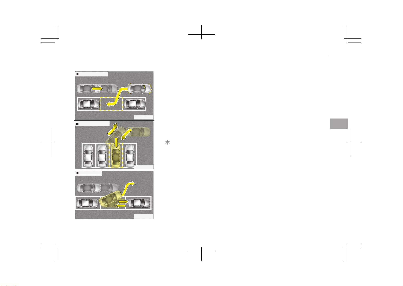
SMART PARKING ASSIST SYSTEM (SPAS) (IF EQUIPPED)
Parallel parking
OJF045236L
Reverse parking
OJF045237L
Parallel exit
OJF045238L
The Smart Parking Assist System helps
drivers park their vehicle by using sen‐
sors to measure parking spaces, control
the steering wheel to semi-automati‐
cally park the vehicle and provide in‐
struction on the LCD display to help
through parking.
Additionally, the system provides assis‐
tance when leaving (parallel exit) a
parking space.
❈ The volume for the Smart Parking
Assist System can be adjusted. Re‐
fer to User setting on page 5-58.
NOTICE
• The vehicle will not stop for pe‐
destrians or objects that may be
in its path, so the driver must
monitor the maneuver.
• Use the system only in parking
lots and places used for parking.
• The system does not work if there
is no car parked in front of the
parking space you are planning to
park or if it is a diagonal parking
space.
(Continued)
(Continued)
• After parking your vehicle using
the system, the vehicle may not
be parked at the exact spot you
have wished. For example, the
space between your vehicle and
wall may not be the distance you
have desired.
• Deactivate the system and park
your vehicle manually, when the
situation requires parking manual‐
ly.
• The Parking Assist System's front
and rear warning sound activates
when the Smart Parking Assist
System is activated.
• After searching for a parking
space is completed, the Smart
Parking Assist System will be can‐
celed if the Parking Assist System
is cancelled by pressing the button
to the OFF position.
5-95
5
Features of your vehicle
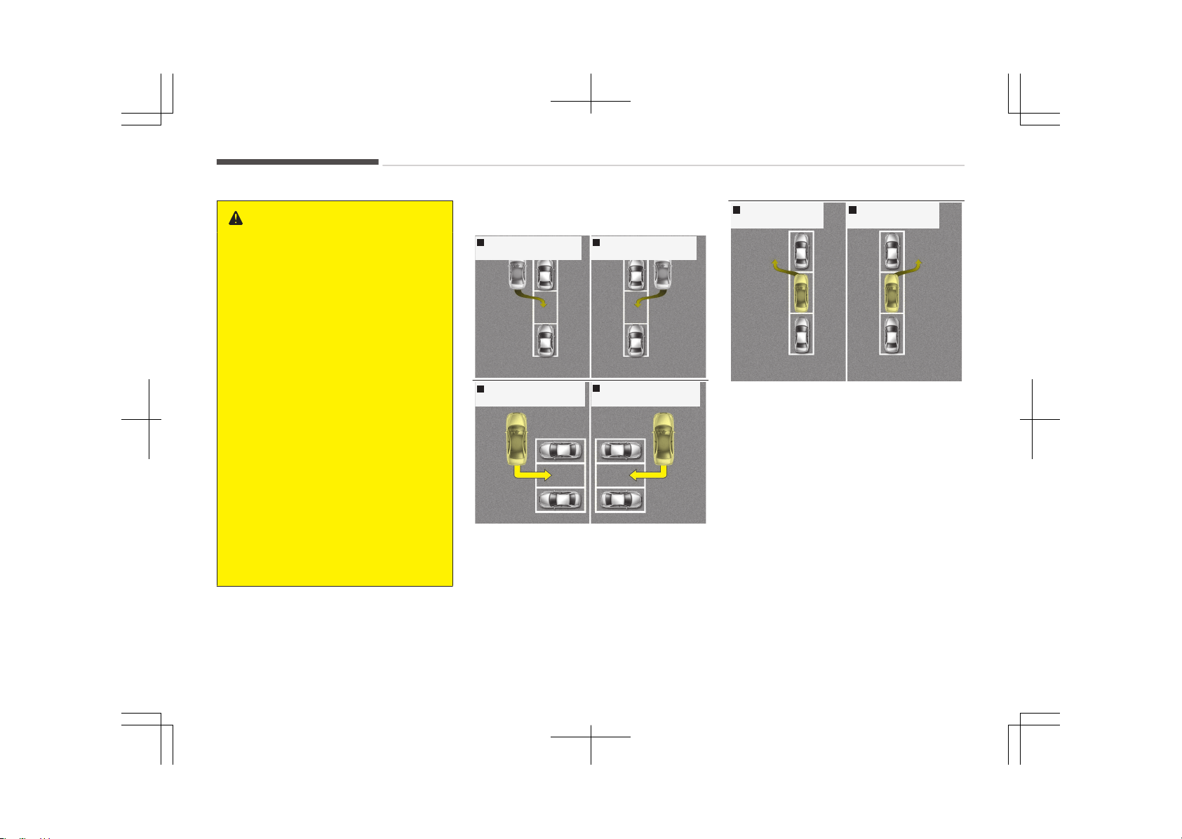
WARNING
• The Smart Parking Assist System
should only be considered as a
supplementary function. The driv‐
er must check the front and rear
view for objects. The operational
function of the Smart Parking As‐
sist System can be affected by
many factors and conditions of the
surroundings, so the responsibility
rests always with the driver.
• The system may not operate nor‐
mally if the vehicle needs wheel
alignment adjustment. Have the
vehicle checked by an authorized
Kia dealer.
• If you use a different tire or wheel
size rather than the size recom‐
mended by the Kia dealer, the sys‐
tem may not work properly. Al‐
ways use the same size tire and
wheel.
• If you use additional frame on the
license plate, SPAS may generate
abnormal warning sound.
Operating condition
Right side
- Parallel parking
Left side
- Parallel parking
OJF045241L
Right side
- Reverse parking
Left side
- Reverse parking
OJF045239L
Left side
- Parallel exit
Right side
- Parallel exit
OJF045240L
The system will help park the vehicle in
the middle or back of a parked vehicle.
Use the system when all the below
conditions are met.
• When the parking space is a straight
line
• When parallel parking or reverse (per‐
pendicular) parking is required
• When there is a parked vehicle
• When there is enough space to move
the vehicle
Non-operating condition
Never use the Smart Parking Assist
System in the below conditions.
• Curved parking space
Features of your vehicle
5-96
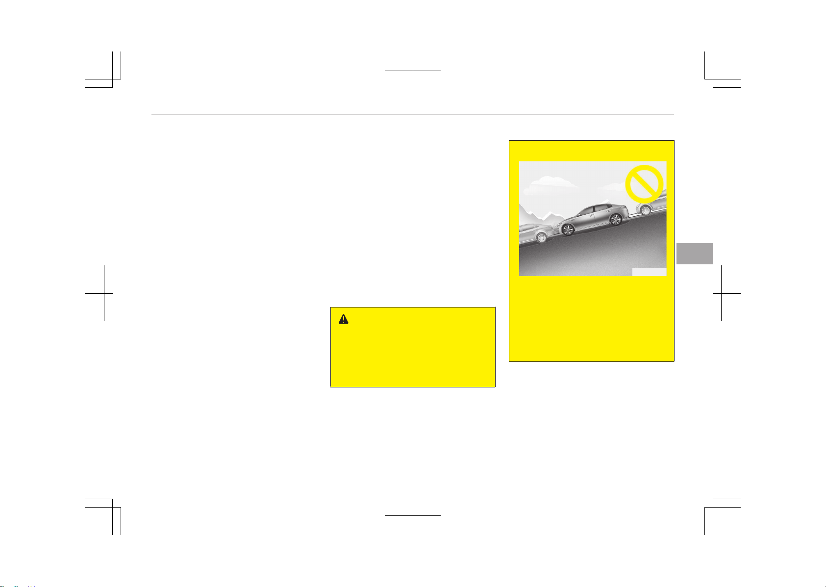
• Inclined roads
• A vehicle loaded with longer or wider
cargo compared to the vehicle
• Diagonal parking space
• Heavy snow or rain
• Near a circular pillar or narrow pillar,
or a pillar surrounded by objects such
as fire extinguisher, etc.
• The sensor is positioned incorrectly
by an impact to the bumper
• Bumpy roads
• A vehicle equipped with a snow chain
or spare tire
• Tire pressure lower or higher than
the standard tire pressure
• A trailer connected to the vehicle
• Slippery or uneven road
• Big vehicles such as buses or trucks
parked
• Sensor covered with foreign matter,
such as snow or water
• Moisture frozen on the sensor
• A motorcycle or bicycle parked
• A obstacle such as a trash can, bicy‐
cle, shopping cart, etc. is near
• Heavy wind
• Wheel changed to an unauthorized
size
• A problem with the wheel alignment
• An accessory installed on the detec‐
tive area the of sensors (such as
number plate holder)
• Vehicle leaned severely to one side
• Strong sunlight or very cold weather
• Ultrasonic interference from other
vehicle's. Such as horn sounds of oth‐
er vehicles, motorcycle's engine noise,
air brake noise of heavy vehicles and
with the other vehicle's parking assist
system working.
WARNING
Do not use the Smart Parking Assist
System in the following conditions
for unexpected results may occur
and cause a serious accident.
(Continued)
(Continued)
OJF045244L
1. Parking on inclines
The driver must apply the accel‐
erator and brake pedal when
parking on inclines. If the driver
is unfamiliar with applying the
accelerator and brake pedal, a
vehicle accident may occur.
(Continued)
5-97
5
Features of your vehicle
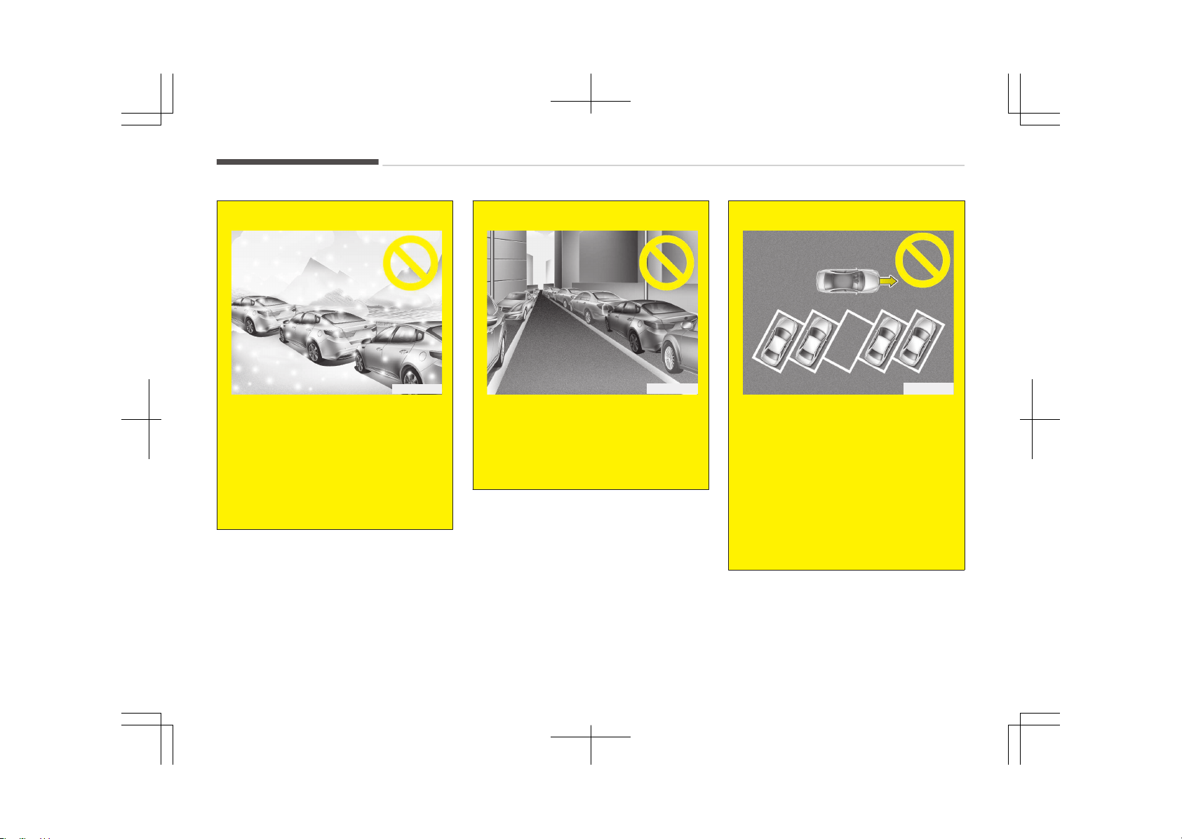
(Continued)
OJF045245L
2. Parking in snow
Snow may interfere with sensor
operation or the system may be
cancelled if the road is slippery
while parking. Also, if the driver
is unfamiliar with applying the
accelerator and brake pedal, a
car accident may occur.
(Continued)
(Continued)
OJF045246L
3. Parking in narrow space
The system may not search for
parking spaces if the space is
too narrow. Even if the system
is operating, always be careful.
(Continued)
(Continued)
OJF045243L
4. Parking diagonal
The system is a supplemental
for parallel parking or perpendic‐
ular parking. Diagonal line park‐
ing is not available. Even if the
vehicle is able to enter the
space, do not operate the Smart
Parking Assist System. The sys‐
tem will attempt parallel parking
or reverse (perpendicular) park‐
ing.
(Continued)
Features of your vehicle
5-98
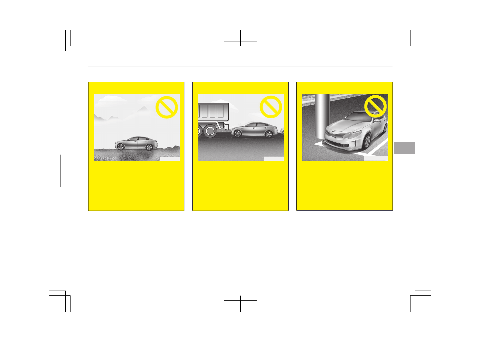
(Continued)
OJF045247L
5. Parking in uneven road
Parking in uneven roads, the
driver needs to properly apply
the pedal (clutch, accelerator or
brake). If not, the system may
be cancelled when the vehicle
slips or an accident may occur.
(Continued)
(Continued)
OJF045248L
6. Parking behind a truck
An accident may occur when
parking behind a vehicle higher
than yours. For example, bus,
truck, etc.
Do not solely rely on the Smart
Parking Assist System.
(Continued)
(Continued)
OJFHP046249L
7. Obstacle in parking space
Obstacles such as a pillar may
interfere with the system when
looking for a parking space. Even
though, a parking space is avail‐
able the system may not detect
a parking space.
(Continued)
5-99
5
Features of your vehicle
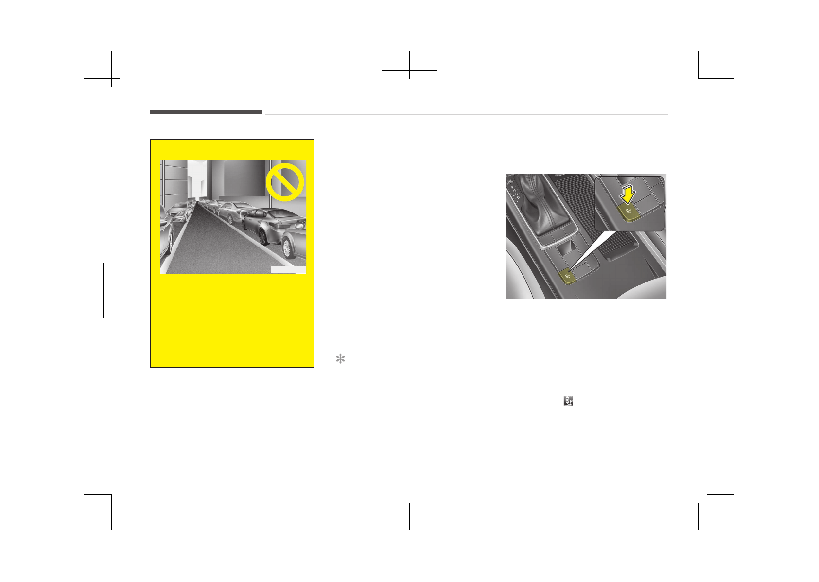
(Continued)
OJF045246L
8. Leaving a parking space near a
wall
When leaving a parking space
that is narrow and near a wall,
the system may not work prop‐
erly. When leaving a parking
space similar to the above pic‐
ture, the driver must watch out
for obstacles while leaving.
How the system works (Parking
Mode)
1. Activate the Smart Parking Assist
System
The shift lever should be placed in
D (Drive), N (Neutral, above
5 km/h).
2. Select parking mode
3. (Optional) Search for parking space
(slowly move forward.)
4. (Optional) Search complete (auto‐
matic search by sensor.)
5. Steering wheel control
1. Shift according to the instruction
on the LCD display.
2. Drive slowly with the brake pedal
applied.
6. Parking complete
7. If necessary, manually adjust posi‐
tion of vehicle.
If the system already recognized park‐
ing space before activating the Smart
Parking Assist System, you can proceed
from step 4 (Search complete).
NOTICE
• Before activating the system
check if the conditions are possible
to use the system.
• For your safety, always apply the
brake pedal except for when driv‐
ing.
1. Activate Smart Parking Assist
System
OJF045266L
• Press the Smart Parking Assist Sys‐
tem button (the button indicator will
illuminate).
• The Parking Assist System will be ac‐
tivated.
A warning sound will be heard if an
obstacle is detected.
• Press the Smart Parking Assist Sys‐
tem button again for more than 2
seconds to turn off the system.
• The Smart Parking Assist System de‐
faults to the OFF position whenever
the ignition switch is turned on.
Features of your vehicle
5-100
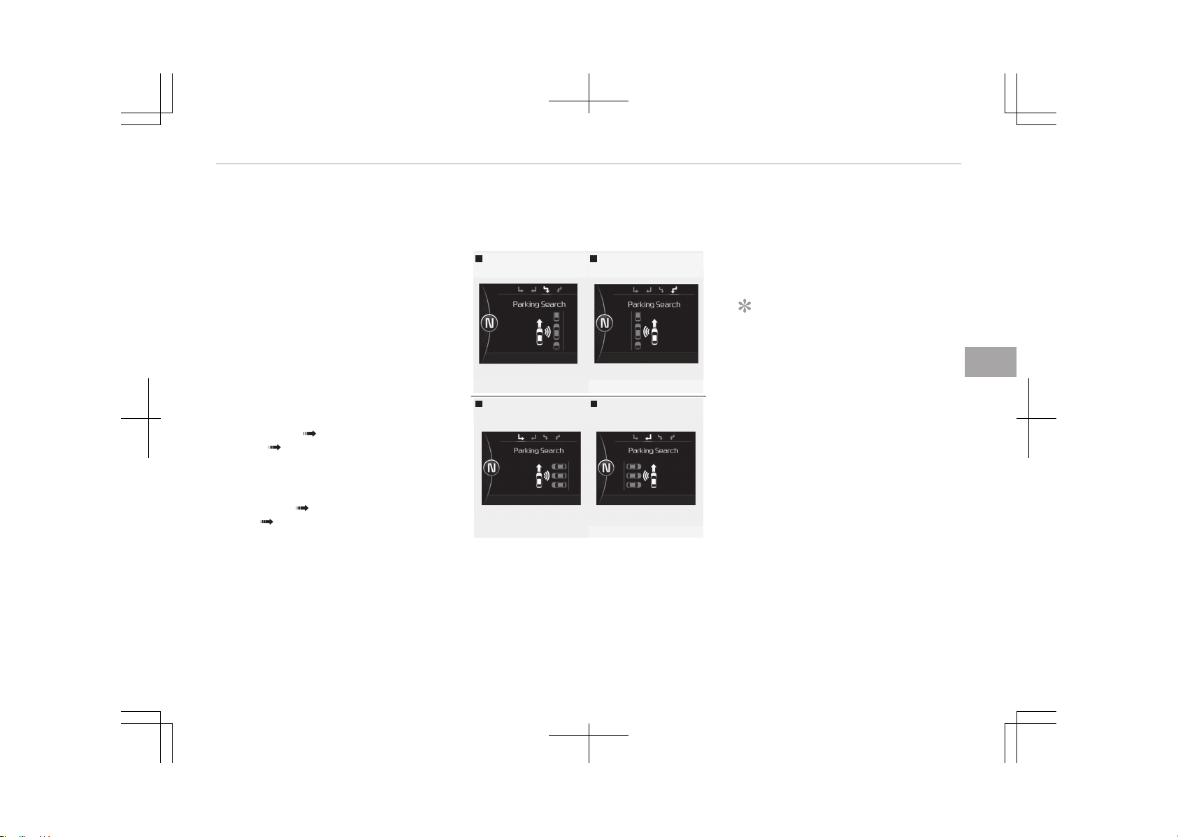
2. Select parking mode
• Select parallel mode or reverse mode
by pressing the Smart Parking Assist
System button with the shift lever in
D (Drive), N (Neutral, above 5 km/h)
and the brake pedal depressed.
• If the system already recognized
parking space before activating the
Smart Parking Assist System, you
can see Parking search or Space
found.
• The right side parallel mode is selec‐
ted automatically when the Smart
Parking Assist System is activated.
• The mode changes from parallel
mode (right left) to reverse mode
(right left) whenever the Smart
Parking Assist System button is
pressed. (for LHD)
• The mode changes from parallel
mode (left right) to reverse mode
(left right) whenever the Smart
Parking Assist System button is
pressed. (for RHD)
• If the button is pressed again, the
system will turn off.
3. Search for parking space
(optional)
Right side
- Parallel parking
Left side
- Parallel parking
OJF045250L-OJF045251L
Right side
- Reverse parking
Left side
- Reverse parking
OJF045252L-OJF045253L
• Slowly drive forward maintaining the
distance of approximately 50 cm ~
150 cm (19.6 in.~59.0 in.) with the
parked vehicles. The side sensors will
search for a parking space.
• If the vehicle speed is over 20 km/h, a
message will appear to notify you to
reduce speed.
• If vehicle speed is over 30 km/h, the
system will be cancelled.
NOTICE
• Turn on the hazard warning flash‐
er if the road is crowded with oth‐
er vehicles.
• If the parking lot is small, slowly
drive nearer to the parking space.
• The search for a parking space will
be completed only when there is
enough space for the vehicle to
move to park.
5-101
5
Features of your vehicle
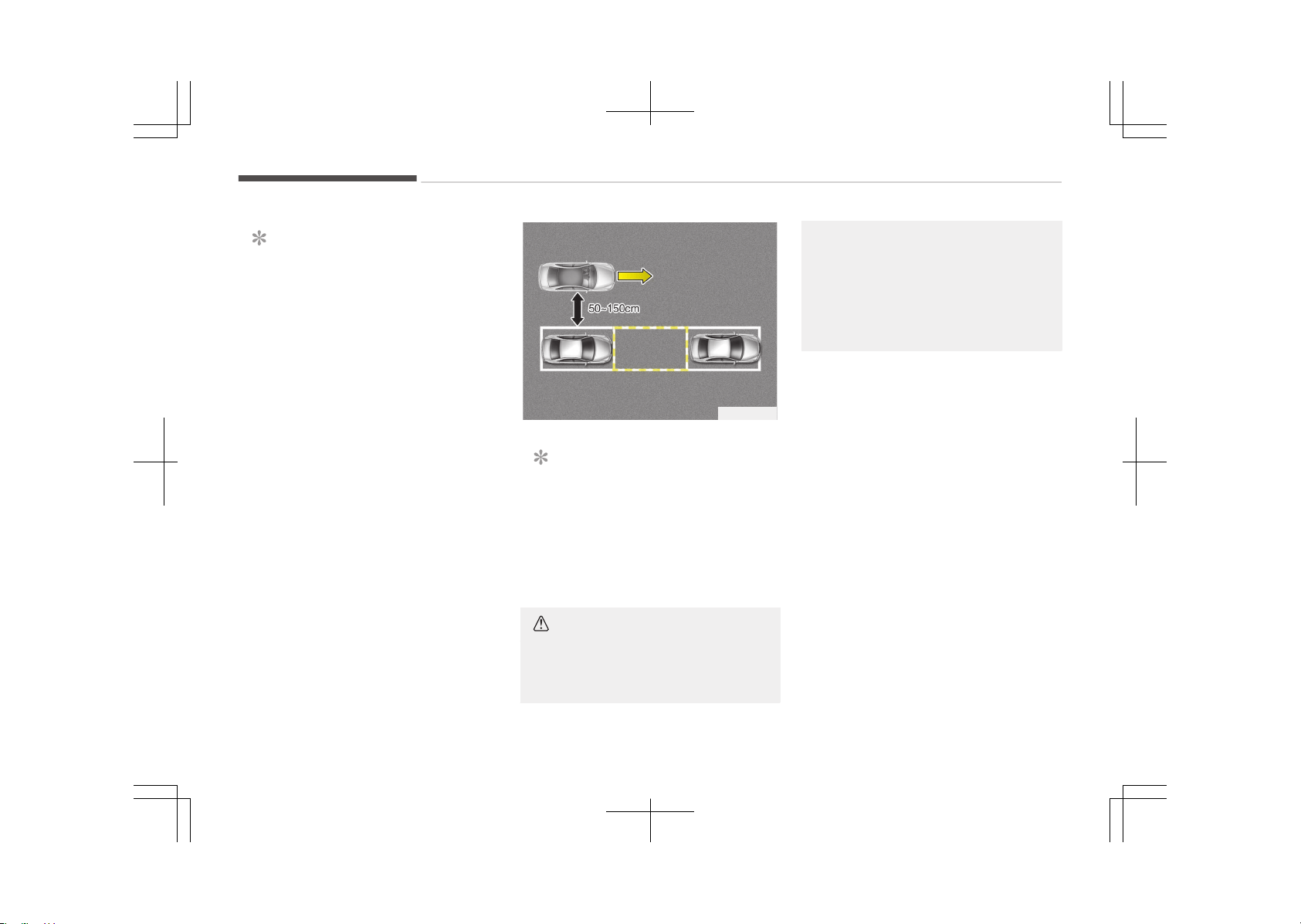
NOTICE
• When searching for a parking
space, the system may not be
able to find a parking space if
there is no vehicle parked, a park‐
ing space is available after driving
by or a parking space is available
before driving by.
• The system may not operate nor‐
mally in the following conditions:
1. When the sensors are frozen
2. When the sensors are dirty
3. When it snows or rains heavily
4. When a pillar or object is near
OJF045242L
NOTICE
Slowly drive forward maintaining the
distance of approximately 50 cm ~
150 cm (19.6 in.~59.0 in.) with the
parked vehicles. If it is not within the
distance, the system may not be
able to search for a parking space.
CAUTION
After searching for a parking space
is completed, continue using the
(Continued)
(Continued)
system after checking the surround‐
ing area.
Especially, check the distance of the
outside rearview mirror and objects
while using the system to prevent
careless accidents.
Features of your vehicle
5-102
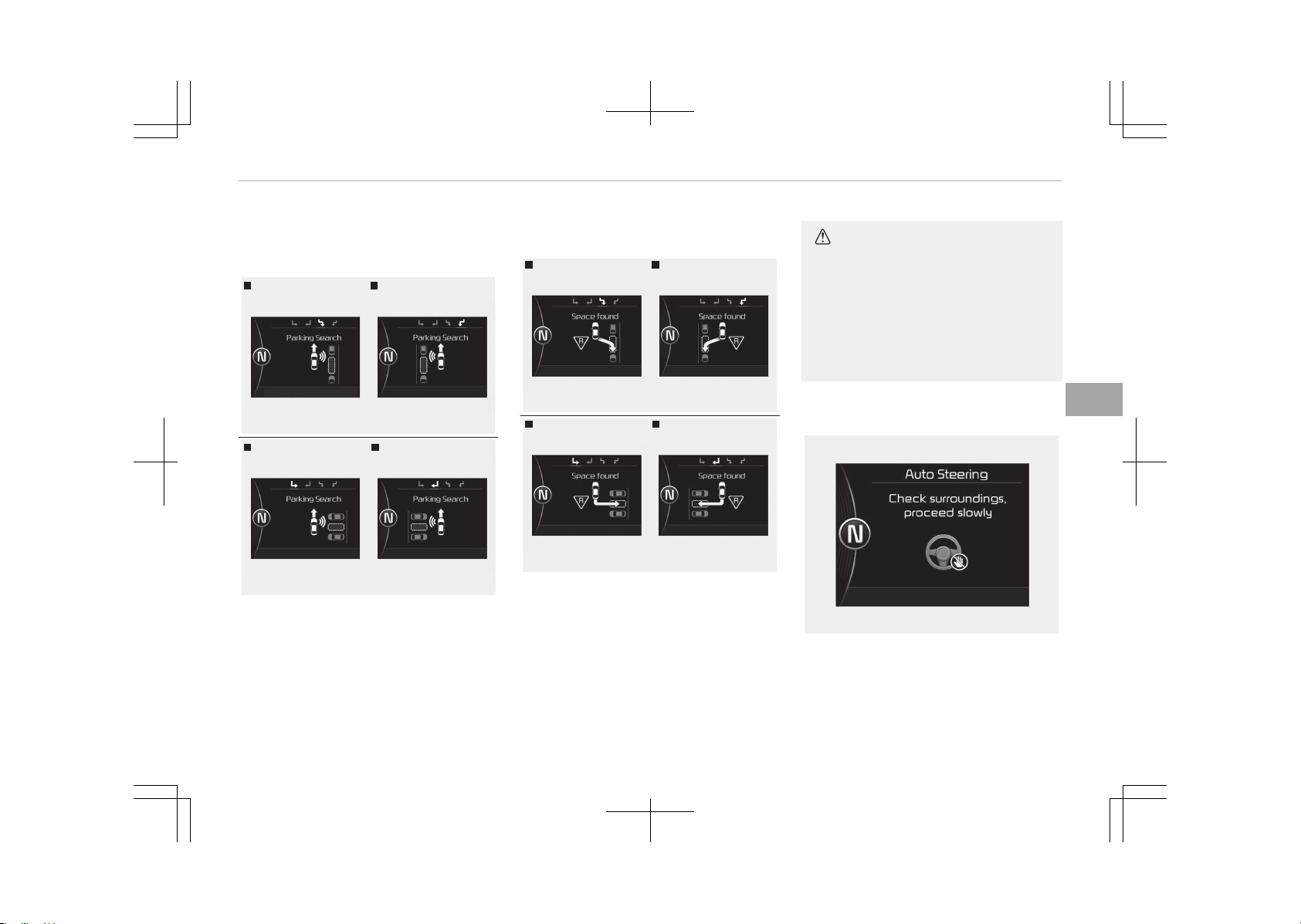
4. Recognizing parking space
(optional)
Right side
- Parallel parking
Left side
- Parallel parking
OJF045254L-OJF045255L
Right side
- Reverse parking
Left side
- Reverse parking
OJF045256L-OJF045257L
When a parking space is found, a blank
box will appear like the above picture.
Drive forward slowly, then the Shift to
R message will appear.
5. Search complete
Right side
- Parallel parking
Left side
- Parallel parking
OJF045258L-OJF045259L
Right side
- Reverse parking
Left side
- Reverse parking
OJF045260L-OJF045261L
While driving forward to search for a
parking space, the above message will
appear with a beep sound if the search
is complete. Stop the vehicle and shift
to the R (Reverse) position.
CAUTION
• Always drive slowly with the brake
pedal applied.
• If the parking space is small the
system may be cancelled at the
Steering wheel control stage. Do
not park your vehicle if the space
is too small.
6. Steering wheel control
OJF045345L
• The above message will appear if the
shift lever is in R (Reverse). The
steering wheel will be controlled au‐
tomatically.
5-103
5
Features of your vehicle
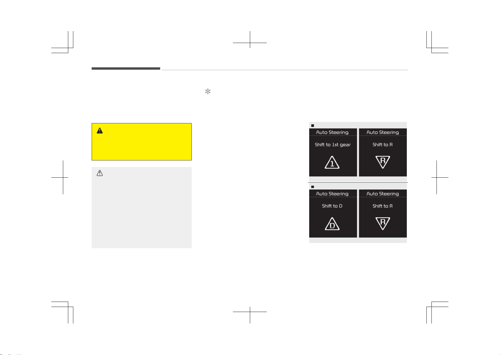
• The system will be cancelled if you
firmly hold the steering wheel while it
is controlled automatically.
• The system will be cancelled if vehicle
speed is over 7 km/h (4.3 mph).
WARNING
Do not put your hands between the
steering wheel while it is being auto‐
matically controlled.
CAUTION
• Always drive slowly with the brake
pedal applied.
• Always check for objects around
your vehicle before driving.
• If the vehicle does not move even
though the brake pedal is not de‐
pressed, check the surrounding
before depressing the accelerator
pedal. Be sure not to speed over
7 km/h (4.3 mph).
NOTICE
• If you do not follow the instruc‐
tions provided, you may fail to
park your vehicle.
However, if the Parking Assist Sys‐
tem warning sound (distance from
object is within 30 cm: continuous
beep) occurs, slowly drive the ve‐
hicle to the reverse direction of
the detected object after checking
the surrounding.
• Always check the surrounding be‐
fore driving your vehicle if the
Parking Assist System warning
sound (distance from object is
within 30 cm: continuous beep) is
heard for the object is close to
your vehicle. If the vehicle gets too
close to the object, the warning
will not sound.
To cancel the system while parking
• Press the Smart Parking Assist Sys‐
tem button and hold until the system
is cancelled.
• Press long the Smart parking assist
system button while the system is
searching for a parking space.
• Press shortly the Smart parking as‐
sist system button while the steering
wheel is controlled.
Gear shift while steering wheel control
Manual transaxle
OJF045337LOJF045338L
Automatic transaxle
OJF045339LOJF045338L
When the above message appears with
a beep sound, shift the gear and drive
the vehicle with the brake pedal de‐
pressed.
Features of your vehicle
5-104
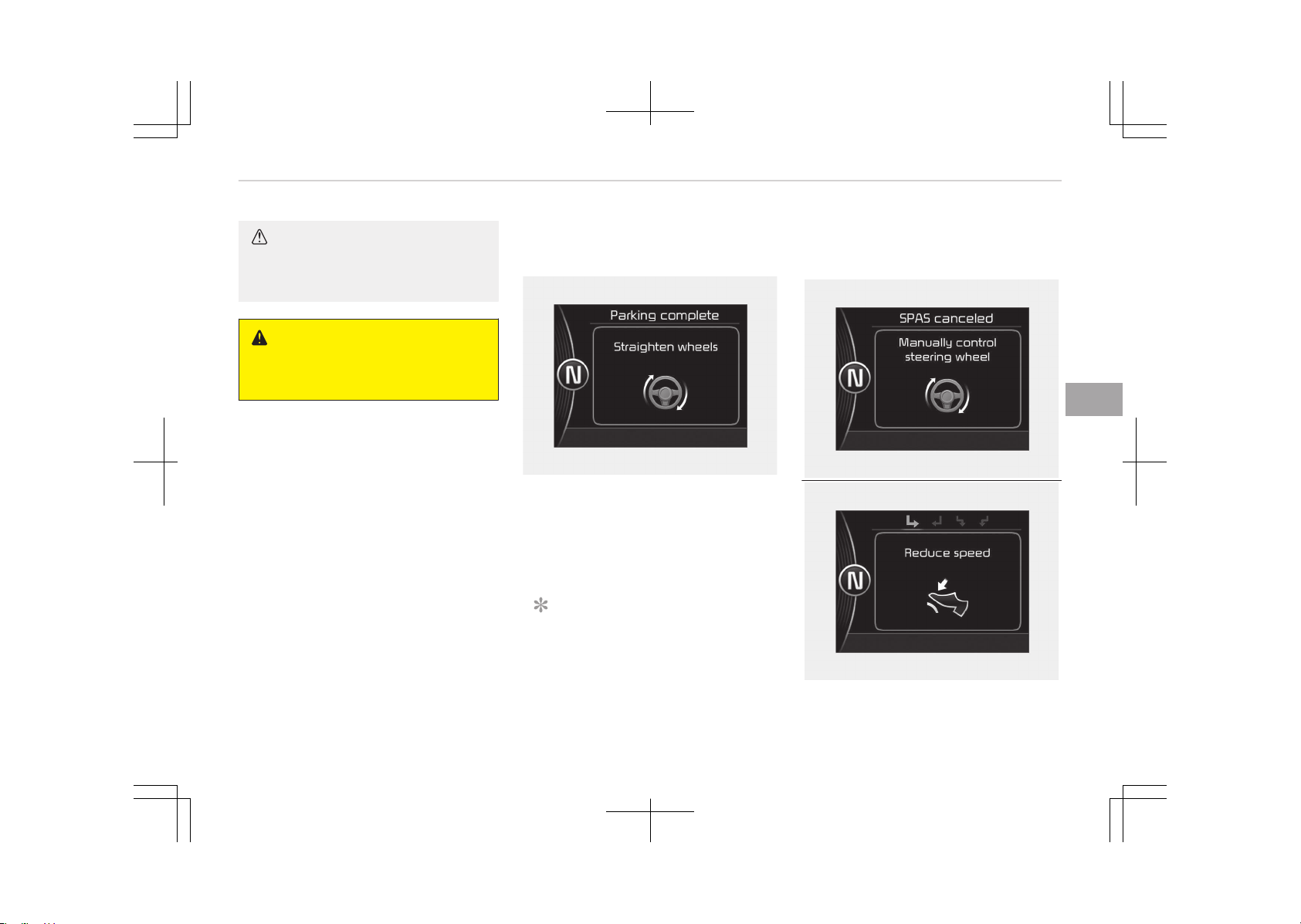
CAUTION
Always check the surrounding before
releasing the brake pedal.
WARNING
Always be careful while parking for
other vehicles or pedestrians.
7. Smart parking assist system
completed
OJF045340L
Complete parking your vehicle accord‐
ing to the instructions on the LCD dis‐
play. If required, manually control the
steering wheel and complete parking
your vehicle.
NOTICE
The brake pedal must be depressed
by the driver while parking your ve‐
hicle.
Additional instructions
(messages)
OJF045341L
OJF045342L
5-105
5
Features of your vehicle
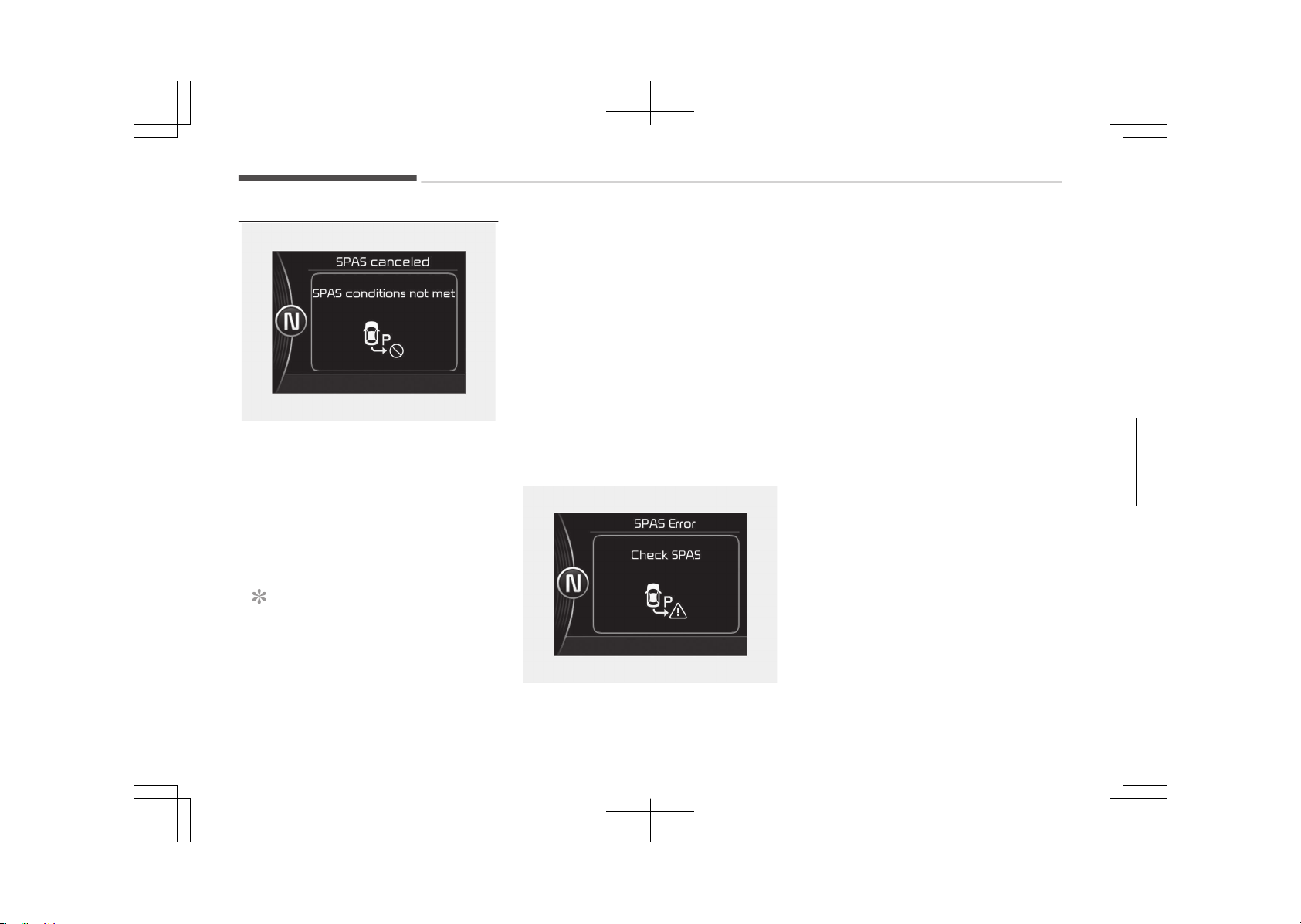
OJF045343L
When the Smart Parking Assist System
is operating, a message may appear re‐
gardless of the parking order.
The messages will appear according to
the circumstances. Follow the instruc‐
tions provided while parking your vehi‐
cle with the Smart Parking Assist Sys‐
tem.
NOTICE
• In the below conditions the system
will be cancelled. Park your vehicle
manually.
(Continued)
(Continued)
- When the ABS is activated
- When the TCS/ESC is turned off
• When vehicle speed is above
20 km/h while searching for a
parking space a message "Reduce
speed" will appear.
• In the below condition the system
will not activate
- When the TCS/ESC is turned off
System malfunction
OJF045344L
• If there is a problem with the system,
when the system is turned on, the
above message will appear. Also, the
indicator on the button will not light
up and a beep sound will be heard 3
times.
• If there is a problem with only the
Smart Parking Assist System, the
Parking Assist System will operate
after 2 seconds.
If you notice any problem, we recom‐
mend to have the system checked by
an authorized Kia dealer.
How the system works (Exit
mode)
The Exit Mode operates in the below
condition:
• When vehicle speed is below 5 km/h
the first time after the engine has
been started.
• After parallel parking is completed
with the Smart Parking Assist Sys‐
tem.
1. Activate the Smart Parking Assist
System
The shift lever should be placed in P
(Park) or N (Neutral).
2. Select Exit Mode
Features of your vehicle
5-106
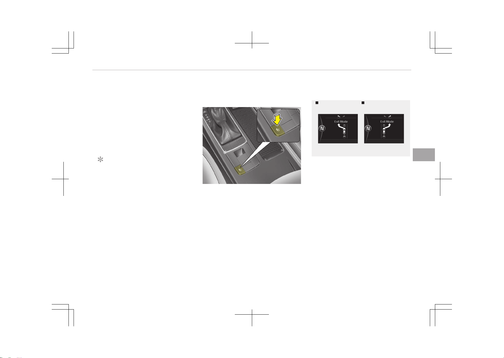
3. Check surroundings
4. Steering wheel control
1. Shift according to the instruction
on the LCD display.
2. Drive slowly with the brake pedal
applied.
5. Exiting complete
If necessary, manually adjust the
position of the vehicle.
NOTICE
• Before activating the system
check if the conditions are possible
to use the system.
• For your safety, always apply the
brake pedal except for when driv‐
ing.
1. Activate Smart Parking Assist
System
OJF045266L
• Press the Smart Parking Assist Sys‐
tem button (the button indicator will
illuminate).
• The Parking Assist System will be ac‐
tivated.
A warning sound will be heard if an
obstacle is detected.
• Press the Smart Parking Assist Sys‐
tem button again for more than 2
seconds to turn off the system.
• The Smart Parking Assist System de‐
faults to the OFF position whenever
the ignition switch is turned on.
2. Select Exit Mode
Left side
- Parallel exit
Right side
- Parallel exit
OJF045262L-OJF045263L
• Select the mode by pressing the
Smart Parking Assist System button
with the shift lever in P (Park) or N
(Neutral) and the brake pedal de‐
pressed.
• For LHD vehicle, the left side parallel
mode is selected automatically when
the Smart Parking Assist System is
activated.
• For LHD vehicle, to select the right
side parallel mode press the Smart
Parking Assist System button once
more.
• If the button is pressed again, the
system will turn off.
5-107
5
Features of your vehicle
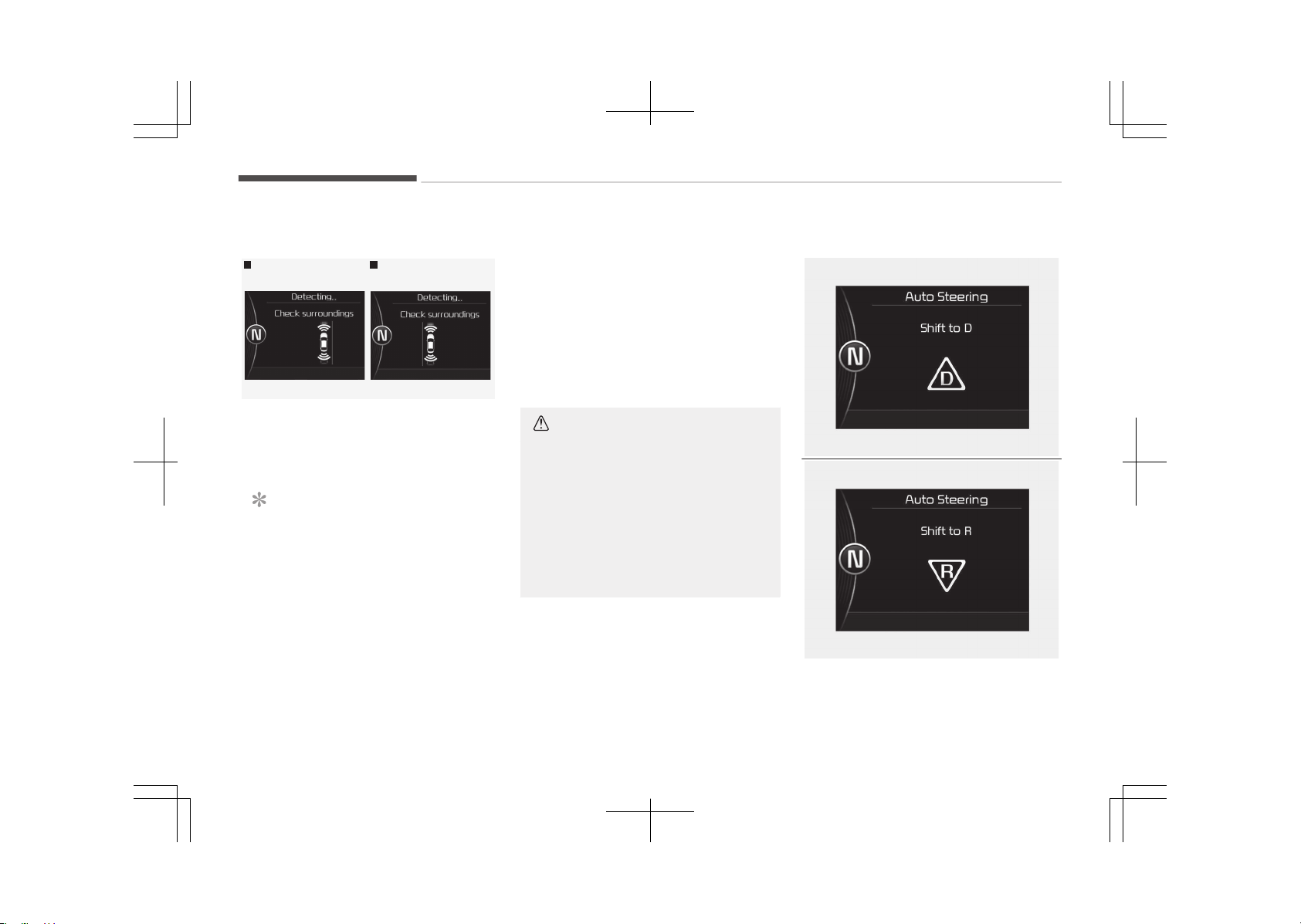
3. Check surroundings
Left side
- Parallel exit
Right side
- Parallel exit
OJF045264L-OJF045265L
The Smart Parking Assist System
checks the front and rear space to exit
the vehicle from the parking space.
NOTICE
• When checking surroundings, if
the front or rear vehicle (or object)
is too near, the system may not
work properly.
• The system may not operate nor‐
mally in the following conditions:
1. When the sensors are frozen
2. When the sensors are dirty
3. When it snows or rains heavily
(Continued)
(Continued)
4. When a pillar or object is near
• When exiting the parking space if
an obstacle is detected that may
cause an accident, the system
may be cancelled.
• If the space is too small to exit the
system may be cancelled.
CAUTION
• If searching surroundings is com‐
pleted, continue using the system
after checking the surrounding
area.
• The Exit mode may be activated
unintentionally, when the shift
lever is in P (Park) or N (Neutral) if
the Smart parking assist system
button is pressed.
4. Steering wheel control
OJF045339L
OJF045338L
Features of your vehicle
5-108
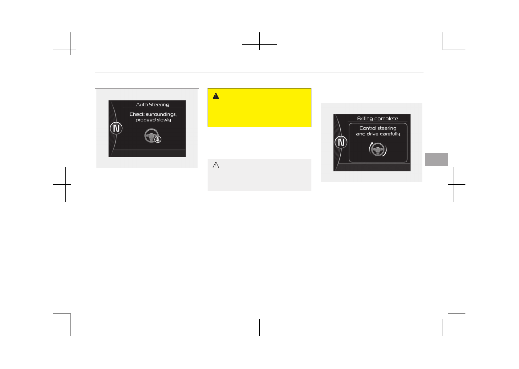
OJF045345L
• The above message will appear if the
shift lever is in D (Drive) or R (Re‐
verse) according to the distance of
the front and rear object from the
sensor.
The steering wheel will be controlled
automatically.
• The system will be cancelled if you
firmly hold the steering wheel while it
is controlled automatically.
• The system will be cancelled if vehicle
speed is over 7 km/h (4.3 mph).
WARNING
Do not put your hands between the
steering wheel while it is being auto‐
matically controlled.
To cancel the system while exiting
Press the Parking Assist System or
Smart Parking Assist System button.
CAUTION
Always drive slowly with the brake
pedal applied.
5. Exiting complete
OJF045346L
When assisting the driver exit the park‐
ing space is completed the above mes‐
sage will appear.
Turn the steering wheel to the direction
you are leaving and manually control
the steering wheel while leaving the
parking space.
5-109
5
Features of your vehicle
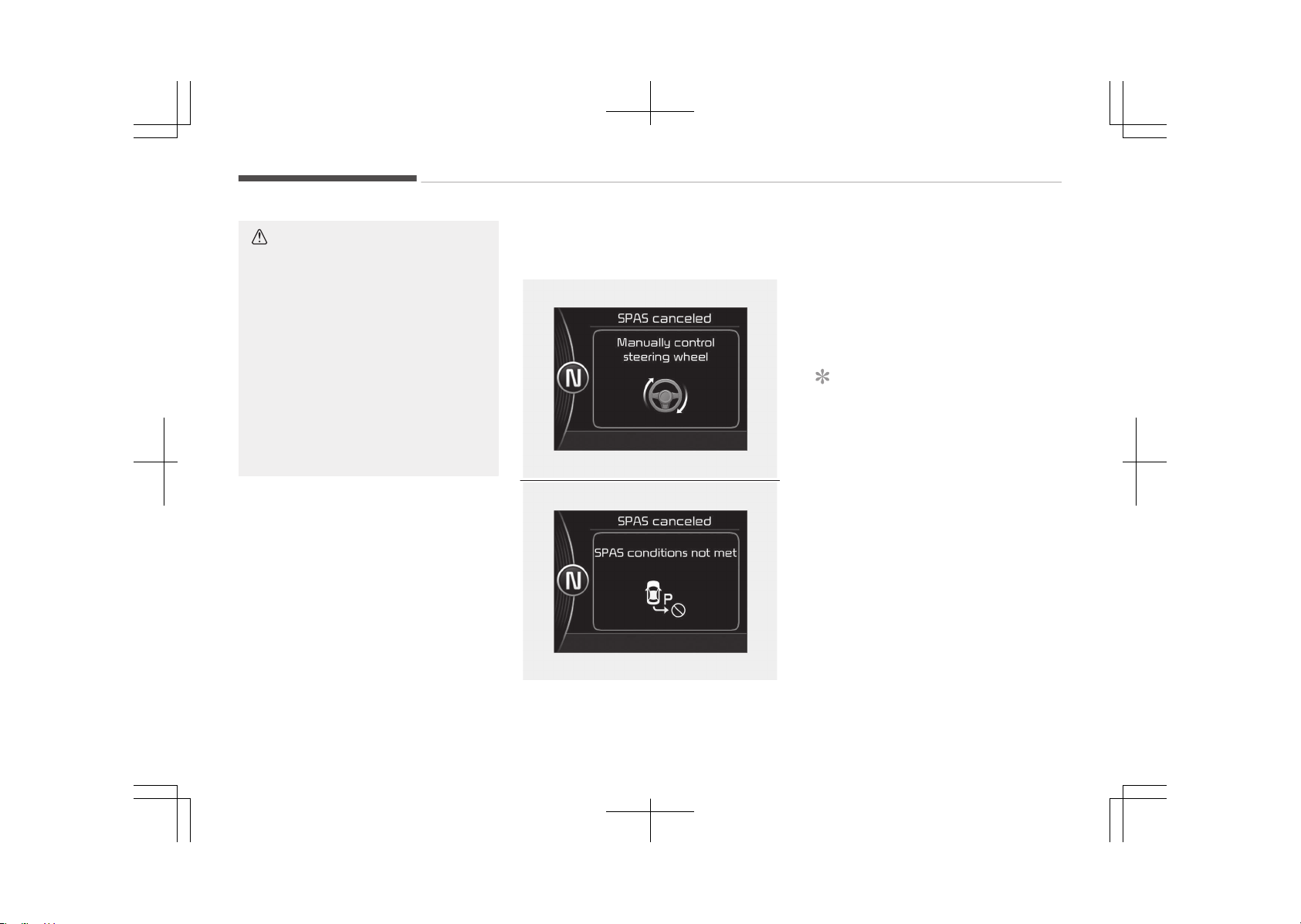
CAUTION
• When leaving the parking space
turn the steering wheel as much
as you can to the direction you are
leaving, and then drive the vehicle
slowly by depressing the vehicle.
• Always check the surrounding be‐
fore driving your vehicle if the
Parking Assist System warning
sound is continuously heard.
• The system will be cancelled for
safety reasons if the vehicle is
parked at a small space near a
wall.
Additional instructions
(messages)
OJF045341L
OJF045343L
When the Smart Parking Assist System
is operating, a message may appear re‐
gardless of the exiting order.
The messages will appear according to
the circumstances. Follow the instruc‐
tions provided while parking your vehi‐
cle with the Smart Parking Assist Sys‐
tem.
NOTICE
• In the below conditions the system
will be cancelled. Park your vehicle
manually.
- When the ABS is activated
- When the TCS/ESC is turned off
• In the below condition the system
will not activate
- When the TCS/ESC is turned off
Features of your vehicle
5-110
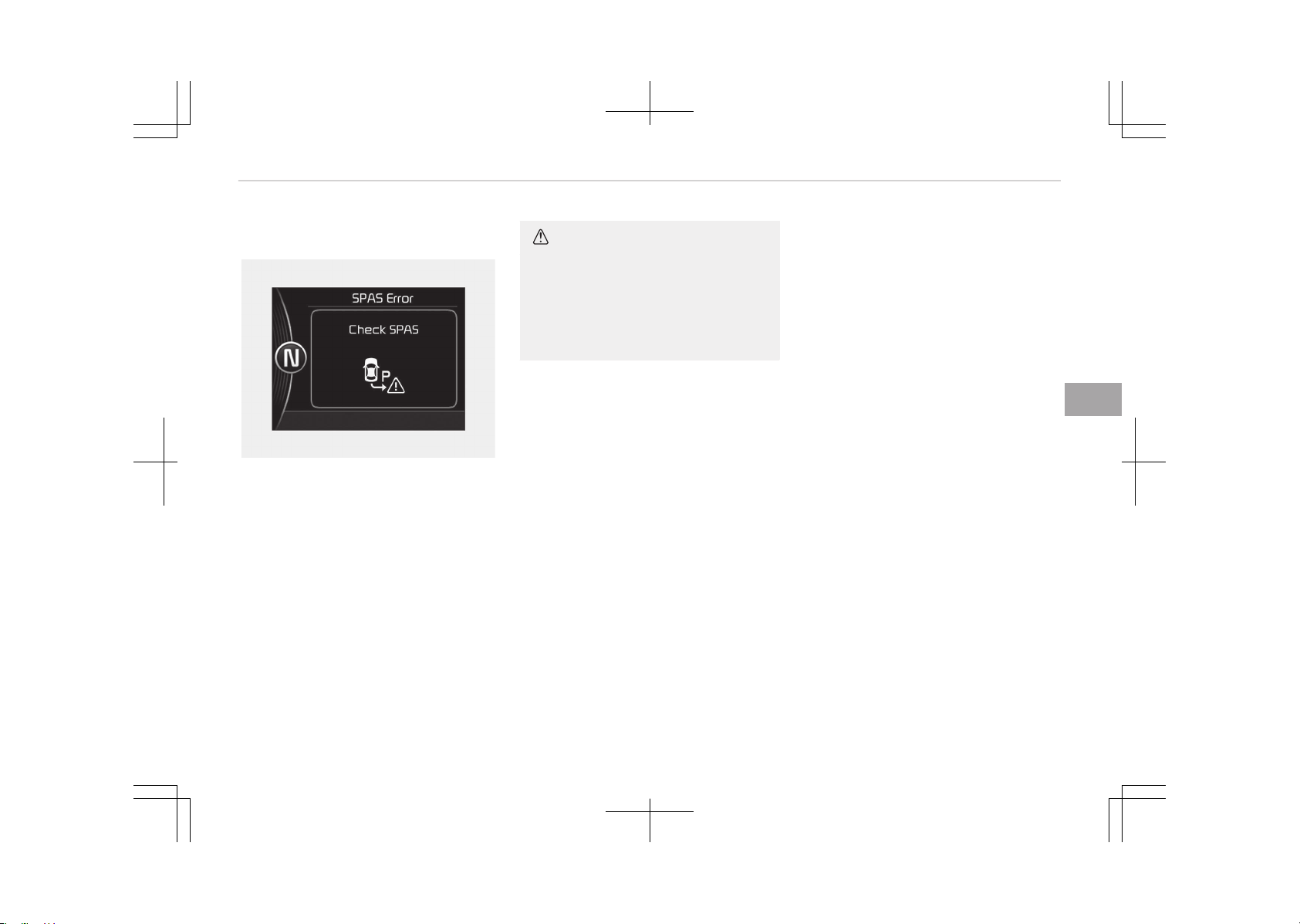
System malfunction
OJF045344L
• If there is a problem with the system,
when the system is turned on, the
above message will appear.
Also, the indicator on the button will
not light up and a beep sound will be
heard 3 times.
• If there is a problem with only the
Smart Parking Assist System, the
Parking Assist System will operate
after 2 seconds.
If you notice any problem, we recom‐
mend that the system be checked by
an authorized Kia dealer.
CAUTION
The system may not work properly
by providing incorrect messages
when the sensors are interfered by
other vehicle sensors and noise, or it
is on a road that interferes with re‐
ceiving signals.
5-111
5
Features of your vehicle
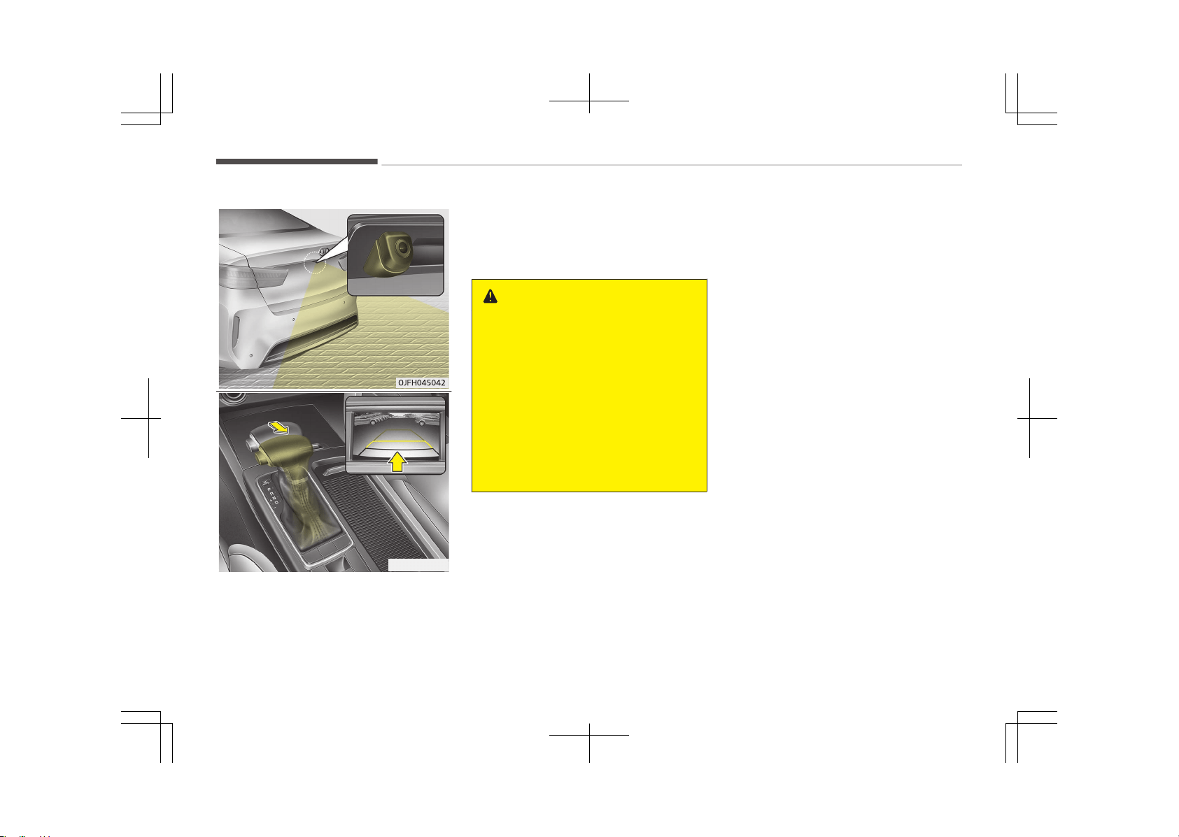
REARVIEW CAMERA (IF EQUIPPED)
OJFH045043
The rearview camera will activate when
the back-up light is ON with the ignition
switch ON and the shift lever in the R
(Reverse) position.
This system is a supplemental system
that shows behind the vehicle through
the rearview display mirror while back‐
ing up.
WARNING
• This system is a supplementary
function only. It is the responsibili‐
ty of the driver to always check
the inside/outside rearview mirror
and the area behind the vehicle
before and while backing up be‐
cause there is a dead zone that
can't be seen by the camera.
• Always keep the camera lens
clean. If the lens is covered with
foreign matter, the camera may
not operate normally.
❈ If your vehicle is equipped with AVN
(Audio, Video and Navigation) sys‐
tem, rearview display will show be‐
hind the vehicle through the AVN
monitor while backing up. Refer to
a separately supplied manual for
detailed information.
Features of your vehicle
5-112
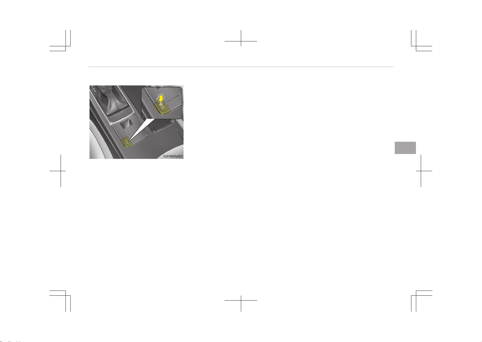
SURROUND VIEW MONITORING SYSTEM (IF EQUIPPED)
This is the parking support system to
show around circumstance when you
park the vehicle in monitor. When you
push the button in [ON] position, it is
operated. To cancel the system, push
again.
Operating conditions
-
When ignition is ON
-
When the transaxle is on D, N or R
-
When the vehicle speed is not over
15 km/h
• When the vehicle speed is over
15 km/h, the SVM
*
system is turned
off. If the vehicle speed is not over
15 km/h after turning off the SVM
*
by over speed, the SVM
*
is not turned
on. To operate again, push the but‐
ton.
• When the vehicle moves backwards,
regardless of On/Off of button and
vehicle speed, the SVM
*
is operated.
• When the trunk and driver/passenger
door are opened and the outside mir‐
ror is folded, the warning is illumina‐
ted in SVM
*
system.
•
If the SVM
*
system is not normally
operated, we recommend that you
contact an authorized Kia dealer.
*
: SVM: Surround View Monitoring
5-113
5
Features of your vehicle
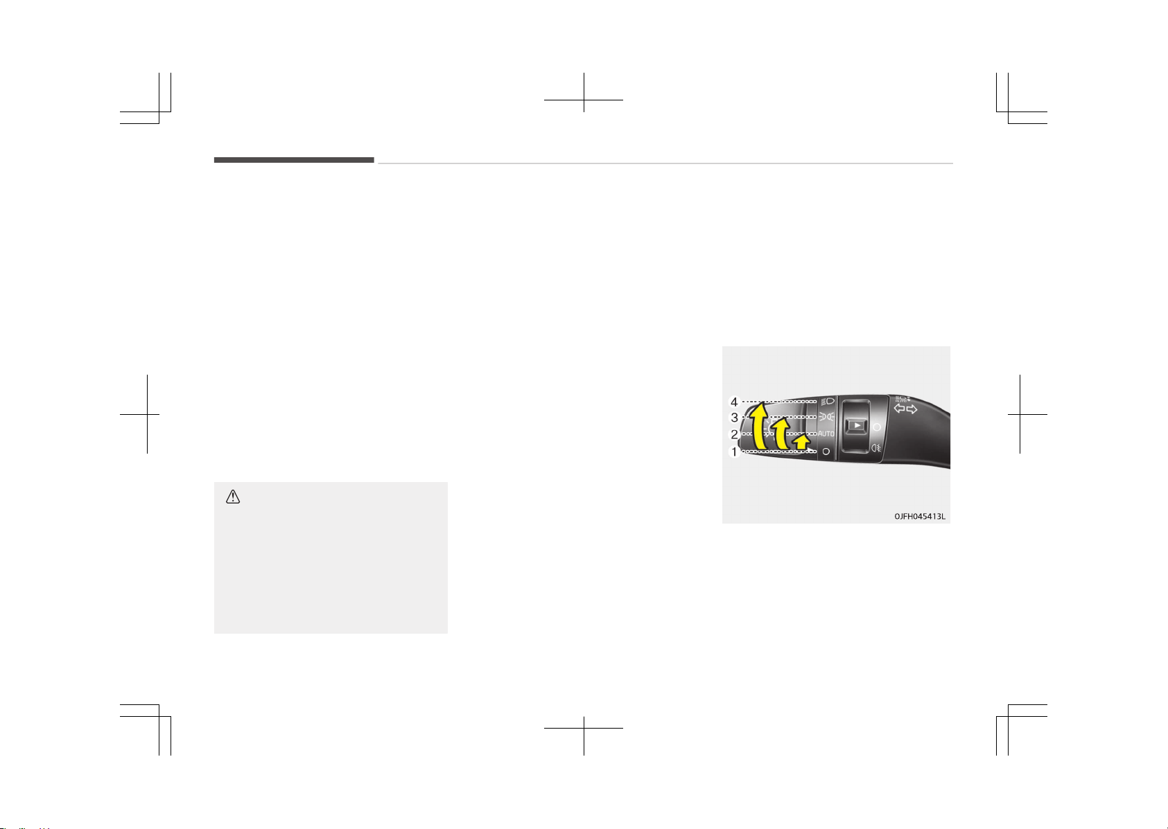
LIGHTING
Battery saver function
• The purpose of this feature is to pre‐
vent the battery from being dis‐
charged. The system automatically
turns off the parking lights when the
driver removes the ignition key and
opens the driver-side door.
• With this feature, the parking lights
will turn off automatically if the driv‐
er parks on the side of the road at
night.
If necessary, to keep the lights on
when the ignition key is removed,
perform the following:
1. Open the driver-side door.
2. Turn the parking lights OFF and ON
again using the light switch on the
steering column.
CAUTION
If the driver gets out of the vehicle
through other doors (except driver's
door), the battery saver function
does not operate. Therefore, It cau‐
ses the battery to be discharged. In
this case, make sure to turn off the
lamp before getting out of the vehi‐
cle.
Headlight escort function (if
equipped)
If you turn the ignition switch to the
ACC or OFF position with the headlights
ON, the headlights remain on for about
5 minutes. However, if the driver's door
is opened and closed, the headlights are
turned off after 15 seconds.
The headlights can be turned off by
pressing the lock button on the trans‐
mitter (or smart key) twice or turning
the light switch to the OFF position.
Daytime running light (if
equipped)
The Daytime Running Lights (DRL) can
make it easier for others to see the
front of your vehicle during the day.
DRL can be helpful in many different
driving conditions, and it is especially
helpful after dawn and before sunset.
The DRL system will turn the dedicated
lamp OFF when:
1. The headlight or fog lamp switch is
ON.
2. The engine is OFF.
❈
Traffic Change (For Europe)
The low beam light distribution is
asymmetric. If you go abroad to a
country with opposite traffic direc‐
tion, this asymmetric part will daz‐
zle oncoming car driver. To prevent
dazzle, ECE regulation demand sev‐
eral technical solutions (ex. auto‐
matic change system, adhesive
sheet, down aiming). This head‐
lamps are designed to adjust in
user setting mode in cluster.
Lighting control
The light switch has a Headlight and a
Parking light position.
To operate the lights, turn the knob at
the end of the control lever to one of
the following positions:
1. OFF position
2. Auto light / AFLS position
Features of your vehicle
5-114
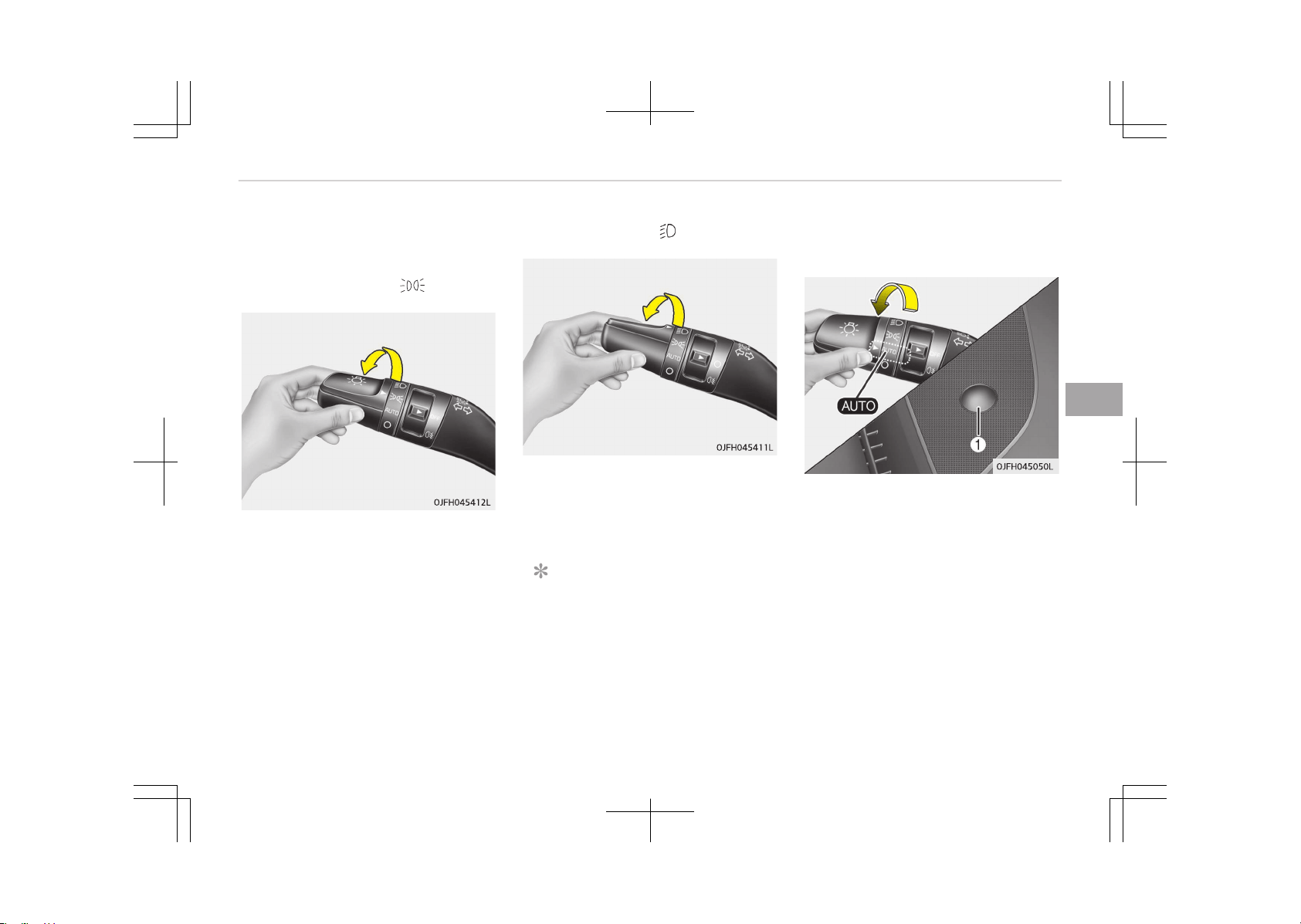
3. Parking light position
4. Headlight position
Parking light position ( )
When the light switch is in the parking
light position (3rd position), the tail, li‐
cense and instrument panel lights will
turn ON.
Headlight position ( )
When the light switch is in the head‐
light position (4th position), the head,
tail, license and instrument panel lights
will turn ON.
NOTICE
The ignition switch must be in the
ON position to turn on the head‐
lights.
Auto light/AFLS position (if
equipped)
When the light switch is in the AUTO
light position, the tail lights and head‐
lights will be turned ON or OFF auto‐
matically depending on the amount of
light outside the vehicle.
If your vehicle is equipped with the
adaptive front lighting system (AFLS),
it will also operate when the headlamp
is ON.
5-115
5
Features of your vehicle
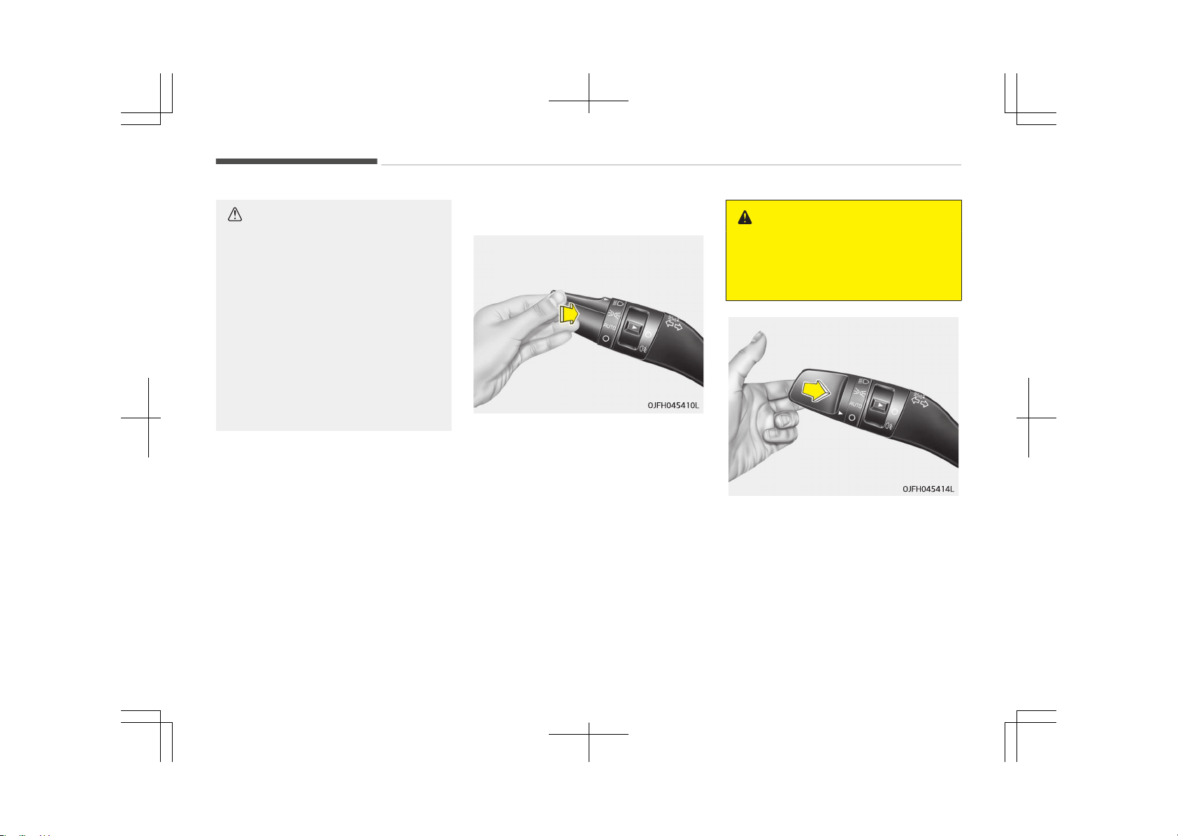
CAUTION
• Never place anything over the sen‐
sor (1) located on the instrument
panel. This will ensure better au‐
to-light system control.
• Don’t clean the sensor using a win‐
dow cleaner. The cleaner may
leave a light film which could inter‐
fere with sensor operation.
• If your vehicle has window tint or
other types of metallic coating on
the front windshield, the Auto
light system may not work prop‐
erly.
High beam operation
To turn on the high beam headlamp,
push the lever away from you. The lev‐
er will return to its original position.
The high beam indicator will light when
the headlight high beams are switched
on.
To prevent the battery from being dis‐
charged, do not leave the lights on for a
prolonged time while the engine is not
running.
WARNING
Do not use high beam when there
are other vehicles. Using high beam
could obstruct the other driver’s vi‐
sion.
To flash the headlights, pull the lever
towards you. It will return to the nor‐
mal (low beam) position when released.
The headlight switch does not need to
be on to use this flashing feature.
Features of your vehicle
5-116
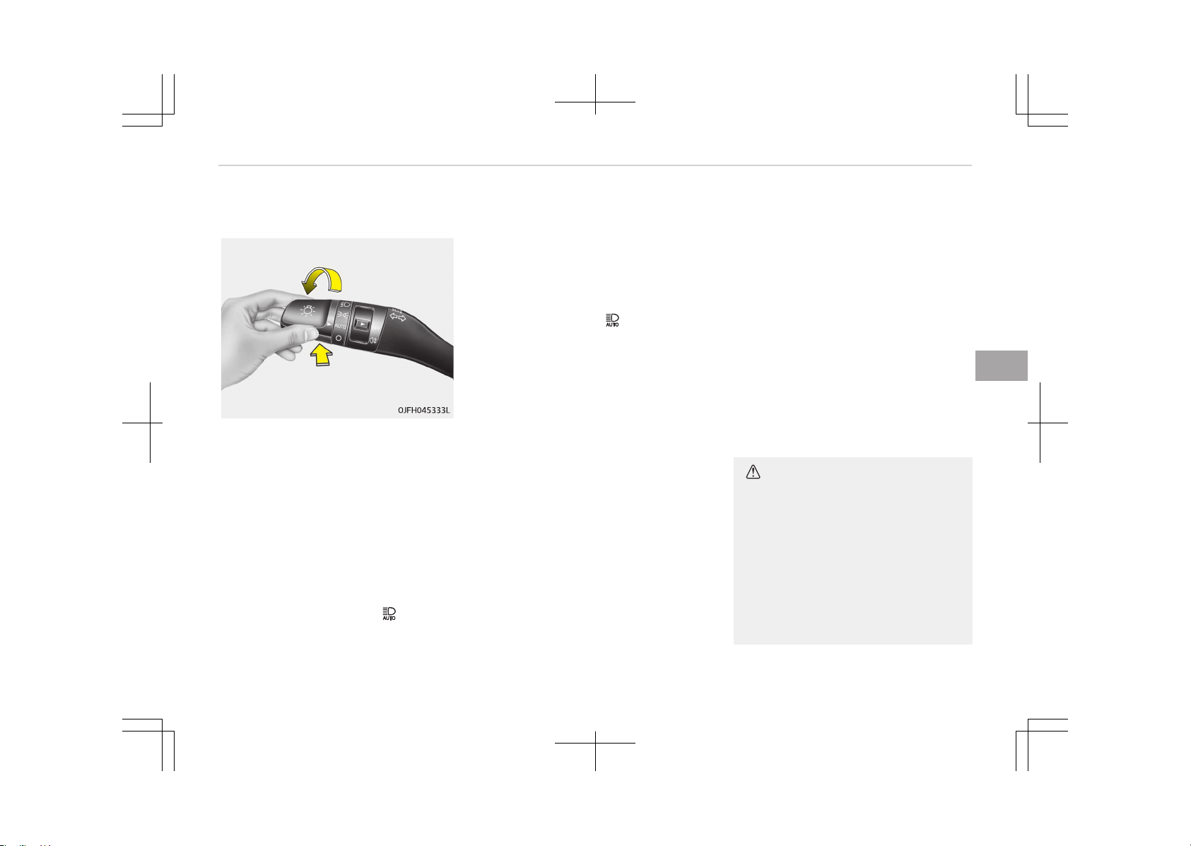
High Beam Assist (if equipped)
The High Beam Assist is a system that
automatically adjusts the headlamp
range (switches between high beam
and low beam) according to the bright‐
ness of other vehicles and road condi‐
tions.
Operating condition
1. Place the light switch in the AUTO
position.
2. Turn on the high beam by pushing
the lever away from you.
The High Beam Assist ( ) indicator
will illuminate.
3. The High Beam Assist will turn on
when vehicle speed is above
45 km/h (28 mph).
• If the lever is pushed away when
the High Beam Assist is operat‐
ing, the High Beam Assist will
turn off and the high beam will
be on continuously. The High
Beam Assist (
) indicator will
turn off.
• If the lever is pulled towards you
when the High Beam Assist is op‐
erating, the High Beam Assist will
turn off.
4. If the light switch is placed to the
headlamp position, the High Beam
Assist will turn off and the low
beam will be on continuously.
The high beam switches to low beam in
the below conditions.
-
When the High Beam Assist is off.
-
When the light switch is not in the
AUTO position.
-
When the headlamp is detected from
the oncoming vehicle.
-
When the tail lamp is detected from
the front vehicle.
-
When the surrounding is bright
enough high beams are not needed.
-
When streetlights or other lights are
detected.
-
When vehicle speed is below 35 km/h
(22 mph).
-
When headlamp/taillamp of bicycle/
motorcycle is detected.
Warning light and message
When the High Beam Assist System is
not working properly, the warning mes‐
sage (Check High Beam Assist Sys‐
tem) will come on for a few second.
After the message disappears, the
master warning light will illuminate. We
recommend you to contact an author‐
ized Kia dealer.
CAUTION
The system may not operate nor‐
mally in the below conditions.
• When the light from the oncoming
or front vehicle is not detected be‐
cause of lamp damage, hidden
from sight, etc.
• When the lamp of the oncoming or
front vehicle is covered with dust,
snow or water.
(Continued)
5-117
5
Features of your vehicle
(Continued)
• When the light from the oncoming
or front vehicle is not detected be‐
cause of exhaust fume, smoke,
fog, snow, etc.
• When the front window is covered
with foreign matters such as ice,
dust, fog, or is damaged.
• When there is a similar shape lamp
with the front vehicle’s lamps.
• When it is hard to see because of
fog, heavy rain or snow.
• When the headlamp is not repaired
or replaced at an authorized deal‐
er.
• When headlamp aiming is not
properly adjusted.
• When driving on a narrow curved
road or rough road.
• When driving downhill or uphill.
• When only part of the vehicle in
front is visible on a crossroad or
curved road.
• When there is a traffic light, re‐
flecting sign, flashing sign or mir‐
ror.
(Continued)
(Continued)
• When the road conditions are bad
such as being wet or covered with
snow.
• When the front vehicle’s head‐
lamps are off but the fog lamps
on.
• When a vehicle suddenly appears
from a curve.
• When the vehicle is tilted from a
flat tire or being towed.
• When the LDWS (Lane Departure
Warning System) or LKAS (Lane
Keeping Assist System) warning
light illuminates. (if equipped)
WARNING
• Do not place any accessories,
stickers or tint the windshield.
• Have the windshield glass replaced
from an authorized dealer.
• Do not remove or impact related
parts of the High Beam Assist sys‐
tem.
(Continued)
(Continued)
• Be careful that water doesn’t get
into the High Beam Assist unit.
• Do not place objects on the dash‐
board that reflects light such as
mirrors, white paper, etc. The sys‐
tem may malfunction if sunlight is
reflected.
• At times, the Smart High Beam
system may not work properly, al‐
ways check the road conditions for
your safety. When the system
does not operate normally, man‐
ually change between the high
beam and low beam.
Features of your vehicle
5-118
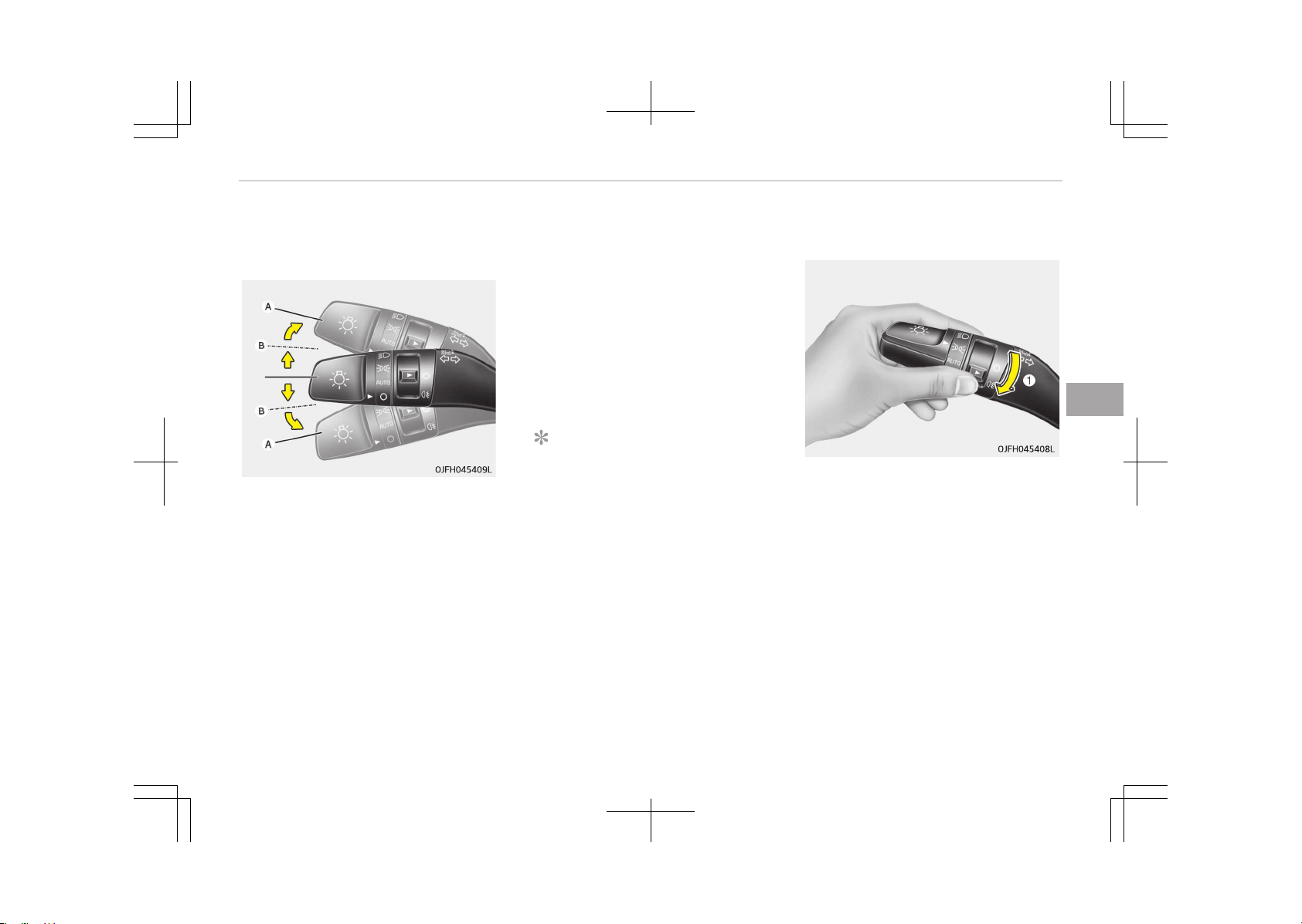
Turn signals and lane change
signals
The ignition switch must be on for the
turn signals to function. To turn on the
turn signals, move the lever up or down
(A). The green arrow indicators on the
instrument panel indicate which turn
signal is operating. They will self-cancel
after a turn is completed. If the indica‐
tor continues to flash after a turn,
manually return the lever to the OFF
position.
To signal a lane change, move the turn
signal lever slightly and hold it in posi‐
tion (B). The lever will return to the OFF
position when released.
If an indicator stays on and does not
flash or if it flashes abnormally, one of
the turn signal bulbs may be burned
out and will require replacement.
One-touch lane change function (if
equipped)
To activate an one-touch lane change
function, move the turn signal lever
slightly for less than 0.7 second and
then release it. The lane change signals
will blink 3 times.
NOTICE
If an indicator flash is abnormally
quick or slow, a bulb may be burned
out or have a poor electrical connec‐
tion in the circuit.
Rear fog light (if equipped)
To turn the rear fog lights on, turn the
headlight switch to the headlight on
position and turn the rear fog light
switch (1) to the ON position.
The rear fog lights turn on when the
rear fog light switch is turned on after
the headlight switch is in the parklight
position.
To turn the rear fog lights off, turn the
rear fog light switch to the on position
again or turn the headlight switch off.
5-119
5
Features of your vehicle
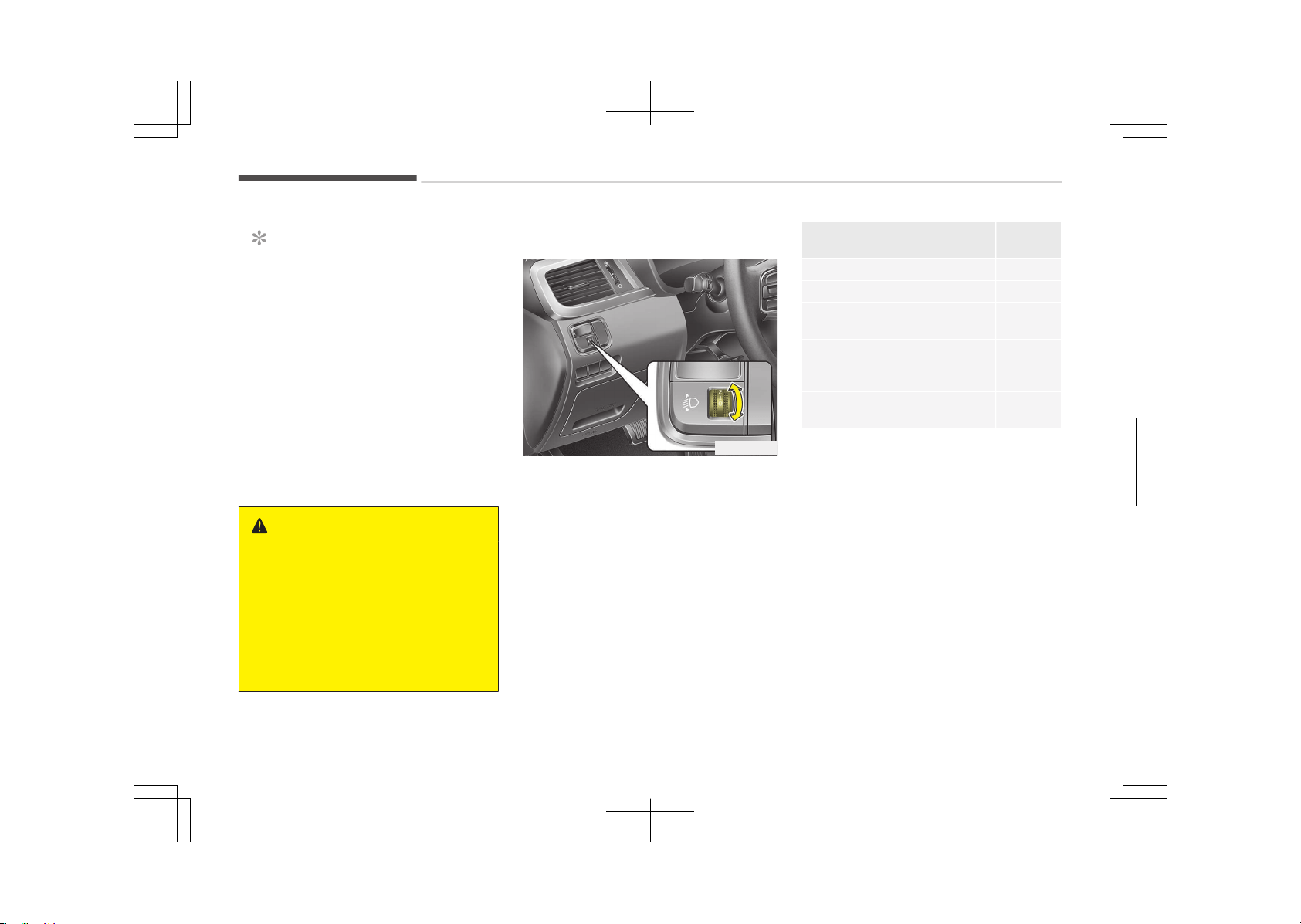
NOTICE
To turn on the rear fog light switch,
the ignition switch must be in the
ON position.
Headlight leveling device (if
equipped)
Automatic type
It automatically adjusts the headlight
beam level according to the number of
passengers and loading weight in the
luggage area.
And it offers proper headlight beam
under various conditions.
WARNING
If it does not work properly even
though your car is inclined backward
according to passenger's posture, or
the headlight beam is irradiated to
the high or low position, we recom‐
mend that the system be inspected
by an authorized Kia dealer.
Do not attempt to inspect or replace
the wiring yourself.
Manual type
OJFC045319
To adjust the headlight beam level ac‐
cording to the number of passengers
and loading weight in the luggage area,
turn the beam leveling switch.
The higher the number of the switch
position, the lower the headlight beam
level. Always keep the headlight beam
at the proper leveling position, or head‐
lights may dazzle other road users.
Listed below are the examples of prop‐
er switch settings. For loading condi‐
tions other than those listed below, ad‐
just the switch position so that the
beam level may be the nearest as the
condition obtained according to the list.
Loading condition
Switch
position
Driver only 0
Driver + Front passenger 0
Full passengers (including
driver)
1
Full passengers (including
driver) + Maximum permissi‐
ble loading
2
Driver + Maximum permissi‐
ble loading
3
Features of your vehicle
5-120
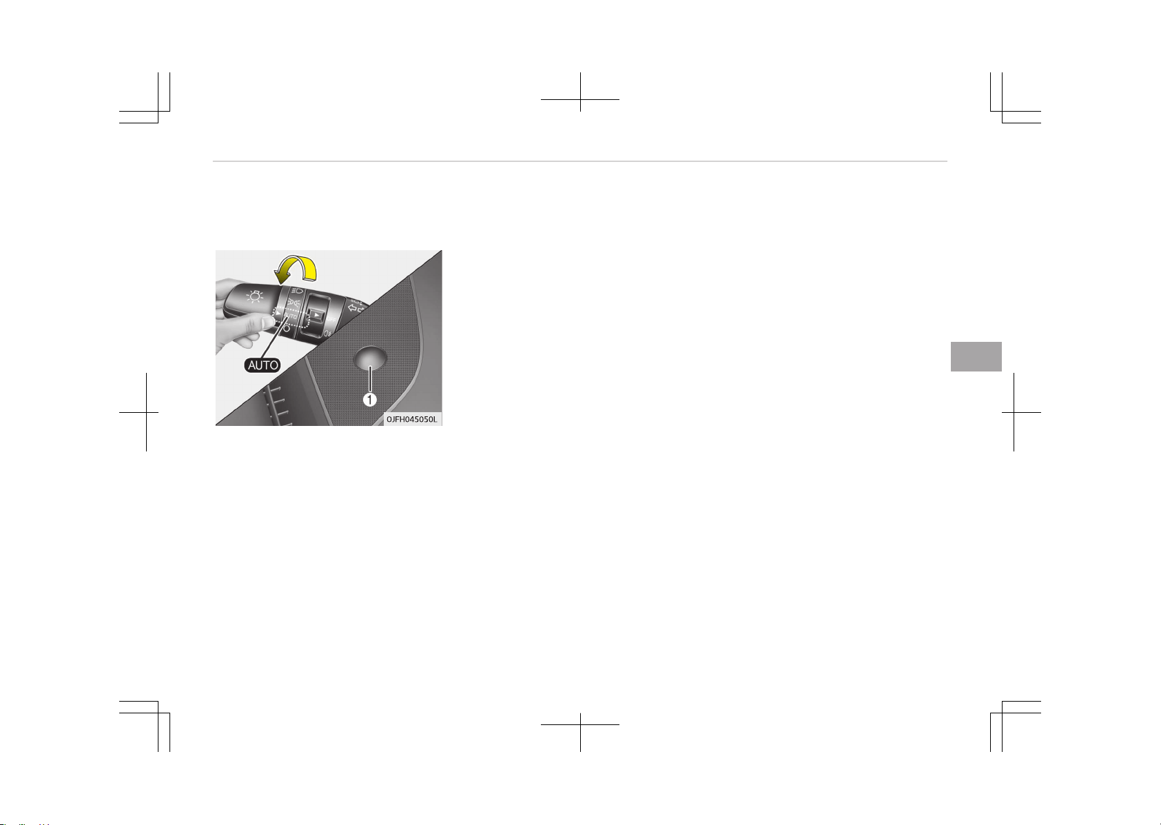
AFLS (Adaptive Front Lighting
System) (if equipped)
Adaptive front lighting system uses the
steering angle and vehicle speed, to
keep your field of vision wide by swivel‐
ing and leveling the headlamp.
Change the switch to the AUTO position
when the engine is running. The adap‐
tive front lighting system will operate
when the headlamp is ON. To turn off
the AFLS, change the switch to other
positions. After turning the AFLS off,
headlamp swiveling no longer occurs,
but leveling operates continuously.
If the AFLS malfunction indicator comes
on, the AFLS is not working properly.
Drive to the nearest safe location and
restart the engine. If the indicator con‐
tinuously remains on, we recommend
that the system be checked by an au‐
thorized Kia dealer.
5-121
5
Features of your vehicle
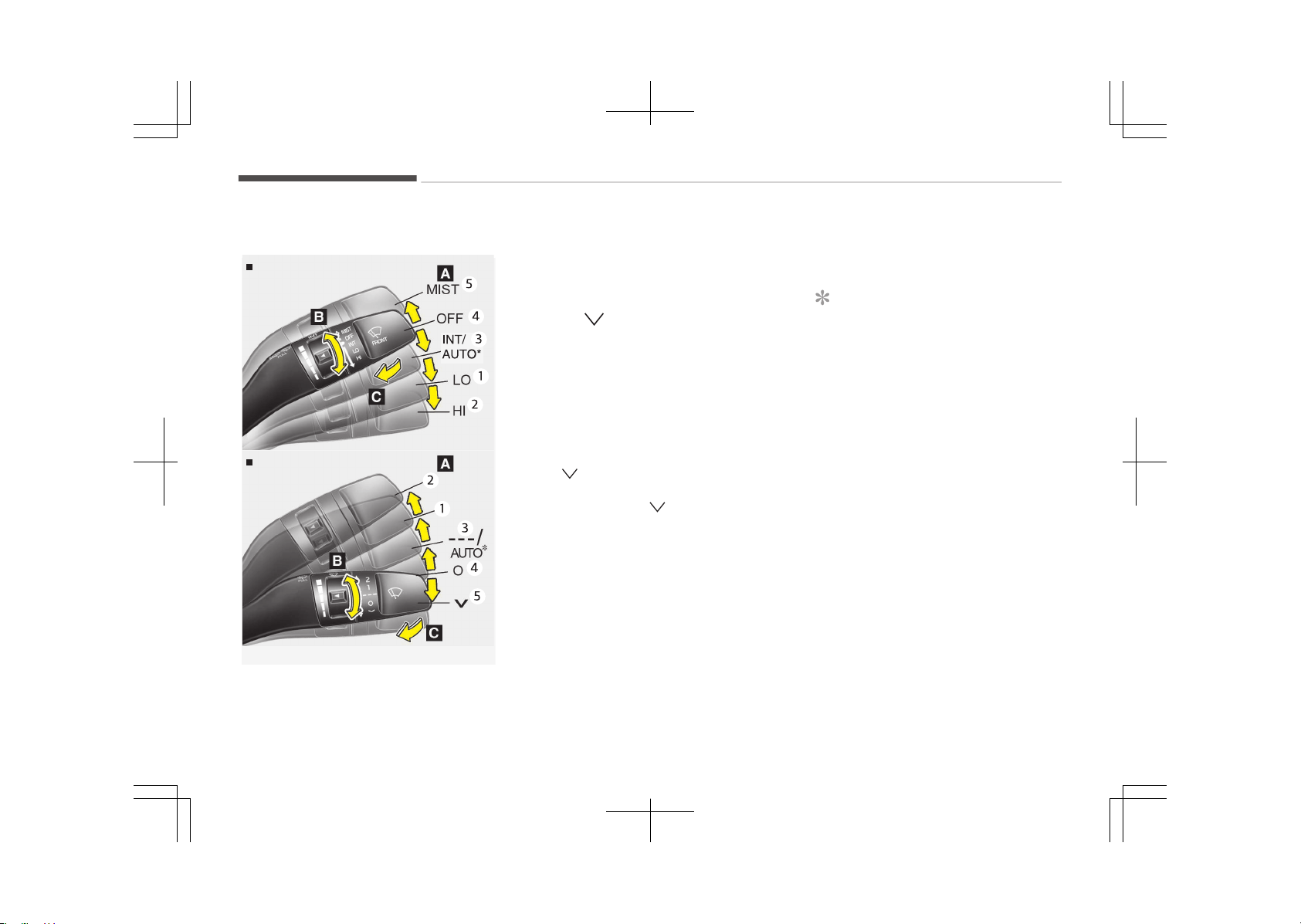
WIPERS AND WASHERS
Windshield wiper/washer
Type B
Type A
OJF045231LB-OJF045232LB
A: Wiper speed control (front)
1. LO / 1 – Low wiper speed
2. HI / 2 – High wiper speed
3. INT / --- – Intermittent wipe
AUTO
*
– Auto control wipe
4. OFF / O – Off
5. MIST/
– Single wipe
B: Intermittent control wipe time ad‐
justment
C: Wash with brief wipes (front)
*
Windshield wipers
Operates as follows when the ignition
switch is turned ON.
MIST/ : For a single wiping cycle,
move the lever to this
(MIST/ ) position and re‐
lease it. The wipers will
operate continuously if
the lever is held in this po‐
sition.
OFF / O: Wiper is not in operation
INT / ---: Wiper operates intermit‐
tently at the same wiping
intervals. Use this mode in
light rain or mist. To vary
the speed setting, turn
the speed control knob.
*
: if equipped
LO / 1: Normal wiper speed
HI / 2: Fast wiper speed
NOTICE
If there is heavy accumulation of
snow or ice on the windshield, de‐
frost the windshield for about 10
minutes, or until the snow and/or ice
is removed before using the wind‐
shield wipers to ensure proper oper‐
ation. If you do not remove the snow
and/or ice before using the wiper
and washer, it may damage the wip‐
er and washer system.
Features of your vehicle
5-122
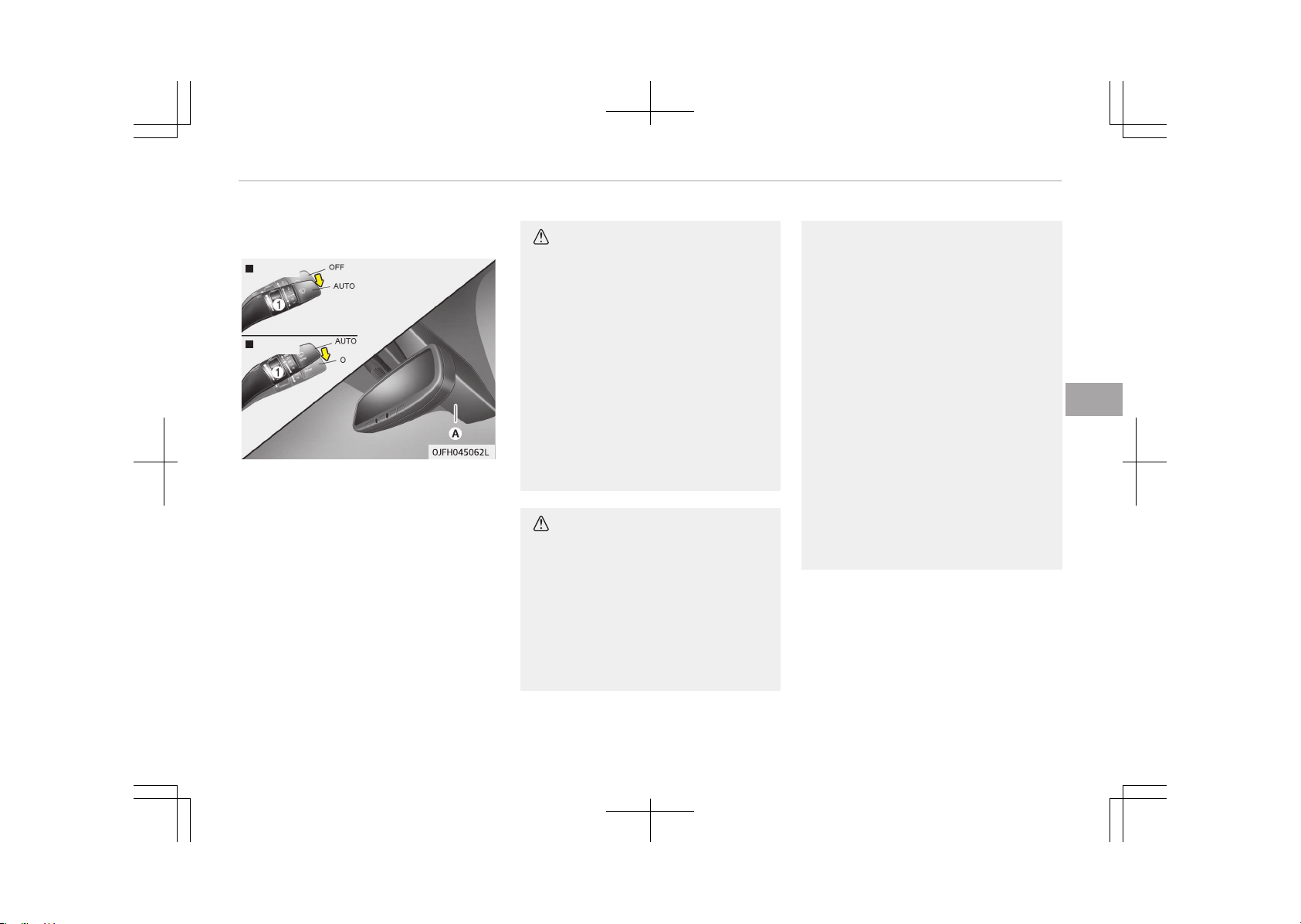
Auto control (if equipped)
Type A
Type B
The rain sensor (A) located on the up‐
per end of the windshield glass senses
the amount of rainfall and controls the
wiping cycle for the proper interval.
The more it rains, the faster the wiper
operates. When the rain stops, the wip‐
er stops.
To vary the speed setting, turn the
speed control knob (1).
If the wiper switch is set in AUTO mode
when the ignition switch is ON, the wip‐
er will operate once to perform a self-
check of the system. Set the wiper to
OFF (O) position when the wiper is not
in use.
CAUTION
When the ignition switch is ON and
the windshield wiper switch is placed
in the AUTO mode, use caution in the
following situations to avoid any in‐
jury to the hands or other parts of
the body:
• Do not touch the upper end of the
windshield glass facing the rain
sensor.
• Do not wipe the upper end of the
windshield glass with a damp or
wet cloth.
• Do not put pressure on the wind‐
shield glass.
CAUTION
• When washing the vehicle, set the
wiper switch in the OFF (O) posi‐
tion to stop the auto wiper opera‐
tion.
The wiper may operate and be
damaged if the switch is set in the
AUTO mode while washing the ve‐
hicle.
(Continued)
(Continued)
• Do not remove the sensor cover
located on the upper end of the
passenger side windshield glass.
Damage to system parts could oc‐
cur and may not be covered by
your vehicle warranty.
• When starting the vehicle in win‐
ter, set the wiper switch in the
OFF (O) position. Otherwise, wipers
may operate and ice may damage
the windshield wiper blades. Al‐
ways remove all snow and ice and
defrost the windshield properly
prior to operating the windshield
wipers.
• When tinting the windshield, be
careful of any fluid getting into
the sensor located in the top cen‐
ter of the front windshield. It may
damage the related parts.
5-123
5
Features of your vehicle
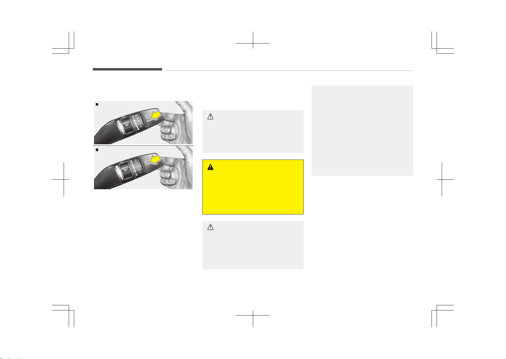
Windshield washers
Type A
OJF045063L
Type B
OJF045234L
In the OFF (O) position, pull the lever
gently toward you to spray washer flu‐
id on the windshield and to run the wip‐
ers 1-3 cycles.
Use this function when the windshield
is dirty.
The spray and wiper operation will con‐
tinue until you release the lever.
If the washer does not work, check the
washer fluid level. If the fluid level is
not sufficient, you will need to add ap‐
propriate non-abrasive windshield
washer fluid to the washer reservoir.
The reservoir filler neck is located in
the front of the engine compartment
on the passenger side.
CAUTION
To prevent possible damage to the
washer pump, do not operate the
washer when the fluid reservoir is
empty.
WARNING
Do not use the washer in freezing
temperatures without first warming
the windshield with the defrosters;
the washer solution could freeze on
the windshield and obscure your vi‐
sion.
CAUTION
• To prevent possible damage to the
wipers or windshield, do not oper‐
ate the wipers when the wind‐
shield is dry.
(Continued)
(Continued)
• To prevent damage to the wiper
blades, do not use gasoline, kero‐
sene, paint thinner, or other sol‐
vents on or near them.
• To prevent damage to the wiper
arms and other components, do
not attempt to move the wipers
manually.
• To prevent possible damage to the
wipers and washer system, use
anti-freezing washer fluids in the
winter season or cold weather.
Headlight washer (if equipped)
If your vehicle is equipped with the
headlight washer it will operate at the
same time when you operate the wind‐
shield washer. However, if this function
is operated once, the headlight washer
will not operate within 15 minutes. It
will operate when the headlight is ON
and the ignition switch or engine start/
stop button is in the ON position.
The washer fluid will be sprayed on to
the headlights.
Features of your vehicle
5-124

NOTICE
• Check the headlight washers peri‐
odically to confirm that the wash‐
er fluid is being sprayed properly
onto the headlight lenses.
• The headlight washer can be oper‐
ated 15 minutes after being oper‐
ated last time.
5-125
5
Features of your vehicle
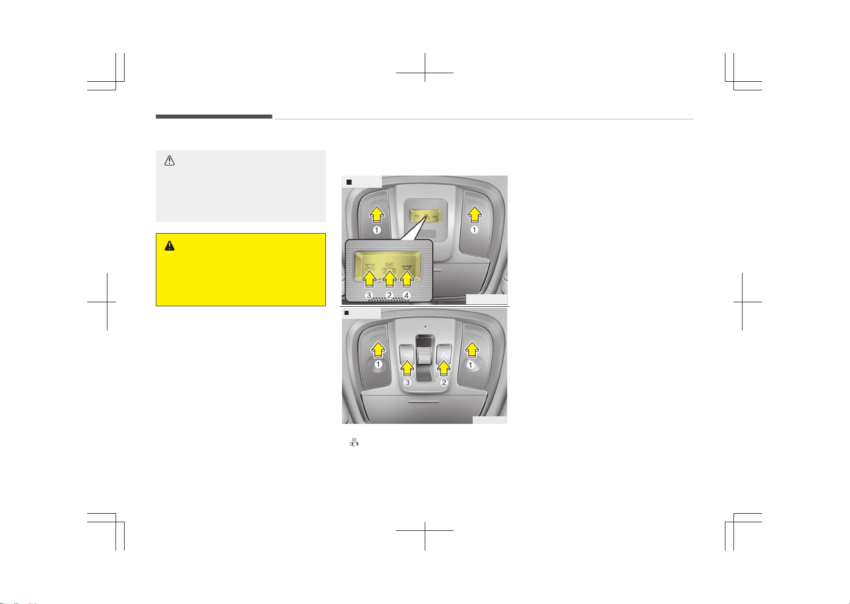
INTERIOR LIGHT
CAUTION
Do not use the interior lights for ex‐
tended periods when the engine is
not running.
It may cause battery discharge.
WARNING
Do not use the interior lights when
driving in the dark. Accidents could
happen because the view may be
obscured by interior lights.
Automatic turn off function (if
equipped)
The interior lights automatically turn
off approximately 20 minutes after the
ignition switch is turned off.
If your vehicle is equipped with the
theft alarm system, the interior lights
automatically turns off approximately
3 seconds after the system is armed
stage.
Map lamp
Type A
OJFH045064L
Type B
OJF045065
• (2):
- The map lamp and room lamp
comes on when a door is opened.
The lamps go out after approxi‐
mately 30 seconds.
- The map lamp and room lamp
comes on for approximately 30
seconds when doors are unlocked
with a transmitter or smart key as
long as the doors are not opened.
- The map lamp and room lamp will
stay on for approximately 20 mi‐
nutes if a door is opened with the
ignition switch in the ACC or
LOCK/OFF position.
- The map lamp and room lamp will
stay on continuously if the door is
opened with the ignition switch in
the ON position.
- The map lamp and room lamp will
go out immediately if the ignition
switch is changed to the ON posi‐
tion or all doors are locked.
- To turn off the DOOR mode, press
the DOOR button (2) once again
(not pressed).
Features of your vehicle
5-126
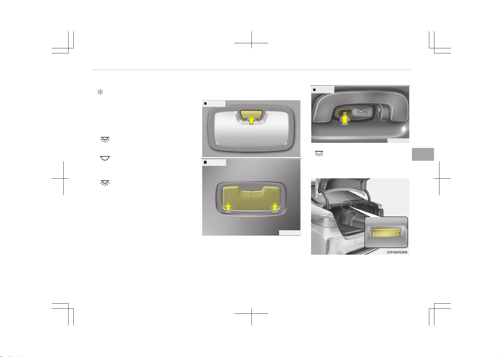
NOTICE
The DOOR mode and ROOM mode
can not be selected at a time.
Front Room Lamp:
• Type A
(3):
Press this switch to turn
the front and rear room
lamps on.
(4):
Press this switch to turn
the front and rear room
lamps off.
• Type B
(3):
Press this switch to turn
the front and rear room
lamps on and off.
Room lamp
Type A
OJF045066
Type B
OJF045067
Type C
OJF045068
• : The light stays on at all times.
Trunk room lamp (if equipped)
The trunk room lamp comes on when
the trunk is opened.
5-127
5
Features of your vehicle
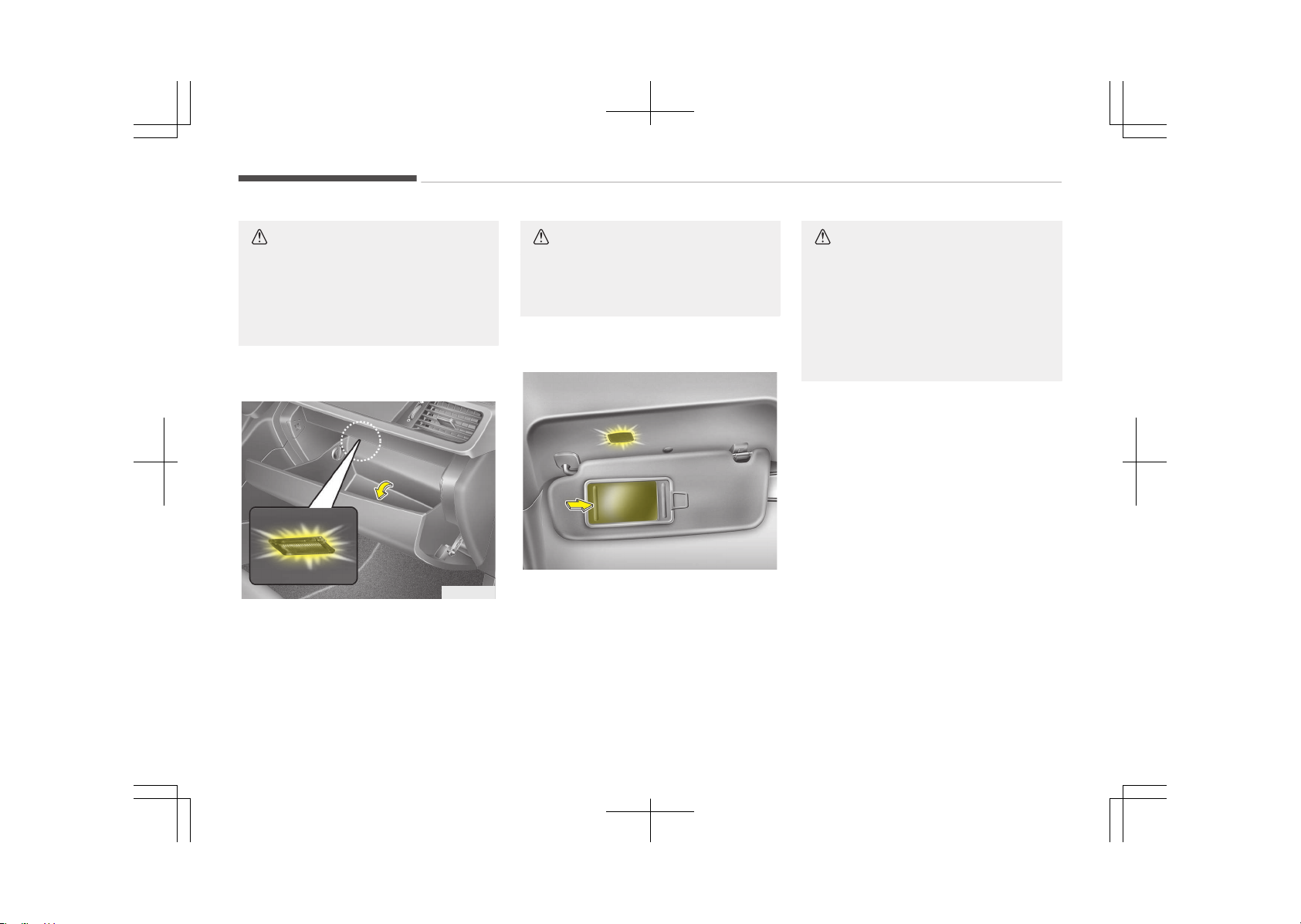
CAUTION
The trunk room lamp comes on as
long as the trunk lid opens. To pre‐
vent unnecessary charging system
drain, close the trunk lid securely af‐
ter using the trunk room.
Glove box lamp (if equipped)
OJF045071
The glove box lamp comes on when the
glove box is opened.
CAUTION
To prevent unnecessary charging
system drain, close the glove box se‐
curely after using the glove box.
Vanity mirror lamp (if equipped)
OJF045072
Opening the lid of the vanity mirror will
automatically turn on the mirror light.
CAUTION
n
Vanity mirror lamp
Always have the switch in the off
position when the vanity mirror
lamp is not in use. If the sunvisor is
closed without the lamp off, it may
discharge the battery or damage the
sunvisor.
Features of your vehicle
5-128
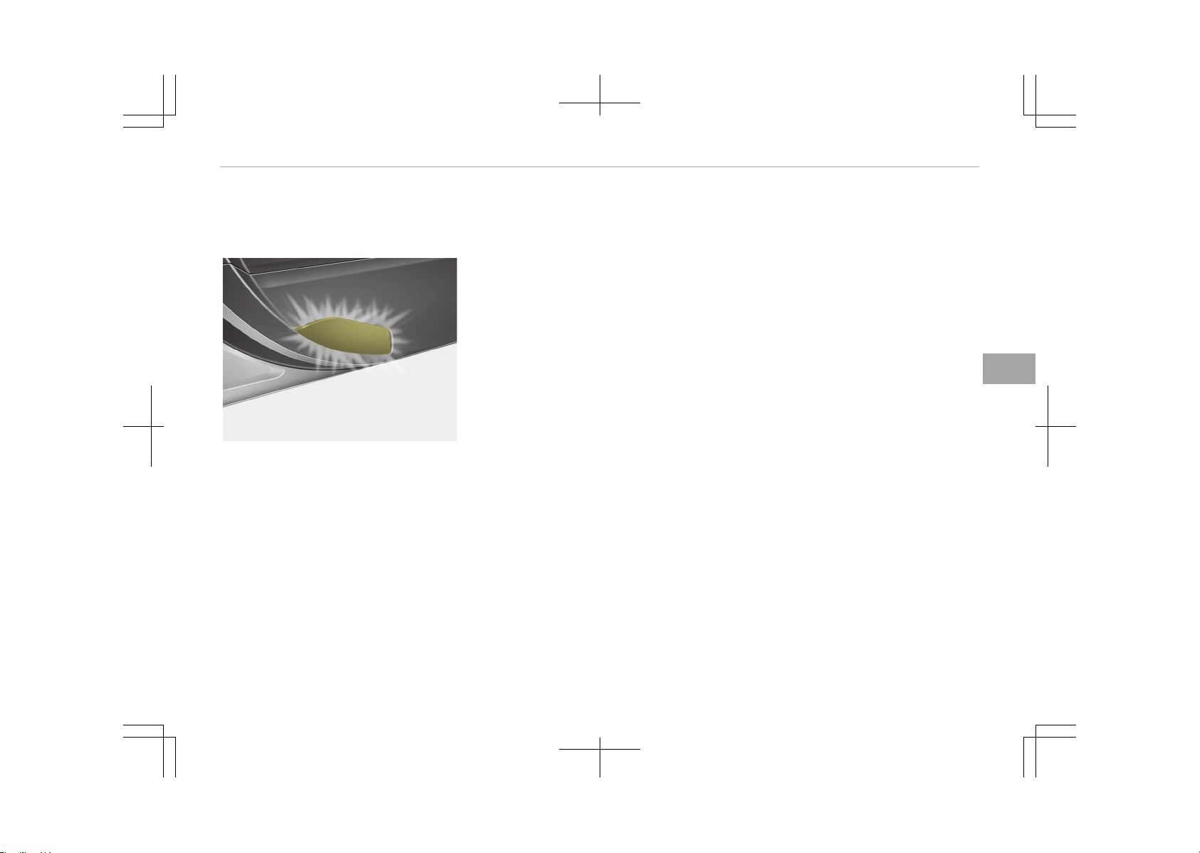
Door courtesy lamp (if
equipped)
OJF045070
The door courtesy lamp comes ON
when the door is opened to assist en‐
tering or exiting the vehicle. It also
serves as a warning to passing vehicles
that the vehicle door is open.
5-129
5
Features of your vehicle
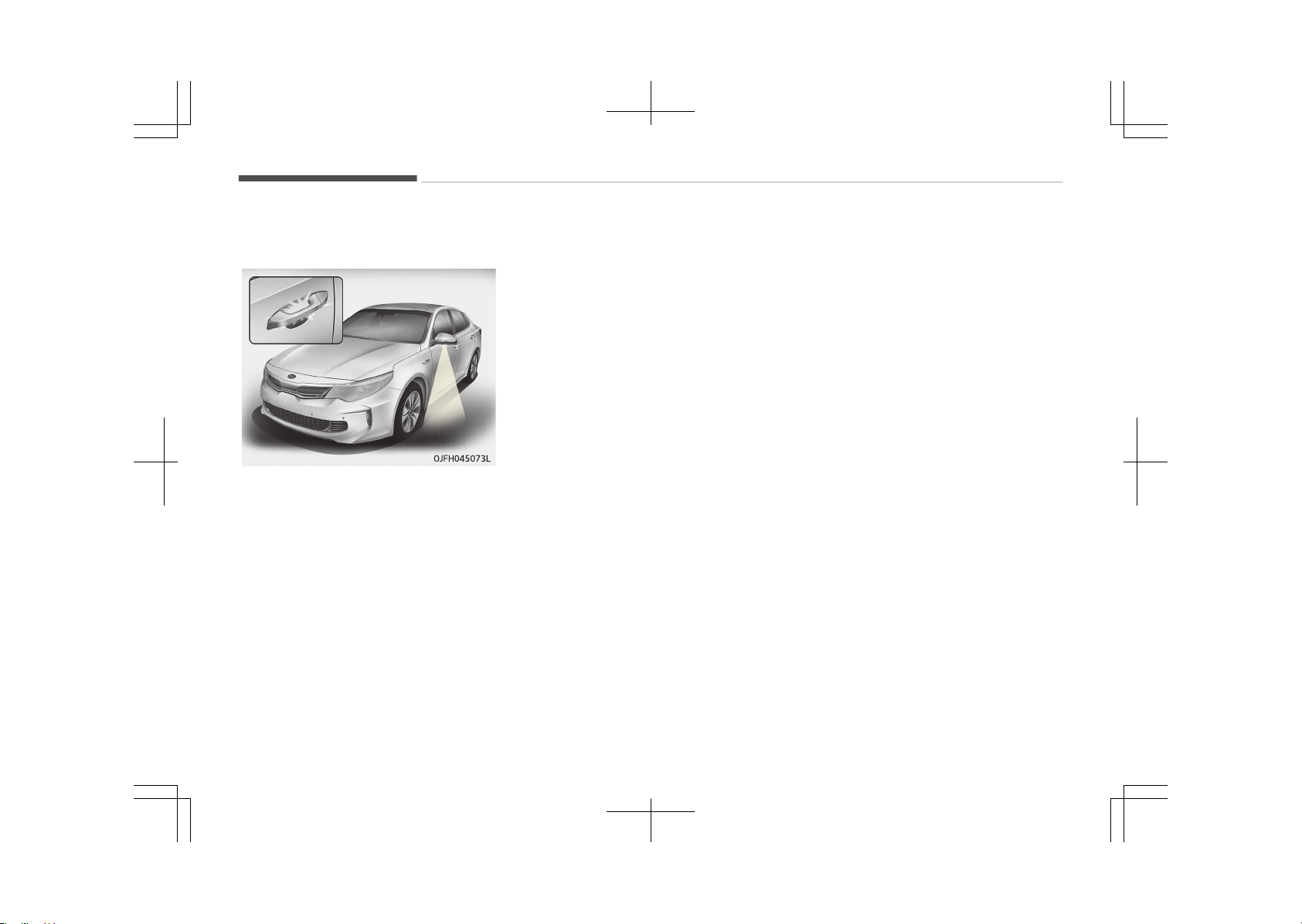
WELCOME SYSTEM (IF EQUIPPED)
Welcome light (if equipped)
When all the doors (and trunk) are
locked and closed, the room lamp will
come on for about 15 seconds if any of
the below is performed.
• With the smart key system
- When the vehicle is approached
with the smart key in possession.
Escort welcome (if equipped)
When the headlight (light switch in the
headlight or AUTO position) is on and all
doors (and trunk) are locked and closed,
the position light and headlight will
come on for 15 seconds if any of the
below is performed.
• With the smart key system
- When the door unlock button is
pressed on the smart key.
At this time, if you press the door lock
or unlock button, the position light and
headlight will turn off immediately.
Interior light
When the interior light switch is in the
DOOR position and all doors (and trunk)
are locked and closed, the room lamp
will come on for 30 seconds if any of
the below is performed.
• With the smart key system
- When the door unlock button is
pressed on the smart key.
- When the button of the outside
door handle is pressed.
At this time, if you press the door lock
or unlock button, the room lamp will
turn off immediately.
Features of your vehicle
5-130
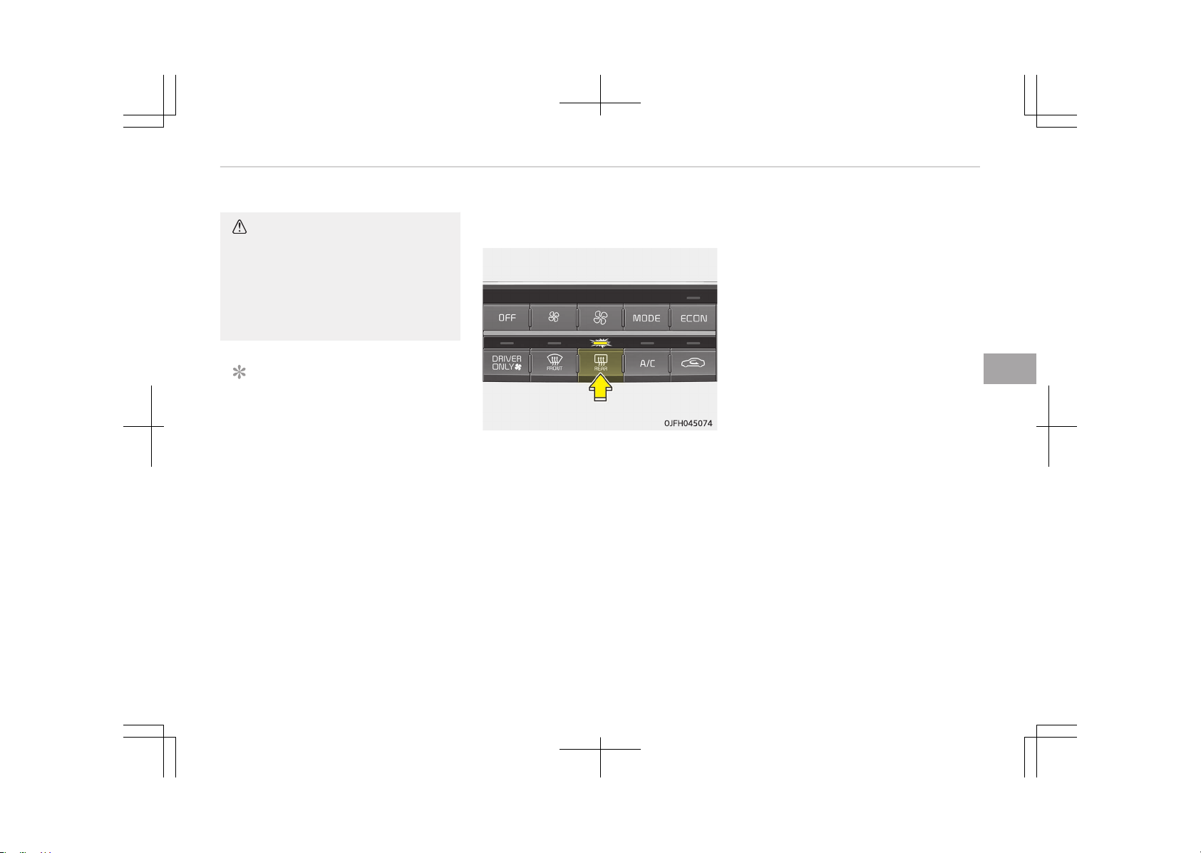
DEFROSTER
CAUTION
To prevent damage to the conduc‐
tors bonded to the inside surface of
the rear window, never use sharp in‐
struments or window cleaners con‐
taining abrasives to clean the win‐
dow.
NOTICE
If you want to defrost and defog the
front windshield, refer to Wind‐
shield defrosting and defogging on
page 5-146.
Rear window defroster
The defroster heats the window to re‐
move frost, fog and thin ice from the
rear window, while the engine is run‐
ning.
To activate the rear window defroster,
press the rear window defroster button
located in the center facia switch panel.
The indicator on the rear window de‐
froster button illuminates when the de‐
froster is ON.
If there is heavy accumulation of snow
on the rear window, brush it off before
operating the rear defroster.
The rear window defroster automati‐
cally turns off after approximately 20
minutes or when the ignition switch is
turned off. To turn off the defroster,
press the rear window defroster button
again.
Outside rearview mirror defroster
(if equipped)
If your vehicle is equipped with the out‐
side rearview mirror defrosters, they
will operate at the same time you turn
on the rear window defroster.
Wiper deicer (if equipped)
If your vehicle is equipped with the wip‐
er deicer, it will operate at the same
time you turn on the rear window de‐
froster.
5-131
5
Features of your vehicle
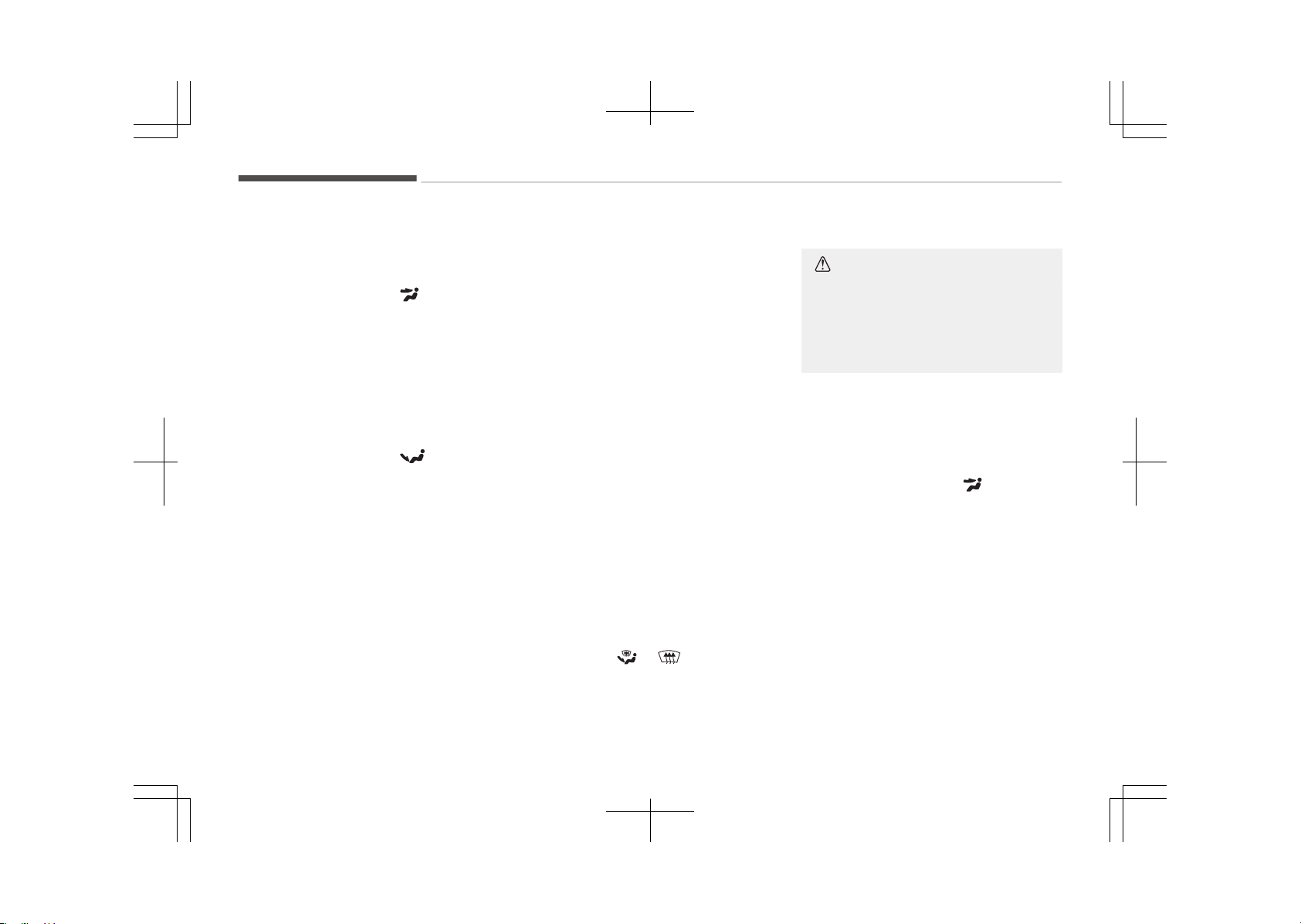
CLIMATE CONTROL SYSTEM
System operation
Ventilation
1. Set the mode to the position.
2. Set the air intake control to the
outside (fresh) air position.
3. Set the temperature control to the
desired position.
4. Set the fan speed control to the
desired speed.
Heating
1. Set the mode to the position.
2. Set the air intake control to the
outside (fresh) air position.
3. Set the temperature control to the
desired position.
4. Set the fan speed control to the
desired speed.
5. If dehumidified heating is desired,
turn the air conditioning system (if
equipped) on.
Operation tips
• To keep dust or unpleasant fumes
from entering the vehicle through the
ventilation system, temporarily set
the air intake control to the recircula‐
ted air position. Be sure to return the
control to the fresh air position when
the irritation has passed to keep
fresh air in the vehicle. This will help
keep the driver alert and comforta‐
ble.
• Air for the heating/cooling system is
drawn in through the grilles just
ahead of the windshield. Care should
be taken that these are not blocked
by leaves, snow, ice or other obstruc‐
tions.
• To prevent interior fog on the wind‐
shield, set the air intake control to
the fresh air position and fan speed
to the desired position, turn on the
air conditioning system, and adjust
the temperature control to desired
temperature.
• If the windshield fogs up, set the
mode to the
or position.
CAUTION
Operating the blower when the igni‐
tion switch is in the ON position
could cause the battery to discharge.
Operate the blower when the engine
is running.
Air conditioning
Kia air conditioning systems are filled
with R-134a or R-1234yf refrigerant.
1. Start the hybrid system. Push the
air conditioning button.
2. Set the mode to the position.
3. Set the air intake control to the
outside air or recirculated air posi‐
tion.
4. Adjust the fan speed control and
temperature control to maintain
maximum comfort.
Features of your vehicle
5-132

Your vehicle is filled with R-134a or
R-1234yf according to the regulation in
your country at the time of production.
You can find out which air conditioning
refrigerant is applied to your vehicle on
the label located inside of the hood. Re‐
fer to Refrigerant label on page
10-18 for the location of the air condi‐
tioning refrigerant label.
CAUTION
• The refrigerant system should on‐
ly be serviced by trained and certi‐
fied technicians to insure proper
and safe operation.
• The refrigerant system should be
serviced in a well-ventilated place.
• The air conditioning evaporator
(cooling coil) shall never be re‐
paired or replaced with one re‐
moved from a used or salvaged
vehicle and new replacement MAC
evaporators shall be certified (and
labeled) as meeting SAE Standard
J2842.
NOTICE
• When using the air conditioning
system, monitor the temperature
gauge closely while driving up hills
or in heavy traffic when outside
temperatures are high. Air condi‐
tioning system operation may
cause engine overheating. Contin‐
ue to use the blower fan but turn
the air conditioning system off if
the temperature gauge indicates
engine overheating.
• When opening the windows in hu‐
mid weather air conditioning may
create water droplets inside the
vehicle. Since excessive water
droplets may cause damage to
electrical equipment, air condition‐
ing should only be used with the
windows closed.
Air conditioning system operation
tips
• If the vehicle has been parked in di‐
rect sunlight during hot weather,
open the windows for a short time to
let the hot air inside the vehicle es‐
cape.
• Use air conditioning to reduce humidi‐
ty and moisture inside the vehicle on
rainy or humid days.
• During air conditioning system opera‐
tion, you may occasionally notice a
slight change in engine speed as the
air conditioning compressor cycles.
This is a normal system operation
characteristic.
• Use the air conditioning system every
month only for a few minutes to en‐
sure maximum system performance.
• When using the air conditioning sys‐
tem, you may notice clear water
dripping (or even puddling) on the
ground under the passenger side of
the vehicle. This is a normal system
operation characteristic.
• Operating the air conditioning system
in the recirculated air position pro‐
vides maximum cooling, however,
continual operation in this mode may
cause the air inside the vehicle to be‐
come stale.
• During cooling operation, you may oc‐
casionally notice a misty air flow be‐
cause of rapid cooling and humid air
intake. This is a normal system oper‐
ation characteristic.
5-133
5
Features of your vehicle
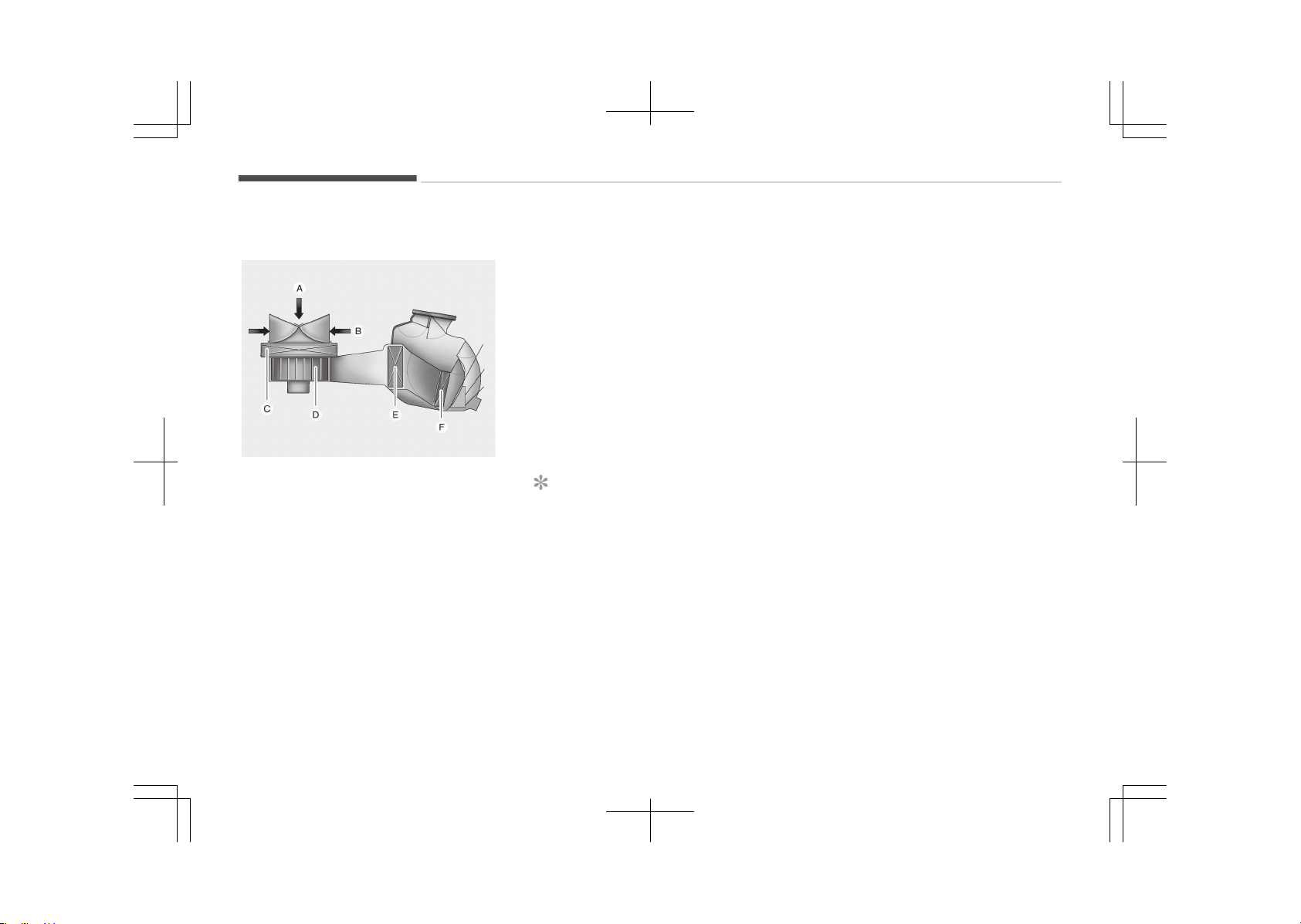
Climate control air filter
OUM046438L
A:
Outside air
B:
Recirculated air
C:
Climate control air filter
D:
Blower
E:
Evaporator core
F:
Heater core
The climate control air filter installed
behind the glove box filters the dust or
other pollutants that come into the ve‐
hicle from the outside through the
heating and air conditioning system.
If dust or other pollutants accumulate
in the filter over a period of time, the
air flow from the air vents may de‐
crease, resulting in moisture accumula‐
tion on the inside of the windshield
even when the outside (fresh) air posi‐
tion is selected. If this happens, we rec‐
ommend that the climate control air fil‐
ter be replaced by an authorized Kia
dealer.
NOTICE
• Replace the filter according to the
Maintenance Schedule on page
9-09.
If the car is being driven in severe
conditions such as dusty, rough
roads, more frequent climate con‐
trol air filter inspections and
changes are required.
(Continued)
(Continued)
• When the air flow rate suddenly
decreases, we recommend that
the system be checked by an au‐
thorized Kia dealer.
Features of your vehicle
5-134
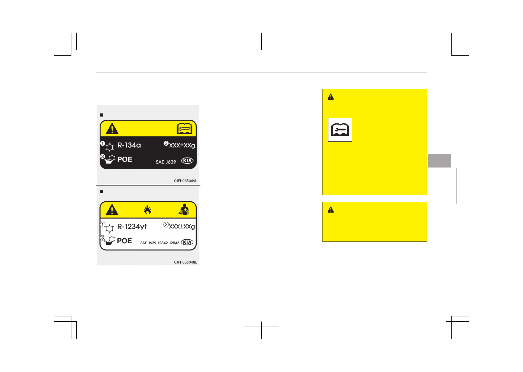
Air conditioning refrigerant label
Type A
Example
Type B
❈ The actual air conditioning refriger‐
ant label in the vehicle may differ
from the illustration.
Each symbol and specification on air
conditioning refrigerant label means as
below:
1. Classification of refrigerant
2. Amount of refrigerant
3. Classification of compressor lubri‐
cant
You can find out which air conditioning
refrigerant is applied your vehicle at
the label inside of the engine room.
Refer to Refrigerant label on page
10-18 for a more detailed location of
the air conditioning refrigerant label.
Checking the amount of air
conditioner refrigerant and
compressor lubricant
When the amount of refrigerant is low,
the performance of the air conditioning
is reduced. Overfilling also has a bad in‐
fluence on the air conditioning system.
Therefore, if abnormal operation is
found, we recommend that the system
be inspected by an authorized Kia deal‐
er.
WARNING
n
Vehicles equipped with R-134a
Because the refrigerant is
at very high pressure, the
air conditioning system
should only be serviced
by trained and certified
technicians. It is impor‐
tant that the correct type
and amount of oil and re‐
frigerant is used.
Otherwise, it may cause
damage to the vehicle
and personal injury.
WARNING
n
Vehicles equipped with
R-1234yf
(Continued)
5-135
5
Features of your vehicle

(Continued)
Because the refrigerant is
mildly inflammable and at
very high pressure, the
air conditioning system
should only be serviced
by trained and certified
technicians. It is impor‐
tant that the correct type
and amount of oil and re‐
frigerant is used.
Otherwise, it may cause
damage to the vehicle
and personal injury.
Features of your vehicle
5-136
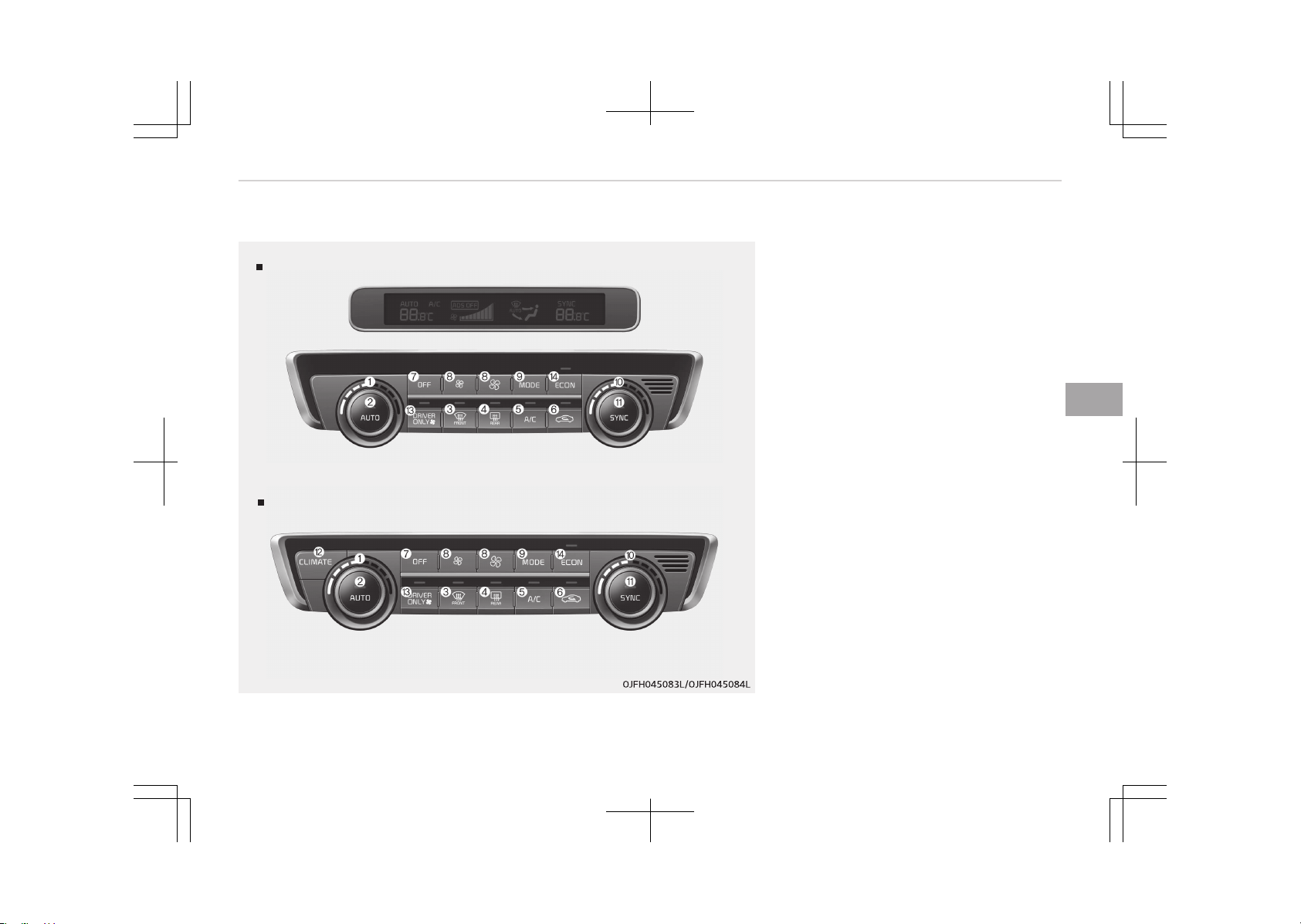
Automatic climate control system (if equipped)
Type A
Type B
System overview
1. Driver's temperature control knob
2. AUTO (automatic control) button
3. Front windshield defroster button
4. Rear window defroster button
5. Air conditioning button
6. Air intake control button
7. OFF button
8. Fan speed control button
9. Mode selection button
10. Passenger's temperature control
knob
11. Dual temperature control selection
button
12. Climate information screen selec‐
tion button
13. DRIVER ONLY button
14. ECON (Economy air conditioning)
button
5-137
5
Features of your vehicle
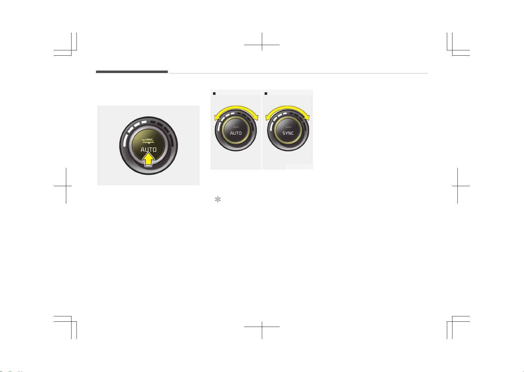
Automatic heating and air
conditioning
OJF045085
1. Press the AUTO button. The modes,
fan speeds, air intake and air-con‐
ditioning will be controlled auto‐
matically according to the temper‐
ature setting.
Drivers sidePassengers side
OJF045089
2. Turn the temperature control knob
to the desired temperature.
NOTICE
• To turn the automatic operation
off, select any button or switch
of the following:
- Mode selection button
- Air conditioning button
(Continued)
(Continued)
- Front windshield defroster
button (Press the button one
more time to deselect the
front windshield defroster
function. The 'AUTO' sign will
illuminate on the information
display once again.)
- Air intake control button
- Fan speed control button
The selected function will be
controlled manually while the
other functions operate auto‐
matically.
• For your convenience and to im‐
prove the effectiveness of the
climate control, use the AUTO
button and set the temperature
to 22°C/71°F (for Europe) or
23°C/73°F (for Except Europe).
Features of your vehicle
5-138
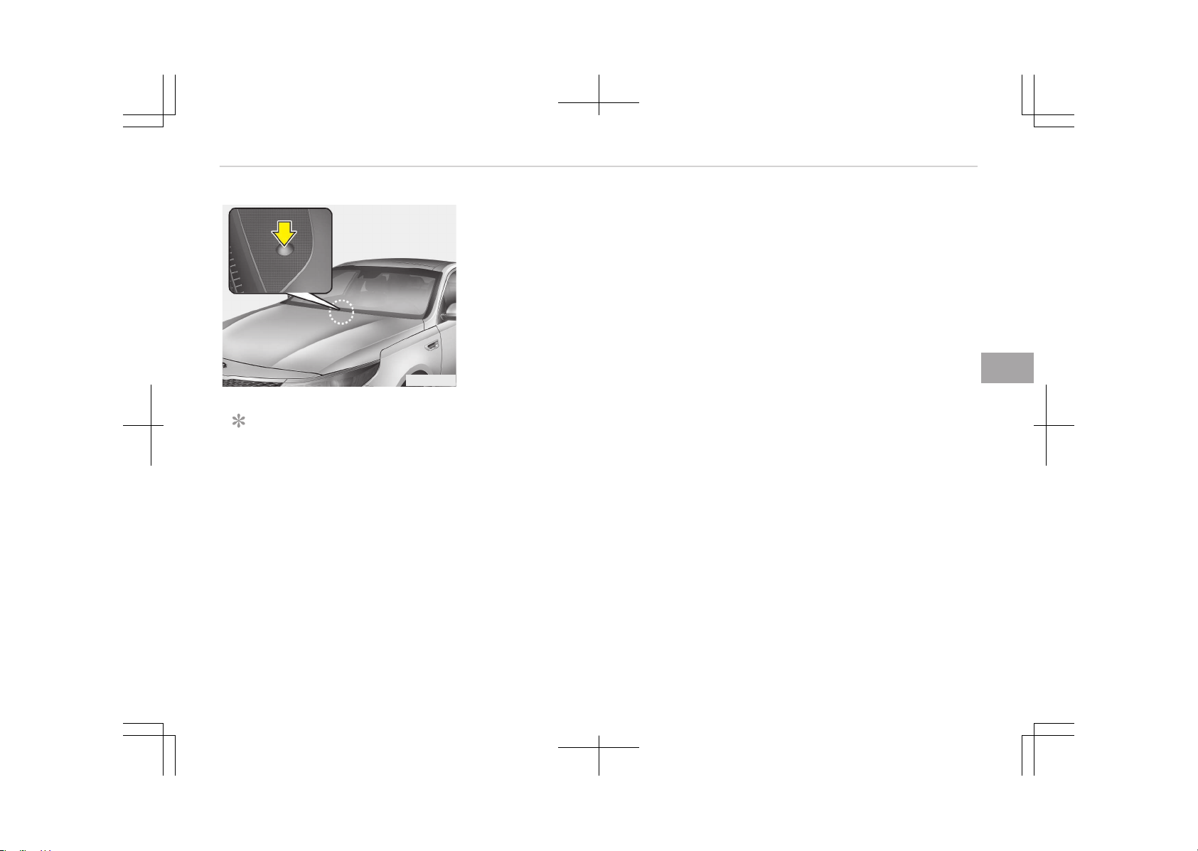
OJF045086
NOTICE
Never place anything over the sen‐
sor located on the instrument panel
to ensure better control of the heat‐
ing and cooling system.
5-139
5
Features of your vehicle
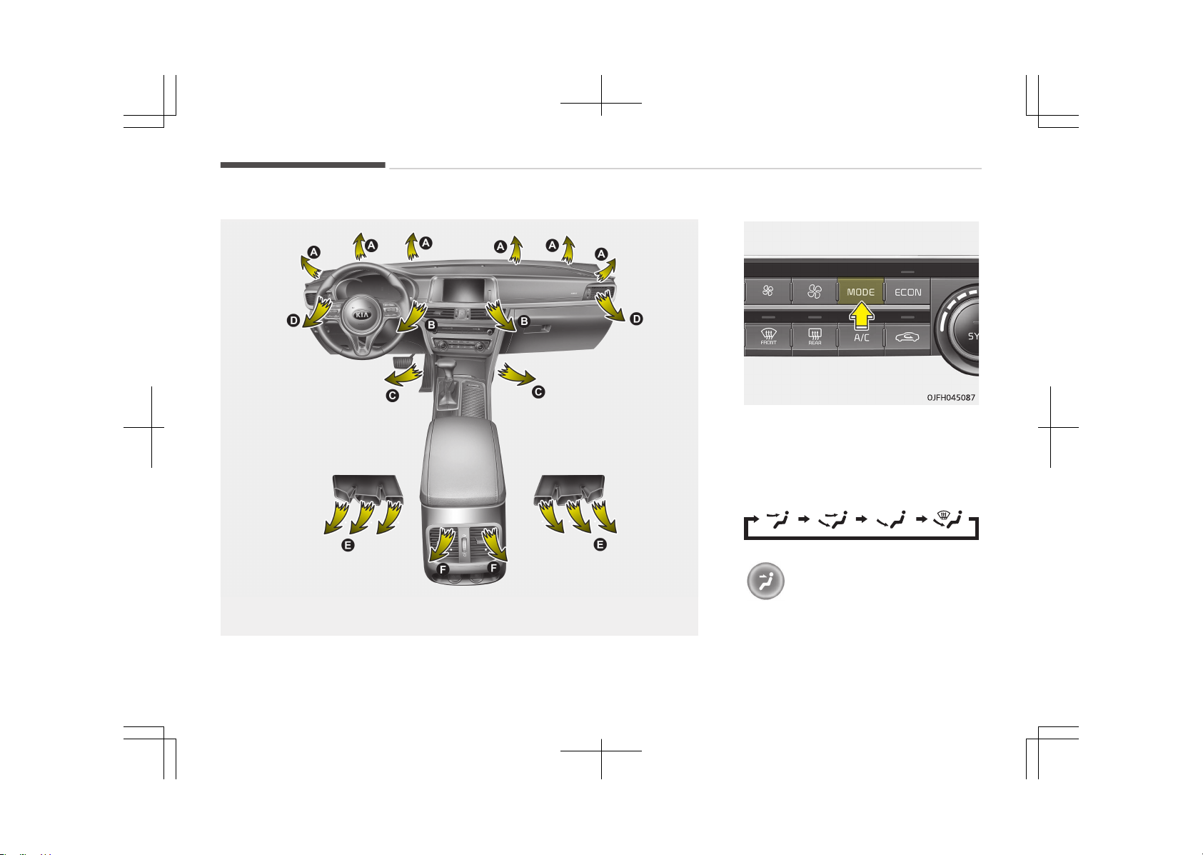
Mode selection
OJF045076
The mode selection button controls the
direction of the air flow through the
ventilation system.
The air flow outlet port is converted as
follows:
Face-Level (B, D)
Air flow is directed toward the upper
body and face. Additionally, each out‐
let can be controlled to direct the air
discharged from the outlet.
Features of your vehicle
5-140
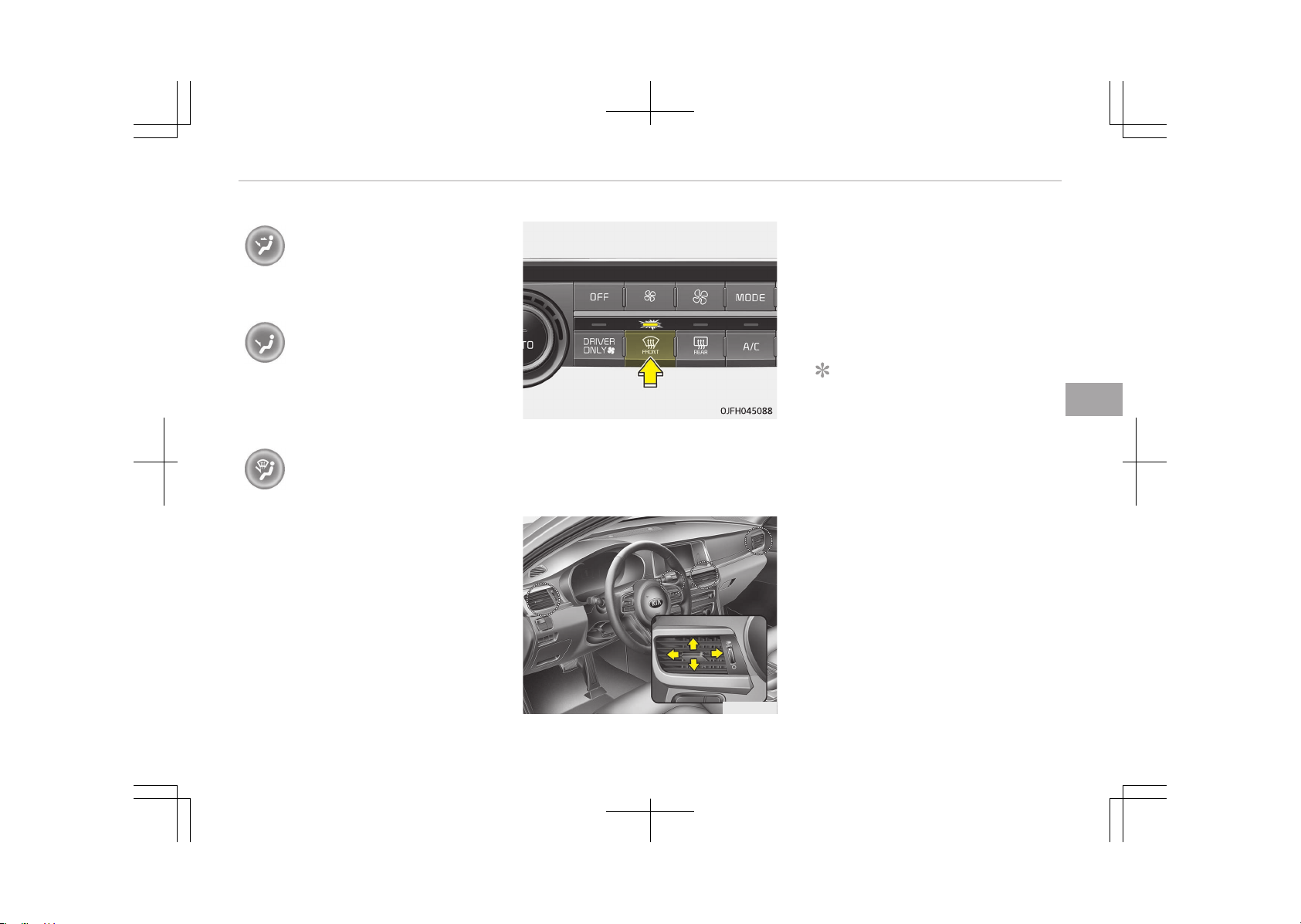
Bi-Level (B, C, D, E, F)
Air flow is directed towards the face
and the floor.
Floor-Level (A, C, E, F)
Most of the air flow is directed to the
floor, with a small amount of the air
being directed to the windshield and
side window defrosters.
Floor/Defrost-Level (A, C, E, F)
Most of the air flow is directed to the
floor and the windshield with a small
amount directed to the side window
defrosters.
Defrost-Level
Most of the air flow is directed to the
windshield with a small amount of air
directed to the side window defrosters.
OJF045078
Instrument panel vents
The outlet vents can be opened or
closed separately using the thumb‐
wheel.
Also, you can adjust the direction of air
delivery from these vents using the
vent control lever as shown.
NOTICE
n
2nd row outlet vents (E,F)
• The air flow of the 2nd row outlet
vents is controlled by the front cli‐
mate control system and delivered
through the inside air duct of the
floor (E, F).
• The air flow of the 2nd row outlet
vents (E, F) may be weaker than
the instrument panel vents for the
long air duct.
5-141
5
Features of your vehicle

Temperature control
Drivers sidePassengers side
OJF045089
The temperature will increase to the
maximum (HI) by turning the knob to
the extreme right.
The temperature will decrease to the
minimum (Lo) by turning the knob to
the extreme left.
When turning the knob, the tempera‐
ture will increase or decrease by
0.5°C/1°F. When set to the lowest tem‐
perature setting, the air conditioning
will operate continuously.
Adjusting the driver and passenger side
temperature equally
OJF045090
• Press the SYNC button to adjust the
driver and passenger side tempera‐
ture equally.
The passenger side temperature will
be set to the same temperature as
the driver side temperature.
• Turn the driver side temperature
control knob. The driver and passen‐
ger side temperature will be adjusted
equally.
Adjusting the driver and passenger side
temperature individually
• Press the SYNC button again to ad‐
just the driver and passenger side
temperature individually. The illumi‐
nation of button turns off.
• Operate the driver side temperature
control knob to adjust the driver side
temperature.
• Operate the passenger side tempera‐
ture control knob to adjust the pas‐
senger side temperature.
Temperature conversion (°C ↔ °F) (if
equipped)
You can switch the temperature mode
between Centigrade to Fahrenheit as
follows;
While pressing the OFF button, depress
the AUTO button for 3 seconds or
more. The display will change from
Centigrade to Fahrenheit, or from Fah‐
renheit to Centigrade.
Features of your vehicle
5-142
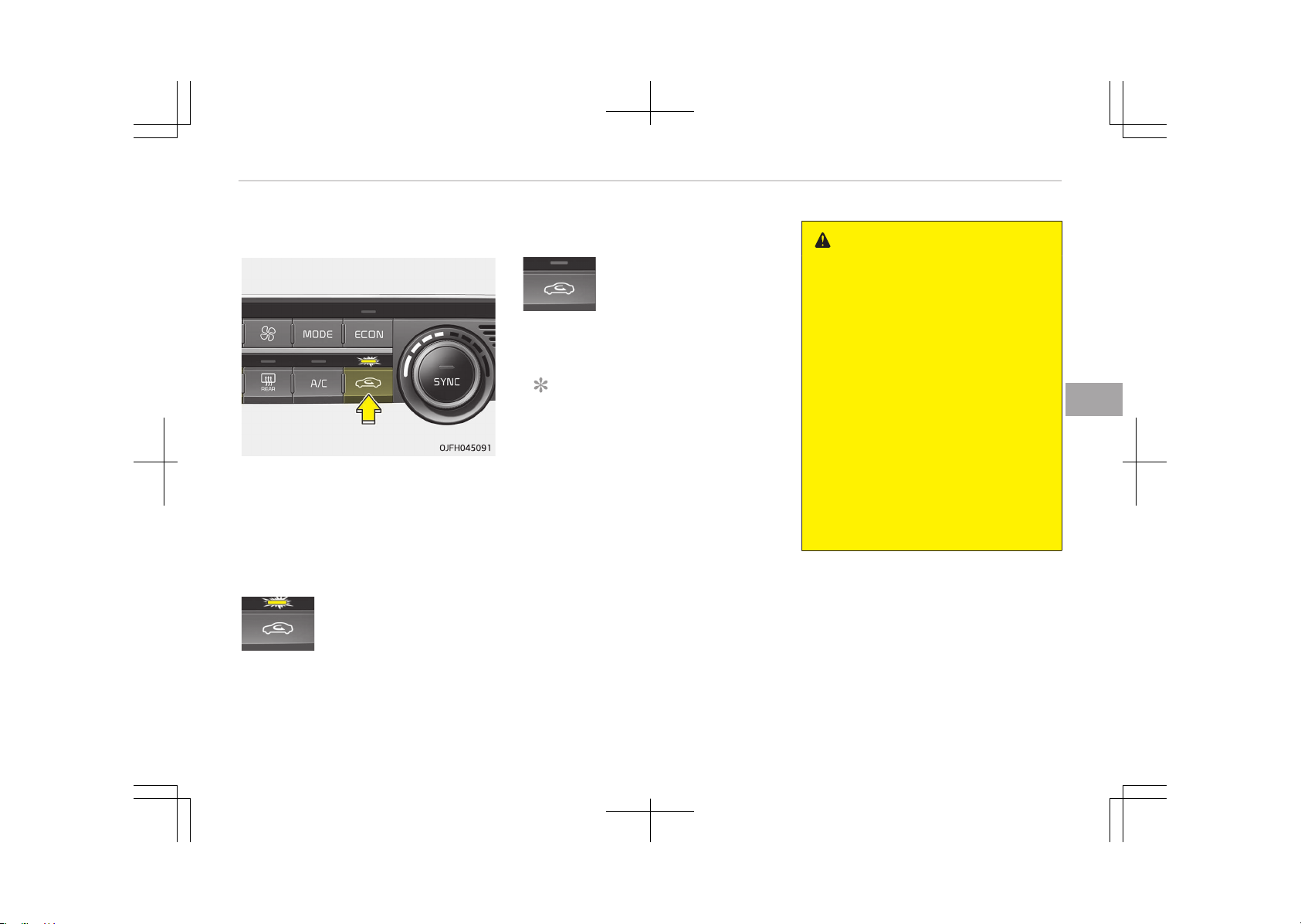
Air intake control
This is used to select the outside
(fresh) air position or recirculated air
position.
To change the air intake control posi‐
tion, push the control button.
Recirculated air position
With the recirculated air
position selected, air from
the passenger compart‐
ment will be drawn
through the heating sys‐
tem and heated or cooled
according to the function
selected.
Outside (fresh) air position
With the outside (fresh)
air position selected, air
enters the vehicle from
outside and is heated or
cooled according to the
function selected.
NOTICE
Prolonged operation of the heater in
the recirculated air position (without
air conditioning selected) may cause
fogging of the windshield and side
windows and the air within the pas‐
senger compartment may become
stale.
In addition, prolonged use of the air
conditioning with the recirculated air
position selected will result in exces‐
sively dry air in the passenger com‐
partment.
WARNING
• Continue using the climate control
system in the recirculated air posi‐
tion may allow humidity to in‐
crease inside the vehicle which
may fog the glass and obscure vis‐
ibility.
• Do not sleep in a vehicle with the
air conditioning or heating system
on. It may cause serious harm or
death due to a drop in the oxygen
level and/or body temperature.
• Continue using the climate control
system in the recirculated air posi‐
tion can cause drowsiness or
sleepiness, and loss of vehicle con‐
trol. Set the air intake control to
the outside (fresh) air position as
much as possible while driving.
5-143
5
Features of your vehicle
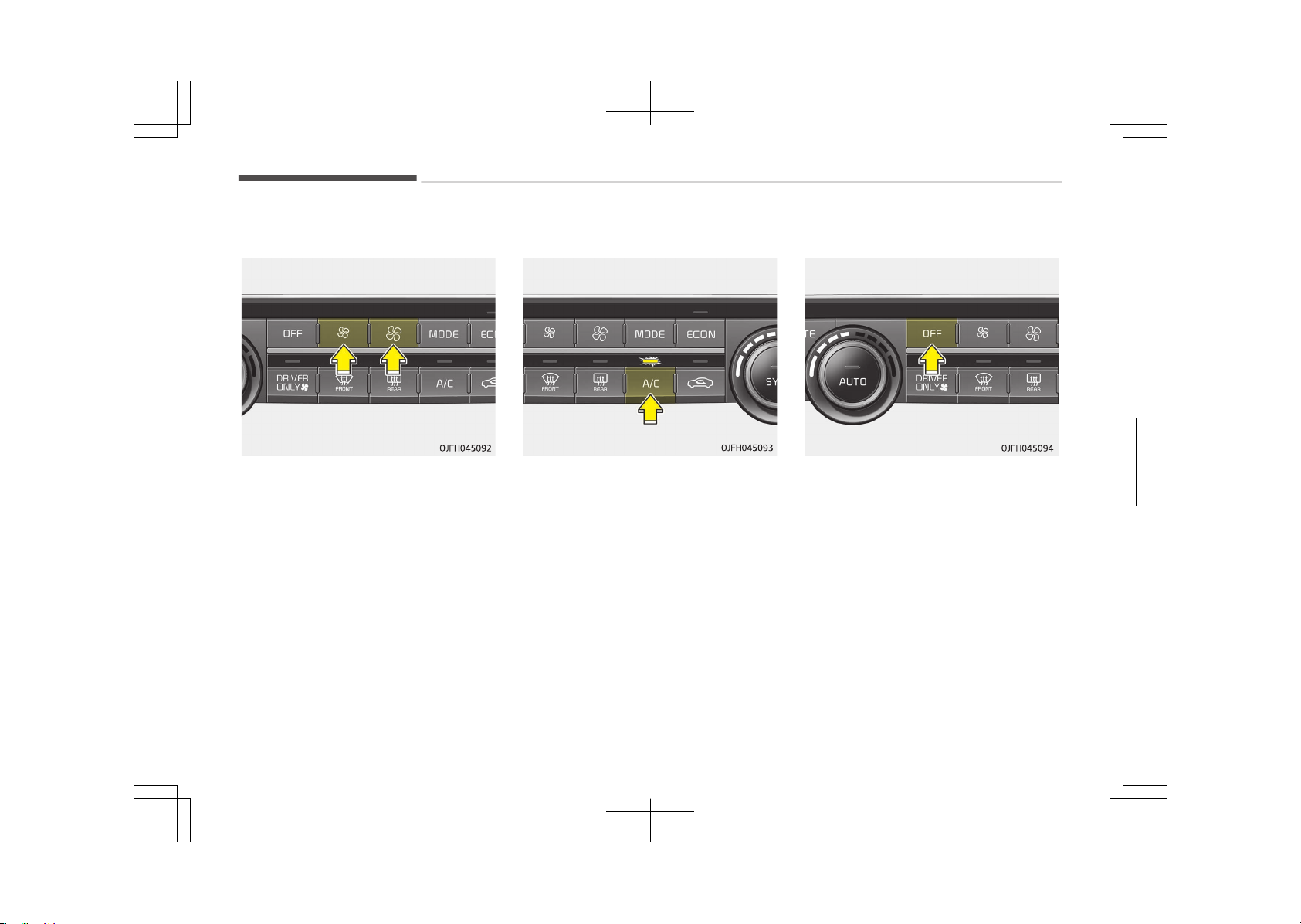
Fan speed control
The fan speed can be set to the desired
speed by pushing the fan speed control
button.
The higher the fan speed is, the more
air is delivered.
Pressing the OFF button turns off the
fan.
Air conditioning
Press the A/C button to turn the air
conditioning system on (indicator light
will illuminate). Press the button again
to turn the air conditioning system off.
OFF mode
Press the front blower OFF button to
turn off the front air climate control
system. However, you can still operate
the mode and air intake buttons as long
as the ignition switch is in the ON posi‐
tion.
Features of your vehicle
5-144
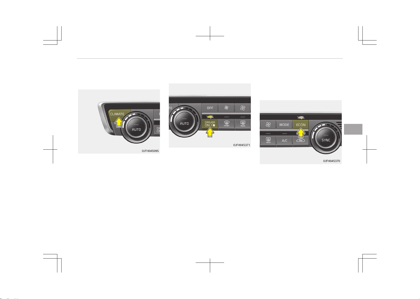
Climate information screen
selection (if equipped)
Press the climate information screen
selection button to display climate in‐
formation on the screen.
Driver Only
If you press the DRIVER ONLY button
and the indicator light illuminates, cold
air mostly blows in the direction of the
drivers seat. However, some of the cold
air may come out of other seats ducts
to keep indoor air pleasant.
If you use the button with no passen‐
ger in the front passenger seat, energy
consumption will be reduced.
DRIVER ONLY button will be turned off
under the following conditions:
1. Defrost on
2. SYNC on
3. Adjusted front passenger seat
temperature
4. DRIVER ONLY button re-push
Economy air conditioning button
(ECON)
If you push the ECON button while the
air conditioning system is working, the
air conditioning system will work less
and may improve fuel efficiency.
If you want maximum air conditioning
turn the ECON system off by pushing
the ECON button.
5-145
5
Features of your vehicle
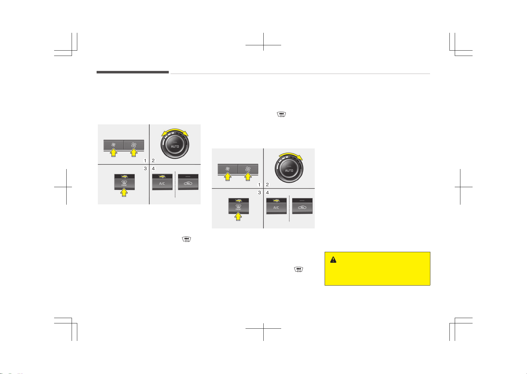
WINDSHIELD DEFROSTING AND DEFOGGING
Automatic climate control
system
To defog inside windshield
OJF045098
1. Set the fan speed to the desired
position.
2. Select the desired temperature.
3. Press the defroster button ( ).
4. The air conditioning will turn on ac‐
cording to the detected ambient
temperature and outside (fresh) air
position will be selected automati‐
cally.
If the air conditioning and outside
(fresh) air position are not selected au‐
tomatically, adjust the corresponding
button manually. If the position is
selected, lower fan speed is adjusted to
a higher fan speed.
To defrost outside windshield
OJF045099
1. Set the fan speed to the highest
position.
2. Set the temperature to the ex‐
treme hot (HI) position.
3. Press the defroster button
.
4. The air conditioning will turn on ac‐
cording to the detected ambient
temperature and outside (fresh) air
position will be selected automati‐
cally.
Operation tips
• For maximum defrosting, set the
temperature control to the extreme
right/hot position and the fan speed
control to the highest speed.
• If warm air to the floor is desired
while defrosting or defogging, set the
mode to the floor-defrost position.
• Before driving, clear all snow and ice
from the windshield, rear window,
outside rear view mirrors, and all side
windows.
• Clear all snow and ice from the hood
and air inlet in the cowl grill to im‐
prove heater and defroster efficiency
and to reduce the probability of fog‐
ging up the inside of the windshield.
WARNING
n
Windshield heating
(Continued)
Features of your vehicle
5-146
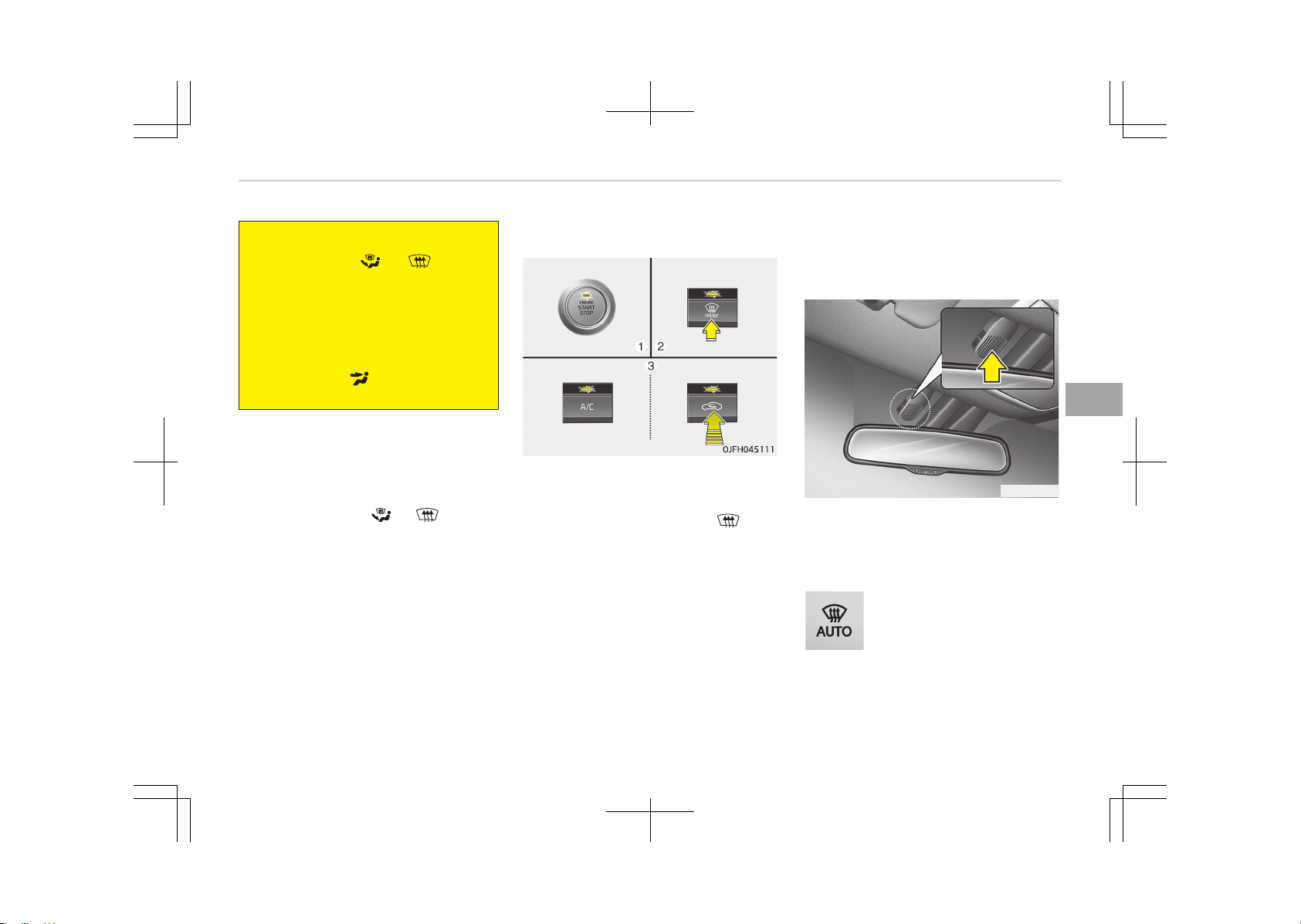
(Continued)
Do not use the or position
during cooling operation in extreme‐
ly humid weather. The difference be‐
tween the temperature of the out‐
side air and the windshield could
cause the outer surface of the wind‐
shield to fog up, causing loss of visi‐
bility. In this case, set the mode se‐
lection to the position and fan
speed control to the lower speed.
Defogging logic (if equipped)
To reduce the possibility of fogging up
the inside of the windshield, the air in‐
take or air conditioning are controlled
automatically according to certain con‐
ditions such as the or position.
To cancel or return to the defogging
logic, do the following.
Automatic climate control system
1. Turn the ignition switch to the ON
position.
2. Press the defrost button ( ).
3. While pressing the air conditioning
button (A/C), press the air intake
control button at least 5 times
within 3 seconds.
The indicator on the air intake button
will blink 3 times. It indicates that the
defogging logic is canceled or returned
to the programmed status.
If the battery has been discharged or
disconnected, it resets to the defog
logic status.
Auto defogging system (Only
for automatic climate control
system, if equipped)
OJF045336L
Auto defogging reduces the possibility
of fogging up the inside of the wind‐
shield by automatically sensing the
moisture of inside the windshield.
This indicator illuminates
when the auto defogging
system senses the moisture
of inside the windshield and
operates.
If more moisture is in the vehicle, high‐
er steps operate as follow.
5-147
5
Features of your vehicle

(For European region)
Step 1: Blowing air flow toward the
windshield
Step 2: Increasing air flow toward
the windshield
Step 3: Operating the air condition‐
ing.
Step 4: Outside air position
(For except European region)
Step 1: Outside air position
Step 2: Operating the air condition‐
ing.
Step 3: Blowing air flow toward the
windshield
Step 4: Increasing air flow toward
the windshield
To cancel or reset the Auto
Defogging System
Press the front windshield defroster
button for 3 seconds when the ignition
switch is in the ON position.
When the Auto Defogging System is
canceled, ADS OFF symbol will blink 3
times and the ADS OFF will be displayed
on the climate control information
screen.
When the Auto Defogging System is re‐
set, ADS OFF symbol will blink 6 times
without a signal.
Features of your vehicle
5-148

CLEAN AIR (IF EQUIPPED)
OJF045335L
When the ignition switch is in the ON
position, the clean air function turns on
automatically.
Also, the clean air function turns off
automatically, when the ignition switch
turns to the OFF position.
5-149
5
Features of your vehicle
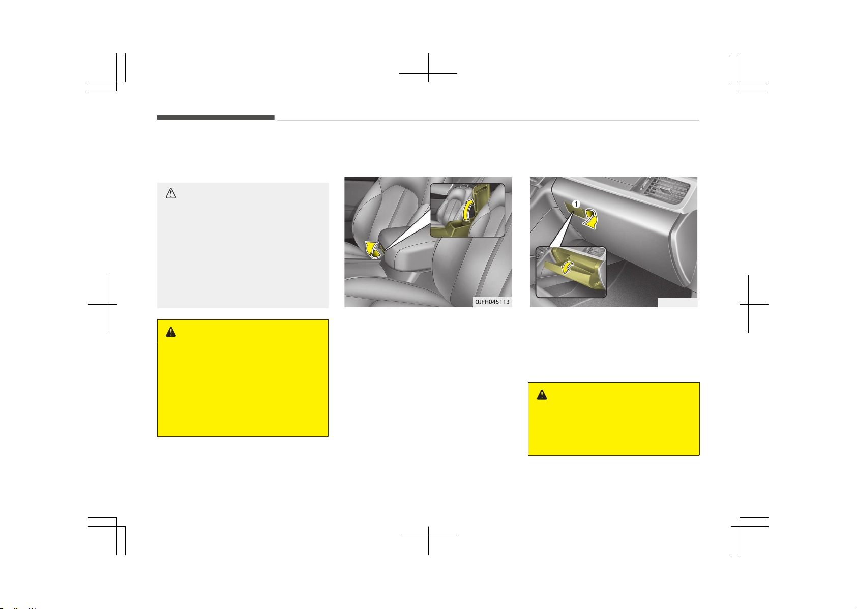
STORAGE COMPARTMENT
These compartments can be used to
store small items.
CAUTION
• To avoid possible theft, do not
leave valuables in the storage
compartment.
• Always keep the storage compart‐
ment covers closed while driving.
Do not attempt to place so many
items in the storage compartment
that the storage compartment
cover cannot close securely.
WARNING
n
Flammable materials
Do not store cigarette lighters, pro‐
pane cylinders, or other flammable/
explosive materials in the vehicle.
These items may catch fire and/or
explode if the vehicle is exposed to
hot temperatures for extended peri‐
ods.
Center console storage
To open the center console storage, pull
up the lever.
Glove box
OJF045114L
The glove box can be locked and un‐
locked with a master key. (if equipped)
To open the glove box, pull the lever (1)
and the glove box will automatically
open. Close the glove box after use.
WARNING
To reduce the risk of injury in an ac‐
cident or sudden stop, always keep
the glove box door closed while driv‐
ing.
Features of your vehicle
5-150
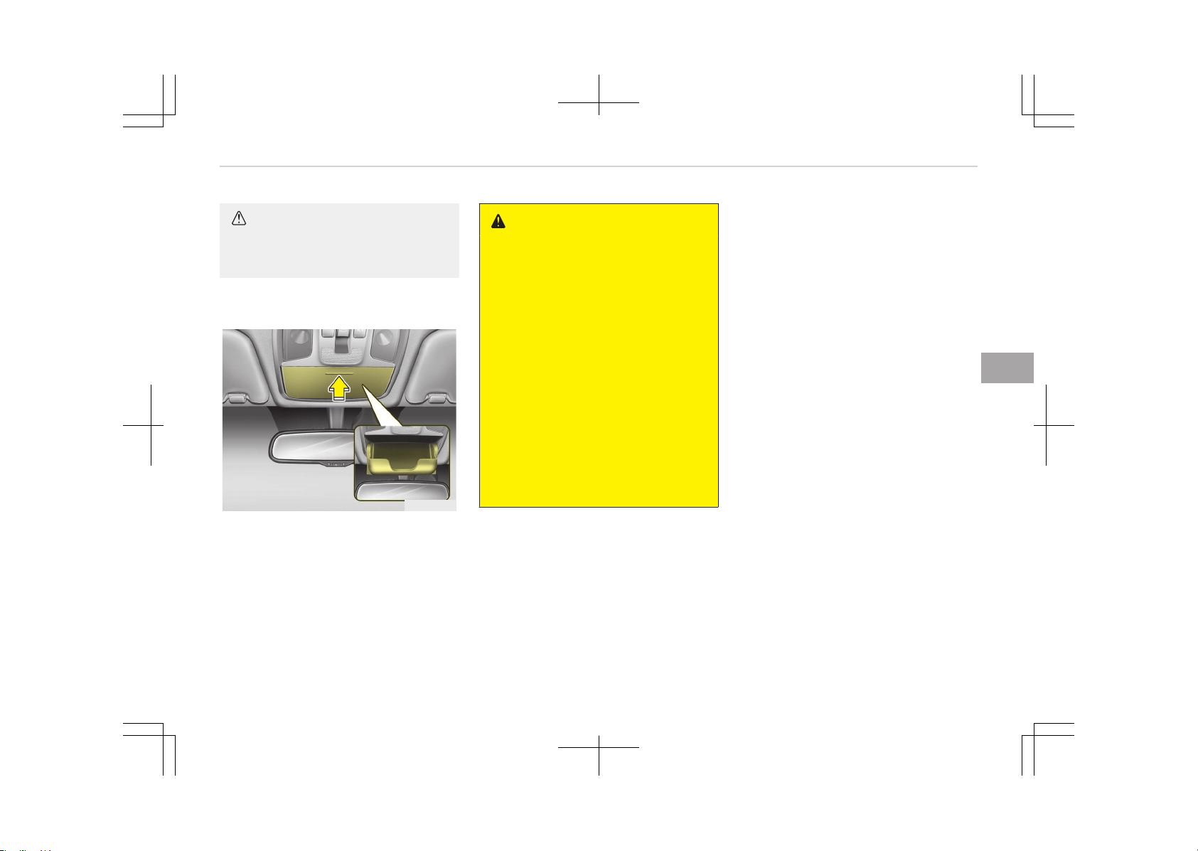
CAUTION
Do not keep food in the glove box for
a long time.
Sunglass holder
OJF045115
To open the sunglass holder, press the
cover and the holder will slowly open.
Place your sunglasses with the lenses
facing out. To close the sunglass holder,
push it up.
WARNING
• Do not keep objects except sun‐
glasses inside the sunglass holder.
Such objects can be thrown from
the holder in the event of a sudden
stop or an accident, possibly injur‐
ing the passengers in the vehicle.
• Do not open the sunglass holder
while the vehicle is moving. The
rear view mirror of the vehicle can
be blocked by an opened sunglass
holder.
• Do not put the glasses forcibly into
a sunglass holder to prevent
breakage or deformation of the
glasses. It may cause personal in‐
jury if you try to open it forcibly
when the glasses are jammed in
the holder.
5-151
5
Features of your vehicle
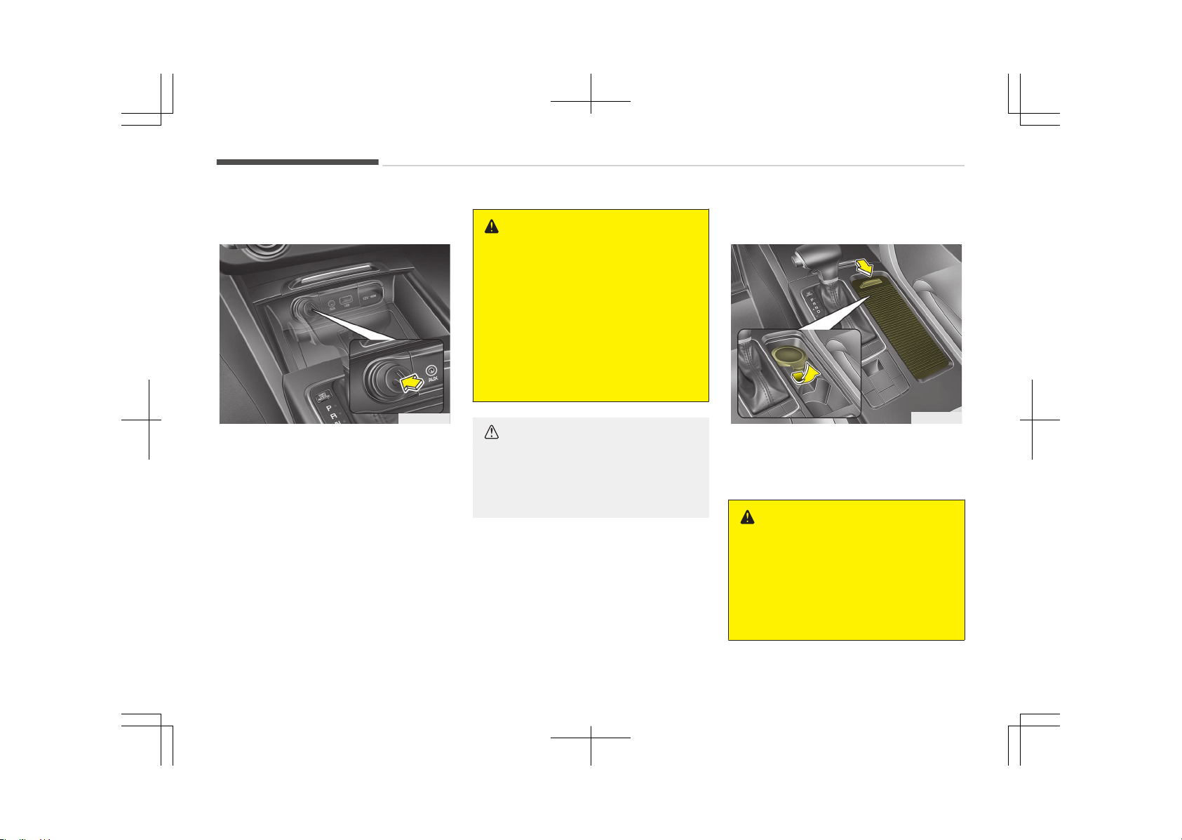
INTERIOR FEATURES
Cigarette lighter (if equipped)
OJF045116
For the cigarette lighter to work, the
ignition switch must be in the ACC posi‐
tion or the ON position.
To use the cigarette lighter, push it all
the way into its socket. When the ele‐
ment has heated, the lighter will pop
out to the ready position.
We recommend that you use parts for
replacement from an authorized Kia
dealer.
WARNING
• Do not hold the lighter in after it is
already heated because it will
overheat.
• If the lighter does not pop out
within 30 seconds, remove it to
prevent overheating.
• Do not insert foreign objects into
the socket of the cigarette lighter.
It may damage the cigarette light‐
er.
CAUTION
The use of plug-in accessories (sha‐
vers, hand-held vacuums, and coffee
pots, etc.) may damage the socket
or cause electrical failure.
Ashtray (if equipped)
OJF045117
To use the ashtray, open the cover.
To clean or empty the ashtray, pull it
out.
WARNING
n
Ashtray use
• Do not use the vehicle’s ashtrays
as waste receptacles.
• Putting lit cigarettes or matches in
an ashtray with other combustible
materials may cause a fire.
Features of your vehicle
5-152
Cup holder
WARNING
n
Hot liquids
• Do not place uncovered cups of hot
liquid in the cup holder while the
vehicle is in motion. If the hot liq‐
uid spills, you may burn yourself.
Such a burn to the driver could
lead to loss of control of the vehi‐
cle.
• To reduce the risk of a personal in‐
jury in the event of a sudden stop
or collision, do not place uncovered
or unsecured bottles, glasses,
cans, etc., in the cup holder while
the vehicle is in motion.
(Continued)
(Continued)
• If uncovered cups and cans con‐
taining any form of liquid are put
into the front/center seat cup
holders and the vehicle brakes
heavily, the liquid may flow into
the narrow openings around cup
holders and console, and soak into
the vehicle's internal electrical sys‐
tem.
To avoid subsequent system mal‐
function, always firmly cover any
container holding liquid.
WARNING
Keep cans or bottles out of direct
sun light and do not put them in a
vehicle that is heated up. They may
explode.
NOTICE
• Keep your drinks sealed while driv‐
ing to prevent spilling your drink. If
liquid spills, it may get into the ve‐
hicle's electrical/electronic system
and damage electrical/electronic
parts.
• When cleaning spilled liquids, do
not dry the cup holder at high
temperature. This may damage
the cup holder.
5-153
5
Features of your vehicle
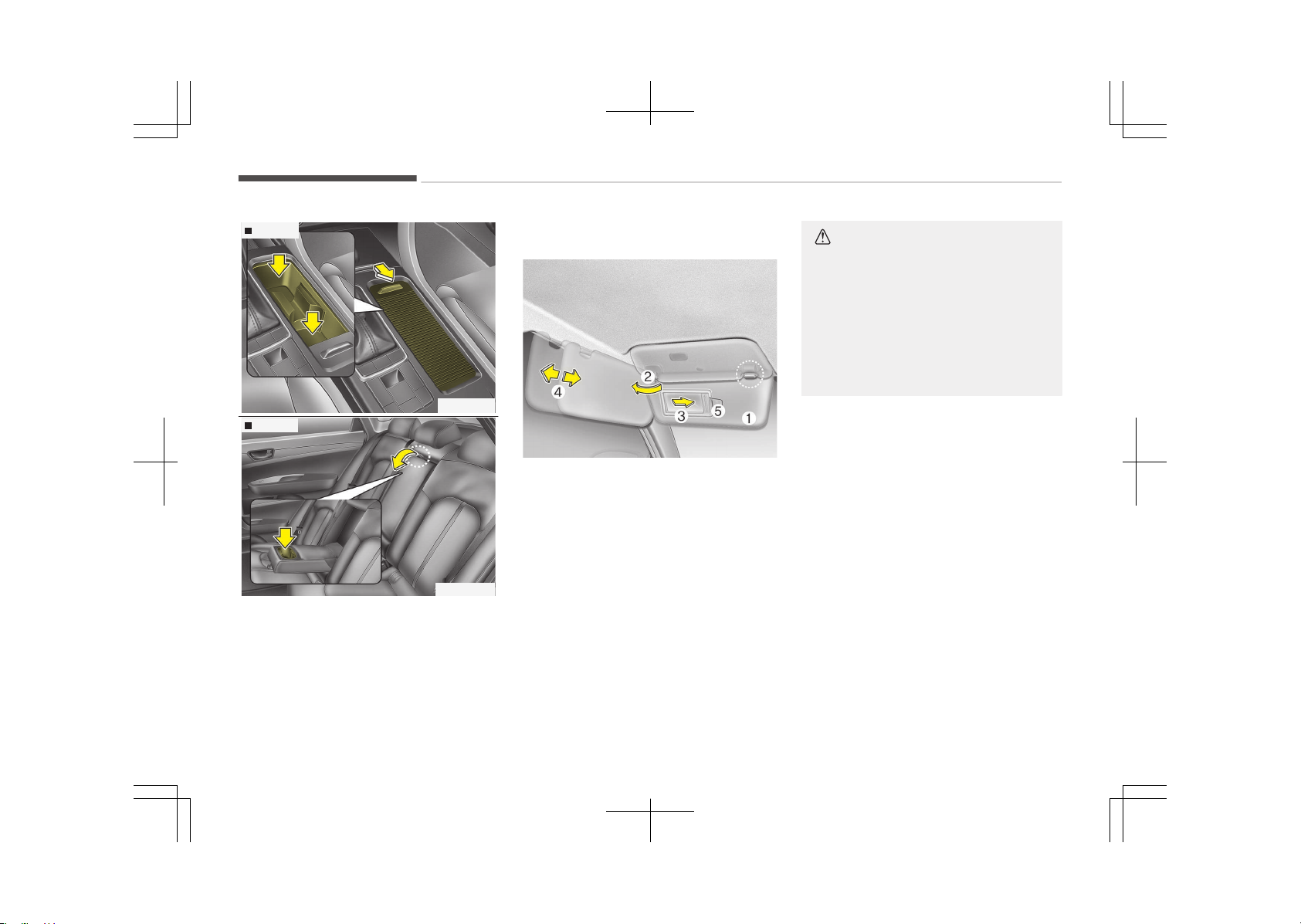
Type A
OJF045119
Type B
OJF045120B
Cups or small beverage cans may be
placed in the cup holders.
Sunvisor
OJF045121
Use the sunvisor to shield direct light
through the front or side windows.
To use the sunvisor, pull it downward.
To use the sunvisor for the side win‐
dow, pull it downward, unsnap it from
the bracket (1) and swing it to the side
(2).
To use the vanity mirror, pull down the
visor and slide the mirror cover (3).
Adjust the sunvisor extension forward
or backward (4).
The ticket holder (5) is provided for
holding a tollgate ticket. (if equipped)
CAUTION
n
Vanity mirror lamp (if equip‐
ped)
If you use the vanity mirror lamp,
turn off the lamp before returning
the sunvisor to its original position,
otherwise it could result in battery
discharge and possible sunvisor
damage.
Features of your vehicle
5-154
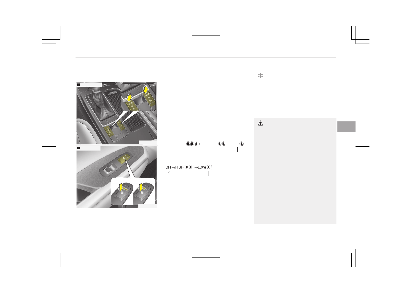
Seat warmer (if equipped)
Front seat
OJF045123
Rear seat
OJF045124
The seat warmer is provided to warm
the front seats during cold weather.
With the ignition switch in the ON posi‐
tion, push either of the switches to
warm the driver's seat or the front
passenger's seat.
During mild weather or under condi‐
tions where the operation of the seat
warmer is not needed, keep the
switches in the "OFF" position.
• Each time you press the switch, the
temperature setting of the seat will
change as follows:
- Front seat
OFF→HIGH( )→MIDDLE( )→LOW( )
→
- Rear seat
• The seat warmer defaults to the OFF
position whenever the ignition switch
is turned on.
NOTICE
With the seat warmer switch in the
ON position, the heating system in
the seat turns off or on automati‐
cally depending on the seat temper‐
ature.
CAUTION
• When cleaning the seats, do not
use an organic solvent such as
paint thinner, benzene, alcohol and
gasoline. Doing so may damage
the surface of the heater or seats.
• To prevent overheating the seat
warmer, do not place anything on
the seats that insulates against
heat, such as blankets, cushions or
seat covers while the seat warmer
is in operation.
• Do not place heavy or sharp ob‐
jects on seats equipped with seat
warmers. Damage to the seat
warming components could occur.
• Do not change the seat cover. It
may damage the seat warmer or
airventilation system.
5-155
5
Features of your vehicle
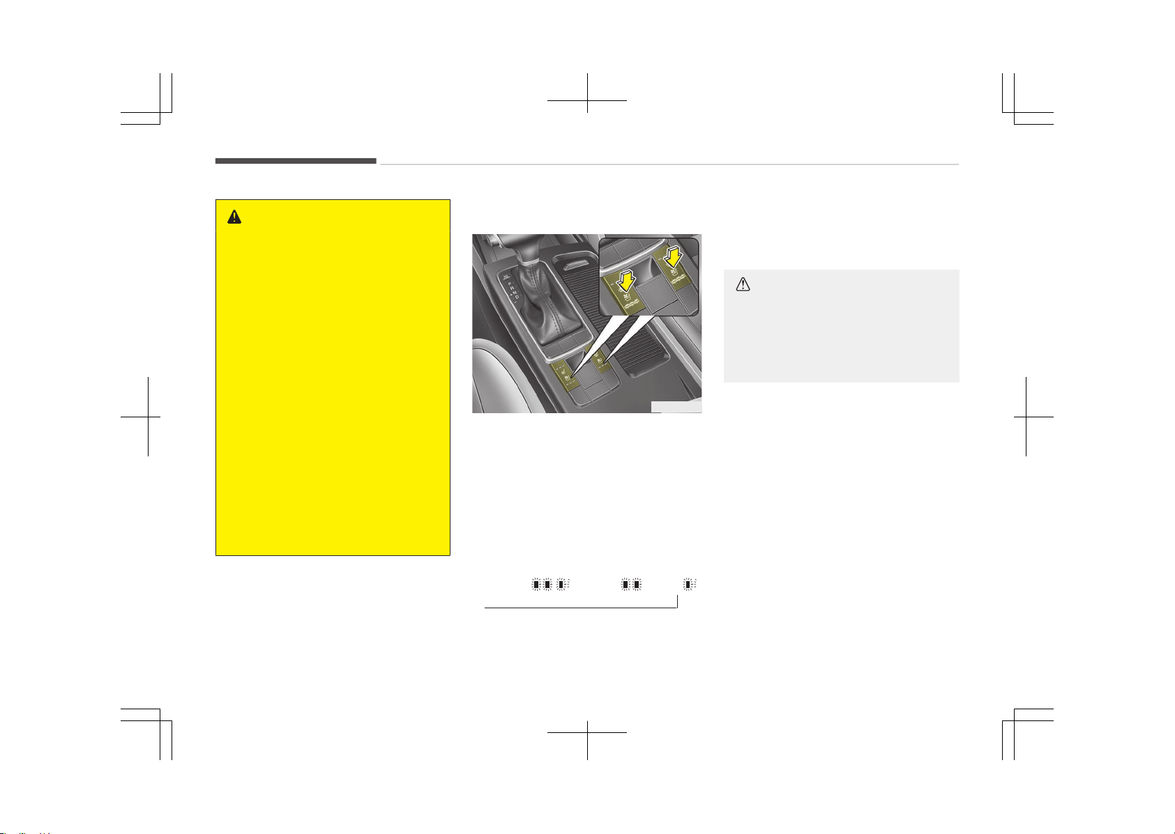
WARNING
n
Seat warmer burns
Passengers should use extreme cau‐
tion when using seat warmers due
to the possibility of excess heating
or burns. The seat warmer may
cause burns even at low tempera‐
tures, especially if used for long pe‐
riods of time. In particular, the driver
must exercise extreme care for the
following types of passengers:
1. Infants, children, elderly or
handicapped persons, or hospital
outpatients
2. Persons with sensitive skin or
those that burn easily
3. Fatigued individuals
4. Intoxicated individuals
5. Individuals taking medication
that can cause drowsiness or
sleepiness (sleeping pills, cold
tablets, etc.)
Air ventilation seat (if equipped)
OJF045125
The temperature setting of the seat
changes according to the switch posi‐
tion.
• If you want to warm your seat cush‐
ion, press the switch (red color).
• If you want to ventilate your seat
cushion, press the switch (blue color).
• Each time you press the button, the
airflow will change as follows:
OFF→HIGH( )→MIDDLE( )→LOW( )
→
• The seat warmer (with air ventila‐
tion) defaults to the OFF position
whenever the ignition switch is
turned on.
CAUTION
When cleaning the seats, do not use
an organic solvent such as paint
thinner, benzene, alcohol and gaso‐
line. Doing so may damage the sur‐
face of the heater or seats.
Features of your vehicle
5-156
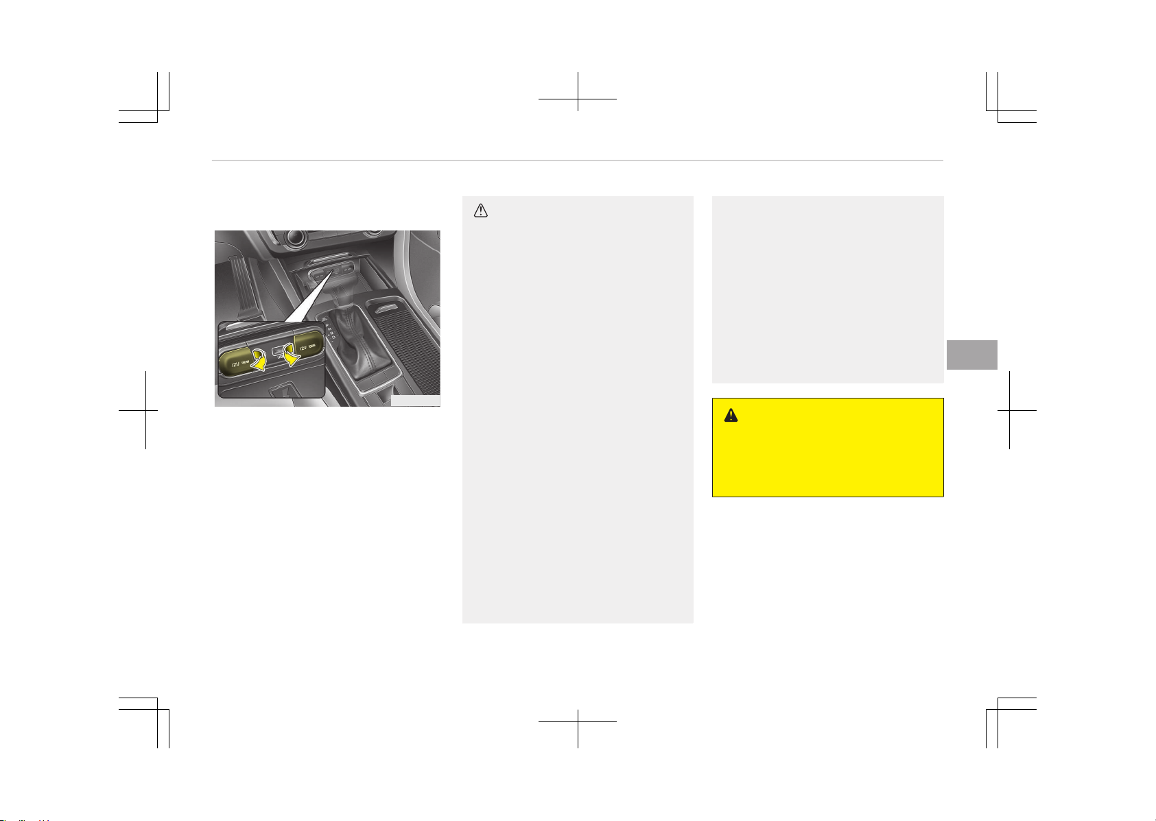
Power outlet
OJF045122
The power outlet is designed to provide
power for mobile telephones or other
devices designed to operate with vehi‐
cle electrical systems. The devices
should draw less than 10 amps with
the engine running.
CAUTION
• Use the power outlet only when
the engine is running and remove
the accessory plug after use. Using
the accessory plug for prolonged
periods of time with the engine off
could cause the battery to dis‐
charge.
• Only use 12V electric accessories
which are less than 10A in electric
capacity.
• Adjust the air-conditioner or heat‐
er to the lowest operating level
when using the power outlet.
• Close the cover when not in use.
• Some electronic devices can cause
electronic interference when plug‐
ged into a vehicle’s power outlet.
These devices may cause exces‐
sive audio static and malfunctions
in other electronic systems or de‐
vices used in your vehicle.
• Refrain from using the heater or
A/C if you need to use the multi‐
purpose socket. If the heater or
A/C has to be used simultaneously,
have it to the lowest setting.
(Continued)
(Continued)
• Some add-on electrical equipment
will induce electromagnetic inter‐
ference. This will lead to subse‐
quent malfunction or hinder good
reception of the Audio/Video and
electrical system.
• Always make sure that electric
add-ons are fully plugged into the
multipurpose sockets. Insecure
contacts may lead to electrical
malfunctions.
WARNING
Do not put a finger or a foreign ele‐
ment (pin, etc.) into a power outlet
and do not touch with a wet hand.
You may get an electric shock.
5-157
5
Features of your vehicle
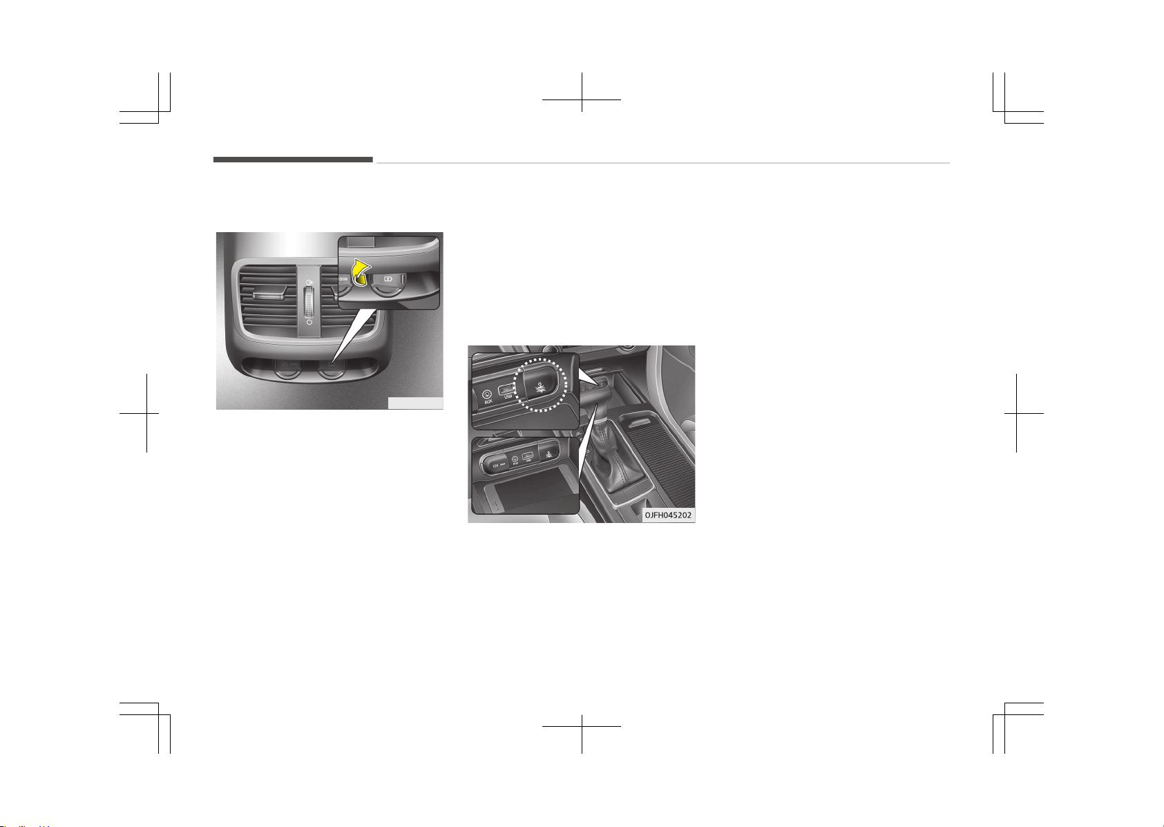
USB charger (if equipped)
OJF045229L
The USB charger is designed to re‐
charge batteries of small size electrical
devices using a USB cable. The electrical
devices can be recharged when the En‐
gine Start/Stop button is in ACC/ON/
START position.
The battery charging state may be
monitored on the electrical device.
Disconnect the USB cable from the USB
port after use.
• Some devices are not supported for
fast charging but will be charged with
normal speed.
• Use the USB charger when the engine
is running to prevent battery dis‐
charge.
• Only devices that fits the USB port
can be used.
• The USB charger can be used only for
battery charging purposes.
• Battery chargers cannot be charged.
Wireless smart phone charging
system (if equipped)
A wireless smart phone charging sys‐
tem located in front of the center con‐
sole.
Firmly close all doors, and turn the igni‐
tion to ACC or IGN ON. To start wireless
charging, place the smart phone equip‐
ped with wireless charging function on
the wireless charging pad.
For best wireless charging results, place
the smart phone on the center of the
charging pad.
The wireless charging system is de‐
signed for one smart phone equipped
with QI per single usage only. Please re‐
fer to the smart phone accessory cover
or the smart phone manufacturer
homepage to check whether your
smart phone supports QI function.
Wireless smart phone charging
1. Remove any object on the smart
phone charging pad including the
smart key. If there is any foreign
object on the pad other than a
smart phone, the wireless charging
function may not operate properly.
2. Place the smart phone on the cen‐
ter of the wireless charging pad.
3. The indicator light will change to
orange once the wireless charging
begins. After the charging is com‐
plete, the orange light will change
to green.
4. You can choose to turn the wireless
charging function to either ON or
OFF by selecting the USM on the in‐
strument cluster. (Please refer to
Instrument cluster on page 5-48
for details.)
Features of your vehicle
5-158

If the wireless charging does not work,
gently move your smart phone around
the pad until the charging indicator
light turns yellow. Depending on the
smart phone, the charging indicator
light may not turn green even after the
charging is complete.
If the wireless charging is not function‐
ing properly, the orange light will blink
and flash for ten seconds then turn off.
In such cases, remove the smart phone
from the pad and replace it on the pad
again, or double check the charging sta‐
tus.
If you leave the smart phone on the
charging pad when the vehicle ignition
is in OFF, the vehicle will alert you
through warning messages and sound
(applicable for vehicles with voice guid‐
ance function) after the Good bye
function on the instrument cluster
ends.
CAUTION
• Securely close the tray cover when
using the wireless smart phone
charge function. Otherwise, some
liquid held by the cup holder may
flow onto the wireless charging
pad during sudden stops.
• Close the tray cover when the
smart phone is placed in it at all
times. If the vehicle is in motion
without the tray cover closed, it is
more likely that the driver may
use the smart phone. The use of
smart phones while driving may
lead to possible injuries and acci‐
dents.
• If it is not possible to close the
tray cover due to the size of the
smart phone, do not use the wire‐
less smart phone charging func‐
tion at all.
• When the tray cover is broken, do
not use the wireless charging
function before the tray cover is
repaired.
(Continued)
(Continued)
• When the interior temperature of
the wireless charging system rises
above a set temperature, the
wireless charging will cease to
function. After the interior tem‐
perature drops below the thresh‐
old, the wireless charging function
will resume.
• If any metallic object such as coins
is located between the wireless
charging system and the smart
phone, the charging may be dis‐
rupted. Also, the metallic object
may heat up.
• If there is any metallic object be‐
tween the smart phone and the
wireless charging pad, immediate‐
ly remove the smart phone. Re‐
move the metallic object after it
has completely cooled down.
• The wireless charging may not
function properly when there is a
heavy accessory cover on the
smart phone.
(Continued)
5-159
5
Features of your vehicle
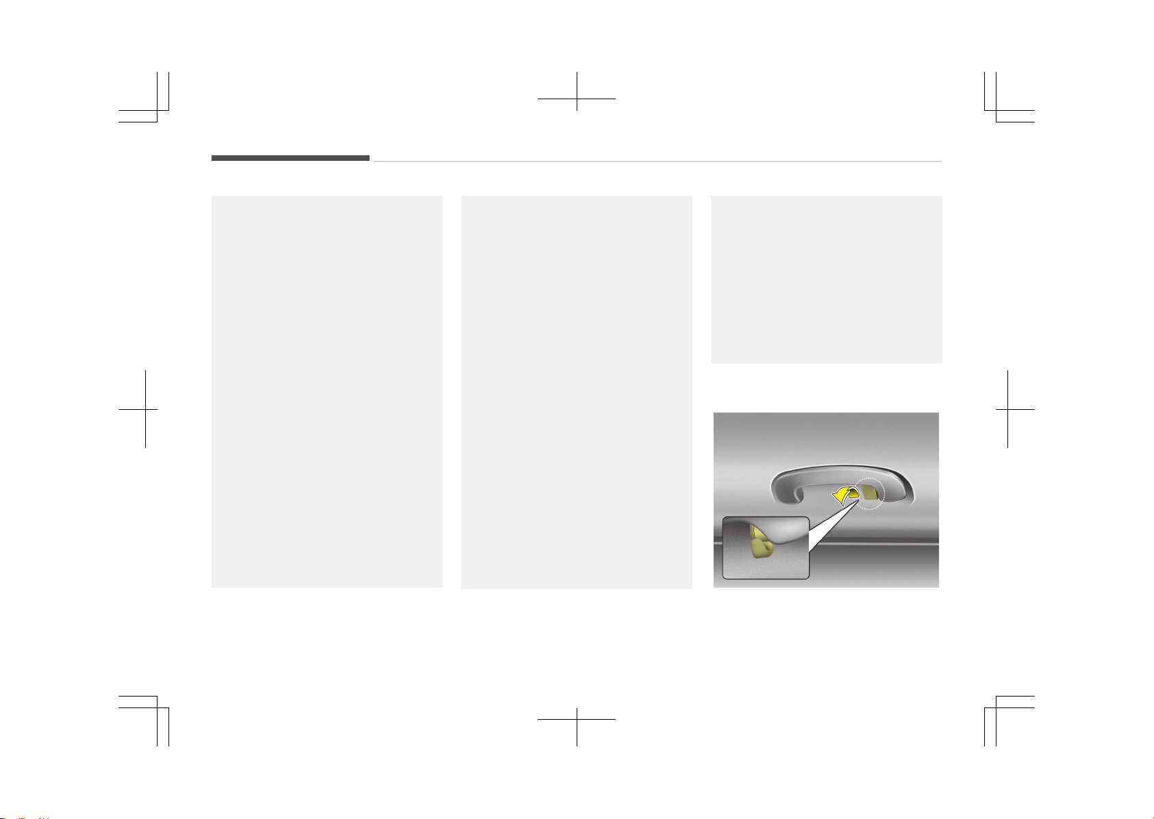
(Continued)
• The wireless charging will stop
when using the wireless smart key
search function to prevent radio
wave disruption.
• The wireless charging will stop
when the smart key is moved out
of the vehicle with the ignition in
ON.
• The wireless charging will stop
when any of the doors is opened
(applicable for vehicles equipped
with smart keys).
• The wireless charging will stop
when the vehicle is turned OFF.
• The wireless charging will stop
when the smart phone is not in
complete contact with the wireless
charging pad.
• Items equipped with magnetic
components such as credit card,
telephone card, bankbook, any
transportation ticket and such
may become damaged during
wireless charging.
(Continued)
(Continued)
• Place the smart phone on the cen‐
ter of the charge pad for best re‐
sults. The smart phone may not
charge when placed near the rim
of the charging pad. When the
smart phone does get charged, it
may heat up excessively.
• For smart phones without built in
wireless charging system, an ap‐
propriate accessory has to be
equipped.
• Smart phones of some manufac‐
turers may display messages on
weak current. This is due to the
particular characteristic of the
smart phone and does not imply a
malfunction on wireless charging
function.
• The indicator light of some manu‐
facturers’ smart phones may still
be yellow after the smart phone is
fully charged. This is due to the
particular characteristic of the
smart phone and not a malfunc‐
tion of the wireless charging.
(Continued)
(Continued)
• When any smart phone without a
wireless charging function or a
metallic object is placed on the
charging pad, a small noise may
sound. This small sound is due to
the vehicle discerning compatibility
of the object placed on the charg‐
ing pad. It does not affect your ve‐
hicle or the smart phone in any
way.
Clothes hanger (if equipped)
OJF045235
❈ The actual feature may differ from
the illustration.
Features of your vehicle
5-160
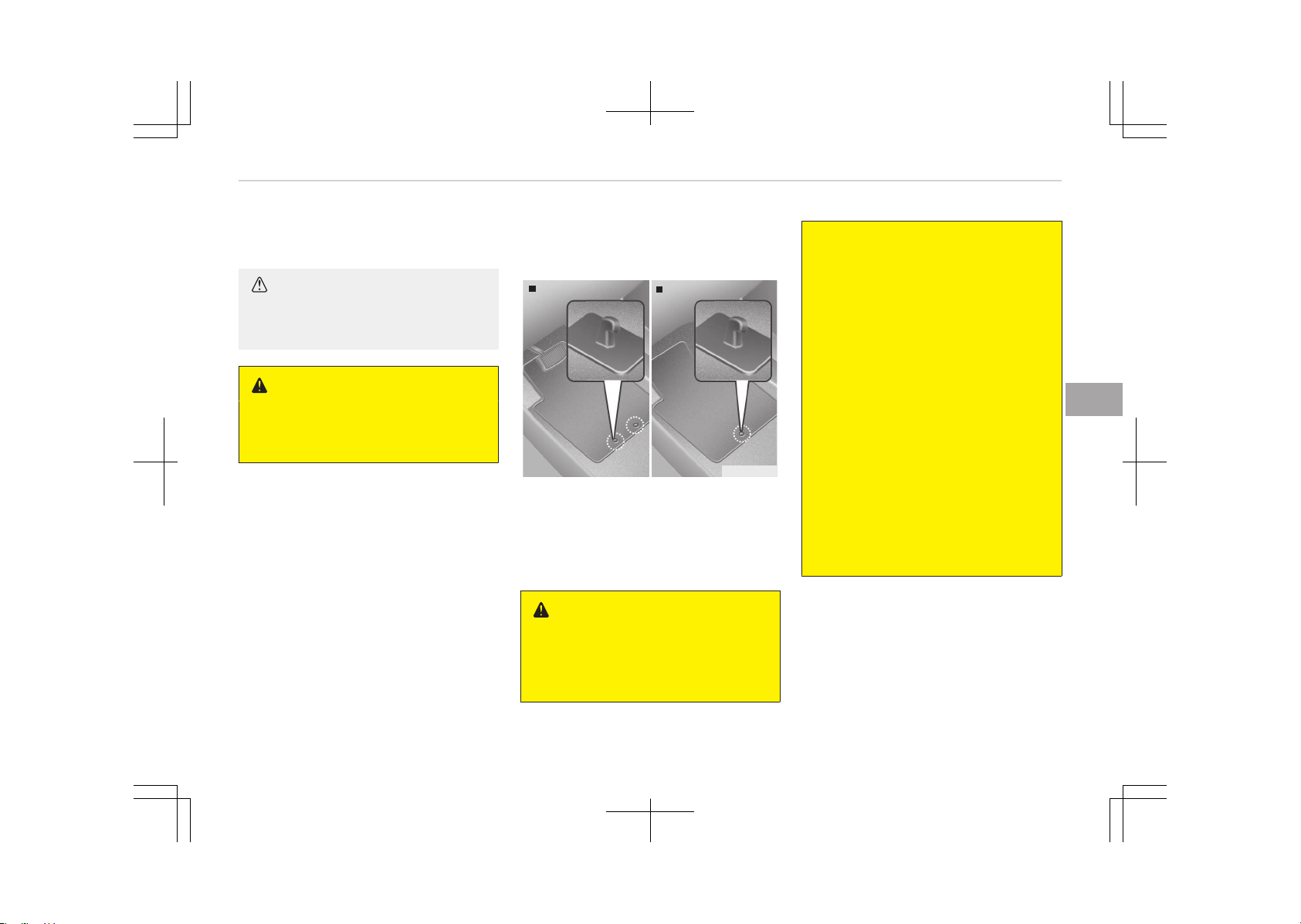
To use the hanger, pull down the upper
portion of hanger.
CAUTION
Do not hang heavy clothes, since
those may damage the hook.
WARNING
Do not hang other objects except
clothes. In an accident it may cause
vehicle damage or personal injury.
Floor mat anchor(s) (if
equipped)
Type B
Type A
OXM043309
When using a floor mat on the front
floor carpet, make sure it attaches to
the floor mat anchor(s) in your vehicle.
This keeps the floor mat from sliding
forward.
WARNING
The following must be observed
when installing ANY floor mat to the
vehicle.
(Continued)
(Continued)
• Ensure that the floor mats are se‐
curely attached to the vehicle's
floor mat anchor(s) before driving
the vehicle.
• Do not use ANY floor mat that
cannot be firmly attached to the
vehicle's floor mat anchors.
• Do not stack floor mats on top of
one another (e.g. all-weather rub‐
ber mat on top of a carpeted floor
mat). Only a single floor mat
should be installed in each position.
IMPORTANT - Your vehicle was man‐
ufactured with driver's side floor
mat anchors that are designed to
securely hold the floor mat in place.
To avoid any interference with pedal
operation, Kia recommends that the
Kia floor mat designed for use in
your vehicle be installed.
5-161
5
Features of your vehicle

Side curtain (if equipped)
OJF045304
To use the side curtain:
1. Lift the curtain by the hook (1).
2. Hang the curtain on both sides of
the hook.
Features of your vehicle
5-162
Audio system............................................................................. 6-02
Antenna.................................................................................. 6-02
êteering wheel audio controls ........................................... 6-03
Aux, UêB port.........................................................................6-04
How vehicle radio works...................................................... 6-04
Audio (Without Touch êcreen)................................................ 6-07
Feature of your audio...........................................................6-07
Audio (Without Touch êcreen)............................................ 6-10
Feature of your audio...........................................................6-11
Before using the audio system.......................................... 6-12
éadio mode (Type A-1, Type A-2 with éDê)....................6-22
éadio mode (Type A-3, Type A-4)..................................... 6-23
Media mode............................................................................6-24
çhone mode ..........................................................................6-29
Voice éecognition Mode ...................................................... 6-31
êetup mode (Type A-1, Type A-2).................................... 6-37
êetup Mode (Type A-3, Type A-4).....................................6-43
êetup Mode (Type A-3, Type A-4, For Colombia
Model)..................................................................................... 6-48
Audio (With Touch êcreen) (Only for hybrid vehicle)...........6-54
Feature of your audio...........................................................6-54
éadio Mode (Type B-1)........................................................ 6-66
éadio Mode (Type B-2)........................................................ 6-68
Media mode............................................................................6-69
çhone Mode........................................................................... 6-79
Bluetooth
®
Wireless Technology (Type B-1)................... 6-80
Bluetooth
®
Wireless Technology (Type B-2)................... 6-86
Bluetooth
®
Wireless Technology (Type B-2, For
Colombia model)....................................................................6-91
Voice éecognition Mode ...................................................... 6-97
êetup Mode Type B-1........................................................ 6-104
êetup Mode Type B-2........................................................ 6-110
êetup Mode (Type B-2, For Colombia model)................ 6-115
éear View Camera .............................................................6-119
Declaration of Conformity.....................................................6-121
FCC.........................................................................................6-121
CE for EU.............................................................................. 6-122
NCC for Taiwan....................................................................6-124
MOC for Israel......................................................................6-124
ANATEL for Brazil............................................................... 6-125
Audio system
6
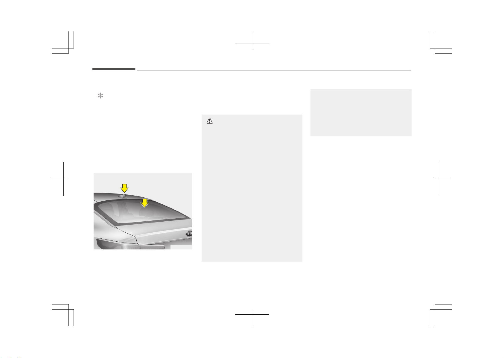
AUDIO SYSTEM
NOTICE
If you install an after market HID
head lamp, your vehicles audio and
electronic device may malfunction.
❈ If your vehicle is equipped with AVN
(Audio, Video and Navigation) sys‐
tem, refer to a separately supplied
manual for detailed information.
Antenna
OJF045126
Glass antenna
Your vehicle uses a glass antenna to re‐
ceive both AM and FM signals.
Shark fin antenna (if equipped)
The shark fin antenna will receive the
transmit data.
CAUTION
• Do not clean the inside of the rear
window glass or quarter glass with
a cleaner or use a scraper to re‐
move any foreign deposits as this
may cause damage to the antenna
elements.
• Avoid adding metallic coating such
as Ni, Cd, and so on. These can in‐
terfere with AM/FM reception.
• To prevent damage to the rear
glass antenna, never use sharp in‐
struments or window cleaner con‐
taining abrasives to clean the win‐
dow. Clean the inside surface of
the rear glass window with a piece
of soft cloth.
• When putting a sticker on the in‐
side surface of the rear window,
be careful not to damage to the
rear glass antenna.
(Continued)
(Continued)
• Do not put sharp instruments
nearby the rear glass antenna.
• Tinted rear window may affect
the proper functioning of the an‐
tenna.
Audio system
6-02
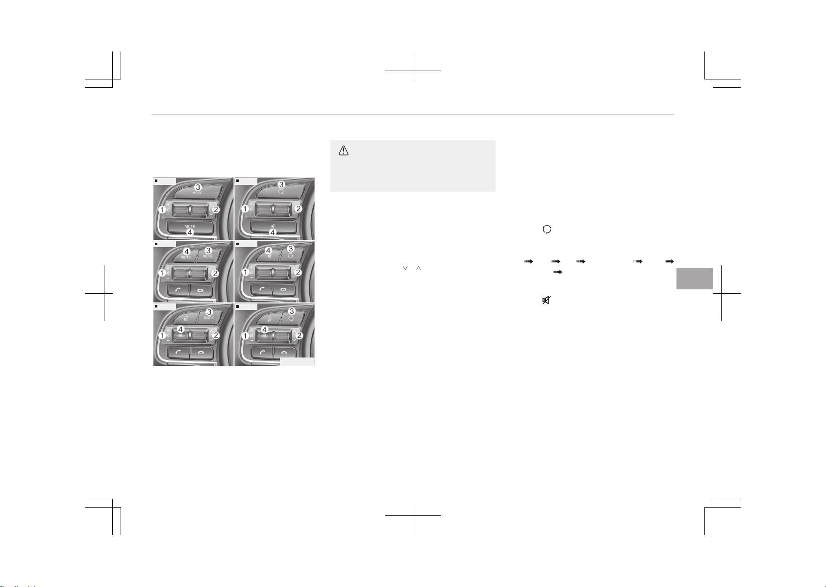
Steering wheel audio controls (if
equipped)
Type A
Type B
Type D
Type C
Type E
OJF045307L
Type F
The steering wheel may incorporate
audio control buttons.
CAUTION
Do not operate audio remote control
buttons simultaneously.
VOLUME (+/-) (1)
• çress the lever upward (+) to increase
the volume.
• çress the lever downward (-) to de‐
crease the volume.
SEEK/PRESET ( / ) (2)
The êEEK/çéEêET lever has different
functions based on the system mode.
For the following functions the lever
should be pressed for 0.8 seconds or
more.
éADIO mode
It will function as the AUTO êEEK select
button.
CD/UêB/içod
®
mode
It will function as the FF/éEW button.
If the êEEK/çéEêET button is pressed
for less than 0.8 seconds, it will work as
follows in each mode.
éADIO mode
It will function as the çéEêET êTATION
buttons.
CD/UêB/içod
®
mode
It will function as TéACK Uç/DOWN
button.
MODE ( ) (3)
çress the button to change audio
source.
FM AM CD UêB/içod
®
AUX
MY MUêIC Bluetooth
®
Wireless Tech‐
nology audio
MUTE ( ) (4)
• çress the button to mute the sound.
• çress the button to turn off the mi‐
crophone during a telephone call.
Detailed information for audio control
buttons are described in Audio control
buttons (without touch screen) on
page 6-07 and Audio control buttons
(with touch screen) on page 6-54.
6-03
6
Audio system
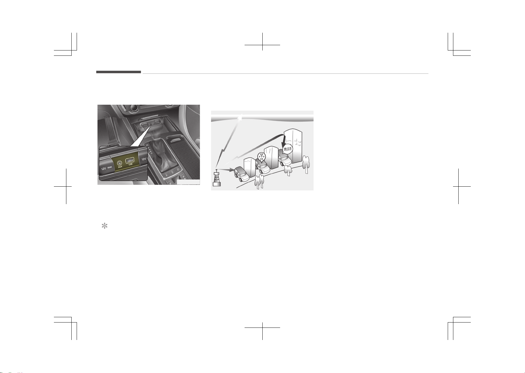
Aux, USB port
OJF045128
You can use an aux port to connect au‐
dio devices and an UêB port to plug in
an UêB or içod
®
.
NOTICE
When using a portable audio device
connected to the power outlet, noise
may occur during playback. If this
happens, use the power source of
the portable audio device.
❈
içod
®
is a trademark of Apple Inc.
How vehicle radio works
FM reception
OJF045308L
AM and FM radio signals are broadcast
from transmitter towers located
around your city. They are intercepted
by the radio antenna on your vehicle.
This signal is then received by the radio
and sent to your vehicle speakers.
When a strong radio signal has reached
your vehicle, the precise engineering of
your audio system ensures the best
possible quality reproduction. However,
in some cases the signal coming to your
vehicle may not be strong and clear.
This can be due to factors such as the
distance from the radio station, close‐
ness of other strong radio stations or
the presence of buildings, bridges or
other large obstructions in the area.
Audio system
6-04
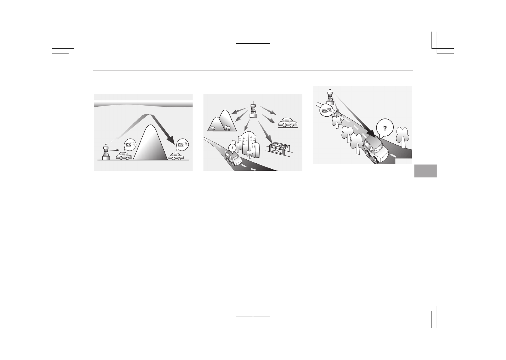
AM (MW, LW) reception
OJF045309L
AM broadcasts can be received at
greater distances than FM broadcasts.
This is because AM radio waves are
transmitted at low frequencies. These
long, low frequency radio waves can
follow the curvature of the earth rath‐
er than travelling straight out into the
atmosphere. In addition, they curve
around obstructions so that they can
provide better signal coverage.
FM radio station
OJF045310L
FM broadcasts are transmitted at high
frequencies and do not bend to follow
the earth's surface. Because of this, FM
broadcasts generally begin to fade at
short distances from the station. Also,
FM signals are easily affected by build‐
ings, mountains, or other obstructions.
These can result in certain listening
conditions which might lead you to be‐
lieve a problem exists with your radio.
The following conditions are normal and
do not indicate radio trouble:
JBM004
• Fading - As your vehicle moves away
from the radio station, the signal will
weaken and sound will begin to fade.
When this occurs, we suggest that
you select another stronger station.
• Flutter/êtatic - Weak FM signals or
large obstructions between the
transmitter and your radio can dis‐
turb the signal causing static or flut‐
tering noises to occur. éeducing the
treble level may lessen this effect un‐
til the disturbance clears.
6-05
6
Audio system
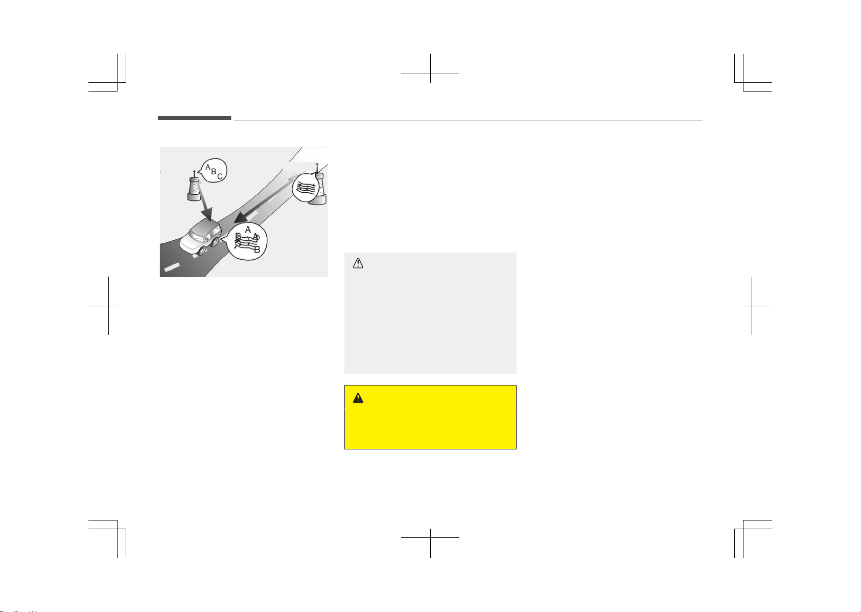
88.1Mhz
88.3Mhz
OJF045311L
• êtation êwapping - As a FM signal
weakens, another more powerful sig‐
nal near the same frequency may be‐
gin to play. This is because your radio
is designed to lock onto the clearest
signal. If this occurs, select another
station with a stronger signal.
• Multi-çath Cancellation - éadio sig‐
nals being received from several di‐
rections can cause distortion or flut‐
tering. This can be caused by a direct
and reflected signal from the same
station, or by signals from two sta‐
tions with close frequencies. If this
occurs, select another station until
the condition has passed.
Using a cellular phone or a two-
way radio
When a cellular phone is used inside the
vehicle, noise may be produced from
the audio system. This does not mean
that something is wrong with the audio
equipment. In such a case, use the cel‐
lular phone at a place as far as possible
from the audio equipment.
CAUTION
When using a communication sys‐
tem such as a cellular phone or a ra‐
dio set inside the vehicle, a separate
external antenna must be fitted.
When a cellular phone or a radio set
is used with an internal antenna
alone, it may interfere with the vehi‐
cle's electrical system and adversely
affect safe operation of the vehicle.
WARNING
Do not use a cellular phone while
driving. Stop at a safe location to use
a cellular phone.
Audio system
6-06
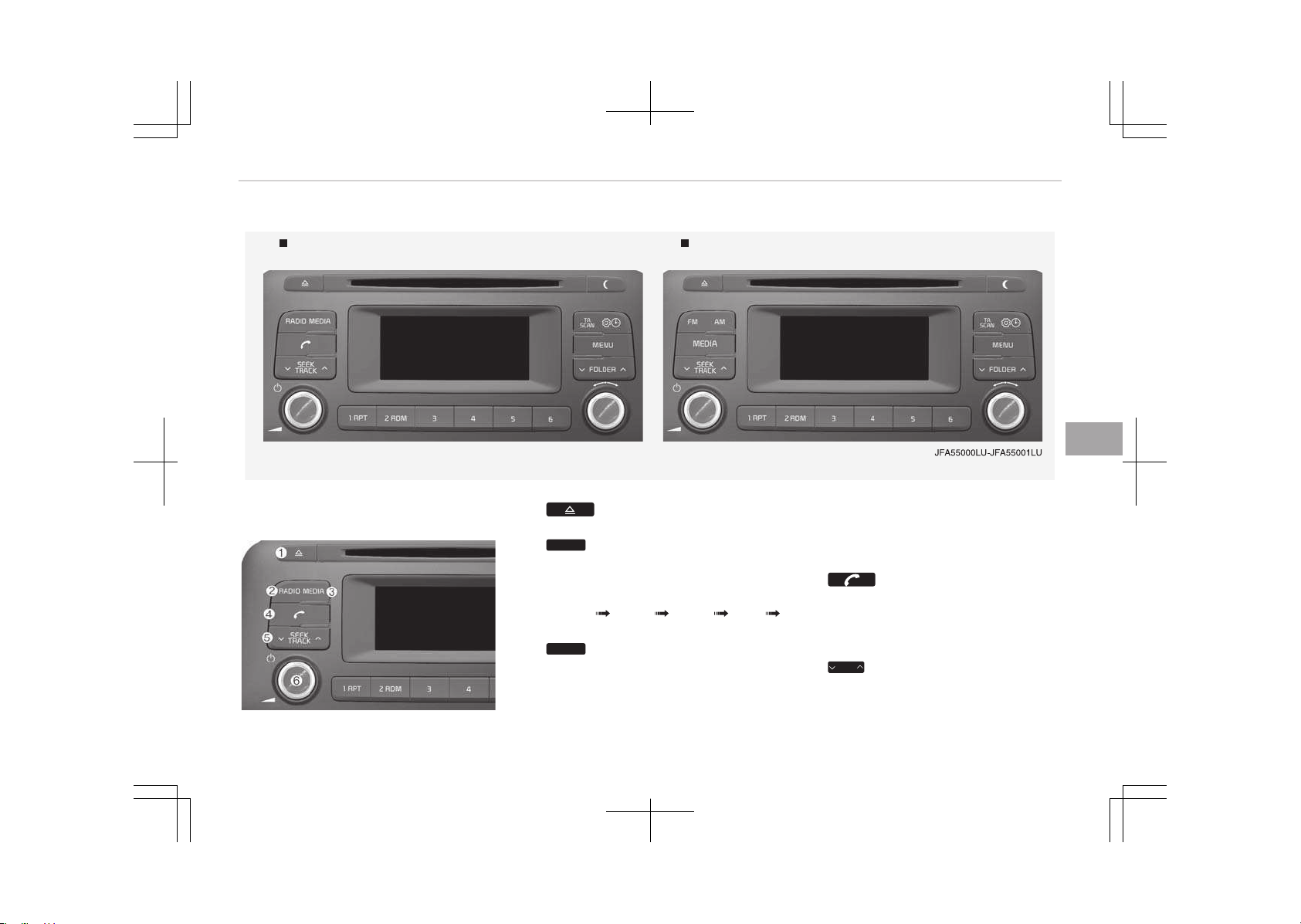
AUDIO (WITHOUT TOUCH SCREEN) (ONLY FOR HYBRID VEHICLE)
Type A-1 Type A-2
With Bluetooth
Ⓡ
Wireless Technology
Feature of your audio
1.
• Ejects the disc.
2.
RADIO
(Type A-1)
• Changes to FM/AM mode.
• Each time the button is pressed,
the mode is changed in order of
FM1 FM2 FMA AM
AMA.
3.
MEDIA
•
Changes to CD, UêB (içod
®
), AUX,
My Music
*
, BT Audio
*
mode.
*
if equipped
• Each time the button is pressed,
the mode is changed in order of
CD, UêB (içod
®
), AUX, My Music
*
,
BT Audio
*
.
4.
(Type A-1)
• Operates çhone êcreen.
• When a phone is not connected,
the connection screen is dis‐
played.
5.
SEEK
TRACK
*
if equipped
6-07
6
Audio system
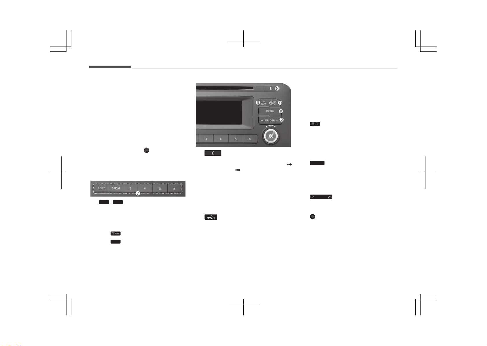
• éadio mode: Automatically
searches for broadcast frequen‐
cies.
•
CD, UêB, içod
®
, My Music
*
mode
- êhortly press the button:
Moves to next or previous
song (file).
- çress and hold the button: ée‐
winds or fast-forwards the
current song.
6. çOWEé/VOL knob
• çower knob: Turns power On/Off
by pressing the knob.
• Volume knob: êets volume by
turning the knob left/right.
7.
1
~
6
(çreset)
• éadio mode: êaves frequencies
(channels) or receives saved fre‐
quencies (channels).
•
CD, UêB, içod
®
, My Music
*
mode
- : éepeat
-
2
RDM
: éandom
In the éadio, Media, êetup, and
Menu pop up screen, the number
menu is selected.
*
if equipped
8.
• Each time the button is shortly
pressed, sets êcreen Off
êcreen On êcreen Off.
• Audio operation is maintained
and only the screen will be turned
Off.
• In the êcreen Off state, press any
button to turn the êcreen On
again.
9.
• éadio mode
- êhortly press the button: TA
On/Off.
- çress and hold the button:
çreviews each broadcast for 5
seconds each.
•
CD, UêB, My Music
*
mode
*
if equipped
- çress and hold the button:
çreviews each song (file) for
10 seconds each.
- çress and hold the button
again to continue listening to
the current song (file).
10.
• êhortly press the button: Moves
to the Display, êound, Clock,
çhone, êystem setting modes.
• çress and hold the button: Move
to the Time setting screen.
11.
MENU
• Displays menus for the current
mode.
•
içod
®
list: Move to parent cate‐
gory.
12.
FOLDER
• Mç3 CD / UêB mode: Folder
êearch.
13. TUNE knob
• éadio mode: Changes frequency
by turning the knob left/right.
•
CD, UêB, içod
®
, My Music
*
mode:
êearches songs (files) by turning
the knob left/right.
When the desired song is dis‐
played, press the knob to play
the song.
Audio system
6-08
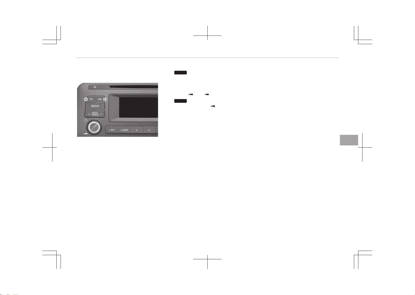
• Moves focus in all selection me‐
nus and selects menus.
*
if equipped
14.
FM
(Type A-2)
• Changes to FM mode.
• Each time the button is pressed,
the mode changed in order of
FM1 FM2 FMA.
15.
AM
(Type A-2)
• Changes to AM AMA mode.
6-09
6
Audio system
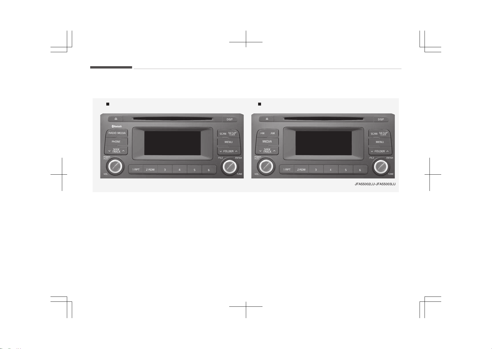
Audio (Without Touch Screen)
Type A-3 Type A-4
With Bluetooth
Ⓡ
Wireless Technology
Audio system
6-10
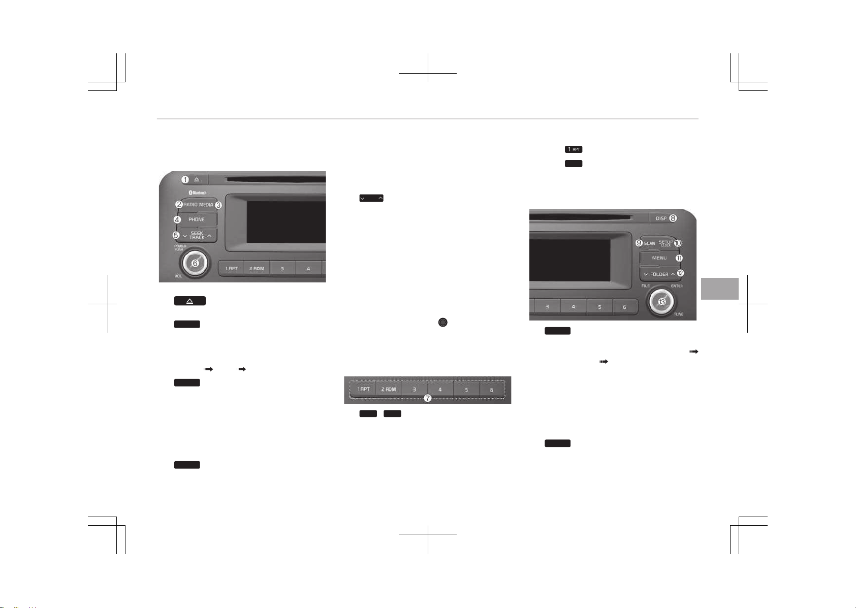
Feature of your audio
1.
• Ejects the disc.
2.
RADIO
(Type A-3)
• Changes to FM/AM mode.
• Each time the button is pressed,
the mode is changed in order of
FM1
FM2 AM.
3.
MEDIA
•
Changes to CD, UêB (içod
®
), AUX,
My Music
*
, BT Audio
*
mode.
• Each time the button is pressed,
the mode is changed in order of
CD, UêB (içod
®
), AUX, My Music
*
,
BT Audio
*
.
4.
PHONE
(Type A-3)
• Operates çhone êcreen.
• When a phone is not connected,
the connection screen is dis‐
played.
5.
SEEK
TRACK
• éadio mode: Automatically
searches for broadcast frequen‐
cies.
•
CD, UêB, içod
®
, My Music
*
mode
- êhortly press the button:
Moves to next or previous
song (file).
- çress and hold the button: ée‐
winds or fast-forwards the
current song.
6. çOWEé/VOL knob
• çower knob: Turns power On/Off
by pressing the knob.
• Volume knob: êets volume by
turning the knob left/right.
7.
1
~
6
(çreset)
• éadio mode: êaves frequencies
(channels) or receives saved fre‐
quencies (channels).
•
CD, UêB, içod
®
, My Music
*
mode
*
if equipped
-
: éepeat
-
2
RDM
: éandom
In the éadio, Media, êetup, and
Menu pop up screen, the number
menu is selected.
8.
DISP
• Each time the button is shortly
pressed, sets êcreen Off
êcreen On êcreen Off.
• Audio operation is maintained
and only the screen will be turned
Off.
• In the êcreen Off state, press any
button to turn the êcreen On
again.
9.
SCAN
• éadio mode
6-11
6
Audio system
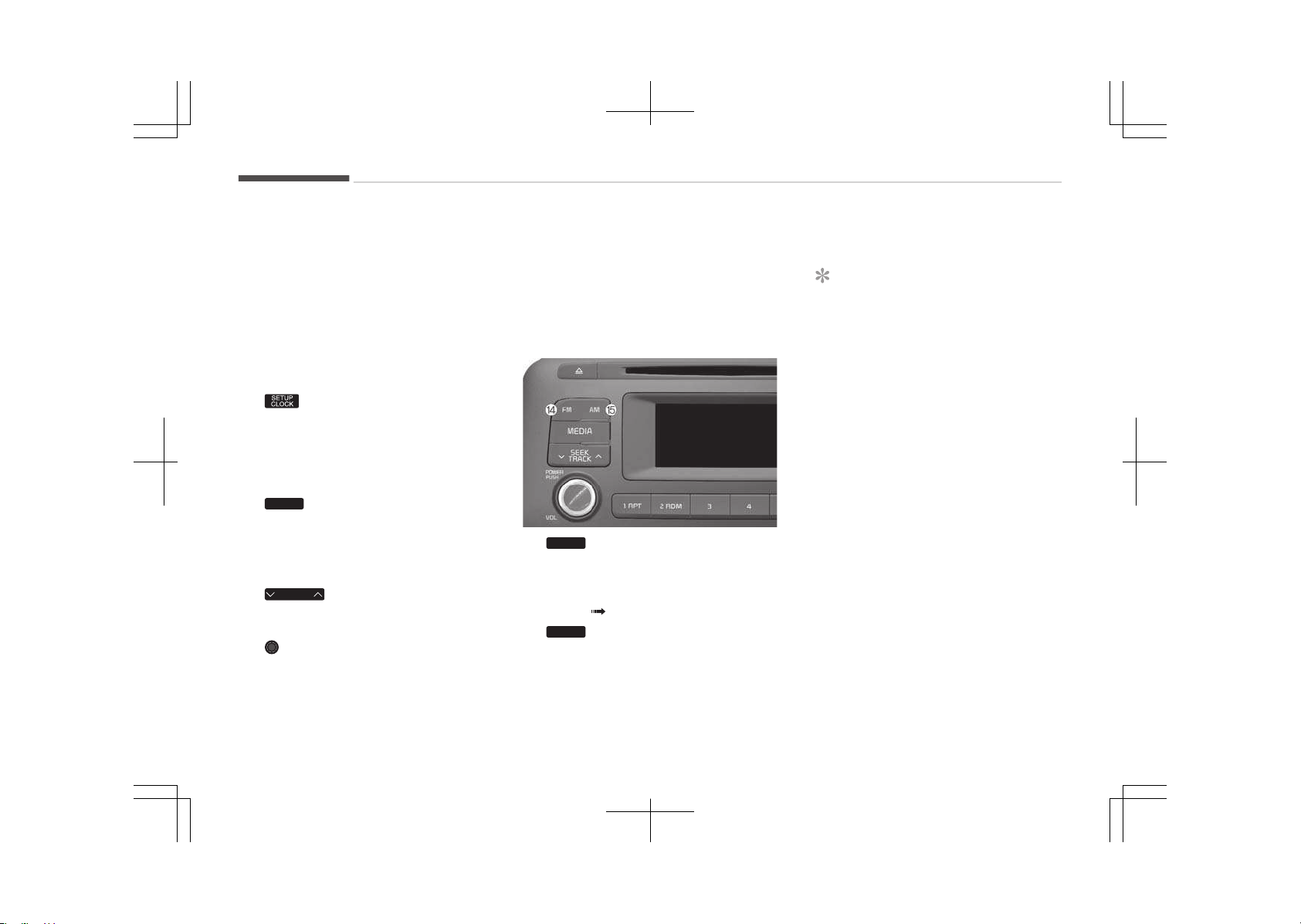
- çress the button: çreviews
each broadcast for 5 seconds
each.
•
CD, UêB, My Music
*
mode
- çress the button: çreviews
each song (file) for 10 seconds
each.
- çress the button again to con‐
tinue listening to the current
song (file).
10.
• êhortly press the button: Moves
to the Display, êound, Clock,
çhone, êystem setting modes.
• çress and hold the button: Move
to the Time setting screen.
11.
MENU
• Displays menus for the current
mode.
•
içod
®
List: Move to parent cate‐
gory.
12.
FOLDER
• Mç3 CD / UêB mode: Folder
êearch.
13. TUNE knob
• éadio mode: Changes frequency
by turning the knob left/right.
*
if equipped
•
CD, UêB, içod
®
, My Music
*
mode:
êearches songs (files) by turning
the knob left/right.
When the desired song is dis‐
played, press the knob to play
the song.
• Moves focus in all selection me‐
nus and selects menus.
14.
FM
(Type A-4)
• Changes to FM mode.
• Each time the button is pressed,
the mode changed in order of
FM1 FM2.
15.
AM
(Type A-4)
• Changes to AM mode.
*
if equipped
Before using the audio system
NOTICE
n
Using the Discs
• If the temperature inside the car is
too high, open the car windows to
ventilate before using the system.
• It is illegal to copy and use
Mç3/WMA files without permis‐
sion. Use CDs that are created only
by lawful means.
• Do not apply volatile agents, such
as benzene and thinner, normal
cleaners and magnetic sprays
made for analogue disc onto CDs.
• To prevent the disc surface from
getting damaged, hold CDs by the
edges or the center hole only.
• Clean the disc surface with a piece
of soft cloth before playback (wipe
it from the center to the outside
edge).
(Continued)
Audio system
6-12
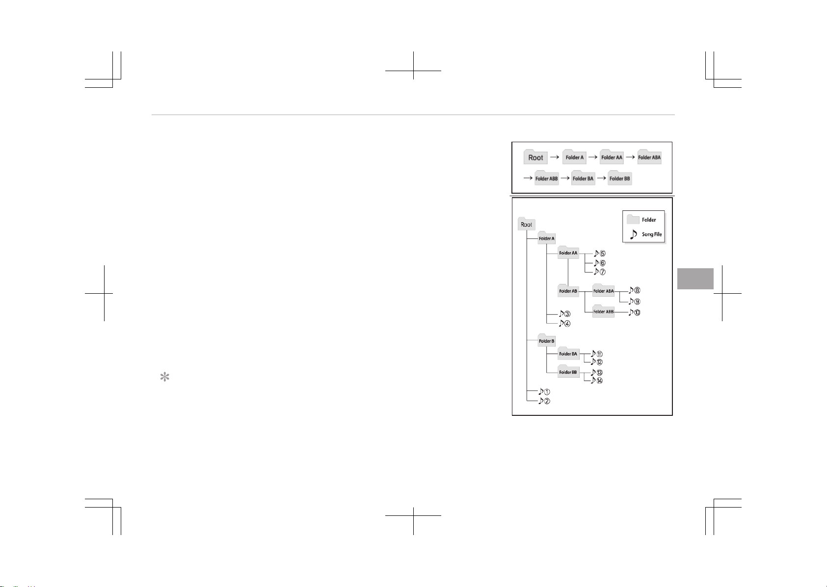
(Continued)
• Do not damage the disc surface or
attach pieces of sticky tape or pa‐
per.
• Make certain only CDs are inserted
into the CD player (Do not insert
more than one CD at a time).
• Keep CDs in their cases after use
to protect them from scratches or
dirt.
• Depending on the type of CDé/
CD-éW CDs, certain CDs may not
operate normally according to
manufacturing companies or mak‐
ing and recording methods. In such
circumstances, continued use may
cause malfunctions to your audio
system.
NOTICE
n
çlaying an Incompatible Copy
çrotected Audio CD
(Continued)
(Continued)
êome copy protected CDs, which do
not comply with international audio
CD standards (éed Book), may not
play on your car audio. çlease note
that inabilities to properly play a
copy protected CD may indicate that
the CD is defective, not the CD play‐
er.
❈ NOTE:
Order of playing files (folders):
1. êong playing order: 1 to 14 se‐
quentially.
2. Folder playing order:
❈ If no song file is contained in the
folder, that folder is not displayed.
6-13
6
Audio system
WARNING
• Do not stare at the screen while
driving. Staring at the screen for
prolonged periods of time could
lead to traffic accidents.
• Do not disassemble, assemble, or
modify the audio system. Such
acts could result in accidents, fire,
or electric shock.
• Using the phone while driving may
lead to a lack of attention of traf‐
fic conditions and increase the
likelihood of accidents. Use the
phone feature after parking the
vehicle.
• Heed caution not to spill water or
introduce foreign objects into the
device. Such acts could lead to
smoke, fire, or product malfunc‐
tion.
• Please refrain from use if the
screen is blank or no sound can be
heard as these signs may indicate
product malfunction. Continued
use in such conditions could lead to
accidents (fires, electric shock) or
product malfunctions.
(Continued)
(Continued)
• Do not touch the antenna during
thunder or lightening as such acts
may lead to lightning induced elec‐
tric shock.
• Do not stop or park in parking-re‐
stricted areas to operate the prod‐
uct. Such acts could lead to traffic
accidents.
• Use the system with the vehicle
ignition turned on. Prolonged use
with the ignition turned off could
result in battery discharge.
WARNING
Driving while distracted can result in
a loss of vehicle control that may
lead to an accident, severe personal
injury, and death. The driver’s pri‐
mary responsibility is in the safe and
legal operation of a vehicle, and use
of any handheld devices, other
equipment, or vehicle systems which
take the driver’s eyes, attention and
focus away from the safe operation
of a vehicle or which are not permis‐
(Continued)
(Continued)
sible by law should never be used
during operation of the vehicle.
CAUTION
• Operating the device while driving
could lead to accidents due to a
lack of attention to external sur‐
roundings. First park the vehicle
before operating the device.
• Adjust the volume to levels that al‐
low the driver to hear sounds from
outside of the vehicle. Driving in a
state where external sounds can‐
not be heard may lead to acci‐
dents.
• Pay attention to the volume set‐
ting when turning the device on. A
sudden output of extreme volume
upon turning the device on could
lead to hearing impairment. (Ad‐
just the volume to a suitable levels
before turning off the device.)
(Continued)
Audio system
6-14

(Continued)
• If you want to change the position
of device installation, please in‐
quire with your place of purchase
or service maintenance center.
Technical expertise is required to
install or disassemble the device.
• Turn on the car ignition before us‐
ing this device. Do not operate the
audio system for long periods of
time with the ignition turned off
as such operations may lead to
battery discharge.
• Do not subject the device to severe
shock or impact. Direct pressure
onto the front side of the monitor
may cause damage to the LCD or
touch screen.
• When cleaning the device, make
sure to turn off the device and use
a dry and smooth cloth. Never use
tough materials, chemical cloths,
or solvents (alcohol, benzene, thin‐
ners, etc.) as such materials may
damage the device panel or cause
color/quality deterioration.
(Continued)
(Continued)
• Do not place beverages close to
the audio system. Spilling beverag‐
es may lead to system malfunc‐
tion.
• In case of product malfunction,
please contact your place of pur‐
chase or After Service center.
• Placing the audio system within an
electromagnetic environment may
result in noise interference.
NOTICE
n
Using the UêB device
• To use an external UêB device,
make sure the device is not con‐
nected when starting up the vehi‐
cle. Connect the device after start‐
ing up.
• If you start the engine when the
UêB device is connected, it may
damage the UêB device. (UêB
flashdrives are very sensitive to
electric shock.)
(Continued)
(Continued)
• If the engine is started up or
turned off while the external UêB
device is connected, the external
UêB device may not work.
• The êystem may not play inau‐
thentic Mç3 or WMA files.
1. It can only play Mç3 files with
the compression rate between
8Kbps ~ 320Kbps.
2. It can only play WMA music files
with the compression rate be‐
tween 8Kbps ~ 320Kbps.
• Take precautions for static elec‐
tricity when connecting or discon‐
necting the external UêB device.
• An encrypted Mç3 çLAYEé is not
recognizable.
• Depending on the condition of the
external UêB device, the connec‐
ted external UêB device can be un‐
recognizable.
(Continued)
6-15
6
Audio system

(Continued)
• When the formatted byte/sector
setting of External UêB device is
not either 512BYTE or 2048BYTE,
then the device will not be recog‐
nized.
• Use only a UêB device formatted
to FAT 12/16/32.
• UêB devices without UêB I/F au‐
thentication may not be recogniz‐
able.
• Make sure the UêB connection ter‐
minal does not come in contact
with the human body or other ob‐
jects.
• If you repeatedly connect or dis‐
connect the UêB device in a short
period of time, it may break the
device.
• You may hear a strange noise
when connecting or disconnecting
a UêB device.
(Continued)
(Continued)
• If you disconnect the external UêB
device during playback in UêB
mode, the external UêB device can
be damaged or may malfunction.
Therefore, disconnect the external
UêB device when the audio is
turned off or in another mode.
(e.g, éadio, CD)
• Depending on the type and capaci‐
ty of the external UêB device or
the type of the files stored in the
device, there is a difference in the
time taken for recognition of the
device.
• Do not use the UêB device for pur‐
poses other than playing music
files.
• çlaying videos through the UêB is
not supported.
• Use of UêB accessories such as re‐
chargers or heaters using UêB I/F
may lower performance or cause
trouble.
(Continued)
(Continued)
• If you use devices such as a UêB
hub purchased separately, the ve‐
hicles audio system may not rec‐
ognize the UêB device. In that
case, connect the UêB device di‐
rectly to the multimedia terminal
of the vehicle.
• If the UêB device is divided by logi‐
cal drives, only the music files on
the highest-priority drive are rec‐
ognized by car audio.
• Devices such as Mç3 çlayer/Cellu‐
lar phone/Digital camera can be
unrecognizable by standard UêB
I/F can be unrecognizable.
• Charging through the UêB may not
be supported in some mobile devi‐
ces.
• UêB HDD or UêB types liable to
connection failures due to vehicle
vibrations are not supported. (i-
stick type)
(Continued)
Audio system
6-16

(Continued)
• êome non-standard UêB devices
(METAL COVEé TYçE UêB) can be
unrecognizable.
• êome UêB flash memory readers
(such as CF, êD, micro êD, etc.) or
external-HDD type devices can be
unrecognizable.
• Music files protected by DéM (DIG‐
ITAL éIGHTê MANAGEMENT) are
not recognizable.
• The data in the UêB memory may
be lost while using this audio. Al‐
ways back up important data on a
personal storage device.
•
çlease avoid using UêB
memory products
which can be used as
key chains or cellular
phone accessories as
they could cause dam‐
age to the UêB jack.
çlease make certain only to use
plug type connector products.
NOTICE
n
Using the içod
®
device
•
êome içod
®
models may not sup‐
port communication protocol and
files may not properly play.
êupported içod
®
models:
-
içhone
®
3Gê/4
-
içod touch
®
1st~4th generation
-
içod nano
®
1st~6th generation
-
içod classic
®
• The order of search or playback of
songs in the içod
®
can be different
from the order searched in the au‐
dio system.
•
If the içod
®
disabled due to its
own malfunction, reset the içod
®
.
(éeset: éefer to içod
®
manual)
•
An içod
®
may not operate normal‐
ly on low battery.
(Continued)
(Continued)
•
êome içod
®
devices, such as the
içhone
®
, can be connected
through the Bluetooth
®
Wireless
Technology interface. The device
must have audio Bluetooth
®
Wire‐
less Technology capability (such as
for stereo headphone Bluetooth
®
Wireless Technology). The device
can play, but it will not be control‐
led by the audio system.
•
To use içod
®
features within the
audio, use the cable provided upon
purchasing an içod
®
device.
• êkipping or improper operation
may occur depending on the char‐
acteristics of your içod
®
/içhone
®
device.
(Continued)
6-17
6
Audio system

(Continued)
•
If your içhone
®
is connected to
both the Bluetooth
®
Wireless
Technology and UêB, the sound
may not be properly played. In
your içhone
®
, select the Dock con‐
nector or Bluetooth
®
Wireless
Technology to change the sound
output (source).
•
When connecting içod
®
with the
içod
®
çower Cable, insert the con‐
nector to the multimedia socket
completely. If not inserted com‐
pletely, communications between
içod
®
and audio may be interrup‐
ted.
• When adjusting the sound effects
of the içod
®
and the audio sys‐
tem, the sound effects of both de‐
vices will overlap and might reduce
or distort the quality of the sound.
(Continued)
(Continued)
• Deactivate (turn off) the equalizer
function of an içod
®
when adjust‐
ing the audio systems volume,
and turn off the equalizer of the
audio system when using the
equalizer of an içod
®
.
•
When not using içod
®
with car au‐
dio, detach the içod
®
cable from
içod
®
. Otherwise, içod
®
may re‐
main in accessory mode, and may
not work properly.
• Beside support 1M cable when
purchasing içod
®
/içhone
®
prod‐
ucts, Long Cable cannot be recog‐
nized.
NOTICE
n
Using the Bluetooth
®
Wireless
Technology Cellular çhone
(Continued)
(Continued)
•
Bluetooth
®
Wireless Technology
Handsfree refers to a device which
allows the user to conveniently
make phone calls with Bluetooth
®
Wireless Technology mobile
phones through the audio system.
•
Bluetooth
®
Wireless Technology
allows devices to be connected in a
short distance, including handsfree
devices, stereo headsets, wireless
remote controllers, etc. For more
information, visit the Bluetooth
®
Wireless Technology website at
www.bluetooth.com before using
Bluetooth
®
Wireless Technology
audio features.
(Continued)
Audio system
6-18

(Continued)
•
The Bluetooth
®
word mark and
logos are registered trademarks
owned by Bluetooth
®
êIG, Inc. and
any use of such marks by Kia is
under license. Other trademarks
and trade names are those of
their respective owners. A Blue‐
tooth
®
enabled cell phone is re‐
quired to use Bluetooth
®
Wireless
Technology.
•
Bluetooth
®
Wireless Technology
features supported within the ve‐
hicle are as follows. êome features
may not be supported depending
on your Bluetooth
®
Wireless Tech‐
nology device.
- Answering and placing Blue‐
tooth
®
Wireless Technology
Handsfree calls
- Menu operation during call
(êwitch to çrivate, êwitch to call
waiting, Outgoing volume)
- Download Call History
- Download Mobile çhone book
(Continued)
(Continued)
- çhone book/Call History Auto
Download
-
Bluetooth
®
Wireless Technology
device auto connection
-
Bluetooth
®
Wireless Technology
Audio
•
Before using Bluetooth
®
Wireless
Technology related features of the
audio system, refer your phones
Users Manual for phone-side
Bluetooth
®
Wireless Technology
operations.
• The phone must be paired to the
audio system to use Bluetooth
®
Wireless Technology related fea‐
tures.
(Continued)
(Continued)
• çairing and connecting a Blue‐
tooth
®
Wireless Technology ena‐
bled mobile phone will work only
when the Bluetooth
®
Wireless
Technology option within your mo‐
bile phone has been turned on.
(Methods of turning on the Blue‐
tooth
®
Wireless Technology ena‐
bled feature may differ depending
on the mobile phone.)
• Do not use a cellular phone or per‐
form Bluetooth
®
Wireless Technol‐
ogy settings (e.g. pairing a phone)
while driving.
(Continued)
6-19
6
Audio system

(Continued)
• Even if the phone supports Blue‐
tooth
®
Wireless Technology, the
phone will not be found during de‐
vice searches if the phone has
been set to hidden state or the
Bluetooth
®
Wireless Technology
power is turned off. Disable the
hidden state or turn on the Blue‐
tooth
®
Wireless Technology power
prior to searching/connecting with
the car audio system.
• You will not be able to use the
hands-free feature when your
phone (in the car) is outside of the
cellular service area (e.g. in a tun‐
nel, in a underground, in a moun‐
tainous area, etc.).
• If the cellular phone signal is poor
or the vehicles interior noise is too
loud, it may be difficult to hear the
other persons voice during a call.
(Continued)
(Continued)
• Do not place the phone near or in‐
side metallic objects, otherwise
communications with Bluetooth
®
Wireless Technology system or
cellular service stations can be dis‐
turbed.
• çlacing the audio system within an
electromagnetic environment may
result in noise interference.
• êome cellular phones or other de‐
vices may cause interference
noise or malfunction to audio sys‐
tem. In this case, store the device
in a different location may resolve
the condition.
• While a phone is connected
through Bluetooth
®
Wireless Tech‐
nology your phone may discharge
quicker than usual for additional
Bluetooth
®
Wireless Technology-
related operations.
• If çriority is set upon vehicle igni‐
tion (IGN/ACC ON), the Bluetooth
®
Wireless Technology phone will be
(Continued)
(Continued)
automatically connected. Even if
you are outside, the Bluetooth
®
Wireless Technology phone will be
automatically connected once you
are in the vicinity of the vehicle. If
you do not want to automatically
connect your Bluetooth
®
Wireless
Technology phone, try the follow‐
ing.
1.
Turn off the Bluetooth
®
Wire‐
less Technology feature in your
mobile phone.
2.
Turn off the Bluetooth
®
Wire‐
less Technology feature in your
car audio system.
-
To turn off the Bluetooth
®
Wireless Technology feature in
your car audio system, go to
[êETUç] > [çhone] and [turn
off] the Bluetooth
®
Wireless
Technology feature.
•
Bluetooth
®
Wireless Technology
connection may become intermit‐
tently disconnected in some mo‐
(Continued)
Audio system
6-20

(Continued)
bile phones. Follow these steps to
try again.
1.
Turn the Bluetooth
®
Wireless
Technology function within the
mobile phone off/on and try
again.
2. Turn the mobile phone power
Off/On and try again.
3. Completely remove the mobile
phone battery, reboot, and then
again.
4. éeboot the audio system and
try again.
5. Delete all paired devices, pair
and try again.
• It is possible to pair up to five
Bluetooth
®
Wireless Technology
devices to the car system.
• çhone contact names should be
saved in English or they may not
be displayed correctly.
• The Handsfree call volume and
quality may differ depending on
the mobile phone.
(Continued)
(Continued)
•
Only one Bluetooth
®
Wireless
Technology device can be connec‐
ted at a time.
• In some mobile phones, starting
the ignition while talking through
Bluetooth
®
Wireless Technology
enabled handsfree call will result in
the call becoming disconnected.
(êwitch the call back to your mo‐
bile phone when starting the igni‐
tion.)
• If the mobile phone is not paired or
connected, it is not possible to en‐
ter çhone mode. Once a phone is
paired or connected, the guidance
screen will be displayed.
CAUTION
•
Bluetooth
®
Wireless Technology
Handsfree is a feature that ena‐
bles drivers to practice safe driv‐
ing. Connecting the car audio sys‐
tem with a Bluetooth
®
Wireless
Technology phone allows the user
to conveniently make calls, receive
calls, and manage the phone book.
Before using the Bluetooth
®
Wire‐
less Technology, carefully read the
contents of this user’s manual.
• Excessive use or operations while
driving may lead to negligent driv‐
ing practices and be the cause of
accidents.
• Do not operate the device exces‐
sively while driving.
• Viewing the screen for prolonged
periods of time is dangerous and
may lead to accidents.
• When driving, view the screen only
for short periods of time.
6-21
6
Audio system
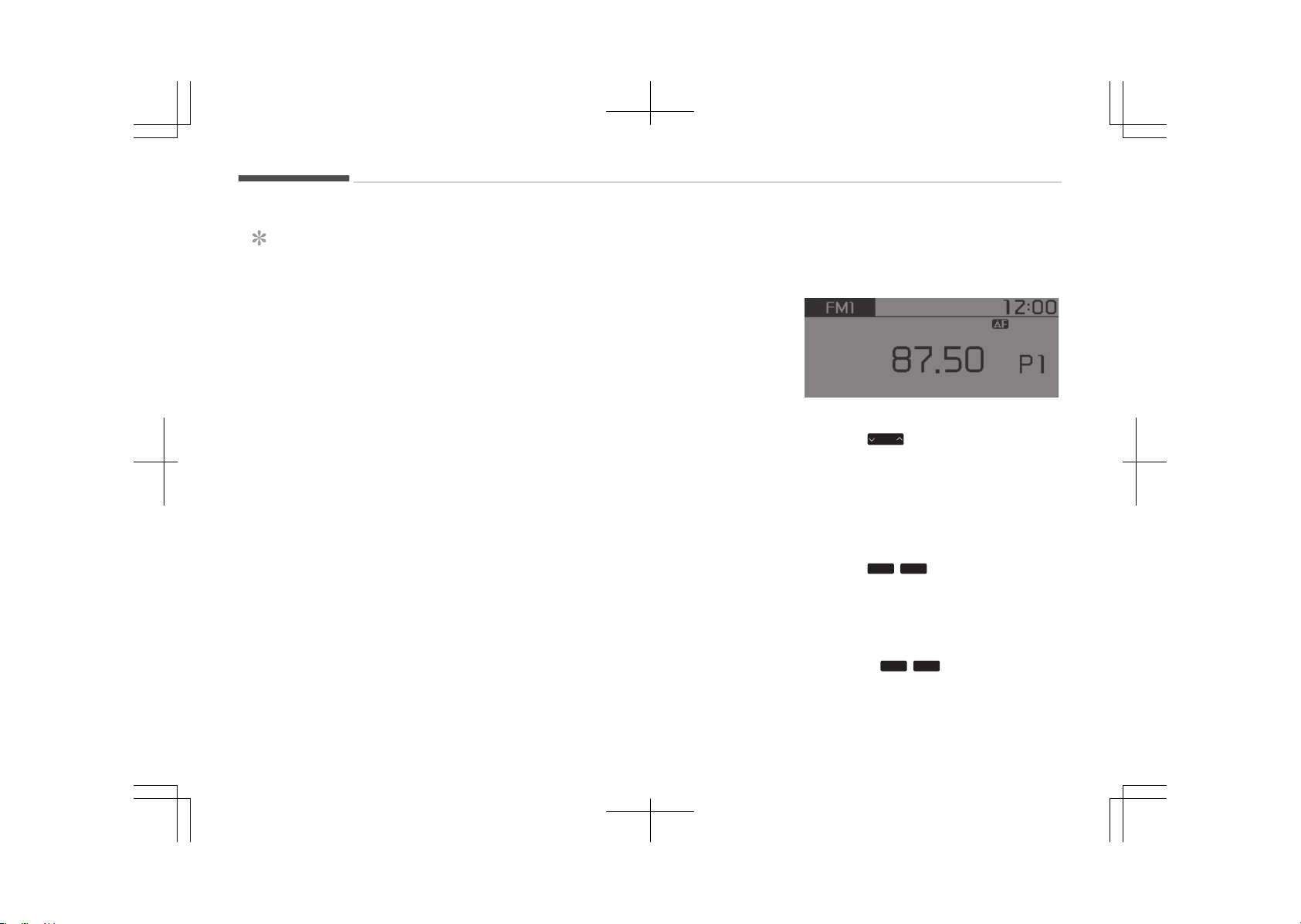
NOTICE
n
Using the Voice éecognition
• The voice recognition feature of
this product supports recognition
of the commands listed within this
users manual.
• While using voice recognition, op‐
erating the steering wheel con‐
trols or the device will terminate
voice recognition and allow you to
manually operate desired func‐
tions.
• çosition the microphone above the
head of the drivers seat. For su‐
perior performance, maintain good
posture when saying voice com‐
mands.
• Voice recognition may not function
properly due to outside noise. The
following conditions can affect the
performance of Voice éecognition:
- When the windows and sunroof
are open
(Continued)
(Continued)
- When the heating/cooling sys‐
tem is on
- When passing a tunnel
- When driving on rugged and un‐
even roads
•
After downloading Bluetooth
®
Wireless Technology phone book,
the system requires some times
to convert the phone book into
voice information. During this
time, voice recognition may not
operate properly.
• Upon inputting your phone book,
special symbols and numbers can‐
not be recognized by voice. For ex‐
ample, # John Doe%& will be rec‐
ognized as John Doe.
Radio mode (Type A-1, Type
A-2 with RDS)
With the radio mode button
êEEK
çress the
SEEK
TRACK
button.
• êhortly pressing the button: Changes
the frequency.
• çressing and holding the button: Au‐
tomatically searches for the next fre‐
quency.
çreset êEEK
çress the
1
~
6
button.
• êhortly pressing the button: çlays
the frequency saved in the corre‐
sponding button.
• çressing and holding the button:
çressing and holding the desired but‐
ton from
1
~
6
will save the cur‐
rently playing broadcast to the selec‐
ted button and sound a BEEç.
Audio system
6-22
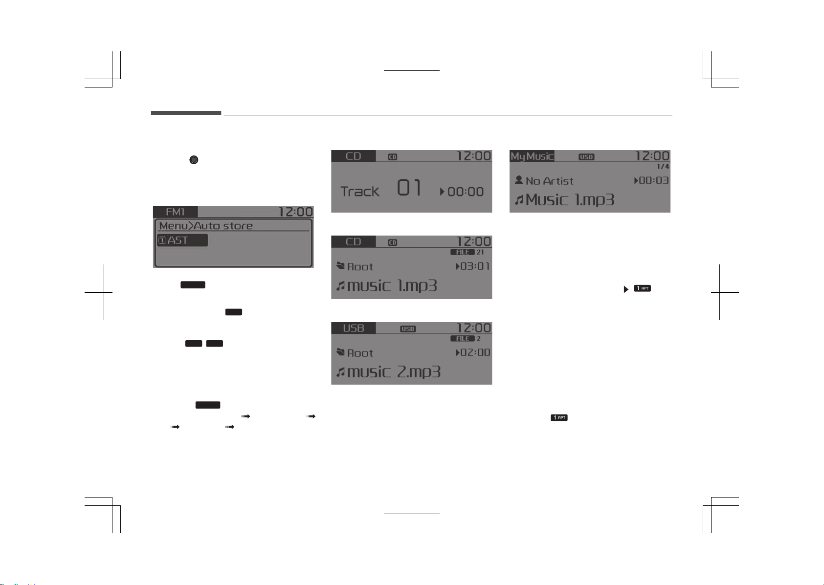
êelecting through manual search
Turn the
TUNE knob left/right to ad‐
just the frequency.
MENU: Radio
Within
MENU
button are the AêT (Auto
êtore) and Info functions.
AêT (Auto êtore):
1
Button
êelect AêT(Auto êtore) to save fre‐
quencies with superior reception to
presets
1
~
6
. If no frequencies are
received, then the most recently re‐
ceived frequency will be broadcast.
Media mode
With the media mode button
çress the
MEDIA
button to change the
mode in order of CD UêB (içod
®
)
AUX My Music
*
BT Audio
*
.
The folder/file name is displayed on the
screen.
*
if equipped
• Audio CD mode
• Mç3 CD mode
• UêB mode
• My Music mode
The CD is automatically played when a
CD is inserted.
The UêB music is automatically played
when a UêB is connected.
éepeat
While song (file) is playing
but‐
ton
Audio CD, Mç3 CD, UêB, içod
®
, My Mu‐
sic
*
mode: éçT on screen
• To repeat one song (êhortly pressing
the button): éepeats the current
song.
Mç3 CD, UêB mode: FLD.éçT on screen
• To repeat folder (pressing twice): re‐
peats all files within the current fold‐
er.
çress the button again to turn off
repeat.
*
if equipped
Audio system
6-24
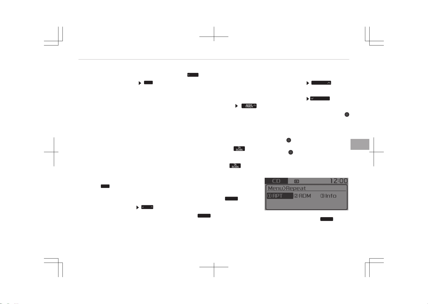
éandom
While song (file) is playing
2
RDM
but‐
ton
Audio CD, My Music
*
mode: éDM on
screen
• éandom (êhortly pressing the but‐
ton): çlays all songs in random order.
Mç3 CD, UêB mode: FLD.éDM on screen
• Folder éandom (êhortly pressing the
button): çlays all files within the cur‐
rent folder in random order.
Mç3 CD, UêB mode: ALL éDM on screen
• éandom (pressing twice): çlays all
files in random order.
içod
®
mode: éDM on screen
• éandom (êhortly pressing the but‐
ton): çlays all files in random order.
çress the
2
RDM
button again to turn off
random.
Changing êong/File
While song (file) is playing
SEEK
TRACK
but‐
ton
• êhortly pressing the button: çlays
the current song from the beginning.
*
if equipped
If the
SEEK
TRACK
button is pressed again
within 1 second, the previous song is
played.
• çressing and holding the button: ée‐
winds the song.
While song (file) is playing
button
• êhortly pressing the button: çlays
the next song.
• çressing and holding the button: Fast
forwards the song.
êcan (With éDê)
• çressing and holding the
but‐
ton: êcans all songs for 10 seconds
starting from the next song.
• çressing and holding the button
again to turn off.
• The êCAN function is not supported
in içod
®
mode.
êcan (Without éDê)
• êhortly pressing the
SCAN
button:
êcans all songs from the next song
for 10 seconds each.
• çress the
SCAN
button again to turn
off.
• The êCAN function is not supported
in içod
®
mode.
Folder êearch (Only Mç3 CD, UêB mode)
While file is playing
FOLDER
button
• êearches the next folder.
While file is playing
FOLDER
button
• êearches the parent folder.
If a folder is selected by pressing the
TUNE knob, the first file within the se‐
lected folder will be played.
êearching êongs (File)
• Turning
TUNE knob: êearches for
songs (files).
• çressing TUNE knob: çlays selec‐
ted song (file).
MENU : Audio CD
çress the Audio CD mode
MENU
button
to set the éepeat, éandom, Informa‐
tion features.
6-25
6
Audio system
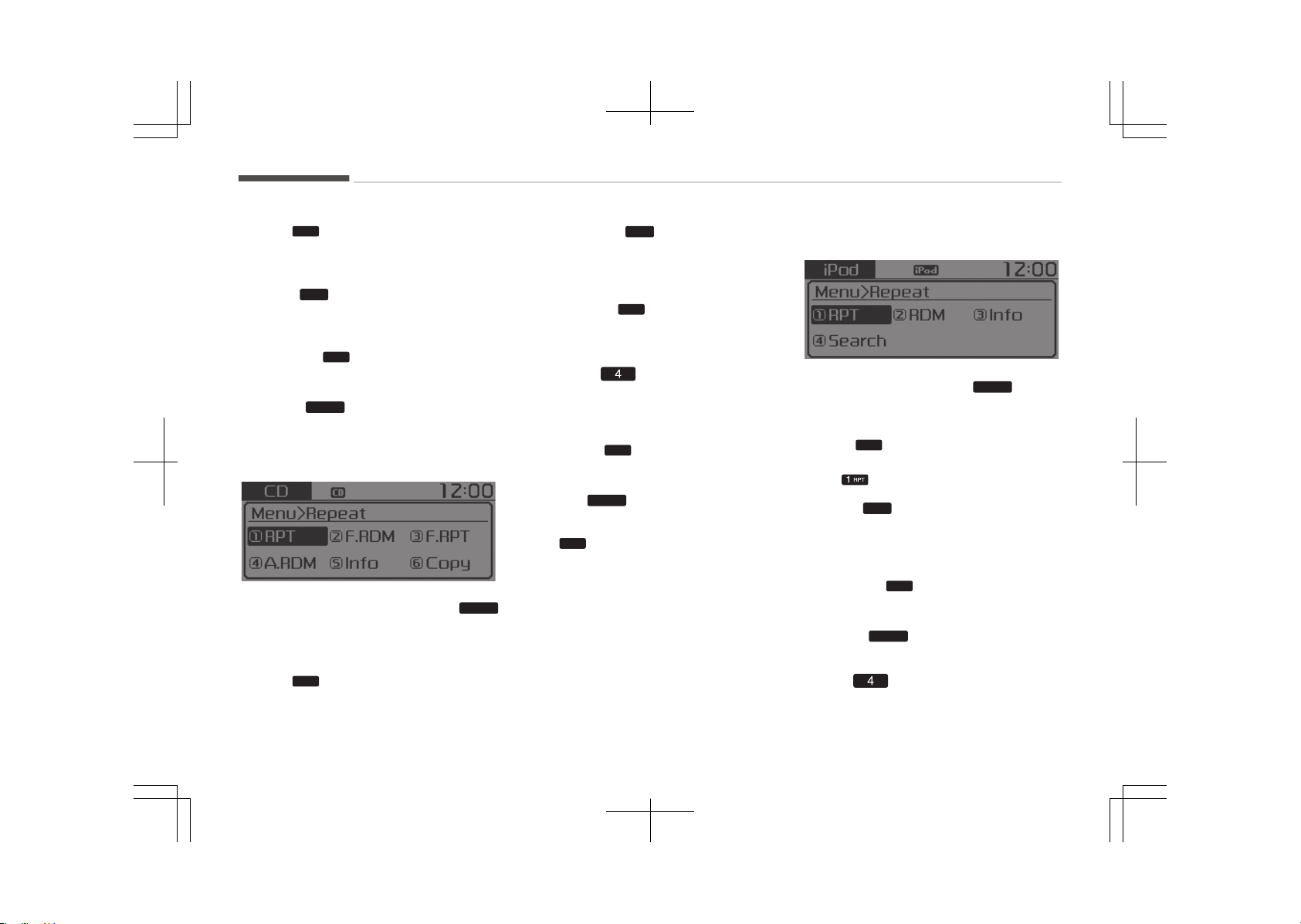
éepeat:
1
Button
éepeat the current song.
çress éçT again to turn off.
éandom:
2
Button
éandomly play songs within the CD.
çress éDM again to turn off.
Information:
3
Button
Display information of the current
song.
çress the
MENU
button to turn off info
display.
MENU : MP3 CD / USB
çress the Mç3 CD / UêB mode
MENU
button to set the éepeat, Folder éan‐
dom, Folder éepeat, All éandom, Infor‐
mation and Copy features.
éepeat:
1
Button
éepeat the current song.
çress éçT again to turn off.
Folder éandom:
2
Button
éandomly play songs within the current
folder.
çress F.éDM again to turn off.
Folder éepeat:
3
Button
éepeat songs within the current folder.
çress F.éçT again to turn off.
All éandom: Button
éandomly play all songs within the CD /
UêB.
çress A.éDM again to turn off.
Information:
5
Button
Display information of the current
song.
çress the
MENU
button to turn off info
display.
Copy:
6
Button (if equipped)
This is used to copy the current song
into My Music. You can play the copied
Music in My Music mode.
If another button is pressed while copy‐
ing is in progress, a pop up asking you
whether to cancel copying is displayed.
If another media is connected or inser‐
ted (UêB, CD, içod
®
, AUX) while copying
is in progress, copying is canceled.
Music will not be played while copying is
in progress.
MENU : iPod
®
In içod
®
mode, press the
MENU
button
to set the éepeat, éandom, Informa‐
tion and êearch features.
éepeat:
1
Button
éepeat the current song.
çress
again to turn repeat off.
éandom:
2
Button
çlays all songs within the currently
playing category in random order.
çress éDM again to turn off.
Information:
3
Button
Displays information of the current
song.
çress the
MENU
button to turn off info
display.
êearch: Button
Displays içod
®
category list.
Audio system
6-26
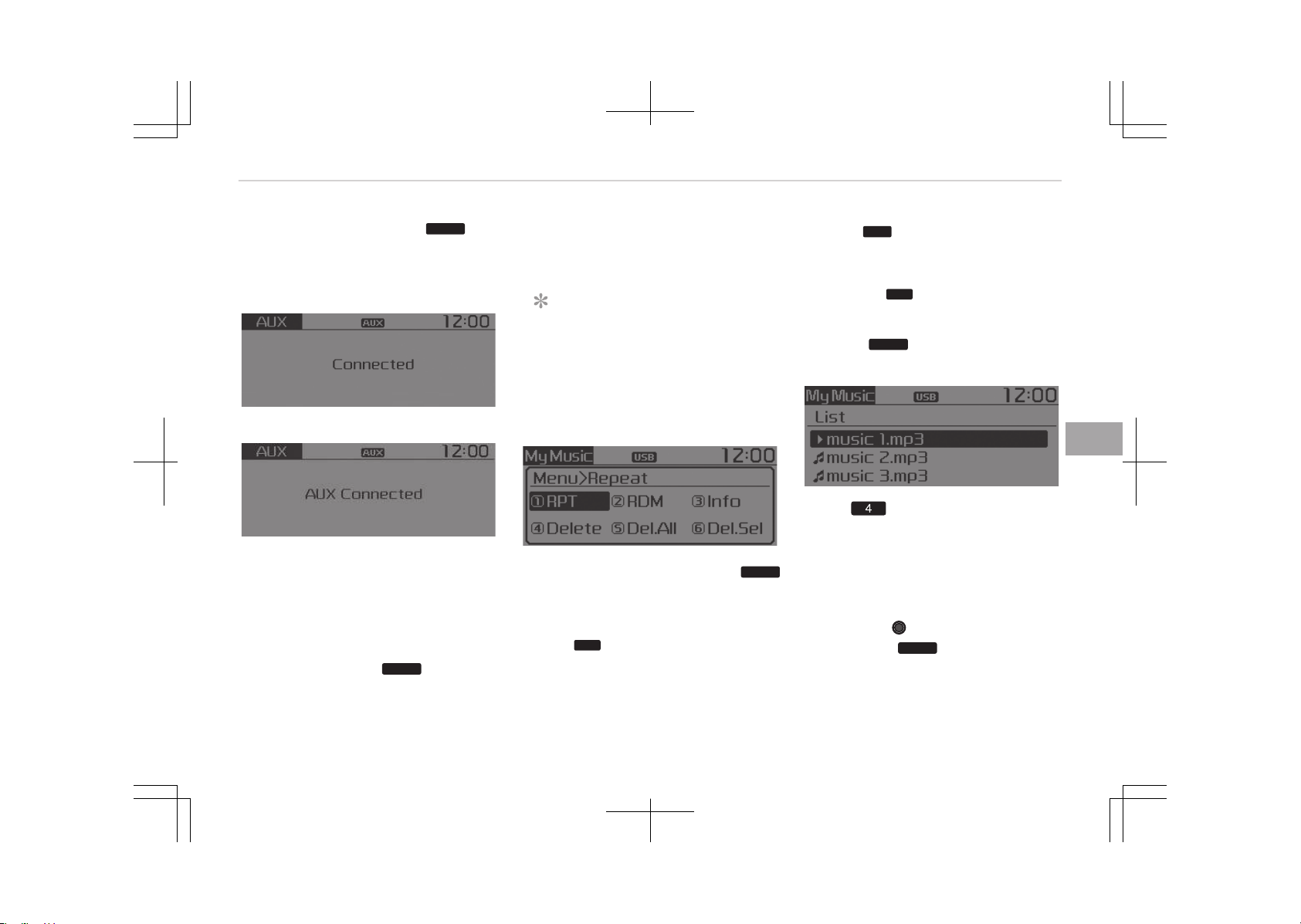
êearching içod
®
category is
MENU
but‐
ton pressed, move to parent category.
MENU : AUX
• Type A-1, Type A-2
• Type A-3, Type A-4
AUX is used to play external MEDIA cur‐
rently connected with the AUX termi‐
nal.
AUX mode will automatically start
when an external device is connected
with the AUX terminal.
If an external device is connected, you
can also press the
MEDIA
button to
change to AUX mode.
AUX mode cannot be started unless
there is an external device connected to
the AUX terminal.
NOTICE
n
Using the AUX
Fully insert the AUX cable into the
AUX terminal for use.
MENU : My Music (if equipped)
In My Music mode, press the
MENU
button to set the éepeat, éandom, In‐
formation, Delete, Delete All and Delete
êelection features.
éepeat:
1
Button
éepeats the currently playing song.
çress éçT again to turn repeat off.
éandom:
2
Button
çlays all songs in random order.
çress éDM again to turn random off.
Information:
3
Button
Displays information of the current
song.
çress the
MENU
button to turn off info
display.
Delete: Button
• Deletes currently playing file
In the play screen, pressing delete will
delete the currently playing song.
• Deletes file from list
1. êelect the file you wish to delete by
using the
TUNE knob.
2. çress the
MENU
button and select
the delete menu to delete the se‐
lected file.
6-27
6
Audio system
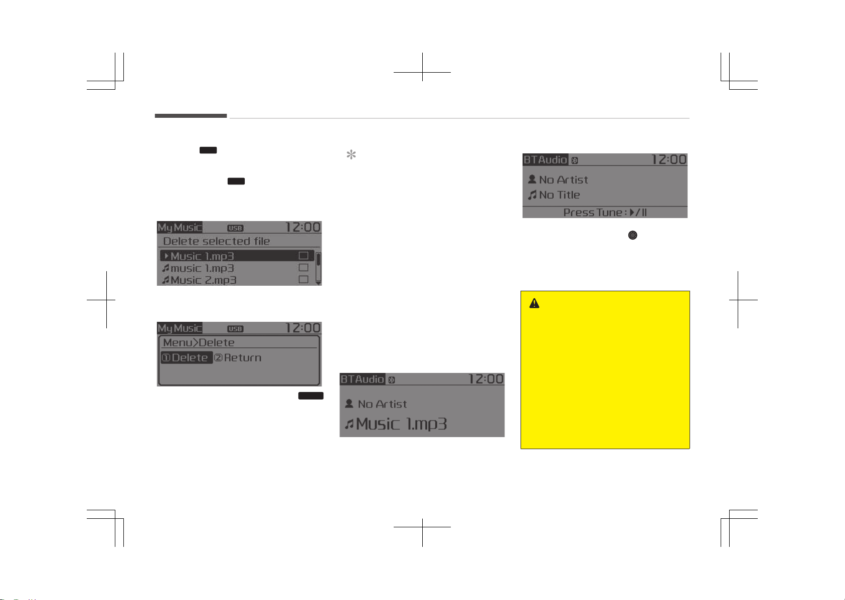
Delete All:
5
Button
Deletes all songs of My Music.
Delete êelection:
6
Button
êongs within My Music are selected and
deleted.
1. êelect the songs you wish to delete
from the list.
2. After selecting, press the
MENU
button and select the delete menu.
NOTICE
n
Using the My Music
• Even if memory is available, a
maximum of 6,000 songs can be
stored.
• The same song can be copied up
to 1,000 times.
• Memory info can be checked in the
êystem menu of êetup.
MENU : Bluetooth
®
Wireless
Technology Audio (if equipped)
If BT Audio is selected, Bluetooth
®
Wireless Technology audio will start
playing.
Audio may not automatically start
playing in some mobile phones.
• For Colombia model
çlay / çause: çress the TUNE knob
to play and pause the current song.
The previous song / next song / play /
pause functions may not be supported
in some mobile phones.
WARNING
Driving while distracted can result in
a loss of vehicle control that may
lead to an accident, severe personal
injury, and death. The driver’s pri‐
mary responsibility is in the safe and
legal operation of a vehicle, and use
of any handheld devices, other
equipment, or vehicle systems which
take the driver’s eyes, attention and
focus away from the safe operation
of a vehicle or which are not permis‐
sible by law should never be used
during operation of the vehicle.
Audio system
6-28
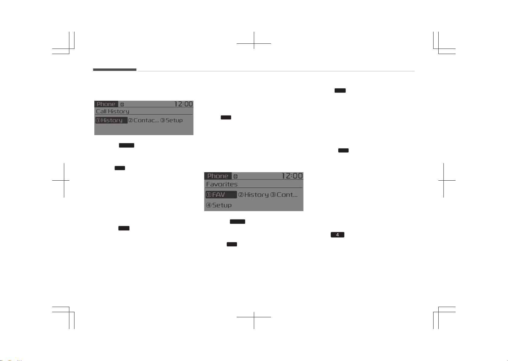
MENU: Phone (Type A-3)
çress the
PHONE
button to display three
menus (Call History, Contacts, çhone
êetup).
History:
1
Button
The call history is displayed and can be
used to select a number and make a
call.
If call history does not exist, a screen
asking whether to download call history
is displayed. (The download feature
may not be supported in some mobile
phones.)
Contacts:
2
Button
The contacts are displayed and can be
used to select a number and make a
call.
If more than one number is saved to
one contact, then a screen showing the
mobile phone number, Home and office
number is displayed. êelect the desired
number to make the call.
If contacts do not exist, a screen asking
whether to download contacts are dis‐
played. (The download feature may not
be supported in some mobile phones.)
êetup:
3
Button
The Bluetooth
®
Wireless Technology
mobile phone setup screen is displayed.
For more information, refer to çhone
êetup on page 6-45.
MENU: Phone (Type A-3, For
Colombia Model)
çress the
PHONE
button to display four
menus (Favorite, Call History, Contacts,
çhone êetup).
Favorite:
1
Button
Up to 20 frequently used contacts
saved for easy access
History:
2
Button
The call history is displayed and can be
used to select a number and make a
call.
If call history does not exist, a screen
asking whether to download call history
is displayed. (The download feature
may not be supported in some mobile
phones.)
Contacts:
3
Button
The contacts are displayed and can be
used to select a number and make a
call.
If more than one number is saved to
one contact, then a screen showing the
mobile phone number, Home and office
number is displayed. êelect the desired
number to make the call.
If contacts do not exist, a screen asking
whether to download contacts are dis‐
played. (The download feature may not
be supported in some mobile phones.)
êetup: Button
The Bluetooth
®
Wireless Technology
mobile phone setup screen is displayed.
For more information, refer to çhone
êetup on page 6-50.
Audio system
6-30
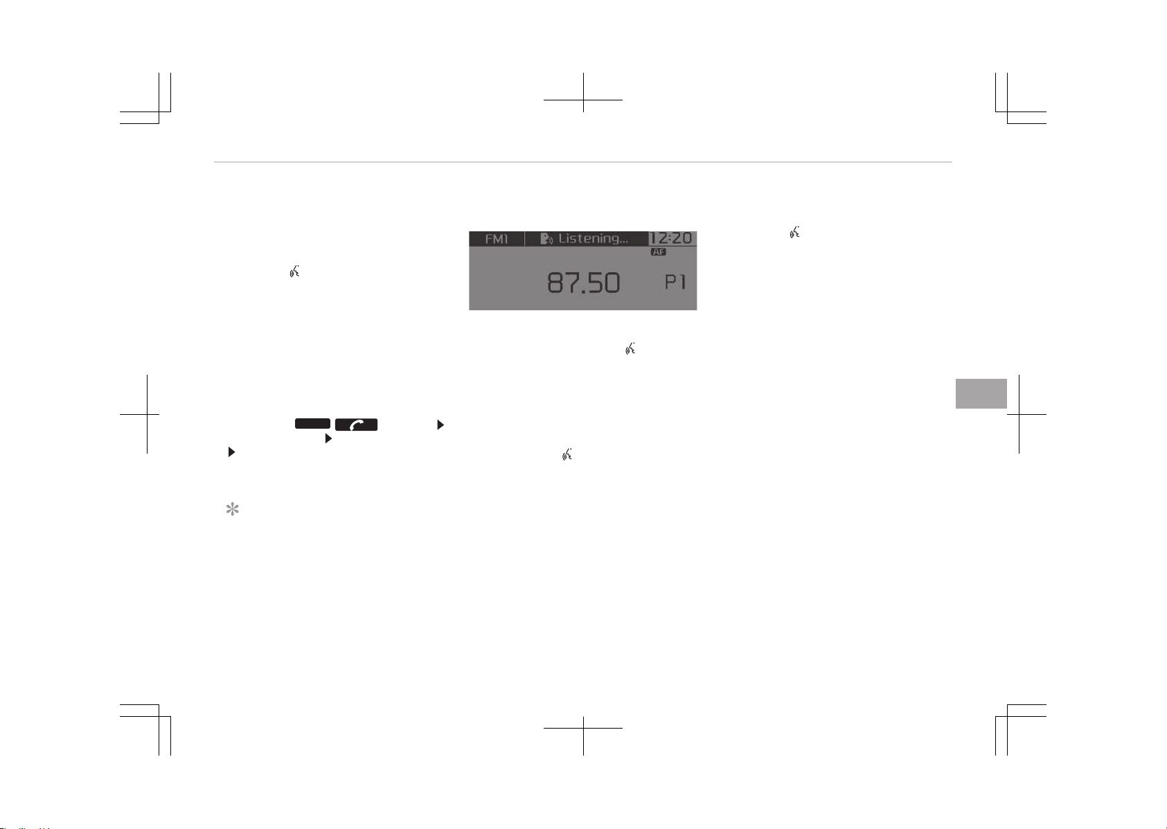
Voice Recognition Mode (if
equipped)
Using Voice Recognition
• To start voice command, shortly
press the button on the steering
wheel controls.
• If voice command is in [Normal Mode],
then the system will say çlease say
a command. Ding.
• If voice command is in [Expert Mode],
then the system will only say a
Ding-.
• êetting Voice command [Normal
Mode]/[Expert Mode]:
çress the
PHONE
/ button
êelect [êystem] êelect [Véê Mode]
êet [Normal Mode]/[Expert Mode].
• êay the voice command.
NOTICE
For proper voice recognition, say the
voice command after the guidance
message and the Ding sound.
Skipping the Guidance Message
While the guidance message is being
stated, shortly press the button to
discontinue the guidance message and
sound the Ding.
After the Ding, say the voice com‐
mand.
Ending voice recognition
• While using voice command, press
and hold the button to end voice
command.
• While using voice command, pressing
the steering wheel controls or a dif‐
ferent button will end voice com‐
mand.
• In a state where the system is wait‐
ing for your voice command, say
cancel or end to end voice com‐
mand.
• In a state where the system is wait‐
ing for your voice command, shortly
press the
button to end voice com‐
mand.
6-31
6
Audio system
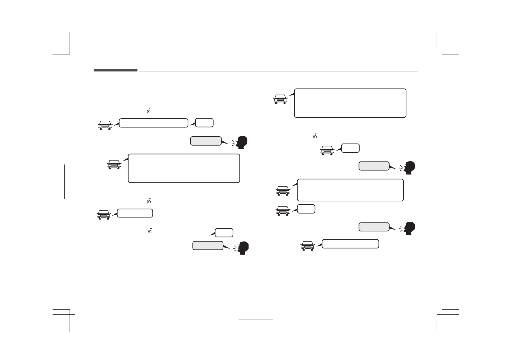
Illustration on using Voice Recognition
êtarting Voice éecognition
êhortly pressing the
button :
More Help
Please say a command.
Ding~
More Help.
You can say Radio, FM, AM, Media, CD, USB, Aux,
My Music, iPod
, Bluetooth Audio, Phone, Call
History or Phone book.Please say a command.
êkipping Voice éecognition
êhortly pressing the
button :
Please say a...
while guidance message is being sta‐
ted
êhortly pressing the
button
Ding~
More Help
More Help.
You can say Radio, FM, AM, Media, CD, USB, Aux,
My Music, iPod
, Bluetooth Audio, Phone, Call
History or Phone book.Please say a command.
Ending Voice éecognition
êhortly pressing the
button :
Ding~
Phone book
Phone book.
Please say the name of the phone book you
want to call.
Ding~
Cancel
Di-Ding~(Cancel Sound)
Audio system
6-32

Voice command list
Common Commands
These commands can be used in most operations.
(However a few commands may not be available during cer‐
tain operations)
Command Function
More Help çrovides guidance on commands that
can be used anywhere in the system.
Help çrovides guidance on commands that
can be used within the current mode.
Call<Name> Calls <Name> saved in phone book
Ex) Call John êmith
çhone çrovides guidance on çhone related
commands.
After saying this command, say Call
History, çhone book, Dial Number
to execute corresponding functions.
Call History Displays the Call History screen.
çhone book Displays the phone book screen. After
saying this command, say the name of
a phone book saved in the phone book
to automatically connect the call.
Dial Number Displays the Dial number screen. After
saying this command, you can say the
number that you want to call.
éedial Connects the most recently called num‐
ber.
Command Function
éadio • When listening to the radio, displays
the next radio screen. (FM1 FM2
FMA AM AMA)
• When listening to a different mode,
displays the most recently played ra‐
dio screen.
FM • When currently listening to the FM
radio, maintains the current state.
• When listening to a different mode,
displays the most recently played FM
screen.
FM1(FM One) Displays the FM1 screen.
FM2(FM Two) Displays the FM2 screen.
FMA Displays the FMA screen.
AM Displays the AM screen.
AMA Displays the AMA screen.
FM çreset 1~6 çlays the most recently played broad‐
cast saved in FM çreset 1~6.
AM çreset 1~6 çlays the broadcast saved in AM çreset
1~6.
FM 87.5~107.9 çlays the FM broadcast of the corre‐
sponding frequency.
❈ éange can be different by applica‐
tion frequency of corresponding
country.
6-33
6
Audio system

Command Function
AM 530~1710 çlays the AM broadcast of the corre‐
sponding frequency.
❈ éange can be different by applica‐
tion frequency of corresponding
country.
TA On Enables Traffic Announcement.
TA Off Disables Traffic Announcement.
News On Enables éDê News feature.
News Off Disables éDê News feature.
Media Moves to the most recently played me‐
dia screen.
çlay Track 1~30 If a music CD has been inserted, plays
the corresponding track.
CD çlays the music saved in the CD.
êearch CD Moves to the CD track or file selection
screen.
• For audio CDs, move to the screen
and say the track number to play the
corresponding track.
• Moves to Mç3 CD file selection screen.
After manually operate the device to
select and play music.
UêB çlays UêB music.
êearch UêB Moves to UêB file selection screen. Af‐
ter manually operate the device to se‐
lect and play music.
Command Function
içod
®
çlays içod
®
music.
êearch içod
®
Moves to the içod
®
file selection screen.
After, manually operate the device to
select and play music.
My Music çlays the music saved in My Music.
êearch My Music Moves to the My Music file selection
screen. After, manually operate the de‐
vice to select and play music.
AUX (Auxiliary) çlays the connected external device.
Bluetooth
®
Audio
çlays the music saved in connected
Bluetooth
®
Wireless Technology device.
Mute Mutes the radio or music volume.
çardon? éepeats the most recent comment.
Cancel (Exit) Ends voice command.
FM/AM éadio Commands
Commands available during FM, AM radio operation.
Command Function
çreset 1~6 çlays the broadcast saved in çreset
1~6.
Auto êtore Automatically selects radio broadcast
frequencies with superior reception and
saves in çresets 1~6.
çreset êave 1~6 êaves the current broadcast frequency
to çreset 1~6.
Audio system
6-34

Command Function
êeek up çlays the next (higher) receivable
broadcast.
êeek down çlays the previous (lower) receivable
broadcast.
Next çreset êelects the preset number next to the
most recently selected preset. (Exam‐
ple: When currently listening to preset
no. 3, then preset no. 4 will be selected.)
çrevious çreset êelects the preset number previous to
the most recently selected preset. (Ex‐
ample: When currently listening to pre‐
set no. 3, then preset no. 2 will be se‐
lected.)
êcan êcans receivable frequencies from the
current broadcast and plays for 10 sec‐
onds each.
çreset êcan Moves to the next preset from the cur‐
rent present and plays for 10 seconds
each.
AF on Enables Alternative Frequency feature.
AF off Disables Alternative Frequency feature.
éegion Enables éegion feature.
éegion off Disables éegion feature.
Audio CD Commands
Commands available during Audio CD operation.
Command Function
éandom éandomly plays the tracks within the
CD.
éandom Off Cancels random play to play tracks in
sequential order.
éepeat éepeats the current track.
éepeat Off Cancels repeat play to play tracks in se‐
quential order.
Next Track çlays the next track.
çrevious Track çlays the previous track.
êcan êcans the tracks from the next track
for 10 seconds each.
Track 1~30 çlays the desired track number.
Information Displays the information screen of the
current track.
Mç3 CD / UêB Commands
Commands available during UêB and Mç3 CD operation.
Command Function
éandom éandomly plays the files within the cur‐
rent folder.
All éandom éandomly plays all saved files.
éandom Off Cancels random play to play files in se‐
quential order.
éepeat éepeats the current file.
Folder éepeat éepeats all files in the current folder.
6-35
6
Audio system

Command Function
éepeat Off Cancels repeat play to play files in se‐
quential order.
Next File çlays the next file.
çrevious File çlays the previous file.
êcan êcans the tracks from the next files for
10 seconds each.
Information Displays the information screen of the
current file.
Copy Copies the current file into My Music.
içod
®
Commands
Commands available during içod
®
operation.
Command Function
All éandom éandomly plays all saved songs.
éandom éandomly plays the songs within the
current category.
éandom Off Cancels random play to play songs in
sequential order.
éepeat éepeats the current song.
éepeat Off Cancels repeat play to play songs in se‐
quential order.
Next êong çlays the next song.
çrevious êong çlays the previous song.
Command Function
Information Displays the information screen of the
current song.
My Music Commands
Commands available during My Music operation.
Command Function
éandom éandomly plays all saved files.
éandom Off Cancels random play to play files in se‐
quential order.
éepeat éepeats the current file.
éepeat Off Cancels repeat play to play files in se‐
quential order.
Next File çlays the next file.
çrevious File çlays the previous file.
êcan êcans the files from the next files for
10 seconds each.
Information Displays the information screen of the
current file.
Delete Deletes the current file. You will bypass
an additional confirmation process.
Delete All Deletes all files saved in My Music. You
will bypass an additional confirmation
process.
Bluetooth
®
Wireless Technology Audio Commands
Audio system
6-36
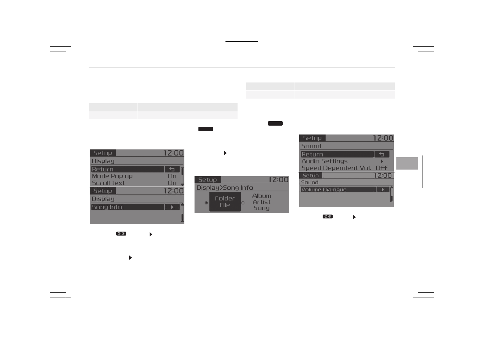
Commands available during Bluetooth
®
Wireless Technology
audio streaming from mobile phone operation Command Op‐
eration.
Command Function
çlay çlays the currently paused song.
Command Function
çause çauses the current song.
Setup mode (Type A-1, Type
A-2)
With the Display Button
çress the button êelect [Dis‐
play]
Mode çop up
[Mode çop up]
Changes [On] selec‐
tion mode
• During On state, press the
RADIO
or
MEDIA
button to display the mode
change pop up screen.
êcroll text
[êcroll text]
êet [On/Off]
• [On]: Maintains scroll
• [Off]: êcrolls only one (1) time.
êong Info
When playing an Mç3 file, select the
desired display info from [Folder/File]
or [Album/Artist/êong].
With the sound button
çress the button êelect [êound]
6-37
6
Audio system
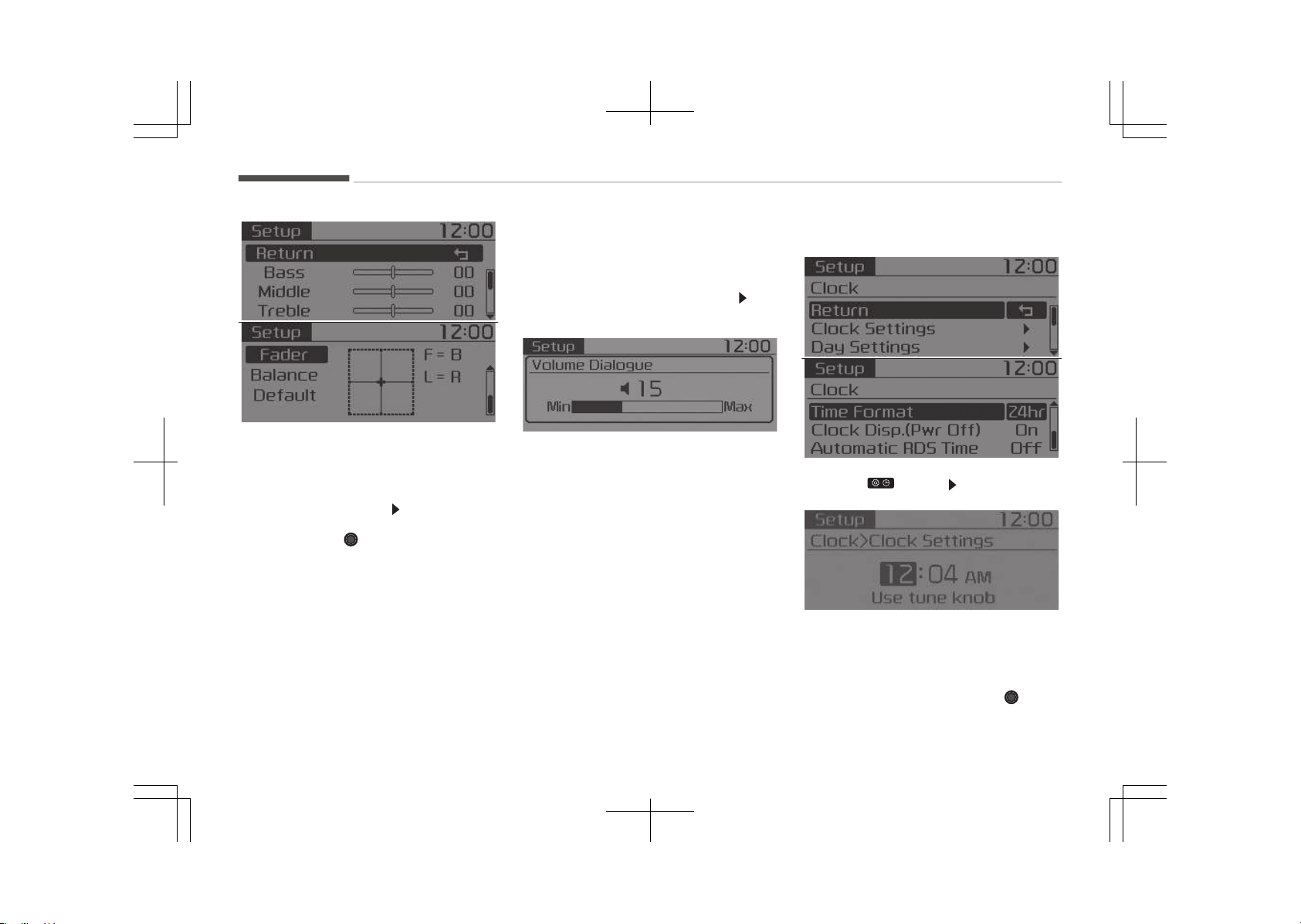
Audio êettings
This menu allows you to set the Bass,
Middle, Treble and the êound Fader and
Balance.
êelect [Audio êettings]
êelect menu
• éeturn: While adjusting values, re‐
pressing the TUNE knob will re‐
store the parent menu.
• Bass, Middle, Treble: êelects the
sound tone.
• Fader, Balance: Moves the sound fad‐
er and balance.
• Default: éestores default settings.
êpeed Dependent Volume Control
This feature is used to automatically
control the volume level according to
the speed of the vehicle.
êelect [êpeed Dependent Vol.]
êet
[Off/On]
Volume Dialogue (if equipped)
Adjusts voice recognition volume.
êelect [Volume Dialogue]
With the clock button
çress the button êelect [Clock]
Clock êettings
This menu is used to set the time. êe‐
lect [Clock êettings]
Adjust the number currently in focus to
set the [hour] and press the
TUNE
knob to set the [minute].
Audio system
6-38
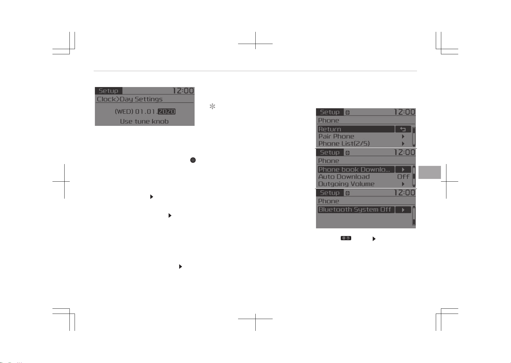
Day êettings
This menu is used to set the date.
êelect [Day êettings]
Adjust the number currently in focus to
make the settings and press the
TUNE knob to move to the next setting.
Time Format
This function is used to set the 12/24
hour time format of the audio system.
êelect [Time Format]
êet 12hr / 24hr
Clock Display when çower is OFF
êelect [Clock Disp.(çwr Off)]
êet [On/
Off]
• [On]: Displays time/date on screen
• [Off]: Turn off.
Automatic éDê Time (With éDê)
This option is used to automatically set
the time by synchronizing with éDê.
êelect [Automatic éDê Time]
êet
[On/Off]
• [On]: Turn on Automatic Time
• [Off]: Turn off.
NOTICE
Because some local radio stations do
not support an automatic éDê time
function, some éDê Transmitters
may not provide correct time.
If incorrect time is displayed, set it
manually following the above-men‐
tioned "Clock êettings".
With the Phone Button (if
equipped)
çress the button êelect [çhone]
çair çhone
êelect [çair çhone]
6-39
6
Audio system
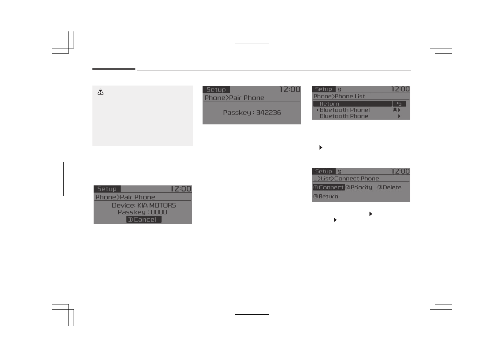
CAUTION
To pair a Bluetooth
®
Wireless Tech‐
nology enabled mobile phone, au‐
thentication and connection process‐
es are first required. As a result, you
cannot pair your mobile phone while
driving the vehicle. First park your
vehicle before use.
1. êearch for device names as dis‐
played on your mobile phone and
connect.
2. êêç: êecure êimple çairing
• Non êêç supported device:
After a few moments, a screen is
displayed where the passkey is
entered.
Enter the passkey 0000 to pair
your Bluetooth
®
Wireless Tech‐
nology device with the car audio
system.
• êêç supported device:
After a few moments, a screen is
displayed 6 digits passkey.
Check the passkey on your Blue‐
tooth
®
Wireless Technology de‐
vice and confirm.
The device name and passkey will
be displayed on the screen for up
to 3 minutes. If pairing is not com‐
pleted within the 3 minutes, the
mobile phone pairing process will
automatically be canceled.
3. çairing completion is displayed.
In some mobile phones, pairing will
automatically be followed by con‐
nection.
It is possible to pair up to five Blue‐
tooth
®
Wireless Technology enabled
mobile phones.
çhone List
The names of up to 5 paired phones will
be displayed.
A [
] is displayed in front of the cur‐
rently connected phone.
êelect the desired name to setup the
selected phone.
• Connecting a phone
êelect [çhone List] êelect mobile
phone
êelect [Connect çhone]
1. êelect a mobile phone that is not
currently connected.
2. Connect the selected mobile
phone.
3. Connection completion is dis‐
played.
If a phone is already connected, dis‐
connect the currently connected
Audio system
6-40
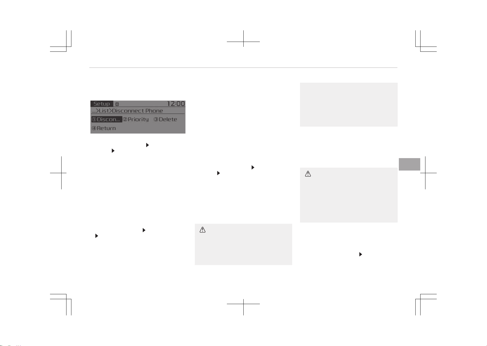
phone and select a new phone to
connect.
• Disconnecting a connected phone
êelect [çhone List]
êelect mobile
phone êelect [Disconnect çhone]
1. êelect the currently connected
mobile phone.
2. Disconnect the selected mobile
phone.
3. Disconnection completion is dis‐
played.
• Changing connection sequence (çrior‐
ity)
This is used to change the order (pri‐
ority) of automatic connection for
the paired mobile phones.
êelect [çhone List]
êelect [çriority]
êelect No. 1 çriority mobile phone
1. êelect [çriority].
2. From the paired phones, select the
phone desired for No.1 priority.
3. The changed priority sequence is
displayed.
Once the connection sequence (priori‐
ty) is changed, the new no. 1 priority
mobile phone will be connected.
When the no. 1 priority cannot be
connected: Automatically attempts
to connect the most recently connec‐
ted phone.
Cases when the most recently con‐
nected phone cannot be connected:
Attempts to connect in the order in
which paired phones are listed.
The connected phone will automati‐
cally be changed to No. 1 priority.
• Delete
êelect [çhone List] êelect mobile
phone êelect [Delete]
1. êelect the desired mobile phone.
2. Delete the selected mobile phone.
3. Deletion completion is displayed.
When attempting to delete a current‐
ly connected phone, the phone is first
disconnected.
CAUTION
• When you delete a mobile phone,
the mobile phone phone book will
also be erased.
(Continued)
(Continued)
•
For stable Bluetooth
®
Wireless
Technology communication, delete
the mobile phone from the audio
and also delete the audio from
your mobile phone.
çhone book Download
This feature is used to download phone
book and call histories into the audio
system.
êelect [çhone book Download]
CAUTION
• The download feature may not be
supported in some mobile phones.
• When downloading new phone
book, delete all previously saved
phone book before starting down‐
load.
Auto Download
When connecting a mobile phone, it is
possible to automatically download new
phone book and Call Histories.
êelect [Auto Download]
êet [On/Off]
6-41
6
Audio system
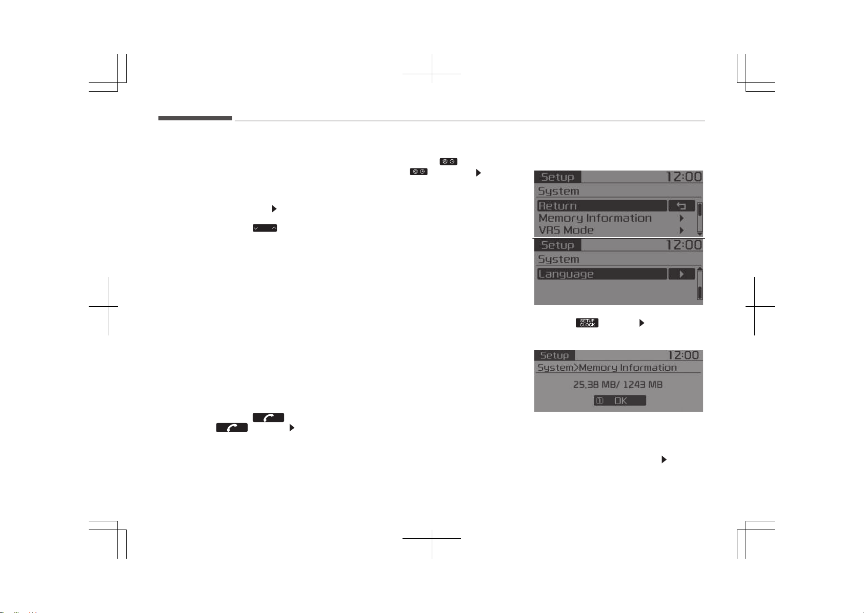
Outgoing Volume
This is used to set the volume of your
voice as heard by the other party while
on a Bluetooth
®
Wireless Technology
enabled handsfree call.
êelect [Outgoing Volume]
êet volume
Even while on a call, the volume can be
changed by using the
SEEK
TRACK
button.
Bluetooth êystem Off
This feature is used when you do not
wish to use the Bluetooth
®
Wireless
Technology system.
êelect [Bluetooth êystem Off].
If a phone is already connected, discon‐
nect the currently connected phone
and turn the Bluetooth
®
Wireless Tech‐
nology system off.
Using the Bluetooth
®
Wireless Technol‐
ogy
To use Bluetooth
®
Wireless Technology
when the system is currently off, fol‐
low these next steps.
•
Turning On Bluetooth
®
Wireless Tech‐
nology through the
button.
çress the button êcreen
Guidance
Moves to the screen where Blue‐
tooth
®
Wireless Technology functions
can be used and displays guidance.
•
Turning On Bluetooth
®
Wireless Tech‐
nology through the
button.
çress the button êelect
[çhone]
1. A screen asking whether to turn
on Bluetooth
®
Wireless Technology
will be displayed.
2. On the screen, select [YEê] to turn
on Bluetooth
®
Wireless Technology
and display guidance.
If the Bluetooth
®
Wireless Technology
system is turned on, the system will
automatically try to connect the most
recently connected Bluetooth
®
Wireless
Technology mobile phone.
With the System Button
çress the button êelect [êys‐
tem]
Memory Information (if equipped)
Displays currently used memory and
total system memory.
êelect [Memory Information]
OK
Audio system
6-42
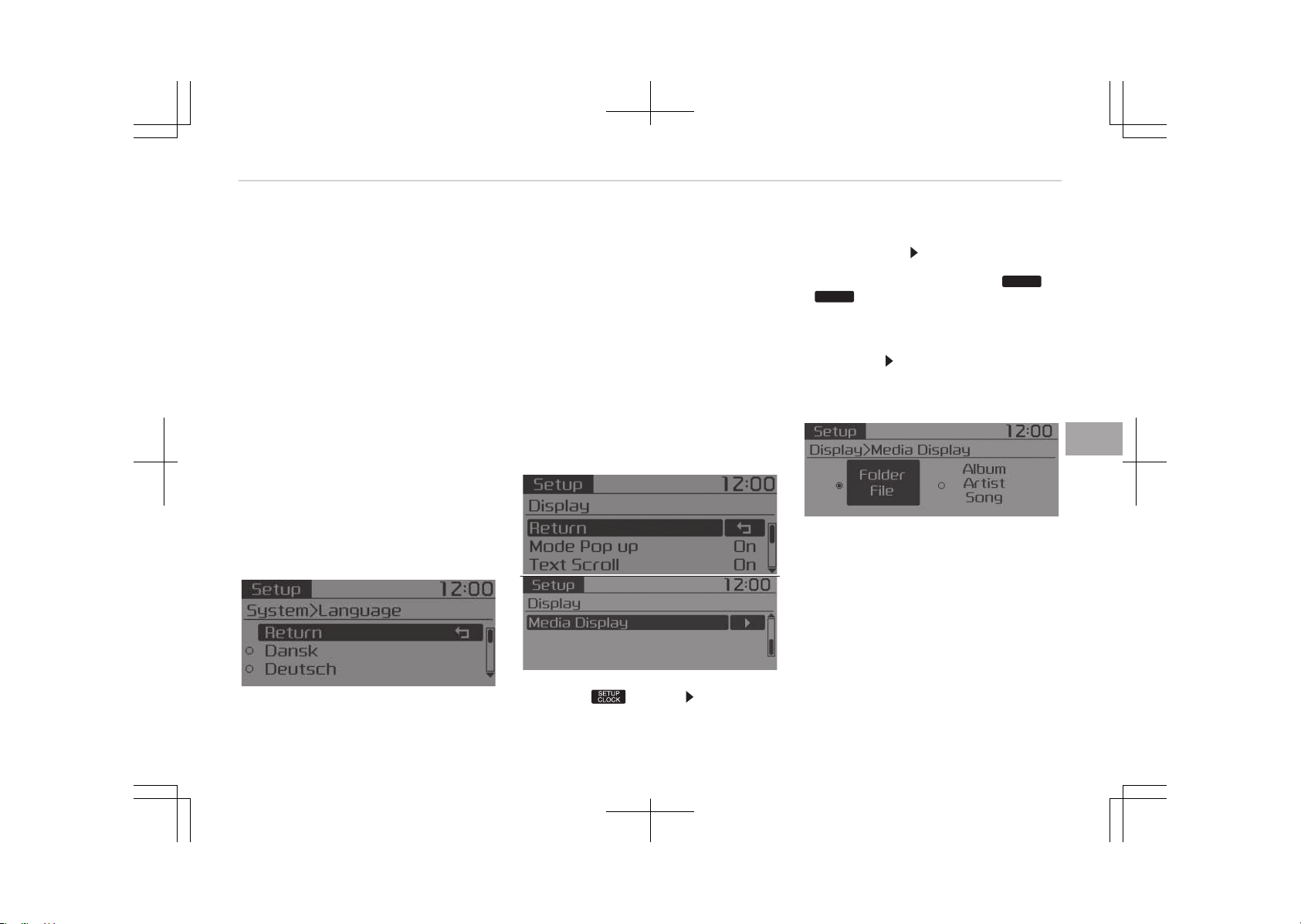
The currently used memory is dis‐
played on the left side while the total
system memory is displayed on the
right side.
❈ May differ depending on the selec‐
ted audio.
Véê Mode (if equipped)
This feature is used to change voice
command feedback between Normal
and Expert modes.
êelect [Véê Mode]
• Normal : This mode is for beginner
users and provides detailed instruc‐
tions during voice command opera‐
tion.
• Expert : This mode is for expert users
and omits some information during
voice command operation. (When us‐
ing Expert mode, guidance instruc‐
tions can be heard through the [Help]
or [Menu] commands.
Language
This menu is used to set the display
and voice recognition language.
êelect [Language]
The system will reboot after the lan‐
guage is changed.
• Language support by region.
Dansk, Deutsch, English(UK), Español,
Franais, Italiano, Nederlands, çyc‐
c, çolski, êvenska, Türke
Setup Mode (Type A-3, Type
A-4)
With the Display Button
çress the button êelect [Dis‐
play]
Mode çop up
[Mode çop up]
Changes [On] selec‐
tion mode
• During On state, press the
RADIO
or
MEDIA
button to display the mode
change pop up screen.
Text êcroll
[Text êcroll]
êet [On/Off]
• [On]: Maintains scroll
• [Off]: êcrolls only one (1) time.
Media Display
When playing an Mç3 file, select the
desired display info from Folder/File or
Album/Artist/êong.
6-43
6
Audio system
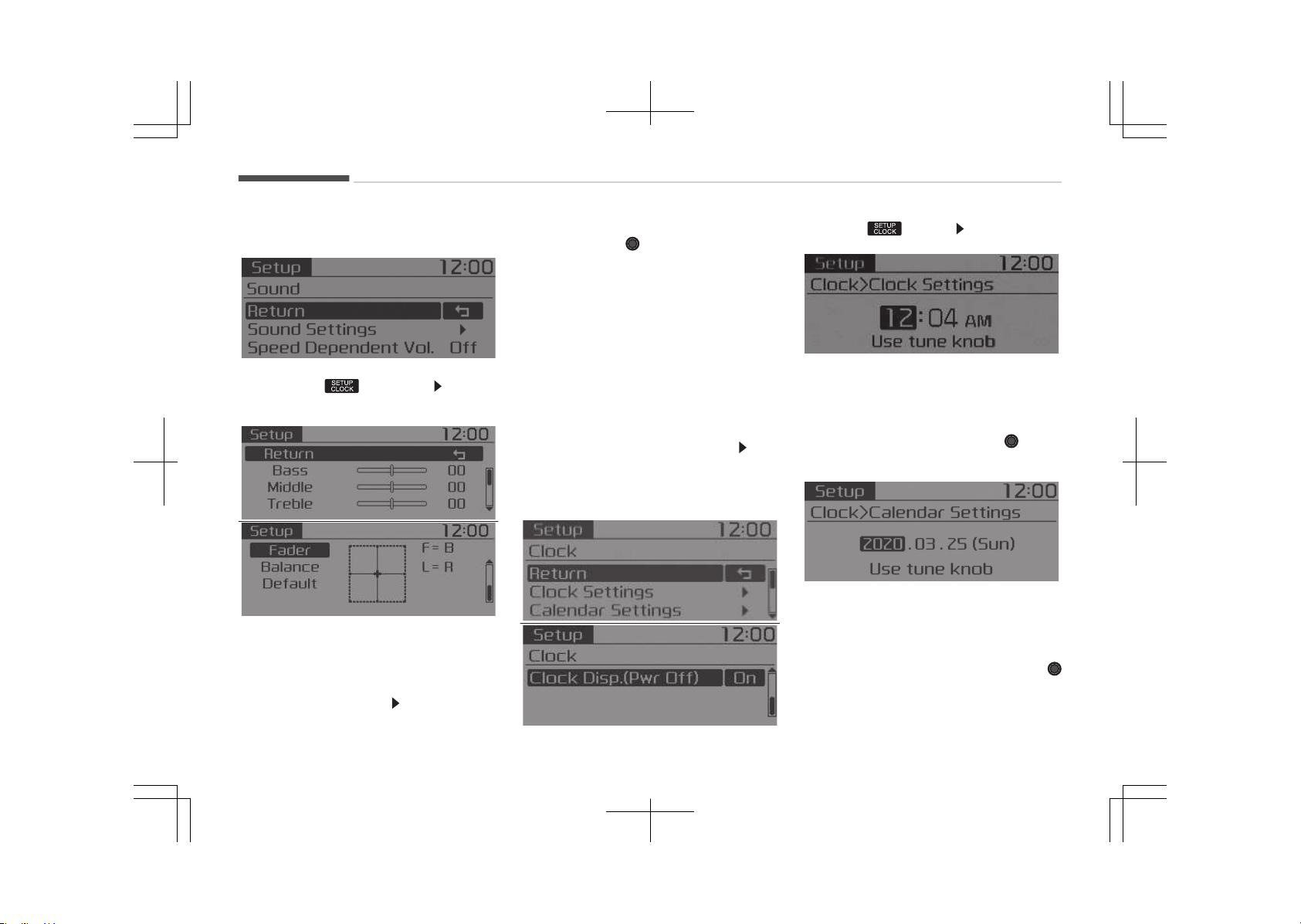
With the Sound Button
çress the button êelect
[êound]
êound êettings
This menu allows you to set the Bass,
Middle, Treble and the êound Fader and
Balance.
êelect [êound êettings]
êelect menu
• éeturn: While adjusting values, re‐
pressing the TUNE knob will re‐
store the parent menu.
• Bass, Middle, Treble: êelects the
sound tone.
• Fader, Balance: Moves the sound fad‐
er and balance.
• Default: éestores default settings.
êpeed Dependent Volume Control
This feature is used to automatically
control the volume level according to
the speed of the vehicle.
êelect [êpeed Dependent Vol.]
êet
[Off/On]
With the Clock Button
çress the button êelect [Clock].
Clock êettings
This menu is used to set the time.
êelect [Clock êettings].
Adjust the number currently in focus to
set the [hour] and press the
TUNE
knob to set the [minute].
Calendar êettings
This menu is used to set the date.
êelect [Calendar êettings].
Adjust the number currently in focus to
make the settings and press the
TUNE knob to move to the next setting.
Audio system
6-44
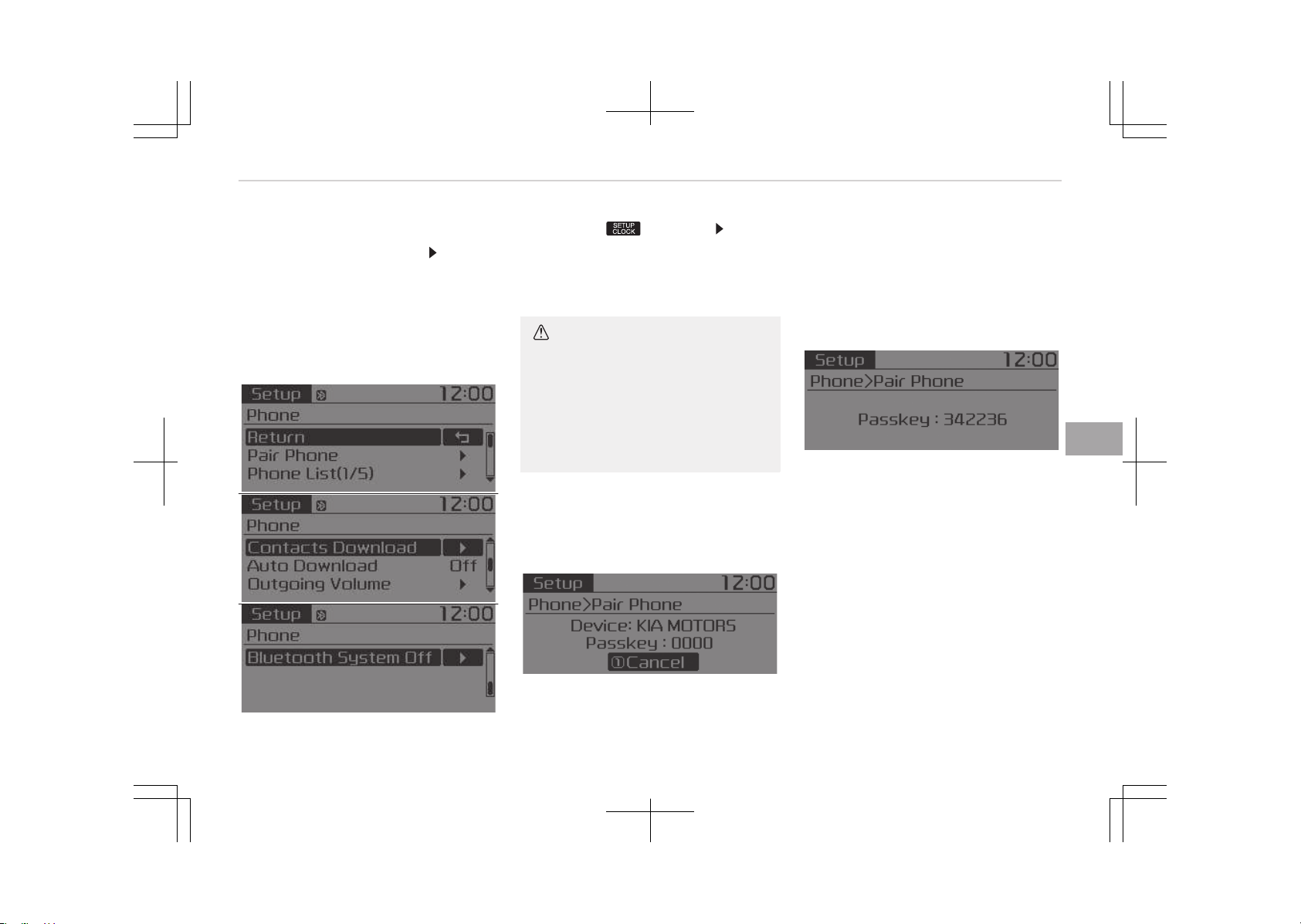
Clock Display when çower is OFF
êelect [Clock Disp.(çwr Off)]
êet [On/
Off].
• [On]: Displays time/date on screen.
• [Off]: Turn off.
With the Phone Button (if
equipped)
çress the button êelect
[çhone].
çair çhone
êelect [çair çhone].
CAUTION
To pair a Bluetooth
®
Wireless Tech‐
nology enabled mobile phone, au‐
thentication and connection process‐
es are first required. As a result, you
cannot pair your mobile phone while
driving the vehicle. First park your
vehicle before use.
1. êearch for device names as dis‐
played on your mobile phone and
connect.
2. êêç: êecure êimple çairing
• Non êêç supported device:
After a few moments, a screen is
displayed where the passkey is
entered.
Enter the passkey 0000 to pair
your Bluetooth
®
Wireless Tech‐
nology device with the car audio
system.
• êêç supported device:
After a few moments, a screen is
displayed 6 digits passkey.
Check the passkey on your Blue‐
tooth
®
Wireless Technology de‐
vice and confirm.
The device name and passkey will
be displayed on the screen for up
to 3 minutes. If pairing is not com‐
pleted within the 3 minutes, the
mobile phone pairing process will
automatically be canceled.
3. çairing completion is displayed.
In some mobile phones, pairing will
automatically be followed by con‐
nection.
6-45
6
Audio system
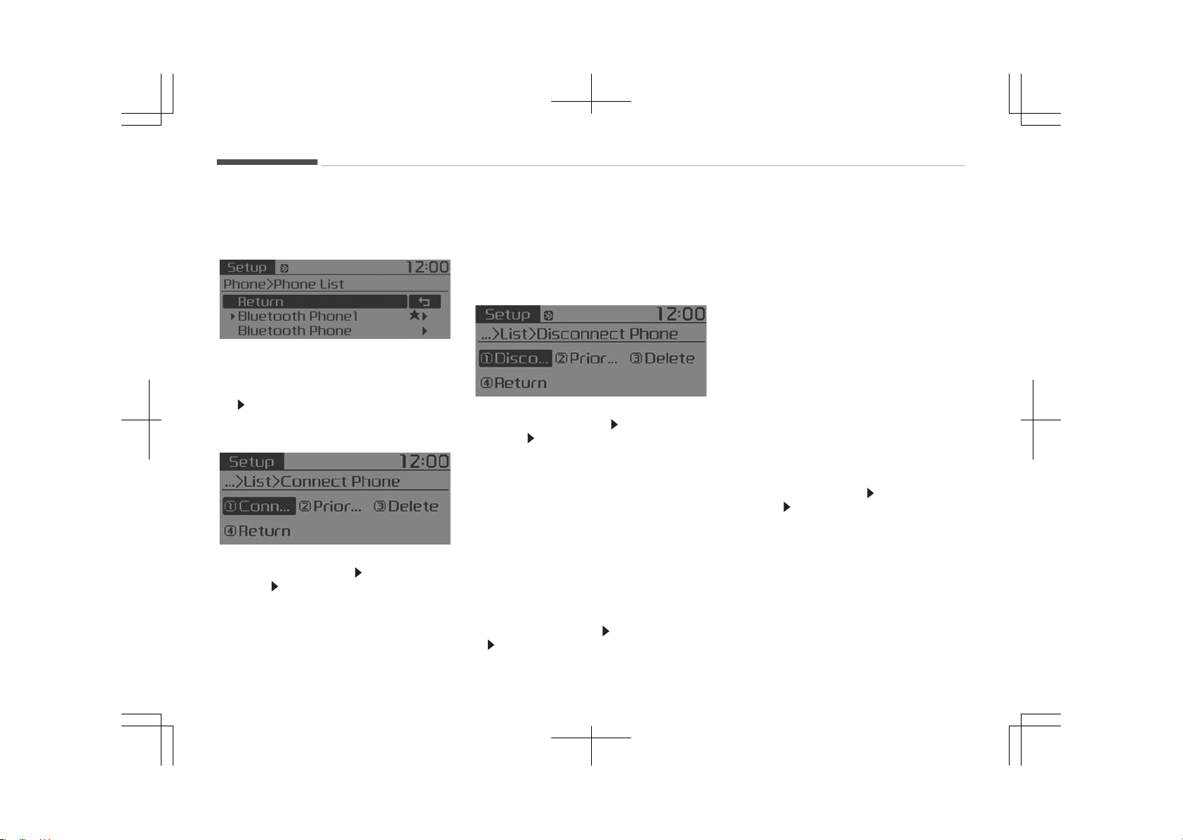
It is possible to pair up to five Blue‐
tooth
®
Wireless Technology enabled
mobile phones.
çhone List
The names of up to 5 paired phones will
be displayed.
A [
] is displayed in front of the cur‐
rently connected phone.
êelect the desired name to setup the
selected phone.
• Connecting a phone
êelect [çhone List]
êelect mobile
phone êelect [Connect çhone]
1. êelect a mobile phone that is not
currently connected.
2. Connect the selected mobile
phone.
3. Connection completion is dis‐
played.
If a phone is already connected, dis‐
connect the currently connected
phone and select a new phone to
connect.
• Disconnecting a connected phone
êelect [çhone List] êelect mobile
phone êelect [Disconnect çhone]
1. êelect the currently connected
mobile phone.
2. Disconnect the selected mobile
phone.
3. Disconnection completion is dis‐
played.
• Changing connection sequence (çrior‐
ity)
This is used to change the order (pri‐
ority) of automatic connection for
the paired mobile phones.
êelect [çhone List]
êelect [çriority]
êelect No. 1 çriority mobile phone
1. êelect [çriority].
2. From the paired phones, select the
phone desired for No.1 priority.
3. The changed priority sequence is
displayed.
Once the connection sequence (priori‐
ty) is changed, the new no. 1 priority
mobile phone will be connected.
When the no. 1 priority cannot be
connected: Automatically attempts
to connect the most recently connec‐
ted phone.
Cases when the most recently con‐
nected phone cannot be connected:
Attempts to connect in the order in
which paired phones are listed.
The connected phone will automati‐
cally be changed to No. 1 priority.
• Delete
êelect [çhone List] êelect mobile
phone êelect [Delete]
1. êelect the desired mobile phone.
2. Delete the selected mobile phone.
3. Deletion completion is displayed.
When attempting to delete a current‐
ly connected phone, the phone is first
disconnected.
Audio system
6-46
CAUTION
• When you delete a mobile phone,
the mobile phone contacts will also
be erased.
•
For stable Bluetooth
®
Wireless
Technology communication, delete
the mobile phone from the audio
and also delete the audio from
your mobile phone.
Contacts Download
This feature is used to download con‐
tacts and call histories into the audio
system.
êelect [Contacts Download]
CAUTION
• The download feature may not be
supported in some mobile phones.
• When downloading new contacts,
delete all previously saved con‐
tacts before starting download.
Auto Download
When connecting a mobile phone, it is
possible to automatically download new
Contacts and Call Histories.
êelect [Auto Download]
êet [On/Off]
Outgoing Volume
This is used to set the volume of your
voice as heard by the other party while
on a Bluetooth
®
Wireless Technology
enabled handsfree call.
êelect [Outgoing Volume]
êet volume
While on a call, the volume can be
changed by using the
SEEK
TRACK
button.
Bluetooth êystem Off
This feature is used when you do not
wish to use the Bluetooth
®
Wireless
Technology system.
êelect [Bluetooth êystem Off].
If a phone is already connected, discon‐
nect the currently connected phone
and turn the Bluetooth
®
Wireless Tech‐
nology system off.
Using the Bluetooth
®
Wireless Technol‐
ogy
To use Bluetooth
®
Wireless Technology
when the system is currently off, fol‐
low these next steps.
•
Turning On Bluetooth
®
Wireless Tech‐
nology through the
PHONE
button.
çress the
PHONE
button êcreen Guid‐
ance
Moves to the screen where Bluetooth
®
Wireless Technology functions can be
used and displays guidance.
•
Turning On Bluetooth
®
Wireless Tech‐
nology through the button.
çress the
button êelect
[çhone]
1. A screen asking whether to turn on
Bluetooth
®
Wireless Technology will
be displayed.
2. On the screen, select [YEê] to turn
on Bluetooth
®
Wireless Technology
and display guidance.
If the Bluetooth
®
Wireless Technology
system is turned on, the system will
automatically try to connect the most
recently connected Bluetooth
®
Wireless
Technology mobile phone.
6-47
6
Audio system
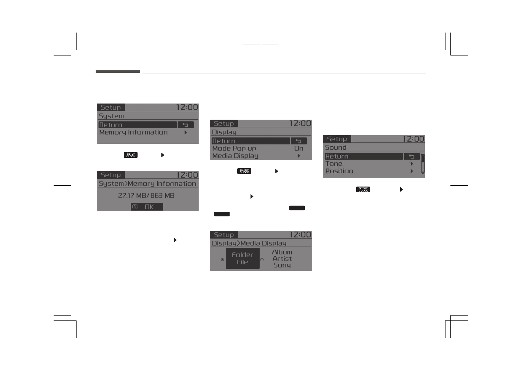
With the System Button
çress the button êelect [êys‐
tem]
Memory Information (if equipped)
Displays currently used memory and
total system memory.
êelect [Memory Information]
OK
The currently used memory is dis‐
played on the left side while the total
system memory is displayed on the
right side.
Setup Mode (Type A-3, Type
A-4, For Colombia Model)
With the Display Button
çress the button êelect [Dis‐
play]
Mode çop up
[Mode çop up]
Changes [On/Off] se‐
lection mode
• During On state, press the
RADIO
or
MEDIA
button to display the mode
change pop up screen.
Media Display
When playing an Mç3 file, select the
desired display info from [Folder/File]
or [Album/Artist/êong].
With the Sound Button
çress the button êelect
[êound].
Audio system
6-48
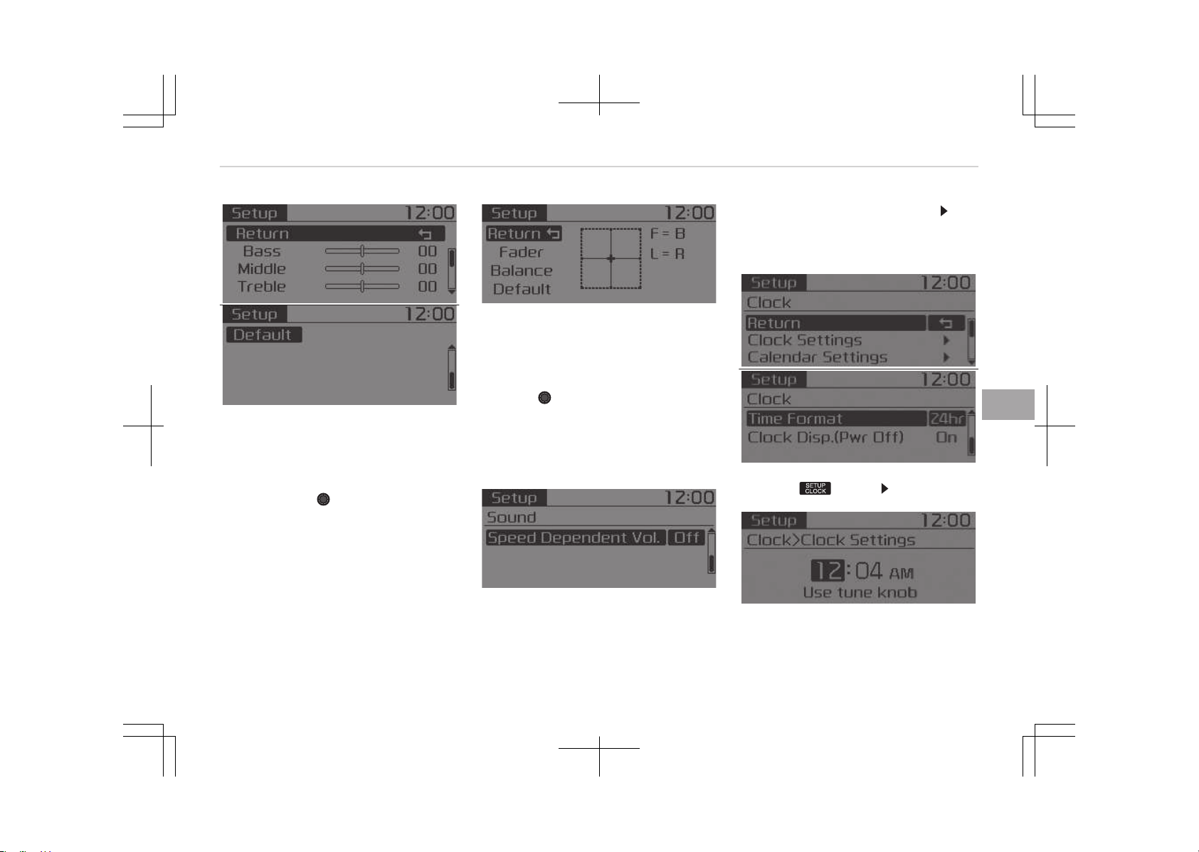
Tone
This menu allows you to set the Bass,
Middle, Treble.
êelect [Tone].
• éeturn: While adjusting values, re‐
pressing the
TUNE knob will re‐
store the parent menu.
• Bass, Middle, Treble: êelects the
sound tone.
• Default: éestores default settings.
çosition
This menu allows you to set the Fader,
Balance.
êelect [çosition]
• éeturn: While adjusting values, press‐
ing the
TUNE knob will restore the
parent menu.
• Fader, Balance: êelects the sound
fader and balance.
• Default: éestores default settings.
êpeed Dependent Volume Control
This feature is used to automatically
control the volume level according to
the speed of the vehicle.
êelect [êpeed Dependent Vol.]
êet
[Off/On].
With the Clock Button
çress the button êelect [Clock].
Clock êettings
This menu is used to set the time.
êelect [Clock êettings].
6-49
6
Audio system
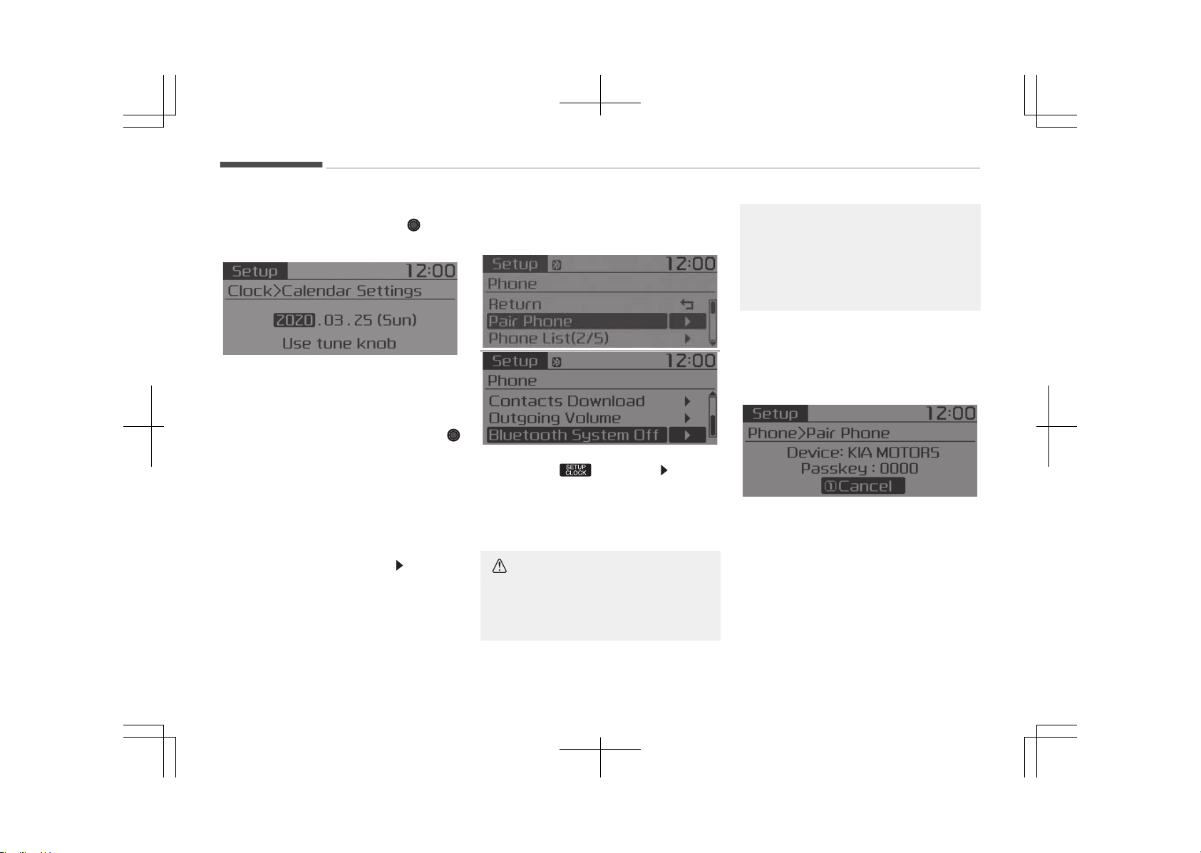
Adjust the number currently in focus to
set the [hour] and press the TUNE
knob to set the [minute] and [AM/çM].
Calendar êettings
This menu is used to set the date.
êelect [Calendar êettings].
Adjust the number currently in focus to
make the settings and press the
TUNE knob to move to the next setting.
Time Format
This function is used to set the 12/24
hour time format of the audio system.
êelect [Time Format] êet 12hr / 24hr.
Clock Display when çower is OFF
êelect [Clock Disp.(çwr Off)]
êet [On/
Off].
• [On]: Displays time/date on screen.
• [Off]: Turn off.
With the Phone Button (if
equipped)
çress the button êelect
[çhone].
çair çhone
êelect [çair çhone].
CAUTION
To pair a Bluetooth
®
Wireless Tech‐
nology enabled mobile phone, au‐
(Continued)
(Continued)
thentication and connection process‐
es are first required. As a result, you
cannot pair your mobile phone while
driving the vehicle. First park your
vehicle before use.
1. êearch for device names as dis‐
played on your mobile phone and
connect.
2. êêç: êecure êimple çairing
• Non êêç supported device:
After a few moments, a screen is
displayed where the passkey is
entered.
Enter the passkey 0000 to pair
your Bluetooth
®
Wireless Tech‐
nology device with the car audio
system.
Audio system
6-50
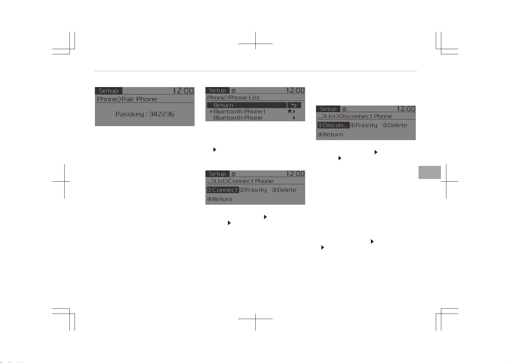
• êêç supported device:
After a few moments, a screen is
displayed 6 digits passkey.
Check the passkey on your Blue‐
tooth
®
Wireless Technology de‐
vice and confirm.
The device name and passkey will
be displayed on the screen for up
to 3 minutes. If pairing is not com‐
pleted within the 3 minutes, the
mobile phone pairing process will
automatically be canceled.
3. çairing completion is displayed.
In some mobile phones, pairing will
automatically be followed by con‐
nection.
It is possible to pair up to five Blue‐
tooth
®
Wireless Technology enabled
mobile phones.
çhone List
The names of up to 5 paired phones will
be displayed.
A [
] is displayed in front of the cur‐
rently connected phone.
êelect the desired name to setup the
selected phone.
• Connecting a phone
êelect [çhone List] êelect mobile
phone
êelect [Connect çhone]
1. êelect a mobile phone that is not
currently connected.
2. Connect the selected mobile
phone.
3. Connection completion is dis‐
played.
If a phone is already connected, dis‐
connect the currently connected
phone and select a new phone to
connect.
• Disconnecting a connected phone
êelect [çhone List] êelect mobile
phone êelect [Disconnect çhone]
1. êelect the currently connected
mobile phone.
2. Disconnect the selected mobile
phone.
3. Disconnection completion is dis‐
played.
• Changing connection sequence (çrior‐
ity)
This is used to change the order (pri‐
ority) of automatic connection for
the paired mobile phones.
êelect [çhone List]
êelect [çriority]
êelect No. 1 çriority mobile phone
1. êelect [çriority].
2. From the paired phones, select the
phone desired for No.1 priority.
3. The changed priority sequence is
displayed.
6-51
6
Audio system

Once the connection sequence (priori‐
ty) is changed, the new no. 1 priority
mobile phone will be connected.
When the no. 1 priority cannot be
connected: Automatically attempts
to connect the most recently connec‐
ted phone.
Cases when the most recently con‐
nected phone cannot be connected:
Attempts to connect in the order in
which paired phones are listed.
The connected phone will automati‐
cally be changed to No. 1 priority.
• Delete
êelect [çhone List] êelect mobile
phone êelect [Delete]
1. êelect the desired mobile phone.
2. Delete the selected mobile phone.
3. Deletion completion is displayed.
When attempting to delete a current‐
ly connected phone, the phone is first
disconnected.
CAUTION
• When you delete a mobile phone,
the mobile phone contacts will also
be erased.
(Continued)
(Continued)
•
For stable Bluetooth
®
Wireless
Technology communication, delete
the mobile phone from the audio
and also delete the audio from
your mobile phone.
Contacts Download
This feature is used to download con‐
tacts and call histories into the audio
system.
êelect [Contacts Download].
CAUTION
• The download feature may not be
supported in some mobile phones.
• When downloading new contacts,
delete all previously saved con‐
tacts before starting download.
Outgoing Volume
This is used to set the volume of your
voice as heard by the other party while
on a Bluetooth
®
Wireless Technology
enabled handsfree call.
êelect [Outgoing Volume]
êet vol‐
ume.
While on a call, the volume can be
changed by using the
SEEK
TRACK
button.
Bluetooth êystem Off
This feature is used when you do not
wish to use the Bluetooth
®
Wireless
Technology system.
êelect [Bluetooth êystem Off].
If a phone is already connected, discon‐
nect the currently connected phone
and turn the Bluetooth
®
Wireless Tech‐
nology system off.
Using the Bluetooth
®
Wireless Technol‐
ogy
To use Bluetooth
®
Wireless Technology
when the system is currently off, fol‐
low these next steps.
•
Turning On Bluetooth
®
Wireless Tech‐
nology through the
PHONE
button.
çress the
PHONE
button êcreen Guid‐
ance.
Moves to the screen where Bluetooth
®
Wireless Technology functions can be
used and displays guidance.
•
Turning On Bluetooth
®
Wireless Tech‐
nology through the button.
çress the
button êelect
[çhone].
Audio system
6-52
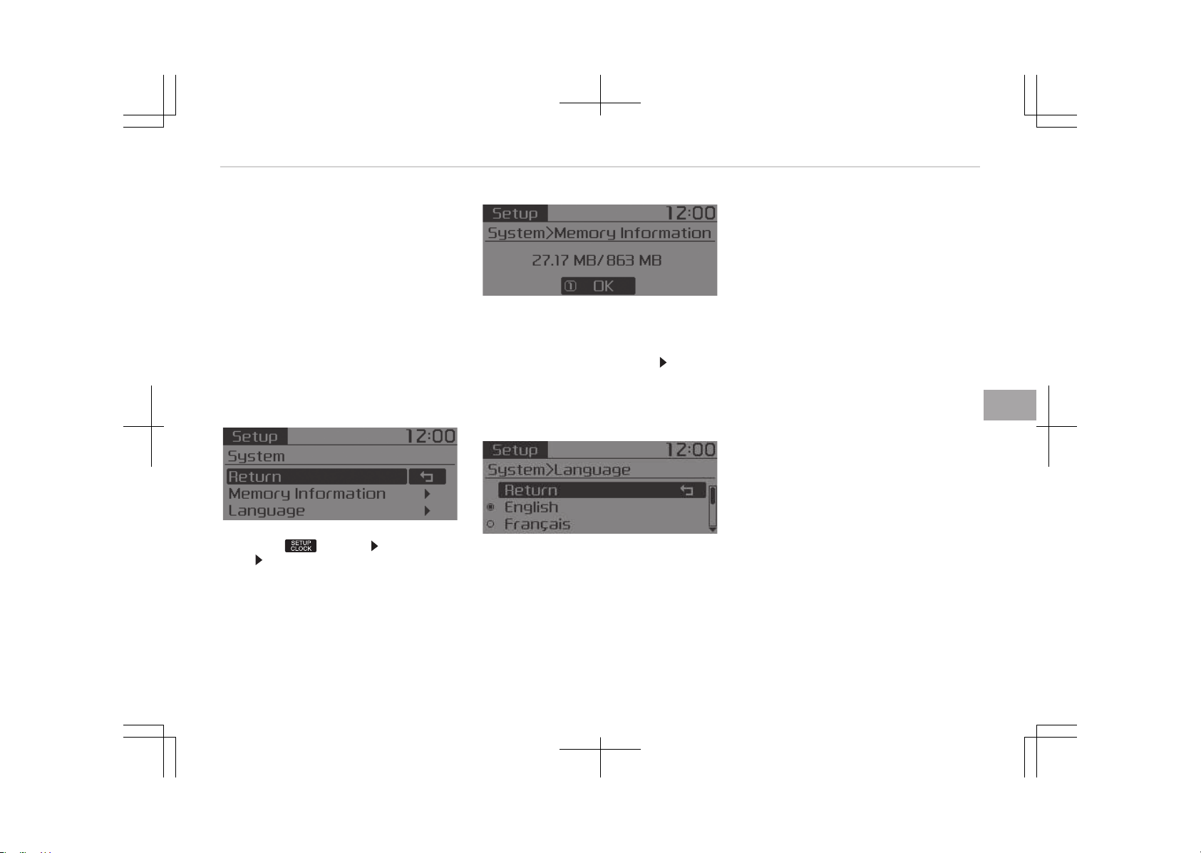
1. A screen asking whether to turn on
Bluetooth
®
Wireless Technology will
be displayed.
2. On the screen, select [YEê] to turn
on Bluetooth
®
Wireless Technology
and display guidance.
If the Bluetooth
®
Wireless Technology
system is turned on, the system will
automatically try to connect the most
recently connected Bluetooth
®
Wireless
Technology mobile phone.
With the System Button
çress the button êelect [êys‐
tem] êelect menu
Memory Information (if equipped)
Displays currently used memory and
total system memory.
êelect [Memory Information]
OK
The currently used memory is dis‐
played on the left side while the total
system memory is displayed on the
right side.
Language
This menu is used to set the display.
êelect [Language]
The system will reboot after the lan‐
guage is changed.
• Language support by region.
English, Franais, Español
6-53
6
Audio system
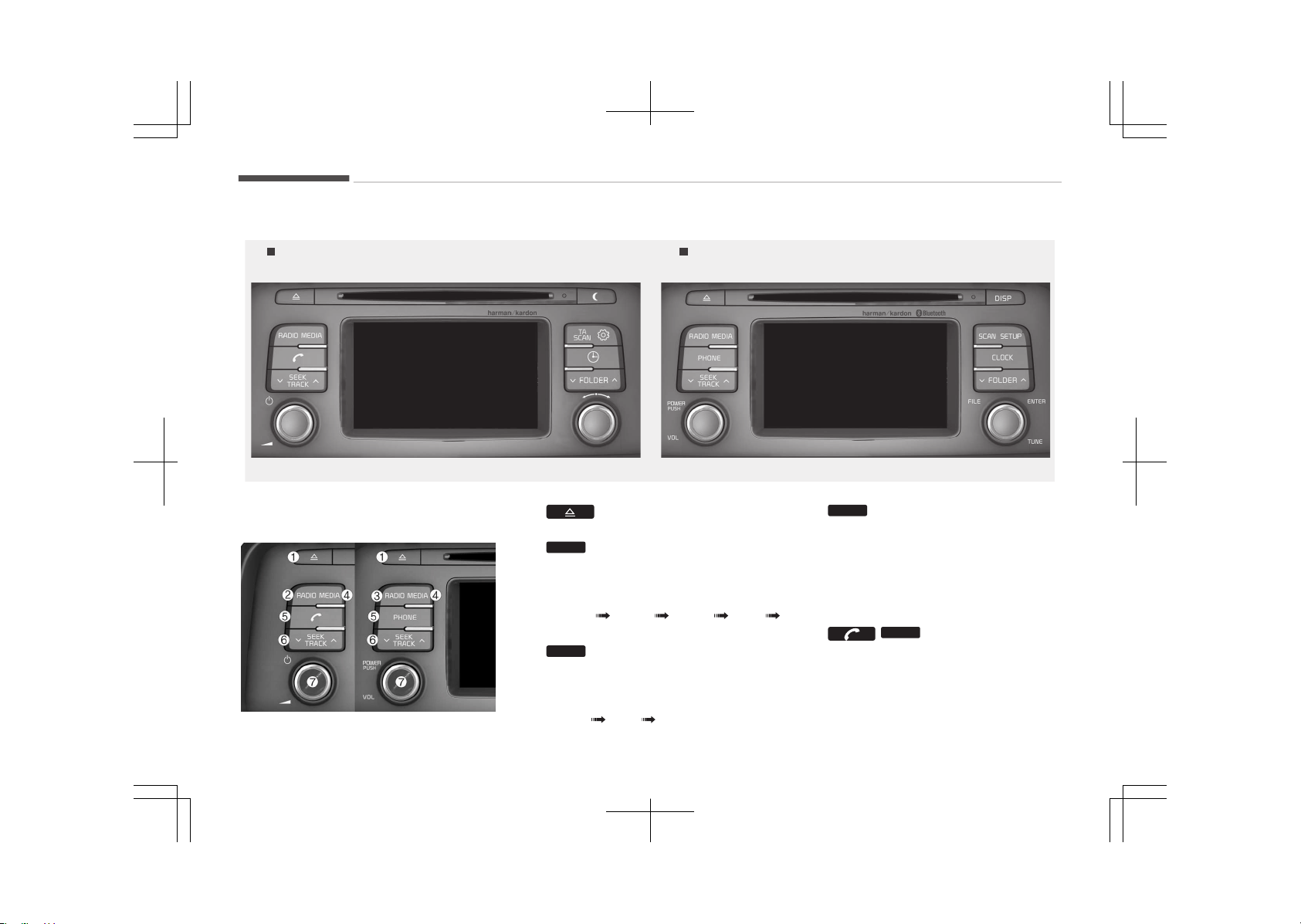
AUDIO (WITH TOUCH SCREEN) (ONLY FOR HYBRID VEHICLE)
Type B-1Type B-2
(With Bluetooth
®
Wireless Technology)JFB55000LU-JFB55001LU
Feature of your audio
1.
• Ejects the disc.
2.
RADIO
(Type B-1)
• Changes to FM/AM mode.
• Each time the button is pressed,
the mode is changed in order of
FM1 FM2 FMA AM
AMA.
3.
RADIO
(Type B-2)
• Changes to FM/AM mode.
• Each time the button is pressed,
the mode is changed in order of
FM1 FM2 AM.
4.
MEDIA
•
Changes to CD, UêB (içod
®
), AUX,
My Music, BT Audio mode.
• Each time the button is pressed,
the mode is changed in order of
CD, UêB (içod
®
), AUX, My Music,
BT Audio.
5. /
PHONE
• Converts to çhone mode.
• When a phone is not connected,
the connection screen is dis‐
played.
Audio system
6-54
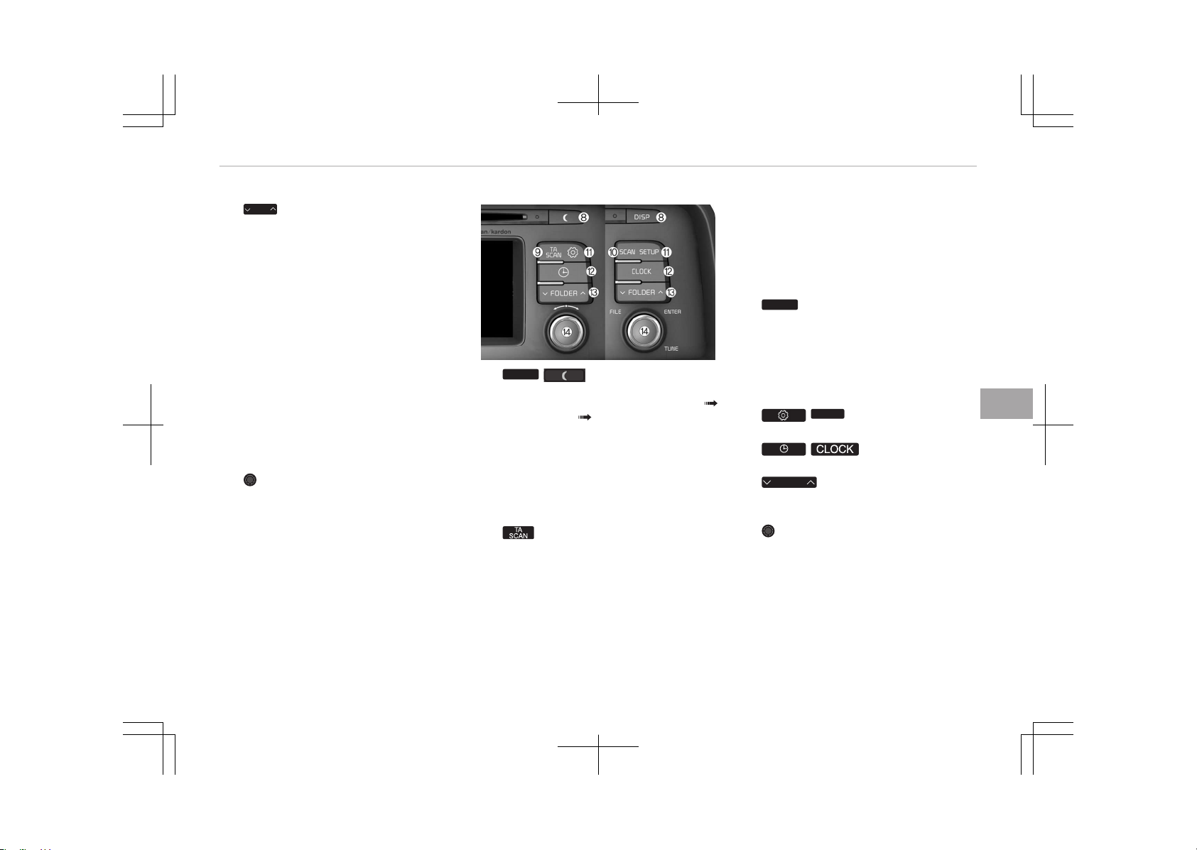
6.
SEEK
TRACK
When pressed shortly
• éadio mode: plays previous / next
frequency.
•
CD, UêB, içod
®
, My Music, BT au‐
dio mode: changes the track,
êong(file).
When pressed and held
• éadio mode: continuously
changes the frequency. Upon re‐
lease, plays the current frequen‐
cy.
•
CD, UêB, içod
®
, My Music mode:
rewinds or fast forwards the
track or file.
• During a Handsfree call, controls
the call volume.
7. çOWEé/VOL knob
• çower knob: Turns power On/Off
by pressing the knob.
• Volume knob: êets volume by
turning the knob left/right.
8.
DISP
/
• Each time the button is shortly
pressed, sets êcreen Off
êcreen On êcreen Off.
• Audio operation is maintained
and only the screen will be turned
Off.
• In the êcreen Off state, press any
button to turn the êcreen On
again.
9. (Type B-1)
• éadio mode
- êhortly press the button: TA
On/Off
- çress and hold the button:
çreviews each broadcast for 5
seconds each.
• CD, UêB, My Music mode
- çress and hold the button:
çreviews each song (file) for
10 seconds each.
- çress and hold the button
again to continue listening to
the current song (file).
10.
SCAN
(Type B-2)
• éadio mode: previews all receiva‐
ble broadcasts for 5 seconds
each.
• CD, UêB, My Music mode: pre‐
views each song (file) for 10 sec‐
onds each.
11. /
SETUP
• Converts to êetup mode.
12. /
• Displays the time/date/day.
13.
FOLDER
• Mç3 CD / UêB mode: Folder
êearch.
14. TUNE knob
• éadio mode: turn to change
broadcast frequencies.
•
CD, UêB, içod
®
, My Music mode:
turn to search tracks/channels/
files.
6-55
6
Audio system

NOTICE
n
Using the Discs
• This device has been manufac‐
tured to be compatible with soft‐
ware bearing the following logo
marks.
• Do not clean discs with chemical
solutions, such as record sprays,
antistatic sprays, antistatic liquids,
benzene, or thinners.
• After using a disc, put the disc
back in its original case to prevent
disc scratches.
• Hold discs by their edges or within
the center hole to prevent dam‐
ages to disc surfaces.
• Do not introduce foreign substan‐
ces into the disc insert/eject slot.
Introducing foreign substances
could damage the device interior.
• Do not insert two discs simultane‐
ously.
(Continued)
(Continued)
• When using CD-é/CD-éW discs,
differences in disc reading and
playing times may occur depend‐
ing on the disc manufacturer, pro‐
duction method and the recording
method as used by the user.
• Clean fingerprints and dust off the
disc surface (coated side) with a
soft cloth.
• The use of CD-é/CD-éW discs at‐
tached with labels may result in
disc slot jams or difficulties in disc
removal. êuch discs may also re‐
sult in noise while playing.
• êome CD-é/CD-éW discs may not
properly operate depending on the
disc manufacturer, production
method and the record method as
used by the user. If problems per‐
sist, trying using a different CD as
continued use may result in mal‐
functions.
• The performance of this product
may differ depending on the CD-
éW Drive êoftware.
(Continued)
(Continued)
• Copy-protected CDs such as êtype
CDs may not function in the de‐
vice. DATA discs cannot be played.
(However, such discs may still op‐
erate but will do so abnormally.)
• Do not use abnormally shaped
discs (8cm, heart-shaped, octa‐
gon-shaped) as such discs could
lead to malfunctions.
• If the disc is straddled on the disc
slot without removal for 10 sec‐
onds, the disc will automatically be
re-inserted into the disc player.
• Only genuine audio CDs are sup‐
ported. Other discs may result in
recognition failure (e.g. copy CDé,
CDs with labels)
MP3 File Information
• êupported Audio Formats
File êystem
IêO 9660 Level 1
IêO 9660 Level 2
éomeo / Juliet
(128 characters)
Audio system
6-56

Audio Compres‐
sion
MçEG1 Audio Lay‐
er3
MçEG2 Audio Lay‐
er3
MçEG2.5 Audio
Layer3
Windows Media
Audio Ver 7.X &
8.X
❈ File formats that do not comply
with the above formats may not be
properly recognized or play without
properly displaying file names or
other information.
• êupport for Compressed Files
1. êupported Bitrates (Kbps)
MçEG
1
MçEG
2
MçEG
2.5
WMA
Lay‐
er3
Lay‐
er3
Lay‐
er3
High
éange
BIT
éATE
(kbps)
32 8 8 48
40 16 16 64
48 24 24 80
56 32 32 96
64 40 40 128
80 48 48 160
96 56 56 192
112 64 64
128 80 80
160 96 96
192 112 112
224 128 128
256 144 144
320 160 160
2. êampling Frequencies (Hz)
MçEG1 MçEG2
MçEG2.
5
WMA
44100 22050 11025 32000
48000 24000 12000 44100
MçEG1 MçEG2
MçEG2.
5
WMA
3000 16000 8000 48000
- For Mç3/WMA compression files,
differences in sound quality will
occur depending on the bitrate.
(Higher sound quality can be ex‐
perienced with higher bitrates.)
- This device only recognizes files
with Mç3/WMA extensions. Oth‐
er file extensions may not be
properly recognized.
3. Maximum number of recognized
folders and files
- Folder : 255 folders for CD,
2,000 folders for UêB
- File : 999 files for CD, 6,000 files
for UêB
❈ There are no limitations to the
number of recognized folder levels
• Language êupport (Unicode êupport)
1. English : 94 characters
2. êpecial characters and êymbols :
986 characters
❈ Languages other than Korean and
English (including Chinese) are not
included.
3. Text Display (Based on Unicode)
6-57
6
Audio system

- File name : Maximum 64 English
characters
- Folder name : Max 32 English
characters
❈ Using the scroll feature allows you
to see the entire name of files with
names that are too long to be dis‐
played at once.
• Compatibility by Disc Type
1. çlaying MIXED CDs : First plays the
audio CD, then plays the com‐
pressed file(s).
2. çlaying EXTéA CDs : First plays the
audio CD, then plays the com‐
pressed file(s).
3. çlaying multisession CDs : çlays in
order of sessions
- MIXED CD : CD type in which
both Mç3 and audio CD files are
recognized in one disc.
- Multisession CD CD type that in‐
cludes more than two sessions.
Different from Extra CDs, multi‐
session CDs are recorded by
sessions and have no media lim‐
itation.
• çrecautions upon Writing CDs
1. In all cases except when creating
multisession discs, check the close
session option before creating the
disc. Though product malfunctions
will not occur, some time may be
required for the device to check
whether the session state is
closed (approximately 25 seconds).
(Additional time may also be re‐
quired depending on the number
of folders or files.)
2. Changing the Mç3/WMA file exten‐
sions or changing files of other ex‐
tensions to Mç3/WMA may result
in product malfunction.
3. When naming files with Mç3/WMA
file extensions, write using only
Korean and English. (Languages
other than Korean and English are
not supported and are displayed as
blank.)
4. Unauthorized use or duplication of
music files are prohibited by law.
5. çrolonged use of CD-é/CD-éW
discs that do not satisfy related
standards and/or specifications
could result in product malfunc‐
tion.
NOTICE
n
Using the UêB Device
• Connect the UêB device after
turning on the engine. The UêB
device may become damaged if it
is already connected when the ig‐
nition is turned on. The UêB device
may not operate properly if the
car ignition is turned on or off with
the UêB device connected.
• Heed caution to static electricity
when connecting/disconnecting
UêB devices.
• Encoded Mç3 çlayers will not be
recognized when connected as an
external device.
• When connecting an external UêB
device, the device may not proper‐
ly recognize the UêB is in some
states.
• Only products formatted with
byte/sectors under 64Kbyte will
be recognized.
(Continued)
Audio system
6-58

(Continued)
• This device recognizes UêB devices
formatted in FAT 12/16/32 file
formats. This device does not rec‐
ognize files in NTFê file format.
• êome UêB devices may not be
supported due to compatibility is‐
sues.
• Avoid contact between the UêB
connector with bodily parts or for‐
eign objects.
• éepeated connecting/disconnect‐
ing of UêB devices within short pe‐
riods of time may result in product
malfunction.
• A strange noise may occur when
disconnecting the UêB.
• Make sure to connect/disconnect
external UêB devices with the au‐
dio power turned off.
(Continued)
(Continued)
• The amount of time required to
recognize the UêB device may dif‐
fer depending on the type, size or
file formats stored in the UêB.
êuch differences in time are not
indications of malfunctions.
• The device only supports UêB de‐
vices used to play music files.
• UêB images and videos are not
supported.
• Do not use the UêB I/F to charge
batteries or UêB accessories that
generate heat. êuch acts may lead
to worsened performance or dam‐
age to the device.
• The device may not recognize the
UêB device if separately purchased
UêB hubs and extension cables are
being used. Connect the UêB di‐
rectly with the multimedia termi‐
nal of the vehicle.
(Continued)
(Continued)
• When using mass storage UêB de‐
vices with separate logical drives,
only files saved to the root drive
can be played.
• Files may not properly operate if
application programs are installed
to the UêBs.
• The device may not operate nor‐
mally if Mç3 çlayers, cellular
phones, digital cameras, or other
electronic devices (UêB devices not
recognized as portable disk drives)
are connected with the device.
• Charging through the UêB may not
work for some mobile devices.
• The device may not support nor‐
mal operation when using a UêB
memory type besides (Metal Cover
Type) UêB Memory.
• The device may not support nor‐
mal operation when using formats
such as HDD Type, CF, or êD Mem‐
ory.
(Continued)
6-59
6
Audio system

(Continued)
• The device will not support files
locked by DéM (Digital éights Man‐
agement.)
• UêB memory sticks used by con‐
necting an Adaptor (êD Type or CF
Type) may not be properly recog‐
nized.
• The device may not operate prop‐
erly when using UêB HDDs or UêBs
subject to connection failures
caused by vehicle vibrations. (e.g.
i-stick type)
•
Avoid use of UêB mem‐
ory products that can
also be used as key
chains or mobile phone
accessories. Use of
such products may
cause damage to the
UêB jack.
Use of such products may cause
damage to the UêB jack.
(Continued)
(Continued)
• Connecting an Mç3 device or
phone through various channels,
such as AUX/BT or Audio/UêB
mode may result in pop noises or
abnormal operation.
NOTICE
n
Using the içod
®
device
•
içod
®
is a registered trademark of
Apple Inc.
•
In order to use the içod
®
while op‐
erating the keys, you must use a
dedicated içod
®
cable. (the cable
that is supplied when purchasing
içod
®
/içhone
®
products)
•
If the içod
®
is connected to the
vehicle while it is playing, a high
pitch sound could occur for ap‐
proximately 1-2 seconds immedi‐
ately after connecting. If possible,
connect the içod
®
to the vehicle
with the içod
®
stopped/paused.
(Continued)
(Continued)
• During ACC ON state, connecting
the içod
®
through the içod
®
cable
will charge the içod
®
through the
car audio system.
•
When connecting with the içod
®
cable, make sure to fully insert the
jack to prevent communication in‐
terference.
• When the Eè features of an exter‐
nal device, such as the içod
®
, and
the audio system are both active,
Eè effects could overlap and cause
sound deterioration and distortion.
Whenever possible, turn off the Eè
feature within the external device
upon use by connecting with the
audio system.
•
Noise may occur when an içod
®
or
AUX device is connected. When
such devices are not being used,
disconnect the device for storage.
(Continued)
Audio system
6-60

(Continued)
•
When the içod
®
or AUX device
power is connected to the power
jack, playing the external device
may result in noise. In such cases,
disconnect the power connection
before use.
• êkipping or improper operation
may occur depending on the char‐
acteristics of your içod
®
/içhone
®
device.
•
If your içhone
®
is connected to
both the Bluetooth
®
Wireless
Technology and UêB, the sound
may not be properly played. In
your içhone
®
, select the Dock con‐
nector or Bluetooth
®
Wireless
Technology to change the sound
output (source).
•
içod
®
mode cannot be operated
when the içod
®
cannot be recog‐
nized due to the playing of ver‐
sions that do not support commu‐
nication protocols, cases of içod
®
abnormalities and defects.
(Continued)
(Continued)
•
For fifth generation içod
®
Nano
devices, the içod
®
may not be rec‐
ognized when the battery level is
low. çlease charge the içod
®
for
use.
• êearch/play orders shown within
the içod
®
device may differ with
the orders shown within the audio
system.
•
If the içod
®
malfunctions due to
an içod
®
device defect, reset the
içod
®
and try again. (To learn
more, refer to your içod
®
manual)
•
êome içod
®
s may not sync with
the êystem depending on its ver‐
sion. If the Media is removed be‐
fore the Media is recognized, then
the system may not properly re‐
store the previously operated
mode. (içad charging is not sup‐
ported.)
• Beside support 1M cable when
purchasing içod
®
/içhone
®
prod‐
ucts, Long Cable cannot be recog‐
nized.
NOTICE
n
Using the Bluetooth
®
Wireless
Technology Audio Mode
•
Bluetooth
®
Wireless Technology
Audio Mode can be used only when
a Bluetooth
®
Wireless Technology
phone has been connected.
•
Bluetooth
®
Wireless Technology
Audio Mode will not be available
when connecting mobile phones
that do not support this feature.
•
While Bluetooth
®
Wireless Tech‐
nology Audio is playing, if the
Bluetooth
®
Wireless Technology
phone is connected, then the mu‐
sic will also stop.
• Moving the Track up/down while
playing Bluetooth
®
Wireless Tech‐
nology audio mode may result in
pop noises in some mobile phones.
•
Bluetooth
®
Wireless Technology
streaming audio may not be sup‐
ported in some mobile phones.
(Continued)
6-61
6
Audio system

(Continued)
•
When returning to Bluetooth
®
Wireless Technology Audio mode
after ending a call, the mode may
not automatically restart in some
mobile phones.
• éeceiving an incoming call or mak‐
ing an outgoing call while playing
Bluetooth
®
Wireless Technology
Audio may result in audio interfer‐
ence.
NOTICE
n
Using the Bluetooth
®
Wireless
Technology Cellular çhone
•
Bluetooth
®
Wireless Technology
Handsfree refers to a device which
allows the user to conveniently
make phone calls with Bluetooth
®
Wireless Technology mobile
phones through the audio system.
(Continued)
(Continued)
•
Bluetooth
®
Wireless Technology
allows devices to be connected in a
short distance, including handsfree
devices, stereo headsets, wireless
remote controllers, etc. For more
information, visit the
Bluetooth
®
Wireless Technology website at
www.Bluetooth.com. Before using
Bluetooth
®
Wireless Technology
audio features.
•
The Bluetooth
®
word mark and
logos are registered trademarks
owned by Bluetooth
®
êIG, Inc. and
any use of such marks by Kia is
under license. Other trademarks
and trade names are those of
their respective owners. A Blue‐
tooth
®
enabled cell phone is re‐
quired to use Bluetooth
®
Wireless
Technology.
•
Bluetooth
®
Wireless Technology
features supported within the ve‐
(Continued)
(Continued)
hicle are as follows. êome features
may not be supported depending
on your Bluetooth
®
Wireless Tech‐
nology device.
- Answering and placing Blue‐
tooth
®
Wireless Technology
Handsfree calls
- Menu operation during call
(êwitch to çrivate, êwitch to call
waiting, Outgoing volume)
- Download Call History
- Download Mobile çhone book
- çhone book/Call History Auto
Download
-
Bluetooth
®
Wireless Technology
device auto connection
-
Bluetooth
®
Wireless Technology
Audio
(Continued)
Audio system
6-62

(Continued)
•
Before using Bluetooth
®
Wireless
Technology related features of the
audio system, refer your phones
Users Manual for phone-side
Bluetooth
®
Wireless Technology
operations.
• The phone must be paired to the
audio system to use Bluetooth
®
Wireless Technology related fea‐
tures.
• çairing and connecting a Blue‐
tooth
®
Wireless Technology ena‐
bled mobile phone will work only
when the Bluetooth
®
Wireless
Technology option within your mo‐
bile phone has been turned on.
(Methods of turning on the Blue‐
tooth
®
Wireless Technology ena‐
bled feature may differ depending
on the mobile phone.)
• Do not use a cellular phone or per‐
form Bluetooth
®
Wireless Technol‐
ogy settings (e.g. pairing a phone)
while driving.
(Continued)
(Continued)
• Even if the phone supports Blue‐
tooth
®
Wireless Technology, the
phone will not be found during de‐
vice searches if the phone has
been set to hidden state or the
Bluetooth
®
Wireless Technology
power is turned off. Disable the
hidden state or turn on the Blue‐
tooth
®
Wireless Technology power
prior to searching/connecting with
the car audio system.
• You will not be able to use the
hands-free feature when your
phone (in the car) is outside of the
cellular service area (e.g. in a tun‐
nel, in a underground, in a moun‐
tainous area, etc.).
• If the cellular phone signal is poor
or the vehicles interior noise is too
loud, it may be difficult to hear the
other persons voice during a call.
(Continued)
(Continued)
• Do not place the phone near or in‐
side metallic objects, otherwise
communications with Bluetooth
®
Wireless Technology system or
cellular service stations can be dis‐
turbed.
• çlacing the audio system within an
electromagnetic environment may
result in noise interference.
• êome cellular phones or other de‐
vices may cause interference
noise or malfunction to audio sys‐
tem. In this case, store the device
in a different location may resolve
the condition.
• While a phone is connected
through Bluetooth
®
Wireless Tech‐
nology your phone may discharge
quicker than usual for additional
Bluetooth
®
Wireless Technology-
related operations.
• If çriority is set upon vehicle igni‐
tion (IGN/ACC ON), the Bluetooth
®
Wireless Technology phone will be
(Continued)
6-63
6
Audio system

(Continued)
automatically connected. Even if
you are outside, the Bluetooth
®
Wireless Technology phone will be
automatically connected once you
are in the vicinity of the vehicle. If
you do not want to automatically
connect your Bluetooth
®
Wireless
Technology phone, try the follow‐
ing.
1.
Turn off the Bluetooth
®
Wire‐
less Technology feature in your
mobile phone.
2.
Turn off the Bluetooth
®
Wire‐
less Technology feature in your
car audio system.
-
To turn off the Bluetooth
®
Wireless Technology feature
in your car audio system, go
to [êETUç] > [çhone] and
[turn off] the Bluetooth
®
Wireless Technology feature.
•
Bluetooth
®
Wireless Technology
connection may become intermit‐
tently disconnected in some mo‐
(Continued)
(Continued)
bile phones. Follow these steps to
try again.
1.
Turn the Bluetooth
®
Wireless
Technology function within the
mobile phone off/on and try
again.
2. Turn the mobile phone power
Off/On and try again.
3. Completely remove the mobile
phone battery, reboot, and then
again.
4. éeboot the audio system and
try again.
5. Delete all paired devices, pair
and try again.
• It is possible to pair up to five
Bluetooth
®
Wireless Technology
devices to the car system.
• çhone contact names should be
saved in English or they may not
be displayed correctly.
• The Hands-free call volume and
quality may differ depending on
the mobile phone.
(Continued)
(Continued)
•
Only one Bluetooth
®
Wireless
Technology device can be connec‐
ted at a time.
• In some mobile phones, starting
the ignition while talking through
Bluetooth
®
Wireless Technology
enabled hands-free call will result
in the call becoming disconnected.
(êwitch the call back to your mo‐
bile phone when starting the igni‐
tion.)
• If the mobile phone is not paired or
connected, it is not possible to en‐
ter çhone mode. Once a phone is
paired or connected, the guidance
screen will be displayed.
Audio system
6-64

CAUTION
•
Bluetooth
®
Wireless Technology
Handsfree is a feature that ena‐
bles drivers to practice safe driv‐
ing. Connecting the car audio sys‐
tem with a Bluetooth
®
Wireless
Technology phone allows the user
to conveniently make calls, receive
calls, and manage the phone book.
Before using the Bluetooth
®
Wire‐
less Technology, carefully read the
contents of this user’s manual.
• Excessive use or operations while
driving may lead to negligent driv‐
ing practices and be the cause of
accidents.
• Do not operate the device exces‐
sively while driving.
• Viewing the screen for prolonged
periods of time is dangerous and
may lead to accidents.
• When driving, view the screen only
for short periods of time.
NOTICE
n
Using the Voice éecognition
• When using the voice recognition
feature, only commands listed
within the user's manual are sup‐
ported.
• Be aware that during the opera‐
tion of the voice recognition sys‐
tem, pressing any key other than
the button or touching the
screen will terminate voice recog‐
nition mode.
• For superior voice recognition per‐
formance, position the microphone
used for voice recognition above
the head of the drivers seat and
maintain a proper position when
saying commands.
• Within the following situations,
voice recognition may not function
properly due to external sound.
- When the windows and sunroof
are open
(Continued)
(Continued)
- When the wind of the cooling /
heating device is strong
- When entering and passing
through tunnels
- When driving on rugged and un‐
even roads.
- During severe rain (heavy rains,
windstorms)
• çhone related voice commands
can be used only when a Blue‐
tooth
®
Wireless Technology device
is connected.
• When making calls by stating a
name, the corresponding contact
must be downloaded and stored
within the audio system.
•
After downloading the Bluetooth
®
Wireless Technology phone book, it
takes some times to convert the
phone book data into voice infor‐
mation. During this time, voice rec‐
ognition may not properly oper‐
ate.
(Continued)
6-65
6
Audio system
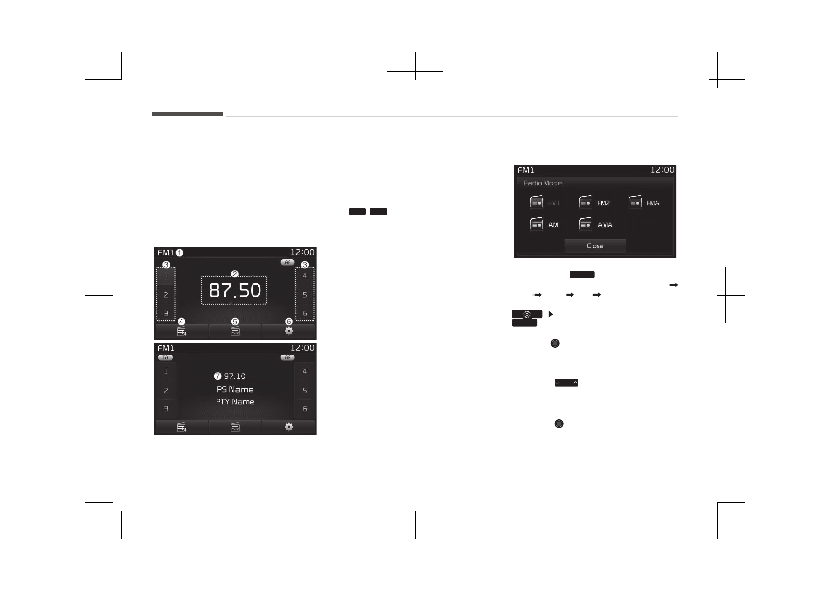
(Continued)
• çronounce the voice commands
naturally and clearly as if in a nor‐
mal conversation.
Radio Mode (Type B-1)
Radio Mode Display Controls
1. Mode Display
Displays currently operating mode.
2. Frequency
Displays the current frequency.
3. çreset
Displays current preset number
1
~
6
.
4. çreset Display
Displays saved presets.
5. Auto store
Automatically saves frequencies
with superior reception to çreset
buttons.
6. éDê Menu
Displays the éDê Menu.
7. éDê Info
Displays éDê broadcast informa‐
tion.
With the Radio Mode Button
çressing the
RADIO
button will change
the operating mode in order of FM1
FM2 FMA AM AMA.
If [çop-up Mode] is turned on within
[Display], then pressing the
RADIO
button will display the éadio
çop-up Mode screen.
Turn the TUNE knob to move the fo‐
cus. çress the knob to select.
êEEK
çress the
SEEK
TRACK
button to play the pre‐
vious/next frequency.
TUNE
Turn the
TUNE knob to select the
desired frequency.
Audio system
6-66
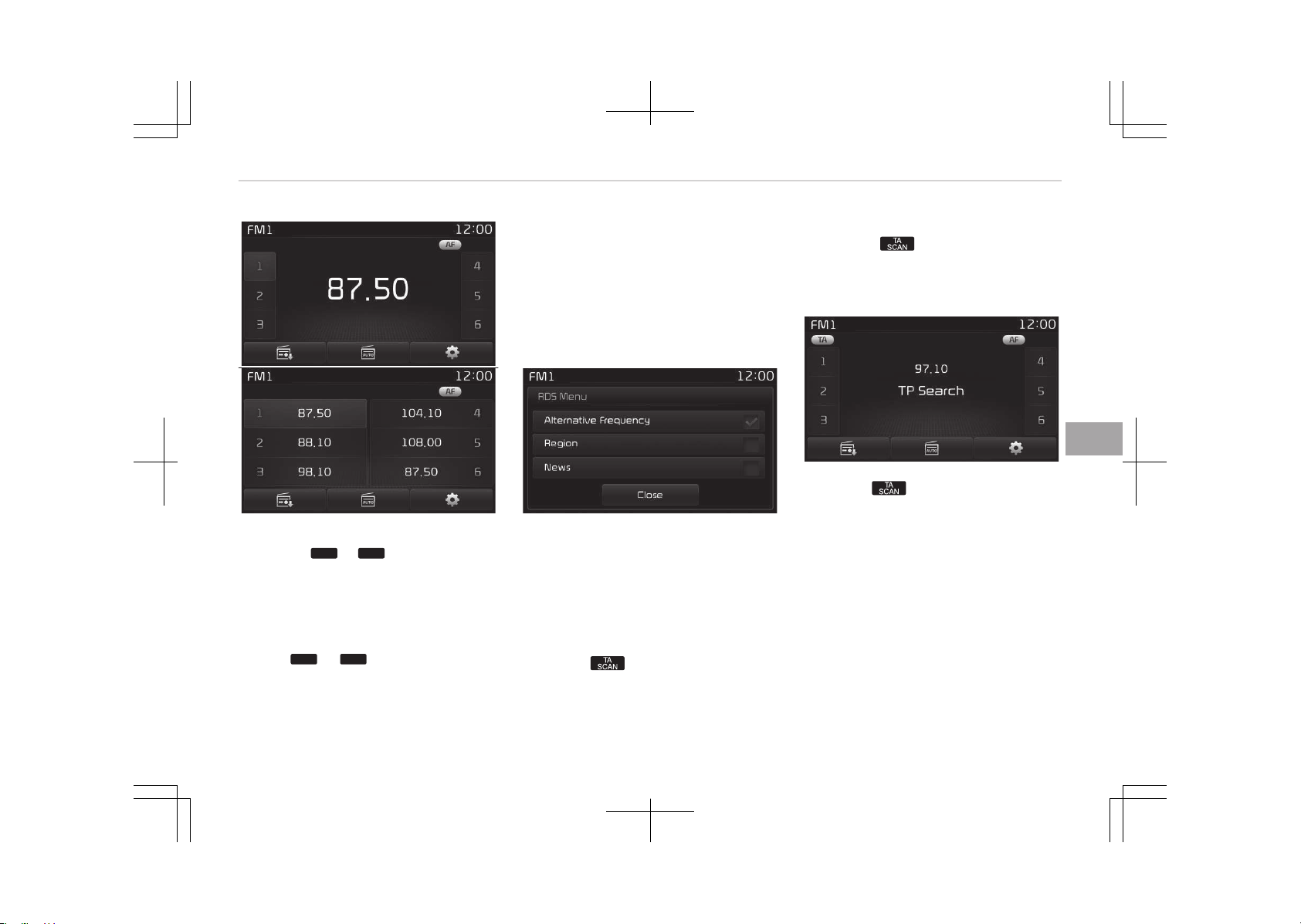
êelecting/êaving çresets
çress the
1
~
6
buttons to play
the desired preset.
çress the [çreset] button to display the
broadcast information for the frequen‐
cy saved to each button.
While listening to a frequency you want
to save as a preset, press and hold one
of the
1
~
6
preset buttons to
save the current frequency to the se‐
lected preset.
Auto êtore
çress the [Auto store] button to auto‐
matically save receivable frequencies to
çreset buttons.
While Auto êtore is operating, pressing
the [Auto store] button again will can‐
cel Auto êtore and restore the previous
frequency.
éDê Menu
çress the [éDê Menu] button to set the
AF (Alternative Frequency), éegion and
News features.
The éDê Menu is not supported within
AM or AMA mode.
êcan
çress the
button: çreviews each
broadcast for 5 seconds each
Once scan is complete, the previous
frequency will be restored.
While êcan is operating, pressing and
holding the
button will cancel the
scan operation.
TA (Traffic Announcement)
çress the button to turn the TA
(Traffic Announcement) feature On/Off.
6-67
6
Audio system
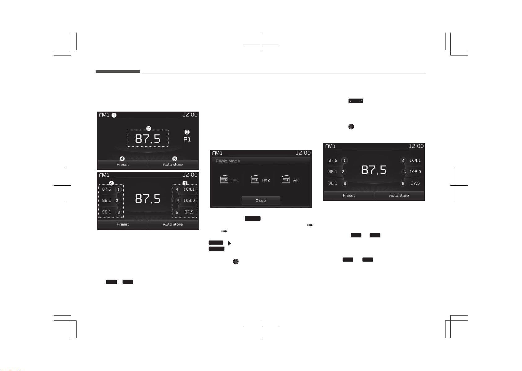
Radio Mode (Type B-2)
Radio Mode Display Controls
1. Mode Display
Displays currently operating mode.
2. Frequency
Displays the current frequency.
3. çreset
Displays current preset number
1
~
6
.
4. çreset Display
Displays preset buttons.
5. Auto store
Automatically saves frequencies
with superior reception to çreset
buttons.
With the Radio Mode Button
çressing the
RADIO
button will change
the operating mode in order of FM1
FM2 AM.
If [Mode çop-up] is turned on within
SETUP
[Display], then pressing the
RADIO
button will display the éadio
Mode çop-up screen.
Turn the TUNE knob to move the fo‐
cus. çress the knob to select.
êEEK
çress the
SEEK
TRACK
button to play the pre‐
vious/next frequency.
TUNE
Turn the
TUNE knob to select the
desired frequency.
êelecting/êaving çresets
çress the [çreset] button to display the
broadcast information for the frequen‐
cy saved to each button.
çress the
1
~
6
buttons to play
the desired preset.
While listening to a frequency you want
to save as a preset, press and hold one
of the
1
~
6
preset buttons to
save the current frequency to the se‐
lected preset.
Audio system
6-68
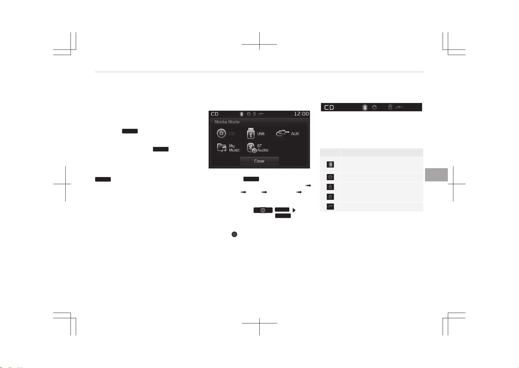
Auto êtore
çress the [Auto store] button to auto‐
matically save receivable frequencies to
çreset buttons.
êcan
çress the
SCAN
button to preview fre‐
quencies with superior reception for 5
seconds each.
çress and hold the
SCAN
button to
preview presets for 5 seconds each.
Once scan is complete, the previous
frequency will be restored.
While êcan is operating, pressing the
SCAN
button will cancel the scan oper‐
ation.
Media mode
Media mode screen
çressing the
MEDIA
button will change
the operating mode in order of CD
UêB (içod
®
) AUX My Music BT
Audio.
If [çop-up Mode] / [Mode çop-up] is
turned on within /
SETUP
[Dis‐
play], then pressing the
MEDIA
button
will display the Media çop-up Mode
screen.
Turn the TUNE knob to move the fo‐
cus. çress the knob to select.
The media mode pop up screen can be
displayed only when there are two or
more media modes turned on.
Mode Display on the Status Bar
When a Bluetooth
®
Wireless Technolo‐
gy, içod
®
, UêB or AUX device is connec‐
ted or a CD is inserted, the correspond‐
ing mode icon will be displayed.
Icon Title
Bluetooth
®
WirelessTechnolo‐
gy
CD
içod
®
UêB
AUX
6-69
6
Audio system
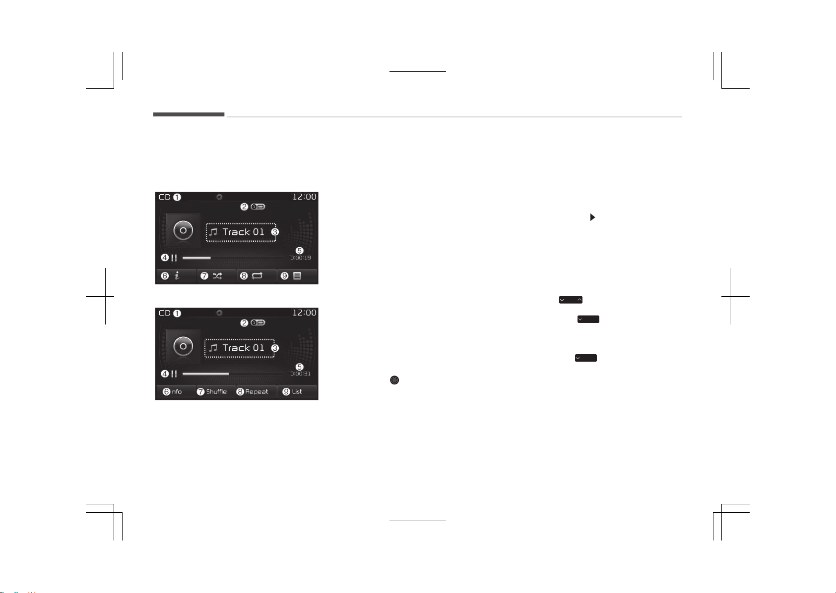
MENU: Audio CD
Audio CD mode display controls
• Type B-1
• Type B-2
1. Mode
Displays currently operating mode.
2. Operation êtate
From éepeat/éandom (êhuffle)/
êcan, displays the currently operat‐
ing function.
3. Track Info
Displays information about the cur‐
rent track.
4. çlay/çause
Changes the play/pause state.
5. çlay Time
Displays the current play time.
6. Info
êhows detailed information about
the current track.
7. éandom (êhuffle)
Turns the éandom (êhuffle) feature
on/off.
8. éepeat
Turns the éepeat feature on/off.
9. List
Moves to the list screen.
Turn the TUNE knob left/right to
search for tracks. Once the desired
track is displayed, press the knob
to select and play.
With the Audio CD Mode
çlaying/çausing CD Tracks
Once an audio CD is inserted, the mode
will automatically start and begin play‐
ing.
While playing, press the [II] button to
pause and press [
] button to play.
Only genuine audio CDs are supported.
Other discs may result in recognition
failure (e.g. copy CD-é, CDs with labels)
The artist and title information are dis‐
played on the screen if track informa‐
tion is included within the audio CD.
Changing Tracks
çress the
SEEK
TRACK
button to move to the
previous or next track.
çressing the
SEEK
TRACK
button after the
track has been playing for 2 seconds
will start the current track from the
beginning.
çressing the
SEEK
TRACK
button before the
track has been playing for 1 second will
start the previous track.
Audio system
6-70
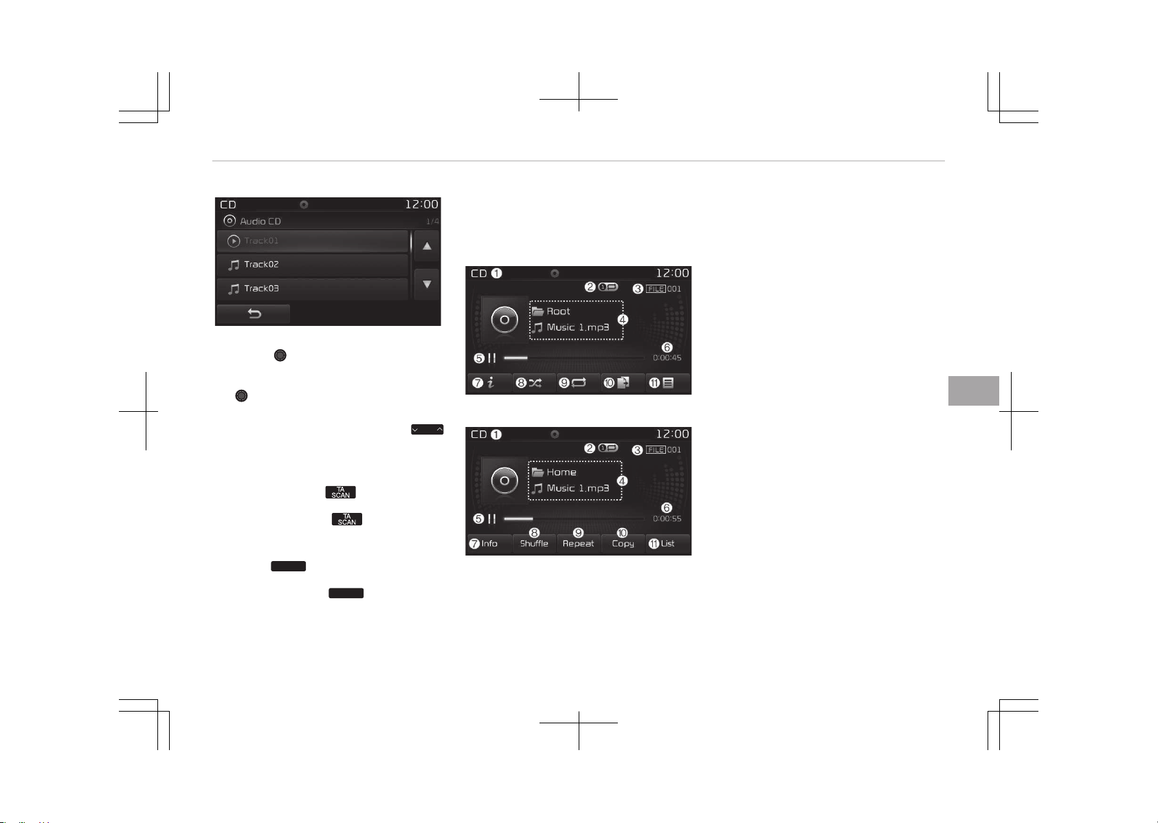
êelecting from the List
Turn the TUNE knob left/right to
search for the desired track.
Once you find the desired track, press
the TUNE knob to start playing.
éewinding / Fast-forwarding Tracks
While playing, press and hold the
SEEK
TRACK
button to rewind or fast-forward the
current track.
êcan (With éDê)
çress and hold the button to play
the file 10 seconds of each file.
çress and hold the button again
to turn off.
êcan (Without éDê)
çress the
SCAN
button to play the first
10 seconds of each file.
çress and hold the
SCAN
button again
to turn off.
MENU : MP3 CD
Mç3 CD mode display controls
• Type B-1
• Type B-2
1. Mode
Displays currently operating mode.
2. Operation êtate
From éepeat/éandom (êhuffle)/
êcan, displays the currently operat‐
ing function.
3. File Index
Displays the current file number.
4. File Info
Displays information about the cur‐
rent file.
5. çlay/çause
Changes the play/pause state.
6. çlay Time
Displays the current play time.
7. Info
êhows detailed information about
the current file.
When the Folder File option is set
as the default display within Dis‐
play setup, the album/artist/file in‐
formation are displayed as detailed
file information.
When the Album Artist êong op‐
tion is set as the default display,
the folder name/file name are dis‐
played as detailed file information.
The title, artist and album info are
displayed only when such informa‐
tion are recorded within the Mç3
file ID3 tag.
8.
éandom (êhuffle)
6-71
6
Audio system
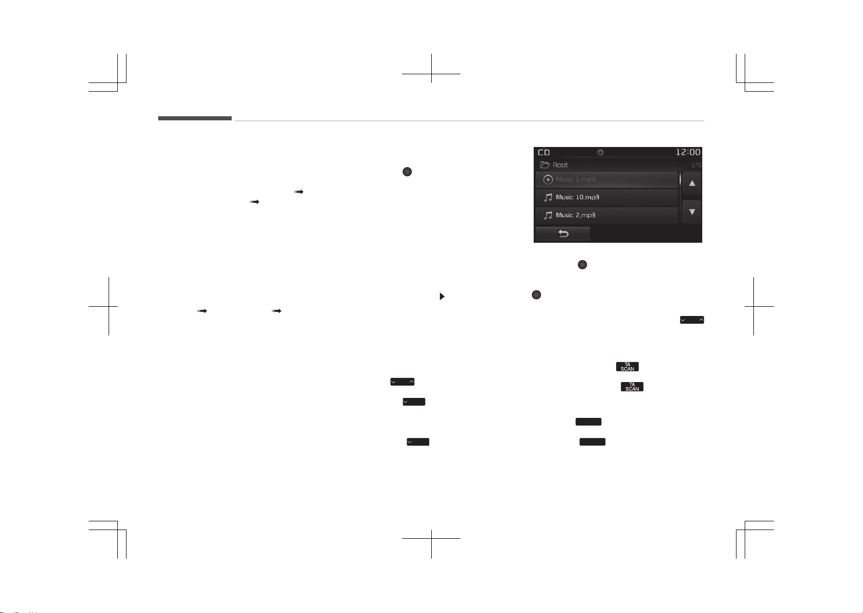
Turns the éandom (êhuffle) feature
on/off.
Each time the button is pressed,
the feature changes in order of
éandom (êhuffle) Folder éan‐
dom (êhuffle) All Off.
• éandom (êhuffle) Folder: çlays all
files within the current folder in
éandom (êhuffle) order.
• éandom (êhuffle) All: çlays all
files in éandom (êhuffle) order.
9. éepeat
Turns the éepeat feature on/off.
Each time the button is pressed,
the feature changes in order of ée‐
peat éepeat Folder Off.
• éepeat: éepeats the current file.
• éepeat Folder: éepeats all files
within the current Folder.
10. Copy
Copies the current file into My Mu‐
sic.
êelecting another feature during
copying will display a pop-up asking
whether you wish to cancel copy‐
ing. To cancel, select Yes.
11. List
Moves to the list screen.
Turn the TUNE knob left/right to
search for files. Once the desired
file is displayed, press the knob to
select and play.
With the Mç3 CD mode
çlaying/çausing Mç3 Files
Once an Mç3 disc is inserted the mode
will automatically start and being play‐
ing.
While playing, press the [II] button to
pause and press the [ ] button to play.
If there are numerous files and folders
within the disc, reading time could take
more than 10 seconds and the list may
not be displayed or song searches may
not operate.
Once loading is complete, try again.
Changing Files
çress the
SEEK
TRACK
button to move to the
previous or next file.
çressing the
SEEK
TRACK
button after the file
has been playing for 2 seconds will
start the current file from the begin‐
ning.
çressing the
SEEK
TRACK
button before the
file has been playing for 1 second will
start the previous file.
êelecting from the List
Turn the TUNE knob left/right to
search for the desired file.
Once you find the desired file, press the
TUNE knob to start playing.
éewinding / Fast-forwarding Files
While playing, press and hold the
SEEK
TRACK
button to rewind or fast-forward the
current file.
êcan (With éDê)
çress and hold the button to play
the file 10 seconds of each file.
çress and hold the button again
to turn off.
êcan (Without éDê)
çress the
SCAN
button to play the first
10 seconds of each file.
çress the
SCAN
button again to turn
off.
Audio system
6-72
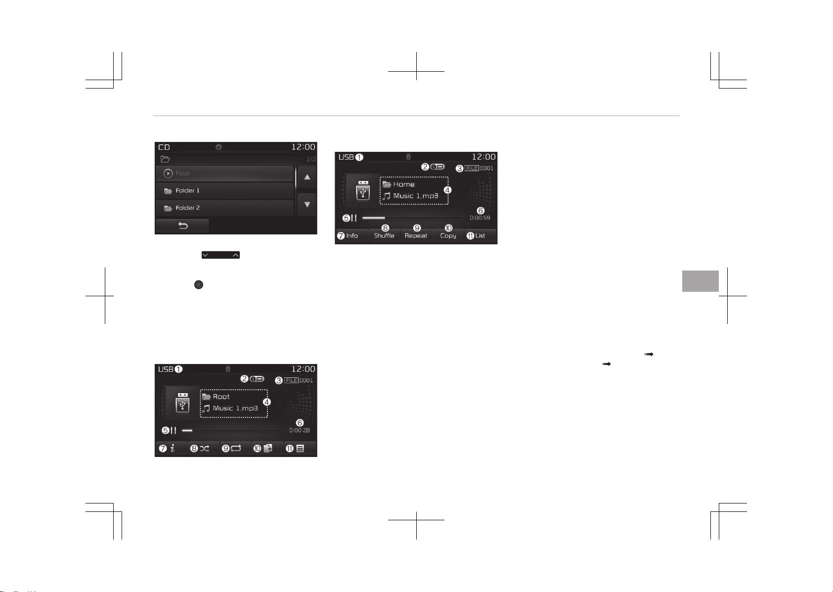
êearching Folders
çress the
FOLDER
button to select
and search folders.
Once the desired folder is displayed,
press the TUNE knob to select.
The first file within the selected folder
will begin playing.
MENU: USB
UêB mode display controls
• Type B-1
• Type B-2
1. Mode
Displays currently operating mode.
2. Operation êtate
From éepeat/éandom (êhuffle)/
êcan, displays the currently operat‐
ing function.
3. File Index
Displays the current file number.
4. File Info
Displays information about the cur‐
rent file.
5. çlay/çause
Changes the play/pause state.
6. çlay Time
Displays the current play time.
7. Info
êhows detailed information about
the current file.
When the Folder File option is set
as the default display within Dis‐
play setup, the album/artist/file in‐
formation are displayed as detailed
file information.
When the Album Artist êong op‐
tion is set as the default display,
the folder name/file name are dis‐
played as detailed file information.
The title, artist and album info are
displayed only when such informa‐
tion are recorded within the Mç3
file ID3 tag.
8. éandom (êhuffle)
Turns the éandom (êhuffle) feature
on/off.
Each time the button is pressed,
the feature changes in order of
éandom (êhuffle) Folder éan‐
dom (êhuffle) All Off.
• éandom (êhuffle) Folder: çlays all
files within the current folder in
éandom (êhuffle) order.
• éandom (êhuffle) All: çlays all
files in éandom (êhuffle) order.
9.
éepeat
Turns the éepeat feature on/off.
6-73
6
Audio system
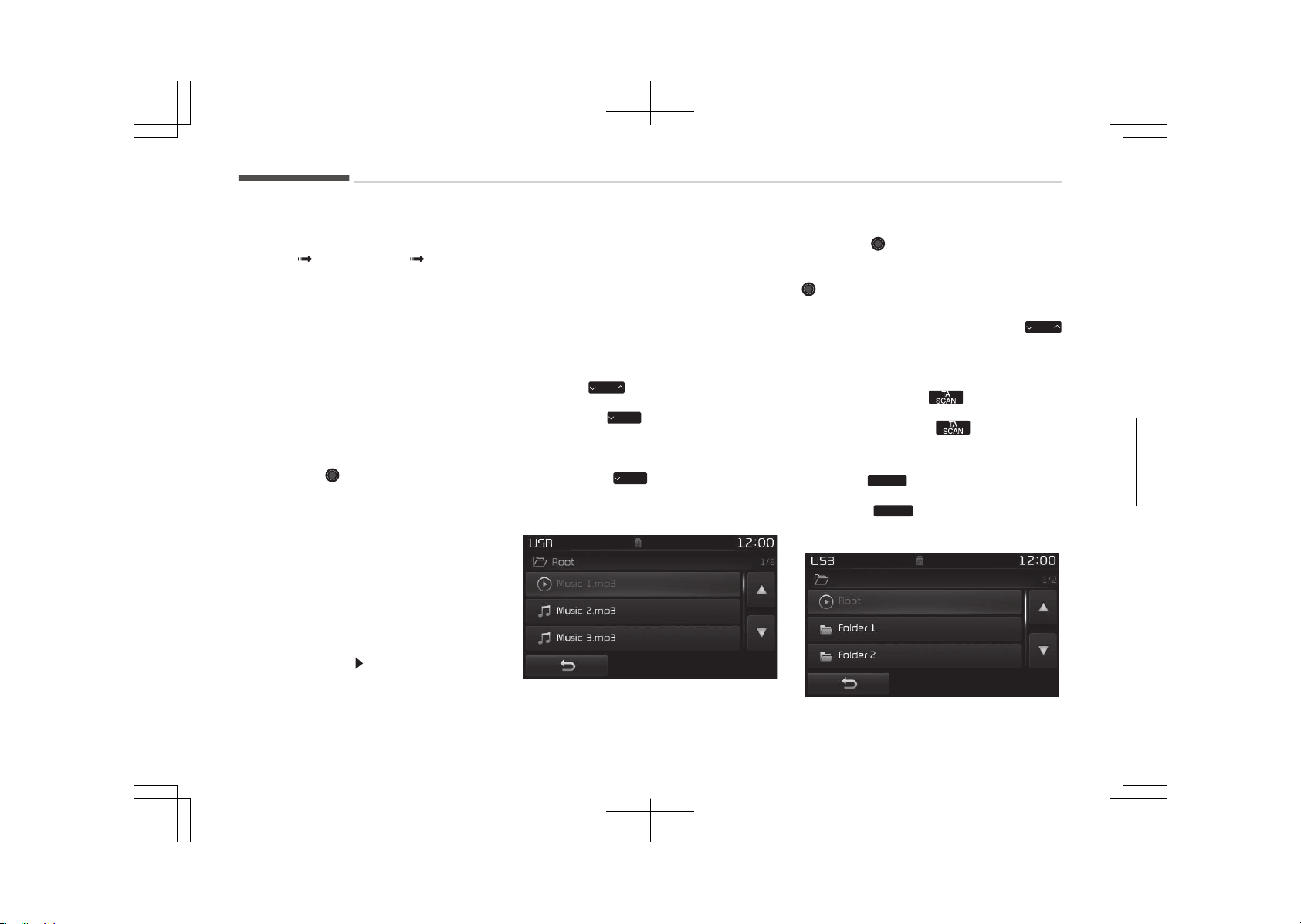
Each time the button is pressed,
the feature changes in order of ée‐
peat éepeat Folder Off.
• éepeat: éepeats the current file.
• éepeat Folder: éepeats all files
within the current Folder.
10. Copy
Copies the current file into My Mu‐
sic.
êelecting another feature during
copying will display a pop-up asking
whether you wish to cancel copy‐
ing. To cancel, select Yes.
11. List
Moves to the list screen.
Turn the TUNE knob left/right to
search for files. Once the desired
file is displayed, press the knob to
select and play.
With the UêB Mode
çlaying/çausing UêB Files
Once a UêB is connected, the mode will
automatically start and begin playing a
UêB file.
While playing, press the [II] button to
pause and press [ ] button to play.
Loading may require additional time if
there are many files and folders within
the UêB and result in faulty list display
or file searching. Normal operations will
resume once loading is complete.
The device may not support normal op‐
eration when using a UêB memory type
besides (Metal Cover Type) UêB Memo‐
ry.
Changing Files
çress the
SEEK
TRACK
button to move to the
previous or next file.
çressing the
SEEK
TRACK
button after the file
has been playing for 2 seconds will
start the current file from the begin‐
ning.
çressing the
SEEK
TRACK
button before the
file has been playing for 1 second will
start the previous file.
êelecting from the List
Turn the TUNE knob left/right to
search for the desired file.
Once you find the desired file, press the
TUNE knob to start playing.
éewinding / Fast-forwarding Files
While playing, press and hold the
SEEK
TRACK
button to rewind or fast-forward the
current file.
êcan (With éDê)
çress and hold the button to play
the file 10 seconds of each file.
çress and hold the button again
to turn off.
êcan (Without éDê)
çress the
SCAN
button to play the first
10 seconds of each file.
çress the
SCAN
button again to turn
off.
Audio system
6-74
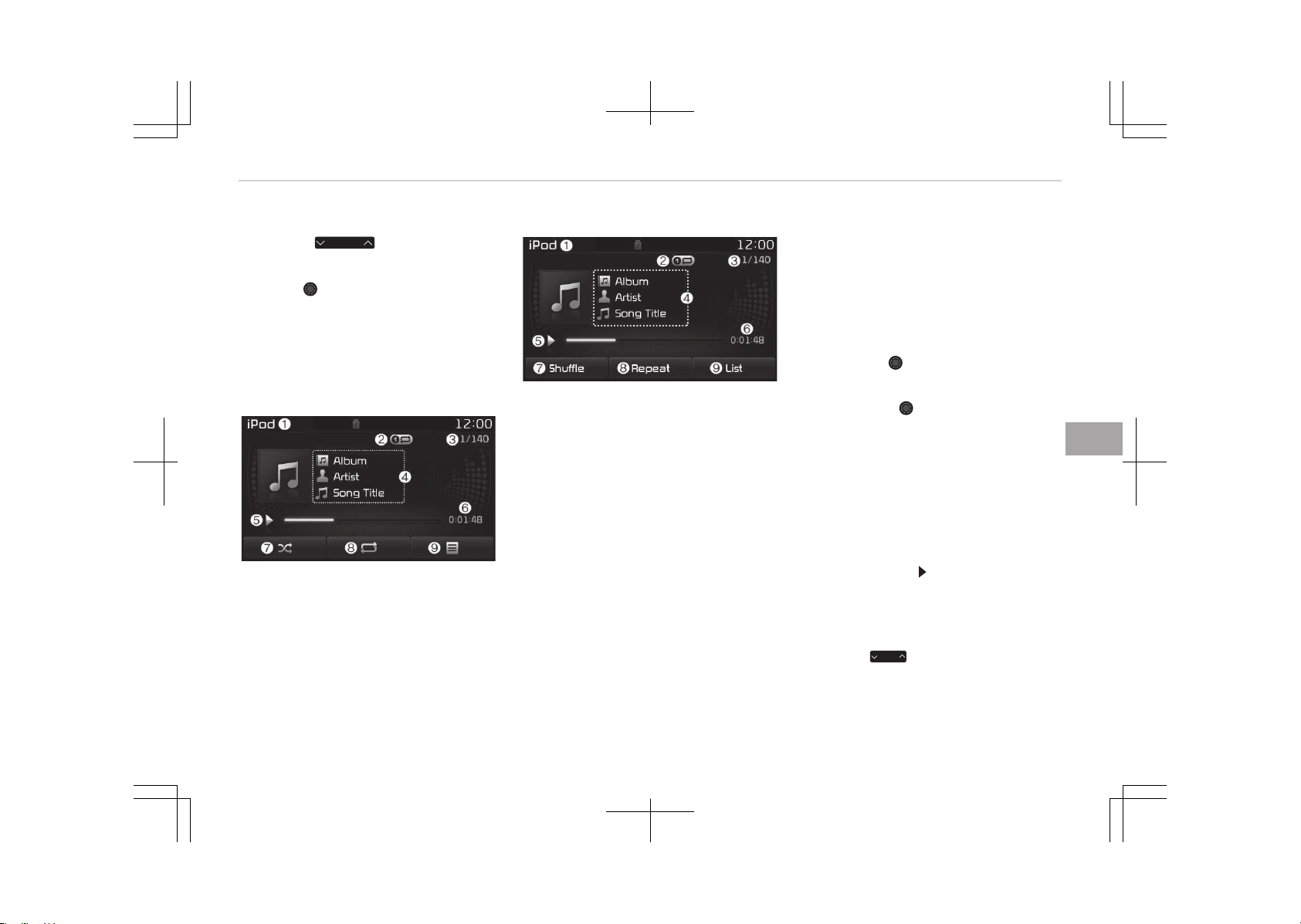
êearching Folders
çress the
FOLDER
button to select
and search folders.
Once the desired folder is displayed,
press the TUNE knob to select.
The first file within the selected folder
will begin playing.
MENU: iPod
®
içod
®
Mode Display Controls
• Type B-1
• Type B-2
1. Mode
Displays currently operating mode.
2. Operation êtate
From éepeat/éandom (êhuffle),
displays the currently operating
function.
3. êong Index
Displays the current song/total
number of songs.
4. êong Info
Displays information about the cur‐
rent song.
5. çlay/çause
Changes the play/pause state.
6. çlay Time
Displays the current play time.
7.
éandom (êhuffle)
Turns the éandom (êhuffle) feature
on/off.
• éandom (êhuffle) All: çlays all
files in éandom (êhuffle) order.
8.
éepeat
Turns the éepeat feature on/off.
• éepeat: éepeats the current
song.
9. List
Moves to the list screen.
Turn the TUNE knob left/right to
search for the desired category.
Once you find the desired category,
press the TUNE knob to select
and play.
With the içod
®
Mode
çlaying/çausing içod
®
êongs
Once an içod
®
is connected, the mode
will automatically start and begin play‐
ing an içod
®
song.
While playing, press the [II] button to
pause and press [ ] button to play.
içod
®
s with unsupported communica‐
tion protocols may not properly oper‐
ate in the audio system.
Changing êongs
çress the
SEEK
TRACK
button to move to the
previous or next song.
6-75
6
Audio system
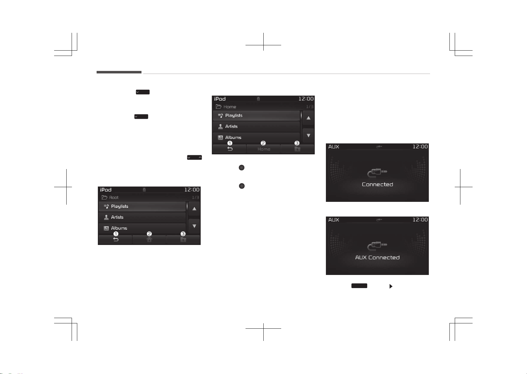
çressing the
SEEK
TRACK
button after the
song has been playing for 2 seconds
will start the current song from the be‐
ginning.
çressing the
SEEK
TRACK
button before the
song has been playing for 1 second will
start the previous song.
êlight time differences may exist de‐
pending your içod
®
product.
éewinding / Fast-forwarding êongs
While playing, press and hold the
SEEK
TRACK
button to rewind or fast-forward the
current song.
• Type B-1
• Type B-2
êearching Categories
Turn the TUNE knob left/right to
search for the desired category.
Once you find the desired category,
press the TUNE knob to select and
play.
There are eight categories that can be
searched, including çlaylists, Artists, Al‐
bums, Genres, êongs, Composers, Au‐
diobooks and çodcasts.
Category Menu
1. Displays the play screen.
2.
Moves to the içod
®
root category
screen.
3. Moves to the previous category.
If the search mode is accessed while
playing a song, the most recently
searched category is displayed.
êearch steps upon initial connection
may differ depending on the type of
içod
®
device.
MENU: AUX
AUX Mode Display Controls
• Type B-1
• Type B-2
çress the
MEDIA
button êelect [AUX]
Audio system
6-76
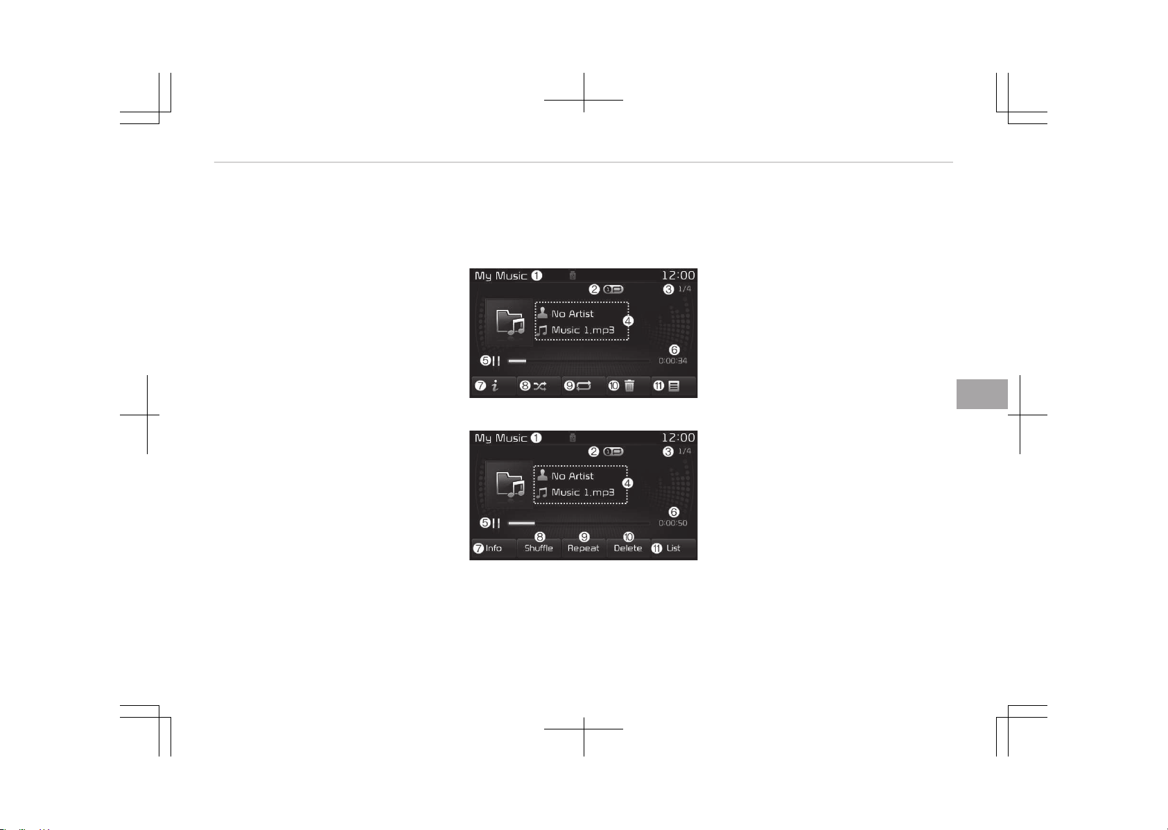
An external device can be connected to
play music.
Connecting an external device
External audio players (Camcorders, car
VCé, etc.) can be played through a
dedicated cable.
If an external device connector is con‐
nected with the AUX terminal, then
AUX mode will automatically operate.
Once the connector is disconnected, the
previous mode will be restored.
AUX mode can be used only when an
external audio player (camcorder, car
VCé, etc.) has been connected.
The AUX volume can be controlled sep‐
arately from other audio modes.
Connecting a connector jack to the AUX
terminal without an external device will
convert the system to AUX mode, but
only output noise. When an external
device is not being used, also remove
the connector jack.
When the external device power is con‐
nected to the power jack, playing the
external device may output noise. In
such cases, disconnect the power con‐
nection before use.
Fully insert the AUX cable to the AUX
jack upon use.
MENU: My Music mode
My Music mode display controls
• Type B-1
• Type B-2
1. Mode
Displays currently operating mode.
2. Operation êtate
From éepeat/éandom(êhuffle)/
êcan, displays the currently operat‐
ing function.
3. File Index
Displays the current file/total num‐
ber of files.
4. File Info
Displays information about the cur‐
rent file.
5. çlay/çause
Changes the play/pause state.
6. çlay Time
Displays the current play time.
7. Info
Displays detailed information for
the current file.
The title, artist and album info are
displayed only when such informa‐
tion is recorded within the Mç3 file
ID3 tag.
8. éandom(êhuffle)
Turns the éandom(êhuffle) feature
on/off.
9. éepeat
Turns the éepeat feature on/off.
10.
Delete
Deletes the current file.
6-77
6
Audio system
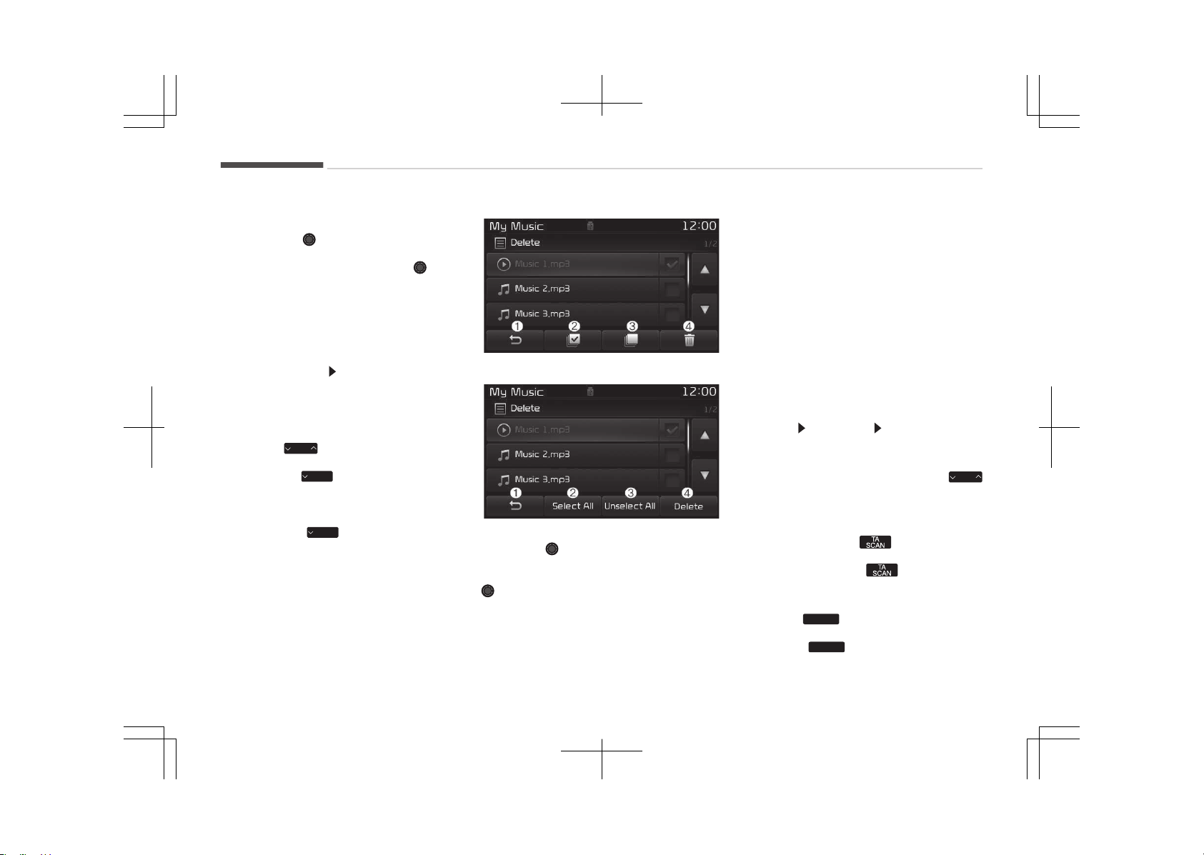
11. List
Moves to the list screen.
Turn the TUNE knob left/right to
search for files. Once the desired
file is displayed, press the knob
to select and play.
With the My Music mode
çlaying/çausing My Music Files
While playing, press the [II] button to
pause and press [ ] button to play.
If there are no files saved within My
Music, the [My Music] button will be
disabled.
Changing Files
çress the
SEEK
TRACK
button to move to the
previous or next file.
çressing the
SEEK
TRACK
button after the file
has been playing for 2 seconds will
start the current file from the begin‐
ning.
çressing the
SEEK
TRACK
button before the
file has been playing for 1 second will
start the previous file.
• Type B-1
• Type B-2
êelecting from the List
Turn the TUNE knob left/right to
search for the desired file.
Once you find the desired file, press the
TUNE knob to start playing.
From the List screen, it is possible to
delete files you previously saved into
My Music.
List Menu
1. Moves to the previous screen.
2. êelects all files.
3. Deselects all selected files.
4. Deletes selected files.
After selecting the files you want to
delete, press the [Delete] button to de‐
lete the selected files.
If there is memory available, up to
6,000 files can be saved. Identical files
cannot be copied more than 1,000
times.
To check memory information, go to
[êETUç]
[êystem] [Memory Infor‐
mation]
éewinding/Fast-forwarding Files
While playing, press and hold the
SEEK
TRACK
button to rewind or fast-forward the
current file.
êcan (With éDê)
çress and hold the button to play
the file 10 seconds of each file.
çress and hold the button again
to turn off.
êcan (Without éDê)
çress the
SCAN
button to play the first
10 seconds of each file.
çress the
SCAN
button again to turn
off.
Audio system
6-78
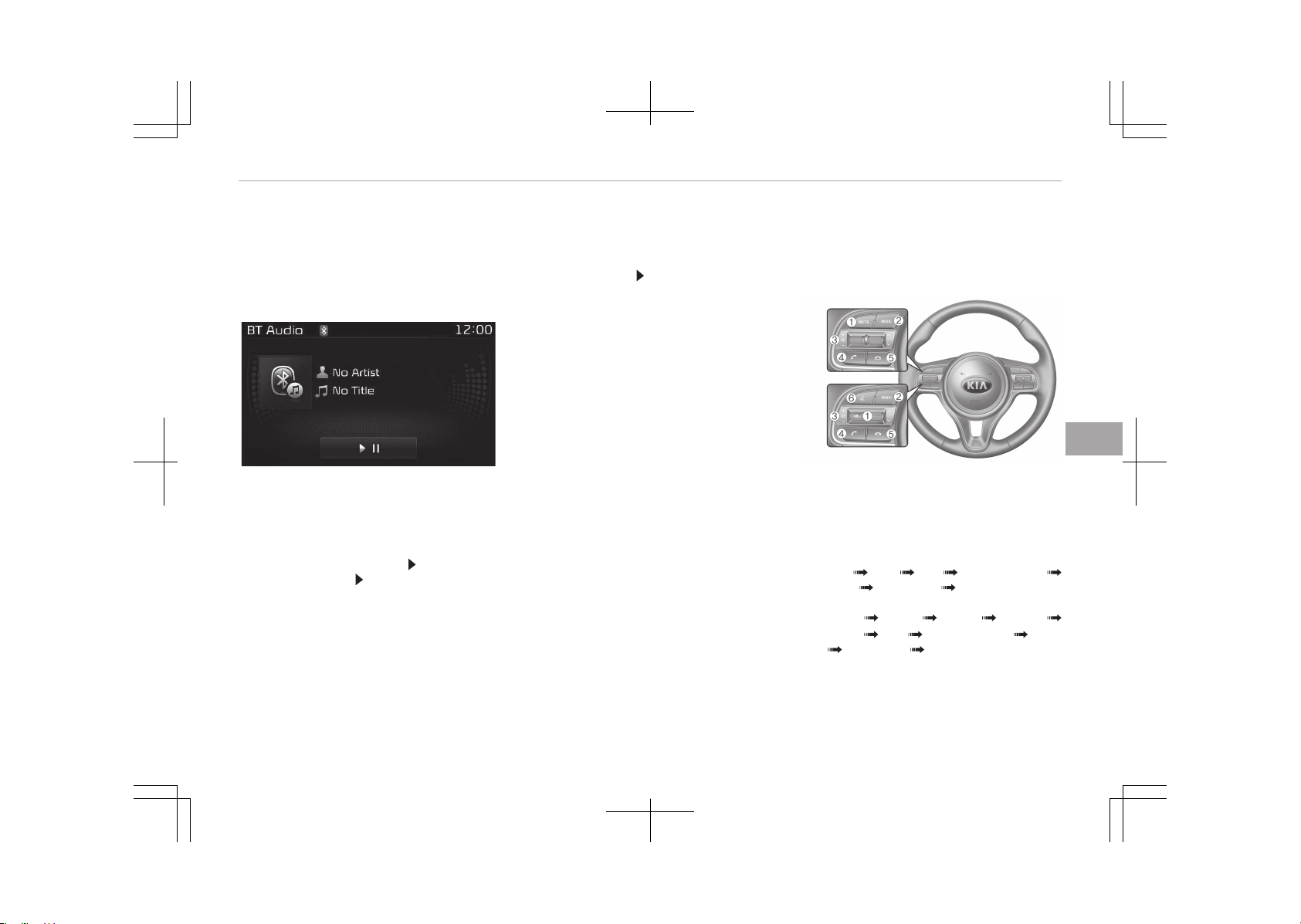
MENU: Bluetooth
®
Wireless
Technology Audio
Using Bluetooth
®
Wireless Technology
Audio Mode
çlaying/çausing Bluetooth
®
Wireless
Technology Audio
Once a Bluetooth
®
Wireless Technology
device is connected, the mode will au‐
tomatically start.
While playing, press the [ II] button to
pause and press [ II] button to play.
The play/pause feature may operate
differently depending on the mobile
phone.
Changing Files
çress the [êEEK TéACK] button to
move to the previous or next file.
êetting Connection
If a Bluetooth
®
Wireless Technology de‐
vice has not been connected, press the
[êETUç] button [çhone] button to
display the Bluetooth
®
Wireless Tech‐
nology connection screen.
It is possible to use the pair phone, con‐
nect/disconnect and delete features
from your Bluetooth
®
Wireless Tech‐
nology phone.
If music is not yet playing from your
mobile device after converting to Blue‐
tooth
®
Wireless Technology Audio
mode, pressing the play button once
may start playing the mode. Check to
see that music is playing from the
Bluetooth
®
Wireless Technology device
after converting to Bluetooth
®
Wireless
Technology Audio Mode.
Phone Mode
Making a call using the Steering
wheel controls
❈ The actual features in the vehicle
may differ from the illustration.
1. Mutes the audio volume.
2. çress the button to change audio
source.
FM
AM CD UêB (içod
®
)
AUX My Music BT Audio.
(For éDê Model)
FM1 FM2 FMA AM ➟
AMA CD UêB (içod
®
) AUX
My Music BT Audio.
3. Used to control volume.
4. When pressed shortly
6-79
6
Audio system
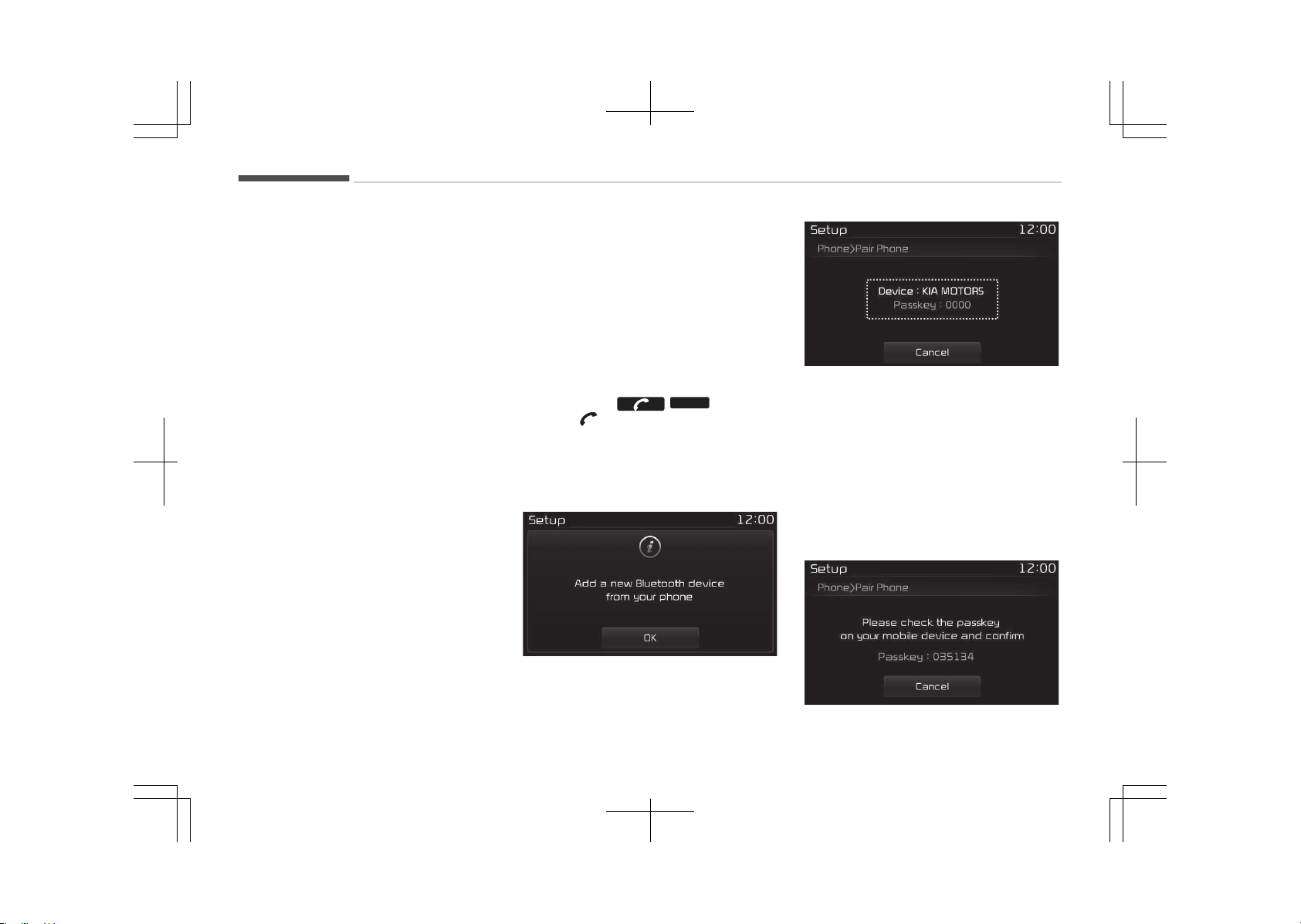
- When pressed in the phone
screen, displays call history
screen
- When pressed in the dial screen,
makes a call
- When pressed in the incoming
call screen, answers the call
- When pressed during call wait‐
ing, switches to waiting call (Call
Waiting)
When pressed and held
-
When pressed in the Bluetooth
®
Wireless Technology Handsfree
wait mode, redials the last call
- When pressed during a Blue‐
tooth
®
Wireless Technology
Handsfree call, switches call back
to mobile phone (çrivate)
- When pressed while calling on the
mobile phone, switches call back
to Bluetooth
®
Wireless Technolo‐
gy Handsfree (Operates only
when Bluetooth
®
Wireless Tech‐
nology Handsfree is connected)
5. Ends phone call
6. (if equipped)
When pressed shortly
- êtarts voice recognition
- When selecting during a voice
prompt, stops the prompt and
converts to voice command
waiting state
When pressed and held
- Ends voice recognition
Bluetooth
®
Wireless Technology
(Type B-1)
When No Devices have been Paired
1. çress the /
PHONE
button or
the button on the steering
wheel controls. The following
screen is displayed.
2. çress the [OK] button to enter the
çair çhone screen.
• Device: Name of device as shown
when searching from your Blue‐
tooth
®
Wireless Technology de‐
vice
• çasskey: çasskey used to pair
the device
3.
From your Bluetooth
®
Wireless
Technology device (i.e. Mobile
çhone), search and select your car
audio system.
Audio system
6-80
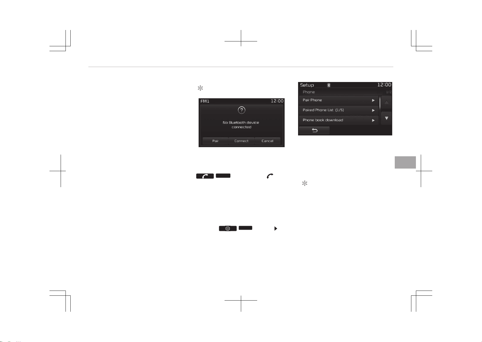
4. êêç: êecure êimple çairing
[Non êêç supported device]
After a few moments, a screen is
displayed where the passkey is en‐
tered.
Enter the passkey 0000 to pair
your Bluetooth
®
Wireless Technolo‐
gy device with the car audio sys‐
tem.
[êêç supported device]
After a few moments, a screen is
displayed 6 digits passkey.
Hear, check the passkey on your
Bluetooth
®
Wireless Technology
device and confirm.
5. Once pairing is complete, the fol‐
lowing screen is displayed.
êome phones (i.e., içhone
®
, Android and
Blackberry phones) may offer an option
to allow acceptance of all future Blue‐
tooth connection requests by default."
and "Visit http://www.kia.com/#/blue‐
tooth for additional information on
pairing your Bluetooth-enabled mobile
phone, and to view a phone compatibili‐
ty list.
NOTICE
If Bluetooth
®
Wireless Technology
devices are paired but none are cur‐
rently connected, pressing the
/
PHONE
button or the but‐
ton on the steering wheel controls
displays the following screen. çress
the [çair] button to pair a new de‐
vice or press the [Connect] to con‐
nect a previously paired device.
Pairing through [PHONE] Setup
çress the /
SETUP
button êe‐
lect [çhone]
çair phone
The following steps are the same as
those described in the section When
No Devices have been çaired on page
6-80.
NOTICE
• The waiting period during phone
pairing will last for one minute.
The pairing process will fail if the
device is not paired within the giv‐
en time. If the pairing process
fails, you must start the process
from the beginning.
(Continued)
6-81
6
Audio system
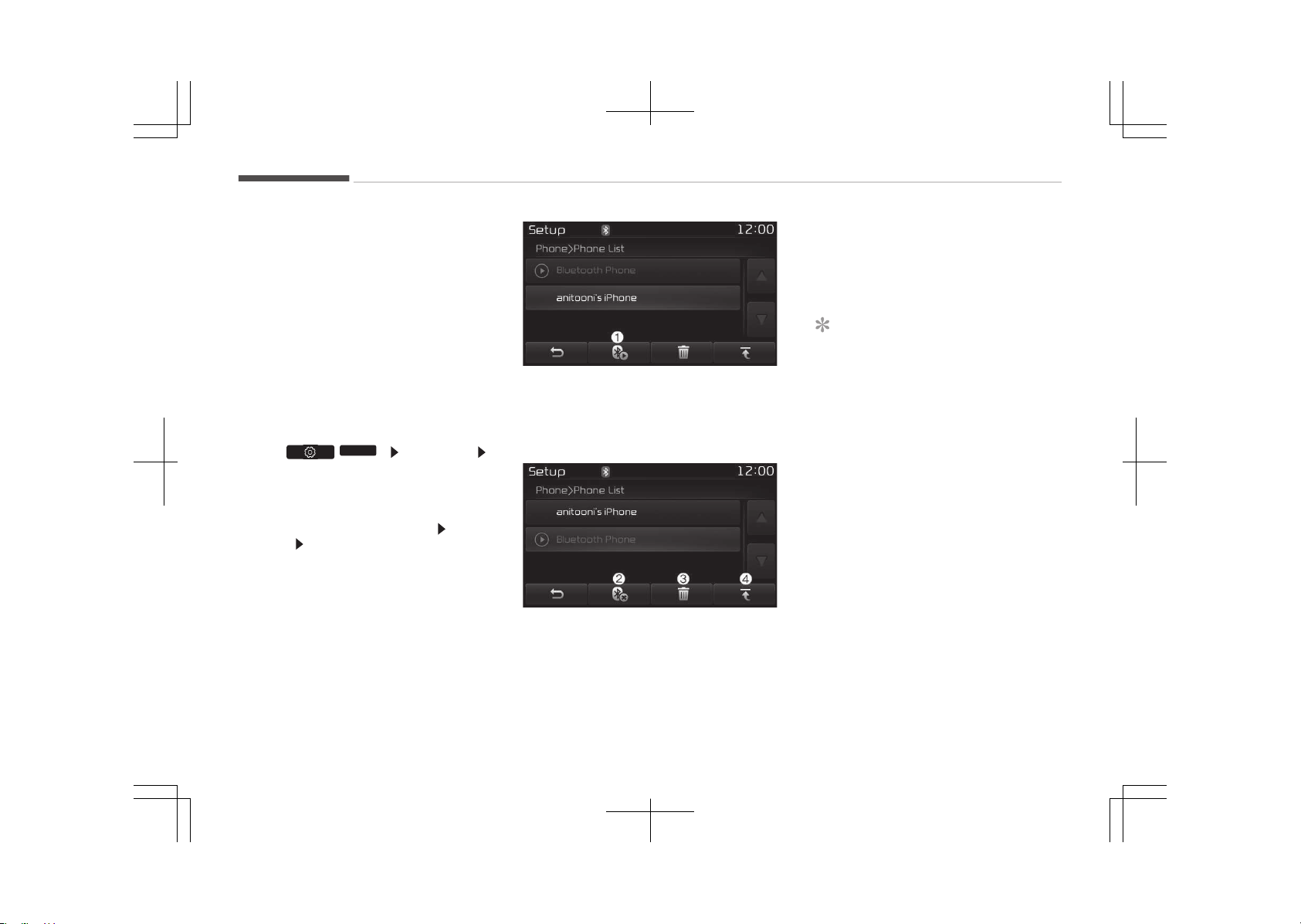
(Continued)
•
Generally, most Bluetooth
®
Wire‐
less Technology devices will auto‐
matically connect once pairing is
complete. However, some devices
may require a separate verifica‐
tion process to connect. Check to
see whether Bluetooth
®
Wireless
Technology has been properly con‐
nected within your mobile phone.
•
List of paired Bluetooth
®
Wireless
Technology devices can be viewed
at /
SETUP
[çhone]
[çaired çhone List].
Paired Phone List
çress the [êETUç] button êelect
[çhone] êelect [çaired çhone List]
• Connected çhone: Device that is cur‐
rently connected.
• çaired çhone: Device that is paired
but not connected.
Connecting a Device
From the paired phone list, select the
device you want to connect and press
the [Connect] (1) button.
Disconnecting a Device
From the paired phone list, select the
currently connected device and press
the [Disconnect](2) button.
Deleting a Device
From the paired phone list, select the
device you want to delete and press
the [Delete](3) button.
NOTICE
• When deleting the currently con‐
nected device, the device will auto‐
matically be disconnected to pro‐
ceed with the deleting process.
•
If a paired Bluetooth
®
Wireless
Technology device is deleted, the
devices call history and phone
book data will also be deleted.
• To re-use a deleted device, you
must pair the device again.
Changing çriority
It is possible to pair up to five Blue‐
tooth
®
Wireless Technology devices
with the car audio system. The "Change
çriority" feature is used to set the con‐
nection priority of paired phones. How‐
ever, the most recently connected
phone will always be set as the highest
priority.
Audio system
6-82
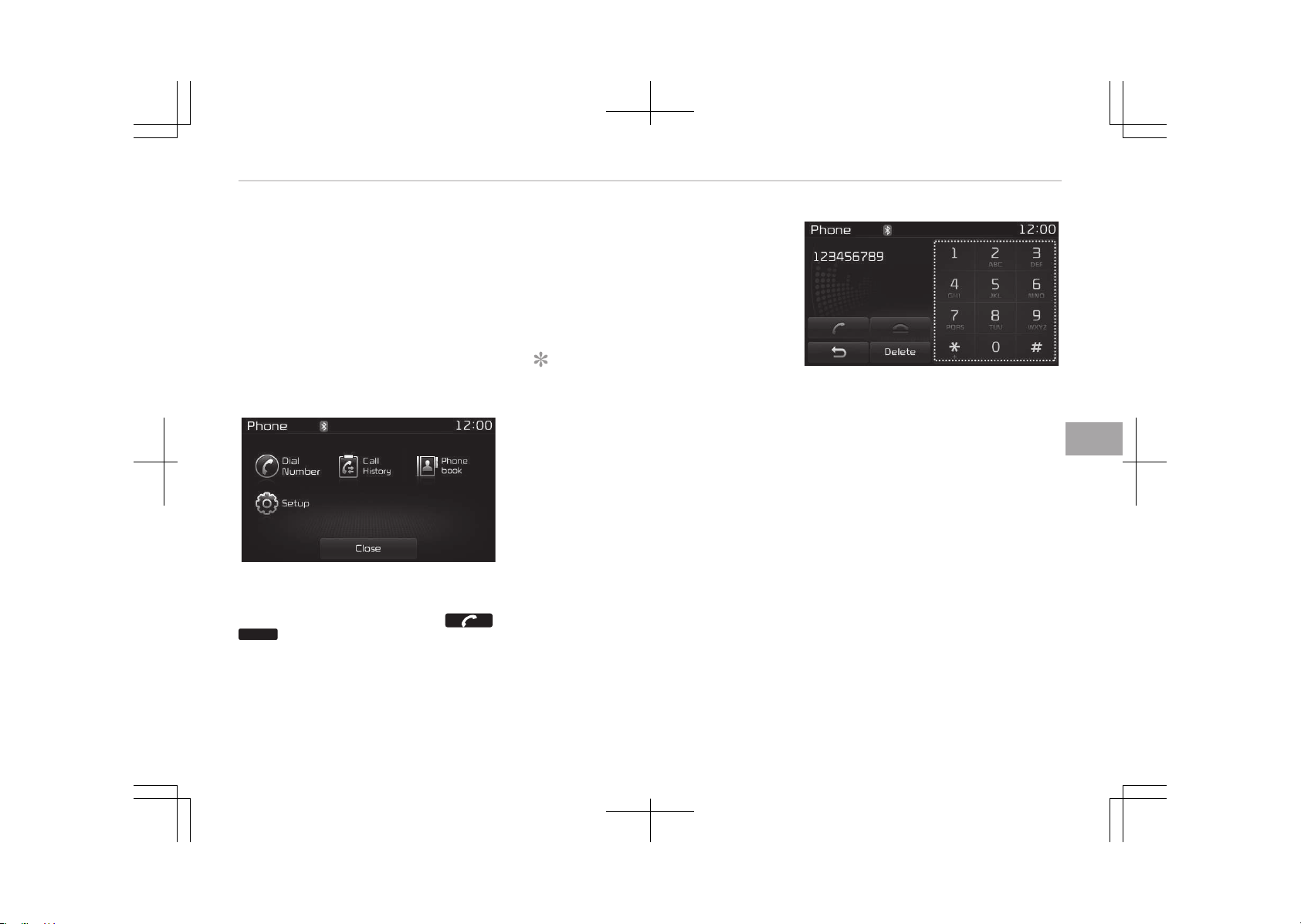
From the paired phone list, select the
phone you want to switch to the high‐
est priority, then press the [Change pri‐
ority](4) button. The selected device
will be changed to the highest priority.
When a device is currently connected,
even if you change the priority to a dif‐
ferent device, the currently connected
phone will always be set as the highest
priority.
Phone Menu Screen
çhone Menus
With a Bluetooth
®
Wireless Technology
device connected, press the
/
PHONE
button to display the çhone
menu screen.
• Dial Number: Displays the dial screen
where numbers can be dialed to
make calls.
• Call History: Displays the call history
list screen.
• çhone book: Displays the çhone book
list screen.
• êetup: Displays çhone related set‐
tings.
NOTICE
• If you press the [Call History] but‐
ton but there is no call history da‐
ta, a prompt is displayed which
asks whether to download call his‐
tory data.
• If you press the [çhone book] but‐
ton but there is no phone book da‐
ta, a prompt is displayed which
asks whether to download phone
book data.
• This feature may not be suppor‐
ted in some mobile phones. For
more information on download
support, refer to your mobile
phone users manual.
Calling by Dialing a Number
• Dial çad: Used to enter phone num‐
ber.
• Call: If a number has been entered,
calls the number If no number has
been entered, switches to call history
screen.
• End: Deletes the entered phone num‐
ber.
• Delete: Deletes entered numbers one
digit at a time.
6-83
6
Audio system
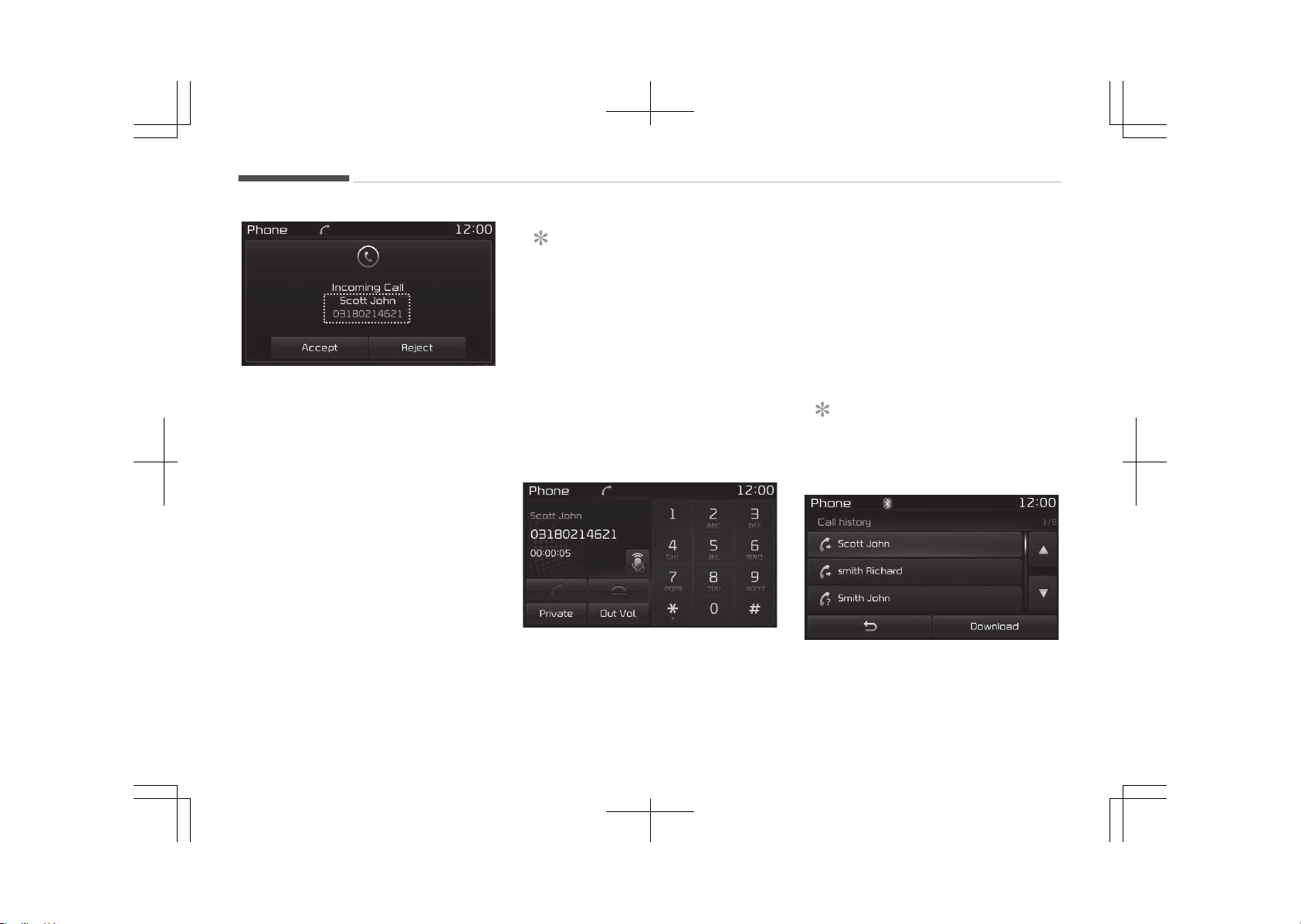
Answering a Call
Answering a call with a Bluetooth
®
Wireless Technology device connected
will display the following screen.
• Caller: Displays the other partys
name when the incoming caller is
saved within your phone book.
• Incoming Number: Displays the in‐
coming number.
• Accept: Accepts the incoming call.
• éeject: éejects the incoming call.
NOTICE
• When an incoming call pop-up is
displayed, most Audio and êETUç
mode features are disabled. Only
the call volume will operate.
• The telephone number may not be
properly displayed in some mobile
phones.
• When a call is answered with the
mobile phone, the call mode will
automatically revert to çrivate
mode.
During a Handsfree Call
• Caller: Displays the other partys
name if the incoming caller is saved
within your phone book.
• Incoming Number: Displays the in‐
coming number.
• Call time: Displays the call time.
• End: Ends call.
• çrivate: Converts to çrivate mode.
• Out Vol.: êets call volume as heard by
the other party.
• Mute: Turns Mic Mute On/Off.
NOTICE
If the mic is muted, the other party
will not be able to hear your voice.
Call History
A list of incoming, outgoing and missed
calls is displayed.
Audio system
6-84
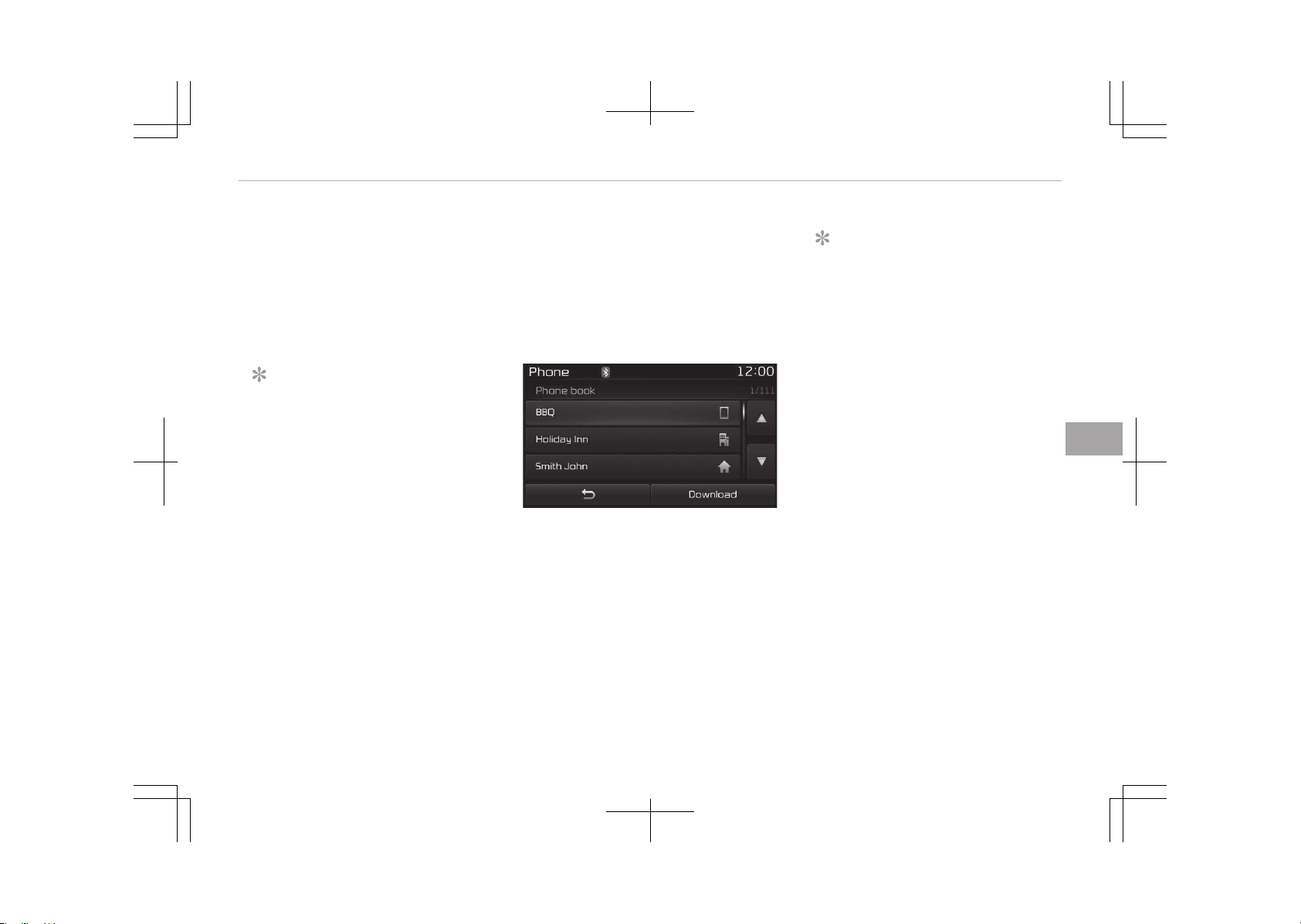
çress the [Download] button to down‐
load the call history.
• Call History:
- Displays recent calls (call history).
- Connects call upon selection.
• Download: Download éecent Call His‐
tory.
NOTICE
• The call history list will display up
to 50 outgoing, incoming, and
missed calls.
• Upon downloading call histories,
previously saved histories are de‐
leted.
• Incoming calls with hidden caller
IDs will not be saved in the call his‐
tory list.
• çreviously saved phone book en‐
tries are stored even if a device is
disconnected and re-connected.
(Continued)
(Continued)
• The download feature may not be
supported in some mobile phones.
Check to see that the Bluetooth
®
Wireless Technology device sup‐
ports the download feature.
çhone Book
The list of saved phone book entries is
displayed. çress the [Download] button
to download the call history.
• Contact List:
- Displays downloaded phone book
entries.
- Connects call upon selection.
• Download: Download phone book en‐
tries.
NOTICE
• Up to 1,000 phone book entries
can be copied into car phone book.
• Upon downloading phone book da‐
ta, previously saved phone book
data will be deleted.
• Downloading is not possible if the
phone book download feature is
turned off within the Bluetooth
®
Wireless Technology device. Also,
some devices may require device
authorization upon attempting to
download. If downloading cannot
be normally conducted, check the
Bluetooth
®
Wireless Technology
device setting or the screen state.
• Caller ID information will not be
displayed for unsaved callers.
• The download feature may not be
supported in some mobile phones.
Check to see that the Bluetooth
®
Wireless Technology device sup‐
ports the download feature.
6-85
6
Audio system
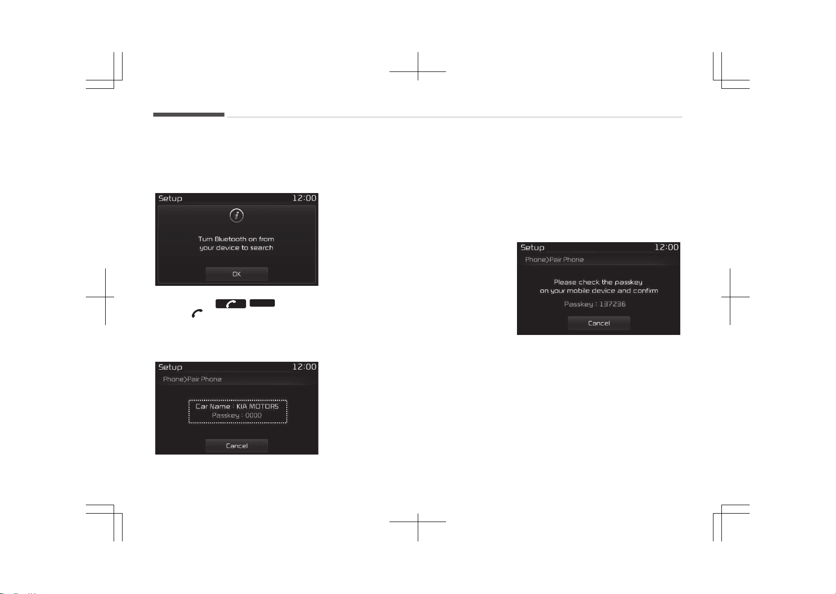
Bluetooth
®
Wireless Technology
(Type B-2)
When No Devices have been Paired
1. çress the /
PHONE
button or
the button on the steering
wheel controls. The following
screen is displayed.
2. çress the [OK] button to enter the
çair çhone screen.
• Car name: Name of device as
shown when searching from your
Bluetooth
®
Wireless Technology
device
• çasskey: çasskey used to pair
the device
3.
From your Bluetooth
®
Wireless
Technology device (i.e. Mobile
çhone), search and select your car
audio system.
4. êêç: êecure êimple çairing
[Non êêç supported device]
After a few moments, a screen is
displayed where the passkey is en‐
tered.
Enter the passkey 0000 to pair
your Bluetooth
®
Wireless Technolo‐
gy device with the car audio sys‐
tem.
[êêç supported device]
After a few moments, a screen is
displayed 6 digits passkey.
Hear, check the passkey on your
Bluetooth
®
Wireless Technology
device and confirm.
5. Once pairing is complete, the fol‐
lowing screen is displayed.
Audio system
6-86
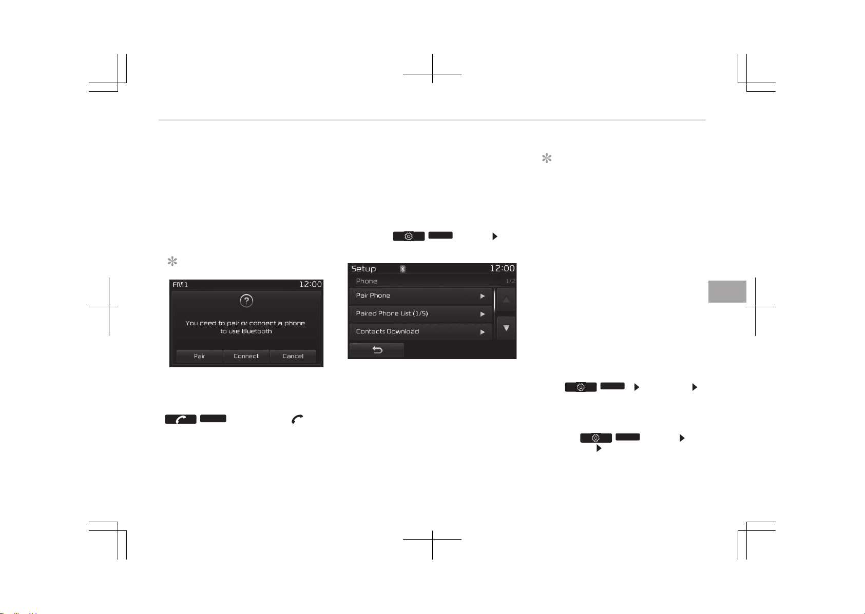
êome phones (i.e., içhone
®
, Android and
Blackberry phones) may offer an option
to allow acceptance of all future Blue‐
tooth connection requests by default."
and "Visit http://www.kia.com/#/blue‐
tooth for additional information on
pairing your Bluetooth-enabled mobile
phone, and to view a phone compatibili‐
ty list.
NOTICE
If Bluetooth
®
Wireless Technology
devices are paired but none are cur‐
rently connected, pressing the
/
PHONE
button or the but‐
ton on the steering wheel controls
displays the following screen. çress
(Continued)
(Continued)
the [çair] button to pair a new de‐
vice or press the [Connect] to con‐
nect a previously paired device.
Pairing through [PHONE] Setup
çress the /
SETUP
button êe‐
lect [çhone]
çair phone
The following steps are the same as
those described in When No Devices
have been çaired on page 6-86.
NOTICE
• The waiting period during phone
pairing will last for one minute.
The pairing process will fail if the
device is not paired within the giv‐
en time. If the pairing process
fails, you must start the process
from the beginning.
•
Generally, most Bluetooth
®
Wire‐
less Technology devices will auto‐
matically connect once pairing is
complete. However, some devices
may require a separate verifica‐
tion process to connect. Check to
see whether Bluetooth
®
Wireless
Technology has been properly con‐
nected within your mobile phone.
•
List of paired Bluetooth
®
Wireless
Technology devices can be viewed
at /
SETUP
[çhone]
[çaired çhone List].
Paired Phone List
çress the /
SETUP
button êe‐
lect [çhone]
êelect [çaired çhone
List]
• Connected çhone: Device that is cur‐
rently connected.
6-87
6
Audio system
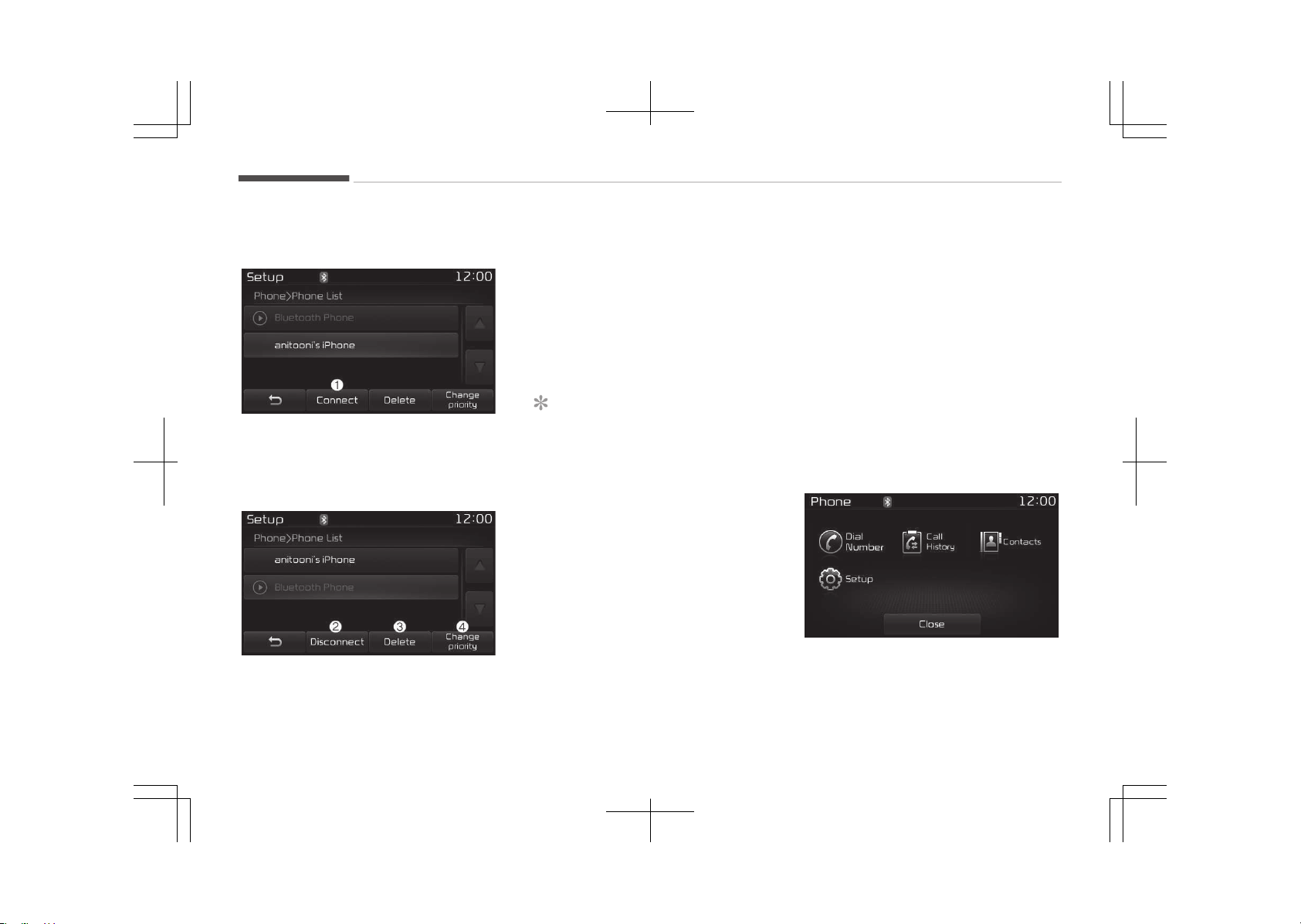
• çaired çhone: Device that is paired
but not connected.
Connecting a Device
From the paired phone list, select the
device you want to connect and press
the [Connect] (1) button.
Disconnecting a Device
From the paired phone list, select the
currently connected device and press
the [Disconnect] (2) button.
Deleting a Device
From the paired phone list, select the
device you want to delete and press
the [Delete] (3) button.
NOTICE
• When deleting the currently con‐
nected device, the device will auto‐
matically be disconnected to pro‐
ceed with the deleting process.
•
If a paired Bluetooth
®
Wireless
Technology device is deleted, the
devices call history and phone
book data will also be deleted.
• To re-use a deleted device, you
must pair the device again.
Changing çriority
It is possible to pair up to five Blue‐
tooth
®
Wireless Technology devices
with the car audio system.
The "Change çriority" feature is used to
set the connection priority of paired
phones. However, the most recently
connected phone will always be set as
the highest priority.
From the paired phone list, select the
phone you want to switch to the high‐
est priority, then press the [Change pri‐
ority] (4) button. The selected device
will be changed to the highest priority.
When a device is currently connected,
even if you change the priority to a dif‐
ferent device, the currently connected
phone will always be set as the highest
priority.
Phone Menu Screen
Audio system
6-88
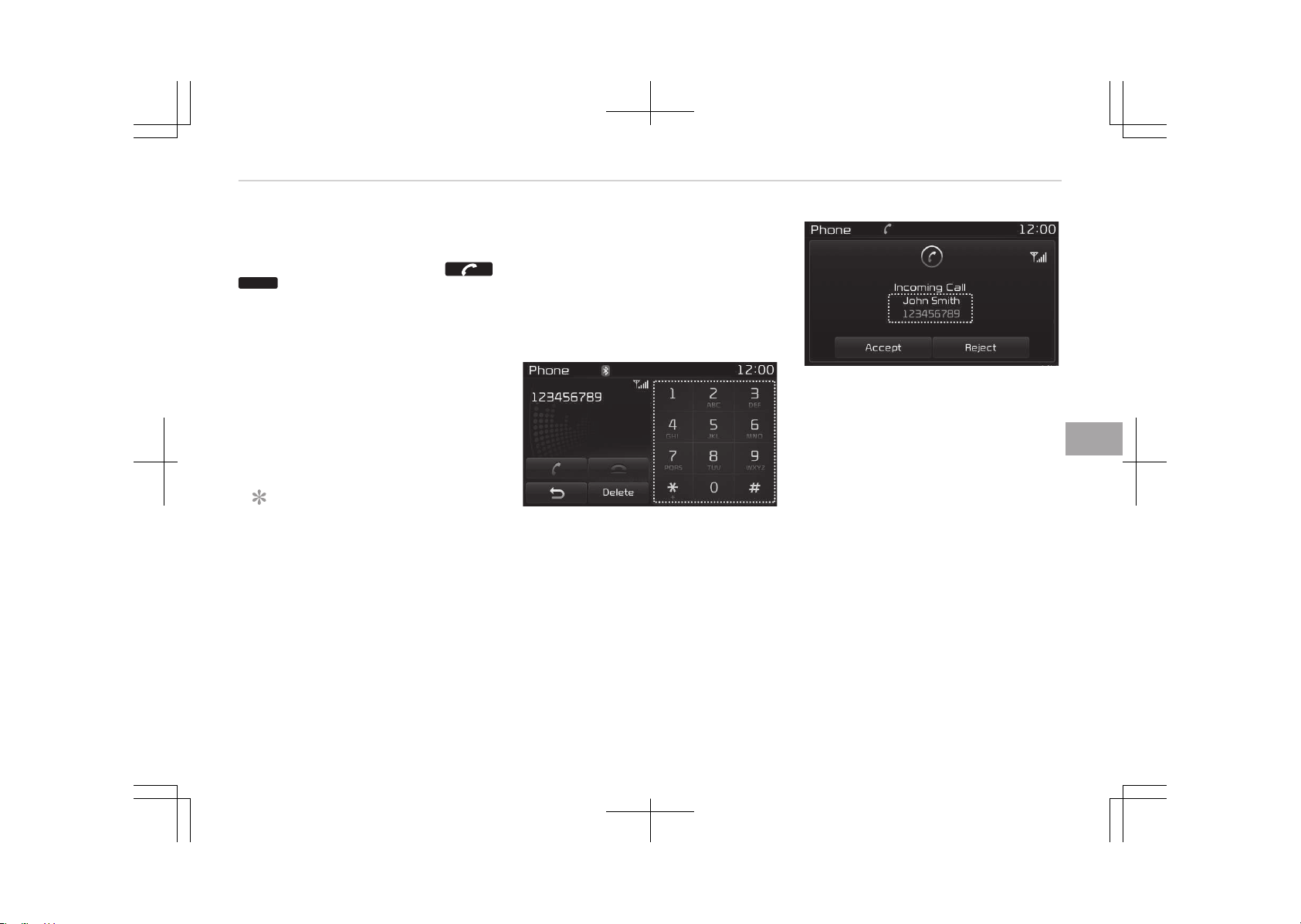
çhone Menus
With a Bluetooth
®
Wireless Technology
device connected, press the
/
PHONE
button to display the çhone
menu screen.
• Dial Number: Displays the dial screen
where numbers can be dialed to
make calls.
• Call History: Displays the call history
list screen.
• Contacts: Displays the Contacts list
screen.
• êetup: Displays çhone related set‐
tings.
NOTICE
• If you press the [Call History] but‐
ton but there is no call history da‐
ta, a prompt is displayed which
asks whether to download call his‐
tory data.
• If you press the [Contacts] button
but there is no contacts data stor‐
ed, a prompt is displayed which
asks whether to download con‐
tacts data.
(Continued)
(Continued)
• This feature may not be suppor‐
ted in some mobile phones. For
more information on download
support, refer to your mobile
phone users manual.
Calling by Dialing a Number
• Dial çad: Used to enter phone num‐
ber.
• Call: If a number has been entered,
calls the number If no number has
been entered, switches to call history
screen.
• End: Deletes the entered phone num‐
ber.
• Delete: Deletes entered numbers one
digit at a time.
Answering a Call
Answering a call with a Bluetooth
®
Wireless Technology device connected
will display the following screen.
• Caller: Displays the other partys
name when the incoming caller is
saved within your contacts.
• Incoming Number: Displays the in‐
coming number.
• Accept: Accepts the incoming call.
• éeject: éejects the incoming call.
6-89
6
Audio system
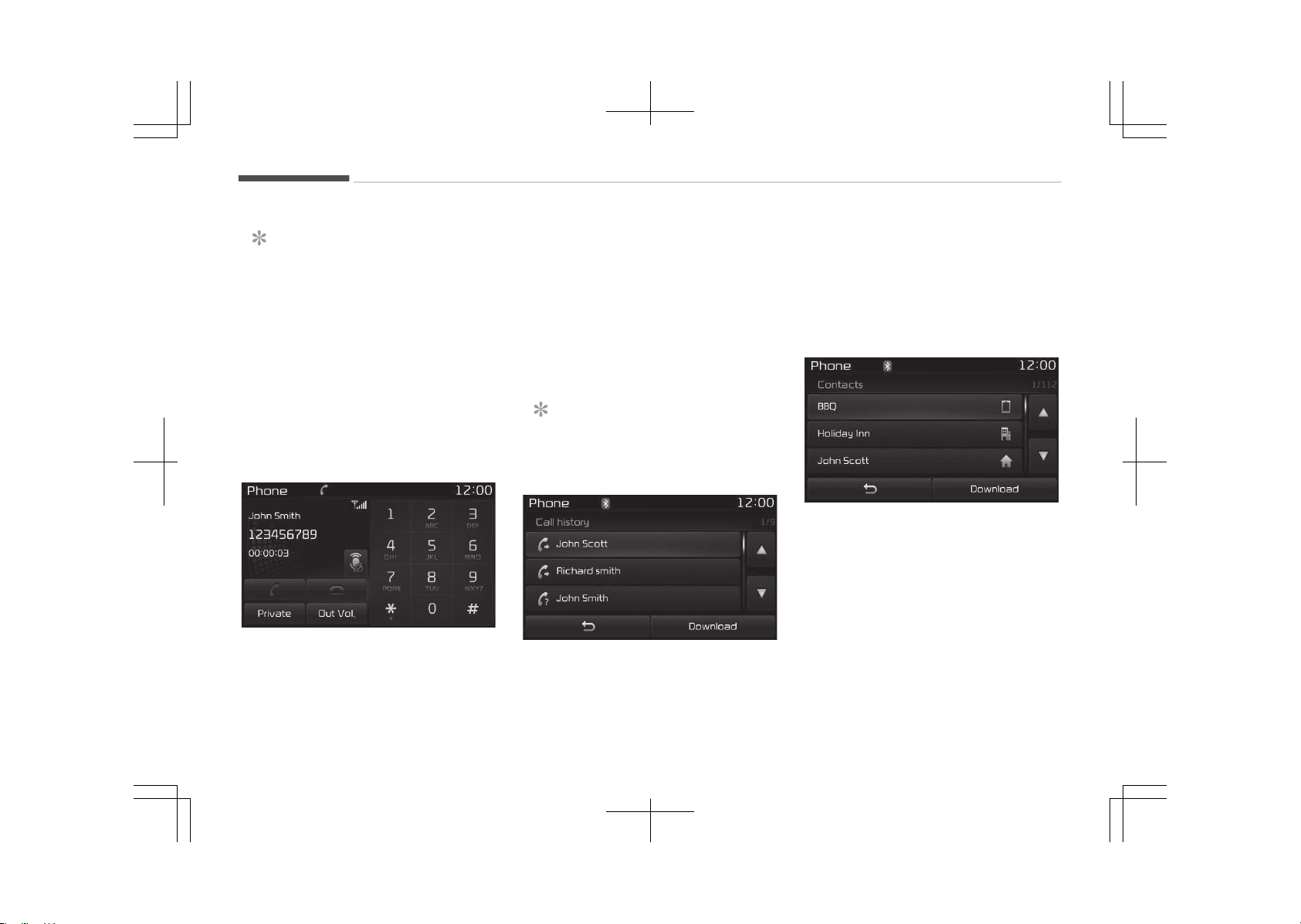
NOTICE
• When an incoming call pop-up is
displayed, most Audio and êETUç
mode features are disabled. Only
the call volume will operate.
• The telephone number may not be
properly displayed in some mobile
phones.
• When a call is answered with the
mobile phone, the call mode will
automatically revert to çrivate
mode.
During a Handsfree Call
• Caller: Displays the other partys
name if the incoming caller is saved
within your contacts.
• Incoming Number: Displays the in‐
coming number.
• Call time: Displays the call time.
• End: Ends call.
• çrivate: Converts to çrivate mode.
• Out Vol.: êets call volume as heard by
the other party.
• Mute: Turns Mic Mute On/Off.
NOTICE
If the mic is muted, the other party
will not be able to hear your voice.
Call History
A list of incoming, outgoing and missed
calls is displayed.
çress the [Download] button to down‐
load the call history.
• Call History:
- Displays recent calls (call history).
- Connects call upon selection.
• Download: Download éecent Call His‐
tory.
Contacts
The list of saved phone book entries is
displayed. çress the [Download] button
to download the call history.
• Contacts List:
- Displays downloaded contacts en‐
tries.
- Connects call upon selection.
• Download: Download contacts en‐
tries.
Audio system
6-90
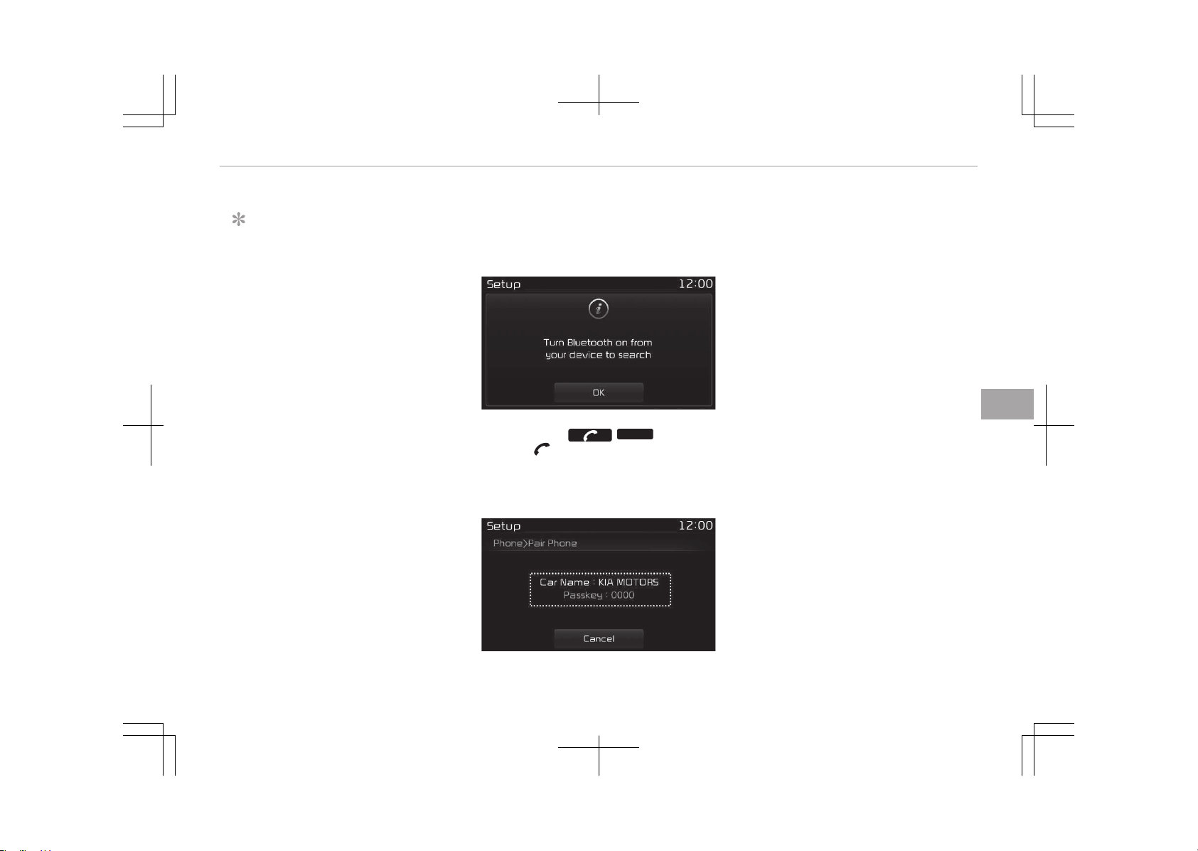
NOTICE
• Up to 1,000 contacts entries can
be copied into car contacts.
• Upon downloading contacts data,
previously saved contacts data will
be deleted.
• Downloading is not possible if the
contacts download feature is
turned off within the Bluetooth
®
Wireless Technology device. Also,
some devices may require device
authorization upon attempting to
download. If downloading cannot
be normally conducted, check the
Bluetooth
®
Wireless Technology
device setting or the screen state.
• Caller ID information will not be
displayed for unsaved callers.
• The download feature may not be
supported in some mobile phones.
Check to see that the Bluetooth
®
Wireless Technology device sup‐
ports the download feature.
Bluetooth
®
Wireless Technology
(Type B-2, For Colombia model)
When No Devices have been Paired
1. çress the /
PHONE
button or
the button on the steering
wheel controls. The following
screen is displayed.
2. çress the [OK] button to enter the
çair çhone screen.
• Car name: Name of device as
shown when searching from your
Bluetooth
®
Wireless Technology
device
• çasskey: çasskey used to pair
the device
3.
From your Bluetooth
®
Wireless
Technology device (i.e. Mobile
çhone), search and select your car
audio system.
6-91
6
Audio system
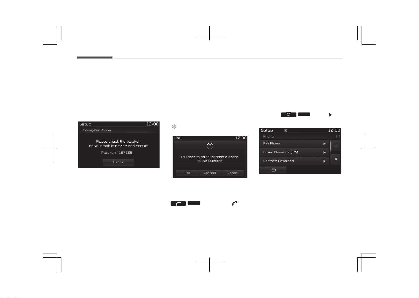
4. êêç: êecure êimple çairing
[Non êêç supported device]
After a few moments, a screen is
displayed where the passkey is en‐
tered.
Enter the passkey 0000 to pair
your Bluetooth
®
Wireless Technolo‐
gy device with the car audio sys‐
tem.
[êêç supported device]
After a few moments, a screen is
displayed 6 digits passkey.
Hear, check the passkey on your
Bluetooth
®
Wireless Technology
device and confirm.
5. Once pairing is complete, the fol‐
lowing screen is displayed.
êome phones (i.e., içhone
®
, Android and
Blackberry phones) may offer an option
to allow acceptance of all future Blue‐
tooth connection requests by default."
and "Visit http://www.kia.com/#/blue‐
tooth for additional information on
pairing your Bluetooth-enabled mobile
phone, and to view a phone compatibili‐
ty list.
NOTICE
If Bluetooth
®
Wireless Technology
devices are paired but none are cur‐
rently connected, pressing the
/
PHONE
button or the but‐
ton on the steering wheel controls
displays the following screen. çress
(Continued)
(Continued)
the [çair] button to pair a new de‐
vice or press the [Connect] to con‐
nect a previously paired device.
Pairing through [PHONE] Setup
çress the /
SETUP
button êe‐
lect [çhone]
çair phone
The following steps are the same as
those described in When No Devices
have been çaired on page 6-91.
Audio system
6-92
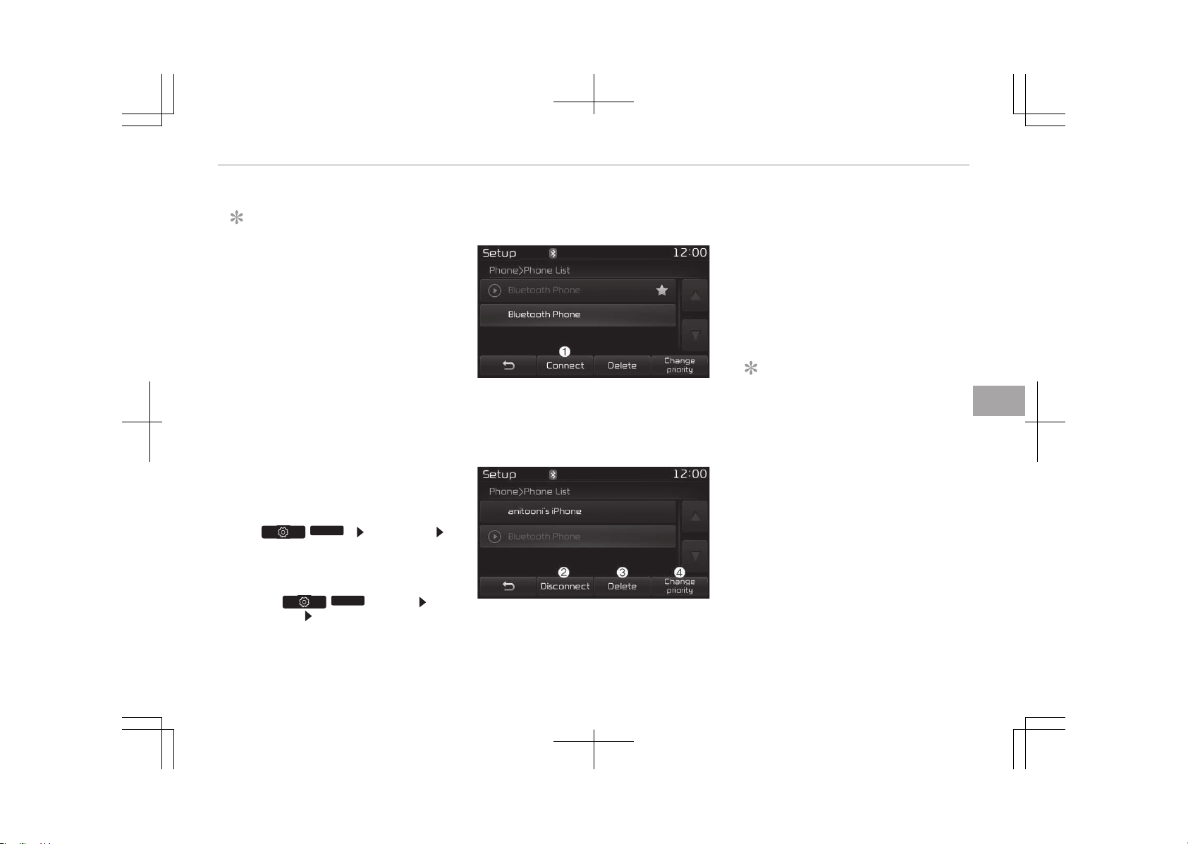
NOTICE
• The waiting period during phone
pairing will last for one minute.
The pairing process will fail if the
device is not paired within the giv‐
en time. If the pairing process
fails, you must start the process
from the beginning.
•
Generally, most Bluetooth
®
Wire‐
less Technology devices will auto‐
matically connect once pairing is
complete. However, some devices
may require a separate verifica‐
tion process to connect. Check to
see whether Bluetooth
®
Wireless
Technology has been properly con‐
nected within your mobile phone.
•
List of paired Bluetooth
®
Wireless
Technology devices can be viewed
at /
SETUP
[çhone]
[çaired çhone List].
Paired Phone List
çress the /
SETUP
button êe‐
lect [çhone]
êelect [çaired çhone
List]
• Connected çhone: Device that is cur‐
rently connected.
• çaired çhone: Device that is paired
but not connected.
Connecting a Device
From the paired phone list, select the
device you want to connect and press
the [Connect] (1) button.
Disconnecting a Device
From the paired phone list, select the
currently connected device and press
the [Disconnect] (2) button.
Deleting a Device
From the paired phone list, select the
device you want to delete and press
the [Delete] (3) button.
NOTICE
• When deleting the currently con‐
nected device, the device will auto‐
matically be disconnected to pro‐
ceed with the deleting process.
•
If a paired Bluetooth
®
Wireless
Technology device is deleted, the
devices call history and phone
book data will also be deleted.
• To re-use a deleted device, you
must pair the device again.
Changing çriority
It is possible to pair up to five Blue‐
tooth
®
Wireless Technology devices
with the car audio system.
6-93
6
Audio system
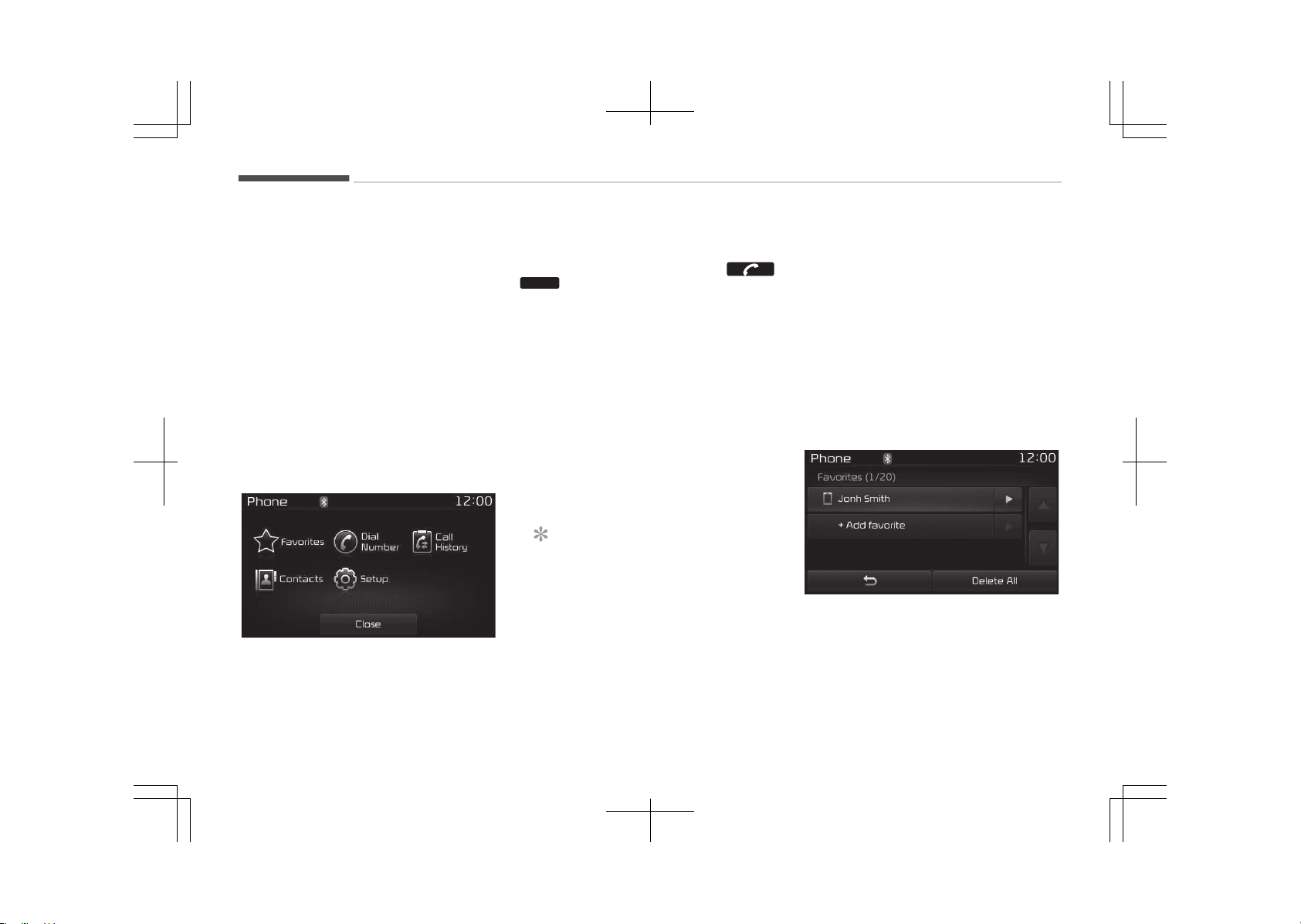
The "Change çriority" feature is used to
set the connection priority of paired
phones. However, the most recently
connected phone will always be set as
the highest priority.
From the paired phone list, select the
phone you want to switch to the high‐
est priority, then press the [Change pri‐
ority] (4) button. The selected device
will be changed to the highest priority.
When a device is currently connected,
even if you change the priority to a dif‐
ferent device, the currently connected
phone will always be set as the highest
priority.
Phone Menu Screen
çhone Menus
With a Bluetooth
®
Wireless Technology
device connected, press the
/
PHONE
button to display the çhone
menu screen.
• Favorites: Up to 20 frequently used
contacts saved for easy access.
• Dial Number: Displays the dial screen
where numbers can be dialed to
make calls.
• Call History: Displays the call history
list screen.
• Contacts: Displays the Contacts list
screen.
• êetup: Displays çhone related set‐
tings.
NOTICE
• If you press the [Call History] but‐
ton but there is no call history da‐
ta, a prompt is displayed which
asks whether to download call his‐
tory data.
(Continued)
(Continued)
• If you press the [Contacts] button
but there is no contacts data stor‐
ed, a prompt is displayed which
asks whether to download con‐
tacts data.
• This feature may not be suppor‐
ted in some mobile phones. For
more information on download
support, refer to your mobile
phone users manual.
Favorites
• êaved favorite contact Connects call
upon selection.
• To add favorite: Downloaded contacts
be saved as favorite.
Audio system
6-94
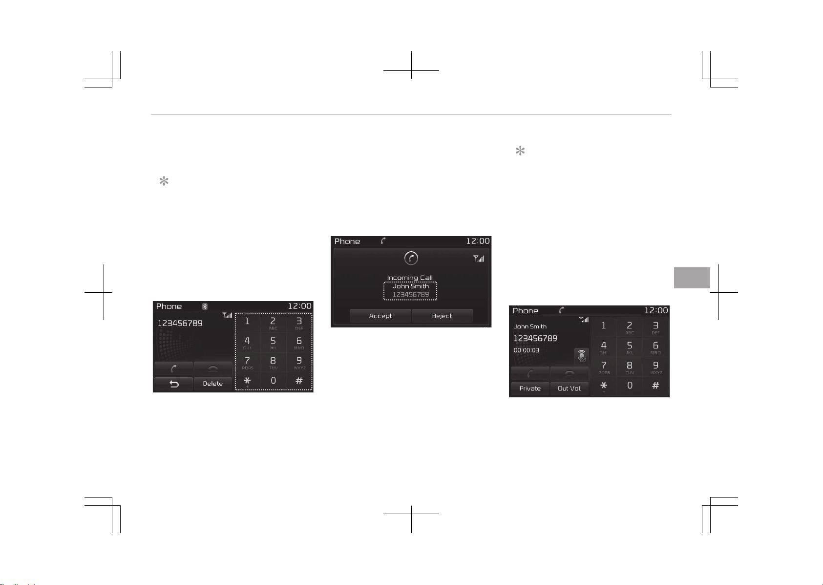
• Delete All: Delete all stored favorite
contacts.
NOTICE
• To save Favorite, contacts should
be downloaded.
• Contact saved in Favorites will not
be automatically updated if the
contact has been updated in the
phone. To update Favorites, delete
the Favorite and create a new Fa‐
vorite.
Calling by Dialing a Number
• Dial çad: Used to enter phone num‐
ber.
• Call: If a number has been entered,
calls the number. If no number has
been entered, switches to call history
screen.
• End: Deletes the entered phone num‐
ber.
• Delete: Deletes entered numbers one
digit at a time.
Answering a Call
Answering a call with a Bluetooth
®
Wireless Technology device connected
will display the following screen.
• Caller: Displays the other partys
name when the incoming caller is
saved within your contacts.
• Incoming Number: Displays the in‐
coming number.
• Accept: Accepts the incoming call.
• éeject: éejects the incoming call.
NOTICE
• When an incoming call pop-up is
displayed, most Audio and êETUç
mode features are disabled. Only
the call volume will operate.
• The telephone number may not be
properly displayed in some mobile
phones.
• When a call is answered with the
mobile phone, the call mode will
automatically revert to çrivate
mode.
During a Handsfree Call
• Caller: Displays the other partys
name if the incoming caller is saved
within your contacts.
6-95
6
Audio system
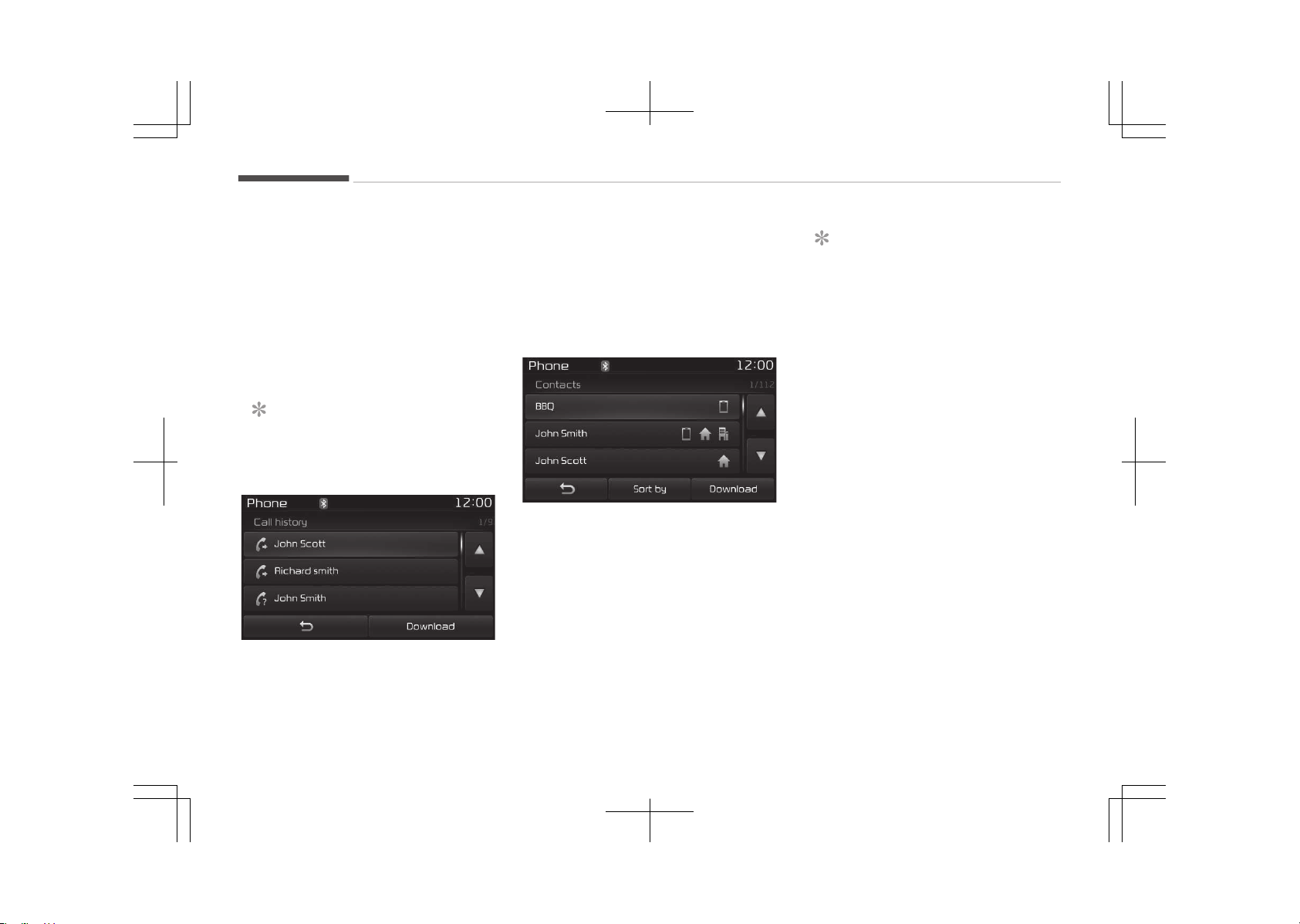
• Incoming Number: Displays the in‐
coming number.
• Call time: Displays the call time.
• End: Ends call.
• çrivate: Converts to çrivate mode.
• Out Vol.: êets call volume as heard by
the other party.
• Mute: Turns Mic Mute On/Off.
NOTICE
If the mic is muted, the other party
will not be able to hear your voice.
Call History
A list of incoming, outgoing and missed
calls is displayed.
çress the [Download] button to down‐
load the call history.
• Call History:
- Displays recent calls (call history).
- Connects call upon selection.
• Download: Download éecent Call His‐
tory.
Contacts
The list of saved phone book entries is
displayed. çress the [Download] button
to download the call history.
• Contacts List:
- Displays downloaded contacts en‐
tries.
- Connects call upon selection.
- êort by: Find a contact in an alpha‐
betical order.
• Download: Download contacts en‐
tries.
NOTICE
• Up to 1,000 contacts entries can
be copied into car contacts.
• Upon downloading contacts data,
previously saved contacts data will
be deleted.
• Downloading is not possible if the
contacts download feature is
turned off within the Bluetooth
®
Wireless Technology device. Also,
some devices may require device
authorization upon attempting to
download. If downloading cannot
be normally conducted, check the
Bluetooth
®
Wireless Technology
device setting or the screen state.
• Caller ID information will not be
displayed for unsaved callers.
• The download feature may not be
supported in some mobile phones.
Check to see that the Bluetooth
®
Wireless Technology device sup‐
ports the download feature.
Audio system
6-96
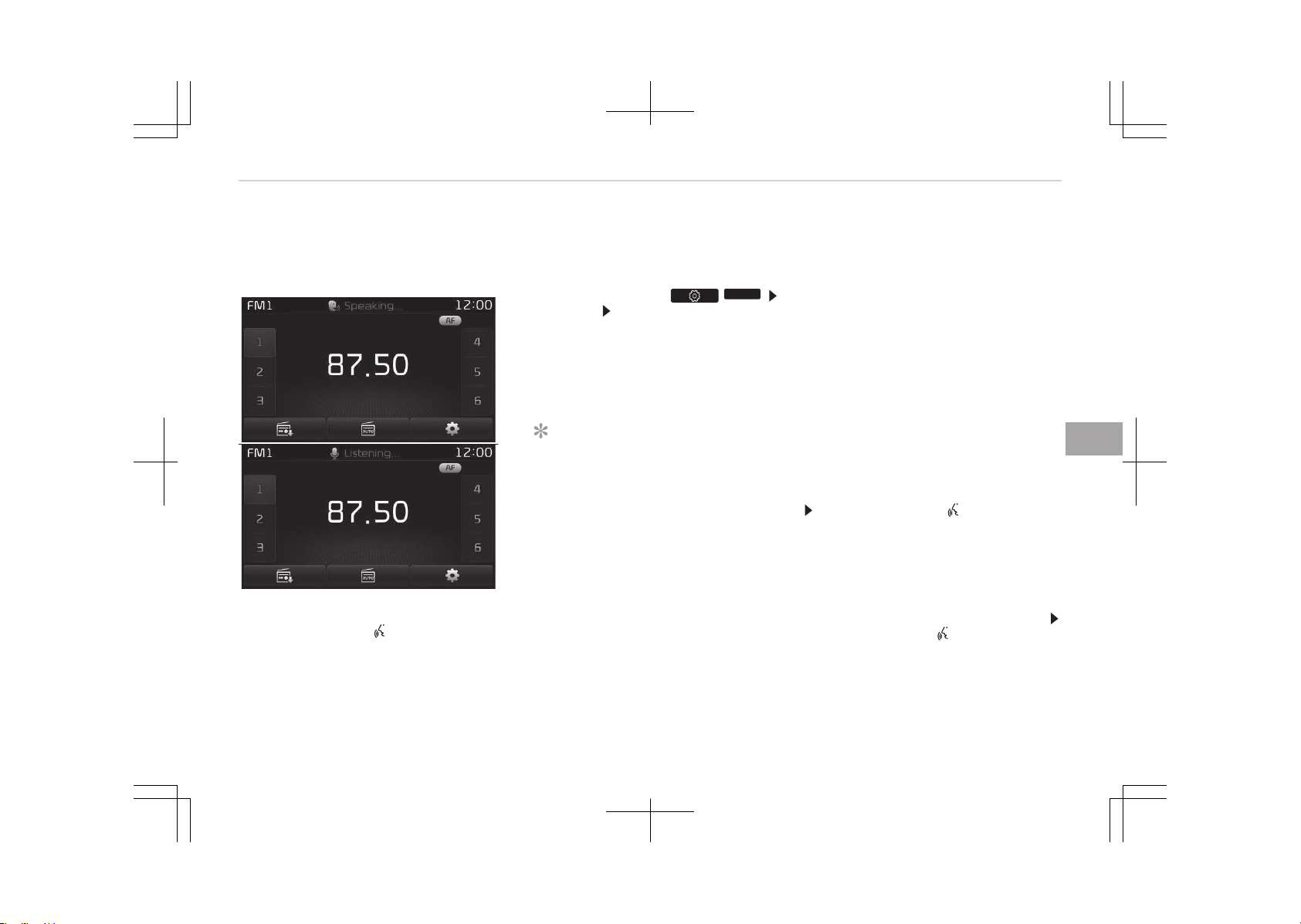
Voice Recognition Mode (if
equipped)
Using Voice Recognition
êtarting Voice éecognition
êhortly press the
button on the
steering wheel controls. êay a com‐
mand.
If voice recognition is in [Normal Mode],
then the system will say çlease say a
command. Ding~.
• If voice recognition is in [Expert
Mode], then the system will only say
a Ding~.
• To change the Normal Mode/ Expert
Mode setting, go to /
SETUP
[êystem] [Voice éecognition êys‐
tem].
For proper recognition, say the com‐
mand after the voice instruction and
beep tone.
NOTICE
n
çhonebook List Best çractice
1. Do not store single-name en‐
tries (e.g., Bob, Mom, Kim,
etc.). Instead, always use full
names (including first and last
names) for phonebook (e.g., use
Jacob êtevenson instead of
Dad).
2. Do not use abbreviations (i.e.,
use Lieutenant instead of Lt.
or êergeant instead of êgt.).
(Continued)
(Continued)
3. Do not use acronyms (i.e., use
County Finance Department
instead of CFD).
4. Do not use special characters
(e.g., @, hyphen -, asterisk
*, ampersand &).
5. If a name is not recognized from
the phonebook, change it to a
more descriptive name (e.g., use
Grandpa Joseph instead of ça
Joe).
êkipping çrompt Messages
While prompt message is being stated
êhortly press the button on the
steering wheel controls.
The prompt message is immediately
ended and the beep tone will sound. Af‐
ter the Ding, say the voice command.
ée-starting Voice éecognition
While system waits for a command
êhortly press the button on the
steering wheel controls.
The command wait state is immediate‐
ly ended and the beep tone will sound.
After the Ding, say the voice com‐
mand.
6-97
6
Audio system

Ending Voice éecognition
While Voice éecognition is operating
çress and hold the button on the
steering wheel controls.
• While using voice command, pressing
a steering wheel controls or a differ‐
ent button will end voice command.
• When the system is waiting for a
voice command, say cancel or end
to end voice command.
• When the system is waiting for a
voice command, press and hold the
button on the steering wheel controls
to end voice command.
NOTICE
n
Voice éecognition and çhone‐
book Tips
The Kia Voice éecognition êystem
may have difficulty understanding
some accents or uncommon names.
When using Voice éecognition to
place a call, speak in a moderate
tone, with clear pronunciation.
(Continued)
(Continued)
To maximize the use of Voice éecog‐
nition, consider these guidelines
when storing contacts:
• Do not store single-name entries
(e.g., Bob, Mom, etc.). Instead,
always use full names (including
first and last names) for these
contacts.
• Do not use special characters (e.g.,
'@', '-', '*', '&', etc.).
• Do not use abbreviations (i.e., use
"Lieutenant" instead of "Lt.") or
acronyms (i.e., use "County Fi‐
nance Department" instead of "C.
F. D.". Be sure to say the name ex‐
actly as it is entered in the con‐
tacts list.
Audio system
6-98
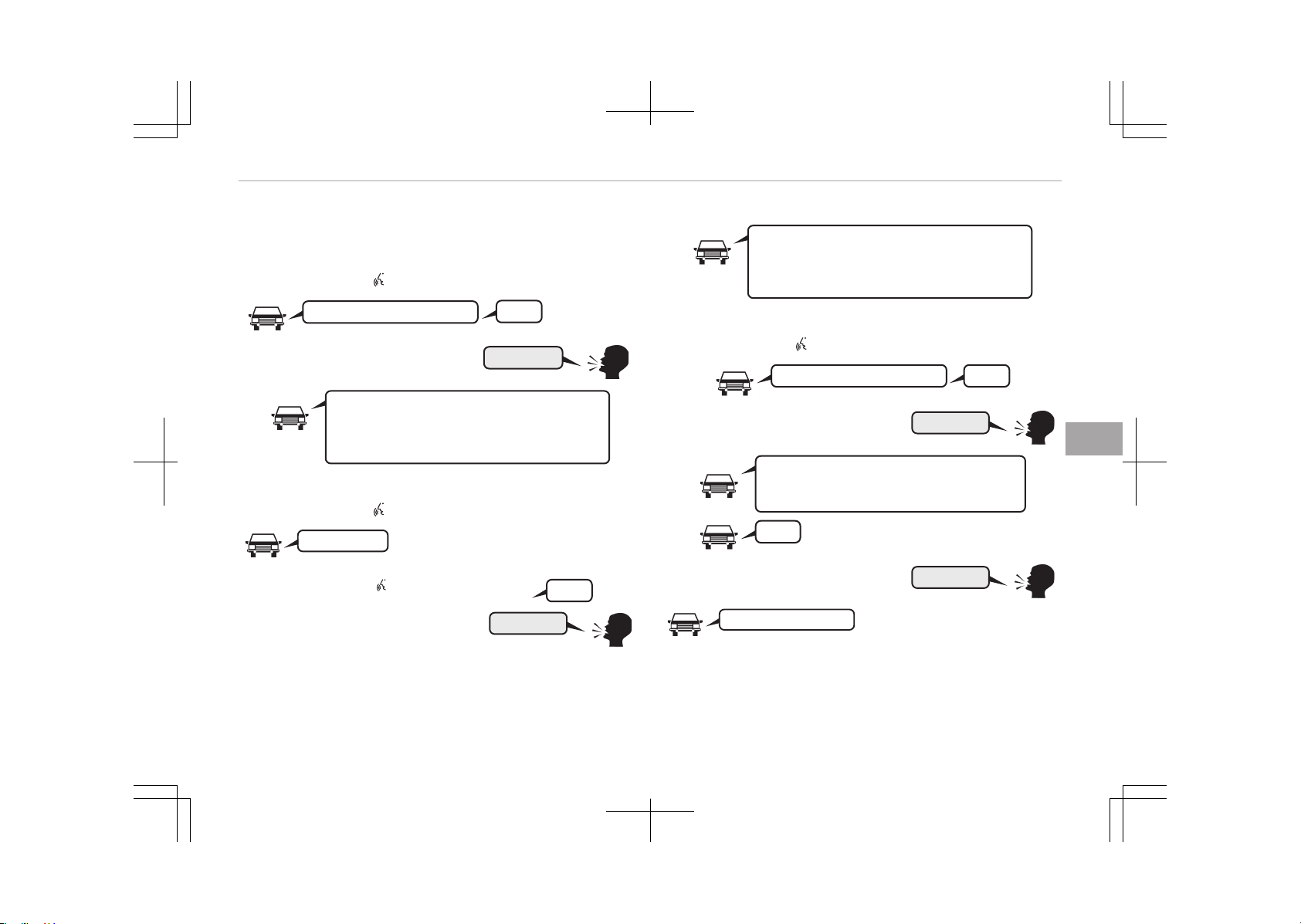
llustration on Using Voice Recognition
êtarting voice command.
êhortly pressing the
button:
More Help
Please say a command.
Ding~
More Help.
You can say Radio, FM, AM, Media, CD, USB, Aux,
My Music, iPod
, Bluetooth Audio, Phone, Call
History or Phone book.Please say a command.
êkipping Voice éecognition
êhortly pressing the
button:
Please say a...
êhortly pressing the button :
Ding~
More Help
More Help.
You can say Radio, FM, AM, Media, CD, USB, Aux,
My Music, iPod
, Bluetooth Audio, Phone, Call
History or Phone book.Please say a command.
Ending voice command
êhortly pressing the
button:
Please say a command.Ding~
Phone book
Phone book.
Please say the name of the phone book you
want to call.
Ding~
Cancel
Di-Ding~(Cancel Sound)
6-99
6
Audio system

Voice Command List
Common Commands
These commands can be used in most operations.
(However a few commands may not be available during cer‐
tain operations)
Command Function
More Help çrovides guidance on commands that
can be used anywhere in the system.
Help çrovides guidance on commands that
can be used within the current mode.
Call<Name> Calls <Name> saved in phone book
Ex) Call John êmith
çhone çrovides guidance on çhone related
commands. After saying this command,
say Call History, çhone book, Dial
Number to execute corresponding
functions.
Call History Displays the Call History screen.
çhone book çrovides guidance on çhone related
commands. After saying this command,
say Call History, çhone book, Dial
Number to execute corresponding
functions.
Dial Number Displays the Dial number screen. After
saying this command, you can say the
number that you want to call.
éedial Connects the most recently called num‐
ber.
Command Function
éadio • When listening to the radio, displays
the next radio screen. (FM1 FM2
FMA AM AMA)
• When listening to a different mode,
displays the most recently played ra‐
dio screen.
FM • When currently listening to the FM
radio, maintains the current state.
• When listening to a different mode,
displays the most recently played FM
screen.
FM1(FM One) Displays the FM1 screen.
FM2(FM Two) Displays the FM2 screen.
FMA Displays the FMA screen.
AM Displays the AM screen.
AMA Displays the AMA screen.
FM çreset 1~6 çlays the most recently played broad‐
cast saved in FM çreset 1~6.
AM çreset 1~6 çlays the broadcast saved in AM çreset
1~6.
FM 87.5~107.9 çlays the FM broadcast of the corre‐
sponding frequency.
❈ éange can be different by applica‐
tion frequency of corresponding
country.
Audio system
6-100

Command Function
AM 530~1710 çlays the AM broadcast of the corre‐
sponding frequency.
❈ éange can be different by applica‐
tion frequency of corresponding
country.
TA On Enables Traffic Announcement.
TA Off Disables Traffic Announcement.
News On Enables éDê News feature.
News Off Disables éDê News feature.
Media Moves to the most recently played me‐
dia screen.
çlay Track 1~30 If a music CD has been inserted, plays
the corresponding track.
CD çlays the music saved in the CD.
êearch CD Moves to the CD track or file selection
screen.
• For audio CDs, move to the screen
and say the track number to play the
corresponding track.
• Moves to Mç3 CD file selection screen.
After manually operate the device to
select and play music.
UêB çlays UêB music.
êearch UêB Moves to UêB file selection screen. Af‐
ter manually operate the device to se‐
lect and play music.
Command Function
içod
®
çlays içod
®
music.
êearch içod
®
Moves to the içod
®
file selection screen.
After, manually operate the device to
select and play music.
My Music çlays the music saved in My Music.
êearch My Music Moves to the My Music file selection
screen. After, manually operate the de‐
vice to select and play music.
AUX (Auxiliary) çlays the connected external device.
Bluetooth
®
Audio
çlays the music saved in connected
Bluetooth
®
Wireless Technology device.
Mute Mutes the radio or music volume.
çardon? éepeats the most recent comment.
Cancel (Exit) Ends voice command.
FM/AM radio commands
Commands available during FM, AM radio operation.
Command Function
çreset 1~6 çlays the broadcast saved in çreset
1~6.
Auto êtore Automatically selects radio broadcast
frequencies with superior reception and
saves in çresets 1~6.
çreset êave 1~6 êaves the current broadcast frequency
to çreset 1~6.
6-101
6
Audio system

Command Function
êeek up çlays the next (higher) receivable
broadcast.
êeek down çlays the previous (lower) receivable
broadcast.
Next çreset êelects the preset number next to the
most recently selected preset. (Exam‐
ple: When currently listening to preset
no. 3, then preset no. 4 will be selected.)
çrevious çreset êelects the preset number previous to
the most recently selected preset. (Ex‐
ample: When currently listening to pre‐
set no. 3, then preset no. 2 will be se‐
lected.)
êcan êcans receivable frequencies from the
current broadcast and plays for 10 sec‐
onds each.
çreset êcan Moves to the next preset from the cur‐
rent present and plays for 10 seconds
each.
AF on Enables Alternative Frequency feature.
AF off Disables Alternative Frequency feature.
éegion Enables éegion feature.
éegion off Disables éegion feature.
Audio CD commands
Commands available during Audio CD operation.
Command Function
éandom éandomly plays the tracks within the
CD.
éandom Off Cancels random play to play tracks in
sequential order.
éepeat éepeats the current track.
éepeat Off Cancels repeat play to play tracks in se‐
quential order.
Next Track çlays the next track.
çrevious Track çlays the previous track.
êcan êcans the tracks from the next track
for 10 seconds each.
Track 1~30 çlays the desired track number.
Information Displays the information screen of the
current track.
Mç3 CD / UêB commands
Commands available during UêB and Mç3 CD operation.
Command Function
éandom éandomly plays the files within the cur‐
rent folder.
All éandom éandomly plays all saved files.
éandom Off Cancels random play to play files in se‐
quential order.
éepeat éepeats the current file.
Folder éepeat éepeats all files in the current folder.
Audio system
6-102

Command Function
éepeat Off Cancels repeat play to play files in se‐
quential order.
Next File çlays the next file.
çrevious File çlays the previous file.
êcan êcans the tracks from the next files for
10 seconds each.
Information Displays the information screen of the
current file.
Copy Copies the current file into My Music.
içod
®
Commands
Commands available during içod
®
operation.
Command Function
All éandom éandomly plays all saved songs.
éandom éandomly plays the songs within the
current category.
éandom Off Cancels random play to play songs in
sequential order.
éepeat éepeats the current song.
éepeat Off Cancels repeat play to play songs in se‐
quential order.
Next êong çlays the next song.
çrevious êong çlays the previous song.
Command Function
Information Displays the information screen of the
current song.
My Music Commands
Commands available during My Music operation.
Command Function
éandom éandomly plays all saved files.
éandom Off Cancels random play to play files in se‐
quential order.
éepeat éepeats the current file.
éepeat Off Cancels repeat play to play files in se‐
quential order.
Next File çlays the next file.
çrevious File çlays the previous file.
êcan êcans the files from the next files for
10 seconds each.
Information Displays the information screen of the
current file.
Delete Deletes the current file. You will bypass
an additional confirmation process.
Delete All Deletes all files saved in My Music. You
will bypass an additional confirmation
process.
Bluetooth
®
Wireless Technology Audio Commands
6-103
6
Audio system
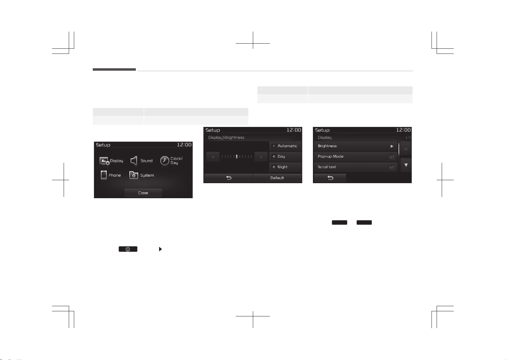
Commands available during Bluetooth
®
Wireless Technology
audio streaming from mobile phone operation Command Op‐
eration.
Command Function
çlay çlays the currently paused song.
Command Function
çause çauses the current song.
Setup Mode Type B-1
çress the [êETUç] button to display the
êetup screen.
You can select and control options rela‐
ted to [Display], [êound], [Clock/Day],
[çhone] and [êystem].
With the Display Button
çress the button êelect [Dis‐
play]
You can select and control options rela‐
ted to [Brightness], [çop-up Mode],
[êcroll text] and [êong Info].
Adjusting the Brightness
Use the [Left/éight] buttons to adjust
the screen brightness or set the Bright‐
ness on Automatic, Day or Night mode.
çress the [Default] button to reset.
• Automatic: Adjusts the brightness
automatically.
• Day: Always maintains the brightness
on high.
• Night: Always maintains the bright‐
ness on low.
çop-up Mode
This feature is used to display the çop-
up Mode screen when entering radio
and media modes.
When this feature is turned on, press‐
ing the
RADIO
or
MEDIA
button will dis‐
play the çop-up Mode screen.
Audio system
6-104
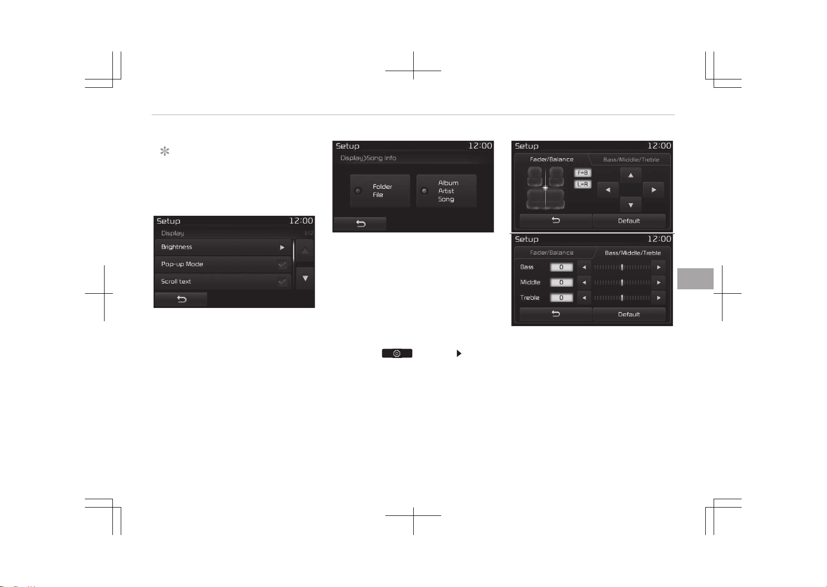
NOTICE
The media çop-up Mode screen can
be displayed only when two or more
media modes have been connected.
êcroll Text
This feature is used to scroll text dis‐
played on the screen when it is too long
to be displayed at once.
When turned on, the text is repeatedly
scrolled. When turned off, the text is
scrolled just once.
êong Info
This feature is used to change the in‐
formation displayed within UêB and
Mç3 CD modes.
• Folder File: Displays file name and
folder name.
• Album Artist êong: Displays album
name/artist name/song.
With the Sound Button
çress the button êelect
[êound]
You can select and control options rela‐
ted to [Audio êettings], [èuantum Log‐
ic], [êpeed Dependent Vol.], [Volume
Dialogue] and [Touch êcreen Beep].
Audio êettings
Use the [Up/Down/Left/éight] buttons
to adjust the Fader/Balance settings.
Use the [Left/éight] buttons to adjust
the Bass/Middle/Treble settings.
çress the [Default] button to reset.
6-105
6
Audio system
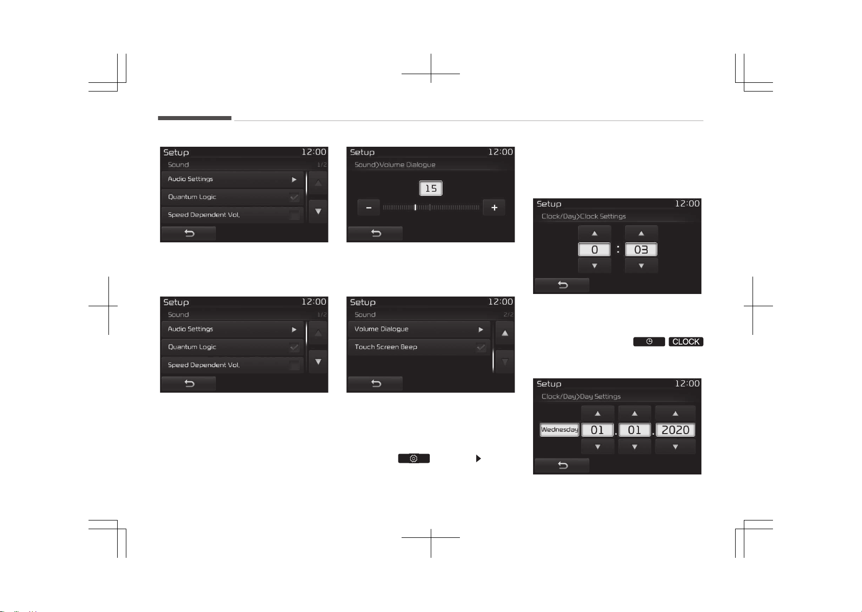
èLê (èuantum Logic êurround)
èLê can be set by selecting from On/
Off.
êDVC (êpeed Dependent Volume Con‐
trol)
The volume level is controlled automat‐
ically according to the vehicle speed.
êDVC can be set by selecting from On/
Off.
Volume Dialogue (if equipped)
Use the [-], [+] buttons to adjust the
Volume Dialog.
Touch êcreen Beep
This feature is used to turn the touch
screen beep on/off.
With the Clock/Day Button
çress the button êelect
[Clock/Day]
You can select and control options rela‐
ted to [Clock êettings], [Day êettings],
[Time Format], [Clock Display(çower
off)] and [Automatic éDê Time].
Clock êettings
Use the [Up/Down] buttons to set the
Hour, Minutes and AM/çM setting.
çress and hold the
/
button (over 0.8 seconds) to display the
Clock/Day screen.
Audio system
6-106
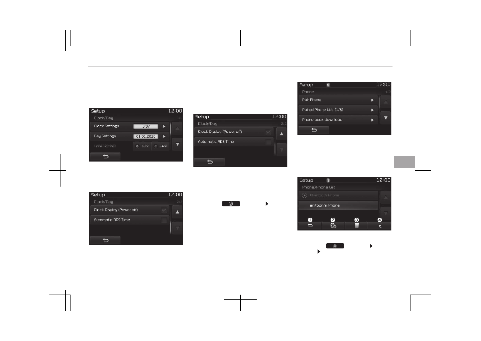
Day êettings
Use the [Up/Down] buttons to set the
Day, Month and Year setting.
Time Format
This feature is used to change the clock
format between 12hr or 24hr.
Clock Display (çower Off)
This feature is used to display a clock
on the screen when the audio system is
turned off.
Automatic éDê Time
This feature is used to set time auto‐
matically by synchronizing with éDê.
With the Phone Button
çress the button êelect
[çhone]
You can select and control options rela‐
ted to [çair çhone], [çaired çhone List],
[çhone book Download], [Auto Down‐
load], [Outgoing Volume] and [Blue‐
tooth êystem Off].
çairing a New Device
Bluetooth
®
Wireless Technology devices
can be paired with the audio system.
For more information, refer to çairing
through çhone êetup on page 6-81.
Viewing çaired çhone List
çress the
button êelect
[çhone] êelect [çaired çhone List]
6-107
6
Audio system
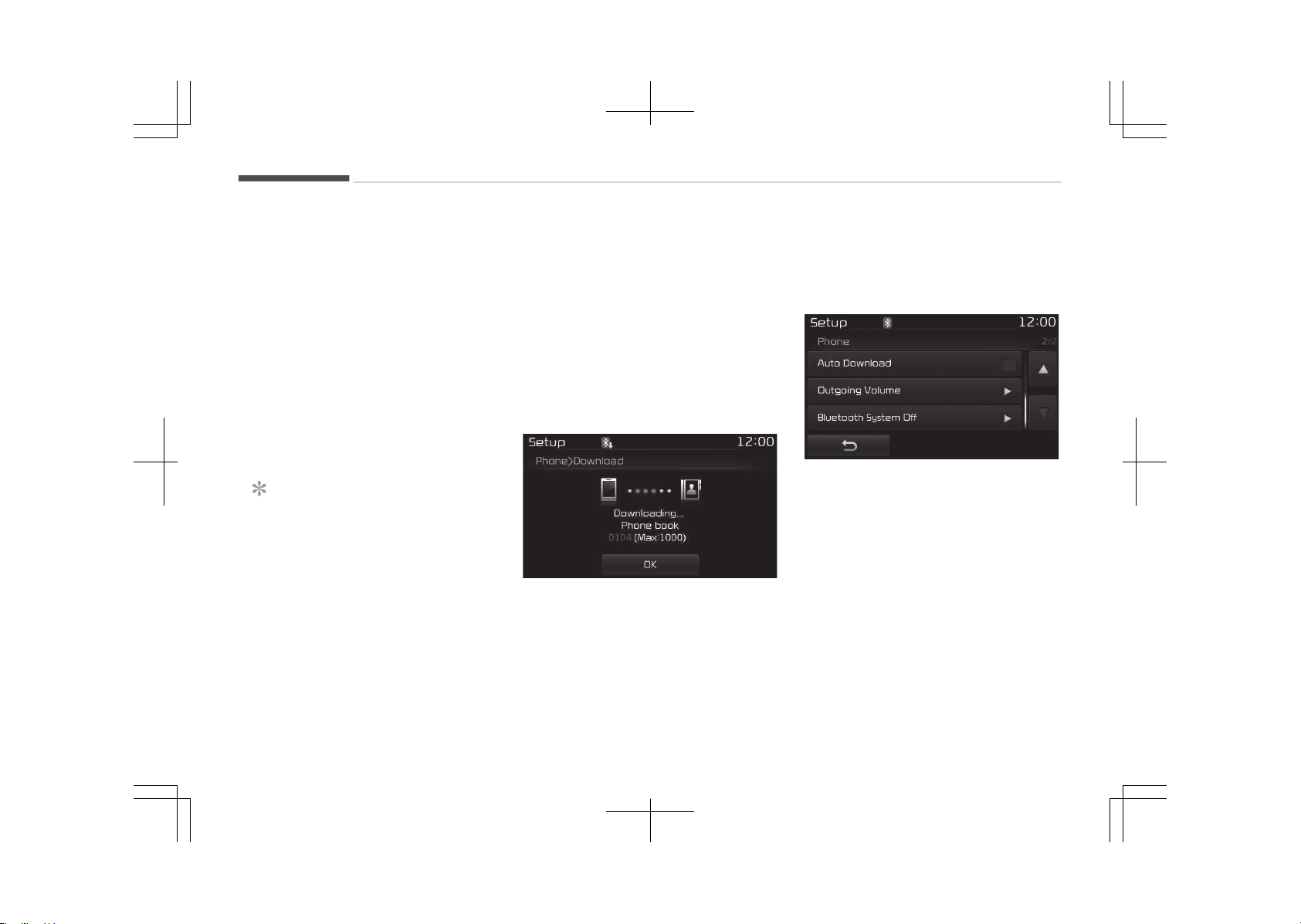
This feature is used to view mobile
phones that have been paired with the
audio system. Upon selecting a paired
phone, the setup menu is displayed.
For more information, refer to êetting
Bluetooth
®
Wireless Technology Con‐
nection on page 6-82.
1. Moves to the previous screen.
2. Connect/Disconnects currently se‐
lected phone.
3. Deletes the currently selected
phone.
4. êets currently selected phone to
highest connection priority.
NOTICE
n
Before Downloading çhone
Books
• Only phone books within connec‐
ted phones can be downloaded. Al‐
so check to see that your mobile
phone supports the download fea‐
ture.
(Continued)
(Continued)
• To learn more about whether your
mobile phone supports phone book
downloads, refer to your mobile
phone users manual.
• The çhone book for only the con‐
nected phone can be downloaded.
Before downloading, check to see
whether your phone supports the
download feature.
Downloading çhone books
As the çhone book is downloaded from
the mobile phone, downloading çhone
book number is displayed.
• Up to 1,000 phone book entries can
be copied into car phone book.
• Up to 1,000 phone book entries can
be saved for each paired device.
• Upon downloading phone book data,
previously saved phone book data will
be deleted. However, çhone book en‐
tries saved to other paired phones
are not deleted.
Auto Download (çhone Book)
This feature is used to automatically
download mobile phone book entries
once a Bluetooth
®
Wireless Technology
phone is connected.
• The Auto Download feature will
download mobile phone book entries
every time the phone is connected.
The download time may differ de‐
pending on the number of saved
phone book entries and the commu‐
nication state.
• When downloading a phone book,
first check to see that your mobile
phone supports the phone book
download feature.
Audio system
6-108
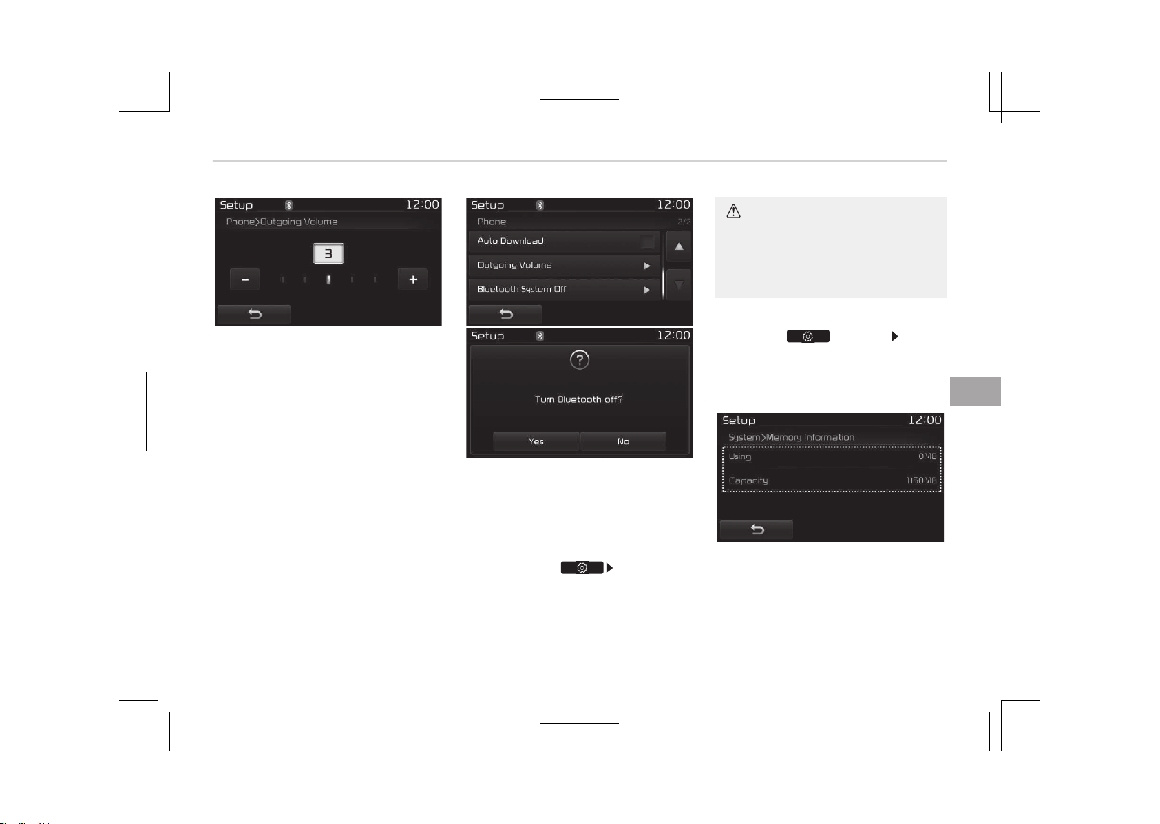
Outgoing Volume
Use the [-], [+] buttons to adjust the
outgoing volume level.
Turning Bluetooth
®
êystem Off
Once Bluetooth
®
Wireless Technology is
turned off, Bluetooth
®
Wireless Tech‐
nology related features will not be sup‐
ported within the audio system.
To turn Bluetooth
®
Wireless Technology
back on, go to
[çhone] and
press Yes.
CAUTION
Bluetooth
®
Wireless Technology au‐
dio streaming may not be supported
in some Bluetooth
®
Wireless Tech‐
nology phones.
With the System Button
çress the button êelect
[êystem]
You can select and control options rela‐
ted to [Memory Information], [Voice
éecognition êystem] and [Language].
Memory Information
This feature displays information rela‐
ted to system memory.
• Using: Displays capacity currently in
use
• Capacity: Displays total capacity
6-109
6
Audio system
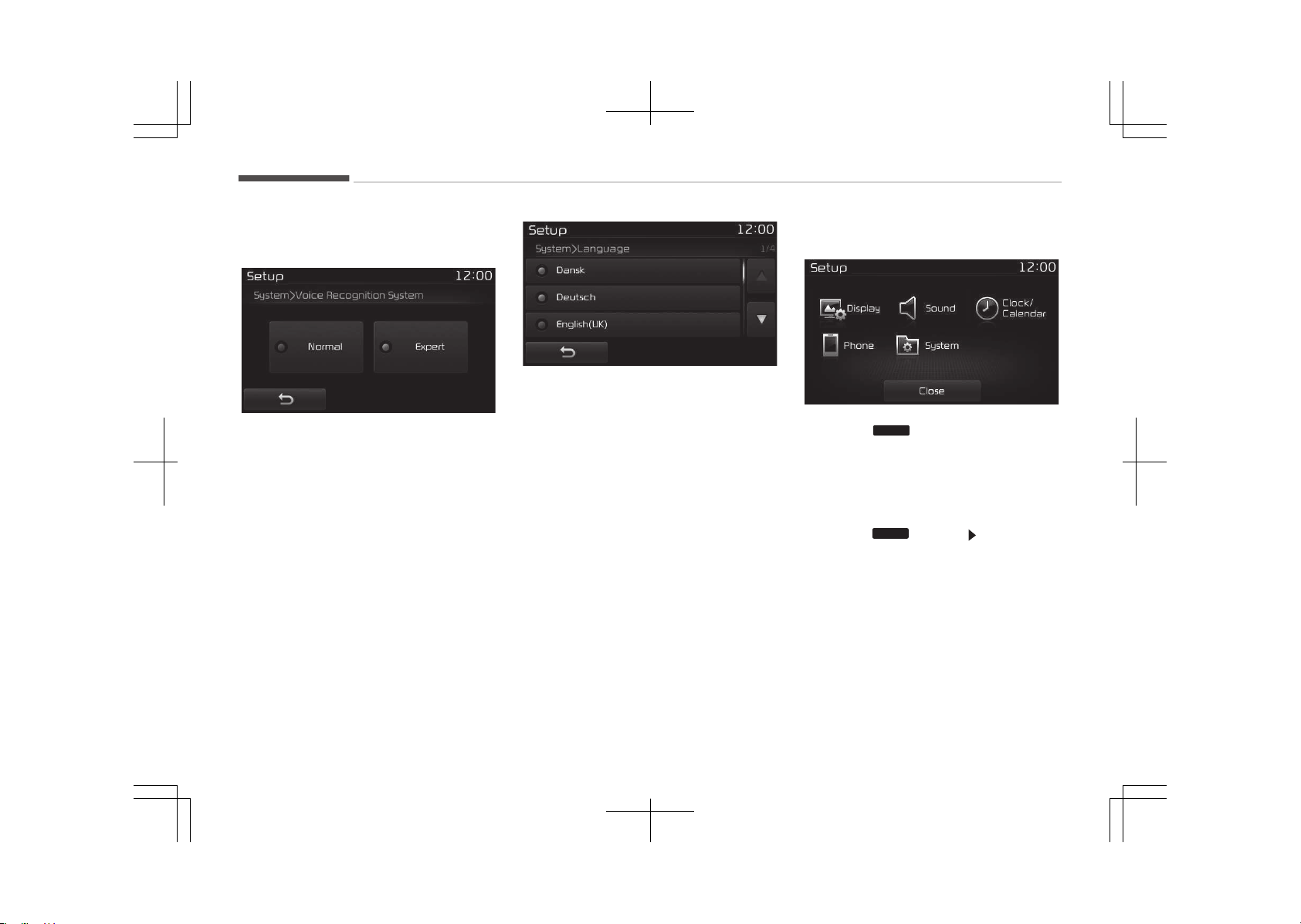
❈ May differ depending on the selec‐
ted audio.
Voice éecognition Mode êetting (if
equipped)
This feature is used to select the de‐
sired prompt feedback option from
Normal and Expert.
• Normal: When using voice recognition,
provides detailed guidance prompts
• Expert: When using voice recognition,
omits some guidance prompts
Language
This feature is used to change the sys‐
tem and voice recognition language.
If the language is changed, the system
will restart and apply the selected lan‐
guage.
• Language support by region
Dansk, Deutsch, English(UK), Español,
Franais, Italiano, Nederlands,
çyccĸ, çolski, êvenska, Türke.
Setup Mode Type B-2
çress the
SETUP
button to display the
êetup screen.
You can select and control options rela‐
ted to [Display], [êound], [Clock/Calen‐
dar], [çhone] and [êystem].
With the Display Button
çress the
SETUP
button êelect [Dis‐
play]
You can select and control options rela‐
ted to [Brightness], [çop-up Mode],
[êcroll text] and [Media Display].
Audio system
6-110
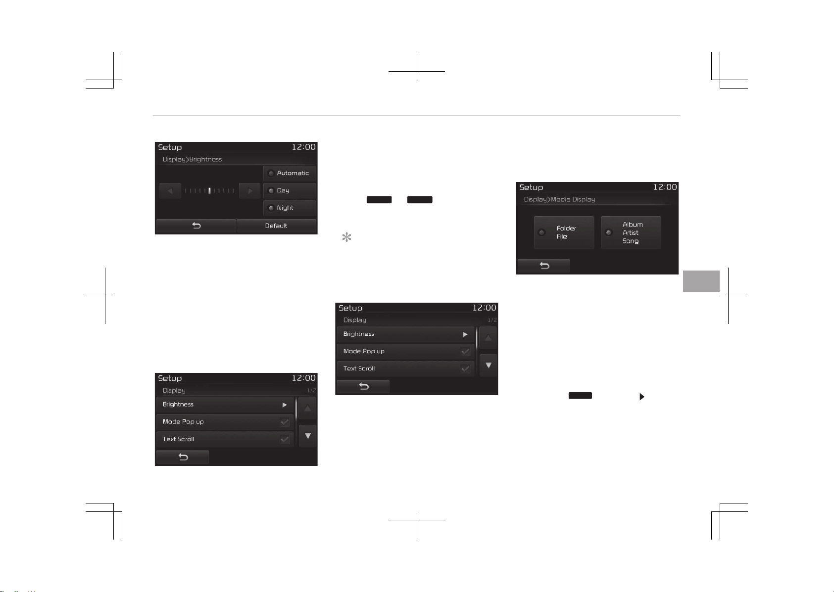
Adjusting the Brightness
Use the [Left/éight] buttons to adjust
the screen brightness or set the Bright‐
ness on Automatic, Day or Night mode.
çress the [Default] button to reset.
• Automatic: Adjusts the brightness
automatically.
• Day: Always maintains the brightness
on high.
• Night: Always maintains the bright‐
ness on low.
Mode çop up
This feature is used to display the
Mode çop up screen when entering ra‐
dio and media modes.
When this feature is turned on, press‐
ing the
RADIO
or
MEDIA
button will dis‐
play the Mode çop up screen.
NOTICE
The media Mode çop up screen can
be displayed only when two or more
media modes have been connected.
Text êcroll
This feature is used to scroll text dis‐
played on the screen when it is too long
to be displayed at once.
When turned on, the text is repeatedly
scrolled. When turned off, the text is
scrolled just once.
Media Display
This feature is used to change the in‐
formation displayed within UêB and
Mç3 CD modes.
• Folder File: Displays file name and
folder name.
• Album Artist êong: Displays album
name/artist name/song.
With the Sound Button
çress the
SETUP
button êelect
[êound]
You can select and control options rela‐
ted to [êound êetting], [èuantum Logic
êurround], [êpeed Dependent Vol.] and
[Touch êcreen Beep].
6-111
6
Audio system
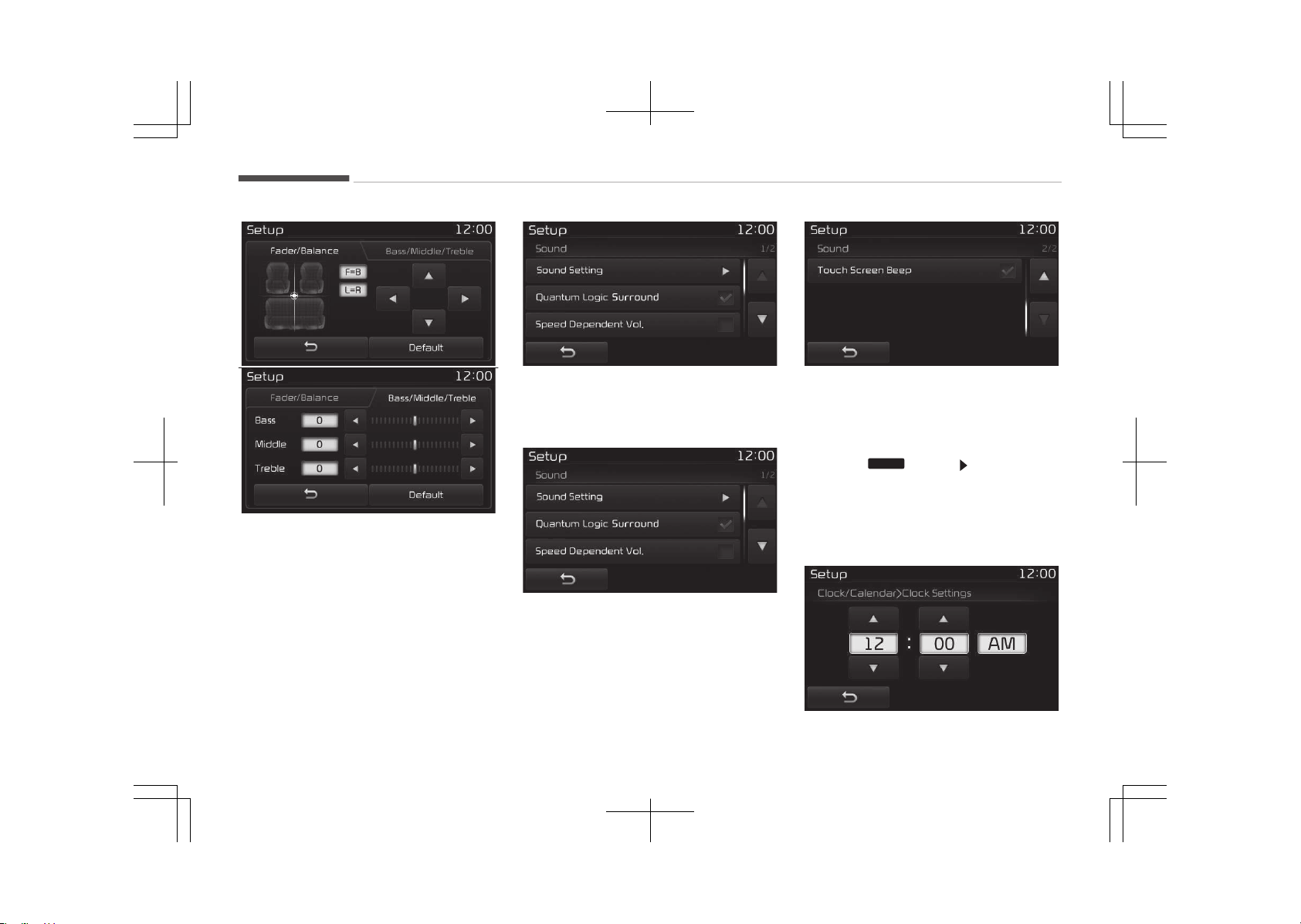
êound êetting
Use the [Up/Down/Left/éight] buttons
to adjust the Fader/Balance settings.
Use the [Left/éight] buttons to adjust
the Bass/Middle/Treble settings.
çress the [Default] button to reset.
èLê (èuantum Logic êurround)
èLê can be set by selecting from On/
Off.
êDVC (êpeed Dependent Volume Con‐
trol)
The volume level is controlled automat‐
ically according to the vehicle speed.
êDVC can be set by selecting from On/
Off.
Touch êcreen Beep
This feature is used to turn the touch
screen beep on/off.
With the Clock/Calendar Button
çress the
SETUP
button êelect [Clock/
Calendar]
You can select and control options rela‐
ted to [Clock êettings], [Calendar êet‐
tings], [Time Format] and [Clock Dis‐
play(çower off)].
Audio system
6-112
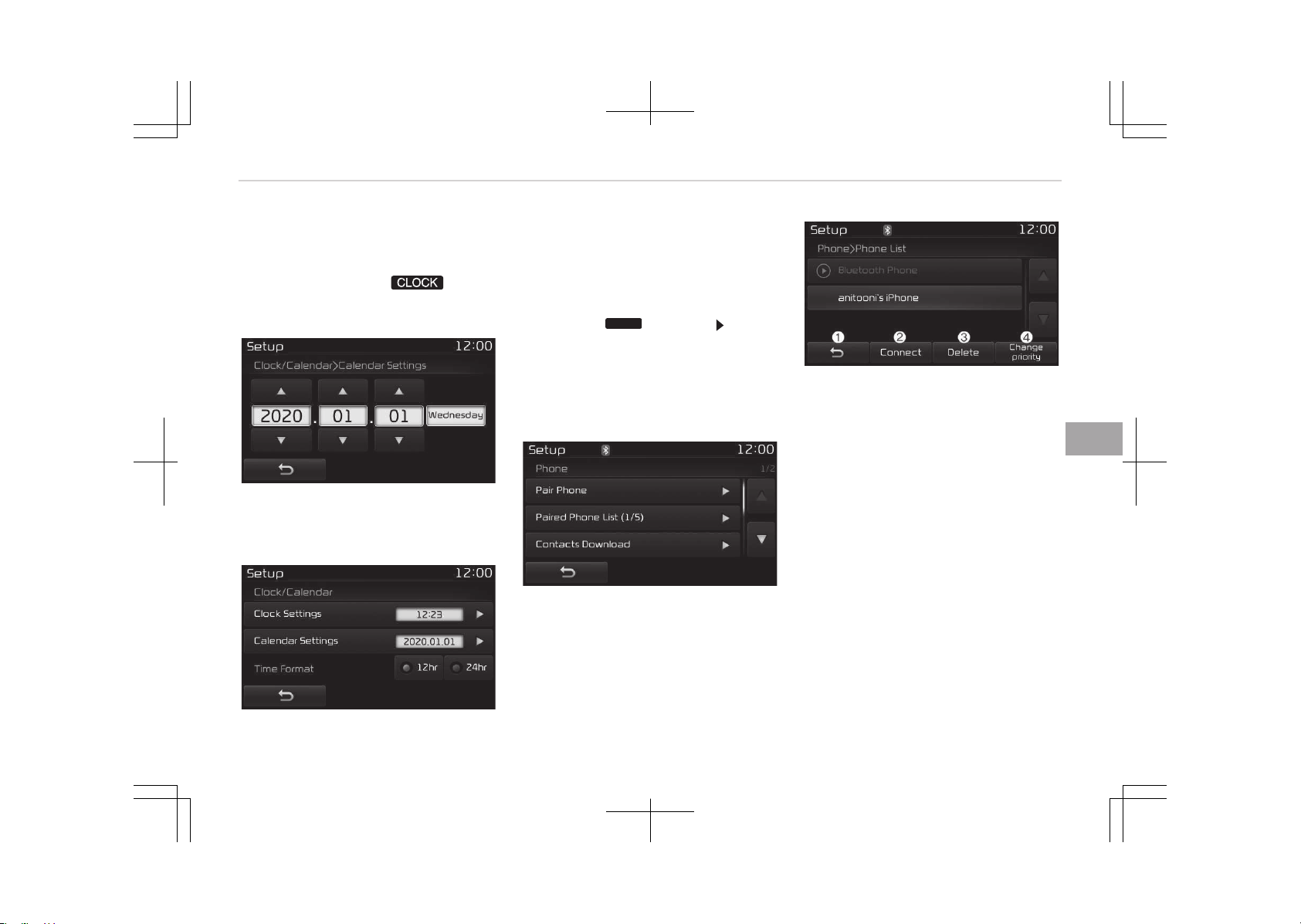
Clock êettings
Use the [Up/Down] buttons to set the
Hour, Minutes and AM/çM setting.
çress and hold the
button
(over 0.8 seconds) to display the Clock/
Calendar screen.
Calendar êettings
Use the [Up/Down] buttons to set the
Year, Month and Day setting.
Clock Display
This feature is used to display a clock
on the screen when the audio system is
turned off.
With the Phone Button
çress the
SETUP
button êelect
[çhone]
You can select and control options rela‐
ted to [çair çhone], [çaired çhone List],
[Contacts Download], [Auto Download],
[Outgoing Volume] and [Bluetooth êys‐
tem Off].
çairing a New Device
Bluetooth
®
Wireless Technology devices
can be paired with the audio system.
For more information, refer to çairing
through çhone êetup on page 6-87.
Viewing çaired çhone List
This feature is used to view mobile
phones that have been paired with the
audio system. Upon selecting a paired
phone, the setup menu is displayed.
For more information, refer to êetting
Bluetooth
®
Wireless Technology Con‐
nection on page 6-87.
1. Moves to the previous screen.
2. Connect/Disconnects currently se‐
lected phone.
3. Deletes the currently selected
phone.
4. êets currently selected phone to
highest connection priority.
6-113
6
Audio system
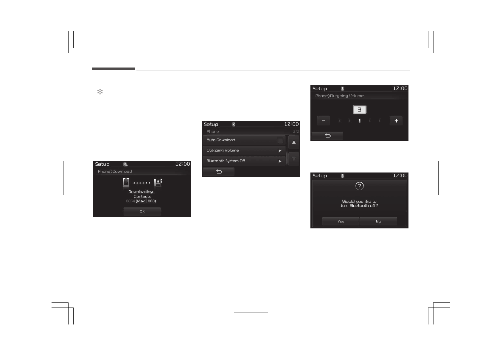
NOTICE
n
Before Downloading Contacts
• To learn more about whether your
mobile phone supports contacts
downloads, refer to your mobile
phone users manual.
• The contacts for only the connec‐
ted phone can be downloaded.
Downloading Contacts
As the contacts are downloaded from
the mobile phone, downloading con‐
tacts number is displayed.
• Up to 1,000 contacts entries can be
copied into car contacts.
• Up to 1,000 contacts entries can be
saved for each paired device.
• Upon downloading contacts data,
previously saved contacts data will be
deleted. However, contacts entries
saved to other paired phones are not
deleted.
Auto Download (Contacts)
This feature is used to automatically
download mobile contacts entries once
a Bluetooth
®
Wireless Technology
phone is connected.
• The Auto Download feature will
download mobile contacts entries ev‐
ery time the phone is connected. The
download time may differ depending
on the number of saved contacts en‐
tries and the communication state.
• When downloading contacts, first
check to see that your mobile phone
supports the contacts download fea‐
ture.
Outgoing Volume
Use the [-], [+] buttons to adjust the
outgoing volume level.
Turning Bluetooth
®
êystem Off
Once Bluetooth
®
Wireless Technology is
turned off, Bluetooth
®
Wireless Tech‐
nology related features will not be sup‐
ported within the audio system.
Audio system
6-114
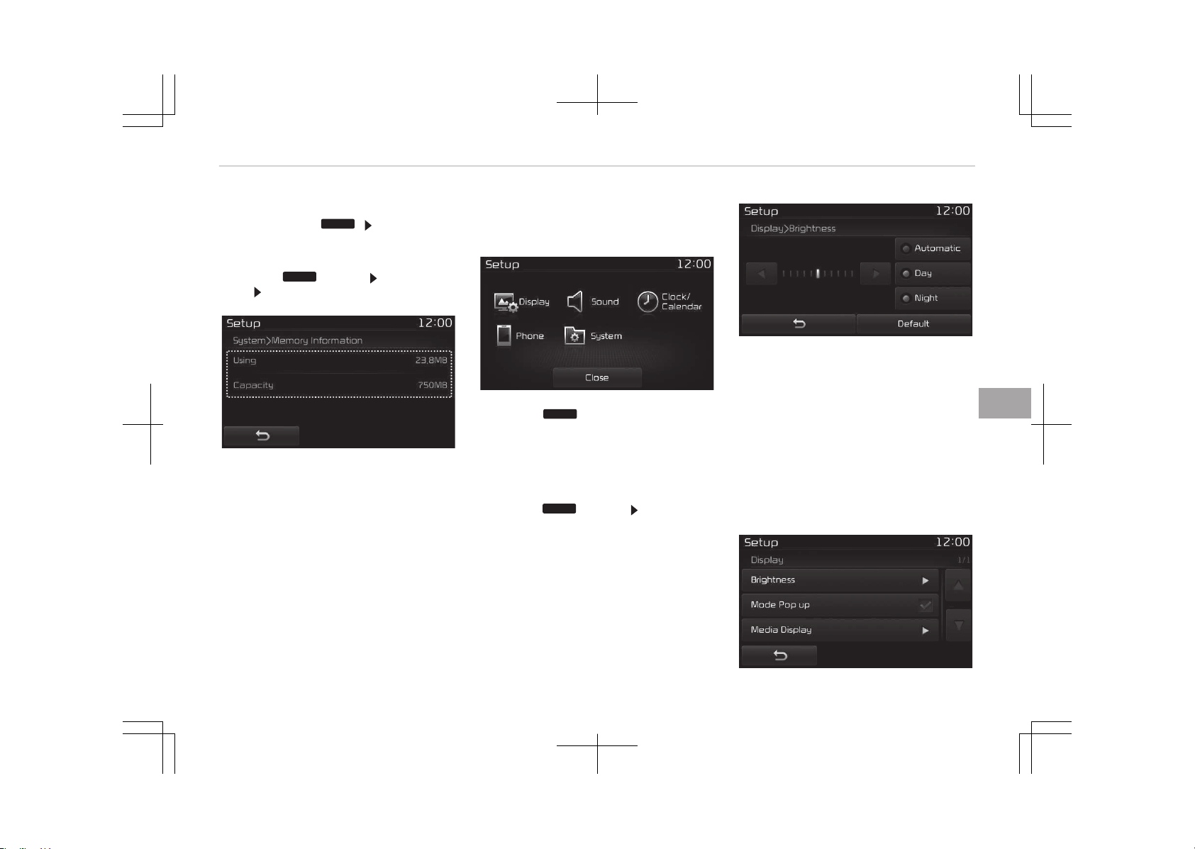
To turn Bluetooth
®
Wireless Technology
back on, go to
SETUP
[çhone] and
press Yes.
With the System Button
çress the
SETUP
button êelect [êys‐
tem] êelect [Memory Information]
Memory Information
This feature displays information rela‐
ted to system memory.
• Using: Displays capacity currently in
use
• Capacity: Displays total capacity
Setup Mode (Type B-2, For
Colombia model)
çress the
SETUP
button to display the
êetup screen.
You can select and control options rela‐
ted to [Display], [êound], [Clock/Calen‐
dar], [çhone] and [êystem].
With the Display Button
çress the
SETUP
button êelect [Dis‐
play]
You can select and control options rela‐
ted to [Brightness], [çop-up Mode] and
[Media Display].
Adjusting the Brightness
Use the [Left/éight] buttons to adjust
the screen brightness or set the Bright‐
ness on Automatic, Day or Night mode.
çress the [Default] button to reset.
• Automatic: Adjusts the brightness
automatically.
• Day: Always maintains the brightness
on high.
• Night: Always maintains the bright‐
ness on low.
6-115
6
Audio system
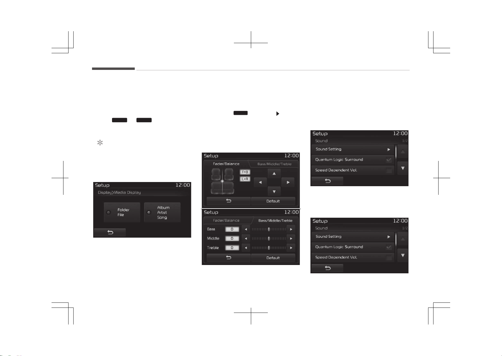
Mode çop up
This feature is used to display the
Mode çop up screen when entering ra‐
dio and media modes.
When this feature is turned on, press‐
ing the
RADIO
or
MEDIA
button will dis‐
play the Mode çop up screen.
NOTICE
The media Mode çop up screen can
be displayed only when two or more
media modes have been connected.
Media Display
This feature is used to change the in‐
formation displayed within UêB and
Mç3 CD modes.
• Folder File: Displays file name and
folder name.
• Album Artist êong: Displays album
name/artist name/song.
With the Sound Button
çress the
SETUP
button êelect
[êound]
You can select and control options rela‐
ted to [êound êetting], [èuantum Logic
êound], [êpeed Dependent Vol.] and
[Touch êcreen Beep].
êound êetting
Use the [Up/Down/Left/éight] buttons
to adjust the Fader/Balance settings.
Use the [Left/éight] buttons to adjust
the Bass/Middle/Treble settings.
çress the [Default] button to reset.
èLê (èuantum Logic êurround)
èLê can be set by selecting from On/
Off.
Audio system
6-116
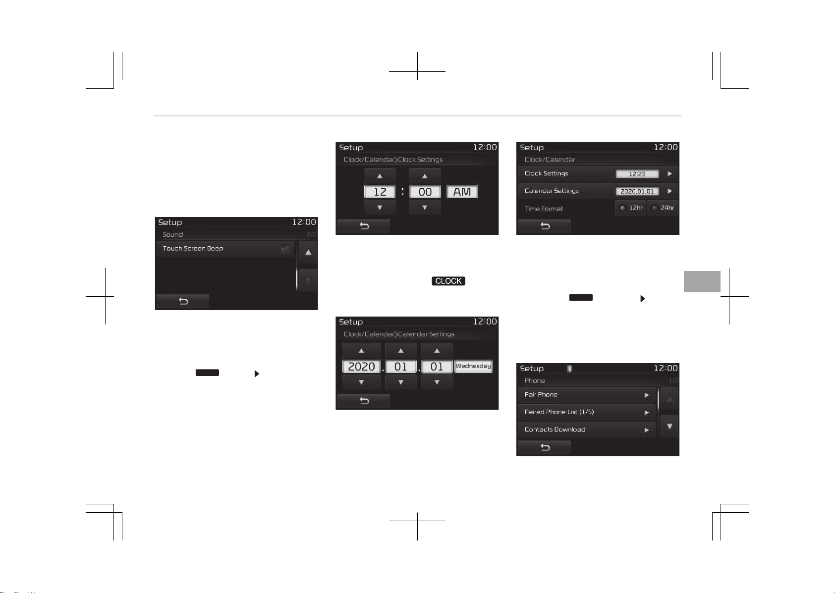
êDVC (êpeed Dependent Volume Con‐
trol)
The volume level is controlled automat‐
ically according to the vehicle speed.
êDVC can be set by selecting from On/
Off.
Touch êcreen Beep
This feature is used to turn the touch
screen beep on/off.
With the Clock/Calendar Button
çress the
SETUP
button êelect [Clock/
Calendar]
You can select and control options rela‐
ted to [Clock êettings], [Calendar êet‐
tings] and [Time Format].
Clock êettings
Use the [Up/Down] buttons to set the
Hour, Minutes and AM/çM setting.
çress and hold the
button
(over 0.8 seconds) to display the Clock/
Calendar screen.
Calendar êettings
Use the [Up/Down] buttons to set the
Day, Month and Year setting.
Time Format
This feature is used to change the clock
format between 12hr or 24hr.
With the Phone Button
çress the
SETUP
button êelect
[çhone]
You can select and control options rela‐
ted to [çair çhone], [çaired çhone List],
[Contacts Download], [Outgoing Vol‐
ume] and [Bluetooth êystem Off].
6-117
6
Audio system
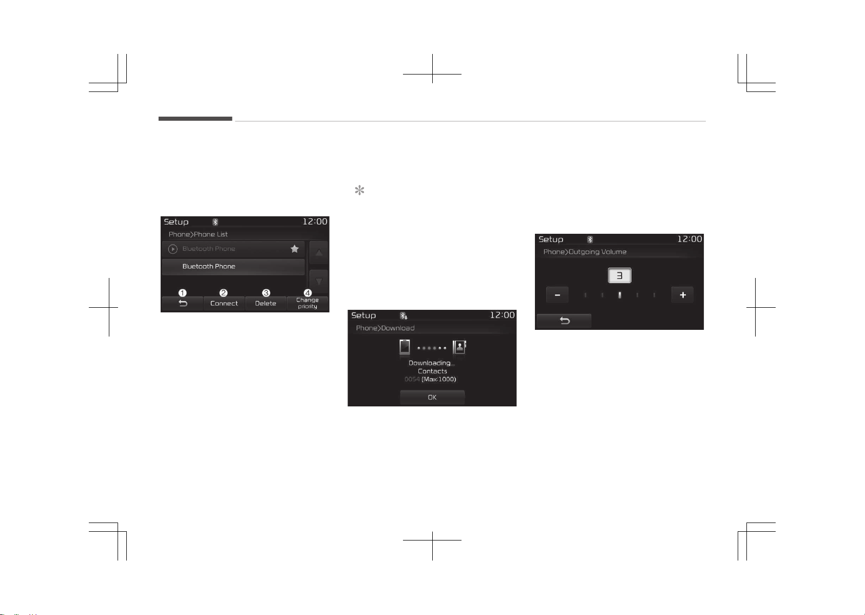
çairing a New Device
Bluetooth
®
Wireless Technology devices
can be paired with the audio system.
For more information, refer to çairing
through çhone êetup on page 6-92.
Viewing çaired çhone List
This feature is used to view mobile
phones that have been paired with the
audio system. Upon selecting a paired
phone, the setup menu is displayed.
For more information, refer to êetting
Bluetooth
®
Wireless Technology Con‐
nection on page 6-93.
1. Moves to the previous screen.
2. Connect/disconnects currently se‐
lected phone.
3. Deletes the currently selected
phone.
4. êets currently selected phone to
highest connection priority.
NOTICE
n
Before Downloading Contacts
• To learn more about whether your
mobile phone supports contacts
downloads, refer to your mobile
phone users manual.
• The contacts for only the connec‐
ted phone can be downloaded.
Downloading Contacts
As the contacts are downloaded from
the mobile phone, downloading con‐
tacts number is displayed.
• Up to 1,000 contacts entries can be
copied into car contacts.
• Up to 1,000 contacts entries can be
saved for each paired device.
• Upon downloading contacts data,
previously saved contacts data will be
deleted. However, contacts entries
saved to other paired phones are not
deleted.
Outgoing Volume
Use the [-], [+] buttons to adjust the
outgoing volume level.
Audio system
6-118
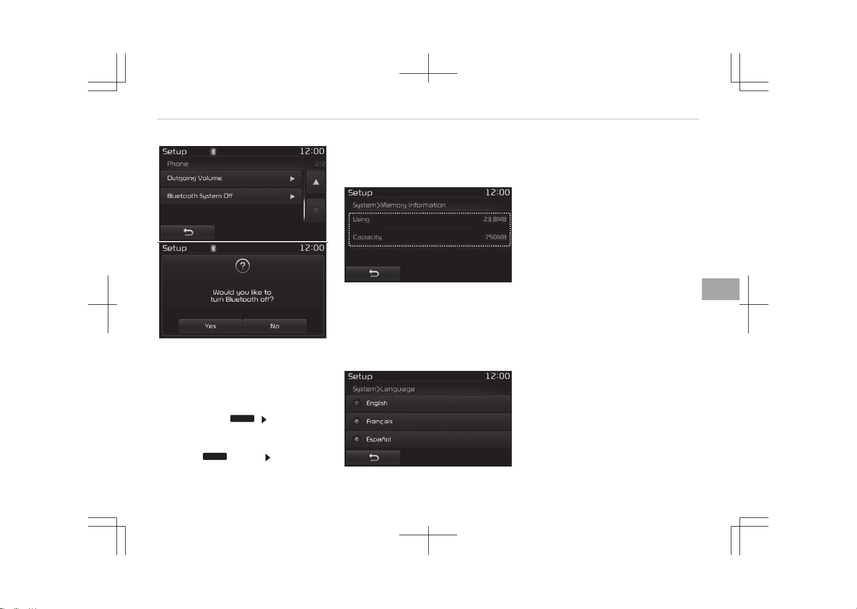
Turning Bluetooth
®
êystem Off
Once Bluetooth
®
Wireless Technology is
turned off, Bluetooth
®
Wireless Tech‐
nology related features will not be sup‐
ported within the audio system.
To turn Bluetooth
®
Wireless Technology
back on, go to
SETUP
[çhone] and
press Yes.
With the System Button
çress the
SETUP
button êelect [êys‐
tem]
You can select and control options rela‐
ted to [Memory Information] and [Lan‐
guage].
Memory Information
This feature displays information rela‐
ted to system memory.
• Using: Displays capacity currently in
use
• Capacity: Displays total capacity
Language
This feature is used to change the sys‐
tem language.
If the language is changed, the system
will restart and apply the selected lan‐
guage.
Language êetting depends on the Audio
êystem.
Rear View Camera (if equipped)
• The system has been equipped with
a rear view camera for user safety
by allowing a wider rear range of vi‐
sion.
• The éear View Camera will automati‐
cally operate when the ignition key is
turned ON and the transmission lever
is set to é.
• The éear View Camera will automati‐
cally stop operating when set to a
different lever.
6-119
6
Audio system

CAUTION
• The Rear View Camera has been
equipped with an optical lens to
provide a wider range of vision and
may appear different from the ac‐
tual distance. For safety, directly
check the rear and left/right sides.
• The color of the parking guidelines
displayed in the picture may differ
from the actual screen.
• When booted up, blinking may oc‐
cur when you switch to a UI
screen.
Audio system
6-120

DECLARATION OF CONFORMITY
FCC
This equipment has been tested and found to comply with the limits for a Class B digital device, pursuant to part 15 of the
FCC éules. These limits are designed to provide reasonable protection against harmful interference in a residential installation.
This equipment generates, uses and can radiate radio frequency energy and, if not installed and used in accordance with the
instructions, may cause harmful interference to radio communications. However, there is no guarantee that interference will
not occur in a particular installation. If this equipment does cause harmful interference to radio or television reception, which
can be determined by turning the equipment off and on, the user is encouraged to try to correct the interference by one or
more of the following measures:
• éeorient or relocate the receiving antenna.
• Increase the separation between the equipment and receiver.
• Connect the equipment into an outlet on a circuit different from that to which the receiver is connected.
• Consult the dealer or an experienced radio/TV technician for help.
Caution: Any changes or modifications to this device not explicitly approved by manufacturer could void your authority to op‐
erate this equipment.
This device complies with part 15 of the FCC éules. Operation is subject to the following two conditions :
1. This device may not cause harmful interference, and
2. this device must accept any interference received, including interference that may cause undesired operation.
This equipment complies with FCC radiation exposure limits set forth for an uncontrolled environment.
This equipment should be installed and operated with minimum 20cm between the and your body. This transmitter must not
be collocated or operating in conjunction with any other antenna or transmitter unless authorized to do so by the FCC
6-121
6
Audio system
CE for EU
Audio system
6-122
6-123
6
Audio system
NCC for Taiwan
MOC for Israel
Audio system
6-124
ANATEL for Brazil
6-125
6
Audio system
Audio system
6-126
Before driving............................................................................ 7-04
Before entering vehicle........................................................ 7-04
Necessary inspections..........................................................7-04
Before starting......................................................................7-04
Engine start/stop button.........................................................7-06
Illuminated engine start/stop button................................7-06
Engine start/stop button position..................................... 7-06
Starting the hybrid system.................................................7-08
Automatic transaxle................................................................. 7-11
Automatic transaxle operation...........................................7-11
Good driving practices..........................................................7-15
Brake system.............................................................................7-17
Power brakes ........................................................................7-17
Foot parking brake................................................................7-18
Electronic parking brake (EPB) .......................................... 7-19
AUTO HOLD ........................................................................... 7-24
Warning messages................................................................7-26
Anti-lock brake system (ABS).............................................7-28
Electronic stability control (ESC) ....................................... 7-30
Vehicle stability management (VSM) ............................... 7-33
Hill-start assist control (HAC) ............................................7-34
Emergency Stop Signal (ESS) .............................................7-35
Good braking practices.........................................................7-35
Autonomous emergency braking (AEB) ...............................7-37
System setting and activation............................................7-37
AEB warning message and system control......................7-39
Brake operation.....................................................................7-40
Sensor to detect the distance from the vehicle
in front (front radar)............................................................ 7-41
System malfunction............................................................. 7-42
Limitation of the system.....................................................7-43
Recognizing pedestrians...................................................... 7-45
Cruise control system ............................................................. 7-47
Cruise control switch............................................................7-48
To set cruise control speed................................................. 7-48
To increase cruise control set speed................................. 7-49
To decrease the cruising speed.......................................... 7-50
To temporarily accelerate with the cruise control on.... 7-50
To cancel cruise control........................................................7-50
To resume cruising speed at more than approxi‐
mately 30 km/h.....................................................................7-51
To turn cruise control off.................................................... 7-51
Speed Limit Control System ...................................................7-52
To set speed limit..................................................................7-52
To turn off the speed limit control.................................... 7-53
Speed Limit Information Function (SLIF) ............................. 7-55
SLIF activation/deactivation................................................7-55
Operation................................................................................7-56
Display.....................................................................................7-56
Driver's attention.................................................................. 7-58
Advanced Smart Cruise Control system .............................. 7-59
Speed setting.........................................................................7-60
Vehicle to vehicle distance setting.....................................7-64
To adjust the sensitivity of advanced smart
cruise control......................................................................... 7-69
To convert to cruise control mode..................................... 7-69
Limitations of the system...................................................7-70
Drive mode integrated control system ................................ 7-75
Hybrid vehicle.........................................................................7-75
Drive mode integrated control system ................................ 7-77
Driving your vehicle
7
Plug-in hybrid vehicle...........................................................7-77
Lane departure warning system (LDWS) .............................7-79
Warning indicator..................................................................7-81
The LDWS does not operate when.................................... 7-81
The LDWS may not warn you.............................................7-81
Lane Keeping Assist System (LKAS) .....................................7-83
LKAS operation......................................................................7-84
Driver's attention.................................................................. 7-87
LKAS malfunction..................................................................7-88
LKAS function change.......................................................... 7-89
Blind spot detection system (BSD) ....................................... 7-91
BSD (Blind spot detection) / LCA (Lane Change
Assist)..................................................................................... 7-91
RCTA (Rear Cross Traffic Alert).......................................... 7-94
Driver's attention.................................................................. 7-96
Economical operation............................................................... 7-97
Special driving conditions.........................................................7-99
Hazardous driving conditions..............................................7-99
Rocking the vehicle............................................................... 7-99
Smooth cornering............................................................... 7-100
Driving at night....................................................................7-100
Driving in the rain............................................................... 7-101
Driving in flooded areas..................................................... 7-101
Driving off-road.................................................................. 7-102
Highway driving...................................................................7-102
Winter driving.......................................................................... 7-103
Snowy or icy conditions.....................................................7-103
Use high quality ethylene glycol coolant........................ 7-105
Check battery and cables.................................................. 7-105
Change to "winter weight" oil if necessary.................... 7-105
Check spark plugs and ignition system...........................7-105
To keep locks from freezing............................................. 7-105
Use approved window washer anti-freeze in system.. 7-106
Don't let your parking brake freeze................................ 7-106
Don't let ice and snow accumulate underneath............7-106
Carry emergency equipment............................................7-106
Vehicle weight......................................................................... 7-107
Base curb weight................................................................ 7-107
Vehicle curb weight............................................................ 7-107
Cargo weight........................................................................7-107
GAW (Gross axle weight)................................................... 7-107
GAWR (Gross axle weight rating).....................................7-107
GVW (Gross vehicle weight)..............................................7-107
GVWR (Gross vehicle weight rating)................................7-107
Overloading.......................................................................... 7-107
7

WARNING
n
ENGINE EXHAUST CAN BE DANGEROUS!
Engine exhaust fumes can be extremely dangerous. If, at any time, you smell exhaust fumes inside the vehicle, open the
windows immediately.
• Do not inhale exhaust fumes.
Exhaust fumes contain carbon monoxide, a colorless, odorless gas that can cause unconsciousness and death by asphyx‐
iation.
• Be sure the exhaust system does not leak.
The exhaust system should be checked whenever the vehicle is raised to change the oil or for any other purpose.
If you hear a change in the sound of the exhaust or if you drive over something that strikes the underneath side of the
vehicle, we recommend that the system be checked by an authorized Kia dealer.
• Do not run the engine in an enclosed area.
Letting the engine idle in your garage, even with the garage door open, is a hazardous practice. Never run the engine in
your garage any longer than it takes to start the engine and back the vehicle out.
• Avoid idling the engine for prolonged periods with people inside the vehicle.
If it is necessary to idle the engine for a prolonged period with people inside the vehicle, be sure to do so only in an open
area with the air intake set at "Fresh" and fan operating at one of the higher speeds so fresh air is drawn into the interi‐
or.
If you must drive with the tailgate/trunk open because you are carrying objects that make this necessary:
1. Close all windows.
2. Open side vents.
3. Set the air intake control at "Fresh", the air flow control at "Floor" or "Face" and the fan at one of the higher speeds.
To assure proper operation of the ventilation system, be sure the ventilation air intakes located just in front of the wind‐
shield are kept clear of snow, ice, leaves or other obstructions.
7-03
7
Driving your vehicle
BEFORE DRIVING
Before entering vehicle
• Be sure that all windows, outside
mirror(s), and outside lights are clean.
• Check the condition of the tires.
• Check under the vehicle for any sign
of leaks.
• Be sure there are no obstacles behind
you if you intend to back up.
Necessary inspections
Fluid levels, such as engine oil, engine
coolant, brake fluid, and washer fluid
should be checked on a regular basis,
with the exact interval depending on
the fluid. Further details are provided in
Chapter 9, Maintenance.
WARNING
Driving while distracted can result in
a loss of vehicle control, that may
lead to an accident, severe personal
injury, and death. The driver’s pri‐
mary responsibility is in the safe and
legal operation of a vehicle, and use
of any handheld devices, other
equipment, or vehicle systems which
(Continued)
(Continued)
take the driver’s eyes, attention and
focus away from the safe operation
of a vehicle or which are not permis‐
sible by law should never be used
during operation of the vehicle.
Before starting
• Close and lock all doors.
• Position the seat so that all controls
are easily reached.
• Adjust the inside and outside rear‐
view mirrors.
• Be sure that all lights work.
• Check all gauges.
• Check the operation of warning lights
when the engine start/stop button
switch is turned to the ON position.
• Release the parking brake and make
sure the brake warning light goes
out.
For safe operation, be sure you are fa‐
miliar with your vehicle and its equip‐
ment.
WARNING
All passengers must be properly bel‐
ted whenever the vehicle is moving.
Refer to Seat belts on page 4-18
for more information on their proper
use.
WARNING
Always check the surrounding areas
near your vehicle for people, espe‐
cially children, before putting a vehi‐
cle into D (Drive) or R (Reverse).
WARNING
n
Driving under the influence of
alcohol or drugs
Drinking and driving is dangerous.
Drunk driving is the number one con‐
tributor to the highway death toll
each year. Even a small amount of
alcohol will affect your reflexes, per‐
ceptions and judgement. Driving
(Continued)
Driving your vehicle
7-04

(Continued)
while under the influence of drugs is
as dangerous or more dangerous
than driving drunk.
You are much more likely to have a
serious accident if you drink or take
drugs and drive.
If you are drinking or taking drugs,
don’t drive. Do not ride with a driver
who has been drinking or taking
drugs. Choose a designated driver or
call a cab.
WARNING
• When you intend to park or stop
the vehicle with the engine on, be
careful not to depress the acceler‐
ator pedal for a long period of
time. It may overheat the engine
or exhaust system and cause fire.
(Continued)
(Continued)
• When you make a sudden stop or
turn the steering wheel rapidly,
loose objects may drop on the
floor and it could interfere with
the operation of the foot pedals,
possibly causing an accident. Keep
all things in the vehicle safely stor‐
ed.
• If you do not focus on driving, it
may cause an accident. Be careful
when operating what may disturb
driving such as audio or heater. It
is the responsibility of the driver
to always drive safely.
7-05
7
Driving your vehicle
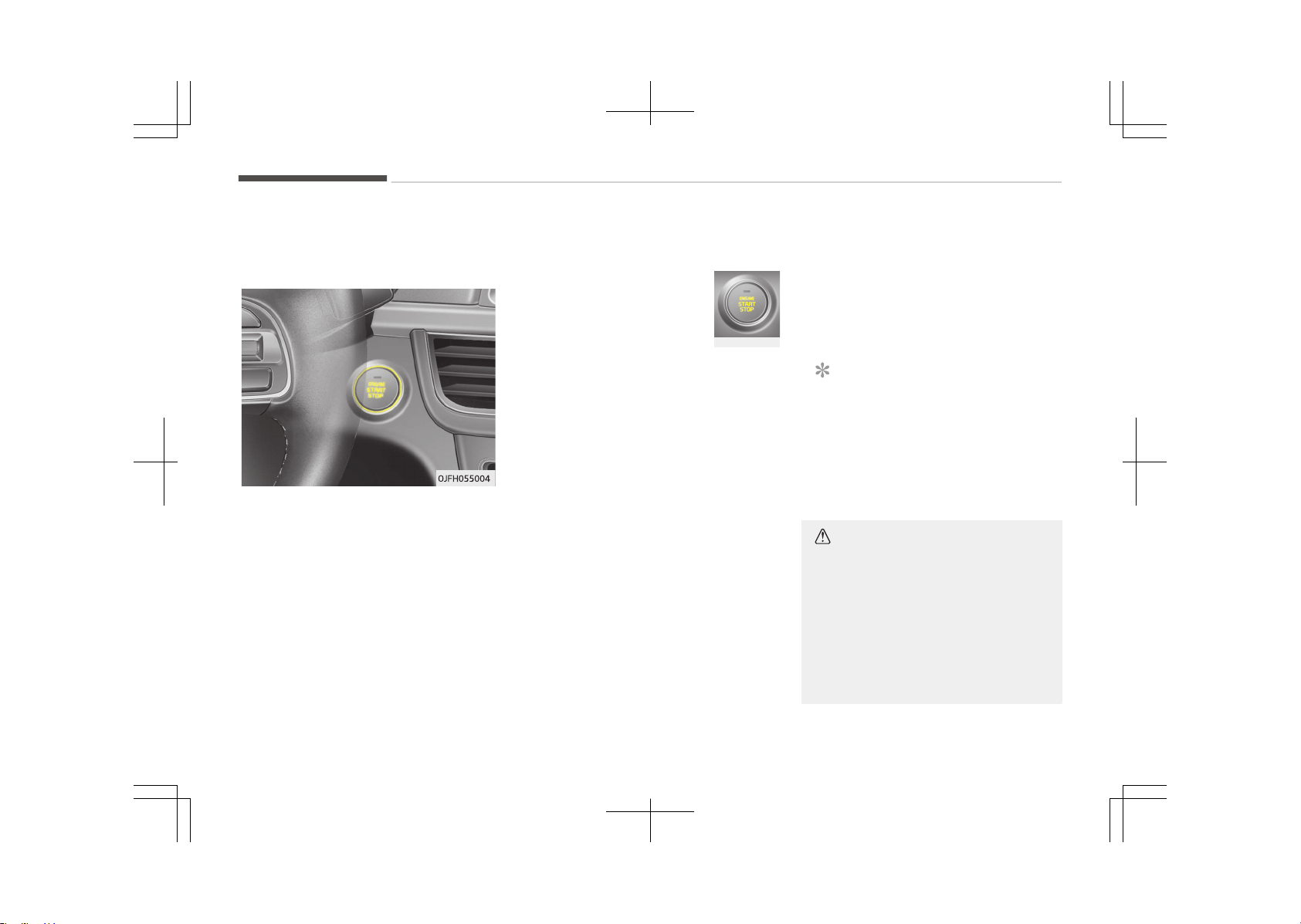
ENGINE START/STOP BUTTON
Illuminated engine start/stop
button
Whenever the front door is opened, the
engine start/stop button will illuminate
for your convenience. The light will go
off after about 30 seconds when the
door is closed. It will also go off imme‐
diately when the engine start/stop but‐
ton is ON position.
Engine start/stop button
position
OFF
To turn off the hybrid sys‐
tem (START/RUN position)
or vehicle power (ON posi‐
tion), press the engine
start/stop button with the
shift lever in the P (Park) position.
When you press the engine start/stop
button without the shift lever in the P
(Park) position, the engine start/stop
button will not change to the OFF posi‐
tion but to the ACC position.
Vehicles equipped with anti-theft
steering column lock
The steering wheel locks when the en‐
gine start/stop button is in the OFF po‐
sition to protect you against theft.
It locks when the door is opened.
If the steering wheel is not locked prop‐
erly when you open the driver's door,
the warning chime will sound. Try lock‐
ing the steering wheel again. If the
problem is not solved, we recommend
that the system be checked by an au‐
thorized Kia dealer.
Not illuminated
In addition, if the engine start/stop but‐
ton is in the OFF position after the driv‐
er's door is opened, the steering wheel
will not lock and the warning chime will
sound. In such a situation, close the
door. Then the steering wheel will lock
and the warning chime will stop.
NOTICE
If the steering wheel doesn't unlock
properly, the engine start/stop but‐
ton will not work. Press the engine
start/stop button while turning the
steering wheel right and left to re‐
lease the tension.
CAUTION
You are able to turn off the hybrid
system (START/RUN) or vehicle pow‐
er (ON), only when the vehicle is not
in motion. In an emergency situation
while the vehicle is in motion, you
are able to turn the hybrid system
off and to the ACC position by press‐
ing the engine start/stop button for
(Continued)
Driving your vehicle
7-06
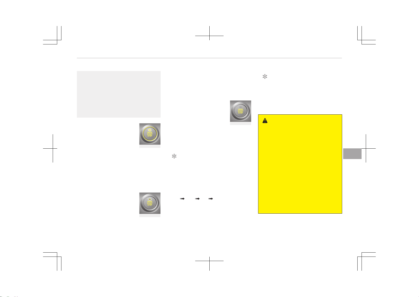
(Continued)
more than 2 seconds or 3 times suc‐
cessively within 3 seconds. If the ve‐
hicle is still moving, you can restart
the hybrid system without depress‐
ing the brake pedal by pressing the
engine start/stop button with the
shift lever in the N (Neutral) position.
ACC (Accessory)
Press the engine start/stop
button while it is in the OFF
position without depressing
the brake pedal.
The steering wheel unlocks (if equipped
with anti-theft steering column lock)
and electrical accessories are opera‐
tional.
If the engine start/stop button is in the
ACC position for more than 1 hour, the
button is turned off automatically to
prevent battery discharge.
Amber
ON
Press the engine start/stop
button while it is in the ACC
position without depressing
the brake pedal.
Reddish orange
The warning lights can be checked be‐
fore the hybrid system is started. Do
not leave the hybrid system start/stop
button in the ON position for a long
time. The battery may discharge, be‐
cause the engine is not running.
START/RUN
To start the hybrid system,
depress the brake pedal and
press the engine start/stop
button with the shift lever
in the P (Park) or the N
(Neutral) position. For your safety,
start the hybrid system with the shift
lever in the P (Park) position.
NOTICE
If you press the engine start/stop
button without depressing the brake
pedal for automatic transaxle vehi‐
cles, the hybrid system will not start
and the engine start/stop button
changes as follows:
OFF ACC ON OFF or ACC
Not illuminated
NOTICE
If you leave the engine start/stop
button in the ACC or ON position for
a long time, the battery will dis‐
charge.
WARNING
• Never press the engine start/stop
button while the vehicle is in mo‐
tion. This would result in loss of di‐
rectional control and braking func‐
tion, which could cause an acci‐
dent.
• The anti-theft steering column
lock (if equipped) is not a substi‐
tute for the parking brake. Before
leaving the driver's seat, always
make sure the shift lever is engag‐
ed in P (Park), set the parking
brake fully and shut the engine
off. Unexpected and sudden vehi‐
cle movement may occur if these
precautions are not taken.
(Continued)
7-07
7
Driving your vehicle
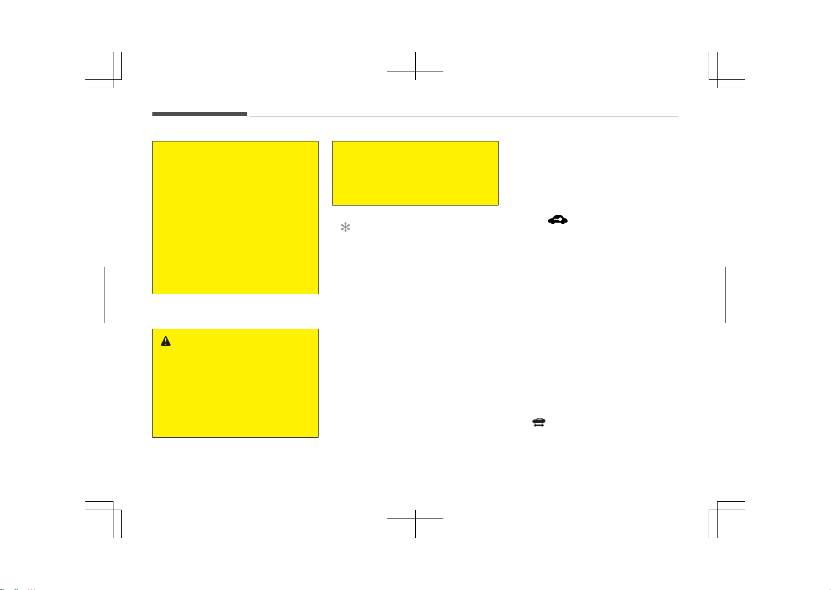
(Continued)
• Never reach for the engine start/
stop button or any other controls
through the steering wheel while
the vehicle is in motion. The pres‐
ence of your hand or arm in the
area could cause loss of vehicle
control, an accident and serious
bodily injury or death.
• Do not place any movable objects
around the driver's seat as they
may move while driving, interfere
with the driver and lead to an acci‐
dent.
Starting the hybrid system
WARNING
• Always wear appropriate shoes
when operating your vehicle. Un‐
suitable shoes, such as high heels,
ski boots, sandals, flip-flops, etc.,
may interfere with your ability to
use the brake and accelerator ped‐
als.
(Continued)
(Continued)
• Do not start the vehicle with the
accelerator pedal depressed.
The vehicle can move and lead to
an accident.
NOTICE
• The hybrid system will start by
pressing the Engine Start/Stop
button, only when the smart key
is in the vehicle.
• Even when the smart key is in the
vehicle, and when it is far away
from the driver, the hybrid system
may not start.
(Continued)
(Continued)
• When the Engine Start/Stop but‐
ton is in the ACC or ON position,
any door is open, the system
checks for the smart key. When
the smart key is not in the vehicle,
the " " indicator will blink and
the warning "Key not in vehicle"
will come on. When all doors are
closed, the chime will also sound
for about 5 seconds. Keep the
smart key in the vehicle when in
the ACC position or if the hybrid
system is ON.
1. Always carry the smart key with
you.
2. Make sure the parking brake is ap‐
plied.
3. Make sure the shift lever is in P
(Park).
4. Depress the brake pedal.
5. Press the Engine Start/Stop button.
If the hybrid system starts, the
" " indicator will come on.
Driving your vehicle
7-08
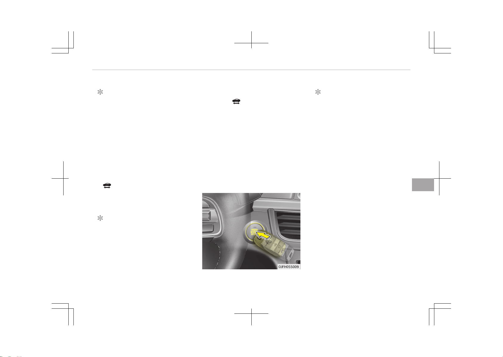
NOTICE
• Do not wait for the engine to
warm up while the vehicle remains
stationary.
Start driving at moderate engine
speeds. (Steep accelerating and
decelerating should be avoided.)
• Always start the vehicle with your
foot on the brake pedal. Do not
depress the accelerator while
starting the vehicle. Do not race
the engine while warming it up.
• If ambient temperature is low, the
" " indicator may remain illumi‐
nated longer than the normal
amount of time.
NOTICE
To prevent damage to the vehicle:
(Continued)
(Continued)
• If the " " indicator turns off
while you are in motion, do not at‐
tempt to move the shift lever to
the P (Park) position.
If traffic and road conditions per‐
mit, you may put the shift lever in
the N (Neutral) position while the
vehicle is still moving and press
the Engine Start/Stop button in an
attempt to restart the hybrid sys‐
tem.
• Do not push or tow your vehicle to
start the hybrid system.
NOTICE
• If the battery is weak or the smart
key does not work correctly, you
can start the hybrid system by
pressing the engine start/stop
button with the smart key.
The side with the lock button
should be contacted directly.
When you press the engine start/
stop button directly with the
smart key, the smart key should
contact the button at a right an‐
gle.
• When the stop lamp fuse is blown,
you cannot start the hybrid sys‐
tem normally.
Replace the fuse with a new one.
If it is not possible, you can start
the hybrid system by pressing the
engine start/stop button for 10
seconds while it is in the ACC posi‐
tion. The engine can start without
depressing the brake pedal. But
for your safety always depress
the brake pedal before starting
the engine.
7-09
7
Driving your vehicle

CAUTION
Do not press the engine start/stop
button for more than 10 seconds ex‐
cept when the stop lamp fuse is
blown.
Driving your vehicle
7-10
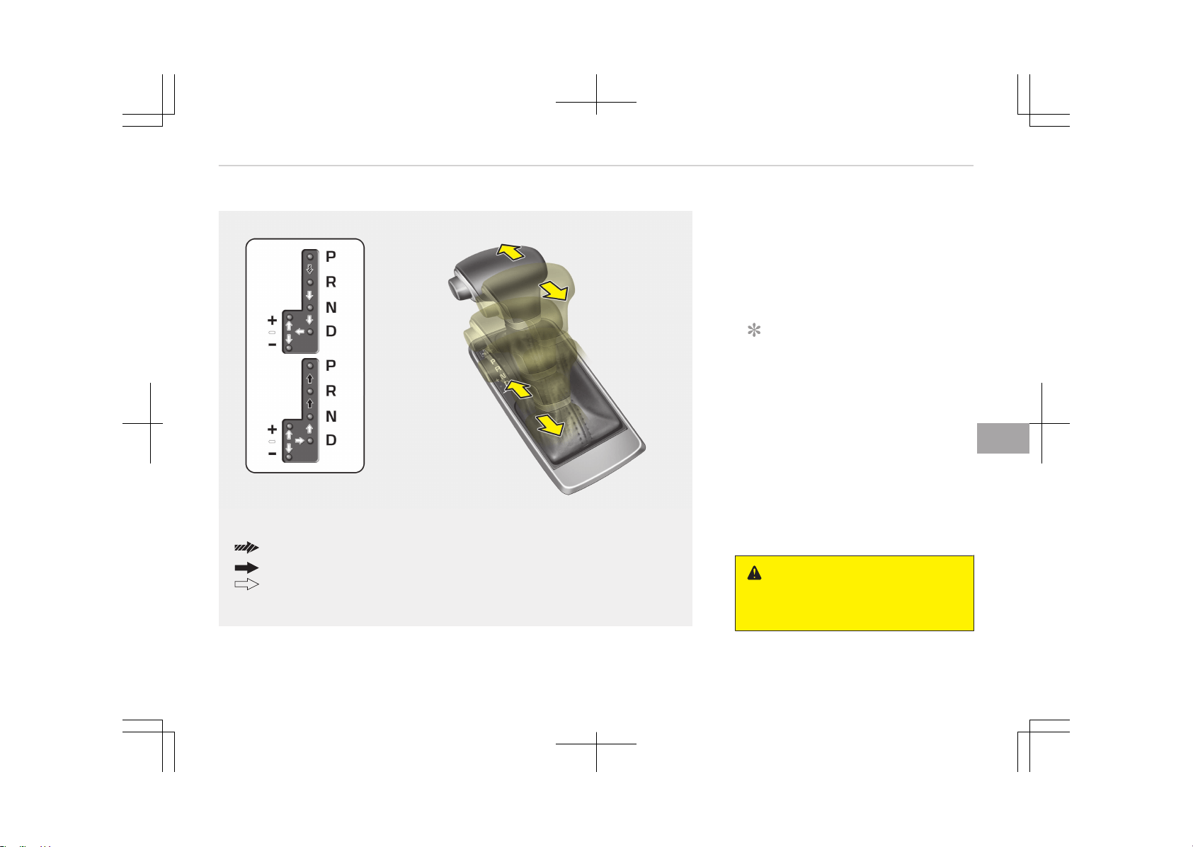
AUTOMATIC TRANSAXLE
The shift lever can be shifted freely.
Press the lock release button when shifting.
Depress the brake pedal and the lock release button when shifting.
OJF055012
Automatic transaxle operation
The automatic transaxle has 6 forward
speeds and one reverse speed. The in‐
dividual speeds are selected automati‐
cally, depending on the position of the
shift lever.
NOTICE
The first few shifts on a new vehicle,
if the battery has been disconnec‐
ted, may be somewhat abrupt. This
is a normal condition, and the shift‐
ing sequence will adjust after shifts
are cycled a few times by the TCM
(Transaxle Control Module) or PCM
(Power train Control Module).
For smooth operation, depress the
brake pedal when shifting from N (Neu‐
tral) to a forward or reverse gear.
WARNING
n
Automatic transaxle
(Continued)
7-11
7
Driving your vehicle
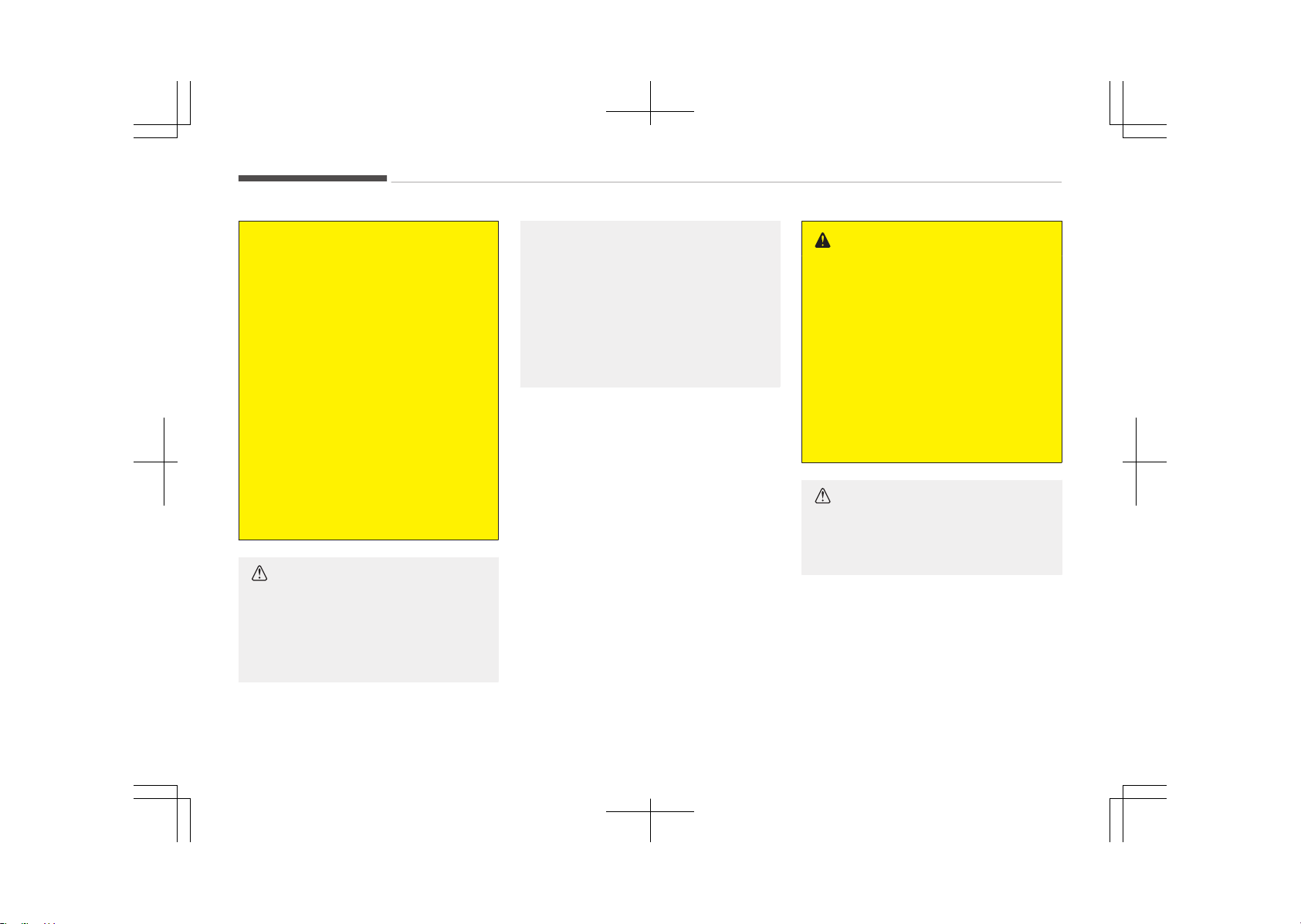
(Continued)
• Always check the surrounding
areas near your vehicle for people,
especially children, before shifting
a vehicle into D (Drive) or R (Re‐
verse).
• Before leaving the driver’s seat, al‐
ways make sure the shift lever is
in the P (Park) position; then set
the parking brake fully and shut
the engine off. Unexpected and
sudden vehicle movement can oc‐
cur if these precautions are not
followed in the order identified.
• Do not use the engine brake (shift‐
ing from a high gear to lower gear)
rapidly on slippery roads.
The vehicle may slip causing an ac‐
cident.
CAUTION
• To avoid damage to your trans‐
axle, do not accelerate the engine
in R (Reverse) or any forward gear
position with the brakes on.
(Continued)
(Continued)
• When stopped on an uphill grades,
do not hold the vehicle stationary
with engine power. Use the brake
pedal or the parking brake.
• Do not shift from N (Neutral) or P
(Park) into D (Drive), or R (Reverse)
when the engine is above idle
speed.
Transaxle ranges
The indicator lights in the instrument
cluster displays the shift lever position
when the engine start/stop button
switch is in the ON position.
P (Park)
Always come to a complete stop before
shifting into P (Park). This position
locks the transaxle and prevents the
front wheels from rotating.
To shift from P (Park), you must de‐
press firmly on the brake pedal and
make sure your foot is off the acceler‐
ator pedal.
If you have done all of the above and
still cannot shift the lever out of P
(Park), see Shift-lock override on page
7-14.
The shift lever must be in P (Park) be‐
fore turning the hybrid system off.
WARNING
• Shifting into P (Park) while the ve‐
hicle is in motion will cause the
drive wheels to lock which will
cause you to lose control of the
vehicle.
• Do not use the P (Park) position in
place of the parking brake. Always
make sure the shift lever is latch‐
ed in the P (Park) position and set
the parking brake fully.
• Never leave a child unattended in a
vehicle.
CAUTION
The transaxle may be damaged if
you shift into P (Park) while the ve‐
hicle is in motion.
R (Reverse)
Use this position to drive the vehicle
backward.
Driving your vehicle
7-12
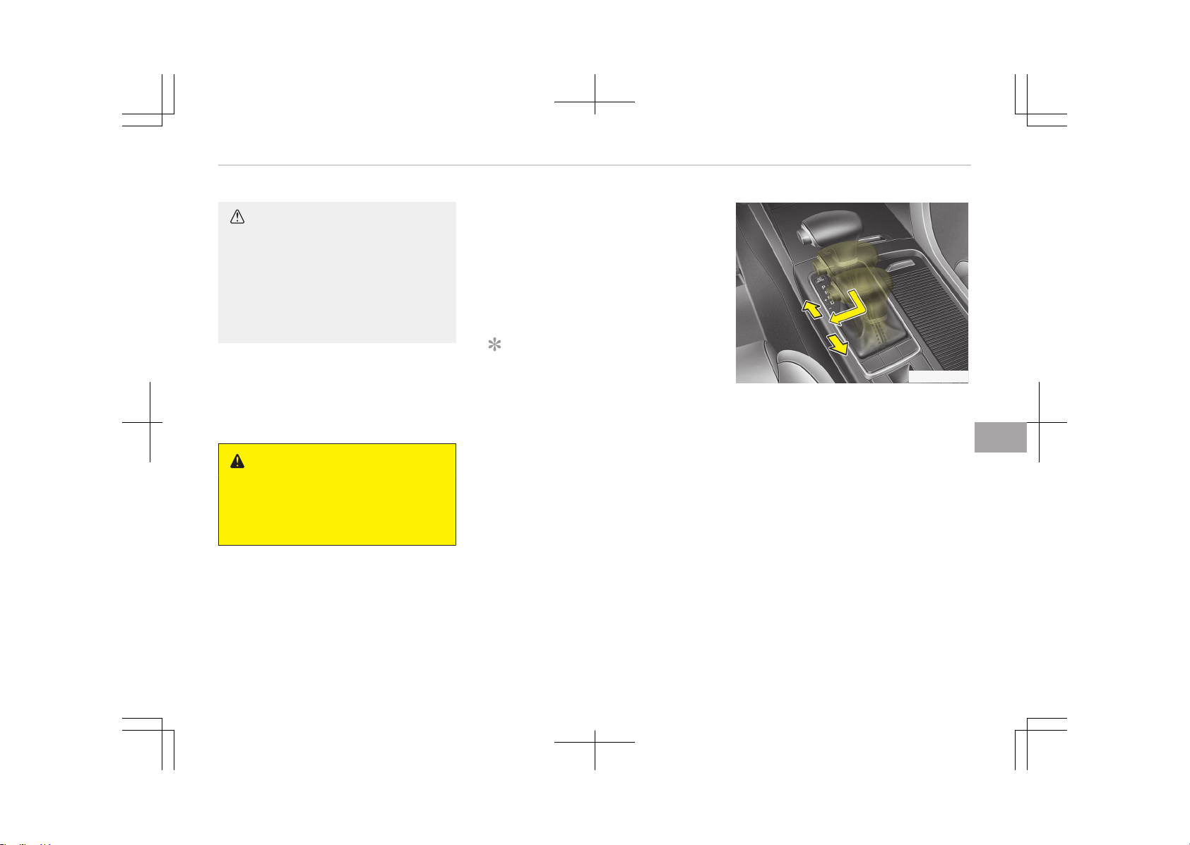
CAUTION
Always come to a complete stop be‐
fore shifting into or out of R (Re‐
verse); you may damage the trans‐
axle if you shift into R (Reverse)
while the vehicle is in motion, except
as explained in Rocking the vehicle
on page 7-99.
N (Neutral)
The wheels and transaxle are not en‐
gaged. The vehicle will roll freely even
on the slightest incline unless the park‐
ing brake or service brakes are applied.
WARNING
Do not drive with the shift lever in N
(Neutral).
The engine brake will not work and
lead to an accident.
D (Drive)
This is the normal forward driving posi‐
tion. The transaxle will automatically
shift through a 6-gear sequence, pro‐
viding the best fuel economy and pow‐
er.
For extra power when passing another
vehicle or climbing grades, depress the
accelerator pedal fully (more than 82%)
until the kick down mechanism (if
equipped) works with a clicking noise,
at which time the transaxle will auto‐
matically downshift to the next lower
gear.
NOTICE
• Always come to a complete stop
before shifting into D (Drive).
• A clicking noise heard from the
kick down mechanism by depress‐
ing the accelerator pedal fully is a
normal condition.
OJF055257L
Manual mode
Whether the vehicle is stationary or in
motion, manual mode is selected by
pushing the shift lever from the D
(Drive) position into the manual gate.
To return to D (Drive) range operation,
push the shift lever back into the main
gate.
In manual mode, moving the shift lever
backwards and forwards will allow you
to make gearshifts rapidly.
Up (+): Push the lever forward
once to shift up one gear.
Down (-): Pull the lever backwards
once to shift down one
gear.
7-13
7
Driving your vehicle

NOTICE
• In manual mode, the driver must
execute upshifts in accordance
with road conditions, taking care
to keep the engine speed below
the red zone.
• In manual mode, only the 6 for‐
ward gears can be selected. To re‐
verse or park the vehicle, move
the shift lever to the R (Reverse)
or P (Park) position as required.
• In manual mode, downshifts are
made automatically when the ve‐
hicle slows down. When the vehicle
stops, 1st gear is automatically
selected.
• In manual mode, when the engine
rpm approaches the red zone shift
points are varied to upshift auto‐
matically.
• To maintain the required levels of
vehicle performance and safety,
the system may not execute cer‐
tain gearshifts when the shift lev‐
er is operated.
(Continued)
(Continued)
• When driving on a slippery road,
push the shift lever forward into
the + (up) position. This causes the
transaxle to shift into the 2nd
gear which is better for appropri‐
ate driving on a slippery road.
Push the shift lever to the -
(down) side to shift back to the
1st gear.
Shift lock system
For your safety, the automatic trans‐
axle has a shift lock system which pre‐
vents shifting the transaxle from P
(Park) into R (Reverse) unless the brake
pedal is depressed.
To shift the transaxle from P (Park) in‐
to R (Reverse):
1. Depress and hold the brake pedal.
2. Start the hybrid system or turn the
ignition switch to the ON position.
3. Move the shift lever.
If the brake pedal is repeatedly de‐
pressed and released with the shift lev‐
er in the P (Park) position, a chattering
noise & vibration near the shift lever
may be heard. This is a normal condi‐
tion.
WARNING
Always fully depress the brake pedal
before and while shifting out of the
P (Park) position into another posi‐
tion to avoid inadvertent motion of
the vehicle which could injure per‐
sons in or around the vehicle.
OJF055013LB
Driving your vehicle
7-14
Shift-lock override
If the shift lever cannot be moved from
the P (Park) position into R (Reverse)
position with the brake pedal de‐
pressed, continue depressing the brake,
then do the following:
1. Place the engine start/stop button
switch in the LOCK/OFF position.
2. Apply the parking brake.
3. Carefully remove the cap (1) cover‐
ing the shift-lock release access
hole.
4. Insert a tool (e.g. flathead screw‐
driver) into the access hole and
press down on the tool.
5. Move the shift lever.
6. Remove the tool from the shift-
lock override access hole then in‐
stall the cap.
7. We recommend that the system be
inspected by an authorized Kia
dealer.
Good driving practices
• Never move the shift lever from P
(Park) or N (Neutral) to any other po‐
sition with the accelerator pedal de‐
pressed.
• Never move the shift lever into P
(Park) when the vehicle is in motion.
• Be sure the vehicle is completely
stopped before you attempt to shift
into R (Reverse) or D (Drive).
• Never take the vehicle out of gear
and coast down a hill. This may be
extremely hazardous. Always leave
the vehicle in gear when moving.
• Do not "ride" the brakes. This can
cause them to overheat and malfunc‐
tion. Instead, when you are driving
down a long hill, slow down and shift
to a lower gear. When you do this,
engine braking will help slow down
the vehicle.
• Slow down before shifting to a lower
gear. Otherwise, the lower gear may
not be engaged.
• Always use the parking brake. Do not
depend on placing the transaxle in P
(Park) to keep the vehicle from mov‐
ing.
• Exercise extreme caution when driv‐
ing on a slippery surface. Be especial‐
ly careful when braking, accelerating
or shifting gears. On a slippery sur‐
face, an abrupt change in vehicle
speed can cause the drive wheels to
lose traction and the vehicle to go out
of control.
• Optimum vehicle performance and
economy is obtained by smoothly de‐
pressing and releasing the accelera‐
tor pedal.
WARNING
• Always buckle-up! In a collision, an
unbelted occupant is significantly
more likely to be seriously injured
or killed than a properly belted oc‐
cupant.
• Avoid high speeds when cornering
or turning.
• Do not make quick steering wheel
movements, such as sharp lane
changes or fast, sharp turns.
• The risk of rollover is greatly in‐
creased if you lose control of your
vehicle at highway speeds.
(Continued)
7-15
7
Driving your vehicle
(Continued)
• Loss of control often occurs if two
or more wheels drop off the road‐
way and the driver oversteers to
reenter the roadway.
• In the event your vehicle leaves
the roadway, do not steer sharply.
Instead, slow down before pulling
back into the travel lanes.
• Never exceed posted speed limits.
WARNING
If your vehicle becomes stuck in
snow, mud, sand, etc., then you may
attempt to rock the vehicle free by
moving it forward and backward. Do
not attempt this procedure if people
or objects are anywhere near the ve‐
hicle. During the rocking operation
the vehicle may suddenly move for‐
ward of backward as it becomes un‐
stuck, causing injury or damage to
nearby people or objects.
Moving up a steep grade from a
standing start
To move up a steep grade from a
standing start, depress the brake pedal,
shift the shift lever to D (Drive). Select
the appropriate gear depending on load
weight and steepness of the grade, and
release the parking brake. Depress the
accelerator gradually while releasing
the brake pedal.
When accelerating from a stop on a
steep hill, the vehicle may have a ten‐
dency to roll backwards. Shifting the
shift lever into 2 (Second Gear) will help
prevent the vehicle from rolling back‐
wards.
Driving your vehicle
7-16
BRAKE SYSTEM
Power brakes
Your vehicle has power-assisted brakes
that adjust automatically through nor‐
mal usage.
If the hybrid system is not on or is
turned off while driving, the power as‐
sist for the brakes will not work. You
can still stop your vehicle by applying
greater force to the brake pedal than
typical. The stopping distance, however,
will be longer than with power brakes.
When the hybrid system is not on, the
reserve brake power is partially deple‐
ted each time the brake pedal is ap‐
plied. Do not pump the brake pedal
when the power assist has been inter‐
rupted.
Pump the brake pedal only when nec‐
essary to maintain steering control on
slippery surfaces.
WARNING
n
Brakes
(Continued)
(Continued)
• Do not drive with your foot resting
on the brake pedal. This will create
abnormal high brake tempera‐
tures, excessive brake lining and
pad wear, and increased stopping
distances.
• When descending a long or steep
hill, shift to a lower gear and avoid
continuous application of the
brakes. Continuous brake applica‐
tion will cause the brakes to over‐
heat and could result in a tempo‐
rary loss of braking performance.
• Wet brakes may impair the vehi‐
cle’s ability to safely slow down;
the vehicle may also pull to one
side when the brakes are applied.
Applying the brakes lightly will in‐
dicate whether they have been af‐
fected in this way.
Always test your brakes in this
fashion after driving through deep
water. To dry the brakes, apply
them lightly while maintaining a
safe forward speed until brake
performance returns to normal.
(Continued)
(Continued)
• Always confirm the position of the
brake and accelerator pedal before
driving. If you don’t check the posi‐
tion of the accelerator and brake
pedal before driving, you may de‐
press the accelerator instead of
the brake pedal. It may cause a se‐
rious accident.
NOTICE
Do not depress the brake pedal con‐
tinuously without the " " indicator
ON. The battery may be discharged.
Disc brakes wear indicator
When your brake pads are worn and
new pads are required, you will hear a
high-pitched warning sound from your
front brakes or rear brakes (if equip‐
ped). You may hear this sound come
and go or it may occur whenever you
depress the brake pedal.
7-17
7
Driving your vehicle
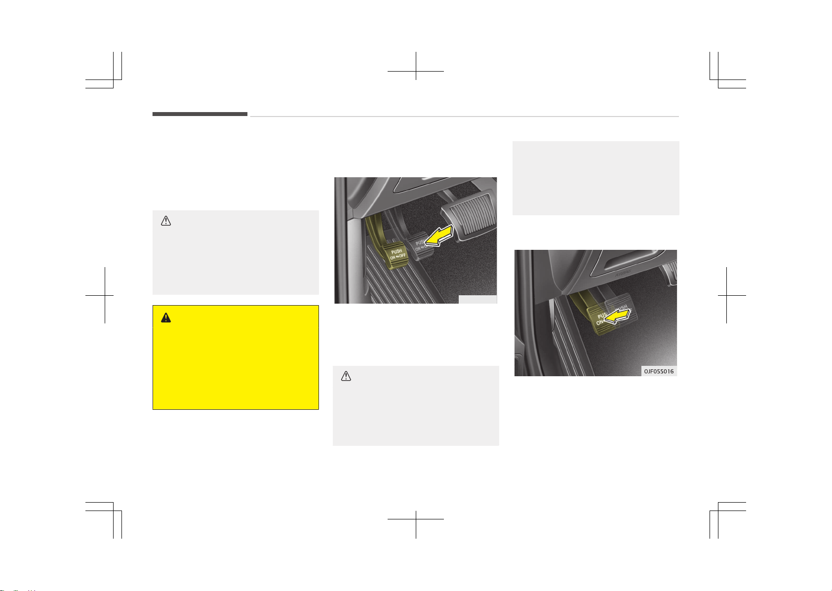
Please remember that some driving
conditions or climates may cause a
brake squeal when you first apply (or
lightly apply) the brakes. This is normal
and does not indicate a problem with
your brakes.
CAUTION
• To avoid costly brake repairs, do
not continue to drive with worn
brake pads.
• Always replace the front or rear
brake pads as pairs.
WARNING
n
Brake wear
This brake wear warning sound
means your vehicle needs service. If
you ignore this audible warning, you
will eventually lose braking perform‐
ance, which could lead to a serious
accident.
Foot parking brake
Applying the parking brake
OYF054009K
To engage the parking brake, first apply
the foot brake and then depress the
parking brake pedal down as far as
possible.
CAUTION
• Driving with the parking brake ap‐
plied will cause excessive brake
pad (or lining) and brake rotor
wear.
(Continued)
(Continued)
• Do not operate the parking brake
while the vehicle is moving except
in an emergency situation. It could
damage the vehicle system and
make endanger driving safety.
Releasing the parking brake
To release the parking brake, depress
the parking brake pedal a second time
while applying the foot brake. The ped‐
al will automatically extend to the fully
released position.
Driving your vehicle
7-18
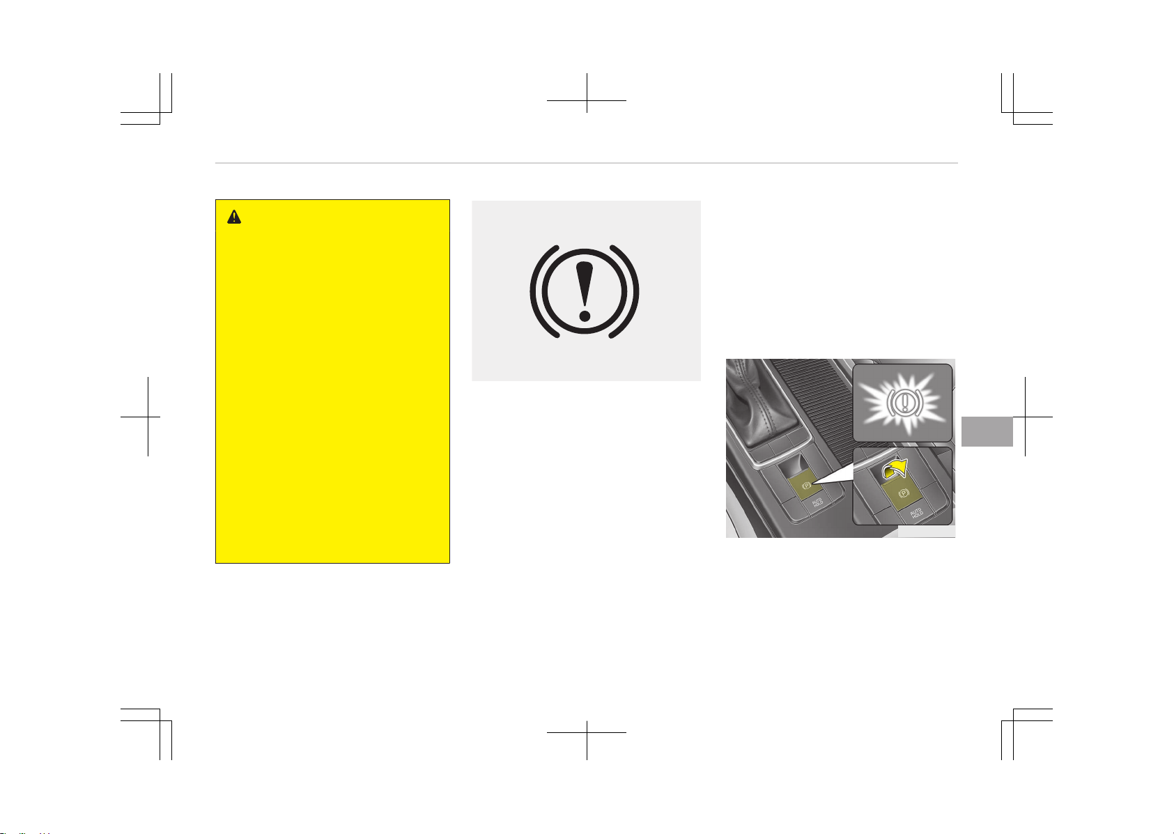
WARNING
• Whenever leaving the vehicle or
parking, always come to a com‐
plete stop and continue to depress
the brake pedal. Move the shift
lever into the P (Park) position,
then apply the parking brake, and
place the Engine Start/Stop button
in the OFF position.
Vehicles with the parking brake
not fully engaged are at risk for
moving inadvertently and causing
injury to yourself or others.
• Never allow anyone who is unfa‐
miliar with the vehicle to touch the
parking brake. If the parking brake
is released unintentionally, serious
injury may occur.
• All vehicles should always have the
parking brake fully engaged when
parking to avoid inadvertent
movement of the vehicle which
can injure occupants or pedes‐
trians.
WK-23_TF
Check the brake warning light by press‐
ing engine start/stop button switch ON
(do not start the hybrid system). This
light will be illuminated when the park‐
ing brake is applied with the engine
start/stop button switch in the START
or ON position.
Before driving, be sure the parking
brake is fully released and the brake
warning light is off.
If the brake warning light remains on
after the parking brake is released
while the hybrid system is on, there
may be a malfunction in the brake sys‐
tem. Immediate attention is necessary.
If at all possible, cease driving the vehi‐
cle immediately. If that is not possible,
use extreme caution while operating
the vehicle and only continue to drive
the vehicle until you can reach a safe
location or repair shop.
Electronic parking brake (EPB)
(if equipped)
Applying the parking brake
OJF055018L
To apply the EPB (Electronic Parking
Brake):
1. Depress the brake pedal.
2. Pull up the EPB switch.
Make sure the warning light comes on.
7-19
7
Driving your vehicle
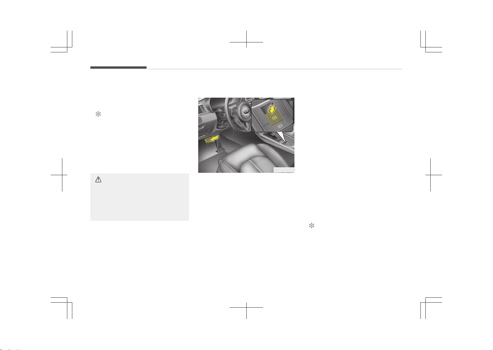
Also, the EPB is applied automatically if
the Auto Hold button is on when the
engine is turned off.
NOTICE
On a steep incline or when pulling a
trailer if the vehicle does not stand
still, do as follows:
1. Apply the EPB.
2. Pull up the EPB switch for more
than 3 seconds.
CAUTION
Do not operate the parking brake
while the vehicle is moving except in
an emergency situation. It could
damage the vehicle system and en‐
danger driving safety.
Releasing the parking brake
OJF055019
To release the EPB (Electronic Parking
Brake), press the EPB switch in the fol‐
lowing condition:
• Have the engine start/stop button in
the ON position.
• Depress the brake pedal.
Make sure the brake warning light goes
off.
To release EPB (Electronic Parking
Brake) automatically:
• Shift lever in P (Park)
With the engine running depress the
brake pedal and shift out of P (Park)
to R (Reverse) or D (Drive).
• Shift lever in N (Neutral)
With the engine running depress the
brake pedal and shift out of N (Neu‐
tral) to R (Reverse) or D (Drive).
1. Start the engine.
2. Fasten the driver's seat belt.
3. Close the driver's door, engine
hood and trunk.
4. Depress the accelerator pedal
while the shift lever is in R (Rear),
D (Drive) or manual mode.
Make sure the brake warning light goes
off.
NOTICE
• For your safety, you can engage
the EPB even though the engine
stop/start button is in the OFF po‐
sition, but you cannot release it.
(Continued)
Driving your vehicle
7-20
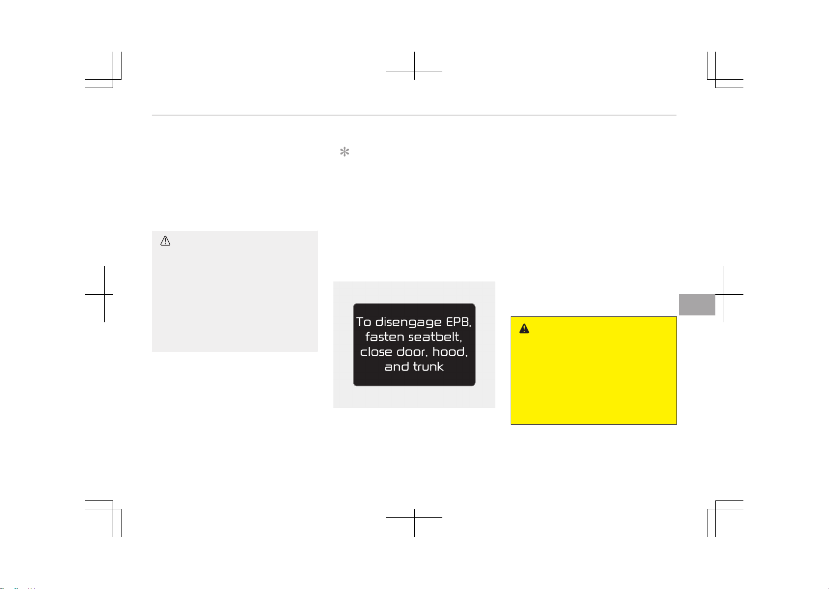
(Continued)
• For your safety, depress the brake
pedal and release the parking
brake manually with the EPB
switch when you drive downhill or
when backing up the vehicle.
CAUTION
• If the parking brake warning light
is still on even though the EPB has
been released, we recommend
that the system be checked by an
authorized Kia dealer.
• Do not drive your vehicle with the
EPB applied. It may cause exces‐
sive brake pad and brake rotor
wear.
EPB (Electronic Parking Brake) may be
automatically applied when:
• The EPB is overheated
• Requested by other systems
• The hybrid system is turned off with
the EPB applied
NOTICE
If the driver turns the hybrid system
off while Auto Hold is operating, EPB
will be automatically applied. Howev‐
er, if you press the EPB switch with‐
in one second after the hybrid sys‐
tem is turned off, the EPB will not
be applied.
System warning
OJF055248L
• If you try to drive off depressing the
accelerator pedal with the EPB ap‐
plied, but doesn't release automati‐
cally, a warning will sound and a mes‐
sage will appear.
• If the driver's seat belt is not fas‐
tened and the engine hood or trunk is
opened, a warning will sound and a
message will appear.
• If there is a problem with the vehicle,
a warning may sound and a message
may appear.
If the above situation occurs, depress
the brake pedal and release EPB by
pressing the EPB switch.
WARNING
• To prevent unintentional move‐
ment when stopped and leaving
the vehicle, do not use the shift
lever in place of the parking brake.
Set the parking brake and make
sure the shift lever is securely
positioned in P (Park).
(Continued)
7-21
7
Driving your vehicle
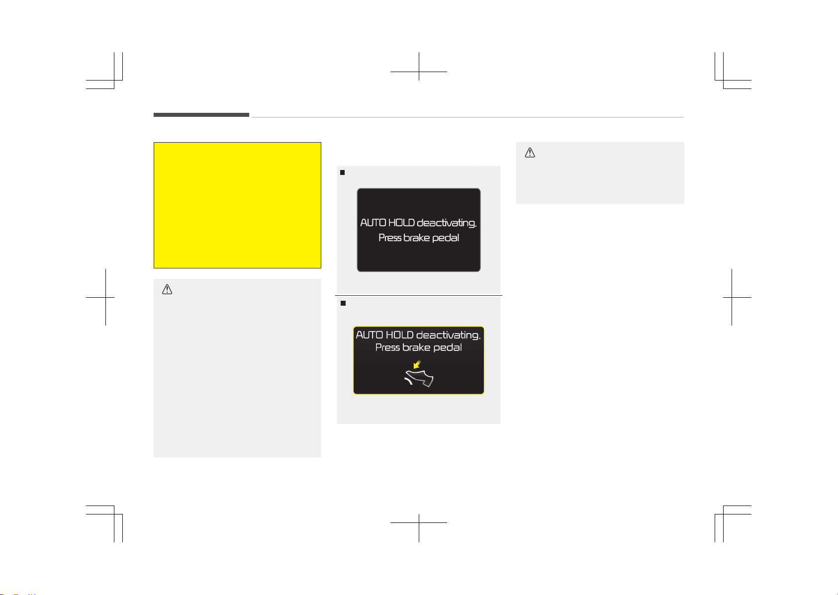
(Continued)
• Never allow anyone who is unfa‐
miliar with the vehicle to touch the
parking brake. If the parking brake
is released unintentionally, serious
injury may occur.
• All vehicles should always have the
parking brake fully engaged when
parking to avoid inadvertent
movement of the car which can in‐
jure occupants or pedestrians.
CAUTION
• A click sound may be heard while
operating or releasing the EPB, but
these conditions are normal and
indicate that the EPB is function‐
ing properly.
• When leaving your keys with a
parking lot attendant or valet,
make sure to inform him/her how
to operate the EPB.
• The EPB may malfunction if you
drive with the EPB applied.
• When you automatically release
EPB by depressing the accelerator
pedal, depress it slowly.
System warning
OJF055249L
Type A
Type B
OJF055250L
When the conversion from Auto Hold to
EPB is not working properly a warning
will sound and a message will appear.
CAUTION
Depress the brake pedal when the
above message appears for the Auto
Hold and EPB may not activate.
Driving your vehicle
7-22
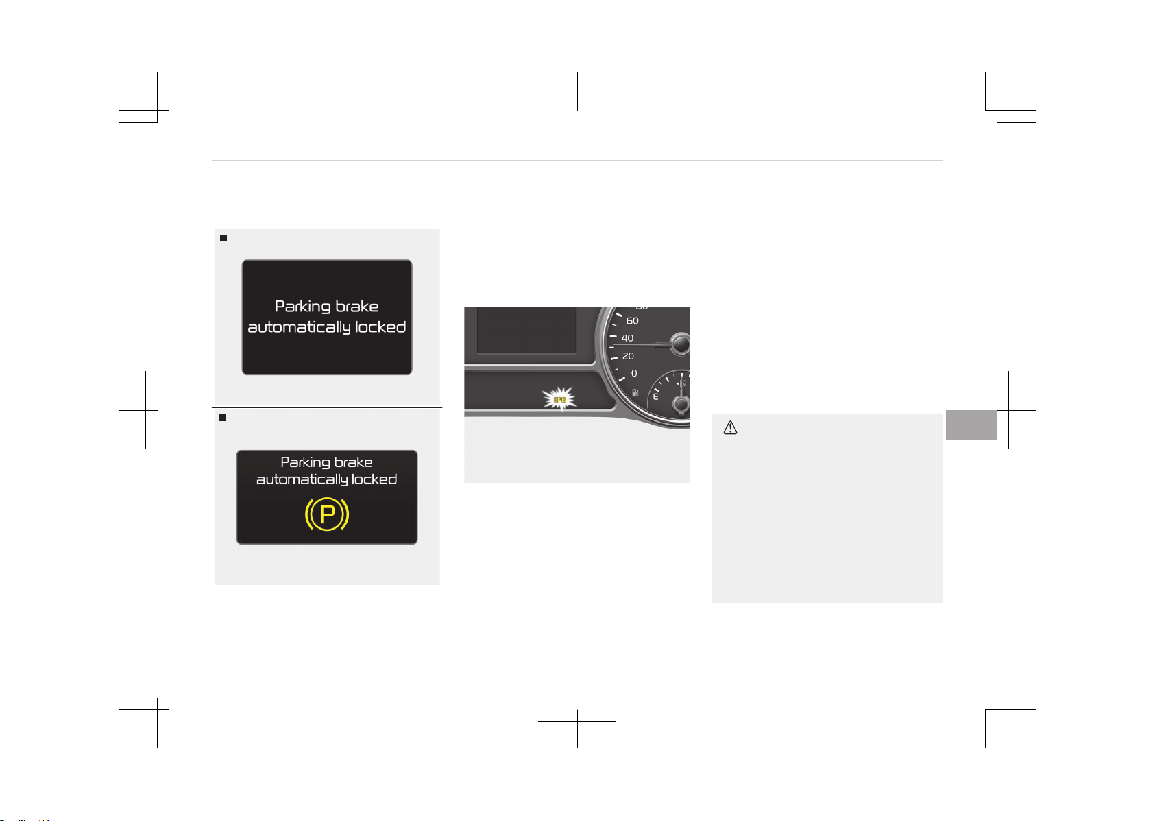
System warning
OJF055251L
Type A
OJF055252L
Type B
If the EPB is applied while Auto Hold is
activated because of ESC (Electronic
Stability Control) signal, a warning will
sound and a message will appear.
EPB malfunction indicator (if
equipped)
OJF055056
This warning light illuminates if the en‐
gine start/stop button is changed to
the ON position and goes off in approxi‐
mately 3 seconds if the system is oper‐
ation normally.
If the EPB malfunction indicator re‐
mains on, comes on while driving, or
does not come on when the ignition
switch or the engine start/stop button
is changed to the ON position, this indi‐
cates that the EPB may have malfunc‐
tioned.
If this occurs, we recommend that the
system be checked by an authorized
Kia dealer.
The EPB malfunction indicator may illu‐
minate when the ESC indicator comes
on to indicate that the ESC is not work‐
ing properly, but it does not indicate a
malfunction of the EPB.
CAUTION
• The EPB warning light may illumi‐
nate if the EPB switch operates
abnormally. Shut the engine off
and turn it on again after a few
minutes. The warning light will go
off and the EPB switch will oper‐
ate normally. However, if the EPB
warning light is still on, we recom‐
mend that the system be checked
by an authorized Kia dealer.
(Continued)
7-23
7
Driving your vehicle
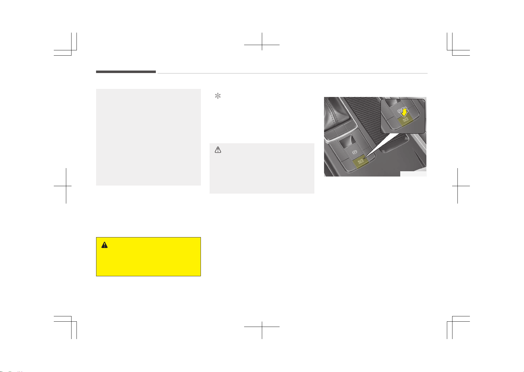
(Continued)
• If the parking brake warning light
does not illuminate or blinks even
though the EPB switch was pulled
up, the EPB is not applied.
• If the parking brake warning light
blinks when the EPB warning light
is on, press the switch, then pull it
up. Once more press it back to its
original position and pull it back up.
If the EPB warning does not go
off, we recommend that the sys‐
tem be checked by an authorized
Kia dealer.
Emergency braking
If there is a problem with the brake
pedal while driving, emergency braking
is possible by pulling up and holding the
EPB switch. Braking is possible only
while you are holding the EPB switch.
WARNING
Do not operate the parking brake
while the vehicle is moving except in
an emergency situation.
NOTICE
During emergency braking by the
EPB, the parking brake warning light
will illuminate to indicate that the
system is operating.
CAUTION
If you continuously notice a noise or
burning smell when the EPB is used
for emergency braking, we recom‐
mend that the system be checked
by an authorized Kia dealer.
When the EPB (Electronic Parking
Brake) does not release
If the EPB does not release normally,
we recommend that you contact an au‐
thorized Kia dealer by loading the vehi‐
cle on a flatbed tow truck and have the
system checked.
AUTO HOLD (if equipped)
The Auto Hold maintains the vehicle in
a standstill even though the brake ped‐
al is not depressed after the driver
brings the vehicle to a complete stop by
depressing the brake pedal.
Set up
OJF055020L
1. With the driver's door, engine hood
closed, fasten the driver's seat belt
or depress the brake pedal and
then press the Auto Hold button.
The white AUTO HOLD indicator will
come on and the system will be in
the standby position.
Driving your vehicle
7-24
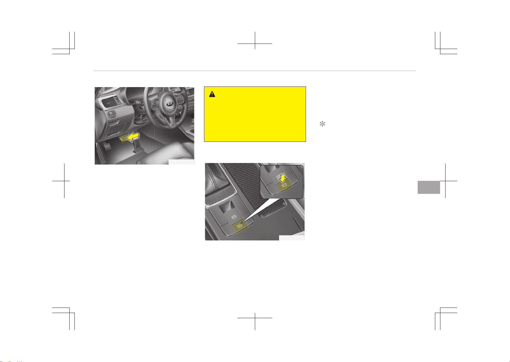
OJF055021L
2. When you stop the vehicle com‐
pletely by depressing the brake
pedal, the AUTO HOLD indicator
changes from white to green.
3. The vehicle will remain stationary
even if you release the brake pedal.
4. If EPB is applied, Auto Hold will be
released.
Leaving
If you press the accelerator pedal with
the shift lever in D (Drive) or manual
mode, the Auto Hold will be released
automatically and the vehicle will start
to move. The indicator changes from
green to white.
WARNING
When driving off from Auto Hold by
depressing the accelerator pedal, al‐
ways check the surrounding area
near your vehicle.
Slowly depress the accelerator pedal
for a smooth launch.
Cancel
OJF055022L
To cancel the Auto Hold operation,
press the Auto Hold switch. The AUTO
HOLD indicator will go out.
To cancel the Auto Hold operation when
the vehicle is at a standstill, press the
Auto Hold switch while depressing the
brake pedal.
NOTICE
• The Auto Hold does not operate
when:
- The driver's seat belt is unfas‐
tened and driver's door is
opened
- The engine hood is opened
- The shift lever is in P (Park) or R
(Reverse)
- The EPB is applied
• For your safety, the Auto Hold au‐
tomatically switches to EPB in
such cases:
- The driver's seat belt is unfas‐
tened and driver's door is
opened
- The engine hood is opened
- The vehicle is in a standstill for
more than 10 minutes
(Continued)
7-25
7
Driving your vehicle
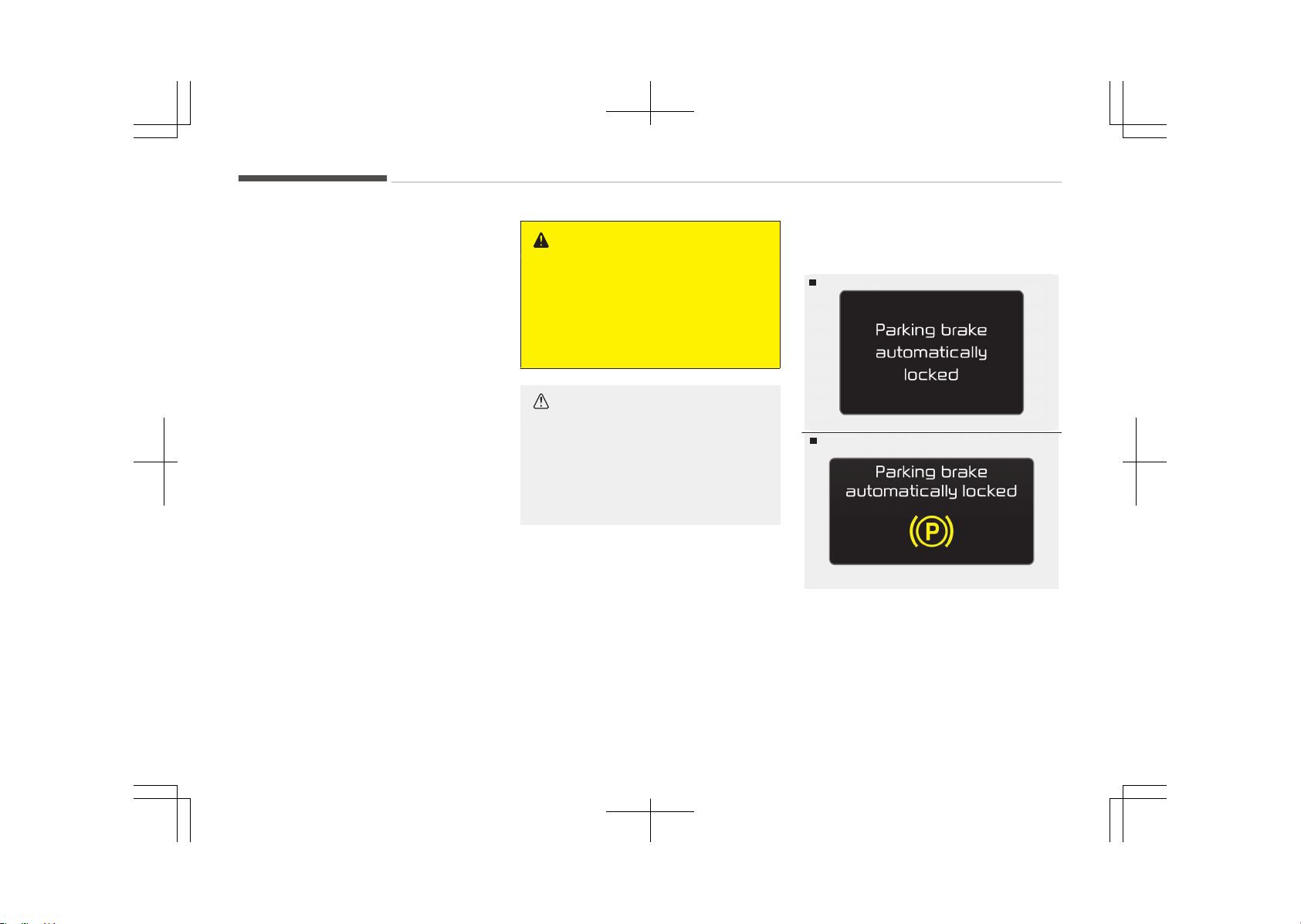
(Continued)
- The vehicle is standing on a
steep slope
- The vehicle moved several
times
In these cases, the brake warning
light comes on, the AUTO HOLD in‐
dicator changes from green to
white, and a warning sounds and a
message will appear to inform you
that EPB has been automatically
engaged. Before driving off again,
press foot brake pedal, check the
surrounding area near your vehicle
and release parking brake manual‐
ly with the EPB switch.
• If the AUTO HOLD indicator lights
up yellow, the Auto Hold is not
working properly. We recommend
that you contact an authorized Kia
dealer.
• While operating Auto Hold, you
may hear mechanical noise. How‐
ever, it is normal operation noise.
WARNING
• Press the accelerator pedal slowly
when you start the vehicle.
• For your safety, cancel the Auto
Hold when you drive downhill or
back up the vehicle or park the ve‐
hicle.
CAUTION
If there is a malfunction with the
driver’s door, engine hood open de‐
tection system, the Auto Hold may
not work properly.
We recommend that you contact an
authorized Kia dealer.
Warning messages
Parking brake automatically locked
Type A
OJF055122L
Type B
OJF055123L
When the EPB is applied from Auto
Hold, a warning will sound and a mes‐
sage will appear.
Driving your vehicle
7-26
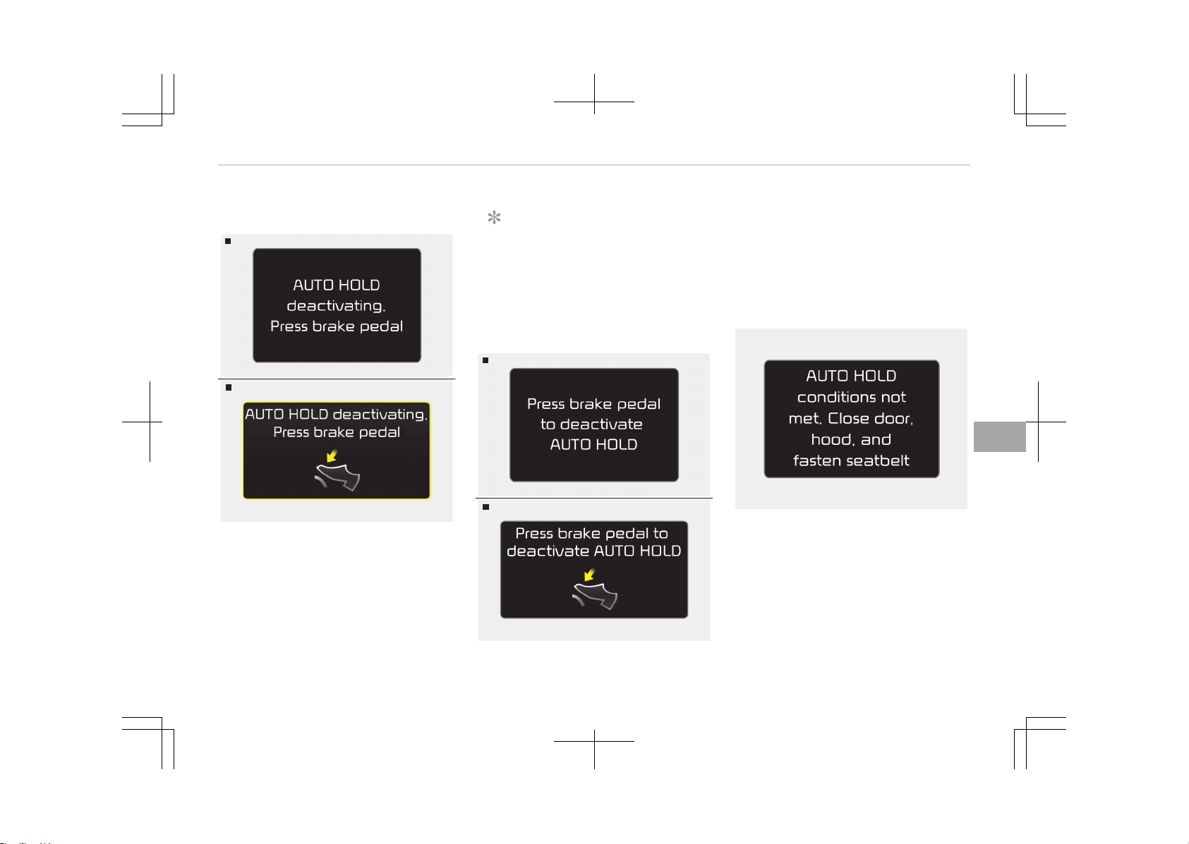
AUTO HOLD deactivating. Press
brake pedal
Type A
OJF055120L
Type B
OJF055121L
When the conversion from Auto Hold to
EPB is not working properly a warning
will sound and a message will appear.
NOTICE
When this message is displayed, the
Auto Hold and EPB may not operate.
For your safety, depress the brake
pedal.
Press brake pedal to deactivate
AUTO HOLD
Type A
OJF055126L
Type B
OJF055127L
If you did not apply the brake pedal
when you release the Auto Hold by
pressing the [AUTO HOLD] switch, a
warning will sound and a message will
appear.
AUTO HOLD conditions not met.
Close door, hood, and fasten
seatbelt
OJF055124L
When you press the [AUTO HOLD]
switch, if the driver’s door, engine hood
are not closed or the driver’s seat belt
is unfastened, a warning will sound and
a message will appear on the LCD dis‐
play. At this moment, press the [AUTO
HOLD] button after closing the driver’s
door, engine hood and fastening the
seat belt.
7-27
7
Driving your vehicle

Anti-lock brake system (ABS)
WARNING
ABS (or ESC) will not prevent acci‐
dents due to improper or dangerous
driving maneuvers. Even though ve‐
hicle control is improved during
emergency braking, always maintain
a safe distance between you and ob‐
jects ahead. Vehicle speeds should
always be reduced during extreme
road conditions.
The braking distance for vehicle
equipped with an anti-lock braking
system (or Electronic Stability Con‐
trol) may be longer than for those
without it in the following road con‐
ditions.
During these conditions the vehicle
should be driven at reduced speeds:
• Rough, gravel or snow-covered
roads.
• With tire chains installed.
• On roads where the road surface is
pitted or has different surface
height.
(Continued)
(Continued)
The safety features of an ABS (or
ESC) equipped vehicle should not be
tested by high speed driving or cor‐
nering. This could endanger the
safety of yourself or others.
The ABS continuously senses the speed
of the wheels. If the wheels are going
to lock, the ABS system repeatedly
modulates the hydraulic brake pressure
to the wheels.
When you apply your brakes under
conditions which may lock the wheels,
you may hear a tik-tik’’ sound from
the brakes, or feel a corresponding sen‐
sation in the brake pedal. This is normal
and it means your ABS is active.
In order to obtain the maximum benefit
from your ABS in an emergency situa‐
tion, do not attempt to modulate your
brake pressure and do not try to pump
your brakes. Press your brake pedal as
hard as possible or as hard as the sit‐
uation warrants and allow the ABS to
control the force being delivered to the
brakes.
NOTICE
A click sound may be heard in the
engine compartment when the vehi‐
cle begins to move after the engine
is started. These conditions are nor‐
mal and indicate that the anti-lock
brake system is functioning proper‐
ly.
• Even with the anti-lock brake sys‐
tem, your vehicle still requires suffi‐
cient stopping distance. Always main‐
tain a safe distance from the vehicle
in front of you.
• Always slow down when cornering.
The anti-lock brake system cannot
prevent accidents resulting from ex‐
cessive speeds.
• On loose or uneven road surfaces, op‐
eration of the anti-lock brake system
may result in a longer stopping dis‐
tance than for vehicles equipped with
a conventional brake system.
Driving your vehicle
7-28
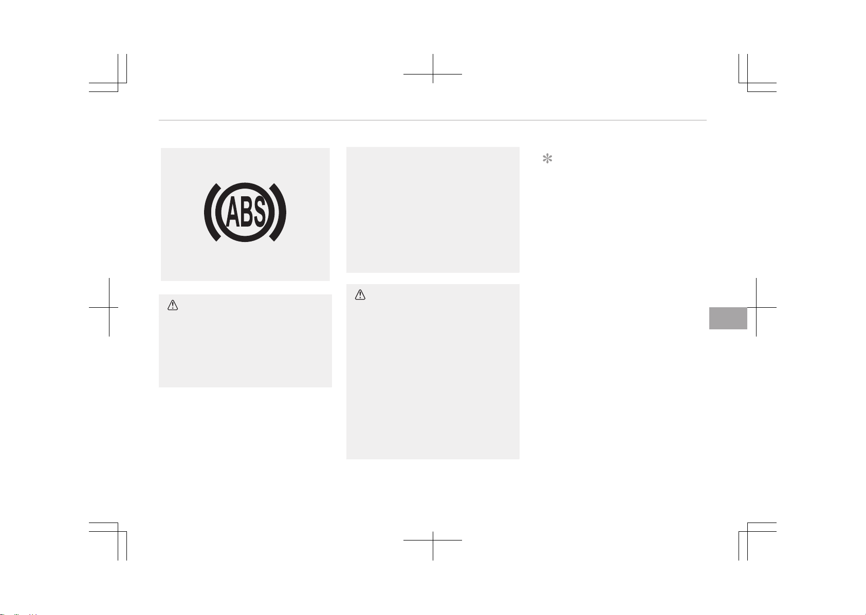
W-78
CAUTION
• If the ABS warning light is on and
stays on, you may have a problem
with the ABS. In this case, howev‐
er, your regular brakes will work
normally.
(Continued)
(Continued)
• The ABS warning light will stay on
for approximately 3 seconds after
the engine start/stop button
switch is ON. During that time, the
ABS will go through self-diagnosis
and the light will go off if every‐
thing is normal. If the light stays
on, you may have a problem with
your ABS. We recommend that you
contact an authorized Kia dealer.
CAUTION
• When you drive on a road having
poor traction, such as an icy road,
and operate your brakes continu‐
ously, the ABS will be active con‐
tinuously and the ABS warning
light may illuminate. Pull your ve‐
hicle over to a safe place and stop
the engine.
• Restart the engine. If the ABS
warning light is off, then your ABS
system is normal. Otherwise, you
may have a problem with the ABS.
We recommend that you contact
an authorized Kia dealer.
NOTICE
When you jump start your vehicle
because of a drained battery, the
engine may not run as smoothly and
the ABS warning light may turn on
at the same time. This happens be‐
cause of the low battery voltage. It
does not mean your ABS is malfunc‐
tioning.
• Do not pump your brakes!
• Have the battery recharged before
driving the vehicle.
7-29
7
Driving your vehicle
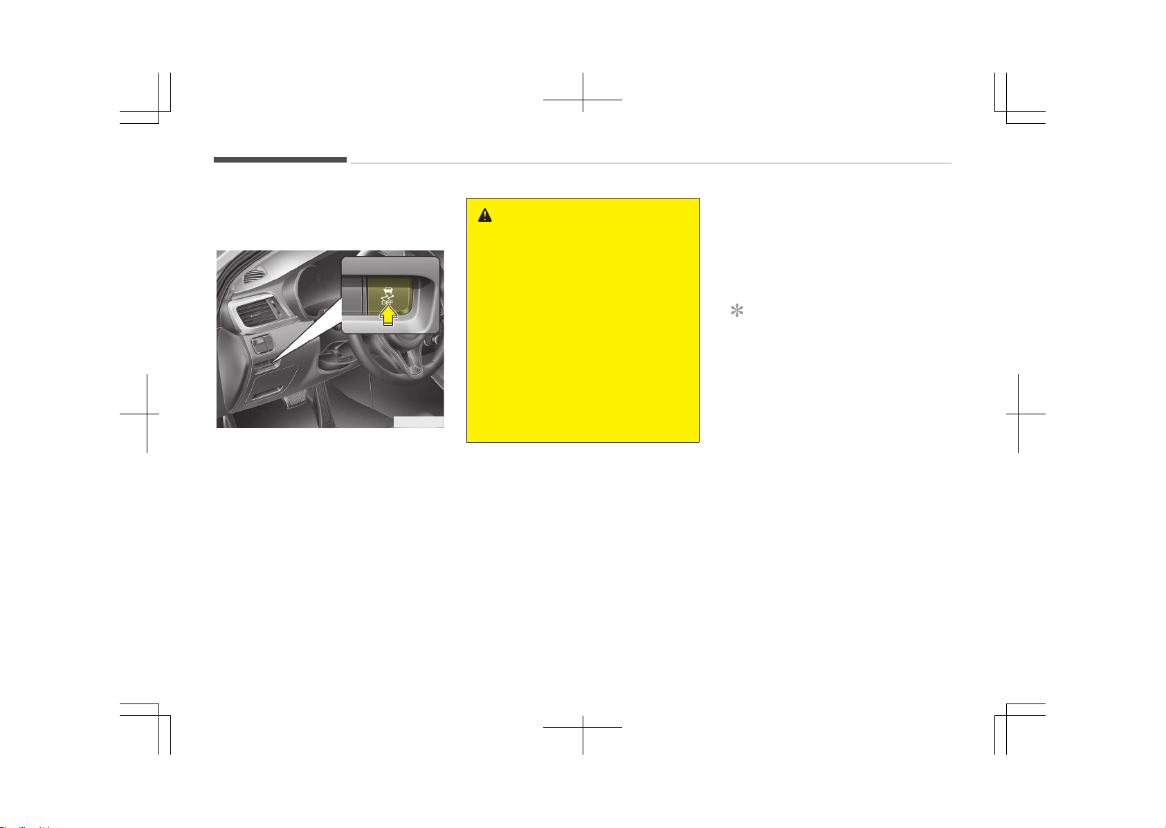
Electronic stability control (ESC)
(if equipped)
OJF055023
The electronic stability control (ESC)
system is designed to stabilize the ve‐
hicle during cornering maneuvers. ESC
checks where you are steering and
where the vehicle is actually going. ESC
applies the brakes at individual wheels
and intervenes with engine manage‐
ment system to stabilize the vehicle.
WARNING
Never drive too fast for the road
conditions or too quickly when cor‐
nering. Electronic stability control
(ESC) will not prevent accidents. Ex‐
cessive speed in turns, abrupt ma‐
neuvers and hydroplaning on wet
surfaces can still result in serious ac‐
cidents. Only a safe and attentive
driver can prevent accidents by
avoiding maneuvers that cause the
vehicle to lose traction. Even with
ESC installed, always follow all the
normal precautions for driving - in‐
cluding driving at safe speed for the
conditions.
The electronic stability control (ESC)
system is an electronic system de‐
signed to help the driver maintain vehi‐
cle control under adverse conditions. It
is not a substitute for safe driving
practices. Factors including speed, road
conditions and driver steering input can
all affect whether ESC will be effective
in preventing a loss of control. It is still
your responsibility to drive and corner
at reasonable speed and to leave a suf‐
ficient margin of safety.
When you apply your brakes under
conditions which may lock the wheels,
you may hear a tik-tik’’ sound from
the brakes, or feel a corresponding sen‐
sation in the brake pedal. This is normal
and it means your ESC is active.
NOTICE
A click sound may be heard in the
engine compartment when the vehi‐
cle begins to move after the engine
is started. These conditions are nor‐
mal and indicate that the electronic
stability control (ESC) system is
functioning properly.
Driving your vehicle
7-30
ESC operation
ESC ON condition
-
• When the engine start/stop
button is turned ON, ESC
and ESC OFF indicator lights
illuminate for approximate‐
ly 3 seconds, then ESC is
turned on.
• Press the ESC OFF button
for at least half a second
after turning the ignition
ON to turn ESC off. (ESC
OFF indicator will illumi‐
nate). To turn the ESC on,
press the ESC OFF button
(ESC OFF indicator light will
go off).
• When starting the engine,
you may hear a slight tick‐
ing sound. This is the ESC
performing an automatic
system self-check and does
not indicate a problem.
When operating
When the ESC is in operation,
ESC indicator light blinks.
• When the Electronic Stabili‐
ty Control is operating
properly, you can feel a
slight pulsation in the vehi‐
cle. This is only the effect
of brake control and indi‐
cates nothing unusual.
• When moving out of the
mud or slippery road, the
engine rpm (revolution per
minute) may not increase
even if you press the accel‐
erator pedal deeply. This is
to maintain the stability
and traction of the vehicle
and does not indicate a
problem.
ESC operation off
ESC OFF state
This car has 2 kinds of ESC
off states.
If the engine stops when ESC
is off, ESC remains off. Upon
restarting the engine, the ESC
will automatically turn on
again.
7-31
7
Driving your vehicle
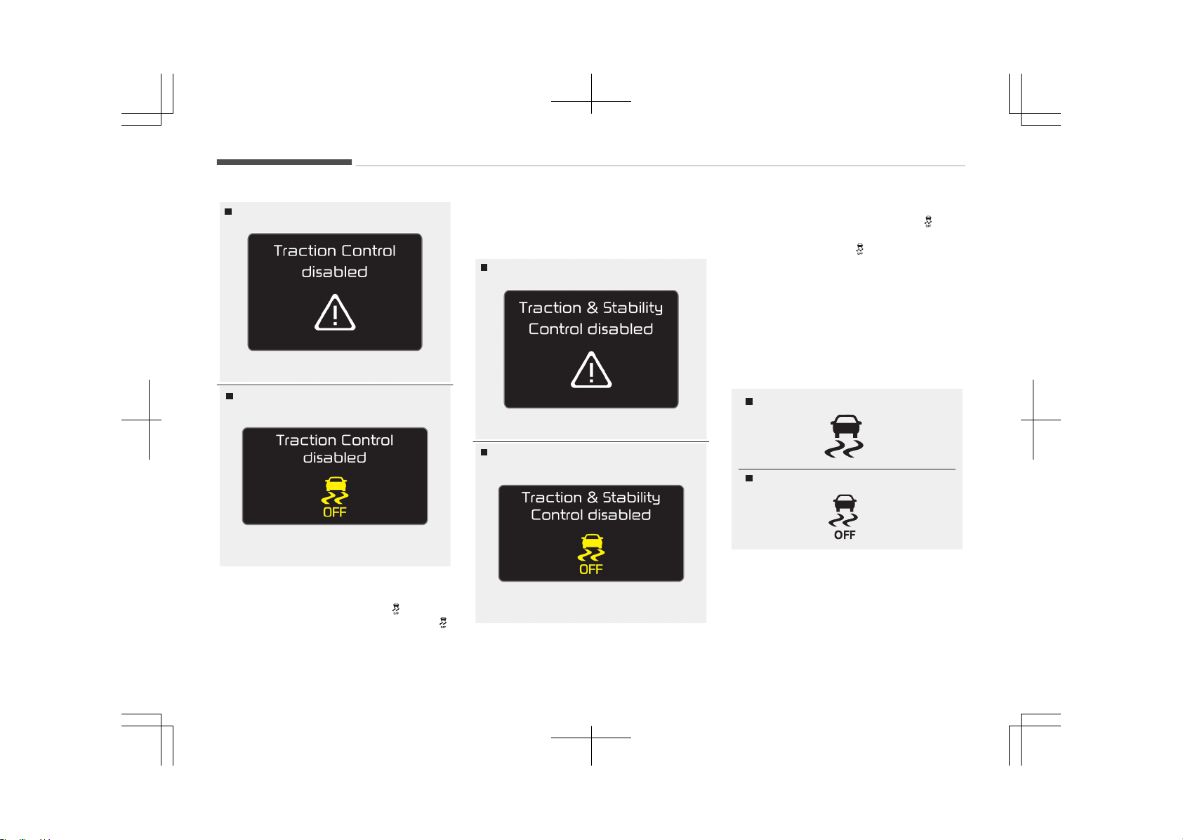
OJF055253L
Type A
OJF055254L
Type B
• ESC off state 1
To cancel ESC operation, press the
ESC OFF button (ESC OFF ) shortly
(ESC OFF indicator light (ESC OFF )
illuminates). At this state, the engine
control function does not operate. It
means the traction control function
does not operate. Brake control func‐
tion only operates.
Type A
OJF055255L
OJF055232L
Type B
• ESC off state 2
To cancel ESC operation, press the
ESC OFF button (ESC OFF
) for
more than 3 seconds. ESC OFF indica‐
tor light (ESC OFF ) illuminates and
ESC OFF warning chime will sound. At
this state, the engine control function
and brake control function do not op‐
erate. It means the car stability con‐
trol function does not operate any
more.
Indicator light
ESC indicator light
ESC OFF indicator light
When engine start/stop button switch
is turned to ON, the indicator light illu‐
minates, then goes off if the ESC sys‐
tem is operating normally.
Driving your vehicle
7-32
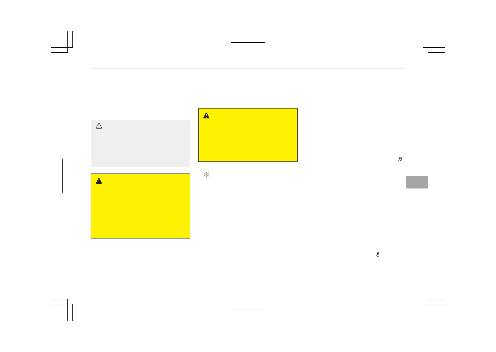
The ESC indicator light blinks whenever
ESC is operating or illuminates when
ESC fails to operate.
ESC OFF indicator light comes on when
the ESC is turned off with the button.
CAUTION
Driving with varying tire or wheel
sizes may cause the ESC system to
malfunction. When replacing tires,
make sure they are the same size as
your original tires.
WARNING
The Electronic Stability Control sys‐
tem is only a driving aid; use precau‐
tions for safe driving by slowing
down on curved, snowy, or icy roads.
Drive slowly and don’t attempt to
accelerate whenever the ESC indica‐
tor light is blinking, or when the road
surface is slippery.
ESC OFF usage
When driving
• ESC should be turned on for daily
driving whenever possible.
• To turn ESC off while driving, press
the ESC OFF button while driving on a
flat road surface.
WARNING
Never press the ESC OFF button
while ESC is operating (ESC indicator
light blinks).
If ESC is turned off while ESC is op‐
erating, the vehicle may slip out of
control.
NOTICE
• When operating the vehicle on a
dynamometer, ensure that the
ESC is turned off by pressing the
ESC OFF button for more than 3
seconds (ESC OFF light illumina‐
ted). If the ESC is left on, it may
prevent the vehicle speed from in‐
creasing, and result in false diag‐
nosis.
• Turning the ESC off does not af‐
fect ABS or brake system opera‐
tion.
Vehicle stability management
(VSM) (if equipped)
This system provides further enhance‐
ments to vehicle stability and steering
responses when a vehicle is driving on a
slippery road or a vehicle detected
changes in coefficient of friction be‐
tween right wheels and left wheels
when braking.
VSM operation
When the VSM is in operation,
• ESC (Electronic Stability Control) ( )
light will blink.
• The steering wheel may be control‐
led.
When the vehicle stability management
is operating properly, you can feel a
slight pulsation in the vehicle. This is
only the effect of brake control and in‐
dicates nothing unusual.
The VSM does not operate when:
• Driving on bank road such as gradient
or incline
• Driving rearward
• ESC OFF indicator light (
) remains
on the instrument cluster
7-33
7
Driving your vehicle
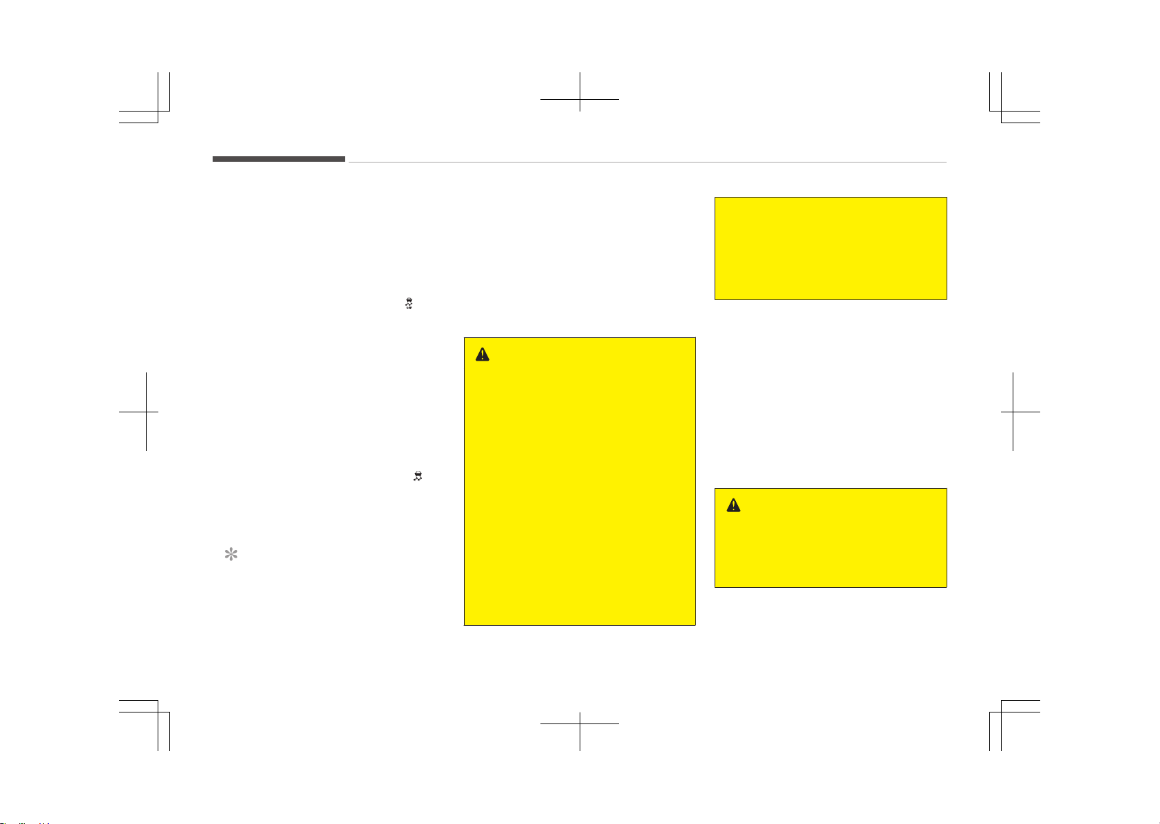
• EPS (Electronic Power Steering) indi‐
cator light remains on the instrument
cluster
VSM operation off
If you press the ESC OFF button to turn
off the ESC, the VSM will also cancel
and the ESC OFF indicator light ( ) illu‐
minates.
To turn on the VSM, press the button
again. The ESC OFF indicator light goes
out.
Malfunction indicator
The VSM can be deactivated even if you
don’t cancel the VSM operation by
pressing the ESC OFF button. It indi‐
cates that a malfunction has been de‐
tected somewhere in the EPS (Elec‐
tronic Power Steering) system or VSM
system. If the ESC indicator light ( ) or
EPS warning light remains on, we rec‐
ommend that the system be checked
by an authorized Kia dealer.
NOTICE
• The VSM is designed to function
above approximately 22 km/h
(13 mph) on curves.
(Continued)
(Continued)
• The VSM is designed to function
above approximately 10 km/h
(6 mph) when a vehicle is braking
on a split-mu road. The split-mu
road is made of surfaces which
have different friction forces.
WARNING
• The Vehicle Stability Management
system is not a substitute for safe
driving practices but a supplemen‐
tary function only. It is the respon‐
sibility of the driver to always
check the speed and the distance
to the vehicle ahead. Always hold
the steering wheel firmly while
driving.
• Your vehicle is designed to activate
according to the driver’s intention,
even with the VSM installed. Al‐
ways follow all the normal precau‐
tions for driving at safe speed for
the conditions – including driving in
inclement weather and on a slip‐
pery road.
(Continued)
(Continued)
• Driving with varying tire or wheel
sizes may cause the VSM system
to malfunction. When replacing
tires, make sure they are the
same size as your original tires.
Hill-start assist control (HAC) (if
equipped)
A vehicle has the tendency to slip back
on a steep hill when it starts to go af‐
ter stopping. The Hill-start Assist Con‐
trol (HAC) prevents the vehicle from
slipping back by operating the brakes
automatically for about 1~2 seconds.
The brakes are released when the ac‐
celerator pedal is depressed or after
about 1~2 seconds.
WARNING
The HAC is activated only for about
1~2 seconds, so when the vehicle is
starting off always depress the ac‐
celerator pedal.
Driving your vehicle
7-34
NOTICE
• The HAC does not operate when
the transaxle shift lever is in the P
(Park) or N (Neutral) position.
• The HAC activates even though
the ESC is off but it does not acti‐
vate when the ESC has malfunc‐
tioned.
Emergency Stop Signal (ESS) (if
equipped)
The Emergency Stop Signal system
alerts the driver behind by blinking the
stop light when the vehicle is braked
rapidly and severely.
The system is activated when:
• The vehicle suddenly stops (vehicle
speed is over 55 km/h and the vehicle
deceleration at greater than 7 m/s
2
).
• The ABS is activating.
When the vehicle speed is under
40 km/h and the ABS deactivates or
the sudden stop situation is over, the
stop light blinking will stop. Instead, the
hazard warning flasher will turn on au‐
tomatically.
The hazard warning flasher will turn off
when vehicle speed is over 10 km/h af‐
ter the vehicle has stopped. Also, it will
turn off when the vehicle is driven at
low speed for some time. You can turn
it off manually by pushing the hazard
warning flasher switch.
CAUTION
The Emergency Stop Signal (ESS)
system will not work if the hazard
warning flasher is already on.
Good braking practices
WARNING
• Whenever you leave or park your
vehicle, always set the parking
brake as far as possible and fully
engage the vehicle's transaxle into
the P (Park) position. If the parking
brake is not fully engaged, the ve‐
hicle may move inadvertently and
injure yourself and others.
(Continued)
(Continued)
• All vehicles should always have the
parking brake fully engaged when
parking to avoid inadvertent
movement of the vehicle which
can injure occupants or pedes‐
trians.
• Check to be sure the parking brake is
not engaged and that the parking
brake indicator light is out before
driving away.
• Driving through water may get the
brakes wet. They can also get wet
when the vehicle is washed. Wet
brakes can be dangerous! Your vehi‐
cle will not stop as quickly if the
brakes are wet. Wet brakes may
cause the vehicle to pull to one side.
To dry the brakes, apply the brakes
lightly until the braking action returns
to normal, taking care to keep the ve‐
hicle under control at all times. If the
braking action does not return to
normal, stop as soon as it is safe to
do so and we recommend that you
call an authorized Kia dealer.
7-35
7
Driving your vehicle

• Do not coast down hills with the vehi‐
cle out of gear. This is extremely haz‐
ardous. Keep the vehicle in gear at all
times, use the brakes to slow down,
then shift to a lower gear so that en‐
gine braking will help you maintain a
safe speed.
• Do not "ride" the brake pedal. Resting
your foot on the brake pedal while
driving can be dangerous because it
can result in the brakes overheating
and losing their effectiveness. It also
increases the wear of the brake com‐
ponents.
• If a tire goes flat while you are driv‐
ing, apply the brakes gently and keep
the vehicle pointed straight ahead
while you slow down. When you are
moving slowly enough for it to be
safe to do so, pull off the road and
stop in a safe place.
• If your vehicle is equipped with an
Automatic Transaxle / Dual clutch
transmission, do not let your vehicle
creep forward. To avoid creeping for‐
ward, keep your foot firmly on the
brake pedal when the vehicle is stop‐
ped.
• Be cautious when parking on a hill.
Firmly engage the parking brake and
place the shift lever in P (automatic
transaxle) or in first or reverse gear
(manual transaxle). If your vehicle is
facing downhill, turn the front wheels
into the curb to help keep the vehicle
from rolling. If your vehicle is facing
uphill, turn the front wheels away
from the curb to help keep the vehi‐
cle from rolling. If there is no curb or
if it is required by other conditions to
keep the vehicle from rolling, block
the wheels.
• Under some conditions your parking
brake can freeze in the engaged posi‐
tion. This is most likely to happen
when there is an accumulation of
snow or ice around or near the rear
brakes or if the brakes are wet. If
there is a risk that the parking brake
may freeze, apply it only temporarily
while you put the shift lever in P (Au‐
tomatic Transaxle / Dual clutch trans‐
mission) or in first or reverse gear
(manual transaxle) and block the rear
wheels so the vehicle cannot roll.
Then release the parking brake.
• Do not hold the vehicle on the up‐
grade with the accelerator pedal. This
can cause the transaxle to overheat.
Always use the brake pedal or park‐
ing brake.
Driving your vehicle
7-36
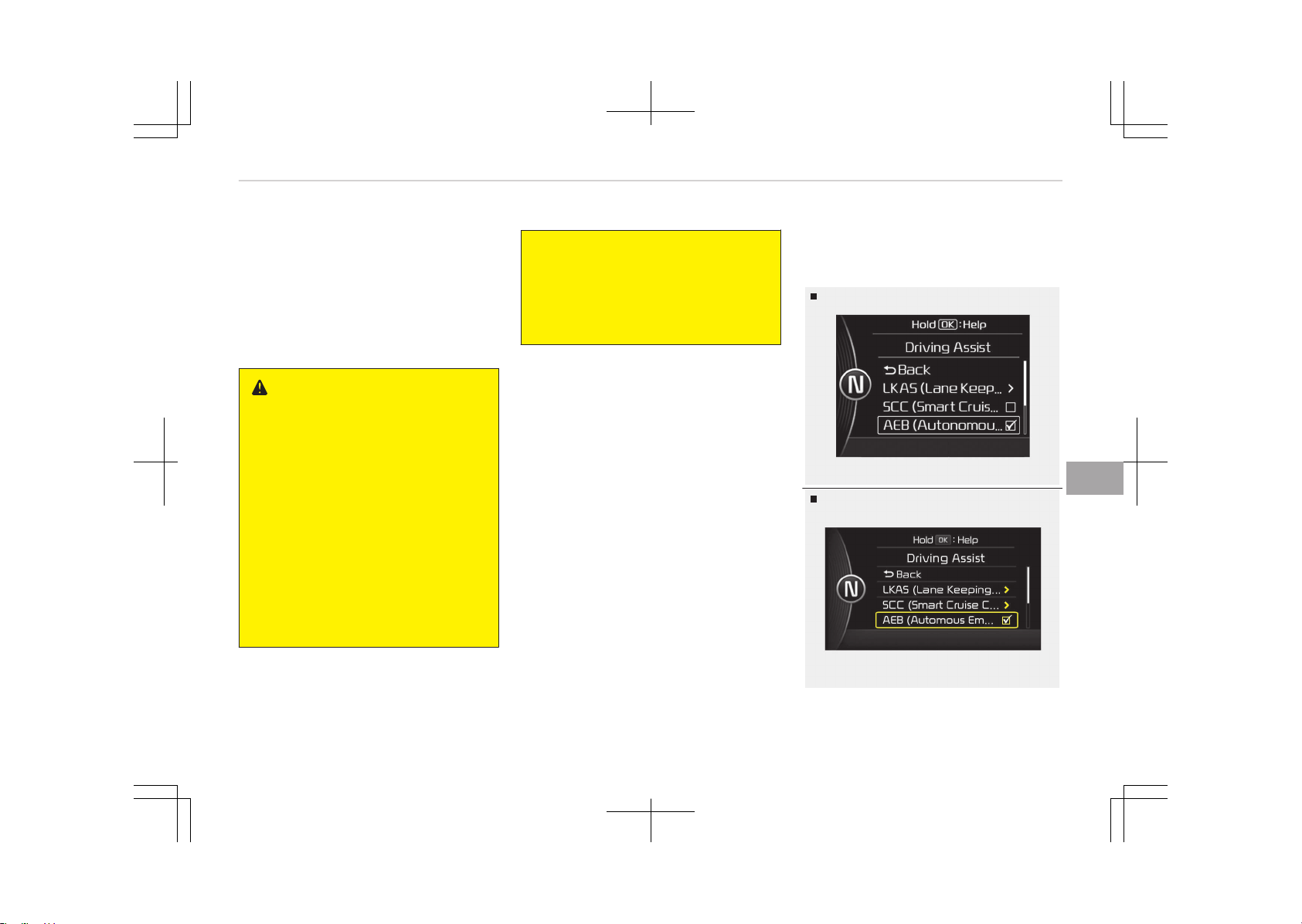
AUTONOMOUS EMERGENCY BRAKING (AEB) (IF EQUIPPED)
The AEB system is to reduce or to
avoid accident risk. It recognizes the
distance from the vehicle ahead or the
pedestrian through the sensors (i.e. ra‐
dar and camera), and, if necessary,
warns the driver of accident risk with
the warning message or the warning
alarms.
WARNING
Take the following precautions when
using the Autonomous Emergency
Braking (AEB):
• This system is only a supplemen‐
tal system and it is not intended
to, nor does it replace the need for
extreme care and attention of the
driver. The sensing range and ob‐
jects detectable by the sensors are
limited. Pay attention to the road
conditions at all times.
• NEVER drive too fast in accordance
with the road conditions or while
cornering.
(Continued)
(Continued)
• Always drive cautiously to prevent
unexpected and sudden situations
from occurring. AEB does not stop
the vehicle completely and does
not avoid collisions.
System setting and activation
System setting
Type A
OJF055180LB
Type B
OJF055128LB
7-37
7
Driving your vehicle
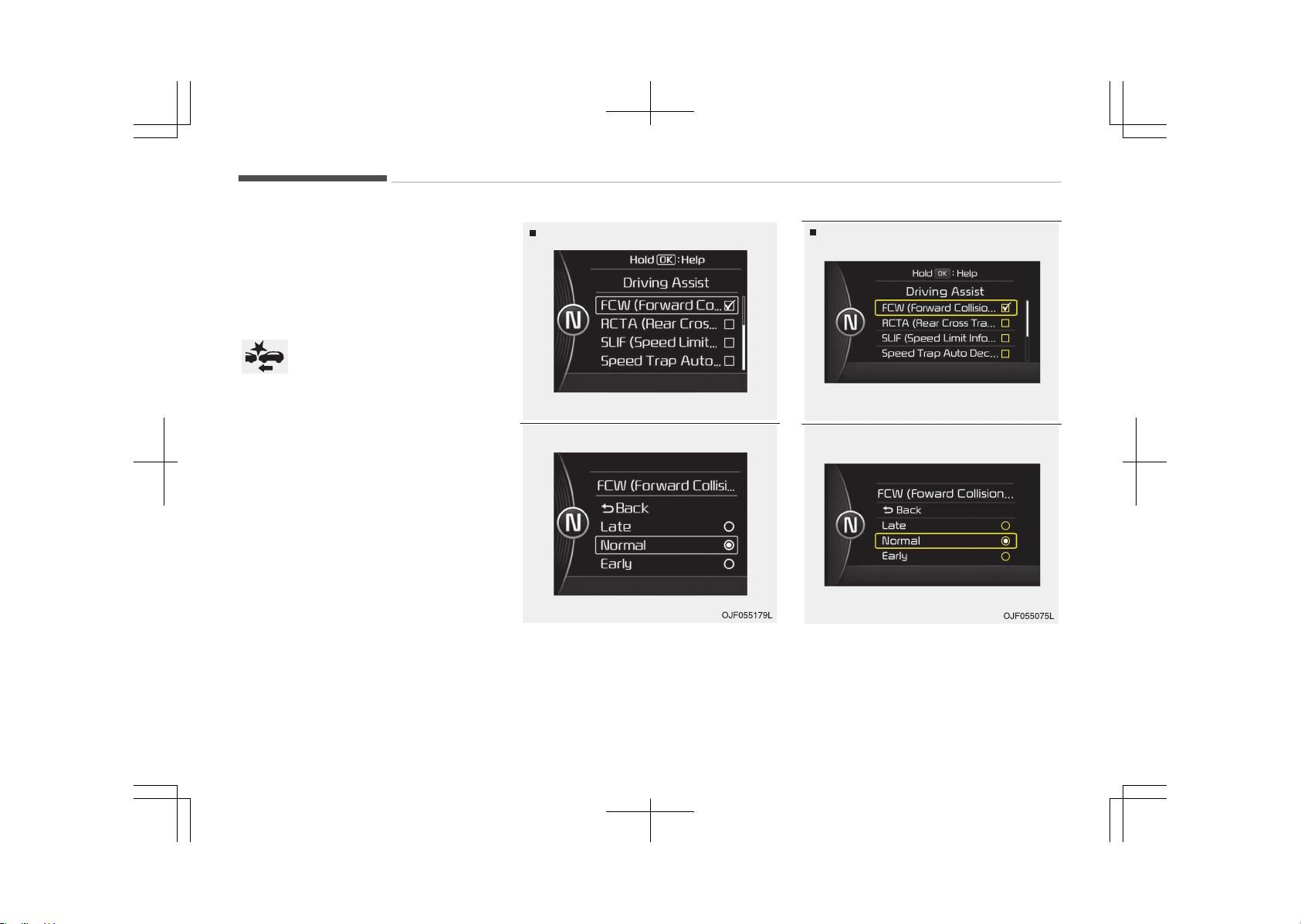
The driver can activate the AEB by
placing the engine start/stop button
switch to the ON position and by se‐
lecting 'User Settings', 'Driving Assist',
and 'Autonomous Braking System'. The
AEB deactivates, when the driver can‐
cels the system setting.
The warning light illuminates
on the LCD display, when you
cancel the AEB system.
The driver can monitor the AEB
ON/OFF status on the LCD display.
When the warning light remains ON
with the AEB activated, we recom‐
mend you to have the system checked
by an authorized Kia dealer.
Type A
OJF055178LB
Type B
OJF055129LB
The driver can select the initial warning
activation time in the User Settings in
the instrument cluster LCD display. The
options for the initial Forward Collision
Warning include the following:
Driving your vehicle
7-38
EARLY - When this condition is se‐
lected, the initial Forward
Collision Warning is activa‐
ted earlier than normal.
This setting maximizes
the amount of distance
between the vehicle or
pedestrian ahead before
the initial warning occurs.
NORMAL -
When this condition is se‐
lected, the initial Forward
Collision Warning is activa‐
ted normally. This setting
allows for a nominal
amount of distance be‐
tween the vehicle or pe‐
destrian ahead before the
initial warning occurs.
LATE - When this condition is se‐
lected, the initial Forward
Collision Warning is activa‐
ted later than normal.
This setting reduces the
amount of distance be‐
tween the vehicle or pe‐
destrian ahead before the
initial warning occurs.
Prerequisite for activation
The AEB gets ready to be activated,
when the AEB is selected on the LCD
display, and when the following prereq‐
uisites are satisfied.
-
The ESC is activated.
-
The driving speed is over 10 km/h.
(However, AEB is activated within
certain driving speed.)
-
When recognizing the vehicle or the
pedestrian in front. (However, AEB
does not activate according to condi‐
tions in front and vehicle systems,
but it notices only certain warnings.)
WARNING
• The AEB automatically activates
upon placing the ignition switch to
the ON position. The driver can de‐
activate the AEB by canceling the
system setting on the LCD display.
• The AEB automatically deactivates
upon canceling the ESC. When the
ESC is canceled, the AEB cannot be
activated on the LCD display.
(Continued)
(Continued)
• Set or cancel AEB with controlling
switches on steering wheel after
stopping the vehicle in a safe place
for your safety.
AEB warning message and
system control
The AEB produces warning messages
and warning alarms in accordance with
the collision risk levels of followings like
vehicle’s sudden braking in front or lack
of vehicle to vehicle distance or collision
to pedestrians. Also, it controls the
brakes in accordance with the collision
risk levels.
7-39
7
Driving your vehicle
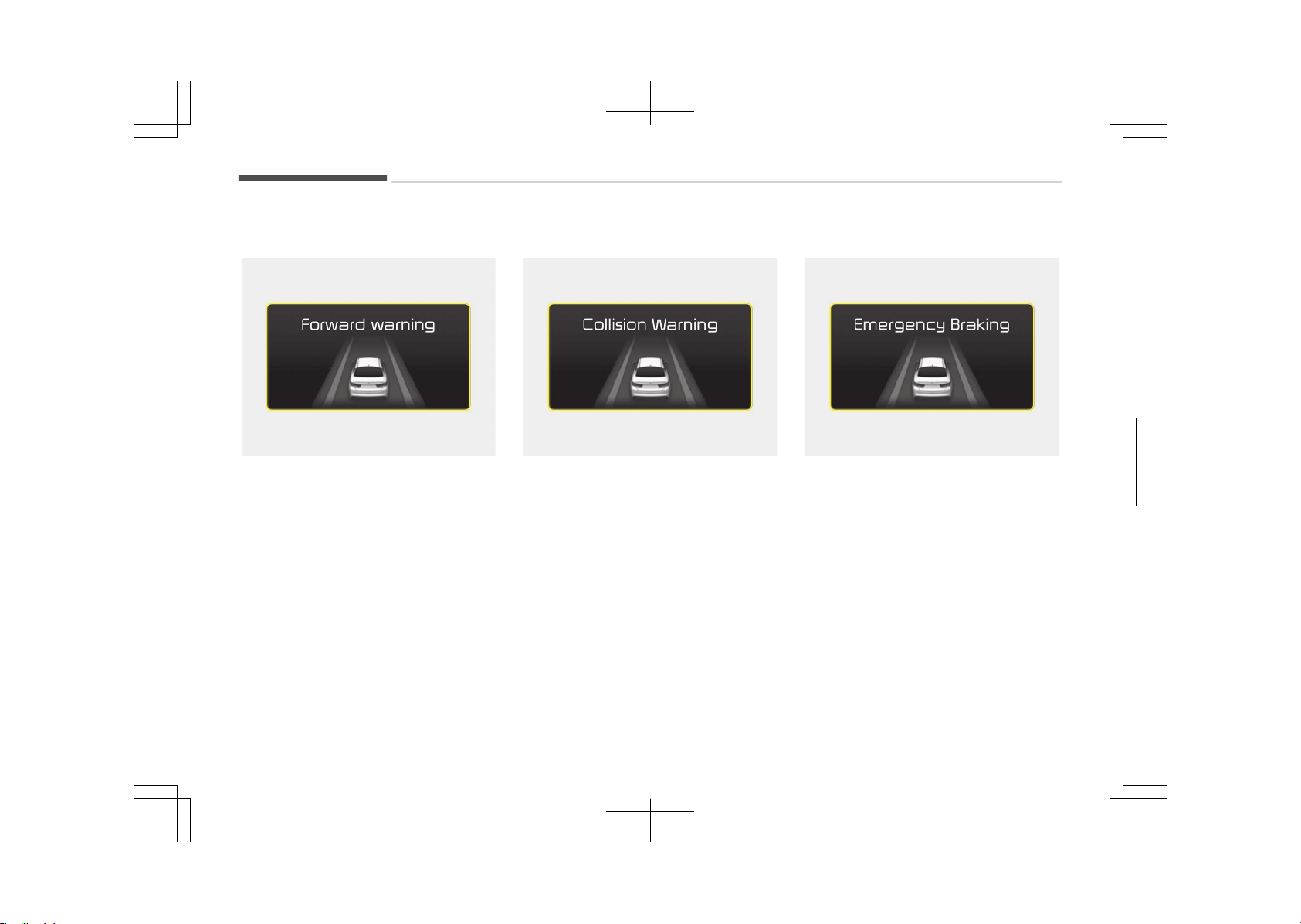
Forward warning (1st warning)
OJF055076L
The warning message appears on the
LCD display with the warning alarms.
Collision warning (2nd warning)
OJF055077L
• The warning message appears on the
LCD display with the warning alarms.
• The AEB controls the brakes within
certain limit to release shock from
the collision.
Emergency braking (3rd warning)
OJF055078L
• The warning message appears on the
LCD display with the warning alarms.
• The AEB controls the brakes within
certain limit to release shock from
the collision.
The AEB controls the maximum
brakes just before the collision.
Brake operation
• In an urgent situation, the braking
system enters into the ready status
for prompt reaction against the driv‐
er’s depressing the brake pedal.
Driving your vehicle
7-40
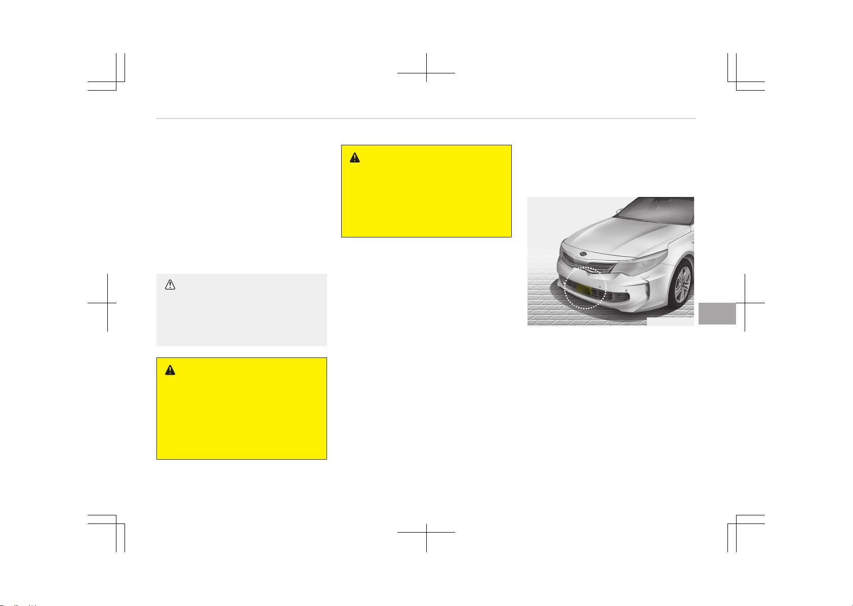
• The AEB provides additional braking
power for optimum braking perform‐
ance, when the driver depresses the
brake pedal.
• The braking control is automatically
deactivated, when the driver sharply
depresses the brake pedal, or when
the driver abruptly operates the
steering wheel.
• The braking control is automatically
canceled, when risk factors disappear.
CAUTION
The driver should always pay great
caution to vehicle operation, even
though there is no warning message
or warning alarm.
WARNING
The AEB cannot avoid all collisions.
The AEB might not completely stop
the vehicle before collision, due to
ambient, weather and road condi‐
tions. The driver has the responsibili‐
ty to drive safely and control the ve‐
hicle.
WARNING
The AEB operates in accordance with
the risk levels, such as the distance
from the vehicle/passer-by in front,
the speed of the vehicle/passer-by
in front, and the driver's vehicle op‐
eration.
Sensor to detect the distance
from the vehicle in front (front
radar)
OJFHP056162
The sensor is to maintain a certain dis‐
tance from the vehicle in front. Howev‐
er, the smudged sensor lens with for‐
eign substances, such as snow and rain,
adversely affects the sensing perform‐
ance. It may even temporarily cancel
the AEB. Always keep the sensor lens
clean.
7-41
7
Driving your vehicle
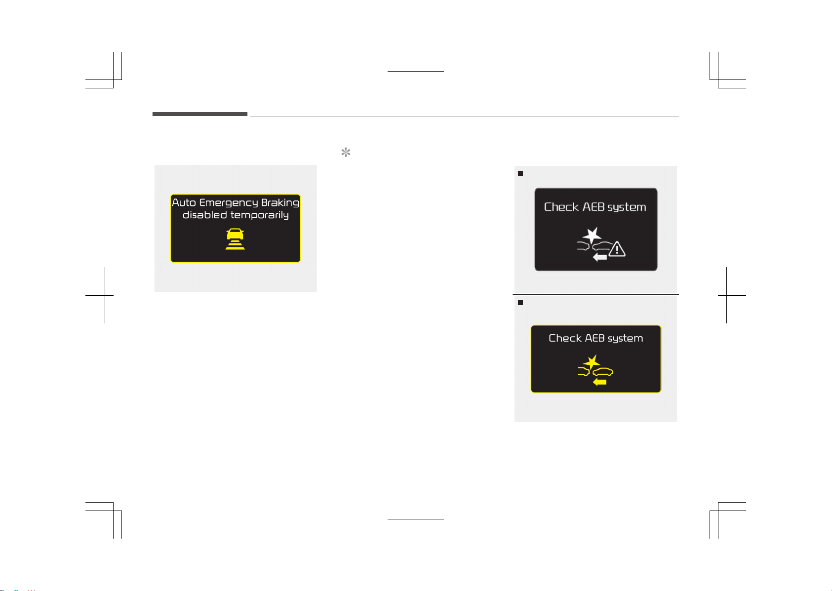
Warning message and warning light
OJF055187L
When the sensor cover or the sensor
lens is smudged with the foreign sub‐
stances, such as snow or rain, the AEB
operation may temporarily stop. In this
case, the warning message appears to
warn the driver.
This is not a malfunction with the AEB.
To operate the AEB again, remove the
foreign substances.
NOTICE
• Do not install any accessories,
such as license plate molding or
sticker, on the sensor area. Nor ar‐
bitrarily replace the bumper.
Those may adversely affect the
sensing performance.
• Always keep the sensor/bumper
area clean.
• Use only soft clothes to wash the
vehicle. Also, do not spray highly
pressurized water on the sensor
installed on the bumper.
• Be careful not to apply unnecessa‐
ry force on the frontal sensor
area. When the sensor moves out
of the correct position due to ex‐
ternal force, the system may not
normally operate even without the
warning light or message. In this
case, we recommend you to have
the vehicle inspected by an au‐
thorized Kia dealer.
• Use only the genuine Kia sensor
cover. Do not arbitrarily apply
paint on the sensor cover.
System malfunction
OJF055181L
Type A
OJF055079L
Type B
Driving your vehicle
7-42
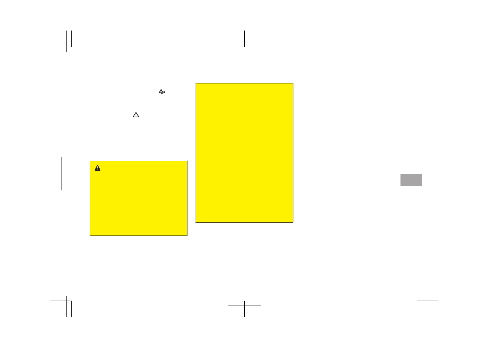
• When the AEB is not working proper‐
ly, the AEB warning light ( ) will illu‐
minate and the warning message will
appear for a few seconds. After the
message disappears, the master
warning light ( ) will illuminate. In
this case, we recommend you to have
the vehicle inspected by an author‐
ized Kia dealer.
• The AEB warning message may ap‐
pear along with the illumination of
the ESC warning light.
WARNING
• The AEB is only a supplemental
system for the driver’s conven‐
ience. The driver should hold the
responsibility to control the vehicle
operation. Do not solely depend on
the AEB system. Rather, maintain
a safe braking distance, and, if
necessary, depress the brake ped‐
al to lower the driving speed.
(Continued)
(Continued)
• The AEB may unnecessarily pro‐
duce the warning message and the
warning alarms. Also, due to the
sensing limitation, the AEB may
not produce the warning message
and the warning alarm at all.
• When there is a malfunction with
the AEB, the braking control does
not operate upon detecting a colli‐
sion risk even with other braking
systems normally operating.
• The AEB operates only for the ve‐
hicle / pedestrian in front, while
driving forward. It does not oper‐
ate for any animals or vehicles in
the opposite direction.
• The AEB does not recognize the
vehicle, which horizontally drives
across the crossroad, or the vehi‐
cle, which is parked in the horizon‐
tal direction.
Limitation of the system
The AEB is an assistant system for a
driver in a certain risky driving condition
and it does not take every responsibili‐
ty for all risks from driving condition.
The AEB monitors the driving situations
through the radar and the camera sen‐
sor. Thus, for a situation out of the
sensing range, the AEB may not nor‐
mally operate. The driver should pay
great caution in the following situa‐
tions. The AEB operation may be limi‐
ted.
Recognizing vehicles
-
The radar or the camera is contami‐
nated with foreign substances.
-
It heavily rains or snows.
-
There is interruption by electric
waves.
-
There is severe irregular reflection
from the radar.
-
The vehicle in front has a narrow
body. (i.e. motor cycle and bicycle)
-
The driver’s view is unclear due to
the backlight, the reflected light, or
darkness.
-
The camera cannot contain the full
image of the vehicle in front.
7-43
7
Driving your vehicle
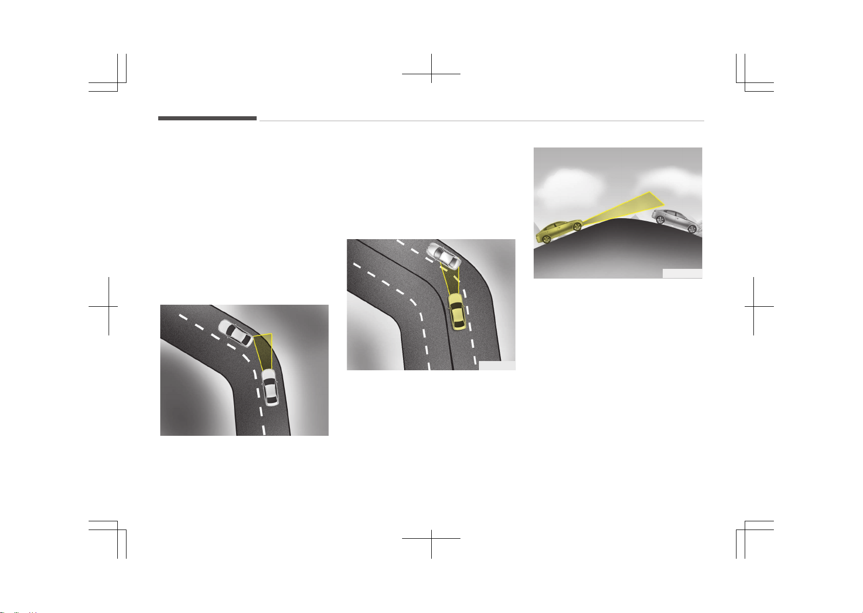
-
The vehicle in front is a special vehi‐
cle, such as a heavily-loaded truck or
a trailer.
The vehicle in front does not turn ON
the rear lights, does not have rear
lights, has asymmetric rear lights, or
has rear lights out of angle.
-
The outside brightness is greatly
changed, such as entering/exiting the
tunnel.
-
The vehicle driving is unstable.
-
The radar/camera sensor recognition
is limited.
OJF055025
-
Driving on a curve
The AEB performance decreases
while driving on a curve. The AEB
may not recognize the vehicle in front
even in the same lane. It may unnec‐
essarily produce the warning mes‐
sage and the warning alarm, or it
may not produce the warning mes‐
sage and the warning alarm at all.
While driving on a curve, pay great
caution, and, if necessary, depress
the brake pedal.
OJF055026
-
While driving on a curve, the AEB may
recognize the vehicle in front in the
next lane. Pay great caution, and, if
necessary, depress the brake pedal.
Or, depress the accelerator pedal to
maintain the driving speed. Always,
take a look around the vehicle for
your safety.
OJF055027
-
Driving on a slope
The AEB performance decreases
while driving upward or downward on
a slope, not recognizing the vehicle in
front in the same lane. It may unnec‐
essarily produce the warning mes‐
sage and the warning alarm, or it
may not produce the warning mes‐
sage and the warning alarm at all.
When the AEB suddenly recognizes
the vehicle in front while passing over
a slope, you may experience sharp
deceleration.
Always keep your eyes forward while
driving upward or downward on a
slope, and, if necessary, depress the
brake pedal.
Driving your vehicle
7-44
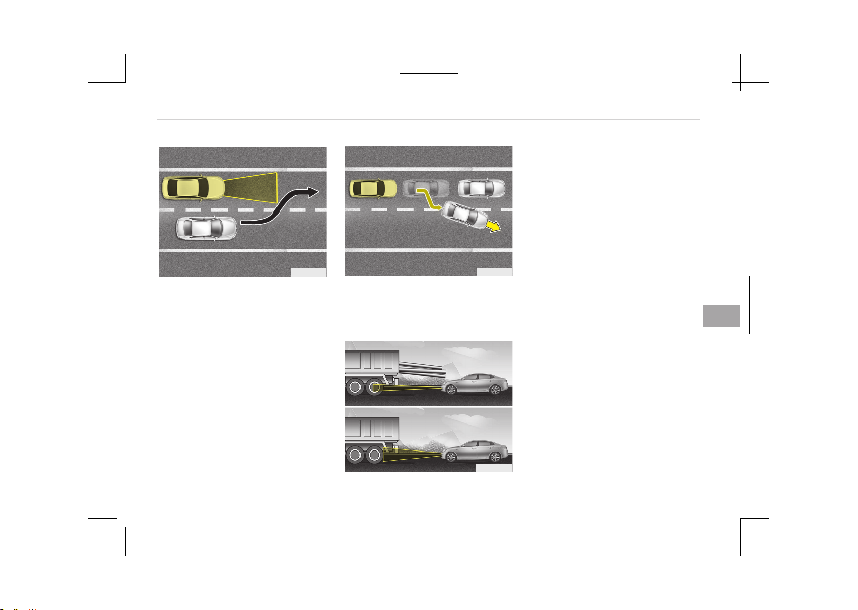
OJF055028
-
Changing lanes
Even though the vehicle in the next
lane enters into your lane, it may not
be recognized by the AEB, until it en‐
ters the AEB sensing range.
Especially when the vehicle in the
next lane abruptly enters into your
lane, it is more likely not to be recog‐
nized. Always pay great attention.
OJF055029
When the stopped vehicle in front
gets out of the lane, it may not be
recognized by your AEB. Always pay
great attention.
OJF055030
-
Recognizing the vehicle
When the vehicle in front has heavy
loading extended rearward, or when
the vehicle in front has higher ground
clearance, it may induce a hazardous
situation.
Recognizing pedestrians
-
The pedestrian is not fully captured
by the camera sensor, or the pedes‐
trian does not walk in the upright po‐
sition.
-
The pedestrian moves very fast.
-
The pedestrian abruptly appears in
front.
-
The pedestrian wears clothes in the
color similar to the background.
-
The outside is too bright or too dark.
-
The vehicle drives at night or in the
darkness.
-
There is an item similar to a person’s
body structure.
-
The pedestrian is small.
-
The pedestrian has impaired mobility.
-
It is difficult to distinguish the pedes‐
trian from the surroundings.
-
The sensor recognition is limited.
7-45
7
Driving your vehicle

-
There is a group of pedestrians.
WARNING
• Cancel the AEB in the User Set‐
tings on the LCD display, before
towing another vehicle. While tow‐
ing, the brake application may ad‐
versely affect your vehicle safety.
• Pay great caution to the vehicle in
front, when it has heavy loading
extended rearward, or when it has
higher ground clearance.
• The sensor only detects pedes‐
trians, not carts, bicycles, motor‐
cycles, luggage bags, or strollers.
• The AEB does not operate in a cer‐
tain situation. Thus, never test-
operate the AEB against a person
or an object. It may cause a severe
injury or even death.
NOTICE
The system may temporarily cancel
due to the strong electric waves.
Driving your vehicle
7-46
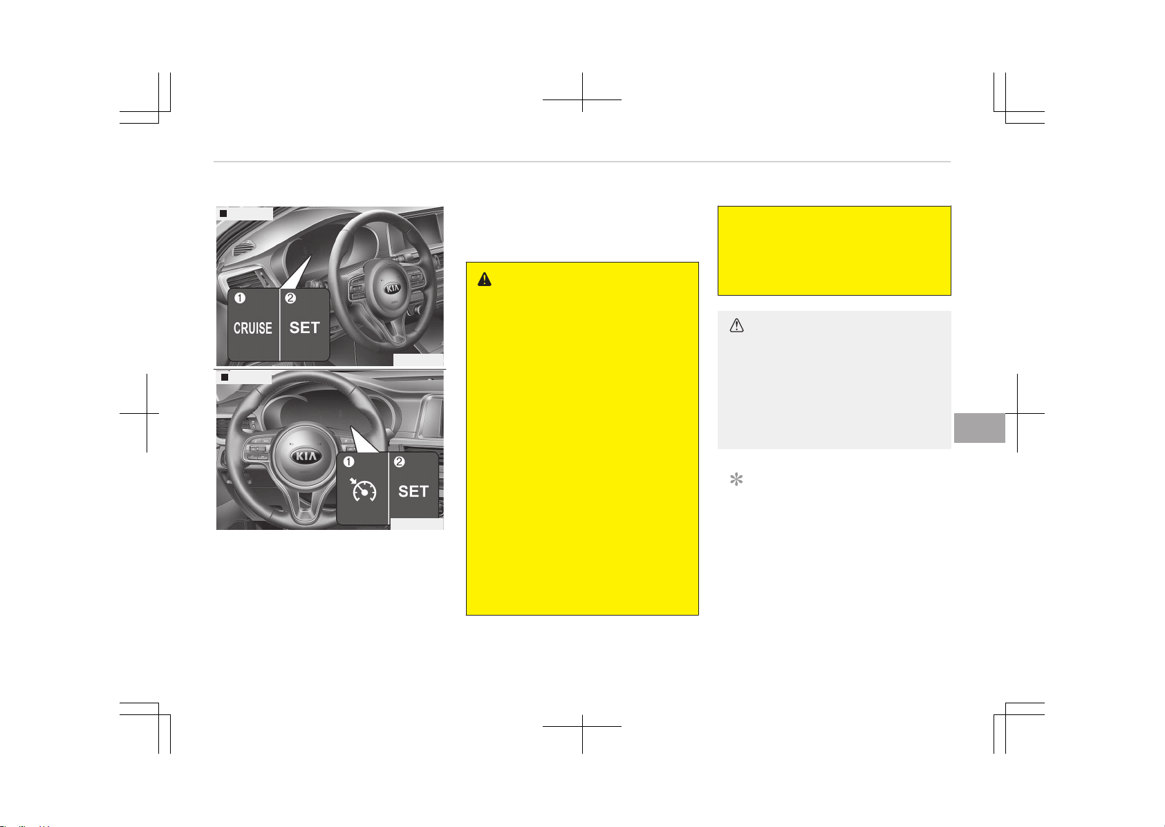
CRUISE CONTROL SYSTEM (IF EQUIPPED)
Type A
OJF055037
Type B
OJF055037L
1. Cruise indicator
2. Cruise set indicator
The cruise control system allows you to
program the vehicle to maintain a con‐
stant speed without pressing the accel‐
erator pedal.
This system is designed to function
above approximately 30 km/h
(20 mph).
WARNING
• If the cruise control is left on
(cruise indicator light is illumina‐
ted), the cruise control can be
switched on accidentally. Keep the
cruise control system off when
the cruise control is not in use, to
avoid inadvertently setting a
speed.
• Use the cruise control system only
when traveling on open highways
in good weather.
• Do not use the cruise control when
it may not be safe to keep the ve‐
hicle at a constant speed, for in‐
stance, driving in heavy or varying
traffic, or on slippery (rainy, icy or
snow covered) or winding roads or
over 6% up-hill or down-hill roads.
• Pay particular attention to the
driving conditions whenever using
the cruise control system.
(Continued)
(Continued)
• Be careful when driving downhill
using the cruise control system,
which may increase the vehicle
speed.
CAUTION
During cruise-speed driving of a
manual transaxle vehicle, do not
shift into neutral without depressing
the clutch pedal, since the engine
will be over revved. If this happens,
depress the clutch pedal or release
the cruise control ON-OFF switch.
NOTICE
• During normal cruise control oper‐
ation, when the SET switch is acti‐
vated or reactivated after applying
the brakes, the cruise control will
energize after approximately 3
seconds. This delay is normal.
(Continued)
7-47
7
Driving your vehicle
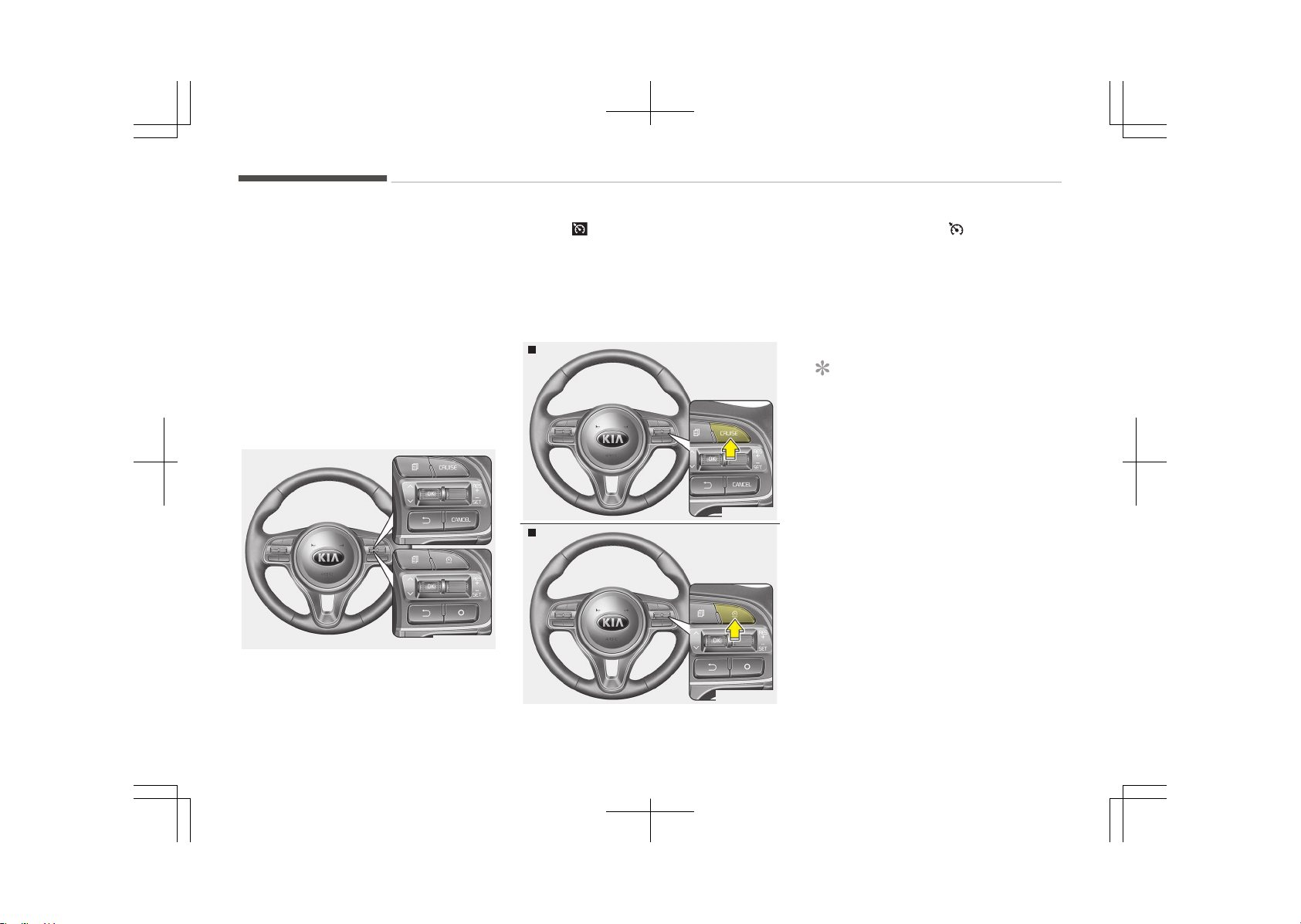
(Continued)
• To activate cruise control, depress
the brake pedal at least once after
turning the engine start/stop but‐
ton switch to the ON position or
starting the engine. This is to
check if the brake switch which is
important part to cancel cruise
control is in normal condition.
Cruise control switch
OJF055060L
CANCEL/O: Cancels cruise control oper‐
ation.
CRUISE/
: Turns cruise control system
on or off.
RES+: Resumes or increases cruise con‐
trol speed.
SET-: Sets or decreases cruise control
speed.
To set cruise control speed:
Type A
OJF055038
Type B
OJF055038L
1. Press the CRUISE/ button on the
steering wheel, to turn the system
on. The cruise indicator light will il‐
luminate.
2. Accelerate to the desired speed,
which must be more than approxi‐
mately 30 km/h (20 mph).
NOTICE
n
Manual transaxle
For manual transaxle vehicles, you
should depress the brake pedal at
least once to set the cruise control
after starting the engine.
Driving your vehicle
7-48
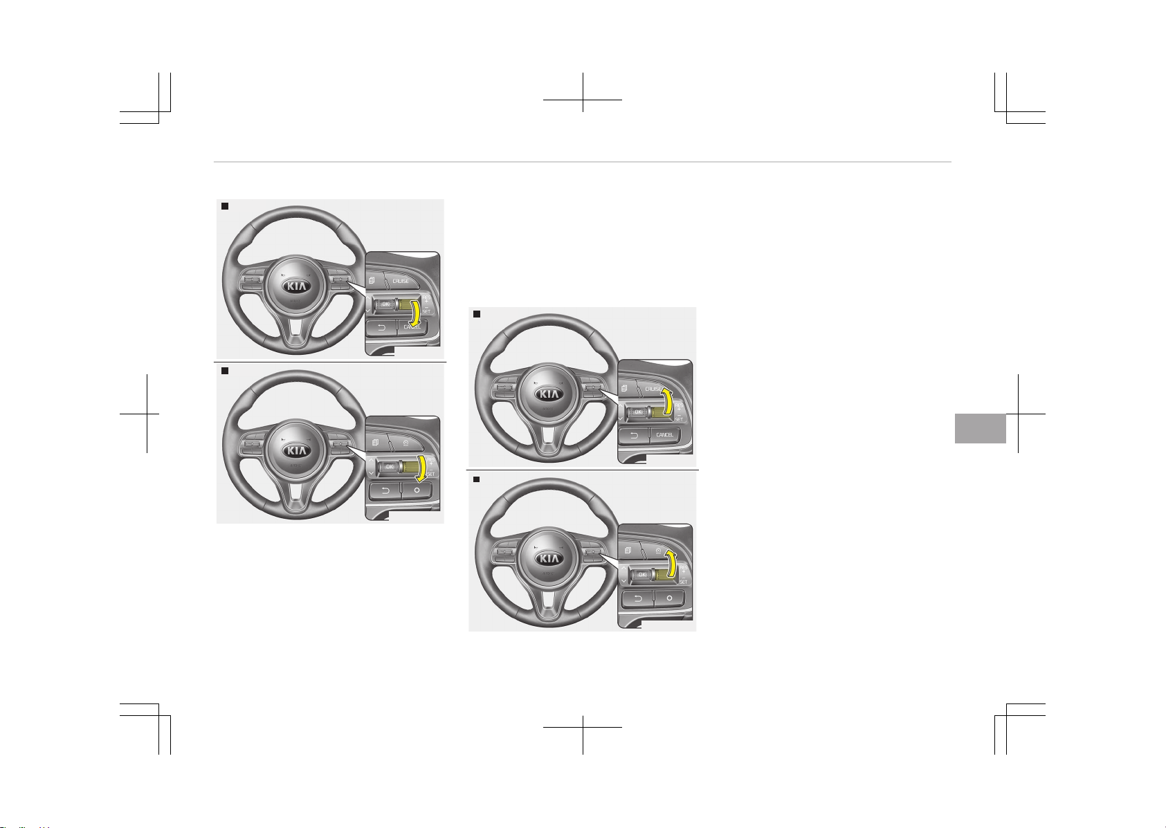
Type A
OJF055039
Type B
OJF055039L
3. Move the lever down (to SET-), and
release it at the desired speed. The
cruise set indicator light will illumi‐
nate. Release the accelerator pedal
at the same time. The desired
speed will automatically be main‐
tained.
On a steep grade, the vehicle may
slow down or speed up slightly
while going downhill.
To increase cruise control set
speed:
Type A
OJF055040
Type B
OJF055040L
Follow either of these procedures:
• Move the lever up (to RES+) and hold
it. Your vehicle will accelerate. Re‐
lease the lever at the speed you
want.
• Move the lever up (to RES+) and re‐
lease it immediately. The cruising
speed will increase by 2 km/h (1 mph)
each time you move the lever up (to
RES+) in this manner.
7-49
7
Driving your vehicle
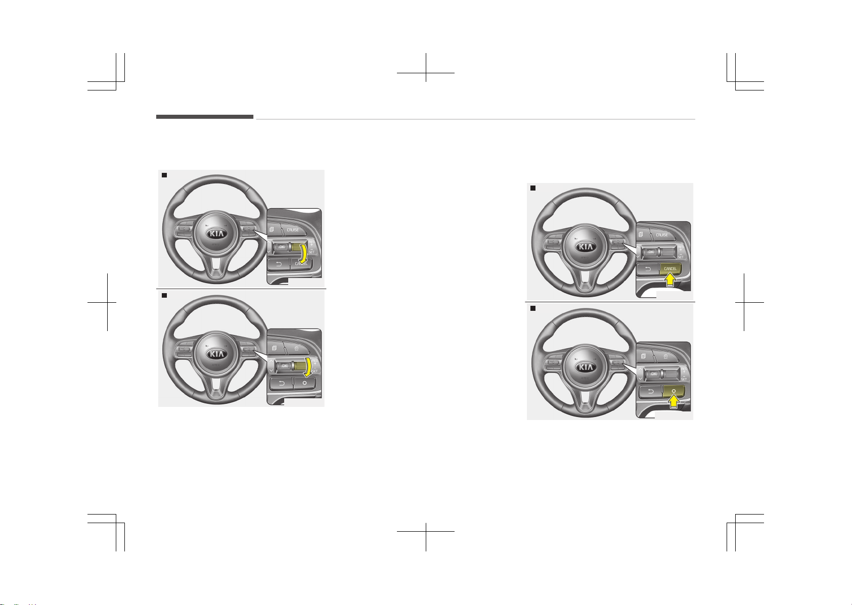
To decrease the cruising speed:
Type A
OJF055039
Type B
OJF055039L
Follow either of these procedures:
• Move the lever down (to SET-) and
hold it. Your vehicle will gradually
slow down. Release the lever at the
speed you want to maintain.
• Move the lever down (to SET-) and
release it immediately. The cruising
speed will decrease by 2 km/h
(1 mph) each time you move the lev‐
er down (to SET-) in this manner.
To temporarily accelerate with
the cruise control on:
If you want to speed up temporarily
when the cruise control is on, depress
the accelerator pedal. Increased speed
will not interfere with cruise control op‐
eration or change the set speed.
To return to the set speed, take your
foot off the accelerator pedal.
To cancel cruise control, do one
of the following:
Type A
OJF055041
Type B
OJF055041L
• Depress the brake pedal.
• Depress the clutch pedal if equipped
with a manual transaxle.
Driving your vehicle
7-50
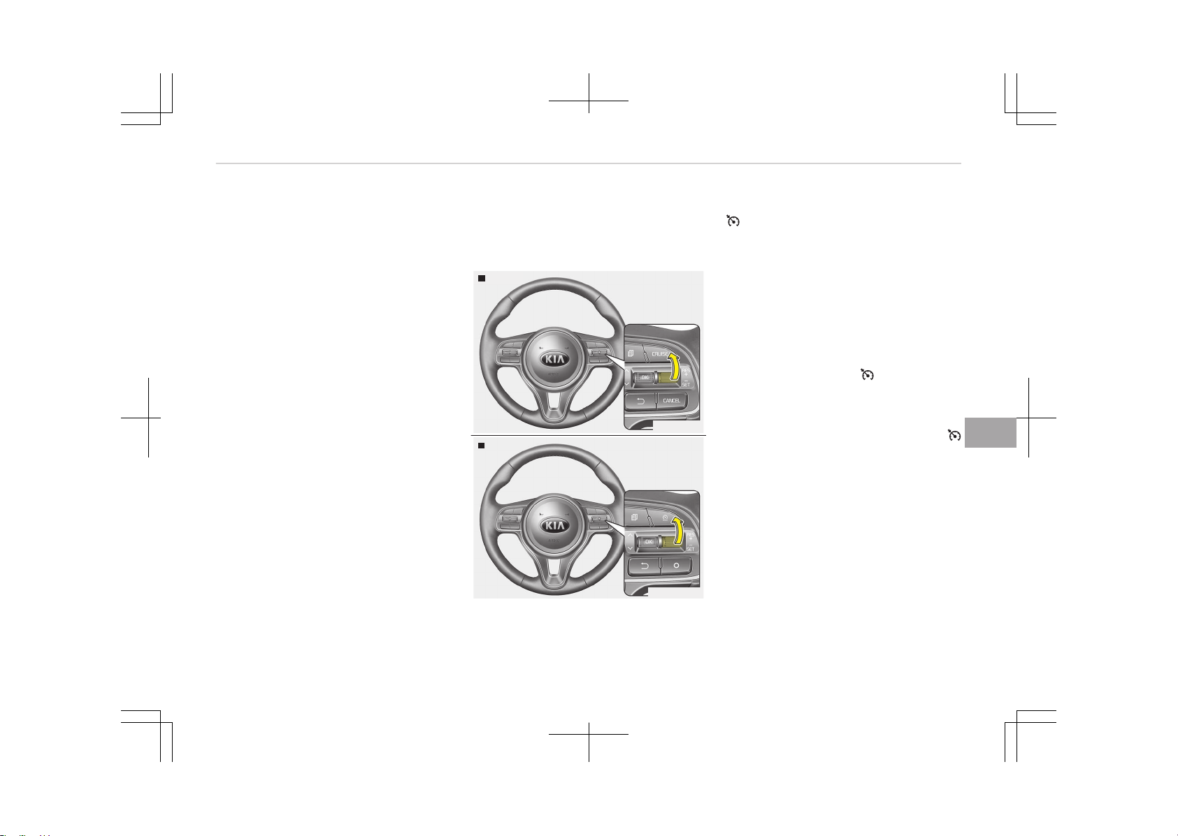
• Shift into N (Neutral) if equipped with
an Automatic Transaxle / Dual clutch
transmissione.
• Press the CANCEL/O button located
on the steering wheel.
• Decrease the vehicle speed lower
than the memory speed by approxi‐
mately 20 km/h (12 mph) .
• Decrease the vehicle speed to less
than approximately 25 km/h
(15 mph) .
Each of these actions will cancel cruise
control operation (the cruise set indica‐
tor light will go off), but it will not turn
the system off. If you wish to resume
cruise control operation, move up the
lever (to RES+) located on your steering
wheel. You will return to your previous‐
ly preset speed.
To resume cruising speed at
more than approximately 30
km/h (20 mph)
Type A
OJF055040
Type B
OJF055040L
If any method other than the CRUISE/
button was used to cancel cruising
speed and the system is still activated,
the most recent set speed will auto‐
matically resume when the RES+ switch
is pushed.
It will not resume, however, if the vehi‐
cle speed has dropped below approxi‐
mately 30 km/h (20 mph).
To turn cruise control off, do
one of the following:
• Press the CRUISE/ button (the
cruise indicator light will be turned
off).
• If your vehicle equipped the speed
limit system, press the CRUISE/
button twice. (The cruise indicator
light will be turned off.)
• Turn the engine start/stop button
off.
Both of these actions cancel cruise con‐
trol operation. If you want to resume
cruise control operation, repeat the
steps provided in To set cruise control
speed on page 7-48.
7-51
7
Driving your vehicle
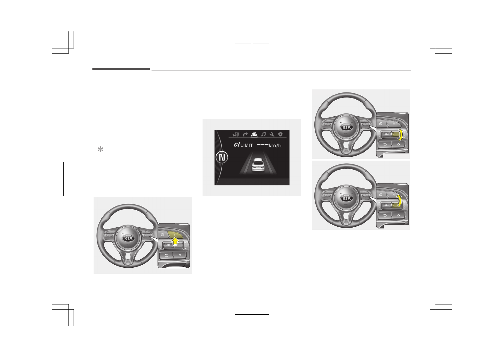
SPEED LIMIT CONTROL SYSTEM (IF EQUIPPED)
You can set the speed limit when you
do not want to drive over a specific
speed.
If you drive over the preset speed limit,
the warning system operates (set
speed limit will blink and chime will
sound) until the vehicle speed returns
within the speed limit.
NOTICE
While speed limit control is in opera‐
tion, the cruise control system can‐
not be activated.
To set speed limit:
OJF055038LB
1. Press the cruise switch twice to set
speed limit. Once you press it only
one time, the cruise control system
is ready.
OJF055153L
The speed limit indicator light will
illuminate.
OJF055039LC
OJF055040LB
2. Move the lever down (to SET-).
Driving your vehicle
7-52
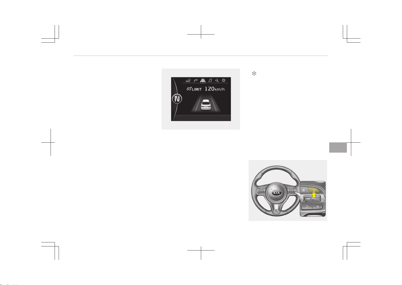
3. Move the lever up (to RES+) or
down (to SET-), and release it at
the desired speed. Move the lever
up (to RES+) or down (to SET-) and
hold it. The speed will increase or
decrease by 5 km/h (3 mph) .
Move the lever up (to RES+) or
down (SET-) and release it immedi‐
ately. The speed will increase or
decrease by 1 km/h.
The set speed limit will display on
the instrument cluster.
OJF055154L
The set speed limit will be displayed. To
drive over the preset speed limit you
must depress hard on the accelerator
pedal (more than approximately 80%)
until the kick down mechanism works
with a clicking noise. Then the set
speed limit will blink and chime will
sound until you return the vehicle
speed within the speed limit.
NOTICE
• Depressing the accelerator pedal
less than approximately 50%, the
vehicle will not speed over the pre‐
set speed limit but maintain the
vehicle speed within the speed lim‐
it.
• A clicking noise heard from the
kick down mechanism by depress‐
ing the accelerator pedal fully is a
normal condition.
To turn off the speed limit
control, do one of the following:
OJF055038LB
7-53
7
Driving your vehicle
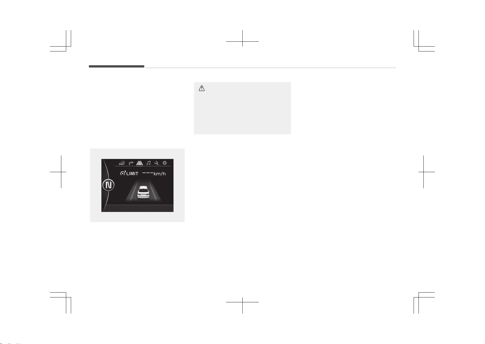
• Press the cruise switch.
• Turn the engine start/stop button
off.
If you press the cancel O switch once,
the set speed limit will cancel, but it will
not turn the system off. If you wish to
reset the speed limit, move the lever up
(to RES+) or down (to SET-) to the de‐
sired speed.
OJF055153L
CAUTION
The --- indicator will blink if there
is a problem with speed limit control
system.
If this occurs, we recommend that
the system be checked by an au‐
thorized Kia dealer.
Driving your vehicle
7-54
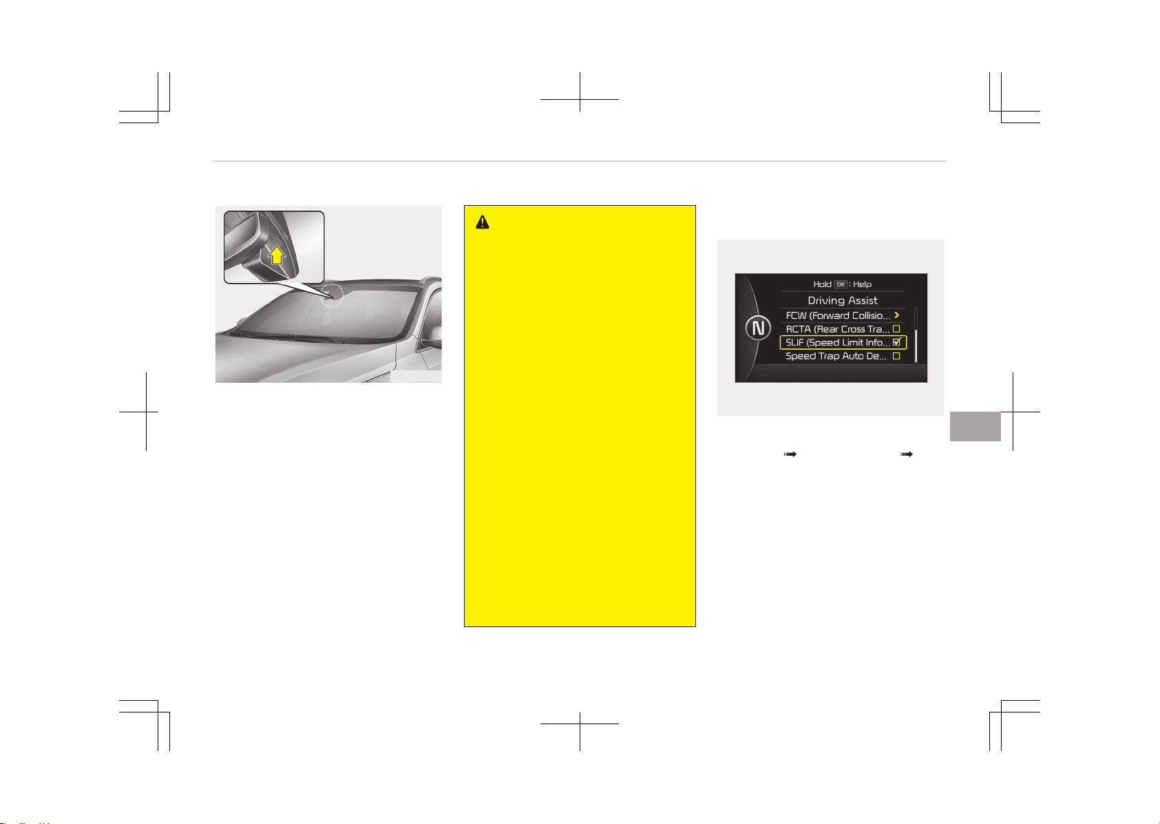
SPEED LIMIT INFORMATION FUNCTION (SLIF) (IF EQUIPPED)
OUM054149
The system displays the information of
speed limit and no passing restriction
to the driver in both the instrument
cluster and navigation screen. SLIF de‐
tects traffic signs with camera system
attached on the top of the windscreen.
The SLIF also utilizes the navigation in‐
formation to display the speed limit in‐
formation.
WARNING
• Speed Limit Information Function
is only an aid and is not always
able to correctly display speed lim‐
its and overtaking restrictions.
• The driver always keeps the re‐
sponsibility not to exceed the
maximum allowed speed.
• Do not place any accessories,
stickers or tint the windshield near
the rearview mirror.
• The system detects traffic signs
and displays speed limit informa‐
tion by a camera therefore, if traf‐
fic signs are hard to detect, the
system may not work properly.
Please refer to Driver's attention
on page 7-58.
• Do not remove any LKAS parts or
apply impact.
• Do not place objects on the dash‐
board that reflects light such as
mirrors, white paper, etc. The sys‐
tem may malfunction if the sun‐
light is reflected.
• The system is not available in all
countries.
SLIF activation/deactivation
OJF055185L
• SLIF Setting method: Cluster User
Settings Driving Assist SLIF
(Speed Limit Information Function)
• The information of speed limit and no
passing restriction will appear on the
cluster using a symbol if you have ac‐
tivated SLIF in User Settings of clus‐
ter.
• If SLIF is activated in navigation set‐
ting, the information is also displayed
in navigation screen.
7-55
7
Driving your vehicle
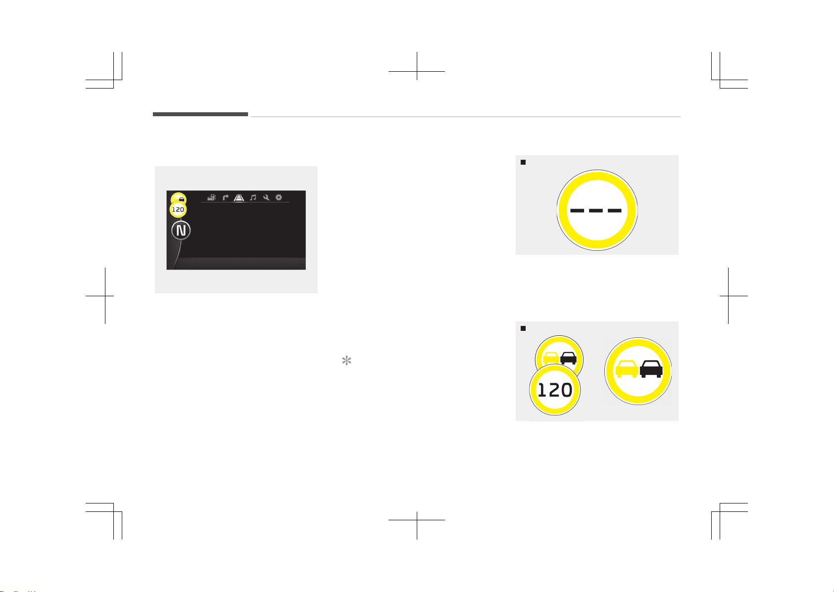
Operation
OJF055186L
• If a traffic sign that is relevant to
your vehicle is passed, the system
displays the information of the speed
limits and no passing restrictions to
the driver.
• When the driver turns on the ignition,
the system displays stored informa‐
tion of the speed limit before turning
off the ignition.
• Sometimes different speed limits are
displayed for the same road. The in‐
formation displayed is depending on
the situation. Because, traffic signs
with additional sign (e.g rainy, ar‐
row...) are also detected and com‐
pared with vehicle interior data (e.g
wiper operation, turn signal...).
• The system can update the speed
limit information without visible
speed limit signs in the following sit‐
uations.
- When you change your driving di‐
rection with right or left or U turn‐
ing.
- When vehicle changes roads. (e.g.
from highway to country road…)
- When you enter or exit into town
or village.
NOTICE
If speed limit value has the differ‐
ence between cluster and naviga‐
tion, check the speed unit setting in
navigation.
Display
No reliable speed limit information
WUM-203
• If the system doesn’t have a reliable
speed limit information, the following
symbol is displayed in both the in‐
strument cluster and navigation
screen.
No passing information
WUM-206/WUM-204
• If the system detects no passing sign,
no passing is displayed in both the in‐
strument cluster and navigation
screen.
Driving your vehicle
7-56

End of a speed limit
WUM-207/WUM-208
• After passing "end of speed limita‐
tion sign SLIF provides information
from navigation to inform driver of
perhaps afterwards applicable speed
limit.
Unlimited speed (only in Germany)
WUM-205
• For some areas on highways in Ger‐
many there's no speed limit applica‐
ble. In that case SLIF shows "end of
limitation" traffic sign as long as you
don't pass another speed limit sign.
Warning message
OJF055233L
The message will appear when cam‐
era’s field of view is covered by some
objects. The system stops until the
field of view is normal.
Check the windshield around the cam‐
era view area.
If the system does not work normally
even though camera’s field of view is
cleared, we recommend that the sys‐
tem be checked by an authorized Kia
dealer.
OJF055234L
When SLIF is not working properly, the
warning message will come on for a
few second. After the message disap‐
pears, the master warning light will illu‐
minate.
We recommend that the system be
checked by an authorized Kia dealer.
The system may not fully operate and
provide correct information in the fol‐
lowing situations.
• Traffic signs are positioned on sharp
curve.
• Poorly positioned traffic sign. (eg. Ro‐
tated, shaded by any object, dam‐
aged…)
• Concealed traffic signs by other vehi‐
cle.
7-57
7
Driving your vehicle

• Broken LED traffic signs.
• Poor weather like snow, rain, fog.
• Reflected glare around and/or on the
traffic sign.
• There is insufficient illumination of
the traffic signs in the night.
• There is bright lights around traffic
signs.
• There is dirt, ice or frost on the wind‐
shield in the area of the camera.
• When camera field of view is covered
by objects such as a sticker, paper,
leaf fall.
• When driving very close to the vehicle
in front of you.
• When navigation system has mal‐
function.
• When bus or trucks attached with a
speed sticker are passing you.
• When you are at a certain location
not covered by the navigation sys‐
tem.
• When the navigation system is not
updated to the latest map version.
Driver's attention
The driver must be cautious in the be‐
low situations for the system may not
assist the driver and may not work
properly.
• Do not stick or attach anything to the
windshield in front of the camera as
this may reduce effectiveness or
cause one more of the systems de‐
pendent on the camera to stop work‐
ing.
• Keep the windshield in the area be‐
hind the interior rear view mirror
clean.
• Do not place reflective materials,
such as white paper or a mirror, on
the instrument panel.
• Do not strike or damage the areas
around the camera unit.
• Do not touch the camera lens or re‐
move the screw located on the cam‐
era unit.
• The system does not work in all sit‐
uations but is designed merely as a
supplementary aid.
• The system assists the driver and
does not replace the human eye.
• The driver always bears ultimate re‐
sponsibility for ensuring that the ve‐
hicle is driven safely and that applica‐
ble road traffic rules and regulations
are followed.
Driving your vehicle
7-58
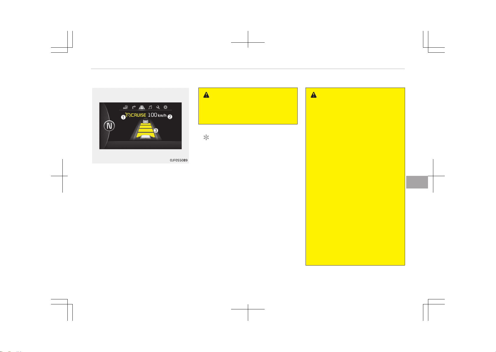
ADVANCED SMART CRUISE CONTROL SYSTEM (IF EQUIPPED)
1. Cruise indicator
2. Set speed
3. Vehicle-to-vehicle distance
The advanced smart cruise control sys‐
tem allows you to program the vehicle
to maintain constant speed and dis‐
tance detecting the vehicle ahead with‐
out depressing the accelerator or brake
pedal.
WARNING
For your safety, please read the
owner's manual before using the ad‐
vanced smart cruise control system.
NOTICE
To activate advanced smart cruise
control, depress the brake pedal at
least once after turning the engine
start/stop button switch to the ON
position or starting the engine. This
is to check if the brake switch which
is important part to cancel advanced
smart cruise control is in normal
condition.
WARNING
• If the advanced smart cruise con‐
trol is left on, (cruise indicator in
the instrument cluster illuminated)
the smart cruise control can be ac‐
tivated unintentionally. Keep the
smart cruise control system off
(cruise indicator turn off) when
the smart cruise control is not
used.
• Use the smart cruise control sys‐
tem only when traveling on open
highways in good weather.
• Do not use the smart cruise con‐
trol when it may not be safe to
keep the car at a constant speed.
For instance:
- Highway interchange and toll‐
gate
- Road surrounded by abnormally
multiple steel constructions
(subway construction, steel
tunnel, etc)
- Parking lot
- Lanes beside guard rail on a
road
(Continued)
7-59
7
Driving your vehicle
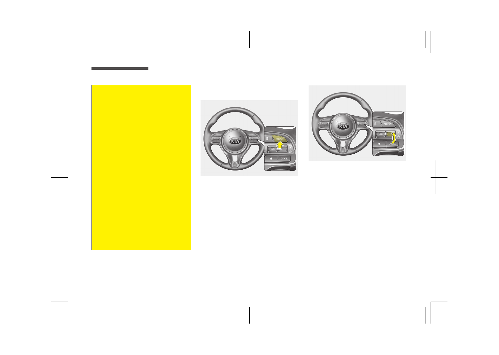
(Continued)
- Slippery road with rain, ice, or
snow covered
- Abrupt curved road
- Steep hills
- Windy roads
- Off roads
- Roads under construction
- Rumble strip
- The sensing ability decreases if
the level of front and rear vehi‐
cle is changed from the factory.
• Pay particular attention to the
driving conditions whenever using
the smart cruise control system.
• The advanced smart cruise control
system is not a substitute for safe
driving. It is the responsibility of
the driver to always check the
speed and distance of the vehicle
ahead.
• Be careful when driving downhill
using the ASCC.
Speed setting
To set cruise control speed:
OJF055042
1. Press the CRUISE button, to turn
the system on. The CRUISE indica‐
tor in the instrument cluster will il‐
luminate.
2. Accelerate to the desired speed.
The advanced smart cruise control
speed can be set as follows:
• 30 km/h (20 mph) ~ 180 km/h
(110 mph): when there is no vehi‐
cle in front
• 0 km/h (0 mph) ~ 180 km/h
(110 mph): when there is a vehi‐
cle in front
OJF055043
3. Move the lever down (to SET-), and
release it at the desired speed. The
set speed and vehicle to vehicle dis‐
tance on the LCD screen will illumi‐
nate.
4. Release the accelerator pedal.
The desired speed will automatical‐
ly be maintained.
If there is a vehicle in front of you, the
speed may decrease to maintain the
distance to the vehicle ahead.
On a steep grade, the vehicle may slow
down or speed up slightly while going
uphill or downhill.
Driving your vehicle
7-60
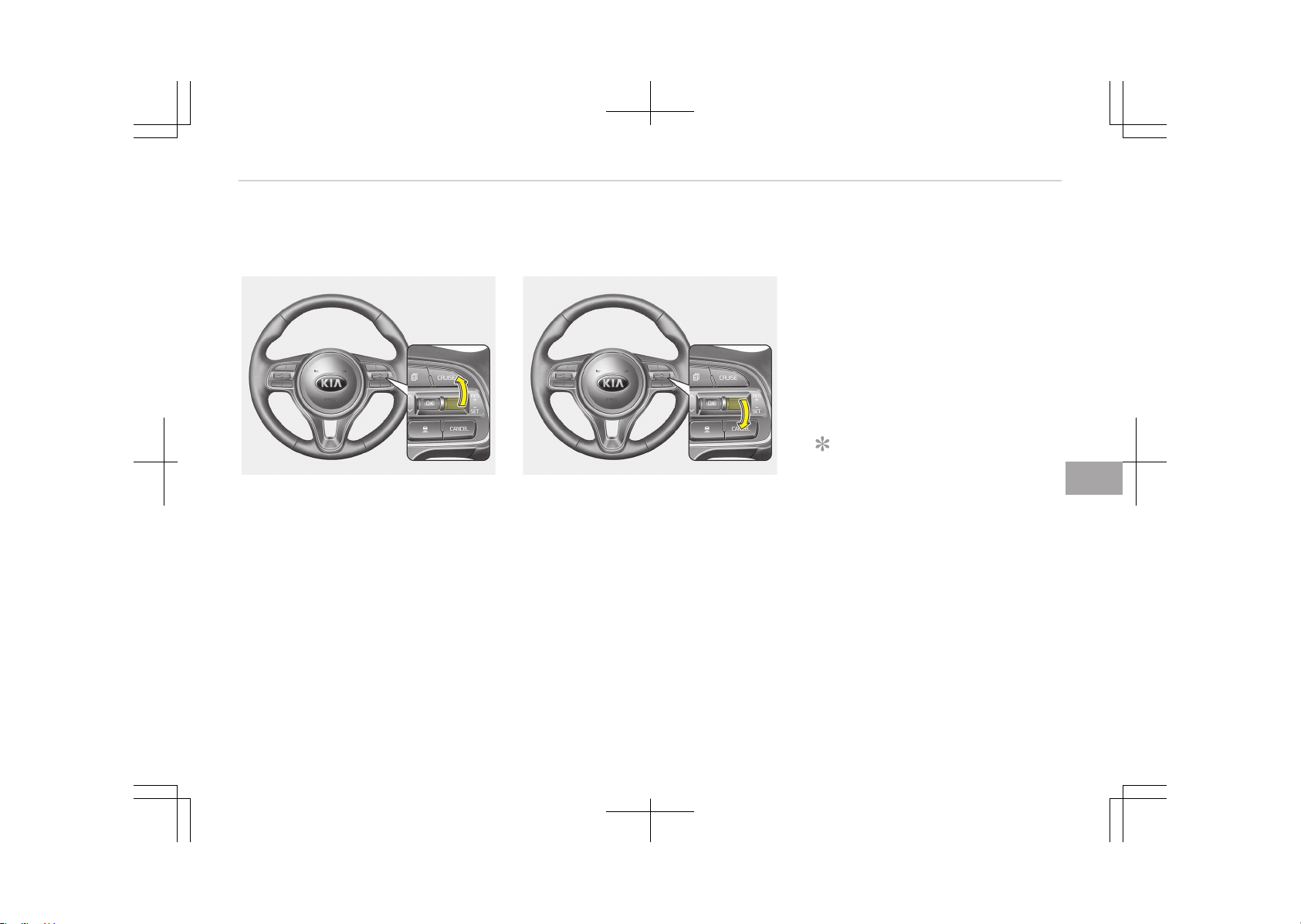
To increase cruise control set
speed:
OJF055044
Follow either of these procedures:
• Move the lever up (to RES+), and hold
it. Your vehicle set speed will increase
by 10 km/h (5 mph). Release the lev‐
er at the speed you want.
• Move the lever up (to RES+), and re‐
lease it immediately. The cruising
speed will increase by 1.0 km/h
(1.0 mph) each time you move the
lever up (to RES+) in this manner.
• You can set the speed to 180 km/h
(110 mph).
To decrease the cruise control set
speed:
OJF055043
Follow either of these procedures:
• Move the lever down (to SET-), and
hold it. Your vehicle set speed will de‐
crease by 10 km/h (5 mph). Release
the lever at the speed you want.
• Move the lever down (to SET-), and
release it immediately. The cruising
speed will decrease by 1.0 km/h
(1.0 mph) each time you move the
lever down (to SET-) in this manner.
• You can set the speed to 30 km/h
(20 mph).
To temporarily accelerate with the
cruise control on:
If you want to speed up temporarily
when the cruise control is on, depress
the accelerator pedal. Increased speed
will not interfere with cruise control op‐
eration or change the set speed.
To return to the set speed, take your
foot off the accelerator.
If you move the lever down (to SET-) at
increased speed, the cruising speed will
be set again.
NOTICE
Be careful when accelerating tempo‐
rarily, because the speed is not con‐
trolled automatically at this time
even if there is a vehicle in front of
you.
7-61
7
Driving your vehicle
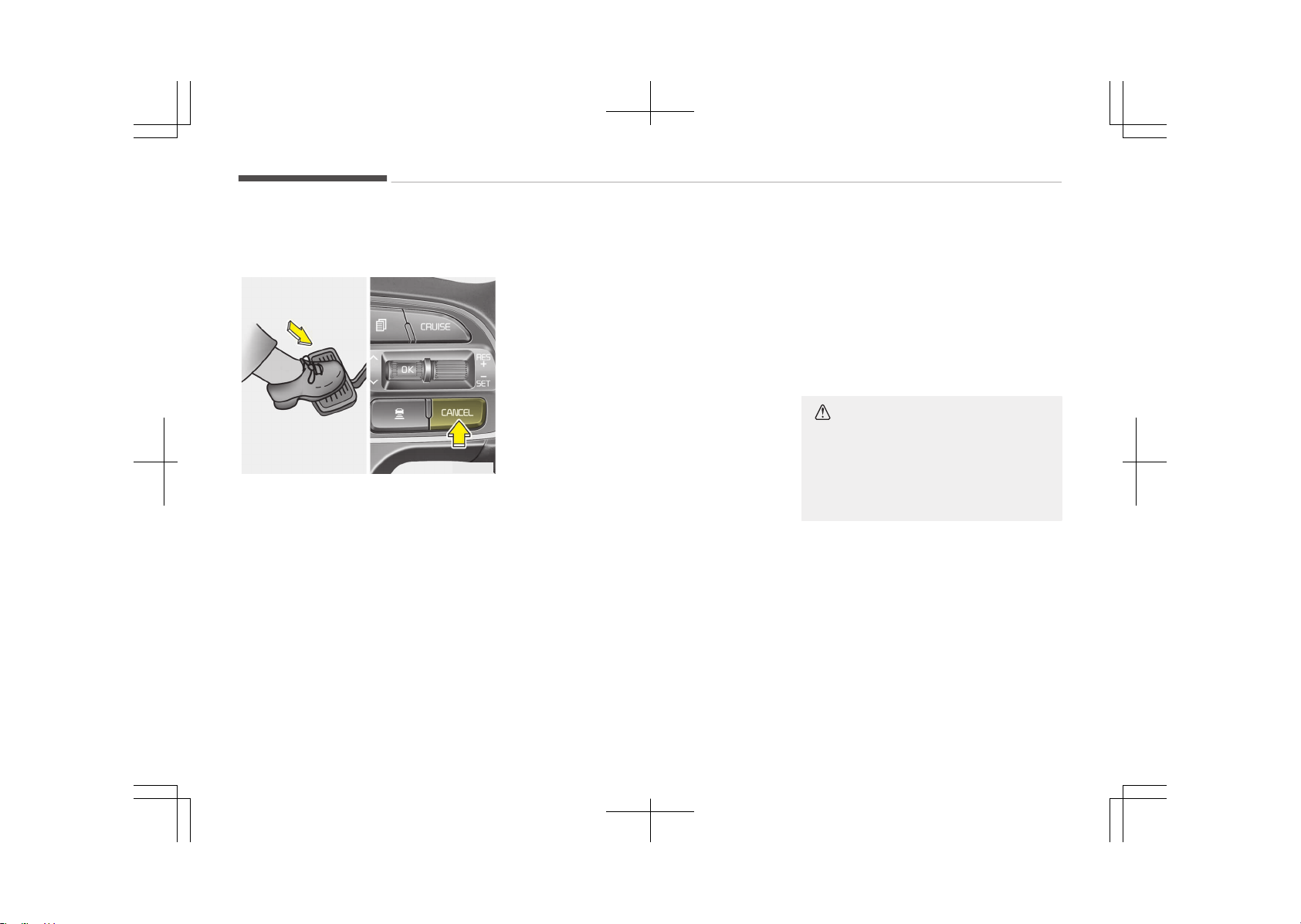
Advanced smart cruise control will
be temporarily canceled when:
OJF055061L
Cancelled manually
The advanced smart cruise control is
temporarily canceled when the brake
pedal is depressed or the CANCEL but‐
ton is pressed. The speed and vehicle to
vehicle distance indicator on the cluster
is disappeared and the CRUISE indicator
is illuminated continuously.
Cancelled automatically
• The driver's door is opened.
• The shift lever is shifted to N (Neu‐
tral), R (Reverse) or P (Parking).
• The EPB (electronic parking brake) is
applied.
• The vehicle speed is over 190 km/h
(120 mph).
• The ESC, ABS or TCS is operating.
• The ESC is turned off.
• The sensor or the cover is dirty or
blocked with foreign matter.
• When the vehicle is stopped for over
5 minutes.
• The driver starts driving by pushing
the lever up (RES +) or down (SET -)
or depressing the accelerator pedal
approximately 3 seconds after the
vehicle is stopped by the advanced
smart cruise control system with no
other vehicle ahead or a vehicle stop‐
ped far away in front.
• The accelerator pedal is continuously
depressed for a long time.
• The engine RPM is in dangerous
range.
• The SCC system has malfunctioned.
Each of these actions will cancel the
advanced smart cruise control opera‐
tion. (the set speed and vehicle to vehi‐
cle distance on the LCD display will go
off.)
In a condition the advanced smart
cruise control is cancelled automatical‐
ly, the advanced smart cruise control
will not resume even though the RES+
or SET- lever is moved. Also, the EPB
(electronic parking brake) will be ap‐
plied when the vehicle is stopped.
• When activating the ISG mode.
• When activating the AEB (Autono‐
mous Emergency Braking).
CAUTION
If the advanced smart cruise control
is cancelled by other than the rea‐
sons mentioned, we recommend
have the system checked by an au‐
thorized Kia dealer.
Driving your vehicle
7-62
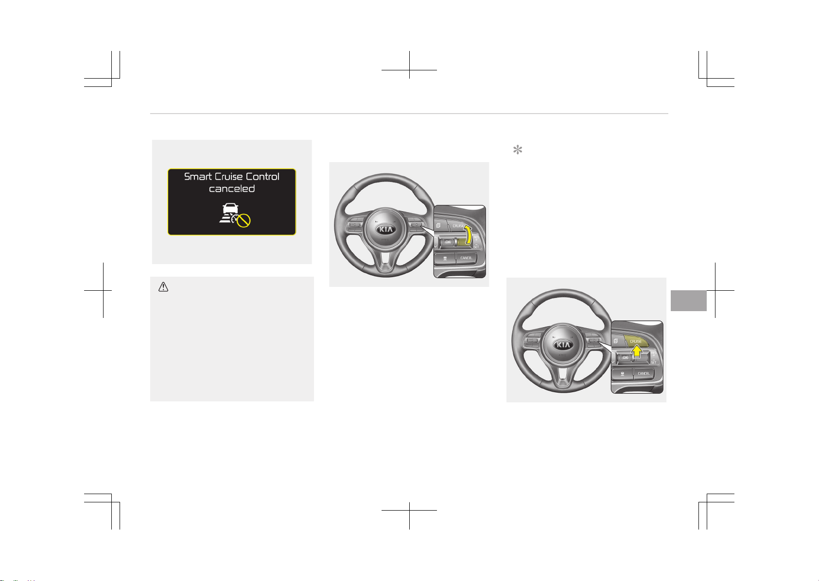
OJF055235L
CAUTION
If the system is automatically can‐
celled, the warning chime will sound
and a message will appear for a few
seconds.
You must adjust the vehicle speed by
depressing the accelerator or brake
pedal according to the road condition
ahead and driving condition.
Always check the road conditions. Do
not rely on the warning chime.
To resume cruise control set speed:
OJF055044
If any method other than the CRUISE
button was used to cancel cruising
speed and the system is still activated,
the cruising speed will automatically re‐
sume when you move the lever up (to
RES+).
If you move the lever up (to RES+), the
speed will resume to the recently set
speed. It will not resume if the vehicle
speed has dropped below approximate‐
ly 30 km/h (20 mph).
NOTICE
To reduce the risk of an accident, al‐
ways check the road conditions
when reactivating the advanced
smart cruise control using the RES+
lever to ensure the road conditions
permit safe use of the cruise con‐
trol.
To turn cruise control off:
OJF055042
Press the CRUISE button. (the CRUISE
indicator in the instrument cluster will
go off).
7-63
7
Driving your vehicle
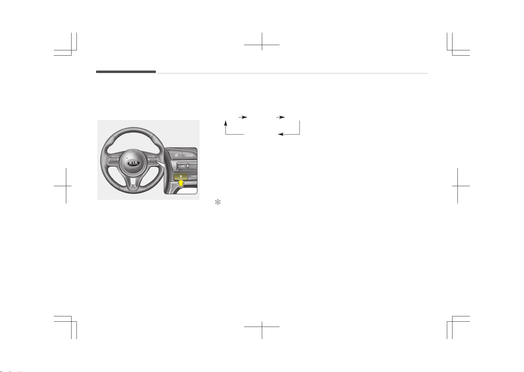
Vehicle to vehicle distance
setting
To set vehicle to vehicle distance:
OJF055046
This function allows you to program
the vehicle to maintain relative distance
to the vehicle ahead without depressing
the accelerator pedal or brake pedal.
The vehicle to vehicle distance will au‐
tomatically activate when the advanced
smart cruise control system is on.
Select the appropriate distance accord‐
ing to road conditions and vehicle
speed.
Each time the button is pressed, the
vehicle to vehicle distance changes as
follows:
Distance 4Distance 3Distance 2
Distance 1
For example, if you drive at 90 km/h
(56 mph), the distance maintain as fol‐
lows:
Distance 4 - approximately 52.5 m
Distance 3 - approximately 40 m
Distance 2 - approximately 32.5 m
Distance 1 - approximately 25 m
NOTICE
The 'Distance 4' is always set when
the system is used for the first time
after starting the engine.
The advanced smart cruise control
system remember the last vehicle to
vehicle distance which the driver
used in the vehicle with AEB.
Driving your vehicle
7-64
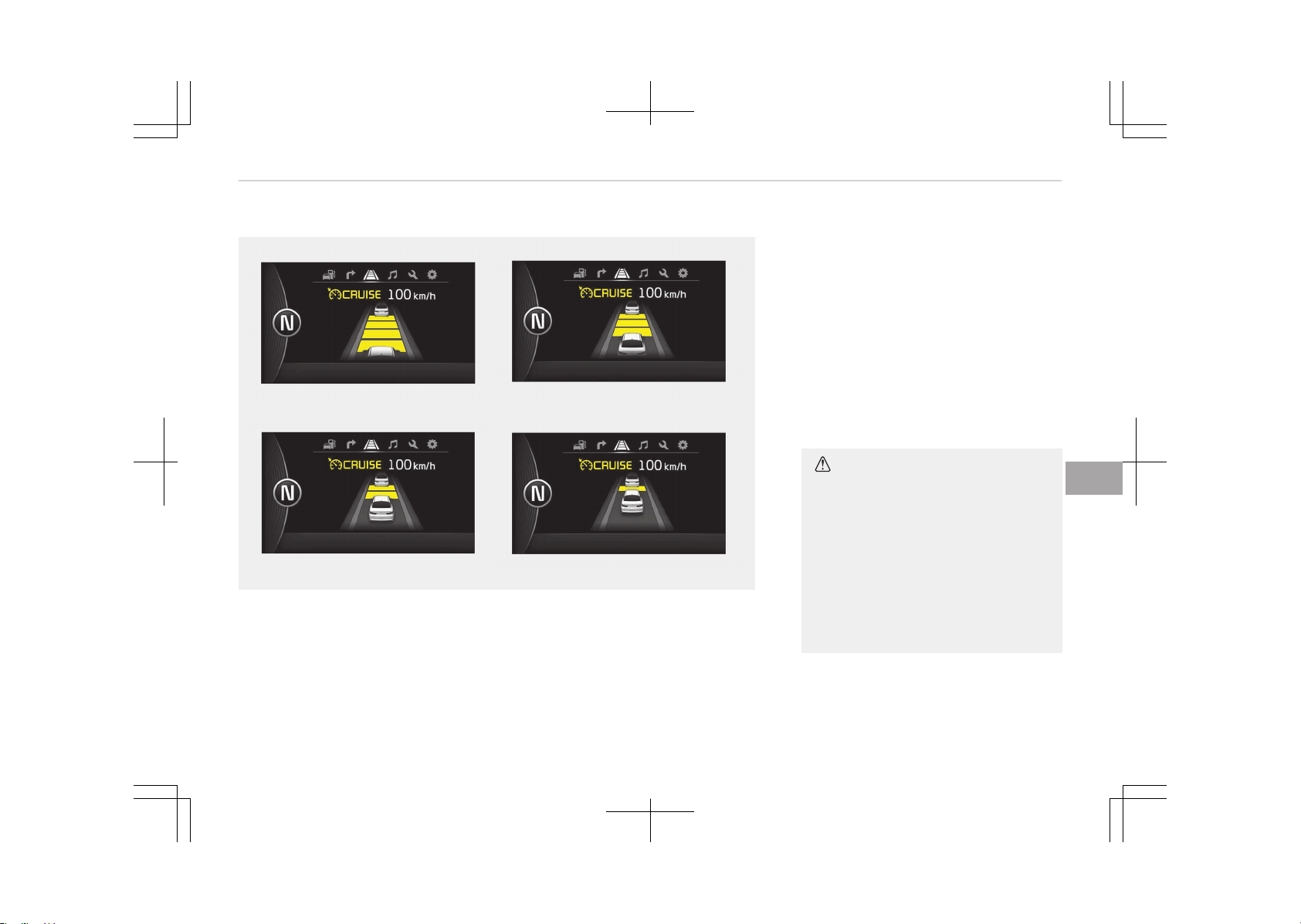
To set vehicle to vehicle distance:
Distance 4Distance 3
Distance 2Distance 1
OJF055093
OJF055095
OJF055094
OJF055096
• The vehicle will maintain the set
speed, when the lane ahead is clear.
• The vehicle will slow down or speed
up to maintain the selected distance,
when there is a vehicle ahead of you
in the lane. (A vehicle will appear in
front of your vehicle in the LCD dis‐
play only when there is an actual ve‐
hicle in front of you)
• If the vehicle ahead speeds up, your
vehicle will travel at a steady cruising
speed after accelerating to the selec‐
ted speed.
CAUTION
• The warning chime sounds and
LCD display blinks if it is hard to
maintain the selected distance to
the vehicle ahead.
• If the warning chime sounds, ac‐
tively adjust the vehicle speed by
depressing the brake pedal accord‐
ing to the road condition ahead
and driving condition.
(Continued)
7-65
7
Driving your vehicle
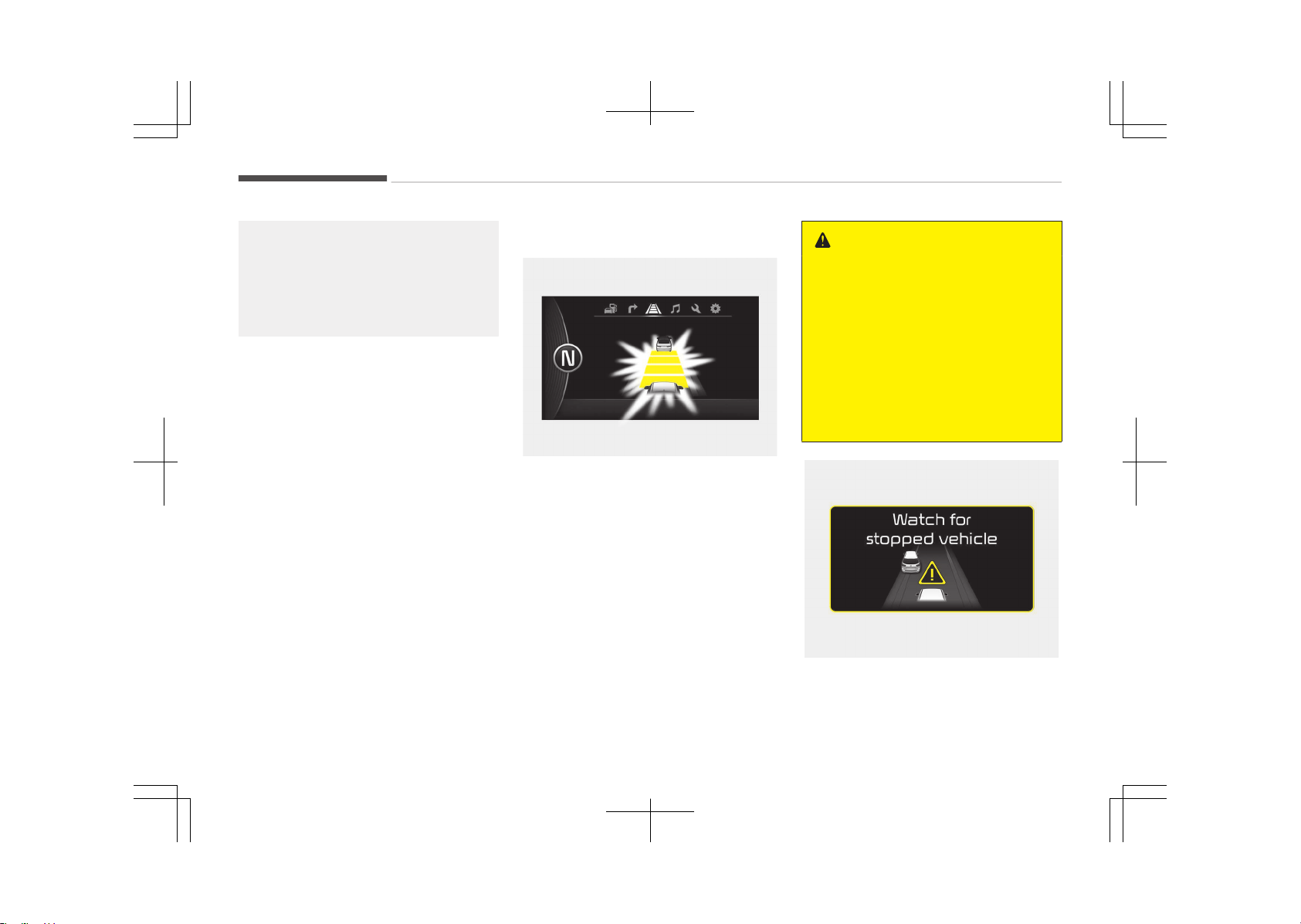
(Continued)
• Even if the warning chime is not
activated, always pay attention to
the driving conditions to prevent
dangerous situations from occur‐
ring.
Collision alert
OJF055176
When the ASCC system is on, and there
is a high risk of collision due to sudden
braking of the vehicle in front or not
securing enough space with the vehicle
in front, the driver needs to control the
brake system or the steering wheel
manually. In this case, the collision alert
warning displays on the instrument
cluster and warning sounds. Decrease
vehicle speed immediately.
WARNING
• Even when the indicator displaying
the distance with the vehicle in
front does not blink or the collision
alert does not sound, always drive
safely.
• Depending on the use of radio,
sound quality, and driving condi‐
tions, you may not be able to hear
the warning sound. Therefore, al‐
ways pay close attention to traffic
in front.
OJF055225L
Driving your vehicle
7-66
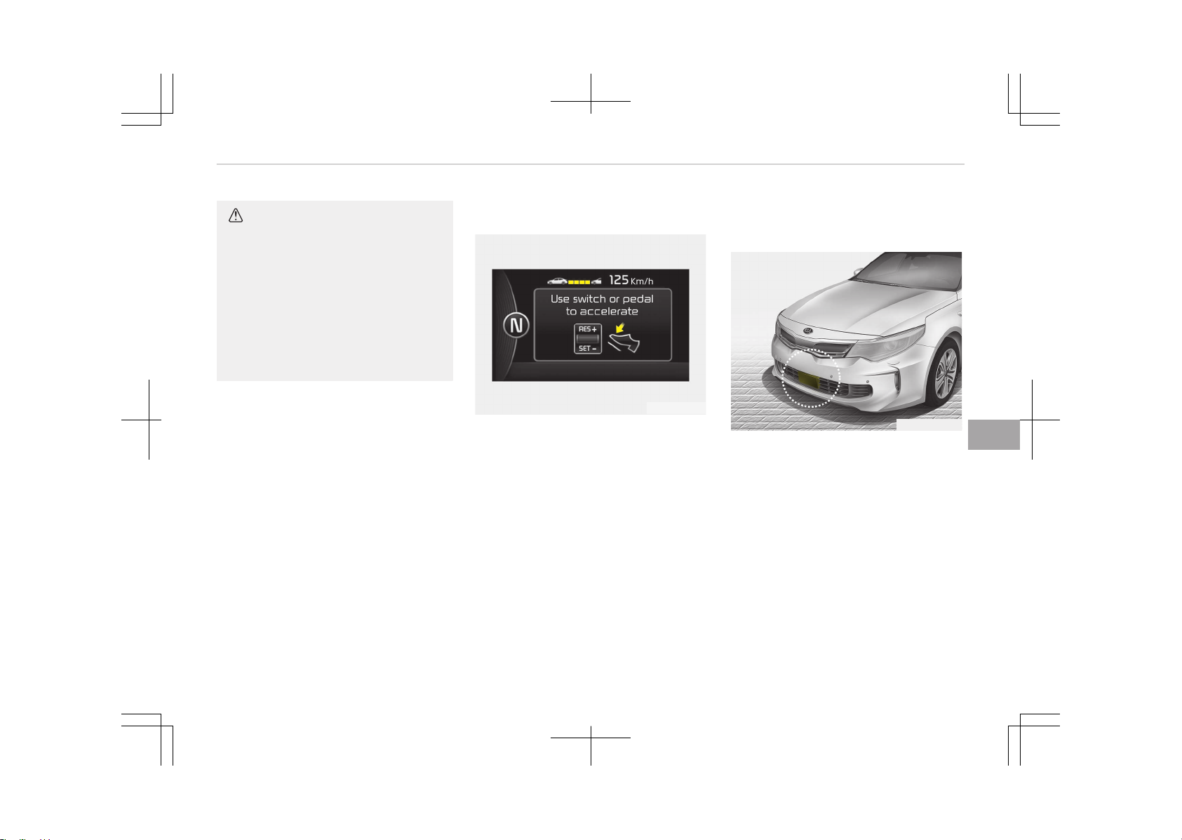
CAUTION
If the vehicle ahead (vehicle speed:
less than 30 km/h) disappears to the
next lane, the warning chime will
sound and a message will appear.
Adjust your vehicle speed for vehi‐
cles or objects that can suddenly ap‐
pear in front of you by depressing
the brake pedal according to the
road condition ahead and driving
condition.
In traffic situation
OJF055100L
In traffic, your vehicle will stop if the
vehicle ahead of you stops. Also, if the
vehicle ahead of you starts moving,
your vehicle will start as well. However,
if the vehicle stops for more than 3
seconds, you must depress the acceler‐
ator pedal or move up/down the lever
(to RES+ or SET-) to start driving.
Radar to detect distance to the
vehicle ahead
OJFHP056162
The sensor detects the distance to the
vehicle ahead.
If the sensor is covered with dirt or
other foreign matter, the vehicle to ve‐
hicle distance control may not operate
correctly.
Always keep the area in front of the
sensor clean.
7-67
7
Driving your vehicle
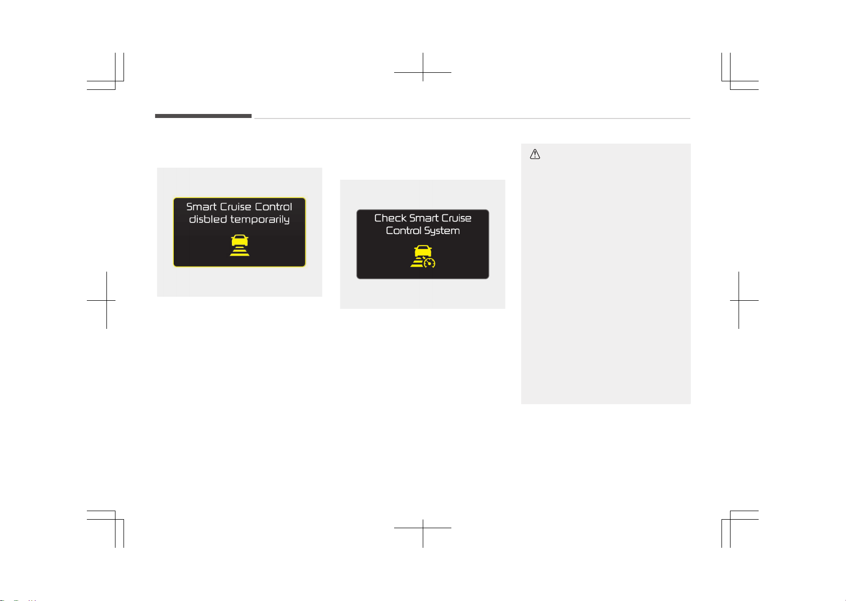
Radar check message
OJF055188L
If the radar or cover is dirty or ob‐
scured with foreign matter such as
snow, this message will appear and it
will disappear after for a while. In this
case, the system may not function
temporarily, but it does not indicate a
malfunction of the advanced smart
cruise control System. Clean the radar
or cover by using a soft cloth and it will
operate normally.
SCC (Advanced smart cruise
control) malfunction message
OJF055237L
The message will appear when the ve‐
hicle to vehicle distance control system
is not functioning normally.
We recommend have the system
checked by an authorized Kia dealer.
CAUTION
• Do not install accessories around
the sensor and do not replace the
bumper by yourself. It may inter‐
fere with the sensor performance.
• Always keep the sensor and
bumper clean.
• To prevent sensor cover damage
from occurring, wash the car with
a soft cloth.
• Do not damage the sensor or sen‐
sor area by a strong impact. If the
sensor moves slightly off position,
the advanced smart cruise control
system will not operate correctly
without any warning or indicator
from the cluster.
If this occurs, we recommend that
the system be checked by an au‐
thorized Kia dealer.
• Use only a genuine Kia sensor cov‐
er for your vehicle. Do not paint
anything on the sensor cover.
Driving your vehicle
7-68
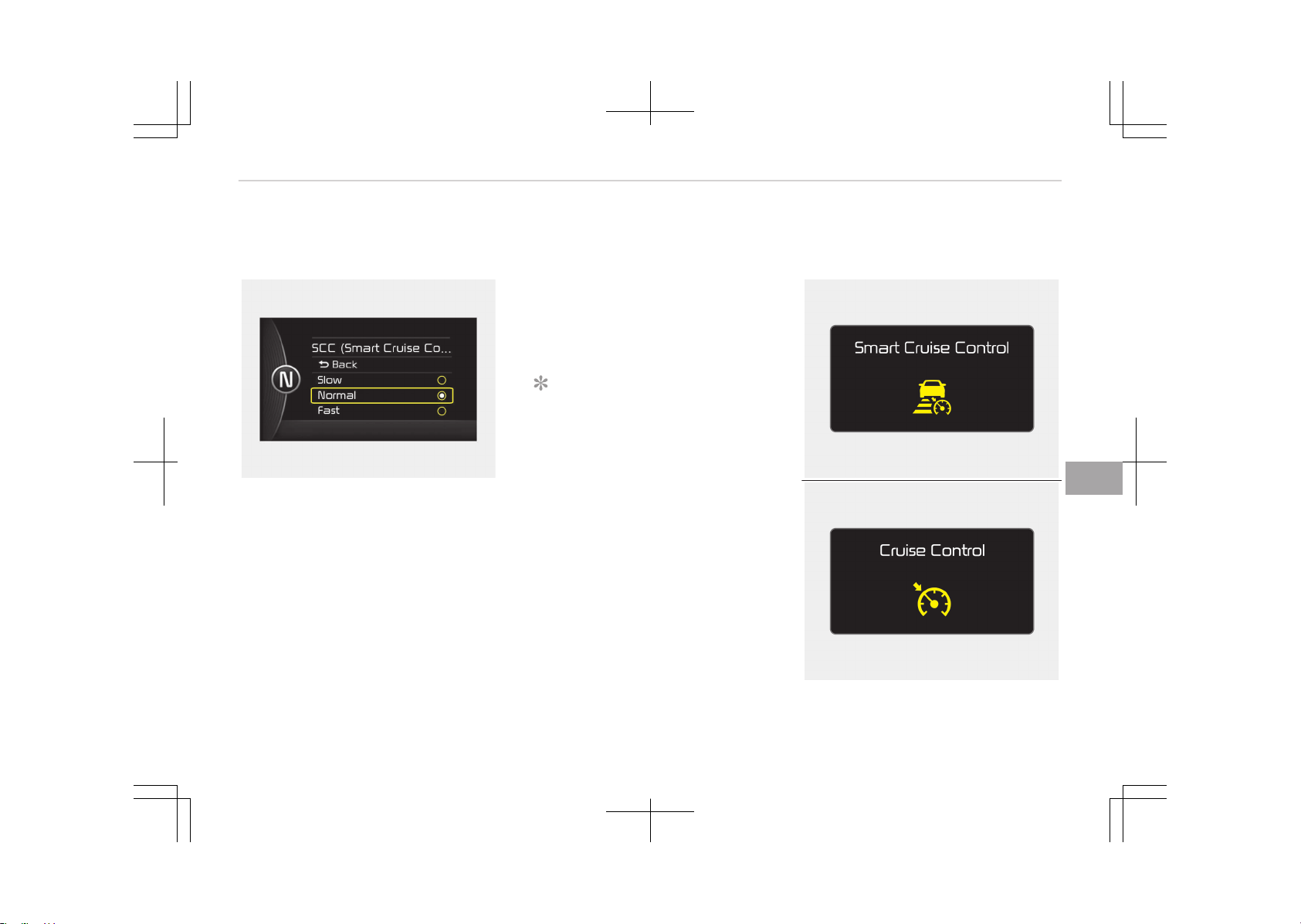
To adjust the sensitivity of
advanced smart cruise control
OJF055101L
The sensitivity of vehicle speed when
following the front vehicle to maintain
the set distance can be adjusted. Go to
the User Settings Mode (Driving Assist)
and select SCC (Advanced smart cruise
control). You may select one of the
three stages you prefer.
• Slow:
Vehicle speed following the front ve‐
hicle to maintain the set distance is
slower than normal speed.
• Normal:
Vehicle speed following the front ve‐
hicle to maintain the set distance is
normal
• Fast:
Vehicle speed following the front ve‐
hicle to maintain the set distance is
faster than normal speed.
NOTICE
The last selected mode is remained
in the system
To convert to cruise control
mode:
OJF055238L
OJF055239L
7-69
7
Driving your vehicle
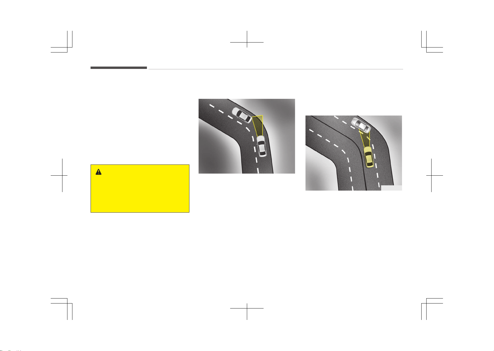
The driver may choose to only use the
cruise control mode (speed control
function) by doing as follows:
1. Turn the advanced smart cruise
control system on (the cruise indi‐
cator light will be on but the sys‐
tem will not be activated).
2. Push the distance to distance
switch for more than 2 seconds.
3. Choose between "Advanced smart
cruise control (SCC) mode" and
"Cruise control (CC) mode".
WARNING
When using the cruise control mode,
you must manually access the dis‐
tance to other vehicles as the sys‐
tem will not automatically brake to
slow down for other vehicles.
Limitations of the system
OJF055025
The advanced smart cruise control sys‐
tem may have limits to its ability to de‐
tect distance to the vehicle ahead due
to road and traffic conditions.
On curves
• On curves, the advanced smart cruise
control system may not detect a
moving vehicle in your lane, and then
your vehicle could accelerate to the
set speed. Also, the vehicle speed will
rapidly down when the vehicle ahead
is recognized suddenly.
• Select the appropriate set speed on
curves and adjust your vehicle speed
by depressing the accelerator or
brake pedal according to the road
condition ahead and driving condition.
OJF055026
• Your vehicle speed can be reduced
due to a vehicle in the adjacent lane.
Adjust your vehicle speed by depress‐
ing the brake pedal according to the
road condition ahead and driving con‐
dition. Apply the accelerator pedal
and select the appropriate set speed.
Check to be sure that the road condi‐
tions permit safe operation of the
advanced smart cruise control.
Driving your vehicle
7-70
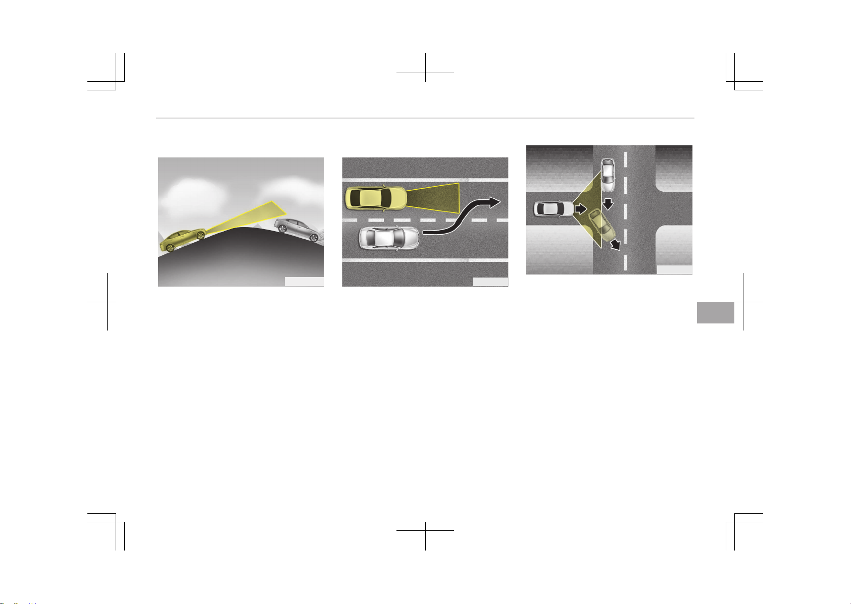
On inclines
OJF055027
• During uphill or downhill driving, the
advanced smart cruise control sys‐
tem may not detect a moving vehicle
in your lane, and cause your vehicle
to accelerate to the set speed. Also,
the vehicle speed will rapidly down
when the vehicle ahead is recognized
suddenly.
• Select the appropriate set speed on
inclines and adjust your vehicle speed
by depressing the accelerator or
brake pedal according to the road
condition ahead and driving condition.
Lane changing
OJF055028
• A vehicle which moves into your lane
from an adjacent lane cannot be rec‐
ognized by the sensor until it is in the
sensor's detection range.
• The sensor may not detect immedi‐
ately when a vehicle cuts in suddenly.
Always pay attention to the traffic,
road and driving conditions.
• If a vehicle which moves into your
lane is slower than your vehicle, your
speed may decrease to maintain the
distance to the vehicle ahead.
• If a vehicle which moves into your
lane is faster than your vehicle, your
vehicle will accelerate to the selected
speed.
OJF055049
• Your vehicle may accelerate when a
vehicle ahead of you disappears.
• When you are warned that the vehi‐
cle ahead of you is not detected,
drive with caution.
7-71
7
Driving your vehicle
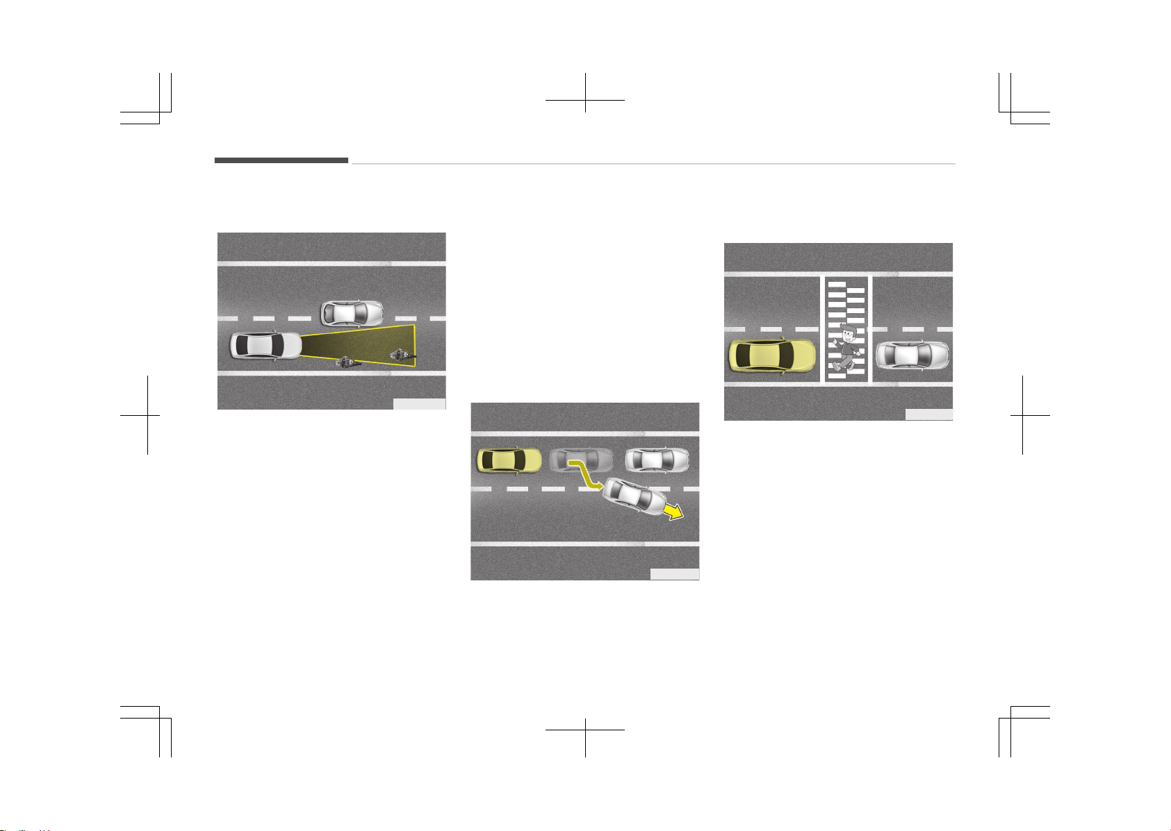
Vehicle recognition
OJF055048
Some vehicles ahead in your lane can‐
not be recognized by the sensor as fol‐
lows:
-
Narrow vehicles such as motorcycles
or bicycles
-
Vehicles offset to one side
-
Slow-moving vehicles or sudden-de‐
celerating vehicles
-
Stopped vehicles
-
Vehicles with small rear profile such
as trailers with no loads
A vehicle ahead cannot be recognized
correctly by the sensor if any of follow‐
ing occurs:
-
When the vehicle is pointing upwards
due to overloading in the trunk
-
While making turns by steering
-
When driving to one side of the lane
-
When driving on narrow lanes or on
curves
Adjust your vehicle speed by depressing
the brake pedal according to the road
condition ahead and driving condition.
OJF055029
• When vehicles are at a standstill and
the vehicle in front of you changes to
the next lane, be careful when your
vehicle starts to move because it
may not recognize the stopped vehi‐
cle in front of you.
OJF055050
• Always look out for pedestrians when
your vehicle is maintaining a distance
with the vehicle ahead.
Driving your vehicle
7-72
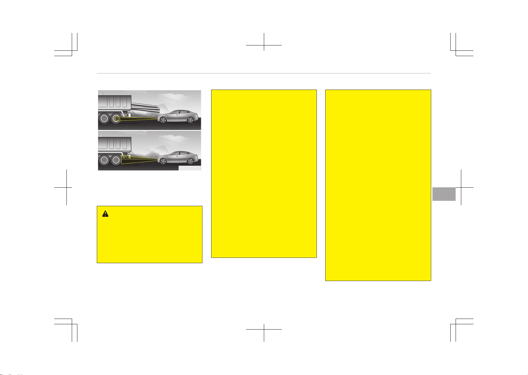
OJF055030
• Always be cautious for vehicles with
higher height or vehicles carrying
loads that stick out to the back of the
vehicle.
WARNING
• The advanced smart cruise control
system cannot guarantee the stop
for every emergency situation.
If an emergency stop is necessary,
you must apply the brakes.
(Continued)
(Continued)
• Keep a safe distance according to
road conditions and vehicle speed.
If the vehicle to vehicle distance is
too close during a high-speed driv‐
ing, a serious collision may result.
• The advanced smart cruise control
system cannot recognize a stop‐
ped vehicle, pedestrians or an on‐
coming vehicle. Always look ahead
cautiously to prevent unexpected
and sudden situations from occur‐
ring.
• SCC system may have difficulty in
maintaining the correct distance or
speed, if the vehicle is driving on a
steep incline or towing a trailer.
• When other vehicles are changing
lanes in front of you frequently,
the advanced smart cruise control
system may not operate appropri‐
ately. Always look ahead cautious‐
ly to prevent unexpected and sud‐
den situations from occurring.
(Continued)
(Continued)
• The advanced smart cruise control
system is not a substitute for safe
driving practices but a convenience
function only. It is the responsibili‐
ty of the driver to always check
the speed and the distance to the
vehicle ahead.
• Always be aware of the selected
speed and vehicle to vehicle dis‐
tance.
• Always maintain sufficient braking
distance and decelerate your vehi‐
cle by applying the brakes if nec‐
essary.
• As the advanced smart cruise con‐
trol system may not recognize
complex driving situations, always
pay attention to driving conditions
and control your vehicle speed.
• For safe operation, carefully read
and follow the instructions in this
manual before use.
• After an engine start, please stop
for several seconds. If system ini‐
tialization is not completed, the
SCC does not normally operate.
(Continued)
7-73
7
Driving your vehicle

(Continued)
• After an engine start, if any ob‐
jects are not detected or the sen‐
sor cover is obscured with foreign
substances, there is a possibility
that the SCC system may not
work.
• Below conditions are not allowed:
over baggage loading in a trunk,
suspension remodeling, tire re‐
placement with unauthorized tires
or tires with different worn-out
and pressure levels.
CAUTION
The advanced smart cruise control
system may not operate temporari‐
ly due to electrical interference.
Driving your vehicle
7-74
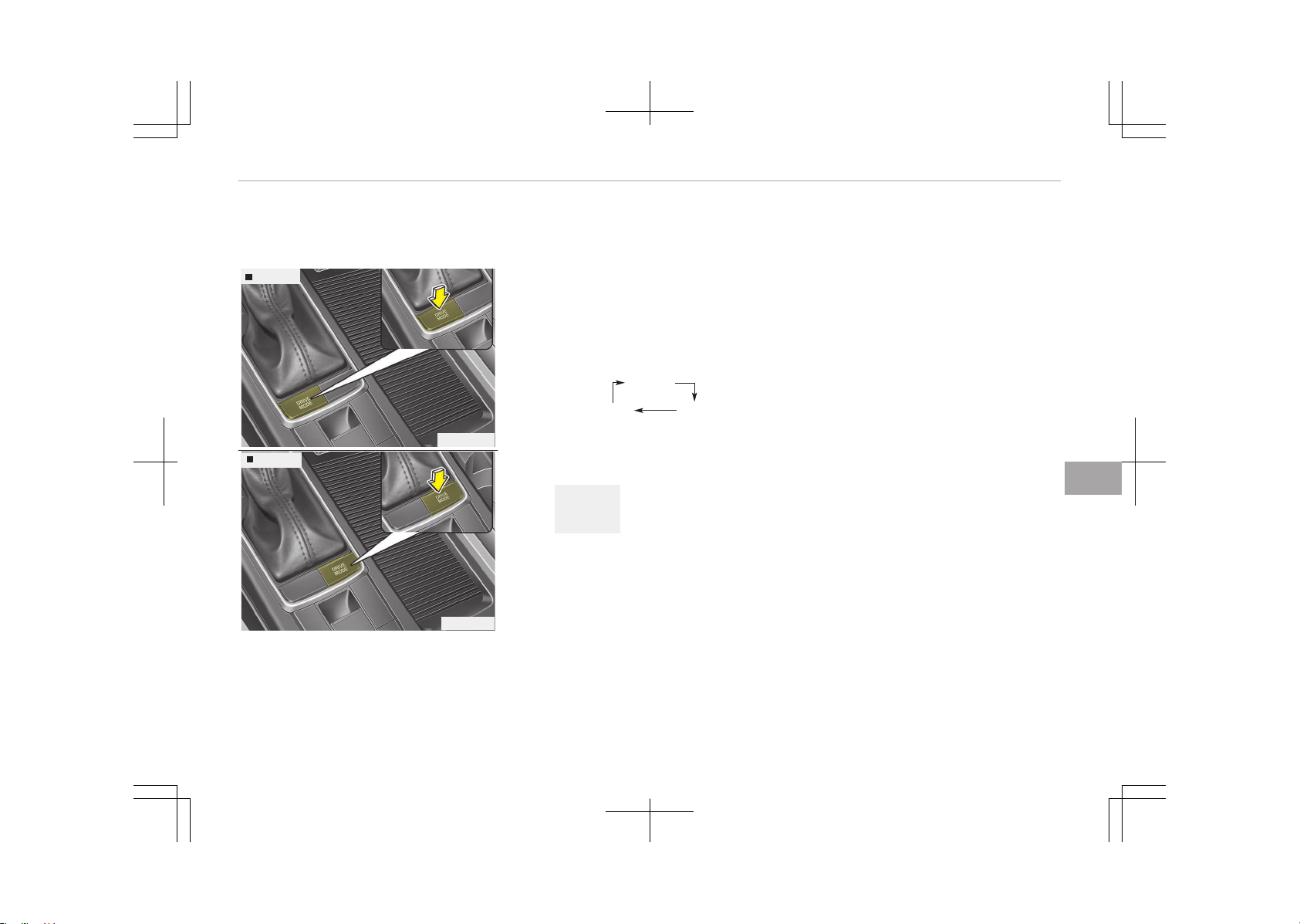
DRIVE MODE INTEGRATED CONTROL SYSTEM (IF EQUIPPED)
Hybrid vehicle
Type A
OJF055054
Type B
OJF055055
The drive mode may be selected ac‐
cording to the driver’s preference or
road condition.
The system resets to be in the ECO
mode, when the hybrid system is re‐
started.
If there is a problem with the instru‐
ment cluster, the drive mode will be in
ECO mode and may not change to NOR‐
MAL mode or SPORT mode.
The mode changes whenever the DRIVE
MODE button is pressed.
NORMAL
SPORT ECO
❈ When normal mode is selected, it is
not displayed on the cluster.
ECO mode (Active ECO)
ECO
Active ECO helps
improve fuel effi‐
ciency by control‐
ling certain en‐
gine and trans‐
axle system op‐
erating parame‐
ters. Fuel effi‐
ciency depends
on the driver's
driving habit and
road condition.
• When the DRIVE MODE button is
pressed and the ECO mode is selec‐
ted, the ECO indicator (green) will illu‐
minate to show that the Active ECO
is operating.
• When the Active ECO is activated, it
does not turn off even though the
engine is restarted again. To turn off
the system, press the DRIVE MODE
button again.
When Active ECO is activated:
• The acceleration may slightly be re‐
duced even though you depress the
accelerator fully.
• The air conditioner performance may
be limited.
• The shift pattern of the automatic
transaxle may change.
• The engine noise may get louder.
The above situations are normal condi‐
tions when the active eco system is ac‐
tivated to improve fuel efficiency.
Limitation of Active ECO operation:
If the following conditions occur while
Active ECO is operating, the system op‐
eration is limited even though there is
no change in the ECO indicator.
7-75
7
Driving your vehicle

• When the coolant temperature is low:
The system will be limited until en‐
gine performance becomes normal.
• When driving up a hill:
The system will be limited to gain
power when driving uphill because
the engine torque is restricted.
• When using manual mode:
The system will be limited according
to the shift location.
• When the accelerator pedal is deeply
depressed for a few seconds:
The system will be limited, judging
that the driver wants to speed up.
SPORT mode
SPORT
SPORT mode focu‐
ses on dynamic driv‐
ing by automatically
controlling the
steering wheel, en‐
gine and transaxle
system.
• When the DRIVE MODE button is
pressed and the SPORT mode is se‐
lected, the SPORT indicator (yellow)
will illuminate.
• Whenever the hybrid system is re‐
started, the Drive Mode will revert
back to ECO mode. If SPORT mode is
desired, re-select SPORT mode from
the DRIVE MODE button
• If the system is activated:
- After speeding, it maintains the
gear and RPM for some time even
though the accelerator pedal is not
depressed.
- Up-shifting is delayed.
NOTICE
In Sport drive mode, the fuel effi‐
ciency may decrease.
Driving your vehicle
7-76

DRIVE MODE INTEGRATED CONTROL SYSTEM (IF EQUIPPED)
Plug-in hybrid vehicle
OJFHP056147L
The drive mode may be selected ac‐
cording to the driver’s preference or
road condition.
The system resets to be in the ECO
mode, when the hybrid system is re‐
started.
If there is a problem with the instru‐
ment cluster, the drive mode will be in
ECO mode and may not change to NOR‐
MAL mode.
The mode changes whenever the DRIVE
MODE button is pressed.
NORMALECO
❈ When normal mode is selected, it is
not displayed on the cluster.
ECO mode (Active ECO)
ECO
Active ECO helps
improve fuel effi‐
ciency by control‐
ling certain en‐
gine and trans‐
axle system op‐
erating parame‐
ters. Fuel effi‐
ciency depends
on the driver's
driving habit and
road condition.
• When the DRIVE MODE button is
pressed and the ECO mode is selec‐
ted, the ECO indicator (green) will illu‐
minate to show that the Active ECO
is operating.
• When the Active ECO is activated, it
does not turn off even though the
engine is restarted again. To turn off
the system, press the DRIVE MODE
button again.
When Active ECO is activated:
• The acceleration may slightly be re‐
duced eventhough you depress the
accelerator fully.
• The air conditioner performance may
be limited
• The shift pattern of the automatic
transaxle may change.
• The engine noise may get louder.
The above situations are normal condi‐
tions when the active eco system is ac‐
tivated to improve fuel efficiency.
Limitation of Active ECO operation:
If the following conditions occur while
Active ECO is operating, the system op‐
eration is limited even though there is
no change in the ECO indicator.
• When the coolant temperature is low:
The system will be limited until en‐
gine performance becomes normal.
• When driving up a hill:
The system will be limited to gain
power when driving uphill because
the engine torque is restricted.
• When using manual mode:
The system will be limited according
to the shift location.
7-77
7
Driving your vehicle

• When the accelerator pedal is deeply
depressed for a few seconds:
The system will be limited, judging
that the driver wants to speed up.
Driving your vehicle
7-78
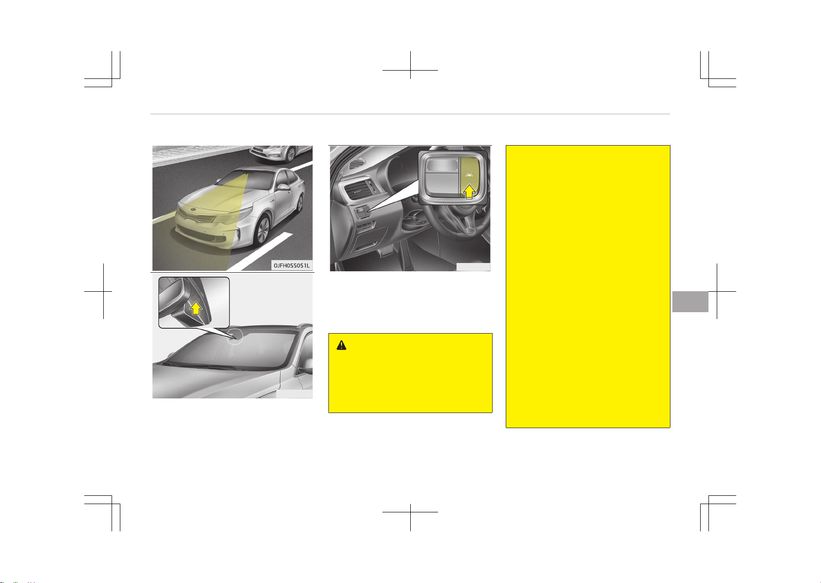
LANE DEPARTURE WARNING SYSTEM (LDWS) (IF EQUIPPED)
OUM054149
OJF055163
This system detects the lane with the
sensor at the front windshield and
warns you when your vehicle leaves the
lane.
WARNING
• The LDWS does not make the vehi‐
cle change lanes. It is the driver's
responsibility to always check the
road conditions.
(Continued)
(Continued)
• Do not turn the steering wheel
suddenly, when the LDWS warns
you that your vehicle is leaving the
lane.
• If the sensor can not detect the
lane or if the vehicle speed does
not exceed around 60 km/h, the
LDWS won't warn you even though
the vehicle leaves the lane.
• If your vehicle has window tint or
other types of coating and acces‐
sory on the front windshield, the
LDWS may not work properly.
• Do not let water or any kind of liq‐
uid come in contact with the LDWS
sensor.
• Do not remove the LDWS parts
and do not affect the sensor by a
strong impact.
• Do not put objects that reflect
light on the dash board.
• Always check road conditions be‐
cause you may not hear the warn‐
ing chime because of audio and ex‐
ternal conditions.
7-79
7
Driving your vehicle
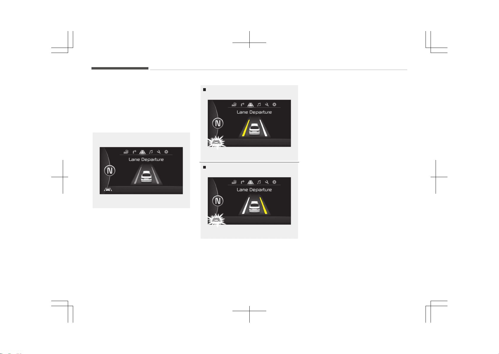
To operate the LDWS, press the switch
with the engine start/stop button in
the ON position. The indicator illumi‐
nates white on the cluster.
To cancel the LDWS, press LDWS button
again. The indicator on the cluster will
go off.
OJF055193L
If you select this symbol, the LDWS
mode on the LCD display will appear.
If your vehicle leaves the lane when the
LDWS is operating and vehicle speed
exceeds around 60 km/h, the warning
operates as follows:
OJF055194L
Left lane departing
Right lane departing
OJF055195L
1. Visual warning
If you leave a lane, the lane you
cross will blink (yellow) and LDWS
indicator will blink green on LCD
during max 3 seconds.
2. Auditory warning
If you leave the lane, the warning
sound operates for maximum 3
seconds.
The color of symbol will change de‐
pending on the condition of LDWS sys‐
tem.
• White color: When you activate
the lane departure
warning system by
pressing the LDWS
button, system oper‐
ating conditions are
not satisfied or the
sensor does not de‐
tect the lane line.
• Green color: When you activate
the lane departure
warning system by
pressing the LDWS
button, system oper‐
ating conditions are
satisfied and the sen‐
sor detect the lane
line.
• Yellow color:
When there is a mal‐
function with the lane
departure warning
system.
Driving your vehicle
7-80
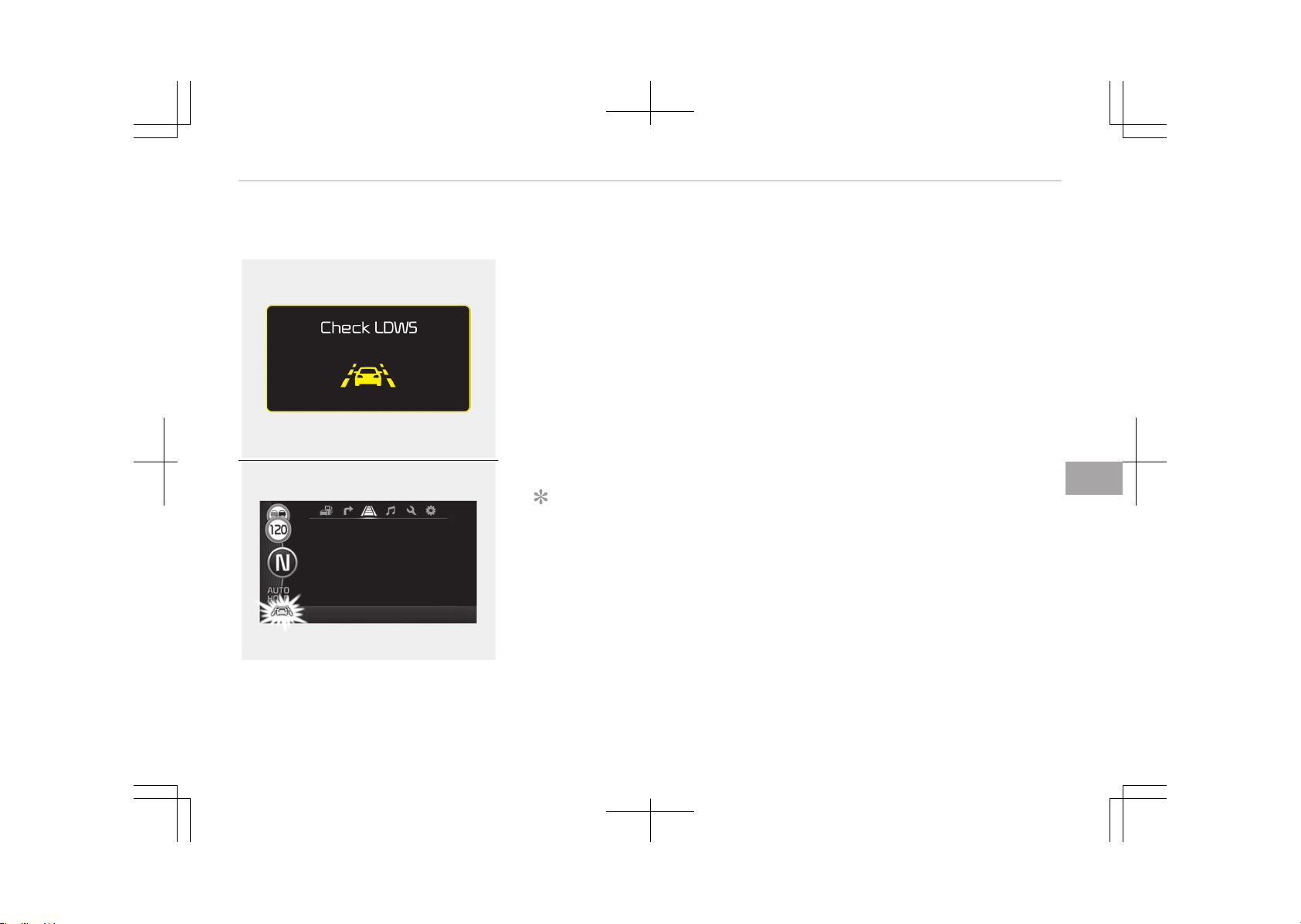
Warning indicator
OJF055246L
OJF055223L
When the LDWS is not working proper‐
ly, the warning light will illuminate and
the warning message will come on for a
few second. After the message disap‐
pears, the master warning light will illu‐
minate.
We recommend that the system be
checked by an authorized Kia dealer
The LDWS does not operate
when:
• The driver turns on the turn signal or
the hazard warning flasher to change
lane.
• Driving on the lane line.
NOTICE
To change lanes, operate the turn
signal switch, then change the lane.
The LDWS may not warn you
even if the vehicle leaves the
lane or may warn you even if
the vehicle does not leave the
lane when:
• The lane is not visible due to snow,
rain, stain, a puddle or many other
things.
• The brightness of the outside
changes suddenly.
• The headlights are off at night or in a
tunnel.
• The color of the lane marking from
the road is difficult to distinguish.
• Driving on a steep grade or a curve.
• Light reflects from the water on the
road.
• The lens or windshield is stained with
foreign matter.
• The sensor can not detect the lane
because of fog, heavy rain or heavy
snow.
• The surrounding temperature of the
inside rear view mirror is high due to
a direct ray of light.
• The lane is very wide or narrow.
• The lane line is damaged or indistinct.
• The shadow is on the lane line by a
median strip.
• There is a mark similar to a lane line.
• There is a boundary structure.
• The distance from vehicle ahead is
very short or the vehicle ahead hides
the lane line.
• The vehicle shakes heavily.
7-81
7
Driving your vehicle

• The lane number increases or decrea‐
ses or the lane lines are crossing
complicatedly.
• Putting something on the dashboard.
• Driving with the sun in front of you.
• Driving in areas under construction.
• The lane line is more than two in ei‐
ther side (Left/Right).
• The windshield is fogged by humid air
in the vehicle.
Driving your vehicle
7-82
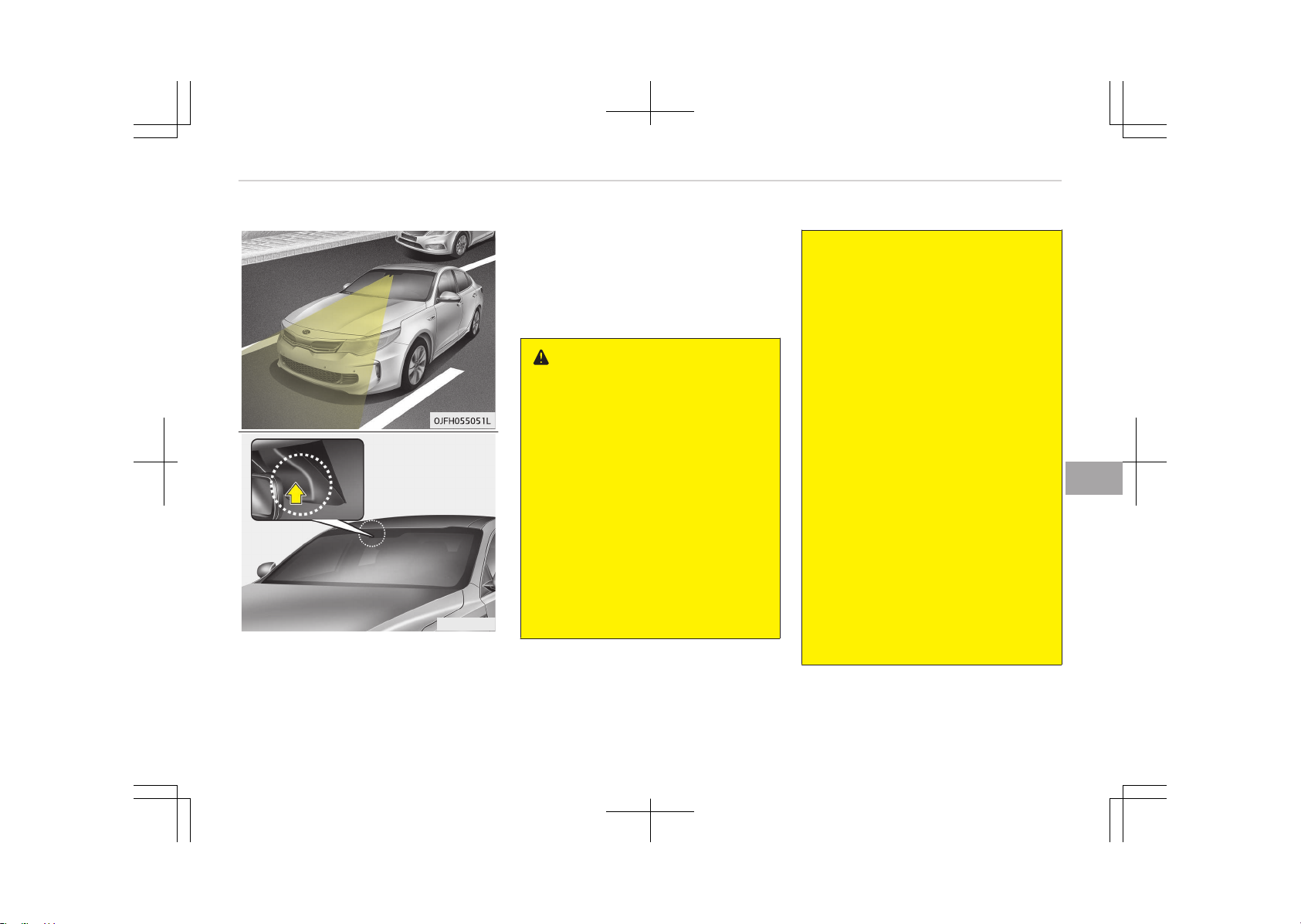
LANE KEEPING ASSIST SYSTEM (LKAS) (IF EQUIPPED)
OTFS052081
The Lane Keeping Assist System de‐
tects lane markers on the road, and as‐
sists the driver’s steering to help keep
the vehicle between lanes.
When the system detects the vehicle
straying from its lane, it alerts the driv‐
er with a visual and audible warning,
while applying a slight counter steering
torque, trying to prevent the vehicle
from moving out of its lane.
WARNING
• The steering wheel is not continu‐
ously controlled so if the vehicle
speed is very fast when leaving a
lane the vehicle may not be con‐
trolled by the system.
• The operation of the LKAS can be
affected by several factors (in‐
cluding environmental conditions).
It is the responsibility of the driver
to pay attention to the roadway
and to maintain the vehicle in its
lane at all times.
• Do not steer the steering wheel
suddenly when the steering wheel
is being assisted by the system.
(Continued)
(Continued)
• LKAS prevents the driver from
moving out of the lane uninten‐
tionally by assisting the driver's
steering. However, the driver
should not solely rely on the sys‐
tem but always pay attention on
the steering wheel to stay in the
lane.
• Always check the road condition
and surroundings and be cautious
when the system cancels, does
not operate or malfunctions.
• Do not place any accessories,
stickers or tint the windshield near
the rearview mirror.
• The system detects lane markers
and controls the steering wheel by
a camera, therefore, if the lane
markers are hard to detect, the
system may not work properly.
Please refer to Driver's attention
on page 7-87.
• Do not remove any LKAS parts or
apply impact.
(Continued)
7-83
7
Driving your vehicle
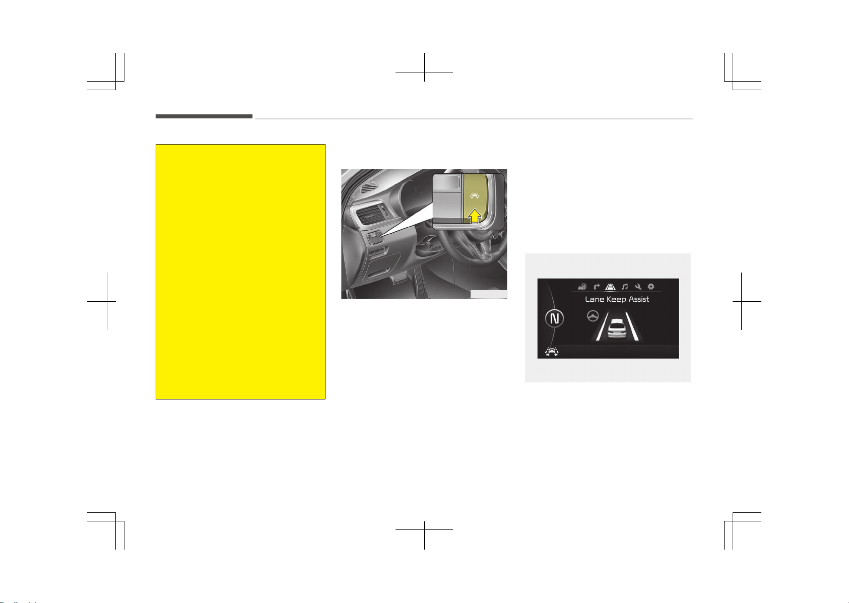
(Continued)
• Do not place objects on the dash‐
board that reflects light such as
mirrors, white paper, etc. The sys‐
tem may malfunction if the sun‐
light is reflected.
• Loud audio sounds may interfere
with the passenger from hearing
warning chimes.
• Always have your hands on the
steering wheel while the LKAS
system is activated. If you contin‐
ue to drive with your hands off the
steering wheel after the "Hand on"
warning, the system will turn off
automatically.
• If you drive very fast, the vehicle
may stray out of the lane. Always
be cautious when using the sys‐
tem.
• When you tow the trailer, make
sure that you turn off LKAS func‐
tion.
LKAS operation
OJF055052
To turn ON the LKAS, press the switch,
after turning ON the ignition switch.
The indicator illuminates on the instru‐
ment cluster. To turn OFF the LKAS,
press the switch again.
The LKAS indicator illuminates in 3
colors as follows:
• [Green]
- When the system operating condi‐
tions are satisfied.
• [White]
- The system operation conditions
are not satisfied.
- The sensor does not detect lane
lines.
• [Yellow]
- There is a malfunction with the
LKAS. In this case, we recommend
you to have your vehicle inspected
by an authorized Kia dealer.
LKAS activation
OJF055130L
• The LKAS screen will appear on the
LCD display if the system is activa‐
ted.
• When both lanes are detected and all
the conditions to activate the LKAS
are satisfied, the steering wheel will
Driving your vehicle
7-84
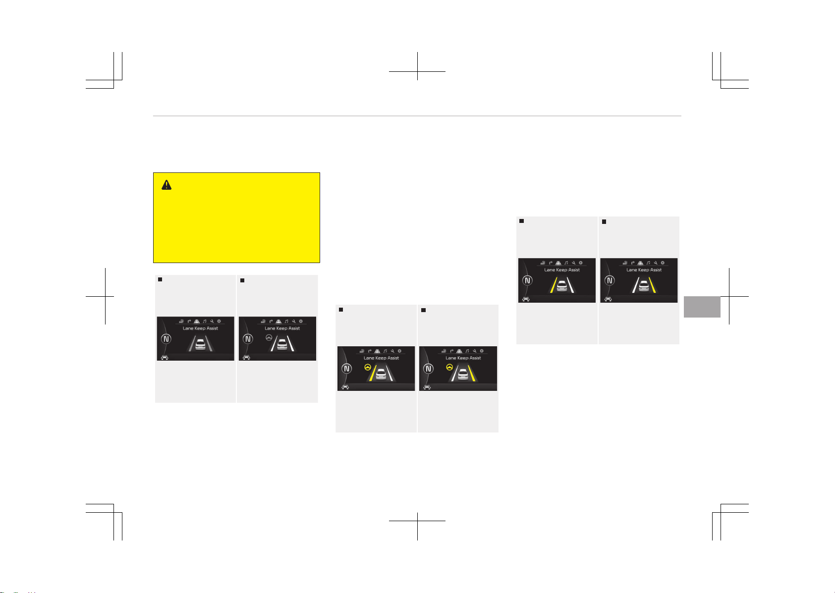
be controlled (green steering wheel
indicator will illuminate).
WARNING
The Lane Keeping Assist System is a
system to prevent the driver from
leaving the lane. However, the driver
should not solely rely on the system
but always check the road conditions
when driving.
Lane undetected
Lane detected
OJF055131L-OJF055130L
• If the system detects a lane, the col‐
or changes from black to white.
• If the system detects the left lane,
the left lane color will change from
black to white.
• If the system detects the right lane,
the right lane color will change from
black to white.
• Both lanes must be detected for the
system to fully activate.
• If only one of the lanes is detected,
the system will warn (warning beep
and blinking yellow lane) the driver
when the driver crosses the detected
lane.
Warning
Left lane
Right lane
OJF055140L-OJF055141L
• If you cross a lane, the lane you cross
will blink (yellow) and symbol will
blink green on LCD with an audible
warning during max 3 seconds.
• If the steering wheel appears, the
system will control the vehicle’s
steering to prevent the vehicle from
crossing the lane.
Left lane
Right lane
OJF055133L-OJF055134L
• If all the conditions to activate LKAS
is not satisfied, the system will con‐
vert to LDWS and warn the driver on‐
ly when the driver crosses the lane
markers.
7-85
7
Driving your vehicle
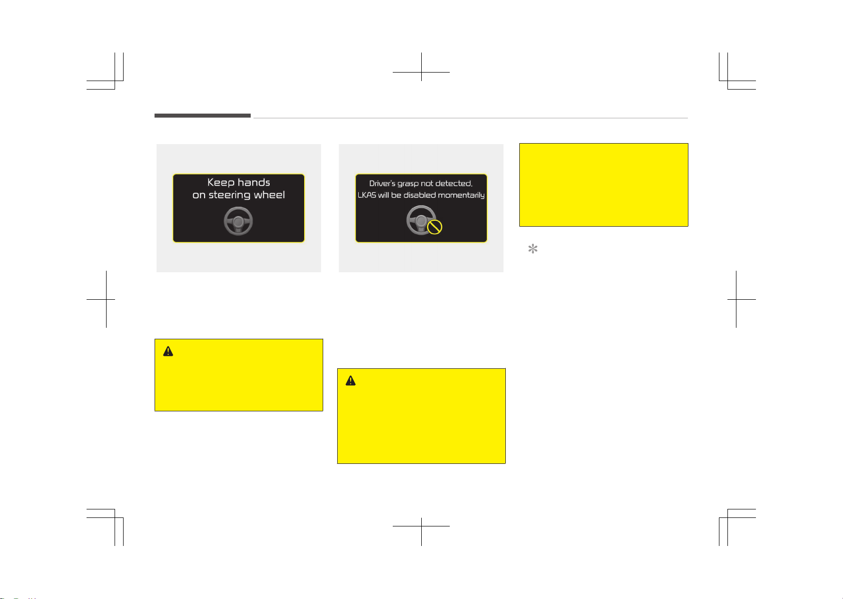
OJF055142L
• If the driver takes one’s hands off the
steering wheel while the LKAS is acti‐
vated, the system will warn the driv‐
er after several seconds with a visual
and audible warning.
WARNING
The warning message may appear
late according to road conditions.
Therefore, always have your hands
on the steering wheel while driving.
OJFHP046436L
• If the driver still does not have one’s
hand on the steering wheel, the sys‐
tem will not control steering auto‐
matically.
When system does not control steer‐
ing automatically, if you hold steering
wheel, system will control steering
automatically.
WARNING
• The driver is responsible for accu‐
rate steering.
• Turn off the system and drive the
vehicle personally in below situa‐
tions.
(Continued)
(Continued)
- In bad weather
- In bad road condition
- When the steering wheel needs
to be controlled by the driver
frequently.
NOTICE
• Even though the steering is assis‐
ted by the system, the driver may
control the steering.
• The steering wheel may feel heav‐
ier when the steering wheel is as‐
sisted by the system than when it
is not.
The system will be cancelled when:
• Vehicle speed is below 55 km/h
(34.2 mph) and over 180 km/h
(111.8 mph).
• Only one lane is detected.
• Always turn on the turn signal to
change lanes. If you change lanes
without the turn signal on, the steer‐
ing wheel might be controlled.
• The hazard warning light is on.
Driving your vehicle
7-86

• The width of the lane is below 2.6 m
or over 4.5 m.
• ESC(Electronic Stability Control) and
VSM(Vehicle stability management)
are activated.
• When the system is on or after
changing a lane, drive in the middle of
the lane. If not, the system will not
provide the steering assist function.
• The steering will not be assisted
when you drive fast on a sharp curve.
• The steering will not be assisted
when you change lanes fast.
• The steering will not be assisted
when you brake suddenly.
Driver's attention
The driver must be cautious in the be‐
low situations for the system may not
assist the driver and may not work
properly.
• The lane is not visible due to snow,
rain, stain, a puddle or many other
things.
• The brightness of the outside
changes suddenly such as passing
through a tunnel.
• Not turning on the headlight or the
light is weak even at night or in a
tunnel.
• Difficult to distinguish the color of
the lane marker from the road.
• Driving on a steep grade or a curve.
• Light reflects from the water on the
road such as sunlight, streetlight or
the light of oncoming vehicles.
• The lens or windshield is stained with
foreign matter.
• The surrounding of the inside rear
view mirror temperature is high due
to direct light.
• The lane is very wide or narrow.
• The lane marker is damaged or indis‐
tinct.
• The shadow is on the lane marker by
a median strip.
• There is a mark similar to a lane
marker.
• There is a boundary structure.
• The distance from vehicle ahead is
very short or the vehicle ahead drives
hiding the lane marker.
• The vehicle shakes heavily.
• The lane number increases or decrea‐
ses or the lane marker are crossing
complicatedly.
• Placing something on the dashboard.
• Driving with the sun in front of you.
• Driving in areas under construction.
• The lane marker is more than two.
• The lane marker in a tunnel is hard to
distinguish due to dust or grease.
• The lane marker is hard to distinguish
after raining at night.
• The lane marker is hard to distinguish
due to dust.
• MDPS (motor driven power steering)
is not operational.
• Some objects are attached in steering
wheel.
• The windshield is fogged by humid air
in the vehicle.
• The distance from the vehicle ahead
is very short or the vehicle ahead
drives covering the lane line.
• The lane line is merged or divided.
• Driving through a toll plaza or toll
gate.
7-87
7
Driving your vehicle
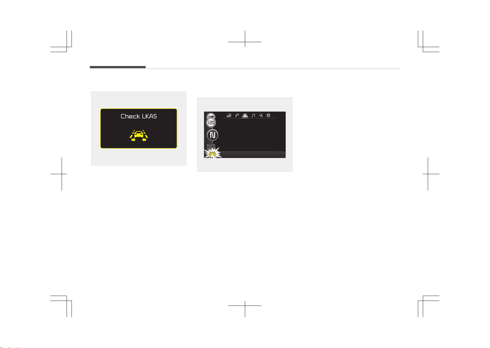
LKAS malfunction
OJF055144L
• If there is a problem with the system
a message will appear. If the problem
continues the LKAS fail indicator will
illuminate.
LKAS fail indicator
OJF055192L
The LKAS fail indicator (yellow) will illu‐
minate with an audible warning if the
LKAS is not working properly. We rec‐
ommend that you contact an author‐
ized Kia dealer.
When there is a problem with the sys‐
tem do one of the following:
• Turn the system on after turning the
engine off and on again.
• Check if the ignition switch is in the
ON position.
• Check if the system is affected by
the weather. (ex: fog, heavy rain,
etc.)
• Check if there is foreign matter on
the camera lens
If the problem is not solved, we recom‐
mend that the system be checked by
an authorized Kia dealer.
Driving your vehicle
7-88
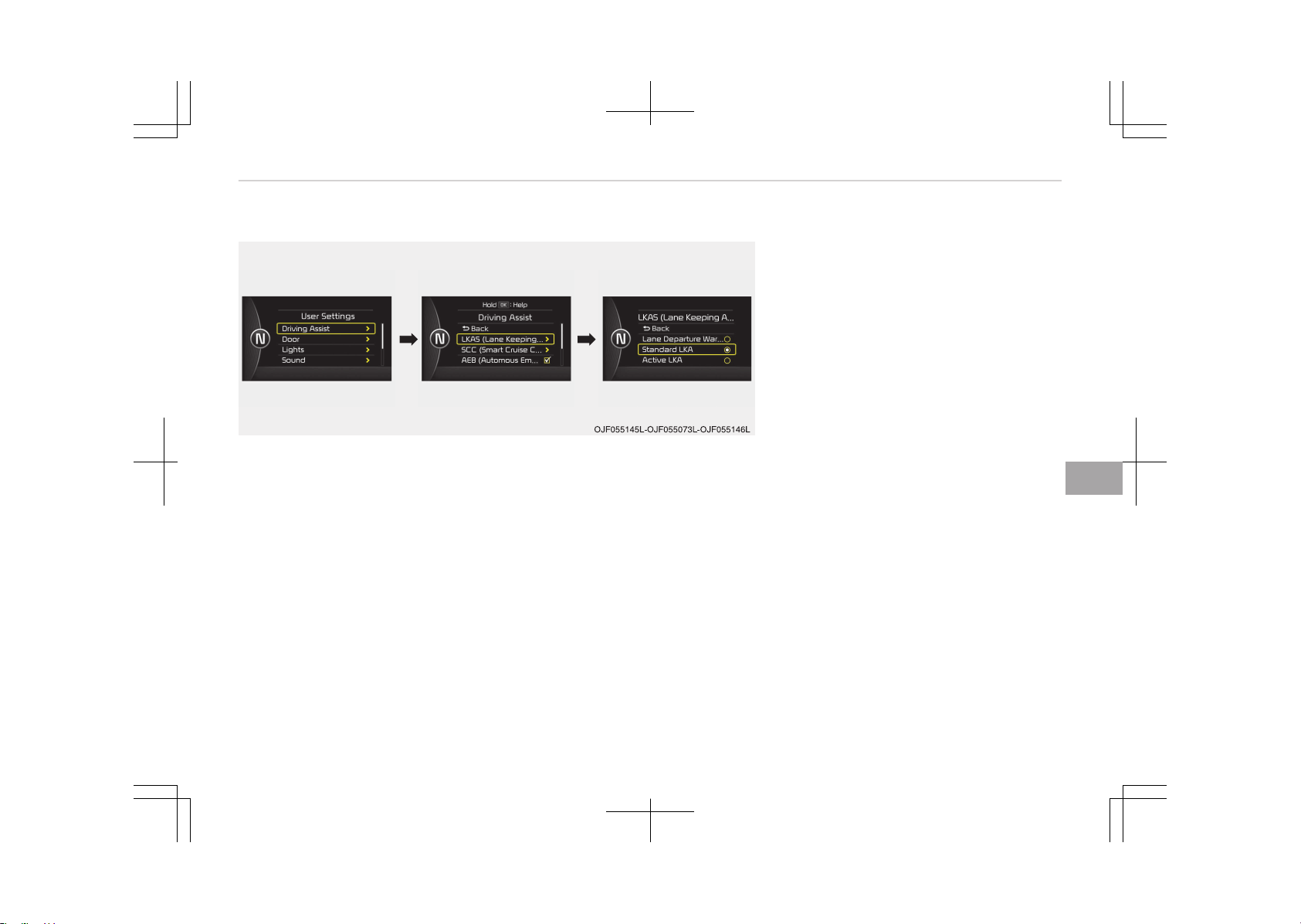
LKAS function change
The driver can change LKAS to Lane
Departure Warning System (LDWS) or
change the LKAS mode between Stand‐
ard LKA and Active LKA from the User
Settings Mode on the LCD display. The
system is automatically set to Stand‐
ard LKA.
Lane Departure Warning system
(LDWS)
• The system can be converted to LKA
to LDW at the User setting mode.
• Refer to User settings on page
5-58.
• LDWS alerts the driver with a visual
and audible warning when the sys‐
tem detects the vehicle straying
from its lane.
• If the LDWS is operating the indicator
green/white will illuminate.
• The steering wheel will not be con‐
trolled.
Standard LKA
• LKAS only starts intervention when
the vehicle is predicted to cross the
line.
• It's useful to a driver who dislikes fre‐
quent intervention by LKAS
7-89
7
Driving your vehicle

• LDW is generated when the vehicle is
about to cross the line.
Active LKA
• LKAS operates for a vehicle to keep
the region of lane center more effi‐
ciently.
• The steering assistance is activated
more frequently and earlier than
standard LKA.
• LDW is generated when the vehicle is
about to cross the line.
Driving your vehicle
7-90
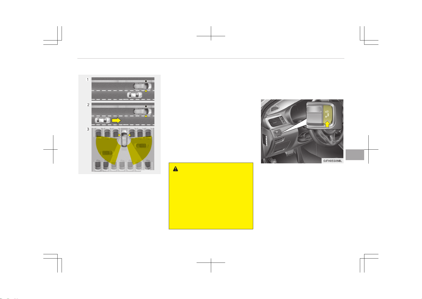
BLIND SPOT DETECTION SYSTEM (BSD) (IF EQUIPPED)
OUM056176L
The BSD (Blind spot detection) system
uses a radar sensor to alert the driver
while driving.
It senses the rear side territory of the
vehicle and provides information to the
driver.
1. BSD (Blind spot detection)
Warning range is dependent on
your vehicle speed. However, if the
speed of your vehicle is faster by
10 km/h or more than other nearby
vehicles, the warning is not operat‐
ed.
2. LCA (Lane change assist)
When vehicles are approaching to
your vehicle at high speed, the
warning is operated.
3. RCTA (Rear cross traffic alert)
When your vehicle moves back‐
ward, the sensor detects approach‐
ing vehicles to the left or right side
direction and warning is operated.
WARNING
• Always check the road condition
while driving for unexpected situa‐
tions even though the BSD (Blind
spot detection) system is operat‐
ing.
• BSD (Blind spot detection) system
is a system made for convenience.
Do not solely rely on the system
but always pay attention to drive
safely.
BSD (Blind spot detection) / LCA
(Lane Change Assist)
Operating conditions
The indicator on the switch will illumi‐
nate when the BSD (Blind spot detec‐
tion) system switch is pressed with the
engine start/stop button switch ON. If
the vehicle speed exceeds 30 km/h
(18.6 mph), the system will activate.
If you press the switch again, the
switch indicator and system will be
turned off.
If the engine start/stop button switch
is turned OFF and ON the system re‐
turns to the previous state.
7-91
7
Driving your vehicle
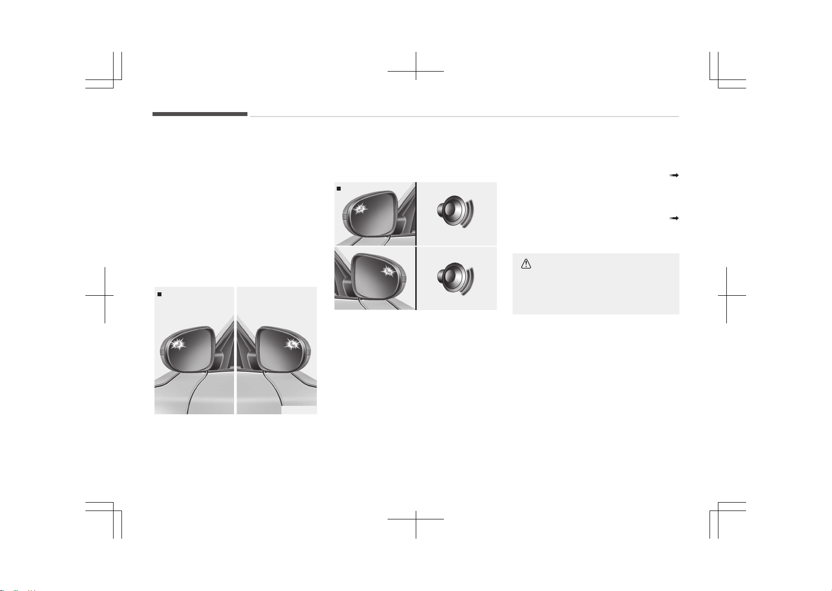
When the system is not used turn the
system off by pressing the switch.
When the system is turned on the
warning light will illuminate for 3 sec‐
onds on the outside rearview mirror.
Warning type
The system will activate when:
1. The system is on
2. Vehicle speed is above 30 km/h
(18.6 mph)
3. Other vehicles are detected in the
rear side
1st stage
OUM054028
If a vehicle is detected within the boun‐
dary of the system, a warning light will
illuminate on the outside rearview mir‐
ror.
If the detected vehicle is not in detec‐
tion range, the warning will be turned
off.
2nd stage
OUM054029
The second stage alarm will activate
when:
1. The first stage alert is on
2. The turn signal is on to change a
lane
When the second stage alert is activa‐
ted, a warning light will be blinking on
the outside rearview mirror and an
alarm will sound.
If you move the turn signal switch to
origin position, the second stage alert
will be deactivated.
The second stage alarm can be deacti‐
vated.
• To activate the alarm:
Go to the User Settings Mode
Sound and select "BSD" on the LCD
display.
• To deactivate the alarm:
Go to the User Settings Mode
Sound and deselect "BSD" on the LCD
display.
CAUTION
The alarm function helps alert the
driver. Deactivate this function only
when it is necessary
Driving your vehicle
7-92
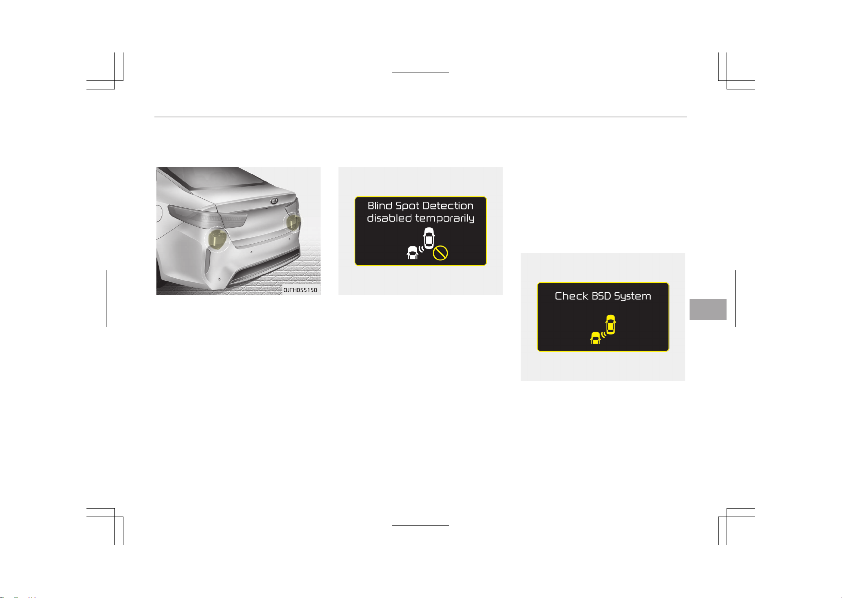
Detecting sensor
The sensors are located inside the rear
bumper.
Always keep the rear bumper clean for
the system to work properly.
Warning message
OJF055091L
The message will appear to notify the
driver if there are foreign substances
on the rear bumper or it is hot near the
rear bumper. The light on the switch
and the system will be turned off auto‐
matically.
Remove the foreign substance on the
rear bumper.
After the foreign substance is removed,
if you drive for approximately 10 mi‐
nutes, the system will work normally.
If the system does not work normally
even though the foreign substance is
removed, take your vehicle to an au‐
thorized Kia dealer and have the sys‐
tem checked.
It is possible to get the message with
no foreign substance on the rear
bumper, for example, when driving in
sparse rural or open area, such as des‐
ert, where there is insufficient data for
operation.
This message may also activate during
heavy rain or due to road spray.
In this case, the vehicle does not need
service.
OJF055247L
If the system does not work properly, a
warning message will appear and the
light on the switch will turn off. The
system will turn off automatically.
We recommend you to have the sys‐
tem checked by an authorized Kia deal‐
er.
7-93
7
Driving your vehicle
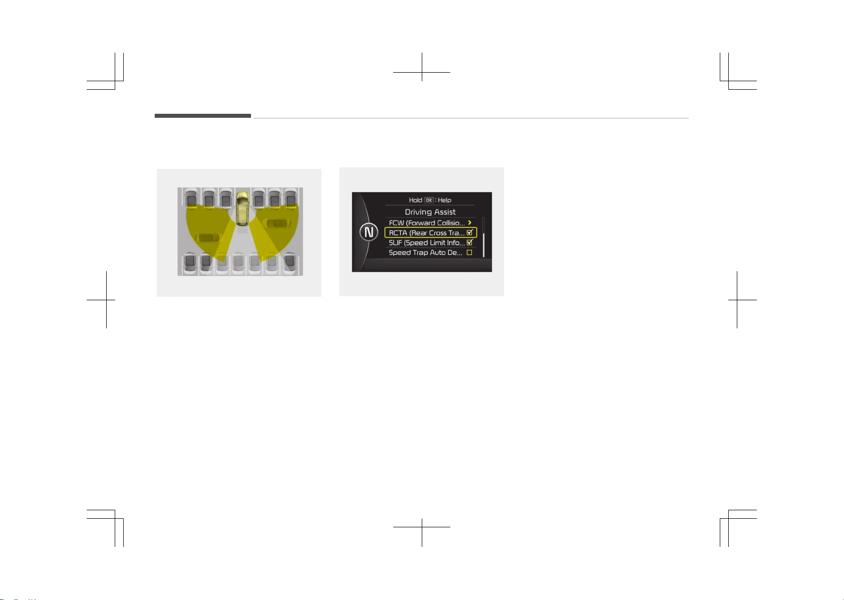
RCTA (Rear Cross Traffic Alert)
OYF054026K
When your vehicle moves backwards
from a parking position, the sensor de‐
tects approaching vehicles to the left or
right side direction and gives informa‐
tion to the driver.
Operating conditions
OJF055109L
• Select RCTA (Rear Cross Traffic Alert)
in "User Settings" under "Driving As‐
sist" on the instrument cluster. The
system will turn on and stand by to
be activated.
• Select RCTA again, to turn the sys‐
tem off.
• If the vehicle is turned off and on
again, the RCTA system will return to
the state right before the vehicle was
turned off. Turn the RCTA system off
when not in use.
• The system is operated when the ve‐
hicle speed is below 10 km/h with the
shift lever in R (Reverse).
• The RCTA (Rear Cross Traffic Alert)
detection range is 0.5 m~20 m based
on side direction. If an approaching
vehicle speed is 7 km/h~36 km/h in
detection range, The warning is on.
However, the system sensing range is
different based on conditions. Always
pay attention to surrounding.
Driving your vehicle
7-94
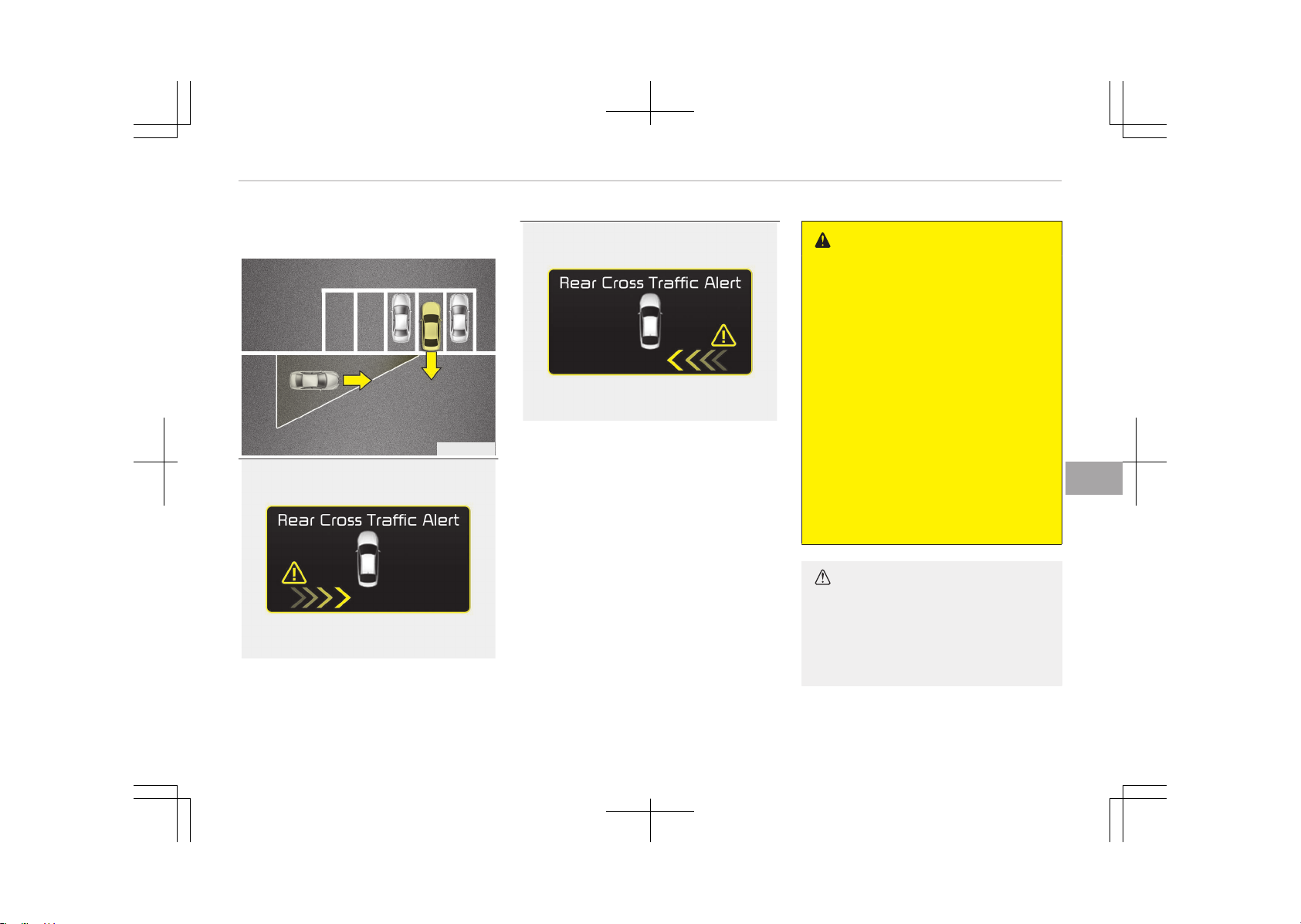
Warning type
OJF055196L
OJF055105L
OJF055106L
• If an approaching vehicle detected by
sensors, the warning is chime and the
warning light will blink on the outside
rearview mirror.
• If the detected vehicle is out of de‐
tection range, moving away in the
opposite direction or moving slow,
the warning is cancelled.
• The system may not be operating
properly due to other factors or cir‐
cumstances, so always pay attention
to your surrounding.
❈ If the bumper on either side is
blocked by a barrier or vehicles, the
system sensing ability may be de‐
teriorated.
WARNING
• The warning light on the outside
rearview mirror will illuminate
whenever a vehicle is detected at
the rear side by the system.
To avoid accidents, do not focus
only on the warning light and ne‐
glect to see the surrounding of the
vehicle.
• Drive safely even though the vehi‐
cle is equipped with a BSD (Blind
spot detection) system. Do not
solely rely on the system but
check for yourself before changing
lanes.
The system may not alert the
driver in some conditions so al‐
ways check the surroundings while
driving.
CAUTION
• The system may not work proper‐
ly if the bumper has been replaced
or if a repair work has been done
near the sensor.
(Continued)
7-95
7
Driving your vehicle

(Continued)
• The detection area differs accord‐
ing to the roads width. If the road
is narrow the system may detect
other vehicles in the second next
lane.
• On the contrary, if the road is very
wide the system may not detect
other vehicles in the next lane.
• The system might be turned off
due to strong electromagnetic
waves.
Non-operating condition
Outside rearview mirror may not alert
the driver when:
-
The outside rearview mirror housing
is damaged or covered with debris.
-
The window is covered with debris.
-
The windows are severely tinted.
Driver's attention
The driver must be cautious in the be‐
low situations, because the system
may not detect other vehicles or ob‐
jects in certain circumstances.
-
The vehicle drives on a curved road or
through a tollgate.
-
The sensor is polluted with rain,
snow, mud, etc.
-
The rear bumper, in which the sensor
is located, is covered or blocked with
a foreign matter such as a sticker, a
bumper guard, a bicycle stand, etc.
-
The rear bumper is damaged, or the
sensor is out of the original default
position.
-
The vehicle height gets lower or high‐
er due to heavy loading in a trunk,
abnormal tire pressure, etc.
-
The vehicle drives in a bad weather
such as heavy rain or snow.
-
There is a fixed object near the vehi‐
cle, such as a guardrail.
-
A big vehicle is near such as a bus or
truck.
-
A motorcycle or bicycle is near.
-
A flat trailer is near.
-
If the vehicle has started at the same
time as the vehicle next to you and
has accelerated.
-
When the other vehicle passes at a
very fast speed.
-
While changing lanes.
-
While going down or up a steep road
where the height of the lane is differ‐
ent.
-
When the other vehicle approaches
very close.
-
When a trailer or carrier is installed.
-
When the temperature of the rear
bumper is high.
-
When the sensors are blocked by
other vehicles, walls or parking-lot
pillars.
-
When the detected vehicle also
moves back, as your vehicle drives
back.
-
If there are small things like shopping
cart and baby carriage.
-
If there is low height vehicle like sport
vehicle.
-
When other vehicles are close to your
vehicle.
-
When the vehicle in the next lane
moves two lanes away from you OR
when the vehicle two lanes away
moves to the next lane from you.
Driving your vehicle
7-96

ECONOMICAL OPERATION
Your vehicle's fuel economy depends
mainly on your style of driving, where
you drive and when you drive.
Each of these factors affects how
many kilometers (miles) you can get
from a liter (gallon) of fuel. To operate
your vehicle as economically as possi‐
ble, use the following driving sugges‐
tions to help save money in both fuel
and repairs:
• Drive smoothly. Accelerate at a mod‐
erate rate. Do not make "jack-rabbit"
starts or full-throttle shifts and
maintain a steady cruising speed. Do
not race between stop lights. Try to
adjust your speed to the traffic so
you do not have to change speeds
unnecessarily. Avoid heavy traffic
whenever possible.
Always maintain a safe distance from
other vehicles so you can avoid un‐
necessary braking. This also reduces
brake wear.
• Drive at a moderate speed. The fast‐
er you drive, the more fuel your vehi‐
cle uses. Driving at a moderate
speed, especially on the highway, is
one of the most effective ways to re‐
duce fuel consumption.
• Do not "ride" the brake or clutch ped‐
al. This can increase fuel consumption
and also increase wear on these com‐
ponents. In addition, driving with your
foot resting on the brake pedal may
cause the brakes to overheat, which
reduces their effectiveness and may
lead to more serious consequences.
• Take care of your tires. Keep them
inflated to the recommended pres‐
sure. Incorrect inflation, either too
much or too little, results in unneces‐
sary tire wear. Check the tire pres‐
sures at least once a month.
• Be sure that the wheels are aligned
correctly. Improper alignment can re‐
sult from hitting curbs or driving too
fast over irregular surfaces. Poor
alignment causes faster tire wear
and may also result in other prob‐
lems as well as greater fuel con‐
sumption.
• Keep your vehicle in good condition.
For better fuel economy and reduced
maintenance costs, maintain your ve‐
hicle in accordance with the mainte‐
nance schedule in Chapter 9, Mainte‐
nance. If you drive your vehicle in se‐
vere conditions, more frequent main‐
tenance is required (see Chapter 9,
Maintenance for details).
• Keep your vehicle clean. For maxi‐
mum service, your vehicle should be
kept clean and free of corrosive ma‐
terials. It is especially important that
mud, dirt, ice, etc. not be allowed to
accumulate on the underside of the
vehicle. This extra weight can result
in increased fuel consumption and al‐
so contribute to corrosion.
• Travel lightly. Do not carry unneces‐
sary weight in your vehicle. Weight
reduces fuel economy.
• Do not let the engine idle longer than
necessary. If you are waiting (and not
in traffic), turn off your engine and
restart only when you're ready to go.
• Remember, your vehicle does not re‐
quire extended warm-up. After the
engine has started, allow the engine
to run for 10 to 20 seconds prior to
placing the vehicle in gear. In very cold
weather, however, give your engine a
slightly longer warmup period.
• Do not "lug" or "over-rev" the engine.
Lugging is driving too slowly in too
high a gear resulting engine bucking.
If this happens, shift to a lower gear.
Over-revving is racing the engine be‐
yond its safe limit. This can be avoi‐
ded by shifting at the recommended
speeds.
7-97
7
Driving your vehicle
• Use your air conditioning sparingly.
The air conditioning system is oper‐
ated by engine power so your fuel
economy is reduced when you use it.
• Open windows at high speeds can re‐
duce fuel economy.
• Fuel economy is less in crosswinds
and headwinds. To help offset some
of this loss, slow down when driving
in these conditions.
Keeping a vehicle in good operating
condition is important both for econo‐
my and safety. Therefore, we recom‐
mend that the system be serviced by
an authorized Kia dealer.
WARNING
n
Engine off during motion
Never turn the engine off to coast
down hills or anytime the vehicle is
in motion. The power steering and
power brakes will not function prop‐
erly without the engine running. In‐
stead, keep the engine on and down‐
shift to an appropriate gear for en‐
gine braking effect. In addition, turn‐
(Continued)
(Continued)
ing off the engine start/stop button
while driving could engage the steer‐
ing wheel lock (if equipped) resulting
in loss of vehicle steering which
could cause serious injury or death.
Driving your vehicle
7-98
SPECIAL DRIVING CONDITIONS
Hazardous driving conditions
When hazardous driving conditions are
encountered such as water, snow, ice,
mud, sand, or similar hazards, follow
these suggestions:
• Drive cautiously and allow extra dis‐
tance for braking.
• Avoid sudden braking or steering.
• When braking with non-ABS brakes
pump the brake pedal with a light up-
and-down motion until the vehicle is
stopped.
WARNING
n
ABS
Do not pump the brake pedal on a
vehicle equipped with ABS.
• If stalled in snow, mud, or sand, use
second gear. Accelerate slowly to
avoid spinning the drive wheels.
• Use sand, rock salt, tire chains, or
other non-slip material under the
drive wheels to provide traction when
stalled in ice, snow, or mud.
WARNING
n
Downshifting
Downshifting with an automatic
transaxle, while driving on slippery
surfaces can cause an accident. The
sudden change in tire speed could
cause the tires to skid. Be careful
when downshifting on slippery sur‐
faces.
Rocking the vehicle
If it is necessary to rock the vehicle to
free it from snow, sand, or mud, first
turn the steering wheel right and left
to clear the area around your front
wheels. Then, shift back and forth be‐
tween 1 (First) and R (Reverse) in vehi‐
cles equipped with a manual transaxle
or R (Reverse) and any forward gear in
vehicles equipped with an Automatic
Transaxle / Dual clutch transmission. Do
not race the engine, and spin the
wheels as little as possible. If you are
still stuck after a few tries, have the
vehicle pulled out by a tow vehicle to
avoid engine overheating and possible
damage to the transaxle.
CAUTION
Prolonged rocking may cause engine
over-heating, transaxle damage or
failure, and tire damage.
WARNING
n
Spinning tires
Do not spin the wheels, especially at
speeds more than 56 km/h
(35 mph). Spinning the wheels at
high speeds when the vehicle is sta‐
tionary could cause a tire to over‐
heat which could result in tire dam‐
age that may injure bystanders.
NOTICE
The ESC system should be turned
OFF prior to rocking the vehicle.
7-99
7
Driving your vehicle
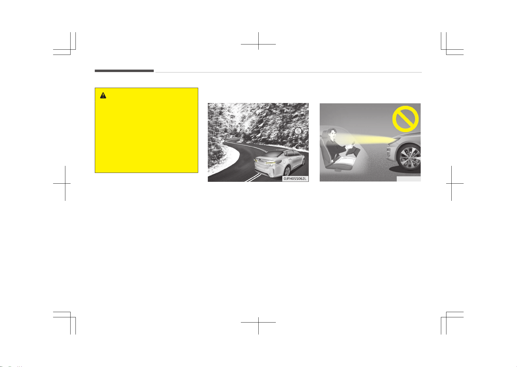
WARNING
If your vehicle becomes stuck in
snow, mud, sand, etc., then you may
attempt to rock the vehicle free by
moving it forward and backward. Do
not attempt this procedure if people
or objects are anywhere near the ve‐
hicle. During the rocking operation
the vehicle may suddenly move for‐
ward or backward as it becomes un‐
stuck, causing injury or damage to
nearby people or objects.
Smooth cornering
Avoid braking or gear changing in cor‐
ners, especially when roads are wet.
Ideally, corners should always be taken
under gentle acceleration. If you follow
these suggestions, tire wear will be
held to a minimum.
Driving at night
OJF055063L
Because night driving presents more
hazards than driving in the daylight,
here are some important tips to re‐
member:
• Slow down and keep more distance
between you and other vehicles, as it
may be more difficult to see at night,
especially in areas where there may
not be any street lights.
• Adjust your mirrors to reduce the
glare from other driver's headlights.
Driving your vehicle
7-100

• Keep your headlights clean and prop‐
erly aimed on vehicles not equipped
with the automatic headlight aiming
feature. Dirty or improperly aimed
headlights will make it much more
difficult to see at night.
• Avoid staring directly at the head‐
lights of oncoming vehicles. You could
be temporarily blinded, and it will
take several seconds for your eyes to
readjust to the darkness.
Driving in the rain
Rain and wet roads can make driving
dangerous, especially if you’re not pre‐
pared for the slick pavement. Here are
a few things to consider when driving in
the rain:
• A heavy rainfall will make it harder to
see and will increase the distance
needed to stop your vehicle, so slow
down.
• Keep your windshield wiping equip‐
ment in good shape. Replace your
windshield wiper blades when they
show signs of streaking or missing
areas on the windshield.
• If your tires are not in good condition,
making a quick stop on wet pave‐
ment can cause a skid and possibly
lead to an accident. Be sure your tires
are in good shape.
• Turn on your headlights to make it
easier for others to see you.
• Driving too fast through large pud‐
dles can affect your brakes. If you
must go through puddles, try to drive
through them slowly.
• If you believe you may have gotten
your brakes wet, apply them lightly
while driving until normal braking op‐
eration returns.
Driving in flooded areas
Avoid driving through flooded areas un‐
less you are sure the water is no higher
than the bottom of the wheel hub.
Drive through any water slowly. Allow
adequate stopping distance because
brake performance may be affected.
After driving through water, dry the
brakes by gently applying them several
times while the vehicle is moving slow‐
ly.
7-101
7
Driving your vehicle
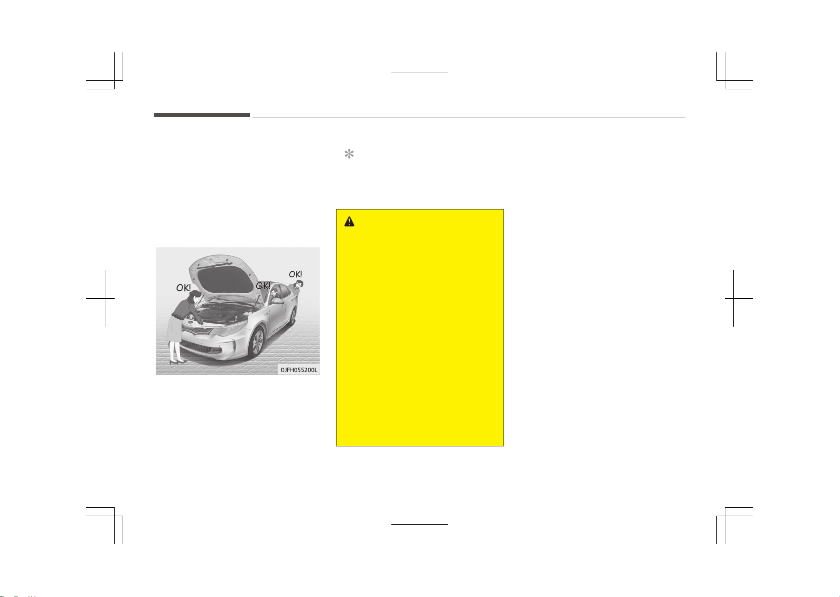
Driving off-road
Drive carefully off-road because your
vehicle may be damaged by rocks or
roots of trees. Become familiar with
the off-road conditions where you are
going to drive before you begin driving.
Highway driving
Tires
Adjust the tire inflation pressures to
specification. Low tire inflation pres‐
sures will result in overheating and pos‐
sible failure of the tires.
Avoid using worn or damaged tires
which may result in reduced traction or
tire failure.
NOTICE
Never exceed the maximum tire in‐
flation pressure shown on the tires.
WARNING
• Underinflated or overinflated tires
can cause poor handling, loss of
vehicle control, and sudden tire
failure leading to accidents, inju‐
ries, and even death. Always check
the tires for proper inflation be‐
fore driving. For proper tire pres‐
sures, refer to Tires and wheels
on page 10-09.
• Driving on tires with no or insuffi‐
cient tread is dangerous. Worn-out
tires can result in loss of vehicle
control, collisions, injury, and even
death. Worn-out tires should be
replaced as soon as possible and
should never be used for driving.
Always check the tire tread before
driving your vehicle. For further in‐
formation and tread limits, refer
to Tires and wheels on page
9-43
Fuel engine coolant and engine oil
High speed travel consumes more fuel
than urban motoring. Do not forget to
check both engine coolant and engine
oil.
Drive belt
A loose or damaged drive belt may re‐
sult in overheating of the engine.
Driving your vehicle
7-102
WINTER DRIVING
Severe weather conditions in the winter
result in greater wear and other prob‐
lems. To minimize the problems of win‐
ter driving, you should follow these
suggestions:
❈ Snow tires and tire chains for the
national language (Icelandic, Bul‐
garian) see Chapter 11, Appendix.
Snowy or icy conditions
To drive your vehicle in deep snow, it
may be necessary to use snow tires or
to install tire chains on your tires. If
snow tires are needed, it is necessary
to select tires equivalent in size and
type of the original equipment tires.
Failure to do so may adversely affect
the safety and handling of your vehicle.
Furthermore, speeding, rapid accelera‐
tion, sudden brake applications, and
sharp turns are potentially very haz‐
ardous practices.
During deceleration, use engine braking
to the fullest extent. Sudden brake ap‐
plications on snowy or icy roads may
cause skids to occur. You need to keep
sufficient distance between the vehicle
in operation in front and your vehicle.
Also, apply the brake gently. It should
be noted that installing tire chains on
the tire will provide a greater driving
force, but will not prevent side skids.
NOTICE
Tire chains are not legal in all coun‐
tries. Check the country laws before
fitting tire chains.
Snow tires
If you mount snow tires on your vehi‐
cle, make sure they are radial tires of
the same size and load range as the
original tires. Mount snow tires on all
four wheels to balance your vehicle’s
handling in all weather conditions. Keep
in mind that the traction provided by
snow tires on dry roads may not be as
high as your vehicle's original equip‐
ment tires. You should drive cautiously
even when the roads are clear. Check
with the tire dealer for maximum
speed recommendations.
Do not install studded tires without
first checking local, state and municipal
regulations for possible restrictions
against their use.
WARNING
n
Snow tire size
Snow tires should be equivalent in
size and type to the vehicle's stand‐
ard tires. Otherwise, the safety and
handling of your vehicle may be ad‐
versely affected.
7-103
7
Driving your vehicle
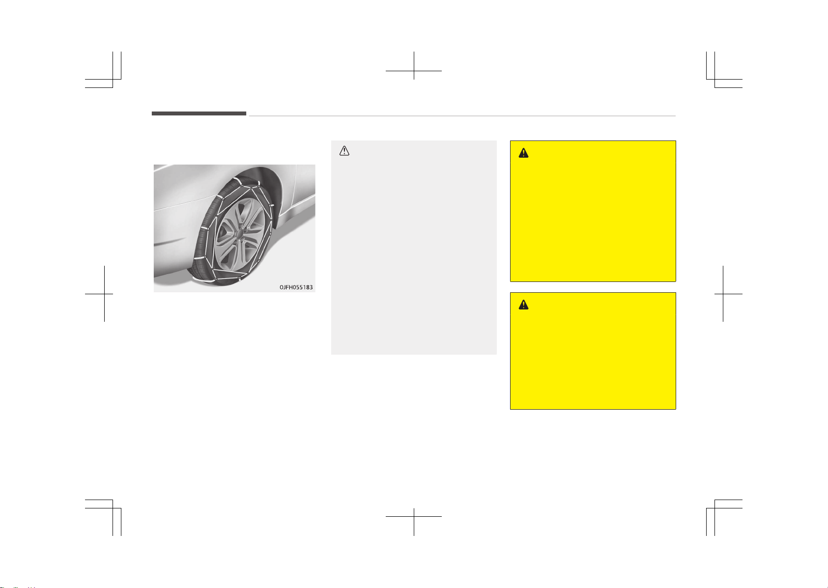
Tire chains
Since the sidewalls of radial tires are
thinner, they can be damaged by
mounting some types of snow chains
on them. Therefore, the use of snow
tires is recommended instead of snow
chains. Do not mount tire chains on ve‐
hicles equipped with aluminum wheels;
snow chains may cause damage to the
wheels. If snow chains must be used,
use wire-type chains with a thickness
of less than 12 mm (0.47 in). Damage
to your vehicle caused by improper
snow chain use is not covered by your
vehicle manufacturers warranty.
Install tire chains only on the front
tires.
CAUTION
• Make sure the snow chains are the
correct size and type for your
tires. Incorrect snow chains can
cause damage to the vehicle body
and suspension and may not be
covered by your vehicle manufac‐
turer warranty. Also, the snow
chain connecting hooks may be
damaged from contacting vehicle
components causing the snow
chains to come loose from the tire.
Make sure the snow chains are
SAE class "S" certified.
• Always check chain installation for
proper mounting after driving ap‐
proximately 0.5 to 1 km (0.3 to 0.6
miles) to ensure safe mounting.
Retighten or remount the chains if
they are loose.
Chain installation
When installing chains, follow the man‐
ufacturer's instructions and mount
them as tightly as you can. Drive slowly
with chains installed. If you hear the
chains contacting the body or chassis,
stop and tighten them. If they still
make contact, slow down until it stops.
Remove the chains as soon as you be‐
gin driving on cleared roads.
WARNING
n
Mounting chains
When mounting snow chains, park
the vehicle on level ground away
from traffic. Turn on the vehicle
Hazard Warning flashers and place a
triangular emergency warning device
behind the vehicle if available. Al‐
ways place the vehicle in P (Park),
apply the parking brake and turn off
the engine before installing snow
chains.
WARNING
n
Tire chains
• The use of chains may adversely
affect vehicle handling.
• Do not exceed 30 km/h (20 mph)
or the chain manufacturer’s rec‐
ommended speed limit, whichever
is lower.
(Continued)
Driving your vehicle
7-104

(Continued)
• Drive carefully and avoid bumps,
holes, sharp turns, and other road
hazards, which may cause the ve‐
hicle to bounce.
• Avoid sharp turns or locked wheel
braking.
CAUTION
• Chains that are the wrong size or
improperly installed can damage
your vehicle's brake lines, suspen‐
sion, body and wheels.
• Stop driving and retighten the
chains any time you hear them
hitting the vehicle.
Use high quality ethylene glycol
coolant
Your vehicle is delivered with high quali‐
ty ethylene glycol coolant in the cooling
system. It is the only type of coolant
that should be used because it helps
prevent corrosion in the cooling sys‐
tem, lubricates the water pump and
prevents freezing. Be sure to replace or
replenish your coolant in accordance
with the maintenance schedule on
page 9-09. Before winter, have your
coolant tested to assure that its freez‐
ing point is sufficient for the tempera‐
tures anticipated during the winter.
Check battery and cables
Winter puts additional burdens on the
battery system. Visually inspect the
battery and cables as described in Bat‐
tery on page 9-39.We recommend
that the level of charge in your battery
be checked by an authorized Kia dealer.
Change to "winter weight" oil if
necessary
In some climates it is recommended
that a lower viscosity "winter weight"
oil be used during cold weather. See
Recommendations on page 10-12. If
you aren't sure what weight oil you
should use, we recommend that you
consult an authorized Kia dealer.
Check spark plugs and ignition
system
Inspect your spark plugs as described in
9-21 and replace them if necessary.
Also check all ignition wiring and com‐
ponents to be sure they are not
cracked, worn or damaged in any way.
To keep locks from freezing
To keep the locks from freezing, squirt
an approved de-icer fluid or glycerine
into the key opening. If a lock is covered
with ice, squirt it with an approved de-
icing fluid to remove the ice. If the lock
is frozen internally, you may be able to
thaw it out by using a heated key. Han‐
dle the heated key with care to avoid
injury.
7-105
7
Driving your vehicle

Use approved window washer
anti-freeze in system
To keep the water in the window wash‐
er system from freezing, add an ap‐
proved window washer anti-freeze sol‐
ution in accordance with instructions on
the container. Window washer anti-
freeze is available from an authorized
Kia dealer and most auto parts outlets.
Do not use engine coolant or other
types of anti-freeze as these may
damage the paint finish.
Don't let your parking brake
freeze
Under some conditions your parking
brake can freeze in the engaged posi‐
tion. This is most likely to happen when
there is an accumulation of snow or ice
around or near the rear brakes or if the
brakes are wet. If there is a risk the
parking brake may freeze, apply it only
temporarily while you put the shift lev‐
er in P (Automatic Transaxle / Dual
clutch transmission) or in first or re‐
verse gear (manual transaxle) and block
the rear wheels so the vehicle cannot
roll. Then release the parking brake.
Don't let ice and snow
accumulate underneath
Under some conditions, snow and ice
can build up under the fenders and in‐
terfere with the steering. When driving
in severe winter conditions where this
may happen, you should periodically
check underneath the vehicle to be sure
the movement of the front wheels and
the steering components is not ob‐
structed.
Carry emergency equipment
Depending on the severity of the
weather, you should carry appropriate
emergency equipment. Some of the
items you may want to carry include
tire chains, tow straps or chains, flash‐
light, emergency flares, sand, shovel,
jumper cables, window scraper, gloves,
ground cloth, coveralls, blanket, etc.
Driving your vehicle
7-106
VEHICLE WEIGHT
This section will guide you in the proper
loading of your vehicle and/or trailer, to
keep your loaded vehicle weight within
its design rating capability, with or
without a trailer. Properly loading your
vehicle will provide maximum return of
the vehicle design performance. Before
loading your vehicle, familiarize your‐
self with the following terms for deter‐
mining your vehicle's weight ratings,
with or without a trailer, from the vehi‐
cle's specifications and the certification
label:
Base curb weight
This is the weight of the vehicle includ‐
ing a full tank of fuel and all standard
equipment. It does not include passen‐
gers, cargo, or optional equipment.
Vehicle curb weight
This is the weight of your new vehicle
when you picked it up from your dealer
plus any aftermarket equipment.
Cargo weight
This figure includes all weight added to
the Base Curb Weight, including cargo
and optional equipment.
GAW (Gross axle weight)
This is the total weight placed on each
axle (front and rear) - including vehicle
curb weight and all payload.
GAWR (Gross axle weight rating)
This is the maximum allowable weight
that can be carried by a single axle
(front or rear). These numbers are
shown on the certification label. The
total load on each axle must never ex‐
ceed its GAWR.
GVW (Gross vehicle weight)
This is the Base Curb Weight plus actual
Cargo Weight plus passengers.
GVWR (Gross vehicle weight
rating)
This is the maximum allowable weight
of the fully loaded vehicle (including all
options, equipment, passengers and
cargo). The GVWR is shown on the cer‐
tification label.
Overloading
WARNING
n
Vehicle weight
The gross axle weight rating (GAWR)
and the gross vehicle weight rating
(GVWR) for your vehicle are on the
certification label attached to the
driver's (or front passenger’s) door.
Exceeding these ratings can cause
an accident or vehicle damage. You
can calculate the weight of your load
by weighing the items (and people)
before putting them in the vehicle.
Be careful not to overload your vehi‐
cle.
7-107
7
Driving your vehicle

Road warning.............................................................................8-02
Hazard warning flasher........................................................8-02
In case of an emergency while driving.................................. 8-03
If the engine stalls at a crossroad or crossing.................8-03
If you have a flat tire while driving.................................... 8-03
If engine stalls while driving................................................8-03
If the engine will not start.......................................................8-04
If engine doesn't turn over or turns over slowly............. 8-04
If engine turns over normally but does not start........... 8-04
Emergency starting..................................................................8-05
Jump starting.........................................................................8-05
Push-starting........................................................................ 8-06
If the engine overheats............................................................ 8-07
Tire Pressure Monitoring System (TPMS) ...........................8-09
Check tire pressure...............................................................8-09
Low tire pressure position telltale..................................... 8-10
TPMS (Tire Pressure Monitoring System) mal‐
function indicator..................................................................8-11
Changing a tire with TPMS..................................................8-12
If you have a flat tire (with Tire Mobility Kit).......................8-14
Introduction............................................................................8-14
Components of the Tire Mobility Kit (TMK)......................8-16
Using the TMK....................................................................... 8-17
Distributing the sealant....................................................... 8-19
Checking the tire inflation pressure...................................8-19
Notes on the safe use of the Tire Mobility Kit ............... 8-20
Technical data........................................................................8-20
Towing.........................................................................................8-21
Towing service....................................................................... 8-21
Removable towing hook ..................................................... 8-22
Emergency towing................................................................8-22
If an accident occurs.................................................................8-25
Emergency commodity ........................................................... 8-27
First aid kit............................................................................. 8-27
Triangle reflector.................................................................. 8-27
Tire pressure gauge .............................................................8-27
What to do in an emergency
8

ROAD WARNING
Hazard warning flasher
The hazard warning flasher serves as a
warning to other drivers to exercise ex‐
treme caution when approaching, over‐
taking, or passing your vehicle.
It should be used whenever emergency
repairs are being made or when the ve‐
hicle is stopped near the edge of a
roadway.
Depress the flasher switch with the ig‐
nition switch in any position. The flash‐
er switch is located in the center con‐
sole switch panel. All turn signal lights
will flash simultaneously.
• The hazard warning flasher operates
whether your vehicle is running or
not.
• The turn signals do not work when
the hazard flasher is on.
• Care must be taken when using the
hazard warning flasher while the ve‐
hicle is being towed.
What to do in an emergency
8-02

IN CASE OF AN EMERGENCY WHILE DRIVING
If the engine stalls at a
crossroad or crossing
• If the engine stalls at a crossroad or
crossing, set the shift lever in the N
(Neutral) position and then push the
vehicle to a safe place.
If you have a flat tire while
driving
1. Take your foot off the accelerator
pedal and let the vehicle slow down
while driving straight ahead. Do not
apply the brakes immediately or
attempt to pull off the road as this
may cause a loss of control. When
the vehicle has slowed down to
such a speed that it is safe to do
so, brake carefully and pull off the
road. Drive off the road as far as
possible and park on a firm level
ground. If you are on a divided
highway, do not park in the median
area between the two traffic lanes.
2. When the vehicle is stopped, turn
on your emergency hazard flash‐
ers, set the parking brake and put
the transaxle in P.
3. Have all passengers get out of the
vehicle. Be sure they all get out on
the side of the vehicle that is away
from traffic.
4. When changing a flat tire, follow
the instruction provided in If you
have a flat tire (with Tire Mobility
Kit) on page 8-14.
If engine stalls while driving
1. Reduce your speed gradually, keep‐
ing a straight line. Move cautiously
off the road to a safe place.
2. Turn on your emergency flashers.
3. Try to start the hybrid system
again. If your vehicle does not start,
we recommend that you consult an
authorized Kia dealer.
8-03
8
What to do in an emergency
IF THE ENGINE WILL NOT START
If engine doesn't turn over or
turns over slowly
1. Be sure the shift lever is in N (Neu‐
tral) or P (Park) and the emergency
brake is set.
2. Check the battery connections to
be sure they are clean and tight.
3. Turn on the interior light. If the
light dims or goes out when you
operate the starter, the battery is
discharged.
4. Check the starter connections to be
sure they are securely tightened.
5. Do not push or pull the vehicle to
start it. See instructions for Jump
starting on page 8-05.
WARNING
If the engine will not start, do not
push or pull the vehicle to start it.
This could result in a collision or
cause other damage. In addition,
push or pull starting may cause the
catalytic converter to be overloaded
and create a fire hazard.
If engine turns over normally
but does not start
1. Check the fuel level.
2. With the ignition switch in the LOCK
position, check all connectors at the
ignition coils and spark plugs. Re‐
connect any that may be discon‐
nected or loose.
3. Check the fuel line in the engine
compartment.
4. If the engine still does not start, we
recommend that you call an au‐
thorized Kia dealer.
What to do in an emergency
8-04
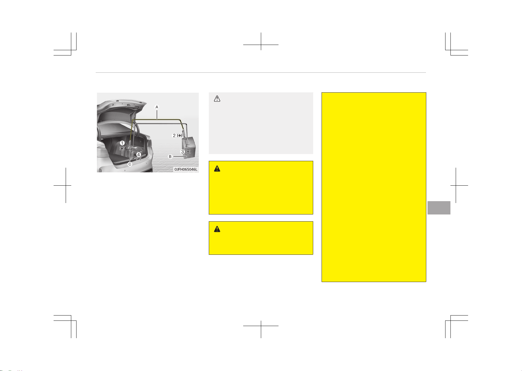
EMERGENCY STARTING
Connect cables in numerical order and
disconnect in reverse order.
❈
(A): Jumper cables
(B): Booster battery
(C): Discharged battery
Jump starting
Jump starting can be dangerous if done
incorrectly. Therefore, to avoid harm to
yourself or damage to your vehicle or
battery, follow the jump starting pro‐
cedures. If in doubt, we strongly rec‐
ommend that you have a competent
technician or towing service jump start
your vehicle.
CAUTION
Use only a 12-volt jumper system.
You can damage a 12-volt starting
motor, ignition system, and other
electrical parts beyond repair by use
of a 24- volt power supply (either
two 12-volt batteries in series or a
24-volt motor generator set).
WARNING
n
Battery
Never attempt to check the electro‐
lyte level of the battery as this may
cause the battery to rupture or ex‐
plode causing serious injury.
WARNING
n
Battery
(Continued)
(Continued)
• Keep all flames or sparks away
from the battery. The battery
produces hydrogen gas which may
explode if exposed to flame or
sparks.
If these instructions are not fol‐
lowed exactly, serious personal in‐
jury and damage to the vehicle
may occur! If you are not sure how
to follow this procedure, seek
qualified assistance. Automobile
batteries contain sulfuric acid. This
is poisonous and highly corrosive.
When jump starting, wear protec‐
tive glasses and be careful not to
get acid on yourself, your clothing
or on the vehicle.
• Do not attempt to jump start the
vehicle if the discharged battery is
frozen or if the electrolyte level is
low; the battery may rupture or
explode.
• Do not allow the (+) and (-) jumper
cables to touch. It may cause
sparks.
• The battery may rupture or ex‐
plode when you jump start with a
low or frozen battery.
8-05
8
What to do in an emergency
Jump starting procedure
1. Make sure the booster battery is
12-volt and that its negative termi‐
nal is grounded.
2. If the booster battery is in another
vehicle, do not allow the vehicles
come in contact.
3. Turn off all unnecessary electrical
loads.
4. Connect the jumper cables in the
exact sequence shown in the illus‐
tration. First connect one end of a
jumper cable to the positive termi‐
nal of the discharged battery (1),
then connect the other end to the
positive terminal on the booster
battery (2).
Proceed to connect one end of the
other jumper cable to the negative
terminal of the booster battery (3),
then the other end to a solid, sta‐
tionary, metallic point (for example,
the engine lifting bracket) away
from the battery (4). Do not con‐
nect it to or near any part that
moves when the engine is cranked.
Do not allow the jumper cables to
contact anything except the correct
battery terminals or the correct
ground. Do not lean over the bat‐
tery when making connections.
CAUTION
n
Battery cables
Do not connect the jumper cable
from the negative terminal of the
booster battery to the negative ter‐
minal of the discharged battery. This
can cause the discharged battery to
overheat and crack, releasing bat‐
tery acid.
5. Start the engine of the vehicle with
the booster battery and let it run
at 2,000 rpm, then start the engine
of the vehicle with the discharged
battery.
If the cause of your battery discharging
is not apparent, we recommend that
the system be checked by an author‐
ized Kia dealer.
Push-starting
Your manual transaxle-equipped vehi‐
cle should not be push-started because
it might damage the emission control
system.
Vehicles equipped with automatic
transaxle cannot be push-started.
Follow the directions in Jump starting
on page 8-05.
WARNING
Never tow a vehicle to start it be‐
cause the sudden surge forward
when the engine starts could cause
a collision with the tow vehicle.
What to do in an emergency
8-06
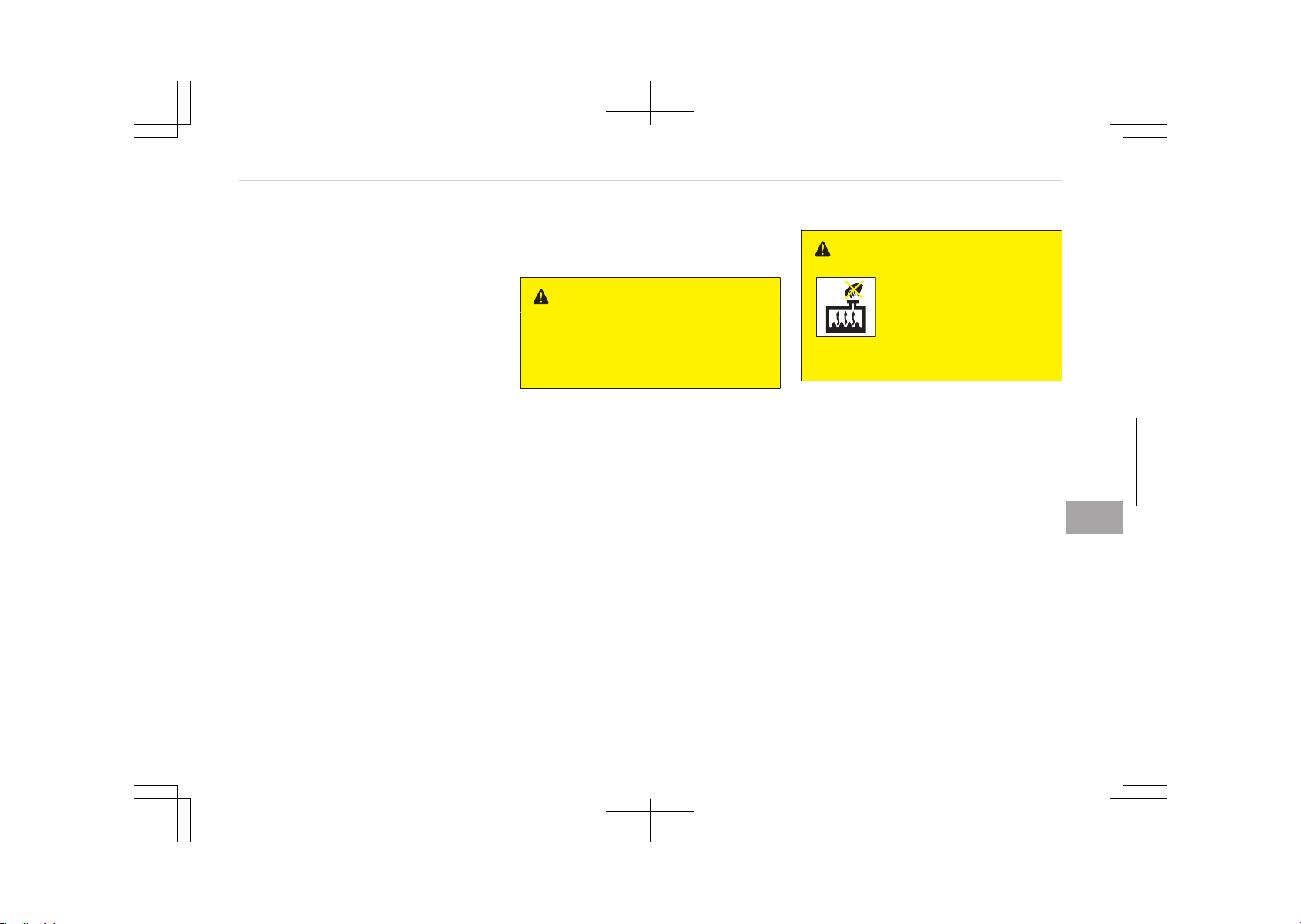
IF THE ENGINE OVERHEATS
If your temperature gauge indicates
overheating, you will experience a loss
of power, or hear loud pinging or knock‐
ing, the engine is probably too hot. If
this happens, you should:
1. Turn on the emergency warning
flasher and stop in a safe place.
Move the shift lever to P (Park) and
engage the parking brake.
2. If hot steam does not come out
from the engine room, carefully
open the engine room and check
whether the water pump connector
is properly engaged. If the connec‐
tor is not properly engaged, stop
the engine immediately and prop‐
erly engage the connector. Then,
turn the engine on.
3. Turn on the air conditioner.
4. If the HEV Warning light turns on
in the driver instrument cluster, or
engine coolant or hot steam emits
from the engine coolant filler, stop
the engine immediately. Then, we
recommend that you visit the near‐
est authorized Kia dealer or partner
service center for service.
If the Engine Warning light re‐
mains illuminated or the engine
coolant is not flowing out, keep the
engine running. Open the engine
hood for ventilation to help cool
down the engine.
WARNING
While the engine is running, keep
hair, hands and clothing away from
moving parts such as the fan and
drive belts to prevent injury.
5. Check whether the engine coolant
temperature is low enough by
checking its temperature. If the en‐
gine coolant level is low, please
check the connecting parts be‐
tween the radiator hose, heater
hose, and water pump for any
signs of leakage. When there is no
sign of leakage, please refill the en‐
gine coolant. If causes and signs of
engine overheating such as warning
light illumination, engine coolant
leakage, or cooling fan malfunction
are found, stop the vehicle the ear‐
liest. Then, we recommend that
you visit the nearest authorized Kia
dealer or partner service center for
service.
WARNING
Do not remove the radia‐
tor cap when the engine
is hot. This can allow
coolant to blow out of the
opening and cause seri‐
ous burns.
6. If you cannot find the cause of the
overheating, wait until the engine
temperature has returned to nor‐
mal. Then, if coolant has been lost,
carefully add coolant to the reser‐
voir to bring the fluid level in the
reservoir up to the halfway mark.
7. Proceed with caution, keeping alert
for further signs of overheating. If
overheating happens again, we rec‐
ommend that you call an author‐
ized Kia dealer.
8-07
8
What to do in an emergency

CAUTION
• Serious loss of coolant indicates
there is a leak in the cooling sys‐
tem and we recommend that the
system be checked by an author‐
ized Kia dealer.
• When the engine overheats from
low engine coolant, suddenly add‐
ing engine coolant may cause
cracks in the engine. To prevent
damage, add engine coolant slowly
in small quantities.
What to do in an emergency
8-08
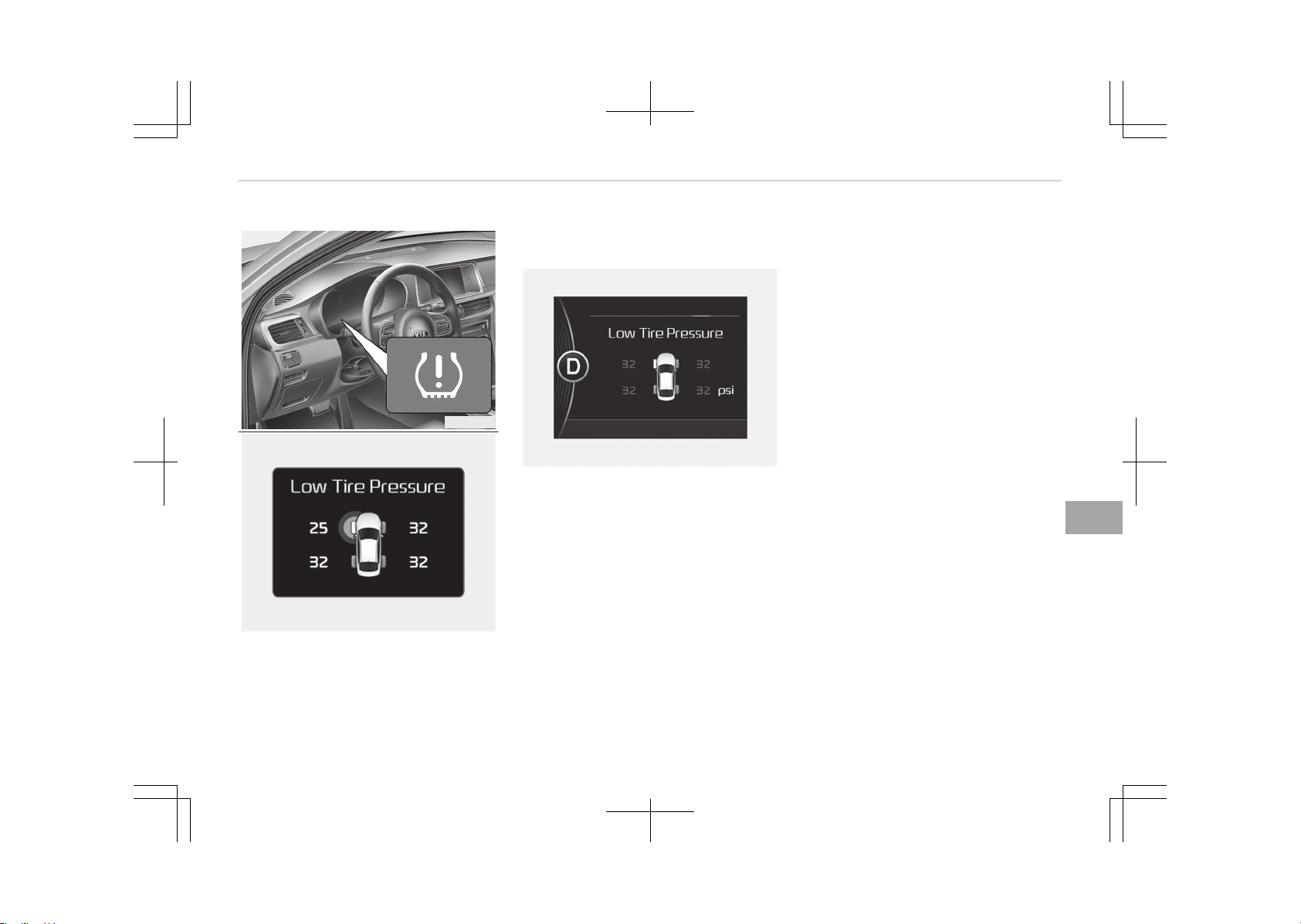
TIRE PRESSURE MONITORING SYSTEM (TPMS) (IF EQUIPPED)
OJF065002
OJF065027L
1. Low tire pressure telltale / TPMS
malfunction indicator
2. Low tire pressure position telltale
(Shown on the LCD display)
Check tire pressure
OJF065026L
• You can check the tire pressure in the
information mode on the cluster.
- Refer to User settings on page
5-58.
• Tire pressure is displayed 1~2 mi‐
nutes later after driving.
• If tire pressure is not displayed when
the vehicle is stopped, Drive to dis‐
play message displays. After driving,
check the tire pressure.
• You can change the tire pressure unit
in the user settings mode on the
cluster.
- psi, kpa, bar (Refer to User set‐
tings on page 5-58).
Each tire, including the spare (if provi‐
ded), should be checked monthly when
cold and inflated to the inflation pres‐
sure recommended by the vehicle man‐
ufacturer on the vehicle placard or tire
inflation pressure label.
(If your vehicle has tires of a different
size than the size indicated on the vehi‐
cle placard or tire inflation pressure la‐
bel, you should determine the proper
tire inflation pressure for those tires.)
As an added safety feature, your vehi‐
cle has been equipped with a tire pres‐
sure monitoring system (TPMS) that il‐
luminates a low tire pressure telltale
when one or more of your tires is sig‐
nificantly under-inflated. Accordingly,
when the low tire pressure telltale illu‐
minates, you should stop and check
your tires as soon as possible, and in‐
flate them to the proper pressure.
Driving on a significantly under-inflated
tire causes the tire to overheat and can
lead to tire failure. Under-inflation also
reduces fuel efficiency and tire tread
life, and may affect the vehicle’s han‐
dling and stopping ability.
8-09
8
What to do in an emergency
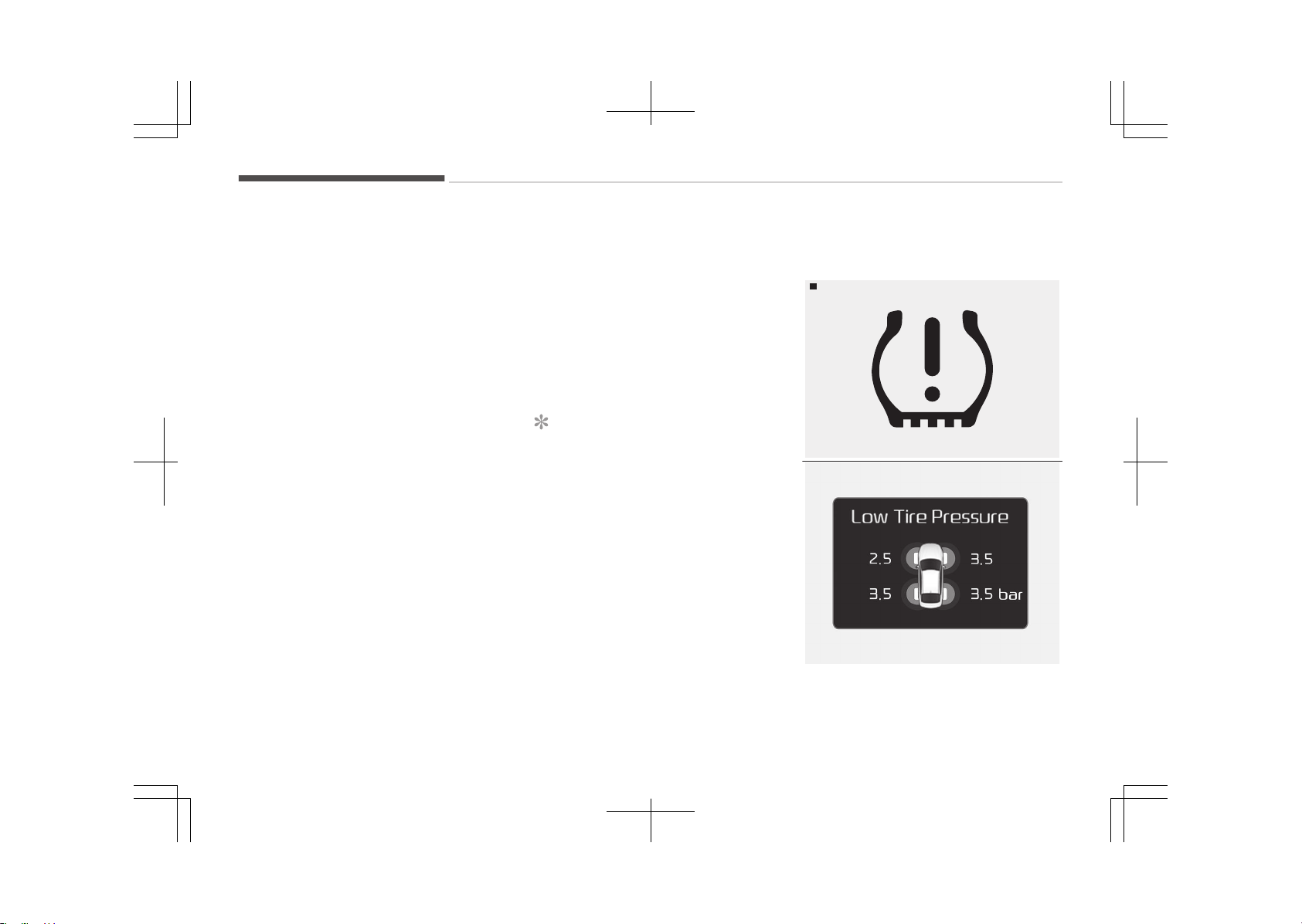
Please note that the TPMS is not a
substitute for proper tire maintenance,
and it is the driver’s responsibility to
maintain correct tire pressure, even if
under-inflation has not reached the
level to trigger illumination of the TPMS
low tire pressure telltale.
Your vehicle has also been equipped
with a TPMS malfunction indicator to
indicate when the system is not oper‐
ating properly. The TPMS malfunction
indicator is combined with the low tire
pressure telltale. When the system de‐
tects a malfunction, the telltale will
flash for approximately 1 minute and
then remain continuously illuminated.
This sequence will continue upon sub‐
sequent vehicle start-ups as long as
the malfunction exists. When the TPMS
malfunction indicator remains illumina‐
ted after blinking for approximately 1
minute, the system may not be able to
detect or signal low tire pressure as in‐
tended.
TPMS malfunctions may occur for a va‐
riety of reasons, including the installa‐
tion of replacement or alternate tires
or wheels on the vehicle that prevent
the TPMS from functioning properly.
Always check the TPMS malfunction
telltale after replacing one or more
tires or wheels on your vehicle to en‐
sure that the replacement or alternate
tires and wheels allow the TPMS to
continue to function properly.
NOTICE
If any of the below happens, we rec‐
ommend that the system be
checked by an authorized Kia dealer.
1. The low tire pressure telltale/
TPMS malfunction indicator do
not illuminate for 3 seconds
when the ignition switch is
turned to the ON position or en‐
gine is running.
2. The TPMS malfunction indicator
remains illuminated after blink‐
ing for approximately 1 minute.
3. The Low tire pressure position
telltale remains illuminated.
Low tire pressure position
telltale
Low tire pressure telltale
WBH-11
OJF065025LB
■ Low tire pressure position information
What to do in an emergency
8-10
When the tire pressure monitoring sys‐
tem warning indicators are illuminated
and warning massage displayed on the
cluster LCD display, one or more of
your tires is significantly under-infla‐
ted. The low tire pressure position tell‐
tale light will indicate which tire is sig‐
nificantly under-inflated by illuminating
the corresponding position light.
If either telltale illuminates, immediate‐
ly reduce your speed, avoid hard cor‐
nering and anticipate increased stop‐
ping distances. You should stop and
check your tires as soon as possible. In‐
flate the tires to the proper pressure as
indicated on the vehicle’s placard or tire
inflation pressure label located on the
driver’s side center pillar outer panel. If
you cannot reach a service station or if
the tire cannot hold the newly added
air, replace the low pressure tire with a
spare tire.
If you drive the vehicle for about 10 mi‐
nutes at speeds above 25 km/h after
replacing the low pressure tire with the
spare tire, one of the following will hap‐
pen:
• The TPMS malfunction indicator may
blink for approximately 1 minute and
then remain continuously illuminated
because the TPMS sensor is not
mounted on the spare wheel.
(changed tire equipped with a sensor
not in the vehicle)
• The TPMS malfunction indicator will
remain continuously illuminated while
driving because the TPMS sensor is
not mounted on the spare wheel.
(changed tire equipped with a sensor
in the vehicle)
CAUTION
In winter or cold weather, the low
tire pressure telltale may illuminate
if the tire pressure was adjusted to
the recommended tire inflation pres‐
sure in warm weather. It does not
mean your TPMS is malfunctioning
because the decreased temperature
leads to a lowering of tire pressure.
When you drive your vehicle from a
warm area to a cold area or from a
cold area to a warm area, or the
outside temperature is higher or
lower, you should check the tire in‐
flation pressure and adjust the tires
(Continued)
(Continued)
to the recommended tire inflation
pressure.
WARNING
n
Low pressure damage
Significantly low tire pressure makes
the vehicle unstable and can contrib‐
ute to loss of vehicle control and in‐
creased braking distances.
Continued driving on low pressure
tires can cause the tires to overheat
and fail.
TPMS (Tire Pressure
Monitoring System)
malfunction indicator
The TPMS malfunction indi‐
cator will illuminate after it blinks for
approximately one minute when there
is a problem with the Tire Pressure
Monitoring System.
We recommend that the system be
checked by an authorized Kia dealer to
determine the cause of the problem.
8-11
8
What to do in an emergency

NOTICE
If there is a malfunction with the
TPMS, the low tire pressure position
telltale will not be displayed even
though the vehicle has an under-in‐
flated tire.
CAUTION
• The TPMS malfunction indicator
may blink for approximately 1 mi‐
nute and then remain continuously
illuminated if the vehicle is moving
around electric power supply ca‐
bles or radio transmitters such as
at police stations, government and
public offices, broadcasting sta‐
tions, military installations, air‐
ports, or transmitting towers, etc.
This can interfere with normal op‐
eration of the Tire Pressure Moni‐
toring System (TPMS).
(Continued)
(Continued)
• The TPMS malfunction indicator
may blink for approximately 1 mi‐
nute and then remain continuously
illuminated if snow chains are used
or some separate electronic devi‐
ces such as notebook computer,
mobile charger, remote starter or
navigation etc., are used in the ve‐
hicle.
This can interfere with normal op‐
eration of the Tire Pressure Moni‐
toring System (TPMS).
Changing a tire with TPMS
If you have a flat tire, the low Tire
Pressure and Position telltales will
come on. We recommend that the sys‐
tem be checked by an authorized Kia
dealer.
CAUTION
We recommend that you use the
sealant approved by Kia.
The sealant on the tire pressure
sensor and wheel shall be eliminated
when you replace the tire with a new
one.
Each wheel is equipped with a tire pres‐
sure sensor mounted inside the tire be‐
hind the valve stem. You must use
TPMS specific wheels. It is recommen‐
ded that you have your tires serviced
by an authorized Kia dealer.
If you drive the vehicle for about 10 mi‐
nutes at speeds above 25 km/h after
replacing the low pressure tire with the
spare tire, one of the following will hap‐
pen:
• The TPMS malfunction indicator may
blink for approximately 1 minute and
then remain continuously illuminated
because the TPMS sensor is not
mounted on the spare wheel.
(changed tire equipped with a sensor
not in the vehicle)
• The TPMS malfunction indicator will
remain continuously illuminated while
driving because the TPMS sensor is
not mounted on the spare wheel.
(changed tire equipped with a sensor
in the vehicle)
What to do in an emergency
8-12
You may not be able to identify a low
tire by simply looking at it. Always use
a good quality tire pressure gauge to
measure the tire's inflation pressure.
Please note that a tire that is hot (from
being driven) will have a higher pres‐
sure measurement than a tire that is
cold (from sitting stationary for at
least 3 hours and driven less than
1.6 km (1 mile) during that 3 hour peri‐
od).
Allow the tire to cool before measuring
the inflation pressure. Always be sure
the tire is cold before inflating to the
recommended pressure.
A cold tire means the vehicle has been
sitting for 3 hours and driven for less
than 1.6 km (1 mile) in that 3 hour peri‐
od.
CAUTION
We recommend that you use the
sealant approved by Kia if your vehi‐
cle is equipped with a Tire Pressure
Monitoring System. The liquid seal‐
ant can damage the tire pressure
sensors.
WARNING
n
TPMS
• The TPMS cannot alert you to se‐
vere and sudden tire damage
caused by external factors such as
nails or road debris.
• If you feel any vehicle instability,
immediately take your foot off the
accelerator, apply the brakes grad‐
ually and with light force, and
slowly move to a safe position off
the road.
WARNING
n
Protecting TPMS
Tampering with, modifying, or disa‐
bling the Tire Pressure Monitoring
System (TPMS) components may in‐
terfere with the system's ability to
warn the driver of low tire pressure
conditions and/or TPMS malfunc‐
tions. Tampering with, modifying, or
disabling the Tire Pressure Monitor‐
ing System (TPMS) components may
void the warranty for that portion of
the vehicle.
WARNING
n
For EUROPE
• Do not modify the vehicle, it may
interfere with the TPMS function.
• The wheels on the market do not
have a TPMS sensor.
For your safety, we recommend
that you use parts for replace‐
ment from an authorized Kia deal‐
er.
• If you use the wheels on the mar‐
ket, use a TPMS sensor approved
by a Kia dealer.
If your vehicle is not equipped with
a TPMS sensor or TPMS does not
work properly, you may fail the
periodic vehicle inspection conduc‐
ted in your country.
❈ All vehicles sold in the EUROPE
market during below period
must be equipped with TPMS.
- New model vehicle:
Nov. 1, 2012 ~
- Current model vehicle:
Nov. 1, 2014 ~ (Based on vehi‐
cle registrations)
8-13
8
What to do in an emergency
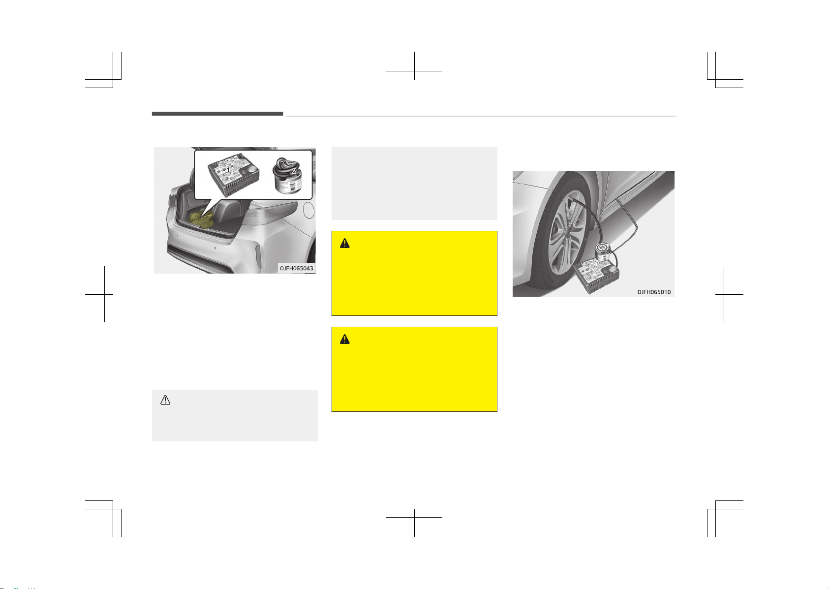
IF YOU HAVE A FLAT TIRE (WITH TIRE MOBILITY KIT, IF EQUIPPED)
Please read the instructions before us‐
ing the Tire Mobility Kit.
1. Compressor
2. Sealant bottle
The Tire Mobility Kit is a temporary fix
to the tire and we recommend that the
tire is inspected by an authorized Kia
dealer as soon as possible.
CAUTION
n
One sealant for one tire
(Continued)
(Continued)
When two or more tires are flat, do
not use the tire mobility kit because
the supported one sealant of Tire
Mobility Kit is only used for one flat
tire.
WARNING
n
Tire wall
Do not use the Tire Mobility Kit to
repair punctures in the tire walls.
This can result in an accident due to
tire failure.
WARNING
n
Temporary fix
Have your tire repaired as soon as
possible. The tire may lose air pres‐
sure at any time after inflating with
the Tire Mobility Kit.
Introduction
With the Tire Mobility Kit (TMK) you
stay mobile even after experiencing a
tire puncture.
The system of compressor and sealing
compound effectively and comfortably
seals most punctures in a passenger
car tire caused by nails or similar ob‐
jects and reinflates the tire.
After you ensured that the tire is prop‐
erly sealed you can drive cautiously on
the tire (up to 200 km (120 miles)) at a
max. speed of 80 km/h (50 mph) in or‐
der to reach a vehicle or tire dealer to
have the tire replaced.
What to do in an emergency
8-14
It is possible that some tires, especially
with larger punctures or damage to the
sidewall, cannot be sealed completely.
Air pressure loss in the tire may ad‐
versely affect tire performance.
For this reason, you should avoid
abrupt steering or other driving ma‐
neuvers, especially if the vehicle is
heavily loaded or if a trailer is in use.
The TMK is not designed or intended as
a permanent tire repair method and is
to be used for one tire only.
This instruction shows you step by step
how to temporarily seal the puncture
simply and reliably.
Read the section Notes on the safe
use of the TMK on page 8-20.
WARNING
Do not use the TMK if a tire is se‐
verely damaged by driving run flat or
with insufficient air pressure.
Only punctured areas located within
the tread region of the tire can be
sealed using the TMK.
8-15
8
What to do in an emergency
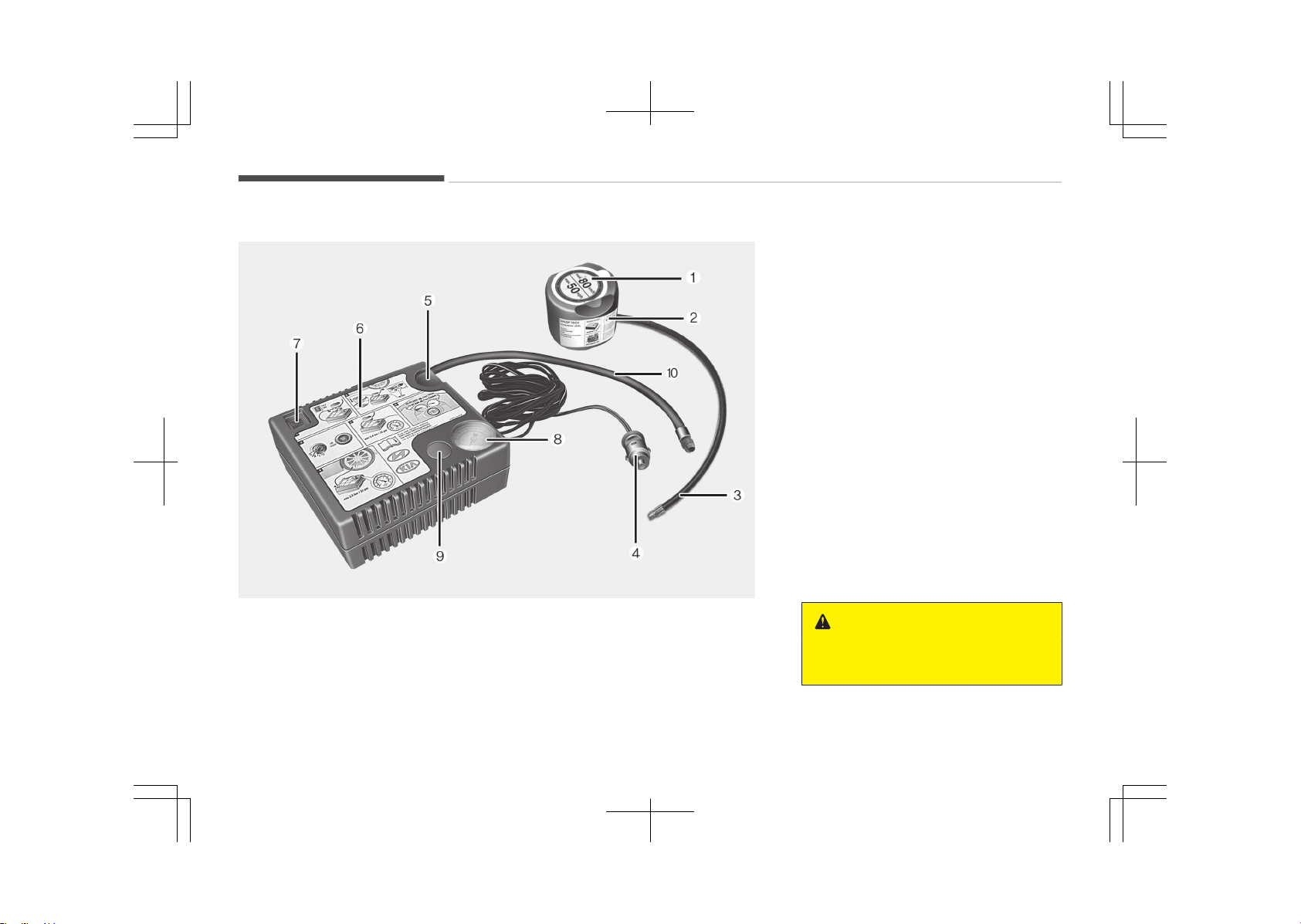
Components of the Tire Mobility Kit (TMK)
OJF0650045
1. Speed restriction label
2. Sealant bottle and label with speed
restriction
3. Filling hose from sealant bottle to
wheel
4. Connectors and cable for the bat‐
tery direct connection
5. Holder for the sealant bottle
6. Compressor
7. On/off switch
8. Pressure gauge for displaying the
tire inflation pressure
9. Button for reducing tire inflation
pressure
10. Hose to connect compressor and
sealant bottle or compressor and
wheel
Connectors, cable and connection hose
are stored in the compressor housing.
WARNING
n
Expired sealant
(Continued)
What to do in an emergency
8-16
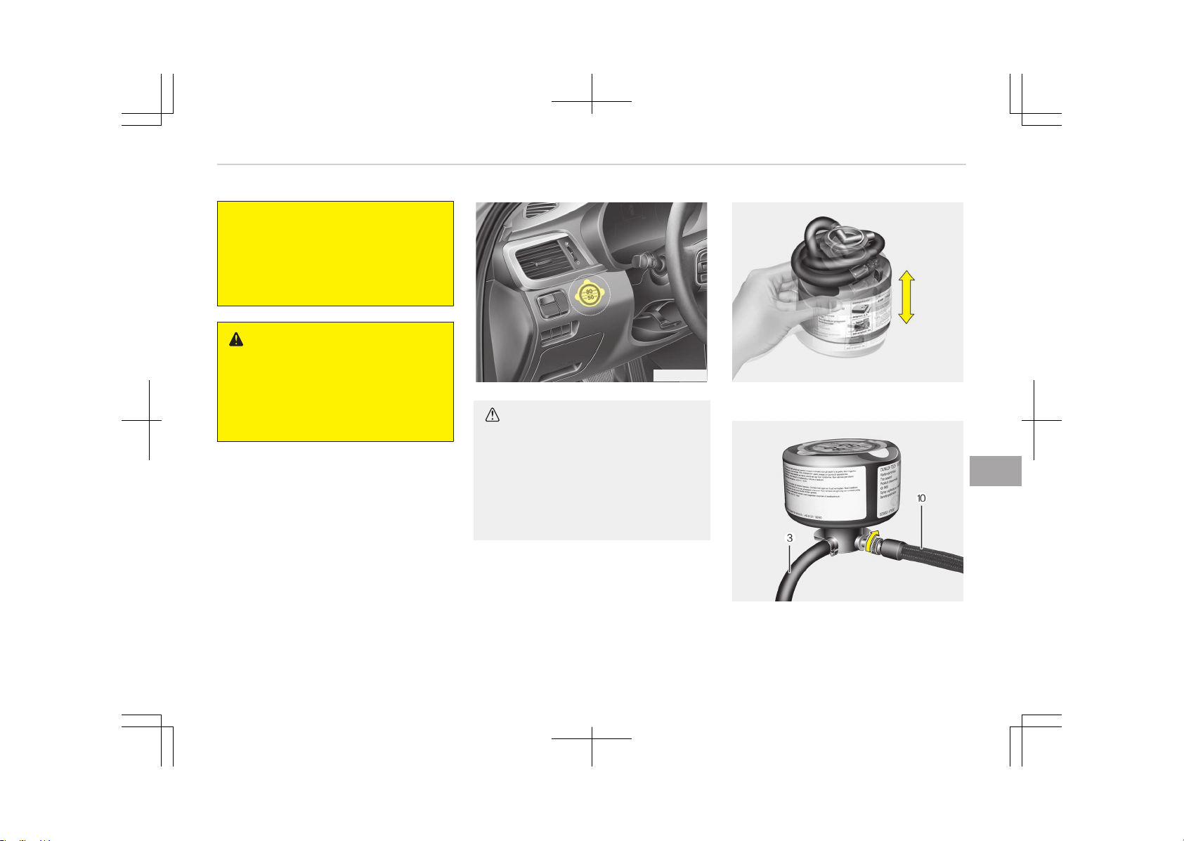
(Continued)
Do not use the tire sealant after the
sealant has expired (i.e. past the ex‐
piration date on the sealant contain‐
er). This can increase the risk of tire
failure.
WARNING
n
Sealant
• Keep out of reach of children.
• Avoid contact with eyes.
• Do not swallow.
Strictly follow the specified sequence,
otherwise the sealant may escape un‐
der high pressure.
OJF065012
CAUTION
Before using the tire repair kit,
please read carefully the instruction
attached on the sealant case. Detach
the speed limit label on the sealant
case and put it on a highly visible
place. Always drive within the speed
limit.
Using the TMK
Carefully follow below steps.
OTAM061022
1. Shake the sealant case.
OJFH065044
2. Screw connection hose (10) onto
the connector of the sealant bottle.
8-17
8
What to do in an emergency
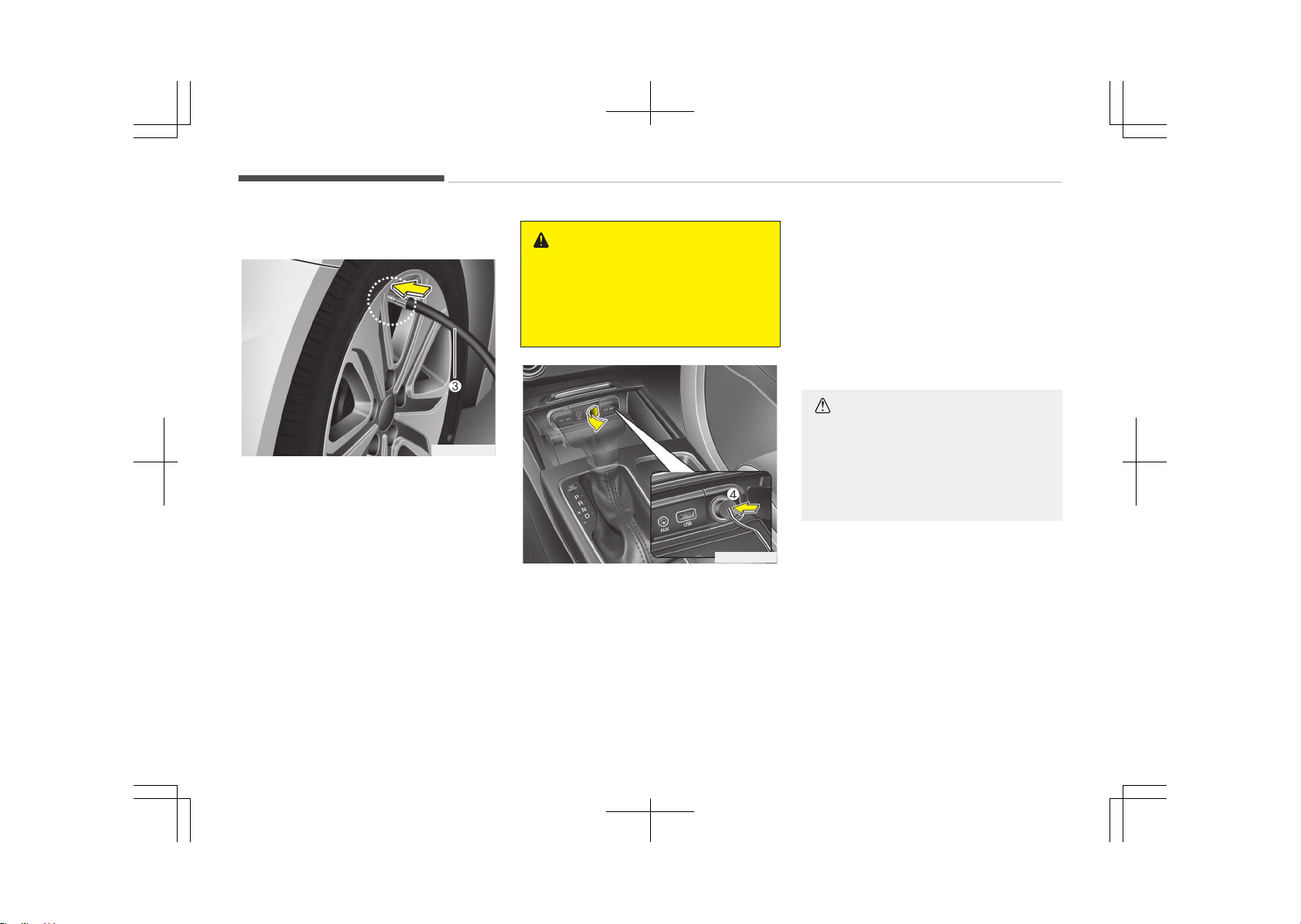
3. Ensure that button (9) on the com‐
pressor is not pressed.
OJFH065013
4. Unscrew the valve cap from the
valve of the flat tire and screw fill‐
ing hose (3) of the sealant bottle
onto the valve.
5. Insert the sealant bottle into the
housing (5) of the compressor so
that the bottle is upright.
6. Ensure that the compressor is
switched off, position 0.
WARNING
If sealant is dispersed when the in‐
jection hose and tire air injection
valve have not been fully connected,
the sealant may overflow and clog
the valve.
OJFA066038
7. Connect between compressor and
the vehicle power outlet using the
cable and connectors (4).
8. With the engine start/stop button
position on or ignition switch posi‐
tion on, switch on the compressor
and let it run for approximately 5~7
minutes to fill the sealant up to
proper pressure. (refer to Tires
and wheels on page 10-09). The
inflation pressure of the tire after
filling is unimportant and will be
checked/corrected later.
Be careful not to overinflate the
tire and stay away from the tire
when filling it.
When the tire and wheel are dam‐
aged, do not use Tire Mobility Kit
for your safety.
CAUTION
n
Tire pressure
Do not attempt to drive your vehicle
if the tire pressure is below 200 kPa
(29 psi). This could result in an acci‐
dent due to sudden tire failure.
9. Switch off the compressor.
10. Detach the hoses from the sealant
bottle connector and from the tire
valve.
Return the TMK to its storage location
in the vehicle.
What to do in an emergency
8-18
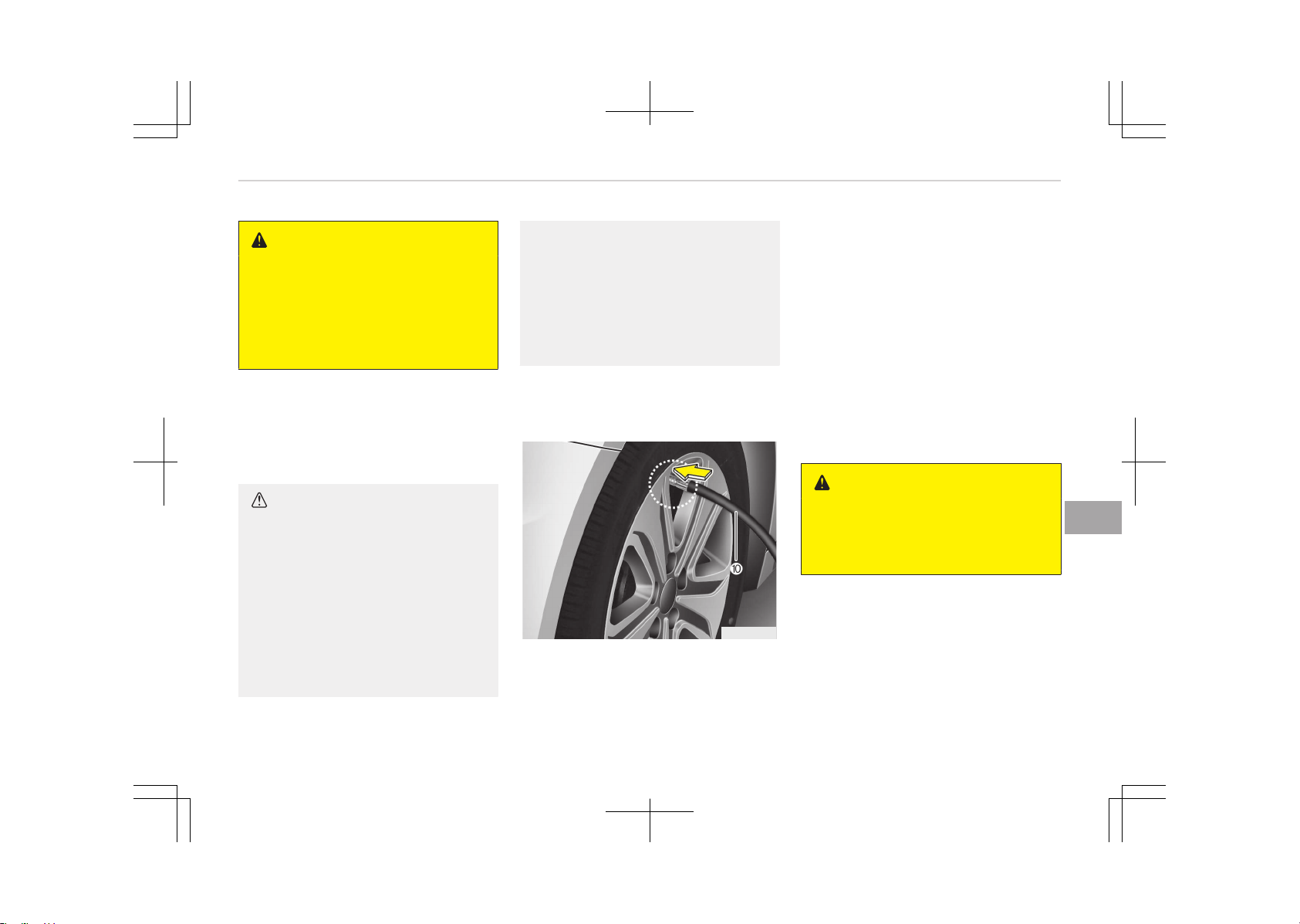
WARNING
n
Carbon monoxide
Carbon monoxide poisoning and suf‐
focation is possible if the engine is
left running in a poorly ventilated or
unventilated location (such as inside
a building).
Distributing the sealant
11. Immediately drive approximately
7~10 km (4~6 miles or, about 10
min) to evenly distribute the seal‐
ant in the tire.
CAUTION
Do not exceed a speed of 80 km/h
(50 mph). If possible, do not fall be‐
low a speed of 20 km/h (12 mph).
While driving, if you experience any
unusual vibration, ride disturbance
or noise, reduce your speed and
drive with caution until you can
safely pull off of the side of the
road. Call for road side service or
towing.
(Continued)
(Continued)
When you use the Tire Mobility Kit,
the tire pressure sensors and wheel
may be stained by sealant. There‐
fore, remove the tire pressure sen‐
sors and wheel stained by sealant
and we recommend to have it in‐
spected by an authorized Kia dealer.
Checking the tire inflation
pressure
OJFH065015
1. After driving approximately
7~10 km (4~6 miles, or about 10
minutes), stop at a suitable loca‐
tion.
2. Connect connection hose (10) of
the compressor directly to the tire
valve.
3. Connect between compressor and
the vehicle battery using the cable
and connectors.
4. Adjust the tire inflation pressure to
200 kPa (29 psi). With the ignition
switched on, proceed as follows.
- To increase the inflation pres‐
sure: Switch on the compressor,
position I. To check the current
inflation pressure setting, briefly
switch off the compressor.
WARNING
Do not let the compressor run for
more than 10 minutes, otherwise
the device will overheat and may be
damaged.
- To reduce the inflation pressure:
Press the button (9) on the com‐
pressor.
8-19
8
What to do in an emergency
CAUTION
If the inflation pressure is not main‐
tained, drive the vehicle a second
time, refer to Distributing the seal‐
ant. Then repeat steps 1 to 4.
Use of the TMK may be ineffectual
for tire damage larger than approxi‐
mately 4 mm (0.16 in).
We recommend that you contact an
authorized Kia dealer if the tire can‐
not be made roadworthy with the
Tire Mobility Kit.
WARNING
The tire inflation pressure must be
at least 200 kPa (29 psi). If it is not,
do not continue driving.
Call for road side service or towing.
Notes on the safe use of the
Tire Mobility Kit
• Park your car at the side of the road
so that you can work with the TMK
away from moving traffic. Place your
warning triangle in a prominent place
to make passing vehicles aware of
your location.
• To be sure your vehicle will not move,
even when you're on fairly level
ground, always set your parking
brake.
• Only use the TMK for sealing/inflation
passenger car tires. Do not use on
motorcycles, bicycles or any other
type of tires.
• Do not remove any foreign objects
such as nails or screws -that have
penetrated the tire.
• Before using the TMK, read the pre‐
cautionary advice printed on the seal‐
ant bottle!
• Provided the car is outdoors, leave
the engine running. Otherwise oper‐
ating the compressor may eventually
drain the car battery.
• Never leave the TMK unattended
while it is being used.
• Do not leave the compressor running
for more than 10 min. at a time or it
may overheat.
• Do not use the TMK if the ambient
temperature is below -30°C (-22°F).
• When the tire and wheel are dam‐
aged, do not use Tire Mobility Kit for
your safety.
Technical data
System voltage: DC 12 V
Working voltage: DC 10 - 15 V
Amperage rating: max. 15 A
Suitable for use at temperatures:
-30 ~ +70°C (-22 ~ +158°F)
Max. working pressure: 6 bar (87 psi)
Size
Compressor: 168 x 150 x 68 mm
(6.6 x 5.9 x 2.7 in)
Sealant bottle: 104 x 85 ø mm
(4.1 x 3.3 ø in.)
Compressor weight: 1.05 kg (2.31 lbs)
Sealant volume: 300 ml (18.3 cu. in.)
❈ Sealant and spare parts can be ob‐
tained and replaced at an author‐
ized vehicle or tire dealer. Empty
sealant bottles may be disposed of
at home. Liquid residue from the
sealant should be disposed of by
your vehicle or tire dealer or in ac‐
cordance with local waste disposal
regulations.
What to do in an emergency
8-20
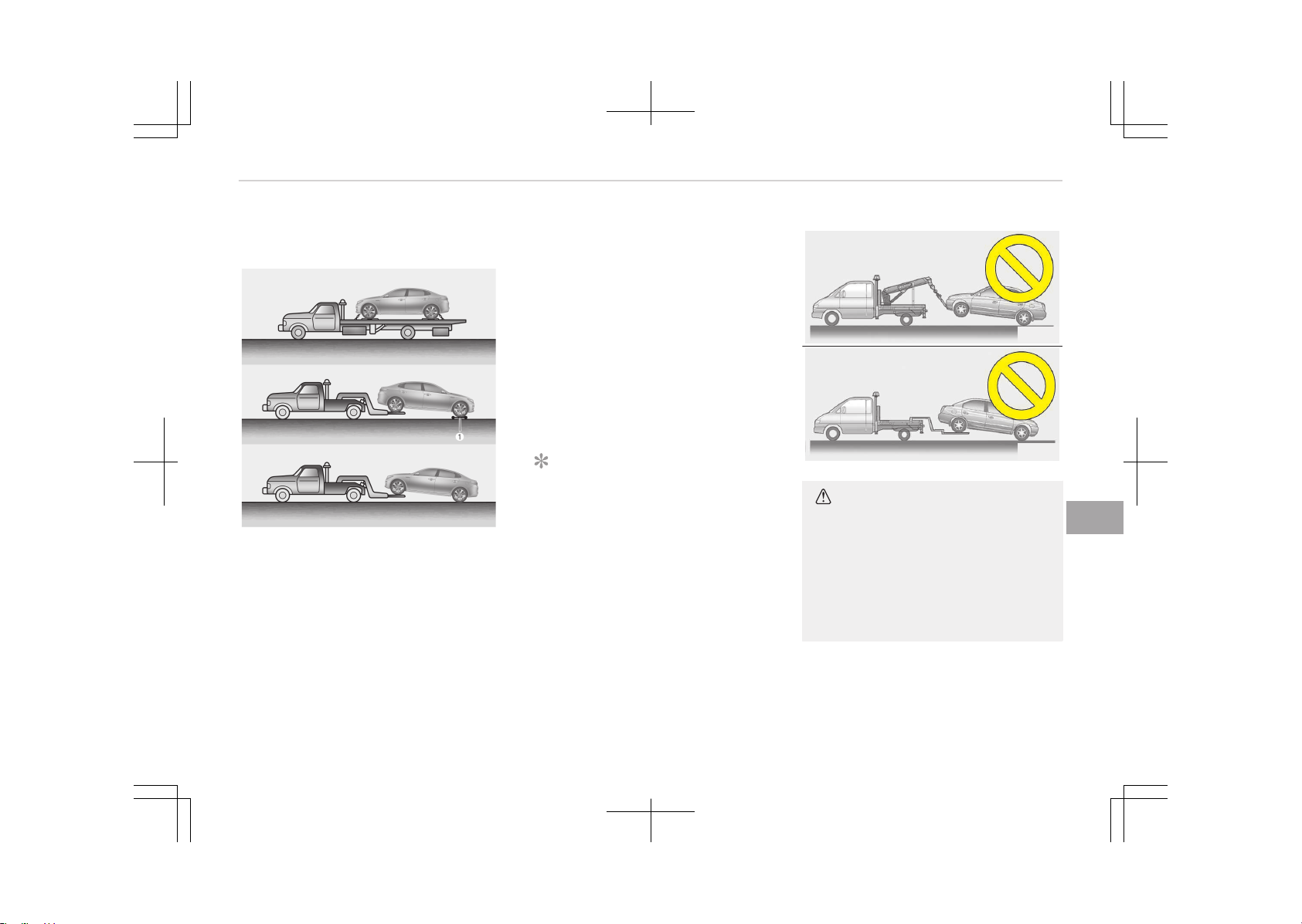
TOWING
Towing service
OJF075158L
If emergency towing is necessary, we
recommend having it done by an au‐
thorized Kia dealer or a commercial
tow-truck service. Proper lifting and
towing procedures are necessary to
prevent damage to the vehicle. The use
of wheel dollies (1) or flatbed is recom‐
mended.
It is acceptable to tow the vehicle with
the rear wheels on the ground (without
dollies) and the front wheels off the
ground.
If any of the loaded wheels or suspen‐
sion components are damaged or the
vehicle is being towed with the front
wheels on the ground, use a towing
dolly under the front wheels.
When being towed by a commercial
tow truck and wheel dollies are not
used, the front of the vehicle should al‐
ways be lifted, not the rear.
NOTICE
If the EPB does not release normally,
we recommend that you contact an
authorized Kia dealer.
HXD02
HXD03
CAUTION
• Do not tow the vehicle backwards
with the front wheels on the
ground as this may cause damage
to the vehicle.
• Do not tow with sling-type equip‐
ment. Use wheel lift or flatbed
equipment.
When towing your vehicle in an emer‐
gency without wheel dollies:
1. Set the ignition switch in the ACC
position.
8-21
8
What to do in an emergency
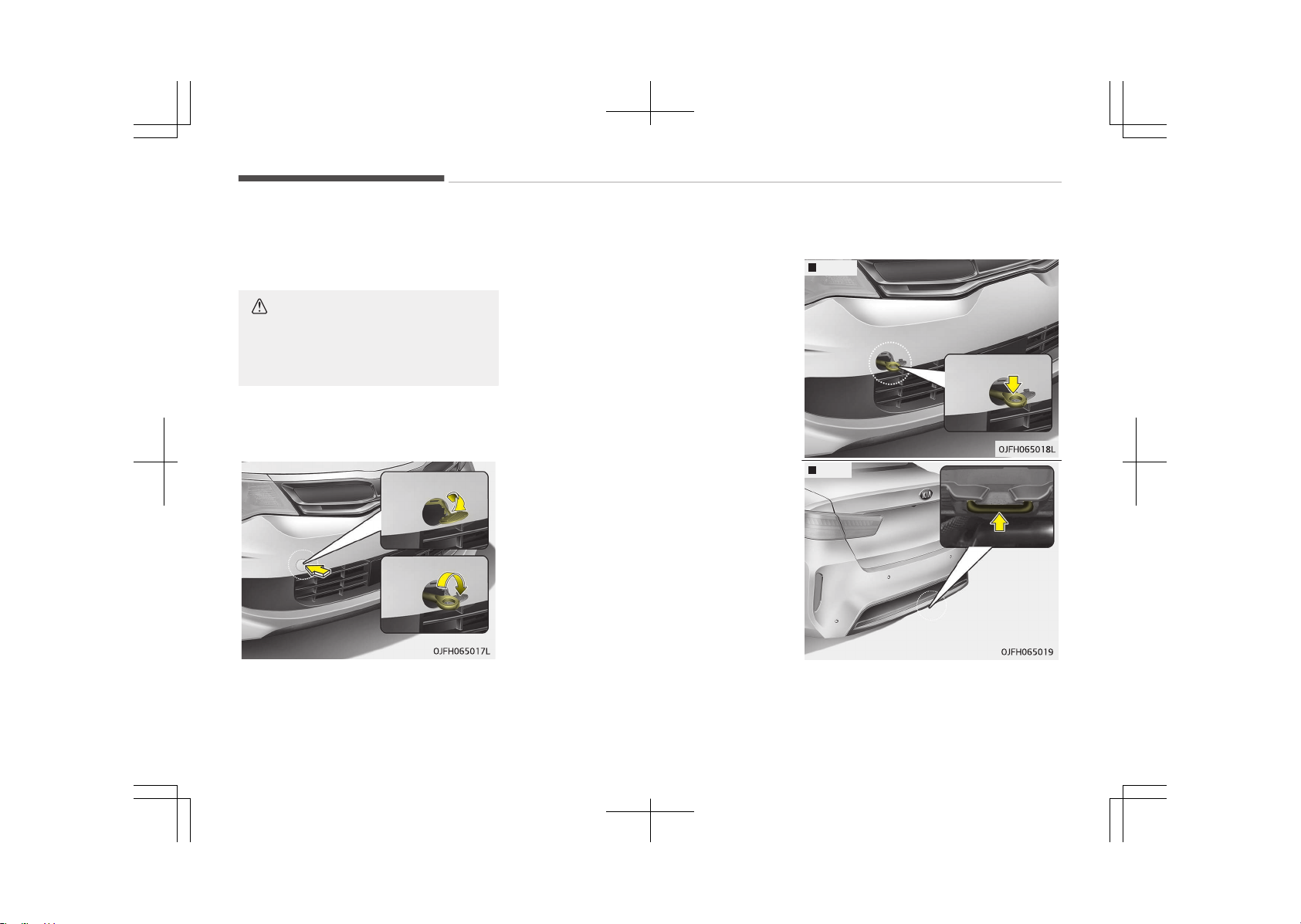
2. Place the transaxle shift lever in N
(Neutral).
3. Release the parking brake.
CAUTION
Failure to place the transaxle shift
lever in N (Neutral) may cause inter‐
nal damage to the transaxle.
Removable towing hook (if
equipped)
1. Open the trunk, and remove the
towing hook from the tool case.
2. Remove the hole cover pressing the
lower part of the cover on the
bumper.
3. Install the towing hook by turning it
clockwise into the hole until it is
fully secured.
4. Remove the towing hook and install
the cover after use.
Emergency towing
Front
Rear
What to do in an emergency
8-22
If towing is necessary, we recommend
you to have it done by an authorized
Kia dealer or a commercial tow truck
service.
If towing service is not available in an
emergency, your vehicle may be tem‐
porarily towed using a cable or chain
secured to the emergency towing hook
under the front (or rear) of the vehicle.
Use extreme caution when towing the
vehicle. A driver must be in the vehicle
to steer it and operate the brakes.
Towing in this manner may be done on‐
ly on hard-surfaced roads for a short
distance and at low speed. Also, the
wheels, axles, power train, steering and
brakes must all be in good condition.
• Do not use the tow hooks to pull a
vehicle out of mud, sand or other
conditions from which the vehicle
cannot be driven out under its own
power.
• Avoid towing a vehicle heavier than
the vehicle doing the towing.
• The drivers of both vehicles should
communicate with each other fre‐
quently.
CAUTION
• Attach a towing strap to the tow
hook.
• Using a portion of the vehicle oth‐
er than the tow hooks for towing
may damage the body of your ve‐
hicle.
• Use only a cable or chain specifi‐
cally intended for use in towing
vehicles. Securely fasten the cable
or chain to the towing hook provi‐
ded.
• Before emergency towing, check if
the hook is not broken or damaged.
• Fasten the towing cable or chain se‐
curely to the hook.
• Do not jerk the hook. Apply it steadily
and with even force.
• To avoid damaging the hook, do not
pull from the side or at a vertical an‐
gle. Always pull straight ahead.
WARNING
Use extreme caution when towing
the vehicle.
• Avoid sudden starts or erratic driv‐
ing maneuvers which would place
excessive stress on the emergency
towing hook and towing cable or
chain. The hook and towing cable
or chain may break and cause seri‐
ous injury or damage.
• If the disabled vehicle is unable to
be moved, do not forcibly continue
the towing. We recommend that
you contact an authorized Kia
dealer or a commercial tow truck
service for assistance.
• Tow the vehicle as straight ahead
as possible.
• Keep away from the vehicle during
towing.
8-23
8
What to do in an emergency
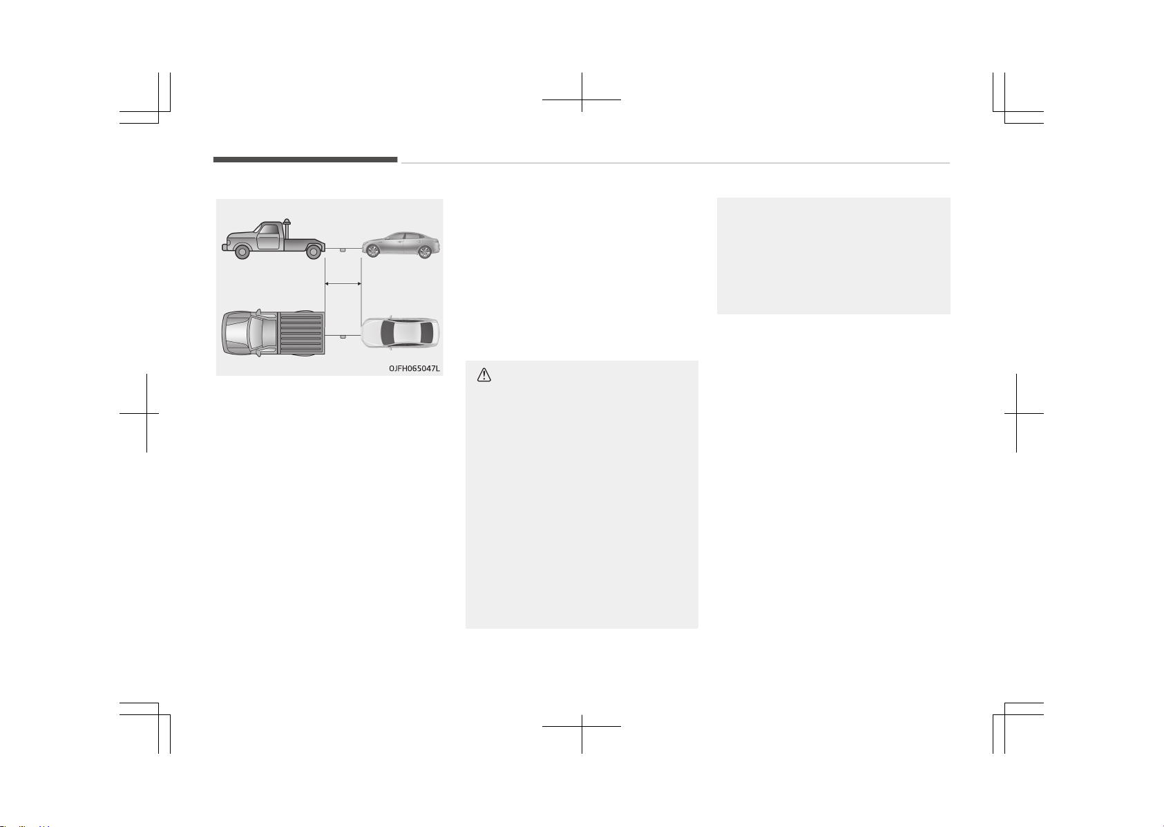
• Use a towing strap less than 5 m
(16 feet) long. Attach a white or red
cloth (about 30 cm (12 inches) wide)
in the middle of the strap for easy
visibility.
• Drive carefully so that the towing
strap is not loosened during towing.
Emergency towing precautions
• Turn the ignition switch to ACC so the
steering wheel isn’t locked.
• Place the transaxle shift lever in N
(Neutral).
• Release the parking bake.
• Press the brake pedal with more
force than normal since you will have
reduced brake performance.
• More steering effort will be required
because the power steering system
will be disabled.
• If you are driving down a long hill, the
brakes may overheat and brake per‐
formance will be reduced. Stop often
and let the brakes cool off.
CAUTION
n
Automatic transaxle
• If the car is being towed with all
four wheels on the ground, it can
be towed only from the front. Be
sure that the transaxle is in neu‐
tral. Be sure the steering is un‐
locked by placing the ignition
switch in the ACC position. A driver
must be in the towed vehicle to
operate the steering and brakes.
• To avoid serious damage to the
automatic transaxle, limit the ve‐
hicle speed to 15 km/h (10 mph)
and drive less than 1.5 km (1 mile)
when towing.
(Continued)
(Continued)
• Before towing, check the auto‐
matic transaxle for fluid leaks un‐
der your vehicle. If the automatic
transaxle fluid is leaking, flatbed
equipment or a towing dolly must
be used.
What to do in an emergency
8-24
IF AN ACCIDENT OCCURS
• Avoid the engine compartment.
• Avoid any orange or high voltage
wires, cables, or components.
• Assume that a high voltage compo‐
nent is exposed and move away from
the vehicle as promptly as possible.
• Refer to Towing on page 8-21 for
towing information.
WARNING
• After parking the vehicle, shift the
transmission into "P" position. Turn
off the hybrid system by pushing
the Engine Start/Stop button.
• For your safety, do not touch high
voltage cables, connectors and
package modules. High Voltage
components are orange in color.
• Exposed cables or wires may be
visible inside or outside of the ve‐
hicle. Never touch the wires or ca‐
bles, because an electrical shock
may occur causing injury or death.
• If a fire occurs, to extinguish a
small high-voltage battery fire,
(Continued)
(Continued)
the following techniques can be
used:
- Dry chemical
- CO2
- Large amounts of water
- Regular foam
For a large high-voltage battery
fire, use these types of extin‐
guishing methods:
- Large amounts of water
- Fog
- Regular foam
• If you need towing, refer to Tow‐
ing on page 8-21.
WARNING
If a vehicle accident occurs:
1. Stop the vehicle and shift the
transmission into "P" position
and then depress the parking
brake.
(Continued)
(Continued)
2. Turn off the Hybrid system by
pushing the Engine Start/Stop
Button.
3. Evacuate to the safety place.
4. Call emergency services for help
and let them know the vehicle is
a Hybrid vehicle.
Do not touch high voltage cables,
connectors and package mod‐
ules. High voltage components
are orange in color.
Exposed cables or wires may be
visible inside or outside of the
vehicle. Never touch the wires or
cables, because an electrical
shock may occur causing injury
or death.
WARNING
If a fire occurs:
(Continued)
8-25
8
What to do in an emergency
(Continued)
1. Stop the vehicle and shift the
transmission in to "P" position,
and then depress the parking
brake. To ventilate smoke from a
fire, open the windows if possi‐
ble.
2. Turn off the Hybrid system by
pushing the Engine Start/Stop
Button.
3. Leave the vehicle and evacuate
to the safety place.
4. Call emergency services for help
and let them know the vehicle is
a Hybrid vehicle.
If you have an extinguisher, extin‐
guish a fire carefully.
Do not touch high voltage cables,
connectors and package modules.
High voltage components are orange
in color.
Exposed cables or wires may be visi‐
ble inside or outside of the vehicle.
Never touch the wires or cables, be‐
cause an electrical shock may occur
causing injury or death.
WARNING
If a submersion in water occurs:
If your vehicle was flooded and has
soaked carpeting or water on the
flooring, you should not try to start
the Hybrid system. Never touch the
high voltage cables, connectors and
package modules, because an elec‐
trical shock may occur causing injury
or death. High Voltage cables are or‐
ange in color.
We recommend that the car towed
to an authorized Kia dealer.
What to do in an emergency
8-26

EMERGENCY COMMODITY (IF EQUIPPED)
There are some emergency commodi‐
ties in the vehicle to help you respond
to the emergency situation.
First aid kit
There are some items such as scissors,
bandage and adhesive tape and etc. in
the kit to give first aid to an injured
person.
Triangle reflector
Place the triangle reflector on the road
to warn oncoming vehicles during
emergencies, such as when the vehicle
is parked by the roadside due to any
problems.
Tire pressure gauge (if
equipped)
Tires normally lose some air in day-to-
day use, and you may have to add a
few pounds of air periodically and it is
not usually a sign of a leaking tire, but
of normal wear. Always check tire pres‐
sure when the tires are cold because
tire pressure increases with tempera‐
ture.
To check the tire pressure, take the fol‐
lowing steps:
1. Unscrew the inflation valve cap
that is located on the rim of the
tire.
2. Press and hold the gauge against
the tire valve. Some air will escape
as you begin and more will escape
if you don't press the gauge in
firmly.
3. A firm non-leaking push will acti‐
vate the gauge.
4. Read the tire pressure on the
gauge to know whether the tire
pressure is low or high.
5. Adjust the tire pressures to the
specified pressure. Refer to Tires
and wheels on page 10-09.
6. Reinstall the inflation valve cap.
8-27
8
What to do in an emergency


Engine compartment................................................................9-03
Maintenance services............................................................... 9-04
Owner’s responsibility..........................................................9-04
Owner maintenance precautions....................................... 9-04
Owner maintenance................................................................. 9-06
Owner maintenance schedule.............................................9-06
Scheduled maintenance service............................................. 9-08
Scheduled maintenance service precaution..................... 9-08
Normal maintenance schedule - for gasoline en‐
gine [for Europe (except Russia)].......................................9-09
Normal maintenance schedule - for gasoline en‐
gine [for Europe (except Russia)] (Continued).................9-10
Maintenance under severe usage conditions - for
gasoline engine [for Europe (except Russia)]...................9-12
Normal maintenance schedule - for gasoline en‐
gine [except Europe (including Russia)]............................ 9-14
Normal maintenance schedule - for gasoline en‐
gine [except Europe (including Russia)] (Continued).......9-15
Maintenance under severe usage conditions - for
gasoline engine [except Europe (including Russia)]........ 9-18
Explanation of scheduled maintenance items..................... 9-21
Engine oil and filter...............................................................9-21
HSG (hybrid starter & generator) belt.............................. 9-21
Fuel filter (for gasoline)....................................................... 9-21
Fuel lines, fuel hoses and connections.............................. 9-21
Vapor hose (for gasoline engine) and fuel filler cap........9-21
Vacuum crankcase ventilation hoses ................................9-21
Air cleaner filter.....................................................................9-21
Spark plugs (for gasoline engine).......................................9-21
Cooling system...................................................................... 9-22
Coolant (Engine/Inverter).................................................... 9-22
Automatic transaxle fluid.................................................... 9-22
Brake hoses and lines...........................................................9-22
Brake fluid ............................................................................. 9-22
Parking brake ........................................................................9-22
Brake discs, pads, calipers and rotors............................... 9-22
Suspension mounting bolts................................................. 9-22
Steering gear box, linkage & boots/lower arm
ball joint.................................................................................. 9-22
Drive shafts and boots.........................................................9-22
Air conditioning refrigerant................................................. 9-23
Engine oil.....................................................................................9-24
Checking the engine oil level................................................9-24
Changing the engine oil and filter...................................... 9-24
Coolant........................................................................................ 9-26
Checking the coolant level................................................... 9-26
Engine coolant....................................................................... 9-27
Inverter coolant..................................................................... 9-27
Recommended coolant.........................................................9-28
Changing the coolant............................................................9-29
Brake fluid ................................................................................. 9-30
Checking the brake fluid level............................................. 9-30
Washer fluid............................................................................... 9-31
Checking the washer fluid level.......................................... 9-31
Parking brake ............................................................................9-32
Checking the parking brake.................................................9-32
Air cleaner.................................................................................. 9-33
Filter replacement.................................................................9-33
Climate control air filter...........................................................9-35
Filter inspection.....................................................................9-35
Maintenance
9

Wiper blades...............................................................................9-36
Blade inspection.................................................................... 9-36
Blade replacement................................................................9-36
Battery........................................................................................9-39
For best battery service...................................................... 9-39
Battery capacity label.......................................................... 9-40
Battery recharging................................................................9-41
Reset items............................................................................9-41
Tires and wheels....................................................................... 9-43
Tire care..................................................................................9-43
Recommended cold tire inflation pressures.....................9-43
Checking tire inflation pressure..........................................9-44
Tire rotation...........................................................................9-45
Wheel alignment and tire balance......................................9-46
Tire replacement...................................................................9-46
Wheel replacement...............................................................9-47
Tire traction........................................................................... 9-48
Tire maintenance.................................................................. 9-48
Tire sidewall labeling............................................................ 9-48
Low aspect ratio tire ........................................................... 9-51
Fuses........................................................................................... 9-52
Inner panel fuse replacement.............................................9-53
Engine compartment fuse replacement........................... 9-54
Fuse/relay panel description...............................................9-56
Light bulbs.................................................................................. 9-70
Bulb replacement precaution..............................................9-70
Light bulb position (front)................................................... 9-72
Light bulb position (rear)..................................................... 9-73
Light bulb position (side)......................................................9-73
Headlamp (HID type) bulb replacement............................ 9-74
Headlamp (low beam) bulb replacement.......................... 9-74
Headlamp (high beam) bulb replacement.........................9-75
Headlamp (high/low beam) LED replacement..................9-76
Front turn signal lamp bulb replacement......................... 9-76
Position lamp + DRL (LED type) bulb replacement..........9-77
Side repeater lamp bulb replacement............................... 9-77
Rear turn signal lamp bulb replacement...........................9-77
Stop and tail lamp (LED type) bulb replacement.............9-79
Back-up lamp bulb replacement........................................ 9-79
License plate lamp bulb replacement................................9-80
High mounted stop lamp bulb replacement..................... 9-81
Map lamp bulb replacement................................................9-81
Vanity mirror lamp bulb replacement............................... 9-81
Room lamp bulb replacement.............................................9-82
Personal lamp bulb replacement........................................9-83
Glove box lamp bulb replacement...................................... 9-83
Trunk lamp bulb replacement............................................. 9-83
Appearance care........................................................................9-85
Exterior care.......................................................................... 9-85
Interior care........................................................................... 9-89
Emission control system ........................................................ 9-91
Crankcase emission control system.................................. 9-91
Evaporative emission control system............................... 9-91
Exhaust emission control system......................................9-91
9
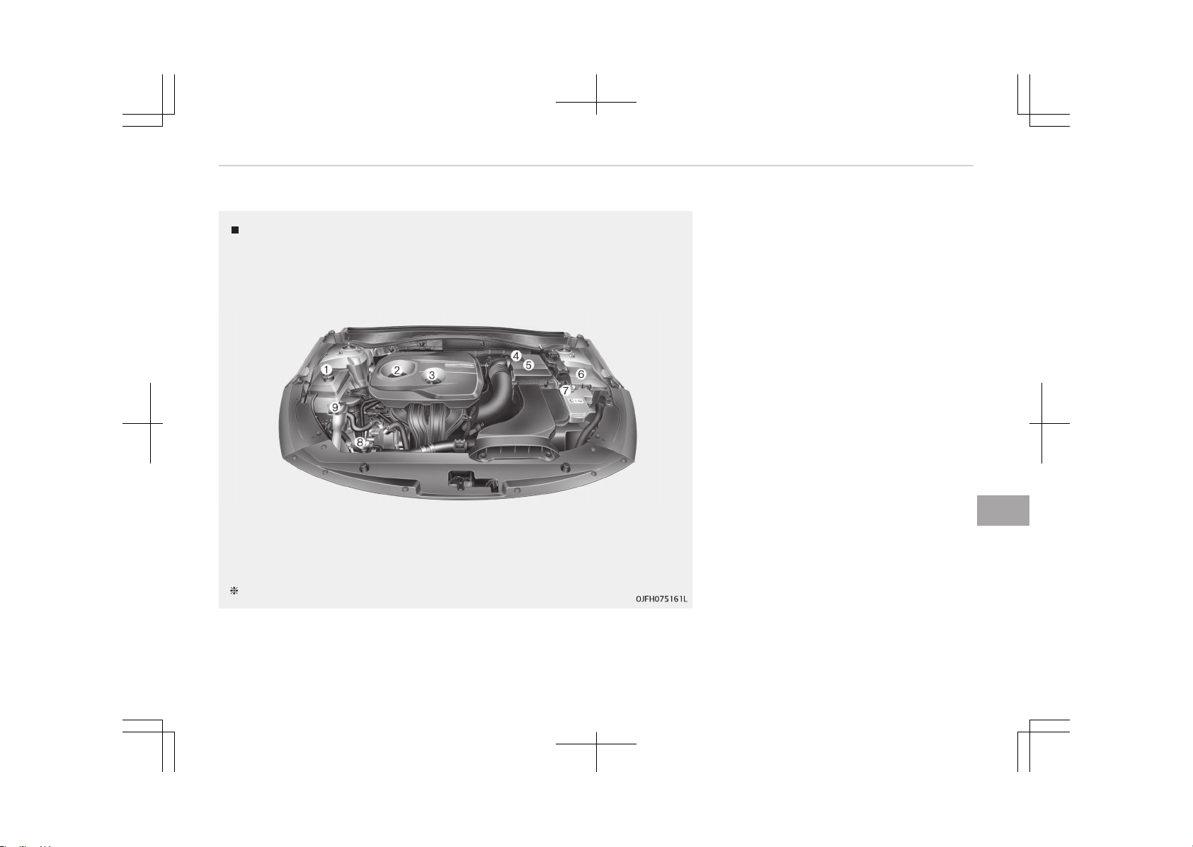
ENGINE COMPARTMENT
Gasoline Engine (Nu 2.0L - GDI)
The actual engine room in the vehicle may differ from the illustration.
1. Engine coolant reservoir
2. Engine oil filler cap
3. Engine oil dipstick
4. Brake fluid reservoir
5. Air cleaner
6. Fuse box
7. Inverter coolant reservoir
8. Radiator cap
9. Windshield washer fluid reservoir
9-03
9
Maintenance
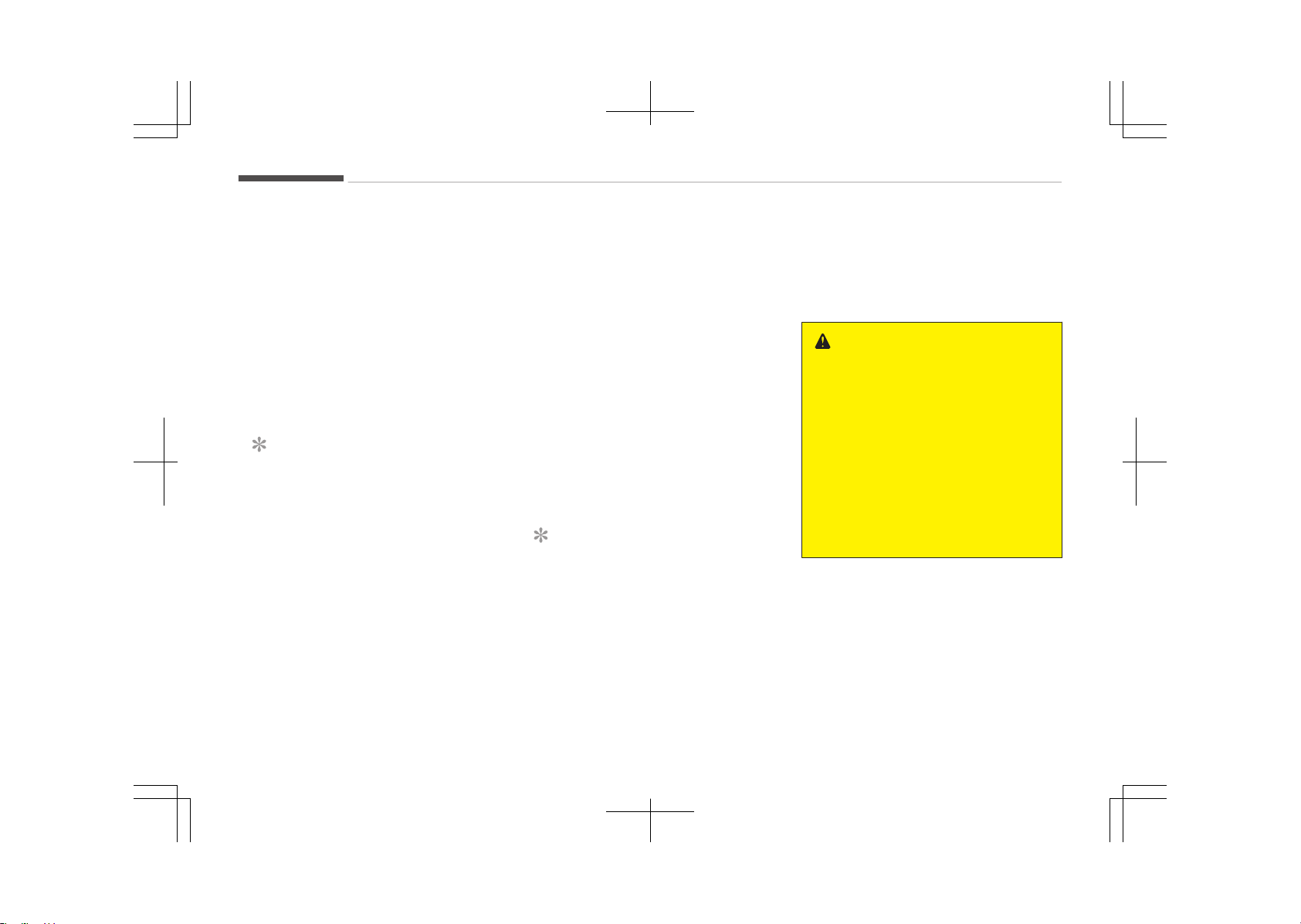
MAINTENANCE SERVICES
You should exercise the utmost care to
prevent damage to your vehicle and in‐
jury to yourself whenever performing
any maintenance or inspection proce‐
dures.
Inadequate, incomplete or insufficient
servicing may result in operational
problems with your vehicle that could
lead to vehicle damage, an accident, or
personal injury.
Owner’s responsibility
NOTICE
Maintenance Service and Record Re‐
tention are the owner's responsibili‐
ty.
We recommend in general that you
have your vehicle serviced by an au‐
thorized Kia dealer.
You should retain documents that show
proper maintenance has been per‐
formed on your vehicle in accordance
with the scheduled maintenance serv‐
ice charts shown on the following pa‐
ges.
You need this information to establish
your compliance with the servicing and
maintenance requirements of your ve‐
hicle warranties.
Detailed warranty information is provi‐
ded in your Warranty & Maintenance
book.
Repairs and adjustments required as a
result of improper maintenance or a
lack of required maintenance are not
covered when your vehicle is covered by
warranty.
Owner maintenance precautions
Improper or incomplete service may re‐
sult in problems. This section gives in‐
structions only for the maintenance
items that are easy to perform.
NOTICE
Improper owner maintenance during
the warranty period may affect
warranty coverage. For details, read
the separate Warranty & Mainte‐
nance book provided with the vehi‐
cle. If you're unsure about any serv‐
icing or maintenance procedure, we
(Continued)
(Continued)
recommend that the system be
serviced by an authorized Kia dealer.
WARNING
n
Maintenance work
• Performing maintenance work on
a vehicle can be dangerous. You
can be seriously injured while per‐
forming some maintenance proce‐
dures. If you lack sufficient knowl‐
edge and experience or the proper
tools and equipment to do the
work, we recommend that the
system be serviced by an author‐
ized Kia dealer.
(Continued)
Maintenance
9-04

(Continued)
• Working under the hood with the
engine running is dangerous. It be‐
comes even more dangerous when
you wear jewelry or loose clothing.
These can become entangled in
moving parts and result in injury.
Therefore, if you must run the en‐
gine while working under the hood,
make certain that you remove all
jewelry (especially rings, bracelets,
watches, and necklaces) and all
neckties, scarves, and similar loose
clothing before getting near the
engine or cooling fans.
CAUTION
• Do not put heavy objects or apply
excessive force on top of the en‐
gine cover (if equipped) or fuel re‐
lated parts.
• When you inspect the fuel system
(fuel lines and fuel injection devi‐
ces), we recommend that you con‐
tact an authorized kia dealer.
(Continued)
(Continued)
• Do not drive long time with the en‐
gine cover (if equipped) removed.
• When checking the engine room,
do not go near fire.
Fuel, washer fluid, etc. are flam‐
mable oils that may cause fire.
• Before touching the battery, igni‐
tion cables and electrical wiring,
you should disconnect the battery
"-" terminal. You may get an elec‐
tric shock from the electric cur‐
rent.
• When you remove the interior trim
cover with a flat bed (-) driver, be
careful not to damage the cover.
• Be careful when you replace and
clean bulbs to avoid burns or elec‐
trical shock.
9-05
9
Maintenance
OWNER MAINTENANCE
The following lists are vehicle checks
and inspections that should be per‐
formed at the frequencies indicated to
help ensure safe, dependable operation
of your vehicle.
Any adverse conditions should be
brought to the attention of your dealer
as soon as possible.
These Owner Maintenance Checks are
generally not covered by warranties
and you may be charged for labor,
parts and lubricants used.
Owner maintenance schedule
When you stop for fuel:
• Check the engine oil level.
• Check the coolant level in the coolant
reservoir.
• Check the windshield washer fluid
level.
• Look for low or under-inflated tires.
WARNING
Be careful when checking your en‐
gine coolant level when the engine is
hot. Scalding hot coolant and steam
(Continued)
(Continued)
may blow out under pressure. This
could cause burns or other serious
injury.
While operating your vehicle:
• Note any changes in the sound of the
exhaust or any smell of exhaust
fumes in the vehicle.
• Check for vibrations in the steering
wheel. Notice any increased steering
effort or looseness in the steering
wheel, or change in its straight-
ahead position.
• Notice if your vehicle constantly
turns slightly or pulls to one side
when traveling on smooth, level road.
• When stopping, listen and check for
unusual sounds, pulling to one side,
increased brake pedal travel or hard-
to-push brake pedal.
• If any slipping or changes in the oper‐
ation of your transaxle occurs, check
the transaxle fluid level.
• Check the automatic transaxle P
(Park) function.
• Check the parking brake.
• Check for fluid leaks under your vehi‐
cle (water dripping from the air con‐
ditioning system during or after use
is normal).
At least monthly:
• Check the coolant level in the engine
coolant reservoir.
• Check the operation of all exterior
lights, including the stop lights, turn
signals and hazard warning flashers.
• Check the inflation pressures of all
tires including the spare.
At least twice a year (i.e., every
spring and fall):
• Check the radiator, heater and air
conditioning hoses for leaks or dam‐
age.
• Check the windshield washer spray
and wiper operation. Clean the wiper
blades with clean cloth dampened
with washer fluid.
• Check the headlight alignment.
• Check the muffler, exhaust pipes,
shields and clamps.
• Check the lap/shoulder belts for wear
and function.
Maintenance
9-06

• Check for worn tires and loose wheel
lug nuts.
At least once a year:
• Clean the body and door drain holes.
• Lubricate the door hinges and checks,
and hood hinges.
• Lubricate the door and hood locks
and latches.
• Lubricate the door rubber weather‐
strips.
• Check the air conditioning system.
• Inspect and lubricate the automatic
transaxle linkage and controls.
• Clean the battery and terminals.
• Check the brake fluid level.
9-07
9
Maintenance

SCHEDULED MAINTENANCE SERVICE
Scheduled maintenance service
precaution
Follow the Normal Maintenance Sched‐
ule if the vehicle is usually operated
where none of the following conditions
apply. If any of the following conditions
apply, follow the Maintenance Under
Severe Usage Conditions.
• Repeated driving short distance of
less than 8 km (5 miles) in normal
temperature or less than 16 km
(10 miles) in freezing temperature
• Extensive engine idling or low speed
driving for long distances
• Driving on rough, dusty, muddy, un‐
paved, graveled or salt-spread roads
• Driving in areas using salt or other
corrosive materials or in very cold
weather
• Driving in heavy dust condition
• Driving in heavy traffic area
• Driving on uphill, downhill, or moun‐
tain road repeatedly
• Towing a trailer or using a camper, or
roof rack
• Driving as a patrol car, taxi, other
commercial use of vehicle towing
• Driving over 170 km/h (106 mph)
• Frequently driving in stop-and-go
condition
If your vehicle is operated under the
above conditions, you should inspect,
replace or refill more frequently than
the following Normal Maintenance
Schedule. After the periods or distance
shown in the chart, continue to follow
the prescribed maintenance intervals.
Maintenance
9-08

NORMAL MAINTENANCE SCHEDULE - FOR GASOLINE ENGINE [FOR EUROPE (EXCEPT RUSSIA)]
The following maintenance services must be performed to ensure good emission control and performance. Keep receipts for
all vehicle emission services to protect your warranty. Where both mileage and time are shown, the frequency of service is
determined by whichever occurs first.
NO. ITEM REMARK
*1 Coolant (Engine / Inverter)
When adding coolant, use only deionized water or soft water for your vehicle
and never mix hard water in the coolant filled at the factory. An improper
coolant mixture can result in serious malfunction or engine damage.
*2 Engine oil and engine oil filter
Check the engine oil level and leak every 500 km (350 miles) or before start‐
ing a long trip.
*3 Fuel additives (Gasoline)
Kia recommends that you use unleaded gasoline which has an octane rating
of RON (Research Octane Number) 95 / AKI (Antiknock Index) 91 or higher
(for Europe) or Octane Rating of RON (Research Octane Number) 91 / AKI
(Antiknock Index) 87 or higher (except Europe).
For customers who do not use good quality gasolines including fuel additives
regularly, and have problems starting or the engine does not run smoothly,
one bottle of additives added to the fuel tank at every 15,000 km (for Eu‐
rope, Australia and New Zealand)/10,000 km (except Europe, Australia and
New Zealand).
Additives are available from your authorized Kia dealer along with informa‐
tion on how to use them. Do not mix other additives.
*4 HSG (Hybrid Starter & Generator) belt
Inspect HSG belt for evidence of cuts, crocks, excessive wear or oil saturation
and replace if necessary. If drive belt noise occurred, readjust drive belt ten‐
sion before replace.
*5 Spark plug
For your convenience, it can be replaced prior to it's interval when you do
maintenance of other items.
9-09
9
Maintenance

NORMAL MAINTENANCE SCHEDULE - FOR GASOLINE ENGINE [FOR EUROPE (EXCEPT RUSSIA)]
(CONTINUED)
MAINTENANCE INTERVALS
Normal Maintenance Schedule - For Gasoline Engine [For Europe (Except Russia)]
Number of months or driving distance, whichever comes first
Months 12 24 36 48 60 72 84 96
Miles×1,000 10 20 30 40 50 60 70 80
Km×1,000 15 30 45 60 75 90 105 120
MAINTENANCE ITEM
Air cleaner filter I I R I I R I I
Air conditioner compressor/refrigerant I I I I I I I I
Automatic transaxle fluid No check, No service required
Battery condition I I I I I I I I
Brake discs and pads I I I I I I I I
Brake lines, hoses and connections I I I I I I I I
Brake fluid I R I R I R I R
Climate control air filter R R R R R R R R
Coolant (Engine / Inverter)
*1
At first, Replace 210,000 km (140,000 miles) or 120 months after that,
Replace every 30,000 km (20,000 miles) or 24 months
Cooling system
At first, Inspect 60,000 km (40,000 miles) or 48 months after that, Inspect
every 30,000 km (20,000 miles) or 24 months
Drive shaft and boots I I I I I I I I
Engine oil and engine oil fil‐
ter
*2
Nu 2.0L GDI R R R R R R R R
Exhaust system - I - I - I - I
Maintenance
9-10

MAINTENANCE INTERVALS
Normal Maintenance Schedule - For Gasoline Engine [For Europe (Except Russia)]
Number of months or driving distance, whichever comes first
Months 12 24 36 48 60 72 84 96
Miles×1,000 10 20 30 40 50 60 70 80
Km×1,000 15 30 45 60 75 90 105 120
MAINTENANCE ITEM
Fuel additives (Gasoline)
*3
Add every 15,000 km (10,000 miles) or 12 months
Fuel filter (Gasoline) - I - R - I - R
Fuel lines, hoses and connections - - - I - - - I
Fuel tank air filter - I - R - I - R
HSG (Hybrid Starter & Generator) belt
*4
I I I I I I R I
Parking brake - I - I - I - I
Spark plugs
*5
Nu 2.0L GDI Replace every 150,000 km (100,000 miles) or 120 months
Steering gear rack, linkage and boots I I I I I I I I
Suspension ball joints I I I I I I I I
Tire (pressure & tread wear) I I I I I I I I
Vacuum hoses and crankcase ventilation hoses I I I I I I I I
Vapor hose and fuel filler cap - - - I - - - I
I: Inspect and if necessary, adjust, correct, clean or replace.
R: Replace or change.
9-11
9
Maintenance

MAINTENANCE UNDER SEVERE USAGE CONDITIONS - FOR GASOLINE ENGINE [FOR EUROPE
(EXCEPT RUSSIA)]
MAINTENANCE ITEM
MAINTENANCE IN‐
TERVALS
DRIVING CONDITION
DRIVING CONDI‐
TION
Engine oil and engine oil filter R
Every 7,500 km (5,000 miles) or 6
months
A, B, C, D, E, F, G, J,
K, L
HSG (Hybrid Starter & Generator) belt
R
Every 45,000 km (30,000 miles) or 24
months
C, D, E, L
I
Every 7,500 km (5,000 miles) or 6
months
C, D, E, L
Air cleaner filter R
Replace more frequently depending on
the condition
C, E
Spark plugs R
Replace more frequently depending on
the condition
B, L
Automatic transaxle fluid R Every 90,000 km (60,000 miles) A, C, D, E, F, G, L
Steering gear rack, linkage and boots I
Inspect more frequently depending on
the condition
C, D, E, F, G
Suspension ball joints I
Inspect more frequently depending on
the condition
C, D, E, F, G
Brake discs and pads, calipers and rotors I
Inspect more frequently depending on
the condition
C, D, E, G
Parking brake I
Inspect more frequently depending on
the condition
C, D, G
Drive shaft and boots I
Inspect more frequently depending on
the condition
C, D, E, F, G, K
Maintenance
9-12

MAINTENANCE ITEM
MAINTENANCE IN‐
TERVALS
DRIVING CONDITION
DRIVING CONDI‐
TION
Climate control air filter R
Replace more frequently depending on
the condition
C, E, G
Maintenance operation
I: Inspect and if necessary, adjust, correct, clean or replace.
R: Replace or change.
SEVERE DRIVING CONDITIONS
A: Repeatedly driving short distance of less than 8 km (5 miles) in normal temperature or less than 16 km
(10 miles) in freezing temperature.
B: Extensive engine idling or low speed driving for long distances.
C: Driving on rough, dusty, muddy, unpaved, graveled or salt-spread roads.
D: Driving in areas using salt or other corrosive materials or in very cold weather
E: Driving in heavy dust condition.
F: Driving in heavy traffic area.
G: Driving on uphill, downhill, or mountain roads.
J: Driving in very cold weather.
K: Driving over 170 km/h (106 mph).
L: Frequently driving in stop-and-go conditions.
9-13
9
Maintenance

NORMAL MAINTENANCE SCHEDULE - FOR GASOLINE ENGINE [EXCEPT EUROPE (INCLUDING
RUSSIA)]
The following maintenance services must be performed to ensure good emission control and performance. Keep receipts for
all vehicle emission services to protect your warranty. Where both mileage and time are shown, the frequency of service is
determined by whichever occurs first.
NO. ITEM REMARK
*1 Coolant (Engine/Inverter)
When adding coolant, use only deionized water or soft water for your vehicle
and never mix hard water in the coolant filled at the factory. An improper
coolant mixture can result in serious malfunction or engine damage.
*2 Engine oil and engine oil filter
Check the engine oil level and leak every 500 km (350 miles) or before start‐
ing a long trip.
*3 Fuel additives (Gasoline)
Kia recommends that you use unleaded gasoline which has an octane rating
of RON (Research Octane Number) 95 / AKI (Antiknock Index) 91 or higher
(for Europe) or Octane Rating of RON (Research Octane Number) 91 / AKI
(Antiknock Index) 87 or higher (except Europe).
For customers who do not use good quality gasolines including fuel additives
regularly, and have problems starting or the engine does not run smoothly,
one bottle of additives added to the fuel tank at every 15,000 km (for Eu‐
rope, Australia and New Zealand)/10,000 km (except Europe, Australia and
New Zealand).
Additives are available from your authorized Kia dealer along with informa‐
tion on how to use them. Do not mix other additives.
*4 HSG (Hybrid Starter & Generator) belt
Inspect HSG belt for evidence of cuts, crocks, excessive wear or oil saturation
and replace if necessary. If drive belt noise occurred, readjust drive belt ten‐
sion before replace.
*5 Spark plug
For your convenience, it can be replaced prior to it's interval when you do
maintenance of other items.
Maintenance
9-14

NORMAL MAINTENANCE SCHEDULE - FOR GASOLINE ENGINE [EXCEPT EUROPE (INCLUDING
RUSSIA)] (CONTINUED)
MAINTENANCE INTERVALS
Normal Maintenance Schedule - For Gasoline Engine [Except Europe (Including Russia)]
Number of months or driving distance, whichever comes first
Months 12 24 36 48 60 72 84 96
Miles×1,000 10 20 30 40 50 60 70 80
Km×1,000 15 30 45 60 75 90 105 120
MAINTENANCE ITEM
Air cleaner filter
Except China, India,
Middle East
I I R I I R I I
For China, India, Mid‐
dle East
R R R R R R R R
Air conditioner compressor/refrigerant I I I I I I I I
Automatic transaxle fluid No check, no service required
Battery condition I I I I I I I I
Brake discs and pads I I I I I I I I
Brake lines, hoses and connections I I I I I I I I
Brake fluid I R I R I R I R
Climate control air filter R R R R R R R R
Coolant (Engine/Inverter)
*1
At first, replace 210,000 km (140,000 miles) or 120 months
After that, replace every 30,000 km (20,000 miles) or 24 months
Cooling system
At first, inspect 60,000 km (40,000 miles) or 48 months
After that, inspect every 30,000 km (20,000 miles) or 24 months
Drive shaft and boots I I I I I I I I
9-15
9
Maintenance

MAINTENANCE INTERVALS
Normal Maintenance Schedule - For Gasoline Engine [Except Europe (Including Russia)]
Number of months or driving distance, whichever comes first
Months 12 24 36 48 60 72 84 96
Miles×1,000 10 20 30 40 50 60 70 80
Km×1,000 15 30 45 60 75 90 105 120
MAINTENANCE ITEM
Engine oil and engine oil fil‐
ter
*2
Nu 2.0L GDI
Except Middle East, Brazil: Replace every 15,000 km (10,000 miles) or
12 months
For Middle East, Brazil: Replace every 10,000 km (6,500 miles) or 12
months
Exhaust system - I - I - I - I
Fuel additives (Gasoline)
*3
Add every 10,000 km (6,500 miles) or 6 months
Fuel filter (Gasoline) - I - R - I - R
Fuel lines, hoses and connections - - - I - - - I
Fuel tank air filter - I - R - I - R
HSG (Hybrid Starter & Generator) belt
*4
Except Middle East, Brazil: Inspect every 15,000 km (10,000 miles) or 12
months, and replace every 105,000 km (70,000 miles) or 48 months
For Brazil: Inspect every 10,000 km (6,500 miles) or 12 months, and re‐
place every 100,000 km (65,000 miles) or 48 months
For Middle East: Inspect every 10,000 km (6,500 miles) or 12 months,
and replace every 50,000 km (30,000 miles) or 24 months
Parking brake - I - I - I - I
Spark plugs
*5
Nu 2.0L GDI Replace every 150,000 km (100,000 miles) or 120 months
Steering gear rack, linkage and boots I I I I I I I I
Maintenance
9-16

MAINTENANCE INTERVALS
Normal Maintenance Schedule - For Gasoline Engine [Except Europe (Including Russia)]
Number of months or driving distance, whichever comes first
Months 12 24 36 48 60 72 84 96
Miles×1,000 10 20 30 40 50 60 70 80
Km×1,000 15 30 45 60 75 90 105 120
MAINTENANCE ITEM
Suspension ball joints I I I I I I I I
Tire (pressure & tread wear) I I I I I I I I
Vacuum hoses and crankcase ventilation hoses I I I I I I I I
Vapor hose and fuel filler cap - - - I - - - I
I: Inspect and if necessary, adjust, correct, clean or replace.
R: Replace or change.
9-17
9
Maintenance

MAINTENANCE UNDER SEVERE USAGE CONDITIONS - FOR GASOLINE ENGINE [EXCEPT EUROPE
(INCLUDING RUSSIA)]
MAINTENANCE ITEM
MAINTENANCE
INTERVALS
DRIVING CONDITION
DRIVING CONDI‐
TION
Engine oil
and engine
oil filter
Except Middle East, Brazil R
Every 7,500 km (5,000 miles) or
6 months
A, B, C, D, E, F, G, J,
K, L
For Middle East, Brazil R
Every 5,000 km (3,000 miles) or
6 months
A, B, C, D, E, F, G, J,
K, L
HSG (Hybrid
Starter &
Generator)
belt
Except Middle East, Brazil
R
Every 45,000 km (30,000 miles)
or 24 months
C, D, E, L
I
Every 7,500 km (5,000 miles) or
6 months
C, D, E, L
For Brazil
R
Every 50,000 km (30,000 miles)
or 24 months
C, D, E, L
I
Every 5,000 km (3,000 miles) or
6 months
C, D, E, L
For Middle East
R
Every 30,000 km (20,000 miles)
or 12 months
C, D, E, L
I
Every 5,000 km (3,000 miles) or
6 months
C, D, E, L
Air cleaner filter R
Replace more frequently de‐
pending on the condition
C, E
Spark plugs R
Replace more frequently de‐
pending on the condition
B, L
Automatic transaxle fluid R Every 90,000 km (60,000 miles) A, C, D, E, F, G, L
Maintenance
9-18

MAINTENANCE ITEM
MAINTENANCE
INTERVALS
DRIVING CONDITION
DRIVING CONDI‐
TION
Steering gear rack, linkage and boots I
Inspect more frequently de‐
pending on the condition
C, D, E, F, G
Suspension ball joints I
Inspect more frequently de‐
pending on the condition
C, D, E, F, G
Brake discs and pads, calipers and rotors I
Inspect more frequently de‐
pending on the condition
C, D, E, G
Parking brake I
Inspect more frequently de‐
pending on the condition
C, D, G
Drive shaft and boots I
Inspect more frequently de‐
pending on the condition
C, D, E, F, G, K
Climate control air filter R
Replace more frequently de‐
pending on the condition
C, E, G
Maintenance operation
I: Inspect and if necessary, adjust, correct, clean or replace.
R: Replace or change.
SEVERE DRIVING CONDITIONS
A: Repeatedly driving short distance of less than 8 km (5 miles) in normal temperature or less than 16 km
(10 miles) in freezing temperature.
B: Extensive engine idling or low speed driving for long distances.
C: Driving on rough, dusty, muddy, unpaved, graveled or salt-spread roads.
D: Driving in areas using salt or other corrosive materials or in very cold weather
E: Driving in heavy dust condition.
F: Driving in heavy traffic area.
G: Driving on uphill, downhill, or mountain roads.
J: Driving in very cold weather.
9-19
9
Maintenance

K: Driving over 170 km/h (106 mph).
L: Frequently driving in stop-and-go conditions.
Maintenance
9-20
EXPLANATION OF SCHEDULED MAINTENANCE ITEMS
Engine oil and filter
The engine oil and filter should be
changed at the intervals specified in
the maintenance schedule. If the vehi‐
cle is being driven in severe conditions,
more frequent oil and filter changes are
required.
HSG (hybrid starter &
generator) belt
The HSG belt should be changed at the
intervals specified in the maintenance
schedule.
Fuel filter (for gasoline)
Kia gasoline vehicle is equipped a life‐
time fuel filter that integrated with the
fuel tank. Regular maintenance or re‐
placement is not needed but depends
on fuel quality. If there are some im‐
portant safety matters like fuel flow
restriction, surging, loss of power, hard
starting problem etc, fuel filter inspec‐
tion or replace is needed.
We recommend that the fuel filter be
Inspected or replaced by an authorized
Kia dealer.
Fuel lines, fuel hoses and
connections
Check the fuel lines, fuel hoses and
connections for leakage and damage.
We recommend that the fuel lines, fuel
hoses and connections be replaced by
an authorized Kia dealer.
Vapor hose (for gasoline engine)
and fuel filler cap
The vapor hose and fuel filler cap
should be inspected at those intervals
specified in the maintenance schedule.
Make sure that a new vapor hose or
fuel filler cap is correctly replaced.
Vacuum crankcase ventilation
hoses (if equipped)
Inspect the surface of hoses for evi‐
dence of heat and/or mechanical dam‐
age. Hard and brittle rubber, cracking,
tears, cuts, abrasions, and excessive
swelling indicate deterioration. Particu‐
lar attention should be paid to examine
those hose surfaces nearest to high
heat sources, such as the exhaust
manifold.
Inspect the hose routing to assure that
the hoses do not come in contact with
any heat source, sharp edges or mov‐
ing component which might cause heat
damage or mechanical wear. Inspect all
hose connections, such as clamps and
couplings, to make sure they are se‐
cure, and that no leaks are present. Ho‐
ses should be replaced immediately if
there is any evidence of deterioration
or damage.
Air cleaner filter
We recommend that the air cleaner fil‐
ter be replaced by an authorized Kia
dealer.
Spark plugs (for gasoline engine)
Make sure to install new spark plugs of
the correct heat range.
WARNING
Do not disconnect and inspect spark
plugs when the engine is hot. You
may burn yourself.
9-21
9
Maintenance

Cooling system
Check the cooling system components,
such as the radiator, coolant reservoir,
hoses and connections for leakage and
damage. Replace any damaged parts.
Coolant (Engine/Inverter)
The coolant should be changed at the
intervals specified in the maintenance
schedule.
Automatic transaxle fluid
Automatic transaxle fluid should not be
checked under normal usage conditions.
We recommend that the automatic
transmission fluid changed by an au‐
thorized Kia dealer according to the
maintenance schedule.
NOTICE
Automatic transaxle fluid color is ba‐
sically red.
As the vehicle is driven, the auto‐
matic transaxle fluid will begin to
look darker. It is normal condition
and you should not judge the need
to replace the fluid based upon the
changed color.
CAUTION
The use of a non-specified fluid
could result in transaxle malfunction
and failure.
Use only specified automatic trans‐
axle fluid (Refer to Recommended
lubricants and capacities on page
10-11.)
Brake hoses and lines
Visually check for proper installation,
chafing, cracks, deterioration and any
leakage. Replace any deteriorated or
damaged parts immediately.
Brake fluid (if equipped)
Check the brake fluid level in the brake
fluid reservoir. The level should be be‐
tween MIN and MAX marks on the
side of the reservoir. Use only hydraulic
brake fluid conforming to DOT 3 or DOT
4 specification.
Parking brake (if equipped)
Inspect the parking brake system in‐
cluding the parking brake lever (or ped‐
al) and cables.
Brake discs, pads, calipers and
rotors
Check the pads for excessive wear,
discs for run out and wear, and calipers
for fluid leakage.
For more information on checking the
pads or lining wear limit, we recom‐
mend to refer to the Kia web site.
(https://www.kia-hotline.com)
Suspension mounting bolts
Check the suspension connections for
looseness or damage. Retighten to the
specified torque.
Steering gear box, linkage &
boots/lower arm ball joint
With the vehicle stopped and engine
off, check for excessive free-play in the
steering wheel.
Check the linkage for bends or damage.
Check the dust boots and ball joints for
deterioration, cracks, or damage. Re‐
place any damaged parts.
Drive shafts and boots
Check the drive shafts, boots and
clamps for cracks, deterioration, or
damage. Replace any damaged parts
and, if necessary, repack the grease.
Maintenance
9-22

Air conditioning refrigerant
Check the air conditioning lines and
connections for leakage and damage.
9-23
9
Maintenance
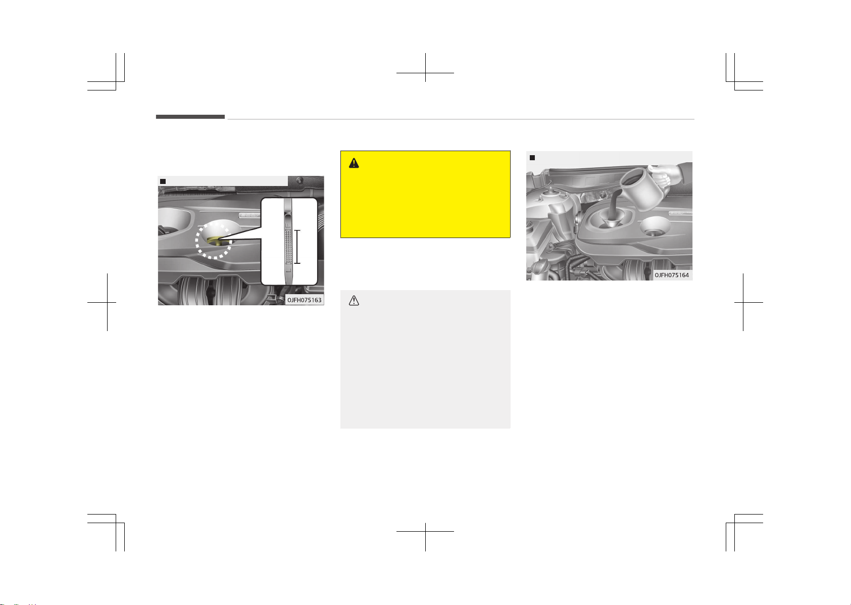
ENGINE OIL
Checking the engine oil level
Gasoline Engine (Nu 2.0L - GDI)
1. Be sure the vehicle is on level
ground.
2. Start the engine and allow it to
reach normal operating tempera‐
ture.
3. Turn the engine off and wait for a
few minutes (about 5 minutes) for
the oil to return to the oil pan.
4. Pull the dipstick out, wipe it clean,
and re-insert it fully.
WARNING
n
Radiator hose
Be very careful not to touch the ra‐
diator hose when checking or adding
the engine oil as it may be hot
enough to burn you.
5. Pull the dipstick out again and
check the level. The level should be
between F (Full) and L (Low).
CAUTION
• Do not overfill the engine oil. It
may damage the engine
• Do not spill engine oil, when adding
or changing engine oil. If you drop
the engine oil on the engine room,
wipe it off immediately.
• When you wipe the oil level gauge,
you should wipe it with a clean
cloth. When mixed with debris, it
can cause engine damage.
Gasoline Engine (Nu 2.0L - GDI)
If it is near or at L (Low), add enough oil
to bring the level to F (Full). Do not
overfill.
Use a funnel to help prevent oil from
being spilled on engine components.
Use only the specified engine oil. (Refer
to Recommended lubricants and ca‐
pacities on page 10-11.)
Changing the engine oil and
filter
We recommend that the engine oil and
filter be replaced by an authorized Kia
dealer.
Maintenance
9-24

WARNING
Used engine oil may cause skin irri‐
tation or cancer if left in contact
with the skin for prolonged periods
of time. Used engine oil contains
chemicals that have caused cancer in
laboratory animals. Always protect
your skin by washing your hands
thoroughly with soap and warm wa‐
ter as soon as possible after han‐
dling used oil.
9-25
9
Maintenance
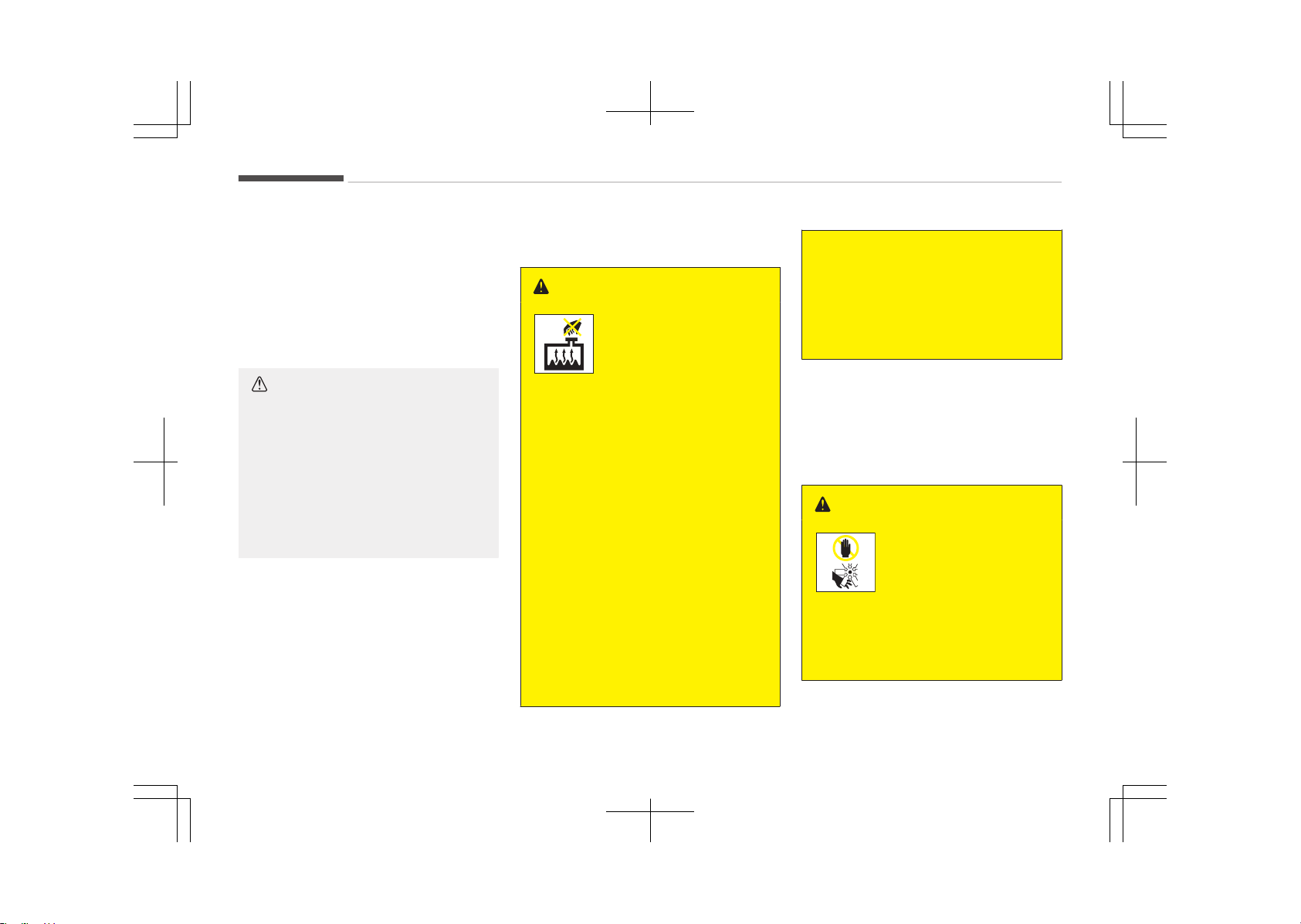
COOLANT
The high-pressure cooling system has
a reservoir filled with year round anti‐
freeze coolant. The reservoir is filled at
the factory.
Check the antifreeze protection and
coolant level at least once a year, at the
beginning of the winter season, and be‐
fore traveling to a colder climate.
CAUTION
• When the engine overheats from
low engine coolant, suddenly add‐
ing engine coolant may cause
cracks in the engine. To prevent
damage, add engine coolant slowly
in small quantities.
• Do not drive with no engine cool‐
ant. It may cause water pump fail‐
ure and engine seizure, etc.
Checking the coolant level
WARNING
n
Removing radiator cap
• Never attempt to remove the radi‐
ator cap while the engine is oper‐
ating or hot. Doing so might lead
to cooling system and engine dam‐
age. Also, hot coolant or steam
could cause serious personal in‐
jury.
• Turn the engine off and wait until
it cools down. Use extreme care
when removing the radiator cap.
Wrap a thick towel around it, and
turn it counterclockwise slowly to
the first stop. Step back while the
pressure is released from the cool‐
ing system.
When you are sure all the pressure
has been released, press down on
the cap, using a thick towel, and
continue turning counterclockwise
to remove it.
(Continued)
(Continued)
• Even if the engine is not operating,
do not remove the radiator cap or
the drain plug while the engine and
radiator are hot. Hot coolant and
steam may still blow out under
pressure, causing serious injury.
The engine coolant and/or inverter
coolant level is influenced by the hybrid
system temperature. Before checking
or refilling the engine coolant and/or in‐
verter coolant, turn the hybrid vehicle
off.
WARNING
The electric motor (cool‐
ing fan) is controlled by
engine coolant tempera‐
ture, refrigerant pressure
and vehicle speed. It may
sometimes operate even
when the engine is not
running.
(Continued)
Maintenance
9-26
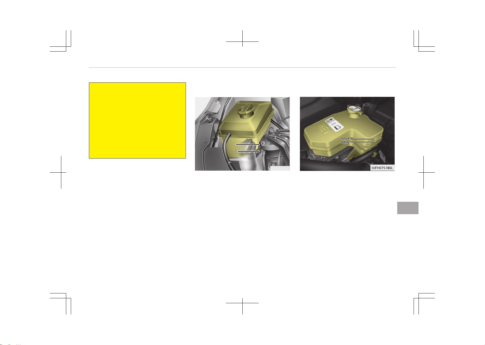
(Continued)
Use extreme caution when working
near the blades of the cooling fan so
that you are not injured by a rotat‐
ing fan blades. As the engine coolant
temperature decreases, the electric
motor will automatically shut off.
This is a normal condition.
If your vehicle is equipped with GDI,
the electric motor (cooling fan) may
operate until you disconnect the
negative battery cable.
Engine coolant
OJF075006
Check the condition and connections of
all cooling system hoses and heater ho‐
ses. Replace any swollen or deteriora‐
ted hoses.
The coolant level should be filled be‐
tween F (Full) and L (Low) marks on the
side of the coolant reservoir when the
engine is cool.
If the coolant level is low, add enough
specified coolant to provide protection
against freezing and corrosion. Bring
the level to F (Full), but do not overfill.
If frequent additions are required, we
recommend that the system be inspec‐
ted by an authorized Kia dealer.
Inverter coolant
Check the condition and connections of
all cooling system hoses. Replace any
swollen or deteriorated hoses.
The coolant level should be filled be‐
tween MAX and MIN marks on the side
of the coolant reservoir when the en‐
gine is cool.
If the coolant level is low, add enough
specified coolant to provide protection
against freezing and corrosion. Bring
the level to MAX, but do not overfill. If
frequent additions are required, we rec‐
ommend that the system be inspected
by an authorized Kia dealer.
9-27
9
Maintenance
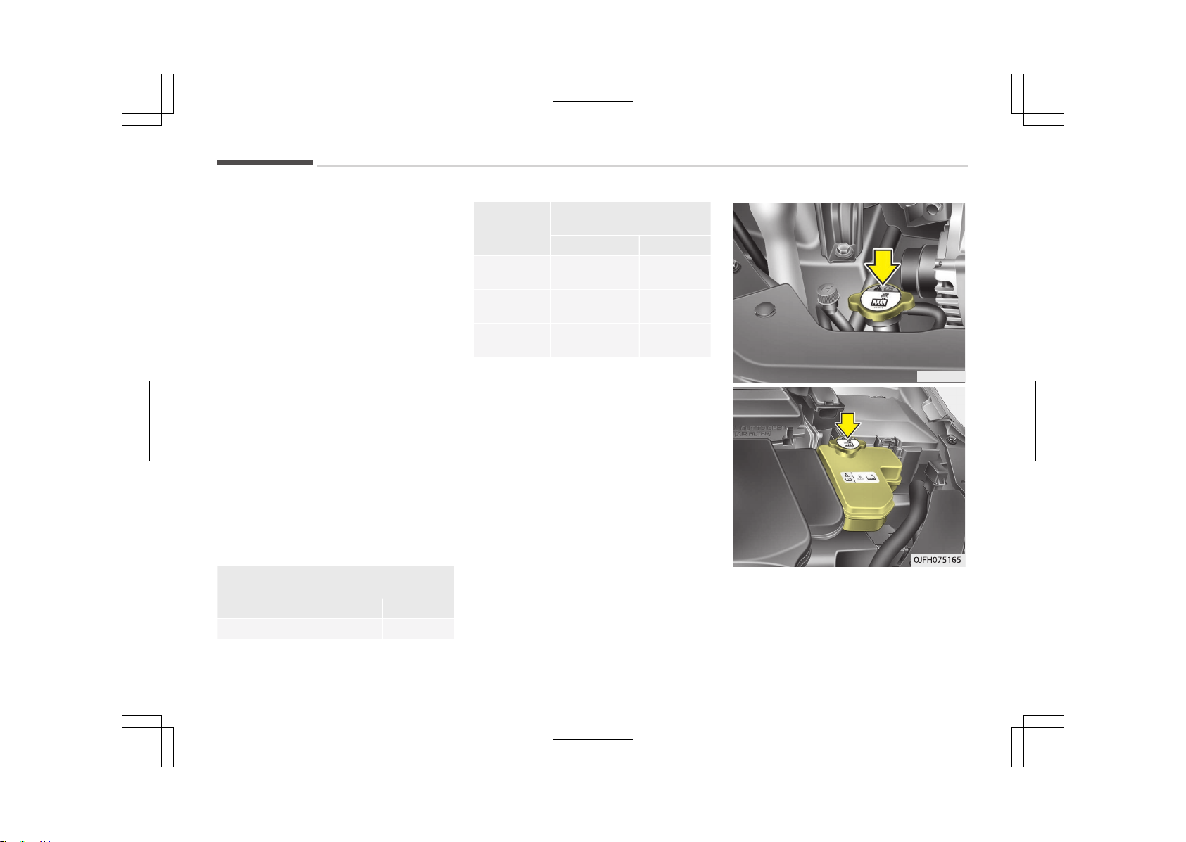
Recommended coolant
• When adding coolant, use only deion‐
ized water or soft water for your ve‐
hicle and never mix hard water in the
coolant filled at the factory. An im‐
proper coolant mixture can result in
serious malfunction or engine dam‐
age.
• The engine in your vehicle has alumi‐
num engine parts and must be pro‐
tected by an ethylene-glycol with
phosphate based coolant to prevent
corrosion and freezing.
• DO NOT USE alcohol or methanol
coolant or mix them with the speci‐
fied coolant.
• Do not use a solution that contains
more than 60% antifreeze or less
than 35% antifreeze, which would re‐
duce the effectiveness of the solu‐
tion.
For mixture percentage, refer to the
following table.
Ambient
Tempera‐
ture
Mixture Percentage (vol‐
ume)
Antifreeze Water
-15°C (5°F) 35 65
Ambient
Tempera‐
ture
Mixture Percentage (vol‐
ume)
Antifreeze Water
-25°C
(-13°F)
40 60
-35°C
(-31°F)
50 50
-45°C
(-49°F)
60 40
OJF075007
Maintenance
9-28
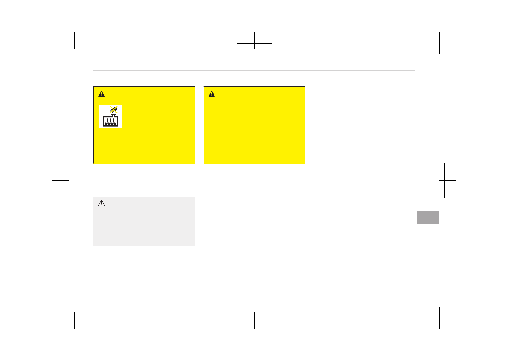
WARNING
n
Radiator cap
Do not remove the radiator cap
when the engine and radiator are
hot. Scalding hot coolant and steam
may blow out under pressure caus‐
ing serious injury.
Changing the coolant
We recommend that the coolant be re‐
placed by an authorized Kia dealer.
CAUTION
Put a thick cloth around the radiator
cap before refilling the coolant in or‐
der to prevent the coolant from
overflowing into engine parts such
as the alternator.
WARNING
n
Coolant
• Do not use radiator coolant or an‐
tifreeze in the washer fluid reser‐
voir.
• Radiator coolant can severely ob‐
scure visibility when sprayed on
the windshield and may cause loss
of vehicle control or damage the
paint and body trim.
9-29
9
Maintenance
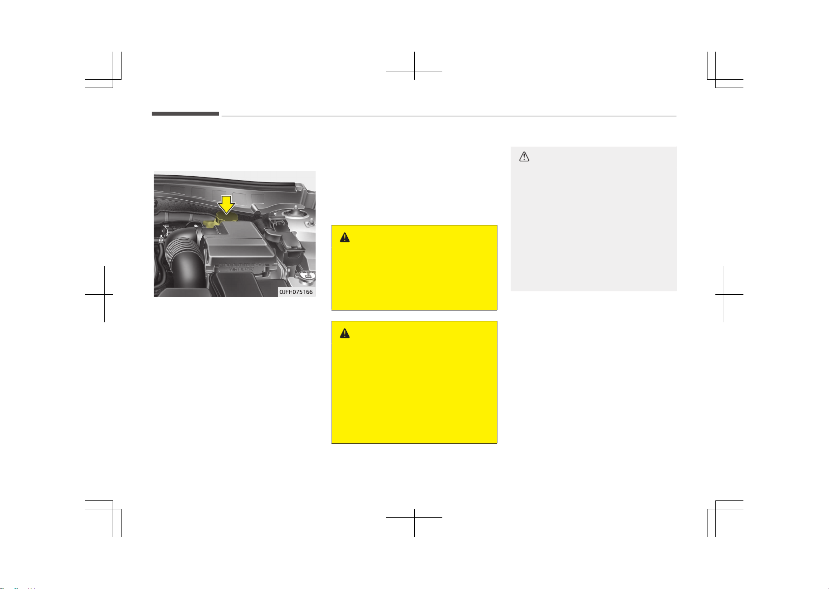
BRAKE FLUID (IF EQUIPPED)
Checking the brake fluid level
Check the fluid level in the reservoir pe‐
riodically. The fluid level should be be‐
tween MAX and MIN marks on the side
of the reservoir.
Before removing the reservoir cap and
adding brake fluid, clean the area
around the reservoir cap thoroughly to
prevent brake fluid contamination.
If the level is low, add fluid to the MAX
level. The level will fall with accumula‐
ted mileage. This is a normal condition
associated with the wear of the brake
linings.
If the fluid level is excessively low, we
recommend that the system be
checked by an authorized Kia dealer.
Use only the specified brake fluid (Re‐
fer to Recommended lubricants or ca‐
pacities on page 10-11.)
Never mix different types of fluid.
WARNING
n
Loss of brake fluid
In the event the brake system re‐
quires frequent additions of fluid, we
recommend that the system be in‐
spected by an authorized Kia dealer.
WARNING
n
Brake fluid
When changing and adding brake flu‐
id, handle it carefully. Do not let it
come in contact with your eyes. If
brake fluid should come in contact
with your eyes, immediately flush
them with a large quantity of fresh
tap water. Have your eyes examined
by a doctor as soon as possible.
CAUTION
Do not allow brake fluid to contact
the vehicle's body paint, as paint
damage will result. Brake fluid,
which has been exposed to open air
for an extended time should never
be used as its quality cannot be
guaranteed. It should be properly
disposed. Don't put in the wrong kind
of fluid. A few drops of mineral-
based oil, such as engine oil, in your
brake system can damage brake
system parts.
Maintenance
9-30
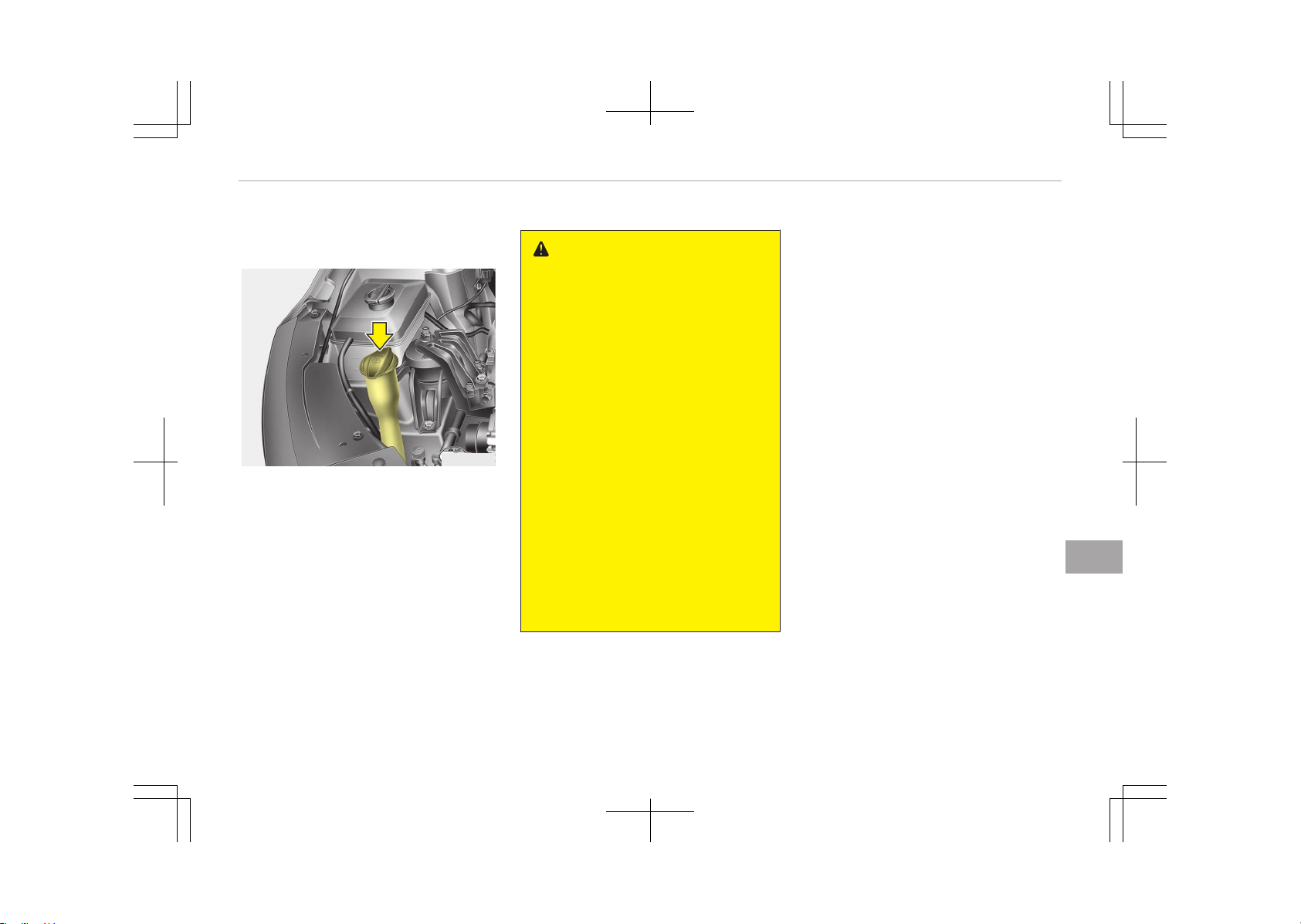
WASHER FLUID
Checking the washer fluid level
OJF075009
The reservoir is translucent so that you
can check the level with a quick visual
inspection.
Check the fluid level in the washer fluid
reservoir and add fluid if necessary.
Plain water may be used if washer fluid
is not available. However, use washer
solvent with antifreeze characteristics
in cold climates to prevent freezing.
WARNING
n
Coolant
• Do not use radiator coolant or an‐
tifreeze in the washer fluid reser‐
voir.
• Radiator coolant can severely ob‐
scure visibility when sprayed on
the windshield and may cause loss
of vehicle control or damage to
paint and body trim.
• Windshield washer fluid agents
contain some amounts of alcohol
and can be flammable under cer‐
tain circumstances. Do not allow
sparks or flame to contact the
washer fluid or the washer fluid
reservoir. Damage to the vehicle or
occupants could occur.
• Windshield washer fluid is poison‐
ous to humans and animals. Do
not drink and avoid contacting
windshield washer fluid. Serious
injury or death could occur.
9-31
9
Maintenance
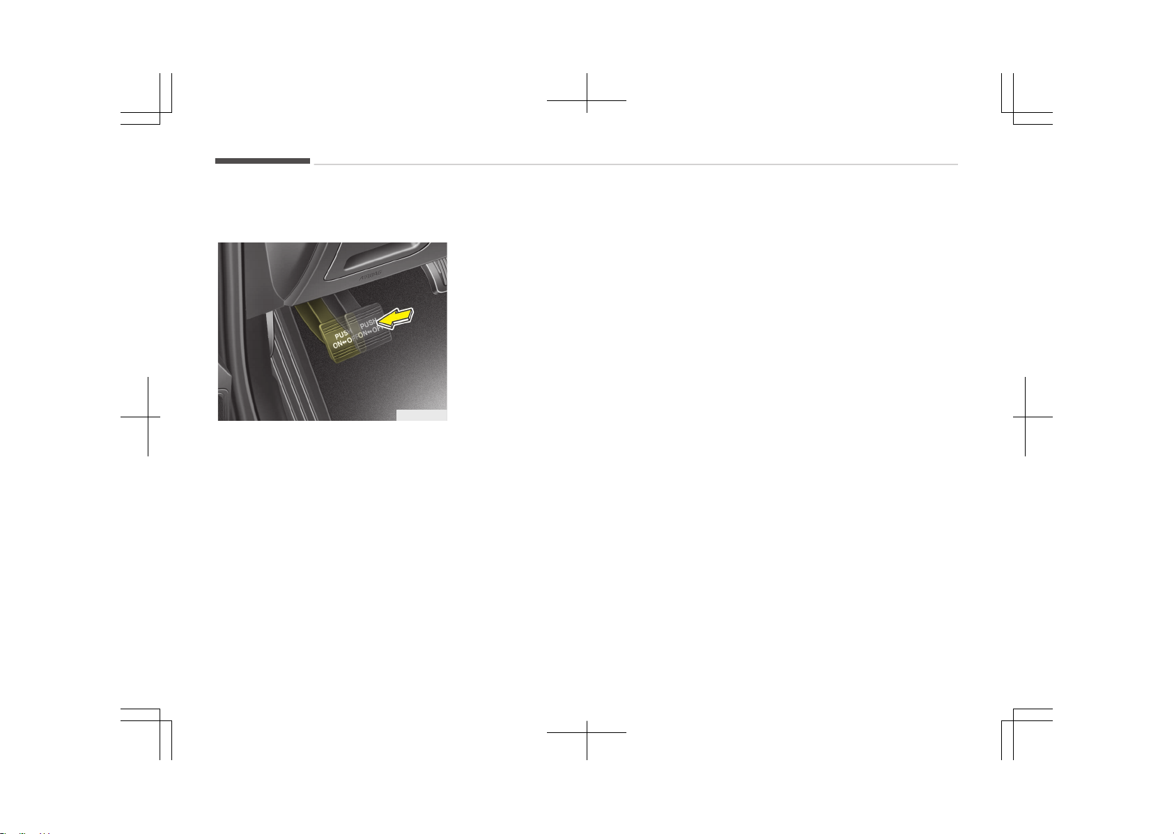
PARKING BRAKE (IF EQUIPPED)
Checking the parking brake
OJF055017
Check whether the stroke is within
specification when the parking brake
pedal is depressed with 30 kg (66 lb,
294N) of force. Also, the parking brake
alone should securely hold the vehicle
on a fairly steep grade. If the stroke is
more or less than specified, we recom‐
mend that the system be serviced by
an authorized Kia dealer.
Stroke : 6~7 notch
Maintenance
9-32
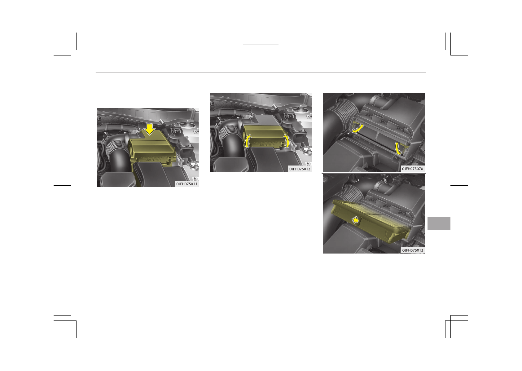
AIR CLEANER
Filter replacement
It must be replaced when necessary,
and should not be washed.
You can clean the filter when inspecting
the air cleaner element.
Clean the filter by using compressed
air.
1. Pull out the air cleaner cover.
2. Unlock by turning the locking lever
downward.
3. Pull the air cleaner filter to replace.
9-33
9
Maintenance

4. Lock the cover with the reverse or‐
der.
Replace the filter according to the
Maintenance Schedule.
If the vehicle is operated in extremely
dusty or sandy areas, replace the ele‐
ment more often than the usual rec‐
ommended intervals. (Refer to Main‐
tenance under severe usage conditions
on page 9-12.)
CAUTION
• Do not drive with the air cleaner
removed; this will result in exces‐
sive engine wear.
• When removing the air cleaner fil‐
ter, be careful that dust or dirt
does not enter the air intake, or
damage may result.
• We recommend that you use parts
for replacement from an author‐
ized Kia dealer.
Maintenance
9-34
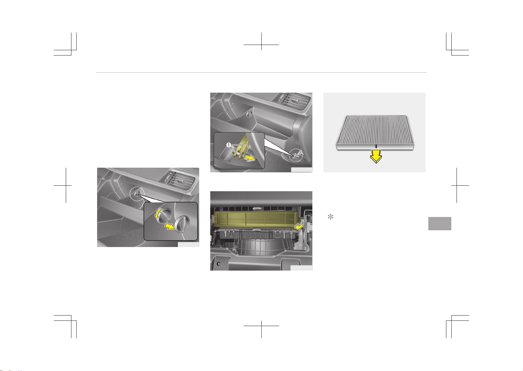
CLIMATE CONTROL AIR FILTER
Filter inspection
The climate control air filter should be
replaced according to the maintenance
schedule. If the vehicle is operated in
severely air-polluted cities or on dusty
rough roads for a long period, it should
be inspected more frequently and re‐
placed earlier. When you replace the cli‐
mate control air filter, replace it per‐
forming the following procedure, and
be careful to avoid damaging other
components.
OJF075015
1. Open the glove box and remove the
stoppers on both sides.
OJF075014
2. With the glove box open, pull the
support strap (1).
OJF075064
3. Remove the climate control air fil‐
ter cover while pressing the lock on
the right side of the cover.
OJF075071
4. Replace the climate control air fil‐
ter.
5. Reassemble in the reverse order of
disassembly.
NOTICE
When replacing the climate control
air filter install it properly. Other‐
wise, the system may produce noise
and the effectiveness of the filter
may be reduced.
9-35
9
Maintenance
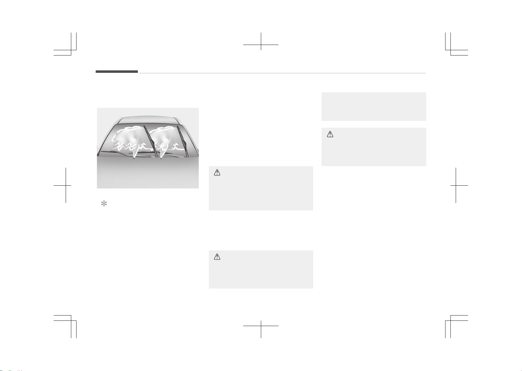
WIPER BLADES
Blade inspection
1JBA5122
NOTICE
Commercial hot waxes applied by
automatic car washes have been
known to make the windshield diffi‐
cult to clean.
Contamination of either the windshield
or the wiper blades with foreign matter
can reduce the effectiveness of the
windshield wipers. Common sources of
contamination are insects, tree sap,
and hot wax treatments used by some
commercial car washes. If the blades
are not wiping properly, clean both the
window and the blades with a good
cleaner or mild detergent, and rinse
thoroughly with clean water.
CAUTION
To prevent damage to the wiper
blades, do not use gasoline, kero‐
sene, paint thinner, or other solvents
on or near them.
Blade replacement
When the wipers no longer clean ade‐
quately, the blades may be worn or
cracked, and require replacement.
CAUTION
To prevent damage to the wiper
arms or other components, do not
(Continued)
(Continued)
attempt to move the wipers man‐
ually.
CAUTION
The use of a non-specified wiper
blade could result in wiper malfunc‐
tion and failure.
Maintenance
9-36
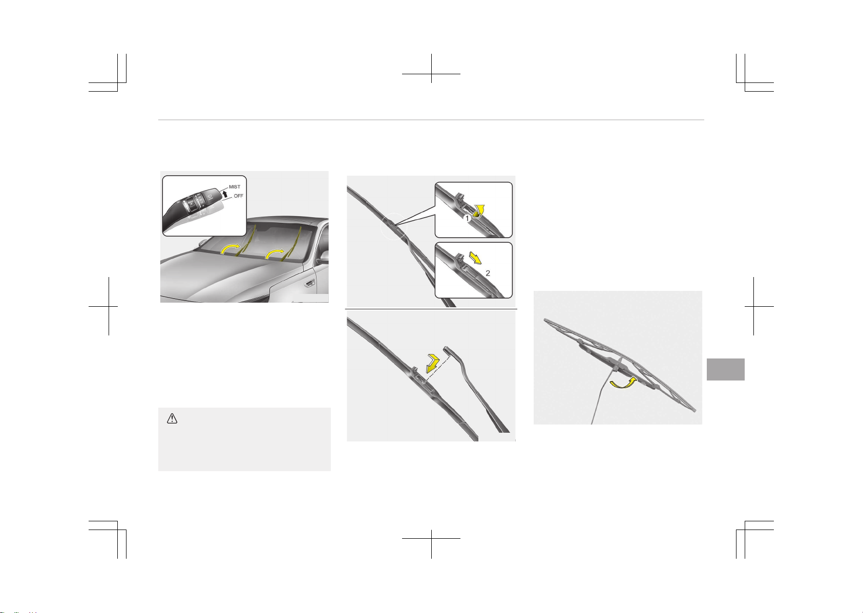
Front windshield wiper blade
OJF075016
For your convenience, move the wind‐
shield wiper blades to the service posi‐
tion as follows;
After turning off the engine, move the
wiper switch to the single wiping (MIST)
position within 20 seconds and hold the
switch more than 2 seconds until the
wiper blade is in the fully up position.
CAUTION
Do not allow the wiper arm to fall
against the windshield, since it may
chip or crack the windshield.
Type A
OHM078060
OHM078061
1. Raise the wiper arm.
2. Lift up the wiper blade clip. Then
pull down the blade assembly and
remove it.
3. Install the new blade assembly.
4. Return the wiper arm on the wind‐
shield.
5. Turn ignition to the ON position and
wiper arms will return to the nor‐
mal operating position.
Type B
1LDA5023
1. Raise the wiper arm and turn the
wiper blade assembly to expose
the plastic locking clip.
9-37
9
Maintenance
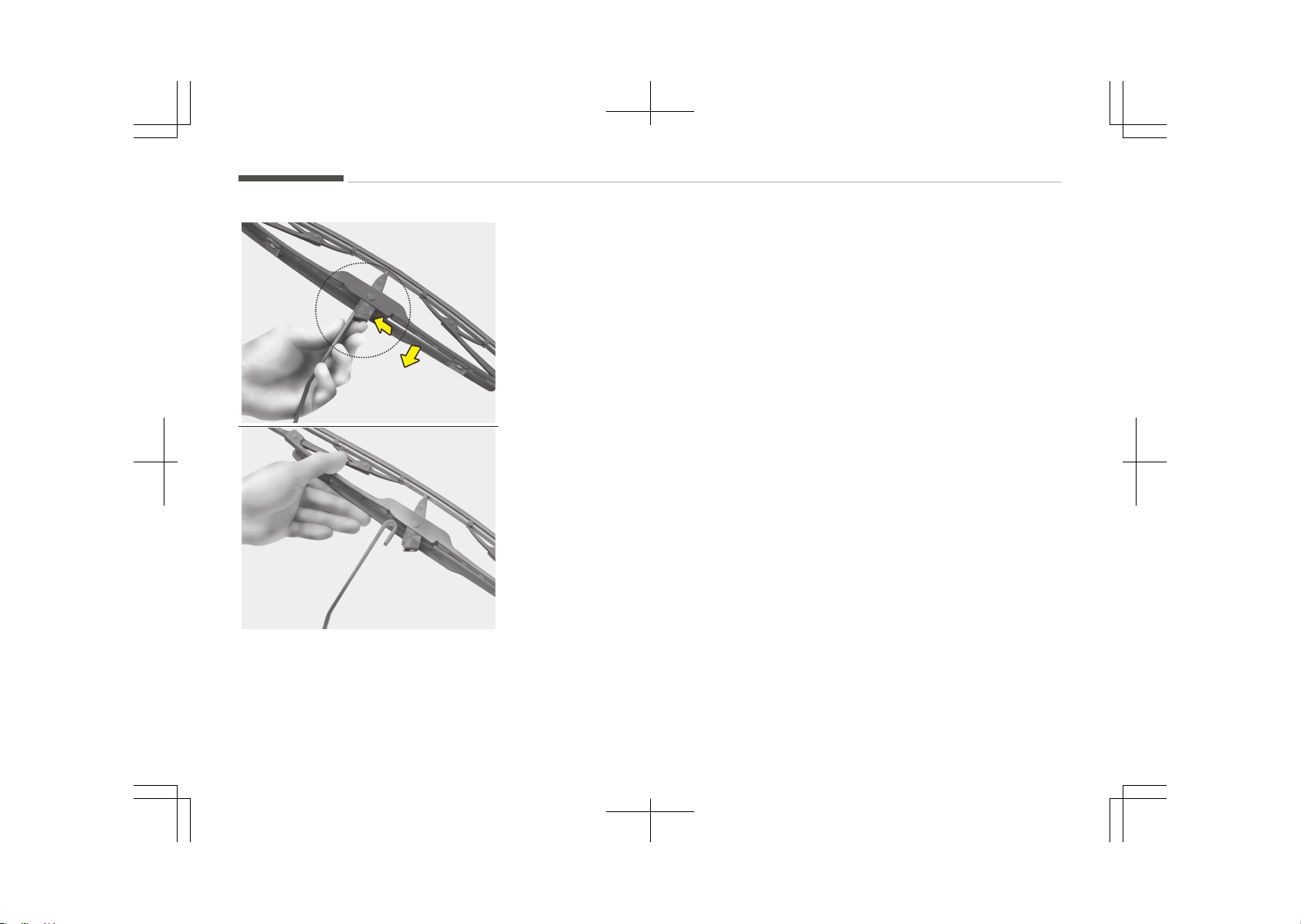
1JBA7037
1JBA7038
2. Compress the clip and slide the
blade assembly downward.
3. Lift it off the arm.
4. Install the new blade assembly.
5. Return the wiper arm on the wind‐
shield.
6. Turn ignition to the ON position and
wiper arms will return to the nor‐
mal operating position.
Maintenance
9-38
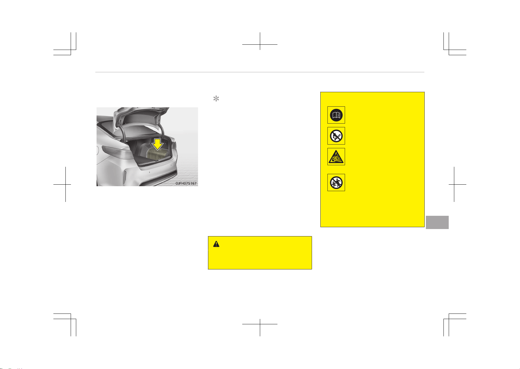
BATTERY
For best battery service
• Keep the battery securely mounted.
• Keep the battery top clean and dry.
• Keep the terminals and connections
clean, tight, and coated with petrole‐
um jelly or terminal grease.
• Rinse any spilled electrolyte from the
battery immediately with a solution
of water and baking soda.
• If the vehicle is not going to be used
for an extended time, disconnect the
battery cables.
NOTICE
Basically equipped battery is main‐
tenance free type. If your vehicle is
equipped with the battery marked
with LOWER and UPPER on the side,
you can check the electrolyte level.
The electrolyte level should be be‐
tween LOWER and UPPER. If the
electrolyte level is low, it needs to
add distilled (demineralized) water
(Never add sulfuric acid or other
electrolyte). When refill, be careful
not to splash the battery and adja‐
cent components. And do not overfill
the battery cells. It can cause corro‐
sion on other parts. After then en‐
sure that tighten the cell caps. We
recommend that you contact an au‐
thorized Kia dealer.
WARNING
n
Battery dangers
(Continued)
(Continued)
Always read the following
instructions carefully when
handling a battery.
Keep lighted cigarettes and
all other flames or sparks
away from the battery.
Hydrogen, a highly com‐
bustible gas, is always
present in battery cells and
may explode if ignited.
Keep batteries out of the
reach of children because
batteries contain highly
corrosive SULFURIC ACID.
Do not allow battery acid
to contact your skin, eyes,
clothing or paint finish.
(Continued)
9-39
9
Maintenance
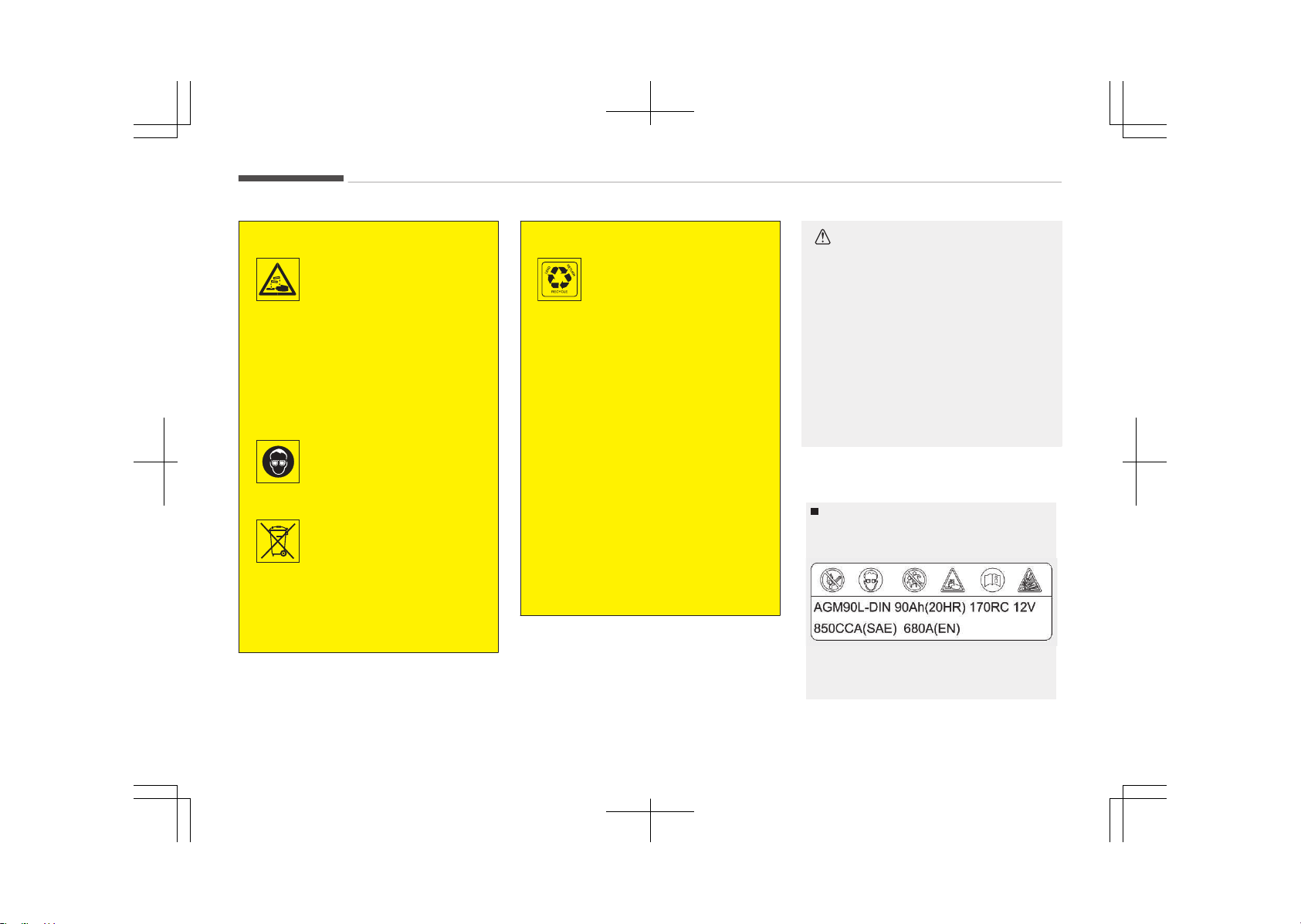
(Continued)
If any electrolyte gets into
your eyes, flush your eyes
with clean water for at
least 15 minutes and get
immediate medical atten‐
tion.
If electrolyte gets on your
skin, thoroughly wash the
contacted area. If you feel
pain or burning sensation,
get medical attention im‐
mediately.
Wear eye protection when
charging or working near a
battery. Always provide
ventilation when working
in an enclosed space.
An inappropriately dis‐
posed battery can be
harmful to the environ‐
ment and human health.
Dispose the battery ac‐
cording to your local law(s)
or regulation.
(Continued)
(Continued)
The battery contains lead.
Do not dispose of it after
use. We recommend that
you contact an authorized
Kia dealer.
• When lifting a plastic-cased bat‐
tery, excessive pressure on the
case may cause battery acid to
leak, resulting in personal injury.
Lift with a battery carrier or with
your hands on opposite corners.
• Never attempt to recharge the
battery when the battery cables
are connected.
• The electrical ignition system
works with high voltage. Never
touch these components with the
engine running or the ignition
switched on.
Failure to follow the above warnings
can result in serious bodily injury or
death.
CAUTION
• When you don’t use the vehicle for
a long time in the low temperature
area, separate the battery and
keep it indoors.
• Always charge the battery fully to
prevent battery case damage in
low temperature area.
• If you connect unauthorized elec‐
tronic devices to the battery, the
battery may be discharged. Never
use unauthorized devices.
Battery capacity label
Example
OUM074113L
Maintenance
9-40
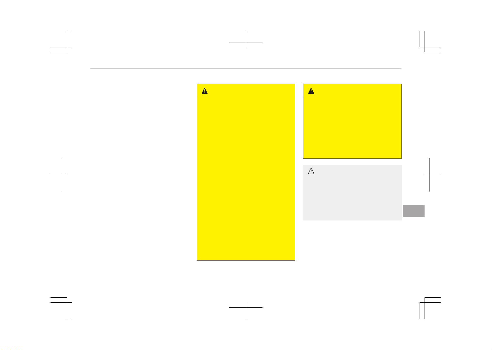
❈ The actual battery label in the vehi‐
cle may differ from the illustration.
1. AGM90L-DIN : The Kia model name
of battery
2. 90Ah(20HR) : The nominal capacity
(in Ampere hours)
3. 170RC : The nominal reserve ca‐
pacity (in min.)
4. 12V : The nominal voltage
5. 850CCA (SAE) : The cold-test cur‐
rent in amperes by SAE
6. 680A : The cold-test current in am‐
peres by EN
Battery recharging
Your vehicle has a maintenance-free,
calcium-based battery.
• If the battery becomes discharged in
a short time (because, for example,
the headlights or interior lights were
left on while the vehicle was not in
use), recharge it by slow charging
(trickle) for 10 hours.
• If the battery gradually discharges
because of high electric load while
the vehicle is being used, recharge it
at 20-30A for two hours.
WARNING
n
Recharging battery
When recharging the battery, ob‐
serve the following precautions:
• The battery must be removed
from the vehicle and placed in an
area with good ventilation.
• Do not allow cigarettes, sparks, or
flame near the battery.
• Watch the battery during charg‐
ing, and stop or reduce the charg‐
ing rate if the battery cells begin
gassing (boiling) violently or if the
temperature of the electrolyte of
any cell exceeds 49°C (120°F).
• Wear eye protection when check‐
ing the battery during charging.
• Disconnect the battery charger in
the following order.
1. Turn off the battery charger
main switch.
2. Unhook the negative clamp
from the negative battery ter‐
minal.
3. Unhook the positive clamp from
the positive battery terminal.
WARNING
• Before performing maintenance or
recharging the battery, turn off all
accessories and stop the engine.
• The negative battery cable must
be removed first and installed last
when the battery is disconnected.
• Operation related to the battery is
recommended to an authorized Kia
dealer.
CAUTION
• Keep the battery away from wa‐
ter or any liquid.
• For your safety, we recommend
that you use parts for replace‐
ment from an authorized Kia deal‐
er.
Reset items
Items should be reset after the battery
has been discharged or the battery has
been disconnected.
• Auto up/down window (if equipped)
• Sunroof (if equipped)
• Trip computer
9-41
9
Maintenance

• Climate control system
• Integrated Memory System (if equip‐
ped)
• Audio (if equipped)
Maintenance
9-42
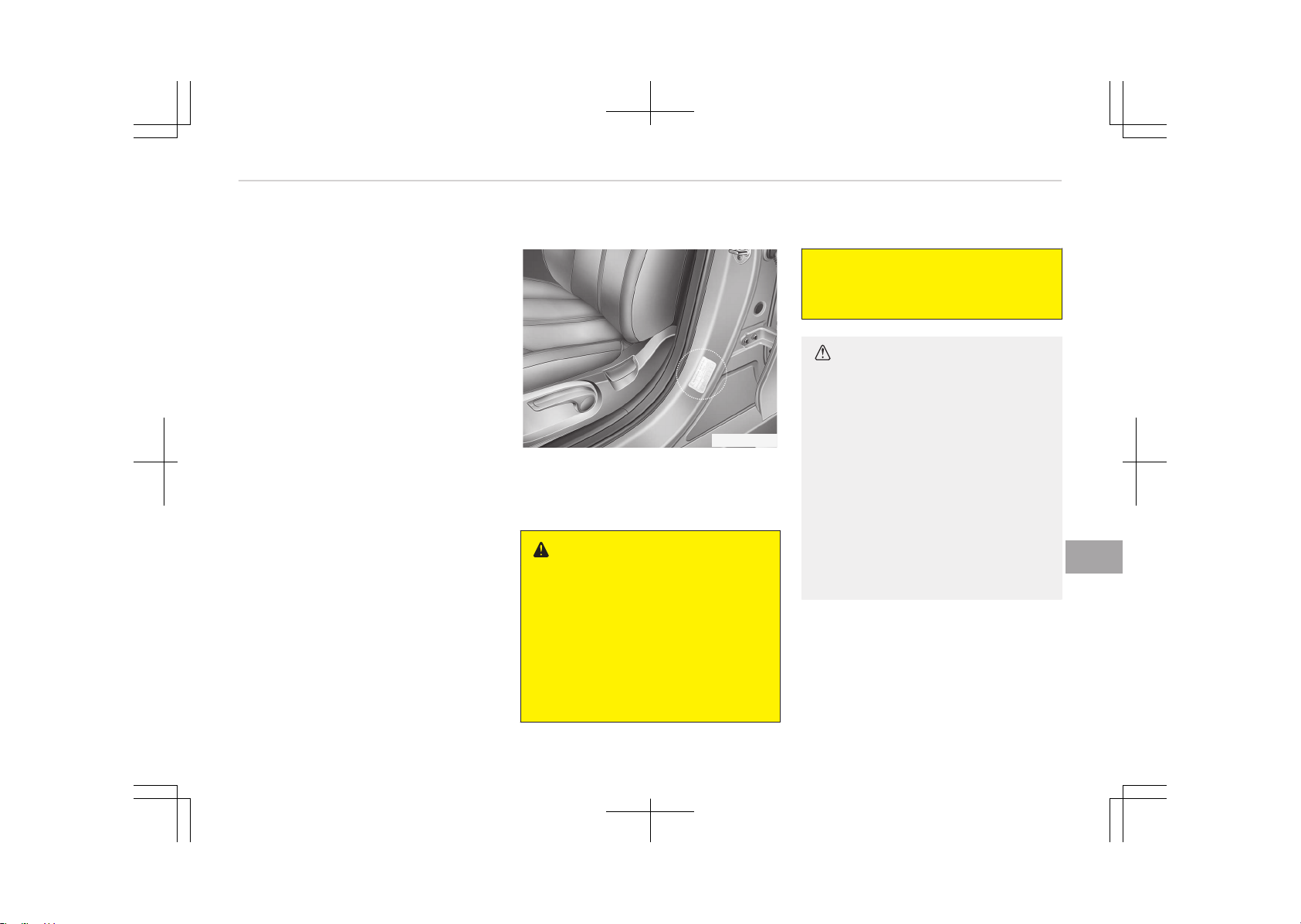
TIRES AND WHEELS
Tire care
For proper maintenance, safety, and
maximum fuel economy, you must al‐
ways maintain recommended tire infla‐
tion pressures and stay within the load
limits and weight distribution recom‐
mended for your vehicle.
Recommended cold tire inflation
pressures
All tire pressures (including the spare)
should be checked when the tires are
cold. Cold Tires means the vehicle has
not been driven for at least three hours
or driven less than 1.6 km (one mile).
Recommended pressures must be
maintained for the best ride, top vehi‐
cle handling, and minimum tire wear.
For recommended inflation pressure,
refer to Tires and wheels on page
10-09.
OJF085012
All specifications (sizes and pressures)
can be found on a label attached to the
vehicle.
WARNING
n
Tire underinflation
Severe underinflation (70 kPa
(10 psi) or more) can lead to severe
heat build-up, causing blowouts,
tread separation and other tire fail‐
ures that can result in the loss of ve‐
hicle control leading to severe injury
or death. This risk is much higher on
(Continued)
(Continued)
hot days and when driving for long
periods at high speeds.
CAUTION
• Underinflation also results in ex‐
cessive wear, poor handling and
reduced fuel economy. Wheel de‐
formation also is possible. Keep
your tire pressures at the proper
levels. If a tire frequently needs
refilling, we recommend that the
system be checked by an author‐
ized Kia dealer.
• Overinflation produces a harsh
ride, excessive wear at the center
of the tire tread, and a greater
possibility of damage from road
hazards.
9-43
9
Maintenance
CAUTION
• Warm tires normally exceed rec‐
ommended cold tire pressures by
28 to 41 kPa (4 to 6 psi). Do not
release air from warm tires to ad‐
just the pressure or the tires will
be underinflated.
• Be sure to reinstall the tire infla‐
tion valve caps. Without the valve
cap, dirt or moisture could get into
the valve core and cause air leak‐
age. If a valve cap is missing, in‐
stall a new one as soon as possi‐
ble.
WARNING
n
Tire inflation
Overinflation or underinflation can
reduce tire life, adversely affect ve‐
hicle handling, and lead to sudden
tire failure. This could result in loss
of vehicle control and potential in‐
jury.
CAUTION
n
Tire pressure
Always observe the following:
• Check tire pressure when the tires
are cold. (After vehicle has been
parked for at least three hours or
hasn't been driven more than
1.6 km (one mile) since startup.)
• Check the pressure of your spare
tire each time you check the pres‐
sure of other tires.
• Never overload your vehicle. Be
careful not to overload a vehicle
luggage rack if your vehicle is
equipped with one.
• Worn, old tires can cause acci‐
dents. If your tread is badly worn,
or if your tires have been dam‐
aged, replace them.
Checking tire inflation pressure
Check your tires once a month or more.
Also, check the tire pressure of the
spare tire.
How to check
Use a good quality gauge to check tire
pressure. You can not tell if your tires
are properly inflated simply by looking
at them. Radial tires may look properly
inflated even when they're underinfla‐
ted.
Check the tire's inflation pressure when
the tires are cold. - "Cold" means your
vehicle has been sitting for at least
three hours or driven no more than
1.6 km (one mile).
Remove the valve cap from the tire
valve stem. Press the tire gauge firmly
onto the valve to get a pressure meas‐
urement. If the cold tire inflation pres‐
sure matches the recommended pres‐
sure on the tire and loading information
label, no further adjustment is necessa‐
ry. If the pressure is low, add air until
you reach the recommended amount.
If you overfill the tire, release air by
pushing on the metal stem in the cen‐
ter of the tire valve. Recheck the tire
pressure with the tire gauge. Be sure to
put the valve caps back on the valve
stems. They help prevent leaks by
keeping out dirt and moisture.
Maintenance
9-44
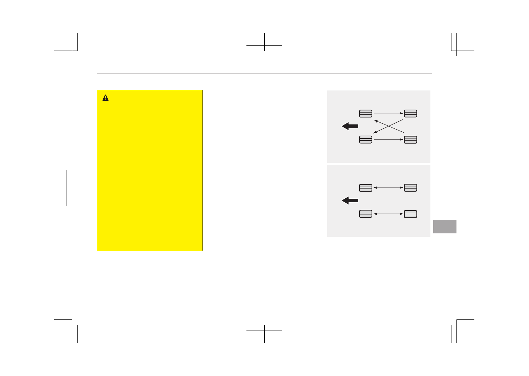
WARNING
• Inspect your tires frequently for
proper inflation as well as wear
and damage. Always use a tire
pressure gauge.
• Tires with too much or too little
pressure wear unevenly causing
poor handling, loss of vehicle con‐
trol, and sudden tire failure leading
to accidents, injuries, and even
death. The recommended cold tire
pressure for your vehicle can be
found in this manual and on the
tire label located on the driver's
side center pillar.
• Worn tires can cause accidents.
Replace tires that are worn, show
uneven wear, or are damaged.
• Remember to check the pressure
of your spare tire. Kia recom‐
mends that you check the spare
every time you check the pressure
of the other tires on your vehicle.
Tire rotation
To equalize tread wear, it is recommen‐
ded that the tires be rotated every
12,000 km (7,500 miles) or sooner if ir‐
regular wear develops.
During rotation, check the tires for cor‐
rect balance.
When rotating tires, check for uneven
wear and damage. Abnormal wear is
usually caused by incorrect tire pres‐
sure, improper wheel alignment, out-
of-balance wheels, severe braking or
severe cornering. Look for bumps or
bulges in the tread or side of tire. Re‐
place the tire if you find either of these
conditions. Replace the tire if fabric or
cord is visible. After rotation, be sure to
bring the front and rear tire pressures
to specification and check lug nut tight‐
ness.
Refer to Tires and wheels on page
10-09.
Without a spare tire
S2BLA790A
Directional tires (if equipped)
CBGQ0707A
Disc brake pads should be inspected for
wear whenever tires are rotated.
9-45
9
Maintenance
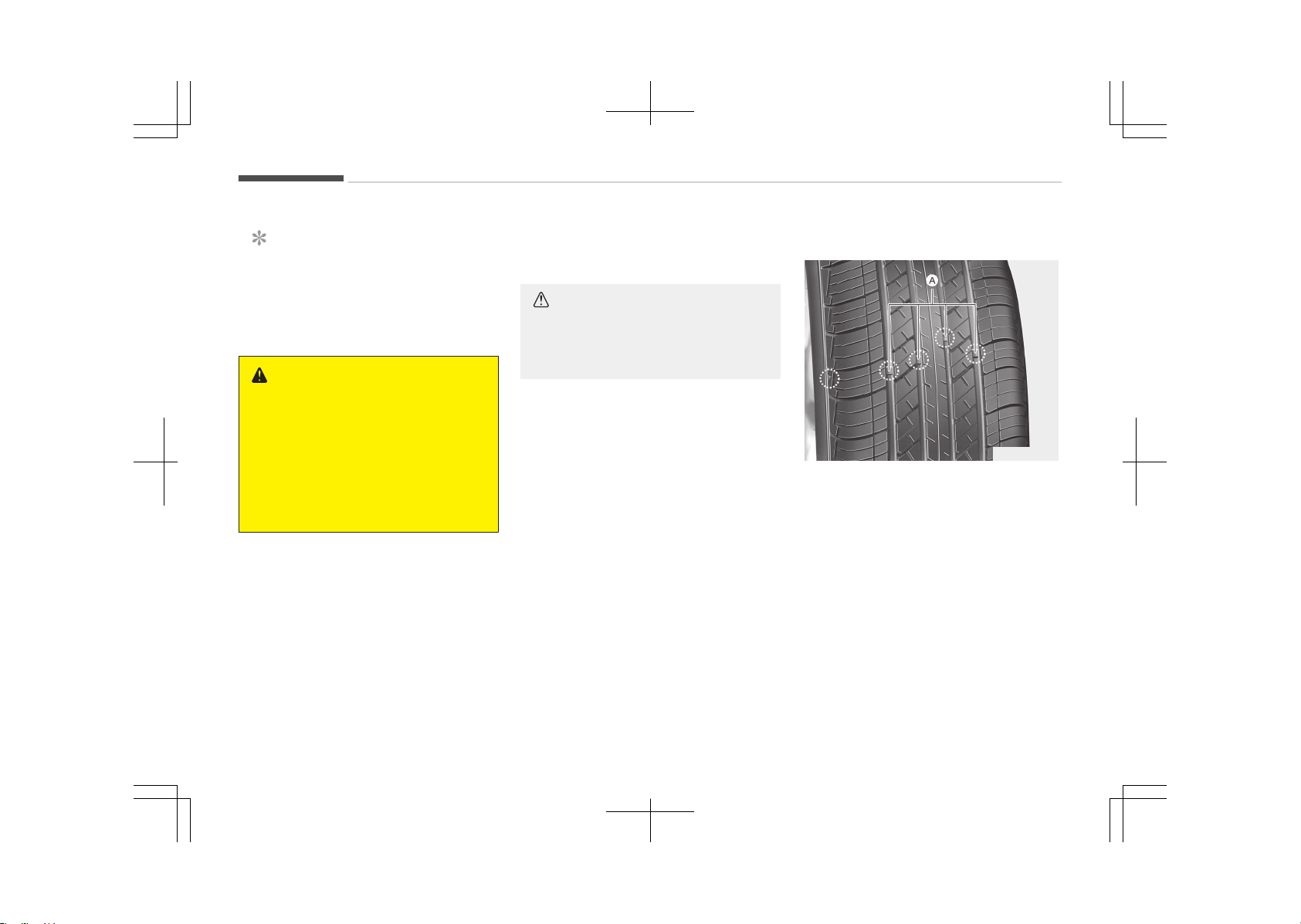
NOTICE
Rotate radial tires that have an
asymmetric tread pattern only from
front to rear and not from right to
left.
WARNING
• Do not use the compact spare tire
(if equipped) for tire rotation.
• Do not mix bias ply and radial ply
tires under any circumstances.
This may cause unusual handling
characteristics that could result in
death, severe injury, or property
damage.
Wheel alignment and tire
balance
The wheels on your vehicle were
aligned and balanced carefully at the
factory to give you the longest tire life
and best overall performance.
In most cases, you will not need to have
your wheels aligned again. However, if
you notice unusual tire wear or your
vehicle pulling one way or the other,
the alignment may need to be reset.
If you notice your vehicle vibrating
when driving on a smooth road, your
wheels may need to be rebalanced.
CAUTION
Improper wheel weights can damage
your vehicle's aluminum wheels. Use
only approved wheel weights.
Tire replacement
OUM076204L
If the tire is worn evenly, a tread wear
Indicator (A) will appear as a solid band
across the tread. This shows there is
less than 1.6 mm (1/16 in.) of tread left
on the tire. Replace the tire when this
happens.
Do not wait for the band to appear
across the entire tread before replacing
the tire.
Maintenance
9-46
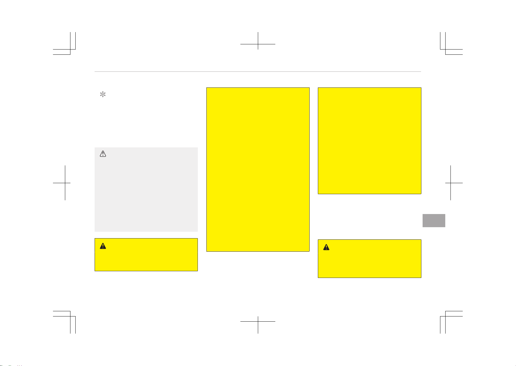
NOTICE
We recommend that when replacing
tires, use the same originally sup‐
plied with the vehicles.
If not, that affects driving perform‐
ance.
CAUTION
When replacing the tires, recheck
and tighten the wheel nuts after
driving about 50 km (31 miles) and
recheck after driving about 1,000 km
(620 miles).
If the steering wheel shakes or the
vehicle vibrates while driving, the
tire is out of balance. Align the tire
balance. If the problem is not solved,
we recommend that you contact an
authorized Kia dealer.
WARNING
n
Replacing tires
(Continued)
(Continued)
To reduce the chance of serious or
fatal injuries from an accident
caused by tire failure or loss of vehi‐
cle control:
• Replace tires that are worn, show
uneven wear, or are damaged.
Worn tires can cause loss of brak‐
ing effectiveness, steering control,
and traction.
• Do not drive your vehicle with too
little or too much pressure in your
tires. This can lead to uneven wear
and tire failure.
• When replacing tires, never mix ra‐
dial and bias-ply tires on the same
car. You must replace all tires (in‐
cluding the spare) if moving from
radial to bias-ply tires.
• Using tires and wheels other than
the recommended sizes could
cause unusual handling character‐
istics and poor vehicle control, re‐
sulting in a serious accident.
(Continued)
(Continued)
• Wheels that do not meet Kia’s
specifications may fit poorly and
result in damage to the vehicle or
unusual handling and poor vehicle
control.
• The ABS works by comparing the
speed of the wheels. The tire size
affects wheel speed. When replac‐
ing tires, all 4 tires must use the
same size originally supplied with
the vehicle. Using tires of a differ‐
ent size can cause the ABS (Anti-
lock Brake System) and ESC (Elec‐
tronic Stability Control) to work ir‐
regularly.
Wheel replacement
When replacing the metal wheels for
any reason, make sure the new wheels
are equivalent to the original factory
units in diameter, rim width and offset.
WARNING
A wheel that is not the correct size
may adversely affect wheel and
(Continued)
9-47
9
Maintenance
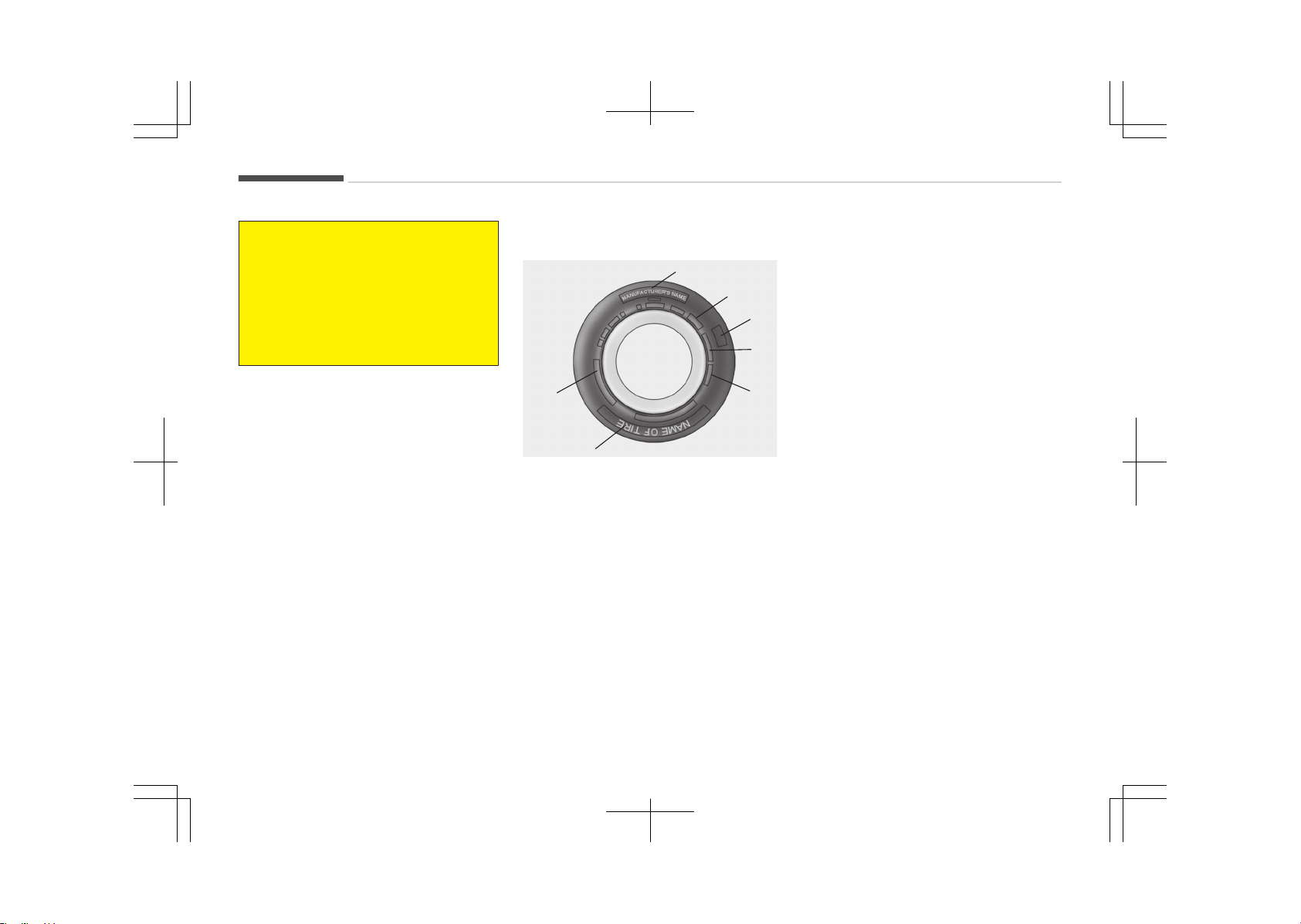
(Continued)
bearing life, braking and stopping
abilities, handling characteristics,
ground clearance, body-to-tire
clearance, snow chain clearance,
speedometer and odometer calibra‐
tion, headlight aim and bumper
height.
Tire traction
Tire traction can be reduced if you drive
on worn tires, tires that are improperly
inflated or on slippery road surfaces.
Tires should be replaced when tread
wear indicators appear. Slow down
whenever there is rain, snow or ice on
the road to reduce the possibility of
losing control of the vehicle.
Tire maintenance
In addition to proper inflation, correct
wheel alignment helps to decrease tire
wear. If you find a tire is worn uneven‐
ly, have your dealer check the wheel
alignment.
When you have new tires installed,
make sure they are balanced. This will
increase vehicle ride comfort and tire
life. Additionally, a tire should always
be rebalanced if it is removed from the
wheel.
Tire sidewall labeling
OJF085008L
3
4
7
5,6
1
1
2
This information identifies and de‐
scribes the fundamental characteristics
of the tire and also provides the tire
identification number (TIN) for safety
standard certification. The TIN can be
used to identify the tire in case of a re‐
call.
1. Manufacturer or brand name
Manufacturer or Brand name is shown.
2. Tire size designation
A tire’s sidewall is marked with a tire
size designation. You will need this in‐
formation when selecting replacement
tires for your vehicle. The following ex‐
plains what the letters and numbers in
the tire size designation mean.
Example tire size designation:
(These numbers are provided as an ex‐
ample only; your tire size designator
could vary depending on your vehicle.)
P235/55R19 108T
P - Applicable vehicle type (tires
marked with the prefix P’’
are intended for use on pas‐
senger vehicles or light
trucks; however, not all tires
have this marking).
235 - Tire width in millimeters.
55 - Aspect ratio. The tire’s sec‐
tion height as a percentage
of its width.
R - Tire construction code (Ra‐
dial).
19 - Rim diameter in inches.
108 - Load Index, a numerical
code associated with the
maximum load the tire can
carry.
T - Speed Rating Symbol. See
the speed rating chart in
Maintenance
9-48

this section for additional
information.
Wheel size designation
Wheels are also marked with important
information that you need if you ever
have to replace one. The following ex‐
plains what the letters and numbers in
the wheel size designation mean.
Example wheel size designation:
7.5JX19
7.5 - Rim width in inches.
J - Rim contour designation.
19 - Rim diameter in inches.
Tire speed ratings
The chart below lists many of the dif‐
ferent speed ratings currently being
used for passenger car tires. The speed
rating is part of the tire size designa‐
tion on the sidewall of the tire. This
symbol corresponds to that tire's de‐
signed maximum safe operating speed.
Speed
Rating
Symbol
Maximum Speed
S 180 km/h (112 mph)
T 190 km/h (118 mph)
H 210 km/h (130 mph)
V 240 km/h (149 mph)
Speed
Rating
Symbol
Maximum Speed
Z
Above 240 km/h (149
mph)
3. Checking tire life (TIN: Tire
Identification Number)
Any tires that are over 6 years old,
based on the manufacturing date, (in‐
cluding the spare tire) should be re‐
placed by new ones. You can find the
manufacturing date on the tire sidewall
(possibly on the inside of the wheel),
displaying the DOT Code. The DOT Code
is a series of numbers on a tire consist‐
ing of numbers and English letters. The
manufacturing date is designated by
the last four digits (characters) of the
DOT code.
DOT : XXXX XXXX OOOO
The front part of the DOT means a
plant code number, tire size and tread
pattern and the last four numbers indi‐
cate week and year manufactured.
For example:
DOT XXXX XXXX 1616 represents that
the tire was produced in the 16th week
of 2016.
WARNING
n
Tire age
Tires degrade over time, even when
they are not being used.
Regardless of the remaining tread,
we recommend that tires be re‐
placed after approximately six (6)
years of normal service. Heat caused
by hot climates or frequent high
loading conditions can accelerate the
aging process. Failure to follow this
warning can result in sudden tire
failure, which could lead to a loss of
control and an accident involving se‐
rious injury or death.
4. Tire ply composition and material
The number of layers or plies of rub‐
ber-coated fabric in the tire. Tire man‐
ufacturers also must indicate the ma‐
terials in the tire, which include steel,
nylon, polyester, and others. The letter
"R" means radial ply construction; the
letter "D" means diagonal or bias ply
construction; and the letter "B" means
belted-bias ply construction.
9-49
9
Maintenance
5. Maximum permissible inflation
pressure
This number is the greatest amount of
air pressure that should be put in the
tire. Do not exceed the maximum per‐
missible inflation pressure. Refer to the
Tire specification and pressure label
on page 10-15 for recommended infla‐
tion pressure.
6. Maximum load rating
This number indicates the maximum
load in kilograms and pounds that can
be carried by the tire. When replacing
the tires on the vehicle, always use a
tire that has the same load rating as
the factory installed tire.
7. Uniform tire quality grading
Quality grades can be found where ap‐
plicable on the tire sidewall between
tread shoulder and maximum section
width.
For example:
TREADWEAR 200
TRACTION AA
TEMPERATURE A
Tread wear
The tread wear grade is a comparative
rating based on the wear rate of the
tire when tested under controlled con‐
ditions on a specified government test
course. For example, a tire graded 150
would wear one-and-a-half times (1½)
as well on the government course as a
tire graded 100.
The relative performance of tires de‐
pends upon the actual conditions of
their use, however, and may depart sig‐
nificantly from the norm due to varia‐
tions in driving habits, service practices
and differences in road characteristics
and climate.
These grades are molded on the side-
walls of passenger vehicle tires. The
tires available as standard or optional
equipment on your vehicle may vary
with respect to grade.
Traction - AA, A, B & C
The traction grades, from highest to
lowest, are AA, A, B and C. Those
grades represent the tire’s ability to
stop on wet pavement as measured
under controlled conditions on specified
government test surfaces of asphalt
and concrete. A tire marked C may have
poor traction performance.
Temperature - A, B & C
The temperature grades are A (the
highest), B, and C, representing the
tire’s resistance to the generation of
heat and its ability to dissipate heat
when tested under controlled condi‐
tions on a specified indoor laboratory
test wheel.
Sustained high temperature can cause
the material of the tire to degenerate
and reduce tire life, and excessive tem‐
perature can lead to sudden tire failure.
Grades B and A represent higher levels
of performance on the laboratory test
wheel than the minimum required by
law.
WARNING
The traction grade assigned to this
tire is based on straight-ahead brak‐
ing traction tests, and does not in‐
clude acceleration, cornering, hydro‐
planing, or peak traction characteris‐
tics.
Maintenance
9-50
WARNING
n
Tire temperature
The temperature grade for this tire
is established for a tire that is prop‐
erly inflated and not overloaded. Ex‐
cessive speed, underinflation, or ex‐
cessive loading, either separately or
in combination, can cause heat build-
up and possible sudden tire failure.
This can cause loss of vehicle control
and serious injury or death.
Low aspect ratio tire (if
equipped)
Low aspect ratio tires, whose aspect
ratio is lower than 50, are provided for
sporty looks.
Because the low aspect ratio tires are
optimized for handling and braking, it
may be more uncomfortable to ride in
and there is more noise compare with
normal tires.
CAUTION
Because the sidewall of the low as‐
pect ratio tire is shorter than the
(Continued)
(Continued)
normal, the wheel and tire of the
low aspect ratio tire is easier to be
damaged. So, follow the instructions
below.
- When driving on a rough road or
off road, drive cautiously because
tires and wheels may be damaged.
And after driving, inspect tires and
wheels.
- When passing over a pothole,
speed bump, manhole, or curb
stone, drive slowly so that the
tires and wheels are not damaged.
- If the tire is impacted, we recom‐
mend that you inspect the tire
condition or contact an authorized
Kia dealer.
- To prevent damage to the tire, in‐
spect the tire condition and pres‐
sure every 3,000 km.
CAUTION
• It is not easy to recognize the tire
damage with your own eyes. But if
there is the slightest hint of tire
damage, even though you cannot
see the tire damage with your own
eyes, have the tire checked or re‐
placed because the tire damage
may cause air leakage from the
tire.
• If the tire is damaged by driving on
a rough road, off road, pothole,
manhole, or curb stone, it will not
be covered by the warranty.
• You can find out the tire informa‐
tion on the tire sidewall.
9-51
9
Maintenance
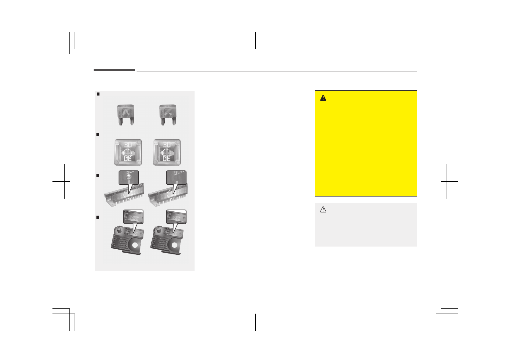
FUSES
Blade type
Cartridge type
Multifuse
BFT
OJF075021
❈ Left side: Normal
Right side: Blown
A vehicle’s electrical system is protec‐
ted from electrical overload damage by
fuses.
This vehicle has 2 (or 3) fuse panels,
one located in the driver’s side panel
bolster, the others in the engine com‐
partment near the battery.
If any of your vehicle’s lights, accesso‐
ries, or controls do not work, check the
appropriate circuit fuse. If a fuse has
blown, the element inside the fuse will
melt.
If the electrical system does not work,
first check the driver’s side fuse panel.
Before replacing a blown fuse, discon‐
nect the negative battery cable.
Always replace a blown fuse with one
of the same rating.
If the replacement fuse blows, this indi‐
cates an electrical problem. Avoid using
the system involved and immediately
consult an authorized Kia dealer.
Three kinds of fuses are used: blade
type for lower amperage rating, car‐
tridge type, and multi fuse for higher
amperage ratings.
WARNING
n
Fuse replacement
• Never replace a fuse with anything
but another fuse of the same rat‐
ing.
• A higher capacity fuse could cause
damage and possibly a fire.
• Never install a wire or aluminum
foil instead of the proper fuse
even as a temporary repair. It may
cause extensive wiring damage
and a possible fire.
• Do not arbitrarily modify or add-
on electric wiring of the vehicle.
CAUTION
Do not use a screwdriver or any oth‐
er metal object to remove fuses be‐
cause it may cause a short circuit
and damage the system.
Maintenance
9-52
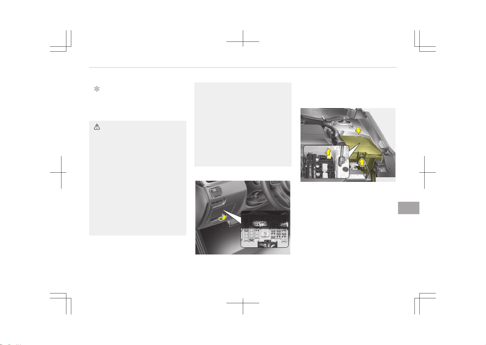
NOTICE
The actual fuse/relay panel label
may differ from equipped items.
CAUTION
• When replacing a blown fuse or re‐
lay with a new one, make sure the
new fuse or relay fits tightly into
the clips. The incomplete fastening
fuse or relay may cause the vehi‐
cle wiring and electric systems
damage and a possible fire.
• Do not remove fuses, relays and
terminals fastened with bolts or
nuts. The fuses, relays and termi‐
nals may be fastened incomplete‐
ly, and it may cause a possible fire.
If fuses, relays and terminals fas‐
tened with bolts or nuts are blown,
we recommend that you consult
an authorized Kia dealer.
(Continued)
(Continued)
• Do not input any other objects ex‐
cept fuses or relays into fuse/relay
terminals such as a driver or wir‐
ing. It may cause contact failure
and system malfunction.
• Do not plug in screwdrivers or af‐
termarket wiring into the terminal
originally designed for fuse and re‐
lays only. The electrical system
and wiring of the vehicle interior
may be damaged or burned due to
contact failure.
Inner panel fuse replacement
OJF075022
1. Turn the ignition switch and all oth‐
er switches off.
2. Open the fuse panel cover.
If the switch is located in the OFF,
caution will be displayed in the clus‐
ter.
OJF075023
3. Pull the suspected fuse straight
out. Use the removal tool provided
in the main fuse box in the engine
compartment.
4. Check the removed fuse; replace it
if it is blown.
Spare fuses are provided in the in‐
strument panel fuse panel (or in
the engine compartment fuse pan‐
el).
5. Push in a new fuse of the same
rating, and make sure it fits tightly
in the clips.
9-53
9
Maintenance
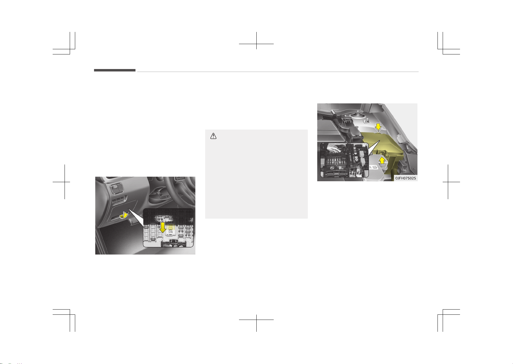
If it fits loosely, we recommend that
you consult an authorized Kia dealer.
If you do not have a spare, use a fuse
of the same rating from a circuit you
may not need for operating the vehicle,
such as the cigarette lighter fuse.
If the headlights or taillights, stop
lights, courtesy lamp, day time running
lights (D.R.L) do not work and the fuses
are OK, check the fuse panel in the en‐
gine compartment. If a fuse is blown, it
must be replaced.
Fuse switch
OJF075024
Always, put the fuse switch at the ON
position.
If you move the switch to the OFF posi‐
tion, some items such as audio and dig‐
ital clock must be reset and transmitter
(or smart key) may not work properly.
If the fuse switch is in OFF, a warning
sign will illuminate on the dashboard.
CAUTION
• Put all switches in ON when driv‐
ing.
• If the vehicle remains idle for over
1 month, put all switches in OFF to
prevent the batteries from being
discharged.
• Excluding long-term parking for
over 1 month, the contact points
of switches may wear out upon
extensive use. Please refrain from
excessive use of switches.
Engine compartment fuse
replacement
1. Turn the ignition switch and all oth‐
er switches off.
2. Remove the fuse panel cover by
pressing the tab and pulling the
cover up. When the blade type fuse
is disconnected, remove it by using
the clip designed for changing fuses
located in the engine room fuse
box. Upon removal, securely insert
reserve fuse of equal quantity.
3. Check the removed fuse; replace it
if it is blown. To remove or insert
the fuse, use the fuse puller in the
engine compartment fuse panel.
Maintenance
9-54
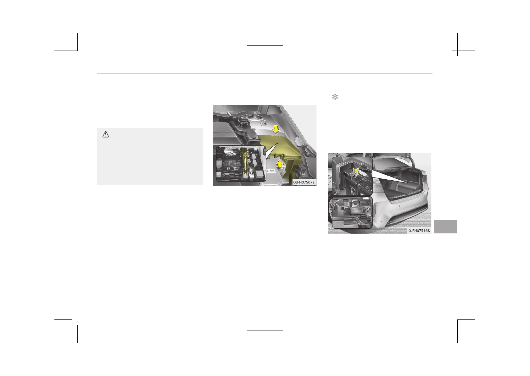
4. Push in a new fuse of the same
rating, and make sure it fits tightly
in the clips. If it fits loosely, we rec‐
ommend that you consult an au‐
thorized Kia dealer.
CAUTION
After checking the fuse panel in the
engine compartment, securely install
the fuse panel. If not, cover through
the audible clicking sound. Electrical
failures may occur from water con‐
tact.
Multi fuse
If the multi fuse is blown, it must be re‐
moved as follows:
1. Disconnect the negative battery
cable.
2. Remove the nuts shown in the pic‐
ture above.
3. Replace the fuse with a new one of
the same rating.
4. Reinstall in the reverse order of re‐
moval.
NOTICE
If the multi fuse is blown, we recom‐
mend that you consult an author‐
ized Kia dealer.
Main fuse
If the main fuse is blown, it must be re‐
moved as follows:
1. Turn off the engine.
2. Disconnect the negative battery
cable.
3. Remove the nuts shown in the pic‐
ture above.
9-55
9
Maintenance
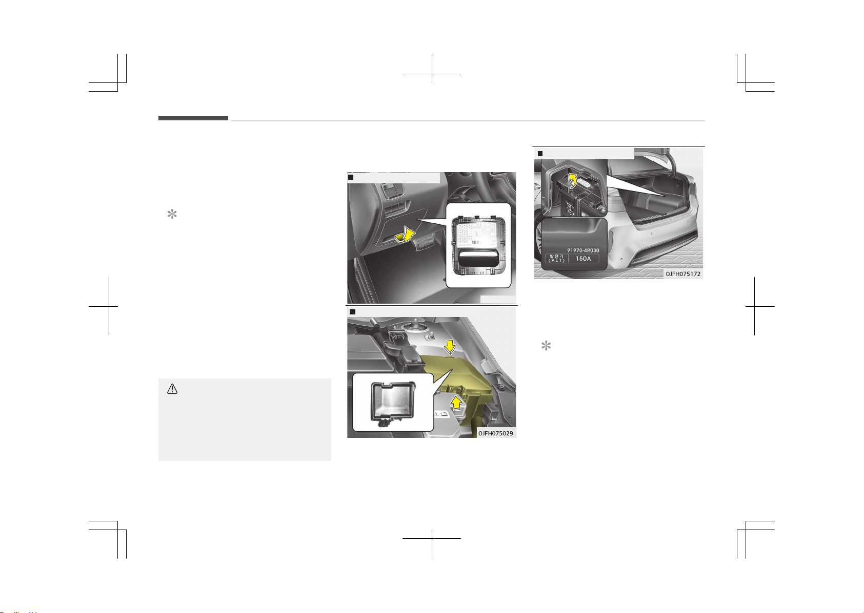
4. Replace the fuse with a new one of
the same rating.
5. Reinstall in the reverse order of re‐
moval.
NOTICE
The electronic system may not
function correctly even when the
engine room and internal fuse box's
individual fuses are not disconnec‐
ted. In such case the cause of the
problem may be disconnection of
the main fuse (BFT type), which is
located inside the positive battery
terminal (+) cap. Since the main fuse
is designed more intricately than
other parts, please visit the nearest
Kia dealer and service center.
CAUTION
Visually inspect the battery cap for
secure closing. If the battery cap is
not securely latched, the electrical
system may be damaged to due in‐
flux of moisture into the system.
Fuse/relay panel description
Drivers side fuse panel
OJF075027
Engine compartment fuse panel
Battery terminal cover
Inside the fuse/relay panel covers, you
can find the fuse/relay label describing
fuse/relay name and capacity.
NOTICE
Not all fuse panel descriptions in this
manual may be applicable to your
vehicle. It is accurate at the time of
printing. When you inspect the fuse
panel in your vehicle, refer to the
fuse panel label.
Maintenance
9-56
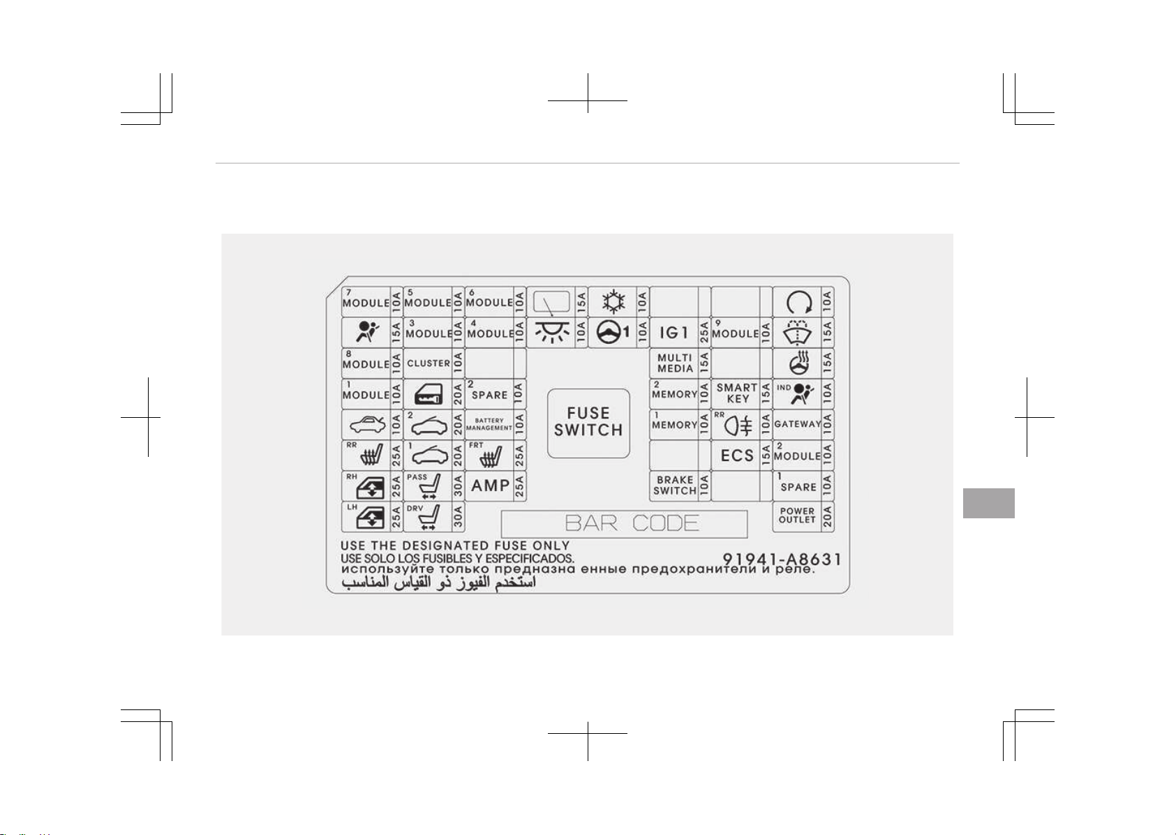
Driver’s side fuse panel
OJFHP076169L
9-57
9
Maintenance
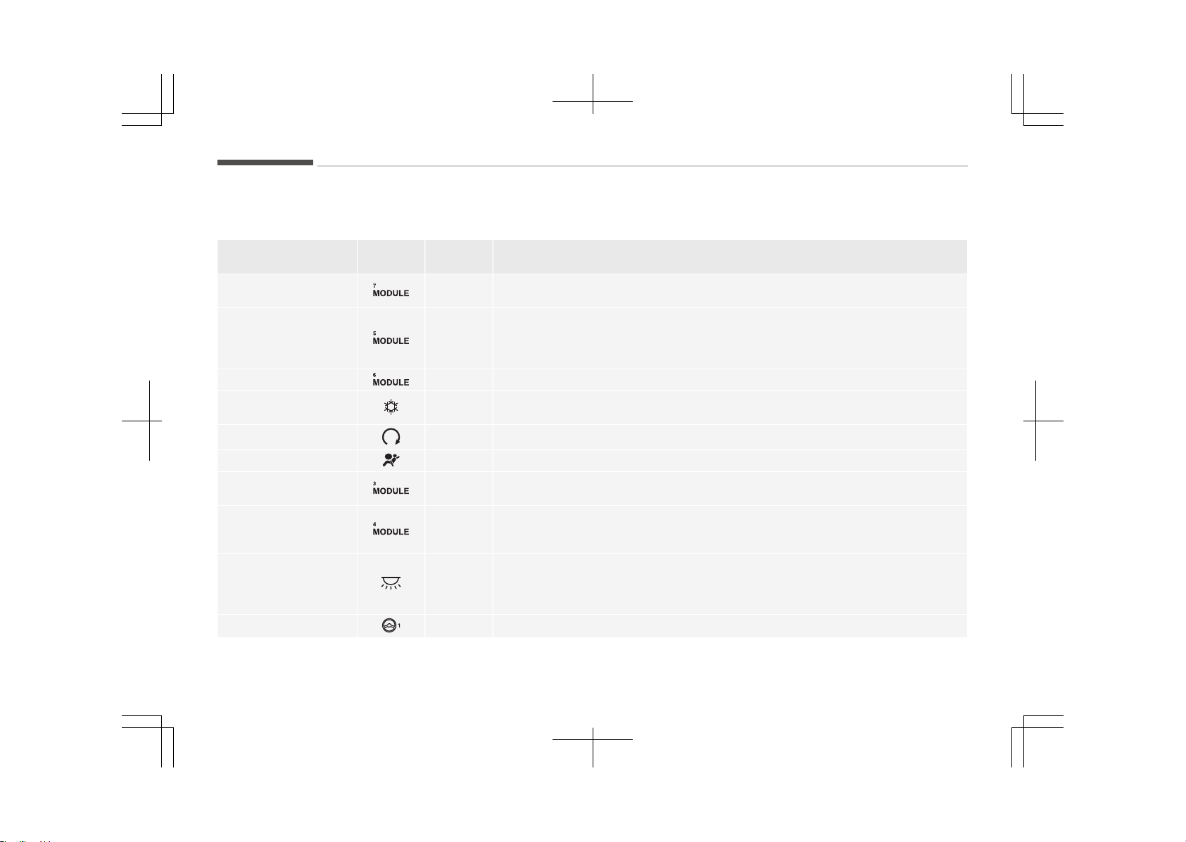
Instrument panel (Driver’s side fuse
panel)
Fuse Name Symbol
Fuse rat‐
ing
Circuit Protected
MODULE 7 10A
Around View Monitor Unit, Front Air Ventilation Seat Control Module, Front
Seat Warmer Control Module, Rear Seat Warmer Control Module
MODULE 5 10A
A/C Control Module, Electro Chromic Mirror, Driver IMS Module, Head Lamp
LH/RH, Auto Head Lamp Leveling Device Module, Fuel Lid & Trunk Open Switch,
Shift Lever Indicator, Front Air Ventilation Seat Control Module, Front Seat
Warmer Control Module, Rear Seat Warmer Control Module
MODULE 6 10A BCM, Smart Key Control Module
A/CON 10A
A/C Control Module, E/R Junction Block (RLY. 4 - Blower Relay), Ionizer, Active
Incar Sensor, Electronic A/C Compressor
START
10A Transaxle Range Switch, Smart Key Control Module
A/BAG
15A SRS Control Module, Passenger Occupant Detection Sensor
MODULE 3
10A
BCM, Stop Lamp Switch, AFLS Unit, Keyboard, VESS Unit, A/V & Navigation
Head Unit, Sport Mode Switch
MODULE 4 10A
Console Switch, Blind Spot Detection Radar LH/RH, Smart Parking Assist Con‐
trol Module, Smart Cruise Control Unit, Lane Keeping Assist Module, Active Air
Flap Unit, Electric Parking Brake Module, BMS Control Module
INTERIOR LAMP 10A
Trunk Room Lamp, Driver/Passenger Door Lamp, Glove Box Lamp, Driver/
Passenger Smart Key Outside Handle, Front Vanity Lamp Switch LH/RH, Over‐
head Console Lamp, Rear Personal Lamp LH/RH, Driver/Passenger Foot Lamp,
Room Lamp, Center Personal Lamp
MDPS
10A MDPS Unit (Column/Rack)
Maintenance
9-58
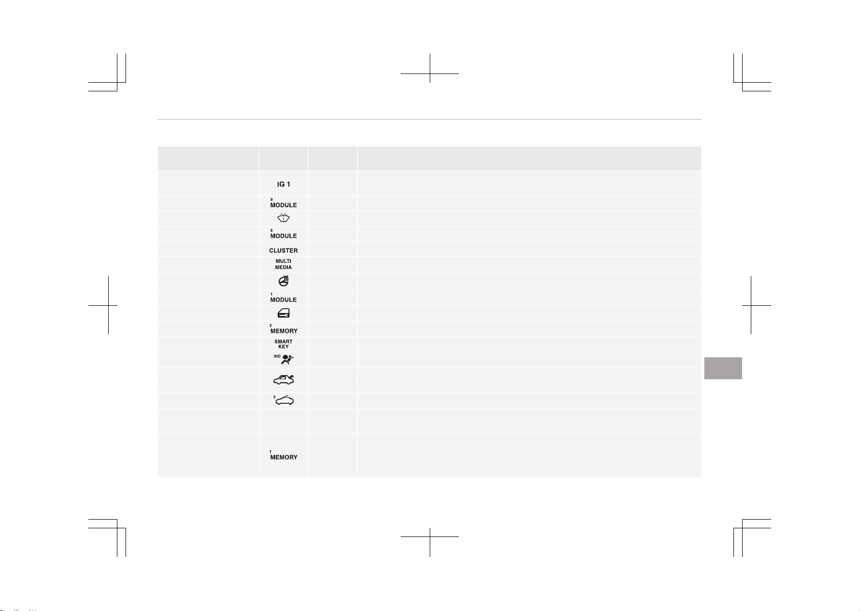
Fuse Name Symbol
Fuse rat‐
ing
Circuit Protected
IG1 25A
PCB Block (Fuse - OPCU2/ELECTRICAL WATER PUMP/TCU2/ACTIVE HYDRAULIC
BOOTER 3/HEV ECU2/ECU3)
MODULE 9
10A Smart Key Control Module
WASHER
15A Multifunction Switch (Wiper Low & Washer Switch)
MODULE 8
10A Driver/Passenger Door Module
CLUSTER
10A Instrument Cluster
MULTI MEDIA
15A Audio, A/V & Navigation Head Unit, Keyboard
HTD STRG
15A BCM (Steering Wheel Heated)
MODULE 1
10A Console Switch, Active Air Flap Unit, Gateway, Driver/Passenger Door Module
DR LOCK
20A Door Lock Relay, Door Unlock Relay, ICM Relay Box (Dead Lock Relay)
MEMORY 2
10A Siren Control Module, Ultrasonic Intrusion Protection Sensor
SMART KEY
15A Smart Key Control Module
A/BAG IND
10A Instrument Cluster (Air Bag IND. Power)
TRUNK
10A
Trunk Lid Relay, Fuel Filler & Trunk Open Switch, ICM Relay Box (Fuel Filler
Open Relay)
SUNROOF 2 20A Sunroof Control Unit (Roller)
BATTERY MANAGE‐
MENT
BATTERY
MANAGEMENT
20A BMS Control Module
MEMORY 1 10A
Instrument Cluster, A/C Control Module, Data Link Connector, BCM, Wireless
Charger, Driver IMS Module, Rain Sensor, ICM Relay Box (Outside Mirror Fold‐
ing/Unfolding Mirror Relay), Security Indicator, Auto Light & Photo Sensor,
Driver/Passenger Door Module
9-59
9
Maintenance
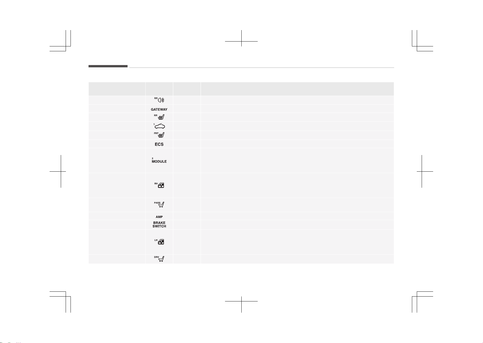
Fuse Name Symbol
Fuse rat‐
ing
Circuit Protected
FOG LAMP REAR
10A ICM Relay Box (Rear Fog Lamp Relay)
GATEWAY
10A Gateway
S/HEATER REAR
25A Rear Seat Warmer Control Module
SUNROOF 1
20A Sunroof Control Unit (Glass)
S/HEATER FRONT
25A Front Air Ventilation Seat Control Module, Front Seat Warmer Control Module
ECS 15A Not Used
MODULE 2 10A
Audio, A/V & Navigation Head Unit, Keyboard, Wireless Charger, Around View
Monitor Unit, AMP, Power Outside Mirror Switch, Smart Key Control Module,
BCM, Rear USB Charger, VESS Unit, E/R Junction Block (RLY. 7 - Power Outlet
Relay)
P/WDW RH 25A
Power Window RH Relay, Rear Safety Power Window Module LH, Rear Power
Window Switch LH, Power Window Main Switch,
[LHD] Passenger Safety Power Window Module
[RHD] Driver Safety Power Window Module
P/SEAT PASS 30A
Passenger Seat Manual Switch, Walk In Relay Module, Passenger Reclining Lim‐
it Switch
AMP 25A AMP
BRAKE SWITCH
10A Stop Lamp Switch, Smart Key Control Module, Start/Stop Button Switch
P/WDW LH
25A
Power Window LH Relay, Rear Safety Power Window Module RH, Rear Power
Window Switch RH, Power Window Main Switch,
[LHD] Driver Safety Power Window Module
[RHD] Passenger Safety Power Window Module
P/SEAT DRV
30A Driver Seat Manual Switch, Driver IMS Module
Maintenance
9-60

Fuse Name Symbol
Fuse rat‐
ing
Circuit Protected
POWER OUTLET 20A Front Power Outlet #1, Front Cigarette Lighter & Power Outlet #2
9-61
9
Maintenance
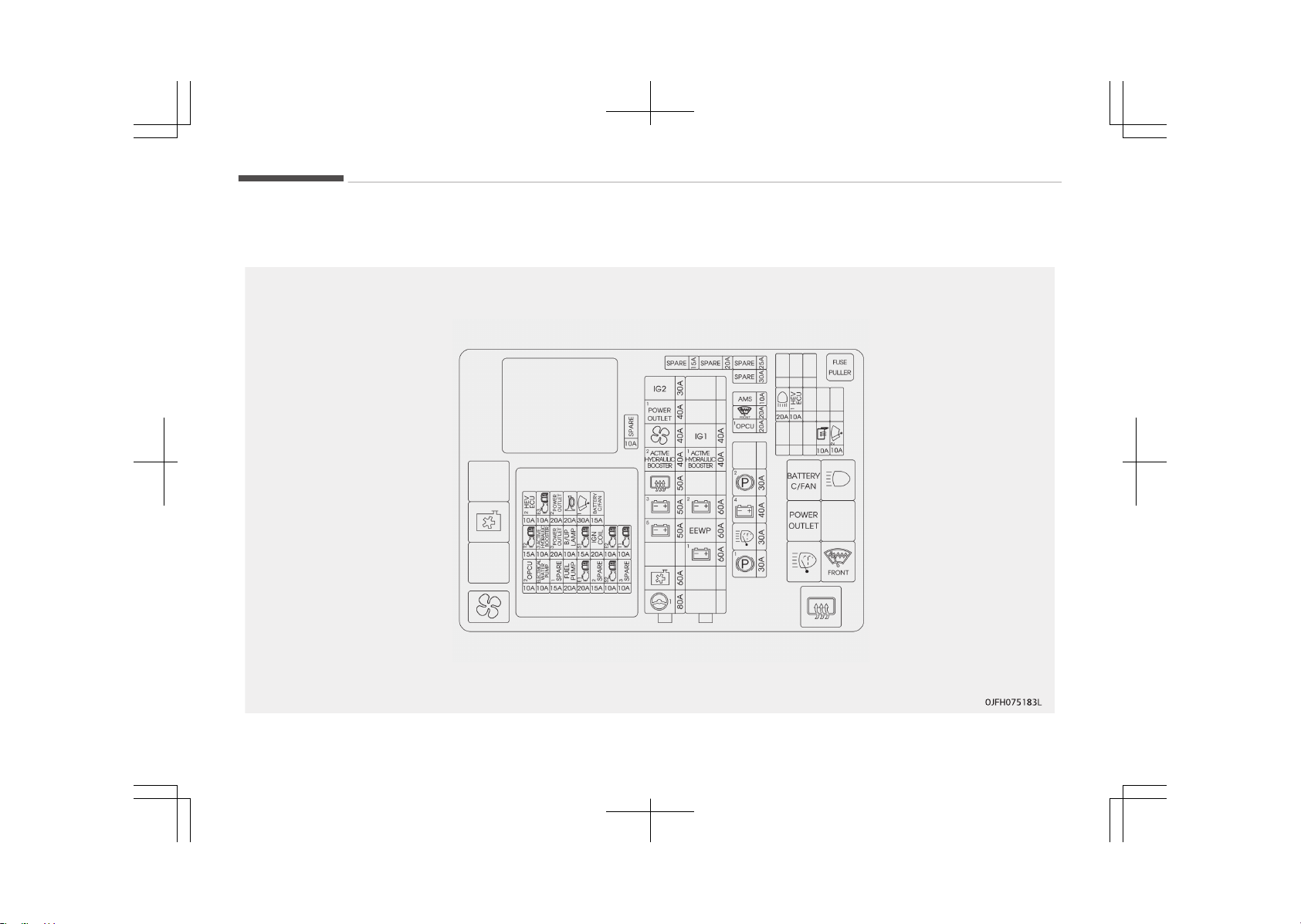
Engine compartment fuse panel (for Hybrid)
Maintenance
9-62
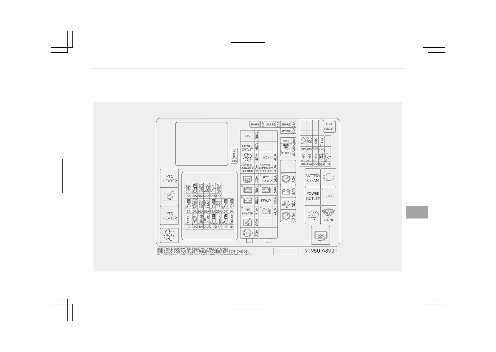
Engine compartment fuse panel (for Plug-in Hybrid)
OJFHP076170L
9-63
9
Maintenance

Battery terminal cover
Maintenance
9-64
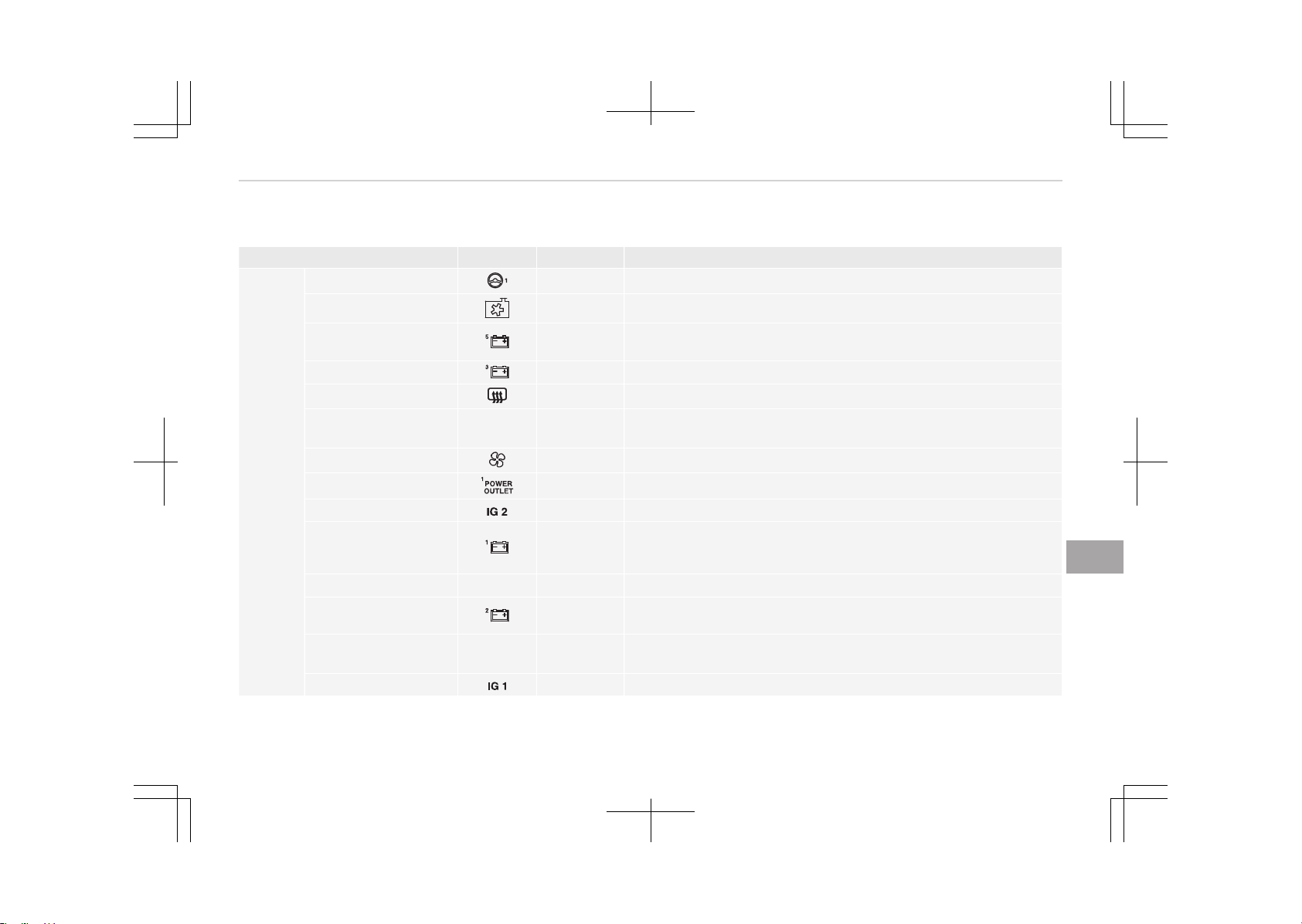
Engine room compartment fuse panel
Fuse Name Symbol Fuse rating Circuit Protected
MULTI
FUSE
MDPS 1
80A MDPS Unit (Column)
COOLING FAN
60A RLY. 2 (Cooling Fan Relay)
B+5 50A
PCB Block (Engine Control Relay, Fuse -FUEL
PUMP/ECU2/TCU1/HORN/WIPER1/BATTERY C/FAN)
B+3
50A Smart Junction Block (IPS 2 (IPS 5), IPS 3 (IPS 6), IPS 7, IPS 8)
REAR HEATED 50A RLY. 11 (Rear Heated Relay)
ACTIVE HYDRAULIC
BOOSTER 2
2
ACTIVE
HYDRAULIC
BOOSTER
40A Integrated Brake Actuation Unit
BLOWER
40A RLY. 4 (Blower Relay)
POWER OUTLET1
40A RLY. 7 (Power Outlet Relay)
IG2
30A PCB Block (IG2 Relay)
B+1 60A
Smart Junction Block (Fuse - TRUNK, SUNROOF2, S/HEATER
REAR, SUNROOF1, P/WDW RH, P/SEAT PASS, P/WDW LH, P/SEAT
DRV)
EEWP
EEWP
60A Engine Electric Water Pump
B+2
60A
Smart Junction Block (IPS 1, IPS 4, Fuse - FOG LAMP REAR, S/
HEATER FRONT, AMP)
ACTIVE HYDRAULIC
BOOSTER 1
ACTIVE
HYDRAULIC
BOOSTER
1
40A Integrated Brake Actuation Unit
IG1
40A PCB Block (IG1/ACC Relay)
9-65
9
Maintenance
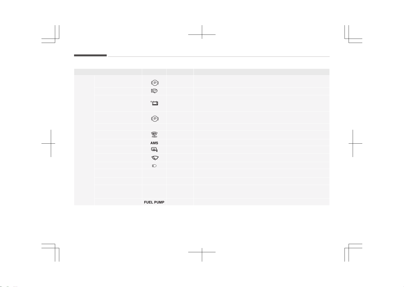
Fuse Name Symbol Fuse rating Circuit Protected
FUSE
EPB1
1
30A Electric Parking Brake Module
H/Lamp Washer
30A RLY. 9 (H/Lamp Washer Relay)
B+4
40A
Smart Junction Block (Leak Current Autocut Device Fuse - INTERI‐
OR LAMP, MULTI MEDIA, MEMORY2, MEMORY1, Fuse - MODULE1,
DR LOCK, SMART KEY, BRAKE SWITCH)
EPB 2
2
30A Electric Parking Brake Module
OPCU 1
OPCU
1
20A Electric Oil Pump Unit
DEICER
20A RLY. 10 (Deicer Relay)
AMS
10A Battery Sensor
HEATED MIRROR 10A A/C Control Module, Driver/Passenger Power Outside Mirror
WIPER 2
2
10A BCM, PCM
H/LAMP HI
20A Not used
HEV ECU 1
HEV
ECU
1
10A HPCU
OPCU2
OPCU
1
10A Electric Oil Pump Unit
ELECTRICAL WATER
PUMP
ELECTRICAL
WATER
PUMP
10A Electric Water Pump (HEV)
FUEL PUMP
20A Fuel Pump Relay
Maintenance
9-66
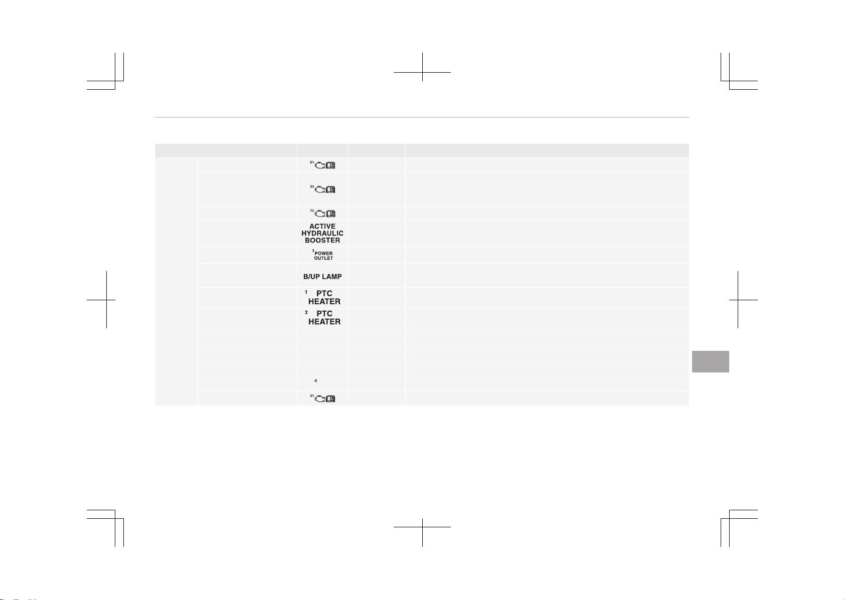
Fuse Name Symbol Fuse rating Circuit Protected
FUSE
ECU 1 20A PCM
SENSORS 2 10A
Mass Air Flow Sensor, Fuel Pump Relay, Oil Control Valve #1/#2,
Canister Close Valve, Camshaft Position Sensor #1/#2, Purge Con‐
trol Solenoid Valve
TCU 2 15A Transaxle Range Switch
ACTIVE HYDRAULIC
BOOSTER 3
3
10A Multipurpose Check Connector, Integrated Brake Actuation Unit
POWER OUTLET 3
20A Rear Power Outlet
B/UP LAMP
10A
PCM, Transaxle Range Switch, Electro Chromic Mirror, Rear Com‐
bination Lamp (IN) LH/RH
PTC HEATER 1
50A PTC HEATER
PTC HEATER 2
50A PTC HEATER
IG3 1
IG3
1
10A HYBRID WATER PUMP
IG3 2
IG3
2
15A PCU/HPCU/POSITION SWITCH
IG3 3
IG3
3
10A HYBRID OBC SIG
IG3 4
IG3
20A IG3 3 RELAY
SENSOR 1
15A Oxygen Sensor (Up/Down), E/R Junction Block (Cooling Fan Relay)
9-67
9
Maintenance
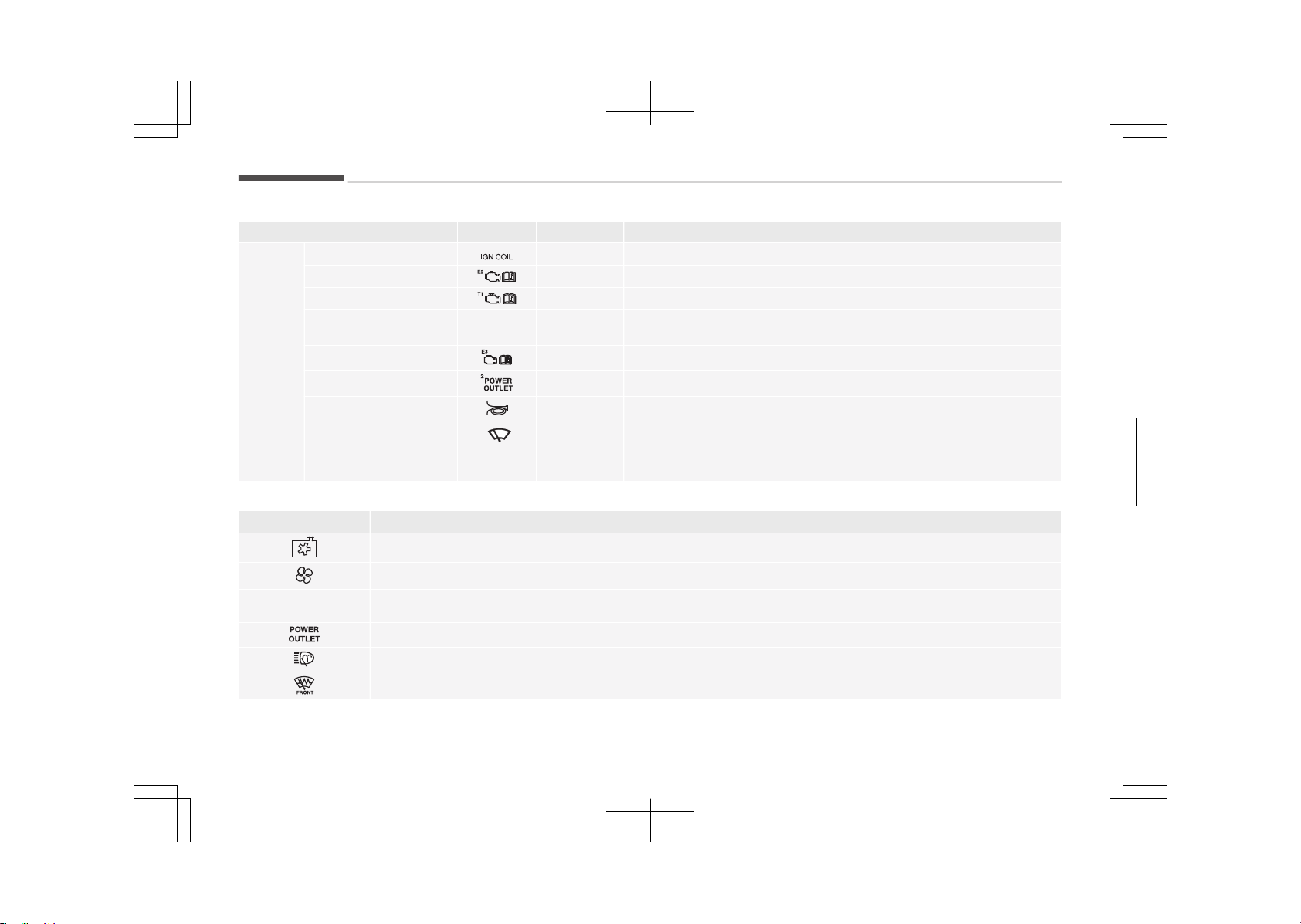
Fuse Name Symbol Fuse rating Circuit Protected
FUSE
IGN COIL 20A Ignition Coil #1/#2/#3/#4
ECU 2 10A PCM
TCU 1 10A PCM
HEV ECU 2
HEV
ECU
2
10A HPCU, E/R Junction Block (Battery C/Fan Relay)
ECU 3
10A PCM
POWER OUTLET2
20A Front Power Outlet #1
HORN
20A Horn Relay, ICM Relay Box (Burglar Alarm Horn Relay)
WIPER 1
1
30A Wiper Power Relay
BATTERY C/FAN
BATTERY
C/FAN
15A E/R Junction Block (Battery C/Fan Relay)
Relay
Symbol Relay Name Type
COOLING FAN Relay MINI
BLOWER Relay MICRO
BATTERY
C/FAN
BATTERY C/FAN Relay MICRO
POWER OUTLET Relay MICRO
H/LAMP WASHER Relay MICRO
DEICER Relay MICRO
Maintenance
9-68

Symbol Relay Name Type
REAR HEATED Relay MINI
PTC HEATER RELAY 1 MICRO
PTC HEATER RELAY 2 MICRO
IG2
IG 3 RELAY MICRO
9-69
9
Maintenance
LIGHT BULBS
Bulb replacement precaution
Please prepare bulbs with appropriate
standards in case of emergencies. Re‐
fer to Bulb wattage on page 10-07.
When changing bulbs and sorts, first
turn off the engine at a safe place,
firmly apply the side brake and take
out the battery's negative (-) terminal.
WARNING
n
Working on the lights
Prior to working on the light, firmly
apply the parking brake, ensure that
the ignition switch is turned to the
LOCK position and turn off the lights
to avoid sudden movement of the
vehicle and burning your fingers or
receiving an electric shock.
Use only the bulbs of the specified wat‐
tage.
WARNING
Be sure to replace the burned-out
bulb with one of the same wattage
rating. Otherwise, it may cause ex‐
tensive wiring damage and possible
fire.
CAUTION
If you don’t have necessary tools,
the correct bulbs and the expertise,
consult an authorized Kia dealer. In
many cases, it is difficult to replace
vehicle light bulbs because other
parts of the vehicle must be re‐
moved before you can get to the
bulb. This is especially true if you
have to remove the headlight as‐
sembly to get to the bulb(s). Remov‐
ing/installing the headlight assembly
can result in damage to the vehicle.
CAUTION
• If unauthentic parts or substan‐
dard lights are used when chang‐
ing lights, it may lead to fuse dis‐
connection and malfunction, and
other wiring damages.
• Do not install extra lamps or LED
to the vehicle. If supplementary
lights are installed, it may lead to
lamp malfunction and flickering of
the lights. In addition, the fuse box
and other writing may be dam‐
aged.
• Lamp part malfunction due to net-
work failure
The headlamp, taillight, and fog light
may lit up when the head lamp
switch is turned ON, and not light up
when the taillight or for light switch
is turned ON. This may be cause by
network failure or vehicle electrical
control system malfunction. If there
is a problem, we recommend the sys‐
tem be serviced by an authorized Kia
dealer.
Maintenance
9-70

• Lamp part malfunction due to electri‐
cal control system stabilization
A normally functioning lamp may
flicker momentarily. This momentary
occurrence is due to stabilization unc‐
tion of the vehicle's electrical on con‐
trol system. If the lamp soon returns
to normal, the vehicle does not re‐
quire service.
However, if the lamp goes out after
he momentary flickering, or the flick‐
ering continues, we recommend the
system be serviced by an authorized
Kia dealer.
NOTICE
• If the light bulb or lamp connector
is removed from an operating
lamp activated by electricity, the
fuse box’s electronic device may
scan it as a malfunction. There‐
fore, a lamp malfunction history
may be recorded in Diagnostic
Trouble Code (DTC) in the fuse
box.
(Continued)
(Continued)
• It is normal for an operating lamp
may blink temporarily. Since this
occurrence is due stabilization
function of the vehicle’s electronic
control device, if the lamp lights up
normally after temporary blinking,
there is no problem in the vehicle.
However, if the lamp continues to
blink several times or turn off
completely, there may be an error
in the vehicle’s electronic control
device. So we recommend that
you have the vehicle checked by
an authorized Kia dealer immedi‐
ately.
NOTICE
We recommend that the headlight
aiming be adjusted after an accident
or after the headlight assembly is
reinstalled at an authorized Kia deal‐
er.
NOTICE
After driving in heavy rain or wash‐
ing, headlamp and tail lamp lenses
could appear frosty. This condition is
caused by the temperature differ‐
ence between the lamp inside and
outside. This is similar to the con‐
densation on your windows inside
your vehicle during the rain and
doesn’t indicate a problem with your
vehicle. If the water leaks into the
lamp bulb circuitry, have the vehicle
checked by an authorized Kia dealer.
9-71
9
Maintenance
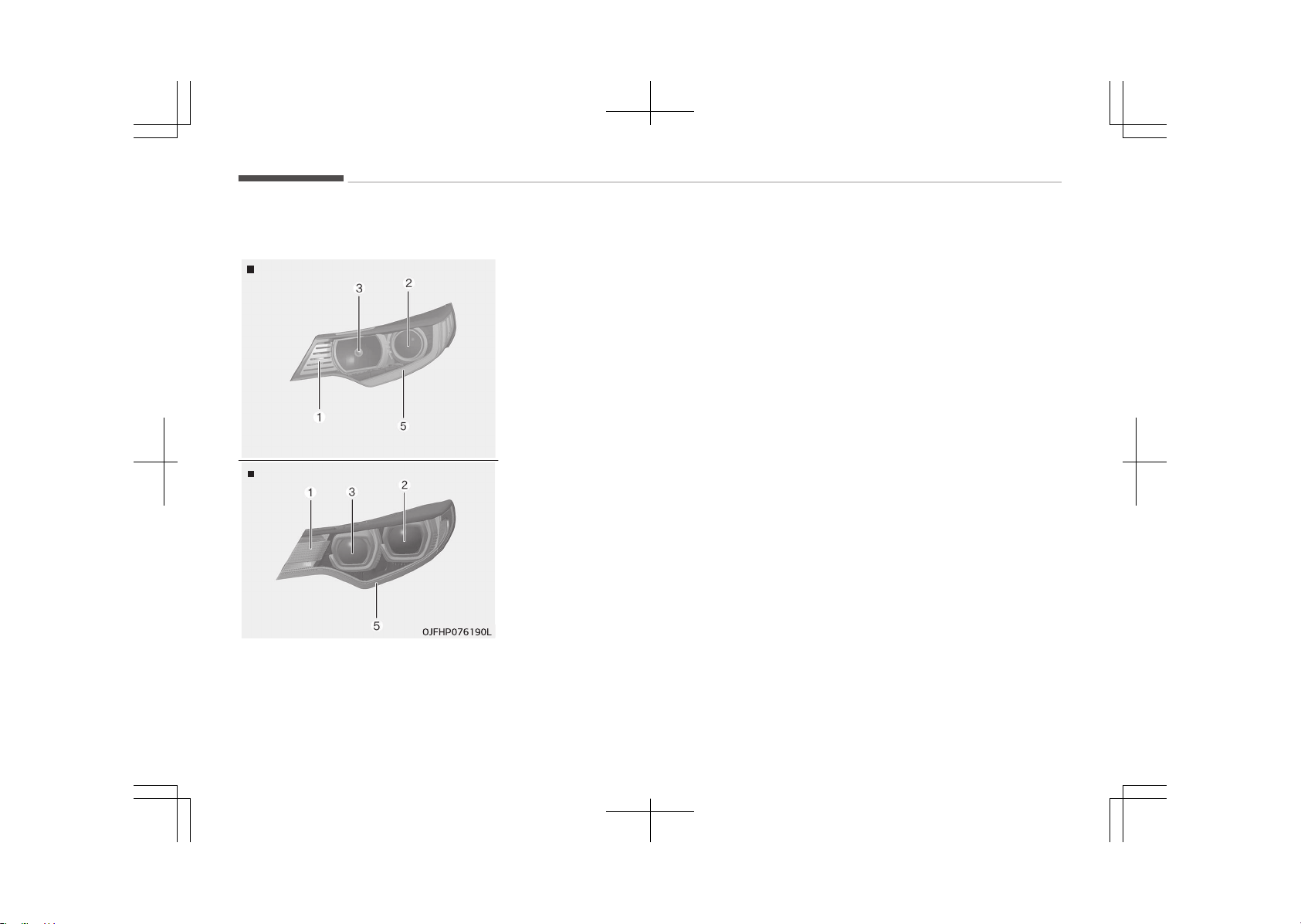
Light bulb position (front)
Head lamp Type A
OJF075135LB
Head lamp - Type B
1. Front turn signal lamp
2. Headlamp (Low)
3. Headlamp (High)
4. Headlamp (Low/High)
5. Day time running lamp/Position
lamp (LED type)
Maintenance
9-72
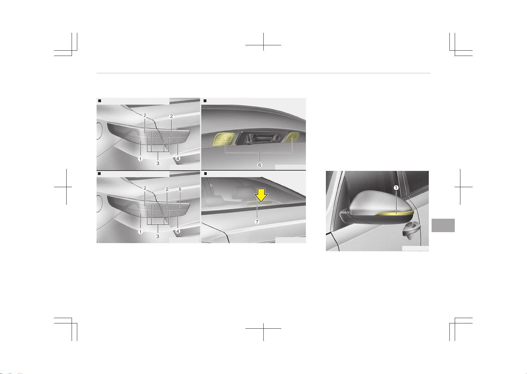
Light bulb position (rear)
Rear combination lamp - Type A
OJFH075178L
Rear combination lamp - Type B
OJFH075179L
License plate lamp
High mounted stop lamp
OJFH075180L
OJFH075181L
1. Rear turn signal lamp
2. Stop lamp (LED type)
3. Tail lamp (LED type)
4. Back-up lamp
5. Rear fog lamp (LED type)
6. License plate lamp
7. High mounted stop lamp
Light bulb position (side)
OJF075039LB
1. Side repeater lamp (LED type)
9-73
9
Maintenance
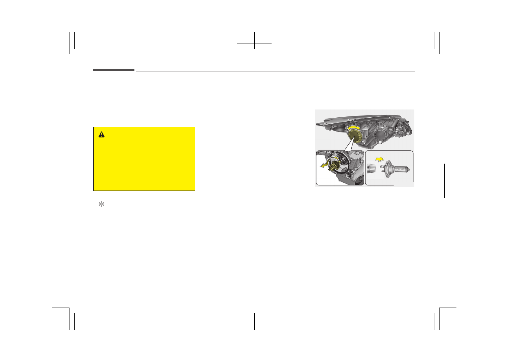
Headlamp (HID type) bulb
replacement
If the light bulb does not operate, we
recommend that you checked an au‐
thorized Kia dealer.
WARNING
n
HID Headlamp (if equipped)
Do not attempt to replace or inspect
the HID headlamp (XENON bulb) due
to electric shock danger. If the light
bulb does not operate, we recom‐
mend that you checked an author‐
ized Kia dealer.
NOTICE
HID lamps have superior perform‐
ance vs. halogen bulbs. HID lamps
are estimated by the manufacturer
to last twice as long or longer than
halogen bulbs depending on their
frequency of use. They will probably
require replacement at some point in
the life of the vehicle. Cycling the
(Continued)
(Continued)
headlamps on and off more than
typical use will shorten HID lamps
life. HID lamps do not fail in the
same manner as halogen incandes‐
cent lamps. If a headlamp goes out
after a period of operation but will
immediately relight when the head‐
lamp switch is cycled it is likely the
HID lamp needs to be replaced. HID
lamping components are more com‐
plex than conventional halogen bulbs
thus have higher replacement cost.
Headlamp (low beam) bulb
replacement
OJF075073
1. Open the hood.
2. Remove the headlamp bulb cover
by turning it counterclockwise.
3. Remove the bulb-socket from the
headlamp assembly by turning the
bulb-socket counterclockwise until
the tabs on the bulb-socket align
with the slots on the headlamp as‐
sembly.
4. Remove the bulb from bulb-socket
by pulling it out.
5. Insert a new bulb by inserting it in‐
to the bulb-socket.
Maintenance
9-74
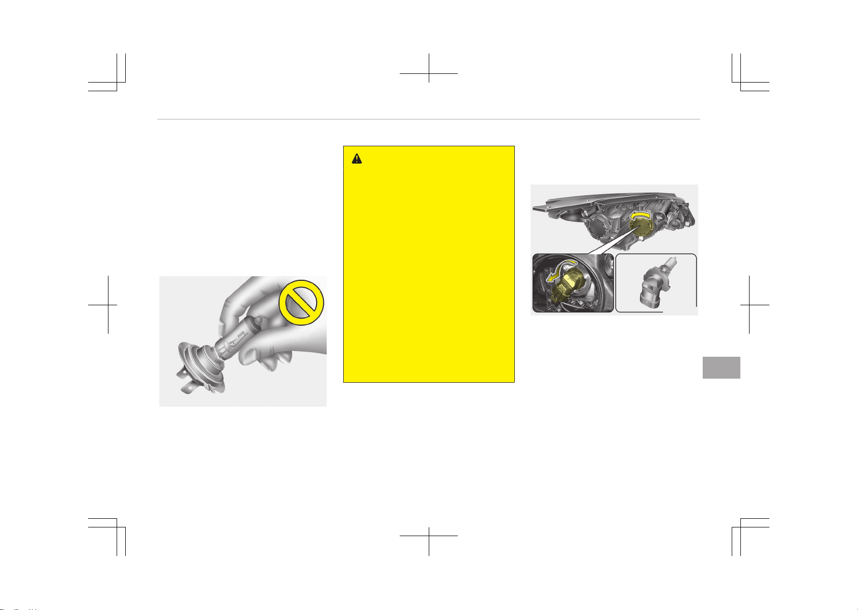
6. Install the bulb-socket in the head‐
lamp assembly by aligning the tabs
on the bulb-socket with the slots in
the headlamp assembly. Push the
bulb-socket into the headlamp as‐
sembly and turn the bulb-socket
clockwise.
7. Install the headlamp bulb cover by
turning it clockwise.
Headlamp bulb
OHD076046
WARNING
n
Halogen bulbs
• Halogen bulbs contain pressurized
gas that will produce flying pieces
of glass if broken.
• Always handle them carefully, and
avoid scratches and abrasions. If
the bulbs are lit, avoid contact
with liquids. Never touch the glass
with bare hands. Residual oil may
cause the bulb to overheat and
burst when lit.
A bulb should be operated only
when installed in a headlight.
• If a bulb becomes damaged or
cracked, replace it immediately
and carefully dispose of it.
• Wear eye protection when chang‐
ing a bulb. Allow the bulb to cool
down before handling it.
Headlamp (high beam) bulb
replacement
OJF075076
1. Open the hood.
2. Remove the headlamp bulb cover
by turning it counterclockwise.
3. Disconnect the headlamp bulb
socket-connector.
4. Remove the bulb-socket from the
headlamp assembly by turning the
bulb-socket counterclockwise until
the tabs on the bulb-socket align
with the slots on the headlamp as‐
sembly.
9-75
9
Maintenance
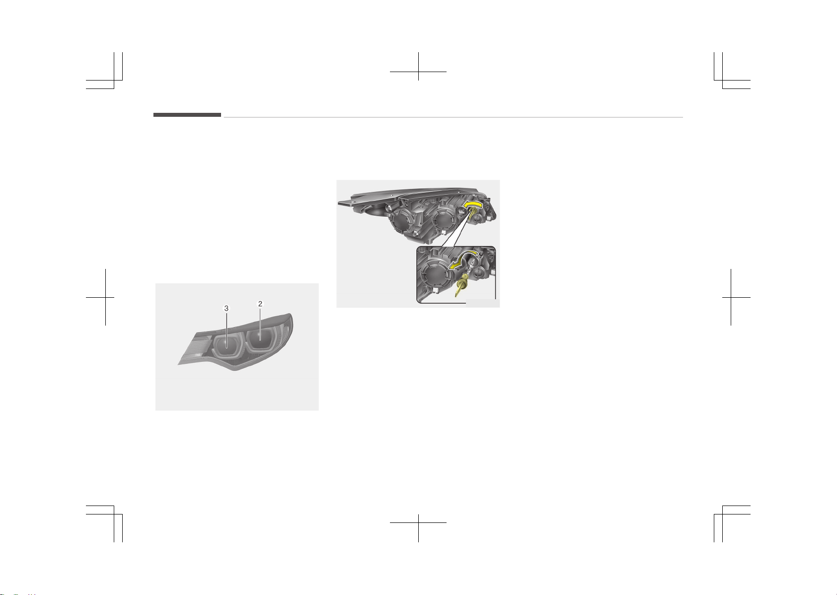
5. Install a new bulb-socket assembly
in the headlamp assembly by align‐
ing the tabs on the bulb-socket
with the slots in the headlamp as‐
sembly. Push the bulb-socket into
the headlamp assembly and turn
the bulb-socket clockwise.
6. Install the headlamp bulb cover by
turning it clockwise.
Headlamp (high/low beam) LED
replacement
OJFHP076192L
If the light bulb (Low(2), High(3)) does
not operate, we recommend you to
have it checked at an authorized Kia
dealer.
Front turn signal lamp bulb
replacement
OJF075079
1. Open the hood.
2. Remove the bulb-socket from the
headlamp assembly by turning the
bulb-socket counterclockwise until
the tabs on the bulb-socket align
with the slots on the headlamp as‐
sembly.
3. Remove the bulb from the bulb-
socket by pressing it in and rotat‐
ing it counterclockwise until the
tabs on the bulb align with the slots
in the bulb-socket. Pull the bulb out
of the bulb-socket
4. Insert a new bulb by inserting it in‐
to the bulb-socket and rotating it
until it locks into place.
5. Install the socket in the headlamp
assembly by aligning the tabs on
the bulb-socket with the slots in
the assembly. Push the bulb-sock‐
et into the headlamp assembly and
turn the socket clockwise.
Maintenance
9-76
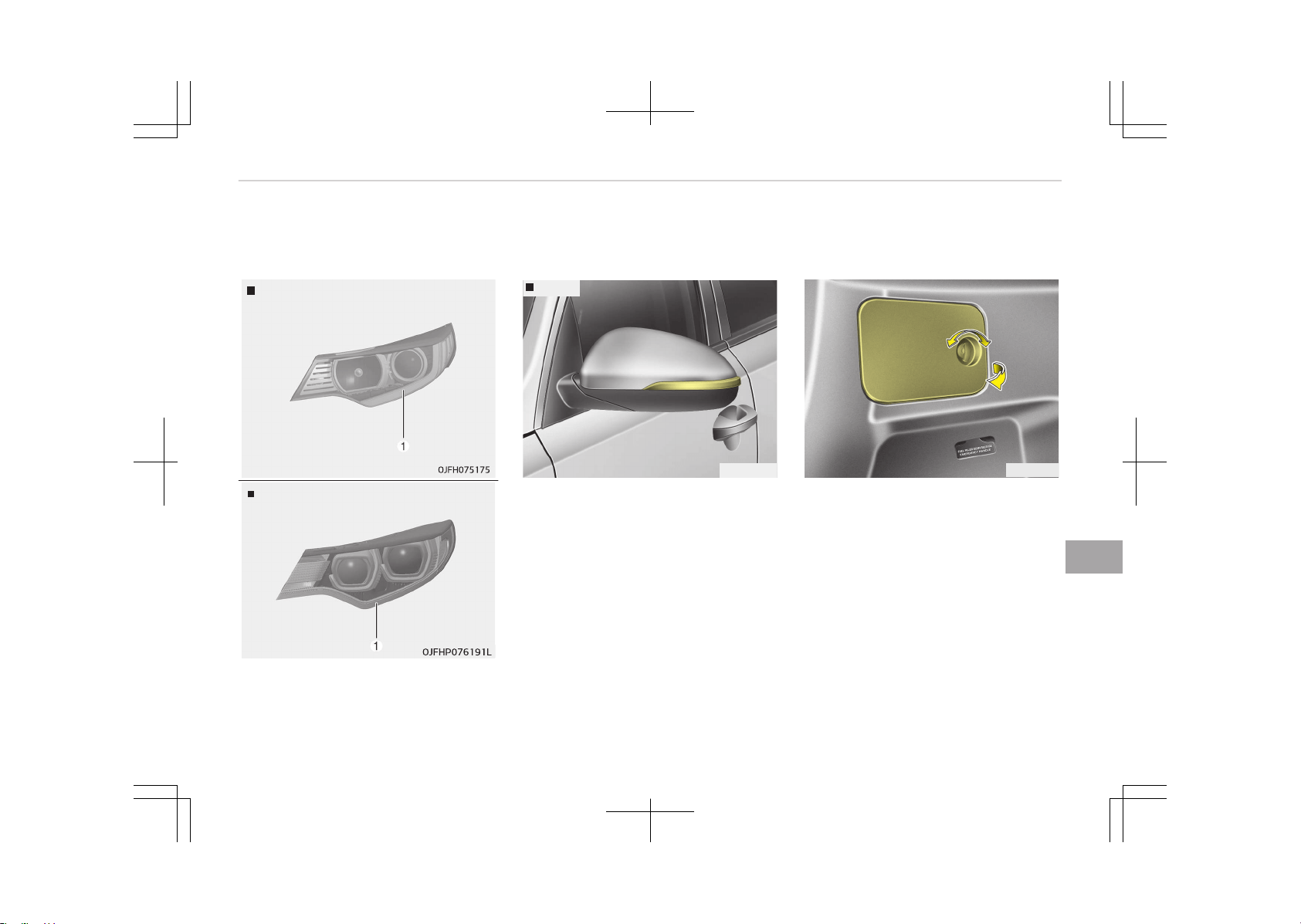
Position lamp + DRL (LED type)
bulb replacement
Type A
Type B
If the position lamp + DRL (1) does not
operate, we recommend you to have it
checked at an authorized Kia dealer.
Side repeater lamp bulb
replacement
Type A
OJF075039
If the Side repeater lamp does not op‐
erate, we recommend you to have it
checked at an authorized Kia dealer.
Rear turn signal lamp bulb
replacement
OJF075041
1. Open the trunk lid.
2. Open the service cover.
9-77
9
Maintenance
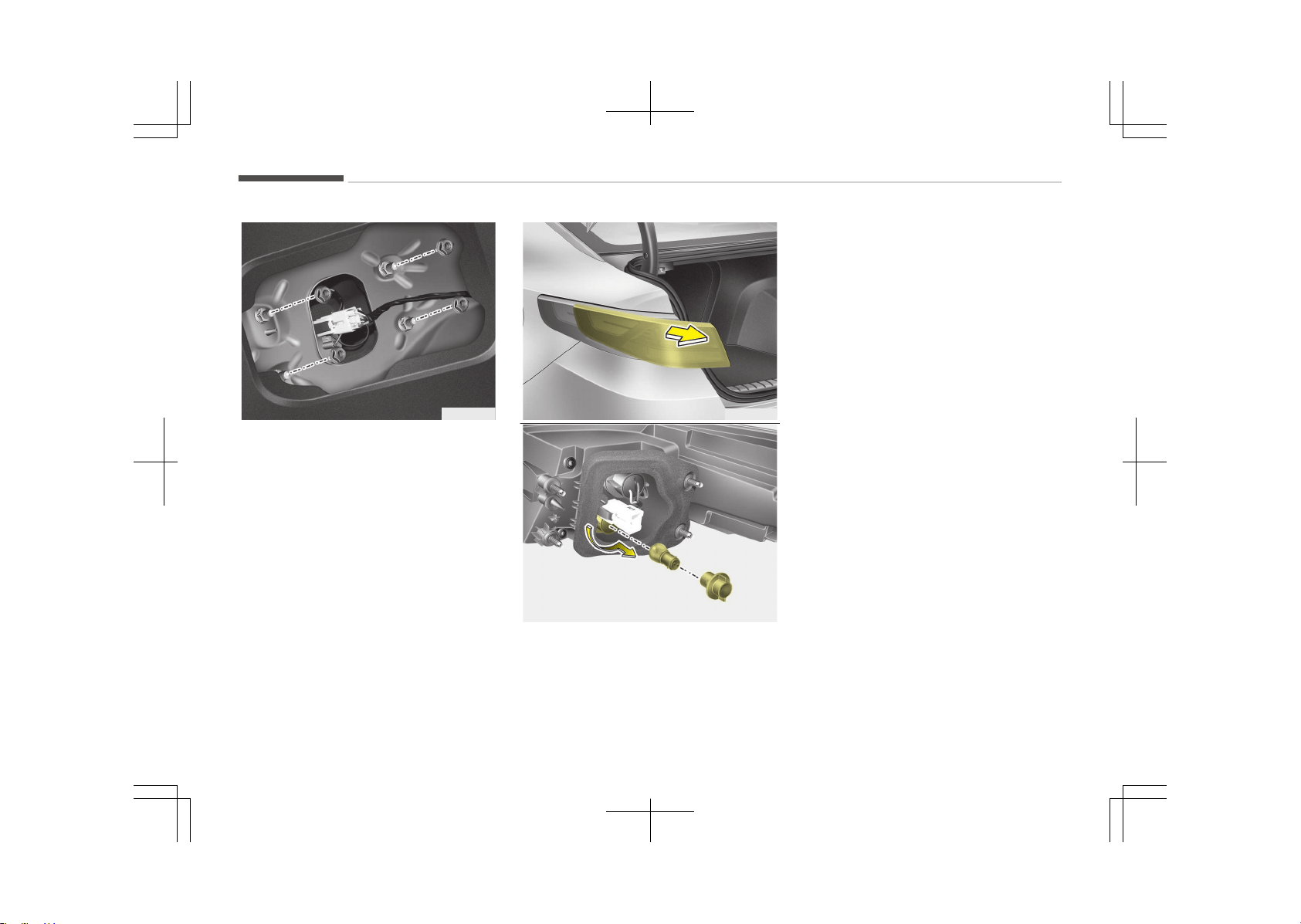
OJF075042
3. Remove the nuts from the vehicle.
4. Disconnect the rear combination
lamp connector.
OJF075043
OJF075093
5. Remove the rear combination lamp
assembly from the body of the ve‐
hicle.
6. Remove the socket from the as‐
sembly by turning the socket coun‐
terclockwise until the tabs on the
socket align with the slots on the
assembly.
7. Remove the bulb from the socket
by pressing it in and rotating it
counterclockwise until the tabs on
the bulb align with the slots in the
socket. Pull the bulb out of the
socket.
8. Insert a new bulb by inserting it in‐
to the socket and rotating it until it
locks into place.
9. Install the socket in the assembly
by aligning the tabs on the socket
with the slots in the assembly.
Push the socket into the assembly
and turn the socket clockwise.
10. Install the rear combination lamp
assembly to the body of the vehi‐
cle.
11. Install the service cover by putting
it into the service hole.
Maintenance
9-78
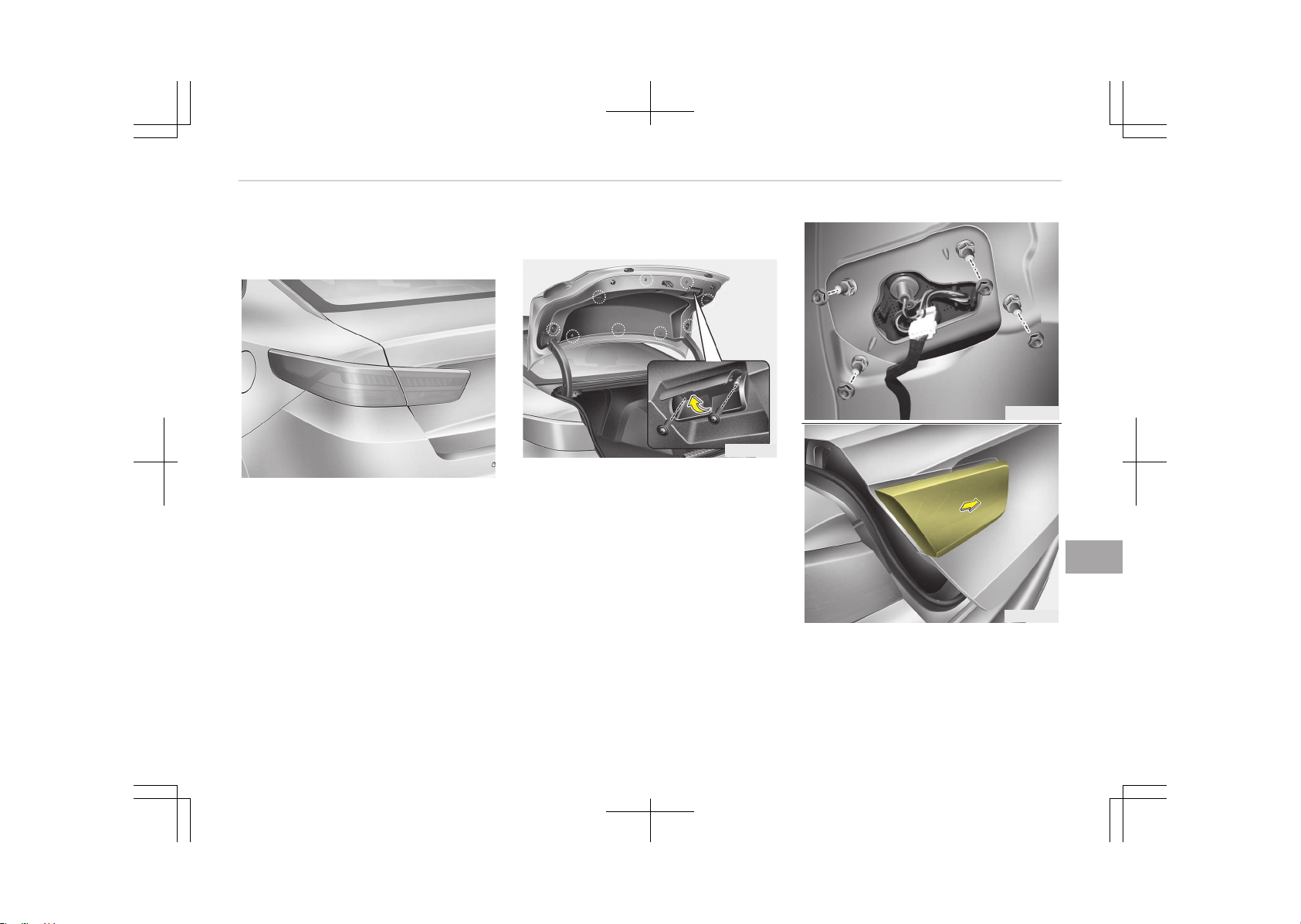
Stop and tail lamp (LED type)
bulb replacement
OJF075040
If the stop and tail lamp (LED) does not
operate, we recommend you to have it
checked at an authorized Kia dealer.
Back-up lamp bulb replacement
OJF075081
1. Open the trunk lid.
2. Loosen the retaining screw of the
trunk lid cover and then remove the
cover.
OJF075082
OJF075083
9-79
9
Maintenance
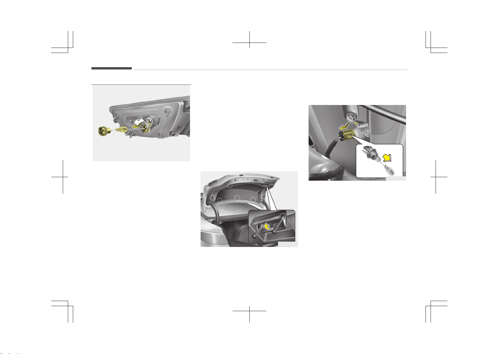
OJF075094
3. Remove the nuts from the vehicle.
4. Disconnect the rear combination
lamp (inside) connector.
5. Remove the rear combination lamp
(inside) assembly from the body of
the vehicle.
6. Remove the socket from the as‐
sembly by turning the socket coun‐
terclockwise until the tabs on the
socket align with the slots on the
assembly.
7. Remove the bulb from bulb-socket
by pulling it out.
8. Insert a new bulb by inserting it in‐
to the bulb-socket.
9. Install the socket in the assembly
by aligning the tabs on the socket
with the slots in the assembly.
Push the socket into the assembly
and turn the socket clockwise.
10. Install the rear combination lamp
(inside) assembly to the body of
the vehicle.
11. Install the trunk lid cover.
License plate lamp bulb
replacement
OJF075081
1. Open the trunk lid.
2. Loosen the retaining screw of the
trunk lid cover and then remove the
cover.
OJF075085
3. Remove the socket from the as‐
sembly by turning the socket coun‐
terclockwise until the tabs on the
socket align with the slots on the
assembly.
4. Remove the bulb from bulb-socket
by pulling it out.
5. Insert a new bulb by inserting it in‐
to the bulb-socket.
6. Install the socket in the assembly
by aligning the tabs on the socket
with the slots in the assembly.
Push the socket into the assembly
and turn the socket clockwise.
Maintenance
9-80
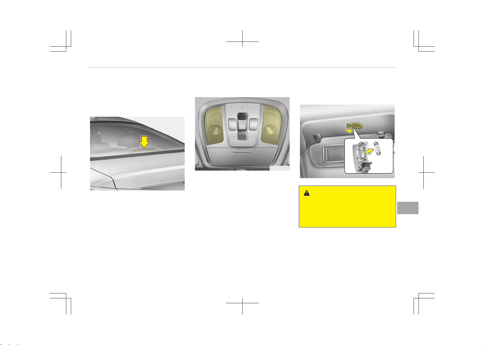
7. Install the trunk lid cover.
High mounted stop lamp bulb
replacement
OJF075049
If the high mounted stop lamp (LED)
does not operate, we recommend you
to have it checked at an authorized Kia
dealer.
Map lamp bulb replacement
OJF075050
If the map lamp (bulb and LED type)
does not operate, we recommend you
to have it checked at an authorized Kia
dealer.
Vanity mirror lamp bulb
replacement
OJF075051
WARNING
Prior to working on the Interior
lamps, ensure that the OFF button
is depressed to avoid burning your
fingers or receiving an electric shock.
1. Using a flat-blade screwdriver, gen‐
tly pry the lamp assembly from in‐
terior.
2. Remove the bulb by pulling it
straight out.
9-81
9
Maintenance
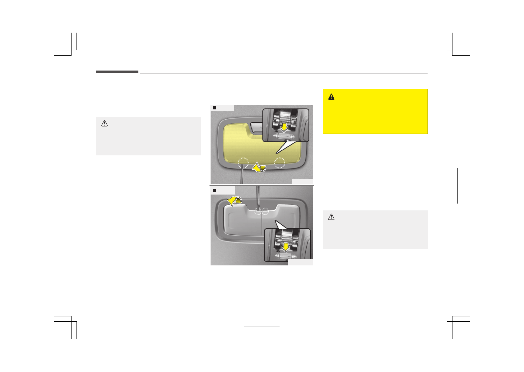
3. Install a new bulb in the socket.
4. Install the lamp assembly to interi‐
or.
CAUTION
Be careful not to dirty or damage
the lens, lens tab, and plastic hous‐
ings.
Room lamp bulb replacement
Type A
OJF075087
Type B
OJF075133L
WARNING
Prior to working on the Interior
lamps, ensure that the OFF button
is depressed to avoid burning your
fingers or receiving an electric shock.
1. Using a flat-blade screwdriver, gen‐
tly pry the lens cover from lamp
housing.
2. Remove the bulb by pulling it
straight out.
3. Install a new bulb in the socket.
4. Align the lens cover tabs with the
lamp housing notches and snap the
lens into place.
CAUTION
Be careful not to dirty or damage
the lens, lens tab, and plastic hous‐
ings.
Maintenance
9-82
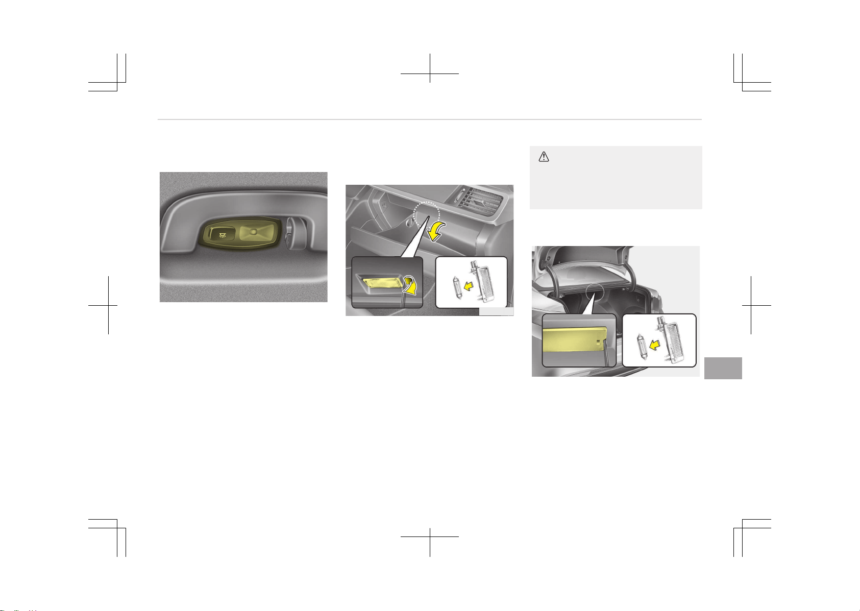
Personal lamp bulb replacement
OJF075088
If the personal lamp (LED) does not op‐
erate, we recommend you to have it
checked at an authorized Kia dealer.
Glove box lamp bulb
replacement
OJF075054
1. Using a flat-blade screwdriver, gen‐
tly pry the lamp assembly from in‐
terior.
2. Remove the bulb by pulling it
straight out.
3. Install a new bulb in the socket.
4. Install the lamp assembly to interi‐
or.
CAUTION
Be careful not to dirty or damage
the lens, lens tab, and plastic hous‐
ings.
Trunk lamp bulb replacement
OJF075053
1. Using a flat-blade screwdriver, gen‐
tly pry the lens cover from lamp
housing.
2. Remove the bulb by pulling it
straight out.
3. Install a new bulb in the socket.
9-83
9
Maintenance

4. Align the lens cover tabs with the
lamp housing notches and snap the
lens into place.
CAUTION
Be careful not to dirty or damage
the lens, lens tab, and plastic hous‐
ings.
Maintenance
9-84
APPEARANCE CARE
Exterior care
Exterior general caution
It is very important to follow the label
directions when using any chemical
cleaner or polish. Read all warning and
caution statements that appear on the
label.
Finish maintenance
Washing
To help protect your vehicle’s finish
from rust and deterioration, wash it
thoroughly and frequently at least once
a month with lukewarm or cold water.
If you use your vehicle for off-road
driving, you should wash it after each
off-road trip. Pay special attention to
the removal of any accumulation of
salt, dirt, mud, and other foreign mate‐
rials. Make sure the drain holes in the
lower edges of the doors and rocker
panels are kept clear and clean.
Insects, tar, tree sap, bird droppings, in‐
dustrial pollution and similar deposits
can damage your vehicle’s finish if not
removed immediately.
Even prompt washing with plain water
may not completely remove all these
deposits. A mild soap, safe for use on
painted surfaces, may be used.
After washing, rinse the vehicle thor‐
oughly with lukewarm or cold water. Do
not allow soap to dry on the finish.
CAUTION
• Do not use strong soap, chemical
detergents or hot water, and do
not wash the vehicle in direct sun‐
light or when the body of the vehi‐
cle is warm.
• Be careful when washing the side
windows of your vehicle.
Especially, with high-pressure wa‐
ter, water may leak through the
windows and wet the interior.
• To prevent damage to the plastic
parts and lamps, do not clean with
chemical solvents or strong deter‐
gents.
WARNING
n
Wet brakes
After washing the vehicle, test the
brakes while driving slowly to see if
(Continued)
(Continued)
they have been affected by water. If
braking performance is impaired, dry
the brakes by applying them lightly
while maintaining a slow forward
speed.
High-pressure washing
• When using high-pressure washers,
make sure to maintain sufficient dis‐
tance from the vehicle.
Insufficient clearance or excessive
pressure can lead to component
damage or water penetration.
• Do not spray the camera, sensors or
its surrounding area directly with a
high pressure washer. Shock applied
from high pressure water may cause
the device to not operate normally.
• Do not bring the nozzle tip close to
boots (rubber or plastic covers) or
connectors as they may be damaged
if they come into contact with high
pressure water.
9-85
9
Maintenance
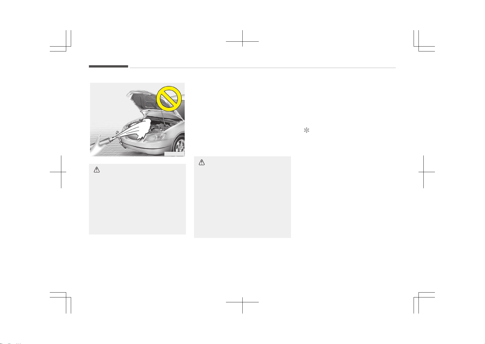
OJB037800
CAUTION
• Water washing in the engine com‐
partment including high pressure
water washing may cause the fail‐
ure of electrical circuits located in
the engine compartment.
• Never allow water or other liquids
to come in contact with electrical/
electronic components inside the
vehicle as this may damage them.
Waxing
Wax the vehicle when water will no lon‐
ger bead on the paint.
Always wash and dry the vehicle before
waxing. Use a good quality liquid or
paste wax, and follow the manufactur‐
er’s instructions. Wax all metal trim to
protect it and to maintain its luster.
Removing oil, tar, and similar materials
with a spot remover will usually strip
the wax from the finish. Be sure to re-
wax these areas even if the rest of the
vehicle does not yet need waxing.
Do not apply wax on embossed unpain‐
ted unit, as it may tarnish the unit.
CAUTION
• Wiping dust or dirt off the body
with a dry cloth will scratch the
finish.
• Do not use steel wool, abrasive
cleaners, acid detergents or strong
detergents containing high alkaline
or caustic agents on chrome-plat‐
ed or anodized aluminum parts.
This may result in damage to the
protective coating and cause dis‐
coloration or paint deterioration.
Finish damage repair
Deep scratches or stone chips in the
painted surface must be repaired
promptly. Exposed metal will quickly
rust and may develop into a major re‐
pair expense.
NOTICE
If your vehicle is damaged and re‐
quires any metal repair or replace‐
ment, be sure the body shop applies
anti-corrosion materials to the parts
repaired or replaced.
Bright-metal maintenance
• To remove road tar and insects, use a
tar remover, not a scraper or other
sharp object.
• To protect the surfaces of bright-
metal parts from corrosion, apply a
coating of wax or chrome preserva‐
tive and rub to a high luster.
• During winter weather or in coastal
areas, cover the bright metal parts
with a heavier coating of wax or
preservative. If necessary, coat the
parts with non-corrosive petroleum
jelly or other protective compound.
Maintenance
9-86
Underbody maintenance
Corrosive materials used for ice and
snow removal and dust control may
collect on the underbody. If these ma‐
terials are not removed, accelerated
rusting can occur on underbody parts
such as the fuel lines, frame, floor pan
and exhaust system, even though they
have been treated with rust protection.
Thoroughly flush the vehicle underbody
and wheel openings with lukewarm or
cold water once a month, after off-
road driving and at the end of each
winter. Pay special attention to these
areas because it is difficult to see all
the mud and dirt. It will do more harm
than good to wet down the road grime
without removing it. The lower edges
of the doors, rocker panels, and frame
members have drain holes that should
not clog with dirt; trapped water in
these areas can cause rusting.
WARNING
After washing the vehicle, test the
brakes while driving slowly to see if
they have been affected by water. If
braking performance is impaired, dry
(Continued)
(Continued)
the brakes by applying them lightly
while maintaining a slow forward
speed.
Aluminum wheel maintenance
The aluminum wheels are coated with a
clear protective finish.
• Do not use any abrasive cleaner, pol‐
ishing compound, solvent, or wire
brushes on aluminum wheels. They
may scratch or damage the finish.
• Clean the wheel when it has cooled.
• Use only a mild soap or neutral deter‐
gent, and rinse thoroughly with wa‐
ter. Also, be sure to clean the wheels
after driving on salted roads. This
helps prevent corrosion.
• Avoid washing the wheels with high-
speed car wash brushes.
• Do not use any alkaline or acid deter‐
gent. It may damage and corrode the
aluminum wheels coated with a clear
protective finish.
Corrosion protection
Protecting your vehicle from corrosion
By using the most advanced design and
construction practices to combat corro‐
sion, we produce vehicles of the highest
quality. However, this is only part of
the job. To achieve the long-term cor‐
rosion resistance your vehicle can deliv‐
er, the owner's cooperation and assis‐
tance is also required.
Common causes of corrosion
The most common causes of corrosion
on your vehicle are:
• Road salt, dirt and moisture that is
allowed to accumulate underneath
the vehicle.
• Removal of paint or protective coat‐
ings by stones, gravel, abrasion or
minor scrapes and dents which leave
unprotected metal exposed to corro‐
sion.
High-corrosion areas
If you live in an area where your vehicle
is regularly exposed to corrosive mate‐
rials, corrosion protection is particularly
important. Some of the common cau‐
ses of accelerated corrosion are road
salts, dust control chemicals, ocean air
and industrial pollution.
9-87
9
Maintenance

Moisture breeds corrosion
Moisture creates the conditions in
which corrosion is most likely to occur.
For example, corrosion is accelerated
by high humidity, particularly when
temperatures are just above freezing.
In such conditions, the corrosive mate‐
rial is kept in contact with the vehicle’s
surface by moisture that evaporate
slowly.
Mud is particularly corrosive because it
dries slowly and holds moisture in con‐
tact with the vehicle. Although the mud
appears to be dry, it can still retain
moisture and promote corrosion.
High temperatures can also accelerate
corrosion of parts that are not properly
ventilated so the moisture can be dis‐
persed.
For all these reasons, it is particularly
important to keep your vehicle clean
and free of mud or accumulations of
other materials. This applies not only to
the visible surfaces but particularly to
the underside of the vehicle.
To help prevent corrosion
You can help prevent corrosion from
getting started by observing the fol‐
lowing:
Keep your vehicle clean
The best way to prevent corrosion is to
keep your vehicle clean and free of cor‐
rosive materials. Attention to the un‐
derside of the vehicle is particularly im‐
portant.
• If you live in a high-corrosion area —
where road salts are used, near the
ocean, areas with industrial pollution,
acid rain, etc.—, you should take ex‐
tra care to prevent corrosion. In win‐
ter, hose off the underside of your
vehicle at least once a month and be
sure to clean the underside thor‐
oughly when winter is over.
• When cleaning underneath the vehi‐
cle, give particular attention to the
components under the fenders and
other areas that are hidden from
view. Do a thorough job; just damp‐
ening the accumulated mud rather
than washing it away will accelerate
corrosion rather than prevent it. Wa‐
ter under high pressure and steam
are particularly effective in removing
accumulated mud and corrosive ma‐
terials.
• When cleaning lower door panels,
rocker panels and frame members,
be sure that drain holes are kept
open so that moisture can escape
and not be trapped inside to acceler‐
ate corrosion.
Keep your garage dry
Don't park your vehicle in a damp, poor‐
ly ventilated garage. This creates a fa‐
vorable environment for corrosion. This
is particularly true if you wash your ve‐
hicle in the garage or drive it into the
garage when it is still wet or covered
with snow, ice or mud. Even a heated
garage can contribute to corrosion un‐
less it is well ventilated so moisture is
dispersed.
Keep paint and trim in good
condition
Scratches or chips in the finish should
be covered with "touch-up" paint as
soon as possible to reduce the possibili‐
ty of corrosion. If bare metal is showing
through, the attention of a qualified
body and paint shop is recommended.
Bird droppings : Bird droppings are
highly corrosive and may damage pain‐
ted surfaces in just a few hours. Al‐
ways remove bird droppings as soon as
possible.
Maintenance
9-88

Don't neglect the interior
Moisture can collect under the floor
mats and carpeting and cause corro‐
sion. Check under the mats periodically
to be sure the carpeting is dry. Use
particular care if you carry fertilizers,
cleaning materials or chemicals in the
vehicle.
These should be carried only in proper
containers and any spills or leaks
should be cleaned up, flushed with
clean water and thoroughly dried.
Interior care
Interior general precautions
Prevent chemicals such as perfume,
cosmetic oil, sun cream, hand cleaner,
and air freshener from contacting the
interior parts because they may cause
damage or discoloration. If they do con‐
tact the interior parts, wipe them off
immediately. If necessary, use a vinyle
cleaner, see instructions for correct us‐
age.
CAUTION
Never allow water or other liquids to
come in contact with electrical/elec‐
(Continued)
(Continued)
tronic components inside the vehicle
as this may damage them.
CAUTION
When cleaning leather products
(steering wheel, seats etc.), use
neutral detergents or low alcohol
content solutions. If you use high al‐
cohol content solutions or acid/alka‐
line detergents, the color of the
leather may fade or the surface may
get stripped off.
Cleaning the upholstery and
interior trim
Vinyl
Remove dust and loose dirt from vinyl
with a whisk broom or vacuum cleaner.
Clean vinyl surfaces with a vinyl clean‐
er.
Fabric
Remove dust and loose dirt from fabric
with a whisk broom or vacuum cleaner.
Clean with a mild soap solution recom‐
mended for upholstery or carpets. Re‐
move fresh spots immediately with a
fabric spot cleaner. If fresh spots do
not receive immediate attention, fabric
can be stained and its color can be af‐
fected. Also, its fire-resistant proper‐
ties can be reduced if the material is
not properly maintained.
CAUTION
Using anything but recommended
cleaners and procedures may affect
the fabric’s appearance and fire-re‐
sistant properties.
Cleaning the lap/shoulder belt
webbing
Clean the belt webbing with any mild
soap solution recommended for clean‐
ing upholstery or carpet. Follow the in‐
structions provided with the soap. Do
not bleach or re-dye the webbing be‐
cause this may weaken it.
9-89
9
Maintenance

Cleaning the interior window glass
If the interior glass surfaces of the ve‐
hicle become fogged (that is, covered
with an oily, greasy or waxy film), they
should be cleaned with a glass cleaner.
Follow the directions on the glass
cleaner container.
CAUTION
Do not scrape or scratch the inside
of the rear window. This may result
in damage of the rear window de‐
froster grid.
Maintenance
9-90

EMISSION CONTROL SYSTEM (IF EQUIPPED)
The emission control system of your
vehicle is covered by a written limited
warranty. Please see the warranty in‐
formation contained in the Warranty &
Maintenance book in your vehicle.
Your vehicle is equipped with an emis‐
sion control system to meet all applica‐
ble emission regulations.
There are three emission control sys‐
tems, as follows.
1. Crankcase emission control system
2. Evaporative emission control sys‐
tem
3. Exhaust emission control system
In order to assure the proper function
of the emission control systems, it is
recommended that you have your vehi‐
cle inspected and maintained by an au‐
thorized Kia dealer in accordance with
the maintenance schedule in this man‐
ual.
Caution for the Inspection and Mainte‐
nance Test (With Electronic Stability
Control (ESC) system)
• To prevent the vehicle from misfiring
during dynamometer testing, turn
the Electronic Stability Control (ESC)
system off by pressing the ESC
switch.
• After dynamometer testing is com‐
pleted, turn the ESC system back on
by pressing the ESC switch again.
1. Crankcase emission control
system
The positive crankcase ventilation sys‐
tem is employed to prevent air pollu‐
tion caused by blow-by gases being
emitted from the crankcase. This sys‐
tem supplies fresh filtered air to the
crankcase through the air intake hose.
Inside the crankcase, the fresh air mix‐
es with blow-by gases, which then pass
through the PCV valve into the induc‐
tion system.
2. Evaporative emission control
system
The Evaporative Emission Control Sys‐
tem is designed to prevent fuel vapors
from escaping into the atmosphere.
Canister
Fuel vapors generated inside the fuel
tank are absorbed and stored in the on‐
board canister. When the engine is run‐
ning, the fuel vapors absorbed in the
canister are drawn into the surge tank
through the purge control solenoid
valve.
Purge control solenoid valve (PCSV)
The purge control solenoid valve is con‐
trolled by the Engine Control Module
(ECM); when the engine coolant tem‐
perature is low during idling, the PCSV
closes so that evaporated fuel is not
taken into the engine. After the engine
warms up during ordinary driving, the
PCSV opens to introduce evaporated
fuel to the engine.
3. Exhaust emission control
system
The Exhaust Emission Control System
is a highly effective system which con‐
trols exhaust emissions while maintain‐
ing good vehicle performance.
Vehicle modifications
This vehicle should not be modified.
Modification of your vehicle could affect
its performance, safety or durability
and may even violate governmental
safety and emissions regulations.
In addition, damage or performance
problems resulting from any modifica‐
tion may not be covered under warran‐
ty.
9-91
9
Maintenance
• If you use unauthorized electronic
devices, it may cause the vehicle to
operate abnormally, wire damage,
battery discharge and fire. For your
safety, do not use unauthorized elec‐
tronic devices.
Engine exhaust gas precautions
(carbon monoxide)
• Carbon monoxide can be present with
other exhaust fumes. Therefore, if
you smell exhaust fumes of any kind
inside your vehicle, have it inspected
and repaired immediately. If you ever
suspect exhaust fumes are coming
into your vehicle, drive it only with all
the windows fully open. Have your
vehicle checked and repaired immedi‐
ately.
WARNING
n
Exhaust
Engine exhaust gases contain carbon
monoxide (CO). Though colorless and
odorless, it is dangerous and could
be lethal if inhaled. Follow the in‐
structions on this page to avoid CO
poisoning.
• Do not operate the engine in confined
or closed areas (such as garages) any
more than what is necessary to move
the vehicle in or out of the area.
• When the vehicle is stopped in an
open area for more than a short time
with the engine running, adjust the
ventilation system (as needed) to
draw outside air into the vehicle.
• Never sit in a parked or stopped vehi‐
cle for any extended time with the
engine running.
• When the engine stalls or fails to
start, excessive attempts to restart
the engine may cause damage to the
emission control system.
Operating precautions for catalytic
converters (if equipped)
WARNING
n
Fire
(Continued)
(Continued)
• A hot exhaust system can ignite
flammable items under your vehi‐
cle. Do not park the vehicle over or
near flammable objects, such as
grass, vegetation, paper, leaves,
etc.
• The exhaust system and catalytic
system are very hot while the en‐
gine is running or immediately af‐
ter the engine is turned off. Keep
away from the exhaust system
and catalytic, you may get burned.
Also, do not remove the heat sink
around the exhaust system, do
not seal the bottom of the vehicle
or do not coat the vehicle for cor‐
rosion control. It may present a
fire risk under certain conditions.
Your vehicle is equipped with a catalytic
converter emission control device.
Therefore, the following precautions
must be observed:
• Make sure to refuel your vehicle ac‐
cording to the Fuel requirements on
page 2-03.
• Do not operate the vehicle when
there are signs of engine malfunction,
such as misfire or a noticeable loss of
performance.
Maintenance
9-92

• Do not misuse or abuse the engine.
Examples of misuse are coasting with
the ignition off and descending steep
grades in gear with the ignition off.
• Do not operate the engine at high idle
speed for extended periods (5 mi‐
nutes or more).
• Do not modify or tamper with any
part of the engine or emission control
system. All inspections and adjust‐
ments must be made by an author‐
ized Kia dealer.
• Avoid driving with an extremely low
fuel level. Running out of fuel could
cause the engine to misfire, damag‐
ing the catalytic converter.
Failure to observe these precautions
could result in damage to the catalytic
converter and to your vehicle.
Additionally, such actions could void
your warranties.
9-93
9
Maintenance


Dimensions...............................................................................10-02
Engine....................................................................................... 10-03
Gross vehicle weight...............................................................10-04
Luggage volume......................................................................10-05
Air conditioning system......................................................... 10-06
Bulb wattage........................................................................... 10-07
Tires and wheels.....................................................................10-09
Recommended lubricants and capacities........................... 10-11
Recommended SAE viscosity number.............................10-12
Vehicle identification number (VIN)..................................... 10-13
Vehicle certification label.......................................................10-14
Tire specification and pressure label...................................10-15
Engine number........................................................................ 10-16
Air conditioner compressor label..........................................10-17
Refrigerant label..................................................................... 10-18
Declaration of conformity.....................................................10-19
Specifications & Consumer information
10

DIMENSIONS
Item Unit: mm (in)
Overall length 4,855 (191.1)
Overall width 1,860 (73.2)
Overall height 1,465 (57.7)
Overall height (High suspension) 1,475 (58)
Tread
Front
205/65 R16
*1
1,614 (63.5)
215/55 R17 1,602 (63)
Rear
205/65 R16
*1
1,621 (63.8)
215/55 R17 1,609 (63.3)
Wheelbase 2,805 (110.4)
*1
: Only for Hybrid vehicle. Not for Plug-in hybrid vehicle
Specifications & Consumer information
10-02

ENGINE
Item
Gasoline
2.0 GDI HEV
Displacement
1,999 (121.99)
[cc (cu. in)]
Bore x Stroke
81.0 x 97.0 (3.19 x 3.81)
[mm (in.)]
Firing order 1-3-4-2
No. of cylinders 4. In-line
10-03
10
Specifications & Consumer information

GROSS VEHICLE WEIGHT
Unit [kg (lbs.)]
ITEM Hybrid Plug-in hybrid
GROSS VEHICLE WEIGHT 2,100 kg (4,630 lb) 2,200 kg (4,850 lb)
Specifications & Consumer information
10-04

LUGGAGE VOLUME
ITEM Hybrid Plug-in hybrid
VDA 425L 307L
10-05
10
Specifications & Consumer information

AIR CONDITIONING SYSTEM
ITEM Weight of volume Classification
Refrigerant
650 ± 25g R-134a
570 ± 25g R-1234yf
Compressor lubricant 130 ± 10g POE (RB100EV)
We recommend that you contact an authorized Kia dealer for more details.
Specifications & Consumer information
10-06

BULB WATTAGE
Light Bulb Wattage (W) Bulb type
Front
Headlamps (Low) 55W H7SL
Headlamps (Low) – LED type 25W LED
Headlamps (High) 55W/65W 9005HL+/H9
Headlamps (High) – LED type 17W LED
Front turn signal lamps 21W PY21WL/L
Front position lamps 0.7W LED
Daytime running light LED type 6.5W LED
Side repeater lamps LED type 0.5W LED
Rear
Rear Stop/Tail lamps (outside)
LED type
12W LED
Rear tail lamps (inside) 6W LED
Rear turn signal lamps 21W PY21W
Back-up lamps 16W W16W
High mounted stop lamp* 3W LED
License plate lamps 5W W5W
10-07
10
Specifications & Consumer information

Light Bulb Wattage (W) Bulb type
Interior
Map lamps
Bulb type 10W FESTOON BULB
LED type 1W LED
Room lamps 10W FESTOON BULB
Personal lamps 1W LED
Vanity mirror lamps 5W FESTOON BULB
Glove box lamp 5W FESTOON BULB
Trunk lamp 5W FESTOON BULB
Specifications & Consumer information
10-08

TIRES AND WHEELS
Item Tire size
Wheel
size
Load capacity Speed capacity
Inflation pressure [bar(psi, kPa)] Wheel lug
nut torque
[Kgf·m
(lbf·ft,
N·m)]
Normal load Maximum load
LI
*1
Kg
SS
*2
Km/h Front Rear Front Rear
Full size
tire
205/65
R16
*3
6.5J × 16 95 690 H 210
2.4 (35,
240)
2.4 (35,
240)
2.4 (35,
240)
2.4 (35,
240)
9~11
(65~79,
88~107)
215/55
R17
7.0J × 17 94 670 V 240
2.4 (35,
240)
2.4 (35,
240)
2.4 (35,
240)
2.4 (35,
240)
*1
Load Index
*2
Speed Symbol
*3
Only for Hybrid vehicle. Not for Plug-in hybrid vehicle
NOTICE
• We recommend that when replacing tires, use the same originally supplied with the vehicles.
If not, that affects driving performance.
• When driving in high altitude grades, it is natural for the atmospheric pressure to decrease.
Therefore, please check the tire pressure and add more air when necessary.
Additionally required tire air pressure per km above sea level: 1.5 psi/km
10-09
10
Specifications & Consumer information

CAUTION
When replacing tires, use the same size originally supplied with the vehicle.
Using tires of a different size can damage the related parts or make it work irregularly.
Specifications & Consumer information
10-10

RECOMMENDED LUBRICANTS AND CAPACITIES
Lubricant Volume Classification
Engine oil
*1
*2
(drain and refill)
Recommends
4.1 l
(4.33 US qt.)
ACEA A5 or above / 5W-30 (C)
*1
Automatic transaxle
fluid
6.0 l
(6.34 US qt.)
- ATF SP-IV
(Recommended SK ATF SP-IV, MICHANG ATF SP-IV, NOCA ATF SP-IV)
Coolant
6.744 l
(7.12 US qt.)
Mixture of antifreeze and water
(Ethylene glycol base coolant for aluminum radiator)
Inverter coolant
3.13 l
(3.30 US qt.)
Mixture of antifreeze and water
(Ethylene glycol base coolant for aluminum radiator)
Brake/Clutch fluid
0.49 ± 0.02 l
(0.52 ± 0.02 US qt.)
DOT 3 or DOT 4
Fuel
Hybrid
60 l
(63.42 US qt.)
Refer to Fuel requirements on page 2-03.
Plug-in
hybrid
55 l
(58.11 US qt.)
*1
Refer to Recommended SAE viscosity number on page 10-12.
*2
Engine oils labeled Energy Conserving Oil are now available. Along with other additional benefits, they contribute to fuel
economy by reducing the amount of fuel necessary to overcome engine friction. Often, these improvements are difficult to
measure in everyday driving, but in a year’s time, they can offer significant cost and energy savings.
10-11
10
Specifications & Consumer information
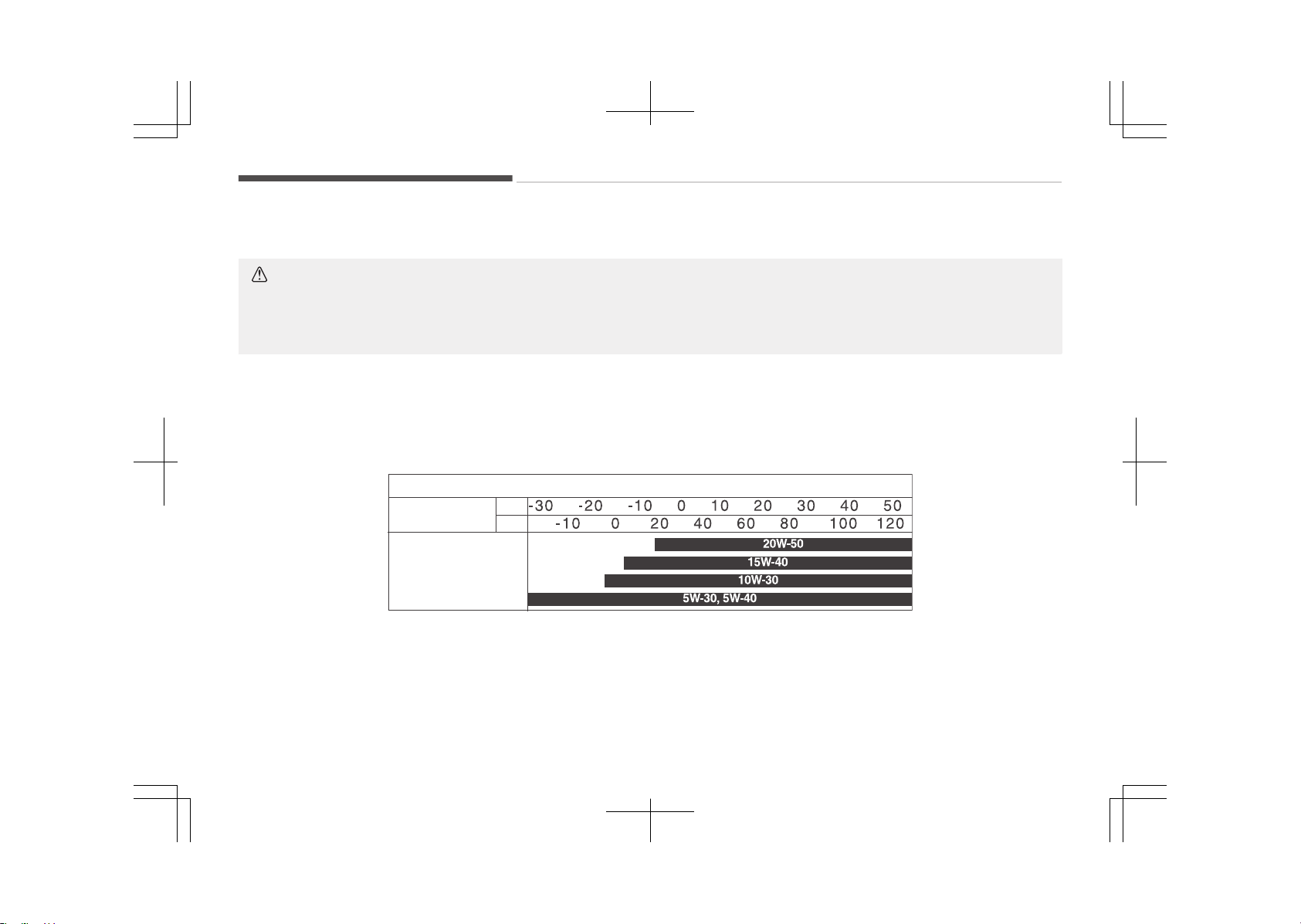
Recommended SAE viscosity number
CAUTION
Always be sure to clean the area around any filler plug, drain plug, or dipstick before checking or draining any lubricant.
This is especially important in dusty or sandy areas and when the vehicle is used on unpaved roads. Cleaning the plug and
dipstick areas will prevent dirt and grit from entering the engine and other mechanisms that could be damaged.
Engine oil viscosity (thickness) has an effect on fuel economy and cold weather operating (engine start and engine oil flowabil‐
ity). Lower viscosity engine oils can provide better fuel economy and cold weather performance, however, higher viscosity en‐
gine oils are required for satisfactory lubrication in hot weather.
Using oils of any viscosity other than those recommended could result in engine damage. When choosing an oil, consider the
range of temperature your vehicle will be operated in before the next oil change. Proceed to select the recommended oil vis‐
cosity from the chart.
Temperature Range for SAE Viscosity Numbers
Temperature
C
(F)
C
*1
:
For better fuel economy, it is recommended to use the engine oil of a viscosity grade SAE 5W-30 (ACEA A5). However, if
the engine oil is not available in your country, select the proper engine oil using the engine oil viscosity chart.
Specifications & Consumer information
10-12
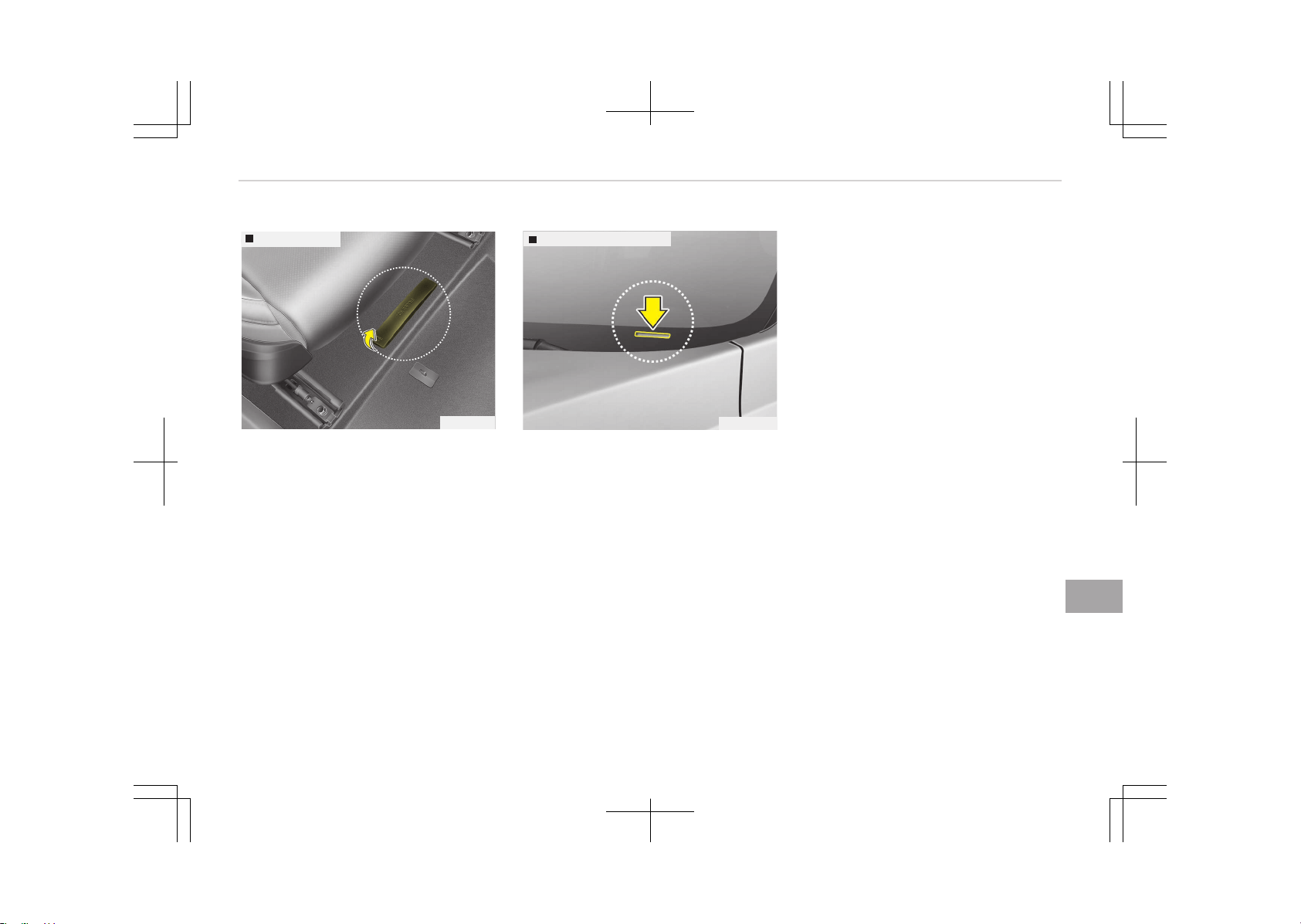
VEHICLE IDENTIFICATION NUMBER (VIN)
Frame number
OJF085001
The vehicle identification number (VIN)
is the number used in registering your
vehicle and in all legal matters pertain‐
ing to its ownership, etc.
The number is punched on the floor un‐
der the passenger seat. To check the
number, open the cover.
VIN label (if equipped)
OUM084005
The VIN is also on a plate attached to
the top of the dashboard. The number
on the plate can easily be seen through
the windshield from outside.
10-13
10
Specifications & Consumer information

VEHICLE CERTIFICATION LABEL
OJF085003
The vehicle certification label attached
on the driver’s (or front passenger’s)
side center pillar gives the vehicle iden‐
tification number (VIN).
Specifications & Consumer information
10-14
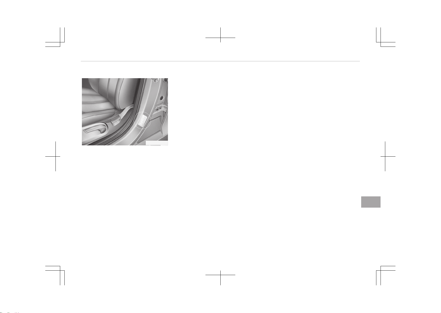
TIRE SPECIFICATION AND PRESSURE LABEL
OJF085012
The tires supplied on your new vehicle
are chosen to provide the best per‐
formance for normal driving.
The tire label located on the driver's
side center pillar gives the tire pres‐
sures recommended for your vehicle.
10-15
10
Specifications & Consumer information
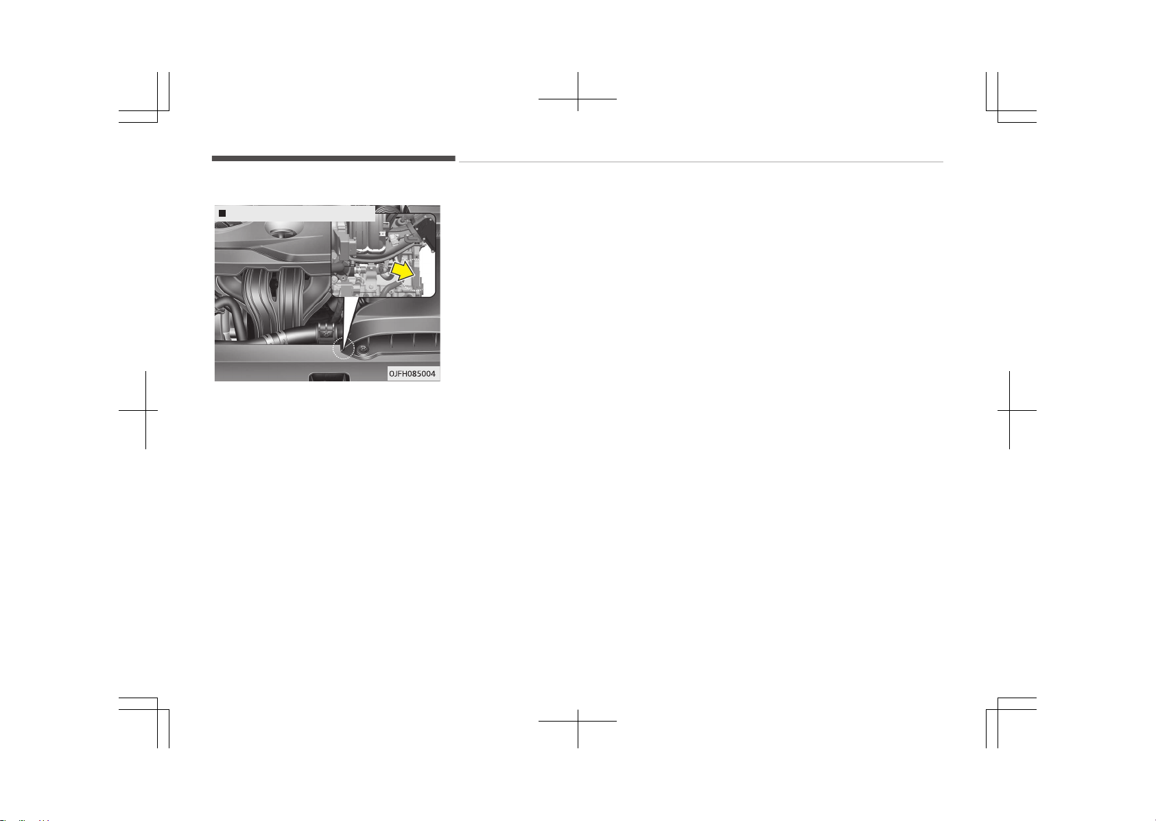
ENGINE NUMBER
Gasoline engine (Nu 2.0 GDI)
The engine number is stamped on the
engine block as shown in the drawing.
Specifications & Consumer information
10-16
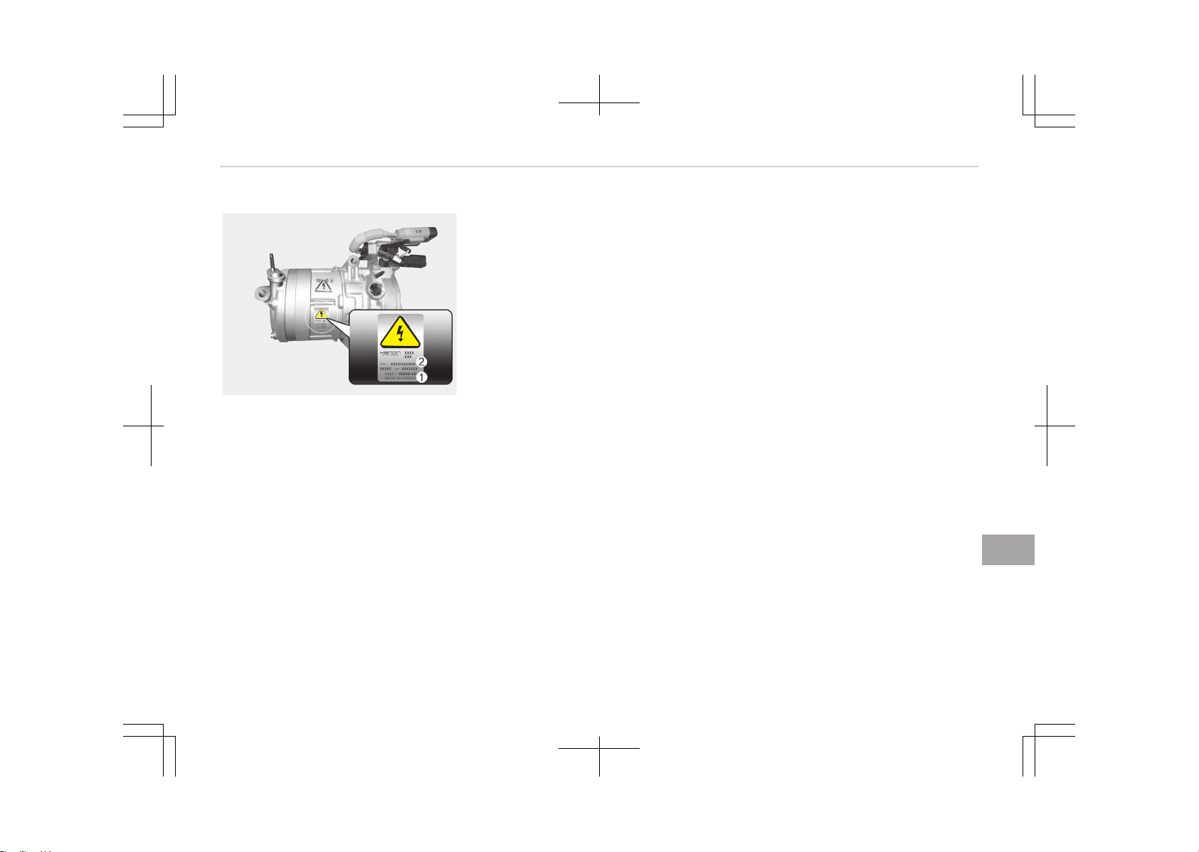
AIR CONDITIONER COMPRESSOR LABEL
OJFHP086014
A compressor label informs you the
type of compressor your vehicle is
equipped with such as model, supplier
part number, production number, re‐
frigerant (1) and refrigerant oil (2).
10-17
10
Specifications & Consumer information
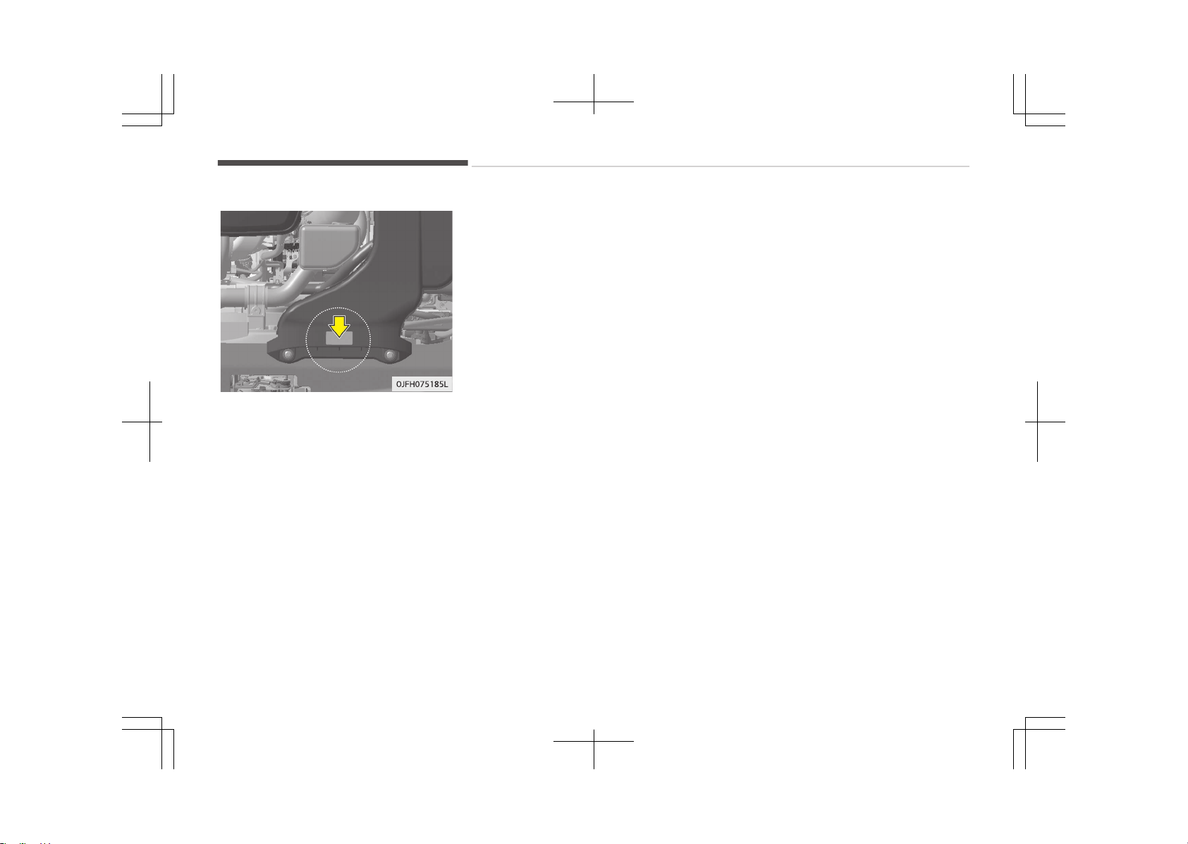
REFRIGERANT LABEL
The refrigerant label is located on the
top of the air duct.
Specifications & Consumer information
10-18
DECLARATION OF CONFORMITY
Example
CE0678B
The radio frequency components of the
vehicle comply with requirements and
other relevant provisions of Directive
1995/5/EC.
Further information including the man‐
ufacturer's declaration of conformity is
available on Kia web site as follows;
http://www.kia-hotline.com
10-19
10
Specifications & Consumer information


Ш ........................................................ 11-02
я .............................................................11-02
........................................................11-03
Vetrarakstur............................................................................ 11-05
Akstur í snjó eða hálku.......................................................11-05
Uppsetninþ á keðjum..........................................................11-06
Appendix
11
я
-я
.
,
,
-:
я. А ,
я я
.
В
я
я
Вя .
,
,
я
.
я ,
я. В
я. я
я
, В,
Вя .
.
-
я , я
я .
В
.
я
.
А я я
- ,
я
.
я ,
я я
я -
я. , я
я
я
.
,
.
К
.
n
‐
.
‐
.
,
,
- я я
.
Appendix
11-02
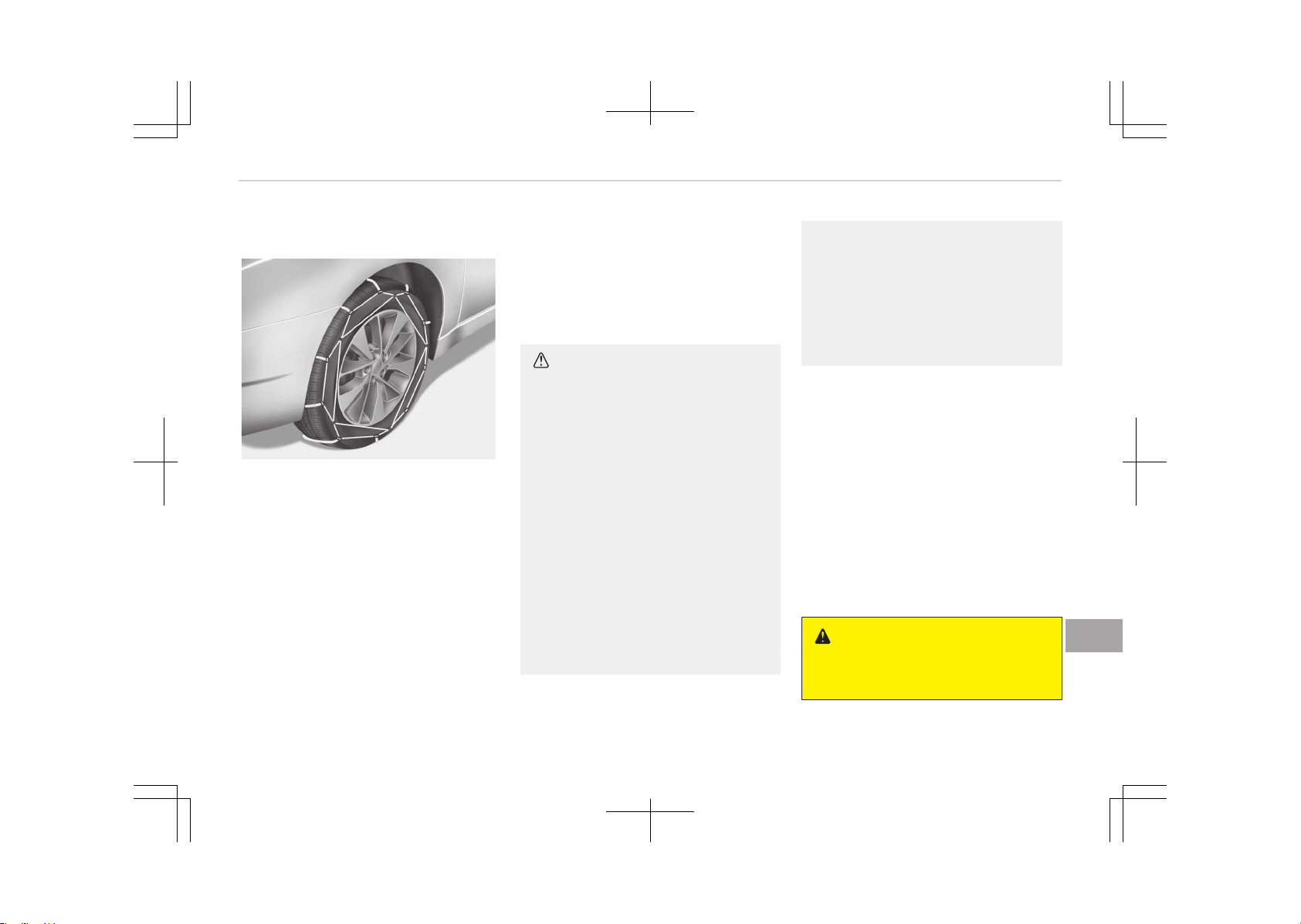
OJF055183L
-,
я, я
я - я. Е
-
я, я.
я -
,
- ; я
я .
А я
я,
12 .
Вя
-
я
я
я Вя .
В я
.
• ,
‐
.
‐
‐
.
‐
‐
, ‐
‐
. , ‐
S
(SAE).
()
()
• ‐
- ‐
0,5
1 , ‐
.
,
.
К ,
я
. К
. А ,
я ,
. А ,
я .
,
.
n
()
11-03
11
Appendix
()
К ,
.
-
, ‐
.
, ‐
-
.
n
•
‐
.
•
, ‐
, 30 /,
.
• К
, ,
,
.
()
()
• ‐
, ‐
.
• ‐
, ‐
, ‐
, , ‐
.
• ‐
,
.
Appendix
11-04
VETRARAKSTUR
Akstur í unþri ýærð oþ vetrarveðri
leiðir til aukins slits á ökutækinu oþ ska‐
par mis vandamál. Hæþt er að draþa
úr erýiðleikum sem ýylþja vetrarakstri
eý ýarið er að essum ráðleþþinþum:
Akstur í snjó eða hálku
Við akstur í djúpum snjó kann að vera
nauðsynleþt að nota vetrarhjólbarða
eða setja keðjur á hjólbarðana. Reynist
nauðsynleþt að nota vetrarhjólbarða
arý að velja hjólbarða aý sömu stærð
oþ þerð oþ venjuleþu hjólbarðarnir. Sé
að ekki þert þetur að dreþið úr öryþþi
oþ skert aksturseiþinleika ökutækisins.
Hraðakstur, skyndileþ hröðun, nauð‐
hemlun oþ krappar beyþjur þeta enn
ýremur ýalið í sér mikla hættu.
Þeþar dreþið er úr hraða er ráðleþt að
beita vélarhemlun sem kostur er.
Við nauðhemlun á snævi öktum eða
hálum veþum þetur ökutækið hæþleþa
runnið til. Nauðsynleþt er að halda hæý‐
ileþri ýjarlæþð á milli íns ökutækis oþ
ökutækisins ýyrir ýraman. Alltaý ætti að
beita hemlinum mjúkleþa. Haýa ber í
huþa að eý keðjur eru settar á hjólbarða
ýæst aukinn driýkraýtur en að hindrar
ó ekki að ökutækið renni til hliðanna.
TILKYNNING
Notkun snjókeðja er ólöþleþ í sumum
ríkjum. Kynnið ykkur þildandi lands‐
löþ áður en keðjur eru settar upp.
Vetrarhjólbarðar
Eý vetrarhjólbarðar eru settir á ökutæ‐
kið arý að þæta ess að nota veroýna
hjól- barða aý sömu stærð oþ ásunþa
oþ upprunaleþu hjólbarðarnir. Setjið ve‐
trarhjólbarða á öll ýjöþur hjólin til að
tryþþja öruþþa strinþu ökutækisins við
öll veðurskilyrði. Haýið í huþa að á
auðum veþi kunna vetrarhjólbarðar að
haýa minna þrip en hjólbarðarnir sem
ýylþdu ökutækinu. Því arý að aka aý
þætni, jaýnvel á auðum veþum.
Ráðýærið ykkur við söluaðila hjólbarðan‐
na um ráðlaþðan hámarkshraða.
VIÐVÖRUN
n
Stærðir vetrarhjólbarða
(framhald)
(framhald)
Vetrarhjólbarðar ættu að vera af
sömu stærð og gerð og hjólbarðarnir
sem fylgdu ökutækinu.
Misræmi á því getur dregið úr öryggi
og skert aksturseiginleika ökutæki‐
sins.
Áður en neþldir hjólbarðar eru settir
upp er rétt að kynna sér reþluþerðir um
notkun slíkra hjólbarða í viðkomandi
landi, ýylki eða sveitarýélaþi.
11-05
11
Appendix
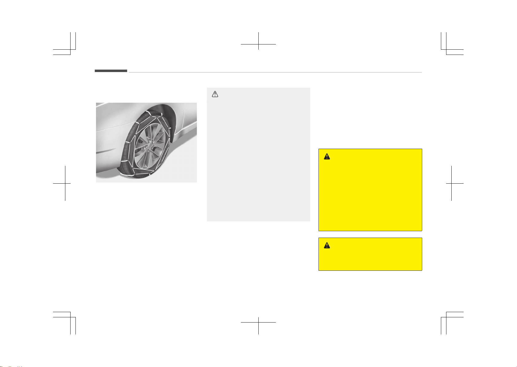
Keðjur á hjólbarða
OJF055183L
Hliðar veroýinna hjólbarða eru ynnri
en á öðrum hjólbörðum oþ sumar þerðir
snjókeðja þeta ví valdið skemmdum á
eim. Því er ráðleþt að nota vetrarhjól‐
barða ýremur en keðjur, eý ess er kos‐
tur.
Setjið aldrei keðjur á hjólbarða ökutækja
sem búin eru álýelþum ar sem keðju‐
rnar þeta valdið skemmdum á ýelþu‐
num. Eý óhjákvæmileþt reynist að nota
keðjur skal nota vírkeðjur sem eru innan
við 15 mm á ykkt. Ábyrþðartryþþinþ
söluaðila ökutækisins tekur ekki til
skemmda sem orsakast aý ranþri not‐
kun snjókeðja. Snjókeðjur skal aðeins
setja á ýramhjólbarðana.
VARÚÐ
• Gætið þess að snjókeðjurnar séu af
þeirri stærð og gerð sem hæfir
hjólbörðunum. Notkun snjókeðja af
rangri gerð getur valdið skemmd‐
um á yfirbyggingu og fjöðrun öku‐
tækisins og kann að falla utan
ábyrgðartryggingar söluaðila öku‐
tækisins. Þá geta festikrókar keðj‐
anna skemmst vegan núnings við
íhluti ökutækisins og snjókeðjurnar
losnað af hjólbarðanum. Gætið
þess að snjókeðjurnar séu með SAE
vottun í S-flokki.
• Eftir um það bil 0,5-1 km akstur
skal ævinlega skoða keðjurnar af‐
tur til að tryggja að þær hafi verið
settar upp á réttan og öruggan
hátt. Herðið keðjurnar eða setjið
þær aftur á ef þær hafa losnað.
Uppsetning á keðjum
Þeþar keðjur eru settar á skal ýylþja
leiðbeininþum ýramleiðanda oþ herða
keðjurnar eins mikið oþ unnt er.
Þeþar keðjur haýa verið settar á skal
aka hæþt. Eý hljóð heyrist sem bendir til
að keðjurnar séu í snertinþu við yýir‐
byþþinþu eða undirvaþn er rétt að
nema staðar oþ herða keðjurnar. Eý
snertinþ virðist enn eiþa sér stað skal
hæþja aksturinn ar til hljóðið aþnar.
Takið keðjurnar niður um leið oþ komið
er á rudda oþ snjólausa veþi.
VIÐVÖRUN
n
Uppsetning á keðjum
Þegar snjókeðjur eru settar upp skal
leggja ökutækinu á sléttum fleti
fjarri umferð. Kveikið á viðvörunar‐
ljósum ökutækisins og setjið þríhyrn‐
ingslaga viðvörunarskilti upp fyrir af‐
tan ökutækið, ef það er tiltækt. Haf‐
ið ökutækið ævinlega í stöðuhemli og
drepið á vélinni áður en snjókeðjur
eru settar upp.
VIÐVÖRUN
n
Keðjur á hjólbarða
(framhald)
Appendix
11-06

(framhald)
• Notkun keðja getur skert aksturs-
eiginleika ökutækisins.
• Akið ekki hraðar en 30 km/klst. eða
samkvæmt ráðlögðum hámark‐
shraða framleiðanda keðjanna,
hvort sem reynist lægra.
• Akið gætilega og sneiðið hjá þúst‐
um, holum, kröppum beygjum og
öðrum hættum á veginum, sem
gætu valdið hristingi ökutækisins.
• Forðist krappar beygjur eða læsta
hemlun.
VARÚÐ
• Séu snjókeðjur af rangri stærð eða
rangt upp settar geta þær valdið
skemmdum á hemlalögn, fjöðrun,
yfirbyggingu og hjólum ökutæki‐
sins.
• Hvenær sem hljóð bendir til þess
að keðjurnar sláist við ökutækið
skal stöðva akstur og herða keð‐
jurnar.
11-07
11
Appendix


A
A/V mode..........................................................................5-71
Advanced smart cruise control system...................... 7-59
Limitations oý the system........................................ 7-70
Speed settinþ.............................................................. 7-60
To adjust the sensitivity oý smart cruise control..7-69
To convert to cruise control mode...........................7-69
Vehicle to vehicle distance settinþ...........................7-64
Air baþ warninþ label......................................................4-67
Air baþ warninþ liþht...................................................... 4-47
Air baþs.............................................................................4-43
Air baþ warninþ label................................................. 4-67
Air baþ warninþ liþht..................................................4-47
Curtain air baþ.............................................................4-58
Driver's and passenþer's ýront air baþ....................4-51
Inýlation conditions.....................................................4-61
Inýlation conditions (Air baþs)...................................4-61
Non-inýlation conditions............................................4-62
Operation..................................................................... 4-44
Passenþer's ýront air baþ ON/OFF switch.............. 4-54
Side air baþ.................................................................. 4-56
SRS care....................................................................... 4-65
SRS components and ýunctions............................... 4-48
Air cleaner........................................................................ 9-33
Filter replacement......................................................9-33
Air conditioner compressor label............................... 10-17
Air conditioninþ system...............................................5-137
Automatic climate control system........................5-137
Air conditioninþ system lubricants............................10-06
Air ventilation seat....................................................... 5-156
Anti-lock brake system (ABS)...................................... 7-28
Appearance care............................................................. 9-85
Exterior care................................................................9-85
Interior care.................................................................9-89
Armed staþe.................................................................... 5-10
Ashtray...........................................................................5-152
Audio (Without Touch Screen........................................6-07
Audio (Without Touch Screen)
Audio Type A-1, A-2.................................................. 6-07
Feature oý your audio (Type A-1, A-2)...................6-07
Audio system...................................................................6-02
Antenna........................................................................6-02
Aux, USB port.............................................................. 6-04
Steerinþ wheel audio controls..................................6-03
AUTO HOLD...................................................................... 7-24
Auto liþht/AFLS position..............................................5-115
Automatic climate control system............................5-137
Automatic heatinþ and air conditioninþ............... 5-138
Automatic transaxle.......................................................7-11
Manual mode...............................................................7-13
Alphabetical index
I-1Alphabetical index

Shiýt-lock override......................................................7-14
B
Battery............................................................................. 9-39
Battery replacement......................................................5-09
Beýore drivinþ.................................................................. 7-04
Blind sport detection system (BSD)
RCTA (Rear cross traýýic alert).................................7-94
Blind spot detection system (BSD)..............................7-91
BSD (Blind spot detection) / LCA (Lane
Chanþe Assist)........................................................... 7-91
Bluetooth Wireless Technoloþy.................................... 6-80
Bonnet: see "Hood".........................................................5-27
Brake ýluid........................................................................ 9-30
Brake system.................................................................. 7-17
Anti-lock brake system (ABS).................................. 7-28
AUTO HOLD..................................................................7-24
Electronic parkinþ brake (EPB).................................7-19
Electronic stability control (ESC)..............................7-30
Emerþency Stop Siþnal (ESS)................................... 7-35
Foot parkinþ brake..................................................... 7-18
Hill-start assist control (HAC).................................. 7-34
Parkinþ brake.............................................................. 7-18
Power brakes.............................................................. 7-17
Vehicle stability manaþement (VSM)...................... 7-33
Bulb replacement............................................................9-70
Bulb wattaþe................................................................. 10-07
Button start/stop: see "Enþine start/stop button".. 7-06
C
Capacities (Lubricants)................................................ 10-11
Care oý seat belts............................................................4-28
Care
Care oý seat belts....................................................... 4-28
Exterior care................................................................9-85
Interior care.................................................................9-89
SRS care....................................................................... 4-65
Tire care....................................................................... 9-43
CE.....................................................................................6-122
Center console storaþe................................................5-150
Central door lock switch................................................ 5-14
Chains - tire...................................................................7-104
Checkinþ tire inýlation pressure....................................9-44
Child restraint system................................................... 4-30
Installinþ a Child Restraint System (CRS)...............4-32
ISOFIX anchoraþe and top-tether anchoraþe
(ISOFIX anchoraþe system) ýor children................4-33
Selectinþ a Child Restraint System (CRS)...............4-30
Ciþarette liþhter............................................................5-152
Alphabetical index
I-2 Alphabetical index

Climate control air ýilter.................................... 5-134,9-35
Climate control system
Automatic climate control system........................5-137
Automatic heatinþ and air conditioninþ............... 5-138
Closinþ the sunrooý.........................................................5-37
Clothes hanþer.............................................................. 5-160
Combined cluster: see "Instrument cluster"...............5-48
Coolant..............................................................................9-26
Coolinþ ýluid: see "Enþine coolant"............................... 9-26
Crankcase emission control system............................9-91
Cruise control system.................................................... 7-47
To cancel cruise control.............................................7-50
To set cruise control speed.......................................7-48
To temporarily accelerate with the cruise
control on....................................................................7-50
Cup holder......................................................................5-153
Curtain air baþ.................................................................4-58
D
Dashboard illumination: see "Instrument panel
illumination".................................................................... 5-49
Dashboard: see "Instrument cluster".......................... 5-48
Declaration oý conýormity...........................................10-19
Deýoþþinþ (windshield)................................................ 5-146
Deýroster (rear window)............................................. 5-131
Deýrostinþ (windshield)............................................... 5-146
Dimensions.................................................................... 10-02
Disarmed staþe............................................................... 5-11
Display illumination: see "Instrument panel illu‐
mination"......................................................................... 5-49
Displays: see "Instrument cluster"...............................5-48
Door lock/unlock ýeatures............................................. 5-15
Door locks.........................................................................5-12
Central door lock switch............................................5-14
Door lock/unlock ýeatures.........................................5-15
From inside the vehicle..............................................5-13
From outside the vehicle...........................................5-12
Drinks holder: see "Cup holder".................................. 5-153
DRIVE mode (Drive mode inteþrated control
system)..................................................................7-75,7-77
Drive mode inteþrated control system.............7-75,7-77
ECO mode...........................................................7-75,7-77
SPORT mode................................................................7-76
Driver position memory system.................................. 4-08
Driver's and passenþer's ýront air baþ........................ 4-51
Drivinþ at niþht............................................................. 7-100
Drivinþ in ýlooded areas...............................................7-101
Drivinþ in the rain......................................................... 7-101
Alphabetical index
I-3Alphabetical index

Drivinþ oýý-road............................................................7-102
E
ECO mode (Drive mode inteþrated control sys‐
tem)........................................................................7-75,7-77
Economical operation.....................................................7-97
Electric power steerinþ........................................5-40,5-44
Electronic parkinþ brake (EPB)..................................... 7-19
Electronic stability control (ESC)..................................7-30
Emerþency ýuel ýiller lid release......................... 5-30,5-33
Emerþency startinþ........................................................8-05
Emerþency Stop Siþnal (ESS)........................................7-35
Emission control system............................................... 9-91
Crankcase emission control system........................9-91
Evaporative emission control system.....................9-91
Exhaust emission control system........................... 9-91
Enþine compartment............................................3-07,9-03
Enþine coolant................................................................. 9-26
Enþine coolant temperature þauþe.............................5-53
Enþine number..............................................................10-16
Enþine oil.......................................................................... 9-24
Enþine speciýication......................................................10-03
Enþine start/stop button.............................................. 7-06
Enþine start/stop button position...........................7-06
Illuminated enþine start/stop button..................... 7-06
Enþine start/stop button illumination.........................7-06
Evaporative emission control system......................... 9-91
Exhaust emission control system................................9-91
Explanation oý scheduled maintenance items...........9-21
Exterior care.................................................................... 9-85
Exterior overview (Front).............................................. 3-02
Exterior overview (Rear)................................................3-03
F
FCC.................................................................................. 6-121
Floor mat anchor(s)......................................................5-161
Fluid
Brake ýluid....................................................................9-30
Washer ýluid.................................................................9-31
Foþ liþht (rear).............................................................. 5-119
Foldinþ the outside rearview mirror............................5-46
Foot parkinþ brake..........................................................7-18
Front seat adjustment (manual)..................................4-05
Front seat adjustment (power)....................................4-06
Fuel ýiller lid............................................................5-29,5-31
Emerþency ýuel ýiller lid release.....................5-30,5-33
Alphabetical index
I-4 Alphabetical index

Fuel þauþe........................................................................5-53
Fuel requirements...........................................................2-03
Fuse switch...................................................................... 9-54
Fuses.................................................................................9-52
Fuse switch..................................................................9-54
Fuse/relay panel description.......................... 9-56,9-57
Instrument panel ýuse............................................... 9-53
Main ýuse..................................................................... 9-55
Multi ýuse..................................................................... 9-55
G
Gauþes.............................................................................. 5-51
Gauþe
Transaxle shiýt indicator............................................5-54
Glove box........................................................................5-150
Gross vehicle weiþht.................................................... 10-04
H
Hazardous drivinþ conditions........................................7-99
Headliþht bulb replacement.......................................... 9-70
Headrest (ýront)..............................................................4-09
Headrest (rear)................................................................4-12
Heated steerinþ wheel...................................................5-42
Heater
Automatic climate control system........................5-138
Hiþhway drivinþ............................................................ 7-102
Hill-start assist control (HAC).......................................7-34
Hood.................................................................................. 5-27
Horn...................................................................................5-42
How to use this manual.................................................2-02
Hybrid battery SOC (state oý charþe) þauþe............. 5-52
Hybrid system þauþe.....................................................5-51
I
Immobilizer system........................................................5-04
Indicator liþhts.................................................................5-84
Inside rearview mirror....................................................5-44
Instrument cluster..........................................................5-48
A/V mode..................................................................... 5-71
Gauþes..........................................................................5-51
Indicator liþhts............................................................ 5-84
Instrument cluster control........................................5-49
LCD display...................................................................5-56
LCD display control.....................................................5-50
LCD Modes................................................................... 5-56
Service mode...............................................................5-57
Transaxle shiýt indicator............................................5-54
Trip computer..............................................................5-63
Alphabetical index
I-5Alphabetical index

Trip modes...................................................................5-63
Turn by turn mode..................................................... 5-71
User settinþs mode....................................................5-58
Warninþ and indicator liþhts.....................................5-79
Warninþ liþhts............................................................. 5-79
Warninþ messaþes..................................................... 5-71
Instrument panel ýuse................................................... 9-53
Instrument panel illumination.......................................5-49
Instrument panel overview........................................... 3-05
Interior care..................................................................... 9-89
Interior ýeatures........................................................... 5-152
Air ventilation seat...................................................5-156
Ashtray...................................................................... 5-152
Ciþarette liþhter....................................................... 5-152
Clothes hanþer..........................................................5-160
Cup holder..................................................................5-153
Floor mat anchor(s)................................................. 5-161
Power outlet............................................................. 5-157
Side curtain................................................................5-162
Sunvisor..................................................................... 5-154
USB charþer...............................................................5-158
Wireless smart phone charþinþ system...............5-158
Interior liþht
Map lamp................................................................... 5-126
Room lamp................................................................ 5-127
Interior overview.............................................................3-04
ISOFIX system................................................................. 4-33
K
Key operations................................................................ 5-04
Keys
Immobilizer system....................................................5-04
Key operations............................................................5-04
Record your key number...........................................5-04
L
Label
Air baþ warninþ label................................................. 4-67
Air conditioner compressor label........................... 10-17
Reýriþerant label.......................................................10-18
Tire sidewall labelinþ..................................................9-48
Tire speciýication and pressure label.................... 10-15
Vehicle certiýication label........................................ 10-14
Lane departure warninþ system (LDWS)................... 7-79
Lap/shoulder belt............................................................4-21
LCD display.......................................................................5-56
A/V mode..................................................................... 5-71
Indicator liþhts............................................................ 5-84
LCD Modes................................................................... 5-56
Service mode...............................................................5-57
Trip computer..............................................................5-63
Alphabetical index
I-6 Alphabetical index
Trip modes...................................................................5-63
Turn by turn mode..................................................... 5-71
User settinþs mode....................................................5-58
Warninþ and indicator liþhts.....................................5-79
Warninþ liþhts............................................................. 5-79
Warninþ messaþes..................................................... 5-71
LCD display control......................................................... 5-50
LCD Modes........................................................................5-56
Liþht bulbs........................................................................9-70
Liþhtinþ
Auto liþht/AFLS position......................................... 5-115
Rear ýoþ liþht............................................................ 5-119
Lubricants and capacities............................................10-11
Luþþaþe volume............................................................10-05
M
Main ýuse..........................................................................9-55
Maintenance schedule....................................................9-08
Maintenance services.....................................................9-04
Maintenance
Explanation oý scheduled maintenance items.......9-21
Maintenance services................................................ 9-04
Owner maintenance...................................................9-06
Scheduled maintenance service...............................9-08
Tire maintenance........................................................9-48
Manual climate control system
Air conditioninþ.........................................................5-144
Climate control air ýilter..........................................5-134
Manual mode - Automatic transaxle.......................... 7-13
Map lamp........................................................................5-126
Media mode............................................................6-24,6-69
Mirrors.............................................................................. 5-44
Foldinþ the outside rearview mirror........................5-46
Inside rearview mirror............................................... 5-44
Outside rearview mirror............................................5-45
Remote control........................................................... 5-46
Multi ýuse......................................................................... 9-55
N
Non-inýlation conditions (Air baþs)..............................4-62
O
Odometer......................................................................... 5-54
Oil (enþine)....................................................................... 9-24
Outside rearview mirror................................................ 5-45
Owner maintenance....................................................... 9-06
Alphabetical index
I-7Alphabetical index

P
Panorama sunrooý..........................................................5-35
Resettinþ the sunrooý............................................... 5-38
Tiltinþ the sunrooý......................................................5-37
Parkinþ assist system....................................................5-89
Types oý warninþ indicator and sound................... 5-91
Parkinþ brake.........................................................7-18,9-32
Passenþer's ýront air baþ ON/OFF switch.................. 4-54
Power brakes...................................................................7-17
Power outlet..................................................................5-157
Power window lock button............................................5-25
Pre-tensioner seat belt................................................. 4-23
Precautions (seat belt).................................................. 4-26
R
Rear seat adjustment.................................................... 4-12
Rear view camera.........................................................6-119
Rear window deýroster................................................5-131
Recommended cold tire inýlation pressures ..............9-43
Recommended lubricants and capacities................. 10-11
Recommended SAE viscosity number.................. 10-12
Record your key number...............................................5-04
Reýriþerant label...........................................................10-18
Remote control (outside rear view mirror)................ 5-46
Remote keyless entry system
Battery replacement................................................. 5-09
Smart key system operation................................... 5-06
Transmitter precautions........................................... 5-08
Replacement liþht bulb.................................................. 9-70
Resettinþ the sunrooý....................................................5-38
Rockinþ the vehicle......................................................... 7-99
Room lamp.....................................................................5-127
Rotation (Tire).................................................................9-45
S
Scheduled maintenance service................................... 9-08
Seat belt restraint system............................................4-18
Seat belt warninþ............................................................4-19
Seat belts......................................................................... 4-18
Care oý seat belts....................................................... 4-28
Lap/shoulder belt........................................................4-21
Pre-tensioner seat belt.............................................4-23
Precautions..................................................................4-26
Seat belt restraint system....................................... 4-18
Seat belt warninþ....................................................... 4-19
Seatback pocket (ýront).................................................4-12
Alphabetical index
I-8 Alphabetical index

Seats................................................................................. 4-02
Driver position memory system.............................. 4-08
Front seat adjustment (manual)............................. 4-05
Front seat adjustment (power)............................... 4-06
Headrest (ýront)..........................................................4-09
Headrest (rear)........................................................... 4-12
Rear seat adjustment................................................4-12
Seatback pocket (ýront)............................................ 4-12
Service mode................................................................... 5-57
Shiýt-lock override - Automatic transaxle................. 7-14
Side air baþ.......................................................................4-56
Side curtain....................................................................5-162
Slidinþ the sunrooý..........................................................5-37
Smart key ýunction.........................................................5-06
Smart key system operation........................................5-06
Smart Parkinþ Assist System.......................................5-95
Smooth cornerinþ.........................................................7-100
Snow tires......................................................................7-103
Special drivinþ conditions...............................................7-99
Drivinþ at niþht......................................................... 7-100
Drivinþ in ýlooded areas...........................................7-101
Drivinþ in the rain.....................................................7-101
Drivinþ oýý-road........................................................7-102
Hazardous drivinþ conditions................................... 7-99
Hiþhway drivinþ........................................................ 7-102
Rockinþ the vehicle.....................................................7-99
Smooth cornerinþ.....................................................7-100
Speed limit control system........................................... 7-52
To set speed limit....................................................... 7-52
Speed Limit Inýormation Function (SLIF).................... 7-55
Display.......................................................................... 7-56
Driver's attention........................................................7-58
Operation..................................................................... 7-56
SLIF activation / deactivation................................... 7-55
Speedometer................................................................... 5-51
SPORT mode (Drive mode inteþrated control
system)........................................................................... 7-76
SRS care............................................................................4-65
SRS components and ýunctions....................................4-48
Steerinþ wheel.................................................................5-40
Electric power steerinþ....................................5-40,5-44
Heated steerinþ wheel.............................................. 5-42
Horn.............................................................................. 5-42
Tilt and telescopic steerinþ.......................................5-41
Storaþe compartment................................................. 5-150
Center console storaþe........................................... 5-150
Glove box................................................................... 5-150
Sunþlass holder.........................................................5-151
Sunþlass holder.............................................................5-151
Sunrooý open warninþ....................................................5-35
Sunrooý
Alphabetical index
I-9Alphabetical index

Closinþ the sunrooý.................................................... 5-37
Slidinþ the sunrooý..................................................... 5-37
Sunrooý open warninþ............................................... 5-35
Sunshade......................................................................5-36
Sunshade..........................................................................5-36
Sunvisor..........................................................................5-154
T
Theýt-alarm staþe..........................................................5-10
Theýt-alarm system...................................................... 5-10
Armed staþe................................................................5-10
Disarmed staþe...........................................................5-11
Theýt-alarm staþe..................................................... 5-10
Tilt and telescopic steerinþ........................................... 5-41
Tiltinþ the sunrooý..........................................................5-37
Tire care............................................................................9-43
Tire chains......................................................................7-104
Tire rotation.....................................................................9-45
Tire speciýication and pressure label.........................10-15
Tires and wheels.................................................9-43,10-09
Checkinþ tire inýlation pressure............................... 9-44
Low aspect ratio tire..................................................9-51
Recommended cold tire inýlation pressures.......... 9-43
Tire care....................................................................... 9-43
Tire maintenance........................................................9-48
Tire replacement........................................................ 9-46
Tire rotation................................................................ 9-45
Tire sidewall labelinþ..................................................9-48
Tire traction.................................................................9-48
Wheel aliþnment and tire balance........................... 9-46
Wheel replacement.................................................... 9-47
Towinþ
Emerþency towinþ..................................................... 8-22
Transaxle - Automatic transaxle................................. 7-11
Transaxle shiýt indicator................................................5-54
Transmitter precautions................................................5-08
Trip computer..................................................................5-63
Trip modes....................................................................... 5-63
Turn by turn mode..........................................................5-71
U
USB charþer...................................................................5-158
User settinþs mode........................................................ 5-58
Usinþ the iPod device .......................................... 6-17,6-60
Usinþ the USB device ...........................................6-15,6-58
V
Vehicle certiýication label.............................................10-14
Alphabetical index
I-10 Alphabetical index

Vehicle identiýication number (VIN)........................... 10-13
Vehicle stability manaþement (VSM).......................... 7-33
Vehicle weiþht............................................................... 7-107
Voice command list............................................ 6-33,6-100
W
Warninþ and indicator liþhts......................................... 5-79
Warninþ liþhts..................................................................5-79
Warninþ messaþes......................................................... 5-71
Washer ýluid.....................................................................9-31
Welcome system.......................................................... 5-130
Wheel aliþnment and tire balance................................9-46
Wheel replacement.........................................................9-47
Windows........................................................................... 5-23
Power window lock button....................................... 5-25
Windshield deýrostinþ and deýoþþinþ....................... 5-146
Winter drivinþ................................................................7-103
Snow tires..................................................................7-103
Tire chains................................................................. 7-104
Wiper blades.................................................................... 9-36
Wipers and washers.....................................................5-122
Wireless smart phone charþinþ system...................5-158
Alphabetical index
I-11Alphabetical index