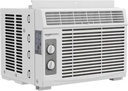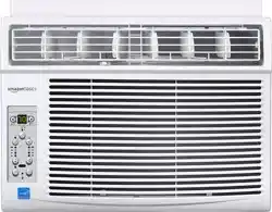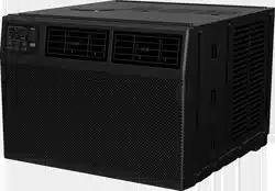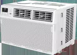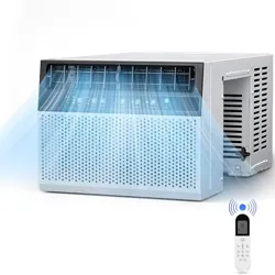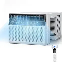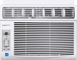
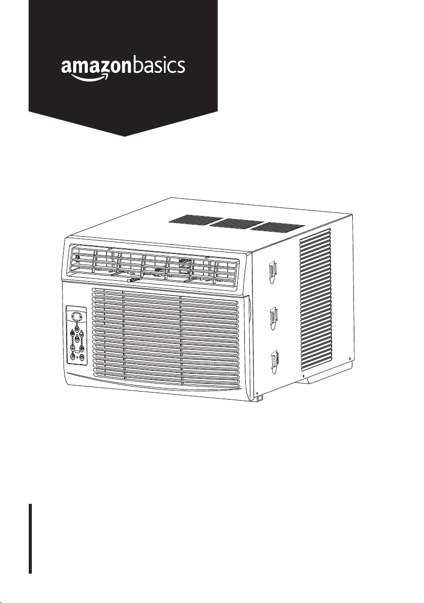
Window-Mounted Air Conditioner with Remote, Energystar
Sistema de Aire Acondicionado para Instalación en Ventanas, con
Control Remoto, Energystar
Climatiseur De Type Fenêtre avec Télécommande, Certifié Energystar
B07Y2CND3Q, B07Y2C57KD, B07Y2B3ZXV, B07N6LPL7V

English . . . . . . . . . . . . . . . . . . . . . . . . . . . . . . . . . 4
Españo . . . . . . . . . . . . . . . . . . . . . . . . . . . . . . . 37
Français . . . . . . . . . . . . . . . . . . . . . . . . . . . . . . . 69

3
x 2
Ø 1/8"
LEFT
RIGHT
A (x 1) B (x 1) C (x 1)
D (x 1) E (x 1) F (x 1)
G (x 2) H (x 2) I (x 1)
J (x 1) K (x 4) L (x 7)
M (x 2) N (x 2)
AAA
AAA
3.2 mm
4
EN
IMPORTANT SAFEGUARDS
Read these instructions carefully and retain them for future use.
If this product is passed to a third party, then these instructions
must be included.
When using electrical appliances, basic safety precautions should always
be followed to reduce the risk of fire, electric shock, and/or injury to
persons including the following:
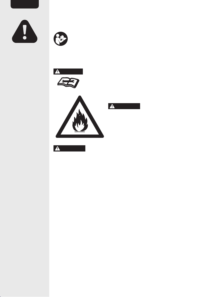
DANGER
Risk of fire or explosion! Flammable refrigerant used.
To be repaired only by trained service personnel. Do not
puncture refrigerant tubing.
WARNING
Risk of fire. Flammable
materials. This product uses refrigerant
R32 and must be disposed of by a licensed
refrigeration mechanic with knowledge of
appropriate gas reclamation methods.
WARNING
Do not pierce or burn. Be aware that refrigerants may
not contain an odor. Appliance shall be installed, operated and stored in
a room with a floor area larger than 120 ft
2
(11 m
2
).
• This appliance is not intended for use by persons (including children)
with reduced physical, sensory or mental capabilities, or lack of
experience and knowledge, unless they have been given supervision
or instruction concerning use of the appliance by a person
responsible for their safety.
• Children should be supervised to ensure that they do not play with
the product.
• Do not block air inlets and/or air outlets.
• Do not operate with wet hands.
• Do not disassemble or modify the product.
• Always switch off the product before pulling the power plug out of the
wall outlet.
• This product shall be installed in accordance with national wiring
regulations.
• If there is a gas leak from another product, ventilate the room before
operating the product.

5
EN
• Do not insert or allow foreign objects to enter any ventilation or
exhaust opening as this may cause an electric shock, fire or damage
the product.
• Disconnect the plug from the wall outlet when not using the product
for a long time.
Battery Warnings
• Always insert batteries correctly with regard to polarity (+ and –)
marked on the battery and the product.
• Exhausted batteries should be immediately removed from product
and properly disposed of.
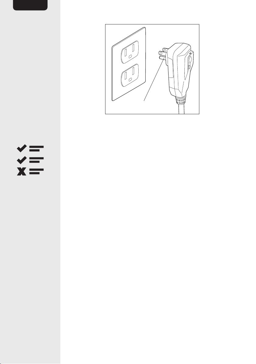
Grounding Instructions
• This product must be grounded while in use to protect the operator
from electrical shock. The product is equipped with a 3-conductor
cord and a 3-prong grounding-type plug. This product can only be
used with a standard 3-prong wall outlet to minimize the possibility
of electric shock. Where a 2-prong outlet is encountered, it must be
replaced with a properly grounded 3-prong wall outlet.
• Always use dedicated power circuit with a dedicated circuit breaker.
• Before connecting the product to the power supply, check that the
power supply voltage and current rating corresponds with the power
supply details shown on the product rating label.
• If the power cord is damaged, it must be replaced by the
manufacturer, its service agent or similarly qualified persons in order
to avoid a hazard.
• Do not modify power cord length or share an outlet with another
appliance. This may cause electric shock or fire.
• Do not use the outlet if it is loose or damaged. It may cause electric
shock.
• Always plug this product directly into a wall outlet/receptacle. Never
use with an extension cord or relocatable power tap (outlet/power
strip).
6
EN
Grounding pin
SAVE THESE INSTRUCTIONS
Intended Use
• This product is intended to regulate temperature and humidity
indoors.
• This product is intended for a fixed installation in a window only. The
power cord must be connected to indoor power supply only. This
product is not intended for use in bathrooms, laundry areas and
similar indoor locations.
• This product is intended for household use only. It is not intended for
commercial use.
• This product is intended to be used in dry indoor areas only.
• No liability will be accepted for damages resulting from improper use
or non-compliance with these instructions.
7
EN
Before First Use
• Check the product for transport damages.
• Remove all the packing materials.
• Before connecting the product to the power supply, check that the
power supply voltage and current rating corresponds with the power
supply details shown on the product rating label.
DANGER
Risk of suffocation! Keep any packaging materials away
from children – these materials are a potential source of danger, e.g.
suffocation.
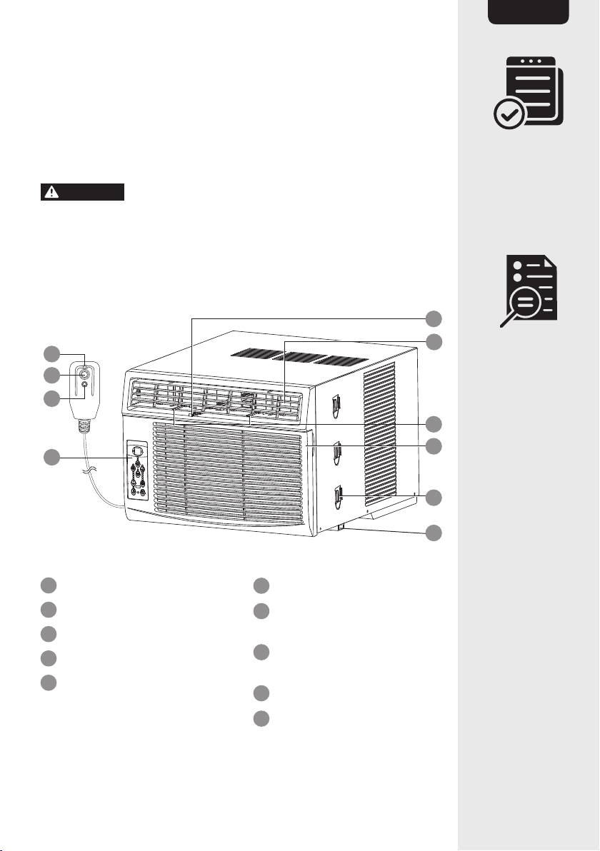
Product Description
Main unit
RESET
TEST
O
P
Q
R
Y
V
U
T
S
W
O
Power plug with indicator
P
RESET button
Q
TEST button
R
Control panel
S
Bottom rail
T
Shutter locks
U
Front grill
V
Air vent control lever
(for B07Y2C57KD and
B07Y2B3ZXV only)
W
Air vents
Y
Fresh air vent control
8
EN
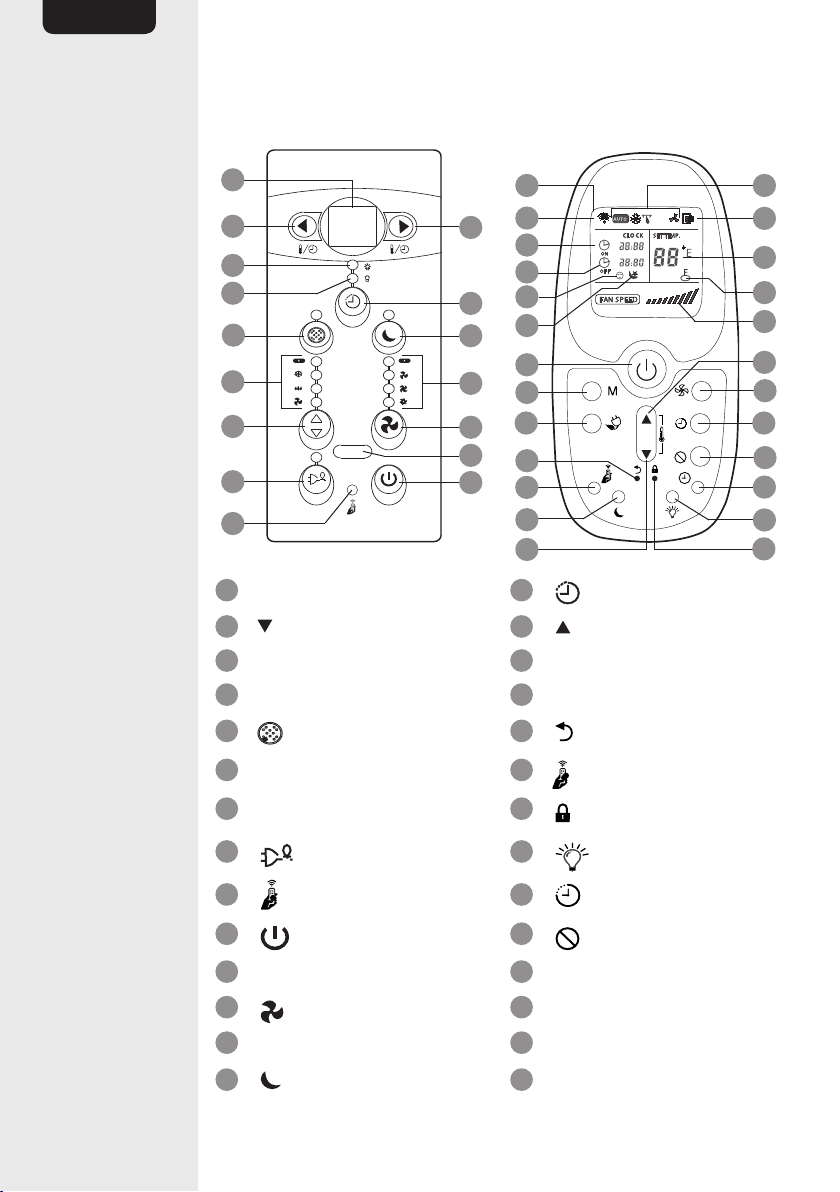
Controls
Control panel
Remote control
1
2
3
4
5
6
7
8
9
16
15
13
12
10
X
17
3
4
9
10
7
8
20
14
2
22
21
23
24
15
12
16
13
25
26
27
6
11
14
18
19
1
Main unit display
15
Timer button
2
Decrease button
16
Increase button
3
Timer on indicator
17
Relay signal indicator
4
Timer off indicator
18
Sleep indicator
5
Clean filter button
19
Reset button
6
Mode indicator
20
Follow me button
7
Mode button
21
Lock button
8
Energy Saver button
22
LED button
9
Follow me indicator
23
Clock button
10
On/off button
24
Cancel button
11
Remote control receiver
25
Child lock indicator
12
Fan button
26
Temperature indicator
13
Fan speed indicator
27
Power on indicator
14
Sleep button
X
Display
9
EN
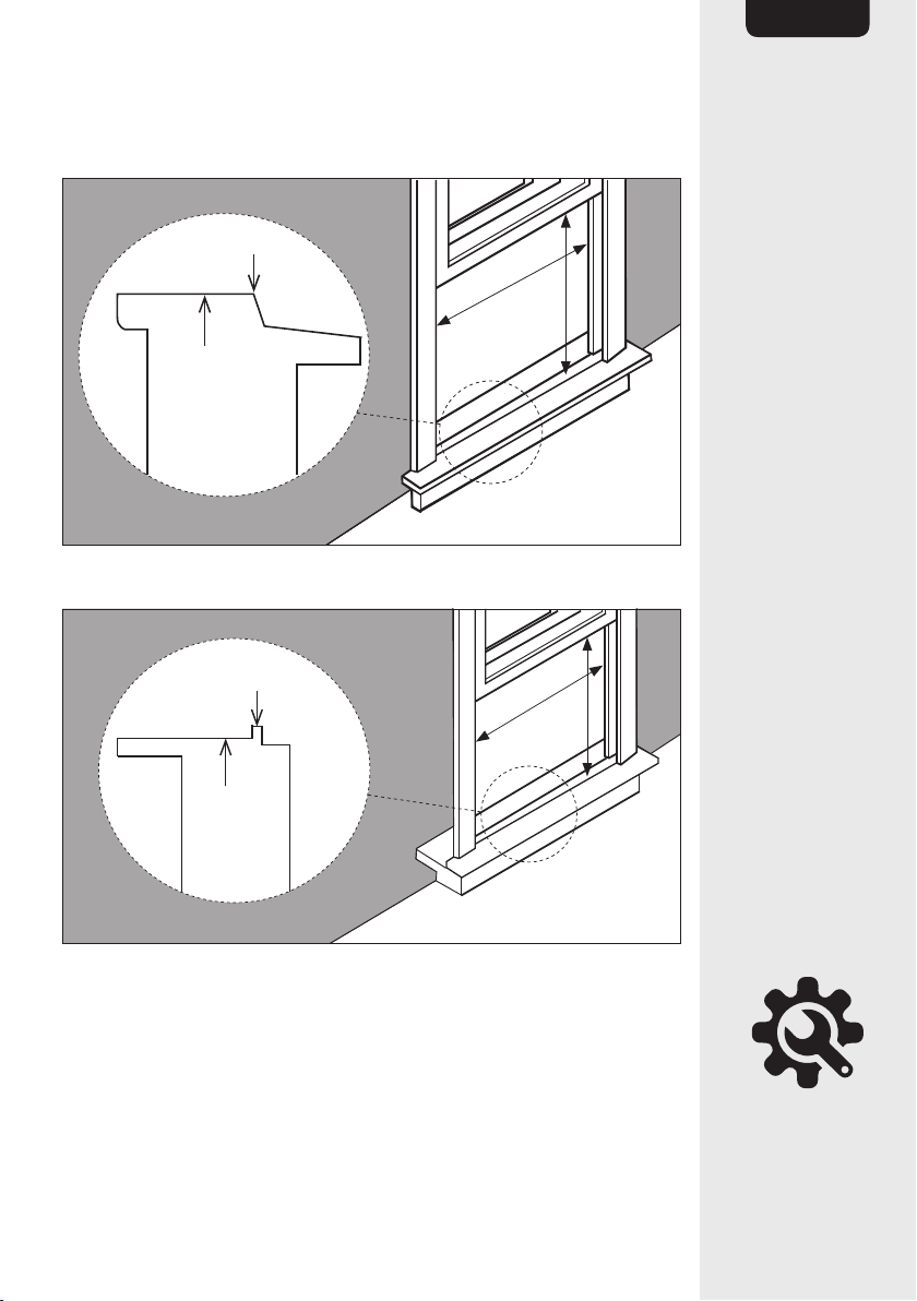
Window Requirements
Wooden window
A
B
offset
inner window sill
Vinyl-clad window
A
B
offset
inner
window sill
Installation
• The product should be installed by 2 skilled persons.
• To avoid vibration and noise, make sure the product is installed
securely and firmly.
• The window should be able to withstand the weight of the product.
• Install the product where the sunlight does not directly shine on it. If
the product receives direct sunlight, build an awning to shade it.
10
EN
• The rear part of the product must be installed outdoors, not inside a
building, garage or another room.
• There should be no obstacles, such as a fence or wall, within 20"
(50cm) from the back of the product and the side louvers. Obstacles
might limit the heat radiation, which greatly reduces the cooling
efficiency of the product.
• Install the product with its bottom portion approx. 30-60"
(75-150cm) above the floor level.
• Install the product within a reach to the wall outlet.
CAUTION
Risk of cuts! When handling the product be careful to
avoid cuts from sharp metal edges.
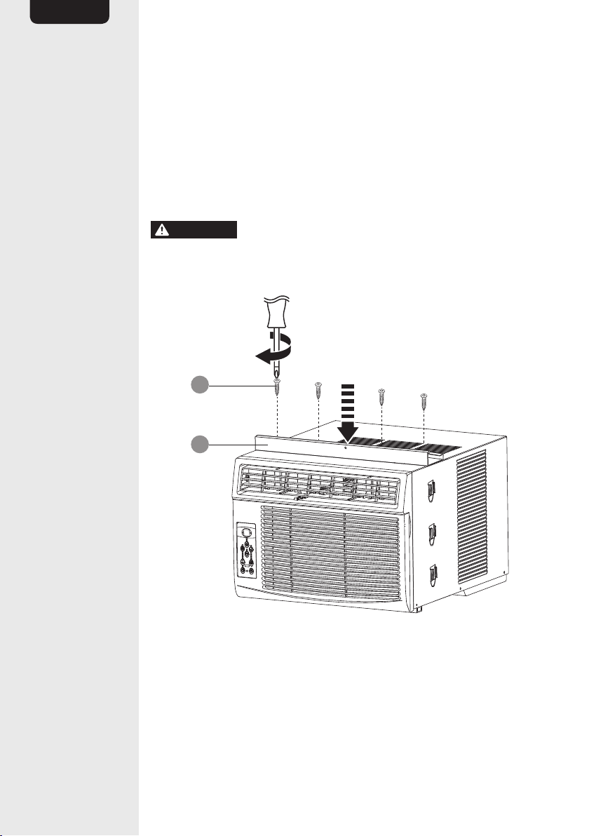
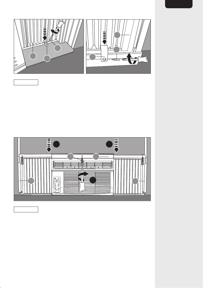
Step 1
K
F
• Attach the top rail (F) with 4 screws (K) by following the pre-drilled
holes on the unit.
11
EN
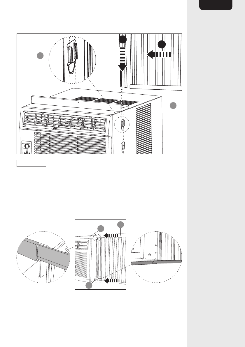
Step 2
x2
R
E
2
1
NOTICE
The accordion shutters are marked LEFT (D) and RIGHT (E)
for easy identification.
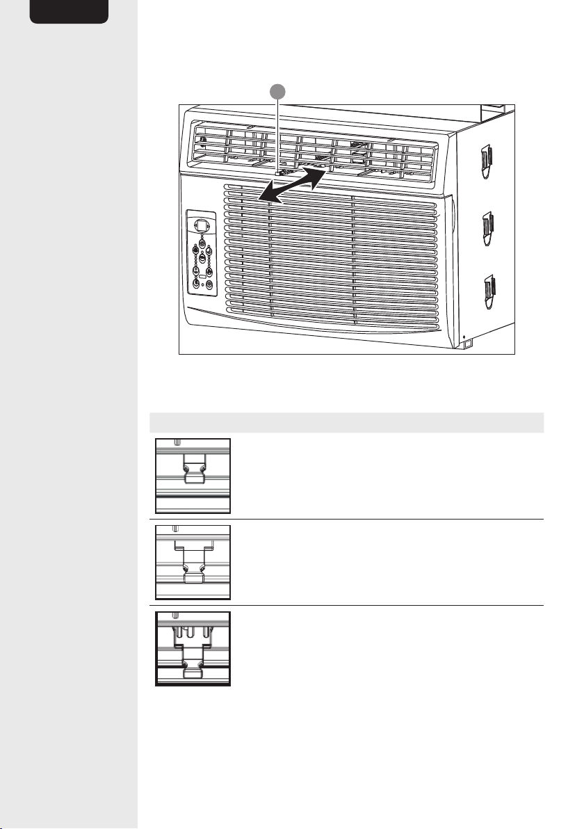
• Slide the rail of the right accordion shutter (E) out of the frame.
• Slide the rail into the shutter locks (T) of the main unit.
• Repeat on the other side with the left accordion shutter (D).
Step 3
x2
E
F
Q
• Slide the top and bottom rails of the right accordion shutter (E) into
the top rail’s (F) channel and the bottom rail (S).
• Repeat on the other side with the left accordion shutter (D).
12
EN
Step 4
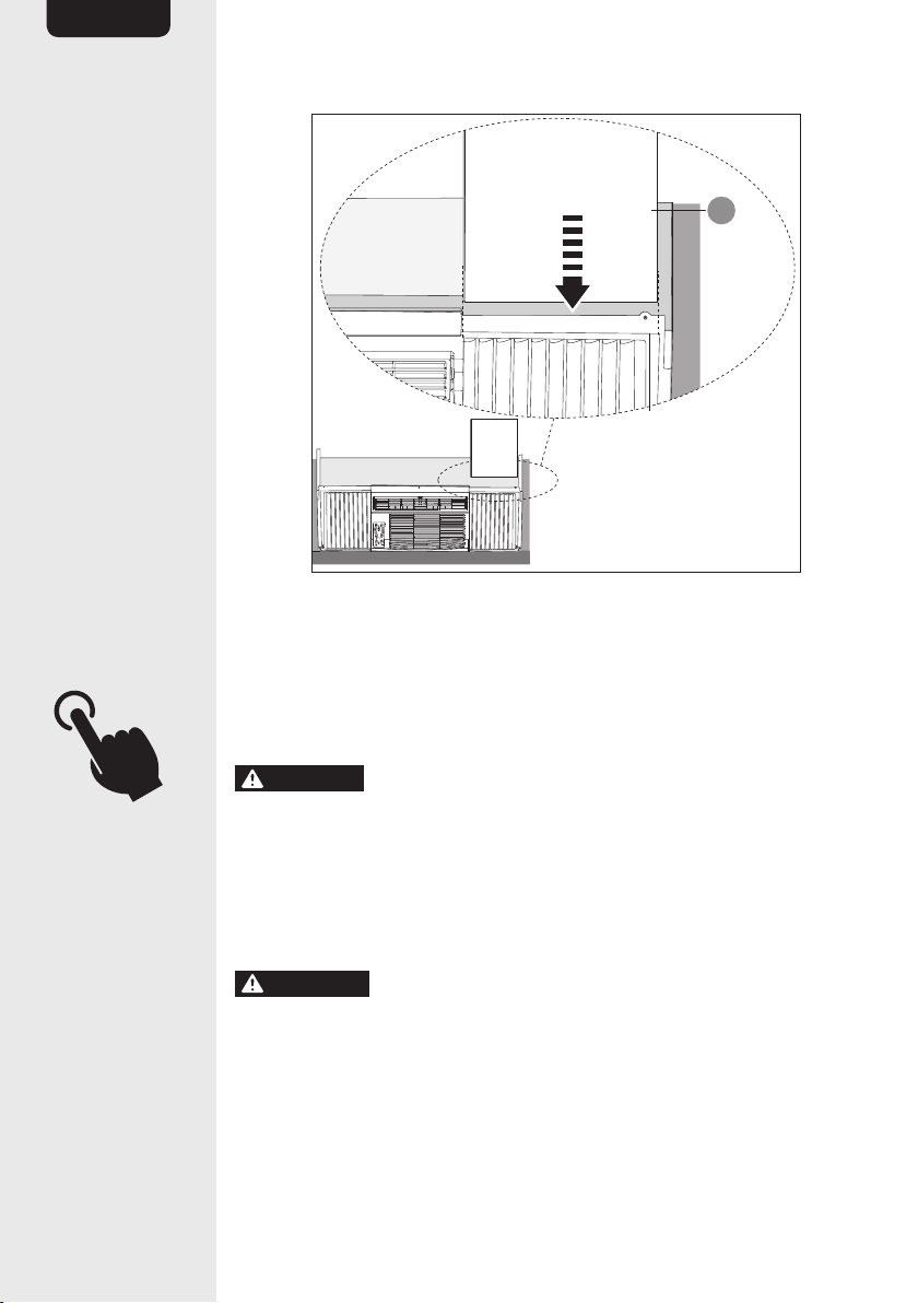
Wooden window Vinyl-clad window
Q
Q
A
A
• Place the product on the window sill. The bottom rail (S) needs to be
placed against the window sill’s offset.
NOTICE
Ensure the product is tilted 3° to 4° (A = 0.75 - 1" /
1.9-2. cm) downwards with reference to the window sill.
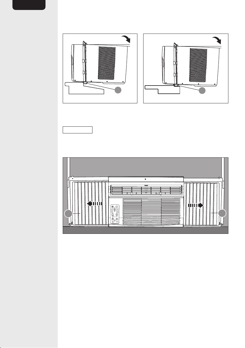
Step 5
E
D
• Fully extend the accordion shutters (E) and (D) so they fit the window
frame.
• Not shown: Use the strips of the weather stripping (C) to close any
leaking points. Cut them to the required size and remove the wax
paper. To improve insulation, stick them on appropriate areas.
13
EN
Wooden window
Vinyl-clad window
E
G
L
H
L
E
NOTICE
Ensure the product is tilted 3° to 4° (A = 0.75 - 1” /
1.9-2. cm) downwards with reference to the window sill.
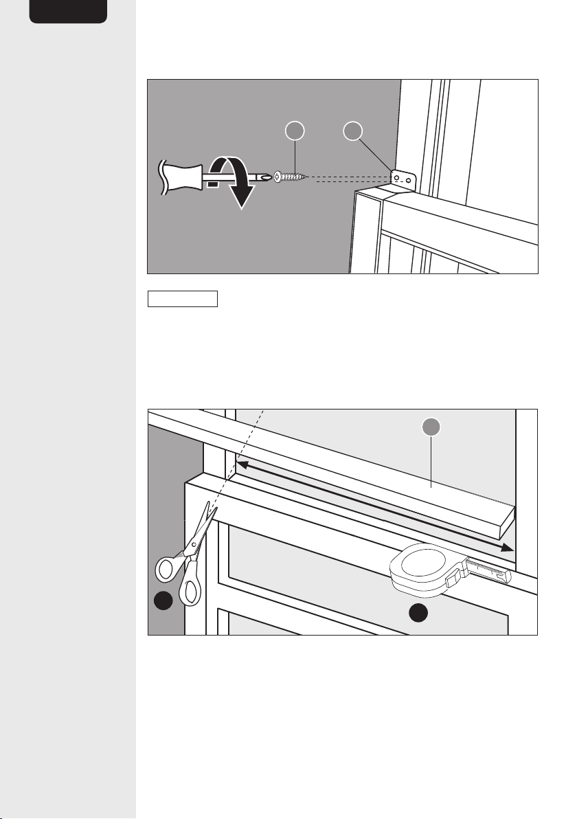
• Wooden windows: Secure the accordion shutters (E) and (D) with the
brackets (G) and the screws (L).
• Vinyl clad windows: Secure the accordion shutters (E) and (D) with
the brackets (H) and the screws (L).
Step 7
D
E
L
F
1 1
2
NOTICE
Before securing the accordion shutters (E) and (D) and
the top rail (F), mark and drill 3 pilot holes in the lower window sash to
prevent it from splitting.
• Close the window sash, so it rests on the top rail (F) and the
accordion shutters (E) and (D).
• Attach the accordion shutters (E) and (D) and the top rail (F) guided
by the pre-drilled holes to the window sash using 3 screws (L).
14
EN
Step 8
L
I
NOTICE
Before securing the lower window sash, mark and drill 2
pilot holes to prevent it from splitting.
• Secure the position of the lower window sash using the bracket (I)
and 2 screws (L).
Step 9
1
2
B
• Measure the width of the window sash.
• Cut the sash seal (B) so it fits the space between the lower and upper
window sash.

15
EN
Step 10
B
• Place the sash seal (B) between the lower and upper window sash.
Step 11
x2
2
1
x
• Measure the widths between the isolation board intakes of the
accordion shutters (E) and (D).
• Cut the isolation boards (N) according to the measured widths.
16
EN
Step 12
x2
N
• Slide the isolation boards (N) into the ledge of the accordion shutters
(E) and (D).
Operation
Performance test
DANGER
Risk of electric shock! The power plug of this product
provides LCDI protection (Leakage Current Detection and Interruption).
If the LCDI is de-activated this indicates an arcing fault. Unplug and
check the power cord and product. If no damage is visible, reset the
product by pressing the RESET button (N). If the LCDI de-activates
again, a hazardous condition may be present and the product should
be discarded or returned to an authorized service facility for examination
and/or repair.
CAUTION
Risk of electric shock! Run performance test before
each use.
• Press the RESET button (N).
• Connect the power plug to a wall outlet. The power plug indicator (M)
lights up.
• Press the TEST button (Q). The RESET button (P) should pop out
and the indicator on the power plug (O) should go off.
17
EN
• Press the RESET button (P) again. The indicator on the power
plug (O) lights up again and the product is ready for use.
NOTICE
If the indicator on the power plug (O) does not light up,
consult a specialist before using the product.
Installing/replacing the batteries
NOTICE
The batteries are not provided. Use 2 x 1.5 V type
AAA/LR03 batteries.
Switching on/off
To switch on/off the product, press the on/off button (10) either on
the remote control or on the control panel.
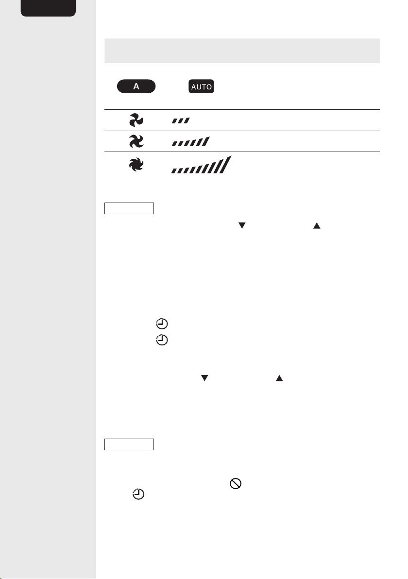
Mode control
To set the mode, press the mode button (7). The active mode is indicated
by the mode indicator (6).
Icon
control panel
Icon
remote control
Description
Auto: Depending on the set
target temperature and the
room temperature, the product
automatically switches between
cooling mode and fan mode. The
fan speed cannot be regulated
manually.
Cool: Airflow with cooling.
Dry: In this mode the product
mainly has a dehumidifying function.
There will be a little unavoidable
cooling effect on the room too.
The fan speed cannot be regulated
manually.
Fan: Airflow only.
Fan control
To set the fan mode, press the fan button (12). The fan speed is
indicated by the fan speed indicator (13).
18
EN
Icon
control panel
Icon
remote control
Description
Auto: Depending on the selected
mode, the set temperature and
the room temperature, the product
automatically sets the fan speed.
Low airflow
Medium airflow
High airflow
Temperature control
NOTICE
The temperature control does not work in fan mode.
Set the target temperature with the decrease (2) and increase (16)
buttons. The set temperature is shown on the display of the control panel
and the remote control.
Timer control
You can set the timer (0.5 to 24 hours) after which period the product
automatically switches on or off.
Set timer
• Press the timer button (15) to initialize the timer setting.
• Press the timer button (15) several times to toggle between the
on timer and the off timer. The chosen function is indicated by the
timer indicators (3 and/or 4).
• Set the timer with the decrease (2) and increase (16) buttons.
The set time is shown on the display of the control panel and the
remote control.
• Wait 5 seconds. The timer is now set and starts to run. The timer
indicator (3 and/or 4) light up if a timer is running.
NOTICE
The temperature control does not work in fan mode.
Cancel timer
• To reset the timers, press the cancel button (24) or press and hold
the timer button (15) for 3 seconds.
– This deletes the timer setting.
– If the ON timer is being canceled, the product switches off.
– If the OFF timer is being canceled, the product switches on.
19
EN
– Alternatively, you can set the concerned timer to 0.0 h.
Sleep function
NOTICE
The sleep function works only when the product is set to
cooling or auto mode.
– The sleep function increases the target temperature by 2 °F (1 °C) 30
minutes after activation.
– After another 30 minutes the target temperature is increased by
another 2 °F (1 °C).
– The product maintains the temperature for the following 6
hours. Afterwards, the product returns to the originally selected
temperature.
• Press the sleep button (14) to activate the sleep function. The
activated sleep function is being indicated with a light above the
sleep button (14) and with a on the remote control display (X).
Energy saver
NOTICE
The energy saver control does not work in fan mode.
– While the energy saver is activated, the product is cooling the room
with the maximum compressor efficiency below the set target
temperature.
– When the room temperature is below the set temperature, the
compressor switches off. Only the fan is working in short intervals.
– When the room temperature increases above the set target
temperature, the compressor switches on again.
• Press the energy saver button (8) to activate the energy saver.
The activated energy saver is being indicated with a light above the
energy saver button (8).
Follow me function
• Press the follow me button (20) to activate this function.
• While activated:
– The follow me indicator (9) lights up and is shown on the left
side of the remote control display (X).
– The remote control displays the temperature of its immediate
surroundings.
20
EN
– While activated, the product uses the temperature sensor of the
remote control to measure the room temperature.
– The remote control transmits the measured temperature in 3-minute
intervals to the main unit.
– This allows to set the target temperature for a specific location in the
room.
NOTICE
When the main unit does not receive any signal from the
remote control for 7 minutes, it switches off the follow me function.
As soon as the temperature signal is being received, the main unit
automatically switches on the follow me function.
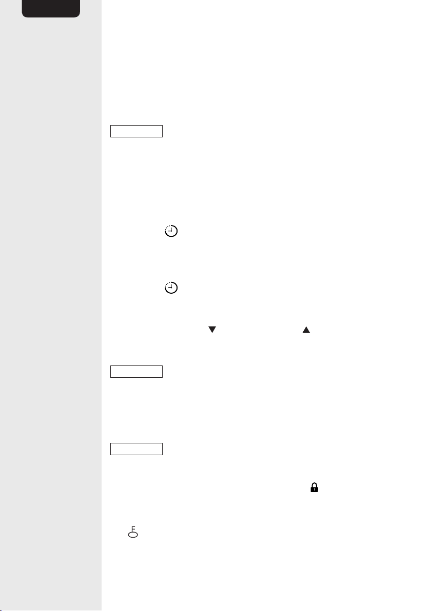
Clock
The remote control is equipped with a clock. The time is shown on the
left side of the display (X).
• Press the clock button (23) for 3 seconds. The clock starts to
flash.
• Set the time with the decrease (2) and increase (16) buttons. Press
and hold the button to change the time quicker.
• Press the clock button (23) to confirm the setting.
°F/°C
Press and hold both the decrease (2) and the increase (16) button
for 3 seconds to toggle the temperature units between Fahrenheit and
Celsius.
NOTICE
When the main unit does not receive any signal from the
remote control for 7 minutes, it switches off the follow me function.
As soon as the temperature signal is being received, the main unit
automatically switches on the follow me function.
Child lock
NOTICE
The child lock is only available for the remote control. The
control panel (P) is always active.
• To activate/deactivate the child lock, press the lock button (21),
e.g. with a toothpick.
• When the child lock is activated:
– is shown on the right side of the remote control display (X).
– All buttons of the remote control are locked.
21
EN
LEDs on/off
• Press the LED button (22) to switch off/on the lights of the
control panel (P).
NOTICE
The LEDs light up for a short time when a setting is
changed.
Reset
NOTICE
The reset function is only available for the remote control.
• To reset the remote control back to factory settings, press the
reset button (19), e.g. with a toothpick.
Clean filter reminder
The product measures the total working time. After 250 hours of
operation, the indicator above the clean filter button(5) lights up.
• Clean the removable air filter (see Cleaning and Maintenance).
• Press the clean filter button(5) to reset the counter.
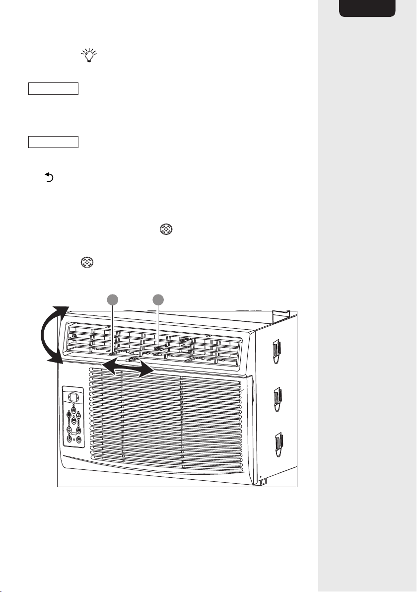
Airflow direction control
U W
• To adjust the airflow direction, move the air vent control lever (U) left
or right and the air vent (W) up or down.
22
EN
Fresh air vent control (only for B07Y2C57KD and B07Y2B3ZXV)
V
• Change the position of the fresh air vent control (V) to choose one of
the below air circulation mode.
Position Description Vent Exhaust
Vent closed: The air
circulates inside the room.
Closed Closed
Half opened: The fresh air
is drawn into the room from
outside.
Open Closed
Fully opened: The air is
circulated between inside
and outside.
Open Open
23
EN
Cleaning and Maintenance
WARNING
Risk of electric shock! To prevent electric shock,
unplug the product before cleaning.
WARNING
Risk of electric shock! During cleaning do not
immerse the product in water or other liquids. Never hold the product
under running water.
Cleaning the removable air filter
S
NOTICE
Clean the removable air filter at least every 2 weeks.
NOTICE
Do not clean the filter with water warmer than
104 °F (40 °C).
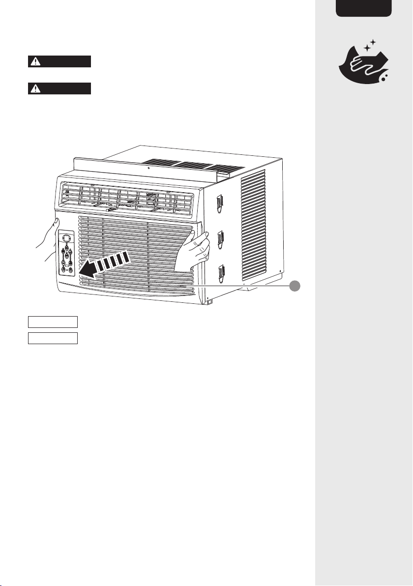
• Open the front grill (U) and remove the filter.
• Pull out the -filter on the right side.
• Rinse the filter thoroughly in warm water with mild detergent.
• Gently shake off the excess water from the filter and air-dry it.
• Put the filter back in the main unit and close the front grill (U).
Cleaning the main unit
• To clean, wipe with a soft, slightly moist cloth.
• Never use corrosive detergents, wire brushes, abrasive scourers,
metal or sharp utensils to clean the product.
24
EN
Storage
• Store the product in its original packaging in a dry area. Keep away
from children and pets.
Maintenance
• Any other servicing than mentioned in this manual should be
performed by a professional repair centre.
Troubleshooting
Problem Solution
The product does not switch
on.
• Check if the power plug is
connected to the power outlet.
Check if the power outlet works.
• Plug’s Leakage Current Detection
and Interruption device tripped.
Press the RESET button (P).
• The circuit breaker of the electrical
installation tripped. Flip the suspect
breaker to the “on” position.
The product does not cool
efficiently.
• Clean the removable air filter.
• Check the air vents for
obstructions.
• Adjust the airflow direction.
• Ensure the doors and windows are
closed.
• Compressor has shut off due to
changed operating mode. After
switching off the product, wait at
least 3 minutes before switching it
on again.
Ice forms on the product.
• Clean the removable air filter.
• Set to the fan mode to remove the
ice. Decrease the set temperature
to stop ice from forming.
The product is noisy and
vibrates abnormally.
• Incorrect installation. Refer to
installation instructions.
• Clean the removable air filter.
25
EN
Problem Solution
The product turns on and off
rapidly.
• Outside temperature is extremely
hot. Set fan speed to a higher
setting.
• Clean the removable air filter.
Water drips inside when the
product is on.
• Incorrect installation. Refer to
installation instructions.
Water drips outside when the
product is on.
• This is normal during excessively
humid days. The product is
removing large quantity of moisture
from the humid room.
The product does not
respond to the remote
control.
• Operate the remote control within
26 ft (8 m) from the product.
• Point the remote control directly
towards the product when
operating.
The main unit display shows
an error code.
• Unplug the product from the power
supply, and then connect it again.
• Refer to the table below for the
details of the code.
Error Code
Error Code Meaning
AS Room temperature sensor error.
ES Evaporator temperature sensor error.
HS Electric heating sensor error.
CS Condenser temperature sensor error.
OS Outside temperature sensor error.
E7 Unit malfunction.

26
EN
FCC – Supplier’s Declaration of Conformity
Unique Identifier
B07Y2CND3Q Window-Mounted Air
Conditioner with Remote - Cools 250 Square
Feet, 6000 BTU, Energystar
B07Y2C57KD Window-Mounted Air
Conditioner with Remote - Cools 450 Square
Feet, 10000 BTU, Energystar
B07Y2B3ZXV Window-Mounted Air
Conditioner with Remote - Cools 550 Square
Feet, 12000 BTU, Energystar
B07N6LPL7V Window-Mounted Air
Conditioner with Remote - Cools 172 Square
Feet, 8000 BTU, Energystar
Responsible Party Amazon.com Services, Inc
U.S. Contact
Information
410 Terry Ave N.
Seattle, WA
98109, United States
Telephone Number (206) 266-1000
FCC Compliance Statement
1. This device complies with Part 15 of the FCC rules. Operation is
subject to the following two conditions:
(1) this device may not cause harmful interference, and
(2) this device must accept any interference received, including
interference that may cause undesired operation.
2. Changes or modifications not expressly approved by the party
responsible for compliance could void the user’s authority to operate
the equipment.
FCC Interference Statement
This equipment has been tested and found to comply with the limits for
a Class B digital device, pursuant to part 15 of the FCC Rules. These
limits are designed to provide reasonable protection against harmful
interference in a residential installation. This equipment generates, uses
and can radiate radio frequency energy and, if not installed and used in
accordance with the instructions, may cause harmful interference to radio
communications. However, there is no guarantee that interference will
not occur in a particular installation. If this equipment does cause harmful
interference to radio or television reception, which can be determined by
turning the equipment off and on, the user is encouraged to try to correct
the interference by one or more of the following measures:
• Reorient or relocate the receiving antenna.
• Increase the separation between the equipment and receiver.
27
EN
• Connect the equipment into an outlet on a circuit different from that
to which the receiver is connected.
• Consult the dealer or an experienced radio / TV technician for help.
Canada IC Notice
This Class B digital apparatus complies with Canadian CANICES-3(B) /
NMB-3(B) standard.
Specifications
B07Y2CND3Q B07Y2C57KD
Model number: 22020310002997 22020310003018
Voltage/frequency: 115 V~, 60 Hz 115 V~, 60 Hz
Rated input:
490 W
(max. 700 W)
925 W
(max. 983.6 W)
Rated current: 4.5 A (max. 6.5 A)
8.03 A
(max. 9.68 A)
Standby power: 0.9 W 1 W
Fuse: 15 A 15 A
Cooling capacity:
250 ft
2
(23.2 m
2
),
6000 BTU/h
450 ft
2
(52 m
2
),
10000 BTU/h
Design pressure:
300/520 PSI
(20.7/35.9 bar)
300/520 PSI
(20.7/35.9 bar)
Indoor side air flow
(Hi/Mi/Lo):
189/145/132 ft
3
/min
(287/247/224 m
3
/h)
300/266/240 ft
3
/min
(510/452/408 m
3
/h)
Indoor side noise
level (Hi/Mi/Lo):
56/53/52 dB(A) 61/58/56 dB(A)
Operating
temperature indoor:
62-90 °F (17-32 °C) 62-90 °F (17-32 °C)
Operating
temperature
outdoor:
64-109 °F (18-43 °C) 64-109 °F (18-43 °C)
Dimensions
(W x H x D):
approx.
18.5 x 13.4 x 15.7"
(47.1 x 34 x 40cm)
approx.
19 x 14.7 x 21.5"
(48.2 x 37.2 x 54.5cm)

28
EN
Net weight:
approx. 41.9 lbs
(19 kg)
approx. 57.3 lbs
(26 kg)
Refrigerant type +
quantity:
R32, 7.8 oz (220 g) R32, 12.35 oz (350 g)
Remote control
range:
26 ft (8 m) 26 ft (8 m)
Battery type:
2 x 1.5 V, type AAA/
LR03
2 x 1.5 V, type AAA/
LR03
B07Y2B3ZXV B07N6LPL7V
Model number: 22020310003057 22020310003018
Voltage/frequency: 115 V~, 60 Hz 115 V~, 60 Hz
Rated input:
1000 W
(max. 1207 W)
667 W
(max. 865 W)
Rated current:
9.72 A (max. 11.99 A)
5.9 A (max. 8.4 A)
Standby power: 1 W 0.9 W
Fuse: 15 A 10 A
Cooling capacity:
550 ft
2
(42 m
2
),
12000 BTU/h
118-172 ft
2
(11-16 m
2
),
8000 BTU/h
Design pressure:
300/520 PSI
(20.7/35.9 bar)
300/520 PSI
(20.7/35.9 bar)
Indoor side air flow
(Hi/Mi/Lo):
300/270/244 ft
3
/min
(510/459/415 m
3
/h)
196/165/148 ft
3
/min
(333.2/280.5/251.6
m
3
/h)
Indoor side noise
level (Hi/Mi/Lo):
60.5/59.3/57.5 dB(A) 57.7/55/53.3 dB(A)
Operating
temperature indoor:
62-90 °F (17-32 °C) 62-90 °F (17-32 °C)
Operating
temperature
outdoor:
64-109 °F (18-43 °C) 64-109 °F (18-43 °C)
Dimensions
(W x H x D):
approx.
19 x 14.7 x 21.5"
(48.2 x 37.2 x
54.5cm)
approx.
18.5 x 13.4 x 15.7"
(47.1 x 34 x 40cm)
29
EN
Net weight:
approx. 67.7 lbs
(30.7 kg)
approx. 47 lbs
(21.3 kg)
Refrigerant type +
quantity:
R32, 10.58 oz (320 g)
R32, 10.58 oz (300 g)
Remote control
range:
26 ft (8 m) 26 ft (8 m)
Battery type:
2 x 1.5 V, type AAA/
LR03
2 x 1.5 V, type AAA/
LR03
Feedback and Help
Love it? Hate it? Let us know with a customer review.
AmazonBasics is committed to delivering customer-driven products
that live up to your high standards. We encourage you to write a review
sharing your experiences with the product.
amazon.com/review/review‑your‑purchases#
amazon.com/gp/help/customer/contact‑us
END OF USER MANUAL
SERVICING MANUAL
Servicing
• Any person who is involved with working on or breaking into a
refrigerant circuit should hold a current valid certificate from an
industry-accredited assessment authority, which authorizes their
competence to handle refrigerants safely in accordance with an
industry recognized assessment specification.
• Servicing shall only be performed as recommended by the equipment
manufacturer. Maintenance and repair requiring the assistance of
other skilled personnel shall be carried out under the supervision of
the person competent in the use of flammable refrigerants.

30
EN
Checks to the area
Prior to beginning work on systems containing flammable refrigerants,
safety checks are necessary to ensure that the risk of ignition is
minimised. For repair to the refrigerating system, the following
precautions shall be complied with prior to conducting work on the
system.
Work procedure
Work shall be undertaken under a controlled procedure so as to minimise
the risk of a flammable gas or vapour being present while the work is
being performed.
General work area
All maintenance staff and others working in the local area shall be
instructed on the nature of work being carried out. Work in confined
spaces shall be avoided. The area around the workspace shall be
sectioned off. Ensure that the conditions within the area have been made
safe by control of flammable material.
Checking for presence of refrigerant
The area shall be checked with an appropriate refrigerant detector prior
to and during work, to ensure the technician is aware of potentially
flammable atmospheres. Ensure that the leak detection equipment being
used is suitable for use with flammable refrigerants, i.e. non-sparking,
adequately sealed or intrinsically safe.
Presence of fire extinguisher
If any hot work is to be conducted on the refrigeration equipment or
any associated parts, appropriate fire extinguishing equipment shall be
available to hand. Have a dry powder or CO
2
fire extinguisher adjacent to
the charging area.
No ignition sources
No person carrying out work in relation to a refrigeration system
which involves exposing any pipe work that contains or has contained
flammable refrigerant shall use any sources of ignition in such a manner
that it may lead to the risk of fire or explosion. All possible ignition
sources, including cigarette smoking, should be kept sufficiently far away
from the site of installation, repairing, removing and disposal, during
which flammable refrigerant can possibly be released to the surrounding
space. Prior to work taking place, the area around the equipment is to
be surveyed to make sure that there are no flammable hazards or ignition
risks. No Smoking signs shall be displayed.

31
EN
Ventilated area
Ensure that the area is in the open or that it is adequately ventilated
before breaking into the system or conducting any hot work. A degree
of ventilation shall continue during the period that the work is carried
out. The ventilation should safely disperse any released refrigerant and
preferably expel it externally into the atmosphere.
Checks to the refrigeration equipment
Where electrical components are being changed, they shall be fit for the
purpose and to the correct specification. At all times the manufacturer’s
maintenance and service guidelines shall be followed. If in doubt consult
the manufacturer’s technical department for assistance.
The following checks shall be applied to installations using flammable
refrigerants:
• The charge size is in accordance with the room size within which the
refrigerant containing parts are installed;
• The ventilation machinery and outlets are operating adequately and
are not obstructed;
• If an indirect refrigerating circuit is being used, the secondary circuit
shall be checked for the presence of refrigerant;
• Marking to the equipment continues to be visible and legible.
Markings and signs that are illegible shall be corrected;
• Refrigeration pipe or components are installed in a position where
they are unlikely to be exposed to any substance which may corrode
refrigerant containing components, unless the components are
constructed of materials which are inherently resistant to being
corroded or are suitably protected against being so corroded.
Checks to electrical devices
Repair and maintenance to electrical components shall include initial
safety checks and component inspection procedures. If a fault exists that
could compromise safety, then no electrical supply shall be connected
to the circuit until it is satisfactorily dealt with. If the fault cannot be
corrected immediately but it is necessary to continue operation, an
adequate temporary solution shall be used. This shall be reported to the
owner of the equipment so all parties are advised.
Initial safety checks shall include:
• That capacitors are discharged: this shall be done in a safe manner
to avoid possibility of sparking;
• That there no live electrical components and wiring are exposed while
charging, recovering or purging the system;
• That there is continuity of earth bonding.

32
EN
Repairs to sealed components
1. During repairs to sealed components, all electrical supplies shall be
disconnected from the equipment being worked upon prior to any
removal of sealed covers, etc. If it is absolutely necessary to have an
electrical supply to equipment during servicing, then a permanently
operating form of leak detection shall be located at the most critical
point to warn of a potentially hazardous situation.
2. Particular attention shall be paid to the following to ensure that by
working on electrical components, the casing is not altered in such a
way that the level of protection is affected. This shall include damage
to cables, excessive number of connections, terminals not made to
original specification, damage to seals, incorrect fitting of glands, etc.
Ensure apparatus is mounted securely.
Ensure that seals or sealing materials have not degraded such that they
no longer serve the purpose of preventing the ingress of flammable
atmospheres. Replacement parts shall be in accordance with the
manufacturer’s specifications.
NOTICE
The use of silicon sealant may inhibit the effectiveness of
some types of leak detection equipment. Intrinsically safe components
do not have to be isolated prior to working on them.
Repair to intrinsically safe components
Do not apply any permanent inductive or capacitance loads to the circuit
without ensuring that this will not exceed the permissible voltage and
current permitted for the equipment in use.
Intrinsically safe components are the only types that can be worked on
while live in the presence of a flammable atmosphere. The test apparatus
shall be at the correct rating.
Replace components only with parts specified by the manufacturer.
Other parts may result in the ignition of refrigerant in the atmosphere from
a leak.
Cabling
Check that cabling will not be subject to wear, corrosion, excessive
pressure, vibration, sharp edges or any other adverse environmental
effects. The check shall also take into account the effects of aging or
continual vibration from sources such as compressors or fans.
Detection of flammable refrigerants
Under no circumstances shall potential sources of ignition be used in the
searching for or detection of refrigerant leaks. A halide torch (or any other
detector using a naked flame) shall not be used.

33
EN
Leak detection methods
The following leak detection methods are deemed acceptable for
systems containing flammable refrigerants.
Electronic leak detectors shall be used to detect flammable refrigerants,
but the sensitivity may not be adequate, or may need re-calibration
(detection equipment shall be calibrated in a refrigerant-free area). Ensure
that the detector is not a potential source of ignition and is suitable for
the refrigerant used.
Leak detection equipment shall be set at a percentage of the LFL of
the refrigerant and shall be calibrated to the refrigerant employed and
the appropriate percentage of gas (25% maximum) is confirmed. Leak
detection fluids are suitable for use with most refrigerants but the use of
detergents containing chlorine shall be avoided as the chlorine may react
with the refrigerant and corrode the copper pipe-work.
If a leak is suspected, all naked flames shall be removed/extinguished.
If a leakage of refrigerant is found which requires brazing, all of the
refrigerant shall be recovered from the system, or isolated (by means of
shut off valves) in a part of the system remote from the leak. Oxygen free
nitrogen (OFN) shall then be purged through the system both before and
during the brazing process.
Removal and evacuation
When breaking into the refrigerant circuit to make repairs or for any other
purpose conventional procedures shall be used. However, it is important
that best practice is followed since flammability is a consideration.
Opening of the refrigeration systems shall not be done by brazing.The
following procedure shall be adhered to:
• Remove refrigerant;
• Purge the circuit with inert gas;
• Evacuate;
• Purge again with inert gas;
• Open the circuit by cutting or brazing.
The refrigerant charge shall be recovered into the correct recovery
cylinders. The system shall be flushed with OFN to render the unit safe.
This process may need to be repeated several times. Compressed air or
oxygen shall not be used for this task.

34
EN
Flushing shall be achieved by breaking the vacuum in the system with
OFN and continuing to fill until the working pressure is achieved, then
venting to atmosphere, and finally pulling down to a vacuum. This
process shall be repeated until no refrigerant is within the system.
When the final OFN charge is used, the system shall be vented down
to atmospheric pressure to enable work to take place. This operation is
absolutely vital if brazing operations on the pipe-work are to take place.
Ensure that the outlet for the vacuum pump is not close to any ignition
sources and there is ventilation available.
Charging procedures
In addition to conventional charging procedures, the following
requirements shall be followed.
• Ensure that contamination of different refrigerants does not occur
when using charging equipment. Hoses or lines shall be as short as
possible to minimise the amount of refrigerant contained in them;
• Cylinders shall be kept upright;
• Ensure that the refrigeration system is earthed prior to charging the
system with refrigerant;
• Label the system when charging is complete (if not already);
• Extreme care shall be taken not to overfill the refrigeration system.
Prior to recharging the system it shall be pressure tested with OFN.
The system shall be leak tested on completion of charging but prior to
commissioning. A follow up leak test shall be carried out prior to leaving
the site.
Decommissioning
Before carrying out this procedure, it is essential that the technician
is completely familiar with the equipment and all its detail. It is
recommended good practice that all refrigerants are recovered safely.
Prior to the task being carried out, an oil and refrigerant sample shall be
taken in case analysis is required prior to re-use of reclaimed refrigerant.
It is essential that electrical power is available before the task is
commenced.
1. Become familiar with the equipment and its operation.
2. Isolate system electrically.
3. Before attempting the procedure ensure that:
• Mechanical handling equipment is available, if required, for handling
refrigerant cylinders;

35
EN
• All personal protective equipment is available and being used
correctly;
• The recovery process is supervised at all times by a competent
person;
• Recovery equipment and cylinders conform to the appropriate
standards.
4. Pump down refrigerant system, if possible.
5. If a vacuum is not possible, make a manifold so that refrigerant can
be removed from various parts of the system.
6. Make sure that cylinder is situated on the scales before recovery
takes place.
7. Start the recovery machine and operate in accordance with
manufacturer’s instructions.
8. Do not overfill cylinders. (No more than 80% volume liquid charge).
9. Do not exceed the maximum working pressure of the cylinder, even
temporarily.
10. When the cylinders have been filled correctly and the process
completed, make sure that the cylinders and the equipment are
removed from site promptly and all isolation valves on the equipment
are closed off.
11. Recovered refrigerant shall not be charged into another refrigeration
system unless it has been cleaned and checked.
Labelling
Equipment shall be labelled stating that it has been de-commissioned
and emptied of refrigerant. The label shall be dated and signed. Ensure
that there are labels on the equipment stating the equipment contains
flammable refrigerant.
Recovery
When removing refrigerant from a system, either for servicing or
decommissioning, it is recommended good practice that all refrigerants
are removed safely.
When transferring refrigerant into cylinders, ensure that only appropriate
refrigerant recovery cylinders are employed. Ensure that the correct
number of cylinders for holding the total system charge is available.
All cylinders to be used are designated for the recovered refrigerant
and labelled for that refrigerant (i.e. special cylinders for the recovery
of refrigerant). Cylinders shall be complete with pressure relief valve
and associated shut-off valves in good working order. Empty recovery
cylinders are evacuated and, if possible, cooled before recovery occurs.

36
EN
The recovery equipment shall be in good working order with a set of
instructions concerning the equipment that is at hand and shall be
suitable for the recovery of flammable refrigerants. In addition, a set of
calibrated weighing scales shall be available and in good working order.
Hoses shall be complete with leak-free disconnect couplings and in
good condition. Before using the recovery machine, check that it is in
satisfactory working order, has been properly maintained and that any
associated electrical components are sealed to prevent ignition in the
event of a refrigerant release. Consult manufacturer if in doubt.
The recovered refrigerant shall be returned to the refrigerant supplier
in the correct recovery cylinder, and the relevant Waste Transfer Note
arranged. Do not mix refrigerants in recovery units and especially not in
cylinders.
If compressors or compressor oils are to be removed, ensure that
they have been evacuated to an acceptable level to make certain
that flammable refrigerant does not remain within the lubricant. The
evacuation process shall be carried out prior to returning the compressor
to the suppliers. Only electric heating to the compressor body shall be
employed to accelerate this process. When oil is drained from a system,
it shall be carried out safely.

amazon.com/AmazonBasics
V05-11/19
MADE IN CHINA
FABRIQUÉ EN CHINE
HECHO EN CHINA