Loading ...
Loading ...
Loading ...
8
INSTALLATION INSTRUCTIONS
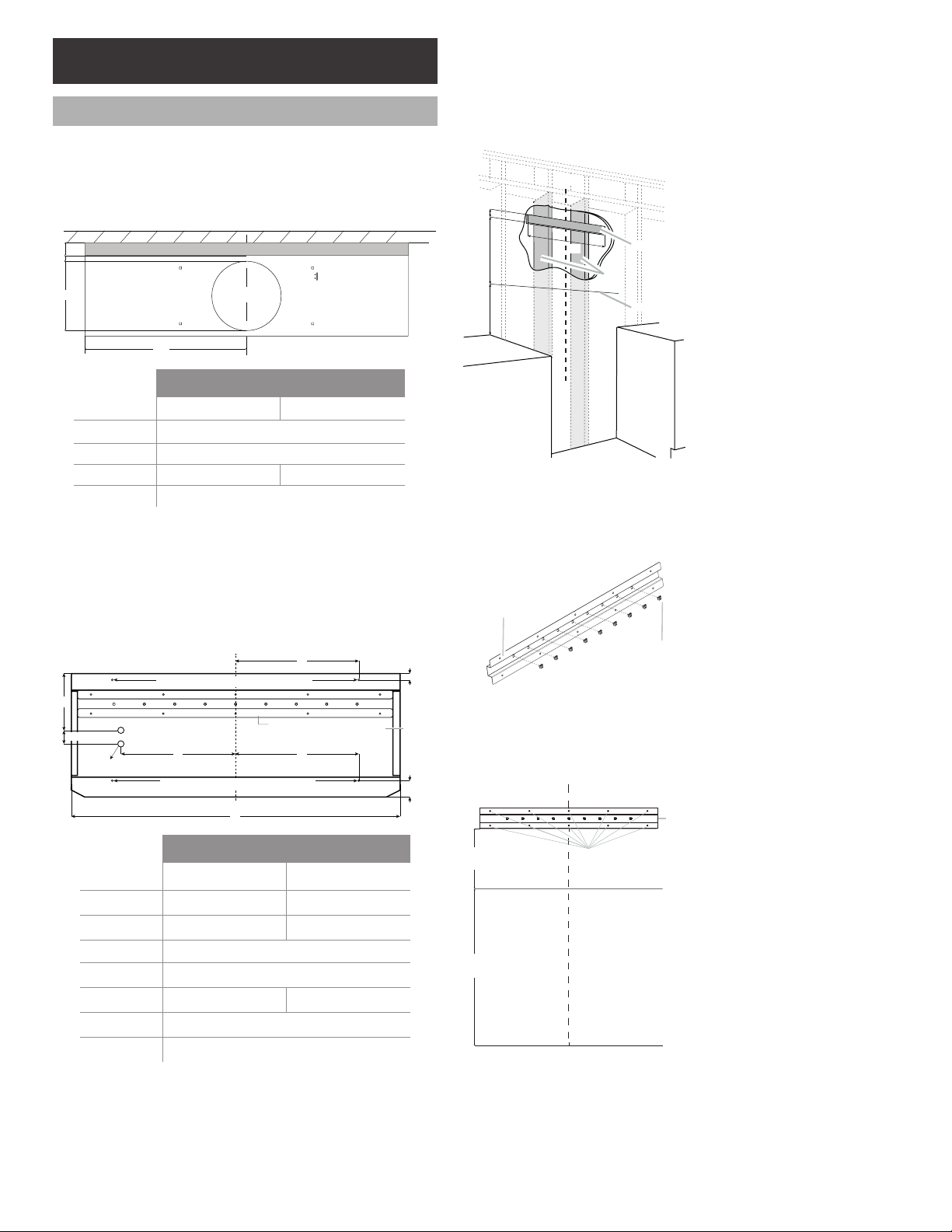
Prepare Location
Outside top exhaust
(Vertical duct – 10” Round transition)
Use the diagram or the hood as a template and mark the
locations on the ceiling or wall for ductwork, electrical wiring
and keyhole screw slots. It is recommended to make the marks
before the installation.
WALL
Range Hood
Top Front Side
A
B
C
Center
Line
D
Depth Spacer Kit (Optional Accessory)
Models
ECP136SS ECP148SS
A
14
⁄ 16” (2.2 cm)
B Ø 10
1
⁄ 4” (26 cm)
C 18” (45.71 cm) 24” (60.8 cm)
D* 3" (7.62 cm)
*Optional measure
Install framing for hood support
1 Remove the wiring knockouts.
2 Mark the knockouts and the upper and lower safety
screws holes locations.
NOTE: Use the diagram and mark the locations on the
wall. It is recommended to make the marks before the
installation.
Upper safety screws
Lower safety screws
Range
Hood
Rear
View
Range Hood
Top
Hood Support
Rear View
1
1
⁄4"
(3.2 cm)
E
F
G
E
A
B
D
C
Wiring
Knockouts
Models
ECP136SS ECP148SS
A
36" (91.2 cm) 48" (121.7 cm)
B
10
12
⁄16" (27.2 cm) 16
12
⁄16" (42.4 cm)
C 2” (5 cm)
D
8
5
⁄16" (21.1 cm)
E
12" (30.4 cm) 18" (45.6 cm)
F
7
⁄8" (2.4 cm)
G
2
7
⁄16" (6.2 cm)
3 If drywall is present, cut away enough drywall to expose
2 vertical studs at the indicated holes location. Install an
horizontal wood support between two wall studs at the
bottom and upper mounting holes installation locations.
See ther diagram to determine the wood support dimen-
sion.
4 The horizontal support must be flush with the room side
of the studs. Use cleats behind both sides of the support
to secure wall studs.
NOTE: This structure must be strong enough to support
the weight of 330 lb (150 kg).
5 Reinstall drywall and refinish.
G
F
E
D
A
B
C
H
A. Vertical centerline
B. Vertical studs
C. Horizontal wood support
D. 30" (76.2 cm) or 36"
(91 cm) depending on
your hood model
E. 6
5
⁄16" (16 cm)
F. 11
7
⁄16" (29 cm)
G. Installation height from
cooking surface
H. Range hood lower edge
6 Cut holes at marked locations for duct and electrical wiring.
Install the hood support
1 Remove the protective.
2 From the back of the support you must install the
9 - square nuts.
A
B
A. Rear support view
B. 9 - square nuts
3 Use the support as a template and mark a vertical
centerline. From the buttom of the support mark a total
distance of 11
9
⁄ 16”(29.29 cm); above the line you must
consider the range hood distance above the cooking
surface, 30" (76.2 cm) at least.
A
E
B
C
D
F
G
A. Centerline
B. 11
7
⁄16" (29 cm)
C. Installation height from
cooking surface. At least
30" (76.2 cm)
D. Hood's metallic support
E. 10 installation holes
F. Hood's lower edge
G. Cooking surface
4 Drill the the
1
⁄ 8” (3.0 mm) pilot holes over the screws
location until penetrates the wall.
5 Remove the support.
6 With a
5
⁄ 8” (15.8 mm) drill the pilot holes and place
the wall anchors in the pilot holes.
Loading ...
Loading ...
Loading ...