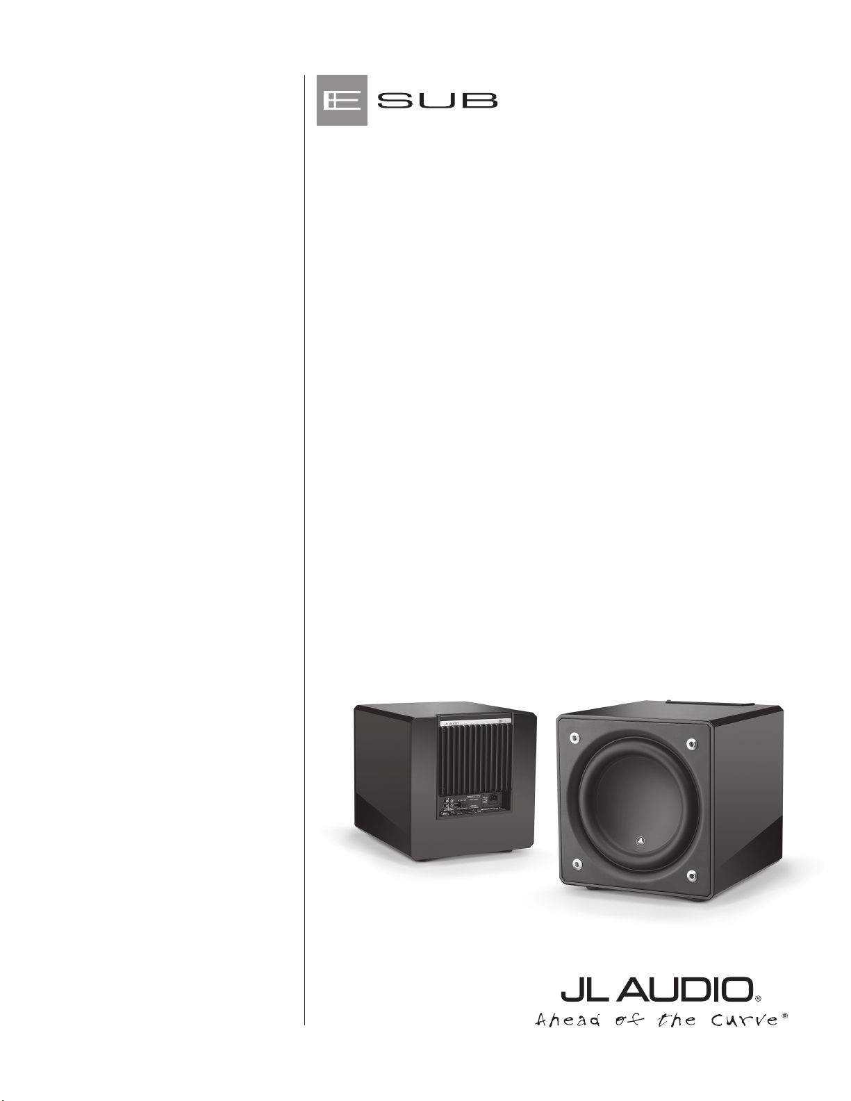
e110
e112
Owner’s Manual

| e110 & e112Page 2
IMPORTANT SAFETY INSTRUCTIONS
1) Read the Instructions — All safety and operating instructions should be
read before the subwoofer is operated.
2) Retain the Instructions — e safety and operating instructions should be
retained for future reference.
3) Heed Warnings — All warnings on the subwoofer and in the operating
instructions should be followed.
4) Follow Instructions — All operating and use instructions should
be followed.
5) Water and Moisture — e subwoofer should NOT be used near water – for
example, near a bathtub, washbowl, sink, laundry tub, in a wet basement,
near a swimming pool, etc.
6) Ventilation — e subwoofer should be situated so that its location or
position does not interfere with its proper ventilation. For example, the
subwoofer should not be situated on a bed, sofa, rug, or similar surface
that may block airow over the heatsink ns. If placing the subwoofer in
a “built-in” installation, ensure that airow to the heat sink at the rear of
the subwoofer is not impeded. Do not cover the subwoofer heatsink with
tablecloths, curtains, etc.
7) Heat and Flames — e subwoofer should be situated away from heat
sources such as radiators, heat registers, stoves, replaces, or other devices
which produce heat. Do not place candles on top of or near the subwoofer.
8) Power sources — e subwoofer should only be connected to a power supply of
the type described in the operating instructions or as marked on the subwoofer.
9) Power Cord Protection — Power-supply cords should be routed so that they
are not likely to be walked on or pinched by items placed upon or against
them, paying particular attention to cords at plugs, convenience receptacles,
and the point where they exit the subwoofer.
e lightning ash with arrowhead
symbol, within an equilateral triangle, is
intended to alert the user to the presence
of uninsulated “dangerous voltage” within
the product’s enclosure that may be of
sucient magnitude to constitute a risk of
electric shock to persons.
WARNING: TO REDUCE THE RISK OF FIRE OR ELECTRIC SHOCK,
DO NOT EXPOSE THIS PRODUCT TO RAIN OR MOISTURE.
CAUTION
RISK OF ELECTRIC SHOCK
DO NOT OPEN
CAUTION: TO REDUCE THE RISK OF ELECTRIC SHOCK, DO NOT REMOVE
AMP PANEL OR SPEAKER. NO USER SERVICEABLE PARTS INSIDE. REFER
SERVICING TO QUALIFIED PERSONNEL.
e exclamation point within an
equilateral triangle is intended to alert the
user to the presence of important operating
and maintenance instructions in the
literature accompanying the product.
Page 3 | e110 & e112
10) Cleaning — e subwoofer should be cleaned only as recommended in the
operating instructions.
11) Nonuse Periods — e power cord of the subwoofer should be unplugged
from the outlet when the subwoofer is le unused for long periods of time.
12) Lightning and Power Surges — We recommend that you disconnect the
subwoofer from the electrical outlet during electrical storms and/or recurring
power interruptions to prevent damage due to power surges.
13) Object or Liquid Entry — Care should be taken so that objects do not fall
into and liquids are not spilled onto the subwoofer enclosure. Do not expose
the subwoofer to dripping or splashing from liquids. Do not place objects
lled with liquids on top of, or near the subwoofer. For example: ower vases,
beverages, liquid-fueled lamps, etc.
14) Damage Requiring Service — e subwoofer should be serviced by qualied
service personnel when:
a. the power-supply cord or plug has been damaged
b. objects have fallen or liquid has been spilled into the subwoofer
c. the subwoofer has been exposed to rain
d. the subwoofer does not appear to operate normally or exhibits a marked
change in performance
e. the subwoofer has been dropped or the cabinet has been damaged
f. the subwoofer driver’s cone and/or suspension has been
physically damaged
15) Servicing — e user should not attempt to service the subwoofer beyond
what is described in the operating instructions. All other servicing should be
referred to qualied service personnel.
16) Overloading — Do not overload wall outlets, extension cords, or outlet strips
as this can result in a risk of re or electric shock.
17) Grounding — is subwoofer is supplied with a three-prong, grounded
power cord. Precautions should be taken so that the grounding means of the
subwoofer are not defeated. Defeating the grounding prong on the subwoofer
power cord could increase the risk of electric shock and could result in
permanent damage to the subwoofer’s electronics.
WARNING
THIS SUBWOOFER IS CAPABLE OF PRODUCING VERY HIGH SOUND
PRESSURE LEVELS. PLEASE EXERCISE RESTRAINT IN ITS OPERATION TO
PROTECT YOUR HEARING FROM PERMANENT DAMAGE.

| e110 & e112Page 4
FCC COMPLIANCE STATEMENT
NOTE: is equipment has been tested and found to comply with the limits of Part 15 of the FCC
Rules. ese limits are designed to provide reasonable protection against harmful interference in
a residential installation. is equipment generates, uses and can radiate radio frequency energy
and, if not installed in accordance with the instructions, may cause harmful interference to radio
communications. However, there is no guarantee that interference will not occur in a particular
installation. If this equipment does cause harmful interference to radio or television reception,
which can be determined by turning the equipment o and on, the user is encouraged to try to
correct the interference by one or more of the following measures:
- Reorient or relocate the receiving antenna.
- Increase the separation between the equipment and receiver.
- Connect the equipment into an outlet on a circuit dierent from that to which the
receiver is connected.
- Consult the dealer or an experienced radio/TV technician for help.
TABLE OF CONTENTS
Important Safety Instructions: ......................................... 2-3
Introduction:. . . . . . . . . . . . . . . . . . . . . . . . . . . . . . . . . . . . . . . . . . . . . . . . . . . . . . . . . . . 4
Product Overview: ...................................................... 5
Placing your E-Sub in Your Listening Room: ............................ 6-10
Unpacking your E-Sub: ................................................. 11
Top-Mounted Control Panel Layout: ..................................... 12
Rear Connection Panel Layout: .......................................... 13
Top-Mounted Controls in Detail: ......................................14-16
Connecting your E-Sub(s): ............................................17-23
Recommended Setup Procedure: ......................................24-26
Frequently Asked Questions: ............................................ 27
Cleaning Your E-Sub: .................................................. 28
Troubleshooting: ...................................................... 29
Limited Warranty / Service Information: ..................................31
Specications: ......................................................... 32
INTRODUCTION
Congratulations on your purchase of a JL Audio E-Sub powered subwoofer
system. is product has been critically engineered to deliver exceptional
performance in your home theater or audio system for many years to come.
As a company, we are intensely committed to core research into
high-performance loudspeaker and amplier technologies. JL Audio’s long-
excursion subwoofer driver designs are widely considered as reference
standards for linear behavior and high output. We have also focused our
eorts to create powerful amplier and signal-processing technologies
specically aimed at delivering exceptional low-frequency performance.
Your E-Sub combines these core disciplines within a compact, beautifully
craed package to deliver an unparalleled listening experience.

Page 5 | e110 & e112
We sincerely thank you for your purchase and invite you to read this
manual thoroughly in order to achieve the highest level of performance with
your E-Sub subwoofer system. Enjoy.
PRODUCT OVERVIEW
JL Audio E-Sub subwoofers combine a state-of-the-art JLAudio
subwoofer driver and electronics/amplier package within a
highly optimized enclosure to deliver an exceptional listening
experience in your home theater or home audio system.
e subwoofer driver in your E-Sub subwoofer system is capable of
outstanding linear excursion without distress or audible distortion. is purpose-
engineered driver enables your E-Sub to reproduce powerful low-frequency
events with stunning impact and outstanding accuracy. e E-Sub drivers oer
peak-to-peak excursion capabilities well in excess of 2.5 inches (64 mm - e110),
and 3 inches (76 mm - e112) to comfortably handle the dynamics of the most
demanding program material.
To get the most from this long excursion driver platform, your E-Sub
incorporates a precisely engineered switching amplier. e E-Sub ampliers are
capable of unclipped output voltages equivalent to 1200 watts (e110), and 1500 watts
(e112) of RMS power when referenced to the nominal loudspeaker impedance,
allowing us to take full advantage of each driver’s full excursion envelope.
e beautiful cabinet enclosing the workings of your E-Sub is also the result
of careful engineering. To contain the pressures created by the E-Sub driver, we
utilize solid, CNC-cut, MDF material with extensive internal bracing features
and advanced assembly techniques.
e E-Subs also include an on-board 2-way active crossover, permitting
them to support a conventional 2-channel audio system by providing a high-
pass ltered output to the main speakers’ amplier, while delivering a low-pass
ltered signal to the internal subwoofer amplier. A polarity switch and phase
control are provided to aid in achieving an optimal acoustic transition between
the subwoofer(s) and main speakers. Inputs are via a pair of line level stereo RCA
inputs or via a removable plug for speaker level inputs.
As you can see from this brief introduction, there is a lot of technology in
this compact subwoofer. e contents of this manual will explain the features,
and guide you through the setup and tuning of your E-Sub to help achieve an
outstanding low-frequency listening experience.
If you require assistance, we urge you to contact your authorized
JL Audio retailer for expert setup advice and service.
IMPORTANT
IMPORTANT! IT IS A VERY GOOD IDEA TO READ THE NEXT SECTION
BEFORE UNPACKING YOUR E-SUB. UNPACKING THE SUBWOOFER NEAR
ITS FINAL LOCATION IS RECOMMENDED.

| e110 & e112Page 6
PLACING YOUR E-SUB IN YOUR LISTENING ROOM:
Your listening room or theater is an integral part of your sound reproduction
system. e physical dimensions of the room and its furnishings, materials,
doors and windows play an important role in dening how your system sounds.
When you place a sound source in an enclosed rectangular space, “standing
waves” are created, resulting from the relationship between the sound’s
wavelength and your room’s dimensions. In other words, standing waves result
from sound energy that is trapped in the room as it bounces back and forth
between opposing walls. Standing waves in the room create acoustic peaks and
dips where the sound is either louder or soer, based solely on your physical
position in the room. Energy also “builds up” at the room’s boundaries, creating
exaggerated bass response at certain frequencies. ese fundamental room
resonances are called room “modes.”
e moral of this mode story is to try and avoid seating positions in standing
wave peak or dip regions. It is highly recommended that you place your listening
chairs in areas where modal peaks and dips are moderate and do not reinforce
one another. e two most obvious areas to avoid are those near the exact center
of the room and those close to any of the room’s walls.
Just as your listening seat can be in a peak or dip region, so can your
subwoofer. When placed in a room corner, a subwoofer maximally excites the
room’s mode structure, creating the strongest output with the fewest dips. When
the subwoofer is pulled away from a corner or wall, the room modes are excited
less, which can alter the sound at your listening seat.
Be sure to experiment with both your listening seat position and subwoofer
position to nd the best solution. Careful experimentation usually leads to a
superior sounding system. Use our setup suggestions (illustrated on the opposing
page and the following pages) to get you started.
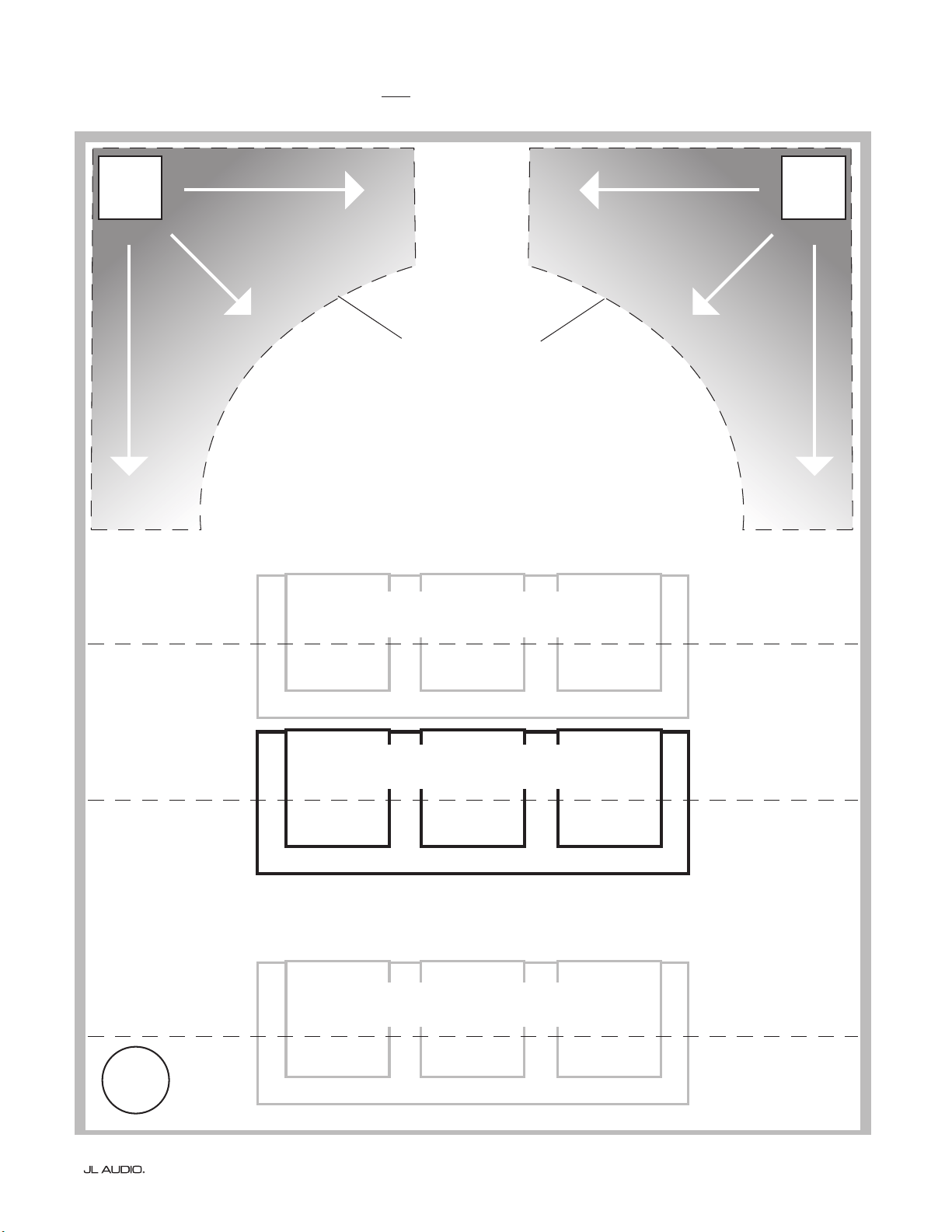
We recommend that you begin by placing your E-Sub in the front of the
room, on the oor, near the front le or right speaker. Placing the E-Sub near
solid walls will reinforce bass response and pulling it away from solid walls will
decrease bass. Increasing the distance between the subwoofer and the walls may
help to smooth upper bass response in some rooms.
We recommend that you avoid placing the E-Sub near windows to prevent
rattling and sound transmission to the outside world.
If you are planning to install your E-Sub
inside a cabinet, please refer to the
guidelines on page 8.
Page 7 | e110 & e112
MORE INTENSE
SMOOTHER
RECOMMENDED
SUBWOOFER
PLACEMENT
ZONES
(For Single Subwoofer)
SMOOTHER
SMOOTHER
MORE INTENSE
SMOOTHER
SMOOTHER
SMOOTHER
COMPROMISED SEATING POSITIONS
(Results in weaker, uneven bass performance)
BEST SEATING POSITIONS
(Most accurate bass performance)
COMPROMISED SEATING POSITIONS
(More intense, but less accurate bass performance)
WORST
SEAT
CENTERLINE OF ROOM
APPROX. 1/3 OF TOTAL ROOM
LENGTH AWAY FROM BACK WALL
CLOSE TO BACK WALL OF ROOM
Recommended Floor Placement Options for One E-Sub
| e110 & e112Page 8
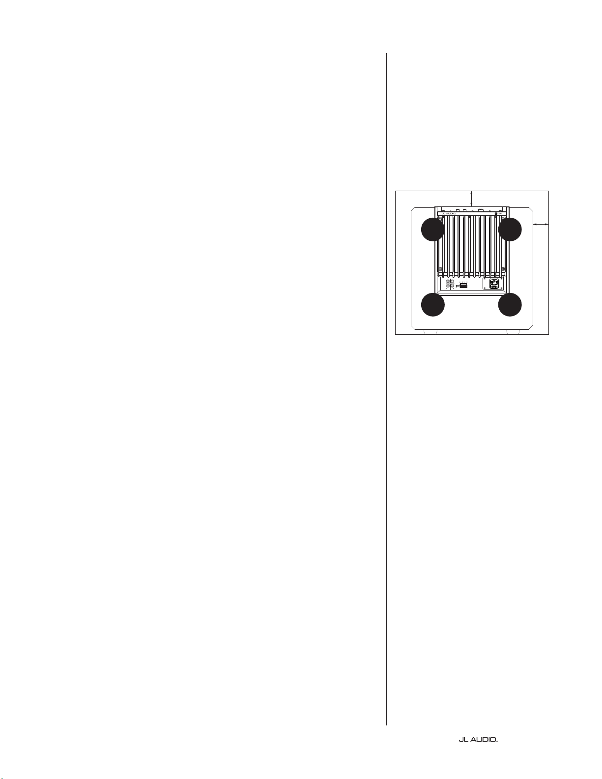
SPECIAL CONSIDERATIONS FOR BUILT-IN INSTALLATIONS
e E-Sub can be integrated into custom cabinetry by following a few
simple guidelines.
1) Allow 4 inches (10 cm) of clear space behind the E-Sub’s amp panel for
adequate cooling and connector clearance.
2) On all other sides (except the bottom), allow at least 2 inches
(5 cm) clearance for adequate ventilation.
3) While the E-Sub generally runs only warm during spirited operation, we do
recommend that adequate heat vents are included in any custom cabinet which
encloses the E-Sub. A pair of 3 inch (7.5 cm) diameter vents near the bottom of
the cabinet and near the top of the cabinet, will allow cool air to circulate over the
amp panel of your E-Sub subwoofer system keeping it cool and happy.
4) Your E-Sub subwoofer is capable of moving substantial quantities of
air. If the front of the E-Sub is covered by a custom grille, the grille
must have AT LEAST 85 square inches (548 sq.cm.) of vent area for
the e112, and AT LEAST 60 square inches (386 sq.cm.) for the e110.
ese areas are equal to the woofer cone area for each model and will
ensure that the E-Sub’s output is not choked by the custom cabinet.
CH. 2
(
R
)
Grounded
Isolated
CH. 1
(
L
)
HIGH LEVEL INPUTS
SERIAL NUMBER:
Warranty void if serial number is
removed, altered or defaced.
LINE
OUTPUTS
LL
RR
LINE
INPUTS
Built in USA
with domestic and
imported components
VENT VENT
2 in. min.
2 in.
min.
Rear-view of cabinet install:
VENT VENT
Page 9 | e110 & e112
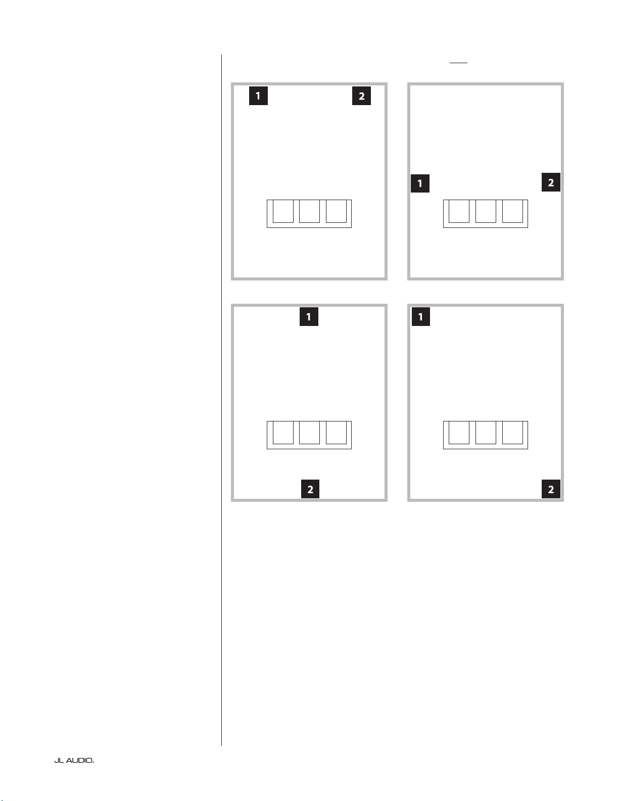
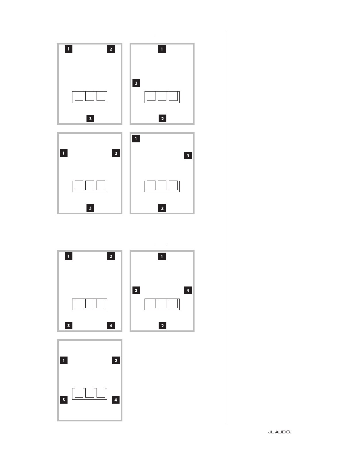
Recommended Subwoofer Placement Options for Two E-Subs
Using Two E-Subs
When using two E-Subs, try
placement near the front corners of the
room, at diagonally-opposite corners
of the room, or at the center points of
opposing walls as shown at right.
Experimentation with
subwoofer and listener
placement is recommended to
achieve the best results – the
benets can be substantial.
High-resolution measurements
and professional system calibration
are recommended for the best possible
results & system performance.
| e110 & e112Page 10
Recommended Subwoofer Placement Options for Three E-Subs
Recommended Subwoofer Placement Options for Four E-Subs
Using Three or Four E-Subs
Research indicates that the
smoothest bass response for a large
listening area can be achieved using
four subwoofers, placing one at
the midpoint of each of the four
walls (although using two or three
subwoofers can be almost as good).
Experimentation with
subwoofer and listener
placement is recommended to
achieve the best results – the
benets can be substantial.
High-resolution measurements
and professional system calibration
are recommended for the best possible
results & system performance.
Page 11 | e110 & e112
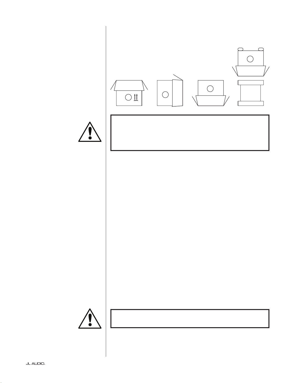
Detailed instructions on unpacking the subwoofer:
1. Place the carton on the oor near its intended location in the room.
2. Open the top of the carton (observe markings on carton) and remove the manual
and power cord.
3. e subwoofer is packed upside-down. Li the styrofoam cap o the bottom of
the subwoofer.
4. Loosen the protective cloth cover to make later removal easier (do not remove at
this time). When you open the cloth cover, you are looking at the bottom of the
subwoofer cabinet.
5. Replace the styrofoam cap you removed in Step 3 to protect the subwoofer’s
cabinet while ipping and unpacking the subwoofer in the following steps.
6. Gently ip the box on its side, folding back the carton aps to the outside.
7. Holding the carton aps back, gently ip the carton onto its top (open end).
8. Pull the carton straight up until it clears the subwoofer and place to one side.
9. Remove the top-most styrofoam cap and place this cap in the carton.
10. Remove the plastic bag and place in the carton.
11. Li the subwoofer o the remaining styrofoam cap and place this cap in the
carton.
12. Remove the protective cloth cover and place in the carton.
Unpack this box close to where the
subwoofer will be placed. e subwoofer
is PACKED upside down. is box must be
ipped over CAREFULLY to remove the
subwoofer and minimize eort.
UNPACKING YOUR E-SUB
Now that you have determined your E-Sub’s position on the oor of your room,
you can proceed with unpacking it near its intended location.
C
D
A
B
IMPORTANT
IMPORTANT: DUE TO THE WEIGHT OF THE E-Sub SUBWOOFER, PLEASE
EXERCISE CAUTION WHILE UNPACKING AND POSITIONING IT TO PREVENT
INJURY. IF POSSIBLE, ENLIST THE HELP OF A SECOND PERSON TO
FACILITATE THE PROCESS. TO MINIMIZE THE RISK OF INJURY, BEND YOUR
KNEES AND LIFT WITH YOUR LEGS, NOT YOUR BACK.
IMPORTANT
IMPORTANT! PLEASE RETAIN ALL PACKAGING FOR SAFE TRANSPORTATION
OF THE SUBWOOFER AND FOR ANY FUTURE SERVICE NEEDS.
Page 12
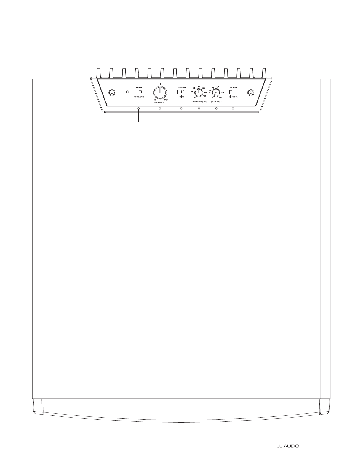
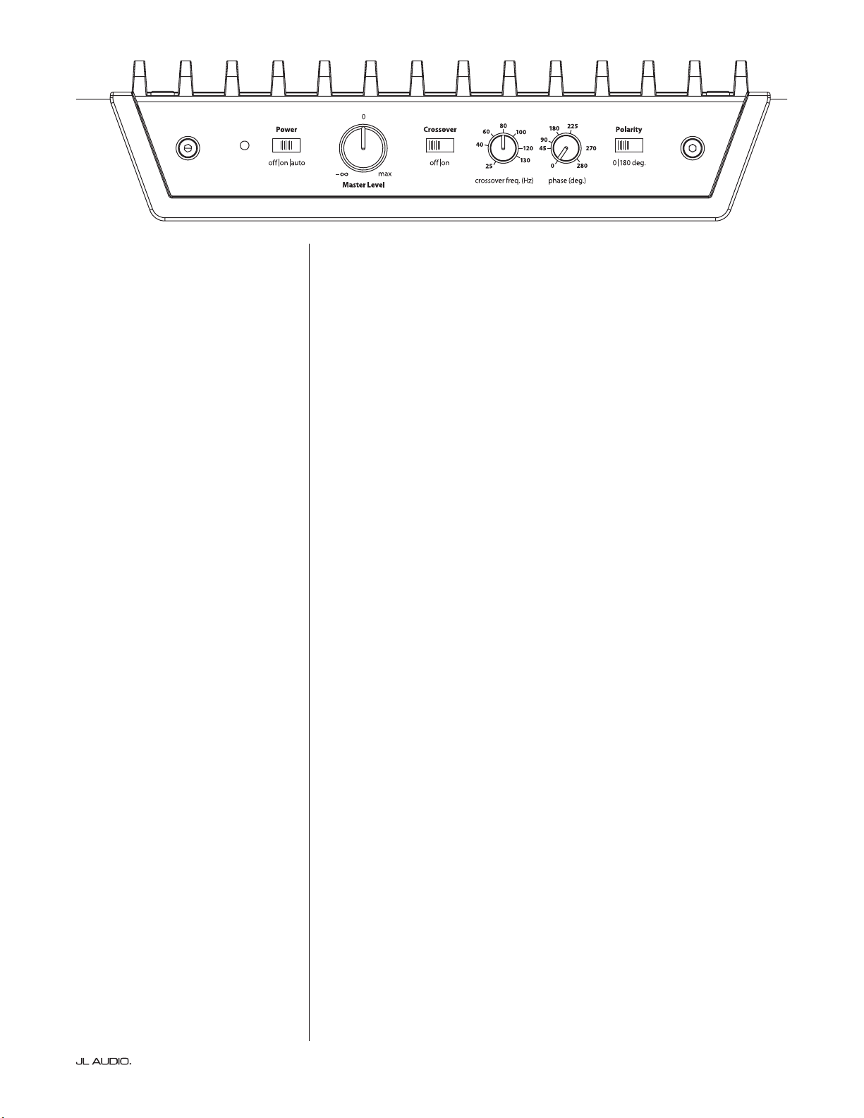
Top-Mounted Control Panel
e labeled Figure below depicts the top-mounted control panel of the E-Sub subwoofer.
e E110 and E112 have identical layouts.
Power
page 14
Master Level
page 14
Crossover Switch
page 15
Crossover
freq. (Hz)
page 15
phase (deg.)
page 16
Polarity
page 15
CH. 2
(
R
)
Grounded
Isolated
CH. 1
(
L
)
HIGH LEVEL INPUTS
SERIAL NUMBER:
Warranty void if serial number is
removed, altered or defaced.
LINE
OUTPUTS
LL
RR
LINE
INPUTS
Built in USA
with domestic and
imported components
Page 13 | e110 & e112
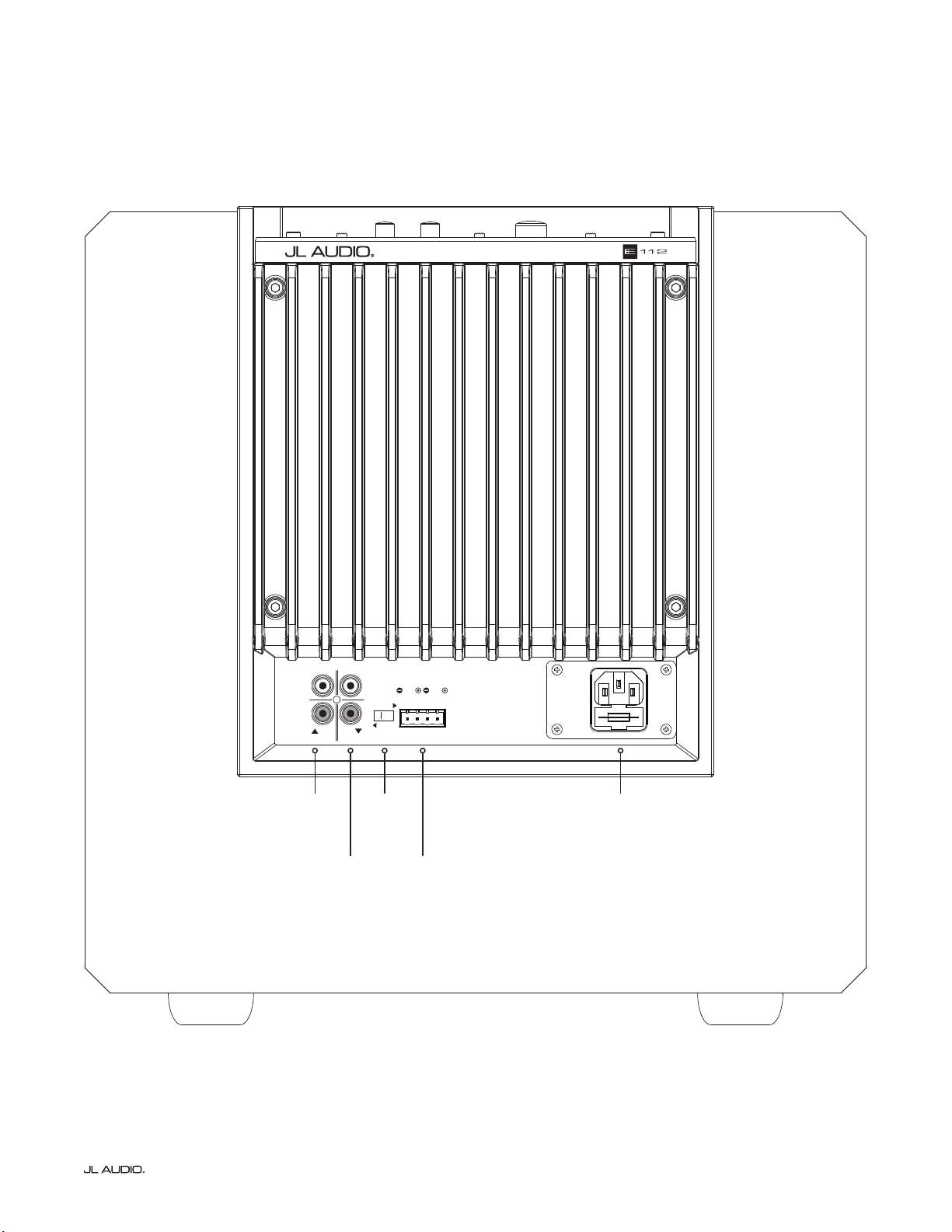
Rear Connection Panel (120V Model Shown)
e labeled Figure below depicts the rear panel of the E-Sub subwoofer.
e e110 and e112 have identical layouts.
Line
Inputs
page 17
Grounded/
Isolated
Switch
page 17
IEC-Style AC
Connector
page 18
Line
Outputs
page 18
High Level
Inputs
page 17
| e110 & e112Page 14
TOP-MOUNTED CONTROLS IN DETAIL
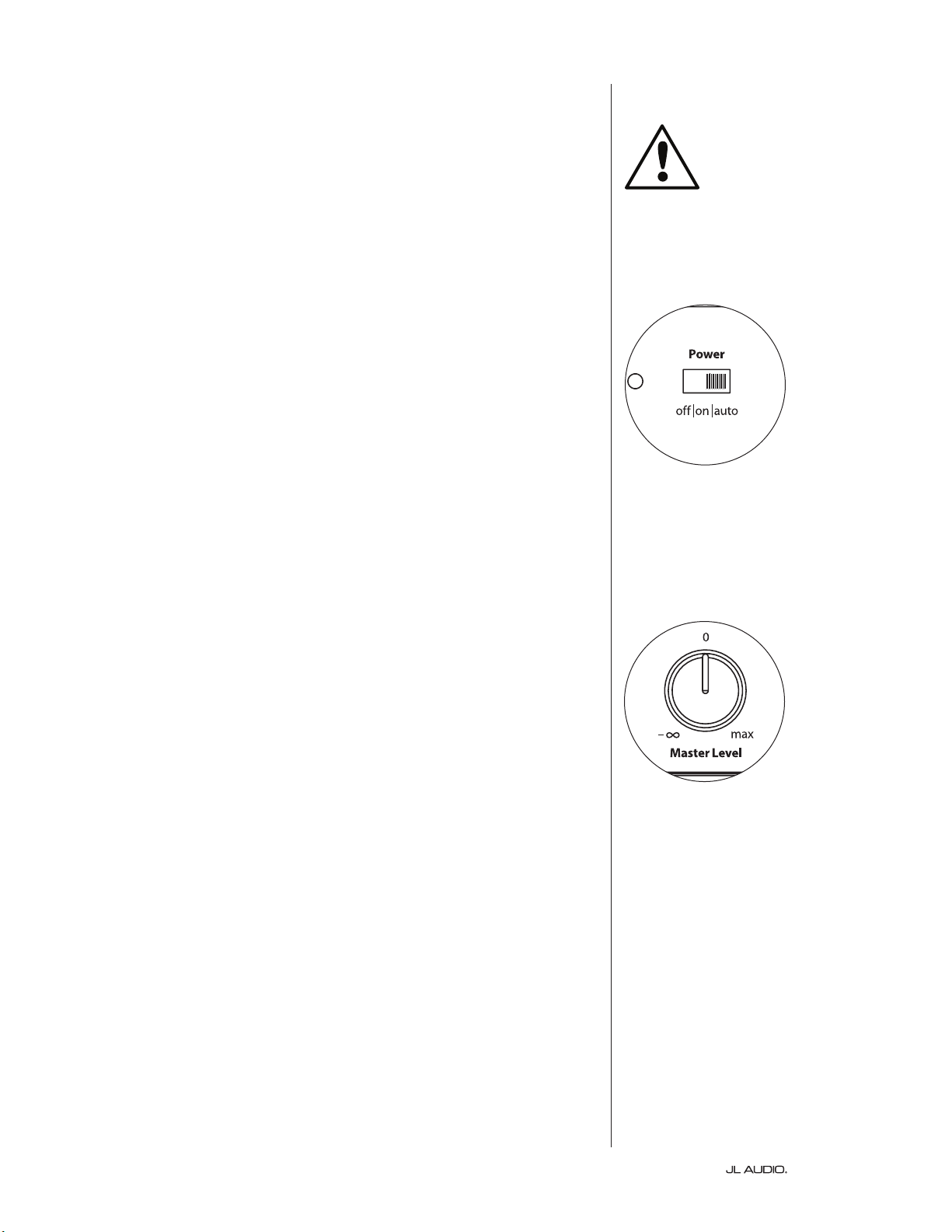
Top-Panel Power Switch and Indicator LED
e “Power” switch on the top panel determines the operational readiness of the
E-Sub subwoofer and should be the only switch used to turn the E-Sub on and o
during typical use.
e top-panel “Power” switch has three positions:
“O ”: e E-Sub’s internal power amplier is powered down.
Indicator LED: red
In this stand-by state, a tiny amount of power is consumed (< 0.5 watt) to
energize the E-Sub’s so turn-on circuitry.
“On”: e E-Sub is fully operational.
Indicator LED: green
Power consumption will vary, depending on program material and level
“Auto”: e E-Sub will power up its internal amplier when it detects an audio
signal at any of its inputs, and will power down the internal amplier if no
signal has been detected at its inputs for approximately thirty (30) minutes.
While dormant, the E-Sub consumes a tiny amount of power (< 0.5 watt).
Indicator LED: amber (dormant) / green (operational)
In the unlikely event that the Auto Turn-On feature is not sensitive
enough for a particular system, use a Y-cable adaptor (one female to
two male RCA type connectors) to split the incoming signal into both
RCA inputs on the E-Sub. is will increase the input sensitivity by
6 dB. Please be aware that if there is signicant noise entering the
E-Sub’s input, the E-Sub may not turn o as desired. If this happens,
remove the Y-cable adaptor and/or look for the noise source in the
upstream components.
e only way to completely power down an E-Sub is to unplug its AC Power
Cord. Before disconnecting the power cord, always place the top-panel “Power” switch
in the “o” position (to prevent damaging pops and transient noises).
Do not use a power strip switch, switched outlet or any other external switch to
interrupt or engage power to an E-Sub in “auto” or “on” positions, as this will also result
in undesirable and potentially damaging transient pops.
Master Level Knob
e “Master Level” Knob is used to set the output level of the E-Sub, relative
to the rest of the audio system.
When rotated fully counter clockwise, the E-Sub’s output will be fully muted.
When at the “0” or straight up position, the level is at reference gain. When
turned fully clockwise, the E-Sub’s level is at its maximum sensitivity (loudest).
IMPORTANT
Page 15 | e110 & e112
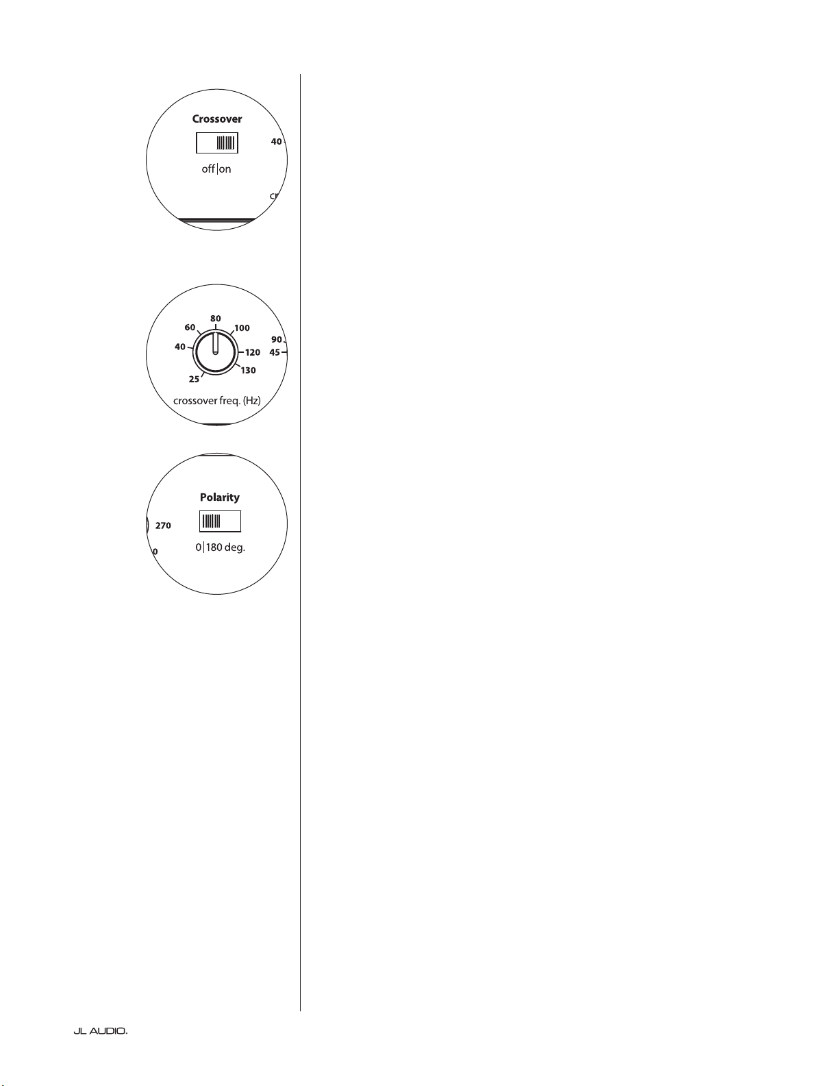
Crossover Switch
e “crossover” selector switch determines the operating mode of the E-Sub’s
built-in active crossover.
“O” defeats the crossover lter, completely removing this circuit from the
signal path and is most useful when using a receiver or preamp/processor’s lters
and bass-management features.
“On” activates the on-board active crossover. is crossover consists of a 24
dB/octave low-pass lter for signals feeding the E-Sub’s internal amplier, plus
a 24 dB/octave high-pass lter feeding the “Line-Outputs” on the E-Sub’s rear
connection panel. is is most useful when integrating the E-Sub into a two-
channel audio system.
Crossover Frequency Knob
e “crossover freq. (Hz)” selector knob allows the user to choose the
crossover frequency of the E-Sub’s built-in, active crossover. It has no eect when
the “crossover” switch is in the “o” position. e frequency is variable from 25
Hz (full counter-clockwise) to 130 Hz (full clockwise). 80 Hz is a commonly used
lter frequency and usually serves as a good starting point for adjustments.
Polarity Switch
e “Polarity” switch allows the user to select between normal (0 deg) and
reversed (180 deg) signal polarity. e “Polarity” switch will primarily aect the
small frequency range around the crossover point between your subwoofer and
satellite speakers.
Unlike the “phase (deg.)” control, which eectively adds time delay, the
“Polarity” switch produces an instantaneous reversal of the signal’s amplitude
peaks. For example, if at a given reference point a sine wave has an amplitude
peak, by ipping the “phase (deg.)” switch you instantly convert that peak
into a trough or amplitude dip. Because the eect of the “Polarity” switch
is immediate, it compliments the operation of the “phase (deg.)” control and
cannot be replaced by it.
When placing your E-Sub in the room, experiment with the “Polarity “switch
before adjusting the “phase (deg.)” control. Either position of the “Polarity” switch
may provide a smoother transition between your E-Sub and the satellite speakers.
Use source material with good mid and upper bass content for evaluation.

| e110 & e112Page 16
Phase Knob
e “phase (deg.)” control knob allows the user to adjust the timing of the
subwoofer output relative to the main speakers. e “phase (deg.)” control will
primarily aect the small frequency range around the crossover point between
your subwoofer and satellite speakers. e “phase (deg.)” control’s degree labeling
is referenced to 80 Hz, since this is the most common crossover point between
satellite speakers and a subwoofer. Phase settings between 0 degrees (full counter-
clockwise rotation) and 280 degrees (full clockwise rotation) are possible.
Speaker, subwoofer, and listening seat positions vary greatly in home theater
installations. Since physical positioning of speakers relative to the room
boundaries and each other greatly aects the perceived quality of sound output,
sometimes it is helpful to delay the subwoofer output. is is exactly what occurs
when you turn the “phase (deg.)” control beyond 0 degrees.
Once your E-Sub has been placed in your listening room to give you the
smoothest overall sound, and aer you have determined the optimum “Polarity”
switch position (see preceding section), experiment with the position of the
“phase (deg.)” control. Using familiar source material with good mid and upper
bass content, adjust the “phase (deg.)” control and listen for better dened mid-
bass and a smoother transition between the subwoofer and satellite speaker
systems. If no single setting sounds better than another, leave the “phase (deg.)”
control at 0 degrees.
Page 17 | e110 & e112
CH. 2
(
R
)
Grounded
Isolated
CH. 1
(
L
)
HIGH LEVEL INPUTS
SERIAL NUMBER:
Warranty void if serial number is
removed, altered or defaced.
LINE
OUTPUTS
LL
RR
LINE
INPUTS
Built in USA
with domestic and
imported components
CH. 2
(
R
)
Grounded
Isolated
CH. 1
(
L
)
HIGH LEVEL INPUTS
SERIAL NUMBER:
Warranty void if serial number is
removed, altered or defaced.
LINE
OUTPUTS
LL
RR
LINE
INPUTS
Built in USA
with domestic and
imported components
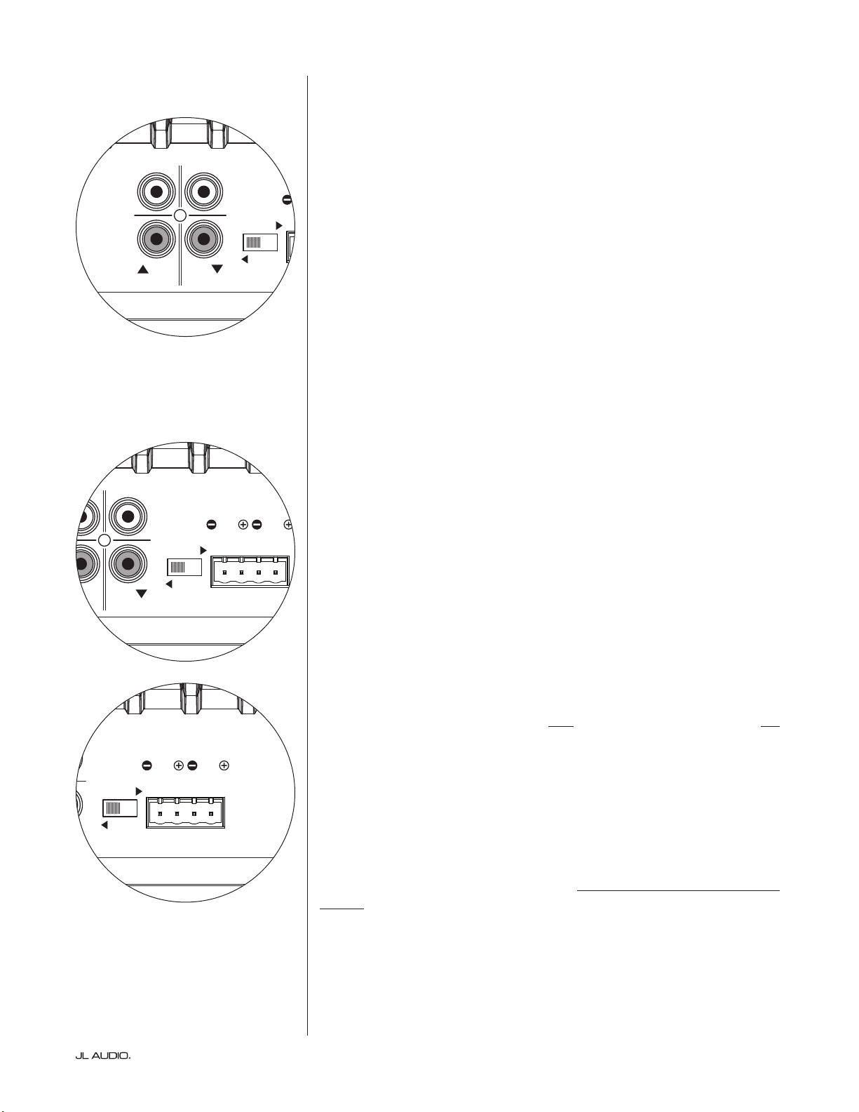
CONNECTING YOUR E-SUB(S)
Line Inputs
e E-Sub features individual, le and right, unbalanced RCA-type
input connectors. ese are the most commonly used connectors for home
audio applications.
For systems with a mono subwoofer or “LFE” channel connection, only one
RCA-type jack will be used (Le or Right). is method applies to most modern
multi-channel receivers and preamplier / processors.
Separate le and right RCA-type input jacks are provided for systems without
a dedicated mono subwoofer connection. is typically applies to two-channel
audio equipment. In a two-channel application, you must supply separate le and
right inputs to a single E-Sub in order to have high-pass ltered, stereo outputs
from its Line Outputs. e E-Sub will automatically sum the le and right inputs
to feed its internal subwoofer amplier.
RCA-type connectors (one for each channel):
Tip: Positive
Sleeve: Negative
Input Impedance: 10 kΩ
“Grounded / Isolated” Switch
is feature is included to deal with the signal grounding issues oen
encountered in home theater systems when several components from dierent
manufacturers are interconnected. e “Grounded / Isolated” Input Mode switch
on the rear connection panel alters only the “Line Inputs” and is designed to
facilitate a quiet, hum-free connection to your audio or home theater system. is
switch has no eect on signals connected to the “High-Level Inputs”.
e E-Sub ships with this switch in the “Isolated” position. If, with all system
components connected and turned on (but no source material playing), you
hear a continuous low-frequency hum through your E-Sub, ip this switch to the
“Grounded” position and evaluate the dierence in the noise level. Use whichever
switch position provides the least hum or noise.
High Level Inputs
is feature is included for convenience when needing to connect the E-Sub
to a receiver or integrated amplier that only oers speaker level outputs. It is not
the preferred method when a line-level signal is available.
To use the “High Level Inputs” feature, simply connect the speaker outputs of
the receiver or integrated amplier to the “High Level Input” plug of the E-Sub, in
parallel with the main speakers. e main speakers will remain full-range in this
application and their sound will not be aected by the connection to the E-Sub.
e “High Level Input” consists of an input connector and removable plug
with captured-wire receptacles. Standard speaker cable, up to 12 AWG (3 mm
2
),
can be used and connected to the removable plug by backing out each set screw,
inserting the bared end of each speaker wire, taking care not to short any wire to
another, and tightening the set screw. Connections are as follows:
“High Level Input” Connector (from le to right):
1: Right Channel Negative
2: Right Channel Positive
3: Le Channel Negative
4: Le Channel Positive
Input Impedance: 4.3 kΩ
e Le and Right inputs on the E-Sub are
internally summed to a single mono channel.
CH. 2
(
R
)
Grounded
Isolated
CH. 1
(
L
)
HIGH LEVEL INPUTS
SERIAL NUMBER:
Warranty void if serial number is
removed, altered or defaced.
LINE
OUTPUTS
LL
RR
LINE
INPUTS
Built in USA
with domestic and
imported components
| e110 & e112Page 18
Line Outputs
e E-Sub features individual, le and right, unbalanced RCA-type output
connectors to feed a second subwoofer or an amplier powering main stereo
speakers. e “Line Outputs” can be used in two distinct ways, depending on
your system’s conguration.
Crossover On: High-Pass Filtered Outputs
When the E-Sub’s on-board crossover is engaged (“Crossover” switch in
the “on” position - page 15), the “Line Outputs” will deliver a high-pass ltered
signal according to the frequency selected by the “crossover freq. (Hz)” knob.
is creates a true, two-way, 24 dB/octave, Linkwitz-Riley crossover between the
E-Sub and the main stereo speakers.
Please note that you must supply separate le and right channel stereo inputs
to the E-Sub in order to have high-pass ltered, stereo outputs from its “Line
Outputs”. If you supply only one channel of input to the E-Sub, only the line
output corresponding to the input with signal will deliver a high-pass ltered
signal (the other line output will have no signal). If you are using two E-Subs in
a two-channel system, you can assign one E-Sub to the le stereo channel and
the other E-Sub to the right stereo channel, using only one “Line Input” and one
“Line Output” per E-sub.
Crossover O: Pass-rough Subwoofer Output
When the E-Sub’s on-board crossover is defeated (“Crossover” switch in the
“o” position - page 15), the “Line Outputs” will deliver a pass-through, buered
signal that is identical to the signal feeding the E-Sub’s “Line Inputs”. is is very
useful for passing a subwoofer signal from one E-Sub to another E-Sub in a multi-
subwoofer installation.
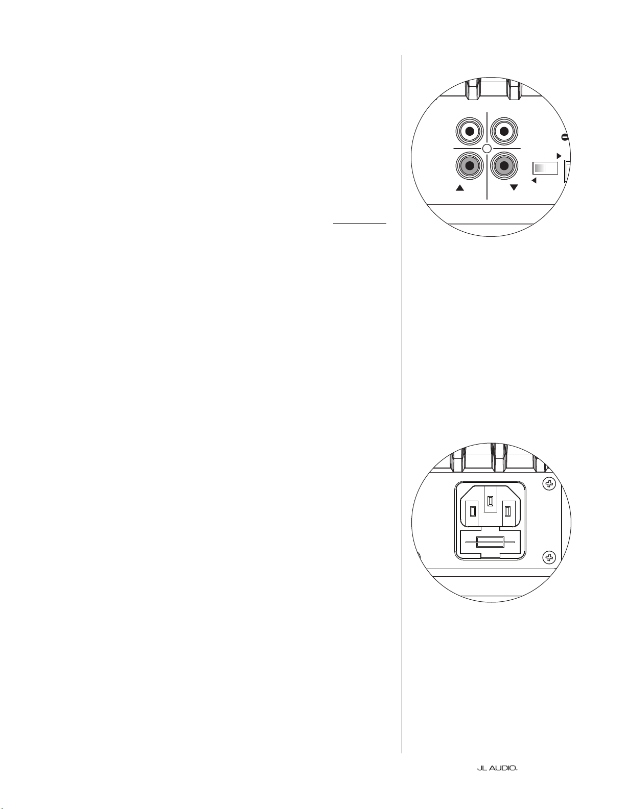
AC Power Connector
e IEC-style AC cord receptacle receives the heavy-gauge, 6 . (1.8 m) long,
power cord included with your E-Sub subwoofer. E-Subs sold in dierent parts
of the world are congured for each market’s electrical system and include
approprate plugs on their power cords. Please note the voltage markings next
to the AC Connector and make sure you are only powering the E-Sub from a
receptacle that matches these markings. Do not use any AC power cord other
than the one supplied with the E-Sub.
e E-Sub subwoofer is a very powerful device and can draw a lot of current.
If too many components are connected with an E-Sub subwoofer to one electrical
outlet, you risk tripping a household circuit breaker during very demanding
program material. If this happens, split the E-Sub and other components between
two AC electrical circuits.
CH. 2
(
R
)
Grounded
Isolated
CH. 1
(
L
)
HIGH LEVEL INPUTS
SERIAL NUMBER:
Warranty void if serial number is
removed, altered or defaced.
LINE
OUTPUTS
LL
RR
LINE
INPUTS
Built in USA
with domestic and
imported components
CH. 2
(
R
)
Grounded
Isolated
CH. 1
(
L
)
HIGH LEVEL INPUTS
SERIAL NUMBER:
Warranty void if serial number is
removed, altered or defaced.
LINE
OUTPUTS
LL
RR
LINE
INPUTS
Built in USA
with domestic and
imported components
Page 19 | e110 & e112
WARNING
WARNING! TURN OFF THE E-SUB(S) AND ALL OTHER EQUIPMENT IN THE
SYSTEM BEFORE MAKING OR CHANGING ANY CONNECTIONS!
CH. 2
(
R
)
Grounded
Isolated
CH. 1
(
L
)
HIGH LEVEL INPUTS
LINE
OUTPUTS
LL
RR
LINE
INPUTS
SUB
REAR
REAR CENTER
FRONT
FRONT
R
L
PRE OUT
E-SUB REAR PANEL
RECEIVER / PROCESSOR
E-SUB TOP CONTROL PANEL
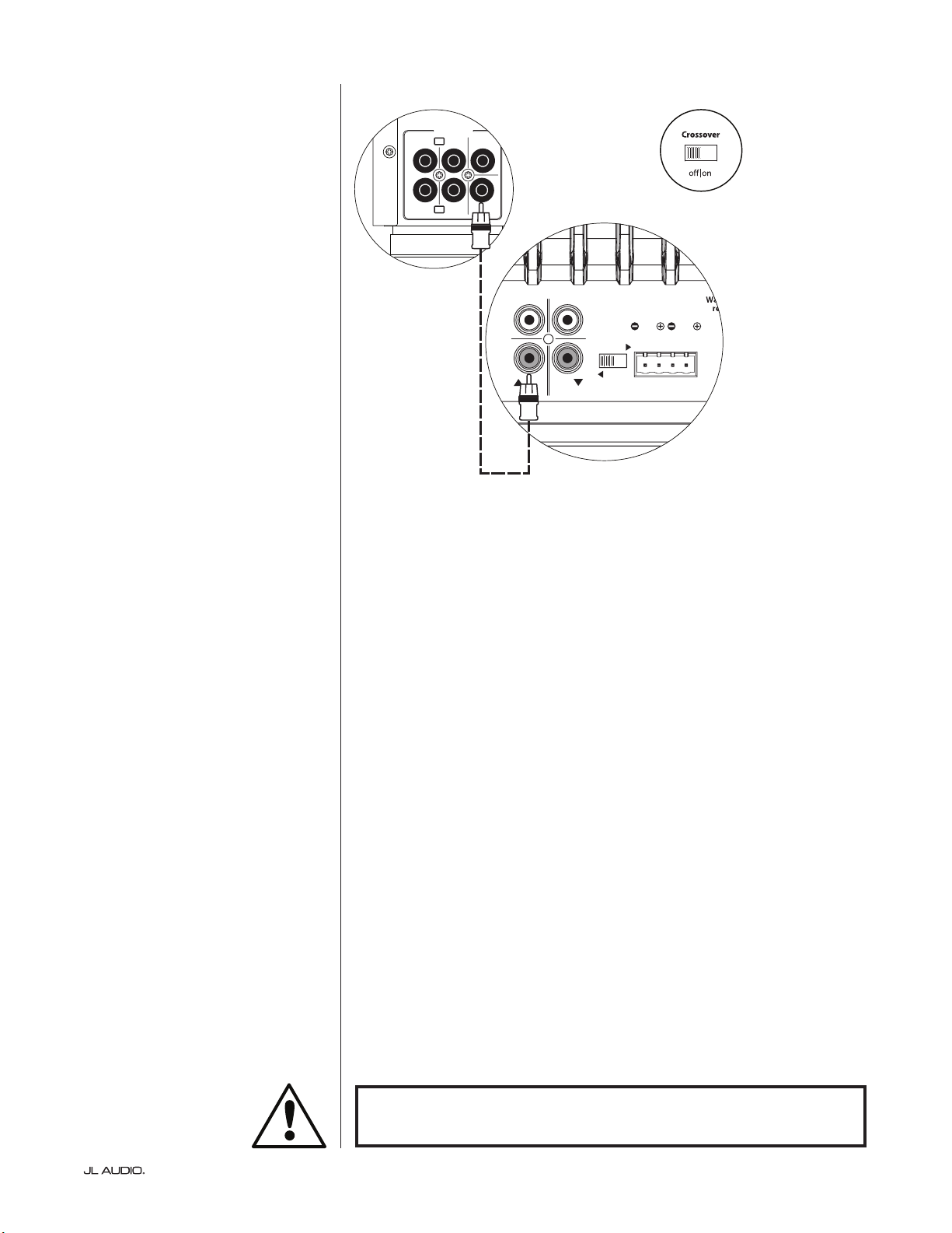
SYSTEM CONNECTION DIAGRAM 1:
One E-Sub to Home Theater Receiver
or Home Theater Preamp/Processor
Most home theater receivers and
preamp/processors provide a single
(mono) subwoofer line-level output.
When connecting a mono
subwoofer output to your E-Sub, you
only need to connect to one of the
E-Sub’s “Line Inputs” (Le or Right). Use
a good-quality audio interconnect cable
with RCA-type connectors.
In most cases, you will use the bass
management/crossover features of the
receiver or preamp/processor. is
requires that the E-Sub’s “Crossover”
switch is placed in the “O” position.
| e110 & e112Page 20
IMPORTANT
WARNING! TURN OFF THE E-SUB(S) AND ALL OTHER EQUIPMENT IN THE
SYSTEM BEFORE MAKING OR CHANGING ANY CONNECTIONS!
WARNING
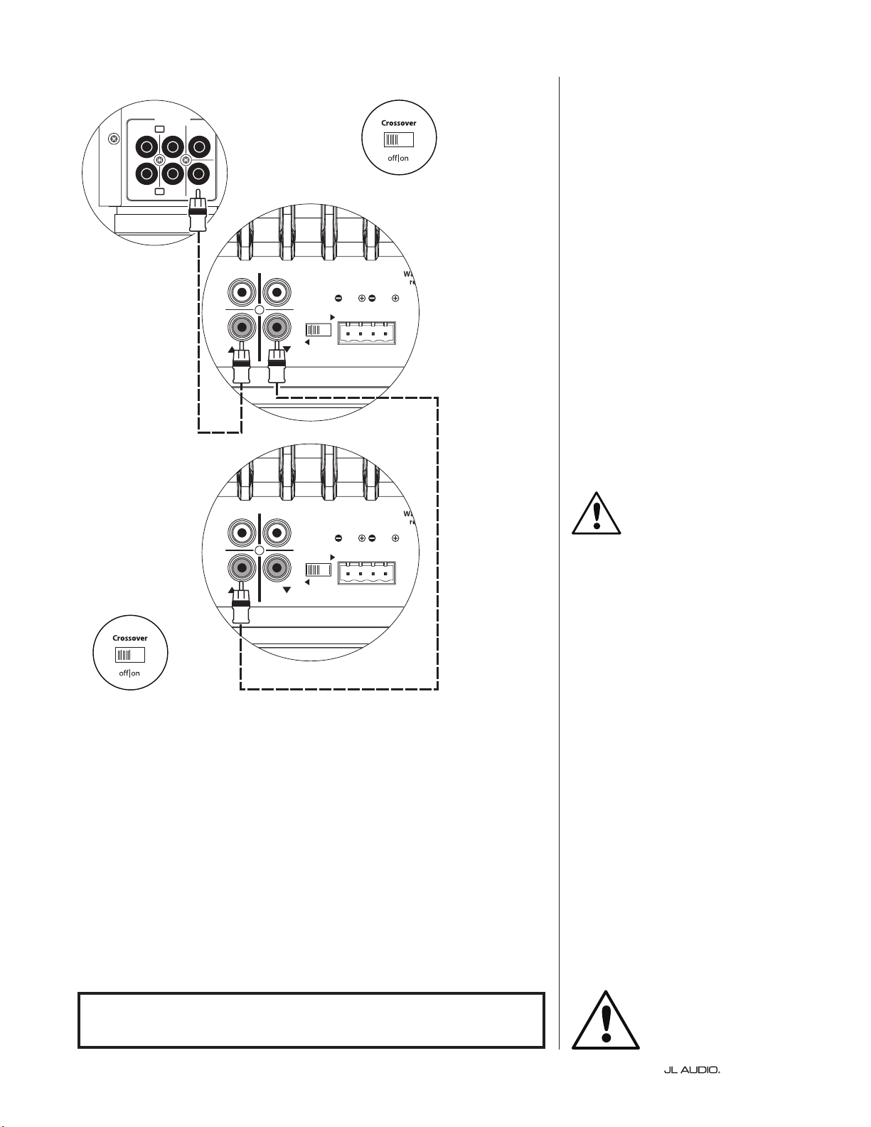
SYSTEM CONNECTION DIAGRAM 2:
Multiple E-Subs to Home Theater
Receiver or Home Theater Preamp/
Processor
Most home theater receivers and
preamp/processors provide a single
(mono) subwoofer line-level output.
To greatly simplify the connection
of multiple subwoofers in a single home
theater system, E-Subs include a pass-
through line output feature. is allows
an input signal connected to one E-Sub to
be passed from that E-Sub to a second one,
and from the second E-Sub to a third, etc.
When connecting a mono subwoofer
output to multiple E-Subs, you only need
to connect to one of each E-Sub’s “Line
Inputs” (Le or Right). Run an audio
interconnect cable from the receiver/pre-
pro’s subwoofer output to one “Line Input”
of the rst E-Sub in the system. en run
a second audio cable from that E-Sub’s
corresponding “Line Output” to one “Line
Input” of the next E-Sub in the system, as
shown in the diagram. Additional E-Subs
can be added using the same method.
You must turn the E-Sub’s “Crossover”
o to use the pass-through signal feature,
allowing the receiver/pre-pro to perform
crossover/bass-management functions.
Make sure the “Crossover” switch on the
top control panel of the E-Sub is in the “o”
position to use this connection method.
Alternative Method:
If running cables from one E-Sub
to the next is not practical due to the
physical layout of the E-Subs relative
to the receiver/pre-pro, you can use a
Y-Adaptor cable (splitter) to split the
receiver/pre-pro output signal to multiple
audio interconnect cables, each feeding a
separate E-Sub.
Some receivers and preamp/processors
oer multiple subwoofer outputs, which
can also be used to connect multiple
E-Subs. Refer to the manual of your
receiver/pre-pro for details.
CH. 2
(
R
)
Grounded
Isolated
CH. 1
(
L
)
HIGH LEVEL INPUTS
LINE
OUTPUTS
LL
RR
LINE
INPUTS
SUB
REAR
REAR CENTER
FRONT
FRONT
R
L
PRE OUT
RECEIVER / PROCESSOR
CH. 2
(
R
)
Grounded
Isolated
CH. 1
(
L
)
HIGH LEVEL INPUTS
LINE
OUTPUTS
LL
RR
LINE
INPUTS
E-SUB REAR PANEL (#1)
E-SUB REAR PANEL (#2)
E-SUB
TOP CONTROL PANEL (#2)
E-SUB TOP CONTROL PANEL (#1)

Page 21 | e110 & e112
WARNING
WARNING! TURN OFF THE E-SUB(S) AND ALL OTHER EQUIPMENT IN THE
SYSTEM BEFORE MAKING OR CHANGING ANY CONNECTIONS!
CH. 2
(
R
)
Grounded
Isolated
CH. 1
(
L
)
HIGH LEVEL INPUTS
LINE
OUTPUTS
LL
RR
LINE
INPUTS
R
R
L
L
INPUTS
SATELLITE AMPLIFIER
TO SATELLITE
SPEAKERS
(L) (R)
E-SUB REAR PANEL
+
–
+
–
SPEAKER OUTPUTS
PRE-AMPLIFIER
R L
OUTPUTS
E-SUB TOP CONTROL PANEL
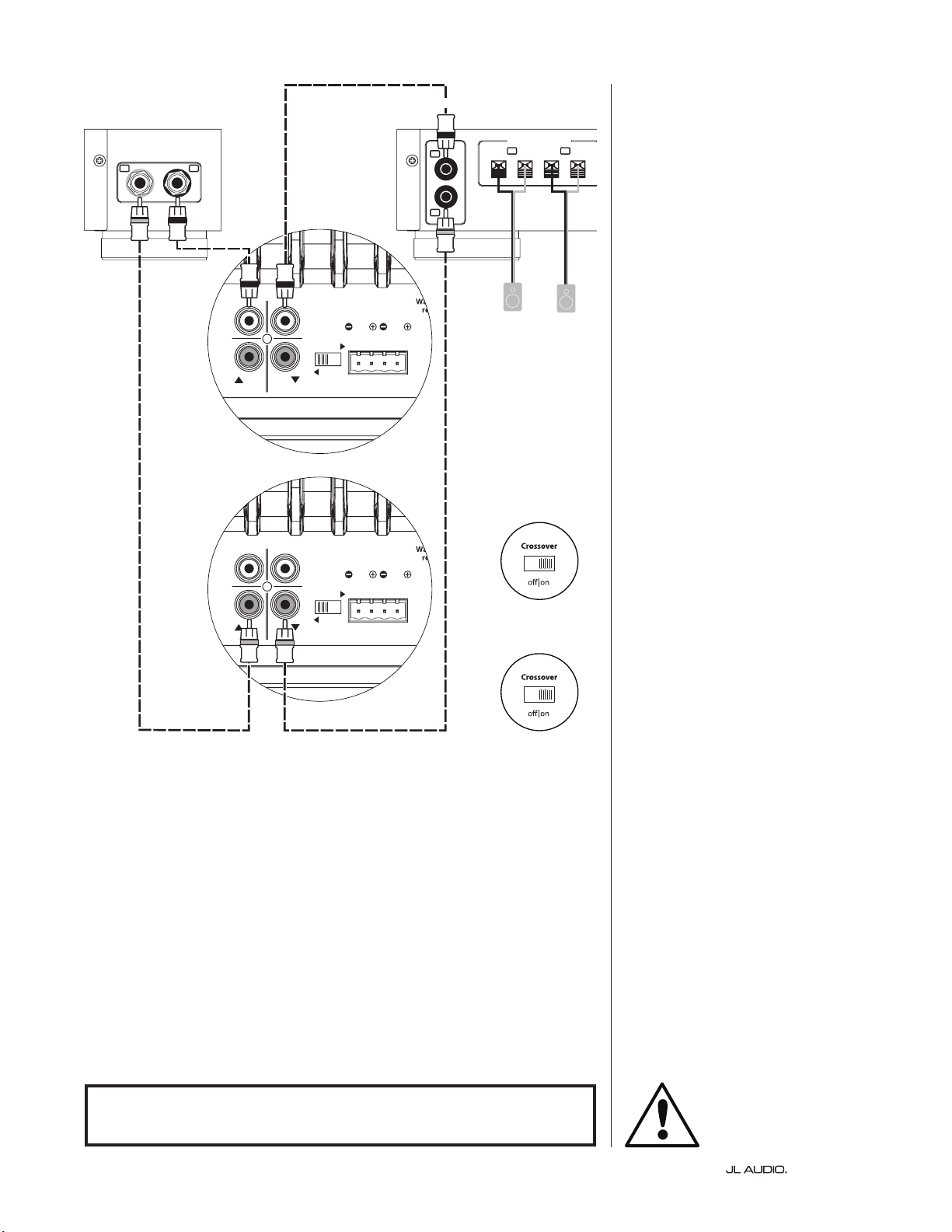
SYSTEM CONNECTION DIAGRAM 3:
One E-Sub in Mono to
Two-Channel Audio System
When connecting a single E-Sub in
mono to a two-channel audio system you
will use both the “Le” and the “Right”
“Line Inputs” of the E-Sub and you will
engage the E-Sub’s active crossover
by selecting the “on” position on the
“Crossover” switch located on the top
control panel.
e internal active crossover will apply
low-pass ltering to feed the subwoofer’s
internal amplier with a summed L+R
signal. It will also high-pass lter the input
signal and send it to the satellite amplier
via the “Line Outputs” jacks. is creates
a true two-way crossover that greatly
improves the overall performance of your
audio system by preventing the subwoofer
and satellite speakers from playing the
same frequency range, and by liberating
the satellite amplier and speakers from
the burden of reproducing power hungry,
distortion-inducing low-frequencies.
Use good-quality audio interconnect
cables with RCA-type connectors to make
these connections.
| e110 & e112Page 22
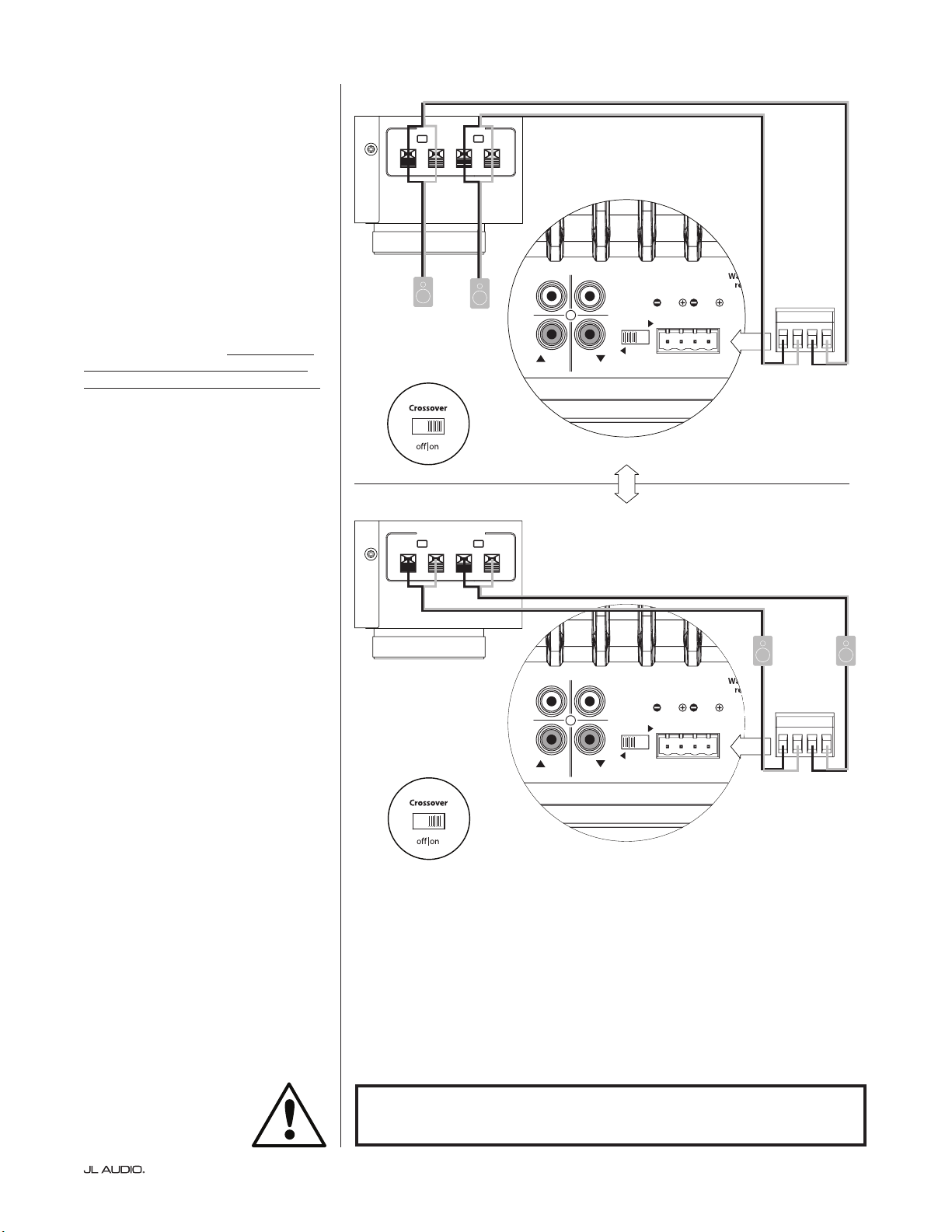
SYSTEM CONNECTION DIAGRAM 4:
Two E-Subs in Stereo to
Two-Channel Audio System
When connecting two E-Subs in
stereo to a two-channel audio system you
will assign one E-Sub to the le channel
and the other one to the right channel.
You will engage each E-Sub’s active
crossover by selecting the “on” position on
the “Crossover” switch located on the top
control panel.
e internal active crossover will
apply low-pass ltering to feed the
subwoofer’s internal amplier. It will also
high-pass lter the input signal and send
it to the satellite amplier via the “Line
Outputs” jack corresponding to the input
channel used. is creates a true two-
way crossover that greatly improves the
overall performance of your audio system
by preventing the subwoofer and satellite
speakers from playing the same frequency
range, and by liberating the satellite
amplier and speakers from the burden
of reproducing power hungry, distortion-
inducing low-frequencies.
You will only use one “Line Input” on
each E-Sub (le or right). First, connect
the le output of your preamplier to the
“Line Input” of the E-Sub designated as
the le subwoofer, and then connect that
E-Sub’s “Line Output” to the le input of
your satellite amplier.
en, connect the right output of your
preamplier to the “Line Input” of the
E-Sub designated as the right subwoofer,
and then connect that E-Sub’s “Line
Output” to the right input of your satellite
amplier.
Use good-quality audio interconnect
cables with RCA-type connectors to make
these connections.
WARNING! TURN OFF THE E-SUB(S) AND ALL OTHER EQUIPMENT IN THE
SYSTEM BEFORE MAKING OR CHANGING ANY CONNECTIONS!
WARNING
CH. 2
(
R
)
Grounded
Isolated
CH. 1
(
L
)
HIGH LEVEL INPUTS
LINE
OUTPUTS
LL
RR
LINE
INPUTS
CH. 2
(
R
)
Grounded
Isolated
CH. 1
(
L
)
HIGH LEVEL INPUTS
LINE
OUTPUTS
LL
RR
LINE
INPUTS
E-SUB REAR CONTROLS (LEFT)
E-SUB REAR CONTROLS (RIGHT)
SATELLITE AMPLIFIER
E-SUB TOP CONTROL PANEL
(LEFT)
E-SUB TOP CONTROL PANEL
(RIGHT)
R
R
L
L
INPUTS
+
–
+
–
SPEAKER OUTPUTS
R L
OUTPUTS
PRE-AMPLIFIER
TO SATELLITE
SPEAKERS
(L) (R)
Page 23 | e110 & e112
WARNING
WARNING! TURN OFF THE E-SUB(S) AND ALL OTHER EQUIPMENT IN THE
SYSTEM BEFORE MAKING OR CHANGING ANY CONNECTIONS!
CH. 2
(
R
)
Grounded
Isolated
CH. 1
(
L
)
HIGH LEVEL INPUTS
LINE
OUTPUTS
LL
RR
LINE
INPUTS
OROR
CH. 2
(
R
)
Grounded
Isolated
CH. 1
(
L
)
HIGH LEVEL INPUTS
LINE
OUTPUTS
LL
RR
LINE
INPUTS
E-SUB REAR CONTROLS
E-SUB REAR CONTROLS
SATELLITE AMPLIFIER
SATELLITE AMPLIFIER
R
L
TO SATELLITE
SPEAKERS
HIGH LEVEL
INPUT PLUG
HIGH LEVEL
INPUT PLUG
(L) (R)
+
–
+
–
SPEAKER OUTPUTS
R
L
+
–
+
–
SPEAKER OUTPUTS
TO SATELLITE
SPEAKERS
(L)
(R)
E-SUB TOP CONTROL PANEL
E-SUB TOP CONTROL PANEL
SYSTEM CONNECTION DIAGRAM 5:
Connecting one E-Sub to a Receiver
via the High-Level Inputs
e E-Sub features high-level inputs
designed to accept the output of an
amplied source, such as a stereo receiver’s
speaker outputs. e use of this feature is
only recommended when no suitable line-
level signal is available.
When connecting a single E-Sub in
mono to a two-channel receiver’s speaker
outputs, you will use both the Le and
Right connections on the “High-Level
Inputs” plug of the E-Sub. Use good-quality
speaker cables (up to 12 AWG / 3 mm
2
) to
make these connections. Make sure you
capture all the wire strands and do not
allow any of these wires to short together.
You can make the connections to
the E-Sub inputs at the receiver’s output
terminals, or at the main speakers,
whichever is more convenient. On receivers
with A/B speaker circuit selectors, you
can connect the E-Sub to the “B” outputs,
giving you the ability to easily switch the
subwoofer’s signal on and o with the
receiver’s speaker circuit selector switch.
e E-Sub’s input section will sum the
le and right inputs to mono and apply
low-pass ltering to feed the subwoofer’s
internal amplier if the E-Sub’s “Crossover”
is switched “on”.
Because the main speakers are being
fed in parallel with the connection to
the E-Sub’s inputs, they will only operate
as full-range speakers. Any adjustment
of the “crossover” frequency” knob will
only aect the sound of the E-Sub, not the
main speakers.

| e110 & e112Page 24
RECOMMENDED SETUP PROCEDURES
1) Preparation for Setup Process: ..................................... 24-25
2) Level Setting: ....................................................... 26
3) Polarity/Phase Adjustment: ........................................... 26
4) Experiment with Location: ........................................... 26
PREPARATION FOR SETUP:
Please conrm the following system settings before beginning the setup
process. is will ensure a neutral starting point and an eective setup of your
subwoofer system.
On your Home Theater Receiver or Preamp/Processor:
Before beginning setup of your E-Sub subwoofer system, we recommend that
you set your receiver or preamp/processor as follows (please turn o all E-Subs in
the system via their front panel power switches prior to making these adjustments):
1. Speaker Size
In the speaker setup menu of your receiver or preamp/processor, set up all of
your high-frequency speakers as “small” with a crossover point of 80 Hz. is
will send ALL bass to the E-Sub(s).
2. Speaker Distance
In the speaker setup menu, properly set all speaker distances to the primary
listening seat, including the subwoofer’s distance. Use a tape measure to
determine these distances (time coherence is important.) If multiple E-Subs
are being used, average their distances to the primary listening seat and use
that number to set the subwoofer distance.
3. Subwoofer Level
Set the subwoofer level in the receiver or preamp/processor to “0” or its
middle position.
4. Tone Controls / Equalizers
Set all tone controls to “0” and defeat all equalizer features.
On your Active Crossover or Bass Management Processor:
If you are using an active crossover or bass-management processor, we
recommend that you set it as follows before beginning setup of your E-Sub
subwoofer system (please turn o all E-Subs in the system prior to making
these adjustments):
1. Crossover Filter Frequency
Select a low-pass lter frequency of 80 Hz (24dB/octave slope, if given an option)
2. Subwoofer Output Level
Set the subwoofer output level to “0” or its middle position.
Page 25 | e110 & e112
On the E-Sub’s Top Panel:
Please turn o the home theater receiver or preamp/processor to make
these adjustments.
1. “Power” Switch
Flip each E-Sub’s “Power” switch to the “On” position.
2. “Crossover” Switch and “crossover freq. (Hz)” knob
If your home theater receiver/processor is handling bass management
(speakers set on “small”), or if you are using an outboard crossover/bass-
management processor, ip the master E-Sub’s “Crossover” switch to “o.”
If you intend to use the E-Sub’s built-in, active crossover, select the “on”
position and set the “Crossover Freq. (Hz)” knob to the “80 Hz” position.
3. “Polarity” Switch
Flip the “Polarity” switch to “0”.
4. “phase (deg.)” Knob
Rotate the “phase (deg.)” knob to “0” degrees
| e110 & e112Page 26
RECOMMENDED SETUP PROCEDURES (continued)
Subwoofer System Setup:
Once you have set the controls on your home theater receiver or preamp/
processor and on your E-Sub(s) to the settings recommended on pages 24 and 25,
you are ready to begin setting up your E-Sub for optimum performance.
1) Level Setting
Using familiar music or movie material with deep bass content, adjust the
subwoofer level to blend with the other speakers using your receiver or preamp /
processor’s subwoofer level control.
In the unlikely event that the subwoofer level control in your receiver or
preamp/processor cannot be turned up enough to level match the E-Sub, return
that control to “0”. en, use the E-Sub’s “Master Level” control to level match the
subwoofer with the other speakers.
For more detailed information on your E-Sub’s level setting controls, please
refer to the “Master Level” section on page 14 of this manual.
2) Polarity and Phase Adjustment
It is oen helpful to have a second person operating these controls so that you
can easily hear the changes from the primary listening seat.
Listening to familiar source material (preferably music with good upper bass
and midbass response), ip the “Polarity” switch from “0” to “180” and listen for
dierences. e correct setting will sound most natural with the best upper bass
punch and articulation. If both sound similar, choose “0”.
Once Polarity is set, use the same music material to audition dierent “Phase”
control settings and choose the one that further enhances the upper and midbass
response. If you cannot hear a dierence, set the control to “0.”
3) Experiment with alternative subwoofer locations (if necessary).
If you are satised with the basic performance of your subwoofer, you are
ready to move on to the next step. If not, we recommend that you experiment
with the position of your subwoofer until you are pleased with its basic
performance. Experimenting with placement is KEY to a superior sounding
system. Moving the subwoofer just a few feet can have a signicant eect on the
smoothness of the bass. For each new position, start with the polarity and phase
controls at “0” and repeat the setup process beginning with Step 1.
is completes the basic setup process! You can achieve further
improvements through the correct use of processing built into your receiver or
preamp/processor. Consult with your JL Audio authorized retailer if you require
further setup assistance.
IMPORTANT! WRITE DOWN ALL SETTINGS PERFORMED IN STEPS 1-3 FOR
FUTURE REFERENCE. PAGE 30 IS PROVIDED FOR INSTALLATION NOTES.
IMPORTANT

Page 27 | e110 & e112
FREQUENTLY ASKED QUESTIONS
Can I place objects on my subwoofer?
We do not recommend placing any items on the subwoofer cabinet as they may
vibrate, causing undesirable noise and possible damage to the nish. Under no
circumstances should any object containing liquid be placed on the E-Sub cabinet.
Is the E-Sub magnetically shielded?
NO. To avoid magnetic distortion with certain television types, place the E-Sub
at least 3-4 feet (1 - 1.5m) from your screen. If you notice any discoloration in the
picture, try moving the subwoofer further away until these artifacts disappear.
Will my electric bill be high if I leave the E-Sub in “Auto” mode?
When in “Auto” mode, the E-Sub’s amplier is only powered up when a
signicant signal is detected on the inputs. When powered down, only
“housekeeping” circuits remain on, which draw negligible amounts of power
from the wall (less than 0.5 watt).
Should I unplug the E-Sub during a thunderstorm or extended absence?
YES. You should unplug your E-Sub during (or before) thunderstorms. is
will prevent any possible damage from voltage spikes due to lightning. In
these conditions, it’s a good idea to unplug all of your audio/video components.
Unplugging your audio/video equipment before an extended absence is highly
recommended, in the event that a storm event occurs during that absence.
Is it safe to use my E-Sub outdoors, in a sauna or on a pool deck?
NO. e E-Sub is only designed for operation in dry, indoor environments.

| e110 & e112Page 28
CLEANING YOUR E-SUB
Dust your E-Sub subwoofer’s cabinet using a clean, so microber cloth or
feather duster. Microber cloths are commonly available where automotive
detailing supplies are sold.
Gloss-black models:
Light smudges can generally be wiped o with a clean microber cloth. For more
stubborn smudges, polish and protect the nish using a high-quality automotive
wax and a microber cloth, both available wherever automotive detailing
supplies are sold.
Vinyl-Veneer models:
Light smudges can generally be wiped o with a clean microber cloth.
For more stubborn stains, clean the cabinet’s surface with a damp cloth.
Never use a polish that contains harsh solvents or abrasives as these may
permanently damage the nish. Never use furniture polish or any oil-based
product on your E-Sub. Never use solvents or aggressive cleaning agents on your
E-Sub. When in doubt, test the cleaning product on the underside of the cabinet
and let it sit for several days before committing to its use on visible portions of
the cabinet.

Page 29 | e110 & e112
TROUBLESHOOTING
No sound from subwoofer.
1. Verify that E-Sub is plugged in, turned “ON” & that the top-panel LED is green. If
the E-Sub will not power up, check the circuit breaker that feeds its outlet, or the
AC power cord.
2. Verify that your receiver’s subwoofer settings have not changed.
3. If your other speakers play, but the E-Sub does not, try changing the cable
that connects the E-Sub to the system.
4. If the problem persists, call your dealer or JL Audio Technical Support
for assistance.
e bass level has changed.
Make sure your level settings on the E-Sub’s “Master Level” knob and in your
receiver/preamp/processor have not changed.
Hums or other unusual noises from your E-Sub
1. See discussion of “Grounded/Isolated” switch on page 17 of this manual,
especially if any upstream components, cables, etc., have recently changed.
2. Turn o the E-Sub, disconnect all its input and output signal cables; then
turn the E-Sub back on. If the noise disappears, the noise is being caused
elsewhere in your system.
Bass sounds “muddy” or “too heavy”.
1. Decrease the overall subwoofer level.
2. Verify your receiver’s subwoofer settings.
3. Try a dierent subwoofer location or main listening seat location. Changing
one or the other can have a HUGE eect on how your system sounds. See the
placement discussion on pages 6-10 of this manual.
Your E-Sub is clearly audible outside of your house.
1. Revisit the “Master Level” setting on your E-Sub(s) or your home theater
receiver/preamp/processor.
2. Inquire with your JL Audio dealer about noise isolation strategies.
3. Move the E-Sub away from windows.
Angry neighbors knocking at your door.
Invite them in and oer them a beverage.

| e110 & e112Page 30
INSTALLATION NOTES
Page 31 | e110 & e112
LIMITED WARRANTY / SERVICE INFORMATION
JL AUDIO warrants this product to be free of defects in materials and
workmanship for a period of three (3) years from the original date of purchase.
Damage caused by the following is not covered under warranty: accident,
misuse, abuse, product modication or neglect, failure to follow installation
instructions, unauthorized repair attempts, misrepresentations by the seller. is
warranty does not cover incidental or consequential damages and does not cover
the cost of removing or reinstalling the unit(s) or shipping the unit(s) to JL Audio
for service. Cosmetic damage due to accident or normal wear and tear is not
covered under warranty.
is warranty is not transferable and applies only to the original purchaser
of the product from an authorized JL AUDIO dealer. Warranty is voided if the
factory-applied product serial number is removed or defaced.
Should service be necessary under this warranty for any reason due to
manufacturing defect or malfunction, JL AUDIO will, at its discretion, repair or
replace the defective product with new or remanufactured product at no charge.
Any applicable implied warranties are limited in duration to the period of
the express warranty as provided herein beginning with the date of the original
purchase at retail, and no warranties, whether express or implied, shall apply
to this product thereaer. Some states do not allow limitations on implied
warranties, therefore these exclusions may not apply to you. is warranty gives
you specic legal rights, and you may also have other rights which vary from
state to state.
If you need service on your JL AUDIO product:
All warranty returns should be sent to JL AUDIO freight prepaid through
an authorized JL AUDIO dealer and must be accompanied by proof of purchase
(a copy of the original sales receipt.) Direct returns from consumers or non-
authorized dealers will be refused unless specically authorized by JL AUDIO
with a valid return authorization number. Warranty expiration on products
returned without proof of purchase will be determined from the manufacturing
date code. Coverage may be invalidated as this date is previous to purchase date.
Return only defective components. Non-defective items received will be returned
freight-collect. Customer is responsible for shipping charges and insurance in
sending the product to JL AUDIO. Freight damage on returns is not covered
under warranty. Always include proof of purchase (sales receipt).
For Service Information in the U.S.A. please call:
JL Audio customer service:
(954) 443-1100 during normal business hours (Eastern Time)
JL Audio, Inc • 10369 North Commerce Parkway, Miramar, FL 33025
International Warranties:
Products purchased outside the United States of America are covered only by that
country’s distributor and not by JL Audio, Inc.
WARNING
WARNING: THIS PRODUCT CONTAINS NO USERSERVICEABLE PARTS.
PRODUCT IN WHICH DISASSEMBLY, REPAIR AND/OR MODIFICATION HAS
BEEN ATTEMPTED BY UNAUTHORIZED PARTIES WILL NOT BE COVERED
UNDER WARRANTY.
| e110 & e112Page 32
CH. 2
(R
)
Grounded
Isolated
CH. 1
(L
)
HIGH LEVEL INPUTS
SERIAL NUMBER:
Warranty void if serial numbe r is
removed, altered or defaced .
LINE
OUTPUTS
LL
RR
LINE
INPUTS
Built in USA
with domestic and
imported components
Specifications
E110
E-Sub powered subwoofer
E112
E-Sub powered subwoofer
Enclosure Type: Sealed Sealed
Driver: Single 10-inch (nominal diameter) Single 12-inch (nominal diameter)
Frequency Response (anechoic):
25-116 Hz (±1.5dB)
–3 dB at 23 Hz / 120 Hz
–10 dB at 18 Hz / 165 Hz
22-118 Hz (±1.5dB)
–3 dB at 21 Hz / 120 Hz
–10 dB at 17 Hz / 153 Hz
Effective Piston Area: 58.78 sq. in. (0.0379 sq. m) 84.4 sq. in. (0.0545 sq. m)
Effective Displacement: 131 cu. in. (2.1 liters) 235 cu. in. (3.9 liters)
Amplifier Power: 1200 watts RMS short-term 1500 watts RMS short-term
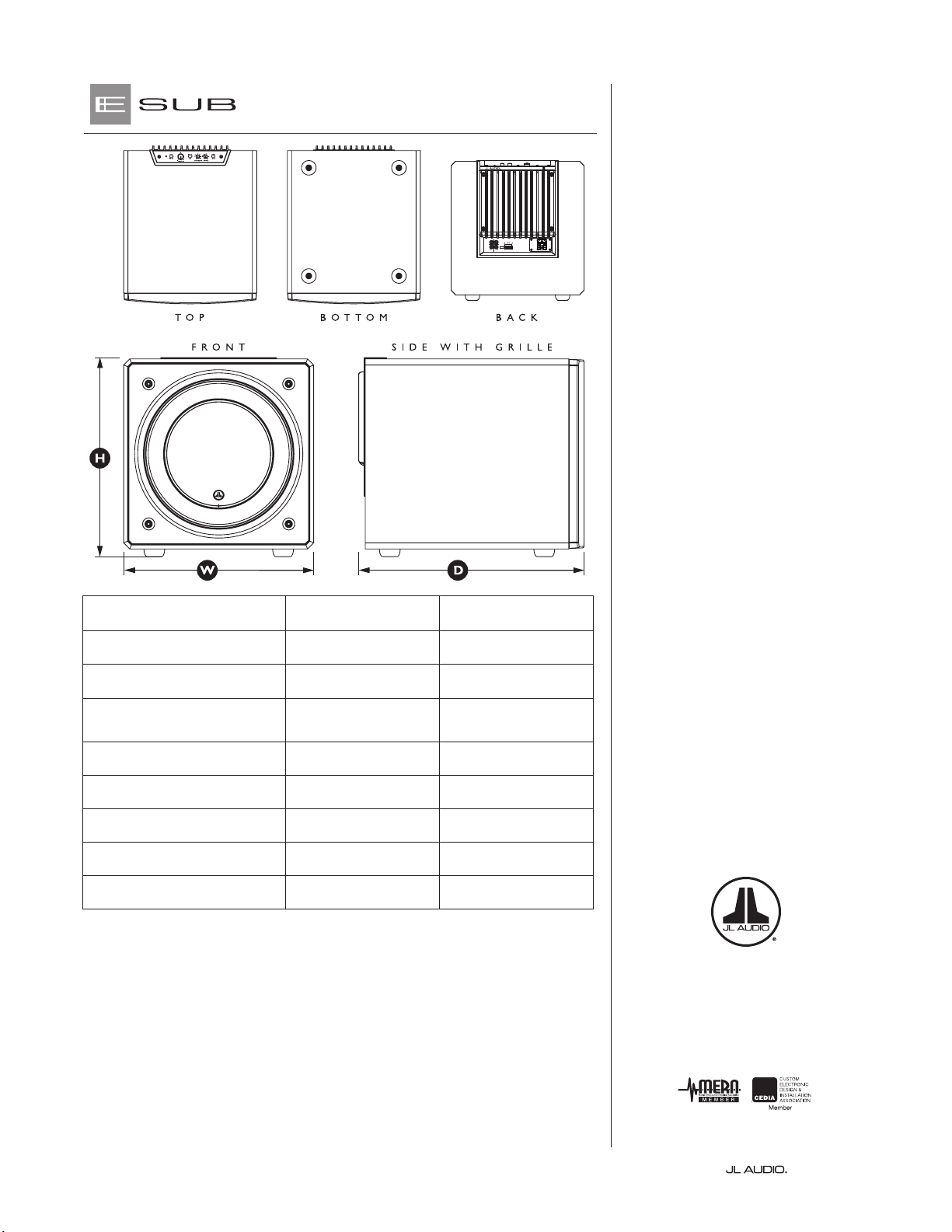
Dimensions: (H) Height x (W) Width x (D) Depth
Height Dimensions include feet.
14.24 in. x 13.5 in. x 16.51 in.
362 mm x 343 mm x 419 mm
16.23 in. x 15.50 in. x 18.39 in.
412 mm x 394 mm x 467 mm
Net Weight: 52.7 lbs. (23.9 kg) 73.5 lbs. (33.3 kg)
FEATURES
Unbalanced Inputs:
Stereo or Mono (two RCA jacks)
High-Level Inputs:
Removable 4-Pole plug and connector
Line Outputs:
Stereo or Mono (two RCA jacks)
Master Level Adjustment:
Variable from full mute to +15dB over
reference gain
Power Modes:
O, On or Automatic (Signal-Sensing)
Active Crossover:
24 dB per octave, Linkwitz-Riley,
variable from 25 Hz – 130 Hz, defeatable
Polarity:
0 or 180 degrees
Phase:
Variable from 0 – 280 degrees,
referenced to 80 Hz
Power Supply:
Regulated PWM Switching Type
Amplier Topology:
Class D Switching Type
www.jlaudio.com
North Commerce Parkway • Miramar, Florida • • USA
HOME AUDIO
|
MOBILE AUDIO
|
MARINE AUDIO
|
POWERSPORTS
“JL Audio”, “E-Sub” and the JL Audio logo are registered trademarks of JL Audio,
Inc., “Ahead of the Curve” is a trademark of JL Audio, Inc. Due to continuous
product development, all specifications are subject to change without notice.
Printed in USA • ©2013 JL Audio, Inc. • U.S. PATENTS: #5,734,734 #6,501,844
Other U.S. & Foreign patents pending. For more detailed information please
visit us online at www.jlaudio.com.
SKU- 011362-08-2013_Rev2