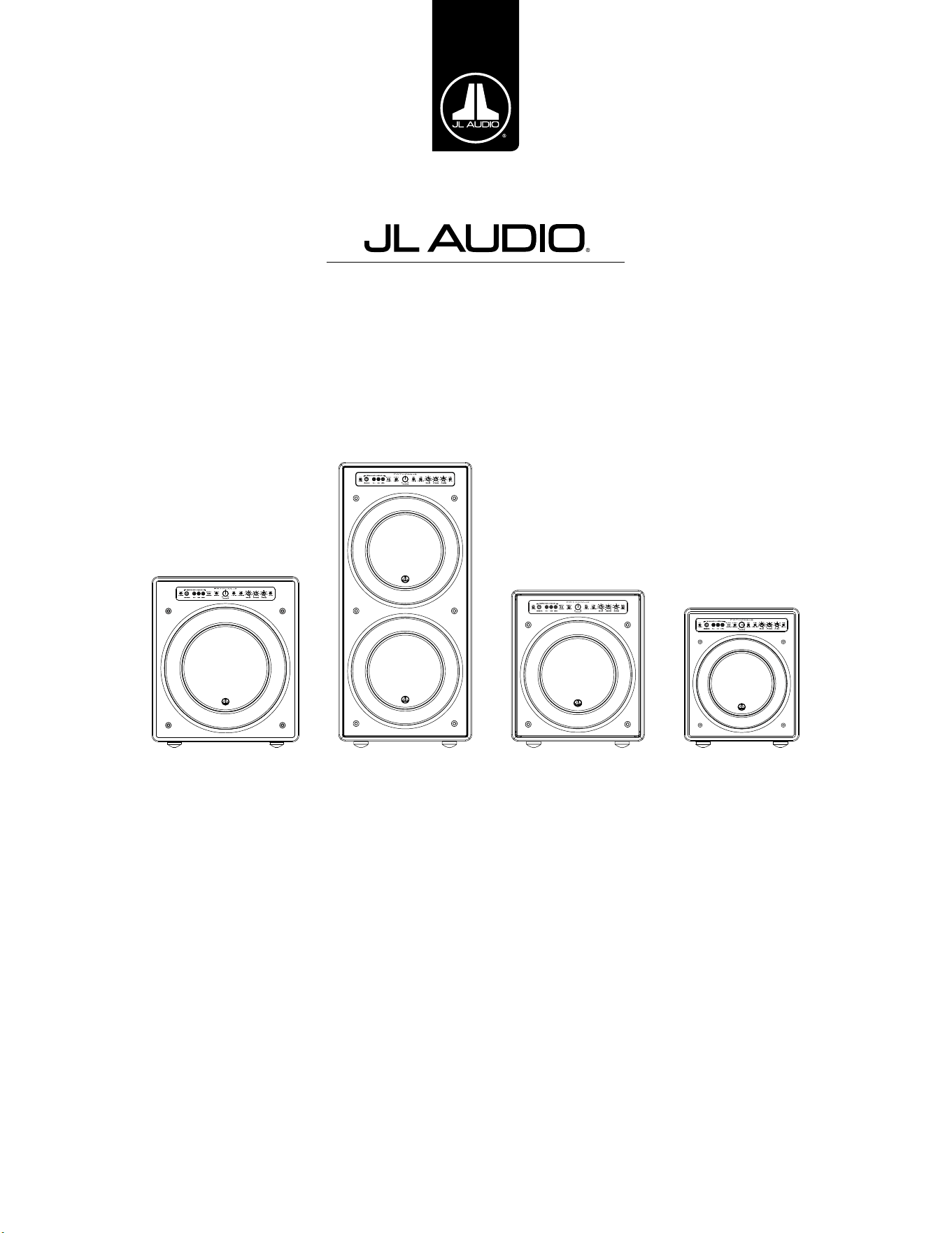
Fathom v2 Powered Subwoofer
Ow ner’s Ma nua l
Manuel de l’utilisateur • Manual del propietario • Bedienungsanleitung
Manuale del proprietario • 用户手册
f113v2 f212v2 f112v2 f110v2

EN | Pg 2
|
Fathom
®
v2
IMPORTANT SAFETY INSTRUCTIONS
WARNING: TO REDUCE THE RISK OF FIRE OR ELECTRIC SHOCK, DO NOT
EXPOSE THIS PRODUCT TO RAIN OR MOISTURE.
CAUTION
RISK OF ELECTRIC SHOCK
DO NOT OPEN
CAUTION: TO REDUCE THE RISK OF ELECTRIC SHOCK, DO NOT REMOVE
COVER. NO USER SERVICEABLE PARTS INSIDE. REFER SERVICING TO
QUALIFIED PERSONNEL.
1. Read the Instructions — All safety and operating instructions should be
read before the subwoofer is operated.
2. Retain the Instructions — e safety and operating instructions should be
retained for future reference.
3. Heed Warnings — All warnings on the subwoofer and in the operating
instructions should be followed.
4. Follow Instructions — All operating and use instructions should be
followed.
5. Water and Moisture — e subwoofer should NOT be used near water – for
example, near a bathtub, washbowl, sink, laundry tub, in a wet basement,
near a swimming pool, etc.
6. Ventilation — e subwoofer should be situated so that its location or
position does not interfere with its proper ventilation. For example, the
subwoofer should not be situated on a bed, sofa, rug, or similar surface
that may block airow over the heatsink ns. If placing the subwoofer in
a “built-in” installation, ensure that airow to the heat sink at the rear of
the subwoofer is not impeded. Do not cover the subwoofer heatsink with
tablecloths, curtains, etc.
7. Heat and Flames — e subwoofer should be situated away from heat
sources such as radiators, heat registers, stoves, replaces, or other devices
which produce heat. Do not place candles on top of or near the subwoofer.
8. Power sources — e subwoofer should only be connected to a power supply of
the type described in the operating instructions or as marked on the subwoofer.
9. Power Cord Protection — Power-supply cords should be routed so that they
are not likely to be walked on or pinched by items placed upon or against
them, paying particular attention to cords at plugs, convenience receptacles,
and the point where they exit the subwoofer.
10. Cleaning — e subwoofer should be cleaned only as recommended in the
operating instructions.
11. Nonuse Periods — e power cord of the subwoofer should be unplugged
from the outlet when the subwoofer is le unused for long periods of time.
12. Lightning and Power Surges — We recommend that you disconnect
the subwoofer from the electrical outlet during electrical storms and/or
recurring power interruptions to prevent damage due to power surges.
e lightning ash with arrowhead
symbol, within an equilateral triangle, is
intended to alert the user to the presence
of uninsulated “dangerous voltage” within
the product’s enclosure that may be of
sucient magnitude to constitute a risk of
electric shock to persons.
e exclamation point within an
equilateral triangle is intended to alert the
user to the presence of important operating
and maintenance instructions in the
literature accompanying the product.
Pg 3 | EN
|
Fathom
®
v2
EN
13. Object or Liquid Entry — Care should be taken so that objects do not fall
into and liquids are not spilled onto the subwoofer enclosure. Do not expose
the subwoofer to dripping or splashing from liquids. Do not place objects
lled with liquids on top of, or near the subwoofer. For example: ower vases,
beverages, liquid-fueled lamps, etc.
14. Damage Requiring Service — e subwoofer should be serviced by
qualied service personnel when:
a. the power-supply cord or plug has been damaged
b. objects have fallen or liquid has been spilled into the subwoofer
c. the subwoofer has been exposed to rain
d. the subwoofer does not appear to operate normally or exhibits a marked
change in performance
e. the subwoofer has been dropped or the cabinet has been damaged
f. the subwoofer driver’s cone and/or suspension has been
physically damaged
15. Servicing — e user should not attempt to service the subwoofer beyond
what is described in the operating instructions. All other servicing should be
referred to qualied service personnel.
16. Overloading — Do not overload wall outlets, extension cords, or outlet
strips as this can result in a risk of re or electric shock.
17. Grounding — is subwoofer is supplied with a three-prong, grounded
power cord. Precautions should be taken so that the grounding means of the
subwoofer are not defeated. Defeating the grounding prong on the subwoofer
power cord could increase the risk of electric shock and could result in
permanent damage to the subwoofer’s electronics.
THIS SUBWOOFER IS CAPABLE OF PRODUCING VERY HIGH SOUND PRESSURE
LEVELS. PLEASE EXERCISE RESTRAINT IN ITS OPERATION TO PROTECT YOUR
HEARING FROM PERMANENT DAMAGE.
WARNING

EN | Pg 4
|
Fathom
®
v2
FCC COMPLIANCE STATEMENT
NOTE: is equipment has been tested and found to comply with the limits of Part 15 of the FCC
Rules. ese limits are designed to provide reasonable protection against harmful interference in
a residential installation. is equipment generates, uses and can radiate radio frequency energy
and, if not installed in accordance with the instructions, may cause harmful interference to radio
communications. However, there is no guarantee that interference will not occur in a particular
installation. If this equipment does cause harmful interference to radio or television reception,
which can be determined by turning the equipment o and on, the user is encouraged to try to
correct the interference by one or more of the following measures:
- Reorient or relocate the receiving antenna.
- Increase the separation between the equipment and receiver.
- Connect the equipment into an outlet on a circuit dierent from that to which the receiver is
connected.
- Consult the dealer or an experienced radio/TV technician for help.
TABLE OF CONTENTS
Important Safety Instructions: ......................................... 2-3
Introduction:. . . . . . . . . . . . . . . . . . . . . . . . . . . . . . . . . . . . . . . . . . . . . . . . . . . . . . . . . . . 4
Product Overview: ...................................................... 5
Placing your Fathom v2 in Your Listening Room: ........................ 6-10
Unpacking your Fathom v2: ............................................. 11
Front Control Panel Layout: ............................................. 12
Rear Control and Connector Panel Layout: .............................12-13
Front Panel Controls in Detail: ........................................14-17
Connecting your Fathom v2(s): ........................................18-25
Recommended Setup Procedure: ......................................26-30
Frequently Asked Questions: ............................................ 31
Cleaning Your Fathom v2: ...............................................31
Troubleshooting: ....................................................32-33
Limited Warranty / Service Information: ................................. 35
Specications: ......................................................... 36
INTRODUCTION
Congratulations on your purchase of a JL Audio Fathom v2 powered subwoofer
system. is product has been critically engineered to deliver exceptional
performance in your home theater or audio system for many years to come.
As a company, we are intensely committed to core research into high-
performance loudspeaker and amplier technologies. JL Audio’s long-excursion
subwoofer driver designs are widely considered as reference standards for linear
behavior and high output. We have also focused our eorts to create powerful
amplier and signal-processing technologies specically aimed at delivering
exceptional low-frequency performance. Your Fathom v2 combines these core
disciplines within a compact, beautifully craed package to deliver an unparalleled
listening experience.
We sincerely thank you for your purchase and invite you to read this
manual thoroughly in order to achieve the highest level of performance with
your Fathom v2 subwoofer system. Enjoy.
JL AUDIO TECHNOLOGIES INCLUDED
IN FATHOM V2 SUBWOOFERS
DMA-Optimized Motor System
DMA is JL Audio’s innovative Dynamic
Motor Analysis system aimed at
improving dynamic motor behavior. As a
result of DMA optimization, loudspeaker
motors remain linear in force over an
extreme range of excursion and also
maintain a highly stable xed magnetic
eld over a wide power range. is leads
to vastly reduced distortion and faithfully
reproduced transients... or put simply:
tight, clean, articulate bass.
OverRoll™ Surround
e OverRoll™ surround spans over
the driver’s mounting ange, utilizing
available diameter wasted in conventional
speakers. is allows the use of the wider
roll necessary to control high-excursions
without sacricing precious cone area.
W-Cone™
e W-Cone™ is a unit-body cone
assembly that delivers astonishing cone
stiness with minimal mass.
Floating-Cone™ Attach Method
is assembly technique ensures proper
surround geometry in the assembled
speaker for better excursion control and
dynamic voice coil alignment.
Plateau-Reinforced Spider Attachment
is high-integrity suspension attachment
relieves stress from the spider material at
high-excursions for enhanced reliability.
Elevated Frame Cooling Technology
Delivers cool air, through slots directly
above the top-plate, to the voice coil of the
speaker. is enhances power handling
and sound quality by minimizing
dynamic parameter shis and power
compression.
Radially Cross-Drilled Pole Piece
is innovative venting system greatly
enhances thermal dissipation and power
handling by directing air ow onto the
voice coil former, working in conjunction
with the Elevated Frame technology.
High-Damping Feedback Circuit
is innovative, discrete control circuit
design allows our Class D switching
ampliers to maintain an excellent
damping factor for improved transient
behavior and delity.
Pg 5 | EN
|
Fathom
®
v2
EN
PRODUCT OVERVIEW
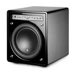
JL Audio Fathom v2 subwoofers combine a state-of-the-art
JLAudio subwoofer driver and electronics/amplier package within
a highly optimized enclosure to deliver an exceptional listening
experience in your home theater or home audio system.
e subwoofer driver in your Fathom v2 subwoofer system is capable of
outstanding linear excursion without distress or audible distortion. is
reference-quality driver enables your Fathom v2 to reproduce powerful
low-frequency events with stunning impact and unprecedented accuracy.
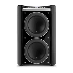
Derived from JL Audio’s legendary W7 design platform, the Fathom v2
drivers oer prodigious peak-to-peak excursion capabilities to comfortably
handle the dynamics of the most demanding program material.
To get the most from this long excursion driver platform, a tremendous
amount of controlled power is needed. Our electronics engineering team
conducted an intense analysis of typical program material and its dynamic
demands in order to balance current draw and actual output power requirements
relative to the system’s impedance characteristics. Aer careful study, precisely
engineered switching ampliers employing patented feedback technology were
created to take full advantage of each driver’s full excursion envelope. Compared
to their predecessors, Fathom v2’s have been improved with all new digital
signal processing and a 20% increase in amplier power, further enhancing their
outstanding dynamic capabilities.
e beautiful cabinet enclosing the workings of your Fathom v2 is also the
result of careful engineering. To contain the pressures created by the Fathom v2
driver, we utilized solid, CNC-cut, MDF material with extensive internal bracing
features and advanced assembly techniques.
Your listening room is the other enclosure that aects the way your bass will
sound. All rooms create a specic sonic signature, which must be eectively
managed to achieve well-balanced low frequency performance. To help properly
integrate your subwoofers with your room’s acoustics, all Fathom v2 subwoofers
employ a powerful, Digital Automatic Room Optimization (D.A.R.O.) system.
is system deploys eighteen bands of digital equalization to tame room
acoustics and deliver spine-tingling sub-bass accuracy.
As you can see from this brief introduction, Fathom v2 subwoofer systems
employ many advanced technologies. e contents of this manual will explain the
features, guide you through the setup and tuning of your Fathom v2 subwoofer and
help you achieve your ultimate low-frequency listening experience.
If you require assistance, we urge you to contact your authorized JL Audio
retailer for expert setup advice and service.
IMPORTANT! IT IS A VERY GOOD IDEA TO READ THE NEXT SECTION BEFORE
UNPACKING YOUR FATHOM v2. UNPACKING THE SUBWOOFER NEAR ITS FINAL
LOCATION IS RECOMMENDED.
IMPORTANT

EN | Pg 6
|
Fathom
®
v2
PLACING YOUR FATHOM v2 IN YOUR LISTENING ROOM:
Your listening room or theater is an integral part of your sound reproduction
system. e physical dimensions of the room and its furnishings, materials, doors
and windows play an important role in dening how your system sounds.
When you place a sound source in an enclosed rectangular space, “standing
waves” are created, resulting from the relationship between the sound’s
wavelength and your room’s dimensions. In other words, standing waves result
from sound energy that is trapped in the room as it bounces back and forth
between opposing walls. Standing waves in the room create acoustic peaks and
dips where the sound is either louder or soer, based solely on your physical
position in the room. Energy also “builds up” at the room’s boundaries, creating
exaggerated bass response at certain frequencies. ese fundamental room
resonances are called room “modes.”
e moral of this mode story is to try and avoid seating positions in standing
wave peak or dip regions. It is highly recommended that you place your listening
chairs in areas where modal peaks and dips are moderate and do not reinforce
one another. e two most obvious areas to avoid are those near the exact center
of the room and those close to any of the room’s walls.
Just as your listening seat can be in a peak or dip region, so can your
subwoofer. When placed in a room corner, a subwoofer maximally excites the
room’s mode structure, creating the strongest output with the fewest dips. When
the subwoofer is pulled away from a corner or wall, the room modes are excited
less, which can alter the sound at your listening seat.
Be sure to experiment with both your listening seat position and subwoofer
position to nd the best solution. Careful experimentation usually leads to a
superior sounding system. Use our setup suggestions (illustrated on the opposing
page and the following pages) to get you started.
If you cannot avoid placing your sofa against the back wall,
or your subwoofer in a less than optimal position, your Fathom
v2’s Digital Automatic Room Optimization (D.A.R.O.) System
can dramatically improve these less-than-ideal situations.
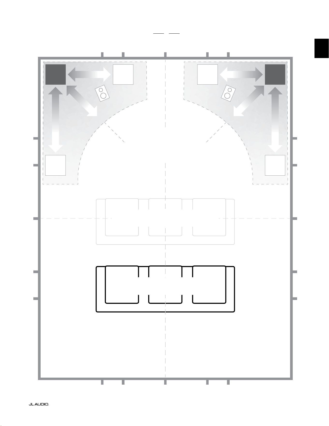
We recommend that you begin by placing your Fathom v2 in the front
of the room, near the front le or right speaker. Placing it directly in the
front corner of the room will produce the maximum number of peaks and
the minimum number of dips in the bass response. is can be advantageous
because the Fathom v2’s D.A.R.O. system can correct the resulting peaks very
eectively, whereas dips in response cannot be corrected via equalization. Dips in
response can only be minimized via careful subwoofer and listener placement.
Placing the Fathom v2 near solid walls will reinforce bass response and
pulling it away from solid walls will decrease bass. Increasing the distance
between the subwoofer and the walls may help to smooth upper bass response in
some rooms.
We recommend that you avoid placing the Fathom v2 near windows to prevent
rattling and sound transmission to the outside world.
If you are planning to install your Fathom
v2 inside a cabinet, please refer to the
guidelines on page 8.
Pg 7 | EN
|
Fathom
®
v2
EN
Recommended Subwoofer Placement Options for for One or Two Fathom v2s
SMOOTHER
Recommended Subwoofer Placement
for ONE or TWO subwoofers
(place TWO with left-right symmetry)
SMOOTHER
SMOOTHERSMOOTHER
COMPROMISED SEATING POSITIONS
(Weaker, uneven bass performance)
BEST SEATING POSITIONS
(Most accurate bass performance)
½
1⁄3
1⁄3
¼
¼
½
½
1⁄3
1⁄3 1⁄3
1⁄3
¼
¼ ¼
½1⁄3 1⁄3¼ ¼
¼
APPROXIMATELY 1/3 OF
ROOM LENGTH
FROM BACK WALL
CENTERLINE OF ROOM
MORE
INTENSE
MORE
INTENSE
EN | Pg 8
|
Fathom
®
v2
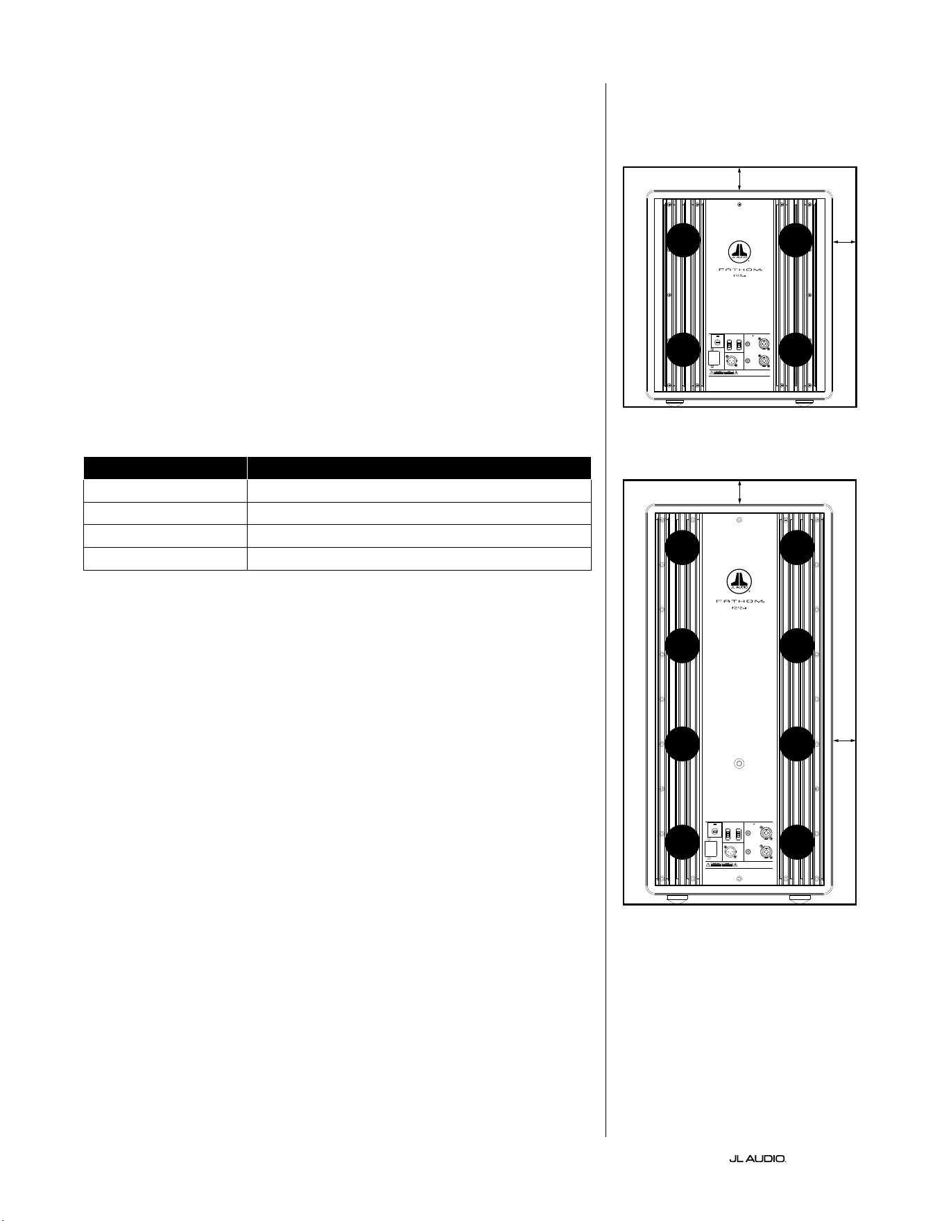
SPECIAL CONSIDERATIONS FOR BUILT-IN INSTALLATIONS
Fathom v2 subwoofers are designed to be “built-in” friendly. All typically
needed controls are located on the front panel above the woofer. A Fathom v2 can
be easily integrated into custom cabinetry by following a few simple guidelines.
1) Allow 4 inches (10 cm) of clear space behind the amplier panel for adequate
cooling and connector clearance.
2) On all other sides (except the bottom), allow at least 2 inches (5 cm) clearance
for adequate ventilation.
3) While the Fathom v2 generally runs only warm during spirited operation, we do
recommend that adequate heat vents are included in any custom cabinet which
encloses the Fathom v2. A pair of 3 inch (7.5 cm) diameter vents near the bottom
of the cabinet and near the top of the cabinet, will allow cool air to circulate over
the amp panel of your Fathom v2 subwoofer system keeping it cool and happy.
4) Your Fathom v2 subwoofer is capable of moving substantial quantities of air. If
the front of the Fathom v2 is covered by a custom grille, the grille size must be
AT LEAST equal to the woofer cone area for each model to ensure the output is
not choked by the custom cabinet. Refer to the chart below for recommended
vent areas for each model.
Model Recommended Custom Grille Vent Area
f110v2 ≥ 60 in
2
(386 cm
2
)
f112v2 ≥ 85 in
2
(550 cm
2
)
f113v2 ≥ 108 in
2
(700 cm
2
)
f212v2 ≥ 170 in
2
(110 0 cm
2
)
1200VA
Built in USA with Imported and domestic components
LEFT
or
MONO
RIGHT
ONLY
INPUTS
Output to Slave
(Balanced)
Balanced
Unbalanced
Input Modes
Slave
Master
Grounded
Isolated
SERIAL NUMBER:
Warranty void if serial number is remove d, altered or deface d.
F 12A H
250V
120 V ~ 60 Hz
F
U
S
E
F
U
S
E
Built in USA with Imported and domestic components
LEFT
or
MONO
RIGHT
ONLY
INPUTS
Output to Slave
(Balanced)
Balanced
Unbalanced
Input Modes
Slave
Master
Grounded
Isolated
SERIAL NUMBER:
Warranty void if serial number is remo ved, altered or defa ced.
F 15A H
250V
120 V ~ 60 Hz
F
U
S
E
F
U
S
E
VENT
VENT
VENT
VENT
VENT
VENT
VENT
VENT
2 in. min.
2 in. min.
2 in.
min.
2 in.
min.
Rear-view of cabinet install (f110, f112, f113):
Rear-view of cabinet install (f212):
VENT
VENT
VENT
VENT
Pg 9 | EN
|
Fathom
®
v2
EN
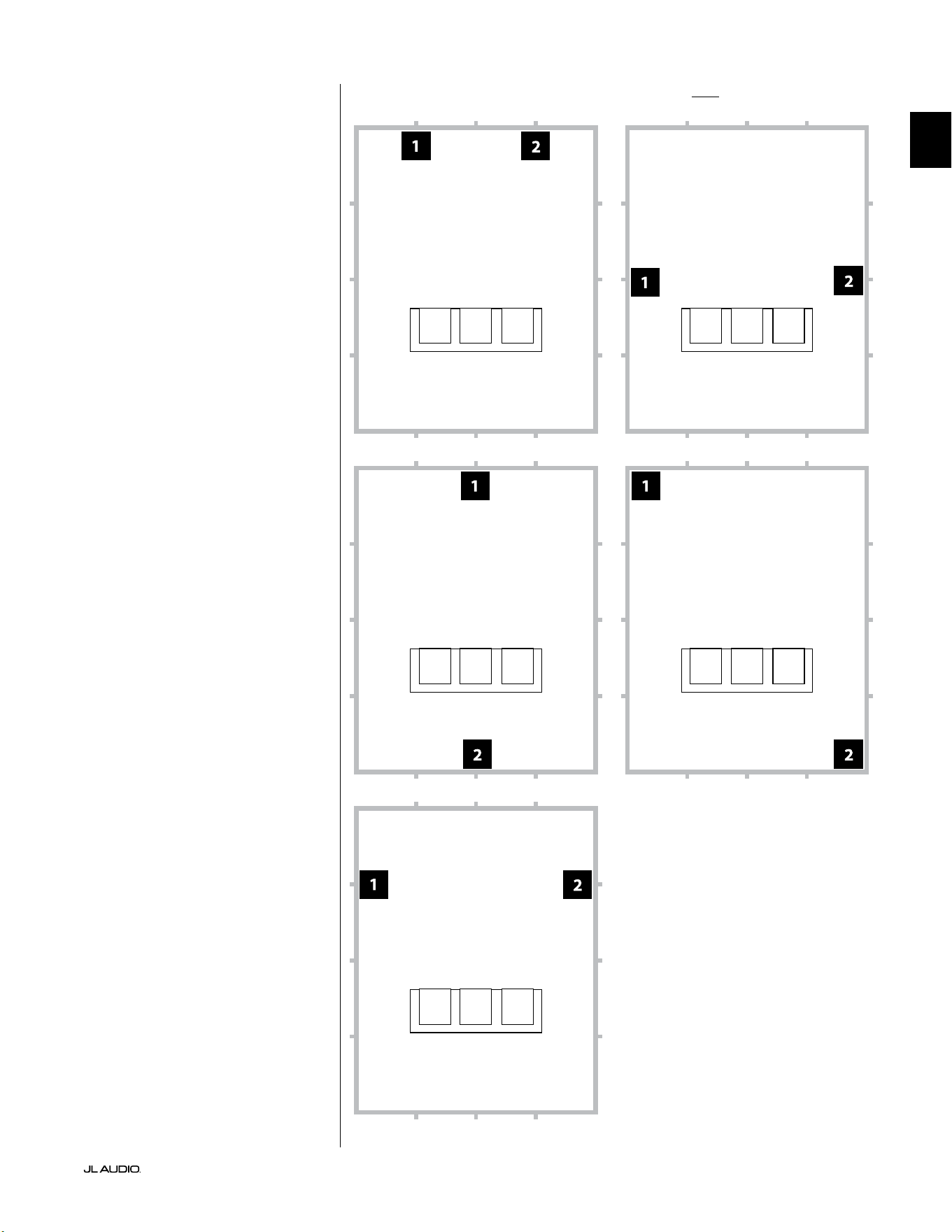
Recommended Subwoofer Placement Options for Two Fathom v2sUsing Two Fathom v2s
When using two Fathom v2s, try
placement near the front corners of the
room, at diagonally-opposite corners
of the room, or at the center points of
opposing walls as shown at right.
Experimentation with
subwoofer and listener
placement is recommended to
achieve the best results – the
benets can be substantial.
High-resolution measurements
and professional system calibration
are recommended for the best possible
results & system performance.
EN | Pg 10
|
Fathom
®
v2
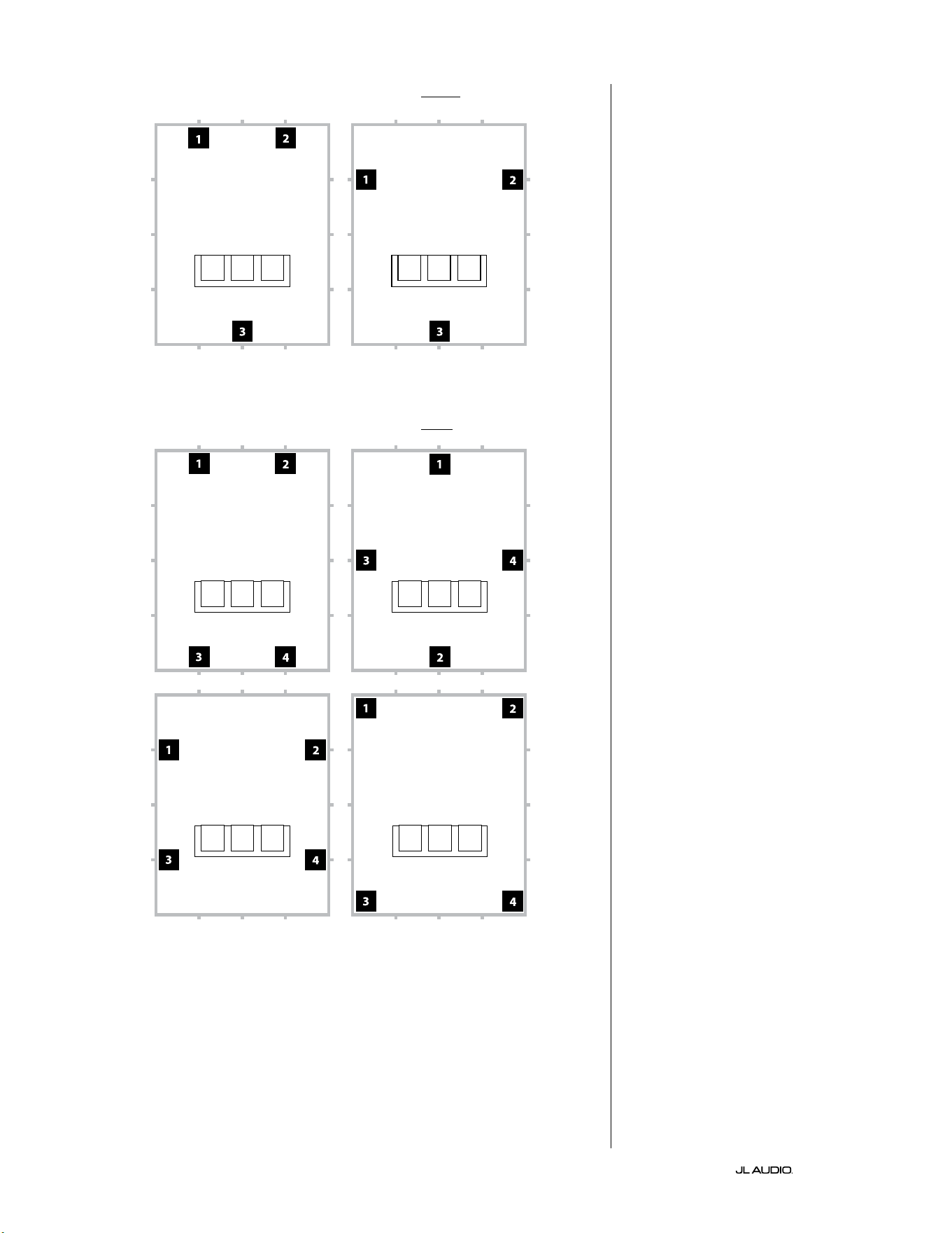
Recommended Subwoofer Placement Options for Three Fathom v2s
Recommended Subwoofer Placement Options for Four Fathom v2s
Using Three or Four Fathom v2s
Research indicates that the
smoothest bass response for a large
listening area can be achieved using
four subwoofers, placing one at
the midpoint of each of the four
walls (although using two or three
subwoofers can be almost as good).
Experimentation with
subwoofer and listener
placement is recommended to
achieve the best results – the
benets can be substantial.
High-resolution measurements
and professional system calibration
are recommended for the best possible
results & system performance.
Pg 11 | EN
|
Fathom
®
v2
EN
IMPORTANT! DUE TO THE WEIGHT OF THE FATHOM V2 SUBWOOFER, PLEASE
EXERCISE CAUTION WHILE UNPACKING AND POSITIONING IT TO PREVENT
INJURY. IF POSSIBLE, ENLIST THE HELP OF A SECOND PERSON TO FACILITATE
THE PROCESS. TO MINIMIZE THE RISK OF INJURY, BEND YOUR KNEES AND LIFT
WITH YOUR LEGS, NOT YOUR BACK.
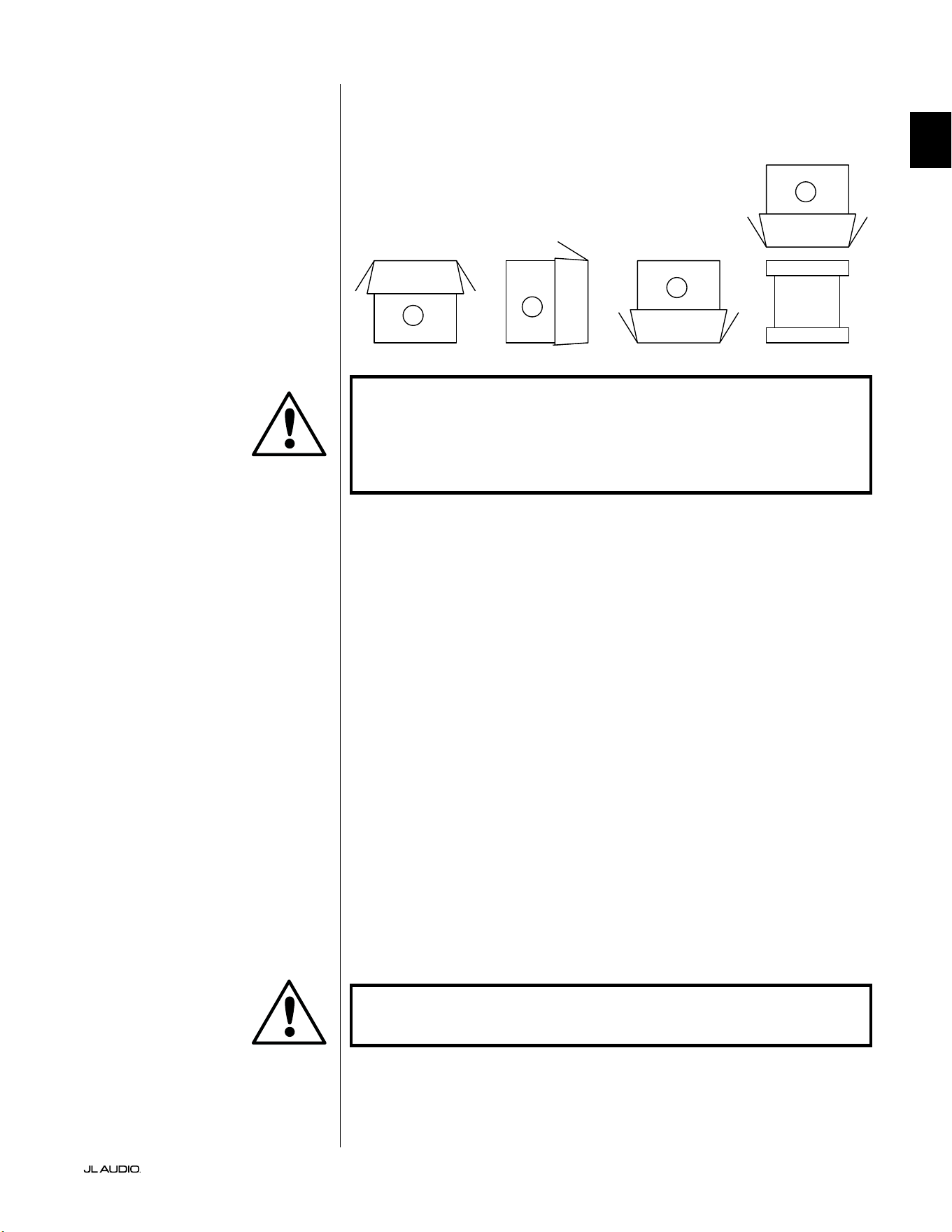
Detailed instructions on unpacking the subwoofer:
1. Place the carton on the oor near its intended location in the room.
2. Open the top of the carton (observe markings on carton) and remove the
manual, calibration microphone and power cord.
3. Temporarily remove the split-foam packing inserts.
4. Untie and loosen the pr otective cloth cover to make later removal easier (do
not remove at this time). When you open the cloth cover, you are looking at the
bottom of the subwoofer cabinet.
5. Replace the split-foam inserts to protect the subwoofer’s cabinet while
unpacking.
6. Gently ip the box on its side, folding back the carton aps to the outside.
7. Holding the carton aps back, gently ip the carton onto its top (open end).
8. Pull the carton straight up until it clears the subwoofer and place to one side.
9. Remove the one-piece foam insert and place in the carton.
10. Remove the plastic bag and place in the carton.
11. Tilt the subwoofer forward (toward its grille) to remove the rear split-foam
insert rst. en tilt the subwoofer in the opposite direction (towards its
amplier panel) to remove the remaining split-foam insert. Place both split-
foam inserts in the carton.
12. Remove the protective cloth cover and place in the carton.
IMPORTANT! PLEASE RETAIN ALL PACKAGING FOR SAFE TRANSPORTATION
OF THE SUBWOOFER AND FOR ANY FUTURE SERVICE NEEDS.
Unpack this box close to where the
subwoofer will be placed. e subwoofer
is PACKED upside down. is box must be
ipped over CAREFULLY to remove the
subwoofer and minimize eort.
UNPACKING YOUR FATHOM v2
Now that you have determined your Fathom v2’s position in the room, you can
proceed with unpacking it near its intended location.
C
D
A
B
IMPORTANT
IMPORTANT

LP freq. (Hz) e.l.f. trim (dB) phase (deg.)
Polarity
0
|
180 deg.
LP Filter
o
|
12d B
|
24dB
Master Level
max
0
Lights
o
|
dim
|
on
-∞
Level Mode
ref.
|
variable
Input Mode
master
|
slave
calibration mic. demo defeat calibrate
Power
o
|
on
|
auto
Digital Automatic Room Optimization
1200VA
Built in USA with Imported and domestic components
LEFT
or
MONO
RIGHT
ONLY
INPUTS
Output to Slave
(Balanced)
Balanced
Unbalanced
Input Modes
Slave
Master
Grounded
Isolated
SERIAL NUMBER:
Warranty void if serial numb er is removed, altered or defaced.
F 12A H
250V
120 V ~ 60 Hz
F
U
S
E
F
U
S
E
EN | Pg 12
|
Fathom
®
v2
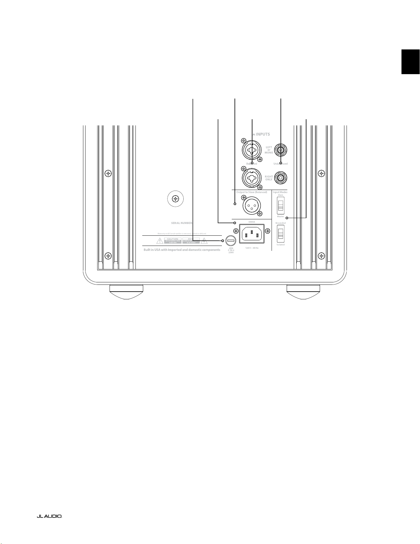
Rear Controls and Connectors (f112v2, f113v2, f212v2 Models)
e labeled Figure below depicts the rear panel of a Fathom f113v2 subwoofer.
e controls and connectors layout is the same for the Fathom f112v2 & f212v2.
Balanced
Inputs
page 18
Unbalanced
Inputs
page 19
IEC-Style AC
Connector
page 21-22
Output to
Slave Connector
page 21
Input Mode
Switches
page 20
Region-
Specic Fuse
page 33
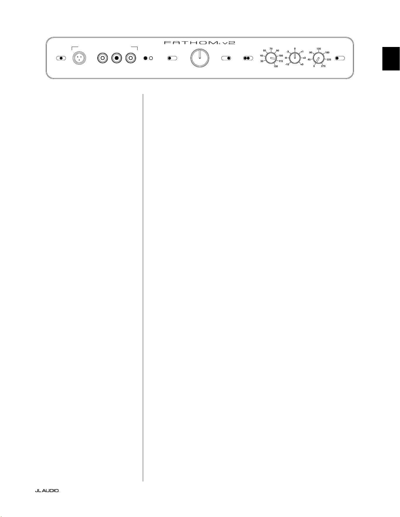
Front Control Panel (All Models)
e labeled Figure below depicts the front control panel of a Fathom f113v2 subwoofer.
e controls layout is the same for all Fathom v2 models.
D.A.R.O.
page 14-15
Power
page 14
Input Mode
page 15
Level Mode
page 15
Master Level
page 16
Lights
page 16
LP Filter
page 16
LP freq. (Hz)
page 16
e.l.f. trim (dB)
page 17
phase (deg.)
page 17
Polarity
page 17
F
U
S
E
F
U
S
E
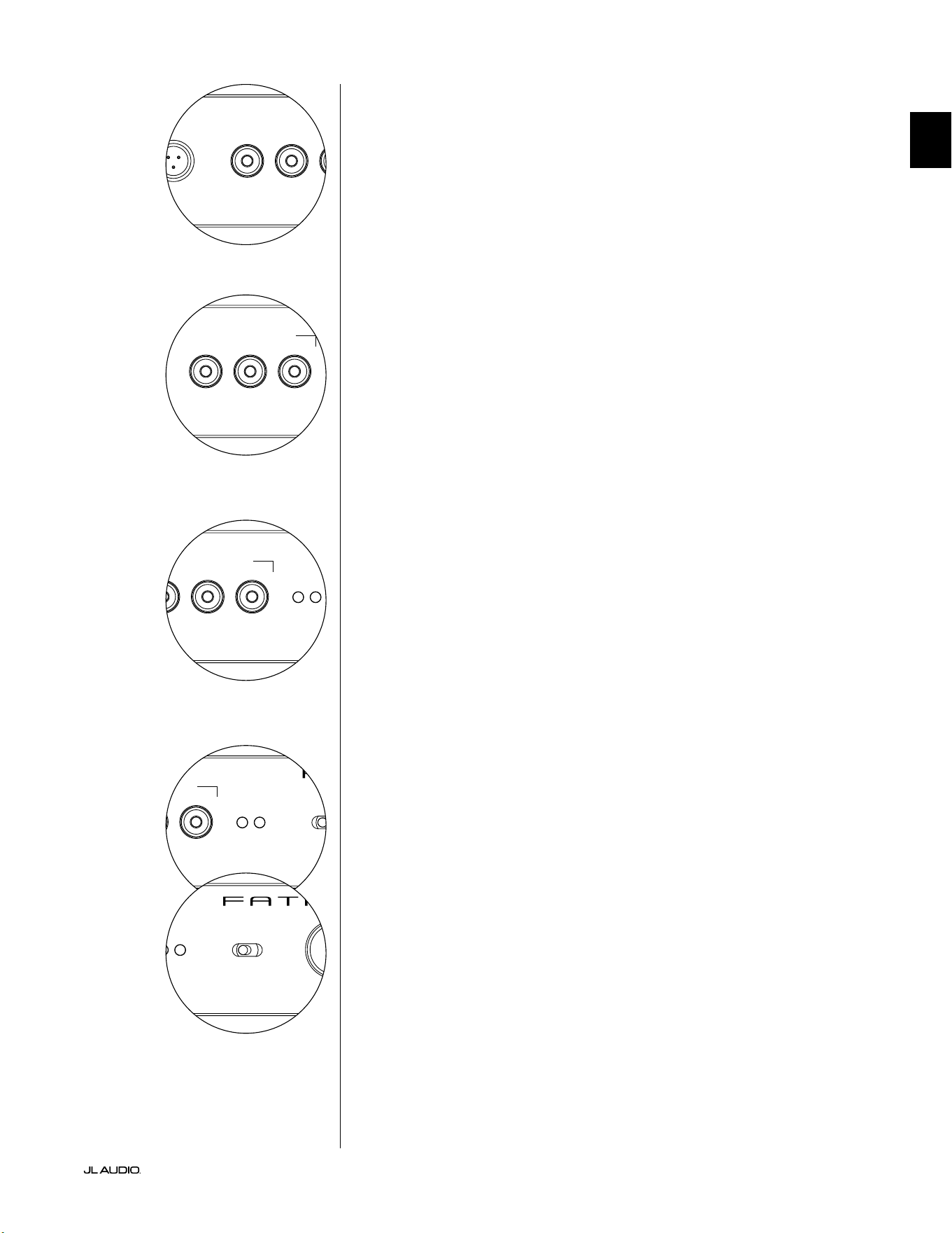
Rear Controls and Connectors (f110v2 Model)
e labeled Figure below depicts the rear panel of a Fathom f110v2 subwoofer.
*e rear control and connector detail images throughout this manual depict other Fathom v2 models and are not
representative of the arrangement of the f110v2.
Balanced
Inputs
page 18
Unbalanced
Inputs
page 19
IEC-Style AC
Connector
page 21-22
Output to Slave
Connector
page 21
Input Mode
Switches
page 20
Pg 13 | EN
|
Fathom
®
v2
EN
Region-
Specic Fuse
page 33

EN | Pg 14
|
Fathom
®
v2
FRONT PANEL CONTROLS IN DETAIL
Power Switch
e “Power” switch determines the operational readiness of the Fathom v2
subwoofer and should be the only switch used to turn the Fathom v2 on and o. Do
not use a power strip switch, switched outlet or any other external switch as these
may result in undesirable and potentially damaging transient pops. Do not unplug
the Fathom v2’s AC power cord while the unit is turned on. e power switch has
three positions:
“On”: e Fathom v2 is fully powered at all times. Front panel lights are on
unless they have been turned o via the “Lights” switch.
“O ”: e Fathom v2’s internal power amplier is powered down. In this state,
a negligible current draw will exist for operating the main power relays. All front
panel lights are o .
“Auto”: e Fathom v2 will power up its internal amplier when an audio signal is
present at any of its inputs and will power down the internal amplier if no signal has
been detected at its inputs for thirty (30) minutes. When dormant, the Fathom v2 will
draw a very small amount of current (< 5 watts) to power its signal-sensing circuitry.
Front panel lights will turn o when the Fathom v2 powers down and light when the
Fathom v2 powers up (unless they have been turned o via the “Lights” switch).
In the unlikely event that the Auto feature is not sensitive enough for a particular
system, use a Y-cable adaptor to split the incoming signal into both RCA or XLR
inputs on the Fathom v2. is will increase the input sensitivity by 6 dB. Please be
aware that if the Auto sensitivity is too high or if there is signicant noise on the
input cable, the Fathom v2 may not turn o as desired. If this happens, remove the
Y-cable adaptor or look for the noise source in the upstream components.
Digital Automatic Room Optimization (D.A.R.O.)
A powerful feature of the JL Audio Fathom v2 subwoofers is their innovative
Digital Automatic Room Optimization (D.A.R.O.) technology. is one-touch
system includes 18 bands of digital equalization to eliminate the largest acoustic
response peaks in your home theater at the main listening seat, greatly improving
the in-room low-frequency response. Calibration of the D.A.R.O. system is fully
automated. Please consult the next section of this manual for details on how to use
the D.A.R.O. system.
Using the included JL Audio calibration microphone, the D.A.R.O. calibration
procedure takes less than three minutes. In brief, you will connect the included
microphone to the “Calibration Mic.” input, press the Calibrate button, and then
hold the microphone at ear height in your main listening seat during the test. A
noise sequence will be played through the Fathom v2 subwoofer, and the room
response will be automatically measured, analyzed and equalized to eliminate
the single largest acoustic room response peak at your listening seat. For detailed
instructions on the D.A.R.O. setup procedure, refer to pages 29-30.
Calibration Mic. Input
is input is for connecting the supplied JL Audio calibration microphone to the
Fathom v2 subwoofer. Connect one end of the supplied cable to the microphone and
the other end to this jack prior to using the D.A.R.O. system. e D.A.R.O. system
is specically calibrated to this microphone and its connection scheme is specic to
the supplied microphone. e calibration sequence will not operate when a dierent
microphone is connected or if no microphone is connected.
IMPORTANT
LP freq. (Hz) e.l.f. trim (dB) phase (deg.)
Polarity
0
|
180 deg.
LP Filter
o
|
12dB
|
24dB
Master Level
max
0
Lights
o
|
dim
|
on
-∞
Level Mode
ref.
|
variable
Input Mode
master
|
slave
calibration mic. demo defeat calibrate
Power
o
|
on
|
auto
Digital Automatic Room Optimization
LP freq. (Hz) e.l.f. trim (dB) phase (deg.)
Polarity
0
|
180 deg.
LP Filter
o
|
12dB
|
24dB
Master Level
max
0
Lights
o
|
dim
|
on
-∞
Level Mode
ref.
|
variable
Input Mode
master
|
slave
calibration mic. demo defeat calibrate
Power
o
|
on
|
auto
Digital Automatic Room Optimization
LP freq. (Hz) e.l.f. trim (dB) phase (deg.)
Polarity
0
|
180 deg.
LP Filter
o
|
12dB
|
24dB
Master Level
max
0
Lights
o
|
dim
|
on
-∞
Level Mode
ref.
|
variable
Input Mode
master
|
slave
calibration mic. demo defeat calibrate
Power
o
|
on
|
auto
Digital Automatic Room Optimization
Pg 15 | EN
|
Fathom
®
v2
EN
LP freq. (Hz) e.l.f. trim (dB) phase (deg.)
Polarity
0
|
180 deg.
LP Filter
o
|
12dB
|
24dB
Master Level
max
0
Lights
o
|
dim
|
on
-∞
Level Mode
ref.
|
variable
Input Mode
master
|
slave
calibration mic. demo defeat calibrate
Power
o
|
on
|
auto
Digital Automatic Room Optimization
LP freq. (Hz) e.l.f. trim (dB) phase (deg.)
Polarity
0
|
180 deg.
LP Filter
o
|
12dB
|
24dB
Master Level
max
0
Lights
o
|
dim
|
on
-∞
Level Mode
ref.
|
variable
Input Mode
master
|
slave
calibration mic. demo defeat calibrate
Power
o
|
on
|
auto
Digital Automatic Room Optimization
Demo Button
e Demo button triggers a 20 second long tone sequence that briey
demonstrates the range of the Fathom v2 subwoofer. e Demo function is useful
for showcasing the output capability of the Fathom v2 and to verify that the Fathom
v2 (or multiple Fathom v2s) are operational during system troubleshooting.
e Demo button is also used (in combination) to clear (return to at) the
D.A.R.O. equalizer settings. To clear the D.A.R.O.’s settings & turn o the Calibrate
light, press and hold the Demo button and then press the Defeat button. Please note
that you must perform this button sequence quickly. If you hold the Demo button
for more than 2 seconds without touching the Defeat button, the Demo tones will
start. Should this happen, simply wait for the Demo sequence to end and try again.
Defeat Button
If “Demo” or “Calibrate” is pressed while the defeat function is active, “Defeat” is
automatically canceled. No other front panel controls will alter the D.A.R.O. Defeat
state. e Defeat setting is stored in non-volatile memory and will not change even if
power is disconnected.
e Defeat button is also used (in combination) to clear (return to at) the
D.A.R.O. equalizer settings. To clear the D.A.R.O.’s settings & turn o the Calibrate
light, press and hold the Demo button and then press the Defeat button. Please note
that you must perform this button sequence quickly. If you hold the Demo button
for more than 2 seconds without touching the Defeat button, the Demo tones will
start. Should this happen, simply wait for the Demo sequence to end and try again.
Calibrate Button
During the D.A.R.O. test sequence, the Calibrate button’s green LED will blink
quickly to alert the user to two special conditions:
1. “JL Audio Microphone NOT Connected”: If you forget to connect the mic
before trying to start a Calibration you will get this alert. Press the Calibrate button
once to cancel the alert, connect the D.A.R.O. microphone, and try again.
2. “Inappropriate Sound Level for D.A.R.O. Calibration”: Since the D.A.R.O.
sequence is completely automatic, this alert likely indicates a problem with the
microphone. Press the Calibrate button once to cancel the alert. Ensure that the JL
Audio microphone is properly connected and try again. For further help, please refer
to Troubleshooting on page 33.
Input Mode Indicators
e Input Mode indicator LEDs show the input mode, either “Master” or “Slave”,
selected by the switch on the Fathom v2’s back panel (unless the “Lights” switch is
set to “o”). For further details, see page 20.
Level Mode
e two-position Level Mode switch allows you
to select between the following modes:
“Reference”: In this mode, the Master Level control knob has no eect on the
Fathom v2’s output level. Use this setting if you will primarily be controlling the
subwoofer level via your receiver or preamplier/processor. For those of us with
small children or overenthusiastic teenagers, this mode of operation will prevent
direct manipulation of the Master Level.
“Variable”: In this mode, the Master Level control knob determines the output
level of the Fathom v2 subwoofer. is mode is also useful when level matching the
Fathom v2 subwoofer to a pair of stereo speakers in a two-channel system.
LP freq. (Hz) e.l.f. trim (dB) phase (deg.)
Polarity
0
|
180 deg.
LP Filter
o
|
12dB
|
24dB
Master Level
max
0
Lights
o
|
dim
|
on
-∞
Level Mode
ref.
|
variable
Input Mode
master
|
slave
calibration mic. demo defeat calibrate
Power
o
|
on
|
auto
Digital Automatic Room Optimization
LP freq. (Hz) e.l.f. trim (dB) phase (deg.)
Polarity
0
|
180 deg.
LP Filter
o
|
12dB
|
24dB
Master Level
max
0
Lights
o
|
dim
|
on
-∞
Level Mode
ref.
|
variable
Input Mode
master
|
slave
calibration mic. demo defeat calibrate
Power
o
|
on
|
auto
Digital Automatic Room Optimization
LP freq. (Hz) e.l.f. trim (dB) phase (deg.)
Polarity
0
|
180 deg.
LP Filter
o
|
12dB
|
24dB
Master Level
max
0
Lights
o
|
dim
|
on
-∞
Level Mode
ref.
|
variable
Input Mode
master
|
slave
calibration mic. demo defeat calibrate
Power
o
|
on
|
auto
Digital Automatic Room Optimization
EN | Pg 16
|
Fathom
®
v2
Master Level Knob
e Master Level Knob is used to control the output level of the Fathom v2
when the Variable Level mode is selected on the front control panel.
When rotated fully counter-clockwise, the Fathom v2’s output will be fully
muted. When at the “0” or vertical position, the Variable gain level matches the
Reference level setting. When turned fully clockwise, the Fathom v2’s output level
is 15 dB higher than the Reference setting.
Lights
e “Lights” selector switch allows the user to select one of three indicator
light modes.
“O” turns o all of the front panel LED’s at all times.
“Dim” sets all of the front panel LEDs to a low brightness level when the
Fathom v2 is turned on.
“On” sets all of the front panel LEDs to full brightness level when the Fathom
v2 is turned on.
IMPORTANT! WHEN TROUBLESHOOTING OR CALIBRATING THE D.A.R.O.
FEATURE, MAKE SURE THAT THE “LIGHTS” SWITCH IS SET TO “DIM” or “ON.”
LP Filter
e Low Pass (LP) Filter selector switch determines the operating mode of the
Fathom v2’s built-in low pass lter.
“O” defeats the low pass lter, completely removing this circuit from the
signal path.
“12 dB” sets the roll o slope of the low pass lter to a 12 dB per octave slope
(Butterworth alignment).
“24 dB” sets the roll o slope of the low pass lter to a 24 dB per octave slope
(Linkwitz-Riley alignment).
e 24 dB setting more aggressively attenuates high frequencies above the LP
Frequency setting (see below). If you are using the Fathom v2’s built-in low pass
lter, experiment with the LP Filter slope setting to achieve the best transition
to your satellite speakers. If you prefer to use the lters and bass management
features in your receiver or preamplier, defeat the on-board lter by selecting
the “O” position.
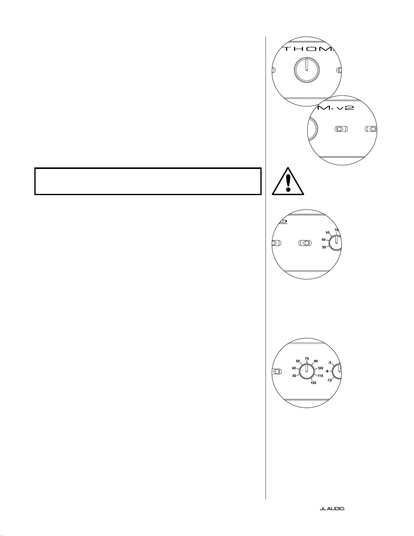
LP Freq
e Low Pass (LP) Frequency selector knob allows the user to choose the roll-
o frequency of the Fathom v2’s internal low pass lter. e frequency is variable
between 30 Hz (full counter-clockwise) to 130 Hz (full clockwise). is knob does
not aect the input signal in any way if the LP Filter switch is set to “O”. 80 Hz
is a commonly used lter frequency and usually serves as a good starting point
for adjustments.
LP freq. (Hz) e.l.f. trim (dB) phase (deg.)
Polarity
0
|
180 deg.
LP Filter
o
|
12dB
|
24dB
Master Level
max
0
Lights
o
|
dim
|
on
-∞
Level Mode
ref.
|
variable
Input Mode
master
|
slave
calibration mic. demo defeat calibrate
Power
o
|
on
|
auto
Digital Automatic Room Optimization
LP freq. (Hz) e.l.f. trim (dB) phase (deg.)
Polarity
0
|
180 deg.
LP Filter
o
|
12dB
|
24dB
Master Level
max
0
Lights
o
|
dim
|
on
-∞
Level Mode
ref.
|
variable
Input Mode
master
|
slave
calibration mic. demo defeat calibrate
Power
o
|
on
|
auto
Digital Automatic Room Optimization
LP freq. (Hz) e.l.f. trim (dB) phase (deg.)
Polarity
0
|
180 deg.
LP Filter
o
|
12dB
|
24dB
Master Level
max
0
Lights
o
|
dim
|
on
-∞
Level Mode
ref.
|
variable
Input Mode
master
|
slave
calibration mic. demo defeat calibrate
Power
o
|
on
|
auto
Digital Automatic Room Optimization
LP freq. (Hz) e.l.f. trim (dB) phase (deg.)
Polarity
0
|
180 deg.
LP Filter
o
|
12dB
|
24dB
Master Level
max
0
Lights
o
|
dim
|
on
-∞
Level Mode
ref.
|
variable
Input Mode
master
|
slave
calibration mic. demo defeat calibrate
Power
o
|
on
|
auto
Digital Automatic Room Optimization
IMPORTANT
Pg 17 | EN
|
Fathom
®
v2
EN
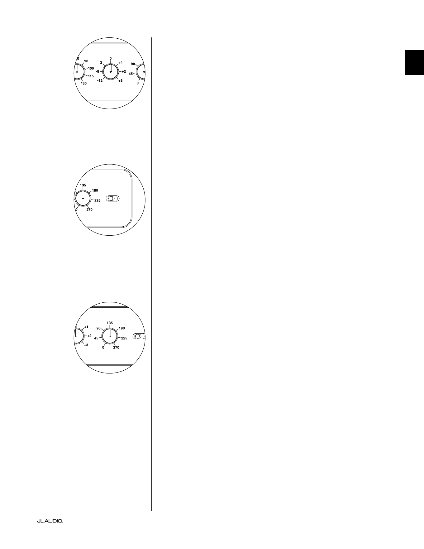
E.L.F. Trim
e Extreme Low Frequency (“e.l.f. trim”) knob allows the user to apply
a certain amount of signal equalization at 24 Hertz (extremely low bass). At
full counter-clockwise rotation, the signal at 24 Hz is cut by 12 dB. At “0” the
equalizer is set at for zero contribution to the signal. At full clockwise rotation,
the signal at 24 Hz is boosted by 3 dB.
e e.l.f. trim feature is useful for tailoring the Fathom v2’s very low frequency
output for your particular room. Adding some boost can make certain material
feel more exciting. Using the cut function can help to compensate for room or
boundary gain in the low frequencies. Room boundaries and the room’s nite
(limited) size naturally cause very low frequencies to be boosted relative to
other parts of the signal. As such, using the e.l.f. trim feature to cut the lowest
frequencies can help to tame “bloat” or unnatural sounding low bass in small to
medium sized rooms (and can also reduce unwanted vibrations in the room or
throughout the house).
Polarity
e Polarity switch allows the user to select between normal (0 deg) and
reversed (180 deg) signal polarity. e Polarity switch will primarily aect the
small frequency range around the crossover point between your subwoofer and
satellite speakers.
Unlike the Phase control, which eectively adds time delay, the Polarity
switch produces an instantaneous reversal of the signal’s amplitude peaks.
For example, if at a given reference point a sine wave has an amplitude peak,
by ipping the phase switch you instantly convert that peak into a trough
or amplitude dip. Because the eect of the Polarity switch is immediate, it
compliments the operation of the Phase control and cannot be replaced by it.
When placing your Fathom v2 in the room, experiment with the Polarity switch
before adjusting the “Phase” control. Either position of the Polarity switch may
provide a smoother transition between your Fathom v2 subwoofer and the satellite
speakers. Use source material with good mid and upper bass content for evaluation.
Phase
e Phase control knob allows the user to adjust the “timing” of the
subwoofer output relative to the main speakers. e Phase control will primarily
aect the small frequency range around the crossover point between your
subwoofer and satellite speakers. Phase settings between 0 degrees (full counter-
clockwise rotation) and 270 degrees (full clockwise rotation) are possible. e
Phase control’s labels are referenced to a frequency of 80 Hz since this is the most
common crossover point between satellite speakers and a subwoofer.
Speaker, subwoofer, and listening seat positions vary greatly in home
theater installations. Since physical positioning of speakers relative to the room
boundaries, and each other, greatly aects the perceived quality of sound output,
sometimes it is helpful to delay the subwoofer output. is is exactly what occurs
when you turn the Phase control beyond 0 degrees.
Once your Fathom v2 has been placed in your listening room to give you the
smoothest overall sound and aer you have determined the optimum “Polarity”
switch position (see preceding section), experiment with the position of the Phase
control. Using familiar source material with good mid and upper bass content,
adjust the Phase control and listen for better dened mid-bass and a smoother
transition between the subwoofer and satellite speaker systems. If no single
setting sounds better than another, leave the Phase control at 0 degrees.
LP freq. (Hz) e.l.f. trim (dB) phase (deg.)
Polarity
0
|
180 deg.
LP Filter
o
|
12dB
|
24dB
Master Level
max
0
Lights
o
|
dim
|
on
-∞
Level Mode
ref.
|
variable
Input Mode
master
|
slave
calibration mic. demo defeat calibrate
Power
o
|
on
|
auto
Digital Automatic Room Optimization
LP freq. (Hz) e.l.f. trim (dB) phase (deg.)
Polarity
0
|
180 deg.
LP Filter
o
|
12dB
|
24dB
Master Level
max
0
Lights
o
|
dim
|
on
-∞
Level Mode
ref.
|
variable
Input Mode
master
|
slave
calibration mic. demo defeat calibrate
Power
o
|
on
|
auto
Digital Automatic Room Optimization
LP freq. (Hz) e.l.f. trim (dB) phase (deg.)
Polarity
0
|
180 deg.
LP Filter
o
|
12dB
|
24dB
Master Level
max
0
Lights
o
|
dim
|
on
-∞
Level Mode
ref.
|
variable
Input Mode
master
|
slave
calibration mic. demo defeat calibrate
Power
o
|
on
|
auto
Digital Automatic Room Optimization
EN | Pg 18
|
Fathom
®
v2
CONNECTING YOUR FATHOM v2
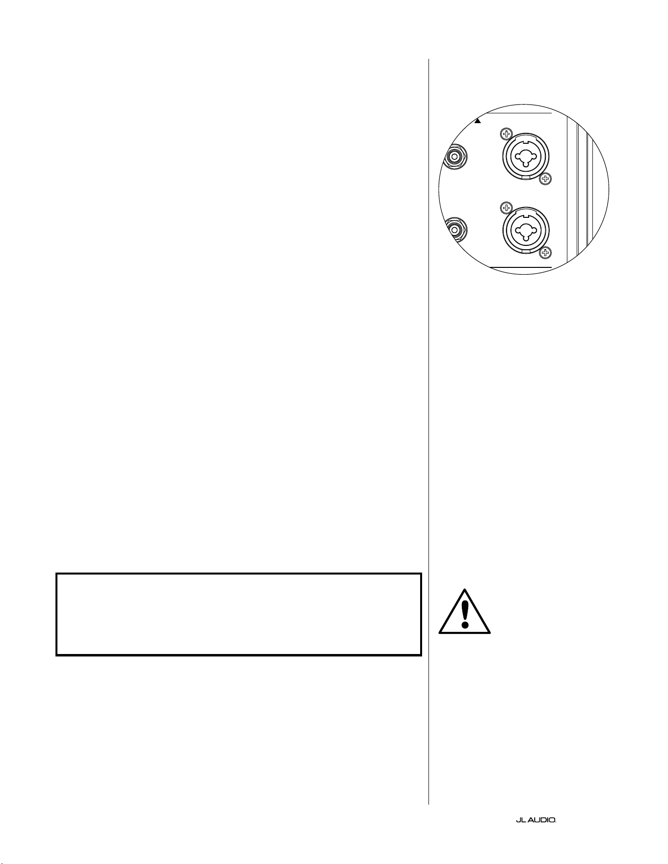
Balanced Inputs
If your home-theater receiver or preamplier/processor provides balanced
outputs, the Fathom v2’s balanced inputs are the preferred connection. Balanced
connections are used extensively in professional studios and sound reinforcement
applications for a number of very good reasons. Besides ensuring proper grounding
between components, balanced signal transmission is designed to cancel induced
cable noise from the surrounding environment (particularly important with long
cable runs). e bottom line is that your system will be far less likely to exhibit
humming or other extraneous noises if you use balanced connections.
e Fathom v2 subwoofers feature individual le and right balanced input
connections with XLR “combo” jacks. ese special jacks accept either a
three-pin male XLR connector or a “tip-ring-sleeve” (TRS) 1/4-inch (6.3 mm)
connector for compatibility with a wide range of equipment.
For systems with a mono subwoofer or “LFE” channel connection, only the
jack labeled “Le or Mono” will be used. is applies to most modern multi-
channel receivers and preamplier/processors. Separate le and right input jacks
are provided for systems without a dedicated mono subwoofer connection. is
typically applies to two-channel audio equipment.
Appropriate balanced cables are available from your JL Audio dealer and are
not included with the Fathom v2.
Technical Notes:
• Do not use the balanced inputs with unbalanced signals via adaptors. e
unbalanced inputs of the Fathom v2 are optically isolated and preferable in
situations where only an unbalanced signal source is available. Balanced input
impedance is 20 kohms.
• Input connectors are congured according to Audio Engineering Society
recommendations for balanced signal cables as follows:
XLR Connection
Pin 1: Shield
Pin 2: Positive
Pin 3: Negative
TRS connection:
Tip: Positive
Ring: Negative
Sleeve: Shield
IMPORTANT! IF YOUR RECEIVER OR PREAMPLIFIER/PROCESSOR DOES NOT
HAVE XLR OR 1/4-INCH TRS BALANCED OUTPUTS, PLEASE REFER TO THE
“UNBALANCED INPUTS” SECTION ON PAGE 19 FOR INPUT CONNECTION
INFORMATION. DO NOT ATTEMPT TO CONNECT UNBALANCED OUTPUTS
TO THE FATHOM V2’S BALANCED INPUTS VIA ADAPTORS.
e Le and Right inputs on the Fathom
v2 are internally summed to a single mono
channel. Since the Fathom v2 is inherently
a “mono” or single channel device, you can
use the Le and Right inputs for the master
Fathom v2 and then distribute the summed
mono signal to additional slave Fathom v2s
in the system.
IMPORTANT
1200VA
Built in USA with Imported and domestic components
LEFT
or
MONO
RIGHT
ONLY
INPUTS
Output to Slave
(Balanced)
Balanced
Unbalanced
Input Modes
Slave
Master
Grounded
Isolated
SERIAL NUMBER:
Warranty void if serial number is removed, altered or defaced.
F 12A H
250V
120 V ~ 60 Hz
F
U
S
E
F
U
S
E
Pg 19 | EN
|
Fathom
®
v2
EN
Unbalanced Inputs
e Fathom v2 subwoofer features individual le and right
unbalanced RCA-type input connectors. ese are the most commonly
used connectors for home audio applications and must be used if your
receiver or preamplier/processor does not provide balanced outputs.
While unbalanced connections are not as noise-immune as a balanced
connection, Fathom v2 subwoofers employ optical isolation on the
unbalanced inputs to minimize the possibility of noise in your system.
For systems with a mono subwoofer or “LFE” channel connection, only
the RCA-type jack labeled “Le or Mono” will be used. is applies to most
modern multi-channel receivers and preamplier / processors. Separate le and
right RCA-type input jacks are provided for systems without a dedicated mono
subwoofer connection. is typically applies to two-channel audio equipment.
Technical Notes:
• When balanced outputs are not available on the signal source, you must
use the RCA-type unbalanced inputs. Fathom v2s feature optical isolation
circuitry on the unbalanced inputs to minimize the likelihood of ground
loop induced noise. Unbalanced input impedance is 50 kohms.
• Connections are industry-standard for unbalanced signal cables as follows:
RCA-type connection:
Tip: Positive
Sleeve: Negative
IMPORTANT! IF NOISE EXISTS AFTER CONNECTION, FATHOM V2s ALLOW
FOR GROUNDING OR ISOLATION OF THE UNBALANCED INPUTS. PLEASE
REFER TO THE “INPUT MODE SWITCHES” SECTION ON PAGE 20 OF THIS
MANUAL FOR FURTHER INFORMATION ON MINIMIZING NOISE.
1200VA
Built in USA with Imported and domestic components
LEFT
or
MONO
RIGHT
ONLY
INPUTS
Output to Slave
(Balanced)
Balanced
Unbalanced
Input Modes
Slave
Master
Grounded
Isolated
SERIAL NUMBER:
Warranty void if serial number is removed, altered or defaced.
F 12A H
250V
120 V ~ 60 Hz
F
U
S
E
F
U
S
E
IMPORTANT
EN | Pg 20
|
Fathom
®
v2
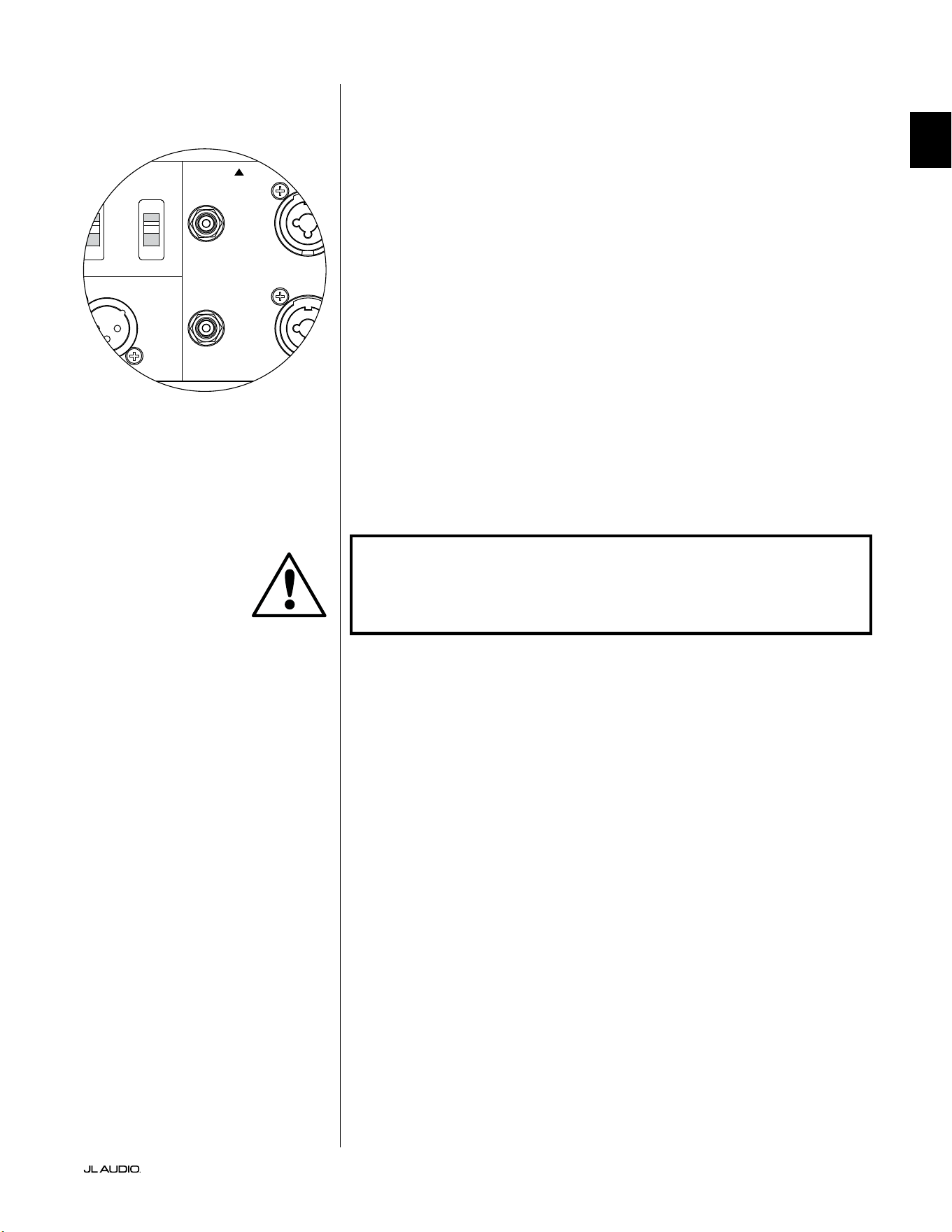
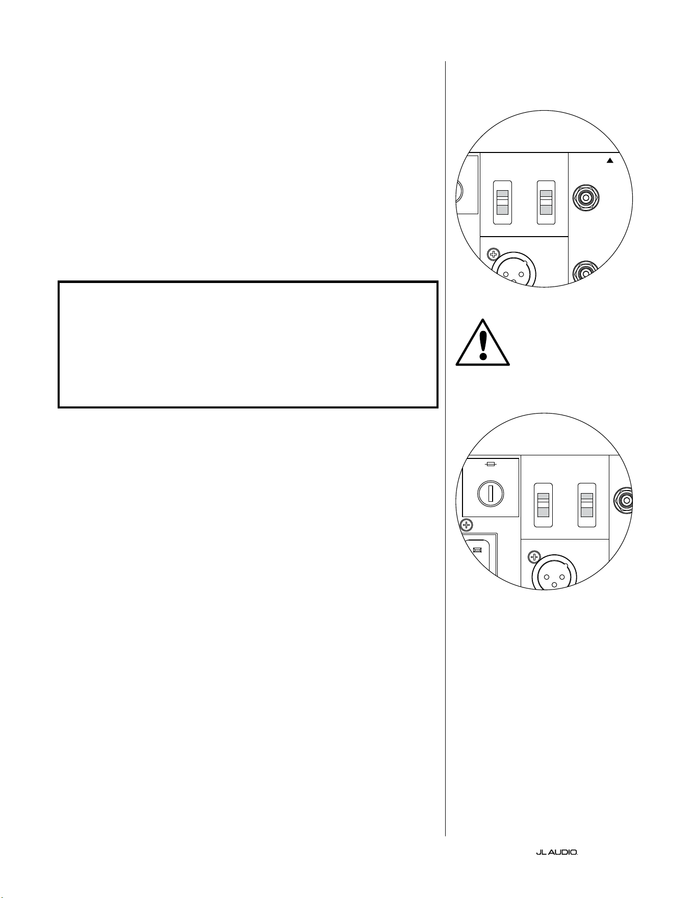
Input Mode Switches:
Two switches are located on the rear panel to control unbalanced signal
grounding and master/slave operation.
“Grounded / Isolated” Switch
e “Grounded / Isolated” Input Mode switch aects only the unbalanced
RCA inputs and is designed to facilitate a quiet, hum-free connection to your
audio or home theater system. is feature is included to deal with the signal
grounding issues oen encountered in home theater systems when several
components from dierent manufacturers are interconnected.
e Fathom v2 ships with this switch in the “Isolated” mode. If, with all system
components connected and turned on (but no source material playing), you hear
a continuous low-frequency hum through your Fathom v2, ip this switch to the
“Grounded” position and evaluate the dierence in the noise level. Use whichever
switch position provides the least hum or noise.
IMPORTANT! PLEASE NOTE THAT CHANGING ANY COMPONENT IN THE
OPTIMIZED SYSTEM (RECEIVER, AMPLIFIER, DVD PLAYER, CABLE OR
SATELLITE BOX, ETC.) COULD ALTER THE SIGNAL GROUNDING SCHEME AND
CAUSE HUM TO APPEAR IN YOUR PREVIOUSLY QUIET SYSTEM. IF YOU ADD
OR CHANGE AN UPSTREAM COMPONENT IN YOUR HOME THEATER SYSTEM,
YOU MAY NEED TO REVISIT THIS INPUT MODE SETTING ON THE FATHOM
V2 SUBWOOFER FOR OPTIMUM NOISE PERFORMANCE. CABLE & SATELLITE
BOXES ARE PARTICULARLY TROUBLESOME IN THIS WAY.
Master / Slave Switch
e Fathom v2s are designed to easily accommodate the implementation
of multiple subwoofers in your home theater system through a master/slave
connection chain. is method allows you to utilize the signal processing
features of one Fathom v2 to centrally control multiple Fathom v2s in the room.
Master/Slave functionality also makes it possible for the D.A.R.O. system to
optimize the response of a multiple subwoofer installation.
e Fathom v2 ships with this switch in the “Master” position. If you are using
a single Fathom v2 you will use the “Master” position and you need not concern
yourself with this section any further.
If your installation incorporates two or more Fathom v2s, you will designate
one Fathom v2 as the “Master” and all others in the system as “Slave” subwoofers
via the “Master/Slave” switch on the rear amplier panel of each Fathom v2.
LED’s on the front panel of the Fathom v2 are provided to indicate whether the
“Master” or “Slave” mode is selected for a given subwoofer.
From the Fathom v2 operating in “Master” mode, the “Output to Slave” signal
carries any signal processing selected on the Master Fathom v2 (including the
Master Level setting and D.A.R.O. processing) to further Fathom v2s operating
in “Slave” mode. “Slave” subwoofer signal processing and level controls will be
inoperable. In this mode, the user does not have to worry about level, crossover,
and other settings for the slave subwoofers.
Technical Notes:
• Selecting the “Slave” position defeats all user-denable signal processing and
the master level control. Because of this, there are some special situations
in which you may want to operate a single Fathom v2 in “Slave” mode. If
you are utilizing outboard signal processing and level-matching controls,
activating the “Slave” mode will prevent anyone from aecting system
parameters with the manual controls on the Fathom v2.
IMPORTANT
1200VA
Built in USA with Imported and domestic components
LEFT
or
MONO
RIGHT
ONLY
INPUTS
Output to Slave
(Balanced)
Balanced
Unbalanced
Input Modes
Slave
Master
Grounded
Isolated
SERIAL NUMBER:
Warranty void if serial number is removed, altered or defaced.
F 12A H
250V
120 V ~ 60 Hz
F
U
S
E
F
U
S
E
1200VA
Built in USA with Imported and domestic components
LEFT
or
MONO
RIGHT
ONLY
INPUTS
Output to Slave
(Balanced)
Balanced
Unbalanced
Input Modes
Slave
Master
Grounded
Isolated
SERIAL NUMBER:
Warranty void if serial number is removed, altered or defaced.
F 12A H
250V
120 V ~ 60 Hz
F
U
S
E
F
U
S
E
Pg 21 | EN
|
Fathom
®
v2
EN
IMPORTANT! PLEASE REFER TO THE “SYSTEM CONNECTION DIAGRAMS”
ON PAGES 22-25 FOR MORE INFORMATION ON USING THE INPUT / OUTPUT
CONNECTIONS.
“Output to Slave” Connector
If you are operating more than one Fathom v2 subwoofer in one home theater
system, you will designate one Fathom v2 as the Master (see page 20), and then
feed signal from it to the remaining “Slave” Fathom v2s via this balanced XLR
output. e “Output to Slave” cable can be connected to the “Le or Mono”
balanced XLR input on the next Fathom v2. When a Fathom v2 is in “Slave”
Mode, its “Output to Slave” connection can be used to pass signal to further
Fathom v2s operating in “Slave” mode.
e “Output to Slave” connector is designed to be used as follows:
1) From the “Master” Fathom v2’s “Output to Slave” connector to the rst
“Slave” Fathom v2’s “Le or Mono” XLR balanced input.
2) From the rst “Slave” Fathom v2’s “Output to Slave” connector to the
second “Slave” Fathom v2’s “Le or Mono” XLR balanced input.
3) From the second “Slave” Fathom v2’s “Output to Slave” connector to the
third “Slave” Fathom v2’s “Le or Mono” XLR balanced input. Etc, etc. (up
to ten Fathom v2s may be connected in this conguration). Appropriate
balanced cables with XLR terminations are available from your JL Audio
dealer and are not included with the Fathom v2.
Technical Notes:
• e “Output to Slave” signal carries any signal processing selected on
the Master Fathom v2 (including the Master Level setting and D.A.R.O.
processing) to further Fathom v2s operating in “Slave” mode.
• From Fathom v2s operating in “Slave” mode, the “Output to Slave” signal is
an exact, buered replica of the balanced input signal, making this method
of signal distribution preferable to using Y-adapters or splitters.
• Use only shielded, connection cables with high quality XLR connectors for
Master/Slave connection. Never use unbalanced cables with adaptors.
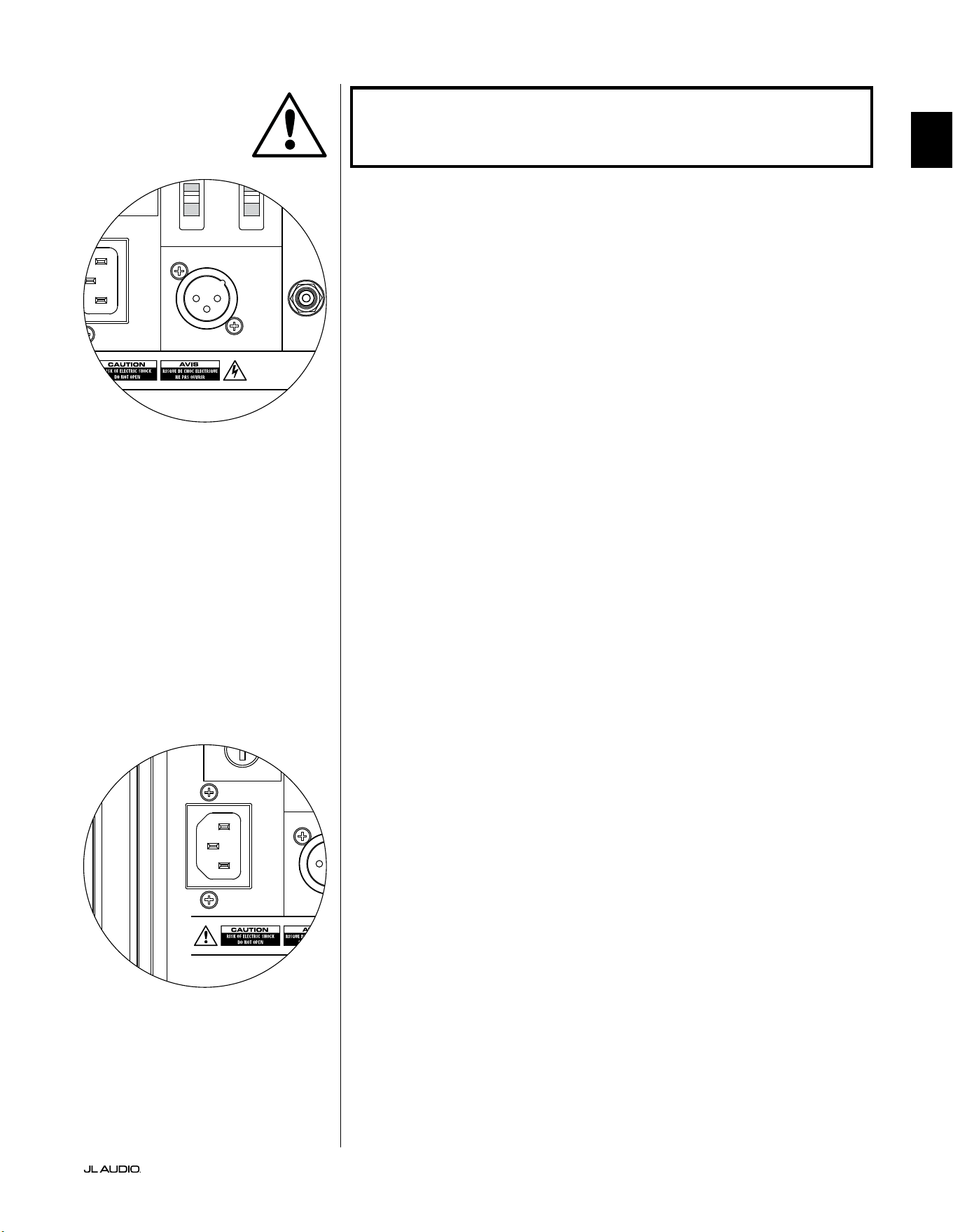
IEC-Style AC Power Connector
e IEC-style AC cord receptacle receives the heavy-gauge, 6 . (1.8 m) long,
power cord included with your Fathom v2 subwoofer. Fathom v2s sold in dierent
parts of the world are congured for each market’s electrical system and include
appropriate plugs on their power cords. Please note the voltage markings next to
the AC connector and make sure you are only powering your Fathom v2 from
a receptacle that matches these markings. Do not use any AC power cord other
than the one supplied with the Fathom v2. For information about the Main Fuse
Holder, please see the Troubleshooting section of this manual.
e Fathom v2 subwoofer is a very powerful device and can draw a lot of
current. If too many components are connected with a Fathom v2 subwoofer
to one electrical outlet, you risk tripping a household circuit breaker during
very demanding program material. If this happens, split the Fathom v2 and
other components between two AC electrical circuits. If possible, for maximum
performance, dedicate an AC circuit to each Fathom v2.
IMPORTANT
1200VA
Built in USA with Imported and domestic components
LEFT
or
MONO
RIGHT
ONLY
INPUTS
Output to Slave
(Balanced)
Balanced
Unbalanced
Input Modes
Slave
Master
Grounded
Isolated
SERIAL NUMBER:
Warranty void if serial number is removed, altered or defaced.
F 12A H
250V
120 V ~ 60 Hz
F
U
S
E
F
U
S
E
1200VA
Built in USA with Imported and domestic components
LEFT
or
MONO
RIGHT
ONLY
INPUTS
Output to Slave
(Balanced)
Balanced
Unbalanced
Input Modes
Slave
Master
Grounded
Isolated
SERIAL NUMBER:
Warranty void if serial number is removed, altered or defaced.
F 12A H
250V
120 V ~ 60 Hz
F
U
S
E
F
U
S
E
EN | Pg 22
|
Fathom
®
v2
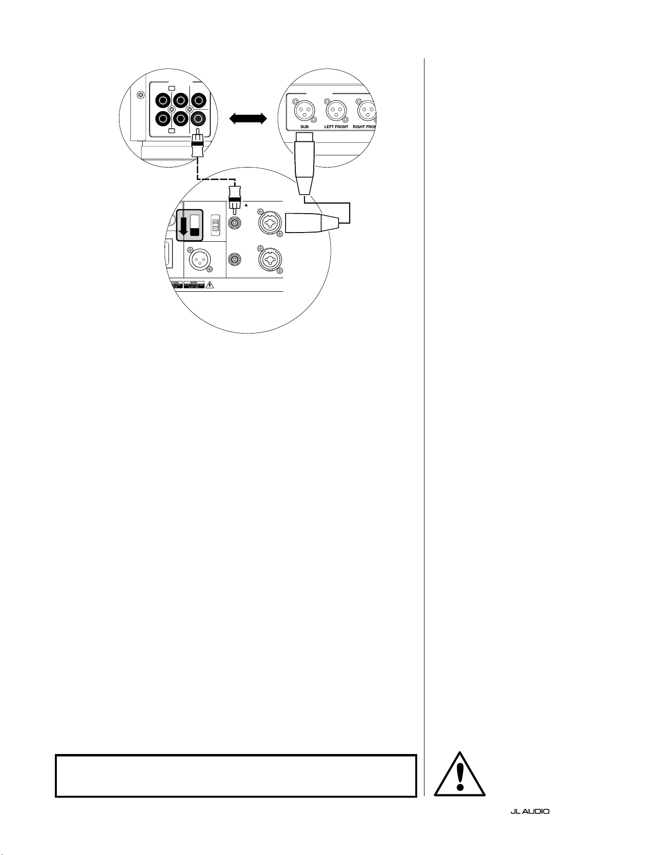
SYSTEM CONNECTION DIAGRAM 1:
One Fathom v2 to
Home Theater Receiver or
Home Theater Preamp/Processor
Most home theater receivers and
preamp/processors provide a single
(mono) subwoofer output. When
connecting a mono subwoofer output
to your Fathom v2, you will only use the
Fathom’s “Le or Mono” input.
Two connection types are available
for connecting the Fathom v2 to your
home theater system: balanced (XLR or
1/4-inch TRS connector) and unbalanced
(RCA-type connector). Balanced
connections provide superior noise
rejection and ensure proper grounding
between components. If your receiver or
processor has balanced outputs, we highly
recommend that you use them.
In the connection diagram at le,
balanced connections are shown as solid
lines, unbalanced connections are shown
dotted. You will only use one of these
input connection methods (not both).
1200VA
ilt in USA with Imported and domestic components
LEFT
or
MONO
RIGHT
ONLY
INPUTS
Output to Slave
(Balanced)
Balanced
Unbalanced
Input Modes
Slave
Master
Grounded
Isolated
SERIAL NUMBER:
Warranty void if serial number is removed, altered or defaced.
F 12A H
250V
0 V ~ 60 Hz
F
U
S
E
F
U
S
E
S
l
ave
Master
z
OUTPUTS
SUB
REAR
REAR CENTER
FRONT
FRONT
R
L
PRE OUT
PROCESSOR (BALANCED OUTPUTS)
FATHOM REAR CONTROLS (MASTER)
OR
RECEIVER / PROCESSOR (UNBALANCED OUTPUTS)
WARNING
WARNING! TURN OFF THE FATHOM v2 AND ALL OTHER EQUIPMENT IN THE
SYSTEM BEFORE MAKING OR CHANGING ANY CONNECTIONS!
Pg 23 | EN
|
Fathom
®
v2
EN
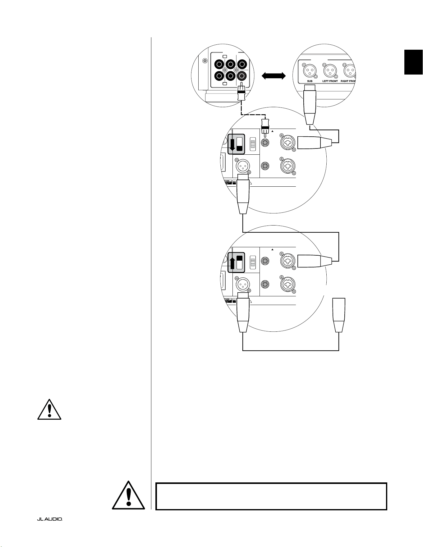
SYSTEM CONNECTION DIAGRAM 2:
Multiple Fathom v2s to
Home Theater Receiver or
Home Theater Preamp/Processor
To greatly simplify using multiple
subwoofers in a single home theater
system, Fathom v2s incorporate a “Master/
Slave” signal distribution system. is
allows control of all the Fathom v2s in a
system from a single “Master” unit.
First, you will select a Fathom v2
subwoofer as the “Master” via its upper
“Input Mode” switch. Generally, you will
designate the Fathom v2 closest to the
receiver/preamp as the master. In some
cases; for example, when the control panel
of certain units is dicult to access, you
may prefer to designate the one which is
easiest to access as the master.
Two connection types are available for
connecting the master Fathom v2 to your
home theater system: balanced (XLR or
1/4-inch TRS connector) and unbalanced
(RCA-type connector). Balanced
connections provide superior noise
rejection and ensure proper grounding
between components. If your receiver or
processor has balanced outputs, we highly
recommend that you use them to connect
to the Fathom v2 designated as the master.
In the connection diagram at le,
balanced connections are shown as solid
lines, unbalanced connections are shown
dotted. You will only use one of these
input connection methods for the Fathom
v2 designated as the master (not both).
e remaining Fathom v2s in the
system will be congured as “Slave” units
via their upper “Input Mode” switches.
Using balanced XLR cables, you will
connect the master Fathom v2’s “Output
to Slave” to the “Le or Mono” balanced
input of the rst slave Fathom v2. at
slave unit’s “Output to Slave” connector
will feed the “Le or Mono” input of
the next slave unit via another balanced
XLR cable. Subsequent slave units will
be connected in the same manner.
Connections between the “Master” and
“Slave” Fathoms and between “Slave”
Fathoms are via balanced XLR cables ONLY.
1200VA
ilt in USA with Imported and domestic components
LEFT
or
MONO
RIGHT
ONLY
INPUTS
Output to Slave
(Balanced)
Balanced
Unbalanced
Input Modes
Slave
Master
Grounded
Isolated
SERIAL NUMBER:
Warranty void if serial number is removed, altered or defaced.
F 12A H
250V
0 V ~ 60 Hz
F
U
S
E
F
U
S
E
1200VA
ilt in USA with Imported and domestic components
LEFT
or
MONO
RIGHT
ONLY
INPUTS
Output to Slave
(Balanced)
Balanced
Unbalanced
Input Modes
Slave
Master
Grounded
Isolated
SERIAL NUMBER:
Warranty void if serial number is removed, altered or defaced.
F 12A H
250V
0 V ~ 60 Hz
F
U
S
E
F
U
S
E
Sl
ave
Master
z
Sl
ave
Master
z
OUTPUTS
SUB
REAR
REAR CENTER
FRONT
FRONT
R
L
PRE OUT
PROCESSOR (BALANCED OUTPUTS)
FATHOM REAR CONTROLS (MASTER)
FATHOM REAR CONTROLS (SLAVE)
OR
RECEIVER / PROCESSOR (UNBALANCED OUTPUTS)
TO ADDITIONAL FATHOMS
(IF APPLICABLE)
IMPORTANT
WARNING
WARNING! TURN OFF THE FATHOM v2 AND ALL OTHER EQUIPMENT IN THE
SYSTEM BEFORE MAKING OR CHANGING ANY CONNECTIONS!
EN | Pg 24
|
Fathom
®
v2
1200VA
ilt in USA with Imported and domestic components
LEFT
or
MONO
RIGHT
ONLY
INPUTS
Output to Slave
(Balanced)
Balanced
Unbalanced
Input Modes
Slave
Master
Grounded
Isolated
SERIAL NUMBER:
Warranty void if serial number is removed, altered or defaced.
F 12A H
250V
0 V ~ 60 Hz
F
U
S
E
F
U
S
E
S
l
ave
M
aster
z
STEREO ACTIVE CROSSOVER (BALANCED OUTPUTS)
LOW OUT
(SUB OUT)
STEREO ACTIVE CROSSOVER (UNBALANCED OUTPUTS)
RIGHTLEFT
LOW OUT
(SUB OUT)
FATHOM REAR CONTROLS (MASTER)
OR
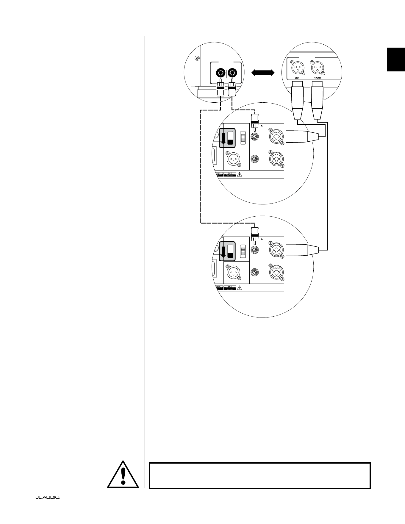
SYSTEM CONNECTION DIAGRAM 3:
One Fathom v2 in Mono to
Two-Channel Audio System
When connecting a Fathom v2
(or multiple Fathom v2s) in mono to
a two-channel audio system you will
use both the “Le or Mono” and the
“Right” inputs. Summing circuitry
in the Fathom v2’s input section will
sum the stereo signals to mono.
We strongly recommend that you
use a high-quality active crossover,
like the JL Audio CR-1, to divide your
preamplier’s signals prior to connection
to the Fathom v2 and to the amplier
driving your main speakers. is will
allow you to lter low frequencies out of
the signals driving the main speakers,
resulting in better performance.
If you are not using an active crossover
and are comfortable running your main
speakers full-range, you can split your
preamplier’s output signals using
appropriate Y-connectors in place of the
active crossover shown in the diagram.
Two connection types are available
for connecting the Fathom v2 to your
two-channel audio system: balanced
(XLR or 1/4-inch TRS connector) and
unbalanced (RCA-type connector).
Balanced connections provide superior
noise rejection and ensure proper
grounding between components. If your
preamplier or active crossover oers
balanced outputs, we highly recommend
that you use them.
In the connection diagram at le,
balanced connections are shown as solid
lines, unbalanced connections are shown
dotted. You will only use one of these
input connection methods (not both).
NOTE: If desired, additional Fathom v2s
can be connected in “Slave” mode to the
Fathom v2 connected as shown on this
diagram. See “Connection Diagram 2” on
page 23 for slave connection explanation.
WARNING
WARNING! TURN OFF THE FATHOM v2 AND ALL OTHER EQUIPMENT IN THE
SYSTEM BEFORE MAKING OR CHANGING ANY CONNECTIONS!
Pg 25 | EN
|
Fathom
®
v2
EN
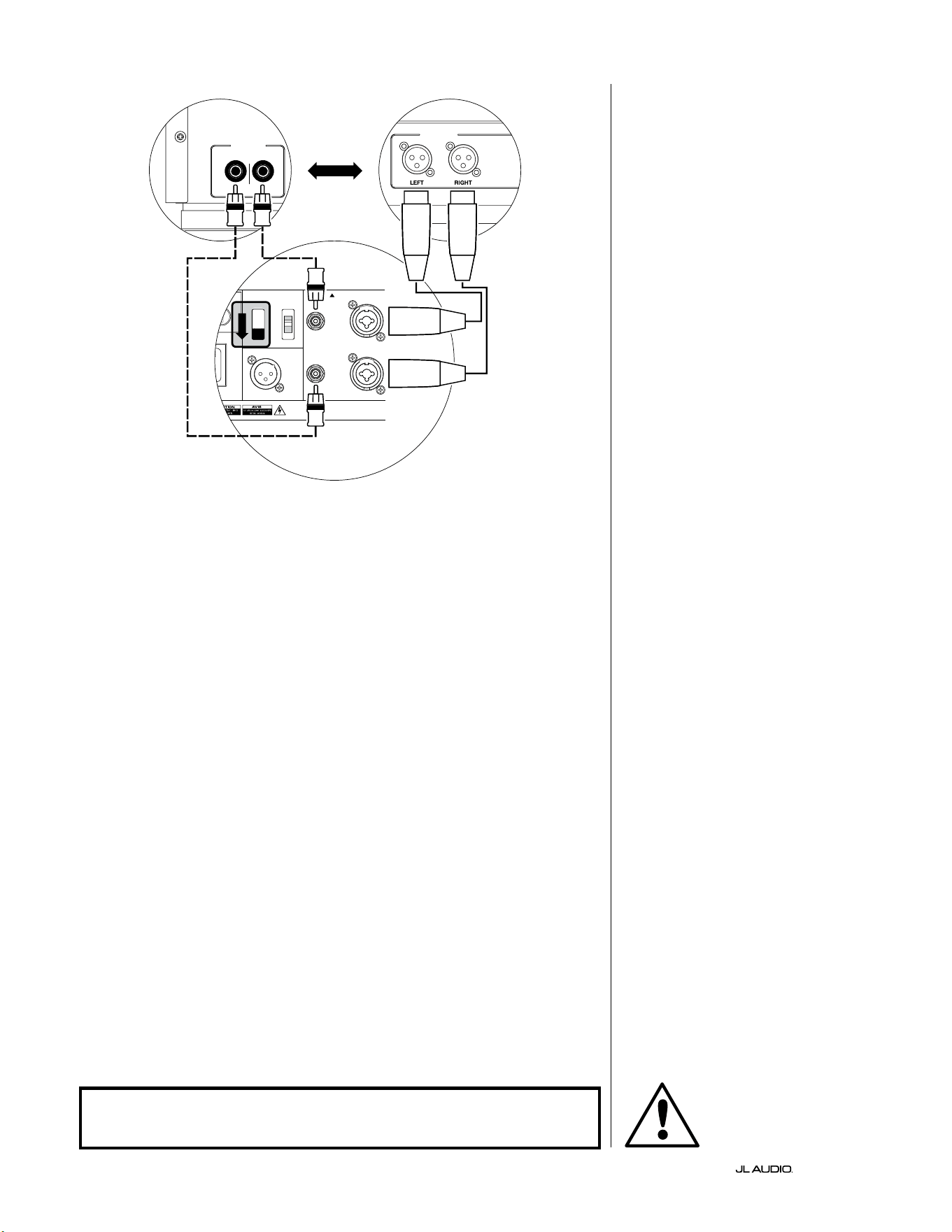
SYSTEM CONNECTION DIAGRAM 4:
Two Fathom v2s in Stereo to
Two-Channel Audio System
When connecting two Fathom v2s in
stereo to a two-channel audio system you
will only use the “Le or Mono” inputs of
each Fathom v2. e upper “Input Mode”
switch on each Fathom v2 will be set in
the “Master” position.
We strongly recommend that you use
a high-quality active crossover, like the JL
Audio CR-1, to divide your preamplier’s
signals prior to connection to the Fathom
v2 and to the amplier driving your main
speakers. is will allow you to lter low
frequencies out of the signals driving
the main speakers, resulting in better
performance.
If you are not using an active crossover
and are comfortable running your main
speakers full-range, you can split your
preamplier’s output signals using
appropriate Y-connectors in place of the
active crossover shown in the diagram.
Two connection types are available
for connecting the Fathom v2s to your
two-channel audio system: balanced
(XLR or 1/4-inch TRS connector) and
unbalanced (RCA-type connector).
Balanced connections provide superior
noise rejection and ensure proper
grounding between components. If your
preamplier or active crossover oers
balanced outputs, we highly recommend
that you use them.
In the connection diagram at right,
balanced connections are shown as solid
lines, unbalanced connections are shown
dotted. You will only use one of these
input connection methods (not both).
NOTE: If desired, additional Fathom v2s
can be connected in “Slave” mode to each
Fathom v2 connected as shown on this
diagram. See “Connection Diagram 2” on
page 23 for slave connection explanation.
LOW OUT
(SUB OUT)
RIGHTLEFT
LOW OUT
(SUB OUT)
1200VA
ilt in USA with Imported and domestic components
LEFT
or
MONO
RIGHT
ONLY
INPUTS
Output to Slave
(Balanced)
Balanced
Unbalanced
Input Modes
Slave
Master
Grounded
Isolated
SERIAL NUMBER:
Warranty void if serial number is removed, altered or defaced.
F 12A H
250V
0 V ~ 60 Hz
F
U
S
E
F
U
S
E
S
l
ave
Master
z
PROCESSOR (BALANCED OUTPUTS)
FATHOM REAR CONTROLS (MASTER)
OR
RECEIVER / PROCESSOR (UNBALANCED OUTPUTS)
FATHOM REAR CONTROLS (MASTER)
WARNING
WARNING! TURN OFF THE FATHOM v2 AND ALL OTHER EQUIPMENT IN THE
SYSTEM BEFORE MAKING OR CHANGING ANY CONNECTIONS!

EN | Pg 26
|
Fathom
®
v2
RECOMMENDED SETUP PROCEDURES
1) Preparation for Setup Process: ..................................... 26-27
2) Level Setting: ....................................................... 28
3) Polarity/Phase Adjustment: ........................................... 28
4) Experiment with Location: ........................................... 28
5) Apply D.A.R.O: .................................................. 29-30
6) Adjust E.L.F. Trim: .................................................. 30
PREPARATION FOR SETUP PROCESS:
Please conrm the following system settings before beginning the setup
process. is will ensure a neutral starting point and an eective setup of your
subwoofer system.
On your Home Theater Receiver or Preamp/Processor:
Before beginning setup of your Fathom v2 subwoofer system we recommend
that you set your receiver or preamp/processor as follows (please turn o all
Fathom v2s in the system via their front panel power switches prior to making
these adjustments):
1. Speaker Size
In the speaker setup menu of your receiver or preamp/processor, set up all
of your high-frequency speakers as “small” with a crossover point of 80 Hz.
is will send ALL bass to the Fathom v2(s).
2. Speaker Distance
In the speaker setup menu, properly set all speaker distances to the primary
listening seat, including the subwoofer’s distance. Use a tape measure to
determine these distances (time coherence is important.) If multiple Fathom
v2s are being used, average their distances to the primary listening seat and
use that number to set the subwoofer distance.
3. Subwoofer Level
Set the subwoofer level in the receiver or preamp/processor to “0” or its
middle position.
4. Tone Controls / Equalizers
Set all tone controls to “0” and defeat all equalizer features.
On your Active Crossover or Bass Management Processor:
If you are using an active crossover or bass-management processor, we
recommend that you set it as follows before beginning setup of your Fathom v2
subwoofer system (please turn o all Fathom v2s in the system prior to making
these adjustments):
1. Low-Pass Filter Frequency
Select a low-pass lter frequency of 80 Hz (24 dB/octave slope)
2. High-Pass Filter Frequency
Select a high-pass lter frequency of 80 Hz (24 dB/octave slope)
3. Low-Pass (Subwoofer) Output Level
Set the subwoofer output level to “0” or its middle position.
Pg 27 | EN
|
Fathom
®
v2
EN
On the Fathom v2’s Front Panel:
Please turn o the home theater receiver or preamp/processor to make these
adjustments.
1. “Power” Switch
Flip each Fathom v2’s “Power” switch to the “On” position.
2. “Lights” Switch
Flip each Fathom v2’s “Lights” switch to the “On” position. If you don’t see
any lights on the front panel, you may have forgotten to plug the Fathom v2
in or there may be a problem with the electrical circuit.
3. “Input Mode” Indicator Lights
If you are using a single Fathom v2, conrm that its “Input Mode” indicator
light is on the “Master” position. If not, you will need to access the upper
“Input Mode” switch on the rear panel of the Fathom v2.
If you are using multiple Fathom v2s in a Master/Slave conguration,
conrm that the unit connected directly to your receiver or preamp/
processor is indicating “Master” on its “Input Mode” lights and that all other
units are indicating “Slave” on their “Input Mode” lights. If not, you will
need to access the upper “Input Mode” switches on the rear panels of the
Fathom v2s.
4. “Level Mode” Switch
Flip the master Fathom v2’s “Level Mode” switch to the “REF” position.
5. “LP Filter” Switch
If your home theater receiver/processor is handling bass management
(speakers set on “small”) or if you are using an outboard crossover/bass-
management processor, ip the master Fathom v2’s “LP Filter” switch to
“OFF.” If not, select the “12 dB” position.
6. “LP Freq. (Hz)” Knob
Rotate the “LP Freq.” knob to the “80 Hz” position.
7. “e.l.f. trim (dB)” Knob
Rotate the “e.l.f. trim” knob to “0”
8. “Polarity” Switch
Flip the “Polarity” switch to “0”.
9. “phase (deg.)” Knob
Rotate the “phase” knob to “0” degrees
10. D.A.R.O. Defeat Switch
Press the D.A.R.O. defeat switch so that the
red light in the switch remains lit.
LP freq. (Hz) e.l.f. trim (dB) phase (deg.)
Polarity
0
|
180 deg.
LP Filter
o
|
12dB
|
24dB
Master Level
max
0
Lights
o
|
dim
|
on
-∞
Level Mode
ref.
|
variable
Input Mode
master
|
slave
calibration mic. demo defeat calibrate
Power
o
|
on
|
auto
Digital Automatic Room Optimization
EN | Pg 28
|
Fathom
®
v2
RECOMMENDED SETUP PROCEDURES (continued)
Subwoofer System Setup:
Once you have set the controls on your home theater receiver or preamp/
processor and on your Fathom v2(s) to the settings recommended on pages 26 and
27, you are ready to begin setting up your Fathom v2 for optimum performance.
1. Level Setting
Using familiar music or movie material with deep bass content, adjust
the subwoofer level to blend with the other speakers using your receiver or
preamp/processor’s subwoofer level control. is method is more immune to
tampering than using the Fathom v2’s “Master Level” knob (think toddlers or
curious visitors).
In the unlikely event that the subwoofer level control in your receiver or
preamp/processor cannot be turned up enough to level match the Fathom v2,
return that control to “0”. en, ip the Fathom v2’s “Level Mode” switch to
“Variable” and with “0” as your reference point (REF mode gain and Variable
“0” gain are identical) use the “Master Level” control to level match the
subwoofer with the other speakers. MAKE NOTE OF THIS SETTING FOR
FUTURE USE.
For more detailed information on your Fathom v2’s level setting controls,
please refer to the “Level Mode” and “Master Level” sections on pages 15 - 16 of
this manual.
2. Polarity and Phase Adjustment
It is oen helpful to have a second person operating these controls so that you
can easily hear the changes from the primary listening seat.
Listening to familiar source material (preferably music with good upper bass
and midbass response), ip the “Polarity” switch from “0” to “180” and listen for
dierences. e correct setting will sound most natural with the best upper bass
punch and articulation. If both sound similar, choose “0”.
Once Polarity is set, use the same music material to audition dierent “Phase”
control settings and choose the one that further enhances the upper and midbass
response. If you can’t hear a dierence, set the control to “0.”
3. Experiment with alternative subwoofer locations (if necessary).
If you are satised with the basic performance of your subwoofer you are ready
to move on to the next step. If not, we recommend that you experiment with
the position of your subwoofer until you are pleased with its basic performance.
Experimentating with placement is KEY to a superior sounding system. Moving
the subwoofer just a few feet can have a signicant eect on the smoothness of the
bass. For each new position, start with the polarity and phase controls at “0” and
repeat the setup process beginnng with Step 1.
IMPORTANT! WRITE DOWN ALL SETTINGS PERFORMED IN STEPS 1-3 FOR
FUTURE REFERENCE.
IMPORTANT
Pg 29 | EN
|
Fathom
®
v2
EN
IMPORTANT! MAKE SURE THE ROOM IS QUIET DURING D.A.R.O.
CALIBRATION! TURN OFF ANY NOISY APPLIANCES NEAR THE LISTENING
ROOM (DISHWASHERS, WASHING MACHINES, ETC.)
IT IS PARTICULARLY IMPORTANT TO TURN OFF AIR CONDITIONERS OR HEAT
PUMPS DURING CALIBRATION. THESE FORCED-AIR-TYPE HVAC SYSTEMS
CAN CREATE MODERATE LEVELS OF 15 – 20 HZ NOISE THAT MAY INTERFERE
WITH CALIBRATION.
4. Applying Digital Automatic Room Optimization (D.A.R.O.)
You are now ready to apply the power of JL Audio’s exclusive Digital
Automatic Room Optimization (D.A.R.O.) system. is system will measure the
response of the subwoofer at your primary listening seat and apply a powerful
18-band equalizer to tame the peaks caused by room modes, resulting in
smoother, more accurate bass performance. If you are using multiple Fathom
v2s in a master/slave conguration, you will only need to address the unit
designated as “master” to perform D.A.R.O. calibration for the entire subwoofer
system. Note that all front-panel signal processing is defeated during D.A.R.O.
calibration, regardless of the knob settings. Normal operation is restored once
calibration is complete.
a) Set the Main Power switch to the “ON” position and be sure the Fathom v2’s
indicator lights are switched “ON” via the “Lights” switch.
b) Remove the calibration microphone from its protective pouch and connect
its cable to the mini-XLR jack on the Fathom v2’s front control panel.
NOTE: D.A.R.O. Calibration is only possible when the included JL Audio test
microphone is plugged in to the Fathom v2 front panel. e “Calibrate” feature is
disabled with no microphone plugged in to prevent accidental loss of settings.
c) Connect the microphone to the other end of the mic cable and temporarily
place the mic in the primary listening seat. If you have a microphone stand,
you can place the microphone at head height and position in the primary
listening seat.
d) On the Fathom v2’s control panel, press the “Calibrate” button. e green
light on the “Calibrate” button will ash slowly, indicating that calibration will
begin in 5 seconds.
e) Within 5 seconds of pressing the “Calibrate” button, return to your primary
listening seat and hold the microphone in your normal, seated head position at
the approximate height of your ears.
f) A noise sequence will be played through the Fathom v2 that sounds like hashy
static. e sequence will last approximately 3 minutes. During this process,
the D.A.R.O. system is taking a frequency response measurement at your seat
and correcting the problems it nds. e D.A.R.O. system also compensates
for any before & aer level dierences so that your Fathom v2 will have a
similar perceived loudness aer the calibration process. When D.A.R.O. is
nished calibrating, the “Calibrate” button will light and stay on, indicating a
successful calibration.
Should you wish to run a new calibration, simply repeat the steps above.
IMPORTANT
EN | Pg 30
|
Fathom
®
v2
To clear the D.A.R.O.’s settings (i.e., return them to at) & turn o the
Calibrate light, press and hold the Demo button and then press the Defeat
button. Please note that you must perform this button sequence quickly. If
you hold the Demo button for more than 2 seconds without touching the
Defeat button, the Demo tones will start. Should this happen, simply wait for
the Demo sequence to end and try again. You can perform a new calibration
by following the normal procedure outlined above.
IMPORTANT! IF YOU MOVE YOUR FATHOM V2 OR PRIMARY LISTENING SEAT
IN THE FUTURE, YOU WILL NEED TO RUN D.A.R.O. AGAIN. ANY PARTICULAR
CALIBRATION IS UNIQUE TO THAT PARTICULAR SUBWOOFER POSITION
AND LISTENING SEAT POSITION COMBINATION. SIMPLY FOLLOW THE STEPS
ABOVE TO CREATE A NEW CALIBRATION CURVE.
5. Extreme Low Frequency (e.l.f.) Trim
Use the “e.l.f. trim” control to adjust the extreme low bass extension of the
Fathom v2. is control allows -12 dB of cut or +3 dB of boost at 24 Hertz and
is particularly useful when using a Fathom v2 (or two) in a small to medium
sized home theater. Since smaller enclosed spaces help to boost the level of the
lowest bass frequencies, smaller theaters can be overwhelmed by the strong low-
bass output of the Fathom v2 subwoofer. is can create a “thick” or “bloated”
character in the lower bass region. Turning down the “e.l.f. trim” knob cuts the
extreme low bass level and alleviates this condition. Feel free to experiment and
listen to a variety of demanding material until you nd the best match for your
room and your tastes.
Your Fathom v2 is now optimized for maximum bass performance at your
listening seat. Congratulations!
IMPORTANT

Pg 31 | EN
|
Fathom
®
v2
EN
FREQUENTLY ASKED QUESTIONS
Can I place objects on my subwoofer?
We do not recommend placing any items on the subwoofer cabinet
as they may vibrate, causing undesirable noise and possible
damage to the nish. Under no circumstances should any object
containing liquid be placed on the Fathom v2 cabinet.
Is the Fathom v2 magnetically shielded?
Fathom v2 subwoofers are not magnetically shielded. To avoid magnetic
distortion with certain television types, place the Fathom v2 at least 3-4 feet (1 -
1.5m) from your screen. If you notice any discoloration in the picture, try moving
the subwoofer further away until these artifacts disappear.
Will my electric bill be high if I leave the Fathom v2 in “Auto” mode?
When in “Auto” mode, the Fathom v2 amplier is only powered up when
a signicant signal is detected on the inputs. When powered down, only
“housekeeping” circuits remain on, which draw negligible amounts of power
from the wall (less than 5 watts).
Should I unplug my subwoofer during a thunderstorm or extended absence?
YES. You should unplug your Fathom v2 during (or before) thunderstorms. is
will prevent any possible damage from voltage spikes due to lightning. In these
conditions, it’s a good idea to unplug all of your audio / video components. If you
are going to be away from home for several days, it is also a good idea to unplug
your home theater components to prevent damage from unexpected storms or
power line conditions.
CLEANING YOUR FATHOM v2
Dust your Fathom v2’s subwoofer cabinet using a clean, so microber cloth
or feather duster. Microber cloths are commonly available where automotive
detailing supplies are sold.
Light smudges can generally be wiped o with a clean microber cloth. For more
stubborn smudges, polish and protect the nish using a high-quality automotive
wax and a microber cloth, both available wherever automotive detailing supplies
are sold. We recommend Meguiar’s® “NXT Tech Wax” and Meguiar’s® Microber
Detailing cloths.
Never use a polish that contains harsh solvents or abrasives as these may
permanently damage the nish. Never use furniture polish or any oil-based
product on your Fathom v2. Never use solvents or aggressive cleaning agents on
your Fathom v2. When in doubt, test the cleaning product on the underside of
the cabinet and let it sit for several days before committing to its use on visible
portions of the cabinet.

EN | Pg 32
|
Fathom
®
v2
TROUBLESHOOTING
No sound from subwoofer.
1. Verify that Fathom v2 is plugged in, turned “ON” & that front panel lights are
“ON”. If the lights do not turn on, check the circuit breaker that feeds its outlet or
plug the Fathom v2 into another AC power outlet. If your AC outlet has power
but the lights still do not come on, you may need to inspect/replace the Fathom
v2’s main power fuse. Refer to the “Main Fuse Holder” section on the next page.
2. Test the subwoofer by pressing the DEMO button on the front panel – if the sub
emits demo tones the subwoofer’s internal circuitry is ne and an input problem
is likely. Check the input cable connections at the Fathom v2 and at the receiver/
preamp/processor.
3. Verify that your receiver’s subwoofer settings have not changed.
4. If your other speakers play, but the Fathom v2 does not, try changing the cable
that connects the Fathom v2 to the system.
5. If the problem persists, call your dealer or JL Audio Technical Support for
assistance.
e bass level has changed.
1. Make sure your level settings (on the Fathom v2 and in your receiver/preamp/
processor) have not changed.
2. If you are using the Fathom v2’s “Master Level” knob to set the subwoofer level,
conrm that the “Level Mode” switch is set to “Variable”.
3. erify the position of the ELF Trim knob.
Hums or other unusual noises from your Fathom v2
1. See Input Mode discussion on page 20 of this manual, especially if any upstream
components, cables, etc., have recently changed.
2. Turn o the Fathom v2, disconnect all its input and output signal cables,
turn the Fathom v2 back on. If the noise disappears, the noise is being caused
elsewhere in your system.
Bass sounds “muddy” or “too heavy”.
1. Try decreasing the 24 Hertz level using the “e.l.f. trim” control. Muddy bass
can sometimes be caused by too much low frequency output in a moderately
sized room.
2. Decrease the overall subwoofer level.
3. Verify your receiver’s subwoofer settings.
4. Try a di erent subwoofer or main listening seat location. Changing one or the
other can have a HUGE e ect on how your system sounds. See the placement
discussion on pages 6-10 of this manual.
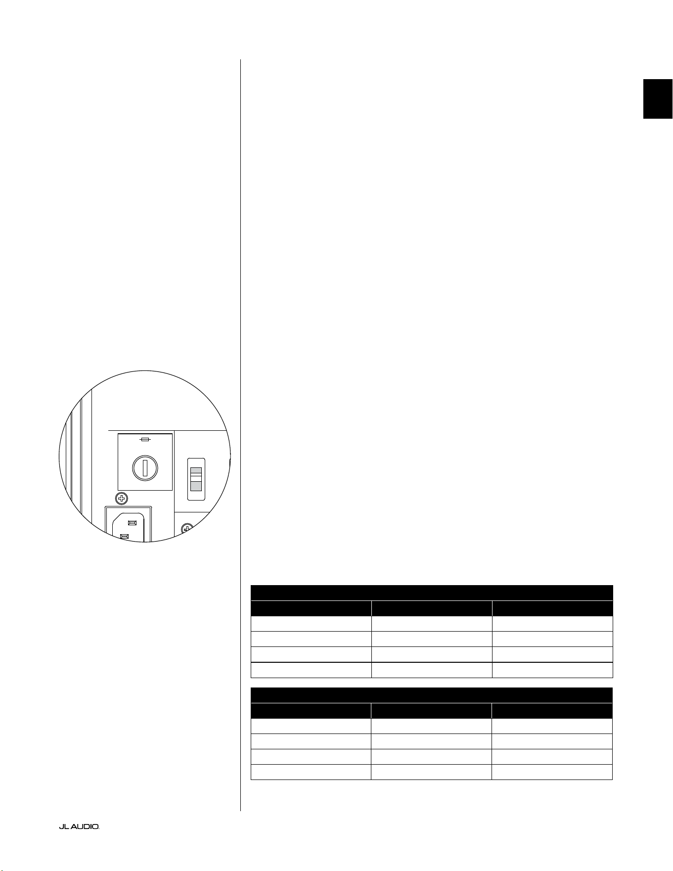
Pg 33 | EN
|
Fathom
®
v2
EN
TROUBLESHOOTING - continued
D.A.R.O. Calibration attempt gives blinking Calibrate light
1. If the included JL Audio Microphone is not properly plugged into the front panel
jack, calibration will fail and the green Calibrate light will blink fast. Calibration
will ONLY proceed with the JL Audio microphone connected. Connecting any
other mic will cause the calibration to fail. Cancel the blinking Calibrate light by
pressing the Calibrate button again.
2. If calibration fails with the JL Audio microphone properly connected,
the green Calibrate light will blink slowly. Test the microphone and
cable connections and try running calibration again. If calibration
fails aer following the steps above, the microphone or microphone
cable may be bad. Contact JL Audio Home Technical Support.
Your Fathom v2 is clearly audible outside of your house.
1. Revisit the “Master Level” setting on your Fathom v2(s) or your home theater
receiver/preamp/processor.
2. Inquire with your JL Audio dealer about noise isolation strategies.
3. Move the Fathom v2 away from windows.
MAIN FUSE HOLDER
Located on the rear panel, next to the AC cord receptacle is the main fuse
holder’s cover. is small spring-loaded cap may be removed, allowing access
to inspect or replace the main power fuse. If your AC outlet has power but
the Fathom v2’s lights do not come on, the main power fuse may be blown.
To Remove - Unplug the subwoofer’s AC power cord. Insert a small athead
screwdriver into the cap’s slot and turn counter-clockwise slowly until the fuse holder
is released. Once removed, the fuse can be inspected and if necessary, replaced.
Refer to the chart below for fuse values for your specic Fathom v2 model.
To Reinstall - Note that the fuse holder’s body is keyed to the opening and must
be aligned to t properly. Insert the fuse holder into the opening and gently turn
clockwise (about 1/8 turn) to lock in place. Pressing the cap and feeling for the spring
to compress will help to locate the correct position. Reconnect the AC power cord.
If the replacement fuse blows immediately aer a fuse replacement,
the subwoofer’s amplier may require service. Please contact
your JL Audio Authorized Retailer or Distributor.
Fuse Ratings, 120V Models Only
Model Fuse Type Fuse Size
f110 v2 (120V) 0.25 x 1.25-inch, fast-acting 7A, 250V
f112v2 (120V) 0.25 x 1.25-inch, fast-acting 8A, 250V
f113v2 (120V ) 0.25 x 1.25-inch, fast-acting 12A, 250V
f212v2 (120V) 0.25 x 1.25-inch, fast-acting 15A, 250V
Fuse Ratings, 240V Models Only
Model Fuse Type Fuse Size
f110v2 (240V) 5mm x 20mm, fast-acting 6.3A, 250V
f112v2 (240V) 5mm x 20mm, fast-acting 6.3A, 250V
f113v2 (240V ) 5mm x 20mm, fast-acting 8A, 250V
f212v2 (240V) 5mm x 20mm, fast-acting 10A, 250V
1200VA
Built in USA with Imported and domestic components
LEFT
or
MONO
RIGHT
ONLY
INPUTS
Output to Slave
(Balanced)
Balanced
Unbalanced
Input Modes
Slave
Master
Grounded
Isolated
SERIAL NUMBER:
Warranty void if serial number is removed, altered or defaced.
F 12A H
250V
120 V ~ 60 Hz
F
U
S
E
F
U
S
E

H
W
D
Specifications: f110v2 f112v2 f113v2 f212v2
Enclosure Type: Sealed Sealed Sealed Sealed
Driver:
Single 10-inch
(nominal diameter)
Single 12-inch
(nominal diameter)
Single 13.5-inch
(nominal diameter)
Dual 12-inch
(nominal diameter)
Frequency Response (anechoic):
27 – 111 Hz (±1.5dB)
–3 dB at 25 Hz / 120 Hz
–10 dB at 19 Hz / 155 Hz
21-119 Hz (+1.5dB)
–3 dB at 19 Hz / 150 Hz
–10 dB at 17 Hz / 167 Hz
20-86 Hz (+1.5dB)
–3 dB at 18 Hz / 127 Hz
–10 dB at 16 Hz / 154 Hz
20 - 97 Hz (+/- 1.5 dB)
-3 dB at 19 / 110 Hz
-10 dB at 15 / 157 Hz
Effective Piston Area:
60 in
2
0.0387 m
2
84 in
2
0.0542 m
2
107. 35 in
2
0.0693 m
2
168 in
2
0.1084 m
2
Effective Displacement:
160 in
3
2.6 liters
287 in
3
4.7 liters
386 in
3
6.3 liters
574 in
3
9.4 liters
Amplifier Power:
1100 watts
RMS short-term
1800 watts
RMS short-term
3000 watts
RMS short-term
3600 watts
RMS short-term
Dimensions: (H) x (W) x (D)
Height Dimensions include feet
15.64 x 12.92 x 17.27 in
397 x 328 x 439 mm
18.5 x 15 x 17.625 in
470 x 381 x 448 mm
19.625 x 16.5 x 19.25 in
498 x 419 x 489 mm
31.96 x 14.92 x 20.39 in
812 x 379 x 518 mm
Net Weight:
69 lbs
31 kg
117 l bs
53 kg
133 lbs
60 kg
224 lbs
102 kg
Cabinet Finish: High-Gloss Black High-Gloss Black High-Gloss Black High-Gloss Black
FEATURES
Unbalanced Inputs:
Stereo or Mono (two RCA jacks)
Balanced Inputs:
Stereo or Mono (two female XLR jacks)
Output To Slave:
Balanced (one male XLR jack)
Input Modes:
Master or Slave
Level Modes:
Reference (xed gain) or Variable from
full mute to +15dB over reference gain
Power Modes:
O, On or Automatic Signal-Sensing
Light Modes:
O, On or Dim
Low Pass Filter Mode:
O, 12 dB per octave or 24 dB per octave
Low Pass Filter Cuto Frequency:
Variable from 30 Hz – 130 Hz
Polarity:
0 or 180 degrees
Phase:
Variable from 0 – 270 degrees
E.L.F. Trim:
Variable from –12 dB to +3 dB at 24 Hz
Digital Automatic Room Optimization
(D.A.R.O.)
Automatic, 18-band digital equalizer with
included laboratory-grade calibration
microphone, defeatable.
www.jlaudio.com
10369 North Commerce Parkway • Miramar, Florida • 33025 • USA
“JL Audio”, “Fathom”, and the JL Audio logo are registered trademarks of JL Audio, Inc.
©2022 JLAudio, Inc. • For more detailed information please visit us online at www.jlaudio.com. Product images shown are for illustrative purposes only and may differ from the actual
product. Due to continuous product development, all specifications are subject to change without notice.
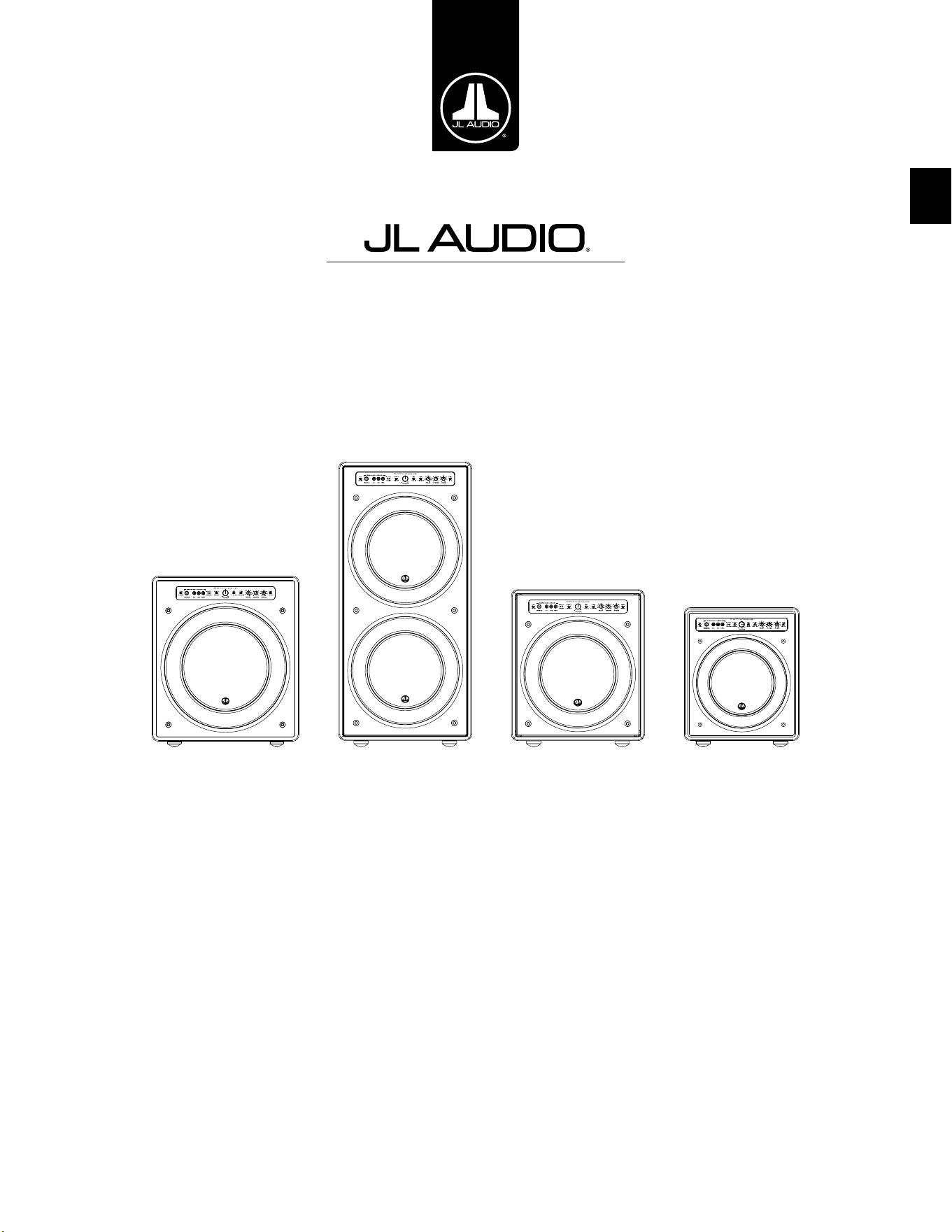
FR
Subwoofer amplifié Fathom v2
Manuel de l’utilisateur
f113v2 f212v2 f112v2 f110v2

FR | Pg 2
|
Fathom
®
v2
INSTRUCTIONS IMPORTANTES SUR LA SÉCURITÉ
AVERTISSEMENT: POUR RÉDUIRE TOUT RISQUE D’INCENDIE OU DE CHOC
ÉLECTRIQUE, N’EXPOSEZ PAS CE PRODUIT À LA PLUIE OU L’HUMIDITÉ.
ATTENTION
RISQUE DE CHOC ÉLECTRIQUE
NE PAS OUVRIR
ATTENTION: POUR RÉDUIRE LES RISQUES DE CHOC ÉLECTRIQUE, NE RETIREZ
PAS LE CACHE. AUCUNE PIÈCE INTERNE RÉPARABLE PAR L’UTILISATEUR.
CONFIEZ LES RÉPARATIONS À DES TECHNICIENS QUALIFIÉS.
1. Lire les instructions-Lisez toutes les instructions relatives à la sécurité et à
l’utilisation avant de faire fonctionner le subwoofer.
2. Conserver les instructions-Conservez les instructions relatives à la sécurité
et à l’utilisation an de pouvoir les consulter ultérieurement.
3. Tenir compte des avertissements-Respectez tous les avertissements indiqués
sur le subwoofer et dans le manuel d’utilisation.
4. Suivre les instructions-Toutes les instructions de fonctionnement et
d’utilisation doivent être suivies.
5. Eau et humidité-Le subwoofer NE DOIT PAS être utilisé à proximité d’une
source d’eau, telle qu’une baignoire, un lavabo, un évier, un lave-linge, dans un
sous-sol humide, près d’une piscine, etc.
6. Ventilation-Le subwoofer doit être placé de sorte que son emplacement ou
sa position ne nuise pas à une bonne ventilation. Par exemple, le subwoofer
ne doit pas être placé sur un lit, un canapé, un tapis, ou toute autre surface
similaire susceptible de bloquer le ux d’air sur les ailettes du dissipateur
thermique. Si le subwoofer est «encastré» dans l’installation, veillez à ce que
la circulation de l’air vers le dissipateur thermique à l’arrière du subwoofer ne
soit pas entravée. Ne couvrez pas le dissipateur thermique du subwoofer avec
des nappes, des rideaux, etc.
7. Chaleur et ammes-Le subwoofer ne doit pas être installé à proximité d’une
source de chaleur telle qu’un radiateur, une bouche de chaleur, un poêle, une
cheminée, ou tout autre dispositif produisant de la chaleur. Ne posez pas de
bougies sur ou à côté du subwoofer.
8. Sources d’alimentation-Branchez le subwoofer uniquement au type
d’alimentation indiqué dans le manuel d’utilisation ou sur la plaque
signalétique placée sur le subwoofer.
9. Protection du cordon d’alimentation-Le cordon d’alimentation doit être
disposé de sorte à éviter d’être piétiné ou pincé par des objets placés sur ou
contre lui. Faites particulièrement attention aux cordons au niveau des ches,
des prises murales, et du point de sortie du subwoofer.
10. Nettoyage-Le subwoofer doit être nettoyé conformément aux instructions
fournies dans le manuel d’utilisation.
11. Périodes de non-utilisation-Le cordon d’alimentation du subwoofer doit
être débranché de la prise de courant lorsqu’il n’est pas utilisé pendant une
longue période.
Le symbole de l’éclair terminé par une
èche dans un triangle équilatéral est
destiné à avertir l’utilisateur de la présence
d’une «tension dangereuse » non isolée à
l’intérieur du produit. Cette tension peut
avoir une force susante pour constituer un
risque de choc électrique.
Le symbole d’un point d’exclamation dans
un triangle équilatéral est destiné à avertir
l’utilisateur de la présence d’instructions
d’utilisation et d’entretien importantes dans
la documentation accompagnant le produit.
Pg 3 | FR
|
Fathom
®
v2
FR
12. Protection contre la foudre et la surtension-Débranchez le subwoofer de
la prise murale en cas d’orage et/ou de coupures de courant récurrentes an
d’éviter les dégâts consécutifs à une surtension.
13. Intrusion d’objet ou de liquide-Prenez soin de ne pas faire tomber d’objets
dans l’appareil et de ne pas déverser de liquides sur le boîtier du subwoofer.
N’exposez pas le subwoofer aux gouttes d’eau et éclaboussures de liquides. Ne
posez pas d’objets remplis de liquides sur ou à côté du subwoofer. Par exemple,
des vases, boissons, lampes à combustible liquide, etc.
14. Dégâts nécessitant réparation-Conez la réparation du subwoofer à du
personnel qualié dans les cas suivants:
a. Le cordon d’alimentation ou la che ont été endommagés.
b. Des objets sont tombés ou du liquide a été déversé sur le subwoofer.
c. Le subwoofer a été exposé à la pluie.
d. Le subwoofer ne semble pas fonctionner correctement ou ne fonctionne
plus de manière optimale.
e. Le subwoofer est tombé ou le boîtier a été endommagé.
f. Le cône du haut-parleur et/ou la suspension ont été physiquement
endommagés.
15. Entretien-L’utilisateur doit éviter tout entretien du subwoofer qui n’est pas
explicitement décrit dans le manuel d’utilisation. Toutes les autres opérations
d’entretien doivent être conées à des techniciens spécialisés.
16. Surcharge-Évitez toute surcharge au niveau des prises murales, des rallonges
ou des prises multiples, au risque de provoquer un incendie ou un choc
électrique.
17. Mise à la terre-Ce subwoofer est doté d’un cordon d’alimentation à trois
broches mis à la terre. Les précautions nécessaires doivent être prises
an de ne pas endommager le dispositif de mise à la terre du subwoofer.
L’endommagement de la broche de mise à la terre du cordon d’alimentation du
subwoofer pourrait augmenter les risques de choc électrique et endommager
les pièces électroniques de manière irréversible.
CE SUBWOOFER EST CAPABLE DE PRODUIRE DES NIVEAUX DE PRESSION
SONORE TRÈS ÉLEVÉS. VEUILLEZ FAIRE PREUVE DE MODÉRATION EN
L’UTILISANT POUR ÉVITER DES LÉSIONS AUDITIVES IRRÉVERSIBLES.
AVERTISSEMENT

FR | Pg 4
|
Fathom
®
v2
DÉCLARATION DE CONFORMITÉ FCC
REMARQUE: cet appareil a été testé et déclaré conforme aux limites de la partie15 imposées par
les règles de la FCC. Ces limites visent à garantir une protection raisonnable contre les interférences
nuisibles dans une installation à usage domestique. Cet appareil génère, utilise et peut émettre de
l’énergie de fréquence radio et, s’il n’est pas installé conformément aux instructions, il peut causer
des interférences nuisibles aux communications radio. Il est toutefois impossible de garantir que des
interférences ne se produiront pas dans une installation particulière. Si cet appareil provoque des
interférences nuisibles avec la réception des signaux de radio ou de télévision, qui peuvent être vériés
en éteignant et en rallumant l’appareil, l’utilisateur est encouragé à essayer de corriger ce problème en
prenant une ou plusieurs des mesures suivantes:
- Réorienter ou repositionner l’antenne de réception.
- Augmenter la distance de séparation entre l’appareil et le récepteur.
- Brancher l’appareil sur un circuit électrique diérent de celui où le récepteur est branché.
- Consulter le revendeur ou un technicien radio/ télévision expérimenté pour obtenir des
conseils.
TABLE DES MATIÈRES
Instructions importantes sur la sécurité: ................................. 2-3
Introduction: .......................................................... 4
Présentation du produit: ................................................. 5
Installation de votre Fathomv2 dans votre espace d’écoute: ................ 6-10
Déballage de votre Fathomv2: .......................................... 11
Schéma du panneau de commande avant: ................................. 12
Schéma du panneau de commande arrière et du panneau de connexions: ...12-13
Boutons de réglage du panneau avant en détail: ..........................14-17
Branchement de votre/ vos Fathomv2: .................................18-25
Procédures de réglage recommandées:. . . . . . . . . . . . . . . . . . . . . . . . . . . . . . . . . .26-30
Questions les plus fréquentes: ........................................... 31
Nettoyage de votre Fathomv2: .......................................... 31
Dépannage: .........................................................32-33
Garantie limitée/Informations sur l’assistance: ............................ 35
Spécications techniques: .............................................. 36
INTRODUCTION
Nous vous félicitons d’avoir choisi le subwoofer amplié JLAudio Fathom
v2. Ce produit a été rigoureusement conçu pour assurer une performance
exceptionnelle de votre home cinéma ou système audio pendant les nombreuses
années à venir.
Notre entreprise s’est totalement engagée dans la recherche de pointe en
matière d’enceintes haute performance et de technologies d’amplication. Les
modèles de subwoofer longue excursion JL Audio sont largement considérés
comme des références pour leur comportement linéaire et leur haut niveau
de sortie. Nous avons également concentré nos eorts sur la création d’un
amplicateur puissant et sur les techniques de traitement des signaux an d’obtenir
des performances en basse fréquence exceptionnelles. Votre Fathom v2 combine
toutes ces disciplines de base dans un boîtier compact, magniquement réalisé
pour vous orir une expérience d’écoute incomparable.
Nous vous remercions sincèrement pour votre achat et vous invitons à lire
attentivement ce manuel an d’obtenir le plus haut niveau de performance de
votre système de subwoofer Fathom v2. Bonne écoute.
TECHNOLOGIES JL AUDIO INCLUSES
DANS LES SUBWOOFERS FATHOM V2
Système de moteur optimisé pour l’AMD
L’AMD est le système d’analyse mécanique
dynamique innovant de JL Audio
conçu pour améliorer le comportement
dynamique du moteur. Grâce à
l’optimisation AMD, les moteurs de haut-
parleur restent linéaires sur une vaste
gamme d’excursions et conservent un
champ magnétique xe très stable sur une
gamme de puissance très étendue. Ceci
permet d’obtenir une faible la distorsion
et une reproduction dèle des transitoires
ou, en d’autres termes, d’obtenir des graves
puissants, clairs et précis.
OverRoll™ Surround
L’OverRoll™ dépasse de la bride de montage
du haut-parleur pour utiliser le diamètre
disponible perdu dans les enceintes
classiques. Cela permet d’utiliser le rouleau
plus large nécessaire pour contrôler
les excursions longues sans sacrier la
précieuse surface du cône.
W-Cone™
Le W-Cone™ est une structure de cône en
une pièce qui ore une rigidité étonnante
pour une masse minimale.
Méthode de xation Floating-Cone™
Cette technique de montage assure la
géométrie «surround» adéquate du haut-
parleur assemblé pour un meilleur contrôle
de l’excursion et un meilleur alignement
dynamique de la bobine.
«Plateau-Reinforced Spider Attachment»
Cette structure de suspension à haute
intégrité soulage les contraintes exercées
sur le matériau du spider lors des longues
excursions, pour plus de abilité.
Technologie «Elevated Frame Cooling»
Permet d’acheminer de l’air frais par les
orices situés au-dessus de la plaque
supérieure vers la bobine mobile du haut-
parleur. Ceci améliore la tenue en puissance
et la qualité acoustique en minimisant les
décalages des paramètres dynamiques et la
compression de puissance.
«Radially Cross-Drilled Pole Piece»
Ce système de ventilation innovant
améliore considérablement la dissipation
thermique et la tenue en puissance en
dirigeant le ux d’air sur la bobine mobile,
tout en se combinant à la technologie
«Elevated Frame Cooling».
«High-Damping Feedback Circuit»
Cette conception de circuit de commande
discrète et exclusive permet à nos
amplicateurs de commutation de classe
D de maintenir un excellent facteur
d’amortissement pour un comportement
transitoire et une délité améliorés.
Pg 5 | FR
|
Fathom
®
v2
FR
PRÉSENTATION DU PRODUIT
Les subwoofers Fathom v2 JL Audio combinent un haut-parleur individuel
de dernière génération JL Audio et un module doté de composants électroniques
et d’un amplicateur dans une enceinte très optimisée pour vous orir une
expérience d’écoute exceptionnelle avec votre home cinéma ou système audio.
Le haut-parleur individuel de votre système de subwoofer Fathom
v2 est capable d’adopter un comportement linéaire impressionnant sans
dégradation ou distorsion audible. Ce haut-parleur de qualité exceptionnelle
permet à votre Fathom v2 de reproduire des événements puissants en basse
fréquence avec un impact stupéant et une précision sans précédent. Dérivés
de la plateforme légendaire W7 de JL Audio, les haut-parleurs Fathom
v2 orent des capacités d’excursion de «crête à crête» prodigieuses pour
traiter ecacement la dynamique du programme audio le plus exigeant.
Pour tirer le meilleur parti de cette plateforme longue excursion, une
énorme quantité de puissance électrique contrôlée est nécessaire. Notre équipe
d’ingénieurs en électronique a réalisé une analyse approfondie du matériel type
et de ses exigences dynamiques an de trouver un équilibre entre les besoins
en courant et en puissance de sortie réelle par rapport aux caractéristiques
d’impédance du système. Cette étude poussée a donné lieu à la conception
d’amplicateurs à commutation aux spécications précises dotés d’une technologie
de rétroaction brevetée an de tirer pleinement prot de l’amplitude maximale de
l’enveloppe de chaque haut-parleur. Comparés à leurs prédécesseurs, les Fathom
v2 ont bénécié d’un tout nouveau traitement du signal numérique et d’une
augmentation de 20% de la puissance de l’amplicateur, ce qui renforce encore
leurs capacités dynamiques exceptionnelles.
Le magnique boîtier de votre Fathom v2 est également le fruit d’une
technologie précise. Pour contenir les niveaux de pression émis par le haut-parleur
du Fathom v2, nous utilisons un matériau découpé par commande numérique
sous calculateur en MDF ainsi que de multiples systèmes de xation interne et des
techniques d’assemblage avancées.
Votre espace d’écoute constitue l’autre élément qui aecte le son de vos graves.
Toutes les pièces ont une signature acoustique spécique qui doit être gérée
ecacement pour obtenir des performances de basse fréquence correctement
équilibrées. Pour faciliter l’intégration de vos subwoofers dans l’acoustique de
la pièce, tous les subwoofers Fathom v2 doivent utiliser un système puissant
d’optimisation numérique automatique de la pièce (DARO, Digital Automatic
Room Optimization). Ce système déploie dix-huit bandes d’égalisation numérique
an de dompter l’acoustique de la pièce et d’orir une précision des graves à
couper le soue.
Comme vous pouvez le constater à la lecture de cette brève introduction,
les systèmes de subwoofers Fathom v2 font appel à de nombreuses technologies
avancées. Le contenu de ce manuel décrit les diérentes fonctions et vous guidera
dans le processus de conguration et de réglage de votre subwoofer Fathom v2 an
que vous puissiez obtenir la meilleure expérience d’écoute à basse fréquence.
Si vous avez besoin d’une assistance, nous vous conseillons vivement de
contacter votre revendeur JL Audio pour des conseils et des services d’experts.
IMPORTANT ! NOUS VOUS CONSEILLONS VIVEMENT DE LIRE LA SECTION
SUIVANTE AVANT DE DÉBALLER VOTRE FATHOM V2. IL EST RECOMMANDÉ DE
DÉBALLER LE SUBWOOFER PRÈS DE SON EMPLACEMENT DÉFINITIF.
IMPORTANT

FR | Pg 6
|
Fathom
®
v2
INSTALLATION DE VOTRE FATHOMV2 DANS VOTRE ESPACE
D’ÉCOUTE:
Votre espace d’écoute ou salle de spectacle fait partie intégrante de votre
système de reproduction du son. Les dimensions physiques de l’espace, son
ameublement, son équipement, les portes et les fenêtres sont essentiels dans la
dénition de la sonorité du système.
Lorsque vous placez une source sonore dans un espace rectangulaire clos,
des ondes stationnaires se créent et découlent de la relation entre la longueur
d’onde du son et les dimensions de votre espace. En d’autres termes, les ondes
stationnaires naissent d’une énergie sonore qui est piégée dans l’espace lorsqu’elle
rebondit entre les deux murs opposés. Les ondes stationnaires dans l’espace
d’écoute créent des crêtes et des creux acoustiques lorsque le son est plus fort ou
plus faible, selon votre position dans l’espace. L’énergie s’accumule également aux
limites de l’espace, créant une réponse des graves exagérée à certaines fréquences.
Ces résonances fondamentales sont également appelées «modes» de résonance.
Pour conclure cette histoire de mode, il faut éviter les places assises dans les
zones de crête ou de creux des ondes stationnaires. Il est vivement recommandé
de placer vos sièges dans des zones où les crêtes et les creux modaux sont modérés
et ne se renforcent pas mutuellement. Les deux grandes zones à éviter sont celles
situées près du centre de la pièce et à proximité des murs.
Tout comme vos sièges d’écoute peuvent être installés dans une zone de crête
ou de creux, votre subwoofer peut l’être également. Un subwoofer placé dans un
coin d’une pièce excite au maximum la structure du mode de cette pièce, créant
ainsi la sortie la plus puissante avec un nombre minimum de creux. Lorsque le
subwoofer est placé loin d’un coin ou d’un mur, les modes de la pièce sont moins
excités, ce qui peut altérer le son à la position d’écoute.
Faites des essais pour choisir l’emplacement de votre siège
d’écoute et l’emplacement du subwoofer pour trouver la meilleure
solution. Des essais précis permettent généralement d’obtenir un
système de sonorisation de meilleure qualité. Suivez nos conseils de
conguration (décrits aux pages suivantes) pour démarrer.
Si vous ne pouvez pas éviter de placer votre canapé contre le mur du fond
de la pièce ou votre subwoofer à un emplacement moins optimal, le système
d’optimisation numérique automatique (DARO) de votre Fathom v2. peut vous
aider considérablement à améliorer ces situations.
Nous vous recommandons de commencer en plaçant votre Fathom v2 à
l’avant de la pièce, sur le sol, près de l’enceinte avant gauche ou droite. En le
plaçant directement dans le coin avant de la pièce, vous obtiendrez le maximum de
crêtes et le minimum de creux dans la réponse dans le grave. Ceci peut s’avérer être
avantageux, car le système DARO du Fathom v2 peut corriger très ecacement les
crêtes qui en résultent, alors que les creux résultant de la réponse ne peuvent pas se
corriger à l’aide de l’égalisation. Les creux dans la réponse peuvent uniquement être
atténués par un placement judicieux du subwoofer et de l’auditeur.
Placez le Fathom v2 à proximité des murs pour renforcer la réponse des
graves et placez-le à distance des murs pour diminuer les graves. En augmentant
la distance entre le subwoofer et les murs, on peut lisser la réponse des graves
extrêmes dans certaines pièces.
Nous recommandons de ne pas placer le Fathom v2 à proximité des fenêtres an
d’éviter les grondements et les transmissions sonores à l’extérieur.
Si vous prévoyez d’installer votre Fathom v2
à l’intérieur d’un boîtier, veuillez consulter
les instructions en page8.
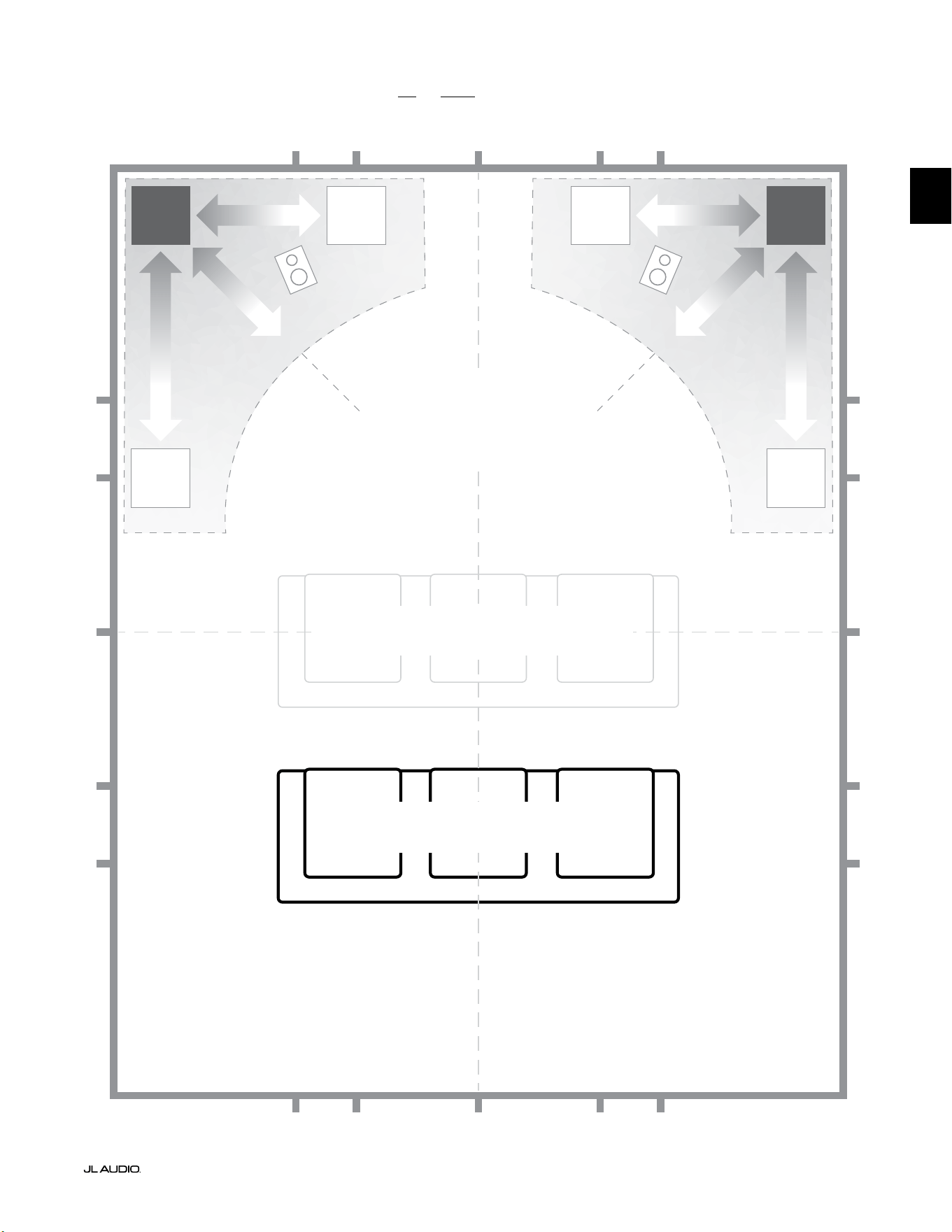
Pg 7 | FR
|
Fathom
®
v2
FR
Options d’emplacement recommandées pour un ou deux Fathom v2
PLUS DOUX
Emplacement conseillé pour UN ou DEUX
subwoofers (placez-en DEUX
symétriquement à gauche et à droite)
PLUS DOUX
PLUS DOUXPLUS DOUX
PLACES ASSISES DÉCONSEILLÉES
(Reproduction plus faible et irrégulière des graves)
MEILLEURES PLACES ASSISES
(Reproduction plus précise des graves)
½
1⁄3
1⁄3
¼
¼
½
½
1⁄3
1⁄3 1⁄3
1⁄3
¼
¼ ¼
½1⁄3 1⁄3¼ ¼
¼
À ENVIRON 1/3 DE LA
LONGUEUR DE LA PIÈCE
À PARTIR DU MUR DU FOND
CENTRE DE LA PIÈCE
PLUS
INTENSE
PLUS
INTENSE
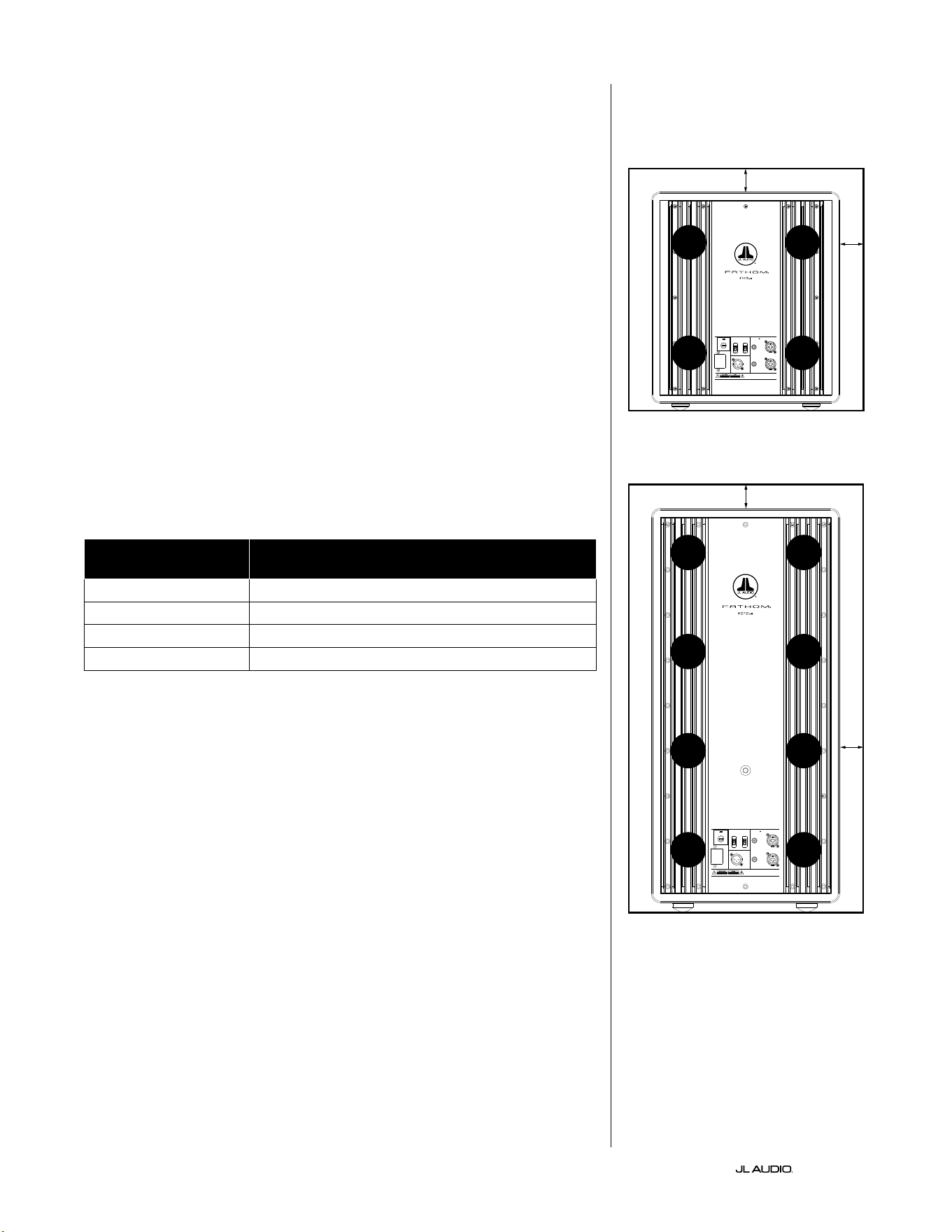
FR | Pg 8
|
Fathom
®
v2
CONSIDÉRATIONS PARTICULIÈRES CONCERNANT LES
INSTALLATIONS ENCASTRÉES
Les subwoofers Fathom v2 sont conçus pour un «encastrement» facile. Toutes
les commandes se trouvent sur le panneau avant et sur le dessus du subwoofer.
Le Fathom v2 peut être encastré dans un boîtier fait sur mesure en suivant ces
quelques conseils simples.
1) Laissez un espace libre de 10cm (4po) derrière le panneau ampli pour un
refroidissement adéquat et pour pouvoir accéder au connecteur.
2) Sur tous les autres côtés (sauf en dessous), laissez un espace d’au moins 5cm
(2po) pour assurer une ventilation adéquate.
3) Le Fathom v2 fonctionnant généralement à chaud durant une utilisation
poussée, nous recommandons de prévoir des orices de ventilation adéquats
dans le boîtier sur mesure autour du Fathom v2. Deux orices de 7,5cm (3po)
de diamètre, placés à proximité de la partie inférieure et de la partie supérieure
du boîtier, permettront à l’air frais de circuler sur le panneau de l’ampli de votre
subwoofer Fathom v2 et de le maintenir frais et en bonne condition.
4) Votre subwoofer Fathom v2 est capable de déplacer de grandes quantités d’air.
Si l’avant du Fathom v2 est recouvert d’une grille sur mesure, la taille de la grille
doit être AU MOINS égale à celle du cône pour chaque modèle an que la sortie
ne soit pas étouée par le boîtier sur mesure. Consultez le tableau ci-dessous
pour connaître la dimension recommandée pour la zone de ventilation pour
chaque modèle.
Modèle Dimension recommandée pour la zone de ventilation
de la grille sur mesure
f110v2 ≥ 386cm
2
(60po
2
)
f112v2 ≥ 550cm
2
(85po
2
)
f113v2 ≥ 700cm
2
(108po
2
)
f212v2 ≥ 1100cm
2
(170po
2
)
1200VA
Built in USA with Imported and domestic components
LEFT
or
MONO
RIGHT
ONLY
INPUTS
Output to Slave
(Balanced)
Balanced
Unbalanced
Input Modes
Slave
Master
Grounded
Isolated
SERIAL NUMBER:
Warranty void if serial number is remove d, altered or deface d.
F 12A H
250V
120 V ~ 60 Hz
F
U
S
E
F
U
S
E
Built in USA with Imported and domestic components
LEFT
or
MONO
RIGHT
ONLY
INPUTS
Output to Slave
(Balanced)
Balanced
Unbalanced
Input Modes
Slave
Master
Grounded
Isolated
SERIAL NUMBER:
Warranty void if serial number is remo ved, altered or defa ced.
F 15A H
250V
120 V ~ 60 Hz
F
U
S
E
F
U
S
E
ORIFICE
DE VENTI-
LATION
ORIFICE
DE VENTI-
LATION
ORIFICE
DE VENTI-
LATION
ORIFICE
DE VENTI-
LATION
ORIFICE
DE VENTI-
LATION
ORIFICE
DE VENTI-
LATION
ORIFICE
DE VENTI-
LATION
ORIFICE
DE VENTI-
LATION
5cm (2po) min.
5cm (2po) min.
5cm
(2po)
min.
5cm
(2po)
min.
Vue arrière du boîtier (f110, f112, f113):
Vue arrière du boîtier (f212):
ORIFICE
DE VENTI-
LATION
ORIFICE
DE VENTI-
LATION
ORIFICE
DE VENTI-
LATION
ORIFICE
DE VENTI-
LATION
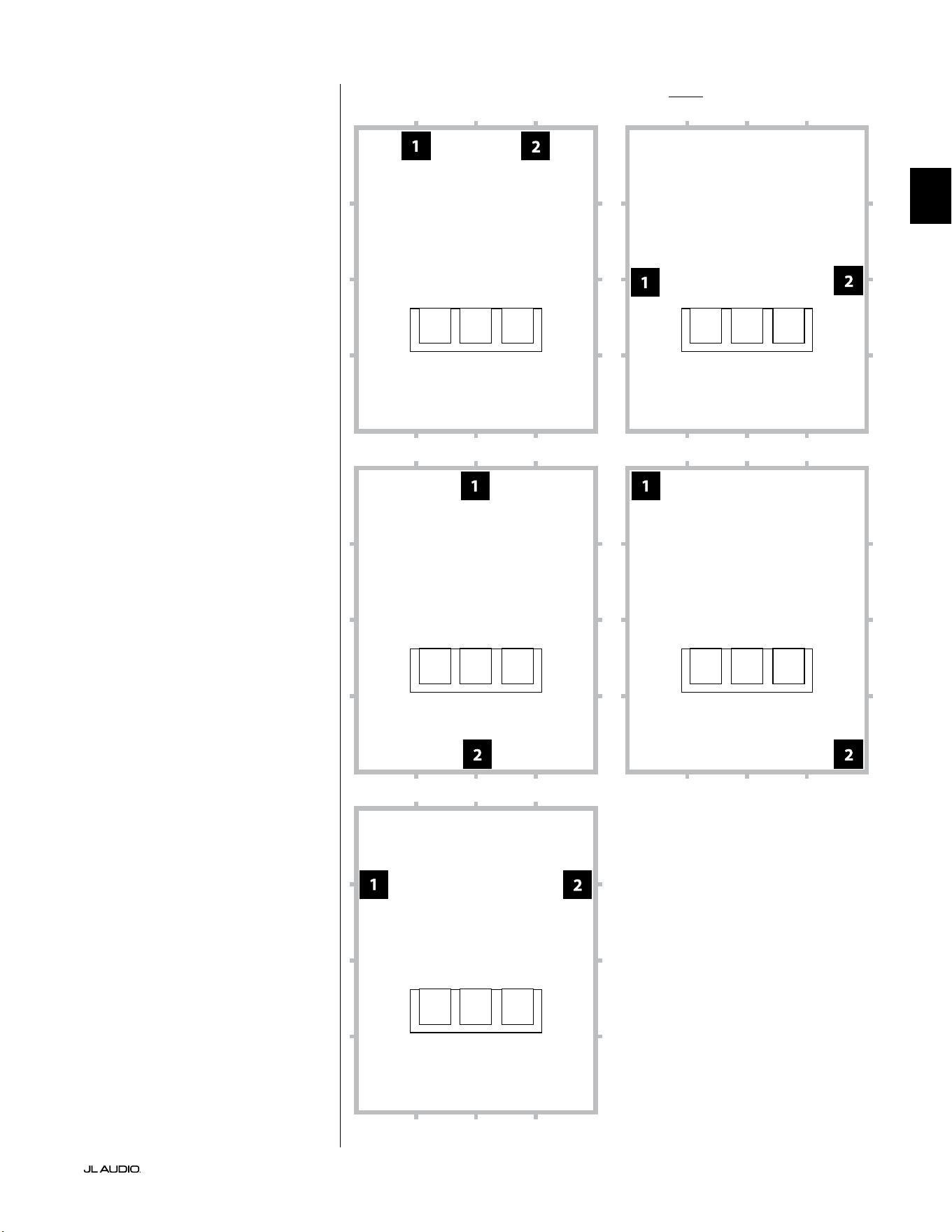
Pg 9 | FR
|
Fathom
®
v2
FR
Options d’emplacement recommandées pour deux subwoofers Fathom v2Utilisation de deux Fathom v2
Si vous utilisez deux Fathom
v2, placez-les à proximité des
coins avant de la pièce, aux coins
diagonalement opposés de la pièce,
ou au centre des murs opposés,
comme indiqué ci-contre.
Les essais d’emplacement du
subwoofer et de l’auditeur sont
recommandés pour obtenir les
meilleurs résultats, car les avantages
peuvent être signicatifs.
Des mesures à haute résolution
et un calibrage professionnel du
système sont recommandés pour
obtenir les meilleurs résultats et
performances du système.

FR | Pg 10
|
Fathom
®
v2
Options d’emplacement recommandées pour trois subwoofers Fathom v2
Options d’emplacement recommandées pour quatre subwoofers Fathom v2
Utilisation de trois ou quatre
Fathom v2
Des études démontrent qu’il est
possible d’obtenir une réponse des
graves très lisse dans un grand espace
d’écoute avec quatre subwoofers, en
les plaçant au centre de chacun des
quatre murs (même si deux ou trois
subwoofers peuvent donner quasiment
les mêmes résultats).
Les essais d’emplacement du
subwoofer et de l’auditeur sont
recommandés pour obtenir les
meilleurs résultats, car les avantages
peuvent être signicatifs.
Des mesures à haute résolution
et un calibrage professionnel du
système sont recommandés pour
obtenir les meilleurs résultats et
performances du système.
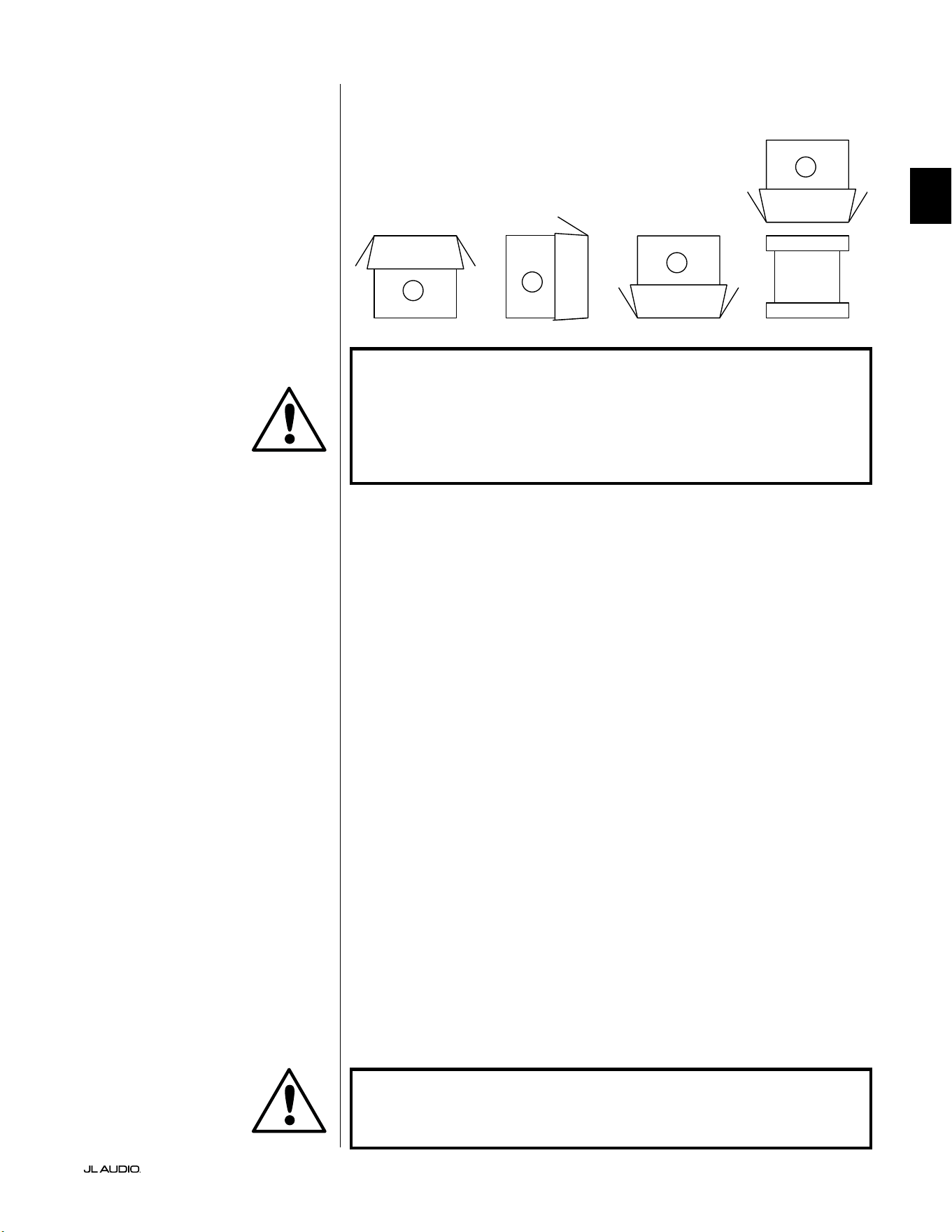
Pg 11 | FR
|
Fathom
®
v2
FR
IMPORTANT! LE SUBWOOFER FATHOM V2 PÈSE UN CERTAIN POIDS, VEUILLEZ
FAIRE ATTENTION EN LE DÉBALLANT ET EN LE POSITIONNANT AFIN D’ÉVITER
LES RISQUES DE BLESSURE. SI POSSIBLE, DEMANDEZ L’AIDE D’UNE AUTRE
PERSONNE POUR FACILITER CETTE OPÉRATION. POUR MINIMISER LES RISQUES
DE BLESSURE, PLIEZ LES GENOUX ET SOULEVEZ LE CARTON EN UTILISANT VOS
JAMBES, SANS SOLLICITER VOTRE DOS.
Instructions détaillées pour le déballage du subwoofer:
1. Placez le carton sur le sol près de l’endroit où
vous voulez l’installer dans la pièce.
2. Ouvrez le haut du carton (en respectant les marquages) et retirez le manuel, le
microphone de calibrage et le câble d’alimentation.
3. Retirez temporairement les intercalaires de garniture en mousse.
4. Détachez et tirez légèrement sur la housse de protection en tissu pour pouvoir
retirer plus facilement l’appareil par la suite (ne le retirez pas encore). Lorsque
vous ouvrez la housse de protection en tissu, vous voyez le dessous du boîtier
du subwoofer.
5. Replacez les intercalaires en mousse pour protéger le boîtier du subwoofer
pendant le déballage.
6. Retournez délicatement la boîte sur le côté, en repliant les rabats du carton
vers l’extérieur.
7. Tout en maintenant les rabats du carton repliés, retournez délicatement le
carton sur sa partie supérieure (extrémité ouverte).
8. Tirez le carton tout droit vers le haut jusqu’à ce que le subwoofer soit dégagé et
mettez-le de côté.
9. Retirez le morceau de mousse et placez-le dans le carton.
10. Retirez le sac en plastique et placez-le dans le carton.
11. Inclinez le subwoofer vers l’avant (vers le côté de la grille) pour retirer d’abord
l’intercalaire en mousse à l’arrière. Inclinez ensuite le subwoofer dans l’autre
sens (vers le panneau de l’amplicateur) pour retirer l’intercalaire en mousse
restant. Placez les deux intercalaires en mousse dans le carton.
12. Retirez la housse de protection en tissu et placez-la dans le carton.
IMPORTANT ! VEUILLEZ CONSERVER TOUT L’EMBALLAGE POUR GARANTIR
UN TRANSPORT EN TOUTE SÉCURITÉ DU SUBWOOFER ET POUR TOUTE
ÉVENTUELLE RÉPARATION NÉCESSAIRE DANS LE FUTUR.
Déballez le carton à proximité de l’endroit
où le subwoofer sera installé . Le subwoofer
est emballé à l’envers (tête en bas). Retournez
SOIGNEUSEMENT le carton pour retirer le
subwoofer et minimiser les eorts.
DÉBALLAGE DE VOTRE FATHOM v2
Une fois l’emplacement de votre Fathom v2 déterminé dans votre salle, vous
pouvez le déballer près de l’emplacement prévu pour son installation.
C
D
A
B
IMPORTANT
IMPORTANT

LP freq. (Hz) e.l.f. trim (dB) phase (deg.)
Polarity
0
|
180 deg.
LP Filter
o
|
12d B
|
24dB
Master Level
max
0
Lights
o
|
dim
|
on
-∞
Level Mode
ref.
|
variable
Input Mode
master
|
slave
calibration mic. demo defeat calibrate
Power
o
|
on
|
auto
Digital Automatic Room Optimization
1200VA
Built in USA with Imported and domestic components
LEFT
or
MONO
RIGHT
ONLY
INPUTS
Output to Slave
(Balanced)
Balanced
Unbalanced
Input Modes
Slave
Master
Grounded
Isolated
SERIAL NUMBER:
Warranty void if serial numb er is removed, altered or defaced.
F 12A H
250V
120 V ~ 60 Hz
F
U
S
E
F
U
S
E
FR | Pg 12
|
Fathom
®
v2
Boutons de réglage et connecteurs arrière (modèle f112v2, f113v2, f212v2)
La gure ci-dessous décrit le panneau arrière d’un subwoofer Fathom f113v2.
La disposition des boutons de réglage et des connecteurs est identique pour les modèles Fathom f112v2 et f212v2.
Entrées
symétriques
page18
Entrées
asymétriques
page19
Connecteur
CA type CEI
page21-22
Connecteur sortie
vers esclave
page21
Commutateurs de
mode d’entrée
page20
Fusible
spécique à
chaque région
page33
Schéma du panneau de commande avant (tous les modèles)
La gure ci-dessous illustre le panneau de commande avant du subwoofer Fathom f113v2.
La disposition des boutons de réglage est identique pour tous les modèles Fathom v2.
Système DARO
page14-15
Alimentation
page14
Mode d’entrée
page15
Mode de niveau
page15
Niveau principal
page16
Lumières
page16
Filtre
passe-bas
page16
Fréquence du ltre
passe-bas (Hz)
page16
Filtre e.l.f.
trim (dB)
page17
Bouton de réglage
de phase (deg.)
page17
Polarité
page17
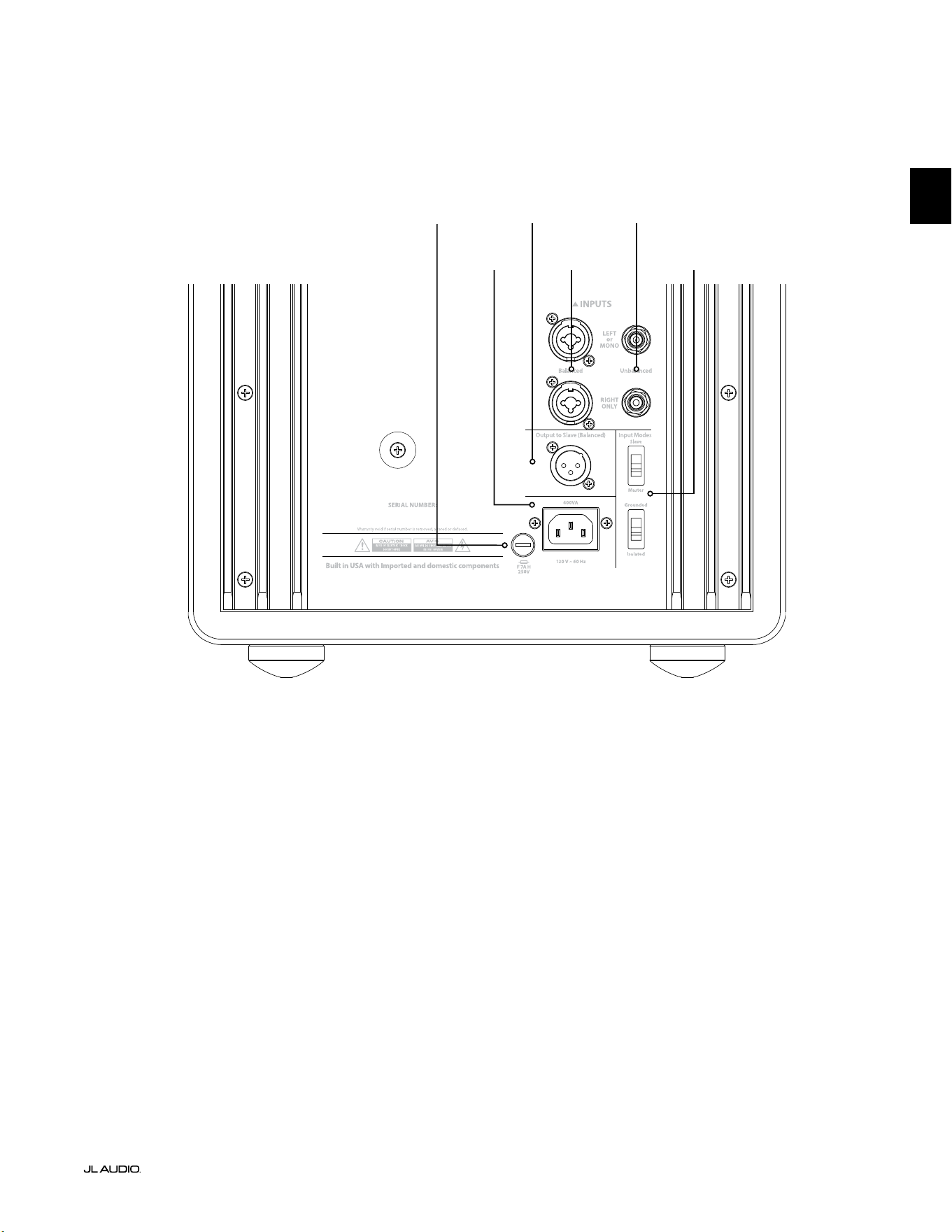
F
U
S
E
F
U
S
E
Boutons de réglage et connecteurs arrière (modèle f110v2)
La gure ci-dessous décrit le panneau arrière d’un subwoofer Fathom f110v2.
*Les illustrations des détails du panneau de commande arrière et des connecteurs de ce manuel montrent d’autres modèles de
Fathom v2 et ne sont pas représentatives de la disposition sur le modèle f110v2.
Entrées
symétriques
page18
Entrées
asymétriques
page19
Connecteur
CA type CEI
page21-22
Connecteur sortie
vers esclave
page21
Commutateurs de
mode d’entrée
page20
Pg 13 | FR
|
Fathom
®
v2
FR
Fusible spécique à
chaque région
page33
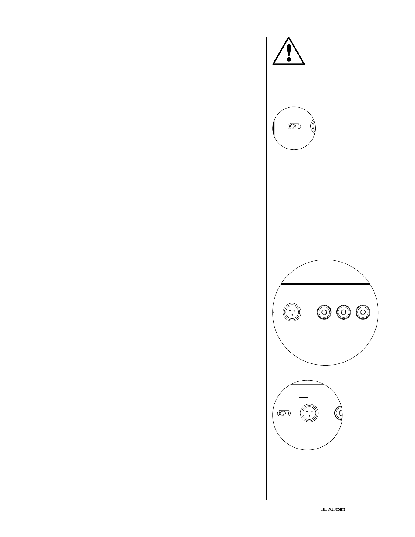
FR | Pg 14
|
Fathom
®
v2
BOUTONS DE RÉGLAGE DU PANNEAU AVANT EN DÉTAIL
Interrupteur d’alimentation
L’interrupteur «Power» détermine l’état de fonctionnement du subwoofer
Fathom v2 et est le seul interrupteur à utiliser pour allumer et éteindre le Fathom
v2. N’utilisez pas de prise commutée, prise multiple équipée d’un interrupteur,
ou tout autre interrupteur externe, car cela pourrait provoquer des bruits
transitoires indésirables et potentiellement nuisibles. Ne débranchez pas le
cordon d’alimentation secteur du Fathom v2 tant que l’appareil est sous tension.
L’interrupteur «Power» a trois positions:
«On»: le Fathom v2 est tout le temps sous tension. Les voyants du panneau
avant sont allumés sauf s’ils ont été éteints à l’aide de l’interrupteur «Lights».
«O»: l’amplicateur de puissance interne du Fathom v2 est hors tension.
Dans ce cas, le courant consommé pour faire fonctionner les relais d’alimentation
principale est négligeable. Tous les voyants du panneau avant sont éteints.
«Auto»: le Fathom v2 allume automatiquement son amplicateur interne s’il détecte
un signal sonore à l’une de ses entrées et éteint l’amplicateur interne s’il ne détecte aucun
signal au niveau de ses entrées pendant environ trente (30) minutes. Lorsqu’il est en mode
veille, le Fathom v2 consomme très peu de courant (<5watts) pour alimenter le circuit
de détection du signal. Les voyants du panneau avant s’éteignent lorsque le Fathom v2
s’éteint et s’allument lorsque le Fathom v2 s’allume (à moins qu’ils n’aient été éteints via
l’interrupteur «Lights»).
Dans le cas peu probable où la fonction de mise sous tension automatique ne
serait pas assez sensible pour un système particulier, utilisez un câble adaptateur
Y pour diviser le signal entrant en deux signaux d’entrée RCA ou XLR sur le
Fathom v2. Cela augmentera la sensibilité d’entrée de 6dB. Veuillez noter que si
la sensibilité automatique est trop élevée ou s’il y a un bruit important sur le câble
d’entrée, le Fathom v2 peut ne pas s’éteindre comme souhaité. Dans ce cas, retirez le
câble adaptateur Y ou recherchez la source du bruit dans les composants en amont.
Optimisation numérique automatique de la pièce (système DARO)
La technologie innovante d’optimisation numérique automatique de la pièce
(DARO) est une caractéristique puissante des subwoofers JL Audio Fathom v2. Ce
système «one-touch» comprend 18bandes d’égalisation an d’éliminer les crêtes
les plus élevées de réponse acoustique dans votre home cinéma au niveau du siège
d’écoute principal, ce qui améliore considérablement la réponse en basse fréquence
dans la pièce. Le calibrage du système DARO est complètement automatisé.
Veuillez consulter la section suivante de ce manuel pour obtenir plus de détails sur
l’utilisation du système DARO.
À l’aide du microphone de calibrage JL Audio inclus, la procédure de
calibrage DARO prend moins de troisminutes. En résumé, vous devez connecter
le microphone fourni à l’entrée «calibration mic.», appuyer sur le bouton
«calibrate», puis tenir le microphone à hauteur d’oreille dans votre siège d’écoute
principal pendant le test. Une séquence de bruit sera diusée par le subwoofer
Fathom v2 et la réponse de la pièce sera automatiquement mesurée, analysée et
égalisée an d’éliminer la plus grande crête de réponse acoustique de la pièce à
votre siège d’écoute. Pour obtenir des instructions détaillées sur la procédure de
conguration du système DARO, reportez-vous aux pages 29-30.
Entrée micro de calibrage
Cette entrée permet de connecter le microphone de calibrage JL Audio fourni
au subwoofer Fathom v2. Avant d’utiliser le système DARO, connectez une
extrémité du câble fourni au microphone et l’autre extrémité à cette prise jack.
Le système DARO est spéciquement calibré pour ce microphone et son schéma
de connexion est spécique au microphone fourni. La séquence de calibrage ne
fonctionnera pas si un autre microphone est connecté ou si aucun microphone
n’est connecté.
IMPORTANT
LP freq. (Hz) e.l.f. trim (dB) phase (deg.)
Polarity
0
|
180 deg.
LP Filter
o
|
12dB
|
24dB
Master Level
max
0
Lights
o
|
dim
|
on
-∞
Level Mode
ref.
|
variable
Input Mode
master
|
slave
calibration mic. demo defeat calibrate
Power
o
|
on
|
auto
Digital Automatic Room Optimization
LP freq. (Hz) e.l.f. trim (dB) phase (deg.)
Polarity
0
|
180 deg.
LP Filter
o
|
12dB
|
24dB
Master Level
max
0
Lights
o
|
dim
|
on
-∞
Level Mode
ref.
|
variable
Input Mode
master
|
slave
calibration mic. demo defeat calibrate
Power
o
|
on
|
auto
Digital Automatic Room Optimization
LP freq. (Hz) e.l.f. trim (dB) phase (deg.)
Polarity
0
|
180 deg.
LP Filter
o
|
12dB
|
24dB
Master Level
max
0
Lights
o
|
dim
|
on
-∞
Level Mode
ref.
|
variable
Input Mode
master
|
slave
calibration mic. demo defeat calibrate
Power
o
|
on
|
auto
Digital Automatic Room Optimization
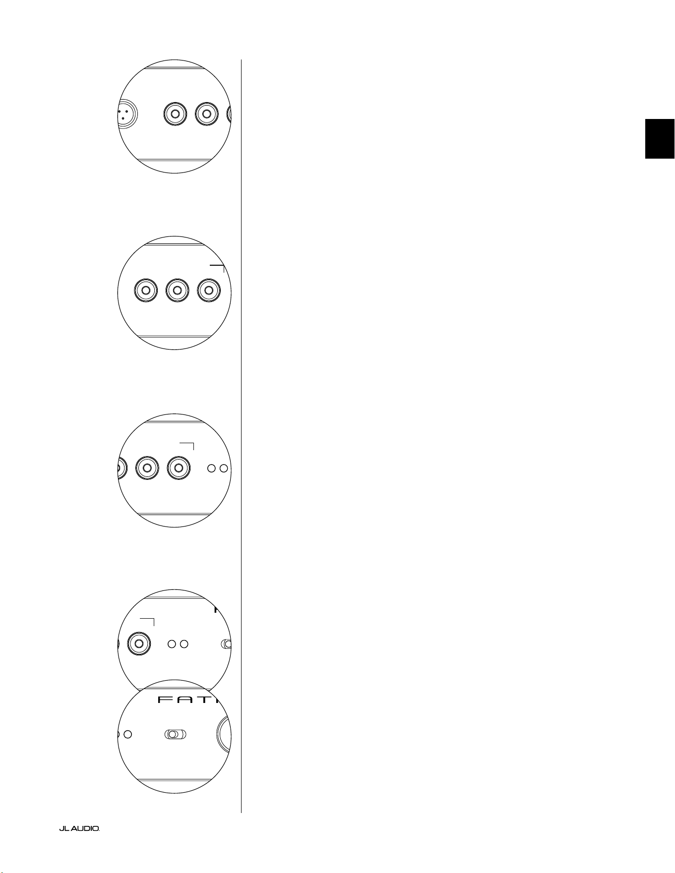
Pg 15 | FR
|
Fathom
®
v2
FR
LP freq. (Hz) e.l.f. trim (dB) phase (deg.)
Polarity
0
|
180 deg.
LP Filter
o
|
12dB
|
24dB
Master Level
max
0
Lights
o
|
dim
|
on
-∞
Level Mode
ref.
|
variable
Input Mode
master
|
slave
calibration mic. demo defeat calibrate
Power
o
|
on
|
auto
Digital Automatic Room Optimization
LP freq. (Hz) e.l.f. trim (dB) phase (deg.)
Polarity
0
|
180 deg.
LP Filter
o
|
12dB
|
24dB
Master Level
max
0
Lights
o
|
dim
|
on
-∞
Level Mode
ref.
|
variable
Input Mode
master
|
slave
calibration mic. demo defeat calibrate
Power
o
|
on
|
auto
Digital Automatic Room Optimization
Bouton de démo
Le bouton «demo» déclenche une séquence sonore de 20secondes
qui démontre brièvement la portée du subwoofer Fathom v2. La
fonction de démo est utile pour faire une démonstration de la capacité
de sortie du Fathom v2 et pour vérier que le Fathom v2 (ou plusieurs
Fathom v2) est opérationnel pendant le dépannage du système.
Le bouton «demo» est également utilisé (en combinaison) pour annuler
(retourner au plat) les réglages de l’égaliseur du système DARO. Pour eacer
les réglages du système DARO et éteindre le voyant de calibrage, maintenez
enfoncé le bouton «demo», puis appuyez sur le bouton «defeat». Veillez
à appuyer sur cette séquence de boutons rapidement. Si vous maintenez
le bouton «demo» enfoncé plus de 2secondes sans toucher le bouton
«defeat», les tonalités de démo commenceront. Si cela arrive, attendez
simplement que la séquence de démo se termine, puis réessayez.
Bouton d’annulation
Si vous appuyez sur le bouton «demo» ou «calibrate» alors que la fonction
d’annulation est active, l’eet du bouton «defeat» est automatiquement annulé. Aucun
autre bouton de réglage du panneau avant n’aecte l’état d’annulation du système
DARO. Le paramètre «defeat» est stocké dans la mémoire non volatile et ne changera
pas tant que l’appareil reste connecté à l’alimentation.
Le bouton «defeat» est également utilisé (en combinaison) pour annuler
(retourner au plat) les réglages de l’égaliseur du système DARO. Pour eacer
les réglages du système DARO et éteindre le voyant de calibrage, maintenez
enfoncé le bouton «demo», puis appuyez sur le bouton «defeat». Veillez
à appuyer sur cette séquence de boutons rapidement. Si vous maintenez
le bouton «demo» enfoncé plus de 2secondes sans toucher le bouton
«defeat», les tonalités de démo commenceront. Si cela arrive, attendez
simplement que la séquence de démo se termine, puis réessayez.
Bouton de calibrage
Au cours de la séquence de test du système DARO, le voyant vert du bouton
«calibrate» clignote pour avertir l’utilisateur sur deux conditions spéciques:
1. «Microphone JL Audio NON connecté»: si vous avez oublié de connecter le
microphone avant de commencer le calibrage, vous verrez cette alerte. Appuyez une
fois sur le bouton «calibrate» pour annuler l’alerte, connectez le microphone DARO
et réessayez.
2. «Niveau sonore inapproprié pour le calibrage DARO»: Comme la séquence
DARO est complètement automatique, cette alerte indique un problème au niveau
du microphone. Appuyez une fois sur le bouton «calibrate» pour annuler l’alerte.
Assurez-vous que le microphone JL Audio est correctement connecté, puis réessayez.
Pour obtenir une assistance supplémentaire, reportez-vous à la section Dépannage à la
page33.
Voyants de mode d’entrée
Les voyants de mode d’entrée indiquent le mode d’entrée («master» ou «slave»)
sélectionné sur le panneau arrière du Fathom v2 (sauf si l’interrupteur «Lights» est en
position «O»). Pour plus de détails, consultez la page20.
Mode de niveau
L’interrupteur «Level Mode» à deux positions vous permet de sélectionner l’un
des modes suivants:
«ref.»: lorsque ce mode est sélectionné, le bouton de réglage «Master Level» n’a
aucun eet sur le niveau de sortie du Fathom v2. Utilisez ce réglage si vous comptez
d’abord contrôler le niveau du subwoofer via votre récepteur ou préamplicateur/
processeur. Pour ceux d’entre nous qui ont de jeunes enfants ou des adolescents trop
enthousiastes, ce mode de fonctionnement empêche toute manipulation directe du
bouton «Master Level».
«variable»: lorsque ce mode est sélectionné, le bouton de réglage «Master
Level» détermine le niveau de sortie du subwoofer Fathom v2. Ce mode est également
utile pour harmoniser le niveau du subwoofer Fathom v2 à une paire d’enceintes stéréo
dans un système à deux canaux.
LP freq. (Hz) e.l.f. trim (dB) phase (deg.)
Polarity
0
|
180 deg.
LP Filter
o
|
12dB
|
24dB
Master Level
max
0
Lights
o
|
dim
|
on
-∞
Level Mode
ref.
|
variable
Input Mode
master
|
slave
calibration mic. demo defeat calibrate
Power
o
|
on
|
auto
Digital Automatic Room Optimization
LP freq. (Hz) e.l.f. trim (dB) phase (deg.)
Polarity
0
|
180 deg.
LP Filter
o
|
12dB
|
24dB
Master Level
max
0
Lights
o
|
dim
|
on
-∞
Level Mode
ref.
|
variable
Input Mode
master
|
slave
calibration mic. demo defeat calibrate
Power
o
|
on
|
auto
Digital Automatic Room Optimization
LP freq. (Hz) e.l.f. trim (dB) phase (deg.)
Polarity
0
|
180 deg.
LP Filter
o
|
12dB
|
24dB
Master Level
max
0
Lights
o
|
dim
|
on
-∞
Level Mode
ref.
|
variable
Input Mode
master
|
slave
calibration mic. demo defeat calibrate
Power
o
|
on
|
auto
Digital Automatic Room Optimization
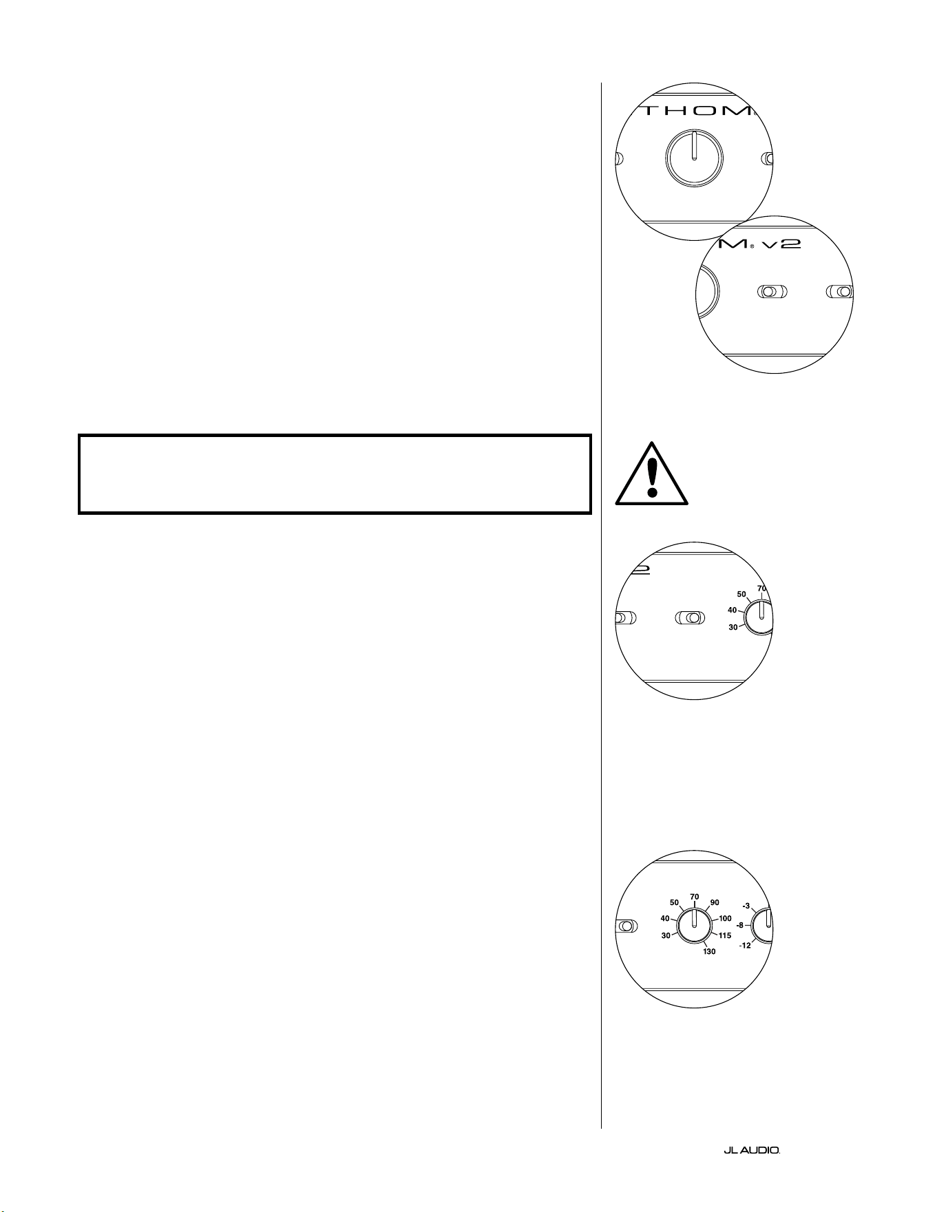
FR | Pg 16
|
Fathom
®
v2
Bouton de réglage du niveau principal
Le bouton «Master Level» permet de régler le niveau de
sortie du Fathom v2 lorsque le mode de niveau variable est
sélectionné sur le panneau de commande avant.
Lorsque vous le tournez dans le sens inverse des aiguilles d’une
montre, la sortie du Fathom v2 est complètement coupée. Lorsque
vous le positionnez sur «0» ou à la verticale, le niveau de gain variable
correspond au réglage du niveau de référence. Lorsque vous le tournez
complètement dans le sens des aiguilles d’une montre, le niveau de
sortie du Fathom v2 est 15dB plus élevé que le réglage de référence.
Lumières
Le sélecteur «Lights» permet à l’utilisateur de sélectionner un des trois modes
pour les voyants.
«O» : pour éteindre tous les voyants du panneau avant en même temps.
«Dim»: pour régler le niveau de luminosité de tous les voyants du panneau
avant au minimum lorsque le Fathom v2 est sous tension.
«On»: pour régler le niveau de luminosité de tous les voyants du panneau
avant au maximum lorsque le Fathom v2 est sous tension.
IMPORTANT! LORS DU DÉPANNAGE OU DU CALIBRAGE DE LA FONCTION
DARO, ASSUREZ-VOUS QUE L’INTERRUPTEUR «LIGHTS» EST POSITIONNÉ SUR
«DIM» OU «ON».
Filtre passe-bas
Le sélecteur «LP Filter» détermine le mode opérationnel du ltre passe-bas
intégré du Fathom v2.
«O»: pour désactiver le ltre passe-bas, en retirant complètement ce circuit
du chemin du signal.
«12dB»: pour régler la pente de coupure progressive du ltre passe-bas à
12dB par octave (alignement Butterworth).
«24 dB»: pour régler la pente de coupure progressive du ltre passe-bas à
24dB par octave (alignement Linkwitz-Riley).
Le réglage de 24dB atténue de manière plus agressive les hautes fréquences
supérieures au réglage de la fréquence du ltre passe-bas (voir ci-dessous). Si vous
utilisez le ltre passe-bas intégré du Fathom v2, testez le réglage de la pente du
ltre passe-bas pour obtenir la meilleure transition vers vos enceintes satellites.
Si vous préférez utiliser les ltres et les fonctions de gestion des graves de votre
récepteur ou de votre préamplicateur, désactivez le ltre intégré en sélectionnant
la position «O».
Fréquence du ltre passe-bas
Le bouton de sélection «LP freq. (Hz)» permet à l’utilisateur de choisir
la fréquence de coupure du ltre passe-bas du Fathom v2. La fréquence varie
entre 30Hz (rotation complète dans le sens antihoraire) et 130Hz (rotation
complète dans le sens horaire). Ce bouton n’aecte en rien le signal de sortie si
l’interrupteur «LP Filter» est positionné sur «O». 80Hz est une fréquence de
ltre couramment utilisée et constitue généralement un bon point de départ pour
les réglages.
LP freq. (Hz) e.l.f. trim (dB) phase (deg.)
Polarity
0
|
180 deg.
LP Filter
o
|
12dB
|
24dB
Master Level
max
0
Lights
o
|
dim
|
on
-∞
Level Mode
ref.
|
variable
Input Mode
master
|
slave
calibration mic. demo defeat calibrate
Power
o
|
on
|
auto
Digital Automatic Room Optimization
LP freq. (Hz) e.l.f. trim (dB) phase (deg.)
Polarity
0
|
180 deg.
LP Filter
o
|
12dB
|
24dB
Master Level
max
0
Lights
o
|
dim
|
on
-∞
Level Mode
ref.
|
variable
Input Mode
master
|
slave
calibration mic. demo defeat calibrate
Power
o
|
on
|
auto
Digital Automatic Room Optimization
LP freq. (Hz) e.l.f. trim (dB) phase (deg.)
Polarity
0
|
180 deg.
LP Filter
o
|
12dB
|
24dB
Master Level
max
0
Lights
o
|
dim
|
on
-∞
Level Mode
ref.
|
variable
Input Mode
master
|
slave
calibration mic. demo defeat calibrate
Power
o
|
on
|
auto
Digital Automatic Room Optimization
LP freq. (Hz) e.l.f. trim (dB) phase (deg.)
Polarity
0
|
180 deg.
LP Filter
o
|
12dB
|
24dB
Master Level
max
0
Lights
o
|
dim
|
on
-∞
Level Mode
ref.
|
variable
Input Mode
master
|
slave
calibration mic. demo defeat calibrate
Power
o
|
on
|
auto
Digital Automatic Room Optimization
IMPORTANT
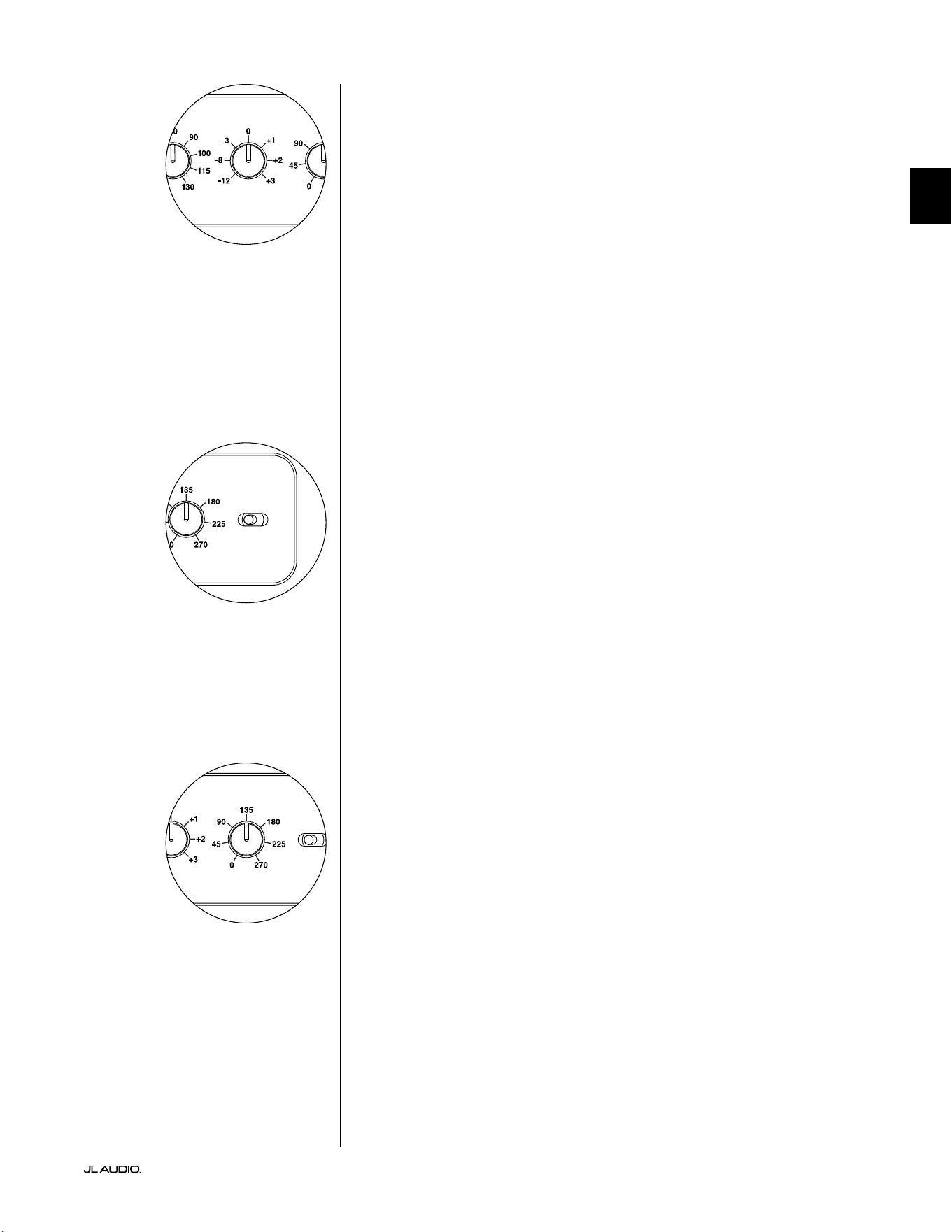
Pg 17 | FR
|
Fathom
®
v2
FR
Filtre e.l.f. trim
Le bouton «e.l.f. trim» (extrême basse fréquence) permet à l’utilisateur
d’appliquer une certaine valeur d’égalisation du signal à 24Hertz (extrême basse
fréquence). Lorsque le bouton est tourné complètement dans le sens contraire des
aiguilles d’une montre, le signal à 24Hz est réduit de 12dB. Lorsque le bouton est sur
«0», l’égaliseur est en mode plat pour une contribution nulle au signal. Lorsque le
bouton est tourné complètement dans le sens des aiguilles d’une montre, le signal à
24Hz est amplié de 3dB.
La fonction de ltree.l.f trim est utile pour adapter la sortie de très basse
fréquence du Fathom v2 à une pièce en particulier. Une légère intensication peut
rendre certains sons plus excitants. Le recours à la fonction de coupure peut aider
à compenser le gain de la pièce («room gain») ou les réverbérations murales
(«boundary gain») dans les basses fréquences. Les parois de la pièce et l’espace
restreint de la pièce amplient naturellement les très basses fréquences par rapport
aux autres parties du signal. Par conséquent, l’utilisation de la fonction ltre e.l.f.
trim pour couper les extrêmement basses fréquences peut aider à maîtriser le
«foisonnement» ou les basses fréquences qui semblent peu naturelles dans les pièces
de taille petite à moyenne (et peut également réduire les vibrations indésirables dans
la pièce ou dans toute la maison).
Polarité
L’interrupteur «Polarity» permet à l’utilisateur de sélectionner la polarité du
signal entre normale (0deg) et inversée (180deg). L’interrupteur «Polarity» aectera
tout d’abord la petite gamme de fréquences autour du point de coupure entre le
subwoofer et les enceintes satellites.
Contrairement au bouton de réglage de phase qui ajoute eectivement un délai,
l’interrupteur «Polarity» produit un renversement instantané des pics d’amplitude
du signal. Par exemple si, à un point de référence donné, une onde sinusoïdale a
un pic d’amplitude, en actionnant l’interrupteur «phase (deg.)» vous convertissez
instantanément ce pic en un creux d’amplitude. L’eet de l’interrupteur «Polarity»
étant immédiat, il complète l’utilisation du bouton de réglage de la phase et ne peut
pas être remplacé par ce réglage.
Lorsque vous placez le Fathom v2 dans la pièce, faites des essais avec
l’interrupteur «Polarity» avant d’ajuster le bouton de réglage «phase (deg.)».
Chaque position de l’interrupteur «Polarity» peut générer une transition plus lisse
entre le Fathom v2 et les enceintes satellites. Utilisez un matériel source avec un bon
contenu de graves moyens et extrêmes pour l’évaluation.
Bouton de réglage de phase
Le bouton de réglage «phase (deg.)» permet à l’utilisateur de régler la
temporisation de la sortie du subwoofer relative aux enceintes principales. Le bouton
de réglage «phase (deg.)» aecte tout d’abord la petite gamme de fréquences autour
du point de coupure entre le subwoofer et les enceintes satellites. Les réglages de
phase entre 0degré (rotation complète dans le sens antihoraire) et 270degrés
(rotation complète dans le sens horaire) sont possibles. La légende des degrés sur le
bouton de réglage «phase (deg.)» marque 80Hz comme référence, point de coupure
le plus courant entre des enceintes satellites et un subwoofer.
L’emplacement de l’enceinte, du subwoofer et du siège d’écoute varie beaucoup
selon les installations home cinéma. Considérant que l’emplacement des enceintes
dans la pièce aecte beaucoup la qualité perçue de la sortie sonore, il est parfois utile
de retarder la sortie du subwoofer. C’est exactement ce qu’il se passe lorsque vous
tournez le bouton de réglage «phase (deg.)» au-delà de 0degré.
Une fois votre Fathom v2 positionné dans votre espace d’écoute pour vous
donner la sonorité globale optimale, et après avoir déterminé la position optimale de
l’interrupteur «Polarity» (cf. section précédente), faites des essais de réglage à l’aide
du bouton «phase (deg.)». En utilisant une source familière avec un bon contenu de
grave moyen et extrême, ajustez le bouton de réglage «phase (deg.)» et écoutez pour
mieux dénir le son grave moyen et une transition plus douce entre le subwoofer
et les enceintes satellites. Si aucun réglage ne semble meilleur que l’autre, laissez le
bouton de réglage «phase (deg.)» sur 0degré.
LP freq. (Hz) e.l.f. trim (dB) phase (deg.)
Polarity
0
|
180 deg.
LP Filter
o
|
12dB
|
24dB
Master Level
max
0
Lights
o
|
dim
|
on
-∞
Level Mode
ref.
|
variable
Input Mode
master
|
slave
calibration mic. demo defeat calibrate
Power
o
|
on
|
auto
Digital Automatic Room Optimization
LP freq. (Hz) e.l.f. trim (dB) phase (deg.)
Polarity
0
|
180 deg.
LP Filter
o
|
12dB
|
24dB
Master Level
max
0
Lights
o
|
dim
|
on
-∞
Level Mode
ref.
|
variable
Input Mode
master
|
slave
calibration mic. demo defeat calibrate
Power
o
|
on
|
auto
Digital Automatic Room Optimization
LP freq. (Hz) e.l.f. trim (dB) phase (deg.)
Polarity
0
|
180 deg.
LP Filter
o
|
12dB
|
24dB
Master Level
max
0
Lights
o
|
dim
|
on
-∞
Level Mode
ref.
|
variable
Input Mode
master
|
slave
calibration mic. demo defeat calibrate
Power
o
|
on
|
auto
Digital Automatic Room Optimization
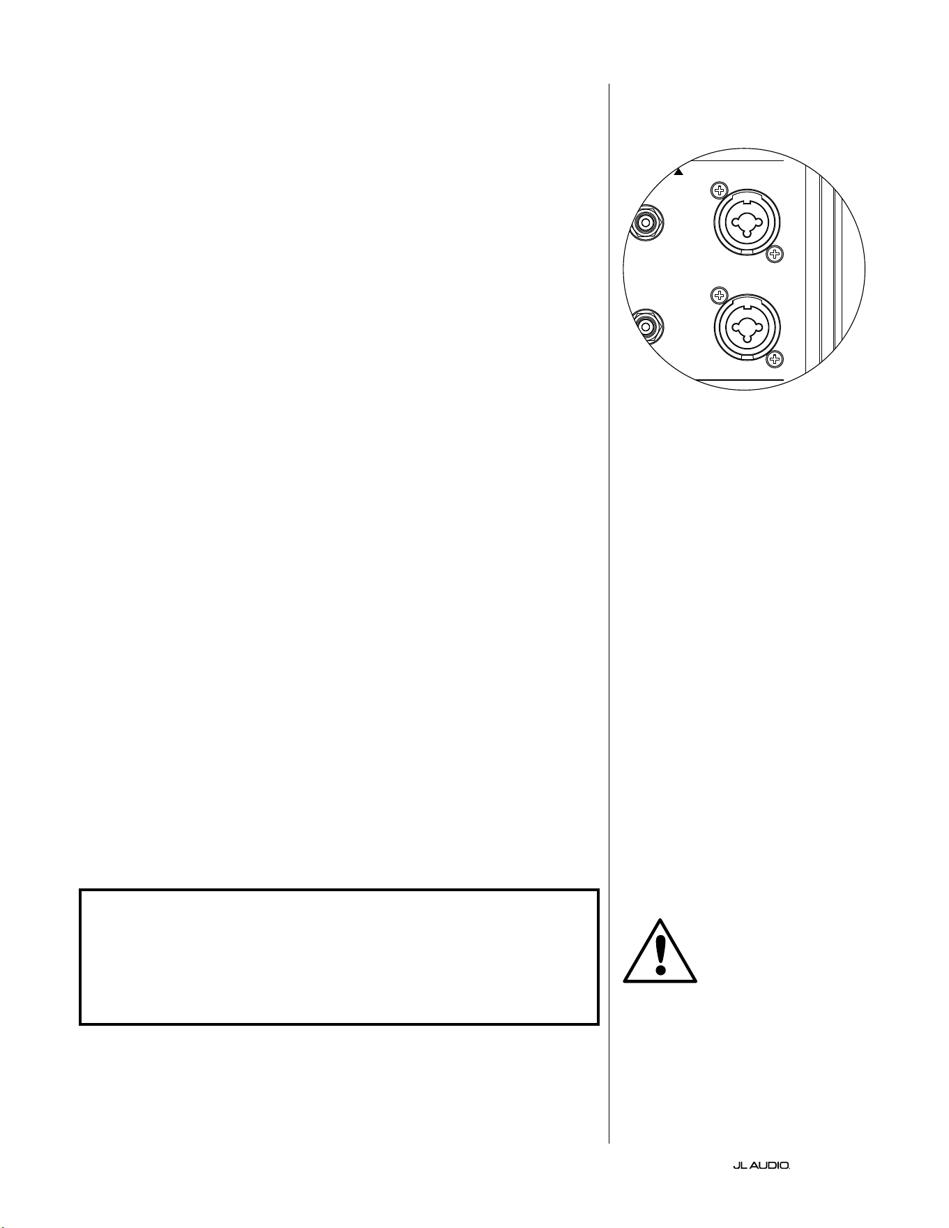
FR | Pg 18
|
Fathom
®
v2
BRANCHEMENT DE VOTRE FATHOM v2
Entrées symétriques
Si votre récepteur home cinéma ou votre préamplicateur/ processeur dispose
de sorties symétriques, connectez-les de préférence aux entrées symétriques du
Fathom v2. Les connexions symétriques sont largement utilisées dans les studios
professionnels et les applications de sonorisation pour un certain nombre de
très bonnes raisons. En plus de garantir une mise à la terre correcte entre les
composants, la transmission symétrique des signaux est conçue pour annuler les
bruits parasites des câbles induits par l’environnement (ce qui est particulièrement
important pour les grandes longueurs de câbles). En dénitive, votre système
sera beaucoup moins sujet aux bourdonnements ou autres bruits parasites si vous
utilisez des connexions symétriques.
Les subwoofers Fathom v2 sont dotés de connexions d’entrées symétriques
gauche et droite individuelles avec des prises jack XLR «combo». Ces prises
jack spéciales acceptent soit un connecteur XLR mâle à trois broches, soit un
connecteur TRS (Tip [pointe], Ring [anneau], Sleeve [manchon]) de 6,3mm
(1/4po) pour être compatibles avec une large gamme d’équipements.
Pour les systèmes dotés d’un subwoofer mono ou d’une connexion au
canal «LFE», seule la prise jack étiquetée «Le or Mono» sera utilisée. Cette
méthode s’applique à la plupart des récepteurs multicanaux et préamplicateurs/
processeurs modernes. Des prises d’entrée gauche et droite sont fournies
séparément pour les systèmes dépourvus de connexion dédiée au subwoofer
mono. Ceci s’applique généralement aux équipements audio à deux canaux.
Des câbles symétriques appropriés sont disponibles auprès de votre revendeur
JL Audio et ne sont pas fournis avec le Fathom v2.
Notes techniques:
• N’utilisez pas les entrées symétriques avec des signaux asymétriques via des
adaptateurs. Les entrées asymétriques du Fathom v2 sont isolées optiquement et
sont préférables dans les situations où seule une source de signal asymétrique est
disponible. L’impédance des entrées symétriques est de 20kOhms.
• Les connecteurs d’entrée sont congurés conformément aux recommandations de
l’Audio Engineering Society pour les câbles de signal symétrique, comme suit:
Connexion XLR:
Broche1: blindage
Broche2: positif
Broche3: négatif
Connexion TRS:
Pointe: positif
Anneau: négatif
Manchon: blindage
IMPORTANT ! SI VOTRE RÉCEPTEUR OU VOTRE PRÉAMPLIFICATEUR /
PROCESSEUR NE DISPOSE PAS DE SORTIES SYMÉTRIQUES XLR OU TRS 6,35MM
(1/4PO), VEUILLEZ VOUS REPORTER À LA SECTION «ENTRÉES ASYMÉTRIQUES»
À LA PAGE19 POUR OBTENIR DES INFORMATIONS SUR LA CONNEXION DES
ENTRÉES. NE TENTEZ PAS DE CONNECTER DES SORTIES ASYMÉTRIQUES AUX
ENTRÉES SYMÉTRIQUES DU FATHOM V2 VIA DES ADAPTATEURS.
Les entrées gauche et droite du Fathom v2
sont automatiquement additionnées pour
donner un seul canal mono. Le Fathom v2
étant par nature un appareil «mono» ou à
canal unique, vous pouvez utiliser les entrées
gauche et droite pour le Fathom v2 maître,
puis distribuer le signal mono additionné
sur d’autres Fathom v2 esclaves au sein du
système.
IMPORTANT
1200VA
Built in USA with Imported and domestic components
LEFT
or
MONO
RIGHT
ONLY
INPUTS
Output to Slave
(Balanced)
Balanced
Unbalanced
Input Modes
Slave
Master
Grounded
Isolated
SERIAL NUMBER:
Warranty void if serial number is removed, altered or defaced.
F 12A H
250V
120 V ~ 60 Hz
F
U
S
E
F
U
S
E
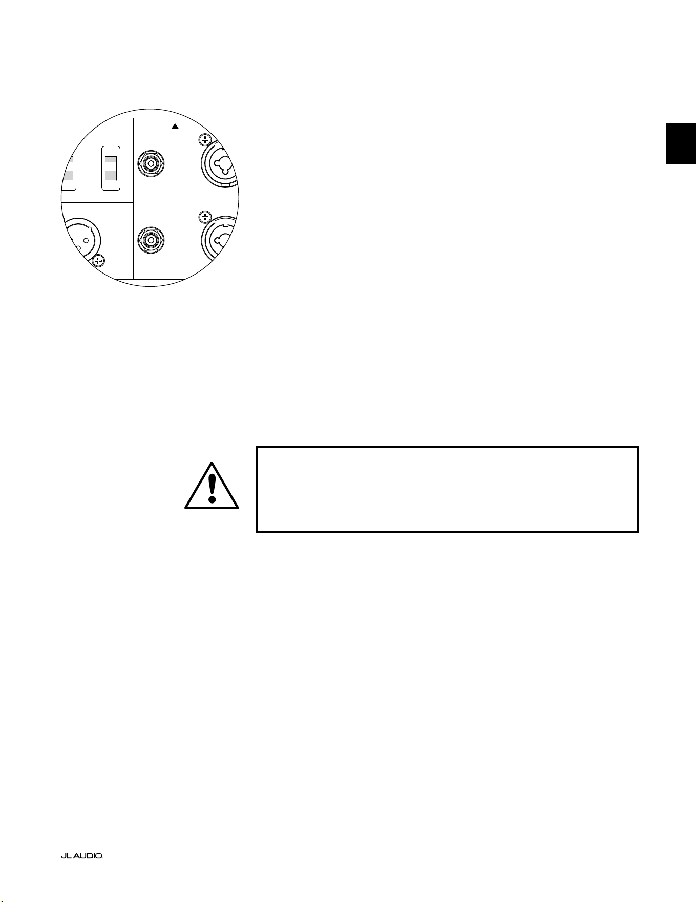
Pg 19 | FR
|
Fathom
®
v2
FR
Entrées asymétriques
Le subwoofer Fathom v2 dispose de connecteurs d’entrée RCA individuels,
gauche et droite, asymétriques. Ce sont les connecteurs les plus couramment
utilisés pour les applications audio domestiques et ils doivent être utilisés si
votre récepteur ou votre préamplicateur/ processeur ne fournit pas de sorties
symétriques. Bien que les connexions asymétriques ne soient pas aussi insensibles
au bruit qu’une connexion symétrique, les subwoofers Fathom v2 appliquent une
isolation optique sur les entrées asymétriques pour minimiser la présence de bruit
dans votre système.
Pour les systèmes dotés d’un subwoofer mono ou d’une connexion au canal
«LFE», seule la prise jack RCA étiquetée «Le or Mono» sera utilisée. Cette
méthode s’applique à la plupart des récepteurs multicanaux et préamplicateurs/
processeurs modernes. Des prises jack d’entrée RCA gauche et droite sont fournies
séparément pour les systèmes dépourvus de connexion dédiée au subwoofer
mono. Ceci s’applique généralement aux équipements audio à deux canaux.
Notes techniques:
• En l’absence de sorties symétriques sur la source du signal, vous devez
utiliser des entrées asymétriques de type RCA. Le Fathom v2s dispose de
circuits d’isolation optique sur les entrées asymétriques an de minimiser
l’éventualité de bruit induite par une boucle de masse. L’impédance des
entrées asymétriques est de 50kOhms.
• Les connexions sont conformes aux normes industrielles relatives aux câbles
de signal asymétrique:
Connexion de type RCA:
Pointe: positif
Manchon: négatif
IMPORTANT ! EN CAS DE BRUIT APRÈS LE RACCORDEMENT, LES FATHOM
V2 PERMETTENT UNE MISE À LA TERRE OU UNE ISOLATION DES ENTRÉES
ASYMÉTRIQUES. VEUILLEZ VOUS REPORTER À LA SECTION «COMMUTATEURS
DE MODE D’ENTRÉE» À LA PAGE20 DE CE MANUEL POUR DE PLUS AMPLES
INFORMATIONS SUR LA RÉDUCTION DU BRUIT.
1200VA
Built in USA with Imported and domestic components
LEFT
or
MONO
RIGHT
ONLY
INPUTS
Output to Slave
(Balanced)
Balanced
Unbalanced
Input Modes
Slave
Master
Grounded
Isolated
SERIAL NUMBER:
Warranty void if serial number is removed, altered or defaced.
F 12A H
250V
120 V ~ 60 Hz
F
U
S
E
F
U
S
E
IMPORTANT
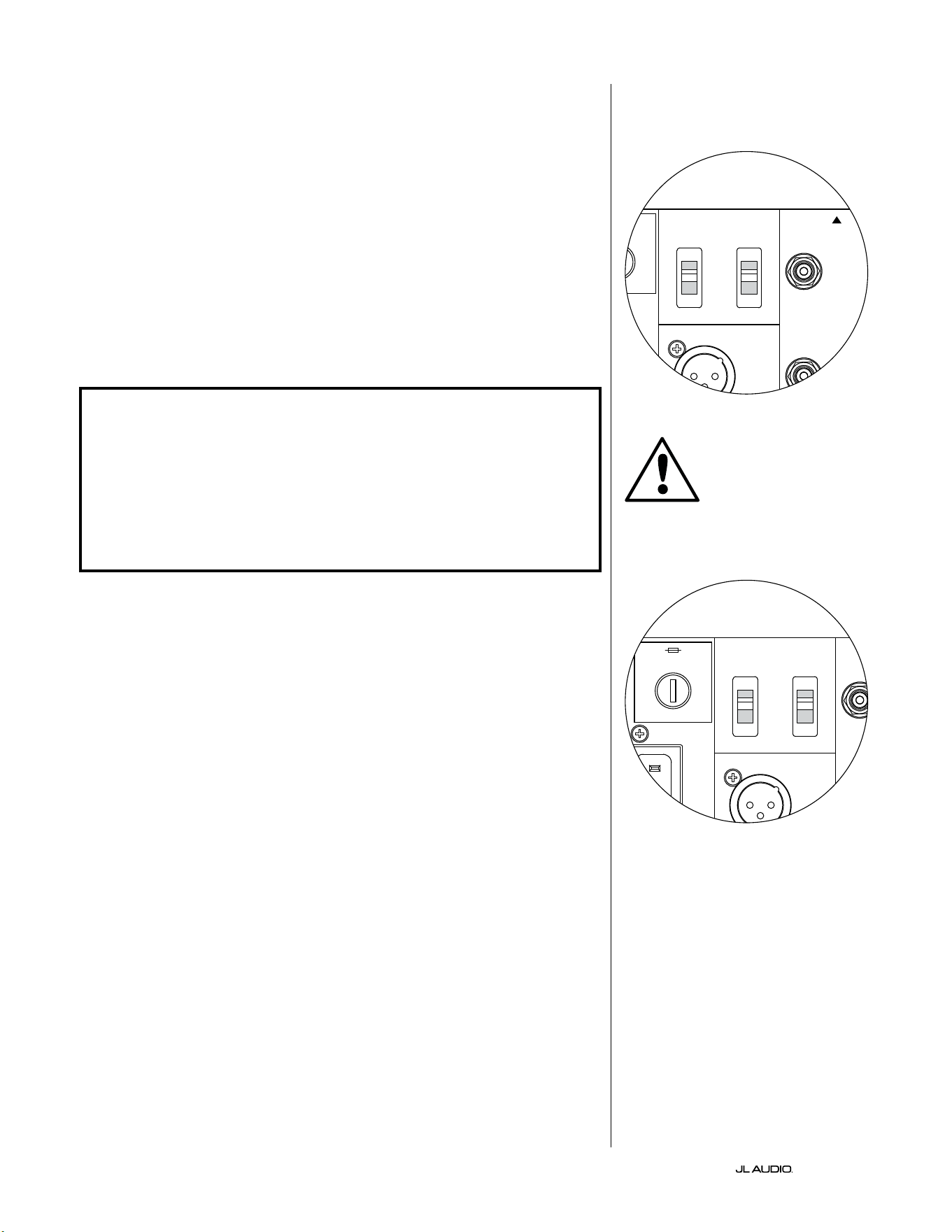
FR | Pg 20
|
Fathom
®
v2
Commutateurs de mode d’entrée:
Deux interrupteurs situés sur le panneau arrière permettent de contrôler la mise à
la terre des signaux asymétriques et le fonctionnement en mode maître/ esclave.
Interrupteur de mise à la terre/ d’isolement
L’interrupteur de mode d’entrée «Grounded/ Isolated» n’altère que les entrées
RCA asymétriques et est conçu pour faciliter une connexion silencieuse, sans
bourdonnements à votre installation audio ou home cinéma. Cette fonction permet
de résoudre les problèmes de mise à la terre du signal des installations home cinéma
lorsque plusieurs composants provenant de diérents fabricants sont interconnectés.
À la livraison du Fathom v2, l’interrupteur est positionné sur «Isolated». Lorsque
tous les composants du système ont été connectés et activés (mais sans matériel source
en cours de lecture), si vous entendez un bourdonnement continu en basse fréquence
dans votre Fathom v2, placez l’interrupteur en position «Grounded» et évaluez le
niveau de bruit. Testez l’une ou l’autre position de l’interrupteur an de réduire les
bourdonnements ou les bruits.
IMPORTANT ! VEUILLEZ NOTER QUE LE CHANGEMENT DE TOUT COMPOSANT
DU SYSTÈME OPTIMISÉ (RÉCEPTEUR, AMPLIFICATEUR, LECTEUR DVD, BOÎTIER DE
CÂBLE OU DE SATELLITE, ETC.) PEUT MODIFIER LE SCHÉMA DE MISE À LA TERRE
DU SIGNAL ET PROVOQUER DES BOURDONNEMENTS DANS VOTRE SYSTÈME
AUPARAVANT SILENCIEUX. SI VOUS AJOUTEZ OU MODIFIEZ UN COMPOSANT EN
AMONT DANS VOTRE SYSTÈME HOME CINÉMA, VOUS DEVREZ PEUT-ÊTRE REVOIR
CE RÉGLAGE DU MODE D’ENTRÉE SUR LE SUBWOOFER FATHOM V2 POUR OBTENIR
DES PERFORMANCES SONORES OPTIMALES. LES CÂBLES ET BOÎTIERS SATELLITES
SONT PARTICULIÈREMENT PROBLÉMATIQUES DANS CE CAS.
Interrupteur maître/ esclave
Les Fathom v2 sont conçus pour s’adapter facilement à la mise en œuvre de
plusieurs subwoofers dans votre système home cinéma sur la base d’une conguration
maître/ esclave. Cette méthode vous permet d’utiliser les fonctions de traitement
du signal d’un Fathom v2 pour contrôler de manière centralisée plusieurs Fathom v2
dans la pièce. La fonctionnalité maître/ esclave permet également au système DARO
d’optimiser la réponse d’une installation à plusieurs subwoofers.
À la livraison du Fathom v2, l’interrupteur est positionné sur «Master». Si vous
utilisez un seul Fathom v2, vous utiliserez la position «Master» et vous n’avez pas
besoin de vous préoccuper davantage de cette section.
Si votre installation comprend deux Fathom v2 ou plus, vous désignerez un Fathom
v2 en tant que «Master» (maître) et tous les autres en tant que subwoofers «Slave»
(esclave) à l’aide de l’interrupteur «Master/ Slave» sur le panneau de commande
arrière de l’amplicateur de chaque Fathom v2. Des voyants sur le panneau avant
du Fathom v2 indiquent si le mode «Master» ou «Slave» est sélectionné pour un
subwoofer donné.
À partir du Fathom v2 en mode «Master», le signal «Output to Slave» transporte
tout traitement de signal sélectionné sur le Fathom v2 maître (y compris le réglage du
«Master Level» et du traitement DARO) vers les autres Fathom v2 fonctionnant en
mode «Slave». Le traitement du signal du subwoofer «Slave» et les réglages du niveau
seront alors inopérants. Dans ce mode, l’utilisateur n’a pas à se soucier du niveau, du
ltre et des autres réglages des subwoofers esclaves.
Notes techniques:
• La sélection de la position «Slave» annule tout traitement du signal déni par
l’utilisateur et le réglage du niveau principal. C’est pourquoi il existe certaines
situations particulières dans lesquelles vous pouvez vouloir faire fonctionner
un seul Fathom v2 en mode «Slave». Si vous utilisez des commandes externes
de traitement du signal et d’adaptation de niveau, l’activation du mode «Slave»
empêchera quiconque d’aecter les paramètres du système avec les boutons de
réglage manuel du Fathom v2.
IMPORTANT
1200VA
Built in USA with Imported and domestic components
LEFT
or
MONO
RIGHT
ONLY
INPUTS
Output to Slave
(Balanced)
Balanced
Unbalanced
Input Modes
Slave
Master
Grounded
Isolated
SERIAL NUMBER:
Warranty void if serial number is removed, altered or defaced.
F 12A H
250V
120 V ~ 60 Hz
F
U
S
E
F
U
S
E
1200VA
Built in USA with Imported and domestic components
LEFT
or
MONO
RIGHT
ONLY
INPUTS
Output to Slave
(Balanced)
Balanced
Unbalanced
Input Modes
Slave
Master
Grounded
Isolated
SERIAL NUMBER:
Warranty void if serial number is removed, altered or defaced.
F 12A H
250V
120 V ~ 60 Hz
F
U
S
E
F
U
S
E
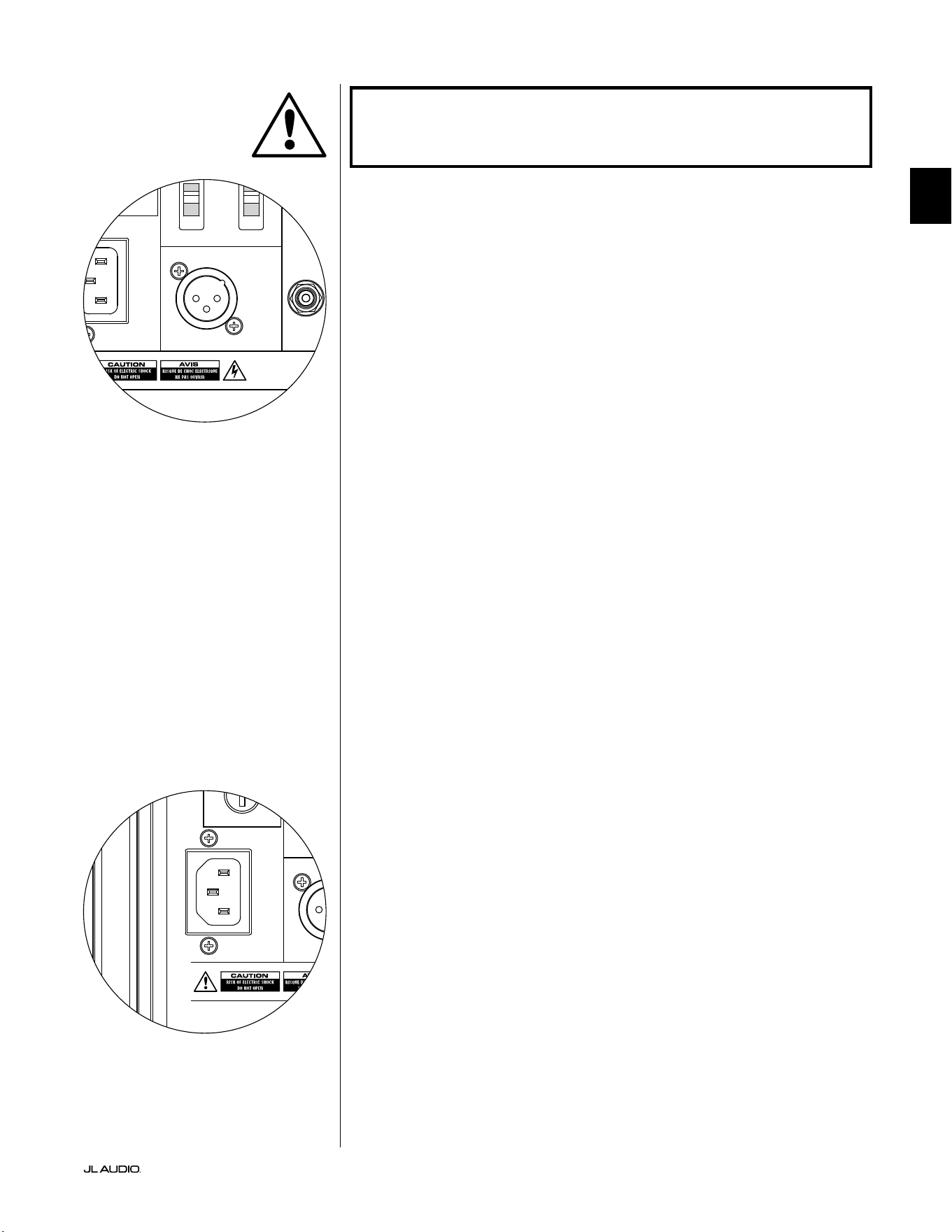
Pg 21 | FR
|
Fathom
®
v2
FR
IMPORTANT! VEUILLEZ VOUS REPORTER AUX «SCHÉMAS DE CONNEXION DU
SYSTÈME» AUX PAGES 22-25 POUR PLUS D’INFORMATIONS SUR L’UTILISATION
DES CONNEXIONS D’ENTRÉE/ SORTIE.
Connecteur «Sortie vers esclave»
Si vous utilisez plusieurs subwoofers Fathom v2 dans un système home
cinéma, vous désignerez un Fathom v2 en mode maître (voir page20), puis vous
transmettrez le signal de ce dernier aux autres Fathom v2 en mode esclave via cette
sortie XLR symétrique. Le câble «Output to slave» peut être connecté à l’entrée
XLR symétrique «Le orMono» du prochain Fathom v2. Lorsqu’un Fathom v2
est en mode «Slave», sa connexion «Output to Slave» peut être utilisée pour
transmettre un signal à d’autres Fathom v2 fonctionnant en mode «Slave».
Le connecteur «Output to Slave» est conçu pour être utilisé comme suit:
1) Du connecteur «Output to Slave» du Fathom v2 «Master» vers l’entrée
XLR symétrique «Le or Mono» du premier Fathom v2 «Slave».
2) Du connecteur «Output to Slave» du premier Fathom v2 «Slave» vers
l’entrée XLR symétrique «Le or Mono» du deuxième Fathom v2 «Slave».
3) Du connecteur «Output to Slave» du second Fathom v2 «Slave»
vers l’entrée XLR symétrique «Le or Mono» du troisième Fathom v2
«Slave». Etc., etc. (jusqu’à 10Fathom v2 peuvent être connectés dans cette
conguration). Des câbles symétriques appropriés aux connecteurs XLR
sont disponibles auprès de votre revendeur JL Audio et ne sont pas fournis
avec le Fathom v2.
Notes techniques:
• Le signal «Output to Slave» transporte tout traitement de signal sélectionné
sur le Fathom v2 «Master» (y compris le réglage du «Master Level» et du
traitement DARO) vers les autres Fathom v2 fonctionnant en mode «Slave».
• Depuis le Fathom v2 en mode «Slave», le signal «Output to Slave» est une
réplique exacte buérisée du signal d’entrée symétrique, ce qui rend cette
méthode de distribution du signal préférable à l’utilisation d’adaptateurs Y ou
de séparateurs.
• Utilisez uniquement des câbles de connexion blindés dotés de connecteurs
XLR de haute qualité pour la connexion «Master/ Slave». N’utilisez jamais
de câbles asymétriques avec des adaptateurs.
Connecteur d’alimentation CA type CEI
La prise pour cordon d’alimentation secteur de type CEI permet de brancher le
cordon d’alimentation de gros calibre de 1,8m (6pi) inclus avec votre subwoofer
Fathom v2. Les Fathom v2 vendus dans les diérentes régions du monde sont
congurés pour chaque système électrique local et comprennent des prises
appropriées sur leurs cordons d’alimentation. Veuillez noter les marquages de
tension visibles à côté du connecteur CA et vous assurer que vous alimentez le
Fathom v2 uniquement avec une prise adaptée à ces indications. N’utilisez que le
cordon d’alimentation secteur fourni avec le Fathom v2. Pour plus d’informations
concernant le porte-fusible, veuillez lire la section Dépannage du présent manuel.
Le subwoofer Fathom v2 est un dispositif puissant qui peut exiger beaucoup
de courant. Si un trop grand nombre de composants sont connectés à un
subwoofer Fathom v2 sur une seule prise électrique, vous risquez de déclencher un
disjoncteur de la maison lors d’une utilisation intense. Dans ce cas, répartissez le
Fathom v2 et les autres composants sur deux circuits électriques CA. Si possible,
pour une performance maximale, dédiez un circuit CA à chaque Fathom v2.
IMPORTANT
1200VA
Built in USA with Imported and domestic components
LEFT
or
MONO
RIGHT
ONLY
INPUTS
Output to Slave
(Balanced)
Balanced
Unbalanced
Input Modes
Slave
Master
Grounded
Isolated
SERIAL NUMBER:
Warranty void if serial number is removed, altered or defaced.
F 12A H
250V
120 V ~ 60 Hz
F
U
S
E
F
U
S
E
1200VA
Built in USA with Imported and domestic components
LEFT
or
MONO
RIGHT
ONLY
INPUTS
Output to Slave
(Balanced)
Balanced
Unbalanced
Input Modes
Slave
Master
Grounded
Isolated
SERIAL NUMBER:
Warranty void if serial number is removed, altered or defaced.
F 12A H
250V
120 V ~ 60 Hz
F
U
S
E
F
U
S
E
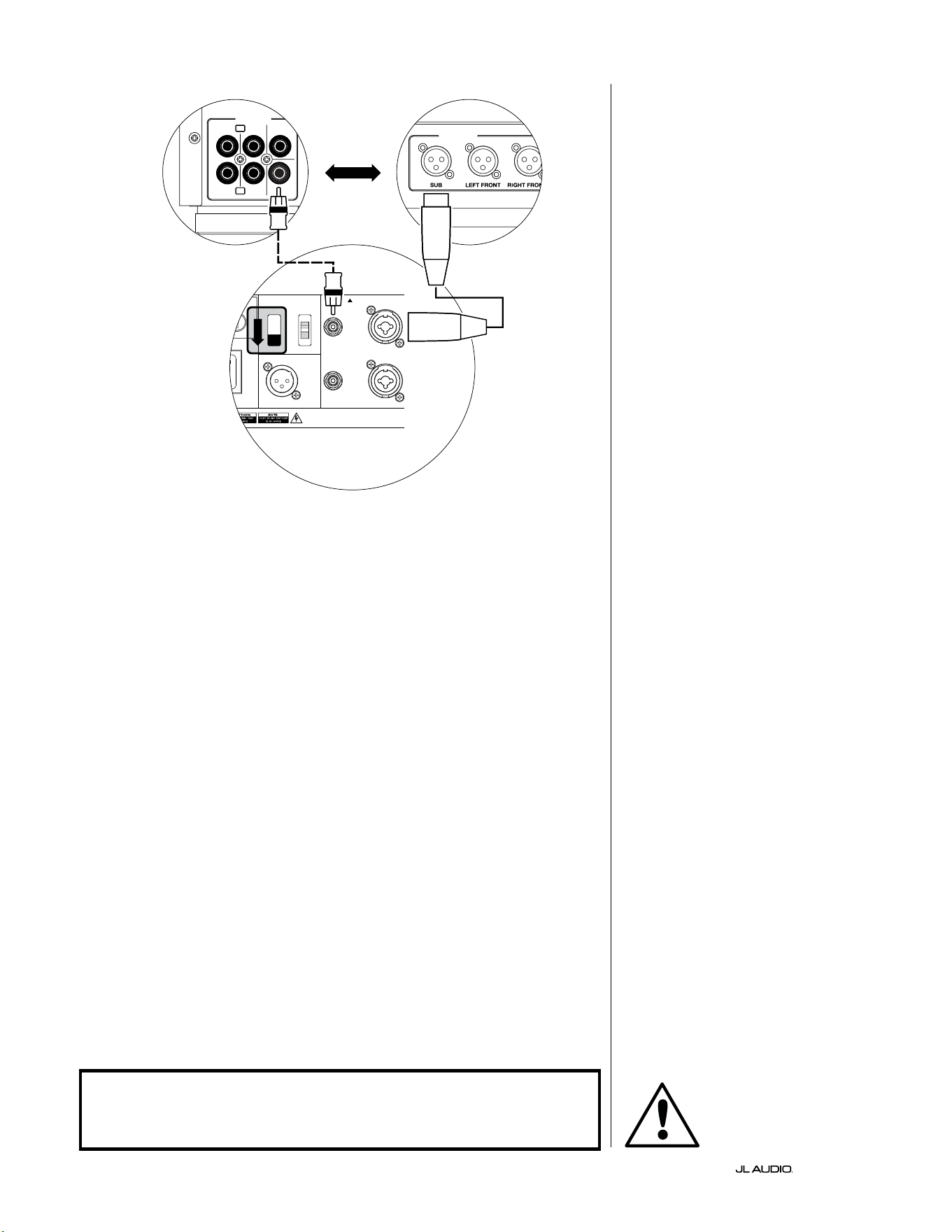
FR | Pg 22
|
Fathom
®
v2
CONNEXION DU SYSTÈME (SCHÉMA1):
Un Fathom v2 connecté au
récepteur home cinéma ou au
préamplicateur/ processeur home
cinéma
La plupart des récepteurs et des
préamplicateurs/ processeurs home
cinéma disposent d’une seule (mono)
sortie de subwoofer. Lorsque vous
connectez une sortie de subwoofer
mono à votre Fathom v2, vous utiliserez
uniquement l’entrée «Le of Mono» du
Fathom v2.
Il existe deux types de connexion pour
brancher le Fathom v2 à votre système
home cinéma: symétrique (connecteur
XLR ou TRS 6,35mm [1/4po]) et
asymétrique. Les connexions symétriques
permettent une élimination du bruit
supérieure et assurent une mise à la terre
correcte entre les composants. Si votre
récepteur ou processeur dispose de sorties
symétriques, nous vous recommandons
vivement de les utiliser.
Dans le schéma de connexion à
gauche, les connexions symétriques sont
représentées par des lignes pleines, les
connexions asymétriques sont représentées
en pointillés. Vous utiliserez uniquement
une de ces méthodes de connexion d’entrée
(pas les deux).
1200VA
ilt in USA with Imported and domestic components
LEFT
or
MONO
RIGHT
ONLY
INPUTS
Output to Slave
(Balanced)
Balanced
Unbalanced
Input Modes
Slave
Master
Grounded
Isolated
SERIAL NUMBER:
Warranty void if serial number is removed, altered or defaced.
F 12A H
250V
0 V ~ 60 Hz
F
U
S
E
F
U
S
E
S
l
ave
M
aster
z
OUTPUTS
SUB
REAR
REAR CENTER
FRONT
FRONT
R
L
PRE OUT
PROCESSEUR (SORTIES SYMÉTRIQUES)
BOUTONS DE RÉGLAGE ARRIÈRE DU FATHOM (MAÎTRE)
OU
RÉCEPTEUR / PROCESSEUR (SORTIES ASYMÉTRIQUES)
AVERTISSEMENT
AVERTISSEMENT ! ÉTEIGNEZ LE(S) APPAREIL(S) FATHOM v2 ET TOUS LES
AUTRES COMPOSANTS DU SYSTÈME AVANT D’EFFECTUER OU DE CHANGER
DES CONNEXIONS!
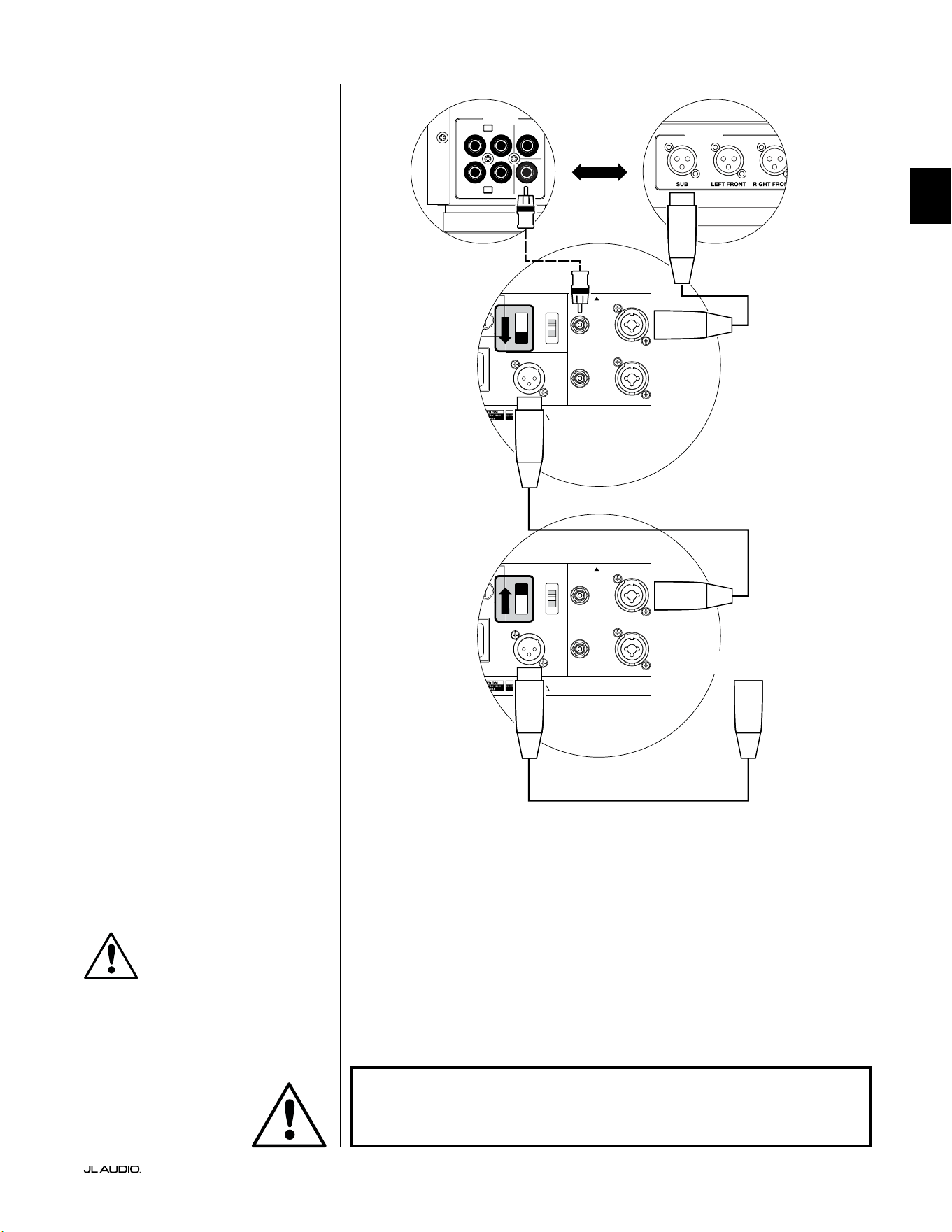
Pg 23 | FR
|
Fathom
®
v2
FR
CONNEXION DU SYSTÈME (SCHÉMA2):
Plusieurs Fathom v2 connectés au
récepteur home cinéma ou
préampli/ processeur home cinéma
Pour simplier considérablement
l’utilisation de plusieurs subwoofers dans
un même système home cinéma, les Fathom
v2 comprennent un système de distribution
du signal «Master/ Slave». Cela permet de
contrôler tous les Fathom v2 d’un système à
partir d’une seule unité «Master» (maître).
Tout d’abord, sélectionnez un subwoofer
Fathom v2 en tant que «Master» à l’aide de
l’interrupteur «Input Mode» sur le panneau
de commande supérieur. En général, vous
désignerez le Fathom v2 le plus proche du
récepteur/ préampli comme «Master»
(maître). Dans certains cas, par exemple
lorsque le panneau de commande de certains
appareils est dicile d’accès, vous pouvez
préférer désigner comme maître celui qui est le
plus facile d’accès.
Il existe deux types de connexion pour
brancher le Fathom v2 à votre système home
cinéma: symétrique (connecteur XLR ou
TRS 6,35mm [1/4po]) et asymétrique. Les
connexions symétriques permettent une
élimination du bruit supérieure et assurent une
mise à la terre correcte entre les composants.
Si votre récepteur ou processeur dispose de
sorties symétriques, nous vous recommandons
vivement de les utiliser pour la connexion au
Fathom v2 désigné comme maître.
Dans le schéma de connexion à gauche, les
connexions symétriques sont représentées par
des lignes pleines, les connexions asymétriques
sont représentées en pointillés. Vous utiliserez
uniquement une de ces méthodes de
connexion d’entrée pour le Fathom v2 désigné
comme maître (pas les deux).
Les Fathom v2 restant dans le système
seront congurés en tant qu’appareils
«Slave» (esclaves) à l’aide des interrupteurs
«Input Mode» situés sur le panneau de
commande supérieur. À l’aide de câbles XLR
symétriques, vous relierez le connecteur
«Output to Slave» du Fathom v2 maître à
l’entrée asymétrique «Le or Mono» du
premier Fathom v2 esclave. Le connecteur
«Output to Slave» de cet appareil esclave
alimentera l’entrée «Le or Mono» du
prochain appareil esclave via un autre câble
XLR symétrique. Les appareils esclaves
suivants seront connectés de la même manière.
Les connexions entre les Fathom «Master»
et «Slave» et entre les Fathom «Slave»
se font à l’aide de câbles XLR symétriques
UNIQUEMENT.
1200VA
ilt in USA with Imported and domestic components
LEFT
or
MONO
RIGHT
ONLY
INPUTS
Output to Slave
(Balanced)
Balanced
Unbalanced
Input Modes
Slave
Master
Grounded
Isolated
SERIAL NUMBER:
Warranty void if serial number is removed, altered or defaced.
F 12A H
250V
0 V ~ 60 Hz
F
U
S
E
F
U
S
E
1200VA
ilt in USA with Imported and domestic components
LEFT
or
MONO
RIGHT
ONLY
INPUTS
Output to Slave
(Balanced)
Balanced
Unbalanced
Input Modes
Slave
Master
Grounded
Isolated
SERIAL NUMBER:
Warranty void if serial number is removed, altered or defaced.
F 12A H
250V
0 V ~ 60 Hz
F
U
S
E
F
U
S
E
S
l
ave
M
aster
z
S
l
ave
M
aster
z
OUTPUTS
SUB
REAR
REAR CENTER
FRONT
FRONT
R
L
PRE OUT
PROCESSEUR (SORTIES SYMÉTRIQUES)
BOUTONS DE RÉGLAGE ARRIÈRE DU FATHOM (MAÎTRE)
BOUTONS DE RÉGLAGE ARRIÈRE
DU FATHOM (ESCLAVE)
OU
RÉCEPTEUR / PROCESSEUR (SORTIES ASYMÉTRIQUES)
VERS FATHOM SUPPLÉMENTAIRES
(SI APPLICABLE)
IMPORTANT
AVERTISSEMENT
AVERTISSEMENT ! ÉTEIGNEZ LE(S) APPAREIL(S) FATHOM v2 ET TOUS LES
AUTRES COMPOSANTS DU SYSTÈME AVANT D’EFFECTUER OU DE CHANGER
DES CONNEXIONS!
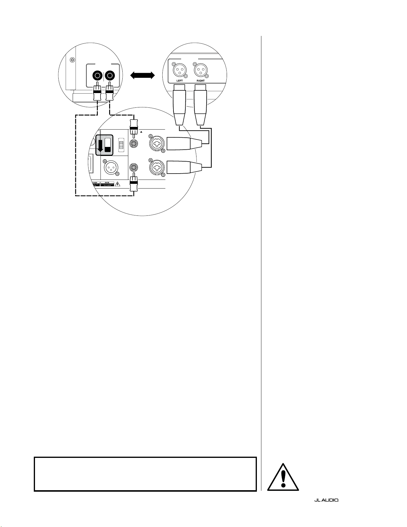
FR | Pg 24
|
Fathom
®
v2
1200VA
ilt in USA with Imported and domestic components
LEFT
or
MONO
RIGHT
ONLY
INPUTS
Output to Slave
(Balanced)
Balanced
Unbalanced
Input Modes
Slave
Master
Grounded
Isolated
SERIAL NUMBER:
Warranty void if serial number is removed, altered or defaced.
F 12A H
250V
0 V ~ 60 Hz
F
U
S
E
F
U
S
E
S
l
ave
M
aster
z
FILTRE ACTIF STÉRÉO (SORTIES SYMÉTRIQUES)
LOW OUT
(SUB OUT)
FILTRE ACTIF STÉRÉO (SORTIES ASYMÉTRIQUES)
RIGHTLEFT
LOW OUT
(SUB OUT)
BOUTONS DE RÉGLAGE ARRIÈRE DU FATHOM (MAÎTRE)
OU
CONNEXION DU SYSTÈME (SCHÉMA3):
Un Fathom v2 en mono vers
un système à deux canaux
Lorsque vous connectez un Fathom v2
(ou plusieurs Fathom v2) en mono à un
système audio à deux canaux, vous utilisez
à la fois les entrées «Le or Mono» et
«Right». Les circuits au sein de la section
d’entrée du Fathom v2 additionnent les
signaux stéréo pour donner du mono.
Nous vous recommandons vivement
d’utiliser un ltre actif de haute qualité,
comme le CR-1 de JL Audio, pour diviser
les signaux de votre préamplicateur
avant de le brancher au Fathom v2 et à
l’amplicateur qui alimente vos enceintes
principales. Cela vous permettra de ltrer
les basses fréquences des signaux qui
alimentent les enceintes principales an
d’optimiser les performances.
Si vous n’utilisez pas de ltre actif et
que vous êtes satisfait de vos enceintes
principales «full range», vous pouvez
diviser les signaux de sortie de votre
préamplicateur à l’aide de connecteurs en
Y appropriés à la place du ltre actif illustré
dans le schéma.
Deux types de connexion sont
disponibles pour raccorder le Fathom v2
à votre système audio à deux canaux:
symétrique (connecteur XLR ou TRS
6,35mm [1/4po]) et asymétrique
(connecteur de type RCA). Les connexions
symétriques permettent une élimination
du bruit supérieure et assurent une mise
à la terre correcte entre les composants. Si
votre préamplicateur ou votre ltre actif
est doté de sorties symétriques, nous vous
recommandons vivement de les utiliser.
Dans le schéma de connexion à
gauche, les connexions symétriques sont
représentées par des lignes pleines, les
connexions asymétriques sont représentées
en pointillés. Vous utiliserez uniquement
une de ces méthodes de connexion d’entrée
(pas les deux).
REMARQUE: Si vous le souhaitez,
vous pouvez brancher des Fathom v2
supplémentaires en mode «Slave» au
Fathom v2 connecté comme indiqué sur
ce schéma. Reportez-vous à la section
«Schéma de connexion2» à la page23
pour l’explication relative à la connexion en
mode esclave.
AVERTISSEMENT
AVERTISSEMENT ! ÉTEIGNEZ LE(S) APPAREIL(S) FATHOM v2 ET TOUS LES
AUTRES COMPOSANTS DU SYSTÈME AVANT D’EFFECTUER OU DE CHANGER
DES CONNEXIONS!
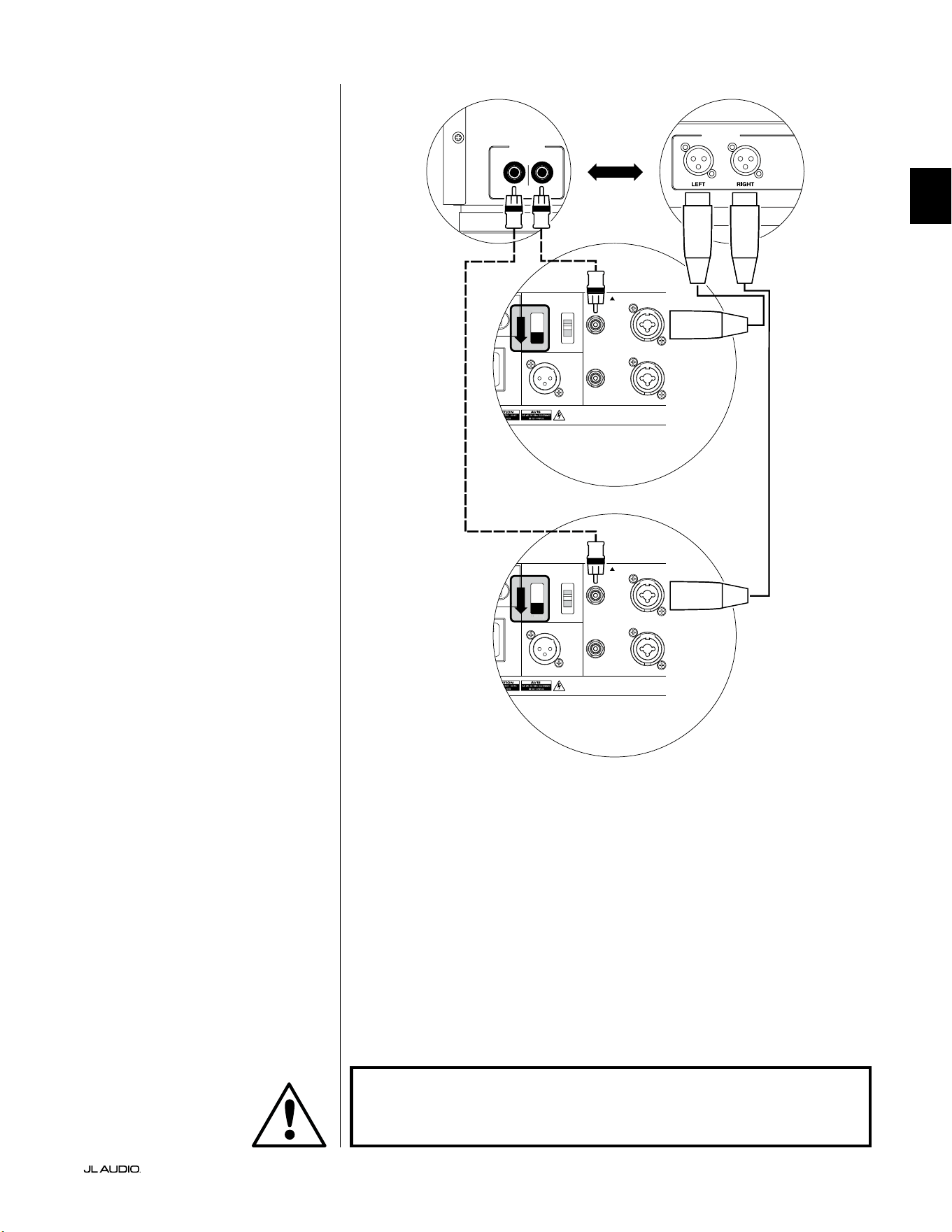
Pg 25 | FR
|
Fathom
®
v2
FR
CONNEXION DU SYSTÈME (SCHÉMA4):
Deux Fathom v2 en stéréo connectés à
un système à deux canaux
Lorsque vous connectez deux Fathom
v2 en stéréo à un système audio à deux
canaux, vous n’utiliserez que les entrées
«Le or Mono» de chaque Fathom v2.
L’interrupteur «Input Mode» sur le
panneau de commande supérieur de
chaque Fathom v2 sera réglé sur la position
«Master».
Nous vous recommandons vivement
d’utiliser un ltre actif de haute qualité,
comme le CR-1 de JL Audio, pour diviser
les signaux de votre préamplicateur
avant de le brancher au Fathom v2 et à
l’amplicateur qui alimente vos enceintes
principales. Cela vous permettra de ltrer
les basses fréquences des signaux qui
alimentent les enceintes principales an
d’optimiser les performances.
Si vous n’utilisez pas de ltre actif et
que vous êtes satisfait de vos enceintes
principales «full range», vous pouvez
diviser les signaux de sortie de votre
préamplicateur à l’aide de connecteurs en
Y appropriés à la place du ltre actif illustré
dans le schéma.
Deux types de connexion sont
disponibles pour raccorder les Fathom
v2 à votre système audio à deux canaux:
symétrique (connecteur XLR ou TRS
6,35mm [1/4po]) et asymétrique
(connecteur de type RCA). Les connexions
symétriques permettent une élimination
du bruit supérieure et assurent une mise
à la terre correcte entre les composants. Si
votre préamplicateur ou votre ltre actif
est doté de sorties symétriques, nous vous
recommandons vivement de les utiliser.
Dans le schéma de connexion à
droite, les connexions symétriques sont
représentées par des lignes pleines, les
connexions asymétriques sont représentées
en pointillés. Vous utiliserez uniquement
une de ces méthodes de connexion d’entrée
(pas les deux).
REMARQUE: si vous le souhaitez,
vous pouvez brancher des Fathom v2
supplémentaires en mode «Slave» à
chaque Fathom v2 connecté comme
indiqué sur ce schéma. Reportez-vous à
la section «Schéma de connexion2» à
la page23 pour l’explication relative à la
connexion en mode esclave.
LOW OUT
(SUB OUT)
RIGHTLEFT
LOW OUT
(SUB OUT)
1200VA
ilt in USA with Imported and domestic components
LEFT
or
MONO
RIGHT
ONLY
INPUTS
Output to Slave
(Balanced)
Balanced
Unbalanced
Input Modes
Slave
Master
Grounded
Isolated
SERIAL NUMBER:
Warranty void if serial number is removed, altered or defaced.
F 12A H
250V
0 V ~ 60 Hz
F
U
S
E
F
U
S
E
S
l
ave
M
aster
z
PROCESSEUR (SORTIES SYMÉTRIQUES)
BOUTONS DE RÉGLAGE ARRIÈRE DU FATHOM (MAÎTRE)
OU
RÉCEPTEUR / PROCESSEUR (SORTIES ASYMÉTRIQUES)
BOUTONS DE RÉGLAGE ARRIÈRE DU FATHOM (MAÎTRE)
AVERTISSEMENT
AVERTISSEMENT ! ÉTEIGNEZ LE(S) APPAREIL(S) FATHOM v2 ET TOUS LES
AUTRES COMPOSANTS DU SYSTÈME AVANT D’EFFECTUER OU DE CHANGER
DES CONNEXIONS!

FR | Pg 26
|
Fathom
®
v2
PROCÉDURES DE RÉGLAGE RECOMMANDÉES
1) Préparation à la procédure de réglage: ............................... 26-27
2) Réglage du niveau: .................................................. 28
3) Réglage de la polarité/ phase: ......................................... 28
4) Essais d’emplacement: ............................................... 28
5) Application de la fonction DARO: .................................. 29-30
6) Réglage du ltre e.l.f. trim: ........................................... 30
PRÉPARATION À LA PROCÉDURE DE RÉGLAGE:
Veuillez conrmer que les réglages système suivants ont été faits avant de
commencer la procédure de conguration. Ceci permet de démarrer sur une base
neutre et de congurer ecacement votre système.
Sur votre récepteur ou préampli/ processeur home cinéma:
Avant de commencer à congurer votre système de subwoofer Fathom v2,
nous vous recommandons de régler votre récepteur ou votre préampli/ processeur
comme suit (veuillez éteindre tous les Fathom v2 du système en appuyant sur
l’interrupteur d’alimentation en façade avant d’eectuer ces réglages):
1. Taille de l’enceinte
Dans le menu de conguration des enceintes de votre récepteur ou préampli/
processeur, congurez toutes les enceintes haute fréquence en sélectionnant
l’option «small» avec un point de coupure de 80Hz. Ceci permet d’envoyer
TOUS les graves vers les Fathom v2.
2. Distance des enceintes
Dans le menu de conguration des enceintes, réglez correctement la distance
qui sépare toutes les enceintes de la position d’écoute, y compris la distance
par rapport au subwoofer. Utilisez un mètre ruban pour mesurer ces distances
(la cohérence temporelle est importante). Si vous utilisez plusieurs Fathom
v2s, calculez leurs distances moyennes par rapport à la position d’écoute
principale et utilisez cette valeur pour régler la distance par rapport au
subwoofer.
3. Niveau du subwoofer
Réglez le niveau du subwoofer sur le récepteur ou préampli/ processeur à
«0» ou à la position du milieu.
4. Commandes de tonalité/ Égaliseurs
Réglez toutes les commandes de tonalité sur «0» et désactivez toutes les
fonctions de l’égaliseur.
Sur votre ltre actif ou processeur de gestion des graves:
Si vous utilisez un processeur avec ltre actif ou gestion des graves, nous vous
recommandons de le régler comme suit avant de procéder à la conguration de
votre subwoofer Fathom v2 (veuillez éteindre tous les Fathom v2 avant d’eectuer
ces réglages):
1. Fréquence de ltre passe-bas
Sélectionnez une fréquence de ltre passe-bas de 80Hz (pente de 24dB/
octave).
2. Fréquence de ltre passe-haut
Sélectionnez une fréquence de ltre passe-haut de 80Hz (pente de 24dB/
octave).
3. Niveau de sortie (subwoofer) passe-bas
Réglez le niveau de sortie du subwoofer sur «0» ou à sa position moyenne.
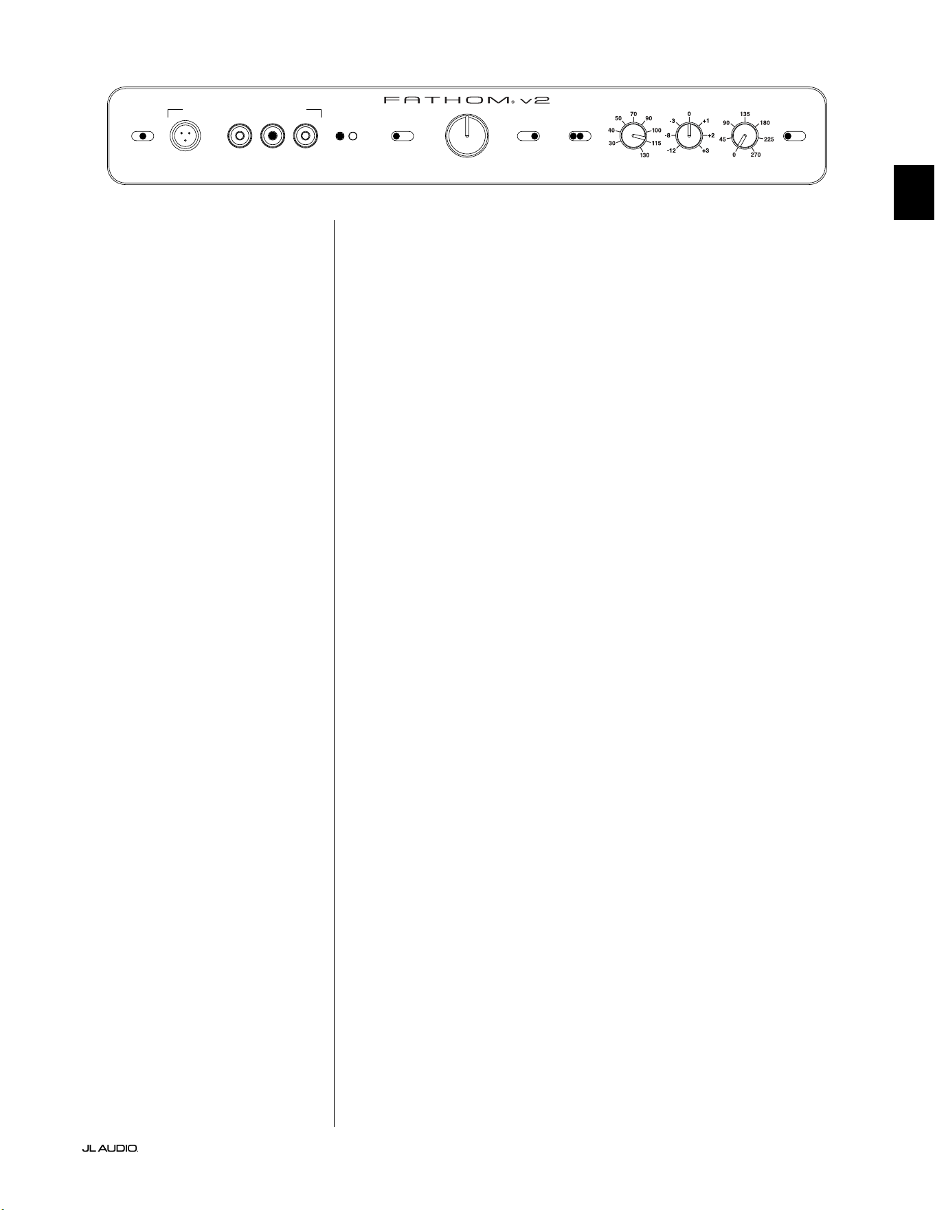
Pg 27 | FR
|
Fathom
®
v2
FR
Sur le panneau avant du Fathom v2:
Veuillez éteindre le récepteur ou le préampli/ processeur home cinéma pour
eectuer ces réglages.
1. Interrupteur «Power»
Tournez l’interrupteur «Power» de chaque Fathom v2 en position «On».
2. Interrupteur «Lights»
Tournez l’interrupteur «Lights» de chaque Fathom v2 en position «On».
Si vous ne voyez aucun voyant sur le panneau avant, il se peut que vous ayez
oublié de brancher le Fathom v2 ou qu’il y ait un problème avec le circuit
électrique.
3. Voyant «Input Mode»
Si vous utilisez un seul Fathom v2, vériez que le voyant «Input Mode» est en
position «Master». Si ça n’est pas le cas, vous devez accéder à l’interrupteur
du haut «Input Mode» sur le panneau arrière du Fathom v2.
Si vous utilisez plusieurs Fathom v2 dans une conguration Maître/ Esclave,
vériez que l’appareil connecté directement à votre récepteur ou préampli/
processeur indique «Master» sur son voyant «Input Mode» et que tous les
autres appareils indiquent «Slave» sur leur voyant «Input Mode». Si ça n’est
pas le cas, vous devez accéder à l’interrupteur du haut «Input Mode» sur le
panneau arrière du Fathom v2.
4. Interrupteur «Level Mode»
Positionnez l’interrupteur «Level Mode» du Fathom v2 sur «ref.».
5. Interrupteur «LP Filter»
Si le récepteur/ processeur de votre home cinéma dispose d’une gestion
des graves (haut-parleurs réglés sur «small»), ou si vous utilisez un ltre/
processeur de gestion des graves externe, positionnez l’interrupteur «LP
Filter» de votre Fathom v2 sur «O». Si ça n’est pas le cas, sélectionnez la
position «12dB».
6. Bouton «LP Freq. (Hz)»
Faites tourner le bouton «LP Freq.» sur la position 80Hz.
7. Bouton «e.l.f. trim (dB)»
Faites tourner le bouton «e.l.f. trim» sur «0».
8. Interrupteur «Polarity»
Positionnez l’interrupteur «Polarity» sur «0».
9. Bouton «phase (deg.)»
Positionnez le bouton «phase (deg.)» sur «0» degré.
10. Interrupteur d’annulation de la fonction DARO
Appuyez sur l’interrupteur «defeat» de la fonction DARO pour que le voyant
rouge reste allumé.
LP freq. (Hz) e.l.f. trim (dB) phase (deg.)
Polarity
0
|
180 deg.
LP Filter
o
|
12dB
|
24dB
Master Level
max
0
Lights
o
|
dim
|
on
-∞
Level Mode
ref.
|
variable
Input Mode
master
|
slave
calibration mic. demo defeat calibrate
Power
o
|
on
|
auto
Digital Automatic Room Optimization
FR | Pg 28
|
Fathom
®
v2
PROCÉDURES DE RÉGLAGE RECOMMANDÉES (suite)
Conguration du subwoofer:
Après avoir réglé les boutons sur votre récepteur ou préampli/ processeur
home cinéma et sur le Fathom v2 conformément aux recommandations des pages
26 et 27 du présent manuel, vous êtes prêt à démarrer la conguration de votre
Fathom v2 pour obtenir des performances optimales.
1. Réglage du niveau
Choisissez une musique ou un lm avec des graves profonds, réglez le
niveau du subwoofer pour qu’il s’harmonise avec les autres enceintes en
utilisant le bouton de réglage du niveau du subwoofer sur votre récepteur
ou préampli/ processeur. Cette méthode permet d’éviter des manipulations
intempestives du bouton «Master Level» sur le Fathom v2 (pensez aux enfants
en bas âge ou aux visiteurs curieux).
Dans le cas improbable où le réglage du niveau du subwoofer de votre
récepteur ou préampli/ processeur ne peut pas être augmenté susamment
au niveau adapté au Fathom v2, repositionnez le bouton de réglage sur
«0». Ensuite, faites tourner l’interrupteur «Level Mode» du Fathom v2 sur
«variable» avec «0» comme point de référence (le gain du mode REF et le
gain du mode Variable «0» sont identiques), utilisez la commande «Master
Level» pour faire correspondre le niveau du subwoofer à celui des autres
enceintes. PRENEZ NOTE DE CE RÉGLAGE POUR UNE UTILISATION
FUTURE.
Pour des informations plus détaillées concernant les boutons de réglage du
niveau de votre Fathom v2, veuillez consulter les sections «Mode de niveau» et
«Niveau principal» à la page 15-16 du présent manuel.
2. Réglage de la polarité et de la phase
Il peut s’avérer utile de faire appel à une autre personne pour eectuer ces
réglages an que vous puissiez évaluer plus facilement les diérences depuis
votre position d’écoute.
En écoutant une source familière (de préférence une musique contenant
une bonne réponse de grave extrême et de grave moyen), tournez l’interrupteur
«Polarity» entre la position «0» et «180» et écoutez les diérences. Le réglage
correct sera plus naturel avec une puissance et une articulation optimale du
grave extrême. Si les deux sont similaires, sélectionnez «0».
Une fois la polarité réglée, utilisez la même musique pour auditionner
diérents réglages à l’aide du bouton «phase (deg.)» et sélectionnez le réglage
qui améliore la réponse des graves extrêmes et moyens. Si vous n’entendez
aucune diérence, réglez sur «0».
3. Testez d’autres emplacements pour le subwoofer (si nécessaire).
Si vous êtes satisfait des performances de base de votre subwoofer, vous pouvez
passer à l’étape suivante. Dans le cas contraire, nous vous recommandons de faire
des essais d’emplacement de votre subwoofer jusqu’à ce que vous soyez satisfait
de ses performances de base. Les essais d’emplacement sont ESSENTIELS pour
obtenir une sonorisation de qualité supérieure. Déplacer le subwoofer de quelques
centimètres peut avoir un eet important sur la qualité du son grave. Pour chaque
nouvel emplacement, commencez avec un réglage de la polarité et de la phase à
«0» et répétez le processus de conguration à partir de l’étape1.
IMPORTANT ! NOTEZ TOUS LES RÉGLAGES EFFECTUÉS AUX ÉTAPES 1 À 3
POUR RÉFÉRENCE FUTURE.
IMPORTANT
Pg 29 | FR
|
Fathom
®
v2
FR
IMPORTANT! ASSUREZ-VOUS QUE LA PIÈCE EST CALME LORS DU CALIBRAGE
DARO ! ÉTEIGNEZ TOUT APPAREIL BRUYANT À PROXIMITÉ DE L’ESPACE
D’ÉCOUTE (LAVE-VAISSELLE, LAVE-LINGE, ETC.).
IL EST PARTICULIÈREMENT IMPORTANT D’ÉTEINDRE LES CLIMATISEURS OU LES
POMPES À CHALEUR PENDANT LE CALIBRAGE. CES SYSTÈMES DE TYPE CVC
À AIR FORCÉ PEUVENT GÉNÉRER DES NIVEAUX MODÉRÉS DE BRUIT DE 15 À
20HZ QUI PEUVENT INTERFÉRER AVEC LE CALIBRAGE.
4. Application de la fonction d’optimisation numérique automatique de la
pièce (DARO)
Vous êtes maintenant prêt à tirer parti système exclusif d’optimisation
numérique automatique de la pièce (DARO) de JL Audio. Ce système mesurera
la réponse du subwoofer au niveau de votre siège d’écoute principal et
appliquera un puissant égaliseur à 18bandes pour dompter les crêtes causées
par les modes de la pièce, ce qui donnera des graves plus doux et plus précis.
Si vous utilisez plusieurs Fathom v2 dans une conguration maître/ esclave,
il vous sura de désigner l’appareil désigné comme maître pour eectuer le
calibrage DARO de l’ensemble du système de subwoofers. Notez que tous les
traitements de signal du panneau avant sont désactivés au cours du calibrage
DARO, quels que soient les réglages des boutons. Le fonctionnement normal
est restauré une fois le calibrage terminé.
a) Positionnez l’interrupteur de marche/ arrêt principal sur «ON» et assurez-
vous que l’interrupteur «Lights» sur le Fathom v2 est positionné sur «ON».
b) Retirez le microphone de calibrage de sa pochette de protection et connectez
son câble à la prise jack mini-XLR du panneau de commande avant du
Fathom v2.
REMARQUE: Le calibrage DARO n’est possible que lorsque le microphone de
test JL Audio fourni est branché sur le panneau avant du Fathom v2. La fonction
«calibrate» est désactivée lorsqu’aucun microphone n’est branché an d’éviter
toute perte accidentelle des réglages.
c) Connectez le microphone à l’autre extrémité du câble du micro et placez
temporairement le micro dans le siège d’écoute principal. Si vous disposez
d’un pied de micro, vous pouvez placer le micro à hauteur de tête et le
positionner dans le siège d’écoute principal.
d) Sur le panneau de commande du Fathom v2, appuyez sur le bouton
«calibrate». Le voyant vert du bouton «calibrate» clignote lentement,
indiquant que le calibrage commencera dans 5secondes.
e) Dans les 5secondes qui suivent l’appui sur le bouton «calibrate», retournez
à votre siège d’écoute principal et tenez le microphone dans la position
normale, assis, à la hauteur approximative de vos oreilles.
f) Une séquence de bruit sera jouée par le Fathom v2 qui ressemble à un bruit
parasite hachuré. La séquence va durer environ 3minutes. Pendant ce
processus, le système DARO prend une mesure de la réponse en fréquence à
votre siège et corrige les éventuels problèmes qu’il détecte. Le système DARO
compense également toute diérence de niveau avant et après, de sorte que
votre Fathom v2 aura une intensité sonore perçue similaire après le processus
de calibrage. Lorsque le système DARO a terminé le calibrage, le bouton
«calibrate» s’allume et reste allumé, indiquant un calibrage réussi.
Si vous souhaitez eectuer un nouveau calibrage, il sut de répéter les étapes
ci-dessus.
IMPORTANT
FR | Pg 30
|
Fathom
®
v2
Pour eacer les réglages du DARO (c.-à-d. revenir au plat) et éteindre le
voyant de calibrage, maintenez enfoncé le bouton «demo», puis appuyez sur le
bouton «defeat». Veillez à appuyer sur cette séquence de boutons rapidement.
Si vous maintenez le bouton «demo» enfoncé plus de 2secondes sans toucher
le bouton «defeat», les tonalités de démo commenceront. Si cela arrive,
attendez simplement que la séquence de démo se termine, puis réessayez. Vous
pouvez eectuer un nouveau calibrage en suivant la procédure normale décrite
ci-dessus.
IMPORTANT ! SI VOUS DÉPLACEZ VOTRE FATHOM V2 OU VOTRE SIÈGE
D’ÉCOUTE PRINCIPAL À L’AVENIR, VOUS DEVREZ À NOUVEAU EXÉCUTER LA
FONCTION DARO. TOUT CALIBRAGE PARTICULIER EST UNIQUE POUR CETTE
COMBINAISON PARTICULIÈRE DE POSITION DU SUBWOOFER ET DE POSITION
DU SIÈGE D’ÉCOUTE. IL SUFFIT DE SUIVRE LES ÉTAPES CI-DESSUS POUR CRÉER
UNE NOUVELLE COURBE DE CALIBRAGE.
5. Filtre extrêmement basse fréquence (e.l.f.)
Utilisez le bouton de réglage «e.l.f. trim» pour régler l’extension de
l’extrêmement basse fréquence du Fathom v2. Ce réglage permet d’obtenir
une atténuation de -12dB ou une amplication de +3dB à 24Hertz. Il
est particulièrement utile lorsqu’on utilise un Fathom v2 (ou deux) dans
un système home cinéma de taille petite à moyenne. Étant donné que les
espaces clos plus petits contribuent à augmenter le niveau d’extrêmement
basse fréquence, les petites salles de cinéma peuvent être submergées par la
forte production de graves du subwoofer Fathom v2. Cela peut générer un
eet de graves «lourds» ou «exagérés» dans la zone d’extrêmement basse
fréquence. En tournant vers le bas le bouton «e.l.f. trim», vous réduisez le
niveau d’extrêmement basse fréquence et vous atténuez ce problème. N’hésitez
pas à expérimenter et à écouter une variété de matériels exigeants jusqu’à ce
que vous trouviez le meilleur compromis en fonction de votre pièce et de vos
préférences.
Votre Fathom v2 est désormais optimisé pour restituer les meilleurs graves
au niveau de votre siège d’écoute. Félicitations!
IMPORTANT

Pg 31 | FR
|
Fathom
®
v2
FR
QUESTIONS LES PLUS FRÉQUENTES
Puis-je poser des objets sur mon subwoofer?
Il n’est pas recommandé de poser des objets sur le boîtier du subwoofer, car ils
peuvent vibrer et générer des bruits indésirables et causer des dégâts éventuels.
Aucun objet contenant du liquide ne doit être placé sur le boîtier du Fathom v2.
Le Fathom v2 dispose-t-il d’un blindage magnétique?
Les subwoofers Fathom v2 ne disposent pas de blindage magnétique. Pour éviter
toute perturbation magnétique avec certains modèles de téléviseurs, placez le
Fathom v2 à une distance d’au moins 1 à 1,5m (3 à 4pi) de votre écran. Si vous
observez une décoloration de l’image, déplacez le subwoofer encore plus loin
jusqu’à ce que ces perturbations disparaissent.
Ma facture d’électricité sera-t-elle élevée si je laisse le Fathom v2 en mode
«Auto»?
Lorsqu’il est en mode «Auto», l’amplicateur du Fathom v2 n’est mis sous tension
que lorsqu’un signal signicatif est détecté au niveau des entrées. Lorsqu’il est hors
tension, seuls les circuits «du mode veille» restent sous tension, ce qui nécessite
une quantité de courant négligeable (moins de 5watts).
Dois-je débrancher le subwoofer pendant un orage ou une absence prolongée?
OUI. Vous devez débrancher votre Fathom v2 pendant (ou avant) un orage. Cela
permettra d’éviter tout endommagement dérivant des pics de tension provoqués
par la foudre. Dans ces conditions, il est bon de débrancher tous les composants
audio/ vidéo. Si vous devez vous absenter de chez vous pendant plusieurs jours, il
est également conseillé de débrancher les composants de votre home cinéma an
d’éviter les dommages causés par des tempêtes ou des perturbations électriques
imprévues.
NETTOYAGE DE VOTRE FATHOM V2
Dépoussiérez le boîtier de vos subwoofers Fathom v2 avec un chion en microbre
propre et doux ou un plumeau à poussière. Les chions en microbre sont
généralement vendus dans les commerces de fourniture d’accessoires automobiles.
Les taches supercielles peuvent généralement être nettoyées avec un chion
propre en microbre. Pour les taches plus tenaces, polissez et protégez la surface
de nition avec de la cire automobile de haute qualité et un chion en microbre
vendus dans les commerces de fourniture d’accessoires automobiles. Nous vous
conseillons d’utiliser la cire «NXT Tech Wax» de Meguiar® et les chions en
microbre Meguiar®.
N’utilisez jamais de produits contenant des solvants agressifs ou des abrasifs, car
ces produits peuvent endommager la surface de manière irréversible. N’utilisez
jamais de produits d’entretien pour meubles ou à base d’huile sur votre Fathom
v2. N’utilisez jamais des solvants ou des produits de nettoyage agressifs sur votre
Fathom v2. En cas de doute, testez le produit sur la partie inférieure du boîtier et
laissez agir plusieurs jours avant de vous engager à l’utiliser sur des parties visibles.

FR | Pg 32
|
Fathom
®
v2
DÉPANNAGE
Aucun son ne sort du subwoofer.
1. Vériez que le Fathom v2 est branché, en position «ON»et que les voyants du
panneau avant sont allumés. Si les voyants ne s’allument pas, vériez le disjoncteur
qui alimente sa prise ou branchez le Fathom v2 sur une autre prise de courant
alternatif. Si la prise secteur est alimentée, mais que les voyants ne s’allument
toujours pas, vous devez contrôler/ remplacer le fusible principal du Fathom v2.
Consultez la section «Porte-fusible» à la page suivante.
2. Testez le subwoofer en appuyant sur le bouton «demo» sur le panneau avant. Si le
subwoofer émet des tonalités de démonstration, le circuit interne du subwoofer est
bon et il pourrait y avoir un problème d’entrée. Vériez les branchements du câble
d’entrée au niveau du Fathom v2 et du récepteur/ préampli/ processeur.
3. Assurez-vous que les réglages du récepteur n’ont pas été modiés.
4. Si les autres enceintes fonctionnent, mais que le Fathom v2 ne fonctionne pas,
essayez de changer le câble qui relie le Fathom v2 au système.
5. Si le problème persiste, contactez votre revendeur
ou l’assistance technique JL Audio.
Le niveau de grave a changé.
1. Assurez-vous que les réglages du niveau du Fathom v2 et sur votre récepteur/
préampli/ processeur n’ont pas été modiés.
2. Si vous utilisez le bouton «Master Level» du Fathom v2 pour régler le niveau du
subwoofer, vériez que l’interrupteur «Level Mode» est réglé sur «variable».
3. Vériez la position du bouton «e.l.f. trim».
Bourdonnements ou autres bruits inusuels émis par votre Fathom v2
1. Veuillez consulter le point relatif au mode d’entrée à la page20 du présent manuel,
en particulier si des composants en amont, des câbles, etc., ont fait l’objet de
modications.
2. Éteignez le Fathom v2, débranchez tous les câbles de signal d’entrée et de sortie,
puis rallumez le Fathom v2. Si le bruit disparaît, le bruit a été provoqué ailleurs
dans votre système.
Les graves sont «brouillés» ou «trop lourds».
1. Essayez de diminuer le niveau de 24Hertz à l’aide du bouton de réglage «e.l.f.
trim». Les graves lourds peuvent parfois être causés par une trop grande
sortie de basses fréquences dans une pièce de taille moyenne.
2. Diminuez le niveau général du subwoofer.
3. Vériez les réglages du récepteur.
4. Essayez de changer de subwoofer ou de changer la position d’écoute principale.
Changer l’un ou l’autre peut avoir un eet ÉNORME sur la sonorisation de votre
équipement. Consultez la section relative à l’installation aux pages 6 à 10 du
présent manuel.
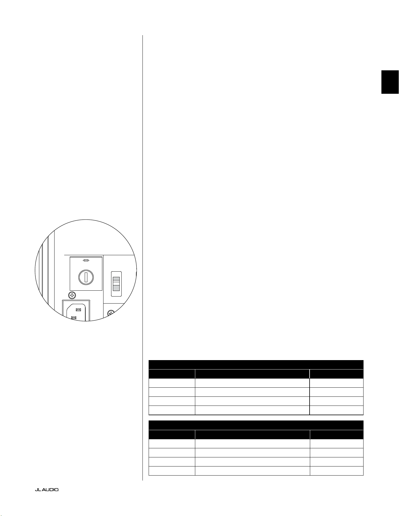
Pg 33 | FR
|
Fathom
®
v2
FR
DÉPANNAGE - suite
Le calibrage clignotant indique que le calibrage DARO est en cours.
1. Si le microphone JL Audio fourni n’est pas correctement branché dans la prise
du panneau avant, le calibrage échouera et le voyant vert «calibrate» clignotera
rapidement. Le calibrage se poursuit UNIQUEMENT avec le microphone JL Audio
branché. Si vous connectez un autre micro, le calibrage échouera. Appuyez sur le
bouton «calibrate» pour annuler l’état clignotant du voyant «calibrate».
2. Si le calibrage échoue alors que le microphone JL Audio est correctement
connecté, le témoin vert du bouton «calibrate» clignote lentement. Vériez le
branchement du microphone et du câble et relancez le calibrage. Si le calibrage
échoue après les étapes décrites ci-dessus, le microphone ou le câble du microphone
peut être défectueux. Contactez l’assistance technique de JL Audio Home.
Votre Fathom v2 est nettement audible en dehors de votre maison.
1. Réexaminez le réglage «Master Level» de votre Fathom v2 ou de votre récepteur/
préampli/ processeur home cinéma.
2. Renseignez-vous auprès de votre revendeur JL Audio pour obtenir des informations
sur les méthodes d’insonorisation.
3. Éloignez le Fathom v2 des fenêtres.
PORTE-FUSIBLE
Le cache du porte-fusible se trouve sur le panneau arrière, près de la prise du cordon
d’alimentation. Ce petit cache à ressort peut être retiré pour faciliter l’accès an de
contrôler ou remplacer le fusible principal. Si votre prise secteur est alimentée mais que
les voyants du subwoofer Fathom v2 ne s’allument pas, le fusible principal peut être brûlé.
Pour le retirer: débranchez le cordon d’alimentation du subwoofer. Introduisez un
petit tournevis à tête plate dans la fente du cache et tournez lentement dans le sens
contraire des aiguilles d’une montre jusqu’à ce que le porte-fusible se détache. Une fois
retiré, le fusible peut être contrôlé et, le cas échéant, remplacé. Consultez le tableau
ci-dessous pour connaître les valeurs de fusible de votre appareil Fathom v2.
Pour le réinstaller: notez que le corps du porte-fusible est adapté à l’ouverture et qu’il
doit être aligné pour correspondre parfaitement. Introduisez le porte-fusible dans
l’ouverture et tournez doucement dans le sens des aiguilles d’une montre (environ 1/8
e
de
tour) pour l’enclencher. En appuyant sur le cache et en sentant le ressort se comprimer
vous pourrez localiser la bonne position. Rebranchez le cordon d’alimentation secteur.
Si le fusible de remplacement brûle immédiatement après avoir été
remplacé, l’amplicateur du subwoofer devra être réparé. Veuillez
contacter votre revendeur ou distributeur JL Audio agréé.
Calibre de fusible, modèles à 120V uniquement
Modèle Type de fusible Taille du fusible
f110v2 (120V) 6,35x31,75mm (0,25x1,25po), action rapide 7A, 250V
f112v2 (120V) 6,35x31,75mm (0,25x1,25po), action rapide 8A, 250V
f113v2 (120V) 6,35x31,75mm (0,25x1,25po), action rapide 12A, 250V
f212v2 (120V) 6,35x31,75mm (0,25x1,25po), action rapide 15A, 250V
Calibre de fusible, modèles à 240V uniquement
Modèle Type de fusible Taille du fusible
f110v2 (240V) 5x20mm (0,20x0,79po), action rapide 6,3A, 250V
f112v2 (240V) 5x20mm (0,20x0,79po), action rapide 6,3A, 250V
f113v2 (240V) 5x20mm (0,20x0,79po), action rapide 8A, 250V
f212v2 (240V) 5x20mm (0,20x0,79po), action rapide 10A, 250V
1200VA
Built in USA with Imported and domestic components
LEFT
or
MONO
RIGHT
ONLY
INPUTS
Output to Slave
(Balanced)
Balanced
Unbalanced
Input Modes
Slave
Master
Grounded
Isolated
SERIAL NUMBER:
Warranty void if serial number is removed, altered or defaced.
F 12A H
250V
120 V ~ 60 Hz
F
U
S
E
F
U
S
E
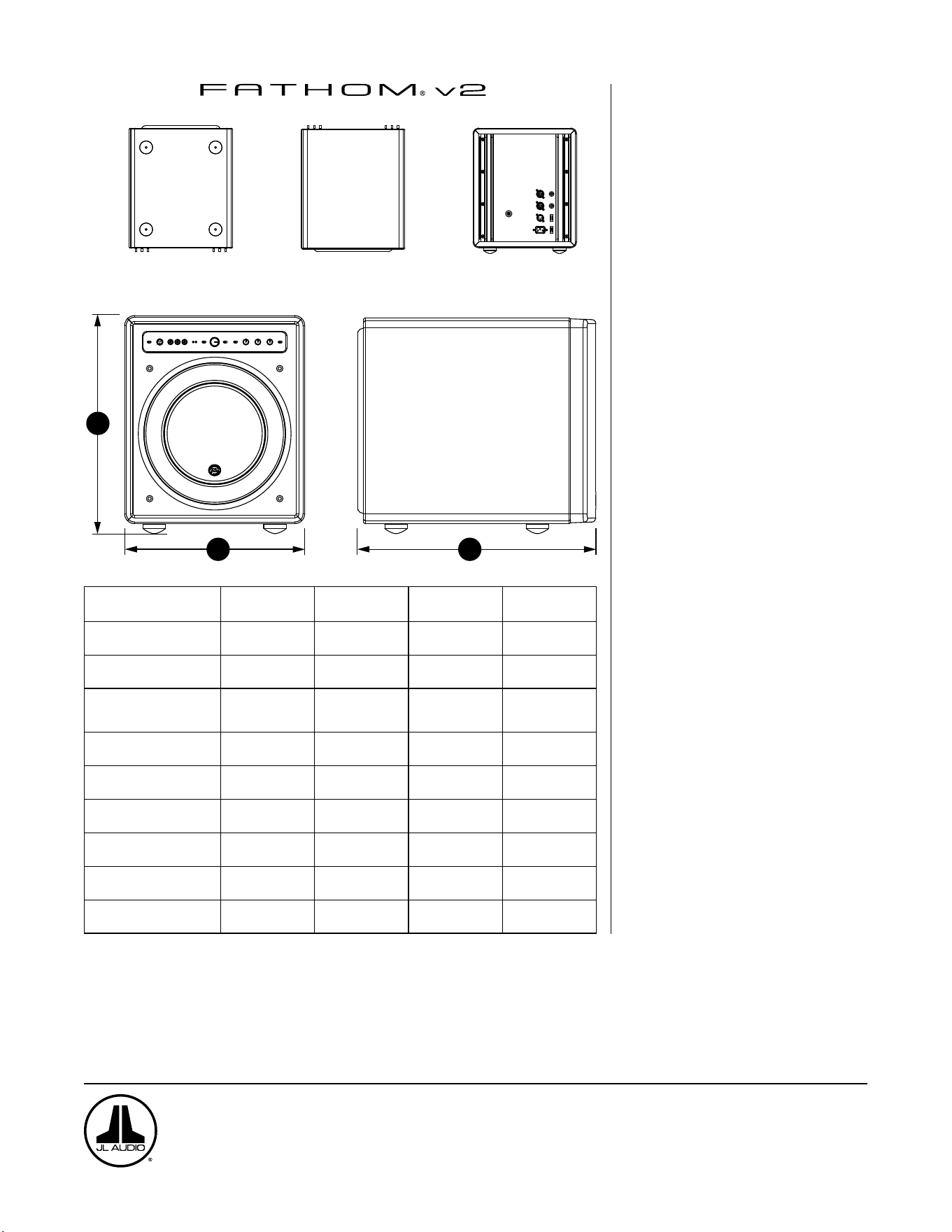
DESSOUS
DESSUS ARRIÈRE
CÔTÉ AVEC GRILLE
AVANT
H
W
D
Spécifications
techniques:
f110v2 f112v2 f113v2 f212v2
Type d’enceinte: Scellée Scellée Scellée Scellée
Haut-parleur:
Unique 25cm/ 10po
(diamètre nominal)
Unique 28cm/ 12po
(diamètre nominal)
Unique 34cm/ 13,5po
(diamètre nominal)
Double 28cm/ 12po
(diamètre nominal)
Réponse en fréquence
(anéchoïque):
27 à 111Hz (±1,5dB)
-3dB à 25Hz/ 120Hz
-10dB à 19Hz/ 155Hz
21-119Hz (+1,5dB)
-3dB à 19Hz/ 150Hz
-10dB à 17Hz/ 167Hz
20 à 86Hz (+1,5dB)
-3dB à 18Hz/ 127Hz
-10dB à 16Hz/ 154Hz
20 à 97Hz (±1,5dB)
-3dB à 19/ 110Hz
-10dB à 15/ 157Hz
Surface effective du piston:
0,0387m
2
(60po
2
)
0,0542m
2
(84po
2
)
0,0693m
2
(107,35po
2
)
0,1084m
2
(168po
2
)
Excursion effective:
2,6litres
(160po
3
)
4,7litres
287po
3
6,3litres
386po
3
9,4litres
(574po
3
)
Puissance de l’amplificateur:
1100watts
RMS court terme
1800watts
RMS court terme
3000watts
RMS court terme
3600watts
RMS court terme
Dimensions: (H) x (L) x (P)
La hauteur inclut les pieds.
397x328x439mm
(15,64x12,92x17,27po)
470x381x448mm
(18,5x15x17,625po)
498x419x489mm
(19,625x16,5x19,25po)
812x379x518mm
(31,96x14,92x20,39po)
Poids net:
31kg
(69lbs)
53kg
(117lbs)
60kg
(133lbs)
102kg
(224lbs)
Finition du boîtier: Noir brillant Noir brillant Noir brillant Noir brillant
CARACTÉRISTIQUES
Entrées asymétriques:
Stéréo ou Mono (deux prises jack RCA)
Entrées symétriques:
Stéréo ou Mono (deux prises jack femelles
XLR)
Sortie vers esclave: Asymétrique (une
prise jack mâle XLR)
Modes d’entrée:
Maître ou esclave
Modes de niveau:
Référence (gain xe) ou Variable de
sourdine à +15dB au-dessus du gain de
référence
Modes d’alimentation:
Hors tension, sous tension, automatique
(détection de signal)
Modes des voyants:
Éteints, allumés ou lumière faible
Mode ltre passe-bas:
Éteint, 12dB par octave ou 24dB par
octave
Fréquence de coupure de ltre passe-bas:
Variable de 30Hz à 130Hz
Polarité:
0 ou 180degrés
Phase:
Variable de 0 à 270degrés
Filtre E.L.F. Trim:
Variable de -12dB à +3dB à 24Hz
Optimisation numérique automatique de
la pièce (DARO):
Automatique, égaliseur numérique
18bandes avec microphone de calibrage de
grade laboratoire inclus, désactivable.
www.jlaudio.com
10369 North Commerce Parkway • Miramar, Floride • 33025 • États-Unis
«JL Audio», «Fathom» et le logo JL Audio sont des marques déposées de JL Audio, Inc.
©2022 JLAudio, Inc. • Pour des informations plus détaillées, veuillez visiter notre site www.jlaudio.com. Les images des produits sont fournies à titre d’illustration uniquement et
peuvent différer du produit réel. En raison du développement continu de nos produits, toutes les caractéristiques sont susceptibles d’être modifiées sans préavis.
ES
Subwoofer potenciado Fathom v2
Manual del propietario
f113v2 f212v2 f112v2 f110v2
ES | Pg 2
|
Fathom
®
v2
INSTRUCCIONES IMPORTANTES DE SEGURIDAD
ADVERTENCIA: PARA DISMINUIR EL RIESGO DE INCENDIO O DESCARGA
ELÉCTRICA, NO EXPONGA ESTE PRODUCTO A LA LLUVIA O LA HUMEDAD.
PRECAUCIÓN
RIESGO DE DESCARGA ELÉCTRICA
NO ABRIR
PRECAUCIÓN: CON EL FIN DE DISMINUIR EL RIESGO DE DESCARGA ELÉCTRICA,
NO RETIRE LA CUBIERTA. NO HAY PARTES INTERNAS QUE EL USUARIO
PUEDA REPARAR. DELEGUE LAS TAREAS DE MANTENIMIENTO EN PERSONAL
CUALIFICADO.
1. Lea las instrucciones: Deben leerse todas las instrucciones de seguridad y
operación antes de utilizar el subwoofer.
2. Conserve las instrucciones: Deben conservarse todas las instrucciones de
seguridad y operación para tenerlas como referencia futura.
3. Preste atención a las advertencias: Deben seguirse todas las advertencias en
el subwoofer y en las instrucciones de operación.
4. Siga las instrucciones: Deben seguirse todas las
instrucciones de uso y operación.
5. Agua y humedad: El subwoofer NO debe usarse cerca del agua; por ejemplo,
cerca de una bañera, un lavatorio, una pileta, una tina para lavar ropa o una
piscina, o en un sótano húmedo, etc.
6. Ventilación: El subwoofer debe estar colocado de manera que su ubicación
o posición no intereran con su ventilación adecuada. Por ejemplo, el
subwoofer no debe colocarse en una cama, un sofá, una alfombra o una
supercie similar que pueda bloquear el ujo de aire por las aletas del
disipador de calor. Si va a colocar el subwoofer en una instalación de tipo
"incrustado", asegúrese de que el ujo de aire al disipador de calor en la parte
posterior del subwoofer no se vea impedido. No cubra el disipador de calor
del subwoofer con manteles, cortinas, etc.
7. Calor y llamas: El subwoofer debe estar colocado lejos de las fuentes de calor,
tales como radiadores, rejillas de direccionamiento del calor, calentadores,
chimeneas u otros dispositivos que produzcan calor. No coloque velas en la
parte superior del subwoofer o cerca de este.
8. Fuentes de alimentación: El subwoofer debe conectarse únicamente a una
fuente de alimentación del tipo descrito en las instrucciones de operación o
según lo indicado en el aparato.
9. Protección del cable de alimentación: Los cables de alimentación deben
pasarse de modo que se disminuya la posibilidad de caminar sobre ellos
o de que se los pellizque con los elementos colocados sobre o contra ellos,
prestando especial atención a los cables en los enchufes, los tomacorrientes y
la zona de salida desde el subwoofer.
10. Limpieza: El subwoofer debe limpiarse únicamente según las
recomendaciones en las instrucciones de operación.
El símbolo del rayo con punta de echa
dentro de un triángulo equilátero tiene como
n alertar al usuario sobre la presencia de
"voltaje peligroso" dentro del alojamiento
del producto, que puede ser de magnitud
suciente como para representar un riesgo
de descarga eléctrica para las personas.
El signo de exclamación dentro de un
triángulo equilátero tiene como n
alertarle al usuario sobre la existencia de
instrucciones importantes de operación y
mantenimiento en la bibliografía incluida
con el producto.
Pg 3 | ES
|
Fathom
®
v2
ES
11. Periodos de no utilización: El cable de alimentación del subwoofer debe
desconectarse del tomacorriente cuando el altavoz permanezca sin utilizarse
por periodos extensos.
12. Iluminación y sobretensión de alimentación: Le recomendamos
desconectar el subwoofer del tomacorriente durante tormentas
eléctricas o interrupciones de alimentación recurrentes
para evitar daños por sobretensión de alimentación.
13. Ingreso de líquidos u objetos: Se debe tener cuidado de que no caigan
objetos ni ingresen líquidos derramados sobre el alojamiento del subwoofer.
No exponga el subwoofer a goteras o salpicaduras de líquidos. No coloque
objetos llenos con líquidos en la parte superior del subwoofer o cerca de este.
Por ejemplo: oreros, bebidas, lámparas con combustible líquido, etc.
14. Daños que requieren del servicio técnico: Personal técnico cualicado
deberá realizar tareas de mantenimiento en el subwoofer en los siguientes
casos:
a. Cuando el cable o enchufe de alimentación se hayan dañado.
b. Cuando hayan caído objetos o se haya derramado líquido en el
subwoofer.
c. Cuando se haya expuesto el subwoofer a la lluvia.
d. Cuando el subwoofer parezca funcionar anormalmente o presente un
cambio marcado en su rendimiento.
e. Cuando el subwoofer se haya caído o se haya dañado su gabinete.
f. Cuando el cono o la suspensión del transductor del subwoofer se hayan
dañado físicamente.
15. Mantenimiento: El usuario no debe intentar realizar un servicio de
mantenimiento en el subwoofer más allá de lo descrito en las instrucciones
de operación. Todas las demás tareas de mantenimiento deben delegarse en
personal técnico cualicado.
16. Sobrecarga: No sobrecargue los tomacorrientes, los cables de extensión ni las
barras de alimentación eléctrica, ya que ello puede resultar en un riesgo de
incendio o descarga eléctrica.
17. Puesta a tierra: Este subwoofer incluye un cable de alimentación de tres
espigas con conexión a tierra. Deben tomarse precauciones para que los
medios de puesta a tierra del subwoofer no queden inhabilitados. Si se
inhabilita la espiga de conexión a tierra del cable de alimentación del
subwoofer, se puede aumentar el riesgo de descarga eléctrica y se pueden
generar daños permanentes en los componentes electrónicos del subwoofer.
ESTE SUBWOOFER PUEDE PRODUCIR NIVELES MUY ALTOS DE PRESIÓN
SONORA. LIMITE EL VOLUMEN DE OPERACIÓN PARA EVITAR DAÑAR SU
AUDICIÓN EN FORMA PERMANENTE.
ADVERTENCIA

ES | Pg 4
|
Fathom
®
v2
DECLARACIÓN DE CUMPLIMIENTO CON LA FCC
NOTA: Este equipo ha sido probado y se ha comprobado que cumple con los límites de la
sección 15 de las Reglas de la FCC. Dichos límites tienen como n proporcionar protección
razonable contra interferencias perjudiciales en una instalación residencial. Este equipo genera,
usa y puede irradiar energía de radiofrecuencia y, en caso de no ser instalado conforme a las
instrucciones, puede ocasionar interferencias perjudiciales para las comunicaciones por radio.
No obstante, no existe garantía de que no se produzcan interferencias en una instalación en
particular. Si este equipo genera interferencias perjudiciales en la recepción de televisores
o radios, lo que puede establecerse encendiendo y apagando el equipo, se alienta al usuario
a tratar de corregir la interferencia mediante una o más de las siguientes medidas:
—Reoriente o reubique la antena de recepción.
—Aumente la separación entre el equipo y el receptor.
— Conecte el equipo en una salida de un circuito diferente
de aquel al cual está conectado el receptor.
— Consulte con el distribuidor o con un técnico experimentado
en radios/televisores para obtener ayuda.
ÍNDICE
Instrucciones importantes de seguridad: ................................. 2-3
Introducción: .......................................................... 4
Descripción general del producto: ......................................... 5
Colocación de su Fathom v2 en su sala de audio: ......................... 6-10
Desembalaje de su Fathom v2: ........................................... 11
Distribución del panel de control frontal: .................................. 12
Distribución del panel de control y conexiones trasero: ....................12-13
Controles del panel frontal en detalle: ...................................14-17
Conexión de su(s) Fathom v2: .........................................18-25
Procedimiento de conguración recomendado: ..........................26-30
Preguntas frecuentes: ................................................... 31
Limpieza de su Fathom v2: .............................................. 31
Resolución de problemas: .............................................32-33
Garantía limitada/Información de servicio: ................................ 35
Especicaciones: ....................................................... 36
INTRODUCCIÓN
Felicidades por adquirir un sistema de subwoofer potenciado Fathom v2 de JL
Audio. Este producto ha sido diseñado esencialmente para brindar un rendimiento
excepcional en su sistema de audio o cine en casa por muchos años.
Como compañía, estamos intensamente comprometidos con la investigación base
de altavoces de alto rendimiento y de las tecnologías de amplicadores. Los diseños
de larga trayectoria de los transductores del subwoofer de JL Audio son ampliamente
considerados como estándares de referencia para obtener patrones lineales y
un máximo rendimiento. Además, hemos centrado nuestros esfuerzos en crear
amplicadores y tecnologías de procesamiento de señales potentes, especícamente
dirigidos a obtener un rendimiento excepcional en las frecuencias bajas. Su equipo
Fathom v2 combina estas disciplinas base dentro de un empaque compacto y
hermosamente construido para brindar una experiencia de audio sin igual.
Le agradecemos sinceramente por su compra y lo invitamos a leer este manual
en su totalidad para poder lograr el mayor nivel de rendimiento con su sistema de
subwoofer Fathom v2. Que lo disfrute.
TECNOLOGÍAS DE JL AUDIO INCLUIDAS
EN LOS SUBWOOFERS FATHOM V2
Sistema de motor optimizado con análisis
dinámico (DMA)
DMA es el innovador sistema de análisis
dinámico del motor (DMA, por su sigla en
inglés) de JL Audio, cuyo n consiste en
mejorar el comportamiento dinámico del
motor. Como resultado de la optimización
por DMA, los motores de los altavoces se
mantienen efectivamente lineales durante
un rango extremo de trayectoria, además
de mantener un campo magnético jo de
alta estabilidad durante un amplio rango de
alimentación. Esto genera una distorsión
mucho menor y temporalidades reproducidas
elmente… o, dicho de manera más sencilla:
sonidos graves fuertes, claros y articulados.
Envolvente OverRoll™
El envolvente OverRoll™ se extiende sobre el
reborde de montaje del transductor, utilizando
el diámetro disponible que se desperdicia en
los altavoces convencionales. Esto permite
utilizar el rodillo más ancho, necesario para
controlar las altas excursiones sin sacricar la
preciosa área del cono.
W-Cone™
El W-Cone™ es un conjunto de conos de
cuerpo unitario que ofrece una asombrosa
rigidez de cono con una masa mínima.
Método de sujeción Floating-Cone™
Esta técnica de ensamblaje garantiza una
correcta geometría envolvente en el altavoz
armado, para conseguir así un mejor control
de la trayectoria y una alineación dinámica de
la bobina de voz.
Sujeción reforzada de la araña
Esta sujeción de suspensión de alta integridad
alivia la tensión del material de la araña en las
altas excursiones para mejorar la conabilidad.
Tecnología de refrigeración por marco
elevado
Proporciona aire frío a la bobina de voz
del altavoz a través de ranuras situadas
directamente encima de la placa superior. Esto
mejora el manejo de la potencia y la calidad del
sonido, ya que minimiza los desplazamientos
de los parámetros dinámicos y la compresión
de la potencia.
Parte de poste con perforación transversal
Este innovador sistema de ventilación mejora
en gran medida la disipación térmica y el
manejo de la potencia dirigiendo el ujo de
aire hacia el formador de la bobina de voz,
trabajando en conjunto con la tecnología de
marco elevado.
Circuito de realimentación de alta
amortiguación
Este innovador diseño de circuito de control
discreto permite a nuestros amplicadores de
conmutación de clase D mantener un excelente
factor de amortiguación para mejorar el
comportamiento transitorio y la delidad.
Pg 5 | ES
|
Fathom
®
v2
ES
DESCRIPCIÓN GENERAL DEL PRODUCTO
Los subwoofers Fathom v2 de JL Audio combinan un transductor de subwoofer
de JL Audio de última tecnología y un paquete de componentes electrónicos/
amplicador dentro de un alojamiento altamente optimizado para brindar una
experiencia de audio excepcional en su sistema de audio o cine en el hogar.
El transductor del subwoofer en su sistema de subwoofer Fathom v2
es capaz de generar una impresionante trayectoria lineal sin afectar o
distorsionar el audio. Este transductor de calidad de referencia permite que
su subwoofer Fathom v2 reproduzca eventos potentes de baja frecuencia
con un asombroso impacto y una precisión sin precedentes. Derivados de
la legendaria plataforma de diseño W7 de JL Audio, los transductores del
Fathom v2 ofrecen una prodigiosa capacidad de excursión pico a pico para
manejar cómodamente la dinámica del material de programa más exigente.
Para sacarle el máximo partido a esta plataforma de transductores de larga
trayectoria, se necesita una enorme cantidad de potencia controlada. Nuestro
equipo de ingeniería electrónica llevó a cabo un intenso análisis del material típico
del programa y sus requisitos dinámicos para equilibrar el consumo de corriente
y los requisitos reales de potencia de salida en relación con las características
de impedancia del sistema. Tras un detallado estudio, se crearon amplicadores
de conmutación con ingeniería de precisión que emplean una tecnología de
retroalimentación patentada para aprovechar al máximo la envolvente de
excursión completa de cada transductor. En comparación con sus predecesores, los
Fathom v2 han sido mejorados con un procesamiento de señal digital totalmente
nuevo y un aumento del 20% en la potencia del amplicador, lo que mejora aún
más sus extraordinarias capacidades dinámicas.
El hermoso gabinete que encierra las partes operantes de su
equipo Fathom v2 también son el resultado de un delicado diseño.
Para contener la presión generada por el transductor del Fathom
v2, utilizamos material sólido MDF cortado por CNC con amplias
funciones de refuerzo internas y avanzadas técnicas de ensamblaje.
Su sala de audio es el otro espacio acotado que afecta a la forma en que sonarán
sus graves. Todas las salas crean una rma sonora especíca, que debe gestionarse
ecazmente para conseguir un rendimiento de bajas frecuencias bien equilibrado.
Para ayudar a integrar adecuadamente sus subwoofers con la acústica de su sala,
todos los subwoofers Fathom v2 emplean un potente sistema de optimización
digital automática de la sala (DARO). Este sistema despliega dieciocho bandas de
ecualización digital para domar la acústica de la sala y ofrecer una precisión de
subgraves estremecedora.
Como puede ver en esta breve introducción, los sistemas de subwoofer Fathom
v2 emplean muchas tecnologías avanzadas. En el contenido de este manual se
explicarán las características y se lo guiará a través de la conguración y anación
de su subwoofer Fathom v2 para ayudarle a lograr una inmejorable experiencia de
audio de baja frecuencia.
Si necesita ayuda, lo instamos a contactar a su vendedor minorista
autorizado de JL Audio para obtener consejos de expertos sobre la
conguración del equipo y por cuestiones de mantenimiento.
¡IMPORTANTE! SE RECOMIENDA ENCARECIDAMENTE QUE LEA LA SECCIÓN
SIGUIENTE ANTES DE DESEMBALAR SU FATHOM v2. SE RECOMIENDA
DESEMBALAR EL SUBWOOFER CERCA DE SU UBICACIÓN FINAL.
IMPORTANTE

ES | Pg 6
|
Fathom
®
v2
COLOCACIÓN DE SU FATHOM v2 EN SU SALA DE AUDIO:
Su sala de audio o cine en el hogar son una parte integral de su sistema
de reproducción de sonidos. Las dimensiones físicas de la sala y sus muebles,
materiales, puertas y ventanas juegan un papel importante en la denición del tipo
de sonido de su sistema.
Cuando se coloca una fuente de sonido en un espacio rectangular encerrado, se
generan "ondas estacionarias", que resultan de la relación entre la longitud de onda
del sonido y las dimensiones de su sala. En otras palabras, las ondas estacionarias
resultan de la energía de sonido atrapada en la sala, a medida que rebota de atrás
a adelante entre las paredes opuestas. Las ondas estacionarias en la sala crean
picos y depresiones acústicos, donde el sonido es más alto o más suave, en base
únicamente a la posición física de la sala. La energía también "se acumula" en los
alrededores de la sala, creando una respuesta exagerada de los sonidos graves en
ciertas frecuencias. Estas resonancias fundamentales de la sala se llaman "modos"
de salas.
La lección de esta historia de modos consiste en intentar evitar posiciones
de asentamiento en regiones de picos o depresiones de ondas estacionarias. Se
recomienda ampliamente colocar las sillas desde donde se va a escuchar en áreas
donde los picos y depresiones modales sean moderados y no se refuercen entre sí.
Las dos áreas más claramente evitables son aquellas cercanas al centro exacto de la
sala y aquellas cercanas a cualquiera de las paredes de la sala.
Así como su asiento puede estar en una región de pico o depresión, también
puede suceder lo mismo con su subwoofer. Cuando se lo coloca en la esquina de
una sala, un subwoofer excita al máximo la estructura modal de la sala, creando
una salida más fuerte con menores depresiones. Cuando se aleja al subwoofer de
una esquina o pared, los modos de la sala se aumentan menos, lo que puede alterar
el sonido en el lugar de su asiento.
Asegúrese de probar tanto con su posición de asiento y con la posición del
subwoofer para encontrar la mejor solución. Una cuidadosa experimentación
suele conducir a un sistema que suena mejor. Utilice nuestras sugerencias de
conguración (ejemplicadas en la página de al lado y en las páginas siguientes)
para comenzar.
Si no puede evitar colocar su sofá contra la pared del fondo, o su subwoofer en
una posición que no sea óptima, el sistema de optimización digital automática de
la sala (DARO) de su Fathom v2 puede mejorar drásticamente estas situaciones
poco ideales.
Le recomendamos comenzar colocando su Fathom v2 en la parte frontal de
la sala, cerca del altavoz frontal izquierdo o del derecho. Colocarlo directamente
en la esquina delantera de la sala producirá el máximo número de picos y el
mínimo número de caídas en la respuesta de graves. Esto puede ser ventajoso
porque el sistema DARO del Fathom v2 puede corregir los picos resultantes de
forma muy ecaz, mientras que las caídas en la respuesta no pueden corregirse
mediante la ecualización. Las caídas en la respuesta solo pueden minimizarse
colocando cuidadosamente el subwoofer y al oyente.
Si coloca el Fathom v2 cerca de paredes sólidas, reforzará la respuesta de los
sonidos graves y, si lo coloca lejos de paredes sólidas, generará el efecto contrario.
Aumentar la distancia entre el subwoofer y las paredes puede ayudar a suavizar la
respuesta de los sonidos graves superiores en algunas salas.
Le recomendamos evitar colocar el Fathom v2 cerca de ventanas para evitar que
vibre y que transmita los sonidos al exterior.
Si está planeando instalar su Fathom v2
dentro de un gabinete, consulte las pautas en
la página 8.
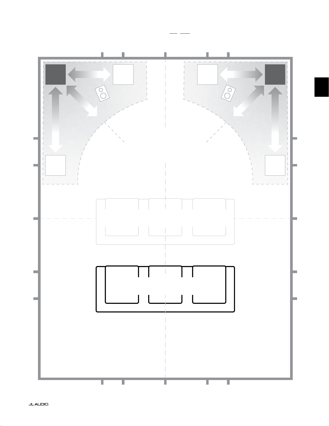
Pg 7 | ES
|
Fathom
®
v2
ES
Opciones de colocación del subwoofer recomendadas para un o dos Fathom v2
MÁS SUAVE
Colocación recomendada para UNO o
DOS subwoofers (coloque DOS con
simetría izquierda-derecha)
MÁS SUAVE
MÁS SUAVEMÁS SUAVE
POSICIONES DE ASIENTOS AFECTADAS
(Rendimiento más débil y poco uniforme de los sonidos graves)
MEJORES POSICIONES PARA LOS ASIENTOS
(Rendimiento más preciso de los sonidos graves)
½
1⁄3
1⁄3
¼
¼
½
½
1⁄3
1⁄3 1⁄3
1⁄3
¼
¼ ¼
½1⁄3 1⁄3¼ ¼
¼
APROXIMADAMENTE
1/3 DE LA LONGITUD DE
LA HABITACIÓN DESDE
LA PARED TRASERA
LÍNEA CENTRAL DE LA SALA
MÁS
INTENSO
MÁS
INTENSO

ES | Pg 8
|
Fathom
®
v2
CONSIDERACIONES ESPECIALES PARA
INSTALACIONES INCRUSTADAS
Los subwoofers Fathom v2 están diseñados para poder encastrarlos. Por ello,
todos los controles típicamente necesarios se encuentran en el panel frontal,
encima del woofer. El subwoofer Fathom v2 puede integrarse fácilmente en un
gabinete personalizado siguiendo unas simples pautas.
1) Deje 4 pulgadas (10cm) de espacio libre detrás del panel del amplicador para
obtener una adecuada separación para la refrigeración y el conector.
2) En todos los otros laterales (excepto la base), deje al menos 2 pulgadas (5cm)
de separación para obtener una ventilación apropiada.
3) Si bien el Fathom v2 generalmente se recalienta solamente durante un
funcionamiento enérgico, le recomendamos que incluya ventilaciones
adecuadas para el calor en cualquier gabinete personalizado que encierre al
Fathom v2. Con un par de ventilaciones de 3pulgadas (7,5cm) de diámetro
cerca de la base y de la parte superior del gabinete, se permitirá la circulación
de aire fresco por encima del panel del amplicador de su sistema de subwoofer
Fathom v2, manteniéndolo fresco y contento.
4) Su subwoofer Fathom v2 es capaz de mover signicativas cantidades de aire.
Si la parte frontal del Fathom v2 está cubierta por una rejilla personalizada, el
tamaño de esta debe ser AL MENOS igual al área del cono del subwoofer en
cada modelo para garantizar que la salida no se vea impedida por el gabinete
personalizado. Consulte la tabla a continuación para ver las áreas de ventilación
recomendadas para cada modelo.
Modelo Área recomendada de ventilación personalizada por rejilla
f110v2 ≥60in
2
(386cm
2
)
f112v2 ≥85in
2
(550cm
2
)
f113v2 ≥108in
2
(700cm
2
)
f212v2 ≥170in
2
(1100cm
2
)
1200VA
Built in USA with Imported and domestic components
LEFT
or
MONO
RIGHT
ONLY
INPUTS
Output to Slave
(Balanced)
Balanced
Unbalanced
Input Modes
Slave
Master
Grounded
Isolated
SERIAL NUMBER:
Warranty void if serial number is remove d, altered or deface d.
F 12A H
250V
120 V ~ 60 Hz
F
U
S
E
F
U
S
E
Built in USA with Imported and domestic components
LEFT
or
MONO
RIGHT
ONLY
INPUTS
Output to Slave
(Balanced)
Balanced
Unbalanced
Input Modes
Slave
Master
Grounded
Isolated
SERIAL NUMBER:
Warranty void if serial number is remo ved, altered or defa ced.
F 15A H
250V
120 V ~ 60 Hz
F
U
S
E
F
U
S
E
VENTI-
LACIÓN
VENTI-
LACIÓN
VENTI-
LACIÓN
VENTI-
LACIÓN
VENTI-
LACIÓN
VENTI-
LACIÓN
VENTI-
LACIÓN
VENTI-
LACIÓN
mín. 2in(5cm)
mín. 2in(5cm)
mín.
2in
(5cm)
mín.
2in
(5cm)
Vista trasera de la instalación en gabinete
(f110, f112, f113):
Vista trasera de la instalación en gabinete
(f212):
VENTI-
LACIÓN
VENTI-
LACIÓN
VENTI-
LACIÓN
VENTI-
LACIÓN
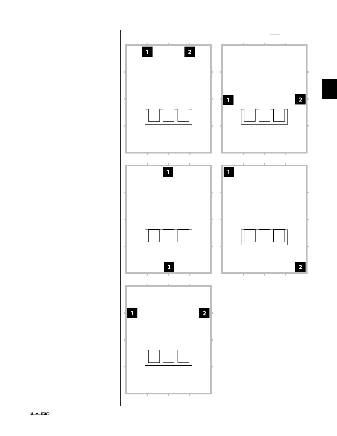
Pg 9 | ES
|
Fathom
®
v2
ES
Opciones de colocación del subwoofer recomendadas para dos Fathom v2Utilización de dos Fathom v2
Cuando use dos subwoofers
Fathom v2, trate de colocarlos
cerca de las esquinas frontales de
la sala, en esquinas enfrentadas
diagonalmente en la sala, o en los
puntos centrales de paredes opuestas,
como se muestra a la derecha.
Se recomienda probar con la
colocación del equipo, teniendo en
cuenta la posición del oyente y del
subwoofer, para lograr los mejores
resultados. Los benecios pueden
ser realmente signicativos.
Se recomienda tomar mediciones
de alta resolución y calibrar el sistema
de forma profesional para obtener los
mejores resultados y rendimiento del
sistema posibles.

ES | Pg 10
|
Fathom
®
v2
Opciones de colocación del subwoofer recomendadas para tres Fathom v2
Opciones de colocación del subwoofer recomendadas para cuatro Fathom v2
Utilización de tres o cuatro
Fathom v2
Conforme a lo investigado, la mejor
respuesta de los sonidos graves en un
área amplia de escucha puede lograrse
usando cuatro subwoofers, colocando
uno en el punto medio de cada una de
las cuatro paredes (aunque usar dos
o tres subwoofers puede ser igual de
satisfactorio).
Se recomienda probar con la
colocación del equipo, teniendo en
cuenta la posición del oyente y del
subwoofer, para lograr los mejores
resultados. Los benecios pueden
ser realmente signicativos.
Se recomienda tomar mediciones
de alta resolución y calibrar el sistema
de forma profesional para obtener los
mejores resultados y rendimiento del
sistema posibles.
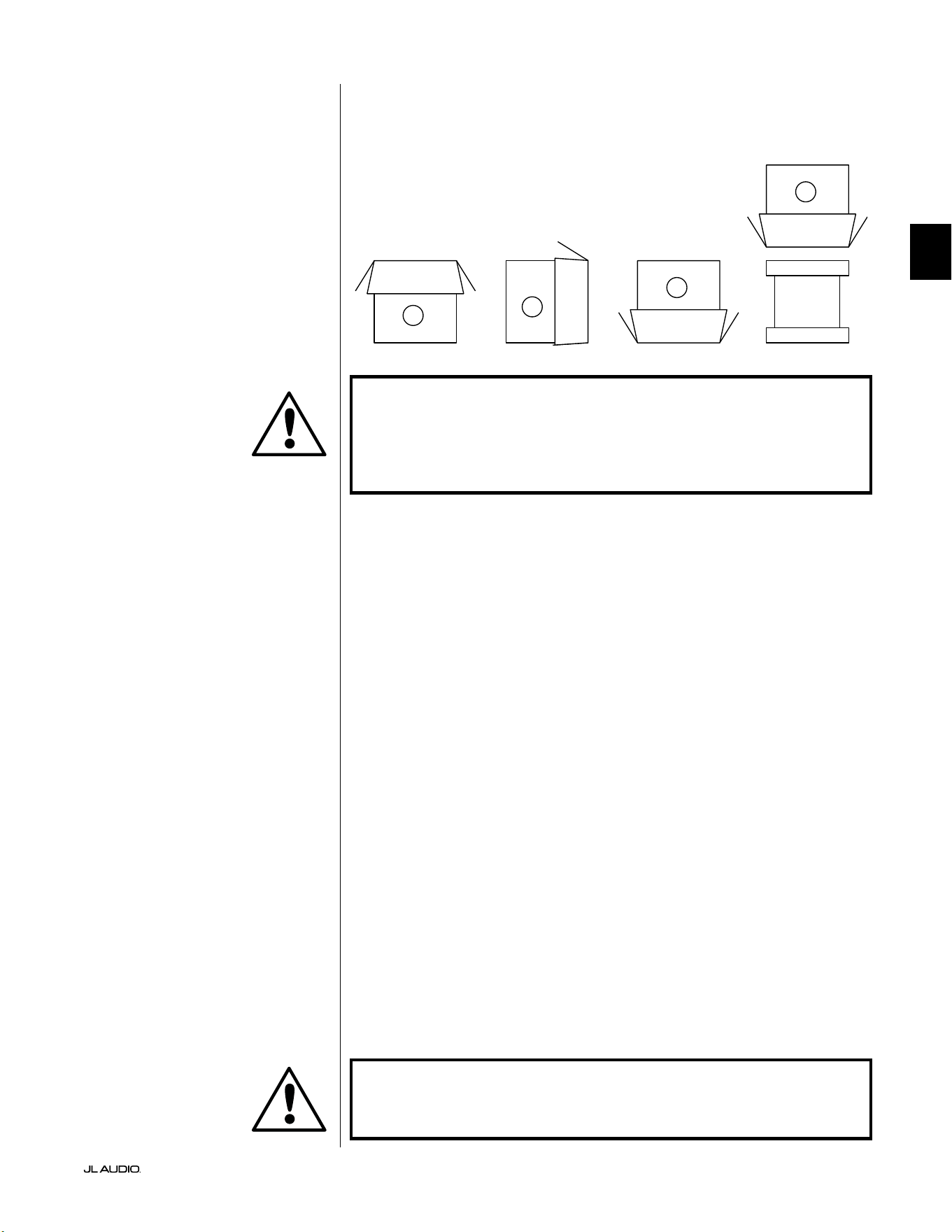
Pg 11 | ES
|
Fathom
®
v2
ES
¡IMPORTANTE! DEBIDO AL PESO DEL SUBWOOFER FATHOM V2, TENGA
CUIDADO MIENTRAS LO DESEMBALA Y POSICIONA PARA EVITAR LESIONES. DE
SER POSIBLE, PÍDALE AYUDA A OTRA PERSONA PARA FACILITAR EL PROCESO.
A FIN DE MINIMIZAR EL RIESGO DE LESIONES, FLEXIONE LAS RODILLAS Y
LEVÁNTELO HACIENDO FUERZA CON LAS PIERNAS, NO CON LA ESPALDA.
Instrucciones detalladas sobre el desembalaje del subwoofer:
1. Coloque la caja sobre el suelo, cerca de su ubicación designada en la sala.
2. Abra la tapa de la caja (observe las marcas en ella) y extraiga el manual, el
micrófono de calibración y el cable de alimentación.
3. Retire temporalmente los insertos de espuma dividida del embalaje.
4. Desamarre y aoje la cubierta protectora de paño para permitir una
extracción fácil más adelante (no la extraiga en este momento). Cuando abra
la cubierta de paño, estará viendo la base del gabinete del subwoofer.
5. Vuelva a colocar los insertos de espuma dividida para proteger el gabinete del
subwoofer mientras lo desembala.
6. Con cuidado, voltee la caja sobre su lateral, doblando hacia afuera las solapas
de la caja.
7. Mientras sostiene las solapas de la caja hacia atrás, voltee la caja para que
quede sobre su parte superior (el extremo abierto).
8. Tire de la caja directamente hacia arriba hasta poder descubrir el subwoofer y
apártela.
9. Retire el inserto de espuma de una pieza y colóquelo en la caja.
10. Extraiga la bolsa de plástico y colóquela en la caja.
11. Incline el subwoofer hacia delante (hacia su rejilla) para retirar primero el
inserto de espuma dividida trasero. A continuación, incline el subwoofer en
la dirección opuesta (hacia su panel de amplicación) para retirar el resto del
inserto de espuma dividida. Coloque los dos insertos de espuma dividida en
la caja.
12. Extraiga la cubierta protectora de paño y colóquela en la caja.
¡IMPORTANTE! CONSERVE TODO EL EMBALAJE PARA PODER TRANSPORTAR
EL SUBWOOFER CON SEGURIDAD Y PARA CUALQUIER FUTURA TAREA DE
MANTENIMIENTO QUE SEA NECESARIA.
Desembale esta caja cerca de la zona donde
se colocará el subwoofer. El subwoofer está
embalado de forma invertida. Esta caja debe
voltearse CON CUIDADO para extraer el
subwoofer minimizando el esfuerzo.
DESEMBALAJE DE SU FATHOM v2
Ahora que ha decidido dónde colocar su Fathom v2 en la sala, puede proceder a
desembalarlo cerca de su ubicación designada.
C
D
A
B
IMPORTANTE
IMPORTANTE

LP freq. (Hz) e.l.f. trim (dB) phase (deg.)
Polarity
0
|
180 deg.
LP Filter
o
|
12d B
|
24dB
Master Level
max
0
Lights
o
|
dim
|
on
-∞
Level Mode
ref.
|
variable
Input Mode
master
|
slave
calibration mic. demo defeat calibrate
Power
o
|
on
|
auto
Digital Automatic Room Optimization
1200VA
Built in USA with Imported and domestic components
LEFT
or
MONO
RIGHT
ONLY
INPUTS
Output to Slave
(Balanced)
Balanced
Unbalanced
Input Modes
Slave
Master
Grounded
Isolated
SERIAL NUMBER:
Warranty void if serial numb er is removed, altered or defaced.
F 12A H
250V
120 V ~ 60 Hz
F
U
S
E
F
U
S
E
ES | Pg 12
|
Fathom
®
v2
Controles y conectores traseros (modelos f112v2, f113v2 y f212v2)
La gura etiquetada a continuación muestra el panel trasero de un subwoofer Fathom f113v2.
La disposición de los controles y los conectores es la misma para los modelos de Fathom f112v2 y f212v2.
Entradas
balanceadas
Página 18
Entradas no
balanceadas
Página 19
Conector CA
estilo IEC
Páginas 21-22
Conector de salida
a esclavo
Página 21
Interruptores del
modo de entrada
Página 20
Fusible especíco
de la región
Página 33
Panel de control frontal (todos los modelos)
La gura a continuación muestra el panel de control frontal del subwoofer Fathom f113v2 y nombra sus componentes.
La disposición de los controles es la misma para todos los modelos de Fathom v2.
DARO
Páginas 14-15
Encendido
Página 14
Modo de
entrada
Página 15
Modo de nivel
Página 15
Nivel maestro
Página 16
Luces
Página 16
Filtro LP
Página 16
Frecuencia
LP (Hz)
Página 16
Ajuste
de FEB (dB)
Página 17
Fase (grados)
Página 17
Polaridad
Página 17
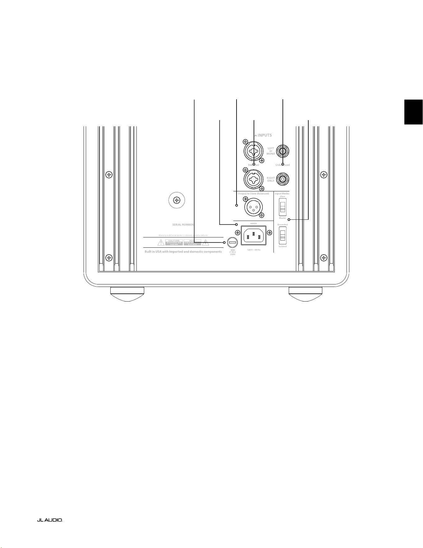
F
U
S
E
F
U
S
E
Controles y conectores traseros (modelo f110v2)
La gura etiquetada a continuación muestra el panel trasero de un subwoofer Fathom f110v2.
*Las imágenes de detalle de los controles y conectores traseros a lo largo de este manual muestran otros modelos de Fathom
v2 y no son representativas de la disposición del f110v2.
Entradas
balanceadas
Página 18
Entradas no
balanceadas
Página 19
Conector CA
estilo IEC
Páginas 21-22
Conector de
salida a esclavo
Página 21
Interruptores del
modo de entrada
Página 20
Pg 13 | ES
|
Fathom
®
v2
ES
Fusible especíco
de la región
Página 33
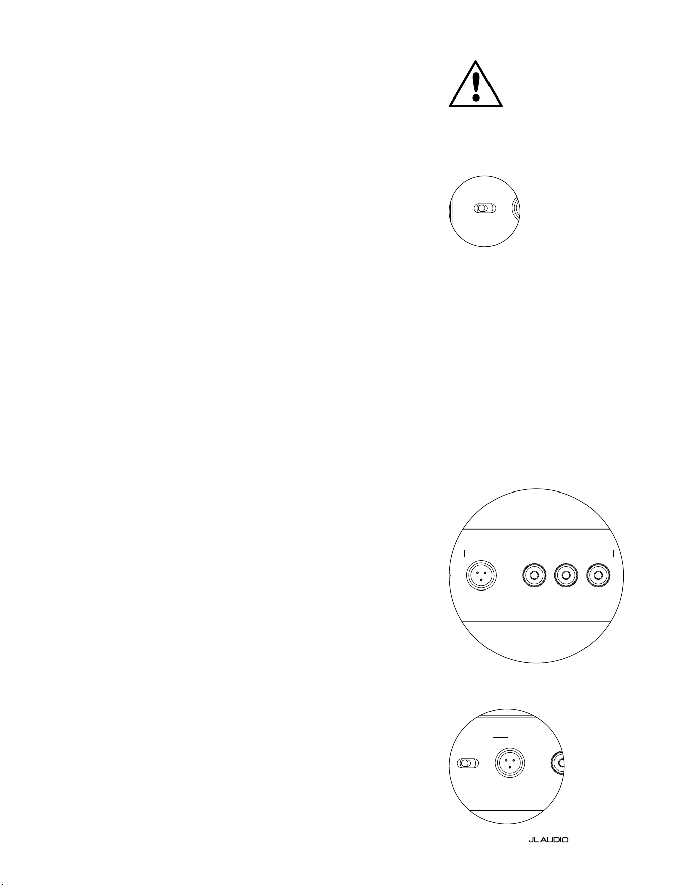
ES | Pg 14
|
Fathom
®
v2
CONTROLES DEL PANEL FRONTAL EN DETALLE
Interruptor de encendido
El interruptor "Power" determina la disponibilidad de funcionamiento del
subwoofer Fathom v2 y debería ser el único interruptor utilizado para encender
y apagar el Fathom v2. No utilice un interruptor en la barra de alimentación, un
tomacorriente conmutado ni ningún otro interruptor externo, ya que esto puede
generar sobretensiones transitorias indeseadas y potencialmente perjudiciales. No
desenchufe el cable de alimentación de CA del Fathom v2 mientras la unidad esté
encendida. El interruptor "Power" tiene tres posiciones:
"on": El Fathom v2 está completamente alimentado en todo momento. Las
luces del panel frontal están encendidas a menos que se hayan apagado mediante el
interruptor "Lights".
"o ": El amplicador de potencia interno del Fathom v2 está apagado. En este
estado, se produce un consumo insignicante de corriente para que funcionen los
relés de potencia principales. Todas las luces del panel frontal están apagadas.
"auto": El Fathom v2 encenderá su amplicador interno cuando haya una señal de
audio en cualquiera de sus entradas, y lo apagará si no se ha detectado ninguna señal en
sus entradas durante treinta (30) minutos. Cuando está inactivo, el Fathom v2 consumirá
una cantidad muy pequeña de corriente (<5W) para alimentar sus circuitos de detección
de señales. Las luces del panel frontal se apagarán cuando el Fathom v2 se apague y se
encenderán cuando el Fathom v2 se encienda (a menos que se hayan apagado mediante el
interruptor "Lights").
En el improbable caso de que la función "auto" no percibiera adecuadamente
un sistema en particular, utilice un cable adaptador en Y para dividir la señal de
entrada en ambas entradas RCA o XLR en el equipo Fathom v2. Esto aumentará la
sensibilidad de entrada en 6dB. Tenga en cuenta que, si la sensibilidad automática
es demasiado alta o si hay un ruido importante en el cable de entrada, es posible
que el Fathom v2 no se apague como sería de esperar. Si esto sucediera, extraiga el
cable adaptador en Y o busque la fuente de origen del ruido en los componentes
conectados a la entrada.
Optimización digital automática de la sala (DARO)
Una potente característica de los subwoofers Fathom v2 de JL Audio es su
innovadora tecnología de optimización digital automática de la sala (DARO, "Digital
Automatic Room Optimization"). Este sistema de un solo toque incluye 18 bandas
de ecualización digital que eliminan los mayores picos de respuesta acústica de
su sistema de cine en casa en el asiento principal de escucha, mejorando en gran
medida la respuesta de las frecuencias bajas en la sala. La calibración del sistema
DARO está totalmente automatizada. Consulte la siguiente sección de este manual
para saber cómo utilizar el sistema DARO.
Utilizando el micrófono de calibración de JL Audio incluido, el procedimiento
de calibración del DARO dura menos de tres minutos. En resumen, conectará el
micrófono incluido a la entrada "calibration mic.", presionará el botón Calibrate y,
a continuación, mantendrá el micrófono a la altura del oído en su asiento principal
de escucha durante la prueba. Se reproducirá una secuencia de ruidos a través del
subwoofer Fathom v2 y la respuesta de la sala se medirá, analizará y ecualizará
automáticamente para eliminar el mayor pico de respuesta acústica de la sala en su
asiento de escucha. Para obtener instrucciones detalladas sobre el procedimiento
de conguración del DARO, consulte las páginas 29-30.
Entrada "calibration mic."
Esta entrada sirve para conectar al subwoofer Fathom v2 el micrófono
de calibración de JL Audio suministrado. Conecte un extremo del cable
suministrado al micrófono y el otro a este conector antes de utilizar el
sistema DARO. El sistema DARO está calibrado especícamente para
este micrófono y su esquema de conexión es especíco para el micrófono
suministrado. La secuencia de calibración no funcionará si se conecta
un micrófono diferente o si no se conecta ningún micrófono.
IMPORTANTE
LP freq. (Hz) e.l.f. trim (dB) phase (deg.)
Polarity
0
|
180 deg.
LP Filter
o
|
12dB
|
24dB
Master Level
max
0
Lights
o
|
dim
|
on
-∞
Level Mode
ref.
|
variable
Input Mode
master
|
slave
calibration mic. demo defeat calibrate
Power
o
|
on
|
auto
Digital Automatic Room Optimization
LP freq. (Hz) e.l.f. trim (dB) phase (deg.)
Polarity
0
|
180 deg.
LP Filter
o
|
12dB
|
24dB
Master Level
max
0
Lights
o
|
dim
|
on
-∞
Level Mode
ref.
|
variable
Input Mode
master
|
slave
calibration mic. demo defeat calibrate
Power
o
|
on
|
auto
Digital Automatic Room Optimization
LP freq. (Hz) e.l.f. trim (dB) phase (deg.)
Polarity
0
|
180 deg.
LP Filter
o
|
12dB
|
24dB
Master Level
max
0
Lights
o
|
dim
|
on
-∞
Level Mode
ref.
|
variable
Input Mode
master
|
slave
calibration mic. demo defeat calibrate
Power
o
|
on
|
auto
Digital Automatic Room Optimization
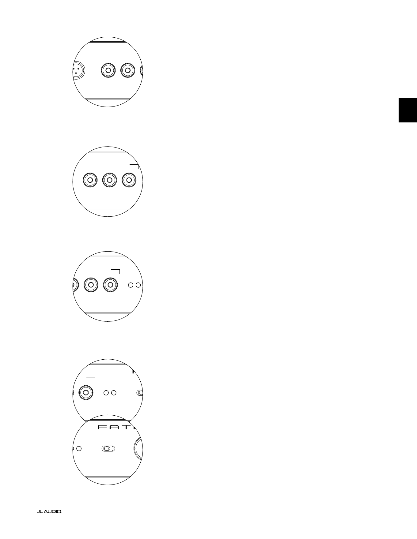
Pg 15 | ES
|
Fathom
®
v2
ES
LP freq. (Hz) e.l.f. trim (dB) phase (deg.)
Polarity
0
|
180 deg.
LP Filter
o
|
12dB
|
24dB
Master Level
max
0
Lights
o
|
dim
|
on
-∞
Level Mode
ref.
|
variable
Input Mode
master
|
slave
calibration mic. demo defeat calibrate
Power
o
|
on
|
auto
Digital Automatic Room Optimization
LP freq. (Hz) e.l.f. trim (dB) phase (deg.)
Polarity
0
|
180 deg.
LP Filter
o
|
12dB
|
24dB
Master Level
max
0
Lights
o
|
dim
|
on
-∞
Level Mode
ref.
|
variable
Input Mode
master
|
slave
calibration mic. demo defeat calibrate
Power
o
|
on
|
auto
Digital Automatic Room Optimization
Botón "demo"
El botón "demo" activa una secuencia de tonos de 20 segundos de duración que
demuestra brevemente el rango del subwoofer Fathom v2. La función demo es útil
para mostrar la capacidad de salida del Fathom v2 y para vericar que el Fathom v2
(o varios Fathom v2) están operativos durante la resolución de problemas del sistema.
El botón "demo" también se utiliza (en combinación) para borrar (regresar
a la conguración plana) los ajustes del ecualizador DARO. Para borrar los
ajustes del DARO y apagar la luz de calibración, presione el botón "demo"
y, sin soltarlo, presione el botón "defeat". Tenga en cuenta que debe realizar
con rapidez esta secuencia de presionar botones. Si mantiene pulsado el
botón "demo" durante más de 2 segundos sin tocar el botón "defeat", se
iniciarán los tonos de demostración. Si esto ocurriera, simplemente espere
a que termine la secuencia de demostración y vuelva a intentarlo.
Botón "defeat"
Si se presionan "demo" o "calibrate" mientras la función de anulación ("defeat")
está activa, esta se cancela automáticamente. Ningún otro control del panel frontal
alterará el estado de anulación ("defeat") del DARO. El ajuste de "defeat" se almacena
en la memoria no volátil y no cambiará aunque se desconecte la alimentación.
El botón "defeat" también se utiliza (en combinación) para borrar (regresar
a la conguración plana) los ajustes del ecualizador DARO. Para borrar los
ajustes del DARO y apagar la luz de calibración, presione el botón "demo"
y, sin soltarlo, presione el botón "defeat". Tenga en cuenta que debe realizar
con rapidez esta secuencia de presionar botones. Si mantiene pulsado el
botón "demo" durante más de 2 segundos sin tocar el botón "defeat", se
iniciarán los tonos de demostración. Si esto ocurriera, simplemente espere
a que termine la secuencia de demostración y vuelva a intentarlo.
Botón "calibrate"
Durante la secuencia de prueba del DARO, el LED verde del botón "calibrate"
parpadeará rápidamente para alertar al usuario de dos condiciones especiales:
1. "Micrófono de JL Audio NO conectado": Si se olvida de
conectar el micro antes de intentar iniciar una calibración, recibirá
esta alerta. Presione el botón "calibrate" una vez para cancelar la
alerta, conecte el micrófono DARO y vuelva a intentarlo.
2. "Nivel sonoro inadecuado para la calibración del DARO": Dado que la
secuencia del DARO es completamente automática, esta alerta indica probablemente
un problema con el micrófono. Presione el botón "calibrate" una vez para cancelar
la alerta. Asegúrese de que el micrófono de JL Audio está bien conectado y vuelva a
intentarlo. Para obtener más ayuda, consulte la sección Resolución de problemas en
la página 33.
Indicadores del modo de entrada
Los LED indicadores del modo de entrada muestran el modo de entrada, ya sea
"maestro" ("master") o "esclavo" ("esclavo"), seleccionado mediante el interruptor del
panel trasero del Fathom v2 (a menos que el interruptor "Lights" esté en "o"). Para
obtener más detalles, consulte la página 20.
Modo de nivel
El interruptor de modo de nivel ("Level Mode") de dos posiciones le permite
seleccionar entre los siguientes modos:
"ref.": En este modo, la perilla de control del nivel maestro no tiene efecto
alguno sobre el nivel de salida del Fathom v2. Utilice este ajuste si va a controlar
principalmente el nivel del subwoofer mediante su receptor o preamplicador/
procesador. Para los que tenemos niños pequeños o adolescentes demasiado
entusiastas, este modo de funcionamiento impedirá que se pueda manipular
directamente la perilla "Master Level".
"variable": En este modo, la perilla de control del nivel maestro determina el
nivel de salida del subwoofer Fathom v2. Este modo también es útil cuando se adapta
el nivel del subwoofer Fathom v2 a un par de altavoces estéreo en un sistema bicanal.
LP freq. (Hz) e.l.f. trim (dB) phase (deg.)
Polarity
0
|
180 deg.
LP Filter
o
|
12dB
|
24dB
Master Level
max
0
Lights
o
|
dim
|
on
-∞
Level Mode
ref.
|
variable
Input Mode
master
|
slave
calibration mic. demo defeat calibrate
Power
o
|
on
|
auto
Digital Automatic Room Optimization
LP freq. (Hz) e.l.f. trim (dB) phase (deg.)
Polarity
0
|
180 deg.
LP Filter
o
|
12dB
|
24dB
Master Level
max
0
Lights
o
|
dim
|
on
-∞
Level Mode
ref.
|
variable
Input Mode
master
|
slave
calibration mic. demo defeat calibrate
Power
o
|
on
|
auto
Digital Automatic Room Optimization
LP freq. (Hz) e.l.f. trim (dB) phase (deg.)
Polarity
0
|
180 deg.
LP Filter
o
|
12dB
|
24dB
Master Level
max
0
Lights
o
|
dim
|
on
-∞
Level Mode
ref.
|
variable
Input Mode
master
|
slave
calibration mic. demo defeat calibrate
Power
o
|
on
|
auto
Digital Automatic Room Optimization
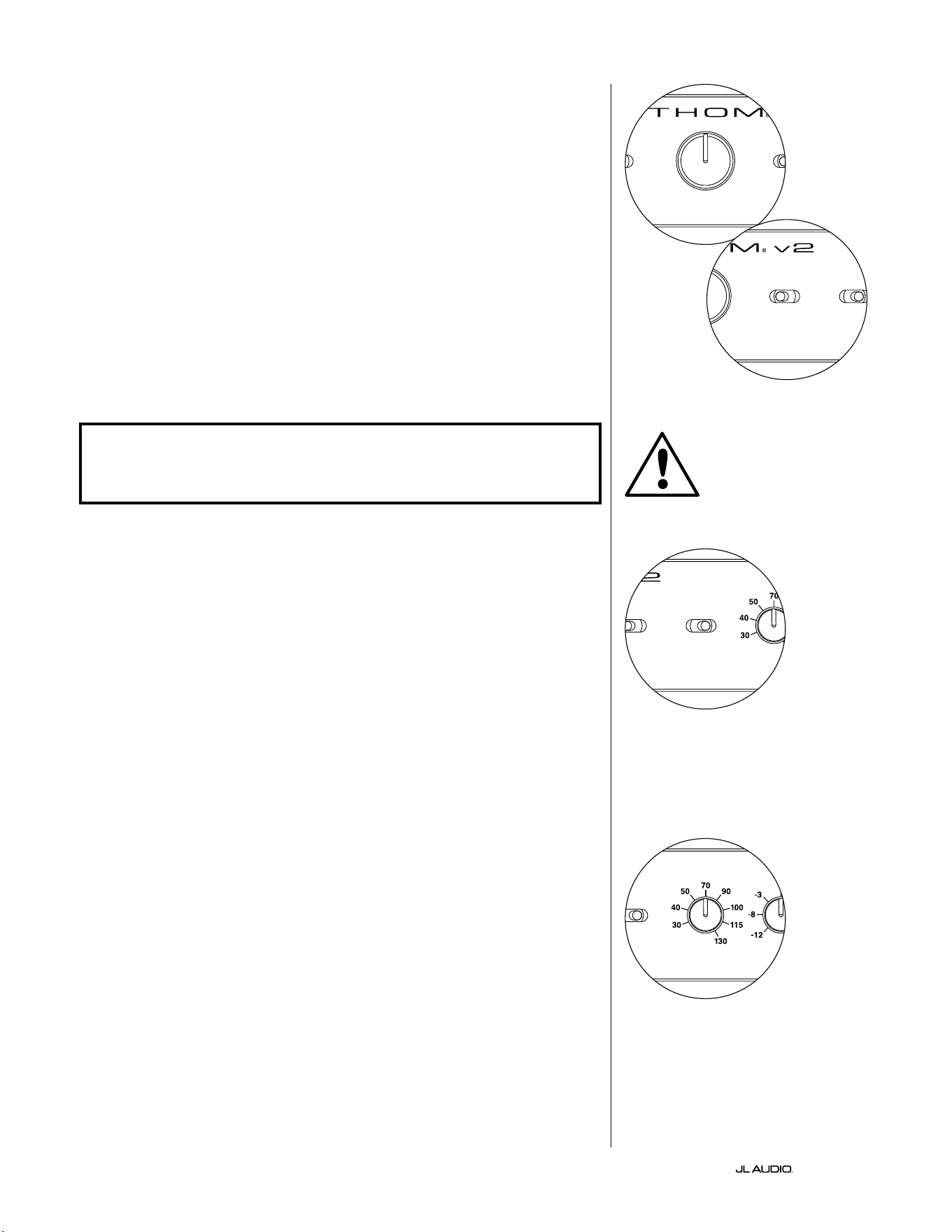
ES | Pg 16
|
Fathom
®
v2
Perilla de nivel maestro
La perilla de nivel maestro ("Master Level") se utiliza para controlar el nivel de
salida del Fathom v2 cuando se selecciona el modo de nivel variable en el panel de
control frontal.
Cuando se gira completamente hacia la izquierda, la salida del Fathom v2
se silencia completamente. Cuando está en la posición "0" o vertical, el nivel de
ganancia variable coincide con el ajuste del nivel de referencia. Cuando se gira
completamente hacia la derecha, el nivel de salida del Fathom v2 es 15dB mayor
que el ajuste de referencia.
Luces
El interruptor selector de luces ("Lights") permite al usuario seleccionar uno de
los tres modos de luces indicadoras.
"o" apaga todos los LED del panel frontal en todo momento.
"dim" ajusta todos los LED del panel frontal a un nivel de brillo reducido
cuando se enciende el Fathom v2.
"on" ajusta todos los LED del panel frontal a un nivel de brillo máximo cuando
se enciende el Fathom v2.
¡IMPORTANTE! CUANDO REALICE LA RESOLUCIÓN DE PROBLEMAS O CALIBRE
EL DARO, ASEGÚRESE DE QUE EL INTERRUPTOR "LIGHTS" ESTÁ EN "DIM" U
"ON".
Filtro LP
El interruptor selector del ltro LP ("LP Filter") establece el modo de operación
del ltro paso bajo incorporado en el Fathom v2.
"o" desactiva el ltro paso bajo, eliminando completamente este circuito de la
ruta de la señal.
"12dB" ajusta la pendiente de roll-o del ltro paso bajo a una pendiente de
12dB por octava (alineación Butterworth).
"24dB" ajusta la pendiente de roll-o del ltro paso bajo a una pendiente de
24dB por octava (alineación Linkwitz-Riley).
El ajuste de 24dB atenúa de una forma más agresiva las frecuencias altas
por encima del ajuste de frecuencia LP (ver más abajo). Si utiliza el ltro paso
bajo incorporado en el Fathom v2, experimente con el ajuste de la pendiente
del ltro LP para conseguir la mejor transición hacia sus altavoces satélite. Si
preere utilizar los ltros y las funciones de gestión de graves de su receptor o
preamplicador, anule el ltro incorporado seleccionando la posición "o".
Frecuencia LP
La perilla selectora de frecuencia de paso bajo ("LP freq.") permite al usuario
elegir la frecuencia de roll-o del ltro paso bajo interno del Fathom v2. La
frecuencia es variable, desde los 30Hz (completamente girada hacia la izquierda)
hasta los 130Hz (completamente girada hacia la derecha). Esta perilla no afecta
en absoluto a la señal de entrada si el interruptor "LP lter" está en "o". 80Hz es
una frecuencia de ltro muy utilizada y suele ser un buen punto de partida para
los ajustes.
LP freq. (Hz) e.l.f. trim (dB) phase (deg.)
Polarity
0
|
180 deg.
LP Filter
o
|
12dB
|
24dB
Master Level
max
0
Lights
o
|
dim
|
on
-∞
Level Mode
ref.
|
variable
Input Mode
master
|
slave
calibration mic. demo defeat calibrate
Power
o
|
on
|
auto
Digital Automatic Room Optimization
LP freq. (Hz) e.l.f. trim (dB) phase (deg.)
Polarity
0
|
180 deg.
LP Filter
o
|
12dB
|
24dB
Master Level
max
0
Lights
o
|
dim
|
on
-∞
Level Mode
ref.
|
variable
Input Mode
master
|
slave
calibration mic. demo defeat calibrate
Power
o
|
on
|
auto
Digital Automatic Room Optimization
LP freq. (Hz) e.l.f. trim (dB) phase (deg.)
Polarity
0
|
180 deg.
LP Filter
o
|
12dB
|
24dB
Master Level
max
0
Lights
o
|
dim
|
on
-∞
Level Mode
ref.
|
variable
Input Mode
master
|
slave
calibration mic. demo defeat calibrate
Power
o
|
on
|
auto
Digital Automatic Room Optimization
LP freq. (Hz) e.l.f. trim (dB) phase (deg.)
Polarity
0
|
180 deg.
LP Filter
o
|
12dB
|
24dB
Master Level
max
0
Lights
o
|
dim
|
on
-∞
Level Mode
ref.
|
variable
Input Mode
master
|
slave
calibration mic. demo defeat calibrate
Power
o
|
on
|
auto
Digital Automatic Room Optimization
IMPORTANTE
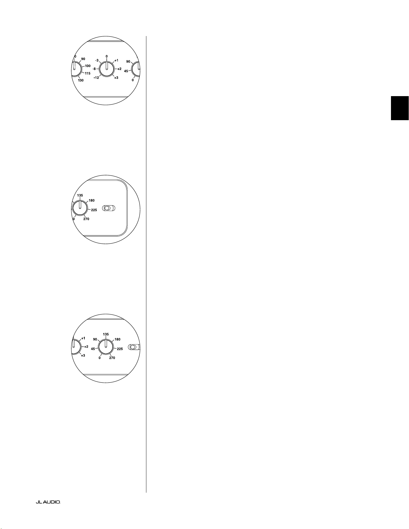
Pg 17 | ES
|
Fathom
®
v2
ES
Ajuste de FEB
La perilla de ajuste de frecuencia extremadamente baja (FEB, "extreme low
frequency" en inglés) permite al usuario aplicar una cierta cantidad de ecualización
de la señal a 24Hz (graves extremadamente bajos). Completamente girada hacia
la izquierda, la señal a 24Hz se corta en 12dB. En "0" el ecualizador se ajusta a la
conguración plana para que la contribución a la señal sea nula. Completamente
girada hacia la derecha, la señal a 24Hz se potencia en 3dB.
La función de ajuste de FEB es útil para adaptar la salida de frecuencias muy bajas
del Fathom v2 a su sala en particular. Añadir algo de potencia puede hacer que cierto
material resulte más emocionante. El uso de la función de corte puede ayudar a
compensar la ganancia de la sala o de los límites en las frecuencias bajas. Los límites
de la sala y su tamaño nito (limitado) provocan de forma natural que las frecuencias
muy bajas se potencien en relación con otras partes de la señal. Por ello, el uso de la
función de ajuste de FEB para cortar las frecuencias más bajas puede ayudar a domar
la "hinchazón" o el sonido antinatural de los graves en salas de tamaño pequeño
o medio (y también puede reducir las vibraciones no deseadas en la habitación o
incluso en toda la casa).
Polaridad
El interruptor "Polarity" le permite al usuario seleccionar entre polaridad de señal
normal (0 grados) e invertida (180 grados). Este interruptor de polaridad afectará
principalmente el pequeño rango de frecuencias alrededor del punto de cruce entre el
subwoofer y los altavoces satélite.
A diferencia del control "phase (deg.)", que efectivamente suma tiempo de
retardo, el interruptor de "Polarity" produce una inversión instantánea de los picos
de amplitud de la señal. Por ejemplo, si, en un punto de referencia dado, una onda
senoidal tiene un pico de amplitud, al girar el interruptor "phase (deg.)" convierte
instantáneamente ese pico en una demodulación o un descenso de amplitud. Dado
que el efecto del interruptor de polaridad es inmediato, complementa la operación
del control de fase "phase (deg.)" y no puede ser reemplazado por este.
Cuando coloque su Fathom v2 en la sala, experimente con el interruptor
"Polarity" antes de ajustar el control "phase (deg.)". Cualquier posición del interruptor
de polaridad puede proporcionar una transición más suave entre su subwoofer
Fathom v2 y los altavoces satélite. Utilice material de fuente con buen contenido de
sonidos graves medios y altos para la evaluación.
Fase
La perilla de control de fase "phase (deg.)" le permite al usuario ajustar la
sincronización de la salida del subwoofer con respecto a los altavoces principales.
El control "phase (deg.)" afectará principalmente al rango de frecuencias menor
alrededor del punto de cruce entre el subwoofer y los altavoces satélite. Es posible
implementar ajustes de fase de entre 0 grados (completamente girada a la izquierda)
y 270 grados (completamente girada a la derecha). La escala en grados del control de
fase "phase (deg.)" está referido a 80Hz, ya que este es el punto de cruce más común
entre los altavoces de satélite y un subwoofer.
En las instalaciones de cine en el hogar, las posiciones del altavoz, del subwoofer
y del asiento desde donde se escucha variarán considerablemente. Dado que la
posición física de los altavoces respecto de los límites de la sala y entre sí afecta
en gran medida la calidad percibida de la salida del sonido, a veces es de utilidad
retardar la salida del subwoofer. Esto es exactamente lo que sucede cuando se gira el
control "phase (deg.)" más allá de los 0 grados.
Una vez que haya colocado su Fathom v2 en su sala de audio para obtener el
sonido general más suave, y después de haber determinado la posición óptima del
interruptor "Polarity" (véase la sección anterior), experimente con la posición del
control "phase (deg.)". Con material de fuente conocido que tenga un buen contenido
de sonidos graves medios y altos, ajuste el control de fase "phase (deg.)" y escuche
para detectar un grave medio mejor denido y una transición más suave entre el
subwoofer y los sistemas de altavoces satélite. Si no encuentra una conguración que
suene mejor que otra, deje el control "phase (deg.)" en 0 grados.
LP freq. (Hz) e.l.f. trim (dB) phase (deg.)
Polarity
0
|
180 deg.
LP Filter
o
|
12dB
|
24dB
Master Level
max
0
Lights
o
|
dim
|
on
-∞
Level Mode
ref.
|
variable
Input Mode
master
|
slave
calibration mic. demo defeat calibrate
Power
o
|
on
|
auto
Digital Automatic Room Optimization
LP freq. (Hz) e.l.f. trim (dB) phase (deg.)
Polarity
0
|
180 deg.
LP Filter
o
|
12dB
|
24dB
Master Level
max
0
Lights
o
|
dim
|
on
-∞
Level Mode
ref.
|
variable
Input Mode
master
|
slave
calibration mic. demo defeat calibrate
Power
o
|
on
|
auto
Digital Automatic Room Optimization
LP freq. (Hz) e.l.f. trim (dB) phase (deg.)
Polarity
0
|
180 deg.
LP Filter
o
|
12dB
|
24dB
Master Level
max
0
Lights
o
|
dim
|
on
-∞
Level Mode
ref.
|
variable
Input Mode
master
|
slave
calibration mic. demo defeat calibrate
Power
o
|
on
|
auto
Digital Automatic Room Optimization
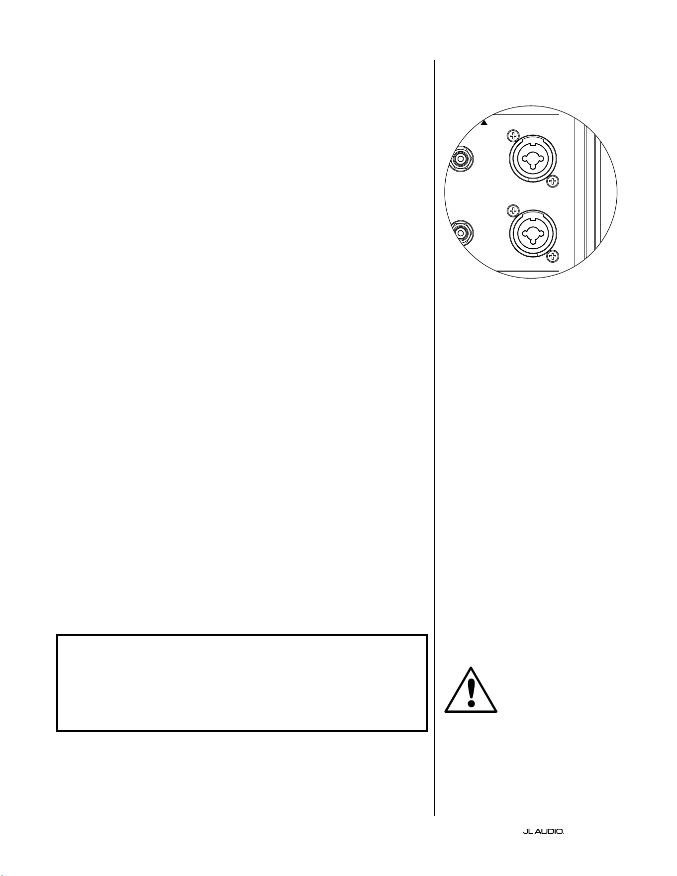
ES | Pg 18
|
Fathom
®
v2
CONEXIÓN DE SUS FATHOM v2
Entradas balanceadas
Si su receptor de cine en casa o preamplicador/procesador proporciona
salidas balanceadas, las entradas balanceadas del Fathom v2 son la conexión
más adecuada. Las conexiones balanceadas se utilizan mucho en los estudios
profesionales y en las aplicaciones de refuerzo de sonido por una serie de
buenas razones. Además de garantizar una conexión a tierra adecuada entre los
componentes, la transmisión equilibrada de la señal está diseñada para anular el
ruido inducido por los cables del entorno (especialmente importante en el caso de
cables largos). La conclusión es que será mucho menos probable que su sistema
presente zumbidos u otros ruidos extraños si utiliza conexiones balanceadas.
Los subwoofers Fathom v2 cuentan con conexiones individuales de entrada
balanceada izquierda y derecha con tomas XLR "combo". Estas tomas especiales
aceptan un conector XLR macho de tres clavijas o un conector TRS ("tip-ring-
sleeve", punta-anillo-funda) de 1/4 de pulgada (6,3mm) para ser compatibles con
una amplia gama de equipos.
Para los sistemas con un subwoofer mono o conexión de canal "LFE", solo se
usará el conector etiquetado "Le or Mono". Este método se aplica a la mayoría
de los receptores multicanal y preamplicador/procesadores modernos. Los
conectores de entrada separados, a izquierda y derecha, se incluyen en los sistemas
que no cuentan con una conexión de subwoofer mono especíca. Generalmente,
esto se aplica a los equipos de audio bicanal.
Su distribuidor de JL Audio tiene a su disposición los cables balanceados
apropiados, ya que no se incluyen con el Fathom v2.
Notas técnicas:
• No utilice las entradas balanceadas con señales no balanceadas mediante
adaptadores. Las entradas no balanceadas del Fathom v2 están aisladas
ópticamente y son preferibles en situaciones en las que solo se dispone de una
fuente de señal no balanceada. La impedancia de entrada balanceada es de 20kΩ.
• Los conectores balanceados están congurados de acuerdo con las
recomendaciones de la Sociedad de Ingeniería de Audio para los cables de señal
balanceada, como se indica a continuación:
Conexión XLR
Clavija 1: malla
Clavija 2: positivo
Clavija 3: negativo
Conexión TRS
Punta: positivo
Anillo: negativo
Funda: malla
¡IMPORTANTE! SI SU RECEPTOR O PREAMPLIFICADOR/PROCESADOR NO
TIENE SALIDAS BALANCEADAS XLR O TRS DE 1/4 DE PULGADA (6,35 mm),
CONSULTE LA SECCIÓN "ENTRADAS NO BALANCEADAS" EN LA PÁGINA 19
PARA OBTENER INFORMACIÓN SOBRE LA CONEXIÓN DE LAS ENTRADAS.
NO INTENTE CONECTAR SALIDAS NO BALANCEADAS A LAS ENTRADAS
BALANCEADAS DEL FATHOM V2 MEDIANTE ADAPTADORES.
Las entradas izquierda y derecha del
Fathom v2 están combinadas internamente
a un solo canal mono. Dado que el Fathom
v2 es intrínsecamente un dispositivo "mono"
o de un solo canal, puede utilizar las
entradas izquierda y derecha para el Fathom
v2 maestro y luego distribuir la señal mono
sumada a los Fathom v2 esclavos adicionales
del sistema.
IMPORTANTE
1200VA
Built in USA with Imported and domestic components
LEFT
or
MONO
RIGHT
ONLY
INPUTS
Output to Slave
(Balanced)
Balanced
Unbalanced
Input Modes
Slave
Master
Grounded
Isolated
SERIAL NUMBER:
Warranty void if serial number is removed, altered or defaced.
F 12A H
250V
120 V ~ 60 Hz
F
U
S
E
F
U
S
E
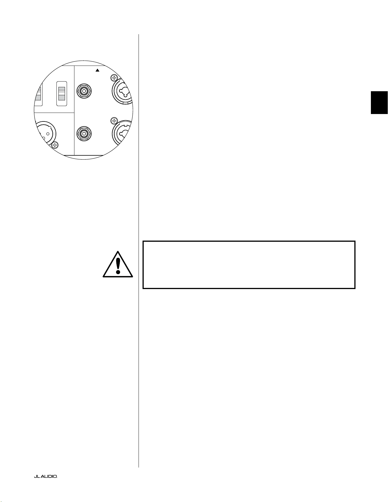
Pg 19 | ES
|
Fathom
®
v2
ES
Entradas no balanceadas
El subwoofer Fathom v2 presenta conectores individuales de entrada tipo RCA
no balanceados, a derecha e izquierda. Estos son los conectores más utilizados en
las aplicaciones de audio domésticas y son los que deben utilizarse si su receptor
o preamplicador/procesador no dispone de salidas balanceadas. Aunque las
conexiones no balanceadas no son tan inmunes al ruido como una conexión
balanceada, los subwoofers Fathom v2 emplean un aislamiento óptico en las
entradas no balanceadas para minimizar la posibilidad de ruido en su sistema.
Para los sistemas con un subwoofer mono o conexión de canal "LFE", solo se
usará el conector tipo RCA etiquetado "Le or Mono". Este método se aplica a la
mayoría de los receptores multicanal y preamplicador/procesadores modernos.
Los conectores de entrada separados tipo RCA, a izquierda y derecha, se incluyen
en los sistemas que no cuentan con una conexión de subwoofer mono especíca.
Generalmente, esto se aplica a los equipos de audio bicanal.
Notas técnicas:
• Cuando la fuente de señal no dispone de salidas balanceadas, debe utilizar
las entradas no balanceadas tipo RCA. Los subwoofers Fathom v2 cuentan
con un circuito de aislamiento óptico en las entradas no balanceadas para
minimizar la probabilidad de ruido inducido por el bucle de tierra. La
impedancia de entrada no balanceada es de 50kΩ.
• Las conexiones son las habituales en el sector para los cables de señal no
balanceada, tal como se indica a continuación:
Conexión tipo RCA:
Punta: positivo
Funda: negativo
¡IMPORTANTE! SI EXISTE RUIDO DESPUÉS DE LA CONEXIÓN, LOS FATHOM
V2 PERMITEN LA CONEXIÓN A TIERRA O EL AISLAMIENTO DE LAS ENTRADAS
NO BALANCEADAS. CONSULTE LA SECCIÓN "INTERRUPTORES DEL MODO
DE ENTRADA" EN LA PÁGINA 20 DE ESTE MANUAL PARA OBTENER MÁS
INFORMACIÓN SOBRE CÓMO MINIMIZAR EL RUIDO.
1200VA
Built in USA with Imported and domestic components
LEFT
or
MONO
RIGHT
ONLY
INPUTS
Output to Slave
(Balanced)
Balanced
Unbalanced
Input Modes
Slave
Master
Grounded
Isolated
SERIAL NUMBER:
Warranty void if serial number is removed, altered or defaced.
F 12A H
250V
120 V ~ 60 Hz
F
U
S
E
F
U
S
E
IMPORTANTE
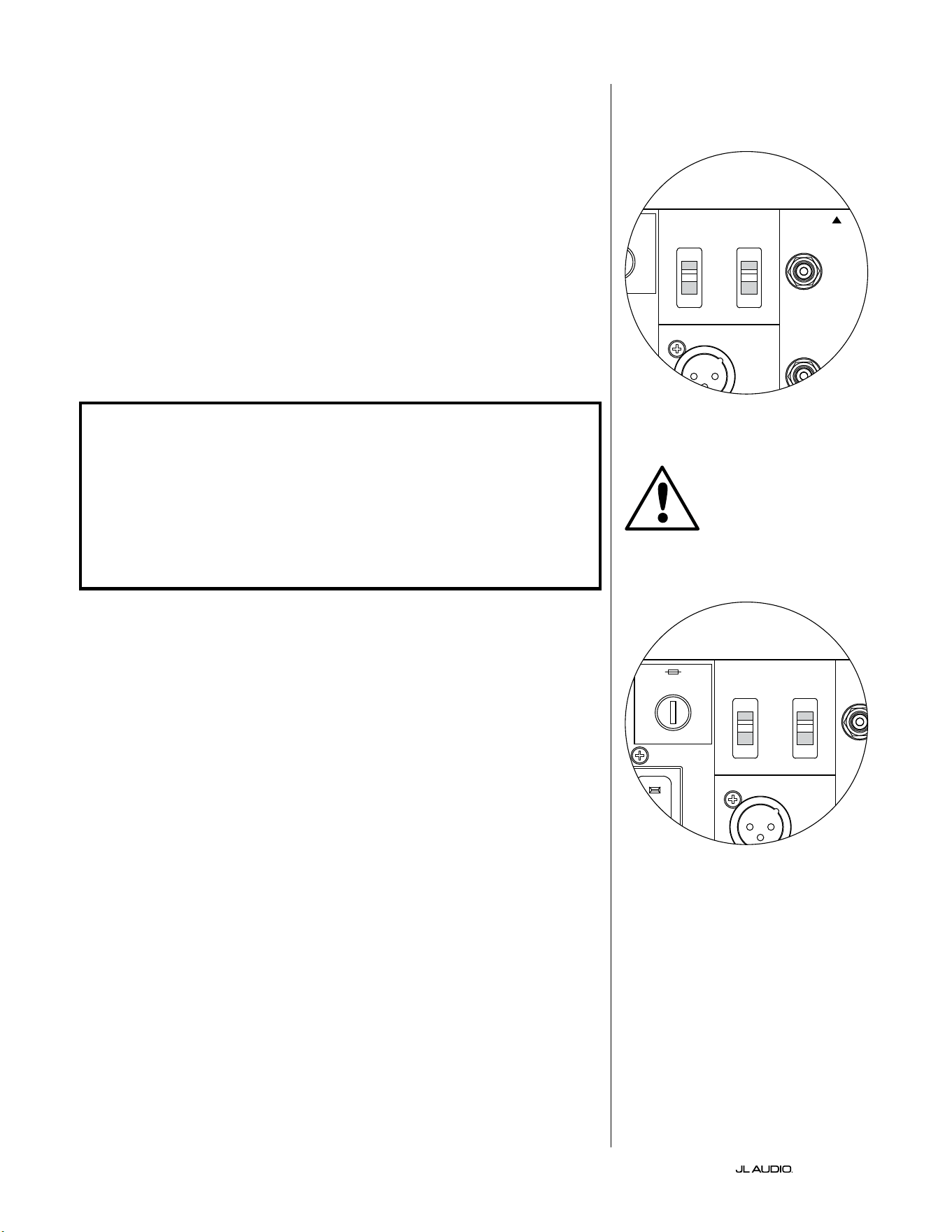
ES | Pg 20
|
Fathom
®
v2
Interruptores del modo de entrada:
En el panel trasero hay dos interruptores para controlar la conexión a tierra de la
señal no balanceada y el funcionamiento maestro/esclavo.
Interruptor "a tierra/aislado"
El interruptor de modo de entrada "a tierra/aislado" ("Grounded/Isolated")
afecta únicamente a las entradas RCA no balanceadas y está diseñado para facilitar
una conexión silenciosa y sin zumbidos a su sistema de audio o cine en el hogar.
Se incluye esta función para solucionar los problemas de conexión a tierra de la
señal que aparecen con frecuencia en los sistemas de cine en el hogar cuando hay
interconectados varios componentes de diferentes fabricantes.
El equipo Fathom v2 se envía con este interruptor en el modo "Isolated"
("aislado"). Si, con todos los componentes del sistema conectados y activados (pero
sin material fuente en reproducción), usted escucha un zumbido constante de
frecuencia baja a través de su equipo Fathom v2, gire este interruptor a la posición
"Grounded" ("conectado a tierra") y evalúe la diferencia en el nivel de ruido. Utilice la
posición del interruptor que proporcione el menor zumbido o ruido.
¡IMPORTANTE! TENGA EN CUENTA QUE EL CAMBIO DE CUALQUIER COMPONENTE
DEL SISTEMA OPTIMIZADO (RECEPTOR, AMPLIFICADOR, REPRODUCTOR DE DVD,
RECEPTOR DE TV POR CABLE O SATÉLITE, ETC.) PODRÍA ALTERAR EL ESQUEMA
DE CONEXIÓN A TIERRA DE LA SEÑAL Y PROVOCAR LA APARICIÓN DE ZUMBIDOS
EN SU SISTEMA. SI AÑADE O CAMBIA UN COMPONENTE DE ENTRADA EN SU
SISTEMA DE CINE EN CASA, ES POSIBLE QUE TENGA QUE VOLVER A REVISAR
ESTE AJUSTE DEL MODO DE ENTRADA EN EL SUBWOOFER FATHOM V2 PARA
OBTENER UN RENDIMIENTO ACÚSTICO ÓPTIMO. LOS RECEPTORES DE CABLE Y
SATÉLITE SON PARTICULARMENTE PROBLEMÁTICOS EN ESTE SENTIDO.
Interruptor maestro/esclavo
Los Fathom v2 están diseñados para acomodar fácilmente la implementación de
múltiples subwoofers en su sistema de cine en casa mediante una cadena de conexión
maestro/esclavo. Este método le permite utilizar las funciones de procesamiento de
señales de un Fathom v2 para controlar de forma centralizada varios Fathom v2 en la
sala. La funcionalidad maestro/esclavo también hace posible que el sistema DARO
optimice la respuesta de una instalación de varios subwoofers.
El equipo Fathom v2 se envía con este interruptor en la posición "Master"
("maestro"). Si utiliza un solo Fathom v2 utilizará la posición "Master" y no es
necesario que siga leyendo esta sección.
Si su instalación incorpora dos o más Fathom v2, designará un Fathom v2 como
"maestro" y todos los demás del sistema como subwoofers "esclavos" mediante el
interruptor "Master/Slave" del panel posterior del amplicador de cada Fathom v2.
Los LED del panel frontal de cada Fathom v2 indican si se ha seleccionado el modo
"maestro" o "esclavo" en ese subwoofer.
Desde el Fathom v2 que funciona en modo "maestro", la señal de "Output to
Slave" llevará el procesamiento de señal seleccionado en el Fathom v2 maestro
(incluyendo el ajuste del nivel maestro y el procesamiento DARO) a los Fathom
v2 que funcionen en modo "esclavo". En los subwoofers en modo "esclavo" no
funcionarán ni el procesamiento de la señal ni los controles de nivel. En este modo, el
usuario no tiene que preocuparse por el nivel, el ltro de cruce ni otros ajustes de los
subwoofers esclavos.
Notas técnicas:
• Al seleccionar la posición "Slave", se anulan todo el procesamiento de señal
denible por el usuario y el control de nivel maestro. Por esta razón, hay algunas
situaciones especiales en las que convendría hacer funcionar un solo Fathom
v2 en modo "esclavo". Si utiliza controles externos de procesamiento de señales
y de nivelación, activar el modo "esclavo" impedirá que nadie afecte a los
parámetros del sistema con los controles manuales del Fathom v2.
IMPORTANTE
1200VA
Built in USA with Imported and domestic components
LEFT
or
MONO
RIGHT
ONLY
INPUTS
Output to Slave
(Balanced)
Balanced
Unbalanced
Input Modes
Slave
Master
Grounded
Isolated
SERIAL NUMBER:
Warranty void if serial number is removed, altered or defaced.
F 12A H
250V
120 V ~ 60 Hz
F
U
S
E
F
U
S
E
1200VA
Built in USA with Imported and domestic components
LEFT
or
MONO
RIGHT
ONLY
INPUTS
Output to Slave
(Balanced)
Balanced
Unbalanced
Input Modes
Slave
Master
Grounded
Isolated
SERIAL NUMBER:
Warranty void if serial number is removed, altered or defaced.
F 12A H
250V
120 V ~ 60 Hz
F
U
S
E
F
U
S
E
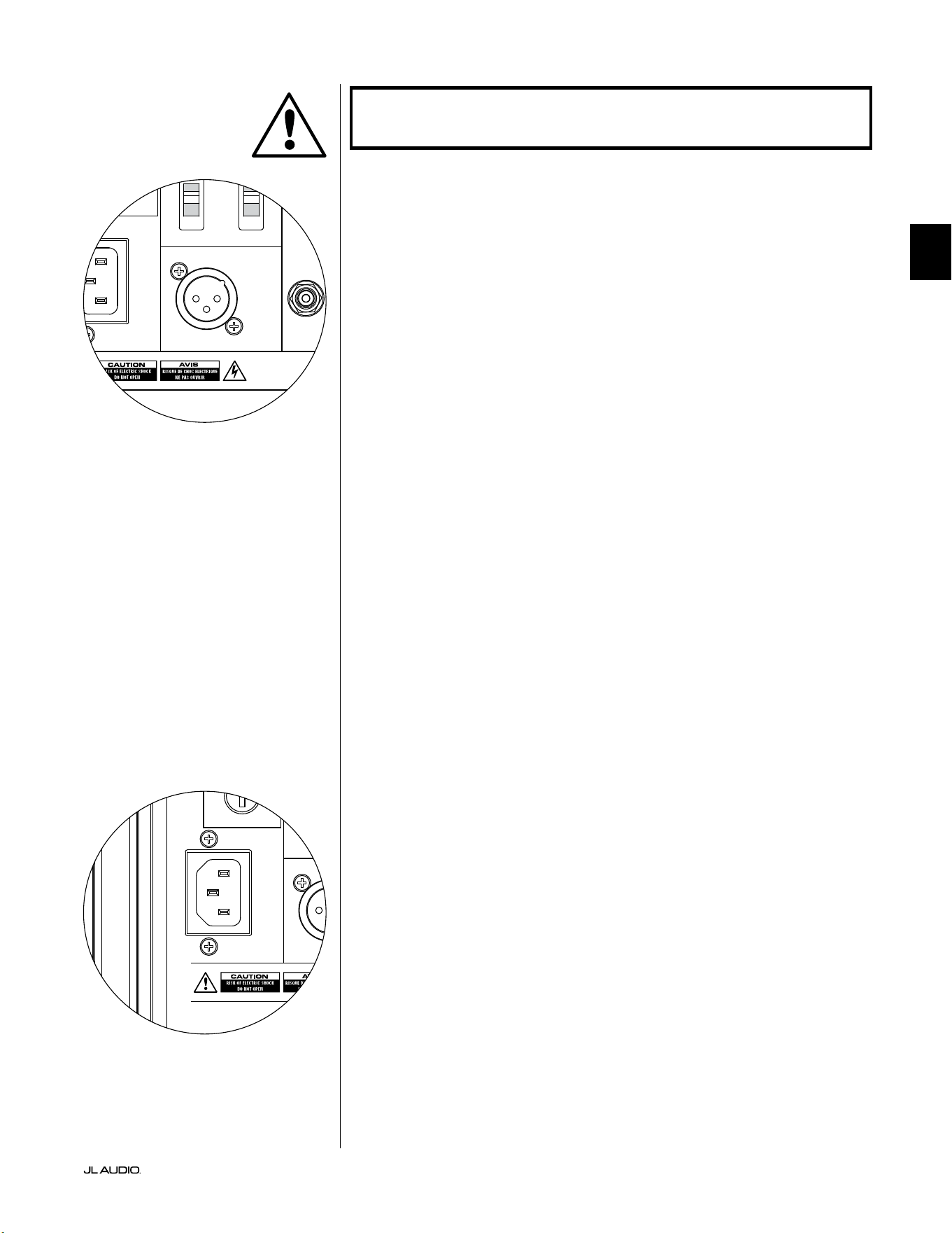
Pg 21 | ES
|
Fathom
®
v2
ES
¡IMPORTANTE! CONSULTE LAS PÁGINAS 22-25 PARA OBTENER MÁS
INFORMACIÓN SOBRE EL USO DE LAS CONEXIONES DE ENTRADA/SALIDA.
Conector de salida a esclavo ("Output to Slave")
Si está operando más de un subwoofer Fathom v2 en un sistema de cine en casa,
designará un Fathom v2 como maestro (ver página 20), y luego alimentará con
la señal de este a los subwoofers Fathom v2 "esclavos" a través de esta salida XLR
balanceada. El cable conectado a "Output to Slave" puede conectarse a la entrada
XLR balanceada "Le or Mono" del siguiente Fathom v2. Cuando un Fathom v2
está en modo "esclavo", su conexión "Output to Slave" puede utilizarse para pasar
la señal a otros subwoofers Fathom v2 que estén también en modo "esclavo".
El conector "Output to Slave" está diseñado para ser utilizado de la siguiente
manera:
1) Desde el conector "Output to Slave" del Fathom v2 maestro a la entrada XLR
balanceada "Le or Mono" del primer Fathom v2 esclavo.
2) Desde el conector "Output to Slave" del primer Fathom v2 esclavo a la
entrada XLR balanceada "Le or Mono" del segundo Fathom v2 esclavo.
3) Desde el conector "Output to Slave" del segundo Fathom v2 esclavo a la
entrada XLR balanceada "Le or Mono" del tercer Fathom v2 esclavo. Y
así sucesivamente, hasta un máximo de diez subwoofers Fathom v2. Su
distribuidor de JL Audio tiene a su disposición los cables balanceados
apropiados con extremos XLR, ya que no se incluyen con el Fathom v2.
Notas técnicas:
• La señal de "Output to Slave" llevará el procesamiento de señal seleccionado
en el Fathom v2 maestro (incluyendo el ajuste del nivel maestro y el
procesamiento DARO) a los Fathom v2 que funcionen en modo "esclavo".
• Desde los Fathom v2 que estén en modo "esclavo", la señal de "Output to
Slave" es una réplica exacta, compensada, de la señal de entrada balanceada,
lo que hace que este método de distribución de la señal sea preferible al uso
de adaptadores en Y o divisores.
• Utilice solo cables de conexión apantallados con conectores XLR de alta
calidad para las conexiones "Master/Slave". No utilice nunca cables no
balanceados mediante adaptadores.
Conector de alimentación por CA estilo IEC
El receptáculo del cable de CA estilo IEC recibe el cable de alimentación de
calibre ancho, de 6pies (1,8m) de largo, incluido con su subwoofer Fathom v2. Los
Fathom v2 vendidos en diferentes partes del mundo vienen congurados para el
sistema eléctrico de cada mercado e incluyen los enchufes correspondientes en sus
cables de alimentación. Observe las marcas de voltaje al lado del conector de CA
y asegúrese de alimentar el equipo Fathom v2 únicamente desde un tomacorriente
que coincida con dichas marcas. No utilice ningún cable de alimentación de
CA diferente del que viene incluido con el equipo Fathom v2. Para obtener
información sobre el portafusible principal, consulte la sección "Resolución de
problemas" de este manual.
El subwoofer Fathom v2 es un dispositivo muy potente y puede consumir
mucha electricidad. Si hay demasiados componentes conectados junto con un
subwoofer Fathom v2 en un mismo tomacorriente, se corre el riesgo de activar el
disyuntor del hogar durante un uso muy exigente de material de programación.
Si ello sucediera, distribuya el equipo Fathom v2 y los demás componentes entre
dos circuitos eléctricos de CA. Si es posible, para obtener el máximo rendimiento,
conecte cada Fathom v2 a un circuito de CA diferente.
IMPORTANTE
1200VA
Built in USA with Imported and domestic components
LEFT
or
MONO
RIGHT
ONLY
INPUTS
Output to Slave
(Balanced)
Balanced
Unbalanced
Input Modes
Slave
Master
Grounded
Isolated
SERIAL NUMBER:
Warranty void if serial number is removed, altered or defaced.
F 12A H
250V
120 V ~ 60 Hz
F
U
S
E
F
U
S
E
1200VA
Built in USA with Imported and domestic components
LEFT
or
MONO
RIGHT
ONLY
INPUTS
Output to Slave
(Balanced)
Balanced
Unbalanced
Input Modes
Slave
Master
Grounded
Isolated
SERIAL NUMBER:
Warranty void if serial number is removed, altered or defaced.
F 12A H
250V
120 V ~ 60 Hz
F
U
S
E
F
U
S
E

ES | Pg 22
|
Fathom
®
v2
DIAGRAMA 1 DE CONEXIÓN DEL
SISTEMA:
Un Fathom v2 con
el receptor del cine en el hogar o
preamplicador/procesador
del cine en el hogar
La mayoría de los receptores y
preamplicadores/procesadores de
los cines en el hogar proporcionan
una sola salida (mono) de subwoofer.
Al conectar una salida de subwoofer
mono a su Fathom v2, solo utilizará la
entrada "Le or Mono" del Fathom.
Hay dos tipos de conexión disponibles
para conectar el Fathom v2 a su sistema de
cine en casa: balanceada (conector XLR o
TRS de 1/4 de pulgada) y no balanceada
(conector tipo RCA). Las conexiones
balanceadas ofrecen un mayor rechazo al
ruido y garantizan una correcta conexión a
tierra entre los componentes. Si su receptor
o procesador tiene salidas balanceadas,
le recomendamos que las utilice.
En el diagrama de conexión de la
izquierda, las conexiones balanceadas
se muestran como líneas continuas,
las conexiones no balanceadas
se muestran discontinuas. Solo
utilizará uno de estos métodos de
conexión de entrada (no ambos).
1200VA
ilt in USA with Imported and domestic components
LEFT
or
MONO
RIGHT
ONLY
INPUTS
Output to Slave
(Balanced)
Balanced
Unbalanced
Input Modes
Slave
Master
Grounded
Isolated
SERIAL NUMBER:
Warranty void if serial number is removed, altered or defaced.
F 12A H
250V
0 V ~ 60 Hz
F
U
S
E
F
U
S
E
Sl
ave
Master
z
OUTPUTS
SUB
REAR
REAR CENTER
FRONT
FRONT
R
L
PRE OUT
PROCESADOR (SALIDAS BALANCEADAS)
CONTROLES TRASEROS FATHOM (MAESTRO)
O
RECEPTOR/PROCESADOR (SALIDAS NO BALANCEADAS)
ADVERTENCIA
¡ADVERTENCIA! ¡APAGUE EL/LOS EQUIPO(S) FATHOM v2 Y TODOS LOS
DEMÁS EQUIPOS DEL SISTEMA ANTES DE REALIZAR O MODIFICAR CUALQUIER
CONEXIÓN!
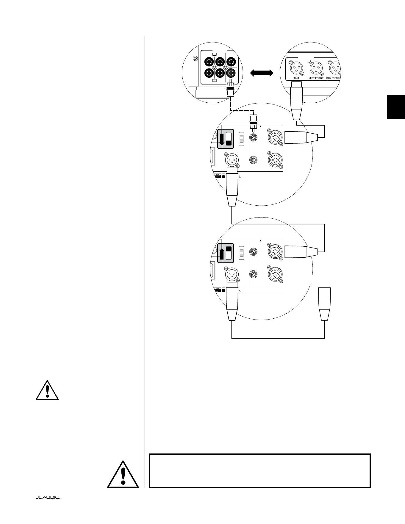
Pg 23 | ES
|
Fathom
®
v2
ES
DIAGRAMA 2 DE CONEXIÓN DEL
SISTEMA:
Varios Fathom v2 con
el receptor del cine en el hogar o
preamplicador/procesador
del cine en el hogar
Para simplicar en gran medida el uso de
varios subwoofers en un mismo sistema de cine
en casa, los Fathom v2 incorporan un sistema
de distribución de la señal "maestro/esclavo".
Esto permite controlar todos los Fathom v2 de
un sistema desde una única unidad "maestra".
En primer lugar, seleccionará un subwoofer
Fathom v2 como "Master" mediante su
interruptor superior "Input Mode". Por lo
general, designará como maestro el Fathom v2
más cercano al receptor/preamplicador. En
algunos casos (por ejemplo, cuando el panel
de control de ciertas unidades es de difícil
acceso), puede preferir designar como maestro
a aquel Fathom v2 al que sea más fácil acceder.
Hay dos tipos de conexión disponibles para
conectar el Fathom v2 maestro a su sistema
de cine en casa: balanceada (conector XLR
o TRS de 1/4 de pulgada) y no balanceada
(conector tipo RCA). Las conexiones
balanceadas ofrecen un mayor rechazo al
ruido y garantizan una correcta conexión a
tierra entre los componentes. Si su receptor
o procesador tiene salidas balanceadas, le
recomendamos que las utilice para conectar
el Fathom v2 designado como maestro.
En el diagrama de conexión de la izquierda,
las conexiones balanceadas se muestran
como líneas continuas, las conexiones no
balanceadas se muestran discontinuas.
Solo utilizará uno de estos métodos de
conexión de entrada para el Fathom v2
designado como maestro (no ambos).
Los restantes equipos Fathom v2 del
sistema se congurarán como unidades
"esclavas" mediante sus interruptores
superiores de "Input Mode". Utilizando
cables XLR balanceados, conectará la salida
"Output to Slave" del Fathom v2 maestro
a la entrada balanceada "Le or Mono"
del primer Fathom v2 esclavo. El conector
"Output to Slave" de esa unidad esclava
alimentará la entrada "Le or Mono" de la
siguiente unidad esclava a través de otro cable
XLR balanceado. Las siguientes unidades
esclavas se conectarán de la misma manera.
Las conexiones entre los equipos Fathom
"maestro" y "esclavo", y entre los equipos
"esclavos" se deben realizar SOLO con cables
XLR balanceados.
1200VA
ilt in USA with Imported and domestic components
LEFT
or
MONO
RIGHT
ONLY
INPUTS
Output to Slave
(Balanced)
Balanced
Unbalanced
Input Modes
Slave
Master
Grounded
Isolated
SERIAL NUMBER:
Warranty void if serial number is removed, altered or defaced.
F 12A H
250V
0 V ~ 60 Hz
F
U
S
E
F
U
S
E
1200VA
ilt in USA with Imported and domestic components
LEFT
or
MONO
RIGHT
ONLY
INPUTS
Output to Slave
(Balanced)
Balanced
Unbalanced
Input Modes
Slave
Master
Grounded
Isolated
SERIAL NUMBER:
Warranty void if serial number is removed, altered or defaced.
F 12A H
250V
0 V ~ 60 Hz
F
U
S
E
F
U
S
E
Sl
ave
Master
z
Sl
ave
Master
z
OUTPUTS
SUB
REAR
REAR CENTER
FRONT
FRONT
R
L
PRE OUT
PROCESADOR (SALIDAS BALANCEADAS)
CONTROLES TRASEROS FATHOM (MAESTRO)
CONTROLES TRASEROS FATHOM (ESCLAVO)
O
RECEPTOR/PROCESADOR (SALIDAS NO BALANCEADAS)
A FATHOMS ADICIONALES
(SI PROCEDE)
IMPORTANTE
ADVERTENCIA
¡ADVERTENCIA! ¡APAGUE EL/LOS EQUIPO(S) FATHOM v2 Y TODOS LOS
DEMÁS EQUIPOS DEL SISTEMA ANTES DE REALIZAR O MODIFICAR CUALQUIER
CONEXIÓN!
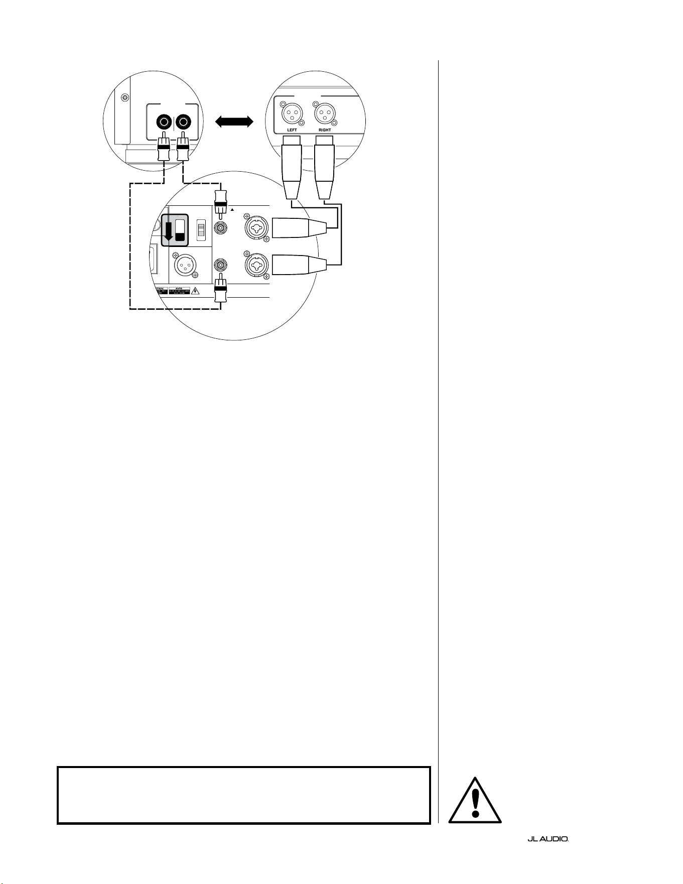
ES | Pg 24
|
Fathom
®
v2
1200VA
ilt in USA with Imported and domestic components
LEFT
or
MONO
RIGHT
ONLY
INPUTS
Output to Slave
(Balanced)
Balanced
Unbalanced
Input Modes
Slave
Master
Grounded
Isolated
SERIAL NUMBER:
Warranty void if serial number is removed, altered or defaced.
F 12A H
250V
0 V ~ 60 Hz
F
U
S
E
F
U
S
E
Sl
ave
M
aster
z
FILTRO DE CRUCE ACTIVO ESTÉREO (SALIDAS BALANCEADAS)
LOW OUT
(SUB OUT)
FILTRO DE CRUCE ACTIVO ESTÉREO (SALIDAS NO BALANCEADAS)
RIGHTLEFT
LOW OUT
(SUB OUT)
CONTROLES TRASEROS FATHOM (MAESTRO)
O
DIAGRAMA 3 DE CONEXIÓN DEL
SISTEMA:
Un Fathom v2 en mono a
un sistema de audio bicanal
Si conecta un solo Fathom v2 (o varios
Fathom v2) en mono con un sistema de
audio bicanal, deberá usar ambas entradas:
"Le or Mono" y "Right". Los circuitos de
suma en la sección de entrada del Fathom
v2 sumarán las señales estéreo a mono.
Le recomendamos encarecidamente
que utilice un ltro de cruce activo de
alta calidad, como el JL Audio CR-1, para
dividir las señales de su preamplicador
antes de conectarlo al Fathom v2 y al
amplicador que alimenta a sus altavoces
principales. Esto le permitirá ltrar
las frecuencias bajas de las señales que
conducen a los altavoces principales,
lo que dará como resultado un mejor
rendimiento.
Si no utiliza un ltro de cruce activo
y se siente cómodo utilizando sus
altavoces principales de rango completo,
puede dividir las señales de salida de su
preamplicador utilizando conectores en
Y adecuados en lugar del ltro de cruce
activo mostrado en el diagrama.
Hay dos tipos de conexión disponibles
para conectar el Fathom v2 a su sistema
de audio bicanal: balanceada (conector
XLR o TRS de 1/4 de pulgada) y no
balanceada (conector tipo RCA). Las
conexiones balanceadas ofrecen un mayor
rechazo al ruido y garantizan una correcta
conexión a tierra entre los componentes.
Si su preamplicador o ltro de cruce
activo cuenta con salidas balanceadas, le
recomendamos que las utilice.
En el diagrama de conexión de la
izquierda, las conexiones balanceadas
se muestran como líneas continuas,
las conexiones no balanceadas
se muestran discontinuas. Solo
utilizará uno de estos métodos de
conexión de entrada (no ambos).
NOTA: Si se desea, se pueden conectar más
Fathom v2 en modo "esclavo" a los Fathom
v2 ya conectados tal como se indica en
este esquema. Vea el "Diagrama 2 de
conexión" en la página 23 para obtener una
explicación de cómo conectar los esclavos.
ADVERTENCIA
¡ADVERTENCIA! ¡APAGUE EL/LOS EQUIPO(S) FATHOM v2 Y TODOS LOS
DEMÁS EQUIPOS DEL SISTEMA ANTES DE REALIZAR O MODIFICAR CUALQUIER
CONEXIÓN!
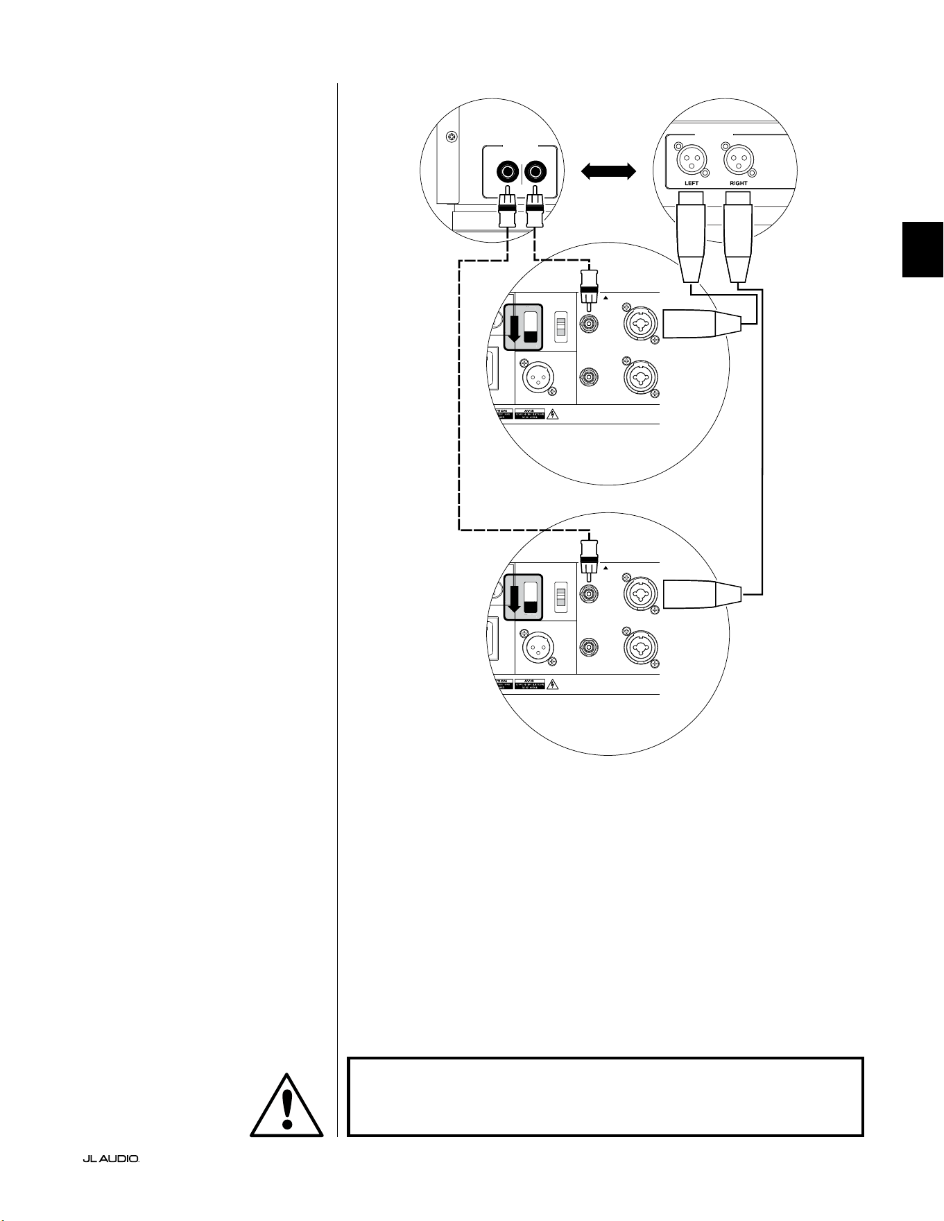
Pg 25 | ES
|
Fathom
®
v2
ES
DIAGRAMA 4 DE CONEXIÓN DEL
SISTEMA:
Dos Fathom v2 en estéreo a
un sistema de audio bicanal
Si conecta dos Fathom v2 en estéreo a
un sistema de audio bicanal, solo utilizará
las entradas "Le or Mono" de cada Fathom
v2. El interruptor superior de modo de
entrada ("Input Mode") de cada Fathom v2
deberá colocarse en la posición "Master".
Le recomendamos encarecidamente
que utilice un ltro de cruce activo
de alta calidad, como el JL Audio
CR-1, para dividir las señales de su
preamplicador antes de conectarlo
al Fathom v2 y al amplicador que
alimenta a sus altavoces principales.
Esto le permitirá ltrar las frecuencias
bajas de las señales que conducen a los
altavoces principales, lo que dará como
resultado un mejor rendimiento.
Si no utiliza un ltro de cruce activo
y se siente cómodo utilizando sus
altavoces principales de rango completo,
puede dividir las señales de salida de su
preamplicador utilizando conectores
en Y adecuados en lugar del ltro de
cruce activo mostrado en el diagrama.
Hay dos tipos de conexión disponibles
para conectar el Fathom v2 a su sistema
de audio bicanal: balanceada (conector
XLR o TRS de 1/4 de pulgada) y no
balanceada (conector tipo RCA). Las
conexiones balanceadas ofrecen un mayor
rechazo al ruido y garantizan una correcta
conexión a tierra entre los componentes.
Si su preamplicador o ltro de cruce
activo cuenta con salidas balanceadas,
le recomendamos que las utilice.
En el diagrama de conexión de la
derecha, las conexiones balanceadas
se muestran como líneas continuas,
las conexiones no balanceadas
se muestran discontinuas. Solo
utilizará uno de estos métodos de
conexión de entrada (no ambos).
NOTA: Si se desea, se pueden conectar más
Fathom v2 en modo "esclavo" a los Fathom
v2 ya conectados tal como se indica en
este esquema. Vea el "Diagrama 2 de
conexión" en la página 23 para obtener una
explicación de cómo conectar los esclavos.
LOW OUT
(SUB OUT)
RIGHTLEFT
LOW OUT
(SUB OUT)
1200VA
ilt in USA with Imported and domestic components
LEFT
or
MONO
RIGHT
ONLY
INPUTS
Output to Slave
(Balanced)
Balanced
Unbalanced
Input Modes
Slave
Master
Grounded
Isolated
SERIAL NUMBER:
Warranty void if serial number is removed, altered or defaced.
F 12A H
250V
0 V ~ 60 Hz
F
U
S
E
F
U
S
E
Sl
ave
Master
z
PROCESADOR (SALIDAS BALANCEADAS)
CONTROLES TRASEROS FATHOM (MAESTRO)
O
RECEPTOR/PROCESADOR (SALIDAS NO BALANCEADAS)
CONTROLES TRASEROS FATHOM (MAESTRO)
ADVERTENCIA
¡ADVERTENCIA! ¡APAGUE EL/LOS EQUIPO(S) FATHOM v2 Y TODOS LOS
DEMÁS EQUIPOS DEL SISTEMA ANTES DE REALIZAR O MODIFICAR CUALQUIER
CONEXIÓN!

ES | Pg 26
|
Fathom
®
v2
PROCEDIMIENTOS DE CONFIGURACIÓN RECOMENDADOS
1) Preparación para el proceso de conguración: ........................ 26-27
2) Conguración de nivel: ............................................... 28
3) Ajuste de polaridad/fase:. . . . . . . . . . . . . . . . . . . . . . . . . . . . . . . . . . . . . . . . . . . . . . 28
4) Experimentar con la ubicación: ........................................ 28
5) Aplicar el DARO: ................................................. 29-30
6) Ajustar FEB: ........................................................ 30
PREPARACIÓN PARA EL PROCESO DE CONFIGURACIÓN:
Corrobore los siguientes ajustes del sistema antes de comenzar con el proceso
de conguración. Esto garantizará un punto de partida neutro y la conguración
efectiva de su sistema de subwoofer.
En el receptor o preamplicador/procesador de su cine en el hogar:
Antes de comenzar la conguración de su sistema de subwoofer Fathom v2,
le recomendamos que ajuste su receptor o preamplicador/procesador de la
siguiente manera (recuerde apagar todos los Fathom v2 del sistema mediante sus
interruptores de alimentación del panel frontal antes de realizar estos ajustes):
1. Tamaño del altavoz
En el menú de conguración del altavoz de su receptor o preamplicador/
procesador, congure todos sus altavoces de frecuencia alta como "small"
(pequeños) con un punto de cruce de 80Hz. De este modo se enviarán
TODOS los bajos a los equipos Fathom v2.
2. Distancia del altavoz
En el menú de conguración del altavoz, congure de forma adecuada
todas las distancias del altavoz hasta el asiento principal, con inclusión de
la distancia del subwoofer. Utilice una cinta métrica para establecer estas
distancias (la coherencia temporal es importante). Si se van a usar múltiples
subwoofers Fathom v2, promedie sus distancias con el asiento principal y use
esa cifra para determinar la distancia del subwoofer.
3. Nivel del subwoofer
Congure el nivel del subwoofer en el receptor o preamplicador/procesador
en "0" o su posición intermedia.
4. Controles de tono/Ecualizadores
Congure todos los controles de tono (graves, agudos, etc.) a "0" y desactive
todas las funciones de ecualización.
En su procesador de control de sonidos graves o ltro de cruce activo:
Si va a usar un ltro de cruce activo o un procesador de control de sonidos
graves, le recomendamos que lo congure como se indica a continuación, antes
de comenzar a congurar su sistema de subwoofers Fathom v2 (apague todos los
Fathom v2 del sistema antes de realizar estos ajustes):
1. Frecuencia de ltro paso bajo
Seleccione una frecuencia de ltro paso bajo de 80Hz (pendiente de 24dB/
octava).
2. Frecuencia de ltro paso alto
Seleccione una frecuencia de ltro paso alto de 80Hz (pendiente de 24dB/
octava).
3. Nivel de salida paso bajo (subwoofer)
Congure el nivel de salida del subwoofer en "0" o en su posición intermedia.
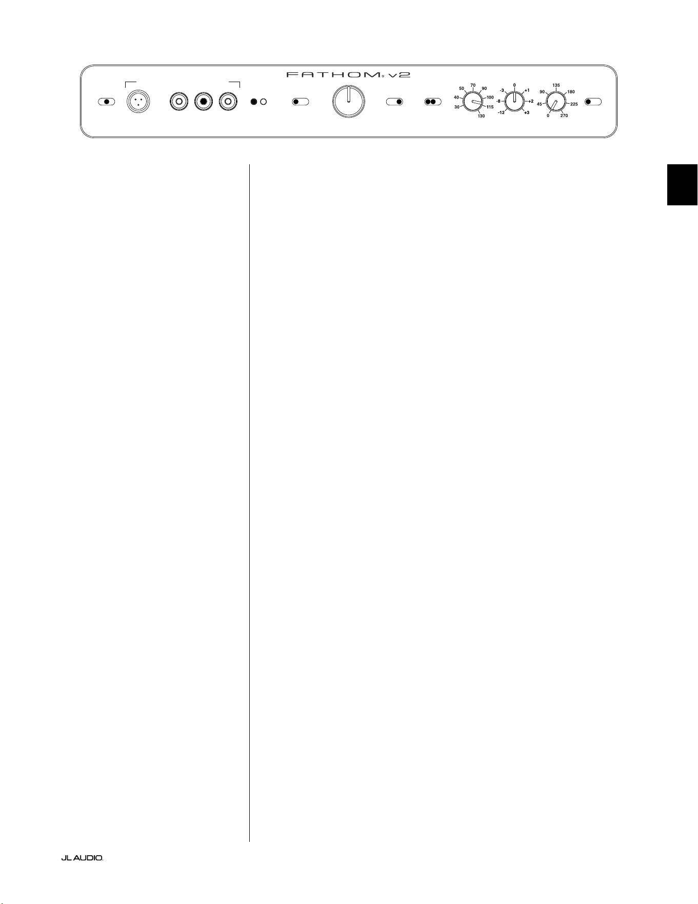
Pg 27 | ES
|
Fathom
®
v2
ES
En el panel frontal del Fathom v2:
Apague el receptor de cine en casa o el preamplicador/procesador para realizar
estos ajustes.
1. Interruptor "Power"
Ponga el interruptor "Power" de alimentación de cada Fathom v2 en la
posición "on".
2. Interruptor "Lights"
Ponga el interruptor de luces ("Lights") de cada Fathom v2 en la posición "on".
Si no ve ninguna luz en el panel frontal, es posible que haya olvidado enchufar
el Fathom v2 o que haya un problema con el circuito eléctrico.
3. Luces indicadoras "Input Mode"
Si está utilizando un solo Fathom v2, conrme que su luz indicadora "Input
Mode" está en la posición "Master". Si no es así, tendrá que acceder al
interruptor superior "Input Mode" en el panel trasero del Fathom v2.
Si utiliza varios Fathom v2 en una conguración maestro/esclavo,
conrme que la unidad conectada directamente a su receptor o
preamplicador/procesador indica "Master" en sus luces "Input
Mode" y que todas las demás unidades indican "Slave" en sus
luces "Input Mode". Si no es así, tendrá que acceder al interruptor
superior "Input Mode" en el panel trasero de los Fathom v2.
4. Interruptor "Level Mode"
Ponga el interruptor de modo de nivel ("Level Mode") del Fathom v2 maestro
en la posición "ref.".
5. Interruptor "LP Filter"
Si el receptor/procesador de su cine en casa tiene el control actual de los
sonidos graves (los altavoces están congurados como "small" [pequeños]) o
si usted está usando un ltro de cruce externo o un procesador de control de
sonidos graves, ponga el interruptor "LP Filter" de su Fathom v2 maestro en la
posición "o". En caso contrario, seleccione la posición "12dB".
6. Perilla "LP freq. (Hz)"
Gire la perilla "LP freq." a la posición "80Hz".
7. Perilla "e.l.f. trim (dB)"
Gire la perilla de ajuste de FEB ("e.l.f. trim") a "0".
8. Interruptor "Polarity"
Ponga el interruptor de polaridad "Polarity" en "0".
9. Perilla "phase (deg.)"
Gire la perilla de fase "phase (deg.)" a "0" grados.
10. Interruptor "defeat" de DARO
Presione el interruptor de desactivación de la optimización digital automática
de la sala (DARO) para que la luz roja del interruptor permanezca encendida.
LP freq. (Hz) e.l.f. trim (dB) phase (deg.)
Polarity
0
|
180 deg.
LP Filter
o
|
12dB
|
24dB
Master Level
max
0
Lights
o
|
dim
|
on
-∞
Level Mode
ref.
|
variable
Input Mode
master
|
slave
calibration mic. demo defeat calibrate
Power
o
|
on
|
auto
Digital Automatic Room Optimization
ES | Pg 28
|
Fathom
®
v2
PROCEDIMIENTOS DE CONFIGURACIÓN RECOMENDADOS
(continuación)
Conguración del sistema del subwoofer:
Una vez que haya congurado los controles de su receptor o preamplicador/
procesador de su cine en el hogar y su(s) Fathom v2 a las conguraciones
recomendadas en las páginas 26 y 27, estará listo para comenzar a congurar su(s)
Fathom v2 para obtener un máximo rendimiento.
1. Conguración de nivel
Ajuste el nivel del subwoofer para mezclarlo con los otros altavoces usando
el control de nivel del subwoofer de su receptor o preamplicador/procesador
y reproduciendo música o una película que conozca y que tenga un alto
contenido de sonidos graves. Este método es más inmune a la manipulación
que el uso de la perilla "Master Level" del Fathom v2 (piense en niños pequeños
o visitantes curiosos).
En el improbable caso de que el control de nivel del subwoofer en
su receptor o preamplicador/procesador no pueda aumentarse lo
suciente como para nivelarlo igual que el Fathom v2, gire ese control
a "0". A continuación, coloque el interruptor "Level Mode" del Fathom
v2 en "variable" y con "0" como punto de referencia (la ganancia del
modo "ref." y la ganancia variable "0" son idénticas) utilice el control
"Master Level" para nivelar el subwoofer con los otros altavoces. TOME
NOTA DE ESTA CONFIGURACIÓN USARLA EN EL FUTURO.
Para obtener más información detallada sobre los controles de conguración de
nivel de su Fathom v2, consulte las secciones "Level Mode" y "Master Level" en las
páginas 15-16 de este manual.
2. Ajuste de polaridad y fase
Con frecuencia, es de utilidad contar con una segunda persona que se
encargue de operar estos controles, de modo que se puedan oír fácilmente los
cambios desde el asiento principal desde el que se va a escuchar.
Mientras reproduce material de una fuente conocida (preferentemente
música con una buena respuesta de sonidos graves altos y medios), gire el
interruptor "Polarity" de "0" a "180" y escuche las diferencias. La conguración
correcta sonará más natural con la mejor fuerza y articulación de los sonidos
graves altos. Si ambos suenan de forma similar, seleccione "0".
Una vez que la polaridad esté congurada, utilice el mismo material musical
para auditar distintas conguraciones del control "phase (deg.)", y seleccione
una que mejore aún más la respuesta de los sonidos graves altos y medios. Si no
oye ninguna diferencia, congure el control en "0".
3. Pruebe ubicando el subwoofer en lugares diferentes (de ser necesario).
Si está satisfecho con el rendimiento básico de su subwoofer, está listo para
continuar con el siguiente paso. De lo contrario, le recomendamos que pruebe
con las posiciones del subwoofer hasta estar satisfecho con su rendimiento básico.
Experimentar con diferentes ubicaciones es FUNDAMENTAL para obtener un
sistema de audio superior. Moviendo el subwoofer solo unos pocos centímetros se
puede lograr un efecto sustancial en la suavidad de los sonidos graves. Para cada
nueva ubicación, comience con los controles "Polarity" y "phase (deg.)" en "0", y
repita el proceso de conguración comenzando con el paso 1.
¡IMPORTANTE! ANOTE TODAS LAS CONFIGURACIONES REALIZADAS EN LOS
PASOS 1-3 PARA TENERLAS COMO REFERENCIA FUTURA.
IMPORTANTE
Pg 29 | ES
|
Fathom
®
v2
ES
¡IMPORTANTE! ¡ASEGÚRESE DE QUE LA SALA ESTÉ EN SILENCIO DURANTE
LA CALIBRACIÓN DARO! APAGUE LOS APARATOS RUIDOSOS CERCANOS A LA
SALA DE AUDIO (LAVAVAJILLAS, LAVADORAS, ETC.)
ES ESPECIALMENTE IMPORTANTE APAGAR LOS APARATOS DE AIRE
ACONDICIONADO O LAS BOMBAS DE CALOR DURANTE LA CALIBRACIÓN.
ESTOS SISTEMAS DE AIRE ACONDICIONADO DE TIPO FORZADO PUEDEN CREAR
NIVELES MODERADOS DE RUIDO DE 15 A 20HZ QUE PUEDEN INTERFERIR CON
LA CALIBRACIÓN.
4. Aplicación de la optimización digital automática de la sala (DARO)
Ahora está todo listo para aplicar la potencia del exclusivo sistema de
optimización digital automática de la sala (DARO) de JL Audio. Este sistema
medirá la respuesta del subwoofer en su asiento principal y aplicará un potente
ecualizador de 18 bandas para domar los picos causados por los modos de la
sala, lo que dará como resultado un rendimiento de graves más suave y preciso.
Si utiliza varios Fathom v2 en conguración maestro/esclavo, solo tendrá que
manipular la unidad designada como "maestro" para realizar la calibración
DARO para todo el sistema de subwoofers. Tenga en cuenta que todo el
procesamiento de señales del panel frontal se anula durante la calibración
DARO, independientemente de los ajustes de las perillas. El funcionamiento
normal se restablece una vez nalizada la calibración.
a) Ponga el interruptor principal en la posición "on" y asegúrese de que las
luces indicadoras de Fathom v2 están encendidas con el interruptor "Lights"
en "on".
b) Saque el micrófono de calibración de su funda protectora y conecte su cable
al conector mini-XLR del panel de control frontal del Fathom v2.
NOTA: La calibración DARO solo puede realizarse si está conectado en el
panel frontal del Fathom v2 el micrófono de prueba de JL Audio incluido. La
función "calibrate" se desactiva cuando no hay un micrófono conectado para evitar
la pérdida accidental de los ajustes.
c) Conecte el micrófono al otro extremo del cable del micrófono y colóquelo
temporalmente en el asiento principal de la sala de audio. Si cuenta con un
soporte de micrófono, puede colocar el micrófono a la altura de la cabeza en
el asiento principal de la sala.
d) En el panel de control del Fathom v2, presione el botón "calibrate". La
luz verde del botón "calibrate" parpadeará lentamente, indicando que la
calibración empezará en 5 segundos.
e) Durante los 5 segundos siguientes a haber presionado el botón "calibrate",
vuelva al asiento principal de su sala de audio y sostenga el micrófono en el
lugar que ocuparía su cabeza, a la altura aproximada de sus oídos.
f) Se reproducirá una secuencia de ruidos a través del Fathom v2 que suena
como ruido blanco estático. La secuencia durará aproximadamente 3
minutos. Durante este proceso, el sistema DARO realiza una medición de la
respuesta en frecuencia en su asiento y corrige los problemas que encuentra.
El sistema DARO también compensa cualquier diferencia de nivel antes y
después para que su Fathom v2 tenga un volumen percibido similar después
del proceso de calibración. Cuando el DARO termine de calibrarse, el
botón "calibrate" se iluminará y permanecerá encendido, indicando que la
calibración se ha realizado con éxito.
Si desea realizar una nueva calibración, simplemente repita los pasos
anteriores.
IMPORTANTE
ES | Pg 30
|
Fathom
®
v2
Para borrar los ajustes del DARO (es decir, devolverlos a la conguración
plana) y apagar la luz de calibración, presione el botón "demo" y, sin soltarlo,
presione el botón "defeat". Tenga en cuenta que debe realizar con rapidez
esta secuencia de presionar botones. Si mantiene pulsado el botón "demo"
durante más de 2 segundos sin tocar el botón "defeat", se iniciarán los tonos de
demostración. Si esto ocurriera, simplemente espere a que termine la secuencia
de demostración y vuelva a intentarlo. Puede realizar una nueva calibración
siguiendo el procedimiento normal descrito anteriormente.
¡IMPORTANTE! SI MUEVE SU FATHOM V2 O SU ASIENTO PRINCIPAL DE LA
SALA, NECESITARÁ VOLVER A EJECUTAR EL DARO. TODA CALIBRACIÓN SERÁ
ESPECÍFICA DE LA COMBINACIÓN PARTICULAR DE POSICIÓN DEL SUBWOOFER
Y POSICIÓN DEL ASIENTO. SIMPLEMENTE SIGA LOS PASOS ANTERIORES PARA
CREAR UNA NUEVA CURVA DE CALIBRACIÓN.
5. Ajuste de la frecuencia extremadamente baja (FEB)
Utilice el control de ajuste de FEB ("e.l.f. trim") para ajustar la extensión
de los graves extremos del Fathom v2. Este control permite cortar (–12dB) o
potenciar (+3dB) a 24Hz y es especialmente útil cuando se utiliza un Fathom
v2 (o dos) en un cine en casa de tamaño pequeño o mediano. Dado que los
espacios cerrados más pequeños ayudan a potenciar el nivel de las frecuencias
graves más bajas, los teatros más pequeños pueden verse abrumados por la
fuerte salida de graves del subwoofer Fathom v2. Esto puede darle un carácter
"grueso" o "hinchado" a la región de los graves. Al bajar la perilla de ajuste
de FEB ("e.l.f. trim"), se reduce el nivel de graves extremos y se alivia esta
condición. No dude en experimentar y escuchar una variedad de material
exigente hasta que encuentre el mejor ajuste para su sala y sus gustos.
Su Fathom v2 está ahora optimizado para obtener el máximo rendimiento
de los graves desde el asiento de su sala de audio. ¡Felicidades!
IMPORTANTE

Pg 31 | ES
|
Fathom
®
v2
ES
PREGUNTAS FRECUENTES
¿Puedo colocar objetos sobre el subwoofer?
No recomendamos colocar ningún artículo en el gabinete del subwoofer, ya que
pueden vibrar y causar ruidos no deseados y posibles daños en el acabado del
aparato. Bajo ninguna circunstancia se deben colocar objetos que contengan
líquido sobre el gabinete del Fathom v2.
¿El Fathom v2 tiene una pantalla de protección magnética?
Los subwoofers Fathom v2 no están protegidos magnéticamente. Para evitar
distorsiones magnéticas con ciertos tipos de televisores, coloque el Fathom v2 al
menos a 3-4 pies (1-1,5m) de distancia de su pantalla. Si observa que la imagen
pierde color, intente alejar el subwoofer hasta que estas distorsiones desaparezcan.
¿Deberé abonar mucho por mi factura de electricidad si dejo el Fathom v2 en
modo "auto"?
Cuando está en modo "auto", el amplicador del Fathom v2 solo se enciende
cuando se detecta una señal signicativa en las entradas. Cuando se encuentra
en modo de suspensión por alimentación baja, solo los circuitos de servicio
permanecerán activos, lo que necesita cantidades ínmas de alimentación del
tomacorriente (menos de 5W).
¿Debo desenchufar el subwoofer durante una tormenta eléctrica o si me
ausento por mucho tiempo?
SÍ. Debe desenchufar su Fathom v2 durante las tormentas eléctricas, o antes de que
se produzcan. Esto evitará cualquier potencial daño derivado de picos de voltaje
ocasionados por los relámpagos. En estas condiciones, es buena idea desenchufar
todos sus componentes de audio/video. Si va a estar fuera de casa durante varios
días, también es conveniente desenchufar los componentes del sistema de cine en
casa para evitar daños causados por tormentas inesperadas o por las condiciones
de la línea eléctrica.
LIMPIEZA DE SU FATHOM v2
Quite el polvo del gabinete de su subwoofer Fathom v2 usando un paño limpio
de microbra suave o un plumero. Los paños de microbra generalmente pueden
conseguirse en los lugares de ventas de suministros de limpieza para automóviles.
En general, las manchas leves pueden quitarse con un paño limpio de microbra.
En el caso de manchas más difíciles, pula y proteja el acabado usando cera de
buena calidad para automóviles y un paño de microbra, ambos disponibles en los
lugares de venta de suministros de limpieza de automóviles. Recomendamos "NXT
Tech Wax" de Meguiar's®y los paños de detallado de microbra de Meguiar's®.
Nunca utilice un pulidor que contenga solventes o abrasivos fuertes, ya que estos
pueden dañar el acabado permanentemente. Nunca utilice cera para muebles o
cualquier otro producto a base de aceite en su equipo Fathom v2. Nunca utilice
agentes de limpieza agresivos o solventes en su equipo Fathom v2. En caso de duda,
pruebe el producto de limpieza en la parte inferior del gabinete y déjelo asentarse
por varios días antes de comenzar a usarlo en las partes visibles del gabinete.

ES | Pg 32
|
Fathom
®
v2
RESOLUCIÓN DE PROBLEMAS
No se escucha ningún sonido en el subwoofer.
1. Verique que el Fathom v2 esté enchufado, encendido ("on") y que las luces
del panel frontal estén encendidas. Si las luces no se encienden, compruebe el
disyuntor que alimenta su toma de corriente o enchufe el Fathom v2 en otra toma
de corriente de CA. Si su tomacorriente de CA tiene alimentación pero las luces
siguen sin encenderse, es posible que deba revisar/reemplazar el fusible de la
alimentación principal del Fathom v2. Consulte la sección "Portafusible principal"
en la página siguiente.
2. Pruebe el subwoofer pulsando el botón "demo" del panel frontal: si el subwoofer
emite tonos de demostración, el circuito interno del subwoofer está bien y es
probable que haya un problema en la entrada. Compruebe las conexiones de los
cables de entrada en el Fathom v2 y en el receptor/preamplicador/procesador.
3. Verique que las conguraciones del subwoofer de su receptor no hayan sido
modicadas.
4. Si sus demás altavoces funcionan pero el equipo Fathom v2 no, intente cambiar el
cable que conecta al Fathom v2 con el sistema.
5. Si el problema persiste, contacte a su vendedor o al Soporte Técnico de JL Audio
para obtener ayuda.
El nivel de los sonidos graves ha cambiado.
1. Asegúrese de que las conguraciones de nivel (en el Fathom v2 y en su receptor/
preamplicador/procesador) no hayan sido modicadas.
2. Si utiliza la perilla "Master Level" del Fathom v2 para ajustar el nivel del
subwoofer, conrme que el interruptor "Level Mode" está en "variable".
3. Verique la posición de la perilla de ajuste de FEB ("e.l.f. trim").
Zumbidos u otros ruidos inusuales de su Fathom v2
1. Consulte el apartado sobre el modo de entrada en la página 20 de este manual, en
especial si recientemente se han cambiado componentes conectados al sistema,
cables, etc.
2. Apague el Fathom v2 y desconecte todos los cables de señal de entrada y salida.
Luego, vuelva a encender el Fathom v2. Si el ruido persiste, signica que está
siendo causado en otra parte de su sistema.
Los sonidos graves suenan "confusos" o "demasiado pesados".
1. Pruebe a disminuir el nivel de 24Hz utilizando el control "e.l.f. trim". Los
bajos turbios pueden ser causados a veces por un exceso de salida de bajas
frecuencias en una sala de tamaño moderado.
2. Disminuya el nivel general del subwoofer.
3. Verique las conguraciones del subwoofer de su receptor.
4. Pruebe colocando el subwoofer en una ubicación diferente o modicando la
ubicación del asiento principal de la sala. Al cambiar uno u otro, puede lograr un
ENORME efecto en la forma en que suena el sistema. Consulte el debate sobre la
colocación del aparato en las páginas 6-10 de este manual.
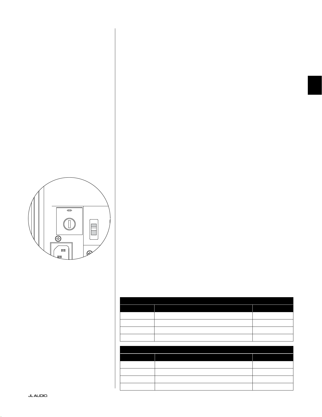
Pg 33 | ES
|
Fathom
®
v2
ES
RESOLUCIÓN DE PROBLEMAS (continuación)
Al intentar realizar la calibración DARO, la luz de "calibrate" parpadea
1. Si el micrófono de JL Audio incluido no está bien conectado a la toma del panel
frontal, la calibración fallará y la luz verde de "calibrate" parpadeará rápidamente. La
calibración solo se realizará si el micrófono de JL Audio está conectado. Si se conecta
cualquier otro micrófono, la calibración fallará. Cancele el parpadeo de la luz de
"calibrate" presionando de nuevo el botón "calibrate".
2. Si la calibración falla con el micrófono JL Audio correctamente conectado,
la luz verde de "calibrate" parpadeará lentamente. Compruebe las
conexiones del micrófono y del cable e intente realizar la calibración
de nuevo. Si la calibración falla después de seguir los pasos anteriores,
es posible que el micrófono o el cable del micrófono estén dañados.
Póngase en contacto con el servicio técnico de JL Audio Home.
Se puede escuchar el equipo Fathom v2 claramente desde fuera de la casa.
1. Vuelva a revisar la sección de conguraciones de "Master Level" en su equipo
Fathom v2 o en el receptor/preamplicador/procesador de su cine en el hogar.
2. Consulte con su vendedor de JL Audio sobre las estrategias de aislamiento de ruidos.
3. Aleje el subwoofer Fathom v2 de las ventanas.
PORTAFUSIBLE PRINCIPAL
Ubicado en el panel trasero, al lado del receptáculo del cable de CA, se encuentra
el portafusible principal. Esta pequeña tapa de accionamiento por resorte puede
extraerse, lo que da acceso para inspeccionar o reemplazar el fusible principal.
Si su tomacorriente de CA tiene alimentación, pero las luces del Fathom v2 no se
encienden, es posible que el fusible de alimentación principal se haya quemado.
Para extraerlo: Desenchufe el cable de alimentación por CA del subwoofer. Inserte
un pequeño destornillador de cabeza plana en la ranura de la tapa y gire en sentido
antihorario lentamente, hasta que salga el portafusible. Una vez que lo haya extraído,
podrá revisar el fusible y, de ser necesario, reemplazarlo. Consulte a la tabla a
continuación para ver los valores de los fusibles de su modelo Fathom v2 especíco.
Para volver a instalarlo: Observe que el cuerpo del portafusible está enganchado con
la abertura y debe quedar alineado para caber correctamente. Inserte el portafusible en
la abertura y, con cuidado, gire en sentido horario (alrededor de un 1/8 de giro) para
bloquearlo en su lugar. Si presiona la tapa y busca el muelle sintiendo si se comprime,
podrá encontrar la posición correcta. Vuelva a conectar el cable de alimentación por CA.
Si el fusible de repuesto se quema inmediatamente luego de haber sido repuesto, es
posible que el amplicador del subwoofer necesite un servicio de mantenimiento.
Contacte a su vendedor minorista o distribuidor autorizados de JL Audio.
Características nominales del fusible, modelos de 120V solamente
Modelo Tipo de fusible Tamaño de fusible
f110v2 (120V) 0,25×1,25in (6,35 ×31,75mm), de acción rápida 7A, 250V
f112v2 (120V) 0,25×1,25in (6,35 ×31,75mm), de acción rápida 8A, 250V
f113v2 (120V) 0,25×1,25in (6,35 ×31,75mm), de acción rápida 12A, 250V
f212v2 (120V) 0,25×1,25in (6,35 ×31,75mm), de acción rápida 15A, 250V
Características nominales del fusible, modelos de 240V solamente
Modelo Tipo de fusible Tamaño de fusible
f110v2 (240V) 5mm×20mm, de acción rápida 6,3A, 250V
f112v2 (240V) 5mm×20mm, de acción rápida 6,3A, 250V
f113v2 (240V) 5mm×20mm, de acción rápida 8A, 250V
f212v2 (240V) 5mm×20mm, de acción rápida 10A, 250V
1200VA
Built in USA with Imported and domestic components
LEFT
or
MONO
RIGHT
ONLY
INPUTS
Output to Slave
(Balanced)
Balanced
Unbalanced
Input Modes
Slave
Master
Grounded
Isolated
SERIAL NUMBER:
Warranty void if serial number is removed, altered or defaced.
F 12A H
250V
120 V ~ 60 Hz
F
U
S
E
F
U
S
E

BASE
PARTE SUPERIOR PARTE TRASERA
LATERAL CON REJILLA
PARTE FRONTAL
H
W
D
Especificaciones: f110v2 f112v2 f113v2 f212v2
Tipo de alojamiento: Sellado Sellado Sellado Sellado
Transductor:
Único de 10pulgadas
(254mm)
(diámetro nominal)
Único de 12pulgadas
(305mm)
(diámetro nominal)
Único de 13,5pulgadas
(203mm) (diámetro
nominal)
Doble de 12pulgadas
(305mm)
(diámetro nominal)
Respuesta de frecuencia
(anecoica):
27-111Hz (±1,5dB)
–3dB a 25Hz/120Hz
–10dB a 19Hz/155Hz
21-119Hz (+1,5dB)
–3dB a 19Hz/150Hz
–10dB a 17Hz/167Hz
20-86Hz (+1,5dB)
–3dB a 18Hz/127Hz
–10dB a 16Hz/154Hz
20-97Hz (±1,5dB)
–3dB a 19Hz/110Hz
–10dB a 15Hz/157Hz
Área efectiva del pistón:
60in
2
0,0387m
2
84in
2
0,0542m
2
107,35in
2
0,0693m
2
168in
2
0,1084m
2
Desplazamiento efectivo:
160in
3
2,6litros
287in
3
4,7litros
386in
3
6,3litros
574in
3
9,4litros
Alimentación del amplificador:
1100W
RMS a corto plazo
1800W
RMS a corto plazo
3000W
RMS a corto plazo
3600W
RMS a corto plazo
Dimensiones: (al.) × (an.) × (pr.)
Las dimensiones de la altura
incluyen a las patas
15,64×12,92×17,27in
397×328×439mm
18,5×15×17,625in
470×381×448mm
19,625×16.5×19,25in
498×419×489mm
31,96×14,92×20,39in
812×379×518mm
Peso neto:
69lb
31kg
117lb
53kg
133lb
60kg
224lb
102kg
Acabado del gabinete: Negro brillante Negro brillante Negro brillante Negro brillante
CARACTERÍSTICAS
Entradas no balanceadas:
Estéreo o mono (dos conectores RCA)
Entradas balanceadas:
Estéreo o mono (dos conectores XLR
hembra)
Salida a esclavo ("Output to Slave"):
Balanceada (un conector XLR macho)
Modos de entrada:
Maestro o esclavo
Modos de nivel:
Referencia (ganancia ja) o variable desde
el silencio total hasta +15dB sobre la
ganancia de referencia
Modos de alimentación:
Apagado, encendido o automático (con
detección de señal)
Modos de luces:
Apagado, encendido o atenuado
Modo de ltro paso bajo:
Apagado, 12dB por octava o 24dB por
octava
Frecuencia de corte del ltro paso bajo:
Variable entre 30Hz y 130Hz
Polaridad:
0 o 180 grados
Fase:
Variable entre 0 y 270 grados
Ajuste de FEB:
Variable entre –12dB y +3dB a 24Hz
Optimización digital automática de la
sala (DARO)
Ecualizador digital automático de
18 bandas con micrófono de calibración
de grado de laboratorio incluido, anulable.
www.jlaudio.com
10369 North Commerce Parkway • Miramar, Florida • 33025 • EE.UU.
"JL Audio", "Fathom" y el logotipo de JL Audio son marcas registradas de JL Audio, Inc.
©2022 JLAudio, Inc. • Para obtener información más detallada, visítenos en línea en www.jlaudio.com. Las imágenes del producto se muestran solo para fines ilustrativos y pueden
diferir del producto real. Dado que el desarrollo de producto es continuo, todas las especificaciones están sujetas a cambios sin previo aviso.
DE
Fathom v2 Aktiv-Subwoofer
Bedienungsanleitung
f113v2 f212v2 f112v2 f110v2
DE | Pg 2
|
Fathom
®
v2
WICHTIGE SICHERHEITSHINWEISE
ACHTUNG: UM BRAND- ODER STROMSCHLAGGEFAHR ZU VERMEIDEN,
SETZEN SIE DIESES PRODUKT WEDER REGEN NOCH FEUCHTIGKEIT AUS.
VORSICHT
STROMSCHLAGGEFAHR
NICHT ÖFFNEN
VORSICHT: ZUR VERMEIDUNG VON STROMSCHLÄGEN DIE ABDECKUNG
NICHT ENTFERNEN. KEINE VOM BENUTZER ZU WARTENDEN TEILE IM INNEREN.
DIE WARTUNG DARF NUR VON FACHPERSONAL VORGENOMMEN WERDEN.
1. Anweisungen durchlesen – Lesen Sie vor der Inbetriebnahme des
Subwoofers sämtliche Sicherheits- und Bedienungshinweise durch.
2. Anleitungen auewahren – Bewahren Sie die Sicherheits- und
Bedienungsanleitungen für zukünige Referenzzwecke auf.
3. Warnhinweise beachten – Sämtliche Warnhinweise am
Subwoofer und in den Bedienungsanleitungen beachten.
4. Anweisungen befolgen – Sämtliche Bedienungs-
und Nutzungshinweise sind einzuhalten.
5. Wasser und Feuchtigkeit – Den Subwoofer NICHT in der Nähe von
Feuchtigkeitsquellen, z.B. Badewannen, Waschschüsseln, Waschbecken,
Wäschewannen, Schwimmbecken oder in einem feuchten Keller verwenden.
6. Belüung – Der Subwoofer sollte immer so aufgestellt sein, dass die
Eigenbelüung nicht blockiert wird. Beispielsweise sollte der Subwoofer
nicht auf einem Bett, Sofa, Teppich oder einer ähnlich gearteten Oberäche
aufgestellt werden, durch die der Lustrom über den Kühlrippen
blockiert werden könnte. Beim Einbauen des Subwoofers in einen
Hohlraum ist darauf zu achten, dass der Lustrom zum Kühlkörper an
der Rückseite des Subwoofers nicht blockiert wird. Bedecken Sie den
Kühlkörper des Subwoofers nicht mit Tischdecken, Vorhängen usw.
7. Hitze und Flammen – Der Subwoofer sollte nicht in der Nähe von
Wärmequellen wie Heizkörpern, Heizlüern, Öfen, Kaminen usw. aufgestellt
werden. Keine Kerzen auf dem Subwoofer oder in dessen Nähe aufstellen.
8. Stromquellen - Der Subwoofer darf nur an eine Stromversorgung
angeschlossen werden, die der in der Bedienungsanleitung
beschriebenen oder auf dem Subwoofer angegebenen Art entspricht.
9. Schutz des Stromkabels – Verlegen Sie das Netzkabel so,
dass es nicht zur Stolperfalle wird und es nicht beschädigt
werden kann, insbesondere im Bereich von Steckern und dort
wo das Netzkabel aus dem Gerät herausgeführt wird.
10. Reinigung – Der Subwoofer ist ausschließlich wie in der
Bedienungsanleitung beschrieben zu reinigen.
11. Nichtnutzungszeiten – Wenn der Subwoofer über einen längeren
Zeitraum ungenutzt bleibt, das Netzkabel des Subwoofers abziehen.
Das Blitzsymbol mit Pfeilspitze in einem
gleichseitigen Dreieck weist den Benutzer
auf das Vorhandensein einer nicht isolierten
„gefährlichen elektrischen Spannung“ im
Gehäuse des Produkts hin, die so hoch
sein könnte, dass sie ein Stromschlagrisiko
darstellt.
Das Ausrufezeichen in einem gleichseitigen
Dreieck soll den Benutzer auf das
Vorhandensein wichtiger Bedienungs- und
Wartungsanweisungen in der Begleitliteratur
zu diesem Produkt aufmerksam machen.
Pg 3 | DE
|
Fathom
®
v2
DE
12. Blitzschlag und Überspannung – Wir empfehlen Ihnen,
bei Gewitter und/oder regelmäßigen Unterbrechungen der
Stromversorgung den Subwoofer von der Steckdose zu trennen,
um Schäden durch Überspannung zu verhindern.
13. Eintritt von Fremdkörpern und Flüssigkeit – Achten Sie darauf,
dass keine Gegenstände oder Flüssigkeiten durch Önungen
in das Subwoofer-Gehäuse gelangen können. Schützen Sie den
Subwoofer vor Tropf- und Spritzwasser. Keine mit Flüssigkeit
gefüllten Objekte auf dem Subwoofer oder in dessen Nähe aufstellen.
Blumenvasen, Getränkebehälter und üssigkeitsgefüllte Lampen
14. Reparaturbedürige Schäden – Der Subwoofer muss
von Fachpersonal gewartet werden, wenn:
a. Kabel oder Stecker für die Stromversorgung beschädigt wurden
b. Objekte auf den Subwoofer gefallen oder Flüssigkeiten
in den Subwoofer eingetreten sind
c. der Subwoofer im Regen stand
d. der Subwoofer nicht ordnungsgemäß zu funktionieren
scheint oder eine deutliche Leistungsänderung aufweist
e. der Subwoofer fallen gelassen oder das Gehäuse beschädigt wurde
f. die Lautsprechermembran und/oder Auängung
des Subwoofers sichtbar beschädigt wurde
15. Wartung – Wartungen des Subwoofers sind vom Kunden nur im dem im
Bedienungshandbuch beschriebenen Umfang durchzuführen. Alle übrigen
Wartungsarbeiten sind von qualiziertem Fachpersonal vorzunehmen.
16. Überlastung – Die Überlastung von Steckdosen, Verlängerungskabeln
oder Steckdosenleisten kann Brände oder Stromschläge verursachen.
17. Erdung - Dieser Subwoofer wird mit einem dreipoligen, geerdeten
Netzkabel geliefert. Es sind Vorkehrungen zu treen, damit
die Erdung des Subwoofers nicht unterbrochen werden kann.
Durch das Blockieren des Erdungsanschlusses am Stromkabel
des Subwoofers erhöht sich das Risiko eines Stromschlags sowie
einer dauerhaen Beschädigung der Subwoofer-Elektronik.
DIESER SUBWOOFER IST IN DER LAGE, SEHR HOHE SCHALLDRUCKWELLEN ZU
ERZEUGEN. BERÜCKSICHTIGEN SIE DIES BEI DER BEDIENUNG, UM DAUERHAFTE
SCHÄDIGUNGEN DES GEHÖRS ZU VERMEIDEN.
WARNHINWEIS

DE | Pg 4
|
Fathom
®
v2
FCC-KONFORMITÄTSERKLÄRUNG
HINWEIS: Das Gerät wurde überprü und entspricht den Beschränkungen gemäß Absatz 15
der FCC-Normen für digitale Geräte. Diese Anforderungen gewährleisten angemessenen Schutz
gegen elektromagnetische Störungen im häuslichen Bereich. Dieses Gerät erzeugt und verwendet
Funkfrequenzenergie und kann solche ausstrahlen, wodurch es bei unsachgemäßer Installation
und Bedienung zu Störungen des Funkverkehrs kommen kann. Allerdings besteht keine Garantie
dafür, dass eine Störung bei einer bestimmten Installation nicht doch auritt. Falls dieses Gerät
Funkstörungen im Radio- oder Fernsehempfang verursacht (überprüfen Sie dies durch Ein- und
Ausschalten des Geräts), versuchen Sie, diese mithilfe einer oder mehrerer der folgenden Maßnahmen
zu beheben:
- Die Empfangsantenne neu ausrichten oder neu positionieren.
- Abstand zwischen dem Gerät und dem Receiver erhöhen.
- Gerät an einen anderen Stromkreis als den des Receivers anschließen.
- Hilfe des Händlers oder eines erfahrenen Radio-/TV Technikers in Anspruch nehmen.
INHALTSVERZEICHNIS
Wichtige Sicherheitshinweise: .......................................... 2-3
Einführung: ............................................................ 4
Produktübersicht: ....................................................... 5
Aufstellen des Fathom v2 im Hörraum: ................................. 6-10
Auspacken des Fathom v2: .............................................. 11
Ansicht des vorderen Bedienfelds: ........................................ 12
Ansicht des hinteren Bedien- und Anschlussfelds: ........................12-13
Bedienelemente auf der Vorderseite im Detail: ...........................14-17
Anschließen des Fathom v2: ...........................................18-25
Empfohlene Vorgehensweise bei der Einrichtung: ........................26-30
Häug gestellte Fragen: ................................................. 31
Reinigung des Fathom v2: ............................................... 31
Fehlerbehebung: .....................................................32-33
Eingeschränkte Gewährleistung/Kundendienstinformationen: ............... 35
Technische Daten: ..................................................... 36
EINFÜHRUNG
Herzlichen Glückwunsch zum Kauf eines aktiven Fathom v2
Subwoofersystems von JL Audio. Dieses Produkt wurde nach strengsten
Vorgaben gefertigt, um viele Jahre lang einen herausragenden Klang
in Ihrem Heimkino oder Audiosystem zu gewährleisten.
JL Audio befasst sich intensiv mit der Erforschung von
Hochleistungstechnologien für Lautsprecher und Verstärker. Die Subwoofer-
Treiber von JL Audio in langhubiger Ausführung sind in breiten Kreisen als
Referenzstandard für lineares Verhalten und hohe Leistung anerkannt. Wir haben
zudem viel Energie in die der Entwicklung leistungsstarker Verstärker- und
Signalverarbeitungstechnologien investiert, die durch eine herausragende Leistung
bei niedrigen Frequenzen überzeugen. In Ihrem Fathom v2 sind diese drei
Technologien in einem kompakten und wunderschönen Design vereint, die Ihnen
ein unvergleichliches Hörerlebnis bieten.
Nochmals herzlichen Dank für Ihren Kauf. Bitte lesen Sie sich dieses
Handbuch gründlich durch, um das Optimum aus Ihrem Fathom v2
Subwoofer-System herauszuholen. Wir wünschen Ihnen viel Vergnügen.
JL AUDIO TECHNOLOGIEN IM
FATHOM V2 SUBWOOFER
DMA-Optimized Motor SystemDMA
ist das innovative Dynamic Motor
Analysis System von JL Audio zur
Verbesserung des dynamischen Verhaltens.
Aufgrund der DMA-Optimierung
arbeiten die Lautsprecher auch bei
extremer Auslenkung im linearen
Bereich und halten über einen breiten
Leistungsbereich ein hochstabiles festes
Magnetfeld aufrecht. Dies führt zu einer
extrem reduzierten Verzerrung und
einer präzisen Transientenreproduktion
... oder einfach gesagt: präzisen,
sauberen, abgesetzten Bässen.
OverRoll™ Surround Die OverRoll™-
Sicke überspannt den Treiberansch
und nutzt so die größtmögliche
Membranäche. Dies ermöglicht die
Verwendung einer breiteren Wulst, die
für die Kontrolle starker Auslenkungen
erforderlich ist, ohne dass wertvolle
Konusäche geopfert werden muss.
W-Cone™W-Cone™ ist ein W-förmiger
Membran-Auau mit erstaunlicher
Formsteigkeit bei geringem Gewicht.
Floating-Cone™ Attach Method Dieser
neuartige Auängemechanismus
der Membran sorgt für die korrekte
Sickengeometrie des Lautsprechersystems
und damit für eine bessere
Auslenkungssteuerung und dynamische
Schwingspulenausrichtung.
Plateau-Reinforced Spider Attachment
Verstärkte Spider-Struktur für optimale
Zugentlastung bei extremen Auslenkungen
für erhöhte Zuverlässigkeit.
Elevated Frame Cooling Technology
Führt der Schwingspule des Lautsprechers
durch Schlitze direkt über der Deckplatte
kühle Lu zu. Dies verbessert die
Belastbarkeit und die Klangqualität, da
dynamische Parameterverschiebungen und
Leistungskompression minimiert werden.
Radially Cross-Drilled Pole Piece
Dieses innovative Belüungssystem
verbessert die Wärmeableitung und
die Belastbarkeit erheblich, indem
es den Lustrom in Verbindung mit
der Elevated Frame-Technologie auf
den Schwingspulenträger leitet.
High-Damping Feedback Circuit
Diese innovative, diskrete Steuerschaltung
ermöglicht es unseren Class-D-
Schaltverstärkern, einen ausgezeichneten
Dämpfungsfaktor beizubehalten,
der das Einschwingverhalten und
die Klangtreue verbessert.
Pg 5 | DE
|
Fathom
®
v2
DE
PRODUKTÜBERSICHT
JL Audio Fathom v2 Subwoofer stehen für modernste JL Audio-Subwoofer-
Treiber mit Elektronik-/Verstärkersystem in einem optimierten Gehäuse für ein
Klangerlebnis der Extraklasse in Ihrem Heimkino oder Ihrer Audioanlage.
Der Subwoofer-Treiber in Ihrem Fathom v2 Subwoofer-System ist zu einer
hervorragenden linearen Auslenkung ohne Verzerrungen oder hörbaren
Störungen in der Lage. Dieser Treiber in Referenzqualität ermöglicht
es Ihrem Fathom v2, kravolle Tieonereignisse mit atemberaubender
Wucht und beispielloser Präzision wiederzugeben. Die von JL Audios
legendärer W7-Designplattform abgeleiteten Fathom v2 Treiber bieten ein
enormes Auslenkungsvermögen von Spitze zu Spitze, um auch dynamisch
extrem anspruchsvolles Tonmaterial komfortabel zu bewältigen.
Um das Beste aus diesem Langhub-Treiber herauszuholen, ist eine enorme
Menge an kontrollierter Leistung erforderlich. Unser Elektronik-Team hat eine
intensive Analyse von typischem Klangmaterial und den damit verbundenen
dynamischen Anforderungen durchgeführt, um die Stromaufnahme
und die tatsächlich erforderliche Ausgangsleistung im Hinblick auf die
Impedanzcharakteristik des Systems zu ermitteln. Aufgrund dieser sorgfältigen
Analyse wurden präzise konstruierte Schaltverstärker mit patentierter
Rückkopplungstechnologie entwickelt, um den vollen Auslenkungsbereich jedes
Treibers zu nutzen. Im Vergleich zu den Vorgängermodellen wurden die Fathom
v2 durch eine völlig neue digitale Signalverarbeitung und eine um 20 % höhere
Verstärkerleistung verbessert, wodurch ihre herausragenden dynamischen
Fähigkeiten noch weiter gesteigert werden konnten.
Das wunderschöne Gehäuse, das den funktionalen Teil des Fathom v2 umgibt,
ist ebenfalls das Ergebnis präziser Fertigung. Zum Ausgleich des vom Fathom v2
Treiber erzeugten Drucks verwenden wir CNC-geschnittenes MDF-Material mit
umfangreichen internen Verstrebungen und fortschrittlichen Fertigungstechniken.
Ihr Hörraum ist das andere „Gehäuse“, das die Art und Weise beeinusst, wie
Ihr Bass klingen wird. Alle Räume erzeugen eine spezische Klangsignatur, die
für eine ausgewogene Tieonwiedergabe eektiv gemanagt werden muss. Alle
Fathom v2 Subwoofer verfügen über ein leistungsfähiges D.A.R.O.-System (Digital
Automatic Room Optimization), um Ihre Subwoofer optimal an die Raumakustik
anzupassen. Dieses System nutzt einen digitalen Equalizer mit achtzehn Bändern,
um die Raumakustik zu zähmen und eine atemberaubende Präzision im Subbass-
Bereich zu erzielen.
Wie Sie dieser kurzen Einführung entnehmen können, verwenden die Fathom
v2 Subwoofer-Systeme viele fortschrittliche Technologien. Dieses Handbuch
erklärt sämtliche Funktionen, führt Sie durch die Einrichtung und Abstimmung
Ihres Fathom v2 Subwoofers, um das ultimative Tieon-Hörerlebnis zu erzielen.
Falls Sie Hilfe bei Installation und Wartung benötigen, erhalten Sie bei
Ihrem JL Audio-Händler fachkundigen Rat.
WICHTIG! LESEN SIE SICH UNBEDINGT DEN NÄCHSTEN ABSCHNITT DURCH,
BEVOR SIE DEN FATHOM v2 AUSPACKEN. ES WIRD EMPFOHLEN, DEN
SUBWOOFER IN DER NÄHE DES AUFSTELLUNGSORTES AUSZUPACKEN.
WICHTIG

DE | Pg 6
|
Fathom
®
v2
AUFSTELLEN DES FATHOM v2 IM HÖRRAUM:
Ihr Hörraum oder Heimkino ist integraler Bestandteil Ihres
Klangwiedergabesystems. Die physischen Abmessungen des Raumes sowie der
darin bendlichen Möbel, Materialien, Türen und Fenster wirken sich allesamt auf
den Klang Ihres Systems aus.
Bei Aufstellung einer Schallquelle in einem geschlossenen rechteckigen
Raum werden „stehende Wellen“ erzeugt, die sich aus dem Verhältnis zwischen
der Wellenlänge des Schalls und den Abmessungen des Raumes ergeben.
Die stehenden Wellen sind also das Ergebnis der im Raum eingefangenen
Schallenergie, die sich zwischen gegenüberliegenden Wänden hin- und
herbewegt. Stehende Wellen im Raum verursachen Schallspitzen und -senken mit
entsprechenden Lautstärkeschwankungen, die einzig davon abhängen, an welcher
Stelle im Raum Sie sich benden. An den Raumgrenzen baut sich ebenfalls
Energie auf, die bei bestimmten Frequenzen zu einer deutlich überhöhten
Tieonwiedergabe führt. Diese grundlegenden Raumresonanzen werden auch
Raummoden genannt.
Achten Sie also darauf, Hörpositionen in Schallspitzen und -senken
zu vermeiden. Es wird empfohlen, Hörplätze in Bereichen mit moderaten
Schallspitzen und -senken zu positionieren, die sich nicht gegenseitig verstärken.
Sie sollten sich also denitiv weder direkt an den Raumwänden noch genau in der
Mitte des Raumes benden
Auch Ihr Subwoofer kann sich wie Ihr Hörplatz in einer Schallspitze oder
Schallsenke benden. Wenn ein Subwoofer in einer Raumecke platziert wird, regt
er die Modenstruktur des Raums maximal an und erzeugt die stärkste Leistung
mit den wenigsten Einbrüchen. Wenn der Subwoofer aus einer Ecke oder von der
Wand verschoben wird, werden die Raummoden in geringerem Umfang angeregt,
wodurch sich der Klang am Hörplatz ändern kann.
Probieren Sie verschiedene Sitz- und Subwooferpositionen aus, um eine
optimale Lösung zu nden. Durch sorgfältiges Austarieren erhalten Sie meist das
beste Klangergebnis. Beachten Sie unsere (auf der gegenüberliegenden Seite und
den Folgeseiten dargestellten) Aufstellhinweise, um loslegen zu können.
Wenn Sie es nicht vermeiden können, Ihr Sofa an die Rückwand zu stellen oder
Ihren Subwoofer in einer nicht optimalen Position zu platzieren, kann das Digital
Automatic Room Optimization (D.A.R.O.) Ihres Fathom v2 derart ungünstige
Situationen erheblich verbessern.
Wir empfehlen Ihnen, den Fathom v2 vorn im Raum in der Nähe des
vorderen linken oder rechten Lautsprechers aufzustellen. Wenn Sie ihn direkt
in der vorderen Ecke des Raumes aufstellen, wird die maximale Anzahl von
Spitzen und die minimale Anzahl von Einbrüchen in der Basswiedergabe erzeugt.
Dies kann von Vorteil sein, da das D.A.R.O.-System des Fathom v2 die daraus
resultierenden Spitzen sehr eektiv korrigieren kann, während Einbrüche im
Frequenzgang nicht durch Entzerrung korrigiert werden können. Einbrüche im
Frequenzgang können nur durch sorgfältige Subwoofer- und Hörerplatzierung
minimiert werden.
Durch die Aufstellung des Fathom v2 in der Nähe fester Wände wird die
Tieonwiedergabe verstärkt und durch Vergrößerung des Abstands zu einer
festen Wand verringert. In manchen Räumen kann es hilfreich sein, den Abstand
zwischen dem Subwoofer und den Wänden zu vergrößern, um die Wiedergabe der
oberen Bässe zu glätten.
Stellen Sie den Fathom v2 möglichst nicht in Fensternähe auf, um ein Klappern
und eine Schallübertragung nach außen zu verhindern.
Wenn Sie den Fathom v2 in einem Gehäuse
installieren möchten, beachten Sie hierzu die
Hinweise auf Seite 8.
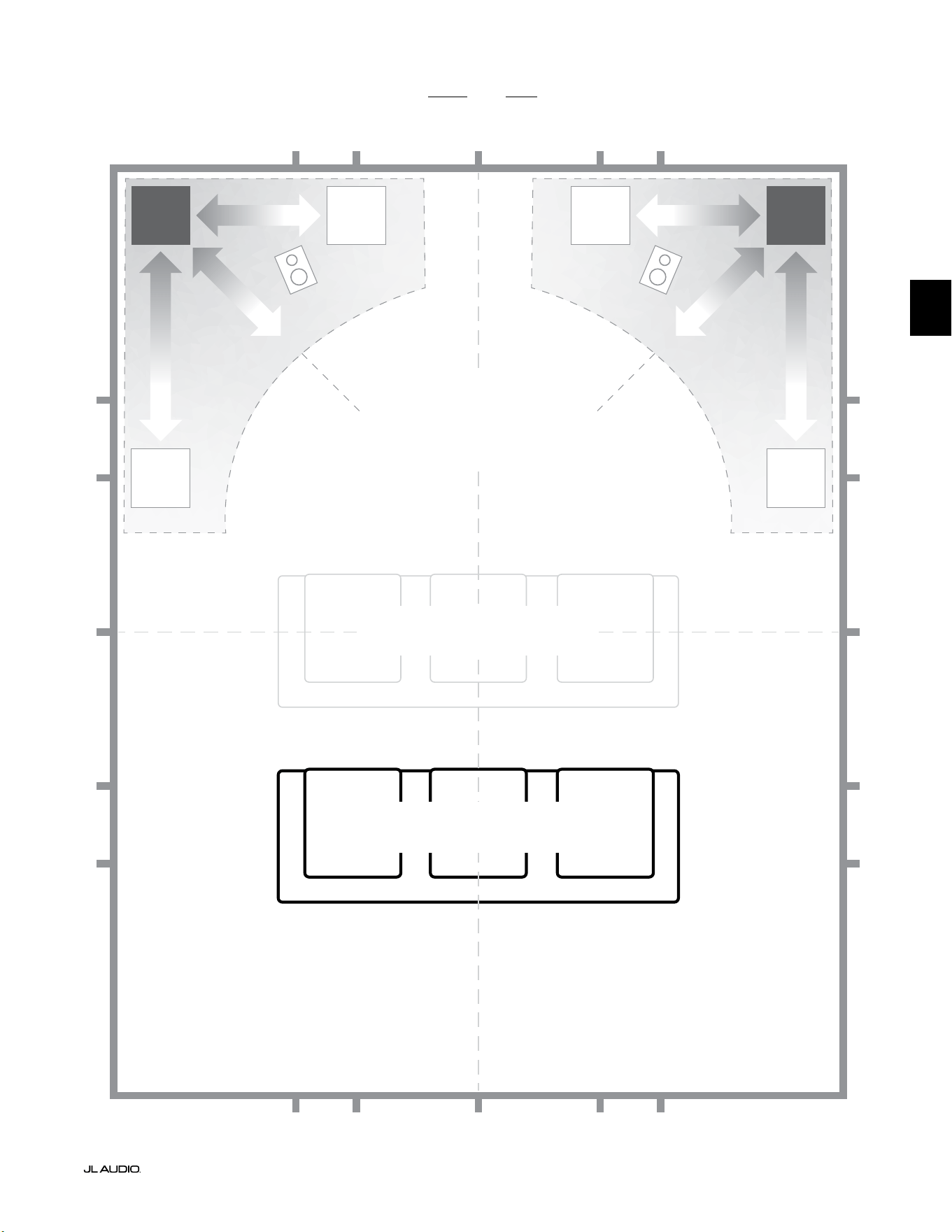
Pg 7 | DE
|
Fathom
®
v2
DE
Empfohlene Subwoofer-Platzierungsoptionen für einen oder zwei Fathom v2 Subwoofer
WEICHER
Empfohlene Subwoofer-Aufstellung für
EINEN oder ZWEI Subwoofer
(ZWEI symmetrisch links-rechts aufstellen)
WEICHER
WEICHERWEICHER
BEEINTRÄCHTIGTE SITZPOSITIONEN
(Führt zu schwächerer,
ungleichmäßiger Basswiedergabe)
BESTE SITZPOSITIONEN
(Präziseste Basswiedergabe)
½
1⁄3
1⁄3
¼
¼
½
½
1⁄3
1⁄3 1⁄3
1⁄3
¼
¼ ¼
½1⁄3 1⁄3¼ ¼
¼
CA. 1/3 DER RAUMLÄNGE
AB RÜCKWAND
MITTELLINIE DES RAUMS
INTEN-
SIVER
INTEN-
SIVER

DE | Pg 8
|
Fathom
®
v2
SPEZIELLE HINWEISE FÜR EINBAUSYSTEME
Die Fathom v2 Subwoofer sind für den Einbau konzipiert. Alle normalerweise
benötigten Bedienelemente benden sich auf der Vorderseite über dem
Tieöner. A Beim Integrieren des Fathom v2 Subwoofers in kundenspezische
Einbausysteme sind folgende einfache Richtlinien zu beachten.
1) Hinter dem Verstärkerpanel 10cm Platz lassen, um eine hinreichende Kühlung
und genügend Abstand zu den Anschlüssen zu gewährleisten.
2) Für eine ausreichende Belüung auf allen Seiten (außer dem Boden)
mindestens 5cm Abstand halten.
3) Auch wenn der Fathom v2 meist nur bei intensivem Betrieb warmläu,
empfehlen wir ausdrücklich, für den Wärmeabzug angemessene
Belüungsönungen in jedes Gehäuse einzubauen, in dem sich ein Fathom
v2 bendet. Ein Paar 7,5cm lange Belüungsönungen in der Nähe der
Gehäuseoberseite und des Gehäusebodens ermöglicht die Luzirkulation
über dem Verstärker-Panel Ihrer Fathom v2 Subwoofer-Anlage, sodass diese
möglichst gut gekühlt und funktionstüchtig bleibt.
4) Ihr Fathom v2 Subwoofer ist in der Lage, erhebliche Lumengen in Bewegung
zu setzen. Wenn sich an der Vorderseite des Fathom v2 eine Gitterabdeckung
bendet, muss die Größe des Gitters MINDESTENS der Membranäche
des Tieöners für jedes Modell entsprechen, damit sichergestellt ist, dass die
Wiedergabe nicht durch das kundenspezische Gehäuse gedrosselt wird.
Angaben zu den empfohlenen Belüungsächen für das jeweilige Modell nden
Sie in der nachfolgenden Tabelle.
Modell Empfohlene Belüftungsäche für kundenspezische Gitter
f110v2 ≥ 60 in
2
(386 cm
2
)
f112v2 ≥ 85 in
2
(550 cm
2
)
f113v2 ≥ 108 in
2
(700 cm
2
)
f212v2 ≥ 170 in
2
(1100 cm
2
)
1200VA
Built in USA with Imported and domestic components
LEFT
or
MONO
RIGHT
ONLY
INPUTS
Output to Slave
(Balanced)
Balanced
Unbalanced
Input Modes
Slave
Master
Grounded
Isolated
SERIAL NUMBER:
Warranty void if serial number is remove d, altered or deface d.
F 12A H
250V
120 V ~ 60 Hz
F
U
S
E
F
U
S
E
Built in USA with Imported and domestic components
LEFT
or
MONO
RIGHT
ONLY
INPUTS
Output to Slave
(Balanced)
Balanced
Unbalanced
Input Modes
Slave
Master
Grounded
Isolated
SERIAL NUMBER:
Warranty void if serial number is remo ved, altered or defa ced.
F 15A H
250V
120 V ~ 60 Hz
F
U
S
E
F
U
S
E
Mind. 5cm
Mind. 5cm
Mind.
5cm
Mind.
5cm
Rückansicht bei Gehäuseeinbau (f110, f112, f113):
Rückansicht bei Gehäuseeinbau (f212):
BELÜF-
TUNG
BELÜF-
TUNG
BELÜF-
TUNG
BELÜF-
TUNG
BELÜF-
TUNG
BELÜF-
TUNG
BELÜF-
TUNG
BELÜF-
TUNG
BELÜF-
TUNG
BELÜF-
TUNG
BELÜF-
TUNG
BELÜF-
TUNG
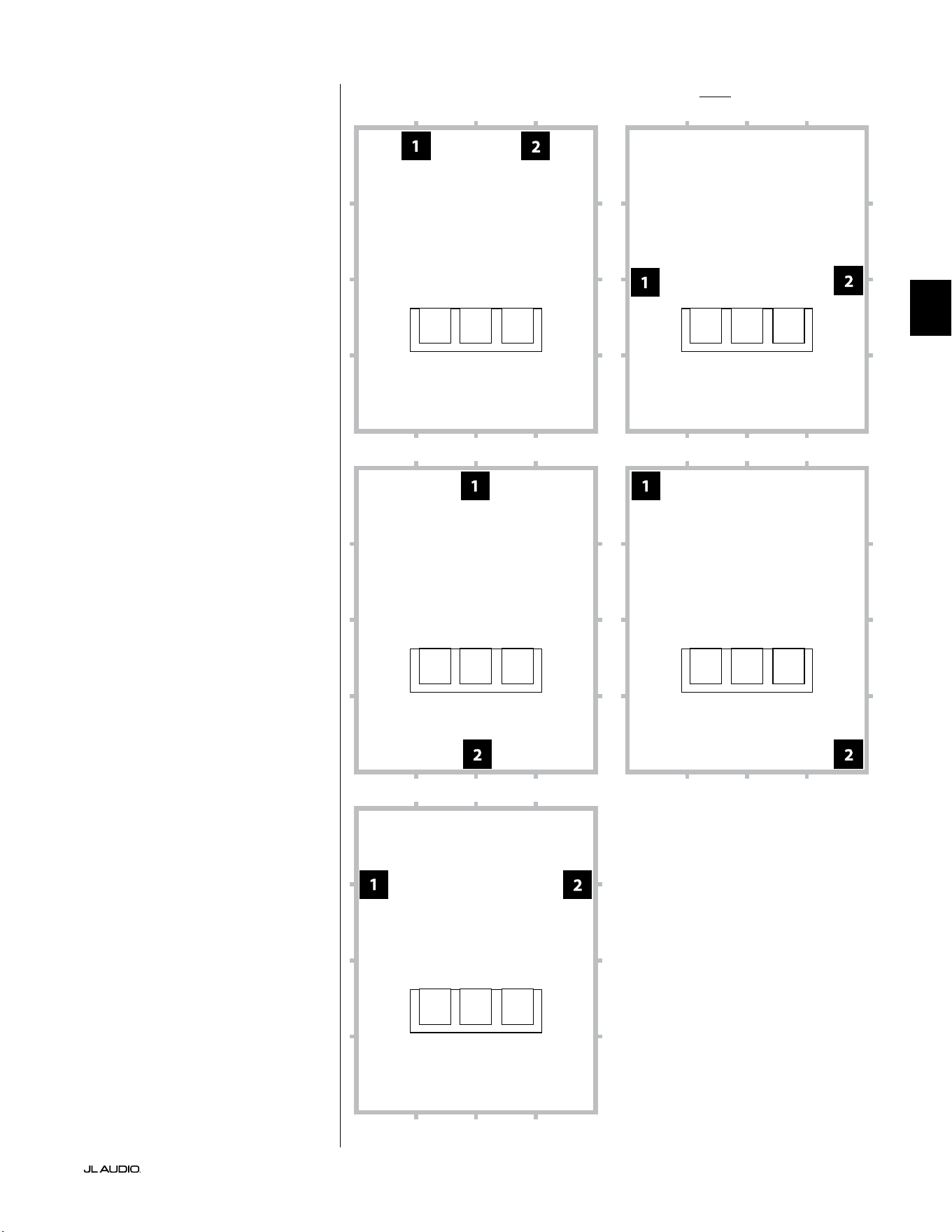
Pg 9 | DE
|
Fathom
®
v2
DE
Empfohlene Subwoofer-Aufstellungsoptionen für zwei Fathom v2 SubwooferVerwendung von zwei Fathom v2
Wenn Sie zwei Fathom v2
Subwoofer verwenden, stellen Sie
diese nach Möglichkeit in den
vorderen Ecken des Raums, in
diagonal gegenüberliegenden Ecken
des Raums oder in der Mitte jeweils
gegenüberliegender Wände auf (siehe
Abbildung rechts).
Es wird empfohlen, verschiedene
Positionen für Subwoofer und
Hörplatz auszuprobieren, um ein
optimales Ergebnis zu erzielen– die
Verbesserungen können erheblich sein.
Für bestmögliche Ergebnisse
und Systemleistungen werden
hochauösende Messungen
und eine professionelle
Systemkalibrierung empfohlen.

DE | Pg 10
|
Fathom
®
v2
Empfohlene Subwoofer-Aufstellungsoptionen für drei Fathom v2 Subwoofer
Empfohlene Subwoofer-Aufstellungsoptionen für vier Fathom v2 Subwoofer
Verwendung von drei oder vier
Fathom v2 Subwoofern
Forschungsergebnisse
haben gezeigt, dass sich die
beste Basswiedergabe in großen
Hörbereichen mit vier Subwoofern
erzielen lässt, die jeweils in der Mitte
der vier Wände aufgestellt werden.
(Mit zwei oder drei Subwoofern lassen
sich jedoch schon fast genauso gute
Ergebnisse erreichen.)
Es wird empfohlen, verschiedene
Positionen für Subwoofer und
Hörplatz auszuprobieren, um ein
optimales Ergebnis zu erzielen– die
Verbesserungen können erheblich sein.
Für bestmögliche Ergebnisse
und Systemleistungen werden
hochauösende Messungen
und eine professionelle
Systemkalibrierung empfohlen.
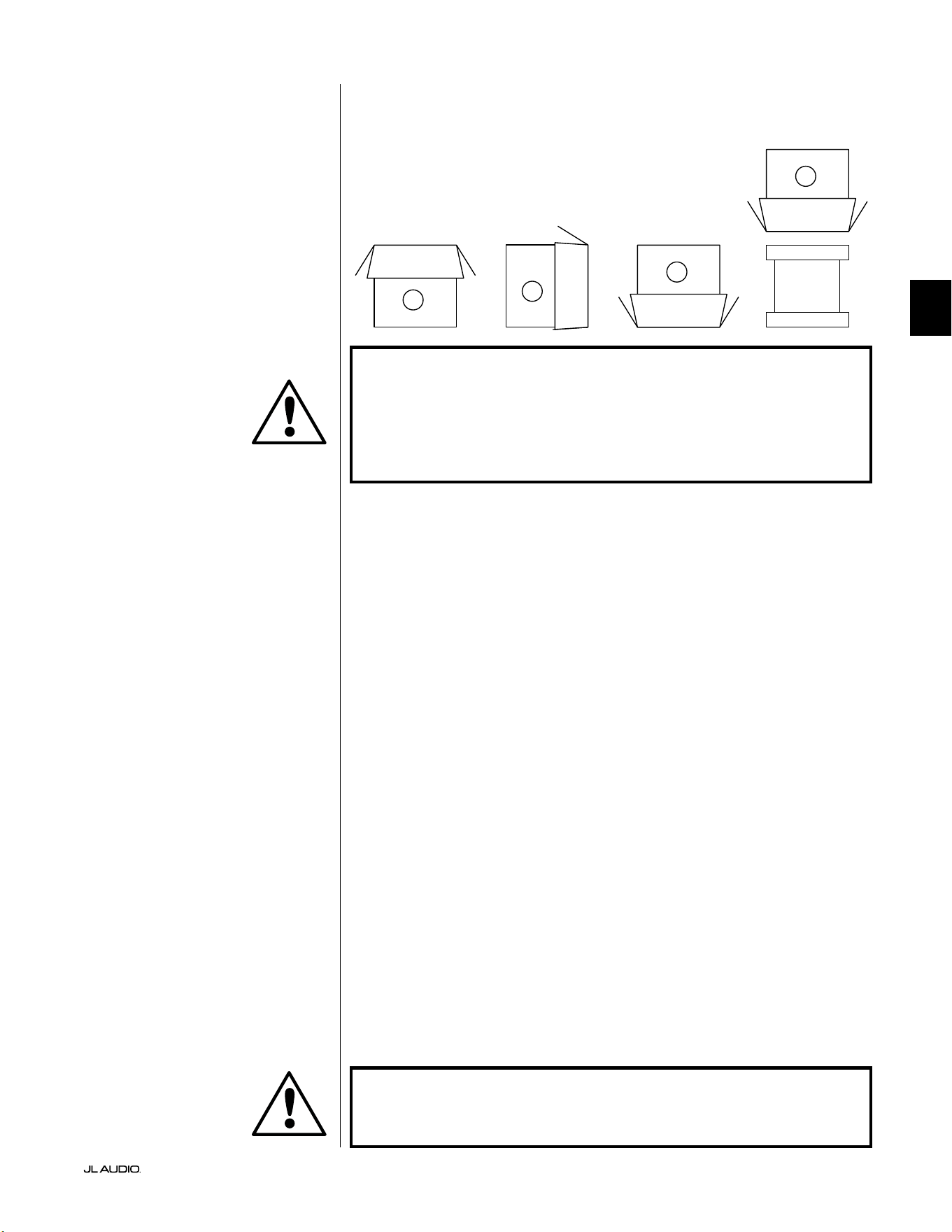
Pg 11 | DE
|
Fathom
®
v2
DE
WICHTIG! AUFGRUND DES HOHEN GEWICHTS DES FATHOM V2 SUBWOOFERS
MÜSSEN SIE BEIM AUSPACKEN UND AUFSTELLEN BESONDERE VORSICHT
WALTEN LASSEN, UM VERLETZUNGEN ZU VERMEIDEN. HOLEN SIE NACH
MÖGLICHKEIT EINE ZWEITE PERSON FÜR DIESEN VORGANG ZU HILFE. ZUR
MINIMIERUNG DES VERLETZUNGSRISIKOS KNIE BEUGEN UND NICHT AUS DEM
RÜCKEN, SONDERN AUS DEN BEINEN ANHEBEN.
Detaillierte Anweisungen zum Auspacken des Subwoofers:
1. Stellen Sie den Karton in der Nähe der vorgesehenen Position auf den Boden.
2. Önen Sie den Karton oben (die Markierungen auf dem Karton beachten)
und nehmen Sie Handbuch, Kalibriermikrofon und Stromkabel heraus.
3. Entfernen Sie vorübergehend die Schaumstoeinlagen.
4. Lockern Sie das Abdecktuch, um es später (jetzt noch nicht) leicht entfernen
zu können. Wenn Sie die Stoabdeckung önen, schauen Sie auf den Boden
des Subwoofer-Gehäuses.
5. Setzen Sie die Schaumstoeinlagen wieder ein, um das Gehäuse des
Subwoofers beim Auspacken zu schützen.
6. Drehen Sie den Karton vorsichtig auf die Seite und klappen Sie die
Kartonlaschen nach außen.
7. Drehen Sie den Karton vorsichtig auf die Oberseite (das oene Ende) und
halten Sie dabei die Kartonlaschen am Karton.
8. Ziehen Sie den Karton gerade nach oben, bis der Subwoofer zum Vorschein
kommt, und stellen Sie ihn auf einer Seite ab.
9. Entfernen Sie die einteilige Schaumstoeinlage
und legen Sie sie in den Karton.
10. Entfernen Sie die Plastiktüte und legen Sie diese in den Karton.
11. Kippen Sie den Subwoofer nach vorne (in Richtung des Gitters), um
zuerst den hinteren Schaumstoeinsatz zu entfernen. Kippen Sie dann
den Subwoofer in die entgegengesetzte Richtung (in Richtung der
Verstärkerfrontplatte), um den verbleibenden Schaumstoeinsatz zu
entfernen. Legen Sie beide Schaumstoeinlagen in den Karton.
12. Entfernen Sie die Stoschutzhülle und legen Sie sie in den Karton.
WICHTIG! BEWAHREN SIE SÄMTLICHE VERPACKUNGSMATERIALIEN AUF,
UM DEN SUBWOOFER FÜR EVENTUELL ERFORDERLICHE ZUKÜNFTIGE
KUNDENDIENSTLEISTUNGEN SICHER VERSENDEN ZU KÖNNEN.
Packen Sie diesen Karton in der Nähe der
geplanten Aufstellposition des Subwoofers
aus. Der Subwoofer ist VERKEHRT
herum verpackt. Dieser Karton muss
VORSICHTIG umgedreht werden,
um den Subwoofer zu entnehmen.
AUSPACKEN DES FATHOM v2:
Nachdem Sie nun die Position Ihres Fathom v2 im jeweiligen Raum bestimmt
haben, können Sie mit dem Auspacken in der Nähe des vorgesehenen Standorts
beginnen.
C
D
A
B
WICHTIG
WICHTIG

LP freq. (Hz) e.l.f. trim (dB) phase (deg.)
Polarity
0
|
180 deg.
LP Filter
o
|
12d B
|
24dB
Master Level
max
0
Lights
o
|
dim
|
on
-∞
Level Mode
ref.
|
variable
Input Mode
master
|
slave
calibration mic. demo defeat calibrate
Power
o
|
on
|
auto
Digital Automatic Room Optimization
1200VA
Built in USA with Imported and domestic components
LEFT
or
MONO
RIGHT
ONLY
INPUTS
Output to Slave
(Balanced)
Balanced
Unbalanced
Input Modes
Slave
Master
Grounded
Isolated
SERIAL NUMBER:
Warranty void if serial numb er is removed, altered or defaced.
F 12A H
250V
120 V ~ 60 Hz
F
U
S
E
F
U
S
E
DE | Pg 12
|
Fathom
®
v2
Rückseitige Bedienelemente und Anschlüsse (Modelle f112v2, f113v2, f212v2)
In der nachstehenden beschrieten Abbildung ist das Panel auf der Rückseite eines Fathom f113v2 Subwoofers zu sehen.
Die Anordnung der Bedienelemente und Anschlüsse ist für die Fathom f112v2 und f212v2 identisch.
Symmetrische
Eingänge
Seite 18
Unsymmetrische
Eingänge
Seite 19
IEC-
Kaltgerätestecker
Seite 21-22
Ausgang zum
Slave-Anschluss
Seite 21
„Input Mode“-
Schalter
Seite 20
Länderspezische
Sicherung
Seite 33
Vorderes Bedienfeld (alle Modelle)
Die beschriete Abbildung unten zeigt das vordere Bedienfeld eines Fathom f113v2 Subwoofers.
Die Anordnung der Bedienelemente ist für alle Fathom v2 Modelle gleich.
D.A.R.O.
Seite 14-15
Power
Seite 14
Input Mode
Seite 15
Level Mode
Seite 15
Master Level
Seite 16
Lights
Seite 16
LP Filter
Seite 16
LP freq. (Hz)
Seite 16
e.l.f. trim (dB)
Seite 17
phase (deg.)
Seite 17
Polarity
Seite 17
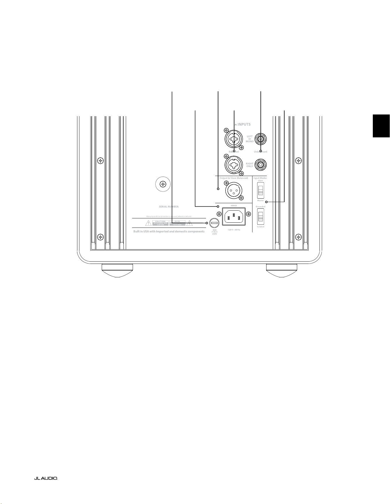
F
U
S
E
F
U
S
E
Rückseitige Bedienelemente und Anschlüsse (Modell f110v2)
In der nachstehenden beschrieten Abbildung ist das Panel auf der Rückseite eines Fathom f110v2 Subwoofers zu sehen.
*Die Detailbilder der hinteren Bedienelemente und Anschlüsse in diesem Handbuch zeigen andere Fathom v2 Modelle und
sind nicht repräsentativ für die Anordnung des f110v2.
Symmetrische
Eingänge
Seite 18
Unsymmetrische
Eingänge
Seite 19
IEC-
Kaltgerätestecker
Seite 21-22
Ausgang zum
Slave-Anschluss
Seite 21
„Input Mode“-
Schalter
Seite 20
Pg 13 | DE
|
Fathom
®
v2
DE
Länderspezische
Sicherung
Seite 33
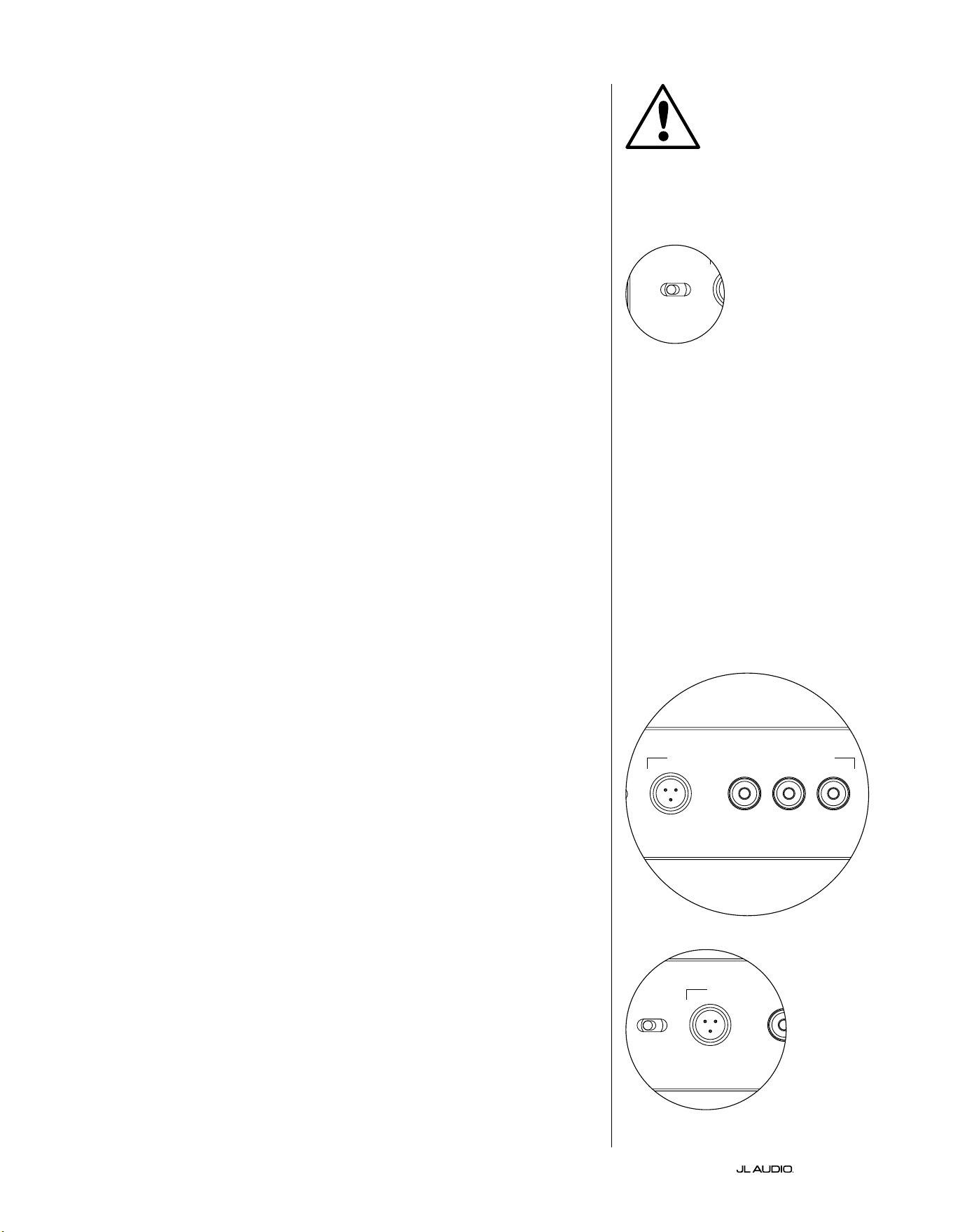
DE | Pg 14
|
Fathom
®
v2
BEDIENELEMENTE AUF DER VORDERSEITE IM DETAIL
Netzschalter
Der „Power“-Schalter bestimmt die Betriebsbereitscha des Fathom v2
Subwoofers und sollte der einzige Schalter sein, mit dem der Fathom v2 ein-
und ausgeschaltet wird. Verwenden Sie keinen Steckdosenleistenschalter,
keine geschaltete Steckdose oder einen anderen externen Schalter, da dies zu
unerwünschten und möglicherweise schädlichen Knackgeräuschen führen kann.
Ziehen Sie das Netzkabel des Fathom v2 nicht aus der Steckdose, solange das Gerät
eingeschaltet ist. Der Netzschalter hat drei Stellungen:
„Ein“: Der Fathom v2 ist jederzeit voll einsatzbereit. Die
Frontplattenbeleuchtung ist eingeschaltet, sofern sie nicht über den Schalter
„Lights“ ausgeschaltet wurde.
„Aus“: Die interne Endstufe des Fathom v2 ist ausgeschaltet. In diesem
Zustand besteht eine minimale Stromaufnahme für den Betrieb der
Hauptleistungsrelais. Alle Leuchten auf der Vorderseite sind ausgeschaltet.
„Auto“: Der Fathom v2 schaltet den internen Verstärker automatisch ein, sobald
an einem beliebigen Eingang ein Audiosignal erkannt wird und schaltet diesen
automatisch wieder ab, wenn dreißig (30) Minuten lang kein Signal erfasst wurde.
Im Ruhezustand verbraucht der Fathom v2 nur sehr wenig Strom (< 5 Watt) für die
Signalerkennungsfunktion. Die Beleuchtung auf der Vorderseite erlischt, wenn der
Fathom v2 ausgeschaltet wird, und leuchtet beim Einschalten des Fathom v2 auf (es sei
denn, sie wurde über den Schalter „Lights“ deaktiviert).
In dem unwahrscheinlichen Fall, dass die Auto-Funktion für ein bestimmtes
System nicht empndlich genug ist, verwenden Sie einen Y-Kabeladapter, um das
eingehende Signal auf die Cinch- oder XLR-Eingänge des Fathom v2 aufzuteilen.
Dadurch wird die Eingangsempndlichkeit um 6 dB erhöht. Bitte beachten Sie,
dass sich der Fathom v2 möglicherweise nicht wie gewünscht ausschaltet, wenn die
automatische Empndlichkeit zu hoch eingestellt ist oder wenn das Eingangskabel
starke Störsignale führt. Ziehen Sie in diesem Fall das Y-Adapterkabel ab oder
suchen Sie in den vorgelagerten Komponenten nach der Geräuschursache.
Digital Automatic Room Optimization (D.A.R.O.)
Ein leistungsstarkes Merkmal der Fathom v2 Subwoofer von JL Audio ist die
innovative Digital Automatic Room Optimization (D.A.R.O.)-Technologie. Dieses
One-Touch-System umfasst 18 Bänder zur digitalen Entzerrung, um die größten
akustischen Spitzen in Ihrem Heimkino am Haupthörplatz zu eliminieren und
die Tieonwiedergabe im Raum deutlich zu verbessern. Die Kalibrierung des
D.A.R.O.-Systems erfolgt vollautomatisch. Bitte lesen Sie im nächsten Abschnitt
dieses Handbuchs nach, wie das D.A.R.O.-System verwendet wird.
Mit dem mitgelieferten JL Audio-Kalibriermikrofon dauert das D.A.R.O.-
Kalibrierverfahren weniger als drei Minuten. Sie verbinden das mitgelieferte
Mikrofon einfach mit dem „Calibration Mic“. Eingang, drücken die Taste
„Calibrate“ und halten das Mikrofon während des Tests auf Ohrhöhe an Ihrem
Haupthörplatz. Es wird eine Schallsequenz durch den Fathom v2 Subwoofer
abgespielt und die Raumakustik automatisch gemessen, analysiert und entzerrt,
um die größten einzelnen akustischen Spitzen an Ihrem Hörplatz zu eliminieren.
Ausführliche Anweisungen zum D.A.R.O.-Einmessverfahren nden Sie auf den
Seiten 29-30.
Calibration Mic. Eingang
Dieser Eingang dient zum Anschluss des mitgelieferten JL Audio-
Kalibrierungsmikrofons an den Fathom v2 Subwoofer. Schließen Sie das eine Ende
des mitgelieferten Kabels an das Mikrofon und das andere Ende an diese Buchse
an, bevor Sie das D.A.R.O.-System verwenden. Das D.A.R.O.-System ist speziell
auf dieses Mikrofon kalibriert und die Anschlussbelegung ist spezisch für das
mitgelieferte Mikrofon. Die Kalibrierung funktioniert nicht, wenn kein oder ein
anderes Mikrofon angeschlossen ist.
WICHTIG
LP freq. (Hz) e.l.f. trim (dB) phase (deg.)
Polarity
0
|
180 deg.
LP Filter
o
|
12dB
|
24dB
Master Level
max
0
Lights
o
|
dim
|
on
-∞
Level Mode
ref.
|
variable
Input Mode
master
|
slave
calibration mic. demo defeat calibrate
Power
o
|
on
|
auto
Digital Automatic Room Optimization
LP freq. (Hz) e.l.f. trim (dB) phase (deg.)
Polarity
0
|
180 deg.
LP Filter
o
|
12dB
|
24dB
Master Level
max
0
Lights
o
|
dim
|
on
-∞
Level Mode
ref.
|
variable
Input Mode
master
|
slave
calibration mic. demo defeat calibrate
Power
o
|
on
|
auto
Digital Automatic Room Optimization
LP freq. (Hz) e.l.f. trim (dB) phase (deg.)
Polarity
0
|
180 deg.
LP Filter
o
|
12dB
|
24dB
Master Level
max
0
Lights
o
|
dim
|
on
-∞
Level Mode
ref.
|
variable
Input Mode
master
|
slave
calibration mic. demo defeat calibrate
Power
o
|
on
|
auto
Digital Automatic Room Optimization
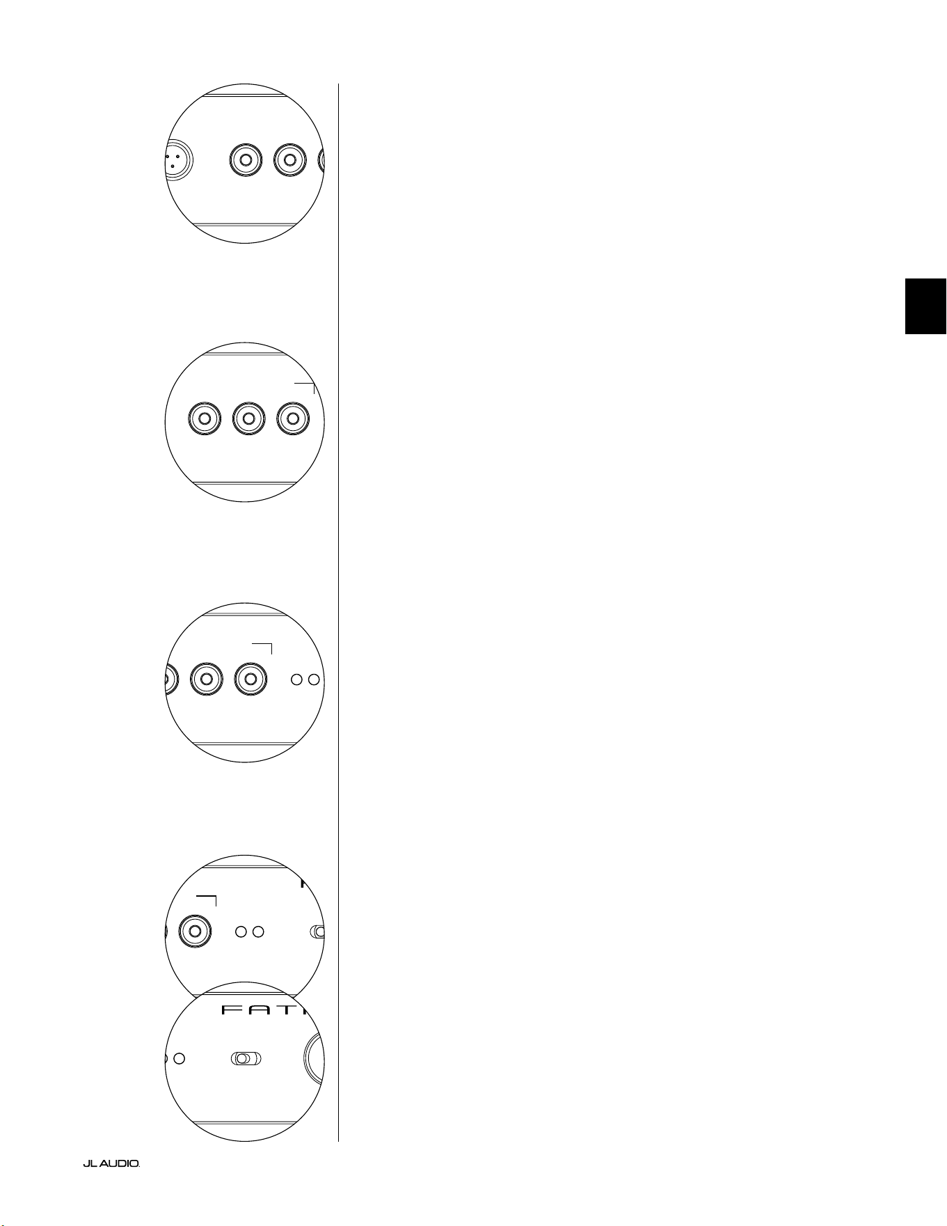
Pg 15 | DE
|
Fathom
®
v2
DE
LP freq. (Hz) e.l.f. trim (dB) phase (deg.)
Polarity
0
|
180 deg.
LP Filter
o
|
12dB
|
24dB
Master Level
max
0
Lights
o
|
dim
|
on
-∞
Level Mode
ref.
|
variable
Input Mode
master
|
slave
calibration mic. demo defeat calibrate
Power
o
|
on
|
auto
Digital Automatic Room Optimization
LP freq. (Hz) e.l.f. trim (dB) phase (deg.)
Polarity
0
|
180 deg.
LP Filter
o
|
12dB
|
24dB
Master Level
max
0
Lights
o
|
dim
|
on
-∞
Level Mode
ref.
|
variable
Input Mode
master
|
slave
calibration mic. demo defeat calibrate
Power
o
|
on
|
auto
Digital Automatic Room Optimization
Demo-Taste
Die Demo-Taste löst eine 20 Sekunden lange Tonfolge aus, die den Klang des
Fathom v2 Subwoofers kurz demonstriert. Die Demofunktion ist nützlich, um
die Leistungsfähigkeit des Fathom v2 zu demonstrieren und um zu überprüfen,
ob der Fathom v2 (oder mehrere Fathom v2) während der Fehlersuche im System
betriebsbereit sind.
Die Demo-Taste wird auch (in Kombination) verwendet, um die D.A.R.O.-
Equalizer-Einstellungen zu löschen (auf Null zurückzusetzen). Um die D.A.R.O.-
Einstellungen zu löschen und die Kalibrieranzeige auszuschalten, halten Sie die
Demo-Taste gedrückt und drücken Sie dann die Defeat-Taste. Bitte beachten Sie, dass
Sie diese Tastenfolge schnell ausführen müssen. Wenn Sie die Demo-Taste länger als
2 Sekunden gedrückt halten, ohne die Defeat-Taste zu berühren, werden die Demo-
Töne gestartet. Sollte dies der Fall sein, warten Sie einfach, bis die Demosequenz
beendet ist, und versuchen Sie es erneut.
Defeat-Taste
Wenn „Demo“ oder „Calibrate“ gedrückt wird, während die Defeat-Funktion
aktiv ist, wird „Defeat“ automatisch abgebrochen. Keine anderen Bedienelemente
auf der Vorderseite verändern den D.A.R.O. Defeat-Status. Die Defeat-Einstellung
wird dauerha gespeichert und ändert sich auch nicht, wenn die Stromversorgung
unterbrochen wird.
Die Defeat-Taste wird auch (in Kombination) verwendet, um die D.A.R.O.-
Equalizer-Einstellungen zu löschen (auf Null zurückzusetzen). Um die D.A.R.O.-
Einstellungen zu löschen und die Kalibrieranzeige auszuschalten, halten Sie die
Demo-Taste gedrückt und drücken Sie dann die Defeat-Taste. Bitte beachten Sie, dass
Sie diese Tastenfolge schnell ausführen müssen. Wenn Sie die Demo-Taste länger als
2 Sekunden gedrückt halten, ohne die Defeat-Taste zu berühren, werden die Demo-
Töne gestartet. Sollte dies der Fall sein, warten Sie einfach, bis die Demosequenz
beendet ist, und versuchen Sie es erneut.
Calibrate-Taste
Während der D.A.R.O.-Testsequenz blinkt die grüne LED der Calibrate-Taste
schnell, um den Benutzer auf zwei besondere Umstände hinzuweisen:
1. „JL Audio Microphone NOT Connected”: Wenn Sie vergessen, das Mikrofon
anzuschließen, bevor Sie versuchen, eine Kalibrierung zu starten, erhalten Sie
diese Meldung. Drücken Sie die Calibrate-Taste einmal, um die Warnmeldung
abzubrechen, schließen Sie das D.A.R.O.-Mikrofon an und versuchen Sie es erneut.
2. „“Inappropriate Sound Level for D.A.R.O. Calibration”: Da die D.A.R.O.-
Sequenz vollständig automatisch abläu, weist diese Meldung wahrscheinlich auf
ein Problem mit dem Mikrofon hin. Drücken Sie die Calibrate-Taste einmal, um
die Warnmeldung abzubrechen. Stellen Sie sicher, dass das JL Audio-Mikrofon
richtig angeschlossen ist, und versuchen Sie es erneut. Weitere Hilfe nden Sie unter
Fehlerbehebung auf Seite 33.
Input Mode-Anzeigen
Diese LEDs zeigen den Eingangsmodus an, entweder „Master“ oder „Slave“, der
mit dem Schalter auf der Rückseite der Fathom v2 ausgewählt wurde (es sei denn, der
Schalter „Lights“ ist auf „o“ gestellt). Weitere Einzelheiten nden Sie auf Seite 20.
Level Mode-Schalter
Mit dem Level Mode-Schalter können Sie zwischen den folgenden Betriebsarten
wählen:
„Reference”: In diesem Modus hat der Master Level-Regler keinen Einuss auf
den Ausgangspegel des Fathom v2. Verwenden Sie diese Einstellung, wenn Sie den
Subwoofer-Pegel hauptsächlich über Ihren Receiver oder Vorverstärker/Prozessor
steuern wollen. Wenn Sie kleine Kinder oder übereifrige Teenager haben, verhindert
diese Betriebsart ein direktes Ändern des Master-Pegels.
„Variable“: In diesem Modus bestimmt der Master Level-Regler den
Ausgangspegel des Fathom v2 Subwoofers. Dieser Modus ist auch bei der
Pegelanpassung des Fathom v2 Subwoofers an ein Paar Stereolautsprecher in einem
Zweikanalsystem nützlich.
LP freq. (Hz) e.l.f. trim (dB) phase (deg.)
Polarity
0
|
180 deg.
LP Filter
o
|
12dB
|
24dB
Master Level
max
0
Lights
o
|
dim
|
on
-∞
Level Mode
ref.
|
variable
Input Mode
master
|
slave
calibration mic. demo defeat calibrate
Power
o
|
on
|
auto
Digital Automatic Room Optimization
LP freq. (Hz) e.l.f. trim (dB) phase (deg.)
Polarity
0
|
180 deg.
LP Filter
o
|
12dB
|
24dB
Master Level
max
0
Lights
o
|
dim
|
on
-∞
Level Mode
ref.
|
variable
Input Mode
master
|
slave
calibration mic. demo defeat calibrate
Power
o
|
on
|
auto
Digital Automatic Room Optimization
LP freq. (Hz) e.l.f. trim (dB) phase (deg.)
Polarity
0
|
180 deg.
LP Filter
o
|
12dB
|
24dB
Master Level
max
0
Lights
o
|
dim
|
on
-∞
Level Mode
ref.
|
variable
Input Mode
master
|
slave
calibration mic. demo defeat calibrate
Power
o
|
on
|
auto
Digital Automatic Room Optimization

DE | Pg 16
|
Fathom
®
v2
Master Level-Regler
Der Master Level-Regler wird verwendet, um den Ausgangspegel des Fathom
v2 zu regeln, wenn der Variable Level-Modus auf dem vorderen Bedienfeld
ausgewählt ist.
Wenn er ganz gegen den Uhrzeigersinn gedreht ist, wird die Wiedergabe des
Fathom v2 vollständig stummgeschaltet. In der senkrechten Position „0“ entspricht
der variable Verstärkungspegel der Einstellung des Referenzpegels. Wenn er ganz
nach rechts gedreht wird, ist der Ausgangspegel des Fathom v2 um 15 dB höher als
bei der Einstellung „Reference“.
Lights-Schalter
Mit dem Wahlschalter „Lights“ kann der Benutzer eine von drei
Beleuchtungsarten auswählen.
„O” schaltet alle LEDs auf der Vorderseite aus.
„Dim“ setzt alle LEDs auf der Vorderseite auf eine niedrige Helligkeitsstufe,
wenn der Fathom v2 eingeschaltet wird.
„On“ setzt alle LEDs auf der Vorderseite auf volle Helligkeit, wenn der Fathom
v2 eingeschaltet wird.
WICHTIG! BEI DER FEHLERSUCHE ODER KALIBRIERUNG DER D.A.R.O.
FUNKTION, VERGEWISSERN SIE SICH, DASS DER SCHALTER „LIGHTS“ AUF „DIM“
ODER „ON“ EINGESTELLT IST.
LP-Filter
Der Wahlschalter für den LP-Filter bestimmt die Betriebsweise des integrierten
Tiefpasslters des Fathom v2.
„O“ schaltet den Tiefpasslter aus und entfernt diesen Schaltkreis vollständig
aus dem Signalweg.
„12 dB“ setzt die Flankensteilheit des Tiefpasslters auf eine Flankensteilheit
von 12 dB pro Oktave (Butterworth).
„24 dB“ setzt die Flankensteilheit des Tiefpasslters auf eine Flankensteilheit
von 24 dB pro Oktave (Linkwitz-Riley).
Mit der Einstellung 24 dB werden hohe Frequenzen oberhalb der „LP
Frequency“-Einstellung (siehe unten) stärker gedämp. Wenn Sie den eingebauten
Tiefpasslter des Fathom v2 nutzen, experimentieren Sie mit der Flankensteilheit
des „LP Filter“, um den besten Übergang zu Ihren Satellitenlautsprechern zu
erzielen. Wenn Sie es vorziehen, die Filter und Bassmanagement-Funktionen Ihres
Receivers oder Vorverstärkers zu nutzen, deaktivieren Sie den integrierten Filter,
indem Sie die Position „O“ wählen.
LP Freq
Mit dem Low Pass (LP)-Frequenzwahlregler kann der Benutzer die
Grenzfrequenz des internen Tiefpasslters des Fathom v2 auswählen.
Die Frequenz kann zwischen 30 Hz (ganz gegen den Uhrzeigersinn)
und 130 Hz (ganz im Uhrzeigersinn) eingestellt werden. Dieser Regler
beeinusst das Eingangssignal in keiner Weise, wenn der LP Filter-
Schalter auf „O“ steht. 80 Hz ist eine häug verwendete Filterfrequenz
und dient in der Regel als guter Ausgangspunkt für Anpassungen.
LP freq. (Hz) e.l.f. trim (dB) phase (deg.)
Polarity
0
|
180 deg.
LP Filter
o
|
12dB
|
24dB
Master Level
max
0
Lights
o
|
dim
|
on
-∞
Level Mode
ref.
|
variable
Input Mode
master
|
slave
calibration mic. demo defeat calibrate
Power
o
|
on
|
auto
Digital Automatic Room Optimization
LP freq. (Hz) e.l.f. trim (dB) phase (deg.)
Polarity
0
|
180 deg.
LP Filter
o
|
12dB
|
24dB
Master Level
max
0
Lights
o
|
dim
|
on
-∞
Level Mode
ref.
|
variable
Input Mode
master
|
slave
calibration mic. demo defeat calibrate
Power
o
|
on
|
auto
Digital Automatic Room Optimization
LP freq. (Hz) e.l.f. trim (dB) phase (deg.)
Polarity
0
|
180 deg.
LP Filter
o
|
12dB
|
24dB
Master Level
max
0
Lights
o
|
dim
|
on
-∞
Level Mode
ref.
|
variable
Input Mode
master
|
slave
calibration mic. demo defeat calibrate
Power
o
|
on
|
auto
Digital Automatic Room Optimization
LP freq. (Hz) e.l.f. trim (dB) phase (deg.)
Polarity
0
|
180 deg.
LP Filter
o
|
12dB
|
24dB
Master Level
max
0
Lights
o
|
dim
|
on
-∞
Level Mode
ref.
|
variable
Input Mode
master
|
slave
calibration mic. demo defeat calibrate
Power
o
|
on
|
auto
Digital Automatic Room Optimization
WICHTIG
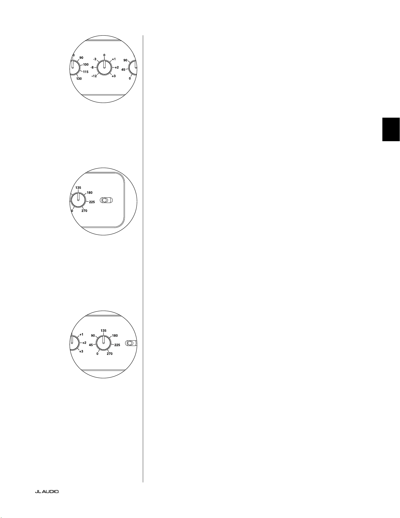
Pg 17 | DE
|
Fathom
®
v2
DE
E.L.F. Trim
Mit dem Extreme Low Frequency („e.l.f. trim“)-Regler kann der Benutzer eine
gewisse Signalentzerrung bei 24 Hertz (extrem tiefer Bass) vornehmen. Bei voller
Drehung gegen den Uhrzeigersinn wird das Signal bei 24 Hz um 12 dB abgesenkt.
Bei „0“ ist der Equalizer ach eingestellt und beeinusst das Signal nicht. Bei voller
Drehung im Uhrzeigersinn wird das Signal bei 24 Hz um 3 dB angehoben.
Die e.l.f. trim-Funktion ist nützlich, um die sehr niedrigen Frequenzen des Fathom
v2 auf den jeweiligen Raum abzustimmen. Indem dieser Frequenzbereich etwas
angehoben wird, können bestimmte Passagen lebendiger wirken. Eine Absenkung
kann helfen, die Verstärkung von tiefen Frequenzen durch den Raum bzw. die
Raumbegrenzung zu kompensieren. Raumbegrenzungen und die begrenzte Größe
eines Raums führen unweigerlich dazu, dass sehr tiefe Frequenzen im Vergleich
zu anderen Teilen des Signals angehoben werden. So kann die Verwendung der
e.l.f. trim-Funktion zum Absenken der niedrigsten Frequenzen dazu beitragen,
„aufgeblähte“ oder unnatürlich klingende tiefe Bässe in kleinen bis mittelgroßen
Räumen zu zähmen (und auch unerwünschte Vibrationen im Raum oder im ganzen
Gebäude zu reduzieren).
Polarity-Schalter
Mit dem „Polarity“-Schalter kann zwischen normaler (0 Grad) und umgekehrter
Signalpolarität (180 Grad) gewählt werden. Der „Polarity“-Schalter wirkt sich
vorwiegend auf den kleinen Frequenzbereich um den Crossover-Punkt zwischen
Subwoofer und Satellitenlautsprechern aus.
Im Gegensatz zum „Phase“-Regler, über den sich eine zeitliche Verzögerung
einstellen lässt, wird über den „Polarity“-Schalter eine sofortige Umkehrung der
Spitzen der Signalamplituden bewirkt. Wenn beispielsweise eine Sinuswelle an
einem bestimmten Referenzpunkt eine Spitzenamplitude aufweist, lässt sich diese
mit dem „Polarity“-Schalter unmittelbar in einen Tiefstwert umwandeln. Da sich die
Einstellung des „Polarity“-Schalters sofort auswirkt, ist dieser als Ergänzung und nicht
als Ersatz für den „Phase“-Regler anzusehen.
Wenn Sie einen Fathom v2 im Raum aufgestellt haben, sollten Sie erst die
Einstellungen des „Polarity“-Schalters ausprobieren, bevor Sie den Regler „Phase“
anpassen. Welche Position des „Polarity“-Schalters für einen weicheren Übergang
zwischen dem Fathom v2 Subwoofers und den Satellitenlautsprechern sorgt,
muss ausprobiert werden. Verwenden Sie zur Bewertung Klangmaterial mit gut
ausgeprägten mittleren und tiefen Bässen.
Phase-Regler
Mit dem Regler „Phase“ lässt sich die Phasenlage des Subwoofers im zeitlichen
Verhältnis zu den Hauptlautsprechern einstellen. Der Regler „Phase“ hat
hauptsächlich Auswirkungen auf den kleinen Frequenzbereich um den Crossover-
Punkt zwischen Subwoofer und Satellitenlautsprechern. Die Phasenlage kann auf
Werte zwischen 0 Grad (Linksanschlag) und 270 Grad (Rechtsanschlag) eingestellt
werden. Die Kennzeichnung des Reglers ist „Phase“ und bezieht sich auf eine
Frequenz von 80Hz, da es sich hierbei um den häugsten Crossover-Punkt zwischen
Satellitenlautsprechern und Subwoofer handelt.
Die Positionen von Lautsprecher, Subwoofer und Hörplatz können je nach
Heimkinoinstallation stark variieren. Da sich die physische Anordnung der
Lautsprecher zueinander sowie im Verhältnis zu den Begrenzungsächen des Raums
entscheidend auf die wahrgenommene Klangqualität auswirkt, kann es hilfreich sein,
den Subwoofer-Ausgang zu verzögern. Genau dies ist der Fall, wenn Sie den Regler
„Phase“ über 0 Grad hinaus einstellen.
Sobald Sie den Fathom v2 in Ihrem Hörraum so aufgestellt haben, dass er
insgesamt den angenehmsten Klang erzeugt, und die optimale Stellung des Schalters
„Polarity“ eingestellt ist (siehe vorheriger Abschnitt), können Sie verschiedene
Positionen des Reglers „Phase“ ausprobieren. Passen Sie mithilfe geläugen
Klangmaterials mit guten mittleren und oberen Bässen den Regler „Phase“ an, und
achten Sie dabei auf die Tonqualität der mittleren Bässe und einen weichen Übergang
zwischen Subwoofer und Satellitenlautsprechersystemen. Wenn sich die Klangqualität
bei den verschiedenen Einstellungen nicht ändert, belassen Sie den Regler „Phase“
auf 0 Grad.
LP freq. (Hz) e.l.f. trim (dB) phase (deg.)
Polarity
0
|
180 deg.
LP Filter
o
|
12dB
|
24dB
Master Level
max
0
Lights
o
|
dim
|
on
-∞
Level Mode
ref.
|
variable
Input Mode
master
|
slave
calibration mic. demo defeat calibrate
Power
o
|
on
|
auto
Digital Automatic Room Optimization
LP freq. (Hz) e.l.f. trim (dB) phase (deg.)
Polarity
0
|
180 deg.
LP Filter
o
|
12dB
|
24dB
Master Level
max
0
Lights
o
|
dim
|
on
-∞
Level Mode
ref.
|
variable
Input Mode
master
|
slave
calibration mic. demo defeat calibrate
Power
o
|
on
|
auto
Digital Automatic Room Optimization
LP freq. (Hz) e.l.f. trim (dB) phase (deg.)
Polarity
0
|
180 deg.
LP Filter
o
|
12dB
|
24dB
Master Level
max
0
Lights
o
|
dim
|
on
-∞
Level Mode
ref.
|
variable
Input Mode
master
|
slave
calibration mic. demo defeat calibrate
Power
o
|
on
|
auto
Digital Automatic Room Optimization
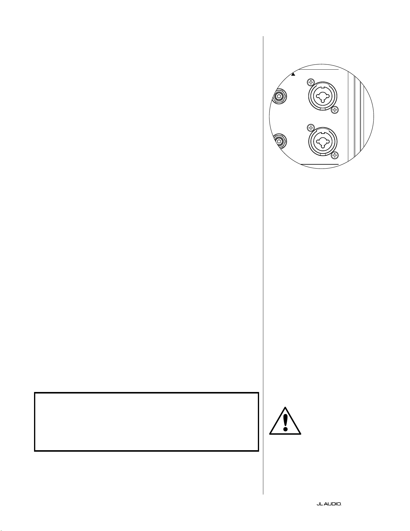
DE | Pg 18
|
Fathom
®
v2
ANSCHLIESSEN DES FATHOM v2
Symmetrische Eingänge
Wenn Ihr Heimkino-Receiver oder Vorverstärker/Prozessor über
symmetrische Ausgänge verfügt, sind die symmetrischen Eingänge des Fathom
v2 die bevorzugte Verbindung. Symmetrische Verbindungen werden in
professionellen Studios und Beschallungsanwendungen aus einer Reihe von guten
Gründen häug verwendet. Neben der Sicherstellung einer ordnungsgemäßen
Erdung zwischen den Komponenten dient die symmetrische Signalübertragung
dazu, induzierte Störsignale aus der Umgebung zu unterdrücken (besonders
wichtig bei langen Kabelwegen). Letztendlich ist die Wahrscheinlichkeit, dass
Ihr System Brummen oder andere Störgeräusche erzeugt, bei symmetrischen
Verbindungen wesentlich geringer.
Die Fathom v2 Subwoofer verfügen über individuelle linke und rechte
symmetrische Eingangsanschlüsse mit XLR-Combo-Buchsen. Diese speziellen
Buchsen nehmen entweder einen dreipoligen XLR-Stecker oder einen 6,3 mm (1/4
Zoll) TRS-Stecker (Tip-Ring-Sleeve) auf und sind somit mit einer Vielzahl von
Geräten kompatibel.
Bei Systemen mit einem Mono-Subwoofer oder „LFE“-Kanalanschluss wird
nur die mit „Links oder Mono“ gekennzeichnete Buchse verwendet. Dies gilt für
die meisten modernen Mehrkanal-Receiver und Vorverstärker/Prozessoren. Für
Systeme ohne speziellen Mono-Subwoofer-Anschluss stehen separate linke und
rechte Eingangsbuchsen zur Verfügung. Dies gilt typischerweise für Zweikanal-
Audiogeräte.
Geeignete symmetrische Kabel sind bei Ihrem JL Audio-Händler erhältlich
und nicht im Lieferumfang des Fathom v2 enthalten.
Technische Hinweise:
• Verwenden Sie die symmetrischen Eingänge nicht mit unsymmetrischen
Signalen über Adapter. Die unsymmetrischen Eingänge des Fathom v2
sind optisch isoliert und werden bevorzugt dann genutzt, wenn lediglich
eine unsymmetrische Signalquelle zur Verfügung steht. Die symmetrische
Eingangsimpedanz beträgt 20 kOhm.
• Die Eingangsanschlüsse sind gemäß den Empfehlungen der Audio Engineering
Society für symmetrische Signalkabel wie folgt konguriert:
XLR-Anschluss
Pin 1: Abschirmung
Pin 2: Plus
Pin 3: Minus
TRS-Anschluss:
Spitze: Plus
Ring: Minus
Scha: Abschirmung
WICHTIG! FALLS IHR RECEIVER ODER VORVERSTÄRKER/PROZESSOR NICHT
ÜBER SYMMETRISCHE XLR- ODER 1/4-ZOLL-TRS-AUSGÄNGE VERFÜGT, LESEN
SIE BITTE DEN ABSCHNITT „UNSYMMETRISCHE EINGÄNGE“ AUF SEITE 19
FÜR INFORMATIONEN ZU EINGANGSANSCHLÜSSEN. VERSUCHEN SIE NICHT,
UNSYMMETRISCHE AUSGÄNGE ÜBER ADAPTER MIT DEN SYMMETRISCHEN
EINGÄNGEN DES FATHOM V2 ZU VERBINDEN.
Die linken und rechten Eingänge am
Fathom v2 werden intern in einem einzigen
Mono-Kanal zusammengeführt. Da der
Fathom v2 von Haus aus ein „Mono“- oder
Einkanalgerät ist, können Sie den linken
und rechten Eingang für den Master-Fathom
v2 verwenden und dann das summierte
Monosignal an weitere Slave-Fathom v2 im
System verteilen.
WICHTIG
1200VA
Built in USA with Imported and domestic components
LEFT
or
MONO
RIGHT
ONLY
INPUTS
Output to Slave
(Balanced)
Balanced
Unbalanced
Input Modes
Slave
Master
Grounded
Isolated
SERIAL NUMBER:
Warranty void if serial number is removed, altered or defaced.
F 12A H
250V
120 V ~ 60 Hz
F
U
S
E
F
U
S
E
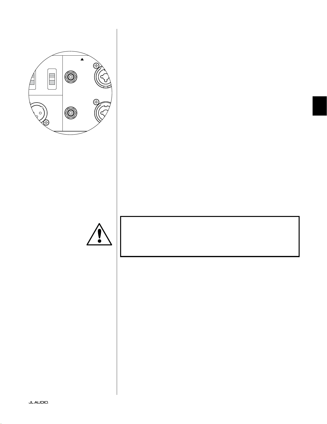
Pg 19 | DE
|
Fathom
®
v2
DE
Unsymmetrische Eingänge
Der Fathom v2 Subwoofer verfügt über einzelne unsymmetrische Cinch-
Eingangsanschlüsse für rechts und links. Dies sind die am häugsten verwendeten
Anschlüsse im Heim-Audio-Bereich und müssen verwendet werden, wenn
Ihr Receiver oder Vorverstärker/Prozessor keine symmetrischen Ausgänge
hat. Obwohl unsymmetrische Verbindungen nicht so störunempndlich sind
wie symmetrische Verbindungen, verwenden Fathom v2 Subwoofer optische
Isolierung an den unsymmetrischen Eingängen, um mögliche Störeinüsse in
Ihrem System zu minimieren.
Bei Systemen mit einem Mono-Subwoofer oder „LFE“-Kanalanschluss wird
nur die mit „Links oder Mono“ gekennzeichnete Cinch-Buchse verwendet.
Dies gilt für die meisten modernen Mehrkanal-Receiver und Vorverstärker/
Prozessoren. Für Systeme ohne speziellen Mono-Subwoofer-Anschluss stehen
separate linke und rechte Cinch-Eingangsbuchsen zur Verfügung. Dies gilt
typischerweise für Zweikanal-Audiogeräte.
Technische Hinweise:
• Wenn an der Signalquelle keine symmetrischen Ausgänge verfügbar sind,
müssen Sie die unsymmetrischen Cinch-Eingänge verwenden. Der Fathom
v2 verfügt über optische Isolationsschaltungen an den unsymmetrischen
Eingängen, um die Wahrscheinlichkeit von induzierten Störungen aufgrund
von Masseschleifen zu minimieren. Die unsymmetrische Eingangsimpedanz
beträgt 50 kOhm.
• Die Anschlüsse entsprechen dem Industriestandard für unsymmetrische
Signalkabel wie folgt:
Cinch-Anschluss:
Spitze: Plus
Scha: Minus
WICHTIG! FALLS NACH DEM ANSCHLUSS STÖRUNGEN VORHANDEN SIND,
ERMÖGLICHEN FATHOM V2 SUBWOOFER DIE ERDUNG ODER ISOLIERUNG
DER UNSYMMETRISCHEN EINGÄNGE. WEITERE INFORMATIONEN ZUR
GERÄUSCHMINIMIERUNG FINDEN SIE IM ABSCHNITT „INPUT MODE“-SCHALTER
AUF SEITE 20 DIESER ANLEITUNG.
1200VA
Built in USA with Imported and domestic components
LEFT
or
MONO
RIGHT
ONLY
INPUTS
Output to Slave
(Balanced)
Balanced
Unbalanced
Input Modes
Slave
Master
Grounded
Isolated
SERIAL NUMBER:
Warranty void if serial number is removed, altered or defaced.
F 12A H
250V
120 V ~ 60 Hz
F
U
S
E
F
U
S
E
WICHTIG
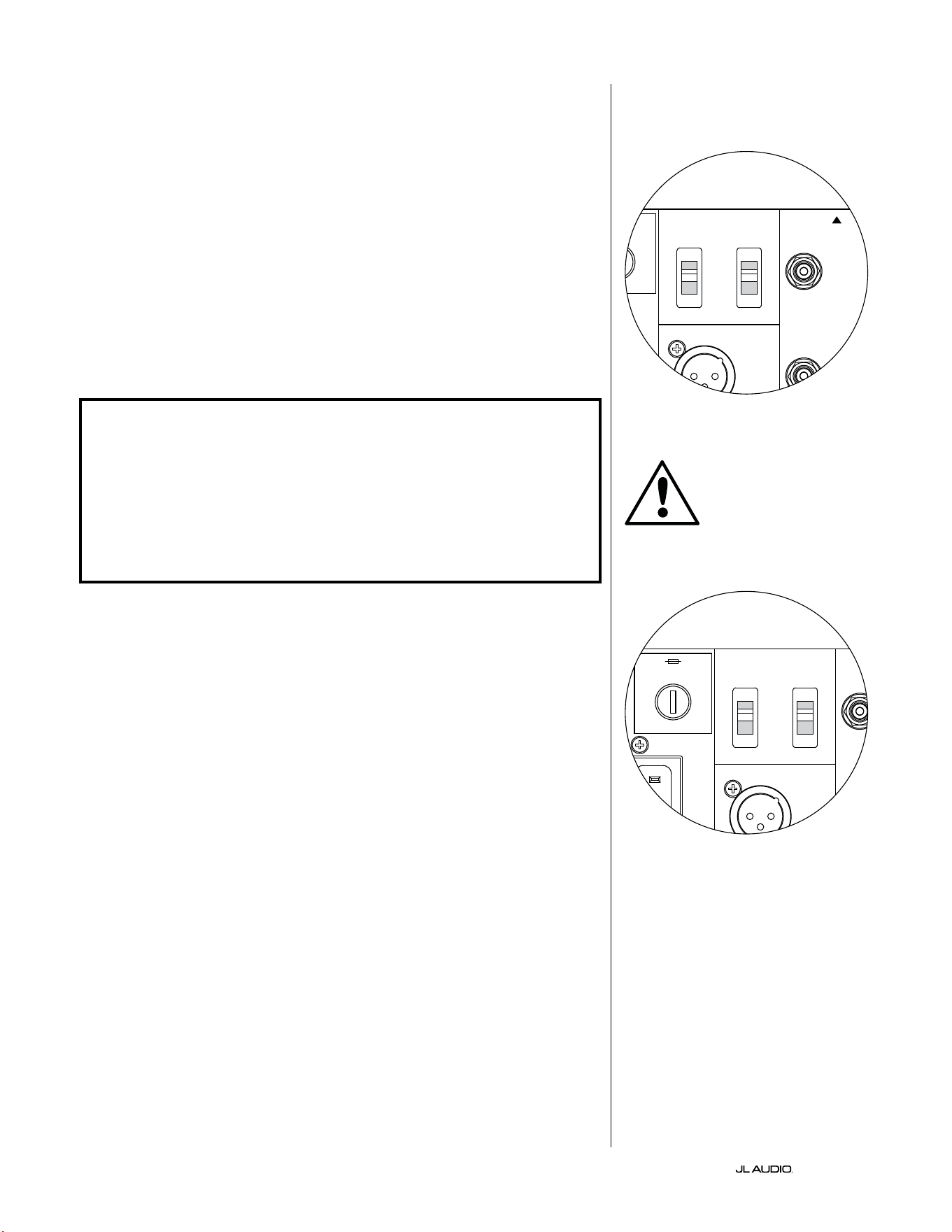
DE | Pg 20
|
Fathom
®
v2
Input Mode-Schalter:
Auf der Rückseite benden sich zwei Schalter für die Erdung unsymmetrischer
Signale und den Master/Slave-Betrieb.
„Grounded/Isolated“-Schalter
Durch den Schalter „Grounded/Isolated“ werden nur die unsymmetrischen
Cinch-Eingänge beeinusst, damit die Verbindung zum Audio- oder
Heimkinosystem ohne Brummen oder sonstige Geräusche möglich ist.
Mit dieser Funktion lassen sich Probleme mit der Signalerdung beheben,
die häug bei Heimkinosystemen aureten, wenn mehrere Komponenten
unterschiedlicher Hersteller miteinander verbunden werden.
Bei Auslieferung des Fathom v2 bendet sich dieser Schalter in der Stellung
„Isolated“. Wenn Sie bei angeschlossenen und eingeschalteten Systemkomponenten
(aber ohne Wiedergabe von Tonmaterial), ein kontinuierliches tierequentes
Brummen durch den Fathom v2 hören, stellen Sie diesen Schalter auf die Position
„Grounded“ (geerdet) und achten Sie auf den Unterschied beim Geräuschpegel.
Verwenden Sie die Schalterposition mit dem leisesten Brummen bzw. Geräusch.
WICHTIG! BITTE BEACHTEN SIE, DASS DAS ÄNDERN JEGLICHER KOMPONENTEN
IM OPTIMIERTEN SYSTEM (EMPFÄNGER, VERSTÄRKER, DVD-PLAYER, KABEL-
ODER SATELLITENANLAGE USW.) DAS ERDUNGSPRINZIP DER SIGNALFÜHRUNG
VERÄNDERN UND EIN BRUMMEN IN IHREM ZUVOR LEISEN SYSTEM VERURSACHEN
KANN. FALLS SIE EINE VORGEORDNETE KOMPONENTE IN IHREM HEIMKINOSYSTEM
HINZUFÜGEN ODER ÄNDERN, MÜSSEN SIE DIESE EINGANGSMODUS-EINSTELLUNG
AM FATHOM V2 SUBWOOFER FÜR EINE OPTIMALE GERÄUSCHUNTERDRÜCKUNG
MÖGLICHERWEISE ÜBERPRÜFEN. KABEL- UND SATELLITENANLAGEN SIND IN
DIESER HINSICHT BESONDERS ANFÄLLIG.
Master/Slave-Schalter
Die Fathom v2 sind so konzipiert, dass sie über eine Master/Slave-Verbindungskette
problemlos mehrere Subwoofer in Ihr Heimkinosystem einbinden können. Mit dieser
Methode können Sie die Signalverarbeitungsfunktionen eines Fathom v2 nutzen, um
mehrere Fathom v2 im Raum zentral zu steuern. Die Master/Slave-Funktionalität
ermöglicht es dem D.A.R.O.-System zudem, die Wiedergabetreue einer Installation mit
mehreren Subwoofern zu optimieren.
Bei Auslieferung des Fathom v2 bendet sich dieser Schalter in der Stellung
„Master“. Wenn Sie einen einzelnen Fathom v2 verwenden, stellen Sie den Schalter auf
„Master“. Sie können diesen Abschnitt anschließend ignorieren.
Wenn Ihre Installation zwei oder mehr Fathom v2 umfasst, bestimmen Sie einen
Fathom v2 als „Master“ und alle anderen im System als „Slave“-Subwoofer über den
„Master/Slave“-Schalter auf der Rückseite des Verstärkers jedes Fathom v2. LEDs auf
der Vorderseite des Fathom v2 zeigen an, ob der „Master“- oder „Slave“-Modus für
einen bestimmten Subwoofer ausgewählt ist.
Vom Fathom v2, der im „Master“-Modus betrieben wird, überträgt das „Output to
Slave“-Signal jede am Master Fathom v2 gewählte Signalverarbeitung (einschließlich
der Master-Pegeleinstellung und der D.A.R.O.-Signalverarbeitung) an weitere
Fathom v2, die im „Slave“-Modus betrieben werden. Die Signalverarbeitung und die
Pegelregler der „Slave“-Subwoofer sind dann nicht funktionsfähig. In diesem Modus
muss sich der Benutzer nicht um Pegel-, Crossover- und andere Einstellungen für die
Slave-Subwoofer kümmern.
Technische Hinweise:
• Wenn Sie die Position„ Slave“ wählen, werden alle benutzerdenierten
Signalverarbeitungsfunktionen und der Master-Pegelregler deaktiviert. Aus
diesem Grund gibt es einige spezielle Situationen, in denen Sie vielleicht einen
einzelnen Fathom v2 im „Slave“-Modus betreiben möchten. Wenn Sie externe
Signalverarbeitung und Pegelregler verwenden, verhindert die Aktivierung des
„Slave“-Modus, dass jemand die Systemparameter mit den manuellen Reglern des
Fathom v2 beeinussen kann.
WICHTIG
1200VA
Built in USA with Imported and domestic components
LEFT
or
MONO
RIGHT
ONLY
INPUTS
Output to Slave
(Balanced)
Balanced
Unbalanced
Input Modes
Slave
Master
Grounded
Isolated
SERIAL NUMBER:
Warranty void if serial number is removed, altered or defaced.
F 12A H
250V
120 V ~ 60 Hz
F
U
S
E
F
U
S
E
1200VA
Built in USA with Imported and domestic components
LEFT
or
MONO
RIGHT
ONLY
INPUTS
Output to Slave
(Balanced)
Balanced
Unbalanced
Input Modes
Slave
Master
Grounded
Isolated
SERIAL NUMBER:
Warranty void if serial number is removed, altered or defaced.
F 12A H
250V
120 V ~ 60 Hz
F
U
S
E
F
U
S
E
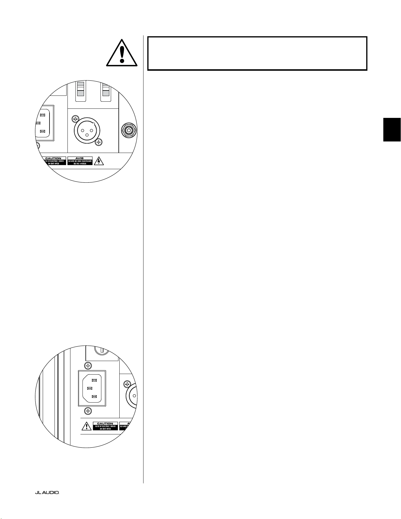
Pg 21 | DE
|
Fathom
®
v2
DE
WICHTIG! BITTE BEACHTEN SIE DIE „SYSTEMANSCHLUSSPLÄNE“ AUF DEN
SEITEN 22 -25 FÜR WEITERE INFORMATIONEN ZUR VERWENDUNG DER EIN-
UND AUSGANGSANSCHLÜSSE.
Anschluss „Output to Slave”
Wenn Sie mehr als einen Fathom v2 Subwoofer in einem Heimkinosystem
betreiben, bestimmen Sie einen Fathom v2 als Master (siehe Seite 20) und leiten das
Signal von ihm über diesen symmetrischen XLR-Ausgang an die anderen „Slave“
Fathom v2 weiter. Das „Output to Slave“-Kabel kann an den symmetrischen XLR-
Eingang „Le or Mono“ des nächsten Fathom v2 angeschlossen werden. Wenn sich
ein Fathom v2 im „Slave“-Modus bendet, kann sein „Output to Slave“-Anschluss
verwendet werden, um Signale an weitere Fathom v2 weiterzuleiten, die im „Slave“-
Modus arbeiten.
Der Anschluss „Output to Slave“ ist für folgende Verwendung ausgelegt:
1) Vom „Output to Slave“-Anschluss des „Master“-Fathom v2 zum
symmetrischen „Le or Mono“-XLR-Eingang der ersten „Slave“-Fathom v2.
2) Vom „Output to Slave“-Anschluss des ersten „Slave“-Fathom v2 zum
symmetrischen „Le or Mono“-XLR-Eingang des zweiten „Slave“-Fathom v2.
3) Vom „Output to Slave“-Anschluss des zweiten „Slave“-Fathom v2 zum
symmetrischen „Le or Mono“-XLR-Eingang des dritten „Slave“-Fathom v2.
usw. (in dieser Konguration können bis zu zehn Fathom v2 angeschlossen
werden). Geeignete symmetrische Kabel mit XLR-Anschlüssen sind bei
Ihrem JL Audio-Händler erhältlich und nicht im Lieferumfang des Fathom v2
enthalten.
Technische Hinweise:
• Das „Output to Slave“-Signal überträgt die am Master-Fathom v2 ausgewählte
Signalverarbeitung (einschließlich der Master-Pegeleinstellung und der
D.A.R.O.-Signalverarbeitung) an weitere Fathom v2, die im „Slave“-Modus
arbeiten.
• Bei Fathom v2, die im „Slave“-Modus arbeiten, ist das „Output to Slave“-Signal
eine exakte, gepuerte Kopie des symmetrischen Eingangssignals, weshalb
diese Methode der Signalverteilung der Verwendung von Y-Adaptern oder
Splittern vorzuziehen ist.
• Verwenden Sie für die Master/Slave-Verbindung nur abgeschirmte
Verbindungskabel mit hochwertigen XLR-Steckern. Verwenden Sie niemals
unsymmetrische Kabel mit Adaptern.
IEC-Kaltgerätestecker
An die IEC-Kaltgerätebuchse wird das groß dimensionierte 1,8 m
lange Netzkabel angeschlossen, das im Lieferumfang Ihres Fathom v2
Subwoofers enthalten ist. Fathom v2 Subwoofer werden in verschieden
Teilen der Welt vertrieben und sind am Netzkabel mit dem für das jeweilige
Stromversorgungssystem passenden Stecker ausgestattet. Beachten Sie die
Spannungsangaben neben dem Netzanschluss und versorgen Sie den Fathom
v2 ausschließlich über eine mit diesen Kennzeichnungen übereinstimmende
Steckdose mit Strom. Verwenden Sie ausschließlich das zum Fathom v2
mitgelieferte Netzkabel. Weitere Informationen zum Hauptsicherungshalter
entnehmen Sie dem Abschnitt „Fehlerbehebung“ dieses Handbuchs.
Der Fathom v2 Subwoofer ist ein leistungsstarkes Gerät, das viel Strom
aufnehmen kann. Wenn zu viele andere Komponenten mit einem Fathom v2
Subwoofer an eine einzige Steckdose angeschlossen sind, besteht die Gefahr,
dass bei sehr intensivem Programmmaterial der Schutzschalter ausgelöst wird.
Falls dies geschieht, teilen Sie den Fathom v2 und die übrigen Komponenten auf
zwei Stromkreise auf. Weisen Sie für maximale Leistung nach Möglichkeit jedem
Fathom v2 einen eigenen Wechselstromkreis zu.
WICHTIG
1200VA
Built in USA with Imported and domestic components
LEFT
or
MONO
RIGHT
ONLY
INPUTS
Output to Slave
(Balanced)
Balanced
Unbalanced
Input Modes
Slave
Master
Grounded
Isolated
SERIAL NUMBER:
Warranty void if serial number is removed, altered or defaced.
F 12A H
250V
120 V ~ 60 Hz
F
U
S
E
F
U
S
E
1200VA
Built in USA with Imported and domestic components
LEFT
or
MONO
RIGHT
ONLY
INPUTS
Output to Slave
(Balanced)
Balanced
Unbalanced
Input Modes
Slave
Master
Grounded
Isolated
SERIAL NUMBER:
Warranty void if serial number is removed, altered or defaced.
F 12A H
250V
120 V ~ 60 Hz
F
U
S
E
F
U
S
E

DE | Pg 22
|
Fathom
®
v2
SYSTEMANSCHLUSSPLAN 1:
One Fathom v2 an Heimkino-
Receiver oder Heimkino-
Vorverstärker/Prozessor
Die meisten Heimkino-Receiver und
Vorverstärker/Prozessoren verfügen über
einen einzelnen (Mono)-Subwoofer-
Ausgang. Wenn Sie einen Mono-
Subwoofer-Ausgang an Ihres Fathom v2
anschließen, können Sie nur den „Le or
Mono“-Eingang des Fathom verwenden.
Für den Anschluss des Fathom v2
an Ihr Heimkinosystem stehen zwei
Verbindungsarten zur Verfügung:
symmetrisch (XLR- oder 1/4-Zoll-TRS-
Anschluss) und unsymmetrisch (Cinch-
Anschluss). Symmetrische Verbindungen
bieten eine hervorragende Unterdrückung
von Störsignalen und gewährleisten
eine ordnungsgemäße Erdung zwischen
den Komponenten. Wenn Ihr Receiver
oder Prozessor über symmetrische
Ausgänge verfügt, empfehlen wir Ihnen
dringend, diese zu verwenden.
Im Anschlussplan links sind
symmetrische Verbindungen
als durchgezogene Linien und
unsymmetrische Verbindungen
gestrichelt dargestellt. Sie werden nur
eine dieser Methoden zur Verbindung
der Eingänge verwenden (nicht beide).
1200VA
ilt in USA with Imported and domestic components
LEFT
or
MONO
RIGHT
ONLY
INPUTS
Output to Slave
(Balanced)
Balanced
Unbalanced
Input Modes
Slave
Master
Grounded
Isolated
SERIAL NUMBER:
Warranty void if serial number is removed, altered or defaced.
F 12A H
250V
0 V ~ 60 Hz
F
U
S
E
F
U
S
E
S
l
ave
Master
z
OUTPUTS
SUB
REAR
REAR CENTER
FRONT
FRONT
R
L
PRE OUT
PROZESSOR (SYMMETRISCHE AUSGÄNGE)
FATHOM HINTERE BEDIENELEMENTE (MASTER)
ODER
RECEIVER/PROZESSOR (UNSYMMETRISCHE AUSGÄNGE)
WARNHINWEIS
ACHTUNG! SCHALTEN SIE DEN FATHOM v2 UND ALLE ANDEREN GERÄTE IM
SYSTEM AUS, BEVOR SIE ANSCHLÜSSE EINRICHTEN ODER ÄNDERN!
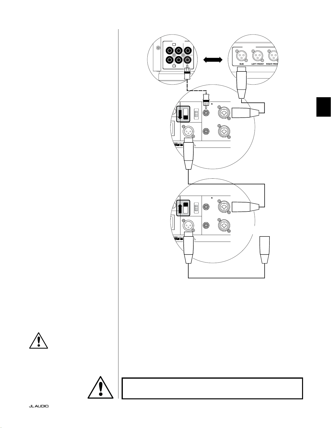
Pg 23 | DE
|
Fathom
®
v2
DE
SYSTEMANSCHLUSSPLAN 2:
Mehrere Fathom v2s an Heimkino-
Receiver oder Heimkino-
Vorverstärker/Prozessor
Um die Verwendung mehrerer
Subwoofer in einem Heimkinosystem zu
vereinfachen, verfügt der Fathom v2 über
ein „Master/Slave“-Signalverteilungssystem.
Dies ermöglicht die Steuerung aller
Fathom v2 in einem System von einem
einzigen „Master“-Subwoofer aus.
Zunächst wählen Sie einen Fathom v2
Subwoofer als „Master“ über den oberen
„Input Mode“-Schalter aus. In der Regel
werden Sie den Fathom v2, der dem Receiver/
Vorverstärker am nächsten ist, als Master
bestimmen. In einigen Fällen, z. B. wenn
das Bedienfeld bestimmter Geräte schwer
zugänglich ist, können Sie den am leichtesten
zugänglichen Subwoofer als Master festlegen.
Für den Anschluss des Master
Fathom v2 an Ihr Heimkinosystem stehen
zwei Verbindungsarten zur Verfügung:
symmetrisch (XLR- oder 1/4-Zoll-TRS-
Anschluss) und unsymmetrisch (Cinch-
Anschluss). Symmetrische Verbindungen
bieten eine hervorragende Unterdrückung
von Störsignalen und gewährleisten eine
ordnungsgemäße Erdung zwischen den
Komponenten. Wenn Ihr Receiver oder
Prozessor über symmetrische Ausgänge
verfügt, empfehlen wir Ihnen dringend,
diese für den Anschluss an den Fathom v2
zu verwenden, der als Master fungiert.
Im Anschlussplan links sind
symmetrische Verbindungen als
durchgezogene Linien und unsymmetrische
Verbindungen gestrichelt dargestellt.
Sie werden nur eine dieser Methoden
zur Verbindung der Eingänge für
den als Master bezeichneten Fathom
v2 verwenden (nicht beide).
Die verbleibenden Fathom v2 im System
werden über ihre oberen „Input Mode“-
Schalter als „Slave“-Einheiten konguriert.
Über symmetrische XLR-Kabel verbinden
Sie den „Output to Slave“ des Master-
Fathom v2 mit dem symmetrischen „Le
or Mono“-Eingang des ersten Slave-Fathom
v2. Der „Output to Slave“-Anschluss dieser
Slave-Einheit speist den „Le or Mono“-
Eingang der nächsten Slave-Einheit über
ein weiteres symmetrisches XLR-Kabel.
Nachfolgende Slave-Einheiten werden
auf die gleiche Weise angeschlossen.
Die Verbindungen zwischen „Master“- und
„Slave“-Fathom und zwischen „Slave“-
Fathom erfolgen AUSSCHLIESSLICH über
symmetrische XLR-Kabel.
1200VA
ilt in USA with Imported and domestic components
LEFT
or
MONO
RIGHT
ONLY
INPUTS
Output to Slave
(Balanced)
Balanced
Unbalanced
Input Modes
Slave
Master
Grounded
Isolated
SERIAL NUMBER:
Warranty void if serial number is removed, altered or defaced.
F 12A H
250V
0 V ~ 60 Hz
F
U
S
E
F
U
S
E
1200VA
ilt in USA with Imported and domestic components
LEFT
or
MONO
RIGHT
ONLY
INPUTS
Output to Slave
(Balanced)
Balanced
Unbalanced
Input Modes
Slave
Master
Grounded
Isolated
SERIAL NUMBER:
Warranty void if serial number is removed, altered or defaced.
F 12A H
250V
0 V ~ 60 Hz
F
U
S
E
F
U
S
E
S
l
ave
Master
z
S
l
ave
Master
z
OUTPUTS
SUB
REAR
REAR CENTER
FRONT
FRONT
R
L
PRE OUT
PROZESSOR (SYMMETRISCHE AUSGÄNGE)
FATHOM HINTERE BEDIENELEMENTE (MASTER)
FATHOM HINTERE BEDIENELEMENTE (SLAVE)
ODER
RECEIVER/PROZESSOR (UNSYMMETRISCHE AUSGÄNGE)
AN ZUSÄTZLICHE FATHOM
(FALLS ZUTREFFEND)
WICHTIG
WARNHINWEIS
ACHTUNG! SCHALTEN SIE DEN FATHOM v2 UND ALLE ANDEREN GERÄTE IM
SYSTEM AUS, BEVOR SIE ANSCHLÜSSE EINRICHTEN ODER ÄNDERN!
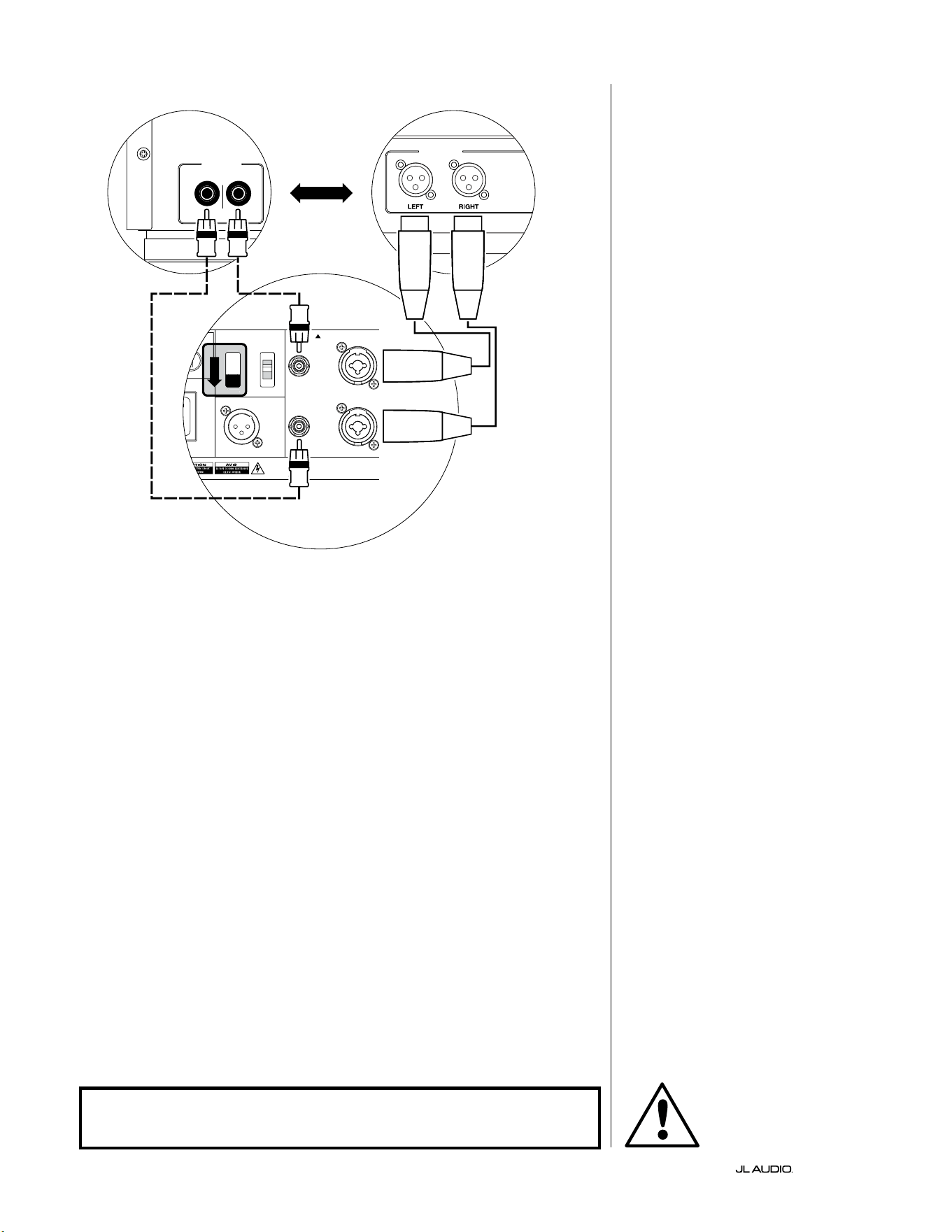
DE | Pg 24
|
Fathom
®
v2
1200VA
ilt in USA with Imported and domestic components
LEFT
or
MONO
RIGHT
ONLY
INPUTS
Output to Slave
(Balanced)
Balanced
Unbalanced
Input Modes
Slave
Master
Grounded
Isolated
SERIAL NUMBER:
Warranty void if serial number is removed, altered or defaced.
F 12A H
250V
0 V ~ 60 Hz
F
U
S
E
F
U
S
E
S
l
ave
M
aster
z
AKTIVE STEREO-FREQUENZWEICHE
(SYMMETRISCHE AUSGÄNGE)
LOW OUT
(SUB OUT)
AKTIVE STEREO-FREQUENZWEICHE
(UNSYMMETRISCHE AUSGÄNGE)
RIGHTLEFT
LOW OUT
(SUB OUT)
FATHOM HINTERE BEDIENELEMENTE (MASTER)
ODER
SYSTEMANSCHLUSSPLAN 3:
Ein Fathom v2 in Mono an
Zweikanal-Audiosystem
Wenn Sie einen Fathom v2 (oder
mehrere Fathom v2) in Mono an ein
Zweikanal-Audiosystem anschließen,
verwenden Sie sowohl die „Le
or Mono“ als auch die „Right“
Eingänge. Die Summierschaltung am
Eingang des Fathom v2 summiert die
Stereosignale zu Monosignalen.
Wir empfehlen dringend, eine
hochwertige aktive Frequenzweiche wie
die JL Audio CR-1 zu verwenden, um die
Signale Ihres Vorverstärkers aufzuteilen,
bevor Sie diesen an den Fathom v2 und an
den Verstärker für Ihre Hauptlautsprecher
anschließen. Auf diese Weise können
Sie tiefe Frequenzen aus den Signalen
für die Hauptlautsprecher herausltern,
was zu einer besseren Leistung führt.
Wenn Sie keine aktive Frequenzweiche
verwenden und Ihre Hauptlautsprecher
über den gesamten Frequenzbereich
betreiben möchten, können Sie die
Ausgangssignale Ihres Vorverstärkers
anstelle der in der Abbildung
gezeigten aktiven Frequenzweiche
mit geeigneten Y-Kabeln aueilen.
Für den Anschluss des Fathom v2
an Ihr Zweikanal-Audiosystem stehen
zwei Verbindungsarten zur Verfügung:
symmetrisch (XLR- oder 1/4-Zoll-
TRS-Anschluss) und unsymmetrisch
(Cinch-Anschluss). Symmetrische
Verbindungen bieten eine hervorragende
Unterdrückung von Störsignalen und
gewährleisten eine ordnungsgemäße
Erdung zwischen den Komponenten.
Wenn Ihr Vorverstärker oder Ihre aktive
Frequenzweiche über symmetrische
Ausgänge verfügt, empfehlen wir Ihnen
dringend, diese zu verwenden.
Im Anschlussplan links sind
symmetrische Verbindungen
als durchgezogene Linien und
unsymmetrische Verbindungen
gestrichelt dargestellt. Sie werden nur
eine dieser Methoden zur Verbindung
der Eingänge verwenden (nicht beide).
Hinweis: Falls gewünscht, können
zusätzliche Fathom v2 im „Slave“-
Modus an den Fathom v2 angeschlossen
werden (siehe Abbildung). Siehe
„Anschlussplan 2“ auf Seite 23 für eine
Erläuterung der Slave-Verbindung.
WARNHINWEIS
ACHTUNG! SCHALTEN SIE DEN FATHOM v2 UND ALLE ANDEREN GERÄTE IM
SYSTEM AUS, BEVOR SIE ANSCHLÜSSE EINRICHTEN ODER ÄNDERN!

Pg 25 | DE
|
Fathom
®
v2
DE
SYSTEMANSCHLUSSPLAN 4:
Zwei Fathom v2 in Stereo an
Zweikanal-Audiosystem
Wenn Sie zwei Fathom v2 in Stereo an
ein Zweikanal-Audiosystem anschließen,
verwenden Sie nur die „Le or Mono“-
Eingänge jedes Fathom v2. Der obere
„Input Mode“-Schalter an jedem Fathom
v2 wird auf die Position „Master“ gestellt.
Wir empfehlen dringend, eine
hochwertige aktive Frequenzweiche wie
die JL Audio CR-1 zu verwenden, um die
Signale Ihres Vorverstärkers aufzuteilen,
bevor Sie diesen an den Fathom v2 und an
den Verstärker für Ihre Hauptlautsprecher
anschließen. Auf diese Weise können Sie
tiefe Frequenzen aus den Signalen für die
Hauptlautsprecher herausltern, was zu
einer besseren Leistung führt.
Wenn Sie keine aktive Frequenzweiche
verwenden und Ihre Hauptlautsprecher
über den gesamten Frequenzbereich
betreiben möchten, können Sie die
Ausgangssignale Ihres Vorverstärkers
anstelle der in der Abbildung gezeigten
aktiven Frequenzweiche mit geeigneten
Y-Kabeln aueilen.
Für den Anschluss des Fathom v2
an Ihr Zweikanal-Audiosystem stehen
zwei Verbindungsarten zur Verfügung:
symmetrisch (XLR- oder 1/4-Zoll-
TRS-Anschluss) und unsymmetrisch
(Cinch-Anschluss). Symmetrische
Verbindungen bieten eine hervorragende
Unterdrückung von Störsignalen und
gewährleisten eine ordnungsgemäße
Erdung zwischen den Komponenten.
Wenn Ihr Vorverstärker oder Ihre aktive
Frequenzweiche über symmetrische
Ausgänge verfügt, empfehlen wir Ihnen
dringend, diese zu verwenden.
Im Anschlussplan rechts sind
symmetrische Verbindungen
als durchgezogene Linien und
unsymmetrische Verbindungen
gestrichelt dargestellt. Sie werden nur
eine dieser Methoden zur Verbindung
der Eingänge verwenden (nicht beide).
Hinweis: Falls gewünscht, können
zusätzliche Fathom v2 im „Slave“-
Modus an den Fathom v2 angeschlossen
werden (siehe Abbildung). Siehe
„Anschlussplan 2“ auf Seite 23 für eine
Erläuterung der Slave-Verbindung.
LOW OUT
(SUB OUT)
RIGHTLEFT
LOW OUT
(SUB OUT)
1200VA
ilt in USA with Imported and domestic components
LEFT
or
MONO
RIGHT
ONLY
INPUTS
Output to Slave
(Balanced)
Balanced
Unbalanced
Input Modes
Slave
Master
Grounded
Isolated
SERIAL NUMBER:
Warranty void if serial number is removed, altered or defaced.
F 12A H
250V
0 V ~ 60 Hz
F
U
S
E
F
U
S
E
Sl
ave
Master
z
PROZESSOR (SYMMETRISCHE AUSGÄNGE)
FATHOM HINTERE BEDIENELEMENTE (MASTER)
ODER
RECEIVER/PROZESSOR (UNSYMMETRISCHE AUSGÄNGE)
FATHOM HINTERE BEDIENELEMENTE (MASTER)
WARNHINWEIS
ACHTUNG! SCHALTEN SIE DEN FATHOM v2 UND ALLE ANDEREN GERÄTE IM
SYSTEM AUS, BEVOR SIE ANSCHLÜSSE EINRICHTEN ODER ÄNDERN!

DE | Pg 26
|
Fathom
®
v2
EMPFOHLENE EINRICHTUNGSSCHRITTE
1) Vorbereitung auf die Einrichtung: ................................... 26-27
2) Pegeleinstellung: ..................................................... 28
3) Polaritäts-/Phaseneinstellung: ......................................... 28
4) Aufstellorte ausprobieren: ............................................ 28
5) D.A.R.O. anwenden: .............................................. 29-30
6) E.L.F. Trim einstellen: ................................................ 30
VORBEREITUNG AUF DIE EINRICHTUNG:
Bitte bestätigen Sie die folgenden Systemeinstellungen, bevor sie mit der
Einrichtung beginnen. Dadurch werden ein neutraler Startpunkt und eine
sachgemäße Einrichtung Ihres Subwoofer-Systems sichergestellt.
Einstellungen an Ihrem Heimkino-Receiver oder Vorverstärker/Prozessor:
Bevor Sie mit der Einrichtung Ihres Fathom v2 Subwoofer-Systems beginnen,
empfehlen wir Ihnen, Ihren Receiver oder Vorverstärker/Prozessor wie folgt
einzustellen (bitte schalten Sie alle Fathom v2 im System über deren Netzschalter
an der Vorderseite aus, bevor Sie diese Einstellungen vornehmen):
1. Lautsprechergröße
Stellen Sie alle Hochfrequenzlautsprecher im Lautsprecher-Setup-Menü
Ihres Receivers oder Vorverstärkers/Prozessors auf „klein“ mit einem
Übergangspunkt von 80Hz ein. Dadurch werden ALLE Bässe an
die Fathom v2 gesendet.
2. Lautsprecherabstand
Stellen Sie alle Lautsprecherabstände, einschließlich Subwoofer-Abstand, im
Lautsprecher-Setup-Menü auf den Haupthörplatz ein. Verwenden Sie zur
Bestimmung dieser Abstände ein Maßband (zeitliche Kohärenz ist wichtig).
Bei Verwendung mehrerer Fathom v2 Subwoofer sollte der durchschnittliche
Abstand zum Haupthörplatz berechnet und dieser Wert zur Einstellung des
Subwoofer-Abstands eingesetzt werden.
3. Subwoofer-Pegel
Stellen Sie den Subwoofer-Pegel im Receiver oder Vorverstärker/Prozessor auf
„0“ oder die mittlere Position ein.
4. Klangregler / Equalizer
Stellen Sie alle Klangregler auf „0“ und deaktivieren Sie alle Equalizer-
Funktionen.
Einstellungen an Ihrem Prozessor mit aktivem Crossover oder
Bassmanagement:
Bei Verwendung eines Prozessors mit aktivem Crossover oder
Bassmanagement empfehlen wir, diesen vor der Einrichtung Ihres
Fathom v2 Subwoofer-Systems wie folgt einzustellen (bitte schalten Sie alle
Fathom v2 Subwoofer im System aus, bevor Sie diese Einstellungen vornehmen):
1. Tiefpasslterfrequenz
Wählen Sie eine Tiefpasslterfrequenz von 80 Hz
(24 dB/Oktave Flankensteilheit)
2. Hochpasslterfrequenz
Wählen Sie eine Hochpasslterfrequenz von 80 Hz
(24 dB/Oktave Flankensteilheit)
3. Tiefpass-Ausgangspegel (Subwoofer)
Stellen Sie den Subwoofer-Ausgangspegel auf „0“ oder die mittlere Position.
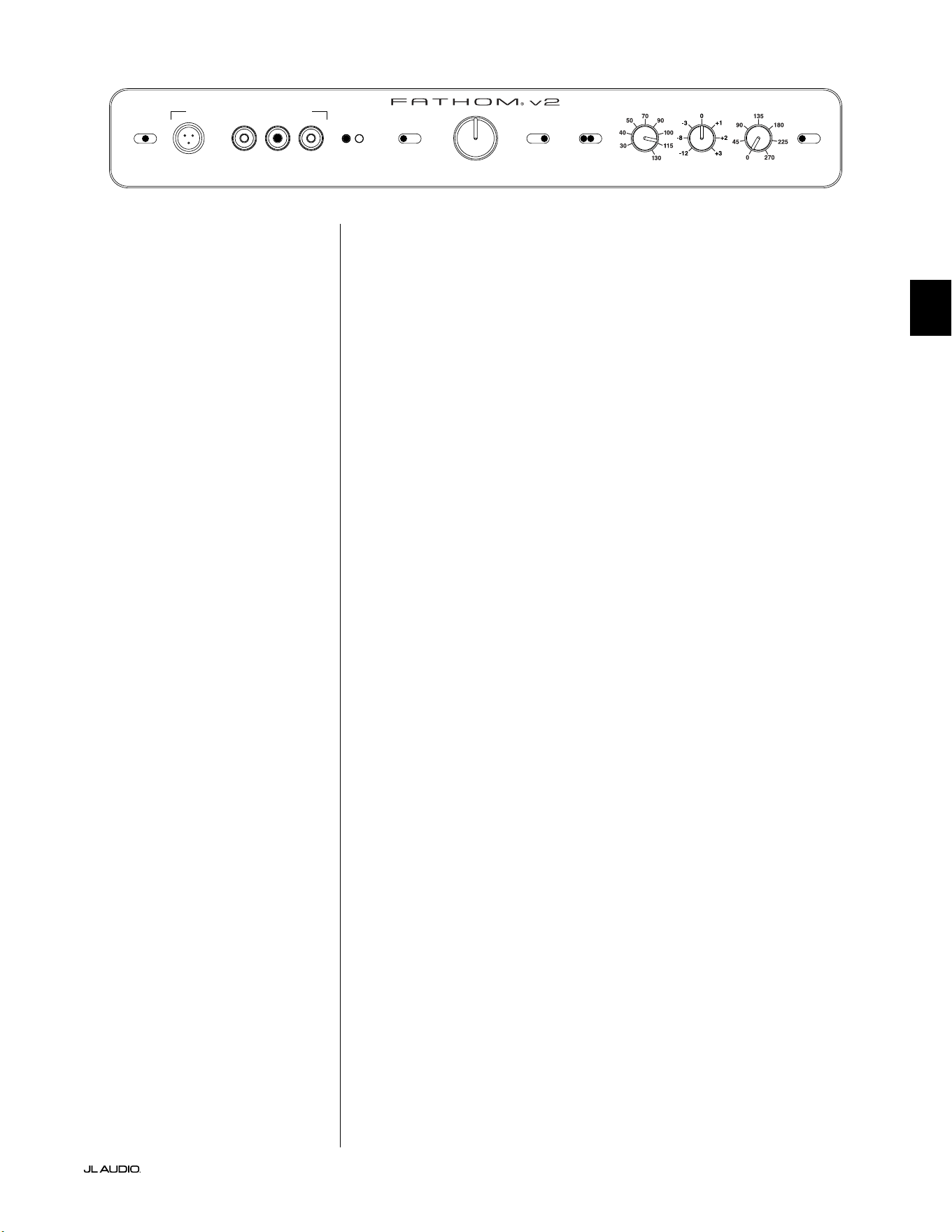
Pg 27 | DE
|
Fathom
®
v2
DE
Auf der Frontplatte des Fathom v2:
Bitte schalten Sie den Heimkino-Receiver oder Vorverstärker/Prozessor aus, um
diese Einstellungen vorzunehmen.
1. „Power“-Schalter
Stellen Sie den „Power“-Schalter jedes Fathom v2 in die Position „On“.
2. „Lights“-Schalter
Stellen Sie den „Lights“-Schalter jedes Fathom v2 in die Position „On“. Wenn
auf der Vorderseite keine Beleuchtung zu sehen ist, haben Sie möglicherweise
vergessen, den Fathom v2 anzuschließen, oder es liegt ein Problem mit dem
Stromkreis vor.
3. „Input Mode“-Anzeigeleuchten
Wenn Sie einen einzelnen Fathom v2 verwenden, vergewissern Sie sich, dass
dessen „Input Mode“-Anzeigeleuchte auf der Position „Master“ steht. Falls
nicht, müssen Sie den oberen „Input Mode“-Schalter auf der Rückseite des
Fathom v2 betätigen.
Wenn Sie mehrere Fathom v2 in einer Master/Slave-Konguration
verwenden, vergewissern Sie sich, dass der Subwoofer, der direkt an Ihren
Receiver oder Vorverstärker/Prozessor angeschlossen ist, „Master“ auf seiner
„Input Mode“-Leuchte anzeigt und dass alle anderen Subwoofer „Slave“ auf
ihrer „Input Mode“-Leuchte anzeigen. Falls nicht, müssen Sie die oberen
„Input Mode“-Schalter auf der Rückseite des Fathom v2 benutzen.
4. „Level Mode“-Schalter
Stellen Sie den „Level Mode“-Schalter des Fathom v2 auf die Position „REF“.
5. „LP Filter“-Schalter
Stellen Sie den „LP Filter“-Schalter Ihres Master Fathom v2 auf „OFF“,
wenn Ihr Heimkino-Receiver/Prozessor das Bassmanagement übernimmt
(Lautsprecher auf „klein“ eingestellt) oder wenn Sie einen externen Crossover
bzw. Bassmanagementprozessor verwenden. Wenn nicht, wählen Sie die
Position „12 dB“.
6. “LP Freq. (Hz)“-Regler
Drehen Sie den „LP Freq.“-Knopf. Regler auf die Position „80 Hz“.
7. Regler „e.l.f. trim (dB)“
Drehen Sie den Regler „e.l.f. trim“ auf „0“.
8. Schalter „Polarity“
Stellen Sie den Schalter „Polarity“ auf „0“.
9. „phase (deg.)“-Regler
Drehen Sie den „phase“-Regler auf „0“ Grad
10. D.A.R.O. Defeat-Schalter
Drücken Sie den D.A.R.O.-Defeat-Schalter, so dass das rote Licht des
Schalters leuchtet.
LP freq. (Hz) e.l.f. trim (dB) phase (deg.)
Polarity
0
|
180 deg.
LP Filter
o
|
12dB
|
24dB
Master Level
max
0
Lights
o
|
dim
|
on
-∞
Level Mode
ref.
|
variable
Input Mode
master
|
slave
calibration mic. demo defeat calibrate
Power
o
|
on
|
auto
Digital Automatic Room Optimization
DE | Pg 28
|
Fathom
®
v2
EMPFOHLENE EINRICHTUNGSSCHRITTE (Fortsetzung)
Einrichtung des Subwoofer-Systems:
Sobald Sie die Regler an Ihrem Heimkino-Receiver oder Vorverstärker/
Prozessor eingestellt und die auf den Seiten 26 und 27empfohlenen Einstellungen
am Fathom v2 vorgenommen haben, können Sie mit der Einrichtung Ihres Fathom
v2 beginnen, um optimale Leistung zu erzielen.
1. Pegeleinstellung
Bei vertrauter Musik bzw. Filmen mit tiefen Bässen stellen Sie den
Subwoofer-Pegel mit dem Subwoofer-Pegelregler Ihres Receivers oder
Vorverstärkers/Prozessors so ein, dass er mit den anderen Lautsprechern
harmoniert. Diese Methode ist sicherer vor Eingrien als die Verwendung
des „Master Level“-Reglers des Fathom v2 (denken Sie an Kleinkinder oder
neugierige Besucher).
In dem unwahrscheinlichen Fall, dass der Subwoofer-Level-Regler Ihres
Receivers oder Vorverstärkers/Prozessors nicht ausreichend auf den Pegel
des Fathom v2 abgestimmt werden kann, muss der Regler wieder auf „0“
gestellt werden. Stellen Sie dann den „Level Mode“-Schalter des Fathom v2
auf „Variable“ und verwenden Sie den „Master Level“-Regler, um den Pegel
des Subwoofers mit den anderen Lautsprechern abzustimmen, wobei „0“ als
Referenzpunkt dient (REF-Modus-Verstärkung und variable „0“-Verstärkung
sind identisch). NOTIEREN SIE SICH DIESE EINSTELLUNG FÜR EINE
SPÄTERE VERWENDUNG.
Detaillierte Informationen zu den Pegeleinstellungen Ihres Fathom v2 nden
Sie in den Abschnitten „Level Mode“ und „Master Level“ auf den Seiten 15 - 16
dieses Handbuchs.
2. Polaritäts- und Phaseneinstellung
Es ist häug hilfreich, diese Regler von einer zweiten Person bedienen zu
lassen, damit Sie Veränderungen leicht vom Haupthörplatz aus beurteilen
können.
Hören Sie sich vertrautes Ausgangsmaterial (vorzugsweise Musik mit guter
Wiedergabe von oberen und mittleren Bässen) an, stellen Sie den „Polarity“-
Schalter von „0“ auf „180“ und achten Sie auf Unterschiede. Die korrekte
Einstellung klingt bei kräigen hohen Bässen und hoher Artikulation am
natürlichsten. Wählen Sie „0“, wenn beide ähnlich klingen.
Wenn die Polarität korrekt eingestellt ist, sollten Sie die gleiche
Musik mit verschiedenen „Phase“-Einstellungen abspielen und
die Einstellung wählen, bei der die Wiedergabe von hohen und
mittleren Bässen noch weiter verstärkt wird. Stellen Sie den
Regler auf „0“, wenn Sie keinen Unterschied hören können.
3. Probieren Sie ggf. andere Aufstellorte für den Subwoofer aus.
Sobald Sie mit der grundlegenden Leistung Ihres Subwoofers zufrieden
sind, können Sie zum nächsten Schritt übergehen. Wenn nicht, empfehlen wir
Ihnen, mit der Position Ihres Subwoofers zu experimentieren, bis Sie mit der
grundlegenden Leistung zufrieden sind. Das Experimentieren mit dem Standort ist
der SCHLÜSSEL zu einem System mit überragendem Klang. Wenn der Subwoofer
um ca. 1Meter verschoben wird, kann dies bereits eine bedeutende Auswirkung
auf die Gleichmäßigkeit der Bässe haben. Drehen Sie bei jeder neuen Position
die „Polarity“- und „phase“-Regler zunächst auf „0“ und wiederholen Sie die
Einrichtung beginnend bei Schritt 1.
WICHTIG! NOTIEREN SIE SICH ALLE IN SCHRITT 1–3 VORGENOMMENEN
EINSTELLUNGEN FÜR ZUKÜNFTIGE REFERENZZWECKE.
WICHTIG
Pg 29 | DE
|
Fathom
®
v2
DE
WICHTIG! STELLEN SIE SICHER, DASS DER RAUM WÄHREND DER D.A.R.O.
KALIBRIERUNG ABSOLUT LEISE IST! SCHALTEN SIE ALLE LAUTEN GERÄTE IN DER
NÄHE DES HÖRRAUMS AUS (GESCHIRRSPÜLER, WASCHMASCHINEN USW.)
ES IST BESONDERS WICHTIG, DASS KLIMAANLAGEN ODER WÄRMEPUMPEN
WÄHREND DER KALIBRIERUNG AUSGESCHALTET WERDEN. KLIMAANLAGEN
MIT ZWANGSBELÜFTUNG KÖNNEN MÄSSIGE GERÄUSCHPEGEL VON 15-20 HZ
ERZEUGEN, DIE DIE KALIBRIERUNG STÖREN.
4. Anwendung der digitalen automatischen Raumoptimierung (D.A.R.O.)
Sie sind nun in der Lage, die Leistungsfähigkeit des exklusiven Digital
Automatic Room Optimization (D.A.R.O.)-Systems von JL Audio zu nutzen.
Dieses System misst den Frequenzgang des Subwoofers an Ihrem primären
Hörplatz und wendet einen leistungsstarken 18-Band-Equalizer an, um
die durch Raummoden verursachten Spitzen zu zähmen, was zu einer
ausgeglicheneren, präziseren Basswiedergabe führt. Wenn Sie mehrere Fathom
v2 in einer Master/Slave-Konguration verwenden, müssen Sie sich nur mit
dem als „Master“ festgelegten Subwoofer beschäigen, um die D.A.R.O.-
Kalibrierung für das gesamte Subwoofer-System durchzuführen. Beachten Sie,
dass die gesamte Signalverarbeitung auf der Frontplatte während der D.A.R.O.-
Kalibrierung deaktiviert wird, unabhängig von den Reglereinstellungen. Der
Normalbetrieb wird wiederhergestellt, sobald die Kalibrierung abgeschlossen
ist.
a) Stellen Sie den Netzschalter auf die Position „ON“ und vergewissern Sie sich,
dass die Anzeigeleuchten des Fathom v2 über den Schalter „Lights“ auf „ON“
gestellt sind.
b) Nehmen Sie das Kalibrierungsmikrofon aus der
Schutzhülle und schließen Sie das Kabel an die Mini-XLR-
Buchse auf dem Bedienfeld des Fathom v2 an.
HINWEIS: Die D.A.R.O. Kalibrierung ist nur möglich, wenn das mitgelieferte
JL Audio Testmikrofon an der Vorderseite des Fathom v2 angeschlossen ist. Die
Funktion „Calibrate“ ist deaktiviert, wenn kein Mikrofon angeschlossen ist, um
einen versehentlichen Verlust der Einstellungen zu verhindern.
c) Schließen Sie das Mikrofon an das andere Ende des Mikrofonkabels an und
platzieren Sie das Mikrofon vorübergehend auf dem primären Hörplatz.
Wenn Sie einen Mikrofonständer haben, können Sie das Mikrofon in
Kopöhe aufstellen und auf dem primären Hörplatz positionieren.
d) Drücken Sie auf dem Bedienfeld des Fathom v2 die Taste „Calibrate“. Das
grüne Licht auf der „Calibrate“-Taste blinkt langsam und zeigt damit an,
dass die Kalibrierung in 5 Sekunden beginnt.
e) Kehren Sie innerhalb von 5 Sekunden nach dem Drücken der Taste
„Calibrate“ zu Ihrem primären Hörplatz zurück und halten Sie das Mikrofon
in Ihrer normalen, sitzenden Position ungefähr auf Höhe Ihrer Ohren.
f) Über den Fathom v2 wird eine Schallsequenz abgespielt, die wie statisches
Rauschen klingt. Die Sequenz dauert ungefähr 3 Minuten. Während dieses
Vorgangs führt das D.A.R.O.-System eine Frequenzgangmessung an Ihrem
Sitzplatz durch und korrigiert die gefundenen Probleme. Das D.A.R.O.-
System kompensiert auch eventuelle Pegelunterschiede vor und nach
der Kalibrierung, so dass Ihr Fathom v2 nach dem Kalibrierungsprozess
eine ähnliche wahrgenommene Lautstärke aufweist. Wenn die D.A.R.O.-
Kalibrierung abgeschlossen ist, leuchtet die Taste „Calibrate“ auf und bleibt
an, um eine erfolgreiche Kalibrierung anzuzeigen.
Wenn Sie eine neue Kalibrierung durchführen möchten, wiederholen Sie
einfach die obigen Schritte.
WICHTIG
DE | Pg 30
|
Fathom
®
v2
Um die D.A.R.O.-Einstellungen zu löschen (d. h. sie auf Null
zurückzusetzen) und die Kalibrieranzeige auszuschalten, halten Sie die
Demo-Taste gedrückt und drücken Sie dann die Defeat-Taste. Bitte
beachten Sie, dass Sie diese Tastenfolge schnell ausführen müssen.
Wenn Sie die Demo-Taste länger als 2 Sekunden gedrückt halten, ohne
die Defeat-Taste zu berühren, werden die Demo-Töne gestartet. Sollte
dies der Fall sein, warten Sie einfach, bis die Demosequenz beendet
ist, und versuchen Sie es erneut. Sie können eine neue Kalibrierung
durchführen, indem Sie das oben beschriebene Verfahren befolgen.
WICHTIG! WENN SIE IHREN FATHOM V2 ODER IHREN PRIMÄREN HÖRPLATZ
IN ZUKUNFT VERLEGEN, MÜSSEN SIE D.A.R.O. ERNEUT AUSFÜHREN.
EINE BESTIMMTE KALIBRIERUNG IST EINZIGARTIG FÜR EINE BESTIMMTE
KOMBINATION AUS SUBWOOFERPOSITION UND HÖRSITZPOSITION. FOLGEN
SIE EINFACH DEN OBIGEN SCHRITTEN, UM EINE NEUE KALIBRIERKURVE ZU
ERSTELLEN.
5. Extreme Low Frequency (e.l.f.) Trim
Verwenden Sie den „e.l.f. trim“-Regler, um die Tiefstbasswiedergabe des
Fathom v2 einzustellen. Dieser Regler ermöglicht eine Absenkung um -12
dB oder eine Anhebung um +3 dB bei 24 Hertz und ist besonders nützlich,
wenn ein (oder zwei) Fathom v2 in einem kleinen bis mittelgroßen Heimkino
verwendet werden. Da kleinere geschlossene Räume dazu neigen, den Pegel
der tiefsten Bassfrequenzen anzuheben, können kleinere Heimkinos von der
starken Tieassausgabe des Fathom v2 Subwoofers überwältigt werden. Dies
kann im unteren Bassbereich einen „zu satten“ oder „aufgeblähten“ Eindruck
erzeugen. Drehen Sie den „e.l.f. trim“-Regler herunter, um den Tiefstbasspegel
zu reduzieren und diesen Zustand zu entschärfen. Experimentieren Sie ruhig
und hören Sie sich eine Vielzahl anspruchsvoller Aufnahmen an, bis Sie die
beste Lösung für Ihren Raum und Ihren Geschmack gefunden haben.
Ihr Fathom v2 ist jetzt für die optimale Basswiedergabe an Ihrem Hörplatz
optimiert. Herzlichen Glückwunsch!
WICHTIG

Pg 31 | DE
|
Fathom
®
v2
DE
HÄUFIG GEFRAGTE FRAGEN
Darf ich Gegenstände auf meinen Subwoofer stellen?
Wir empfehlen, keine Gegenstände auf das Subwoofer-Gehäuse zu stellen, da
diese vibrieren und so unerwünschte Geräusche sowie mögliche Schäden an der
Oberäche verursachen können. Unter keinen Umständen darf ein Gegenstand,
der Flüssigkeit enthält, auf das Gehäuse des Fathom v2 gestellt werden.
Ist der Fathom v2 magnetisch abgeschirmt?
Fathom v2 Subwoofer sind nicht magnetisch abgeschirmt. Um magnetische
Verzerrungen bei bestimmten Fernsehgeräten zu vermeiden, stellen Sie den
Fathom v2 mindestens 1 bis 1,5 m von Ihrem Bildschirm entfernt auf. Wenn Sie
auf dem Bild Farbveränderungen feststellen, platzieren Sie den Subwoofer weiter
weg, bis diese verschwinden.
Wird meine Stromrechnung steigen, wenn ich den Fathom v2 im „Auto“-
Modus belasse?
Im „Auto“-Modus wird der Verstärker des Fathom v2 nur dann eingeschaltet,
wenn ein deutliches Signal an den Eingängen erkannt wird. Im Low-Power-
Standby bleiben nur die nötigsten Stromkreise eingeschaltet, die unerhebliche
Mengen Strom verbrauchen (weniger als 5Watt).
Sollte ich den Subwoofer bei einem Gewitter oder längerer Abwesenheit vom
Netz trennen?
JA. Bei (oder vor) einem Gewitter sollten Sie Ihren Fathom v2 vom Netz trennen.
Dadurch werden mögliche Schäden durch Spannungsspitzen oder Blitzeinschlag
verhindert. In einem solchen Fall sollten alle Audio- und Videokomponenten vom
Stromnetz getrennt werden. Wenn Sie mehrere Tage lang nicht zu Hause sind,
sollten Sie Ihre Heimkino-Komponenten vom Stromnetz trennen, um Schäden
durch unerwartete Stürme oder Netzstörungen zu vermeiden.
REINIGUNG IHRES FATHOM v2
Reinigen Sie das Subwoofergehäuse Ihres Fathom v2 mit einem sauberen,
weichen Mikrofasertuch oder einem Staubwedel. Mikrofasertücher sind u.a. dort
erhältlich, wo Automobilzubehör verkau wird.
Leichte Verschmutzungen können in der Regel mit einem sauberen
Mikrofasertuch abgewischt werden. Für hartnäckigere Flecken polieren und
schützen Sie die Oberäche mit einem hochwertigen Autowachs und einem
Mikrofasertuch, die beide überall dort erhältlich sind, wo Autozubehör verkau
wird. Wir empfehlen „NXT Tech Wax“ und Mikrofasertücher von Meguiar®.
Verwenden Sie niemals ein Poliermittel mit aggressiven Lösungsmitteln
oder Schleiörpern, da diese die Oberäche dauerha beschädigen können.
Verwenden Sie für den Fathom v2 niemals Möbelpolitur oder Produkte auf
Ölbasis. Verwenden Sie für den Fathom v2 niemals Lösungsmittel oder aggressive
Reinigungsmittel. Testen Sie das Reinigungsmittel im Zweifelsfall an der
Unterseite des Gehäuses und warten Sie einige Tage ab, bevor Sie es für sichtbare
Gehäuseteile anwenden.

DE | Pg 32
|
Fathom
®
v2
FEHLERBEHEBUNG
Aus dem Subwoofer kommt kein Ton.
1. Vergewissern Sie sich, dass der Fathom v2 angeschlossen und eingeschaltet ist
und dass die Beleuchtung auf der Vorderseite auf „On“ eingestellt wurde. Wenn
sich die Beleuchtung nicht einschaltet, überprüfen Sie den Schutzschalter der
jeweiligen Steckdose oder schließen Sie den Fathom v2 an eine andere Steckdose
an. Wenn Ihre Steckdose Strom hat, aber die LEDs noch immer nicht leuchten,
müssen Sie die Hauptnetzsicherung des Fathom v2 überprüfen und ggf.
austauschen. Siehe Abschnitt „Hauptsicherungshalter“ auf der nächsten Seite.
2. Testen Sie den Subwoofer, indem Sie die DEMO-Taste an der Vorderseite
drücken – wenn der Subwoofer Demotöne ausgibt, ist die interne Schaltung des
Subwoofers in Ordnung und es liegt wahrscheinlich ein Eingangsproblem vor.
Überprüfen Sie die Eingangskabelverbindungen am Fathom v2 und am Receiver/
Preamp/Prozessor.
3. Stellen Sie sicher, dass die Subwoofer-Einstellungen
Ihres Receivers nicht geändert wurden.
4. Wenn Ihre anderen Lautsprecher Ton wiedergeben, aber der Fathom v2 nicht,
tauschen Sie das Kabel aus, das den Fathom v2 mit dem System verbindet.
5. Wenn das Problem weiterhin besteht, wenden Sie sich an Ihren Händler oder den
technischen Support von JL Audio.
Der Basspegel hat sich geändert.
1. Stellen Sie sicher, dass die Pegeleinstellungen (am Fathom v2 und an Ihrem
Receiver/Vorverstärker/Prozessor) nicht geändert wurden.
2. Wenn Sie den „Master Level“-Regler des Fathom v2 zur Einstellung des
Subwoofer-Pegels verwenden, vergewissern Sie sich, dass der „Level Mode“-
Schalter auf „Variable“ eingestellt ist.
3. Überprüfen Sie die Position des ELF-Trim-Reglers.
Fathom v2 gibt Brummen oder andere ungewöhnliche Geräusche aus
1. Siehe Abschnitt zum Eingangsmodus auf Seite 20 dieses Handbuchs, vor allem,
wenn vorgeschaltete Komponenten, Kabel usw. vor Kurzem ausgetauscht wurden.
2. Schalten Sie den Fathom v2 aus, trennen Sie alle Eingangs- und
Ausgangssignalkabel und schalten Sie den Fathom v2 dann
wieder ein. Wenn das Geräusch verschwunden ist, wird es
an einer anderen Stelle in Ihrem System verursacht.
Bass klingt „matschig“ und „zu schwer“.
1. Versuchen Sie, den 24-Hertz-Pegel mit dem "e.l.f. trim"-Regler zu
verringern. Matschige Bässe können manchmal durch eine zu hohe
Niederfrequenzausgabe in einem mittelgroßen Raum verursacht werden.
2. Verringern Sie den Gesamtpegel des Subwoofers.
3. Überprüfen Sie die Subwoofer-Einstellungen Ihres Receivers.
4. Probieren Sie einen anderen Subwoofer-Standort oder einen anderen
Haupthörplatz aus. Die Änderung einer der beiden Standorte kann eine
GROSSE Auswirkung auf den Klang Ihres Systems haben. Siehe Abschnitte zum
Aufstellbereich auf Seite 6–10 dieses Handbuchs.
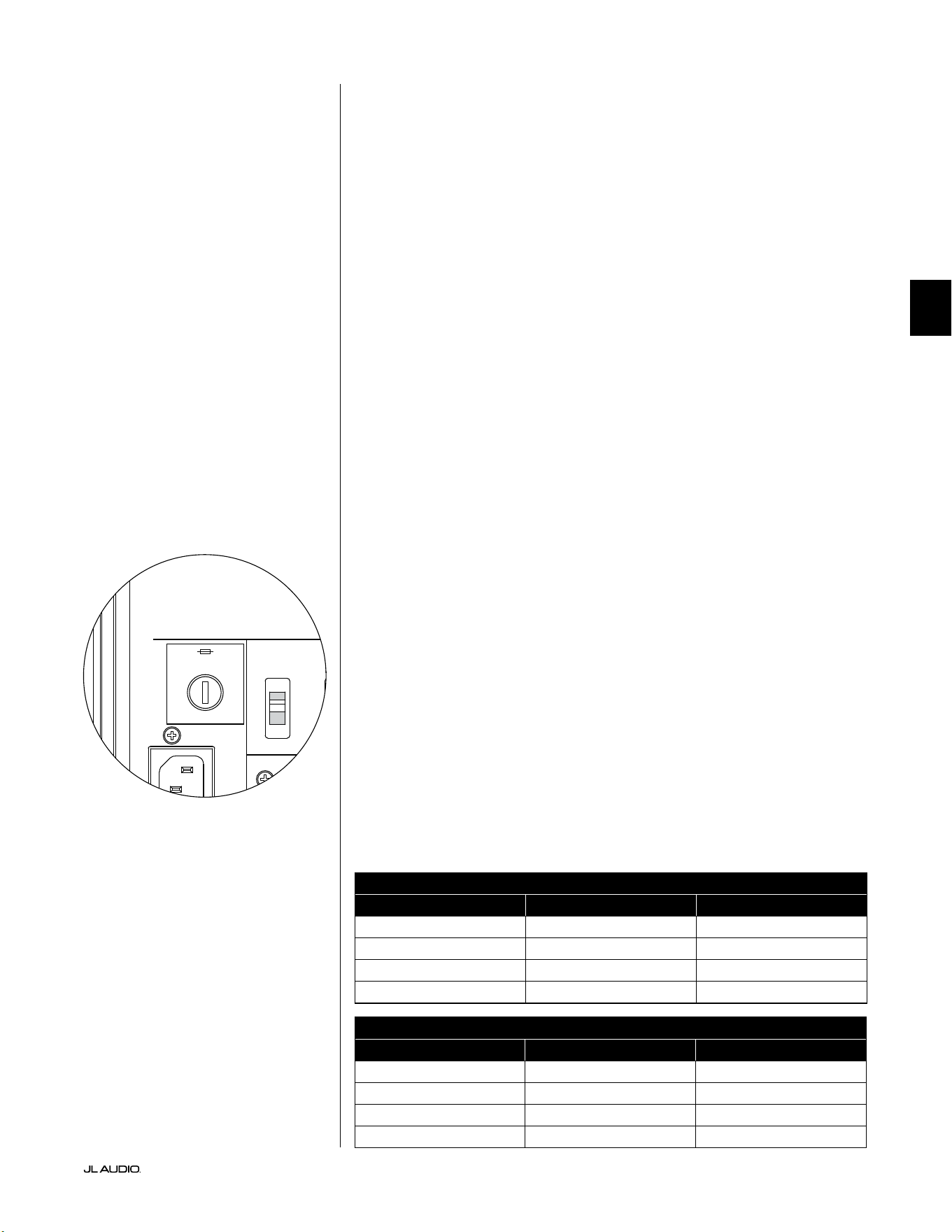
Pg 33 | DE
|
Fathom
®
v2
DE
FEHLERBEHEBUNG – Fortsetzung
Beim D.A.R.O. Kalibrierungsversuch blinkt die Kalibrieranzeige
1. Wenn das mitgelieferte JL Audio-Mikrofon nicht richtig in die Buchse an
der Vorderseite eingesteckt ist, schlägt die Kalibrierung fehl und die grüne
Kalibrieranzeige blinkt schnell. Die Kalibrierung erfolgt NUR, wenn das JL Audio-
Mikrofon angeschlossen ist. Wenn Sie ein anderes Mikrofon anschließen, schlägt die
Kalibrierung fehl. Beenden Sie das Blinken der Kalibrieranzeige, indem Sie die Taste
„Calibrate“ erneut drücken.
2. Wenn die Kalibrierung bei ordnungsgemäß angeschlossenem JL Audio-
Mikrofon fehlschlägt, blinkt die grüne Kalibrieranzeige langsam. Testen Sie die
Mikrofon- und Kabelverbindungen und versuchen Sie erneut, die Kalibrierung
durchzuführen. Wenn die Kalibrierung nach den oben genannten Schritten
fehlschlägt, ist möglicherweise das Mikrofon oder das Mikrofonkabel defekt.
Kontaktieren Sie den technischen Kundendienst von JL Audio Home.
Ihr Fathom v2 ist außerhalb des Hauses deutlich zu hören.
1. Überprüfen Sie die „Master Level“-Einstellung am Fathom v2 oder am Heimkino-
Receiver/Vorverstärker/Prozessor.
2. Erkundigen Sie sich bei Ihrem JL Audio-Händler nach Möglichkeiten zur
Schallisolierung.
3. Stellen Sie den Fathom v2 nicht in der Nähe von Fenstern auf.
HAUPTSICHERUNGSHALTER
Die Abdeckung des Hauptsicherungshalters bendet sich an der Rückseite,
neben der Buchse für das Netzkabel. Diese kleine federbelastete Kappe kann
abgenommen werden, um die Hauptnetzsicherung inspizieren oder austauschen
zu können. Wenn Ihre Steckdose Strom führt, aber die LEDs des Fathom v2
nicht leuchten, ist möglicherweise die Hauptnetzsicherung durchgebrannt.
Ausbau: Ziehen Sie das Netzkabel des Subwoofers ab. Stecken Sie einen kleinen
Schlitzschraubendreher in den Schlitz der Kappe und drehen Sie ihn langsam
gegen den Uhrzeigersinn, bis der Sicherungshalter herausgenommen werden kann.
Nun kann die Sicherung inspiziert und ggf. ersetzt werden. Die Sicherungswerte
für Ihr Fathom v2 Modell nden Sie in der nachfolgenden Tabelle.
Wiedereinbau - Beachten Sie, dass das Gehäuse des Sicherungshalters präzise
ausgerichtet werden muss, um formschlüssig in die Önung zu passen. Führen
Sie den Sicherungshalter in die Önung ein und drehen Sie ihn vorsichtig
im Uhrzeigersinn (ca. 1/8-Drehung), um ihn einrasten zu lassen. Drücken
Sie auf die Kappe und fühlen Sie, wie die Feder zusammengedrückt wird, um
die richtige Position zu nden. Schließen Sie das Netzkabel wieder an.
Wenn die Ersatzsicherung unmittelbar nach dem Austausch einer Sicherung
durchbrennt, muss der Verstärker des Subwoofers eventuell repariert werden. Bitte
wenden Sie sich an Ihren autorisierten JL Audio-Fachhändler oder Lieferanten.
Sicherungswerte, nur 120-V-Modelle
Modell Sicherungstyp Sicherungsgröße
f110v2 (120V) 0,25 x 1,25Zoll, ink 7 A, 250V
f112v2 (120V) 0,25 x 1,25Zoll, ink 8 A, 250V
f113v2 (120V) 0,25 x 1,25Zoll, ink 12 A, 250V
f212v2 (120V) 0,25 x 1,25Zoll, ink 15 A, 250V
Sicherungswerte, nur 240-V-Modelle
Modell Sicherungstyp Sicherungsgröße
f110v2 (240V) 5 x 20mm, ink 6,3 A, 250 V
f112v2 (240V) 5 x 20mm, ink 6,3 A, 250V
f113v2 (240V) 5 x 20mm, ink 8 A, 250V
f212v2 (240V) 5 x 20mm, ink 10 A, 250V
1200VA
Built in USA with Imported and domestic components
LEFT
or
MONO
RIGHT
ONLY
INPUTS
Output to Slave
(Balanced)
Balanced
Unbalanced
Input Modes
Slave
Master
Grounded
Isolated
SERIAL NUMBER:
Warranty void if serial number is removed, altered or defaced.
F 12A H
250V
120 V ~ 60 Hz
F
U
S
E
F
U
S
E
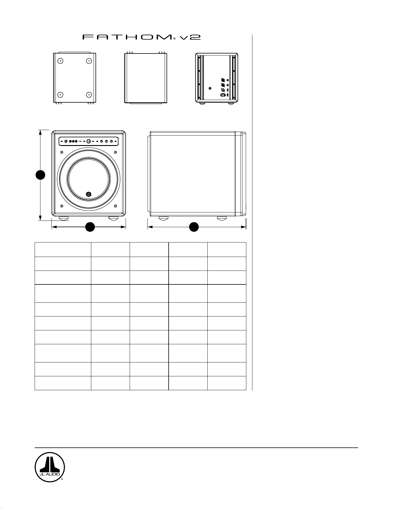
UNTERSEITE
OBERSEITE RÜCKSEITE
SEITE MIT GITTER
FRONT
H
W
D
Technische Daten: f110v2 f112v2 f113v2 f212v2
Gehäusetyp: Geschlossen Geschlossen Geschlossen Geschlossen
Treiber:
Single 10 Zoll
(Nenndurchmesser)
Single 12 Zoll
(Nenndurchmesser)
Single 13,5 Zoll
(Nenndurchmesser)
Dual 12 Zoll
(Nenndurchmesser)
Frequenzgang (reflexionsfrei):
27 – 111 Hz (±1,5dB)
–3dB bei 25 Hz/120 Hz
-10dB bei 19 Hz/155 Hz
21-119 Hz (+1,5dB)
–3dB bei 19 Hz/150 Hz
-10dB bei 17 Hz/167 Hz
20-86 Hz (+1,5dB)
–3dB bei 18Hz/127Hz
–10dB bei 16Hz/154Hz
20 - 97 Hz (+/-1,5 dB) -3
dB bei 19/110 Hz -10 dB
bei 15/157 Hz
Effektive Abstrahlfläche:
60 in
2
0,0387 m
2
84 in
2
0,0542 m
2
107.35 in
2
0,0693 m
2
168 in
2
0,1084 m
2
Luftverdrängung:
160 in
3
2,6 Liter
287 in
3
4,7 Liter
386 in
3
6,3 Liter
574 in
3
9,4 Liter
Verstärkerleistung: 1100Watt Kurzzeit-RMS 1800Watt Kurzzeit-RMS
3000 Watt
Kurzzeit-RMS
3600 Watt
Kurzzeit-RMS
Abmessungen: (H) x (B) x (T)
Höhenabmessungen
einschließlich Füße
15,64 x 12,92 x 17,27 Zoll
397 x 328 x 439 mm
18,5 x 15 x 17,625 Zoll
470 x 448 mm
19,625 x 16,5 x 19,25 Zoll
498 x 489 mm
31,96 x 14,92 x 20,39 Zoll
812 x 379 x 518 mm
Nettogewicht: 31kg (69lb) 53kg (117lb) 60kg (133lb) 102kg (224lb)
Gehäuseausführung: Hochglanz-Schwarz Hochglanz-Schwarz Hochglanz-Schwarz Hochglanz-Schwarz
MERKMALE
Unsymmetrische Eingänge:
Stereo oder Mono (zwei Cinch-Buchsen)
Symmetrische Eingänge:
Stereo oder Mono (zwei XLR-Buchsen)
Ausgang zum Slave: Symmetrisch (ein
XLR-Stecker)
Eingangsmodus:
Master oder Slave
Level-Modus: Referenz (feste Verstärkung)
oder variabel von voller Stummschaltung
bis +15 dB über Referenzverstärkung
Betriebsmodus:
Aus, Ein oder automatische
Signalerkennung
Beleuchtungsmodus: Aus, Ein oder
Dimmen
Tiefpassltermodus:
Aus, 12 dB pro Oktave oder 24 dB pro
Oktave
Grenzfrequenz des Tiefpasslters:
Variabel von 30 Hz - 130 Hz
Polarität:
0 oder 180 Grad
Phase:
Variabel von 0 - 270 Grad
E.L.F. Trim:
Variabel von -12 dB bis +3 dB bei 24 Hz
Digital Automatic Room Optimization
(D.A.R.O.)
Automatischer, digitaler 18-Band-Equalizer
mit integriertem Kalibrierungsmikrofon in
Laborqualität, abschaltbar.
www.jlaudio.com
10369 North Commerce Parkway • Miramar, Florida • 33025 • USA
„JL Audio“, „Fathom“ und das JL Audio-Logo sind eingetragene Warenzeichen von JL Audio, Inc.
©2022 JLAudio, Inc. • Weitere Informationen finden Sie online unter www.jlaudio.com. Die gezeigten Produktbilder dienen nur zur Veranschaulichung und können vom tatsächlichen
Produkt abweichen. Aufgrund der Weiterentwicklung der Produkte können alle technischen Daten ohne Ankündigung geändert werden.
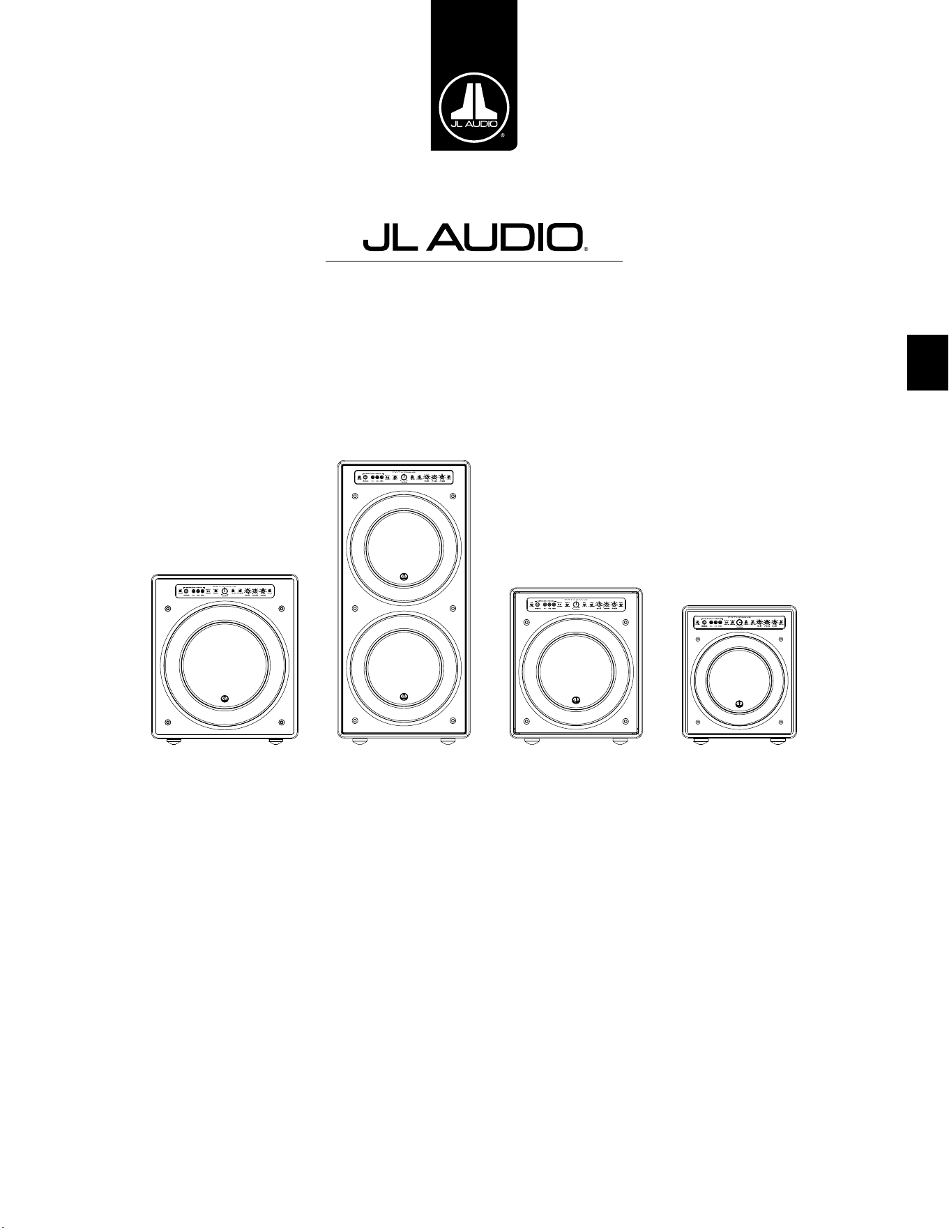
IT
Subwoofer alimentato Fathom v2
Manuale del proprietario
f113v2 f212v2 f112v2 f110v2
IT | Pg 2
|
Fathom
®
v2
ISTRUZIONI IMPORTANTI PER LA SICUREZZA
ATTENZIONE: PER RIDURRE IL RISCHIO D’INCENDIO O SCOSSA ELETTRICA,
NON ESPORRE QUESTO PRODOTTO ALLA PIOGGIA O ALL’UMIDITÀ.
AVVERTENZA
RISCHIO DI SCOSSA ELETTRICA
NON APRIRE
AVVERTENZA: PER RIDURRE IL RISCHIO DI SCOSSA ELETTRICA, NON
RIMUOVERE LA COPERTURA. ALL’INTERNO NON VI SONO PARTI RIPARABILI
DALL’UTENTE. PER UN INTERVENTO IN ASSISTENZA, RIVOLGERSI AL PERSONALE
QUALIFICATO.
1. Leggere le istruzioni — Tutte le istruzioni relative alla sicurezza e al
funzionamento devono essere lette prima di mettere in funzione il subwoofer.
2. Conservare le istruzioni — Le istruzioni relative alla sicurezza e al
funzionamento devono essere conservate per la consultazione futura.
3. Rispettare le avvertenze — Tutte le avvertenze sul subwoofer e nelle
istruzioni operative devono essere rispettate.
4. Attenersi alle istruzioni — Tutte le istruzioni relative al funzionamento e
all’uso devono essere rispettate.
5. Acqua e umidità — Il subwoofer NON deve essere usato in prossimità
dell’acqua, ad es. vicino a una vasca da bagno, un lavandino, un lavabo, una
vaschetta per lavanderia, in un seminterrato umido, accanto a una piscina,
ecc.
6. Ventilazione — Il subwoofer deve essere posizionato di modo che la sua sede
non interferisca con la sua ventilazione appropriata. Ad esempio, il subwoofer
non deve essere collocato su un letto, un divano, un tappeto o supercie simile
che possa ostruire il usso di aria sulle alette del dissipatore di calore. Se il
subwoofer è collocato in un’installazione “a incasso”, accertarsi che il usso
di aria al dissipatore di calore sul retro del subwoofer non sia ostacolato. Non
coprire il dissipatore di calore del subwoofer con tovaglie, tende, ecc.
7. Calore e amme — Il subwoofer deve essere posizionato lontano da
sorgenti di calore come caloriferi, diusori di aria calda, stufe, camini o altri
dispositivi che generano calore. Non posizionare candele su o in prossimità
del subwoofer.
8. Sorgenti di alimentazione — Il subwoofer deve essere collegato
esclusivamente a un’alimentazione del tipo descritto nelle istruzioni operative
o come contrassegnato sul subwoofer.
9. Protezione del cavo di alimentazione — I cavi di alimentazione devono
essere istradati di modo che non sia possibile camminarci sopra o schiacciarli
con oggetti collocati su di loro, prestando particolare attenzione ai connettori,
alle prese e al punto in cui escono dal subwoofer.
10. Pulizia — Il subwoofer deve essere pulito soltanto come consigliato nelle
istruzioni operative.
Il simbolo del fulmine con punta a freccia
all’interno di un triangolo equilatero è
destinato ad avvertire l’utente della presenza
di una “tensione pericolosa” non isolata
nella cassa del prodotto che potrebbe essere
di una magnitudo suciente da costituire
un rischio di scossa elettrica per le persone.
Il punto esclamativo in un triangolo
equilatero è destinato ad avvertire l’utente
della presenza di istruzioni relative all’uso
e alla manutenzione nella documentazione
che accompagna il prodotto.
Pg 3 | IT
|
Fathom
®
v2
IT
11. Periodi di mancato utilizzo — Il cavo di alimentazione del subwoofer deve
essere scollegato dalla presa quando il subwoofer è inutilizzato per lunghi
periodi.
12. Fulmini e picchi di corrente — Consigliamo di scollegare il subwoofer
dalla presa elettrica durante tempeste elettriche e/o interruzioni ricorrenti di
alimentazione, al ne di prevenire danni dovuti ai picchi di corrente.
13. Ingresso di oggetti o liquidi — È necessario prestare attenzione di modo che
eventuali oggetti non cadano all’interno e i liquidi non siano versati sulla cassa
del subwoofer. Non esporre il subwoofer a liquidi gocciolanti né rispettivi
schizzi. Non collocare oggetti riempiti di liquidi su o in prossimità del
subwoofer. Esempio: vasi di ori, bevande, lampade alimentate a liquidi, ecc.
14. Danni che richiedono un intervento in assistenza — Il subwoofer deve
essere sottoposto a manutenzione dal personale qualicato di assistenza
quando:
a. il cavo di alimentazione o la spina ha subito danni
b. degli oggetti sono caduti o del liquido è stato versato nel subwoofer
c. il subwoofer è stato esposto alla pioggia
d. il subwoofer non sembra funzionare normalmente oppure presenta
variazioni evidenti sul piano delle prestazioni
e. il subwoofer è caduto oppure la cassa è stata danneggiata
f. il cono e/o la sospensione del driver del subwoofer ha subito danni sici
15. Manutenzione — L’utente non deve tentare di riparare il subwoofer andando
oltre le indicazioni descritte nelle istruzioni operative. Tutti gli altri interventi
di manutenzione devono essere rinviati al personale di assistenza.
16. Sovraccarico — Non sovraccaricare le prese a parete, le prolunghe oppure le
prese multiple in quanto tutto questo può comportare il rischio d’incendio o
di scossa elettrica.
17. Messa a terra — Questo subwoofer è fornito con un cavo di alimentazione
collegato a terra provvisto di tre pin. È necessario prendere delle precauzioni
di modo che il pin di messa a terra del subwoofer non sia compromesso.
La compromissione del pin di messa a terra sul cavo di alimentazione del
subwoofer può aumentare il rischio di scossa elettrica e potrebbe comportare
danni permanenti all’impianto elettronico del subwoofer.
QUESTO SUBWOOFER È IN GRADO DI PRODURRE LIVELLI DI PRESSIONE
SONORA MOLTO ALTI. SI PREGA DI FARNE USO IN MISURA LIMITATA AL FINE DI
PROTEGGERE IL PROPRIO UDITO DA DANNI PERMANENTI.
ATTENZIONE

IT | Pg 4
|
Fathom
®
v2
DICHIARAZIONE DI CONFORMITÀ FCC
NOTA: La presente apparecchiatura è stata collaudata e ritenuta conforme ai limiti del documento
Part 15 delle Disposizioni FCC. Questi limiti sono stati studiati per fornire una protezione ragionevole
contro le interferenze nocive in un’installazione di tipo residenziale. Quest’apparecchiatura genera,
utilizza e può irradiare energia a radiofrequenza e, se non installata in osservanza delle istruzioni,
potrebbe provocare interferenze dannose alle comunicazioni radio. Tuttavia, non vi è alcuna garanzia
che le interferenze non si verichino in una particolare installazione. Se la presente apparecchiatura
dovesse causare interferenze nocive alla ricezione di radio o televisione, che possono essere determinate
dall’accensione e dallo spegnimento dell’apparecchiatura, s’incoraggia l’utente a cercare di correggere le
interferenze intraprendendo uno o più provvedimenti indicati di seguito:
- Orientare nuovamente oppure cambiare la posizione dell’antenna ricevente.
- Aumentare lo spazio divisorio tra l’apparecchiatura e il ricevitore.
- Collegare l’apparecchiatura a una presa su un circuito diverso da quello a cui è collegato il
ricevitore.
- Rivolgersi al rivenditore oppure a un tecnico esperto in materia di radio/TV per richiedere
assistenza.
INDICE DEI CONTENUTI
Istruzioni importanti per la sicurezza: ................................... 2-3
Introduzione:. . . . . . . . . . . . . . . . . . . . . . . . . . . . . . . . . . . . . . . . . . . . . . . . . . . . . . . . . . . 4
Panoramica del prodotto: ................................................ 5
Collocazione del Fathom v2 nella propria stanza di ascolto: ................ 6-10
Disimballaggio del Fathom v2: ........................................... 11
Layout del pannello di controllo anteriore: ................................ 12
Layout del pannello dei collegamenti e dei comandi posteriori: .............12-13
Comandi del pannello anteriore in dettaglio: .............................14-17
Collegamento del Fathom v2: ..........................................18-25
Procedura consigliata di congurazione: ................................26-30
Domande frequenti: .................................................... 31
Pulizia del Fathom v2: .................................................. 31
Risoluzione dei problemi: .............................................32-33
Garanzia limitata / Informazioni sull’assistenza: ............................ 35
Speciche: ............................................................ 36
INTRODUZIONE
Ci congratuliamo per il vostro acquisto di un impianto subwoofer alimentato
JL Audio Fathom v2. Questo prodotto è stato realizzato con maestria per orire
prestazioni eccezionali nel vostro impianto home theater o audio per molti anni a
venire.
Nelle vesti di azienda, riversiamo le nostre energie nella ricerca per tecnologie
di altoparlanti e amplicatori ad alte prestazioni. I design dei driver per subwoofer
a escursione lunga JL Audio sono ampiamente considerati standard di riferimento
di una risposta lineare e uscita potente. Abbiamo anche incentrato i nostri sforzi
nella creazione di potenti tecnologie di amplicazione e trasformazione del
segnale, puntando appositamente all’erogazione di prestazioni eccezionali a basse
frequenze. Il Fathom v2 riunisce questi aspetti essenziali in una cassa compatta,
realizzata con maestria ed eleganza, per orire un’esperienza di ascolto senza
precedenti.
Vi ringraziamo per aver acquistato questo prodotto e v’invitiamo a leggere
attentamente il presente manuale, al ne di raggiungere il livello più elevato di
prestazioni con il vostro impianto subwoofer Fathom v2. Buon divertimento.
TECNOLOGIE JL AUDIO INCLUSE NEI
SUBWOOFER FATHOM V2
Impianto del motore ottimizzato DMA
Con DMA s’intende l’innovativo sistema
di analisi dinamica del motore (Dynamic
Motor Analysis) JL Audio, volto a migliorare
la risposta dinamica del motore. In seguito
all’ottimizzazione del DMA, i motori
dell’altoparlante restano lineari in atto
lungo una gamma estrema di escursioni e
mantengono anche un campo magnetico sso
a elevata stabilità in un ampio intervallo di
potenza. Questo contribuisce alla notevole
riduzione delle distorsioni e alla riproduzione
fedele dei transienti o, detto in termini
semplici, bassi limpidi, puliti e articolati.
Surround OverRoll™
Il surround OverRoll™ si estende
sulla angia di montaggio del driver,
impiegando del diametro utile sprecato
negli altoparlanti tradizionali. Questo
consente l’impiego di un rullo più largo
per controllare le escursioni elevate senza
rinunciare alla preziosa area del cono.
W-Cone™
Il W-Cone™ è un gruppo cono corpo
unitario assemblato che ore una rigidità
sensazionale del cono con una massa minima.
Metodo di aggancio Floating-Cone™
Questa tecnica di assemblaggio
assicura una geometria appropriata del
surround nell’altoparlante assemblato
per un controllo migliore dell’escursione
nonché un allineamento dinamico
della bobina mobile più ecaci.
Aggancio del centratore rinforzato con
Plateau
Questa sospensione a elevata integrità
allevia la sollecitazione del materiale
del centratore a escursioni elevate
per un’adabilità ottimizzata.
Tecnologia di rareddamento Elevated
Frame
Eroga aria fredda attraverso delle fessure
direttamente sulla piastra superiore,
alla bobina mobile dell’altoparlante.
Questa tecnologia ottimizza la gestione
della potenza e la qualità del suono,
riducendo al minimo gli spostamenti dei
parametri e la compressione di potenza.
Pezzo polare a croce radiale
Questo innovativo sistema di ventilazione
migliora notevolmente la dissipazione
termica e la gestione della potenza dirigendo
il usso d'aria sul formatore della bobina
mobile, lavorando in combinazione con la
tecnologia di rareddamento Elevated Frame.
Circuito di risposta a elevata attenuazione
Questo design del circuito di controllo,
discreto e innovativo consente ai nostri
amplicatori switching di Classe D
di mantenere un eccellente fattore di
attenuazione per una risposta ai transienti e
una fedeltà ottimizzate.
Pg 5 | IT
|
Fathom
®
v2
IT
PANORAMICA DEL PRODOTTO
I subwoofer JL Audio Fathom v2 riuniscono un driver per subwoofer e
pacchetto elettronica/amplicatore JLAudio all’avanguardia della tecnica
in una cassa a livello elevato di ottimizzazione per erogare un’esperienza di
ascolto eccezionale nel proprio impianto home theater o home audio.
Il driver del subwoofer nell’impianto subwoofer Fathom v2 è in grado
di orire un’eccellente escursione lineare senza distorsioni o difetti udibili.
Questo driver di apposita progettazione consente al Fathom v2 di riprodurre
potenti eventi a basse frequenze con un impatto eccezionale e precisione
sorprendente. Nati dalla leggendaria piattaforma di design W7 di JL Audio,
i driver Fathom v2 orono abilità di escursione peak-to-peak prodigiose
per gestire comodamente le dinamiche dei programmi più impegnativi.
Per ottenere il meglio da questa piattaforma driver a escursione lunga, è
necessaria una quantità portentosa di potenza controllata. Il nostro team di
ingegneri elettronici ha condotto un’analisi esaustiva del materiale tipico di un
programma e delle sue esigenze di dinamicità, al ne di bilanciare l’assorbimento
di corrente e la potenza erogata eettiva in relazione alle caratteristiche
d’impedenza dell’impianto. In seguito a uno studio approfondito, sono stati
creati degli amplicatori switching dalla progettazione precisa che si avvalgono
di una tecnologia brevettata volta a sfruttare a pieno l’escursione di ciascun
driver. Rispetto ai modelli precedenti, i Fathom v2 sono stati migliorati con
un’elaborazione completamente nuova del segnale digitale e un aumento del
20% della potenza di amplicazione, ottimizzando ulteriormente le loro abilità
dinamiche.
Anche l’elegante cassa che accoglie gli ingranaggi del Fathom v2 è frutto
dell’ingegneria di precisione. Per contenere le pressioni generate dal driver del
Fathom v2, ci avvaliamo di MDF pieno, tagliato a CNC, con ssaggi interni e
tecniche avanzate di assemblaggio.
La propria stanza di ascolto è l’altro ambiente che inuisce sul modo in
cui sono emessi i bassi. Tutte le stanze creano una rma sonora specica che
deve essere gestita con ecacia per ottenere prestazioni a bassa frequenza ben
bilanciate. Per aiutare i subwoofer a integrarsi adeguatamente con l’acustica
della stanza, tutti i subwoofer Fathom v2 impiegano il sistema D.A.R.O. (Digital
Automatic Room Optimization). Il sistema si avvale di diciotto bande di
equalizzazione digitale per domare l’acustica della stanza ed erogare una precisione
di bassi sub emozionanti.
Come è possibile notare da questa breve introduzione, gli impianti subwoofer
Fathom v2 si avvalgono di numerose tecnologie avanzate. Il contenuto del
presente manuale spiegherà le funzioni, guiderà l’utente nella congurazione e
nella sintonizzazione del proprio subwoofer Fathom v2 e aiuterà a raggiungere
un’eccezionale esperienza di ascolto a basse frequenze.
Se si necessita assistenza, invitiamo l’utente a contattare il proprio
rivenditore autorizzato JL Audio per consigli e assistenza di congurazione da
parte di un esperto.
IMPORTANTE! È UNA BUONA IDEA LEGGERE IL CAPITOLO SUCCESSIVO
PRIMA DI DISIMBALLARE IL FATHOM v2. SI CONSIGLIA DI DISIMBALLARE IL
SUBWOOFER VICINO LA SUA SEDE FINALE.
IMPORTANTE
IT | Pg 6
|
Fathom
®
v2
COLLOCAZIONE DEL FATHOM v2 IN UNA STANZA DI ASCOLTO:
La propria stanza di ascolto o teatro è parte integrante dell’impianto di
riproduzione audio. Le dimensioni siche della stanza, dei rispettivi arredi,
materiali, porte e nestre, svolgono un ruolo importante nella denizione
dell’audio erogato dal proprio impianto.
Quando si colloca una sorgente audio in uno spazio rettangolare chiuso,
si creano delle “onde costanti” derivanti dalla relazione tra la lunghezza
d’onda dell’audio e le dimensioni della propria stanza. In altre parole, le
onde costanti nascono dall’energia del suono che è intrappolata nella stanza
mentre rimbalza in avanti e indietro tra le pareti opposte. Le onde costanti
nella stanza creano picchi e cali acustici laddove l’audio è più alto o più
delicato, esclusivamente in base alla posizione dell’utente nella stanza.
Anche l’energia “si accumula” in corrispondenza dei conni della stanza,
creando una risposta esagerata dei bassi a certe frequenze. Queste risonanze
fondamentali della stanza prendono il nome di “modi” della stanza.
La morale di questa storia sulle modalità è tentare di evitare di collocare i
sedili nelle regioni di picco o calo delle onde costanti. Si consiglia vivamente di
posizionare i propri sedili di ascolto in aree in cui i picchi e i cali modali sono
moderati e non si raorzano reciprocamente. Le due aree più ovvie da evitare sono
quelle in prossimità del centro esatto della stanza e quelle vicine a una delle pareti
della stanza.
Proprio come il proprio sedile di ascolto può trovarsi in una regione di
picco o calo, lo stesso si applica al subwoofer. Quando collocato in un angolo
della stanza, un subwoofer esalta al massimo la struttura modale della stanza,
creando l’emissione più forte con il numero minore di cali. Quando il subwoofer è
allontanato da un angolo o una parete, i modi della stanza sono eccitati in misura
minore, il che altera il suono in corrispondenza del sedile di ascolto.
L’utente deve accertarsi di sperimentare le posizioni di entrambi il sedile di
ascolto e il subwoofer per trovare la soluzione migliore. Una sperimentazione
attenta contribuisce, generalmente, a un impianto audio superiore. Invitiamo
l’utente ad avvalersi dei suggerimenti di congurazione (illustrati alla pagina
opposta e nelle seguenti pagine) per i primi passi.
Se non è possibile evitare di collocare il divano contro la parete posteriore o
il subwoofer in una posizione meno che ottimale, il sistema D.A.R.O. (Digital
Automatic Room Optimization) del Fathom v2 può ottimizzare sensibilmente
queste situazioni non proprio ideali.
Consigliamo d’iniziare posizionando il Fathom v2 nella parte anteriore
della stanza, accanto all’altoparlante sinistro o destro. La collocazione
direttamente all’angolo anteriore della stanza produrrà il numero massimo di
picchi e il numero minimo di cali nella risposta dei bassi. Questo aspetto si rivela
vantaggioso perché il sistema D.A.R.O. del Fathom v2 può correggere con buona
ecacia i picchi, mentre i cali nella risposta non possono essere corretti tramite
l’equalizzatore. I cali nella risposta possono essere ridotti al minimo soltanto con
una collocazione attenta del subwoofer e dell’ascoltatore.
Posizionando il Fathom v2 in prossimità di pareti piene si raorzerà la risposta
dei bassi e allontanandolo dalle pareti piene si ridurranno i bassi. Aumentando
la distanza tra il subwoofer e le pareti, sarà possibile rendere uida la risposta dei
bassi superiori in alcune stanze.
Consigliamo all’utente di evitare di posizionare il Fathom v2 in prossimità di
nestre per prevenire tremolii e la trasmissione del suono al mondo esterno.
Se si prevede d’installare il proprio Fathom
v2 all’interno di una teca, si prega di
consultare le linee guida a pagina 8.
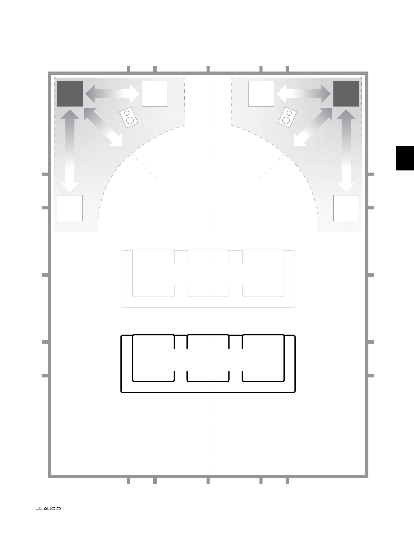
Pg 7 | IT
|
Fathom
®
v2
IT
Opzioni consigliate per la collocazione del subwoofer per uno o due Fathom v2
PIÙ FLUIDO
Collocazione consigliata dei subwoofer
per UNO o DUE subwoofer (posizionare
DUE con simmetria sinistra-destra)
PIÙ FLUIDO
PIÙ FLUIDOPIÙ FLUIDO
POSIZIONI COMPROMESSE DEI SEDILI
(Prestazioni dei bassi deboli e disomogenee)
POSIZIONI MIGLIORI DEI SEDILI
(Prestazioni più accurate dei bassi)
½
1⁄3
1⁄3
¼
¼
½
½
1⁄3
1⁄3 1⁄3
1⁄3
¼
¼ ¼
½1⁄3 1⁄3¼ ¼
¼
APPROSSIMATIVAMENTE 1/3
DELLA LUNGHEZZA
DELLA STANZA DALLA
PARETE POSTERIORE
LINEA CENTRALE DELLA STANZA
PIÙ
INTENSO
PIÙ
INTENSO
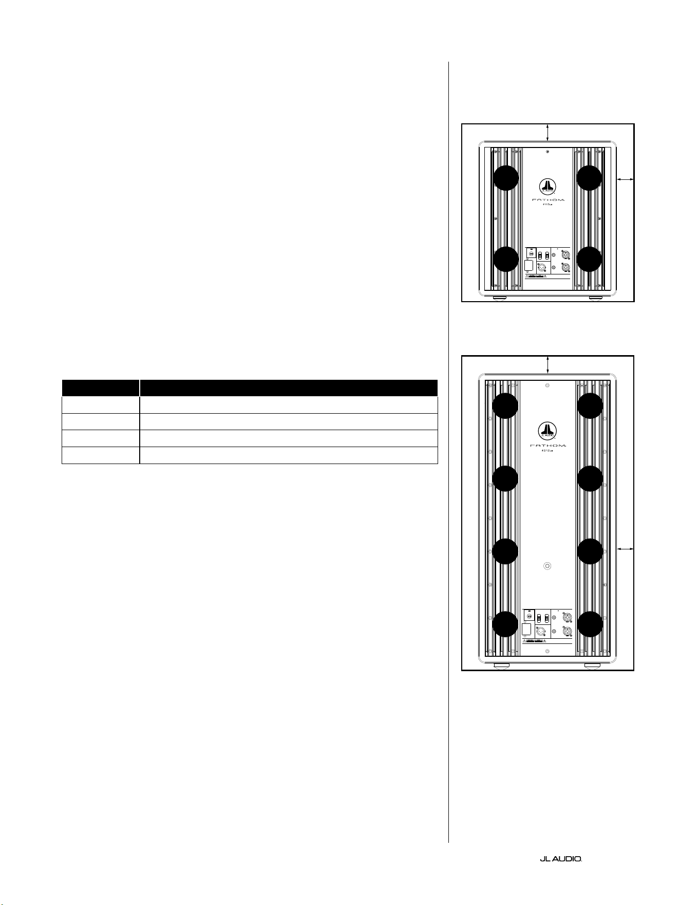
IT | Pg 8
|
Fathom
®
v2
CONSIDERAZIONI SPECIALI SULLE ISTALLAZIONI A INCASSO
I subwoofer Fathom v2 sono progettati per l’installazione “a incasso” agevolata.
Tutti i comandi usati generalmente sono posizionati sul pannello anteriore sul
woofer. Un Fathom v2 può essere integrato in una teca personalizzata attenendosi
alle seguenti linee guida pratiche.
1) Lasciare 4pollici (10cm) di spazio libero dietro il pannello amplicatore per il
rareddamento e lo spazio dei connettori adeguati.
2) Su tutti gli altri lati (fatta eccezione per la parte inferiore), lasciare almeno
2pollici (5cm) di spazio per una ventilazione adeguata.
3) Sebbene ilFathom v2 si surriscaldi solo alla massima potenza, consigliamo
di includere delle fessure adeguate per il calore in qualsiasi armadietto in
cui è alloggiato il Fathom v2. Una coppia di fessure con diametro di 3pollici
(7,5cm) vicino la parte inferiore della teca e vicino la parte superiore della teca,
consentirà la circolazione dell’aria fresca sul pannello amplicatore del proprio
impianto subwoofer Fathom v2 tenendolo bene al fresco.
4) Il subwoofer Fathom v2 è in grado di spostare quantità sostanziali di aria. Se
la parte anteriore del Fathom v2 è coperta da una griglia personalizzata, le
dimensioni della griglia devono essere ALMENO pari all’area del cono del
woofer per ciascun modello, per garantire che l’uscita non sia soocata dalla
teca personalizzata. Consultare la tabella sottostante per le aree consigliate delle
fessure per ciascun modello.
Modello Area consigliata della fessura sulla griglia personalizzata
f110v2 ≥ 60in
2
(386cm
2
)
f112v2 ≥ 85in
2
(550cm
2
)
f113v2 ≥ 108in
2
(700cm
2
)
f212v2 ≥ 170in
2
(1100cm
2
)
1200VA
Built in USA with Imported and domestic components
LEFT
or
MONO
RIGHT
ONLY
INPUTS
Output to Slave
(Balanced)
Balanced
Unbalanced
Input Modes
Slave
Master
Grounded
Isolated
SERIAL NUMBER:
Warranty void if serial number is remove d, altered or deface d.
F 12A H
250V
120 V ~ 60 Hz
F
U
S
E
F
U
S
E
Built in USA with Imported and domestic components
LEFT
or
MONO
RIGHT
ONLY
INPUTS
Output to Slave
(Balanced)
Balanced
Unbalanced
Input Modes
Slave
Master
Grounded
Isolated
SERIAL NUMBER:
Warranty void if serial number is remo ved, altered or defa ced.
F 15A H
250V
120 V ~ 60 Hz
F
U
S
E
F
U
S
E
FESSURA
FESSURA
FESSURA
FESSURA
FESSURA
FESSURA
FESSURA
FESSURA
2 in.min.
2 in.min.
2 in.
min.
2 in.
min.
Visuale posteriore dell’installazione nella teca
(f110, f112, f113):
Visuale posteriore dell’installazione nella
teca (f212):
FESSURA
FESSURA
FESSURA
FESSURA
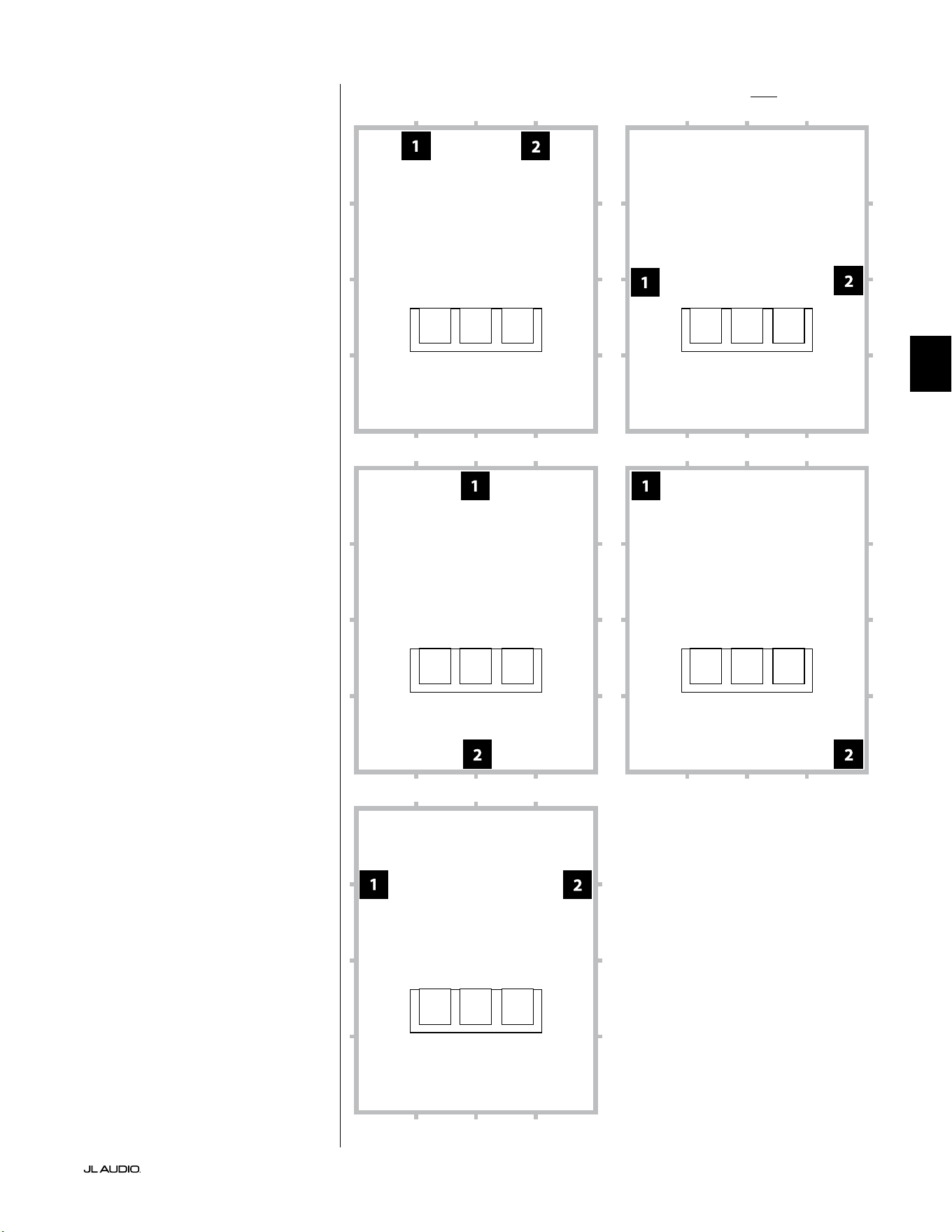
Pg 9 | IT
|
Fathom
®
v2
IT
Opzioni consigliate per la collocazione del subwoofer per due Fathom v2Impiego di due Fathom v2
Quando trovano impiego
due Fathom v2, tentarne il
posizionamento in prossimità degli
angoli anteriori della stanza, ad
angolazioni diagonalmente opposte
oppure in corrispondenza dei
punti centrali delle pareti opposte
come mostrato sulla destra.
La sperimentazione del
collocamento del subwoofer
e dell’ascoltatore è consigliata
per ottenere risultati migliori
e i vantaggi sono tangibili.
Rilevamenti ad alta risoluzione
e la calibrazione professionale
dell’impianto sono consigliati per i
migliori risultati possibili e prestazioni
ottimali di quest’ultimo.
Visuale posteriore dell’installazione nella teca
(f110, f112, f113):

IT | Pg 10
|
Fathom
®
v2
Opzioni consigliate per la collocazione del subwoofer per tre Fathom v2
Opzioni consigliate per la collocazione del subwoofer per quattro Fathom v2
Impiego di tre o quattro Fathom v2
Degli studi indicano che la
risposta più uida dei bassi per
una grande area di ascolto può
essere ottenuta impiegando quattro
subwoofer, posizionandone uno
al centro di ciascuna delle quattro
pareti (sebbene impiegando due
o tre subwoofer si possa ottenere
pressoché lo stesso risultato).
La sperimentazione del
collocamento del subwoofer
e dell’ascoltatore è consigliata
per ottenere risultati migliori
e i vantaggi sono tangibili.
Rilevamenti ad alta risoluzione
e la calibrazione professionale
dell’impianto sono consigliati per i
migliori risultati possibili e prestazioni
ottimali di quest’ultimo.
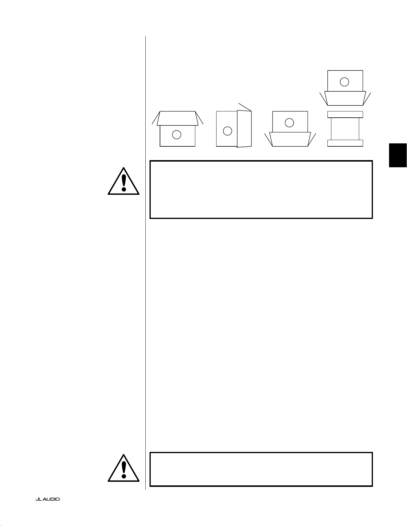
Pg 11 | IT
|
Fathom
®
v2
IT
IMPORTANTE! A CAUSA DEL PESO DEL SUBWOOFER FATHOM V2, SI PREGA
DI PRESTARE CAUTELA DURANTE IL DISIMBALLAGGIO E IL POSIZIONAMENTO,
AL FINE DI EVITARE LESIONI. SE POSSIBILE, AVVALERSI DELL’AIUTO DI UNA
SECONDA PERSONA PER AGEVOLARE IL PROCEDIMENTO. PER RIDURRE AL
MINIMO IL RISCHIO DI LESIONI, PIEGARE LE GINOCCHIA E SOLLEVARLO CON LE
GAMBE, NON CON LA SCHIENA.
Istruzioni dettagliate per il disimballaggio del subwoofer:
1. Posare lo scatolone sul pavimento in prossimità
della sua sede prevista nella stanza.
2. Aprire la parte superiore dello scatolone (osservare i contrassegni su di esso) e
rimuovere il manuale, il microfono di calibrazione e il cavo di alimentazione.
3. Rimuovere temporaneamente gli inserti d’imballaggio in polistirene.
4. Allentare il telo protettivo per agevolarne la rimozione in un secondo
momento (non rimuoverlo per adesso). Quando si apre il telo
protettivo, si vede la parte inferiore della cassa del subwoofer.
5. Posizionare nuovamente gli inserti in polistirene per proteggere
la cassa del subwoofer durante il disimballaggio.
6. Ribaltare delicatamente la scatola a lato, piegando
i lembi dello scatolone all’esterno.
7. Tenere indietro i lembi dello scatolone, ribaltare delicatamente
lo scatolone sulla sua parte superiore (estremità aperta).
8. Mettere lo scatolone in verticale no a quando esce il subwoofer e posarlo a lato.
9. Rimuovere l’inserto monopezzo in espanso e metterlo nello scatolone.
10. Rimuovere la busta in plastica e posarla nello scatolone.
11. Inclinare il subwoofer in avanti (verso la sua griglia) per rimuovere prima
l’inserto posteriore in polistirene. Poi, inclinare il subwoofer nella direzione
opposta (verso il pannello amplicatore) per rimuovere l’inserto restante
in polistirene. Posare entrambi gli inserti in polistirene nello scatolone.
12. Rimuovere il telo protettivo e posarlo nello scatolone.
IMPORTANTE! CONSERVARE TUTTI GLI IMBALLAGGI PER IL TRASPORTO
SICURO DEL SUBWOOFER E PER L’EVENTUALE UTILIZZO FUTURO IN SEDE DI
MANUTENZIONE.
Disimballare questa scatola in prossimità
della futura sede del subwoofer. Il subwoofer
è IMBALLATO al rovescio. Questa scatola
deve essere capovolta CON LA MASSIMA
CAUTELA per rimuovere il subwoofer e
ridurre al minimo gli sforzi.
DISIMBALLAGGIO DEL FATHOM v2
Ora che è stata determinata la posizione del Fathom v2 in stanza, è possibile
procedere con il suo disimballaggio in prossimità della sua sede di destinazione.
C
D
A
B
IMPORTANTE
IMPORTANTE
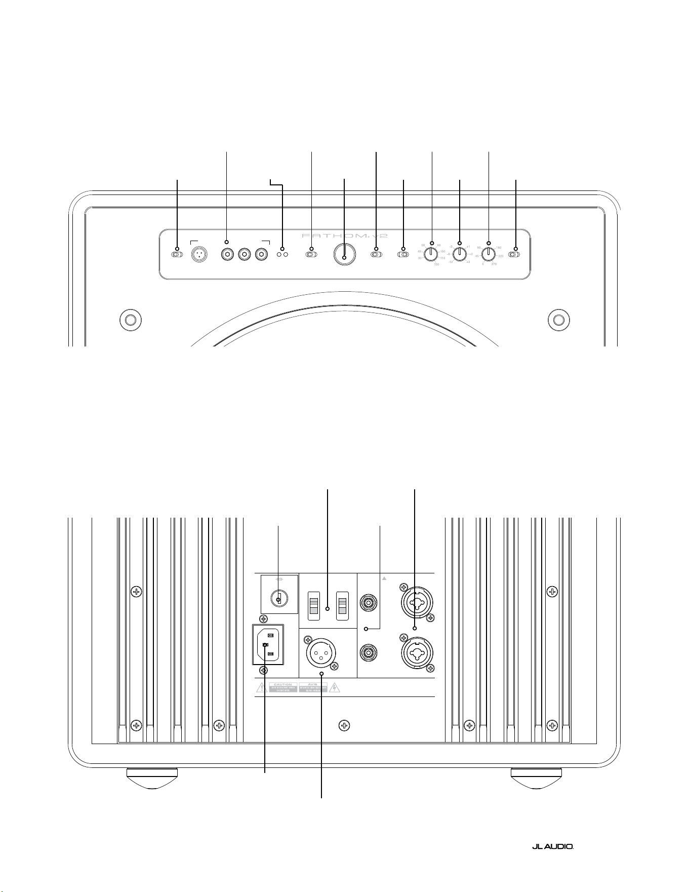
LP freq. (Hz) e.l.f. trim (dB) phase (deg.)
Polarity
0
|
180 deg.
LP Filter
o
|
12d B
|
24dB
Master Level
max
0
Lights
o
|
dim
|
on
-∞
Level Mode
ref.
|
variable
Input Mode
master
|
slave
calibration mic. demo defeat calibrate
Power
o
|
on
|
auto
Digital Automatic Room Optimization
1200VA
Built in USA with Imported and domestic components
LEFT
or
MONO
RIGHT
ONLY
INPUTS
Output to Slave
(Balanced)
Balanced
Unbalanced
Input Modes
Slave
Master
Grounded
Isolated
SERIAL NUMBER:
Warranty void if serial numb er is removed, altered or defaced.
F 12A H
250V
120 V ~ 60 Hz
F
U
S
E
F
U
S
E
IT | Pg 12
|
Fathom
®
v2
|
Fathom
®
v2
Comandi e collegamenti posteriori (modelli f112v2, f113v2, f212v2)
La gura sottostante mostra il pannello posteriore del subwoofer Fathom f113v2.
Il layout dei comandi e dei connettori è lo stesso del Fathom f112v2 e f212v2.
Ingressi
bilanciati
pag. 18
Ingressi
sbilanciati
pag. 19
Connettore
CA mod. IEC
pag. 21-22
Uscita a Slave -
Connettore
pag. 21
Interruttori della
modalità d’ingresso
pag. 20
Fusibile specico
per la regione
pag. 33
Layout del pannello di controllo anteriore (tutti i modelli)
La gura sottostante mostra il pannello di controllo anteriore del subwoofer Fathom f113v2.
Il layout dei comandi è lo stesso di tutti i modelli Fathom v2.
D.A.R.O.
pag. 14-15
Accensione
pag. 14
Modalità d’ingresso
pag. 15
Modalità del livello
pag. 15
Livello Master
pag. 16
Luci
pag. 16
Filtro PB
pag. 16
Freq. PB (Hz)
pag. 16
E.L.F. trim (dB)
pag. 17
Fase (gradi)
pag. 17
Polarità
pag. 17
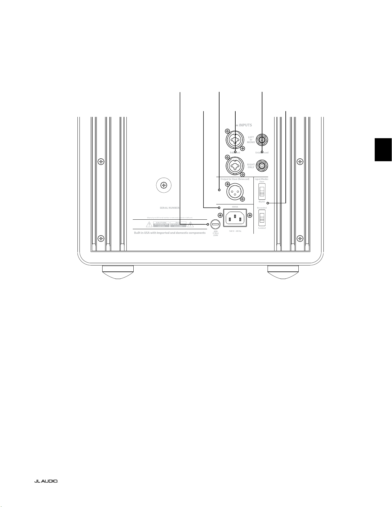
F
U
S
E
F
U
S
E
Comandi e collegamenti posteriori (modello f110v2)
La gura sottostante mostra il pannello posteriore del subwoofer Fathom f110v2.
*Le immagini dettagliate dei connettori e dei comandi posteriori nel presente manuale mostrano altri modelli Fathom v2 e
non sono indicative della disposizione del f110v2.
Ingressi
bilanciati
pag. 18
Ingressi
sbilanciati
pag. 19
Connettore
CA mod. IEC
pag. 21-22
Connettore
Uscita a Slave
pag. 21
Interruttori della
modalità d’ingresso
pag. 20
Pg 13 | IT
|
Fathom
®
v2
IT
Fusibile specico
per la regione
pag. 33
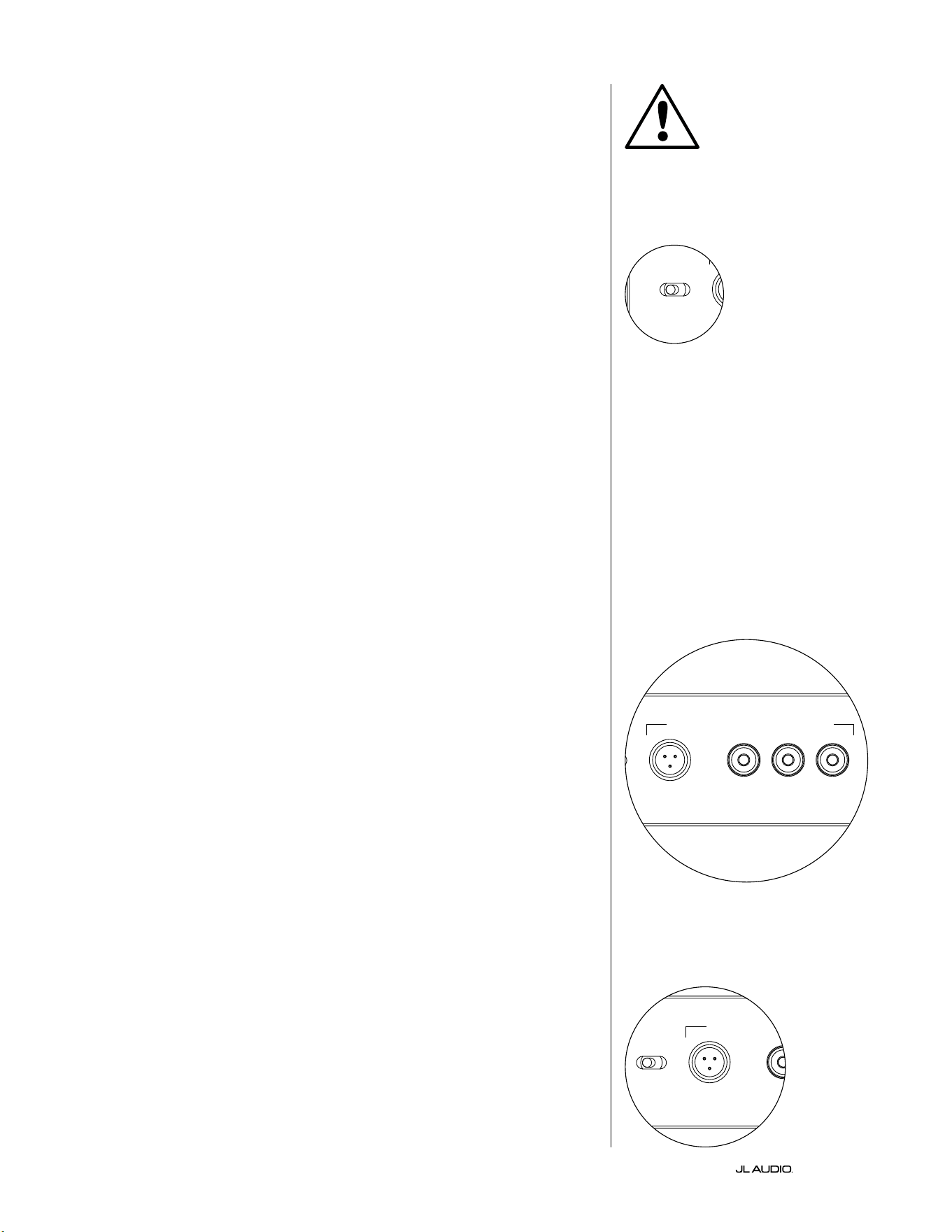
IT | Pg 14
|
Fathom
®
v2
COMANDI DEL PANNELLO ANTERIORE IN DETTAGLIO
Interruttore di accensione
L’interruttore “Power” determina la predisposizione operativa del subwoofer
Fathom v2 e dovrebbe essere l’unico metodo in uso per accendere e spegnere il
Fathom v2. Non usare una presa multipla, una presa elettrica con interruttore
o altro interruttore esterno, in quanto possono comportare picchi di tensione
indesiderati e potenzialmente pericolosi. Non scollegare il cavo dell’alimentazione
CA del Fathom v2 mentre l’unità è accesa. L’interruttore “Power” ha tre posizioni:
“On”: Il Fathom v2 è pienamente alimentato in qualsiasi momento. Le spie
del pannello anteriore sono accese, a meno che non siano state spente tramite
l’interruttore “Lights”.
“O ”: L’amplicatore di potenza interno del Fathom v2 è spento. In questo
stato, esiste un assorbimento di corrente trascurabile per l’attivazione dei relè di
potenza principali. Tutte le spie del pannello anteriore sono spente.
“Auto” : Il Fathom v2 attiverà il suo amplicatore interno quando un segnale audio è
presente in corrispondenza di uno dei suoi ingressi e disattiverà il suo amplicatore interno
se non è stato rilevato alcun segnale sui suoi ingressi per trenta (30) minuti. Quando a
riposo, il Fathom v2 assorbirà una quantità minima di corrente (<5Watt) per alimentare
i suoi circuiti di rilevamento del segnale. Le luci del pannello anteriore si spengono quando
il Fathom v2 si disattiva e si accendono quando il Fathom v2 si attiva (a meno che, non
siano state spente tramite l’interruttore “Lights”).
Nell’improbabile eventualità che la funzione Auto non sia sucientemente
sensibile per un particolare impianto, utilizzare un cavo adattatore a Y per
suddividere il segnale in ingresso in entrambi gli ingressi RCA o XLR sul Fathom
v2. In questo modo, sarà possibile incrementare la sensibilità ingresso di 6dB.
È importante ricordare che, se la sensibilità automatica è troppo alta oppure se
è presente un rumore notevole sul cavo in ingresso, il Fathom v2 potrebbe non
spegnersi, come desiderato. Qualora questo sia il caso, rimuovere l’adattatore del
cavo a Y o individuare la sorgente del rumore nei componenti a monte.
Digital Automatic Room Optimization (D.A.R.O.)
Una funzione potente dei subwoofer JL Audio Fathom v2 consiste
nell’innovativa tecnologia D.A.R.O. (Digital Automatic Room Optimization,
Ottimizzazione digitale automatica della stanza). Questo sistema one-touch
include 18 bande di equalizzazione digitale per eliminare i picchi più grandi di
risposta acustica nel proprio home theater in corrispondenza del sedile di ascolto
principale, migliorando notevolmente la risposta a bassa frequenza in stanza. La
calibrazione del sistema D.A.R.O. avviene completamente in automatico. Si prega
di consultare il capitolo successivo del manuale per i dettagli su come utilizzare il
sistema D.A.R.O.
Servendosi del microfono di calibrazione JL Audio, la procedura di calibrazione
D.A.R.O. richiede meno di tre minuti. In breve, è necessario collegare il microfono
incluso all’ingresso “Calibration Mic.”, premere il tasto “Calibrate” e tenere il
microfono all’altezza delle orecchie nel proprio sedile di ascolto principale durante
la prova. Una sequenza di rumori sarà riprodotta dal subwoofer Fathom v2 e la
risposta della stanza sarà rilevata in automatico, analizzata ed equalizzata per
eliminare il picco singolo di risposta acustica della stanza presso il proprio sedile di
ascolto. Per le istruzioni dettagliate sulle procedure di congurazione D.A.R.O.,
consultare le pagg. 29-30.
Microfono di calibrazione: ingresso
Questo ingresso serve a collegare il microfono di calibrazione JL Audio fornito
con il subwoofer Fathom v2. Collegare un’estremità del cavo fornito al microfono
e l’altra estremità a questo connettore jack prima di usare il sistema D.A.R.O. Il
sistema D.A.R.O. è appositamente calibrato per questo microfono e il suo schema
di collegamento è specico per il microfono fornito. La sequenza di calibrazione
non funziona quando è collegato un microfono diverso oppure se non è collegato
alcun microfono.
IMPORTANTE
LP freq. (Hz) e.l.f. trim (dB) phase (deg.)
Polarity
0
|
180 deg.
LP Filter
o
|
12dB
|
24dB
Master Level
max
0
Lights
o
|
dim
|
on
-∞
Level Mode
ref.
|
variable
Input Mode
master
|
slave
calibration mic. demo defeat calibrate
Power
o
|
on
|
auto
Digital Automatic Room Optimization
LP freq. (Hz) e.l.f. trim (dB) phase (deg.)
Polarity
0
|
180 deg.
LP Filter
o
|
12dB
|
24dB
Master Level
max
0
Lights
o
|
dim
|
on
-∞
Level Mode
ref.
|
variable
Input Mode
master
|
slave
calibration mic. demo defeat calibrate
Power
o
|
on
|
auto
Digital Automatic Room Optimization
LP freq. (Hz) e.l.f. trim (dB) phase (deg.)
Polarity
0
|
180 deg.
LP Filter
o
|
12dB
|
24dB
Master Level
max
0
Lights
o
|
dim
|
on
-∞
Level Mode
ref.
|
variable
Input Mode
master
|
slave
calibration mic. demo defeat calibrate
Power
o
|
on
|
auto
Digital Automatic Room Optimization
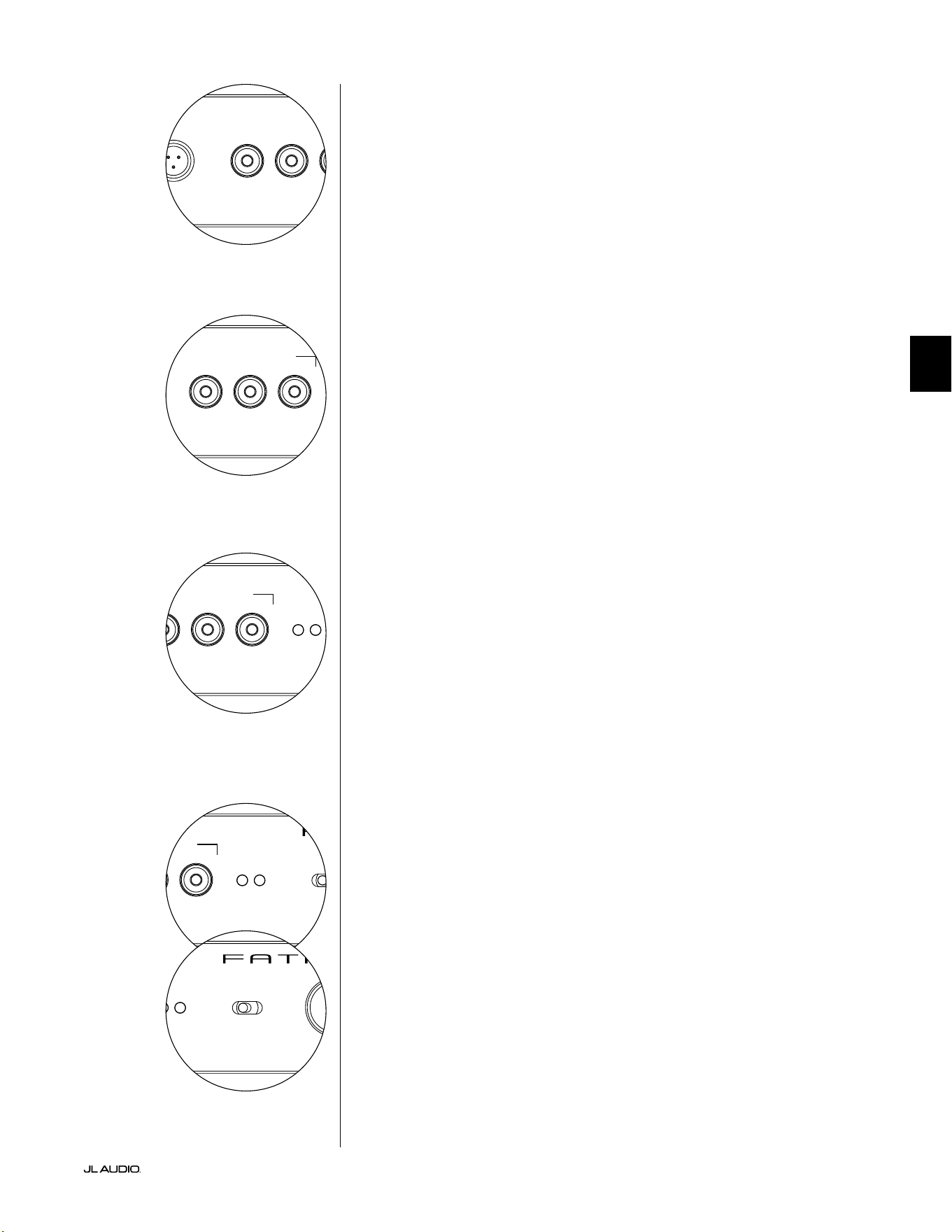
Pg 15 | IT
|
Fathom
®
v2
IT
LP freq. (Hz) e.l.f. trim (dB) phase (deg.)
Polarity
0
|
180 deg.
LP Filter
o
|
12dB
|
24dB
Master Level
max
0
Lights
o
|
dim
|
on
-∞
Level Mode
ref.
|
variable
Input Mode
master
|
slave
calibration mic. demo defeat calibrate
Power
o
|
on
|
auto
Digital Automatic Room Optimization
LP freq. (Hz) e.l.f. trim (dB) phase (deg.)
Polarity
0
|
180 deg.
LP Filter
o
|
12dB
|
24dB
Master Level
max
0
Lights
o
|
dim
|
on
-∞
Level Mode
ref.
|
variable
Input Mode
master
|
slave
calibration mic. demo defeat calibrate
Power
o
|
on
|
auto
Digital Automatic Room Optimization
Tasto Demo
Il tasto Demo attiva una sequenza di toni lunga 20 secondi che dimostra
brevemente il range del subwoofer Fathom v2. La funzione Demo è utile per
mostrare le abilità di potenza del Fathom v2 e per vericare che il Fathom v2 (o
diversi Fathom v2) sia operativo durante la risoluzione dei problemi dell’impianto.
Il pulsante Demo è usato anche (in combinazione) per eliminare (ritorno a
piatto) le impostazioni dell’equalizzatore D.A.R.O. Per eliminare le impostazioni
D.A.R.O. e spegnere la spia Calibrate, tenere premuto il tasto Demo, quindi
premere il tasto Defeat. Si prega di notare che questa sequenza di tasti deve avvenire
rapidamente. Se si tiene premuto il tasto Demo per più di 2 secondi senza toccare
il tasto Defeat, inizieranno i toni Demo. Qualora ciò dovesse accadere, attendere
semplicemente che termini la sequenza Demo e tentare di nuovo.
Tasto Defeat
Se “Demo” o “Calibrate” è premuto mentre la funzione Defeat è attiva, “Defeat”
si annullerà automaticamente. Nessun altro comando sul pannello anteriore altera
D.A.R.O. e la relativa disattivazione. L’impostazione di disattivazione è conservata in
una memoria non volatile e non cambierà anche se l’alimentazione è scollegata.
Il tasto Defeat è usato anche (in combinazione) per eliminare (ritorno a piatto)
le impostazioni dell’equalizzatore D.A.R.O. Per eliminare le impostazioni D.A.R.O.
e spegnere la spia Calibrate, tenere premuto il tasto Demo, quindi premere il tasto
Defeat. Si prega di notare che questa sequenza di tasti deve avvenire rapidamente.
Se si tiene premuto il tasto Demo per più di 2 secondi senza toccare il tasto Defeat,
inizieranno i toni Demo. Qualora ciò dovesse accadere, attendere semplicemente
che termini la sequenza Demo e tentare di nuovo.
Tasto di calibrazione
Durante la sequenza di prova D.A.R.O., il LED verde del tasto Calibrate
lampeggia rapidamente per avvisare l’utente di due condizioni speciali:
1. “JL Audio Microphone NOT Connected”: Se ci si dimentica di collegare il
microfono prima di iniziare una calibrazione, sarà emesso questo avviso. Premere
una volta il tasto Calibrate per eliminare l’avviso, collegare il microfono D.A.R.O. e
tentare di nuovo.
2. “Inappropriate Sound Level for D.A.R.O. Calibration”: Dal momento
che la sequenza D.A.R.O. è completamente automatica, questo avviso indica
probabilmente un problema con il microfono. Premere il tasto Calibrate una
volta per eliminare l’avviso. Accertarsi che il microfono JL Audio sia collegato
adeguatamente e tentare di nuovo. Per un ulteriore aiuto, consultare la risoluzione
dei problemi a pag. 33.
Indicatori della modalità d’ingresso
I LED indicatori della modalità d’ingresso mostrano la modalità d’ingresso,
di tipo “Master” o “Slave”, selezionata con l’interruttore sul pannello posteriore
del Fathom v2 (a meno che l’interruttore “Lights” non sia impostato su “o”). Per
maggiori dettagli, vedere la pag. 20.
Modalità del livello
L’interruttore a due posizioni Level Mode consente di selezionare tra le seguenti
modalità:
“Reference”: In questa modalità, la manopola di controllo Master Level non
ha alcun eetto sul livello di uscita del Fathom v2. Servirsi di questa impostazione
se si controlla, principalmente, il livello del subwoofer tramite il ricevitore o
preamplicatore/processore. Per coloro che hanno bambini piccoli o gli adolescenti
iper-entusiasti, questa modalità operativa previene la manipolazione diretta del
livello Master.
“Variable”: In questa modalità, la manopola di controllo Master Level determina
il livello di uscita del subwoofer Fathom v2. Questa modalità è anche utile quando si
fa corrispondere il livello del subwoofer Fathom v2 a un paio di altoparlanti stereo in
un impianto a due canali.
LP freq. (Hz) e.l.f. trim (dB) phase (deg.)
Polarity
0
|
180 deg.
LP Filter
o
|
12dB
|
24dB
Master Level
max
0
Lights
o
|
dim
|
on
-∞
Level Mode
ref.
|
variable
Input Mode
master
|
slave
calibration mic. demo defeat calibrate
Power
o
|
on
|
auto
Digital Automatic Room Optimization
LP freq. (Hz) e.l.f. trim (dB) phase (deg.)
Polarity
0
|
180 deg.
LP Filter
o
|
12dB
|
24dB
Master Level
max
0
Lights
o
|
dim
|
on
-∞
Level Mode
ref.
|
variable
Input Mode
master
|
slave
calibration mic. demo defeat calibrate
Power
o
|
on
|
auto
Digital Automatic Room Optimization
LP freq. (Hz) e.l.f. trim (dB) phase (deg.)
Polarity
0
|
180 deg.
LP Filter
o
|
12dB
|
24dB
Master Level
max
0
Lights
o
|
dim
|
on
-∞
Level Mode
ref.
|
variable
Input Mode
master
|
slave
calibration mic. demo defeat calibrate
Power
o
|
on
|
auto
Digital Automatic Room Optimization

IT | Pg 16
|
Fathom
®
v2
Manopola del livello Master
La manopola Master Level è usata per controllare il livello
di uscita del Fathom v2 quando la modalità Variable Level
è selezionata sul pannello di controllo anteriore.
Quando ruotata in senso antiorario no in fondo, l’uscita del Fathom v2 sarà
tacitata completamente. Quando in corrispondenza di “0” o in posizione verticale,
il livello di guadagno Variable corrisponde all’impostazione del livello Reference.
Quando ruotata in senso orario no in fondo, il livello di uscita del Fathom v2 è
15dB più alto rispetto all’impostazione Reference.
Luci
Il selettore “Lights” permette all’utente di selezionare una delle seguenti
modalità di spia luminosa.
“O” spegne tutti i LED del pannello anteriore in qualsiasi momento.
“Dim” imposta tutti i LED del pannello anteriore a un livello di luminosità
ridotta quando il Fathom v2 è acceso.
“On” imposta tutti i LED del pannello anteriore a un livello di luminosità piena
quando il Fathom v2 è acceso.
IMPORTANTE! QUANDO SI EFFETTUA LA RISOLUZIONE DEI PROBLEMI O
LA CALIBRAZIONE D.A.R.O. ACCERTARSI CHE L’INTERRUTTORE “LIGHTS” SIA
IMPOSTATO SU “DIM” o “ON”.
Filtro PB
Il selettore LP Filter (passa-basso) determina la modalità operativa del ltro
passa-basso integrato del Fathom v2.
“O” disattiva il ltro passa-basso eliminando completamente questo circuito
dal percorso di segnale.
“12dB” imposta la pendenza roll-o del ltro passa-basso a una pendenza di
12dB per ottava (allineamento Butterworth).
“24dB” imposta la pendenza roll-o del ltro passa-basso a una pendenza di
24dB per ottava (allineamento Linkwitz-Riley).
L’impostazione di 24dB attenua, con maggiore aggressività, le alte frequenze
sopra l’impostazione della frequenza PB (vedi sotto). Se si sta usando il ltro
passa-basso integrato Fathom v2, sperimentare l’impostazione della pendenza
del ltro PB per ottenere la migliore transizione agli altoparlanti satelliti. Se si
preferisce usare i ltri e le funzioni di gestione dei bassi nel proprio ricevitore o
preamplicatore, disattivare il ltro integrato selezionando la posizione “O”.
Freq. PB
La manopola selettrice LP Frequency (passa-basso) permette all’utente di
scegliere la frequenza roll-o del ltro passa-basso interno del Fathom v2. La
frequenza è variabile da 30Hz (no in fondo in senso antiorario) a 130Hz (no
in fondo in senso orario). Questa manopola non inuisce sul segnale d’ingresso
in qualsiasi modo se l’interruttore LP Filter è impostato su “O ”. 80Hz è una
frequenza del ltro comunemente utilizzata e, solitamente, funge da buon punto di
partenza per le regolazioni.
LP freq. (Hz) e.l.f. trim (dB) phase (deg.)
Polarity
0
|
180 deg.
LP Filter
o
|
12dB
|
24dB
Master Level
max
0
Lights
o
|
dim
|
on
-∞
Level Mode
ref.
|
variable
Input Mode
master
|
slave
calibration mic. demo defeat calibrate
Power
o
|
on
|
auto
Digital Automatic Room Optimization
LP freq. (Hz) e.l.f. trim (dB) phase (deg.)
Polarity
0
|
180 deg.
LP Filter
o
|
12dB
|
24dB
Master Level
max
0
Lights
o
|
dim
|
on
-∞
Level Mode
ref.
|
variable
Input Mode
master
|
slave
calibration mic. demo defeat calibrate
Power
o
|
on
|
auto
Digital Automatic Room Optimization
LP freq. (Hz) e.l.f. trim (dB) phase (deg.)
Polarity
0
|
180 deg.
LP Filter
o
|
12dB
|
24dB
Master Level
max
0
Lights
o
|
dim
|
on
-∞
Level Mode
ref.
|
variable
Input Mode
master
|
slave
calibration mic. demo defeat calibrate
Power
o
|
on
|
auto
Digital Automatic Room Optimization
LP freq. (Hz) e.l.f. trim (dB) phase (deg.)
Polarity
0
|
180 deg.
LP Filter
o
|
12dB
|
24dB
Master Level
max
0
Lights
o
|
dim
|
on
-∞
Level Mode
ref.
|
variable
Input Mode
master
|
slave
calibration mic. demo defeat calibrate
Power
o
|
on
|
auto
Digital Automatic Room Optimization
IMPORTANTE
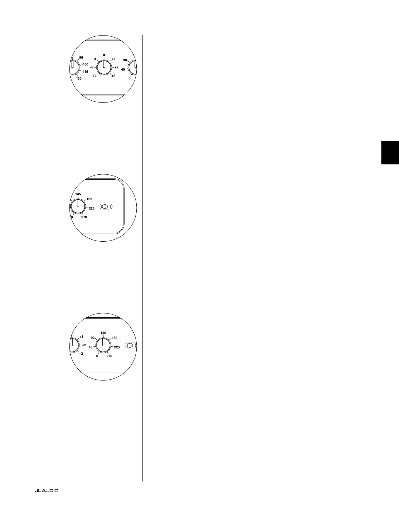
Pg 17 | IT
|
Fathom
®
v2
IT
E.L.F. Trim
La manopola “E.L.F. Trim” (Extreme Low Frequency) permette all’utente di
applicare una determinata quantità di equalizzazione di segnale a 24Hertz (bassi
molto ridotti). Con la rotazione completamente in senso antiorario, il segnale a
24Hz è tagliato di 12dB. Su 0, l’equalizzatore è impostato piatto per un contributo
zero al segnale. Con la rotazione completamente in senso orario, il segnale a 24Hz è
aumentato di 3dB.
La funzione E.L.F. Trim è utile per realizzare un’uscita di frequenza
molto bassa del Fathom v2 per la propria stanza. Con un po’ di aumento, è
possibile rendere del materiale acustico più entusiasmante. Impiegando la
funzione di taglio, si può compensare il guadagno della stanza o del conne
nelle basse frequenze. I conni della stanza e le dimensioni (limitate) nite
della stanza causano l’aumento delle frequenze molto basse in relazione ad
altre parti del segnale. Di conseguenza, la funzione E.L.F. Trim per tagliare le
frequenze più basse può rivelarsi utile per domare bassi ridotti che suonano
“rigon” o non naturali in stanze di piccola e media grandezza (ed è anche
possibile ridurre le vibrazioni indesiderate in stanza o nella casa).
Polarità
L’interruttore “Polarity” consente all’utente di scegliere tra la polarità di segnale
normale (0 deg) e inversa (180 deg). L’interruttore Polarity inuisce principalmente
sull’intervallo piccolo di frequenza intorno al punto di crossover tra il proprio
subwoofer e gli altoparlanti satelliti.
Diversamente dal comando Phase, che aggiunge ecacemente il ritardo
temporale, l’interruttore Polarity produce un’inversione istantanea dei picchi di
ampiezza del segnale. Ad esempio, se a un determinato punto di riferimento un’onda
sinusoidale ha un picco di ampiezza, facendo scattare l’interruttore Phase, l’utente
converte istantaneamente quel picco in un calo o una diminuzione dell’ampiezza.
Dal momento che l’eetto dell’interruttore Polarity è immediato, completa il
funzionamento del comando Phase e non può essere sostituito da esso.
Quando si colloca il Fathom v2 nella stanza, sperimentare l’interruttore Polarity
prima di regolare il comando “Phase”. Ciascuna posizione dell’interruttore Polarity
potrebbe fornire una transizione più uida tra il proprio Fathom v2 e gli altoparlanti
satelliti. Servirsi di materiale sorgente con un buon contenuto di bassi medi e
superiori per la valutazione.
Fase
La manopola di controllo Phase consente all’utente di regolare la
“temporizzazione” dell’uscita del subwoofer in relazione agli altoparlanti principali.
Il comando Phase inuisce principalmente sull’intervallo piccolo di frequenza
intorno al punto di crossover tra il proprio subwoofer e gli altoparlanti satelliti.
Sono possibili impostazioni di fase tra 0 gradi (rotazione completamente in senso
antiorario) e 270 gradi (rotazione completamente in senso orario). Le diciture del
comando Phase sono indicizzate a una frequenza di 80Hz, dal momento che questo
è il punto di crossover più comune tra gli altoparlanti satelliti e un subwoofer.
Le posizioni degli altoparlanti, del subwoofer e dei sedili di ascolto variano
sensibilmente nelle istallazioni home theater. Dal momento che la posizione
sica degli altoparlanti in relazione ai conni della stanza e reciproca inuisce
notevolmente sulla qualità percepita dell’uscita audio, a volte è di aiuto ritardare
l’uscita del subwoofer. Questo è esattamente ciò che si verica quando si ruota il
comando Phase oltre 0 gradi.
Una volta che il Fathom v2 è stato posizionato nella propria stanza di ascolto per
orire l’audio completo più uido, e dopo aver determinato la posizione ottimale
dell’interruttore “Polarity” (vedere il capitolo che segue), sperimentare la posizione
della manopola Phase. Impiegando del materiale sorgente familiare con un buon
contenuto di bassi medi e superiori, regolare il comando Phase e ascoltare bassi
medi meglio deniti e una transizione più uida tra il subwoofer e gli impianti degli
altoparlanti satelliti. Se nessuna impostazione individuale suona meglio dell’altra,
lasciare la manopola Phase su 0 gradi.
LP freq. (Hz) e.l.f. trim (dB) phase (deg.)
Polarity
0
|
180 deg.
LP Filter
o
|
12dB
|
24dB
Master Level
max
0
Lights
o
|
dim
|
on
-∞
Level Mode
ref.
|
variable
Input Mode
master
|
slave
calibration mic. demo defeat calibrate
Power
o
|
on
|
auto
Digital Automatic Room Optimization
LP freq. (Hz) e.l.f. trim (dB) phase (deg.)
Polarity
0
|
180 deg.
LP Filter
o
|
12dB
|
24dB
Master Level
max
0
Lights
o
|
dim
|
on
-∞
Level Mode
ref.
|
variable
Input Mode
master
|
slave
calibration mic. demo defeat calibrate
Power
o
|
on
|
auto
Digital Automatic Room Optimization
LP freq. (Hz) e.l.f. trim (dB) phase (deg.)
Polarity
0
|
180 deg.
LP Filter
o
|
12dB
|
24dB
Master Level
max
0
Lights
o
|
dim
|
on
-∞
Level Mode
ref.
|
variable
Input Mode
master
|
slave
calibration mic. demo defeat calibrate
Power
o
|
on
|
auto
Digital Automatic Room Optimization

IT | Pg 18
|
Fathom
®
v2
COLLEGAMENTO DEL FATHOM v2
Ingressi bilanciati
Se il ricevitore home theater o il preamplicatore/processore ore uscite
bilanciate, gli ingressi bilanciati del Fathom v2 sono il collegamento preferito.
I collegamenti bilanciati trovano ampio uso negli studi professionali e in
applicazioni di raorzamento acustico per una serie di motivi molto validi. Oltre a
fornire una messa a terra adeguata tra i componenti, la trasmissione bilanciata del
segnale è studiata per annullare rumori indotti del cavo dall’ambiente circostante
(aspetto particolarmente importante per i cavi lunghi). Di conseguenza, se si
usano collegamenti bilanciati, l’impianto emetterà, con buona probabilità, meno
ronzii o altri rumori estranei.
I subwoofer Fathom v2 presentano dei collegamenti d’ingresso bilanciati a
sinistra e a destra con connettori jack combinati XLR. Questi connettori jack
speciali accettano un connettore XLR maschio a tre pin o un connettore “punta-
anello-manicotto” (TRS) da 1/4 di pollice (6,3mm) per la compatibilità con una
serie di apparecchiature.
Per gli impianti con un subwoofer mono oppure collegamento di canali “LFE”,
si utilizzerà soltanto un connettore jack indicato come “Le or Mono”. Questo
metodo si applica ai ricevitori multi-canale più moderni e a preamplicatore/
processori. Connettori jack d’ingresso separati a sinistra e destra sono forniti per
i sistemi senza un collegamento subwoofer mono dedicato. Questo si applica,
tipicamente, alle apparecchiature audio a due canali.
Dei cavi bilanciati appropriati sono disponibili presso il proprio rivenditore JL
Audio e non sono inclusi con il Fathom v2.
Note tecniche:
• Non utilizzare degli ingressi bilanciati con segnali sbilanciati tramite adattatori.
Gli ingressi sbilanciati del Fathom v2 sono preferibili in situazioni in cui è
disponibile soltanto una sorgente di segnale sbilanciata. L’impedenza degli
ingressi bilanciati è 20kOhm.
• I connettori d’ingresso sono congurati in osservanza delle raccomandazioni
della Audio Engineering Society per cavi segnale bilanciati come indicato di
seguito:
Collegamento XLR
Pin 1: Schermatura
Pin 2: Positivo
Pin 3: Negativo
Collegamento TRS:
Punta: Positiva
Anello: Negativo
Manicotto: Schermatura
IMPORTANTE! SE IL RICEVITORE O PREAMPLIFICATORE/PROCESSORE NON
HA USCITE XLR O BILANCIATE TRS DA 1/4 POLLICE, SI PREGA DI CONSULTARE
LA SEZIONE “INGRESSI SBILANCIATI” A PAG. 19 PER INFORMAZIONI SUL
COLLEGAMENTO DEGLI INGRESSI. NON TENTARE DI COLLEGARE LE USCITE
SBILANCIATE AGLI INGRESSI BILANCIATI DEL FATHOM V2 MEDIANTE
ADATTATORI.
Gli ingressi a sinistra e a destra sul Fathom
v2 sono addizionati internamente in un
unico canale mono. Dal momento che il
Fathom v2 è intrinsecamente un dispositivo
a canale “mono” o singolo, è possibile usare
gli ingressi a sinistra e destra per il Fathom
v2 Master e poi distribuire il segnale mono
sommato a Fathom v2 Slave aggiuntivi
nell’impianto.
IMPORTANTE
1200VA
Built in USA with Imported and domestic components
LEFT
or
MONO
RIGHT
ONLY
INPUTS
Output to Slave
(Balanced)
Balanced
Unbalanced
Input Modes
Slave
Master
Grounded
Isolated
SERIAL NUMBER:
Warranty void if serial number is removed, altered or defaced.
F 12A H
250V
120 V ~ 60 Hz
F
U
S
E
F
U
S
E
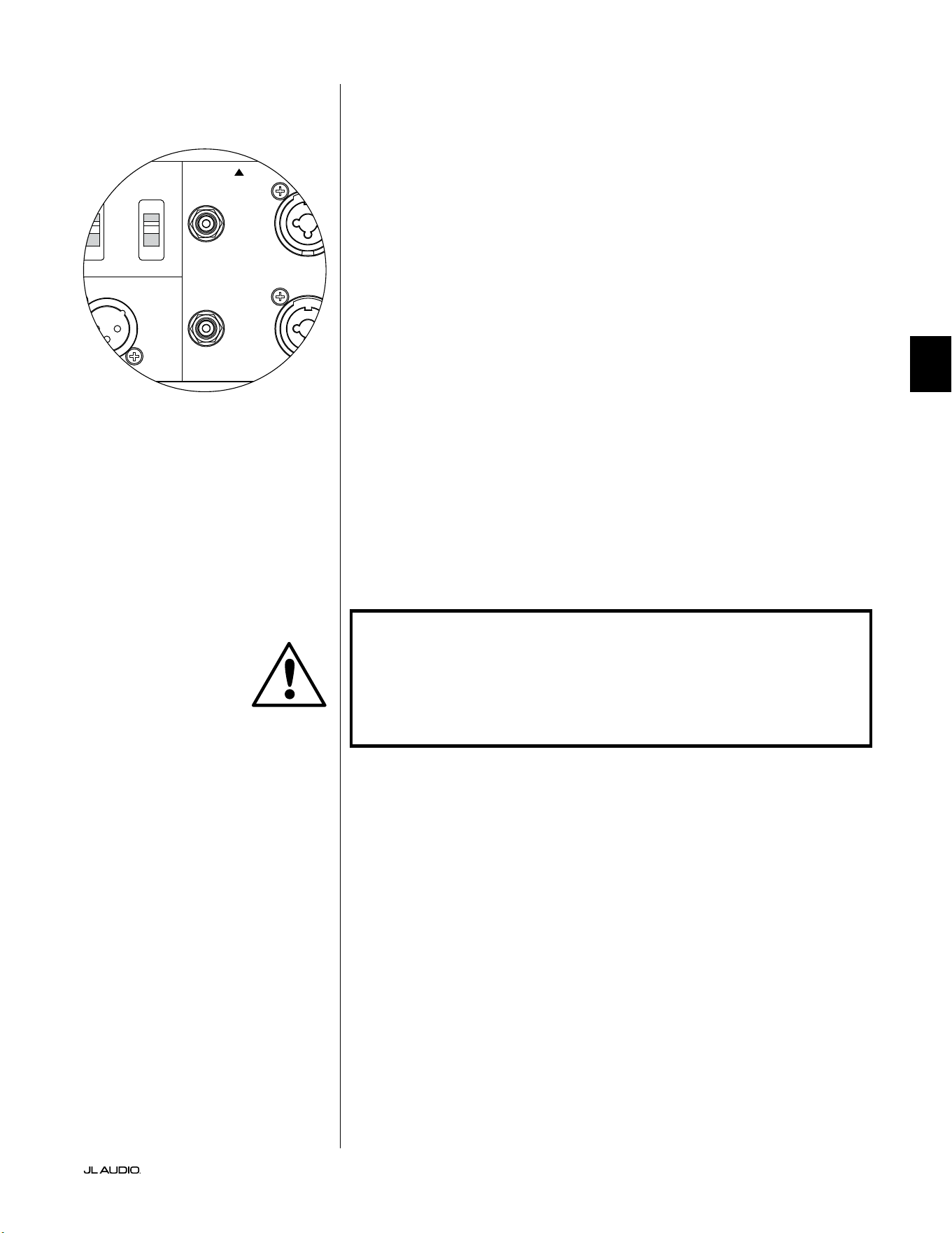
Pg 19 | IT
|
Fathom
®
v2
IT
Ingressi sbilanciati
Il subwoofer Fathom v2 presenta dei connettori d’ingresso di tipo RCA,
individuali, sbilanciati, a sinistra e a destra. Questi sono i connettori più
comunemente usati per le applicazioni audio domestiche e devono essere
impiegati se il ricevitore o il preamplicatore/processore non ore uscite
bilanciate. Sebbene i collegamenti sbilanciati non siano immuni al rumore come
un collegamento bilanciato, i subwoofer Fathom v2 impiegando l’isolamento ottico
sugli ingressi sbilanciati, al ne di ridurre al minimo i possibili rumori nel proprio
impianto.
Per gli impianti con un subwoofer mono oppure collegamento di canali
“LFE”, si utilizzerà soltanto un connettore jack tipo RCA indicato come “Le
or Mono”. Questo metodo si applica ai ricevitori multi-canale più moderni e a
preamplicatore/processori. Connettori jack d’ingresso di tipo RCA separati a
sinistra e destra sono forniti per i sistemi senza un collegamento subwoofer mono
dedicato. Questo si applica, tipicamente, alle apparecchiature audio a due canali.
Note tecniche:
• Quando le uscite bilanciate non sono disponibili sulla sorgente di segnale,
è necessario impiegare gli ingressi sbilanciati di tipo RCA. I Fathom v2
presentano circuiti con isolamento ottico sugli ingressi sbilanciati per
ridurre al minimo la probabilità di rumore indotto da un circuito di terra.
L’impedenza degli ingressi sbilanciati è 50kOhm.
• I collegamenti sono standard del settore per i cavi di segnale sbilanciati come
indicato di seguito:
Collegamento di tipo RCA:
Punta: Positiva
Manicotto: Negativo
IMPORTANTE! SE ESISTE DEL RUMORE DOPO IL COLLEGAMENTO, GLI
AMPLIFICATORI FATHOM V2 CONSENTONO IL COLLEGAMENTO A MASSA
O L’ISOLAMENTO DEGLI INGRESSI SBILANCIATI. CONSULTARE LA SEZIONE
“INTERRUTTORI DELLA MODALITÀ D’INGRESSO” A PAG. 20 DEL PRESENTE
MANUALE PER MAGGIORI INFORMAZIONI SULLA RIDUZIONE AL MINIMO DEL
RUMORE.
1200VA
Built in USA with Imported and domestic components
LEFT
or
MONO
RIGHT
ONLY
INPUTS
Output to Slave
(Balanced)
Balanced
Unbalanced
Input Modes
Slave
Master
Grounded
Isolated
SERIAL NUMBER:
Warranty void if serial number is removed, altered or defaced.
F 12A H
250V
120 V ~ 60 Hz
F
U
S
E
F
U
S
E
IMPORTANTE
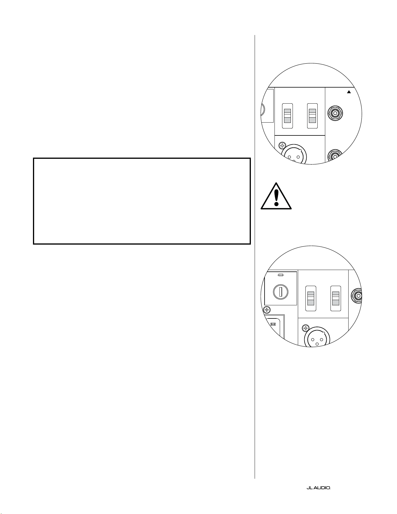
IT | Pg 20
|
Fathom
®
v2
Interruttori della modalità d’ingresso:
Due interruttori si trovano sul pannello posteriore al ne di controllare il
collegamento a terra del segnale sbilanciato e il funzionamento master/slave.
Interruttore isolato/messo a terra
L’interruttore Input Mode “Grounded / Isolated” inuisce soltanto sugli ingressi
RCA sbilanciati ed è progettato per agevolare un collegamento silenzioso e privo
di ronzio al proprio impianto audio o home theater. Questa funzione è inclusa per
gestire problemi di messa a terra del segnale riscontrati spesso negli impianti home
theater quando sono interconnessi diversi componenti di svariati produttori.
Il Fathom v2 è spedito con questo interruttore nella posizione “Isolated”. Se,
con tutti i componenti dell’impianto collegati e accesi (ma senza alcuna sorgente
in riproduzione), si sente un ronzio continuo a basse frequenze dal Fathom v2, far
scattare questo interruttore nella posizione “Grounded” e valutare la dierenza di
livello di rumorosità. Servirsi della posizione dell’interruttore che ore meno ronzio
o rumorosità.
IMPORTANTE! SI PREGA DI NOTARE CHE LA SOSTITUZIONE DI UN EVENTUALE
COMPONENTE NELL’IMPIANTO OTTIMIZZATO (RICEVITORE, AMPLIFICATORE,
LETTORE DVD, CAVO O DISPOSITIVO SATELLITARE, ECC.) POTREBBE ALTERARE
LO SCHEMA DI MESSA A TERRA DEL SEGNALE E CAUSARE UN RONZIO
NELL’IMPIANTO PRECEDENTEMENTE SILENZIOSO. SE SI AGGIUNGE O SI
MODIFICA UN COMPONENTE A MONTE NEL PROPRIO IMPIANTO HOME THEATER,
POTREBBE ESSERE NECESSARIO RIVISITARE L’IMPOSTAZIONE DI QUESTA
MODALITÀ D’INGRESSO SUL SUBWOOFER FATHOM V2 PER PRESTAZIONI DI
RUMORE OTTIMALI. SOTTO QUESTO PUNTO DI VISTA, IL CAVO E IL DISPOSITIVO
SATELLITARE SI RIVELANO PARTICOLARMENTE PROBLEMATICHE.
Interruttore Master/Slave
I Fathom v2 sono progettati per accogliere facilmente l’implementazione di
diversi subwoofer nel proprio impianto home theater mediante una catena di
collegamenti Master/Slave. Questo metodo consente di utilizzare funzioni di
elaborazione del segnale di un Fathom v2 per controllare centralmente Fathom
v2 multipli nella stanza. La funzione Master/Slave, inoltre, consente all’impianto
D.A.R.O. di ottimizzare la risposta di un’installazione di subwoofer multipli.
Il Fathom v2 è spedito con questo interruttore nella posizione “Master”. Se si
usa un unico Fathom v2, si impiegherà la posizione “Master” e non ci si dovrà
preoccupare ulteriormente con questa sezione.
Se l’installazione comprende due o più amplicatori Fathom v2, si designerà
un Fathom v2 come “Master” e tutti gli altri nell’impianto come subwoofer “Slave”
tramite l’interruttore “Master/Slave” sul pannello posteriore dell’amplicatore di
ciascun Fathom v2. I LED sul pannello anteriore del Fathom v2 sono presenti per
indicare se la modalità “Master” o “Slave” è stata selezionata per un dato subwoofer.
Dal Fathom v2 che opera in modalità “Master”, il segnale “Output to
Slave” trasporta qualsiasi elaborazione del segnale selezionata sul Fathom v2
Master (compresa l’impostazione Master Level e l’elaborazione D.A.R.O.)
agli altri Fathom v2 che operano in modalità “Slave”. L’elaborazione
del segnale e i controlli del livello sul subwoofer “Slave” saranno
inattivabili. In questa modalità, l’utente non deve preoccuparsi delle
impostazioni di livello, crossover e altro tipo per i subwoofer slave.
Note tecniche:
• Selezionando la posizione “Slave” si elimina l’elaborazione del segnale denibile
dall’utente e il controllo del livello master. In virtù di questo aspetto, vi sono
alcune situazioni speciali in cui si desidera attivare un unico Fathom v2 in
modalità “Slave”. Se si utilizzano l’elaborazione del segnale e comandi di
corrispondenza del livello, attivando la modalità “Slave” si previene l’inuenza
sui parametri con i comandi manuali sul Fathom v2.
IMPORTANTE
1200VA
Built in USA with Imported and domestic components
LEFT
or
MONO
RIGHT
ONLY
INPUTS
Output to Slave
(Balanced)
Balanced
Unbalanced
Input Modes
Slave
Master
Grounded
Isolated
SERIAL NUMBER:
Warranty void if serial number is removed, altered or defaced.
F 12A H
250V
120 V ~ 60 Hz
F
U
S
E
F
U
S
E
1200VA
Built in USA with Imported and domestic components
LEFT
or
MONO
RIGHT
ONLY
INPUTS
Output to Slave
(Balanced)
Balanced
Unbalanced
Input Modes
Slave
Master
Grounded
Isolated
SERIAL NUMBER:
Warranty void if serial number is removed, altered or defaced.
F 12A H
250V
120 V ~ 60 Hz
F
U
S
E
F
U
S
E
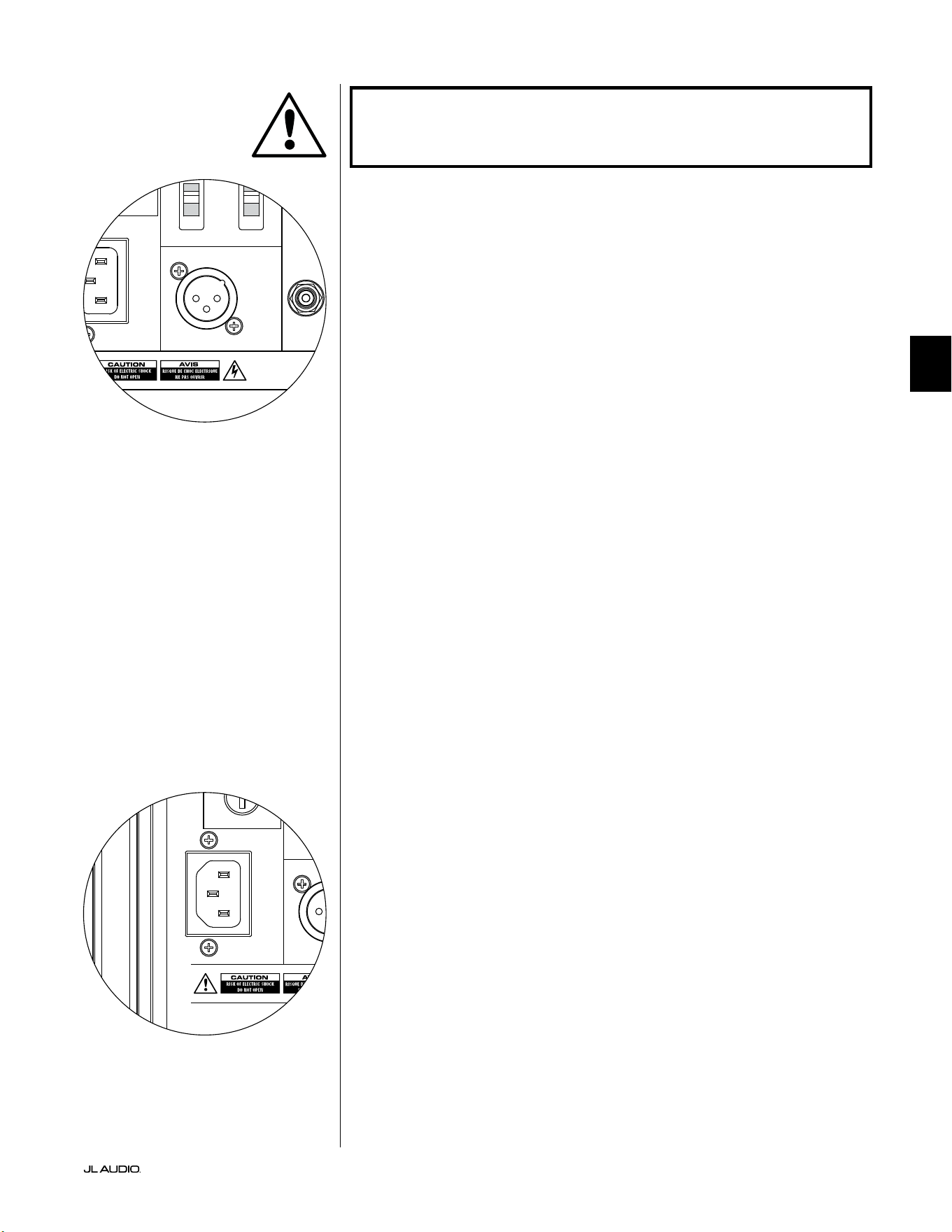
Pg 21 | IT
|
Fathom
®
v2
IT
IMPORTANTE! SI PREGA DI CONSULTARE GLI “SCHEMI DI COLLEGAMENTO
DELL’IMPIANTO” A PAGG. 22-25 PER MAGGIORI INFORMAZIONI SULL’UTILIZZO
DEI COLLEGAMENTI D’INGRESSO/USCITA.
Connettore di uscita a Slave
Se si utilizza più di un subwoofer Fathom v2 in un impianto home theater,
si designerà un Fathom v2 come Master (vedere pag. 20), e si alimenterà il
segnale da esso ai Fathom v2 “Slave” restanti tramite quest’uscita XLR bilanciata.
Il cavo “Output to Slave” può essere collegato all’ingresso XLR “Le or Mono”
bilanciato sul Fathom v2 successivo. Quando un Fathom v2 è in modalità “Slave”, il
collegamento “Output to Slave” può essere usato per passare il segnale a ulteriori
Fathom v2 in modalità “Slave”.
Il connettore “Output to Slave” è studiato per essere usato come indicato di
seguito:
1) Dal connettore “Output to Slave” del Fathom v2 “Master” all’ingresso XLR
bilanciato “Le or Mono” del primo Fathom v2 “S l av e”.
2) Dal connettore “Output to Slave” del primo Fathom v2 “Slave” all’ingresso
XLR bilanciato “Le or Mono” del secondo Fathom v2 “S l a v e”.
3) Dal connettore “Output to Slave” del secondo Fathom v2 “Slave” all’ingresso
XLR bilanciato “Le or Mono” del terzo Fathom v2 “Slave”. Ecc, ecc. (no
a dieci Fathom v2 possono essere collegati in questa congurazione). Dei
cavi bilanciati appropriati con terminazioni XLR sono disponibili presso il
proprio rivenditore JL Audio e non sono inclusi con il Fathom v2.
Note tecniche:
• Il segnale “Output to Slave” trasporta qualsiasi elaborazione del segnale
selezionata sul Fathom v2 Master (compresa l’impostazione Master Level e
l’elaborazione D.A.R.O.) agli altri Fathom v2 che operano in modalità “Slave”.
• Dai Fathom v2 che operano in modalità “Slave”, il segnale “Output to Slave”
è una replica esatta e buerizzata del segnale d’ingresso bilanciato, rendendo
questo metodo di distribuzione del segnale preferibile rispetto all’impiego di
adattatori a Y o splitter.
• Usare esclusivamente cavi di collegamento schermati con connettori XLR
di alta qualità per il collegamento Master/Slave. Non servirsi mai di cavi
sbilanciati con adattatori.
Connettore di alimentazione CA tipo IEC
Il connettore femmina del cavo CA tipo IEC riceve un cavo di alimentazione
a calibro elevato, lungo 6. (1,8m), incluso nel proprio subwoofer Fathom v2.
I Fathom v2 venduti in diverse parti del mondo sono congurati per l’impianto
elettrico di ciascun mercato e includono connettori appropriati sui rispettivi
cavi di alimentazione. Si prega di notare i contrassegni della tensione accanto al
connettore CA e assicurarsi di erogare alimentazione al Fathom v2 soltanto da un
connettore femmina che corrisponda a tali contrassegni. Non usare un cavo di
alimentazione CA diverso da quello fornito con il Fathom v2. Per informazioni
sul portafusibili principale, si prega di consultare il capitolo sulla risoluzione dei
problemi del presente manuale.
Il subwoofer Fathom v2 è un dispositivo potente e può assorbire molta
corrente. Se sono collegati troppi componenti a un subwoofer Fathom v2 verso una
presa elettrica, si rischia di far scattare l’interruttore del circuito domestico durante
programmi molto impegnativi. Se ciò dovesse accadere, separare il Fathom v2
e gli altri componenti tra due circuiti elettrici CA. Se possibile, per le massime
prestazioni, dedicare un circuito CA a ciascun Fathom v2.
IMPORTANTE
1200VA
Built in USA with Imported and domestic components
LEFT
or
MONO
RIGHT
ONLY
INPUTS
Output to Slave
(Balanced)
Balanced
Unbalanced
Input Modes
Slave
Master
Grounded
Isolated
SERIAL NUMBER:
Warranty void if serial number is removed, altered or defaced.
F 12A H
250V
120 V ~ 60 Hz
F
U
S
E
F
U
S
E
1200VA
Built in USA with Imported and domestic components
LEFT
or
MONO
RIGHT
ONLY
INPUTS
Output to Slave
(Balanced)
Balanced
Unbalanced
Input Modes
Slave
Master
Grounded
Isolated
SERIAL NUMBER:
Warranty void if serial number is removed, altered or defaced.
F 12A H
250V
120 V ~ 60 Hz
F
U
S
E
F
U
S
E
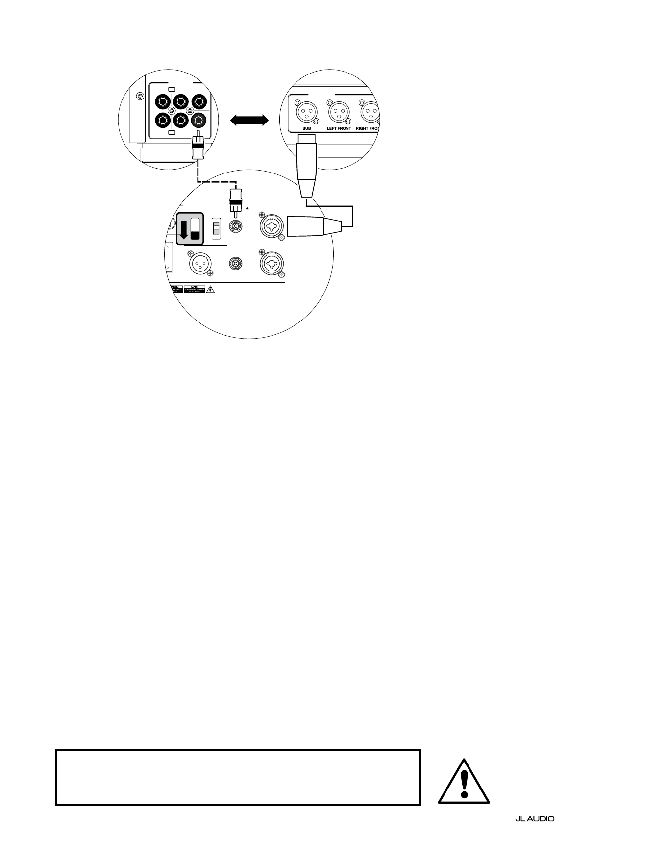
IT | Pg 22
|
Fathom
®
v2
SCHEMA DI COLLEGAMENTO
DELL’IMPIANTO 1:
Un Fathom v2 a
ricevitore Home Theater o
preamplicatore/processore Home
Theater
La maggior parte dei ricevitori e
preamplicatori/processori home theater
forniscono un’unica uscita subwoofer
(mono). Quando si collega un’uscita
subwoofer mono al Fathom v2, si userà
soltanto l’ingresso “Le or Mono” del
Fathom.
Due tipologie di collegamento sono
disponibili per collegare il Fathom v2
all’impianto home theater: bilanciato
(connettore XLR o TRS da 1/4 poll.)
e sbilanciato (connettore tipo RCA).
I collegamenti bilanciati forniscono
una reiezione superiore del rumore e
assicurano una messa a terra appropriata
tra componenti. Se il ricevitore o
processore ha uscite bilanciate, consigliamo
vivamente di utilizzarle.
Nello schema di collegamento sulla
sinistra, i collegamenti bilanciati sono
mostrati come linee piene, i collegamenti
sbilanciati sono mostrati come linee
tratteggiate. L’utente utilizzerà soltanto
uno di questi metodi di collegamento in
ingresso (non entrambi).
1200VA
ilt in USA with Imported and domestic components
LEFT
or
MONO
RIGHT
ONLY
INPUTS
Output to Slave
(Balanced)
Balanced
Unbalanced
Input Modes
Slave
Master
Grounded
Isolated
SERIAL NUMBER:
Warranty void if serial number is removed, altered or defaced.
F 12A H
250V
0 V ~ 60 Hz
F
U
S
E
F
U
S
E
S
l
ave
M
aster
z
OUTPUTS
SUB
REAR
REAR CENTER
FRONT
FRONT
R
L
PRE OUT
PROCESSORE (USCITE BILANCIATE)
COMANDI POSTERIORI FATHOM (MASTER)
O
RICEVITORE/PROCESSORE (USCITE SBILANCIATE)
ATTENZIONE
ATTENZIONE! SPEGNERE IL FATHOM v2 E TUTTE LE ALTRE APPARECCHIATURE
NELL’IMPIANTO PRIMA DI REALIZZARE O MODIFICARE EVENTUALI
COLLEGAMENTI!
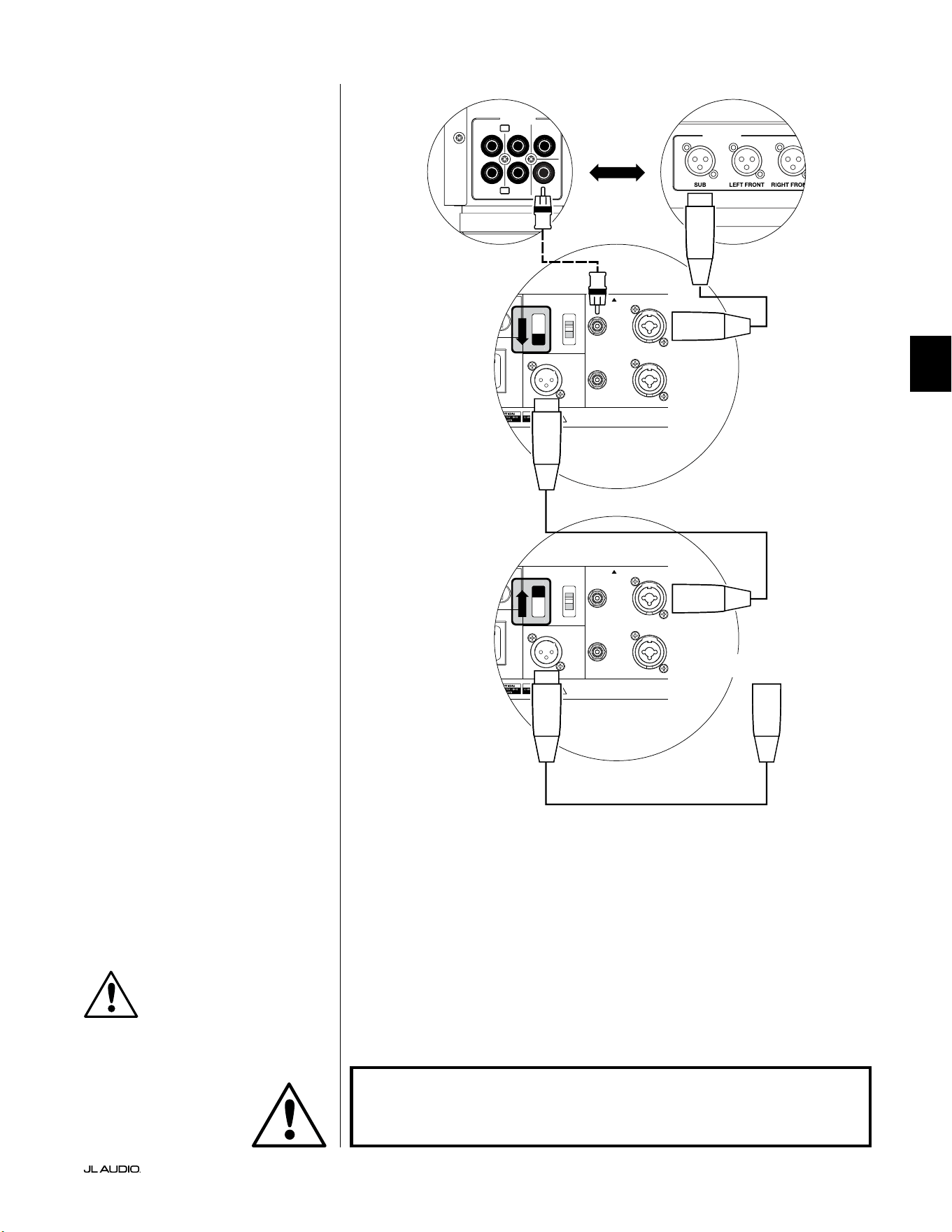
Pg 23 | IT
|
Fathom
®
v2
IT
SCHEMA DI COLLEGAMENTO
DELL’IMPIANTO 2:
Diversi Fathom v2 a
ricevitore Home Theater o
preamplicatore/processore Home
Theater
Per semplicare notevolmente l’impiego
di diversi subwoofer in un unico impianto
home theater, i Fathom v2 integrano un
sistema di distribuzione del segnale “Master/
Slave”. Questo consente il controllo di tutti i
Fathom v2 in un impianto da un’unica unità
“Master”.
Prima di tutto, si seleziona uno dei
subwoofer Fathom v2 come “Master” tramite
il suo interruttore superiore “Input Mode”. In
linea di massima, si designa il Fathom v2 più
vicino al ricevitore/preamplicatore come
Master. In alcuni casi, ad esempio, quando è
dicile accedere al pannello di controllo di
alcune unità, è preferibile designare quello
con accesso più agevolato come il Master.
Due tipologie di collegamento sono
disponibili per collegare il Fathom
v2 Master all’impianto home theater:
bilanciato (connettore XLR o TRS da
1/4 poll.) e sbilanciato (connettore tipo
RCA). I collegamenti bilanciati forniscono
una reiezione superiore del rumore e
assicurano una messa a terra appropriata
tra componenti. Se il ricevitore o processore
ha uscite bilanciate, consigliamo vivamente
di utilizzarle per collegare il Fathom v2
designato come Master.
Nello schema di collegamento sulla
sinistra, i collegamenti bilanciati sono
mostrati come linee piene, i collegamenti
sbilanciati sono mostrati come linee
tratteggiate. Si utilizzerà soltanto uno di
questi metodi di collegamento dell’ingresso
per il Fathom v2 designato come Master
(non entrambi).
I Fathom v2 restanti nell’impianto
saranno congurati come unità “Slave”
tramite gli interruttori superiori “Input
Mode”. Impiegando dei cavi XLR bilanciati,
si collegherà l’“Output to Slave” del Fathom
v2 Master all’ingresso bilanciato “Le
or Mono” del primo Fathom v2 Slave. Il
connettore “Output to Slave” di quella unità
Slave alimenterà l’ingresso “Le or Mono”
dell’unità Slave successiva tramite un altro
cavo XLR. Le unità Slave che seguono
saranno collegate nella stessa maniera.
I collegamenti tra Fathom “Master” e “Slave”
e Fathom “Slave” sono ESCLUSIVAMENTE
tramite cavi XLR bilanciati.
1200VA
ilt in USA with Imported and domestic components
LEFT
or
MONO
RIGHT
ONLY
INPUTS
Output to Slave
(Balanced)
Balanced
Unbalanced
Input Modes
Slave
Master
Grounded
Isolated
SERIAL NUMBER:
Warranty void if serial number is removed, altered or defaced.
F 12A H
250V
0 V ~ 60 Hz
F
U
S
E
F
U
S
E
1200VA
ilt in USA with Imported and domestic components
LEFT
or
MONO
RIGHT
ONLY
INPUTS
Output to Slave
(Balanced)
Balanced
Unbalanced
Input Modes
Slave
Master
Grounded
Isolated
SERIAL NUMBER:
Warranty void if serial number is removed, altered or defaced.
F 12A H
250V
0 V ~ 60 Hz
F
U
S
E
F
U
S
E
S
l
ave
M
aster
z
S
l
ave
M
aster
z
OUTPUTS
SUB
REAR
REAR CENTER
FRONT
FRONT
R
L
PRE OUT
PROCESSORE (USCITE BILANCIATE)
COMANDI POSTERIORI FATHOM (MASTER)
COMANDI POSTERIORI FATHOM (SLAVE)
O
RICEVITORE/PROCESSORE (USCITE SBILANCIATE)
A FATHOM AGGIUNTIVI
(SE APPLICABILE)
IMPORTANTE
ATTENZIONE
ATTENZIONE! SPEGNERE IL FATHOM v2 E TUTTE LE ALTRE APPARECCHIATURE
NELL’IMPIANTO PRIMA DI REALIZZARE O MODIFICARE EVENTUALI
COLLEGAMENTI!
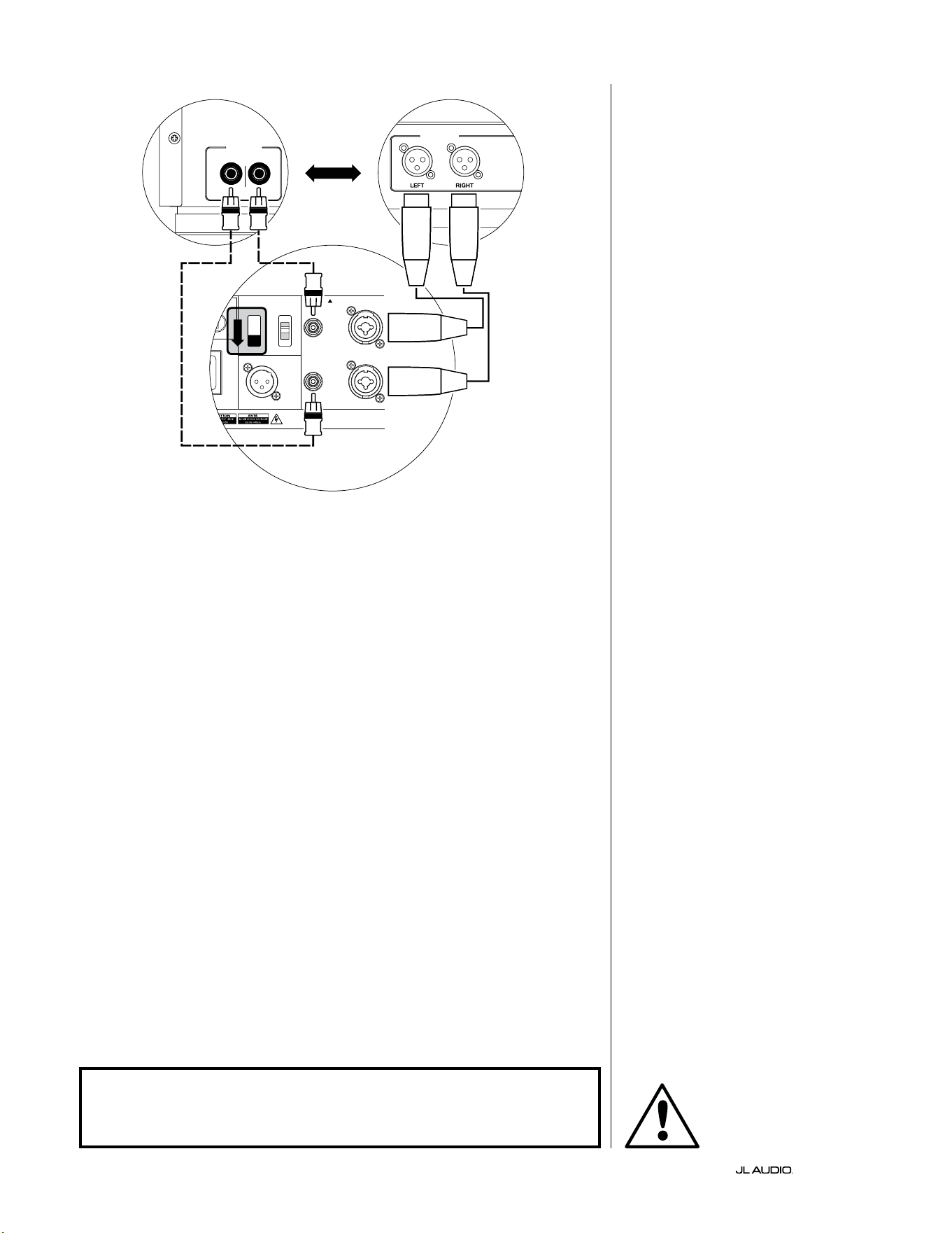
IT | Pg 24
|
Fathom
®
v2
1200VA
ilt in USA with Imported and domestic components
LEFT
or
MONO
RIGHT
ONLY
INPUTS
Output to Slave
(Balanced)
Balanced
Unbalanced
Input Modes
Slave
Master
Grounded
Isolated
SERIAL NUMBER:
Warranty void if serial number is removed, altered or defaced.
F 12A H
250V
0 V ~ 60 Hz
F
U
S
E
F
U
S
E
S
l
ave
Master
z
CROSSOVER ATTIVO STEREO (USCITE BILANCIATE)
LOW OUT
(SUB OUT)
CROSSOVER ATTIVO STEREO (USCITE SBILANCIATE)
RIGHTLEFT
LOW OUT
(SUB OUT)
COMANDI POSTERIORI FATHOM (MASTER)
O
SCHEMA DI COLLEGAMENTO
DELL’IMPIANTO 3:
Un Fathom v2 in mono a un
impianto audio a due canali
Quando si collega un Fathom v2 (o
Fathom v2 multipli) in mono a un impianto
audio a due canali, si utilizzeranno
entrambi gli ingressi indicati con “Le or
“Mono” e “Right”. La somma dei circuiti
nella sezione d’ingresso del Fathom v2
addizionerà i segnali stereo al mono.
Consigliamo vivamente di usare un
crossover attivo di alta qualità, come il
JL Audio CR-1, per dividere i segnali del
preamplicatore prima del collegamento
al Fathom v2 e all’amplicatore che attiva
gli altoparlanti principali. In questo modo,
sarà possibile ltrare le frequenze basse
dai segnali che attivano gli altoparlanti
principali, con conseguenti prestazioni
migliori.
Se non si usa un crossover attivo e si
desidera eseguire gli altoparlanti principali
full-range, è possibile suddividere i segnali
di uscita del preamplicatore impiegando
dei connettori a Y appropriati al posto del
crossover attivo mostrato nello schema.
Due tipologie di collegamento sono
disponibili per collegare il Fathom v2
all’impianto audio a due canali: bilanciato
(connettore XLR o TRS da 1/4 poll.)
e sbilanciato (connettore tipo RCA).
I collegamenti bilanciati forniscono
una reiezione superiore del rumore e
assicurano una messa a terra appropriata
tra componenti. Se il preamplicatore o
il crossover attivo ore uscite bilanciate,
consigliamo vivamente di usarle.
Nello schema di collegamento sulla
sinistra, i collegamenti bilanciati sono
mostrati come linee piene, i collegamenti
sbilanciati sono mostrati come linee
tratteggiate. L’utente utilizzerà soltanto
uno di questi metodi di collegamento in
ingresso (non entrambi).
NOTA: Se desiderato, dei Fathom v2
aggiuntivi possono essere collegati in
modalità “Slave” al Fathom v2 connesso
come mostrato nel presente schema.
Consultare lo “Schema di collegamento
2” a pag. 23 per una spiegazione del
collegamento Slave.
ATTENZIONE
ATTENZIONE! SPEGNERE IL FATHOM v2 E TUTTE LE ALTRE APPARECCHIATURE
NELL’IMPIANTO PRIMA DI REALIZZARE O MODIFICARE EVENTUALI
COLLEGAMENTI!
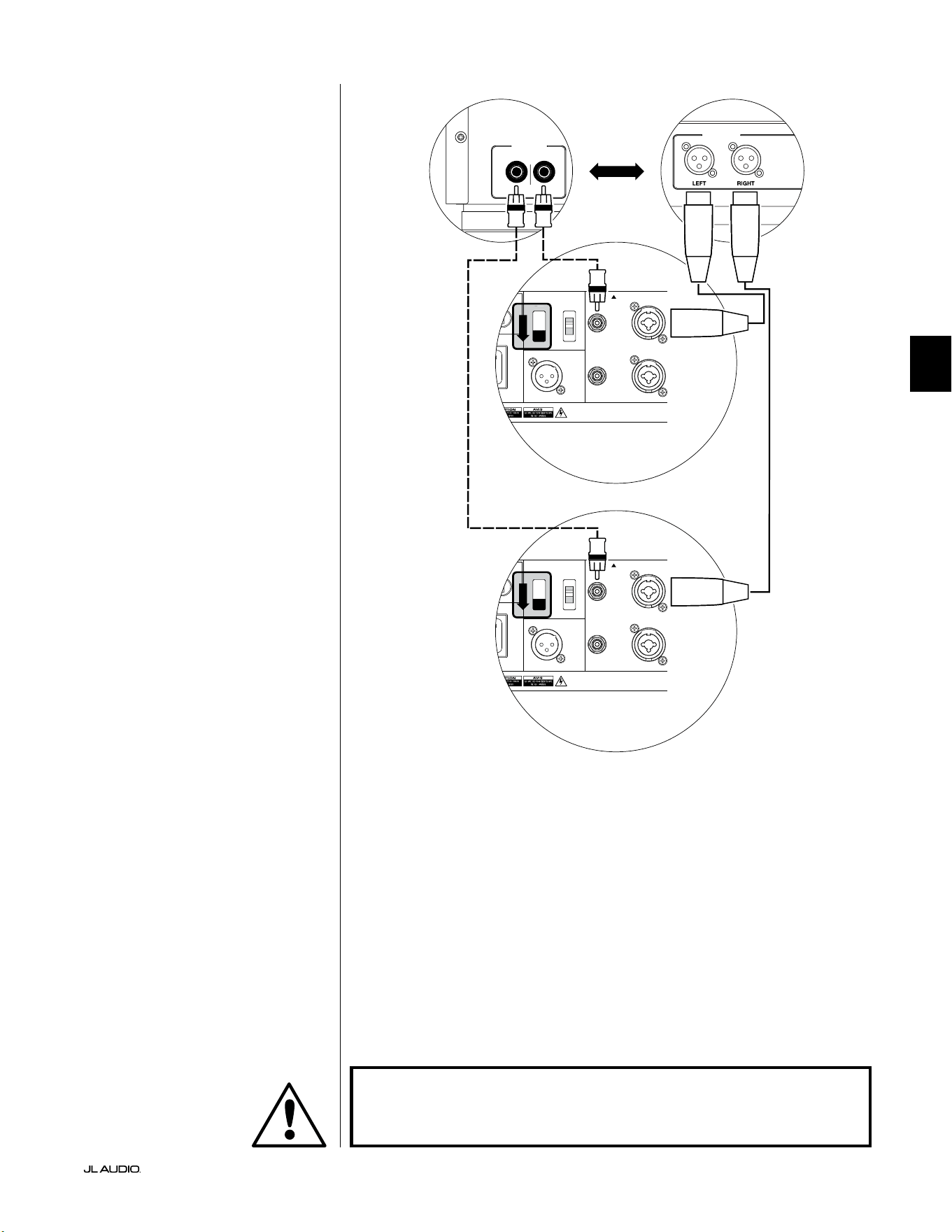
Pg 25 | IT
|
Fathom
®
v2
IT
SCHEMA DI COLLEGAMENTO
DELL’IMPIANTO 4:
Due Fathom v2 in stereo a un
impianto audio a due canali
Quando si collegano due Fathom v2 in
stereo a un impianto audio a due canali, si
utilizzeranno soltanto gli ingressi “Le or
Mono” di ciascun Fathom v2. L’interruttore
superiore “Input Mode” su ciascun Fathom
v2 sarà impostato sulla posizione “Master”.
Consigliamo vivamente di usare un
crossover attivo di alta qualità, come il
JL Audio CR-1, per dividere i segnali del
preamplicatore prima del collegamento
al Fathom v2 e all’amplicatore che attiva
gli altoparlanti principali. In questo modo,
sarà possibile ltrare le frequenze basse
dai segnali che attivano gli altoparlanti
principali, con conseguenti prestazioni
migliori.
Se non si usa un crossover attivo e si
desidera eseguire gli altoparlanti principali
full-range, è possibile suddividere i segnali
di uscita del preamplicatore impiegando
dei connettori a Y appropriati al posto del
crossover attivo mostrato nello schema.
Due tipologie di collegamento sono
disponibili per collegare il Fathom v2
all’impianto audio a due canali: bilanciato
(connettore XLR o TRS da 1/4 poll.)
e sbilanciato (connettore tipo RCA).
I collegamenti bilanciati forniscono
una reiezione superiore del rumore e
assicurano una messa a terra appropriata
tra componenti. Se il preamplicatore o
il crossover attivo ore uscite bilanciate,
consigliamo vivamente di usarle.
Nello schema di collegamento sulla
destra, i collegamenti bilanciati sono
mostrati come linee piene, i collegamenti
sbilanciati sono mostrati come linee
tratteggiate. L’utente utilizzerà soltanto
uno di questi metodi di collegamento in
ingresso (non entrambi).
NOTA: Se desiderato, dei Fathom v2
aggiuntivi possono essere collegati in
modalità “Slave” al Fathom v2 connesso
come mostrato nel presente schema.
Consultare lo “Schema di collegamento
2” a pag. 23 per una spiegazione del
collegamento Slave.
LOW OUT
(SUB OUT)
RIGHTLEFT
LOW OUT
(SUB OUT)
1200VA
ilt in USA with Imported and domestic components
LEFT
or
MONO
RIGHT
ONLY
INPUTS
Output to Slave
(Balanced)
Balanced
Unbalanced
Input Modes
Slave
Master
Grounded
Isolated
SERIAL NUMBER:
Warranty void if serial number is removed, altered or defaced.
F 12A H
250V
0 V ~ 60 Hz
F
U
S
E
F
U
S
E
S
l
ave
M
aster
z
PROCESSORE (USCITE BILANCIATE)
COMANDI POSTERIORI FATHOM (MASTER)
O
RICEVITORE/PROCESSORE (USCITE SBILANCIATE)
COMANDI POSTERIORI FATHOM (MASTER)
ATTENZIONE
ATTENZIONE! SPEGNERE IL FATHOM v2 E TUTTE LE ALTRE APPARECCHIATURE
NELL’IMPIANTO PRIMA DI REALIZZARE O MODIFICARE EVENTUALI
COLLEGAMENTI!

IT | Pg 26
|
Fathom
®
v2
PROCEDURE CONSIGLIATE DELLA CONFIGURAZIONE
1) Predisposizione del processo di congurazione: ....................... 26-27
2) Impostazione del livello: .............................................. 28
3) Regolazione della polarità/fase: ........................................ 28
4) Esperimento con la sede: ............................................. 28
5) Applicazione D.A.R.O.: ............................................ 29-30
6) Regolazione E.L.F. Trim: .............................................. 30
PREDISPOSIZIONE DEL PROCESSO DI CONFIGURAZIONE:
Si prega di confermare le seguenti impostazioni dell’impianto prima d’iniziare
il processo di congurazione. In questo modo, sarà possibile garantire un punto di
partenza neutrale e una congurazione ecace del proprio impianto subwoofer.
Sul proprio ricevitore home theater o preamplicatore/processore:
Prima d’iniziare la congurazione del proprio impianto subwoofer Fathom v2,
consigliamo di impostare il ricevitore o preamplicatore/processore come indicato
di seguito (spegnere tutti i Fathom v2 nell’impianto tramite gli interruttori di
accensione del pannello anteriore prima di eseguire queste regolazioni):
1. Dimensioni dell’altoparlante
Nel menu di congurazione dell’altoparlante del proprio ricevitore o
preamplicatore/processore, congurare tutti gli altoparlanti ad alta frequenza
su “small” con un punto crossover di 80Hz. Questo invierà TUTTI i bassi al/
ai Fathom v2.
2. Distanza dell’altoparlante
Nel menu di congurazione dell’altoparlante, congurare correttamente
le distanze di tutti gli altoparlanti al sedile di ascolto primario, inclusa la
distanza del subwoofer. Servirsi di un metro a nastro per determinare queste
distanze (è importante la coerenza temporale). Se si utilizzano diversi Fathom
v2, calcolare la media delle loro distanze rispetto al sedile di ascolto primario e
utilizzare quel numero per impostare la distanza dei subwoofer.
3. Livello del subwoofer
Impostare il livello del subwoofer nel ricevitore o preamplicatore/processore
su “0” oppure nella sua posizione centrale.
4. Comandi dei toni/Equalizzatori
Congurare i comandi di tutti i toni su “0” e
disattivare tutte le funzioni equalizzatore.
Sul proprio crossover attivo o processore di gestione dei bassi:
Se si usa un crossover attivo oppure un processore di gestione dei bassi,
consigliamo di impostarlo come indicato di seguito prima d’iniziare la
congurazione del proprio impianto subwoofer Fathom v2 (si prega di spegnere
tutti i Fathom v2 nell’impianto, prima di eettuare queste regolazioni):
1. Frequenza del ltro passa-basso
Selezionare una frequenza del ltro passa-basso
di 80Hz (pendenza di 24dB/ottava)
2. Frequenza del ltro passa-alto
Selezionare una frequenza del ltro passa-alto
di 80Hz (pendenza di 24dB/ottava)
3. Livello di uscita (subwoofer) passa-alto
Impostare il livello di uscita del subwoofer su “0” oppure in posizione centrale.
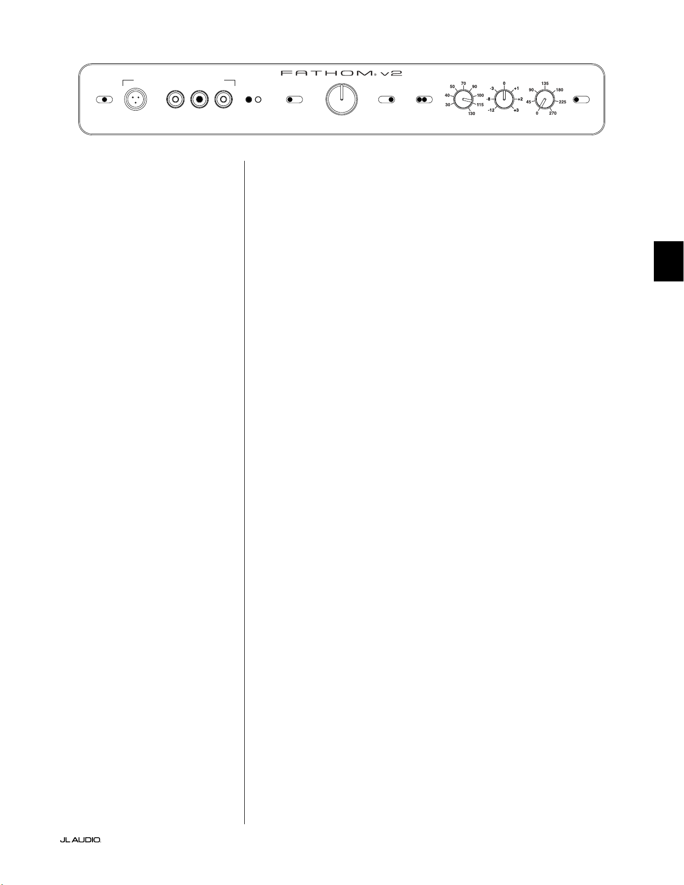
Pg 27 | IT
|
Fathom
®
v2
IT
Sul pannello anteriore del Fathom v2:
Spegnere il ricevitore home theater o preamplicatore/processore per apportare
queste regolazioni.
1. Interruttore “Power”
Far scattare l’interruttore “Power” di ogni Fathom v2 in posizione “On”.
2. Interruttore “Lights”
Far scattare l’interruttore “Lights” di ogni Fathom v2 in
posizione “On”. Se non si vedono luci sul pannello anteriore, è
possibile che ci sia dimenticati di collegare il Fathom v2 oppure
potrebbe esserci un problema con il circuito elettrico.
3. Spie “Input Mode”
Se si usa un unico Fathom v2, confermare che la sua spia “Input Mode” sia in
posizione “Master”. In caso contrario, sarà necessario accedere all’interruttore
superiore “Input Mode” sul pannello posteriore del Fathom v2.
Se si usano Fathom v2 multipli nella congurazione Master/Slave, confermare
che l’unità collegata direttamente al ricevitore o preamplicatore/processore
indichi “Master” sulle sue spie “Input Mode” e che tutte le altre unità indichino
“Slave” sulle loro spie “Input Mode”. In caso contrario, sarà necessario
accedere agli interruttori “Input Mode” sui pannelli posteriori dei Fathom v2.
4. Interruttore “Level Mode”
Far scattare l’interruttore “Level Mode” sul
Fathom v2 Master in posizione “REF”.
5. Interruttore “LP Filter”
Se il proprio ricevitore/processore home theater manipola la
gestione dei bassi (altoparlanti impostati su “small”), oppure se
si usa un crossover/processore di gestione dei bassi esterno, far
scattare l’interruttore “LP Filter” sul proprio Fathom v2 Master su
“OFF”. In caso contrario, selezionare la posizione “12dB”.
6. Freq. PB (Hz)”
Ruotare la manopola “LP Freq.” in posizione “80Hz”.
7. Manopola “E.L.F. Trim (dB)”
Ruotare la manopola “E.L.F. Trim” su “0”
8. Interruttore “Polarity”
Far scattare l’interruttore “Polarity” su “0”.
9. Manopola “phase (deg.)”
Ruotare la manopola “phase” su “0” gradi
10. D.A.R.O. Interruttore Defeat
Premere l’interruttore Defeat D.A.R.O. di modo che
la spia rossa nell’interruttore resti accesa.
LP freq. (Hz) e.l.f. trim (dB) phase (deg.)
Polarity
0
|
180 deg.
LP Filter
o
|
12dB
|
24dB
Master Level
max
0
Lights
o
|
dim
|
on
-∞
Level Mode
ref.
|
variable
Input Mode
master
|
slave
calibration mic. demo defeat calibrate
Power
o
|
on
|
auto
Digital Automatic Room Optimization
IT | Pg 28
|
Fathom
®
v2
PROCEDURE CONSIGLIATE DELLA CONFIGURAZIONE (continua)
Congurazione dell’impianto subwoofer:
Una volta impostati i comandi sul proprio ricevitore home theater o
preamplicatore/processore e sul/sui Fathom v2 alle impostazioni consigliate
alle pagine 26 e 27, si è pronti a iniziare la congurazione del Fathom v2 per
prestazioni ottimali.
1. Impostazione del livello
Impiegando della musica o un lm familiare con bassi profondi, regolare
il livello del subwoofer per mescolarsi con gli altri altoparlanti, servendosi del
comando di livello del subwoofer sul ricevitore o preamplicatore/processore.
Questo metodo è più immune alla manomissione rispetto alla manopola
“Master Level” del Fathom v2 (pensiamo ai bambini piccoli o visitatori curiosi).
Nell’improbabile eventualità che il controllo di livello subwoofer nel
ricevitore o preamplicatore/processore non possa essere innalzato abbastanza
per un’equivalenza di livello del Fathom v2, ruotare quella manopola su “0”.
Poi, far scattare l’interruttore “Level Mode” del Fathom v2 su “Variable” e con
“0” come punto di riferimento (il guadagno in modalità REF e il guadagno “0”
Variable sono identici), usare il comando “Master Level” per un’equivalenza
di livello del subwoofer con altri altoparlanti. PRENDERE NOTA DI
QUEST’IMPOSTAZIONE PER L’USO FUTURO.
Per informazioni più dettagliate sui comandi delle impostazioni di livello del
Fathom v2, consultare i capitoli “Modalità di livello” e “Manopola di livello Master”
alle pagine 15-16 del presente manuale.
2. Regolazione della polarità e della fase
Spesso, è utile avere una seconda persona che attivi
questi comandi, di modo che si possano udire facilmente
le variazioni dal sedile di ascolto primario.
Ascoltando del materiale sorgente familiare (preferibilmente musica con
buona risposta di bassi superiori e massi medi), far scattare l’interruttore
“Polarity” da “0” a “180” e ascoltare le dierenze. L’impostazione corretta
suonerà più naturale con la migliore articolazione dei bassi superiori. Se
entrambe hanno un audio simile, scegliere “0”.
Una volta impostata la polarità, servirsi dello stesso materiale musicale
per testare diverse impostazioni del comando “Phase” e scegliere quella
che ottimizza ulteriormente la risposta dei bassi superiori e medi. Se non è
possibile ascoltare la dierenza, impostare il comando su “0”.
3. Esperimento con sedi alternative del subwoofer (se necessario).
Se l’utente è soddisfatto delle prestazioni di base del subwoofer, è pronto
a passare al passaggio successivo. In caso contrario, consigliamo all’utente di
sperimentare la posizione del proprio subwoofer no a quando è soddisfatto delle
sue prestazioni di base. Sperimentare con il posizionamento si rivela ESSENZIALE
per un impianto dall’audio superiore. Spostando il subwoofer soltanto di
pochi metri può inuire sensibilmente sulla uidità dei bassi. Per ogni nuova
posizione, iniziare con i comandi di polarità e fase su “0” e ripetere il processo di
congurazione iniziando con il passaggio 1.
IMPORTANTE! PRENDERE NOTA DI TUTTE LE IMPOSTAZIONI ESEGUITE NEI
PASSAGGI DA 1 A 3 PER LA CONSULTAZIONE FUTURA.
IMPORTANTE
Pg 29 | IT
|
Fathom
®
v2
IT
IMPORTANTE! ACCERTARSI CHE LA STANZA SIA SILENZIOSA MENTRE IL
D.A.R.O. È CALIBRATO! SPEGNERE EVENTUALI APPARECCHI RUMOROSI IN
PROSSIMITÀ DELLA STANZA DI ASCOLTO (LAVASTOVIGLIE, LAVATRICI, ECC.)
È DI PARTICOLARE IMPORTANZA SPEGNERE I CONDIZIONATORI D’ARIA O LE
POMPE DI CALORE DURANTE LA CALIBRAZIONE. QUESTI SISTEMI HVAC DI
TIPO AD ARIA FORZATA POSSONO GENERARE LIVELLI MODERATI DI RUMORE
A 15 - 20HZ CHE POSSONO INTERFERIRE CON LA CALIBRAZIONE.
4. Applicazione del Digital Automatic Room Optimization (D.A.R.O.)
Ora, si è pronti per applicare la potenza dell’esclusivo sistema Digital
Automatic Room Optimization (D.A.R.O.) di JL Audio. Questo sistema misura
la risposta del subwoofer in corrispondenza del sedile primario di ascolto e
applica un equalizzatore potente a 18 bande per domare i picchi causati dai
modi della stanza, comportando prestazioni di bassi più accurati e uidi. Se si
usano diversi Fathom v2 in una congurazione Master/Slave, sarà necessario
soltanto gestire l’unità designata come “Master” per eseguire la calibrazione
D.A.R.O. per l’intero impianto subwoofer. Si noti che l’elaborazione di tutti i
segnali è disattivata durante la calibrazione D.A.R.O., indistintamente dalle
impostazioni delle manopole. Il normale funzionamento sarà ripristinato una
volta completata la calibrazione.
a) Impostare l’interruttore di accensione principale in posizione “ON” e
accertarsi che le spie del Fathom v2 sono accese mediante l’interruttore
“Lights”.
b) Rimuovere il microfono di calibrazione dalla sua custodia protettiva e
collegare il rispettivo cavo al connettore jack mini-XLR sul pannello di
controllo anteriore del Fathom v2.
NOTA: D.A.R.O. La calibrazione è possibile soltanto quando il microfono
di prova JL Audio è inserito nel pannello anteriore del Fathom v2. La funzione
“Calibration” è disattivata senza alcun microfono collegato, al ne di prevenire
perdite di impostazioni.
c) Collegare il microfono all’altra estremità del cavo del microfono e
posizionare momentaneamente il microfono nel sedile primario di ascolto.
Se si dispone di un’asta per microfono, è possibile posizionare il microfono
all’altezza della testa e collocarlo nel sedile primario di ascolto.
d) Sul pannello di controllo del Fathom v2, premere il tasto “Calibrate”. La
luce verde sul tasto “Calibrate” lampeggerà lentamente, a indicare che la
calibrazione inizierà nel giro di 5 secondi.
e) Una volta trascorsi 5 secondi dalla selezione di “Calibrate”, tornare al proprio
sedile primario di ascolto e tenere il microfono in posizione di seduta
normale della testa, approssimativamente all’altezza delle orecchie.
f) Una sequenza di rumori sarà riprodotta dal Fathom v2 che somigliano
a suoni brevi statici. La sequenza dura approssimativamente 3
minuti. Nel corso di questo processo, il sistema D.A.R.O. esegue un
rilevamento della risposta di frequenza presso il sedile e corregge
i problemi che trova. Il sistema D.A.R.O. compensa che eventuali
dierenze di livello prima e dopo, di modo che il Fathom v2 abbia
un rumore percepito simile dopo il processo di calibrazione. Una
volta che il D.A.R.O. ha terminato la calibrazione, il tasto “Calibrate”
rimarrà acceso, a indicare una calibrazione avvenuta correttamente.
Se l’utente desidera eseguire una calibrazione ex novo, è suciente ripetere i
passaggi sopraindicati.
IMPORTANTE
IT | Pg 30
|
Fathom
®
v2
Per eliminare le impostazioni D.A.R.O. (ad es. ritornare a piatto) e
spegnere la spia Calibrate, tenere premuto il tasto Demo, quindi premere il
tasto Defeat. Si prega di notare che questa sequenza di tasti deve avvenire
rapidamente. Se si tiene premuto il tasto Demo per più di 2 secondi senza
toccare il tasto Defeat, inizieranno i toni Demo. Qualora ciò dovesse accadere,
attendere semplicemente che termini la sequenza Demo e tentare di nuovo.
Attenendosi alla normale procedura indicata in alto, è possibile eseguire una
nuova calibrazione.
IMPORTANTE! SE SI SPOSTA IL FATHOM V2 O IL SEDILE DI ASCOLTO PRINCIPALE
IN FUTURO, È NECESSARIO ESEGUIRE LA PROCEDURA D.A.R.O. DI NUOVO.
UN’EVENTUALE CALIBRAZIONE È UNIVOCA PER QUELLA PARTICOLARE
COMBINAZIONE DI POSIZIONE DEL SUBWOOFER E DEL SEDILE DI ASCOLTO.
È SUFFICIENTE ATTENERSI AI PASSAGGI SOPRAINDICATI PER CREARE UNA
NUOVA CURVA DI CALIBRAZIONE.
5. E.L.F. (Extreme Low Frequency) Trim
Utilizzare il comando “E.L.F. Trim” per regolare l’estensione dei bassi
estremamente ridotti del Fathom v2. Questo comando consente -12dB di taglio
o +3dB di aumento a 24Hertz e si rivela particolarmente utile quando si usa
un Fathom v2 (o due) in un home theater di misure da piccole a medie. Dal
momento che gli spazi chiusi esigui aiutano a innalzare il livello di frequenze
di bassi più ridotti, gli home theater più piccoli possono essere sopraatti
dalla forte uscita dei bassi ridotti del subwoofer Fathom v2. Questo può creare
una nota “spessa” o “rigona” nella zona dei bassi più ridotti. Ruotando la
manopola “E.L.F. Trim” si riduce il livello di bassi ridotti estremi e si allevia
questa condizione. Sentirsi liberi di sperimentare e ascoltare una varietà di
materiali impegnativi no a individuare la migliore corrispondenza per la
propria stanza e i propri gusti.
Ora il Fathom v2 è ottimizzato per le migliori prestazioni dei bassi presso il
proprio sedile di ascolto. Complimenti!
IMPORTANTE

Pg 31 | IT
|
Fathom
®
v2
IT
DOMANDE FREQUENTI
Posso collocare degli oggetti sul mio subwoofer?
Sconsigliamo di collocare eventuali oggetti sulla cassa del subwoofer, in quanto
potrebbero vibrare, causando rumori indesiderati e possibili danni alla rinitura.
In nessuna circostanza si deve collocare un oggetto contenente liquidi sulla cassa
del Fathom v2.
Il Fathom v2 dispone di una schermatura magnetica?
I subwoofer Fathom v2 non hanno una schermatura magnetica. Per evitare
distorsioni magnetiche con alcune tipologie di televisori, collocare il Fathom v2
almeno a 3-4piedi (1 - 1,5m) dal proprio schermo. Se si nota una variazione di
colore nell’immagine, cercare di allontanare ulteriormente il subwoofer no a
quando questi artefatti scompaiono.
La mia bolletta dell’elettricità sarà alta se lascio
il Fathom v2 in modalità “Auto”?
Quando in modalità “Auto”, l’amplicatore Fathom v2 si attiva soltanto se è rilevato
un segnale notevole in corrispondenza degli ingressi. Quando spento, rimangono
attivi soltanto i circuiti di standby, che assorbono quantità trascurabili di corrente
dalla presa a muro (meno di 5Watt).
Dovrei scollegare il mio subwoofer durante una
tempesta oppure un’assenza prolungata?
SÌ. Si dovrebbe scollegare il proprio Fathom v2 durante una tempesta (o prima).
In questo modo si prevengono eventuali danni dovuti a picchi di tensione a causa
dei fulmini. In queste condizioni, è una buona idea scollegare tutti i componenti
audio/video. Se si andrà via da casa per diversi giorni, è anche una buona idea
scollegare i componenti dell’home theater al ne di prevenire danni dovuti a
tempeste impreviste o condizioni della linea elettrica.
PULIZIA DEL PROPRIO FATHOM v2
Spolverare la cassa del proprio subwoofer Fathom v2impiegando un panno
in morbida microbra e pulito, oppure uno spolverino con piume. I panni in
microbra sono disponibili comunemente ovunque siano in vendita delle forniture
per il mercato automobilistico.
È possibile rimuovere delle macchie leggere passando un panno pulito in
microbra. Per le macchie più persistenti, lucidare e proteggere la rinitura
impiegando una cera per automobili di alta qualità e un panno in microbra,
entrambi disponibili presso un rivenditore specializzato in prodotti per auto. Noi
consigliamo la cera Meguiar® “NXT Tech Wax” e panni in microbra Meguiar®.
Non usare mai un lucido che contiene solventi aggressivi o abrasivi, in quanto
potrebbero arrecare danni permanenti alla rinitura. Non usare mai lucido per
mobili o un prodotto a base di olio sul proprio Fathom v2. Non usare dei solventi o
dei detergenti aggressivi sul proprio Fathom v2. Se in dubbio, testare il prodotto sul
lato inferiore della cassa e lasciarlo in posa per diversi giorni prima di utilizzarlo
su parti visibili della cassa.

IT | Pg 32
|
Fathom
®
v2
RISOLUZIONE DEI PROBLEMI
Nessun suono dal subwoofer.
1. Vericare che l’amplicatore Fathom v2 sia collegato, acceso e che le spie
sul pannello anteriore siano accese. Se le luci non si accendono, vericare
l’interruttore di circuito che alimenta la sua uscita oppure collegare il Fathom v2
a un’altra presa di corrente CA. Se la propria presa CA riceve alimentazione, ma
le luci ancora non si accendono, potrebbe essere necessario ispezionare/sostituire
il fusibile principale di alimentazione del Fathom v2. Consultare il capitolo
“Portafusibili principale” alla pagina successiva.
2. Testare il subwoofer impiegando il tasto DEMO sul pannello anteriore
dell’amplicatore. Se il sub emette toni demo, i circuiti interni del subwoofer
sono conformi ed è possibile che vi sia un problema con l’ingresso. Vericare
i collegamenti del cavo in ingresso in corrispondenza del Fathom v2 e del
ricevitore/preamplicatore/processore.
3. Vericare che le impostazioni del subwoofer del
proprio ricevitore non siano cambiate.
4. Se gli altri altoparlanti riproducono audio, ma il Fathom v2 no, tentare di
sostituire il cavo che collega il Fathom v2 all’impianto.
5. Se il problema persiste, contattare il rivenditore o il Supporto tecnico JL Audio per
ricevere assistenza.
Il livello dei bassi è cambiato.
1. Accertarsi che le impostazioni di livello (sulFathom v2 e nel ricevitore/
preamplicatore/processore) non siano cambiate.
2. Se si utilizza la manopola “Master Level” del Fathom v2 per impostare il livello del
subwoofer, confermare che l’interruttore “Level Mode” sia impostato su “Variable”.
3. Vericare la posizione della manopola E.L.F. Trim.
Ronzio e altri rumori insoliti dal proprio Fathom v2
1. Consultare la discussione sulla modalità d’ingresso a pagina 20 del presente
manuale, specialmente se altri componenti a monte, i cavi, ecc. sono stati sostituiti
di recente.
2. Spegnere il Fathom v2, scollegare tutti i suoi cavi di segnale in ingresso e uscita,
quindi accendere di nuovo Fathom v2. Se il rumore scompare, questo può essere
provocato da un’altra zona dell’impianto.
I bassi suonano “torbidi” o “troppo pesanti”.
1. Tentare di ridurre il livello di 24Hertz impiegando il comando “E.L.F. Trim”.
A volte, i bassi torbidi possono essere provocati da un’uscita di frequenza
troppo bassa in una stanza di dimensioni moderate.
2. Ridurre il livello complessivo del subwoofer.
3. Vericare le impostazioni del subwoofer del ricevitore.
4. Tentare una sede dierente del subwoofer o del sedile di ascolto
principale. Il cambiamento di uno o dell’altro può inuire
ENORMEMENTE sul rendimento dell’impianto. Consultare il
paragrafo sulla posizione alle pagine 6-10 del presente manuale.
Pg 33 | IT
|
Fathom
®
v2
IT
RISOLUZIONE DEI PROBLEMI - continua
D.A.R.O. Il tentativo di calibrazione ore un
lampeggiamento della spia di calibrazione
1. Se il microfono JL Audio incluso non è collegato correttamente al jack del pannello
anteriore, la calibrazione non riuscirà e la spia Calibrate verde lampeggerà
rapidamente. La calibrazione si avvierà SOLTANTO con il microfono JL Audio
collegato. Il collegamento di qualsiasi altro microfono comporterà la mancata
riuscita della calibrazione. Spegnere la spia lampeggiante Calibrate premendo il tasto
Calibrate di nuovo.
2. Se la calibrazione non riesce con il microfono JL Audio collegato correttamente, la
spia verde Calibrate lampeggerà lentamente. Testare il microfono e i collegamenti
cablati, quindi tentare una nuova calibrazione. Se la calibrazione non riesce i
passaggi sopraindicati, il microfono o il suo cavo potrebbero non essere conformi.
Contattare il Supporto Tecnico JL Audio per le installazioni domestiche.
Il Fathom v2 è chiaramente udibile al di fuori della propria casa.
1. Rivisitare l’impostazione “Master Level” sul Fathom v2 oppure sul ricevitore/
preamplicatore/processore dell’home theater.
2. Rivolgersi al rivenditore JL Audio per indagare sulle
strategie d’isolamento del rumore.
3. Allontanare il Fathom v2 dalle nestre.
PORTAFUSIBILI PRINCIPALE
Ubicato sul pannello posteriore, accanto alla presa del cavo CA, si trova il
coperchio del portafusibili principale. Questo piccolo cappuccio, caricato a molla,
può essere rimosso, consentendo l’accesso per ispezionare o sostituire il fusibile
principale di alimentazione. Se la propria presa CA riceve alimentazione ma le spie
del Fathom v2 non si accendono, è possibile che il fusibile principale si sia bruciato.
Per lo smontaggio - Scollegare il cavo di alimentazione CA del subwoofer. Inserire un
piccolo cacciavite a testa piatta nella fessura del cappuccio, quindi ruotare lentamente
in senso antiorario no al rilascio del portafusibili. Una volta rimosso, il fusibile
può essere ispezionato e, se necessario, sostituito. Consultare la tabella sottostante
per i valori del fusibile per il modello di amplicatore specico Fathom v2.
Per la reinstallazione - Si noti che il corpo del portafusibili è codicato per l’apertura
e deve essere allineato correttamente. Inserire il portafusibili nell’apertura e ruotare
delicatamente in senso orario (circa 1/8 di giro) per bloccarlo in posizione. Premendo
il cappuccio e percependo la compressione della molla, sarà possibile individuare
la posizione corretta. Collegare nuovamente il cavo di alimentazione CA.
Se il fusibile di ricambio scatta subito dopo la sostituzione di un fusibile,
potrebbe essere necessario un intervento in assistenza sul subwoofer. Si prega
di contattare il proprio rivenditore o distributore autorizzato JL Audio.
Valori nominali dei fusibili, soli modelli da 120V
Modello Tipo di fusibile Dimensioni del fusibile
f110v2 (120V) 0,25 x 1,25 pollici, ad azione rapida 7A, 250V
f112v2 (120V) 0,25 x 1,25 pollici, ad azione rapida 8A, 250V
f113v2 (120V) 0,25 x 1,25 pollici, ad azione rapida 12A, 250V
f212v2 (120V) 0,25 x 1,25 pollici, ad azione rapida 15A, 250V
Valori nominali dei fusibili, soli modelli da 240V
Modello Tipo di fusibile Dimensioni del fusibile
f110v2 (240V) 5mm x 20mm, ad azione rapida 6,3A, 250V
f112v2 (240V) 5mm x 20mm, ad azione rapida 6,3A, 250V
f113v2 (240V) 5mm x 20mm, ad azione rapida 8A, 250V
f212v2 (240V) 5mm x 20mm, ad azione rapida 10A, 250V
1200VA
Built in USA with Imported and domestic components
LEFT
or
MONO
RIGHT
ONLY
INPUTS
Output to Slave
(Balanced)
Balanced
Unbalanced
Input Modes
Slave
Master
Grounded
Isolated
SERIAL NUMBER:
Warranty void if serial number is removed, altered or defaced.
F 12A H
250V
120 V ~ 60 Hz
F
U
S
E
F
U
S
E
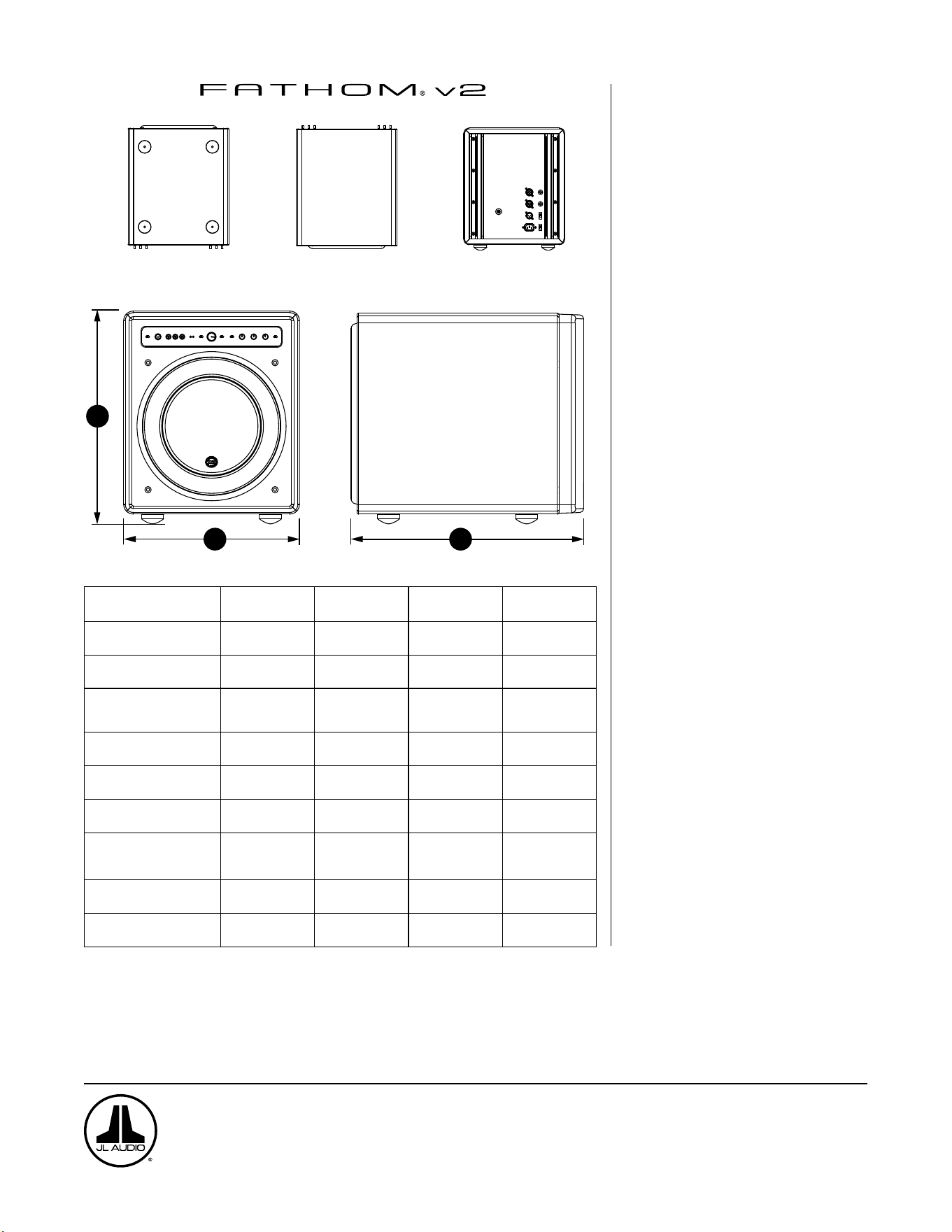
PARTE INFERIORE
PARTE SUPERIORE PARTE POSTERIORE
LATO CON GRIGLIA
PARTE ANTERIORE
H
W
D
Specifiche: f110v2 f112v2 f113v2 f212v2
Tipo di cassa: Sigillata Sigillata Sigillata Sigillata
Driver:
Singolo da 10 pollici
(diametro nominale)
Singolo da 12 pollici
(diametro nominale)
Singolo da 13,5 pollici
(diametro nominale)
Doppio da 12 pollici
(diametro nominale)
Risposta della frequenza
(anecoica):
27 - 111Hz (±1,5dB)
–3dB a 25Hz / 120Hz
–10dB a 19Hz / 155Hz
21-119Hz (+1,5dB)
–3dB a 19Hz / 150Hz
–10dB a 17Hz / 167Hz
20-86Hz (+1,5dB)
–3dB a 18Hz / 127Hz
–10dB a 16Hz / 154Hz
20 - 97Hz (+/- 1,5dB)
-1.5dB a 19Hz / 110Hz
-10dB a 15Hz / 157Hz
Area effettiva del pistone:
60in
2
0,0387m
2
84in
2
0,0542m
2
107,35in
2
0,0693m
2
168in
2
0,1084m
2
Escursione effettiva:
160in
3
2,6 litri
287in
3
4,7 litri
386in
3
6,3 litri
574in
3
9,4litri
Potenza amplificatore:
1100Watt
RMS a breve termine
1800Watt
RMS a breve termine
3000Watt
RMS a breve termine
3600Watt
RMS a breve termine
Dimensioni: (A) x (L) x (P)
Le dimensioni in altezza
includono i piedini
15,64 x 12,92 x 17,27in.
397 x 328 x 439mm
18,5 x 15 x 17,625in.
470 x 381 x 448mm
19,625 x 16,5 x 19,25in.
498 x 419 x 489mm
31,96 x 14,92 x 20,39in.
812 x 379 x 518mm
Peso netto:
69lbs
31kg
117lbs
53kg
133lbs
60kg
224lbs
102kg
Rifinitura della cassa: Nero a elevata lucidità Nero a elevata lucidità Nero a elevata lucidità Nero a elevata lucidità
FUNZIONI
Ingressi sbilanciati:
Stereo o Mono (due connettori jack RCA)
Ingressi bilanciati:
Stereo o Mono (due connettori jack XLR
femmina)
Uscita a Slave:
Bilanciato (un jack XLR maschio)
Modalità d’ingresso:
Master o Slave
Modalità livello:
Riferimento (guadagno sso) o variabile
da -completamente tacitato a +15dB su
guadagno di riferimento
Modalità di potenza:
Spento, Accesso o Automatico
(rilevamento del segnale)
Modalità luci:
Spente, Accese o Basse
Modalità ltro passa-basso:
Spento, 12dB per ottava o 24dB per ottava
Frequenza di cuto del ltro passa-basso:
Variabile da 30Hz – 130Hz
Polarità:
0 o 180 gradi
Fase:
Variabile da 0Hz – 270Hz
E.L.F. Trim:
Variabile da –12dB a +3dB a 24Hz
Digital Automatic Room Optimization
(D.A.R.O.)
Automatico, equalizzatore a 18 bande
con microfono di calibrazione di grado di
laboratorio, disattivabile, in dotazione.
www.jlaudio.com
10369 North Commerce Parkway • Miramar, Florida • 33025 • USA
“JL Audio”, “Fathom” e il logo JL Audio sono marchi commerciali registrati di JL Audio, Inc.
©2022 JLAudio, Inc. • Per informazioni più dettagliate, si prega di visitare il nostro sito Web www.jlaudio.com. Le immagini del prodotto mostrate sono solo a scopo illustrativo e
potrebbero differire dal prodotto effettivo. A causa dello sviluppo continuo del prodotto, tutte le specifiche potrebbero essere soggette a modifica senza preavviso.
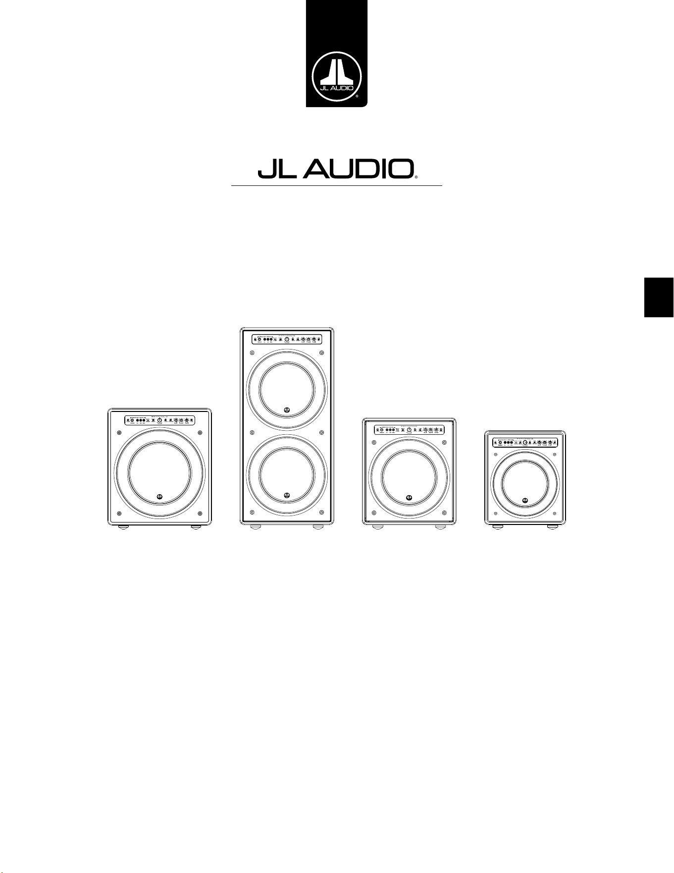
中文
Fathom v2 动力超低音音响
用户手册
f113v2 f212v2 f112v2 f110v2
第 2 页
|
Fathom
®
v2
重要安全说明
警告为降低火灾或触电风险,请勿将本产品暴露在雨水或潮湿的环境中。
注意事项
触电风险
请勿打开
注意事项:为降低触电风险,请勿拆卸机箱。本产品无用户可自行维修的
内置零部件。请向具备资质的人员寻求维修帮助。
1. 阅读相关说明 — 应在操作超低音音响前阅读所有的安全及操作说明。
2. 保存相关说明 — 应妥善保存安全及操作说明,以供未来参考。
3. 注意警告 — 应遵循超低音音响上及操作说明中的所有警告。
4. 遵循说明 — 应遵循所有操作及使用说明。
5. 水和潮湿环境 — 不应在有水的地方附近使用超低音音响,例如,浴缸、洗
脸池、水槽、洗衣机附近、潮湿的地下室、游泳池附近等。
6. 通风 — 应确保超低音音响放置的位置或方式不会影响其正常通风。例
如,超低音音响不应放置在可能阻碍散热器叶片气流的床、沙发、地毯或
类似表面上。如果将超低音音响放置在“内置”安装中,请确保流向超低音
音响后部散热器的气流畅通。请勿使用桌布、窗帘等盖住超低音音响散热
器 。
7. 热源和火源 — 超低音音响应远离热源,如散热器、热风调节器、炉灶、壁
炉或其他产生热量的设备。请勿在超低音音响顶部或附近放置蜡烛。
8. 电源 — 超低音音响仅能连接至操作说明所述或超低音音响上所标记类
型的电源。
9. 电源线保护 — 电源线布线时,应确保电源线上或周围放置的物品不会被
踩到或夹住,并特别注意插头处的电源线、简易型插座以及电源线连接超
低音音响的位置。
10. 清洁 — 应仅按照操作说明中的建议清洁超低音音响。
11. 闲置 — 当超低音音响长期不使用时,应从插座上拔下超低音音响电源
线 。
12. 闪电和电涌 — 我们建议您在雷暴和/或反复停电时断开超低音音响与电
源插座的连接,以防止电涌造成的损坏。
13. 异物或液体进入 — 请注意,不要让异物落入设备中,或液体溅到超低音
音响机箱上。请勿将超低音音响置于液体滴落或飞溅的环境中。请勿在超
低音音响顶部或附近放置装有液体的容器。例如:花瓶、饮料、油灯等。
14. 需维修的损坏 — 超低音音响出现以下情况时,应由具备资质的人员进行
维修:
a. 电源线或插头损坏
b. 异物落入设备中,或液体溅到超低音音响中
c. 超低音音响暴露在雨水中
d. 超低音音响运行似乎不正常,或性能发生明显变化
e. 超低音音响掉落或机箱被物理损坏
f. 超低音音响驱动器的音盆和/或悬架已物理损坏
等边三角形内的闪电和箭头符号旨在提
醒用户,产品机箱内会存在未绝缘的“危
险电压”,其水平可能足以对人体构成触
电危险。
等边三角形内的感叹号旨在提醒用户,
产品随附的档中有重要的操作和维护
说 明 。
第 3 页
|
Fathom
®
v2
中文
15. 维修 — 用户不应尝试超出操作说明描述范围的超低音音响维修。其他所
有类型的维修应由具备资质的人员进行。
16. 过载 — 请勿让墙上插座、电源延长线或插排过载,这可能会导致火灾或
触电的危险。
17. 接地 — 超低音音响配有一根三叉接地电源线。应采取预防措施,确保超
低音音响的接地方式不会失效。破坏超低音音响电源线的接地插头可能
会增加触电风险,并可能导致超低音音响的电子元件永久损坏。
这种超低音音响能够产生非常高的声压级。请在运行过程中保持克制,以
避免您的听力受到永久性损害。
此型号(型号:F113v2, F212v2)的总输出功率大于 500 瓦,无需办理中国
CCC 认证。
警告

第 4 页
|
Fathom
®
v2
FCC 合规声明
注:此设备已经过测试,符合 FCC 规范第 15 部分的限制。此类限制旨在提供合理的保护,以防止
住宅用装置中的有害干扰。此设备会产生、使用和辐射射频能量,如不按照说明安装,可能会对无
线电通信造成有害干扰。但不保证在特定安装条件下不会发生干扰。若此设备确实对无线电或电
视接收造成有害干扰(可通过关闭和开启设备来确定),则建议用户尝试通过以下一种或多种措
施纠正干扰:
- 调整接收天线或移动其位置。
- 扩大设备和接收机之间的距离。
- 将设备连接至与接收机不同的电路的插座中。
- 向经销商或经验丰富的无线电/电视技术人员寻求帮助。
目录
重要安全说明: ................................................. 2-3
简介: ............................................................4
产品概述: ........................................................5
在您的视听室中安置 Fathom v2: ............................... 6-10
Fathom v2 拆封: ............................................... 11
前置控制面板布局: .............................................. 12
后置控制和接口面板布局: ......................................12-13
前置面板控制详细说明: ........................................14-17
连接 Fathom v2: .............................................18-25
推荐设置流程: ................................................26-30
常见问题解答: .................................................. 31
清洁 Fathom v2: ............................................... 31
故障排查: ....................................................32-33
有限责任保修/服务信息: ......................................... 35
规格: .......................................................... 36
简介
感谢您购买捷力 Fathom v2 动力超低音音响系统。本产品经过精心设计,
可在未来多年为您的家庭影院或音频系统提供卓越的性能。
作为一家公司,我们致力于高性能扬声器和功放技术的核心研究。捷力的
远足超低音音响驱动器设计被广泛视为是线性行为和高输出的参考标准。我
们还集中精力研发了强大的功放和信号处理技术,旨在提供卓越的低频性能。
您的 Fathom v2 紧凑、精美的包装中融入了这些核心原则,可提供无与伦比
的视听体验。
我们衷心感谢您的选购,并邀请您仔细阅读本用户手册,以实现 Fathom
v2 超低音音响系统的最高性能。尽情享受吧。
FFATHOM V2 超低音音响中包含捷
力技术
DMA 优化电机系统
DMA 是捷力的创新动态电机分析系统,
旨在改善动态电机行为。经过 DMA 优
化,扬声器电机在极大的位移范围内保
持线性,并在较大的功率范围内保持高
度稳定的固定磁场。这大大减少了失真
现象,并忠实地复制了瞬变...或者简单地
说:紧凑、干净、清晰的低音。
OverRoll™ 环绕声
OverRoll™ 环绕声横跨驱动器的固定法
兰,利用了传统扬声器中浪费的可用直
径。这样便可以使用更宽的辊来控制高
位移量,而不会牺牲宝贵的音盆面积。
W-Cone™
W-Cone™ 是一种单体式音盆总成,能以
最小的质量提供惊人的音盆硬度。
Floating-Cone™ 连接方法
这种组装技术确保了已组装扬声器中恰
当的环绕几何结构,以实现更好的位移
控制和动态音圈对齐。
平稳状态增强型定心支片附件
这种高完整性的悬架附件在高位移量时
缓解了定心支片材料的压力,以提高可
靠性。
高架框架散热设计
通过顶板正上方的插槽将冷气送到扬声
器的音圈。通过最大限度地减少动态参
数位移和功率压缩来增强功率处理和
音质。
径向交叉钻孔极片
这个创新通风系统通过将气流引导到音
圈成型器上,结合高架框架技术,极大地
增强了散热和功率处理。
高阻尼反馈电路
这种创新的分立控制电路设计让我们
的 D 类开关功放能够保持出色的阻尼系
数,从而改善瞬时行为和保真度。
第 5 页
|
Fathom
®
v2
中文
产品概述
捷力 Fathom v2 超低音音响高度优化的机箱中结合了
最先进的捷力超低音音响驱动器和电子/功放组件,能够为
您的家庭影院或家庭音频系统提供非凡的视听体验。
Fathom v2 超低音音响系统中的超低音音响驱动器能够实现出色
的线性位移,而不会产生故障或声音失真。这种参考级品质的驱动器
可支持 Fathom v2 超低音音响以惊人的冲击力和卓越的精度重现强
大的低频事件。Fathom v2 驱动器源自捷力的传奇 W7 设计平台,可提
供惊人的峰间位移能力,轻松处理要求最苛刻的节目素材的动态。
为了最大限度地利用这个远足驱动器平台,需要大量的受控功率。我们的
电子工程团队对典型的节目材料及其动态需求进行了深入的分析,以平衡相
对于系统阻抗特性的电流消耗和实际输出功率要求。经过仔细研究,采用专利
反馈技术并经过精密设计的开关功放得以诞生,以充分利用每个驱动器的完
整位移包络。与前几代相比,Fathom v2 进行了改进,采用了全新的数字信号
处理和 20% 的功放功率,进一步增强了其卓越的动态能力。
封装 Fathom v2 超低音音响的工作部件的精美机箱亦经过精心设计。为
了控制 Fathom v2 驱动器产生的压力,我们采用了坚固的数控切割 MDF 材
料,以及广泛的内部支撑功能和先进的组装技术。
您的视听室是影响您的低音声效的另一个封闭空间。所有房间都会创建特
定的声音信号,必须对其进行有效管理,以实现均衡的低频性能。为了将您的
超低音音响与您房间的声音效果完美结合,所有 Fathom v2 超低音音响都采
用了功能强大的数字化自动房间优化(D.A.R.O.)系统。该系统部署了 18 个频
段的数字均衡,以驯化室内声效并提供紧张刺激的低音增强精度。
您可以从本简要介绍中了解到,Fathom v2 超低音音响系统采用了许多先
进的技术。本手册的内容将针对这些功能进行说明,并指导您完成
Fathom v2 超低音音响的设置和调整,帮助您实现极致的低频视听体验。
如果您需要帮助,我们建议您联系您的捷力授权零售商获取专业设置建议
和服务。
重要!在拆封 FATHOM v2 超低音音响的包装之前,最好先阅读下一章节。
建议在最终安装位置附近拆封超低音音响的包装。
重要
第 6 页
|
Fathom
®
v2
在您的视听室中安置 FATHOM v2:
您的视听室或影院是声音重现系统不可或缺的一部分。房间及其家具、材
料、门窗的物理尺寸在定义您的系统声效方面起着重要作用。
当您把一个声源放在一个封闭的矩形空间中时,就会产生“驻波”,这是由
于声音的波长和您房间的面积之间的关系造成的。换句话说,驻波由被困在房
间里的声能产生,因为它在相对的墙壁之间来回反弹。房间里的驻波仅根据您
在房间里的实际位置,在声音更大或更柔和的地方产生声学波峰和波谷。能量
也会在房间的边界“积聚”,在某些频率上产生夸张的低音响应。这些基本的房
间共振被称为房间“模式”。
这种模式的寓意是尽量避免在驻波波峰或波谷区域的座位位置。强烈建议
您将视听座位放置在波峰和波谷适中且不相互加强的区域。应避免的两个最
明显的区域是靠近房间中心的区域和靠近房间任何墙壁的区域。
就像您的视听座位可放置在波峰区或波谷区一样,超低音音响也可以。放
置在房间角落时,超低音音响会最大限度地激发房间的模式结构,以最少的波
谷创造出最强的输出。当超低音音响从角落或墙面拉出时,房间模式的刺激程
度较低,这可能会改变您视听座位上的声音。
请确保同时尝试您的视听座位位置和超低音音响位置,以找到最佳解决方
案。细致的实验通常会产生一种更优质的音效系统。请使用我们的设置建议
(在对页和后续几页进行说明)可以帮助您入门。
如果您不能避免把沙发放置于靠后墙的位置,或者您的超低音音响处于非
最佳位置,那么您的 Fathom v2 的数字化自动房间优化(D.A.R.O.)系统可以
显著改进这些不太理想的情况。
我们建议您首先将 Fathom v2 放置在房间前部靠近前左扬声器或右扬声
器的位置。将它直接放在房间前部角落将产生最大的峰值和最小的低音响应
波谷次数。这可以是有利的,因为 Fathom v2 的 D.A.R.O. 系统可以非常有效
地校正产生的峰值,而响应中的波谷不能通过均衡来校正。只有通过小心放置
超低音音响和视听者位置,才能最大限度地减少响应中的波谷。
将 Fathom v2 放置在实心墙附近会增强低音响应,而将其从实心墙拉出
会减少低音。增加超低音音响和墙壁之间的距离可有助于某些房间中的平滑
上段低音响应。
我们建议您避免将 Fathom v2 放置在靠近窗户的位置,以防止嘎嘎作响和声
音传播到外界。
如果您计划在机柜内安装 Fathom v2 ,
请参阅第 8 页上的指南。
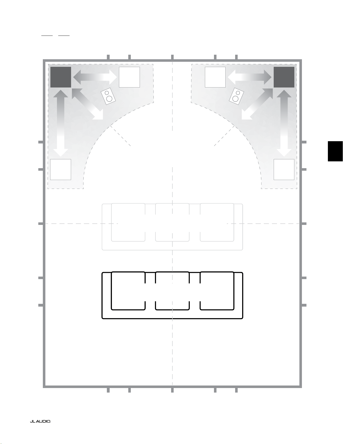
第 7 页
|
Fathom
®
v2
中文
面向一个或两个 Fathom v2 的推荐超低音音响放置选项
更舒缓
面向一个或两个超低音音响的推荐超低音音响放置选项
(放置两个时为左右对称的位置)
更舒缓
更舒缓更舒缓
折中的座位位置
(低音效果较弱且不均匀)
最佳座位位置
(低音效果更准确)
�/�
�/�
�/�
�/�
�/�
�/�
�/�
�/�
�/� �/�
�/�
�/�
�/� �/�
�/��/� �/��/� �/�
�/�
房间距离后墙约 �/� 处
房间中线
更强烈更强烈
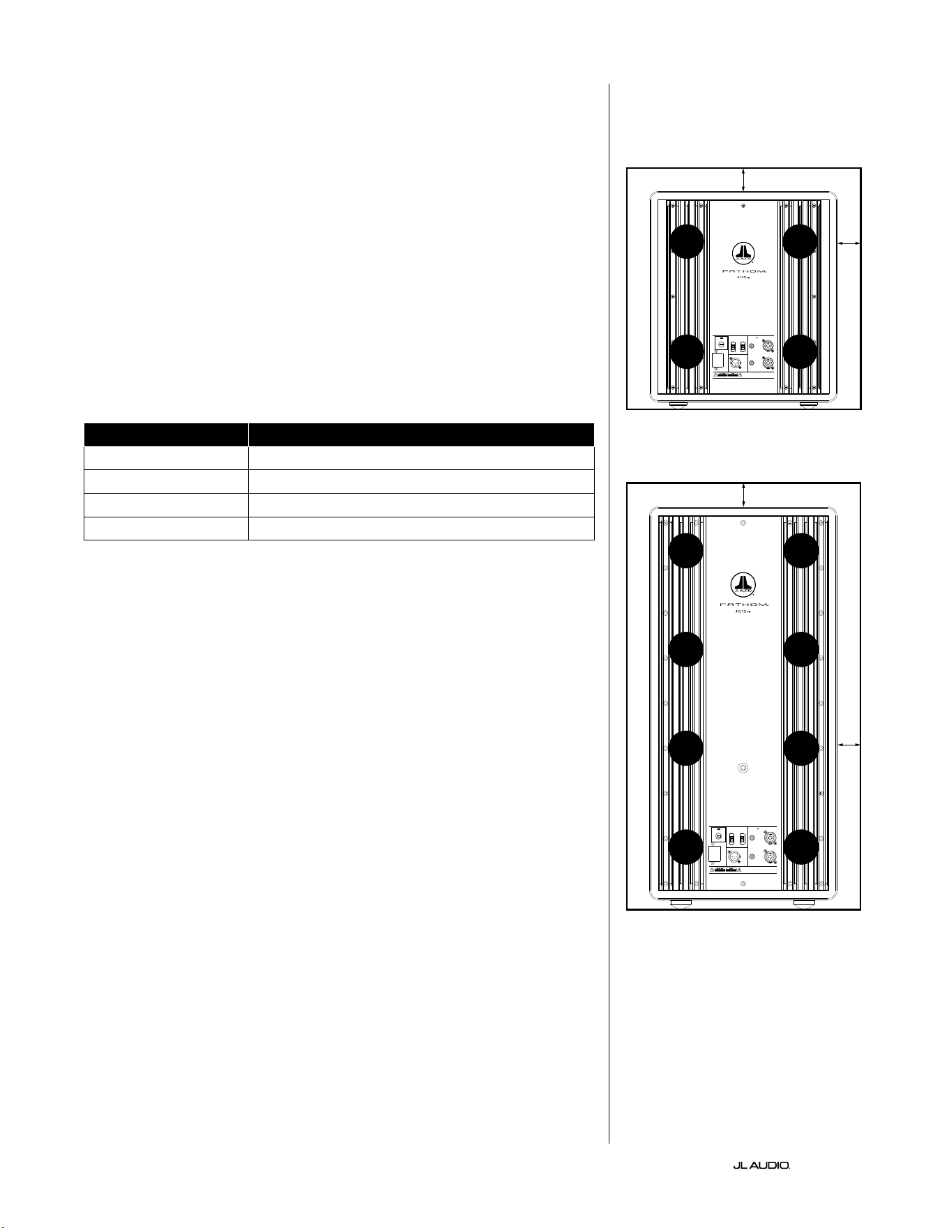
第 8 页
|
Fathom
®
v2
内置安装的特殊注意事项
Fathom v2 超低音音响的设计采用了“内置”友好型设计。所有需要的典型
控制都位于超低音音响上方的前置面板上。Fathom v2 只需遵循几个简单的
指南即可轻松集成到定制机柜中。
1) 在 Fathom v2 的功放面板后部留出 4 英寸(10 厘米)的净空,以获得充足
的散热和接口净空。
2) 在其他每一侧(底部除外),留出至少 2 英寸(5 厘米)的间隙,以获得足够的
通 风 。
3) 虽然 Fathom v2 通常仅在活跃运行期间变热,但我们建议在任何封闭
Fathom v2 的定制机柜中都留出足够的散热孔。靠近机柜底部和靠近机柜
顶部的一对直径 3 英寸(7.5 厘米)的通风口,可支持冷空气在 Fathom v2
超低音音响系统的扬声器面板上循环,以保持其凉爽和舒适。
4) 您的 Fathom v2 超低音音响能够移动大量空气。如果 Fathom v2 的前部
被定制格栅覆盖,则格栅尺寸必须至少等于每个型号的低音喇叭音盆面
积,以确保输出不会被定制机柜堵塞。每种型号的推荐通风口面积请参阅
下 表 。
型号 推荐定制格栅通风面积
f110v2 ≥ 60 平方英寸(386 平方厘米)
f112v2 ≥ 85 平方英寸(550 平方厘米)
f113v2 ≥ 108 平方英寸(700 平方厘米)
f212v2 ≥ 170 平方英寸(1100 平方厘米)
1200VA
Built in USA with Imported and domestic components
LEFT
or
MONO
RIGHT
ONLY
INPUTS
Output to Slave
(Balanced)
Balanced
Unbalanced
Input Modes
Slave
Master
Grounded
Isolated
SERIAL NUMBER:
Warranty void if serial number is remove d, altered or deface d.
F 12A H
250V
120 V ~ 60 Hz
F
U
S
E
F
U
S
E
Built in USA with Imported and domestic components
LEFT
or
MONO
RIGHT
ONLY
INPUTS
Output to Slave
(Balanced)
Balanced
Unbalanced
Input Modes
Slave
Master
Grounded
Isolated
SERIAL NUMBER:
Warranty void if serial number is remo ved, altered or defa ced.
F 15A H
250V
120 V ~ 60 Hz
F
U
S
E
F
U
S
E
通风口
通风口
通风口
通风口
通风口
通风口
通风口
通风口
最小 2 英寸
最小 2 英寸
最
小 2
英寸
最
小 2
英寸
机柜安装背面视图(f110、f112、f113):
机柜安装背面视图(f212):
通风口
通风口
通风口
通风口
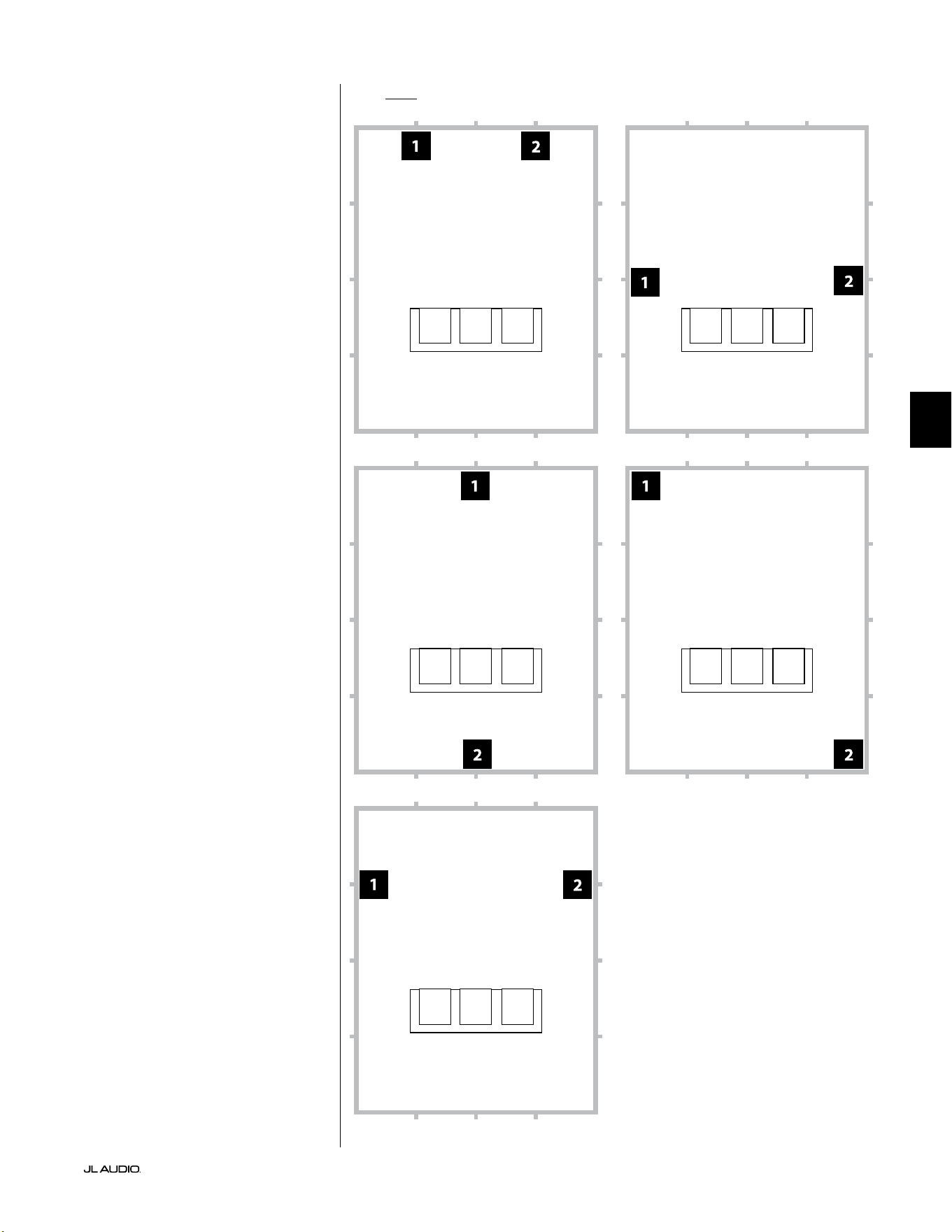
第 9 页
|
Fathom
®
v2
中文
面向两个 Fathom v2 的推荐超低音音响放置选项
使用两个 Fathom v2
使用两个 Fathom v2 时,请尝试
放置在房间前部角落附近、房间对角
线对面的角落或相对墙壁的中心点,
如右图所示。
建议尝试使用超低音音响和视听
者位置以获得最佳效果 - 好处良多。
建议使用高分辨率测量和专业
系统校准,以获得最佳结果和系统
性能。
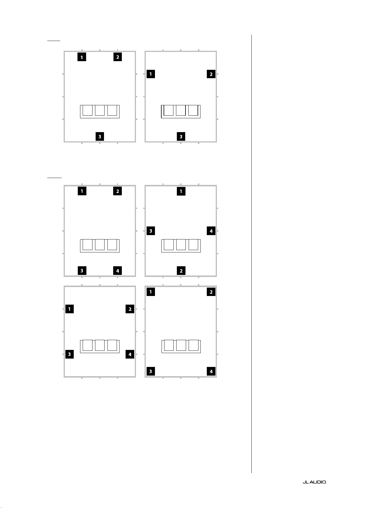
第 10 页
|
Fathom
®
v2
面向三个 Fathom v2 的推荐超低音音响放置选项
面向四个 Fathom v2 的推荐超低音音响放置选项
使用三个或四个 Fathom v2
研究表明,针对较大的视听区域,
使用四个超低音音响,在四面墙的中
点各放置一个超低音音响可实现最
流畅的低音响应(尽管使用两到三
个超低音音响几乎可以达到同样的
效 果 )。
建议尝试使用超低音音响和视听
者位置以获得最佳效果 - 好处良多。
建议使用高分辨率测量和专业
系统校准,以获得最佳结果和系统
性能。
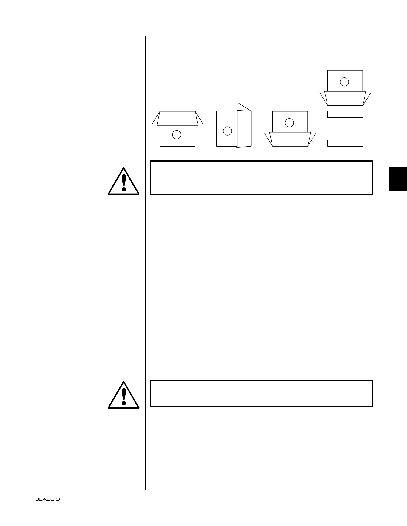
第 11 页
|
Fathom
®
v2
中文
重要!由于 FATHOM V2 超低音音响的重量,请在拆开包装和放置时格外
小心,以防受伤。尽可能寻求另一个人的帮助来完成这个过程。为了将受
伤的风险降至最低,请弯曲膝盖、用腿抬起设备,而不要使用背部。
有关拆封超低音音响包装的详细说明:
1. 将纸箱放在房间内安装位置附近的地板上。
2. 开启纸箱顶部(观察纸箱上的标记),取下用户手册、校准麦克风和电源
线 。
3. 临时拆除分体泡沫包装填充物。
4. 揭开并松开防护布罩,以便后续轻松取出(此时请勿取出)。当您开启布罩
时,看到的是超低音音响机箱的底部。
5. 拆封时,更换分体泡沫填充物以保护超低音音响的机箱。
6. 轻轻向侧面翻转纸箱,将纸箱盖向外折叠。
7. 握住纸箱盖后面,轻轻将纸箱翻转到顶部(开口端)。
8. 将纸盒垂直向上拉,直到它脱离超低音音响,并将其放到一边。
9. 取下一片式泡沫填充物,并放入纸箱里。
10. 取出塑料袋,并放在纸箱里。
11. 将超低音音响向前倾斜(朝向格栅),以便先卸下后面的分体泡沫填充物。
然后朝相反方向倾斜超低音音响(朝向其功放面板)以拆除剩余的分体泡
沫填充物。将两个分体泡沫填充物放入纸箱中。
12. 取下防护布罩,并放入纸箱里。
重要!请保留所有包装,以便安全运输超低音音响,并满足未来的任何维
修服务需求。
在放置超低音音响的位置附近拆封 此包
装。 超低音音响的包装颠倒。 必须小心地
翻转盒子,以便拆封超低音音响,并最大
限度地减少工作量。
FATHOM v2 拆封
现在您已经确定了 Fathom v2 在房间中的位置,可以继续在其安装位置附近
将其拆封。
C
D
A
B
重要
重要
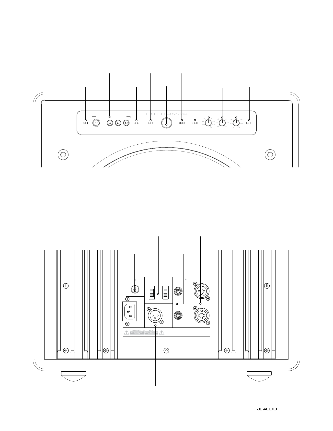
LP freq. (Hz) e.l.f. trim (dB) phase (deg.)
Polarity
0
|
180 deg.
LP Filter
o
|
12d B
|
24dB
Master Level
max
0
Lights
o
|
dim
|
on
-∞
Level Mode
ref.
|
variable
Input Mode
master
|
slave
calibration mic. demo defeat calibrate
Power
o
|
on
|
auto
Digital Automatic Room Optimization
1200VA
Built in USA with Imported and domestic components
LEFT
or
MONO
RIGHT
ONLY
INPUTS
Output to Slave
(Balanced)
Balanced
Unbalanced
Input Modes
Slave
Master
Grounded
Isolated
SERIAL NUMBER:
Warranty void if serial numb er is removed, altered or defaced.
F 12A H
250V
120 V ~ 60 Hz
F
U
S
E
F
U
S
E
第 12 页
|
Fathom
®
v2
后置控制和接口(f112v2、f113v2、f212v2 型号)
下方标签数据为 Fathom v2 f113v2 超低音音响的后置面板的说明。
Fathom f112v2 和 f212v2 的控制和连接器布局相同。
平衡
输入
第 18 页
非平衡
输入
第 19 页
IEC 式交流接口
第 21 页至第 22 页
输出至
从接口
第 21 页
输入模式开关
第 20 页
地区特定保
险丝
第 33 页
前置控制面板(所有型号)
下方标签数据为 Fathom f113v2 超低音音响的前置控制面板的说明。
所有 Fathom v2 型号的控制布局都相同。
D.A.R.O.
第 14 页至第 15 页
电源
第 14 页
输入模式
第 15 页
音量模式
第 15 页
主音量
第 16 页
灯光
第 16 页
低通滤波器
第 16 页
低通频率
(赫兹)
第 16 页
E.L.F.Trim
(分贝)
第 17 页
相位(度)
第 17 页
极性
第 17 页
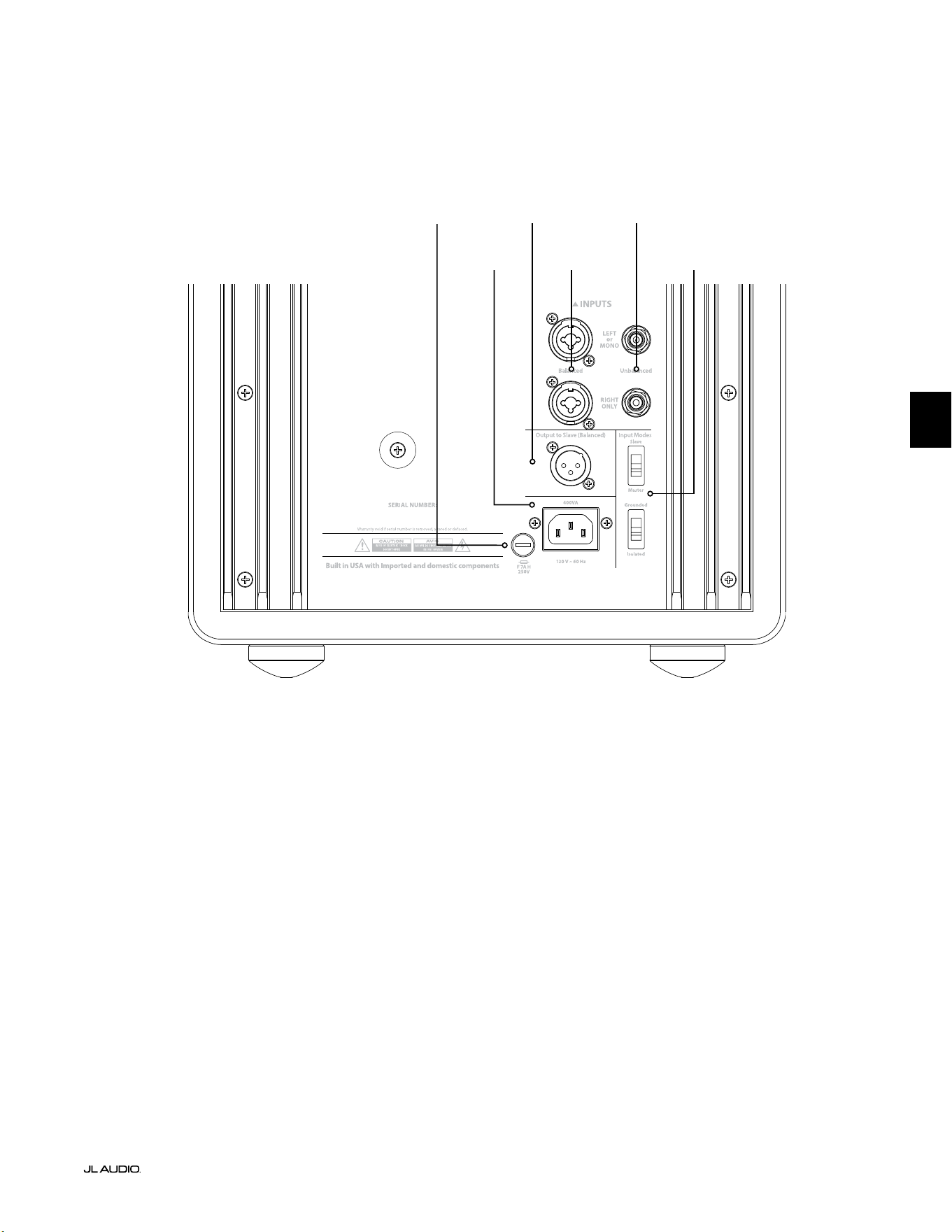
F
U
S
E
F
U
S
E
后置控制和接头(f110v2 型号)
下方标签数据为 Fathom f110v2 超低音音响的后置面板的说明。
*本手册中的后置控制和连接器详细图片为其他 Fathom v2 型号的说明,并不代表 f110v2 的布置。w
平衡
输入
第 18 页
非平衡
输入
第 19 页
IEC 式交流接口
第 21 页至第
22 页
输出至
从接口
第 21 页
输入模式开关
第 20 页
第 13 页
|
Fathom
®
v2
中文
地区特定保
险丝
第 33 页
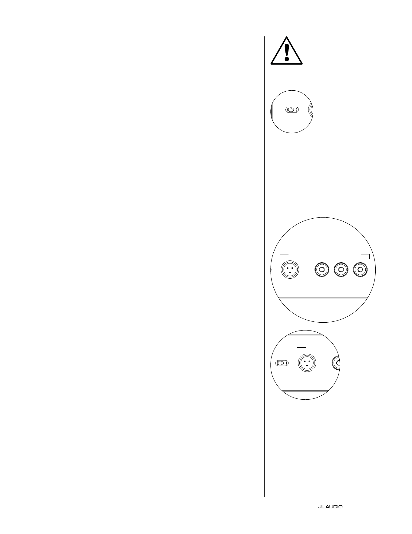
第 14 页
|
Fathom
®
v2
前置面板控制详细说明
电源开关
“电源”开关决定了 Fathom v2 超低音音响的运行就绪状态,并应是唯一
用于开启和关闭 Fathom v2 的开关。请勿使用插排开关、带开关的插座或任
何其他外部开关,因为这会导致不必要的、可能具有破坏性的瞬时爆炸声。请
勿在设备开机时拔下 Fathom v2 的交流电源线。电源开关有三个位置:
“启动”:Fathom v2 随时处于完全供电状态。前置面板指示灯亮起,除非
已通过“灯光”开关将其关闭。
“关闭”:Fathom v2 的内部功率功放已断电。在这种状态下,运行总电源
继电器的电流消耗可以忽略不计。所有前置面板指示灯均已熄灭。
“自动”:Fathom v2 会在输入出现任何音频信号时开启内部功放的电源,
如果在三十(30)分钟内没有检测到信号,则会关闭内部功放电源。处于休眠
状态时,Fathom v2 将消耗非常少量的电流(< 5瓦)来为其信号感应电路供
电。当 Fathom v2 关闭电源时,前置面板指示灯将熄灭,而当 Fathom v2 通
电时,前置面板指示灯将亮起(除非它们已通过“灯光”开关关闭)。
如果出现自动功能针对特定系统不够灵敏的情况,请使用 Y 形电缆将传入
信号分成 Fathom v2 上的两个 RCA 或 XLR 输入。这将使输入灵敏度增加
6 分贝。请注意,如果自动灵敏度过高或输入电缆上有明显的噪音,则
Fathom v2 可能无法按预期关闭。如果发生这种情况,请移除 Y 形电缆适配
器和/或查找上游组件中的噪声源。
数字化自动房间优化(D.A.R.O.)
捷力 Fathom v2 超低音音响的一个强大功能是其创新的数字化自动房
间优化(D.A.R.O.)技术。这个一触式系统包括 18 个频段的数字均衡,以消
除主视听座位上家庭影院的最大声学响应峰值,极大地改善了室内低频响
应。D.A.R.O. 系统的校准完全自动化。有关如何使用 D.A.R.O. 系统的详细信
息,请参阅本手册的下一章节。
使用附带的捷力校准麦克风,D.A.R.O. 校准程序只需不到三分钟即可完
成。简而言之,您需要将随附的麦克风连接到“校准麦克风”输入,按下校准按
钮,然后在测试期间将麦克风与耳朵齐高放在您的主视听座位上。噪声序列将
通过 Fathom v2 超低音音响播放,房间响应将被自动测量、分析和均衡,以消
除您视听座位上的单个最大声学房间响应峰值。有关 D.A.R.O. 设置程序的
详细说明,请参阅第 29-30 页。
校准麦克风输入
此输入用于将附带的捷力校准麦克风连接到 Fathom v2 超低音音响。使
用 D.A.R.O. 系统之前,将随附电缆的一端连接到麦克风,另一端连接到此插
孔。D.A.R.O. 系统专门针对该麦克风进行了校准,其连接方案也特定于所提供
的麦克风。当连接不同的麦克风或没有连接麦克风时,校准序列将不起作用。
重要
LP freq. (Hz) e.l.f. trim (dB) phase (deg.)
Polarity
0
|
180 deg.
LP Filter
o
|
12dB
|
24dB
Master Level
max
0
Lights
o
|
dim
|
on
-∞
Level Mode
ref.
|
variable
Input Mode
master
|
slave
calibration mic. demo defeat calibrate
Power
o
|
on
|
auto
Digital Automatic Room Optimization
LP freq. (Hz) e.l.f. trim (dB) phase (deg.)
Polarity
0
|
180 deg.
LP Filter
o
|
12dB
|
24dB
Master Level
max
0
Lights
o
|
dim
|
on
-∞
Level Mode
ref.
|
variable
Input Mode
master
|
slave
calibration mic. demo defeat calibrate
Power
o
|
on
|
auto
Digital Automatic Room Optimization
LP freq. (Hz) e.l.f. trim (dB) phase (deg.)
Polarity
0
|
180 deg.
LP Filter
o
|
12dB
|
24dB
Master Level
max
0
Lights
o
|
dim
|
on
-∞
Level Mode
ref.
|
variable
Input Mode
master
|
slave
calibration mic. demo defeat calibrate
Power
o
|
on
|
auto
Digital Automatic Room Optimization
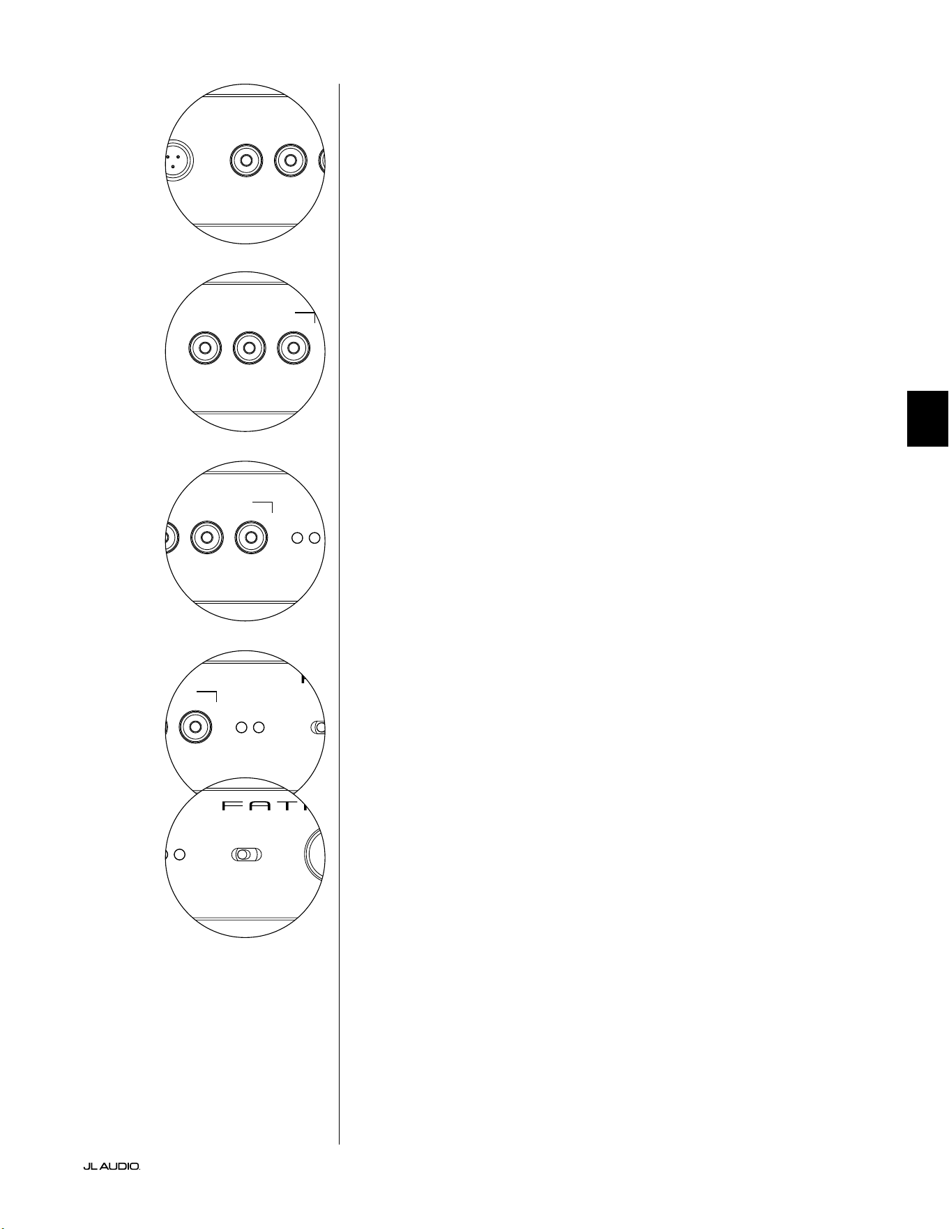
第 15 页
|
Fathom
®
v2
中文
LP freq. (Hz) e.l.f. trim (dB) phase (deg.)
Polarity
0
|
180 deg.
LP Filter
o
|
12dB
|
24dB
Master Level
max
0
Lights
o
|
dim
|
on
-∞
Level Mode
ref.
|
variable
Input Mode
master
|
slave
calibration mic. demo defeat calibrate
Power
o
|
on
|
auto
Digital Automatic Room Optimization
LP freq. (Hz) e.l.f. trim (dB) phase (deg.)
Polarity
0
|
180 deg.
LP Filter
o
|
12dB
|
24dB
Master Level
max
0
Lights
o
|
dim
|
on
-∞
Level Mode
ref.
|
variable
Input Mode
master
|
slave
calibration mic. demo defeat calibrate
Power
o
|
on
|
auto
Digital Automatic Room Optimization
演示按钮
演示按钮触发 20 秒长的音调序列,简要演示 Fathom v2 超低音音响的音
域。演示功能可用于展示 Fathom v2 的输出能力,并在系统故障排查期间验
证 Fathom v2(或多个 Fathom v2)是否正常运行。
演示按钮还可用于(组合使用)清除(恢复为平坦)D.A.R.O. 均衡器设置。要
清除 D.A.R.O. 设置并关闭校准指示灯,请按住演示按钮,然后按断开按钮。请
注意,您必须快速执行此按钮顺序。如果您按住演示按钮超过 2 秒而没有触摸
断开按钮,演示音调将开始播放。如果发生这种情况,只需等待演示序列结束,
然后再重试即可。
断开按钮
如果在断开功能处于激活状态时按下“演示”或“校准”,则“断开”会自动取
消。任何其他前置面板控制都不会改变 D.A.R.O. 的断开状态。断开设置存储
在非易失性存储器中,即使断开电源也不会更改。
断开按钮还可用于(组合使用)清除(恢复为平坦)D.A.R.O. 均衡器设置。要
清除 D.A.R.O. 设置并关闭校准指示灯,请按住演示按钮,然后按断开按钮。请
注意,您必须快速执行此按钮顺序。如果您按住演示按钮超过 2 秒而没有触摸
断开按钮,演示音调将开始播放。如果发生这种情况,只需等待演示序列结束,
然后再重试即可。
校准按钮
在 D.A.R.O. 测试序列中,校准按钮的绿色 LED 将快速闪烁,提醒用户注意
两种特殊情况:
1.“未连接捷力麦克风”:如果您在尝试开始校准之前忘记连接麦克风,您
将收到此提示。按一次校准按钮以取消提示,连接 D.A.R.O. 麦克风,然后重
试 。
2.“D.A.R.O. 的校准音量不适合”: 由于 D.A.R.O. 序列是完全自动的,此
提示很可能表示麦克风有问题。按一次校准按钮以取消提示。请确保捷力麦克
风已正确连接,然后重试。如需更多帮助,请参阅第 33 页的故障排查。
输入模式指示灯
输入模式指示灯 LED 显示由 Fathom v2 后置面板上的开关选择的输入模
式,可以是“主机”或“从机”(除非“灯光”开关设置为“关闭”)。有关详细信息,
请参阅第 20 页。
音量模式
两位音量模式开关支持您在以下模式之间进行选择:
“参考”: 在此模式下,主音量控制旋钮对 Fathom v2 的输出音量没有影
响。如果您主要通过接收器或前置功放/处理器控制超低音音响音量,请使用
此设置。对于与小孩或狂热的青少年共同居住的人群而言,这种运行模式将防
止直接操纵主音量。
“可变”:在此模式下,主音量控制旋钮决定 Fathom v2 超低音音响的输
出音量。当 Fathom v2 超低音音响与双声道系统中的一对立体声扬声器音量
匹配时,此模式也很有用。
LP freq. (Hz) e.l.f. trim (dB) phase (deg.)
Polarity
0
|
180 deg.
LP Filter
o
|
12dB
|
24dB
Master Level
max
0
Lights
o
|
dim
|
on
-∞
Level Mode
ref.
|
variable
Input Mode
master
|
slave
calibration mic. demo defeat calibrate
Power
o
|
on
|
auto
Digital Automatic Room Optimization
LP freq. (Hz) e.l.f. trim (dB) phase (deg.)
Polarity
0
|
180 deg.
LP Filter
o
|
12dB
|
24dB
Master Level
max
0
Lights
o
|
dim
|
on
-∞
Level Mode
ref.
|
variable
Input Mode
master
|
slave
calibration mic. demo defeat calibrate
Power
o
|
on
|
auto
Digital Automatic Room Optimization
LP freq. (Hz) e.l.f. trim (dB) phase (deg.)
Polarity
0
|
180 deg.
LP Filter
o
|
12dB
|
24dB
Master Level
max
0
Lights
o
|
dim
|
on
-∞
Level Mode
ref.
|
variable
Input Mode
master
|
slave
calibration mic. demo defeat calibrate
Power
o
|
on
|
auto
Digital Automatic Room Optimization
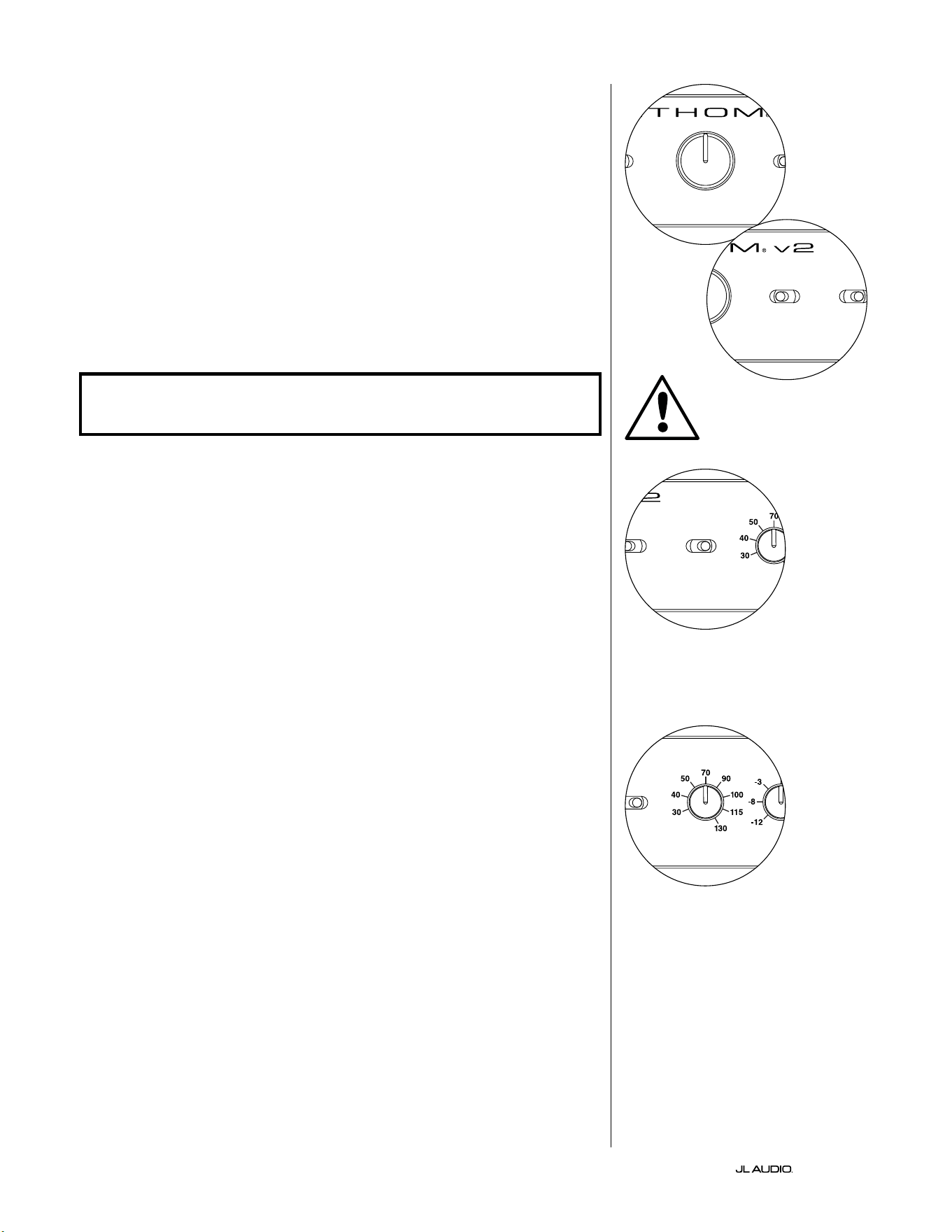
第 16 页
|
Fathom
®
v2
主音量旋钮
在前置控制面板上选择可变音量模式时,主音量旋钮用于控制 Fathom v2
的输出音量。
完全逆时针旋转时,Fathom v2 的输出将完全静音。当处于“0”或垂直位置
时,可变增益音量与参考音量设置相匹配。完全顺时针旋转时,Fathom v2 的
输出音量比基准设置高出 15 分贝。
灯光
“灯光”选择开关支持用户选择三种指示灯模式中的一种。
“关闭”可随时关闭所有前置面板 LED。
当 Fathom v2 开启时,“暗光”会将所有前置面板 LED 设置为低亮度水平。
当 Fathom v2 开启时,“开启”会将所有前置面板 LED 设置为全亮度级别。
重要!在故障排查或校准 D.A.R.O.功能时,请确保将“灯光”开关设置为“
暗 光 ”或“ 开 启 ”。
低通滤波器
低通(LP)滤波器选择开关决定了 Fathom v2 内置低通滤波器的运行模
式 。
“关闭”会断开低通滤波器,将该电路从信号路径中完全移除。
“12 分贝”将低通滤波器的滚降斜率设置为 12 分贝/倍频程斜率
(Butterworth 对齐)。
“24 分贝”将低通滤波器的滚降斜率设置为 24 分贝/倍频程斜率
(Linkwitz-Riley 对齐)。
24 分贝设置更积极地衰减高于低通频率设置的高频(见下文)。如果您使
用的是 Fathom v2 的内置低通滤波器,请尝试使用低通滤波器斜率设置,以
实现到卫星式扬声器的最佳过渡。如果您更喜欢使用接收器或前置功放中的
滤波器和低音管理功能,请通过选择“关闭”位置来断开板载滤波器。
低通频率
低通(LP)频率选择器旋钮支持用户选择 Fathom v2 内部低通滤波器的滚
降频率。频率从 30 赫兹(逆时针完全)到 130 赫兹(顺时针完全)变化。如果低
通滤波器开关设置为“关闭”,则此旋钮不会以任何方式影响输入信号。80 赫
兹是常用的滤波频率,通常是一个良好的调整切入点。
LP freq. (Hz) e.l.f. trim (dB) phase (deg.)
Polarity
0
|
180 deg.
LP Filter
o
|
12dB
|
24dB
Master Level
max
0
Lights
o
|
dim
|
on
-∞
Level Mode
ref.
|
variable
Input Mode
master
|
slave
calibration mic. demo defeat calibrate
Power
o
|
on
|
auto
Digital Automatic Room Optimization
LP freq. (Hz) e.l.f. trim (dB) phase (deg.)
Polarity
0
|
180 deg.
LP Filter
o
|
12dB
|
24dB
Master Level
max
0
Lights
o
|
dim
|
on
-∞
Level Mode
ref.
|
variable
Input Mode
master
|
slave
calibration mic. demo defeat calibrate
Power
o
|
on
|
auto
Digital Automatic Room Optimization
LP freq. (Hz) e.l.f. trim (dB) phase (deg.)
Polarity
0
|
180 deg.
LP Filter
o
|
12dB
|
24dB
Master Level
max
0
Lights
o
|
dim
|
on
-∞
Level Mode
ref.
|
variable
Input Mode
master
|
slave
calibration mic. demo defeat calibrate
Power
o
|
on
|
auto
Digital Automatic Room Optimization
LP freq. (Hz) e.l.f. trim (dB) phase (deg.)
Polarity
0
|
180 deg.
LP Filter
o
|
12dB
|
24dB
Master Level
max
0
Lights
o
|
dim
|
on
-∞
Level Mode
ref.
|
variable
Input Mode
master
|
slave
calibration mic. demo defeat calibrate
Power
o
|
on
|
auto
Digital Automatic Room Optimization
重要
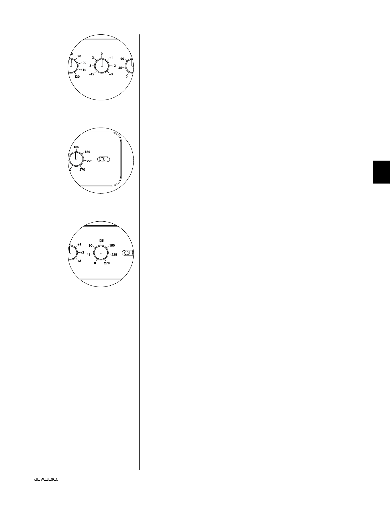
第 17 页
|
Fathom
®
v2
中文
E.L.F.Trim
极低频率(“E.L.F.Trim”)旋钮支持用户在 24 赫兹(极低的低音)下应用一
定量的信号均衡。完全逆时针旋转时,24 赫兹的信号被降低了 12 分贝。均衡
器在“0”位置时设置为平坦,对信号的贡献为零。完全逆时针旋转时,24 赫兹
的信号被提高了 3 分贝。
E.L.F.Trim 功能对于为您的特定房间定制 Fathom v2 的极低频率输出非
常有用。提升一些可以让某些材料听感更刺激。使用截断功能可以帮助补偿低
频下的空间或边界增益。房间的边界和房间的限制(有限)大小自然会导致非
常低的频率相对于信号的其他部分得到提升。因此,使用 E.L.F.Trim 功能来截
断最低频率的微调功能,可以帮助驯化中小型房间中的“过度”或不自然的低
音(还可以减少房间或整个房屋中不必要的振动)。
极性
极性开关支持用户在正常(0 度)和反向(180 度)信号极性之间进行选择。
极性开关将主要影响您的超低音音响和卫星扬声器分频点附近的小频率范
围。
不同于相位控制能有效地增加时间延迟,极性开关会产生信号的幅度峰值
的瞬时反转。例如,如果在给定参考点,正弦波有一个幅度峰值,通过反转相位
开关,您会立即将峰值转换为波谷或幅度下降。因为极性开关的效果立竿见
影,所以它是对相位控制运行的补充,并且不能被它替换。
把 Fathom v2 放置在房间里时,先尝试极性开关,然后再调整相位控制。
在 Fathom v2 超低音音响和卫星式扬声器之间,极性开关的任何位置都可以
提供更平稳的过渡。使用中低音和上段低音含量良好的原材料进行评估。
相位
相位控制旋钮支持用户调整超低音音响输出相对于主扬声器的时间。相位
控制将主要影响您的超低音音响和卫星扬声器分频点附近的小频率范围。可
以在 0 度(逆时针旋转完全)到 270 度(顺时针旋转完全)之间进行相位设置。
相位控制的标签参考 80 赫兹频率,因为这是卫星扬声器和超低音音响之间
最常见的分频点。
家庭影院安装中,扬声器、超低音音响和视听座椅的位置区别很大。由于扬
声器相对于房间边界和彼此之间的物理位置对声音输出的感知质量有很大影
响,有时延迟超低音音响的输出会很有帮助。这就是当您将相位控制转到 0 度
以上时会发生的。
将 Fathom v2 放置在视听室中以便获得最流畅的整体音效,并确定了最
优“极性”开关位置之后(见上一章节),就可以尝试相位控制的位置。用中段低
音和上段低音含量高的熟悉的素材,调整相位控制,并聆听更清晰的中低音,
以及超低音音响和卫星扬声器系统之间更流畅的过渡。如果没有一种设置听
起来其他设置更好,则保留相位控制在 0 度。
LP freq. (Hz) e.l.f. trim (dB) phase (deg.)
Polarity
0
|
180 deg.
LP Filter
o
|
12dB
|
24dB
Master Level
max
0
Lights
o
|
dim
|
on
-∞
Level Mode
ref.
|
variable
Input Mode
master
|
slave
calibration mic. demo defeat calibrate
Power
o
|
on
|
auto
Digital Automatic Room Optimization
LP freq. (Hz) e.l.f. trim (dB) phase (deg.)
Polarity
0
|
180 deg.
LP Filter
o
|
12dB
|
24dB
Master Level
max
0
Lights
o
|
dim
|
on
-∞
Level Mode
ref.
|
variable
Input Mode
master
|
slave
calibration mic. demo defeat calibrate
Power
o
|
on
|
auto
Digital Automatic Room Optimization
LP freq. (Hz) e.l.f. trim (dB) phase (deg.)
Polarity
0
|
180 deg.
LP Filter
o
|
12dB
|
24dB
Master Level
max
0
Lights
o
|
dim
|
on
-∞
Level Mode
ref.
|
variable
Input Mode
master
|
slave
calibration mic. demo defeat calibrate
Power
o
|
on
|
auto
Digital Automatic Room Optimization
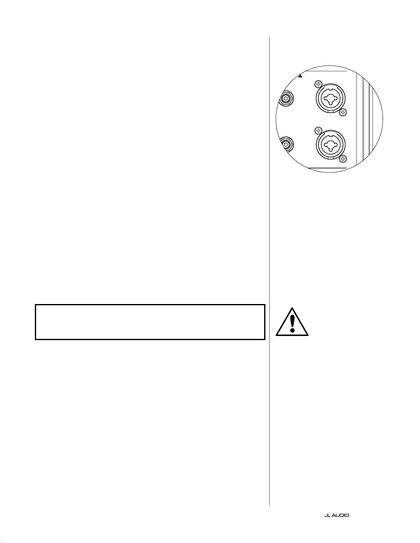
第 18 页
|
Fathom
®
v2
连接 FATHOM v2
平衡输入
如果您的家庭影院接收器或前置功放/处理器提供平衡输出,则 Fathom
v2 的平衡输入是首选连接。平衡连接在专业演播室和扩声应用场景中得到广
泛使用有许多非常良好的原因。除了确保组件之间的适当接地外,平衡信号传
输还旨在消除来自周围环境的电缆噪声(对于长距离电缆铺设尤为重要)。底
线是如果您使用平衡连接,您的系统将不太可能出现杂声或其他无关的噪音。
Fathom v2 超低音音响具有独立的左右平衡输入连接,附带 XLR“组合”插
孔。这些特殊插孔可接受三针公头 XLR 接口或“热端-冷端-接地端”(TRS)1/4
英寸(6.3 毫米)接口,以便与各种设备兼容。
针对带有单声道超低音音响或“LFE”声道连接的系统,将只使用标有“左”
或“单声道”的插孔。这适用于大多数现代多声道接收器和前置功放/处理器。
为没有专用单声道超低音音响连接的系统提供了单独的左右输入插孔。这通
常适用于双声道音频设备。
您的捷力经销商可提供恰当的平衡电缆,但 Fathom v2 中未包含。
技术说明:
• 请勿通过适配器使用带有非平衡信号的平衡输入。Fathom v2 的非平衡
输入经过光学隔离,最好在只有非平衡信号源可用的情况下使用。平衡
输入阻抗为 10 千欧。
• 输入接口均根据音频工程协会关于平衡信号电缆的建议进行配置,如下
所示:
XLR 连接
针脚 1:屏蔽
针脚 2:正
针脚 3:负
TRS 连接:
热端:正
冷端:负
接地端:屏蔽
重要!如果您的接收器或前置功放/处理器没有 XLR 或 1/4 英寸 TRS 平衡
输出,请参阅第 19 页的“非平衡输入”部分以了解输入连接信息。请勿尝
试通过适配器将非平衡输出连接到 FATHOM V2 的平衡输入。
Fathom v2 上的左输入和右输入在内部
加总为单声道。由于 Fathom v2 本身就
是“单声道”或单声道设备,您可以使用
主机 Fathom v2 的左右输入,然后将求
和的单声道信号分配给系统中的其他从
机 Fathom v2。
重要
1200VA
Built in USA with Imported and domestic components
LEFT
or
MONO
RIGHT
ONLY
INPUTS
Output to Slave
(Balanced)
Balanced
Unbalanced
Input Modes
Slave
Master
Grounded
Isolated
SERIAL NUMBER:
Warranty void if serial number is removed, altered or defaced.
F 12A H
250V
120 V ~ 60 Hz
F
U
S
E
F
U
S
E
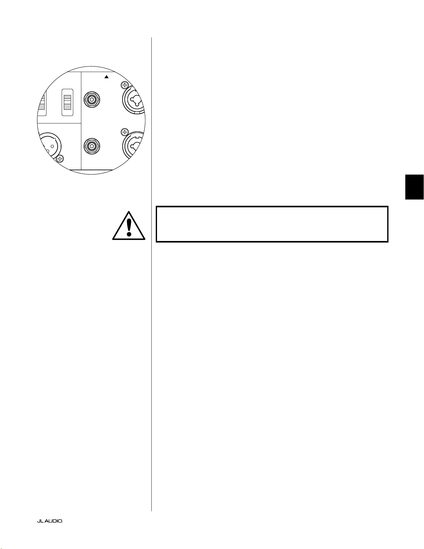
第 19 页
|
Fathom
®
v2
中文
非平衡输入
Fathom v2 超低音音响具有独立、左右、非平衡的 RCA 型输入接口。这些
是家庭影院应用场景中最常用的接口,如果您的接收器或前置功放/处理器没
有提供平衡输出,则必须使用这些接口。虽然非平衡连接不像平衡连接那样抗
噪音,但 Fathom v2 超低音音响在非平衡输入上采用光学隔离,可最大限度
地减少系统中出现噪声的可能性。
针对带有单声道超低音音响或“LFE”声道连接的系统,将只使用标有“左”
或“单声道”的 RCA 型插孔。这适用于大多数现代多声道接收器和前置功放/
处理器。为没有专用单声道超低音音响连接的系统提供了单独的左右 RCA 型
输入插孔。这通常适用于双声道音频设备。
技术说明:
• 当信号源上没有平衡输出时,必须使用 RCA 型的非平衡输入。Fathom
v2 在非平衡输入上配备光学隔离电路,可最大限度地降低接地环路感
应噪声的可能性。非平衡输入阻抗为 50 千欧。
• 连接是非平衡信号电缆的行业标准,如下所示:
RCA 型连接:
热端:正
接地端:负
重要!如果连接后出现噪声,则 FATHOM V2 支持接地或隔离非平衡输
入。有关将噪音降至最低的更多信息,请参阅本手册第 20 页的“输入模式
开 关 ”部 分 。
1200VA
Built in USA with Imported and domestic components
LEFT
or
MONO
RIGHT
ONLY
INPUTS
Output to Slave
(Balanced)
Balanced
Unbalanced
Input Modes
Slave
Master
Grounded
Isolated
SERIAL NUMBER:
Warranty void if serial number is removed, altered or defaced.
F 12A H
250V
120 V ~ 60 Hz
F
U
S
E
F
U
S
E
重要
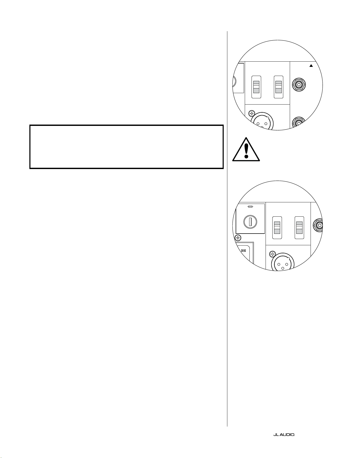
第 20 页
|
Fathom
®
v2
输入模式开关:
两个开关位于后置面板上,用于控制非平衡信号接地和主机/从机运行。
“接地/隔离”开关
“接地/隔离”输入模式开关仅影响非平衡 RCA 输入,旨在支持与音频或
家庭影院系统的安静、无杂声连接。此功能是为了应对不同制造商的多个组件
相互连接时,家庭影院系统中经常遇到的信号接地问题。
Fathom v2 出厂时会将此开关置于“隔离”模式。连接并开启所有系统组件
(但没有播放任何源材料)的情况下,如果听到 Fathom v2 持续传出低频杂
声,请将此开关转到“接地”位置,并评估噪声音量的差异。使用发出杂声或噪
音最小的任何开关位置。
重要!请注意,更改优化系统中的任何组件(接收器、功放、DVD 播放器、
电缆或卫星盒等)。可能会改变信号接地方案,并导致以前安静的系统中
出现杂声。如果您在家庭影院系统中添加或更改上游组件,则可能需要重
新检查 Fathom v2 超低音音响上的输入模式设置,以获得最佳的噪音性
能。在这种情况下,有线电视和卫星电视尤其麻烦。
主机/从机开关
Fathom v2 旨在通过主机/从机连接链轻松适应家庭影院系统中多个超低
音音响的执行。该方法支持利用一台 Fathom v2 的信号处理功能来集中控制
房间内的多台 Fathom v2。主机/从机功能还使 D.A.R.O. 系统能够优化多重
超低音音响安装的响应。
Fathom v2 出厂时会将此开关置于“主机”模式。如果您使用的是单一的
Fathom v2,您将使用“主机”的位置,且无需再关注这一部分。
如果您的安装包含两个或更多的 Fathom v2,您将通过每个 Fathom v2
的后置功放面板上的“主机/从机”开关将其中一个 Fathom v2 指定为
“主机”,并将系统中的所有其他 Fathom v2 指定为“从机”超低音音
响。Fathom v2 前置面板上的 LED 指示灯用于指示给定的超低音音响是选择
了“主机”模式还是“从机”模式。
“主机”模式下运行的 Fathom v2,“输出至从机”信号将在主机 Fathom
v2 上选择的任何信号处理(包括主音量设置和 D.A.R.O. 处理)传送到在“从
机”模式下运行的其他 Fathom v2。“从机”超低音音响的信号处理和音量控
制将无法运行。在此模式下,用户不必担心从机超低音音响的音量、分频和其
他设置。
技术说明:
• 选择“从机”位置会导致所有用户可定义的信号处理和主音量控制断开。
因为如此,在某些特殊情况下,您可能想要在“从机”模式下运行单个
Fathom v2。如果您使用外部信号处理和音量匹配控制,激活“从机”模
式将防止任何人使用 Fathom v2 上的手动控制来影响系统参数。
重要
1200VA
Built in USA with Imported and domestic components
LEFT
or
MONO
RIGHT
ONLY
INPUTS
Output to Slave
(Balanced)
Balanced
Unbalanced
Input Modes
Slave
Master
Grounded
Isolated
SERIAL NUMBER:
Warranty void if serial number is removed, altered or defaced.
F 12A H
250V
120 V ~ 60 Hz
F
U
S
E
F
U
S
E
1200VA
Built in USA with Imported and domestic components
LEFT
or
MONO
RIGHT
ONLY
INPUTS
Output to Slave
(Balanced)
Balanced
Unbalanced
Input Modes
Slave
Master
Grounded
Isolated
SERIAL NUMBER:
Warranty void if serial number is removed, altered or defaced.
F 12A H
250V
120 V ~ 60 Hz
F
U
S
E
F
U
S
E
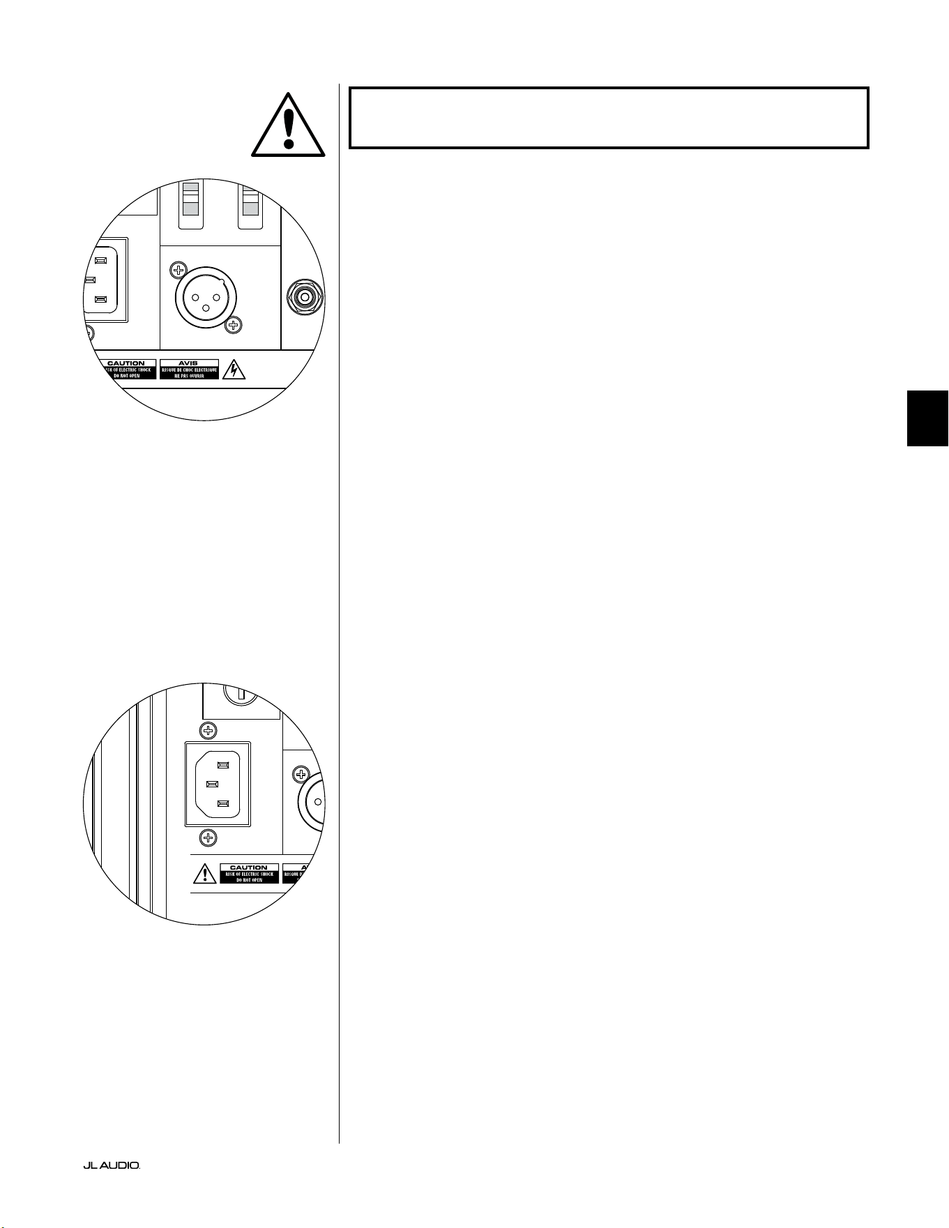
第 21 页
|
Fathom
®
v2
中文
重要!有关使用输入/输出连接的更多信息,请参阅第 22-25 页的“系统连
接 图 ”。
“输出到从机”接口
如果您在一个家庭影院系统中运行多个 Fathom v2 超低音音响,您将指
定一个 Fathom v2 为主机(参见第 20 页),然后通过此平衡 XLR 输出将信号
馈送到其余的“从机”Fathom v2 扬声器。“输出至从机”电缆可以连接到下一
个 Fathom v2 上的“左或单声道”平衡 XLR 输入。当 Fathom v2 处于“从机”
模式时,其“输出至从机”连接可用于将信号传递给在“从机”模式下运行的其
他 Fathom v2。
“输出到从机”接口的设计用途如下:
1) 从“主机”Fathom v2 的“输出至从机”接口到第一个“从机”Fathom v2
的“左或单声道”XLR 平衡输入。
2) 从第一个“从机”Fathom v2 的“输出至从机”接口到第二个“从
机”Fathom v2 的“左或单声道”XLR 平衡输入。
3) 从第二个“从机”Fathom v2 的“输出至从机”接口到第三个“从
机”Fathom v2 的“左或单声道”XLR 平衡输入。等等(此类配置最多可以
连接 10 台 Fathom v2)。您的捷力经销商可提供带 XLR 端的恰当平衡
电缆,但 Fathom v2 中未包含。
技术说明:
• “输出至从机”信号将在主机 Fathom v2 上选择的任何信号处理(包
括主音量设置和 D.A.R.O. 处理)传送到在“从机”模式下运行的其他
Fathom v2。
• Fathom v2 在“从机”模式下运行时,“输出至从机”信号是平衡输入信
号的精确缓冲重制,令这种信号分配方法比使用 Y 适配器或分离器更可
取 。
• 主机/从机连接仅使用带有高质量 XLR 连接器的屏蔽连接电缆。请勿使
用带有适配器的非平衡电缆。
IEC 型交流电源接口
IEC 型交流电源线插座可容纳 6 英尺(1.8 米)长、随 Fathom v2 附带的大
尺寸电源线。世界不同地区销售的 Fathom v2 都根据每个市场的电气系统
进行了配置,并在电源线上安装了适当的插头。请注意交流接口旁边的电压
标记,并确保您仅使用与这些标记匹配的插座为 Fathom v2 供电。请勿使用
Fathom v2 随附的交流电源线以外的任何其他交流电源线。有关电源保险丝
支架的信息,请参阅本手册的故障排查部分。
Fathom v2 超低音音响是一款功能非常强大的设备,能吸收大量电流。如
果连接到一个电源插座上的 Fathom v2 的组件太多,您可能会在播放要求
非常苛刻的节目材料时触发家用断路器。如果发生这种情况,请将 Fathom
v2 和其他组件分散至两个交流电路。如可能,为了获得最高性能,请为每个
Fathom v2 配备专用交流电路。
重要
1200VA
Built in USA with Imported and domestic components
LEFT
or
MONO
RIGHT
ONLY
INPUTS
Output to Slave
(Balanced)
Balanced
Unbalanced
Input Modes
Slave
Master
Grounded
Isolated
SERIAL NUMBER:
Warranty void if serial number is removed, altered or defaced.
F 12A H
250V
120 V ~ 60 Hz
F
U
S
E
F
U
S
E
1200VA
Built in USA with Imported and domestic components
LEFT
or
MONO
RIGHT
ONLY
INPUTS
Output to Slave
(Balanced)
Balanced
Unbalanced
Input Modes
Slave
Master
Grounded
Isolated
SERIAL NUMBER:
Warranty void if serial number is removed, altered or defaced.
F 12A H
250V
120 V ~ 60 Hz
F
U
S
E
F
U
S
E
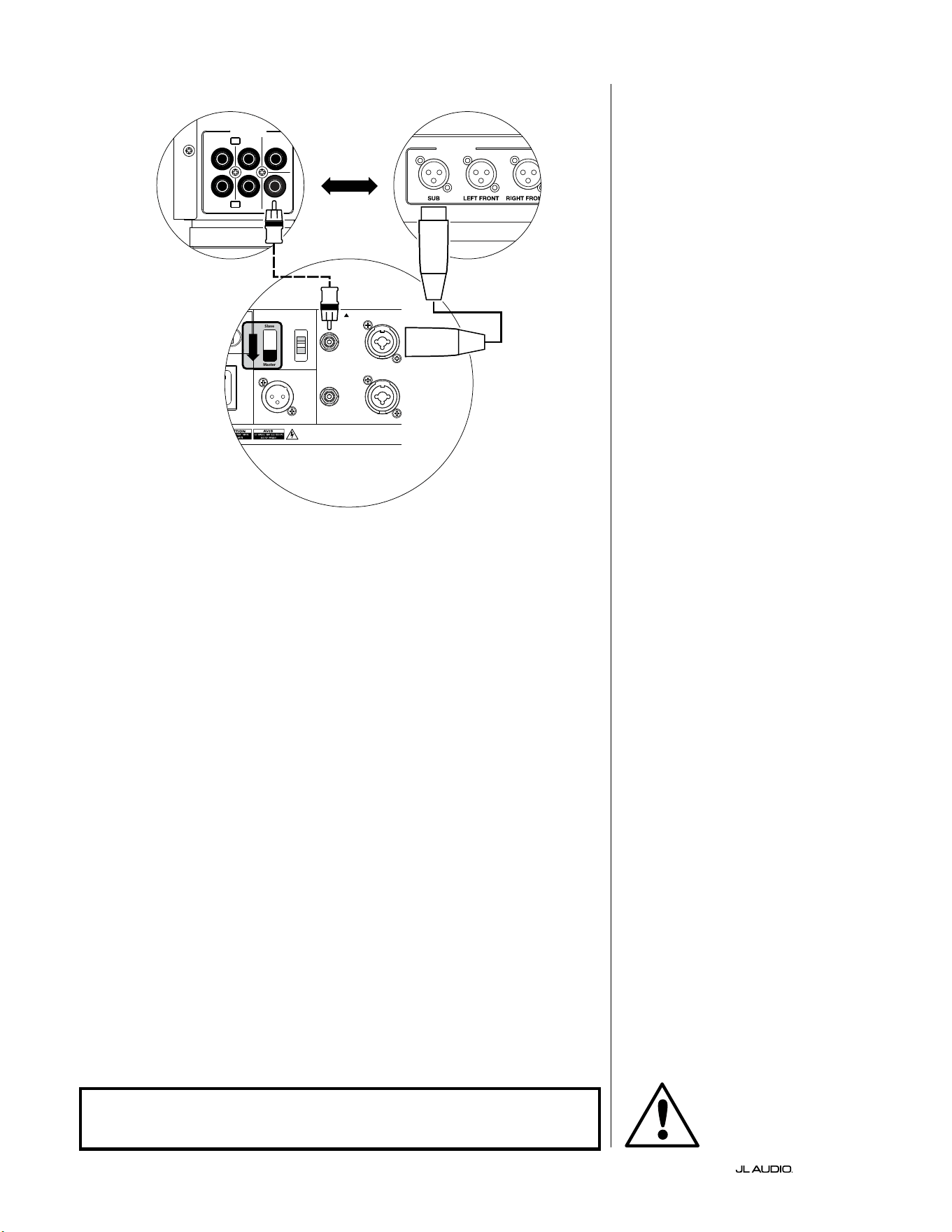
第 22 页
|
Fathom
®
v2
系统连接图 1:
一台 Fathom v2 到家庭影院接收器或
家庭影院前置功放/处理器
大多数家庭影院接收器和前置功
放/处理器提供单一(单声道)超低音音
响输出。连接单声道超低音音响输出到
Fathom v2 时,您将只使用 Fathom 的“
左或单声道”输入。
有两种连接类型可将 Fathom v2 连
接到您的家庭影院系统: 平衡(XLR 或
1/4 英寸 TRS 接口)和非平衡(RCA 型接
口)。平衡连接可提供卓越的噪声抑制,
并确保组件之间的妥善接地。如果您的
接收器或处理器具备平衡输出,我们强
烈建议您使用它们。
在左侧的连接图中,平衡连接显示为
实线,非平衡连接显示为虚线。您将只使
用其中一种输入连接方法(不能同时使
用这两种方法)。
120 0VA
Built in USA with Imported and domestic components
LEFT
or
MONO
RIGHT
ONLY
INPUTS
Output to Slave
(Balanced)
Balanced
Unbalanced
Input Modes
Slave
Master
Grounded
Isolated
SERIAL NUMBER:
Warrant y void if serial nu mber is removed , altered or def aced.
F 12A H
250V
120 V ~ 60 Hz
F
U
S
E
F
U
S
E
OUTPUTS
SUB
REAR
REAR CENTER
FRONT
FRONT
R
L
PRE OUT
处理器(非平衡输出)
FATHOM 后置控制(主机)
或
接收器/处理器(非平衡输出)
警告
警告!在建立或更改任何连接之前,请关闭 FATHOM v2 和系统中的所有
其他设备!
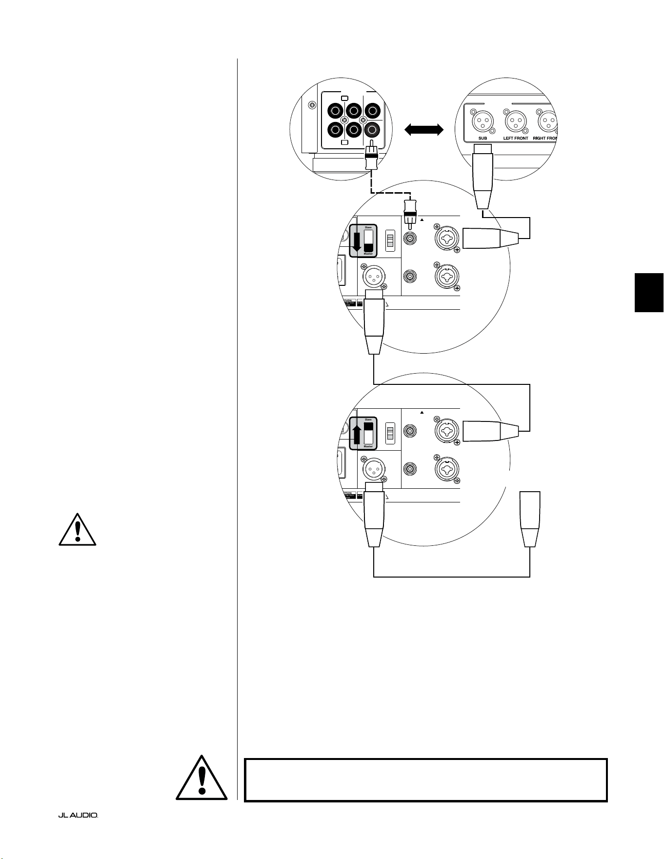
第 23 页
|
Fathom
®
v2
中文
系统连接图 2:
多台 Fathom v2 超低音音响到
家庭影院接收器或
家庭影院前置功放/处理器
为了极大地简化在单个家庭影院系
统中使用多个超低音音响,Fathom v2
集成了“主机/从机”信号分配系统。这可
支持从单一的“主机”单元控制系统中的
所有 Fathom v2。
首先,您将通过其上方的“输入模式”
开关,选择一个 Fathom v2 超低音音响
作为“主机”。通常,您将指定距离接收
器/前置功放最近的 Fathom v2 为主机。
在某些情况下,例如,当某些音响的控制
面板很难访问时,您可能更喜欢将最容
易访问的控制面板指定为主机。
有两种连接类型可将主机 Fathom
v2 连接到您的家庭影院系统: 平衡(XLR
或 1/4 英寸 TRS 接口)和非平衡(RCA
型接口)。平衡连接可提供卓越的噪声抑
制,并确保组件之间的妥善接地。如果您
的接收器或处理器具备平衡输出,我们
强烈建议您使用它们连接到指定为主机
的F Fathom v2。
在左侧的连接图中,平衡连接显示为
实线,非平衡连接显示为虚线。对于指定
为主机的 Fathom v2,您只能使用其中
一种输入连接方法(不能同时使用这两
种方法)。
系统中剩余的 Fathom v2 将通过
其上方的“输入模式”开关配置为“从
机”单元。使用平衡 XLR 电缆,将主机
Fathom v2 的“输出到从机”连接到第一
个从机 Fathom v2 的“左或单声道”平
衡输入。该从机单元的“输出到从机”接
口将通过另一条平衡 XLR 电缆为下一
个从机单元的“左或单声道”输入供电。
后续的从机单元将以相同的方式连接。
“主机”和“从机”Fathom 之间以及“从
机”Fathom 之间的连接仅通过平衡 XLR
电缆进行。
120 0VA
Built in USA with Imported and domestic components
LEFT
or
MONO
RIGHT
ONLY
INPUTS
Output to Slave
(Balanced)
Balanced
Unbalanced
Input Modes
Slave
Master
Grounded
Isolated
SERIAL NUMBER:
Warrant y void if serial nu mber is removed , altered or defa ced.
F 12A H
250V
120 V ~ 60 Hz
F
U
S
E
F
U
S
E
OUTPUTS
SUB
REAR
REAR CENTER
FRONT
FRONT
R
L
PRE OUT
处理器(非平衡输出)
FATHOM 后置控制(主机)
FATHOM 后置控制(从机)
或
接收器/处理器(非平衡输出)
至额外 FATHOM
(如适用)
重要
警告
警告!在建立或更改任何连接之前,请关闭 FATHOM v2 和系统中的所有
其他设备!
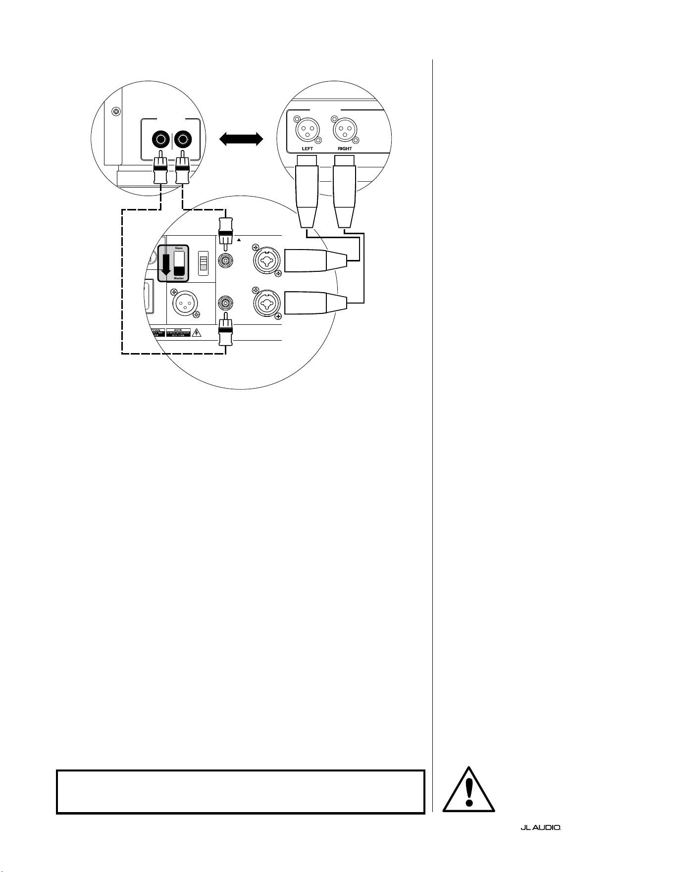
第 24 页
|
Fathom
®
v2
120 0VA
Built in USA with Imported and domestic components
LEFT
or
MONO
RIGHT
ONLY
INPUTS
Output to Slave
(Balanced)
Balanced
Unbalanced
Input Modes
Slave
Master
Grounded
Isolated
SERIAL NUMBER:
Warrant y void if serial nu mber is removed , altered or def aced.
F 12A H
250V
120 V ~ 60 Hz
F
U
S
E
F
U
S
E
立体声有源分频器(平衡输出)
LOW OUT
(SUB OUT)
立体声有源分频器(非平衡输出)
RIGHTLEFT
LOW OUT
(SUB OUT)
FATHOM 后置控制(主机)
或
系统连接图 3:
一个单声道 Fathom v2 到一个双声道
音频系统
将单声道的 Fathom v2 (或多个
Fathom v2)连接到双声道音频系统时,
您将同时使用“左或单声道”输入和“右”
输入。Fathom v2 输入部分中的总和电
路将立体声信号加总为单声道。
我们强烈建议您使用高质量的有
源分频器,如捷力 CR-1,用于在连接到
Fathom v2 和驱动您的主扬声器的功放
之前分割前置功放的信号。这将支持您
滤波驱动主扬声器的信号中的低频,从
而获得更好的性能。
如果您使用的不是有源分频器,并且
可以在全音域范围内运行您的主扬声
器,则可以使用适当的 Y 形接口来代替
图中所示的有源分频器,来分割前置功
放的输出信号。
有两种连接类型可将 Fathom v2 连
接到您的双声道音频系统: 平衡(XLR 或
1/4 英寸 TRS 接口)和非平衡(RCA 型接
口)。平衡连接可提供卓越的噪声抑制,
并确保组件之间的妥善接地。如果您的
前置功放或有源分频器可提供平衡输
出,我们强烈建议您使用它们。
在左侧的连接图中,平衡连接显示为
实线,非平衡连接显示为虚线。您将只使
用其中一种输入连接方法(不能同时使
用这两种方法)。
注:如需要,可以将其他 Fathom v2
以“从机”模式连接到如图所示连接的
Fathom v2。有关从机连接的说明,请参
见第 23 页上的“连接图 2”。
警告
警告!在建立或更改任何连接之前,请关闭 FATHOM v2 和系统中的所有
其他设备!
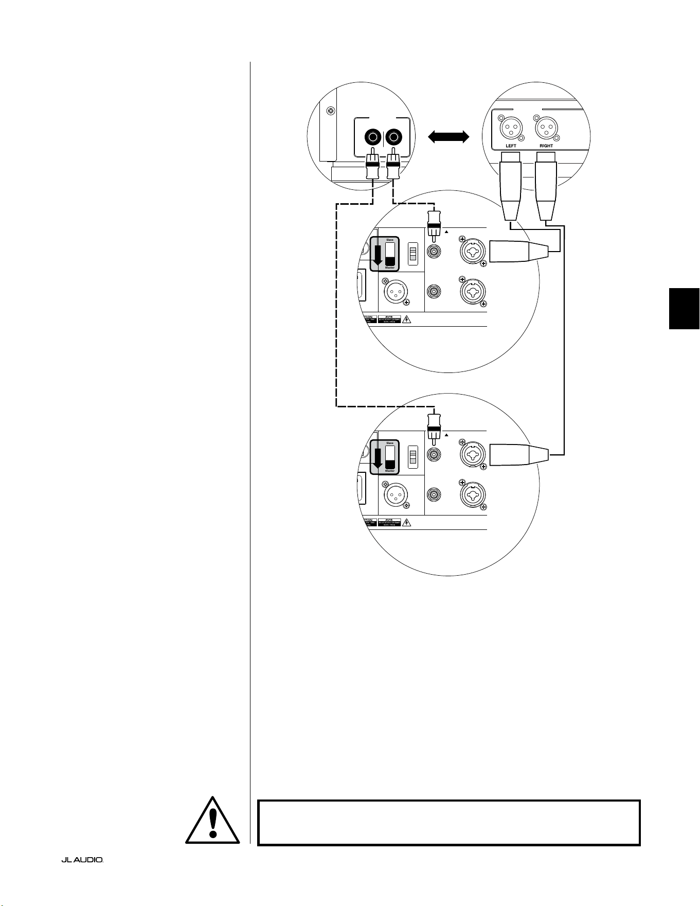
第 25 页
|
Fathom
®
v2
中文
系统连接图 4:
两个立体声 Fathom v2 到双声道音频
系统
将两个立体声 Fathom v2 连接到
双声道音频系统时,您将只使用每个
Fathom v2 的“左或单声道”输入。每个
Fathom v2 上的“输入模式”开关将设置
在“ 主 机 ”位 置 。
我们强烈建议您使用高质量的有
源分频器,如捷力 CR-1,用于在连接到
Fathom v2 和驱动您的主扬声器的功放
之前分割前置功放的信号。这将支持您
滤波驱动主扬声器的信号中的低频,从
而获得更好的性能。
如果您使用的不是有源分频器,并且
可以在全音域范围内运行您的主扬声
器,则可以使用适当的 Y 形接口来代替
图中所示的有源分频器,来分割前置功
放的输出信号。
有两种连接类型可将 Fathom v2 连
接到您的双声道音频系统: 平衡(XLR 或
1/4 英寸 TRS 接口)和非平衡(RCA 型接
口)。平衡连接可提供卓越的噪声抑制,
并确保组件之间的妥善接地。如果您的
前置功放或有源分频器可提供平衡输
出,我们强烈建议您使用它们。
在右侧的连接图中,平衡连接显示为
实线,非平衡连接显示为虚线。您将只使
用其中一种输入连接方法(不能同时使
用这两种方法)。
注:如需要,可以将其他 Fathom v2
以“从机”模式连接到如图所示连接的
Fathom v2。有关从机连接的说明,请参
见第 23 页上的“连接图 2”。
LOW OUT
(SUB OUT)
RIGHTLEFT
LOW OUT
(SUB OUT)
120 0VA
Built in USA with Imported and domestic components
LEFT
or
MONO
RIGHT
ONLY
INPUTS
Output to Slave
(Balanced)
Balanced
Unbalanced
Input Modes
Slave
Master
Grounded
Isolated
SERIAL NUMBER:
Warrant y void if serial nu mber is removed , altered or def aced.
F 12A H
250V
120 V ~ 60 Hz
F
U
S
E
F
U
S
E
处理器(非平衡输出)
FATHOM 后置控制(主机)
或
接收器/处理器(非平衡输出)
FATHOM 后置控制(主机)
警告
警告!在建立或更改任何连接之前,请关闭 FATHOM v2 和系统中的所有
其他设备!

第 26 页
|
Fathom
®
v2
推荐设置流程
1)安装流程准备: ............................................ 26-27
2)音量设置: ................................................... 28
3)极性/相位调整: ............................................... 28
4)定位试验: ................................................... 28
5)应用 D.A.R.O.: ............................................ 29-30
6)调整 E.L.F.Trim: .............................................. 30
安装流程准备:
开始安装程序之前,请确认以下系统设置。这将确保您的超低音音响系统
有一个中立的切入点和有效的设置。
在家庭影院接收器或前置功放/处理器上:
开始设置 Fathom v2 超低音音响系统之前,我们建议您按如下方式设置
您的接收器或前置功放/处理器(在进行这些调整之前,请通过其前置面板电
源开关,关闭系统中的所有 Fathom v2):
1. 扬声器尺寸
在您的接收器或前置功放/处理器的扬声器设置菜单中,将所有高频扬声
器设置为分频点为 80 赫兹的“小”。这将会发送所有低音至 Fathom v2。
2. 扬声器距离
在扬声器设置菜单中,正确设置所有扬声器到主视听座位的距离,包括超
低音音响的距离。用卷尺测量这些距离(时间相干性很重要)。如果使用多
个 Fathom v2,则将它们到主视听座位的距离取平均值,并使用该数字来
设置超低音音响距离。
3. 超低音音响音量
将接收器或前置功放/处理器中的超低音音响音量设置为“0”或其中间位
置。
4. 音调控制/均衡器
将所有音调控制设置为“0”,并断开所有均衡器功能。
在您的有源分频器或低音管理处理器上:
如果您使用的是有源分频器或低音管理处理器,我们建议您在开始设置
Fathom v2 超低音音响系统之前按如下方式进行设置(请在进行这些调整之
前关闭系统中的所有 Fathom v2):
1. 低通滤波器频率
选择 80 赫兹的低通滤波器频率(24 分贝/倍频程斜率)
2. 高通滤波器频率
选择 80 赫兹的高通滤波器频率(24 分贝/倍频程斜率)
3. 低通(超低音音响)输出音量
将超低音音响输出音量设置为“0”或其中间位置。
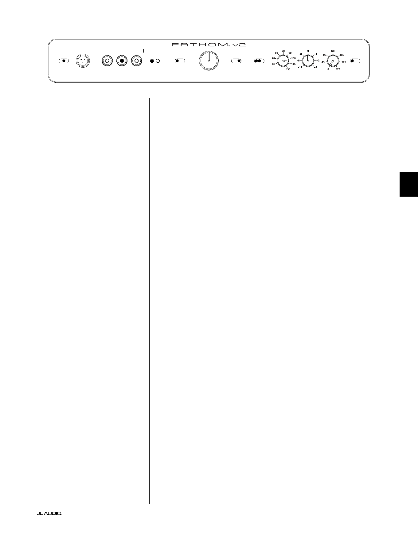
第 27 页
|
Fathom
®
v2
中文
在 Fathom v2 的前置面板上:
请关闭家庭影院接收器或前置功放/处理器再进行调整。
1. “电源”开关
将每个 Fathom v2 的“电源”开关转到“开启”位置。
2. “灯光”开关
将每个 Fathom v2 的“灯光”开关转到“开启”位置。如果您在前置面板
上看不到任何指示灯,您可能忘记了插入 Fathom v2,或者电路有问题。
3. “输入模式”指示灯
如果您使用的是单个 Fathom v2,请确认其“输入模式”指示灯处于“主
机”位置。如果没有,您需要打开 Fathom v2 后置面板上的“输入模式”
开关。
如果您在主机/从机配置中使用多个 Fathom v2,请确认直接连接到您
的接收器或前置功放/处理器的单元在其“输入模式”指示灯上显示“主
机”,并且所有其他单元在其“输入模式”指示灯上显示“从机”。如果没
有,您需要打开 Fathom v2 后置面板上的“输入模式”开关。
4. “音量模式”开关
将主机 Fathom v2 的“音量模式”开关转到“REF”位置。
5. “低通滤波器”旋钮
如果您的家庭影院接收器/处理器正在处理低音管理(扬声器设置
为“小”),或者如果您使用的是外部分频器/低音管理处理器,请将主
Fathom v2 的“低通滤波器”开关转到“关闭”。 如果没有,请选择“12 分
贝 ”位 置 。
6. “低通频率(赫兹)”旋钮
将“低通频率”旋钮转到“80 赫兹”的位置。
7. “E.L.F.Trim(分贝)”旋钮
将“E.L.F.Trim(分贝)”旋钮转到“0”
8. “极性”开关
将“极性”开关拨到“0”。
9. “相位(度)”旋钮
旋 转“ 相 位 ”旋 钮 到“ 0 ”度
10. D.A.R.O.断开开关
按下D.A.R.O.断开开关,以便开关上的红灯保持亮起。
LP freq. (Hz) e.l.f. trim (dB) phase (deg.)
Polarity
0
|
180 deg.
LP Filter
o
|
12dB
|
24dB
Master Level
max
0
Lights
o
|
dim
|
on
-∞
Level Mode
ref.
|
variable
Input Mode
master
|
slave
calibration mic. demo defeat calibrate
Power
o
|
on
|
auto
Digital Automatic Room Optimization
第 28 页
|
Fathom
®
v2
推荐设置流程(续)
超低音音响系统设置:
将家庭影院接收器或前置功放/处理器和 Fathom v2 上的控制设置为第
26 页和第 27 页中推荐的设置后,您就可以开始设置 Fathom v2 以获得最佳
性能。
1. 音量设置
使用具有深低音内容的熟悉音乐或电影素材,借助您的接收器或前置
功放/处理器的超低音音响音量控制,来调整超低音音响的音量,从而与其
他扬声器混合。这种方法比使用 Fathom v2 的“主音量”旋钮更不易被篡改
(想想蹒跚学步的儿童或好奇心强的访客)。
如果您的接收器或前置功放/处理器中的超低音音响音量控制不能调
到与 Fathom v2 匹配的音量,请将该控制音量恢复到“0”,这种情况比较
罕见。然后,将 Fathom v2 的“音量模式”开关翻转到“可变”,并以“0”为参
考点(REF 模式增益和可变“0”增益相同),使用“主音量”控制将超低音音
响与其他扬声器进行音量匹配。记录下此设置以备将来使用。
有关 Fathom v2 音量设置控制的更多详细信息,请参阅本手册第 15-
16 页的“音量模式”和“主音量”章节。
2. 极性和相位调整
让另一个人操作这些控制装置通常会很有帮助,这样您就可以轻松在
主视听座位上听到变化。
听熟悉的素材(最好是上段低音和中低音响应良好的音乐),将“极性”
开关从“0”转到“180”,并聆听不同之处。正确的设置听起来最自然,并能
听到最好的低音击打和发音。如果两者听起来相似,请选择“0”。
设置极性之后,使用相同的音乐材料来试听不同的“相位”控制设置,并
选择进一步增强中低音和上段低音响应的设置。如果听不到差异,请将控
制设置为“0”。
3. 尝试使用其他超低音音响位置(如有必要)。
如果您对超低音音响的基本性能感到满意,即可进入下一步。如果不满
意,我们建议您尝试使用超低音音响的位置,直到您对其基本性能满意为
止。定位试验是获得更好的音效系统的关键。只需将超低音音响移动几英
尺,就会对低音的流畅度产生显著的影响。针对每个新位置,从极性和相位
控制设置“0”开始,并从第 1 步开始重复设置过程。
重要!请记录第 1 步至第 3 步中执行的所有设置,以备将来参考。
重要
第 29 页
|
Fathom
®
v2
中文
重要!确保在 D.A.R.O. 校准期间房间保持安静!关闭视听室附近任何有噪
音 的 电 器( 洗 碗 机 、洗 衣 机 等 )。
在校准过程中关闭空调或暖气泵非常重要。这些强制风型暖通空调系统
可能会产生中等水平的 15-20 赫兹噪声,可能会干扰校准。
4. 应用数字化自动房间优化(D.A.R.O.)
您现在已经准备好应用捷力独家数字化自动房间优化(D.A.R.O.)系统
的强大功能。该系统将测量您的主要视听座位上超低音音响的响应,并应
用功能强大的 18 频段均衡器来驯化由室内模式引起的峰值,从而产生更
流畅、更准确的低音性能。如果您在主机/从机配置中使用多个
Fathom v2,则只需应对指定为“主机”的单元,即可对整个超低音音响系
统执行 D.A.R.O. 校准。请注意,无论旋钮如何设置,在 D.A.R.O. 校准过程
中,所有前置面板信号处理都会断开。校准完成后,即可恢复正常运行。
a) 将主电源开关设置到“开启”位置,并确保 Fathom v2 的指示灯通过“灯
光”开关开启。
b) 从其防护袋中取出校准麦克风,并将其电缆连接到 Fathom v2 前置控
制面板上的 mini-XLR 插孔。
注:D.A.R.O.仅当将随附的捷力测试麦克风插入 Fathom v2 前置面板时,
才能进行校准。没有插入麦克风的情况下禁用“校准”功能,以防止设置意外
丢失。
c) 将麦克风连接到麦克风电缆的另一端,并暂时将麦克风放在主视听座位
上。如果您有麦克风支架,您可以将麦克风放置与头部齐高的位置,并将
其放置在主要视听座位中。
d) 在 Fathom v2 的控制面板上按下“校准”按钮。“校准”按钮上的绿灯将
缓慢闪烁,表示将在 5 秒后开始校准。
e) 按下“校准”按钮后 5 秒内,返回您的主要视听座位,并将麦克风维持在
与您耳朵大致齐高的正常位置。
f) 噪声序列将通过 Fathom v2 播放,听起来像是杂乱的静电。该序列将
持续大约 3 分钟。在此流程中,D.A.R.O. 系统会在您的座位上进行频
率响应测量,并纠正它发现的问题。D.A.R.O. 系统还可以补偿任何前后
的音量差异,以便您的 Fathom v2 在校准过程后将具有类似的感知音
量。D.A.R.O. 完成校准后,“校准”按钮将亮起并保持点亮,表示校准成
功 。
如果您希望运行新的校准,只需重复上述步骤即可。
重要
第 30 页
|
Fathom
®
v2
要清除 D.A.R.O. 设置并关闭校准指示灯(即将其恢复为平摊),请按住
演示按钮,然后按断开按钮。 请注意,您必须快速执行此按钮顺序。如果您
按住演示按钮超过 2 秒而没有触摸断开按钮,演示音调将开始播放。如果
发生这种情况,只需等待演示序列结束,然后再重试即可。您可以按照上述
正常程序执行新的校准。
重要!如果将来您要移动您的 Fathom v2 或主视听座椅,您将需要再次运
行 D.A.R.O.。任何特定的校准对于特定的超低音音响位置和视听座椅位
置组合都是唯一的。只需按照上述步骤创建新的校准曲线即可。
5. 极低频率(e.l.f.) Trim
使用“E.L.F.Trim”控制以调整 Fathom v2 的极低低音延伸。此控制在
24 赫兹时支持 -12 分贝的降低或 +3 分贝的提升,这在中小型家庭影院使
用一个 Fathom v2(或两个)时特别有用。由于较小的封闭空间有助于提高
最低低音频率的音量,较小的影院可能会被 Fathom v2 超低音音响强大
的低音输出所淹没。这可能会在较低的低音区域中创建一个“厚重”或“过
度”的特性。调低“E.L.F.Trim”旋钮会降低极低的低音音量,同时缓解这种
情况。在您找到最适合您房间和品味的材料之前,您可以自由地尝试和聆
听各种要求苛刻的材料。
您的 Fathom v2 现已优化,可在您的视听座位上发挥最大的低音性能。祝
贺您!
重要

第 31 页
|
Fathom
®
v2
中文
常见问题解答
我可以在我的超低音音响上放置物品吗?
我们不建议将任何物品放置在超低音音响机箱上,因为它们可能会振动,导
致噪音产生并可能损坏音质。任何情况下都不应将任何含有液体的物体放在
Fathom v2 机箱上。
Fathom v2 是否有磁屏蔽?
Fathom v2 超低音音响没有磁屏蔽。为避免某些电视类型出现磁性失真,请
将 Fathom v2 放置在离屏幕至少 3-4 英尺(1-1.5 米)的地方。如果您注意到
画面中有任何变色现象,请尝试将超低音音响移至更远的位置,直到这些现象
消 失 。
如果我让 Fathom v2 始终处于“自动”模式,我的电费会不会很高?
处于“自动”模式时,Fathom v2 功放只有在输入端检测到有效信号时才会通
电。当处于关机状态时,只有“内务”电路保持开启状态,来自墙面的功耗可以
忽略不计(小于 5 瓦)。
我应该在雷雨期间或长时间不在时拔下我的超低音音响电源吗?
是的。您应该在雷雨期间(或雷雨前)拔掉 Fathom v2 的电源。这样可以防止
闪电引起的电压尖峰造成任何可能的损害。在这种情况下,建议拔掉所有音
频/视频组件的电源。如果您要离开家几天,拔下家庭影院组件的插头是个好
办法,可防止意外的风暴或电线条件造成的损坏。
清洁 FATHOM v2
使用干净、柔软的超细纤维布或羽毛除尘布为您的 Fathom v2 超低音音响机
箱除尘。出售汽车装饰用品的地方,通常可以买到超细纤维布。
浅色污渍一般可以用干净的超细纤维布擦掉。对于更顽固的污渍,可以使用高
质量的汽车防护蜡和超细纤维布来抛光和保护涂层,这两种材料在任何销售
汽车装饰用品的地方都可以买到。我们推荐 Meguiar's® “NXT Tech Wax”和
Mguiar's® 超细纤维饰面布。
请勿使用含有刺激性溶剂或磨料的抛光剂,因为这可能会永久损坏饰面。请勿
在 Fathom v2 上使用家具抛光剂或任何含油产品。请勿在 Fathom v2 上使
用溶液或侵蚀性清洁剂。如果不确定,请在机箱底部测试清洁产品并放置几
天,然后再在机箱的可见部分使用。

第 32 页
|
Fathom
®
v2
故障排查
超低音音响无声音。
1. 检查 Fathom v2 是否已通电并开启,以及前置面板指示灯是否已开启。
如果指示灯不亮,请检查为其电源插座供电的断路器,或将 Fathom v2
插入另一个交流电源插座。如果交流电源插座已通电,但指示灯仍未亮
起,则可能需要检查/更换 Fathom v2 的电源保险丝。请参阅下一页的“
电源保险丝支架”部分。
2. 通过按前置面板上的演示按钮测试超低音音响,如果超低音音响发出演
示声调,则表示超低音音响的内部电路正常,可能存在输入问题。检查
Fathom v2 和接收器/前置功放/处理器的输入电缆连接。
3. 确认您的接收器的超低音音响设置未更改。
4. 如果您的其它扬声器可以播放,但 Fathom v2 不行,请尝试更换将
Fathom v2 连接到系统的电缆。
5. 如果问题仍然存在,请致电您的捷力技术支持以获得帮助。
低音音量发生改变。
1. 确保 Fathom v2 和接收器/前置功放/处理器上的音量设置没有更改。
2. 如果您正在使用 Fathom v2 的“主音量”旋钮来设置超低音音响音量,请
确认“音量模式”开关已设置为“可变”。
3. 确认 ELF Trim 旋钮的位置。
Fathom v2 发出杂声或其他不寻常的声音
1. 请参阅本手册第 20 页中关于“输入模式”的介绍,特别是如果最近更换了
任何上游组件、电缆等。
2. 关闭 Fathom v2,断开所有输入和输出信号线;然后重新开启 Fathom
v2。如果噪音消失,则噪音是由系统中的其他位置引起的。
低音听起来“浑浊”或“过于厚重”。
1. 尝试使用“E.L.F.Trim”控制降低 24 赫兹的音量。在中等大小的房间里,低
频输出过多有时会导致低音混浊。
2. 降低整体超低音音响音量。
3. 检查您的接收器的超低音音响设置。
4. 尝试不同的超低音音响位置或主视听座位位置。更改其中之一可能会对
系统的声音产生巨大影响。请参阅本手册第 6-10 页的安置说明。
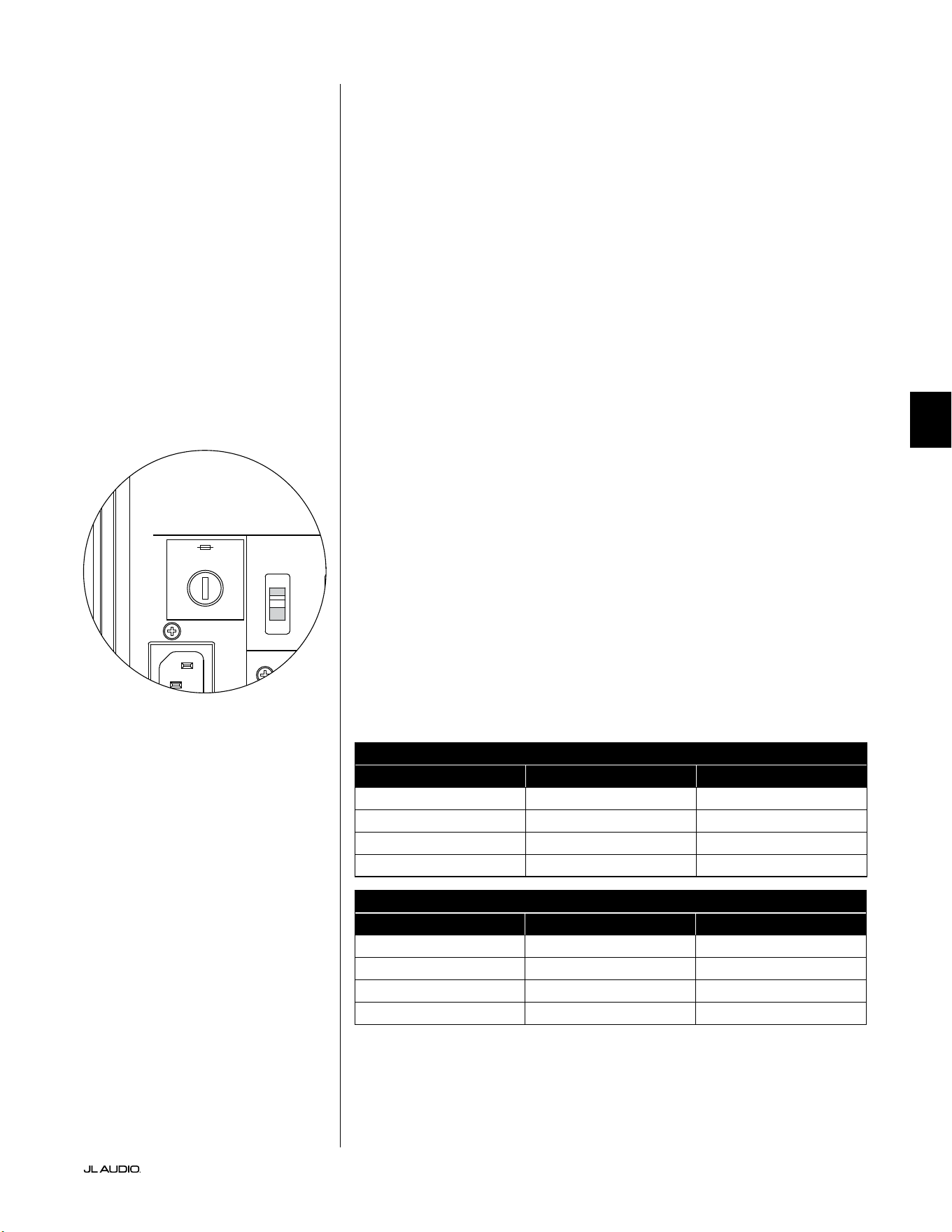
第 33 页
|
Fathom
®
v2
中文
故障排查 - 续
D.A.R.O.校准尝试会发出闪烁的校准指示灯
1. 如果随附的捷力麦克风没有正确插入前置面板插孔,校准将失败,并且绿
色的校准指示灯将快速闪烁。校准将仅在连接捷力麦克风的情况下进行。
连接任何其他麦克风都会导致校准失败。再次按下校准按钮来取消不断
闪烁的校准指示灯。
2. 如果在正确连接捷力麦克风的情况下校准失败,绿色的校准
指示灯将缓慢闪烁。测试麦克风和电缆连接,然后再次尝试运
行校准。如果执行上述步骤后校准失败,则可能是麦克风或
麦克风电缆损坏。请联系捷力主页上的技术支持部门。
您的 Fathom v2 在屋外也可以清楚地听到声音。
1. 重新查看 Fathom v2 或家庭影院接收器/前置功放/处理器上的“主音量”
设置。
2. 向您的捷力经销商咨询噪音隔离策略。
3. 将 Fathom v2 从窗边移开。
电源保险丝支架
位于后置面板上的交流电源线插座旁是电源保险丝支架的盖子。这个弹顶小
盖子可以拆卸,以便检查或更换电源保险丝。如果交流电源插座已通电,但
Fathom v2 超低音音响的指示灯不亮,则可能是电源保险丝熔断。
拆卸 - 拔下超低音音响的交流电源线。将一把小平头螺丝刀插入盖子的槽中,
然后逆时针慢慢旋转,直到保险丝支架松开。拆卸后,可以检查保险丝,如有
必要可以更换保险丝。有关您的特定 Fathom v2 型号的保险丝数值,请参阅
下表。
重新安装 - 请注意,保险丝支架的主体被固定在开口上,必须对齐才能正确安
装。将保险丝支架插入开口,然后轻轻顺时针旋转(约 1/8 圈)以锁定到位。按
下盖子并感受弹簧的压缩可有助于定位正确的位置。重新连接交流电源线。
如果更换保险丝后该保险丝立即熔断,则可能需要维修超低
音音响的功放。请联系您的捷力授权零售商或分销商。
保险丝额定值,仅限 120 伏型号
型号 保险丝类型 保险丝尺寸
f110v2(120 伏) 0.25 x 1.25 英寸,快熔 7 安,250 伏
f112v2(120 伏) 0.25 x 1.25 英寸,快熔 8 安,250 伏
f113v2(120 伏) 0.25 x 1.25 英寸,快熔 12 安,250 伏
f212v2(120 伏) 0.25 x 1.25 英寸,快熔 15 安,250 伏
保险丝额定值,仅限 240 伏型号
型号 保险丝类型 保险丝尺寸
f110v2(240 伏) 5 毫米 x 20 毫米,快熔 6.3 安,250 伏
f112v2(240 伏) 5 毫米 x 20 毫米,快熔 6.3 安,250 伏
f113v2(240 伏) 5 毫米 x 20 毫米,快熔 8 安,250 伏
f212v2(240 伏) 5 毫米 x 20 毫米,快熔 10 安,250 伏
1200VA
Built in USA with Imported and domestic components
LEFT
or
MONO
RIGHT
ONLY
INPUTS
Output to Slave
(Balanced)
Balanced
Unbalanced
Input Modes
Slave
Master
Grounded
Isolated
SERIAL NUMBER:
Warranty void if serial number is removed, altered or defaced.
F 12A H
250V
120 V ~ 60 Hz
F
U
S
E
F
U
S
E
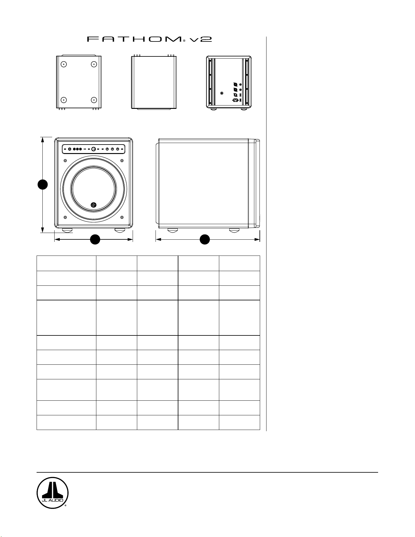
H
W
D
底部
顶部
后部
带格栅的侧面
前部
规格: f110v2 f112v2 f113v2 f212v2
机箱类型:
密封式 密封式 密封式 密封式
驱动器:
单个 10 英寸
(标称直径)
单个 12 英寸
(标称直径)
单个 13.5 英寸(标称
直径)
两个 12 英寸
(标称直径)
频率响应(无回声)
27 – 111 赫兹
(±1.5 分贝)
–25 赫兹/ 120 赫兹时
为 3 分贝
–17 赫兹/ 153 赫兹时
为 10 分贝
21-119 赫兹
(+1.5 分贝)
–19 赫兹/ 150 赫兹时
为 3 分贝
–17 赫兹/ 167 赫兹时
为 10 分贝
20-86 赫兹(+1.5 分贝)
–18 赫兹/ 127 赫兹时
为 3 分贝
–16 赫兹/ 154 赫兹时
为 10 分贝
20 - 97 赫兹
(+/-1.5 分贝)
–19 赫兹/ 110 赫兹时
为 3 分贝
–15 赫兹/ 157 赫兹时
为 10 分贝
有效位置区域:
60 平方英寸
0.0387 平方米
84 平方英寸
0.0542 平方米
107.35 平方英寸
0.0693 平方米
168 平方英寸
0.1084 平方米
有效位移:
160 立方英寸
2.6 升
287 立方英寸
4.7 升
386 立方英寸
6.3 升
574 立方英寸
9.4 升
功放功率:
1100 瓦
RMS 短期
1800 瓦
RMS 短期
3000 瓦
RMS 短期
3600 瓦
RMS 短期
尺寸:(H)x(W)x(D)
高度尺寸包括英尺
15.64 x 12.92 x 17.27
英寸
397 x 328 x 439 毫米
18.5 x 15 x 17.625 英寸
470 x 381 x 448 毫米
19.625 x 16.5 x 19.25
英寸
498 x 419 x 489 毫米
31.96 x 14.92 x 20.39
英寸
812 x 379 x 518 毫米
净重:
69 磅
31 公斤
117 磅
53 公斤
133 磅
60 公斤
224 磅
102 公斤
机箱饰面:
高亮黑色 高亮黑色 高亮黑色 高亮黑色
功能
非平衡输入:
立体声或单声道(两个 RCA 插孔)
平衡输入:
立体声或单声道(两个 XLR 母头插孔)
输出至从机:
平衡(一个 XLR 公头插孔)
输入模式:
主机或从机
音量模式:
从全静音至 + 15 分贝,高于参考增益
电源模式:
关闭、开启或自动信号感应
灯光模式:
关闭,开启或暗光
低通滤波器模式:
关闭,每倍频程 12 分贝或每倍频程 24
分贝
低通滤波截止频率:
从 30 赫兹至 130 赫兹不等
极性:
0 度或 180 度
相位:
从 0 度至 270 度不等
E.L.F.Trim:
24 赫兹时从 -12 分贝到 +3 分贝不等
数字化自动房间优化(D.A.R.O.)
自动,18 频段数字均衡器,包括实验室级
校准麦克风,可断开。
www.jlaudio.com
10369 North Commerce Parkway • 米拉马尔,佛罗里达州 • 33025 • 美国
“JL Audio”、“捷力”、“Fathom”和 JL Audio 标志是 JL Audio,Inc. 的注册商标。
©2022 JL Audio,Inc.•更多相关详细信息,请访问我们的网站 www.jlaudio.com。 所示产品图像仅用于说明目的,可能与实际产品不同。由于产品处于不断开发中,所
有规格如有更改,恕不另行通知。


SKU#011401 09-2022
Printed in U.S.A.