Loading ...
Loading ...
A. 3/8” NPT male pipe thread
B. E lbow
C. Adapter
D. Flexible connector (allows
passage through cabinet wall)
E. Adapter
F. Regulator provided with unit:
• Outlet - 3/8” NPT female pipe
thread
• Inlet - 1/2” NPT female pipe
thread
G. Gas pipe
H. Manual shut-off valve
I. Gas pipe 1/2” or 3/4”
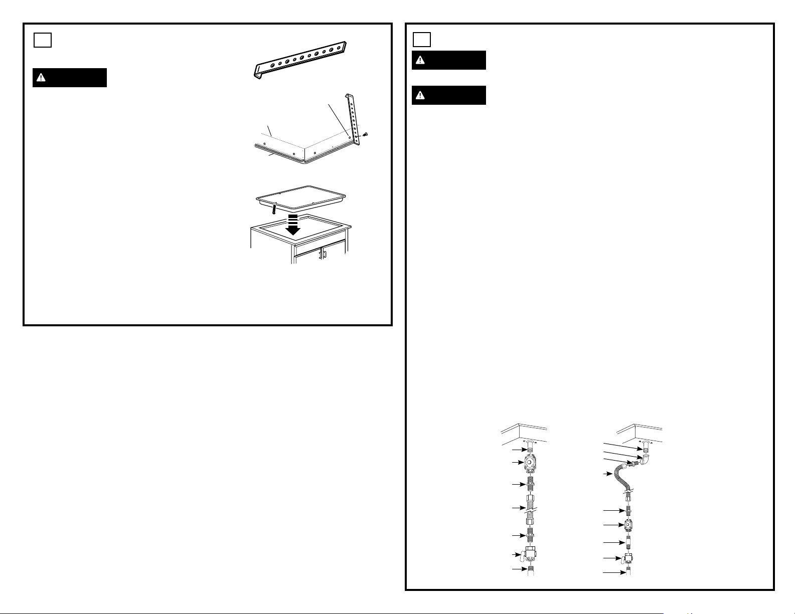
1
INSTALLING THE
COOKTOP
WARNING
Do not remove the 6
black Z brackets screwed to the bottom of the
cooktop (on some models).
A. Locate electrical outlet and gas shut-off
valve beneath cabinet.
B. Lay cooktop upside down on a towel or
tablecloth covered countertop.
C. Locate and remove hold-down brackets
from literature package.
D. Attach brackets to cooktop. Remove the
screw from the side of the cooktop and
screw the hold-down bracket to the side of
the cooktop unit. Repeat for opposite side
of cooktop.
E. Insert the cooktop centered into the cutout
opening. Make sure the front edge of the
countertop is parallel to the cooktop.
Make final check that all required
clearances are met.
Once the unit is in place, screw the hold-
down bracket into the cabinet sides to
secure the unit into place.
Cooktop
Pre-drilled hole
Bottom of Cooktop
Cooktop
Surface
CONNECTOR HOOKUP
2
GAS SUPPLY
WARNING
Fire Hazard: Do not use
a flame to check for gas leaks.
WARNING
Explosion Hazard: Do
not exceed 25 ft-lbs of torque when making
gas line connections. Overtightening may
crack the pressure regulator resulting in fire
or explosion hazard.
Gas Pressure Regulator
You must use the gas pressure regulator supplied
with this range. For proper operations the inlet
pressure to the regulator should be as follows:
Natural Gas:
Minimum pressure: 6” of Water Column
Maximum pressure: 13” of Water Column
Propane Gas:
Minimum pressure: 11” of Water Column
Maximum pressure: 13” of Water Column
If you are not sure about the inlet pressure
contact local gas supplier.
Shut off the main gas supply valve before
disconnecting the old cooktop and leave it off
until the new hook-up has been completed.
Don’t forget to relight the pilot on other gas
appliances when you turn the gas back on.
Because hard piping restricts movement of
the range, the use of a CSA International-
certified flexible metal appliance connector is
recommended unless local codes require a
hard-piped connection.
If the hard piping method is used, you must
carefully align the pipe; the cooktop cannot be
moved after the connection is made.
To prevent gas leaks, apply pipe joint compound
or wrap pipe thread tape with Teflon* around all
male (external) pipe threads.
A. Install provided regulator in the gas line
between the cooktop and manual shut-off
valve. Refer to the arrow on the back of the
regulator for gas flow direction. Ensure the
front of the regulator is facing towards the
cabinet front, easily accessible through the
cabinet doors.
B. Install a manual shut-off valve in the gas line
in a location easily accessible through the
cabinet doors.
C. When all connections have been made,
ensure all gas controls are in the off position
and turn on the main gas supply valve.
Use a liquid leak detector at all joints and
connections to check for leaks in the system.
When using pressures greater than 1/2 psig
to pressure test the gas supply system of
the residence, disconnect the cooktop and
individual shut-off valve from the gas supply
piping. When using pressures of 1/2 psig or
less to pressure test the gas supply system,
simply isolate the cooktop from the gas supply
system by closing the individual shut-off valve.
When checking for proper operation of the
regulator, the inlet pressure must be at least 1”
greater than the operating (manifold) pressure
as given on rating label of product.
*Teflon: Registered trademark of DuPont
TYPICAL INSTALLATION WITH NO
OBSTRUCTION BELOW COOKTOP
ALTERNATE INSTALLATION WITH
OBSTRUCTION BELOW COOKTOP
A
B
C
D
F
G
E
A
B
C
D
F
G
E
I
H
A. 3/8” NPT male pipe
thread
B. Regulator provided with
unit:
• Outlet - 3/8” NPT
female pipe thread
• Inlet - 1/2” NPT female
pipe thread
C. Adapter
D. Flexible connector
E. Adapter
F. Manual shut-off valve
G. Gas pipe 1/2” or 3/4”
1” = 2.5 cm; 1’ = 0.3 m
Loading ...
Loading ...
Loading ...