安全のために
ソニー製品は安全に充分配慮して設計されています。しかし、ま
ちがった使いかたをすると、火災などにより人身事故になること
があり危険です。事故を防ぐために次のことを必ずお守りくださ
い。
ˎ 安全のための注意事項を守る
この「安全のために」の注意事項をよくお読みください。
ˎ 故障したら使わない
動作がおかしくなったり、コードなどが破損しているのに気づ
いたら、すぐにソニーの相談窓口へ相談する。
ˎ 万一、異常が起きたら
電源を切る
ソニーの相談窓口へ相談する
変な音やにおい、
煙が出た場合は
警告表示の意味
取扱説明書および製品では、次のような表示をしています。
表示の内容をよく理解してから本文をお読みください。
この表示の注意事項を守らないと、火災・感電
などにより死亡や大けがなど人身事故の原因
となります。
この表示の注意事項を守らないと、感電やその
他の事故によりけがをしたり周辺の家財に損
害を与えたりすることがあります。
注意を促す記号 行為を禁止する記号
下記の注意事項を守らないと、
火災・感電
により
大けが
の原因
となります。
製品および同梱物を、乳幼児の手の届く範囲に放置
しないでください。
乳幼児の手の届かない場所に置き、口に入れないよう注
意する。万一、飲み込んだ場合は、ただちに医師に相談
してください。
内部に水や異物を入れない
水や異物が入ると火災や感電の原因となります。万一、
水や異物が入ったときは、すぐにスイッチを切り、ソ
ニーの相談窓口にご相談ください。
下記の注意事項を守らないと、
けが
をしたり周辺の家財に
損害
を
与えることがあります。
内部を開けない
感電の原因となることがあります。
内部の点検や修理はソニーの相談窓口へご相談くださ
い。
湿気やほこり、油煙、湯気の多い場所や直射日光のあ
たる場所には置かない
故障の原因となります。
落としたりぶつけたりしない
故障の原因となります。
ブラケット(
VCT-55LH
)等を介し、他のアクセサ
リーも取り付けた状態で使用する場合、手持ち撮影
をしない
落下等により、不慮の事故の原因となりますので、カメ
ラを三脚に取り付けて使用してください。
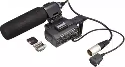
主な特長
本機はマルチインターフェースシュー搭載機器対応の
XLR
アダプ
ターとマイクロホンのキットです。
マルチインターフェースシューを搭載していても使用できないカ
メラがあります。
対応機種は
WEB
をご確認ください。
取り扱い上のご注意
ˎ マイクロホンは精密機器です。落としたり、たたいたり、強い衝
撃を与えないでください。
ˎ 使用中、マイクロホンをスピーカーに近づけるとピーという
音が発生することがあります(ハウリング現象)。その場合は、
マイクロホンとスピーカーの距離をできるだけ離すか、スピー
カーの音量を下げてください。
ˎ 本機をカメラに取り付けた状態で、本機をもってカメラを持ち
上げたり、持ち運んだりしないでください。
ˎ 本機を持ち運ぶ際は、カメラから取りはずして端子保護キャッ
プを取り付けて、同梱のキャリングケースに入れてください。
レンズ交換時のご注意
ˎ レンズ交換は、本機をカメラから取りはずしてから行ってくだ
さい。
ˎ レンズ交換の際、レンズおよびカメラボディにウインドスク
リーンの繊維が付着していないか確認してください。付着して
いる場合は、ブロアーなどで繊維を取り除いてからレンズ交換
してください。
ˎ 本機ご使用後は、レンズのクリーニングをおすすめします。
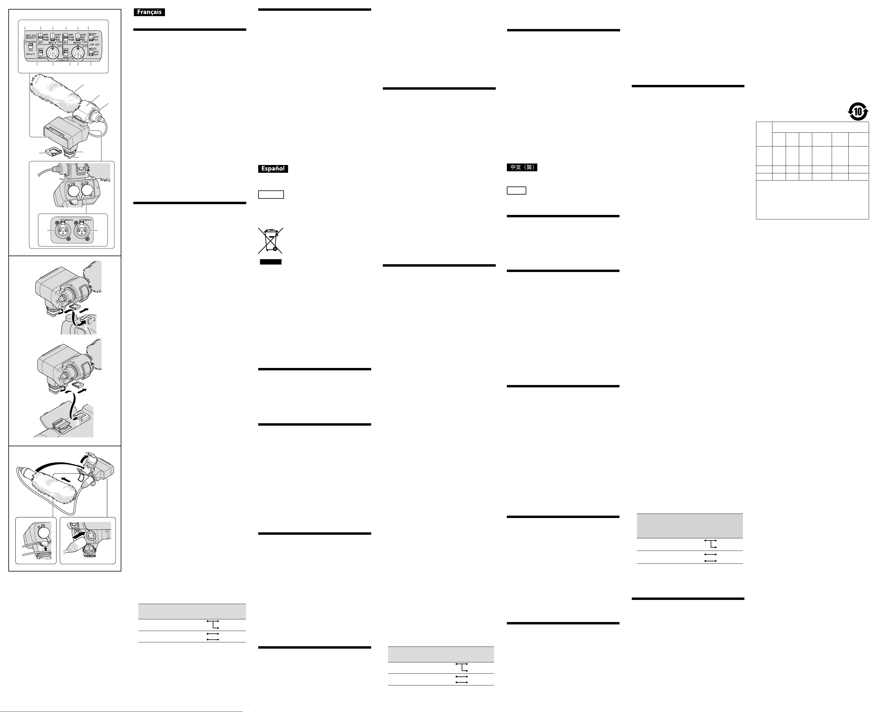
各部の名前
1
ウインドスクリーン
2
マイク
3
マイクホルダー
4 REC CH SELECT
(
INPUT1
)スイッチ
5 ATT
(
INPUT1
)スイッチ
6 INPUT1
(
LINE/MIC/MIC+48V
)スイッチ
7 ATT
(
INPUT2
)スイッチ
8 INPUT2
(
LINE/MIC/MIC+48V
)スイッチ
9 LOW CUT
(
INPUT1
)スイッチ
10 AUTO/MAN
(
CH1
)スイッチ
11 AUDIO LEVEL
(
CH1
)ダイヤル
12 AUTO/MAN
(
CH2
)スイッチ
13 AUDIO LEVEL
(
CH2
)ダイヤル
14 LOW CUT
(
INPUT2
)スイッチ
15
固定ダイヤル
電気製品は安全のための注意事項を守らない
と、火災や人身事故になることがあります。
この取扱説明書には、事故を防ぐための重要な注意事項と
製品の取り扱いかたを示しています。
この取扱説明書をよくお読みのうえ、製品を安全にお使い
ください。お読みになったあとは、いつでも見られるとこ
ろに必ず保管してください。
取扱説明書
/ Operating Instructions /
Mode d’emploi / Manual de
instrucciones /
XLR-K2M
XLR
アダプターキット
XLR Adaptor Kit
Kit adaptateur XLR
XLR 适配器套装
© 2014 Sony Corporation Printed in Japan
4-546-775-
01
(1)
4
10 11 12 13 14
1
17
18
19
20 21
15
16
3
2
5 6 7 8 9
1
3
2
2
1
4
5
3
2
5
1
3
22
(Suite à la page arrière)
16
マルチインターフェースフット
17
端子保護キャップ
18
リリースレバー
19
ケーブルホルダー
20 INPUT2
端子
21 INPUT1
端子
外部音声の入力:
20
、
21
音源の選択:
6
、
8
音源レベルの選択:
5
、
7
録音するチャンネルの選択:
4
録音レベルの選択:
10
、
11
、
12
、
13
風音低減の入
/
切:
9
、
14
XLR
アダプターを取り付ける
1
端子保護キャップをはずす。
XLR
アダプターのマルチインターフェースフット底面から
ロックピンが突き出ていないか確認してください。
2 XLR
アダプターのマルチインターフェースフット
をカメラのマルチインターフェースシューに取り
付ける。
3 XLR
アダプターの固定ダイヤルをしっかり締める。
ご注意
ˎ
XLR
アダプターのマルチインターフェースフットを最後まで
しっかり差し込んでから固定ダイヤルを締め、カメラにしっか
りと固定されていることを確認してください。
XLR
アダプターを取りはずすには
XLR
アダプターの固定ダイヤルを充分にゆるめてから取りはず
す。
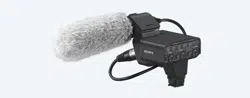
マイクを取り付ける
1
ウインドスクリーン(
-1
)をマイクに取り付ける。
2
マイクホルダーのロックをはずし、取り付け部のカ
バーを開ける。
3
マイクを型名(
ECM-XM1
)が記された部分が上に
なるようにマイクホルダーの取り付け部に入れ、カ
バーを閉じ、マイクホルダーをロックする。
4
マイクケーブルを
XLR
アダプターの
INPUT1
端子
につなぐ。
接続する機器が
1
つの場合は、
INPUT1
端子につないでくださ
い。
5
マイクケーブルを
XLR
アダプターのケーブルホル
ダー(
-19
)に取り付ける。
ˎ 音声の設定については、「音の設定をする」をご覧ください。
ˎ ケーブルを無理に引っ張ったり、またはたゆんだ状態でケー
ブルホルダーに取り付けると、マイクホルダーに取り付けた
マイクが著しく傾く場合があります。
充分な防振効果が得られるように、マイクが大きく傾かない
ようご注意ください。
マイクケーブルを取りはずすには
マイクをマイクホルダーから取りはずす。
リリースレバー(
-18
)を下げながら、プラグを持って引き抜
く。
音の設定をする
付属マイクを使う
単一指向性のモノラル音声を収録できます。
1 INPUT 1
(
LINE/MIC/MIC+48V
)スイッチを
「
MIC+48V
」に切り換える。
2 REC CH SELECT
(
INPUT1
)スイッチを「
CH1
・
CH2
」に切り換える。
この設定で、同じ音声が
CH1
、
CH2
の両方に録音されます。
CH1
だけに録音したいときは、「
CH1
」にしてください。
録音レベルを調節する
INPUT1
端子
/INPUT2
端子から入力した音声の録音レベルを調節
できます。
内蔵マイクと
MIC
入力端子の録音レベルは調節できません。
1
調節するチャンネル(
CH1
または
CH2
)の
AUTO/
MAN
スイッチを「
MAN
」にする。
2 AUDIO LEVEL
ダイヤルを回して、適正なレベルに
なるように音量を調節する。
適正なレベルになっているか、ヘッドホンやオーディオレベル
メーターで確認してください。
自動調整に戻すには
AUTO/MAN
スイッチを「
AUTO
」にする。
風切り音を低減する
INPUT1
端子
/INPUT2
端子から入力した音声の風切り音を低減で
きます。
LOW CUT
(
INPUT1
)スイッチまたは
LOW CUT
(
INPUT2
)スイッチを「
ON
」にする。
外部音声機器などを使う
付属マイク以外のマイクや外部音声機器(ミキサーなど)を使うに
は、以下のように設定してください。
1
入力する音源を選ぶ
INPUT1
端子
/INPUT2
端子に接続する機器に合わせて、
INPUT1/INPUT2
(
LINE/MIC/MIC+48V
)スイッチを設定しま
す。
外部音声機器(ミキサーなど):
LINE
ダイナミックマイクや電池内蔵のマイク:
MIC
+48V
電源(ファンタム電源)対応のマイク:
MIC+48V
ご注意
ˎ
MIC+48V
にしたままで
+48V
電源に対応していない機器を
接続すると、接続した機器の故障の原因になりますので、接
続する前にご確認ください。
ˎ 接続しない端子のノイズが気になるときは、
INPUT1/
INPUT2
(
LINE/MIC/MIC+48V
)スイッチを「
LINE
」にしてく
ださい。
2
マイクの入力レベルを設定する。
INPUT1/INPUT2
(
LINE/MIC/MIC+48V
)スイッチが「
MIC
」か
「
MIC+48V
」のときは、
ATT
(
INPUT1/INPUT2
)スイッチで入
力レベルを設定できます。マイクの感度に応じて調節してく
ださい。
付属のマイクロホン(
ECM-XM1
)の場合は、
ATT 10dB
がおす
すめです。
入力レベルは、以下のようになります。
ATT 0dB
:
-60dBu
ATT 10dB
:
-50dBu
ATT 20dB
:
-40dBu
ご注意
ˎ
INPUT1/INPUT2
(
LINE/MIC/MIC+48V
)スイッチが
LINE
の
ときは、入力レベルは
+4dBu
に固定されます。
ATT
スイッチ
を切り換えても入力レベルは変わりません。
3
録音するチャンネルを設定する。
REC CH SELECT
(
INPUT1
)スイッチで、録音するチャンネルを
選びます。
REC CH SELECT
(
INPUT1
)
スイッチの位置
CH1
、
CH2
に録音される音声
CH1
・
CH2
INPUT1
CH1
CH2
CH1
INPUT1
CH1
INPUT2
CH2
ˎ
XLR
(
3PIN
)プラグが
2
個ついているステレオマイクを使う
には
INPUT1
端子に
Lch
、
INPUT2
端子に
Rch
を接続し、
REC
CH SELECT
(
INPUT1
)スイッチを
CH1
に設定します。
主な仕様
最大外形寸法(約):
XLR
アダプター(
XLR-A2M
)本体
116.5 mm
×
105.5 mm
×
75 mm
(幅/高さ/奥行き)
(突起物、コード含まず)
マイクロホン(
ECM-XM1
)
21 mm
×
162 mm
(直径/長さ)
(ウインドスクリーン、コード含まず)
質量(約):
XLR
アダプター(
XLR-A2M
)本体
250 g
マイクロホン(
ECM-XM1
)
121.5 g
動作温度:
0
℃
〜
40
℃
保存温度:
-20
℃
〜
+60
℃
入力端子:
INPUT1/INPUT2
端子:
XLR
型
3
ピン、凹
MIC
:
-60/-50/-40 dBu
、
3 k
Ω
LINE
:
+4 dBu
、
10 k
Ω
(
0 dBu=0.775 Vrms
)
同梱物:
XLR
アダプター(
XLR-A2M
)(
1
)、マイクロホン(
ECM-XM1
)(
1
)、
ウインドスクリーン(
1
)、端子保護キャップ(
1
)、キャリングケー
ス(
1
)、印刷物一式
仕様および外観は、改良のため予告なく変更することがあります
が、ご了承ください。
マルチインターフェースシューはソニー株式会社の商標です。
保証書とアフターサービス
保証書
ˎ この製品には保証書が添付されていますので、お買い上げの際
お買い上げ店でお受け取りください。
ˎ 所定事項の記入および記載内容をお確かめのうえ、大切に保存
してください。
ˎ 保証期間は、お買い上げ日より
1
年間です。
アフターサービス
調子が悪いときはまずチェックを
この取扱説明書をもう一度ご覧になってお調べください。
それでも具合が悪いときは
ソニーの相談窓口にご相談ください。
保証期間中の修理は
保証書の記載内容に基づいて修理させていただきます。
詳しくは保証書をご覧ください。
保証期間経過後の修理は
修理によって機能が維持できる場合は、ご要望により有償修理さ
せていただきます。
部品の保有期間について
当社では本機の補修用性能部品(製品の機能を維持するために必
要な部品)を、製造打ち切り後最低
7
年間保有しています。この部
品保有期間を修理可能の期間とさせていただきます。ただし、故
障の状況その他の事情により、修理に代えて製品交換をする場合
がありますのでご了承ください。保有期間が経過したあとも、故
障箇所によっては修理可能の場合がありますので、ソニーの相談
窓口にご相談ください。
ご相談になるときは、次のことをお知らせください。
ˎ 品名:
XLR-K2M
ˎ 故障の状態:できるだけ詳しく
ˎ 購入年月日
Before operating the product, please read this manual
thoroughly and retain it for future reference.
WARNING
To reduce fire or shock hazard, do not expose the unit to
rain or moisture.
Keep out of reach of small children to prevent accidental
swallowing.
For the Customers in the U.S.A.
CAUTION
You are cautioned that any changes or modifications not
expressly approved in this manual could void your authority
to operate this equipment.
Note:
This equipment has been tested and found to comply
with the limits for a Class B digital device, pursuant to Part
15 of the FCC Rules. These limits are designed to provide
reasonable protection against harmful interference in a
residential installation. This equipment generates, uses,
and can radiate radio frequency energy and, if not installed
and used in accordance with the instructions, may cause
harmful interference to radio communications. However,
there is no guarantee that interference will not occur in a
particular installation. If this equipment does cause harmful
interference to radio or television reception, which can be
determined by turning the equipment o and on, the user
is encouraged to try to correct the interference by one or
more of the following measures:
—Reorient or relocate the receiving antenna.
—Increase the separation between the equipment and
receiver.
—Connect the equipment into an outlet on a circuit dierent
from that to which the receiver is connected.
—Consult the dealer or an experienced radio/TV technician
for help.
THIS DEVICE COMPLIES WITH PART 15 OF THE FCC
RULES. OPERATION IS SUBJECT TO THE FOLLOWING TWO
CONDITIONS:
(1) THIS DEVICE MAY NOT CAUSE HARMFUL INTERFERENCE,
AND (2) THIS DEVICE MUST ACCEPT ANY INTERFERENCE
RECEIVED, INCLUDING INTERFERENCE THAT MAY CAUSE
UNDESIRED OPERATION.
For the Customers in Europe
Disposal of Old Electrical & Electronic
Equipment (Applicable in the European
Union and other European countries with
separate collection systems)
This symbol on the product or on its
packaging indicates that this product
shall not be treated as household waste.
Instead it shall be handed over to the
applicable collection point for the recycling of electrical
and electronic equipment. By ensuring this product is
disposed of correctly, you will help prevent potential
negative consequences for the environment and human
health, which could otherwise be caused by inappropriate
waste handling of this product. The recycling of materials
will help to conserve natural resources. For more detailed
information about recycling of this product, please contact
your local Civic Oce, your household waste disposal
service or the shop where you purchased the product.
< Notice for the customers in the
countries applying EU Directives >
Manufacturer: Sony Corporation, 1-7-1 Konan Minato-ku
Tokyo, 108-0075 Japan
For EU product compliance: Sony Deutschland GmbH,
Hedelfinger Strasse 61, 70327 Stuttgart, Germany
Features
The XLR-K2M is a kit including an XLR Adaptor for a device
equipped with a Multi Interface Shoe and a microphone.
Some camera models with a Multi Interface Shoe cannot be
used with this kit.
For details on compatible camera models of this unit, visit
the website of Sony in your area, or consult your dealer of
Sony or local authorized Sony service facility.
Notes on use
• The microphone is a precision instrument. Do not drop,
knock it, or subject it to excessive shock.
• If the microphone is placed near speakers, a howling
eect (acoustic feedback) may occur. If this happens,
place the microphone as far as possible from the
speakers, or lower the volume of the speaker.
• Do not hold this unit to pick up or carry the camera when
attached.
• To carry this unit, remove it from the camera, attach
the connector protect cap to this unit and put it in the
supplied carrying case.
Notes on changing the lens
• Before changing the lens, remove this unit from the
camera.
• Before changing the lens, check whether there are any
fibers from the wind screen on the lens or camera body.
Brush any fibers o with a blower etc. and then change
the lens.
• After using this unit, cleaning the lens is recommended.
Identifying the parts
1 Wind screen 2 Microphone 3 Microphone holder
4 REC CH SELECT (INPUT1) switch 5 ATT (INPUT1) switch
6 INPUT1 (LINE/MIC/MIC+48V) switch 7 ATT (INPUT2) switch
8 INPUT2 (LINE/MIC/MIC+48V) switch
9 LOW CUT (INPUT1) switch 10 AUTO/MAN (CH1) switch
11 AUDIO LEVEL (CH1) dial 12 AUTO/MAN (CH2) switch
13 AUDIO LEVEL (CH2) dial 14 LOW CUT (INPUT2) switch
15 Lock dial 16 Multi Interface foot
17 Connector protect cap 18 Release lever 19 Cable holder
20 INPUT2 jack 21 INPUT1 jack
Inputting external sound: 20, 21
Selecting a sound source: 6, 8
Selecting a sound source level: 5, 7
Selecting channel setting for recording: 4
Selecting the recording level: 10, 11, 12, 13
Switching wind noise reduction to ON/OFF: 9, 14
Attaching the XLR Adaptor
1 Detach the connector protect cap from
the connector plug of the XLR Adaptor.
Check that the lock pin is not protruding from the bottom
of the Multi Interface foot of the XLR Adaptor.
2 Attach the Multi Interface foot of the XLR
Adaptor to the Multi Interface Shoe of
the camera.
3 Tighten the lock dial of the XLR Adaptor
securely.
Notes
• Insert the Multi Interface foot of the XLR Adaptor fully into
the Multi Interface Shoe of the camera, and tighten the
lock dial securely. Make sure this unit is attached securely.
When detaching the XLR Adaptor
Fully loosen the lock dial of the XLR Adaptor before
detaching the XLR Adaptor.
Attaching the microphone
1 Attach the wind screen (-1) to the
microphone.
2 Unlock the stopper of the microphone
holder and open the cover.
3 Place the microphone into the holder so
that the model name (ECM-XM1) on the
microphone faces upward. Then close the
cover and firmly lock the stopper.
4 Connect the connector plug of the
microphone to the INPUT1 jack on the
XLR Adaptor.
Connect the connector plug of the microphone to the
INPUT1 jack if you connect one device.
5 Put the microphone cable into the cable
holder (-19) on the XLR Adaptor.
• See “Audio setup” for audio recording.
• If the cable is pulled with too much force or attached to
the cable holder too loosely, the microphone attached
to the microphone holder may tilt a lot.
To get the full anti-vibration eect, make sure the
microphone is not tilting too much.
When detaching the microphone cable
Detach the microphone from the microphone holder.
Unplug the microphone plug while pressing the release
lever (-18) down.
Audio setup
Using the supplied microphone
You can record unidirectional monaural sound with the
microphone.
1 Set the INPUT1 (LINE/MIC/MIC+48V)
switch to MIC+48V.
2 Set the REC CH SELECT (INPUT1) switch to
CH1·CH2.
This setting enables recording on both CH1 and CH2. Set
the switch to CH1 if you want to record on CH1 only.
Adjusting the recording level
You can adjust the recording level input from the INPUT1/
INPUT2 jacks.
You cannot adjust the recording level of the internal
microphone and MIC input jack.
1 Set the AUTO/MAN (CH1/CH2) switch of
the channel to be adjusted to MAN.
2 Turn the AUDIO LEVEL dial to adjust the
volume to the proper level.
Check that the volume is at the proper level, with
headphones or audio level meter.
To restore automatic adjustment
Set the AUTO/MAN (CH1/CH2) switch to AUTO.
Reducing wind noise
You can reduce wind noise input from the INPUT1/INPUT2
jacks.
Set the LOW CUT (INPUT1) switch or LOW
CUT (INPUT2) switch to ON.
Using an external audio device
Set as follows when you use a microphone other than the
supplied microphone or an external audio device (mixer,
etc.).
1 Select the sound source to be input.
Set the INPUT1/INPUT2 (LINE/MIC/MIC+48V) switch
according to the device to be connected to the INPUT1/
INPUT2 jacks.
External audio device (mixer, etc.): LINE
Dynamic microphone or microphone with built-in
battery: MIC
Microphone that is 48V phantom power compliant:
MIC+48V
Notes
• If you connect a device that does not support 48V
phantom power, malfunction may result from setting
this switch to MIC+48V. Check before connecting the
device.
• If noise from the unused jack bothers you, set the
INPUT1/INPUT2 (LINE/MIC/MIC+48V) switch of the
unused jack to LINE.
2 Set the input level of the microphone.
When the INPUT1/INPUT2 (LINE/MIC/MIC+48V) switch is
set to MIC or MIC+48V, you can set the input level with
the ATT (INPUT1/INPUT2) switch.
Adjust according to the microphone sensitivity.
ATT 10dB is recommended when you use the supplied
microphone (ECM-XM1).
The input levels are as follows.
ATT 0dB: -60dBu
ATT 10dB: -50dBu
ATT 20dB: -40dBu
Notes
• When the INPUT1/INPUT2 (LINE/MIC/MIC+48V) switch
is set to LINE, the input level is fixed to +4dBu. Even
if you reset the ATT switch, the input level does not
change.
3 Set the channel to be recorded.
You can select the channel to be recorded, with the REC
CH SELECT (INPUT1) switch.
Position of the REC
CH SELECT (INPUT1)
switch
Audio recorded on CH1 & CH2
CH1·CH2
INPUT1
CH1
CH2
CH1
INPUT1
CH1
INPUT2
CH2
• To use a stereo microphone with two XLR (3PIN) plugs,
connect Lch to the INPUT1 jack and Rch to the INPUT2
jack, and set the REC CH SELECT (INPUT1) switch to
CH1.
Specifications
Maximum dimensions (Approx.)
XLR Adaptor (XLR-A2M) unit
116.5 mm × 105.5 mm × 75 mm (w/h/d)
(4 5/8 in. × 4 1/4 in. × 3 in.)
(excluding the cord and projecting parts)
Microphone (ECM-XM1)
21 mm × 162 mm (Diameter/Length)
(27/32 in. × 61/2in.)
(excluding the wind screen and cord)
Mass (Approx.)
XLR Adaptor (XLR-A2M) unit 250 g (8 oz)
Microphone (ECM-XM1) 121.5 g (4 oz)
Operating temperature 0 °C to 40 °C (32 °F to 104 °F)
Storage temperature -20 °C to +60 °C (-4 °F to +140 °F)
Input jacks
INPUT1/INPUT2 jacks: XLR3-pin, female
MIC: -60 dBu /-50 dBu /-40 dBu, 3 kΩ(kilohms)
LINE: +4 dBu, 10 kΩ (kilohms)
(0 dBu=0.775 Vrms)
Included items
XLR Adaptor (XLR-A2M) (1), Microphone (ECM-XM1) (1),
Wind screen (1), Connector protect cap(1), Carrying case
(1), Set of printed documentation
Design and specifications are subject to change without
notice.
Multi Interface Shoe is a trademark of Sony Corporation.
Avant d’utiliser ce produit, prière de lire attentivement ce
mode d’emploi et de le conserver pour toute référence
future.
AVERTISSEMENT
Afin de réduire les risques d’incendie ou de décharge
électrique, n’exposez pas cet appareil à la pluie ou à
l’humidité.
Rangez hors de portée des enfants pour éviter toute
ingestion accidentelle.
À l’intention des clients aux É.-U.
AVERTISSEMENT
Par la présente, vous êtes avisé du fait que tout
changement ou toute modification ne faisant pas l’objet
d’une autorisation expresse dans le présent manuel
pourrait annuler votre droit d’utiliser l’appareil.
Note
L’appareil a été testé et est conforme aux exigences d’un
appareil numérique de Classe B, conformément à la Partie
15 de la réglementation de la FCC.
Ces critères sont conçus pour fournir une protection
raisonnable contre les interférences nuisibles dans un
environnement résidentiel. L’appareil génère, utilise et peut
émettre des fréquences radio; s’il n’est pas installé et utilisé
conformément aux instructions, il pourrait provoquer des
interférences nuisibles aux communications radio.
Cependant, il n’est pas possible de garantir que des
interférences ne seront pas provoquées dans certaines
conditions particulières. Si l’appareil devait provoquer des
interférences nuisibles à la réception radio ou à la télévision,
ce qui peut être démontré en allumant et éteignant
l’appareil, il est recommandé à l’utilisateur d’essayer de
corriger cette situation par l’une ou l’autre des mesures
suivantes :
—Réorienter ou déplacer l’antenne réceptrice.
—Augmenter la distance entre l’appareil et le récepteur.
—Brancher l’appareil dans une prise ou sur un circuit
diérent de celui sur lequel le récepteur est branché.
—Consulter le détaillant ou un technicien expérimenté en
radio/téléviseurs.
Cet appareil est conforme à la section 15 des règlements
FCC. Son fonctionnement est soumis aux deux conditions
suivantes : (1) cet appareil ne doit pas provoquer
d’interférences nuisibles, (2) cet appareil doit accepter toute
interférence, y compris celles susceptibles de provoquer son
fonctionnement indésirable.
Pour les clients en Europe
Traitement des appareils électriques et
électroniques en fin de vie (Applicable
dans les pays de l’Union Européenne et
aux autres pays européens disposant de
systèmes de collecte sélective)
Ce symbole, apposé sur le produit ou sur son
emballage, indique que ce produit ne doit
pas être traité avec les déchets ménagers.
Il doit être remis à un point de collecte
approprié pour le recyclage des équipements électriques et
électroniques. En vous assurant que ce produit sont mis au
rebut de façon appropriée, vous participez activement à la
prévention des conséquences négatives que leur mauvais
traitement pourrait provoquer sur l’environnement et sur la
santé humaine. Le recyclage des matériaux contribue par
ailleurs à la préservation des ressources naturelles. Pour
toute information complémentaire au sujet du recyclage de
ce produit, vous pouvez contacter votre municipalité, votre
déchetterie locale ou le point de vente où vous avez acheté
le produit.
< Avis aux consommateurs des pays
appliquant les Directives UE >
Fabricant: Sony Corporation, 1-7-1 Konan Minato-ku Tokyo,
108-0075 Japon
Pour toute question relative à la conformité des produits
dans l’UE: Sony Deutschland GmbH, Hedelfinger Strasse 61,
70327 Stuttgart, Allemagne
Caractéristiques
Le XLR-K2M est un kit comprenant un adaptateur XLR pour
appareil à grie multi-interface et un microphone.
Certains modèles d’appareils photo/caméscopes à grie
multi-interface ne peuvent pas être utilisés avec ce kit.
Pour plus de détails sur les modèles d’appareils photo/
caméscopes compatibles avec cet accessoire, consultez le
site Web de Sony de votre région, ou adressez-vous à votre
revendeur Sony ou au service après-vente agréé Sony local.
Remarques sur l’emploi
• Le microphone est un instrument de précision. Ne le
laissez pas tomber, ne le cognez pas et ne le soumettez
pas à des chocs.
• Si le microphone est placé près d’enceintes, un hurlement
(rétroaction acoustique) peut se produire. Dans ce cas,
éloignez le plus possible le microphone des enceintes, ou
bien réduisez le volume du microphone.
• Ne soulevez pas ou ne tenez pas l’appareil photo/
caméscope par cet accessoire lorsque ce dernier est
rattaché.
• Pour transporter cet accessoire, retirez-le de l’appareil
photo/caméscope, rattachez le capuchon de protection
de connecteur et rangez-le dans l’étui de transport fourni.
Remarques sur le changement d’objectif
• Avant de changer d’objectif, retirez cet accessoire de
l’appareil photo/caméscope.
• Avant de changer d’objectif, assurez-vous de l’absence de
fibres de la bonnette antivent sur l’objectif ou l’appareil
photo/caméscope. Retirez toute fibre avec un souet, etc.
avant de changer d’objectif.
• Il est conseillé de nettoyer l’objectif après l’utilisation de
cet accessoire.
Identification des éléments
1 Bonnette antivent 2 Microphone
3 Support de microphone
4 Commutateur REC CH SELECT (INPUT1)
5 Commutateur ATT (INPUT1)
6 Commutateur INPUT1 (LINE/MIC/MIC+48V)
7 Commutateur ATT (INPUT2)
8 Commutateur INPUT2 (LINE/MIC/MIC+48V)
9 Commutateur LOW CUT (INPUT1)
10 Commutateur AUTO/MAN (CH1)
11 Molette AUDIO LEVEL (CH1)
12 Commutateur AUTO/MAN (CH2)
13 Molette AUDIO LEVEL (CH2)
14 Commutateur LOW CUT (INPUT2)
15 Molette de verrouillage 16 Sabot multi-interface
17 Capuchon de protection de connecteur
18 Levier de libération 19 Support de câble
20 Prise d’entrée INPUT2 21 Prise d’entrée INPUT1
Transmission d’un son externe: 20, 21
Sélection d’une source sonore: 6, 8
Sélection du niveau d’une source sonore: 5, 7
Sélection d’un canal pour l’enregistrement: 4
Sélection du niveau d’enregistrement: 10, 11, 12, 13
Activation/désactivation de la réduction du bruit du
vent: 9, 14
Fixation de l’adaptateur
XLR
1 Détachez le capuchon de protection de
connecteur de la fiche-connecteur de
l’adaptateur XLR.
Assurez-vous que la goupille de verrouillage ne dépasse
pas de la partie inférieure du sabot multi-interface de
l'adaptateur XLR.
2 Raccordez le sabot multi-interface
de l’adaptateur XLR à la grie multi-
interface de l’appareil photo/caméscope.
3 Serrez correctement la molette de
verrouillage de l’adaptateur XLR.
Remarques
• Insérez à fond le sabot multi-interface de l’adaptateur
XLR dans la grie multi-interface de l’appareil photo/
caméscope, puis serrez la molette de verrouillage.
Assurez-vous que cet accessoire est bien rattaché.
Pour détacher l’adaptateur XLR
Desserrez complètement la molette de verrouillage de
l’adaptateur XLR avant de détacher l’adaptateur XLR.
(Suite de la page avant)
4
10 11 12 13 14
1
17
18
19
20 21
15
16
3
2
5 6 7 8 9
1
3
2
2
1
3
22
1
4
5
3
2
5
Fixation du microphone
1 Rattachez la bonnette antivent (-1) au
microphone.
2 Débloquez la fermeture du support de
microphone et ouvrez le couvercle.
3 Placez le microphone sur le support de
telle manière que le nom de modèle
(ECM-XM1) du microphone soit orienté
vers le haut. Fermez ensuite le couvercle
et bloquez bien la fermeture.
4 Raccordez la fiche-connecteur du
microphone à la prise INPUT1 de
l’adaptateur XLR.
Raccordez la fiche-connecteur du microphone à la prise
INPUT1 si vous raccordez un appareil.
5 Mettez le câble de microphone dans le
support de câble (-19) sur l’adaptateur
XLR.
• Voir « Réglage du son » pour l’enregistrement du son.
• Si une force excessive est appliquée sur le câble ou si le
câble est trop lâche sur son support, le microphone fixé
au support risque de s’incliner fortement.
Pour obtenir un eet antivibrations total, assurez-vous
que le microphone n’est pas trop incliné.
Lorsque le câble de microphone est
détaché
Détachez le microphone du support de microphone.
Débranchez la fiche de microphone tout en appuyant sur
le levier de libération (-18).
Réglage du son
Utilisation du microphone fourni
Vous pouvez enregistrer le son en monophonie
unidirectionnel avec le microphone.
1 Réglez le commutateur INPUT1 (LINE/
MIC/MIC+48V) sur MIC+48V.
2 Réglez le commutateur REC CH SELECT
(INPUT1) sur CH1·CH2.
Ce réglage permet d’enregistrer sur les deux canaux CH1
et CH2. Réglez le commutateur sur CH1 si vous voulez
enregistrer sur CH1 seulement.
Réglage du niveau d’enregistrement
Vous pouvez régler le niveau d’enregistrement du son
provenant des prises INPUT1/INPUT2.
Vous ne pouvez pas régler le niveau d’enregistrement du
microphone interne et de la prise d’entrée MIC.
1 Réglez le commutateur AUTO/MAN (CH1/
CH2) du canal devant être ajusté sur
MAN.
2 Tournez la molette AUDIO LEVEL pour
ajuster le volume au niveau souhaité.
Assurez-vous que le volume est au niveau correct avec
un casque d’écoute ou un indicateur de niveau sonore.
Pour revenir au réglage automatique
Réglez le commutateur AUTO/MAN (CH1/CH2) sur AUTO.
Réduction du bruit du vent
Vous pouvez réduire le bruit du vent provenant des prises
INPUT1/INPUT2.
Réglez le commutateur LOW CUT (INPUT1)
ou le commutateur LOW CUT (INPUT2) sur
ON.
Utilisation d’un appareil audio externe
Faites les réglages suivants lorsque vous utilisez un
microphone autre que le microphone fourni ou un appareil
audio externe (mixeur, etc.).
1 Sélectionnez la source sonore à
transmettre.
Réglez le commutateur INPUT1/INPUT2 (LINE/MIC/
MIC+48V) selon l’appareil devant être branché sur les
prises INPUT1/INPUT2.
Appareil audio externe (mixeur, etc.) : LINE
Microphone dynamique ou microphone avec pile
intégrée : MIC
Microphone compatible ayant une alimentation fantôme
de 48 V : MIC+48V
Remarques
• Si vous raccordez un appareil ne prenant pas en
charge une alimentation fantôme de 48V, le réglage
de ce commutateur sur MIC+48V peut entraîner
un dysfonctionnement. Vérifiez avant de raccorder
l’appareil.
• Si le bruit émis par la prise non utilisée vous dérange,
réglez le commutateur INPUT1/INPUT2 (LINE/MIC/
MIC+48V) de la prise non utilisée sur LINE.
2 Réglez le niveau d’entrée du microphone.
Lorsque le commutateur INPUT1/INPUT2 (LINE/MIC/
MIC+48V) est réglé sur MIC ou MIC+48V, vous pouvez
régler le niveau d’entrée avec le commutateur ATT
(INPUT1/INPUT2).
Réglez-le en fonction de la sensibilité du microphone.
ATT 10dB est recommandé lorsque vous utilisez le
microphone fourni (ECM-XM1).
Les niveaux d’entrée sont les suivants.
ATT 0dB : -60 dBu
ATT 10dB : -50 dBu
ATT 20dB : -40 dBu
Remarques
• Lorsque le commutateur INPUT1/INPUT2 (LINE/MIC/
MIC+48V) est réglé sur LINE, le niveau d’entrée reste
fixé sur +4dBu. Même si le commutateur ATT est
réinitialisé, le niveau d’entrée ne change pas.
3 Réglez le canal à enregistrer.
Vous pouvez sélectionner le canal à enregistrer avec le
commutateur REC CH SELECT (INPUT1).
Position du
commutateur REC
CH SELECT (INPUT1)
Son enregistré sur CH1 & CH2
CH1·CH2
INPUT1
CH1
CH2
CH1
INPUT1
CH1
INPUT2
CH2
• Pour utiliser un microphone stéréo avec deux fiches
XLR (3PIN), raccordez le canal gauche à la prise
INPUT1 et le canal droit à la prise INPUT2, et réglez le
commutateur REC CH SELECT (INPUT1) sur CH1.
Spécifications
Dimensions (environ)
Adaptateur XLR (XLR-A2M)
116,5 mm × 105,5 mm × 75 mm (l/h/p)
(4 5/8 po. × 4 1/4 po. × 3 po.)
(cordon et parties saillantes non compris)
Microphone (ECM-XM1)
21 mm × 162 mm (diamètre/longueur)
(27/32 po. × 61/2 po.)
(bonnette antivent et cordon non compris)
Poids (environ)
Adaptateur XLR (XLR-A2M) 250 g (8 oz)
Microphone (ECM-XM1) 121,5 g (4 oz)
Température de fonctionnement
0 °C à 40 °C (32 °F à 104 °F)
Température d’entreposage
-20 °C à +60 °C (-4 °F à +140 °F)
Prises d’entrée
Prises INPUT1/INPUT2 : XLR 3 broches, femelle
MIC : -60 dBu /-50 dBu /-40 dBu, 3kΩ (kilohms)
LINE : +4 dBu, 10 kΩ (kilohms) (0dBu=0,775 ecace)
Articles inclus
Adaptateur XLR (XLR-A2M) (1), Microphone (ECM-XM1) (1),
Bonnette antivent (1), Capuchon de protection de
connecteur (1), Étui de transport (1), Jeu de documents
imprimés
La conception et les spécifications peuvent être modifiées
sans préavis.
Multi Interface Shoe est une marque commerciale de Sony
Corporation.
Antes de poner en funcionamiento el producto, lea
detalladamente todo este manual y guárdelo para poderlo
consultar en el futuro.
AVISO
Para reducir el riesgo de incendio o descarga eléctrica, no
exponga la unidad a la lluvia ni a la humedad.
Mantenga fuera del alcance de niños para evitar su tragado
accidental.
Para los clientes en Europa
Tratamiento de los equipos eléctricos y
electrónicos al final de su vida útil
(aplicable en la Unión Europea y en países
europeos con sistemas de tratamiento
selectivo de residuos)
Este símbolo en el equipo o en su embalaje
indica que el presente producto no puede
ser tratado como residuos doméstico normal.
Debe entregarse en el correspondiente
punto de recogida de equipos eléctricos y electrónicos.
Al asegurarse de que este producto se desecha
correctamente, usted ayuda a prevenir las consecuencias
potencialmente negativas para el medio ambiente y la
salud humana que podrían derivarse de la incorrecta
manipulación en el momento de deshacerse de este
producto. El reciclaje de materiales ayuda a conservar los
recursos naturales. Para recibir información detallada sobre
el reciclaje de este producto, póngase en contacto con
el ayuntamiento, el punto de recogida más cercano o el
establecimiento donde ha adquirido el producto.
< Aviso para los clientes de países en
los que se aplican las directivas de la
UE >
Fabricante: Sony Corporation, 1-7-1 Konan Minato-ku Tokyo,
108-0075 Japón
Para la conformidad del producto en la UE: Sony
Deutschland GmbH, Hedelfinger Strasse 61, 70327 Stuttgart,
Alemania
Características
El XLR-K2M es un juego que incluye un adaptador para XLR
para un dispositivo equipado con una zapata de interfaz
múltiple y un micrófono.
Algunos modelos de cámaras con zapata de interfaz
múltiple no pueden utilizarse con este juego.
Con respecto a los detalles sobre los modelos de cámaras
compatibles con esta unidad, visite el sitio Web de Sony de
su área, o póngase en contacto con su proveedor Sony o
con el centro de servicio local autorizado por Sony.
Notas sobre la utilización
• El micrófono es un instrumento de precisión. No lo deje
caer, golpee, ni lo someta a choques excesivos.
• Si coloca el micrófono cerca de altavoces, puede ocurrir
un efecto de aullido (retroalimentación acústica). Si
sucede esto, aleje el micrófono lo más posible de los
altavoces, o reduzca el volumen de dichos altavoces.
• No sujete esta unidad para tomar o transportar la cámara
cuando esté instalada.
• Para transportar esta unidad, retírela de la cámara, fíjele
la tapa protectora de conector, y colóquela en la funda de
transporte suministrada.
Nota sobre el cambio de objetivo
• Antes de cambiar el objetivo, extraiga esta unidad de la
cámara.
• Antes de cambiar el objetivo, compruebe que no haya
fibras del parabrisas en el objetivo o el cuerpo de la
cámara. Elimine las fibras que pueda haber con un
soplador, etc., y después cambie el objetivo.
• Después de utilizar esta unidad, se recomienda limpiar el
objetivo.
Identificación de los
componentes
1 Parabrisas 2 Micrófono 3 Soporte para micrófono
4 Selector REC CH SELECT (INPUT1) 5 Selector ATT (INPUT1)
6 Selector INPUT1 (LINE/MIC/MIC+48V)
7 Selector ATT (INPUT2)
8 Selector INPUT2 (LINE/MIC/MIC+48V)
9 Selector LOW CUT (INPUT1) 10 Selector AUTO/MAN (CH1)
11 Mando AUDIO LEVEL (CH1) 12 Selector AUTO/MAN (CH2)
13 Mando AUDIO LEVEL (CH2)
14 Selector LOW CUT (INPUT2) 15 Mando de bloqueo
16 Pata de interfaz múltiple 17 Tapa protectora de conector
18 Palanca de liberación 19 Soporte para cable
20 Toma INPUT2 21 Toma INPUT1
Aplicación de sonido externo: 20, 21
Selección de una fuente de sonido: 6, 8
Selección de un nivel de fuente de sonido: 5, 7
Selección de un ajuste de canal para grabación: 4
Selección del nivel de grabación: 10, 11, 12, 13
Activación/desactivación de la reducción de ruido de
viento: 9, 14
Fijación del adaptador para
XLR
1 Retire la tapa protectora de conector de
la clavija conectora del adaptador para
XLR.
Compruebe que el pasador de bloqueo no sobresalga
de la parte inferior de la pata de interfaz múltiple del
adaptador para XLR.
2 Fije la pata de interfaz múltiple del
adaptador para XLR a la zapata de
interfaz múltiple de la cámara.
3 Apriete con seguridad el mando de
bloqueo del adaptador para XLR.
Notas
• Inserte la pata de interfaz múltiple del adaptador para XLR
en la zapata de interfaz múltiple de la cámara, y después
apriete con seguridad el mando de bloqueo. Cerciórese
de que ésta haya quedado fijada con seguridad.
Cuando desmonte el adaptador para
XLR
Afloje completamente el mando de bloqueo del adaptador
para XLR antes de desmontar el adaptador para XLR.
Fijación del micrófono
1 Fije el parabrisas (-1) al micrófono.
2 Desbloquee el tope del soporte para
micrófono y abra la cubierta.
3 Coloque el micrófono en el soporte de
forma que el nombre del modelo (ECM-
XM1) del micrófono quede encarado
hacia arriba. Después cierre la cubierta y
bloquee firmemente el tope.
4 Conecte la clavija conectora del
micrófono en la toma INPUT1 del
adaptador para XLR.
Conecte la clavija conectora del micrófono en la toma
INPUT1 si va a conectar un dispositivo.
5 Ponga el cable del micrófono en el
soporte para cable (-19) del adaptador
para XLR.
• Consulte “Configuración de audio” para la grabación
de audio.
• Si tira con demasiada fuerza del cable o lo fija al
soporte del cable demasiado flojo, el micrófono fijado
al soporte del micrófono puede inclinarse mucho.
Para obtener el efecto de anti-vibración completo,
asegúrese de que el micrófono no esté demasiado
inclinando.
Cuando desmonte el cable del
micrófono
Desmonte el micrófono del soporte para micrófono.
Desconecte la clavija conector manteniendo presionada
la palanca de liberación (-18).
Configuración de audio
Utilización del micrófono suministrado
Con el micrófono puede grabar sonido monoaural
unidireccional.
1 Ponga el selector INPUT1 (LINE/MIC/
MIC+48V) en MIC+48V.
2 Ponga el selector REC CH SELECT (INPUT1)
en CH1·CH2.
Este ajuste permite grabar tanto en CH1 como en CH2.
Ponga el selector en CH1 si sólo desea grabar en CH1.
Ajuste del nivel de grabación
Puede ajustar el nivel de grabación de la entrada
procedente de las tomas INPUT1/INPUT2.
No puede ajustar el nivel de grabación del micrófono
interno ni de la toma de entrada MIC.
1 Ponga el selector AUTO/MAN (CH1/CH2)
del canal que desee ajustar en MAN.
2 Gire el mando AUDIO LEVEL para ajustar
el volumen al nivel apropiado.
Compruebe que el volumen esté al nivel apropiado con
los auriculares o el medidor de nivel de audio.
Para restablecer el ajuste automático
Ponga el selector AUTO/MAN (CH1/CH2) en AUTO.
Reducción del ruido de viento
Puede reducir el ruido de viento de la entrada procedente
de las tomas INPUT1/INPUT2.
Ponga el selector LOW CUT (INPUT1) o el
selector LOW CUT (INPUT2) en ON.
Utilización de un dispositivo de audio
externo
Ajuste de la forma siguiente cuando utilice un micrófono
que no sea el suministrado o un dispositivo de audio
externo (mezclador, etc.).
1 Seleccione la fuente de entrada que
desee aplicar.
Ajuste el selector INPUT1/INPUT2 (LINE/MIC/MIC+48V)
de acuerdo con el dispositivo que vaya a conectar a las
tomas INPUT1/INPUT2.
Dispositivo de audio externo (mezclador, etc.): LINE
Micrófono dinámico o micrófono con pila incorporada:
MIC
Micrófono que admite alimentación fantasma de 48 V:
MIC+48V
Notas
• Si conecta un dispositivo que no admite alimentación
fantasma de 48 V, puede resultar un mal
funcionamiento si pone este selector en MIC+48V.
Compruebe antes de conectar el dispositivo.
• Si el ruido procedente de la toma no utilizada le
molesta, ponga el selector INPUT1/INPUT2 (LINE/MIC/
MIC+48V) de la toma no utilizada en LINE.
2 Ajuste el nivel de entrada del micrófono.
Cuando el selector INPUT1/INPUT2 (LINE/MIC/MIC+48V)
esté ajustado a MIC o MIC+48V, podrá ajustar el nivel de
entrada con el selector ATT (INPUT1/INPUT2).
Ajuste de acuerdo con la sensibilidad del micrófono.
Se recomienda ATT 10dB cuando se utilice el micrófono
suministrado (ECM-XM1).
Los niveles de entrada son los siguientes.
ATT 0dB: -60dBu
ATT 10dB: -50dBu
ATT 20dB: -40dBu
Notas
• Cuando el selector INPUT1/INPUT2 (LINE/MIC/
MIC+48V) esté ajustado a LINE, el nivel de entrada
estará fijado a +4dBu. Aunque reponga el selector ATT,
el nivel de entrada no cambiará.
3 Ajuste el canal que desee grabar.
Puede seleccionar el canal que desee grabar con el
selector REC CH SELECT (INPUT1).
Posición del
selector REC CH
SELECT (INPUT1)
Audio grabado en CH1 y CH2
CH1·CH2
INPUT1
CH1
CH2
CH1
INPUT1
CH1
INPUT2
CH2
• Para utilizar un micrófono externo con dos clavijas
XLR (3 contactos), conecte el canal izquierdo a la toma
INPUT1 y el canal derecho a la toma INPUT2, y ajuste el
selector REC CH SELECT (INPUT1) a CH1.
Especificaciones
Dimensiones (Aprox.)
Unidad de adaptador para XLR (XLR-A2M)
116,5 mm × 105,5 mm × 75 mm (an/al/prf)
(excluyendo el cable y las partes salientes)
Micrófono (ECM-XM1)
21 mm × 162 mm (diámetro/longitud)
(excluyendo el parabrisas y el cable)
Peso (Aprox.)
Unidad de adaptador para XLR (XLR-A2M) 250 g
Micrófono (ECM-XM1) 121,5 g
Temperatura de funcionamiento 0 °C a 40 °C
Temperatura de almacenamiento -20 °C a +60 °C
Tomas de entrada
Tomas INPUT1/INPUT2: XLR, 3 contactos, hembra
MIC: -60 dBu /-50 dBu /-40 dBu, 3 kΩ (kiloohmios)
LINE: +4 dBu, 10 kΩ (kiloohmios) (0 dBu=0,775 Vrms)
Elementos incluidos
Adaptador para XLR (XLR-A2M) (1), Micrófono (ECM-XM1)
(1), Parabrisas (1), Tapa protectora de conector (1), Funda
de transporte (1), Juego de documentación impresa
El diseño y las especificaciones están sujetos a cambio sin
previo aviso.
Multi Interface Shoe es marca comercial de Sony
Corporation.
在操作本产品前,请通读本手册,然后保存好
本手册以备将来参考。
警告
为减少发生火灾或触电的危险,请勿让本装置
淋雨或受潮。
应避免儿童触及,以防误吞。
特性
XLR-K2M 是一款套装产品,它包括 XLR 适配
器(用于配备多接口热靴的设备)及麦克风。
有些带有多接口热靴的相机/摄像机并不能使用
本套装。
有关与本装置兼容的相机/摄像机型号的详细信
息,请访问所在地区的 Sony 网站,或者咨询您
的 Sony 经销商或当地的 Sony 授权服务机构。
使用须知
• 本款麦克风属精密设备。 请勿使其摔落,或
者受到撞击或过大震动。
• 如果麦克风位于扬声器旁边,可能会有呼啸声
(回声)。 这种情况下,请将麦克风尽量远
离扬声器,或者调低扬声器的音量。
• 在安装本装置的情况下,拿起或携带相机/摄
像机时切勿只握持本装置。
• 携带本装置时,请将其从相机/摄像机上卸
下,为本装置安装连接器保护帽,然后将其放
入附带的携带包中。
更换镜头须知
• 更换镜头前,请将本装置从相机/摄像机上卸
下。
• 更换镜头前,检查镜头或相机/摄像机机身的
挡风罩上是否有纤维物质。 如果有纤维物质,
请用吹风机等将其吹走,然后再更换镜头。
• 使用本装置后,建议对镜头进行清洁。
部件识别
1 挡风罩 2 麦克风 3 麦克风架
4 REC CH SELECT (INPUT1) 开关
5 ATT (INPUT1) 开关
6 INPUT1 (LINE/MIC/MIC+48V) 开关
7 ATT (INPUT2) 开关
8 INPUT2 (LINE/MIC/MIC+48V) 开关
9 LOW CUT (INPUT1) 开关
10 AUTO/MAN (CH1) 开关
11 AUDIO LEVEL (CH1) 转盘
12 AUTO/MAN (CH2) 开关
13 AUDIO LEVEL (CH2) 转盘
14 LOW CUT (INPUT2) 开关 15 锁定转盘
16 多接口底座 17 连接器保护帽 18 释放杆
19 电缆架 20 INPUT2 插孔 21 INPUT1 插孔
输入外部声音: 20, 21
选择声源: 6, 8
选择声源电平: 5, 7
选择记录时的声道设置: 4
选择记录电平: 10, 11, 12, 13
开/关降风噪功能: 9, 14
安装 XLR 适配器
1 取下 XLR 适配器的连接器插头上的连接
器保护帽。
检查并确保锁定销未从 XLR 适配器的多接口
底座的底部探出。
2 将 XLR 适配器的多接口底座安装到相
机/摄像机的多接口热靴上。
3 牢牢拧紧 XLR 适配器的锁定转盘。
注意
• 应将 XLR 适配器的多接口底座完全插入相机/
摄像机的多接口热靴上,然后将锁定转盘牢牢
拧紧。 务必将本装置安装牢固。
拆卸 XLR 适配器时
在拆卸 XLR 适配器之前,先将 XLR 适配器的
锁定转盘完全松开。
安装麦克风
1 将挡风罩(-1)安装到麦克风上。
2 松开麦克风架的制动器,打开盖子。
3 将麦克风放入支架中,让麦克风上的型号
名 (ECM-XM1) 朝上。 然后,关上盖子
并将制动器牢牢锁紧。
4 将麦克风的连接器插头连接至 XLR 适配
器的 INPUT1 插孔。
如果只连接一台设备,可将麦克风的连接器插
头连接至 INPUT1 插孔。
5 将麦克风电缆放入 XLR 适配器的电缆架
(-19) 中。
• 有关录音事宜,请参阅“音频设置”。
• 如果用力拉拽电缆,或者电缆与电缆架之间
连接太松,安装在麦克风架上的麦克风可能
会有较大倾斜。
为获得最佳防震效果,应确保麦克风不要发
生过大倾斜。
拆卸麦克风电缆时
将麦克风从麦克风架上卸下。
下压释放杆 (-18) 的同时拔下麦克风插
头。
音频设置
使用附带的麦克风
您可以通过此麦克风录制无方向性单声道声
音。
1 将 INPUT1 (LINE/MIC/MIC+48V) 开关设
为 MIC+48V。
2 将 REC CH SELECT (INPUT1) 开关设为
CH1·CH2。
此设置可将声音同时记录到 CH1 和 CH2
上。 如果只想记录到 CH1 上,请将此开关设
为 CH1。
调节记录电平
您可以调节从 INPUT1/INPUT2 插孔输入的记
录电平。
内部麦克风及 MIC 输入插孔的记录电平是无法
调节的。
1 将所要调节的声道的 AUTO/MAN (CH1/
CH2) 开关设为 MAN。
2 转动 AUDIO LEVEL 转盘,将音量调节
至适当的水平。
利用耳机或音量检测仪检查音量是否合适。
如需恢复自动调节
将 AUTO/MAN (CH1/CH2) 开关设为 AUTO。
降风噪
您可以降低从 INPUT1/INPUT2 插孔输入的风
噪。
将 LOW CUT (INPUT1) 开关或 LOW CUT
(INPUT2) 开关设为 ON。
使用外部音频设备
使用非附带的麦克风或外部音频设备(混音器
等)时,请按如下所示进行设置。
1 选择所要输入的声源。
根据要连接至 INPUT1/INPUT2 插孔的设备,
设置 INPUT1/INPUT2 (LINE/MIC/MIC+48V)
开关。
外部音频设备(混音器等): LINE
动态麦克风或带内置电池的麦克风: MIC
符合 48V 幻路供电标准的麦克风:
MIC+48V
注意
• 如果连接的设备不支持 48V 幻路供电,
则将此开关设为 MIC+48V 可能会导致故
障。 请在连接设备之前进行核查。
• 如果是未用的插孔发出噪音,请将此插孔
的 INPUT1/INPUT2 (LINE/MIC/MIC+48V)
开关设为 LINE。
2 设置麦克风的输入电平。
当 INPUT1/INPUT2 (LINE/MIC/MIC+48V) 开
关设为 MIC 或 MIC+48V 时,可以利用 ATT
(INPUT1/INPUT2) 开关设置输入电平。
请根据麦克风的灵敏度进行相应调节。
使用附带的麦克风 (ECM-XM1) 时,建议选择
ATT 10dB。
输入电平如下所示。
ATT 0dB: -60dBu
ATT 10dB: -50dBu
ATT 20dB: -40dBu
注意
• 当 INPUT1/INPUT2 (LINE/MIC/MIC+48V)
开关设为 LINE 时,输入电平将固定为
+4dBu。 即使重置 ATT 开关,输入电平
也不会发生改变。
3 设置记录声道。
利用 REC CH SELECT (INPUT1) 开关可以选
择记录所用的声道。
REC CH
SELECT
(INPUT1) 开关
的位置
音频记录至 CH1 和 CH2
CH1.
CH2
INPUT1
CH1
CH2
CH1
INPUT1
CH1
INPUT2
CH2
• 要通过两个 XLR (3PIN) 插头使用立体声
麦克风,请将 L 声道连接至 INPUT1 插
孔,将 R 声道连接至 INPUT2 插孔,同
时将 REC CH SELECT (INPUT1) 开关设
为 CH1。
规格
尺寸(约)
XLR 适配器 (XLR-A2M) 单元
116.5 mm × 105.5 mm × 75 mm
(宽/高/长)(不包括连接线及突出部位)
麦克风 (ECM-XM1)
21 mm × 162 mm(直径/长度)
(不包括挡风罩和连接线)
质量(约)
XLR 适配器 (XLR-A2M) 单元 250 g
麦克风 (ECM-XM1) 121.5 g
操作温度 0 °C - 40 °C
存放温度 -20 °C - +60 °C
输入插孔
INPUT1/INPUT2 插孔: XLR (3PIN),下凹
MIC: -60 dBu /-50 dBu /-40 dBu,
3 kΩ(千欧)
LINE: +4 dBu,10 kΩ(千欧)
(0 dBu=0.775 Vrms)
所含物品
XLR 适配器 (XLR-A2M) (1)、麦克风 (ECM-
XM1) (1)、挡风罩 (1)、连接器保护帽 (1)、
携带包 (1)、成套印刷文件
设计或规格如有变动,恕不另行通知。
Multi Interface Shoe是 Sony Corporation 的商
标。
产品中有毒有害物质或
元素的名称及含量
部件
名称
有毒有害物质或元素
铅
(Pb)
汞
(Hg)
镉
(Cd)
六价铬
(Cr(VI))
多溴联苯
(PBB)
多溴二苯醚
(PBDE)
内置
线路
板
×○○ ○ ○ ○
外壳×○○ ○ ○ ○
附件×○○ ○ ○ ○
○: 表示该有毒有害物质在该部件所有均质材
料中的含量均在SJ/T11363-2006标准规
定的限量要求以下。
×: 表示该有毒有害物质至少在该部件的某一
均质材料中的含量超出SJ/T11363-2006
标准规定的限量要求。
制造商: 索尼公司
总经销商: 索尼(中国)有限公司
总经销商地址: 北京市朝阳区
太阳宫中路12号楼
冠城大厦701
日本制造(主机)
出版日期: 2014 年 7 月