Loading ...
Loading ...
Loading ...
INSTALLATION
Check the appliance is electrically safe and gas sound when you have nished.
26
Gas Connection
Must be in accordance with the relevant standards.
The gas supply needs to terminate with a threaded tting ½”.
The inlet connector is located just below the hotplate level at
the rear of the cooker.
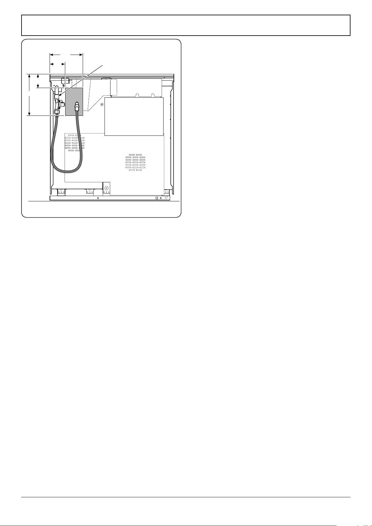
Because the height of the cooker can be adjusted and
each connection is dierent it is dicult to give precise
dimensions. Ideally, the house supply connection should be
in the shaded area (Fig.7-10).
Means of isolation must be provided at the supply point by
either an approved quick-connect device or a Type 1 manual
shut-o valve.
The hose should be tted so that both inlet and outlet
connections are vertical so that the hose hangs downwards in
a ‘U’ shape (Fig.7-10).
A exible connection is supplied with the cooker. If it is
necessary to use another hose it must be to AS 1869 Class
B and be suitable for your gas type. If in doubt contact your
supplier. Screw connect the threaded end of the hose into the
gas inlet.
After completing the gas connection, check the cooker is gas
sound with a pressure test. When checking for gas leaks do
not use washing up liquid – this can corrode. Use a product
specically manufactured for leak detection.
Natural Gas
The adjustable spring loaded gas pressure regulator is preset
to give a nominal pressure of 1 kPa on Natural gas. Connect to
the Rp½ inlet on the underside of the pressure regulator.
Propane
This cooker is supplied ready for use on Natural gas. A
conversion kit for Propane gas is supplied with the cooker –
see the ‘Conversion to Propane Gas’ section.
Pressure Testing
The pressure test point is accessible on the inlet pipe at the
rear. Remove the test nipple screw and t a pressure gauge to
the test point. Turn on and light two of the hotplate burners.
For Natural Gas cookers the pressure should be between
0.95kPa and 1.0kPa.
For Propane X cookers the pressure should be 2.54 kPa.
ArtNo.090-0027 - 90 Elan gas connections
300
100
240
100
All dimensions in millimetres
Gas inlet
Fig.7-10
Loading ...
Loading ...
Loading ...