Loading ...
Loading ...
Loading ...
Version Hi-Lo SS 3/08 - Page 5
PLAN YOUR DUCTWORK
The Inca HC SS requires 6" round
ductwork. To ensure that the blower
performs to its highest possible capacity,
ductwork should be as short and straight
as possilbe.
The ductrun should not exceed 35 feet
if ducted with the required minimum of
6" round duct. Calculate the length of
the ductwork by adding the equivalent
feet in FIGURE A for each piece of duct
in the system An example is given in
FIGURE B.
For best results, use no more than three
90° elbows. Make sure that there is a
minimum of 24" of straight duct between
elbows if more than one is used. Do not
install two elbows together.
TOOLS NEEDED FOR INSTALLATION
• Saber Saw or Jig Saw
• Drill
• 1 1/4" Wood Drill Bit
• Pliers
• Phillips Screwdriver
• Wire Stripper or Utility Knife
• Metal Snips
• Measuring Tape or Ruler
• Level
• Pencil
• Caulking Gun
• Duct Tape
PARTS SUPPLIED FOR INSTALLATION
• 1 Backdraft Damper
• 1 Vent Grate (for recirculating installations only)
• 1 Literature Package
PARTS NEEDED FOR INSTALLATION
• 2 Conduit Connectors
• Power Supply Cable
• 1 Wall or Roof Cap
• All Metal Ductwork
OPTIONAL ACCESSORIES AVAILABLE
• Charcoal Filter Kit
For recirculating installations only,
replace charcoal lters as needed
part # 6093034
• Liners
Create a perfectly-sealed, non-combustible
perimeter around the Inca HC SS. Depth
adjustable from 16" - 17
7/8".
Standard Liner 30 Stainless - part # 620000304
Standard Liner 36 Stainless - part # 620000305
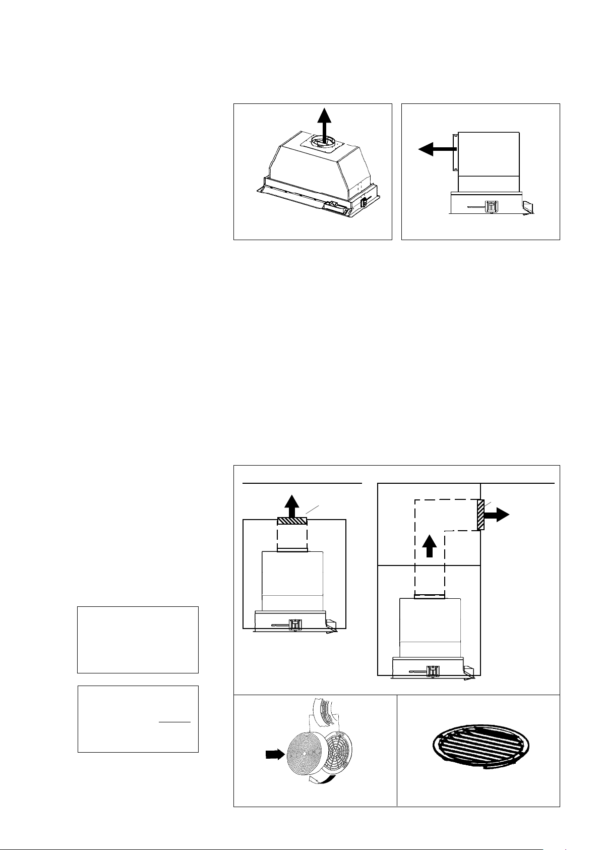
The Inca HC SS power pack rangehood is designed to offer a wide exibility of
installations. The rangehood can be ducted vertically (FIGURE 2) or horizontally
(FIGURE 3) through a 6" round vent. The unit can also be installed in a recirculating
conguration (FIGURE 4). The unit comes standard in top venting position.
45˚ Elbow
90˚ Elbow
90˚ Flat Elbow
Wall Cap
FIGURE A
9 Feet Straight Duct
2 - 90˚ Elbows
Wall Cap
Total System
9.0 feet
10.0 feet
0.0 feet
19.0 feet
FIGURE B
3.0 feet
5.0 feet
12.0 feet
0.0 feet
HORIZONTAL DUCTING
FIGURE 2
VERTICAL
DUCTING
For direct rear venting, you must change the blower position. Remove the 12 screws
that hold the metal housing to the rangehood body. Rotate the metal housing for direct
rear venting. Replace all screws, making sure that they are rmly fastened.
FIGURE 3
RECIRCULATING INSTALLATIONS
For recirculating installations (FIGURE 4), Charcoal Filters are necessary. Remove
all three grease lters and set aside. Attach one charcoal lter to each end of the
blower. Each charcoal lter attaches to the black grid on the side of the blower.
Rotate the lter clockwise to install and counterclockwise to remove (FIGURE 4A).
Replace all three grease lters. Recirculating installations also require some duct
work to divert the air out of the cabinet. The duct work must not terminate inside
the cabinet. The plastic vent grate supplied with the rangehood (FIGURE 4B) can
be used to cover the duct opening.
6” round
duct
ceiling
hood
vent grate
cabinet
ceiling
soft
vent grate
cabinet
6” round
duct
FIGURE 4A FIGURE 4B
FIGURE 4
hood
Loading ...
Loading ...
Loading ...