Loading ...
Loading ...
Loading ...
11
EN
English
Installation and Connections
CAUTION
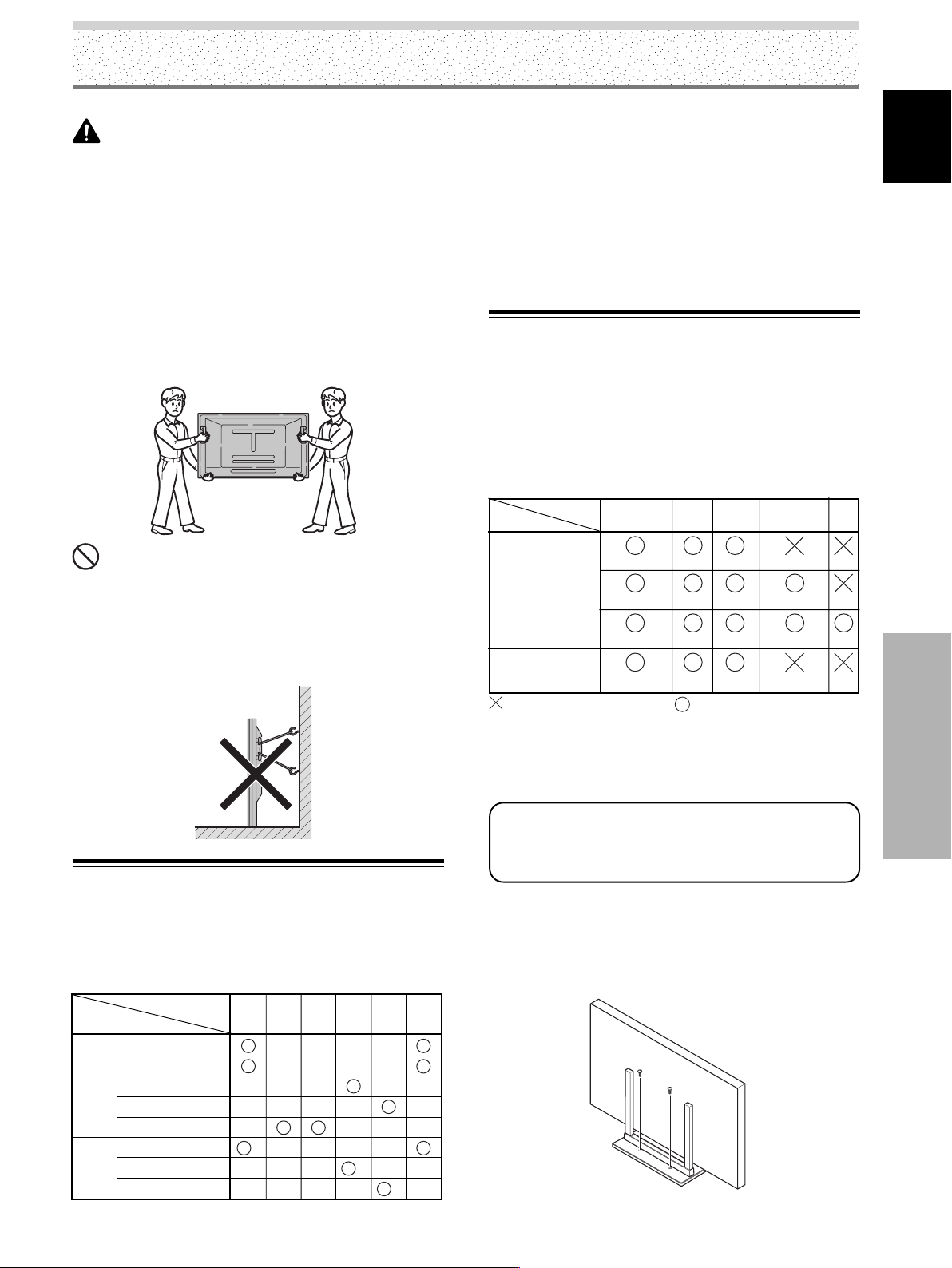
÷ Handles should not be removed or reattached by
anyone other than the professional installation
technician or service personnel.
÷ If handles must be removed due to specific installation
conditions, the mounting screws should be stored
carefully together with the handles. To ensure safety,
the mounting screws should be tightened to a
minimum torque of 2N·m (20 kgf·cm) when reattaching
the handles.
÷ When moving the display, it should always be carried
by two persons holding the rear handles in the manner
shown.
NO!
÷ Never attempt to move the plasma display by holding
only one of the handles.
÷ When installing the plasma display, do not use the
handles as means of hanging the display; also do not
use them as devices to prevent tipping over (see
illustration).
Connection to INPUT1 (D-sub) and
INPUT5
Various components can be connected to the INPUT1(D-
sub) and INPUT5 jacks. After connections are made, on-
screen setup is necessary to match the characteristics of
the connected component. Please see pages 23 to 25 for
on-screen setup after connection.
Note
Components compatible with INPUT1 (D-sub) are also
compatible with INPUT5.
When making connections to INPUT1 (D-sub), please refer to
appendix 3 on page 55.
For the screen sizes and input signals that INPUT1
(D-sub) and INPUT5 are compatible with, please
refer to appendix 1 (page 52) and appendix 2 (pages
53 to 54).
Stabilizing to the floor
÷ Use screws (sold separately) to attach and stabilize the stand.
÷ When stabilizing the stand to the floor, use M6 with a length
above 20 mm (25/32 inch).
Units: mm (inch)
: Do not connect anything. : Connect to this jack.
INPUT5 terminal
Output source
[ON SYNC]
GBR
[H/V SYNC]
HD VD
Video component/
Personal
computer (PC)
with RGB output
G ON SYNC
R
RG
GBR
B
B
VD
H/V SYNC
HD
YCB/PB CR/PR
Video component
with component
video output
*1 Although INPUT1 (D-sub)/INPUT5 are compatible with
various kinds of signals, setup using the on-screen menu is
necessary after connections are made in order match the
characteristics of the source component (pages 23 to 25).
*2 INPUT1 (D-sub) is compatible with Microsoft’s Plug & Play
(VESA DDC 1/2B).
*3 Depending on the video output board of the computer, this
type of connection may not be possible.
*4 Although INPUT1 (HDMI)/INPUT2 are compatible with
various kinds of signals, setup using the on-screen menu is
necessary after connections are made in order match the
characteristics of the source component (pages 25 to 27).
About the Input Connectors on this
Unit
Consult the following chart when making connections to
a plasma display (pages 12 to 21).
INPUT
4
INPUT
3
*3
*3
Input Connector
INPUT1
*1
(D-sub)
INPUT
2
*4
Analog RGB
Component video
S-video
Composite video
Digital video
Personal
computer
(PC)
AV
component
Connected
component and signals
Analog RGB
S-video
Composite video
*2
INPUT
5
*1
INPUT1
*4
(HDMI)
Installation and Connections
Loading ...
Loading ...
Loading ...