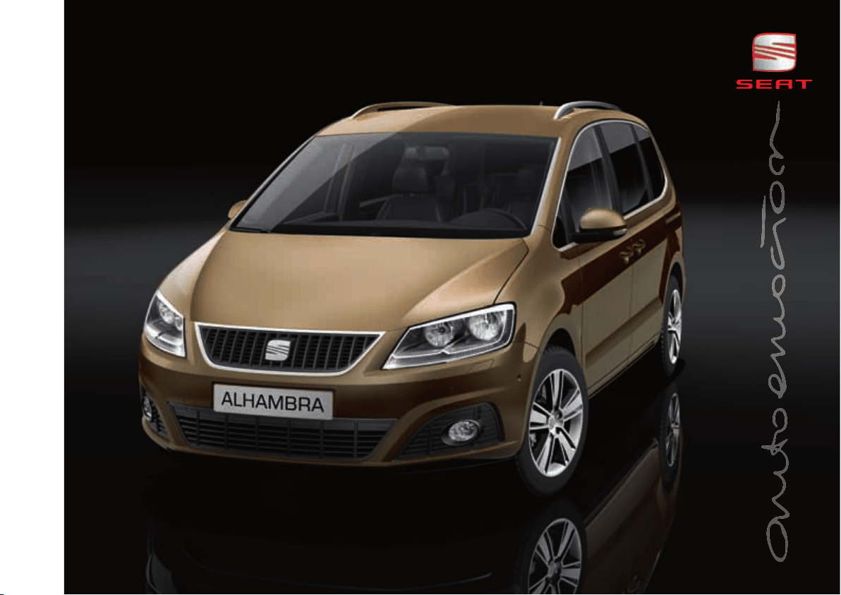
ALHAMBRA OWNER’S MANUAL

Foreword
This Instruction Manual and its corresponding supplements should be read carefully to familiarise yourself with
your vehicle.
Besides the regular care and maintenance of the vehicle, its correct handling will help preserve its value.
For safety reasons, note the information concerning accessories, modifications and parts changes.
If selling the vehicle, give all of the onboard documentation to the new owner, as it should be kept with the
vehicle.


Contents 3
Contents
Manual structure . . . . . . . . . . . . . . . . . . . .
Content . . . . . . . . . . . . . . . . . . . . . . . . . . . . . . . .
Safety First . . . . . . . . . . . . . . . . . . . . . . . . . . .
Safe driving . . . . . . . . . . . . . . . . . . . . . . . . . . . . . .
Dear SEAT Driver . . . . . . . . . . . . . . . . . . . . . . . . .
Tips for driving . . . . . . . . . . . . . . . . . . . . . . . . . . .
Adjusting the seat position . . . . . . . . . . . . . . . . .
Transporting objects . . . . . . . . . . . . . . . . . . . . . .
Seat belts . . . . . . . . . . . . . . . . . . . . . . . . . . . . . . . .
Brief introduction . . . . . . . . . . . . . . . . . . . . . . . .
Why wear seat belts? . . . . . . . . . . . . . . . . . . . . . .
Seat belts . . . . . . . . . . . . . . . . . . . . . . . . . . . . . . .
Seat belt tensioners . . . . . . . . . . . . . . . . . . . . . .
Airbag system . . . . . . . . . . . . . . . . . . . . . . . . . . . .
Brief introduction . . . . . . . . . . . . . . . . . . . . . . . .
Airbag system . . . . . . . . . . . . . . . . . . . . . . . . . . .
Child safety . . . . . . . . . . . . . . . . . . . . . . . . . . . . . .
Child seats (accessories) . . . . . . . . . . . . . . . . . .
Integrated child seat . . . . . . . . . . . . . . . . . . . . . .
Operating instructions . . . . . . . . . . . .
Cockpit . . . . . . . . . . . . . . . . . . . . . . . . . . . . . . . . . . .
Overview . . . . . . . . . . . . . . . . . . . . . . . . . . . . . . .
Instrument panel . . . . . . . . . . . . . . . . . . . . . . . . .
Instruments . . . . . . . . . . . . . . . . . . . . . . . . . . . . .
SEAT information system . . . . . . . . . . . . . . . . . . .
Unlocking and locking . . . . . . . . . . . . . . . . . . . .
Vehicle key set . . . . . . . . . . . . . . . . . . . . . . . . . . .
Central locking and locking system . . . . . . . . . .
Doors . . . . . . . . . . . . . . . . . . . . . . . . . . . . . . . . . .
Sliding doors . . . . . . . . . . . . . . . . . . . . . . . . . . . .
Tailgate . . . . . . . . . . . . . . . . . . . . . . . . . . . . . . . . .
Electric windows . . . . . . . . . . . . . . . . . . . . . . . . .
Panorama sliding sunroof* . . . . . . . . . . . . . . . . .
Garage door remote control* . . . . . . . . . . . . . . .
Lights and visibility . . . . . . . . . . . . . . . . . . . . . . .
Lights . . . . . . . . . . . . . . . . . . . . . . . . . . . . . . . . . .
Sun blind . . . . . . . . . . . . . . . . . . . . . . . . . . . . . . .
Windscreen wiper and washer . . . . . . . . . . . . . .
Rear vision mirror . . . . . . . . . . . . . . . . . . . . . . . .
Seats and storage compartments . . . . . . . . . .
Seat adjustment . . . . . . . . . . . . . . . . . . . . . . . . .
Seat functions . . . . . . . . . . . . . . . . . . . . . . . . . . .
Head restraints . . . . . . . . . . . . . . . . . . . . . . . . . .
Centre armrest . . . . . . . . . . . . . . . . . . . . . . . . . . .
Loading luggage compartment . . . . . . . . . . . . .
Roof carrier system . . . . . . . . . . . . . . . . . . . . . . .
Storage compartments . . . . . . . . . . . . . . . . . . . .
Cup holders . . . . . . . . . . . . . . . . . . . . . . . . . . . . .
Ashtray and cigarette lighter* . . . . . . . . . . . . . .
Sockets . . . . . . . . . . . . . . . . . . . . . . . . . . . . . . . . .
Toll card reader* . . . . . . . . . . . . . . . . . . . . . . . . .
Heating, Ventilation and Air conditioning . .
Climate Control . . . . . . . . . . . . . . . . . . . . . . . . . .
Auxiliary heater* (additional heater) . . . . . . . . .
Driving . . . . . . . . . . . . . . . . . . . . . . . . . . . . . . . . . . .
Steering . . . . . . . . . . . . . . . . . . . . . . . . . . . . . . . .
Stopping and starting the engine . . . . . . . . . . .
Changing gear . . . . . . . . . . . . . . . . . . . . . . . . . . .
Braking, stopping and parking . . . . . . . . . . . . . .
Start assist systems . . . . . . . . . . . . . . . . . . . . . .
Parking sensor system . . . . . . . . . . . . . . . . . . . .
Park Assist system* . . . . . . . . . . . . . . . . . . . . . . .
Rear Assist system* . . . . . . . . . . . . . . . . . . . . . . .
Cruise control system* (CCS) . . . . . . . . . . . . . . .
Dynamic chassis control* (DCC) . . . . . . . . . . . . .
Tyre monitoring systems . . . . . . . . . . . . . . . . . . .
Practical tips . . . . . . . . . . . . . . . . . . . . . . . . .
Driving and the environment . . . . . . . . . . . . . .
Running-in . . . . . . . . . . . . . . . . . . . . . . . . . . . . . .
Ecological driving . . . . . . . . . . . . . . . . . . . . . . . .
Engine management and exhaust gas purification
system . . . . . . . . . . . . . . . . . . . . . . . . . . . . . . . . .
Trailer towing . . . . . . . . . . . . . . . . . . . . . . . . . . . . .
Introduction . . . . . . . . . . . . . . . . . . . . . . . . . . . . .
Driving with a trailer . . . . . . . . . . . . . . . . . . . . . .
Vehicle maintenance and cleaning . . . . . . . .
Care and cleaning the vehicle exterior . . . . . . . .
Caring for and cleaning the vehicle interior . . . .
Notes for the user . . . . . . . . . . . . . . . . . . . . . . . .
Accessories, parts replacement and
modifications . . . . . . . . . . . . . . . . . . . . . . . . . . . .
Accessories, replacement of parts and
modifications . . . . . . . . . . . . . . . . . . . . . . . . . . . .
Checking and refilling levels . . . . . . . . . . . . . .
Filling the tank . . . . . . . . . . . . . . . . . . . . . . . . . . .
Fuel . . . . . . . . . . . . . . . . . . . . . . . . . . . . . . . . . . . .
Selective Catalytic Reduction* (AdBlue) . . . . . .
Working in the engine compartment . . . . . . . . .
5
6
7
7
7
7
10
13
16
16
18
22
27
29
29
33
42
42
52
59
59
59
61
64
70
78
78
83
92
92
97
102
106
109
113
113
122
124
130
134
134
137
143
145
146
159
162
171
173
175
178
179
179
187
192
192
195
201
210
221
225
229
234
239
243
245
251
251
251
252
255
258
258
260
269
269
278
283
285
285
293
293
297
300
304

Contents4
Engine oil . . . . . . . . . . . . . . . . . . . . . . . . . . . . . . .
Engine coolant . . . . . . . . . . . . . . . . . . . . . . . . . . .
Vehicle battery . . . . . . . . . . . . . . . . . . . . . . . . . . .
Wheels and tyres . . . . . . . . . . . . . . . . . . . . . . . . .
Wheels . . . . . . . . . . . . . . . . . . . . . . . . . . . . . . . . .
Wheel trims* . . . . . . . . . . . . . . . . . . . . . . . . . . . .
Changing a wheel* . . . . . . . . . . . . . . . . . . . . . . .
If and when . . . . . . . . . . . . . . . . . . . . . . . . . . . . . .
In case of emergency . . . . . . . . . . . . . . . . . . . . .
Emergency locking and unlocking . . . . . . . . . . .
Tools* . . . . . . . . . . . . . . . . . . . . . . . . . . . . . . . . . .
Fuses . . . . . . . . . . . . . . . . . . . . . . . . . . . . . . . . . .
Changing bulbs . . . . . . . . . . . . . . . . . . . . . . . . . .
Starting assistance . . . . . . . . . . . . . . . . . . . . . . .
Towing and tow starting . . . . . . . . . . . . . . . . . . .
Technical Data . . . . . . . . . . . . . . . . . . . . . . .
General notes on the technical data . . . . . . .
Outstanding information . . . . . . . . . . . . . . . . . .
Data on fuel consumption . . . . . . . . . . . . . . . . .
Towing a trailer . . . . . . . . . . . . . . . . . . . . . . . . . .
Wheels . . . . . . . . . . . . . . . . . . . . . . . . . . . . . . . . .
Technical Data . . . . . . . . . . . . . . . . . . . . . . . . . . . .
Checking fluid levels . . . . . . . . . . . . . . . . . . . . . .
Petrol engine 1.4 110 kW (150 PS) . . . . . . . . . .
Diesel engine 2.0 TDI 100 kW (135 PS) . . . . . . .
Diesel engine 2.0 TDI 100 kW (135 PS)
Automatic . . . . . . . . . . . . . . . . . . . . . . . . . . . . . .
Diesel engine 2.0 TDI 103 kW (140 PS) . . . . . . .
Diesel engine 2.0 TDI 103 kW (140 PS)
Automatic . . . . . . . . . . . . . . . . . . . . . . . . . . . . . .
Dimensions and capacities . . . . . . . . . . . . . . . .
Index . . . . . . . . . . . . . . . . . . . . . . . . . . . . . . . . . .
309
313
318
323
323
336
339
345
345
348
353
356
360
371
375
379
379
379
381
382
382
383
383
384
385
387
388
390
392
393
Manual structure 5
Manual structure
What you should know before reading the on-board manual
This manual contains a description of the equipment supplied with the
vehicle at the time of press. Some of the equipment hereunder described will
not be available until a later date, or is only available in certain markets.
Because this is a general manual for the ALHAMBRA, some of the equipment
and functions that are described in this manual are not included in all types
or variants of the model; they may vary or be modified depending on the
technical requirements and on the market; this is in no way deceptive adver-
tising.
The illustrations are intended as a general guide and may vary from the
equipment fitted in your vehicle in some details.
The direction indications (left, right, front, rear) appearing in this manual
refer to the normal forward working direction of the vehicle except when
otherwise indicated.
The equipment marked with an asterisk** is fitted as standard only in certain
versions, and is only supplied as optional extras for some versions or model
years, or are only offered in certain countries.
® All registered marks are indicated with ®. Although the copyright symbol
does not appear, it is a copyrighted mark.
b The section is continued on the following page.
Marks the end of a section.
WARNING
Texts preceded by this symbol contain information on safety. They warn
you about possible dangers of accident or injury.
Caution
Texts with this symbol draw your attention to potential sources of damage to
your vehicle.
For the sake of the environment
Texts preceded by this symbol refer to relevant points concerning environ-
mental protection.
Note
Texts preceded by this symbol contain additional information.

Content6
Content
This manual is structured to provide the information you need in an organised
way. The content of this Manual is divided into sections which belong to
chapters (e.g. “Air conditioning”). The entire manual is divided into five large
parts which are:
1. Safety First
Information on the vehicle equipment relating to passive safety such as seat
belts, airbags, seats, etc.
2. Operating instructions
Information about the distribution of controls in the driver position of your
vehicle, about the seat adjustment possibilities, about how to create a suit-
able climate in the passenger compartment, etc.
3. Practical tips
Advice relating to the driving, caring and maintenance of your vehicle and
certain problems you can solve yourself.
4. Technical Data
Figures, data, dimensions and measurements (for example fuel consump-
tion) of your vehicle.
5. Alphabetic index
At the end of this manual there is a detailed alphabetical index, this will help
you to rapidly find the information you require.
Safe driving 7
Safety First Operating instructions Practical tips Technical Data
Safety First
Safe driving
Dear SEAT Driver
Safety first!
This chapter contains important information, tips, suggestions and
warnings that you should read and consider for both your own safety
and for your passengers safety.
WARNING
x This manual contains important information concerning the driver's
and passengers' handling of the vehicle. The other booklets in the on
board manual also contain further information that you should be aware of
for your own safety and for the safety of your passengers.
x Ensure that the onboard documentation is kept in the vehicle at all
times. This is especially important when lending or selling the vehicle to
another person.
Tips for driving
Introduction
Depending upon how you expect to use your vehicle, it may a good idea to
protect the engine from below. A guard underneath the engine may help to
reduce the risk of damage to the lower part of the vehicle and the oil sump
when driving over kerbs, or along dirt tracks or rough roads... SEAT recom-
mends you have the guard fitted by a SEAT dealer.
Additional information and warnings:
x Ensure you are correctly seated page 10
x Transporting page 13
x Starting, changing gears, parking page 195
x Ecological driving page 252
x Notes for the user page 283
WARNING
Driving under the influence of alcohol, drugs, medication or narcotics may
result in severe accidents and even loss of life.
x Alcohol, drugs, medication and narcotics may significantly alter
perception, affect reaction times and safety while driving, which could
result in the loss of control of the vehicle.
Preparing for the journey and safe driving
Check list
For your own safety, for the safety of passengers in the car, and for that of
other road users, the following should be checked before and during each
journey :
Safe driving8
x Check that the lights and turn signals operate correctly.
x Check the tyre pressures ( page 323) and level of fuel ( page 293).
x Ensure there is good visibility through all the windows.
x Make sure that all objects and bags in the storage compartments, in the
luggage compartment and, where applicable, on the roof, are securely
fastened page 13.
x Ensure there is nothing obstructing the free passage of the foot pedals.
x Use child retention systems appropriate for the child's body weight and
height page 42.
x Correctly adjust front seat, head rests and rear-view mirrors to suit your
height page 10.
x Wear close-fitting shoes which do not prevent you from using the pedals
correctly.
x The driver's floor mat should be fixed to the floor, leaving the pedal area
unobstructed.
x Before starting out, ensure you are correctly seated and remain in this
position throughout the journey. This applies to all passengers in the vehicle
page 10.
x Correctly fasten your seat belt before starting to drive and keep it securely
fastened throughout the journey. This applies to all passengers in the vehicle
page 22.
x Never carry more passengers than the number of available seats and seat
belts in your vehicle.
x Never drive with impaired faculties (for example, due to medication,
alcohol or drugs).
x Do not allow yourself to be distracted from the traffic, for example, to reset
or switch on a menu, by other passengers or to answer a phone call.
x Always try to adapt the speed of the vehicle and your style of driving to the
condition of the ground or the road and to weather and traffic conditions.
x Observe the highway code and speed limits.
x On long journeys, rest at regular intervals (at least every two hours).
x If carrying animals, make sure they are correctly restrained in accordance
with their weight and size.
WARNING
Always observe traffic regulations and speed limits and try to anticipate
traffic movements. Correctly anticipating traffic situations may mean the
difference between arriving safe and sound at your destination or having a
serious accident.
Note
Regular servicing of your vehicle not only helps to keep it in good working
order but also helps to ensure road safety. Therefore, please ensure the
vehicle is taken for service as indicated in the Maintenance Programme. If the
vehicle is subjected to hard use, it may require certain maintenance work
before the next service date. Hard use may involve frequent driving in traffic
jams, driving in dusty areas or frequent use of the tow-bar. For further infor-
mation, please refer to a SEAT dealer or specialised workshop.
Driving abroad
Check list
In some countries, certain safety regulations and requirements are in force
relating to exhaust gas emissions, which differ from the technical character-
istics of the vehicle. Before travelling abroad, SEAT recommends you consult
a SEAT dealer about the legal requirements and the following points:
x Does the vehicle need technical modifications for driving abroad, for
example, adjustment of the headlamps?
x Does the vehicle have all the tools, diagnostics equipment and spare
parts required for inspections and repairs?
x Are there any SEAT dealers in the destination country?
Safe driving 9
Safety First Operating instructions Practical tips Technical Data
x For petrol vehicles: Is unleaded petrol available at the right octane rating?
x For diesel engines: Is diesel fuel available with a low sulphur content?
x Are a suitable engine oil ( page 309) and other engine fluids complying
with SEAT specifications available in the destination country?
x Will the navigation system fitted at the factory operate correctly in the
destination country with the available navigation data?
x Are special tyres required in the destination country?
Caution
SEAT does not accept liability for any damage to the vehicle due to the use of
a lower quality fuel, an inadequate service or the non-availability of genuine
spare parts.
Driving along flooded roadways
To prevent damage to the vehicle when driving through water, for example,
along a flooded road, please observe the following:
x Check the depth of the water before entering the flooded zone. The water
should never come above the lower edge of the bodywork .
x Do not drive faster than a pedestrian.
x Do not stop in the water, use reverse gear or switch off the engine.
x Oncoming traffic will cause waves which raise the level of the water,
making it difficult to cross the water.
WARNING
When driving through water, mud, melted snow, etc., please remember
that due to damp or frozen brake discs and shoes in winter, the braking
effect may be delayed, therefore the required braking distance is greater.
x Dry the brakes and remove ice by braking carefully. Ensure that you are
not endangering other road-users or breaking traffic regulations in the
process.
x After driving through water, avoid sudden sharp manoeuvres.
Caution
x Driving through flooded areas may severely damage vehicle components
such as the engine, transmission, running gear or electrical system.
x Never drive through salt water as salt causes corrosion. Always rinse any
parts of the vehicle which have been in contact with salt water.
WARNING (continued)
Safe driving10
Adjusting the seat position
Introduction
Number of seats
Depending on the equipment, your vehicle has a total of five or seven seats.
Each seat is equipped with a seat belt.
Additional information and warnings:
x Seat functions page 137
x Seat belts page 22
x Airbag system page 33
x Child seats (accessories) page 42
WARNING
An incorrect sitting position in the vehicle can lead to severe injuries or
death in the event of sudden braking or manoeuvres, collision or accidents
or if the airbag deploys.
x Before the vehicle moves, assume the proper sitting position and main-
tain it throughout the trip. This also includes fastening the seat belt.
x Never transport more people than there are seats with a seat belt avail-
able in the vehicle.
x Children must always be protected with an approved child restraint
system suited to their height and weight page 42, page 33.
x Always keep your feet in the footwell while the vehicle is in motion.
Never, for example, put your feet on the surface of a seat or on the dash
panel and never put them out of a window. Otherwise the airbag and seat
belt offer insufficient protection and the risk of injury in the event of an
accident is increased.
WARNING
Before every trip, adjust the seat, the seat belt and the head restraints and
instruct your passengers to fasten their seat belts properly.
x Move the front passenger seat back as far as possible.
x Adjust the driver's seat so that there is a distance of at least 25 cm (10
inches) between the centre of your chest and the hub of the steering wheel.
Adjust the driver's seat so that you are able to press the accelerator, brake
and clutch pedals to the floor with your knees slightly angled and that the
distance between your knees and the dash panel is at least 10 cm (4
inches). If you physical constitution prevents you from meeting these
requirements, contact a qualified workshop to make any modifications
required.
x Never drive with the backrest tilted far back. The further the backrests
are tilted to the rear, the greater the risk of injury due to incorrect posi-
tioning of the belt web or to the incorrect sitting position.
x Never drive with the backrest tilted forwards. Should a front airbag
deploy, it could throw the backrest backwards and injure the passengers of
the rear seats.
x Sit as far away as possible from the steering wheel and the dash panel.
x Keep your back straight and resting completely against the backrest
and the front seats correctly adjusted. Never place any part of your body in
the area of the airbag or very close to it.
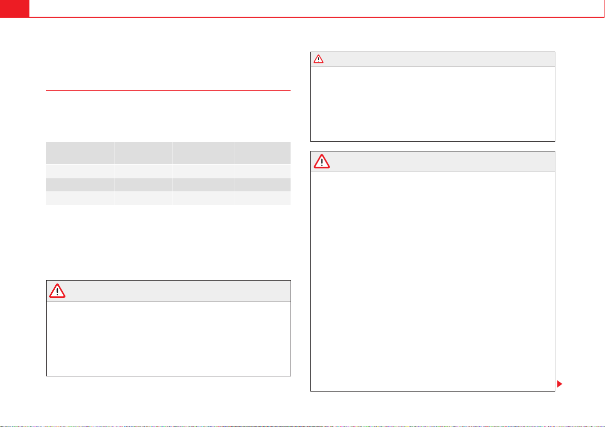
Equipment Seats in the
front
Seats in the
second row
Seats in the
third row
5 seats 2 3 –
6 seats 2 2 2
7 seats 2 3 2
WARNING (continued)
Safe driving 11
Safety First Operating instructions Practical tips Technical Data
x If passengers on the rear seats are not sitting in an upright position, the
risk of severe injury due to incorrect positioning of the belt web increases.
WARNING
Incorrect seat adjustment may lead to accidents and severe injuries.
x Only adjust the seats when the vehicle is stationary, as the seats could
move unexpectedly while the vehicle is in motion and you could lose
control of the vehicle. Furthermore, an incorrect position is adopted when
adjusting the seat.
x Only adjust the height, backrest and forwards or backwards position of
the seat when there is nobody in the seat adjustment area.
x There must be no objects blocking the seat adjustment area.
x Only adjust the height, angle and longitudinal position of the rear seats
when nobody is in the way.
x The seat adjustment and lock areas must be kept clean.
Danger of injuries due to an incorrect sitting position
If the seat belts are worn incorrectly or not at all, the risk of severe injuries
increases. Seat belts can provide optimal protection only if the belt web is
properly worn. The seat belt cannot offer its full protection if the belt web is
not positioned correctly. This could result in severe and even fatal injuries.
The risk of severe or fatal injuries is especially increased when a deploying
airbag strikes an occupant who has assumed an incorrect sitting position.
The driver is responsible for all passengers in the vehicle, particularly chil-
dren.
The following list shows just some examples of incorrect sitting positions
which can be dangerous to all occupants.
Whenever the vehicle is in motion:
x Never stand in the vehicle.
x Never stand on the seats.
x Never kneel on the seats.
x Never tilt your backrest too far to the rear.
x Never lean against the dash panel.
x Never lie on the rear bench.
x Never sit on the front edge of a seat.
x Never sit sideways.
x Never lean out of a window.
x Never put your feet out of a window.
x Never put your feet on the dash panel.
x Never put your feet on the surface of a seat or backrest.
x Never travel in a footwell.
x Never sit on the armrests.
x Never travel on a seat without wearing the seat belt.
x Never carry any person in the luggage compartment.
WARNING
Every incorrect sitting position increases the risk of severe or fatal injuries
in the event of accidents or sudden braking or manoeuvres.
x All passengers must assume the proper sitting position and be properly
belted in while travelling.
x Occupants in incorrect sitting positions, not wearing their seat belt or
too close to the airbag run the risk of suffering severe or fatal injuries,
particularly if the airbag deploys and hits an occupant sitting in an incor-
rect position.
WARNING (continued)
Safe driving12
Correct sitting position
The correct sitting positions for the driver and passengers are shown below.
If you physical constitution prevents you from maintaining the correct sitting
position, contact a qualified workshop for help with any special devices. The
seat belt and airbag can only provide optimum protection if a correct sitting
position is adopted. SEAT recommends visiting a qualified workshop.
For your own safety and to reduce the risk of injury in the event of an accident
or sudden braking or manoeuvre, SEAT recommend the following positions:
Valid for all vehicle occupants:
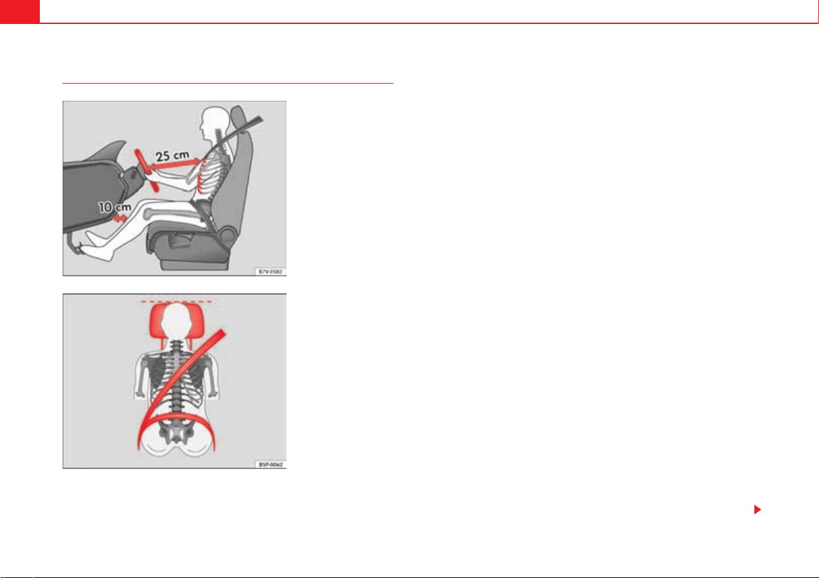
x Adjust the head restraint so that its upper edge is at the same level as the
top of your head, or as close as possible to the same level as the top of your
head and under no circumstances below eye level. Keep the back of your neck
as close as possible to the head restraint fig. 1 and fig. 2.
x Short people must lower the head restraint completely, even if your head
is below its upper edge.
x Tall people must raise the head restraint completely.
x Adjust the backrest to an upright position so that your back rests
completely against it.
x Always keep your feet in the footwell while the vehicle is in motion.
x Adjust and fasten your seat belt correctly page 22.
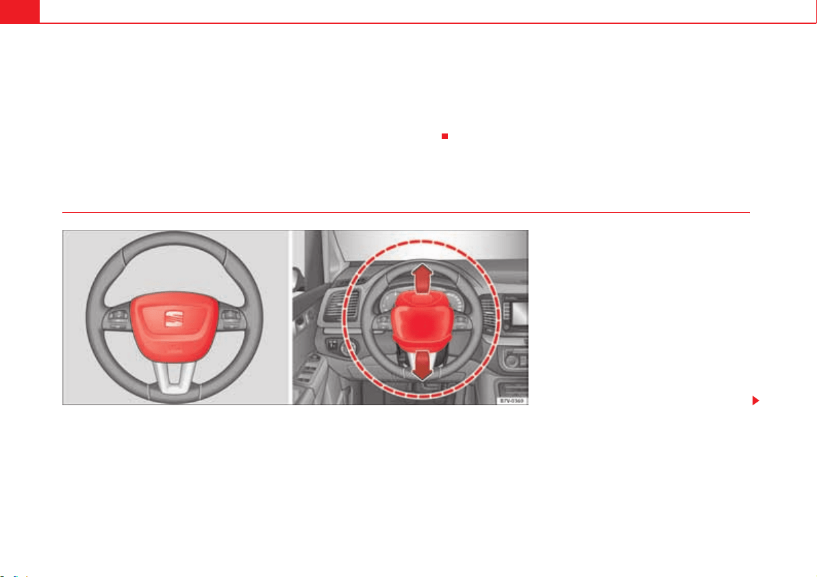
Also valid for the driver:
x Adjust the steering wheel so that there is a distance of at least 25 cm (10
inches) between it and your chest fig. 1 and so that you can hold the
steering wheel with both hands on the outside of the ring at the 9 o'clock and
3 o'clock positions with your arms slightly bent.
x The adjusted steering wheel must face your chest and not your face.
x Adjust the driver's seat forwards or backwards so that you are able to
press the accelerator, brake and clutch pedals to the floor with your knees
slightly angled and the distance between your knees and the dash panel is at
least 10 cm (4 inches) fig. 1.
x Adjust the height of the driver's seat so that you can easily reach the top
of the steering wheel.
Fig. 1 The correct
distance between the
driver and the steering
wheel must be at least 25
cm (10 inches).
Fig. 2 Correct belt web
and head restraint posi-
tions.
Safe driving 13
Safety First Operating instructions Practical tips Technical Data
x Keep both feet in the footwell so that you have the vehicle under control
at all times.
Also valid for the front passenger:
x Move the front passenger seat back as far as possible for optimum protec-
tion should the airbag deploy.
Transporting objects
Introduction
Always transport heavy loads in the trunk and place the seat backs in a
vertical position. Always use the anchors provided with suitable rope to
secure heavy objects. Never overload the vehicle. Both the carrying capacity
as well as the distribution of the load in the vehicle have effects on the driving
behaviour and braking ability .
Additional information and warnings:
x Tailgate page 97
x To lower the passenger seat back page 137
x Light page 113
x Luggage compartment page 146
x Roof carrier page 159
x Towing mode page 260
x Wheels and tyres page 323
WARNING
Unsecured or incorrectly secured objects can cause serious injury in case
of a sudden manoeuvring or breaking or in case of an accident. This is espe-
cially true when objects are struck by a detonating airbag and fired through
the vehicle interior. To reduce the risks, please note the following:
x Secure all objects in the vehicle. Always keep equipment and heavy
objects in the luggage compartment.
x Always secure objects with suitable rope or slings so that they cannot
enter the areas around the frontal or side airbags in case of sudden braking
or an accident.
x Always ensure that objects inside the vehicle cannot move into the area
of the bags while driving.
x While driving, always keep object compartments closed.
x Remove all objects from the passenger seat when this is followed down.
When the seat back is folded down, it presses on small and light objects
and these are detected by the weight sensor on the seat; this sends false
information to the airbag control unit.
x While the backrest of the front passenger's seat is folded, the frontal
airbag must remain disconnected and the PASSENGER AIRBAG OFF light
on.
x Objects secured in the vehicle should never be placed in such a way as
to make passengers sit in an incorrect position.
x If secured objects occupy a seat then this should not be occupied or
used by anybody.
WARNING
The driving behaviour and braking ability change when transporting heavy
and large objects.
x Adjust your speed and driving style to visibility, road, traffic and
weather conditions.
x Accelerate gently and carefully.
x Avoid sudden braking and manoeuvres.
WARNING (continued)
Safe driving14
x Brake early.
Transporting a load
Secure all objects in the vehicle
x Distribute the load throughout the vehicle, on the roof and in a trailer as
uniformly as possible.
x Transport heavy objects as far forward as possible in the luggage
compartment and lock the seat backs in the vertical position.
x Secure luggage in the luggage compartment with suitable straps on the
fastening rings page 146.
x Check the headlight adjustment page 113.
x Use the suitable tyre pressure according to the load being transported.
Read the tire inflation information label page 323.
x For vehicles with a tire pressure indicator, change the vehicle load status
page 245.
Caution
Objects on the shelf could chafe against the wires of the heating element in
the rear window and cause damage.
Note
Please note the information about loading a trailer page 260 and the roof
carrier system page 159.
Driving with the tailgate open
Driving with the tailgate open creates an additional risk. Secure all objects
and secure the tailgate correctly and take all measures possible to reduce
toxic gases from entering the vehicle.
WARNING
Driving with the tailgate unlocked or open could cause serious injuries.
x Always drive with the tailgate closed.
x Secure all objects in the vehicle. Loose items could fall out of the
vehicle and injure other road users or damage other vehicles.
x Drive particularly carefully and think ahead.
x Avoid sudden manoeuvres and braking given that this could cause an
uncontrolled movement of the open tailgate.
x When transporting objects that protrude out of the luggage compart-
ment, indicate them suitably. Observe legal requirements.
x If objects must project out of the luggage compartment, the tailgate
must never be used to “secure” or “attach” objects.
x If a baggage rack is fitted on the tailgate, it should be removed before
travelling with the tailgate open.
WARNING
Toxic gases may enter the vehicle interior when the tailgate is open. This
could cause loss of consciousness, carbon monoxide poisoning, serious
injury and accidents.
x To avoid toxic gases entering the vehicle always drive with the tailgate
closed.
x In exceptional circumstances, if you must drive with the tailgate open,
observe the following to reduce the entry of toxic gases inside the vehicle:
Close all windows and the sliding roof.
WARNING (continued)

Safe driving 15
Safety First Operating instructions Practical tips Technical Data
Turn off the air recirculation for the heating and air conditioning.
Open all of the air outlets in the dashboard.
Turn the heating fan and heater to the highest level.
Caution
An open tailgate changes the length and height of the vehicle.
Driving a loaded vehicle
For the best handling when driving a loaded vehicle, note the following:
x Secure all objects page 14.
x Accelerate gently and carefully.
x Avoid sudden braking and manoeuvres.
x Brake early.
x If necessary, read the instructions for driving with a trailer page 260.
x If necessary, read the instructions for driving with a roof carrier system
page 159.
WARNING
A sliding load could considerably affect the stability and safety of the
vehicle resulting in an accident with serious consequences.
x Secure loads correctly so they do not move.
x When transporting heavy objects, use suitable ropes or straps.
x Lock the seat backs in vertical position.
Specific vehicle weight information
The instructions in the official vehicle documents take precedence. All the
technical data provided in this documentation is applicable to the basic
model. The vehicle data label in the Maintenance Programme or the vehicle
documents show which engine is installed in your vehicle.
The figures may be different depending on if additional equipment is fitted,
for different models and for special vehicles.
WARNING
Exceeding the maximum authorised weight and the load on the axles could
cause damage to the vehicle, accidents and serious injuries.
x The real load on the axles should never exceed the maximum
permitted.
x The load and its distribution in the vehicle have effects on the vehicle
handling and the braking ability. Always drive at a suitable speed.
Caution
Distribute the load as uniformly and as low down on the vehicle as possible.
When transporting heavy objects in the trunk/boot, these should be placed
as far forward as possible or over the rear axle to have as little influence on
handling as possible.
WARNING (continued)
Seat belts16
Seat belts
Brief introduction
Introduction
Check the condition of all the seat belts at regular intervals. If you notice that
the belt webbing, fittings, retractor mechanism or buckle of any of the belts
is damaged, the belt must be replaced immediately by a specialist workshop
. The specialist workshop must use the appropriate spare parts corre-
sponding to the vehicle, the equipment and the model year. SEAT recom-
mends visiting a qualified workshop.
Additional information and warnings:
x Adjust the seat position page 10
x Airbag system page 33
x Child seats (accessories) page 42
x Integrated child seats page 52
x Accessories, parts replacement, repairs and modifications page 285
WARNING
Unbuckled or badly buckled seat belts increase the risk of severe or even
fatal injuries. The seat belt cannot offer its full protection if it is not
fastened and used correctly.
x Seats belts are the most effective ways of reducing the risk of
sustaining severe or fatal injuries In the event of an accident. Seat belts
must be correctly fastened when the vehicle is in motion to protect the
driver and all vehicle occupants.
x Before each trip, every occupant in the vehicle occupants must sit prop-
erly, correctly fasten the seat belt belonging to his or her seat and keep it
fastened throughout the trip. This also applies to other occupants when
driving in town.
x When travelling, children must be secured in the vehicle with a child
restraint system suitable for their weight and height and with the seat
belts correctly fastened page 42.
x Instruct your passengers to fasten their seat belts properly before
driving off.
x Insert the latch plate into the buckle for the appropriate seat and
ensure it is engaged. Using the latch plate in the buckle of another seat will
not protect you properly and may cause severe injuries.
x Do not allow liquids or foreign bodies to enter the buckle fastenings.
This could damage the buckles and seat belts.
x Never unbuckle your seat belt when the vehicle is moving.
x Never allow more than one passenger to share the same seat belt.
x Never hold children or babies on your lap sharing the same seat belt.
x Loose, bulky clothing (such as a jacket) impairs the proper fit and func-
tion of the seat belt.
WARNING
It is extremely dangerous to drive using damaged seat belts and could
result in serious injury or loss of life.
x Avoid damaging the seat belt by jamming it in the door or the seat
mechanism.
x If the fabric or other parts of the seat belt are damaged, the seat belts
could break in the event of an accident or sudden braking.
WARNING (continued)
Seat belts 17
Safety First Operating instructions Practical tips Technical Data
x Always have damaged seatbelts replaced immediately by seat belts
approved for the vehicle in question by SEAT. Seat belts which have been
worn in an accident and stretched must be replaced by a qualified work-
shop. Renewal may be necessary even if there is no apparent damage. The
belt anchorage should also be checked.
x Never attempt to repair, modify or remove a seat belt yourself. All
repairs to seat belts, retractors and buckles must be carried out by a
specialist workshop.
Warning lamp
Some control and warning lamps on the instrument panel will come on to
check certain functions when the ignition is switched on. They will switch off
after a few seconds.
A signal will be heard for a maximum of 90 seconds if the seat belts are not
fastened as the car drives off and reaches a speed of more then 25 km/h or if
the seat belts are unfastened while the vehicle is in motion. The seat belt
warning lamp h will also flash.
WARNING (continued)
Fig. 3 Warning lamp on
the instrument panel
Lights up
or
flashes
Possible cause Solution
h
Driver's seat belt not fastened
or front passenger's seat belt
not fastened if the front pas-
senger's seat is occupied.
Fasten seat belts!
h
Objects on the front passen-
ger's seat.
Remove any objects from the
front passenger's seat and store
them safely.
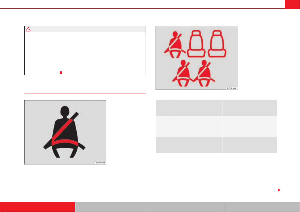
Fig. 4 Example of seat
belt status display for the
rear seats (here, a 7-seat
vehicle) on the instrument
panel. above the second
row and below the third
row of seats.
Seat belts18
The warning lamp h does not switch off until the driver and front passenger
fasten their seat belts while the ignition is switched on.
Seat belt status display for rear seats
The seat belt status display on the instrument panel informs the driver, when
the ignition is switched on, whether any passengers in the rear seats have
fastened their seat belts. The symbol h indicates that the passenger in this
seat has fastened “his or her” seat belt page 17, fig. 4.
The seat belt status is displayed for around 30 seconds when a seat belt in
the rear seats is fastened or unfastened. You can switch off this display by
pressing the button.
The seat belt status flashes for a maximum of 30 seconds when a seat belt in
the rear seats is unfastened while the vehicle is in motion. A signal will also
be heard if the vehicle is travelling at over 25 km/h.
The rear seat display can be enabled or disabled by a Technical Service.
WARNING
Unbuckled or badly buckled seat belts increase the risk of severe or even
fatal injuries. The optimal protection from seat belts can be achieved only
if you use them properly.
Why wear seat belts?
Frontal collisions and the laws of physics
0.0 / SET
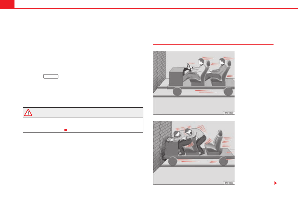
Fig. 5 Vehicle about to hit
a wall: the occupants are
not wearing seat belts.
Fig. 6 The vehicle hits
the wall: the occupants
are not wearing seat
belts.
Seat belts 19
Safety First Operating instructions Practical tips Technical Data
It is easy to explain how the laws of physics work in the case of a head-on
collision: when a vehicle starts moving page 18, fig. 5, this is a certain
amount of energy known as “kinetic energy” both in the vehicle and in the
occupants.
The higher the speed and the greater the weight of the vehicle, the more
energy there is to be absorbed in an accident.
The most significant factor, however, is the speed of the vehicle. If the speed
doubles from 25 km/h to 50 km/h, for example, the kinetic energy is multi-
plied by four.
The amount of “kinetic energy” depends on the speed of the vehicle and the
weight of the vehicle and its passengers. The higher the speed and the
greater the weight of the vehicle and the occupants, the more energy there is
to be absorbed in an accident.
Passengers not wearing seat belts are not “attached” to the vehicle. As a
result, in a frontal collision they will continue to move forward at the speed
their vehicle was travelling just before the impact until something stops
them! Because the passengers in our example are not restrained by seat
belts, all of the passengers' kinetic energy has to be absorbed at the point of
impact page 18, fig. 6.
At speeds of 30 km/h to 50 km/h, the forces acting on bodies in a collision
can easily exceed one tonne (1000 kg). At greater speed these forces are even
higher.
This example applies not only to frontal accidents, but to all accidents and
collisions.
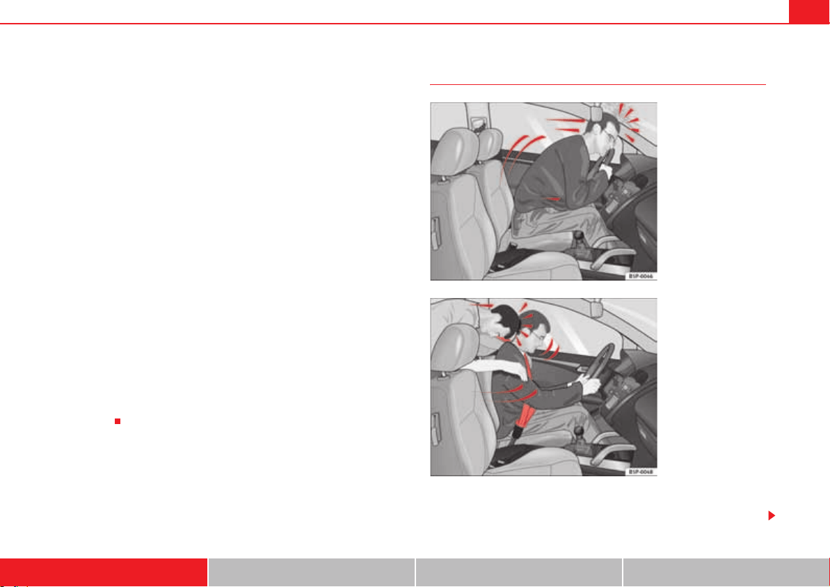
Dangers of not using the seat belt
Many people believe that the occupants can protect themselves with their
hands in a minor collision. This is false!
Fig. 7 A driver not
wearing a seat belt is
thrown forward violently.
Fig. 8 The unbelted rear
passenger is thrown
forward violently, hitting
the driver wearing a seat
belt.
Seat belts20
Even at low speeds, the forces acting on the body in a collision are so great
that it is not possible to brace oneself with just one's arms and hands. In a
frontal collision, unbelted passengers are thrown forward and will make
violent contact with the steering wheel, dash panel, windscreen or whatever
else is in the way page 19, fig. 7.
The airbag system is not a substitute for seat belts. When triggered, airbags
provide only additional protection. Airbags do not deploy in all types of acci-
dent. All occupants (including the driver) must be wearing seat belts properly
during the trip, even if the vehicle is equipped with airbag systems. This will
reduce the risk of critical or fatal injuries in the event of an accident – regard-
less of whether an airbag is fitted for the seat.
The airbag is only deployed once. To achieve the best possible protection, the
seat belt must always be worn properly so that you will be protected in acci-
dents in which no airbag is deployed. Vehicle occupants not wearing belts
could be thrown from the vehicle and sustain even more severe or fatal inju-
ries.
It is also important for the rear passengers to wear seat belts properly, as they
could otherwise be thrown forward violently in an accident. Rear passengers
who do not use seat belts endanger not only themselves but also the driver
and other occupants page 19, fig. 8.
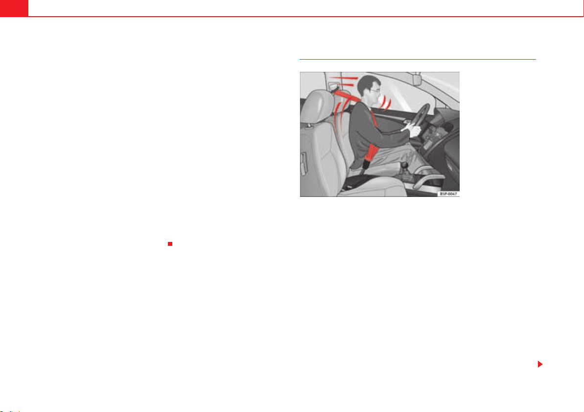
Seat belt protection
Wearing a correctly fastened seat belt can significantly change the situation.
Properly worn seat belts hold the vehicle occupants in the correct sitting posi-
tions and substantially reduce the kinetic energy in the event of an accident.
Seat belts also help to prevent uncontrolled movements that could lead to
severe injuries. In addition, properly worn seat belts reduce the danger of
being thrown from the car fig. 9.
Passengers wearing their seat belts correctly benefit greatly from the ability
of the belts to absorb kinetic energy. The front crumple zones and other
passive safety features (such as the airbag system) are also designed to
absorb the kinetic energy generated in a collision. Taken together, all these
features reduce the energy released and decrease the risk of injury.
Our examples describe frontal collisions. Of course, properly worn seat belts
substantially reduce the risk of injury in all other types of accidents. This is
why it is so important to fasten seat belts before every trip, even when just
driving “around the corner”. Ensure that your passengers wear their seat
belts as well.
Fig. 9 Drivers with prop-
erly worn seat belts will
not be thrown forward in
the event of sudden
braking.

Seat belts 21
Safety First Operating instructions Practical tips Technical Data
Accident statistics have shown properly worn seat belts to be an effective
means of considerably reducing the risk of severe injury and improving the
chances of survival in a serious accident. Furthermore, properly worn seat
belts improve the protection provided by deployed airbags in the event of an
accident. For this reason, wearing a seat belt is required by law in most coun-
tries.
Although your vehicle is equipped with airbags, the seat belts must be
fastened and worn. The front airbags, for example, are only triggered in some
frontal accidents. The front airbags will not be triggered during minor frontal
collisions, minor side collisions, rear collisions, rolls or accidents in which the
airbag trigger threshold value in the control unit is not exceeded.
Therefore, you should always wear your seat belt and ensure that your
passengers have fastened their seat belts properly before you drive off!
Seat belts22
Seat belts
Using seat belts
Checklist
Using seat belts :
x Check the condition of all the seat belts at regular intervals.
x Keep the seat belts clean.
x Keep the belt web, the latch plate and the buckle free of foreign bodies
and liquids.
x Do not jam or damage the seat belt or the latch plate when closing the
door, for example.
x Never remove, modify or repair the seat belt or belt fastening mecha-
nisms.
x Fasten your seat belt properly before each trip and keep it fastened.
Twisted seat belt
If it is difficult to remove the seat belt from the guide, the seat belt may have
become twisted inside the side trim after being wound too quickly on unfas-
tening:
x Pull out the seat belt completely, carefully pulling on the latch plate.
x Untwist the belt and guide it back, assisting it by hand.
The seat belt must be fastened even if it is impossible to untwist it. In this
case, the twisted area must not be in an area in direct contact with your body.
Have the seat belt untwisted urgently by a qualified workshop.
WARNING
An improperly handled seat belt increases the risk of sustaining severe or
fatal injuries.
x Regularly check that the seat belts and their components are in perfect
condition.
x Always keep your seat belt clean.
x Do not jam or damage the seat belt or rub it with sharp edges.
x Make sure there are no liquids or foreign bodies on the latch plate and
in the buckle.
WARNING (continued)
Seat belts 23
Safety First Operating instructions Practical tips Technical Data
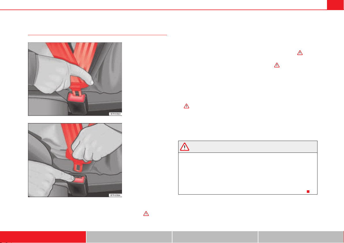
Fastening or unfastening a seat belt with one buckle
Properly worn seat belts hold the vehicle occupants in the position that most
protects them in the event of an accident or sudden braking .
Fastening the seat belt
Fasten your seat belt before each trip.
x Adjust the front seat and head restraint correctly page 10.
x Engage the backrest of the rear seat in an upright position .
x Pull the latch plate and place the belt webbing evenly across your chest
and lap. Do not twist the seat belt when doing so .
x Engage the latch plate in the buckle of the corresponding seat fig. 10.
x Pull the belt to ensure that the latch plate is securely engaged in the
buckle.
Unfastening the seat belt
The seat belt must not be unfastened until the vehicle has come to a standstill
.
x Press the red button on the buckle fig. 11. The latch plate is released
from the buckle.
x Guide the belt back by hand so that it rolls up easily and the trim will not
be damaged.
WARNING
An incorrectly worn seat belt web can cause severe or fatal injuries in the
event of an accident.
x The seat belt cannot offer its full protection unless the backrests are in
an upright position and the seat belt is worn correctly, according to your
size.
x Unbuckling your seat belt while the vehicle is in motion can cause
severe or fatal injuries in the event of an accident or sudden braking.
Fig. 10 Insert the latch
plate into the buckle.
Fig. 11 Release the latch
plate from the buckle.
Seat belts24
Fastening or unfastening the seat belt with two buckles
Properly worn seat belts hold the vehicle occupants in the position that most
protects them in the event of an accident or sudden braking .
The seat belts for the centre seat in the second row of seats and for the seats
in the third row of seats are fastened using two buckles.
Fastening the seat belt
Fasten your seat belt before each trip.
x Adjust the rear seat and head restraint correctly page 10.
x Engage the backrest of the rear seat in an upright position .
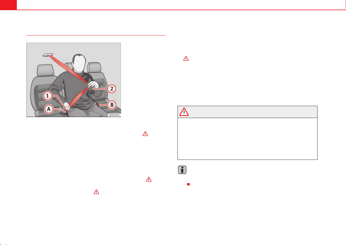
x Use latch plate of the belt fig. 12 to pull the seat belt down. Do not
twist the seat belt when doing so .
x Engage the latch plate in the buckle of the corresponding seat .
x Use the latch plate fig. 12 to pull the seat belt across your lap.
x Engage the latch plate in the buckle of the corresponding seat .
x Pull the belt to ensure that both latch plates are securely engaged in the
buckles.
Unfastening the seat belt
The seat belt must not be unfastened until the vehicle has come to a standstill
.
x Press the red button on the buckle fig. 12 . The latch plate is
released from the buckle.
x Press the red button on the buckle fig. 12 . The latch plate is
released from the buckle.
x Guide the belt back by hand so that it rolls up easily and the trim will not
be damaged.
WARNING
An incorrectly worn seat belt web can cause severe or fatal injuries in the
event of an accident.
x The seat belt cannot offer its full protection unless the backrests are in
an upright position and the seat belt is worn correctly, according to your
size.
x Unbuckling your seat belt while the vehicle is in motion can cause
severe or fatal injuries in the event of an accident or sudden braking.
Note
Seat belts with two buckles include a diagram to show how to fasten the seat
belt.
Fig. 12 Fasten the seat
belt on the centre seat in
the second row of seats.
A
1
A
1
A
A
A
2
A
2
A
B
A
A
A
B
Seat belts 25
Safety First Operating instructions Practical tips Technical Data
Seat belt position
Seat belts offer their maximum protection in the event of an accident and
reduce the risk of sustaining severe or fatal injuries only when they are prop-
erly positioned. Furthermore, if the webbing is correctly positioned, the seat
belt will hold the occupants in the optimum position to ensure the airbag
provides the utmost protection. The seat belt must therefore always be worn
and the webbing correctly positioned.
Incorrectly worn seat belts can cause severe or even fatal injuries page 10,
“Adjusting the seat position”.
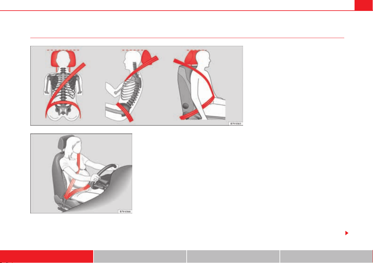
Correct seat belt position
x The shoulder part of the seat belt must lie on the centre of the shoulder,
never across the neck or the arm, under the arm or behind the shoulder.
x The lap part of the seat belt must lie across the pelvis, never across the
stomach.
x The seat belt must lie flat and fit comfortably. Pull the belt tight if neces-
sary to take up any slack.
In the case of pregnant women, the seat belt must lie evenly across the chest
and as low as possible over the pelvis, never across the stomach and must be
worn properly at all times during the pregnancy fig. 14.
Fig. 13 Correct belt web and head restraint positions.
Fig. 14 Correct posi-
tioning of seat belts
during pregnancy.
Seat belts26
Adapting the position of the belt webbing to your size
The seat belt can be adapted using the following equipment:
x Belt height adjustment for the front seats.
x Seat height adjustment (front seats).
WARNING
An incorrectly worn seat belt web can cause severe injuries in the event of
an accident or sudden braking or manoeuvre.
x The seat belt cannot provide optimum protection if it is not correctly
worn and the backrest is not tilted slightly backwards.
x The seat belt itself or a loose seat belt can cause severe injuries if the
belt moves from hard areas of the body to soft areas (e.g. the stomach).
x The shoulder part of the seat belt must lie on the centre of the shoulder,
never across the neck or the arm.
x The seat belt must lie flat and fit comfortably on the torso
x The lap part of the seat belt must lie across the pelvis, never across the
stomach. The seat belt must lie flat and fit comfortably on the pelvis Pull
the belt tight if necessary to take up any slack.
x For pregnant women, the lap part of the seat belt must lie as low as
possible over the pelvis and always lie flat, “surrounding” the stomach.
x Do not twist the seat belt while it is fastened.
x Never pull the seat belt away from your body using your hand.
x Do not lie the seat belt across rigid or fragile objects, e.g. glasses, pens
or keys.
x Never use seat belt clips, retaining rings or similar instruments to alter
the position of the belt webbing.
Note
If you physical constitution prevents you from maintaining the correct posi-
tion of the belt webbing, contact a qualified workshop for help with any
special devices to ensure the optimum protection of the seat belt and airbag.
SEAT recommends visiting a qualified workshop.
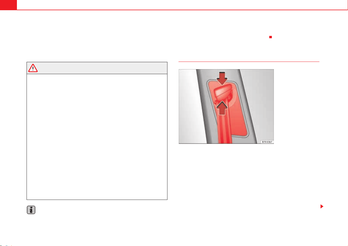
Belt height adjustment
Using the height adjusters for the front seats and the outer seats of the
second row, the position of the seat belts can be adjusted in the shoulder
area according to the height of the occupant:
x Keep the guide device pressed down in the direction of the arrow
fig. 15.
x Move the guide device up or down until the seat belt lies over the centre
of your shoulder page 25, “Seat belt position”.
x Release the guide device.
x Pull the belt sharply to check that the device is engaged securely.
Fig. 15 Next to the front
seats: belt height
adjuster.
Seat belts 27
Safety First Operating instructions Practical tips Technical Data
WARNING
Never adjust the belt height while the vehicle is in motion.
Seat belt tensioners
Automatic belt retainer, belt tension device, belt tension
limiter
Seat belts are part of the vehicle safety concept page 33 and consist of the
following important functions:
Automatic belt retainer
Every seat belt is equipped with an automatic belt retainer on the shoulder
belt. If the belt is pulled slowly or during normal driving, the system allows for
total freedom of movement on the shoulder belt. However, during sudden
braking, during travel in mountains or bends and during acceleration, the
automatic belt retainer on the seat belt is locked is pulled quickly.
Belt tension devices
The seat belts on the front seats and the outer seats of the second row are
equipped with belt tension devices.
Sensors will trigger the belt tension devices during severe head-on, lateral
and rear collisions and retract and tighten the seat belts. If the seat belt is
loose, it is retracted to reduce the forwards movement of occupants or move-
ment in the direction of the collision. The belt tension device works in combi-
nation with the airbag system. The belt tension device will not be triggered in
the event of the vehicle overturning if the side airbags are not deployed.
If the belt tension device is triggered, a fine dust is produced. This is normal
and it is not an indication of fire in the vehicle.
Belt tension limiter
The belt tension limiter reduces the force of the seat belt on the body in the
event of an accident.
Note
The relevant safety requirements must be observed when the vehicle or
components of the system are scrapped. A qualified workshop is familiar with
these requirements page 27.
Service and disposal of belt tension devices
If you work on the belt tension devices or remove and install other parts of the
vehicle when performing other repair work, the seat belt may be damaged.
The consequence may be that, in the event of an accident, the belt tension
devices function incorrectly or not at all.
So that the effectiveness of the belt tension device is not reduced and that
removed parts do not cause any injuries or environmental pollution, regula-
tions must be observed. These requirements are known to qualified dealer-
ships.
WARNING
Improper handling and homemade repairs of seat belts, automatic belt
retainers and tension devices increase the risk of sustaining severe or fatal
injuries. The belt tension device may fail to trigger or may trigger in the
wrong circumstances.
x Never attempt to repair, adjust or remove or install parts of the belt
tension devices or seat belts. Any work must be performed by a qualified
workshop only page 285.
x Belt tension devices and automatic belt retainers cannot be repaired
and must be replaced.

Seat belts28
For the sake of the environment
Airbag modules and belt tension devices may contain perchlorate. Observe
the legal requirements for their disposal.
Airbag system 29
Safety First Operating instructions Practical tips Technical Data
Airbag system
Brief introduction
Introduction
Front airbags have been installed for both driver and passenger. The front
airbags can also protect the chest and head of driver and passenger if the
seats, seat belts head restraints and, for the driver, the steering wheel are
correctly adjusted and used. Airbags are considered as additional safety
equipment. An airbag cannot replace the safety belt, which must be worn at
all times, even in front seats where front airbags have been installed.
Additional information and warnings:
x Driving tips page 7
x Correct sitting positions page 10
x Seat belts page 22
x Child seats (accessories) page 42
x Care and cleaning of the vehicle interior page 278
x Accessories, parts replacement, repairs and modifications page 285
x Notes for the user page 283
WARNING
Never exclusively trust the airbag system as a means of protection.
x Even when triggered, airbag protection is only auxiliary.
x The airbags provide the best protection when the seat belts are prop-
erly fastened, thus reducing the risk of sustaining injuries page 22,
“Seat belts”.
x Before each trip, every occupant must sit properly, correctly fasten the
seat belt belonging to his or her seat and keeping it fastened throughout
the trip. This rule is valid for all occupants.
WARNING
Occupants sitting in the front of the vehicle must never carry any objects in
the deployment space between them and the airbags, as this increases the
risk of sustaining injuries if the airbag is triggered. This modifies the
airbag deployment space or the objects may fly uncontrollably and hit your
body.
x Never carry objects in your hand or on your lap while the vehicle is in
motion.
x Never transport objects on the front passenger seat. In the event of
sudden braking and manoeuvres, the objects may end up in the airbag
deployment space and fly uncontrollably around the vehicle interior if the
airbag is activated.
x Occupants of the front and outer rear seats must never carry any other
people, pets or objects in the deployment space between them and the
airbags. Make sure children and other passengers also respect this recom-
mendation.
WARNING
The airbag system provides protection for one accident only. If they have
been deployed, they must be replaced.
WARNING (continued)
Airbag system30
x Ensure deployed airbags and the system components involved are
immediately replaced with new, SEAT-approved components for the
vehicle.
x Have any repairs or modifications carried out at a qualified workshop.
Qualified workshops have the necessary tools, diagnostics equipment,
repair information and qualified personnel.
x Never fit recycled or reused airbag components in your vehicle.
x Never modify the airbag system components.
WARNING
If the airbags are triggered, a fine dust is produced. This is normal and it is
not an indication of fire in the vehicle.
x This fine dust may irritate the skin and eyes and cause breathing diffi-
culties, particularly in people suffering from or who have suffered from
asthma or other illnesses of the respiratory tract. To reduce breathing diffi-
culties, get out of the vehicle and open and doors and windows to breath in
fresh air.
x Should you touch the dust, wash your hands and face using a mild soap
and water before you eat.
x Prevent the dust from affecting the eyes or open wounds.
x Rinse your eyes with water if you have dust in them.
WARNING
Solvents cause the surfaces of the airbag modules to become porous. If an
airbag is accidentally triggered, the detachment of plastic parts could
cause serious injury.
x Never clean the instrument panel and the surfaces of the airbag
modules with cleaners containing solvents.
WARNING (continued)
Airbag system 31
Safety First Operating instructions Practical tips Technical Data
Warning lamp
Several warning and control lamps should light up for a few seconds when
the ignition is switched. This signals that the lamp is working properly. They
will switch off after a few seconds.
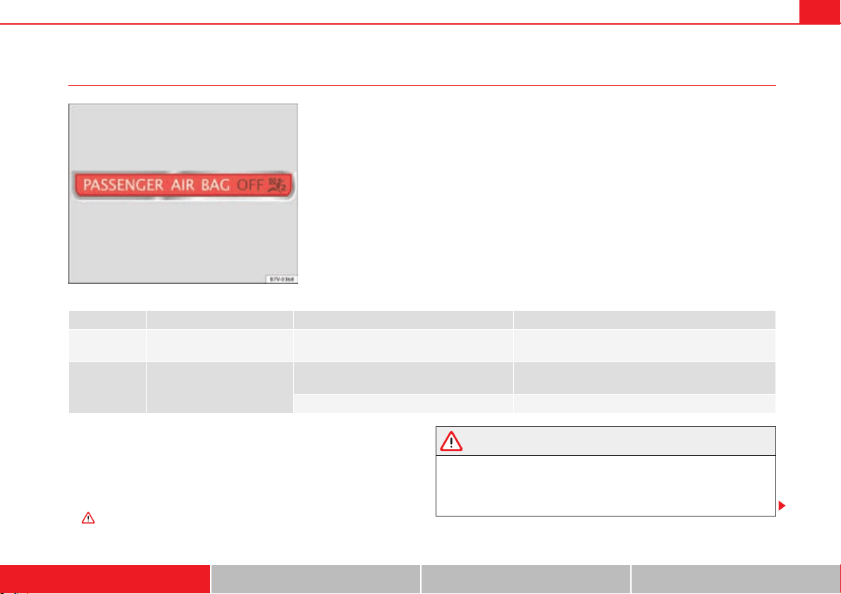
If the PASSENGER AIR BAG /&& warning lamp does not remain lit or if it is
lit together with the control lamp T on the instrument panel and the front
passenger airbag is disabled, there may be a fault in the airbag system
.
WARNING
In the event of a fault in the airbag system, the airbag may not trigger
correctly, may fail to trigger or may even trigger unexpectedly, leading to
severe or fatal injuries.
x Have the airbag system checked immediately by a specialist workshop.
Fig. 16 Warning lamp for
disabling the front
passenger airbag on the
instrument panel.
lights up Digit Possible cause Solution
T
Instrument panel Fault in airbag system and seat belt tensioners.
Have the system checked immediately by a specialist
workshop.
/&&
Dash panel
Fault in the airbag system.
Have the system checked immediately by a specialist
workshop.
Front passenger airbag disabled. Check whether the airbag should remain disabled.
Airbag system32
x Never mount a child seat in the front passenger seat or remove the
mounted child seat! The front passenger airbag may deploy during an acci-
dent in spite of the fault.
Caution
Always pay attention to any lit lamps and to the corresponding descriptions
and instructions to avoid damage to the vehicle.
WARNING (continued)

Airbag system 33
Safety First Operating instructions Practical tips Technical Data
Airbag system
Description and function of the airbag
The airbag can protect vehicle occupants in the event of an accidents, cush-
ioning the movement of the occupants in the direction of the collision in
frontal and side accidents.
Deployed airbags fill with a propellant gas. This causes the airbag covers to
break and the airbags to deploy extremely quickly in their entire deployment
space within fractions of a second. When an occupant with the seat belt prop-
erly fastened puts pressure on the inflated airbag, the propellant gas escapes
to absorb the force of the impact and slow the movement. This reduces the
risk of severe or fatal injuries. Airbag deployment does not mean that other
types of injury such as swelling, bruising, burns and skin injuries can be ruled
out.
Airbags do not protect the arms or the lower part of the body.
The most important factors for triggering the airbag are the type of accident,
the angle of impact, the vehicle speed and the characteristics of the object
the vehicle hits. Therefore, airbags are not triggered every time the vehicle is
visibly damaged.
The airbag system is designed to be triggered in collisions with a severe
impact. The front, curtain, side and knee airbags may be triggered under
special circumstances. The scope of any visible damage to the vehicle is not
an indication of airbag deployment.
Airbags act in conjunction with three-point seat belts in the event of certain
accidents, when the vehicle deceleration rate is severe enough to trigger the
airbags. Airbags only deploy once and only under certain circumstances. Seat
belts remain present to offer protection in situations where airbags are not
triggered or where they have already deployed. For example, when a vehicle
hits another after an initial collision or is hit by another vehicle.
The airbag system is an integral part of the car's passive safety system. The
airbag system can only work effectively when the occupants are wearing their
seat belts correctly and have adjusted the head restraints properly
page 10.
Vehicle safety components
The following safety equipment makes up the vehicle safety design to reduce
the risk of severe and fatal injuries. Depending on the vehicle equipment,
some equipment may not be fitted in the vehicle or may not be available in
some markets.
x Optimised seat belts for all seats.
x Belt tension devices for the driver and front passenger and, where appli-
cable, on the outer seats of the second row of seats in combination with the
side airbags.
x Furthermore, belt tension limiters for the driver's and front passenger's
seat belt.
x Belt height adjustment for the front seats and, where applicable, the
outer seats of the second row of seats.
x Seat belt warning lamp
x Frontal airbags for driver and passenger.
x Side airbags for the driver, front passenger and, where applicable, the
outer seats of the second row of seats.
x Left and right curtain airbags.
x One airbag for the driver's knees.
x Airbag control lamp T.
x PASSENGER AIR BAG /&& control lamp.
x Control units and sensors.
x Height-adjustable head restraint optimised for rear collisions.
x Adjustable steering column.
x Where applicable, mountings for child seats on the rear seats and on the
front passenger's seat.
Airbag system34
x Where applicable, mountings for the child seat upper retaining strap.
Situations in which the frontal, knee, side and curtain airbag does not
deploy:
x If the ignition is switched off during the collision.
x In frontal collisions when the deceleration measured by the control unit is
too low.
x In minor side collisions.
x In rear collisions.
x In the event of the vehicle overturning.
x When the impact speed is lower than the reference value set in the control
unit.
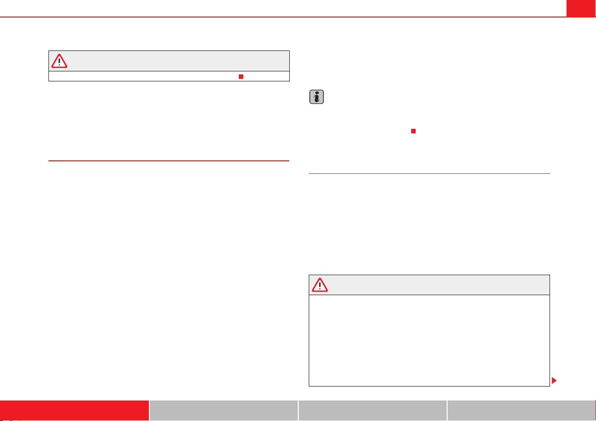
Front airbags
Fig. 17 Location and deployment area of the front airbag
for the driver.
Airbag system 35
Safety First Operating instructions Practical tips Technical Data
In conjunction with the seat belts, the front airbag system gives the front
occupants additional protection for the head and chest in the event of a
severe frontal collision. Always remains as far away as possible from the front
airbag. This way, the front airbags can completely deploy when triggered,
providing their maximum protection.
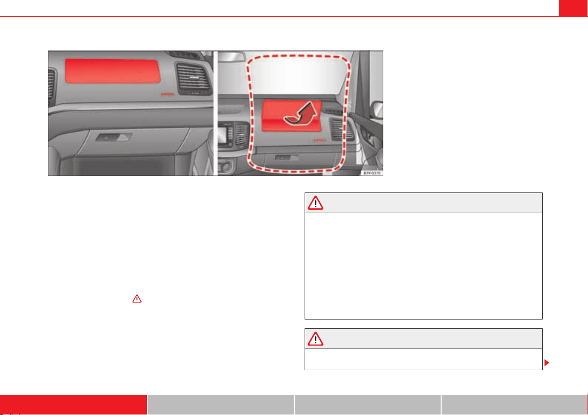
The front airbag for the driver is located in the steering wheel page 34,
fig. 17 and the airbag for the front passenger is located in the dash panel
fig. 18. Airbags are identified by the word “AIRBAG”.
When the front airbags are triggered they fill the zones marked in red (deploy-
ment area) page 34, fig. 17. Therefore, objects should never be placed or
mounted in these areas , Factory-fitted accessories are outside the
range of the front airbag for the driver and the front passenger, e.g. the base-
plate for the mobile phone support.
The airbag covers fold out of the steering wheel or dash panel when the driver
and front passenger airbags are triggered fig. 18. The airbag covers
remain connected to the steering wheel or the dash panel.
WARNING
The airbag is deployed at high speed in fractions of a second.
x Always keep the deployment areas of the front airbags free.
x Never secure objects to the covers or in the deployment area of the
airbag modules, e.g. cup holders or phone supports.
x The deployment space between the front passengers and the airbags
must not in any case be occupied by other passenger, pets and objects.
x Never fix any object to the windscreen above the front airbag on the
front passenger side.
x Do not alter, cover or stick anything to the steering wheel hub or the
surface of the airbag module on the passenger side of the dash panel.
WARNING
Front airbags are deployed in front of the steering wheel page 34, fig. 17
and the dash panel fig. 18.
Fig. 18 Location and deployment area of the front airbag
for the front passenger.
Airbag system36
x When driving, always hold the steering wheel on the outer edge of the
ring with both hands: 9 o'clock and 3 o'clock position.
x Adjust the driver seat so that there is at least 25 cm distance between
your chest and the hub of the steering wheel. If you physical constitution
prevents you from meeting these requirements, make sure you contact a
specialist workshop.
x Adjust the front passenger's seat so there is as much distance as
possible between the front passenger and the dash panel.
Types of front passenger airbag systems
There are two different SEAT front passenger airbag systems:
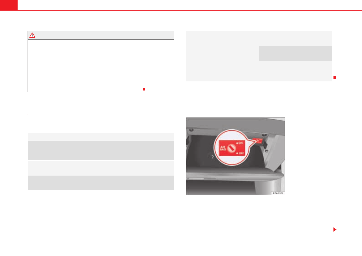
Deactivating and activating the front passenger airbag using
the key switch
The front passenger airbag must be disabled when a rear-facing child seat is
mounted.
Disabling the front passenger airbag
x Switch the ignition off.
A B
Characteristics of the front passen-
ger airbag that can only be disabled
in a specialist workshop.
Characteristics of the front passen-
ger airbag that can be disabled man-
ually page 36.
b Name: airbag system
b Name: airbag system with front
passenger airbag disabling.
b Warning lamp T on the instru-
ment panel.
b Warning lamp T on the instru-
ment panel.
WARNING (continued)
b Front passenger airbag located in
the dash panel.
b Front passenger airbag located in
the dash panel.
b PASSENGER AIR BAG /&& warn-
ing lamp on the instrument panel.
b Key switch in the glove compart-
ment on the front passenger side of
the dash panel.
Fig. 19 In the glove
compartment on the front
passenger side: key
switch for disabling and
enabling the front
passenger airbag.
Airbag system 37
Safety First Operating instructions Practical tips Technical Data
x Open glove compartment on the front passenger side.
x Unfold the key shaft page 78.
x Turn the key switch to OFF fig. 19 using the vehicle key.
x Close the glove compartment on the front passenger side.
x The PASSENGER AIR BAG /&& control lamp on the instrument panel will
remain lit while the ignition is switched on page 31.
Enabling the front passenger airbag
x Switch the ignition off.
x Open glove compartment on the front passenger side.
x Turn the key switch to ON page 36, fig. 19 using the vehicle key.
x Close the glove compartment on the front passenger side.
x Check that the PASSENGER AIR BAG OFF control lamp on the instru-
ment panel does not light up while the ignition is switched on page 31.
How to know whether the front passenger airbag is disabled
Disabling of the front passenger airbag is only indicated by the PASSENGER
AIR BAG /&& control lamp that remains lit on the instrument panel (/&&
remains yellow) page 31, “Warning lamp”.
If the PASSENGER AIR BAG /&& control lamp on the centre console does not
remain lit or is lit in combination with the control lamp T on the instrument
panel, a child restraint system cannot be mounted on the front passenger's
seat for safety reasons. The front passenger airbag may deploy during an
accident.
WARNING
The front passenger airbag must only be disconnected in special cases.
x Disconnect and connect the front passenger airbag when the ignition is
switched off to avoid damage to the airbag system.
x It is the driver's responsibility to ensure that the key operated switch is
set to the correct position.
x Only disconnect the front passenger airbag when a child seat is to be
mounted under exceptional circumstances.
x As soon as the child seat is no longer needed on the front passenger's
seat, reconnect the front passenger airbag.
WARNING (continued)
Airbag system38
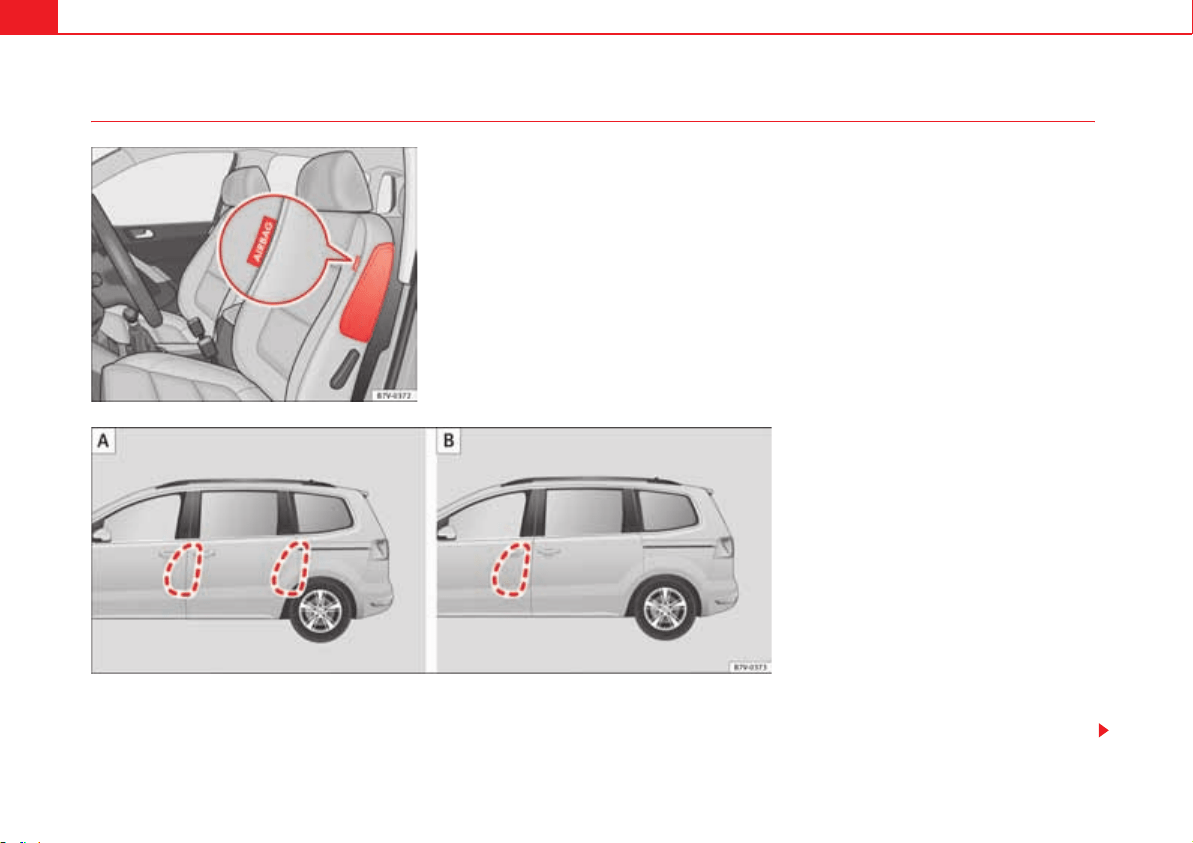
Side airbags
The side airbags are located in the outer cushion of the driver and front
passenger seat backrests page 38, fig. 20. Depending on the equipment
of the model, the outer seats of the second row of seats may also be fitted
with side airbags, located between the seat backrests and the access area.
Their position is indicated by the word “AIRBAG”. The red area (dotted line)
fig. 21 shows the field of action of the side airbags.
Fig. 20 On the side of the
front seat: location of the
side airbag.
Fig. 21 Range of action of the front and rear side
airbags. : with 5 and 7 seats; : with 6 seats.
A
A
A
B

Airbag system 39
Safety First Operating instructions Practical tips Technical Data
In a side collision, the side airbags are triggered on the affected side of the
vehicle, thus reducing the risk of injury to passengers on that side.
WARNING
The airbag is deployed at high speed in fractions of a second.
x Always keep the deployment areas of the side airbags free.
x Occupants of the front and outer rear seats must never carry any other
people, pets or objects in the deployment space between them and the
airbags.
x The built-in coat hooks should be used only for lightweight clothing. Do
not leave any heavy or sharp-edged objects in the pockets.
x Do not mount accessories on the doors.
x Only used protective covers for the seats that are approved for the
vehicle. Otherwise, the side airbag would be obstructed when deployed.
WARNING
Incorrect handling of the driver's and front passenger's seat could prevent
the side airbag from deploying properly and cause severe injuries.
x Never remove the front seats of the vehicle or modify any of their
components.
x Great forces must not be exerted on the backrest bolsters because the
side airbags might not deploy correctly, might not deploy at all or might
deploy unexpectedly.
x Any damage to the original seat upholstery or around the seams of the
side airbag units must be repaired immediately by a qualified workshop.
WARNING (continued)
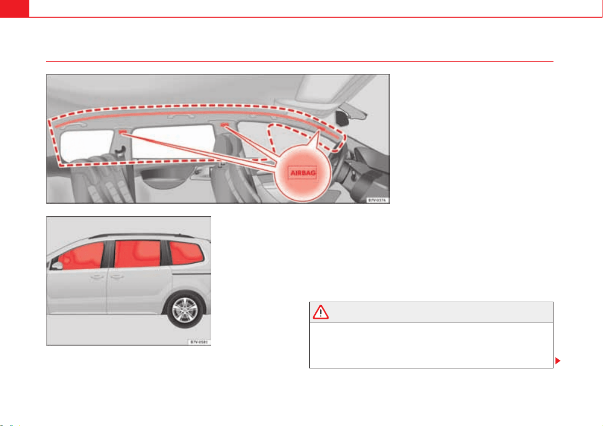
Airbag system40
Curtain airbags
The curtain airbags are located on the driver and front passenger side above
the doors fig. 22. Airbags are identified by the word “AIRBAG”.
The area framed red fig. 22 is covered by the curtain airbag when it is
deployed (deployment area). Therefore, objects should never be placed or
mounted in these areas.
In a side collision, the curtain airbag on the side affected will be deployed.
The airbag covers the windows and pillars.
In a side collision, the curtain airbags for the front and outer rear seats reduce
the risk of injury to the areas of the body facing the impact.
WARNING
The airbag is deployed at high speed in fractions of a second.
x Always keep the deployment areas of the curtain airbags free.
x Do not fix objects to the cover or in the deployment area of the curtain
airbag.
Fig. 22 On the left side of the vehicle: location and
deployment area of the curtain airbag.
Fig. 23 Deployed curtain
airbags
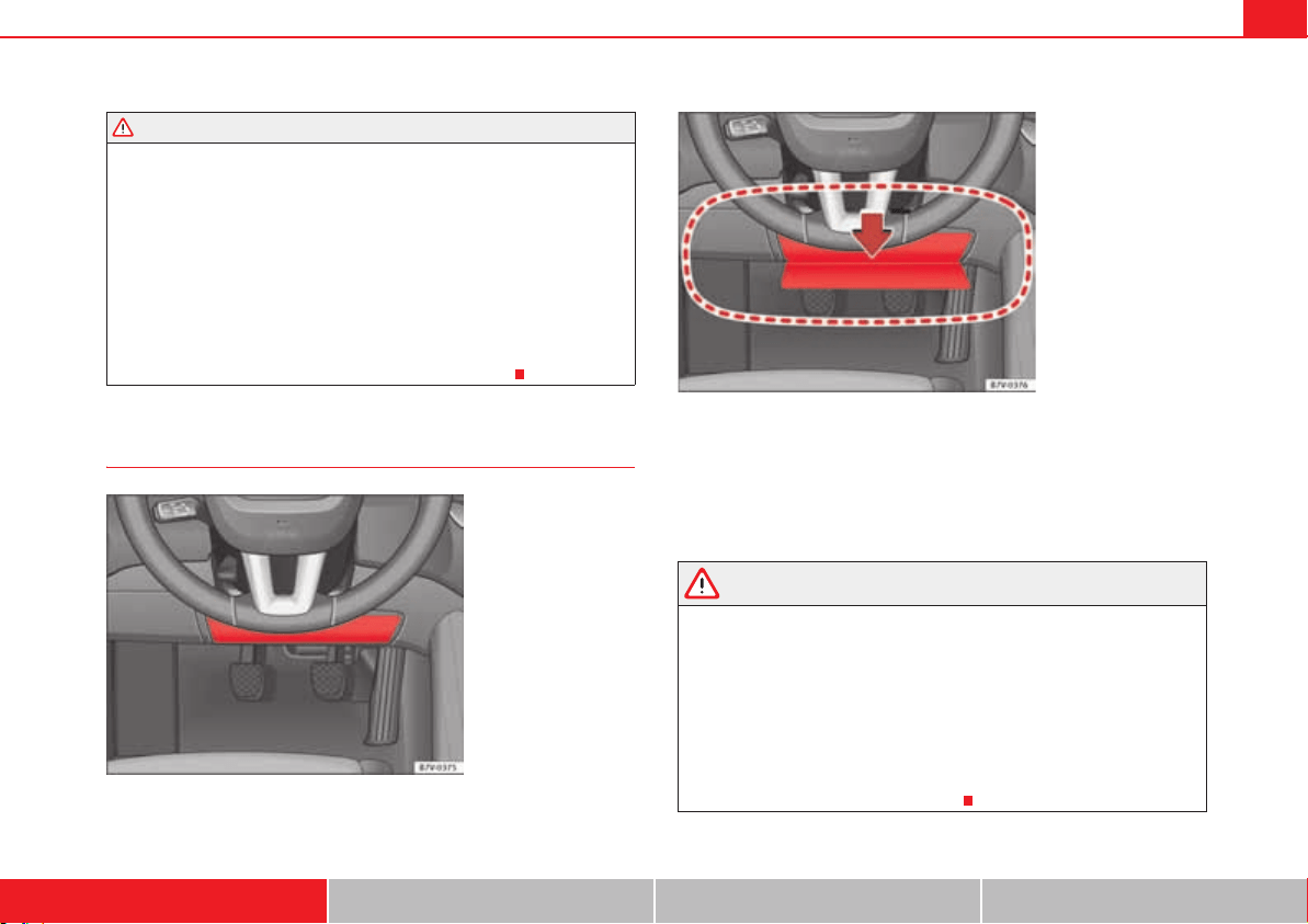
Airbag system 41
Safety First Operating instructions Practical tips Technical Data
x Occupants of the front and outer rear seats must never carry any other
people, pets or objects in the deployment space between them and the
airbags.
x The built-in coat hooks should be used only for lightweight clothing. Do
not leave any heavy or sharp-edged objects in the pockets.
x Do not mount accessories on the doors.
x Do not fit curtains to the windows other than those expressly approved
for use in the vehicle.
x Only turn the sun blinds towards the windows if there is no object, e.g.
pens or garage remote controls, secured to the sun blind.
Kneed airbags
The knee airbag is located on the driver side below the instrument panel
fig. 24. Airbags are identified by the word “AIRBAG”.
The area framed red fig. 25 is covered by the knee airbag when it is
deployed (deployment area). Therefore, objects should never be placed or
mounted in these areas.
WARNING
The airbag is deployed at high speed in fractions of a second.
x The knee airbag is deployed in front of the driver's knees. Always keep
the deployment areas of the knee airbags free.
x Never not fix objects to the cover or in the deployment area of the knee
airbag.
x Adjust the driver's seat so that there is a distance of at least 10 cm (4
inches) between your knees and the location of the knee airbag. If you
physical constitution prevents you from meeting these requirements, make
sure you contact a specialist workshop.
WARNING (continued)
Fig. 24 On the driver
side: location of the knee
airbag.
Fig. 25 On the driver
side: Radius of action of
the knee airbag.
A
A
Child safety42
Child safety
Child seats (accessories)
Introduction
Please read the information regarding the airbag system fully before trans-
porting babies and children in a child seat or other child restraint system
installed on the front passenger seat.
This information is extremely important for driver and passenger safety,
particularly that of babies and children.
SEAT recommends the use of child seats from the SEAT accessory
programme. These child seats have been designed and tested for use in SEAT
vehicles. You can purchase child seats with different mountings from a qual-
ified workshop.
Using child restraint systems with a base or foot
Some child retention systems are secured to the seat using a base or foot. For
certain equipment the use of an additional accessory will be necessary (for
example, the accessory for the floor compartment) to fit the child retention
system correctly and securely.
Additional information and warnings:
x Airbag system page 33
x Integrated child seats page 52
WARNING
Make sure children are properly belted in and correctly secured to avoid
severe or fatal injuries while the vehicle is in motion.
x Never use a rear-facing child seat in the front passenger seat if the front
passenger airbag is enabled.
x You should always transport all children up to 12 years of age on the
rear seat.
x Children must always be protected with an approved child restraint
system suited to their height and weight.
x Children must assume the proper sitting position and be properly
belted in while travelling.
x Ensure the backrest of a seat is upright when a child seat is being used
on it.
x Do not allow the child's head or other part of his or her body to fall into
the deployment area of the side airbags.
x Make sure the belt webbing is correctly positioned.
x Never hold children or babies on your lap or in your arms.
x Only one child may occupy a child seat.
x If you are using a child seat with a base or foot, always install this base
or foot correctly and safely.
x If the vehicle has a storage compartment in the foot well in front of the
last row of seats, this compartment cannot be used as designed; on the
contrary: It must be filled using the specially designed accessory so that
the base or foot is correctly supported by the closed compartment and the
child seat is secured properly. If this compartment is not suitably secured
when using a child seat with a base or foot then the compartment cover
could rupture in an accident and the child will be ejected and suffer serious
injury.
x Please read and observe the child seat manufacturer's handling
instructions.
WARNING (continued)
Child safety 43
Safety First Operating instructions Practical tips Technical Data
WARNING
An empty or loose child seat could fly uncontrollably around the vehicle
interior and cause injuries in the event of an accident or sudden braking.
x When not in use while the vehicle is in motion, always safely secure it
or store it in the luggage compartment.
Note
Replace the child seat after an accident, as it may have invisible damage.

Child safety44
General information on transporting children in the vehicle
Legal regulations and provisions will always take priority over the descrip-
tions of this instruction manual. There are different regulations and provi-
sions for the use of child seats and their mountings ( table on page 45). In
some countries, for example, the use of child seats on certain seats in the
vehicle may be forbidden.
The physical principles and the forces acting on the vehicle in the event of a
collision or other type of accidents also apply to children page 22.
However, unlike adults and youngsters, children do not have fully developed
muscle and bone structures. In the event of an accident, children are subject
to a greater risk than adults of sustaining severe injuries.
Given that children's bodies are not yet fully developed, child restraint
systems must be used that are especially adapted to their height, weight and
constitution. There are laws in force in many countries that determine the use
of approved seat systems for transporting babies and children.
Only used authorised, approved child seats that are suitable for the vehicle.
Always consult with a SEAT qualified workshop or a specialist workshop
should you have any doubts.
Checklist
To transport children in the vehicle :
x Observe the legal requirements specific to each country.
x For safety reasons, SEAT recommends that children under 12 years of age
are transported on the rear seats.
x Only if you have no alternative should a child travel on the front passenger
seat page 46. The safest place in the vehicle is on the rear seat behind the
front passenger seat.
x Child must always use a child restraint system when travelling in the
vehicle. The child restraint system must be suitable for the height, weight and
constitution of the child.
x Only one child may occupy a child seat.
x Follow the user instructions from the child seat manufacturer and always
keep them in the vehicle.
x If the child seat is secured using the seat belt, guide the seat belt through
or around the child seat according to the instructions of the child seat manu-
facturer.
x Make sure the belt webbing is correctly positioned and that the child is
sitting properly.
x The child seat should be installed on the rear seat behind the front
passenger seat so that the child can exit the car on the kerb side.
x Do not leave toys or other loose objects on the child seat or on the seat
while the vehicle is in motion.
Specific child seat regulations for each country (selection)
Regulation Further information
ECE-R 44
a)
a)
ECE-R: Economic Commission for Europe Regulation.
Technical Service or qualified work-
shop
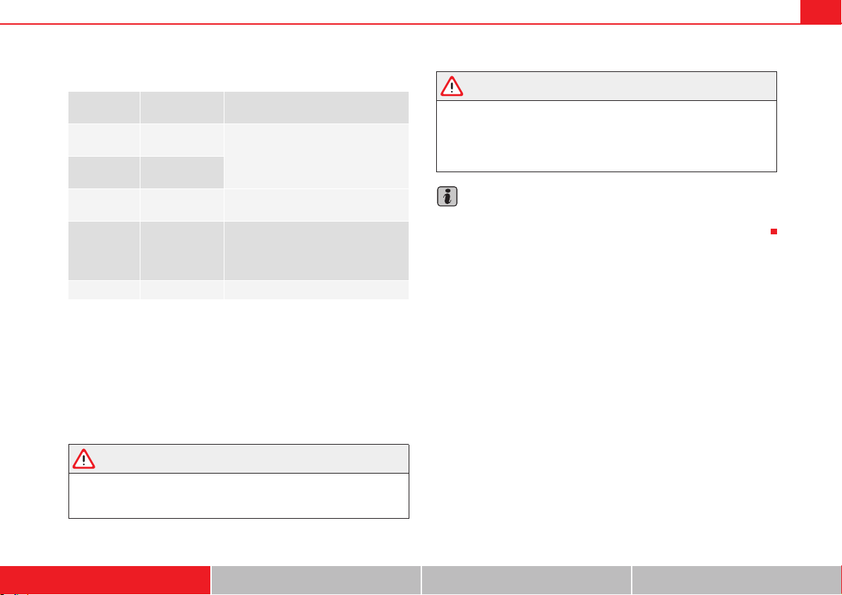
Child safety 45
Safety First Operating instructions Practical tips Technical Data
Categorisation of child seats according to ECE-R 44
Not all children fit in the seat of their weight group. Nor do all seats adapt to
the vehicle. Therefore, always check whether the child fits properly in the
child seat and whether the seat can be installed safely in the vehicle.
The rear seats are suitable for child seats with the ISOFIX system specially
designed for this type of vehicle in accordance with regulation ECE-R 44.
Child seats approved under the ECE-R 44 regulation are fitted with the corre-
sponding approval symbol. The sign is an upper-case E in a circle with the
identification number below it.
WARNING
Not following the checklist prepared for your own safety could lead to acci-
dents and severe injuries.
x Always follow the check list and perform the necessary operations.
WARNING
In general, the rear seat is always the safest place for correctly belted in
children in the event of an accident.
x A suitable child seat that is correctly installed and used on one of the
rear seats offer the most protection possible for babies and small children
in most accidents.
Note
Other accessories may be required to fit the child retention system with a
base or foot security and safely. Contact a specialist or qualified workshop.
Weight cate-
gory
Weight of the
child
Installation of the child seat
Group 0
children up to
10 kg
Rear-facing. On rear seats, optionally
using the ISOFIX system.
Group 0+
children up to
13 kg
Group 1 9 to 18 kg
Forward-facing. On rear seats, option-
ally using the ISOFIX system.
Group 2 15 to 25 kg
Forward-facing. On the outer rear seats
or in the centre seat of the second row
of seats and on all seats in the third
row. Optionally with ISOFIX system.
Group 3 22 to 36 kg Forward-facing.
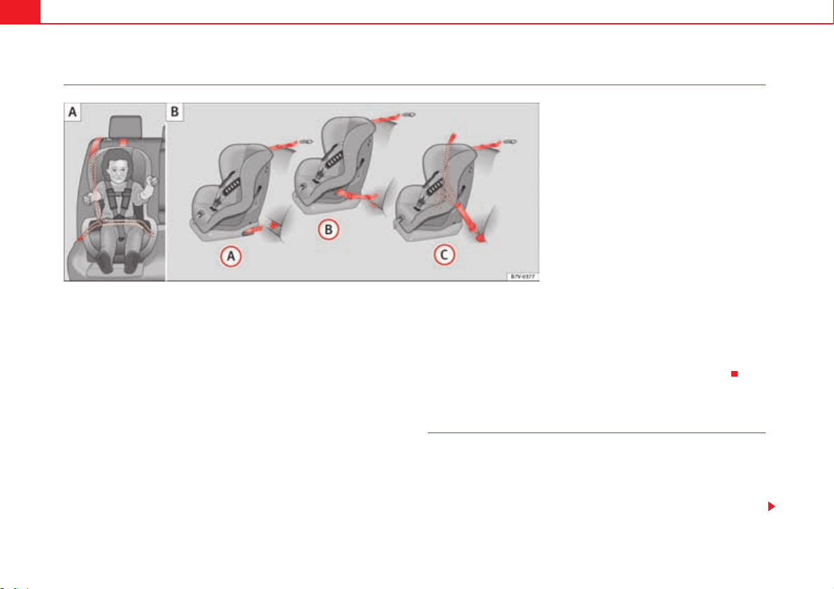
Child safety46
Different mounting systems
Always secure child seats properly and safely in the vehicle according to the
child seat manufacturer's installation instructions.
Mounted child seats must rest correctly on the vehicle's seat and must not
move or rock more than 2.5 cm (1 inch).
Child seats equipped for a Top Tether strap must also be secured using the
Top Tether retaining strap in the vehicle page 50. Only secure the retaining
belt to the rings fitted for this purpose and identified as Top Tether. Not all
rings can be used with the Top Tether system. Always tighten the Top Tether
retaining strap so that the child seat fits snugly against the corresponding
seat in the vehicle.
Specific mounting systems for each country
Europe: ISOFIX retaining rings and upper retaining strap page 49 and
page 50.
Retaining rings and upper retaining strap:
USA: LATCH (Lower Anchors and Tethers for CHildren)
Canada: lower universal anchorages
page 49.
Three-point seat belt and upper retaining strap page 48.
The systems include the child restraint system mounting with an upper
retaining strap (Top Tether) and lower anchoring points on the seat.
Use of the child seat on the front passenger seat
Transporting children on the front passenger seat is not permitted in all coun-
tries. Furthermore, not all child seats are approved for use on the front
passenger seat. Your SEAT qualified workshop has an updated list of all
approved child seats. Only used child seats that are approved for each
vehicle.
Fig. 26 On the rear seats: Figures and show the
basic child restraint system mounting using lower
retaining rings and the upper retaining strap. Figure
shows the child restraint system mounting using the
vehicle's seat belt.
A
A
A
B
A
C
A
A
A
B
A
C
Child safety 47
Safety First Operating instructions Practical tips Technical Data
The frontal airbag on the front passenger side is highly dangerous for a child.
The front passenger seat is life-threatening to a child if he or she is trans-
ported in a rear-facing child seat.
If a rear-facing child seat is secured to the front passenger seat, an inflating
airbag can strike it with such great force that severe or fatal injuries may result
. Therefore, rear-facing child seats must never be used on the front
passenger seat when the front passenger airbag is enabled.
Only use a rear-facing child seat on the front passenger seat if the front
passenger airbag is disabled. When it is disabled, the yellow PASSENGER AIR
BAG /&& control lamp on the instrument panel will be lit page 33. If you
cannot disable the front passenger airbag and it remains enabled, it is
forbidden to transport children on the front passenger seat .
Things to note if using a child seat on the front passenger seat:
x The front passenger airbag must be disabled page 36 if using a
rear-facing child seat.
x The backrest of the front passenger seat must be upright.
x The front passenger seat must be moved as far back as possible.
x The backrest of the front passenger seat must be upright.
x The seat belt height adjustment must be as high as possible.
Suitable child seats
The child seat must be authorised by the manufacturer especially for use on
a front passenger seat with a frontal or side airbag.
If the front passenger seat is equipped with retaining rings, the child seat can
be secured using the approved retaining system provided it is approved for
this type of vehicle in accordance with current regulations in the country in
question.
Universal seats for children in groups 0, 0+, 1, 2 or 3 according to the ECE-R
44 regulation.
WARNING
If a child seat is mounted on the front passenger seat, the risk of the child
sustaining severe or fatal injuries in the event of an accident increases.
Rear-facing child seats must never be mounted on the front passenger seat
when the front passenger airbag is enabled. This is life-threatening to the
child should the frontal airbag deploy, as the child seat would be struck by
the inflated airbag and thrown against the backrest.
WARNING
If, in exceptional circumstances, a child must be transported in a rear-
facing child seat on the front passenger seat, strictly observe the
following:
x Always disable the front passenger airbag and leave it disabled.
x The child seat must be approved by the manufacturer for use on a front
passenger seat with frontal and side airbag.
x Follow the installation instructions of the child seat manufacturer and
observe the warnings.
x Move the front passenger seat as far back as possible and adjust it to
its highest position to keep as far away as possible from the frontal airbag.
x Move the backrest to the upright position.
x The seat belt height adjustment must be as high as possible.
x Children must always be protected with an approved child restraint
system suited to their height and weight.
Use of the child seat on the rear seat
If a child seat is mounted on the rear seat, adapt the position of the front
passenger seat so that the child has enough space. Therefore, adapt the front

Child safety48
passenger seat to the size of the child seat and the height of the child. Ensure
the passenger is in the correct position page 10.
Move the second and third row of seats fully back and lock them. Place the
seat backs in a vertical position and fold the armrests down.
ISOFIX child seats approved for rear seats
The rear seats are suitable for child seats with the ISOFIX system specially
designed for this type of vehicle in accordance with regulation ECE-R 44.
ISOFIX child seats are divided into “specific categories for the vehicle”,
“limited” or “semi-universal”.
Child seat manufacturers supply a list of vehicles with each ISOFIX seat,
which includes the models for which the ISOFIX child seat in question is
approved. If the vehicle is included in the manufacturer's list and the ISOFIX
child seat belongs to a seat category included in the list, then it can be used
in your vehicle. If necessary, contact the child seat manufacturer for an
updated list of vehicles.
WARNING
If child seats are fitted to all the seats in the second row then it is possible
that the seats of this row cannot be folded down from the third row of seats
in case of an accident. In case of an emergency, passengers in the third row
of seats will not be able to leave the vehicle or to help themselves.
x Child seats should not occupy all the seats of the second row if other
passengers are to occupy the third row of seats.
Securing child seats with the seat belt
Securing the child seat using the seat belt
x Please read and observe the child seat manufacturer's handling instruc-
tions.
x Positioning the child seat on the seat according to the manufacturer's
instructions.
x The seat belt height adjustment must be as high as possible.
Group (weight
category)
ISOFIX child seat
category
Seat position on the
rear seats
Group 0: chil-
dren up to 10 kg
E
IUF
a)
Group 0+: chil-
dren up to 13 kg
E
IUF
a)
D
IUF
a)
C
IUF
a)
Group 1: 9 to 18
kg
D
IUF
a)
C
IUF
a)
B
IUF
a)
B1
IUF
a)
A
IUF
a)
a)
IUF: suitable for “universal” ISOFIX child seats authorised for use in this group.
Group (weight
category)
ISOFIX child seat
category
Seat position on the
rear seats
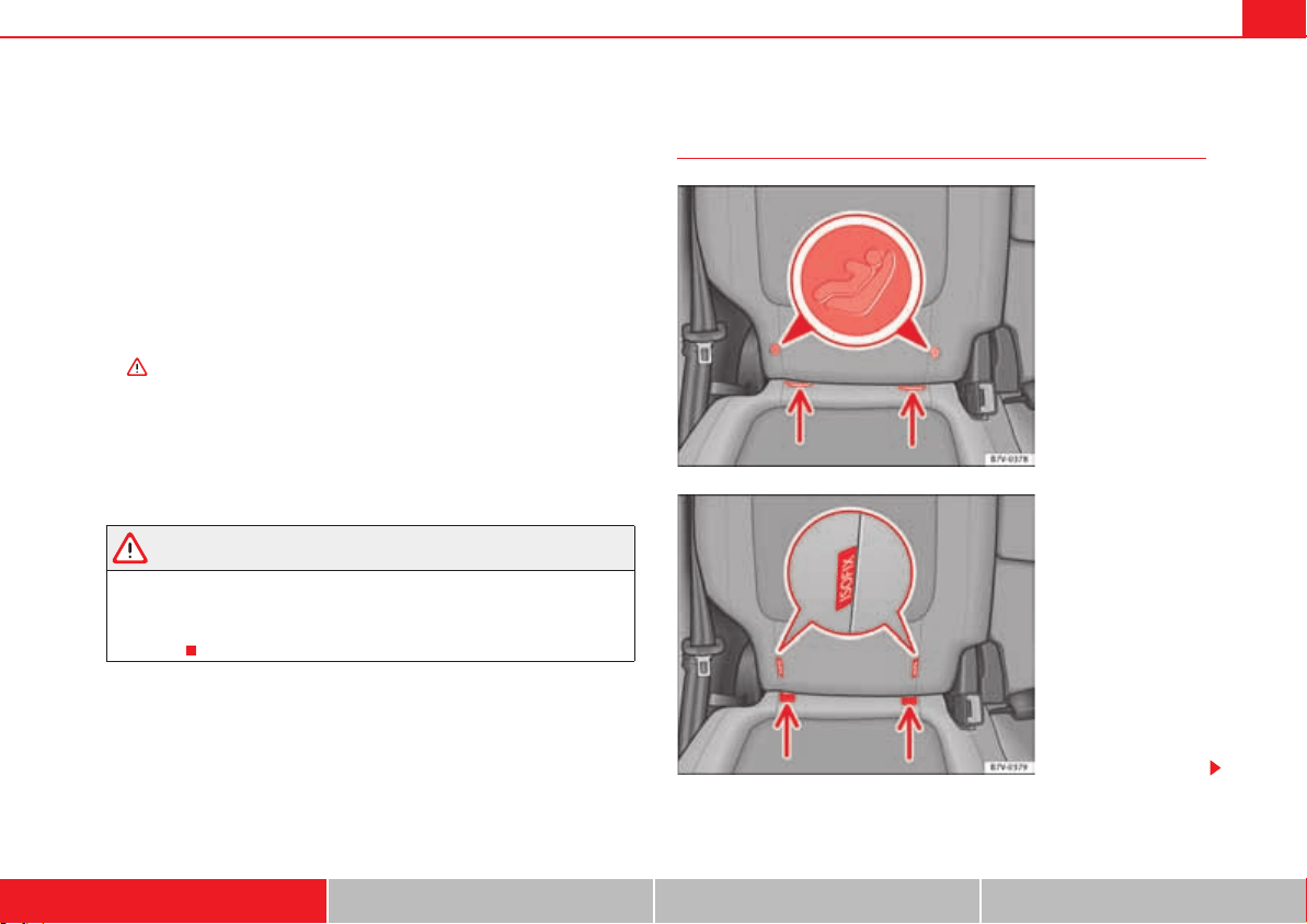
Child safety 49
Safety First Operating instructions Practical tips Technical Data
x Fasten the seat belt or pass it around the child seat structure in the
manner described in the manufacturer's instructions.
x Make sure the seat belt is not twisted.
x Insert the latch plate into the buckle for the appropriate seat and push it
down until it is securely locked with an audible click.
x Ensure that the upper belt web lies tightly on the child seat.
x Pull the belt (it must be no longer possible to pull the lower belt webbing
out).
Removing the child seat
The seat belt must not be unfastened until the vehicle has come to a standstill
.
x Press the red button on the buckle. The latch plate is released from the
buckle.
x Guide the belt back by hand so that it rolls up easily and the trim will not
be damaged.
x Remove the child seat from the vehicle.
WARNING
Unbuckling the seat belt while the vehicle is in motion can cause severe or
fatal injuries in the event of an accident or sudden braking.
x The seat belt must not be unfastened until the vehicle has come to a
standstill.
Securing the child seat using the lower anchor points
(ISOFIX, LATCH*)
Fig. 27 Version 1: identi-
fication of the anchor
points for the child seat
on the vehicle seat.
Fig. 28 Version 2: identi-
fication of the anchor
points for the child seat
on the vehicle seat.
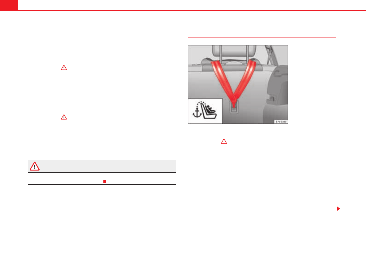
Child safety50
There are two retaining rings, the so-called lower anchor points, on each rear
seat or, where applicable, on the front passenger seat. The retaining rings are
attached to the seat frames.
Child seats with rigid mounting
x Observe the manufacturer's instructions when installing and removing
the child seat .
x Press the child seat onto the retaining rings page 49, fig. 27 or
page 49, fig. 28 in the direction of the arrow. The child seat must be safely
engaged and click audibly into place.
x Pull on both sides of the child seat to ensure that it is secure.
Child seat with adjustable retaining straps
x Observe the manufacturer's instructions when installing and removing
the child seat .
x Place the child seat on the seat cushion and attach the retaining strap
hooks to the retaining rings page 49, fig. 27 or page 49, fig. 28.
x Tighten the straps evenly using the corresponding adjustment device.
The child seat must sit flush against the vehicle seat.
x Pull on both sides of the child seat to ensure that it is secure.
WARNING
The lower anchor points for child seats do not include rings. Only secure
booster seats to lower anchor points.
Securing a child seat using a Top Tether retaining strap
x Observe the manufacturer's instructions when installing and removing
the child seat .
x Raise the head restraint behind the child seat until it engages.
x Secure the child seat to the lower anchor points page 49.
x Pull the upper child seat retaining strap back to the backrest of the rear
seat, below or on both sides of the head restraint (depending on the child
seat model).
x Hook the upper retaining strap to the corresponding retaining ring (for
TOP TETHER) on the back of the backrest on the rear seat fig. 29.
x Push the head restraint down as far as it will go. Ensure that it does not
interfere with the seatbelt from the upper attachment.
x Tighten the strap so that the top of the child seat rests on the backrest.
Fig. 29 Upper retaining
strap hooked in the
luggage compartment

Child safety 51
Safety First Operating instructions Practical tips Technical Data
WARNING
Child seats with lower anchor points and with an upper retaining strap
must be installed in line with the manufacturer's instructions. Failure to
comply could result in severe injuries.
x Always secure just one retaining strap from a child seat to a retaining
ring (for TOP TETHER) on backrest on the rear seat in the luggage compart-
ment.
x Never secure a child seat to the retaining rings.
x Never secure a child seat to the movable attachment elements for vehi-
cles with an attachment element and rail system.
Child safety52
Integrated child seat
Introduction
The integrated child seat is only suitable for children in Group 2 (15-25 kg)
and Group 3 (22-36 kg), according to the ECE-R 44 regulation.
Additional information and warnings:
x Seat belts page 22
WARNING
Child travelling without their seat belt fastened or not secured using a suit-
able restraint system may sustain fatal injuries if the airbag is deployed.
x You should always transport all children up to 12 years of age on the
rear seat.
x Always disable the front passenger airbag if, in exceptional cases, you
have no alternative but to transport a child in a rear-facing child safety seat
on the front passenger seat.
x Children must always be protected with a child restraint system suited
to their height and weight.
x Always fasten children's seat belts correctly.
WARNING
Children must travel in a child seat appropriate to their weight and height
while the vehicle is in motion.
x Children must always be protected with a child restraint system suited
to their height and weight.
x Children must assume the proper sitting position and be properly
belted in while travelling.
x The shoulder part of the seat belt must lie approximately on the centre
of the shoulder, never across the neck or the arm.
x The seat belt must lie close to the upper part of the body.
x The lap belt part must lie across the pelvis, not across the stomach, and
always fit closely.
x Allow the belt to retract until it fits tightly over the child's seat.
x Never hold children or babies on your lap.
x Always use a child seat and the seat belt for children who are less than
1.5 metres tall. The normal seat belt could cause injuries to the abdominal
and neck areas.
x Only one child may occupy a child seat.
x Read and follow the information and warnings provided by the child
seat manufacturer.
x Never leave an unsupervised child alone on a child seat or in the
vehicle.
x All modifications to the integrated child seat must be carried out by a
specialist workshop.
x Replace the child seat or any seat components damaged or involved in
an accident.
WARNING
Loose objects could fly uncontrollably around the vehicle interior and
cause injuries in the event of an accident or sudden braking.
x Do not leave toys or other hard, loose objects on the child seat or on the
seat while the vehicle is in motion.
WARNING (continued)
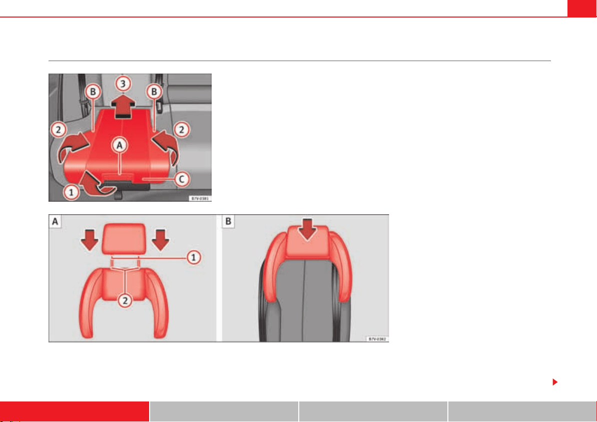
Child safety 53
Safety First Operating instructions Practical tips Technical Data
Unfolding the integrated child seat
The integrated child seat can be fitted with a side head restraint. SEAT recom-
mends use of the integrated child seat with the side head restraint fitted and
also that this seat be used only for children above the age of 3.
Lifting the cushion
x Pull the unlock lever fig. 30 on the cushion in the direction of the
arrow fig. 30 .
Fig. 30 Integrated child
seats. lift up the cushion.
Fig. 31 Integrated child seats. position the head
restraint over the side head restraint and fit into place
.
A
A
A
B
A
A
A
1
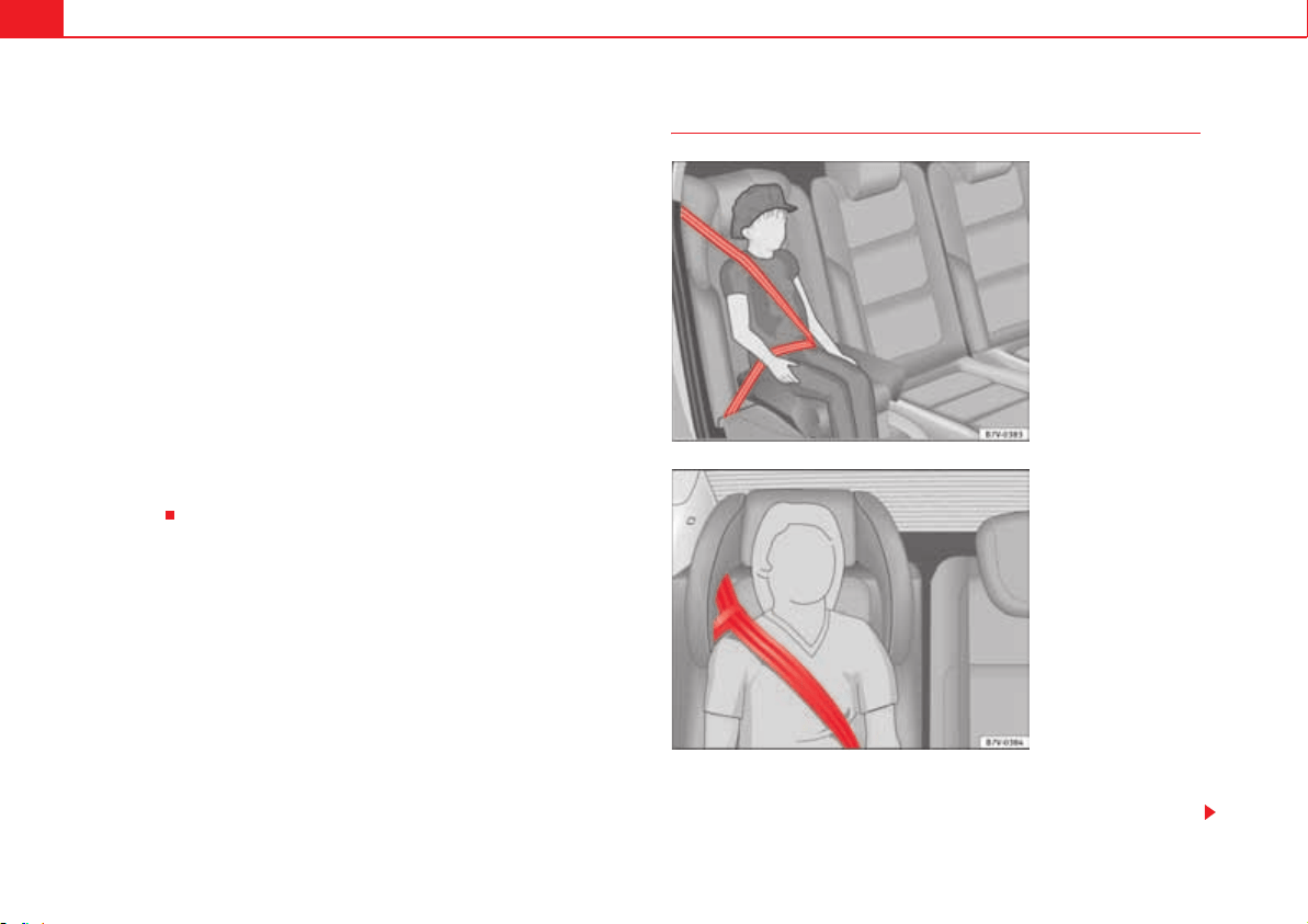
Child safety54
x Fold both sides page 53, fig. 30 up in the direction of the arrow
page 53, fig. 30 .
x Push the cushion page 53, fig. 30 back in the direction of the arrow
page 53, fig. 30 until it engages.
Fitting the side head restraint
x Fold the backrest of the rear seat forwards page 137.
x Remove the head restraint.
x Make sure the belt guide handle on the window side is on the side head
restraint page 54.
x Insert the guide rods page 53, fig. 31 of the head restraint into the
guides on the side head restraint page 53, fig. 31 .
x Insert the head restraint and the side head restraint into the guides on the
corresponding backrest page 53, fig. 31 .
x Push the head restraint down as far as it will go.
x Fold the backrest of the rear seat back.
x Pull the rear seat and the backrest to check whether they are engaged
properly.
Seat belt routing on the integrated child seat
Using the guide handle fig. 33, position the seat belt so that the shoulder
part of the belt lies on the centre of the child's shoulder.
A
B
A
2
A
C
A
3
A
1
A
2
A
B
Fig. 32 Integrated child
seats. Adjusting the belt
webbing.
Fig. 33 Integrated child
seats. seat belt routing
with guide handle.
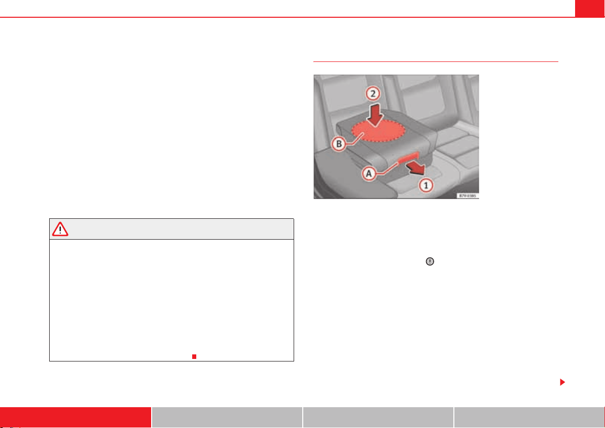
Child safety 55
Safety First Operating instructions Practical tips Technical Data
Seat belt guide handle
x Secure the seat belt guide handle to the side head restraint on the
window side. The guide handle is secured by a button.
x Open the upper button on the seat belt guide handle and pass the belt
webbing below the side head restraint and through the guide handle.
x Close the button again.
Adjusting the belt routing
x Guide the automatic three-point seat belt below the side head restraint.
x Pull the latch plate and slowly place the belt webbing across the child's
chest and lap.
x Insert the latch plate into the buckle for the appropriate seat and push it
down until it is securely locked with an audible click.
x Pull the belt to ensure that the latch plate is securely engaged in the
buckle.
WARNING
The seat belt only offers maximum protection from severe or fatal injuries
when it is correctly positioned.
x Children must assume the proper sitting position and be properly
belted in while travelling.
x The shoulder belt must be positioned against the middle of the
shoulder.
x The seat belt must lie flat and fit comfortably.
x Allow the belt to retract until it fits tightly over the child's seat.
x The lap part of the seat belt must lie across the pelvis, never across the
stomach.
x Only one child may occupy a child seat.
Removing the seat belt
Lowering the cushion
x Pull the unlock lever fig. 34 on the cushion in the direction of the
arrow .
x Push the cushion down through the central area in the direction of the
arrow until it safely engages . The side supports fold away automat-
ically.
Removing the side head restraint
x Open the seat belt guide handle.
x Guide the seat belt by hand to pull the belt back in more easily and not
damage the trim.
x Push the head restraint up as far as it will go.
x Fold the backrest of the rear seat forwards page 137.
x Remove the head restraint along with the side head restraint.
x Remove the head restraint and side head restraint by pulling on it.
x Fitting the head restraint.
Fig. 34 Integrated child
seats. lowering the
cushion.
A
A
A
1
A
B
A
2

Child safety56
Caution
When lowering the integrated child seat, only press on the centre of the
cushion page 55, fig. 34 . Otherwise the cushion could bend and not
engage properly.
A
2

57
Safety First Operating instructions Practical tips Technical Data
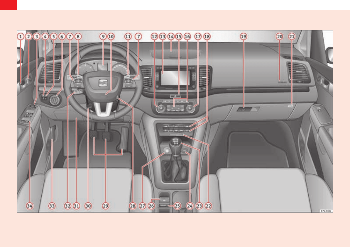
58
Fig. 35 Dash panel

Cockpit 59
Safety First Operating instructions Practical tips Technical Data
Operating instructions
Cockpit
Overview
Overview of the dash panel
This overview will help you to familiarise yourself with the
controls and displays.
Door release lever . . . . . . . . . . . . . . . . . . . . . . . . . . . . . . . . . . .
Central locking button 0 1 . . . . . . . . . . . . . . . . . . . . . . . . . . .
Switch for adjusting the exterior mirrors . . . . . . . . . . . . . . . . .
Exterior mirror adjustment , 2
Heated exterior mirrors ?
Folding exterior mirrors #
Instrument panel controls and lighting control . . . . . . . . .
Headlamp range adjustment . . . . . . . . . . . . . . . . . . . . . . . .
Light switch . . . . . . . . . . . . . . . . . . . . . . . . . . . . . . . . . . . . . .
Light off --
Automatic headlight control -!54/-
Side/dipped lights
Fog lights
Controls on the multi-function steering wheel . . . . . . . . . . . .
Volume control for radio, navigation system and phone
conversations & – '
Radio mute or voice control activation
Activate telephone main menu or accept an incoming
call -
SEAT information system control buttons , , OK, E
Lever for . . . . . . . . . . . . . . . . . . . . . . . . . . . . . . . . . . . . . . . . . . .
Main beam headlights
Headlight flasher
Turn signals
Parking lights
Instrument panel:
Instruments . . . . . . . . . . . . . . . . . . . . . . . . . . . . . . . . . . . . . .
Digital display . . . . . . . . . . . . . . . . . . . . . . . . . . . . . . . . . . . .
Indicator lamps . . . . . . . . . . . . . . . . . . . . . . . . . . . . . . . . . . .
Horn (works only when the ignition is on)/Front driver airbag
Windscreen wiper/ windscreen wash lever . . . . . . . . . . . . . . .
Windscreen wipers ()'( – ,/7
Intermittent wipe u
“Brief wipe” x
Windscreen wipers U
Automatic windscreen wash/wipe W
Rear window wiper Z
Automatic rear window wash/wipe \
Lever with buttons for controlling the SEAT information
system 42)0- , /+/2%3%4 . . . . . . . . . . . . . . . . . . . . . . . . . . . . . .
Left seat heating controls A . . . . . . . . . . . . . . . . . . . . . . . . . . .
A
1
92
A
2
83
A
3
130
A
4
113
A
5
113
A
6
113
A
7
70
A
8
113
A
9
64
64
61
A
10
33
A
11
124
70
A
12
137
Cockpit60
Radio or navigation system (fitted at factory) Booklet
“Radio” or Booklet “Navigation system”
Storage compartment . . . . . . . . . . . . . . . . . . . . . . . . . . . . . . . .
Hazard warning lights switch . . . . . . . . . . . . . . . . . . . . . . .
Switches for:
Climatic . . . . . . . . . . . . . . . . . . . . . . . . . . . . . . . . . . . . . . . . .
Climatronic . . . . . . . . . . . . . . . . . . . . . . . . . . . . . . . . . . . . . .
Right seat heating controls A . . . . . . . . . . . . . . . . . . . . . . . . .
Button for:
Anti-slip regulation (ASR) « /&&. . . . . . . . . . . . . . . . . . . . . .
Start/stop operation . . . . . . . . . . . . . . . . . . . . . . . . . . . .
Parking distance warning system (Park Pilot) ' . . . . . . . .
Parking aid system (Park Assist) i . . . . . . . . . . . . . . . . . .
Tyre pressure monitor ~ 3%4 . . . . . . . . . . . . . . . . . . . . . . . .
Running gear dynamic control (DCC) #/-&/24 – Q – 30/24 . .
Opening the tailgate . . . . . . . . . . . . . . . . . . . . . . . . . . . .
Opening and closing of electric sliding doors ¼ . . . . . . .
Locking lever to open glove compartment . . . . . . . . . . . . . . .
Position of passenger front airbag on the instrument panel .
Key-operated switch in glove box for deactivating front
passenger's airbag . . . . . . . . . . . . . . . . . . . . . . . . . . . . . . . . . .
Passenger front airbag off warning lamp . . . . . . . . . . . . . . . .
Lever for:
Manual gearbox . . . . . . . . . . . . . . . . . . . . . . . . . . . . . . . . . .
Automatic gearbox . . . . . . . . . . . . . . . . . . . . . . . . . . . . . . . .
12 Volt socket . . . . . . . . . . . . . . . . . . . . . . . . . . . . . . . . . . . . . .
Auto Hold Switch !54/-(/,$ . . . . . . . . . . . . . . . . . . . . . . . . . . . .
Electronic parking brake switch G . . . . . . . . . . . . . . . . . . . . .
Starter button (with KESSY starter and close system) . . . . . .
Ignition lock . . . . . . . . . . . . . . . . . . . . . . . . . . . . . . . . . . . . . . .
Pedals . . . . . . . . . . . . . . . . . . . . . . . . . . . . . . . . . . . . . . . . . . . .
Steering column adjustment lever . . . . . . . . . . . . . . . . . . . . .
Fuse box cover . . . . . . . . . . . . . . . . . . . . . . . . . . . . . . . . . . . . .
Lever for:
Cruise control system (GRA) /&& – #!.#%, – /. – 2%35-% /
-30%%$- / -3%4- . . . . . . . . . . . . . . . . . . . . . . . . . . . . . . . . . . . . .
Open bonnet lever . . . . . . . . . . . . . . . . . . . . . . . . . . . . . . . . . .
Controls for:
Electric windows . . . . . . . . . . . . . . . . . . . . . . . . . . . . . . .
Childproof locks r . . . . . . . . . . . . . . . . . . . . . . . . . . . . . . . .
Note
x Some of the items of equipment listed here are fitted only on certain
models/model years or are optional extras.
x In versions with the steering wheel on the right, the layout of the control
elements is somewhat different. But the symbols assigned to the controls
correspond to the symbols used in the versions with the steering wheel on
the left
A
13
A
14
162
A
15
345
A
16
179
179
A
17
137
A
18
210
221
225
229
245
243
97
92
A
19
162
A
20
33
A
21
33
A
22
33
A
23
201
201
A
24
175
A
25
221
A
26
210
A
27
195
A
28
195
A
29
201
A
30
10
A
31
356
A
32
239
A
33
304
A
34
102
92
Cockpit 61
Safety First Operating instructions Practical tips Technical Data
Instrument panel
Control and warning lamps
The control and warning lamps are indicators of warnings, , faults
or certain functions. Some control and warning lamps come on when the igni-
tion is switched on, and go out when the engine starts running, or while
driving.
Depending on the model, additional text messages may be viewed on the
instrument panel display. These may be purely informative or they may be
advising of the need for action page 64, “Instruments”.
Depending upon the equipment fitted in the vehicle, instead of a warning
lamp, sometimes a symbol may be displayed on the instrument panel.
When certain control and warning lamps are lit, an audible warning is also
heard.
Red symbols
Yellow symbols
Symbol
Meaning
See
H
Do not continue driving!
The electronic parking brake is on, the brake
fluid level is too low or the brake system is
faulty.
page 210
v
Do not continue driving!
Fault in the engine cooling system.
page 313
E
Do not continue driving!
Engine oil pressure too low.
page 309
o
Do not continue driving!
At least one of the vehicles doors is open, or is
not correctly closed.
page 92
Do not continue driving!
The tailgate is open or is incorrectly closed.
page 97
D
Do not continue driving!
Fault in the steering.
page 192
b
Engine cannot be started again!
"AdBlue" level too low.
page 300
h
Driver or passenger has not fastened seat belt. page 22
K
Use the foot brake!
Change
page 201
Brake
page 210
F
Faulty generator. page 318
I
Front brake pads worn.
page 210
«
lights: ESP faulty or off
flashes: ESP functioning.
l
TCS manually deactivated.
J
ABS faulty or does not work.
Electronic parking brake faulty. page 210
Rear fog light switched on. page 113
Symbol
Meaning
See
Cockpit62
Green symbols
Blue symbols
Colourless symbols
WARNING
If the warning lamps and messages are ignored, the vehicle may stall in
traffic, or may cause accidents and severe injuries.
lights: Driving light totally or partially faulty. page 360
flashes: Fault in the adaptive light system. page 113
B
Fault in catalytic converter.
page 255
D
lights: pre-ignition of diesel engine.
flashes: Fault in engine management.
%0#
Fault in engine management.
¬
Diesel particulate filter blocked
D
Fault in the steering system. page 192
~
Tyre pressure too low. page 323
Fault in the tyre pressure gauge. page 245
Y
Level of windscreen washer fluid too low. page 124
Fuel tank almost empty. page 293
E
flashes: Engine oil sensor faulty.
page 309
lights: Insufficient engine oil.
T
Fault in airbag system and seat belt tensioners. page 33
/&&
Passenger front airbag is off (PASSENGER
AIRBAG /&& ).
page 33
b
Top up "AdBlue", or there is a fault in the "AdB-
lue" system.
page 300
§
Fuel tank not closed correctly. page 293
Symbol
Meaning
See
Left or right turn signal. page 113
Hazard warning lights on. page 345
K
Use the foot brake!
Change
page 201
Brake
page 210
%
Cruise control operating. page 239
Symbol
Meaning
See
Headlight on or flasher on.
page 113
+
Headlight adjustment (Light Assist) on.
Symbol
Meaning
See
3!&%
Electronic immobiliser active. page 195
>
Service interval display page 68
Cockpit 63
Safety First Operating instructions Practical tips Technical Data
x Never ignore the warning lamps or text messages.
x Stop the vehicle safely as soon as possible.
x Park the vehicle away from the traffic, ensuring that there are no easily
inflammable materials under the vehicle which could come into contact
with the exhaust system (e.g. dry grass, fuel).
x A faulty vehicle represents a risk of accident for the driver and for other
road users. If necessary, switch on the hazard warning lamps and put out
the warning triangle to advise other drivers.
x Before opening the bonnet, switch off the engine and allow it to cool.
x In any vehicle, the engine compartment is a hazardous area and could
cause severe injury page 304.
Caution
Failure to heed the warning lamps and text messages when they appear may
result in faults in the vehicle.
WARNING (continued)
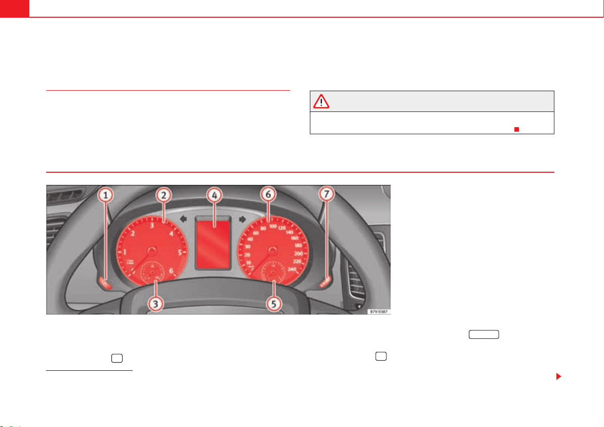
Cockpit64
Instruments
Introduction
Additional information and warnings:
x Indicator lamps page 61
x Gear engaged display (automatic gearbox) page 201.
x Instructions for inspection intervals Booklet “Maintenance
Programme”
WARNING
Any distraction may lead to an accident, with the risk of injury.
x Do not handle the instrument panel controls when driving.
View of instrument panel
Details of the instruments fig. 36:
Clock set button
1)
.
Press button to select the hour or minute display.
To continue setting the time, press button fig. 36 .
Hold button down to scroll through the numbers quickly.
Press button again to end the clock setting.
Rev counter (with the engine running, in thousands of revolutions per
minute).
Fig. 36 Instrument panel, on dash panel.
1)
Depending on the vehicle equipment, it is also possible to set the time using the
settings menu on the instrument panel display page 75.
A
1
¡
0.0 / SET
A
7
¡
A
2
Cockpit 65
Safety First Operating instructions Practical tips Technical Data
The beginning of the red zone of the rev counter indicates the maximum
speed in any gear after running-in and with the engine hot. However, it is
advisable to change up a gear or move the selector lever to D (or lift your
foot off the accelerator) before the needle reaches the red zone .
Engine coolant temperature display v page 313.
Displays on the screen page 65.
Fuel reserve display page 293.
Speedometer.
Reset knob for trip recorder (trip).
Press button to reset to zero.
Caution
To prevent damage to the engine, the rev counter needle should only remain
in the red zone for a short period of time.
For the sake of the environment
Changing up a gear in time reduces fuel consumption and noise.
Displays on screen
A variety of information can be viewed on the instrument panel display
page 64, fig. 36 , depending on the vehicle equipment:
x Warning and information texts
x Mileage
x Time
x Ambient temperature
x Compass
x Selector lever positions page 201
x Recommended gear (manual gearbox) page 201
x Multifunction display (MFI) and menus for different setting options
page 70
x Service interval display. page 68
x Second speed display (menu Configuration) page 70
x Start/Stop operation indicator page 67
Warning and information texts
The system runs a check on certain components and functions when the igni-
tion is switched on and while the vehicle is moving. Faults in the operation
are displayed on the screen using red and yellow symbols and messages on
the instrument panel display ( page 61) and, in some cases, with audible
warnings. The display may vary according to the type of instrument panel
fitted.
A
3
A
4
A
5
A
6
A
7
0.0 / SET
A
4
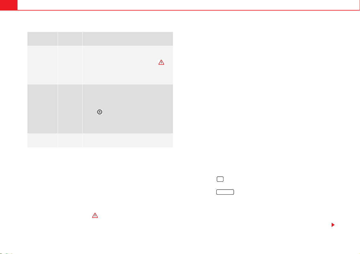
Cockpit66
Mileage
The odometer registers the total distance travelled by the car.
The trip recorder (trip) shows the distance travelled since the last trip recorder
reset. The last digit of the trip recorder indicates distances of 100 metres or
tenths of a mile.
Outside temperature display
When the outside temperature is below +4 °C (+39 °F), the symbol “ice
crystal” (warning of risk of freezing) is also displayed next to the temperature.
At first this symbol flashes and then it remains lit until the outside tempera-
ture rises above +6 °C (+43 °F) .
When the vehicle is at a standstill, with the parking heating on ( page 187),
or when travelling at very low speeds, the temperature displayed may be
higher than the true outside temperature, as a result of the heat produced by
the engine.
The temperatures measured range from -40 °C to +50 °C (-40 °F to +122 °F).
Compass
With the ignition on and the navigation system on, the cardinal point corre-
sponding to the vehicle's direction of travel is displayed on the instrument
panel page 67.
Selector lever positions
The range of engaged gears of the selector lever is shown on the side of the
lever, and on the instrument panel display. In positions D and S, and with the
Tiptronic, the corresponding gear is also displayed.
Recommended gear (manual gearbox)
The recommended gear to save fuel is displayed on the instrument panel
while you are driving page 201.
Second speed display (mph or km/h)
In addition to the speedometer, the speed can also be displayed in a different
unit of measurement (in miles or in km per hour). To change the units, in the
Settings menu, select the option Second speed page 70.
Vehicles without menu display on the instrument panel
x Switch on the engine.
x Press button three times. The odometer display flashes on the instru-
ment panel display.
x Press button once. “mph” or “km/h” is displayed briefly instead
of the odometer.
x This activates the second speed display. To switch it off, repeat the proce-
dure.
This option cannot be disconnected in models destined for countries in which
the second speed must always be visible.
Type of mes-
sage
Symbol
colour
Meanings
Priority 1
warning.
Red
Symbol flashing or lit; partly combined with
audible warnings.
Stop the vehicle! It is dangerous !
Check the function which is faulty and repair.
If necessary, request assistance from special-
ised personnel.
Priority 2
warning.
Yellow
Symbol flashing or lit; partly combined with
audible warnings.
A faulty function, or fluids which are below the
correct levels may cause damage to the vehi-
cle!
Check the faulty function as soon as possible.
If necessary, request assistance from special-
ised personnel.
Informative
text.
–
Information relating to different vehicle proc-
esses.
¡
0.0 / SET
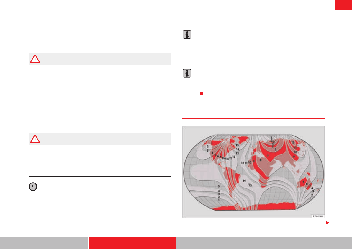
Cockpit 67
Safety First Operating instructions Practical tips Technical Data
Start/Stop operating display
Updated information relating to the status is displayed on the instrument
panel page 221.
WARNING
If the warning lamps and messages are ignored, the vehicle may stall in
traffic, or may cause accidents and severe injuries.
x Never ignore the warning lamps or text messages.
x Stop the vehicle safely as soon as possible.
x A faulty vehicle represents a risk of accident for the driver and for other
road users. If necessary, switch on the hazard warning lamps and put out
the warning triangle to advise other drivers.
x Park the vehicle away from the traffic, ensuring that there are no easily
inflammable materials under the vehicle which could come into contact
with the exhaust system (e.g. dry grass, fuel).
WARNING
Although the outside temperature is above freezing, some roads and
bridges may be frozen.
x At an outside temperature of above +4 °C (+39 °F), even when the “ice
crystal” is not visible, there may still be ice on the road.
x Never rely totally on the outside temperature display!
Caution
Failure to heed the warning lamps and text messages when they appear may
result in faults in the vehicle.
Note
Different versions of the instrument panel are available and therefore the
versions and instructions on the display may vary. In the case of displays
without warning or information texts, faults are indicated exclusively by the
warning lamps.
Note
When several warnings are active at the same time, the symbols are shown
successively for a few seconds. The symbols will stay on until the fault is
rectified.
Compass*
Fig. 37 Magnetic zones.

Cockpit68
The compass does not require calibration in vehicles for which the navigation
system was mounted at the factory. The option compass disappears.
The compass in vehicles in which the navigation system was not mounted at
the factory, is permanently and automatically calibrated. If electronic or metal
accessories (mobile phone, television) are subsequently mounted in the
vehicle, the compass should be recalibrated manually.
Adjusting the magnetic zone
x Switch the ignition on.
x Select the Settings menu followed by the option Compass and Zone.
x Select the magnetic zone corresponding to the position of the vehicle
page 67, fig. 37.
x Adjust and confirm the magnetic zone (1-15).
Calibrating compass
To calibrate the compass you must be in one of the valid magnetic zones with
sufficient space to be able to trace a circumference with the vehicle.
x Switch the ignition on.
x Select the Settings menu followed by the option Compass and Calibrate.
x Confirm the message Describe a complete circumference to calibrate the
compass with and then trace a complete circumference driving at approx-
imately 10 km/h (6 mph).
When the corresponding cardinal point is displayed, the calibration is
complete.
Service interval display
The inspection display appears on the instrument panel page 64, fig. 36
.
SEAT makes a difference between services with engine oil change (Mainte-
nance Service) and services without engine oil change (Inspection Service).
The service interval display only gives information for service dates which
involve an engine oil change. The dates of the remaining services (for
example, the next Inspection Service or change of brake fluid) are listed on
the label attached to the door strut, or even in the Maintenance Programme.
In vehicles with Services established by time or mileage, the service intervals
are already pre-defined.
In vehicles with LongLife Service, the intervals are determined individually.
Technical progress has made it possible to considerably reduce servicing
requirements. The technology used by SEAT ensures that your vehicle only
has an maintenance service when it is necessary. To establish when the Main-
tenance Service is due (max. 2 years), the vehicle's conditions of use and
individual driving styles are considered. The service pre-warning first appears
20 days before the date established for the corresponding service. The kilo-
metres remaining until the next service are always rounded up to the nearest
100 km and the remaining time is given in complete days. The current service
message cannot be viewed until 500 km after the last service. Prior to this
only lines are visible on the display.
Inspection reminder
When the Service date is approaching, when the ignition is switched on a
Service reminder is displayed.
In vehicles without text messages, a spanner is displayed on the instrument
panel > with a figure given in km. The number of kilometres shown is the
maximum number that may be driven until the next service. After a few
seconds,the display mode changes. A clock symbol appears and the number
of days until the next service appointment is due.
In vehicles with text messages, Service in --- km or --- days is displayed on the
instrument panel .
OK
A
4
Cockpit 69
Safety First Operating instructions Practical tips Technical Data
Service due
After the service date, an audible warning is given when the ignition is
switched on and the spanner displayed on the screen flashes for a few
seconds>. In vehicles with text messages, Service in --- km or --- days is
displayed on the instrument panel.
Reading a service notification
With the ignition switched on, the engine off and the vehicle at a standstill,
the current service notification can be read:
x Press the button on the instrument panel several times until the
spanner symbol is displayed >.
x ALTERNATIVELY: select the Settings menu.
x From the Service submenu, select the option Info.
When the service date has past, a minus sign is displayed in front of the
number of kilometres or days. In vehicles with text messages the following is
displayed: Service --- km or --- days ago.
The service interval display is reset
If the service was not carried out by a qualified workshop, the display can be
reset as follows:
Do not reset the indicator to zero between two intervals, otherwise the
display will be incorrect.
If, while the LongLife service is valid, the service interval display is reset to
zero, the “service will be activated by time or mileage”. The service interval is
no longer calculated individually Booklet “Maintenance Programme”.
Note
The service message disappears after a few seconds, when the engine is
started or when is pressed.
Note
In vehicles with the LongLife system in which the battery has been discon-
nected for a long period of time, it is not possible to calculate the date of the
next service. Therefore the service interval display may not be correct. In this
case, please check the maximum permitted service intervals Booklet
“Maintenance Programme”.
In vehicles with text messages:
Select the Settings menu.
In the submenu Service, select the option Reset.
Confirm with when requested to do so by the system.
¡
OK
In vehicles without text messages:
Switch the ignition off.
Press and hold the button.
Switch the ignition back on.
Release the button and, press for the next 20 seconds.
0.0 / SET
0.0 / SET ¡
OK
Cockpit70
SEAT information system
Introduction
With the ignition switched on, it is possible to read the different functions of
the display by scrolling through the menus.
In vehicles with a multifunction steering wheel, there are no buttons on the
windscreen wiper lever. The multifunction display can only be controlled from
the buttons on the multifunction steering wheel.
The number of menus displayed on the instrument panel will vary according
to the vehicle electronics and equipment.
A specialised dealer will be able to programme or modify additional func-
tions, according to the vehicle equipment. SEAT recommends visiting a qual-
ified workshop.
Some menu options can only be read when the vehicle is at a standstill.
As long as a priority 1 warning is displayed, it will not be possible to read the
menus. To display the menus, confirm the warning by pressing .
Additional information and warnings:
x Exterior mirrors page 130
x Parking heating page 187
WARNING
Any distraction may lead to an accident, with the risk of injury.
x Do not read the instrument panel menus when driving.
Summary of the menu structure
Multifunction display (MFI) page 73
Journey duration
Current fuel consumption
Average fuel consumption
Distance to empty (the distance you can travel with the remaining fuel)
Distance covered
Average speed
Digital display of speed
Oil temperature digital display
Speed warning
Audio Booklet “Radio” or Booklet “navigation system”
Navigation Booklet “Navigation system”
Parking heating page 187
Activation
On / Off programme
Switching off
Timer 1-3
Day
Time
Minute
Enabling
Duration
Operating mode
Heat
Ventilation
Day
OK

Cockpit 71
Safety First Operating instructions Practical tips Technical Data
Default setting
Vehicle condition page 73
Configuration page 75
Multifunction display data
Journey duration
Current fuel consumption
Average fuel consumption
Distance covered
Distance to empty (the distance you can travel with the remaining
fuel)
Average speed
Digital display of speed
Speed warning
Compass
Convenience page 76
Open door
Manual
automatic mode
Childproof locks On / Off
Anti-theft alarm confirmation On / Off
Handling windows
Off
All
Driver
Mirror adjustment On / Off
Rear-view mirror adjustment
Synchronised
Individual
Default setting
Lights & visibility page 77
Coming Home
Leaving Home
Footwell light
Convenience indicators On / Off
Default setting
Time
Winter tyres
Settings: Language
Units
Second speed display On / Off
Autohold
Travel mode On / Off
Service
Info
Reset
Default setting
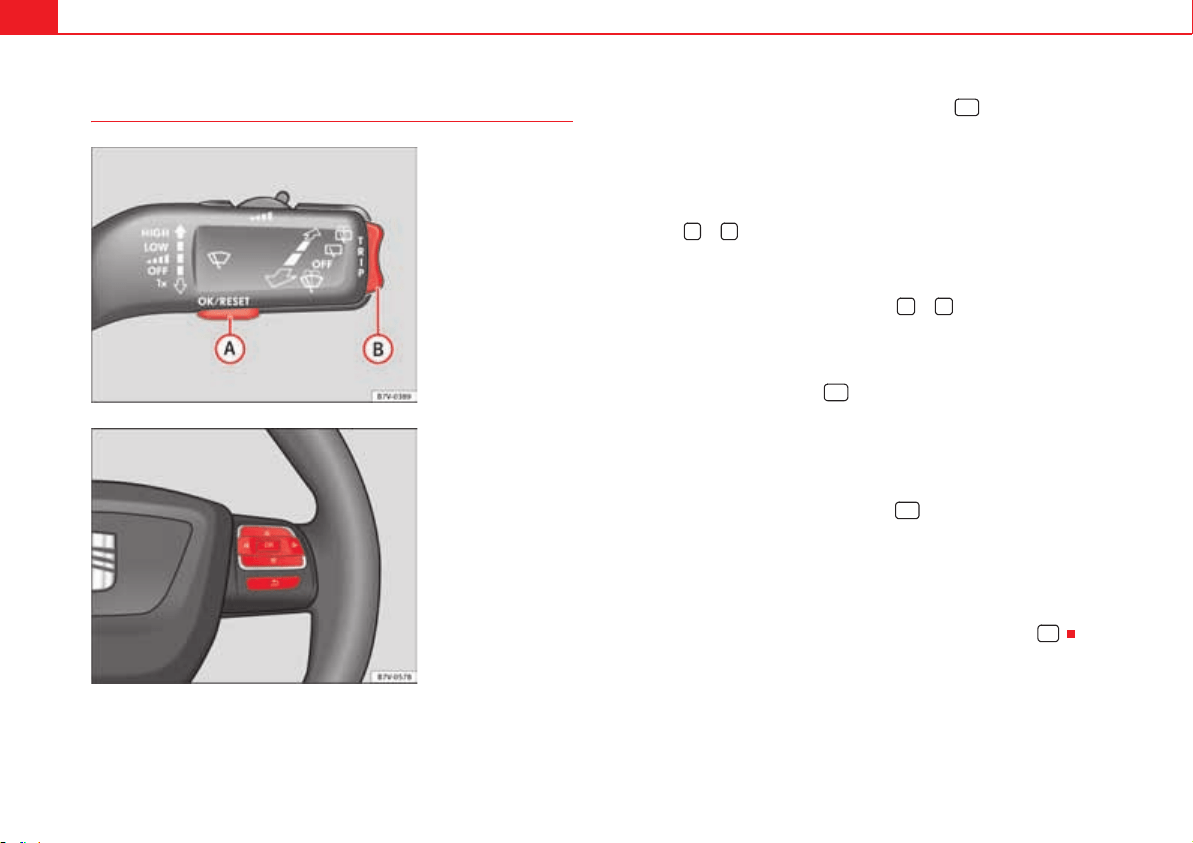
Cockpit72
Using the menus on the instrument panel
Enabling the main menu
x Switch the ignition on.
x If a message or vehicle symbol is displayed, press ( fig. 38 or
fig. 39).
x If managed from the windscreen wiper lever: the main menu list is
displayed.
x If managed from the multifunction steering wheel: the main menu list is
not displayed. To scroll through the options of the main menu, press the
arrow keys or several times page 73.
Select a submenu
x Press the rocker switch fig. 38 upwards or downwards, or, on the
multifunction steering wheel, the arrow keys or , until reaching the
required menu option.
x The selected option is displayed between two horizontal lines. In addi-
tion, a triangle is displayed on the right y.
x To select the submenu, press .
Making changes according to the menu
x Use the rocker switch on the windscreen wiper lever or the arrow keys on
the multifunction steering wheel to make the required modifications. If the
switch or keys are held down, the scroll speed is faster (fast forward or return).
x Mark or confirm the selected option with .
Returning to the main menu
x Via the menu: in the submenu, select the option Return to exit the
submenu.
x If managed from the windscreen wiper lever: hold down the rocker switch.
x If managed from the multifunction steering wheel: press button .
Fig. 38 In vehicles
without multifunction
steering wheel: On the
windscreen washer lever:
button to confirm the
menu point and rocker
switch to change the
menu
A
A
A
B
Fig. 39 Right side of
multifunction steering
wheel: Buttons to access
the instrument panel
menus.
OK
A
A
A
B
* +
OK
OK
E
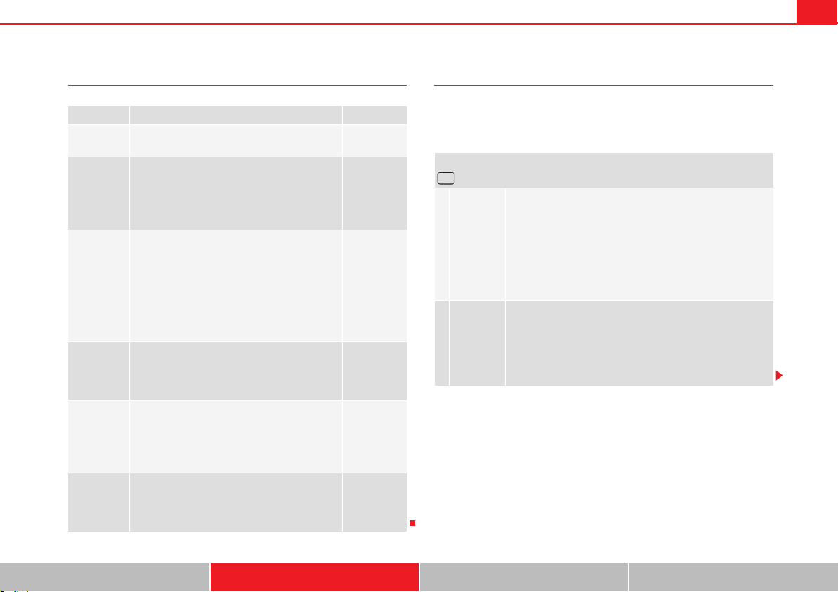
Cockpit 73
Safety First Operating instructions Practical tips Technical Data
Main menu MFI display menu
The multifunction display (MFI) has two automatic memories: 1 - Partial
memory and 2 - Total memory. The selected memory will be shown in the
upper right-hand corner of the display.
Menu Function See
MFI Information and possible configurations of the
multifunction display (MFI).
page 73
Audio
If the radio is on, the station is displayed.
In CD mode, the current CD is played.
Booklet
“Radio” or
Booklet
“navigation
system”
Navigation Navigation system information:
when the navigation to destination is on,
change of direction arrows and a proximity bar
are displayed. These symbols are similar to
those used in the navigation system.
If navigation to destination is not on, the direc-
tion of travel (compass) and the name of the
street on which you are driving are displayed.
Booklet
“Navigation
system”
Parking
heating
Information and configurations of the parking
heating:
switching the parking heating on or off. Select
the operating mode and duration.
page 187
Vehicle
condition
Current warning or information texts.
This option only appears when one of the fol-
lowing texts is available. The number of availa-
ble messages is displayed. Example 1/1 or
2/2.
page 64
Settings Different setting options, for example, the Con-
venience, Lighting & or Visibility menus, and
the time, speed warning with winter tyres, lan-
guage, units of measurement, or “Display off”.
page 75
With the ignition switched on, and memory 1 or 2 displayed, briefly press
to change from one memory to another.
1
Trip mem-
ory (for a
single jour-
ney).
The memory stores the values for the journey and the con-
sumption from the moment the ignition is switched on until
it is switched off again.
If the journey is broken for more than two hours, the mem-
ory is automatically erased. If the journey is continued in
less than two hours after the ignition is switched off, the
new data is added to the data already stored in the mem-
ory.
2
Total mem-
ory (for all
journeys).
The memory records the values for a specific number of
partial trips, up to a total of 19 hours and 59 minutes or 99
hours and 59 minutes, or 1999.9 km (or miles) for 9999 km
(or miles), depending on the model of instrument panel.
On reaching either of these limits, the memory is automati-
cally erased and starts to count from 0 again.
OK
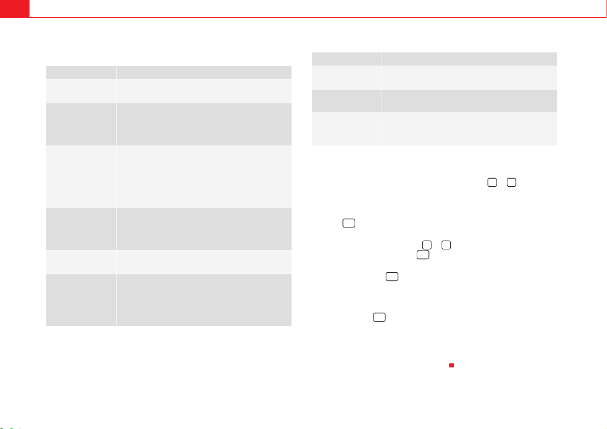
Cockpit74
Possible displays
Changing between display modes
x In vehicles without multifunction steering wheel: press the lever.
x Vehicles with a multifunction steering wheel: press or .
Storing a speed for the speed warning
x Select the display Speed warning at --- km/h.
x Press to store the current speed and switch off the warning.
x In addition, set the required speed by pressing the rocker switch on the
windscreen wiper lever or buttons or on the multifunction steering
wheel for 5 seconds. Next, press again or wait a few seconds. The speed
is stored and the warning activated.
x To switch off, press . The stored speed is deleted.
Manually erasing memory 1 or 2
x Select the memory to be erased.
x Press and hold for approximately two seconds.
Personalising the displays
It is possible to select which of the displays in the multifunction display you
wish to see on the instrument panel in the settings menu. The units of meas-
urement can also be modified page 75.
Menu Function
Journey duration This indicates the hours (h) and minutes (min) since
the ignition was switched on.
Current fuel
consumption
The current fuel consumption while driving is dis-
played in l/100 km (or miles per gallon, mpg); when
the engine is running but the vehicle is not moving,
in l/h (or gallons per hour).
Average fuel
consumption
When the ignition is switched on, the average con-
sumption (in l/100 km or in mpg) is displayed after
the vehicle has moved approximately 100 metres
(328 feet). Otherwise horizontal lines are displayed.
The value shown is updated approximately every 5
seconds.
Distance to empty
(the distance you
can travel with the
remaining fuel)
Approximate distance in km (or miles) that can still
be travelled with the fuel remaining in the tank,
assuming the same style of driving is maintained.
This is calculated using the current fuel consumption.
Distance covered Distance travelled, after ignition is switched on, in km
(or miles).
Average speed After the ignition is switched on, the average speed
will be shown after a distance of approximately 100
metres (328 feet) has been travelled. Otherwise hori-
zontal lines are displayed. The value shown is
updated approximately every 5 seconds.
Digital display of
speed
Current speed displayed digitally.
Oil temperature
digital display
Updated engine oil temperature digital display
Speed warning
to --- km/h
If the stored speed is exceeded (between 30 - 250
km/h, or 18 - 155 mph), an audible warning is given
together with a visual warning.
Menu Function
* +
OK
* +
OK
OK
OK

Cockpit 75
Safety First Operating instructions Practical tips Technical Data
Configuration Menu
Configuration
Menu
Function
Multifunction
display data
Configuration of the multifunction display data which you
wish to see on the instrument panel display page 73.
Compass Changing the magnetic region and calibration of the com-
pass. To calibrate the compass, please follow the instruc-
tions given on the instrument panel display.
Convenience Changing vehicle convenience functions page 76.
Lights &
visibility
Configuration of vehicle lighting page 77.
Time Changing the hours and minutes of the clock and the nav-
igation system. The time can be set here and the choice
can be made between the 24 hour and 12 hour display.
The S in the upper part of the display indicates that the
clock is set to summer time.
Winter tyres Changing the visual and audible speed warnings. This
function should only be used when the vehicle is fitted
with winter tyres, which are not designed for travel at
high speeds.
Settings:
Language
Changing the language of the display texts and the navi-
gation system.
Units Changing the units of measurement for the temperature,
consumption and distance.
Second speed Switching second speed display on and off
Autohold Selecting whether the Auto-Hold function should remain
on permanently.
Travel mode Changing the headlamps for countries in which vehicles
are driven on the other side of the road. When the “mark”
is activated, the headlamps of a left-hand drive vehicle
are adjusted for driving on the left. The travel mode can
only be used for short periods of time.
Service Check the service notifications or reset the service inter-
vals to zero
Manufacturer's
settings
Some functions of the Configuration menu will be reset
to the factory value.
Back The main menu is displayed again.
Configuration
Menu
Function

Cockpit76
Submenu Convenience
Convenience menu Function
Open door
page 83
Manual
When the vehicle is unlocked with the key, the following doors (depending upon the configuration)
are unlocked:
all doors: All of the doors will be unlocked.
one door: see above Method 1.
Side of vehicle: The doors on the driver's side are unlocked.
In vehicles with KESSY page 83 the doors on the driver's side are unlocked together with any
doors on the side where the vehicle key is, using the door handle.
Individually: Only the driver's door is unlocked. In vehicles with KESSY, if a door handle is used,
the door (or tailgate) will unlock, together with the driver's door page 83.
automatic mode
Automatic locking function (Auto Lock) All doors are automatically locked at speeds above approxi-
mately 15 km/h. To unlock when the vehicle is stopped, push the central locking button or remove
the key from the ignition lock.
Automatic unlock: When the key is removed from the ignition lock, all doors and the tailgate are
unlocked.
Electronic childproof locks Switching the childproof locks on or off page 92.
Confirm anti-theft alarm Switching on or off the audible confirmation that the anti-theft alarm is activated page 83.
Handling windows Adjusting the electric windows: This permits the windows to be opened or closed when the vehicle is unlocked or locked
respectively. The open function can only be activated from the driver's door page 102.
Rear-view mirror adjustment Tilts passenger mirror downwards when reverse gear is engaged. This enables the driver to see the edge of the pavement, for
example page 130.
Exterior mirror adjust. If synchronised adjustment is selected, when the driver side exterior mirror is adjusted, the passenger exterior mirror is also
moved.
Manufacturer's settings Some functions of the Convenience submenu will be reset to the factory value.
Back The Configuration menu is displayed again.

Cockpit 77
Safety First Operating instructions Practical tips Technical Data
Lights & visibility submenu.
Personal convenience settings
When two people use a vehicle, SEAT recommends that each person always
uses “their” own remote control key. When the ignition is switched off, or the
vehicle is locked, the personal convenience settings are stored and automat-
ically allocated to the vehicle key page 70.
The values of the personalised convenience settings of the following menu
options are allocated to the vehicle key:
Parking heating menu
Configuration Menu
Time
Settings: Language
Units
Convenience settings menu
Door unlock (individual opening, Auto Lock)
Convenience handling of windows
Rear-view mirror adjustment
Lights & visibility adjustment menu.
Coming home and leaving home
Footwell light
Convenience indicators
The stored settings are automatically activated, at the latest when the igni-
tion is switched on. Please refer to the information and tips relating to the
seat memory page 137.
Lights &
visibility menu.
Function
Coming Home This permits the adjustment of the time the headlamps
stay on after locking or unlocking the vehicle, the function
can also be connected or disconnected here page 119.
Leaving Home
Footwell light This permits the adjustment of the brightness of the foot-
well lighting when the doors are open, the function can
also be connected or disconnected here
Convenience
indicators
Switching convenience indicators on and off When the
convenience indicators are connected, when the indicator
is switched on, these flash at least three times
page 113.
Manufacturer's
settings
All the configurations in the submenu Lights & visibil. are
reset to the predefined factory values.
Back The Configuration menu is displayed again.
Unlocking and locking78
Unlocking and locking
Vehicle key set
Introduction
Additional information and warnings:
x Adjustments to the SEAT information system page 70
x Central locking and locking system page 83
x Start and stop the engine page 195
x Notes for the user page 283
x Emergency locking and unlocking page 348
WARNING
Careless or incorrect use of vehicle keys may result in severe injury and
accident.
x Always take all the keys with you whenever you leave the vehicle. Chil-
dren and unauthorised individuals could lock the doors or the tailgate,
start the engine or turn the ignition on activating electrical systems, for
example: the electric windows.
x Never leave children or disabled people alone in the car. They could be
trapped in the car in an emergency and will not be able to get themselves
to safety. For example, depending on the time of the year, temperatures
inside a locked and closed vehicle can be extremely high or extremely low
resulting in serious injuries and illness or even death, particularly for
young children.
x Never remove the key from the ignition if the vehicle is in motion. The
steering may lock and it will not be possible to turn the steering wheel.
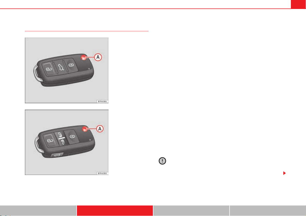
Unlocking and locking 79
Safety First Operating instructions Practical tips Technical Data
Vehicle key
Vehicle keys
With the vehicle key fig. 40 or fig. 41 the vehicle may be locked or
unlocked remotely.
The vehicle key includes an emitter and batteries. The receiver is in the inte-
rior of the vehicle. The range of the vehicle key with remote control and new
batteries is several metres around the vehicle.
If it is not possible to open or close the vehicle using the remote control key,
this should be re-synchronised page 82 or the battery changed
page 81.
Different keys belonging to the vehicle may be used.
Folding the key shaft in and out
When the button is pressed, the key shaft is released and unfolds.
To fold it press the button and fold the key shaft in until it locks in place.
Duplicate keys
To obtain a spare key and other vehicle keys, the vehicle chassis number is
required.
Each new key must contain a microchip and be coded with the data from the
electronic vehicle immobiliser. In vehicle key will not work if it does not
contain microchip or the microchip has not been encoded. This is also true for
keys cut for the vehicle.
The vehicle keys or new spare keys can be obtained from an authorised tech-
nical service, a specialist workshop or approved key service qualified to
create this kind of key.
New keys or spare keys must be synchronised before use page 82.
Caution
All of the vehicle keys contain electronic components. Protect the vehicle
keys from damage, impacts and humidity.
Fig. 40 Vehicle keys.
Fig. 41 Vehicle key for
vehicles with electric
sliding doors.
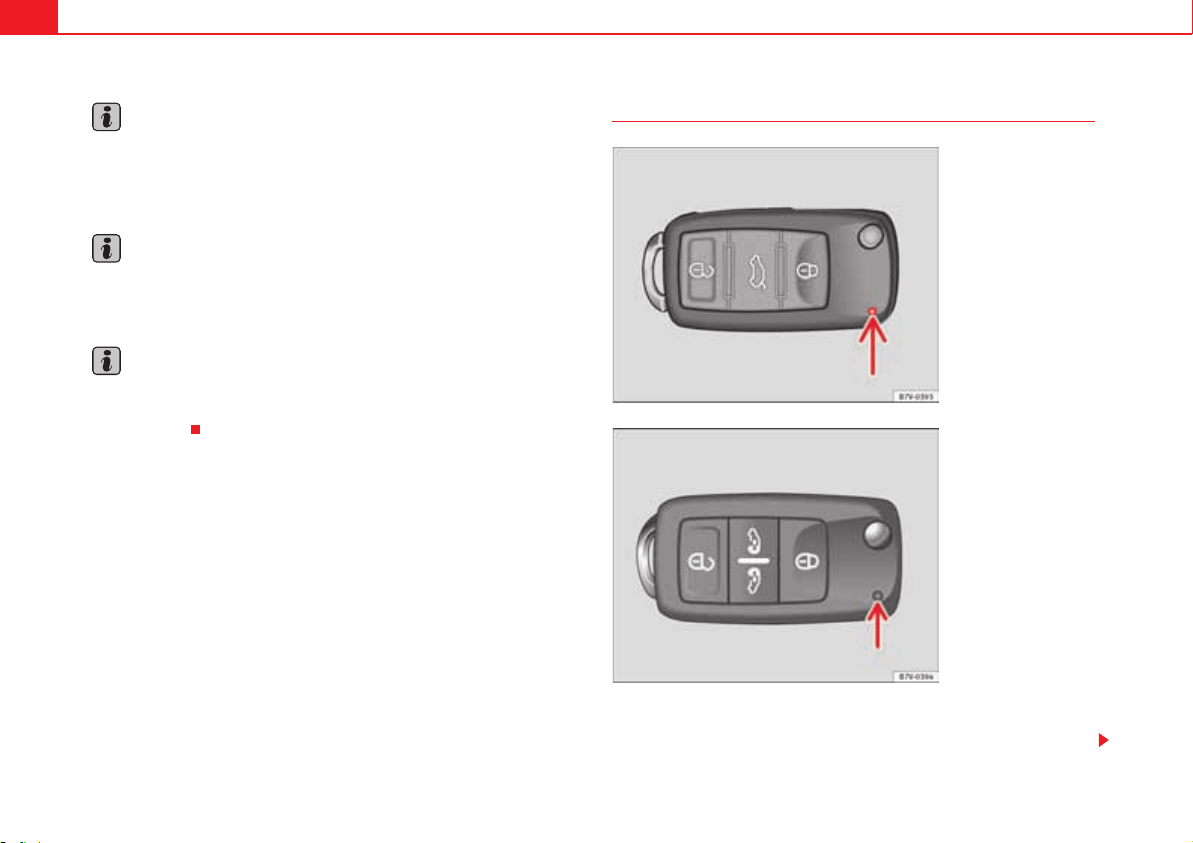
Unlocking and locking80
Note
Only use the key button when you require the corresponding function.
Pushing the button unnecessarily could accidentally unlock the vehicle or
trigger the alarm. It is also possible even when you are outside the radius of
action.
Note
Key operation can be greatly influenced by overlapping radio signals around
the vehicle working in the same range of frequencies (for example, radio
transmitters, mobile telephones).
Note
Obstacles between the remote control and the vehicle, bad weather condi-
tions and discharged batteries can considerably reduce the range of the
remote control.
Indicator on the vehicle key
When a button on the vehicle key is pressed, the indicator light flashes
(arrow) fig. 42 or fig. 43 once briefly. If the button is pressed and held,
Fig. 42 Indicator light on
the vehicle key.
Fig. 43 Indicator light on
the vehicle key for vehi-
cles with electric sliding
doors.
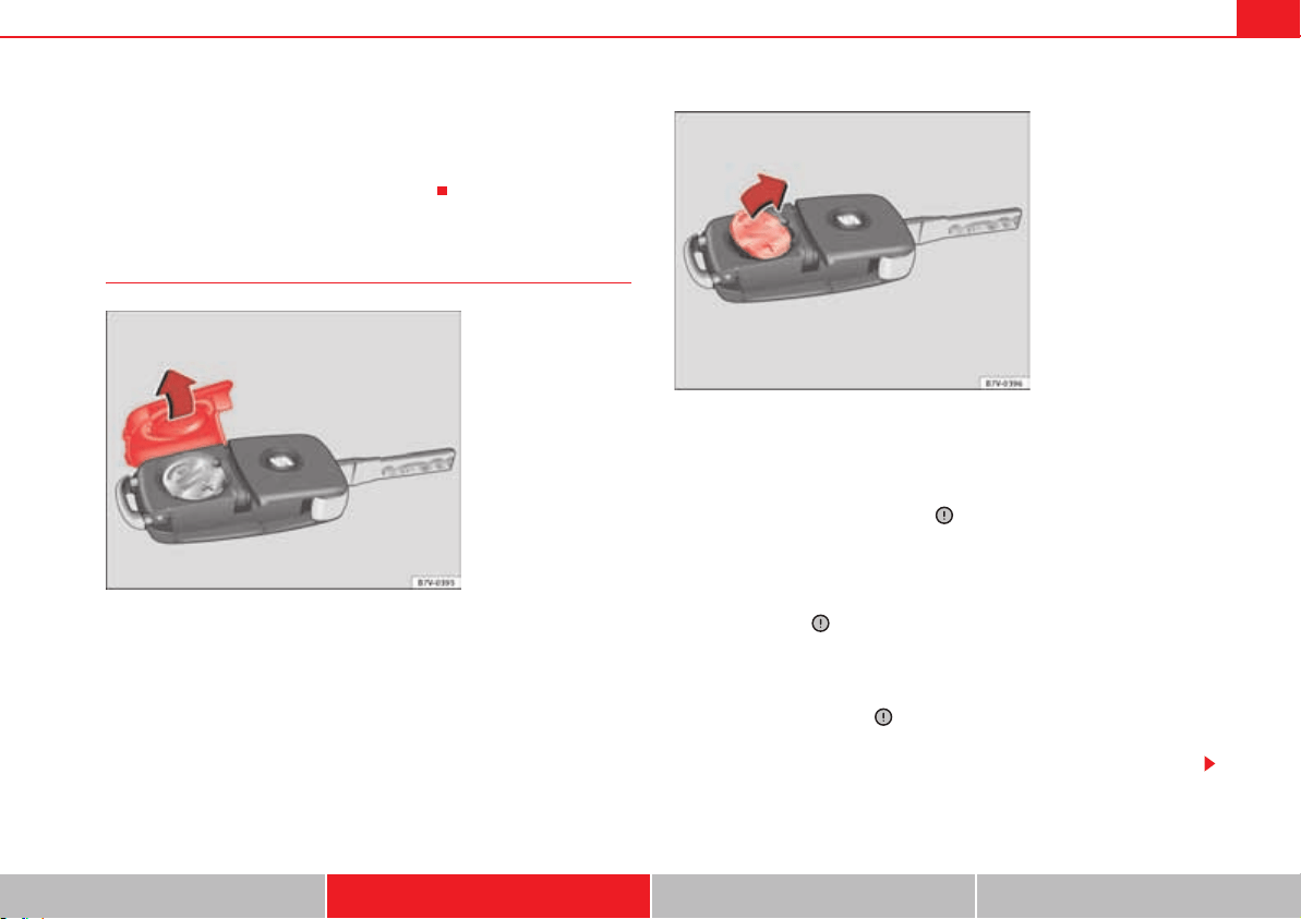
Unlocking and locking 81
Safety First Operating instructions Practical tips Technical Data
the indicator blinks several times, for example: for the convenience opening
function.
When the indicator light does not light upon pushing a button, the batteries
of the vehicle key must be changed page 81.
Changing the battery
SEAT recommend having the batteries changed in a qualified workshop.
The battery is located to the rear of the vehicle key, under a cover fig. 44.
When changing the battery, use another battery of the same model and
observe the polarity when fitting it .
To change the battery
x Unfold the key shaft page 79.
x Remove the cover from the back of the vehicle key fig. 44 in the direc-
tion of the arrow .
x Extract the battery from the compartment using a suitable thin object
fig. 45.
x Place the new battery in the compartment, pressing in the direction of the
arrow as shown fig. 45 .
x Fit the battery compartment cover, pressing in the direction of the arrow
as shown fig. 44 until it clicks into place.
Fig. 44 Vehicle key:
battery compartment
cover.
Fig. 45 Vehicle key:
removing the battery.
Unlocking and locking82
Caution
x If the battery is not changed correctly, the vehicle key may be damaged.
x Use of unsuitable batteries may damage the vehicle key. For this reason,
always replace the dead battery with another of the same voltage, size and
specifications.
For the sake of the environment
Please dispose of your used batteries correctly and with respect for the envi-
ronment.
For the sake of the environment
The vehicle key battery may contain perchlorate. Observe the legal require-
ments for their disposal.
To synchronise the vehicle key
If the button is pressed frequently outside of the vehicle range, it is
possible that the vehicle can no longer be locked or unlocked using the key.
In this case, the vehicle key must be synchronised once more as follows:
x Unfold the key shaft page 79.
x Remove the cover from the driver's door handle page 348.
x Press the button on the vehicle key. For this, it must remain with the
vehicle.
x Open the vehicle within one minute using the key shift.
x Turn on the ignition using the vehicle key. The key has been synchronised.
x Replace the driver's door handle cover.
0
0
Unlocking and locking 83
Safety First Operating instructions Practical tips Technical Data
Central locking and locking system
Introduction
Central locking functions correctly when all the doors and the tailgate are
correctly shut. If the driver's door is open, the vehicle cannot be locked with
the key.
The battery of a vehicle left unlocked during a long period (for instance, in a
private garage) may run down and fail to start the motor.
Additional information and warnings:
x Personal convenience settings in the SEAT information system page 70
x Vehicle key set page 78
x Sliding doors page 92
x Electric windows page 102
x Panorama sliding sunroof page 106
x Towing mode page 260
x Emergency locking and unlocking page 348
WARNING
The incorrect use of the central locking system may cause serious injuries.
x The central locking system will lock all doors. A vehicle locked from the
inside can prevent any non-authorised individual from opening the doors
and accessing the vehicle. Nevertheless, in case of emergency or accident,
locked doors will complicate access to the passenger compartment to help
the passengers.
x Never leave children or disabled people alone in the vehicle. The central
locking button can be used to lock all the doors from within. Therefore,
passengers will be locked inside the vehicle. Individuals locked in the
vehicle can be exposed to very high or very low temperatures.
x Depending on the time of the year, temperatures inside a locked and
closed vehicle can be extremely high or extremely low resulting in serious
injuries and illness or even death, particularly for young children.
x Never leave individuals locked in a closed and locked vehicle. In case of
emergency, they may not be able to exit the vehicle by themselves or get
help.
WARNING (continued)

Unlocking and locking84
Description of the central locking system
The central locking system allows all doors and the tailgate to be locked and
unlocked centrally.
x From outside, using the vehicle key.
x From inside, by pushing the central locking button page 85.
In the submenu Convenience in the Configuration menu, or by visiting a
specialized workshop, special functions of the central locking system can be
switched on or off page 70.
In case of a vehicle key fault or central locking system fault, all doors can be
locked or unlocked manually.
Locking the vehicle after the airbags have been deployed
If the airbags are deployed due to an accident, the vehicle will be automati-
cally and completely unlocked. Depending on the amount of damage, the
vehicle can be locked following an accident in the following ways:
Locking and unlocking the vehicle from the outside
Function Necessary operations
Locking the vehicle
from within:
– Turn off the ignition and turn it on again.
– Push the central locking button .
Locking the vehicle
from the outside:
– Turn off the ignition and turn it on again.
OR: – Remove the key from the ignition.
– Open any door just once.
– Lock the vehicle with the key.
1
Fig. 46 Buttons on the
vehicle key.
Fig. 47 Buttons on the
key of vehicles with
sliding doors.

Unlocking and locking 85
Safety First Operating instructions Practical tips Technical Data
Attention: Depending on the selected function in the central locking
submenu Convenience, you may push the button twice page 70 to
unlock all doors and the tailgate.
The vehicle key only locks and unlocks the vehicle if it is within range of the
vehicle and if the batteries have enough power. When locking, the vehicle's
indicators will blink.
If the driver's door is open, the vehicle cannot be locked with the key. If you
unlock the vehicle without opening any doors or the tailgate, it will lock again
automatically after a few seconds. This function prevents the vehicle from
remaining unlocked if the unlocking button is pressed by mistake.
Convenience open/close function
x See "Electric windows: functions" page 102.
x See "Panorama sliding sunroof: operation" page 106.
Locking and unlocking the vehicle from the inside
The central locking button is still operative when the ignition is switched off.
The central locking button is only deactivated if the "Safe" security system is
activated page 88.
Please note the following when you use the central locking button to lock your
vehicle:
x Do not turn on the "Safe" security system page 88.
x Do not turn on the antitheft alarm.
x It will not be possible to open the doors or the tailgate from the outside
this may offer extra safety, when stopped at traffic lights for example.
Function Handling the buttons on the vehicle
Unlocking the vehicle.
Press button . Keep it pushed for the
convenience opening.
Lock the vehicle.
Press button . Keep it pushed for the
convenience locking function.
Unlocking the tailgate.
Press button .
Open the sliding door. page 92.
0
1
0
Push the button fig. 48:
Unlocking the vehicle.
Lock the vehicle.
Fig. 48 In the driver door:
central locking button.
0
1
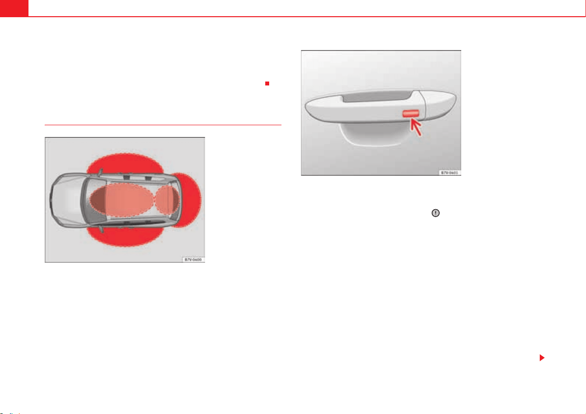
Unlocking and locking86
x The doors can be opened and unlocked individually from the inside by
pulling the inside door handle. If necessary, pull the door release lever twice.
x The driver's door cannot be locked when it is still open. This avoids
locking the vehicle key inside the vehicle when there is nobody inside.
Locking and unlocking the vehicle with KESSY*
KESSY is a locking and unlocking system that can be used to lock and unlock
the vehicle without actively using the key. To do this, a valid vehicle key only
has to be in the vehicle approach zone .
Important
When there is a valid vehicle key in the approach zone ( fig. 49) of a door
or the tailgate, the KESSY locking and unlocking system detects a request to
enter the vehicle. The system checks the access rights and allows the
following functions without active use of the key:
x "Keyless-Entry": Unlocks the handles of the four doors and the tailgate
release button.
x "Keyless-Go": Starts the engine for driving. To do this, a valid vehicle key
only has to be inside the vehicle.
x "Keyless-Exit": locks the vehicle using the driver's side or passenger-side
door handle.
The central locking and locking systems operate in the same way with the
actual locking and unlocking system. Only the controls change.
Fig. 49 KESSY starter and
lock system: approach
zones
Fig. 50 KESSY starter and
lock system: Outside
button on the door
handle.

Unlocking and locking 87
Safety First Operating instructions Practical tips Technical Data
When unlocking the vehicle, all of the indicators blink twice; when locking,
they blink once.
If you unlock the vehicle without opening any doors or the tailgate, it will lock
again automatically after a few seconds.
Unlocking and opening the doors
x Take the handle of the corresponding door and touched the outside
button.
x Door open.
Closing and locking the doors
x Close the driver's door.
x Press on the outermost button of the passenger or driver's side door
( page 86, fig. 50 arrow) once. The vehicle locks with the "Safe" security
system page 88. The door being operated must be closed.
x Operate the outermost button on the driver's or passenger door handle
twice to lock the vehicle without the "Safe" security system.
Locking and unlocking the tailgate
If the vehicle key is within the tailgate approach zone ( page 86, fig. 49)
this will be automatically unlocked when opened.
x Open and close the tailgate normally page 97.
The tailgate locks automatically after it is closed when there is no vehicle key
inside the vehicle.
Locking using the second vehicle key
If there is a key inside the vehicle, this can only be locked from the outside if
a second is key is detected in the approach zone outside the vehicle.
Automatically turning off sensors
When the vehicle is not locked or unlocked for a long period of time then the
approach sensors for the passenger door and rear doors are turned off auto-
matically.
When the outside button of the door handle is repeatedly pressed while the
vehicle is locked, for example due to contact with the branches of a tree, all
of the exterior buttons on the side of the vehicle affected will be turned off for
30 minutes. If the only button affected is the driver's door button, only this
button is turned off.
The sensors are turned on again:
x After 30 minutes.
x ALTERNATIVELY: The vehicle is unlocked using the remote control on
the key.
x ALTERNATIVELY: The tailgate is opened.
Convenience functions
x For convenience locking of all electric windows and the panorama sliding
sunroof, press and hold the button on the outside door handle for more than
two seconds.
x Release the button to interrupt the function. Pushing the button immedi-
ately after releasing it will open all of the electric windows (safety function)
page 102.
When a door is opened using the door handle, all of the settings activated in
the menu Configuration – Convenience page 70 will be applied.
Caution
A strong jet of steam or water can activate a proximity sensor if a valid vehicle
key is within the approach zone. If at least one of the electric windows is open
and the sensor is triggered several times, convenience locking will begin. If
the jet of steam or water is stopped briefly and then directed at one of the
sensors again, it is possible that all of the windows will open page 87,
“Convenience functions”.
0
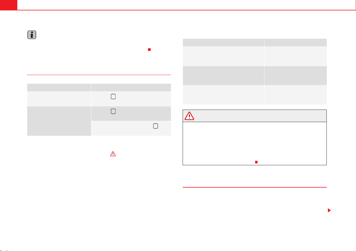
Unlocking and locking88
Note
If the vehicle battery or the battery in the vehicle key is flat, it is possible that
the vehicle cannot be locked or unlock using the KESSY system.
"Safe" security system
When the vehicle is locked, the "Safe" security system deactivates the door
handles and the central locking button making the vehicle difficult to open.
The doors cannot be opened from inside .
When the "Safe" security system is turned off:
x The vehicle can be opened and unlocked from the inside using an inside
door handle.
x The vehicle may be unlocked from the inside by pushing the central
locking button.
x The anti-theft alarm will be activated.
x The vehicle interior monitoring system and the anti-tow system are deac-
tivated.
Driver's door indicator light.
WARNING
Careless use of the "Safe" security system can cause serious injury.
x Never leave anybody inside the vehicle if this is locked using the key.
When the "Safe" security system is activated, doors cannot be opened
from the inside.
x When the doors are locked, it is difficult to get to passengers in the
passenger compartment in case of an emergency. Passengers could remain
trapped inside in case of emergency.
Antitheft alarm
The anti-theft alarm makes it more difficult to break into the vehicle or steal it.
The antitheft alarm is automatically turned on when the vehicle is locked with
the key.
Function Necessary operations
Locks the vehicle with the "Safe"
security system.
Press the button once on the vehicle
key.
Locks the vehicle without the
"Safe" security system.
Press the button twice on the vehicle
key.
Press the central locking button on
the driver's door once.
1
1
1
When the vehicle is locked: Meaning
The red LED flashes for approximately 2
seconds at short intervals and then more
slowly.
The "Safe" security system is
switched on.
The red LED flashes for about two sec-
onds then turns off. After 30 seconds, the
LED flashes again.
The "Safe" security system is
switched off.
The red LED remains lit for about 30 sec-
onds.
There is a fault in the locking
system. Contact a specialist
workshop.
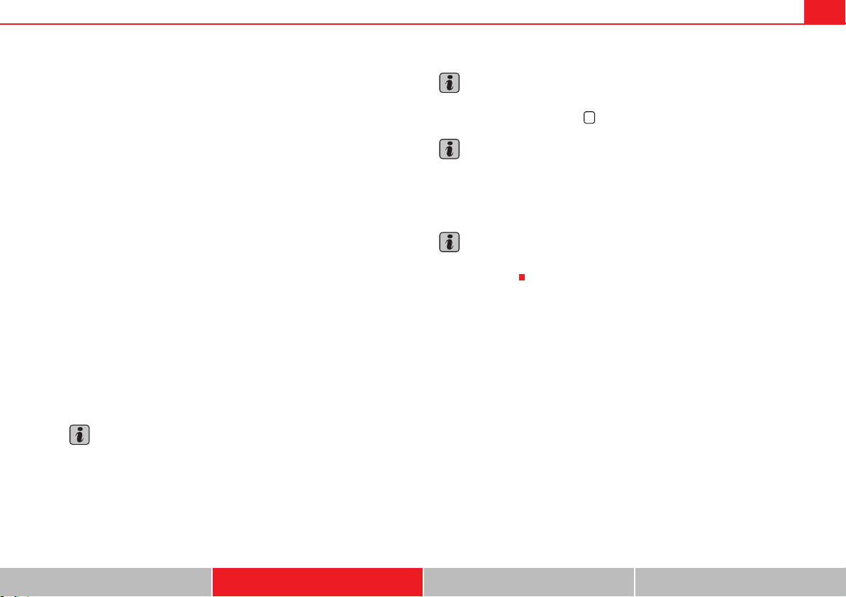
Unlocking and locking 89
Safety First Operating instructions Practical tips Technical Data
When does the system trigger an alarm?
The anti-theft alarm siren will be triggered for about 30 seconds accompa-
nied by optical warning signals for about five minutes when the vehicle is
locked and the following unauthorised actions are taken:
x When the door is mechanically unlocked using the vehicle key without
turning the ignition within the following 15 seconds.
x A door is opened.
x The bonnet is opened.
x The tailgate is opened.
x When the ignition is switched on with a non-authorised key.
x When the vehicle battery is disconnected.
x When there is movement inside the vehicle (vehicles with interior moni-
toring).
x When the vehicle is towed (vehicles with anti-tow system)
x When the vehicle is lifted (vehicles with anti-tow system).
x Transporting the vehicle on a ferry or by railroad (vehicles with an anti-tow
system or passenger compartment monitoring).
x Unhitch a trailer connected to the antitheft alarm page 260.
How to turn OFF the alarm
Unlock the vehicle with the unlocking button on the key or turn on the ignition
with a valid key.
Note
The alarm will be triggered once more when anybody enters the same zone of
surveillance or any other zone. If, for example, after opening a door, the tail-
gate is also opened.
Note
The antitheft alarm is not activated when the vehicle is locked from within
using the central locking button .
Note
If the driver's door is unlocked mechanically with the key, only the driver's
door is unlocked, the rest of the doors remain locked. Only when the ignition
has been turned on will the other doors be available - but not unlocked - and
the central locking button activated.
Note
If the vehicle battery is run down or flat then the antitheft alarm will not
operate correctly.
1
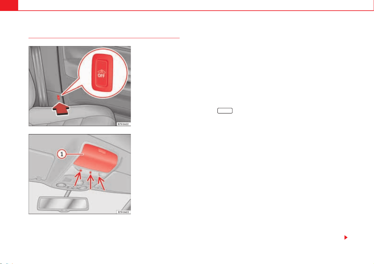
Unlocking and locking90
Interior monitoring system and anti-tow system*
The interior monitoring system triggers the alarm if the vehicle is locked and
movement is detected inside the vehicle. The anti-tow system triggers the
alarm if the vehicle is locked when the system detects the vehicle is being
raised.
Switching on the interior monitoring and the anti-tow systems
Close the storage compartment fig. 52 on the roof console otherwise
the interior of monitoring function (arrow) may not work without restrictions.
Use the key to lock the vehicle. If the antitheft alarm is turned on, the interior
monitoring and the anti-tow systems are also activated.
Switching off the interior monitoring and the anti-tow systems
To turn off the system, the reading light on the button fig. 51 must be lit.
To turn on the reading light, remove the key from the ignition or open a door.
x Push the button. A yellow warning lamp will light up in the button
until the vehicle is locked.
x Lock all doors and tailgate.
x Use the key to lock the vehicle. The interior monitor and / or anti-towing
alarm are switched off until the next time the vehicle is locked.
To turn off the interior monitoring and anti-tow systems before unlocking the
vehicle, for example in the following situations:
x When leaving animals inside the vehicle page 83.
x When the vehicle must be loaded.
x When the vehicle is being transported, for example, by ferry.
x When the vehicle must be towed with the axle raised.
Risk of false alarms
The interior monitoring system only operates correctly if the vehicle is
completely closed. Observe legal requirements. The alarm may be acciden-
tally triggered in the following cases:
x When a window is completely or partially open.
x If the sunglasses storage compartment in the roof console is open.
x When the panorama sliding sunroof is completely or partially open.
Fig. 51 Driver's seat:
button for switching off
the interior monitoring
system and the anti-tow
system.
Fig. 52 On the roof
console: interior moni-
toring sensors.
A
1
d OFF
Unlocking and locking 91
Safety First Operating instructions Practical tips Technical Data
x When suspended objects are hung from the interior mirror (air freshener)
or there are loose papers in the vehicle.
x If the separation net is fitted and moves (due to heating).
x Due to a vibrating mobile telephone inside the vehicle.
Note
Upon activating the alarm, if any door or the tailgate is open, only the alarm
will be activated. The interior monitoring and anti-tow systems will only be
activated when the doors and tailgate are fully closed.
Unlocking and locking92
Doors
Introduction
Additional information and warnings:
x Vehicle key set page 78
x Central locking and locking system page 83
x Emergency locking and unlocking page 348
WARNING
If a door is not correctly closed, it could open unexpectedly when driving
and cause serious injuries.
x Always stop immediately and close the door.
x When closing, ensure that the door has closed correctly. A closed door
should be flush with the corresponding parts of the bodywork.
x Open and close doors only when nobody is in the way of the door.
WARNING
A door held open by its retainer could be blown closed by the wind or close
if the vehicle is on a hill causing injury.
x When opening and closing doors, always use the door handle.
Warning indicator
Several warning and control lamps should light up for a few seconds when
the ignition is switched. This signals that the lamp is working properly. They
will switch off after a few seconds.
If a door is open or incorrectly closed, the indicator or o on the instrument
panel will light.
Depending on the vehicle equipment, a symbol may be displayed on the
instrument panel screen instead of the warning lamp. The indication is also
visible when the ignition is switched off. The indication disappears around 15
seconds after the vehicle has been locked.
Sliding doors
Introduction
Additional information:
x Vehicle key set page 78
x Central locking and locking system page 83
x Emergency locking and unlocking page 348
lights up Possible cause Solution
o
At least one vehicle door is
open or not correctly shut.
Stop driving immediately!
Open the corresponding door
and close it immediately.
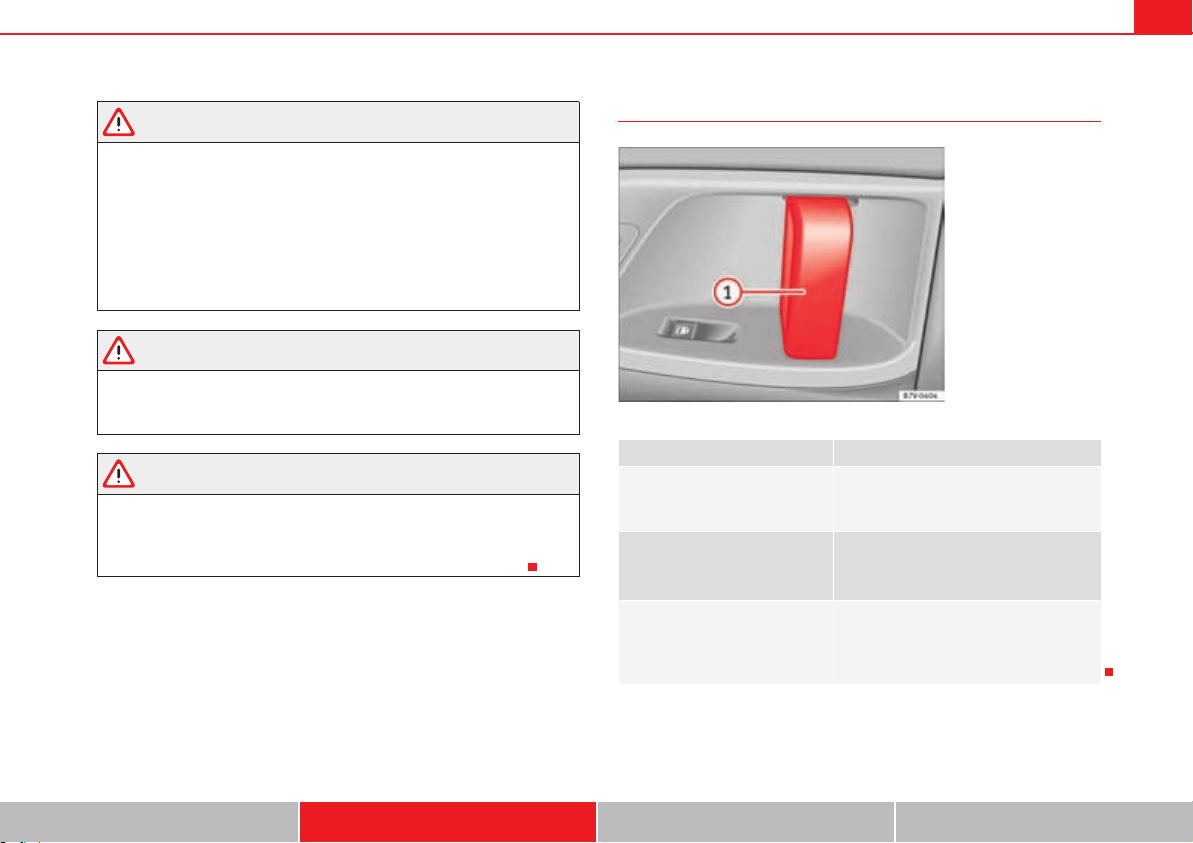
Unlocking and locking 93
Safety First Operating instructions Practical tips Technical Data
WARNING
If a sliding door is not correctly closed, it could open unexpectedly when
driving and cause serious injuries.
x Always stop immediately and close the sliding door.
x When closing, ensure that the sliding door has closed correctly. A
closed sliding door should be flush with the corresponding parts of the
bodywork.
x Only open and close sliding doors when no body is in the way of the
door.
WARNING
If a sliding door is not fully open, it could close unexpectedly and cause
serious injuries.
x Always open the sliding door fully.
WARNING
Opening sliding doors while driving is dangerous. The sliding door could
be pushed open or closed when the vehicle accelerates and brakes causing
serious injuries.
x Never open the sliding doors when the vehicle is in movement.
Manually opening and closing the sliding door
Function Necessary operations
Open the sliding door from the
inside.
When the sliding door is released, open
the door fully by pulling on the outside
handle.
Opening the sliding door from
the inside.
When the sliding door is released, open
the door fully by pulling on its interior
handle fig. 53 .
Closing the sliding door.
Pull on the inside or outside door handle
and close the sliding door by pushing
gently. Make sure that the sliding door is
closed properly.
Fig. 53 On the sliding
door. door handle .
A
1
A
1

Unlocking and locking94
Opening and closing the sliding door electrically*
All of the electric sliding doors can be opened and closed manually using
more force.
Note
When the fuel tank cover is open, the right-hand side electric sliding door is
locked and can only be opened manually.
Note
If the window of a sliding door is lowered them this door cannot open fully.
Fig. 54 On the instru-
ment panel, on the remote
control key and on the
interior lining of the
sliding door: Button for
opening and closing the
electric sliding door.
Function Necessary operations
Opens the sliding door electri-
cally.
Press the fig. 54 button on the instru-
ment panel, on the remote control key
and on the interior lining of the sliding
door. The sliding door opens with the
rollback anti-trap function as long as the
button is not pressed again.
Pull briefly on the interior or exterior han-
dle the door. The sliding door opens
automatically.
Closing the sliding door electri-
cally.
Press the fig. 54 button on the instru-
ment panel, on the remote control key
and on the interior lining of the sliding
door. The sliding door closes with the
rollback anti-trap function as long as the
button is not pressed again. As it closes,
a warning sound is given.
Pull briefly on the interior or exterior han-
dle the door. The sliding door closes with
the roll-back function. As it closes, a
warning sound is given.
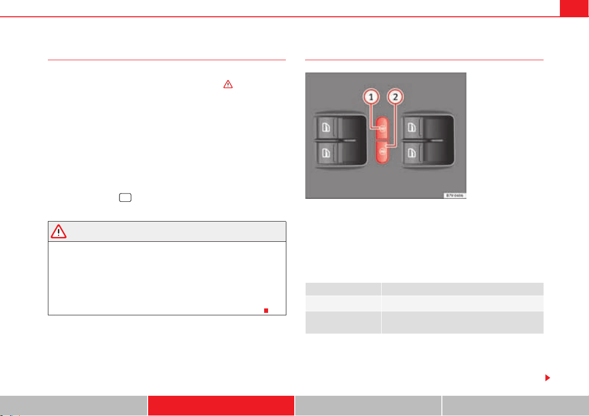
Unlocking and locking 95
Safety First Operating instructions Practical tips Technical Data
Rollback anti-trap function of the electric sliding doors
The rollback anti-trap function of the electric sliding doors can reduce the risk
of injury when opening and closing the sliding doors .
If an object gets in the way of the sliding door while it is closing, it opens
again.
If an object gets in the way of the sliding door while it is opening, the door
stops moving.
x Check the reason for which the sliding door does not open or close.
x Try to open or close the sliding door again.
To close the sliding door without the rollback anti-trap function
x Turn off the ignition and turn it on again.
x Press and hold the page 94, fig. 54 button. The sliding door
closes with full force.
WARNING
Closing the electric windows without the anti-trap function can cause
serious injury.
x Always close the sliding doors carefully.
x Nobody should ever get in the way of the electric sliding doors, espe-
cially when closing without the anti-trap function.
x The anti-trap function does not prevent fingers or other parts of the
body getting pinched against the window frame and causing injury.
Electric child safety lock
The electric child safety lock avoids opening and locking of the sliding door
and its electric windows from the inside so that children cannot accidentally
open the door while the vehicle is being driven. Using the left-hand side
fig. 55 or right-hand side button, the child safety lock is activated
on the left hand side or right-hand side respectively.
Turning on and off the electric child safety
The yellow indicator r indicates that the function is on for the corresponding
button.
In the menu Configuration - Convenience the electric child safety function can
be configured to turn on automatically when the engine starts page 70.
¼
Function Necessary operations
To switch system on:
Press the button fig. 55 o .
The system switches
off:
Press the button again.
Fig. 55 In the driver door:
electric child safety locks
buttons.
A
1
A
2
A
1
A
2
Unlocking and locking96
WARNING
When the electric child safety function is activated, the sliding door can be
opened from the outside only.
x Never leave children or disabled people alone in the vehicle if the doors
are to be locked. Therefore, passengers will be locked inside the vehicle.
They could be trapped in the car in an emergency and will not be able to get
themselves to safety. Individuals locked in the vehicle can be exposed to
very high or very low temperatures.
x Depending on the time of the year, temperatures inside a locked and
closed vehicle can be extremely high or extremely low resulting in serious
injuries and illness or even death, particularly for young children.
Unlocking and locking 97
Safety First Operating instructions Practical tips Technical Data
Tailgate
Introduction
Additional information and warnings:
x Central locking page 83
x Transporting page 13
x Emergency locking and unlocking page 348
WARNING
Careless and unsuitable locking, opening and closing of the tailgate can
cause accidents and serious injury.
x Open and close the tailgate only when nobody is in the way.
x Do not close the tailgate by pushing it down with your hand on the rear
window. The rear window could break and cause injury.
x Ensure the tailgate is locked after closing, otherwise, it may open unex-
pectedly while driving. A closed tailgate should be flush with the corre-
sponding parts of the bodywork.
x Always keep the tailgate closed while driving to avoid toxic gases
entering the passenger compartment.
x Do not open the tailgate when there is a load carrier installed. Likewise,
the tailgate cannot be opened when a load is attached to it, for example
bicycles. An open tailgate could close itself if there is an additional weight
on it. If necessary, press down on the tailgate and remove the load.
x Close and lock both the tailgate and all the other doors when you are
not using the vehicle. Ensure that nobody remains inside the vehicle.
x Never allow children to play inside or around the vehicle without super-
vision, especially if the tailgate is open. Children could enter the luggage
compartment, close the tailgate and become trapped. Depending on the
time of the year, temperatures inside a locked and closed vehicle can be
extremely high or extremely low resulting in serious injuries and illness or
even death, particularly for young children.
x Never leave children or disabled people alone in the vehicle. If the
vehicle key or the central locking button is used, they may be locked in the
vehicle.
Caution
Before opening the tailgate, ensure that there is sufficient free space to open
and close it, for example if you are towing a trailer or in a garage.
Warning indicator
Several warning and control lamps should light up for a few seconds when
the ignition is switched. This signals that the lamp is working properly. They
will switch off after a few seconds.
A warning appears on the instrument panel if the tailgate is open or not
properly closed.
Depending on the vehicle equipment, a symbol may be displayed on the
instrument panel screen instead of the warning lamp. The indication is also
visible when the ignition is switched off. The indication disappears around 15
seconds after the vehicle has been locked.
lights up Possible cause Solution
The tailgate is open or not
correctly shut.
Stop driving immediately!
Open the tailgate and close it
again.
WARNING (continued)
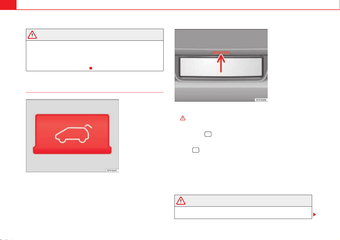
Unlocking and locking98
WARNING
If the tailgate is not correctly closed, it could open unexpectedly when
driving and cause serious injuries.
x Always stop immediately and close the tailgate.
x Ensure that the tailgate has been locked into place by the element on
the lock carrier when you close it.
Opening the tailgate
Before opening the tailgate, always remove any load on its luggage rack
.
Opening with the ignition key
Press the button on the vehicle key until the tailgate opens automatically.
To open using the centre console control
Press the button on the centre console fig. 56. The tailgate will be
automatically opened.
The button is still operative when the ignition is switched off.
Opening the tailgate with the button
x Unlock the vehicle or open a door.
x Raise the tailgate using the button fig. 57 (arrow).
WARNING
Unsuitable or careless unlocking and opening of the tailgate could cause
serious injuries.
Fig. 56 Detailed view of
the centre console: button
for unlocking the tailgate.
Fig. 57 Opening the tail-
gate from the exterior
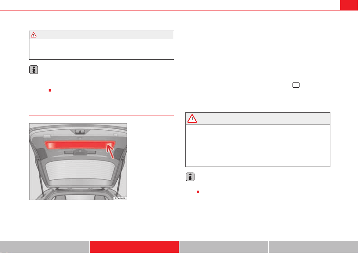
Unlocking and locking 99
Safety First Operating instructions Practical tips Technical Data
x If there is a loaded luggage carrier on the tailgate, it could be unlocked
or open but not recognised as such. An unlocked or open tailgate could
open unexpectedly while driving.
Note
At outside temperatures of less than 0 °C (+32 °F), the pressurised gas struts
cannot always automatically lift the tailgate. In this case, open the tailgate
manually.
Closing the tailgate
Closing the tailgate
x Grab the handgrip inside the tailgate fig. 58 (arrow).
x Push the tailgate downwards until it locks into place in the lock.
x Ensure that it is correctly closed by pulling on it firmly.
Locking the tailgate
If you unlock the vehicle without opening any doors or the tailgate, it will lock
again automatically after 30 seconds. This function prevents the vehicle from
remaining unlocked if the unlocking button is pressed by mistake.
Locking is only possible when the tailgate is correctly and fully closed.
x The tailgate is also locked by a central locking.
x If the vehicle tailgate is locked or unlocked using the button, when it
is closed once more it will lock automatically.
x A closed but not locked tailgate will lock automatically at a speed above
about 9 km/h ( 7 mph).
WARNING
Unsuitable or careless closing and locking of the tailgate could cause
serious injuries.
x Never allow children to play inside or around the vehicle without super-
vision, especially if the tailgate is open. Children could enter the luggage
compartment, close the tailgate and become trapped. A locked vehicle can
be subjected to extremely high and low temperatures, depending on the
time of year, thus causing serious injuries/illness and even death.
Note
Before closing the tailgate, make sure that the key has not been left inside the
boot.
WARNING (continued)
Fig. 58 Tailgate open:
hand grip.
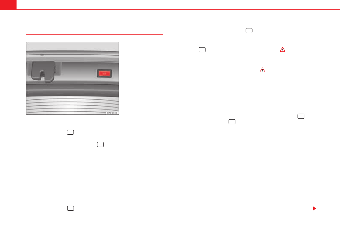
Unlocking and locking100
Opening the tailgate electronically
Opening the tailgate
x Press and hold the button on the vehicle key until the tailgate opens
automatically.
x ALTERNATIVELY: Press and hold the button on the centre console for
approximately 1 second page 98, fig. 56.
x ALTERNATIVELY: Press the page 98, fig. 57 tailgate button (arrow).
In case of difficulty or obstruction, automatic opening of the tailgate is inter-
rupted.
Electronically opening the tailgate does not work when a trailer is electrically
connected and hitched to a factory fitted trailer hitch page 260.
The tailgate can be opened manually by applying more force.
Closing the tailgate
x Press and hold the button on the vehicle key for approximately 1
second.
x ALTERNATIVELY: Press and hold the button on the centre console for
approximately 1 second page 98, fig. 56.
x ALTERNATIVELY: Press the page 98, fig. 57 tailgate button (arrow).
x Press the button on the open tailgate fig. 59 .
x Manually push the tailgate down to close it.
The tailgate will move down to the closed position to close and lock itself
automatically using the power-close feature .
In case of difficulty or obstruction, automatic closing of the tailgate is inter-
rupted and it will open slightly.
Check why the tailgate could not close.
Attempt to close it once more.
Interrupting the opening and closing process
Tailgate opening and closing can be stopped by pressing one of the
buttons. Each time one of the buttons is pressed, the tailgate moves to
its initial position.
Then, it can be opened or closed by hand. To do this, apply a little more force.
Memorising the opening angle
The tailgate must be at least half open to memorise an opening angle.
x Stop automatic opening in the opening position required page 100.
x Hold down the button fig. 59 with the tailgate open for at least three
seconds. The opening angle is memorised.
Memorisation is confirmed by blinking of the hazard lights and a sound
signal.
To be opened completely, the opening angle must be memorised once more.
x Release the tailgate and open it to the memorised height.
x Push the tailgate all the way up. To do this, apply a little more force.
Fig. 59 Button with tail-
gate open.
Unlocking and locking 101
Safety First Operating instructions Practical tips Technical Data
x Hold down the button page 100, fig. 59 with the tailgate open for at
least three seconds.
x The opening angle is reset to the original factory setting.
WARNING
Unsuitable or careless closing and locking of the tailgate could cause
serious injuries.
x Never allow children to play inside or around the vehicle without super-
vision, especially if the tailgate is open. Children could enter the luggage
compartment, close the tailgate and become trapped. A locked vehicle can
be subjected to extremely high and low temperatures, depending on the
time of year, thus causing serious injuries/illness and even death.
WARNING
It is possible that the tailgate does not open completely or, if it is open,
closes alone if a large amount of snow has built up on it or if a luggage rack
is fitted. In this case, the tailgate must be supported.
Caution
x When using a trailer, ensure that there is sufficient space to open and
close the tailgate.
x Before opening the tailgate, any kind of equipment carrier should be
removed, for example a bicycle carrier.
Caution
In case of repeated short-term use, the system is turned off to avoid over-
heating.
x When it has cooled, it may be used once again. During this time, the tail-
gate may be manually opened or closed applying a little more effort.
x If the vehicle battery is disconnected or the fuse blows when the tailgate
is open, the tailgate system must be re-initialised. To do this, close the tail-
gate.
Note
Before closing the tailgate, make sure that the key has not been left inside the
boot.
Unlocking and locking102
Electric windows
Introduction
Additional information and warnings:
x SEAT information system page 70
x Central locking and locking system page 83
WARNING
Careless use of the electric windows can cause serious injury.
x Only operate the electric windows when nobody is in the way.
x Never leave children or disabled people alone in the vehicle if the doors
are to be locked. The windows cannot be opened in case of an emergency.
x Always take all the keys with you whenever you leave the vehicle. After
turning off the ignition, the windows can be opened and closed for a short
time using the buttons on the door as long as the driver's door or
passenger side door is not open.
x When transporting children in the rear seats, always deactivate the rear
electric windows with the child safety lock so that they cannot be opened
and closed.
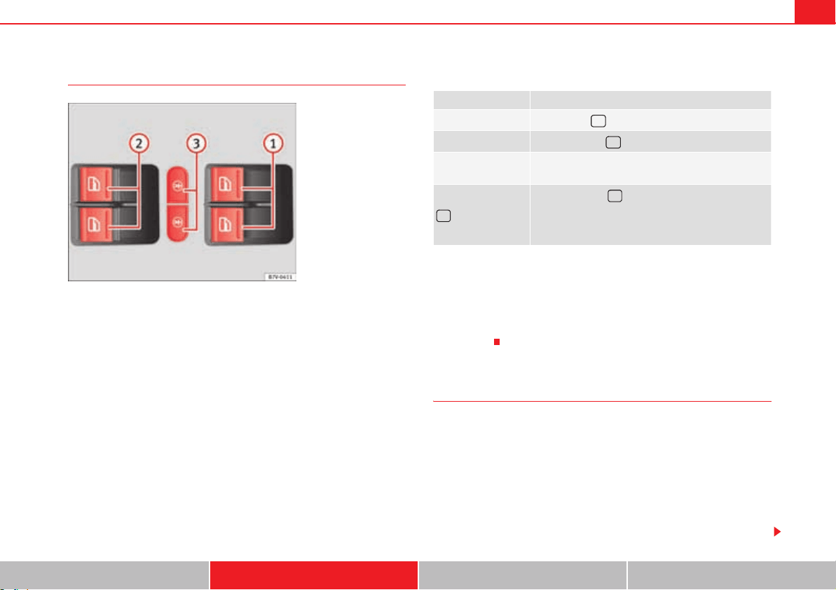
Unlocking and locking 103
Safety First Operating instructions Practical tips Technical Data
Opening and closing the electric windows
Buttons on the driver door
Legend for the fig. 60:
For the front electric windows.
For the sliding door electric windows.
To lock the sliding doors and their windows.
Opening and closing the windows
After turning off the ignition, the windows can be opened and closed for a
short time using the buttons on the door as long as the driver's door or
passenger side door is not open. When the key is removed from the ignition
and the driver's door is open, all of the electric windows can be opened or
closed using the corresponding button on the driver's door. After a few
seconds, the convenience opening or closing function will begin
page 104.
Electric windows: functions
One-touch opening and closing
The one-touch automatic opening and closing is used to open or close the
windows completely. It will not be necessary to hold the button of the corre-
sponding electric window.
For the one-touch closing function: pull up on the button for the window to
the second position.
For the one-touch opening function: Push down the button for the window to
the second position.
Fig. 60 In the driver door:
Buttons for front and rear
electric windows and
child safety lock.
A
1
A
2
A
3
Function Necessary operations
Opening:
Press button .
Closing:
Push the button .
To stop the one
touch function:
Press or pull on the corresponding window button.
Press the button for the electronic child safety
lock to deactivate the controls for the windows on the
sliding doors and to lock these doors page 92. The
button will light up.
r
r
Unlocking and locking104
To stop the one touch function: Push or pull on the button of the corre-
sponding window.
Restoring one-touch opening and closing
The one-touch opening and closing function is not active after the vehicle
battery has been disconnected or is flat and will have to be reset.
x Close all windows and doors.
x Pull the button of the corresponding window and hold it for one second in
this position.
x Release the button and pull upwards and hold again. The one-touch func-
tion is now ready for operation.
The automatic one-touch electric windows can be reinitialised individually or
several at a time.
Convenience opening and closing function
The electric windows can be opened or closed from outside using the vehicle
key:
x Hold in the unlocking for locking button for the vehicle. All windows which
function electrically will be either opened or closed.
x To interrupt the function, release the locking or unlocking button.
During convenience closing, first the windows and then the sliding sunroof
will be closed.
In the Configuration - convenience menu, there are different settings for oper-
ating the windows page 70.
WARNING
Careless use of the electric windows can cause serious injury.
x Only operate the electric windows when nobody is in the way.
x Never leave children or disabled people alone in the vehicle if the doors
are to be locked. The windows cannot be opened in case of an emergency.
x Always take all the keys with you whenever you leave the vehicle. After
turning off the ignition, the windows can be opened and closed for a short
time using the buttons on the door as long as the driver's door or
passenger side door is not open.
x When transporting children in the rear seats, always deactivate the rear
electric windows with the child safety lock so that they cannot be opened
and closed.
Note
The one-touch function and roll-back function will not work if there is a
malfunction in the electric windows. Visit a specialist workshop.
Electric Windows anti-trap function
The anti-trap function of the electric windows can reduce the risk of injury
when opening and closing the electric windows . If a window is not able
to close because it is stiff or because of an obstruction, it will automatically
open again.
x Check why the window does not close.
x Attempt to close the window again.
x If you try within the following 10 seconds and the window closes with
difficulty or there is an obstruction once again, the one-touch closing will stop
working for 10 seconds.
x If the window is still obstructed, it will stop at the corresponding position.
When the button is operated within 10 seconds, the window will close
without the anti-trap function .
WARNING (continued)
Unlocking and locking 105
Safety First Operating instructions Practical tips Technical Data
To close windows without the anti-trap function
x Attempt to close the corresponding electric window within 10 seconds
after by holding the button. The window is closed without the anti-trap func-
tion, deactivated for a short time.
x After more than 10 seconds, the anti-trap function is reactivated. The
window will stop once again if there is another difficulty or obstacle.
x If the window will still not close, visit a specialised workshop.
WARNING
Closing the electric windows without the anti-trap function can cause
serious injury.
x Always close the electric windows carefully.
x Nobody should be in the way of the electric windows, especially when
the anti-trap function is deactivated.
x The anti-trap function does not prevent fingers or other parts of the
body getting pinched against the window frame and causing injury.
Note
The anti-trap function also operates if the windows are closed from the
outside of the vehicle using the ignition key for convenience closing
page 104.
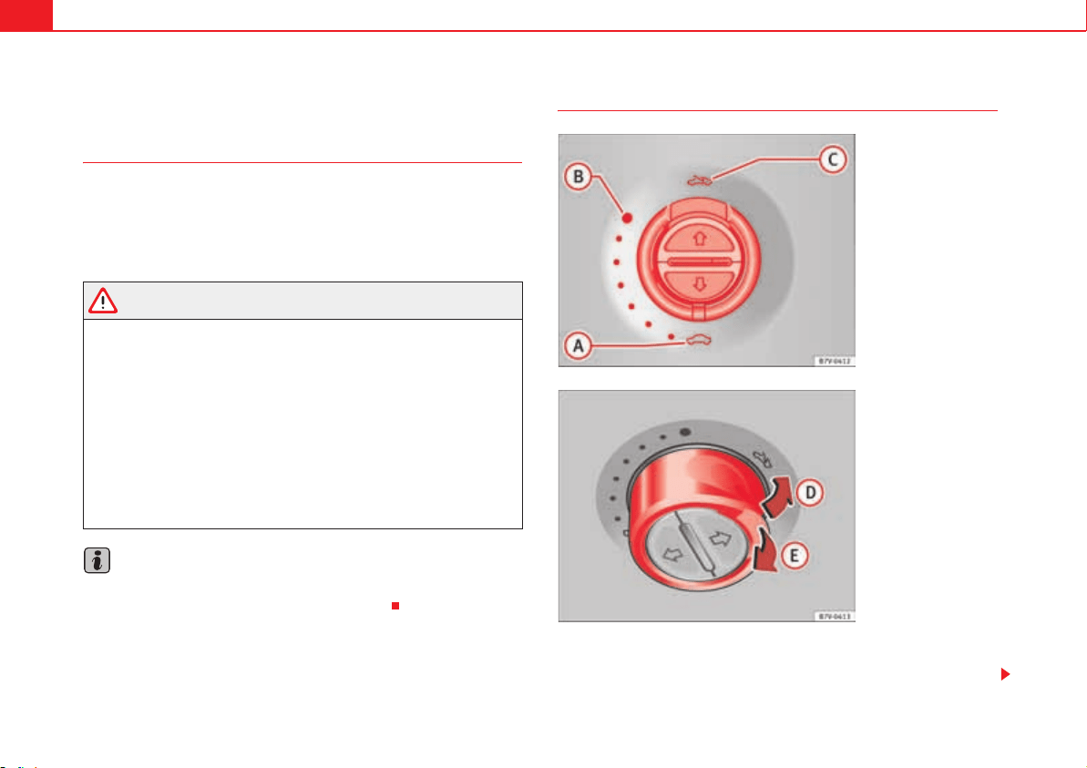
Unlocking and locking106
Panorama sliding sunroof*
Introduction
Additional information and warnings:
x SEAT information system page 70
x Central locking and locking system page 83
x Emergency locking and unlocking page 348
WARNING
Careless use of the panorama sliding sunroof can cause serious injury.
x Only close the panorama sliding sunroof and the sunshade when
nobody is in the way.
x Always take all the keys with you whenever you leave the vehicle.
x Never leave children or disabled persons in the vehicle, particularly if
they have access to the keys. Uncontrolled use of the key could lock the
vehicle, start the engine, turn on the ignition and operate the sliding
sunroof.
x The sliding sunroof can be operated for up to about ten minutes after
the ignition has been switched off, provided the driver door and the front
passenger door are not opened.
Note
In case of a fault in the operation of the sliding sunroof, the anti-trap function
will not operate correctly. Visit a specialist workshop.
Opening or closing the panorama sliding sunroof
To unfold the panorama sliding sunroof, the switch must be in the position
.
Fig. 61 On the interior
roof lining: use the rotary
button to open and close.
Fig. 62 On the interior
roof lining: Press the
button and pull on it to lift
and close the sliding
sunroof.
A
A
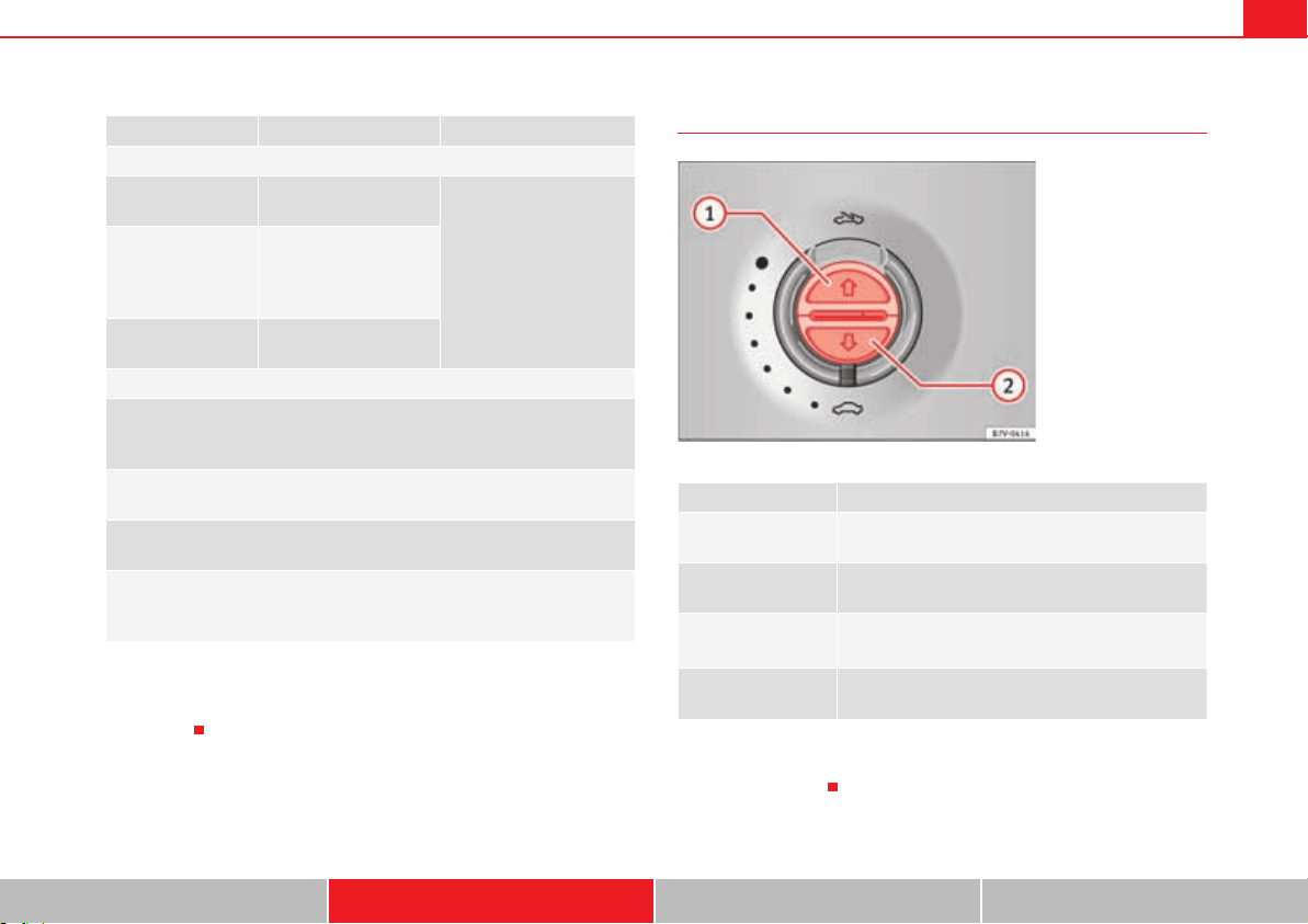
Unlocking and locking 107
Safety First Operating instructions Practical tips Technical Data
The panorama sliding sunroof will only work with the ignition on. The sliding
sunroof can be operated for up to about ten minutes after the ignition has
been switched off, provided the driver door and the front passenger door are
not opened.
Opening or closing the sunshade
The sliding sunroof can be operated for up to about ten minutes after the igni-
tion has been switched off, provided the driver door and the front passenger
door are not opened.
Function Switch setting Necessary operations
page 106, fig. 61
To open the sliding
sunroof completely:
Rotate the switch to the
required position.
To choose the con-
venience position
for the sliding sun-
roof:
To close the sliding
sunroof completely:
page 106, fig. 62
To completely
deploy the roof
deflector:
Briefly push the switch up
(arrow).
To stop automatic
operation:
or
Briefly push the button
again back or pull on it.
To completely close
the roof deflector:
Briefly push the switch up
(arrow).
To set the intermedi-
ate position:
or
Holding the button or hold
it back until the roof is in
the required position.
A
C
A
B
A
A
A
D
A
D
A
E
A
E
A
D
A
E
Function Necessary operations
To open completely
(automatic):
Press the button fig. 63 briefly.
To stop automatic
operation:
Press the button fig. 63 or fig. 63 .
To set the intermedi-
ate position:
Hold the button fig. 63 or fig. 63 until
the required position is reached.
To close completely
(automatic):
Press the button fig. 63 briefly.
Fig. 63 On the interior
roof lining: switches for
the sunshade.
A
1
A
1
A
2
A
1
A
2
A
2
Unlocking and locking108
Panorama sliding sunroof: operation
Convenience open/close function
The panorama sliding sunroof can be opened or closed from outside the
vehicle using the vehicle key:
x Hold in the unlocking for locking button for the vehicle. The panorama
sliding sunroof is adjusted or closes.
x Release the unlock or lock button to stop the function.
During convenience closing, first the windows and then the sliding sunroof
will be closed.
Note
The sliding sunroof rotary button remains in the last position selected if the
roof is closed using convenience closing from outside the vehicle and will
have to be re-positioned the next time you drive.
Anti-trap function of the panorama sliding sunroof and the
sunshade
The anti-trap function reduces the risk of injury when opening and closing the
panorama sliding sunroof and sunshade . When the panorama sliding
sunroof or the sunshade encounter difficulty or an obstacle when closing,
they will stop and reopen.
x Check why the panorama sliding sunroof or the sunshade did not close.
x Attempt to close the panorama sliding sunroof or sunshade once again.
x If the panorama sliding sunroof or sunshade is still obstructed, it will stop
at the corresponding position. Now close the panorama sliding sunroof or
sunshade without the anti-trap function.
Closing without the roll-back function
x The page 106, fig. 61 switch should be in the “closed” position
.
x Panorama sliding sunroof: Within five seconds of triggering the anti-trap
function, pull the control all the way back page 106, fig. 62 (arrow E) until
the panorama sliding sunroof closes fully.
x Sunshade: Within five seconds of triggering the anti-trap function, push
the page 107, fig. 63 button until the sunshade closes completely.
x The panorama sliding sunroof or sunshade close without the anti-trap
function.
x If the panorama sliding sunroof still cannot be closed, visited a special-
ised workshop.
WARNING
Closing the panorama sliding sunroof or sunshade without the anti-trap
function can cause serious injuries.
x Always close the panorama sliding sunroof carefully.
x Nobody should be in the way of the panorama sliding sunroof or
sunshade, especially when they are closed without the anti-trap function.
x The anti-trap function does not prevent fingers or other parts of the
body getting pinched against the window frame and causing injury.
Note
The anti-trap function is activated if the windows and the panorama sliding
sunroof are closed from the outside of the vehicle using the ignition key for
convenience closing page 104.
A
1
A
A
A
2
Unlocking and locking 109
Safety First Operating instructions Practical tips Technical Data
Garage door remote control*
Introduction
Fixed code or variable code
The garage door remote control uses either a fixed code or a variable code.
For remote controls using a variable code, the system must be synchronised
after programming page 110.
Compatibility
SEAT recommends that before buying a remote control or electric system, you
get information from a approved technical service about which products are
compatible with the vehicle remote control.
In some countries, the use of safety controls and electric systems for garage
doors are obligatory.
WARNING
Careless use of the garage remote control can cause serious injury.
x The garage remote control and electric systems operate with enough
energy to cause injury.
x Only use the remote control when you can see the garage door and that
there is nobody in its way.
x When programming, the garage door or electric system could move
causing damage or injury.
x The garage remote control and electric systems that do not detect
obstacles do not comply with the legal requirements in certain countries.
Using remote controls and electric systems that do not detect obstacles
increases the risk of injury or death.
x Always read the assembly instructions and warnings from the manufac-
turer when using a garage door remote control and electric system.
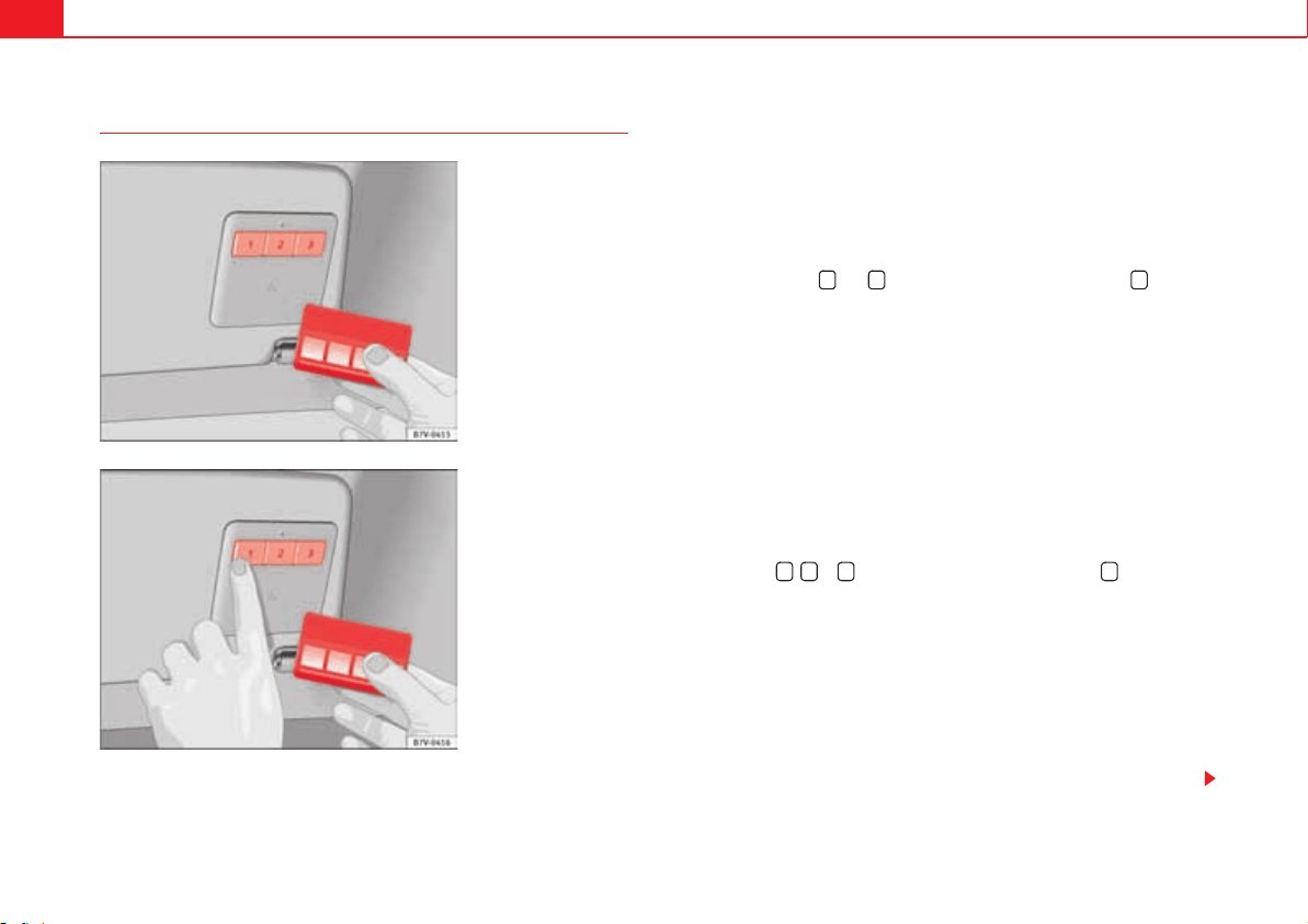
Unlocking and locking110
Programming the garage door remote control
Functions from up to 3 different remote controls for different products can be
transferred to the buttons on the sunshade ( for example, the electric system
for a gateway or a garage door, a house alarm or a lighting system).
Before programming
x Before programming the garage remote control, always read the instruc-
tion manual from the product manufacturer.
x Always stop your vehicle safe distance from the system.
x When programming, turn on the ignition but do not start the engine.
Before programming the unit for the first time:
x Press the buttons and until the indicator above the button begins
to blink.
x Release both buttons. This erases the factory settings. There is no need to
do this again to program the remaining buttons.
x However, if you hold in the buttons for more time, the factory settings will
be re-established.
Programming
x Before programming, carry out the initial steps page 110.
x Put your system's remote control, for example the remote to operate the
garage door, within 30 cm of the sunshade button fig. 64. If this is too far
away, you may have to repeat the procedure.
x Now, simultaneously hold in the button on your system's remote control
and the button , or until the indicator above the button blinks, first
slowly then more quickly fig. 65.
x Release both buttons. The function from your system's remote control is
transferred to the corresponding button.
To transfer other functions to other buttons of the garage door remote control,
repeat the procedure described above with the button to be programmed.
Synchronising a remote control with a variable code
x Before programming, carry out the initial steps page 110.
x Program the remote control page 110.
Fig. 64 Radio frequency
remote control and control
buttons on the sunshade.
Fig. 65 To program: Press
the buttons on the garage
door control and the
remote control simultane-
ously.
1 3 2
1 2 3 2
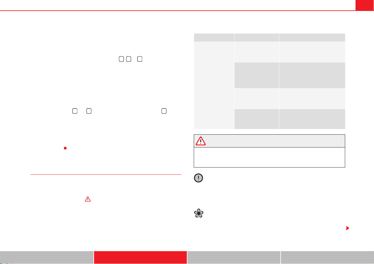
Unlocking and locking 111
Safety First Operating instructions Practical tips Technical Data
x Search the manufacturer's instructions manual for the garage door or
gate to find the “setting button” for the power motor to synchronise a new
remote control.
x After pressing the “settings button” on the power motor, you have a
maximum of 30 seconds to press the button , or . Press the same
button once more to complete the process. For some systems, the button
must be pressed the third time.
Erasing the programming for all buttons
SEAT recommends erasing the programming for all buttons when selling or
loaning your vehicle.
x Before programming, carry out the initial steps page 110.
x Press the buttons and until the indicator above the button begins
to blink.
x Release both buttons. All of the programmed functions are erased.
After programming
Check the garage door remote control page 111, “Using the garage door
remote control”.
Using the garage door remote control
The vehicle must be within range of the garage door or gate power motor.
x With the engine running or the ignition on, push the corresponding
button on the sunshade .
WARNING
Careless use of the garage remote control can cause serious injury.
x Only use the remote control when you can see the garage door and that
there is nobody in its way.
Caution
Use of inappropriate batteries may damage the remote control. For this
reason, always replace the dead battery with another of the same voltage,
size and specifications.
For the sake of the environment
Please dispose of your used batteries correctly and with the utmost respect
for the environment.
1 2 3
1 3 2
Fault Possible cause Possible solution
Garage door or
electric system is
not working.
The batteries of
remote control are
flat.
Change the batteries.
The remote control is
too far away or the
transmission angle
was to large.
Vary the distance and the angle
to the receiver.
The garage door or
electric system are
not compatible.
The system does not corre-
spond to legal requirements
and must be replaced.
Programming was
not completed cor-
rectly.
Program the remote control
once more.

Unlocking and locking112
For the sake of the environment
The remote control battery may contain perchlorate. Observe the legal
requirements for their disposal.

Lights and visibility 113
Safety First Operating instructions Practical tips Technical Data
Lights and visibility
Lights
Introduction
The legal requirements regarding the use of vehicle lights in each country
must be observed.
The driver is personally responsible for the correct use and adjustment of the
lights in all situations.
Additional information and warnings:
x SEAT information system page 70
x Changing bulbs page 360
WARNING
If the headlights are set too high and the main beam is not used correctly,
there is a risk of dazzling or distracting other road users. This could result
in serious accident.
x Always make sure that the headlamps are correctly adjusted.
x Never use the main beam or flashed headlamps as this could dazzle
other drivers.
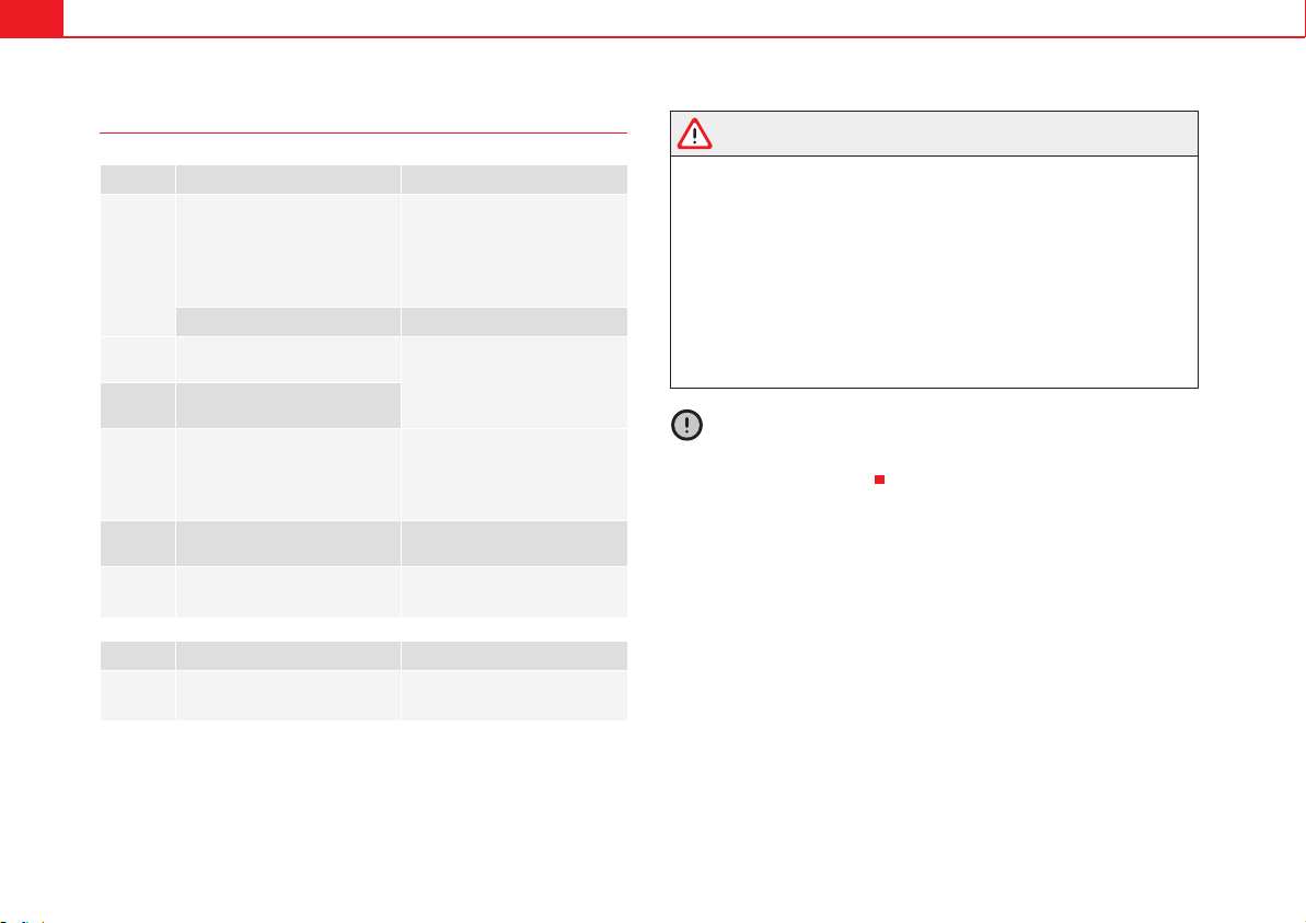
Lights and visibility114
Warning lamps
Several warning and control lamps should light up for a few seconds when
the ignition is switched. This signals that the lamp is working properly. They
will switch off after a few seconds.
WARNING
If the warning lamps and messages are ignored, the vehicle may stall in
traffic, or may cause accidents and severe injuries.
x Never ignore the warning lamps or text messages.
x Stop the vehicle safely as soon as possible.
x Park the vehicle at a suitable distance away from the traffic ensuring
that the exhaust system is not in contact with inflammable material, for
example, dry grass, fuel, oil, etc.
x A faulty vehicle represents a risk of accident for the driver and for other
road users. If necessary, switch on the hazard warning lamps and put out
the warning triangle to advise other drivers.
Caution
Failure to heed the warning lamps and text messages when they appear may
result in faults in the vehicle.
lights up Possible cause Solution
Driving light totally or partially
faulty.
Replace the corresponding
bulb page 360.
If all the bulbs are OK, the vehi-
cle should be taken to a spe-
cialised workshop if necessary.
Fault in adaptive light. page 118.
Rear fog light switched on.
page 116.
Fog lights switched on
Left or right turn signal.
The warning lamp flashes twice
as fast when a vehicle or trailer
turn signal is faulty.
If necessary, check the vehicle
and trailer lighting.
Headlight on or flasher on. page 115.
+
Headlight adjustment (Light
Assist) on.
page 117.
flashes Possible cause Solution
Fault in the adaptive light sys-
tem.
Contact a specialist workshop
page 117.
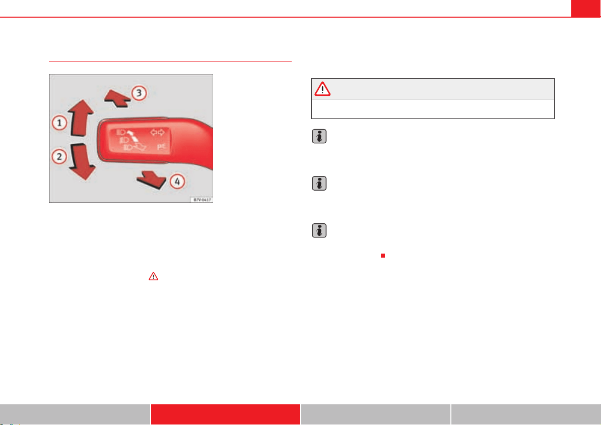
Lights and visibility 115
Safety First Operating instructions Practical tips Technical Data
Turn signal and main beam lever
Move the lever to the required position:
Right turn signal. Right-hand parking light (ignition switched off)
page 117.
Left turn signal. Left-hand parking light (ignition switched off)
page 117.
Main beam switched on . The indicator lamp will light up on the
instrument panel.
Flashing the headlamps. The flashed beam comes on if the lever is
pressed. The indicator lamp will light up.
Push the lever all the way down to turn off the corresponding function.
Convenience indicators
For the convenience turn signals, move the lever as far as possible upwards
or downwards and release the lever. The turn signal will flash three times.
The control turn signals are switched on and off from the menu Lights&
Visibility on the instrument panel display page 70. This function can be
disconnected at a specialised workshop for those vehicles which do not have
the menu Lights & Visibility.
WARNING
Incorrect use of the headlamps may cause accidents and serious injury, as
the main beam may distract or dazzle other drivers.
Note
The turn signal only works when the ignition is switched on. The hazard
warning lights also work when the ignition is switched off page 345.
Note
If a turn signal on the vehicle or trailer is faulty, the warning lamp flashes
twice as fast as usual.
Note
The main beam headlights can only be switched on if the dipped beam head-
lights are already on.
Fig. 66 Turn signal and
main beam lever.
A
1
A
2
A
3
A
4
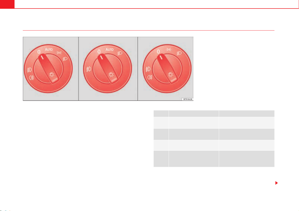
Lights and visibility116
Turning on and off lights
The legal requirements regarding the use of vehicle lights in each country
must be observed.
In vehicles with tow bar fitted as standard: If the trailer is connected electri-
cally and is fitted with a rear fog light, this is automatically switched off on the
vehicle.
Turn the light switch to the required position fig. 67:
Fog lights
The warning lamps or on the light switch also indicate that the fog
lights are switched on.
Fig. 67 Next to the steering wheel: diagram of some of
the types of light switch.
when the ignition is turned off when the ignition is on
/
Fog lights, dipped beam and
side lights off.
Lights off or daytime driving light
on.
!54/
The guidance lights may be
switched on.
Automatic dipped beam control
or daytime driving light on.
Side light on. Side light on.
Dipped beam off; if necessary,
the side light comes on for a
time.
Dipped beam switched on.
Lights and visibility 117
Safety First Operating instructions Practical tips Technical Data
x Switching on the fog lights : Turn the switch to position or pull out
to the first stop.
x Switching on the rear fog light : turn the light switch to position o
pull out to the maximum.
x To switch off the fog lights, press the light switch or turn it to position /.
Audible warnings to advise the driver that the lights have not been switched
off
If the key is not in the ignition and the driver's door is open, an audible
warning signal is heard in the following cases: This is a reminder to turn off
the lights.
x When the parking light is on page 115.
x When the light switch is in position .
WARNING
The side lights or daytime driving lights are not bright enough to illuminate
the road ahead and to ensure that other road users are able to see you.
x Always use your dipped beam head lights if it is raining or if visibility is
poor.
Lights and visibility: functions
Parking light
When the parking light is switched on,(right or left turn signal), the front side
light and the rear light on the corresponding side of the vehicle stay lit. The
parking lights will only work with the ignition off.
Daytime driving light
The daytime driving light consists of individual lights in the front headlamps.
When the daytime driving light is switched on, only the individual lights come
on .
The daytime lights are switched on each time the ignition is turned on if the
light switch is in position !, 5,4 or /.
When the light switch is in position !, 5, 4 or /, a photo sensor goes out and
the instrument and switch lighting comes on automatically.
Automatic dipped beam control !54/
The automatic dipped beam control is merely intended as an aid and is not
able to recognise all driving situations.
When the light switch is in position !, 5, 4 or /, the vehicle lights and the
instrument panel and switch lighting switch on and off automatically in the
following situations :
Activating the daytime lights Deactivating the daytime lights
Press and hold the turn signal and
main beam lever upwards and back-
wards (right turn signal and light
flasher).
Press and hold the turn signal and
main beam lever downwards and
backwards (left turn signal and light
flasher).
Switch the ignition on and off for approximately 3 seconds.
Automatic switching on: Automatic switching off or switch to
daytime lighting:
The photo sensor detects darkness,
for example, when driving through a
tunnel.
When adequate lighting is detected.
When driving at more than 140 km/h
for a few seconds.
When driving at less than 65 km/h
for a few minutes.
The rain sensor detects rain and acti-
vates the windscreen wipers.
When the windscreen wiper has
been inactive for a few minutes.
Lights and visibility118
Adaptive front lighting system (AFS)
The adaptive headlights only operate when the dipped beam is on and at
speeds of over 10 km/h. When taking a bend, the adaptive headlights auto-
matically light up the road better.
The adaptive headlights can be switched on and off from the infotainment
system.
Static turning lights
When turning slowly to change direction or going round a tight bend, the
static cornering lights automatically come on. The static cornering lights only
work at speeds of less than 40 km/h.
The static cornering lights may be incorporated into the fog lights or the front
headlights, depending upon the equipment.
Main beam headlight control
The main beam control (Light Assist) automatically switches the main beam
on and off within the limits of the system, regardless of prevailing conditions,
traffic and vehicle speed . The system is controlled by a sensor on the
inside of the windscreen above the rear view mirror. The main beam and
flashed headlight can be switched on and off manually at the turn signal and
main beam lever.
x To light, with the ignition on, rotate the headlight control to the posi-
tion!54/ and move the turn signal lever to the full beam headlight position.
When the ignition is switched off, the main beam control is also switched off.
The following conditions may prevent the full beam headlight control from
turning off the headlights in time or from turning off altogether:
x In poorly lit towns with highly reflective signs.
x In fog, snow and heavy rain.
x If the area around the sensor on the windscreen is misted, dirty or covered
with a sticker.
x If a stone has struck the area of the sensor.
x Other insufficiently lit road users (for example, pedestrians or cyclists).
x On tight bends and steep slopes and when oncoming vehicles are
partially obscured.
x When the drivers of other oncoming vehicles (such as a truck) can see
over a guard rail in the centre of the road.
WARNING
If the road is not well-lit and the vehicle is not clearly visible to other
drivers, there is a risk of accident.
x The automatic main beam control (!54/) only switches on the dipped
beam when there are no changes in brightness, and not, for example when
it is foggy.
x Never use the daytime driving light if the road is not well-lit as a result
of the weather conditions and poor visibility. The daytime driving lights are
not bright enough to illuminate the road ahead and to ensure that other
road users are able to see you.
x The rear lights do not come on with the daytime driving light. A vehicle
which does not have the rear lights on may not be visible to other drivers
in the darkness, if it is raining or in conditions of poor visibility.
WARNING
The convenience features of the main beam control should not encourage
the taking of risks. The system is not a replacement for driver awareness.
x Always check the main beam and adjust it to the traffic, visibility and
light conditions.
x It is possible that the main beam headlight control does not recognise
all driving situations and is limited under certain circumstances.
x Operation of the main beam headlight control can be affected by
changes made to the vehicle lighting system (for example, if additional
headlights are added).
Lights and visibility 119
Safety First Operating instructions Practical tips Technical Data
Note
The headlights, rear lights and turn signals may mist up temporarily on the
inside in cool or damp weather. This is normal and in no way effects the useful
life of the vehicle lighting system.
Adhesive strips for headlights or adjusting headlights
In those countries where vehicles drive on the other side of the road to the
home country, the asymmetric dipped beam may dazzle drivers of oncoming
vehicles. Therefore, when driving abroad, adhesive strips should be attached
to the headlights or the headlights should be adjusted accordingly.
The direction of the headlights can be adjusted from the instrument panel, in
the menu Settings submenu Travel mode page 70.
For those vehicles in which it is not possible to adjust the headlights from the
menu, adhesive strips are used to cover certain parts of the headlamp cover
or the headlights may be adjusted at a specialised workshop. For further
information, please refer to a specialised workshop. SEAT recommends
visiting a qualified workshop.
Note
The use of Travel mode and adhesive strips on the headlights is only author-
ised for a short period of time. To modify the direction of the headlamps more
permanently, please take the vehicle to a specialised workshop. SEAT recom-
mends visiting a qualified workshop.
Function “Coming home” and “Leaving home” (guidance
lights)
The “Coming home” function should be switched on manually. However the
“Leaving home” function is automatically controlled by a photo sensor.
Lighting around the exterior mirrors
The lighting around the exterior mirrors illuminates the door area on entering
and leaving the vehicles. It comes on when the vehicle is unlocked, when the
vehicle door is opened and when the “Coming home” or “Leaving home”
“Coming Home” Necessary operations
To switch sys-
tem on:
– Switch off the ignition.
– Briefly flash the headlights for approximately one sec-
ond page 115.
The “Coming home” lighting comes on when the driver's
door is opened. The delay in switching off the headlights
is counted from when the last door or tailgate is closed.
The system
switches off:
– Automatically at the end of the delay period.
– Automatically, if 30 seconds after coming on, a vehicle
door or tailgate remains open.
– If the light switch is turned to position /.
– If the ignition is switched on.
“Leaving home” Necessary operations
To switch sys-
tem on:
– Unlock the vehicle when the light switch is in position
!54/ and the photo sensor detects darkness.
The system
switches off:
– Automatically, at the end of the delay period.
– When the vehicle is locked.
– When the light switch is turned to position /.
– When the ignition is switched on.
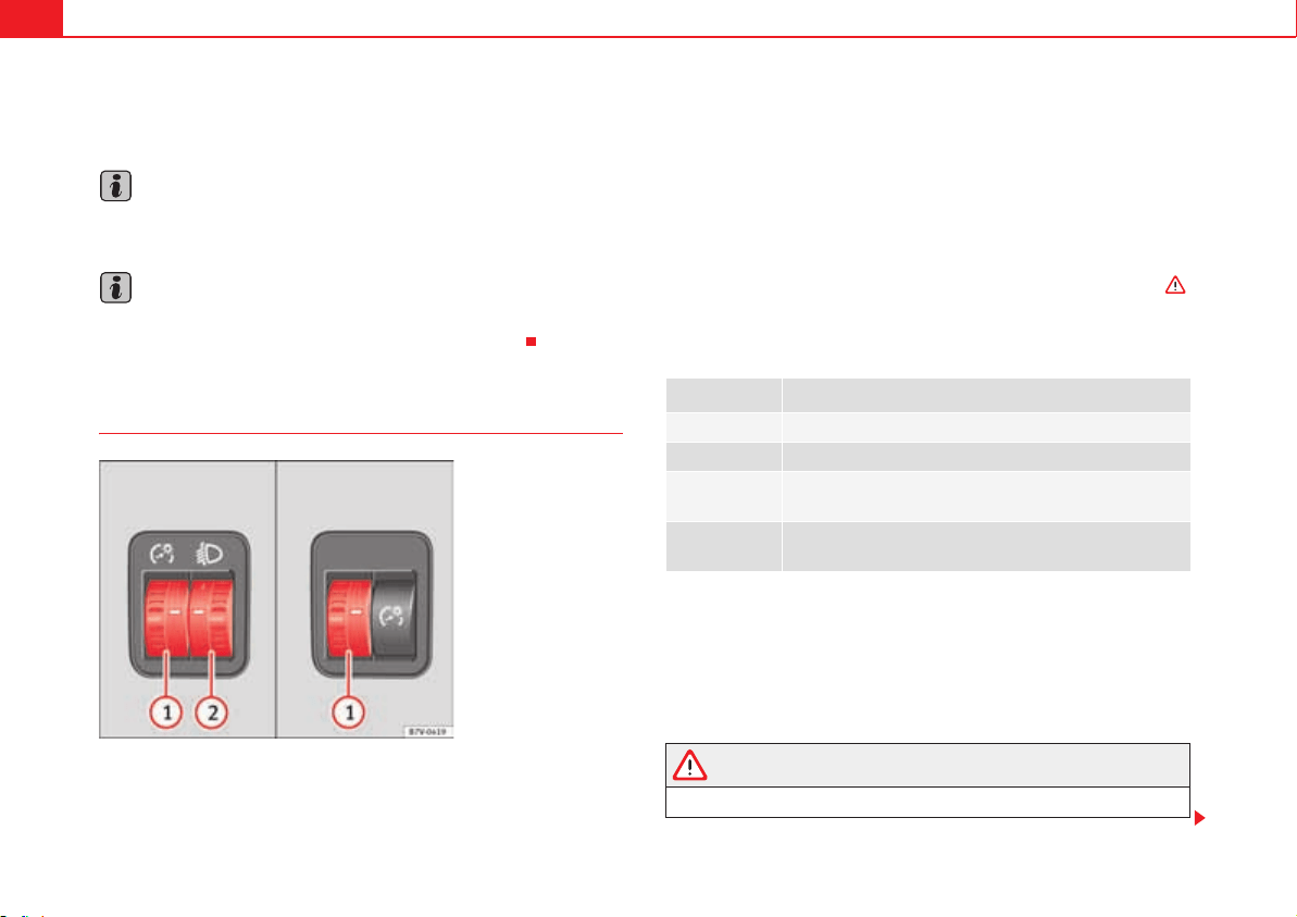
Lights and visibility120
function is switched on. If the equipment includes the light sensor, the
lighting around the exterior mirrors only comes when it is dark.
Note
The time taken for the headlights to go off can be changed in the menu Lights
& Visibility and the function can be switched on or off page 70.
Note
When the “Coming home” function is on, if the vehicle door is opened there
is no audible warning signal to advise that the light is still on.
Headlight range control, instrument and switch lighting
Instrument and switch lighting
When the headlights are switched on, the brightness of the instruments and
switch lighting can be regulated to suit your requirements by turning the
switch fig. 68 .
Headlight range control
The headlight range control fig. 68 is modified according to the value
of the headlight beam and the vehicle load status. This offers the driver
optimum visibility and the headlights do not dazzle oncoming drivers .
The headlights can only be adjusted when the dipped beam is switched on.
To reset, turn switch fig. 68 :
Dynamic headlight range control
The control is not mounted in vehicles with dynamic headlight range
control. The headlight range is automatically adjusted according to the
vehicle load status when the headlights are switched on.
WARNING
Heavy objects in the vehicle may mean that the headlights dazzle and
distract other drivers. This could result in serious accident.
Fig. 68 Next to the
steering wheel: instru-
ment and switch lighting
control and headlight
range control .
A
1
A
2
Value
Vehicle load status
a)
a)
If the vehicle load does not correspond to those shown in the table, it is possible to
select intermediary positions.
– Two front occupants, luggage compartment empty
1 All seats occupied, luggage compartment empty
2
All seats occupied, luggage compartment full. With trailer
and minimum support load
3
Driver only, luggage compartment full. With trailer and
maximum support load
A
1
A
1
A
2
A
2
A
2
A
2
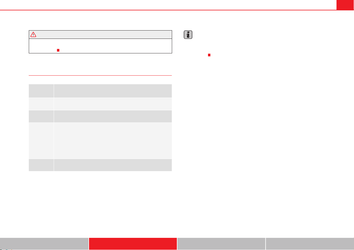
Lights and visibility 121
Safety First Operating instructions Practical tips Technical Data
x Adjust the light beam to the vehicle load status so that it does not blind
other drivers.
Interior and reading lights
Storage and luggage compartment lighting
When the glove box and the tailgate are opened and closed, a light automat-
ically switches on or off.
Background lighting
The background lighting in the front covering of the ceiling lights up the
controls on the central console from above when the side or dipped lights are
on.
In addition, the lever on the door moulding can also be illuminated.
Note
The reading lights go out when the vehicle is locked, or a few minutes after
the key is removed from the ignition. This prevents the battery from
discharging.
Button /
Switch
Function
/
Switches interior lights off.
Switches interior lights on.
o
Switches door contact control on (central position).
The interior lights come on automatically when the vehicle is
unlocked, a door is opened or the key is removed from the
ignition.
The lights go off a few seconds after all the doors are closed,
the vehicle is locked or the ignition is switched on.
Turning the reading light on and off
WARNING (continued)
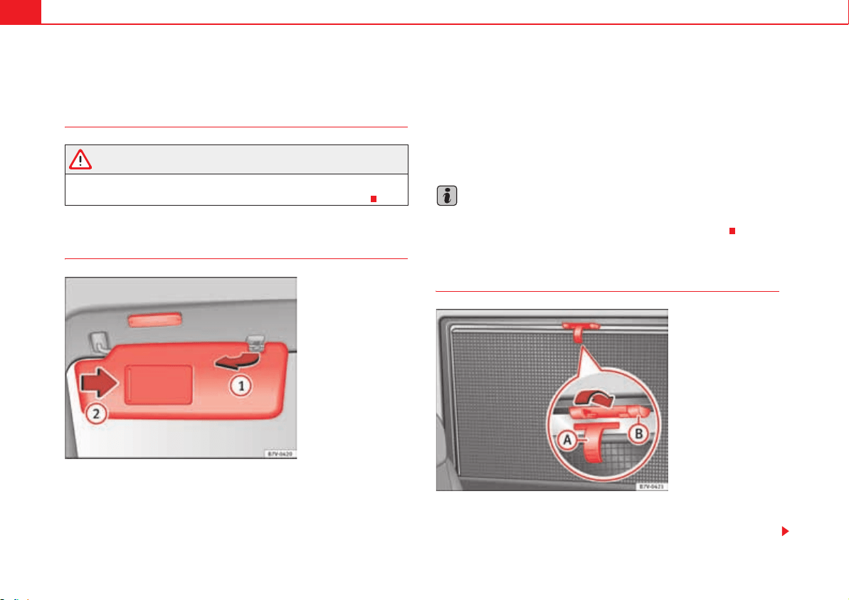
Lights and visibility122
Sun blind
Introduction
WARNING
Sun visors and sun blinds may reduce visibility when open.
x Always roll or fold sun blinds and visors away when not in use.
Sun visors
Options for adjusting driver and front passenger sun visors:
x Lower by unfolding towards the windscreen.
x The sun visor can be pulled out of its mounting and turned towards the
door fig. 69 .
x Swing the sun visor towards the door, longitudinally backwards.
Make-up mirror light
There may be a make-up mirror, with a cover, on the rear of the sun visor.
When the cover is opened fig. 69 a light comes on.
The lamp goes out when the make-up mirror cover is closed or the sun visor
is pushed back up.
Note
The light above the sun visor automatically switches off after a few minutes
in certain conditions. This prevents the battery from discharging.
Rear side window sun blinds
The sun blinds for the passenger compartment are fitted in the side panels of
the windows.
Fig. 69 Sun visor.
A
1
A
2
Fig. 70 On the rear right-
hand window: sun blind.
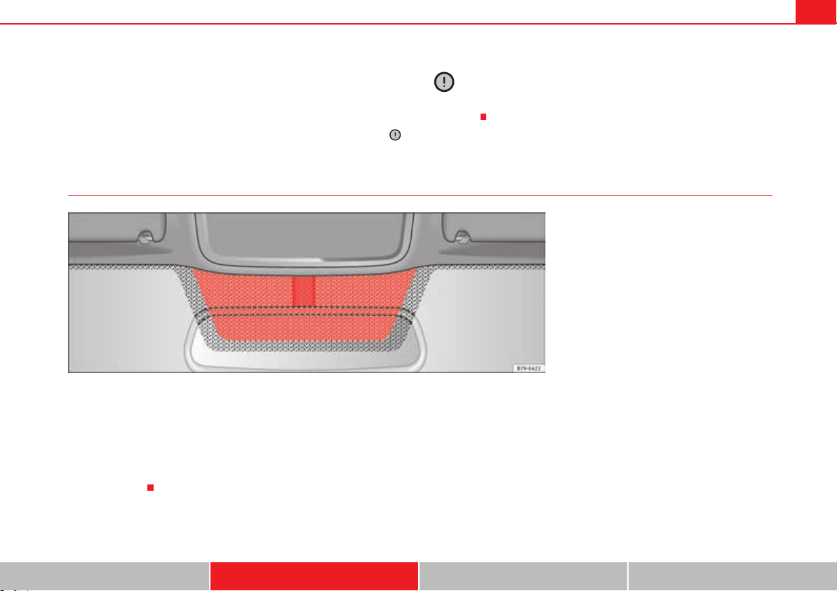
Lights and visibility 123
Safety First Operating instructions Practical tips Technical Data
x Pull the sun blind by the handle page 122, fig. 70 up to the top.
x Hook both rings of the fastening rod in the spaces provided . Check
that the sun blind is securely hooked into the spaces provided when it has
been lowered .
x To put the sun blind away, unhook it at the top and lower by hand .
Caution
To prevent damage to the blind or the interior trim, do not lower the sun blind
“quickly”.
Heat-insulating glass windscreen*
The heat-insulating windscreens include a reflective infrared coating. The
section above the rear vision mirror has been left uncoated (communication
window) to allow electric components from the accessories shop to operate
correctly fig. 71.
The uncoated surface should be covered from inside or outside or have an
adhesive label attached, otherwise the electronic components may not
operate correctly.
A
A
A
B
A
B
Fig. 71 Windscreen with reflective infrared and metal
coating and small window (red surface).
Lights and visibility124
Windscreen wiper and washer
Introduction
Additional information and warnings:
x Recirculation of air conditioning air page 179
x Working in the engine compartment page 304
x Caring for and cleaning the vehicle exterior page 269
WARNING
Water from the windscreen washer water bottle may freeze on the wind-
screen if it does not contain enough anti-freeze, reducing forward visibility.
x In winter, ensure the windscreen washer contains enough anti-freeze.
x In cold conditions, you should not use the wash / wipe system unless
you have warmed the windscreen with the ventilation system. The anti-
freeze could freeze on the windscreen and reduce visibility.
WARNING
Worn or dirty wiper blades reduce visibility and increase the risk of acci-
dent and serious injury.
x Always replace damaged or worn blades or blades which do not clean
the windscreen correctly.
Caution
In icy conditions, always check that the wiper blades are not frozen to the
glass before using the wipers for the first time. In cold weather, it may help to
leave the vehicle parked with the wipers in service position page 127.
Warning lamp
Several warning and control lamps should light up for a few seconds when
the ignition is switched. This signals that the lamp is working properly. They
will switch off after a few seconds.
Caution
Failure to heed the warning lamps and text messages when they appear may
result in faults in the vehicle.
lights up Possible cause Solution
Y
Windscreen wiper fluid level
too low
Top up the windscreen wiper
bottle as soon as possible
page 129.
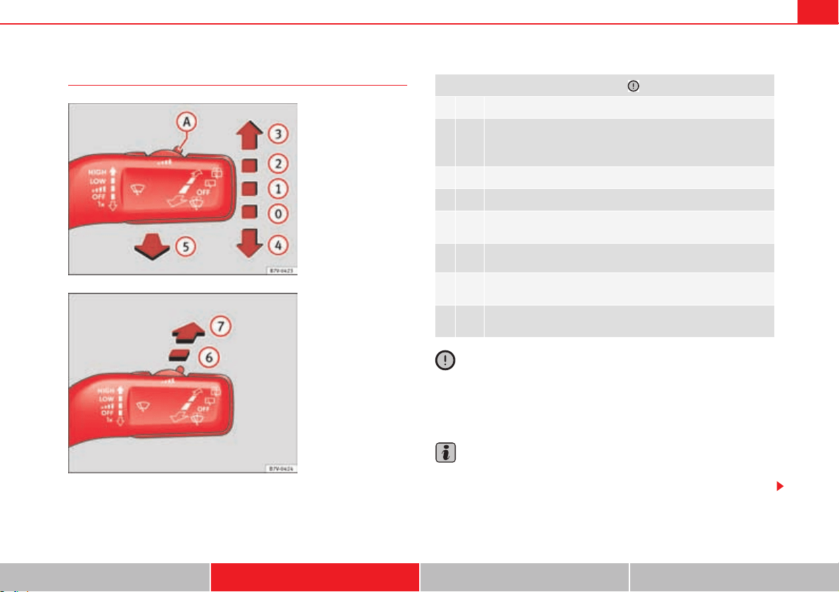
Lights and visibility 125
Safety First Operating instructions Practical tips Technical Data
Windscreen wiper lever
Caution
If the ignition is switched off while the windscreen wipers are on, the wind-
screen wipers carry on wiping at the same level when the ignition is switched
back on. Ice, snow and other obstacles may damage the windscreen wiper
and the wiper motor.
Note
The windscreen wipers will only function when the ignition is switched on and
the bonnet or tailgate are closed.
Fig. 72 Using the wind-
screen wipers.
Fig. 73 Using the rear
window wipers.
Move the lever to the required position :
OFF Windscreen wiper off.
u
Intermittent windscreen wipers wipe.
Using the control fig. 72 adjust the interval (vehicles
without the rain sensor), or the sensitivity of the rain sensor.
LOW Slow wipe.
HIGH Continuous wipe.
x
Brief wipe - short wipe. Hold the lever down for more time to
increase the wipe frequency.
W
Automatic wipe for cleaning windscreens with the lever up.
Z
Intermittent wipe for rear window. The rear wiper will wipe the
window approximately every 6 seconds.
\
Automatic wipe for cleaning rear windows with the lever
pressed.
A
0
A
1
A
A
A
2
A
3
A
4
A
5
A
6
A
7
Lights and visibility126
Note
The intermittent wiper speed varies according to the vehicle speed. The faster
the vehicle is moving, the more often the windscreen is cleaned.
Note
The rear wiper is automatically switched on when the windscreen wiper is
connected and the car is in reverse gear.
Windscreen wiper functions
Heated windscreen washer jets
The heating only thaws the frozen jets, it does not thaw the water in the
washer hoses. The heated windscreen washer jets automatically adjust the
heat depending on the ambient temperature, when the ignition is switched
on.
Headlight wash /wipe system
The headlight washers/wipers clean the headlight lenses.
After the ignition is switched on, the first and every fifth time the windscreen
washer is switched on, the headlights are also washed. Therefore, the wind-
screen wiper lever should be pulled towards the steering wheel when the
dipped beam or main beam are on. Any incrusted dirt (such as insects)
should be cleaned regularly (e.g. when refuelling).
To ensure the headlight washers work correctly in winter, any snow which has
got into the bumper jet supports should be cleaned away. If necessary,
remove snow with an anti-icing spray.
Note
The wiper will try to wipe away any obstacles that are on the windscreen. The
wiper will stop moving if the obstacle blocks its path. Remove the obstacle
and switch the wiper back on again.
Windscreen wiper performance in different situations:
If the vehicle is at a stand-
still:
The activated position provisionally changes
to the previous position.
During the automatic wipe:
The air conditioning comes on for approxi-
mately 30 seconds in air recirculation mode
to prevent the smell of the windscreen
washer fluid entering the inside of the vehi-
cle.
For the intermittent wipe:
The intervals between wipes vary according
to the speed of the vehicle. The higher the
vehicle speed the shorter the intervals.
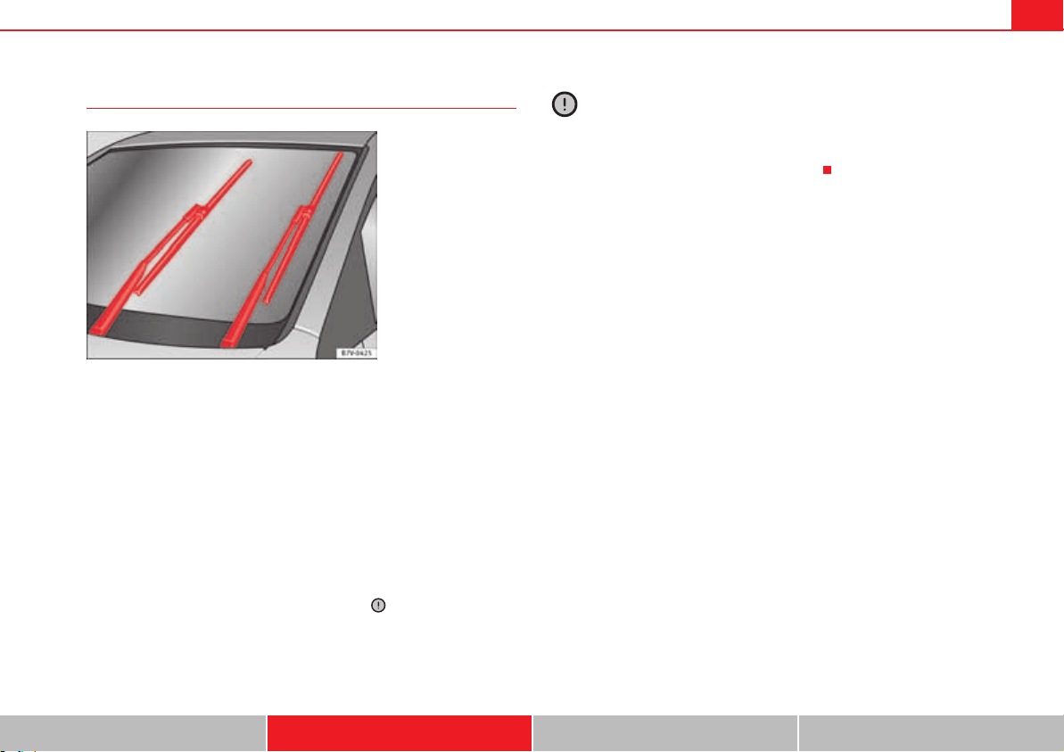
Lights and visibility 127
Safety First Operating instructions Practical tips Technical Data
Windscreen wipers service position
The wiper arms can be raised when the wipers are in service position
fig. 74. To place the windscreen wipers in the service position, proceed as
follows:
x The bonnet must be closed page 304.
x Switching the ignition on and off.
x Press the windscreen wiper lever downwards briefly page 125, fig. 72
.
Before driving, always lower the wiper arms. Using the windscreen wiper
lever, the windscreen wiper arms return to their initial position.
Lifting and returning windscreen wiper arms
x Place the wiper arms in the service position .
x Only hold the wiper arms at the point where the blade is fixed.
Caution
x To prevent damage to the bonnet and the wiper arms, only leave them in
the service position.
x Before driving, always lower the wiper arms.
Fig. 74 Wipers in service
position.
A
4
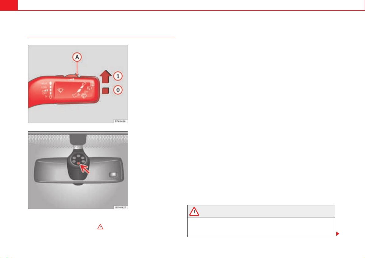
Lights and visibility128
Rain sensor*
The rain sensor controls the frequency of the windscreen wiper intervals,
depending on the amount of rain . The sensitivity of the rain sensor can
be adjusted manually. Manual wipe page 125
Move the lever to the required position fig. 75:
Rain sensor off.
Rain sensor on; automatic wipe if necessary.
Setting sensitivity level of rain sensor
Set control to the right: highly sensitive.
Set control to the left: less sensitive.
When the ignition is switched off and then back on, the rain sensor stays on
and starts operating again when the windscreen wipers are in position
and the vehicle is travelling at more than 4 km/h (2 mph).
Rain sensor modified behaviour
Possible causes of faults and mistaken readings on the sensitive surface
fig. 76 of the rain sensor include:
x Damaged blades: A film of water on the damaged blades may lengthen
the activation time, reduce the washing intervals or result in a fast and contin-
uous wipe.
x Insects: insects on the sensor may trigger the windscreen wipers.
x Salt on roads: in winter, salt spread in the roads may cause an extra long
wipe when the windscreen is almost dry.
x Dirt: dry dust, wax, coating on glass (Lotus effect) or traces of detergent
(car wash) may reduce the effectiveness of the rain sensor or make it react
more slowly, later or not at all.
x Cracked windscreen: the impact of a stone will trigger a single wipe cycle
with the rain sensor on. Next the rain sensor detects the reduction in the
sensitive surface area and adapts accordingly. The behaviour of the sensor
will vary with the size of the damage caused by the stone.
WARNING
The rain sensor may not detect enough rain to switch on the wipers.
x If necessary, switch on the wipers manually when water on the wind-
screen obstructs visibility.
Fig. 75 Windscreen wiper
lever: adjusting the rain
sensor .
A
A
Fig. 76 Rain sensor
sensitive surface.
A
0
A
1
A
A
A
1
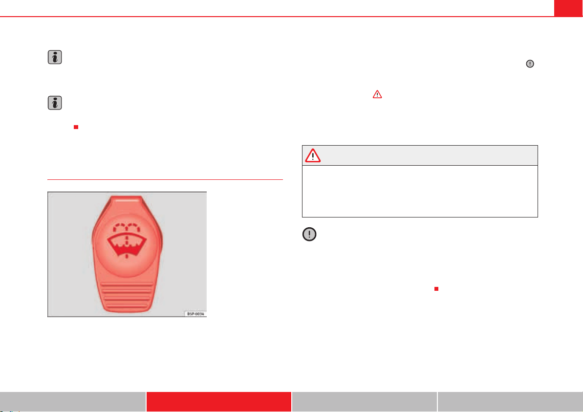
Lights and visibility 129
Safety First Operating instructions Practical tips Technical Data
Note
Clean the sensitive surface of the rain sensor regularly and check the blades
for damage page 128, fig. 76 (arrow).
Note
To remove wax and coatings, we recommend a window cleaner containing
alcohol.
Checking and topping up the windscreen washer bottle with
water
Check the water level in the windscreen washer bottle regularly and top up as
required.
x Open the bonnet page 304.
x The washer bottle is marked with the symbol Y on the lid fig. 77.
x Check there is enough water in the bottle.
x To top up, mix water with a window cleaner recommended by SEAT .
Please follow the instructions for use found on the packaging.
x In cold weather, a special antifreeze should also be added to prevent the
water from freezing .
Bottle capacity
The bottle holds approximately 3.0 litres; in vehicles with headlight washer,
it is approximately 7.0 litres.
WARNING
Never mix an unsuitable antifreeze or other similar products with the wind-
screen washer water. A greasy layer may be formed on the windscreen
which will impair visibility.
x Use clean water with a window cleaner recommended by SEAT.
x If necessary, add a suitable antifreeze to the water bottle.
Caution
x Do not mix cleaning products recommended by SEAT with other products.
This could lead to flocculation and may block the windscreen washer jets.
x When topping up service fluids, make absolutely certain that you fill the
fluids into the correct reservoirs. Failure to observe this point will result in
serious malfunctions and engine damage!
Fig. 77 In the engine
compartment: windscreen
washer bottle top.
Lights and visibility130
Rear vision mirror
Introduction
Additional information and warnings:
x Personal convenience settings in the SEAT information system page 70
x Seat memory page 137
x Changing gear page 201
x Braking, stopping and parking page 210
WARNING
The automatic anti-dazzle rear vision mirror contains an electrolytic fluid
which may leak if the mirror is broken. This fluid can cause irritation to the
skin, eyes and respiratory organs.
x The electrolytic fluid may cause irritation to the skin, eyes and respira-
tory organs, particularly in individuals suffering from asthma or other
illnesses. Make sure that adequate quantities of fresh air enter and leave
the vehicle if it is not possible to open all the doors and windows.
x If the electrolytic fluid comes into contact with eyes or skin, wash the
area for at least 15 minutes with plenty of water, and seek medical advice.
x If the electrolytic fluid comes into contact with shoes or clothing, wash
the area for at least 15 minutes with plenty of water. Wash shoes and
clothing before wearing them again.
x If the electrolytic fluid is swallowed, wash the mouth with plenty of
water for at least 15 minutes. Do not try to provoke vomiting unless recom-
mended by a Doctor. Seek medical advice immediately.
Caution
If an automatic anti-dazzle rear vision mirror is broken, the electrolytic fluid
may leak out. This fluid attacks plastic surfaces. Therefore, it should be
cleaned as fast as possible with a damp sponge or similar.

Lights and visibility 131
Safety First Operating instructions Practical tips Technical Data
Rear vision mirror
The driver should always adjust the rear vision mirror to permit adequate visi-
bility through the rear window.
Manual anti-dazzle function for rear vision mirror
x Basic position: point the lever at the bottom of the mirror forwards.
x Pull the lever to the back to select the anti-dazzle function fig. 78.
Automatic anti-dazzle function for interior mirror
Legend for the fig. 79:
warning lamp
Control
Light incidence sensor
This function can be activated and deactivated by pressing the rear vision
mirror switch fig. 79 . When it is activated, the warning lamp lights up
.
When the ignition is on, the sensor automatically moves the rear vision
mirror to the anti-dazzle position depending upon the incidence of the light
from behind.
The automatic anti-dazzle function is deactivated when reverse gear is
engaged or the interior or reading lights are on.
Note
If the incidence of the light on the sensor is obstructed or prevented, e.g. by
the sun blinds, the rear vision mirror with automatic anti-dazzle function will
not operate correctly.
Fig. 78 Manual anti-
dazzle function for rear
vision mirror
Fig. 79 Automatic anti-
dazzle function for rear
vision mirror
A
1
A
2
A
3
A
2
A
1
A
3
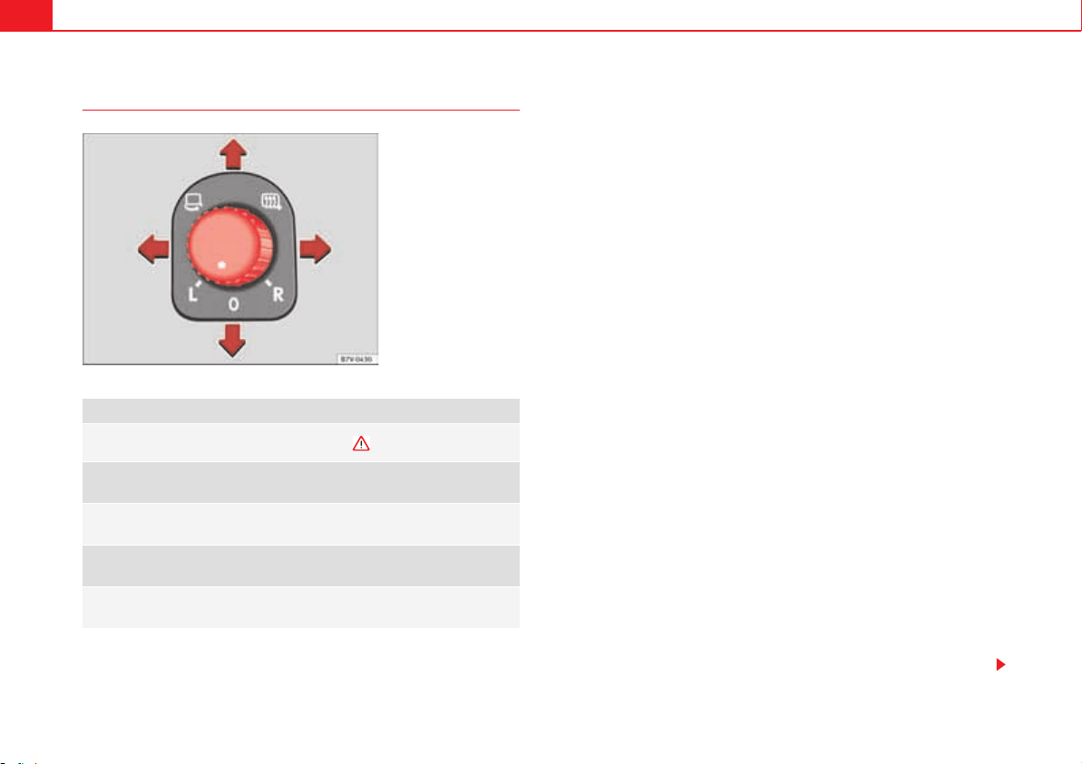
Lights and visibility132
Exterior mirrors
Synchronised mirror adjustment
x In the menu Settings - Convenience select whether or not the mirrors
should move in synchronisation page 70.
x Turn the knob to position L.
x Adjust the left-hand exterior mirror. The right exterior mirror will be
adjusted at the same time (synchronised).
x If necessary the right exterior mirror adjustment may need correcting. Turn
the knob to position R.
Automatic anti-dazzle exterior mirror, driver's side
The automatic anti-dazzle exterior mirror is controlled in the same way as the
automatic anti-dazzle rear vision mirror page 131.
Store the reverse settings for the passenger exterior mirror
x Select the vehicle key in which the setting is to be stored.
x Use this key to unlock the vehicle.
x Connect the automatic parking brake.
x Switch the ignition on.
x Move the gear lever to neutral.
x In the menu Settings - Convenience activate the function Mirror
adjustment.
x Select reverse gear.
x Adjust the front passenger exterior mirror so that you can see, for
example, the kerb area.
x The new position of the mirror will be stored automatically and allocated
to the vehicle key that was used to unlock the vehicle. For vehicles with seat
memory, please see page 137.
Activating the passenger exterior mirror settings
x Turn the exterior mirror knob to position R.
x With the ignition switched on, select reverse gear.
x The stored position of the passenger exterior mirror for reverse gear is
deleted when driving forwards at 15 km/h, or if the knob is turned from posi-
tion R to another position.
Turn the knob to the required position:
#
Electric folding exterior mirrors .
?
Switch on the exterior mirror heating This only heats up if the
ambient temperature is less than +20 °C (+68 °F).
,
Adjust the left-hand exterior mirror by turning the knob for-
wards, backwards, to the left or to the right.
2
Adjust the right-hand exterior mirror by turning the knob for-
wards, backwards, to the left or to the right.
Zero position. Exterior mirror unfolded, exterior mirror heating
off, adjustment of exterior mirror not possible.
Fig. 80 In the driver door:
exterior mirror controls
Lights and visibility 133
Safety First Operating instructions Practical tips Technical Data
WARNING
Fold and unfold the exterior mirror, taking care to avoid injuries.
x Only fold or unfold the exterior mirror when there is no-one in the way
of the mirror.
x When moving the mirror, take care not to trap fingers between the
mirror and the mirror bracket.
WARNING
Failure to correctly estimate the distance of the vehicle behind could lead
to serious accident.
x Rear-view convex or aspheric mirrors increase the field of vision,
however objects appear smaller and further away in the mirrors.
x The use of these mirrors to estimate the distance to the next vehicle
when changing lane is imprecise and could result in serious accident.
x If possible, use the rear vision mirror to estimate distances to vehicles
behind you or in other circumstances.
x Make sure that the rear visibility is adequate.
Caution
x Before entering a car wash, always ensure that the exterior mirrors are
correctly folded in.
x Electrically-folding exterior mirrors should not be folded and unfolded
mechanically as this may damage the electrical operation.
For the sake of the environment
The exterior mirror heating should be switched off when it is no longer
needed. Otherwise, it is an unnecessary fuel waste.
Note
The exterior mirror heating initially heats up with a high power, after two
minutes the heat will depend upon the ambient temperature.
Note
In the event of faults, the electric exterior mirrors can be adjusted manually
by pressing the edge of the mirror surface.
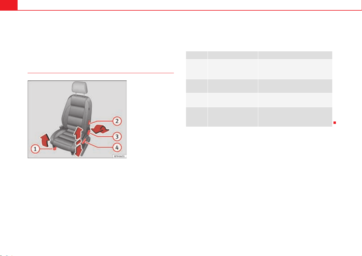
Seats and storage compartments134
Seats and storage compartments
Seat adjustment
Mechanical controls on the front seat
The controls are mirrored for the front right-hand seat.
Mechanically and electrically adjusted controls can be combined on the seat.
Fig. 81 Front left seat
controls.
fig. 81 Function Necessary operations
Moving the head
restraint backwards or
forwards.
Pull the lever and move the seat for-
wards. The front seat must be
engaged when the lever is released!
Adjusting the lumbar
support.
Turn the lever.
Adjusting the backrest
angle.
Turn the wheel.
Adjusting the seat
height.
Pull the lever up or push down (sev-
eral times if necessary) from its home
position.
A
1
A
2
A
3
A
4
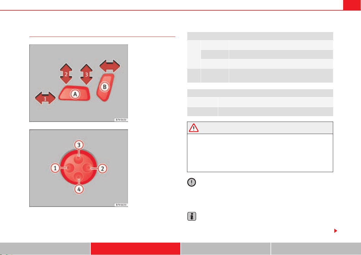
Seats and storage compartments 135
Safety First Operating instructions Practical tips Technical Data
Electrical controls on the front seat
The controls are mirrored for the front right-hand seat.
Mechanically and electrically adjusted controls can be combined on the seat.
WARNING
Using the front electric seats in a careless or uncontrolled manner may lead
to severe injuries.
x The front seats can also be electrically adjusted when the ignition is
switched off. Never leave children or disabled people alone in the vehicle.
x In the event of an emergency, stop electrical adjustment by pressing
any button.
Caution
So as not the damage the electrical components of the front seats, do not
kneel on the seats or apply specific pressure to one point of the seat or back-
rest.
Note
It may not be possible to electrically adjust the seat if the vehicle battery is
very low.
Fig. 82 Adjusting the
front left seat forwards or
backwards, the height,
the seat angle and the
front seat backrest.
Fig. 83 Adjusting the
lumbar support.
page 135, fig. 82 Press the control in the direction of the arrow:
Move the seat backwards or forwards.
and
Raise or lower the seat.
or
Adjust the seat angle.
Forwards or
backwards.
Adjust the backrest angle.
fig. 83 Press the corresponding area of the switch:
or
Adjust the curve of the lumbar support.
or
Adjust the height of the lumbar support.
A
A
A
1
A
2
A
3
A
2
A
3
A
B
A
1
A
2
A
3
A
4
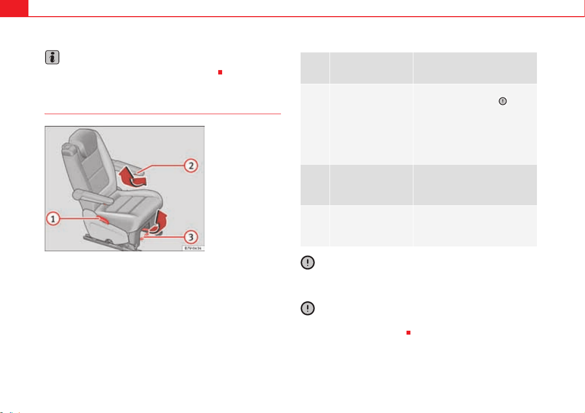
Seats and storage compartments136
Note
Seat adjustment is stopped when the engine is started.
Adjusting the rear seats
Caution
Tilting the backrest of the second row of seats fully back could damage the
luggage compartment tray. Remove the tray before adjusting the backrest.
Caution
Objects in the luggage compartment could cause damage when moving the
rear seats forwards or backwards.
Fig. 84 Adjusting rear
seats.
page
134,
fig. 81
Function Necessary operations
Adjusting the backrest
angle.
Pull the lever and adjust the backrest
to the required position . The
backrest must be engaged when the
lever is released! There is a handle
instead of the lever on the third row of
seats and on the central seat of the
second row. It is used in the same
manner as the lever.
On the second row of
seats of the 6-seat ver-
sion only: Adjusting the
armrest.
Turn the wheel under the armrest.
On the second row of
seats only: Moving the
seat backwards or for-
wards.
Pull the lever and move the seat for-
wards or backwards. The seat must be
engaged when the lever is released!
A
1
A
2
A
3
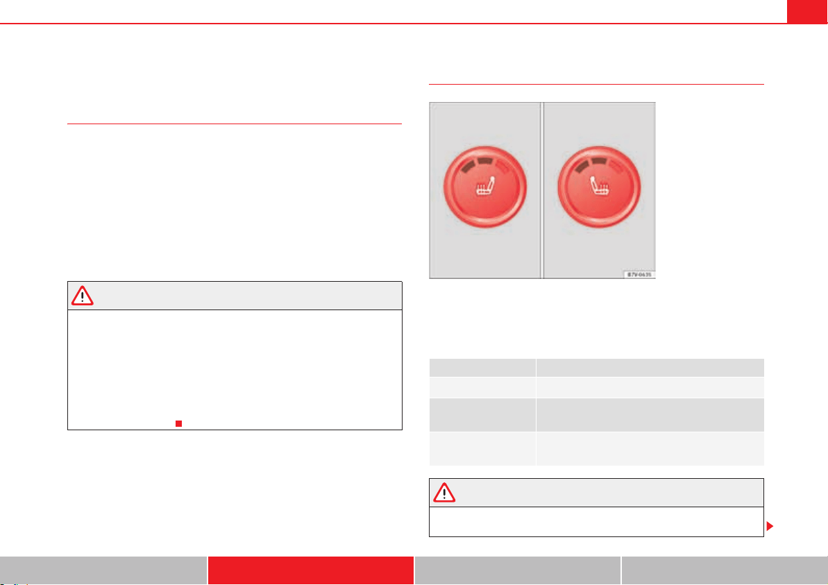
Seats and storage compartments 137
Safety First Operating instructions Practical tips Technical Data
Seat functions
Introduction
Additional information and warnings
x Adjust the seat position page 10
x Seat belts page 22
x Airbag system page 33
x Child seats (accessories) page 42
x Integrated child seats page 52
x Exterior mirrors page 130
x Luggage compartment page 146
WARNING
Inappropriate use of the seat functions can cause severe injuries.
x Assume the proper sitting position before your trip and remain in it
throughout. This also applies to the other occupants.
x Only adjust the seat position memory when the vehicle is stationary.
x Only switch the lumbar massage function on and off when the vehicle
is stationary.
x Keep hands, fingers, feet and other limbs away from the seat operating
and adjustment radius.
Seat heating
The seat cushions can be heated electrically when the ignition is switch on.
The backrest is also heated in some versions.
Switch off seat heating if there is nobody in the seat.
WARNING
People whose pain and temperature threshold has been affected by some
kind of medicine, paraplegia or chronic illness (e.g. diabetes) may sustain
Function Action fig. 85
To switch system on:
Press button A. Seat heating is switched on fully.
Adjusting the heating
output:
Keep pressing button A until the required inten-
sity is set.
The system switches
off:
Keep pressing button A until all of the lights are
switched off fig. 85.
Fig. 85 Detailed view of
the centre console: front
seat heating controls,
here with the second
temperature level set.
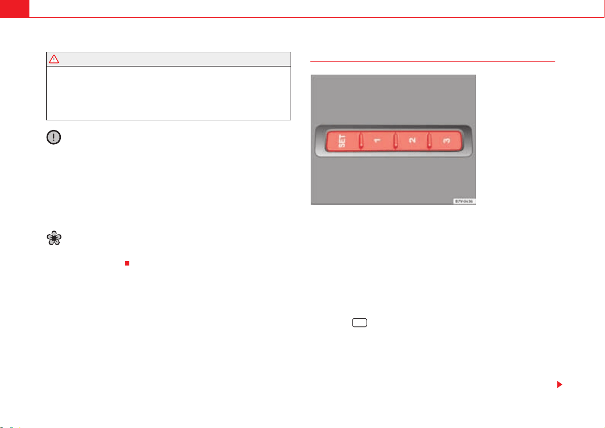
Seats and storage compartments138
burns to the back, buttocks and legs from use of the seat heating that may
lead to a long healing process or that may never completely heal. Seek
medical advice if you have doubts regarding your health.
x People with a limit pain and temperature threshold must never use seat
heating.
Caution
x To avoid damaging the heating elements of the seat heating, please do
not kneel on the seat or apply sharp pressure at a single point to the seat
cushion and backrest.
x Liquids, sharp objects and insulating materials on the seat could damage
the seat heating.
x In the event of smells, switch off the seat heating immediately and have
the unit inspected by a qualified workshop.
For the sake of the environment
The seat heating should remain on only when needed. Otherwise, it is an
unnecessary fuel waste.
Seat with position memory
Memory buttons
Individual settings for the driver seat and the exterior mirror can be assigned
to each memory button.
Storing exterior mirror settings for driving forwards
x Connect the automatic parking brake.
x Move the gear lever to neutral.
x Switch the ignition on.
x Adjust the front seat and the exterior mirrors.
x Keep the button held down for more than one second fig. 86.
x Press the required memory button for the following 10 seconds. A sound
confirms the settings have been stored.
Storing front passenger exterior mirror settings for driving in reverse gear
x Connect the automatic parking brake.
x Move the gear lever to neutral.
WARNING (continued)
Fig. 86 Memory buttons
on the outside of the
driver seat
SET
Seats and storage compartments 139
Safety First Operating instructions Practical tips Technical Data
x Switch the ignition on.
x Press the required memory button.
x Select reverse gear.
x Adjust the front passenger exterior mirror so that you can see, for
example, the kerb area.
x The new position of the mirror will be stored automatically and allocated
to the vehicle key that was used to unlock the vehicle.
Activating exterior mirror settings
x With the driver's door open and the ignition turned off, push the memory
button of the corresponding door briefly.
x ALTERNATIVELY: With the ignition switched on, hold in the corresponding
memory button until the memorised position is reached.
To activate the memory function of the vehicle key
Important: a position must be memorised in the memory.
x Open the driver-side door.
x Press and hold any memory button.
x Within the following three seconds, push the button to open the
vehicle on the vehicle key. A sound confirms the settings have been acti-
vated.
Adjusting the wing mirrors for driving and assigning driver seat settings to a
vehicle key
x Activate the memory function of the vehicle key
x Adjust the front seat and the exterior mirrors.
x Lock the vehicle. The settings are assigned to the vehicle key.
To deactivate the memory function of the vehicle key
Important: a position must be memorised in the memory.
x Press and hold the button.
x Within the following ten seconds, push the button to open the vehicle
on the vehicle key. A sound confirms the settings have been deactivated.
Initialising the seat position memory
The position memory system must be initialised if, for example, the driver's
seat has been changed.
Initialisation deletes all memories and assignments for the seat with position
memory. The memory buttons can then be reprogrammed and the vehicle
keys re-assigned.
x Open the driver's door and do not get into the vehicle.
x Operating the seat settings from outside the vehicle.
x Move the angle of the backrest completely forwards.
x Release the control to set the angle and then press again until a sound is
heard.
Note
The front passenger side wing mirror automatically changes from the position
stored for reversing as soon as the vehicle moves forward at a speed of at
least 15 km/h or when the gear selection lever is changed to a position other
than R.
0
SET
0
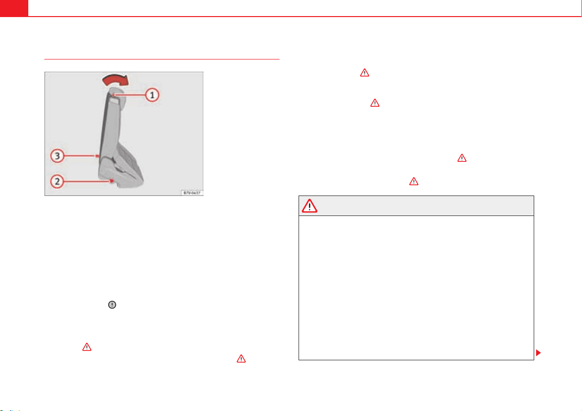
Seats and storage compartments140
Convenient entry function for the third row of seats
The outer seats of the second row can be folded to make it easier to get in and
out of the third row of seats.
Folding down the seat of the second row
x If necessary, open the belt loop and wind up the seat belt by hand.
x If necessary, remove the side head restraint of the integrated child seat
page 52.
x If necessary, raise the armrests.
x Remove any objects located in the floor area of the second row of seats,
where applicable .
x Push the head restraint down as far as it will go page 10.
x Push the lever fig. 87 forwards and fold the backrest of the rear
seat. The seat can still be moved forwards when rear seat is folded completely
forwards .
x Always take care when entering and leaving the vehicle .
Repositioning the seat of the second row
x Lift the backrest of the rear seat in an upright position. The entire seat
folds backwards .
x Make sure that the rear seat is securely engaged so that the seat belts can
provide proper protection in the rear seats. The red mark fig. 87 should
no longer be visible in “Folding down rear seats to create load space”
on page 147.
Emergency exit function
If the lever fig. 87 does not work, e.g. after an accident, the seats on
the second row can be folded forwards from the third row to allow occupants
of the third row of seats to get out of the vehicle .
x Pull handle fig. 87 back and fold the backrest of the rear seat. The
complete rear seat folds forward .
WARNING
Careless or uncontrolled use of the convenient entry assistant may result
in severe injury and accident.
x Never use the convenient entry function when the vehicle is in motion.
x Avoid trapping or damaging the seat belt when folding the rear seats
back.
x Keep your hands, fingers, feet and other body parts out of the hinges
and the seat locking mechanism when folding and unfolding.
x Mats or other objects can be caught in the hinges of the backrests or
rear seat. This could prevent the backrest from locking safely when posi-
tioned upright.
x All backrests must engage correctly for the seat belts on the rear seats
to work properly. When the backrest of an occupied seat is not correctly
locked in place, the passenger can be thrust forward with the backrest in
case of sudden braking, sudden manoeuvres or an accident.
Fig. 87 Second row of
seats: convenient entry
function controls.
A
1
A
2
A
1
A
3
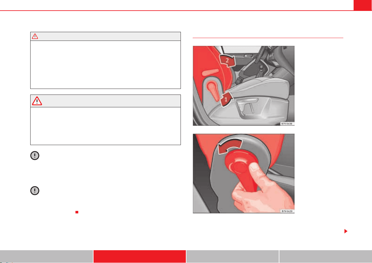
Seats and storage compartments 141
Safety First Operating instructions Practical tips Technical Data
x A red mark on the side of the seat page 140, fig. 87 indicates
that the backrest is not engaged. The mark is no longer visible when the
backrest is correctly engaged.
x If the backrest or seat are folded down and are not correctly locked in
place, no passenger should use them.
x When getting in or out, never lean or hold onto the folded seat on the
second row of seats.
WARNING
If child seats are fitted to all the seats in the second row then it is possible
that the seats of this row cannot be folded down from the third row of seats
in case of an accident. In case of an emergency, passengers in the third row
of seats will not be able to leave the vehicle or to help themselves.
x Child seats should not occupy all the seats of the second row if other
passengers are to occupy the third row of seats.
Caution
Before folding down the rear backrest for returning it to its position, adjust
the front seats so that the head restraints and seatbacks do not hit off each
other when folding and unfolding.
Caution
Any objects located in the floor area of the second row of seats may be
damaged on folding the rear seat forwards. Remove any objects before
folding the seat down.
Folding the backrest of the front passenger's seat
The backrest of the front passenger's seat can be folded and locked horizon-
tally.
WARNING (continued)
A
2
Fig. 88 Folding the back-
rest of the front
passenger's seat.
Fig. 89 Unlocking the
folding backrest of the
front passenger's seat.
Seats and storage compartments142
The front passenger's frontal airbag must be disconnected page 33 if
objects are being transported on the folded front passenger's seat.
Folding the backrest of the front passenger's seat
x Remove any objects from the front passenger's seat cushion .
x Adjust the front passenger's seat to its lowest position page 10.
x Push the head restraint down as far as it will go page 10.
x Unlock the backrest of the front passenger's seat in the direction of the
arrow page 141, fig. 88 .
x Fold the backrest of the front passenger's seat forwards in the direction of
the arrow page 141, fig. 88 until it is horizontal.
x The backrest of the front passenger's seat must engage safely in its folded
position.
Lifting the backrest of the front passenger seat
x Check that there are no objects or parts of the body in the hinge area.
x Lift the backrest of the front passenger's seat by first unlocking it again
page 141, fig. 89.
x Lift the backrest of the front passenger seat until it is upright. The backrest
must be engaged.
x The upright backrest of the front passenger's seat must safely engage.
WARNING
Folding and lifting the backrest of the front passenger's seat uncontrol-
lably or without paying attention may lead to severe injuries.
x Only fold and lift the backrest of the front passenger's seat when the
vehicle is stationary.
x While the backrest of the front passenger's seat is folded, the frontal
airbag must remain disconnected and the PASSENGER AIRBAG OFF light
on.
x Keep your hands, fingers, feet and other body parts out of the hinges
and the seat locking mechanism when folding and unfolding.
x Mats or other objects can be caught in the hinges of the backrest of the
front passenger's seat. This could prevent the backrest from locking safely
when positioned upright.
x The upright backrest of the front passenger's seat must engage. If the
backrest of the front passenger's seat is not locked, it may suddenly move
and cause severe injuries.
WARNING
Seat anchors and hinges exposed when the backrest of the front
passenger's seat is folded may lead to severe injuries in the event of an
accident or sudden braking.
x Never carry people or children on the front passenger's seat when the
backrest is folded.
x When the backrest of the front passenger's seat is folded, only the
outer seat behind the driver on the second row of seats may be occupied.
This also applies to children sitting in a child seat.
A
1
A
2
WARNING (continued)
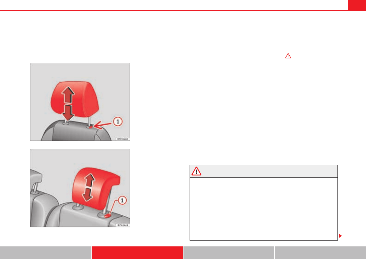
Seats and storage compartments 143
Safety First Operating instructions Practical tips Technical Data
Head restraints
Adjusting the head restraints
All seats are equipped with a head restraint.
Adjusting height
x Push the head restraint up or down in the direction of the arrow with the
button pressed fig. 90 or fig. 91 .
x The head restraint must engage securely in position. There are three
possible positions on the second row of seats and two possible positions on
the third row of seats.
Correct adjustment of head restraints
Adjust the head restraint so that its upper edge is at the same level as the top
of your head, or as close as possible to the same level as the top of your head
and under no circumstances below eye level. Keep the back of your neck as
close as possible to the head restraint.
Adjusting the head restraint for short people
Lower the head restraint completely, even if your head is below its upper
edge. When the head restraint is at its lowest, it is possible that a small gap
remains between it and the backrest.
Adjusting the head restraint for tall people
Raise the head restraint completely.
WARNING
Travelling with the head restraints removed or improperly adjusted
increases the risk of severe or fatal injuries in the event of accidents and
sudden braking or manoeuvres.
x Always fit and adjust the head restraint properly whenever a person is
occupying a seat.
x All occupants must correctly adjust the head restraint according to
their height to reduce the risk of back injuries in the event of an accident.
The upper edge of the head restraint must be as close as possible to the
same level as the top of your head and under no circumstances below eye
level. Keep the back of your neck as close as possible to the head restraint.
Fig. 90 Adjusting the
front head restraints.
Fig. 91 Adjusting the rear
head restraints.
A
1
A
1
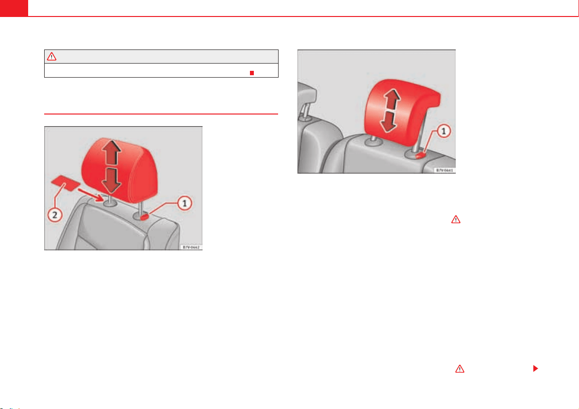
Seats and storage compartments144
x Never adjust the head restraint while the vehicle is in motion.
Removing and fitting the head restraints
All seats are equipped with a head restraint.
Removing the front head restraint
x Push the head restraint up as far as it will go in “Adjusting the head
restraints” on page 143.
x Unlock the head restraint using a flat object such as a plastic card, if
required, sliding it between the upholstery of the head restraint and the head
restraint rod-guide cover fig. 92 .
x Pull the head restraint out of the fitting without releasing the button .
Fitting the front head restraint
x Insert the head restraint into the guides on the backrest.
x Push the head restraint down as far as it will go while pressing button
fig. 92 .
x Adjust the head restraint to the correct position page 143.
Removing the head restraints from the second and third row of seats
x Fold the backrest of the rear seat forwards page 146.
x Push the head restraint up as far as it will go .
WARNING (continued)
Fig. 92 Removing the
front head restraint.
Fig. 93 Removing the
rear head restraint.
A
2
A
1
A
1
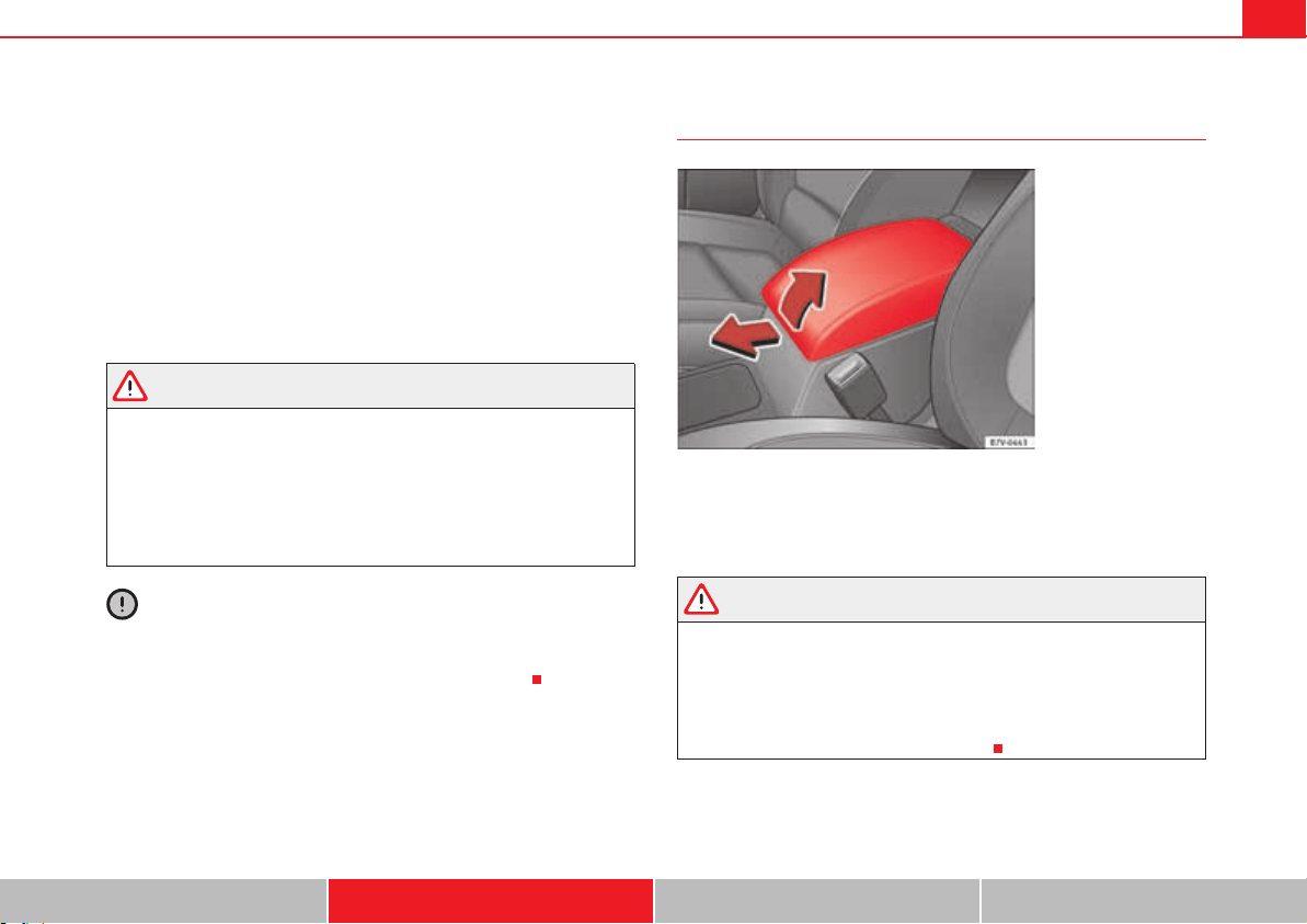
Seats and storage compartments 145
Safety First Operating instructions Practical tips Technical Data
x Pull the head restraint out of the fitting without releasing the button
fig. 93 .
x Fold the backrest of the rear seat backwards until it is engaged.
Installing the head restraints for the second and third row of seats
x Fold the backrest of the rear seat forwards page 146.
x Insert the head restraint into the guides on the backrest.
x Push the head restraint down as far as it will go while pressing button .
x Fold the backrest of the rear seat backwards until it is engaged.
x Adjust the head restraint to the correct position page 143.
WARNING
Travelling with the head restraints removed or improperly adjusted
increases the risk of severe or fatal injuries in the event of accidents and
sudden braking or manoeuvres.
x Always fit and adjust the head restraint properly whenever a person is
occupying a seat.
x Refit any removed head restraints immediately so that passengers are
properly protected.
Caution
On removing and fitting the head restraint, make sure the head restraint does
not hit the interior roof of the vehicle or the backrest of the front seat. This
could damage the interior roof and other parts of the vehicle.
Centre armrest
To lift the central armrest, lift it upwards in the direction of the arrow
fig. 94, setting by setting.
To lower the centre armrest, pull it downwards. Then lower the centre armrest.
WARNING
The centre armrest may limit the freedom of movement of the driver's arm
and cause a serious accident.
x Keep the centre armrest compartments closed while the vehicle is in
motion.
x The centre armrest is not designed for children to sit on! Sitting in this
incorrect position can cause severe injuries.
A
1
A
1
Fig. 94 Front centre
armrest.
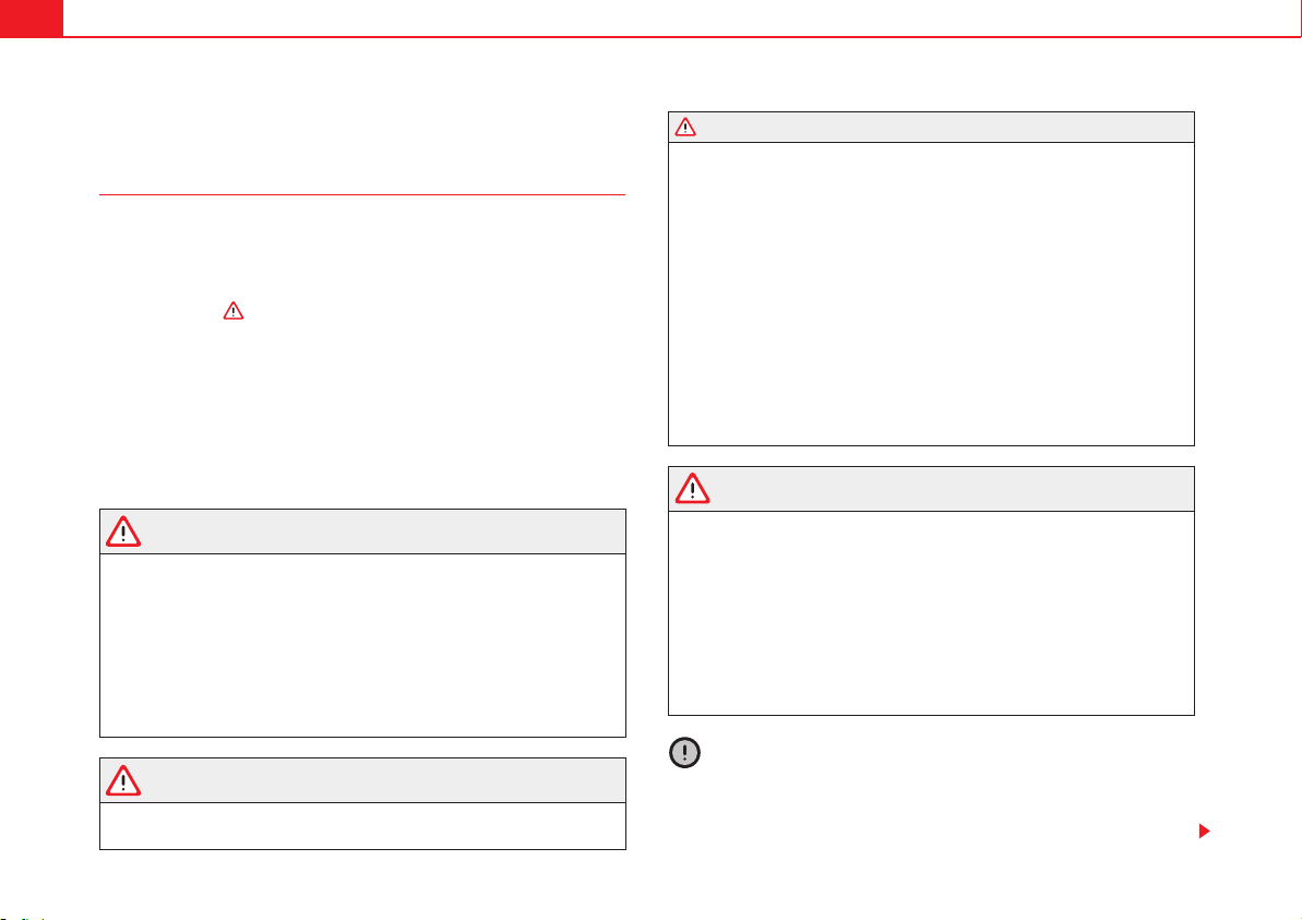
Seats and storage compartments146
Loading luggage compartment
Introduction
Always transport heavy loads in the trunk and place the seat backs in a
vertical position. Always use the fastening rings with suitable rope or straps.
Never overload the vehicle. Both the carrying capacity as well as the distribu-
tion of the load in the vehicle have effects on the driving behaviour and
braking ability .
Additional information and warnings:
x Airbag system page 33
x Light page 113
x Transporting page 13
x Towing mode page 260
x Wheels and tyres page 323
WARNING
When the vehicle is not in use or being watched, always lock the doors and
the tailgate to reduce the risk of serious injury or death.
x Do not leave children unwatched, especially when the tailgate is open.
Children could climb into the luggage compartment, close the tailgate from
inside and be unable to escape themselves. This could lead to serious
injury or death.
x Never allow children to play in or around the vehicle.
x Never transport people in the luggage compartment.
WARNING
Unsecured or incorrectly secured objects can cause serious injury in case
of a sudden manoeuvring or breaking or in case of an accident. This is espe-
cially true when objects are struck by a detonating airbag and fired through
the vehicle interior. To reduce the risks, please note the following:
x Secure all objects in the vehicle. Always keep equipment and heavy
objects in the luggage compartment.
x Always secure objects with suitable rope or straps so that they cannot
enter the areas around the frontal or side airbags in case of sudden braking
or an accident.
x While driving, always keep object compartments closed.
x Do not place hard, heavy or sharp objects inside the passenger
compartment, in open storage compartments, the rear shelf or on the
dashboard.
x Remove hard, heavy and sharp objects from clothes and pockets inside
the vehicle and store securely.
WARNING
The transport of heavy object changes vehicle handling and increases
braking distance. Heavy loads that have not been stored or secured
correctly could cause loss of control and result in serious injury.
x The vehicle handling changes when transporting heavy objects due to
a change in the centre of gravity.
x Distribute the load as uniformly and as low down on the vehicle as
possible.
x Store heavy objects in the luggage compartment as far from the rear
axle as possible.
Caution
x Hard objects on the shelf could chafe the wires of the heating element
and antenna of the rear window and cause damage.
x The side window antenna could be damaged due to chafing from objects.
WARNING (continued)
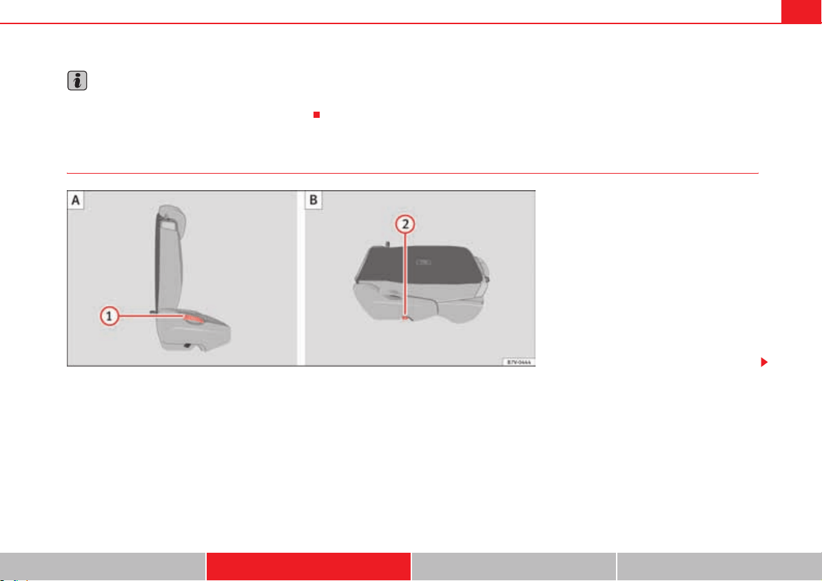
Seats and storage compartments 147
Safety First Operating instructions Practical tips Technical Data
Note
The ventilating slits between the heated rear window and the shelf must not
be covered so that used air can escape from the vehicle.
Folding down rear seats to create load space
Fig. 95 Second row of seats: folding the rear seat ,
rear seat as load space .
A
A
A
B
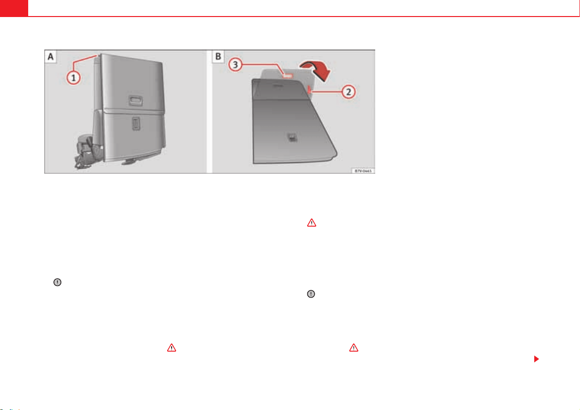
Seats and storage compartments148
Each rear seat can fold down individually to extend the luggage compart-
ment.
Folding the seats in the second row of seats for loading
x If necessary, open the belt loop and wind up the seat belt by hand.
x If it is necessary, remove the head rests on the integrated child seats then
reinstalled the integrated child seats page 52.
x If necessary, raise the armrests.
x Remove objects from the footrest area in front of and behind the rear seat
.
x Move the rear seat all the way back.
x Push the head restraint down as far as it will go page 10.
x In the middle seat, close the drinks carrier in the rear of the centre
console, if necessary.
x Pull lever page 147, fig. 95 back and fold the backrest forwards.
The complete rear seat folds forward .
x Fold the backrest forwards until it locks into the load surface position
page 147, fig. 95 .
x If necessary, pull on the lever fig. 96 to move the seat to the
required position.
x When the seat is folded down, no adults or children should travel in it
.
Folding the seats in the third row of seats for loading
x If necessary, open the belt loop and wind up the seat belt by hand.
x Open the tailgate.
x Push the head restraint down as far as it will go page 10.
x Remove objects from the footrest area in front of and behind the rear seat
.
x Remove objects from the space below the rear seat.
x Remove the attachment elements and supports for the net from the rail
system.
x Pull lever fig. 96 back and fold the backrest forwards. The rear seat
folds forward and the cushion also moves forward.
x Fold the seat tray forward on top of the folded seat.
Fig. 96 Third row of seats: fold down the rear seat to
load then return to position .
A
A
A
B
A
1
A
B
A
2
A
1
Seats and storage compartments 149
Safety First Operating instructions Practical tips Technical Data
x When the seat is folded down, no adults or children should travel in it
.
Putting the seats in the second row back in place
x Pull lever page 147, fig. 95 upwards and place the seatback in
vertical position. The entire seat folds backwards.
x Pull on the rear seats and the backrest to ensure that they are correctly
locked in place and that the safety belt protection is guaranteed for rear seat
passengers.
Putting the seats in the third row back in place
x Open the tailgate.
x Pull on the handle page 148, fig. 96 to put the seat tray back in
position.
x Pull on the handle page 148, fig. 96 . The entire seat folds back-
wards.
x Press on the seat tray in the backrest until it is held in position by its
magnets.
x Open the sliding door.
x Put the backrest into position and press firmly until it clicks into place.
x Pull on the rear seats and the backrest to ensure that they are correctly
locked in place and that the safety belt protection is guaranteed for rear seat
passengers.
WARNING
Folding and lifting the rear seats carelessly without paying attention could
cause serious injury.
x Never fold or lift the seats while driving.
x Do no trap or damage seat belts when raising the backrest.
x Keep your hands, fingers, feet and other body parts out of the hinges
and the seat locking mechanism when folding and unfolding.
x Mats or other objects can be caught in the hinges of the backrests or
rear seat. This could prevent the seat or backrest from locking securely in
the vertical position.
x All backrests must engage correctly for the seat belts on the rear seats
to work properly. When the backrest of an occupied seat is not correctly
locked in place, the passenger can be thrust forward with the backrest in
case of sudden braking, sudden manoeuvres or an accident.
x No seat must be occupied if the backrest or seat is folded or not
correctly engaged.
Caution
Before folding the backrest of the rear seat, adjust the front seats so that the
head restraint or backrest do not hit them when it is folded.
Caution
x Objects placed in the footrest area in front of and behind the rear seats
can be damaged when seats are folded down or put back into position.
Remove any objects in the way before folding seats down or repositioning
them.
x Objects placed in the moulding on the back of the third row of seats can
be damaged when folding down the seats or putting them back into position.
Remove any objects in the way before folding seats down or repositioning
them.
x The attachment elements and supports for the net partition placed on the
rail system can be damaged when folding down seats from the third row or
putting them back into position and these can also damage the seats them-
selves. Before folding down or repositioning the seats, remove the attach-
ment elements and supports for the net from the rail system.
A
1
A
2
A
3
WARNING (continued)
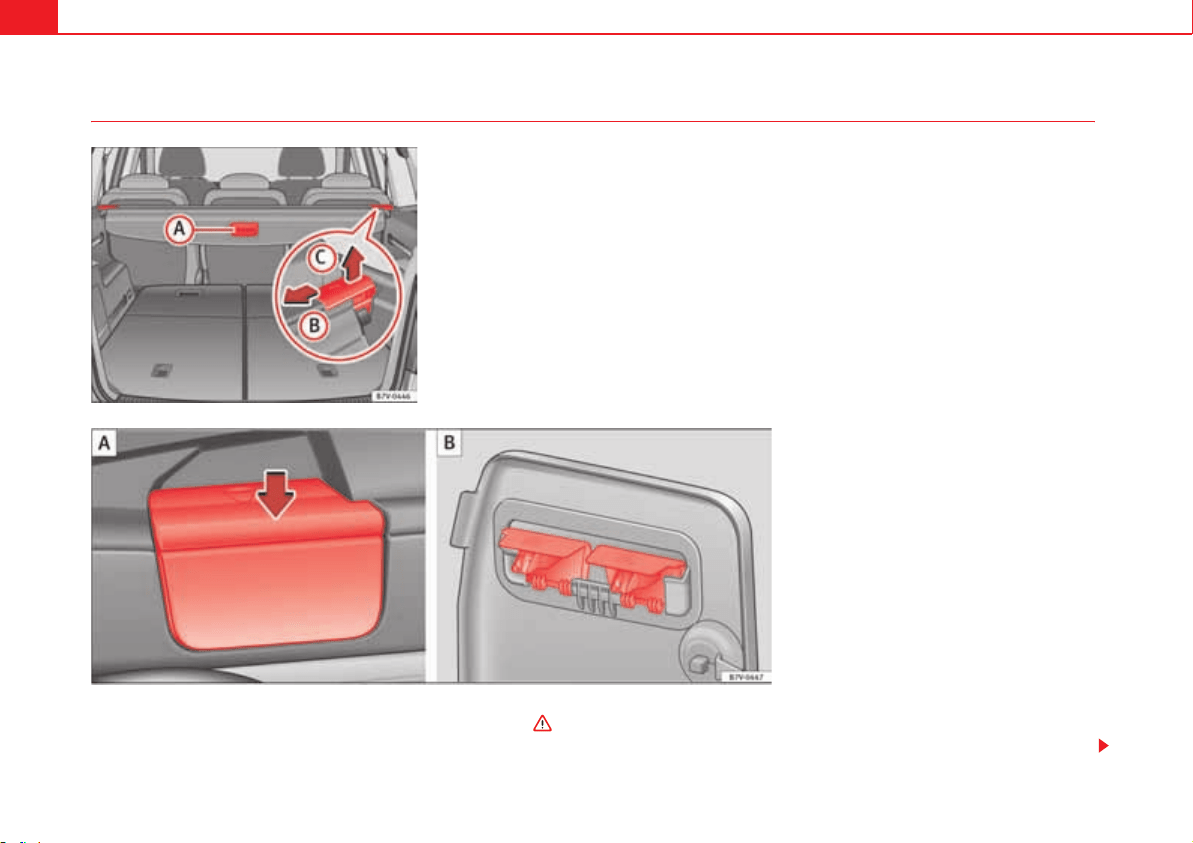
Seats and storage compartments150
Luggage compartment cover
The rear shelf can be fitted behind the second or third row of seats . Opening the shelf
x Pull the shelf handle fig. 97 backwards.
Fig. 97 In the luggage
compartment: Luggage
compartment cover.
Fig. 98 Remove the cover supports then put them
away safely .
A
A
A
B
A
A
Seats and storage compartments 151
Safety First Operating instructions Practical tips Technical Data
x Release the shelf upwards by the side supports and guide it forward.
Closing the shelf
x Pull the unfolded shelf evenly on the guide backwards.
x Secure the shelf using the left and right side supports.
Installing the shelf behind the second row of seats
x Place the shelf in its position in the side lining, left-hand side first.
x Release the shelf in the direction of the arrow page 150, fig. 97 .
x Insert the shelf into the right-hand support, pressing down.
Installing the shelf behind the third row of seats
x Remove the shelf from the support in the side lining page 150, fig. 98
. To do this, press the shelf upwards (arrow) and remove it.
x Open the compartment in the left-hand side rear lining page 162 and
hook the shelf to the rear of the luggage compartment cover page 150,
fig. 98 .
x Close the rear left-hand side lining compartment.
x Place the shelf in its position in the side lining, left-hand side first.
x Lift the shelf off in direction of the arrow page 150, fig. 97 .
x Insert the shelf into the right-hand support, pressing down.
Removing the shelf
x Release the shelf in the direction of the arrow page 150, fig. 97
and lift it in the direction of the arrow .
x Remove the shelf from the right-hand side support.
x Also, when removing from behind the third row of seats: Cover the side-
lining supports with their covers.
x Only with 5 places: Support the released shelf by placing it on the front
section of the luggage compartment floor page 162.
WARNING
If the shelf is placed on one of the rear seats, this could cause serious
injury in case of sudden braking or an accident.
x Whenever it the third row seats are occupied, the shelf should be put
behind this row.
WARNING
Unsecured or incorrectly secured objects or animals on the rear shelf could
cause serious injuries in case of a sudden manoeuvre or braking or even an
accident.
x Do not leave hard, heavy or sharp objects (loose or in bags) on the rear
shelf.
x Never transport animals on the rear shelf.
A
B
A
A
A
B
A
B
A
B
A
C

Seats and storage compartments152
Net partition
The net partition can prevent objects in the luggage compartment entering
the passenger compartment / the driver area.
First remove the net from its bag and unfold it.
Fold out the net partition
Fold out the support transversal rods fig. 99 for the net partition fully
in the direction of the arrow until you hear a “click”.
Installing the net partition behind the second row of seats
x Hook in the net partition on the left-hand side roof support fig. 100
. To do this, guide the rod from up to down.
x Hook in the net partition on the rear right-hand side roof support by
pressing on the rod.
x Secure the net partition hooks into the straps in the front of the luggage
compartment fig. 100 then tighten them.
Installing the net partition behind the front seats
x Hook in the net partition on the left-hand side roof support fig. 100
. To do this, guide the rod from up to down.
Fig. 99 Unfold the net partition then fold it again
and .
A
1
A
2
A
3
Fig. 100 In the luggage
compartment: Install the
net partition behind the
second row of seats.
A
1
A
A
A
B
A
C
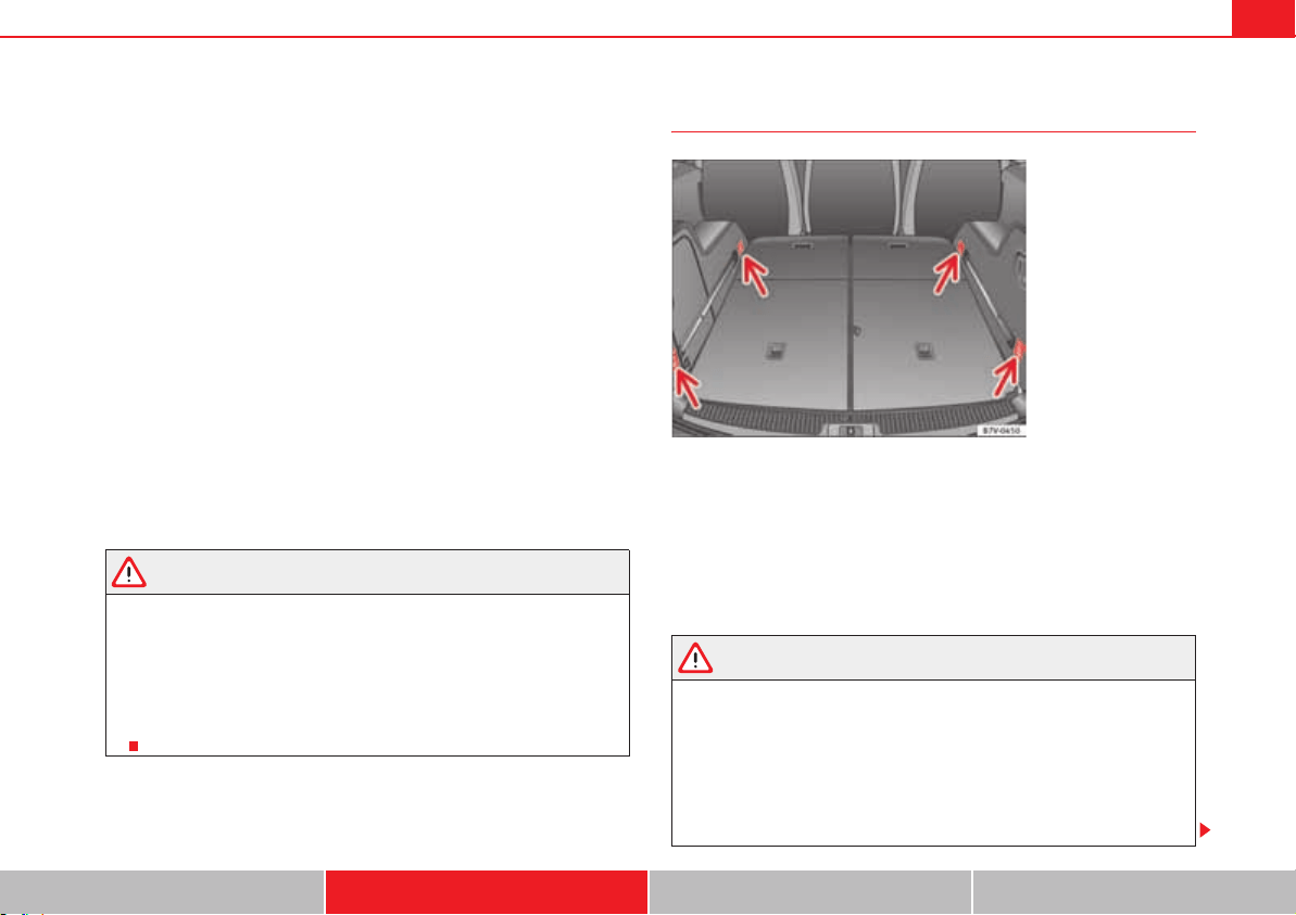
Seats and storage compartments 153
Safety First Operating instructions Practical tips Technical Data
x Hook in the net partition on the rear right-hand side roof support by
pressing on the rod.
x Secure the hooks of the net partition to the attachment rings in the left
and right hand side foot rests on the second row of seats then tighten the
straps.
Removing the net partition
x Loosen the net partition straps.
x Release the net partition hooks from the rings page 152, fig. 100 .
x Release the net partition from the right and left roof supports
page 152, fig. 100 or by pressing on the rod.
x Unhook the net partition from the left-hand side roof support.
Folding in the net partition
x Press on the release button page 152, fig. 99 and bend the rod
in the direction of the arrow with the release o button pressed.
x Press on the release button page 152, fig. 99 and bend the rod
in the direction of the arrow with the release button pressed.
x Store the net partition securely in the vehicle.
WARNING
Loose objects in the passenger compartment can be violently thrown in
case of a sudden manoeuvre or braking and especially in accidents causing
serious injury.
x Ensure that the rods are correctly locked in place.
x Even when net partition is correctly fitted, objects must be secured.
x When driving with the net partition, no passengers should be behind
it.
Fastening rings
To the front and rear of the luggage compartment, there are fastening rings
for securing objects fig. 101 (arrows). On some models, the fastening
rings are all the way to the back on the lock carrier plate.
There are other fastening rings located to the left and right hand side of the
second row footrests.
Some models of fastening rings must be lifted to use them.
WARNING
Unsuitable or damaged ropes or straps may be released in case of sudden
braking or an accident. As a result, objects may be fired through the
passenger compartment causing serious injury or death.
x Always use suitable ropes and straps in good condition.
x Secure the ropes and straps to the fastening rings.
x Loose objects in the luggage compartment can suddenly slide and
change the way the vehicle handles.
A
B
A
A
A
C
A
2
A
A
A
3
A
B
Fig. 101 In the luggage
compartment: fastening
rings
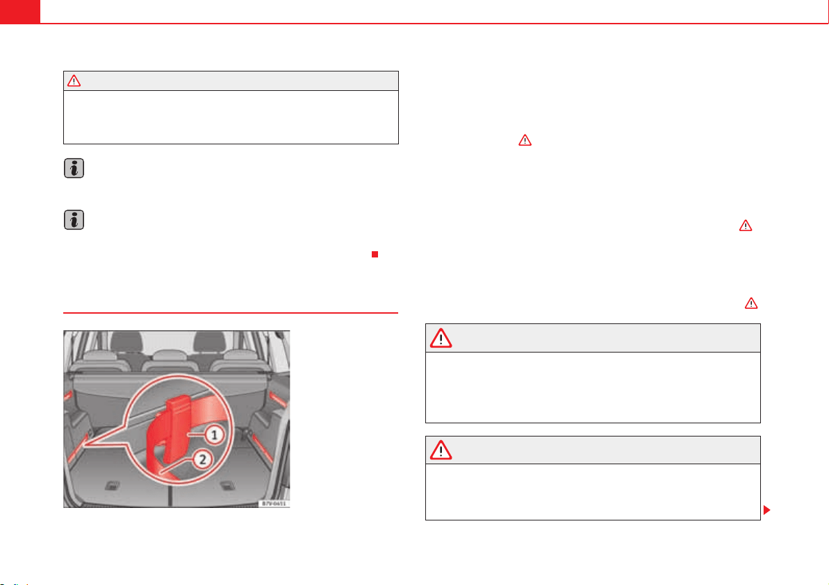
Seats and storage compartments154
x Secure all objects, little and large.
x Never secure a load that is too heavy for the fastening rings.
x Never secure a child seat to the fastening rings.
Note
The maximum load of the fastening rings is approximately 3.5 Kn (3.57 Kp).
Note
You can find suitable transport straps and load securing systems at a
specialist workshop. SEAT recommends visiting a qualified workshop.
Rails and attachment system*
The rails and attachment system consists of four rails, movable attachment
elements, straps to be secured to the rails and a net with supports to cover
baggage page 155. The rail and attachment system is designed to secure
light objects. If the seats in the third row are to be occupied by passengers
then attachment elements should never be placed in the section of the rails
close to the seats .
Installing the attachment elements
x Fit the attachment element with the ruts facing upwards fig. 102 to
the upper part of the guide and press downwards.
x Move the attachment element to the desired position.
x Always ensure that the attachment inserts into the guide system .
Removing the attachment elements
x Remove the attachment element from the guide and pull downwards.
Securing a load
x Pull the strap through the attachment element and secure the load .
WARNING
In case of an accident or sudden braking, the attachment elements in the
parts of the rails close to the seats of the third row could injure seat occu-
pants.
x Whenever the seats on the third row are to be occupied, remove the
attachment elements from the rails or move them all the way back.
WARNING
Movable attachment elements that are not secured correctly can be
released from the guide in case of sudden braking or accident. As a result,
objects may be fired through the passenger compartment causing serious
injury or death.
WARNING (continued)
Fig. 102 In the luggage
compartment: System
including rails, adjustable
attachment elements
and adjustable tightening
straps .
A
1
A
2
A
1
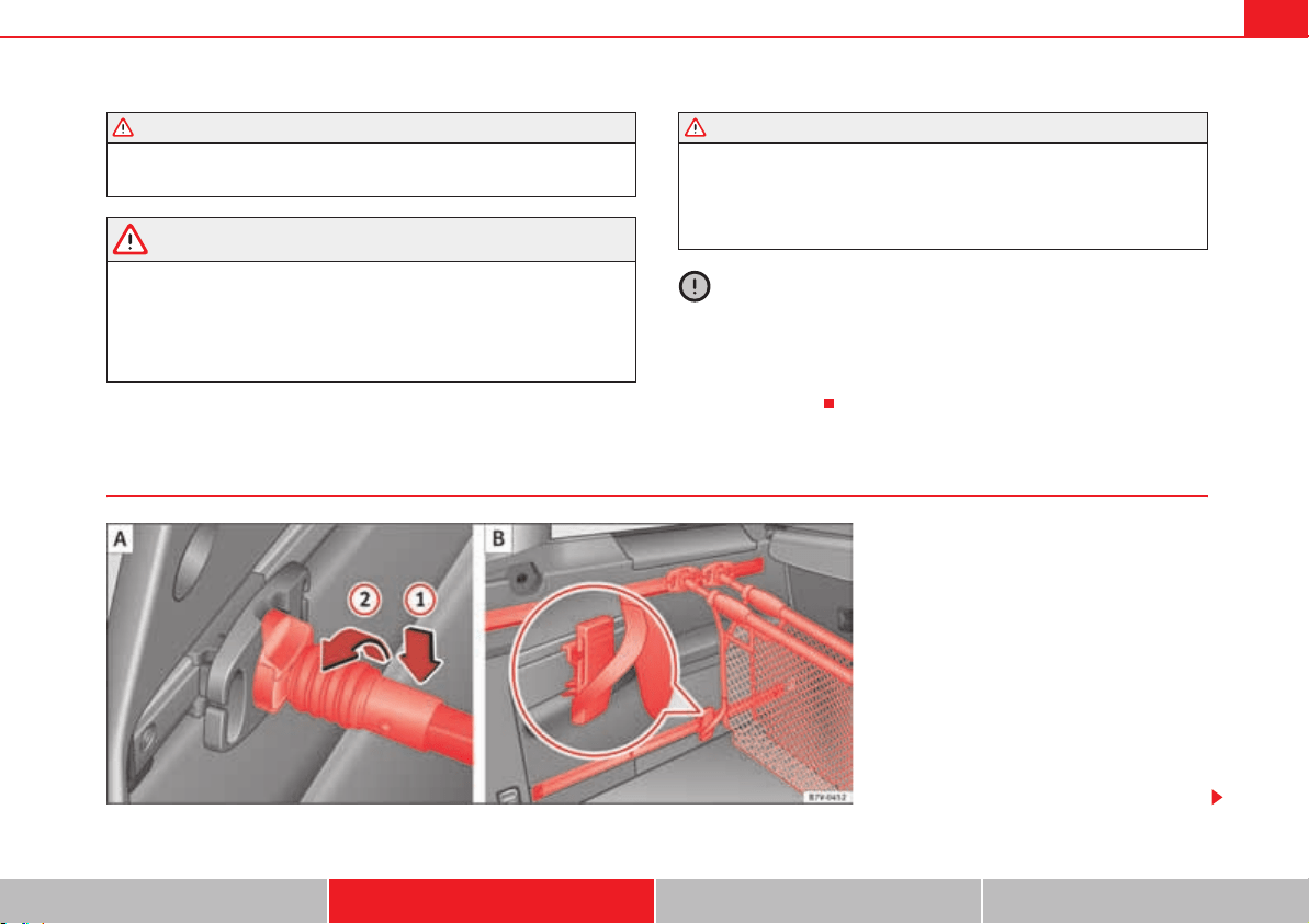
Seats and storage compartments 155
Safety First Operating instructions Practical tips Technical Data
x Always ensure that the movable attachment elements are correctly
inserted into the guides.
WARNING
Unsuitable or damaged ropes or straps may be released in case of sudden
braking or an accident. As a result, objects may be fired through the
passenger compartment causing serious injury or death.
x Always use the attachment straps of the rail and attachment system.
x Secure the attachment straps firmly to the attachment elements.
x Loose objects in the luggage compartment can suddenly slide and
change the way the vehicle handles.
x Secure all objects, little and large.
x Never secure a child seat to the attachment elements.
Caution
x The attachment elements placed on the rail system can be damaged when
folding down seats from the third row or putting them back into position and
these can also damage the seats themselves. Before folding down or reposi-
tioning the seats, remove the attachment elements and supports for the net
from the rail system.
Baggage net*
WARNING (continued) WARNING (continued)
Fig. 103 Hook the baggage net and use it as a bag
.
A
A
A
B
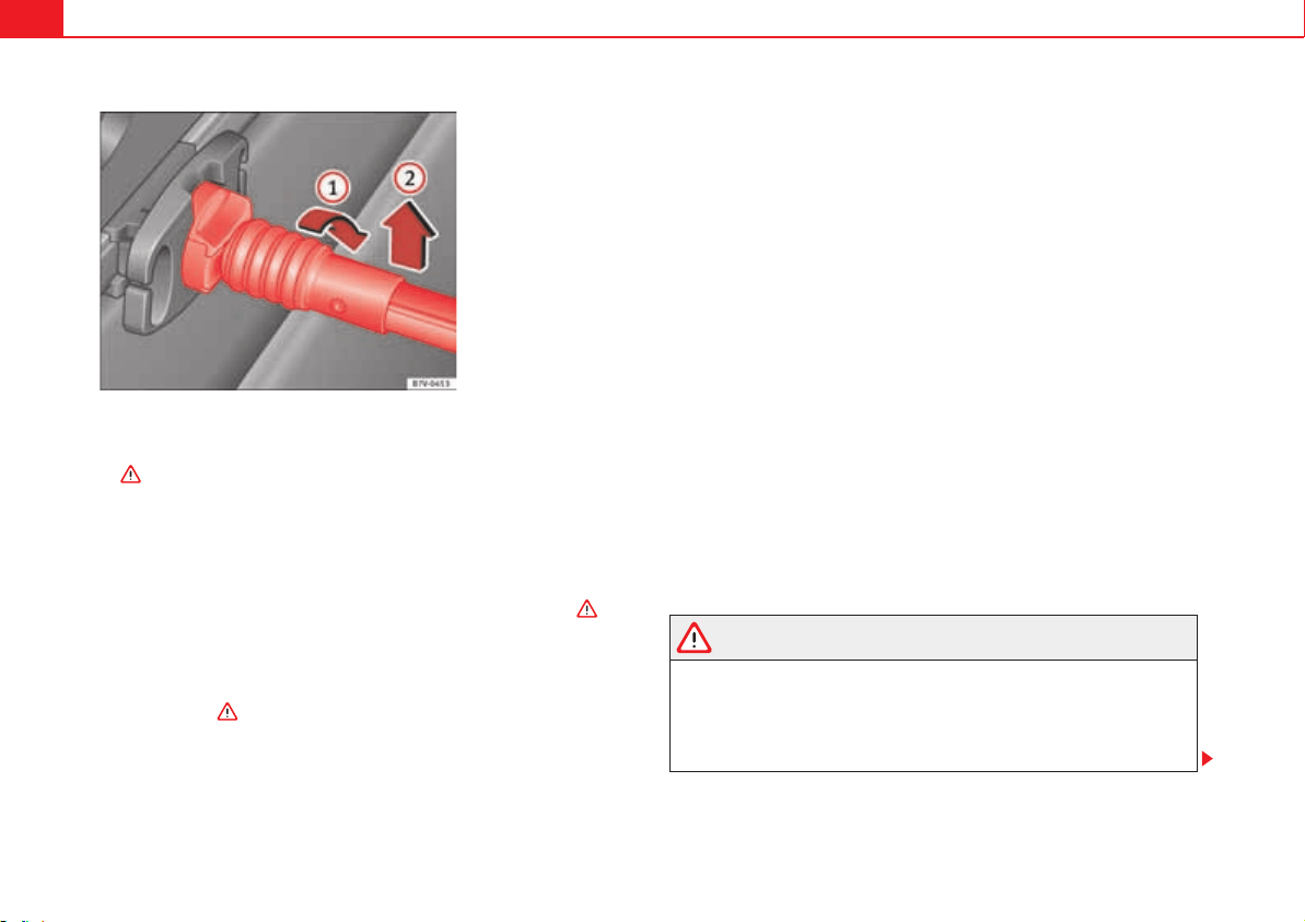
Seats and storage compartments156
If the seats in the third row are to be occupied by passengers then attachment
elements should never be placed in the section of the rails close to the seats
.
Installing the baggage net supports
x Fit the baggage net support into the guide from the back and press down-
wards.
x Move the baggage net support to the required position.
x Always ensure that the net support inserts into the rail system .
Hooking the baggage net into the support
Place the attachment rod on the baggage net support page 155, fig. 103
and rotate 90° to the left . The red mark on the attachment rod should
not be visible .
Using the net for bag type baggage
x Fit the baggage net supports to each one of the upper rails.
x Fit a movable baggage net attachment element to each one of the lower
guides page 154.
x Hook the baggage net into the supports.
x Hook the baggage net attachment strap underneath into one of the
movable attachment elements page 155, fig. 103 .
x Join the baggage net supports to the upper rails as much as possible by
pushing them.
x Press the sides of the baggage net together so that they are held by the
Velcro.
Using the baggage net to separate the luggage compartment
x Fit the baggage net supports to each one of the upper rails.
x Fit the baggage net supports to each one of the lower rails.
x Hook the baggage net into the supports.
To release the baggage net
x Rotate the attachment rod 90° to the right fig. 104 until you can
see the red mark on the rod. Pull the attachment rod upwards .
x Only with 5 places: After removing, place the baggage net safely in the
front compartment on the floor of the luggage compartment page 162.
Removing the baggage net supports
x Remove the net attachment element from the rail and pull it out down-
wards.
WARNING
In case of an accident or sudden braking, the net attachment elements in
the parts of the rails close to the seats of the third row could injure seat
occupants.
x Whenever the seats on the third row are to be occupied, remove the
attachment elements from the rails or move them all the way back.
Fig. 104 Release the
baggage net.
A
1
A
2
A
B
A
1
A
2
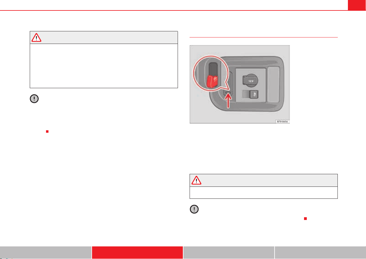
Seats and storage compartments 157
Safety First Operating instructions Practical tips Technical Data
WARNING
Baggage net supports that are not secured correctly can be released from
the guide in case of the sudden braking or accident. As a result, objects
may be fired through the passenger compartment causing serious injury or
death.
x Always ensure that the baggage net supports are correctly inserted into
the rails; the red mark should not be visible.
x Never secure a child seat to the baggage net supports.
Caution
x The baggage net supports placed on the rail system can be damaged
when folding down seats from the third row or putting them back into posi-
tion and these can also damage the seats themselves. Before folding down
or repositioning the seats, remove the baggage net supports from the rail
system.
Retaining hooks
On the right-hand side of the luggage compartment, there are folding
retaining hooks fig. 105 that can be used to secure light shopping bags.
x Press the retaining hooks down fig. 105 (arrow) and fold them.
x Hook the bags in place.
x After use, raise the hooks again.
WARNING
Never use these hooks to secure objects. In case of sudden braking or an
accident, the hooks could rupture.
Caution
The hooks can support a maximum of 2.5 kg (about 5 lbs).
Fig. 105 In the luggage
compartment: retaining
hooks.
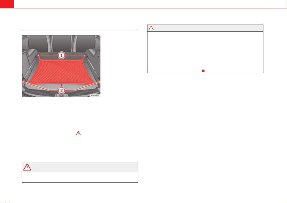
Seats and storage compartments158
Baggage net
The baggage net can be used to secure lighter items.
Hooking the baggage net into the luggage compartment floor
x Hook the baggage net into the fastening rings fig. 106 and .
Releasing the baggage net
The secured baggage net is taut .
x Carefully unhook the baggage net hooks from the fastening rings
fig. 106 .
x Carefully unhook the baggage net hooks from the fastening rings
fig. 106 .
WARNING
The elastic baggage net stretches when it is secured to the luggage
compartment fastening rings. The secured baggage net is taut. The hooks
on the baggage net can cause injury if the net is incorrectly hooked or
unhooked.
x Always ensure that the hooks do not suddenly release from the
fastening rings when hooking or un-hooking.
x Always keep your face and eyes protected at a safe distance to avoid
injury should a hook slip while hooking or unhooking.
x Always engage the hooks in the order given. If a baggage net hook
springs back this can cause injury.
Fig. 106 In the luggage
compartment: net used on
secured baggage.
A
1
A
2
A
1
A
2
WARNING (continued)
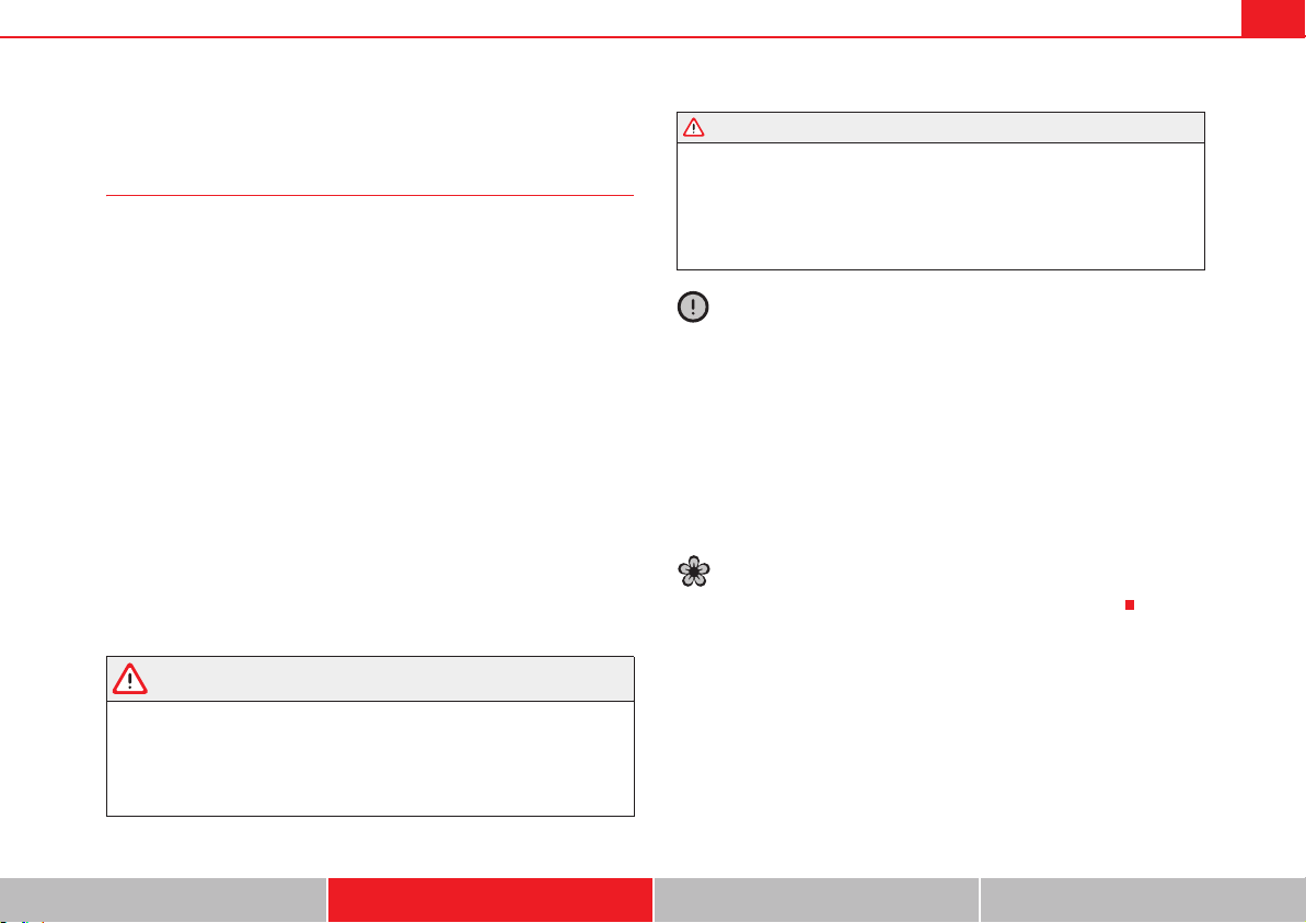
Seats and storage compartments 159
Safety First Operating instructions Practical tips Technical Data
Roof carrier system
Introduction
The vehicle roof has been designed to optimise aerodynamics. For this
reason, conventional roof carrier systems cannot be secured to the roof rails.
Given that the water drains have been incorporated into the roof for aerody-
namic reasons, only the SEAT approved basic supports and roof carrier
systems can be used.
When should the roof carrier system be removed?
x When it is not being used.
x When the vehicle is being washed in a car wash.
x When the vehicle height exceeds the maximum height (for example, in a
garage).
Additional information and warnings:
x Light page 113
x Transporting page 13
x Ecological driving page 252
x Wheels and tyres page 323
x Accessories, parts replacement, repairs and modifications page 285
WARNING
The risk of an accident is increased by transporting heavy or bulky loads on
the roof, which affects the car's handling by shifting the centre of gravity
and increasing susceptibility to cross winds.
x Always secure loads correctly with suitable and undamaged attach-
ment rope or straps.
x Large, heavy, wide and flat loads negatively affect the vehicle aerody-
namics, centre of gravity and handling.
x Avoid brusque manoeuvres and sudden braking.
x Adjust your speed and driving style to visibility, road, traffic and
weather conditions.
Caution
x Always remove the roof carrier system from the roof before entering a car
wash.
x The height of your vehicle is changed by the installation of the roof carrier
and the load secured on it. Compare the vehicle height with the passage
height, for example in underground car parks or entering garage doors.
x The roof antenna, the range of the panoramic sliding roof and the tailgate
should not be affected by the roof carrier system and the load being trans-
ported.
x Take extra care not to let the tailgate strike the roof load when opening.
For the sake of the environment
The vehicle uses more fuel when the roof carrier system is fitted.
WARNING (continued)
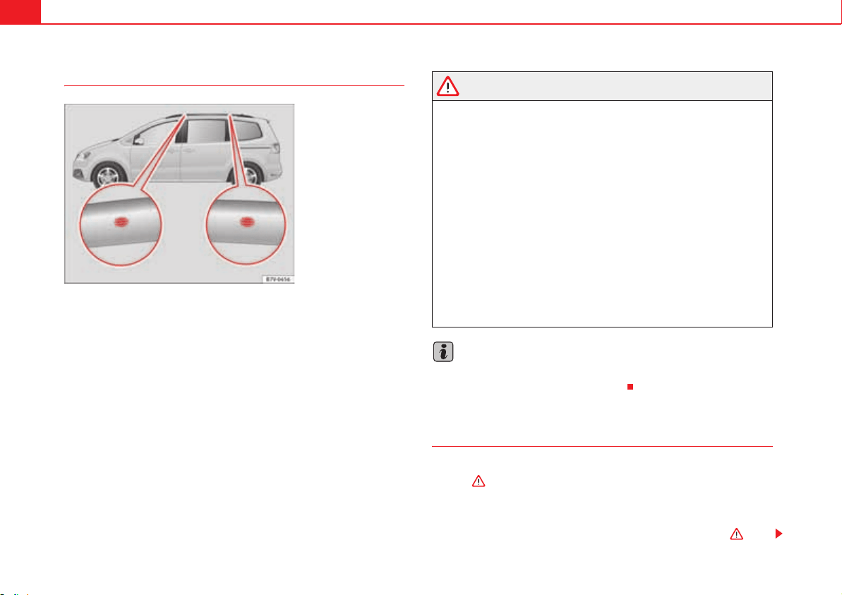
Seats and storage compartments160
Securing the base supports and roof carrier system
The mounts are the basis of a complete roof carrier system. Special fixtures
must then be added in order to safely transport luggage, bicycles, skis, surf
boards or boats on the roof. All these system components are available from
an Authorised Service Centre.
It will only be possible to install a basic support or roof carrier system if the
vehicle has a roof rail.
Securing the base supports and roof carrier system
Always secure the base supports and roof carrier system correctly.
The roof carrier system must always be installed exactly according to the
instructions provided.
The position holes are located on the inner side of the rail fig. 107.
WARNING
If the base supports and the roof carrier system are incorrectly fitted or
used in an unsuitable manner, the entire system could break free causing
accident and injury.
x Always take the manufacturer assembly instructions into account.
x Only use base supports and roof carrier systems that are not damaged
and are correctly fitted.
x The base support should only be fitted to the points indicated in the
diagram fig. 107.
x Secure the base supports and roof carrier system correctly.
x Check the screw fittings and attachments before driving and after a
short distance. During each long journey, check the attachments during
every break.
x Always fit the roof carrier system correctly for wheels, skis and surf-
boards.
x Never change or repair the basic supports or roof carrier system.
Note
Read and take into account the instructions included with the roof carrier
system fitted and keep them in the vehicle.
Loading the roof carrier system
Loads can only be correctly secured when the roof carrier system is correctly
fitted .
Maximum authorised roof load
The maximum authorised roof load is 100 kg (about 220 lbs). The roof load
includes the roof carrier system and the load being transported .
Fig. 107 Attachment
points for the basic
support and the roof
carrier system.
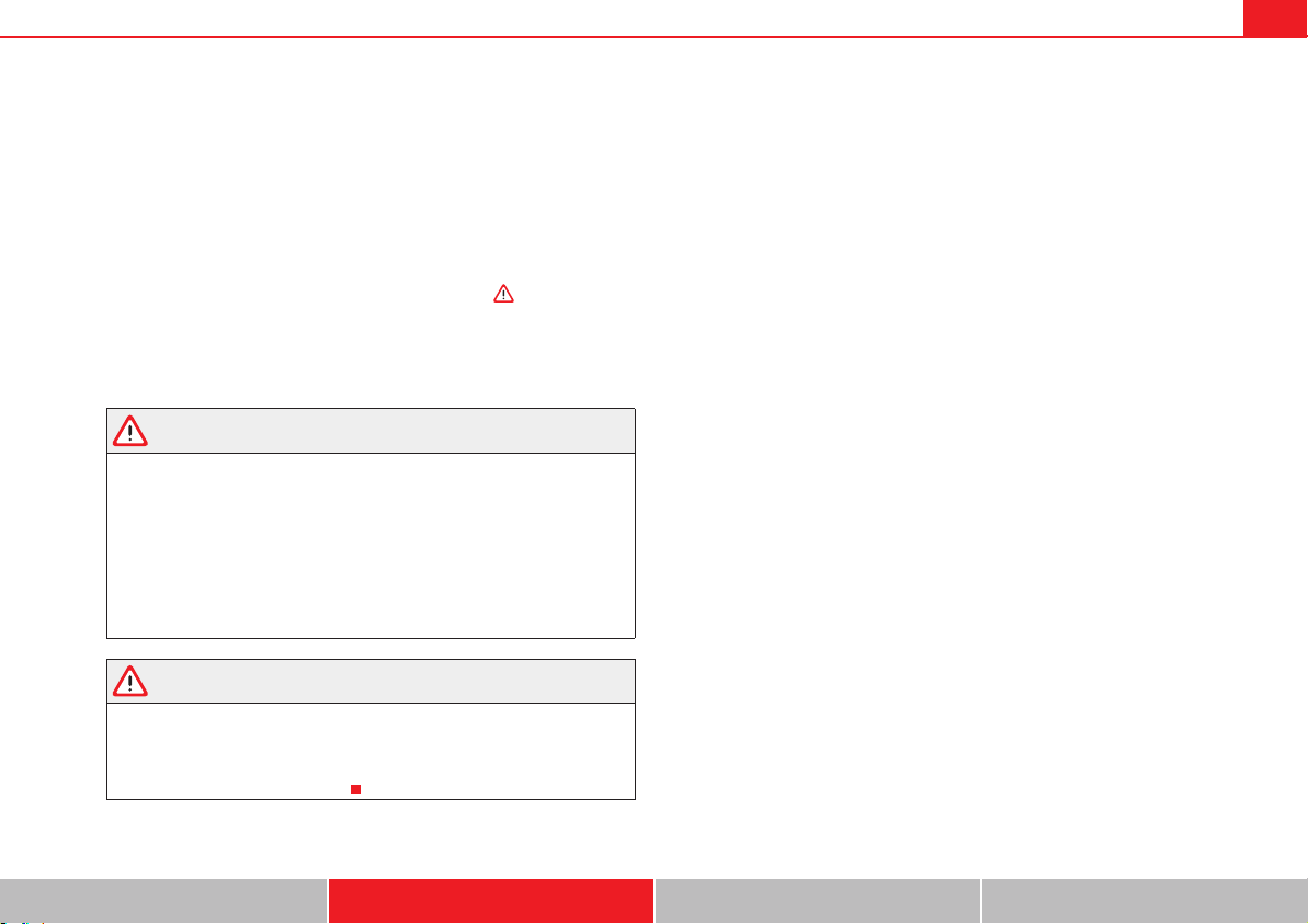
Seats and storage compartments 161
Safety First Operating instructions Practical tips Technical Data
Always check the roof carrier system weight and the weight of the load to be
transported and, if necessary, weigh them. Never exceed the maximum
authorised roof load.
If you are using a roof carrier with a lower weight rating, you cannot transport
the maximum roof load. Do not exceed the maximum weight limit for the roof
carrier given in the fitting instructions.
Distributing a load
Uniformly distribute loads and secure them correctly .
Check attachments
After fitting the base supports and the roof carrier system, always check the
attachments after a short trip or at regular intervals.
WARNING
Exceeding the maximum authorised roof load can result in accidents
and/or vehicle damage.
x Always respect the maximum authorised weight for the roof, the
maximum authorised weight on the axles and the total maximum author-
ised weight of the vehicle.
x Never exceed the capacity of the roof carrier system even if this is less
than the maximum authorised roof load.
x Secure heavy objects towards the front and distribute the load evenly.
WARNING
Loose and incorrectly secured loads can fall from the roof carrier system
causing accidents and injury.
x Always use suitable ropes and straps in good condition.
x Always secure loads correctly.

Seats and storage compartments162
Storage compartments
Introduction
Storage compartments must only be used to store light or small objects.
The front central armrest compartment houses the factory-fitted AUX-IN or
multimedia (MEDIA-IN) connection sockets.
The factory-fitted CD changer is located in the left-hand storage compartment
of the luggage compartment.
Additional information and warnings:
x Child seats (accessories) page 42
x Luggage compartment page 146
x Care and cleaning of the vehicle interior page 278
x Booklet “Radio” or Booklet “navigation system”
WARNING
In the event of sudden braking movements or turns, loose objects may be
thrown around the vehicle interior. This could cause serious injuries to
passengers and cause the driver to lose control of the vehicle.
x Do not transport animals or place hard, heavy or sharp objects inside
the vehicle in: open storage compartments, instrument panel, storage tray,
items of clothing or bags.
x While driving, always keep object compartments closed.
WARNING
Objects falling into the driver's footwell could prevent use of the pedals.
This could lead the driver to lose control of the vehicle, increasing the risk
of a serious accident.
x Make sure the pedals can be used at all times, with no objects rolling
underneath them.
x The floor mat should always be secured to the floor.
x Never place other mats or rugs on top of the original mat supplied by
the factory.
x Make sure that no objects can fall into the driver's footwell while the
vehicle is in motion.
Caution
x Objects on the shelf could chafe against the wires of the heating element
in the rear window and cause damage.
x Do not keep heat-sensitive objects, food or medicines inside the vehicle.
Heat and cold could damage them or render them useless.
x Light-transparent objects placed inside the vehicle, such as lenses,
magnifying glasses or transparent suction caps on the windows, could
concentrate the sun's rays and cause damage to the vehicle.
Note
The ventilating slits between the heated rear window and the shelf must not
be covered so that used air can escape from the vehicle.
WARNING (continued)
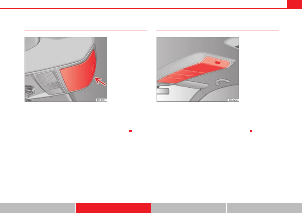
Seats and storage compartments 163
Safety First Operating instructions Practical tips Technical Data
Spectacle case in the roof console
To open, press and release the button fig. 108 (arrow).
To close, press the cover upwards until it clicks into place.
To ensure the passenger compartment monitoring works correctly, the spec-
tacle case must be closed when the vehicle is locked page 90.
Compartment in the roof console*
To open, press and release the button fig. 109.
To close, press the storage compartment upwards until it clicks into place.
To ensure passenger compartment monitoring works properly, the storage
compartments must be closed when the vehicle is locked.
Fig. 108 On the roof
console: Sunglasses
storage compartment.
Fig. 109 On the roof
console: Storage
compartment.
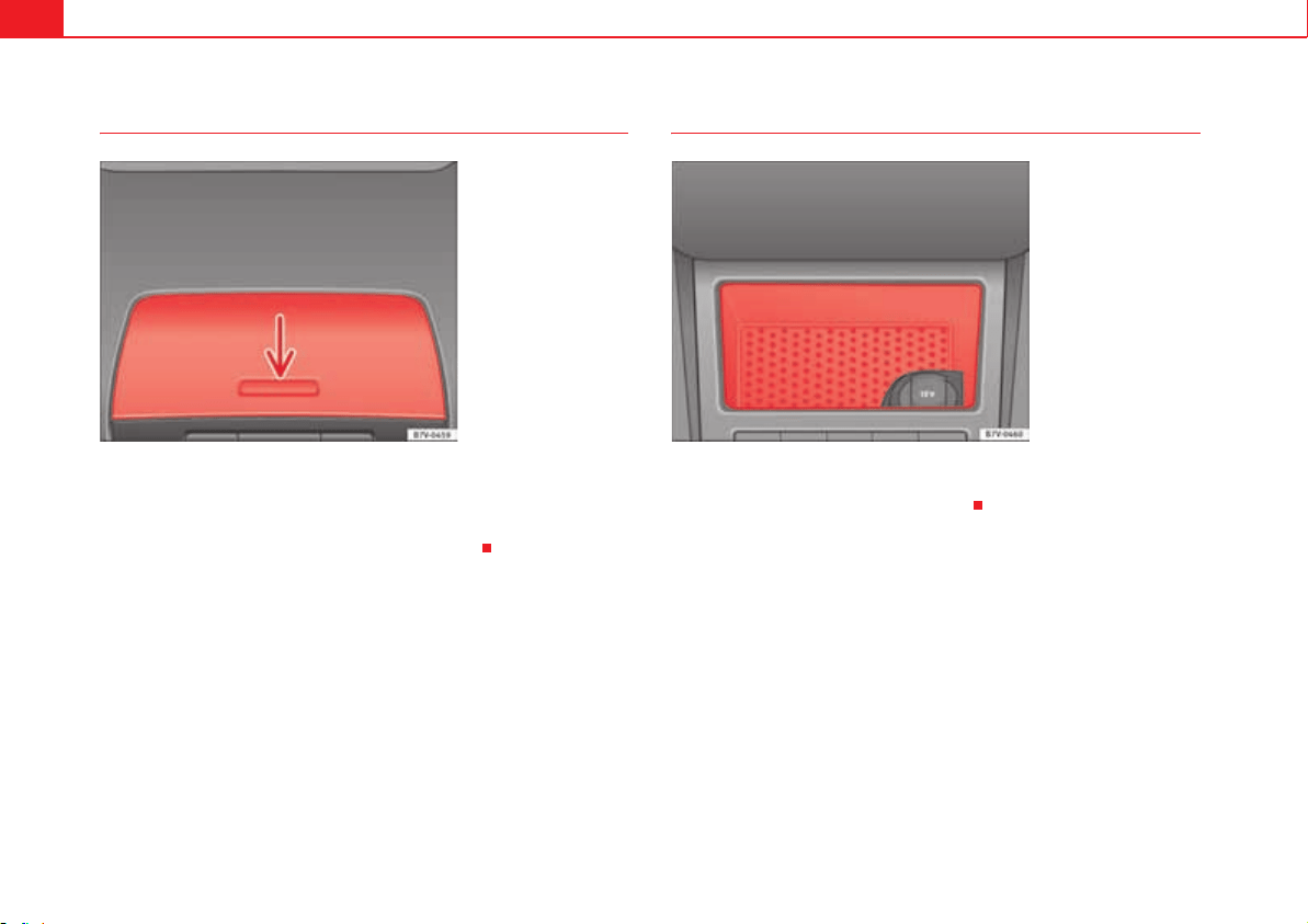
Seats and storage compartments164
Compartment on the instrument panel
The storage compartment on the instrument panel may have a cover.
To open, press the button on the cover fig. 110 (arrow).
To close, press the cover down until it clicks into place.
Compartment on the centre console
There is an open compartment on the centre console fig. 111 in which
there may be a 12 volt socket page 175.
Fig. 110 Storage
compartment on the
instrument panel.
Fig. 111 Compartment in
the front centre console.
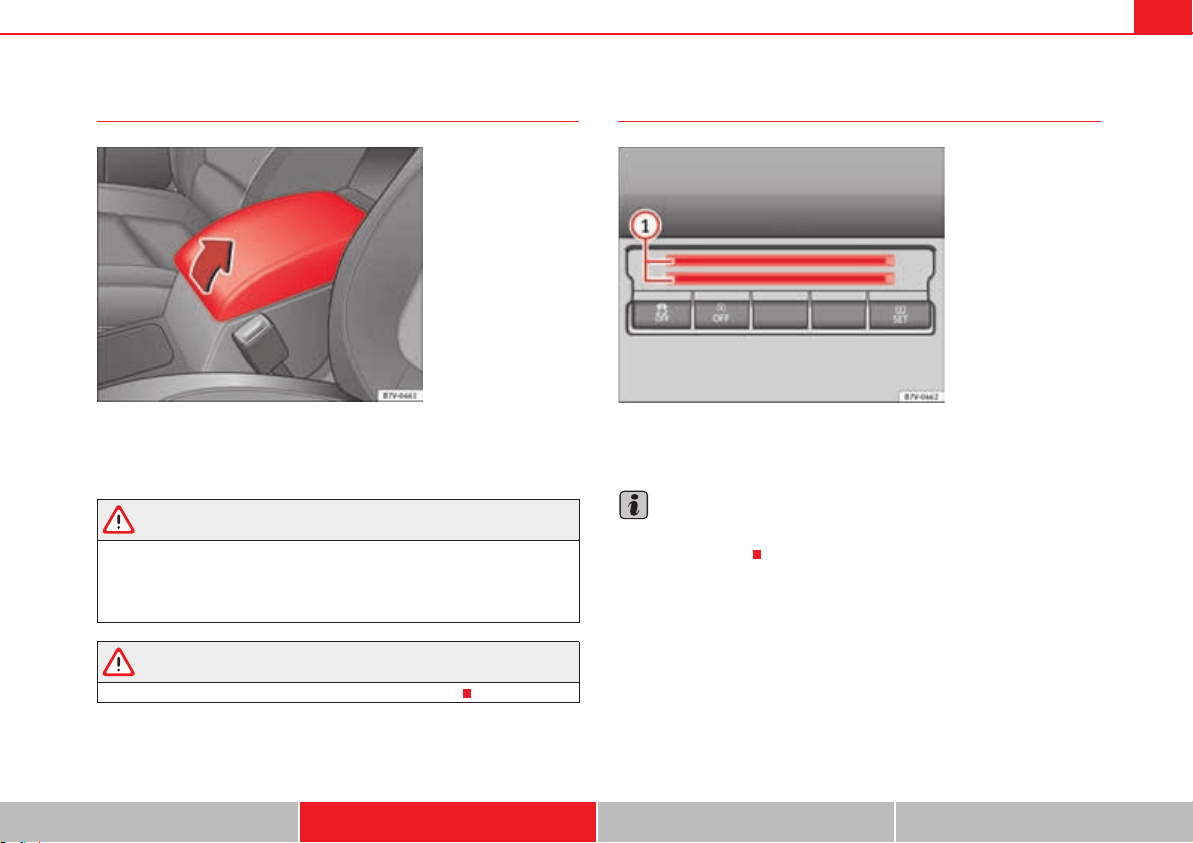
Seats and storage compartments 165
Safety First Operating instructions Practical tips Technical Data
Compartment in the front central armrest
To open, fully lift the central armrest in the direction of the arrow fig. 112.
To close, lower the central armrest.
WARNING
The centre armrest may limit the freedom of movement of the driver's arm
and cause a serious accident.
x Keep the centre armrest compartments closed while the vehicle is in
motion.
WARNING
The centre armrest is not designed for children to sit on!
Card compartments
To the bottom of the centre console there is a compartment fig. 113 for
coins, cards, car park tickets and similar items.
Note
To avoid theft or use by others, do not use the compartment to store credit or
ATM cards or similar.
Fig. 112 Storage
compartment in the front
central armrest.
Fig. 113 Centre console,
lower section: card
compartment.
A
1
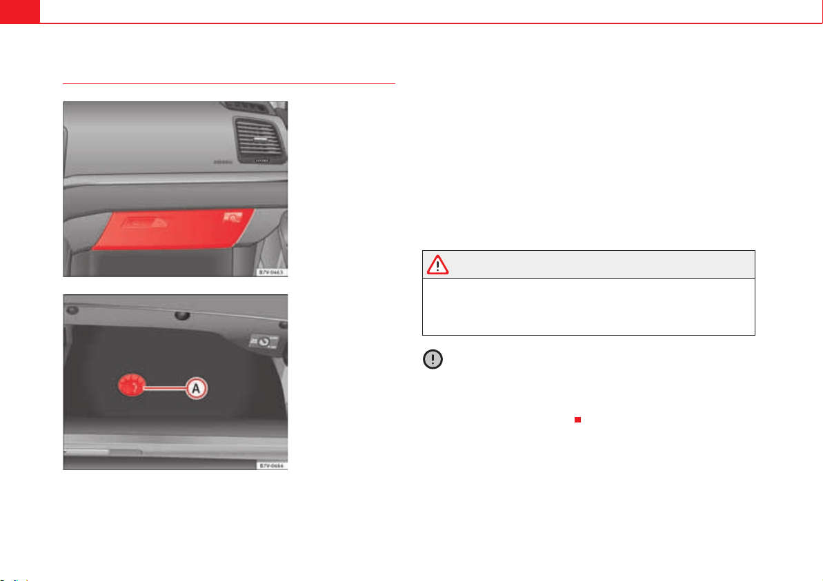
Seats and storage compartments166
Glove compartment
Opening and closing the glove compartment
Unlock the glove compartment where necessary. The glove compartment is
locked when the key slot is vertical.
Pull the lever to open fig. 114.
Press the cover upwards to close.
Vehicle wallet compartment
The glove compartment is designed to store the vehicle wallet.
The vehicle wallet should always be kept in the glove compartment. To store
the wallet, insert it sideways into the glove compartment.
Cooling the glove compartment
There is an air vent fig. 115 on the rear panel so that cooled air from
the climate control system (this must be connected) is fed into the glove
compartment. Turn the air vent to open and close it.
WARNING
The risk of serious injuries in the event of an accident during a sudden
braking manoeuvre or turn is increased if the glove compartment is left
open.
x Keep the glove compartment closed while the vehicle is in motion.
Caution
For structural reasons, some model versions will have gaps behind the glove
compartment into which small objects may fall. This could lead to strange
noises and damage to the vehicle. You should therefore not keep very small
objects in the glove compartment.
Fig. 114 Glove compart-
ment.
Fig. 115 Glove compart-
ment open.
A
A
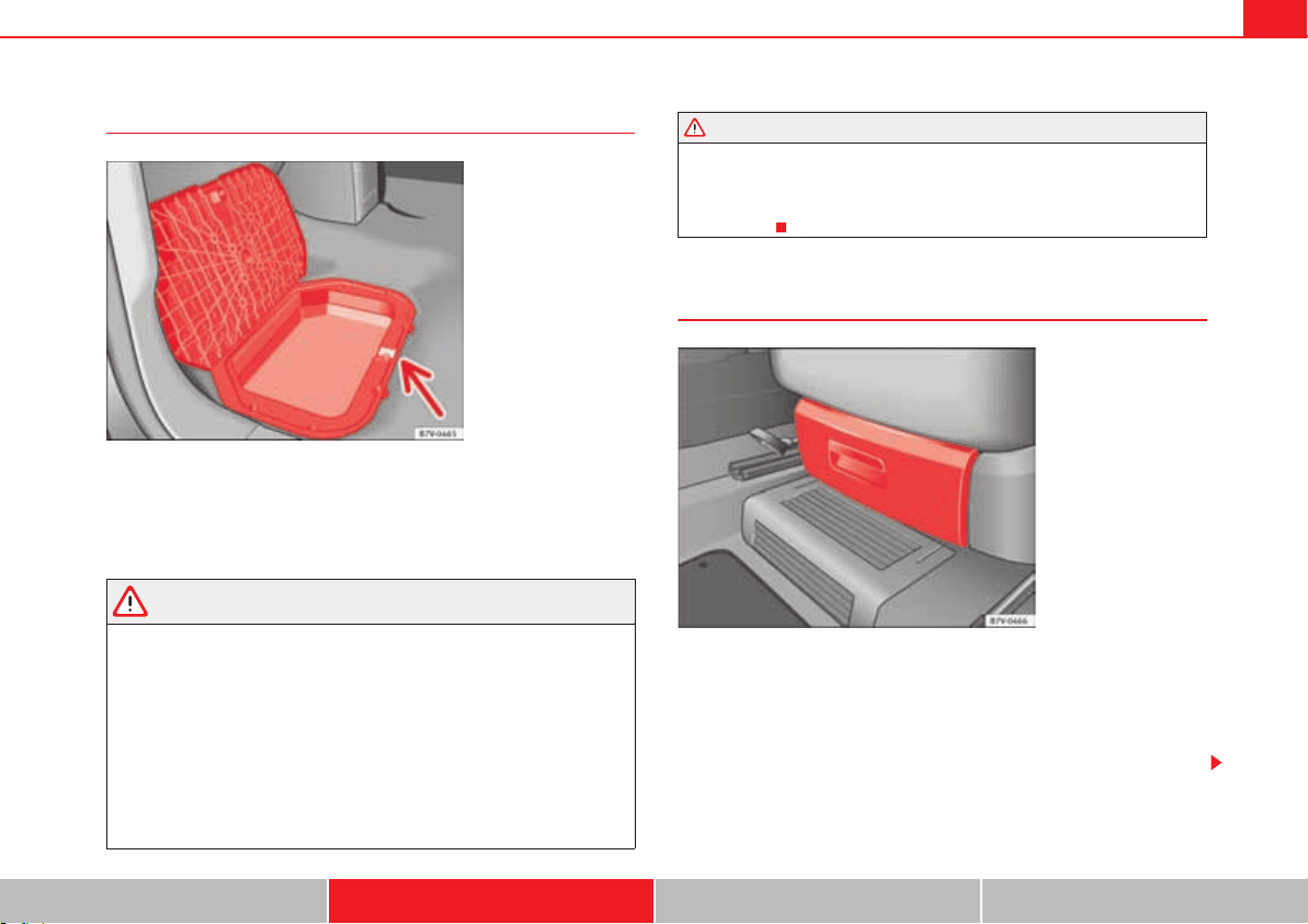
Seats and storage compartments 167
Safety First Operating instructions Practical tips Technical Data
Storage compartments in the rear floor area
Move the mat to one side (where applicable).
To open, pull on the rear centre part of the cover fig. 116 (arrow).
To close, press the cover down.
WARNING
Make sure children are properly belted in and correctly secured to avoid
severe or fatal injuries while the vehicle is in motion.
x If you are using a child seat with a base or foot, always install this base
or foot correctly and safely.
x If the vehicle has a storage compartment in the foot well in front of the
last row of seats, this compartment cannot be used as designed; on the
contrary: It must be filled using the specially designed accessory so that
the base or foot is correctly supported by the closed compartment and the
child seat is secured properly. If this compartment is not suitably secured
when using a child seat with a base or foot then the compartment cover
could rupture in an accident and the child will be ejected and suffer serious
injury.
x Please read and observe the child seat manufacturer's handling
instructions.
Drawers*
There may be a drawer below the front seats.
Opening and closing the drawer
To open, press the button on the drawer handle and pull the drawer out.
To close, push the drawer under the seat until it clicks into place.
Fig. 116 Storage
compartments in the floor
area of the second row of
seats.
WARNING (continued)
Fig. 117 Drawer under
the front seat.
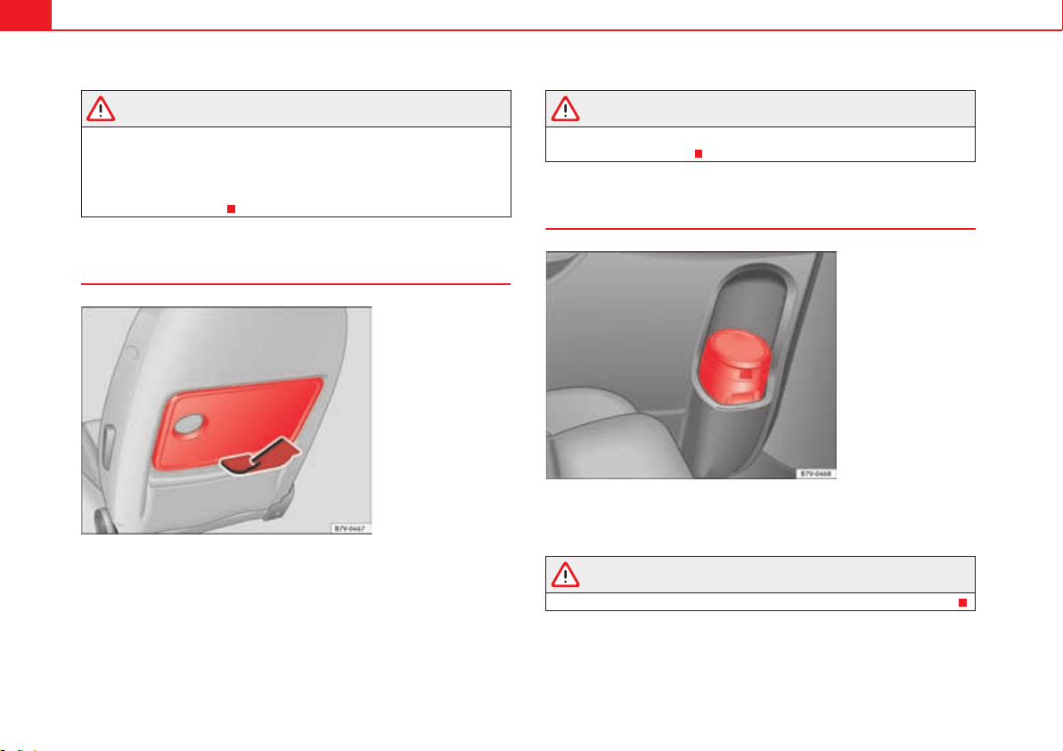
Seats and storage compartments168
WARNING
If the drawer is open it could obstruct use of the pedals. This could result
in serious accident.
x The drawers must remain closed while the vehicle is in motion. Other-
wise, the drawer and any objects in it could fall into the driver's footwell
and obstruct the pedals.
Folding table
Fold out the table by pulling on it fig. 118 (arrow).
A cup holder is built into the folding table page 171.
To fold it back, push the folding table down as far as possible fig. 118.
WARNING
The folding table must not be folded down while the vehicle is in motion to
avoid the risk of injuries.
Portable waste bin
The portable waste bin fits onto the bottle holder on the trim of the left-hand
sliding door.
WARNING
Do not use the portable waste bin as an ashtray to avoid the risk of fire.
Fig. 118 Folding table on
the front seat.
Fig. 119 Portable waste
bin on the trim of the left-
hand sliding door.
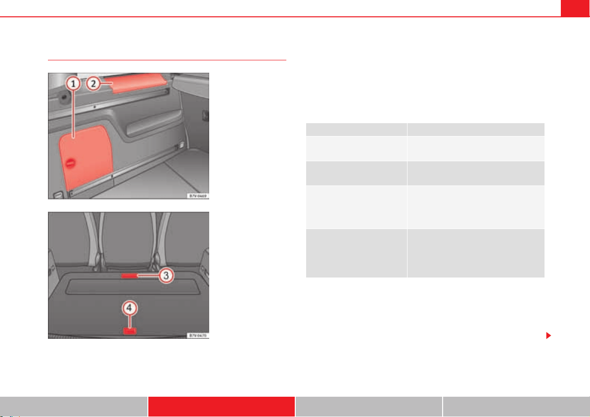
Seats and storage compartments 169
Safety First Operating instructions Practical tips Technical Data
Other storage compartments
Side compartments in the luggage compartment
There are other compartments fig. 120 and in the side of the
luggage compartment. To open the compartment , turn the catch clock-
wise. To open the compartment , lift the cover. The factory-fitted CD
changer can be located in the storage compartment .. The cover of the
compartment can be used to safely store the covers of the rear shelf
supports.
Compartments in the luggage compartment floor
More storage compartments can be found in the luggage compartment floor.
Other storage compartments:
x in the centre console, front and rear.
x in the door trims, front and rear.
x Coat hooks on the central door pillars and on the rear roof handles.
x Bag hook in the luggage compartment page 146.
Fig. 120 In the luggage
compartment: Side
storage compartment.
Fig. 121 Other compart-
ments in the luggage
compartment floor
A
1
A
2
A
1
Function Necessary operations
Open the front compartment
fig. 121 :
Pull the front of the luggage compart-
ment floor back using the handle.
Open the rear compartment
fig. 121 :
Lift the rear of the luggage compartment
floor using the handle.
Keeping the rear compartment
open:
Move the hook at the rear right of the
luggage compartment and hook the lug-
gage compartment floor onto it
page 146.
Closing the compartment:
Push back the hook and push the rear of
the luggage compartment floor down.
Fold the front part of the luggage com-
partment floor forwards .
A
2
A
1
A
1
A
3
A
4
A
4
A
3
Seats and storage compartments170
WARNING
Clothing hung on the coat hooks could restrict the driver's view and lead to
serious accidents.
x Hang the clothes from the hooks so that driver's view is not restricted.
x The coat hook is suitable for light items of clothing. Never place heavy,
hard or sharp objects in the bags.
Caution
Keep the CD changer compartment closed while the vehicle is in motion to
reduce vibrations that could damage the changer.
Note
The first aid kit is located in the rear left compartment of the luggage
compartment.
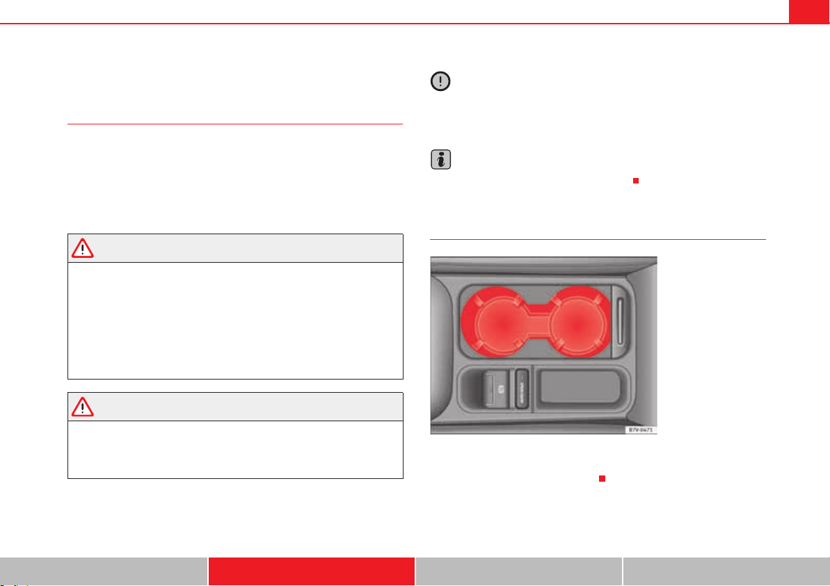
Seats and storage compartments 171
Safety First Operating instructions Practical tips Technical Data
Cup holders
Introduction
Bottle holders
There is a bottle holder in the open compartments in the driver and front
passenger doors and in that of the sliding door.
Additional information and warnings:
x Care and cleaning of the vehicle interior page 278
WARNING
Improper use of the cup holders can cause injury.
x Never place hot drinks in the drink holders. During sudden braking or
driving manoeuvres, the hot drink could be spilled and lead to scalding.
x Ensure that bottles and other object is dropped in the driver footwell,
as it could get under the pedals and obstruct their working.
x Never place heavy containers, food or other heavy objects in the cup
holder. In the event of an accident, these heavy objects could be thrown
around the passenger compartment and cause serious injuries.
WARNING
Closed bottles inside the vehicle could explode or crack due to the heat or
the cold.
x Never leave a closed bottle in the vehicle if the inside temperature is
too high or too low.
Caution
Do not leave open cans in the cup holders when the vehicle is in motion. They
could spill during braking, for example, and cause damage to the vehicle and
the electrical system.
Note
The cup holders can be removed for cleaning.
Cup holders in front centre console
x To open, move the cover backwards fig. 122.
x To close, move the cover forwards.
Fig. 122 Front centre
console: cup holder.
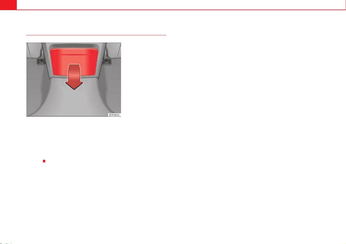
Seats and storage compartments172
Cup holders, rear
Opening and closing the cup holder in the rear centre console
x To open, move the cup holder downwards in the direction of the arrow
fig. 123.
x To close, lift the cup holder.
The third row of seats has a cup holder in the side trim compartment on the
rear left.
Fig. 123 Centre console,
rear section: folding out
the cup holder.
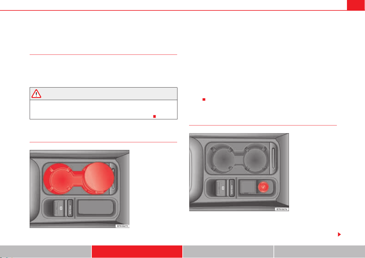
Seats and storage compartments 173
Safety First Operating instructions Practical tips Technical Data
Ashtray and cigarette lighter*
Introduction
Additional information and warnings:
x Sockets page 175.
x Accessories, parts replacement, repairs and modifications page 285.
WARNING
Undue use of the ashtray and cigarette lighter may cause a fire or burns and
other serious injuries.
x Never put paper or other flammable objects in the ashtray.
Ashtray
There are ashtrays located on the front of the centre console fig. 124 and
on the rear lining of the back door.
Opening and closing the ashtray
x To open, lift the ashtray cover.
x To close, push the ashtray cover down.
Emptying the ashtray
x Remove the ashtray from the cup holder or lining of the door by pulling it
upwards.
x After emptying the ashtray, insert it from above into the cup holder or door
lining.
Cigarette lighter
Depending on the vehicle equipment, there may be a lighter to the front of the
centre console fig. 125 or in the compartment to the front of the centre
console.
Fig. 124 Front centre
console: ashtray closed.
Fig. 125 Front centre
console: lighter.
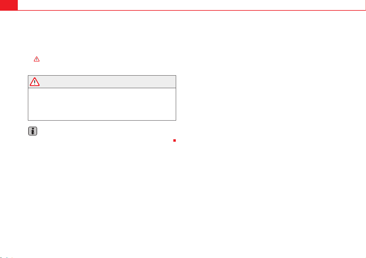
Seats and storage compartments174
x Push the button on the cigarette lighter inwards with the ignition on
page 173, fig. 125.
x Wait for the cigarette lighter to pop out slightly.
x Pull out the cigarette lighter and light the cigarette on the glowing coil
.
x Replace the cigarette lighter in its insert.
WARNING
Undue use of the cigarette lighter may cause a fire or burns and other
serious injuries.
x The cigarette lighter must only be used to light cigarettes or similar.
x Never leave children unsupervised in the vehicle. The cigarette lighter
can be used when the ignition is switched on.
Note
The cigarette lighter can also be used with the 12 Volt socket page 175.

Seats and storage compartments 175
Safety First Operating instructions Practical tips Technical Data
Sockets
Introduction
Electrical equipment can be connected to the sockets in the vehicle.
Connected equipment must be in perfect condition and show no signs of
faults.
Additional information and warnings:
x Cigarette lighter page 173
x Accessories, parts replacement, repairs and modifications page 285
WARNING
Improper use of the sockets or electrical devices could lead to a fire and
cause serious injuries.
x Never leave children unsupervised in the vehicle. The sockets and
equipment connected to them can be used when the ignition is switched
on.
x Should a connected electrical device overheat, switch it off and unplug
it immediately.
Caution
x To avoid damage to the vehicle's electrical system, never connect equip-
ment that generates electrical current, such as solar panels or battery
chargers, to the 12 Volt sockets in order to charge the vehicle's battery.
x Only use accessories with approved electromagnetic compatibility
according to current regulations.
x To avoid damage due to voltage variations, switch off all appliances
connected to the 12 V sockets before switching the ignition on or off and
before starting the engine.
x Never connect an appliance to the 12 Volt socket that consumes more
than the power indicated in watts. Exceeding the maximum power absorption
could damage the vehicle's electrical system.
For the sake of the environment
Do not leave the engine running when the vehicle is at a standstill.
Note
Using electrical appliances with the engine stopped and the ignition
switched on will drain the battery.
Note
Unshielded equipment can cause interference on the radio equipment and
the vehicle's electrical system.
Note
Interference can occur on the radio's AM waveband if electrical appliances
are used near the rear window aerial.
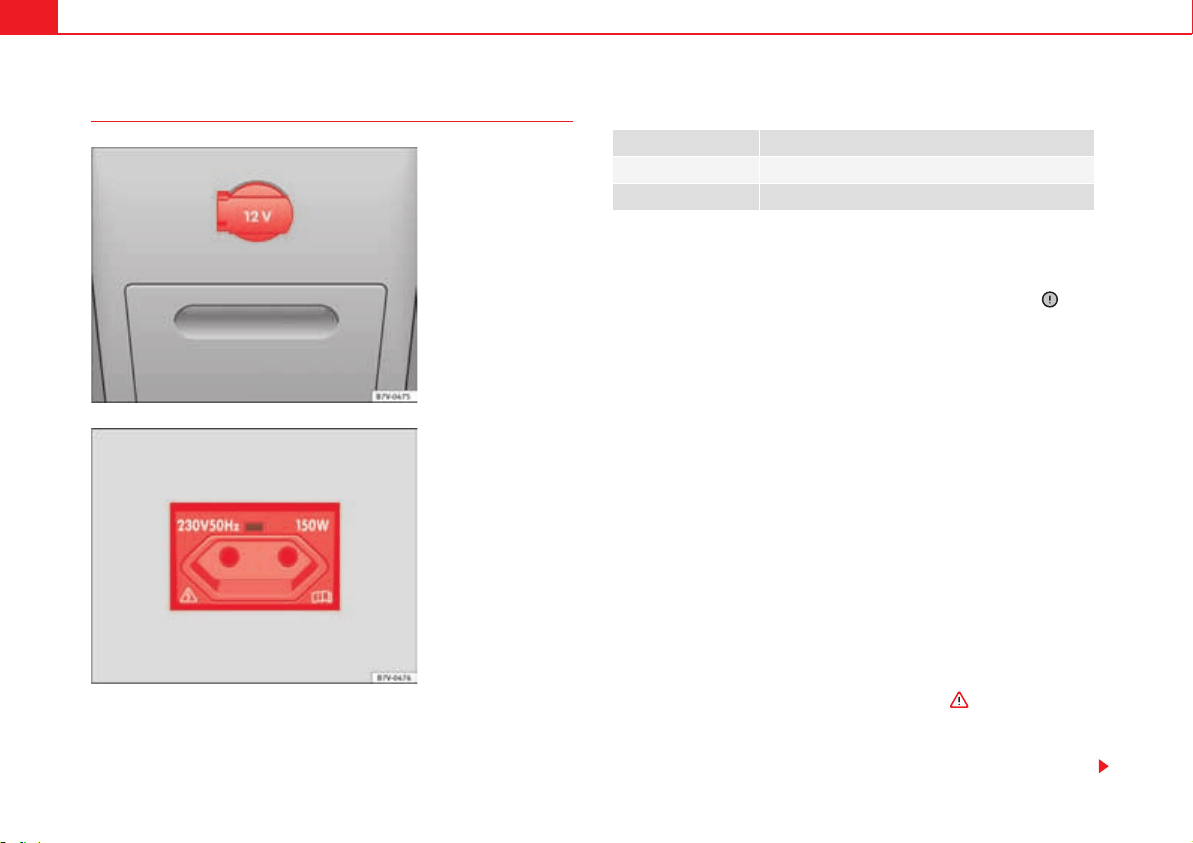
Seats and storage compartments176
Vehicle sockets
Maximum power consumption
The maximum capacity of each socket must not be exceeded. The power
consumption is indicated on the rating plate of each appliance.
Where two or more appliances are connected at the same time, the total
rating of all the connected devices must never exceed 190 Watts .
12 volt socket
The 12 Volt socket will only work with the ignition on.
Using electrical appliances with the engine stopped and the ignition
switched on will drain the battery. Therefore, electrical consumers connected
to the socket must only be used when the engine is running.
To prevent voltage variations from causing damage, switch off the electrical
consumer connected to the 12 Volt socket before switching the ignition on or
off and before starting the engine.
12 Volt sockets can be found in the following locations in the vehicle:
x Compartment in the centre of the centre console.
x Compartment in the front centre console.
x Storage compartment in the front central armrest.
x Rear centre console fig. 126.
x At the rear right of the luggage compartment.
230 Volt Euro socket*
The socket only works when the engine is running .
Connecting an electrical appliance: Plug the appliance into the socket as far
as possible to unlock the built-in child safety device. The current only flows
when the child safety device is unlocked.
Fig. 126 Centre console,
rear section: 12 volt
socket.
Fig. 127 Rear centre
console: 230 Volt Euro
socket.
Socket Maximum power consumption
12 Volts 120 Watts
230 Volts 150 Watts (300 Watt peak)
Seats and storage compartments 177
Safety First Operating instructions Practical tips Technical Data
Heat protection
The 230 Volt Euro power connector converter switches off automatically when
a certain temperature is exceeded. This disconnect prevents overheating in
the event of an increase in power consumption of the connected appliance
and where the atmospheric temperature is too high. The converter will switch
on again automatically after it has cooled down. Appliances that are switched
on and connected to the socket will start up again. Therefore, switch off all
electrical appliances connected to the socket when the current converter
switches off due to overheating.
WARNING
High voltage in the electrical installation!
x Liquids must not be spilt over the socket.
x Do not plug adapters or extension cords into the 230 Volt Euro power
connector. Otherwise, the built-in child safety device will switch off and the
connector will become live.
x Do not plug current conductors such as a knitting needle into the 230
Volt Euro power connector.
Caution
x Always follow the operating instructions for the appliances to be
connected!
x Never exceed the maximum power rating as this could damage the
vehicle's general electrical system.
x 12 volt socket:
Only use accessories with approved electromagnetic compatibility
according to current regulations.
Never power the socket.
x 230 Volt Euro socket:
Do not hang appliances or plugs that are too heavy (e.g. a transformer)
from the socket.
Do not connect lamps which contain a neon tube.
Only plug appliances with a voltage that matches the socket voltage
into the socket.
In the event of consumers with a high start-up current, surge protection
prevents them from switching on. In this case, unplug the consumer and
try plugging it back in after around 10 seconds.
Note
Some appliances may not work properly in the 230 Volt Euro power connector
due to a lack of power (Watts).
Note
The 230 Watt Euro power connector can be modified for 115 Watt appliances
and vice versa. Consult a specialist shop for advice on accessories to adapt
the connector. SEAT recommends visiting a qualified workshop.
LED on the socket page 176, fig. 127
Steady green light: The child safety device is unlocked. The
socket can now be used.
Flashing red light: There is some kind of fault (e.g. discon-
nection due to excess current or tempera-
ture).
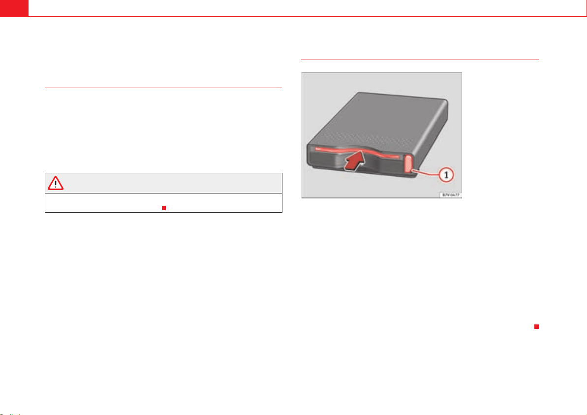
Seats and storage compartments178
Toll card reader*
Introduction
With the toll card reader switched on and operational, the price will be auto-
matically charged when the vehicle crosses a toll. A sound will confirm
payment. A voice will inform you of the price to pay, together with an indica-
tion of the location on the navigation system display.
Additional information and warnings:
x Accessories, parts replacement, repairs and modifications page 285
WARNING
Using the toll card reader while the vehicle is in motion may distract you
from the road and lead to accidents.
Description
Starting the toll reader
Switch on the radio navigation system and insert a suitable ETC card into the
toll card reader fig. 128 (arrow).
A long acoustic signal and the display of the ETC symbol in the status line of
the radio navigation system will indicate that the card is operational.
Removing the toll card
Press the button fig. 128 to remove the toll card.
Error message
If a short signal is heard after switching the system on, this indicates an error
(e.g. ETC card not inserted or faulty). The toll card reader is not operational.
Fig. 128 In the glove
compartment on the front
passenger side: Toll card
reader.
A
1
Heating, Ventilation and Air conditioning 179
Safety First Operating instructions Practical tips Technical Data
Heating, Ventilation and Air conditioning
Climate Control
Introduction
Viewing Climatronic information
The factory-fitted radio or navigation system screen briefly displays informa-
tion relating to Climatronic.
The units of temperature measurement is displayed on the factory-installed
radio or navigation system and, depending on the vehicle equipment, can be
set using the Configuration menu on the instrument panel.
Additional information and warnings:
x SEAT information system page 70
x Windscreen wash system page 124
x Auxiliary heating page 187
x Caring for and cleaning the vehicle exterior page 269
WARNING
Reduced visibility through the windows increases the risk of serious acci-
dents.
x Ensure that all windows are free of ice and snow and that they are not
fogged up preventing a clear view of everything outside.
x The maximum heat output required to defrost windows quickly is only
available when the engine has reached its normal running temperature.
Only drive when you have good visibility.
x Always ensure that you use the climate control and heated rear window
to maintain good visibility.
x Never leave the air recirculation on for a long period of time. If the
cooling mode is switched off and air recirculation mode switched on, the
windows can mist over very quickly, considerably limiting visibility.
x Switch air recirculation mode off when it is not required.
WARNING
Stuffy or used air will increase fatigue and reduce driver concentration
possibly resulting in a serious accident.
x Never leave the fresh air fan turned off or use the air recirculation for
long periods of time; the air inside the passenger compartment will not be
refreshed.
Caution
x Switch the climate control system off if you think it may be broken. This
will avoid additional damage. Have the climate control system checked by a
qualified workshop.
x Repairs to the climate control system require specialist knowledge and
special tools. SEAT recommends visiting a qualified workshop.
x Do not smoke when air recirculation is switched on in vehicles with a
climate control system. The smoke taken in could lie on the cooling system
vaporiser and on the activated charcoal cartridge of the dust and pollen filter,
leading to a permanently unpleasant smell.
Note
When the cooling system is turned off, air coming from the outside will not be
dried. To avoid fogging up the windows, SEAT recommends leaving the cooler
WARNING (continued)

Heating, Ventilation and Air conditioning180
(compressor) on. To do this, press the button. The button indicator
should light up.
Note
If the humidity and temperature outside the vehicle are high, condensation
can drip off the evaporator in the cooling system and form a pool underneath
the vehicle, this is completely normal and there is no need to suspect a leak.
Note
Keep the air vents in front of the windscreen free of snow, ice and leaves to
ensure heating and cooling are not impaired and to prevent the windows
from misting over.
AC
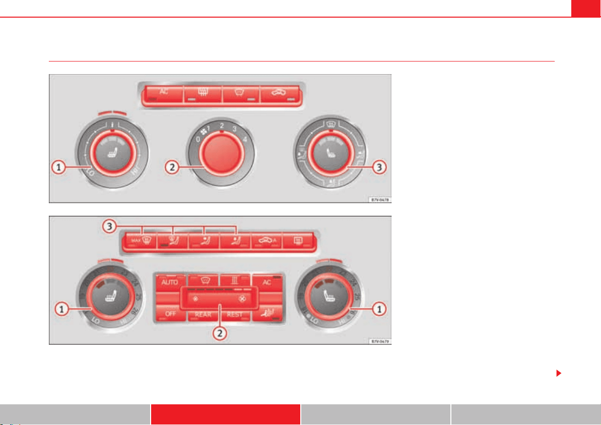
Heating, Ventilation and Air conditioning 181
Safety First Operating instructions Practical tips Technical Data
Controls
To switch a function on or off, press the appropriate button. The corre-
sponding button will light up when a function is switched on. Press the
button again to switch off the function.
The LED on each control lights up to indicate that the respective function of a
control has been switched on.
Fig. 129 Detailed view of the centre console: Climatic
controls
Fig. 130 Detailed view of the centre console: Climatronic
controls.
Heating, Ventilation and Air conditioning182
Some Climatronic controls may also be on the climate control system control
panel located in the rear centre console. These controls are used to make the
appropriate settings for the rear seats.
Control
button
Additional information. Climatic page 181, fig. 129; Cli-
matronic page 181, fig. 130.
Tem-
perature
...
Climatic: rotate the control to adjust the temperature accord-
ingly.
Climatronic: the settings for the left hand side, the right-hand
side and the rear seats are made separately. Rotate the control
to adjust the temperature accordingly. The temperature is indi-
cated on the outside ring.
Fan
...
Climatic: setting 0, fan and Climatic switched off;
setting 4, fan set to maximum.
Climatronic: the Fan speed is automatically adjusted depend-
ing on the vehicle speed to avoid annoying noises. The fan can
also be adjusted manually.
Air dis-
tribution
Climatic: rotate the continuous control to direct the airflow to
the desired area.
Climatronic: manually adjustable using the controls.
<
Climatic: defrost function. The airflow is directed at the wind-
screen. In this position, air recirculation is automatically
switched off or is not switched on.
<
Climatronic: defrost function. The air drawn in from outside the
vehicle is directed at the windscreen and air recirculation is
automatically switched off. To defrost the windscreen more
quickly, the air is dehumidified at temperatures over approxi-
mately +1.5 °C (+35 °F) and the fan runs at maximum output.
K
The air is directed at the chest of driver and passengers by the
dashboard air vents.
L
– Air distribution towards the footwell.
A
1
A
2
A
3
q
Air distribution towards the windscreen and the footwell.
AC Climatic, Climatronic: Press the button to turn off/on cooling.
=
Heated rear window: this only works when the engine is run-
ning and switches off automatically after a maximum of 10
minutes.
Air recirculation mode page 185.
o
Climatronic: Automatic air recirculation page 185.
p
Windscreen heating: only works when the engine is running
and switches off automatically after a few minutes.
>
Instant auxiliary heating on/off button page 187.
Switching
off
OFF
Climatic: turn the fan switch to setting 0.
Climatronic: press the button or set the fan manually to 0.
When the system switches off, the button will light up.
REAR
Climatronic: press the button to adjust the climate con-
trol for the rear seats from the front. The button will light
up when the function is switched on. The settings for the rear
seats will be displayed. Press the button again to switch the
function off or do not touch any other button for around 10
seconds.
Control
button
Additional information. Climatic page 181, fig. 129; Cli-
matronic page 181, fig. 130.
OFF
OFF
REAR
REST
Heating, Ventilation and Air conditioning 183
Safety First Operating instructions Practical tips Technical Data
WARNING
Never turn off the air fan for a long time or the air in the passenger compart-
ment will not be refreshed.
x Stuffy or used air will increase fatigue and reduce driver and passenger
concentration possibly resulting in a serious accident.
Note
Not all Climatronic buttons are operational in REAR mode.
Note
The button is locked in defrost mode.
Climate control user instructions
The cooling system only works when the engine is running and fan is
switched on.
The climate control system operates most effectively with the windows and
the sliding panoramic roof closed. However, if the vehicle has heated up after
standing in the sun for some time, the air inside can be cooled more quickly
by opening the windows briefly.
Keep the air vents in front of the windscreen free of snow, ice and leaves to
ensure heating and cooling are not impaired and to prevent the windows
from misting over.
Adjustment for safer driving
When the air conditioning is switched on, the temperature and the air
humidity in the vehicle interior drop. Hence, when the outside air humidity is
high, the windows do not mist over and comfort for the vehicle occupants is
improved:
With Climatic
x Disable air recirculation mode page 185.
x Set the fan to setting 1 or 2.
x Turn the temperature control to the centre position.
x Open the air outlets in the dash panel page 185.
x Turn the air distribution control to the required position.
x Press the button to turn on cooling. The button will light up.
With Climatronic
x Press the button.
x Set the temperature to +22 °C (+72 °F).
x Open the air outlets in the dash panel page 185.
REST
Climatronic: press the button to use residual heat. When
the engine is still warm but the ignition switched off, the heat
given off by the engine can be used to keep the passenger
compartment warm. The button will light up when the
function is switched on. The function will switch off after
around 30 minutes and if the battery level is low.
p
Climatronic: transferring the driver's seat temperature settings
to the other seats. If the button is not lit up, the set tem-
perature in the driver's seat will also apply to the other seats.
Press the button or the temperature control for the front pas-
senger's seat or the rear seats to set them to a different tem-
perature. The button lights with an indicator.
Vehicles with auxiliary heating: observe the description of the
button.
AUTO Automatic temperature, fan, and air distribution control.
Control
button
Additional information. Climatic page 181, fig. 129; Cli-
matronic page 181, fig. 130.
REST
REST
p
AUTO
REAR
AC
AUTO
Heating, Ventilation and Air conditioning184
Switching the Climatronic temperature measuring unit
Press and hold the and buttons to switch the temperature display
between Celsius and Fahrenheit.
Heat
The maximum heat output required to defrost windows quickly is only avail-
able when the engine has reached its normal running temperature.
The air conditioning system does not switch on
If the air conditioning system cannot be switched on, this may be caused by
the following:
x The engine is not running.
x The fan is switched off.
x The climate control fuse has blown.
x The outside temperature is lower than approximately +3 °C (+38 °F).
x The climate control system compressor has been temporarily switched off
because the engine coolant temperature is too high.
x Another fault in the vehicle. Have the climate control system checked by
a qualified workshop.
Things to note
If the humidity and temperature outside the vehicle are high, condensation
can drip off the evaporator in the cooling system and form a pool underneath
the vehicle. This is normal and does not indicate a leak!
Dust and pollen filter
The dust and pollen filter with its activated charcoal cartridge serves as a
barrier against impurities in the ambient air.
For the climate control system to work with maximum efficiency, the dust and
pollen filter must be replaced at the intervals specified in the Maintenance
Programme.
If the filter loses efficiency prematurely due to use in areas with very high
levels of air pollution, the filter must be changed more frequently than stated
in the Service Schedule.
Note
The climate control system must left running for a few minutes to reach the
set temperature in the vehicle interior.
Note
After starting it, any residual humidity in the climate control system could
mist over the windscreen.
Note
The air from the vents flows through the passenger compartment and out
through the outlets below the rear window. Do not cover these outlets with
items of clothing or other objects.
AC AUTO
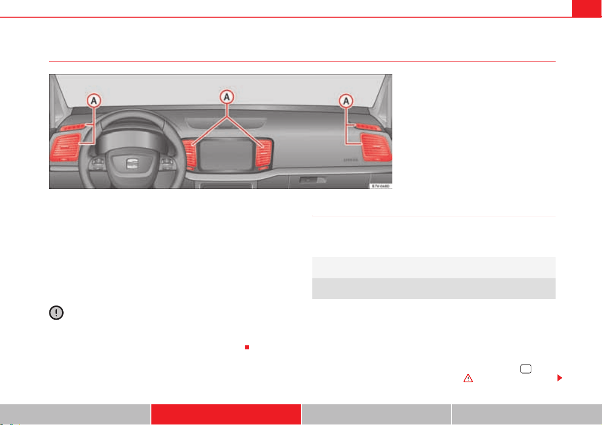
Heating, Ventilation and Air conditioning 185
Safety First Operating instructions Practical tips Technical Data
Air vents
Air vents
Never close the air vents fig. 131 completely to ensure heating,
cooling and ventilation inside the vehicle.
x Turn the thumbwheel in the required direction to open and close the air
vents.
x Change the air direction using the ventilation grille lever.
There are additional vents in the footwell areas and in the rear of the
passenger compartment.
Caution
Never place food, medicines or other heat-sensitive objects close to the air
vents. Food, medicines and other heat-sensitive objects may be damaged or
made unsuitable for use by the air coming from the air vents.
Air recirculation mode
Important
Air recirculation works in two ways:
Air recirculation mode prevents the ambient air from entering the vehicle
interior.
When the outside temperature is very high or very low, selecting manual air
recirculation mode for a short period refreshes or heats the vehicle interior
more quickly.
For safety reasons, air recirculation mode is switched off when the button
is pressed or the air distributor turned to < .
Fig. 131 Air vents in the instrument panel.
A
A
Manual air recirculation mode.
o
Automatic air recirculation mode.
<

Heating, Ventilation and Air conditioning186
Switching air recirculation mode on and off manually
Switching on: press the corresponding button until the light under the symbol
comes on.
Switching off: press the button until no indicator remains lit.
Automatic air recirculation mode o
Fresh air enters the vehicle interior in position o. If the system detects a high
concentration of hazardous substances in the ambient air, air recirculation
mode is switched on automatically. When the level of impurities drops to
within a normal range, recirculation mode is switched off.
The system is unable to detect unpleasant smells.
Air recirculation mode is not automatically switched on in the following cases
of outside temperatures and conditions:
x The cooling system is switched on (the button is lit up) and the
outside temperature is below +3 °C (+38 °F).
x The cooling system and the windscreen wipers are switched off and the
outside temperature is below +10 °C (+50 °F).
x The cooling system is switched on, the outside temperature is below +15
°C (+59 °F) and the windscreen wipers are switched on.
Switching the automatic air recirculation mode on and off
Switching on: press the button until the light under the symbol o
comes on.
Switching off: press the button until no button remains lit.
Switching the automatic air recirculation mode off temporarily
x Press the button once to temporarily switch to manual air recircula-
tion mode in the event of unpleasant smells from outside. The control light
under the symbol comes on.
x After more than two seconds, press the button again to restart
automatic air recirculation. The control light under the symbol o comes on.
WARNING
Stuffy or used air will increase fatigue and reduce driver concentration
possibly resulting in a serious accident.
x Never use recirculation mode for long periods as it does not refresh the
air inside the vehicle.
x If the cooling mode is switched off and air recirculation mode switched
on, the windows can mist over very quickly, considerably limiting visibility.
x Switch air recirculation mode off when it is not required.
Caution
Do not smoke when air recirculation is switched on in vehicles with a climate
control system. The smoke taken in could lie on the cooling system vaporiser
and on the activated charcoal cartridge of the dust and pollen filter, leading
to a permanently unpleasant smell.
Note
Air recirculation mode switches on to prevent exhaust gas from entering the
vehicle interior when it is in reverse and while the automatic windscreen
wash and wipe is working.
AC
o
o
o
o
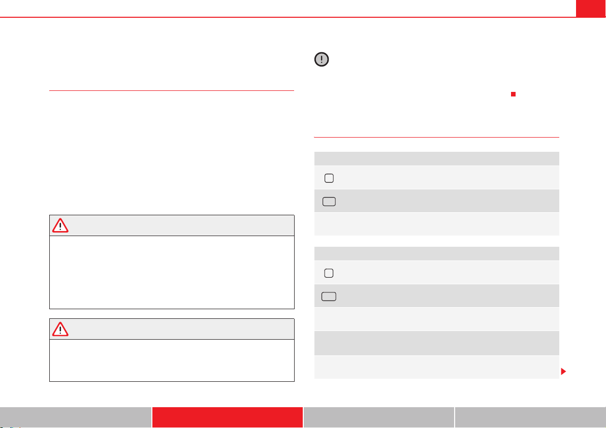
Heating, Ventilation and Air conditioning 187
Safety First Operating instructions Practical tips Technical Data
Auxiliary heater* (additional heater)
Introduction
The auxiliary heater is powered by fuel from the vehicle's fuel tank and can be
used while the vehicle is in motion and at a standstill. Select the mode
required (heat or fan) page 189 on the instrument panel.
In winter, the auxiliary heater can be used in heat mode before switching on
the ignition to remove any ice, mist or snow from the windscreen (thin layers
only).
Additional information and warnings:
x SEAT information system page 70
x Refuelling page 293
WARNING
The auxiliary heater fumes contain carbon dioxide, an odourless and
colourless toxic gas. Carbon monoxide can cause people to lose conscious-
ness. It can also cause death.
x Never switch on the auxiliary heater or leave it running in places that
are enclosed or unventilated.
x Never program the independent heating system to be activated and
operated in closed, unventilated areas.
WARNING
The components of the auxiliary heater exhaust system heat up a great
deal. This could cause a fire.
x Always park your vehicle so that no part of the exhaust system can
come in contact with flammable materials (such as dried grass).
Caution
Never place food, medicines or other heat-sensitive objects close to the air
vents. Food, medicines and other heat-sensitive objects may be damaged or
made unsuitable for use by the air coming from the air vents.
Switching the auxiliary heater on and off
Switching the auxiliary heater on:
Manually using the instant on/off button. page 1
81
Manually using the remote control. page 1
88
Automatically at the programmed and enabled on
time.
page 1
89
Switching the auxiliary heater off:
Manually using the instant on/off button for the cli-
mate control system.
page 1
81
Manually using the remote control. page 1
88
Automatically after the programmed time. page 1
89
Automatically when the light comes on z (fuel
reserve).
page 2
93
Automatically when the battery power drops to a very
low level.
page 3
18
>
ON
>
OFF
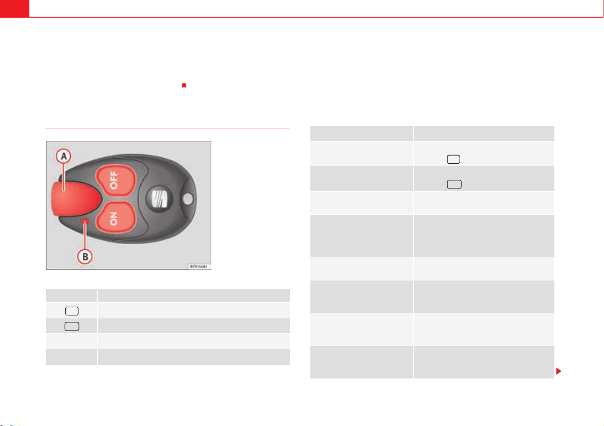
Heating, Ventilation and Air conditioning188
Things to note
After switching the auxiliary heater off, it continues to run for a short period
to completely burn any fuel remaining in the auxiliary heater. The exhaust
fumes are also extracted from the system.
Remote control
The auxiliary heater may accidentally switch on if a button is pressed on the
remote control by mistake. This may also occur outside the range of the
remote control or if the light flashes.
Remote control light
The remote control light provides users with different information at the push
of a button:
fig. 132 Meaning
Switch the auxiliary heater on.
Switch the auxiliary heater off:
Aerial.
Light.
Fig. 132 Auxiliary heater:
remote control.
ON
OFF
A
A
A
B
Battery light fig. 132
Meaning
Lights up green for around two
seconds.
The auxiliary heater has been switched on
using the button.
Lights up red for around two
seconds.
The auxiliary heater has been switched off
using the button.
Slowly flashes green for
around two seconds.
No on
a)
signal has been received.
Quickly flashes green for
around two seconds.
The auxiliary heater is locked.
Possible causes: the fuel tank is almost
empty, the battery charge is very low or
there is a fault.
Flashes red for around two
seconds.
No off
a)
signal has been received.
Lights up orange for around
two seconds, then green or
red.
The remote control battery is almost flat.
However, the on or off signal has been
received, respectively.
Lights up orange for around
two seconds, then flashes
green or red.
The remote control battery is almost flat.
The on or off signal has not been received,
respectively.
Flashes orange for around five
seconds.
The remote control battery is flat. The on or
off signal has not been received, respec-
tively.
A
B
ON
OFF

Heating, Ventilation and Air conditioning 189
Safety First Operating instructions Practical tips Technical Data
Replacing the remote control battery
When the light page 188, fig. 132 on the remote control does not
come on when the button is pressed, the remote control battery should soon
be replaced.
The battery is located beneath a cover on the back of the remote control. Turn
the slot to the left using a flat, blunt object (e.g. a coin). When changing the
battery, use another battery of the same model and observe the polarity when
fitting it .
Range
The receiver is in the interior of the vehicle. The remote control, when fitted
with new batteries, has a range of several hundred metres. Obstacles
between the remote control and the vehicle, bad weather conditions and
discharged batteries can considerably reduce the range of the remote control.
An optimum range is obtained by keeping the remote control vertical, with
the aerial page 188, fig. 132 pointing upwards. When doing so, do not
cover the aerial with your fingers or with the palm of your hand.
There must be a minimum distance of two metres between the remote control
and the vehicle.
Caution
x The radiofrequency remote control contains electronic components.
Therefore, avoid getting the remote control wet and from being knocked and
protect it from direct sunlight.
x Use of inappropriate batteries may damage the remote control. For this
reason, always replace the dead battery with another of the same voltage,
size and specifications.
For the sake of the environment
Please dispose of old batteries so that they do not harm the environment.
For the sake of the environment
The remote control battery may contain perchlorate. Observe the legal
requirements for their disposal.
Programming the auxiliary heater
The heater or ventilation inside the vehicle can be programmed for a certain
period.
Before programming, check that the day is correctly set in the Auxiliary
heater - day of the week menu .
Enabling the Auxiliary heater menu on the instrument panel
x From the main menu, select the Auxiliary heater submenu and press the
button on the windscreen wiper lever.
x ALTERNATIVELY: press the or arrow buttons on the multi-function
steering wheel until the Auxiliary heater menu is displayed.
a)
Within its range, the remote control might not receive the signal sent by the vehicle
receiver. In this case, the remote control will send an error message despite the aux-
iliary heater being on or off. Come closer to the vehicle and press the corresponding
button on the remote control once again.
A
B
A
A
OK
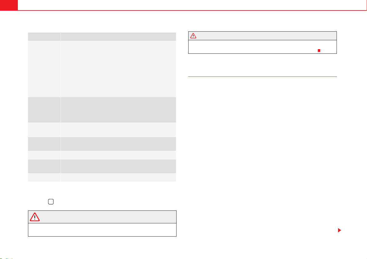
Heating, Ventilation and Air conditioning190
Checking programming
If the timer has been switched on after switching the ignition off, the instant
on button will remain lit for around ten seconds.
WARNING
Never program the independent heating system to be activated and oper-
ated in closed, unventilated areas. The auxiliary heater fumes contain
carbon dioxide, an odourless and colourless toxic gas. Carbon monoxide
can cause people to lose consciousness. It can also cause death.
User instructions
The auxiliary heater exhaust system located below the vehicle must be kept
clear of snow, mud and other objects. The exhaust fumes must not be
obstructed in any way. The exhaust fumes generated by the auxiliary heater
are removed via an exhaust pipe fitted underneath the vehicle.
On heating the vehicle interior, depending on the outside temperature the
warm air is first directed at the windscreen and then to the rest of the
passenger compartment through the air vents. If the air vents are turned
towards the windows, for example, the form of air distribution may be
affected.
Depending on the outside temperature, the temperature at which the auxil-
iary heater warms the vehicle interior may be somewhat higher if the heating
or climate control temperature control is set to maximum before switching the
heating on.
Depending on the engine, vehicles with auxiliary heater may be fitted with a
second battery in the luggage compartment that is responsible for powering
the auxiliary heater.
Cases in which the auxiliary heater will not switch on
x The auxiliary heater requires about as much power as the dipped head-
lights. If the battery charge is low, the auxiliary heater will switch off automat-
ically or will not even switch on. This avoids problems when starting the
engine.
x The heater will switch just once each time. The timer will also have to be
switched back on every time it is required.
Menu options Description
Switching on
Switching off
The auxiliary heater can be set to come on automatically if
required. To do so, select a timer:
– The timer is displayed marked with a y.
– Only one timer can be selected. If a timer has been
selected, Prog. ON will be displayed on the screen. If no
timer has been selected, the instrument panel screen will
display Prog. OFF.
– To modify the programmed timer, select another timer or
select the Off option.
Timer 1
Timer 2
Timer 3
Three different timers (hh.mm) can later be selected using
the On option. If the auxiliary heater is to be switched on
for just a certain day of the week, select the day of the
week and the time for the auxiliary heater to come on.
Duration
The operating time may vary between 10 and 60 minutes
and can be set to 5-minute intervals.
Operating
mode
Set to heat or ventilate the vehicle interior when the auxil-
iary heater is switched on.
Day Set the current day of the week.
Manufacturer's
settings
The predefined factory values for the functions of this
menu are restored.
Back This returns to the main menu
>
WARNING (continued)

Heating, Ventilation and Air conditioning 191
Safety First Operating instructions Practical tips Technical Data
Note
Noise will be heard while the auxiliary heater is running.
Note
When the air humidity is high and the outside temperature low, the heating
system may evaporate condensation from the auxiliary heater. In this case,
steam may be released from underneath the vehicle. This is completely
normal and there is no need to suspect a fault!
Note
If the auxiliary heater runs several times over a prolonged period, the
vehicle's battery may run flat. To re-charge the battery, drive the vehicle for a
long distance. In general: drive for as much time as the auxiliary heating was
working.
Driving192
Driving
Steering
Introduction
The power steering is not hydraulic but electromechanical. The advantage of
this steering system is that it disposes of hydraulic tubes, hydraulic oil, the
pump, filter and other components. The electromechanical system saves
fuel. While a hydraulic system requires oil pressure to be maintained, electro-
mechanical steering only requires energy when the steering wheel is turned.
With the power steering system, the assisted steering function automatically
adjusts according to the vehicle speed, the steering torque and the wheel
turning angle. The power steering only works when the engine is running.
Additional information and warnings:
x Start and stop the engine page 195
x Vehicle battery page 318
x Tow-starting and towing away page 375
WARNING
If the power steering is not working then the steering wheel is much more
difficult to turn and the vehicle more difficult to control.
x The power steering only works when the engine is running.
x Never allow the vehicle to move when the engine is switched off.
x Never remove the key from the ignition if the vehicle is in motion. The
steering may lock and it will not be possible to turn the steering wheel.
Control and warning lamps
lights up Possible cause Solution
D (red)
Power steering faulty.
The steering system should be
checked by a qualified workshop
as soon as possible.
D (yel-
low)
Power steering operation
reduced.
The steering system should be
checked by a qualified workshop
as soon as possible.
If, after restarting the engine and
driving for a short distance, the
yellow warning light no longer
comes on, it will not be neces-
sary to take the vehicle to a spe-
cialised workshop.
The vehicle battery was dis-
connected and has been
reconnected.
Drive for a short distance at 15 –
20 km/h.
Driving 193
Safety First Operating instructions Practical tips Technical Data
Several warning and control lamps should light up for a few seconds when
the ignition is switched. This signals that the lamp is working properly. They
will switch off after a few seconds.
WARNING
If the warning lamps and messages are ignored, the vehicle may stall in
traffic, or may cause accidents and severe injuries.
x Never ignore the warning lamps or text messages.
x Stop the vehicle safely as soon as possible.
Caution
Failure to heed the warning lamps and text messages when they appear may
result in faults in the vehicle.
Information on the steering
Steering column electronic lock
Vehicles with KESSY: The steering column locks when the driver's door is
opened and the ignition is switched off. Therefore, the vehicle should be at a
standstill and, where applicable, the selector lever in position P.
If the driver's door is opened before the ignition is switched off, the steering
column electronic lock is activated via the ignition key or the sensor built into
the door handle.
Mechanical steering lock
To prevent theft, we recommend you lock the steering before leaving the
vehicle.
Electromechanical power steering
With the power steering system, the assisted steering function automatically
adjusts according to the vehicle speed, the steering torque and the wheel
turning angle. The power steering only works when the engine is running.
You should remember that you will need considerably more power than
normal to steer the vehicle if the power steering is not working correctly or not
at all.
Counter steering assistance system
The counter steering assistance system helps the driver in critical situations.
Additional steering power helps the driver when counter steering.
flashes Possible cause Solution
D (red)
Fault in the steering column
electronic lock.
Do not drive on!
Seek professional advice.
D (yel-
low)
Steering column deviation.
Gently turn the steering wheel to
and fro.
Steering wheel not unlocked
or locked.
Remove the key from the ignition
and then switch the ignition
back on. Check the messages
displayed on the instrument
panel at the same time.
Do not drive on, if the steering
column remains locked after the
ignition has been switched on.
You should obtain professional
assistance.
Please engage steering lock Unlocking the steering
Parking the vehicle page 210. Turn the steering wheel slightly to
release the steering lock.
Remove the key from the ignition. Insert the key in the ignition lock.
Turn the steering wheel slightly until
you hear the steering lock.
Hold the steering wheel in this posi-
tion and switch on the ignition.
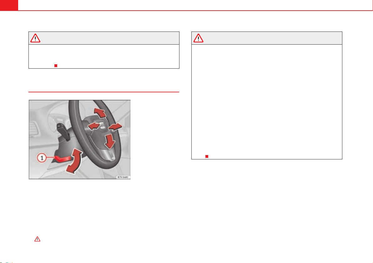
Driving194
WARNING
The counter steering assistance system combined with ESP helps the
driver to steer the vehicle in critical driving conditions. At all times, it is the
driver who steers the vehicle. The counter steering system does not steer
the vehicle.
Adjusting the steering wheel position
Adjust the steering wheel before your trip and only when the vehicle is
stationary.
x Push the lever fig. 133 downwards.
x Adjust the steering wheel so that you can hold onto the steering wheel
with both hands on the outside of the ring at the 9 o'clock and 3 o'clock posi-
tions and your arms slightly bent.
x Push the lever firmly upwards until it is flush to the steering column
.
WARNING
Incorrect use of the steering wheel adjustment function and an incorrect
adjustment of the steering wheel can result in severe or fatal injury.
x After adjusting the steering column, push the lever fig. 133
firmly upwards to ensure the steering wheel does not accidentally change
position while driving.
x Never adjust the steering wheel while the vehicle is in motion. If you
need to adjust the steering wheel while the vehicle is in motion, stop safely
and make the proper adjustment.
x The adjusted steering wheel should be facing your chest and not your
face so as not to hinder the driver's frontal airbag protection in the event of
an accident.
x When driving, always hold the steering wheel with both hands on the
outside of the ring at the 9 o'clock and 3 o'clock positions to reduce injuries
when the driver's frontal airbag deploys.
x Never hold the steering wheel at the 12 o'clock position or in any other
manner (e.g. in the centre of the steering wheel). In such cases, if the
driver's airbag deploys, you may sustain injuries to your arms, hands and
head.
Fig. 133 Mechanical
steering wheel adjust-
ment.
A
1
A
1
Driving 195
Safety First Operating instructions Practical tips Technical Data
Stopping and starting the engine
Introduction
Immobiliser display
When an invalid key is used or in the event of a system fault, 3!&% or
Immobiliser on is displayed on the instrument panel. The engine cannot be
started.
Pushing or towing
For technical reasons, the vehicle must not be push- or tow-started. Jump
starting is preferable.
Additional information and warnings:
x Vehicle key set page 78
x Changing gear page 201
x Braking, stopping and parking page 210
x Steering page 192
x Start assist systems page 221
x Refuelling page 293
x Fuel page 297
x Emergency locking and unlocking page 348
x Jump starting page 371
x Tow-starting and towing away page 375
WARNING
Turning off the engine while driving will make stopping the vehicle diffi-
cult; this could even result in the loss of control causing an accident with
serious consequences.
x The assisted braking and steering systems, the airbag system, safety
belts and certain safety equipment are only active while the engine is
running.
x The engine should only be switched off when the vehicle is at a stand-
still.
WARNING
While the engine is running or starting it could help reduce the risk of
serious injury.
x Never start or leave the engine running in poorly ventilated or closed
spaces. Exhaust gas contains carbon monoxide, a toxic, colourless and
odourless gas. Carbon monoxide can cause people to lose consciousness.
It can also cause death.
x Never leave the vehicle unattended if the engine is running. The vehicle
could move off suddenly or something unexpected could happen resulting
in damage and serious injury.
x Never use start boosters. Cold start sprays could explode or increase
the engine speed unexpectedly.
WARNING
The components of the exhaust system reach very high temperatures. This
could cause a fire and considerable damage.
x Always park your vehicle so that no part of the exhaust system can
come in contact with flammable materials (such as wood, leaves, spilled
fuel, dried grass, etc).
x Do not apply additional underseal or anti-corrosion coatings to the
exhaust pipes, catalytic converter, heat shields or the diesel particulate
filter.
WARNING (continued)
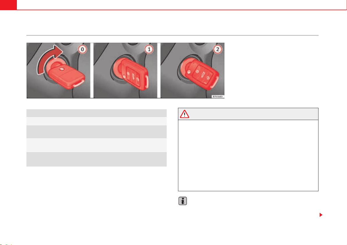
Driving196
Ignition lock
Key not authorised for the vehicle
If a key which is not authorised for this vehicle is inserted in the ignition lock,
it can be removed as follows:
x Automatic gearbox: the key cannot be removed from the ignition lock.
Press and release the selector lever locking button. Key can be removed from
the vehicle.
x Manual gearbox: Remove the key from the ignition.
WARNING
Unsuitable or careless use of the vehicle key could result in serious injury.
x Always take all the keys with you whenever you leave the vehicle. The
engine could accidentally be started and electrical equipment such as the
windows could accidentally be operated resulting in serious injury.
x Never leave children or disabled people alone in the car. They could be
trapped in the car in an emergency and will not be able to get themselves
to safety. For example, depending on the time of the year, temperatures
inside a locked and closed vehicle can be extremely high or extremely low
resulting in serious injuries and illness or even death, particularly for
young children.
x Never remove the key from the ignition if the vehicle is in motion. The
steering may lock and it will not be possible to turn the steering wheel.
Note
If the key is left in the ignition lock with the engine off for long periods, the
vehicle battery will run flat.
Fig. 134 Vehicle key positions
Car keys fig. 134
No key in the ignition lock: The steering lock may be activated.
Ignition off, all electrical components disconnected. Key can be
removed from the vehicle.
Ignition is switched on. Pre-heating of diesel engine. The steering
lock can be unlocked.
Switch on the engine. Release the key when the engine has started.
When it is released, the key returns to position .
A
0
A
1
A
2
A
1
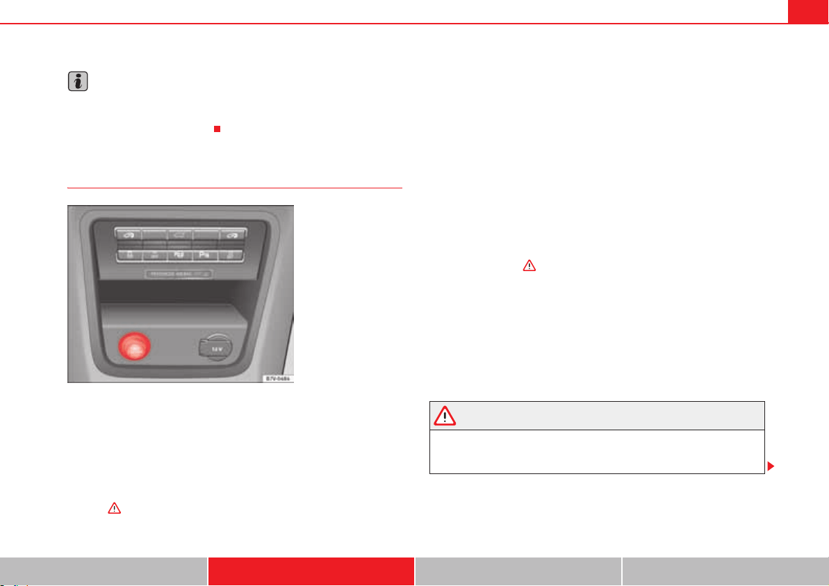
Driving 197
Safety First Operating instructions Practical tips Technical Data
Note
For automatic gearbox vehicles the key can only be removed from the ignition
lock if the gear selector lever is in position P. In this case, press and release
the selector lever locking button.
Starter button*
The starter button can only be used if there is a valid key inside the vehicle.
On leaving the vehicle with the ignition switched off, the electronic lock on
the steering column is activated when the driver's door is opened
page 192.
Switching the ignition on/off
x Briefly press the starter button once without pressing the clutch or brake
pedal .
Emergency starting function
If the system has not recognised a valid key inside the vehicle, the emergency
starter function is activated. The corresponding information text is displayed
on instrument panel. This may occur, for example, if the key battery is flat or
very low:
x Place the key close to the steering column immediately after passing the
start button.
x The engine starts automatically.
Emergency disconnection
If it is not possible to switch off the engine by briefly pressing the starter
button, the emergency disconnection system should be used:
x Press the starter button twice within a second or press it once for more
than two seconds in “Stopping the engine” on page 199.
x The engine turns off automatically.
Re-starting the engine
If, after the engine is switched off, a valid key is not detected in the vehicle,
the engine can only be started after an interval of approximately 5 seconds.
The corresponding message is displayed on the instrument panel.
After this interval, it will not be possible to start the engine without a valid key
inside the vehicle.
WARNING
Unintentional movements of the vehicle could cause serious injury.
x When the starter button is pressed do not press the brake or clutch
pedal as the engine will start immediately.
Fig. 135 Detailed view of
the centre console: KESSY
starter and lock system:
Starter button.
Driving198
WARNING
Careless or incorrect use of vehicle keys may result in severe injury and
accident.
x Always take all the keys with you whenever you leave the vehicle. Chil-
dren and other unauthorised persons could lock the vehicle, start the
engine or switch on the ignition and any electrical components such as the
electric windows.
Note
In vehicles with a diesel engine and KESSY, the starting of the engine may be
delayed due to pre-heating of the engine.
Starting the engine
Complete operations only in the sequence given:
WARNING (continued)
Step Vehicles without KESSY Vehicles with KESSY
1. Press the brake pedal and keep pressed until step 5 has been completed.
1 a. In vehicles with a manual gearbox: Press the clutch pedal all the way and keep pressed until the engine starts.
2. Put the gearstick in neutral or the selector lever in position P or N.
3.
Only in vehicles with diesel engine: To preheat, turn the key in the igni-
tion lock to position page 196, fig. 134 . A warning lamp lights
up in the control panel D.
4.
Turn the key in the ignition lock to position page 196, fig. 134 ;
do not press the accelerator.
Press the starter button page 197, fig. 135; do not press the acceler-
ator. To start the engine, the system should detect a valid key inside
the vehicle.
5. When the engine has started, release the key in the ignition lock. When the engine starts, release the starter button.
6.
If the engine does not start, stop the process and try again after one
minute.
If the engine does not start, stop the process and try again after one
minute. If necessary, perform an emergency start page 197.
7. Disconnect the electronic parking brake when you wish to start driving page 210.
A
1
A
2
Driving 199
Safety First Operating instructions Practical tips Technical Data
WARNING
Never leave the vehicle unattended if the engine is running. The vehicle
could move off suddenly, especially if it is in gear, resulting in an accident
and serious injury.
WARNING
Cold start sprays could explode or cause a sudden increase in the engine
speed.
x Never use start boosters.
Caution
x An attempt to start the engine while driving or starting the engine imme-
diately after turning it off can cause damage to the engine or starter motor.
x When the engine is cold, avoid high revs and heavy acceleration and do
not make the engine work hard.
x Do not push or tow start the engine. Sunburnt fuel could damage the cata-
lytic converter.
For the sake of the environment
Do not warm the engine at idle speed; start driving immediately if the visi-
bility is OK. This helps the engine reach operating temperature faster and
reduces emissions.
Note
For example, if the key battery is very worn or flat, the engine cannot be
started with the starter button. In this case, remove the ignition button from
the lock and insert the key.
Note
Electrical components with a high power consumption are switched off
temporarily when the engine starts.
Note
When the engine is started cold, there may be strong vibrations for a few
moments for technical reasons. This is quite normal, and no cause for
concern.
Note
At temperatures below +5 °C (+41 °F), smoke may be given off below the
vehicle when the additional heater is connected.
Stopping the engine
Complete operations only in the sequence given:
Step Vehicles without KESSY Vehicles with KESSY
1.
Stopping the vehicle completely .
2.
Press the brake pedal and keep pressed until step 4 has been com-
pleted.
3. In automatic gearboxes, put the selector lever in position P.
4. Connect the electronic parking brake page 210.
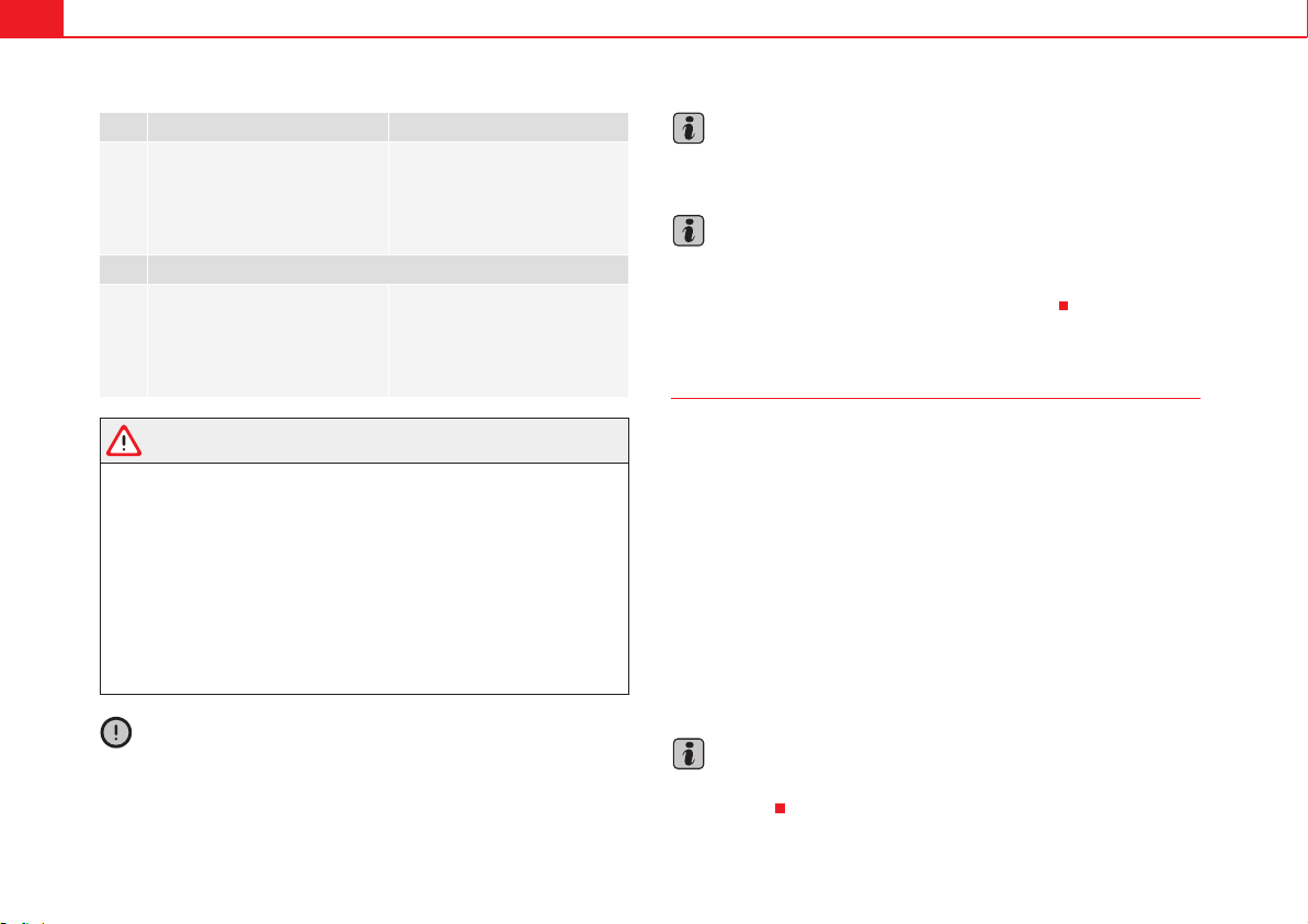
Driving200
WARNING
Never switch off the engine while the vehicle is moving. You may lose
control of the vehicle and there is a risk of serious accident.
x The airbags and belt tensioners do not work when the ignition is
switched off.
x The brake servo does not work when the engine is not running. To stop,
the brake pedal must be pressed with more force.
x As the power steering does not work if the engine is not running, you
will need more strength to steer than normally.
x If the key is removed from the ignition, the steering may lock and it will
not be possible to steer the vehicle.
Caution
If the engine has been driven at high speed for a prolonged period of time, it
may overheat when turned off. To avoid engine damage, allow the engine to
run for approximately two minutes in neutral before switching it off.
Note
In vehicles with automatic gearbox, the key can only be removed when the
selector lever is in position P.
Note
After stopping the engine, the engine compartment fan may continue running
for a few minutes, even when the ignition has been switched off or the key
removed. The radiator fan is automatically switched off.
Electronic immobiliser
The gear lock prevents the engine from being started with an unauthorised
key and the vehicle being moved.
The vehicle key has a built-in chip. It automatically deactivates the immobi-
lizer when the key is inserted into the ignition lock.
The electronic immobiliser will be activated again automatically as soon as
you remove the key from the ignition lock. In vehicles with the KESSY system,
the key should remain outside the vehicle page 86.
For this reason, the vehicle can only be used with a genuine SEAT key with the
correct code. Coded keys can be obtained from your Authorised Service
Centre page 78.
If an unauthorised key is used, the message SAFE or Immobiliser active is
displayed on the instrument panel. The vehicle cannot be started in this case
Note
The correct operation of the vehicle is only guaranteed when original SEAT
keys are used.
5.
Turn the key in the ignition lock
to position page 196, fig. 134
.
Briefly press the starter button
page 197, fig. 135. If it is not
possible to switch off the engine,
use the emergency disconnec-
tion page 197.
6. With a manual gearbox, put the vehicle in first or reverse gear.
7.
Remove the starter button from
the lock to disconnect all electri-
cal components and activate the
electronic lock on the steering
column.
Step Vehicles without KESSY Vehicles with KESSY
A
0
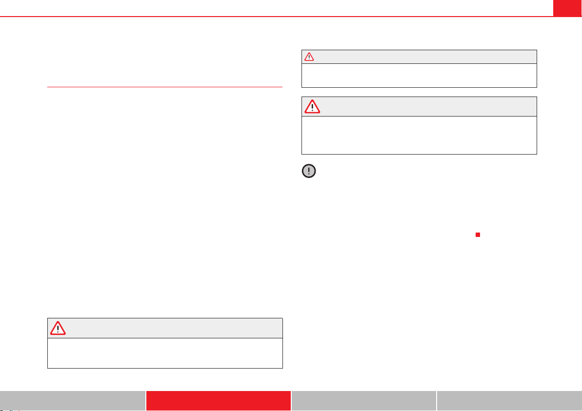
Driving 201
Safety First Operating instructions Practical tips Technical Data
Changing gear
Introduction
When reverse gear is engaged and the ignition is switched on the following
takes place:
x Reverse lights light up.
x When reversing, the air conditioner automatically changes to air recircu-
lation mode.
x The rear window heater switches on when the windscreen wiper is acti-
vated.
x Also, the parking sensor system, the optical parking sensor and the
camera for the reverse assist system are connected.
Additional information and warnings:
x Instruments page 64
x Braking, stopping and parking page 210
x Parking sensor system page 225
x Park Assist system page 229
x Reverse assist system (Rear Assist) page 234
x Air conditioning page 179
x Electronic power control and exhaust gases purification system
page 255
x Emergency locking and unlocking page 348
WARNING
Rapid acceleration can cause loss of traction and skidding, especially on
slippery ground. This could cause loss of control of the vehicle resulting in
an accident and considerable damage.
x Only use the kickdown or rapid acceleration if visibility, weather, road
and traffic conditions so permit.
WARNING
Do not allow the brakes to “rub” for a prolonged period of time, or brake
frequently or for long periods of time. Continuous braking heats up the
brakes. This could significantly reduce braking power, increase braking
distance or even result in the total failure of the brake system.
Caution
x Never make the brakes slip by pressing the pedal gently, if it is not really
necessary to brake. This will increase wear.
x Reduce speed, move down a gear or select a shorter range of gears before
long steep slopes. This allows you to use the engine braking effect and to
reduce the strain on the brake system. Otherwise, the brakes may overheat
and fail. Only use the brakes to reduce speed or to stop.
WARNING (continued)
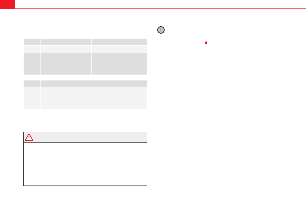
Driving202
Warning and control lamps
Several warning and control lamps should light up for a few seconds when
the ignition is switched. This signals that the lamp is working properly. They
will switch off after a few seconds.
WARNING
If the warning lamps and messages are ignored, the vehicle may stall in
traffic, or may cause accidents and severe injuries.
x Never ignore the warning lamps or text messages.
x Stop the vehicle safely as soon as possible.
x If the vehicle stops and must be stopped for repairs, always park a safe
distance from surrounding traffic, turn on the hazard warning lights, stop
the engine and take all of the safety measures necessary to warn other road
users.
Caution
Failure to heed the warning lamps and text messages when they appear may
result in faults in the vehicle.
lights up Possible cause Solution
K (red)
Brake pedal not pressed! Press brake pedal to the floor.
K
(green)
Brake pedal not pressed.
To select a range of gears, press
the brake pedal.
Please also see "Electronic park-
ing brake" page 210.
flashes Possible cause Solution
K
(green)
The selector lever locking but-
ton has not engaged. The
vehicle does not start to
move.
Engage the selector lever lock
page 206.
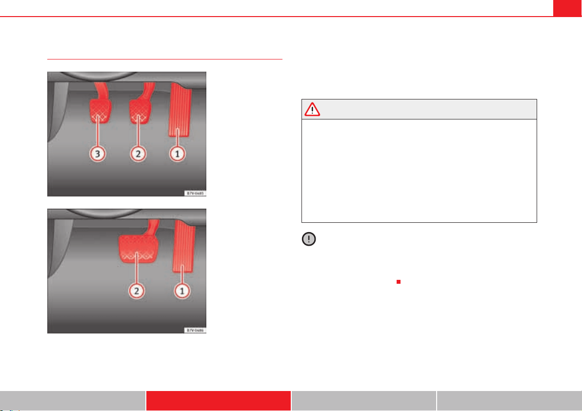
Driving 203
Safety First Operating instructions Practical tips Technical Data
Pedals
Do not allow floor mats or other objects to obstruct the free passage of the
pedals.
Floor mats should leave the pedal area free and unobstructed and be
correctly secured in the footwell zone.
In the event of failure of a brake circuit, the brake pedal must be pressed
harder than normal to brake the vehicle.
WARNING
Objects falling into the driver's footwell could prevent use of the pedals.
This could lead the driver to lose control of the vehicle, increasing the risk
of a serious accident.
x Make sure the pedals can be used at all times, with no objects rolling
underneath them.
x Always secure the mat in the foot well.
x Never place other mats or rugs on top of the original mat supplied by
the factory.
x Ensure that no objects can fall into the driver's footwell while the
vehicle is in motion.
Caution
The pedals must always have free and unobstructed passage to the floor. For
example, in case of a fault in the brake circuit, the brake pedal will need to be
pressed further to stop the vehicle. To press the brake pedal down further will
require more force than usual.
Fig. 136 Pedals in vehi-
cles with a manual
gearbox: accelerator;
brake; clutch.
A
1
A
2
A
3
Fig. 137 Pedals in vehi-
cles with an automatic
gearbox: accelerator;
brake.
A
1
A
2
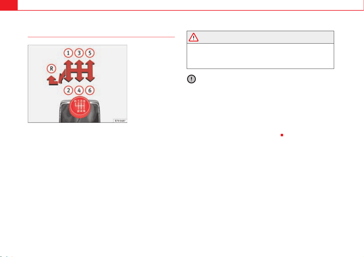
Driving204
Manual gearbox: Engaging gears
The position of each of the gears is shown on the gear stick fig. 138.
x Keep the clutch pedal pushed all the way down.
x Move the gear stick to the required position.
In some countries, it is necessary to press the clutch pedal to the floor to start
the engine.
Selecting reverse gear
x With the vehicle at a standstill, press the clutch pedal to the floor and
keep pressed.
x Push the gear lever down.
x Move the gear stick to the left and then forwards to reverse gear
fig. 138 .
WARNING
When the engine is running, the vehicle will start to move as soon as a gear
is engaged and the clutch released. This is also the case with the electronic
parking brake on.
x Never engage the reverse gear when a vehicle is moving forward.
Caution
To prevent damage and avoid premature wear, please observe the following:
x While driving, do not leave your hand resting on the gear stick. The pres-
sure applied by your hand is transmitted to the gearbox selector forks.
x Always ensure that the vehicle is completely stopped before engaging the
reverse gear.
x When changing gear, always make sure the clutch pedal is pushed right
to the floor.
x Never hold the vehicle on the clutch on hills.
Fig. 138 Gear shift
pattern of a 6-speed
manual gearbox.
A
R
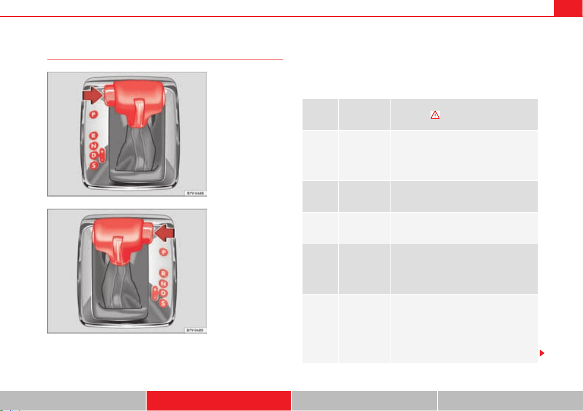
Driving 205
Safety First Operating instructions Practical tips Technical Data
Automatic gearbox*: Selecting gears
The gear selection lever has a lock. When changing the gear selector lever
from the position P to a range of gears, press on the brake pedal and press
the lock on the selector lever in the direction of the arrow fig. 139 or
fig. 140. To move the gear selector lever from the position N to D or to R,
first press and hold the brake pedal.
When the ignition is on, the current position of the selector lever is shown on
the instrument panel.
Fig. 139 Left-hand drive
vehicles: Automatic
gearbox selector lever
with locking button
(arrow).
Fig. 140 Right-hand
drive vehicles: Automatic
gearbox selector lever
with locking button
(arrow).
Selector
lever
positions
Denomination
Meaning
0
Parking lock
The drive wheels are locked mechanically.
They only engage when the vehicle is at a
standstill. To change the position of the selec-
tor lever, press the brake pedal and switch on
the ignition.
2
Reverse gear
Reverse gear is engaged.
Only select reverse gear when the vehicle is at
a standstill.
.
Neutral
The gear box is in neutral. No movement is
transmitted to the wheels and the engine does
not act as a brake.
$
Standard for-
wards driving
position (nor-
mal pro-
gramme)
The gears are changed (up and down) auto-
matically. The gear shifts are determined by
the engine load, your individual driving style
and the speed of the vehicle.
3
Standard for-
wards driving
position
(sports pro-
gramme)
The shift up to a higher gear is automatically
delayed and the shift down is faster with
respect to the D range of gears, to take full
advantage of the engine power. The gear
shifts are determined by the engine load, your
individual driving style and the speed of the
vehicle.

Driving206
Selector lever locking
The gear selector lever lock prevents, in P or N, a gear selection from being
inadvertently engaged and the vehicle moving off accidentally.
To release the gear selector lever lock, press and hold the brake pedal with
the ignition on. Press simultaneously on the selector lever lock.
The selector lever lock is not engaged if the selector lever is moved quickly
through position N (e.g. when shifting from R to D). This makes it possible, for
instance, to rock the vehicle backwards and forwards if it is stuck in snow or
mud. The selector lever lock engages automatically if the brake pedal is not
pressed and the lever is in position N for more than about one second at a
speed of less than 5 km/h (3 mph).
In vehicles with a DSG
®
automatic gearbox, on rare occasions the selector
lever lock may not engage. In this case, the transmission is locked to prevent
the vehicle from moving accidentally. The green control light K flashes and
an information text is displayed. Proceed as follows to engage the selector
lever lock:
x Press the brake pedal and then release.
WARNING
Placing the selector lever in an incorrect position may cause loss of control
of the vehicle and a serious accident.
x Do not press the accelerator when engaging a range of gears.
x With the engine running and a range of gears selected, the vehicle will
move off when the brake pedal is released.
x Never select reverse gear or the parking lock while driving.
WARNING
Unintentional movements of the vehicle could cause serious injury.
x As a driver, you should never leave your vehicle if the engine is running
and a gear is engaged. If you have to leave your vehicle while the engine is
running, you must apply the electronic parking brake and engage parking
lock P.
x While the engine is running and with the D, S or R range of gears
selected, keep the brake pressed to keep the vehicle at a standstill. Trans-
mission is not totally interrupted either when the vehicle is idling or when
the vehicle continues moving forwards.
x Never engage the R or P gear ranges when the vehicle is moving.
x Never leave the vehicle with the gear selector in N. The vehicle may
move downhill regardless of whether the engine is switched on or not.
Caution
If, when the vehicle is at a standstill, the electronic parking brake is not
applied and the brake pedal is released while in position P, the vehicle may
move a few centimetres forwards or backwards.
Note
If, while driving, the selector lever is accidentally placed in position N, lift your
foot off the accelerator. Wait until the engine is running at idle speed before
selecting a new gear ratio.
WARNING (continued)
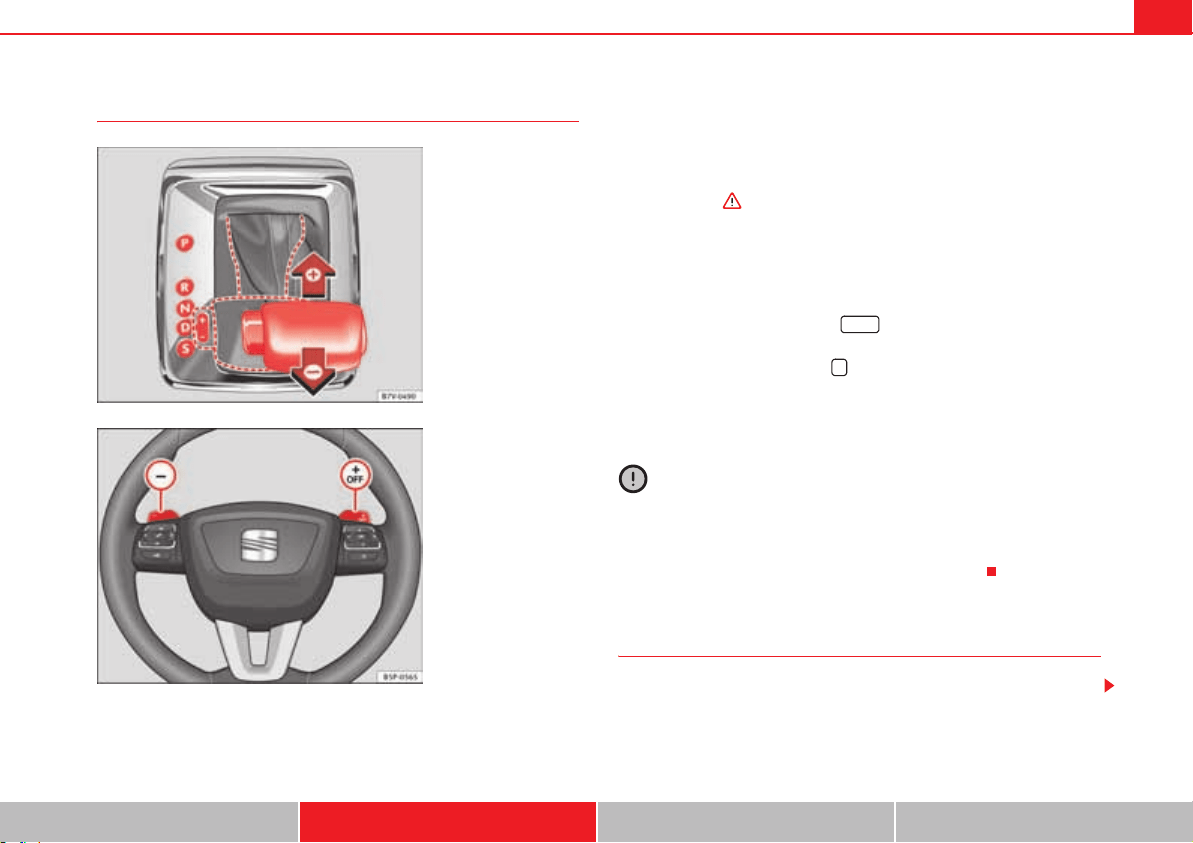
Driving 207
Safety First Operating instructions Practical tips Technical Data
Changing gears with Tiptronic*
The Tiptronic system allows you to manually change gears in vehicles with an
automatic gearbox. When you change to the Tiptronic programme, the
vehicle remains in the currently selected gear. This is possible as long as the
system is not changing gear automatically due to a traffic situation.
Using Tiptronic with the selector lever
x Press the selector lever from position D to the right into the Tiptronic
selector gate in “Automatic gearbox*: Selecting gears” on page 205.
x Press the lever forwards or backwards to move up or down a gear
fig. 141.
Using the Tiptronic with the steering wheel paddle shifts
x In D or S, move the steering wheel paddle shifts fig. 142.
x Pull the right-hand side paddle fig. 142 towards the steering
wheel to step up a gear.
x Pull the left-hand side paddle fig. 142 towards the steering wheel
step down a gear.
If the paddles are not used for a period of time, the vehicle leaves Tiptronic
mode.
Caution
x When accelerating, the gearbox automatically shifts up into the next gear
shortly before the maximum engine speed is reached.
x When reducing speed manually, the gear box only shifts gear when the
engine can no longer exceed the maximum engine speed.
Driving with an automatic gearbox
The gearbox changes gear ratios automatically as the vehicle moves.
Fig. 141 Selector lever in
Tiptronic position (left-
hand drive vehicles). The
lay-out in right-hand drive
vehicles is symmetrically
opposed.
Fig. 142 Steering wheel
with two paddle shifts for
Tiptronic.
A
+
A
–
+ OFF
–
Driving208
Driving down hills
The steeper the gradient, the lower the gear you will need. The lowest gears
increase the engine braking work. Never go down hills with the selector lever
in neutral N.
x You should reduce speed accordingly.
x Press the selector lever from position D to the right into the Tiptronic
selector gate page 207.
x Gently pull the selector lever back to change down a gear.
x ALTERNATIVELY: Reduce using the steering wheel paddles page 207.
Emergency program
If all the selector lever positions on the instrument panel display are shown
with a light-coloured background, this means there is a fault in the system.
The automatic gearbox will operate in emergency programme mode. When
the emergency program is activated, it is possible to drive the vehicle
however, at low speeds and within a selected range of gears.
For the DSG
®
dual clutch gearbox, in some cases, this may mean that reverse
gear does not engage. The gearbox should be checked by a qualified work-
shop as soon as possible.
Overload protection for the 6-speed DSG gearbox
®
When the clutch is overloaded, the vehicle begins to jerk and the selector
lever position indicator begins to flash. To prevent damage to the clutch, this
interrupts the power transmission between the engine and the gearbox.
There is no more traction and it is not possible to accelerate. If the clutch is
opened automatically due to overloading, press the brake pedal. Wait a few
seconds before starting to move again.
Kick-down
The kick-down system provides maximum acceleration when the gear
selector lever is in the positions D, S or in the Tiptronic position.
When the accelerator pedal is pressed right down, the automatic gearbox will
shift down to a lower gear, depending on road speed and engine speed. This
takes advantage of the maximum acceleration of the vehicle .
When the accelerator is pressed to the floor, the automatic gearbox shifts to
the next gear only after the engine reaches the specified maximum engine
speed.
Launch-Control Programme
The Launch-Control programme enables maximum acceleration while at a
standstill.
x Deactivating the TCS page 210.
x Press and hold the brake pedal with your left foot.
x Place the selector lever in position S or Tiptronic.
x Press the accelerator with the right foot until the vehicle reaches an
engine speed of approximately 3,200 rpm.
x Lift the left foot off the brake . The vehicle starts with maximum
acceleration.
x Turn on the TCS after accelerating!
WARNING
Rapid acceleration can cause loss of traction and skidding, especially on
slippery ground. This could cause loss of control of the vehicle resulting in
an accident and considerable damage.
x Only use kick-down and rapid acceleration when weather conditions,
surface conditions and traffic conditions permit; accelerate and drive in a
manner that does not endanger other road users.
x Please remember that the driven wheels can slip and the vehicle can
skid if the TCS is turned off, especially on slippery ground.
x Turn on the TCS after accelerating.
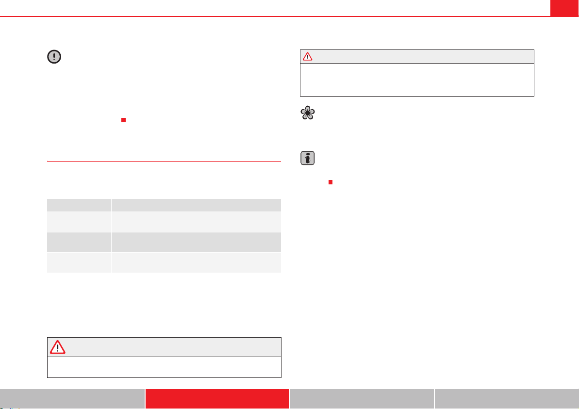
Driving 209
Safety First Operating instructions Practical tips Technical Data
Caution
x If you stop on a hill with a gear ratio engaged, do not try to prevent the
vehicle from rolling back by pressing on the accelerator. This could cause
overheating and damage the automatic gearbox.
x Never allow the vehicle to move with the gear selector lever in N, espe-
cially with the engine turned off. The automatic gearbox will not be lubricated
and could be damaged.
Recommended gear indication
In some vehicles, the recommended gear for reducing fuel consumption is
displayed on the instrument panel:
Information for cleaning the diesel particulate filter
The exhaust gas system control recognises when the diesel particulate filter
is blocked, and helps to clean it by recommending a specific gear for driving.
It may therefore be necessary to drive with the engine at an exceptionally high
speed page 255.
WARNING
The recommended gear display is intended as a guideline only; it should
never replace the driver's attention to driving carefully.
x Responsibility for selecting the correct gear for each situation
continues to lie with the driver, for example when overtaking, climbing a
hill or towing a trailer.
For the sake of the environment
Selecting the most appropriate gear for the situation will help you to save
fuel.
Note
The recommended gear display is switched off when the clutch pedal is
pressed.
Display Meaning
Optimum gear.
Recommendation to change up a gear.
Recommendation to change down a gear.
WARNING (continued)
Driving210
Braking, stopping and parking
Introduction
The assisted braking systems include the anti-lock braking system (ABS), the
brake assist system (BAS), the electronic differential system (EDS), the trac-
tion control system (TCS) and the electronic stabilisation program (ESP).
Additional information and warnings:
x Towing mode page 260
x Start assist systems page 221
x Wheels and tyres page 323
x Accessories, parts replacement, repairs and modifications page 285
WARNING
Driving with worn brake pads or a faulty brake system may lead to serious
accident.
x If I lights, alone or accompanied by a warning message on the instru-
ment panel, please go immediately to a specialist workshop to check the
brake pads and to replace them if they are worn.
WARNING
Careless parking can cause serious injury.
x Never remove the key from the ignition if the vehicle is in motion. The
steering lock may engage and locked the steering wheel making the
vehicle impossible to control.
x Always park your vehicle so that no part of the exhaust system can
come in contact with flammable materials (such as wood, leaves, spilled
fuel, dried grass, etc).
x Always apply the electronic parking brake when you leave your vehicle
and when you park.
x Never leave children or disabled people alone in the vehicle. They could
release the electronic parking brake, activate the selector lever or gear
stick and start the vehicle moving. This could result in serious accident.
x Always take all the keys with you whenever you leave the vehicle. The
engine could accidentally be started and electrical equipment such as the
windows could accidentally be operated resulting in serious injury.
x Never leave children or disabled people alone in the car. They could be
trapped in the car in an emergency and will not be able to get themselves
to safety. For example, depending on the time of the year, temperatures
inside a locked and closed vehicle can be extremely high or extremely low
resulting in serious injuries and illness or even death, particularly for
young children.
Caution
x Special care should be taken when parking in areas with high kerbs or
fixed barriers. Objects protruding from the ground may damage the bumper
or other parts of the vehicle during manoeuvres. To avoid damage, stop
before the wheels touched the barrier or kerb.
x Special attention is required when driving through entrances, over ramps,
kerbs or other objects. The vehicle underbody, bumpers, mudguards and
running gear, and the engine and exhaust system could be damaged as you
drive over these objects.
WARNING (continued)
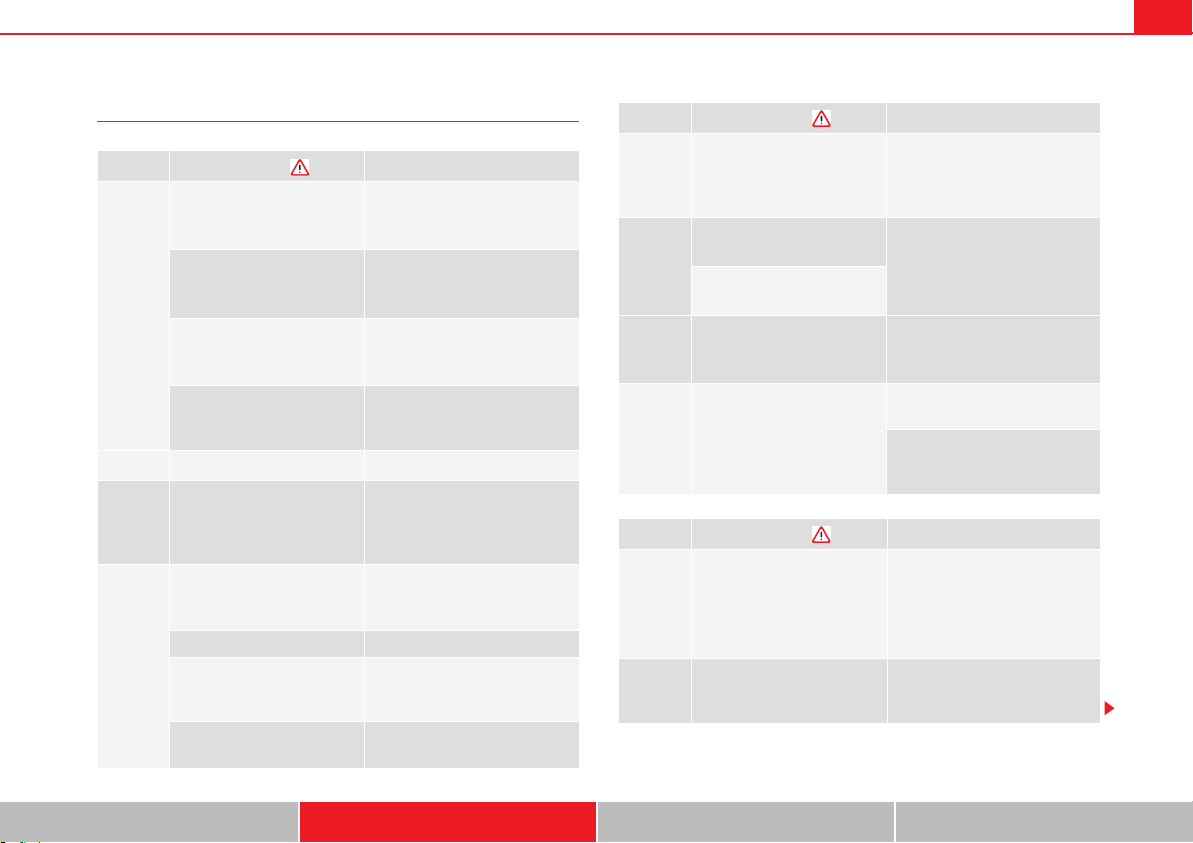
Driving 211
Safety First Operating instructions Practical tips Technical Data
Warning and control lamps
lights up
Possible cause
Solution
H (red)
Together with the control
lamp G on the button: Elec-
tronic parking brake on.
page 212
Fault in the brake system
Stop the vehicle!
Seek professional assistance!
page 215.
Brake fluid level inadequate.
Do not drive on!
Check brake fluid level
page 219.
Together with the ABS control
lamp J: ABS fault.
Contact a specialist workshop.
The vehicle can be braked with-
out ABS.
K (red)
Brake pedal not pressed! Press brake pedal to the floor.
I (yel-
low)
Front brake pads worn.
Contact a specialist workshop
immediately. Inspect all the
brake pads and replace as nec-
essary.
« (yel-
low)
ESP disconnected by system.
Switching the ignition on and off
If necessary, drive for a short
distance.
Fault in ESP. Contact a specialist workshop.
Together with the ABS control
lamp J: Fault in ABS.
Contact a specialist workshop.
The vehicle can be braked with-
out ABS.
The battery has been recon-
nected.
page 318
l (yel-
low)
TCS manually deactivated.
To turn on the TCS page 218.
TCS is automatically activated
when the ignition is switched on
or off.
J (yel-
low)
Together with the ESP control
lamp «: Fault in ABS.
Contact a specialist workshop.
The vehicle can be braked with-
out ABS.
Together with the warning
lamp H or : ABS fault.
(yel-
low)
Together with the warning
lamp H flashing: Electronic
parking brake faulty.
Contact a specialist workshop.
K
(green)
Brake pedal not pressed.
Press the brake pedal to select a
gear ratio.
Press the brake pedal to discon-
nect the electronic parking
brake page 212.
flashes
Possible cause
Solution
H (red)
Electronic parking brake
faulty. The control lamp
may light up at the same time
or the control lamp G may
flash on the button.
Contact a specialised workshop,
as it may not be possible to park
the vehicle in safety.
« (yel-
low)
ESP or TCS adjusting.
Take your foot off the accelera-
tor. Adjust your driving style to
the road conditions.
lights up
Possible cause
Solution
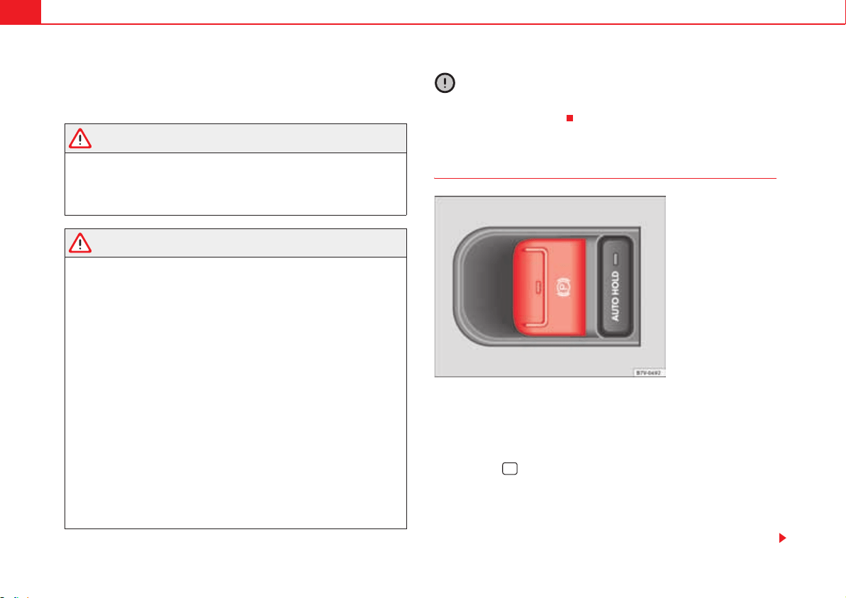
Driving212
Several warning and control lamps should light up for a few seconds when
the ignition is switched. This signals that the lamp is working properly. They
will switch off after a few seconds.
WARNING
If the warning lamps and messages are ignored, the vehicle may stall in
traffic, or may cause accidents and severe injuries.
x Never ignore the warning lamps or text messages.
x Stop the vehicle safely as soon as possible.
WARNING
Driving with brakes in bad condition could result in a serious accident.
x If the brake warning lamp H does not go out, or if it lights up when
driving, the brake fluid level in the reservoir is too low or there is a fault in
the brake system. Obtain professional assistance immediately
page 219, “Brake fluid”.
x If the brake warning lamp H lights up together with the ABS warning
lamp J, the regulation function of the ABS could be malfunctioning. As a
result, the rear wheels can lock relatively easily when braking. If the rear
wheels lock this could result in loss of vehicle control! If possible, reduce
your speed and drive carefully to a specialist workshop close by to check
the brake system. During the following journey, avoid sudden braking and
manoeuvres.
x If the ABS warning lamp J does not go out or if it lights while driving,
the ABS is malfunctioning. The vehicle can only be stopped using normal
braking without ABS. The protection provided by the ABS is not available.
Visit a specialised workshop as soon as possible.
x If I lights, alone or accompanied by a warning message on the instru-
ment panel screen, please go immediately to a specialist workshop to
check the brake pads and to replace them if they are worn.
Caution
Failure to heed the warning lamps and text messages when they appear may
result in faults in the vehicle.
Electronic parking brake
Applying the electronic parking brake
The parking brake can be applied whenever the vehicle is at a standstill, even
when the ignition is switched off. Always apply the parking brake when you
leave your vehicle and when you park.
x Pull button until the control lamp G on the button lights up.
x The parking brake is applied when the control lamp H lights up on the
instrument panel page 211.
Releasing the electronic parking brake
x Switch the ignition on.
Fig. 143 Detailed view of
the centre console: elec-
tronic parking brake
switch
G
Driving 213
Safety First Operating instructions Practical tips Technical Data
x Press button . At the same time, press the brake pedal hard or gently
press the accelerator pedal with the engine switched on.
x The control lamps G on the button and H on the instrument panel go
out.
Automatic release of the electronic parking brake on starting the engine
The electronic parking brake is automatically released when the vehicle starts
moving, if the driver's door is closed and the driver is wearing his/her seat
belt. In vehicles with a manual gearbox the clutch pedal should also be
pressed to the floor before starting the engine so that the system recognises
that the parking brake should be released.
Emergency braking function
Only use the emergency braking function if the vehicle cannot be stopped
with the brake pedal !
x Pull button hard to stop the vehicle. The warning display will be
accompanied by the corresponding warning chime.
x To stop the braking process, release the button or press the accelerator.
WARNING
The incorrect use of the electronic parking brake may result in serious acci-
dent.
x Never use the electronic parking brake to brake the vehicle except in an
emergency. The braking distance is considerably longer, because braking
is only applied to the rear wheels. Always use the foot brake.
x Never accelerate from the engine compartment with the engine running
and a gear or a gear range engaged. The vehicle could move, even if the
parking brake is applied.
Note
In vehicles with a manual gearbox: When the clutch pedal is released and the
accelerator pressed at the same time, the electronic parking brake is auto-
matically released.
Note
If the vehicle battery is flat, it will not be possible to disconnect the electronic
parking brake. Use the jump-start page 371.
Note
When the electronic parking brake is applied or released, noises may be
heard.
Note
If the electronic parking brake has not been used for a long while, the system
sometimes performs automatic and audible checks while the vehicle is at a
standstill.
Parking
When parking your vehicle, all legal requirements should be observed.
To park the vehicle
Complete operations only in the sequence given.
x Park the vehicle on a suitable surface .
x Press and hold the brake pedal until the vehicle comes to a standstill.
x Connect the electronic parking brake page 212.
x For an automatic gearbox, move the selector lever to position P.
G
G
Driving214
x Switch off the engine and release the brake pedal.
x Remove the key from the ignition.
x If necessary, turn the steering wheel slightly to lock the steering.
x With a manual gearbox, engage the 1st gear on flat ground and slopes, or
even the reverse gear on hills, and release the clutch pedal.
x Ensure that all passengers leave the vehicle, especially children.
x When leaving the vehicle, take all keys with you.
x Lock the vehicle.
Additional information for steep slopes and hills
Before switching off the engine, rotate the steering wheel so that if the
vehicle should move then it will be held by the kerb.
x On slopes, turn the front wheels so that they are against the edge of the
kerb.
x Uphill, turn the wheels towards the centre of the road.
WARNING
The components of the exhaust system reach very high temperatures. This
could cause a fire and considerable damage.
x Always park your vehicle so that no part of the exhaust system can
come in contact with flammable materials (such as wood, leaves, spilled
fuel, dried grass, etc).
Caution
x Special care should be taken when parking in areas with high kerbs or
fixed barriers. Objects protruding from the ground may damage the bumper
or other parts of the vehicle during manoeuvres. To avoid damage, stop
before the wheels touched the barrier or kerb.
x Special attention is required when driving through entrances, over ramps,
kerbs or other objects. The vehicle underbody, bumpers, mudguards and
running gear, and the engine and exhaust system could be damaged as you
drive over these objects.
Information about the brakes
For the first 200 to 300 km (100 to 200 miles), new brake pads have not yet
reached their maximum braking capacity, and need to be run in first .
The slightly reduced braking effect can be compensated for by increasing
pressure on the brake pedal. While running in, the full braking distance or
emergency braking distance is larger then when the brake pads have been
run in. While running in, avoid full power braking or situations requiring
braking performance. For example, in heavy traffic.
The rate of wear of the brake pads depends to a great extent on the condi-
tions in which the vehicle is used and the way the vehicle is driven. If the
vehicle is used frequently in city traffic or for short trips or driven sport style,
visit a specialist workshop regularly more frequently than advised in the
Maintenance Programme to have the bake pads checked.
If you drive with wet brakes, for example, after crossing areas of water, in
heavy rainfall or even after washing the car, the effect of the brakes is less-
ened as the brake discs are wet or even frozen (in winter). At higher speed,
dry the brakes as quickly as possible by braking gently several times. Only do
this without endangering vehicles behind you or any other road users .
A layer of salt on the discs and brake pads will reduce brake efficiency and
increase braking distance. If you drive for a prolonged period on salted roads
without braking then brake carefully several times to eliminate the layer of
salt on the brakes .
If the vehicle remains parked for considerable lengths of time, is used little,
or if the brakes are not used, there may be corrosion on the brake discs and
a buildup of dirt on the brake pads. If the brakes are not used frequently, or
if rust has formed on the discs, SEAT recommends cleaning the pads and
Driving 215
Safety First Operating instructions Practical tips Technical Data
discs by braking firmly a few times at a moderately high speed. Only do this
without endangering vehicles behind you or any other road users .
Faults in the brake system
During braking, if you notice that the vehicle does not react as usual (that the
braking distance has increased suddenly) it may be possible that there is a
fault in the braking system. The H warning lamp lights up and a text
message displayed. Take the vehicle to a qualified workshop immediately
and have the fault repaired. Drive at a moderate speed and be prepared to
use more pressure on the brake pedal, and allow for longer stopping
distances.
Brake servo
The brake servo only operates when the engine is running and the pressure
applied by the driver on the brake pedal increases.
If the brake servo does not operate or the vehicle must be towed, then the
brake pedal will have to be pressed with more force given that the braking
distance will be increased when the brake servo does not operate .
WARNING
New brake pads do not brake to full efficiency.
x For the first 320 km (200 miles), new brake pads have not yet reached
their maximum braking capacity, and need to be run in first. For this, to
compensate for reduced braking efficiency the brake pedal will have to be
pressed with more force.
x To avoid losing control of the vehicle and causing serious accidents,
always take great care when driving with new brake pads.
x When running in new brake pads, always respect the safety distances
between you and other vehicles and do not cause situations requiring
extreme braking performance.
WARNING
When brakes overheat, braking is less efficient and braking distances
increase.
x When driving on slopes, brakes can be overloaded and overheat
quickly.
x Reduce speed, move down a gear or select a shorter range of gears
before long steep slopes. This allows you to use the engine braking effect
and to reduce the strain on the brake system.
x Non-standard or damaged front spoilers could restrict the airflow to the
brakes and cause them to overheat.
WARNING
Wet, frozen or salt-covered brakes take time to brake and this increases
braking distances.
x Test the brakes carefully.
x Dry the brakes, free them of ice and salt by braking gently several
times, when weather, road and traffic conditions permit.
WARNING
Driving without the brake servo may significantly increase the braking
distance and result in a severe accident.
x Never allow the vehicle to move forwards when the engine is switched
off.
x If the brake servo does not operate or the vehicle must be towed, then
the brake pedal will have to be pressed with more force given that the
braking distance will be increased when the brake servo does not operate.
Driving216
Caution
x Never make the brakes slip by pressing the pedal gently, if it is not really
necessary to brake. Continuously pressing on the brake pedal will heat the
brakes. This could significantly reduce braking power, increase braking
distance or even result in the total failure of the brake system.
x Reduce speed, move down a gear or select a shorter range of gears before
long steep slopes. This allows you to use the engine braking effect and to
reduce the strain on the brake system. Otherwise, the brakes may overheat
and fail. Only use the brakes to reduce speed or to stop.
Note
When checking the front brake pads, take the time to also check the rear
brake pads. The thickness of the brake pads should be checked visually and
regularly, by looking through the openings in the wheel rims or from under-
neath the vehicle. If necessary, remove the wheels to check them thoroughly.
SEAT recommends visiting a qualified workshop.
Assisted braking systems
The assisted braking systems ESP, ABS, BAS, TCS and EDS only operate when
the ignition is switched on. They contribute significantly to increasing active
safety.
Electronic stability programme (ESP)
ESP reduces the risk of skidding and increases the vehicle stability by braking
individual wheels under specific driving conditions. ESP detects critical
handling situations, such as understeer, oversteer and wheelspin on the
driven wheels. The system stabilises the vehicle by braking individual wheels
or by reducing the engine torque.
The ESP has limits. It is important to realise that the ESP is also subject to the
laws of physics. ESP will not be able to deal with all situations with which
drivers may be faced. For example, if the road surface changes suddenly then
ESP will not be useful in all cases. If the vehicle suddenly enters a section
covered by water, mud or snow then ESP will not provide assistance in the
same way as on dry ground. If the vehicle loses its grip on the ground and
moves on a film of water (aquaplaning), the ESP will not be able to assist the
driver to control the vehicle due to the loss of adherence with the road surface
preventing braking and steering. If the vehicle is driven through series of
bends at high speed, the ESP will not always be as effective: the vehicle reac-
tion to aggressive driving is not the same as at reduced speeds. When driving
with a trailer, ESP does not provide the same amount of vehicle control as
without a trailer.
Adjust your speed and driving style to road, traffic and weather conditions.
ESP cannot push the limits of the laws of physics; improve the transmission
available or maintain the vehicle on the road if a lack of driver attention
creates an inevitable situation. Otherwise, ESP assists in maintaining vehicle
control in extreme situations and uses the movements of the steering made
by the driver to maintain the vehicle moving in the desired direction. If the
vehicle is driven at such a speed that it will leave the road before ESP can
intervene then the system cannot provide assistance.
The ABS, BAS, TCS and EDS systems are incorporated into the ESP. The ESP is
always on. The ESP should only be turned off using the TCS button
page 218, fig. 144 when traction is insufficient. Always remember to turn
on the TCS once more when the vehicle has traction once again.
Anti-lock brake system (ABS)
ABS can prevent the wheels from locking during braking until just before the
vehicle stops thus helping the driver to steer the vehicle and maintain
control. This means that, even during full braking, the risk of skidding is
reduced:
x Press and hold the brake pedal fully. Do not remove your foot from the
brake pedal or reduce braking force!
x Do not “pump” the brake pedal, or reduce braking force!
x Maintain vehicle direction when braking fully.
Driving 217
Safety First Operating instructions Practical tips Technical Data
x When the brake pedal is released or when the brake force is reduced, ABS
is turned off.
ABS control can be observed by vibration of the brake pedal and noise. You
should never expect the ABS to reduce the braking distance under any
circumstances. Braking distances will increase when driving on gravel, recent
snow or on icy and slippery ground.
When driving on loose ground, the all-terrain configuration of the ABS is auto-
matically turned on. When ABS is activated, the front wheels may lock briefly.
This shortens the braking distance in off-road situations as the wheels are
prevented from digging into loose surfaces. All-terrain ABS only intervenes
when driving in a straight line. When the front wheels are turned, the normal
ABS is activated.
Braking assist system (BAS)
The brake assist system may reduce the required braking distance. The brake
assist system boosts the braking force if you press the brake pedal quickly in
an emergency. As a result, the braking pressure increases rapidly, the braking
force is multiplied and the braking distance is reduced. This enables the ABS
to be activated more quickly and efficiently.
¡Do not lift your foot off the brake pedal! When the brake pedal is released or
when the brake force is reduced, braking assist automatically turns off the
brake servo.
Traction control when accelerating (TCS)
In the event of wheelspin, the traction control system reduces the engine
torque to match the amount of grip available. The TCS makes some situations
easier, for example, when starting, accelerating or going uphill, even in unfa-
vourable road conditions.
The TCS can be switched on or off manually page 218.
Electronic differential lock system (EDS)
EDS is available when driving in straight lines under normal conditions. When
the EDL detects wheelspin, it brakes the spinning wheel and directs the
power to the other driven wheels. To prevent the disc brake of the braked
wheel from overheating, the EDL cuts out automatically if subjected to exces-
sive loads. The EDL will switch on again automatically when the brake has
cooled down.
WARNING
Driving at high speed on icy, slippery wet ground can result in loss of
vehicle control and serious injury to the driver and passengers.
x Adjust your speed and driving style to visibility, road, traffic and
weather conditions. Even though the braking assist systems, ABS, BAS,
EDS, TCS and ESP, provide more security, do not take unnecessary risks
while driving.
x Braking assist systems can not overcome the laws of physics. Even with
ESP and other systems, slippery and wet roads will always be dangerous.
x Driving to quickly on wet ground can result in the wheels losing contact
with the ground in an effect known as aquaplaning. Without adherence, it
is impossible to brake, steer or control the vehicle.
x Braking assist systems cannot avoid accidents if, for example, the
driver does not respect safety distances or drives to quickly in difficult
conditions.
x Even though braking assist systems are extremely effective and help
control the vehicle in difficult situations, remember that the vehicle
stability depends on tyre grip.
x When accelerating on a slippery surface, for example on ice and snow,
press the accelerator carefully. The wheels can still slip even with braking
assist systems resulting in loss of vehicle control.
WARNING
The effectiveness of the ESP can be considerably reduced if other compo-
nents and systems affecting driving dynamics are not maintained or are not
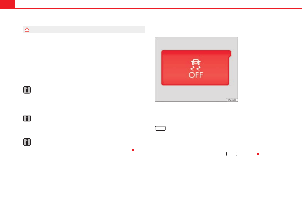
Driving218
functioning correctly. This includes, among others, brakes, tyres and other
systems already mentioned.
x Remember that changing and fitting other components to the vehicle
can affect operation of the ABS, BAS, ASL EDL and ESP.
x Changes to the vehicle suspension or using unapproved wheel/tyre
combinations can affect operation of the ABS, BAS, ASL EDL and ESP and
their effectiveness.
x Likewise, the effectiveness of ESP depends on the use of suitable tyres
page 323.
Note
To ensure that the ESP and TCS work properly, all four wheels must be fitted
with identical tyres. Any differences in the rolling radius of the tyres can cause
the system to reduce engine power when this is not desired.
Note
If a malfunction should occur in the ABS, the ESP, TCS and EDS will also be
affected.
Note
Noises may be heard while any of the above systems are operating.
Turning on and off the TCS
The electronic stabilisation programme (ESP) includes the ABS, EDL and TCS
systems and only works when the engine is running.
The TCS can be switched off while the engine is running by pressing the
fig. 144 button. The TCS (and similar) is only switched off when the
required traction is not obtained:
x When driving through deep snow or on loose ground (gravel...).
x When freeing a trapped vehicle.
Turn the TCS back on by pressing the button fig. 144.
WARNING (continued)
Fig. 144 Detailed view of
the centre console: button
used to switch TCS on and
off (vehicles with ESP).
« OFF
« OFF
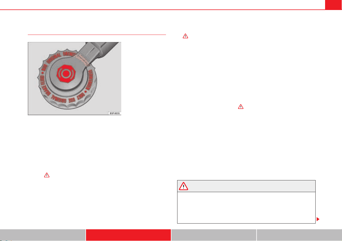
Driving 219
Safety First Operating instructions Practical tips Technical Data
Brake fluid
In the course of time, the brake fluid absorbs water from the ambient air. If
there is too much water contained in the brake fluid, the brake system could
be damaged. In addition, the boiling point of the brake fluid is significantly
lowered. When the brake fluid contains too much water and the brakes are
subject to considerable forces, bubbles of water vapour can form in the
system. These bubbles of water vapour can significantly reduce braking
power, notably increasing braking distance, and could even result in the total
failure of the brake system. Ensuring that the brake system is always func-
tioning correctly is essential for your own safety and the safety of other road
users .
Brake fluid specifications
SEAT have developed a special brake fluid optimised for the brake systems of
their vehicles. To ensure the optimum working of the brake system, SEAT
recommends the use of brake fluid in accordance with the VW 501 14
standard. If this brake fluid is not available or another brake fluid is used for
different reasons, use a brake fluid that complies with the United States
standard FMVSS 116 DOT 4 or the German standard DIN ISO 4925 CLASS 4
.
Brake fluids conforming to the standard VW 501 14, fulfil the American
requirements of the FMVSS 116 DOT 4 standard and the German DIN ISO
4925 CLASS 4 standard. However, fluids that comply with the American
FMVSS 116 DOT 4 standard or the German DIN ISO 4925 CLASS 4 standard do
not necessarily comply with the VW 501 14 standard. Always check the infor-
mation on the brake fluid container and ensure that you are using suitable
brake fluid.
A suitable brake fluid can be obtained from Authorised Service Centres.
Brake fluid level
The level of the brake fluid should always be between the MIN and MAX
marks, or above the MIN mark .
It is not always possible to check the level of the brake fluid, as in some
models the engine components make it difficult to see the brake fluid reser-
voir. If you cannot read the exact brake fluid level, consult a specialist.
The brake fluid level drops slightly when the vehicle is being used due to wear
of the brake pads and the automatic readjustment of the brake.
Changing the brake fluid
The brake fluid should be changed in accordance with the instructions given
in the Maintenance Programme. Have the brake fluid changed by a qualified
workshop. SEAT recommends visiting a qualified workshop. This means that
only brake fluid complying with the required specifications will be used.
WARNING
If the brake fluid level is low or unsuitable/old brake fluid is used, the brake
system may fail or braking power will be reduced.
x Check the brake system and the brake fluid level regularly!
x The brake fluid should be changed regularly in accordance with the
instructions given in the Maintenance Programme.
Fig. 145 In the engine
compartment: brake fluid
reservoir, lid
Driving220
x When the brake fluid is used and brakes are subjected to extreme
braking forces, bubbles of vapour form in the brake system. These bubbles
of water vapour can significantly reduce braking power, notably increasing
braking distance, and could even result in the total failure of the brake
system.
x Only used brake fluid that conforms to the VW 501 14 standard, FMVSS
116 DOT 4 standard or even the DIN ISO 4925 CLASS 4 standard. Other
types of brake fluid could affect brake operation and reduce braking power.
Do not use a brake fluid if the container does not specify compliance with
the VW 501 14, FMVSS 116 DOT 4 or DIN ISO 4925 CLASS 4 standards.
x The replacement brake fluid must be new.
x Always ensure that you use suitable brake fluid. Do not use a brake fluid
if the container does not specify compliance with the VW 501 14, FMVSS
116 DOT 4 or DIN ISO 4925 CLASS 4 standards.
WARNING
Brake fluid is poisonous.
x To reduce the risk of poisoning, do not keep brake fluid in drinks
bottles/containers or similar. Other people could drink from these recipi-
ents even if the contents are clearly marked.
x Always keep brake fluid in the original container; keep it correctly
sealed and out of reach of children.
Caution
Brake fluid could damage the paintwork. Wipe off any brake fluid from the
paintwork immediately.
For the sake of the environment
Brake fluid is an environmental pollutant. Collect any spilt service fluids and
allow a professional to dispose of them.
WARNING (continued)
Driving 221
Safety First Operating instructions Practical tips Technical Data
Start assist systems
Introduction
Additional information and warnings:
x SEAT information system page 70
x Braking, stopping and parking page 210
x Vehicle battery page 318
x Wheels and tyres page 323
x Accessories, parts replacement, repairs and modifications page 285
x Jump starting page 371
WARNING
The intelligent technology in the start assist systems cannot change the
laws of physics. The improved comfort provided by start assist systems
should not prompt you to take risks.
x Unintentional movements of the vehicle could cause serious injury.
x The start assist systems are not a replacement for driver awareness.
x Always try to adapt the speed of the vehicle and your style of driving to
the condition of the ground or the road and to weather and traffic condi-
tions.
x The start assist system cannot keep the vehicle stationary in all condi-
tions on a gradient or cause it to brake on steep downhill gradients, e.g. if
the road is slippery or icy.
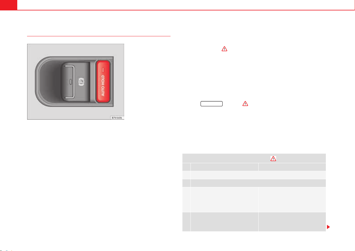
Driving222
Auto Hold function*
The control lamp on the button switches on when the Auto Hold function is
on.
When the Auto Hold function is on, it helps the driver if they must regularly
stop the vehicle or if they must stop with the engine running for prolonged
periods, for example, on hills, before a traffic light or in traffic jams with
continuous stopping and starting.
The Auto Hold function automatically prevents the vehicle from rolling away
accidentally when at a standstill, without the driver having to keep his/her
foot on the brake pedal.
When the system that detects that the vehicle has stopped, the Auto Hold
keeps the vehicle at a standstill. The brake pedal can be released.
If the driver presses the brake pedal briefly or presses the accelerator to start
off, the Auto Hold function releases the brake once more. The vehicle moves
according to the gradient.
If any of the conditions necessary for the Auto Hold function change while the
vehicle stopped, the system is turned off as is the indicator on the button
fig. 146. The electronic parking brake engages where necessary to park
the vehicle safely .
Conditions for keeping the vehicle at a standstill with Auto Hold:
x The driver's door must be closed.
x The driver's seat belt must be buckled.
x The engine must be running.
x The TCS system must be switched on page 210.
Switching Auto Hold on and off manually
Press the button . The control lamp on the button switches
off when the Auto Hold function is switched off.
Permanent Auto Hold connection
The Auto Hold function must be switched on every time the engine is started.
However, to switch the Auto Hold function on permanently, the mark must be
switched on in the Settings menu, Autohold submenu page 70.
Auto Hold works automatically under the following conditions:
Fig. 146 Detailed view of
the centre console: Auto
Hold button.
All points must be fulfilled simultaneously :
manual gearbox Automatic gearbox
1. If the vehicle is stopped using the brake pedal on a flat or slope.
2. The engine must be running smoothly.
3. On a slope, the 1st gear is
engaged uphill or the reverse gear
is engaged for a downhill. The
clutch must be held down.
A gear for driving is selected from
R, D or S.
Upon accelerating and pressing in
the clutch simultaneously, the
brake releases gradually.
Upon accelerating, the brake
releases gradually.
AUTO HOLD
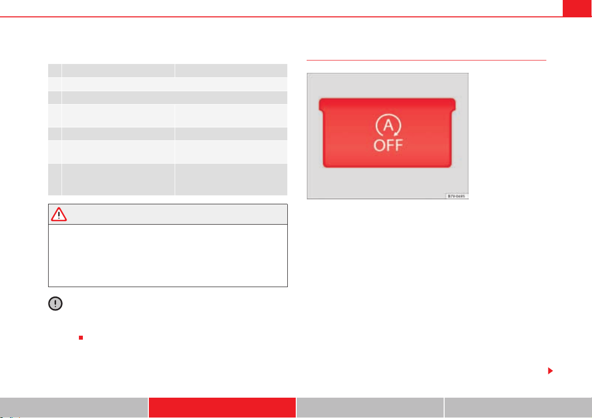
Driving 223
Safety First Operating instructions Practical tips Technical Data
Auto Hold turns off automatically under the following conditions:
WARNING
The Auto Hold technology is limited by the laws of physics. The improved
comfort provided by Auto Hold should never prompt you to take risks.
x Never leave the vehicle running and with the Auto Hold function
switched on.
x Auto Hold cannot always stop the vehicle uphill and downhill (for
example, if the ground is slippery or frozen).
Caution
Before entering an automatic car wash, always switch the Auto Hold function
off, as it could be damaged when the electronic parking brake automatically
engages.
Start-Stop Function*
In Start-Stop mode, the engine is automatically switched off when the vehicle
is at a standstill. The engine restarts automatically when required.
The function is enabled automatically whenever the ignition is switched on.
The instrument panel displays information on the current status.
Vehicles with a manual gearbox
x When the vehicle is at a standstill, leave it in neutral and take your foot off
the clutch. The engine switches off.
x Simply depress the clutch pedal to move off again.
Vehicles with an automatic gearbox
x When the vehicle is at a standstill, depress the brake or keep it pressed
down. The engine switches off.
x The engine will start again as soon as you release the brake pedal.
x With the gear lever set to P, the engine will not start until a range of gears
is selected or the accelerator pedal is depressed.
manual gearbox Automatic gearbox
1. If one of the conditions mentioned in table on page 222 changes.
2. If the engine is not running regularly or if there is a malfunction.
3. When changing to idle speed. If the selector lever is placed in
neutral (N).
4. If the engine is turned off or stalls. If the engine is switched off.
5. If the driver accelerates while
pressing the clutch in.
If the vehicle is accelerated.
6. When one of the wheels has mini-
mal contact with the ground (for
example, on uneven ground).
Fig. 147 Detailed view of
the centre console: Start-
Stop function button.
Driving224
Important conditions for the engine to automatically switch off
x The driver seat belt must be buckled.
x The driver door must be closed.
x The bonnet must be closed.
x The factory-fitted towing bracket must not be electrically connected to a
trailer.
x A minimum engine temperature has been reached.
x The vehicle has moved since the last stop.
x In vehicles with Climatronic: The temperature inside the vehicle is within
the preset temperature range.
x The temperature set is neither very high nor very low.
x The air conditioning defrost function is not switched on.
x In vehicles with Climatronic: the blower has not been manually set to a
high speed.
x The power level of the vehicle's battery is sufficient.
x The vehicle's battery temperature is neither too high nor too low.
x The vehicle is not on a steep gradient or slope.
x The front wheels are not overly turned.
x The heated windscreen is not switched on.
x Reverse gear is not engaged.
x The park assist system is not switched on.
Conditions for automatically restarting the engine
The engine may automatically restart under the following conditions:
x If the vehicle interior is too hot or too cold.
x If the vehicle moves.
x If the vehicle's battery voltage drops.
Conditions requiring the key to restart the engine
The engine must be started using the key under the following conditions:
x If the driver unbuckles his/her seat belt.
x If the driver's door is opened.
x If the bonnet is opened.
x In vehicles with a manual gearbox: If a gear has been selected.
Switching Start-Stop mode on and off manually
x Press the button on the centre console page 223, fig. 147.
x The button will light up when the Start-Stop function is switched off.
The engine will start immediately if the vehicle is in Stop mode when it is
switched off manually.
WARNING
The brake servo and the power steering do not work when the engine is
switched off.
x Never allow the vehicle to move when the engine is switched off.
Caution
Using the Start-Stop function for a long period at very high outdoor tempera-
tures could damage the vehicle's battery.
Note
In some cases, you may have to restart the vehicle using the key. Observe the
corresponding message on the instrument panel display.

Driving 225
Safety First Operating instructions Practical tips Technical Data
Parking sensor system
Introduction
The parking sensor system assists the driver when parking. When the vehicle
approaches an obstacle, forwards or backwards, an intermittent sound will
be heard, higher or lower depending on the distance. The shorter the
distance, the shorter the intervals between tones. If the vehicle is too close to
the obstacle, the sound signal becomes constant.
If you continue to approach an obstacle when the sound is continuous, this
means the system can no longer measure the distance.
The sensor system on the bumpers transmit and receive ultrasound. Using
the ultrasound signal (transmission, reflection from the obstacle and recep-
tion), this system continuously calculates the distance between the bumper
and the obstacle.
Additional information and warnings:
x Park Assist system page 229
x Accessories, parts replacement, repairs and modifications page 285
WARNING
The parking sensor system and the optical parking system cannot replace
driver awareness.
x The sensors have blind spots in which obstacles and people are not
registered.
x Always observe the area around the vehicle, as the sensors do not
always detect small children, animals or objects.
x The surface of certain objects and some clothing do not reflect the
ultrasound signals from the parking distance system. The system cannot
detect or incorrectly detects these objects and people wearing these types
of clothes.
x External sound sources can affect the parking distance aid signals. In
this case, under certain circumstances, people and objects will not be
detected.
Caution
x The sensors may not always be able to detect objects such as trailer draw
bars, thin rails, fences, posts, trees and open boots, etc. This could result in
damage to your car.
x Although the parking sensor system detects and warns of the presence of
an obstacle, the obstacle could disappear from the angle of measurement of
the sensors if it is too high or low and the system would no longer indicate it.
Therefore, it will not warn you of these objects. Ignoring the warnings of the
parking sensor system could cause considerable damage to the vehicle.
x The bumper sensors may become damaged or misaligned, for example,
when parking.
x To ensure that the system works properly, the bumper sensors must be
kept clean, free of ice and snow and uncovered.
x When cleaning the sensors with high-pressure or steam cleaning equip-
ment, spray the sensors briefly at a distance of no less than 10 cm (4 inches).
Note
Acoustic sources may lead to erroneous warnings on the parking sensor
system, e.g. rough tarmac, cobbles or the noise of other vehicles.
WARNING (continued)
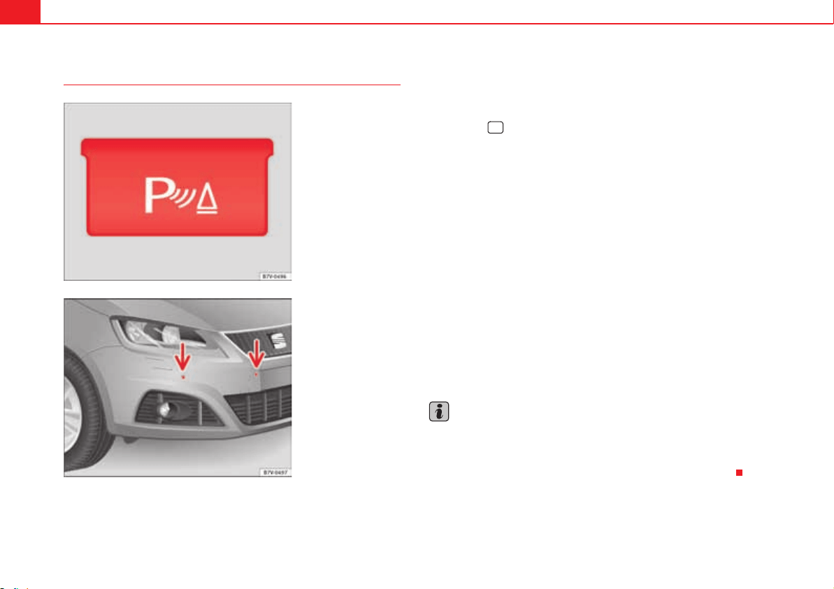
Driving226
Parking sensor system*
The parking sensor system assists the driver when parking. If the vehicle is
approaching an obstacle, an intermittent sound signal is emitted. The shorter
the distance, the shorter the intervals between tones. If the vehicle is too
close to the obstacle, the sound signal becomes constant.
Switching the parking sensor system on and off
x Press the button fig. 148 when the ignition is switched on.
x Automatic on: select reverse gear.
x Automatic off: drive faster than 15 km/h.
The button lights up when the function is switched on.
Things to note regarding the parking sensor system
x The parking sensor system sometimes registers water on the sensors as
an obstacle.
x If the distance does not change, the warning signal will sound less loudly
after a few seconds. If the continuous signal sounds, the volume will remain
constant.
x When the vehicle moves away from the obstacle, the beeping sound auto-
matically switches off. On approaching the obstacle again, the beeping
sound will automatically switch back on.
x If the electronic parking brake is engaged or the gear lever is set to P, no
sound will be emitted.
x Your Authorised Service Centre can adjust the volume of the warning
signals.
Note
If the parking sensor system is faulty, a constant acoustic signal will be
emitted the first time it is switched on and the button will flash. Switch the
parking sensor system off using the button and take the vehicle to a
specialist workshop to have the system checked as soon as possible.
Fig. 148 Detailed view of
the centre console: button
for switching the parking
sensor system on and off.
Fig. 149 Parking sensor
system sensors on the
front bumper.
'
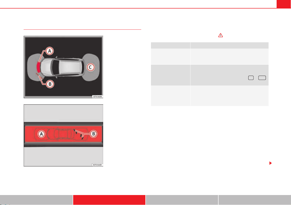
Driving 227
Safety First Operating instructions Practical tips Technical Data
Optical parking system* (OPS)
The optical parking system is an accessory to the Parking sensor system
page 226 and the park assist system page 229.
The zone recorded by the sensors in front of and behind the vehicle is
displayed on the factory-fitted radio or navigation system screen. Any obsta-
cles are display in relation to the vehicle .
Zones explored
The zone in which obstacles are recognised runs to a distance of around 120
cm from the front of the vehicle and up to 60 cm to the side fig. 151 .
Behind the vehicle, the zone analysed reaches a distance of up to 160 cm and
around 60 cm to the sides fig. 150 .
Screen display
The image displayed represents the supervised zones in several segments.
As the vehicle moves closer to an obstacle, the segment moves closer to the
vehicle displayed fig. 150 and fig. 151 . When the penultimate
segment is displayed, this means that the vehicle has reached the collision
zone. Stop the vehicle!
Fig. 150 On-screen OPS
display: an obstacle
has been detected in the
collision zone. an
obstacle has been
detected in the segment.
zone recorded behind
the vehicle.
A
A
A
B
A
C
Fig. 151 On-screen OPS
display: an obstacle
has been detected in the
segment. zone
recorded behind the
vehicle.
A
A
A
B
Function Necessary operations
Switching the display
on:
Switch on the parking sensor system page 226
or the park assist system page 229. The OPS
switches on automatically.
Switching the display
off manually:
Press a zone selection button on the factory-fitted
radio or navigation system
OR: Briefly press the function button or
on the screen.
Switching the display
off manually:
Drive forwards at more than about 10-15 km/h.
Select the reverse gear on vehicles with rear
assist page 234. The display changes to the
image of the camera.
E RVC
A
B
A
C
A
B
A
A
Driving228
With towing bracket
A specific image is displayed on the screen of vehicles with a factory-fitted
towing bracket and an electrically connected trailer. In this case, the
distances behind the vehicle are not indicated.
Switching the parking sensor system sound on and off
If the button on the radio or navigation system screen may mute the
sound of OPS warnings. To switch the warnings back on, press the button
again briefly.
When the OPS is switched off and back on again, muting is cancelled. Error
messages cannot be switched off.
WARNING
Do not be distracted from the traffic when looking at the screen.
Distance from the vehicle to the
obstacle
Acoustic sig-
nal
Displayed in colour on
the screen: colour of the
segment if an obstacle is
recognised
in front: approx. 31 – 120 cm
behind: approx. 31 – 160 cm
beeping
sound
Yellow
approx. 0 – 30 cm in front or
behind
a)
a)
The permanent sound starts at a somewhat greater distance on vehicles with a fac-
tory-fitted towing bracket.
permanent
sound
Red
Driving 229
Safety First Operating instructions Practical tips Technical Data
Park Assist system*
Introduction
The Park Assist system helps the driver to find a suitable place to park, to
insert the vehicle into parallel and perpendicular parking places and to leave
parallel parking places.
The Park Assist system is limited to the system abilities and requires that the
driver is especially attentive .
The parking sensor system is a component of the Park Assist system that
helps to park the vehicle.
For vehicles with the optical parking system, the radio navigation systems
screen displays the detected zones in front of and behind the vehicle, indi-
cating - within the limits of the system - the position of obstacles compared
to the vehicle.
The park assist system cannot be switched on if the factory-fitted towing
bracket is electrically connected to a trailer.
Additional information and warnings:
x Braking, stopping and parking page 210
x Parking sensor system page 225
x Caring for and cleaning the vehicle exterior page 269
x Accessories, parts replacement, repairs and modifications page 285
WARNING
Despite the assistance provided by the park assist system, do not run any
risks when parking. The system is not a replacement for driver awareness.
x Unintentional movements of the vehicle could cause serious injury.
x Adjust your speed and driving style to visibility, road, traffic and
weather conditions.
x The surface of certain objects and items of clothing and external sound
sources may have a negative affect on the park assist signals or on the
system sensors or may not reflect its signals.
x The sensors have blind spots in which obstacles and people are not
registered.
x Always observe the area around the vehicle, as the sensors do not
always detect small children, animals or objects.
Caution
x The park assist system aims exclusively at other parked vehicles, without
taking curbs or other circumstances into account. Make sure you do not
damage the tyres and wheel rims when parking. Where necessary, stop
manoeuvring to avoid damaging the vehicle.
x The sensors may not always be able to detect objects such as trailer draw
bars, thin rails, fences, posts and trees, etc. This could result in damage to
your car.
x Although the parking sensor system detects and warns of the presence of
an obstacle, the obstacle could disappear from the angle of measurement of
the sensors if it is too high or low and the system would no longer indicate it.
Therefore, it will not warn you of these objects. Ignoring the warnings of the
parking sensor system could cause considerable damage to the vehicle. This
is also valid when using the park assist (e.g. to park behind a truck or motor-
cycle). Therefore, always keep a close watch on the area in front of and behind
the vehicle while parking, and intervene promptly if necessary.
x To ensure that the system works properly, the bumper sensors must be
kept clean, free of ice and snow and uncovered.
x The bumper sensors may become damaged or misaligned, for example,
when parking.
WARNING (continued)
Driving230
x When cleaning the sensors with high-pressure or steam cleaning equip-
ment, spray the sensors briefly at a distance of no less than 10 cm.
Note
Contact a specialist workshop with any system faults. SEAT recommends
visiting a qualified workshop.
Parking using the park assist system
Fig. 153 Gap detected: Engage the reverse gear to park (parallel or nose/tail to the
kerb).
Preparing to park
x The Traction control system (TCS) must be turned on page 210.
x Parallel parking: press the button at speeds up to 50 km/h once.
When the function is enabled, the button fig. 152 will light up.
x Perpendicular parking: press the button at speeds up to 50 km/h
twice. When the function is enabled, the button fig. 152 will light up.
x If necessary, press the button once more to change parking mode.
x Apply the turn signal indicator for the side on which a gap is to be
detected for parking. The instrument panel displays the side corresponding
to the road.
Parking
x Parking parallel to the road: Drive next to the gap at a speed of no more
than 40 km/h and at a distance of between 0.5 m and 2 m.
Fig. 152 Detailed view of
the centre console: button
to switch the park assist
system on manually.
i
i
i
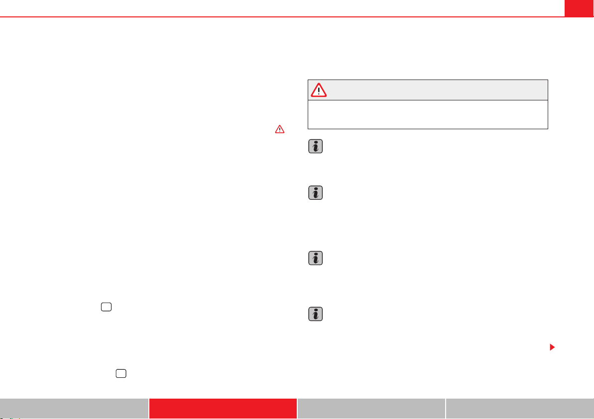
Driving 231
Safety First Operating instructions Practical tips Technical Data
x Parking perpendicular to the road: Drive next to the gap at a speed of no
more than 20 km/h and at a distance of between 0.5 m and 2 m.
x The best parking results will be achieved if you position the vehicle as
parallel as possible to the line of parked cars or the kerb.
x When a suitable parking place is displayed on the instrument panel, stop
and select reverse gear.
x Follow the instructions given on the instrument panel display
x Then, release the steering wheel when the warning signal sounds :
The system will move the steering wheel! Observe the surrounding area.
x Observe the surrounding area and accelerate carefully at a maximum of
up to 7 km/h.
x The park assist system is only responsible for moving the steering wheel
during the manoeuvre. The driver applies the accelerator, the clutch, the
gears and the brake.
x Follow the instructions given by the park assist system until the
manoeuvre is completed.
x The park assist system steers the vehicle forwards and backwards until it
is in a straight position in the parking space.
x The manoeuvre is complete when the corresponding indication is given
on the instrument panel display.
Stopping the parking manoeuvre
The park assist system stops the manoeuvre in the event of one of the
following:
x Press button .
x Driving faster than 7 km/h.
x The driver moves the steering wheel.
x The parking manoeuvre has not been completed after six minutes since
the park assist system was activated.
x A sliding door is opened. To restart the manoeuvre, close the sliding door
and press the button again.
x There is a system malfunction (system temporarily unavailable).
x The TCS system is switched off or the TCS or ESP is working.
WARNING
The steering wheel turns quickly by itself when parking using the park
assist system. Placing your hand between the steering wheel spokes could
lead to injuries.
Note
The park assist system has its limitations. For example, it is not possible to
park on tight bends using the park assist system.
Note
Even if the park assist system recognises that there is not enough space for
parking the vehicle, the display screen on the instrument panel will still
display this place. In this case, the parking manoeuvre should not be
requested.
Note
Changing gears between forward and reverse gears before indicated (that is,
before the signal from the parking sensor system) the parking results may not
be ideal.
Note
For parallel parking (parallel to the road), a sound will tell the driver when
they must change from forward gears to reverse; the signal from the parking
sensor system does not indicate changes of direction.
i
i
Driving232
Note
The park assist can also be activated afterwards, if you pass close to a parallel
parking space at a maximum of 40 km an hour or close to be perpendicular
parking space at about 20 km an hour then press the button .
Note
The progress bar on the screen of the instrument panel shows a display of the
relative distance to be covered.
Note
When the Park Assist system is turning the steering wheel of the stopped
vehicle the symbol K is also displayed. Press on the brake pedal so that the
steering can turn with the vehicle at a standstill and thus reduce the number
of manoeuvres.
Note
A suitable parking space length is at least 1.1 m greater than the length of the
vehicle.
Note
If the results of the park assist system are not as good after changing the
wheels, the system must memorise the perimeter of the new wheels. This
process is performed automatically while the vehicle is in motion. To help this
process, turn slowly (at less than 20 km/h), e.g. in an empty car park.
Leaving a parking space using the Park Assist system
Driving off
x Switch on the engine.
x Press button . When the function is enabled, the button page 230,
fig. 152 will light up.
x Apply the turn signal indicator for the side on which you want to leave the
parking space.
x Select reverse gear.
x Follow the instructions given by the park assist system.
x When the next indication appears, release the steering wheel in
“Parking using the park assist system” on page 230: The system will move
the steering wheel! Observe the surrounding area.
x Observe the surrounding area and accelerate carefully at a maximum of
up to 7 km/h.
x The park assist system is only responsible for moving the steering wheel
during the manoeuvre. The driver applies the accelerator, the clutch, the
gears and the brake.
x When it is possible to leave the parking space, the Park Assist system will
stop. Take control of the steering and when traffic conditions permit, leave
the parking space.
Automatic stoppage of the manoeuvre
The park assist system stops the manoeuvre in the event of one of the
following:
x Driving faster than 7 km/h.
x The driver moves the steering wheel.
x A sliding door is opened. To restart the manoeuvre, close the sliding door
and press the button again.
x There is a system malfunction (system temporarily unavailable).
x The TCS system is switched off or the TCS or ESP is working.
i
i
i
Driving 233
Safety First Operating instructions Practical tips Technical Data
WARNING
The steering wheel turns quickly automatically when leaving a parking
space using the park assist system. Placing your hand between the
steering wheel spokes could lead to injuries.
Park Assist brake operation
The Park Assist system helps the driver by braking automatically. Automatic
braking does not relieve the driver of responsibility for controlling the accel-
erator, brake and clutch .
Braking to avoid damage at excess speed
It is possible that the system operates the brakes to reduce excess speed. The
parking manoeuvre can then continue. The brakes will intervene during each
parking process.
Braking to minimise damage
When approaching an obstacle, the vehicle may brake automatically. In
certain circumstances (for example, storm, detection of ultrasounds, vehicle
status, load, inclination), the Park Assist system may stop the vehicle
completely before an object.
x Press the foot brake !
Following the intervention of the brakes, the Park Assist will stop.
WARNING
Despite the assistance provided by the park assist system, do not run any
risks when parking. The system is not a replacement for driver awareness.
x Always be ready to brake.
x Automatic brake intervention will end after 1.5 seconds approximately.
Following automatic intervention of the brakes, stop the vehicle yourself.
WARNING (continued)
Driving234
Rear Assist system*
Introduction
The camera fitted to the tailgate helps drivers during parking or reversing
manoeuvres. The camera image and certain orientation points generated by
the system are indicated on the factory-fitted radio or navigation system
screen.
Two types of location point (modes) can be selected:
x Mode 1: reverse parking perpendicular to the road (e.g. in a car park).
x Mode 2: reverse parking parallel to the curb.
The mode can be changed by pressing the button on the radio or navigation
system screen. Only the mode to which the points can be changed will be
displayed.
Additional information and warnings:
x Accessories, parts replacement, repairs and modifications page 285
WARNING
Use of the camera to calculate the distance from obstacles (people, vehi-
cles, etc.) is inaccurate and may cause accidents and severe injuries.
x The camera lens expands and distorts the field of vision and displays
the objects on the screen in a different, vague manner.
x Some objects may not be displayed or may not be very clear (e.g. very
thin posts or fences), due to the resolution of the monitor or if the light is
dim.
x The camera has blind spots in which obstacles and people are not regis-
tered.
x Keep the camera lens clean and clear of snow and ice. Do not cover it.
WARNING
The intelligent technology in the rear assist system cannot change the
limits imposed by the laws of physics and by the system itself. Careless or
uncontrolled use of the rear assist system may result in severe injuries and
accidents. The system is not a replacement for driver awareness.
x Adjust your speed and driving style to visibility, road, traffic and
weather conditions.
x Always keep a close eye on the area around the vehicle and always look
towards where you are parking. The display shows the path of the rear end
of the vehicle using the current steering angle. The front of the vehicle
turns more in comparison with the rear.
x Do not be distracted from the traffic when looking at the screen.
x Always observe the area around the vehicle, as the cameras do not
always detect children, animals or objects.
x The system might not show all areas clearly.
x Only use the rear assist system when the tailgate is completely closed.
Caution
x The camera only displays 2D images on the screen. Due to the lack of
depth, it might be difficult or impossible to recognise protruding objects or
cracks in the road.
x The cameras may not always be able to detect objects such as thin rails,
fences, posts and trees, etc. This could result in damage to your car.
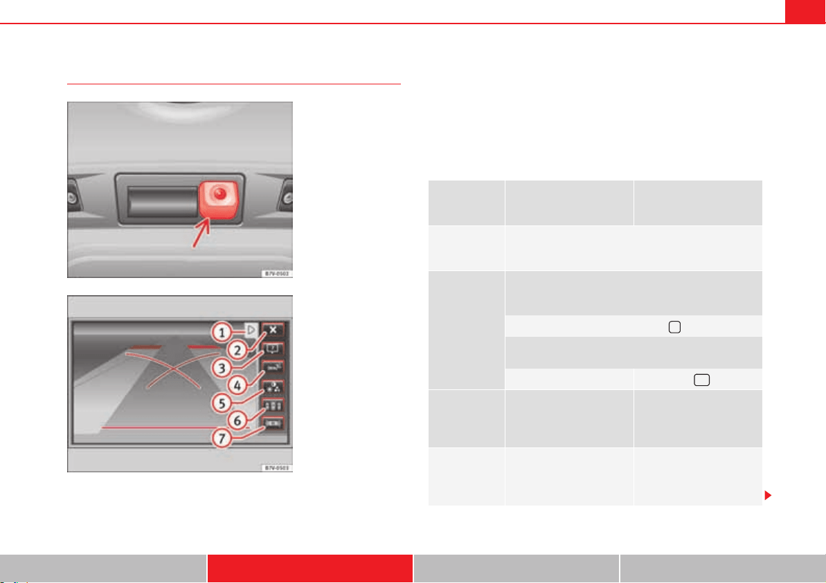
Driving 235
Safety First Operating instructions Practical tips Technical Data
User instructions
Function buttons on the screen:
y display the menu; hide the menu.
O Turning off the reversing camera images
Display help. The help list explains the surfaces and lines on the camera
image. Press E to exit help.
Mute the sound.
Adjust the display: brightness, contrast, colour.
Switching on the orientation points for rear parking perpendicular to the
road (mode 1).
Displaying the optical parking system.
Fig. 154 On the boot lid:
location of the rear assist
camera.
Fig. 155 Rear assist
display: mode 2
connected.
A
1
A
2
Function
Operations in vehicles with
no optical parking system
(OPS)
Operations in vehicles with
the optical parking system
(OPS)
Switching the
display on auto-
matically:
select reverse gear with the ignition switched on or the
engine running. Mode 1 will be displayed.
Switching the
display off man-
ually:
Press a button to select the area on the radio or the navi-
gation system Booklet “Radio” or Booklet “Naviga-
tion system”.
ALTERNATIVELY: Press the button on the screen.
ALTERNATIVELY: After switching off the ignition, the rear
assist image remains on the screen for a short period.
Press button .
Switching off
the display by
disengaging
reverse gear:
The image will switch off
after around 10 seconds.
The OPS display will imme-
diately be shown.
Switching off
the display by
driving for-
wards:
Drive forwards at more than
approx. 15 km/h.
Drive forwards at more than
approx. 10 km/h.
A
3
A
4
A
5
A
6
A
7
O
'
Driving236
Things to note
Cleaning the camera lens
Keep the camera lens clean and clear of snow and ice:
x Moisten the lens using a commercially available, alcohol-based glass
cleaning agent and clean the lens with a dry cloth .
x Remove snow using a small brush.
x Use de-icing spray to remove any ice .
Caution
x Never use abrasive cleaners to clean the camera lens.
x Never remove snow or ice from the camera lens using warm or hot water.
This could damage the lens.
Note
SEAT recommends that you practise parking with the rear assist system in a
quiet location or in a car park to become familiar with the system, including
the orientation lines and their function.
Note
The orientation lines will not be displayed on the screen if the tailgate is open
or the factory-fitted towing bracket is electrically connected to a trailer.
1) Do not use the rear assist system in the following cases:
– If there is a fault in the dynamic chassis control (DCC).
– If the image displayed is not very clear or reliable (low visibility or dirty
lens).
– If the space behind the vehicle cannot be clearly or completely recog-
nised.
- If the vehicle has been overloaded at the rear.
– If the driver is not familiar with the system.
– If the tailgate is open.
- If the position and installation angle of the camera have been changed,
e.g. in a rear-end collision. Have a specialist workshop check the system.
2) Optical illusions of the camera (examples)
The rear assist camera produces two-dimensional images. Any cracks in or
objects protruding from the ground or from other vehicles are more difficult
to spot or cannot be seen due to a lack of depth in the image displayed.
Objects or other vehicles may seem to be closer or further away than what
they really are:
– On changing from a flat surface to a slope or gradient.
– On changing from a slope or gradient to a flat surface.
- If the vehicle has been overloaded at the rear.
– On approaching protruding objects. These objects may be outside the
angle of vision of the camera when reversing.
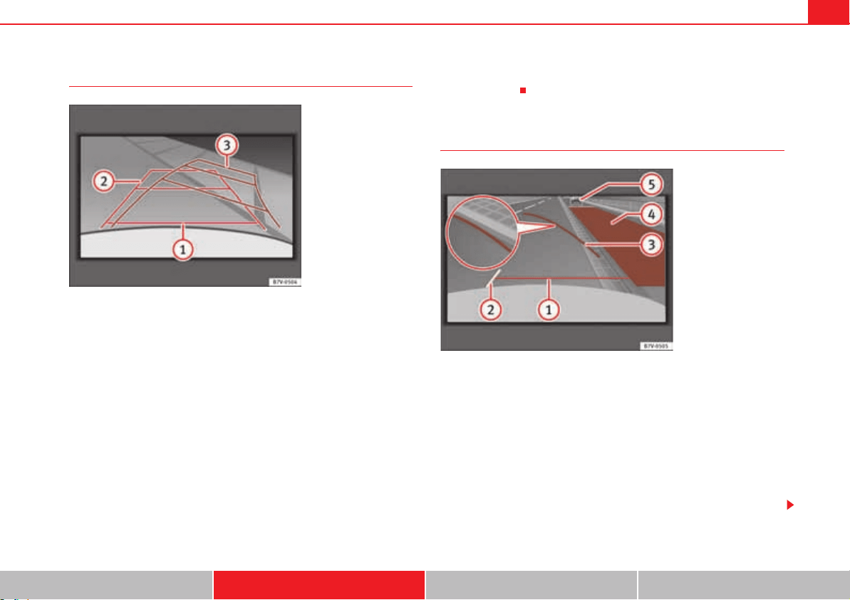
Driving 237
Safety First Operating instructions Practical tips Technical Data
Parking perpendicular to the road (mode 1)
Summary of the orientation points
Meaning of orientation lines displayed on the screen fig. 156. All of the
lengths of the orientation lines use a vehicle located on a horizontal surface
as reference.
Red Safety distance: road area located up to around 40 cm behind the
vehicle.
Green: prolongation of the rear of the vehicle (somewhat enlarged). The
area displayed green ends around two metres behind the vehicle, on the
road.
Yellow: prolongation of the rear of the vehicle as the steering wheel
turns. The area displayed yellow ends around three metres behind the
vehicle, on the road.
Parking the vehicle
x Stop the vehicle in front of a space and select reverse gear.
x Reverse slowly and turn the steering wheel so that the yellow orientation
lines guide you towards the space fig. 156 .
x Align the vehicle straight in the parking place using the help of the green
orientation lines.
Parking parallel to the road (mode 2)
After applying the turn signal indicator, the lines and surfaces not required
are deleted.
Summary of the orientation points
Meaning of orientation lines and surfaces displayed on the screen
fig. 157. All of the lengths of the orientation lines use a vehicle located on
a horizontal surface as reference.
Safety distance: road area located up to around 40 cm behind the
vehicle.
Vehicle side limit.
Fig. 156 Display: orienta-
tion lines for the parking
space behind the vehicle.
A
1
A
2
A
3
A
3
Fig. 157 Display: orienta-
tion lines and surfaces for
the space behind the
vehicle.
A
1
A
2

Driving238
Turning point when parking. When the yellow line touches the curb or
another limit of the parking space, the point for changing direction
(magnifying glass) will have been reached.
Free space required to park the vehicle parallel. The surface displayed
must completely fit in the space.
Possible vehicle parked next to the curb.
Parking the vehicle
x Stop the vehicle 1 m away parallel to the parking space and select reverse
gear.
x Switch on mode 2 on the navigation system screen for parallel parking.
x Slowly reverse and turn the steering wheel so that the surface displayed
yellow on the screen stops in front of any obstacles (e.g. another vehicle).
x Turn the steering wheel fully towards the space and reverse slowly.
x When the yellow line touches the side limit of the space, e.g. the
border or curb (magnifying glass), turn the steering wheel fully in the oppo-
site direction.
x Continue reversing until the vehicle is inside the space, parallel to the
road. Correct the position if necessary.
A
3
A
4
A
5
A
5
A
3

Driving 239
Safety First Operating instructions Practical tips Technical Data
Cruise control system* (CCS)
Introduction
The cruise control system (CCS) is able to maintain the set speed when
driving forwards from approx. 20 km/h (12 mph).
The CCS only slows down by reducing the accelerator but not by braking.
.
Additional information and warnings:
x Changing gear page 201
x Accessories, parts replacement, repairs and modifications page 285
WARNING
Use of the cruise control could cause accidents and severe injuries if it is
not possible to drive at a constant speed maintaining the safety distance.
x Do not use the CCS in heavy traffic, if the distance from the vehicle in
front is insufficient, on steep roads, with several bends or in slippery
circumstances (snow, ice, rain or loose gravel), or on flooded roads.
x Never use the CCS when driving off-road or on unpaved roads.
x Always adapt your speed and the distance to the vehicles ahead in line
with visibility, weather conditions, the condition of the road and the traffic
situation.
x To avoid unexpected operation of the cruise control system, turn it off
every time you finish using it.
x It is dangerous to use a set speed which is too high for the prevailing
road, traffic or weather conditions.
x When travelling down hills, the CCS cannot maintain a constant speed.
The vehicle tends to accelerate under its own weight. Select a lower gear or
use the foot brake to slow the vehicle.
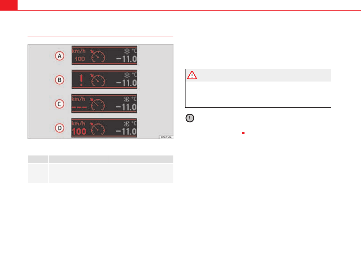
Driving240
Warning and control lamp
Fig. 158 Dash panel display: CCS status indications.
Several warning and control lamps should light up for a few seconds when
the ignition is switched. This signals that the lamp is working properly. They
will switch off after a few seconds.
Display
There are different versions of the cruise control system. In vehicles with the
multifunction display (MFI), the set speed is displayed on the instrument
panel screen.
Status fig. 158:
CCS temporarily switched off. The set speed is displayed in small figures.
System error. Contact a specialist workshop.
CCS switched on. The speed memory is empty.
The CCS is switched on. The set speed is displayed in large figures.
WARNING
If the warning lamps and messages are ignored, the vehicle may stall in
traffic, or may cause accidents and severe injuries.
x Never ignore the warning lamps or text messages.
x Stop the vehicle safely as soon as possible.
Caution
Failure to heed the warning lamps and text messages when they appear may
result in faults in the vehicle.
lights up Possible cause Solution
%
This cruise control system
maintains the set speed of
the vehicle.
–
A
A
A
B
A
C
A
D

Driving 241
Safety First Operating instructions Practical tips Technical Data
Cruise control operation
Travelling down hills with the CCS
When travelling down hills the CCS cannot maintain a constant speed. Slow
the vehicle down using the brake pedal and reduce gears if required.
Automatic off
The cruise control system is switched off automatically or temporarily:
Function
Control position,
control operations
fig. 159
Action
Switching on the
cruise control sys-
tem.
Click ON
The system is switched on. The
system does not maintain the
speed because there is still no
speed set.
Switching on the
cruise control sys-
tem.
SET button
The current speed is stored and
maintained.
Temporarily
switching off the
cruise control sys-
tem.
Press CANCEL
or
engage the clutch
or the brake
The cruise control system is
switched off temporarily. The
speed setting will remain stored.
Fig. 159 On the left of the
steering column: control
lever for cruise control
system.
A
1
A
A
A
2
Switching the
speed setting
back on.
Press RESUME
The stored speed is reached again
and maintained. If no speed has
been set then the vehicle will
record and maintain the actual
speed of the vehicle.
Increasing the
stored speed (dur-
ing CCS setting).
Hold down
SPEED +
Short press: Increases the speed
at intervals of 10 km/h and
records it.
Long press: the vehicle acceler-
ates while the button remains
pressed. Release the button to
store the current speed.
Reducing the
stored speed (dur-
ing CCS setting).
Press SPEED –
Short press: Reduces the speed at
intervals of 10 km/h and records
it.
Long press: while this remains
pressed, speed is reduced inter-
rupting the accelerator without
using the brakes. Release the but-
ton to store the current speed.
Switching off the
cruise control sys-
tem.
Click OFF
The system is switched off. The
stored speed is deleted.
Function
Control position,
control operations
fig. 159
Action
A
1
A
+
A
–
A
2

Driving242
x If the system detects a fault that could affect the working order of the CCS.
x If you increase the stored speed by using the accelerator for a certain
time.
x if the brake or clutch pedal is depressed.
x If you change gears.
x If the airbag is triggered.
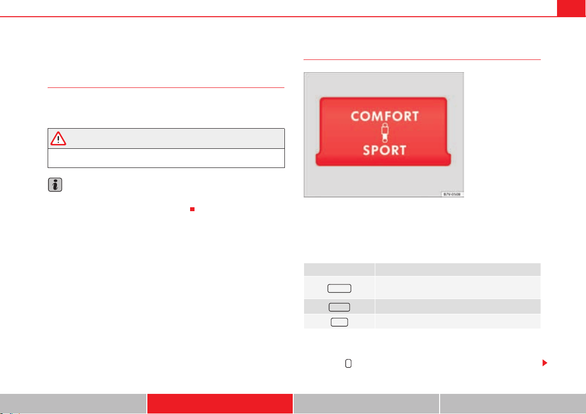
Driving 243
Safety First Operating instructions Practical tips Technical Data
Dynamic chassis control* (DCC)
Introduction
Additional information and warnings:
x Accessories, parts replacement, repairs and modifications page 285
WARNING
Switching the dynamic chassis control system on while the vehicle is in
motion could divert your attention from the traffic and cause accidents.
Note
Have the dynamic chassis control checked by a specialist workshop if it does
not work in the way described in this chapter.
Operation and control
The dynamic chassis control continuously adapts the shock absorbers to the
condition of the road and current traffic conditions, according to the set
programme.
Steering is also adapted in the Sport programme.
Programme selection
x Switch the ignition on.
x Press the button repeatedly until the desired programme is displayed.
Programme Recommended driving situations
Comfort setting (e.g. long distances or on irregular
road surfaces).
Balanced setting (e.g. for day-to-day use).
Sport setting (e.g. for sports driving).
Fig. 160 Detailed view of
the centre console: button
for setting the dynamic
chassis control.
#/-&/24
./2-!,
30/24
Q
Driving244
The programme is switched on if and do not light up on
the button. The set programme remains selected after the ignition is switched
off.
WARNING
The dynamic features are modified by adjusting the shock absorbers.
Dynamic chassis control must never lead to any kinds of risk.
x Always try to adapt the speed of the vehicle and your style of driving to
the condition of the ground or the road and to weather and traffic condi-
tions.
Note
In the event of a fault in the dynamic chassis control, and will
flash on the button. Driving comfort may be affected during the fault. Have
the system checked by a specialist workshop.
./2-!, #/-&/24 30/24
#/-&/24 30/24
Driving 245
Safety First Operating instructions Practical tips Technical Data
Tyre monitoring systems
Introduction
The tyre monitor indicator monitors the tyre pressure of each wheel using the
ABS sensors. The ABS sensors monitor the tyre tread perimeter and vibra-
tions of each tire. The tyre monitor indicator warns the driver if it detects a
considerable drop in tyre pressure of one or several tyres while driving. Loss
of tyre pressure will be indicated by the indicator ~ as well as a sound and
sometimes a text message on the screen of the instrument panel. When you
open the driver's door, you will find a label indicating the tyre pressure recom-
mended by the manufacturer for the maximum vehicle load for each tyre
approved for the vehicle in question. By pressing the adjustment button on
the tyre monitoring indicator, you may change the reference pressure for the
tyres so that the tyre pressure to be monitored coincides with actual tyre pres-
sure page 248.
Suitable use of the adjustment button page 248.
Additional information and warnings:
x Transporting page 13
x Braking, stopping and parking page 210
x Caring for and cleaning the vehicle exterior page 269
x Wheels and tyres page 323
x Accessories, parts replacement, repairs and modifications page 285
WARNING
Unsuitable handling of the wheels and tyres may lead to sudden tyre pres-
sure losses, to tread separation or even to a blow-out.
x Check tyre pressures regularly and ensure they are maintained at the
pressures indicated. If the tyre pressure is too low, the tyres could over-
heat, resulting in tread detachment or even burst tyres.
x Tyre pressure should be that indicated on the label when the tyres are
cold at all times page 328.
x Regularly check the cold inflation pressure of the tyres. If necessary,
change the tyre pressure of the vehicle tyres while they are cold.
x Regularly check your tyres for damage and wear.
x Never exceed the maximum permitted speed or loads specified for the
type of tyre fitted on your vehicle.
WARNING
Incorrect use of the tyre monitoring indicator button could result in the
indicator giving erroneous messages or prevented from indicating the
danger caused by a defective tyre page 248.
Caution
x The tyre valves may be damaged if the cap is not in place. Check that the
caps are identical to the standard caps and have been correctly tightened. Do
not use metal caps page 248.
x Do not damage the valves when changing the tyres page 248.
For the sake of the environment
Under-inflated tyres lead to increased fuel consumption and tyre wear.
Note
Do not only rely on the tyre monitoring system. Regularly check your tyres to
ensure that the tyre pressure is correct and that the tyres are not damaged
due to puncture, cuts, tears and impacts/dents. Remove objects from the
tyres only when the tyres have not been pierced by these.
WARNING (continued)

Driving246
Note
The tyre monitoring system is set to the tyre pressure recommended by the
manufacturer and indicated on the label page 328, fig. 183.
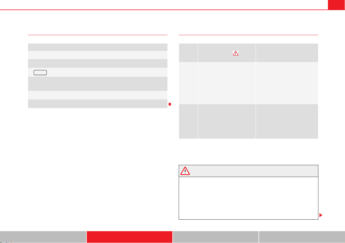
Driving 247
Safety First Operating instructions Practical tips Technical Data
Elements of the tyre monitoring indicator Control lamp
Several warning and control lamps should light up for a few seconds when
the ignition is switched. This signals that the lamp is working properly. They
will switch off after a few seconds.
WARNING
When the tyres are inflated at different pressures or at a pressure that is
too low then a tyre may the damaged resulting in a loss of control of the
vehicle and a serious or mortal accident.
x If the indicator ~ lights, stop immediately and check the tyres.
x If the tyres are inflated at different pressures or if a tyre pressure is too
low, this will increase tyre wear, negatively affecting vehicle stability and
increasing braking distances.
Tyre monitoring indicator with button.
See page 248.
b Warning lamp ~ on the instrument panel.
b button on the centre console.
b Monitoring the tread of all tyres using ABS sensors (indirect measure-
ment).
b Adjustable medium and full-load tyre pressures.
b Button to update the system when the tyre pressure is changed.
~ SET
Lights
up or
flashes
Possible cause
Solution
~
The tyre pressure of a wheel
has dropped considerably in
relation to the pressure set by
the driver page 248.
Stop the vehicle! Reduce your
speed immediately! Stop the
vehicle safely as soon as possi-
ble. Avoid sudden manoeuvres
and braking!
Check all tyres and pressures.
Replace any damaged tyres.
~
System malfunction.
Consult a specialist workshop if
the tyre pressure is correct and
the lamp remains lit after switch-
ing the ignition off and back on
again. Have the system checked
there.
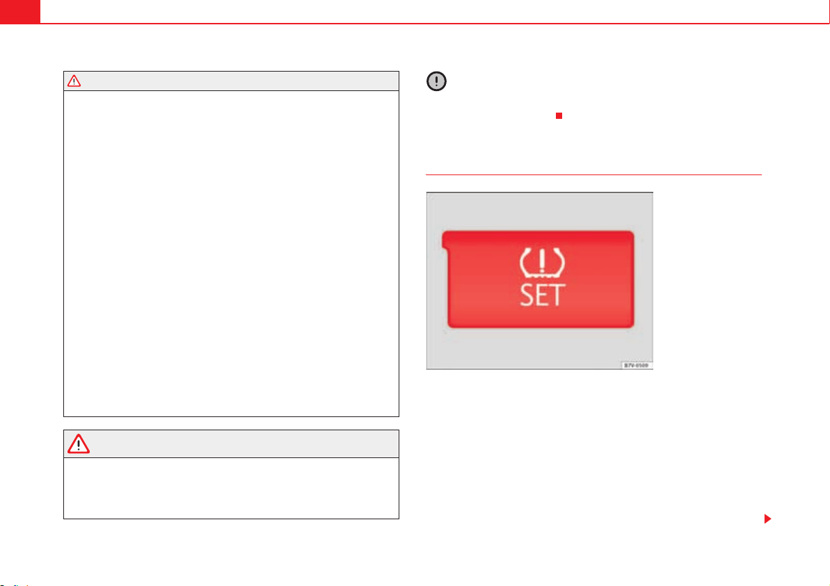
Driving248
x If tyres are inflated at different pressures or a tyre pressure is too low,
a tyre may be damaged and burst resulting in a loss of control of the
vehicle.
x The driver is responsible for ensuring that all of the vehicle tyres are
correctly inflated to the right pressure. The recommended tyre pressure is
indicated on the label page 328, fig. 183.
x The tyre monitoring system can only operate correctly if all of the tyres
are inflated to the correct pressure when cold.
x Driving with tyres at the wrong pressure can cause damage to them and
result in an accident. Ensure that the tyre pressures of all the tyres corre-
spond to the vehicle load.
x Before starting a journey, always inflated tyres to the correct pressure.
x If tyre pressure is too low then the tyre is subject to greater forces and
it may be heated to such an extent that the tread can rupture and the tyre
will burst.
x With an overloaded vehicle at high speed, the tyres can overheat and
burst resulting in a loss of vehicle control.
x Tyre pressures which are too high or too low reduce the useful life of the
tyre, affecting the vehicle's performance.
x If a tyre has not been punctured then it does not have to be changed
immediately; drive to the nearest specialist workshop at a moderate speed
and have the tyre checked and inflated to the correct pressure.
WARNING
If the warning lamps and messages are ignored, the vehicle may stall in
traffic, or may cause accidents and severe injuries.
x Never ignore the warning lamps or text messages.
x Stop the vehicle safely as soon as possible.
Caution
Failure to heed the warning lamps and text messages when they appear may
result in faults in the vehicle.
Tyre monitoring indicator
The tyre monitor indicator compares wheel revolutions and, with this informa-
tion, the tread of each wheel using the ABS sensors. If the tread of a wheel is
changed, the tyre monitoring indicator will indicate as such on the instrument
panel. The wheel tread changes when:
x Tyre pressure is insufficient.
x Tyre structure is damaged.
x The vehicle is unbalanced because of a load.
x The wheels on an axle are subject to a heavier load (e.g. when towing a
trailer).
WARNING (continued)
Fig. 161 Detailed view of
the centre console: button
for the tyre pressure
monitoring indicator.
Driving 249
Safety First Operating instructions Practical tips Technical Data
x The vehicle is fitted with snow chains.
x The wheel on one axle is changed.
There may be a delay in the reaction of the tyre monitoring indicator ~ or it
may not indicate anything under certain circumstances (e.g. sports driving,
snow-covered or unpaved roads).
Adaptation of the tyre monitoring indicator
On adjusting tyre pressure or changing one or more wheels, the page 248,
fig. 161 button on the tyre monitoring indicator must be kept pressed down,
with the ignition on, until a signal is heard. Do the same, for example, when
the front and rear wheels are swapped page 325, fig. 182.
If the wheels are subjected to an excessive load (towing a trailer, heavy load),
the tyre pressure must be increased to the maximum recommended pressure
page 323. Press the tyre monitoring indicator button to confirm the new
pressure value.
Note
An erroneous indication may be given when snow chains are in use because
the chains increase the tread of the wheel.

Driving and the environment 251
Safety First Operating instructions Practical tips Technical Data
Practical tips
Driving and the environment
Running-in
Please observe the instructions for running-in new components.
Running-in the engine
The engine needs to be run-in over the first 1500 km (1000 miles). During its
first few hours of running, the internal friction in the engine is greater than
later on when all the moving parts have bedded down.
How the vehicle is driven for the first 1,500 km (1000 miles) influences the
future engine performance. Throughout the life of the vehicle, it should be
driven at a moderate speed – especially when the engine is cold – this will
reduce engine wear and increase its useful life. Never drive at extremely low
engine speeds. Always engage a lower gear when the engine works “irregu-
larly”. For the first 1000 km or 600 miles, please note:
x Do not use full throttle.
x Do not force the engine above two thirds of its maximum speed.
x Do not tow a trailer.
Between 1000 and 1500 kilometres (600 to 1000 miles), gradually increase
power until reaching the maximum speed and high engine speeds.
Running in new tyres and brake pads
x Replacement of new tyres and wheel rims page 323
x Notes on the brakes page 214
For the sake of the environment
If the engine is run in gently, the life of the engine will be increased and the
engine oil consumption reduced.
Driving and the environment252
Ecological driving
Introduction
Fuel consumption, environmental impact and engine, brake and tyre wear
depend largely on three factors:
x Personal driving style.
x Conditions of use (weather, road surface).
x Technical requirements.
Savings of up to 25% in fuel consumption are possible with an appropriate
driving style and the adoption of certain simple tips.
WARNING
Always adapt your speed and the distance to the vehicles ahead in line
with visibility, weather conditions, the condition of the road and the traffic
situation.
Economic driving style
Changing gear early
General instructions: The highest gear is always the most economical gear.
As a guideline, for the majority of vehicles: At a speed of 30 km/h, drive in
third gear, at 40 km/h in fourth gear and at 50 km/h in fifth gear.
In addition, skipping gears when shifting up helps to save fuel, weather and
traffic conditions permitting.
Do not wait until the last moment before changing gear. Only use first gear
when you move off and change to second gear quickly. Avoid the kick-down
function in vehicles with automatic gearbox.
Vehicles with a gear display help to achieve an economical driving style as
the display indicates the best moment to change gear.
Let the vehicle roll
If you take your foot off the accelerator, the fuel supply is stopped and
consumption is reduced.
Allow the vehicle to roll without accelerating, for example when approaching
a red traffic light. However, if the vehicle is rolling too slowly or the distance
is too long, the clutch pedal should be pressed to declutch. The engine will
then operate at idle speed.
If the vehicle is going to be at a standstill for a period of time, switch off the
engine; for example, while waiting at a level crossing. In vehicles which have
the Start-Stop function on, the engine switches off automatically when the
vehicle is not moving.
Think ahead and “flow” with the traffic
Frequent acceleration and braking considerably increase fuel consumption. If
you think ahead as you drive and keep a safe distance from the vehicle in
front, it is possible to slow down by simply lifting your foot off the accelerator.
This eliminates the need for constant braking and acceleration.
Calm and steady driving
Constancy is more important than speed: The more you drive at a constant
speed, the lower the fuel consumption.
When driving on the motorway, it is more efficient to drive at a constant and
more moderate speed than to be continuously accelerating and braking. As a
general rule, you will reach your destination just as quickly when you drive at
a constant speed.
The cruise control function helps you to achieve a constant style of driving.
Moderate use of additional electrical appliances
It is important to travel in comfort, but convenience systems should be used
in an ecological manner.
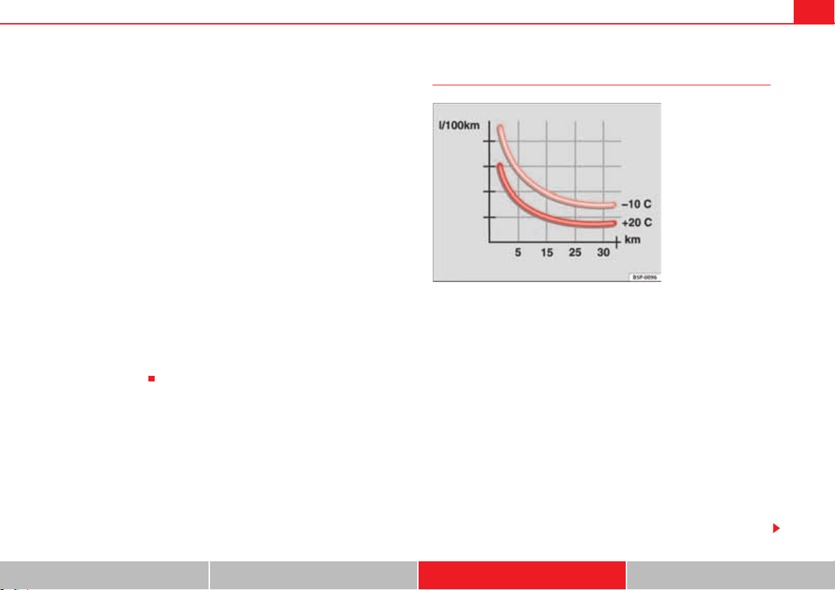
Driving and the environment 253
Safety First Operating instructions Practical tips Technical Data
Some equipment, when connected, increase fuel consumption considerably,
for example:
x Air conditioning cooling system: If the air conditioning system is required
to cool to significantly lower temperatures than the true outside temperature,
it will require a large quantity of energy from the engine. Therefore, we recom-
mend that the selected temperature for the vehicle is not too different to the
outside temperature. It is a good idea to open all the windows of the car
before starting your journey, and to drive a short distance with all the
windows open to allow the vehicle to cool down slightly. Only then should
you close all the windows and switch on the air conditioning. Keep windows
closed when travelling at high speeds. Driving with the windows open
increases fuel consumption.
x Switch off the seat heating when the seats have warmed up.
x Switch off the heated rear window and the windscreen heating when the
windows have demisted and are free of ice.
x Do not leave the independent heating switched on when the vehicle is
moving page 187.
Other factors which increase fuel consumption (examples):
x Fault in engine management.
x Driving on hills.
x Trailer towing.
Saving fuel while driving
By adopting an economical driving style and anticipating the traffic situation
ahead, you can easily reduce fuel consumption by 10-15%.
A vehicle uses most fuel when accelerating. By anticipating the traffic situa-
tion ahead, you will brake and therefore accelerate less. Wherever possible,
let the car roll slowly to a stop, for instance when you can see that the next
traffic lights are red.
Avoid short journeys
Fuel consumption is much higher when the engine is cold, immediately after
it has been started. It takes a few kilometres of driving for the engine to warm
up and to normalise consumption.
The engine and catalytic converter need to reach their proper working
temperature in order to minimise fuel consumption and emissions. The
ambient temperature has a decisive influence.
fig. 162 shows the difference in consumption for the same journey at +20 °C
(+68 °F) and at -10 °C (+14 °F).
Fig. 162 Fuel consump-
tion in litres per 100 km at
different outside tempera-
tures.

Driving and the environment254
Unnecessary short journeys should be avoided. Try to combine trips.
The vehicle uses more fuel in winter than in summer, even when other condi-
tions are the same.
“Warming” the engine is not only forbidden in some countries, but in practice
it is technically superfluous as it is a waste of fuel.
Adjusting type pressures.
Having the correct pressure in your tyres helps to reduce rolling resistance
and, as a result reduces fuel consumption. Increasing the tyre pressure
slightly (+ 0.2 bar / + 3 psi) can help to save fuel.
If you are prepared to accept a slight reduction in comfort, the tyres may be
filled to the pressures recommended for a fully-loaded vehicle. This is also
valid when driving alone without luggage.
When you buy new tyres, make sure they are optimised for minimum rolling
resistance.
Use low friction engine oil
The use of low viscosity totally synthetic oils, known as low friction engine oil,
help to reduce fuel consumption. Low friction engine oils reduce the resist-
ance caused by friction in the engine, they flow around the engine more
quickly and efficiently, particularly in cold starts. The effect is particularly
noticeable in vehicles frequently used for short journeys.
Always check the engine oil level and observe service intervals (engine oil
change intervals).
When purchasing engine oil, always observe legal requirements and ensure
that the oil is approved by SEAT.
Avoid carrying unnecessary loads
The lighter the vehicle, the more economical and ecological the driving style.
For example, an additional weight of 100 kg will increase fuel consumption
up to 0.3 l/100 km.
Remove any unnecessary objects or loads from the vehicle.
Remove optional equipment and unnecessary accessories
The more aerodynamic the vehicle, the lower the fuel consumption. Optional
equipment and accessories (such as roof racks or bike carriers) reduce the
aerodynamic benefits of the vehicle.
Therefore, we recommend you remove all optional and unnecessary equip-
ment and racks, especially if you intend to drive at high speeds.
Driving and the environment 255
Safety First Operating instructions Practical tips Technical Data
Engine management and exhaust gas
purification system
Introduction
Additional information and warnings:
x Changing gear page 201
x Refuelling page 293
x Fuel page 297
x Engine oil page 309
x Vehicle battery page 318
x Information stored in the control units page 285
x Tow-starting and towing away page 375
WARNING
The components of the exhaust system reach very high temperatures. This
could cause a fire.
x Always park your vehicle so that no part of the exhaust system can
come in contact with flammable materials (such as dried grass).
x Do not apply additional underseal or anti-corrosion coatings to the
exhaust pipes, catalytic converter, heat shields or the diesel particulate
filter.
Warning lamps
lights up Possible cause Solution
%0#
Fault in engine management
(Electronic Power Control).
Take the vehicle to a qualified
workshop as soon as possible
and have the engine checked.
D
Pre-heating a diesel engine
before starting the engine.
page 195
B
Fault in catalytic converter.
You should reduce speed accord-
ingly. Drive carefully until you
reach the next qualified work-
shop. Have the engine checked
there.
¬
Diesel particulate filter
blocked
Drive for 15 minutes in 4th gear
(manual gearbox), or in D (auto-
matic gearbox) at a minimum
speed of 70 km/h (45 mph).
Observe speed limits .
If the warning lamp remains lit
up, take the vehicle to a quali-
fied workshop page 256.
flashes Possible cause Solution
D
Fault in the engine manage-
ment (diesel engines).
Take the vehicle to a qualified
workshop as soon as possible
and have the engine checked.
B
Combustion fault which could
damage the catalytic con-
verter.
You should reduce speed accord-
ingly. Drive carefully until you
reach the next qualified work-
shop. Have the engine checked
there.
Driving and the environment256
Several warning and control lamps should light up for a few seconds when
the ignition is switched. This signals that the lamp is working properly. They
will switch off after a few seconds.
WARNING
Observe traffic regulations when cleaning the diesel particulate filter while
driving.
x Only carry on driving if visibility, weather, road and traffic conditions so
permit.
x Never endanger your safety or that of other road users.
Caution
Always pay attention to any lit lamps and to the corresponding descriptions
and instructions to avoid damage to the vehicle.
Note
While the indicators ¬, B or %0# remain lit, there may be engine problems,
fuel consumption may be greater and the engine may lose power
Catalytic converter
The catalytic converter permits the subsequent treatment of the exhaust
gases thus reducing contaminating gas emissions. To ensure a longer
working life for the exhaust system and catalytic converter in a petrol engine:
x Always use unleaded petrol.
x Never run the tank completely dry.
x Do not top up with too much engine oil page 309.
x Do not tow-start the vehicle; use the starter cables page 371.
If you should notice misfiring, uneven running or loss of power when the car
is moving, reduce speed immediately. Have the car inspected by a qualified
workshop. If this happens, unburnt fuel can enter the exhaust system and
escape into the atmosphere. The catalytic converter can also be damaged by
overheating.
For the sake of the environment
Even when the emission control system is working perfectly, there may be a
smell of sulphur from the exhaust gas under some conditions. This depends
on the sulphur content of the fuel being used.
Diesel particulate filter
The diesel particulate filter removes soot particulates from the exhaust gas.
The filter retains these particulates and burns them. To assist the combustion
process, SEAT recommends you avoid frequent short trips.
x Always use diesel with a low sulphur content page 297.
x Never use petrol or fuel oil.
x Never use biodiesel. However, a blend prepared by the diesel manufac-
turer containing biodiesel within the limits established by the EN 590
standard may be used page 297.
x Never run the tank completely dry.
x Do not top up with too much engine oil page 309.
x Do not tow-start the vehicle; use the starter cables page 371.
In order to reduce blocking of the diesel particulate filter, some vehicles with
an automatic gearbox may increase the engine speed slightly to automati-
cally start cleaning the diesel particulate filter. The warning lamp will not light
up in this case ¬.
Driving and the environment 257
Safety First Operating instructions Practical tips Technical Data
For the sake of the environment
Even when the emission control system is working perfectly, there may be a
smell of sulphur from the exhaust gas under some conditions. This depends
on the sulphur content of the fuel being used.
Trailer towing258
Trailer towing
Introduction
Always be aware of the legal requirements for each country to drive with a
trailer and to use a trailer bracket.
Your car is intended mainly for transporting passengers however, it can also
be used to tow a trailer provided that it is fitted with the necessary equip-
ment. The additional load has an effect on the useful life, fuel consumption
and the vehicle performance and, in some cases, reduce the service intervals.
Driving with a trailer requires more force from the vehicle and, thus, more
concentration from the driver.
For wintertime temperatures, fit winter tyres to the vehicle and the trailer.
Drawbar load
The maximum permitted Drawbar load exerted by the trailer drawbar on the
ball joint of the tow hitch must not exceed 100 kg (approximately 220 lbs).
Vehicles with the Start-Stop function
With a SEAT factory fitted or retrofitted trailer bracket, the Start-Stop function
is automatically deactivated when a trailer is connected. For trailer brackets
not installed by SEAT, the Start-Stop function must be deactivated manually
using a button located on the dashboard before driving with a trailer and it
must remain off for the entire journey .
Additional information and warnings:
x Anti-theft alarm system page 83
x Light page 113
x Ecological driving page 252
x Starter assist systems (Start-Stop function) page 221
x Wheels and tyres page 323
x Accessories, parts replacement, repairs and modifications page 285
WARNING
Never transport people in a trailer: this will endanger in their life and is
against the law.
WARNING
The incorrect use of the tow hitch can cause accidents and injury.
x Only use a tow hitch in good condition and correctly installed.
x Never change or repair a tow hitch.
x To reduce the risk of injury in case of a reversing collision, injury to
pedestrians and cyclists when parking, always keep the ball joint in when
a trailer is not being used.
x Never fit a trailer tow hitch “that distributes the load” or “balances the
load”. Your vehicle has not been designed for this type of tow hitch. The
tow hitch may fail and the trailer will separate from the vehicle.
WARNING
Driving with a trailer and transporting heavy or large objects can affect
vehicle handling and even cause an accident.
x Always secure loads correctly with suitable and undamaged attach-
ment rope or straps.
x Adjust your speed and driving style to visibility, road, traffic and
weather conditions.
x Trailers with a high centre of gravity can overturn more easily than
trailers with a low centre of gravity.
Trailer towing 259
Safety First Operating instructions Practical tips Technical Data
x Avoid brusque manoeuvres and sudden braking.
x Always take the following precautions seriously.
x Reduce your speed immediately if you observe the trailer rocking from
side to side.
x Never drive at more than 80 km an hour when towing a trailer (or 100
km an hour in exceptional circumstances). This also applies in countries
where higher speeds are permitted. Always take the speed limits for vehi-
cles with and without trailers in each country into account.
x Never try to stop the “snaking” by increasing speed.
WARNING
When driving with a trailer and using a trailer hitch that was not installed
by SEAT, the Start-Stop function must be manually deactivated. Otherwise,
this could cause a braking anomaly that could result in an accident with
serious consequences.
x Always manually deactivate the Start-Stop function when a trailer is
being used on a trailer hitch that has not been installed by SEAT.
Note
Always turn off the anti-theft alarm system before connecting or discon-
necting a trailer page 88. Otherwise, the tilt sensor may erroneously acti-
vate the alarm.
Note
Never use a trailer with a new engine (for the first 1000 km or 600 miles)
page 285.
Note
At SEAT, we recommend folding in the trailer hitch ball when a trailer is not
being used. In case of a rear collision, the damage caused to the vehicle with
the extended trailer hitch ball could be more extensive.
Note
In some models, a trailer hitch is necessary for towing vehicles. For this
reason, you should store the tow hitch in the vehicle at all times.
WARNING (continued)
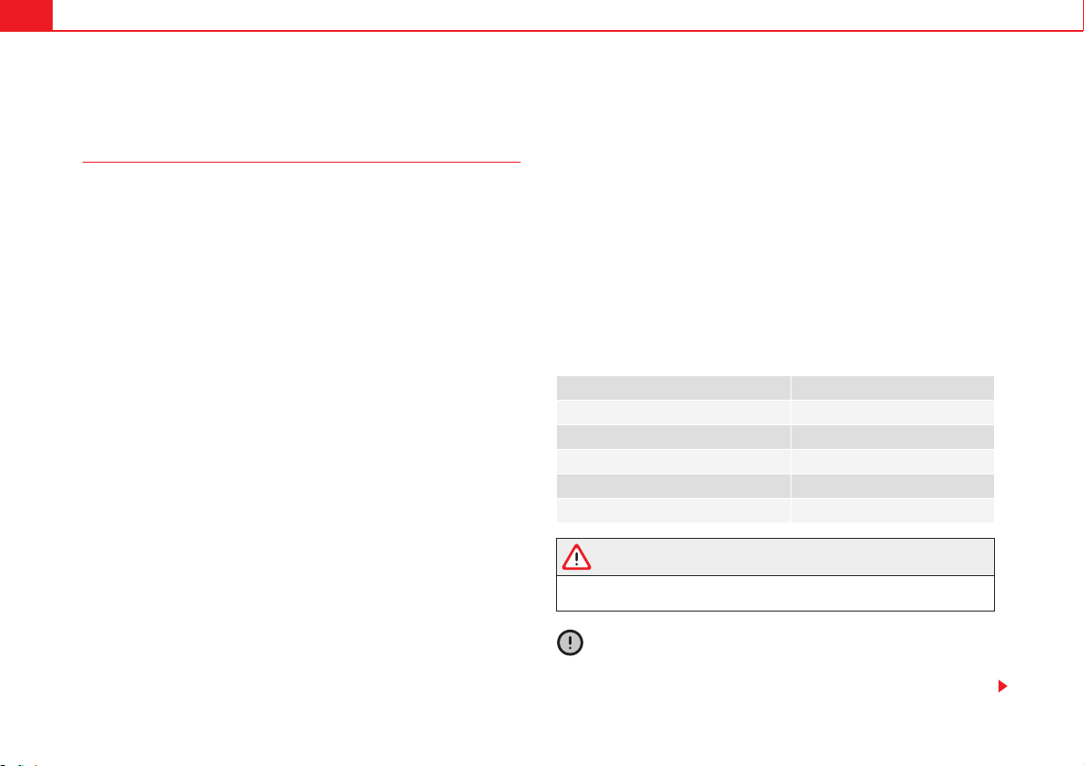
Trailer towing260
Driving with a trailer
Technical requirements
If the car is supplied with a factory-fitted tow hitch it will already have the
necessary technical modifications and meet the statutory requirements for
towing a trailer.
Only use an approved trailer hitch for the gross trailer weight rating. The tow
hitch must be suitable for both the vehicle and trailer and must be securely
fitted to the vehicle chassis. Only use a tow hitch with a removable ball joint.
Always check and take into account the tow hitch manufacturer's instruc-
tions. Never fit a trailer tow hitch “that distributes the load” or “balances the
load”.
Bumper mounted tow hitch
Never fit a tow hitch or its attachments to the bumper. A tow hitch should
never interfere with the bumper performance. Do not modify the exhaust
system and brake system. Regularly check the tow hitch to ensure it is firmly
fitted.
Engine cooling system
Driving with a trailer increases the load on the engine and cooling system.
The cooling system should always have sufficient coolant and to be able to
cope with the vehicle and trailer.
Electric trailer brake
If the trailer has its own braking system, please note the relevant legal
requirements. The trailer braking system should never be connected to the
vehicle braking system.
Trailer cable
Always use a cable between the vehicle and the trailer page 262.
Trailer rear lights
The rear lights of a trailer must fulfil the corresponding standards
page 262.
Never connect the trailer's rear lights directly to the vehicle electric system. In
case of any doubt about the electrical connection of the trailer, ask a
specialist workshop. SEAT recommends visiting a qualified workshop.
Wing mirrors
When the field of vision behind the trailer cannot be seen using the standard
wing mirrors of the towing vehicle, additional wing mirrors are required
according to the legal requirements of each country. The wing mirrors must
be fitted before driving and must provide a sufficient field of vision behind.
Trailer electricity consumption
Never exceed the specifications:
WARNING
If the tow hitch is badly fitted or unsuitable, the trailer may separate from
the vehicle causing an accident with serious consequences.
Caution
x If the rear lights of the trailer are not correctly connected, the vehicle elec-
tronics may be damaged.
Electrical consumer Maximum power
Position lights and rear lights 50 Watts
Indicator (each side) 54 Watts
Brake lights (total) 84 Watts
Reversing lights (total) 42 Watts
Rear fog light 42 Watts
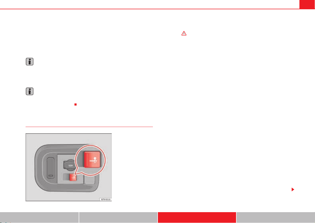
Trailer towing 261
Safety First Operating instructions Practical tips Technical Data
x If the trailer absorbs excessive electric current, the vehicle electronics
may be damaged.
x Never connect the trailer's electric system to the electrical connections of
the rear lights or any other power sources. Only use suitable connections for
providing electric current to the trailer.
Note
Towing a trailer places additional demands on the vehicle. At SEAT, we recom-
mend additional services between the normal inspection intervals if the
vehicle is used frequently for towing a trailer.
Note
In some countries, an additional fire extinguisher is required if the trailer
weight is more than 2500 kg
Electric tow hitch ball
The rotation radius of the tow hitch ball should be free of people, animals and
objects .
The tow hitch is located in the bumper. The electric tow ball is fixed and
cannot be removed.
Releasing and unfolding the tow ball
x Stop the vehicle and apply the electric parking brake.
x Switch the engine off.
x Open the tailgate.
x Press the knob briefly fig. 163. The tow ball is released electronically
and folds out automatically; the button indicator will blink.
x Move the ball joint until it inserts and the button indicator lights.
x Close the tailgate.
x Before hitching the trailer, remove the dust guard from the ball.
x The indicator only lights when the tailgate is open and when a trailer is
not hitched.
Restoring the tow ball to its originally position
x Stop the vehicle and apply the electric parking brake.
x Switch the engine off.
x Remove the trailer and disconnect the cable between the vehicle and
trailer. If necessary, remove the socket adapter.
x Place the dust guard over the ball.
x Open the tailgate.
x Press the knob briefly fig. 163. The tow ball is electronically released;
the indicator blinks.
x Push the tow ball into the bumper until it locks in position and the button
indicator lights.
x Close the tailgate.
Fig. 163 Right-hand side
of the luggage compart-
ment: button to electri-
cally release the tow hitch
ball.
Trailer towing262
The warning lamp
x When the indicator flashes, the tow ball is not in its final position, has not
engaged or is damaged .
x When the indicator remains lit and the tailgate is open, the tow ball has
inserted correctly into the folded or deployed position.
x When the tailgate is closed, the indicator is turned off.
WARNING
The incorrect use of the tow hitch can cause accidents and injury.
x Ensure that no person, animal or object gets in the way of the tow ball.
x Never push the button when there is a trailer hitched or when any kind
of carrier or accessory is fitted to the tow hitch ball.
x While the ball is moving, do not interfere with any tool.
x Do not drive with a trailer if the indicator does not light.
x If there is a fault in the electric system or the trailer tow hitch, visit a
specialist workshop to have it checked.
x If the diameter of the tow hitch is less than 49 mm, never use this for a
trailer.
Caution
x If anything is attached to the tow hitch ball, do not, under any circum-
stances press the button.
x Never direct a high-pressure or steam cleaning system directly at the tow
hitch ball or trailer power socket. This could cause damage to seals or remove
lubricating grease.
Note
In extremely low temperatures, it is possible that the tow hitch is not
released. In this case, place the vehicle in a warmer location (for example, a
garage).
Installing a bicycle carrier to the tow hitch
The maximum load permitted for a bicycle carrier on the tow hitch ball is 75
kg, with a maximum distance of 300 mm from the support. The distance
between supports is the distance between the bicycle carrier centre of gravity
(with the bicycles) and the centre of point of the tow hitch ball.
WARNING
The incorrect use of the tow hitch with a bicycle carrier installed can cause
accidents and injury.
x Never exceed the load and distances between supports indicated.
x Never fit the bicycle carrier to the tow hitch ball neck, underneath the
tow hitch given that the bicycle carrier may be incorrectly fitted due to the
shape of the tow hitch and the model of bicycle carrier.
x Always read and take the manufacturer assembly instructions into
account.
Caution
Exceeding the maximum load and distance between supports indicated can
cause considerable damage to the vehicle.
x Never exceed the specifications.
Hitching and connecting the trailer
Trailer cable
Always secure the trailer cable to the towing vehicle correctly. Leave a little bit
of slack in the cable for turning. However, ensure that the cable does not rub
off the ground while driving.
Trailer towing 263
Safety First Operating instructions Practical tips Technical Data
Trailer electric socket
The electric connection between vehicle and trailer is a 13-pin socket. If the
trailer plug has seven pins, an adapter cable must be used.
Trailer rear lights
Check the trailer rear lights to ensure they work correctly and remain legal.
Ensure that the trailer does not use more than the maximum power
page 260.
Trailer connected to the antitheft alarm:
x When a vehicle comes from the factory fitted with an antitheft alarm and
tow hitch.
x When the trailer is connected to the vehicle using the socket.
x When the vehicle and trailer electrical systems work correctly and are not
damaged.
x When the vehicle is locked using the vehicle key and the antitheft alarm
is turned on.
When the vehicle is locked, the alarm is triggered when the electrical connec-
tion between the vehicle and the trailer is removed.
Always turn off the anti-theft alarm system before connecting or discon-
necting a trailer. Otherwise, the tilt sensor may erroneously activate the
alarm.
WARNING
Erroneous or unsuitable connection of electric cables may supply energy to
the trailer causing an anomaly in the vehicle electronics that could result
in an accident with serious consequences.
x All work on the electrical system must be carried out only by a
specialist workshop.
x Never connect the trailer's electric system to the electrical connections
of the rear lights or any other power sources.
Caution
Do not leave the trailer connected to the vehicle when parked; places on its
support wheel or its supports. For example, when changing the load or a
puncture, the vehicle will be pushed up or down. The force acting on the tow
hitch and the trailer could damage the vehicle or the trailer.
Note
In case of a fault in the vehicle or trailer electrical system or in case of prob-
lems with the antitheft alarm system, have the system checked by a specialist
workshop.
Note
If the trailer accessories use energy from the socket when the engine is
stopped, the battery will be discharged.
Note
For technical reasons, trailers fitted with rear LED lights cannot be connected
to the antitheft alarm system.
Note
If the vehicle battery is running low, the electrical connection with the trailer
is automatically cut.
Note
With the engine running, the electrical equipment on the trailer will consume
power.
Trailer towing264
Loading the trailer
Trailer weight / drawbar load
The trailer weight is the load that the vehicle can pull . The drawbar load
is the vertical weight of the trailer hitch on the tow hitch ball page 267.
The figures for trailer weights and draw bar weights given on the data plate of
the towing bracket are for values of this model only. The correct figures for
your specific vehicle, which may be lower than these figures for the tow hitch,
are given in the registration documents. The instructions in the official
vehicle documents take precedence.
For the sake of road safety, SEAT recommends using the maximum allowed
drawbar load. The handling of the combined vehicle and trailer will be poor if
the drawbar load is too low.
The drawbar load increases the weight on the rear axle, reducing the vehicle
carrying capacity.
Gross combination weight
This figure refers to the combined weight of the loaded vehicle and loaded
trailer.
Loading the trailer
The combined vehicle and trailer must be balanced. Use the maximum
drawbar load authorised and do not overload the front or the rear of the
trailer:
x Distribute loads in the trailer so that heavy objects are as near to the axle
as possible or even above it.
x Correctly secure the trailer load.
Tyre pressure
Inflate the trailer tyres according to the manufacturer's instructions.
Inflate the towing vehicles tyres to the maximum page 323.
WARNING
Exceeding the maximum authorised axle load, drawbar load or the gross
combination weight of the towing vehicle and trailer could cause a serious
accident with severe consequences.
x Never exceed the specifications.
x With the actual load on the front and rear axles, the maximum axle load
should never be exceeded. The weight on the front and rear should never
exceed the gross vehicle weight.
WARNING
If the load moves, the stability and safety of the vehicle and trailer combi-
nation will be seriously affected and this could result in a serious accident.
x Always correctly load the trailer.
x Always secure loads correctly with suitable and undamaged attach-
ment rope or straps.
Driving with a trailer
Adjusting the headlights
When towing a trailer, the front of the vehicle may rise and so the dipped
beam headlights may blind other drivers. Use the headlight range control to
lower the cone of light. If you do not have headlight range control, have the
headlights adjusted by a qualified dealership. Vehicles with high-intensity
discharge lamps adapt automatically and do not require adjustment.
Details of driving with a trailer
x If the trailer has an overrun brake, apply the brakes gently at first and
then, firmly. This will prevent the jerking that can be caused by the trailer
wheels locking.

Trailer towing 265
Safety First Operating instructions Practical tips Technical Data
x As of the combined vehicle and trailer mass, braking distances will be
greater.
x Select a low gear before driving down a steep hill to use the engine
braking effect to slow down the vehicle. Otherwise, the braking system could
overheat and fail.
x The vehicle centre of gravity and handling change because of the trailer
load and because of the increased combined mass of the vehicle and trailer.
x If the towing vehicle is empty and the trailer loaded then the load distri-
bution is incorrect. If you must travel in these conditions, drive carefully and
reduce your speed accordingly.
Hill starts with a trailer
Depending on the hill and the gross combined weight, it is possible that the
combined vehicle and trailer move backwards slightly when starting.
For a hill start with a trailer, proceed as follows:
x Press and hold the brake pedal.
x Press the button once to turn off the electric parking brake
page 210.
x Press and hold the button to hold the vehicle and trailer combination
using the parking brake.
x With a manual gearbox: press the clutch pedal to the floor.
x Engage first gear or the gear range D page 201, “Changing gear”.
x Release the brake pedal.
x Move off slowly. To do this, gently release the clutch pedal (for manual
gearbox).
x Release the button only when the engine provides sufficient power to
move the vehicle and trailer combination.
WARNING
Jerking the trailer in an unsuitable manner could cause loss of vehicle
control with the subsequent serious consequences.
x Driving with a trailer and transporting heavy or a large objects will
change the vehicle handling and braking distances.
x Anticipate traffic and be extremely cautious. Brake early.
x Adjust your speed and driving style to visibility, road, traffic and
weather conditions. Reduce your speed, especially on steep hills.
x Accelerate gently and carefully. Avoid brusque manoeuvres and sudden
braking.
x Always take the following precautions seriously. Reduce your speed
immediately if you observe the trailer rocking from side to side.
x Never try to stop the “snaking” by increasing speed.
x Always take the speed limits for vehicles with and without trailers in
each country into account.
Stabilising the vehicle and trailer combination
Stabilisation of the vehicle and trailer combination is an extension of the
electronic stability programme (ESP) and helps, with the assistance of the
trajectory control, to reduce trailer “snaking”.
Stabilisation of the vehicle and trailer combination is active when the ESP «
indicator on the dashboard remains lit for about two seconds more than the
ABS indicator.
Requirements for stabilising the vehicle/trailer combination
x An original tow hitch is fitted by the manufacturer or a compatible model
is retrofitted.
x The ESP is on. The warning indicator in the control panel « is not lit.
x The trailer is connected to the vehicle using the socket.
x The vehicle is driven faster than 60 km/h.
G
G
G
WARNING (continued)
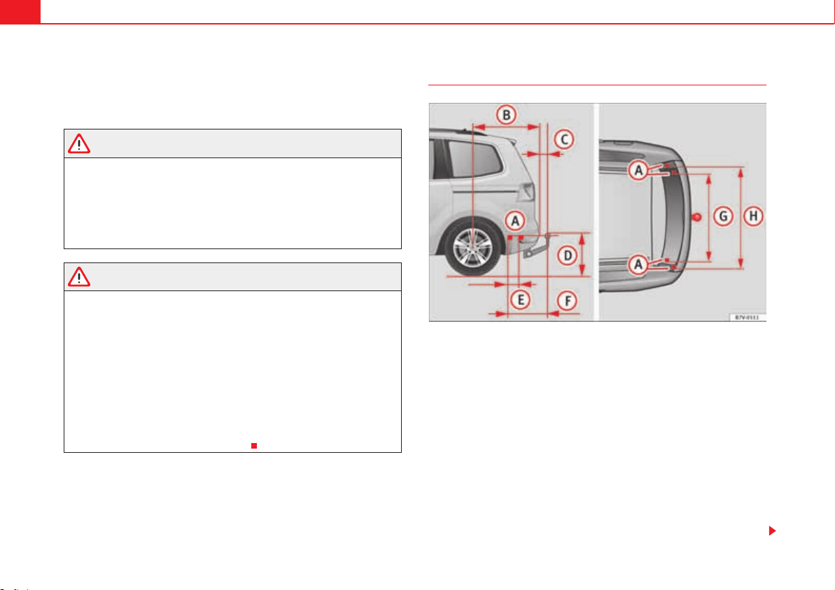
Trailer towing266
x The maximum drawbar load is used.
x The trailer must have a fixed drawbar.
x Trailers with brakes must be equipped with a mechanical inertia brake.
WARNING
Do not let the extra safety afforded by the stabilisation system tempt you
into taking any risks when driving.
x Adjust your speed and driving style to visibility, road, traffic and
weather conditions.
x If the road surface is slippery, take care when accelerating.
x When a system is operating, lift your foot off the accelerator.
WARNING
It is possible that the combination stabilisation system does not correctly
recognised all driving situations.
x It is possible that the stabilisation system does not detect snaking of a
light trailer and thus does not intervene.
x When driving on slippery ground, the trailer could jack-knife despite
the stabilisation system.
x Trailers with a high centre of gravity may even tip over before they start
to rock sideways.
x If a trailer is not used at the trailer socket is connected (for example,
installation of a bicycle carrier with lights), repeated automatic braking
may occur in extreme driving conditions.
Retrofitting a tow hitch
Fig. 164 Measurements and attachments to retrofit a tow hitch.
SEAT recommends visiting a specialist workshop to retrofit a tow hitch. For
example, it may be necessary to adjust the cooling system or to include
thermal plates. SEAT recommends visiting a qualified workshop.
In any case, the separation distances must be observed when fitting a tow
hitch. The distance between the centre of the tow hitch ball and the road
surface fig. 164 must never be lower than that indicated. This also
applies when the vehicle is fully laden, including maximum drawbar load.
Separation distances fig. 164:
Attachment points.
1,040 mm (41 inches)
74 mm (3 inches)
364 mm (14 inches)
A
D
A
A
A
B
A
C
A
D
Trailer towing 267
Safety First Operating instructions Practical tips Technical Data
247 mm (10 inches)
596 mm (23 inches)
1,097 mm (43 inches)
1,102 mm (43 inches)
WARNING
Erroneous or unsuitable connection of electric cables may cause anomalies
in the vehicle electronics that could result in an accident with serious
consequences.
x Never connect the trailer's electric system to the electrical connections
of the rear lights or any other unsuitable power sources. Only use suitable
connectors to connect a trailer.
x Visit a specialist workshop if you wish to retrofit a tow hitch to the
vehicle.
WARNING
If the tow hitch is badly fitted or unsuitable, the trailer may separate from
the vehicle while driving. This could result in serious accident.
Note
Use only tow hitches approved by SEAT for the vehicle.
Maximum gross trailer weight
The instructions in the official vehicle documents take precedence. All the
technical data provided in this documentation is applicable to the basic
model. The vehicle data label in the Maintenance Programme or the vehicle
documents show which engine is installed in your vehicle.
The figures may be different depending on if additional equipment is fitted,
for different models and for special vehicles.
WARNING
Exceeding the maximum trailer weight indicated could cause a serious
accident.
x Never exceed the indicated trailer weight.
Caution
Exceeding the maximum trailer weight indicated could cause damage to the
vehicle.
x Never exceed the indicated trailer weight.
Gross combined vehicle weight rating
The instructions in the official vehicle documents take precedence. All the
technical data provided in this documentation is applicable to the basic
model. The vehicle data label in the Maintenance Programme or the vehicle
documents show which engine is installed in your vehicle.
The figures may be different depending on if additional equipment is fitted,
for different models and for special vehicles.
The maximum combined weights listed are only applicable for altitudes up to
1,000 m above sea level. The weight of the car and trailer must be reduced by
about 10% for every further 1000 m (or part thereof).
WARNING
Exceeding the maximum weight indicated could cause a serious accident.
x Never exceed the gross combined weight rating.
A
E
A
F
A
G
A
H

Trailer towing268
Caution
Exceeding the maximum gross combined weight rating indicated could cause
damage to the vehicle.
x Never exceed the gross combined weight rating.
Vehicle maintenance and cleaning 269
Safety First Operating instructions Practical tips Technical Data
Vehicle maintenance and cleaning
Care and cleaning the vehicle exterior
Introduction
Regular maintenance and washing help to maintain the value of the vehicle.
This may also be one of the requirements for acknowledging warranty claims
in the event of bodywork corrosion or paint defects.
Products suitable for the care of your vehicle are available at any Technical
Service.
Additional information and warnings:
x Care and cleaning of the vehicle interior page 278
x Working in the engine compartment page 304
x Accessories, parts replacement, repairs and modifications page 285
WARNING
Car care products may be toxic and hazardous. If car care products are not
suitable or are used inappropriately, this could result in accident, serious
injury, burns or intoxication.
x Car care products must always be stored in the original container which
should be kept closed.
x Observe information provided by the manufacturer.
x To prevent confusion, never store car care products in empty food cans,
bottles or other containers.
x Keep all care products out of reach of children.
x Harmful vapours may be produced when using car care products. There-
fore, care products should only be used in well-ventilated spaces or in the
open air.
x Never use fuel, turpentine, engine oil, acetone or any other volatile
liquid to wash, clean or care for the vehicle. These are toxic and highly
flammable.
WARNING
Inappropriate care and cleaning of vehicle components may effect the
vehicle safety equipment, increasing the risk of severe injury.
x Vehicle components should only be cleaned and maintained in accord-
ance with the manufacturer's instructions.
x Only use approved or recommended care products.
Caution
Cleaning products which contain solvents will damage the material.
For the sake of the environment
Only wash the vehicle in areas allocated for this purpose, to prevent dirty
water which may be contaminated by oil, grease or fuel, from entering the
drains. In some districts, washing vehicles outside wash bays is prohibited.
For the sake of the environment
Where possible, always use products which respect the environment.
WARNING (continued)
Vehicle maintenance and cleaning270
For the sake of the environment
The remains of car care products should not be disposed of with ordinary
household waste. Observe information provided by the manufacturer.
Washing the vehicle
The longer substances such as insects, bird droppings, resinous tree sap,
road dirt, industrial deposits, tar, soot or road salt and other aggressive mate-
rials remain on the vehicle, the more damage they do to the paintwork. High
temperatures (for instance due to strong sunlight) further intensify the corro-
sive effect. The vehicle undercarriage should also be thoroughly washed at
regular intervals.
Automatic car washes
Always observe the instructions provided at the automatic car wash. The
standard precautionary measures prior to entering the car wash should be
taken to avoid damage to the vehicle (close all windows, fold in exterior
mirrors). If the vehicle is fitted with additional components (spoiler, roof-rack,
aerial...), check with the car wash supervisor whether these can enter the car
wash .
The vehicle paintwork is so durable that the car can normally be washed
without problems in an automatic car washing tunnel. However, wear and
damage to the paintwork will depend on the type of car wash used. SEAT
recommends the use of car washed without brushes.
To remove traces of wax on windows and to prevent wiper blades from
scratching, please observe the following page 272, “Cleaning windows
and exterior mirrors”.
Washing the car by hand
When washing the car by hand, use plenty of water to soften the dirt first, and
rinse off as well as possible.
Then clean the vehicle with a soft sponge, glove or brush using only slight
pressure. Start at the roof and work downwards. Special car shampoo should
only be used for very persistent dirt.
Rinse the sponge or glove thoroughly and often.
Wheels, sills and similar should be cleaned last. Use a second sponge for
this.
WARNING
Sharp components on the vehicle may cause injury.
x Protect arms and hands from sharp edges when cleaning the vehicle
undercarriage or the interior of the wheel hubs.
WARNING
After the vehicle has been washed, the braking effect will be reduced (and
the braking distance increased) due to moisture (and ice in winter) on the
brakes.
x Dry the brakes and remove ice by braking carefully. Ensure that you are
not endangering other road-users or breaking traffic regulations in the
process.
Caution
x The temperature of the water must not exceed +60 °C (+140 °F).
x To avoid damage to the paintwork, do not wash the vehicle in full sun.
x Do not use rough sponges or similar which could damage the surface to
clean away the traces of insects.
x Never wipe the headlights with a dry cloth or sponge, always moisten
first. It is best to use soapy water.
Vehicle maintenance and cleaning 271
Safety First Operating instructions Practical tips Technical Data
x Washing the vehicle in low temperatures: When washing the vehicle with
a hose, do not direct water into the lock cylinders or the gaps around the
doors, tailgate, or sunroof. Locks and seals could freeze!
Caution
To prevent damage to the vehicle, please observe the following before
entering an automatic car wash:
x Compare the distance between the vehicle wheels and the distance
between the guide-rails of the car wash to prevent damage to the wheels and
tyres!
x Switch off the rain sensor and the Auto Hold function before entering a car
wash.
x Compare the height and width of your vehicle with the available height
and width when entering and driving through the car wash.
x Fold in exterior mirrors Electrically retractable exterior mirrors must NOT
be folded in or out by hand. Always use the electrical power control.
x To avoid damaging the bonnet paintwork, rest the wipers on the wind-
screen after drying them. Do not let them fall!
x Lock the tailgate to prevent it from opening unexpectedly while inside the
car wash.
Washing the vehicle with high pressure cleaning equipment
When cleaning the vehicle with a high-pressure cleaner, always follow the
operating instructions for the equipment. Pay special attention to the
required pressure of the jet and the distance between the jet and the vehicle
.
Keep a suitable distance from soft materials, such as rubber hoses or insu-
lating material, and from the parking distance warning system sensors. The
parking distance sensors are fitted in the rear bumpers and, where appli-
cable, in the front bumpers .
Do not use a nozzle that sprays the water out in a direct stream or one that
has a rotating jet for forcing off dirt .
WARNING
The incorrect use of high pressure cleaning equipment could result in
permanent damage, visible or invisible, to the tyres or other materials. This
could result in serious accident.
x Ensure there is a suitable distance between the nozzle and the tyres.
x Never wash tyres with a concentrated jet or so-called “dirt blasters”.
Even at large spraying distances and short cleaning times, you may
damage the tyres.
WARNING
After the vehicle has been washed, the braking effect will be reduced (and
the braking distance increased) due to moisture (and ice in winter) on the
brakes.
x Dry the brakes and remove ice by braking carefully. Ensure that you are
not endangering other road-users or breaking traffic regulations in the
process.
Caution
x The temperature of the water must not be above +60 °C (+140 °F).
x To avoid damage to the paintwork, do not wash the vehicle in full sun.
x The sensors on the bumpers should be kept clean and free of ice at all
times to ensure the parking distance warning system and the parking aid
system operate correctly. When cleaning with pressure hoses and steam
cleaners, the sensors should be sprayed only briefly. A distance of 10 cm
between the sensors and the steam / hose nozzle must be observed.
Vehicle maintenance and cleaning272
x Do not use a high pressure cleaner to remove ice or snow from windows
x Washing the vehicle in low temperatures: When washing the vehicle with
a hose, do not direct water into the lock cylinders or the gaps around the
doors, tailgate, or sunroof. Locks and seals could freeze!
Cleaning windows and exterior mirrors
Cleaning windows and exterior mirrors
Spray windows and exterior windows with a standard window cleaner
containing alcohol.
Dry the windows with a clean chamois leather or a lint-free cloth. The chamois
leathers used on painted surfaces are not suitable for cleaning windows
because they are soiled with wax deposits which could smear the windows.
Use window cleaner or a silicone remover to clean rubber, oil, grease and sili-
cone deposits off .
Removing wax deposits
Automatic car washes and certain car care products may leave wax deposits
on the windows. These deposits can only be removed with a special product
or cleaning cloths. Wax deposits on the windscreen could cause the wiper
blades to judder. SEAT recommends you wipe the wax deposits off the wind-
screen with a soft cloth each time after you have washed the vehicle.
A window cleaning detergent which helps to dissolve the wax may be added
to the windscreen washer fluid to prevent the wiper blades from scratching
the windscreen. Please ensure the you add the cleaning product in the correct
proportions. Products for removing grease do not eliminate the wax deposits
.
Special cleaning products or window cloths are available at any Technical
Service. To remove wax deposits, SEAT recommends the following products:
x For the hottest time of the year: the window cleaner for summer use G 052
184 A1 . Proportion 1:100 (1 part detergent, 100 parts water) in the wind-
screen washer bottle.
x All year round: the window cleaner G 052 164 A2; Proportion 1:2 in wind-
screen washer bottle (1 part concentrate, 2 parts water) in winter, up to
-18 °C (-0.4 °F), or 1:4, during the rest of the year.
x Window cloths G 052 522 A1 for all windows and exterior mirrors.
Removing snow
Use a small brush to remove snow from the windows and exterior mirrors.
Removing ice
If possible, use a de-icing spray to remove ice. If you use an ice scraper, push
it in one direction only without swinging it. If you pull the scraper backwards,
the dirt may scratch the window.
WARNING
Dirty or misted windows reduce visibility in all directions and increase the
risk of accident and serious injury.
x Do not drive unless you have good visibility through all windows!
x Remove ice and snow from the windows and demist inside and out.
Caution
x Never mix our cleaning products with other products not recommended
by SEAT in the windscreen washer bottle. This could lead to flocculation and
may block the windscreen washer jets.
x Do not use hot or warm water to remove ice or snow from the windows and
exterior mirrors. The glass could crack!
x The heating element for the rear window is located on the inner side of the
window. Do not stick adhesive labels over the heating elements and never
clean the inside of the rear window with corrosive or acid products or other
similar chemical cleaning products.
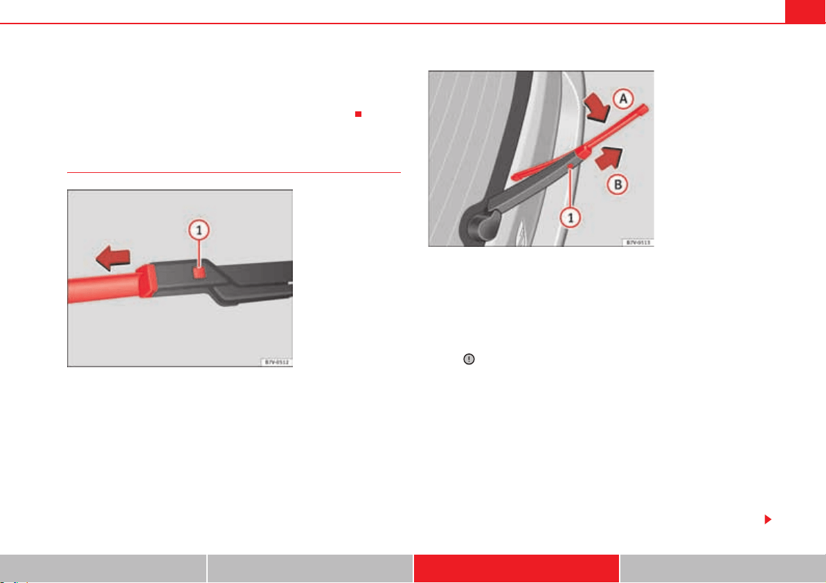
Vehicle maintenance and cleaning 273
Safety First Operating instructions Practical tips Technical Data
x Aerials on the inside of windows may be damaged if knocked or if cleaned
with corrosive or acid cleaning products. Do not stick adhesive labels over the
heating elements and never clean the inside of the rear window with corro-
sive or acid products or other similar chemical cleaning products.
Cleaning and changing windscreen wiper blades
The windscreen wiper blades are supplied as standard with a layer of
graphite. This layer is responsible for ensuring that the wipe is silent. If the
graphite layer is damaged, the noise of the water as it is wiped across the
windscreen will be louder.
Check the condition of the wiper blades regularly. If the wipers scrape across
the glass they should be changed if they are damaged, or cleaned if they are
dirty .
Damaged wiper blades should be replaced immediately. Blades are available
from qualified workshops.
Lifting and unfolding the wiper arms
The wiper arm may only be lifted at the point where it is fastened to the blade.
For windscreen wipers, please note: the wiper should be in service position
before unfolding it page 124.
Cleaning windscreen wiper blades
x Lifting and unfolding the wiper arms.
x Use a soft cloth to remove dust and dirt from the windscreen wiper blades.
Fig. 165 Changing the
front wiper blades
Fig. 166 Changing the
rear wiper blade.
Vehicle maintenance and cleaning274
x If the blades are very dirty, a sponge or damp cloth may be used .
Changing the front wiper blades
x Lifting and unfolding the wiper arms.
x Hold down the release button page 273, fig. 165 while gently
pulling the blade in the direction of the arrow.
x Fit a new wiper blade of the same length and design on to the wiper arm
and hook it into place.
x Rest the wiper arms back onto the windscreen.
Changing the rear wiper blade
x Lift and unfold the wiper arm.
x Pull the wiper blade out of its mounting on the wiper arm page 273,
fig. 166 (arrow ).
x Hold down the release button page 273, fig. 166 while gently
pulling the blade in the direction of the arrow . This may require some
strength.
x Insert a new blade of the same length and type in the wiper arm in the
opposite direction to the arrow page 273, fig. 166 and hook into
place. This feature is operational when the knob is in position (arrow ).
x Replace the wiper arm on the rear window.
WARNING
Worn or dirty wiper blades reduce visibility and increase the risk of acci-
dent and serious injury.
x Always replace damaged or worn blades or blades which do not clean
the windscreen correctly.
Caution
x Damaged or dirty windscreen wipers could scratch the glass.
x If products containing solvents, rough sponges or sharp objects are used
to clean the blades, the graphite layer will be damaged.
x Never use fuel, nail varnish remover, paint thinner or similar products to
clean the windows.
Caring for and polishing the vehicle paintwork
Waxing
Regular waxing protects the paintwork. It is time to apply a good coat of wax
when water no longer forms droplets and rolls off the clean paintwork.
Even if a wax solution is used regularly in the automatic car wash, SEAT
recommends protecting the paint with a hard wax coating at least twice a
year.
Polishing
Polishing is only necessary if the paint has lost its shine, and the gloss cannot
be brought back by applying wax.
If the polish does not contain wax, a wax product should be applied after
polishing.
Caution
x To prevent damage, car polish or hard wax should not be used on compo-
nents painted in matt paint, plastic components and the glass headlamp and
tail light covers.
x Do not polish the paintwork if it is dirty, apply polish in dusty or sandy
zones.
A
1
A
A
A
1
A
B
A
B
A
A
Vehicle maintenance and cleaning 275
Safety First Operating instructions Practical tips Technical Data
Cleaning chrome parts
Clean chrome parts with a damp cloth. SEAT recommends the use of a chrome
care product to clean stains and dirt from chrome surfaces. Use a soft dry
cloth to polish chrome parts.
Caution
To prevent scratching chrome surfaces:
x Do not use abrasive products.
x Do not clean or polish chrome parts in a sandy or dusty environment.
x Do not polish dirty surfaces.
Caring for and cleaning anodized surfaces
It is not easy to detect the difference between aluminium and an anodized
surface, for example, a radiator grille. However, anodized surfaces must not
be treated in the same way as aluminium surfaces. Never use rough sponges
or cloths to wipe away insect remains.
x Use a clean, damp, lint-free cloth to clean anodized surfaces.
x If there is a lot of dirt, use a special cleaning product which does not
contain solvents.
Caution
To prevent damage to the anodized surfaces:
x Do not use products containing solvents.
x Do not use polish or hard wax.
x Do not use abrasive products.
x Do not polish anodized surfaces in sandy or dusty environments.
x Do not polish dirty surfaces.
Cleaning wheels
Cleaning steel wheels
Use an industrial cleaner to remove brake dust. Therefore, clean wheels regu-
larly with a separate sponge.
Any damage to the paint on steel wheels should be touched up before the
metal starts to rust.
Caring for and cleaning alloy wheels
Remove road salt and brake dust by washing the wheels approximately once
a fortnight. Use an acid free detergent to clean the wheel rims. SEAT recom-
mends treating the wheels thoroughly with a wax compound about once
every three months.
It is important to remove road salt and brake dust by washing the wheels at
regular intervals, otherwise the finish will be impaired.
Always use an acid-free detergent for alloy wheel rims. Car polish or other
abrasive agents should not be used.
If the protective coating on the paint has been damaged (for example, hit by
a stone), it should be repaired immediately.
Caring for rubber seals
The rubber seals on doors, windows, etc., remain flexible, provide a better
seal and last longer if they are regularly treated with a product specifically
designed for use on rubber.
Vehicle maintenance and cleaning276
Before applying the product, use a soft cloth to remove dust and dirt from the
rubber seals.
De-icing the door lock cylinder
To de-ice the lock cylinders, SEAT recommend the use of genuine SEAT spray
with lubricating and anti-corrosive properties.
Caution
The use of products containing degreasing agents to de-ice the locks may
rust the lock cylinder.
Protection of vehicle undercarriage
The vehicle underbody is coated to protect it from chemical and mechanical
damage. The protective coat on the undercarriage may wear through use
while driving. Therefore, SEAT recommends that the protective coating on the
undercarriage and on the running gear should be regularly checked, and
repaired if necessary.
WARNING
Additional underseal or anti-corrosion products could catch fire due to the
high temperatures reached by the exhaust gas system and other engine
components.
x Do not apply additional underseal or anti-corrosion products to the
exhaust pipes, catalytic converters, heat shields or other parts of the
vehicle which reach high temperatures.
Cleaning the engine compartment
The engine compartment of any motor vehicle is a potentially hazardous area
page 304.
The engine compartment should only be cleaned by qualified personnel. If it
is not correctly cleaned, the anti-corrosion coating and consequently elec-
trical components may be damaged. Moreover, water may filter directly into
the vehicle interior through the water chamber .
If the engine compartment is very dirty, always take the vehicle to a qualified
workshop for professional cleaning. SEAT recommends visiting a qualified
workshop.
Water box
The water box is in the engine compartment, between the windscreen and the
engine, and beneath a perforated cover. Air is taken in through the water box
from outside to the vehicle interior via the heating and air conditioning
system.
Leaves and other loose objects should be regularly cleaned away from the
water box either by hand or with a vacuum.
WARNING
When working on the engine or in the engine compartment, there is a risk
of injury, burns, accident or fire.
x Before starting work, please ensure you are familiar with the required
procedure and the safety precautions page 304.
x SEAT recommends you have this work performed by a qualified dealer-
ship.
Caution
If water is manually poured into the water box (for example, using a high pres-
sure cleaning appliance), this could cause significant damage to the vehicle.

Vehicle maintenance and cleaning 277
Safety First Operating instructions Practical tips Technical Data
For the sake of the environment
Only wash the engine compartment in areas allocated for this purpose, to
prevent dirty water which may be contaminated by oil, grease or fuel, from
entering the drains. In some districts, the engine compartment may not be
washed outside the wash bays provided for this purpose.
Vehicle maintenance and cleaning278
Caring for and cleaning the vehicle interior
Introduction
The dye from many items of modern clothing (e.g. dark jeans) is not always
solid enough. Seat upholstery (material and leather), especially when light-
coloured, may visibly discolour if the dye comes out of clothing (even when
used correctly). This is not an upholstery defect but indicates that the dye in
the item of clothing is not solid enough.
Additional information and warnings:
x Caring for and cleaning the vehicle exterior page 269
x Accessories, parts replacement, repairs and modifications page 285
WARNING
Car care products may be toxic and hazardous. If car care products are not
suitable or are used inappropriately, this could result in accident, serious
injury, burns or intoxication.
x Car care products must always be stored in the original container which
should be kept closed.
x Observe information provided by the manufacturer.
x To prevent confusion, never store car care products in empty food cans,
bottles or other containers.
x Keep all care products out of reach of children.
x Harmful vapours may be produced when using car care products. There-
fore, care products should only be used in well-ventilated spaces or in the
open air.
x Never use fuel, turpentine, engine oil, acetone or any other volatile
liquid to wash, clean or care for the vehicle. These are toxic and highly
flammable.
WARNING
Inappropriate care and cleaning of vehicle components may effect the
vehicle safety equipment, increasing the risk of severe injury.
x Vehicle components should only be cleaned and maintained in accord-
ance with the manufacturer's instructions.
x Only use approved or recommended care products.
Caution
x Cleaning products which contain solvents will damage the material.
x To avoid damage, stubborn stains should be removed by a specialist
cleaning company.
Note
Suitable car care products are available from your Technical Service.
Treating your upholstery
Check list
For information on how to treat and care for the vehicle upholstery, please
bear the following in mind :
x Before entering the vehicle, fasten all Velcro fastenings which could come
into contact with upholstery and coverings. If the Velcro fastenings on uphol-
stery and material covers are not securely fastened, this could damage them.
x To prevent damage, do not allow the upholstery or covers to come into
contact with sharp or decorative objects. Decorative objects such as zips,
rivets and rhinestones on clothing and belts.
x Dust and grit in the pores and seams should be removed regularly to
prevent them scratching and damaging the surface.
Vehicle maintenance and cleaning 279
Safety First Operating instructions Practical tips Technical Data
x Always check that the dyes used in clothing are fast to prevent them from
staining the upholstery. This is particularly true for clear-coloured upholstery.
Caution
Failure to observe the instructions in the check list for caring for your uphol-
stery could result in damage or discolouration of the upholstery and covers.
x Always follow the check list and perform the necessary operations.
Note
SEAT recommends you take the vehicle to a qualified workshop to treat any
stains on the upholstery caused by the discolouration of clothing.
Cleaning upholstery, textile covers and Alcantara
®
material
Normal cleaning
x Before applying cleaning products, please read the instructions for
handling and the warnings shown on the container.
x The upholstery, textile covers, Alcantara
®
material and mats should be
regularly vacuumed (with vacuum brush).
x We recommend that you use a soft sponge or lint-free, micro-fibre cloth
for normal cleaning .
x Clean Alcantara
®
surfaces with a damp lint-free cotton, wool or micro-
fibre cloth used for normal cleaning .
General superficial dirt on upholstery and textile covers can be cleaned with
a normal foam cleaning product.
If the upholstery and the material trims are very dirty, we recommend you
have them cleaned by a specialist cleaning form.
Cleaning stains
It may be necessary to clean the whole surface and not only the stain itself.
Especially if the surface has been dirtied through normal use. Otherwise, the
stained area may become lighter than the rest of the surface after treatment.
Caution
Brushes should only be used to clean the mats and floor mat! Other surfaces
may be damaged if a brush is used.
Caution
Do not use steam cleaning equipment, as the dirt becomes more incrusted in
the material when steam is applied.
Type of stain Cleaning the vehicle
Water-based stains,
e.g. coffee or fruit
juice.
Use a sponge and wipe with a solution of water
and wool wash.
Dry the area gently with a soft dry cloth.
Persistent stains,
e.g. chocolate or
make-up.
Apply cleaning paste
a)
directly to the stain and
treat.
Next, rinse with clean water using a sponge or
damp cloth to remove the cleaning product deposits.
Carefully dry the area with an absorbent dry cloth.
a)
Bile soap can be used as a cleaning paste.
Grease-based
stains, e.g. oil or lip-
stick.
Apply a neutral soap or cleaning paste
a)
and treat
the stain.
Apply absorbent material to loose colorants or par-
ticles of grease.
Then rinse the area with clean water. Take care not
to soak the upholstery.
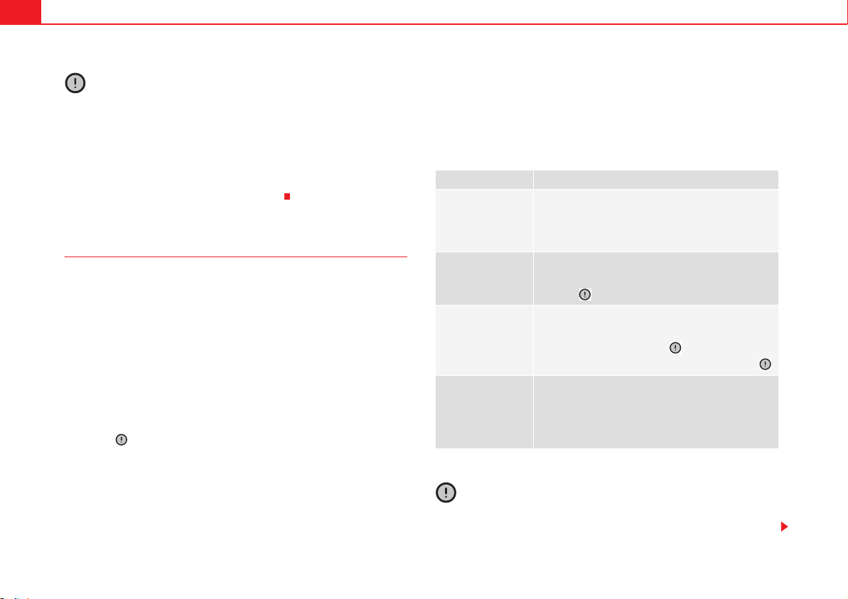
Vehicle maintenance and cleaning280
Caution
x Alcantara
®
upholsteries should never be soaked.
x Do not use leather cleaning products, solvents, wax polish, shoe cream,
spot removers or similar products on Alcantara
®
.
x Never use brushes for cleaning damp material as they could damage the
surface.
x Do not use steam cleaning equipment, as the dirt becomes more
incrusted in the material when steam is applied.
Cleaning and care of real leather upholstery
In the event of query regarding the care or cleaning of the leather in your
vehicle, please ask a Technical Service or specialised workshop.
Cleaning and care
Untreated Nappa is delicate as it is not covered with a layer of colour.
x Use a suitable impregnating cream with ultra-violet protection at regular
intervals and after cleaning. This cream will nourish and moisturise the
leather, keep it supple and able to breathe. It will also form a protective film.
x Clean the leather every two to three months and remove fresh dirt as
necessary.
x Leather should be treated every six months with a suitable leather care
product .
x When using care and cleaning products, only apply the minimum
required quantities.
x Remove stains from fresh ball-pen and other inks, lipstick, shoe cream
and similar stains as soon as possible.
x Caring for coloured leather. A special coloured cream will renew the colour
of the leather when required and will eliminate differences in colour.
x Then wipe off with a soft, dry cloth.
Cleaning the vehicle
SEAT recommends the use of a damp cotton or wool cloth for general
cleaning.
Do not let the water soak through the leather or soak into the seams.
Caution
x On no account use solvents, wax polish, shoe cream, spot removers or
similar materials.
Type of stain Cleaning the vehicle
More stubborn dirt
Apply a mild soap and water solution
a)
using a
cloth. (Squeeze out the cloth well before applica-
tion).
Carefully dry the area with an absorbent dry cloth.
a)
Mild soap and water solution: two table spoons of neutral soap per litre of water.
Water-based stains,
e.g. coffee, tea, fruit
juice, blood, etc.
Remove fresh stains with an absorbent cloth.
Use a suitable cleaning product to treat dried-in
stains .
Grease-based
stains, e.g. oil or lip-
stick, etc.
Remove fresh stains with an absorbent cloth.
Use a suitable cleaning product if the stain has not
yet penetrated the surface .
Treat dry stains with a grease-removal spray .
Dry difficult stains,
e.g. ink, felt-tip pen,
nail varnish, pig-
ment dispersions or
shoe polish.
Carefully dry the area with an absorbent dry cloth.
Clean using a special stain remover suitable for
use on leather.
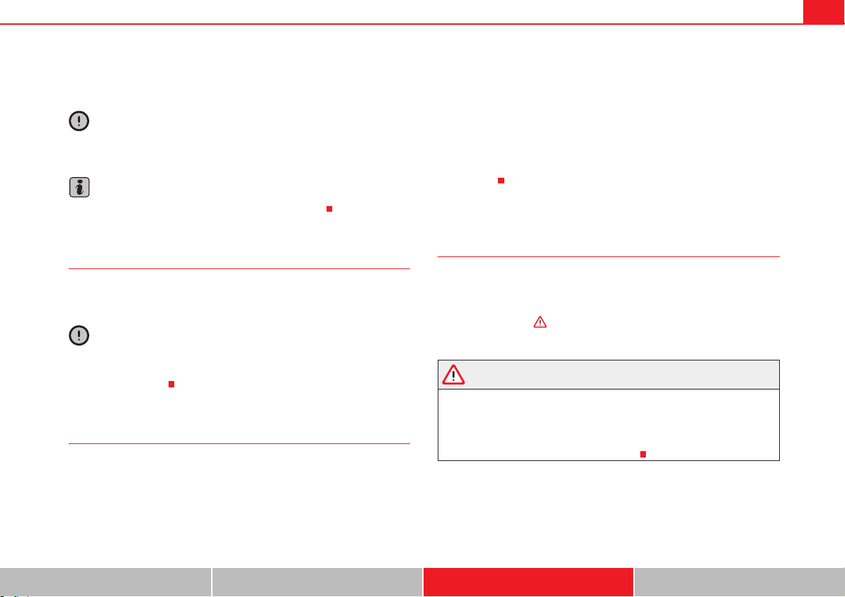
Vehicle maintenance and cleaning 281
Safety First Operating instructions Practical tips Technical Data
x In the event of spilt liquids, dry immediately with an absorbent cloth to
prevent the liquid penetrating through the leather.
Caution
If the car is left standing in the sun for long periods, the leather should be
protected against direct sunlight to prevent it from fading.
Note
However, slight colour variations will arise in normal use.
Cleaning leather upholstery
Only use water and neutral cleaning products to clean imitation leather
upholstery.
Caution
On no account use solvents, wax polish, shoe cream, spot removers or similar
materials on imitation leather. These will stiffen the material, making it more
likely to crack sooner.
Cleaning storage compartments, drinks holders and ashtray
Cleaning storage compartments and drinks holders
Some storage compartments and drinks holders have a removable rubber
mat.
x Use a clean, damp, lint-free cloth to clean parts.
x If this does not provide satisfactory results, we recommend using a
special solvent-free plastic cleaning product.
Cleaning the ashtray
x Extract the ashtray and empty it.
x Clean the ashtray with a dishcloth.
Use a toothpick or similar to remove ash from the area where cigarettes are
stubbed out.
Care and cleaning of plastic parts, wooden trim and the
instrument panel
x Use a clean, damp, lint-free cloth to clean parts.
x Clean plastic parts (inside and outside the vehicle) and the instrument
panel with a special solvent-free product for the care and cleaning of plastic,
approved by SEAT .
x Wash wooden trims with a mild soap and water solution.
WARNING
Solvents cause the surfaces of the airbag modules to become porous. If an
airbag is accidentally triggered, the detachment of plastic parts could
cause serious injury.
x Never clean the instrument panel and the surfaces of the airbag
modules with cleaners containing solvents.
Vehicle maintenance and cleaning282
Cleaning seat belts
If the seat belt is very dirty, the belt retractor may not work correctly thus
preventing the seat belt from operating correctly.
The seat belts should never be removed from the vehicle for cleaning.
x Use a soft brush to remove the worst dirt .
x Pull the seat belt right out and leave it out.
x Clean dirty seat belts with a gentle soap and water solution.
x Wait until they are completely dry.
x Only allow the seat belt to retract when it is completely dry.
WARNING
Check the condition of all the seat belts at regular intervals. If the webbing
or other parts of the belt are damaged, the vehicle should be taken to a
qualified workshop immediately and the belts should be replaced. It is
extremely dangerous to drive using damaged seat belts and could result in
serious injury or loss of life.
x Seat belts and their components must never be cleaned with chemical
products, nor should they be allowed to come into contact with corrosive
liquids, solvents or sharp objects. This could affect the strength of the seat
belt webbing.
x Seat belts should be completely dry before retracting. Damp could
damage the belt retractor so that it is does not operate correctly.
x Do not allow liquids or foreign bodies to enter the buckle fastenings.
This could damage the buckles and seat belts.
x Never attempt to repair, modify or remove a seat belt yourself.
x Always have damaged seatbelts replaced immediately by seat belts
approved for the vehicle in question by SEAT. Seat belts which have been
worn in an accident and stretched must be replaced by a qualified work-
shop. Renewal may be necessary even if there is no apparent damage. The
belt anchorage should also be checked.
WARNING (continued)
Vehicle maintenance and cleaning 283
Safety First Operating instructions Practical tips Technical Data
Notes for the user
Labels and plates
Some parts in the engine compartment come from the factory with certifi-
cates of safety, labels or plates containing important information regarding
the operation of the vehicle, for example, on the petrol cap, on the
passenger's sun visor, on the driver's door strut, or on the floor of the luggage
compartment.
x Never remove these certificates of safety, labels or plates, and ensure
they are kept in good condition and are legible.
x If a vehicle part, bearing a certificate of safety, label or plate, is replaced,
the qualified workshop should attach the information back in the same place.
Certificate of safety
A certificate of safety on the door strut states that all the safety standards and
regulations established by the national traffic authorities responsible for
road safety were met at the time of manufacture. It may also give the month
and year of manufacture, together with the chassis number.
Warning of high voltage label*
There is a label close to the bonnet lock which warns of high voltage in the
vehicle electrical installation. The vehicle ignition system complies with
several standards, including the Canadian standard, ICES-002.
Using your vehicle in other countries and continents
The vehicle is manufactured at the factory for use in a particular country in
accordance with the national legislation in force at the time of manufacture.
If the vehicle is sold in another country or used in another country for an
extended period of time, the applicable legislation of that country should be
observed.
It may be necessary to fit or remove certain pieces of equipment or to deacti-
vate certain functions. Service work may also be affected. This is particularly
true if the vehicle is used in a different climate for an extended period of time.
As there are different types of frequency bands around the world, you may
find that the radio or navigation system supplied at the factory does not work
in another country.
Caution
x SEAT does not accept liability for any damage to the vehicle due to the use
of a lower quality fuel, an inadequate service or the non-availability of
genuine spare parts.
x SEAT does not accept liability if the vehicle does not comply in part or in
full with the legal requirements of other countries or continents.
Radio reception and the aerial
The aerial of radio and navigation systems fitted at the factory may be
mounted in different parts of the vehicle:
x On the inside of the rear window, next to the rear window heating,
x on the inside of the rear side windows,
x on the inside of the windscreen,
x on the roof of the car.
Aerials mounted on the inside of a window can be recognised by the fine
wires.
Vehicle maintenance and cleaning284
Caution
Aerials on the inside of windows may be damaged if knocked or if cleaned
with corrosive or acid cleaning products. Do not stick adhesive labels over the
heating elements and never clean the inside of the rear window with corro-
sive or acid products or other similar chemical cleaning products.
Note
If electrical equipment is used near an aerial built-into the window, you may
observe interference in the reception of AM stations.
Notes on SEAT repairs
WARNING
Repairs or modifications which are not performed correctly may result in
damage or errors in the vehicle operation, affecting the efficiency of the
driver assist and airbag systems. This could result in serious accident.
x Have any repairs or modifications carried out at a qualified workshop.
Collection and scrapping of end-of-life vehicles
Collection of end-of-life vehicles
An extensive network of used car reception centres already exists in much of
Europe. After the vehicle has been delivered, you will receive a certificate of
destruction describing the environmentally friendly scrapping of the vehicle
in accordance with applicable legislation.
We will collect the used vehicle free of charge, provided it complies with all
national legislation.
Please see your Technical Service for further information about the collection
and scrapping of end-of-life vehicles.
Scrapping
The relevant safety requirements must be observed when the vehicle or
components of the airbag or belt tensioner systems are scrapped. These
requirements are known to qualified dealerships.
Accessories, parts replacement and modifications 285
Safety First Operating instructions Practical tips Technical Data
Accessories, parts replacement and modifications
Accessories, replacement of parts and
modifications
Introduction
WARNING
The use of spare parts and accessories, or incorrectly performed modifica-
tions or repairs may result in damage to the vehicle, accidents and serious
injury.
x SEAT strongly recommends you to only use SEAT approved accessories
and SEAT
®
original spare parts. These parts and accessories have been
specially tested by SEAT for suitability, reliability and safety.
x Have any repairs or modifications carried out at a qualified workshop.
Qualified workshops have the necessary tools, diagnostics equipment,
repair information and qualified personnel.
x Only mount parts with the same specifications as the parts fitted at
factory.
x Never mount, fasten or fit objects such as drink holders or telephone
cradles over the covers of the airbag modules or within their radius of
action.
x Only use wheels and tyre combinations which have been approved by
SEAT for your vehicle type.
Accessories and spare parts
SEAT recommends you consult an Official Service before purchasing accesso-
ries and spare parts or consumables. For example, when fitting accessories
at a later date, or when replacing a component. A Technical Service will advise
you as to the legal requirements and manufacturer's recommendations
regarding accessories, spare parts and other components.
SEAT recommend you use only approved SEAT accessories and genuine SEAT
spare parts
®
. These parts and accessories have been specially tested by
SEAT for suitability, reliability and safety. In addition the Technical Service will
guarantee that the assembly is carried out professionally.
Although we continually monitor the market, SEAT cannot guarantee that
products not approved by SEAT are reliable, safe and suitable for the vehicle.
Therefore, SEAT cannot accept liability, even in those cases authorised by an
officially recognised technical inspection office or other official body.
Any retro-fitted equipment which has a direct effect on the vehicle and/or the
way it is driven must be approved by SEAT for use in your vehicle and bear the
e mark (the European Union's authorisation symbol). This includes cruise
control systems or electronically controlled suspension.
If any additional electrical components are fitted which do not serve to
control the vehicle itself, these must bear the & mark (European Union
manufacturer conformity declaration). This includes refrigerator boxes,
laptops or ventilator fans.
WARNING
Unprofessional repairs or modifications to the vehicle may affect the
performance of the airbags, resulting in operating faults or fatal accident.
Accessories, parts replacement and modifications286
x Never mount, fasten or fit objects such as drink holders or telephone
cradles over the covers of the airbag modules or within their radius of
action.
x Objects placed over the airbag covers, or within their radius of action,
could lead to serious injury or loss of life if the airbags are triggered.
Fluids and consumables
All vehicle fluids and consumables, such as notched belts, tyres, coolant
fluids, engine oils, spark plugs and batteries are continually being devel-
oped. Therefore all fluids and consumables should be changed at a qualified
workshop. Qualified workshops are permanently informed of any modifica-
tions.
WARNING
The incorrect use or handling of fluids or consumables may result in acci-
dent, serious injury, burns or intoxication.
x Therefore, fluids must always be stored closed in their original
container.
x Never store fluids in empty food containers or bottles as other people
may accidentally drink the fluid.
x Keep all fluids and consumables out of reach of children.
x Read and observe the information and warnings given on the fluid
containers.
x Only work in the open air or in well-ventilated zones, when using prod-
ucts which give off harmful vapours.
x Never use fuel, turpentine, engine oil, acetone or any other volatile
liquid in the maintenance of the vehicle. These are toxic and highly flam-
mable. They could lead to fire or explosions!
Caution
x Only use appropriate fluids. Never mix the fluids. Failure to observe this
point will result in serious malfunctions and engine damage!
x Accessories and other components mounted in front of the air inlet
reduce the cooling effect of the coolant. If the engine is running under great
strain in high outside temperatures, it could overheat.
For the sake of the environment
Leaking fluids could pollute the environment. Collect any spilt fluids in suit-
able containers and dispose of in accordance with legislation and with
respect for the environment.
Repairs and technical changes
When performing repairs and technical modifications, SEAT's directives
must be observed!
Unauthorised modifications to the electronic components or software in the
vehicle may cause malfunctions. Due to the way the electronic components
are linked together in networks, other indirect systems may be affected by the
faults. This may significantly affect the vehicle's performance, increase
component wear and could mean that the vehicle registration documents are
no longer valid.
Your Technical Service cannot be held liable for any damage caused by tech-
nical modifications or repairs performed incorrectly.
WARNING (continued) WARNING (continued)
Accessories, parts replacement and modifications 287
Safety First Operating instructions Practical tips Technical Data
The Technical Service does not accept liability for damage resulting from
technical modifications or repairs performed incorrectly; neither is the SEAT
warranty valid in these cases.
SEAT recommends you have any technical modifications or repairs performed
at a SEAT authorised service and that you use genuine SEAT spare parts
®
.
Vehicles with special accessories and equipment
The manufacturers of additional equipment guarantee that the equipment
complies with applicable laws and regulations with respect to the environ-
ment, in particular Directives 2000/53/CE and 2003/11/CE. The first direc-
tive governs the disposal of end-of-life vehicles while the second refers to the
restrictions on the marketing and use of certain dangerous substances and
preparations.
The vehicle owner should keep the documentation for the additional equip-
ment safely and hand it over to the scrap yard at the end of the vehicle's
service life. This ensures that any additional equipment mounted in end-of-
life vehicles is correctly disposed of with respect for the environment.
WARNING
Repairs or modifications which are not performed correctly may result in
damage or errors in the vehicle operation, affecting the efficiency of the
driver assist systems. This could result in serious accident.
x All repairs and modifications to the vehicle should only be performed
by a qualified workshop.
Repair and faults in the airbag system
When performing repairs and technical modifications, SEAT's directives
must be observed!
Modifications and repairs to the front bumper, doors, front seats, and repairs
to the roof or chassis should only be carried out in a qualified workshop.
These components may contain parts or sensors belonging to the airbag
system.
If work is carried out on the airbag system or remove and fit parts of the
system when performing other repair work, parts of the airbag system may be
damaged. The consequence may be that, in the event of an accident, the
airbag inflates incorrectly or does not inflate at all.
So that the effectiveness of the airbag is not reduced and that removed parts
do not cause any injuries or environmental pollution, regulations must be
observed. These requirements are known to qualified dealerships.
Modifications to the vehicle suspension may affect the operation of the
airbag system in the event of collision. For example, if wheel and tyre combi-
nations not approved by SEAT are used, or if the vehicle height is lowered, the
suspension is stiffened or the suspension springs, telescopic arms, dampers,
etc., are modified, the results received by the airbag sensors and sent to the
control unit may not be accurate. For example, some modifications to the
suspension could increase the force measured by the sensors and result in
the triggering of the airbag systems in collisions. Under normal conditions,
the measured values would be lower and the airbag would not have been trig-
gered. Other modifications may reduce the forces measured by the sensors
and therefore the airbags are not triggered in situations when they should
have triggered.
WARNING
Repairs or modifications which are not performed correctly may result in
damage or errors in the vehicle operation, affecting the efficiency of the
airbag systems. This could result in serious or fatal accident.
x All repairs and modifications to the vehicle should only be performed
by a qualified workshop.
x Airbag modules must never be repaired: if damaged, they must be
replaced.
Accessories, parts replacement and modifications288
x Never fit recycled or reused airbag components in your vehicle.
WARNING
Modifications to the vehicle suspension, including the use of unauthorised
wheel and tyre combinations, may affect the performance of the airbags
and increase the risk of serious or fatal injury in the event of accident.
x Never fit suspension components which are not identical to the original
parts mounted in the vehicle.
x Never use wheel and tyre combinations not approved by SEAT.
Retro-fitting of two-way radios
An exterior aerial is required for the use of two-way radios in the vehicle.
The retro-fitting of electrical or electronic appliances in the vehicle is subject
to their approval for use in your vehicle. Under certain circumstances, this
could mean that your vehicle registration documents are no longer valid.
SEAT has approved your vehicle for use with two-way radios providing the
following conditions are observed:
x The exterior aerial must be mounted professionally.
x The maximum transmitting power is 10 watts.
An only external aerial is needed to give the equipment its optimal reach.
Check first with a qualified dealer if you wish to use a two-way radio with a
transmitting power of over 10 watts. The qualified workshops are familiar
with the technical options for installation. SEAT recommends visiting a quali-
fied workshop.
All legal requirements, together with the instructions for the use of two-way
radios must be observed.
WARNING
If the two-way radio is not securely fastened in position, it could be sent
flying around the vehicle in the event of sharp braking, sudden manoeuvres
or accident, causing injury.
x While driving, two-way radios must be securely fastened in position,
outside the radius of action of the airbags, or safely stowed away.
WARNING
When using a two-way radio without a connection to an exterior aerial, the
maximum permitted levels of electromagnetic radiation may be exceeded.
This is also the case if the aerial has not been correctly installed.
x You should only use a two-way radio inside the vehicle if it has first
been correctly connected to an exterior aerial.
Information stored by the control units
Your vehicle is fitted at the factory with a series of electronic control units
responsible for the engine and gearbox management. In addition, the control
units supervise the performance of the exhaust gas system and the airbag
systems.
Therefore, while the vehicle is being driven, these electronic control units are
continuously analysing the vehicle data. In the event of faults or deviations
from the theoretical values, only this data is stored. Normally, the warning
lamps on the instrument panel light up in the event of faults.
This data can only be read and analysed using special equipment.
WARNING (continued)

Accessories, parts replacement and modifications 289
Safety First Operating instructions Practical tips Technical Data
The storing of the data allows specialised workshops to detect and repair
faults. Stored data may include:
x Data relating to the engine or the gearbox
x Speed
x Direction of travel
x Braking force
x Detection of seat belt
The vehicle control units never record conversations held by passengers in
the vehicle.
In vehicles equipped with an emergency call function via the mobile phone or
other appliances connected in the vehicle, it is possible to send the vehicle
position. If the control unit records an accident with airbag activation, the
system may automatically send a signal. This will depend on the network
operator. Normally, transmission is only possible in areas with good
coverage.
Event Data Recorder
The vehicle is not fitted with an event data recorder.
An event data recorder temporarily stores the vehicle information. Therefore,
in the event of accident, it is possible to obtain detailed information about
how the accident occurred. For example, in vehicles with airbag systems,
data relating to speed of impact, seat belt status, seat positions and airbag
activation times may be stored. The volume of data depends on the manufac-
turer.
Event data recorders can only be mounted with authorisation from the vehicle
owner and, in some countries, they are governed by local legislation.
Reprogramming control units
On the whole, all the data required for the component management is stored
in the control units. The programming of certain convenience functions, such
as the convenience indicators, individual door opening and instructions on
the display can be modified using special equipment at the workshop. If this
is the case, the information and descriptions given in the instructions manual
will not match the original functions. Therefore, SEAT recommends that any
modifications are recorded in the section “Other workshop notes” in the
Maintenance Programme.
The Technical Service must have a record of any modification to the program-
ming.
Reading the vehicle fault memory
There is a diagnostics connector in the vehicle interior for reading the vehicle
fault memory. The fault memory documents errors and deviations from the
theoretical values of the electronic control units.
The diagnostics connector is in the driver's side footwell area, next to the
lever for opening the bonnet, below a cover.
The fault memory should only be read and reset by a qualified workshop.
Using a mobile telephone in a vehicle without connection to
an exterior aerial
Mobile telephones transmit and receive radio waves, both when in use and
when on stand-by. Scientific studies state that radio waves exceeding certain
values may be harmful to the human body. International committees and
authorities have established limits and directives in order to ensure electro-
magnetic radiation from mobile phones remains within certain limits that do
not endanger human health. However, there is no available conclusive scien-
tific evidence that cordless phones are completely safe.
Therefore, some experts recommend that use of mobile phone be kept to a
minimum until the results of current research are published.
When a mobile phone not connected to an exterior aerial is used inside the
vehicle, the electromagnetic radiation may be greater than if the mobile
phone were connected to a built-in aerial or to another exterior aerial.
Accessories, parts replacement and modifications290
If the vehicle is fitted with a suitable hands-free device, it will comply with the
legislation in many countries which only permits the use of mobile phones
inside vehicles using a hands-free device.
The hands-free system mounted at the factory has been designed for use with
conventional mobile phones and phones with Bluetooth technology. Mobile
phones should be placed on a suitable phone cradle. In addition, the cradle
should always be correctly fitted into the base plate. This ensures that the
mobile phone is securely fastened to the instrument panel and connected to
the exterior aerial of the vehicle.
If the mobile phone is connected to an aerial incorporated into the vehicle or
an exterior aerial connected to the vehicle, this will help to reduce the elec-
tromagnetic radiation transmitted and the risk to human health. It will also
improve the quality of the connection.
If the phone is used inside the vehicle without the hands-free system, it will
not be securely fastened and will not be connected to the exterior aerial of the
vehicle telephone. Nor will the telephone charge if it is not on the support. In
addition, some calls may break off and the quality of the connection will be
affected.
Mobile phones should only be used inside the vehicle if they are connected
to a hands-free system with an exterior aerial.
WARNING
If the mobile phone is not securely fastened in position, it could be sent
flying around the vehicle in the event of sharp braking, sudden manoeuvres
or accident, causing injury.
x While driving, mobile phones must be securely fastened in position,
outside the radius of action of the airbags, or safely stowed away.
WARNING
When using a mobile phone without a connection to an exterior aerial, the
maximum permitted levels of electromagnetic radiation may be exceeded.
This is also the case if the aerial has not been correctly installed.
x A minimum of 20 centimetres should be kept between mobile phone
aerials and artificial pacemakers, as mobile telephones may affect the
working of pacemakers.
x Do not carry a mobile phone in your breast pocket directly over the
pacemaker when the phone is switched on.
x If you suspect interference, switch the mobile phone off immediately.
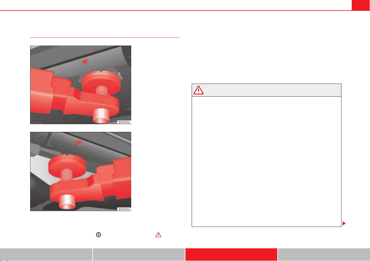
Accessories, parts replacement and modifications 291
Safety First Operating instructions Practical tips Technical Data
Jacking points for raising vehicle
Always use the jacking points indicated in the figures fig. 167 and
fig. 168 when raising the vehicle. If the vehicle is not lifted at these points,
it could be seriously damaged or lead to serious injury .
The vehicle should not be lifted using lifting platforms with lift pads
containing fluid.
When raising a vehicle using a platform or jack, a series of precautionary
measures are required. Never raise the vehicle with a lifting platform or jack
unless you have received training in how to do so and know how to lift the
vehicle safely.
Notes on raising the vehicle with a jack page 342.
WARNING
The improper use of the lifting platform or the jack when raising the vehicle
may result in accidents or serious injury.
x Before raising the vehicle, please observe the manufacturer's instruc-
tions for the platform or jack, and the legal requirements, where appli-
cable.
x There should not be anyone inside the vehicle when it is being raised or
once it is in the air.
x Only use the jacking points indicated in the figures fig. 167 and
fig. 168 when raising the vehicle. If the vehicle is not lifted at the indi-
cated points, it may fall from the platform while the engine or gearbox is
being dismounted, for example.
x The jacking points should be centrally aligned and firmly positioned on
the platform support plates.
x Never start the engine when the vehicle is raised! The vehicle may fall
from the platform due to the engine vibrations.
x If it is necessary to work underneath the vehicle while it is raised, you
should check that the supporting stands have an adequate load capacity.
x Never climb onto the lifting platform.
x Always make sure that the weight of the vehicle does not exceed the
lifting platform load capacity.
Fig. 167 Front jacking
points for raising vehicle
with lifting platform or
jack.
Fig. 168 Rear jacking
points for raising vehicle
with lifting platform or
jack.

Accessories, parts replacement and modifications292
Caution
x Never raise the vehicle at the engine oil sump, the gearbox or the rear or
front axles.
x Always use an intermediate rubber support to prevent damage to the
vehicle underbody. Check that the arms of the lifting platform are able to
move with obstruction.
x The arms should not come into contact with the side running boards or
other parts of the vehicle.
Checking and refilling levels 293
Safety First Operating instructions Practical tips Technical Data
Checking and refilling levels
Filling the tank
Introduction
The fuel tank flap is on the rear right of the vehicle.
Additional information and warnings:
x Fuel page 297
x Selective Catalytic Reduction (AdBlue) page 300
x Working in the engine compartment page 304
WARNING
Refuelling or handling fuel carelessly can cause an explosion or fire
resulting in serious burns and injuries.
x Always make sure that you correctly close the fuel cap to avoid evapo-
ration and fuel spillage.
x Fuels are highly explosive and inflammable substances that can cause
serious burns and injuries.
x Fuel could leak out or be spilt if the engine is not switched off or if the
filler fuel nozzle is not fully inserted into the tank filler neck when refuel-
ling. This could lead to a fire, explosion and severe injuries.
x When refuelling, turn off the engine, the auxiliary heating
( page 187) and turn off the ignition for safety reasons.
x Always turn off mobile telephones, radio apparatus and other radio
wave emitting equipment before refuelling. Electromagnetic waves could
cause sparks and lead to a fire.
x Never enter the vehicle while refuelling. If it is absolutely necessary to
enter the vehicle, close the door and touch a metal surface before touching
the filler nozzle again. This will prevent the generation of static electricity.
Sparks could cause a fire when refuelling.
x Never handle fuel close to open flames, sparks or objects with slow
combustion (e.g. cigarettes).
x Avoid static electricity and electro-magnetic radiation when refuelling.
x Observe the safety regulations of the service station.
x Never spill fuel on the vehicle or in the luggage compartment.
WARNING
For safety reasons, SEAT does not recommend carrying a spare fuel canister
in the vehicle. Fuel could be spilled and catch fire, above all in case of an
accident and this applies to a full container as well as empty containers.
This could lead to explosions, fires and injuries.
x Observe the following if you exceptionally have to carry fuel in a
canister:
Never place a fuel container to fill it inside the vehicle or on the
vehicle, for example, in the luggage compartment or on the tailgate.
Filling in these circumstances could create an electrostatic charge and
spark that could ignite fuel fumes.
Always place the canister on the ground to fill it.
Insert the fuel nozzle into the mouth of the canister as far as
possible.
If you are using a metal fuel canister, the nozzle must always touch
the canister while it is being filled to avoid static electricity.
WARNING (continued)
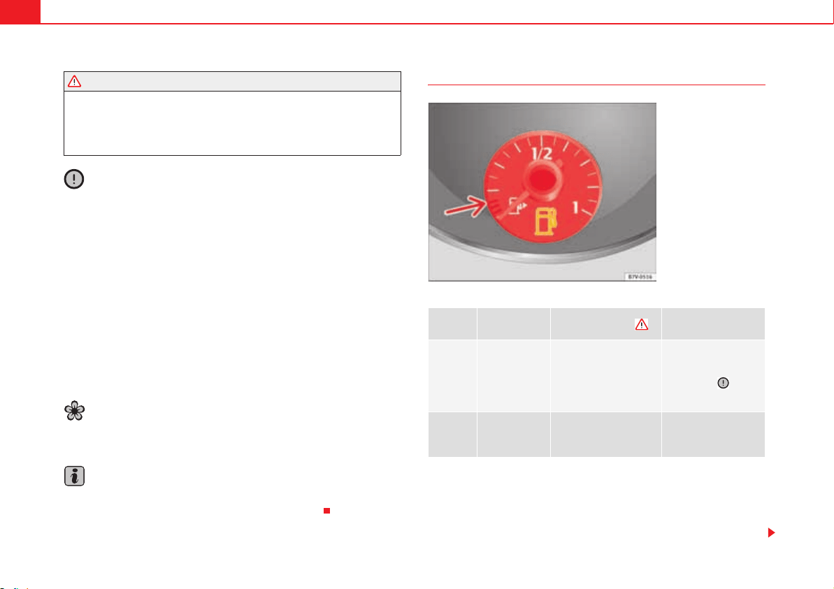
Checking and refilling levels294
Follow the legal requirements for the use, storage and transport of
spare fuel canisters.
Insure that the fuel container complies with manufacturing stand-
ards, for example, ANSI or ASTM F852-86.
Caution
x Always remove any fuel spilled on the vehicle paintwork immediately to
avoid damage to the wheel housing, the tyre and vehicle paintwork.
x Refuelling a petrol engine with diesel or a diesel engine with petrol can
cause serious engine and fuel system damage; the resulting malfunctions
are not covered by the SEAT warranty. If you refuel with the wrong type of fuel,
never start the engine. This applies to even the smallest amount of the wrong
fuel. You should obtain professional assistance. With the engine running, the
composition of the wrong fuel could significantly damage the fuel system and
the engine itself.
x In vehicles with a diesel engine, under no circumstances should you
refuel or drive with petrol, kerosene, heating oil or any other type of different
fuel. Other types of fuels could cause serious damage to the engine and to
the fuel supply system and the resulting problems are not covered by the
SEAT warranty.
For the sake of the environment
Fuels can contaminate the environment. Collect any spilt service fluids and
allow a professional to dispose of them.
Note
There is no emergency mechanism for the manual release of the tank flap. If
necessary, request assistance from specialised personnel.
Control lamps and fuel gauge
Several warning and control lamps should light up for a few seconds when
the ignition is switched. This signals that the lamp is working properly. They
will switch off after a few seconds.
The auxiliary heater and the auxiliary heater running off petrol will automati-
cally switch off when the indicatorz or lights.
WARNING (continued)
lights up
Gauge position
fig. 169
Possible cause
Solution
Red mark
(arrow)
The fuel tank is almost
empty.
The reserve tank is
being used
page 392.
Refuel as soon as
possible .
§
Fuel tank not closed
correctly.
Stop the vehicle and
close the tank flap
properly.
Fig. 169 On the instru-
ment panel: Fuel gauge for
petrol and diesel.
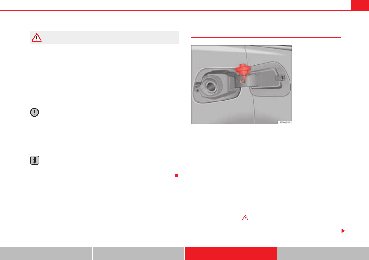
Checking and refilling levels 295
Safety First Operating instructions Practical tips Technical Data
WARNING
Driving with insufficient fuel reserve could result in the vehicle breaking
down in traffic and a serious accident.
x If the fuel level is too low then the fuel supply to the engine can become
irregular especially on slopes.
x If the engine “is choked” or stalls due to lack of or irregularity of the
fuel supply, the power steering as well as all of the driver assistance
systems including braking assistance will stop working.
x Always refuel when there is only one quarter of the fuel tank left to
avoid running out of fuel.
Caution
x Always pay attention to any lit lamps and to the corresponding descrip-
tions and instructions to avoid damage to the vehicle.
x Never run the tank completely dry. An irregular fuel supply may lead to
ignition faults and unburnt fuel could enter the exhaust system. This could
damage the catalytic converter filter or the diesel particulate filter!
Note
The arrow next to the fuel pump symbol on the instrument panel page 294,
fig. 169 indicates the side of the vehicle on which the tank flap is located.
Filling the tank with petrol or diesel
Before refuelling, always turn off the engine, the ignition, mobile telephones,
auxiliary heating and keep them off during refuelling.
Unscrewing the tank cap
x The tank flap is at the rear of the vehicle on the right.
x Press the rear of the tank flap to open it.
x Unscrew the tank cap anti-clockwise and insert it in the hole in the tank
flap hinge fig. 170.
Refilling
The correct petrol type for the vehicle is located on a sticker inside the fuel
tank flap page 297.
x If the automatic filler nozzle is operated correctly, it will switch itself off as
soon as the tank is full .
x Do not continue to refuel if it is turned off! Otherwise, this will fill the
expansion chamber and fuel may leak out if the ambient conditions are warm.
Fig. 170 Open tank flap
with tank cap attached to
the holder.
Checking and refilling levels296
Closing the tank cap
x Screw on the tank cap clockwise until it you hear it click into position.
x Press the tank flap until you hear it click into place. The tank flap must be
flush with the body contour.
WARNING
Do not continue refilling once the fuel nozzle has switched itself off. The
fuel tank may be filled too much. As a result, fuel may spurt out and spill.
This could lead to a fire, explosion and severe injuries.
Caution
x Always remove any fuel spilled on the vehicle paintwork immediately to
avoid damage to the wheel housing, the tyre and vehicle paintwork.
For the sake of the environment
Spilt fuel can contaminate the environment.
Refilling precautions
Information on bulb replacement page 360.
Checklist
Never work on the engine or in the engine compartment if you are not familiar
with the operations to be carried out, the applicable safety standards and
especially if you do not have the instruments, liquids and tools necessary
page 304, “Working in the engine compartment”! Have the work carried
out by a qualified workshop if you are uncertain. Check the following regu-
larly, preferably when you refuel:
x Windscreen washer fluid level page 124
x Engine oil level page 309
x Engine coolant level page 313
x Brake fluid level page 210
x Tyre pressure page 323
x Vehicle lighting required to guarantee road safety:
–Indicators
– Side lights, dipped headlights and full beam headlights
– Rear lights
–Brake lights
– Rear fog light page 116
WARNING
Not following the checklist prepared for your own safety could lead to acci-
dents and severe injuries.
x Always follow the check list and perform the necessary operations.
Checking and refilling levels 297
Safety First Operating instructions Practical tips Technical Data
Fuel
Introduction
You will find a factory-fitted sticker containing information on the type of fuel
for your vehicle on the inside of the fuel tank flap.
Additional information and warnings:
x Booklet “Maintenance Programme”
x Refuelling page 293
x Engine and exhaust system management page 255
WARNING
Refuelling or handling fuel carelessly can cause an explosion or fire
resulting in serious burns and injuries.
x Fuel is a highly explosive, easily flammable substance.
x Observe current safety instructions and local regulations concerning
the handling of fuel.
Types of fuel
The type of fuel to use when refilling will depend on the vehicle's engine. You
will find a factory-fitted sticker containing information on the type of fuel for
your vehicle on the inside of the fuel tank flap.
SEAT recommends the use of sulphur-free or low sulphur fuel to reduce
consumption and prevent engine damage.
Petrol
Petrol types
Vehicles with petrol engines must refuel using unleaded petrol according to
European norm EN 228 .
Petrol types are categorised according to their octane number (e.g. 91, 95, 98
or 99 RON (RON = “Research Octane Number”). You may use petrol with a
high octane number than the one recommended for your engine. However,
this has no advantage in terms of fuel consumption and engine power.
SEAT recommends refuelling with a low sulphur content or sulphur-free petrol
to reduce petrol consumption for petrol engines.
Petrol additives
The quality of the fuel influences running behaviour, performance and service
life of the engine. For this reason, you should use good quality petrol
containing a mixture of additives. These additives will help to prevent corro-
sion, keep the fuel system clean and prevent deposits from building up in the
engine.
Possible types of
fuel
Alternative names Further information
91
a)
RON
a)
RON = Regulation Octane Number
Normal petrol, normal
unleaded petrol
page 297
95
a)
RON
Premium unleaded petrol (95
RON)
98
a)
RON
Premium unleaded petrol (98
RON)
Diesel page 298

Checking and refilling levels298
If good quality petrol with additives is not available or engine problems arise,
the necessary additives must be added when refuelling.
Not all petrol additives have been shown to be effective. The use of unsuit-
able petrol additives could damage the engine. These additives are available
from qualified workshops, who will inform you of their application.
Caution
x Only use fuel with an octane rating that is in line with the norm EN 228,
otherwise significant damage could be caused to the engine and fuel system.
Furthermore, it could lead to a loss of performance with the consequent
engine fault.
x The use of unsuitable petrol additives could damage the engine.
x If, in exceptional circumstances, petrol with a lower octane rating to that
recommended is used, only use moderate engine speeds and a light throttle.
Avoid using full throttle and overloading the engine. Otherwise you may
damage the engine. Fill up with fuel of a suitable octane rating as soon as
possible.
x Do not refuel if the filler indicates that the fuel contains metal. LRP (lead
replacement petrol) fuels also contain high concentrations of metal addi-
tives. This could damage the engine!
x Just one full tank of leaded fuel would seriously impair the efficiency of
the catalytic converter and could damage it.
Diesel
Diesel fuel
Diesel fuel must correspond to European standard EN 590 (In Germany, EN
590 or DIN 51628).
The use of diesel fuel with a high sulphur percentage requires shorter service
intervals Booklet “Maintenance Programme” . Your qualified work-
shop will be able to tell you which countries have diesel with a high sulphur
content.
Do not mix fuel additives (thinners, or similar additives) with diesel fuel.
Winter-grade diesel
When using “summer-grade diesel fuel”, difficulties may be experienced at
temperatures below 0 °C (+32 °F) because the fuel thickens due to wax sepa-
ration. For this reason, “winter-grade diesel fuel” is available in Germany, for
example, during the cold months. It can be used at temperatures as low as
-20 °C (-4 °F).
In countries with different climatic conditions, other types of diesel fuel are
available that are suitable to local temperatures. SEAT qualified workshops
and filling stations in the country concerned will inform you on the type of
diesel fuels available.
A cold diesel engine makes more noise during winter temperatures than
summer temperatures. Furthermore, the exhaust fumes may turn slightly
bluish while the engine is heating. The quantity of exhaust gases will depend
on the outside temperature.
Filter pre-heater
Vehicles with a diesel engine are fitted with a fuel filter pre-heater. This
ensures that the fuel system remains operational to approx. -24 °C (-11.2 °F),
provided you use winter-grade diesel which is safe to -15 °C (+5.00 °F).
However, if the fuel has waxed to such an extent that the engine will not start
at temperatures of under -24 °C (-11.2 °F), simply place the vehicle in a warm
garage or workshop for a while to heat up.
Auxiliary heater
Vehicles with a diesel engine may be fitted with an auxiliary heater. The
heater runs off the fuel from the fuel tank. On doing so, smells and steam may
be noticed outside the vehicle for a short period. This is normal and it is not
an indication of a fault in the vehicle.
Checking and refilling levels 299
Safety First Operating instructions Practical tips Technical Data
Whenever there is little fuel in the tank (reserve), the auxiliary heater auto-
matically switches off.
WARNING
Never use start boosters. An aerosol start booster could explode or cause
a sudden rise in engine speed leading to engine damage and serious injury.
Caution
x The vehicle is not prepared for the use of biodiesel. Under no circum-
stances should this fuel be used. It could damage the fuel system and subse-
quently lead to engine faults!
x The addition of biodiesel to diesel by the diesel producer according to
Standard EN 590 or other equivalent (DIN 51628 in Germany, for example) is
authorised and causes no type of damage to the engine or the fuel system.
x The diesel engine has been designed for to use diesel fuel exclusively.
Therefore, never use petrol, fuel oil or other unsuitable fuels. The composition
of these fuels may significantly damage the fuel system and the engine.
x The use of diesel fuels with a high sulphur percentage could considerably
reduce the service life of the diesel particulate filter. Your qualified workshop
will be able to tell you which countries have diesel with a high sulphur
content.
Information on fuel consumption
The consumption and emission values indicated do not refer to one specific
vehicle. They are only to be used to compare the values of the different
vehicle versions. The fuel consumption and CO
2
emissions of a vehicle not
only depend on the effective use of fuel. They also depend on your driving
style and other non-technical factors.
Calculating fuel consumption
Fuel consumption and emission values are determined according to the
current version of the 715/2007/EC or 80/1268/EEC regulation and are valid
for the vehicle kerb weight. The specifications do not refer to an individual
vehicle. Two measuring cycles are carried out on a rolling road test bed. The
test criteria are as follows:
Note
The kerb weight may vary according to the vehicle equipment. This could
raise consumption and the CO
2
emissions slightly.
Note
In practice, consumption values could be different to the values calculated
based on the 715/2007/EC or 80/1268/EEC regulations.
Urban cycle
Measurement of the urban cycle starts with an engine cold
start. City driving is then simulated at between 0 and 50
km/h.
Road cycle
In the road cycle simulation, the car undergoes frequent
acceleration and braking in all gears, as in normal everyday
driving. The road speed ranges from 0 to 120 km/h.
Combined
The average combined consumption is calculated with a
weighting of around 37 % for the urban cycle and 63 % for
the road cycle.
CO
2
emis-
sions of the
combination
The exhaust gases are collected during both driving cycles to
calculate carbon dioxide emissions (urban and road). The
gas composition is then analysed to evaluate the CO
2
con-
tent and other emissions.
Checking and refilling levels300
Selective Catalytic Reduction* (AdBlue)
Introduction
The AdBlue fill level must be checked when the vehicle is being serviced
Booklet “Maintenance Programme”.
Additional information and warnings:
x Luggage compartment page 146
x Fuel page 297
x Wheels and tyres page 323
x Accessories, parts replacement, repairs and modifications page 285
WARNING
If the AdBlue fill level is too low, the vehicle may not restart after switching
the ignition off. The emergency start or jump start will not be possible
either!
x Top up with AdBlue at the latest 1000 km or 600 miles before it runs
out.
x Do not allow the AdBlue to run too low.
WARNING
AdBlue is an irritant, corrosive liquid that can cause injuries if it touches
the skin, eyes or respiratory organs.
x If AdBlue get in contact with eyes and skin, rinse for at least 15 minutes
with plenty of water and seek medical help.
x If the AdBlue is swallowed, wash the mouth with plenty of water for at
least 15 minutes. Do not try to provoke vomiting unless recommended by a
Doctor. Seek medical advice immediately.
Caution
AdBlue damages surfaces such as painted vehicle parts, plastic, items of
clothing and carpets. Spilt AdBlue should be removed as quickly as possible
using a damp cloth and plenty of cold water.
x If the AdBlue has crystallised, remove with warm water and a sponge.
Control and warning lamps
Several warning and control lamps should light up for a few seconds when
the ignition is switched. This signals that the lamp is working properly. They
will switch off after a few seconds.
lights up
Possible cause
Solution
b (red)
The engine cannot be
restarted! The level of AdBlue
is too low.
Stop the vehicle in a suitable,
safe and flat area then top up
with the minimum quantity of
AdBlue required page 302.
b (red)
with
>
The engine cannot be
restarted! AdBlue system
malfunction.
Contact a specialist workshop.
Have the system checked there.
b (yel-
low)
The AdBlue reserve is low.
Refill AdBlue over the next kilo-
metres or miles as indicated
page 302. SEAT recommends
contacting a specialist work-
shop.
b (red)
with
>
There is a fault in the AdBlue
system or unsuitable AdBlue
fluid has been used.
Contact a specialist workshop.
Have the system checked there.
Checking and refilling levels 301
Safety First Operating instructions Practical tips Technical Data
WARNING
If the warning lamps and messages are ignored, the vehicle may stall in
traffic, or may cause accidents and severe injuries.
x Never ignore the warning lamps or text messages.
x Stop the vehicle safely as soon as possible.
Caution
Failure to heed the warning lamps and text messages when they appear may
result in faults in the vehicle.
Information on AdBlue
In vehicles with Selective Catalytic Reduction, a special urea solution
(AdBlue) is injected into the exhaust gas system in front of the catalytic
converter to reduce nitrogen oxide emissions.
The consumption of AdBlue depends on individual driving style, the temper-
ature at which the system operates and the outside temperature where the
vehicle is driven.
AdBlue is kept in an independent tank in the vehicle and should be refilled at
an official supplier. The AdBlue tank holds about 17 litres.
A message will be displayed on the instrument panel around 2400 km before
the next service to indicate that AdBlue must be refilled page 302. If you
ignore this message and do not refill, you will be unable to start the engine
afterwards page 300.
SEAT recommends contacting a specialist workshop. If you are unable to visit
a qualified specialist workshop, you should temporarily refill with a minimum
of 10.0 litres of AdBlue. Only refill using AdBlue expressly approved by SEAT.
When the indicators b and > light simultaneously, there is a fault. SEAT
recommends visiting the closest qualified workshop.
AdBlue
®
is a registered trademark in the US, Germany, the European Union
and other countries belonging to the German automobile industry ("Verband
der Automobilindustrie e. V.", VDA).
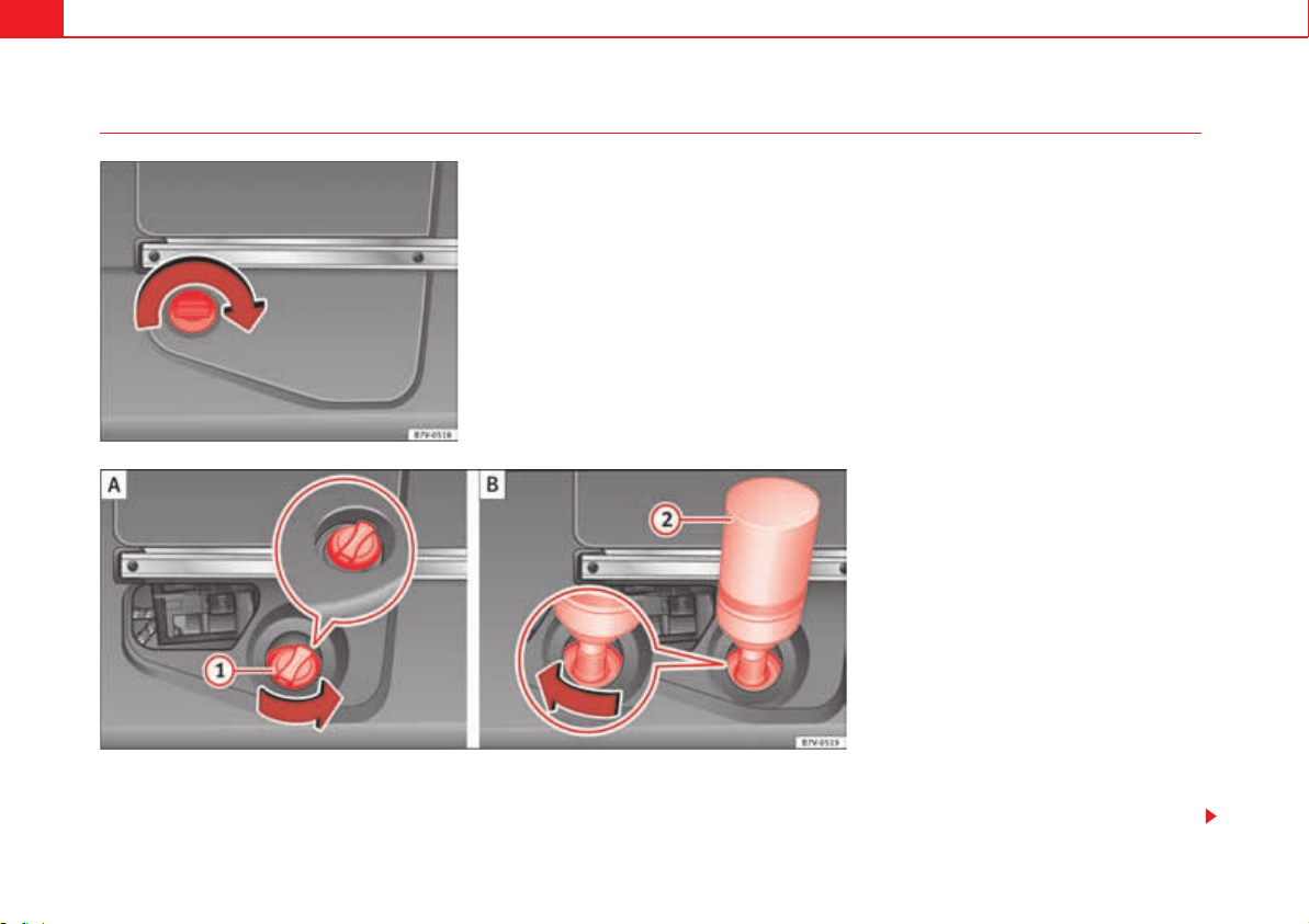
Checking and refilling levels302
Refilling AdBlue
To refill AdBlue, the vehicle must be on flat ground and not, for example,
parked on a kerb or slope. If the vehicle is not on flat ground then the filling
indicator cannot measure the filling quantity.
Opening the tank filling neck
x Open the tailgate.
Fig. 171 At the rear left of
the luggage compart-
ment: AdBlue tank,
behind a cover panel.
Fig. 172 AdBlue tank with filler neck cap and refilling
bottle.
Checking and refilling levels 303
Safety First Operating instructions Practical tips Technical Data
x Rotate the shut off on the cover clockwise page 302, fig. 171 and open
the cover forwards.
x Unscrew the tank filler neck cap page 302, fig. 172 anticlockwise.
Refilling AdBlue
Only use AdBlue that is approved by SEAT and that complies with the ISO
22241-1 Standard. Only use genuine bottles.
x Observe the instructions and information provided by the refill bottle
manufacturer.
x Observe the expiry date.
x Unscrew the cap on the refill bottle.
x Place the refill bottle upside down inside the tank filler neck.
x Press the refill bottle against the filler neck and keep in this position.
x Add at least 10 litres of AdBlue (6 bottles). A lower quantity would be
insufficient.
x Wait until the contents of the refill bottle have been poured into the
AdBlue tank. Do not crush or damage the bottle!
x Unscrew the liquid bottle anticlockwise and remove it carefully .
x You can tell when the AdBlue tank is full because the bottle will be empty.
Closing the tank filling neck
x Screw on the tank filler neck cap page 302, fig. 172 clockwise until
it is fully inserted.
x Place the cover and turn the shut off anticlockwise to close it.
Operations before driving
x Only switch the ignition on after refilling.
x Keep the ignition switch on for at least 30 seconds so that the system
detects tank refilling.
x Wait 30 seconds before starting the engine!
WARNING
Only keep AdBlue in its original container, tightly shut and in a safe place.
x Never keep AdBlue in empty food cans, bottles or other containers to
avoid other people mistaking it for something else.
x Keep the AdBlue out of the reach of small children.
Caution
x Only refill using AdBlue expressly approved by SEAT. The use of any other
type of AdBlue could cause engine damage!
x AdBlue should never be mixed with water or any other additives. Any type
of damage caused by a mixture will not be covered by the warranty.
x Do not add AdBlue to the diesel fuel tank! Otherwise you may damage the
engine.
x Never leave the refill bottle in the vehicle. It could become permeable due
to temperature changes and bottle damage and the AdBlue could damage
the vehicle interior.
For the sake of the environment
Dispose of the refill bottle in an environment-friendly manner.
Note
Suitable AdBlue refill bottles can be purchased from a qualified workshop.
A
1
A
2
A
1
Checking and refilling levels304
Working in the engine compartment
Introduction
Before working in the engine compartment, make sure that the vehicle is
parked on horizontal and firm ground.
The engine compartment of the vehicle is a hazardous area. Never work on
the engine or in the engine compartment if you are not familiar with the oper-
ations to be carried out, the applicable safety standards and especially if you
do not have the instruments, liquids and tools necessary ! Have the
work carried out by a qualified workshop if you are uncertain. Negligent work
can cause serious injury.
Additional information and warnings:
x Windscreen wash system page 124
x Start and stop the engine page 195
x Brake fluid page 210
x Vehicle battery page 318
x Checks when filling up page 293
x Engine oil page 309
x Engine coolant page 313
x Accessories, parts replacement, repairs and modifications page 285
WARNING
If the vehicle moves unexpectedly, this could cause serious injury.
x Never work underneath the vehicle if it is not secured against moving.
If you must work underneath the vehicle with the wheels in contact with
the ground then it should be parked on flat ground, the wheels should be
prevented from moving and the key must be removed from the ignition.
x If you have to work underneath the vehicle, you must use suitable
stands additionally to support the vehicle, there is a risk of accident!. The
jack is not intended for this kind of work and its failure could lead to severe
injuries.
WARNING
The engine compartment is a dangerous area capable of causing serious
injury.
x For all type of work, always take the utmost precautions, work carefully
and note the general safety standards in force. Never take personal risks.
x Never work on the engine or in the engine compartment if you are not
familiar with the necessary operations. If you are not sure about proce-
dures then visit a qualified workshop to carry out the necessary work.
Incorrect work can cause serious injuries.
x Never open the bonnet if you see steam or coolant escaping from the
engine compartment. Hot vapours and coolant can cause serious burns.
Always wait until you cannot see or hear the sound of steam or coolant
coming from the engine compartment.
x Always allow the engine to cool down before opening the bonnet.
x Contact with hot elements of the engine and the exhaust system can
cause burns.
x Once the engine has cooled, follow the instructions below before
opening the bonnet:
Turn on the electronic parking brake and place the gear selector lever
in P or the gear stick in neutral.
Remove the key from the ignition.
Keep children away from the engine compartment and never leave
them unsupervised.
WARNING (continued)
Checking and refilling levels 305
Safety First Operating instructions Practical tips Technical Data
x When the engine is warm or hot, the cooling system is pressurised! Do
not unscrew the cap on the expansion tank when the engine is hot. Other-
wise, coolant may spray out under pressure causing burns and serious
injury.
Carefully and slowly unscrew the cap anticlockwise, gently pressing
down on it.
Always protect your face, hands and arms from hot coolant and
steam using a large, thick cloth.
x When refilling liquids, avoid spilling them on parts of the engine and
the exhaust system. Spilled liquids could cause a fire.
WARNING
The high voltages of the electrical system can give electric shocks as well
as causing burns and serious injury and possibly even death!
x Never cause short circuits in the electrical system. The battery could
explode.
x To minimise the risk of electric shock and serious consequences while
the engine is running or starting the engine, note the following:
Never touch the electrical wiring of the ignition system.
Never touch electric cables or the gas discharge lamps.
WARNING
In the engine compartment, there are rotating parts that could cause
serious injury.
x Never place your hands on or near the radiator fan. Touching the rotor
blades could seriously harm you. The ventilator works according to the
engine temperature and could start suddenly even when the ignition is
turned off and the key is removed.
x If any work has to be performed when the engine is started or with the
engine running, there is an additional, potentially fatal, safety risk from the
rotating parts, such as the drive belts, alternator, radiator fan etc as well as
from the high-voltage ignition system. Always work with the utmost
caution.
Always make sure that no parts of your body, jewellery, ties, loose
clothing and long hair can be trapped by the rotating parts of the
engine. Before any work, remove ties and jewellery ( necklaces, etc), tie
longhair back and tie all items of loose clothing to your body to make
sure that they cannot be trapped by engine components.
Take extreme caution when operating the accelerator and remain
attentive. The vehicle could move, even with the electronic parking
brake activated.
x Always make sure you have not left any objects, such as cloths or tools,
in the engine compartment. If any object is left in the engine compartment,
this could cause malfunctions, engine faults and even a fire.
WARNING
Refill liquids and certain materials can catch fire easily in the engine
compartment, causing a fire and serious injury!
x Never smoke.
x Never work close to places exposed to flames or sparks.
x Never pour service fluids over the engine. These fluid may ignite hot
engine parts and cause injuries.
x If it is necessary to work on the fuel system or the electrical system,
please follow the instructions below:
Always disconnect the vehicle battery. When disconnecting the
battery, ensure that the vehicle is unlocked otherwise the antitheft
alarm will be triggered.
WARNING (continued) WARNING (continued)
Checking and refilling levels306
Never work close to heaters, heat sources or places exposed to
flames or sparks.
x Always keep a recently serviced and perfectly working fire extinguisher
close by.
Caution
When refilling or changing service liquids, ensure that you put the liquids into
the right tank. Making a mistake when refilling could cause serious malfunc-
tions and damage the engine!
For the sake of the environment
Service fluids leaks are harmful to the environment. For this reason you
should make regular checks on the ground underneath your vehicle. Take the
vehicle to a specialist workshop to be checked if you see stains, oil or other
fluids on the ground. Collect any spilt service fluids and allow a professional
to dispose of them.
Preparing the vehicle for work in the engine compartment
Checklist
Carry out the operations below in the order indicated before starting work in
the engine compartment :
x Park the vehicle on an even and solid surface.
x Press and hold the brake pedal until the vehicle comes to a standstill.
x Connect the electronic parking brake page 210.
x Move the selector lever to its intermediate position or to P page 201.
x Stop the engine and remove the key from the ignition page 195.
x Wait for the engine to cool down.
x Always keep children and other people far from the engine compartment.
x Ensure that the vehicle can not move off unexpectedly.
WARNING
Ignoring this checklist, drawn up for your own safety, could result in
serious injury.
x Always complete the operations given in the checklist and observe the
general rules of safety.
WARNING (continued)
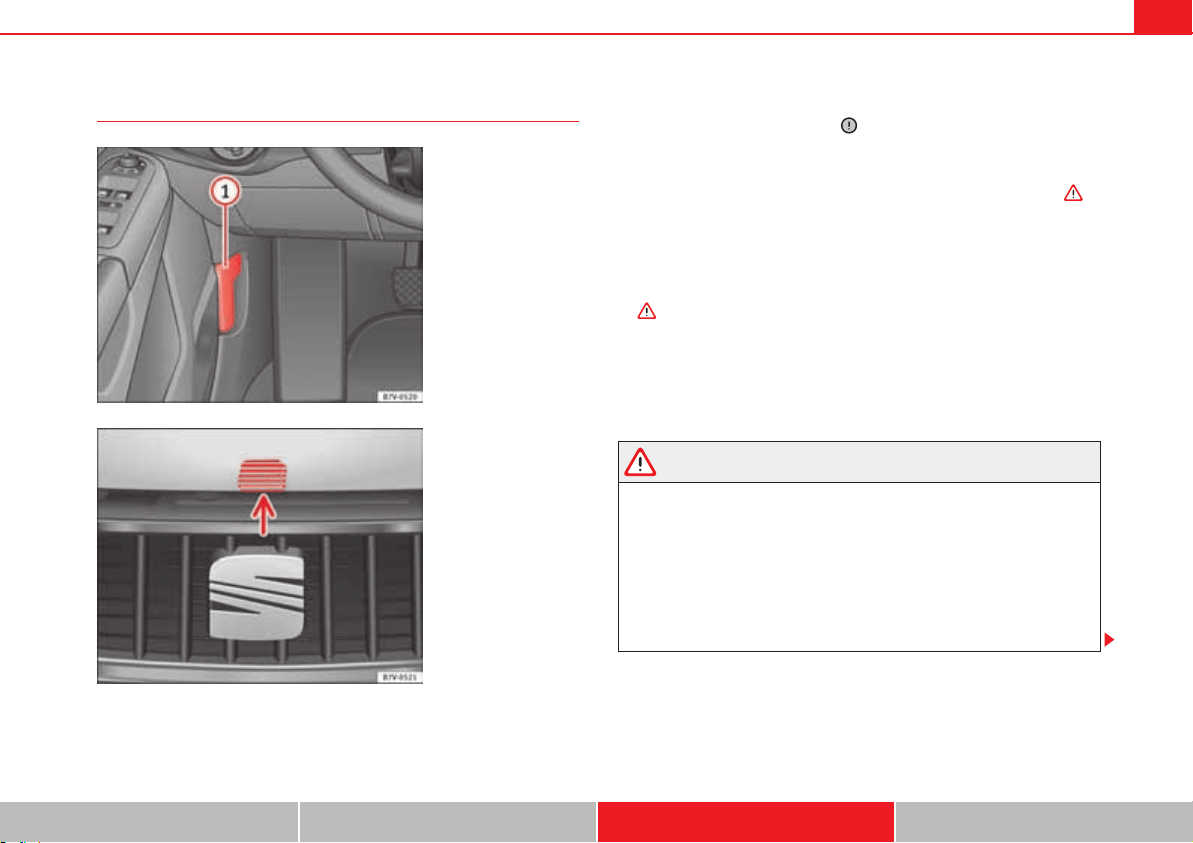
Checking and refilling levels 307
Safety First Operating instructions Practical tips Technical Data
Opening and closing the bonnet
Opening the bonnet
The lever to open the bonnet can only be used if the driver's door is open.
x Before opening the bonnet, make sure that the windscreen wiper arms are
in place against the windscreen .
x Open the driver's door.
x Pull the release lever page 307, fig. 173 in the direction of the arrow.
The bonnet is released from the lock carrier by a spring mechanism .
x Lift the bonnet using the release lever page 307, fig. 174 (arrow) and
open the bonnet fully. The bonnet is held open thanks to the gas strut.
Closing the bonnet
x To close the bonnet, pull it down to overcome the gas strut pressure
.
x Allow the bonnet to fall into the lock carrier. Do not press down.
If the bonnet is not correctly closed, open it once again and close it correctly.
The bonnet is correctly closed when it is flush with the corresponding parts
on the bodywork.
WARNING
If the bonnet is not correctly closed, it could suddenly open while driving
leaving the driver without visibility. This could result in serious accident.
x After closing the bonnet, always check that it is properly secured by the
locking mechanism in the lock carrier. The bonnet must be flush with the
surrounding body panels.
x While driving, if you notice that the bonnet is not correctly closed then
stop immediately and close it correctly.
x Only open and close the bonnet when there is nobody within its range.
Fig. 173 In the footwell
on the driver side: Lever
for unlocking the bonnet.
Fig. 174 Release lever to
open the bonnet in the
radiator grille.

Checking and refilling levels308
Caution
x To avoid damage to the bonnet and to the windscreen wiper arms, only
open the bonnet when the windscreen wipers are in place against the wind-
screen.
x Before driving, always lower the wiper arms.
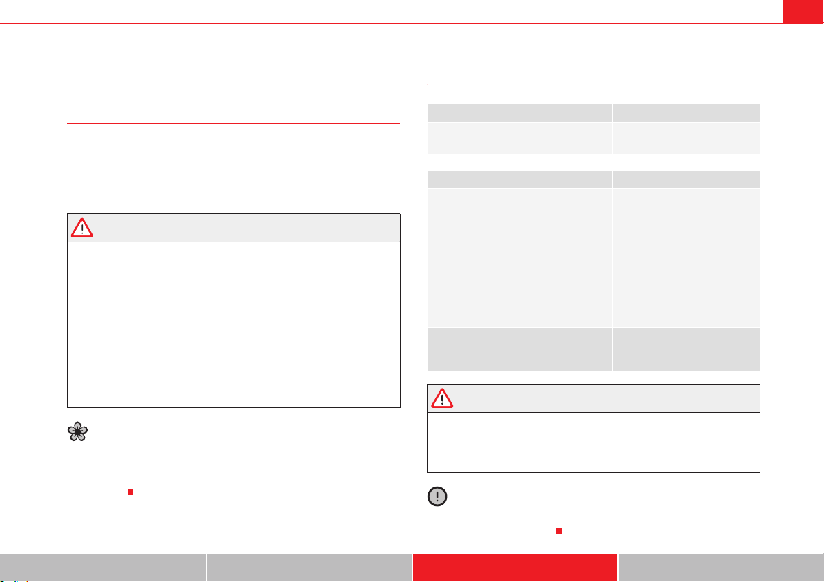
Checking and refilling levels 309
Safety First Operating instructions Practical tips Technical Data
Engine oil
Introduction
Additional information and warnings:
x Booklet “Maintenance Programme”
x Working in the engine compartment page 304
x Accessories, parts replacement, repairs and modifications page 285
WARNING
Incorrectly handling engine oil can cause injury and serious burns.
x Always protect your eyes when handling engine oil.
x Oil is toxic and must be kept out of the reach of children.
x Engine oil must only be kept closed in its original container. The same
applies to use oil until it has been disposed of.
x Never store engine oil in empty food containers or bottles as other
people may accidentally drink it.
x Regular contact with engine oil can be bad for the skin. If you come into
contact with engine oil, wash your skin with soap and water.
x With the engine running, the engine oil gets extremely hot and can
cause severe skin burns. Always wait until the engine has fully cooled.
For the sake of the environment
Similar to the other service liquids, spilled engine oil can be bad for the envi-
ronment. Collect any spilt fluids in suitable containers and dispose of in
accordance with legislation and with the utmost respect for the
environment.
Warning and control lamps
WARNING
If the warning lamps and messages are ignored, the vehicle may stall in
traffic, or may cause accidents and severe injuries.
x Never ignore the warning lamps or text messages.
x Stop the vehicle safely as soon as possible.
Caution
Failure to heed the warning lamps and text messages when they appear may
result in faults in the vehicle.
lights up Possible cause Solution
Insufficient engine oil.
Switch the engine off. Check the
engine oil level page 310.
flashes Possible cause Solution
E
Engine oil pressure too low.
Stop the vehicle!
Switch off the engine. Check the
engine oil level.
- If the warning indicator flashes
although the oil level is correct,
do not continue driving or leave
the engine running. Otherwise,
the engine could be damaged.
You should obtain professional
assistance.
Engine oil sensor faulty.
Contact a specialist workshop.
Have the engine oil sensor
checked.
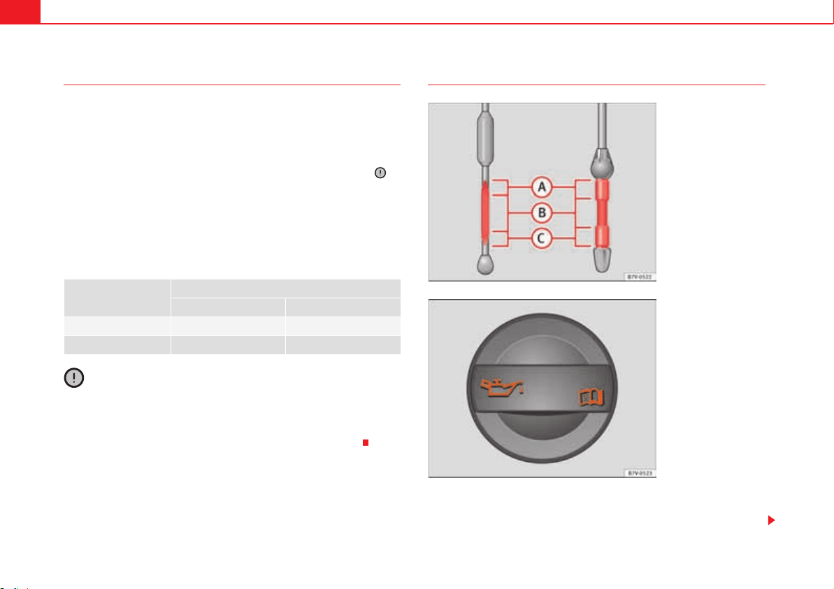
Checking and refilling levels310
Engine oil specifications
Replacement engine oil must strictly comply with the specifications.
The correct oil must be used to ensure the correct operation and long service
life of the engine. The engine comes with a high-quality multigrade oil that
can generally be used all year round.
Only use an oil that complies to SEAT standards whenever possible . If
you wish to maintain the long-life service duration, only engine oils approved
for this service according to the corresponding VW standard ( table on
page 310) may be used. All oils indicated are synthetic multigrade oils.
Engine oils are being continuously further developed. Qualified workshops
are permanently informed of any modifications. SEAT therefore recommends
that you have the engine oil changed by a SEAT Dealership.
Caution
x Only use engine oils whose specifications are expressly approved by
SEAT. The use of any other type of engine oil could cause engine damage!
x No additives should be used with engine oil. Any damage caused by the
use of such additives would not be covered by the factory warranty.
Checking the engine oil level and topping up
Preparations
x Park the vehicle on flat ground so that the engine oil reading is correct.
Engines
Engine oil specifications
with LongLife service without LongLife service
Petrol engines VW 504 00, VW 503 00 VW 504 00, VW 502 00
Diesel engines VW 507 00 VW 507 00
Fig. 175 Marked engine
oil dipstick.
Fig. 176 In the engine
compartment: Engine oil
filler cap.
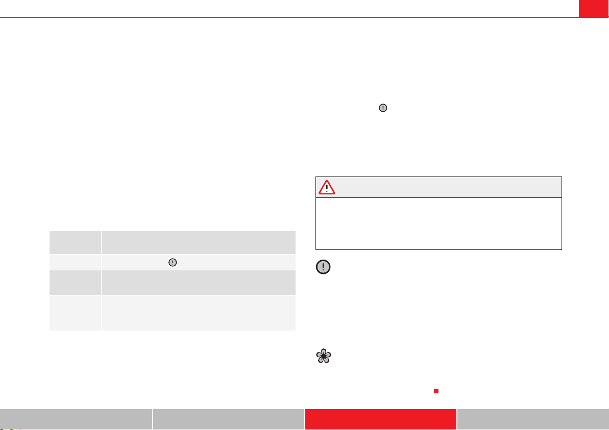
Checking and refilling levels 311
Safety First Operating instructions Practical tips Technical Data
x Stop the engine and wait a few minutes for the oil to drain back into the
sump. When the engine has cooled down, immediately check the oil level and
top up if necessary.
x Open the bonnet page 304.
x The engine oil filler opening can be recognised by the symbol E on the
cap page 310, fig. 176 and the dipstick by its coloured handle.
Checking the engine oil level
x Pull out the dipstick and wipe it on a clean cloth.
x Replace the dipstick, pushing it in as far as it will go. If the dipstick has a
mark, when you reintroduce it this mark should slot into the corresponding
groove located on the upper end of the tube.
x Remove the dipstick again and check the engine oil level table on
page 311.
x After reading the oil level, replace the dipstick in the tube completely.
Engine oil topping up ranges
Adding oil after checking the level
Only add engine oil in small quantities and in steps.
x Unscrew the cap from engine oil filler opening on the cylinder head
page 310, fig. 176. If you are not sure where the cap is, request help from
a specialist.
x Only refill using engine oil expressly approved by SEAT and in small quan-
tities (not more than 0.5 L or 1/2 a quarter of a gallon at a time) page 310.
x To avoid adding too much oil, each time you add a quantity, wait until the
oil has flowed into the crankcase so that it can be measured with the dipstick.
x Check the oil level before adding any more oil. Do not top up with too
much engine oil .
x When the oil level is in at least the page 310, fig. 175 zone, insert
the dipstick into the tube fully to avoid engine oil escaping when the engine
is running.
x After topping up the oil, ensure that the cap is screwed on to the filler
mouth correctly.
WARNING
Oil could catch fire if it comes into contact with hot engine components.
This could lead to a fire, explosion and severe injuries.
x Always ensure that after topping of oil, the engine oil filler cap is
correctly tightened. This will avoid engine oil spilling onto hot engine parts
when the engine is running.
Caution
x If the oil level is above the area page 310, fig. 175 do not start the
engine. You should obtain professional assistance. Otherwise catalytic
converter and engine damage may occur.
x When refilling or changing service liquids, ensure that you put the liquids
into the right tank. Making a mistake when refilling could cause serious
malfunctions and damage the engine!
For the sake of the environment
The oil level must never be above area page 310, fig. 175 . Otherwise
oil can be drawn in through the crankcase breather and escape into the
atmosphere via the exhaust system.
page 310,
fig. 175
Operations required depending on the engine oil topping
up level:
Area
Do not top up oil .
Area
Add approximately 0.5 L of oil (1/2 quarter of a gallon). The
oil level can be in the zone , but never above .
Area :
It is essential to add oil (approximately 1 litre or quarter of
a gallon). Ensure that the level is around the centre of the
zone after adding oil.
A
A
A
B
A
A
A
A
A
C
A
B
A
B
A
A
A
A
Checking and refilling levels312
Engine oil consumption
The consumption of engine oil can be different from one engine to another
and can vary during the useful life of the engine.
Depending on driving style and the conditions of use, the consumption of
engine oil can reach 1 litre every 2,000 km (one quarter of a gallon every
1,200 miles); for new vehicles, this could be higher for the first 5,000 km
(3,000 miles). For this reason the engine oil level must be checked at regular
intervals, preferably when filling the tank and before a journey.
When the engine is working hard, for instance during sustained high-speed
motorway cruising in summer, when towing a trailer or climbing mountain
passes, the oil level should preferably be kept within area page 310,
fig. 175 .
Changing the engine oil
The engine oil must be changed regularly according to the specifications of
the Maintenance Programme.
Due to the problems linked with disposing of used oil and the need for suit-
able tools and special knowledge, always visit a qualified workshop to have
the engine oil and filter changed. SEAT recommends visiting a qualified work-
shop.
Detailed information on the service intervals are shown in the Maintenance
Programme.
Engine oil additives make new oil darker after the engine has been running
for a short period. This is normal and does not mean more frequent oil
changes are required.
WARNING
If, in exceptional circumstances, you must change the engine oil yourself,
please note the following:
x Wear eye protection.
x Always wait until the engine has completely cooled to avoid being
burned.
x Always keep your arms horizontal when unscrewing the oil drainage
bolt so that the oil does not run down your arms when it begins to drain.
x Use a suitable and large enough container to collect all of the used oil
in the engine.
x Never collect engine oil in empty food containers, cans, bottles and
other containers as not all people are able to identify engine oil.
x Oil is toxic and must be kept out of the reach of children.
For the sake of the environment
Before changing the engine oil, find a suitable location or service for proper
disposal.
For the sake of the environment
Always dispose of engine oil with the utmost respect for the environment.
Never dispose of used engine oil in places such as a garden, woods, drains,
roads, paths, rivers and drainage systems.
A
A
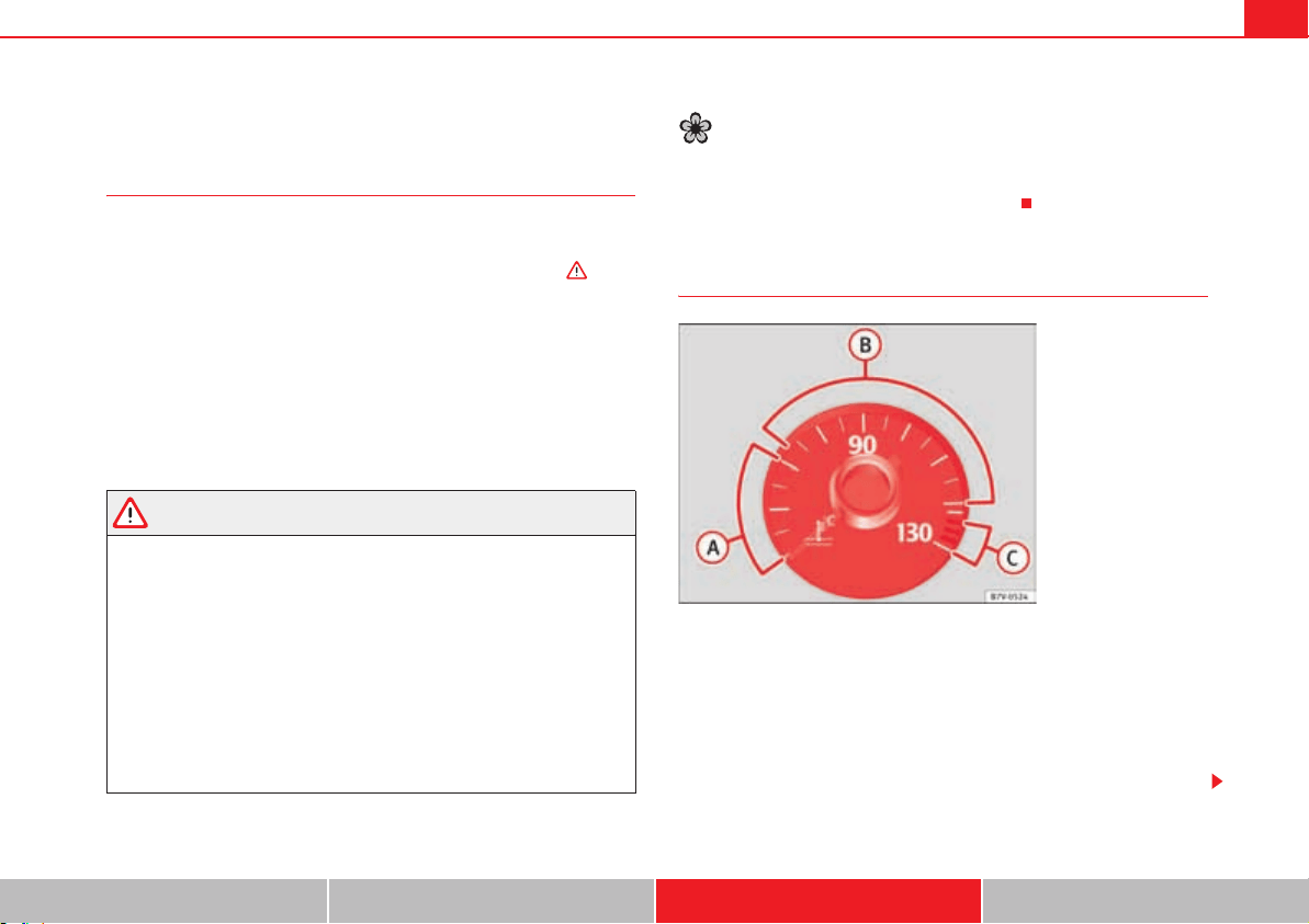
Checking and refilling levels 313
Safety First Operating instructions Practical tips Technical Data
Engine coolant
Introduction
Never work on the engine cooling system or if you are not familiar with the
operations to be carried out, the applicable safety standards and especially
if you do not have the instruments, liquids and tools necessary ! Have
the work carried out by a qualified workshop if you are uncertain. SEAT recom-
mends visiting a qualified workshop.
Negligent work can cause serious injury.
Additional information and warnings:
x Towing mode page 260
x Working in the engine compartment page 304
x Accessories, parts replacement, repairs and modifications page 285
WARNING
Engine coolant is toxic!
x Only keep engine coolant in its original container, tightly shut and in a
safe place.
x Never store engine coolant in empty food containers or bottles as other
people may accidentally drink it.
x Always keep engine coolant out of reach of children.
x Ensure that the proportion of engine coolant additive corresponds to
the lowest outside temperature to which the vehicle will be exposed.
x If the outside temperature is extremely low, the engine coolant could
freeze causing the vehicle to stop. As this would also cause the heating to
stop working, passengers without sufficient clothing could freeze.
For the sake of the environment
Coolants and additives can contaminate the environment. Collect any spilt
fluids in suitable containers and dispose of in accordance with legislation
and with the utmost respect for the environment.
Coolant temperature warning lamp and gauge
When driving normally, the needle will remain in the middle area. The temper-
ature may also rise when the engine is working hard, especially at high
outside temperatures and so the indicator will move quite far to the right-
hand side.
Several warning and control lamps should light up for a few seconds when
the ignition is switched. This signals that the lamp is working properly. They
will switch off after a few seconds.
Fig. 177 Engine coolant
temperature gauge on the
instrument panel: cold
area; normal area;
warning area.
A
A
A
B
A
C
Checking and refilling levels314
WARNING
If the warning lamps and messages are ignored, the vehicle may stall in
traffic, or may cause accidents and severe injuries.
x Always observe any lit warning lamps and text messages.
x Never ignore the warning lamps or text messages.
x Stop the vehicle safely as soon as possible.
Caution
Failure to heed the warning lamps and text messages when they appear may
result in faults in the vehicle.
Engine coolant specifications
The engine cooling system comes with a special mixture of water and at least
40% G 12 plus-plus (TL-VW 774 G) or G 12 plus (TL-VW 774 F) engine coolant
additive. Both are easily recognisable because they are purple in colour.
This mixture gives the necessary frost protection down to -25 °C (-13 °F) and
protects the alloy parts of the cooling system against corrosion. It also
prevents scaling and raises the boiling point of the coolant.
To protect the engine cooling system, the proportion of additive must always
be at least 40%, even if frost protection is not required in countries with a
warm climate.
If greater frost protection is required in very cold climates, the proportion of
additive can be increased. However, the percentage of additive should not
exceed 60 %, as this would reduce the frost protection and, in turn, decrease
the cooling capacity.
When adding coolant, a mixture of distilled water and at least 40 % of the
additive G 12 plus-plus must be use to ensure optimum rust protection .
lights up
Gauge
position
page 31
3, fig. 177
Possible cause Solution
v
Warning
area
Excessive engine
coolant tempera-
ture.
Stop the vehicle!
Stop the vehicle safely as
soon as possible. Switch off
the engine and wait for it to
cool down and for the needle
to return to the normal area.
Check the engine coolant level
page 315.
Normal
area
Insufficient engine
coolant level.
Check the engine coolant
when the engine has cooled
and, if it is low, refill with
engine coolant page 315.
Although the coolant level is
correct, there is a fault.
--
Engine coolant
system faulty.
Do not drive any further.
Obtain professional assist-
ance.
--
Cold area
--
Avoid revving the engine too
much or making it work hard
while it has not reached nor-
mal service temperature.
flashes Possible cause Solution
v
Engine coolant system faulty.
You should obtain profes-
sional assistance.
A
C
A
B
A
A
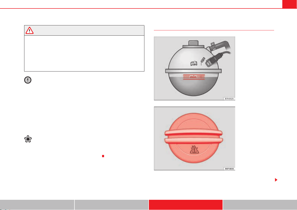
Checking and refilling levels 315
Safety First Operating instructions Practical tips Technical Data
WARNING
In the event of insufficient antifreeze protection in the engine cooling
system, the engine could be damaged and severe injuries caused.
x Ensure that the proportion of engine coolant additive corresponds to
the lowest outside temperature to which the vehicle will be exposed.
x If the outside temperature is extremely low, the engine coolant could
freeze causing the vehicle to stop. As this would also cause the heating to
stop working, passengers without sufficient clothing could freeze.
Caution
Never mix genuine additives with other additives that are not approved by
SEAT. Otherwise, you run the risk of causing severe damage to the engine and
the engine cooling system.
x The engine coolant G 12 plus-plus can be mixed with G 12 plus and G 11.
x If the fluid in the expansion reservoir is not purple but, for example,
brown, this means that you have mixed G 12 plus-plus or G 12 plus with
another coolant. The coolant must be changed as soon as possible if this is
the case! Failure to observe this point will result in serious malfunctions and
engine damage!
For the sake of the environment
Coolants and additives can contaminate the environment. Collect any spilt
fluids in suitable containers and dispose of in accordance with legislation
and with the utmost respect for the environment.
Checking the engine coolant level and refilling
If the coolant level is low, the coolant warning indicator will light.
Fig. 178 In the engine
compartment: Marking on
coolant expansion reser-
voir.
Fig. 179 In the engine
compartment: Coolant
expansion tank cap.
Checking and refilling levels316
Preparations
x Park the vehicle on even, flat and firm ground.
x Allow the engine to cool .
x Open the bonnet page 304.
x The coolant expansion reservoir is easily recognisable because of the
symbol « on the cap page 315, fig. 179.
Checking the engine coolant level
x When the engine is cold, check the coolant level using the side marking
on the expansion reservoir page 315, fig. 178.
x If the level is below the “MIN” mark, top up with coolant. When the engine
is hot it may be slightly above the marked area.
Topping up the engine coolant level
x Always protect your face, hands and arms from hot coolant and steam
using a large, thick cloth over the coolant expansion tank cap.
x Remove the cap very carefully .
x Only refill using new engine coolant according to SEAT specifications
( page 314) .
x The engine coolant level should be between the marks on the coolant
expansion tank page 315, fig. 178. Do not exceed the top level of the
marked area .
x Screw on the cap tightly.
x If, the event of an emergency, you have no coolant that is compliant to the
required specifications ( page 314), never use another type of additive.
Instead, first top up with distilled water only. Then re-establish the
correct proportion of the mixture with the correct additive as soon as possible
page 314.
WARNING
Hot vapours and coolant can cause serious burns.
x Never open the coolant expansion tank if steam or coolant is coming
from the engine compartment. Wait until you cannot see or hear any steam
or coolant escaping.
x Always wait until the engine has completely cooled before very care-
fully opening the expansion tank cap. Contact with hot elements of the
engine can cause skin burns.
x Once the engine has cooled, follow the instructions below before
opening the bonnet:
Turn on the electronic parking brake and place the gear selector lever
in P or the gear stick in neutral.
Remove the key from the ignition.
Keep children away from the engine compartment and never leave
them unsupervised.
x When the engine is warm or hot, the cooling system is pressurised! Do
not unscrew the cap on the expansion tank when the engine is hot. Other-
wise, coolant may spray out under pressure causing burns and serious
injury.
Carefully and slowly unscrew the cap anticlockwise, gently pressing
down on it.
Always protect your face, hands and arms from hot coolant and
steam using a large, thick cloth.
x When refilling liquids, avoid spilling them on parts of the engine and
the exhaust system. Spilled liquids could cause a fire. Under specific
circumstances, the ethylene glycol can catch fire.
Caution
x Top up with distilled water only. Any other type of water may lead to
considerable rusting in the engine due to its chemical components. This
could consequently damage the engine. If you have not used distilled water
WARNING (continued)

Checking and refilling levels 317
Safety First Operating instructions Practical tips Technical Data
but another type of water to top up the coolant, a specialist workshop must
immediately replace all of the fluid in the engine cooling system.
x Only top up coolant to the top level of the marked area page 315,
fig. 178. Otherwise the excess coolant will be forced out of the cooling system
when the engine is hot, causing damage.
x If a lot of liquid coolant has been lost, wait for the engine to cool down
completely before adding coolant. Extensive coolant loss is an indication of
leaks in the engine cooling system. Have the engine cooling system
inspected immediately by a qualified workshop. Otherwise you may damage
the engine.
x When refilling or changing service liquids, ensure that you put the liquids
into the right tank. Making a mistake when refilling could cause serious
malfunctions and damage the engine!
Checking and refilling levels318
Vehicle battery
Introduction
The battery is a component of the vehicle's electrical system.
Never work on the electrical system without fully understanding the opera-
tions required, the applicable safety standards and without the correct tools
! Have the work carried out by a qualified workshop if you are uncertain.
SEAT recommends visiting a qualified workshop. Negligent work can cause
serious injury.
Location and number of batteries in the vehicle
The battery is located in the engine compartment.
Explanation of the warning indications on the vehicle's battery
Additional information and warnings:
x Booklet “Maintenance Programme”
x Starter assist systems (Start-Stop function) page 221
x Working in the engine compartment page 304
x Accessories, parts replacement, repairs and modifications page 285
WARNING
Working on the vehicle battery and the electrical system can cause corro-
sion, fire and electric shocks. Always read and take into account the
following warnings and safety standards before carrying out any work:
x Before working on the battery, switch off the engine, the ignition and
all electrical devices then disconnect the negative connection on the
battery.
x Keep children away from acid and the battery itself!
x Wear eye protection.
x Battery acid is very corrosive and caustic. It can burn skin and cause
blindness. When handling the battery, protect yourself from splashes of
acids, above all your hands, arms and face.
x Do not smoke and never work close to places exposed to flames or
sparks.
x Avoid sparks and electrostatic discharges when working with cables
and electrical devices.
x Never short the battery terminals.
x Never use a damaged battery. It can explode. Replace a damaged
battery immediately.
x Replaced damaged or frozen batteries as soon as possible. A flat
battery can freeze at temperatures around 0°C (+32 °F).
x Vehicles with the battery in the luggage compartment: Ensure that the
battery ventilation hose is correctly secured.
Caution
x Never disconnect the battery if the ignition is switched on or if the engine
is running. This could damage the electrical system or electronic compo-
nents.
Symbol Meaning
Wear eye protection!
Battery acid is very corrosive and caustic. Always wear
protective gloves and eye protection!
Fires, sparks, naked lights and smoking are prohibited.
A highly explosive mixture of gases is released when the
battery is under charge.
Keep children away from acid and batteries!
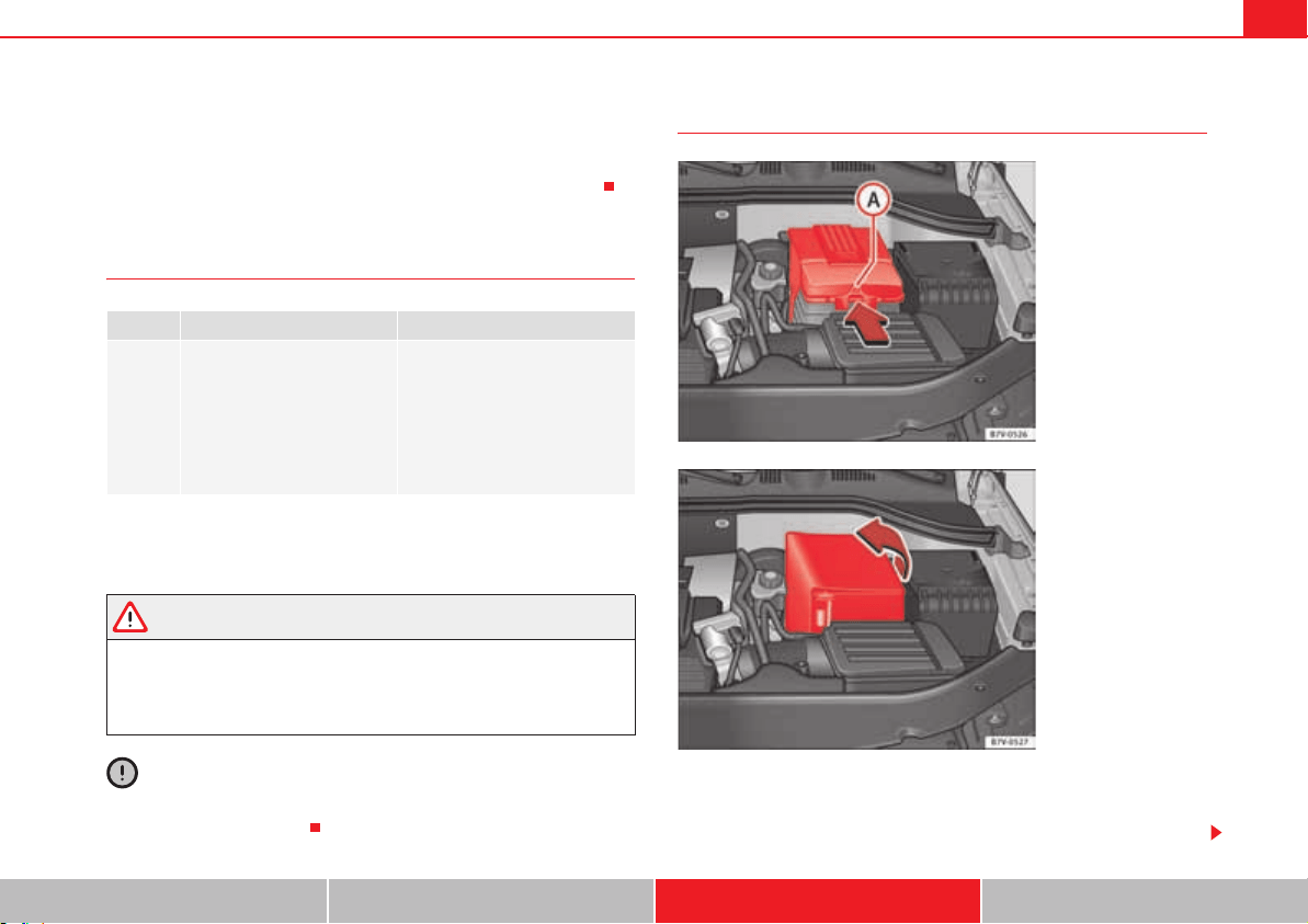
Checking and refilling levels 319
Safety First Operating instructions Practical tips Technical Data
x Do not expose the battery to direct sunlight over a long period of time, as
the intense ultraviolet radiation can damage the battery housing.
x If the car is left standing for long periods, protect the battery from extreme
cold temperature so that it does not “freeze up” and become damaged.
Warning lamp
Several warning and control lamps should light up for a few seconds when
the ignition is switched. This signals that the lamp is working properly. They
will switch off after a few seconds.
WARNING
If the warning lamps and messages are ignored, the vehicle may stall in
traffic, or may cause accidents and severe injuries.
x Never ignore the warning lamps or text messages.
x Stop the vehicle safely as soon as possible.
Caution
Failure to heed the warning lamps and text messages when they appear may
result in faults in the vehicle.
Checking the electrolyte level of the vehicle battery
The battery's electrolyte level should be checked regularly in high-mileage
vehicles, in hot countries and in older batteries. Other batteries do not
require maintenance.
lights up Possible cause Solution
F
Faulty generator.
Contact a specialist workshop.
Have the electrical system
checked.
Disconnect any unnecessary
electrical consumers. The gener-
ator does not charge the battery
while the vehicle is in motion.
Fig. 180 In the engine
compartment: Remove
the cover from the
vehicle's battery.
Fig. 181 In the engine
compartment: Unfold the
vehicle's battery hose.
Checking and refilling levels320
Start-Stop systems page 223 are equipped with a special battery labelled
“AGM”. For technical reasons, it is not possible to check the electrolyte level
of these batteries
Preparations
x Prepare the vehicle for work in the engine compartment page 304
x Open the bonnet page 304.
Opening the battery cover
The battery covers are different depending on the engine size of the vehicle:
x In the case of a cover: press the tab page 319, fig. 180 in the direc-
tion of the arrow and pull the cover upwards.
x In the case of a hose: fold the cover to one side to remove page 319,
fig. 181.
Checking the battery electrolyte level
x Make sure there is sufficient lighting to clearly recognise the colours.
Never use open flames or sparklers as a light source.
x Depending on the level of acid, the Magic eye on the top of the battery will
change colour.
WARNING
Working with the vehicle battery involves a risk of corrosion, explosions
and electric shock.
x Always wear protective gloves and eye protection.
x Battery acid is very corrosive and caustic. It can burn skin and cause
blindness. When handling the battery, protect yourself from splashes of
acids, above all your hands, arms and face.
x Never tilt the vehicle battery. Battery acid could spill out of the open-
ings to release gases and cause corrosion damage.
x Never open the vehicle battery.
x If battery acid splashes on you, immediately rinse your eyes and skin
abundantly with water for several minutes. Then seek medical care imme-
diately.
x If acid is swallowed by mistake, consult a doctor immediately.
Charging, replacing and connecting or disconnecting the
battery
Charging the battery
The vehicle battery should be charged by a specialist workshop only, as
batteries using special technology have been installed and they must be
charged in a controlled environment . SEAT recommends visiting a qual-
ified workshop.
Replacing a vehicle battery
The battery has been developed to suit the conditions of its location and has
special safety features. If the battery must be replaced, consult a qualified
SEAT workshop for information on electromagnetic compatibility, the size
and maintenance, performance and safety requirements of the new battery in
your vehicle before you purchase one. SEAT recommends you have the
battery replaced by a qualified SEAT workshop.
Use only maintenance-free genuine batteries conforming to TL 825 06 and
VW 7 50 73 Standards. These standards must be dated April 2008 or later.
Colour indicator Necessary operations
light yellow or col-
ourless
The electrolyte level of the vehicle's battery is too low.
Have the battery checked and, where applicable,
replaced by a specialist workshop.
Black indication The electrolyte level of the vehicle's battery is correct.
A
A
WARNING (continued)

Checking and refilling levels 321
Safety First Operating instructions Practical tips Technical Data
Start-Stop systems page 223 are equipped with a special battery. There-
fore, it must only be replaced with a battery of the same specifications.
Disconnecting the vehicle's battery
If you must disconnect the battery from the electrical system, please note the
following:
x Switch off the ignition and all electrical equipment.
x The vehicle must be unlocked before disconnecting the battery, otherwise
the alarm will be triggered.
x First disconnect the negative cable and then the positive .
Connecting the vehicle's battery
x Before reconnecting the battery, switch off the engine, the ignition and
electric devices.
x First reconnect the positive cable and then the negative .
Different control lamps may light up after connecting the battery and
switching the ignition on. They will be turned off after a short trip at a speed
of between 15 - 20 km/h (10 - 12 mph). If the warning indicators remain lit,
please visit a specialised workshop to have the vehicle checked.
If the battery has been disconnected for a long time, it is possible that the
next service date is not displayed or calculated correctly page 64. Respect
the maximum service intervals permitted Booklet “Maintenance
Programme”.
Vehicles with the KESSY system ( page 86): If, after connecting the battery,
the ignition cannot be switched on, lock and unlock the vehicle from outside.
Then try to switch the ignition back on. If the ignition can still not be switched
on, request the assistance of a specialist workshop.
Automatic consumer disconnection
The intelligent vehicle electrical system automatically implements a range of
measures to prevent the battery from discharging when high demands are
made on it:
x the idling speed is increased so that the alternator provides more elec-
tricity.
x where necessary, the power of the most powerful consumers is reduced
or even completely disconnected.
x On starting the engine, the power supply from the 12-volt sockets and the
cigarette lighter may be interrupted for a short time.
The on-board management program cannot always prevent the battery from
running flat. For example, if the ignition is left on for a long period with the
engine off or if the side lights or parking lights are left on while the vehicle is
stationary.
Why does the battery run flat?
x When stationary for a long time without starting the engine, particularly if
the ignition is switched on.
x Use of electrical consumers with the engine switched off.
x If the auxiliary heater is running page 187.
WARNING
Incorrectly securing the battery or using the wrong battery can cause
short-circuits, fire and serious injuries.
x Always use only maintenance free batteries that do not run flat alone
and whose properties, specifications and size correspond to the standard
battery. The specifications are indicated on the battery case.
WARNING
A highly explosive mixture of gases is released when the battery is under
charge.
x The batteries should be charged in a well-ventilated room only.
x Never charge a frozen or recently thawed battery. A flat battery can
freeze at temperatures around 0°C (+32 °F).
Checking and refilling levels322
x Always replace a battery which has frozen.
x Battery cables not correctly connected may cause a short circuit.
Reconnect first the positive cable and then the negative cable.
Caution
x Never disconnect the battery if the ignition is switched on or if the engine
is running. This could damage the electrical system or electronic compo-
nents.
x Never plug accessories supply current, such as solar panels or a battery
charger, to the 12-volt sockets or the cigarette lighter. This could damage the
vehicle's electrical system.
For the sake of the environment
Dispose of the battery in an environment-friendly manner. Batteries contain
toxic substances such as sulphuric acid and lead.
For the sake of the environment
Battery acid can contaminate the environment. Collect any spilt service fluids
and allow a dispose of them correctly.
WARNING (continued)

Wheels and tyres 323
Safety First Operating instructions Practical tips Technical Data
Wheels and tyres
Wheels
Introduction
SEAT recommend that all work on tyres and wheels is carried out by a quali-
fied workshop. They have the necessary special tools and replacement parts,
trained personnel and facilities for disposing of the old tyres. SEAT recom-
mends visiting a qualified workshop.
Additional information and warnings:
x Transporting page 13
x Towing mode page 260
x Braking, stopping and parking page 210
x Park assist system page 229
x Tyre control systems page 245
x Caring for and cleaning the vehicle exterior page 269
x Wheel trims page 336
x Change wheel page 339
x Notes for the user page 283
WARNING
The vehicle cannot be totally controlled or braked if the tyres (new or used)
are worn or damaged.
x Incorrect use of wheels and tyres could make driving more dangerous
and result in serious accidents and damage.
x All four wheels must be fitted with radial tyres of the same type, size
(rolling circumference) and the same tread pattern.
x New tyres do not give maximum grip and will not have reached their
maximum braking capacity to start with, and therefore need running in. To
prevent accidents and major damage, extreme caution should be taken for
the first 600 km (370 miles).
x Check tyre pressures regularly and ensure they are maintained at the
pressures indicated. If the tyre pressure is too low, the tyres could over-
heat, resulting in tread detachment or even burst tyres.
x Never drive on damaged (punctured, cut, cracked or dented) or worn
tyres. Driving on damaged or worn tyres could result in burst tyres, serious
accidents or damage. Worn or damaged tyres must be replaced immedi-
ately.
x Never exceed the maximum permitted speed or loads specified for the
type of tyre fitted on your vehicle.
x The efficiency of driver and brake assist systems also depends on the
grip of the tyres.
x If you notice unusual vibration or if the vehicle pulls to one side when
driving, stop the car immediately and check the tyres and wheels for
damage.
x To minimise the risk of losing control of the vehicle or causing a serious
accident, never undo the bolted joints of beadlock wheels.
x Never mount used tyres or wheels if you are not sure of their previous
history. They may be damaged, although the damage is not immediately
visible.
x Old tyres, even if they have never been used, may lose air or burst unex-
pectedly while driving, resulting in serious accident or damage. If tyres are
over six years old, they should only be used in an emergency and with
extreme caution.
WARNING (continued)

Wheels and tyres324
Note
For technical reasons, it is not generally possible to use the wheels from other
vehicles. In some cases, this may also be true for the same model of wheel.
Please refer to the vehicle documents or ask at a SEAT qualified workshop.
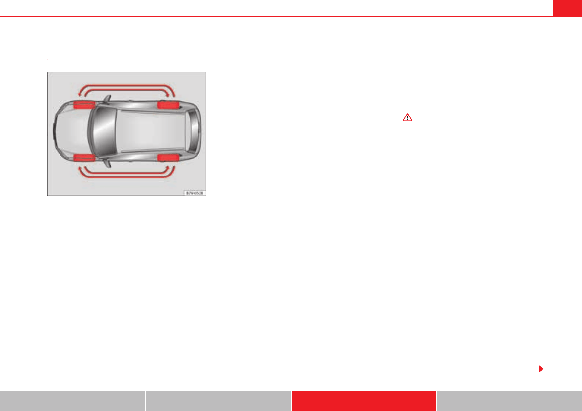
Wheels and tyres 325
Safety First Operating instructions Practical tips Technical Data
About your tyres and wheels
The tyres of a vehicle are the components which are subjected to most stress
and are the most underestimated. Tyres are very important, as the support
offered by their narrow surface is the only point of contact between the
vehicle and the road.
The service life of tyres is dependent on tyre pressure, driving style, the care
they receive and the correct fitting.
The tyres and wheel rims are an essential part of the vehicle's design. The
tyres and rims approved by SEAT are specially matched to the characteristics
of the vehicle and our critical to good road holding and safe handling.
Avoiding damage to tyres and wheels
x If you have to drive over a kerb or similar obstacle, drive very slowly and
as near as possible at a right angle to the kerb.
x Inspect the tyres regularly for damage (punctures, cuts, cracks, dents).
x Remove any foreign bodies found on the outside of the tread provided
they have not passed through the wall of the tyre page 330.
x The instructions for tyre control systems should always be observed.
x Replace damaged or worn tyres as soon as possible page 330.
x Regularly check tyres for non-visible damage page 330.
x Never exceed the maximum permitted speed or loads specified for the
type of tyre fitted on your vehicle page 333.
x Do not allow tyres to come into contact with aggressive substances,
grease, oil, fuel or brake fluid .
x Lost valve caps should be replaced immediately.
Tyres with directional tread pattern
Tyres with directional tread pattern have been designed to operate best when
rotating in only one direction. An arrow on the tyre sidewall indicates the
direction of rotation on tyres with directional tread page 333. Always
observe the direction of rotation indicated when mounting the wheel. This
guarantees optimum grip and helps to avoid aquaplaning, excessive noise
and wear.
If the tyre is mounted in the opposite direction of rotation, drive with extreme
caution, as the tyre is no longer being used correctly. This is of particular
importance when the road surface is wet. Change the tyre as soon as possible
or remount it with the correct direction of rotation.
Interchanging tyres
To ensure that the wear is equal on all tyres the wheels should be changed
round from time to time according to the system fig. 182. All the tyres will
then last for about the same time.
SEAT recommends you take the vehicle to a qualified workshop to have the
tyres changed.
Tyres that are over 6 years old
Tyres are subject to an ageing process as a result of physical and chemical
processes. This may affect their performance. Tyres which are stored for long
periods of time without being used, harden and become more fragile than
tyres which are in constant use.
Fig. 182 Diagram for
changing wheels
Wheels and tyres326
SEAT recommends that tyres over six years old are replaced with new tyres.
This also applies to tyres which appear to be in perfect condition on the
outside and which have a tread depth within the values stipulated by the Law
.
The date of manufacture, part of the tyre identification number (TIN), indi-
cates the age of the tyre page 333.
Storing tyres
Mark tyres when you remove them to indicate the direction of rotation (left,
right, forwards, backwards). This ensures you will be able to mount them
correctly when you replace them. When removed, the wheels and/or tyres
should be stored in a cool, dry and preferably dark location. Do not place
tyres mounted on the wheel in a vertical position.
Protect tyres not mounted on wheels from dirt by storing them in suitable
bags and standing them on the ground on their tread.
WARNING
Aggressive fluids or substances could result in visible or invisible damage
with the consequent risks.
x Always ensure that tyres do not come into contact with chemical prod-
ucts, oil, grease, fuel, brake fluid or other aggressive substances.
WARNING
Old tyres, even if they have never been used, may lose air or burst unex-
pectedly while driving, resulting in serious accident or damage.
x If tyres are over six years old, they should only be used in an emergency
and with extreme caution.
For the sake of the environment
Old tyres must be disposed of by qualified personnel according to the laws in
the country concerned.
Wheel rims
The design of wheel bolts is matched to the rims. If different rims are fitted,
the correct wheel bolts with the right length and correctly shaped bolt heads
must be used. This ensures that wheels are fitted securely and that the brake
system functions correctly page 339.
For technical reasons, it is not generally possible to use the wheels from other
vehicles. In some cases, this may also be true for the same model of wheel.
The tyres and rims approved by SEAT are specially matched to the character-
istics of the vehicle and are critical to good road holding and safe handling.
Wheel bolts
Wheel bolts must be tightened to the correct torque page 339.
Beadlock wheel rims
Beadlock wheel rims have various components. These are joined together by
special bolts using a special procedure. This ensures good performance, a
better seal, improved safety and wheel run out. Therefore, worn rims should
always be replaced and must only be repaired in a qualified workshop. SEAT
recommends visiting a qualified workshop .
Wheel rims with bolted trims
Wheel rims may be fitted with interchangeable trim parts which are attached
to the rim using self-locking bolts. Worn trims should only be replaced at a
qualified workshop. SEAT recommends visiting a qualified workshop .
Wheels and tyres 327
Safety First Operating instructions Practical tips Technical Data
WARNING
The use of worn or damaged wheel rims could make driving more
dangerous and result in serious accidents and damage.
x Only wheel rims which have been approved for use with your vehicle
should be used.
x Inspect wheel rims regularly for damage and replace as required.
WARNING
If the bolted joints of wheel rims with bolted ring trims are not correctly
tightened or loosened, this could result in serious accident.
x Never loosen the bolted joints of wheel rims with bolted ring trims.
x Any work relating to wheel rims with bolted rims should be carried out
at qualified workshop. SEAT recommends visiting a qualified workshop.
Replacement of new tyres and wheel rims
New tyres
x When tyres are new, drive with extreme caution for the first 500 km (310
miles), as all tyres need to be run-in. Tyres which have not been run-in do not
have such good grip or braking capacity .
x All four wheels must be fitted with radial tyres of the same type, size
(rolling circumference) and the same tread pattern.
x The tread depth of new tyres may vary, according to the type and make of
tyre and the tread pattern.
Replacing tyres
x Where possible, always replace both wheels on an axle (both wheels on
the front axle or both wheels on the rear axle) .
x Old tyres should only be replaced by SEAT approved tyres for the vehicle
in question, and in accordance with the maximum permitted size, diameter,
load and speed capacity.
x Never use tyres which are larger than SEAT approved tyres. If the tyres are
too big, they may knock or rub against the chassis or other components,
resulting in damage.
WARNING
New tyres do not give maximum grip and will not have reached their
maximum braking capacity to start with, and therefore need running in.
x To prevent accidents and major damage, extreme caution should be
taken for the first 600 km (370 miles).
WARNING
There should be adequate space between the tyres and the vehicle in
accordance with the vehicle design. If this is not the case, the tyres may rub
against parts of the running gear, chassis or brake lines, leading to faults
in the brake system or to tread detachment, and the risk of burst tyres.
x The true tyre dimension should not be greater than the dimensions of
tyres manufactured and approved by SEAT and should not rub against parts
of the vehicle.
Note
Although tyres may be shown as being the same size, the true dimensions of
different types of tyre may vary with respect to the nominal size, or tread
patterns may be different.
Note
If you use tyres that are approved by SEAT, you can be sure that the true tyre
dimensions will be correct for your vehicle. For other tyre models, the tyre
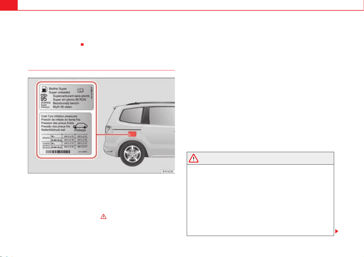
Wheels and tyres328
vendor should provide the manufacturer's certificate with the tyre, indicating
that this type of tyre is suitable for your vehicle. This certificate should always
be carried with the vehicle.
Tyre pressures
Fig. 183 Position of tyre pressure specification plate.
The correct tyre pressures for tyres fitted at the factory is shown on a label and
is valid for summer and winter tyres. This label fig. 183 is either in the
driver's door strut or inside the fuel cap.
Under-inflation or over-inflation will reduce the life of the tyres considerably
and also impair the car's handling . It is essential to maintain the
correct tyre pressures, especially if driving at high speeds. Incorrect tyre pres-
sure causes premature wear and could cause tyre blow-out.
The pressure should therefore be checked at least once a month and before
starting a journey.
As a general rule, the pressures given are for cold tyres. When the tyres are
hot, the pressures are greater.
Never deflate a hot tyre in order to obtain the required pressure. This could
result in very low tyre pressures which may lead to sudden blow-outs.
Checking tyre pressures
Tyre pressures should only be checked when the vehicle has not been driven
for more than a few kilometres (miles) at low speeds in the past three hours.
x The tyre pressures should be checked regularly, and only when the tyres
are cold. Always check all the tyres. Tyre pressures should be checked more
often in colder regions, and only when the vehicle has not been driven
recently. Always use a correctly-operating tyre gauge.
x Adjust tyre pressures to the loads carried in the vehicle.
x After checking the pressure, always replace the valve caps, and where
applicable, observe the instructions given for adjusting the tyre control
system page 245.
WARNING
If tyre pressures are too high or too low, the tyre may deflate or burst
suddenly while driving. This could result in serious accident.
x If the tyre pressure is too low, the tyres could overheat, resulting in
tread detachment or even burst tyres.
x When driving at high speeds and/or fully loaded, the tyre could
suddenly overheat, burst or be subject to tread detachment, with the
resultant loss of control of the vehicle.
x Tyre pressures which are too high or too low reduce the service life of
the tyre, affecting the vehicle's performance.
x Tyre pressures should be checked regularly, at least once a month and
before long journeys.
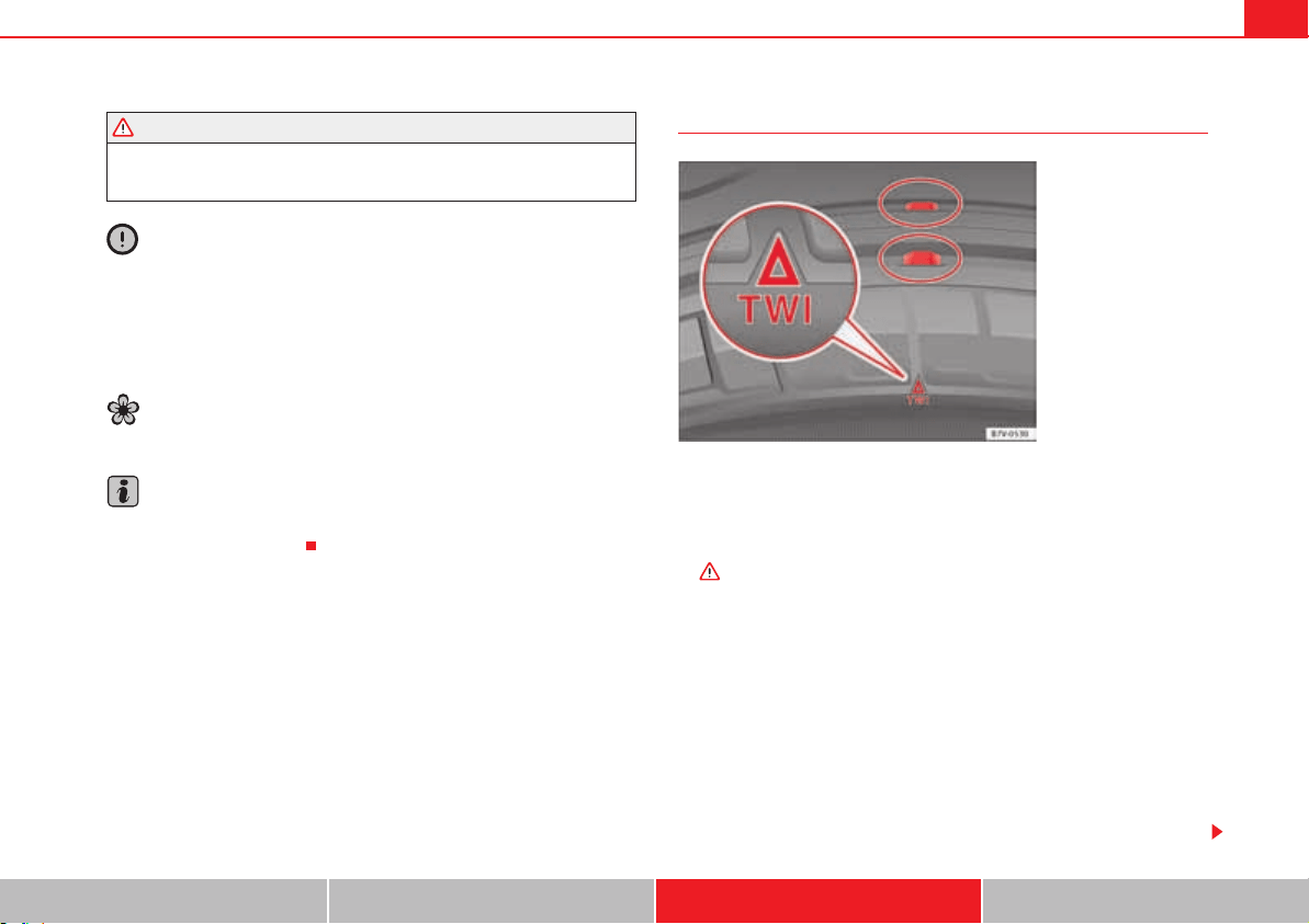
Wheels and tyres 329
Safety First Operating instructions Practical tips Technical Data
x Adjust the pressures of all the tyres to the vehicle load.
x Never deflate excess pressure from hot tyres.
Caution
x Take care not to tilt the manometer when placing it on the valve. Other-
wise, the valve may be damaged.
x To avoid damage to the valves, always replace valve caps correctly. Check
that the caps are identical to the standard caps and have been correctly tight-
ened.
For the sake of the environment
Under-inflated tyres will increase the fuel consumption.
Note
When checking tyre pressures, please observe the instructions for the tyre
control system page 245.
Tread depth and wear indicators
Tread depth
Certain driving conditions require a deeper tread, as well as needing the tread
to be approximately the same on the front and rear tyres. This is particularly
important when driving in winter, in cold temperatures and on wet roads
.
The minimum tread depth required by law in the majority of cases is 1.6 mm
(1/16 of an inch), measured in the tread grooves next to the tread wear indi-
cators. Observe legal requirements in each country.
The performance of winter tyres is much reduced when the tread has worn to
4 mm (5/32 inch).
The tread depth of new tyres may vary, according to the type and make of tyre
and the tread pattern.
Wear indicators on the tyre
The original tyres on your vehicle have 1.6 mm (1/16 inch) high fig. 184
tread wear indicators running across the tread. A number of these indicators
WARNING (continued)
Fig. 184 Tyre tread: tread
wear indicators.
Wheels and tyres330
are equally spaced around the tyre tread. Certain marks on the tyre walls (for
example, the letters “TWI” or other symbols) indicate the position of the wear
indicators.
Tread wear indicators indicate if a tyre is worn. Tyres must always be replaced
before the tyre tread has worn to the level of the indicator.
WARNING
Driving with worn tyres is dangerous, and may lead to loss of control of the
vehicle with serious consequences.
x Tyres must be replaced before the wear indicators are at the same level
as the tread pattern.
x Worn tyres have significantly reduced grip, especially on wet surfaces,
increasing the risk of “aquaplaning”.
x Worn tyres make control of the vehicle more difficult in normal or diffi-
cult driving conditions, increasing the braking distance and the risk of
skidding.
Damaged tyres
Damage to wheels and tyres is often not immediately visible. If you notice
unusual vibration or the car pulling to one side, this may indicate that one of
the tyres is damaged .
x Slow down immediately if you think you have a damaged wheel.
x Check the wheels and tyres for damage.
x If tyres are worn, stop driving and seek qualified assistance.
x If there is no visible exterior damage, drive slowly and carefully to the
nearest qualified workshop and have the vehicle checked.
Foreign bodies in the tyre
x Do not remove foreign bodies if they have penetrated through the tyre
wall!
x You should obtain professional assistance immediately.
The sealant at the lower part of the tyre tread wraps around the foreign body
and provisionally seals the tyre.
Wear of tyres
The wear of tyres depends on a number of factors, for example:
x Driving style.
x Unbalanced wheels.
x Running gear settings.
Driving style: driving round bends fast or sudden acceleration or braking
speed up the wear of tyres. When the driving style is normal, if the tyres wear
too quickly, have the running gear settings checked at a qualified workshop.
Wheel run-out: The wheels on new vehicles are balanced. However, certain
circumstances may lead to imbalance (run-out), which is detected as vibra-
tions in the steering wheel. Run-out leads to wear of the steering and suspen-
sion. In the event of run out, the wheels should be balanced again. When a
new wheel is fitted, it should be balanced again.
Running gear settings: an incorrectly positioned running gear increases the
wear of tyres and affects your safety while driving. If tyres wear too quickly,
have the wheel alignment checked at a specialist workshop.
WARNING
If you notice unusual vibration or the car pulls to one side while driving,
this may indicate that one of the tyres is damaged.
x Reduce speed immediately and stop, while observing the highway
code.
x Check the wheels and tyres for damage.
Wheels and tyres 331
Safety First Operating instructions Practical tips Technical Data
x Never carry on driving on worn tyres or wheels. Request qualified
assistance immediately.
x If there is no visible exterior damage, drive slowly and carefully to the
nearest qualified workshop and have the vehicle checked.
Winter tyres
In winter conditions winter tyres will considerably improve the vehicles
handling. The design of summer tyres (width, rubber compound, tread
pattern) gives less grip on ice and snow. SEAT strongly recommends using
winter tyres or all year round tyres on all four wheels of the vehicle, especially
if you expect to drive in wintery weather. Winter tyres also improve the vehicle
braking performance, reducing the braking distance in winter weather. SEAT
recommend that winter tyres be fitted to the vehicle at temperatures below
+7 °C (+45 °F).
The performance of winter tyres is much reduced if the tyre tread is worn
below 4 mm (1/16 inch). The age of the tyre is another factor affecting
performance, regardless of the depth of the tyre tread.
Please observe the following when using winter tyres:
x Observe legal requirements in each country.
x Winter tyres must be fitted on all four wheels.
x Only use winter tyres in wintery weather conditions.
x Only use winter tyres of the size authorised for the vehicle.
x Only use radial winter tyres of the same type, size (rolling circumference)
and tread pattern.
x Adjust speeds to within the limits indicated (code letter on tyre) .
Speed limit
A code letter indicating the speed limit is stamped on all winter tyres
page 334.
In some vehicles, it is possible to set a speed warning in the MFA
(multifunction indicator) menu on the instrument panel page 70.
If you use V-rated tyres the speed limits and tyre pressure will be determined
by engine size. Please ask your SEAT qualified workshop for further informa-
tion on the maximum permitted speed and the required pressures for the
tyres.
All-wheel drive
Thanks to its all-wheel drive, your car will have plenty of traction in winter
conditions, even with the standard tyres. Nevertheless, SEAT still recommend
that winter tyres or all-season tyres should be fitted on all four wheels when
winter road conditions are expected, mainly because this will give a better
braking response.
Please observe all instructions and warnings when using snow chains
page 332.
WARNING
Although winter tyres help to make driving safer in the winter, you should
not take unnecessary risks.
x Adjust your speed and driving style to visibility, road, traffic and
weather conditions.
x Never exceed the maximum permitted speed or loads specified for the
type of winter tyre fitted on your vehicle.
For the sake of the environment
When winter is over, change back to summer tyres. In temperatures above
+7 °C (+45 °F), performance will be improved if summer tyres are used. Fuel
consumption, wear and noises while driving will all be reduced.
WARNING (continued)
Wheels and tyres332
Note
If the vehicle is fitted with a tyre control system, this should be “repro-
grammed” whenever a tyre is changed page 248.
Note
Please ask at SEAT qualified workshops for information about the permitted
sizes for winter tyres.
Snow chains
When using snow chains, applicable local legislation and maximum
permitted speed limits must be observed.
In winter weather, snow chains not only help to improve grip but also improve
the braking capacity.
Snow chains must only be mounted on the front wheels, even on all-wheel
drive vehicles, and only with the tyre and rim combinations listed below:
SEAT recommends you ask a SEAT qualified workshop for further information
on wheel, tyre and chain sizes.
Wherever possible use fine-link chains measuring less than 15 mm (37/64
inch) including the lock.
Remove wheel hub covers and trim rings before fitting snow chains .
The wheel bolts should be covered with caps for safety reasons. These are
available from qualified workshops.
WARNING
The use of unsuitable or incorrectly fitted chains could lead to serious acci-
dents and damage.
x Always the appropriate snow chains.
x Observe the fitting instructions provided by the snow chain manufac-
turer.
x Never exceed the maximum permitted speeds when driving with snow
chains.
Caution
x You must remove the snow chains to drive on roads which are free of
snow. Otherwise they will impair handling, damage the tyres and wear out
very quickly.
x Wheel rims may be damaged or scratched if the chains come into direct
contact with them. SEAT recommends the use of covered snow chains.
Note
Snow chains are available in different sizes according to the vehicle type.
Tyre size Wheel rim
205/60 R16 6 1/2 J x 16 ET 33
215/60 R16 6 1/2 J x 16 ET 33
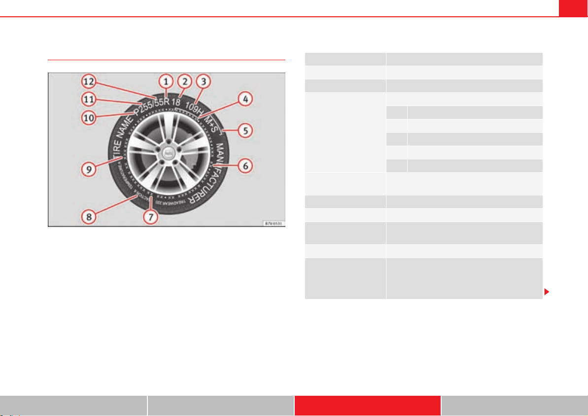
Wheels and tyres 333
Safety First Operating instructions Practical tips Technical Data
Tyre code
Fig. 185 Universal code on tyres.
Radial
Rim diameter code
Load index & speed rating
DOT tyre identification number
Severe snow conditions
Tyre ply composition and materials used
Max. load rating
Treadwear, traction and temperature grades
Max. permissible inflation pressure
Passenger car tyre
Nominal width of tyre in millimetres
Ratio of height to width (aspect ratio)
A
1
A
2
A
3
A
4
A
5
A
6
A
7
A
8
A
9
A
10
A
11
A
12
Tyre code (example) Meaning
Make, logotype Manufacturer
Product name Name of tyre assigned by manufacturer.
P215 / 55 R 16 Size:
P Passenger vehicle code.
215 Nominal width between walls, in mm.
55 Height/width ratio in %
R Tyre type (R indicates "radial").
16 Rim diameter in inches
91 V Load index page 334 and speed rating
page 334.
XL Reinforced tyres.
M+S or M/S Winter tyres (mud and snow tyres) page 331.
SSR or DSST, Eufonia,
RFT, ROF, RSC, ZP
Specific manufacturer codes for run-flat tyres.
RADIAL TUBELESS Radial tyre without inner tube.
E4 ... E-mark certifying tyre complies with international
legislation followed by a number denoting the
country granting the authorisation. The authori-
sation number ( several digits) is shown below.

Wheels and tyres334
Tyres with directional tread pattern
Tyres with directional tread pattern have been designed to operate best when
rotating in only one direction. An arrow on the tyre sidewall indicates the
direction of rotation on tyres with directional tread. Always observe the direc-
tion of rotation indicated when mounting the wheel. This guarantees
optimum grip and helps to avoid aquaplaning, excessive noise and wear.
Tyre load rating
The load rating code indicates the maximum load in kilogrammes each wheel
can carry (load capacity).
91 615 kg (1,356 pounds)
93 650 kg (1,433 pounds)
95 690 kg (1,521 pounds)
97 730 kg (1,609 pounds)
99 775 kg (1,709 pounds)
Speed rating
The speed rating indicates the maximum speed permitted for the tyres.
P max. 150 km/h (93 mph)
Q max. 160 km/h (99 mph)
R max. 170 km/h (106 mph)
S max. 180 km/h (112 mph)
DOT BT RA TY5 1709
Tyre identification number (TIN
a)
, may be only on
interior wall of wheel) and date of manufacture:
DOT The tyre complies with the legal require-
ments of the US Department of Transport,
responsible for tyre safety regulations.
BT Place of manufacture code.
RA Information about manufacturer and tyre
size.
TY5 Manufacturer's tyre specifications.
1709 Date of manufacture: Week 17 of 2009.
TWI This identifies the position of the Tread Wear
Indicator page 329.
Made in Germany Country of manufacture.
MAX LOAD 615 KG (1356
LBS)
US load rating, indicating maximum permitted
load per tyre.
MAX INFLATION 350 KPA
(51 PSI)
US limit, indicating maximum permitted tyre
pressure.
SIDEWALL 1 PLY RAYON Information about tyre wall components:
1 layer of rayon (artificial silk).
TREAD 4 PLIES
1 RAYON + 2 STEEL + 1
NYLON
Information about tread components:
In the example, there are 4 layers below the
tread: 1 layer of rayon (artificial silk), 2 layers of
steel reinforcement and 1 layer of nylon.
Information for the end consumer concerning the comparative values of
the established base tyres (standardised test procedures):
TREADWEAR 280 Relative service life of the tyre, with respect to
specific US standard test.
Tyre code (example) Meaning
TRACTION AA Braking capacity of tyre on wet surface (AA, A, B
or C).
TEMPERATURE A Tyre temperature resistance at higher test speeds
(A, B or C).
If the tyre has other markings, these are specific tyre manufacturer codes
or specific national codes, e.g. for Brazil or China.
a)
The letters TIN refer to the tyre serial number.
Tyre code (example) Meaning

Wheels and tyres 335
Safety First Operating instructions Practical tips Technical Data
T max. 190 km/h (118 mph)
U max. 200 km/h (124 mph)
H max. 210 km/h (130 mph)
V max. 240 km/h (149 mph)
Z max. 240 km/h (149 mph)
W max. 270 km/h (168 mph)
Y max. 300 km/h (186 mph)
Some manufacturers use the letters “ZR” for tyres with a maximum author-
ised speed above 240 km/h (149 miles).
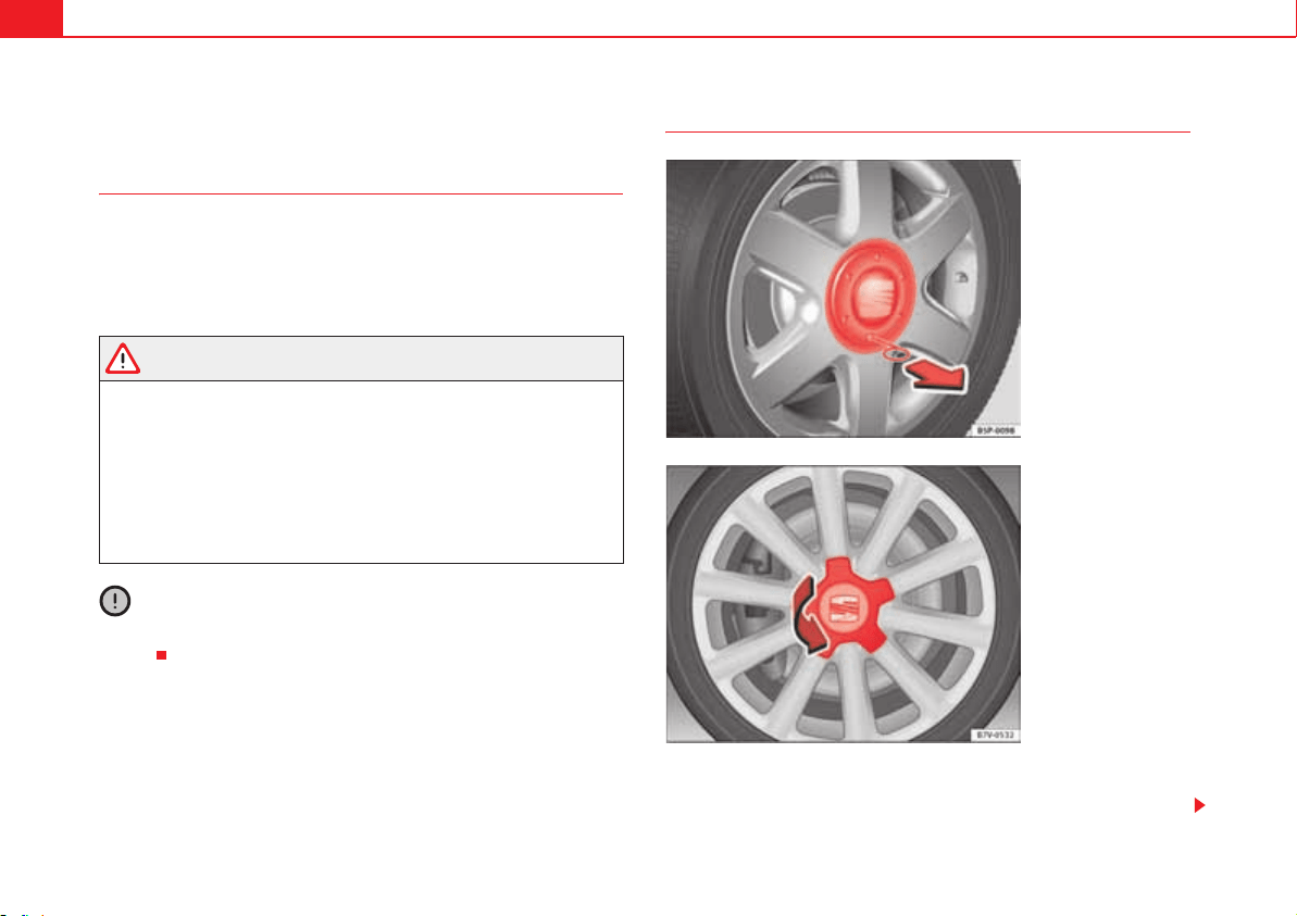
Wheels and tyres336
Wheel trims*
Introduction
Additional information and warnings:
x Caring for and cleaning the vehicle exterior page 269
x Change wheel page 339
x Vehicle tools page 353
WARNING
If the wheel trims are not appropriate or not fitted correctly, they could
cause major accidents or damage.
x Incorrectly mounted wheel trims may come off while driving and
endanger other road users.
x Damaged trims must never be mounted on the wheels.
x Always ensure that the brake ventilation and cooling is not cut off or
blocked. This is also valid if hubcaps are fitted later. If there is not enough
air, you may require significantly longer braking distances.
Caution
Remove and remount wheel trims taking care to avoid damage to the
vehicle.
Hubcaps
Depending upon the version, the hubcap is removed by pulling it fig. 186,
or by unscrewing it fig. 187.
Fig. 186 Removing the
hub cap.
Fig. 187 Remove the
hubcap by turning it
outwards.
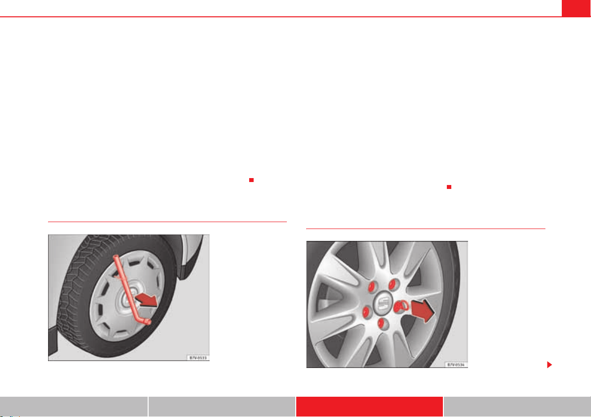
Wheels and tyres 337
Safety First Operating instructions Practical tips Technical Data
Vehicles with removable hubcaps
x To remove the hubcap, take the wire hook from the vehicle tool kit and
hook it through an opening on the trim page 336, fig. 186.
x Remove the trim by pulling it in the direction of the arrow.
x To replace the hubcap, press the hubcap against the rim until it clicks into
place.
Vehicles with screw-on hubcaps
x To remove, turn the hubcap to the right or to the left until it comes off the
rim page 336, fig. 187.
x Hold it from behind by a rib and pull the trim.
x To replace, centrally align the trim on the wheel.
x Press the trim against the wheel rim until it clicks into place.
Full hubcaps*
Removing the full hubcap
x Take the wheel brace and the wire hook from the vehicle tool kit
page 353.
x Hook the wire through one of the grooves on the hubcap.
x Insert the wheel brace onto the wire hook fig. 188 and pull the hub cap
in the direction shown by the arrow.
Fitting hubcaps
Before mounting the full hubcap, the anti-theft wheel lock must be threaded
into position page 340, fig. 191 or . Otherwise it will not be
possible to mount the full hubcap.
Press the hubcap against the wheel so that the space for the valve fits over
the tyre valve page 340, fig. 191 . Make sure that the hubcap is
correctly fitted all the way around the wheel.
Wheel bolt caps
Fig. 188 Removing the
full hubcap.
A
2
A
3
A
1
Fig. 189 Removing the
wheel bolt caps

Wheels and tyres338
x Take the wire hook from the vehicle tool kit page 353.
x Insert the wire hook in the cap through the opening page 337, fig. 189
and pull outwards in the direction of the arrow.
The caps protect the wheel bolts and should be remounted after changing the
tyre.
The anti-theft wheel locking bolt has a special cap. This cap only fits on anti-
theft locking bolts and is not for use with standard wheel bolts.
Wheels and tyres 339
Safety First Operating instructions Practical tips Technical Data
Changing a wheel*
Introduction
The tyres mounted on the vehicle are anti-puncture. The wheels should only
be changed when switching from summer to winter tyres or vice-versa. The
tools required for changing a wheel are only supplied with the vehicle if the
vehicle is supplied from the factory with winter tyres. If this is not the case,
please take the vehicle to a specialised workshop to have the wheels
changed.
You should only change the wheels yourself if the vehicle is parked in a safe
place, you are familiar with the procedure and you have all the necessary
tools! Otherwise, you should seek professional assistance.
Additional information and warnings:
x Vehicle key set page 78
x Wheels and tyres page 323
x Wheel trims page 336
x Vehicle tools page 353
WARNING
Changing a wheel can be dangerous, especially on the hard shoulder.
Please observe the following rules to minimise the risk of injury:
x Stop the vehicle safely as soon as possible. Park your vehicle as safe
distance from surrounding traffic to change a wheel.
x When changing a wheel, keep all passengers and particularly children
a safe distance away from the work area.
x Turn on the hazard warning lights to warn other road users.
x Ensure the ground on which you park is flat and solid. If necessary,
support the jack on a wide solid base.
x If you are changing a wheel yourself, you should be familiar with the
required procedure. Otherwise, you should seek professional assistance.
x Only use suitable tools that are not damaged when changing a wheel.
x Always stop the engine, turn on the electronic parking brake and place
the gear selector lever in position P, for an automatic gearbox, or engage a
gear for a manual gearbox to reduce the risk of the vehicle moving acciden-
tally.
x Have the tightening torque of the wheel bolts checked as soon as
possible with a reliable torque wrench.
Preparations for changing a wheel
Check list
Before changing a wheel, complete the following operations in the order
given :
1. Park the vehicle on an even and solid surface.
2. Connect the electronic parking brake page 210.
3. Automatic gearbox: Move selector lever to position P page 201.
4. Stop the engine and remove the key from the ignition page 195.
5. Manual gearbox: Select a gear page 201.
6. Have all vehicle occupants get out of the vehicle and wait in a safe place
(for example, behind the safety barrier).
7. Block the opposite wheel with two folding wedges taken from the vehicle
tool kit page 354, fig. 208 or similar objects.
8. When towing a trailer: unhook the trailer from the towing vehicle and
park it correctly.
9. If the luggage compartment is full: take the baggage out of the vehicle.
WARNING (continued)
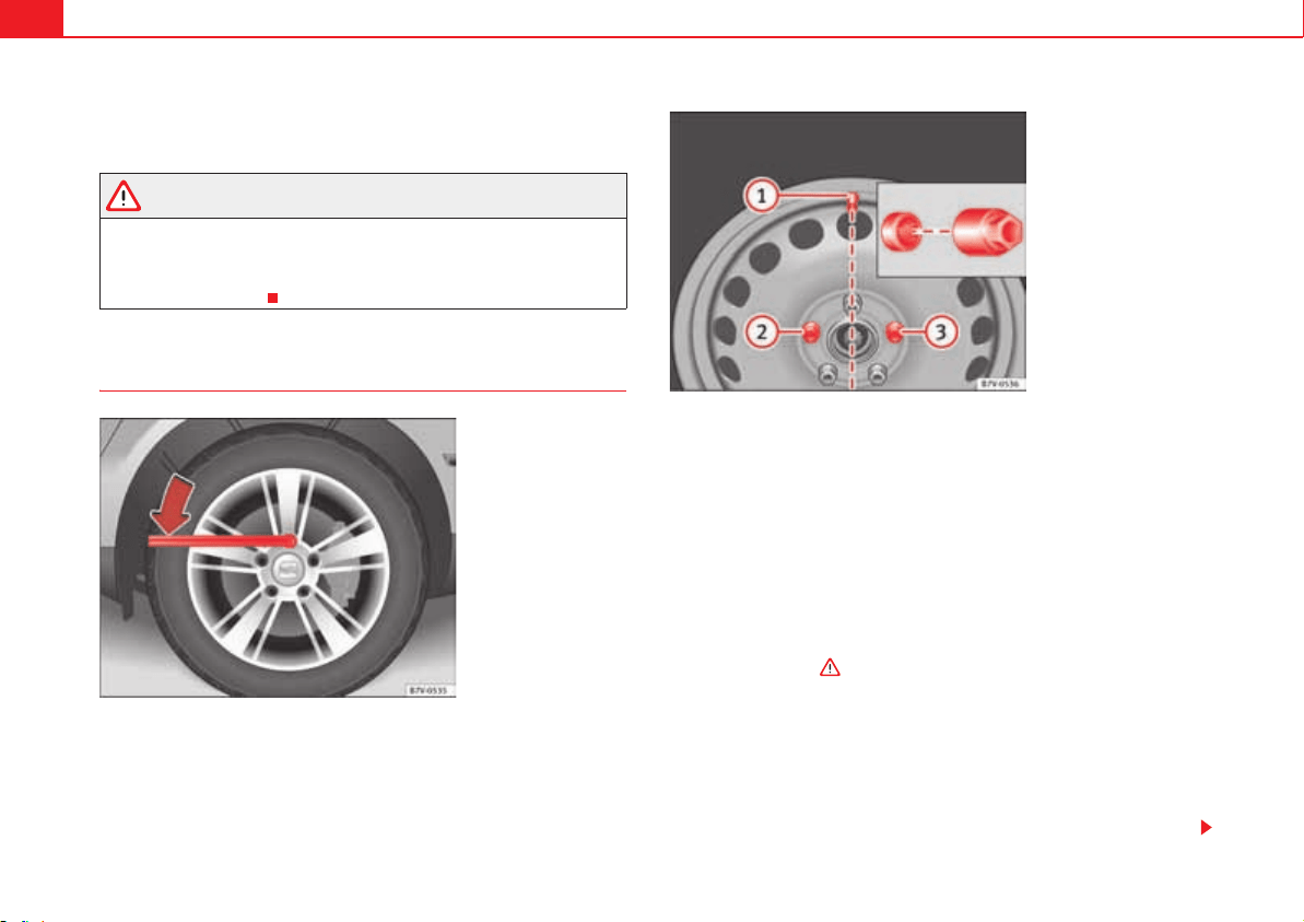
Wheels and tyres340
10. Take the vehicle tool kit out of the luggage compartment.
11. Remove the wheel trims page 336.
WARNING
Failure to follow the checklist prepared for your own safety could lead to
accidents and severe injuries.
x Always complete the operations given in the checklist and observe the
general rules of safety.
Wheel bolts
Only use the tool supplied with the vehicle to loosen the wheel bolts.
Loosen the wheel bolts only about one turn before raising the vehicle with the
jack.
If the wheel bolt is very tight, you may be able to loosen it by pushing down
on the end of the wheel brace carefully with your foot. Hold on to the car for
support and take care not to slip.
Loosening wheel bolts
x Fit the wheel brace as far as it will go over the wheel bolt fig. 190.
x Hold the wheel brace at the end and rotate the bolt approximately one
turn anticlockwise .
Loosening anti-theft wheel bolts
For wheels with full hubcap, the anti-theft wheel lock must be threaded into
position fig. 191 or before mounting the hubcap. Otherwise it will
not be possible to mount the full hubcap.
x Take the adapter for anti-theft wheel bolts out of the vehicle tool kit.
x Insert the adapter onto the wheel bolt.
Fig. 190 Changing the
wheel: Slacken the wheel
bolts.
Fig. 191 Changing the
wheel: Tyre valve and
position of anti-theft
wheel locking bolt or
.
A
1
A
2
A
3
A
2
A
3
Wheels and tyres 341
Safety First Operating instructions Practical tips Technical Data
x Fit the wheel brace onto the adapter as far as possible.
x Hold the wheel brace at the end and rotate the bolt approximately one
turn anticlockwise .
Important information about wheel bolts
The wheel rims and bolts have been designed to be fitted to factory options.
If different rims are fitted, the correct wheel bolts with the right length and
correctly shaped bolt heads must be used. This ensures that wheels are fitted
securely and that the brake system functions correctly.
In some circumstances, wheel bolts from the same model vehicle should not
be used.
Wheel bolt tightening torque
The prescribed tightening torque for wheel bolts for steel and alloy wheels is
140 Nm. Have the tightening torque of the wheel bolts checked as soon as
possible with a reliable torque wrench.
If wheel bolts are rusty and it is difficult to tighten them, the threads should
be replaced and cleaned before checking the torque.
Never grease or lubricate wheel bolts or the wheel hub threads. Although
they have been tightened to the prescribed torque, they could come loose
while driving.
WARNING
If the wheel bolts are not fitted correctly they could be released while
driving leading to loss of vehicle control and serious damage.
x Only use wheel bolts which correspond to the wheel rims in question.
x Never use different wheel bolts.
x The bolts and threads should be clean, free of oil and grease and easy
to thread.
x To loosen and tighten the wheel bolts, always use the wheel brace
supplied with the vehicle.
x Loosen the wheel bolts only about one turn before raising the vehicle
with the jack.
x Never grease or lubricate wheel bolts or the wheel hub threads.
Although they have been tightened to the prescribed torque, they could
come loose while driving.
x Never loosen the bolted joints of wheel rims with bolted ring trims.
x If the wheel bolts are not tightened to the correct torque, they may
come loose while driving, and the bolts and rims may come out. If the tight-
ening torque is too high, the wheel bolts and threads can be damaged.
WARNING (continued)
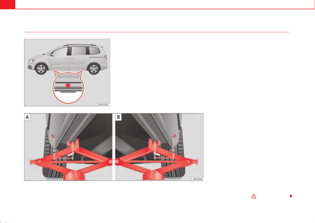
Wheels and tyres342
Raising the vehicle with the jack
The jack may be applied only at the jacking points shown (marks on chassis)
fig. 192. The mark indicates the jacking points below the vehicle. The
jacking points are on the ribs behind the front edges fig. 193. Always the
relevant jacking point for the wheel to be changed .
Fig. 192 Jack position
points
Fig. 193 : jack mounted on the left front part of the
vehicle : jack mounted on the left rear part of the
vehicle.
A
A
A
B
Wheels and tyres 343
Safety First Operating instructions Practical tips Technical Data
Raise the vehicle using only the designated jacking points.
Check list
For your own safety and that of other passengers, the following points should
be observed in the order given :
1. Select a suitable flat and firm surface for raising the vehicle.
2. Switch off the engine, engage a gear (manual gearbox) or place the
selector lever in position P page 201 and turn on the electronic
parking brake page 210.
3. When towing a trailer: unhook the trailer from the towing vehicle and
park it correctly.
4. Loosen the wheel bolts on the wheel to be changed page 340.
5. Look below the vehicle for the jacking point page 342, fig. 192
closest to the tyre which has to be changed.
6. Raise the jack with the handle until it can be inserted below the jacking
point.
7. Ensure that the foot of the jack is firmly on the ground and that it is
placed immediately below the lifting point on the vehicle page 342,
fig. 193.
8. Straighten the jack and continue raising it using the handle until the claw
holds the vertical reinforcement beneath the vehicle page 342,
fig. 193.
9. Raise the vehicle until the wheel is clear of the ground.
WARNING
If the vehicle is not correctly raised, it could fall off the jack causing serious
injury. Please observe the following rules to minimise the risk of injury:
x You should only use a jack approved by SEAT for your vehicle. Other
jacks, even those approved for other SEAT models, might slip out of place.
x The ground should be firm and flat. If the ground is sloped or soft then
the vehicle could slip and fall off the jack. If necessary, support the jack on
a wide solid base.
x If the ground is slippery (for example, on tiles), place a non-slip surface
(for example a floor mat) beneath the jack to avoid slipping.
x Only fit the jack at the prescribed jacking points. The claw of the jack
should grip the reinforcement nerve on the underbody page 342,
fig. 193.
x You should never have any limbs beneath a raised vehicle which is only
supported by a jack.
x If you have to work underneath the vehicle, you must use suitable
stands additionally to support the vehicle, there is a risk of accident!.
x Never raise the vehicle if it is tilting to one side or the engine is running.
x Never start the engine when the vehicle is raised. The vehicle may come
loose from the jack due to the engine vibrations.
WARNING
Failure to follow the checklist prepared for your own safety could lead to
accidents and severe injuries.
x Always complete the operations given in the checklist and observe the
general rules of safety.
WARNING (continued)
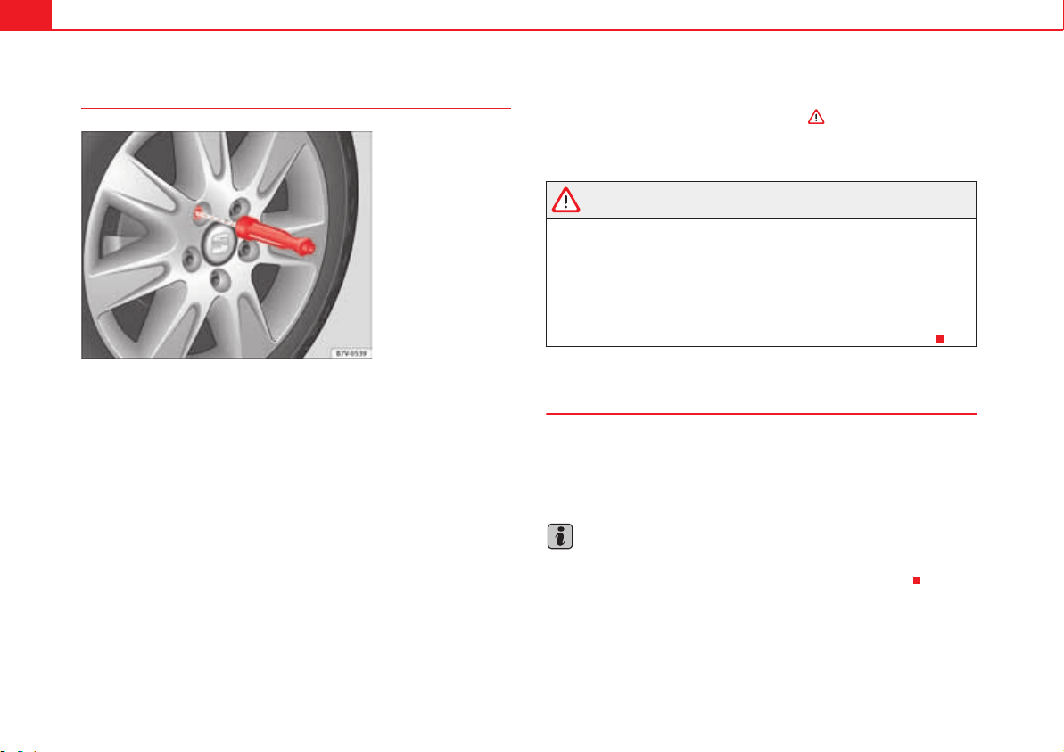
Wheels and tyres344
Changing a wheel
Removing the wheel
x Please observe the check list page 339.
x Loosen the wheel bolts page 340.
x Jacking up the vehicle page 342.
x Using the hexagonal socket in the wheel brace fig. 194, unscrew the
slackened wheel bolts and place them on a clean surface.
x Take off the wheel.
Putting on the spare wheel
Check the direction of rotation of the tyre page 325.
x Fit the wheel.
x Screw on the anti-theft locking bolt with the adapter in position
page 340, fig. 191 or clockwise and tighten gently.
x Replace the other wheel bolts and tighten slightly using the hexagonal
socket on the end of the wheel brace.
x Lower the car with the jack.
x Tighten all of the wheel bolts clockwise . Tighten the bolts in diag-
onal pairs (not in a circle).
x Put the caps, trim or full hubcap back on page 336.
WARNING
If the wheel bolts are not treated suitably or not tightened to the correct
torque then this could lead to loss of vehicle control and to a serious acci-
dent.
x All the wheel bolts and hub threads should be clean and free of oil and
grease. The wheel bolts should be easily tightened to the correct torque.
x The hexagonal socket in the wheel brace should be used for turning
wheel bolts only. Do not use it to loosen or tighten the wheel bolts.
After changing the wheel
x Clean the wheel brace, if necessary and put it away in the luggage
compartment page 353.
x Have the tightening torque of the wheel bolts checked as soon as
possible with a torque wrench page 341.
Note
If the vehicle is fitted with a tyre monitoring system, this should be “repro-
grammed” if necessary whenever a tyre is changed page 248.
Fig. 194 Changing the
wheel: loosen wheel bolts
with the socket at the end
of the wheel brace.
A
2
A
3
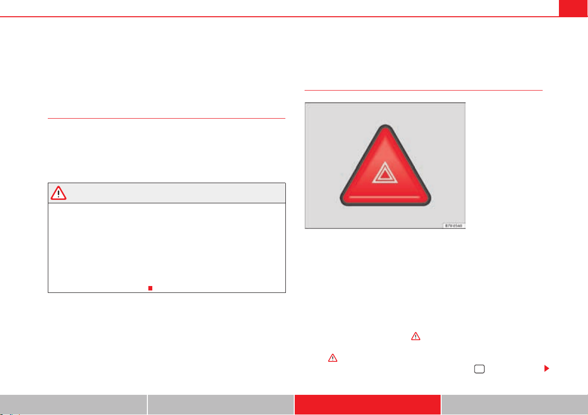
If and when 345
Safety First Operating instructions Practical tips Technical Data
If and when
In case of emergency
Introduction
Additional information and warnings:
x Braking, stopping and parking page 210
x Emergency locking and unlocking page 348
x Vehicle tools page 353
WARNING
A faulty vehicle in traffic represents a risk of accident for the driver and for
other road users.
x Stop the vehicle safely as soon as possible. Park the vehicle a safe
distance from surrounding traffic to lock all the doors in case of an emer-
gency. Turn on the hazard warning lights to warn other road users.
x Never leave children or disabled people alone in the vehicle if the doors
are to be locked. In case of an emergency, passengers will be trapped
inside the vehicle. Individuals locked in the vehicle can be exposed to very
high or very low temperatures.
Protecting yourself and securing the vehicle
Always fulfil legal requirements for securing a broken down vehicle. In a
number of countries it is now obligatory, for example, to turn on the hazard
warning lights and use a reflective safety vest page 347.
When being towed with the hazard warning lights on, a change in direction or
traffic lane can be indicated as usual using the turn indicator lever. The
hazard lights will be interrupted temporarily.
Checklist
For your own safety and that of other passengers, the following points should
be observed in the order given :
1. Park the vehicle a safe distance from traffic and on suitable ground
.
2. Turn on the hazard warning lights with the button fig. 195.
Fig. 195 In the centre of
the instrument panel:
Switch for hazard warning
lights.
If and when346
3. Connect the electronic parking brake page 210.
4. Move the selector lever to its intermediate position or to P page 201.
5. Stop the engine and remove the key from the ignition page 195.
6. Have all occupants leave the vehicle and move to safety, for example
behind a guard rail.
7. When leaving the vehicle, take all keys with you.
8. Place an emergency warning triangle to indicate the position of your
vehicle to other road users.
9. Allow the engine to cool and check if a specialist is required.
Examples of when to use the hazard warning lights:
x If the vehicles ahead suddenly slow down or reach the end of a traffic jam,
to warn the vehicles behind.
x In case of an emergency.
x If the vehicle breaks down.
x When being towed.
Always comply with the applicable laws regarding the use of hazard warning
lights.
If the hazard warning lights are not working, you must use an alternative
method of drawing attention to your vehicle. This method must comply with
traffic legislation.
WARNING
Failure to follow the checklist prepared for your own safety could lead to
accidents and severe injuries.
x Always complete the operations given in the checklist and observe the
general rules of safety.
WARNING
The components of the exhaust system reach very high temperatures. This
could cause a fire and considerable damage.
x Always park your vehicle so that no part of the exhaust system can
come in contact with flammable materials (such as dried grass or fuel).
Note
The vehicle battery will discharge and run down if the hazard warning lights
remain on for too much time (even with the ignition turned off).
Note
For some vehicles, the brake lights will blink when braking suddenly at
speeds of approximately 80 km/h to warn vehicles behind. If braking
continues, then the hazard warning lights will automatically be turned on at
the speed of less than approximately 10 km an hour. The brake lights remain
lit. Upon accelerating, the hazard warning lights will be automatically turned
off.
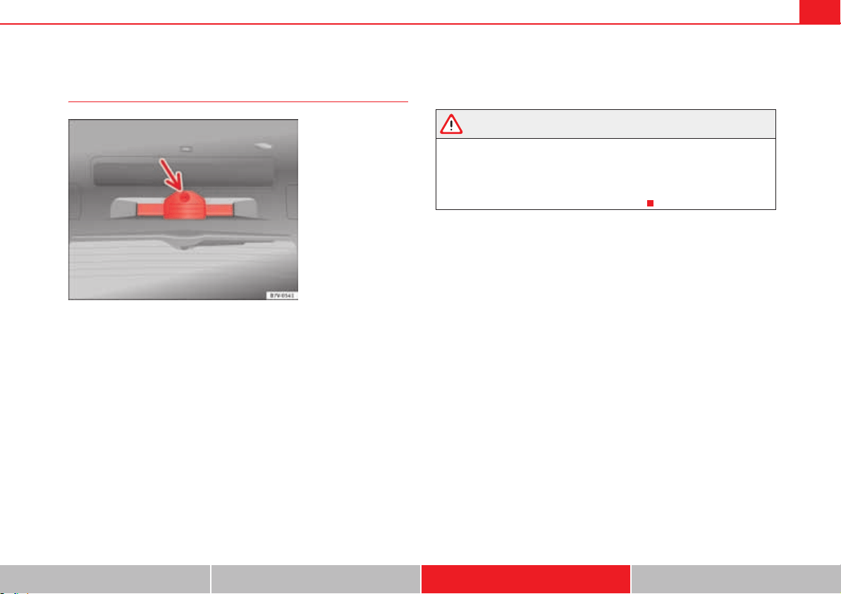
If and when 347
Safety First Operating instructions Practical tips Technical Data
First aid kit, warning triangle, reflective vests and fire
extinguishers
Reflective vests
Some vehicles will have a driver's door compartment to store a reflective vest
page 59.
Warning triangle
With the tailgate open, rotate the lock fig. 196 90°. Lower the bracket and
remove the warning triangle.
First-aid kit
There is a first aid kit page 162 in the rear left-hand side storage compart-
ment of the luggage compartment.
The first aid kit must comply with legal requirements. Check the expiry date
of the contents of the first aid kit.
Fire extinguisher
There is a Fire extinguisher underneath the passenger seat.
The fire extinguisher must conform to legal requirements, be ready for use
and be checked regularly. Check the certification seal on the extinguisher.
WARNING
Loose objects in the passenger compartment can be violently thrown in
case of a sudden manoeuvre or braking and especially in accidents causing
serious injury.
x Secure fire extinguishers, first aid kit, reflective vests and warning
triangle securely to their respective supports.
Fig. 196 On the boot lid:
Warning triangle bracket.
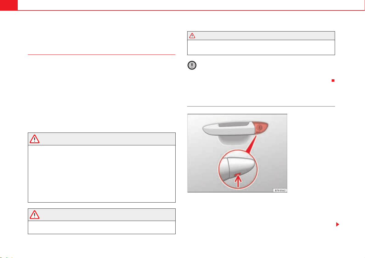
If and when348
Emergency locking and unlocking
Introduction
The doors, tailgate and panoramic sliding roof can be locked manually and
partially opened, for example if the key or the central locking is damaged.
Additional information and warnings:
x Vehicle key set page 78
x Central locking and locking system page 83
x Doors page 92
x Tailgate page 97
x Panorama sliding sunroof page 106
x In case of emergency page 345
WARNING
Opening and closing doors carelessly can cause serious injury.
x If the vehicle is locked from outside, the doors and windows cannot be
opened from the inside.
x Never leave children or disabled people alone in the car. They could be
trapped in the car in an emergency and will not be able to get themselves
to safety.
x Depending on the time of the year, temperatures inside a locked and
closed vehicle can be extremely high or extremely low resulting in serious
injuries and illness or even death, particularly for young children.
WARNING
Getting in the way of the doors and the panoramic sliding roof is dangerous
and can lead to serious injury.
x Open and close the doors and the panoramic sliding roof only when
nobody is in the way.
Caution
When opening and closing in an emergency, carefully disassemble compo-
nents and then reassemble them carefully to avoid damage to the vehicle.
Manually locking and unlocking the driver's door
In general, when the driver's door is locked all other doors are locked.
Unlocking manually only opens the driver's door. Please note the instructions
for the antitheft alarm page 83.
x Unfold the key shaft page 78.
WARNING (continued)
Fig. 197 Driver's door
handle: Hidden lock
cylinder.
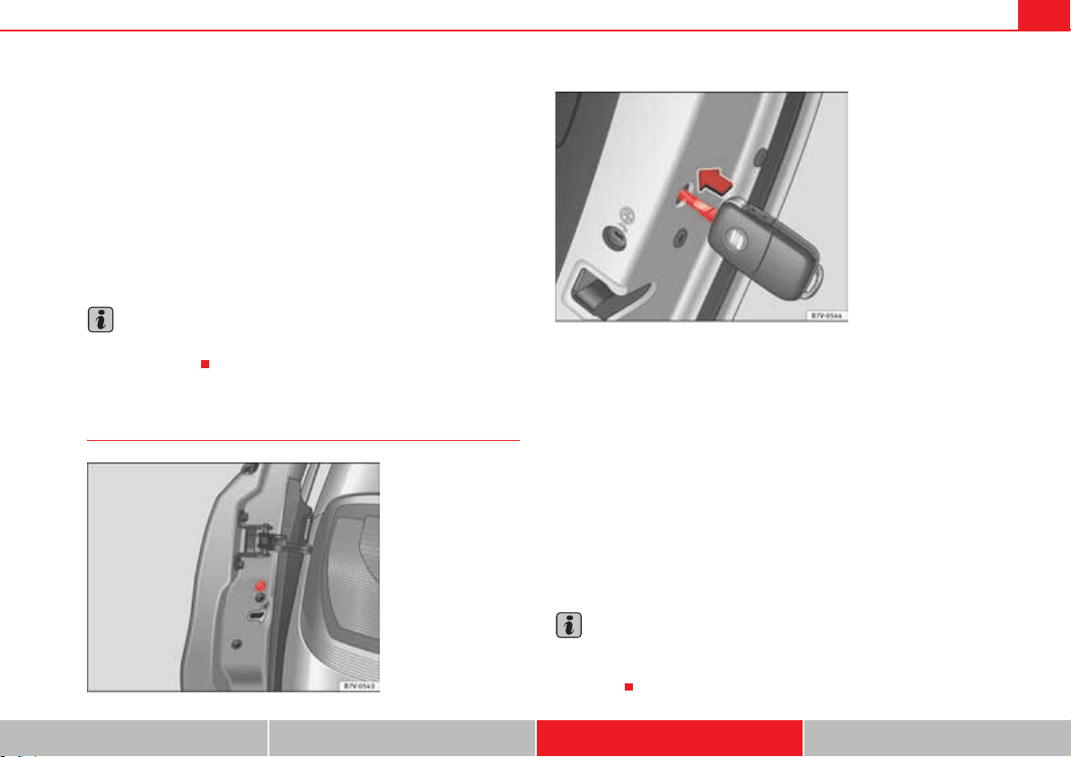
If and when 349
Safety First Operating instructions Practical tips Technical Data
x Insert the key shaft into the opening in the cover on the driver's door
handle from below fig. 197 (arrow) then remove the cover upwards.
x Insert the key shaft into the lock cylinder to unlock or lock the vehicle.
Unlocking notes:
x The antitheft alarm will remain active when vehicles are unlocked.
However, the alarm will not yet be triggered page 83.
x If the driver's door is opened, the alarm will be triggered.
x Switch the ignition on. When the ignition is switched on, the electronic
immobiliser recognises a valid vehicle key and deactivates the anti-theft
alarm system.
Note
The antitheft alarm is not activated when the vehicle is locked manually using
the key page 83.
Locking the passenger side door and sliding doors manually
The passenger side door and the sliding doors can be locked manually. The
antitheft alarm is not activated in this case.
x Door open.
x Remove the rubber cap to the front of the door. The rubber cap is marked
with a lock symbol 1 fig. 198.
x Unfold the key shaft page 78.
x Insert the key shaft horizontally into the opening and moved the colour
lever forwards fig. 199.
x Replace the rubber cap and close the door.
x Check if the door is locked.
x Carry out the same operation on the other doors if necessary.
x Have the vehicle checked by a qualified workshop.
Note
The doors can be opened and unlocked individually from the inside by pulling
the inside door handle. To open, pull the inner door release lever twice
page 83.
Fig. 198 To the front of
the passenger side door:
Emergency lock, hidden
by a rubber cap.
Fig. 199 Emergency
locking of the vehicle
using the vehicle key.
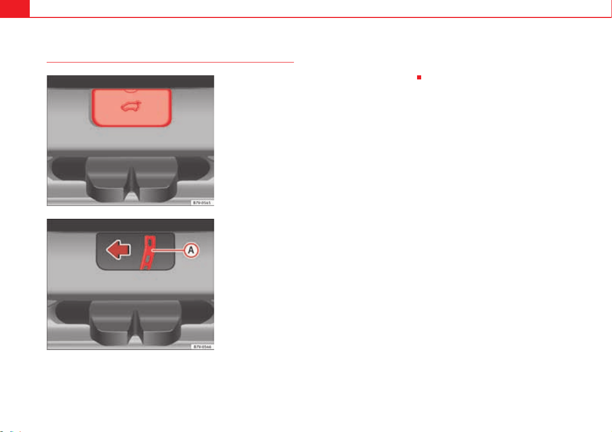
If and when350
Emergency unlocking the tailgate
x Remove equipment to access the inside of the tailgate.
x Remove the square cover in the inner trim of the tailgate fig. 200.
x Push the release lever fig. 201 in the direction of the arrow to
unlock the tailgate.
x Manually open the tailgate.
Fig. 200 From the
luggage compartment:
Remove the tailgate cover.
Fig. 201 From the
luggage compartment:
Manually unlocking the
tailgate.
A
A
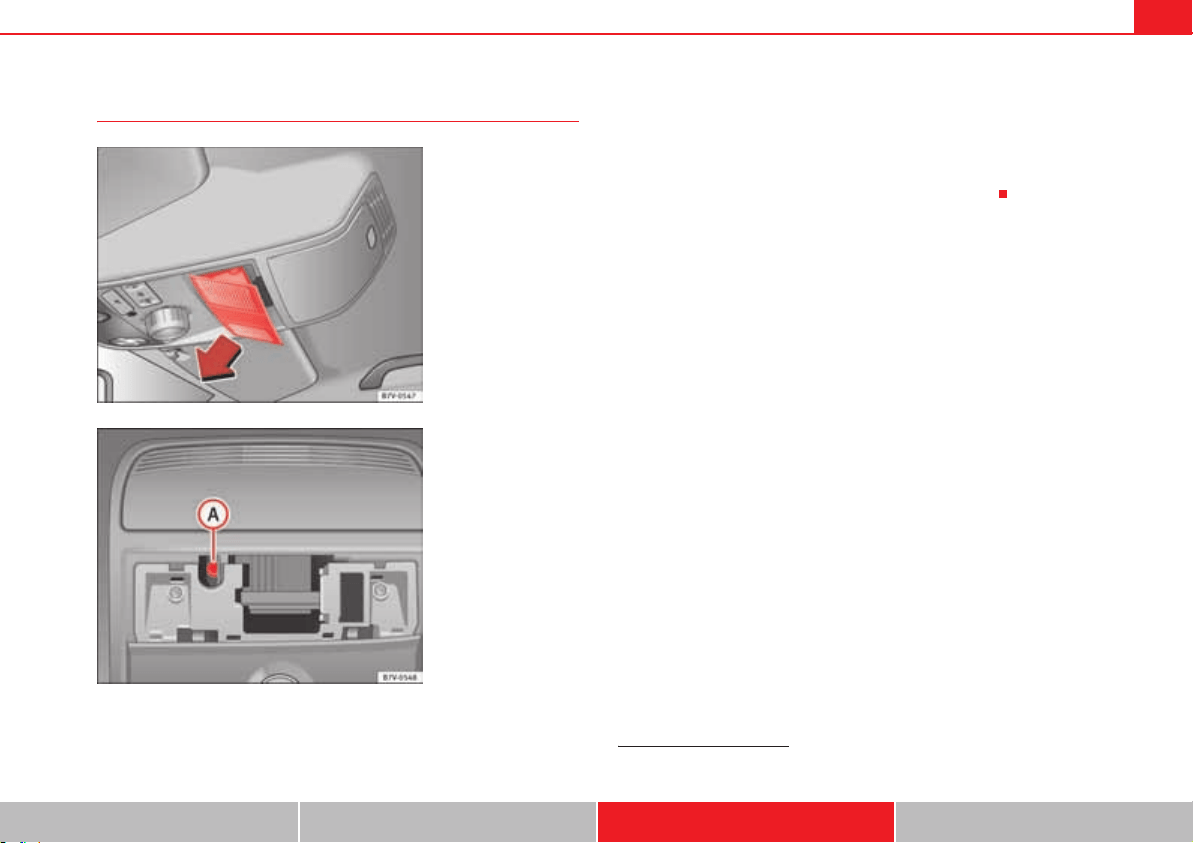
If and when 351
Safety First Operating instructions Practical tips Technical Data
Manually closing the panoramic sliding roof
x Push open the cover in the direction indicated (arrow) fig. 202.
x Insert a standard 4 mm Allen key
2)
into the Allen bolt fig. 203 .
x Rotate the Allen bolt to close the panoramic sliding roof.
x Re-install the lining.
x Bring the vehicle to a specialist workshop to check the panoramic sliding
roof given that the emergency closing operation could damage general oper-
ation or the anti-trap function of the panoramic sliding roof.
Fig. 202 On the interior
roof lining: Remove cover.
Fig. 203 Allen bolt to
close the panoramic
sliding roof.
A
A
2)
Not included with the on-board tools.
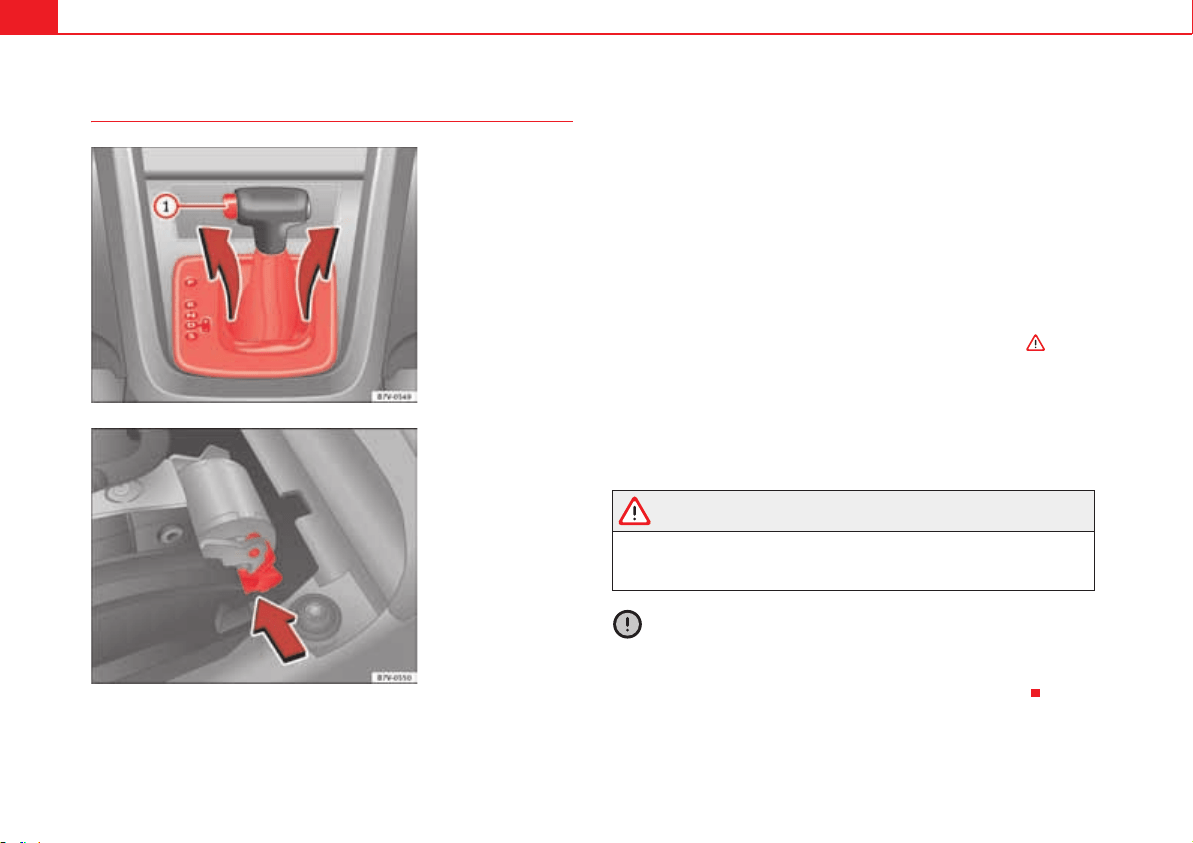
If and when352
Manually unlocking the gear selection lever
If the vehicle power supply should ever fail (discharged battery, etc.) and the
vehicle has to be pushed or towed, the selector lever must first be moved to
position N using the manual release mechanism.
The emergency release mechanism is located underneath the gearbox cover
panel to the right-hand side. To release the gear selector lever mechanism, a
suitable tool is required, for example a screwdriver.
Preparations
x Apply the parking brake. If the parking brake cannot be activated in the
vehicle must be secured otherwise so that it cannot move.
x Switch the ignition off.
To remove the gearbox cover panel
x Pull the cover up around the dust guard on the gear selector lever
fig. 204.
x Take the cover off by passing it over the gear selector lever .
Manual release of selector lever
x Press the release lever fig. 205 in the direction of the arrow and hold it
in this position.
x Press the lock button fig. 204 on the gear selector lever knob and
place the gear selector lever in the N position.
WARNING
Never move the gear selector lever from the position P while the electronic
parking brake is deactivated. Otherwise, the vehicle may accidentally
move off on hills or steep slopes causing serious accidents.
Caution
If the vehicle is moved on its wheels with the engine stopped and the selector
lever in position N for a prolonged period of time and at high speed, for
example for towing, then the automatic gearbox will be damaged.
Fig. 204 Remove the
lining from the area of the
gear indication.
Fig. 205 Manual release
of gear selector lever.
A
1
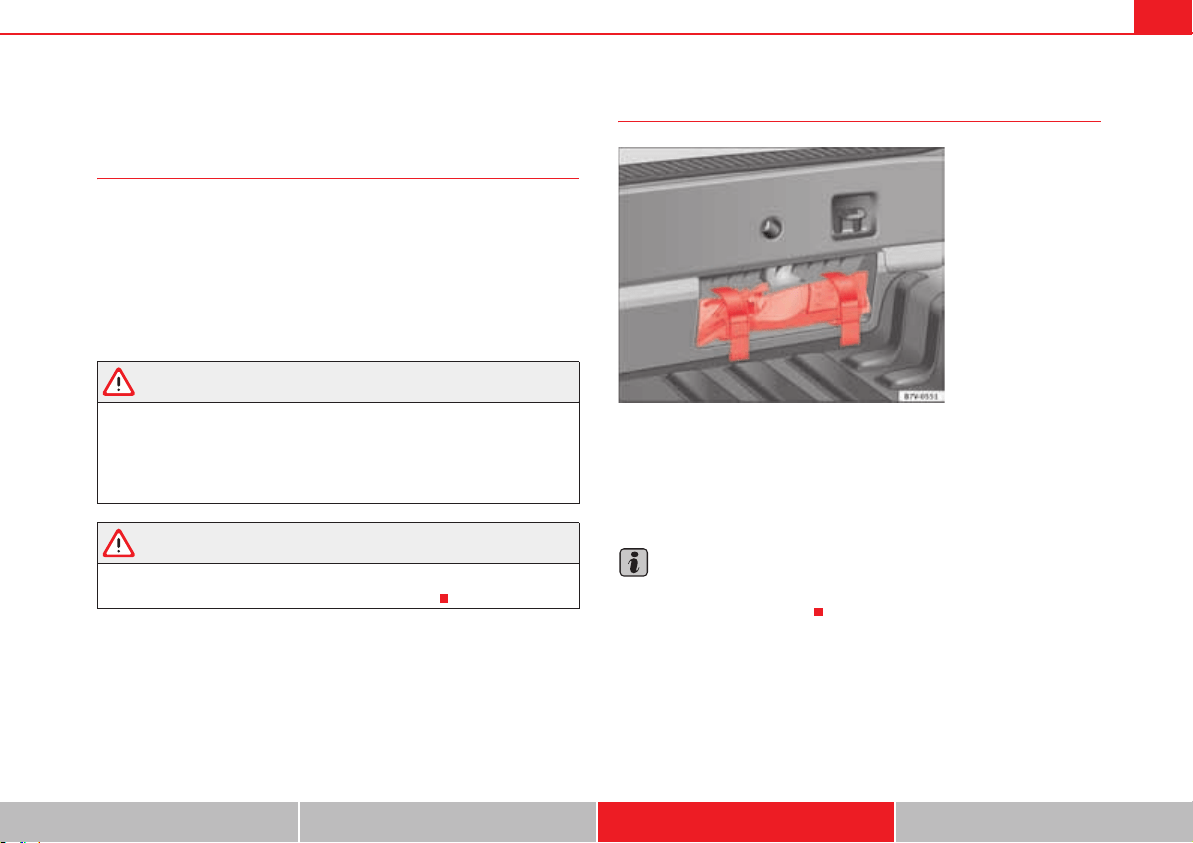
If and when 353
Safety First Operating instructions Practical tips Technical Data
Tools*
Introduction
When securing the vehicle in case of a breakdown, please note the legal
requirements for each country.
Additional information and warnings:
x Working in the engine compartment page 304
x Change wheel page 339
x In case of emergency page 345
WARNING
Loose objects in the passenger compartment can be violently fired through
the compartment in case of a sudden manoeuvre or braking and especially
in accidents causing serious injury.
x Make sure that the vehicle tools are stored safely in the luggage
compartment.
WARNING
Unsuitable or damaged on-board tools can cause injury or accidents.
x Never work with inappropriate or damaged tools.
Location
Depending on the model, the vehicle tools may be kept in the luggage
compartment, in a cavity close to the lock carrier fig. 206. Loosen the
safety straps and remove the on-board tools. For vehicles factory-fitted with
winter tyres, you will find additional tools in a toolbox located in the luggage
compartment.
Note
After use, return the jack to its initial position using the handle in order to
securely store it in the vehicle.
Fig. 206 In the luggage
compartment, viewed
from inside the vehicle:
On-board tools are
located in a cavity close to
the lock carrier.
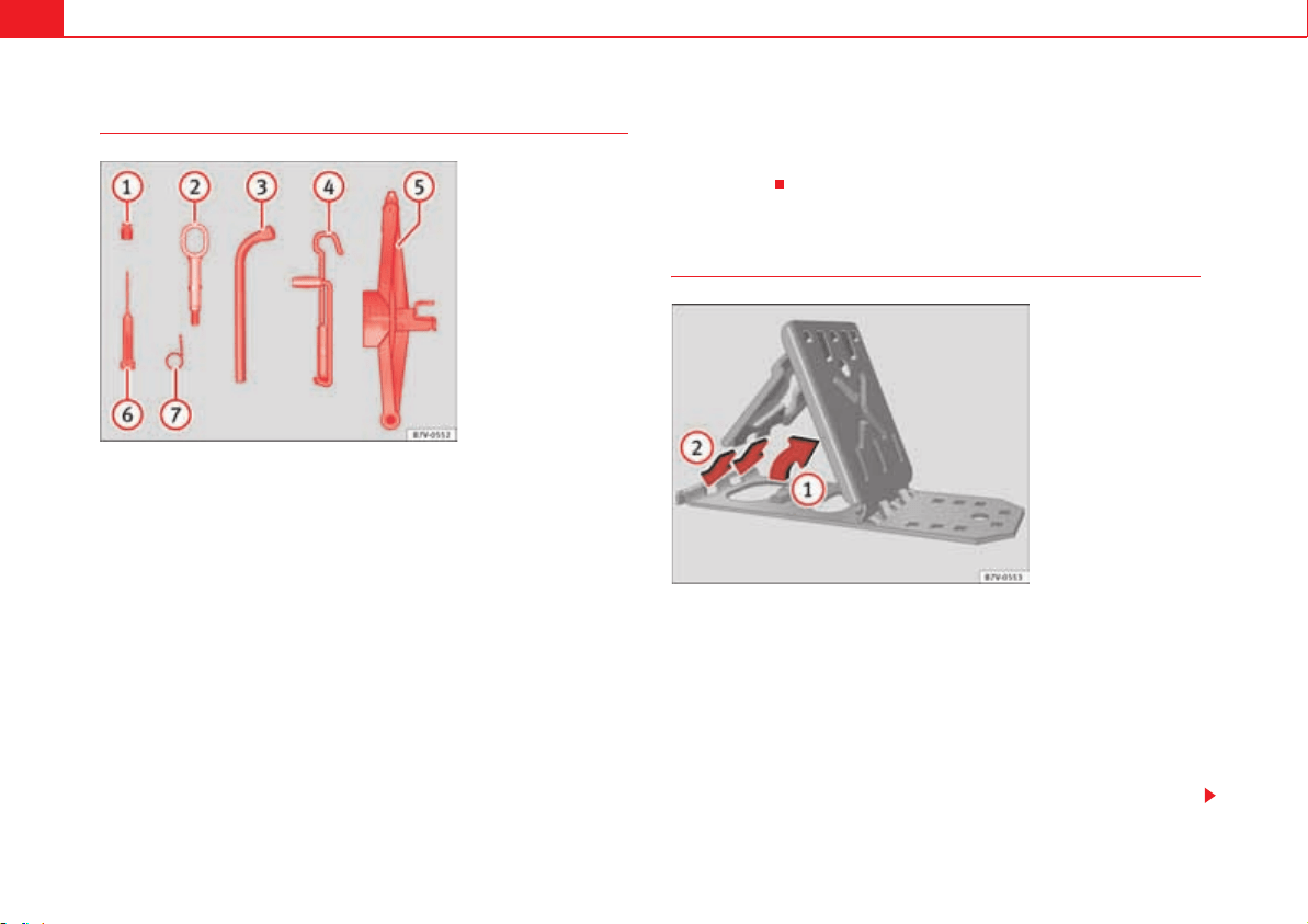
If and when354
Components
The set of on-board tools depends on the vehicle equipment. The following is
a description for a vehicle with all options.
The individual elements of the on-board toolkit fig. 207
Adapter for antitheft bolt. SEAT recommend you carry the wheel bolt
adapter in the vehicle tool kit at all times. The code number of the anti-
theft wheel bolt is stamped on the front of the adapter. In case it is lost,
another adapter can be ordered using this number. Note the antitheft
bolt code for the wheels and keep it in a place other than the vehicle.
Towing eye, removable.
Wheel spanner.
Jack. Fold the jack before returning it to the toolkit.
Jack. Before storing the jack in the toolkit, fold its hook.
Screwdriver with hexagon socket in the handle for screwing and
unscrewing the wheel bolts once loosened. The screwdriver bit is inter-
changeable. The screwdriver may be found underneath the wheel
spanner.
Wire hook for pulling off the wheel cover, integral hubcaps and the wheel
bolt caps.
Foldable wedges*
The foldable wedges are with the on-board tools fig. 207.
Assembling the foldable wedges
x Lift the base plate fig. 208 .
x Insert the two “tabs” of the base plate into its openings.
Improper use
The foldable wedges are used to block the wheel diagonally opposite to the
wheel being changed.
Fig. 207 Components of
the onboard tool kit.
A
1
A
2
A
3
A
4
A
5
A
6
A
7
Fig. 208 To unfold the
foldable wedges.
A
1
If and when 355
Safety First Operating instructions Practical tips Technical Data
The foldable wedges are placed in front of and behind the wheel and must be
used on firm ground.
WARNING
Incorrect assembly and use of the foldable wedges can cause injury and
accidents.
x Never use damaged foldable wedges.
x Do not use the foldable wedges hold the vehicle on hills or slopes.
If and when356
Fuses
Introduction
Due to the constant update of vehicles, fuse assignments depending on
equipment and the use of the same fuse for various electrical components, at
the time of printing this manual it is not possible to provide an up-to-date
summary of the electrical components fuse positions. For detailed informa-
tion about the fuse positions, please consult a qualified workshop.
In general, a fuse can be assigned to various electrical components. Like-
wise, an electrical component can be protected by several fuses.
Only replace fuses when the cause of the problem has been solved. If a newly
inserted fuse blows after a short time, you must have the electrical system
checked by a qualified dealership as soon as possible.
Additional information and warnings:
x Working in the engine compartment page 304
WARNING
The high voltages in the electrical system can give serious electrical
shocks, causing burns and even death!
x Never touch the electrical wiring of the ignition system.
x Take care not to cause short circuits in the electrical system.
WARNING
Using unsuitable fuses, repairing fuses or bridging a current circuit without
fuses can cause a fire and serious injury.
x Never use a fuse with a higher value. Only replace fuses with a fuse of
the same amperage (same colour and markings) and size.
x Never repair a fuse.
x Never replace a fuse by a metal strip, staple or similar.
Caution
x To avoid damage to the vehicles electric system, before replacing a fuse
turn off the ignition, the lights and all electrical elements and remove the
keys from the ignition.
x If you replace a fuse with higher-rating fuse, you could cause damage to
another part of the electrical system.
x Protect the fuse boxes when open to avoid the entry of dust or humidity.
Dirt and humidity inside fuse boxes can cause damage to the electrical
system.
Note
One single consumer could have more than one fuse.
Note
Several consumers could run over one single fuse.
WARNING (continued)
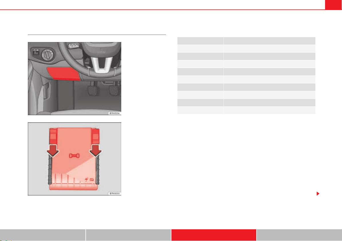
If and when 357
Safety First Operating instructions Practical tips Technical Data
Vehicle fuses
Only replace fuses with a fuse of the same amperage (same colour and mark-
ings) and size.
Identifying fuses by colours
To open the dashboard fuse box
x Reach behind the cover with your hand fig. 209 and pull forwards.
To open the engine compartment fuse box
x Open the bonnet page 304.
x Move the attachment tabs forwards, in the direction indicated by the
arrow to release the fuse box cover fig. 210.
x Then lift the cover out.
x To fit the cover, place it on the fuse box. Push the attachment tabs back,
in the opposite direction indicated by the arrow until they click audibly into
place.
In is possible that there are more fuses behind a cover in the lower left-hand
side of the luggage compartment.
Fig. 209 On the driver-
side dashboard: fuse box
cover.
Fig. 210 In the engine
compartment: fuse box
cover.
Colour Amp rating
purple 3
light brown 5
Brown 7,5
Red 10
Blue 15
Yellow 20
White or transparent 25
Green 30
orange 40
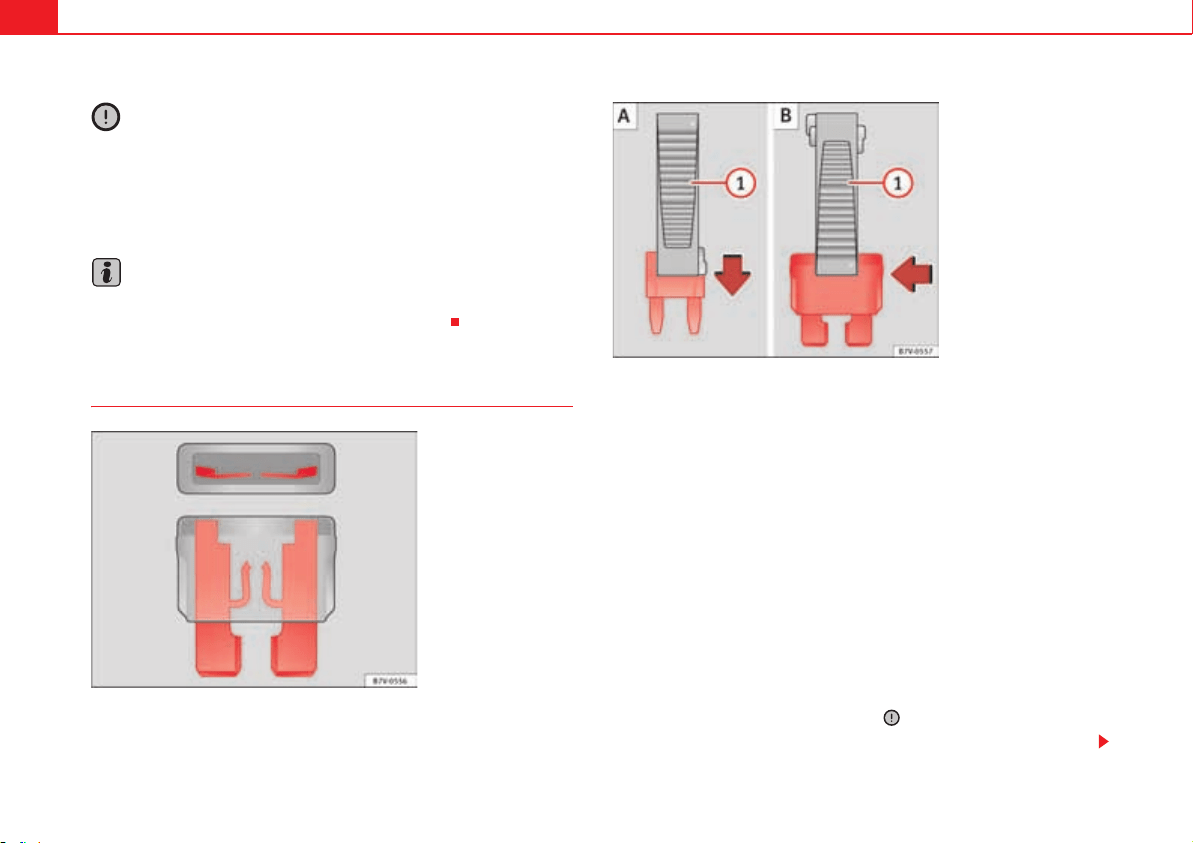
If and when358
Caution
x Always carefully remove the fuse box covers and refit them correctly to
avoid problems with your vehicle.
x Protect the fuse boxes when open to avoid the entry of dust or humidity.
Dirt and humidity inside fuse boxes can cause damage to the electrical
system.
Note
In the vehicle, there are more fuses than those indicated in this chapter.
These should only be changed by a specialist workshop.
Replacing a blown fuse
Preparation
x Switch off the ignition, lights and all electrical equipment.
x Open the corresponding fuse box page 357
Identifying a blown fuse
A fuse is blown if its metal strip is ruptured fig. 211.
Point a lamp at the fuse. This will make it easier to see if the fuse is blown.
To replace a fuse
x If necessary, remove the plastic pincers from the fuse box cover.
x For small fuses, insert the pincers from above fig. 212 .
x For larger fuses, insert the pincers from one side of the fuse fig. 212
.
x Remove the relevant fuse.
x Replace the blown fuse by one with an identical amperage rating (same
colour and markings) and identical size .
x Replace the cover.
Fig. 211 Image of a
blown fuse.
Fig. 212 Removing or
fitting a fuse.
A
A
A
B

If and when 359
Safety First Operating instructions Practical tips Technical Data
Caution
If you replace a fuse with higher-rating fuse, you could cause damage to
another part of the electrical system.
If and when360
Changing bulbs
Introduction
Changing bulbs requires a certain amount of manual skill. If you are unsure,
SEAT recommends that you consult an qualified workshop or request assist-
ance from a specialist. In general, a specialist is required if other vehicle
components must be removed or if the discharge lamps must be replaced.
You should store spare light bulbs in the vehicle for safety-relevant lights.
Spare bulbs may be obtained from the Official dealers and workshops. In
some countries, it is a legal requirement to carry spare bulbs in the vehicle.
Driving with faults and blown bulbs on the vehicle exterior lighting is against
the law.
Additional bulb specifications
The specifications of some headlamp bulbs and bulbs for the tail lamps fitted
at the factory may be different to those of conventional bulbs. Bulb informa-
tion is displayed on the bulb socket or on the bulb itself.
Additional information and warnings:
x Lights and visibility page 113
x Working in the engine compartment page 304
x Vehicle tools page 353
x Fuses page 356
WARNING
If the road is not well-lit and the vehicle is not clearly visible to other
drivers, there is a risk of accident.
WARNING
Failure to replace bulbs correctly may cause serious accidents.
x Before carrying out any work in the engine compartment please read
and observe the warnings page 304. In any vehicle, the engine compart-
ment is a hazardous area and could cause severe injury.
x Discharge lamps work with high-voltage and can cause serious or fatal
injury if handled incorrectly.
x H7 and discharge lamps are highly pressurised and could explode
when being changed.
x Only replace the bulbs concerned when they have cooled.
x Never replace bulbs alone if you are not familiar with the operations
necessary. If you are not sure about procedures then visit a qualified work-
shop to carry out the necessary work.
x Never touch the bulb glass directly. Fingerprints will be evaporated by
the heat of the operating bulb thus “fogging” up the reflector.
x The headlamp frameworks in the engine compartment and the tail
lamps contain sharp elements. Always protect your hands when changing
bulbs.
Caution
After changing a bulb, if the rubber covers and plastic caps are not replaced
correctly on the headlamp framework, the electrical installation may be
damaged, especially if water is allowed to enter.
If and when 361
Safety First Operating instructions Practical tips Technical Data
Indicator
Several warning and control lamps should light up for a few seconds when
the ignition is switched. This signals that the lamp is working properly. They
will switch off after a few seconds.
Checking the bulbs of a trailer
For vehicles with the factory fitted trailer system, certain trailer lights are also
controlled if the socket is correctly connected.
A fault on a trailer turn indicator is indicated on the instrument panel by the
indicator blinking twice as fast ( or ) page 113.
x General fault of all indicators on one side.
x Fault in one tail light (on some models, also the registration light).
x Fault in two brake lights.
WARNING
If the warning lamps and messages are ignored, the vehicle may stall in
traffic, or may cause accidents and severe injuries.
x Never ignore the warning lamps or text messages.
x Stop the vehicle safely as soon as possible.
Caution
Failure to heed the warning lamps and text messages when they appear may
result in faults in the vehicle.
Note
A fault in the LED on the tail lights will not be indicated. However, if the fault
affects all the LEDs then this will be indicated by the indicator .
Information for replacing bulbs
Checklist
To replace a bulb, carry out the following operations always in the order given
:
1. Park the vehicle a safe distance from traffic and on suitable ground.
2. Connect the electronic parking brake page 210.
3. Turn the light switch to position 0 page 113.
4. Move the gear lever into the neutral position page 113.
5. Automatic gearbox: Move selector lever to position P page 201.
6. Stop the engine and remove the key from the ignition page 195.
7. Manual gearbox: Select a gear page 201.
8. Wait until all of the passenger compartment lights are turned off
page 113.
9. Allow the corresponding bulb to cool.
10. Visually inspect fuses to see if any are blown page 356.
11. Replace the bulb according to the instructions . Bulbs should only
be replaced by new identical models. Bulb information is displayed on
the bulb socket or on the bulb itself.
12. In general, never touch the bulb glass directly. The heat of the bulb would
cause the fingerprint to evaporate and condense on the reflector. This
will impair the brightness of the headlight.
lights up Possible cause Solution
A vehicle exterior lighting
bulb is not working.
Replace the faulty bulb.
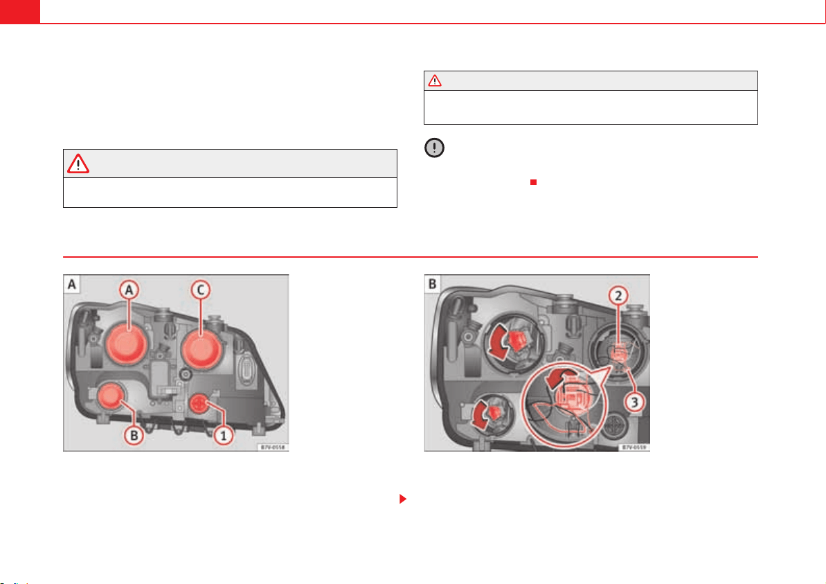
If and when362
13. Check if the new bulb is working. If the bulb is not working, it may not
have been correctly fitted, it could be damaged or the connector may not
be correctly connected.
14. Every time a bulb for the headlights is replaced, visit a specialised work-
shop to check the headlights.
WARNING
Failure to follow the checklist prepared for your own safety could lead to
accidents and severe injuries.
x Always complete the operations given in the checklist and observe the
general rules of safety.
Caution
Always remove and fit headlights carefully to avoid damage to the paintwork
and other vehicle parts.
To replace halogen headlight bulbs
There is no need to remove the headlight to replace bulbs.
Complete operations only in the sequence given:
WARNING (continued)
Fig. 213 In the engine
compartment: Left-hand
side headlight lining.
dipped beam headlights,
daytime lights and
main beam headlights
and side lights.
A
A
A
B
A
C
Fig. 214 Left headlight

If and when 363
Safety First Operating instructions Practical tips Technical Data
Note
The images show the left hand headlight from behind. The structure of the
right hand side headlight is symmetric.
page 362, fig. 213,
page 362, fig. 214
Indicators (small lamp
holder)
Dipped beam head-
lights
Daylight driving lights Main beam headlights Side lights
1. Always take the checklist into account and take the necessary actions page 361.
2.
Open the bonnet page 304.
3. Remove the rubber cover on the rear of the headlight.
4.
Rotate the lamp holder
to the left all the way
and pull it out back-
wards with the bulb.
Rotate the lamp holder to the left all the way and
pull it out backwards with the bulb.
Press the wire clip down-
wards and pull the lamp
holder out with the
bulb.
Pull the lamp holder
out backwards with the
bulb.
5. Depending on the model, the bulb is removed directly from the lamp holder or it may need to be rotated and then removed.
6. Replace the faulty bulb by a new identical bulb.
7. Place the bulb holder in the headlight and rotate to the right all the way.
Place the lamp holder in
the headlight and pull the
wire clip upwards until it
clicks into place.
Place the lamp holder in
the headlight and insert
completely.
8. Insert the rubber cover.
A
A
A
B
A
C
A
1
A
2
A
3
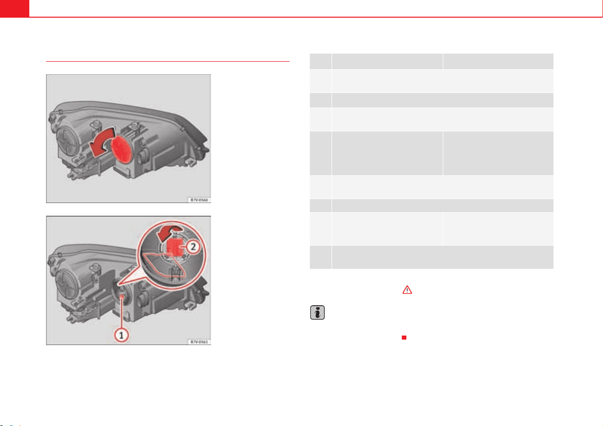
If and when364
To replace the xenon headlights bulb
There is no need to remove the headlight to replace bulbs.
Complete operations only in the sequence given:
Always seek the help of a specialist when changing the Xenon dipped beam
and full beam headlamps in “Introduction” on page 360.
Note
The illustrations show the left hand headlight. The structure of the right hand
side headlight is symmetric.
Fig. 215 In the engine
compartment: Turn signal
cover.
Fig. 216 Turn signal indi-
cator lamp holder and
turning light .
A
1
A
2
Turn signal indicators Turning lights
1.
Always take the checklist into account and take the necessary
actions page 361.
2.
Open the bonnet page 304.
3.
Rotate the cover fig. 215 in the direction of the arrow and remove
it.
4.
Rotate the lamp holder
fig. 216 to the left all the way
and pull it out backwards with the
bulb.
Press the wire clip downwards
and pull the lamp holder
fig. 216 out with the bulb.
5.
Depending on the model, the bulb is removed directly from the lamp
holder or it may need to be rotated and then removed.
6. Replace the faulty bulb by a new identical bulb.
7.
Place the bulb holder in the head-
light and rotate to the right all the
way.
Place the lamp holder in the
headlight and pull the wire clip
upwards until it clicks into place.
8.
Rotate the cover fig. 215 in the opposite direction to the arrow as
far as it will go.
A
1
A
2
A
1
A
2

If and when 365
Safety First Operating instructions Practical tips Technical Data
To replace the front bumper bulbs
Complete operations only in the sequence given:
Fig. 217 On the right-
hand side of the front
bumper: Removing the
headlights
Fig. 218 Changing the
bulbs in the headlights.
1.
Always take the checklist into account and take the necessary
actions page 361.
2. Pull the cover forwards, in the direction of the arrow fig. 217.
3.
Unscrew the attachment screw fig. 217 using the screwdriver
from the on-board tools page 353.
4.
Tilt the headlight slightly forward and extract it from its lateral
attachments fig. 218 (small arrows).
5.
Release the connector fig. 218 and remove it.
6.
Rotate the lamp holder fig. 218 to the left all the way, in the
direction of the arrow, and pull it out backwards with the bulb.
7. Replace the faulty bulb by a new identical bulb.
8.
Place the bulb holder in the headlight and rotate to the right all the
way.
9.
Insert the connector fig. 218 on the lamp holder fig. 218
. The connector must audibly click into place.
10.
Place the headlight into its position fig. 218 (small arrows) and
tilt it backwards.
11.
Tighten the attachment screw fig. 217 using the screwdriver.
12. Replace the cover on the bumper fig. 217.
A
1
A
1
A
2
A
1
A
2
A
1
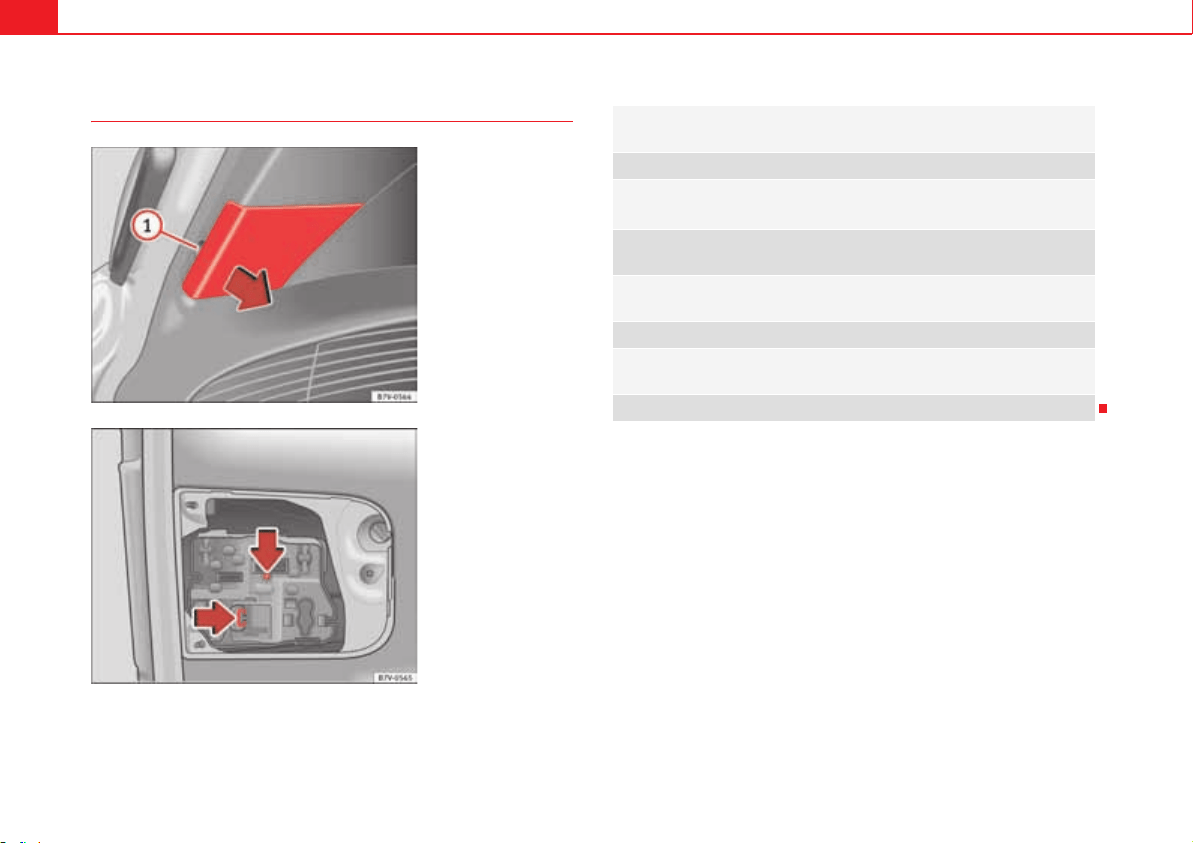
If and when366
To replace the tailgate light bulbs
Complete operations only in the sequence given:
Fig. 219 On the boot lid:
Remove the cover.
Fig. 220 On the boot lid:
Remove the lamp holder.
1.
Always take the checklist into account and take the necessary
actions page 361.
2. Open the tailgate page 97.
3.
Extract the cover carefully using the flat part of the screwdriver as a
lever ( page 354, fig. 207) on the indent fig. 219 .
4.
Release the lamp holder connector by pulling on the red connector
block.
5.
Press on the attachment tabs in the direction of the arrow
fig. 220 and pull out the lamp holder.
6. Replace the faulty bulb by a new identical bulb.
7.
Install the lamp holder. The attachment tabs should audibly click
into place.
8. Insert the cover. The cover should lock into place.
A
1
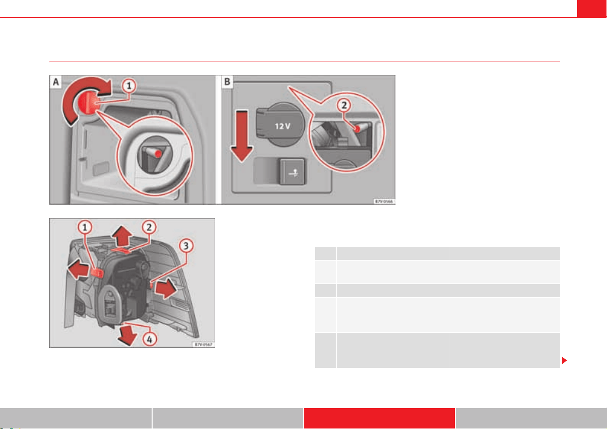
If and when 367
Safety First Operating instructions Practical tips Technical Data
To replace the tail light bulbs
Complete operations only in the sequence given.
Removing the tail light units
Complete operations only in the sequence given:
Fig. 221 On the side of the luggage compartment: To
remove the left and right hand side tail lights. remove
the cap; attachment screw.
A
1
A
2
Fig. 222 Tail lights on
bodywork: To remove the
lamp holder. to :
Attachment tab.
A
1
A
4
Rear light, left Rear light, right
1.
Always take the checklist into account and take the necessary
actions page 361.
2. Open the tailgate page 97.
3.
Open the storage compartments
on the left-hand side of the lug-
gage compartment page 162.
Move the 12 V socket support by
pressing gently downwards
fig. 221 (arrow).
4.
Rotate the cap fig. 221 90°
in the direction of the arrow and
remove it.
A
B
A
1

If and when368
To change the bulb
Assembling the tail light units
Complete operations only in the sequence given:
5.
Unscrew the attachment screw page 367, fig. 221 using the
screwdriver from the on-board tools page 353. The bolt is
secured in its position.
6.
Extract the tail light from the bodywork by carefully pulling back-
wards.
7. Pull the red strip on the connector and extract the connector.
8. Disassemble the tail light unit and place it on a flat, clean surface.
9.
To release the lamp holder, press on the attachment tabs
page 367, fig. 222 to in the direction of the arrow.
10. Remove the lamp holder from the tail light unit.
11. Replace the faulty bulb by a new identical bulb.
12.
Place the lamp holder in the tail light unit. The attachment tabs
should audibly click into place.
13.
Insert the connector and press the red attachment strip in so that
the connector is locked into place.
Rear light, left Rear light, right
A
2
A
1
A
4
Rear light, left Rear light, right
14.
Carefully insert the tail light unit into the opening in the bodywork.
To do this, insert the upper tail light unit guide into the attachment
ring.
15.
Tighten the white attachment screw using the screwdriver from the
on-board tools.
16.
Ensure that the tail light unit has been correctly fitted and is firmly
secured.
17.
Replace the cap and rotate it
90° in the opposite direction of
the arrow.
Move the 12 V socket support
upwards gently until it is correctly
closed.
18. Close the storage compartment.
19. Close the tailgate page 97.
A
1
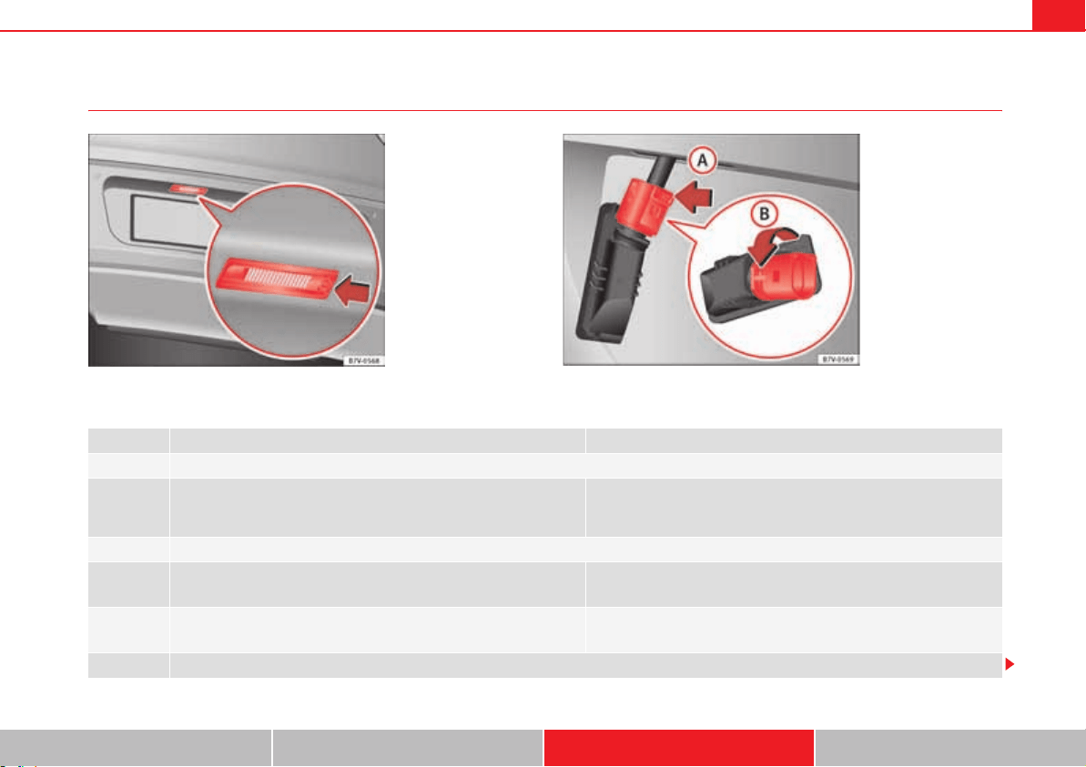
If and when 369
Safety First Operating instructions Practical tips Technical Data
Changing the number plate light
Complete operations only in the sequence given:
Fig. 223 On the rear
bumper: number plate
lights.
Fig. 224 Number plate
light: To remove the lamp
holder.
Fixed number plate light Bolted number plate light
1. Always take the checklist into account and take the necessary actions page 361.
2.
Press the flat part of the screwdriver included in the vehicle on-board
tools ( page 354, fig. 207) in the direction of the arrow, in the groove
of the number plate light fig. 223.
Unscrew the number plate light screws using the screwdriver from the
on-board tools ( page 354, fig. 207).
3. Detach the number plate light.
4.
Press on the connector lock in the direction of the arrow fig. 224
and pull out the connector.
Separate the attachment tabs from the rear panel of the number plate
light by pressing.
5.
Rotate the lamp holder in the direction of the arrow fig. 224 and
extract it with the lamp.
Take the lamp holder out of the number plate light.
6. Replace the faulty bulb by a new identical bulb.
A
A
A
B

If and when370
7.
Insert the lamp holder into the number plate light and rotate all the way
in the opposite direction to the arrow page 369, fig. 224 .
Insert the lamp holder into the number plate light.
8. Plug the connector into the lamp holder.
Press on the attachment tabs. The lamp holder must be firmly attached
to the number plate light.
9. Insert the number plate light carefully into the opening on the bumper. Ensure that the number plate light is in the correct position.
10.
Insert the number plate light into the bumper until it audibly clicks into
place.
Tighten the attachment screws for the number plate light using the
screwdriver.
Fixed number plate light Bolted number plate light
A
B
If and when 371
Safety First Operating instructions Practical tips Technical Data
Starting assistance
Introduction
If the engine fails to start because of a discharged battery, the battery of
another vehicle can be used to start the engine. Before starting, check the
magic eye on the battery page 318.
For starting assistance, jump lead cables conforming to the standard DIN
72553 are required (see the cable manufacturer instructions). The jump lead
cable must be at least 25 mm
2
in section (0.038 inches
2
) for petrol engines,
and 35 mm
2
(0.054 inches
2
) for diesel engines.
For vehicles whose battery is not in the engine compartment, the jump leads
should only be connected to the starting assistance connection points in the
engine compartment.
Additional information and warnings:
x Starter assist systems (Start-Stop function) page 221
x Working in the engine compartment page 304
x Selective Catalytic Reduction (AdBlue) page 300
x Vehicle battery page 318
WARNING
Incorrect use of jump leads and incorrectly jump starting could cause the
battery to explode resulting in serious injury. Please observe the following
rules to minimise the risk of a battery explosion:
x All work involving the vehicle battery and electrical system can cause
corrosion, fire and serious electric shocks. Always read and take into
account the safety warnings and standards before beginning work on the
battery page 318, “Vehicle battery”.
x The battery providing current must have the same voltage (12V) and
approximately the same capacity (see markings on battery) as the flat
battery.
x Never charge a frozen or recently thawed battery. A flat battery can
freeze at temperatures around 0°C (+32 °F).
x If a battery is frozen and/or has been frozen then it must be replaced.
x A highly explosive mixture of gases is released when the battery is
being charged. Always keep lit cigarettes, open flames, sparks and fire far
from the battery. Never use a mobile telephone when connecting and
removing the jump leads.
x Charge the battery only in well ventilated areas given that when the
battery is charged by outside assistance, it creates a mix of highly explo-
sive gases.
x Jump leads should never enter into contact with moving parts in the
engine compartment.
x Never switch the positive and negative poles or connect the jump leads
incorrectly.
x Note the instructions provided by the manufacturer of the jump leads.
Caution
To avoid considerable damage to the vehicle electrical system, note the
following carefully:
x If the jump leads are incorrectly connected, this could result in a short
circuit.
x The vehicles must not touch each other, otherwise electricity could flow as
soon as the positive terminals are connected.
WARNING (continued)
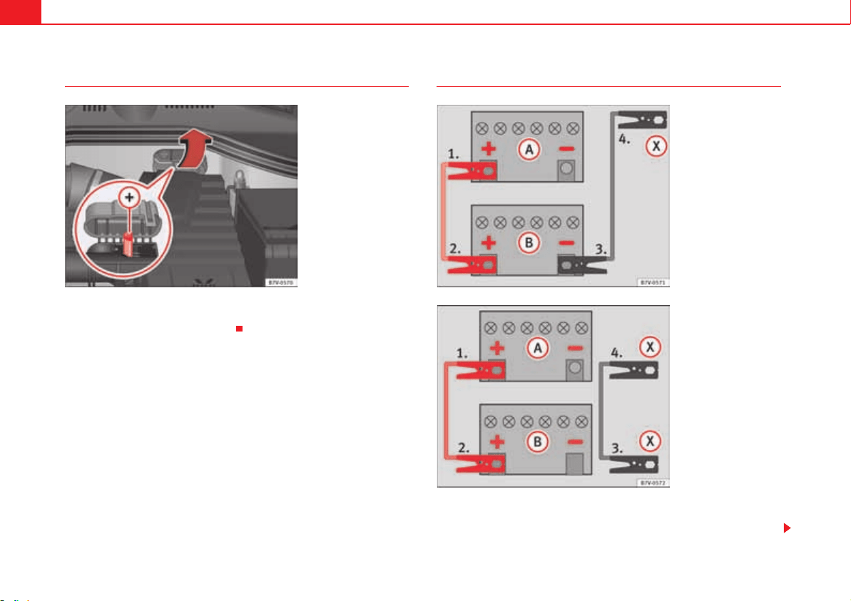
If and when372
Positive pole on the starting assistance points
On some vehicles, there is a starting assistance terminal in the engine
compartment, under a labelled cover.
How to jump start: description
The discharged battery must be properly connected to the vehicle electrical
system.
Fig. 225 In the engine
compartment: positive
pole for starting assist-
ance .
A
+
Fig. 226 Jump lead
connection diagram when
the assistance vehicle
does not have a Start-
Stop system: flat battery
and battery supplying
current .
A
A
A
B
Fig. 227 Jump lead
connection diagram when
the assistance vehicle has
a Start-Stop system: flat
battery and battery
supplying current .
A
A
A
B

If and when 373
Safety First Operating instructions Practical tips Technical Data
The vehicles should not touch. Otherwise, current may be allowed to flow
when the positive poles are connected.
Connect the clamps so they have good metal-to-metal contact with the termi-
nals.
If the engine fails to start straight-away, switch off the starter after about 10
seconds and try again after about a minute.
Complete operations only in the sequence given.
Jump lead terminal connections
x Switch off the ignition of both vehicles page 195.
x Likewise, open the battery cover in the engine compartment page 318,
or remove the positive pole cap from one side
3)
, in the direction of the arrow
page 372, fig. 225.
x Connect one end of the red jump lead to the positive terminal
page 372, fig. 226 or page 372, fig. 225 of the vehicle with the
flat battery .
x Connect the other end of the red jump lead to the positive terminal in
the vehicle providing assistance .
x For vehicles without Start-Stop system: Connect one end of the black
jump lead to the negative terminal in the vehicle providing assistance
page 372, fig. 226.
x For vehicles with Start-Stop system: Connect one end of the black
jump lead to a suitable ground connection, a solid piece of metal in the
engine block, or to the engine block page 372, fig. 227.
x Connect the other end of the black jump lead to a solid metal compo-
nent connected to the engine block, or onto the engine block itself of the
vehicle with the flat battery however, connect it as far away as possible from
the battery .
x Place the leads so that they cannot be caught by any moving parts in the
engine compartment.
Switching on
x Start the engine of the vehicle supplying current and let it run at idling
speed.
x Start the engine of the car with the flat battery and wait two or three
minutes until the engine is “running smoothly”.
Removing the jump leads
x Before you remove the jump leads, switch off the headlights (if they are
switched on).
x Turn on the heating and rear window heater in the vehicle with the flat
battery. This helps minimise voltage peaks which are generated when the
leads are disconnected.
x With the engines running, disconnect the leads in reverse order to
connection.
x Close the battery cover, or replace the positive pole cap
3)
.
WARNING
Incorrectly jump starting could cause the battery to explode resulting in
serious injury. Please observe the following rules to minimise the risk of a
battery explosion:
x All work involving the vehicle battery and electrical system can cause
corrosion, fire and serious electric shocks. Always read and take into
account the safety warnings and standards before beginning work on the
battery page 318, “Vehicle battery”.
x Always protect your eyes with suitable working goggles and never lean
over the vehicle battery.
x The jump leads must be connected in the correct order: first the positive
cable, then the negative cable.
x Do not attach the negative cable to parts of the fuel system or to the
brake hose/pipe.
3)
Vehicles whose battery is not located in the engine compartment page 372.
A
+
A
+
A
A
A
+
A
B
A
-
A
B
A
X
A
X
A
A
If and when374
x The non-insulated parts of the battery clamps must not be allowed to
touch. Also, the cable connected to the positive pole of the battery should
never enter into contact with electrically conductive parts of the vehicle.
x Check the magic eye on the battery; use a lamp if necessary. If it is clear
yellow or clear, do not start the vehicle: obtain specialist technical assist-
ance.
x Avoid static electricity discharges in the area around the battery. In the
event of sparks, explosive gases coming from the battery could ignite.
x Never use starting assistance if the vehicle battery is damaged, frozen
or has been frozen.
WARNING (continued)
If and when 375
Safety First Operating instructions Practical tips Technical Data
Towing and tow starting
Introduction
When towing, always respect legal requirements.
For technical reasons, it is not possible to tow a vehicle if the battery is flat.
Additional information and warnings:
x Electronic power control and exhaust gases purification system
page 255
WARNING
A vehicle with a flat battery should never be towed.
x Never remove the key from the ignition lock. The electronic steering
lock could engage. Then the vehicle will be uncontrollable. You may lose
control of the vehicle and there is a risk of serious accident.
WARNING
When towing the vehicle, the handling and braking efficiency change
considerably. Please observe the following instructions to minimise the
risk of serious accidents and injury:
x As the driver of the vehicle being towed:
The brake must be depressed must harder as the brake servo does
not operate. Always remain aware to avoid collision with the towing
vehicle.
More strength is required at the steering wheel as the power
steering does not operate when the engine is switched off.
x As the driver of the towing vehicle:
Accelerate gently and carefully.
Avoid sudden braking and manoeuvres.
Brake well in advance than usual and brake gently.
Caution
x Carefully fit and remove the towing ring and its cover to avoid damage to
the vehicle (for example, paintwork).
x When towing, fuel could enter the catalytic converter and cause
damage!
Instructions for tow starting
In general, the vehicle should not be started by towing. Jump-starting is
much more preferable page 371.
For technical reasons, the following vehicles can not be tow started:
x Vehicles with an automatic gearbox.
x Vehicles with the KESSY locking and ignition system, given that the elec-
tronic steering lock will certainly not be unlocked.
x Vehicles with an electronic parking brake, given that it is possible that the
brake will not be disengaged.
x If the vehicle battery is flat, it is possible that the engine control units do
not operate correctly.
However, if your vehicle must absolutely be tow-started (manual gearbox):
x Engage 2nd or 3rd gear.
x Keep the clutch pressed down.
x Switch on the ignition and the hazard warning lights.
x Release the clutch when both vehicles are moving.
WARNING (continued)
If and when376
x As soon as the engine starts, press the clutch and move the gear lever into
neutral. This helps to prevent a collision with the towing vehicle.
Caution
When tow-starting, fuel could enter the catalytic converter and damage it.
Towing instructions
Tow-rope or tow-bar
When towing, the tow bar is the safest and vehicle friendly way. You should
only use a tow-rope if you do not have a tow-bar.
A tow-rope should be slightly elastic to avoid damage to both vehicles. It is
advisable to use a tow-rope made of synthetic fibre or similarly elastic mate-
rial.
Only secure the tow rope or tow bar to the tow ring or specially designed
fitting.
Vehicles with a factory fitted towing device, can only be used for towing with
a tow-bar, specially designed to fit on a tow hitch ball page 260.
Towing vehicles with an automatic gearbox
Note the following for a towed vehicle:
x Make sure the gear selector lever is in the N position.
x Do not drive faster than 50 km/h (30 mph) when towing a vehicle.
x Do not tow further than 50 km (30 miles).
x If a breakdown truck is used, the vehicle must be towed with the front
wheels raised. Note the following instructions for towing four wheel drive
vehicles.
Instructions for towing four-wheel-drive vehicles
Four wheel drive vehicles can be towed using a toolbar or tow rope. If the
vehicle is towed with the front or rear axle raised, the engine must be turned
off to avoid transmission damage.
For vehicles with a double clutched DSG
®
(direct shift gearbox) the instruc-
tions for towing vehicles with an automatic gearbox apply page 376.
Situations in which the vehicle should not be towed
In the following cases, the vehicle should not be towed but transported on a
trailer or special vehicle:
x If the vehicle gearbox does not contain lubricant due to a fault.
x If the vehicle battery is flat and, as a result, the electronic steering lock
and electronic parking brake cannot be disengaged if applied.
x If the vehicle to be towed has an automatic gearbox and the distance to
be covered is greater than 50 km (30 miles).
Note
The vehicle can only be towed if the electronic parking brake and steering
lock are deactivated. If the vehicle has no power supply or there is an electric
system fault, the engine must be started using jump leads to deactivate the
electronic parking brake and electronic steering lock.
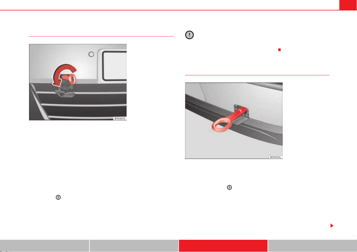
If and when 377
Safety First Operating instructions Practical tips Technical Data
Fitting the front tow ring
The location for the removable tow ring is on the right-hand side of the front
bumper fig. 228.
The towing eye should always be kept in the vehicle.
Note the instructions for towing page 376.
To fit the tow ring
x Take the tow ring from the vehicle tool kit page 353.
x Press on the upper cover and carefully remove it forwards. Allow the cover
to hang.
x Screw in the tow ring into its position anticlockwise as far as it will go
fig. 228 . Use a suitable tool to firmly tighten the tow ring in its loca-
tion.
x After towing, remove the tow ring by turning it clockwise and put the cover
back in place.
Caution
The tow ring must always be completely and firmly tightened. Otherwise, it
could be released while towing and tow-starting.
Fitting the rear tow ring
The location for the removable tow ring is on the right-hand side of the rear
bumper fig. 229. For vehicles with a factory fitted trailer system, there is no
fitting behind the cover to insert the tow ring. For towing, fit and use the trailer
hitch page 260, .
Note the instructions for towing page 376.
Fitting the tow ring to the rear for vehicles without factory fitted tow hitch
x Take the tow ring from the on-board tools page 353.
x Press on the upper cover and carefully remove it back. This may require
some strength. Allow the cover to hang.
Fig. 228 On the right-
hand side of the front
bumper: Screw in the
towing ring.
Fig. 229 On the rear
bumper, to the right hand
side: Tow ring in position.

If and when378
x Screw in the tow ring into its position anticlockwise as far as it will go
. Use a suitable tool to firmly tighten the tow ring in its location.
x After towing, remove the tow ring by turning it clockwise and put the cover
back in place.
Caution
x The tow ring must always be completely and firmly tightened. Otherwise,
it could be released while towing and tow-starting.
x Vehicles with a factory fitted towing device, can only be used for towing
with a tow-bar, specially designed to fit on a tow hitch ball. Otherwise, the tow
hitch ball and the vehicle may be damaged. Otherwise, a tow rope should be
used.
Towing advice
Towing requires some experience, especially when using a tow-rope. Both
drivers should be familiar with the technique required for towing. For this
reason, inexperienced drivers should abstain.
While driving, avoid excessive traction forces and jerking. When towing on an
unpaved road, there is always a risk of overloading and damaging the
anchorage points.
If the vehicle is towed, with the hazard warning lights on and the ignition
switched on, the turn signal may be used to indicate changes of direction.
Simply operate the turn indicator lever as usual. Meanwhile, the hazard
warning lights will go off. When the turn signal lever is returned to the rest
position, the hazard warning lights will be turned on automatically.
Notes for the driver of the towed vehicle
x Leave the ignition on to avoid locking the steering wheel, to release the
electronic parking brake and to activate the turn signal indicators, the horn
as well as the window wipers and window washers.
x As the power assisted steering does not work if the engine is not running,
you will need more strength to steer than normally.
x The brake must be depressed must harder as the brake servo does not
operate. Avoid hitting the towing vehicle.
x Note the instructions and information contained in the instruction manual
for the vehicle to be towed.
Notes for the driver of the towing vehicle
x Accelerate gently and carefully. Avoid sudden manoeuvres.
x Brake well in advance than usual and brake gently.
x Note the instructions and information contained in the instruction manual
for the vehicle to be towed.
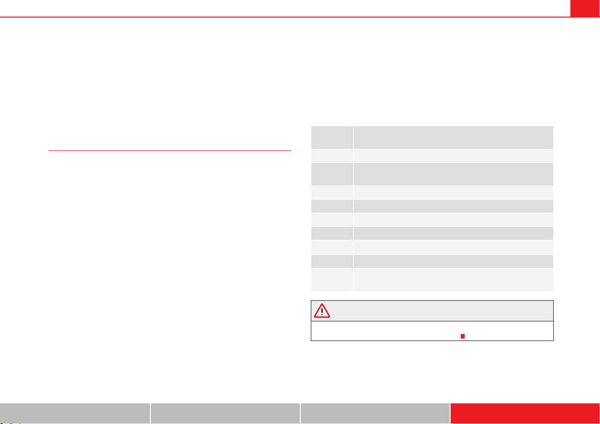
General notes on the technical data 379
Safety First Operating instructions Practical tips Technical Data
Technical Data
General notes on the technical data
Outstanding information
Important
All data in the official vehicle documents take precedence
over this data.
All data provided in this manual are valid for the standard model in Spain. The
vehicle data card included in the Inspection and Maintenance Plan in the
vehicles registration documents show which engine is installed in the
vehicle.
The figures may be different depending on if additional equipment is fitted,
for different models, for special vehicles and for other countries.
Additional information and warnings:
x Transporting page 13
x Ecological driving page 252
x Fuel page 297
x Engine oil page 309
x Engine coolant page 313
x Wheels and tyres page 323
x Notes for the user page 283
Abbreviations used in the Technical Data section
WARNING
Failure to observe requirements for weight, loads, dimensions and
maximum speed may lead to severe accident.
Abbrevia-
tion
Meaning
kW Kilowatt, engine power measurement.
PS
Pferdestärke (horsepower), formerly used to denote engine
power.
rpm Revolutions per minute - engine speed.
Nm Newton metres, unit of engine torque.
l/100 km Fuel consumption in litres per 100 km.
g/km Carbon dioxide emissions in grams per km travelled.
CO
2
Carbon dioxide
CN Cetane number, indication of the diesel combustion power.
RON
Research octane number, indication of the knock resistance
of petrol.
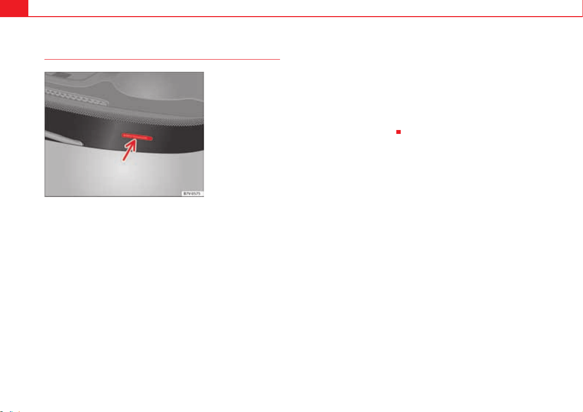
General notes on the technical data380
Vehicle code
Vehicle identification number
The vehicle identification number (chassis number) can be read from outside
the vehicle through a viewer in the windscreen fig. 230. This viewer is
located in the lower part of the windscreen. The vehicle identification number
(chassis number) is also stamped on the right water drain channel. The water
drain channel is located between the suspension tower and the wing. Open
the bonnet to read the vehicle identification number page 304.
Vehicle data plate
The vehicle data plate is attached to the luggage compartment, and contains
the following information:
Vehicle identification number (chassis number)
Vehicle type, engine power, gearbox type
Engine and gearbox code, paint number, interior equipment.
Optional extras, PR numbers
These data are also provided in the Maintenance Programme.
Type plate
The type plate is visible when the driver door is opened, on the lower part of
the strut. Vehicles for certain export countries do not have a type plate.
The manufacturer's type plate contains the following data:
Gross vehicle weight
Maximum authorised weight of vehicle and trailer
Maximum gross front axle weight
Maximum rear axle weight
Fig. 230 Vehicle identifi-
cation number.
A
1
A
2
A
3
A
4
A
5
A
6
A
7
A
8
General notes on the technical data 381
Safety First Operating instructions Practical tips Technical Data
Data on fuel consumption
Fuel consumption
The consumption and emission details shown on the vehicle
data sticker differ from one vehicle to another.
The fuel consumption, CO
2
emissions and actual kerb weight of the vehicle
are noted on the vehicle data sticker.
The fuel consumption and emissions figures given are based on the vehicle
weight category, which is determined according to the engine/gearbox
combination and the equipment fitted.
The consumption and emission figures are calculated in accordance with the
EC test requirements 1999/100/EC. These test requirements specify a real-
istic test method based on normal everyday driving.
The following test conditions are applied:
Note
x Actual consumption may vary from quoted test values, depending on
personal driving style, road and traffic conditions, the weather and the
vehicle condition.
Weights
Kerb weight refers to the basic model with a fuel tank filled to 90% capacity
and without optional extras. The figure quoted includes 75 kg to allow for the
weight of the driver.
For special versions and optional equipment fittings or for the addition of
accessories, the weight of the vehicle will increase .
WARNING
x Please note that the centre of gravity may shift when transporting
heavy objects; this may affect the vehicle's handling and lead to an acci-
dent. Always adjust your speed and driving style to suit road conditions
and requirements.
x Never exceed the gross axle weight rating or the gross vehicle weight
rating. If the allowed axle load or the allowed total weight is exceeded, the
driving characteristics of the vehicle may change, leading to accidents,
injuries and damage to the vehicle.
Urban cycle
The urban cycle starts with an engine cold start. City driving
is then simulated.
Extra urban
cycle
In the extra urban cycle simulation the vehicle frequently
accelerates and brakes in all gears, as in normal everyday
driving. The road speed ranges from 0 to 120 km/h.
Total con-
sumption
The average total consumption is calculated with a weighting
of around 37% for the urban cycle and 63% for the extra
urban cycle.
CO
2
emis-
sions
The exhaust gases are collected during both driving cycles to
calculate carbon dioxide emissions. The gas composition is
then analysed to evaluate the CO
2
content and other emis-
sions.
General notes on the technical data382
Towing a trailer
Trailer weights
Trailer weight
The trailer weights and drawbar loads approved are selected in intensive
trials according to precisely defined criteria. The approved trailer weights are
valid for vehicles in the EU for maximum speeds of 80 km/h (in certain
circumstances up to 100 km/h). The figures may be different in other coun-
tries. All data in the official vehicle documents take precedence over these
data .
Drawbar load
The maximum permitted weight exerted by the trailer drawbar on the ball joint
of the towing bracket must not exceed 85 kg.
In the interest of road safety, we recommend that you always tow
approaching the maximum drawbar load. The response of the trailer on the
road will be poor if the drawbar load is too small.
If the maximum permitted drawbar load is not reached (e.g. in the case of
small single-axle trailers, light and without load, or tandem axle trailers with
a wheelbase of less than 1 m) it is compulsory for the drawbar load to be at
least 4% of the trailer's weight.
WARNING
x For safety reasons, do not exceed the 80 km/h limit. This is also valid in
countries where higher speeds are permitted.
x Never exceed the maximum trailer weights or the drawbar load. If the
permissible axle load or the permissible total weight is exceeded, the
driving characteristics of the vehicle may change, leading to accidents,
injuries and damage to the vehicle.
Wheels
Tyre pressure, snow chains, wheel bolts
Tyre pressures
The sticker with the tyre pressure values can be found on the inside of the
tank flap. The tyre pressure values given there are for cold tyres. The slightly
raised pressures of warm tyres must not be reduced.
Snow chains
Snow chains may be fitted only to the front wheels.
Consult the chapter “wheels” of this manual.
Wheel bolts
After the wheels have been changed, the tightening torque of the wheel bolts
should be checked as soon as possible with a torque wrench . The tight-
ening torque for steel and alloy wheels is 120 Nm.
WARNING
x Check the tyre pressure at least once per month. Checking tyre pressure
value is very important. If the tyre pressure is too high or too low, there is
an increased danger of accidents, particularly at high speeds.
x If the torque of the wheel bolts is too low, they could loosen while the
vehicle is in motion. Risk of accident! If the tightening torque is too high,
the wheel bolts and threads can be damaged.
Note
We recommend that you ask your Authorised Service Centre for information
about appropriate wheel, tyre and snow chain size.
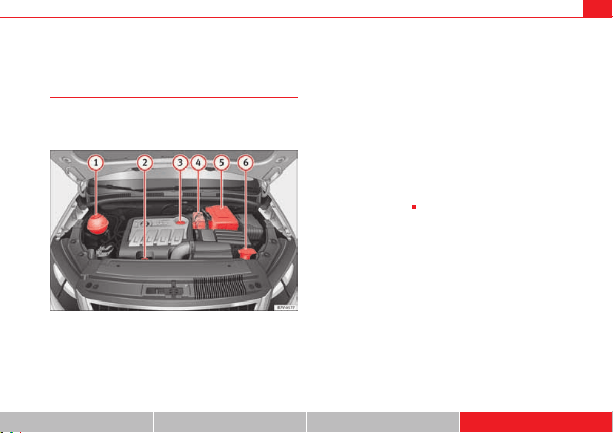
Technical Data 383
Safety First Operating instructions Practical tips Technical Data
Technical Data
Checking fluid levels
From time to time, the levels of the different fluids in the
vehicle must be checked. Never fill with incorrect fluids,
otherwise serious damage to the engine may be caused.
Fig. 231 Diagram for the location of the various elements
Liquid coolant deposit
Engine oil dipstick
Oil filler neck
Brake fluid reservoir
Vehicle battery (underneath a cover)
Windscreen washer fluid reservoir
The checking and refilling of service fluids are carried out on the components
mentioned above. These operations are described in page 304.
Overview
Further explanations, instructions and restrictions on the technical data are
contained as of page 379
A
1
A
2
A
3
A
4
A
5
A
6

Technical Data384
Petrol engine 1.4 110 kW (150 PS)
Engine specifications
Performance figures
Consumption (litres/100 km)/ CO
2
(g/km)
Weights
Power output in kW (PS) rpm 110 (150)/ 5800
Maximum torque in Nm at rpm 240/ 1500-4000
No. of cylinders/ capacity
in cm
3
4/ 1390
Fuel
95 super RON
a)
a)
Research-Octane-Number = Anti-detonation rating of the petrol.
Maximum speed in km/h 197
Acceleration from 0-80 km/h in sec. 6,9
Acceleration from 0-100 km/h in sec. 10,7
Urban cycle 9,2/214
Extra urban cycle 6,1/143
Combined 7,2/167
5 seats 7 seats
Gross vehicle weight in kg 2290 2480
Weight in running order (with driver) in kg 1723 1771
Gross front axle weight in kg 1170/1220 1170/1220
Gross rear axle weight in kg 1070/1120 1260/1310
Permitted roof load in kg 100 100
Technical Data 385
Safety First Operating instructions Practical tips Technical Data
Trailer weight
Engine oil capacity
Diesel engine 2.0 TDI 100 kW (135 PS)
Engine specifications
Performance figures
Trailer without brakes 750
Trailer with brakes, gradients up to 8% 1800
Trailer with brakes, gradients up to 12% 1800
Approximate engine oil capacity with oil filter change 4,0
Power output in kW (PS) rpm 100 (135)/ 4200
Maximum torque in Nm at rpm 320/1750-2500
No. of cylinders/ capacity
in cm
3
4/1968
Fuel
Min. 51 CN
a)
a)
Cetane-Number (cetane index) = Measure of the combustion power of the diesel
Maximum speed in km/h 194
Acceleration from 0-80 km/h in sec. 7,8
Acceleration from 0-100 km/h in sec. 11,1
Technical Data386
Consumption (litres/100 km)/ CO
2
(g/km)
Weights
Trailer weight
Engine oil capacity
5 seats 7 seats
Urban cycle 6,8/179 6,9/182
Extra urban cycle 4,8/127 4,9/130
Combined 5,5/143 5,6/146
5 seats 7 seats
Gross vehicle weight in kg 2340 2510
Weight in running order (with driver) in kg 1174 1822
Gross front axle weight in kg 1190/1240 1200/1250
Gross rear axle weight in kg 1100/1150 1260/1310
Permitted roof load in kg 100 100
Trailer without brakes 750
Trailer with brakes, gradients up to 8% 2200
Trailer with brakes, gradients up to 12% 2200
Approximate engine oil capacity with oil filter change 4,0
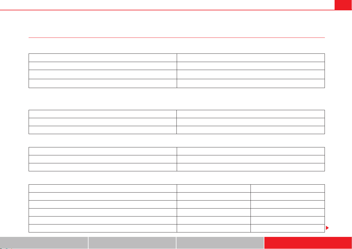
Technical Data 387
Safety First Operating instructions Practical tips Technical Data
Diesel engine 2.0 TDI 100 kW (135 PS) Automatic
Engine specifications
Performance figures
Consumption (litres/100 km)/ CO
2
(g/km)
Weights
Power output in kW (PS) rpm 100 (135)/ 4200
Maximum torque in Nm at rpm 320/1750-2500
No. of cylinders/ capacity
in cm
3
4/1968
Fuel
Min. 51 CN
a)
a)
Cetane-Number (cetane index) = Measure of the combustion power of the diesel
Maximum speed in km/h 191
Acceleration from 0-80 km/h in sec. 7,8
Acceleration from 0-100 km/h in sec. 11,1
Urban cycle 6,9/182
Extra urban cycle 5/132
Combined 5,7/149
5 seats 7 seats
Gross vehicle weight in kg 2370 2540
Weight in running order (with driver) in kg 1803 1851
Gross front axle weight in kg 1220/1270 1230/1280
Gross rear axle weight in kg 1100/1150 1260/1310
Permitted roof load in kg 100 100
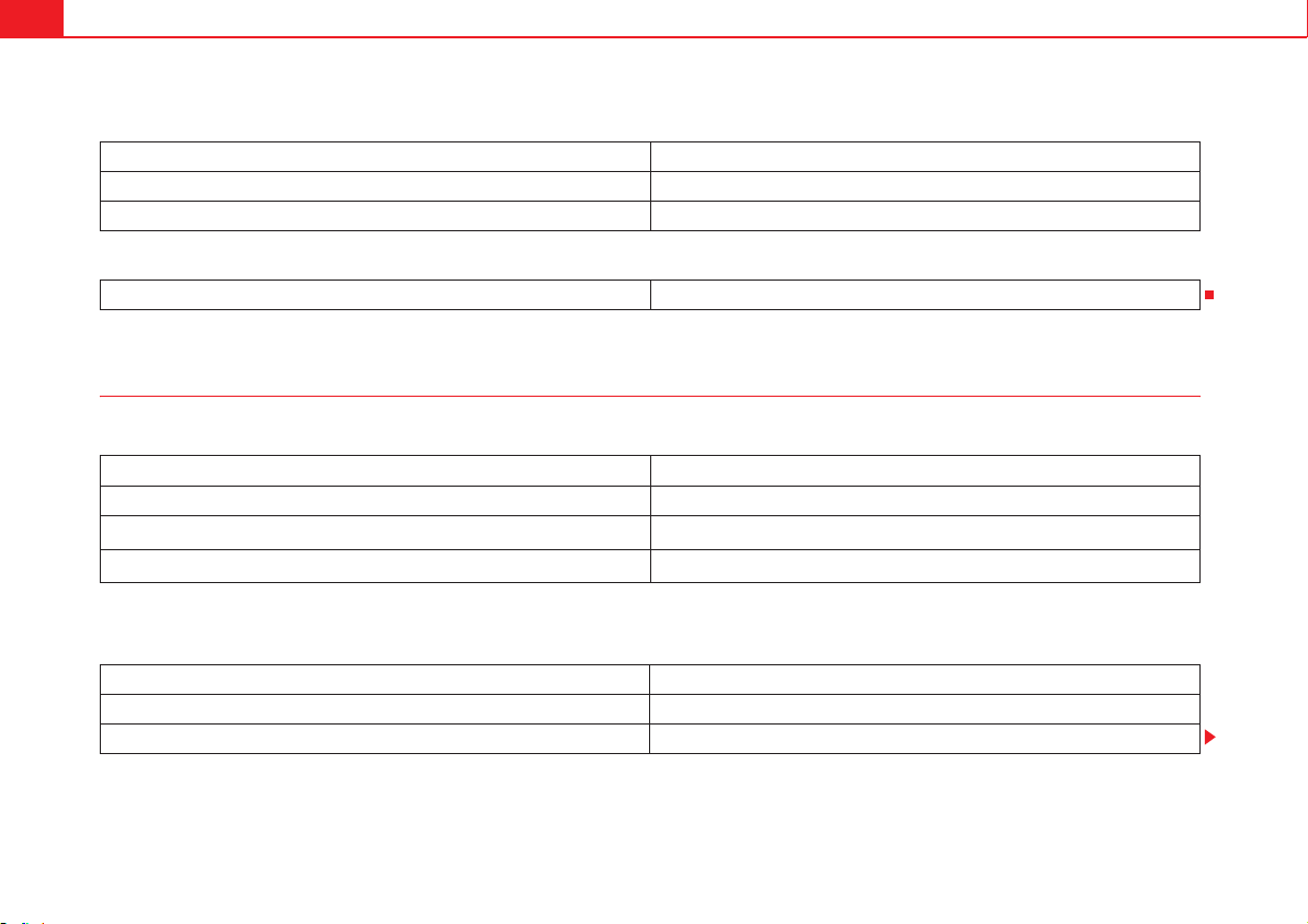
Technical Data388
Trailer weight
Engine oil capacity
Diesel engine 2.0 TDI 103 kW (140 PS)
Engine specifications
Performance figures
Trailer without brakes 750
Trailer with brakes, gradients up to 8% 2200
Trailer with brakes, gradients up to 12% 2200
Approximate engine oil capacity with oil filter change 4,0
Power output in kW (PS) rpm 103 (140)/ 4200
Maximum torque in Nm at rpm 320/1750-2500
No. of cylinders/ capacity
in cm
3
4/1968
Fuel
Min. 51 CN
a)
a)
Cetane-Number (cetane index) = Measure of the combustion power of the diesel
Maximum speed in km/h 194
Acceleration from 0-80 km/h in sec. 7,7
Acceleration from 0-100 km/h in sec. 10,9
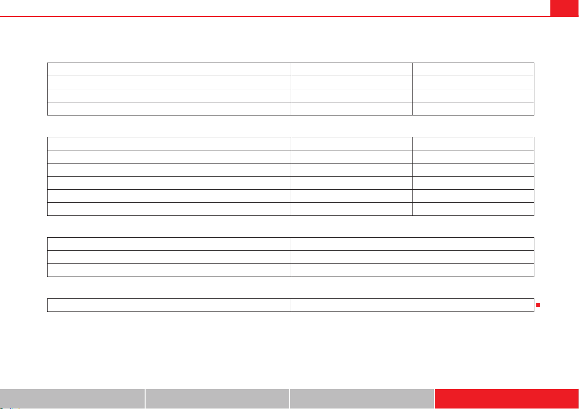
Technical Data 389
Safety First Operating instructions Practical tips Technical Data
Consumption (litres/100 km)/ CO
2
(g/km)
Weights
Trailer weight
Engine oil capacity
5 seats 7 seats
Urban cycle 6,8/179 6,9/182
Extra urban cycle 4,8/127 4,9/130
Combined 5,5/143 5,6/146
5 seats 7 seats
Gross vehicle weight in kg 2340 2510
Weight in running order (with driver) in kg 1174 1822
Gross front axle weight in kg 1190/1240 1200/1250
Gross rear axle weight in kg 1100/1150 1260/1310
Permitted roof load in kg 100 100
Trailer without brakes 750
Trailer with brakes, gradients up to 8% 2200
Trailer with brakes, gradients up to 12% 2200
Approximate engine oil capacity with oil filter change 4,0
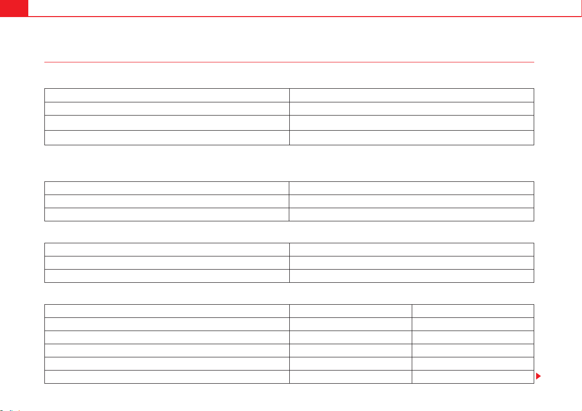
Technical Data390
Diesel engine 2.0 TDI 103 kW (140 PS) Automatic
Engine specifications
Performance figures
Consumption (litres/100 km)/ CO
2
(g/km)
Weights
Power output in kW (PS) rpm 103 (140)/ 4200
Maximum torque in Nm at rpm 320/1750-2500
No. of cylinders/ capacity
in cm
3
4/1968
Fuel
Min. 51 CN
a)
a)
Cetane-Number (cetane index) = Measure of the combustion power of the diesel
Maximum speed in km/h 191
Acceleration from 0-80 km/h in sec. 7,7
Acceleration from 0-100 km/h in sec. 10,9
Urban cycle 6,9/182
Extra urban cycle 5/132
Combined 5,7/149
5 seats 7 seats
Gross vehicle weight in kg 2370 2540
Weight in running order (with driver) in kg 1803 1851
Gross front axle weight in kg 1220/1270 1230/1280
Gross rear axle weight in kg 1100/1150 1260/1310
Permitted roof load in kg 100 100

Technical Data 391
Safety First Operating instructions Practical tips Technical Data
Trailer weight
Engine oil capacity
Trailer without brakes 750
Trailer with brakes, gradients up to 8% 2200
Trailer with brakes, gradients up to 12% 2200
Approximate engine oil capacity with oil filter change 4,0

Technical Data392
Dimensions and capacities
Caution
x Special care should be taken when parking in areas with high kerbs or
fixed barriers. Objects protruding from the ground may damage the bumper
or other parts of the vehicle during manoeuvres.
x Special attention is required when driving through entrances, over ramps,
kerbs or other objects. The vehicle underbody, bumpers, mudguards and
running gear, and the engine and exhaust system could be damaged as you
drive over these objects.
Dimensions
Length, width 4,851 – 4,952 mm 1,904 mm
Height at kerb weight 1,695 – 1,753 mm
Front and rear projection
Wheelbase 2,920 mm
Turning circle
Track width
a)
a)
This data will change depending on the type of wheel rim.
Front Rear
1,557 – 1,569 mm 1,605 – 1,617 mm
Capacities
Fuel tank 70 l. Reserve 8 l.
Windscreen washer fluid container with headlight washer 3.5 l/ 6 l
Tyre pressure
Summer-grade tyres:
The correct tyre pressure can be seen on the sticker on the inside of the tank flap.
Winter tyres:
The pressure of these tyres is the same as the summer tyre pressure plus 0.2 bar.

Index 393
Index
"Safe" security system . . . . . . . . . . . . . . . . . . . . 88
A
Abroad
Extended stay abroad with your vehicle . . 283
Sale of vehicle . . . . . . . . . . . . . . . . . . . . . . . 283
ABS
See "Braking assist systems" . . . . . . . . . . . 216
Accessories . . . . . . . . . . . . . . . . . . . . . . . . . . . . 285
Adaptive headlights
Adaptive . . . . . . . . . . . . . . . . . . . . . . . . . . . . 118
AdBlue
Control lamp . . . . . . . . . . . . . . . . . . . . . . . . 300
Information . . . . . . . . . . . . . . . . . . . . . . . . . 301
Minimum quantity for a refill . . . . . . . . . . . 301
Refilling . . . . . . . . . . . . . . . . . . . . . . . . . . . . 302
Specifications . . . . . . . . . . . . . . . . . . . . . . . 303
Tank filling capacity . . . . . . . . . . . . . . . . . . . 301
Warning lamp . . . . . . . . . . . . . . . . . . . . . . . . 300
Additional equipment . . . . . . . . . . . . . . . . . . . . 286
Additional heater
See "Auxiliary heater" . . . . . . . . . . . . . . . . . 187
Adjusting passenger exterior mirror . . . . . . . . . 132
Adjustment
Correct sitting position . . . . . . . . . . . . . . . . . 12
Electric front seat . . . . . . . . . . . . . . . . . . . . . 135
Head restraints . . . . . . . . . . . . . . . . . . . . . . 143
Mechanical front seat . . . . . . . . . . . . . . . . . 134
Rear seats . . . . . . . . . . . . . . . . . . . . . . . . . . . 136
Seat with position memory . . . . . . . . . . . . . 138
Steering wheel . . . . . . . . . . . . . . . . . . . . . . . 194
Adjustments
Folding the backrest of the front passenger's
seat . . . . . . . . . . . . . . . . . . . . . . . . . . . . . . 141
Headlight range . . . . . . . . . . . . . . . . . . . . . . 120
Aerial . . . . . . . . . . . . . . . . . . . . . . . . . . . . . . . . . 283
Aerial built into the window . . . . . . . . . . . . . . . 283
AFS . . . . . . . . . . . . . . . . . . . . . . . . . . . . . . . . . . . 118
Air conditioning
see "Climate control" . . . . . . . . . . . . . . . . . 179
Air recirculation mode . . . . . . . . . . . . . . . . . . . . 185
Air vents . . . . . . . . . . . . . . . . . . . . . . . . . . . . . . . 185
Airbag system . . . . . . . . . . . . . . . . . . . . . . . . 29, 33
Cleaning instrument panel . . . . . . . . . . . . . 281
Curtain airbags . . . . . . . . . . . . . . . . . . . . . . . 40
Deactivating the front passenger airbag . . . 36
Deactivating using the key switch . . . . . . . . 36
Description . . . . . . . . . . . . . . . . . . . . . . . . . . . 33
Differences between front passenger airbag
systems . . . . . . . . . . . . . . . . . . . . . . . . . . . . 36
Faults . . . . . . . . . . . . . . . . . . . . . . . . . . . . . . 287
Front airbags . . . . . . . . . . . . . . . . . . . . . . . . . 34
Function . . . . . . . . . . . . . . . . . . . . . . . . . . . . . 33
Knee airbag . . . . . . . . . . . . . . . . . . . . . . . . . . 41
Locking the vehicle after airbag deployment . .
84
Repairs . . . . . . . . . . . . . . . . . . . . . . . . . . . . . 287
Side airbags . . . . . . . . . . . . . . . . . . . . . . . . . . 38
Use of child seats . . . . . . . . . . . . . . . . . . . . . 36
Vehicle care . . . . . . . . . . . . . . . . . . . . . . . . . 281
Warning lamp . . . . . . . . . . . . . . . . . . . . . . . . 31
Alarm system . . . . . . . . . . . . . . . . . . . . . . . . . . . . 88
Alcantara . . . . . . . . . . . . . . . . . . . . . . . . . . . . . . 279
All-wheel drive
Snow chains . . . . . . . . . . . . . . . . . . . . . . . . . 332
Winter tyres . . . . . . . . . . . . . . . . . . . . . . . . . 331
Alternator . . . . . . . . . . . . . . . . . . . . . . . . . . . . . . 319
Ambient lighting . . . . . . . . . . . . . . . . . . . . . . . . 121
Anodized surfaces . . . . . . . . . . . . . . . . . . . . . . . 275
Antifreeze . . . . . . . . . . . . . . . . . . . . . . . . . . . . . . 314
Anti-lock brake system (ABS) . . . . . . . . . . . . . . 216
Antitheft alarm . . . . . . . . . . . . . . . . . . . . . . . . . . . 88
Trailer . . . . . . . . . . . . . . . . . . . . . . . . . . . . . . 263
Antitheft alarm system
Anti-tow system . . . . . . . . . . . . . . . . . . . . . . . 90
False alarms . . . . . . . . . . . . . . . . . . . . . . . . . . 90
Interior monitoring . . . . . . . . . . . . . . . . . . . . 90
Antitheft bolts . . . . . . . . . . . . . . . . . . . . . . . . . . 354
Anti-theft locking bolts . . . . . . . . . . . . . . . . . . . 339
Anti-theft wheel locking bolts . . . . . . . . . . . . . . 340
Anti-tow system . . . . . . . . . . . . . . . . . . . . . . . . . . 90

Index394
Anti-trap function
Electric windows . . . . . . . . . . . . . . . . . . . . . 104
Panorama sliding sunroof . . . . . . . . . . . . . 108
Sunshade . . . . . . . . . . . . . . . . . . . . . . . . . . . 108
Armrests . . . . . . . . . . . . . . . . . . . . . . . . . . . . . . . 145
Ashtray . . . . . . . . . . . . . . . . . . . . . . . . . . . . . . . . 173
Assist systems
Anti-lock brake system (ABS) . . . . . . . . . . . 216
Auto Hold . . . . . . . . . . . . . . . . . . . . . . . . . . . 222
Braking assist . . . . . . . . . . . . . . . . . . . . . . . 217
CCS . . . . . . . . . . . . . . . . . . . . . . . . . . . . . . . . 239
Cruise control . . . . . . . . . . . . . . . . . . . . . . . 239
DCC . . . . . . . . . . . . . . . . . . . . . . . . . . . . . . . . 243
Dynamic chassis control . . . . . . . . . . . . . . . 243
Electronic stability programme (ESP) . . . . 216
Optical parking system . . . . . . . . . . . . . . . . 227
Park Assist . . . . . . . . . . . . . . . . . . . . . . . . . . 229
Park assist . . . . . . . . . . . . . . . . . . . . . . . . . . 226
Park Assist system . . . . . . . . . . . . . . . . . . . 229
Parking sensor system . . . . . . . . . . . . . . . . 226
Rear Assist . . . . . . . . . . . . . . . . . . . . . . . . . . 234
Rear assist system . . . . . . . . . . . . . . . . . . . 234
Start assist . . . . . . . . . . . . . . . . . . . . . . . . . . 222
Start-Stop . . . . . . . . . . . . . . . . . . . . . . . . . . . 223
Traction control system (TCS) . . . . . . . . . . . 218
Traction control when accelerating (TCS) . 217
Tyre monitoring indicator . . . . . . . . . . . . . . 248
Assistance systems
Electronic differential lock system (EDS) . . 217
Assisted braking systems . . . . . . . . . . . . . . . . . 216
Auto Hold . . . . . . . . . . . . . . . . . . . . . . . . . . . . . . 222
Automatic belt retainer . . . . . . . . . . . . . . . . . . . . 27
Automatic car wash . . . . . . . . . . . . . . . . . . . . . . 270
Switching Auto Hold off . . . . . . . . . . . . . . . 223
Switching the start assist off . . . . . . . . . . . 223
Automatic consumer disconnection . . . . . . . . 321
Automatic dipped beam control . . . . . . . . . . . 117
Automatic gearbox . . . . . . . . . . . . . . . . . . . . . . 201
Changing gear . . . . . . . . . . . . . . . . . . . . . . . 205
Driving . . . . . . . . . . . . . . . . . . . . . . . . . . . . . 207
DSG automatic gearbox . . . . . . . . . . . . . . . 207
Ignition key lock . . . . . . . . . . . . . . . . . . . . . 197
Kickdown system . . . . . . . . . . . . . . . . . . . . 207
Launch-Control programme . . . . . . . . . . . . 207
Malfunction . . . . . . . . . . . . . . . . . . . . . . . . . 208
Manually unlocking the gear selection lever . .
352
Please also see "Changing gears" . . . . . . . 201
See "Automatic gearbox" . . . . . . . . . . . . . . 201
Towing . . . . . . . . . . . . . . . . . . . . . . . . . . . . . 376
Auxiliary heater . . . . . . . . . . . . . . . . . . . . . 187, 298
Automatic off . . . . . . . . . . . . . . . . . . . . . . . . 294
Programming . . . . . . . . . . . . . . . . . . . . . . . . 189
Remote control . . . . . . . . . . . . . . . . . . . . . . 188
Remote control range . . . . . . . . . . . . . . . . . 189
Remote control: replacing the battery . . . . 189
Switching off . . . . . . . . . . . . . . . . . . . . . . . . 187
Switching on . . . . . . . . . . . . . . . . . . . . . . . . 187
Things to note . . . . . . . . . . . . . . . . . . . 188, 190
User instructions . . . . . . . . . . . . . . . . . . . . . 190
Auxiliary heater remote control
Replacing the battery . . . . . . . . . . . . . . . . . 189
AUX-IN connection . . . . . . . . . . . . . . . . . . . . . . 162
Axle loads . . . . . . . . . . . . . . . . . . . . . . . . . . . . . . 15
B
BAS
See "Braking assist systems" . . . . . . . . . . 217
Battery
Discharge . . . . . . . . . . . . . . . . . . . . . . . . . . 191
Discharging . . . . . . . . . . . . . . . . . . . . . . . . . 346
See Vehicle battery . . . . . . . . . . . . . . . . . . . 318
Battery acid . . . . . . . . . . . . . . . . . . . . . . . . . . . . 320
Before starting out . . . . . . . . . . . . . . . . . . . . . . . . 7
Belt height adjustment . . . . . . . . . . . . . . . . . . . . 26
Belt tension device . . . . . . . . . . . . . . . . . . . . . . . 27
Disposal . . . . . . . . . . . . . . . . . . . . . . . . . . . . . 27
Service and disposal . . . . . . . . . . . . . . . . . . 27
Belt tension limiter . . . . . . . . . . . . . . . . . . . . . . . 27
Bicycle carrier
Installing a bicycle carrier . . . . . . . . . . . . . 262
Maximum load . . . . . . . . . . . . . . . . . . . . . . 262
Biodiesel . . . . . . . . . . . . . . . . . . . . . . . . . . . . . . 299
Bonnet
Closing . . . . . . . . . . . . . . . . . . . . . . . . . . . . . 307
Opening . . . . . . . . . . . . . . . . . . . . . . . . . . . . 307
Bottle capacity
Windscreen washer water bottle . . . . . . . . 129
Bottle holders . . . . . . . . . . . . . . . . . . . . . . . . . . 171
Brake . . . . . . . . . . . . . . . . . . . . . . . . . . . . . . . . . 210
Brake servo . . . . . . . . . . . . . . . . . . . . . . . . . 215
Electronic parking brake . . . . . . . . . . . . . . . 212

Index 395
Emergency braking function . . . . . . . . . . . . 213
Parking brake . . . . . . . . . . . . . . . . . . . . . . . . 212
Brake fluid . . . . . . . . . . . . . . . . . . . . . . . . . . . . . 219
Specification . . . . . . . . . . . . . . . . . . . . . . . . 219
Brake servo . . . . . . . . . . . . . . . . . . . . . . . 215, 216
Brake system
Malfunction . . . . . . . . . . . . . . . . . . . . . . . . . 215
Brake systems . . . . . . . . . . . . . . . . . . . . . . . . . . 216
Brakes
Assisted braking systems . . . . . . . . . . . . . . 216
Brake fluid . . . . . . . . . . . . . . . . . . . . . . . . . . 219
Brake fluid level . . . . . . . . . . . . . . . . . . . . . . 219
Brake pads . . . . . . . . . . . . . . . . . . . . . . . . . . 214
Changing the brake fluid . . . . . . . . . . . . . . 219
Control lamp . . . . . . . . . . . . . . . . . . . . . . . . 211
Emergency brake indicator in case of sudden
braking . . . . . . . . . . . . . . . . . . . . . . . . . . . 346
Running-in brake pads . . . . . . . . . . . . . . . . 214
Warning lamp . . . . . . . . . . . . . . . . . . . . . . . . 211
Braking assist . . . . . . . . . . . . . . . . . . . . . . . . . . 217
Braking assist system (BAS) . . . . . . . . . . . . 217
Braking assist system (BAS) . . . . . . . . . . . . . . . 217
Breakdown
Securing the vehicle . . . . . . . . . . . . . . . . . . 345
Bulb fault
See changing bulbs . . . . . . . . . . . . . . . . . . . 360
C
Card compartments . . . . . . . . . . . . . . . . . . . . . . 165
Card reader . . . . . . . . . . . . . . . . . . . . . . . . . . . . . 178
Care
See "Care of your vehicle" . . . . . . . . . . . . . . 269
Vehicle interior . . . . . . . . . . . . . . . . . . . . . . . 278
Care of your vehicle
Exterior . . . . . . . . . . . . . . . . . . . . . . . . . . . . . 269
Caring for paintwork . . . . . . . . . . . . . . . . . . . . . 274
Carrier system . . . . . . . . . . . . . . . . . . . . . . . . . . 159
Catalytic converter . . . . . . . . . . . . . . . . . . . . . . . 256
Malfunction . . . . . . . . . . . . . . . . . . . . . . . . . 256
Warning lamp . . . . . . . . . . . . . . . . . . . . . . . . 255
CCS . . . . . . . . . . . . . . . . . . . . . . . . . . . . . . . . . . . 239
CD changer . . . . . . . . . . . . . . . . . . . . . . . . 162, 169
Central locking . . . . . . . . . . . . . . . . . . . . . . . . 83, 85
Antitheft alarm . . . . . . . . . . . . . . . . . . . . . . . . 88
KESSY system . . . . . . . . . . . . . . . . . . . . . . . . 86
Locking and unlocking the vehicle . . . . . . . . 84
Central locking system
After airbag deployment . . . . . . . . . . . . . . . . 84
Description . . . . . . . . . . . . . . . . . . . . . . . . . . . 84
Opening doors individually . . . . . . . . . . . . . 84
Centre armrest . . . . . . . . . . . . . . . . . . . . . . . . . . 145
Changing
Windscreen wiper blades . . . . . . . . . . . . . . 273
Changing a wheel . . . . . . . . . . . . . . . . . . . . . . . 339
Changing a wheel . . . . . . . . . . . . . . . . . . . . 344
Preparations . . . . . . . . . . . . . . . . . . . . . . . . . 339
Raising the vehicle . . . . . . . . . . . . . . . . . . . 342
Wheel bolts . . . . . . . . . . . . . . . . . . . . . . . . . 340
Changing bulbs . . . . . . . . . . . . . . . . . . . . . . . . . 360
Bodywork . . . . . . . . . . . . . . . . . . . . . . . . . . . 367
Checklist . . . . . . . . . . . . . . . . . . . . . . . . . . . . 361
Front bumper . . . . . . . . . . . . . . . . . . . . . . . . 365
Halogen headlights . . . . . . . . . . . . . . . . . . . 362
Indicator . . . . . . . . . . . . . . . . . . . . . . . . . . . . 361
Initial operations . . . . . . . . . . . . . . . . . . . . . 361
Number plate light . . . . . . . . . . . . . . . . . . . 369
Sea changing bulbs . . . . . . . . . . . . . . . . . . 360
Tail lights . . . . . . . . . . . . . . . . . . . . . . 366, 367
Tailgate . . . . . . . . . . . . . . . . . . . . . . . . . . . . 366
Xenon headlights . . . . . . . . . . . . . . . . . . . . 364
Changing gear . . . . . . . . . . . . . . . . . . . . . . . . . . 201
Automatic gearbox . . . . . . . . . . . . . . . . . . . 205
Engaging gears (manual gearbox) . . . . . . . 204
Manual gearbox . . . . . . . . . . . . . . . . . . . . . . 204
Manually unlocking the gear selection lever . . .
352
Selecting gears (automatic gearbox) . . . . . 205
Warning and control lamps . . . . . . . . . . . . . 202
Changing gears
Gear recommendation . . . . . . . . . . . . . . . . 209
Tiptronic . . . . . . . . . . . . . . . . . . . . . . . . . . . . 207
Changing the battery
of the vehicle key . . . . . . . . . . . . . . . . . . . . . . 81
Changing the wheel
After changing the wheel . . . . . . . . . . . . . . 344
Check list . . . . . . . . . . . . . . . . . . . . . . . . . . . . . . . . 7
Preparations for changing a wheel . . . . . . 339
Raising the vehicle with the jack . . . . . . . . 343
Upholstery . . . . . . . . . . . . . . . . . . . . . . . . . . 278
Checking
Tyre pressures . . . . . . . . . . . . . . . . . . . . . . . 328
Checking the oil level . . . . . . . . . . . . . . . . . . . . 310

Index396
Checklist
Before working in the engine compartment . . .
306
Changing bulbs . . . . . . . . . . . . . . . . . . . . . . 361
In case of an emergency . . . . . . . . . . . . . . . 345
Refilling precautions . . . . . . . . . . . . . . . . . . 296
Seat belts . . . . . . . . . . . . . . . . . . . . . . . . . . . . 22
Transporting children in the vehicle . . . . . . 44
Child safety . . . . . . . . . . . . . . . . . . . . . . . . . . . . . 42
Child safety seat
Securing with seat belt . . . . . . . . . . . . . . . . . 48
Child seat . . . . . . . . . . . . . . . . . . . . . . . . . . . . . . . 42
Integrated child seat . . . . . . . . . . . . . . . . . . . 52
ISOFIX child seat on rear seats . . . . . . . . . . . 47
Mounting child seats . . . . . . . . . . . . . . . . . . 46
Mounting systems . . . . . . . . . . . . . . . . . . . . . 46
On rear seats . . . . . . . . . . . . . . . . . . . . . . . . . 47
On the front passenger seat . . . . . . . . . . . . . 46
Regulations . . . . . . . . . . . . . . . . . . . . . . . . . . 44
Securing using a Top Tether retaining strap 50
Securing using ISOFIX . . . . . . . . . . . . . . . . . . 49
Securing using LATCH . . . . . . . . . . . . . . . . . . 49
Transporting children in the vehicle . . . . . . 44
Weight categories . . . . . . . . . . . . . . . . . . . . . 45
Child seats
Disabling the front passenger airbag . . . . . 36
Cigarette lighter . . . . . . . . . . . . . . . . . . . . . . . . 173
Cleaning
Alcantara . . . . . . . . . . . . . . . . . . . . . . . . . . . 279
Engine compartment . . . . . . . . . . . . . . . . . . 276
instrument panel . . . . . . . . . . . . . . . . . . . . . 281
Seat belts . . . . . . . . . . . . . . . . . . . . . . . . . . . 282
See "Care of your vehicle" . . . . . . . . . . . . . 269
wheels . . . . . . . . . . . . . . . . . . . . . . . . . . . . . 275
Windscreen wiper blades . . . . . . . . . . . . . . 273
Cleaning chrome parts . . . . . . . . . . . . . . . . . . . 275
Cleaning the vehicle
Folding exterior mirrors . . . . . . . . . . . . . . . 133
Climate control . . . . . . . . . . . . . . . . . . . . . . . . . 179
Air recirculation mode . . . . . . . . . . . . . . . . 185
Air vents . . . . . . . . . . . . . . . . . . . . . . . . . . . . 185
Climatic . . . . . . . . . . . . . . . . . . . . . . . . . . . . 181
Climatronic . . . . . . . . . . . . . . . . . . . . . . . . . 181
Controls . . . . . . . . . . . . . . . . . . . . . . . . . . . . 181
Faults . . . . . . . . . . . . . . . . . . . . . . . . . . . . . . 184
Indirect ventilation . . . . . . . . . . . . . . . . . . . 185
Things to note . . . . . . . . . . . . . . . . . . . . . . . 184
User instructions . . . . . . . . . . . . . . . . . . . . . 183
Climatic
see "Climate control" . . . . . . . . . . . . . . . . . 179
Climatronic
see "Climate control" . . . . . . . . . . . . . . . . . 179
Closing
Doors . . . . . . . . . . . . . . . . . . . . . . . . . . . . . . . 92
Electric sliding door . . . . . . . . . . . . . . . . . . . 94
Electric windows . . . . . . . . . . . . . . . . . . . . . 103
Panorama sliding sunroof . . . . . . . . . . . . . 106
See "Locking" . . . . . . . . . . . . . . . . . . . . . . . . 84
Sliding doors . . . . . . . . . . . . . . . . . . . . . . . . . 92
Sunshade . . . . . . . . . . . . . . . . . . . . . . . . . . 107
Tailgate . . . . . . . . . . . . . . . . . . . . . . . . . . . . . 99
Coat hooks . . . . . . . . . . . . . . . . . . . . . . . . . . . . . 169
Cockpit . . . . . . . . . . . . . . . . . . . . . . . . . . . . . . . . . 59
Code number . . . . . . . . . . . . . . . . . . . . . . . . . . . 354
Collection of end-of-life vehicles . . . . . . . . . . . 284
Combined weight rating . . . . . . . . . . . . . . . . . . 267
Coming Home . . . . . . . . . . . . . . . . . . . . . . . . . . 119
Compartment
Glove compartment . . . . . . . . . . . . . . . . . . 166
Compartments
Card compartments . . . . . . . . . . . . . . . . . . 165
Centre console . . . . . . . . . . . . . . . . . . . . . . 164
Drawers . . . . . . . . . . . . . . . . . . . . . . . . . . . . 167
Folding table . . . . . . . . . . . . . . . . . . . . . . . . 168
Front central armrest . . . . . . . . . . . . . . . . . . 165
Instrument panel . . . . . . . . . . . . . . . . . . . . . 164
Other storage compartments . . . . . . . . . . . 169
Portable waste bin . . . . . . . . . . . . . . . . . . . 168
Rear floor area . . . . . . . . . . . . . . . . . . . . . . . 167
Roof console . . . . . . . . . . . . . . . . . . . . . . . . 163
Spectacle case . . . . . . . . . . . . . . . . . . . . . . 163
Compass . . . . . . . . . . . . . . . . . . . . . . . . . . . . . . . 67
Components . . . . . . . . . . . . . . . . . . . . . . . . . . . 286
Connectors
Faults . . . . . . . . . . . . . . . . . . . . . . . . . . . . . . 177
Consumer disconnection . . . . . . . . . . . . . . . . . 321
Consumption
How it is determined . . . . . . . . . . . . . . . . . . 299
Information . . . . . . . . . . . . . . . . . . . . . . . . . 299
Control lamp
AdBlue . . . . . . . . . . . . . . . . . . . . . . . . . . . . . 300
Brake pad wear indication . . . . . . . . . . . . . 211
Brake system . . . . . . . . . . . . . . . . . . . . . . . . 211
Changing gear . . . . . . . . . . . . . . . . . . . . . . . 202

Index 397
Coolant . . . . . . . . . . . . . . . . . . . . . . . . . . . . . 313
Cruise control . . . . . . . . . . . . . . . . . . . . . . . . 240
Engine oil sensor . . . . . . . . . . . . . . . . . . . . . 309
ESP . . . . . . . . . . . . . . . . . . . . . . . . . . . . . . . . 211
Filling the tank . . . . . . . . . . . . . . . . . . . . . . . 294
Fuel level . . . . . . . . . . . . . . . . . . . . . . . . . . . 294
Pressing the brake . . . . . . . . . . . . . . . . . . . . 211
Steering column lock . . . . . . . . . . . . . . . . . . 192
Tyre monitoring indicator . . . . . . . . . . . . . . 247
Tyre monitoring systems . . . . . . . . . . . . . . . 247
Control of function
Rain sensor . . . . . . . . . . . . . . . . . . . . . . . . . 128
Control units . . . . . . . . . . . . . . . . . . . . . . . . . . . 288
Reprogramming . . . . . . . . . . . . . . . . . . . . . . 289
Controlling function
Electric exterior mirrors . . . . . . . . . . . . . . . . 133
Convenience closing
Electric windows . . . . . . . . . . . . . . . . . . . . . 104
Panorama sliding sunroof . . . . . . . . . . . . . . 108
Convenience functions
Reprogramming . . . . . . . . . . . . . . . . . . . . . . 289
Convenience opening
Electric windows . . . . . . . . . . . . . . . . . . . . . 104
Panorama sliding sunroof . . . . . . . . . . . . . . 108
Convenient entry function for the third row of seats
140
Coolant
Control lamp . . . . . . . . . . . . . . . . . . . . . . . . 313
See engine coolant . . . . . . . . . . . . . . . . . . . 313
Temperature gauge . . . . . . . . . . . . . . . . . . . 313
Warning lamp . . . . . . . . . . . . . . . . . . . . . . . . 313
Counter steering assistance system . . . . . . . . 193
Crossing a river
Salt water . . . . . . . . . . . . . . . . . . . . . . . . . . . . . 9
Cruise control . . . . . . . . . . . . . . . . . . . . . . . . . . . 239
Control lamp . . . . . . . . . . . . . . . . . . . . . . . . 240
Operations . . . . . . . . . . . . . . . . . . . . . . . . . . 241
Warning lamp . . . . . . . . . . . . . . . . . . . . . . . . 240
Cup holder . . . . . . . . . . . . . . . . . . . . . . . . . . . . . 171
Cup holders . . . . . . . . . . . . . . . . . . . . . . . 171, 172
Curb weight . . . . . . . . . . . . . . . . . . . . . . . . . . . . . 15
Curtain airbags
See "Airbag system" . . . . . . . . . . . . . . . . . . . 40
D
Damaged tyres . . . . . . . . . . . . . . . . . . . . . . . . . . 330
Dangers of not using the seat belt . . . . . . . . . . . 19
Dash panel . . . . . . . . . . . . . . . . . . . . . . . . . . . . . . 59
Airbag system . . . . . . . . . . . . . . . . . . . . . . . . 33
Data link connector (DLC) . . . . . . . . . . . . . . . . . 289
Data plate . . . . . . . . . . . . . . . . . . . . . . . . . . . . . . 380
Model identification . . . . . . . . . . . . . . . . . . 380
Technical data . . . . . . . . . . . . . . . . . . . . . . . 380
Vehicle identification number . . . . . . . . . . 380
Data registry . . . . . . . . . . . . . . . . . . . . . . . . . . . . 288
Data storage during the journey . . . . . . . . . . . . 288
Data stored by the control units . . . . . . . . . . . . 288
Daytime driving light . . . . . . . . . . . . . . . . . . . . . 117
DCC
See "Dynamic chassis control" . . . . . . . . . . 243
De-icing the door lock cylinder . . . . . . . . . . . . . 276
De-icing the locks . . . . . . . . . . . . . . . . . . . . . . . 276
Details
Driving with a trailer . . . . . . . . . . . . . . . . . . 264
Diagnostics connection . . . . . . . . . . . . . . . . . . 289
Diesel . . . . . . . . . . . . . . . . . . . . . . . . . . . . . . . . . 298
Auxiliary heater . . . . . . . . . . . . . . . . . . . . . . 298
Biodiesel . . . . . . . . . . . . . . . . . . . . . . . . . . . 299
Filling the tank . . . . . . . . . . . . . . . . . . . . . . . 295
Filter pre-heater . . . . . . . . . . . . . . . . . . . . . . 298
Fuel gauge . . . . . . . . . . . . . . . . . . . . . . . . . . 294
Winter-grade diesel . . . . . . . . . . . . . . . . . . . 298
Diesel particle filter
Malfunction . . . . . . . . . . . . . . . . . . . . . . . . . 256
Diesel particulate filter . . . . . . . . . . . . . . . . . . . 256
Recommended gear . . . . . . . . . . . . . . . . . . 209
Things to note . . . . . . . . . . . . . . . . . . . . . . . 299
Warning lamp . . . . . . . . . . . . . . . . . . . . . . . 255
Differential lock
See "Braking assist systems" . . . . . . . . . . . 217
Digital clock . . . . . . . . . . . . . . . . . . . . . . . . . . . . . 64
Dipped beam headlights . . . . . . . . . . . . . . . . . 116
Dipstick . . . . . . . . . . . . . . . . . . . . . . . . . . . . . . . 310
Display . . . . . . . . . . . . . . . . . . . . . . . . . . . . . . 64, 65
Disposal
Airbag system . . . . . . . . . . . . . . . . . . . . . . . 284
Belt tension device . . . . . . . . . . . . . . . . . . . . 27
End-of-life vehicle . . . . . . . . . . . . . . . . . . . . 284
Door release lever . . . . . . . . . . . . . . . . . . . . . . . . 59

Index398
Doors . . . . . . . . . . . . . . . . . . . . . . . . . . . . . . . . . . 92
Child safety lock . . . . . . . . . . . . . . . . . . . . . . 95
Emergency locking and unlocking . . . . . . . 348
Warning indicator . . . . . . . . . . . . . . . . . . . . . 92
Drawbar load . . . . . . . . . . . . . . . . . . . . . . . . . . . 258
Loading the trailer . . . . . . . . . . . . . . . . . . . . 264
Drawers . . . . . . . . . . . . . . . . . . . . . . . . . . . . . . . 167
Driving
Automatic gearbox . . . . . . . . . . . . . . . . . . . 207
Check list . . . . . . . . . . . . . . . . . . . . . . . . . . . . . 8
Cross country . . . . . . . . . . . . . . . . . . . . . . . . . . 7
Data storage . . . . . . . . . . . . . . . . . . . . . . . . 288
Driving abroad . . . . . . . . . . . . . . . . . . . . . . . . . 8
Driving through water . . . . . . . . . . . . . . . . . . . 9
Ecological . . . . . . . . . . . . . . . . . . . . . . . . . . 252
Economic . . . . . . . . . . . . . . . . . . . . . . . . . . . 252
Fuel gauge . . . . . . . . . . . . . . . . . . . . . . . . . . 294
Fuel level to low . . . . . . . . . . . . . . . . . . . . . . 295
Parking downhill . . . . . . . . . . . . . . . . . . . . . 214
Parking uphill . . . . . . . . . . . . . . . . . . . . . . . 214
Tips . . . . . . . . . . . . . . . . . . . . . . . . . . . . . . . . . . 7
Towing . . . . . . . . . . . . . . . . . . . . . . . . . . . . . 378
Trailer . . . . . . . . . . . . . . . . . . . . . . . . . . . . . . 264
Undercarriage guard . . . . . . . . . . . . . . . . . . . . 7
Driving abroad
Check list . . . . . . . . . . . . . . . . . . . . . . . . . . . . . 8
Headlights . . . . . . . . . . . . . . . . . . . . . . . . . . 119
Driving advice
For a loaded vehicle . . . . . . . . . . . . . . . . . . . 13
Driving in winter
Fuel consumption . . . . . . . . . . . . . . . . . . . . 254
Snow chains . . . . . . . . . . . . . . . . . . . . . . . . 332
Tread depth . . . . . . . . . . . . . . . . . . . . . . . . . 329
Tyre pressures . . . . . . . . . . . . . . . . . . . . . . . 328
Windscreen washer bottle . . . . . . . . . . . . . 272
Winter tyres . . . . . . . . . . . . . . . . . . . . . . . . . 331
Driving through water . . . . . . . . . . . . . . . . . . . . . . 9
Driving with a trailer . . . . . . . . . . . . . . . . . . . . . 260
Extinguisher . . . . . . . . . . . . . . . . . . . . . . . . 261
Technical requirements . . . . . . . . . . . . . . . 260
DSG . . . . . . . . . . . . . . . . . . . . . . . . . . . . . . . . . . 207
DSG Automatic gearbox
Malfunction . . . . . . . . . . . . . . . . . . . . . . . . . 208
DSG automatic gearbox
See "Automatic gearbox" . . . . . . . . . . . . . . 207
Dust filter . . . . . . . . . . . . . . . . . . . . . . . . . . . . . . 184
Dynamic chassis control . . . . . . . . . . . . . . . . . . 243
Control . . . . . . . . . . . . . . . . . . . . . . . . . . . . . 243
Fault . . . . . . . . . . . . . . . . . . . . . . . . . . . 243, 244
Operation . . . . . . . . . . . . . . . . . . . . . . . . . . . 243
Dynamic headlight range control . . . . . . . . . . . 120
Dynamic headlight range control . . . . . . . . 120
E
Ecological driving . . . . . . . . . . . . . . . . . . . . . . . 252
Economic driving . . . . . . . . . . . . . . . . . . . . . . . . 252
EDS
See "Braking assist systems" . . . . . . . . . . 217
Electric child safety lock . . . . . . . . . . . . . . . . . . . 95
Electric devices . . . . . . . . . . . . . . . . . . . . . . . . . 263
Electric sliding doors
Opening and closing . . . . . . . . . . . . . . . . . . 94
Rollback anti-trap function . . . . . . . . . . . . . . 95
Electric sockets
Trailer . . . . . . . . . . . . . . . . . . . . . . . . . . . . . . 263
Electric windows . . . . . . . . . . . . . . . . . . . . . . . . 102
Anti-trap function . . . . . . . . . . . . . . . . . . . . 104
Automatic one-touch operation . . . . . . . . . 103
Closing . . . . . . . . . . . . . . . . . . . . . . . . . . . . . 103
Convenience closing . . . . . . . . . . . . . . . . . . 104
Convenience opening . . . . . . . . . . . . . . . . . 104
Fault . . . . . . . . . . . . . . . . . . . . . . . . . . . . . . . 104
One-touch opening/closing . . . . . . . . . . . . 103
Opening . . . . . . . . . . . . . . . . . . . . . . . . . . . . 103
Electrical components . . . . . . . . . . . . . . . 175, 346
Electrical consumers . . . . . . . . . . . . . . . . . 176, 191
Electronic differential lock system (EDS) . . . . . 217
Electronic immobiliser . . . . . . . . . . . . . . . . . . . 200
Electronic parking brake . . . . . . . . . . . . . . . . . . 212
Electronic stability programme (ESP) . . . . . . . 216
Emergencies
Fire extinguishers . . . . . . . . . . . . . . . . . . . . 347
First aid kit . . . . . . . . . . . . . . . . . . . . . . . . . . 347
Hazard warning triangle . . . . . . . . . . . . . . . 347
Emergency brake indicator . . . . . . . . . . . . . . . . 346
Emergency braking function . . . . . . . . . . . . . . 213
Emergency locking and unlocking . . . . . . . . . . 348
Driver's door . . . . . . . . . . . . . . . . . . . . . . . . 348
Manually unlocking the gear selection lever . .
352

Index 399
Panoramic sliding roof . . . . . . . . . . . . . . . . 351
Passenger side door . . . . . . . . . . . . . . . . . . 349
Sliding doors . . . . . . . . . . . . . . . . . . . . . . . . 349
Tailgate . . . . . . . . . . . . . . . . . . . . . . . . . . . . . 350
Engine
Noises . . . . . . . . . . . . . . . . . . . . . . . . . . . . . . 199
Running-in . . . . . . . . . . . . . . . . . . . . . . . . . . 251
Engine and ignition . . . . . . . . . . . . . . . . . . . . . . 195
12 Volt sockets . . . . . . . . . . . . . . . . . . . . . . 175
Ignition lock . . . . . . . . . . . . . . . . . . . . . . . . . 196
Immobiliser . . . . . . . . . . . . . . . . . . . . . . . . . 200
Pre-heating . . . . . . . . . . . . . . . . . . . . . . . . . . 198
Starting engine with KESSY . . . . . . . . . . . . 197
Starting the engine . . . . . . . . . . . . . . . . . . . 198
Stopping the engine with KESSY . . . . . . . . 199
Unauthorised vehicle key . . . . . . . . . . . . . . 196
Engine compartment . . . . . . . . . . . . . . . . . . . . . 304
Engine coolant . . . . . . . . . . . . . . . . . . . . . . . 313
Engine oil . . . . . . . . . . . . . . . . . . . . . . . . . . . 309
Preparation . . . . . . . . . . . . . . . . . . . . . . . . . 306
Vehicle battery . . . . . . . . . . . . . . . . . . . . . . . 318
Water box . . . . . . . . . . . . . . . . . . . . . . . . . . . 276
Engine coolant . . . . . . . . . . . . . . . . . . . . . . . . . . 313
Checking the level . . . . . . . . . . . . . . . . . . . . 315
Filler . . . . . . . . . . . . . . . . . . . . . . . . . . . . . . . 315
G 12 plus-plus . . . . . . . . . . . . . . . . . . . . . . . 314
Refilling . . . . . . . . . . . . . . . . . . . . . . . . . . . . 315
Specifications . . . . . . . . . . . . . . . . . . . . . . . 314
Engine fault . . . . . . . . . . . . . . . . . . . . . . . . . . . . 255
Engine management . . . . . . . . . . . . . . . . . . . . . 255
Warning lamp . . . . . . . . . . . . . . . . . . . . . . . . 255
Engine oil . . . . . . . . . . . . . . . . . . . . . . . . . . . . . . 309
changing . . . . . . . . . . . . . . . . . . . . . . . . . . . 312
Checking the oil level . . . . . . . . . . . . . . . . . 310
Consumption . . . . . . . . . . . . . . . . . . . . . . . . 312
Dipstick . . . . . . . . . . . . . . . . . . . . . . . . . . . . 310
Filler opening . . . . . . . . . . . . . . . . . . . . . . . . 310
Indicator . . . . . . . . . . . . . . . . . . . . . . . . . . . . 309
Specifications . . . . . . . . . . . . . . . . . . . . . . . 310
Topping up . . . . . . . . . . . . . . . . . . . . . . . . . . 310
ESP
See "Braking assist systems" . . . . . . . . . . . 216
Event Data Recorder . . . . . . . . . . . . . . . . . . . . . 289
Exhaust gas purification system . . . . . . . . . . . 255
Warning lamp . . . . . . . . . . . . . . . . . . . . . . . . 255
Exterior aerial . . . . . . . . . . . . . . . . . . . . . . . . . . . 288
Exterior mirrors . . . . . . . . . . . . . . . . . . . . . . . . . 132
Automatically folding exterior mirrors . . . . 132
Controlling function . . . . . . . . . . . . . . . . . . . 133
Synchronised mirror adjustment . . . . . . . . 132
Vehicle care . . . . . . . . . . . . . . . . . . . . . . . . . 272
Extinguisher
Driving with a trailer . . . . . . . . . . . . . . . . . . 261
F
Fastening rings . . . . . . . . . . . . . . . . . . . . . . . . . 153
Fault
Dynamic chassis control . . . . . . . . . . 243, 244
Electric windows . . . . . . . . . . . . . . . . . . . . . 104
Park assist system . . . . . . . . . . . . . . . . . . . . 230
Parking sensor system . . . . . . . . . . . . . . . . 226
Rear assist . . . . . . . . . . . . . . . . . . . . . . . . . . 236
Fault memory
Connector . . . . . . . . . . . . . . . . . . . . . . . . . . . 289
Faults
Climate control . . . . . . . . . . . . . . . . . . . . . . 184
Panorama sliding sunroof . . . . . . . . . . . . . . 106
Filling capacity
AdBlue tank . . . . . . . . . . . . . . . . . . . . . . . . . 301
Filling the tank . . . . . . . . . . . . . . . . . . . . . . . . . . 293
Control lamp . . . . . . . . . . . . . . . . . . . . . . . . 294
Diesel . . . . . . . . . . . . . . . . . . . . . . . . . . . . . . 295
Fuel . . . . . . . . . . . . . . . . . . . . . . . . . . . . . . . . 295
Fuel gauge . . . . . . . . . . . . . . . . . . . . . . . . . . 294
Petrol . . . . . . . . . . . . . . . . . . . . . . . . . . . . . . 295
Refilling precautions . . . . . . . . . . . . . . . . . . 296
Filter pre-heater . . . . . . . . . . . . . . . . . . . . . . . . . 298
Fire extinguisher . . . . . . . . . . . . . . . . . . . . . . . . 347
Fire extinguishers . . . . . . . . . . . . . . . . . . . . . . . 347
First aid kit . . . . . . . . . . . . . . . . . . . . . . . . . . . . . 347
First-aid kit
Storage . . . . . . . . . . . . . . . . . . . . . . . . . . . . . 347
Fitting
Tow hitch . . . . . . . . . . . . . . . . . . . . . . . . . . . 266
Floor mats . . . . . . . . . . . . . . . . . . . . . . . . . . . . . 203
Fluids . . . . . . . . . . . . . . . . . . . . . . . . . . . . . . . . . 286
Fog light . . . . . . . . . . . . . . . . . . . . . . . . . . . . . . . 116
Foldable wedges
See on-board tools . . . . . . . . . . . . . . . . . . . 354
Folding down rear seats
Load space . . . . . . . . . . . . . . . . . . . . . . . . . . 147
Folding in exterior mirrors . . . . . . . . . . . . . . . . . 132
Folding table . . . . . . . . . . . . . . . . . . . . . . . . . . . 168

Index400
Folding the backrest of the front passenger's seat
141
Four-wheel-drive
Towing . . . . . . . . . . . . . . . . . . . . . . . . . . . . . 376
Front airbags
See "Airbag system" . . . . . . . . . . . . . . . . . . . 34
Front passenger airbag
Deactivating using the key switch . . . . . . . . 36
See "Airbag system" . . . . . . . . . . . . . . . . . . . 33
Fuel . . . . . . . . . . . . . . . . . . . . . . . . . . . . . . . . . . . 297
Depending on the engine . . . . . . . . . . . . . . 297
Diesel . . . . . . . . . . . . . . . . . . . . . . . . . . . . . . 298
Filling the tank . . . . . . . . . . . . . . . . . . . . . . . 295
Information on consumption . . . . . . . . . . . 299
Petrol . . . . . . . . . . . . . . . . . . . . . . . . . . . . . . 297
Type of fuel . . . . . . . . . . . . . . . . . . . . . . . . . 297
Fuel consumption
Economic driving . . . . . . . . . . . . . . . . . . . . . 252
Why does fuel consumption increase? . . . 256
Fuel gauge . . . . . . . . . . . . . . . . . . . . . . . . . . . . . 294
Control lamp . . . . . . . . . . . . . . . . . . . . . . . . 294
Fuel tank flap
Closure . . . . . . . . . . . . . . . . . . . . . . . . . . . . . 295
Opening . . . . . . . . . . . . . . . . . . . . . . . . . . . . 295
Full beam headlights . . . . . . . . . . . . . . . . . . . . 116
Function control
Tow hitch . . . . . . . . . . . . . . . . . . . . . . . . . . . 263
Fuses . . . . . . . . . . . . . . . . . . . . . . . . . . . . . . . . . 356
Fuse box . . . . . . . . . . . . . . . . . . . . . . . . . . . . 357
Identification using colours . . . . . . . . . . . . 357
Identifying blown fuses . . . . . . . . . . . . . . . 358
Preparation before replacing . . . . . . . . . . . 358
Replacement . . . . . . . . . . . . . . . . . . . . . . . . 358
G
G 12 plus . . . . . . . . . . . . . . . . . . . . . . . . . . . . . . 314
G 12 plus-plus . . . . . . . . . . . . . . . . . . . . . . . . . . 314
Garage door remote control . . . . . . . . . . . . . . . 109
Erasing settings . . . . . . . . . . . . . . . . . . . . . 110
Testing . . . . . . . . . . . . . . . . . . . . . . . . . . . . . 111
General overview of the engine compartment 383
Glove box lighting . . . . . . . . . . . . . . . . . . . . . . . 121
Glove compartment . . . . . . . . . . . . . . . . . . . . . . 166
H
Handbrake
See "Parking brake" . . . . . . . . . . . . . . . . . . 212
Hazard warning lights . . . . . . . . . . . . . . . . . . . . 345
Hazard warning triangle . . . . . . . . . . . . . . . . . . 347
Head restraint . . . . . . . . . . . . . . . . . . . . . . . . . . 144
Head restraints . . . . . . . . . . . . . . . . . . . . . . . . . 143
Headlamp range adjustment . . . . . . . . . . . . . . . 59
Headlight range control . . . . . . . . . . . . . . . . . . 120
Headlights
Adaptive headlights . . . . . . . . . . . . . . . . . . 118
Dipped beam headlights . . . . . . . . . . . . . . 116
Driving abroad . . . . . . . . . . . . . . . . . . . . . . . 119
Headlight washers . . . . . . . . . . . . . . . . . . . 126
Headlights control . . . . . . . . . . . . . . . . . . . 116
Main beam headlight control . . . . . . . . . . . 118
Sidelights . . . . . . . . . . . . . . . . . . . . . . . . . . 116
Turning lights . . . . . . . . . . . . . . . . . . . . . . . 118
Heated rear window . . . . . . . . . . . . . . . . . . . . . 182
Heated seats . . . . . . . . . . . . . . . . . . . . . . . . . . . 137
High pressure cleaning equipment . . . . . . . . . 271
Hitch ball
Electric release . . . . . . . . . . . . . . . . . . . . . . 261
Horn . . . . . . . . . . . . . . . . . . . . . . . . . . . . . . . . . . . 59
I
Ignition
See "Engine and ignition" . . . . . . . . . . . . . 195
Ignition lock . . . . . . . . . . . . . . . . . . . . . . . . . . . . 196
Key removal lock . . . . . . . . . . . . . . . . . . . . . 197
Unauthorised vehicle key . . . . . . . . . . . . . . 196
Immobiliser . . . . . . . . . . . . . . . . . . . . . . . . . . . . 200
Operating fault . . . . . . . . . . . . . . . . . . . . . . 195
In case of a breakdown
Securing the vehicle . . . . . . . . . . . . . . . . . . 345
In case of an emergency
Checklist . . . . . . . . . . . . . . . . . . . . . . . . . . . 345
Hazard warning lights . . . . . . . . . . . . . . . . . 345
In case of a breakdown . . . . . . . . . . . . . . . . 345
Protecting yourself and securing the vehicle . .
345
In case of emergency . . . . . . . . . . . . . . . . . . . . 345
Indicator
Changing bulbs . . . . . . . . . . . . . . . . . . . . . . 361
Checking the engine oil level . . . . . . . . . . . 309

Index 401
Engine oil pressure . . . . . . . . . . . . . . . . . . . 309
Vehicle key . . . . . . . . . . . . . . . . . . . . . . . . . . . 80
Information on consumption . . . . . . . . . . . . . . 299
Initial operations
Changing bulbs . . . . . . . . . . . . . . . . . . . . . . 361
Instrument panel . . . . . . . . . . . . . . . . . . . . . . 64, 70
Airbag system . . . . . . . . . . . . . . . . . . . . . . . 281
Display . . . . . . . . . . . . . . . . . . . . . . . 64, 65, 70
Instruments . . . . . . . . . . . . . . . . . . . . . . . . . . 64
Lamps . . . . . . . . . . . . . . . . . . . . . . . . . . . . . . . 61
Menus . . . . . . . . . . . . . . . . . . . . . . . . . . . . . . . 72
Service interval display . . . . . . . . . . . . . . . . . 68
Integrated child seat . . . . . . . . . . . . . . . . . . . . . . 52
Seat belt routing . . . . . . . . . . . . . . . . . . . . . . 54
Setting up . . . . . . . . . . . . . . . . . . . . . . . . . . . . 53
Integrated seat belt
Removing . . . . . . . . . . . . . . . . . . . . . . . . . . . . 55
Interior monitoring . . . . . . . . . . . . . . . . . . . . . . . . 90
ISOFIX . . . . . . . . . . . . . . . . . . . . . . . . . . . . . . . . . . 49
J
Jack . . . . . . . . . . . . . . . . . . . . . . . . . . . . . . . . . . . 339
Raising the vehicle . . . . . . . . . . . . . . . . . . . 342
K
KESSY
Starter button . . . . . . . . . . . . . . . . . . . . . . . . 197
KESSY starter and locking system
Engine and ignition . . . . . . . . . . . . . . . . . . . 199
Key switch
Deactivating the front passenger airbag . . . 36
Keyless
Go . . . . . . . . . . . . . . . . . . . . . . . . . . . . . . . . . 197
Keys . . . . . . . . . . . . . . . . . . . . . . . . . . . . . . . . . . . 78
Assigning a key . . . . . . . . . . . . . . . . . . . . . . . 79
Changing the battery (vehicle key) . . . . . . . . 81
Indicator . . . . . . . . . . . . . . . . . . . . . . . . . . . . . 80
Locking and unlocking without a key . . . . . . 86
Remote control . . . . . . . . . . . . . . . . . . . . . . . . 79
Spare key . . . . . . . . . . . . . . . . . . . . . . . . . . . . 79
Vehicle key . . . . . . . . . . . . . . . . . . . . . . . . . . . 79
Kickdown system . . . . . . . . . . . . . . . . . . . . . . . . 207
Knee airbag
See "Airbag system" . . . . . . . . . . . . . . . . . . . 41
L
Labels . . . . . . . . . . . . . . . . . . . . . . . . . . . . . . . . . 283
Lamps
Audible warnings . . . . . . . . . . . . . . . . . . . . . . 61
Control lamps . . . . . . . . . . . . . . . . . . . . . . . . . 61
Warning lamps . . . . . . . . . . . . . . . . . . . . . . . . 61
LATCH . . . . . . . . . . . . . . . . . . . . . . . . . . . . . . . . . . 49
Launch-Control program . . . . . . . . . . . . . . . . . . 207
Leaving Home . . . . . . . . . . . . . . . . . . . . . . . . . . 119
Lifting platform . . . . . . . . . . . . . . . . . . . . . . . . . 291
Light Assist
See "Main beam headlight control" . . . . . . 118
Lights . . . . . . . . . . . . . . . . . . . . . . . . . . . . . . . . . 113
AUTO . . . . . . . . . . . . . . . . . . . . . . . . . . . . . . . 117
Coming home . . . . . . . . . . . . . . . . . . . . . . . 119
Daytime driving light . . . . . . . . . . . . . . . . . . 117
Fog light . . . . . . . . . . . . . . . . . . . . . . . . . . . . 116
Functions . . . . . . . . . . . . . . . . . . . . . . . . . . . 117
Headlight range control . . . . . . . . . . . . . . . 120
Instrument lighting . . . . . . . . . . . . . . . . . . . 120
Interior lights . . . . . . . . . . . . . . . . . . . . . . . . 121
Leaving home . . . . . . . . . . . . . . . . . . . . . . . 119
Main beam lever . . . . . . . . . . . . . . . . . . . . . 115
Parking light . . . . . . . . . . . . . . . . . . . . . . . . 117
Reading lights . . . . . . . . . . . . . . . . . . . . . . . 121
Remote control . . . . . . . . . . . . . . . . . . . . . . 188
Sounds . . . . . . . . . . . . . . . . . . . . . . . . . . . . . 116
Switch lighting . . . . . . . . . . . . . . . . . . . . . . . 120
Turn signal lever . . . . . . . . . . . . . . . . . . . . . 115
Warning lamps . . . . . . . . . . . . . . . . . . . . . . . 114
Load
Driving with the tailgate open . . . . . . . . . . . 14
Transporting a load . . . . . . . . . . . . . . . . . . . . 14
Loading . . . . . . . . . . . . . . . . . . . . . . . . . . . . . . . 146
Fastening rings . . . . . . . . . . . . . . . . . . . . . . 153
General advice . . . . . . . . . . . . . . . . . . . . . . . . 13
Loading luggage compartment . . . . . . . . . 146
Net partition . . . . . . . . . . . . . . . . . . . . . . . . . 152
Rails and attachment system . . . . . . . . . . . 154
Roof carrier system . . . . . . . . . . . . . . . . . . . 160
Trailer . . . . . . . . . . . . . . . . . . . . . . . . . . . . . . 264
Loading the vehicle . . . . . . . . . . . . . . . . . . . . . . . 13

Index402
Locking
From the inside . . . . . . . . . . . . . . . . . . . . . . . 85
KESSY system . . . . . . . . . . . . . . . . . . . . . . . . 86
The tailgate . . . . . . . . . . . . . . . . . . . . . . . . . . 84
The vehicle from the outside . . . . . . . . . . . . 84
Locking button . . . . . . . . . . . . . . . . . . . . . . . . . 206
Luggage compartment
Extension . . . . . . . . . . . . . . . . . . . . . . . . . . . 147
Folding down rear seats to create load space . .
147
Luggage compartment lighting . . . . . . . . . 121
Net . . . . . . . . . . . . . . . . . . . . . . . . . . . . . . . . 158
Net partition . . . . . . . . . . . . . . . . . . . . . . . . . 152
Rails and attachment system . . . . . . . . . . . 154
Luggage compartment baggage net . . . . . . . . 158
Luggage compartment cover . . . . . . . . . . . . . . 150
M
Main beam headlight control . . . . . . . . . . . . . . 118
Main beam lever . . . . . . . . . . . . . . . . . . . . . . . . 115
Main panel
Turn signal and main beam lever . . . . . . . . 115
Maintenance and cleaning . . . . . . . . . . . . . . . . 269
Malfunction
Automatic gearbox . . . . . . . . . . . . . . . . . . . 208
Catalytic converter . . . . . . . . . . . . . . . . . . . 256
Diesel particle filter . . . . . . . . . . . . . . . . . . . 256
DSG Automatic gearbox . . . . . . . . . . . . . . . 208
DSG automatic gearbox . . . . . . . . . . . . . . . 208
Manual gearbox . . . . . . . . . . . . . . . . . . . . . . . . 201
Please also see "Changing gears" . . . . . . . 201
MEDIA-IN connection . . . . . . . . . . . . . . . . . . . . 162
Menus
Structure . . . . . . . . . . . . . . . . . . . . . . . . . . . . 70
Mirrors
Adjusting passenger mirror . . . . . . . . . . . . 132
Convenience function . . . . . . . . . . . . . . . . . 132
Exterior mirrors . . . . . . . . . . . . . . . . . . . . . . 132
Folding exterior mirrors . . . . . . . . . . . . . . . 133
Rear vision mirror . . . . . . . . . . . . . . . . . . . . 131
Synchronised mirror adjustment . . . . . . . . 132
Mobile telephone
Using without an exterior aerial . . . . . . . . . 289
Mobile tow hitch
Installing a bicycle carrier . . . . . . . . . . . . . 262
Model identification . . . . . . . . . . . . . . . . . . . . . 380
Modifications . . . . . . . . . . . . . . . . . . . . . . 283, 286
Modifications to the vehicle . . . . . . . . . . . . . . . 285
Labels . . . . . . . . . . . . . . . . . . . . . . . . . . . . . 283
Plates . . . . . . . . . . . . . . . . . . . . . . . . . . . . . . 283
N
Net
Luggage compartment . . . . . . . . . . . . . . . . 158
Net partition . . . . . . . . . . . . . . . . . . . . . . . . . . . 152
New engine . . . . . . . . . . . . . . . . . . . . . . . . . . . . 251
New tyres . . . . . . . . . . . . . . . . . . . . . . . . . . . . . . 327
New tyres and wheels
About your tyres and wheels . . . . . . . . . . . 325
Noise
Auxiliary heater . . . . . . . . . . . . . . . . . . . . . . 191
Engine . . . . . . . . . . . . . . . . . . . . . . . . . . . . . 298
Parking brake . . . . . . . . . . . . . . . . . . . . . . . 213
Tyres . . . . . . . . . . . . . . . . . . . . . . . . . . . . . . . 331
Noises
Assisted braking systems . . . . . . . . . . . . . 218
Engine . . . . . . . . . . . . . . . . . . . . . . . . . . . . . 199
Notes for the user . . . . . . . . . . . . . . . . . . . . . . . 283
Number of seats . . . . . . . . . . . . . . . . . . . . . . . . . 10
O
Octane rating . . . . . . . . . . . . . . . . . . . . . . . . . . . 297
Odometer . . . . . . . . . . . . . . . . . . . . . . . . . . . . . . . 64
Oil
See engine oil . . . . . . . . . . . . . . . . . . . . . . . 309
Older tyres . . . . . . . . . . . . . . . . . . . . . . . . . . . . . 325
Onboard diagnostic system (ODB) . . . . . . . . . 289
On-board tools
Components . . . . . . . . . . . . . . . . . . . . . . . . 354
Foldable wedges . . . . . . . . . . . . . . . . . . . . . 354
Location . . . . . . . . . . . . . . . . . . . . . . . . . . . . 353
Opening
Doors . . . . . . . . . . . . . . . . . . . . . . . . . . . . . . . 92
Electric sliding door . . . . . . . . . . . . . . . . . . . 94
Electric windows . . . . . . . . . . . . . . . . . . . . . 103
From the inside . . . . . . . . . . . . . . . . . . . . . . . 85
Panorama sliding sunroof . . . . . . . . . . . . . 106
See "Unlocking" . . . . . . . . . . . . . . . . . . . . . . 84
Sliding doors . . . . . . . . . . . . . . . . . . . . . . . . . 92

Index 403
Sunshade . . . . . . . . . . . . . . . . . . . . . . . . . . . 107
The tailgate . . . . . . . . . . . . . . . . . . . . . . . . . . 98
Opening doors individually . . . . . . . . . . . . . . . . . 84
Operating fault
Immobiliser . . . . . . . . . . . . . . . . . . . . . . . . . 195
Operating faults
Radio reception . . . . . . . . . . . . . . . . . . . . . . 284
Optical parking system . . . . . . . . . . . . . . . . . . . 227
Outside temperature . . . . . . . . . . . . . . . . . . . . . . 66
Overview
Dash panel . . . . . . . . . . . . . . . . . . . . . . . . . . . 59
P
Panorama sliding sunroof . . . . . . . . . . . . . . . . . 106
Anti-trap function . . . . . . . . . . . . . . . . . . . . . 108
Closing . . . . . . . . . . . . . . . . . . . . . . . . . . . . . 106
Convenience closing . . . . . . . . . . . . . . . . . . 108
Convenience opening . . . . . . . . . . . . . . . . . 108
Fault . . . . . . . . . . . . . . . . . . . . . . . . . . . . . . . 106
Opening . . . . . . . . . . . . . . . . . . . . . . . . . . . . 106
Sunshade . . . . . . . . . . . . . . . . . . . . . . . . . . . 107
Panoramic sliding roof
Emergency locking . . . . . . . . . . . . . . . . . . . 351
Park Assist . . . . . . . . . . . . . . . . . . . . . . . . . . . . . 229
Brake operation . . . . . . . . . . . . . . . . . . . . . . 233
Park assist . . . . . . . . . . . . . . . . . . . . . . . . . . . . . 226
Park Assist system . . . . . . . . . . . . . . . . . . . . . . . 229
Park assist system
Automatic stoppage . . . . . . . . . . . . . . . . . . 232
Fault . . . . . . . . . . . . . . . . . . . . . . . . . . . . . . . 230
Leaving the parking space . . . . . . . . . . . . . 232
Parking . . . . . . . . . . . . . . . . . . . . . . . . . . . . . 230
Preparing to park . . . . . . . . . . . . . . . . . . . . . 230
Stopping . . . . . . . . . . . . . . . . . . . . . . . . . . . . 231
Switching on or off (leaving the parking space)
232
Switching on or off (parking) . . . . . . . . . . . 230
Parking . . . . . . . . . . . . . . . . . . . . . . . . . . . 210, 213
Parking aid system
Use of high pressure cleaning equipment . 271
Parking brake . . . . . . . . . . . . . . . . . . . . . . . . . . . 212
Automatic release . . . . . . . . . . . . . . . . . . . . 213
Connection . . . . . . . . . . . . . . . . . . . . . . . . . . 212
Emergency braking function . . . . . . . . . . . . 213
Release . . . . . . . . . . . . . . . . . . . . . . . . . . . . . 212
See "Parking brake" . . . . . . . . . . . . . . . . . . 212
Parking distance warning system
Use of high pressure cleaning equipment . 271
Parking indicator . . . . . . . . . . . . . . . . . . . . . . . . 226
Parking light . . . . . . . . . . . . . . . . . . . . . . . . . . . . 117
Parking sensor system . . . . . . . . . . . . . . 225, 226
Fault . . . . . . . . . . . . . . . . . . . . . . . . . . . . . . . 226
Optical parking system . . . . . . . . . . . . . . . . 227
With towing bracket . . . . . . . . . . . . . . . . . . 226
Particulate filter . . . . . . . . . . . . . . . . . . . . . . . . . 256
Pedals . . . . . . . . . . . . . . . . . . . . . . . . . . . . . . 12, 203
Petrol
Additives . . . . . . . . . . . . . . . . . . . . . . . . . . . 297
Filling the tank . . . . . . . . . . . . . . . . . . . . . . . 295
Fuel . . . . . . . . . . . . . . . . . . . . . . . . . . . . . . . . 297
Fuel gauge . . . . . . . . . . . . . . . . . . . . . . . . . . 294
Types . . . . . . . . . . . . . . . . . . . . . . . . . . . . . . 297
Plates . . . . . . . . . . . . . . . . . . . . . . . . . . . . . . . . . 283
Polishing . . . . . . . . . . . . . . . . . . . . . . . . . . . . . . 274
Pollen filter . . . . . . . . . . . . . . . . . . . . . . . . . . . . . 184
Pollution filter . . . . . . . . . . . . . . . . . . . . . . . . . . 184
Portable waste bin . . . . . . . . . . . . . . . . . . . . . . . 168
Pre-heating . . . . . . . . . . . . . . . . . . . . . . . . . . . . 198
Preparation
Checking the engine coolant level . . . . . . . 315
Vehicle battery . . . . . . . . . . . . . . . . . . . . . . . 319
Work in the engine compartment . . . . . . . . 306
Preparations
Changing a wheel . . . . . . . . . . . . . . . . . . . . 339
Checking the engine oil level . . . . . . . . . . . 310
Topping up the engine oil level . . . . . . . . . 310
Preparing for the journey . . . . . . . . . . . . . . . . . . . 7
Principles of physics regarding a frontal collision .
18
Programmable remote control . . . . . . . . . . . . . 109
Programming the garage door remote control 110
Protection of vehicle undercarriage . . . . . . . . . 276
Pushing . . . . . . . . . . . . . . . . . . . . . . . . . . . . . . . 195
R
Radio reception
Aerial . . . . . . . . . . . . . . . . . . . . . . . . . . . . . . 283
Operating faults . . . . . . . . . . . . . . . . . . . . . . 284
Rails and attachment element system
Baggage net . . . . . . . . . . . . . . . . . . . . . . . . . 155

Index404
Rails and attachment system . . . . . . . . . . . . . . 154
Rain sensor . . . . . . . . . . . . . . . . . . . . . . . . . . . . 128
Control of function . . . . . . . . . . . . . . . . . . . 128
Raising the vehicle
Check list . . . . . . . . . . . . . . . . . . . . . . . . . . . 343
Jack . . . . . . . . . . . . . . . . . . . . . . . . . . . . . . . . 342
Raising vehicle
Lifting platform . . . . . . . . . . . . . . . . . . . . . . 291
With a lifting platform . . . . . . . . . . . . . . . . . 291
Reading the
Fault memory . . . . . . . . . . . . . . . . . . . . . . . . 289
Rear Assist . . . . . . . . . . . . . . . . . . . . . . . . . . . . . 234
Rear assist
Fault . . . . . . . . . . . . . . . . . . . . . . . . . . . . . . . 236
Mode 1 . . . . . . . . . . . . . . . . . . . . . . . . . . . . . 237
Mode 2 . . . . . . . . . . . . . . . . . . . . . . . . . . . . . 237
Screen . . . . . . . . . . . . . . . . . . . . . . . . . . . . . 235
Things to note . . . . . . . . . . . . . . . . . . . . . . . 236
User instructions . . . . . . . . . . . . . . . . . . . . . 235
Rear assist systems . . . . . . . . . . . . . . . . . . . . . 234
Rear seats . . . . . . . . . . . . . . . . . . . . . . . . . . . . . 147
Rear vision mirror . . . . . . . . . . . . . . . . . . . 130, 131
Rear vision mirrors . . . . . . . . . . . . . . . . . . . . . . 131
Recommended gear . . . . . . . . . . . . . . . . . . . . . 209
Recycling . . . . . . . . . . . . . . . . . . . . . . . . . . . . . . 284
Refilling precautions . . . . . . . . . . . . . . . . . . . . . 296
Reflective vest . . . . . . . . . . . . . . . . . . . . . . . . . . 347
Reflective vests . . . . . . . . . . . . . . . . . . . . . . . . . 347
Refuelling
Mistakes . . . . . . . . . . . . . . . . . . . . . . . . . . . 294
Remote control
Auxiliary heater . . . . . . . . . . . . . . . . . . . . . . 188
See "Keys" . . . . . . . . . . . . . . . . . . . . . . . . . . . 79
Removing ice . . . . . . . . . . . . . . . . . . . . . . . . . . . 272
Removing snow . . . . . . . . . . . . . . . . . . . . . . . . . 272
Removing wax deposits . . . . . . . . . . . . . . . . . . 272
Repairs . . . . . . . . . . . . . . . . . . . . . . . . . . . . 285, 286
Airbag system . . . . . . . . . . . . . . . . . . . . . . . 287
Labels . . . . . . . . . . . . . . . . . . . . . . . . . . . . . 283
Lifting platform . . . . . . . . . . . . . . . . . . . . . . 291
Plates . . . . . . . . . . . . . . . . . . . . . . . . . . . . . . 283
Replacement of parts . . . . . . . . . . . . . . . . . . . . 285
Reprogramming control units . . . . . . . . . . . . . 289
Retaining hooks . . . . . . . . . . . . . . . . . . . . . . . . 157
Retro-fitting
Two-way radios . . . . . . . . . . . . . . . . . . . . . . 288
Vehicle telephone . . . . . . . . . . . . . . . . . . . . 288
Rev counter . . . . . . . . . . . . . . . . . . . . . . . . . . . . . 64
Reversing camera . . . . . . . . . . . . . . . . . . . . . . . 234
Rocker switches
Tiptronic . . . . . . . . . . . . . . . . . . . . . . . . . . . . 207
Rollback anti-trap function
Electric sliding doors . . . . . . . . . . . . . . . . . . 95
Roof carrier system . . . . . . . . . . . . . . . . . . . . . . 159
Roof console . . . . . . . . . . . . . . . . . . . . . . . . . . . 163
Rubber seals . . . . . . . . . . . . . . . . . . . . . . . . . . . 275
Run-flat tyres
Codes . . . . . . . . . . . . . . . . . . . . . . . . . . . . . . 333
Running in
Engine . . . . . . . . . . . . . . . . . . . . . . . . . . . . . 251
Running-in
Brake pads . . . . . . . . . . . . . . . . . . . . . . . . . 214
First trips . . . . . . . . . . . . . . . . . . . . . . . . . . . 251
Tyres . . . . . . . . . . . . . . . . . . . . . . . . . . . . . . . 327
Wheels and tyres . . . . . . . . . . . . . . . . . . . . . 327
Running-in brake pads
Please also see "Brakes" . . . . . . . . . . . . . . 214
S
SAFE . . . . . . . . . . . . . . . . . . . . . . . . . . . . . . . 88, 200
Safe driving . . . . . . . . . . . . . . . . . . . . . . . . . . . . . . 7
Check list . . . . . . . . . . . . . . . . . . . . . . . . . . . . . 7
Safety equipment . . . . . . . . . . . . . . . . . . . . . . . . 33
Sale of vehicle
In other countries / continents . . . . . . . . . 283
Salt water . . . . . . . . . . . . . . . . . . . . . . . . . . . . . . . . 9
Scrapping . . . . . . . . . . . . . . . . . . . . . . . . . . . . . 284
Seat adjustment
Front seats . . . . . . . . . . . . . . . . . . . . . . . . . . 134
Seat belt position . . . . . . . . . . . . . . . . . . . . . . . . 25
Seat belt protection . . . . . . . . . . . . . . . . . . . . . . 20
Seat belt warning lamp . . . . . . . . . . . . . . . . . . . . 17
Seat belt with two buckles
Fastening . . . . . . . . . . . . . . . . . . . . . . . . . . . . 24
Twisting . . . . . . . . . . . . . . . . . . . . . . . . . . . . . 24
Unfastening . . . . . . . . . . . . . . . . . . . . . . . . . . 24
Seat belts . . . . . . . . . . . . . . . . . . . . . . . . . . . . 16, 22
Automatic belt retainer . . . . . . . . . . . . . . . . . 27
Belt height adjustments . . . . . . . . . . . . . . . . 26
Belt tension device . . . . . . . . . . . . . . . . . . . . 27

Index 405
Belt tension limiter . . . . . . . . . . . . . . . . . . . . 27
Checklist . . . . . . . . . . . . . . . . . . . . . . . . . . . . . 22
Fastening . . . . . . . . . . . . . . . . . . . . . . . . . . . . 23
Seat belt position . . . . . . . . . . . . . . . . . . . . . 25
Seat belt status display . . . . . . . . . . . . . . . . . 17
Twisted belt . . . . . . . . . . . . . . . . . . . . . . . . . . 22
Unfastened . . . . . . . . . . . . . . . . . . . . . . . . . . . 19
Unfastening . . . . . . . . . . . . . . . . . . . . . . . . . . 23
Use . . . . . . . . . . . . . . . . . . . . . . . . . . . . . . . . . 22
Warning lamp . . . . . . . . . . . . . . . . . . . . . . . . . 17
With two buckles . . . . . . . . . . . . . . . . . . . . . . 24
Seat functions . . . . . . . . . . . . . . . . . . . . . . . . . . 137
Convenient entry function for the third row of
seats . . . . . . . . . . . . . . . . . . . . . . . . . . . . . 140
Folding the backrest of the front passenger's
seat . . . . . . . . . . . . . . . . . . . . . . . . . . . . . . 141
Seat heating . . . . . . . . . . . . . . . . . . . . . . . . . . . . 137
SEAT information system . . . . . . . . . . . . . . . . . . 70
Seat with position memory . . . . . . . . . . . . . . . . 138
Seats . . . . . . . . . . . . . . . . . . . . . . . . . . . . . . . . . . . 10
Adjusting the head restraints . . . . . . . . . . . 143
Adjusting the steering wheel position . . . . 194
Convenient entry function for the third row of
seats . . . . . . . . . . . . . . . . . . . . . . . . . . . . . 140
Correct position . . . . . . . . . . . . . . . . . . . . . . . 12
Electric front seat . . . . . . . . . . . . . . . . . . . . . 135
Fitting the head restraints . . . . . . . . . . . . . . 144
Folding the backrest of the front passenger's
seat . . . . . . . . . . . . . . . . . . . . . . . . . . . . . . 141
Heated seats . . . . . . . . . . . . . . . . . . . . . . . . 137
Mechanical front seat . . . . . . . . . . . . . . . . . 134
Number of seats . . . . . . . . . . . . . . . . . . . . . . 10
Rear seats . . . . . . . . . . . . . . . . . . . . . . . . . . . 136
Removing the head restraints . . . . . . . . . . . 144
Seat with position memory . . . . . . . . . . . . . 138
Selective Catalytic Reduction . . . . . . . . . . . . . . 300
Selector lever locking . . . . . . . . . . . . . . . . . . . . 206
Service interval display . . . . . . . . . . . . . . . . . . . . 68
Service notification: read . . . . . . . . . . . . . . . . . . 69
Side airbags
See "Airbag system" . . . . . . . . . . . . . . . . . . . 38
Sidelights . . . . . . . . . . . . . . . . . . . . . . . . . . . . . . 116
Sitting position
Incorrect position . . . . . . . . . . . . . . . . . . . . . 11
Sliding door
Manually opening and closing . . . . . . . . . . . 93
Sliding doors . . . . . . . . . . . . . . . . . . . . . . . . . . . . 92
Child safety lock . . . . . . . . . . . . . . . . . . . . . . 95
Opening and closing electrically . . . . . . . . . 94
Small window . . . . . . . . . . . . . . . . . . . . . . . . . . . 123
Snow chains . . . . . . . . . . . . . . . . . . . . . . . 332, 382
All-wheel drive . . . . . . . . . . . . . . . . . . . . . . . 332
Sockets . . . . . . . . . . . . . . . . . . . . . . . . . . . . . . . . 175
12 Volts . . . . . . . . . . . . . . . . . . . . . . . . . . . . 176
Faults . . . . . . . . . . . . . . . . . . . . . . . . . . . . . . 177
Sounds
Headlights . . . . . . . . . . . . . . . . . . . . . . . . . . 116
Spanner symbol . . . . . . . . . . . . . . . . . . . . . . . . . . 68
Spare fuel canister . . . . . . . . . . . . . . . . . . . . . . 293
Spare parts . . . . . . . . . . . . . . . . . . . . . . . . . . . . . 285
Special features
Automatic car wash . . . . . . . . . . . . . . . . . . . 271
Folding exterior mirrors . . . . . . . . . . . . . . . . 133
High pressure cleaning equipment . . . . . . 271
Parking . . . . . . . . . . . . . . . . . . . . 210, 214, 392
Pushing . . . . . . . . . . . . . . . . . . . . . . . . . . . . 195
Radio reception . . . . . . . . . . . . . . . . . . . . . . 283
Removing the vehicle key . . . . . . . . . . . . . . 197
Washing the vehicle . . . . . . . . . . . . . . . . . . 270
Windscreen wipers . . . . . . . . . . . . . . . . . . . 126
Special notes
High-pressure cleaning system . . . . . . . . . 262
KESSY . . . . . . . . . . . . . . . . . . . . . . . . . . . . . . . 87
Long parking times . . . . . . . . . . . . . . . . . . . . 83
Tow starting . . . . . . . . . . . . . . . . . . . . . . . . . 375
Towing . . . . . . . . . . . . . . . . . . . . . . . . 375, 376
Washing the vehicle . . . . . . . . . . . . . . . . . . . 87
Specific notes
Electric sliding doors . . . . . . . . . . . . . . . . . . . 94
Specifications
Combined weight . . . . . . . . . . . . . . . . . . . . 267
Drawbar load . . . . . . . . . . . . . . . . . . . . . . . . 258
Trailer weight . . . . . . . . . . . . . . . . . . . . . . . . 267
Spectacle case . . . . . . . . . . . . . . . . . . . . . . . . . . 163
Speed rating . . . . . . . . . . . . . . . . . . . . . . . . . . . 334
Stabilising the vehicle and trailer combination . . .
265
Start assist
See "Start assist systems" . . . . . . . . . . . . . 221
Starter button . . . . . . . . . . . . . . . . . . . . . . . . . . . 197

Index406
Starting assistance . . . . . . . . . . . . . . . . . . . . . . 371
Description . . . . . . . . . . . . . . . . . . . . . . . . . 372
Jump leads . . . . . . . . . . . . . . . . . . . . . . . . . . 372
Positive pole on the starting assistance points
372
Starting using an external battery
See starting assistance . . . . . . . . . . . . . . . 371
Start-Stop Function . . . . . . . . . . . . . . . . . . . . . . 223
Start-Stop function
Driving with a trailer . . . . . . . . . . . . . . . . . . 258
Steering
Control lamp . . . . . . . . . . . . . . . . . . . . . . . . 192
Counter steering assistance system . . . . . 193
Electromechanical . . . . . . . . . . . . . . . . . . . . 193
Power steering . . . . . . . . . . . . . . . . . . . . . . . 193
Steering column lock . . . . . . . . . . . . . . . . . 193
Tendency to pull to one side . . . . . . . . . . . 330
Warning lamp . . . . . . . . . . . . . . . . . . . . . . . 192
Steering wheel
Adjustment . . . . . . . . . . . . . . . . . . . . . . . . . 194
Rocker switches (Tiptronic) . . . . . . . . . . . . 207
Storage compartments . . . . . . . . . . . . . . . . . . . 162
Glove box lighting . . . . . . . . . . . . . . . . . . . . 121
Sudden braking . . . . . . . . . . . . . . . . . . . . . . . . . 346
Sun blind . . . . . . . . . . . . . . . . . . . . . . . . . . . . . . 122
Sun blinds
Rear side windows . . . . . . . . . . . . . . . . . . . 122
Sun visor . . . . . . . . . . . . . . . . . . . . . . . . . . . . . . 122
Sunshade
Anti-trap function . . . . . . . . . . . . . . . . . . . . 108
Closing . . . . . . . . . . . . . . . . . . . . . . . . . . . . . 107
Opening . . . . . . . . . . . . . . . . . . . . . . . . . . . . 107
Suspension . . . . . . . . . . . . . . . . . . . . . . . . . . . . 243
Symbols
See "Lamps" . . . . . . . . . . . . . . . . . . . . . . . . . 61
Synchronising the garage door remote control . . .
110
System
Automatic dipped beam control . . . . . . . . 117
Systems
ABS . . . . . . . . . . . . . . . . . . . . . . . . . . . . . . . . 216
Adaptive headlights . . . . . . . . . . . . . . . . . . 118
Anti-lock brake system (ABS) . . . . . . . . . . . 216
Auto Hold . . . . . . . . . . . . . . . . . . . . . . . . . . . 222
BAS . . . . . . . . . . . . . . . . . . . . . . . . . . . . . . . . 217
Braking assist . . . . . . . . . . . . . . . . . . . . . . . 217
Braking assist system (BAS) . . . . . . . . . . . 217
CCS . . . . . . . . . . . . . . . . . . . . . . . . . . . . . . . . 239
Cruise control . . . . . . . . . . . . . . . . . . . . . . . 239
DCC . . . . . . . . . . . . . . . . . . . . . . . . . . . . . . . . 243
Dynamic chassis control . . . . . . . . . . . . . . . 243
EDS . . . . . . . . . . . . . . . . . . . . . . . . . . . . . . . . 217
Electronic differential lock system (EDS) . . 217
Electronic stability programme (ESP) . . . . 216
ESP . . . . . . . . . . . . . . . . . . . . . . . . . . . . . . . . 216
KESSY . . . . . . . . . . . . . . . . . . . . . . . . . . . . . . . 86
Keyless . . . . . . . . . . . . . . . . . . . . . . . . . . . . . . 86
Launch-Control Programme . . . . . . . . . . . . 208
Light Assist . . . . . . . . . . . . . . . . . . . . . . . . . 118
Main beam headlight control . . . . . . . . . . . 118
Optical parking system . . . . . . . . . . . . . . . . 227
Park Assist . . . . . . . . . . . . . . . . . . . . . . . . . . 229
Park assist . . . . . . . . . . . . . . . . . . . . . . . . . . 226
Park Assist system . . . . . . . . . . . . . . . . . . . 229
Parking sensor system . . . . . . . . . . . . . . . . 226
Rear Assist . . . . . . . . . . . . . . . . . . . . . . . . . . 234
Rear assist system . . . . . . . . . . . . . . . . . . . 234
Start assist . . . . . . . . . . . . . . . . . . . . . . . . . . 222
Start-Stop . . . . . . . . . . . . . . . . . . . . . . . . . . 223
TCS . . . . . . . . . . . . . . . . . . . . . . . . . . . . 217, 218
Traction control system . . . . . . . . . . . . . . . 218
Traction control when accelerating (TCS) . 217
Tyre monitoring indicator . . . . . . . . . . . . . . 248
Tyre monitoring systems . . . . . . . . . . . . . . 245
T
Tailgate . . . . . . . . . . . . . . . . . . . . . . . . . . . . . . . . 97
Closing . . . . . . . . . . . . . . . . . . . . . . . . . . . . . . 99
Driving with the tailgate open . . . . . . . . . . . 14
Electronic locking . . . . . . . . . . . . . . . . . . . . 100
Electronic opening . . . . . . . . . . . . . . . . . . . 100
Emergency locking and unlocking . . . . . . . 350
Locking . . . . . . . . . . . . . . . . . . . . . . . . . . . . . 99
See "Tailgate" . . . . . . . . . . . . . . . . . . . . . . . . 97
Warning indicator . . . . . . . . . . . . . . . . . . . . . 97
TCS
See "Braking assist systems" . . . . . . . . . . 218
See "Braking assist" . . . . . . . . . . . . . . . . . . 217
Turning on and off . . . . . . . . . . . . . . . . . . . . 218

Index 407
Technical data . . . . . . . . . . . . . . . . . . . . . . . . . . 380
Axle loads . . . . . . . . . . . . . . . . . . . . . . . . . . . . 15
Bottle capacity . . . . . . . . . . . . . . . . . . . . . . . 129
Curb weight . . . . . . . . . . . . . . . . . . . . . . . . . . 15
Engine oil specifications . . . . . . . . . . . . . . . 310
Roof load . . . . . . . . . . . . . . . . . . . . . . . . . . . 160
Total weight . . . . . . . . . . . . . . . . . . . . . . . . . . 15
Tyre pressures . . . . . . . . . . . . . . . . . . . . . . . 328
Weights . . . . . . . . . . . . . . . . . . . . . . . . . . . . . 15
Technical details
Type of fuel . . . . . . . . . . . . . . . . . . . . . . . . . . 297
Technical modifications . . . . . . . . . . . . . . . . . . 286
Labels . . . . . . . . . . . . . . . . . . . . . . . . . . . . . . 283
Lifting platform . . . . . . . . . . . . . . . . . . . . . . 291
Plates . . . . . . . . . . . . . . . . . . . . . . . . . . . . . . 283
Temperature display
Outside temperature . . . . . . . . . . . . . . . . . . . 66
Temperature gauge
Coolant . . . . . . . . . . . . . . . . . . . . . . . . . . . . . 313
The tailgate
Locking . . . . . . . . . . . . . . . . . . . . . . . . . . . . . . 84
Opening . . . . . . . . . . . . . . . . . . . . . . . . . . . . . 98
See "The tailgate" . . . . . . . . . . . . . . . . . . . . . 84
Unlocking . . . . . . . . . . . . . . . . . . . . . . . . . 84, 98
Things to note
Auxiliary heater . . . . . . . . . . . . . . . . . 188, 190
Diesel particulate filter . . . . . . . . . . . . . . . . 299
Electric sliding doors . . . . . . . . . . . . . . . . . . . 94
Fumes . . . . . . . . . . . . . . . . . . . . . . . . . . . . . . 191
Increase in exhaust fumes . . . . . . . . . . . . . 298
Parking sensor system . . . . . . . . . . . . . . . . 226
Rear assist . . . . . . . . . . . . . . . . . . . . . . . . . . 236
Switching Auto Hold off . . . . . . . . . . . . . . . 223
Water underneath the vehicle . . . . . . . . . . 184
Tightening torque
Wheel bolts . . . . . . . . . . . . . . . . . . . . . . . . . 341
Tightening torque of wheel bolts . . . . . . . . . . . 382
TIN . . . . . . . . . . . . . . . . . . . . . . . . . . . . . . . . . . . . 334
Tips for driving . . . . . . . . . . . . . . . . . . . . . . . . . . . . 7
Before starting out . . . . . . . . . . . . . . . . . . . . . . 7
Tiptronic . . . . . . . . . . . . . . . . . . . . . . . . . . . . . . . 207
Toll reader
ETC ("e-toll") card . . . . . . . . . . . . . . . . . . . . 178
Tolls . . . . . . . . . . . . . . . . . . . . . . . . . . . . . . . . . . 178
Tools . . . . . . . . . . . . . . . . . . . . . . . . . . . . . . . . . . 353
Total weight . . . . . . . . . . . . . . . . . . . . . . . . . . . . . 15
Tow hitch
Function control . . . . . . . . . . . . . . . . . . . . . . 263
Installing a bicycle carrier . . . . . . . . . . . . . . 262
Tow starting . . . . . . . . . . . . . . . . . . . . . . . . . . . . 375
Towing . . . . . . . . . . . . . . . . . . . . . . . . . . . . . . . . 375
Automatic gearbox . . . . . . . . . . . . . . . . . . . 376
Driving advice . . . . . . . . . . . . . . . . . . . . . . . 378
Four-wheel-drive . . . . . . . . . . . . . . . . . . . . . 376
Front tow ring . . . . . . . . . . . . . . . . . . . . . . . . 377
Rear tow ring . . . . . . . . . . . . . . . . . . . . . . . . 377
Special notes . . . . . . . . . . . . . . . . . . . . . . . . 376
Tow bar . . . . . . . . . . . . . . . . . . . . . . . . . . . . . 376
Towing prohibited . . . . . . . . . . . . . . . . . . . . 376
Towing rope . . . . . . . . . . . . . . . . . . . . . . . . . 376
With a tow hitch . . . . . . . . . . . . . . . . . . . . . . 376
Towing a trailer . . . . . . . . . . . . . . . . . . . . . . . . . 382
Towing bracket
Optical parking system . . . . . . . . . . . . . . . . 228
Parking sensor system . . . . . . . . . . . . . . . . 226
Traction . . . . . . . . . . . . . . . . . . . . . . . . . . . . . . . 334
Traction control system (TCS) . . . . . . . . . . . . . . 218
Traction control when accelerating (TCS) . . . . 217
Trailer
Adjusting the headlights . . . . . . . . . . . . . . 264
Antitheft alarm . . . . . . . . . . . . . . . . . . . . . . . 263
Connection . . . . . . . . . . . . . . . . . . . . . . . . . . 262
Drawbar load . . . . . . . . . . . . . . . . . . . . . . . . 258
Driving with a trailer . . . . . . . . . . . . . 260, 264
Electric socket . . . . . . . . . . . . . . . . . . . . . . . 263
Electrically releasing the hitch ball . . . . . . 261
Fitting a trailer tow hitch . . . . . . . . . . . . . . . 266
Function control . . . . . . . . . . . . . . . . . . . . . . 263
Hitch ball . . . . . . . . . . . . . . . . . . . . . . . . . . . 261
Hitching . . . . . . . . . . . . . . . . . . . . . . . . . . . . 262
Loading . . . . . . . . . . . . . . . . . . . . . . . . . . . . 264
Rear LED lights . . . . . . . . . . . . . . . . . . 260, 263
Rear lights . . . . . . . . . . . . . . . . . . . . . 260, 263
Stabilising the vehicle and trailer combination
265
Trailer cable . . . . . . . . . . . . . . . . . . . . 260, 262
Trailer weight . . . . . . . . . . . . . . . . . . . . . . . . 267
Wing mirrors . . . . . . . . . . . . . . . . . . . . . . . . 260
Trailer cable . . . . . . . . . . . . . . . . . . . . . . . 260, 262
Trailer hitch ball
See "Trailer" . . . . . . . . . . . . . . . . . . . . . . . . . 260
Trailer tow hitch
Electric release . . . . . . . . . . . . . . . . . . . . . . 261

Index408
Trailer weight
Permitted maximum . . . . . . . . . . . . . . . . . . 267
Trailer weights . . . . . . . . . . . . . . . . . . . . . . . . . . 382
Transport
Folding the backrest of the front passenger's
seat . . . . . . . . . . . . . . . . . . . . . . . . . . . . . . 141
Transporting
Transporting a load . . . . . . . . . . . . . . . . . . . . 14
Transporting a load . . . . . . . . . . . . . . . . . . . . . . . 14
Transporting children in the vehicle . . . . . . . . . 44
Checklist . . . . . . . . . . . . . . . . . . . . . . . . . . . . 44
Transporting objects
Baggage net . . . . . . . . . . . . . . . . . . . . . . . . 158
Driving advice . . . . . . . . . . . . . . . . . . . . . . . . 15
Driving with a trailer . . . . . . . . . . . . . . 260, 264
Driving with the tailgate open . . . . . . . . . . . 14
Loading the trailer . . . . . . . . . . . . . . . . . . . . 264
Net partition . . . . . . . . . . . . . . . . . . . . . . . . . 152
Rails and attachment system . . . . . . . . . . . 154
Retaining hooks . . . . . . . . . . . . . . . . . . . . . 157
Roof carrier system . . . . . . . . . . . . . . . 159, 160
Trailer weight . . . . . . . . . . . . . . . . . . . . . . . . 267
Tread depth . . . . . . . . . . . . . . . . . . . . . . . . . . . . 329
Treadwear . . . . . . . . . . . . . . . . . . . . . . . . . . . . . 334
Trip recorder . . . . . . . . . . . . . . . . . . . . . . . . . . . . 64
Turn signal convenience function . . . . . . . . . . 115
Turn signal lever . . . . . . . . . . . . . . . . . . . . . . . . 115
Turning lights
See "Static turning lights" . . . . . . . . . . . . . 118
Static . . . . . . . . . . . . . . . . . . . . . . . . . . . . . . 118
Turning off the lights . . . . . . . . . . . . . . . . . . . . . 116
Turning on the headlights . . . . . . . . . . . . . . . . 116
Two-way radios . . . . . . . . . . . . . . . . . . . . . . . . . 288
Type of fuel . . . . . . . . . . . . . . . . . . . . . . . . . . . . 297
Tyre control systems
Tyre pressures . . . . . . . . . . . . . . . . . . . . . . . 328
Tyre load rating . . . . . . . . . . . . . . . . . . . . . . . . . 334
Tyre monitoring indicator . . . . . . . . . . . . . . . . . 248
Tyre monitoring systems . . . . . . . . . . . . . . . . . 245
Control lamp . . . . . . . . . . . . . . . . . . . . . . . . 247
Tyre monitoring indicator . . . . . . . . . . . . . . 248
Tyre pressures . . . . . . . . . . . . . . . . . . . . . . 328, 382
Tyres with directional tread pattern . . . . . . . . . 334
U
Undercarriage guard . . . . . . . . . . . . . . . . . . . . . . . 7
Unlocking
From the inside . . . . . . . . . . . . . . . . . . . . . . . 85
KESSY system . . . . . . . . . . . . . . . . . . . . . . . . 86
The tailgate . . . . . . . . . . . . . . . . . . . . . . . . . . 84
The vehicle from the outside . . . . . . . . . . . . 84
Upholstery . . . . . . . . . . . . . . . . . . . . . . . . . . . . . 278
Check list . . . . . . . . . . . . . . . . . . . . . . . . . . . 278
Cleaning and care of real leather upholstery . .
280
Cleaning textile covers . . . . . . . . . . . . . . . . 279
Cleaning upholstery . . . . . . . . . . . . . . . . . . 279
Imitation leather . . . . . . . . . . . . . . . . . . . . . 281
Treating your upholstery . . . . . . . . . . . . . . . 278
V
Valve caps . . . . . . . . . . . . . . . . . . . . . . . . . . . . . 329
Vehicle
Collection . . . . . . . . . . . . . . . . . . . . . . . . . . . 284
Parking downhill . . . . . . . . . . . . . . . . . . . . . 214
Parking uphill . . . . . . . . . . . . . . . . . . . . . . . 214
Recycling . . . . . . . . . . . . . . . . . . . . . . . . . . . 284
Securing in case of a breakdown . . . . . . . . 345
Vehicle battery . . . . . . . . . . . . . . . . . . . . . . . . . 318
Acid . . . . . . . . . . . . . . . . . . . . . . . . . . . . . . . 320
Discharging . . . . . . . . . . . . . . . . . . . . . . . . . 196
Disconnect . . . . . . . . . . . . . . . . . . . . . . . . . . . 69
Explanation of symbols . . . . . . . . . . . . . . . 318
Location . . . . . . . . . . . . . . . . . . . . . . . . . . . . 318
Positive pole on the starting assistance points
372
Preparation . . . . . . . . . . . . . . . . . . . . . . . . . 319
Starting assistance . . . . . . . . . . . . . . . . . . . 372
Warning lamp . . . . . . . . . . . . . . . . . . . . . . . 319
Vehicle care
Aerial built into the window . . . . . . . . . . . . 283
Airbag modules (instrument panel) . . . . . . 281
Alcantara . . . . . . . . . . . . . . . . . . . . . . . . . . . 279
Anodized surfaces . . . . . . . . . . . . . . . . . . . 275
Automatic car wash . . . . . . . . . . . . . . . . . . 270
Changing windscreen wiper blades . . . . . 273
Chrome parts . . . . . . . . . . . . . . . . . . . . . . . . 275
Cleaning compartments . . . . . . . . . . . . . . . 281
Cleaning seat belts . . . . . . . . . . . . . . . . . . . 282
Cleaning wheels . . . . . . . . . . . . . . . . . . . . . 275
Cleaning windscreen wiper blades . . . . . . 273

Index 409
De-icing the door lock cylinder . . . . . . . . . . 276
Engine compartment . . . . . . . . . . . . . . . . . . 276
Exterior mirrors . . . . . . . . . . . . . . . . . . . . . . 272
High pressure cleaning equipment . . . . . . 271
Imitation leather . . . . . . . . . . . . . . . . . . . . . 281
Instrument panel . . . . . . . . . . . . . . . . . . . . . 281
Plastic parts . . . . . . . . . . . . . . . . . . . . . . . . . 281
Protection of vehicle undercarriage . . . . . . 276
Real leather . . . . . . . . . . . . . . . . . . . . . . . . . 280
Rubber seals . . . . . . . . . . . . . . . . . . . . . . . . 275
Service position . . . . . . . . . . . . . . . . . . . . . . 127
Special features . . . . . . . . . . . . . . . . . 270, 271
Textile covers . . . . . . . . . . . . . . . . . . . . . . . . 279
Treating your upholstery . . . . . . . . . . . . . . . 278
Upholstery . . . . . . . . . . . . . . . . . . . . . . . . . . 279
Vehicle paintwork . . . . . . . . . . . . . . . . . . . . 274
Washing by hand . . . . . . . . . . . . . . . . . . . . . 270
Washing the vehicle . . . . . . . . . . . . . . . . . . 270
Windows . . . . . . . . . . . . . . . . . . . . . . . . . . . . 272
Wooden trim . . . . . . . . . . . . . . . . . . . . . . . . . 281
Vehicle code . . . . . . . . . . . . . . . . . . . . . . . . . . . . 380
Vehicle data label . . . . . . . . . . . . . . . . . . . . 380
Vehicle identification number . . . . . . . . . . . . . 380
Vehicle key
Synchronising . . . . . . . . . . . . . . . . . . . . . . . . 82
Vehicle key set
See "Keys" . . . . . . . . . . . . . . . . . . . . . . . . . . . 78
Vehicle specifications . . . . . . . . . . . . . . . . . . . . 380
Vehicle telephone . . . . . . . . . . . . . . . . . . . . . . . 288
Vehicle's battery
Automatic consumer disconnection . . . . . . 321
Charging . . . . . . . . . . . . . . . . . . . . . . . . . . . . 320
Checking the electrolyte level . . . . . . . . . . . 319
Connecting . . . . . . . . . . . . . . . . . . . . . . . . . . 320
Disconnecting . . . . . . . . . . . . . . . . . . . . . . . 320
Replacing . . . . . . . . . . . . . . . . . . . . . . . . . . . 320
Running flat . . . . . . . . . . . . . . . . . . . . . . . . . 321
Vibrations
Steering . . . . . . . . . . . . . . . . . . . . . . . . . . . . 330
W
Warning indicator
Doors . . . . . . . . . . . . . . . . . . . . . . . . . . . . . . . 92
Tailgate . . . . . . . . . . . . . . . . . . . . . . . . . . . . . . 97
Warning lamp
AdBlue . . . . . . . . . . . . . . . . . . . . . . . . . . . . . 300
Airbag system . . . . . . . . . . . . . . . . . . . . . . . . 31
Alternator . . . . . . . . . . . . . . . . . . . . . . . . . . . 319
Brake system . . . . . . . . . . . . . . . . . . . . . . . . 211
Catalytic converter . . . . . . . . . . . . . . . . . . . . 255
Changing gear . . . . . . . . . . . . . . . . . . . . . . . 202
Coolant . . . . . . . . . . . . . . . . . . . . . . . . . . . . . 313
Cruise control . . . . . . . . . . . . . . . . . . . . . . . . 240
Diesel particulate filter . . . . . . . . . . . . . . . . 255
Engine management . . . . . . . . . . . . . . . . . . 255
Exhaust gas purification system . . . . . . . . 255
Pressing the brake . . . . . . . . . . . . . . . . . . . . 211
Seat belts . . . . . . . . . . . . . . . . . . . . . . . . . . . . 17
Vehicle battery . . . . . . . . . . . . . . . . . . . . . . . 319
Windscreen wiper fluid level . . . . . . . . . . . . 124
Warning lamps
Lights . . . . . . . . . . . . . . . . . . . . . . . . . . . . . . 114
Warning triangle . . . . . . . . . . . . . . . . . . . . . . . . 347
Washing . . . . . . . . . . . . . . . . . . . . . . . . . . . . . . . 269
by hand . . . . . . . . . . . . . . . . . . . . . . . . . . . . 270
Washing the vehicle . . . . . . . . . . . . . . . . . . . . . 270
Sensors . . . . . . . . . . . . . . . . . . . . . . . 225, 230
Special features . . . . . . . . . . . . . . . . . . . . . . 270
Special notes . . . . . . . . . . . . . . . . . . . . . . . . . 87
with high pressure cleaning equipment . . 271
Water box . . . . . . . . . . . . . . . . . . . . . . . . . . . . . . 276
Wear indicators . . . . . . . . . . . . . . . . . . . . . . . . . 329
Wear of tyres . . . . . . . . . . . . . . . . . . . . . . . . . . . 330
Weights . . . . . . . . . . . . . . . . . . . . . . . . . . . . . . . . 15
Wheel bolts . . . . . . . . . . . . . . . . . . . 339, 340, 382
Caps . . . . . . . . . . . . . . . . . . . . . . . . . . . . . . . 337
Tightening torque . . . . . . . . . . . . . . . . . . . . 341
Wheel load capacity . . . . . . . . . . . . . . . . . . . . . 333
Wheel rims . . . . . . . . . . . . . . . . . . . . . . . . . . . . . 326
Beadlock . . . . . . . . . . . . . . . . . . . . . . . . . . . 326
Bolted trims . . . . . . . . . . . . . . . . . . . . . . . . . 326
See "Wheels and tyres" . . . . . . . . . . . . . . . . 323
Wheel trims . . . . . . . . . . . . . . . . . . . . . . . . . . . . 336
Full hub caps . . . . . . . . . . . . . . . . . . . . . . . . 337
Hub caps . . . . . . . . . . . . . . . . . . . . . . . . . . . 336
Wheel bolts caps . . . . . . . . . . . . . . . . . . . . . 337
Wheels . . . . . . . . . . . . . . . . . . . . . . . . . . . . . . . . 382
Wheels and tyres . . . . . . . . . . . . . . . . . . . . . . . . 323
Avoiding damage . . . . . . . . . . . . . . . . . . . . 325
Changing a wheel . . . . . . . . . . . . . . . . . . . . 339
Code . . . . . . . . . . . . . . . . . . . . . . . . . . . . . . . 333

Index410
Damaged tyres . . . . . . . . . . . . . . . . . . . . . . 330
Errors in wheel alignment . . . . . . . . . . . . . . 330
Foreign bodies in the tyres . . . . . . . . . . . . . 330
Interchanging tyres . . . . . . . . . . . . . . . . . . . 325
New tyres . . . . . . . . . . . . . . . . . . . . . . . . . . . 327
Older tyres . . . . . . . . . . . . . . . . . . . . . . . . . . 325
Replacing tyres . . . . . . . . . . . . . . . . . . . . . . 327
Run-flat tyre codes . . . . . . . . . . . . . . . . . . . 333
Run-out . . . . . . . . . . . . . . . . . . . . . . . . . . . . 330
Serial number . . . . . . . . . . . . . . . . . . . . . . . 334
Snow chains . . . . . . . . . . . . . . . . . . . . . . . . 332
Speed rating . . . . . . . . . . . . . . . . . . . . 333, 334
Storing tyres . . . . . . . . . . . . . . . . . . . . . . . . 326
Technical data . . . . . . . . . . . . . . . . . . . . . . . 333
Tread depth . . . . . . . . . . . . . . . . . . . . . . . . . 329
Tyre code . . . . . . . . . . . . . . . . . . . . . . . . . . . 333
Tyre identification number (TIN) . . . . . . . . . 334
Tyre load rating . . . . . . . . . . . . . . . . . . . . . . 334
Tyre pressure sensor . . . . . . . . . . . . . . . . . . 329
Tyre pressures . . . . . . . . . . . . . . . . . . . . . . . 328
Tyres with directional tread pattern . . 325, 334
Valve caps . . . . . . . . . . . . . . . . . . . . . . . . . . 329
Wear indicators . . . . . . . . . . . . . . . . . . . . . . 329
Wear of tyres . . . . . . . . . . . . . . . . . . . . . . . . 330
Wheel balance . . . . . . . . . . . . . . . . . . . . . . . 330
Wheel rims . . . . . . . . . . . . . . . . . . . . . . . . . . 326
Winter tyres . . . . . . . . . . . . . . . . . . . . . . . . . 331
Windows
See "Electric windows" . . . . . . . . . . . . . . . . 102
Windscreen
Heat-insulating glass . . . . . . . . . . . . . . . . . 123
Windscreen heating . . . . . . . . . . . . . . . . . . . . . 182
Windscreen washer . . . . . . . . . . . . . . . . . . . . . . 124
Windscreen washer water
Checking . . . . . . . . . . . . . . . . . . . . . . . . . . . 129
Topping up . . . . . . . . . . . . . . . . . . . . . . . . . 129
Windscreen wiper . . . . . . . . . . . . . . . . . . . . . . . 124
Windscreen wiper lever . . . . . . . . . . . . . . . 125
Windscreen wiper fluid
Warning lamp . . . . . . . . . . . . . . . . . . . . . . . 124
Windscreen wipers
Functions . . . . . . . . . . . . . . . . . . . . . . . . . . . 126
Headlight washer system . . . . . . . . . . . . . . 126
Heated windscreen washer jets . . . . . . . . . 126
Lifting the wiper blades . . . . . . . . . . . . . . . 127
Rain sensor . . . . . . . . . . . . . . . . . . . . . . . . . 128
Replacing the wiper blades . . . . . . . . . . . . 127
Service position . . . . . . . . . . . . . . . . . . . . . 127
Special features . . . . . . . . . . . . . . . . . . . . . 126
Windscreen wipers service position . . . . . . . . 127
Windscreen with metal coating . . . . . . . . . . . . 123
Windscreen with reflective infrared coating . . 123
Wing mirrors
Driving with a trailer . . . . . . . . . . . . . . . . . . 260
Winter
Additional heater . . . . . . . . . . . . . . . . . . . . 187
Menu configuration . . . . . . . . . . . . . . . . . . . 75
Winter driving
Driving with a trailer . . . . . . . . . . . . . . . . . . 258
Filter pre-heater . . . . . . . . . . . . . . . . . . . . . . 298
Winter-grade diesel . . . . . . . . . . . . . . . . . . . 298
Winter operation
Headlight washers . . . . . . . . . . . . . . . . . . . 126
Heated windscreen washer jets . . . . . . . . . 126
Salt on the roads . . . . . . . . . . . . . . . . . . . . . 128
Winter tyres . . . . . . . . . . . . . . . . . . . . . . . . . . . . 331
All-wheel drive . . . . . . . . . . . . . . . . . . . . . . . 331
Speed limit . . . . . . . . . . . . . . . . . . . . . . . . . 331
Winter-grade diesel . . . . . . . . . . . . . . . . . . . . . 298

SEAT S.A. is permanently concerned about continuous development of its types and models. For this reason we ask you to understand,
that at any given time, changes regarding shape, equipment and technique may take place on the car delivered. For this reason no
right at all may derive based on the data, drawings and descriptions in this current handbook.
All texts, illustrations and standards in this handbook are based on the status of information at the time of printing. Except for error
or omission, the information included in the current handbook is valid as of the date of closing print.
Re-printing, copying or translating, whether total or partial is not allowed unless SEAT allows it in written form.
SEAT reserves all rights in accordance with the "Copyright" Act.
All rights on changes are reserved.
;
This paper has been manufactured using bleached non-chlorine cellulose.
© SEAT S.A. - Reprint: 15.04.10
Vehicle data
1.
2.
3.
4.
1.
2.
3.
4.
Note

Inglés 7N5012003B / S12551SAB20 (04.10)