
ACTIVESMART™ INTEGRATED
FRENCH DOOR REFRIGERATOR FREEZER
RS6A80 models
INSTALLATION GUIDE
US CA
84418B06.19


1
IMPORTANT!
SAVE THESE INSTRUCTIONS
The models shown in this installation guide may not be available in all markets and are subject to change at any time. For current details about model and specification availability in your country,
go to our website fisherpaykel.com or contact your local Fisher & Paykel dealer.
CONTENTS
OR
OR
@7
FINAL CHECKLIST
@6
CABINET TRIMS INSTALLATION
—[B] FIXED SCREW METHOD
@0
DOOR PANEL INSTALLATION - CUSTOM
@5
CABINET TRIMS INSTALLATION
—[A] FLEXIBLE SPRING CLIP METHOD
!9
DOOR PANEL INSTALLATION - STAINLESS STEEL
1
SAFETY AND WARNINGS
2
COMPONENTS
3
TOOLS
4
APPLIANCE AND CAVITY DIMENSIONS
5
CABINETRY OPTIONS
6
STAINLESS STEEL DOOR PANEL AND TOE KICK
DIMENSIONS
7
CUSTOM DOOR PANEL AND TOE KICK DIMENSIONS
8
CUSTOM DOOR PANEL INSTALLATION DIMENSIONS
9
CUSTOM DOOR PANEL INSTALLATION TEMPLATE
!0
DOOR CLEARANCE
!1
ELECTRICAL AND PLUMBING
!2
BEFORE INSTALLATION
!3
CAVITY PREPARATION
!4
WATER AND POWER SUPPLY CONNECTION
!5
TOP TRIM INSTALLATION
!7
POSITIONING INTO CABINETRY
!8
ALIGNING INSIDE CABINETRY
@1
FIXING TO CABINETRY
@2
WATER FILTER INSTALLATION
@3
TOE KICK INSTALLATION
@4
DOOR AND DOOR TRIMS INSTALLATION
2
1SAFETY AND WARNINGS
IMPORTANT!
It is very important for the installer to follow the instructions in this installation guide
to ensure proper installation and operation of the appliance. Ensure that you read the
installation guide thoroughly and understand all information.
The water connection to your Ice and water appliance must be installed by an
authorized plumber or Fisher & Paykel trained and supported service technician
andcomply with all state and local laws.
Installation and use MUST comply with all state and local plumbing codes.
Checkwithyour local public works department for plumbing codes.
You must follow their guidelines as you install the water filtration system.
To avoid serious illness or death, only connect your water filter to safe drinking water.
The water filter cartridge needs to be changed when the replacement indicator icon
illuminates. This will happen every 6 months.
If the water filtration system has been allowed to freeze, replace filter cartridge.
Failureto replace the disposable filter at recommended intervals may lead to reduced
filter performance and failure of the filter, causing property damage from water leakage
or flooding.
In cases of excessively reduced filter life—we recommend that you consult a local
plumber or your water supplier for advice on suitable filtration requirements for the
water supplied to your home.
Filter replacement is the consumer’s responsibility and will not be covered by the
warranty except in the case of faulty parts or materials within the filter cartridge.
If the water has not created ice for some time or ice has an unpleasant taste or odor
dispose of ice and refer to the flushing instructions detailed in the installation section
of this user guide/installation guide. If unpleasant taste or odor persists, you may wish
to fit a new filter cartridge.
Use new tubing supplied with the appliance. DO NOT reuse old tubing from old water
and ice connections.
Your water filtration system can withstand up to 120psi (827kPa) of water pressure.
Ensure the supplied pressure reducing valve is installed before installing the water
filtration system. DO NOT install if water pressure exceeds 120psi (827kPa).
To reduce the risk associated with property damage due to water leakage or flooding:
DO NOT install systems in areas where ambient temperatures may go above 100°F
(38°C) or drop below 33°F (0.6°C).
DO NOT install on hot water supply lines. The maximum operating water temperature
of this filter system is 100°F (38°C).
DO NOT install where water hammer conditions may occur. If water hammer conditions
exist, you must install a water hammer arrester.
WARNING!
To reduce the risk associated with choking:
DO NOT allow children under 3 years of age to have access to small parts during the
installation of the water filter.
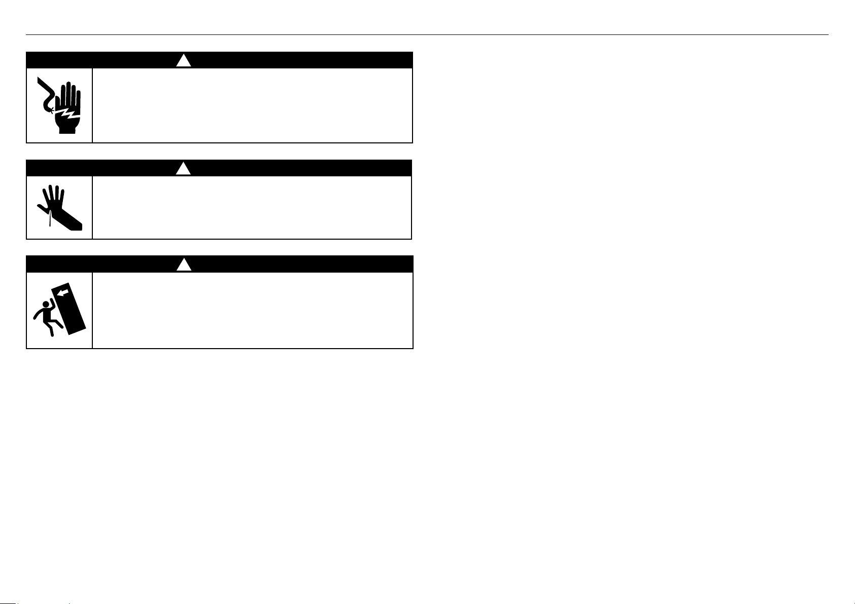
!
WARNING!
Electric Shock Hazard
Read and follow the safety and warnings outlined in this installation
guide before operating this appliance.
Failure to do so can result in death, electric shock, fire or injury
topersons.
!
WARNING!
Cut Hazard
Take care—panel edges are sharp. Failure to use caution could result
ininjury or cuts.
!
WARNING!
This appliance is top-heavy and must be secured to prevent the
possibility of tippingforward.
To ensure that the appliance is stable under all loading conditions,
theanti-tip bracket and fittings supplied must be installed according
tothe following installation instructions by a professional installer.
3
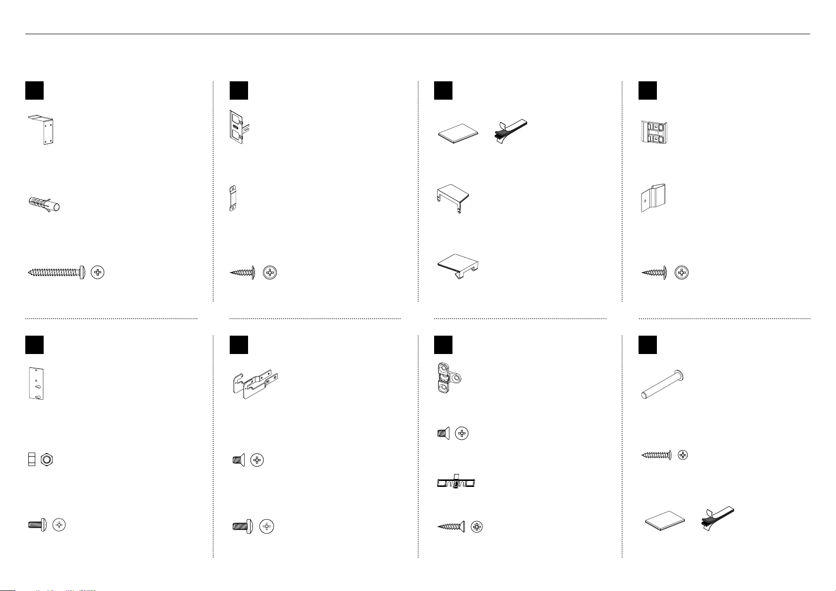
2COMPONENTS
Internal box (Installation kit)
Located inside the appliance
E
Top trim
install kit
Cabinet top trim bracket
(2)
M5 Nut
M5 Nut
M5 nut
(4)
M5 x 10
Pan Head
Philips Screw
M5 x 10
Pan Head
Philips Screw
M5x8 cross-head screw
(4)
G
Fixing bracket
install kit
Fixing bracket
(4)
M5 x 8
Countersunk
Philips Screw
M5 x 8
Countersunk
Philips Screw
M5x8 countersunk cross-head screw
(8)
Screw cover
(4)
#8 x 19
Countersunk
Twin Thread
Posi Screw
#8 x 19
Countersunk
Twin Thread
Posi Screw
#8x19 twin thread screw
(8)
Z
Miscellaneous
components
Hinge limiting pin
(1)
#8 x 5/8
Pan Head
Philips Screw
#8 x 5/8
Pan Head
Philips Screw
#8x16 panhead screw
(3)
Dual adhesive tabs (6 per each strip)
(6)
F
Side bracket
install kit
Side base brackets (right/left)
(2)
M5 x 8
Countersunk
Philips Screw
M5 x 8
Countersunk
Philips Screw
M5x8 countersunk cross-head screw
(4)
M5 x 10
Pan Head
Philips Screw
M5 x 10
Pan Head
Philips Screw
M5x10 cross-head screw
(10)
A
Anti-tip bracket
assemblykit
Anti-tip bracket
(1)
Masonry plug
(4)
#10x40
Pan Head
Philips Screw
#10x40
Pan Head
Philips Screw
10x40 cross-head screw
(4)
B
Door panel
attachmentkit
Side bracket
(10)
Side strap
(10)
#8 x 16
Mush Washer
Twin Thread
Philips Screw
#8 x 16
Mush Washer
Twin Thread
Philips Screw
8x16 mush washer (Custom) screw
(36)
C
Door/drawer trim
installkit
Dual adhesive tabs (6 per each strip)
(12)
Side cover
(4)
Top cover
(2)
D
Cabinet side trim
installkit
Side trim bracket
(6)
Spring clip
(6)
#8 x 16
Mush Washer
Twin Thread
Philips Screw
#8 x 16
Mush Washer
Twin Thread
Philips Screw
8x16 mush washer screw
(12)
4
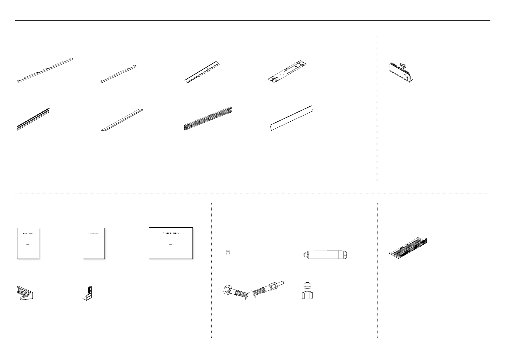
2COMPONENTS
External box
Located at back panel of the appliance
Door side trim
(2)
Drawer side trim
(2)
Cabinet side trim
(2)
Double-sided door panel template
(1)
Top trim
(1)
Drawer top trim
(1)
Top grille
(1)
Toe kick
(1)
Ice and Water display
(Ice and Water models only)
Located inside the appliance
External display module
(1)
Toe kick filter
Located inside the appliance
Toe kick filter
(1)
Miscellaneous items pack
Located inside the appliance
USER GUIDE
NZ AU GB IE HK SG IN US
ACTIVESMART™
INTEGRATED REFRIGERATOR
RS90A, RS9120W,
RS36A72, RS36A80 & RS36W80 models
SERVICE & WARRANTY
SERVICE ET GARANTIE
ΣΈΡΒΙΣ ΚΑΙ ΕΓΓΎΗΣΗ
SERVIZIO E GARANZIA
SERVICE & GARANTIE
HUOLTO JA TAKUU
SERVICE OG GARANTI
保修和维修
服務和保修
ACTIVESMART™ INTEGRATED
SINGLE DOOR / DRAWER REFRIGERATOR
RS36W80 models
INSTALLATION GUIDE
US CA
844189D 02.19
User guide
(1)
Service and Warranty
(1)
Installation guide
(1)
Filter cartridge tool
(1)
Air flow divider
(1)
Water filter install kit
Located inside the appliance
Collet locking clip
(1)
Water filter
(1)
1/4” (6mm) Stainless steel braided
hose with adaptor (1)
Tube adaptor
(1)
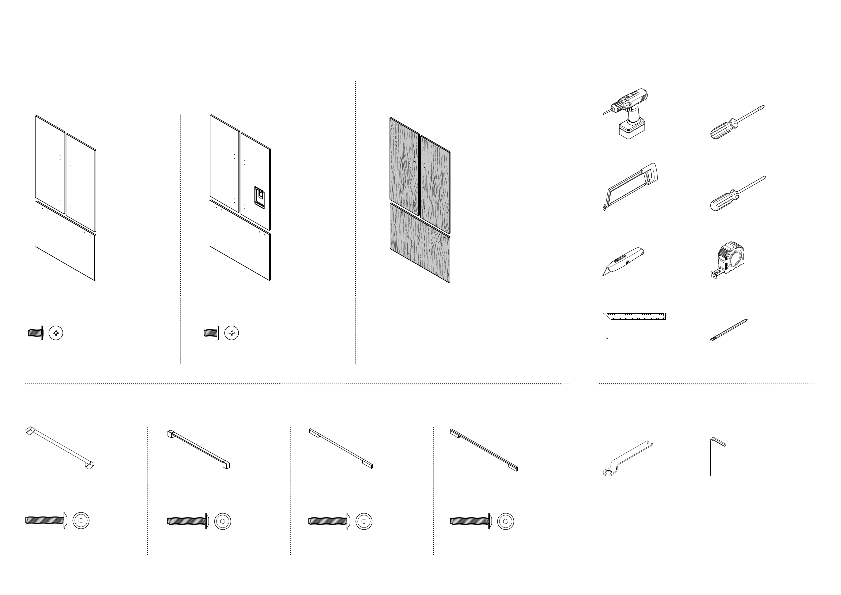
5
Door panel set
Not supplied and must be purchased separately
Stainless steel (Fisher & Paykel) door panel set:
Includes 2x French door panels and 1x drawer panel.
Custom door panel set:
Supplied by customer to match their cabinetry.
Applicable for Ice only appliance models.
Ice only door panel set
(RD3680 / RD3684)
Ice and Water door panel set
(RD3680U / RD3684U)
M5 x 14
Mush Head
SS
Philips Screw
M5 x 14
Mush Head
SS
Philips Screw
M5 x 14
Mush Head
SS
Philips Screw
M5 x 14
Mush Head
SS
Philips Screw
M5x14 mush cross-head (SS) screw
(34)
M5x14 mush cross-head (SS) screw
(34)
Door handle kit
Not supplied and must be purchased separately. Select between the options below:
Professional rounded
door handle (3x)
Professional square
door handle (3x)
Contemporary round
door handle (3x)
Contemporary square
door handle (3x)
M5 x 25
Pan Head
Socket Screw
M5 x 25
Pan Head
Socket Screw
M5 x 25
Pan Head
Socket Screw
M5 x 25
Pan Head
Socket Screw
M5 x 25
Pan Head
Socket Screw
M5 x 25
Pan Head
Socket Screw
M5 x 25
Pan Head
Socket Screw
M5 x 25
Pan Head
Socket Screw
M5x25 pan head socket
screw (12x)
M5x25 pan head socket
screw (12x)
M5x25 pan head socket
screw (12x)
M5x25 pan head socket
screw (12x)
Supplied tools
Included in internal box
FPA spanner
(1)
Hex key
(1)
Required tools
Not included with appliance
Powered driver Flathead screwdriver
Hacksaw Cross-head screwdriver
Cutter Measuring tape
Ruler Pencil
2COMPONENTS 3TOOLS
6
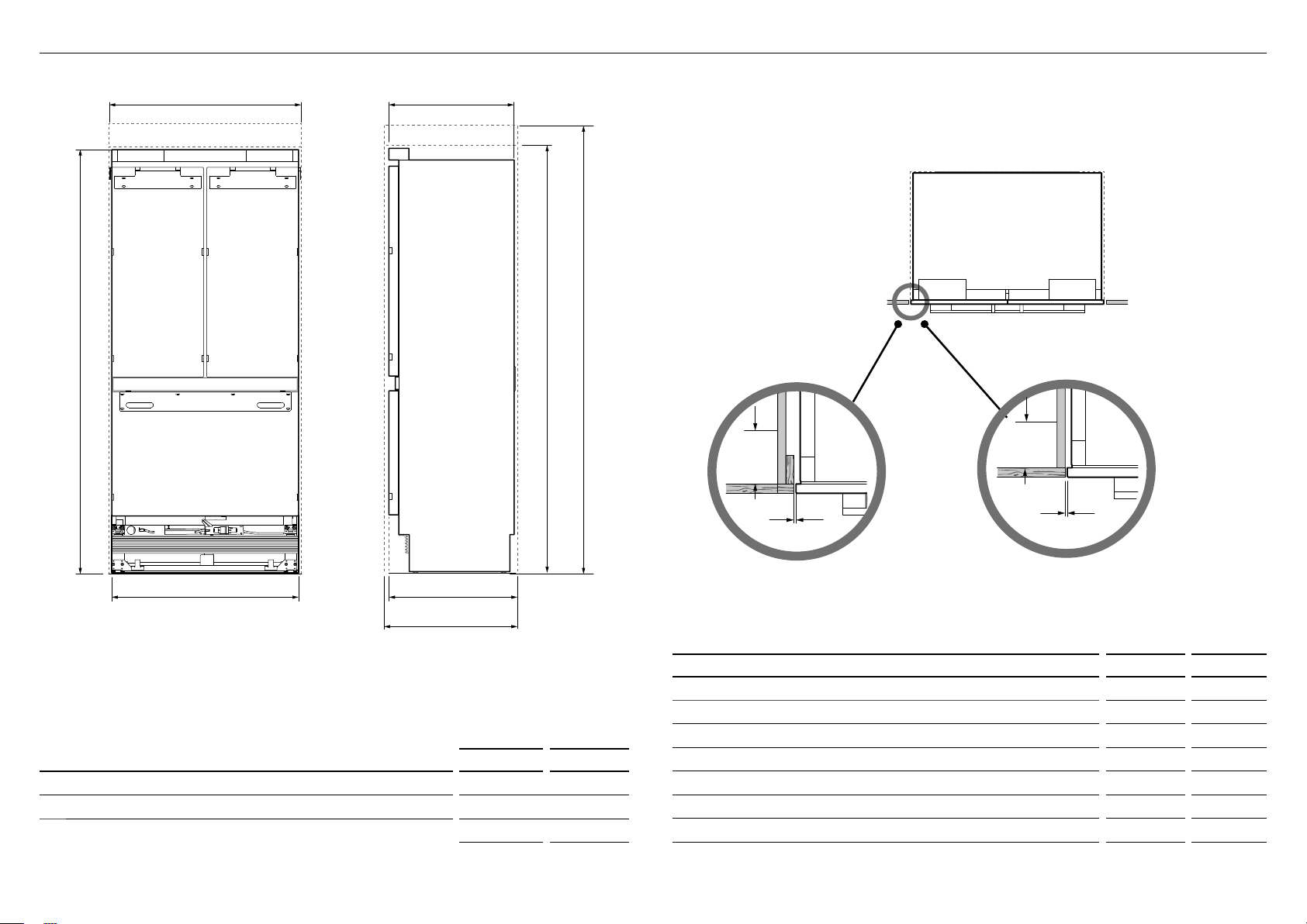
4APPLIANCE AND CAVITY DIMENSIONS
APPLIANCE DIMENSIONS inches mm
A
Overall height of appliance* 7913/16 2028
B
Overall width of appliance 3511/16 906
c
Overall depth of appliance (without door panels) 233/4 603
*
Includes mounted feet
CAVITY DIMENSIONS inches mm
D
Overall height of cavity (for appliance using RD3680 door panel set) 80 2032
e
Overall height of cavity (for appliance using RD3684 door panel set) 84 2134
f
Overall width of cavity 36 914
g
Overall depth of cavity (for flush installation) 25 635
h
Overall depth of cavity (for proud installation) 24 3/4 629
i
Minimum cabinetry gap clearance from edge of appliance 3/16 4
j
Minimum required finished return min. 31/2 89
Flush with front
of cabinetry
PLAN VIEW
FRONT VIEW SIDE VIEW
IMPORTANT!
For ease of installation, ensure cavity width is consistent top
to bottom and height is consistent left to right.
b
A
f
g
h
d
c
e
Framed: Finished return top and sides Frameless: Finished return top and sides
E
B
H
C
ADA
J
I
L GF
F
K
g
J
I
J
I
E
B
H
C
ADA
J
I
L GF
F
K
g
J
I
J
I
7
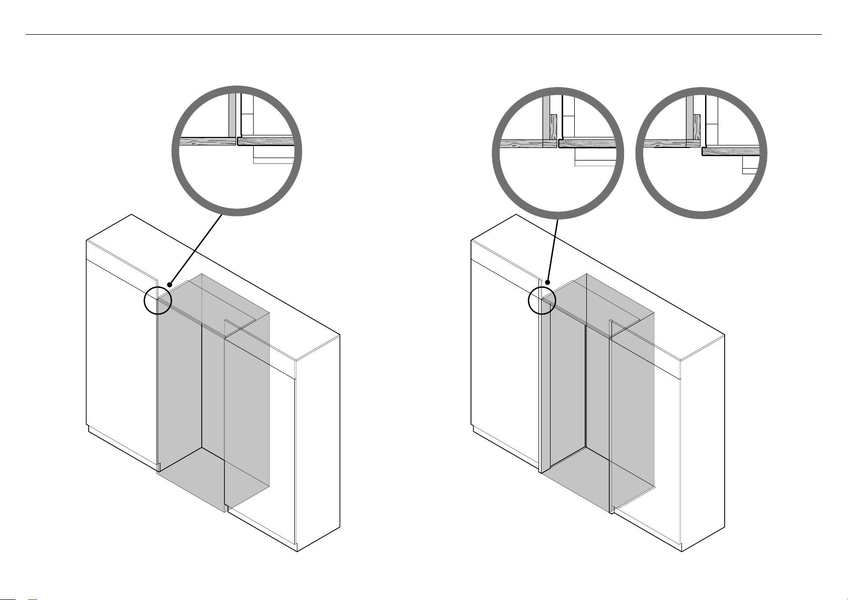
FRAMELESS CABINETRY
(Aligns the appliance with the cabinetry)
Proud
installation
Flush
installation
FRAMED CABINETRY
(Aligns the appliance with the frame of the cabinetry)
5CABINETRY OPTIONS
Note: Drawings are only for reference and not the actual cavity width.
8
b
a
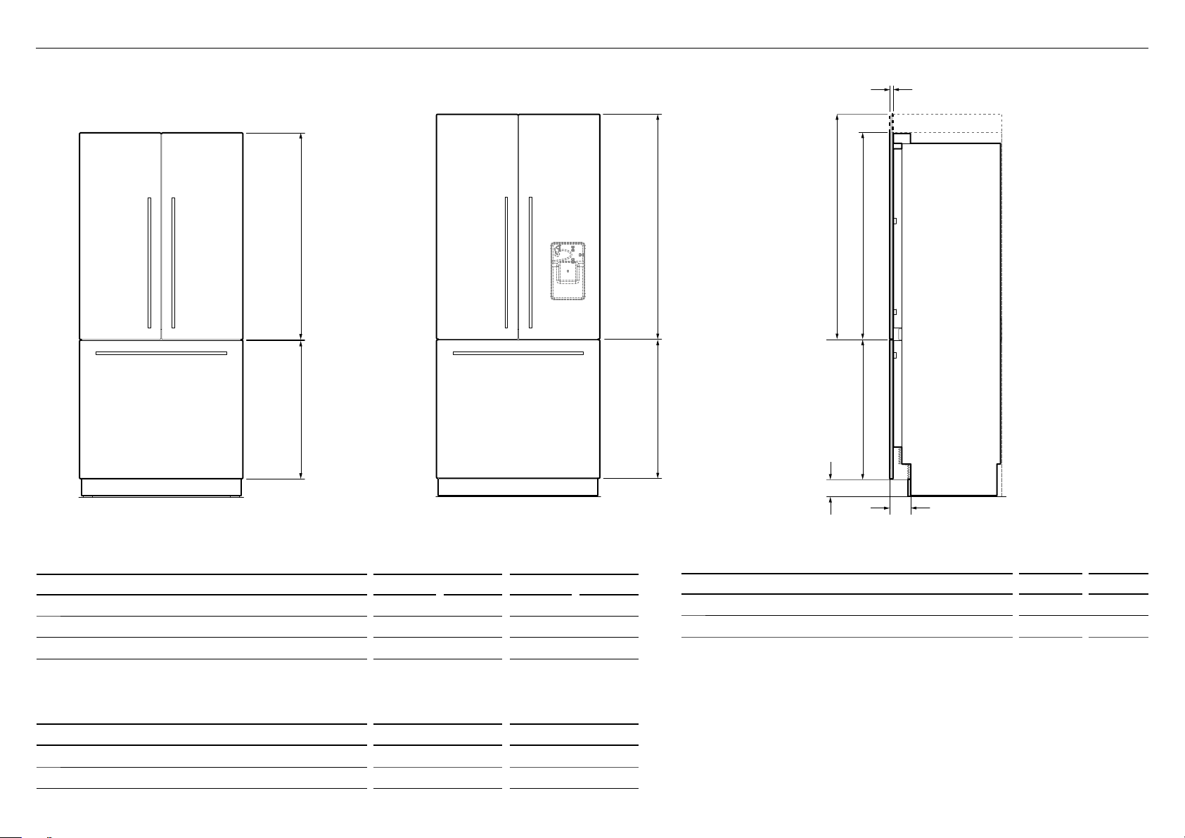
TOE KICK PANEL DIMENSIONS inches mm
d
Height of toe kick panel 4 102
e
Depth of toe kick (measured from front of door panels) 4 3/4 (120)
Note:
Stainless steel toe kick, height 4" (102mm) is supplied with the appliance.
Customers need to supply their own custom toe kick, height 4 – 6" (102 – 152mm).
For toe kick greater than 4, shorten the height of the bottom grille accordingly.
Refer to 'Toe kick installation' for more information.
b
a
RD3680 DOOR PANEL SET RD3684U DOOR PANEL SET
b
a
d
e
c
RD3680/RD3680U RD3684/RD3684U
DOOR PANEL SETS DIMENSIONS inches mm inches mm
a
Height of top door panels 451/4 1150 495/16 1252
b
Height of bottom drawer panel 303/8 772 303/8 772
c
Depth of appliance front panels (excluding handles) 3/4 19 3/4 19
Note:
Fisher & Paykel Stainless steel door panels are not supplied and must be purchased separately.
Model no. RD3680 / RD3684 (Iceonly model) andmodelno. RD3680U / RD3684U (Ice and Water model).
DOOR PANEL WEIGHT lbs kg
Maximum weight of each top door panel
(with handle) 22 10
Maximum weight of drawer panel
(with handle) 241/4 11
6STAINLESS STEEL DOOR PANEL AND TOE KICK DIMENSIONS
9
H
D
A
B
D
g
A
E
I
F
C
g
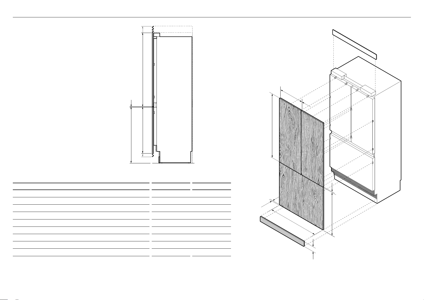
DIMENSIONS inches mm
A
Height of top door panel 451/4–495/16 1150–1252
B
Width of top door panel 73/4 451
C
Gap between top door panels 3/16 4
D
Height of bottom drawer panel 287/16–303/8 722–772
E
Height from bottom of appliance to top of bottom drawerpanel 347/16 874
F
Width of bottom drawer panel 3511/16 906
G
Gap between top door panels and bottom drawer panel 3/16 4
H
Height of toe kick panel 4–6 102–152
I
Depth of custom door panels 5/8–3/4 16–19
Note:
Custom door panels and toe kick must be supplied by the customer.
Custom toe kick should be designed at 4–6" (102–152mm) relative to door/drawer panel height.
For toe kick greater than 4, shorten the height of the bottom grille accordingly. Refer to 'Toe kick installation' for more information.
ISO VIEW
Note: Top trim supplied for
84" (2134mm) installation
H
D
A
B
D
g
A
E
I
F
C
g
PROFILE VIEW
IMPORTANT!
Custom door/drawer panels are only
applicable for Ice only models.
7CUSTOM DOOR PANEL AND TOE KICK DIMENSIONS
10
All measurements to be made
from inner bottom corner.
For the second panel mirror
and repeat dimensions using
inner bottom corner as the
reference point.
Ensure handle is mounted
29/16" (65mm) from inner edge
of panel to the center — this will
avoid interference with brackets.
13/8" (35mm)
165/16" (415mm)
23/16" (56mm)
415/16"
(126mm)
615/16"
(177mm)
2415/16" (634mm)
2615/16" (685mm)
385/8" (982mm)
40" (1016mm)
Ø 3/32" (2mm) REF
12x Pilot holes recommended for bracket attachment.
(Do not penetrate front surface).
157/16" (393mm)
TOP PANEL—REAR VIEW
Ø 3/32" (2mm) REF
10x Pilot holes recommended
forbracket attachment.
(Do not penetrate front surface).
153/16" (386mm)
51/16"
(129mm)
11/8"
(29mm)
37/16"
(88mm)
193/8" (492mm)
215/16" (542mm)
16 3/8" (416mm)
All measurements to be made
from top and centerline.
BOTTOM PANEL—REAR VIEW
Cut outs are located in attachment bracket for Fisher & Paykel handles only.
Iflocating custom handle in the shaded area above, ensure handle screw heads
are counter sunk into back of panel to avoid interference with hanging bracket.
The drawings below apply to Ice-only models RS36A80J. Dimensions apply for the preparation and installation of custom door panels.
For Dwg and Dxf files of the below panel preparation download the folder on thekitchentools.fisherpaykel.com.
8CUSTOM DOOR PANEL INSTALLATION DIMENSIONS
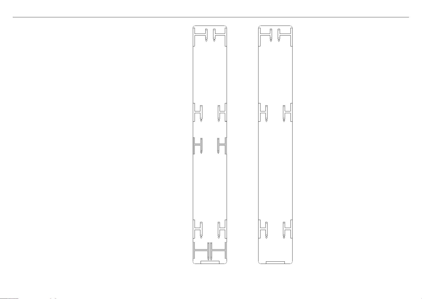
11
This template is a double-sided sheet used as a guide to drill
screw holes for installing your Custom door and drawer panels.
The actual template is included with this installation guide.
Refer to 'Door panel installation — Custom' (page 32) for
moreinformation.
9CUSTOM DOOR PANEL INSTALLATION TEMPLATE
LEFT DOOR
PANEL SIDE
RIGHT DOOR
PANEL SIDE
HANGING BRACKET
HOLES
HANGING BRACKET
HOLES
LEFT DOOR PANEL HINGE SIDE
LEFT DOOR PANEL HANDLE SIDE
LEFT DOOR PANEL
AND DRAWER TEMPLATE
849551
SIDE BRACKET HOLES
SIDE BRACKET HOLES
LEFT DOOR PANEL HINGE SIDE
LEFT DOOR PANEL HANDLE SIDE
FLIP FOR RIGHT
HAND DOOR PANEL
LH DOOR PANEL HANDLE SIDE
LH DOOR PANEL HINGE SIDE
SIDE BRACKET HOLES
SIDE BRACKET HOLES
FLIP FOR LEFT HAND DOOR
AND DRAWER HOLES
RH DOOR PANEL HINGE SIDE
RH DOOR PANEL HANDLE SIDE
SIDE BRACKET HOLES
SIDE BRACKET HOLES
RH DOOR PANEL BOTTOM EDGE
DRAWER PANEL LEFT EDGE
DRAWER PANEL RIGHT EDGE
DRAWE PANEL
SIDE BRACKET HOLES
DRAWE PANEL
SIDE BRACKET HOLES
DRAWER PANEL LEFT EDGE
DRAWER PANEL RIGHT EDGE
DRAWE PANEL HANGING
BRACKET HOLES
DRAWE PANEL HANGING
BRACKET HOLES
LEFT PC PANEL BOTTOM EDGE
DRAWER PANEL TOP EDGE
HANGING BRACKET
HOLES
HANGING BRACKET
HOLES
RH DOOR PANEL HANDLE SIDE
RH DOOR PANEL HINGE SIDE
RIGHT DOOR
PANEL TEMPLATE
849551
RH DOOR PANEL HINGE SIDE
RH DOOR PANEL HANDLE SIDE
SIDE BRACKET HOLES
SIDE BRACKET HOLES
PRINT SPECIFICATION REVISIONS
DRWN DAT E CHKD ECN REV
BJ 04/04/19 1
1
862947
GRAPHICS RS36A DOOR TEMPLATETITLE:
DRAWN: DATE:
SCALE: 1:1
FISHER & PAYKEL APPLIANCES LIMITED
GRAPHICS NO:
REVISION:
BINIL JOSE
04/04/2019
400mm

12
!0DOOR CLEARANCE
D
A
B
C
B
C
A
E
Wall Wall
90° DOOR OPENING115° DOOR OPENING
(FULL INTERNAL ACCESS)
DIMENSIONS inches mm
A
Depth of door (widest opening) measured from front of door 187/8 480
B
Depth of drawer (open) measured from front of drawer, including handle 153/4 400
C
Depth of drawer (open) measured from front of drawer, excluding handle 143/16 360
D
Minimum door clearance* to adjacent wall (115°—full internal access) 123/8 315
E
Minimum door clearance* to adjacent wall (90°—reduced internal access) 45/16 110
* Measured from front cabinetry edge. An additional 3/4" (20mm) is required when using RD3680 and RD3684 door panel sets.
Insert hinge limiting pin
WARNING!
Before opening the doors, ensure that the appliance is
stable.
Follow these steps to avoid risks that can cause serious
injury or death.
For 90° door swing, a hinge limiting pin is supplied with
yourappliance. This pin fits in the boreholes of the top hinge.
1
Open door to 90°.
2
Insert the hinge limiting pin vertically into the bore hole.
– Apply a gentle tap to the pin if it does not slide smoothly.
13
A
C
B
Floor
Left side
of cavity
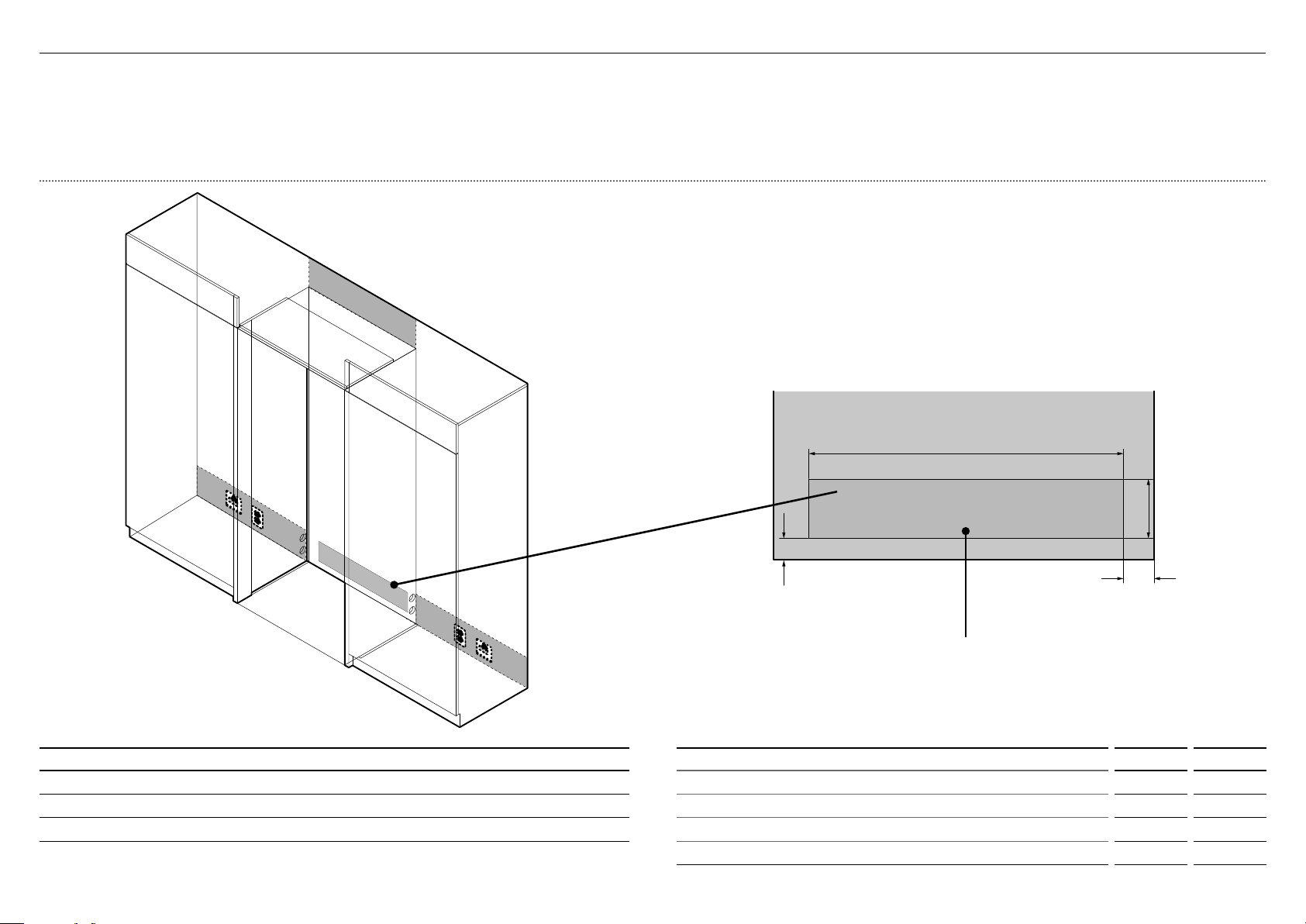
Electrical and water connections must be within
this space if located behind the appliance
IMPORTANT!
Electrical connection should be located in an adjacent cabinet to either side
oftheappliance or above the appliance cavity.
We recommend to use an isolating switch that is easily accessible to the user
aftertheappliance is installed.
WARNING!
Electrical shock hazard. Assume all parts are live.
Disconnect supply before servicing and installation.
!1ELECTRICAL AND PLUMBING
ELECTRICAL AND PLUMBING CONNECTIONS
1
Recommended location for connections in adjacent area or unit
2
Alternative location for connections above the cavity
3
Alternative location for connections at rear of cavity
1
3
2
1
ELECTRICAL AND PLUMBING DIMENSIONS inches mm
A
Overall height of supply area 5 5/8 143
B
Overall width of supply area 29 3/4 756
C
Distance from right side of cavity 2 7/8 73
D
Distance from the floor 2 51
Note: Dimensions are based on minimum depth of cavity.
C
A
D
B

14
!1ELECTRICAL AND PLUMBING
RIGHT HAND SIDELEFT HAND SIDE
Power cord (excl. plug)—31 1/2" (800mm)
Power cord (excl. plug)—803/4" (2051mm)
Power cord (excl. plug)—803/4" (2051mm)
Water inlet hose—53 1/8" (1350mm) Water inlet hose—847/16" (2120mm)
Maximum distance of hose and power cord
ELECTRICAL SPECIFICATIONS
Supply 115VCA, 60Hz
Service 10ampères
PLUMBING SPECIFICATIONS
Supply 1/4" (6mm) comp. Stainless steel braided hose
Pressure min. 22psi (150kPa)
max. 120psi (827kPa) @ 68°F (20°C)
15
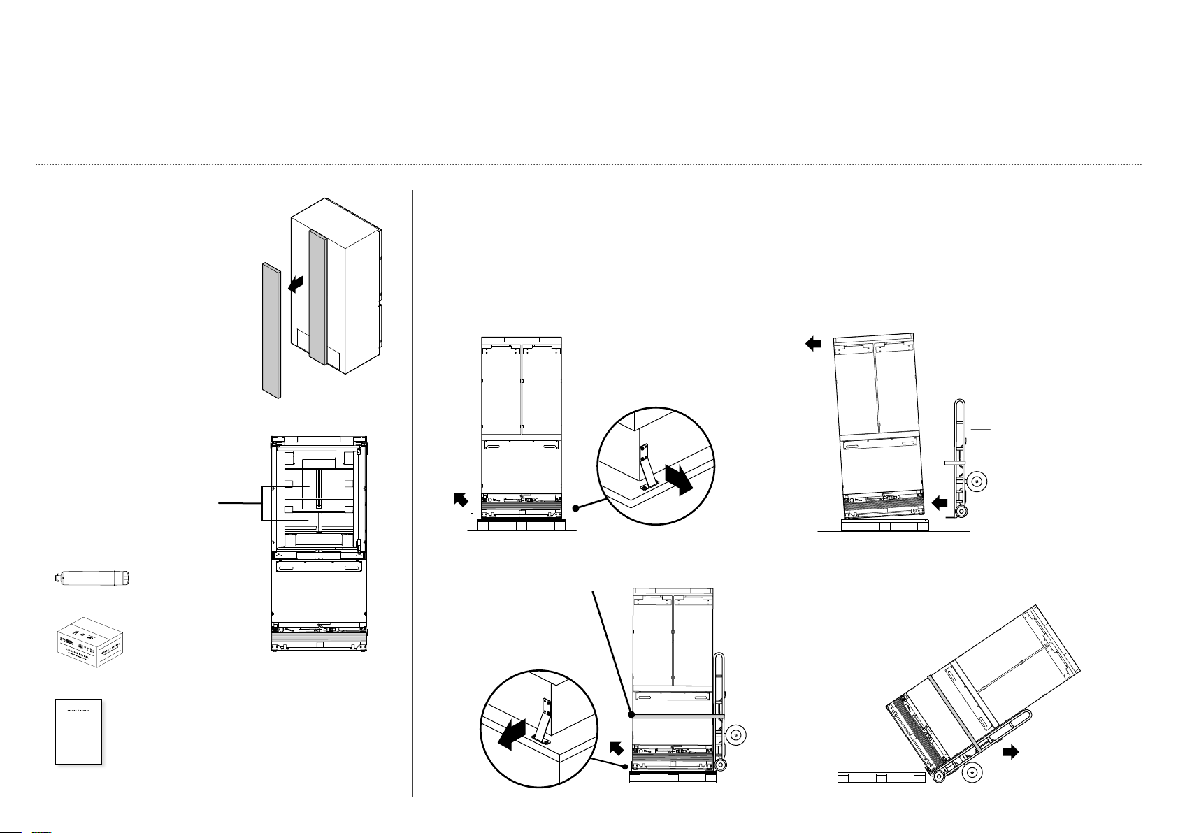
4
Restrain the appliance
tothe cart with straps.
5
Remove the brackets
on the other side of
theappliance.
6
Tilt the appliance backward
onto the cart.
7
Set aside the pallet and
push the cart to the
installation location.
2
Tilt the appliance
slightly to the
opposite side.
3
Insert the hand truck under
the side of the appliance
where the brackets were
removed.
Do NOT insert the hand
truck to the front or back
oftheappliance.
Moving your appliance
1
Remove the brackets from one side of the
appliance. (For single door models, remove
the brackets on the non-hinged side of the
appliance).
Note: Location of brackets depends on the
model of your appliance.
USER GUIDE
NZ AU GB IE HK SG IN US
ACTIVESMART™
INTEGRATED REFRIGERATOR
RS90A, RS9120W,
RS36A72, RS36A80 & RS36W80 models
Water fittings and Water filter kits
Installation kit
2
Remove the water fittings and
water filter kits, installation kit,
and miscellaneous items pack
from inside the appliance.
Refer to 'Components list'.
IMPORTANT!
Be careful when unpacking to prevent damage to the surface of your appliance.
Ensure that the appliance is stable to prevent from tipping over when unpacking.
Do not open the doors to prevent the appliance from tipping over.
The appliance is heavy and requires a minimum of 2persons to unpack and install.
Ensure that the feet of the appliance are retracted.
If the appliance is damaged, contact your Fisher & Paykel dealer.
Take note of your model and registration numbers located at the lower right side of
theappliance. You will need these to request for servicing or repair of your appliance.
hand truck
!2BEFORE INSTALLATION
Miscellaneous items pack
Checking your appliance
1
Remove accessories box
located at the back panel
ofappliance.
Refer to 'Components list' for
contents of accessories box.
IMPORTANT!
Be aware when removing the
carton that the accessories
box may have dislodged from
the rear of the appliance
during transit.

16
IMPORTANT!
The appliance has front and rear rollers for moving the appliance forward and backward.
Do not move the appliance sideways to avoid damaging the rollers or the floor
covering/surface.
The appliance must be installed by a qualified installer, or Fisher & Paykel trained and
supported service technician to avoid faulty electrical connection and water leaks.
All connections for water, electrical power and grounding must comply with local codes
and ordinances and be made by licensed personnel when required.
Avoid installation of the appliance/s under a ground fault circuit interrupter (GFCI).
Ensure the appliance is installed properly. Improper installation that results in appliance
failure is not covered under the appliance warranty.
Check installation location
1
Check the cabinetry
– Check the dimensions — height, width, depth, floor level,
finishedalcovereturns.
– Ensure that the ventilation openings in the cabinetry are clear of obstruction.
– For integrated installation, a finished return of solid material is required
across the top and sides of the new or existing alcove.
– Refer to the ‘Cavity Dimensions’ table prior to installation of the appliance.
2
Check the power supply
– Ensure that there is a separate power outlet for the appliance.
– Avoid sharing the power point with other appliances to prevent the
appliancefrom accidentally switching off.
– For power requirements, refer to the information on the serial plate.
This is located at the front right-hand side of the drawer when open.
– Ensure your appliance is properly grounded (earthed).
– Connect the appliance to the electrical supply (115VAC, 60Hz) with fitted
plugand lead.
– We recommend to use an isolating switch that is easily accessible to the
userafter the appliance is installed.
– Follow the National Electrical Code and all local codes and ordinances
wheninstalling this appliance.
3
Check the water supply (for Ice and Water models only)
– Ensure that there is a separate water supply connection for the appliance.
– Your appliance must be installed by a qualified appliance installer as
incorrect plumbing can lead to water leaks.
– Fisher & Paykel is not liable for damage (including water damage) caused
byfaulty installation or plumbing.
!2BEFORE INSTALLATION
17
Internal box
A
Anti tip
bracket kit
Anti-tip bracket
(1)
Masonry plug
(4)
#10x40
Pan Head
Philips Screw
#10x40
Pan Head
Philips Screw
#10x40 cross-head screw
(4)
Tools
Cross-head screwdriver
Powered driver (optional)
Pencil
IMPORTANT!
The anti-tip bracket and fittings supplied must be fitted to the wall
ofthefinished enclosure to withstand 220lbs (100kg) load.
Ensure that anti-tip bracket is installed correctly to prevent the
appliancetipping forward when door is open.
Ensure the bracket is secured to structural beams or wall studs
nearesttothe center of the alcove.
WARNING!
Read the following before fastening with masonry plugs and/or screws:
Ensure the screws avoid electrical, gas and water conduits.
Ensure lightweight masonry material such as cinder block
andnewconcrete (no curing time) are not used in installation.
Do not use metallic materials that may corrode, stain and/or
damagetheenclosure.
!3CAVITY PREPARATION
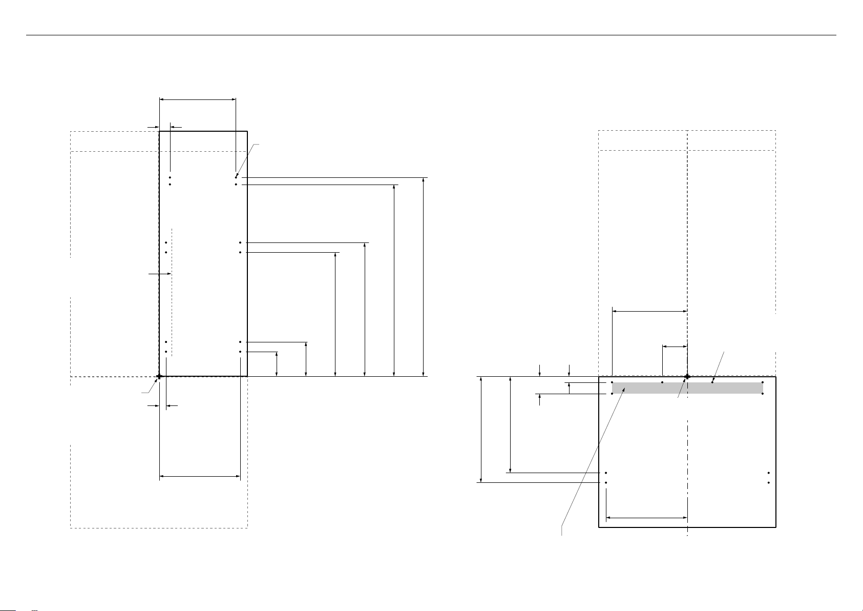
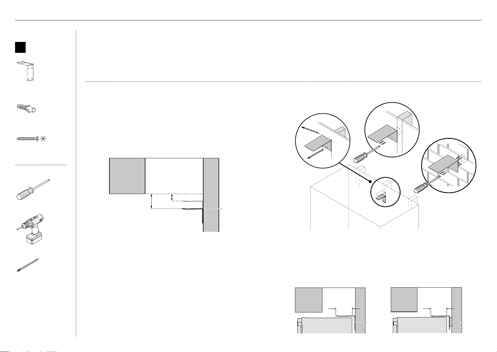
Attach anti-tip bracket
1
Project horizontally from the bottom edge of the finished enclosure
towards the center of the back wall.
– For 80" (2134mm) cavity installation—measure 27/16" (62mm)
downward from the projection line (A).
– For 84" (2032mm) cavity installation—measure 67/16" (164mm)
downward from the projection line (B).
This will locate the contact surface between the bracket and appliance.
2
Mark the location for placement of the anti-tip bracket. Place the bracket
so the top edge of the contact surface aligns with the mark (C).
3
Mark the locations of the screw holes on the wall based on the most
central wall stud (D).
4
Drill screw holes to the marked locations.
5
For wooden/plaster board wall installation:
– Fix the bracket to the wall with #10x40 pan head cross-head screws,
and screw tightly (E).
6
For solid wall installation:
– Hammer masonry plugs into the wall until flush.
– Fix the bracket to the wall with #10x40 pan head cross-head screws
(4x), and screw tightly (F).
A
B
Anti-tip
bracket
E
F
C
D
If the minimum 2 3/8"
(60mm) overlap cannot
be achieved, install a
solid spacer to the wall
stud behind the bracket.
IMPORTANT!
When positioning the appliance
in the cabinetry, ensure that the
anti-tip bracket overlaps the
refrigerator by a minimum 2 3/8"
(60mm) for a secure hold.
.
60mm overlap
Anti-tip
bracket
60mm overlap
Spacer
Anti-tip
bracket
18
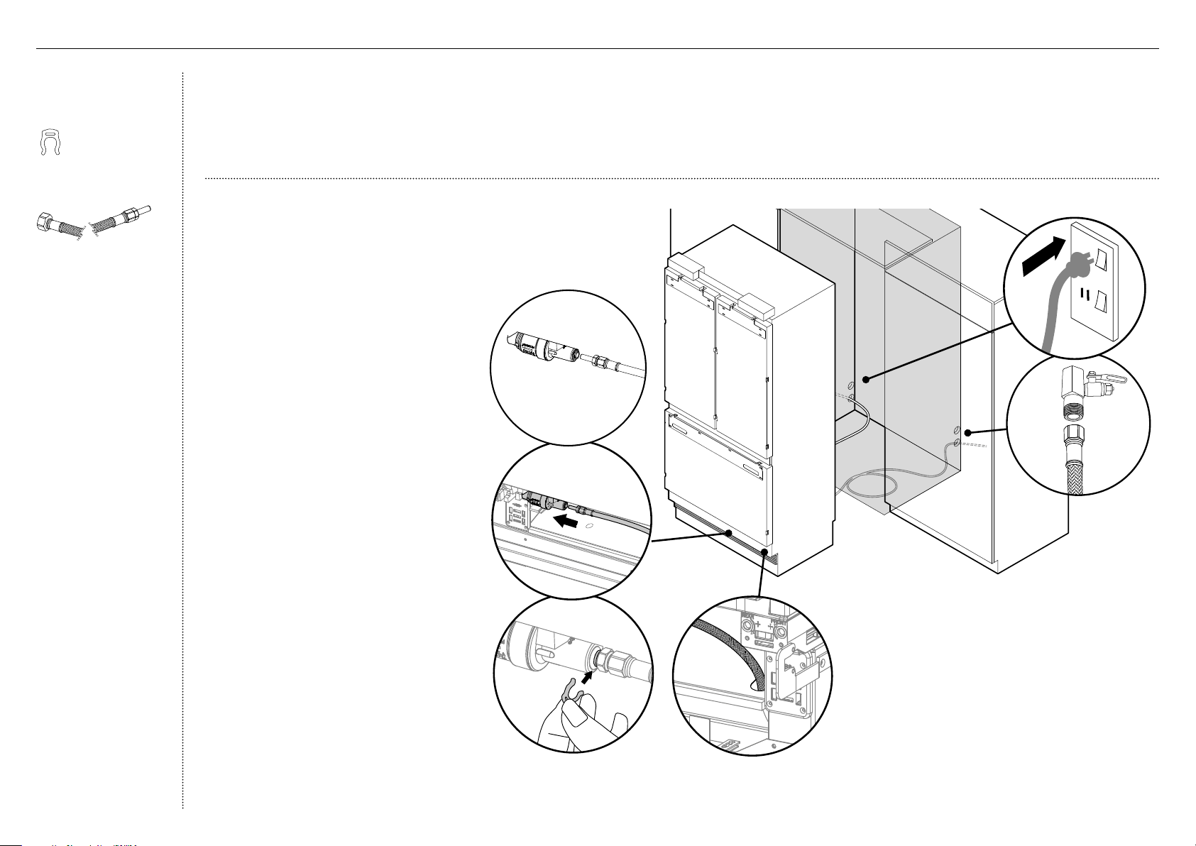
Connect to water
(for Ice and Water models only)
1
Move the appliance in front of the
cabinetry close enough toallow access
behind for power and water connections.
2
At the front of the appliance, insert the
adaptor of the braided water line hose
(A) into the PRV.
Note: If using a 1/4PEX plastic tubing,
you need to use awater fittings kit (not
supplied and must purchase separately).
D
C
B
Water fittings kit
(Ice and Water
modelsonly)
Collet locking clip
(1)
1/4” (6mm) Stainless
steel braided hose with
adaptor (1)
6
At the back of the appliance, connect the freeend
of the braided hose to the water supply (E), and
then loosely coil the water line hose (~2–3 times).
– Do not over-tighten the connection.
– Turn ON the water supply and check that all
connections are dry and free of drips.
Connect to power supply
7
Locate the power cord and connect the fitted
plug to the electrical supply (115VAC, 60Hz)(F).
Turn ON the appliance to test if working.
– If using an isolating switch, turn OFF the
appliance before continuing theinstallation.
IMPORTANT!
Ensure that the water connection is performed by a professional installer.
The standard appliance includes a braided water line hose compatible
withabrass adaptor.
Ensure there is enough tubing for the water connection and to pull
theappliance out for service, if required.
Flush water through the hose prior to connection to the appliance
toremoveany debris in the hose.
We recommend to use an isolating switch that can be accessed
easilyafterthe appliance is installed.
!4WATER AND POWER SUPPLY CONNECTION
3
Insert the tube end of the adaptor fully
into thePRV. Once inserted, pull gently
on the tubing to ensure it is locked in (B).
Note: Dislodge the PRV from the clips,
ifrequired.
4
Secure the connection by inserting a
lockingkey between the PRV and tube
endoftheadaptor (C).
– If the PRV is dislodged during
installation, mount the PRV back
intothe clip.
5
Thread the free end of the water line hose
intothe hole located at the base and
throughthe back of the appliance (D).
E
F
PRV
braided
hose with
adaptor
A
19
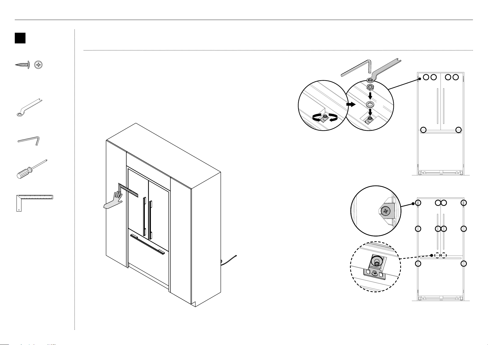
~13" (330mm)
~13" (330mm)
WARNING!
Be careful when working with the appliance outside of the finished enclosure.
Ensure that the appliance is secured to prevent tipping forward. Tipping of appliance can lead to serious injury or death.
Internal box
E
Top trim
install kit
Cabinet top trim bracket
(2)
M5 Nut
M5 Nut
M5 nut
(6)
M5 x 10
Pan Head
Philips Screw
M5 x 10
Pan Head
Philips Screw
M5x8 cross-head screw
(12)
External box
Top trim
(1)
Tools
Cross-head screwdriver
Powered driver (optional)
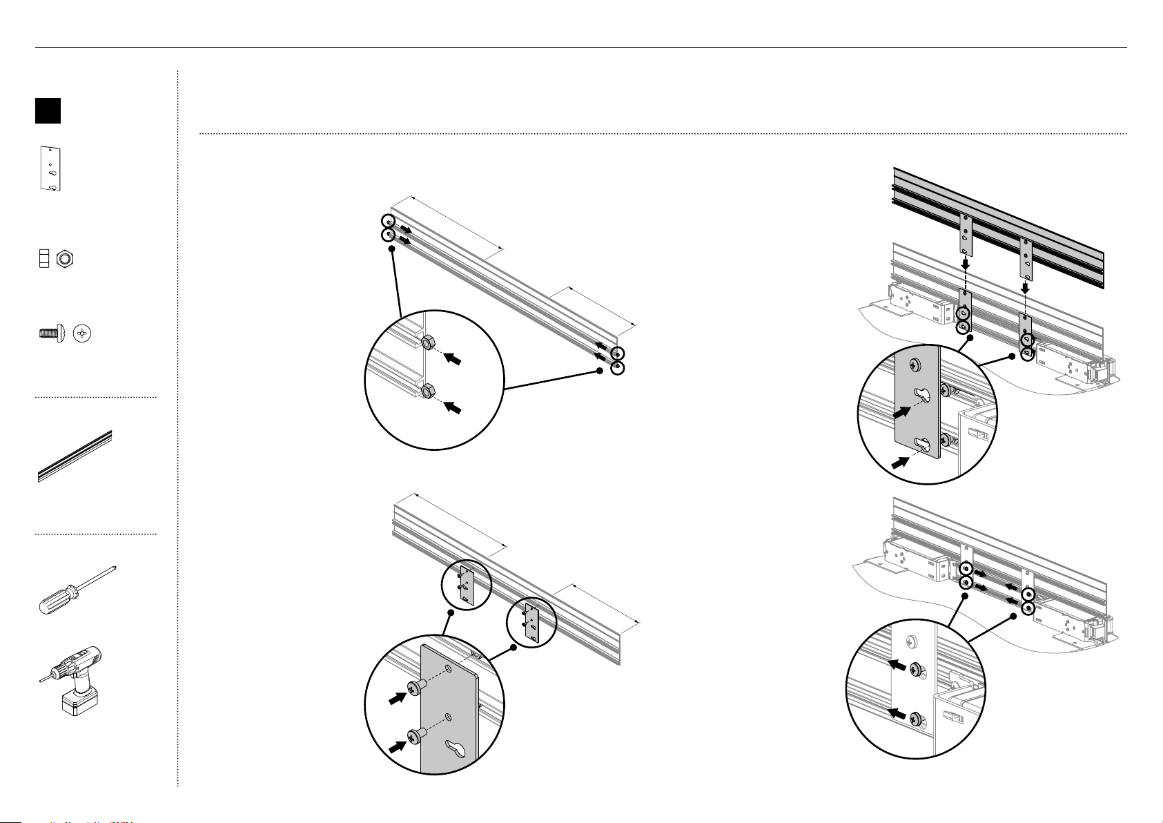
3
At the top of the
appliance, place the
assembled toptrim behind
the existing appliance trim.
Positionthe top trim so
that screw heads in the
appliance trim insert
through the key holes
ofthe brackets (C).
4
Slide the screws of the
appliance trim towards
the narrow side of
the key holes of the
brackets, and tighten
the screws to lock the
top trim in position (D).
2
Position the top trim
brackets over the M5 nuts.
FastenM5x8 cross-head
screws (B) through
brackethole and secure.
1
Insert M5 nuts (A) into
the top and bottom
side of the left and right
ends of the top trim.
Slidethe nuts towards
the center of the trim,
~13" (330mm).
~13" (330mm)
~13" (330mm)
A
B
C
Install top trim—for 84" (2134mm cavity only)
D
!5TOP TRIM INSTALLATION

20
Internal box
F
Side bracket
install kit
Side base brackets
(right/left)
(2)
M5 x 8
Countersunk
Philips Screw
M5 x 8
Countersunk
Philips Screw
M5x8 countersunk
cross-head screw (4)
M5 x 10
Pan Head
Philips Screw
M5 x 10
Pan Head
Philips Screw
M5x10 cross-head screw
(10)
Tools
Cross-head screwdriver
Powered driver (optional)
IMPORTANT!
Ensure all external packaging materials are removed from the appliance before installation.
Ensure the doors of the appliance are closed during installation.
Attach side base brackets
1
Fix the side base brackets to the base left and right sides of the appliance
with M5x8 countersunk cross-head screws (A).
2
Loosely screw (1–2 turns) M5x10 cross-head screws into the doors (B).
1 – 2 turns
B
A
B
A
!6SIDE BRACKETS INSTALLATION
21
A
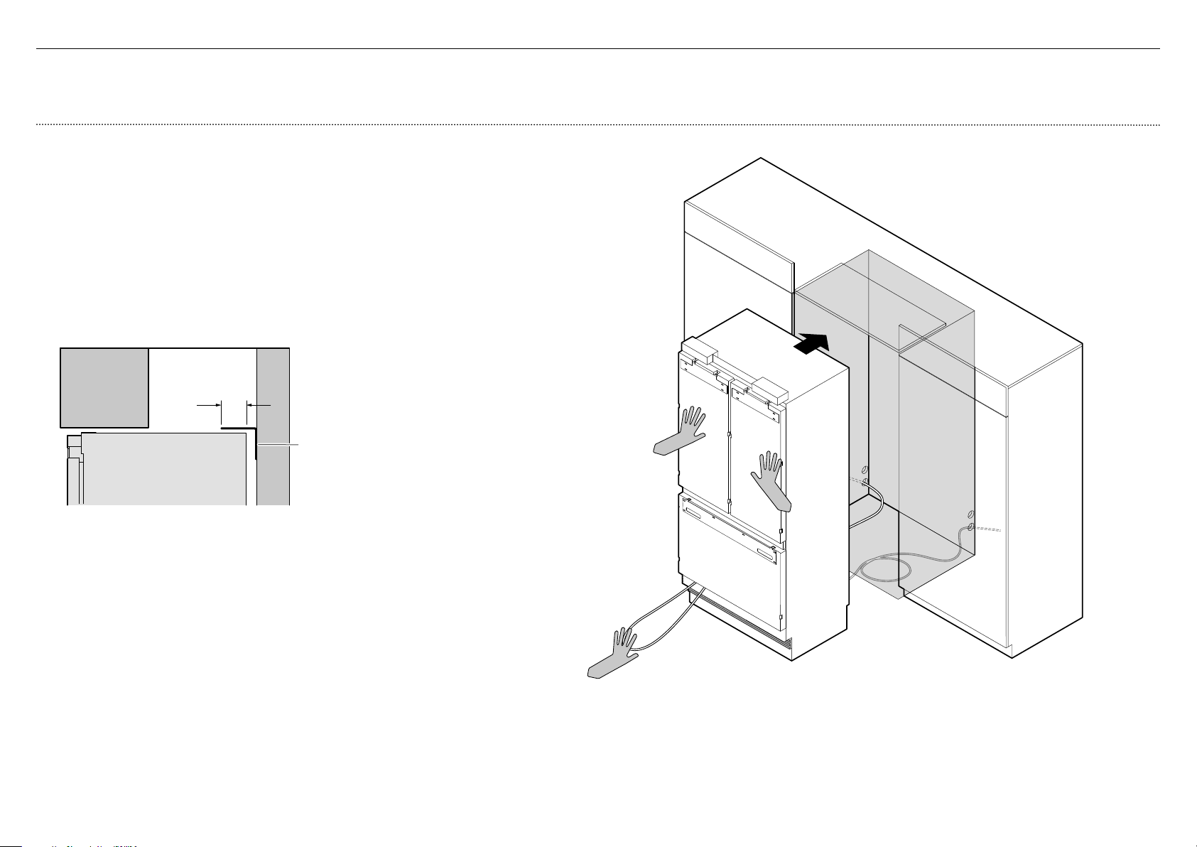
!7POSITIONING INTO CABINETRY
IMPORTANT!
Ensure the hose is not run over by the appliance when pushing into the cabinetry to prevent damage and possible waterleaks.
Position the appliance into the cabinetry
1
Coil the excess water hose and power cord flat behind the appliance (A).
2
Push the appliance into the cabinetry until the anti-tip bracket overlaps the
rear top edge of the appliance (B).
IMPORTANT!
Ensure the appliance is centered.
Ensure the anti-tip bracket overlaps the refrigerator by a minimum 2 3/8"
(60mm) forasecure hold (C).
2 3/8" (60mm) min.
overlap
Anti-tip
bracket
Refer to 'Attach anti-tip bracket' for more information.
C
22
IMPORTANT!
Ensure all four corners of the appliance is supported firmly onto the floor
toeliminate any movement.
DO NOT install the appliance on a soft, uneven, or unlevelled floor to avoid
twisting the appliance and poor door sealing.
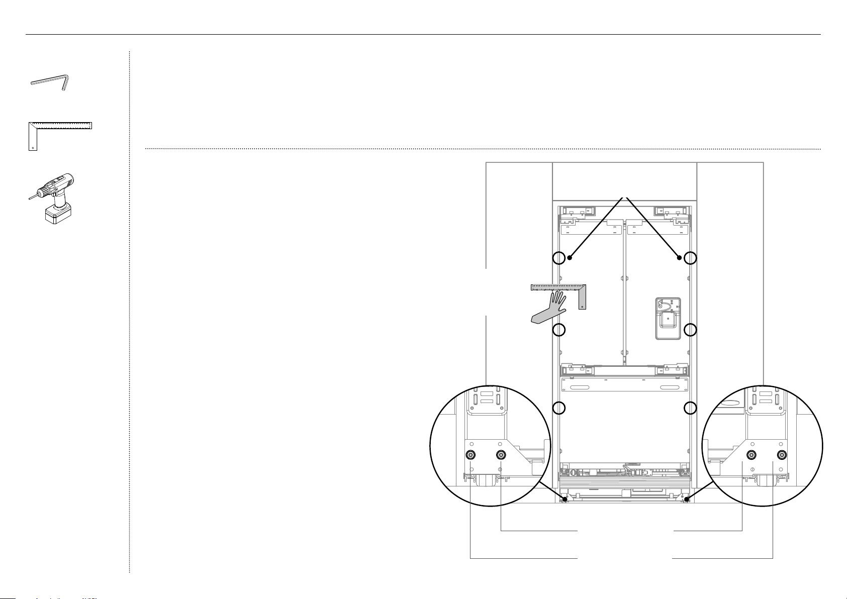
Raise the appliance using a 7/16" (11mm) hex socket or 3/16" (4mm) hex key.
One turn of height adjusting nuts is equivalent to 1/16" (1mm) height adjustment.
Note: Maximum turn is 13/16" (20mm).
If using a powered driver, use low torque setting to avoid damaging
theheight adjustment system.
Ensure that the top, bottom and sidge gaps are not greater than
1/16"(1.5mm) to achieve correct alignment.
Finalalignment will be achieved once door panels have been installed
andtheappliance is pushed back to sit flush with the cabinetry.
Tools
Hex key
Ruler
Powered driver
!8ALIGNING INSIDE CABINETRY
Add ruler to show ushness x 4?
B
Place a ruler on the
front of the appliance to
check flushness top and
bottom, left and right.
Front roller adjustment
Rear roller adjustment
A A
Align appliance inside the cabinetry
1
Centre the appliance within the alcove, using the adjacent
walls as a guide.
2
Turn the front and rear adjustment nuts (A) using a hex key to
extend the feet until it engages the floor.
– Clockwise turn raises the height and counter-clockwise
turn lowers the height.
3
Continue turning the adjusting screws alternately between
front and rear feet to align the front of the doors top to
bottom on both sides, and until you achieve the correct
alignment.
4
Check the top and bottom, left and right gaps by placing
aruler on the front of the appliance.
– Ensure the gaps between appliance and adjacent
cabinetry are even on both sides (B).
– This step will help ensure the appliance is level with the
adjacent cabinetry.
5
Gently push the front of the appliance to check the stability.
23
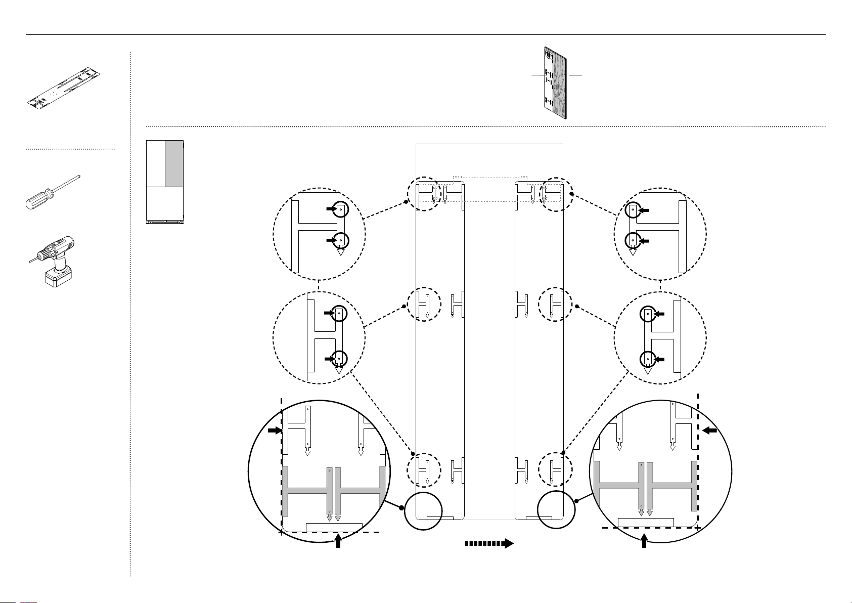
E
IMPORTANT!
Follow these steps to avoid difficulties in door panel adjustment and cosmetic cap fitment.
Ensure to protect the finish of the Stainless steel door panels.
For non-water dispensing door panels: Leave the protective film on the panels when hanging and remove the film only when installation is complete.
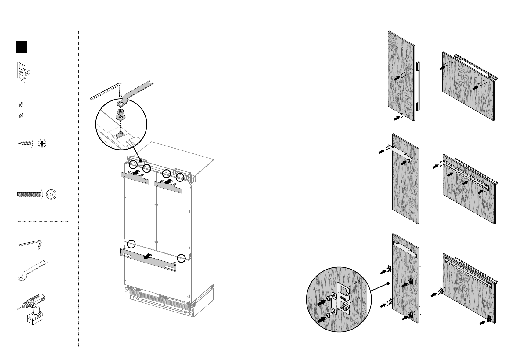
Remove hanging brackets
1
Remove the M8 washers and M8 nuts fromthe
M8 studs at the top the door (A). Keep the
washers and nuts to reuse later.
2
Remove the hanging bracket from the top of
each door and set aside (B) for later installation.
Attach the door and drawer handles (C)
3
Remove the plastic plugs from the handle holes
(4 per each door panel).
4
Align the handle holes with the door panel
holes and secure with M5x25 pan head socket
screws (4 per each door panel).
Note: Door handle kit available and must be
purchased separately. Refer to 'Components'
for more details.
B
C
C
D
D
Attach side brackets and straps (E)
6
Align the brackets and straps to the holes on
the side of the panel and secure with M5x14
mush cross-head SS screws (20).
Attach the hanging brackets (D)
5
Align the bracket to the holes and secure
with M5x14 mush cross-head SS screws (14).
Internal box
B
Door panel
attachment kit
Side bracket
(10)
Side strap
(10)
Door handle kit
M5 x 25
Pan Head
Socket Screw
M5 x 25
Pan Head
Socket Screw
M5x25 pan head socket
screw (12x)
Door panel set
M5 x 14
Mush Head
SS
Philips Screw
M5 x 14
Mush Head
SS
Philips Screw
M5x14 mush cross-head
(SS) screw (34)
Tools
Hex key
FPA spanner
Powered driver
A
!9DOOR PANEL INSTALLATION - STAINLESS STEEL
24
D
E
C
IMPORTANT!
Failure to follow these steps can lead to difficulties in door panel adjustment and cosmetic cap fitment.
For water dispensing door panels: Remove the protective film from the appliance doors before hanging door panels.
Ice and Water display
(Ice and Water
modelsonly)
External display module
(1)
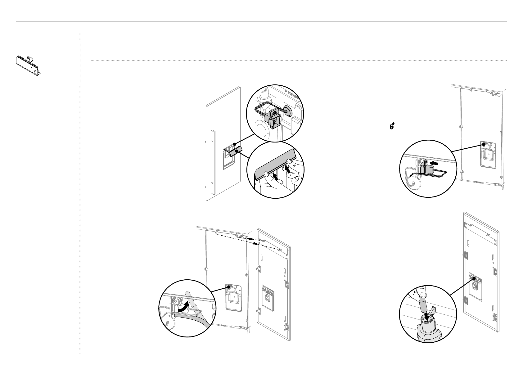
Connect the external display module (for Ice and Water models only)
1
Remove the external display module
taped to the front of the appliance.
2
Thread the display harness through
the door panel cavity (A).
– Ensure the grommet isengaged.
3
Turn the top display tabs at an angle
into the door panel (B).
– Ensure the harness is free
ofpinching.
4
Push firmly against the bottom
display tabsand insert into the door
panel until you feel itclipsecurely.
– Ensure the display is flush
withthe door panel.
5
Remove water tube from the
holder on the appliance door (C).
6
Hang the door panel onto
M8studs.
– Ensure the panel is free to
pivot for water connections.
7
Connect the display harness onto the
appliancedoor by inserting firmly until you
feelit clip securely (D).
– On the external display, enable the
dispenser lock to prevent any water
fromdispensing during water connection.
– To lock, press the button for
4seconds. The LED above the
buttonwillilluminate.
8
Push the water tube firmly into the spigot
behind the door panel until the marked line
is not visible (E).
– Ensure the water tube is routed away
from any sharp objects or corners, and
not in a location where it can be kinked
or squashed when the door panel is
secured, (as this will stop water flow).
B
A
!9DOOR PANEL INSTALLATION - STAINLESS STEEL
25
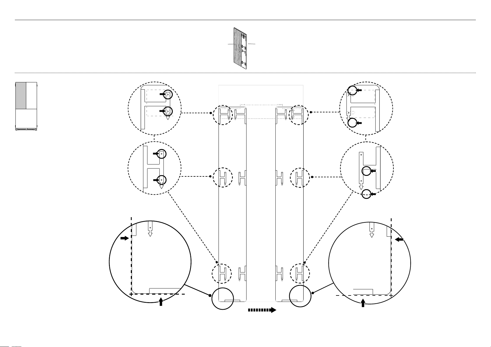
Attach the door panels
1
Open the door and loosen the M5x10 cross-head screws
(do not remove) at the sides of the doors (A).
2
Hang the door panel by inserting theM8 studs
through the holes of the hanging bracket (B).
3
Slide the forks of the side brackets onto the
screwsof the door (C).
4
Screw the M8 washer and nut to each stud(D),
and re-tighten the side screws (E) to fix the
door panel (do not fully tighten). This will allow
opening the door without affecting adjustment
of the doorpanel.
B
D
C
E
A
Tools
FPA spanner
Hex key
Cross-head screwdriver
Powered driver (optional)
!9DOOR PANEL INSTALLATION - STAINLESS STEEL
26
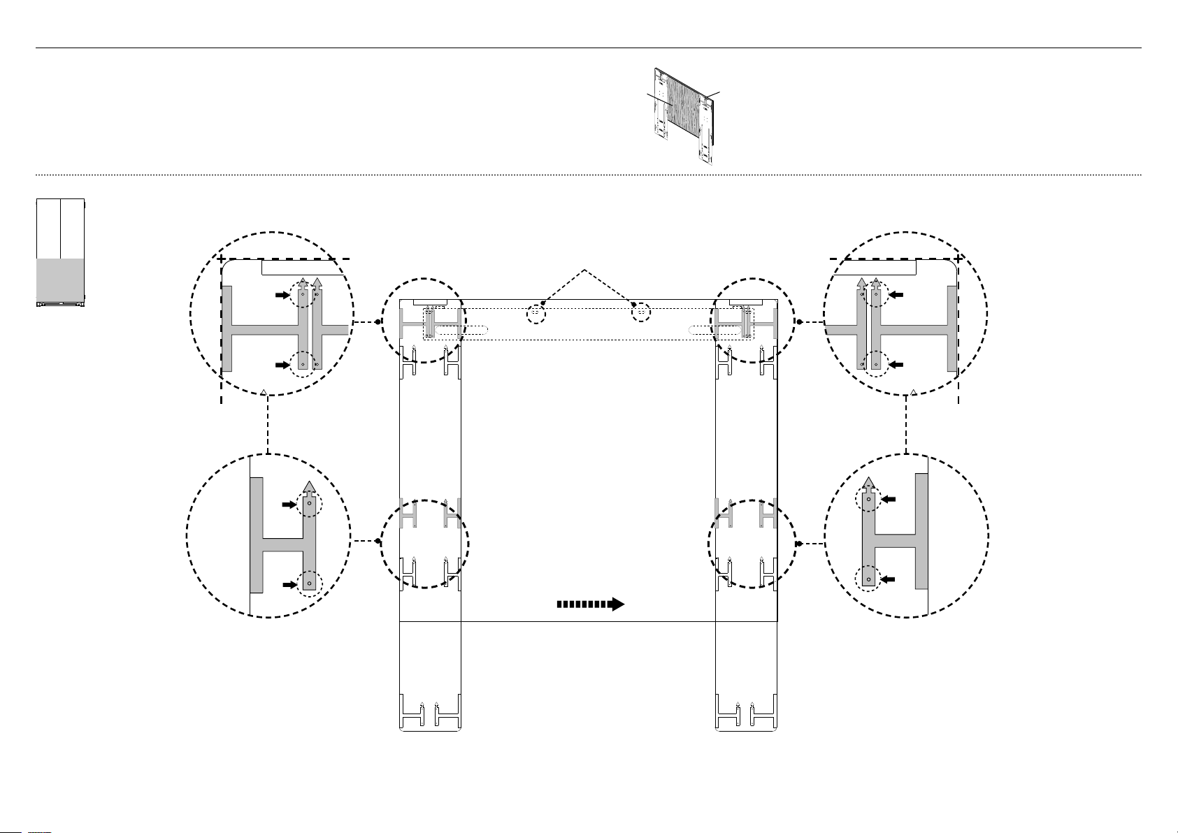
2
Each door panel has full axis adjustment to ensure
flushness with adjacent walls. To adjust the height of
the panel, turn the stud clockwise to raise or counter-
clockwise to lower the door panel (A).
3
Once satisfied with the alignment, secure M8 studs with
M8 washer and M8 nut (B). The top of the stud must
remain below the top face of the door panel.
4
Secure side bracket forks by
tightening side screws(C).
Repeat for all door panels.
Note:
– For depth adjustment,
loosen the side screws(10),
adjustthe panels and then
retightenoncesatisfied.
– Further adjustment of door
panels can be achieved by
removing door panels then
looseningthe fixing screws
for the hanging bracket and
moving the bracket sideways
to suit.
5
Loosen the M8 stud (D) so that
locking bracket can slide freely
back to front.
– Slide the locking bracket out until it touches the
back of the door panel. Fully tighten the M8 stud.
– Screw in place using a #8x16 screw through one
ofthe three slotted holes.
Adjust the door panels
1
Place a ruler on the front of the appliance to check
flushness top and bottom, left and right.
– Ensure the gap between the top of the door panel
and the top cabinetry is not more than 1/4" (7mm).
– To reduce this gap, raise the appliance by turning all
four adjustment nuts the same number of turns.
C
IMPORTANT!
Follow these steps to avoid difficulties in door panel adjustment and cosmetic cap fitment.
B
A
!9DOOR PANEL INSTALLATION - STAINLESS STEEL
D
B
Door panel
attachment
kit
#8 x 16
Mush Washer
Twin Thread
Philips Screw
#8 x 16
Mush Washer
Twin Thread
Philips Screw
8x16 mush washer
(Custom) screw (2)
Tools
FPA spanner
Hex key
Cross-head screwdriver
Ruler
27
FLIP FOR LEFT HAND DOOR
AND DRAWER HOLES
RH DOOR PANEL HINGE SIDE
RH DOOR PANEL HANDLE SIDE
SIDE BRACKET HOLES
SIDE BRACKET HOLES
RH DOOR PANEL BOTTOM EDGE
HANGING BRACKET
HOLES
HANGING BRACKET
HOLES
RH DOOR PANEL HANDLE SIDE
RH DOOR PANEL HINGE SIDE
RIGHT DOOR
PANEL TEMPLATE
849551
RH DOOR PANEL HINGE SIDE
RH DOOR PANEL HANDLE SIDE
SIDE BRACKET HOLES
SIDE BRACKET HOLES
FLIP FOR LEFT HAND DOOR
AND DRAWER HOLES
RH DOOR PANEL HINGE SIDE
RH DOOR PANEL HANDLE SIDE
SIDE BRACKET HOLES
SIDE BRACKET HOLES
RH DOOR PANEL BOTTOM EDGE
HANGING BRACKET
HOLES
HANGING BRACKET
HOLES
RH DOOR PANEL HINGE SIDE
RH DOOR PANEL HINGE SIDE
RIGHT DOOR
PANEL TEMPLATE
849551
RH DOOR PANEL HINGE SIDE
RH DOOR PANEL HANDLE SIDE
SIDE BRACKET HOLES
SIDE BRACKET HOLES
External box
Door panel double-sided
template (1)
Tools
Cross-head screwdriver
Powered driver (optional)
IMPORTANT!
The template is a single sheet with one side used for the left door panel/
drawer panel and the other side for the right door panel.
The template should be placed on the back side of the door panel.
Sample image below shows template applied to door panel RD3680.
Using the installation template
(for left French door panel)
1
FLIP FOR LEFT HAND DOOR
AND DRAWER HOLES
RH DOOR PANEL HINGE SIDE
RH DOOR PANEL HANDLE SIDE
SIDE BRACKET HOLES
SIDE BRACKET HOLES
RH DOOR PANEL BOTTOM EDGE
HANGING BRACKET
HOLES
HANGING BRACKET
HOLES
RH DOOR PANEL HANDLE SIDE
RH DOOR PANEL HANDLE SIDE
RIGHT DOOR
PANEL TEMPLATE
849551
RH DOOR PANEL HINGE SIDE
RH DOOR PANEL HANDLE SIDE
SIDE BRACKET HOLES
SIDE BRACKET HOLES
HANGING BRACKET
HOLES
HANGING BRACKET
HOLES
LEFT DOOR PANEL HINGE SIDE
LEFT DOOR PANEL HANDLE SIDE
LEFT DOOR PANEL
AND DRAWER TEMPLATE
849551
SIDE BRACKET HOLES
SIDE BRACKET HOLES
LEFT DOOR PANEL HINGE SIDE
LEFT DOOR PANEL HANDLE SIDE
FLIP FOR RIGHT
HAND DOOR PANEL
LH DOOR PANEL HANDLE SIDE
LH DOOR PANEL HINGE SIDE
SIDE BRACKET HOLES
SIDE BRACKET HOLES
DRAWER PANEL LEFT EDGE
DRAWER PANEL RIGHT EDGE
DRAWE PANEL
SIDE BRACKET HOLES
DRAWE PANEL
SIDE BRACKET HOLES
DRAWER PANEL LEFT EDGE
DRAWER PANEL RIGHT EDGE
DRAWE PANEL HANGING
BRACKET HOLES
DRAWE PANEL HANGING
BRACKET HOLES
LEFT PC PANEL BOTTOM EDGE
DRAWER PANEL TOP EDGE
3 Move the same template to
right hand side of door panel.
1B Align bottom of template with
bottom edge of top door panel.
1A Align left side edge of
template with left side
edge of top door panel.
2 Mark drill locations of
screw holes for the left
hanging bracket and side
brackets. Drillscrew 3/32"
(2mm) holes to the marked
locations.
4 Mark drill locations of screw
holes for the right hanging
bracket and side brackets.
Drill 3/32" (2mm) screw holes
to the markedlocations.
5B Align bottom of template with
bottom edge of top door panel.
5A Align right side edge of
template with right side
edge of top door panel.
back side of
door panel
front side of
door panel
@0DOOR PANEL INSTALLATION - CUSTOM
28
FLIP FOR LEFT HAND DOOR
AND DRAWER HOLES
RH DOOR PANEL HINGE SIDE
RH DOOR PANEL HANDLE SIDE
SIDE BRACKET HOLES
SIDE BRACKET HOLES
RH DOOR PANEL BOTTOM EDGE
HANGING BRACKET
HOLES
HANGING BRACKET
HOLES
RH DOOR PANEL HANDLE SIDE
RH DOOR PANEL HINGE SIDE
RIGHT DOOR
PANEL TEMPLATE
849551
RH DOOR PANEL HINGE SIDE
RH DOOR PANEL HANDLE SIDE
SIDE BRACKET HOLES
SIDE BRACKET HOLES
FLIP FOR LEFT HAND DOOR
AND DRAWER HOLES
RH DOOR PANEL HINGE SIDE
RH DOOR PANEL HANDLE SIDE
SIDE BRACKET HOLES
SIDE BRACKET HOLES
RH DOOR PANEL BOTTOM EDGE
HANGING BRACKET
HOLES
HANGING BRACKET
HOLES
RH DOOR PANEL HINGE SIDE
RH DOOR PANEL HINGE SIDE
RIGHT DOOR
PANEL TEMPLATE
849551
RH DOOR PANEL HINGE SIDE
RH DOOR PANEL HANDLE SIDE
SIDE BRACKET HOLES
SIDE BRACKET HOLES
back side of
door panel
front side of
door panel
IMPORTANT!
Flip the template over to use for the right top door panel.
The template should be placed on the back side of the door panel.
Using the installation template
(for right French door panel)
1
FLIP FOR LEFT HAND DOOR
AND DRAWER HOLES
RH DOOR PANEL HINGE SIDE
RH DOOR PANEL HANDLE SIDE
SIDE BRACKET HOLES
SIDE BRACKET HOLES
RH DOOR PANEL BOTTOM EDGE
HANGING BRACKET
HOLES
HANGING BRACKET
HOLES
RH DOOR PANEL HANDLE SIDE
RH DOOR PANEL HINGE SIDE
RIGHT DOOR
PANEL TEMPLATE
849551
RH DOOR PANEL HINGE SIDE
RH DOOR PANEL HANDLE SIDE
SIDE BRACKET HOLES
SIDE BRACKET HOLES
FLIP FOR LEFT HAND DOOR
AND DRAWER HOLES
RH DOOR PANEL HINGE SIDE
RH DOOR PANEL HANDLE SIDE
SIDE BRACKET HOLES
SIDE BRACKET HOLES
RH DOOR PANEL BOTTOM EDGE
HANGING BRACKET
HOLES
HANGING BRACKET
HOLES
RH DOOR PANEL HINGE SIDE
RH DOOR PANEL HINGE SIDE
RIGHT DOOR
PANEL TEMPLATE
849551
RH DOOR PANEL HINGE SIDE
RH DOOR PANEL HANDLE SIDE
SIDE BRACKET HOLES
SIDE BRACKET HOLES
FLIP FOR LEFT HAND DOOR
AND DRAWER HOLES
RH DOOR PANEL HINGE SIDE
RH DOOR PANEL HANDLE SIDE
SIDE BRACKET HOLES
SIDE BRACKET HOLES
RH DOOR PANEL BOTTOM EDGE
HANGING BRACKET
HOLES
HANGING BRACKET
HOLES
RH DOOR PANEL HANDLE SIDE
RH DOOR PANEL HINGE SIDE
RIGHT DOOR
PANEL TEMPLATE
849551
RH DOOR PANEL HINGE SIDE
RH DOOR PANEL HANDLE SIDE
SIDE BRACKET HOLES
SIDE BRACKET HOLES
FLIP FOR LEFT HAND DOOR
AND DRAWER HOLES
RH DOOR PANEL HINGE SIDE
RH DOOR PANEL HANDLE SIDE
SIDE BRACKET HOLES
SIDE BRACKET HOLES
RH DOOR PANEL BOTTOM EDGE
HANGING BRACKET
HOLES
HANGING BRACKET
HOLES
RH DOOR PANEL HINGE SIDE
RH DOOR PANEL HINGE SIDE
RIGHT DOOR
PANEL TEMPLATE
849551
RH DOOR PANEL HINGE SIDE
RH DOOR PANEL HANDLE SIDE
SIDE BRACKET HOLES
SIDE BRACKET HOLES
FLIP FOR LEFT HAND DOOR
AND DRAWER HOLES
RH DOOR PANEL HINGE SIDE
RH DOOR PANEL HANDLE SIDE
SIDE BRACKET HOLES
SIDE BRACKET HOLES
RH DOOR PANEL BOTTOM EDGE
HANGING BRACKET
HOLES
HANGING BRACKET
HOLES
RH DOOR PANEL HANDLE SIDE
RH DOOR PANEL HINGE SIDE
RIGHT DOOR
PANEL TEMPLATE
849551
RH DOOR PANEL HINGE SIDE
RH DOOR PANEL HANDLE SIDE
SIDE BRACKET HOLES
SIDE BRACKET HOLES
FLIP FOR LEFT HAND DOOR
AND DRAWER HOLES
RH DOOR PANEL HINGE SIDE
RH DOOR PANEL HANDLE SIDE
SIDE BRACKET HOLES
SIDE BRACKET HOLES
RH DOOR PANEL BOTTOM EDGE
HANGING BRACKET
HOLES
HANGING BRACKET
HOLES
RH DOOR PANEL HINGE SIDE
RH DOOR PANEL HINGE SIDE
RIGHT DOOR
PANEL TEMPLATE
849551
RH DOOR PANEL HINGE SIDE
RH DOOR PANEL HANDLE SIDE
SIDE BRACKET HOLES
SIDE BRACKET HOLES
FLIP FOR LEFT HAND DOOR
AND DRAWER HOLES
RH DOOR PANEL HINGE SIDE
RH DOOR PANEL HANDLE SIDE
SIDE BRACKET HOLES
SIDE BRACKET HOLES
RH DOOR PANEL BOTTOM EDGE
HANGING BRACKET
HOLES
HANGING BRACKET
HOLES
RH DOOR PANEL HANDLE SIDE
RH DOOR PANEL HINGE SIDE
RIGHT DOOR
PANEL TEMPLATE
849551
RH DOOR PANEL HINGE SIDE
RH DOOR PANEL HANDLE SIDE
SIDE BRACKET HOLES
SIDE BRACKET HOLES
FLIP FOR LEFT HAND DOOR
AND DRAWER HOLES
RH DOOR PANEL HINGE SIDE
RH DOOR PANEL HANDLE SIDE
SIDE BRACKET HOLES
SIDE BRACKET HOLES
RH DOOR PANEL BOTTOM EDGE
HANGING BRACKET
HOLES
HANGING BRACKET
HOLES
RH DOOR PANEL HINGE SIDE
RH DOOR PANEL HINGE SIDE
RIGHT DOOR
PANEL TEMPLATE
849551
RH DOOR PANEL HINGE SIDE
RH DOOR PANEL HANDLE SIDE
SIDE BRACKET HOLES
SIDE BRACKET HOLES
FLIP FOR LEFT HAND DOOR
AND DRAWER HOLES
RH DOOR PANEL HINGE SIDE
RH DOOR PANEL HANDLE SIDE
SIDE BRACKET HOLES
SIDE BRACKET HOLES
RH DOOR PANEL BOTTOM EDGE
HANGING BRACKET
HOLES
HANGING BRACKET
HOLES
RH DOOR PANEL HANDLE SIDE
RH DOOR PANEL HINGE SIDE
RIGHT DOOR
PANEL TEMPLATE
849551
RH DOOR PANEL HINGE SIDE
RH DOOR PANEL HANDLE SIDE
SIDE BRACKET HOLES
SIDE BRACKET HOLES
FLIP FOR LEFT HAND DOOR
AND DRAWER HOLES
RH DOOR PANEL HINGE SIDE
RH DOOR PANEL HANDLE SIDE
SIDE BRACKET HOLES
SIDE BRACKET HOLES
RH DOOR PANEL BOTTOM EDGE
HANGING BRACKET
HOLES
HANGING BRACKET
HOLES
RH DOOR PANEL HINGE SIDE
RH DOOR PANEL HINGE SIDE
RIGHT DOOR
PANEL TEMPLATE
849551
RH DOOR PANEL HINGE SIDE
RH DOOR PANEL HANDLE SIDE
SIDE BRACKET HOLES
SIDE BRACKET HOLES
3 Move the same template to
right hand side of door panel.
1B Align bottom of template with
bottom edge of top door panel.
1A
Align left side edge of
template with left side
edge of top door panel.
2
Mark drill locations of
screw holes for the left
hanging bracket and side
brackets. Drill 3/32" (2mm)
screw holes to the marked
locations.
4 Mark drill locations of screw
holes for the right hanging
bracket and side brackets.
Drill 3/32" (2mm) screw holes
to the marked locations.
5B Align bottom of template with
bottom edge of top door panel.
5A Align right side edge of
template with right side
edge of top door panel.
FLIP FOR LEFT HAND DOOR
AND DRAWER HOLES
RH DOOR PANEL HINGE SIDE
RH DOOR PANEL HANDLE SIDE
SIDE BRACKET HOLES
SIDE BRACKET HOLES
RH DOOR PANEL BOTTOM EDGE
HANGING BRACKET
HOLES
HANGING BRACKET
HOLES
RH DOOR PANEL HANDLE SIDE
RH DOOR PANEL HINGE SIDE
RIGHT DOOR
PANEL TEMPLATE
849551
RH DOOR PANEL HINGE SIDE
RH DOOR PANEL HANDLE SIDE
SIDE BRACKET HOLES
SIDE BRACKET HOLES
FLIP FOR LEFT HAND DOOR
AND DRAWER HOLES
RH DOOR PANEL HINGE SIDE
RH DOOR PANEL HANDLE SIDE
SIDE BRACKET HOLES
SIDE BRACKET HOLES
RH DOOR PANEL BOTTOM EDGE
HANGING BRACKET
HOLES
HANGING BRACKET
HOLES
RH DOOR PANEL HINGE SIDE
RH DOOR PANEL HINGE SIDE
RIGHT DOOR
PANEL TEMPLATE
849551
RH DOOR PANEL HINGE SIDE
RH DOOR PANEL HANDLE SIDE
SIDE BRACKET HOLES
SIDE BRACKET HOLES
@0DOOR PANEL INSTALLATION - CUSTOM
29
back side of
drawer panel
front side of
door panel
IMPORTANT!
Use left door panel template to use for the drawer panel.
Place the template at the back side of the drawer panel.
@0DOOR PANEL INSTALLATION - CUSTOM
HANGING BRACKET
HOLES
HANGING BRACKET
HOLES
LEFT DOOR PANEL HINGE SIDE
LEFT DOOR PANEL HANDLE SIDE
LEFT DOOR PANEL
AND DRAWER TEMPLATE
849551
SIDE BRACKET HOLES
SIDE BRACKET HOLES
LEFT DOOR PANEL HINGE SIDE
LEFT DOOR PANEL HANDLE SIDE
FLIP FOR RIGHT
HAND DOOR PANEL
LH DOOR PANEL HANDLE SIDE
LH DOOR PANEL HINGE SIDE
SIDE BRACKET HOLES
SIDE BRACKET HOLES
FLIP FOR LEFT HAND DOOR
AND DRAWER HOLES
RH DOOR PANEL HINGE SIDE
RH DOOR PANEL HANDLE SIDE
SIDE BRACKET HOLES
SIDE BRACKET HOLES
RH DOOR PANEL BOTTOM EDGE
DRAWER PANEL LEFT EDGE
DRAWER PANEL RIGHT EDGE
DRAWE PANEL
SIDE BRACKET HOLES
DRAWE PANEL
SIDE BRACKET HOLES
DRAWER PANEL LEFT EDGE
DRAWER PANEL RIGHT EDGE
DRAWE PANEL HANGING
BRACKET HOLES
DRAWE PANEL HANGING
BRACKET HOLES
LEFT PC PANEL BOTTOM EDGE
DRAWER PANEL TOP EDGE
HANGING BRACKET
HOLES
HANGING BRACKET
HOLES
RH DOOR PANEL HANDLE SIDE
RH DOOR PANEL HANDLE SIDE
RIGHT DOOR
PANEL TEMPLATE
849551
RH DOOR PANEL HINGE SIDE
RH DOOR PANEL HANDLE SIDE
SIDE BRACKET HOLES
SIDE BRACKET HOLES
PRINT SPECIFICATION REVISIONS
DRWN DATE CHKD ECN REV
BJ 04/04/19 1
1
862947
GRAPHICS RS36A DOOR TEMPLATETITLE:
DRAWN: DATE:
SCALE: 1:1
FISHER & PAYKEL APPLIANCES LIMITED
GRAPHICS NO:
REVISION:
BINIL JOSE
04/04/2019
400mm
Using the installation template
(for drawer panel)
HANGING BRACKET
HOLES
HANGING BRACKET
HOLES
LEFT DOOR PANEL HINGE SIDE
LEFT DOOR PANEL HANDLE SIDE
LEFT DOOR PANEL
AND DRAWER TEMPLATE
849551
SIDE BRACKET HOLES
SIDE BRACKET HOLES
LEFT DOOR PANEL HINGE SIDE
LEFT DOOR PANEL HANDLE SIDE
FLIP FOR RIGHT
HAND DOOR PANEL
LH DOOR PANEL HANDLE SIDE
LH DOOR PANEL HINGE SIDE
SIDE BRACKET HOLES
SIDE BRACKET HOLES
DRAWER PANEL LEFT EDGE
DRAWER PANEL RIGHT EDGE
DRAWE PANEL
SIDE BRACKET HOLES
DRAWE PANEL
SIDE BRACKET HOLES
DRAWER PANEL LEFT EDGE
DRAWER PANEL RIGHT EDGE
DRAWE PANEL HANGING
BRACKET HOLES
DRAWE PANEL HANGING
BRACKET HOLES
LEFT PC PANEL BOTTOM EDGE
DRAWER PANEL TOP EDGE
HANGING BRACKET
HOLES
HANGING BRACKET
HOLES
LEFT DOOR PANEL HINGE SIDE
LEFT DOOR PANEL HANDLE SIDE
LEFT DOOR PANEL
AND DRAWER TEMPLATE
849551
SIDE BRACKET HOLES
SIDE BRACKET HOLES
LEFT DOOR PANEL HINGE SIDE
LEFT DOOR PANEL HANDLE SIDE
FLIP FOR RIGHT
HAND DOOR PANEL
LH DOOR PANEL HANDLE SIDE
LH DOOR PANEL HINGE SIDE
SIDE BRACKET HOLES
SIDE BRACKET HOLES
FLIP FOR LEFT HAND DOOR
AND DRAWER HOLES
RH DOOR PANEL HINGE SIDE
RH DOOR PANEL HANDLE SIDE
SIDE BRACKET HOLES
SIDE BRACKET HOLES
RH DOOR PANEL BOTTOM EDGE
DRAWER PANEL LEFT EDGE
DRAWER PANEL RIGHT EDGE
DRAWE PANEL
SIDE BRACKET HOLES
DRAWE PANEL
SIDE BRACKET HOLES
DRAWER PANEL LEFT EDGE
DRAWER PANEL RIGHT EDGE
DRAWE PANEL HANGING
BRACKET HOLES
DRAWE PANEL HANGING
BRACKET HOLES
LEFT PC PANEL BOTTOM EDGE
DRAWER PANEL TOP EDGE
HANGING BRACKET
HOLES
HANGING BRACKET
HOLES
RH DOOR PANEL HANDLE SIDE
RH DOOR PANEL HANDLE SIDE
RIGHT DOOR
PANEL TEMPLATE
849551
RH DOOR PANEL HINGE SIDE
RH DOOR PANEL HANDLE SIDE
SIDE BRACKET HOLES
SIDE BRACKET HOLES
PRINT SPECIFICATION REVISIONS
DRWN DATE CHKD ECN REV
BJ 04/04/19 1
1
862947
GRAPHICS RS36A DOOR TEMPLATETITLE:
DRAWN: DATE:
SCALE: 1:1
FISHER & PAYKEL APPLIANCES LIMITED
GRAPHICS NO:
REVISION:
BINIL JOSE
04/04/2019
400mm
3 Move the same template to
right hand side of drawer panel.
1A Align top of template with
top edge of drawerpanel.
1B Align left side edge of
template with left side edge
of drawer panel.
2 Mark drill locations of
screw holes for the left
hanging bracket and side
brackets. Drill 3/32" (2mm)
screw holes to the marked
locations.
4A Align top of template with
top edge of drawer panel.
4B Align right side edge of
template with right side
edge of drawerpanel.
5 Mark drill locations of
screw holes for the left
hanging bracket and side
brackets. Drill 3/32" (2mm)
screw holes to the marked
locations.
HANGING BRACKET
HOLES
HANGING BRACKET
HOLES
LEFT DOOR PANEL HINGE SIDE
LEFT DOOR PANEL HANDLE SIDE
LEFT DOOR PANEL
AND DRAWER TEMPLATE
849551
SIDE BRACKET HOLES
SIDE BRACKET HOLES
LEFT DOOR PANEL HINGE SIDE
LEFT DOOR PANEL HANDLE SIDE
FLIP FOR RIGHT
HAND DOOR PANEL
LH DOOR PANEL HANDLE SIDE
LH DOOR PANEL HINGE SIDE
SIDE BRACKET HOLES
SIDE BRACKET HOLES
FLIP FOR LEFT HAND DOOR
AND DRAWER HOLES
RH DOOR PANEL HINGE SIDE
RH DOOR PANEL HANDLE SIDE
SIDE BRACKET HOLES
SIDE BRACKET HOLES
RH DOOR PANEL BOTTOM EDGE
DRAWER PANEL LEFT EDGE
DRAWER PANEL RIGHT EDGE
DRAWE PANEL
SIDE BRACKET HOLES
DRAWE PANEL
SIDE BRACKET HOLES
DRAWER PANEL LEFT EDGE
DRAWER PANEL RIGHT EDGE
DRAWE PANEL HANGING
BRACKET HOLES
DRAWE PANEL HANGING
BRACKET HOLES
LEFT PC PANEL BOTTOM EDGE
DRAWER PANEL TOP EDGE
HANGING BRACKET
HOLES
HANGING BRACKET
HOLES
RH DOOR PANEL HANDLE SIDE
RH DOOR PANEL HANDLE SIDE
RIGHT DOOR
PANEL TEMPLATE
849551
RH DOOR PANEL HINGE SIDE
RH DOOR PANEL HANDLE SIDE
SIDE BRACKET HOLES
SIDE BRACKET HOLES
PRINT SPECIFICATION REVISIONS
DRWN DATE CHKD ECN REV
BJ 04/04/19 1
1
862947
GRAPHICS RS36A DOOR TEMPLATETITLE:
DRAWN: DATE:
SCALE: 1:1
FISHER & PAYKEL APPLIANCES LIMITED
GRAPHICS NO:
REVISION:
BINIL JOSE
04/04/2019
400mm
HANGING BRACKET
HOLES
HANGING BRACKET
HOLES
LEFT DOOR PANEL HINGE SIDE
LEFT DOOR PANEL HANDLE SIDE
LEFT DOOR PANEL
AND DRAWER TEMPLATE
849551
SIDE BRACKET HOLES
SIDE BRACKET HOLES
LEFT DOOR PANEL HINGE SIDE
LEFT DOOR PANEL HANDLE SIDE
FLIP FOR RIGHT
HAND DOOR PANEL
LH DOOR PANEL HANDLE SIDE
LH DOOR PANEL HINGE SIDE
SIDE BRACKET HOLES
SIDE BRACKET HOLES
FLIP FOR LEFT HAND DOOR
AND DRAWER HOLES
RH DOOR PANEL HINGE SIDE
RH DOOR PANEL HANDLE SIDE
SIDE BRACKET HOLES
SIDE BRACKET HOLES
RH DOOR PANEL BOTTOM EDGE
DRAWER PANEL LEFT EDGE
DRAWER PANEL RIGHT EDGE
DRAWE PANEL
SIDE BRACKET HOLES
DRAWE PANEL
SIDE BRACKET HOLES
DRAWER PANEL LEFT EDGE
DRAWER PANEL RIGHT EDGE
DRAWE PANEL HANGING
BRACKET HOLES
DRAWE PANEL HANGING
BRACKET HOLES
LEFT PC PANEL BOTTOM EDGE
DRAWER PANEL TOP EDGE
HANGING BRACKET
HOLES
HANGING BRACKET
HOLES
RH DOOR PANEL HANDLE SIDE
RH DOOR PANEL HANDLE SIDE
RIGHT DOOR
PANEL TEMPLATE
849551
RH DOOR PANEL HINGE SIDE
RH DOOR PANEL HANDLE SIDE
SIDE BRACKET HOLES
SIDE BRACKET HOLES
PRINT SPECIFICATION REVISIONS
DRWN DATE CHKD ECN REV
BJ 04/04/19 1
1
862947
GRAPHICS RS36A DOOR TEMPLATETITLE:
DRAWN: DATE:
SCALE: 1:1
FISHER & PAYKEL APPLIANCES LIMITED
GRAPHICS NO:
REVISION:
BINIL JOSE
04/04/2019
400mm
6 To mark the drill locations of middle
screw holes, align the screw holes of
the drawer hanging bracket with the
right and left drilled screw holes. Drill
screw holes to the marked locations.
30
E
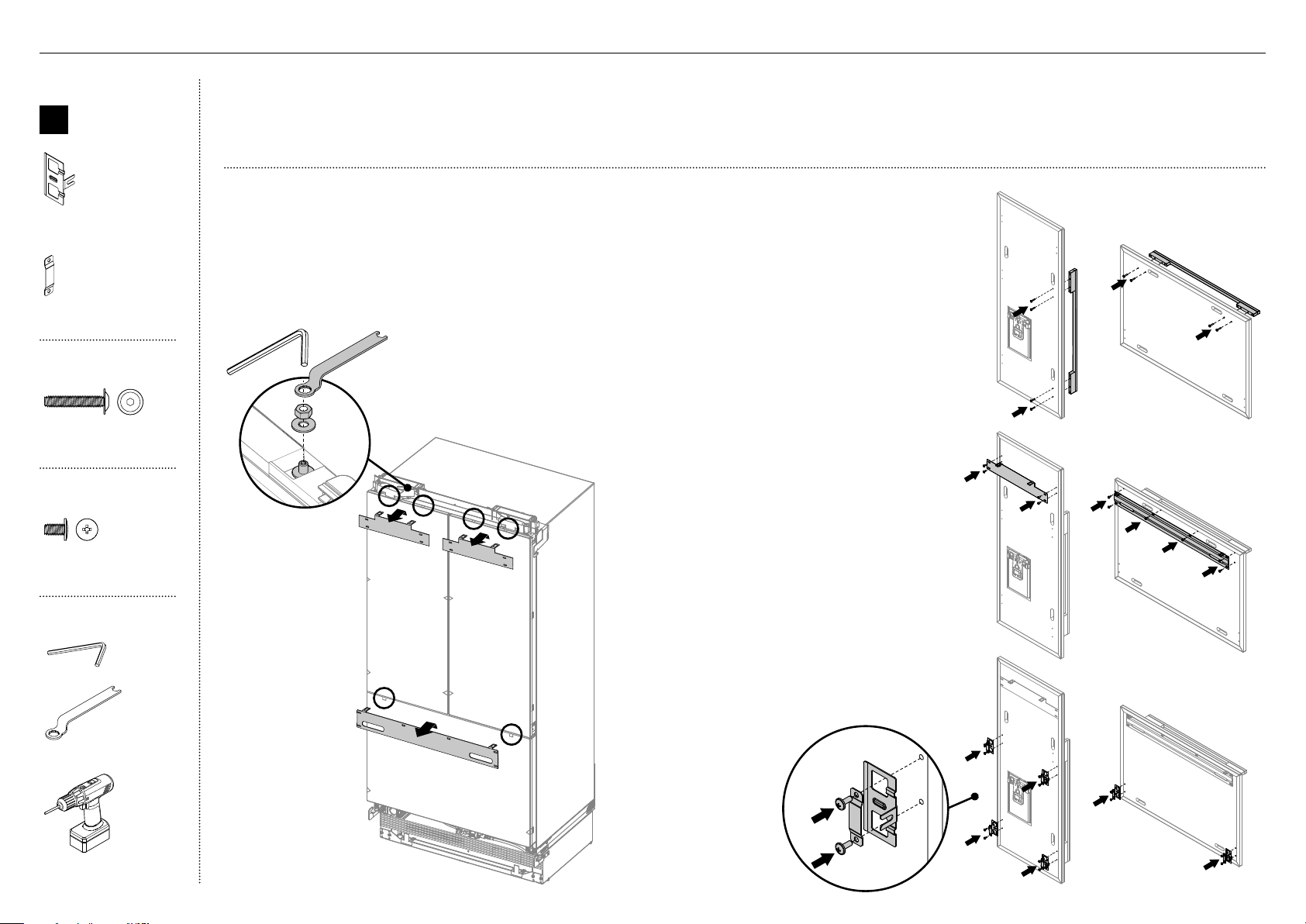
Remove hanging brackets
1
Remove the M8 washers and M8 nuts
fromtheM8 studs at the top the door (A).
Keepthe washers and nuts to reuse later.
2
Remove the hanging bracket from the top of
each door and set aside (B) for later installation.
Attach the door and drawer handles (C)
3
Align the handle holes with the door panel
holes and secure with M5x25 pan head
socket screws (4 per each doorpanel).
Note: Door handle kit available and
must be purchased separately.
Refer to 'Components' for moredetails.
B
A
Attach side brackets and straps (E)
5
Align the brackets and straps to the holes
on the side of the panel and secure with
#8x16 mush washer screw (20).
Attach the hanging brackets (D)
4
Align the bracket to the holes
and secure with #8x16 mush
washer screw (14).
C
C
D
D
Internal box
B
Door panel
attachment kit
Side bracket
(10)
Side strap
(10)
#8 x 16
Mush Washer
Twin Thread
Philips Screw
#8 x 16
Mush Washer
Twin Thread
Philips Screw
#8x16 mush washer
(Custom) screw (36)
Door handle kit
M5 x 25
Pan Head
Socket Screw
M5 x 25
Pan Head
Socket Screw
M5x25 pan head socket
screw (12x)
Tools
Hex key
FPA spanner
Powered driver (optional)
@0DOOR PANEL INSTALLATION CUSTOM

31
Attach the door panels
1
Open the door and loosen the M5x10 cross-head
screws (do not remove) at the sides of the doors (A).
2
Hang the door panel by inserting the M8 studs
through the holes of the hanging bracket (B).
3
Slide the forks of the side brackets onto the
screwsof the door (C).
4
Screw the M8 washer and nut to each stud(D),
and re-tighten the side screws (E) to fix the
door panel (do not fully tighten). This will allow
opening the door without affecting adjustment
of the door panel.
B
D
C
A
E
Tools
FPA spanner
Hex key
Cross-head screwdriver
Powered driver
(optional)
@0DOOR PANEL INSTALLATION - CUSTOM

32
Adjust the door panels
1
Place a ruler on the front of the appliance to check
flushness top and bottom, left and right.
– Ensure the gap between the top of the door panel
and the top cabinetry is not more than 1/4" (7mm).
– To reduce this gap, raise the appliance by turning all
four adjustment nuts the same number of turns.
IMPORTANT!
Follow these steps to avoid difficulties in door panel adjustment and cosmetic cap fitment.
B
Door panel
attachment
kit
#8 x 16
Mush Washer
Twin Thread
Philips Screw
#8 x 16
Mush Washer
Twin Thread
Philips Screw
8x16 mush washer
(Custom) screw (2)
Tools
FPA spanner
Hex key
Cross-head screwdriver
Ruler
@0DOOR PANEL INSTALLATION - CUSTOM
2
Each door panel has full axis adjustment to ensure
flushness with adjacent walls. To adjust the height of
the panel, turn the stud clockwise to raise or counter-
clockwise to lower the door panel (A).
3
Once satisfied with the alignment, secure M8 studs with
M8 washer and M8 nut (B). The top of the stud must
remain below the top face of the door panel.
4
Secure side bracket forks by
tightening side screws(C).
Repeat for all door panels.
Note:
– For depth adjustment,
loosen the side screws(10),
adjustthe panels and then
retightenoncesatisfied.
– Further adjustment of door
panels can be achieved by
removing door panels then
looseningthe fixing screws
for the hanging bracket and
moving the bracket sideways
to suit.
5
Loosen the M8 stud (D) so that
locking bracket can slide freely
back to front.
– Slide the locking bracket out until it touches the
back of the door panel. Fully tighten the M8 stud.
– Screw in place using a #8x16 screw through one
ofthe three slotted holes.
C
B
A
D
33
A
Internal box
G
Fixing bracket
install kit
Fixing bracket
(4)
M5 x 8
Countersunk
Philips Screw
M5 x 8
Countersunk
Philips Screw
M5x8 countersunk
cross-head screw (12)
Screw cover
(4)
#8 x 19
Countersunk
Twin Thread
Posi Screw
#8 x 19
Countersunk
Twin Thread
Posi Screw
#8x19 twin thread screw
(8)
Tools
Cross-head screwdriver
Powered driver (optional)
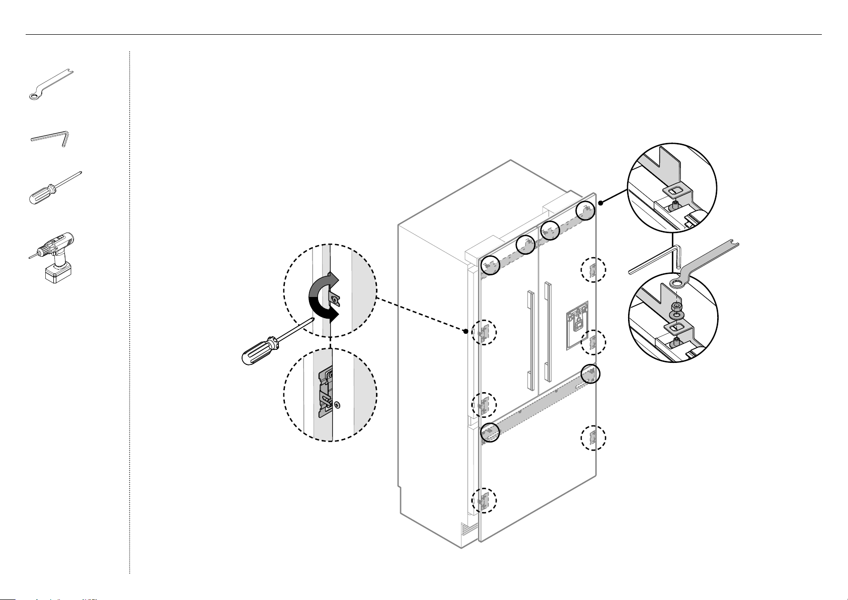
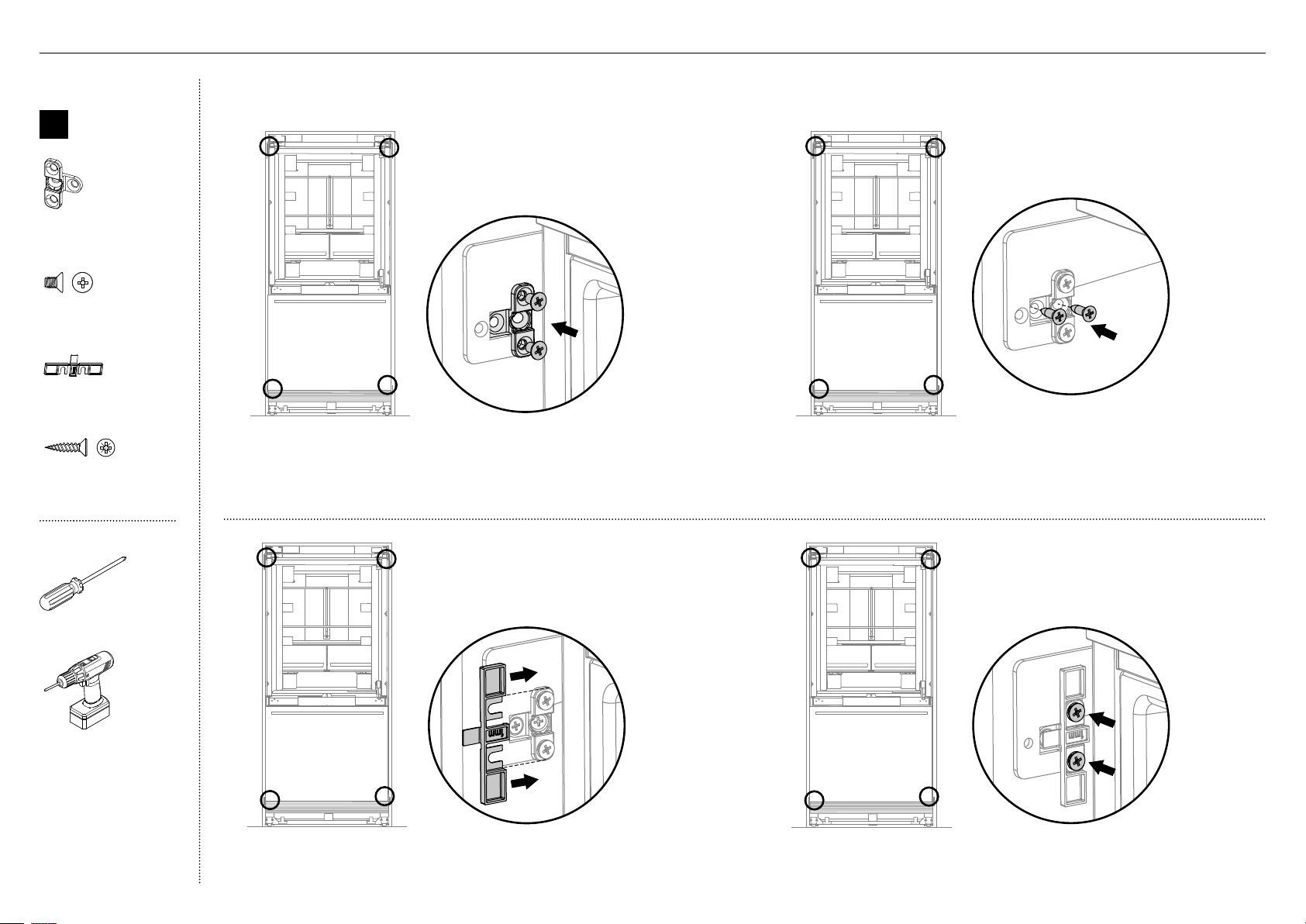
1
Open the refrigerator French doors carefully.
2
Place the fixing brackets on the top and side base brackets of the
appliance and secure mid-way with M5x8 countersunk cross-head screws
(A).
5
Fix the screw cover by tightening M5x8 countersunk
cross-head screws (D).
Attach fixing brackets
B
3
Secure the center of each fixing bracket to the side of the adjacent wall
with #8x19 twin thread screws (B).
C
4
Slide the screw cover between the fixingbracket
and the side bracket on the appliance (C).
D
@1FIXING TO CABINETRY
34
B
IMPORTANT!
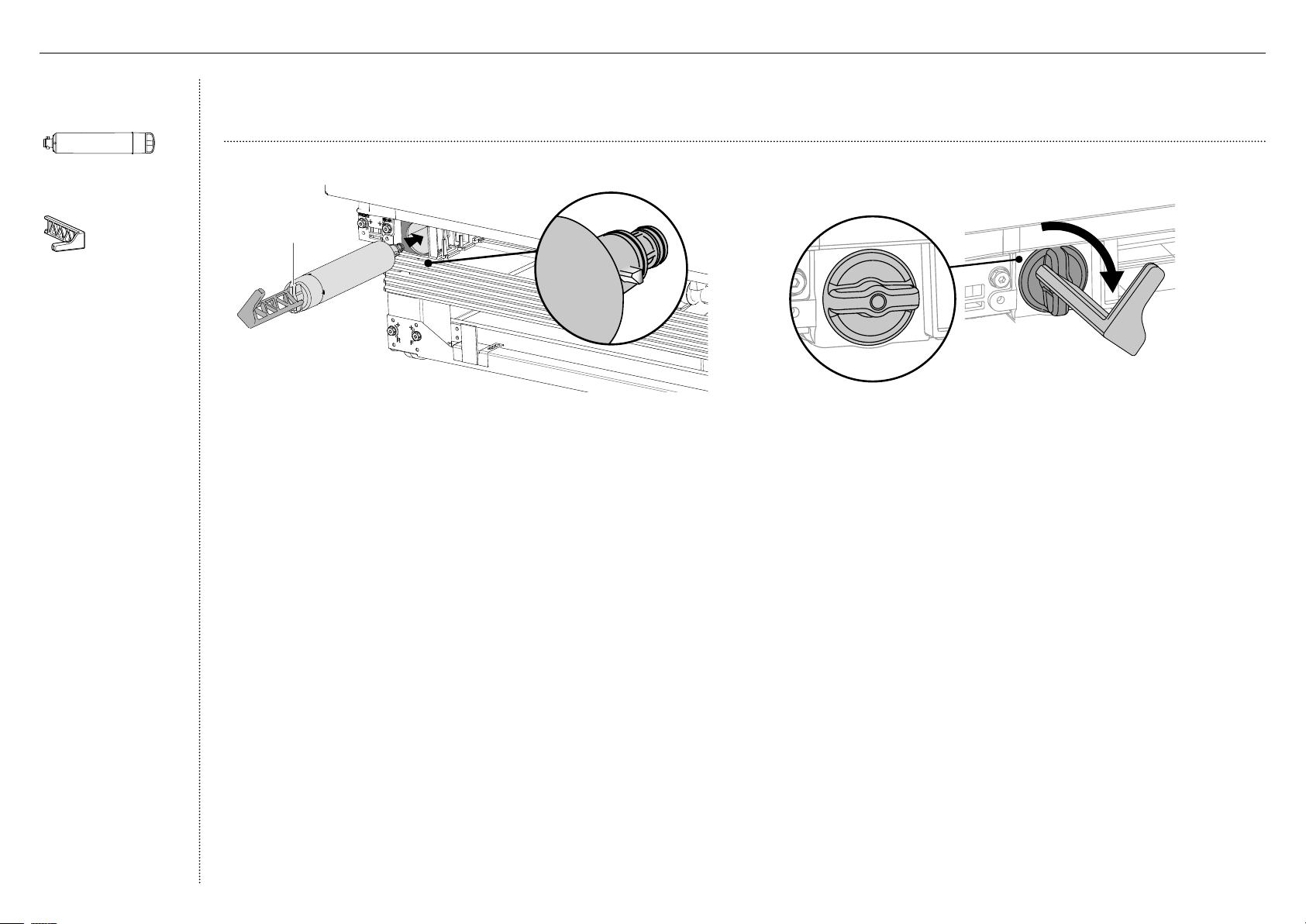
The water filter head must be firmly pushed into the appliance and secured. incorrect installation can lead to water leaks.
4
Align the filter removal tool over the filter handle and turn 90° clockwise
to tighten (B). Remove filter removal tool and close the freezer drawer.
IMPORTANT!
Before turning on your automatic ice maker, the water filter must
be flushed to remove any impurities or trappedair in thewater tank
andfilter system.
Refer to the user guide ‘Operating instructions —Automatic ice maker’
for more information.
Install the water filter
1
Remove the plastic wrapping of the new filter.
2
Pull the freezer drawer out slightly and insert the filter into the casing
at the bottom left corner of the appliance. Ensurethe filter handle is
positioned vertically (A).
3
Push the cartridge firmly inside the casing all the way intothe filter head.
Filter in locked position
A
Front view
Filter
handle
Miscellaneous
itemspack
Water filter
(1)
Filter cartridge tool
(1)
@2WATER FILTER INSTALLATION
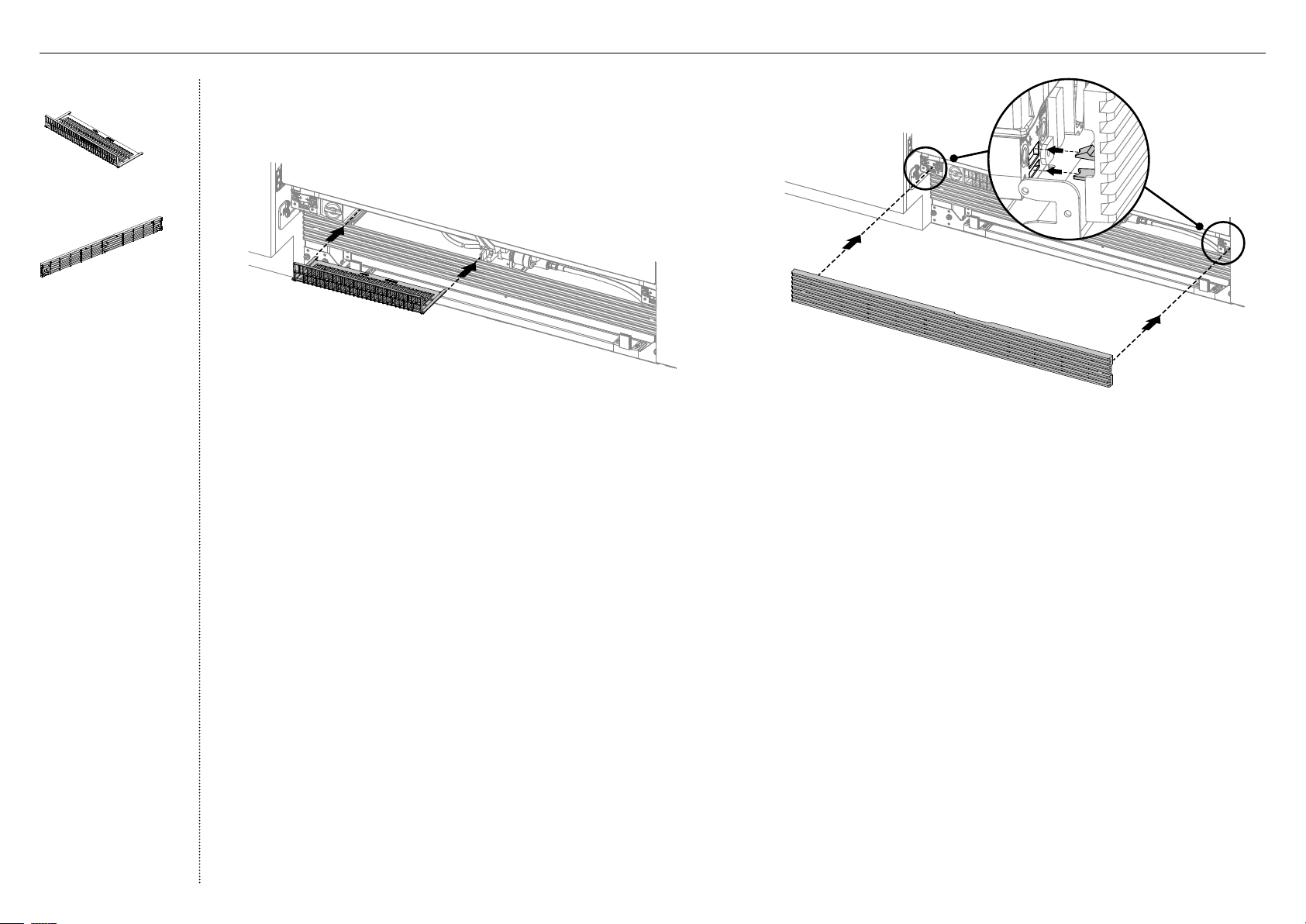
35
Install the top grille
2
Alignthe top grille clips to the top plinth slots. Ensure the top grille is
in the correct orientation (B).
3
Push the grille firmly onto the appliance until the clips engage (C).
B
C
Install the toe kick filter
1
Fit the filter onto the rails and push until it clips securely (A).
External box
Toe kick filter
(1)
Top grille
(1)
A
@3TOE KICK INSTALLATION
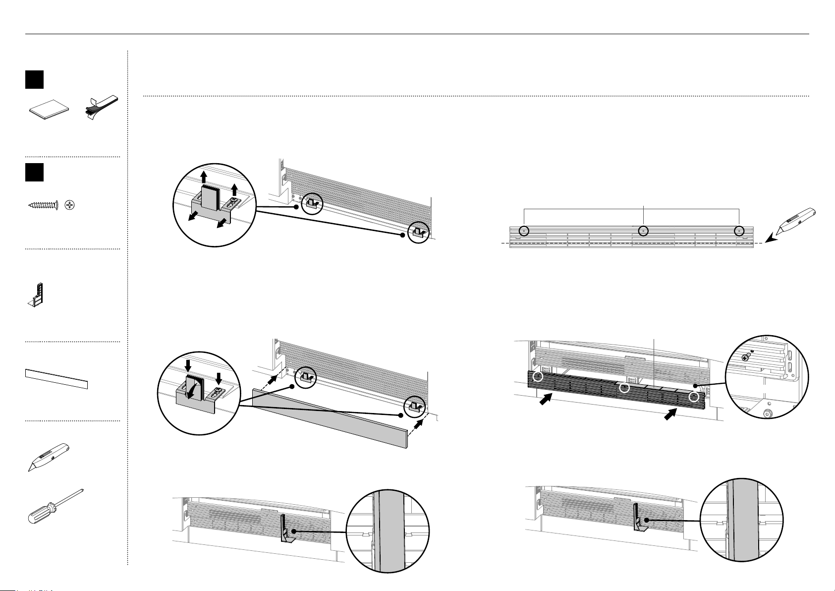
36
IMPORTANT!
The standard appliance includes a stainless steel toe kick 4 (102mm) and the components required to mount the toe kick.
Alternatively, the customer can supply their own custom toe kick 4–6 (102–152mm) for complete integration of the appliance.
For custom toe kick greater than 4" (102mm)
5
Remove the bottom grille from the bottom of the appliance.
6
Measure the required height for the bottom grille.
On a board, carefully score/cut theexcess vanes from
thebottom of the toe kick grille and discard (E).
7
Drill Ø 5/32 (4mm) holes into the dimples of the grille (F).
9
Align the air flow divider underneath the grille tabs
indicator and clip onto the vanes of the bottom grille (H).
For standard toe kick — 4" (102mm)
1
Loosen the toe kick bracket screws (A) mid-way, and move
the brackets forward (B).
4
Align the air flow divider underneath the grille tabs indicator
and clip onto the vanes of the bottom grille (D).
A
B
C
DETAIL A
SCALE 1 : 1
DETAIL D
SCALE 2 : 1
IF TOEKICK IS HIGHER THAN 4" USE SIDE CUTTER TO
1.
CUT UNREQUIRED VANES FROM DOTTOM
DRILL HOLES THROUGH DIMPLES
2.
USE PROVIDED SCREWS TO FIX GRILL TO
3.
MATCHING HOLES ON PLASTIC PARTS
DETAIL A
SCALE 1 : 1
DETAIL D
SCALE 2 : 1
IF TOEKICK IS HIGHER THAN 4" USE SIDE CUTTER TO
1.
CUT UNREQUIRED VANES FROM DOTTOM
DRILL HOLES THROUGH DIMPLES
2.
USE PROVIDED SCREWS TO FIX GRILL TO
3.
MATCHING HOLES ON PLASTIC PARTS
D
DETAIL A
SCALE 1 : 1
DETAIL D
SCALE 2 : 1
IF TOEKICK IS HIGHER THAN 4" USE SIDE CUTTER TO
1.
CUT UNREQUIRED VANES FROM DOTTOM
DRILL HOLES THROUGH DIMPLES
2.
USE PROVIDED SCREWS TO FIX GRILL TO
3.
MATCHING HOLES ON PLASTIC PARTS
DETAIL A
SCALE 1 : 1
DETAIL D
SCALE 2 : 1
IF TOEKICK IS HIGHER THAN 4" USE SIDE CUTTER TO
1.
CUT UNREQUIRED VANES FROM DOTTOM
DRILL HOLES THROUGH DIMPLES
2.
USE PROVIDED SCREWS TO FIX GRILL TO
3.
MATCHING HOLES ON PLASTIC PARTS
H
8
With the grille tabs facing upwards, align the grille to
the bottom of the plinth where the screw holes are
located and secure with #8x16 pan head screws (G).
DETAIL A
SCALE 1 : 1
DETAIL D
SCALE 2 : 1
IF TOEKICK IS HIGHER THAN 4" USE SIDE CUTTER TO
1.
CUT UNREQUIRED VANES FROM DOTTOM
DRILL HOLES THROUGH DIMPLES
2.
USE PROVIDED SCREWS TO FIX GRILL TO
3.
MATCHING HOLES ON PLASTIC PARTS
Grille tabs
DETAIL B
SCALE 2 : 5
G
Front right view
DETAIL A
SCALE 1 : 1
DETAIL D
SCALE 2 : 1
IF TOEKICK IS HIGHER THAN 4" USE SIDE CUTTER TO
1.
CUT UNREQUIRED VANES FROM DOTTOM
DRILL HOLES THROUGH DIMPLES
2.
USE PROVIDED SCREWS TO FIX GRILL TO
3.
MATCHING HOLES ON PLASTIC PARTS
E
Cut excess vanes from the bottom of the grille
F
2
Pre-align the toe kick by placing in front of the brackets until flush
with surrounding cabinetry. Once satisfied with the alignment,
set the toe kick aside and tighten the bracket screws to lock the
brackets in position.
3
Peel off the adhesive backing from one side of dual adhesive tabs
and attach to the brackets. Peel off the adhesive backing from the
other side of dual adhesive tabs and attach the toe kick (C).
Internal box
E
Door/drawer
trim install kit
Dual adhesive tabs
(2)
Z
Miscellaneous
components
#8 x 5/8
Pan Head
Philips Screw
#8 x 5/8
Pan Head
Philips Screw
#8x16 panhead screw (3)
Miscellaneous
itemspack
Air flow divider
(1)
External box
Toe kick
(1)
Tools
Cutter
Cross-head screwdriver
@3TOE KICK INSTALLATION
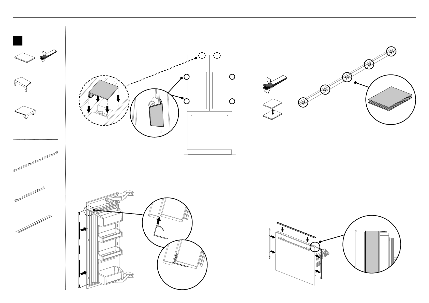
37
Attach the door side trims
3
Install the side trims by inserting into the panel gaps on each side of the
door(s) (C). Align the trim to the top of the door and press evenly into the
panel gap until fully seated (D).
Attach the covers
1
If applicable, remove any remaining protective
film on your door panels.
2
Open both doors. Attach the top covers (A)
firmly over the top studs, and the side covers
(B) to the side brackets.
A
B
F
Attach the drawer top and side trims
4
Peel off two dual adhesive tabs and press them
together to form a pair (E). Remove the adhesive
backing on one side only.
5
Press firmly to the underside of the drawer top trim
inthe indicated locations (F).
4
Remove the remaining adhesive backing from thedual adhesive tabs.
5
Locate the trim against the back surface of the panel and press down
firmly. Ensure the trim is fully seated against the drawer surface (G).
6
Install the side trims by inserting into the panel gaps on each side of the
door(s) (H).
– Make sure the cabinet is centered to prevent the side trims from
interfering with the cabinet.
G
H
Internal box
C
Door/drawer
trim install kit
Dual adhesive tabs
(10)
Side cover
(4)
Top cover
(2)
External box
Door side trim
(2)
Drawer side trim
(2)
Drawer top trim
(1)
@4DOOR AND DOOR TRIMS INSTALLATION
D
C
E
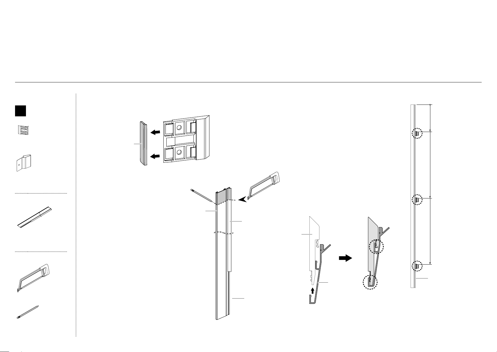
38
@5CABINET TRIMS INSTALLATION—[A] FLEXIBLE SPRING CLIP METHOD
4
Place 3 side trim brackets onto
eachside trim.
Note: Measure from the top of the
trim, with the short lip at the bottom.
Refer to (B) for 80" and 84" bracket
locations and trim orientation.
IMPORTANT!
Each bracket has two engagement
points for the side trim to locate.
Ensure the trim is engaged in both
points (C).
Repeat for all side trims.
80 = 9" (229mm)
84 = 13" (330mm)
80 = 36" (914mm)
84 = 40" (1016mm)
80 = 65" (1651mm)
84 = 69" (1753mm)
0
B
1
Break off the datum lip to each side trim bracket and discard.
Repeat for all side trim brackets.
Discard
Top view of side trim engaged
correctly in side trim bracket
C
Side trim
bracket
Side trim
TWO METHODS ARE AVAILABLE FOR ATTACHING CABINET SIDE TRIMS:
[A] FLEXIBLE SPRING CLIP METHOD — RECOMMENDED METHOD
[B] FIXED SCREW METHOD — METHOD TO USE IF CABINET IS NOT TO SPECIFICATION
(Attempt method [A]. If method [A] results in poor fitment of side trims due to cabinetry that is uneven or out of specification, use method [B]).
For 80 (2032mm) cavity installation only
2
Measure 4" (102mm) from the top of
theside trim with a square ruler and mark
acutting line (A).
3
Cut along the line using a fine tooth
hacksaw to a length of 76" (1930mm) (B).
IMPORTANT!
Ensure the cut is straight and square
asthis is an exposed surface.
Ensure the plastic part does not bend
asthis can causevisual stressmarks.
Repeat for all sidetrims.
short lip
short lip
A
Plastic
Aluminum
B
Internal box
D
Cabinet side
trim install kit
Side trim bracket
(6)
Spring clip
(6)
External box
Cabinet side trim
(2)
Tools
Hacksaw
Pencil
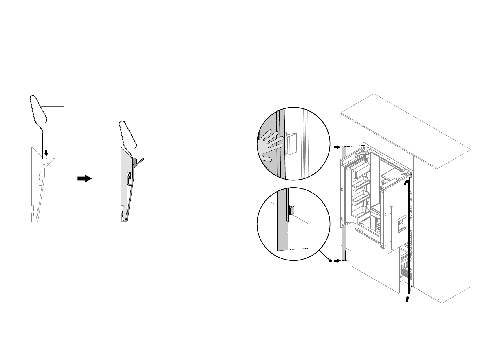
39
G
F
@5CABINET TRIMS INSTALLATION—[A] FLEXIBLE SPRING CLIP METHOD
5
Insert the spring clip into the gap between the side trim and side trim bracket,
orientation as shown in figures (D) and (E).
IMPORTANT!
Ensure spring clip is correctly oriented with the open loop facing the side
trimlip.
Repeat for all side trims.
6
Open the French doors. Place the assembled side trim with brackets and spring
clips against the alcove side wall with the shorter lip facing the bottom (F).
IMPORTANT!
Ensure the side trim is positioned as high as it will go.
Push the side trim at each bracket location until there are no visible gaps
between the trim and cabinetry (G).
Repeat for all side trims.
Spring clip
Side trim lip
D
Top view of spring clip correctly inserted
between side trim and side trim bracket
E
short lip
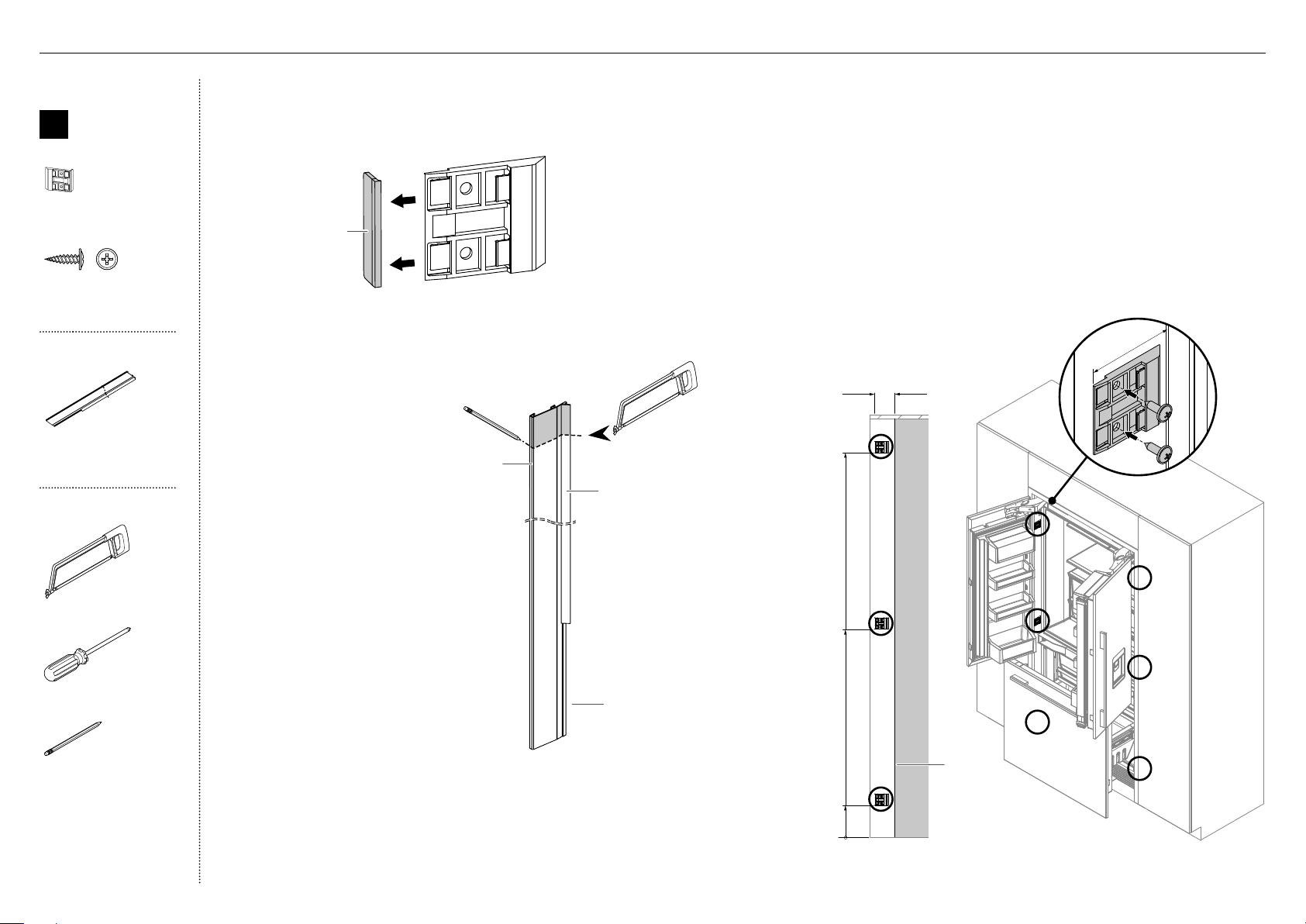
40
0
Front of
cabinet
C
~ 10" (254mm)
~ 40" (1016mm)
~ 69" (1753mm)
2" (50mm)
2" (50mm)
D
4
Position three side trim brackets on one side trim.
Refer to (B) for bracket locations.
5
Open the French doors. Measure 2" (50mm) from the front
of cabinet (from behind the doors), to the front of the alcove
and accurately mark a vertical line (C).
6
Align the bracket edge with the marked line and fix the
bracket to the cabinetry with #8x16 mush washer screws (D).
Repeat on the opposite side.
IMPORTANT!
Inaccurate positioning of bracket can result in inability to
fit side trim or gaps between side trim and refrigerator.
B
1
Break off the datum lip to each side trim bracket and discard.
Repeat for all side trim brackets.
Discard
For 80" (2032mm) cavity
installationonly
2
Measure 4" (102mm) from the top
ofthe side trim with a square ruler
and mark a cutting line (A).
3
Cut along the line using a fine
tooth hacksaw to a length of
76"(1930mm) (B).
IMPORTANT!
Ensure the cut is straight and square
as this is an exposed surface.
Ensure the plastic part does not
bend as this can causevisual
stressmarks.
Repeat for the remaining sidetrim.
A
Plastic
Aluminum
B
short lip
Internal box
D
Cabinet side
trim install kit
Side trim bracket
(6)
#8 x 16
Mush Washer
Twin Thread
Philips Screw
#8 x 16
Mush Washer
Twin Thread
Philips Screw
#8x16 mush washer screw
(12)
External box
Cabinet side trim
(2)
Tools
Hacksaw
Cross-head screwdriver
Pencil
@6CABINET TRIMS INSTALLATION—[B] FIXED SCREW METHOD
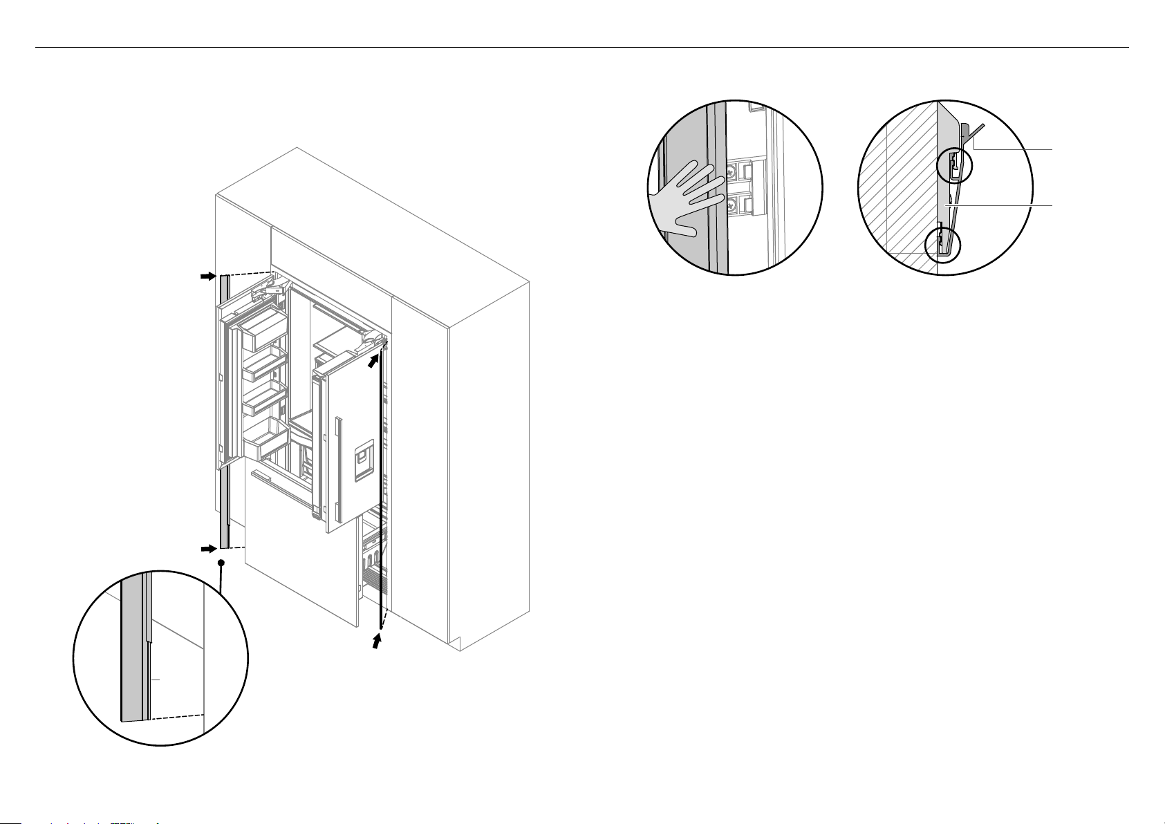
41
@6CABINET TRIMS INSTALLATION—[B] FIXED SCREW METHOD
7
Place the side trim against the alcove side wall with the shorter lip facing
the bottom (E).
– Ensure the side trim is positioned as high as it will go.
E
8
Engage the side trim with the brackets by pushing the trim inwards
atthe locations of the top and middle side trim brackets.
9
Once the trim has engaged with top and middle brackets, push
andengage the side trim at the location of the bottom bracket (F).
Repeat for the remaining side trims.
IMPORTANT!
Each bracket has two engagement points for the trim to locate.
Ensurethe trim is engaged at both points (G).
Ensure there are no visual gaps between the appliance and side trims.
Adjust the gaps by loosening the side trim screws and moving the
trimwithin clearance. Iffurther adjustment is required, relocate
brackets to desired position.
F
Suggestion by Derek showing
engagement in 2 places
“ensure they are fully engaged”
Side trim
bracket
G
Top view of side trim engaged
correctly in side trim bracket
Side trim
short lip

42
Complete and keep for safe reference:
Model ____________________________________________________________
Serial No. ____________________________________________________________
Purchase Date ____________________________________________________________
Purchaser ____________________________________________________________
Dealer Address ____________________________________________________________
Installer’s Name ____________________________________________________________
Installer’s Signature ____________________________________________________________
Installation Company ____________________________________________________________
Installation Date ____________________________________________________________
TO BE COMPLETED BY THE INSTALLER
All models
Ensure all internal and external packaging is removed from the
appliance before use.
Check all parts are installed.
Ensure the appliance is level.
Ensure the appliance is securely fastened to the cabinetry with the
supplied anti-tip bracket and fittings.
Ensure the doors/drawer can open and close freely with no
resistance from surrounding cabinetry.
Ensure hinge limiting pin is fitted for 90° door swing.
Ice and Water models only
Ensure the water filtration system has been flushed.
Ensure a manual ice maker cycle has been forced.
@7FINAL CHECKLIST
FISHERPAYKEL.COM
© Fisher & Paykel Appliances 2019. All rights reserved.
The appliance specifications in this booklet document to the specific
appliances and models described at the date of issue. Under our policy
of continuous appliance improvement, these specifications may change
at any time. You should therefore check with your Dealer to ensure this
booklet correctly describes the appliance currently available.

RÉFRIGÉRATEUR-CONGÉLATEUR ENCASTRABLE
ACTIVESMART™ À PORTES FRANÇAISES
Modèles RS6A80
GUIDE D’INSTALLATION
US CA
84418B06.19


1
IMPORTANT!
CONSERVEZ CES INSTRUCTIONS
Les modèles illustrés dans ce guide d’installation peuvent ne pas être disponibles dans tous les pays et sont sujets à modifications sans préavis. Pour les plus récentes informations sur la
disponibilité des modèles et des caractéristiques dans votre pays, visitez notre site Web fisherpaykel.com ou contactez votre détaillant Fisher&Paykel local.
TABLE DES MATIÈRES
@7
LISTE DE VÉRIFICATION
OR
@6
INSTALLATION DES GARNITURESDE BÂTI
—[B] MÉTHODE AVEC VIS FIXÉE
@0
INSTALLATIONDE PANNEAU DE PORTE—SUR MESURE
@5
INSTALLATION DES GARNITURESDE BÂTI
—[A] MÉTHODE AVEC CLIP DE FIXATION FLEXIBLE
!9
INSTALLATIONDE PANNEAU DE PORTE—EN ACIER INOXYDABLE
OR
1
CONSIGNES DE SÉCURITÉ ET MISES EN GARDE
2
PIÈCES
3
OUTILS
4
DIMENSIONS DE L’APPAREIL ET DE LA CAVITÉ
5
OPTIONS D’ARMOIRES
6
DIMENSIONS DE PANNEAU DE PORTE ET DE PLINTHE EN ACIER
INOXYDABLE
7
DIMENSIONS DE PANNEAU DE PORTE ET DE PLINTHE SUR MESURE
8
DIMENSIONS D’INSTALLATION DE PANNEAU DE PORTE SUR MESURE
9
GABARIT D'INSTALLATION DE PANNEAU DE PORTE SUR MESURE
!0
DÉGAGEMENT DE LA PORTE
!1
Raccordement électrique et plomberie
!2
AVANT L’INSTALLATION
!3
PRÉPARATION DE LA CAVITÉ
!4
ALIMENTATION EN EAU ET ALIMENTATION ÉLECTRIQUE
!5
INSTALLATION DE LA GARNITURE SUPÉRIEURE
!7
POSITIONNEMENT DANS LES ARMOIRES
!8
ALIGNEMENT DANS LES ARMOIRES
@1
Fixation aux armoires
@2
INSTALLATION DU FILTRE À EAU
@3
INSTALLATION DE LA PLINTHE
@4
INSTALLATION DES GARNITURES DE PORTE ET TIROIR
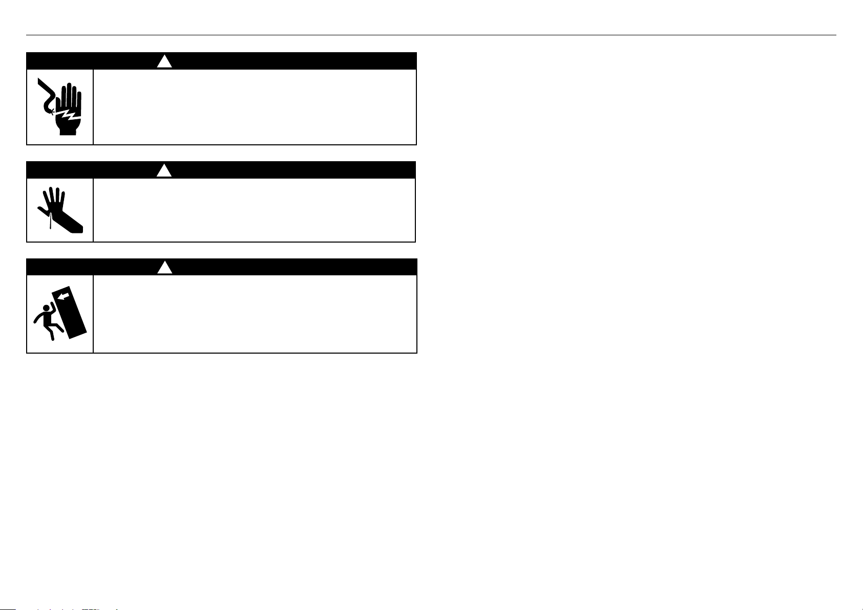
2
1CONSIGNES DE SÉCURITÉ ET MISES EN GARDE
IMPORTANT!
Il est très important que l’installateur suive les instructions de ce guide d’installation
pour assurer l’installation et le fonctionnement convenables du produit. Assurez-vous de
lire attentivement le guide d’installation et de bien comprendre toutes les informations.
Le raccordement de la conduite d’eau à votre produit Glaçons et eau doit être
effectué par un plombier autorisé ou un technicien de service formé et supporté par
Fisher&Paykel, conformément à toutes les réglementations provinciales etlocales.
L’installation et l’utilisation DOIVENT être conformes à tous les codes de plomberie
provinciaux et locaux. Communiquez avec votre service local de travaux publics pour
prendre connaissance des codes de plomberie.
Vous devez vous conformer à ces directives lors de l’installation du système de
filtrationd’eau.
Pour éviter des maladies graves, voire mortelles, raccordez uniquement votre filtre à
unealimentation en eau potable.
La cartouche de filtre à eau doit être remplacée lorsque l’icône de remplacement de
filtre s’allume. Cela se produira tous les 6mois.
Si le système de filtration d’eau gèle, remplacez le filtre. Le fait de ne pas remplacer
lefiltre jetable aux intervalles recommandés pourrait compromettre le rendement du
filtre et causer une défaillance, entraînant des dommages matériels provoqués par des
fuites d’eau ou inondations.
Si vous constatez que le filtre se bouche très rapidement—nous vous recommandons de
consulter un plombier ou de contacter les responsables de votre réseau de distribution
d’eau pour obtenir des conseils sur la filtration de l’eau provenant du réseau.
Le remplacement du filtre est effectué sous l’entière responsabilité du client et n’est pas
couvert par la garantie, sauf si des pièces ou matériaux du filtre s’avéraient défectueux.
Si l’eau n’a pas été utilisée pour produire des glaçons pendant un certain temps ou
silesglaçons présentent un goût ou une odeur désagréable, jetez les glaçons et
reportez-vous aux instructions de rinçage indiquées dans la section d’installation de
ce guide d’utilisation/guide d’installation. Si le goût ou l’odeur persiste, vous pouvez
remplacer le filtre.
Utilisez le tuyau neuf fourni avec le produit. NE réutilisez PAS d’anciens tuyaux ayant
servi pour d’anciens raccordements de distribution d’eau et de glaçons.
Votre système de filtration d’eau peut résister à une pression d’eau maximale de 120psi
(827kPa). Assurez-vous d’installer le réducteur de pression fourni avant l’installation
du système de filtration d’eau. N’installez PAS ce filtre si la pression de l’eau dépasse
120psi (827kPa).
Pour réduire les risques associés aux dommages matériels provoqués par des fuites
d’eau ou inondations:
N’installez PAS les systèmes dans les endroits où les températures ambiantes peuvent
dépasser 100°F (38°C) ou descendre en dessous de 33°F (0,6°C).
N’installez PAS le filtre sur des conduites d’alimentation en eau chaude. La température
maximale de l’eau pour l’utilisation de ce système de filtration est de 100°F (38°C).
N’installez PAS le filtre à un endroit où des coups de bélier peuvent survenir.
Enprésence de coups de bélier, vous devez installer un dispositif antibélier.
MISE EN GARDE!
Pour réduire les risques de suffocation:
NE permettez PAS aux enfants de moins de 3ans d’accéder aux petites pièces pendant
l’installation du filtre à eau.
!
MISE EN GARDE!
Risque de choc électrique
Lisez et observez les consignes de sécurité et mises en garde contenues
dans ce guide d’installation avant d’utiliser ce produit.
Le fait de ne pas respecter ces consignes peut causer la mort, un choc
électrique, un incendie ou des blessures.
!
MISE EN GARDE!
Risque de coupure
Attention—les bords du panneau sont tranchants. Des blessures ou des
coupures peuvent survenir si vous ne faites pas preuve de prudence.
!
MISE EN GARDE!
Comme ce produit est lourd du haut, vous devez le fixer pour éviter qu’il
ne bascule vers l’avant.
Pour assurer la stabilité du produit dans toutes les conditions
d’utilisation, le support antibasculement et les raccords fournis doivent
être installés par un installateur professionnel, conformément aux
instructions d’installation suivantes.
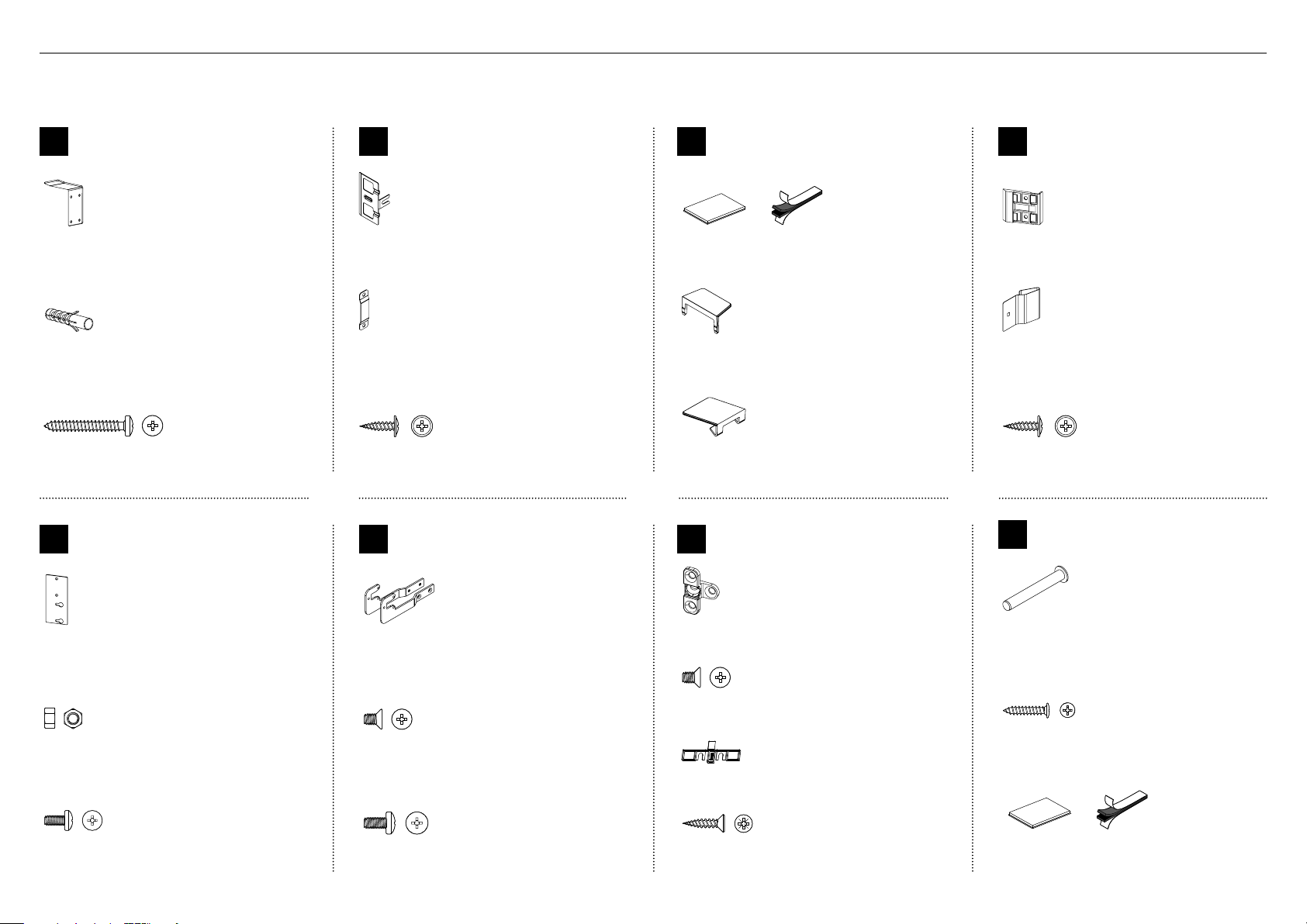
3
2PIÈCES
Boîte interne (Ensemble d’installation)
À l’intérieur de l’appareil
E
Ensemble d’installation
de garniture supérieure
Support de garniture supérieure de bâti
(2)
M5 Nut
M5 Nut
Écrou M5
(4)
M5 x 10
Pan Head
Philips Screw
M5 x 10
Pan Head
Philips Screw
Vis cruciforme M5x8
(4)
G
Ensemble d’installation
de support de fixation
Support de fixation
(4)
M5 x 8
Countersunk
Philips Screw
M5 x 8
Countersunk
Philips Screw
Vis cruciforme à tête fraisée M5x8
(8)
Cache-vis
(4)
#8 x 19
Countersunk
Twin Thread
Posi Screw
#8 x 19
Countersunk
Twin Thread
Posi Screw
Vis à double filetage n°8x19
(8)
F
Ensemble d’installation
de support latéral
Supports de base latéraux (gauche/droit)
(2)
M5 x 8
Countersunk
Philips Screw
M5 x 8
Countersunk
Philips Screw
Vis cruciforme à tête fraisée M5x8
(4)
M5 x 10
Pan Head
Philips Screw
M5 x 10
Pan Head
Philips Screw
Vis cruciforme M5x10
(10)
A
Ensemble d’assemblage de
support antibasculement
Support antibasculement
(1)
Cheville pour maçonnerie
(4)
#10x40
Pan Head
Philips Screw
#10x40
Pan Head
Philips Screw
Vis cruciforme n°10x40
(4)
B
Ensemble de fixation de
panneau de porte
Support latéral
(10)
Bande latérale
(10)
#8 x 16
Mush Washer
Twin Thread
Philips Screw
#8 x 16
Mush Washer
Twin Thread
Philips Screw
Vis rondelle n°8x16 (Sur mesure)
(36)
C
Ensemble d’installation de
garniture de porte/tiroir
Languettes adhésives double face
(6 pour chaque bande) (12)
Couvercle latéral
(4)
Couvercle supérieur
(2)
D
Ensemble d’installation de
garniture latérale de bâti
Support de garniture latérale
(6)
Clip de fixation
(6)
#8 x 16
Mush Washer
Twin Thread
Philips Screw
#8 x 16
Mush Washer
Twin Thread
Philips Screw
Vis rondelle n°8x16
(12)
Z
Miscellaneous
components
Tige de limitation de charnière
(1)
#8 x 5/8
Pan Head
Philips Screw
#8 x 5/8
Pan Head
Philips Screw
Vis à tête cylindrique n°8x16
(3)
Languettes adhésives double face
(6)
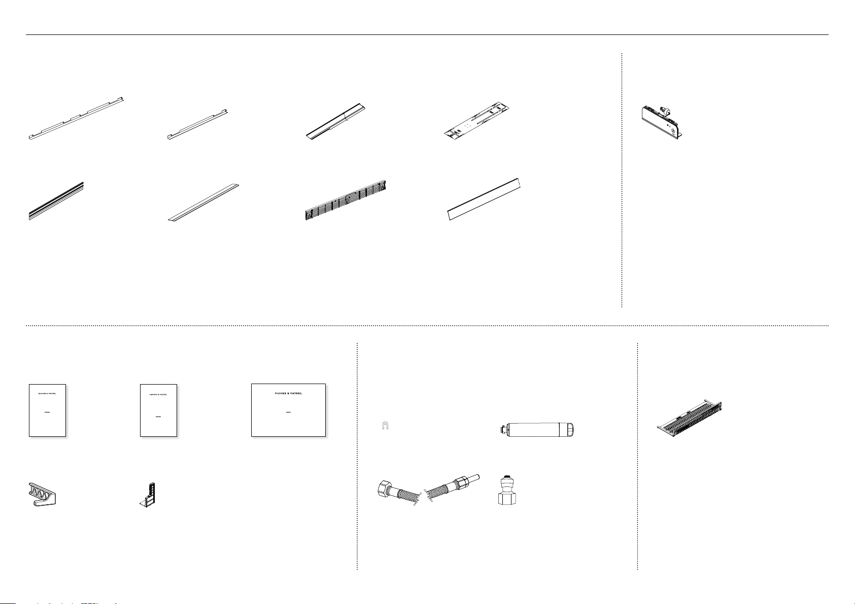
4
2PIÈCES
Boîte externe
À l’intérieur de l’appareil
Garniture latérale de porte
(2)
Garniture latérale de tiroir
(2)
Garniture latérale de bâti
(2)
Gabarit double face de panneau de porte
(1)
Garniture supérieure
(1)
Garniture supérieure de tiroir
(1)
Grille du haut
(1)
Plinthe
(1)
Afficheur Glaçons et eau
(Modèles Glaçons et eau uniquement)
À l’intérieur de l’appareil
Module d’affichage externe
(1)
Filtre de plinthe
À l’intérieur de l’appareil
Filtre de plinthe
(1)
Emballage d’articles divers
À l’intérieur de l’appareil
USER GUIDE
NZ AU GB IE HK SG IN US
ACTIVESMART™
INTEGRATED REFRIGERATOR
RS90A, RS9120W,
RS36A72, RS36A80 & RS36W80 models
SERVICE & WARRANTY
SERVICE ET GARANTIE
ΣΈΡΒΙΣ ΚΑΙ ΕΓΓΎΗΣΗ
SERVIZIO E GARANZIA
SERVICE & GARANTIE
HUOLTO JA TAKUU
SERVICE OG GARANTI
保修和维修
服務和保修
ACTIVESMART™ INTEGRATED
SINGLE DOOR / DRAWER REFRIGERATOR
RS36W80 models
INSTALLATION GUIDE
US CA
844189D 02.19
Guide d’utilisation
(1)
Service et garantie
(1)
Guide d’installation
(1)
Outil de cartouche filtrante
(1)
Diviseur de débit d’air
(1)
Ensemble de raccords d’alimentation en eau
À l’intérieur de l’appareil
Clip de blocage de collet
(1)
Filtre à eau
(1)
1/4po (6mm) Tuyau tressé en
acier inoxydable avec adaptateur
(1)
adaptateur de tube
(1)

5
Ensemble de panneau de porte
Non fourni; vendu séparément
Ensemble de panneau de porte en acier inoxydable (Fisher&Paykel):
Comprend 2x panneaux de portes françaises et 1x panneau de tiroir.
Ensemble de panneau de porte sur mesure:
Fourni par le client, adapté aux armoires.
Convient aux modèles Glaçons uniquement.
Ensemble de panneau de porte pour modèles
Glaçons uniquement
(RD3680 / RD3684)
Ensemble de panneau de porte pour modèles
Glaçons et eau
(RD3680U / RD3684U)
M5 x 14
Mush Head
SS
Philips Screw
M5 x 14
Mush Head
SS
Philips Screw
M5 x 14
Mush Head
SS
Philips Screw
M5 x 14
Mush Head
SS
Philips Screw
Vis rondelle cruciforme M5x14
(acier inoxydable) (34)
Vis rondelle cruciforme M5x14
(acier inoxydable) (34)
Ensemble de poignée de porte
Non fourni; vendu séparément. Sélectionnez l’une des options ci-dessous:
Poignée de porte arrondie
de style professionnel (3x)
Poignée de porte carrée
de style professionnel (3x)
Poignée de porte arrondie
de style contemporain (3x)
Poignée de porte carrée
de style contemporain (3x)
M5 x 25
Pan Head
Socket Screw
M5 x 25
Pan Head
Socket Screw
M5 x 25
Pan Head
Socket Screw
M5 x 25
Pan Head
Socket Screw
M5 x 25
Pan Head
Socket Screw
M5 x 25
Pan Head
Socket Screw
M5 x 25
Pan Head
Socket Screw
M5 x 25
Pan Head
Socket Screw
Vis à tête creuse cylindrique
M5x25 (12x)
Vis à tête creuse cylindrique
M5x25 (12x)
Vis à tête creuse cylindrique
M5x25 (12x)
Vis à tête creuse cylindrique
M5x25 (12x)
Outils fournis
Compris dans la boîte interne
Clé FPA
(1)
Clé hexagonale
(1)
Outils requis
Non compris avec le produit
Visseuse électrique Tournevis à pointe plate
Scie à métaux Tournevis cruciforme
Couteau à lame rétractable Ruban à mesurer
Règle Crayon
2PIÈCES 3OUTILS
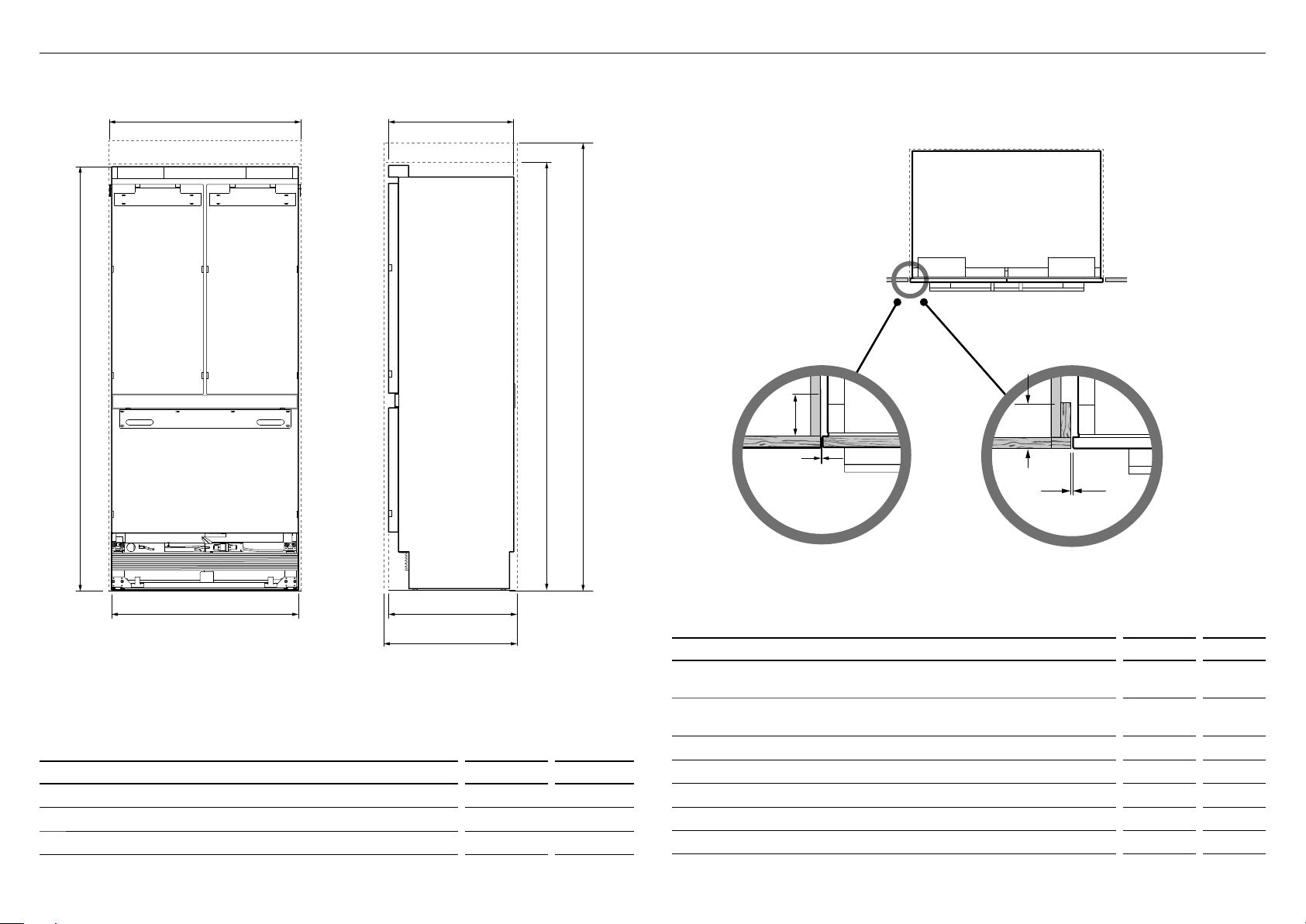
6
4DIMENSIONS DE L’APPAREIL ET DE LA CAVITÉ
DIMENSIONS DE L’APPAREIL po mm
A
Hauteur hors tout de l’appareil* 7913/16 2028
B
Largeur hors tout de l’appareil 3511/16 906
c
Profondeur hors tout de l’appareil (sans les panneaux de portes) 233/4 603
*
Comprenant les pattes installées
DIMENSIONS DE LA CAVITÉ po mm
D
Hauteur hors tout de la cavité (pour appareil avec ensemble de panneau
de porte RD3680)
80 2032
e
Hauteur hors tout de la cavité (pour appareil avec ensemble de panneau
de porte RD3684)
84 2134
f
Largeur hors tout de la cavité 36 914
g
Profondeur hors tout de la cavité (pour installation encastrée) 25 635
h
Profondeur hors tout de la cavité (pour installation superposée) 243/4 629
i
Dégagement minimal des armoires à partir du bord de l’appareil 3/16 4
j
Finition minimale requise min. 31/2 89
Au même niveau que le
devant des armoires
VUE EN PLAN
VUE DE FACE VUE DE CÔTÉ
IMPORTANT!
Pour faciliter l’installation, assurez-vous que la largeur et la hauteur de
la cavité soient uniformes du haut vers le bas et de gauche à droite.
b
A
f
g
h
d
c
e
Avec montant: Finition dans le
haut et sur les côtés
J
I
J
I
Sans montant: Finition dans le
haut et sur les côtés
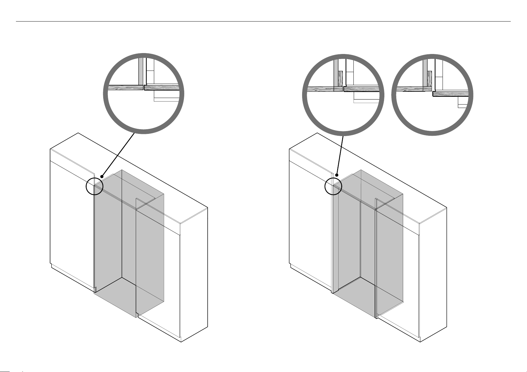
7
ARMOIRES SANS MONTANT
(Alignement du produit avec les armoires)
Installation
superposée
Installation
encastrée
ARMOIRES AVEC MONTANT
(Alignement du produit avec le montant des armoires)
5OPTIONS D’ARMOIRES
Remarque: Les illustrations sont fournies uniquement à titre de référence et ne représentent pas la largeur de cavité réelle.
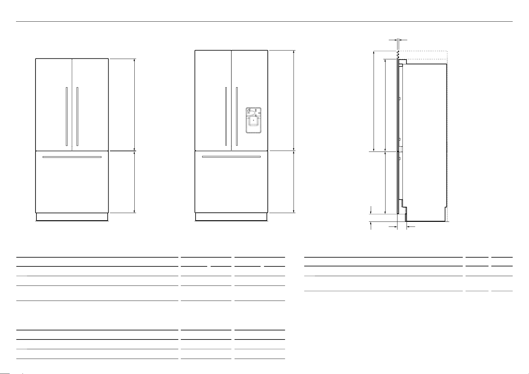
8
b
a
DIMENSIONS DE PANNEAU DE PLINTHE po mm
d
Hauteur du panneau de plinthe 4 102
e
Profondeur de la plinthe (mesurée à partir du devant des
panneaux de portes)
43/4 120
Remarque:
Une plinthe en acier inoxydable d’une hauteur de 4po (102mm) est fournie avec le produit.
Les clients doivent fournir leur propre plinthe sur mesure, d’une hauteur de 4 à 6po (102 à 152mm).
Pour une plinthe dont la hauteur est supérieure à 4po, raccourcissez la grille inférieure en conséquence.
Reportez-vous à ‘Installation de la plinthe’ pour plus d’informations.
b
a
ENSEMBLE DE PANNEAU DE PORTE
RD3680
ENSEMBLE DE PANNEAU DE PORTE
RD3684U
b
a
d
e
c
RD3680/RD3680U RD3684/RD3684U
DIMENSIONS DES ENSEMBLES DE PANNEAUX DE PORTES po mm po mm
a
Hauteur des panneaux de portes supérieurs 451/4 1150 495/16 1252
b
Hauteur du panneau de tiroir inférieur 303/8 772 303/8 772
c
Profondeur des panneaux avant du produit
(excluant les poignées)
3/4 19 3/4 19
Remarque:
Les panneaux de portes en acier inoxydable Fisher&Paykel ne sont pas fournis et doivent être achetés séparément.
N° de modèle RD3680 / RD3684 (modèle Glaçons uniquement) et n° de modèle RD3680U / RD3684U (modèle Glaçons et eau).
POIDS DU PANNEAU DE PORTE lb kg
Poids maximal du panneau de porte supérieur
(avec poignée) 22 10
Poids maximal du panneau de tiroir
(avec poignée) 241/4 11
6DIMENSIONS DE PANNEAU DE PORTE ET DE PLINTHE EN ACIER INOXYDABLE
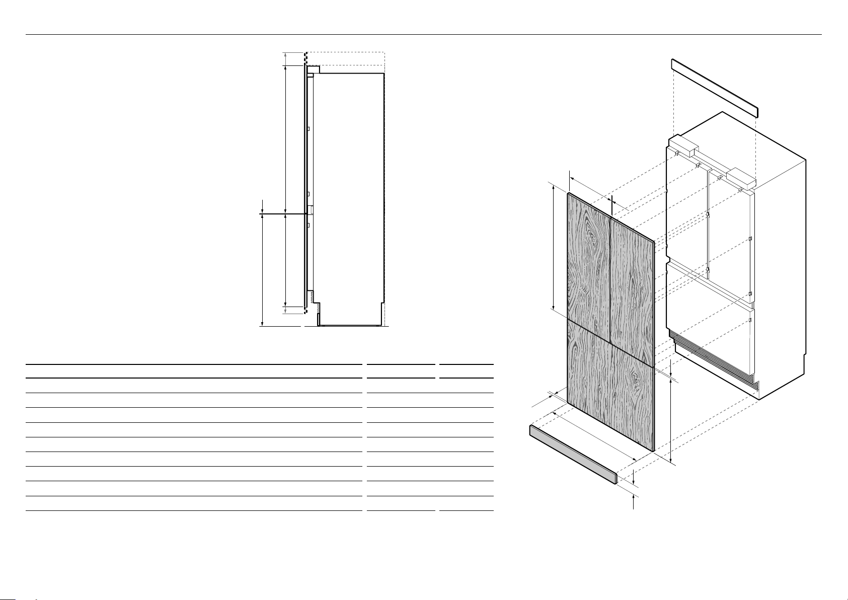
9
H
D
A
B
D
g
A
E
I
F
C
g
DIMENSIONS po mm
A
Hauteur du panneau de porte supérieur 451/4–495/16 1150–1252
B
Largeur du panneau de porte supérieur 73/4 451
C
Espace entre les panneaux de portes supérieurs 3/16 4
D
Hauteur du panneau de tiroir inférieur 287/16–303/8 722–772
E
Hauteur entre le bas du produit et le dessus du panneau de tiroir inférieur 347/16 874
F
Largeur du panneau de tiroir inférieur 3511/16 906
G
Espace entre les panneaux de portes supérieurs et le panneau de tiroir inférieur 3/16 4
H
Hauteur du panneau de plinthe 4–6 102–152
I
Profondeur des panneaux de portes sur mesure 5/8–3/4 16–19
Remarque:
Les panneaux de portes et la plinthe sur mesure doivent être fournis par le client.
La hauteur de la plinthe sur mesure doit être de 4à 6po (102à152mm), selon la hauteur du panneau de porte/tiroir.
Pour une plinthe dont la hauteur est supérieure à 4po, raccourcissez la grille inférieure en conséquence.
Reportez-vous à ‘Installation de la plinthe’ pour plus d’informations.
VUE DE BIAIS
Remarque: la garniture supérieure
est fournie pour l’installation
84po (2134mm)
H
D
A
B
D
g
A
E
I
F
C
g
VUE DE PROFIL
IMPORTANT!
Les panneaux de portes/tiroir sur mesure ne
conviennent qu’aux modèles Glaçons uniquement.
7DIMENSIONS DE PANNEAU DE PORTE ET DE PLINTHE SUR MESURE
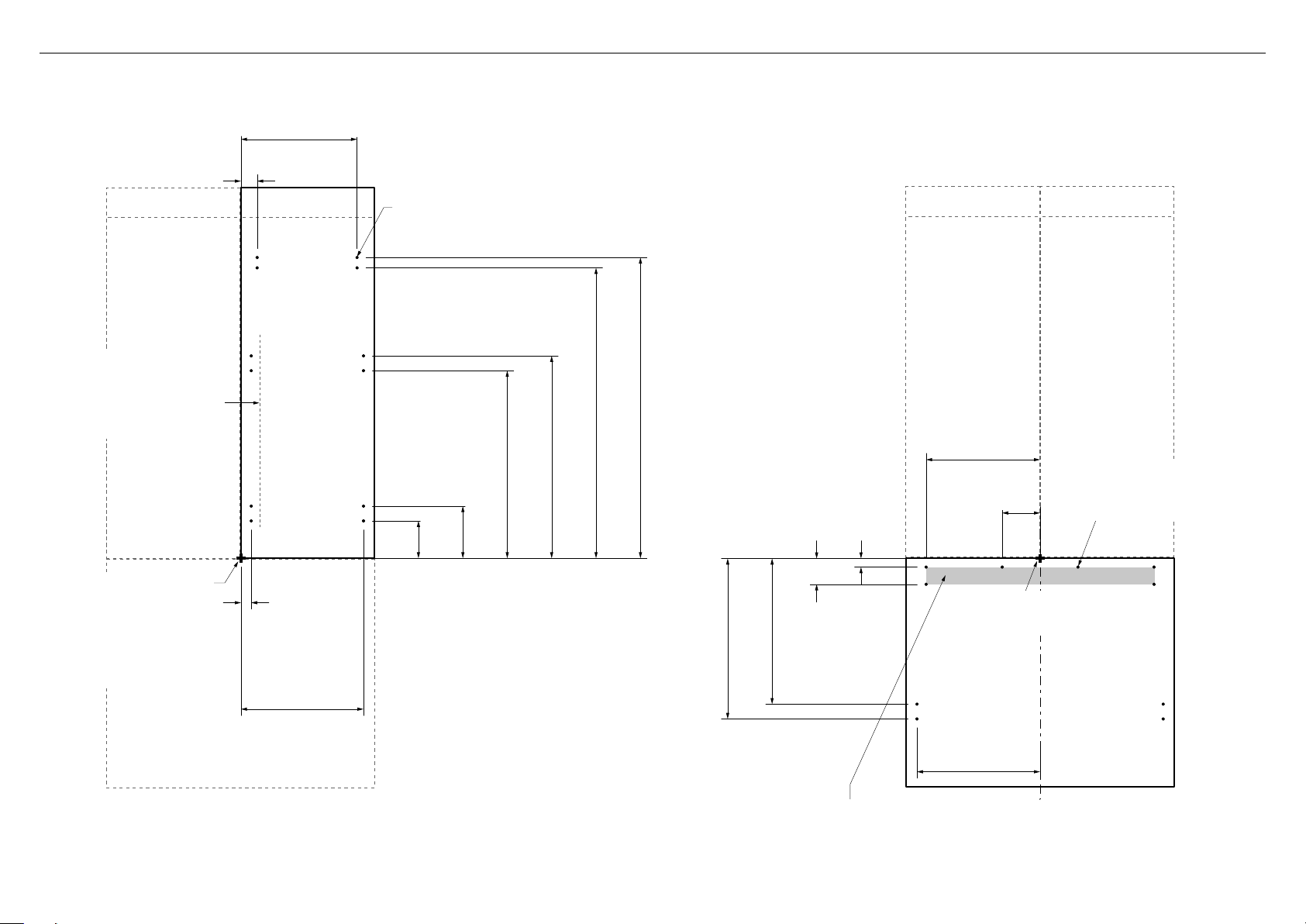
10
Toutes les mesures doivent
être effectuées à partir du
coin inférieur intérieur. Pour le
deuxième panneau, utilisez les
mêmes dimensions sur l’autre
côté, avec le coin inférieur
intérieur comme point de
référence.
Assurez-vous d’installer la
poignée avec une distance de
29/16po (65mm) entre le bord
intérieur du panneau et le centre,
afin d’éviter toute obstruction
avec les supports.
13/8po (35mm)
165/16po (415mm)
23/16po (56mm)
415/16po
(126mm)
615/16po
(177mm)
2415/16po (634mm)
2615/16po (685mm)
385/8po (982mm)
40po (1016mm)
Ø 3/32po (2mm) REF
12avant-trous recommandés pour la fixation des supports.
(Ne perforez pas la surface avant.)
157/16po (393mm)
PANNEAU SUPÉRIEUR—VUE ARRIÈRE
Ø 3/32po (2mm) REF
10avant-trous recommandés
pour la fixation des supports.
(Ne perforez pas la surface avant.)
153/16po (386mm)
51/16PO
(129mm)
11/8po
(29mm)
37/16po
(88mm)
193/8po (492mm)
215/16po (542mm)
16 3/8po (416mm)
Toutes les mesures doivent
être effectuées à partir du
dessus et de la ligne centrale.
PANNEAU INFÉRIEUR—VUE ARRIÈRE
Les ouvertures sont situées dans le support de fixation pour les poignées Fisher&Paykel
uniquement. Si vous devez positionner une poignée sur mesure dans la zone ombragée
ci-dessus, assurez-vous que les têtes de vis de la poignée soient renfoncées dans la partie
arrière du panneau pour éviter toute obstruction avec le support d’accrochage.
Les illustrations ci-dessous concernent les modèles Glaçons uniquement RS36A80J. Les dimensions sont indiquées pour la préparation et l’installation des panneaux de portes sur mesure.
Pour les fichiers Dwg et Dxf de la préparation de panneau ci-dessous, téléchargez le dossier sur thekitchentools.fisherpaykel.com.
8DIMENSIONS D’INSTALLATION DE PANNEAU DE PORTE SUR MESURE
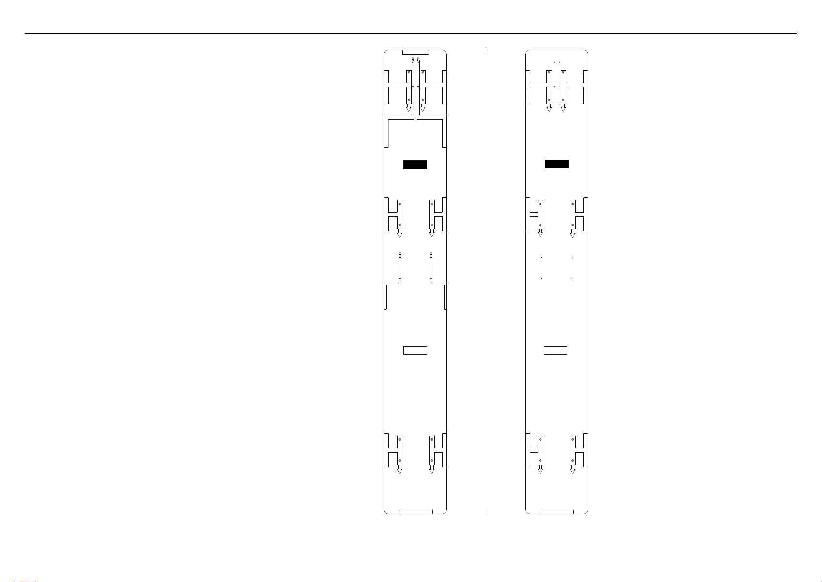
11
Ce gabarit est une feuille double face utilisée comme guide de perçage
des trous de vis pour l’installation de vos panneaux de portes et tiroir
sur mesure. Le gabarit est compris avec ce guide d’installation.
Reportez-vous à ‘Installationde panneau de porte—Sur mesure’
(page27) pour plus d’informations.
9GABARIT D'INSTALLATION DE PANNEAU DE PORTE SUR MESURE
DRAWER PANEL TOP EDGE
LH DOOR PANEL HINGE SIDE
LH DOOR PANEL HANDLE SIDEDRAWER PANEL HANDLE SIDE
DRAWER PANEL HINGE SIDE
LH DOOR PANEL HINGE SIDE
LH DOOR PANEL HANDLE SIDE
DRAWER PANEL HANDLE SIDE
DRAWER PANEL HINGE SIDE
TURN OVER FOR
RIGHT DOOR PANEL
LH DOOR PANEL HINGE SIDE
LH DOOR PANEL HANDLE SIDE
LH DOOR PANEL BOTTOM EDGE
RH DOOR PANEL HINGE SIDE
RH DOOR PANEL BOTTOM EDGE
RH DOOR PANEL HANDLE SIDE
RH DOOR PANEL HINGE SIDE
RH DOOR PANEL HANDLE SIDE
RH DOOR PANEL HANDLE SIDE
RH DOOR PANEL HINGE SIDE
DOOR PANEL
HANGING BRACKET HOLES
DOOR PANEL
HANGING BRACKET HOLES
DRAWER PANEL
HANGING BRACKET HOLES
DRAWER PANEL
HANGING BRACKET HOLES
LEFT DOOR
PANEL TEMPLATE
RIGHT DOOR
PANEL TEMPLATE
DOOR PANEL
SIDE BRACKET HOLES
DRAWER PANEL
SIDE BRACKET HOLES
DRAWER PANEL
SIDE BRACKET HOLES
DOOR PANEL
SIDE BRACKET HOLES
DOOR PANEL
SIDE BRACKET HOLES
DOOR PANEL
SIDE BRACKET HOLES
DOOR PANEL
SIDE BRACKET HOLES
DOOR PANEL
SIDE BRACKET HOLES
DOOR PANEL
HANGING BRACKET HOLES
DOOR PANEL
HANGING BRACKET HOLES
DOOR PANEL
SIDE BRACKET HOLES
DOOR PANEL
SIDE BRACKET HOLES
TURN OVER FOR
LEFT DOOR PANEL
CÔTÉ DU
PANNEAU DE
PORTE GAUCHE
CÔTÉ DU
PANNEAU DE
PORTE DROIT
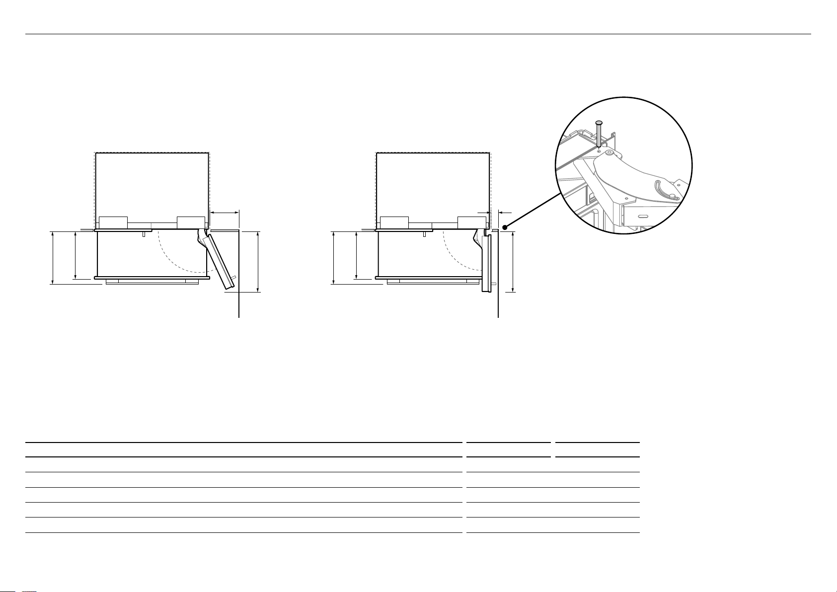
12
D
A
B
C
B
C
A
E
!0DÉGAGEMENT DE LA PORTE
Mur Mur
OUVERTURE DE LA PORTE À 90°OUVERTURE DE LA PORTE À 115°
(ACCÈS COMPLET À L’INTÉRIEUR)
DIMENSIONS po mm
A
Profondeur de la porte (ouverture maximale) mesurée à partir du devant de la porte 187/8 480
B
Profondeur du tiroir (ouvert) mesurée à partir du devant du tiroir, incluant la poignée 153/4 400
C
Profondeur du tiroir (ouvert) mesurée à partir du devant du tiroir, excluant la poignée 143/16 360
D
Dégagement minimal de la porte* par rapport au mur adjacent (115°—accès complet à l’intérieur) 123/8 315
E
Dégagement minimal de la porte* par rapport au mur adjacent (90°—accès réduit à l’intérieur) 45/16 110
* Mesuré à partir du bord avant des armoires. Un dégagement supplémentaire de 3/4po (20mm) est requis lors de l’utilisation des ensembles de panneaux de portes RD3680 et RD3684.
Insertion de la tige de limitation de charnière
MISE EN GARDE!
Avant d’ouvrir les portes, assurez-vous que l’appareil est
stable.
Suivez ces étapes pour éviter les risques de blessures graves
ou mortelles.
Pour une rotation de porte à 90°, utilisez la tige de limitation de
charnière fournie avec votre appareil. Cette tige s’insère dans les
trous de la charnière supérieure.
1
Ouvrez la porte à 90°.
2
Insérez la tige de limitation de charnière à la verticale dans le
trou.
– Donnez un petit coup sur la tige si elle ne glisse pas
facilement.
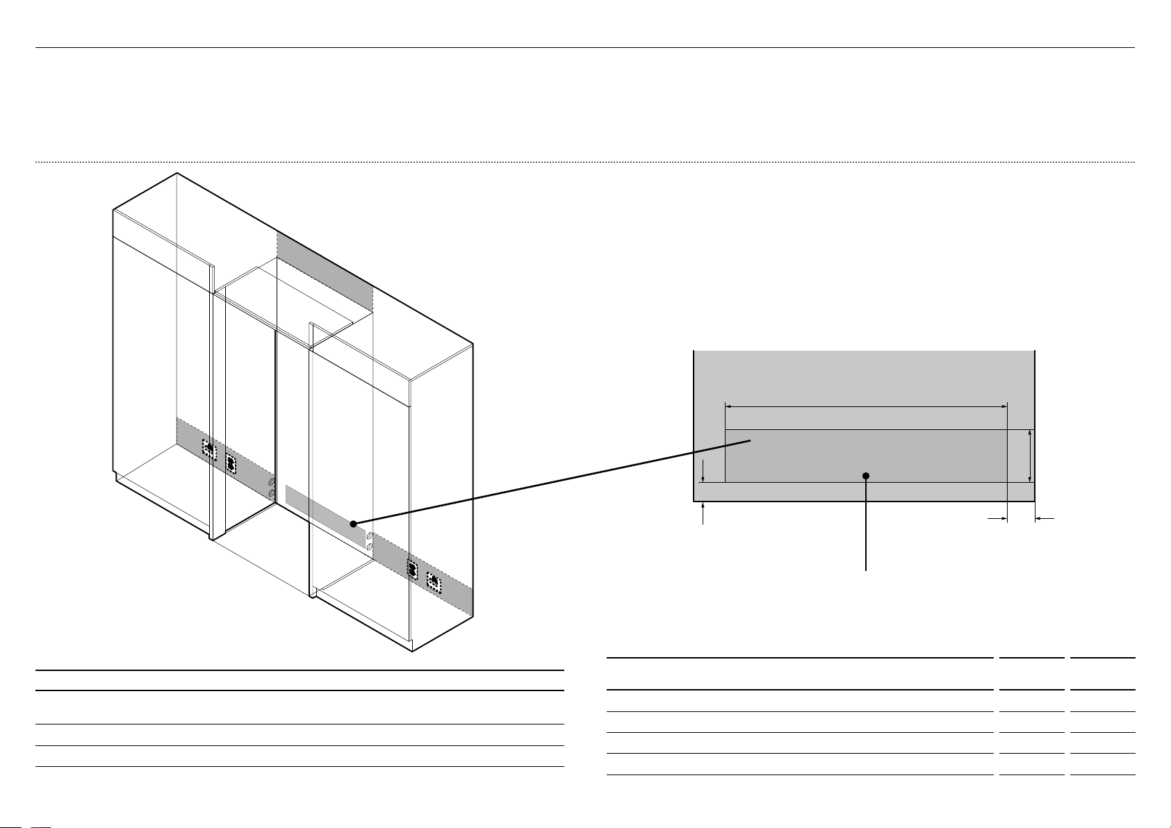
13
IMPORTANT!
Le raccordement électrique doit être situé dans une armoire adjacente d’un côté ou de
l’autre du produit, ou encore au-dessus de la cavité du produit.
Nous recommandons d’utiliser un interrupteur de sectionnement auquel l’utilisateur
pourra facilement accéder après l’installation du produit.
MISE EN GARDE!
Risque de choc électrique. Présumez que toutes les pièces sont sous tension.
Déconnectez l’alimentation avant de procéder à l’entretien et à l’installation.
!1RACCORDEMENT ÉLECTRIQUE ET PLOMBERIE
A
C
B
Plancher
Côté gauche de
la cavité
Les raccordements de l’alimentation en eau et de
l’alimentation électrique doivent être dans cet espace,
s’ils sont situés derrière l’appareil
RACCORDEMENTS D’ALIMENTATION ÉLECTRIQUE ET DE PLOMBERIE
1
Emplacement recommandé pour les raccordements dans une zone adjacente ou derrière
l’appareil
2
Autre emplacement possible pour les raccordements au-dessus de la cavité
3
Autre emplacement possible pour les raccordements à l’arrière de la cavité
1
3
2
1
DIMENSIONS POUR LE RACCORDEMENT ÉLECTRIQUE ET LA
PLOMBERIE
inches mm
A
Hauteur hors tout de la zone d’alimentation 5 5/8 143
B
Largeur hors tout de la zone d’alimentation 29 3/4 756
C
Distance à partir du côté droit de la cavité 2 7/8 73
D
Distance à partir du plancher 2 51
Note: Dimensions are based on minimum depth of cavity.
C
A
D
B
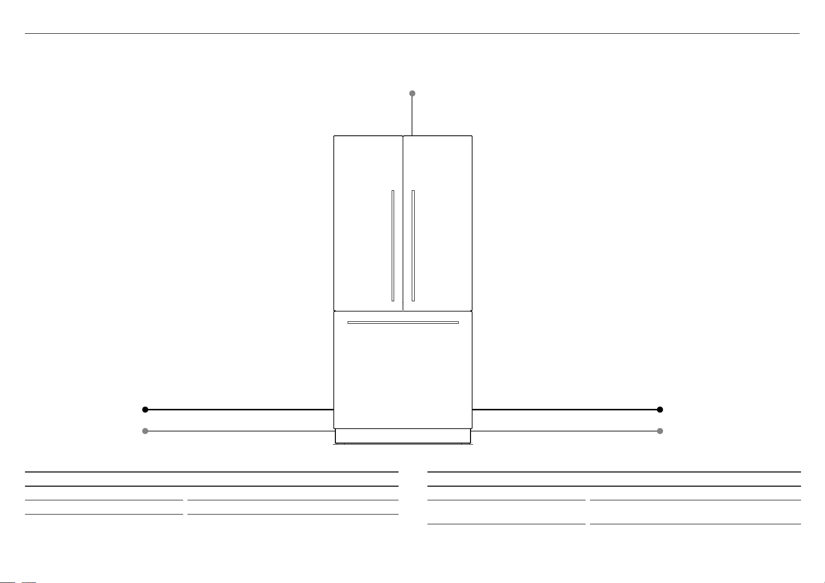
14
Distance maximale du tuyau et du cordon d’alimentation
!1RACCORDEMENT ÉLECTRIQUE ET PLOMBERIE
CÔTÉ DROITCÔTÉ GAUCHE
Cordon d’alimentation (excluant la fiche)—311/2po (800mm)
Cordon d’alimentation (excluant la fiche)—803/4po (2051mm)
Cordon d’alimentation (excluant la fiche)—803/4po (2051mm)
Tuyau d’alimentation en eau—531/8po (1350mm) Tuyau d’alimentation en eau—847/16po (2120mm)
SPÉCIFICATIONS ÉLECTRIQUES
Alimentation 115VCA, 60Hz
Circuit 10ampères
SPÉCIFICATIONS DE PLOMBERIE
Alimentation Tuyau tressé en acier inoxydable de 1/4po (6mm)
Pression min. 22psi (150kPa)
max. 120psi (827kPa) @ 68°F (20°C)
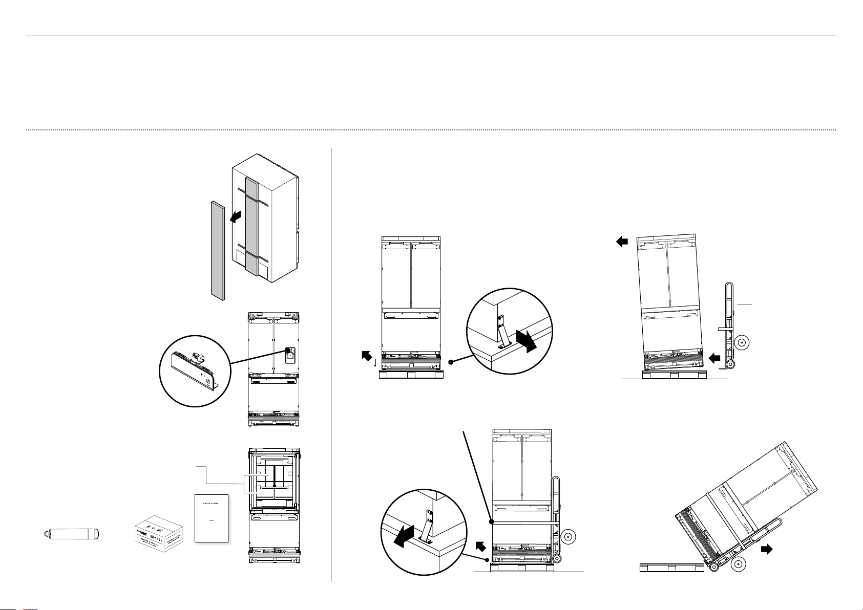
15
4
Attachez le produit
au chariot à l’aide
desangles.
5
Retirez les supports sur
l’autre côté du produit.
6
Inclinez le produit vers
l’arrière sur le chariot.
7
Mettez la palette de côté
et poussez le chariot
jusqu’à l’emplacement
d’installation.
2
Inclinez légèrement
le produit vers le
côté opposé.
3
Insérez le chariot manuel
sous le côté du produit
dont les supports ont
étéretirés.
N’insérez PAS le chariot
manuel par l’avant ou
l’arrière du produit.
Déplacement de votre produit
1
Retirez les supports d’un côté du produit.
(Pourles modèles à porte simple, retirez les
supports sur le côté sans charnière du produit.)
Remarque: L’emplacement des supports
dépend du modèle de votre produit.
Vérification de votre appareil
1
Retirez la boîte d’accessoires située
sur le panneau arrière de l’appareil.
Reportez-vous à ‘Liste des pièces’
(page5) pour connaître le contenu
de la boîte d’accessoires.
IMPORTANT!
Lors du retrait de la boîte, veuillez
prendre note que la boîte
d’accessoires a pu être délogée
du panneau arrière de l’appareil
pendant le transport.
2
Détachez le module d’affichage
externe fixé avec du ruban
adhésif à l’avant du produit.
USER GUIDE
NZ AU GB IE HK SG IN US
ACTIVESMART™
INTEGRATED REFRIGERATOR
RS90A, RS9120W,
RS36A72, RS36A80 & RS36W80 models
Ensembles de raccords
d’alimentation en eau et
de filtre à eau
Ensemble
d’installation
3
Retirez de l’intérieur du produit les
ensembles de raccords d’alimentation
en eau et de filtre à eau, l’ensemble
d’installation et l’emballage
d’articlesdivers.
Reportez-vous à ‘Pièces’
(pages 3–5).
IMPORTANT!
Déballez votre produit avec soin pour éviter d’en endommager la surface.
Assurez-vous que le produit est stable afin d’éviter tout basculement pendant le déballage.
Pour éviter le basculement du produit, n’ouvrez pas les portes.
Le produit est lourd; le déballage et l’installation nécessitent au moins 2personnes.
Assurez-vous que les pattes du produit sont rétractées.
Si le produit est endommagé, communiquez avec votre détaillant Fisher&Paykel.
Notez les numéros de modèle et d’enregistrement situés dans le coin inférieur droit du
produit. Vous aurez besoin de ces informations pour effectuer une demande de service
oude réparation pour votre produit.
chariot
manuel
!2AVANT L’INSTALLATION
Emballage
d’articles
divers
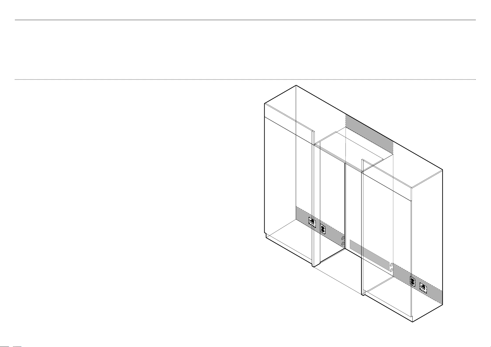
16
IMPORTANT!
Le produit est muni de roulettes avant et arrière qui facilitent le déplacement vers
l’avantet l’arrière. Pour éviter d’endommager les roulettes ou le revêtement/la surface
du plancher, ne déplacez pas le produit latéralement.
Pour éviter un raccordement électrique incorrect et des fuites d’eau, faites installer
leproduit par un installateur qualifié ou un technicien de service formé et supporté
parFisher&Paykel.
Tous les raccordements d’alimentation en eau, d’alimentation électrique et de mise à
laterre doivent être conformes aux codes et règlements locaux et être effectués par
untechnicien autorisé, lorsque nécessaire.
Évitez d’installer les produits sur un disjoncteur différentiel de fuite à la terre (DDFT).
Assurez-vous que le produit est installé correctement. Les défaillances du produit
résultant d’une installation incorrecte ne sont pas couvertes par la garantie du produit.
Vérification de l’emplacement d’installation
1
Vérifiez les armoires
– Vérifiez les dimensions—hauteur, largeur, profondeur, niveau du plancher,
finitions de l’alcôve.
– Assurez-vous que les ouvertures de ventilation dans les armoires sont
exemptes de toute obstruction.
– Pour une installation encastrée, une finition en matériau solide est requise
dans le haut et sur les côtés de l’alcôve existante ou nouvelle.
– Il est recommandé d’installer une bordure de finition mesurant au moins
31/2po (90mm) de profondeur, sur les côtés.
– Reportez-vous au tableau ‘Dimensions de la cavité’ avant de procéder
àl’installation du produit.
2
Vérifiez l’alimentation électrique
– Assurez-vous de brancher le produit à une prise électrique distincte.
– Pour prévenir les interruptions d’alimentation accidentelles du produit,
évitez de partager le point d’alimentation avec d’autres produits.
– Pour connaître les caractéristiques d’alimentation requises, reportez-vous
aux informations inscrites sur la plaque signalétique. Cette plaque est
située dans la partie avant droite du tiroir lorsqu’il est ouvert.
– Assurez-vous que votre produit est correctement mis à la terre.
– Raccordez le produit à l’alimentation électrique (115VCA, 60Hz) à l’aide
de la fiche et du cordon dont il est muni.
– Nous recommandons d’utiliser un interrupteur de sectionnement auquel
l’utilisateur pourra facilement accéder après l’installation du produit.
– Lors de l’installation de ce produit, conformez-vous au Code national de
l’électricité, ainsi qu’à tous les codes et règlements locaux.
3
Vérifiez l’alimentation en eau (pour les modèles Glaçons et eau uniquement)
– Assurez-vous de raccorder le produit à une alimentation en eau distincte.
– Votre produit doit être installé par un installateur qualifié, car un
raccordement de plomberie incorrect pourrait causer des fuites d’eau.
– Fisher&Paykel n’est pas responsable des dommages (y compris les
dommages causés par l’eau) provoqués par une installation ou un
raccordement de plomberie incorrect.
!2AVANT L’INSTALLATION
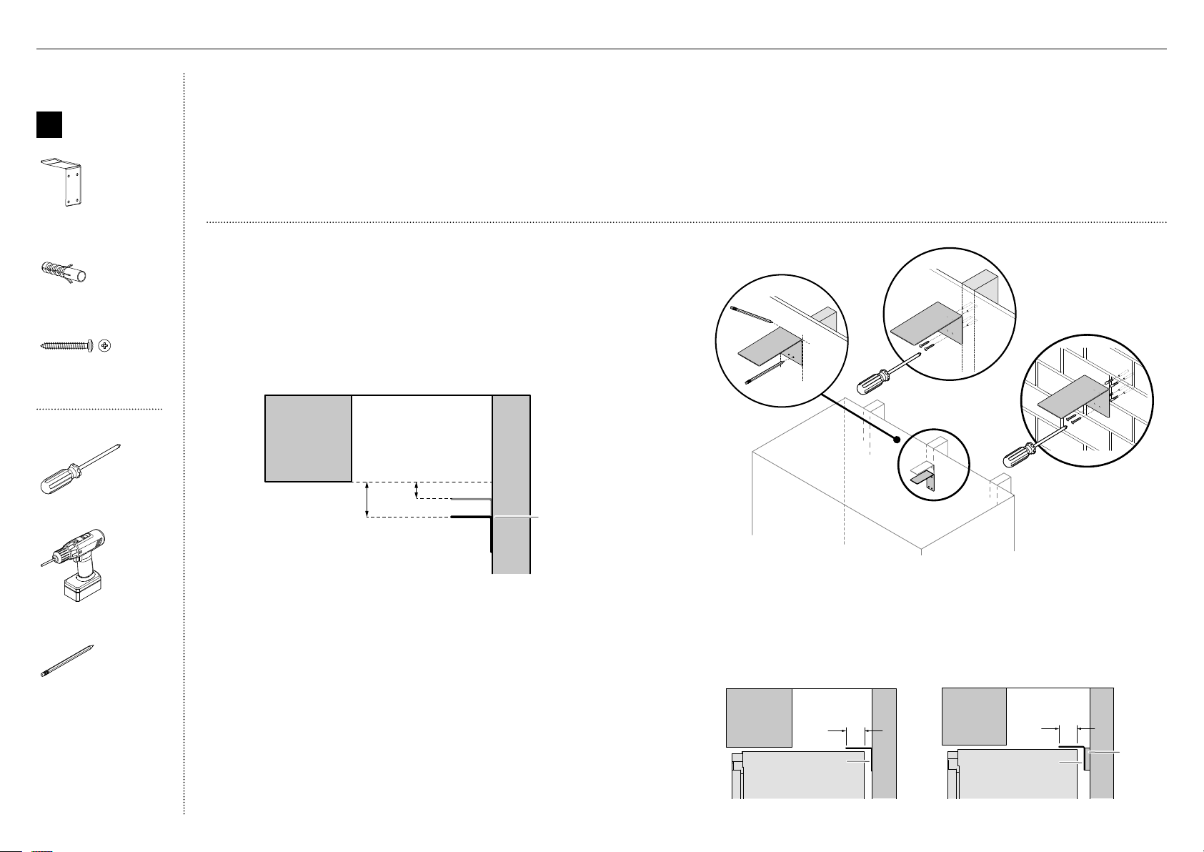
17
IMPORTANT!
Le support antibasculement et les raccords fournis doivent être installés
au mur de l’emplacement d’encastrement fini afin de procurer une
capacitéde charge de 220lb (100kg).
Assurez-vous que le support antibasculement soit installé correctement
pour éviter que le produit puisse basculer vers l’avant lorsque la porte
estouverte.
Assurez-vous que le support soit fixé aux poutres porteuses ou montants
muraux situés le plus près du centre de l’alcôve.
MISE EN GARDE!
Lisez les consignes suivantes avant d’effectuer la fixation avec des vis
et/ou chevilles pour maçonnerie:
Assurez-vous que les vis n’entrent pas en contact avec les raccordements
électriques ou les conduites de gaz et d’eau.
Assurez-vous de ne pas utiliser de matériaux de maçonnerie légers tels que des
blocs de béton et du nouveau béton (sans temps de prise) pour l’installation.
N’utilisez pas de pièces métalliques qui pourraient se corroder, tacher
et/ou endommager le bâti.
Boîte interne
A
Ensemble de
support anti-
basculement
Support antibasculement
(1)
Cheville pour maçonnerie
(4)
#10x40
Pan Head
Philips Screw
#10x40
Pan Head
Philips Screw
Vis cruciforme n°10x40
(4)
Outils
Tournevis cruciforme
Visseuse électrique
(optionnelle)
Crayon
Fixation du support antibasculement
1
Effectuez une projection horizontale allant du rebord inférieur de l’emplacement
d’encastrement fini vers le centre du mur arrière.
– Pour l’installation dans une cavité de 80po (2032mm)—mesurez
27/16po (62mm) vers le bas à partir de la ligne de projection (A).
– Pour l’installation dans une cavité de 84po (2134mm)—mesurez 67/16po
(164mm) vers le bas à partir de la ligne de projection (B).
Cela permettra de localiser la surface de contact entre le support et le produit.
2
Marquez l’emplacement pour le positionnement du support
antibasculement. Placez le support de manière à ce que le rebord
supérieur de la surface de contact soit aligné avec la marque (C).
3
Marquez les emplacements des trous de vis sur le montant le plus au
centre du mur (D).
4
Percez les trous de vis aux emplacements marqués.
5
Pour l’installation sur un mur en bois/plaque de plâtre:
– Fixez le support au mur à l’aide des vis cruciformes à tête cylindrique
n°10x40, puis vissez fermement (E).
6
Pour l’installation sur un mur solide:
– À l’aide d’un marteau, enfoncez les chevilles pour maçonnerie dans
lemur jusqu’à ce qu’elles soient au même niveau que ce dernier.
– Fixez le support au mur à l’aide des vis cruciformes à tête cylindrique
n°10x40 (4x), puis vissez fermement (F).
A
B
Support
antibasculement
E
F
C
D
S’il n’est pas possible
d’obtenir un chevauchement
minimum de 23/8po
(60mm), installez une
pièce d’espacement solide
sur le montant de mur
derrière le support.
IMPORTANT!
Lors du positionnement du
produit dans les armoires,
vérifiez que le support
antibasculement chevauche le
réfrigérateur d’un minimum de
23/8po (60mm) pour assurer
un maintien stable.
Chevauchement
de 23/8po min.
(60mm)
Support
antibasculement
Chevauchement
de 23/8po min.
(60mm)
Pièce
d’espa-
cement
Support
antibasculement
!3PRÉPARATION DE LA CAVITÉ
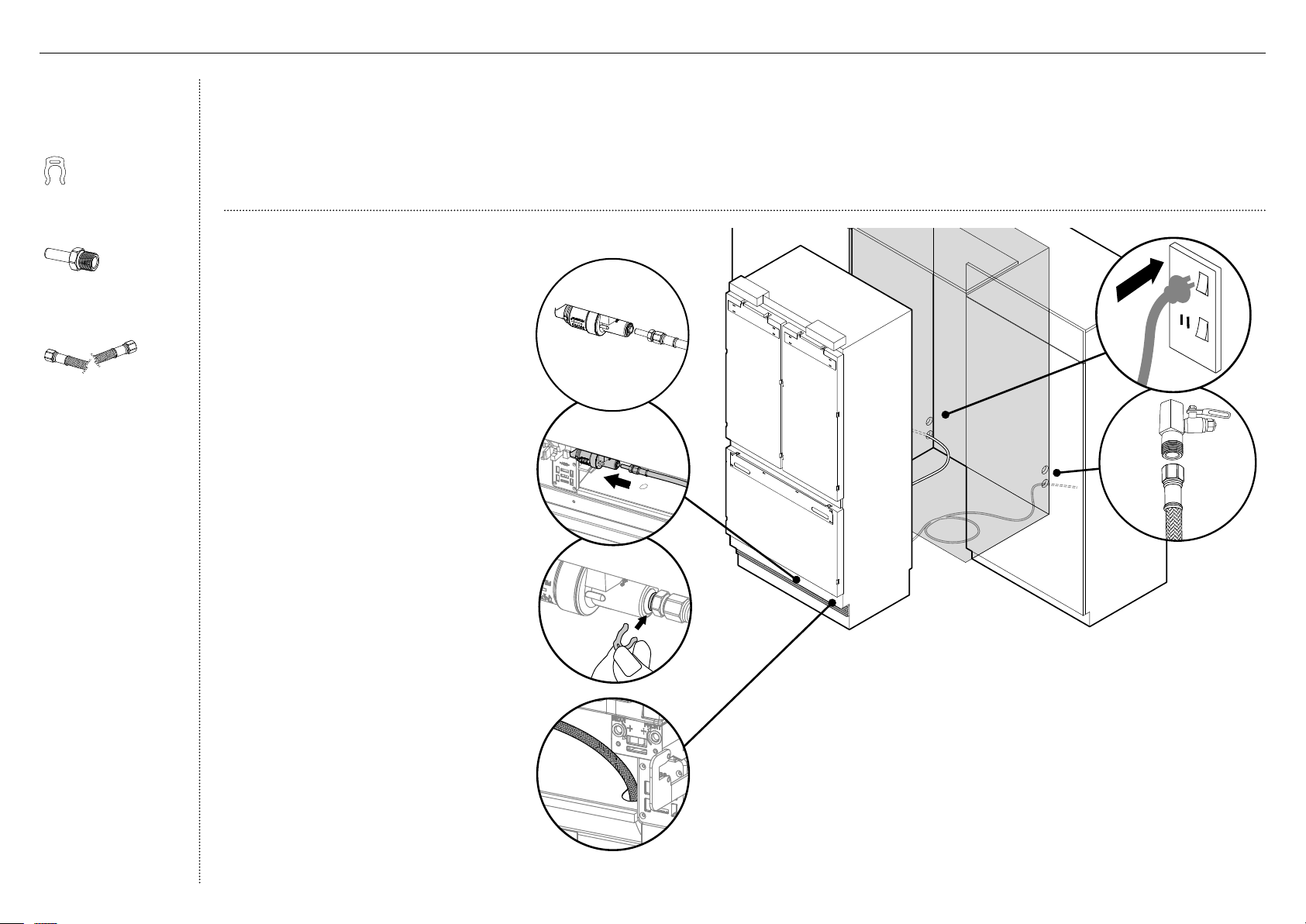
18
Ensemble de raccords
d’alimentation en eau
(Modèles Glaçons et eau
uniquement)
Clip de blocage de collet
(1)
Adaptateur de 1/4po
(6mm) (1)
Tuyau tressé en acier
inoxydable de 1/4po
(6mm) (1)
IMPORTANT!
Assurez-vous de faire raccorder l’alimentation en eau par un installateur professionnel.
Le produit standard est fourni avec un tuyau tressé d’alimentation en eau compatible avec un adaptateur en laiton.
Assurez-vous de laisser une longueur de tuyau suffisante pour effectuer le raccordement de l’alimentation en eau et pour pouvoir avancer
le produit lors des travaux d’entretien, au besoin.
Faites couler de l’eau dans le tuyau avant de le raccorder au produit pour éliminer tout débris présent dans le tuyau.
Nous recommandons d’utiliser un interrupteur de sectionnement facilement accessible après l’installation du produit.
!4ALIMENTATION EN EAU ET ALIMENTATION ÉLECTRIQUE
Raccordement de l’alimentation en eau
(pour les modèles Glaçons et eau
uniquement)
1
Déplacez le produit devant les armoires,
à une distance permettant d’accéder aux
raccordements d’alimentation électrique
et d’alimentation en eau à l’arrière.
2
À l'avant de l'appareil, insérez l'adaptateur
du tuyau de conduite d'eau tressé (A)
dans le PRV.
Remarque: Si vous utilisez un tuyau en
plastique PEX de1/4po, un ensemble
de raccords d’alimentation en eau (non
fourni) est requis.
D
C
B
6
À l’arrière du produit, raccordez l’extrémité libre du tuyau tressé
à l’alimentation en eau (E), puis enroulez sans trop serrer le tuyau
d’alimentation eneau (~2–3fois).
– Ne serrez pas excessivement le raccordement.
– Ouvrez l’alimentation en eau (ON) et vérifiez que tous les
raccordements sont secs et exempts de fuites.
Raccordement de l’alimentation électrique
7
Localisez le cordon d’alimentation et branchez la fiche à l’alimentation
électrique (115VCA, 60Hz)(F). Mettez le produit en marche (ON) et
vérifiez qu’il fonctionne.
– Si vous utilisez un interrupteur de sectionnement, éteignez le
produit (OFF) avant de poursuivre l’installation.
3
Insérez entièrement l’extrémité de tuyau
de l’adaptateur dans la vanne de réglage
de pression. Une fois l’extrémité insérée,
tirez doucement sur le tuyau pour vous
assurer qu’ilest bien verrouillé en place
(B).
Remarque: Délogez la vanne de réglage
de pression des clips, si nécessaire.
4
Fixez le raccordement en insérant une
clavette de blocage entre la vanne de
réglage de pression et l’extrémité de
tuyau de l’adaptateur(C).
– Si la vanne de réglage de pression
estdélogée pendant l’installation,
réinstallez-la dans le clip.
5
Faites passer l’extrémité libre du tuyau
d’alimentation en eau dans l’ouverture
située à la base, pour l’acheminer par
l’arrière du produit (D).
E
F
PRV
braided
hose with
adaptor
A
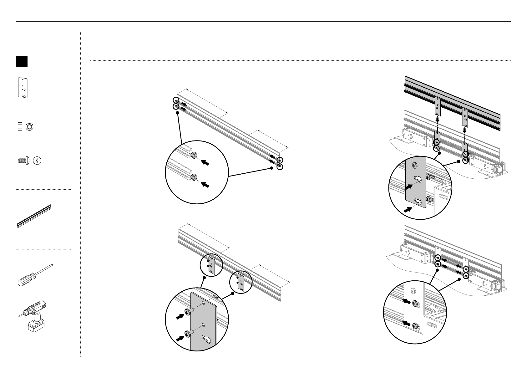
19
~13po (330mm)
~13po (330mm)
MISE EN GARDE!
Soyez prudent lorsque vous effectuez des travaux pendant que le produit est à l’extérieur de l’emplacement d’encastrement fini.
Assurez-vous que le produit soit bien fixé pour éviter qu’il ne bascule vers l’avant. Le basculement du produit peut entraîner des blessures graves, voire mortelles.
Boîte interne
E
Ensemble
d’installation
de garniture
supérieure
Support de garniture
supérieure de bâti (2)
M5 Nut
M5 Nut
Écrou M5
(6)
M5 x 10
Pan Head
Philips Screw
M5 x 10
Pan Head
Philips Screw
Vis cruciforme M5x8
(12)
Boîte externe
Garniture supérieure
(1)
Outils
Tournevis cruciforme
Visseuse électrique
(optionnelle)
3
Dans le haut du produit,
placez la garniture supérieure
assemblée derrière la
garniture existante.
Positionnez la garniture
supérieure de manière à ce
que les têtes de vis dans
la garniture du produit
s’insèrent dans les trous
en forme de serrure des
supports (C).
4
Glissez les vis de la
garniture du produit
vers le côté étroit des
trous en forme de
serrure des supports,
puis serrez les vis
afin de verrouiller la
garniture supérieure en
position (D).
2
Positionnez les supports
de garniture supérieure
au-dessus des écrous M5.
Faites passer les vis
cruciformes M5x8 (B) dans
les ouvertures du support,
puis fixez-les.
1
Insérez les écrous M5
(A) dans les parties
supérieure et inférieure
des extrémités gauche
et droite de la garniture
supérieure. Glissez les
écrous vers le centre
de la garniture, ~13po
(330mm).
~13po (330mm)
~13po (330mm)
A
B
C
Installation de la garniture supérieure—pour cavité de 84po (2134mm) uniquement
D
!5INSTALLATION DE LA GARNITURE SUPÉRIEURE
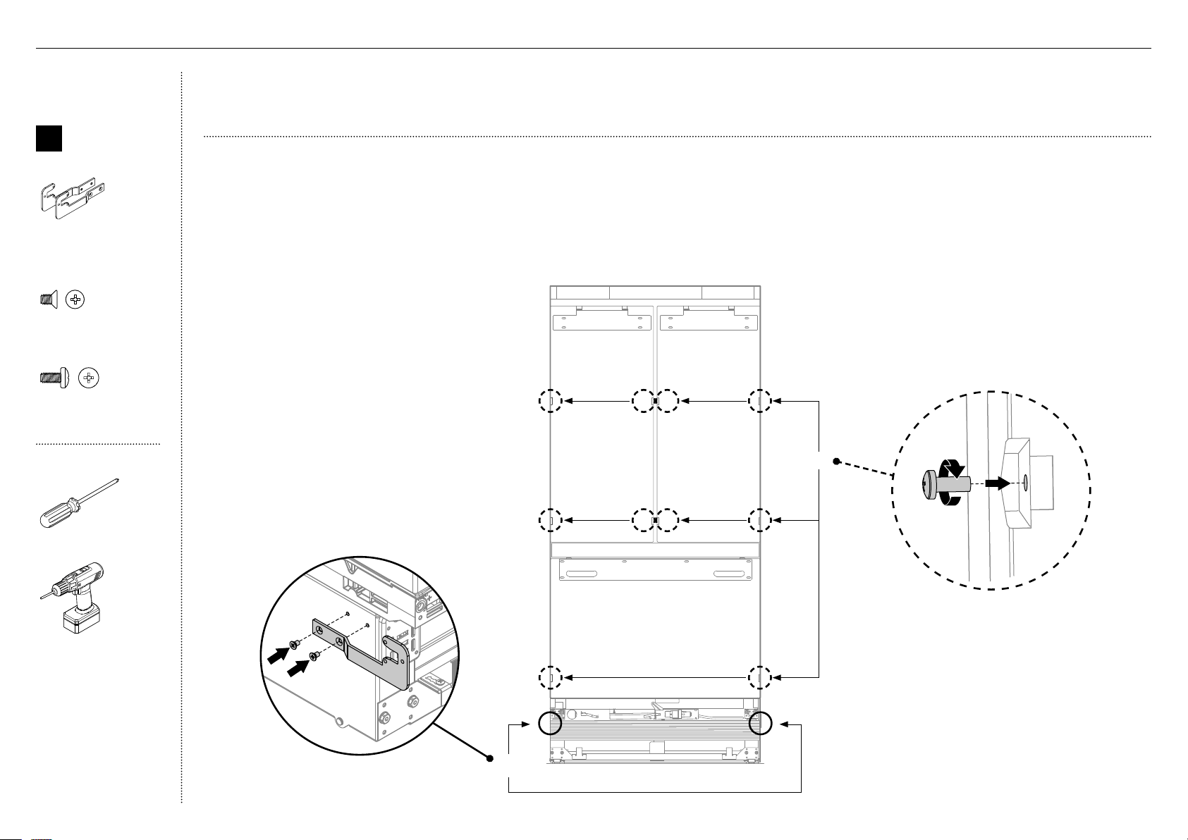
20
Boîte interne
F
Ensemble
d’installation
de support
latéral
Supports de base latéraux
(G/D)
(2)
M5 x 8
Countersunk
Philips Screw
M5 x 8
Countersunk
Philips Screw
Vis cruciforme à
tête fraisée M5x8 (4)
M5 x 10
Pan Head
Philips Screw
M5 x 10
Pan Head
Philips Screw
Vis cruciforme M5x10
(10)
Outils
Tournevis cruciforme
Visseuse électrique
(optionnelle)
IMPORTANT!
Assurez-vous de retirer tous les matériaux d’emballage externes du produit avant l’installation.
Assurez-vous que les portes du produit demeurent fermées pendant l’installation.
Fixation des supports de base latéraux
1
Fixez les supports de base latéraux sur les côtés inférieurs gauche et droit
duproduit à l’aide des vis cruciformes à tête fraisée M5x8 (A).
2
Vissez sans serrer (1–2tours) les vis cruciformes M5x10 dans les portes (B).
1 – 2tours
B
A
B
A
!6INSTALLATION DES SUPPORTS LATÉRAUX
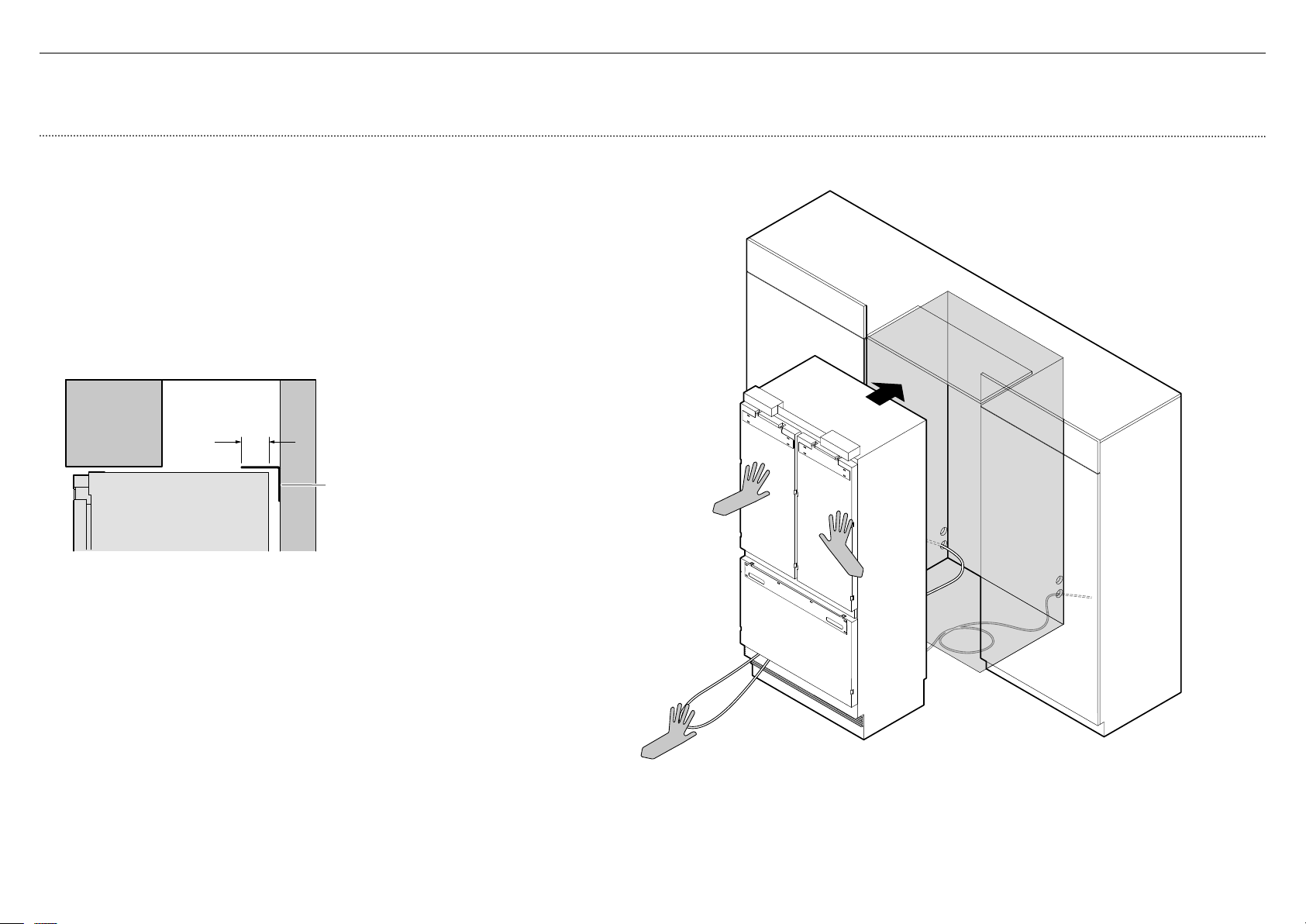
21
!7POSITIONNEMENT DANS LES ARMOIRES
IMPORTANT!
Pour éviter de causer des dommages et de possibles fuites d’eau, veillez à ne pas passer sur le tuyau lors du déplacement du produit dans les armoires.
A
Positionnement du produit dans les armoires
1
Enroulez le surplus d'eau et le cordon d'alimentation à plat derrière l'appareil
(A).
2
Poussez l'appareil dans l'armoire jusqu'à ce que le support antibasculement
chevauche le bord supérieur arrière de l'appareil (B).
IMPORTANT!
Assurez-vous que l'appareil est centré.
Assurez-vous que le support antibasculement chevauche le réfrigérateur
d'au moins 60 mm (2 3/8 po) pour un maintien sûr (C).
Chevauchement
de 23/8po min.
(60mm)
Support
antibasculement
Reportez-vous à ‘Fixation du support antibasculement’ pour plus
d’informations.
C
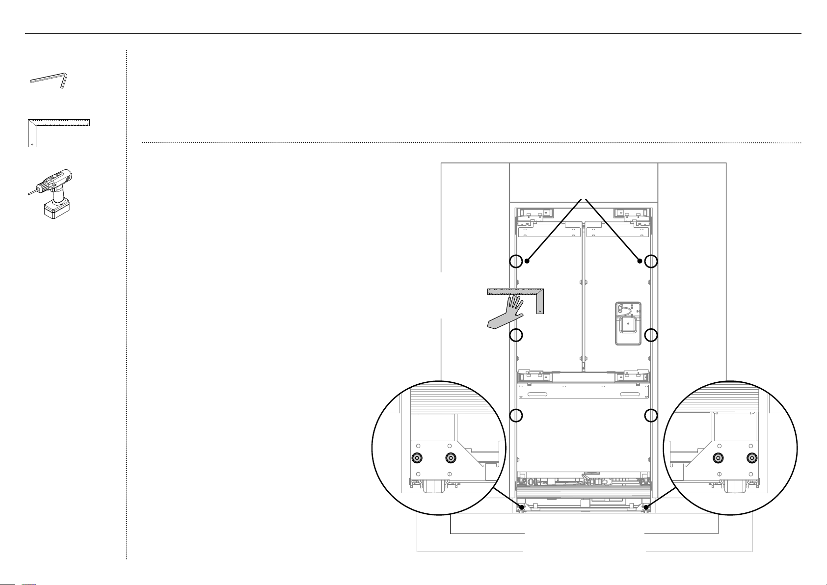
22
IMPORTANT!
N’installez PAS le produit sur un plancher souple, inégal ou qui n’est
pas de niveau, car cela pourrait entraîner une déformation du produit et
compromettre l’étanchéité de la porte.
Élevez le produit à l’aide d’une douille hexagonale de 7/16po (11mm) ou
d’une clé hexagonale de 3/16po (4mm).
Un tour d’écrou de réglage de hauteur équivaut à un ajustement de
hauteur de 1/16po (1mm). Remarque: L’ajustement maximum est de
13/16po (20mm).
Lors de l’utilisation d’une visseuse électrique, utilisez un réglage à faible
couple pour éviter d’endommager le système d’ajustement de hauteur.
Pour l’obtention de l’alignement adéquat, assurez-vous que les espaces
dans le haut, dans le bas et sur les côtés ne soient pas supérieurs à 1/16po
(1,5mm).
L’alignement final sera effectué après l’installation des panneaux de portes
et le positionnement du produit au même niveau que les armoires.
Add ruler to show ushness x 4?
Ajustement de la roulette avant
Ajustement de la roulette arrière
A
C
A
B
Placez une règle sur le
devant du produit pour
vérifier son alignement,
du haut vers le bas et
de gauche à droite.
Outils
Clé hexagonale
Règle
Visseuse électrique
!8ALIGNEMENT DANS LES ARMOIRES
Alignement de l’appareil dans les armoires
1
Centrez l’appareil dans l’alcôve, en utilisant les murs
adjacents comme guide.
2
Tournez les écrous d’ajustement avant et arrière
(A) à l’aide d’une clé hexagonale pour allonger les
pattes afin qu’elles reposent au sol.
– Tournez dans le sens des aiguilles d’une montre
pour augmenter la hauteur ou tournez dans le
sens inverse pour la diminuer.
3
Continuez de tourner les vis d’ajustement des pattes
avant et arrière en alternance pour aligner le devant
des portes, du haut vers le bas, sur les deux côtés,
jusqu’à l’obtention de l’alignement adéquat.
4
Vérifiez les espaces dans le haut et le bas, à gauche
et à droite en plaçant une règle (B) sur le devant de
l’appareil.
– Assurez-vous que les espaces entre l’appareil
et les armoires adjacentes soient égaux sur les
deux côtés (C).
– Cette étape aide à placer l’appareil au même
niveau que les armoires adjacentes.
5
Poussez doucement sur le devant de l’appareil pour
vérifier sa stabilité.
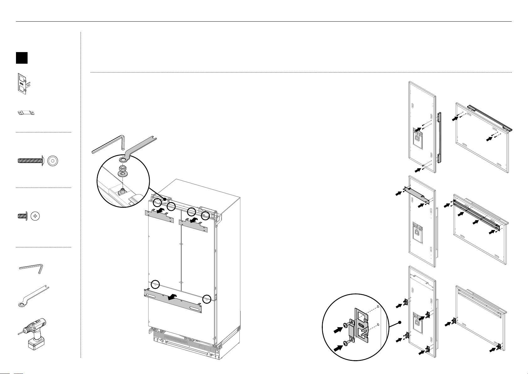
23
E
IMPORTANT!
Suivez ces étapes pour éviter des difficultés lors de l’ajustement du panneau de porte et l’installation du capuchon esthétique.
Assurez-vous de protéger le fini des panneaux de portes en acier inoxydable.
Pour les panneaux de portes sans distributeur d’eau: Laissez la pellicule protectrice sur les panneaux pendant l’installation et retirez-la
uniquement lorsque vous terminez.
Retrait des supports d’accrochage
1
Retirez les rondelles M8 et les écrous M8 des goujons M8
dans le haut de la porte (A). Conservez les rondelles et
écrous pour les réutiliser ultérieurement.
2
Retirez le support d’accrochage du haut de chaque porte
et mettez-le de côté (B) pour l’installation ultérieure.
Fixation des poignées de porte et de tiroir (C)
3
Retirez les bouchons en plastique des trous de
poignée (4 pour chaque panneau de porte).
4
Alignez les trous de poignée avec les trous du
panneau de porte, puis fixez à l’aide de vis à
tête creuse cylindrique M5x25 (4 pour chaque
panneau de porte).
Remarque: L’ensemble de poignée de porte doit
être acheté séparément. Reportez-vous à ‘Pièces’
(page 3-5) pour plus de détails.
B
C
C
D
D
Fixation des supports latéraux et des bandes
latérales (E)
6
Alignez les supports et les bandes sur les trous
de chaque côté du panneau, puis fixez à l’aide
de vis rondelles cruciformes M5x14 (20).
Fixation des supports d’accrochage (D)
5
Alignez le support sur les trous, puis fixez à
l’aide de vis rondelles cruciformes M5x14 (14).
Boîte interne
B
Ensemble
de fixation
de panneau
deporte
Support latéral (10)
Bande latérale (10)
Ensemble de
poignée de porte
M5 x 25
Pan Head
Socket Screw
M5 x 25
Pan Head
Socket Screw
Vis à tête creuse
cylindrique M5x25 (12x)
Ensemble de
panneau de porte
M5 x 14
Mush Head
SS
Philips Screw
M5 x 14
Mush Head
SS
Philips Screw
Vis rondelle cruciforme
M5x14 (acier inoxydable)
(34)
Outils
Clé hexagonale
Clé FPA
Visseuse électrique
A
!9INSTALLATIONDE PANNEAU DE PORTE—EN ACIER INOXYDABLE
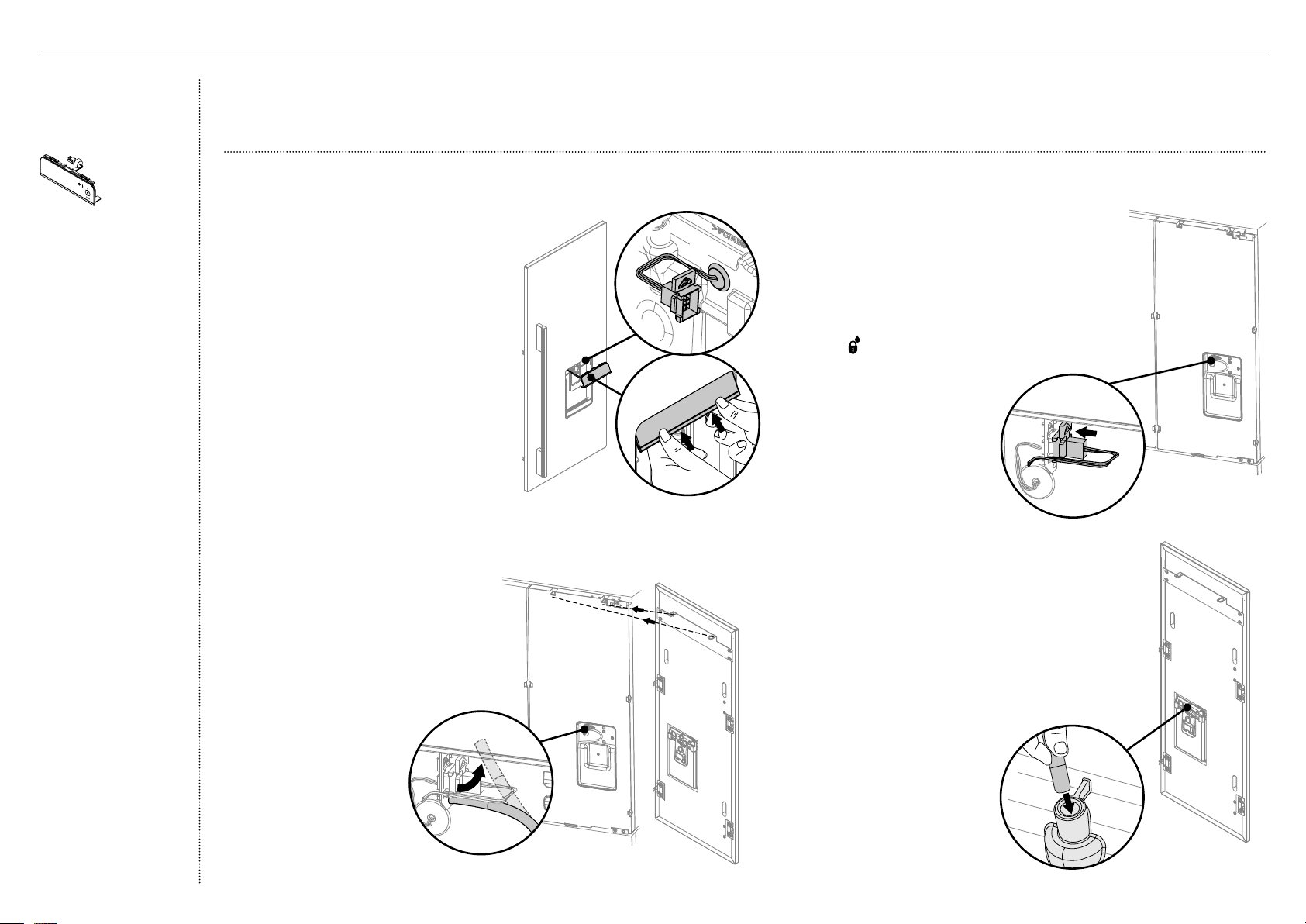
24
7
Connectez les fils couplés de l’afficheur à la
porte du produit en les insérant fermement
jusqu’à ce qu’ils s’enclenchent solidement (D).
– Activez le verrouillage du distributeur
sur l’afficheur externe pour éviter que
l’eau s’écoule du distributeur pendant
leraccordement de l’alimentation en eau.
– Pour le verrouiller, appuyez sur la touche
pendant 4secondes. Le témoin DEL
au-dessus de la touche s’allumera.
D
E
C
IMPORTANT!
Le fait de ne pas suivre ces étapes pourrait entraîner des difficultés lors de l’ajustement du panneau de porte et l’installation du capuchon esthétique.
Pour les panneaux de portes avec distributeur d’eau: Retirez la pellicule protectrice des portes du produit avant de suspendre les panneaux de portes.
Afficheur Glaçons
eteau
(Modèles Glaçons
eteau uniquement)
Module d’affichage
externe (1)
Connectez le module d’affichage externe (pour les modèles Glaçons et eau uniquement)
1
Retirez le module d’affichage externe fixé
avec du ruban adhésif à l’avant du produit.
2
Faites passer les fils couplés de l’afficheur
dans la cavité du panneau de porte (A).
– Assurez-vous que l’œillet
estemboîté.
3
Inclinez les languettes supérieures
de l’afficheur pour les insérer dans
lepanneau de porte (B).
– Assurez-vous de ne pas coincer
lesfils couplés.
4
Poussez fermement contre les languettes
inférieures de l’afficheur afin de les insérer
dans le panneau de porte jusqu’à ce
qu’elles s’enclenchent solidement.
– Assurez-vous que l’afficheur soit
au même niveau que le panneau
deporte.
5
Retirez le tuyau d’alimentation
en eau de la pièce de maintien
sur la porte du produit (C).
6
Suspendez le panneau de porte
sur les goujons M8.
– Assurez-vous que le
panneau puisse pivoter
pour les raccordements
d’alimentation en eau.
8
Poussez fermement le tuyau d’alimentation en eau
dans le raccord situé derrière le panneau de porte,
jusqu’à ce que le trait ne soit plus visible (E).
– Assurez-vous d’acheminer le tuyau
d’alimentation en eau à distance de tout objet
ou coin tranchant, dans un emplacement où il
ne pourra pas être entortillé ou écrasé lorsque
le panneau de porte sera fixé (cela pourrait
interrompre le débit d’eau).
B
A
!9INSTALLATIONDE PANNEAU DE PORTE—EN ACIER INOXYDABLE
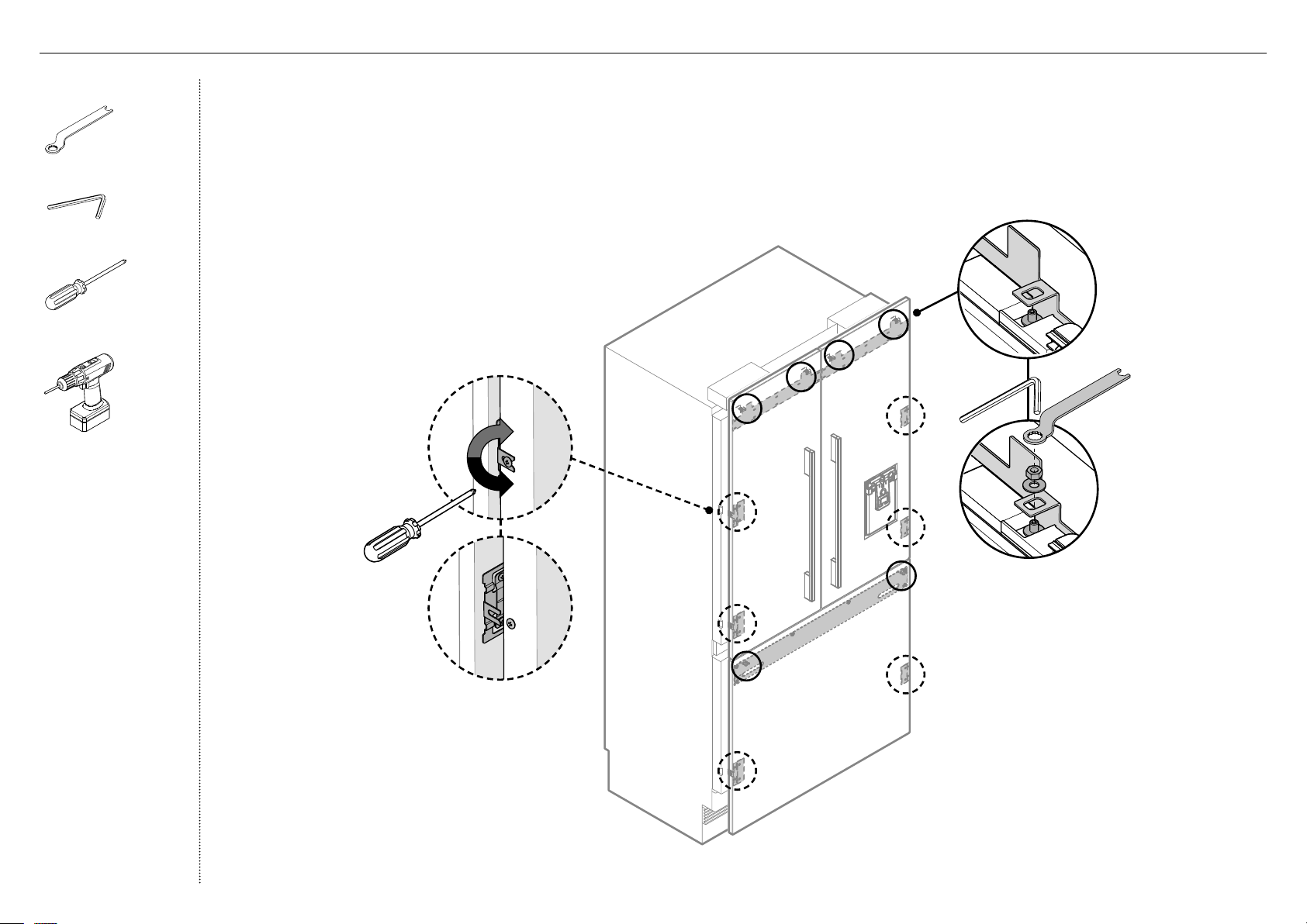
25
Fixation des panneaux de portes
1
Ouvrez la porte et desserrez les vis cruciformes M5x10
(ne les retirez pas) sur les côtés des portes (A).
2
Suspendez le panneau de porte en insérant les
goujonsM8 dans les trous du support d’accrochage (B).
3
Glissez les fourches des supports latéraux sur les vis de
la porte (C).
4
Vissez la rondelle et l’écrou M8 sur chaque goujon
(D), puis resserrez les vis latérales (E) pour fixer le
panneau de porte (ne serrez pas complètement).
Cela permettra d’ouvrir la porte sans affecter
l’ajustement du panneau de porte.
B
D
C
E
A
Outils
Clé FPA
Clé hexagonale
Tournevis cruciforme
Visseuse électrique
(optionnelle)
!7INSTALLATIONDE PANNEAU DE PORTE—EN ACIER INOXYDABLE
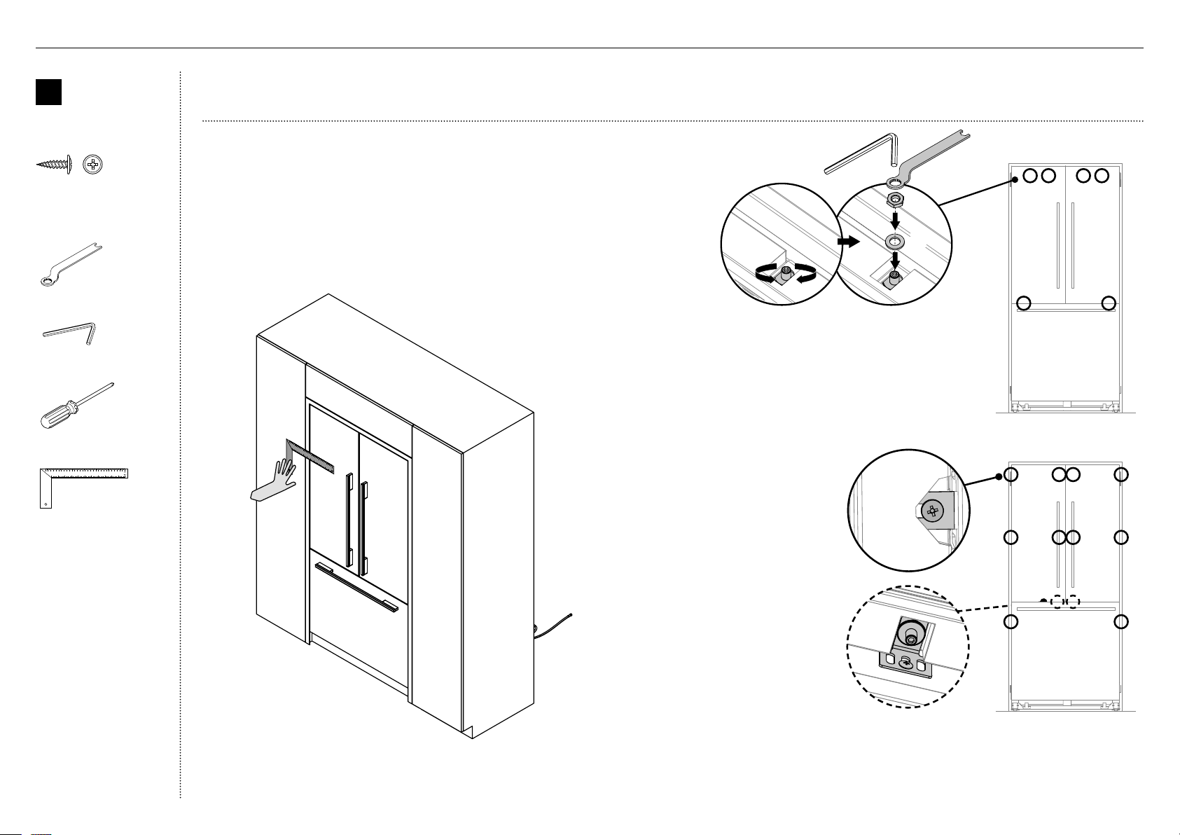
26
Ajustement des panneaux de portes
1
Placez une règle sur le devant du produit pour vérifier son
alignement, du haut vers le bas et de gauche à droite.
– Assurez-vous que l’espace entre le dessus du panneau de
porte et l’armoire du haut ne soit pas supérieur à 1/4po
(7mm).
– Pour réduire cet espace, élevez le produit en tournant les
quatre écrous d’ajustement du même nombre de tours.
IMPORTANT!
Suivez ces étapes pour éviter des difficultés lors de l’ajustement du panneau de porte et l’installation du capuchon esthétique.
!9INSTALLATIONDE PANNEAU DE PORTE—EN ACIER INOXYDABLE
2
Chaque panneau de porte permet un réglage sur axe complet
pour assurer un ajustement au même niveau que les murs
adjacents. Pour ajuster la hauteur du panneau, tournez le
goujon dans le sens des aiguilles d’une montre pour élever le
panneau de porte ou dans le sens inverse pour l’abaisser (A).
3
Une fois satisfait de l’alignement, fixez les goujons M8 avec
la rondelle M8 et l’écrou M8 (B). Le dessus du goujon doit
demeurer sous la face supérieure du panneau de porte.
4
Fixez les fourches de support latéral en
serrant les vis latérales (C).
Répétez pour tous les panneaux de
portes.
Remarque:
– Pour l’ajustement en profondeur,
desserrez les vis latérales (10),
ajustez les panneaux, puis
resserrez les vis lorsque vous êtes
satisfait.
– Pour un ajustement
supplémentaire des panneaux
de portes, retirez les panneaux
de portes et desserrez les vis de
fixation du support d’accrochage,
puis déplacez le support
latéralement selon les besoins.
5
Desserrez le goujon M8 (D) de sorte
que le support de verrouillage puisse
glisser librement vers l'arrière.
– Glissez le support de verrouillage vers l’extérieur jusqu’à ce qu’il touche
à la partie arrière du panneau de porte. Serrez complètement le goujon M8.
– Vissez-le en place en utilisant une vis n°8x16 dans l’un des trois trous oblongs.
B
A
C
D
B
nsemble de
fixation de
panneau de
porte
#8 x 16
Mush Washer
Twin Thread
Philips Screw
#8 x 16
Mush Washer
Twin Thread
Philips Screw
Vis rondelle n°8x16 (Sur
mesure) (2)
Outils
Clé FPA
Clé hexagonale
Tournevis cruciforme
Règle
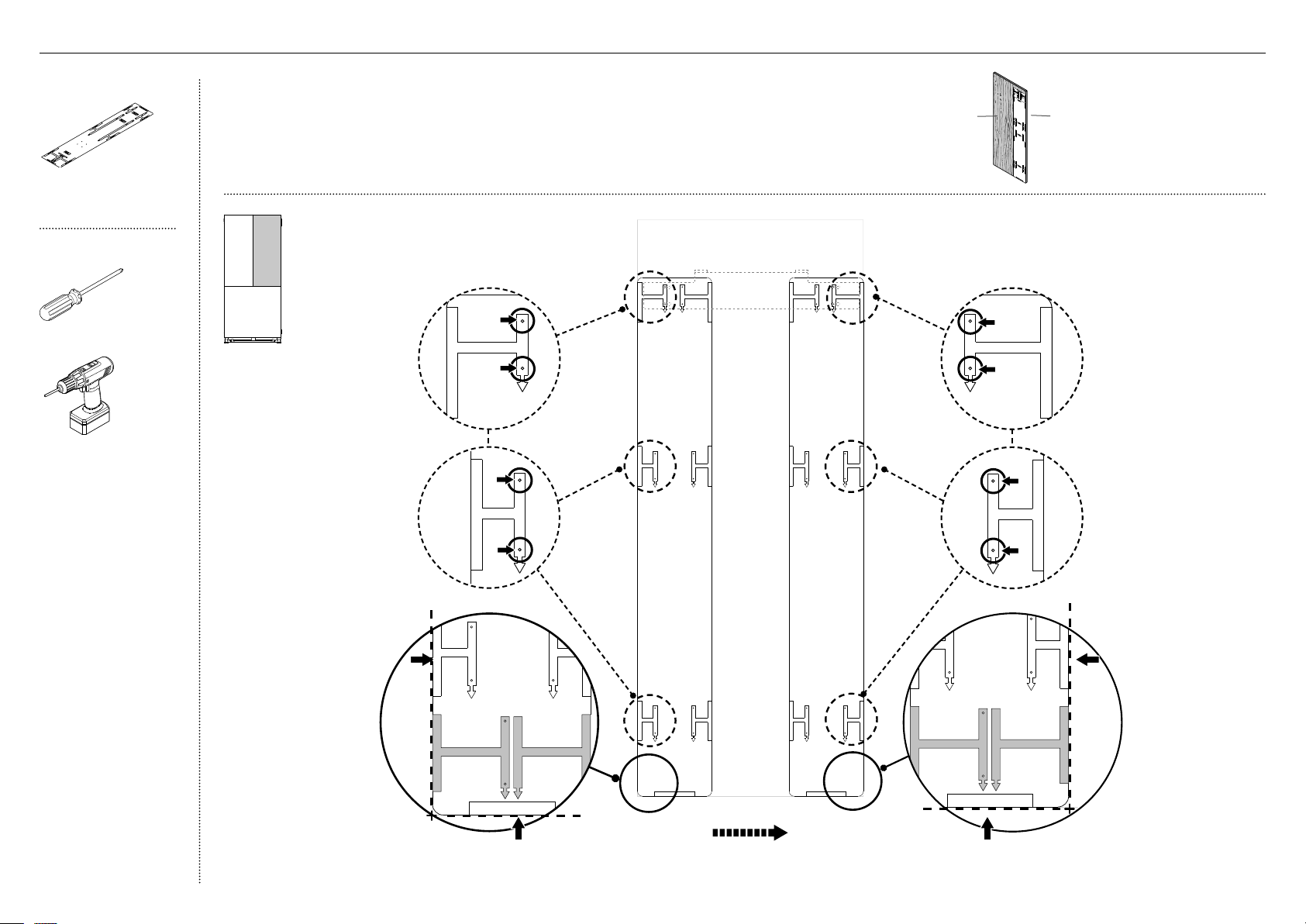
27
face arrière du
panneau de porte
face avant du
panneau de porte
Boîte externe
Gabarit double face de
panneau de porte (1)
Outils
Tournevis cruciforme
Visseuse électrique
(optionnelle)
IMPORTANT!
Le gabarit est une simple feuille dont un côté est utilisé pour le panneau de la porte
gauche/ le panneau de tiroir, et l’autre côté, pour le panneau de la porte droite.
Le gabarit doit être placé sur la face arrière du panneau de porte.
@0INSTALLATIONDE PANNEAU DE PORTE—SUR MESURE
FLIP FOR LEFT HAND DOOR
AND DRAWER HOLES
RH DOOR PANEL HINGE SIDE
RH DOOR PANEL HANDLE SIDE
SIDE BRACKET HOLES
SIDE BRACKET HOLES
RH DOOR PANEL BOTTOM EDGE
HANGING BRACKET
HOLES
HANGING BRACKET
HOLES
RH DOOR PANEL HANDLE SIDE
RH DOOR PANEL HINGE SIDE
RIGHT DOOR
PANEL TEMPLATE
849551
RH DOOR PANEL HINGE SIDE
RH DOOR PANEL HANDLE SIDE
SIDE BRACKET HOLES
SIDE BRACKET HOLES
FLIP FOR LEFT HAND DOOR
AND DRAWER HOLES
RH DOOR PANEL HINGE SIDE
RH DOOR PANEL HANDLE SIDE
SIDE BRACKET HOLES
SIDE BRACKET HOLES
RH DOOR PANEL BOTTOM EDGE
HANGING BRACKET
HOLES
HANGING BRACKET
HOLES
RH DOOR PANEL HINGE SIDE
RH DOOR PANEL HINGE SIDE
RIGHT DOOR
PANEL TEMPLATE
849551
RH DOOR PANEL HINGE SIDE
RH DOOR PANEL HANDLE SIDE
SIDE BRACKET HOLES
SIDE BRACKET HOLES
Utilisation du gabarit d’installation
(pour le panneau de la porte
française droite)
1
FLIP FOR LEFT HAND DOOR
AND DRAWER HOLES
RH DOOR PANEL HINGE SIDE
RH DOOR PANEL HANDLE SIDE
SIDE BRACKET HOLES
SIDE BRACKET HOLES
RH DOOR PANEL BOTTOM EDGE
HANGING BRACKET
HOLES
HANGING BRACKET
HOLES
RH DOOR PANEL HANDLE SIDE
RH DOOR PANEL HANDLE SIDE
RIGHT DOOR
PANEL TEMPLATE
849551
RH DOOR PANEL HINGE SIDE
RH DOOR PANEL HANDLE SIDE
SIDE BRACKET HOLES
SIDE BRACKET HOLES
HANGING BRACKET
HOLES
HANGING BRACKET
HOLES
LEFT DOOR PANEL HINGE SIDE
LEFT DOOR PANEL HANDLE SIDE
LEFT DOOR PANEL
AND DRAWER TEMPLATE
849551
SIDE BRACKET HOLES
SIDE BRACKET HOLES
LEFT DOOR PANEL HINGE SIDE
LEFT DOOR PANEL HANDLE SIDE
FLIP FOR RIGHT
HAND DOOR PANEL
LH DOOR PANEL HANDLE SIDE
LH DOOR PANEL HINGE SIDE
SIDE BRACKET HOLES
SIDE BRACKET HOLES
DRAWER PANEL LEFT EDGE
DRAWER PANEL RIGHT EDGE
DRAWE PANEL
SIDE BRACKET HOLES
DRAWE PANEL
SIDE BRACKET HOLES
DRAWER PANEL LEFT EDGE
DRAWER PANEL RIGHT EDGE
DRAWE PANEL HANGING
BRACKET HOLES
DRAWE PANEL HANGING
BRACKET HOLES
LEFT PC PANEL BOTTOM EDGE
DRAWER PANEL TOP EDGE
3 Déplacez le même gabarit sur le
côté droit du panneau de porte.
1B Alignez le bas du gabarit avec le rebord
inférieur du panneau de porte supérieur.
1A Alignez le rebord gauche
du gabarit avec le rebord
gauche du panneau de
porte supérieur.
2 Marquez les emplacements
de perçage des trous de vis
pour le support d’accrochage
gauche et les supports
latéraux. Percez des trous de
vis de 3/32po (2mm) aux
emplacements marqués.
4 Marquez les emplacements
de perçage des trous de vis
pour le support d’accrochage
droit et les supports latéraux.
Percez des trous de vis
de 3/32po (2mm) aux
emplacements marqués.
5B Alignez le bas du gabarit avec le rebord
inférieur du panneau de porte supérieur.
5A Alignez le rebord droit
du gabarit avec le
rebord droit du panneau
de porte supérieur.
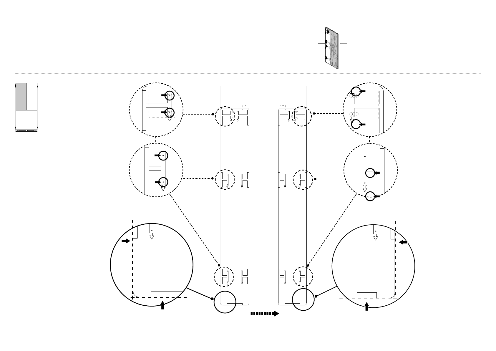
28
face arrière du
panneau de porte
face avant du
panneau de porte
@0INSTALLATIONDE PANNEAU DE PORTE—SUR MESURE
IMPORTANT!
Retournez le gabarit pour l’utiliser avec le panneau supérieur de la porte droite.
Le gabarit doit être placé sur la face arrière du panneau de porte.
FLIP FOR LEFT HAND DOOR
AND DRAWER HOLES
RH DOOR PANEL HINGE SIDE
RH DOOR PANEL HANDLE SIDE
SIDE BRACKET HOLES
SIDE BRACKET HOLES
RH DOOR PANEL BOTTOM EDGE
HANGING BRACKET
HOLES
HANGING BRACKET
HOLES
RH DOOR PANEL HANDLE SIDE
RH DOOR PANEL HINGE SIDE
RIGHT DOOR
PANEL TEMPLATE
849551
RH DOOR PANEL HINGE SIDE
RH DOOR PANEL HANDLE SIDE
SIDE BRACKET HOLES
SIDE BRACKET HOLES
FLIP FOR LEFT HAND DOOR
AND DRAWER HOLES
RH DOOR PANEL HINGE SIDE
RH DOOR PANEL HANDLE SIDE
SIDE BRACKET HOLES
SIDE BRACKET HOLES
RH DOOR PANEL BOTTOM EDGE
HANGING BRACKET
HOLES
HANGING BRACKET
HOLES
RH DOOR PANEL HINGE SIDE
RH DOOR PANEL HINGE SIDE
RIGHT DOOR
PANEL TEMPLATE
849551
RH DOOR PANEL HINGE SIDE
RH DOOR PANEL HANDLE SIDE
SIDE BRACKET HOLES
SIDE BRACKET HOLES
Utilisation du gabarit d’installation
(pour le panneau de la porte
française gauche)
1
FLIP FOR LEFT HAND DOOR
AND DRAWER HOLES
RH DOOR PANEL HINGE SIDE
RH DOOR PANEL HANDLE SIDE
SIDE BRACKET HOLES
SIDE BRACKET HOLES
RH DOOR PANEL BOTTOM EDGE
HANGING BRACKET
HOLES
HANGING BRACKET
HOLES
RH DOOR PANEL HANDLE SIDE
RH DOOR PANEL HINGE SIDE
RIGHT DOOR
PANEL TEMPLATE
849551
RH DOOR PANEL HINGE SIDE
RH DOOR PANEL HANDLE SIDE
SIDE BRACKET HOLES
SIDE BRACKET HOLES
FLIP FOR LEFT HAND DOOR
AND DRAWER HOLES
RH DOOR PANEL HINGE SIDE
RH DOOR PANEL HANDLE SIDE
SIDE BRACKET HOLES
SIDE BRACKET HOLES
RH DOOR PANEL BOTTOM EDGE
HANGING BRACKET
HOLES
HANGING BRACKET
HOLES
RH DOOR PANEL HINGE SIDE
RH DOOR PANEL HINGE SIDE
RIGHT DOOR
PANEL TEMPLATE
849551
RH DOOR PANEL HINGE SIDE
RH DOOR PANEL HANDLE SIDE
SIDE BRACKET HOLES
SIDE BRACKET HOLES
FLIP FOR LEFT HAND DOOR
AND DRAWER HOLES
RH DOOR PANEL HINGE SIDE
RH DOOR PANEL HANDLE SIDE
SIDE BRACKET HOLES
SIDE BRACKET HOLES
RH DOOR PANEL BOTTOM EDGE
HANGING BRACKET
HOLES
HANGING BRACKET
HOLES
RH DOOR PANEL HANDLE SIDE
RH DOOR PANEL HINGE SIDE
RIGHT DOOR
PANEL TEMPLATE
849551
RH DOOR PANEL HINGE SIDE
RH DOOR PANEL HANDLE SIDE
SIDE BRACKET HOLES
SIDE BRACKET HOLES
FLIP FOR LEFT HAND DOOR
AND DRAWER HOLES
RH DOOR PANEL HINGE SIDE
RH DOOR PANEL HANDLE SIDE
SIDE BRACKET HOLES
SIDE BRACKET HOLES
RH DOOR PANEL BOTTOM EDGE
HANGING BRACKET
HOLES
HANGING BRACKET
HOLES
RH DOOR PANEL HINGE SIDE
RH DOOR PANEL HINGE SIDE
RIGHT DOOR
PANEL TEMPLATE
849551
RH DOOR PANEL HINGE SIDE
RH DOOR PANEL HANDLE SIDE
SIDE BRACKET HOLES
SIDE BRACKET HOLES
FLIP FOR LEFT HAND DOOR
AND DRAWER HOLES
RH DOOR PANEL HINGE SIDE
RH DOOR PANEL HANDLE SIDE
SIDE BRACKET HOLES
SIDE BRACKET HOLES
RH DOOR PANEL BOTTOM EDGE
HANGING BRACKET
HOLES
HANGING BRACKET
HOLES
RH DOOR PANEL HANDLE SIDE
RH DOOR PANEL HINGE SIDE
RIGHT DOOR
PANEL TEMPLATE
849551
RH DOOR PANEL HINGE SIDE
RH DOOR PANEL HANDLE SIDE
SIDE BRACKET HOLES
SIDE BRACKET HOLES
FLIP FOR LEFT HAND DOOR
AND DRAWER HOLES
RH DOOR PANEL HINGE SIDE
RH DOOR PANEL HANDLE SIDE
SIDE BRACKET HOLES
SIDE BRACKET HOLES
RH DOOR PANEL BOTTOM EDGE
HANGING BRACKET
HOLES
HANGING BRACKET
HOLES
RH DOOR PANEL HINGE SIDE
RH DOOR PANEL HINGE SIDE
RIGHT DOOR
PANEL TEMPLATE
849551
RH DOOR PANEL HINGE SIDE
RH DOOR PANEL HANDLE SIDE
SIDE BRACKET HOLES
SIDE BRACKET HOLES
FLIP FOR LEFT HAND DOOR
AND DRAWER HOLES
RH DOOR PANEL HINGE SIDE
RH DOOR PANEL HANDLE SIDE
SIDE BRACKET HOLES
SIDE BRACKET HOLES
RH DOOR PANEL BOTTOM EDGE
HANGING BRACKET
HOLES
HANGING BRACKET
HOLES
RH DOOR PANEL HANDLE SIDE
RH DOOR PANEL HINGE SIDE
RIGHT DOOR
PANEL TEMPLATE
849551
RH DOOR PANEL HINGE SIDE
RH DOOR PANEL HANDLE SIDE
SIDE BRACKET HOLES
SIDE BRACKET HOLES
FLIP FOR LEFT HAND DOOR
AND DRAWER HOLES
RH DOOR PANEL HINGE SIDE
RH DOOR PANEL HANDLE SIDE
SIDE BRACKET HOLES
SIDE BRACKET HOLES
RH DOOR PANEL BOTTOM EDGE
HANGING BRACKET
HOLES
HANGING BRACKET
HOLES
RH DOOR PANEL HINGE SIDE
RH DOOR PANEL HINGE SIDE
RIGHT DOOR
PANEL TEMPLATE
849551
RH DOOR PANEL HINGE SIDE
RH DOOR PANEL HANDLE SIDE
SIDE BRACKET HOLES
SIDE BRACKET HOLES
FLIP FOR LEFT HAND DOOR
AND DRAWER HOLES
RH DOOR PANEL HINGE SIDE
RH DOOR PANEL HANDLE SIDE
SIDE BRACKET HOLES
SIDE BRACKET HOLES
RH DOOR PANEL BOTTOM EDGE
HANGING BRACKET
HOLES
HANGING BRACKET
HOLES
RH DOOR PANEL HANDLE SIDE
RH DOOR PANEL HINGE SIDE
RIGHT DOOR
PANEL TEMPLATE
849551
RH DOOR PANEL HINGE SIDE
RH DOOR PANEL HANDLE SIDE
SIDE BRACKET HOLES
SIDE BRACKET HOLES
FLIP FOR LEFT HAND DOOR
AND DRAWER HOLES
RH DOOR PANEL HINGE SIDE
RH DOOR PANEL HANDLE SIDE
SIDE BRACKET HOLES
SIDE BRACKET HOLES
RH DOOR PANEL BOTTOM EDGE
HANGING BRACKET
HOLES
HANGING BRACKET
HOLES
RH DOOR PANEL HINGE SIDE
RH DOOR PANEL HINGE SIDE
RIGHT DOOR
PANEL TEMPLATE
849551
RH DOOR PANEL HINGE SIDE
RH DOOR PANEL HANDLE SIDE
SIDE BRACKET HOLES
SIDE BRACKET HOLES
3 Déplacez le même gabarit sur le côté
droit du panneau de porte.
1B Alignez le bas du gabarit avec le rebord
inférieur du panneau de porte supérieur.
1A
Alignez le rebord
gauche du gabarit
avec le rebord gauche
du panneau de porte
supérieur.
2
Marquez les emplacements
de perçage des trous
de vis pour le support
d’accrochage gauche et les
supports latéraux. Percez
des trous de vis de 3/32po
(2mm) aux emplacements
marqués.
4 Marquez les emplacements
de perçage des trous de vis
pour le support d’accrochage
droit et les supports latéraux.
Percez des trous de vis
de 3/32po (2mm) aux
emplacements marqués.
5B Alignez le bas du gabarit avec le rebord
inférieur du panneau de porte supérieur.
5A Alignez le rebord droit
du gabarit avec le rebord
droit du panneau de
porte supérieur.
FLIP FOR LEFT HAND DOOR
AND DRAWER HOLES
RH DOOR PANEL HINGE SIDE
RH DOOR PANEL HANDLE SIDE
SIDE BRACKET HOLES
SIDE BRACKET HOLES
RH DOOR PANEL BOTTOM EDGE
HANGING BRACKET
HOLES
HANGING BRACKET
HOLES
RH DOOR PANEL HANDLE SIDE
RH DOOR PANEL HINGE SIDE
RIGHT DOOR
PANEL TEMPLATE
849551
RH DOOR PANEL HINGE SIDE
RH DOOR PANEL HANDLE SIDE
SIDE BRACKET HOLES
SIDE BRACKET HOLES
FLIP FOR LEFT HAND DOOR
AND DRAWER HOLES
RH DOOR PANEL HINGE SIDE
RH DOOR PANEL HANDLE SIDE
SIDE BRACKET HOLES
SIDE BRACKET HOLES
RH DOOR PANEL BOTTOM EDGE
HANGING BRACKET
HOLES
HANGING BRACKET
HOLES
RH DOOR PANEL HINGE SIDE
RH DOOR PANEL HINGE SIDE
RIGHT DOOR
PANEL TEMPLATE
849551
RH DOOR PANEL HINGE SIDE
RH DOOR PANEL HANDLE SIDE
SIDE BRACKET HOLES
SIDE BRACKET HOLES

29
HANGING BRACKET
HOLES
HANGING BRACKET
HOLES
LEFT DOOR PANEL HINGE SIDE
LEFT DOOR PANEL HANDLE SIDE
LEFT DOOR PANEL
AND DRAWER TEMPLATE
849551
SIDE BRACKET HOLES
SIDE BRACKET HOLES
LEFT DOOR PANEL HINGE SIDE
LEFT DOOR PANEL HANDLE SIDE
FLIP FOR RIGHT
HAND DOOR PANEL
LH DOOR PANEL HANDLE SIDE
LH DOOR PANEL HINGE SIDE
SIDE BRACKET HOLES
SIDE BRACKET HOLES
DRAWER PANEL LEFT EDGE
DRAWER PANEL RIGHT EDGE
DRAWE PANEL
SIDE BRACKET HOLES
DRAWE PANEL
SIDE BRACKET HOLES
DRAWER PANEL LEFT EDGE
DRAWER PANEL RIGHT EDGE
DRAWE PANEL HANGING
BRACKET HOLES
DRAWE PANEL HANGING
BRACKET HOLES
LEFT PC PANEL BOTTOM EDGE
DRAWER PANEL TOP EDGE
HANGING BRACKET
HOLES
HANGING BRACKET
HOLES
LEFT DOOR PANEL HINGE SIDE
LEFT DOOR PANEL HANDLE SIDE
LEFT DOOR PANEL
AND DRAWER TEMPLATE
849551
SIDE BRACKET HOLES
SIDE BRACKET HOLES
LEFT DOOR PANEL HINGE SIDE
LEFT DOOR PANEL HANDLE SIDE
FLIP FOR RIGHT
HAND DOOR PANEL
LH DOOR PANEL HANDLE SIDE
LH DOOR PANEL HINGE SIDE
SIDE BRACKET HOLES
SIDE BRACKET HOLES
DRAWER PANEL LEFT EDGE
DRAWER PANEL RIGHT EDGE
DRAWE PANEL
SIDE BRACKET HOLES
DRAWE PANEL
SIDE BRACKET HOLES
DRAWER PANEL LEFT EDGE
DRAWER PANEL RIGHT EDGE
DRAWE PANEL HANGING
BRACKET HOLES
DRAWE PANEL HANGING
BRACKET HOLES
LEFT PC PANEL BOTTOM EDGE
DRAWER PANEL TOP EDGE
3 Déplacez le même gabarit sur le
côté droit du panneau de tiroir.
HANGING BRACKET
HOLES
HANGING BRACKET
HOLES
LEFT DOOR PANEL HINGE SIDE
LEFT DOOR PANEL HANDLE SIDE
LEFT DOOR PANEL
AND DRAWER TEMPLATE
849551
SIDE BRACKET HOLES
SIDE BRACKET HOLES
LEFT DOOR PANEL HINGE SIDE
LEFT DOOR PANEL HANDLE SIDE
FLIP FOR RIGHT
HAND DOOR PANEL
LH DOOR PANEL HANDLE SIDE
LH DOOR PANEL HINGE SIDE
SIDE BRACKET HOLES
SIDE BRACKET HOLES
FLIP FOR LEFT HAND DOOR
AND DRAWER HOLES
RH DOOR PANEL HINGE SIDE
RH DOOR PANEL HANDLE SIDE
SIDE BRACKET HOLES
SIDE BRACKET HOLES
RH DOOR PANEL BOTTOM EDGE
DRAWER PANEL LEFT EDGE
DRAWER PANEL RIGHT EDGE
DRAWE PANEL
SIDE BRACKET HOLES
DRAWE PANEL
SIDE BRACKET HOLES
DRAWER PANEL LEFT EDGE
DRAWER PANEL RIGHT EDGE
DRAWE PANEL HANGING
BRACKET HOLES
DRAWE PANEL HANGING
BRACKET HOLES
LEFT PC PANEL BOTTOM EDGE
DRAWER PANEL TOP EDGE
HANGING BRACKET
HOLES
HANGING BRACKET
HOLES
RH DOOR PANEL HANDLE SIDE
RH DOOR PANEL HANDLE SIDE
RIGHT DOOR
PANEL TEMPLATE
849551
RH DOOR PANEL HINGE SIDE
RH DOOR PANEL HANDLE SIDE
SIDE BRACKET HOLES
SIDE BRACKET HOLES
PRINT SPECIFICATION REVISIONS
DRWN DATE CHKD ECN REV
BJ 04/04/19 1
1
862947
GRAPHICS RS36A DOOR TEMPLATETITLE:
DRAWN: DATE:
SCALE: 1:1
FISHER & PAYKEL APPLIANCES LIMITED
GRAPHICS NO:
REVISION:
BINIL JOSE
04/04/2019
400mm
Utilisation du gabarit d’installation
(pour le panneau de tiroir)
HANGING BRACKET
HOLES
HANGING BRACKET
HOLES
LEFT DOOR PANEL HINGE SIDE
LEFT DOOR PANEL HANDLE SIDE
LEFT DOOR PANEL
AND DRAWER TEMPLATE
849551
SIDE BRACKET HOLES
SIDE BRACKET HOLES
LEFT DOOR PANEL HINGE SIDE
LEFT DOOR PANEL HANDLE SIDE
FLIP FOR RIGHT
HAND DOOR PANEL
LH DOOR PANEL HANDLE SIDE
LH DOOR PANEL HINGE SIDE
SIDE BRACKET HOLES
SIDE BRACKET HOLES
FLIP FOR LEFT HAND DOOR
AND DRAWER HOLES
RH DOOR PANEL HINGE SIDE
RH DOOR PANEL HANDLE SIDE
SIDE BRACKET HOLES
SIDE BRACKET HOLES
RH DOOR PANEL BOTTOM EDGE
DRAWER PANEL LEFT EDGE
DRAWER PANEL RIGHT EDGE
DRAWE PANEL
SIDE BRACKET HOLES
DRAWE PANEL
SIDE BRACKET HOLES
DRAWER PANEL LEFT EDGE
DRAWER PANEL RIGHT EDGE
DRAWE PANEL HANGING
BRACKET HOLES
DRAWE PANEL HANGING
BRACKET HOLES
LEFT PC PANEL BOTTOM EDGE
DRAWER PANEL TOP EDGE
HANGING BRACKET
HOLES
HANGING BRACKET
HOLES
RH DOOR PANEL HANDLE SIDE
RH DOOR PANEL HANDLE SIDE
RIGHT DOOR
PANEL TEMPLATE
849551
RH DOOR PANEL HINGE SIDE
RH DOOR PANEL HANDLE SIDE
SIDE BRACKET HOLES
SIDE BRACKET HOLES
PRINT SPECIFICATION REVISIONS
DRWN DATE CHKD ECN REV
BJ 04/04/19 1
1
862947
GRAPHICS RS36A DOOR TEMPLATETITLE:
DRAWN: DATE:
SCALE: 1:1
FISHER & PAYKEL APPLIANCES LIMITED
GRAPHICS NO:
REVISION:
BINIL JOSE
04/04/2019
400mm
1A Alignez le haut du
gabarit avec le rebord
supérieur du panneau
de tiroir.
1B Alignez le rebord
gauche du gabarit avec
le rebord gauche du
panneau de tiroir.
2 Marquez les
emplacements de
perçage des trous de
vis pour le support
d’accrochage gauche
et les supports latéraux.
Percez des trous de
vis de 3/32po (2mm)
aux emplacements
marqués..
4A Alignez le haut du gabarit
avec le rebord supérieur du
panneau de tiroir.
4B Alignez le rebord droit du
gabarit avec le rebord droit
du panneau de tiroir.
5 Marquez les emplacements
de perçage des trous de vis
pour le support d’accrochage
gauche et les supports
latéraux. Percez des trous de
vis de 3/32po (2mm) aux
emplacements marqués.
HANGING BRACKET
HOLES
HANGING BRACKET
HOLES
LEFT DOOR PANEL HINGE SIDE
LEFT DOOR PANEL HANDLE SIDE
LEFT DOOR PANEL
AND DRAWER TEMPLATE
849551
SIDE BRACKET HOLES
SIDE BRACKET HOLES
LEFT DOOR PANEL HINGE SIDE
LEFT DOOR PANEL HANDLE SIDE
FLIP FOR RIGHT
HAND DOOR PANEL
LH DOOR PANEL HANDLE SIDE
LH DOOR PANEL HINGE SIDE
SIDE BRACKET HOLES
SIDE BRACKET HOLES
FLIP FOR LEFT HAND DOOR
AND DRAWER HOLES
RH DOOR PANEL HINGE SIDE
RH DOOR PANEL HANDLE SIDE
SIDE BRACKET HOLES
SIDE BRACKET HOLES
RH DOOR PANEL BOTTOM EDGE
DRAWER PANEL LEFT EDGE
DRAWER PANEL RIGHT EDGE
DRAWE PANEL
SIDE BRACKET HOLES
DRAWE PANEL
SIDE BRACKET HOLES
DRAWER PANEL LEFT EDGE
DRAWER PANEL RIGHT EDGE
DRAWE PANEL HANGING
BRACKET HOLES
DRAWE PANEL HANGING
BRACKET HOLES
LEFT PC PANEL BOTTOM EDGE
DRAWER PANEL TOP EDGE
HANGING BRACKET
HOLES
HANGING BRACKET
HOLES
RH DOOR PANEL HANDLE SIDE
RH DOOR PANEL HANDLE SIDE
RIGHT DOOR
PANEL TEMPLATE
849551
RH DOOR PANEL HINGE SIDE
RH DOOR PANEL HANDLE SIDE
SIDE BRACKET HOLES
SIDE BRACKET HOLES
PRINT SPECIFICATION REVISIONS
DRWN DATE CHKD ECN REV
BJ 04/04/19 1
1
862947
GRAPHICS RS36A DOOR TEMPLATETITLE:
DRAWN: DATE:
SCALE: 1:1
FISHER & PAYKEL APPLIANCES LIMITED
GRAPHICS NO:
REVISION:
BINIL JOSE
04/04/2019
400mm
HANGING BRACKET
HOLES
HANGING BRACKET
HOLES
LEFT DOOR PANEL HINGE SIDE
LEFT DOOR PANEL HANDLE SIDE
LEFT DOOR PANEL
AND DRAWER TEMPLATE
849551
SIDE BRACKET HOLES
SIDE BRACKET HOLES
LEFT DOOR PANEL HINGE SIDE
LEFT DOOR PANEL HANDLE SIDE
FLIP FOR RIGHT
HAND DOOR PANEL
LH DOOR PANEL HANDLE SIDE
LH DOOR PANEL HINGE SIDE
SIDE BRACKET HOLES
SIDE BRACKET HOLES
FLIP FOR LEFT HAND DOOR
AND DRAWER HOLES
RH DOOR PANEL HINGE SIDE
RH DOOR PANEL HANDLE SIDE
SIDE BRACKET HOLES
SIDE BRACKET HOLES
RH DOOR PANEL BOTTOM EDGE
DRAWER PANEL LEFT EDGE
DRAWER PANEL RIGHT EDGE
DRAWE PANEL
SIDE BRACKET HOLES
DRAWE PANEL
SIDE BRACKET HOLES
DRAWER PANEL LEFT EDGE
DRAWER PANEL RIGHT EDGE
DRAWE PANEL HANGING
BRACKET HOLES
DRAWE PANEL HANGING
BRACKET HOLES
LEFT PC PANEL BOTTOM EDGE
DRAWER PANEL TOP EDGE
HANGING BRACKET
HOLES
HANGING BRACKET
HOLES
RH DOOR PANEL HANDLE SIDE
RH DOOR PANEL HANDLE SIDE
RIGHT DOOR
PANEL TEMPLATE
849551
RH DOOR PANEL HINGE SIDE
RH DOOR PANEL HANDLE SIDE
SIDE BRACKET HOLES
SIDE BRACKET HOLES
PRINT SPECIFICATION REVISIONS
DRWN DATE CHKD ECN REV
BJ 04/04/19 1
1
862947
GRAPHICS RS36A DOOR TEMPLATETITLE:
DRAWN: DATE:
SCALE: 1:1
FISHER & PAYKEL APPLIANCES LIMITED
GRAPHICS NO:
REVISION:
BINIL JOSE
04/04/2019
400mm
6 Pour marquer les emplacements de perçage des
trous de vis du centre, alignez les trous de vis du
support d’accrochage pour tiroir avec les trous de
vis percés à gauche et droite. Percez les trous de vis
aux emplacements marqués.
@0INSTALLATIONDE PANNEAU DE PORTE—SUR MESURE
face arrière du
panneau de tiroir
face avant du panneau
de porte
IMPORTANT!
Utilisez le gabarit du panneau de porte gauche pour le panneau de tiroir.
Placez le gabarit sur la face arrière du panneau de tiroir.
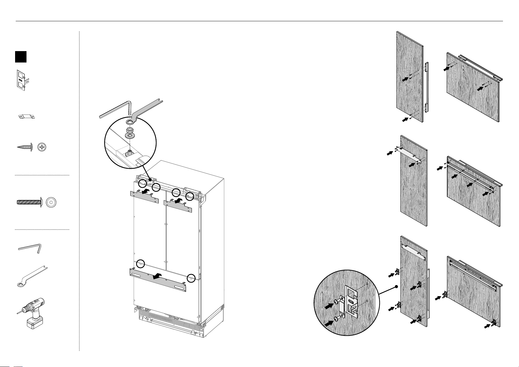
30
E
Retrait des supports d’accrochage
1
Retirez les rondelles M8 et les écrous M8 des goujons M8
dans le haut de la porte (A). Conservez les rondelles et
écrous pour les réutiliser ultérieurement.
2
Retirez le support d’accrochage du haut de chaque porte
et mettez-le de côté (B) pour l’installation ultérieure.
Fixation des poignées de porte et de tiroir (C)
3
Alignez les trous de poignée avec les trous du
panneau de porte, puis fixez à l’aide de vis à
tête creuse cylindrique M5x25 (4 pour chaque
panneau de porte).
Remarque: L’ensemble de poignée de porte
doit être acheté séparément. Reportez-vous à
‘Pièces’ (page -5) pour plus de détails.
B
A
Fixation des supports latéraux et des
bandes latérales (E)
5
Alignez les supports et les bandes sur les
trous de chaque côté du panneau, puis fixez
à l’aide de vis rondelles n°8x16 (20).
Fixation des supports d’accrochage (D)
4
Alignez le support sur les trous, puis fixez
à l’aide de vis rondelles n°8x16 (14).
C
C
D
D
Boîte interne
B
Ensemble
de fixation
de panneau
deporte
Support latéral
(10)
Bande latérale
(10)
#8 x 16
Mush Washer
Twin Thread
Philips Screw
#8 x 16
Mush Washer
Twin Thread
Philips Screw
Vis rondelle n°8x16
(Sur mesure) (34)
Ensemble de
poignée de porte
M5 x 25
Pan Head
Socket Screw
M5 x 25
Pan Head
Socket Screw
Vis à tête creuse
cylindrique M5x25 (12x)
Outils
Clé hexagonale
Clé FPA
Visseuse électrique
(optionnelle)
@0INSTALLATIONDE PANNEAU DE PORTE—SUR MESURE
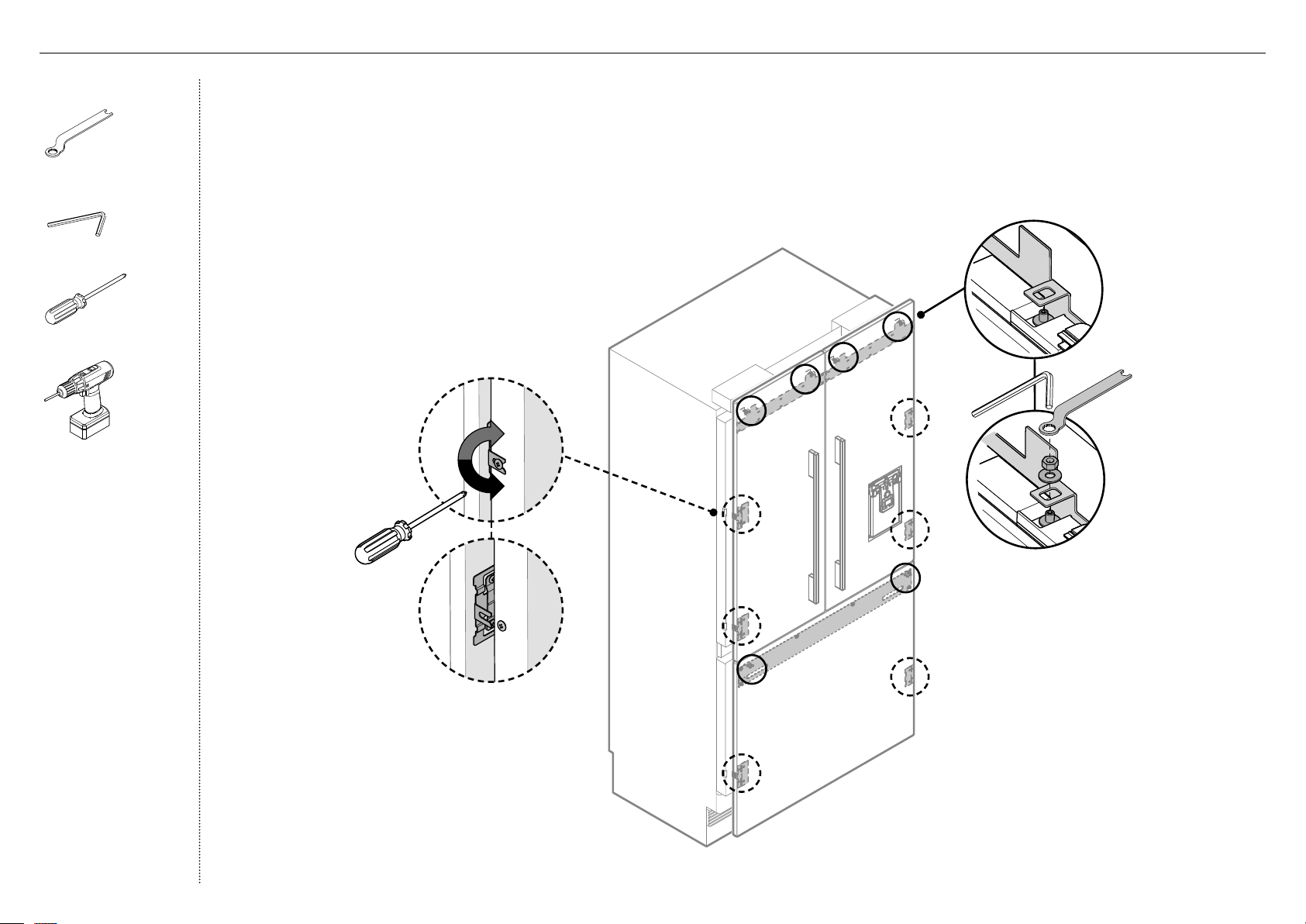
31
Fixation des panneaux de portes
1
Ouvrez la porte et desserrez les vis cruciformes M5x10
(ne les retirez pas) sur les côtés des portes (A).
2
Suspendez le panneau de porte en insérant les
goujonsM8 dans les trous du support d’accrochage (B).
3
Glissez les fourches des supports latéraux sur les vis
dela porte (C).
4
Vissez la rondelle et l’écrou M8 sur chaque goujon
(D), puis resserrez les vis latérales (E) pour fixer le
panneau de porte (ne serrez pas complètement).
Cela permettra d’ouvrir la porte sans affecter
l’ajustement du panneau de porte.
B
D
C
A
E
Outils
Clé FPA
Clé hexagonale
Tournevis cruciforme
Visseuse électrique
(optionnelle)
@0INSTALLATIONDE PANNEAU DE PORTE—SUR MESURE
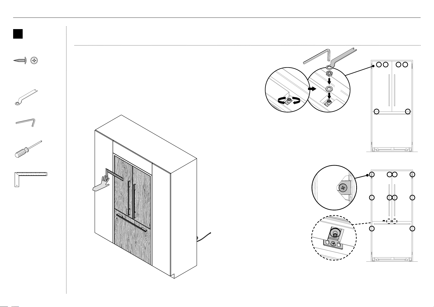
32
Ajustement des panneaux de portes
1
Placez une règle sur le devant du produit pour vérifier son
alignement, du haut vers le bas et de gauche à droite.
– Assurez-vous que l’espace entre le dessus du
panneau de porte et l’armoire du haut ne soit pas
supérieur à 1/4po (7mm).
– Pour réduire cet espace, élevez le produit en
tournant les quatre écrous d’ajustement du même
nombre de tours.
IMPORTANT!
Suivez ces étapes pour éviter des difficultés lors de l’ajustement du panneau de porte et l’installation du capuchon esthétique.
B
Ensemble de
fixation de
panneau de
porte
#8 x 16
Mush Washer
Twin Thread
Philips Screw
#8 x 16
Mush Washer
Twin Thread
Philips Screw
Vis rondelle n°8x16 (Sur
mesure) (2)
Outils
Clé FPA
Clé hexagonale
Tournevis cruciforme
Règle
@0INSTALLATIONDE PANNEAU DE PORTE—SUR MESURE
2
Chaque panneau de porte permet un réglage sur axe complet
pour assurer un ajustement au même niveau que les murs
adjacents. Pour ajuster la hauteur du panneau, tournez le
goujon dans le sens des aiguilles d’une montre pour élever le
panneau de porte ou dans le sens inverse pour l’abaisser (A).
3
Une fois satisfait de l’alignement, fixez les goujons M8 avec
la rondelle M8 et l’écrou M8 (B). Le dessus du goujon doit
demeurer sous la face supérieure du panneau de porte.
4
Fixez les fourches de support latéral en
serrant les vis latérales (C).
Répétez pour tous les panneaux de
portes.
Remarque:
– Pour l’ajustement en profondeur,
desserrez les vis latérales (10),
ajustez les panneaux, puis
resserrez les vis lorsque vous êtes
satisfait.
– Pour un ajustement
supplémentaire des panneaux
de portes, retirez les panneaux
de portes et desserrez les vis de
fixation du support d’accrochage,
puis déplacez le support
latéralement selon les besoins.
5
Desserrez le goujon M8 (D) de sorte
que le support de verrouillage puisse
glisser librement vers l'arrière.
– Glissez le support de verrouillage vers l’extérieur jusqu’à ce qu’il touche
à la partie arrière du panneau de porte. Serrez complètement le goujon M8.
– Vissez-le en place en utilisant une vis n°8x16 dans l’un des trois trous oblongs.
B
A
C
D
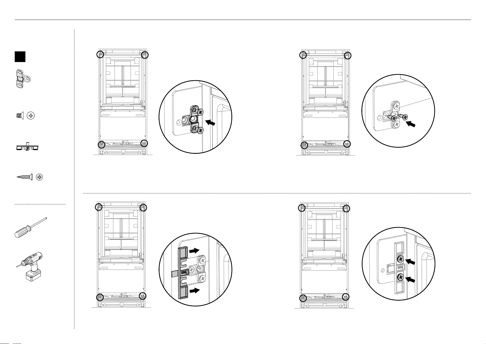
33
D
A
Boîte interne
G
Ensemble
d’installation
de support
defixation
Support de fixation
(4)
M5 x 8
Countersunk
Philips Screw
M5 x 8
Countersunk
Philips Screw
Vis cruciforme à
tête fraisée M5x8 (12)
Cache-vis
(4)
#8 x 19
Countersunk
Twin Thread
Posi Screw
#8 x 19
Countersunk
Twin Thread
Posi Screw
Vis à double filetage
n°8x19 (8)
Outils
Tournevis cruciforme
Visseuse électrique
(optionnelle)
1
Ouvrez doucement les portes françaises du réfrigérateur.
2
Placez les supports de fixation sur les supports de base
supérieurs et latéraux du produit, puis fixez-les à mi-chemin
à l’aide de vis cruciformes à tête fraisée M5x8 (A).
5
Fixez le cache-vis en serrant les vis cruciformes à
tête fraisée M5x8 (D).
Installation des supports de fixation
B
3
Fixez le centre de chaque support de fixation sur le côté du
mur adjacent à l’aide de vis à double filetage n°8x19 (B).
C
4
Glissez le cache-vis entre le support de fixation et le
support latéral sur le produit (C).
@1FIXATION AUX ARMOIRES
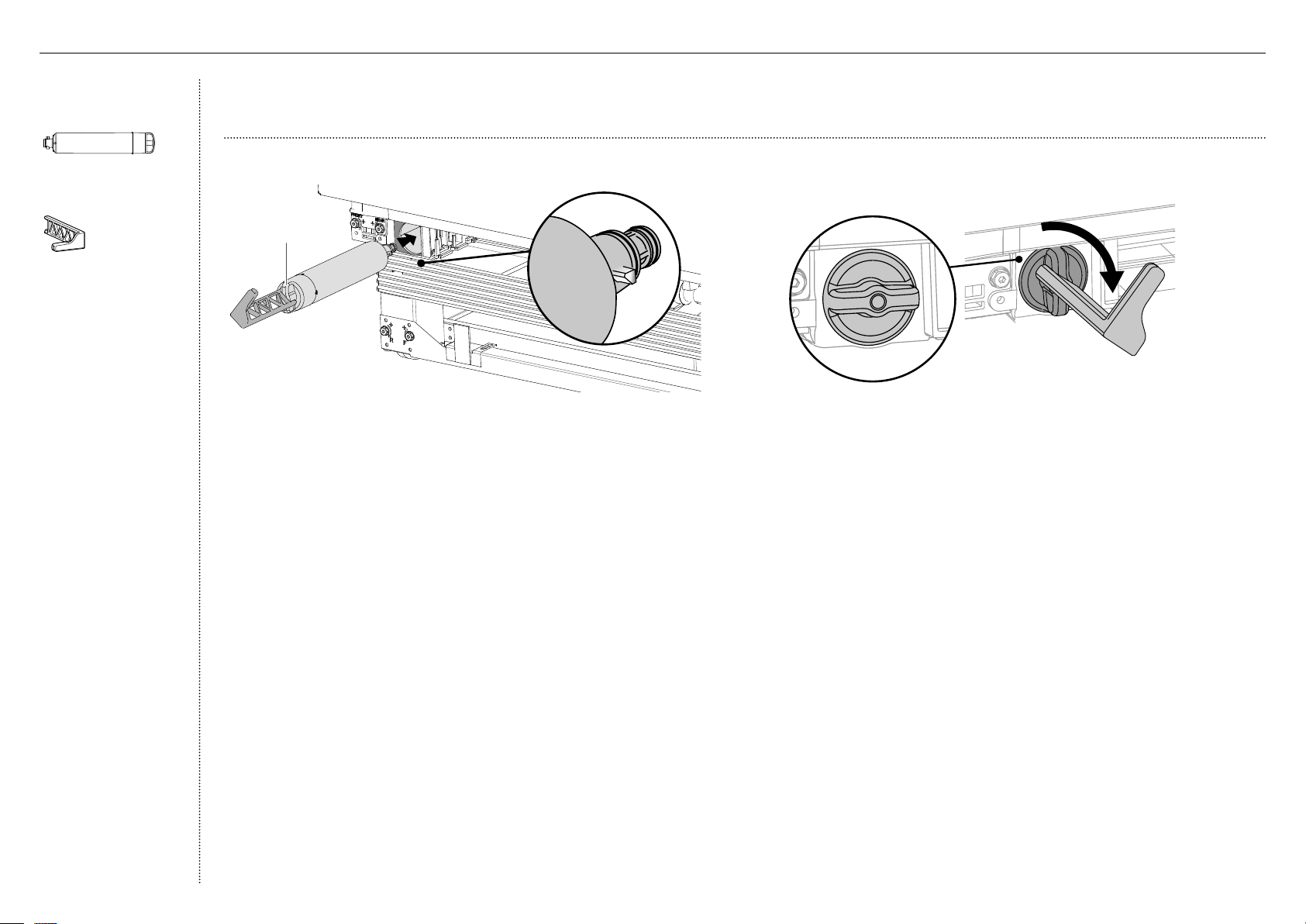
34
B
IMPORTANT!
La tête du filtre à eau doit être enfoncée fermement dans le produit et fixée, car une installation incorrecte pourrait entraîner des fuites d’eau.
4
Alignez l’outil de retrait de filtre sur la poignée du filtre et tournez de
90° dans le sens des aiguilles d’une montre pour serrer le filtre (B).
Retirez l’outil de retrait de filtre et fermez le tiroir de congélateur.
IMPORTANT!
Avant de mettre en marche votre appareil à glaçons automatique,
vous devez faire couler de l’eau dans le filtre pour éliminer les
impuretés ou l’air emprisonné dans le réservoir d’eau et le système
de filtration.
Reportez-vous à ‘Instructions d’utilisation—Appareil à glaçons
automatique’ dans le guide d’utilisation pour obtenir plus d’informations.
Installation du filtre à eau
1
Retirez l’emballage en plastique du nouveau filtre.
2
Ouvrez légèrement le tiroir de congélateur afin d’insérer le filtre à
l’intérieur du boîtier dans le coin inférieur gauche du produit.
Assurez-vous que la poignée du filtre soit positionnée à la verticale (A).
3
Poussez fermement la cartouche à l’intérieur du boîtier, complètement
dans la tête de filtre.
Filtre en position verrouillée
A
Vue de face
Poignée
du filtre
Emballage
d’articlesdivers
Filtre à eau
(1)
Outil de cartouche
filtrante (1)
@2INSTALLATION DU FILTRE À EAU
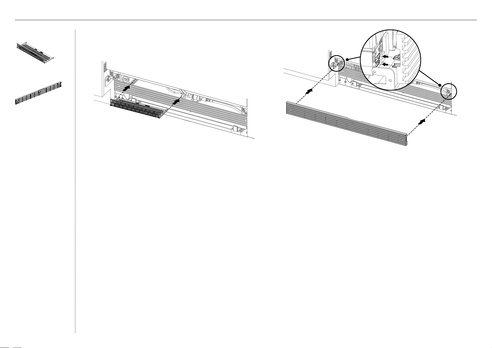
35
Installation de la grille du haut
2
Alignez les clips de la grille du haut avec les fentes de la plinthe
supérieure. Assurez-vous de placer la grille du haut dans le bon sens (B).
3
Poussez la grille fermement sur le produit jusqu’à ce que les clips
s’enclenchent (C).
B
C
Installation du filtre de plinthe
1
Installez le filtre sur les rails, puis poussez jusqu’à ce qu’il s’enclenche
solidement (A).
Boîte externe
Filtre de plinthe
(1)
Grille du haut
(1)
A
@3INSTALLATION DE LA PLINTHE
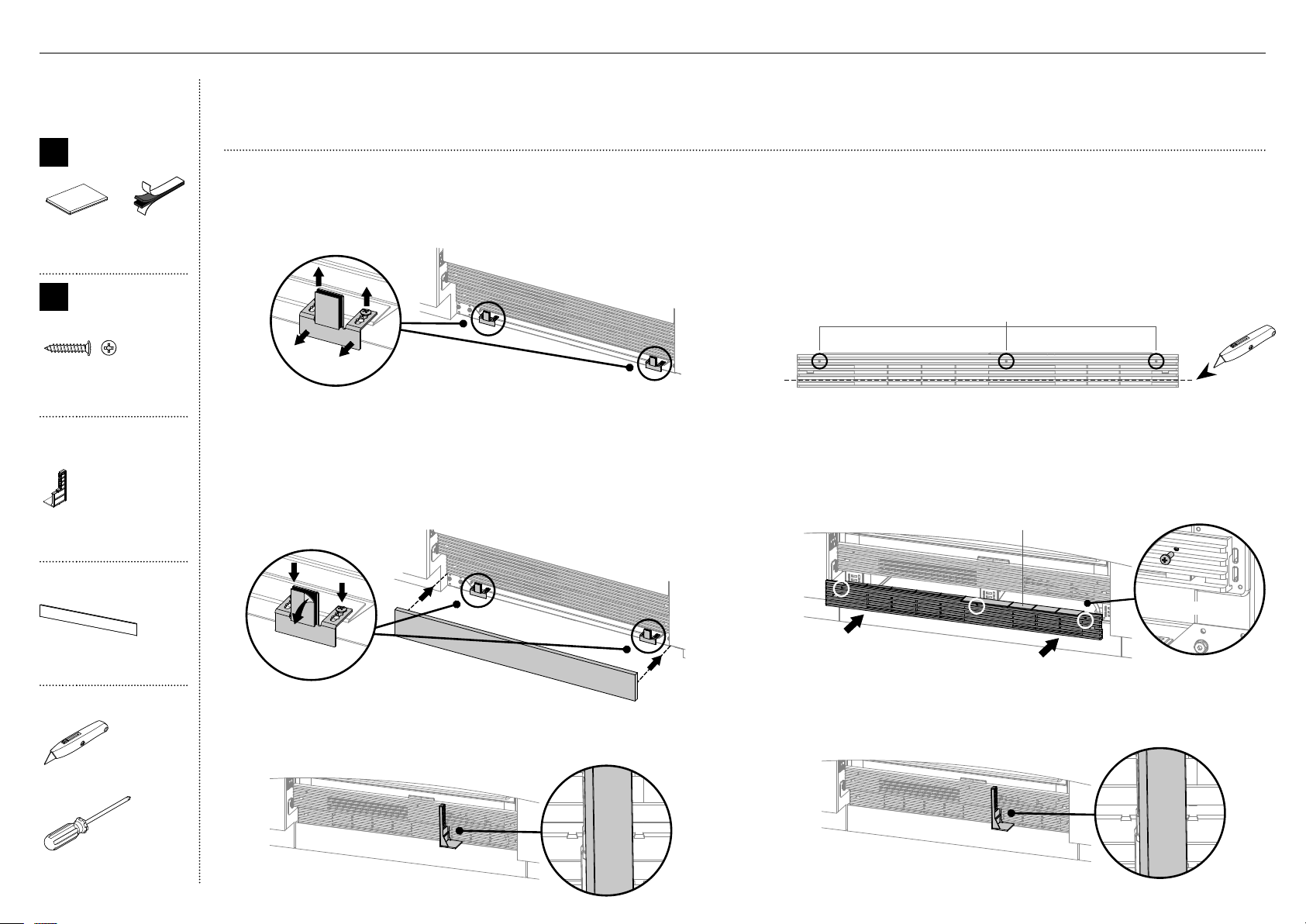
36
IMPORTANT!
Le produit standard est fourni avec une plinthe en acier inoxydable de 4po (102mm) et les pièces de montage requises pour l’installation de la plinthe.
Les clients peuvent également fournir leur propre plinthe sur mesure de 4 à 6po (102 à 152mm) pour l’encastrement complet du produit.
Pour une plinthe sur mesure dont la hauteur est supérieure à 4po (102mm)
5
Retirez la grille inférieure dans le bas du produit.
6
Mesurez la hauteur requise pour la grille inférieure.
Sur un carton, découpez/taillez avec soin les ailettes non requises dans
lebas de la grille de plinthe, puis jetez-les (E).
7
Percez des trous de Ø 5/32po (4mm) dans les encoches de la grille (F).
9
Alignez le diviseur de débit d’air sous l’indicateur de languettes de
la grille, puis fixez-le sur les ailettes de la grille inférieure (H).
Pour une plinthe standard—po (mm)
1
Desserrez les vis des supports de la plinthe (A) à mi-chemin,
puis déplacez les supports vers l’avant (B).
4
Alignez le diviseur de débit d’air sous l’indicateur de languettes de
la grille, puis fixez-le sur les ailettes de la grille inférieure (D).
A
B
C
DETAIL A
SCALE 1 : 1
DETAIL D
SCALE 2 : 1
IF TOEKICK IS HIGHER THAN 4" USE SIDE CUTTER TO
1.
CUT UNREQUIRED VANES FROM DOTTOM
DRILL HOLES THROUGH DIMPLES
2.
USE PROVIDED SCREWS TO FIX GRILL TO
3.
MATCHING HOLES ON PLASTIC PARTS
DETAIL A
SCALE 1 : 1
DETAIL D
SCALE 2 : 1
IF TOEKICK IS HIGHER THAN 4" USE SIDE CUTTER TO
1.
CUT UNREQUIRED VANES FROM DOTTOM
DRILL HOLES THROUGH DIMPLES
2.
USE PROVIDED SCREWS TO FIX GRILL TO
3.
MATCHING HOLES ON PLASTIC PARTS
D
DETAIL A
SCALE 1 : 1
DETAIL D
SCALE 2 : 1
IF TOEKICK IS HIGHER THAN 4" USE SIDE CUTTER TO
1.
CUT UNREQUIRED VANES FROM DOTTOM
DRILL HOLES THROUGH DIMPLES
2.
USE PROVIDED SCREWS TO FIX GRILL TO
3.
MATCHING HOLES ON PLASTIC PARTS
DETAIL A
SCALE 1 : 1
DETAIL D
SCALE 2 : 1
IF TOEKICK IS HIGHER THAN 4" USE SIDE CUTTER TO
1.
CUT UNREQUIRED VANES FROM DOTTOM
DRILL HOLES THROUGH DIMPLES
2.
USE PROVIDED SCREWS TO FIX GRILL TO
3.
MATCHING HOLES ON PLASTIC PARTS
H
8
Avec les languettes de la grille orientées vers le haut, alignez la grille
sur le bas de la plinthe de l’appareil, à l’endroit où les trous de vis
sont situés, puis fixez-la à l’aide de vis à tête cylindrique n°8x16 (G).
DETAIL A
SCALE 1 : 1
DETAIL D
SCALE 2 : 1
IF TOEKICK IS HIGHER THAN 4" USE SIDE CUTTER TO
1.
CUT UNREQUIRED VANES FROM DOTTOM
DRILL HOLES THROUGH DIMPLES
2.
USE PROVIDED SCREWS TO FIX GRILL TO
3.
MATCHING HOLES ON PLASTIC PARTS
Languettes de la grille
DETAIL B
SCALE 2 : 5
G
Vue avant droite
DETAIL A
SCALE 1 : 1
DETAIL D
SCALE 2 : 1
IF TOEKICK IS HIGHER THAN 4" USE SIDE CUTTER TO
1.
CUT UNREQUIRED VANES FROM DOTTOM
DRILL HOLES THROUGH DIMPLES
2.
USE PROVIDED SCREWS TO FIX GRILL TO
3.
MATCHING HOLES ON PLASTIC PARTS
E
Découpez avec soin les ailettes non requises dans le bas de la grille
F
2
Préalignez la plinthe en la plaçant devant les supports, jusqu’à ce
qu’elle soit au même niveau que les armoires à proximité. Une fois
satisfait de l’alignement, mettez la plinthe de côté et serrez les vis
de support afin de verrouiller les supports en position.
3
Enlevez l’endos adhésif d’un côté des languettes adhésives double
face, puis fixez-les aux supports. Enlevez l’endos adhésif de l’autre
côté des languettes adhésives double face, puis fixez la plinthe (C).
Boîte interne
E
Ensemble
d’installation de
garniture
de porte/tiroir
Languettes adhésives
double face (2)
Z
Pièces
diverses
#8 x 5/8
Pan Head
Philips Screw
#8 x 5/8
Pan Head
Philips Screw
Vis à tête cylindrique
n°8x16 (3)
Emballage
d’articles divers
Diviseur de débit d’air
(1)
Boîte externe
Plinthe
(1)
Outils
Couteau à lame rétractable
Tournevis cruciforme
@3INSTALLATION DE LA PLINTHE
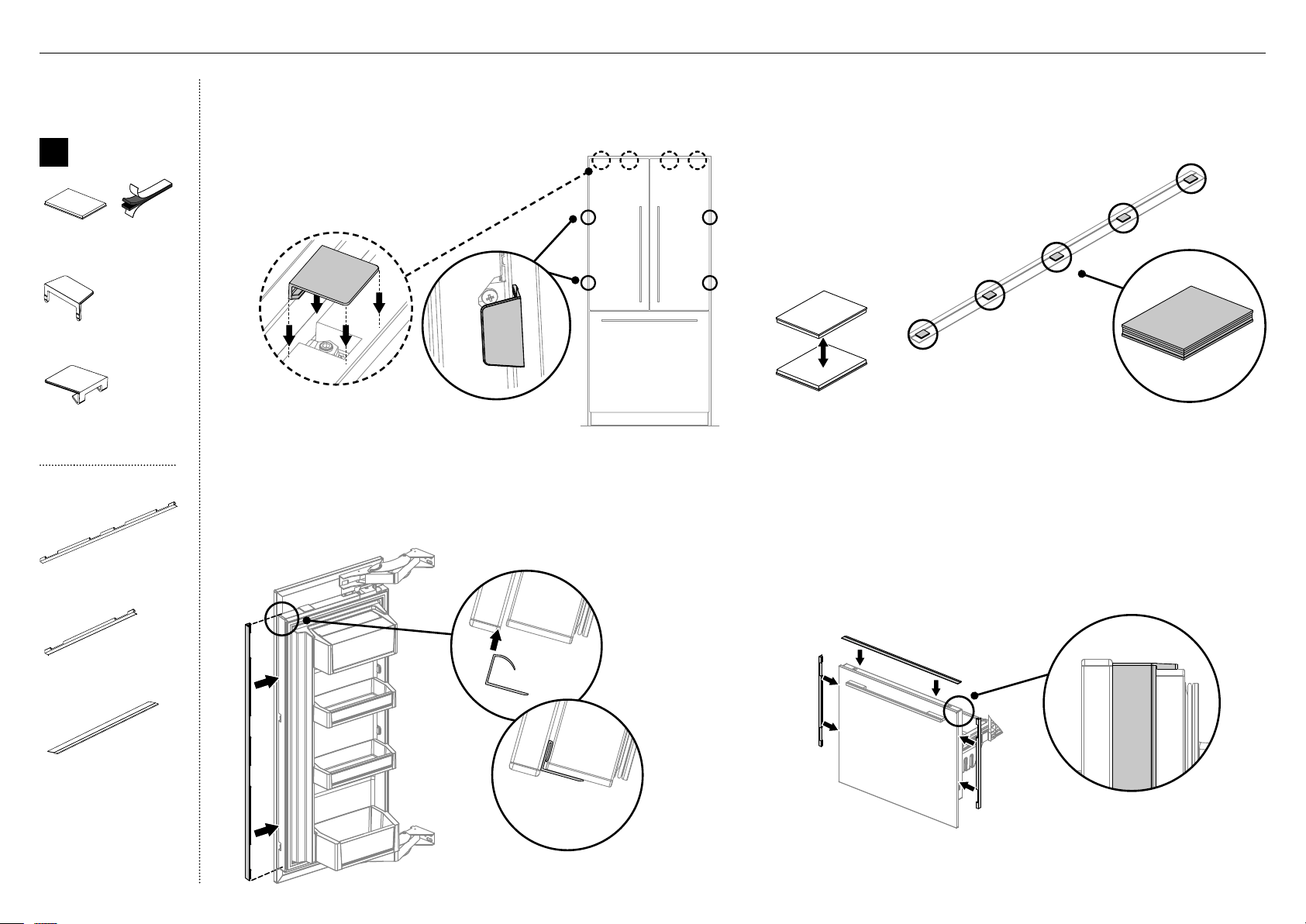
37
Fixation des garnitures latérales de porte
3
Installez les garnitures latérales en les insérant dans l’espace du
panneau de chaque côté de la ou des porte(s) (C). Alignez la garniture
avec le haut de la porte, puis enfoncez-la uniformément dans l’espace
du panneau jusqu’à ce qu’elle soit complètement logée (D).
C
D
A
B
F
E
Fixation des garnitures supérieure et latérales de tiroir
4
Appuyez ensemble des languettes adhésives double face pour former
des paires (E), puis enlevez l’endos adhésif d’un côté seulement.
5
Appuyez fermement sur le dessous de la garniture supérieure de tiroir,
aux emplacements indiqués (F).
6
Enlevez l’endos adhésif restant des languettes adhésives double face.
7
Placez la garniture contre la surface arrière du panneau, puis appuyez
fermement. Assurez-vous que la garniture repose complètement contre
la surface du tiroir (G).
8
Installez les garnitures latérales en les insérant dans l’espace du panneau
de chaque côté de la ou des porte(s) (H).
– Assurez-vous que le bâti soit centré pour éviter toute obstruction
avec les garnitures latérales.
G
H
Boîte interne
C
Ensemble
d’installation
de garniture
de porte/tiroir
Languettes adhésives
double face (10)
Couvercle latéral
(4)
Couvercle supérieur
(2)
Boîte externe
Garniture latérale
de porte (2)
Garniture latérale
de tiroir (2)
Garniture supérieure
de tiroir (1)
Fixation des couvercles
1
S’il y a lieu, retirez la pellicule protectrice
restante de vos panneaux de portes.
2
Ouvrez les deux portes. Fixez les couvercles
supérieurs (A) fermement sur les goujons
dans le haut, et les couvercles latéraux (B) sur
les supports latéraux. Fixation des garnitures
latérales de porte.
@4INSTALLATION DES GARNITURES DE PORTE ET TIROIR
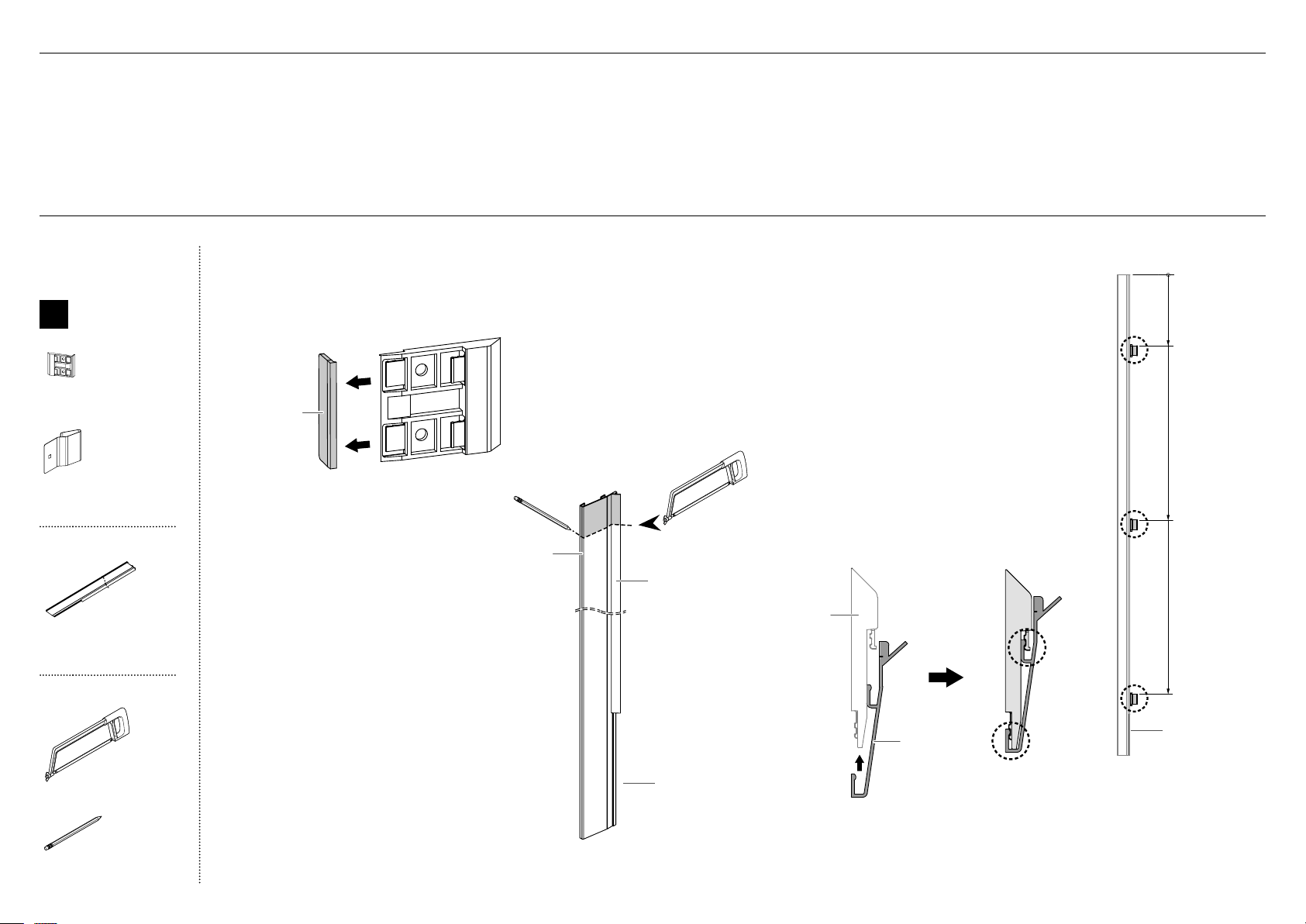
38
@5INSTALLATION DES GARNITURESDE BÂTI—[A] MÉTHODE AVEC CLIP DE FIXATION FLEXIBLE
4
Placez 3supports de garniture latérale sur
chaque garniture latérale.
Remarque: Mesurez à partir du haut de la
garniture, avec la languette courte vers le bas.
Reportez-vous à (B) pour l’orientation de la
garniture et les emplacements de support des
installations de 80po et 84po.
IMPORTANT!
Chaque support comporte deux points
d’enclenchement permettant d’installer la
garniture latérale. Assurez-vous d’enclencher
la garniture aux deux points (C).
Répétez cette étape pour toutes les
garnitures latérales.
80po = 9po
(229mm)
84po = 13po
(330mm)
80po = 36po
(914mm)
84po = 40po
(1016mm)
80po = 65po
(1651mm)
84po = 69po
(1753mm)
0
B
1
Brisez la languette de référence sur chaque support de garniture
latérale, puis jetez-la.
Répétez cette étape pour tous les supports de garniture latérale.
Jetez
Vue de dessus de la
garniture latérale enclenchée
correctement dans le support
de garniture latérale
C
Support de
garniture
latérale
Garniture
latérale
CHOISISSEZ L’UNE DES DEUX MÉTHODES D’INSTALLATION DES GARNITURES LATÉRALES DE BÂTI:
[A] MÉTHODE AVEC CLIP DE FIXATION FLEXIBLE — MÉTHODE RECOMMANDÉE
[B] MÉTHODE AVEC VIS FIXÉE — MÉTHODE À UTILISER SI LES ARMOIRES NE SONT PAS CONFORMES AUX SPÉCIFICATIONS
(Essayez la méthode [A]. Si la méthode [A] ne permet pas l’ajustement adéquat des garnitures latérales parce que les armoires sont inégales ou non conformes aux spécifications, utilisez la méthode [B].)
Pour l’installation dans une cavité de 80po
(2032mm) uniquement
2
Mesurez 4po (102mm) à partir du haut de
la garniture latérale avec une équerre, puis
marquez une ligne de découpage (A).
3
Coupez le long de la ligne avec une scie à
dents fines pour obtenir une longueur de
76po (1930mm) (B).
IMPORTANT!
Assurez-vous de couper bien droit et à
l’équerre, car il s’agit d’une surface exposée.
Veillez à ne pas plier la pièce de plastique,
car cela pourrait causer des marques de
contrainte visibles.
Répétez cette étape pour toutes les
garnitures latérales.
languette courte
languette courte
A
Plastique
Aluminium
B
Boîte interne
D
Ensemble
d’installation
de garniture
latérale de bâti
Support de garniture
latérale (6)
Clip de fixation
(6)
Boîte externe
Garniture latérale de bâti
(2)
Outils
Scie à métaux
Crayon
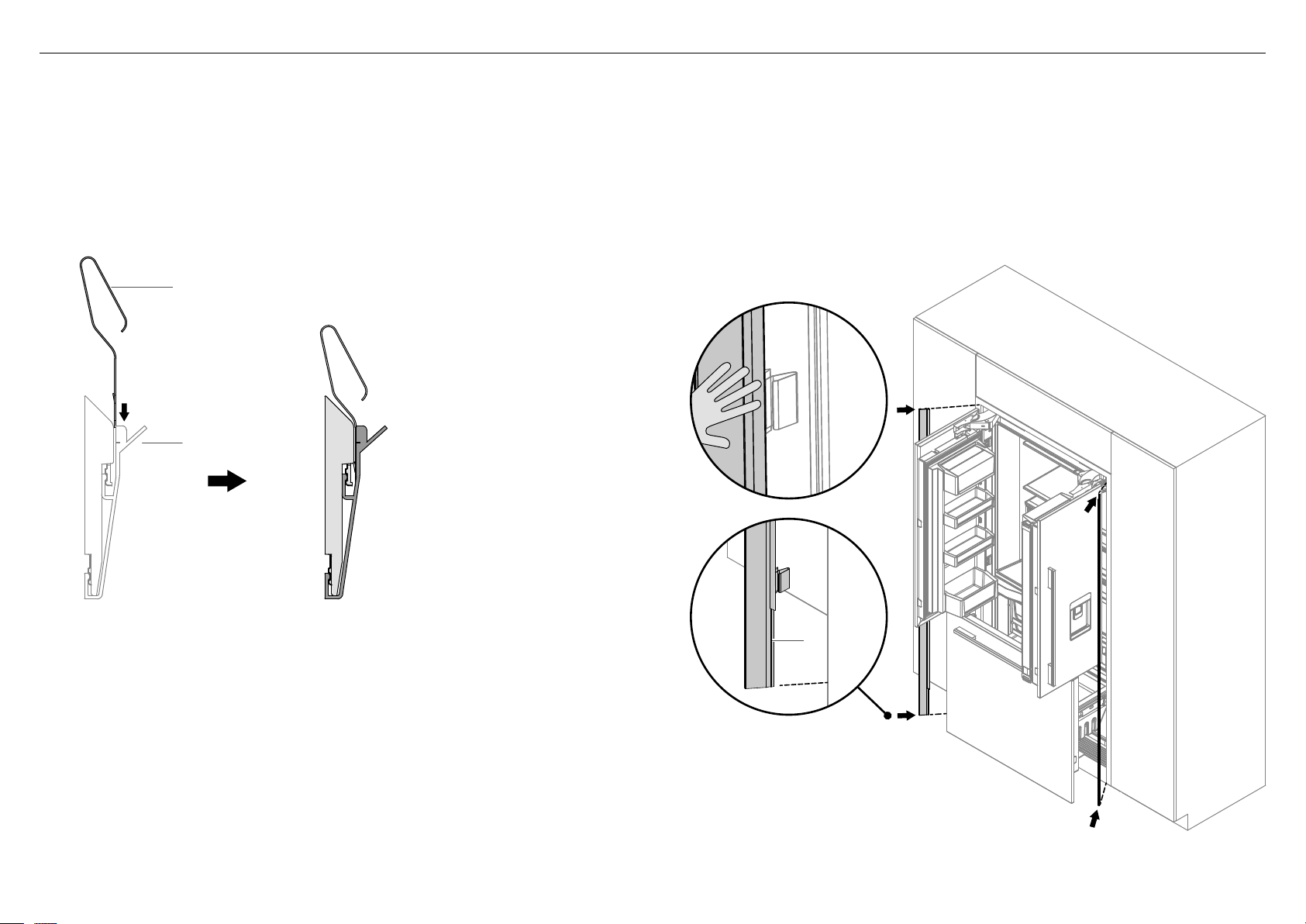
39
80po = 65po
(1651mm)
84po = 69po
(1753mm)
G
F
@5INSTALLATION DES GARNITURESDE BÂTI—[A] MÉTHODE AVEC CLIP DE FIXATION FLEXIBLE
5
Insérez le clip de fixation dans l’espace entre la garniture latérale et le support
de garniture latérale, en l’orientant comme dans les illustrations (D) et (E).
IMPORTANT!
Assurez-vous d’orienter correctement le clip de fixation, avec la boucle
ouverte vers la languette de la garniture latérale.
Répétez cette étape pour toutes les garnitures latérales.
6
Ouvrez les portes françaises. Placez la garniture latérale assemblée avec
les supports et clips de fixation contre la paroi de l’alcôve, en orientant la
languette courte vers le bas (F).
IMPORTANT!
Assurez-vous de positionner la garniture latérale aussi haut que possible.
Poussez la garniture latérale à chaque emplacement de support, jusqu’à ce
qu’il n’y ait aucun espace visible entre la garniture et l’armoire (G).
Répétez cette étape pour toutes les garnitures latérales.
Clip de fixation
Languette de
garniture latérale
D
Vue de dessus du clip de fixation inséré
correctement entre la garniture latérale et le
support de garniture latérale
E
languette courte
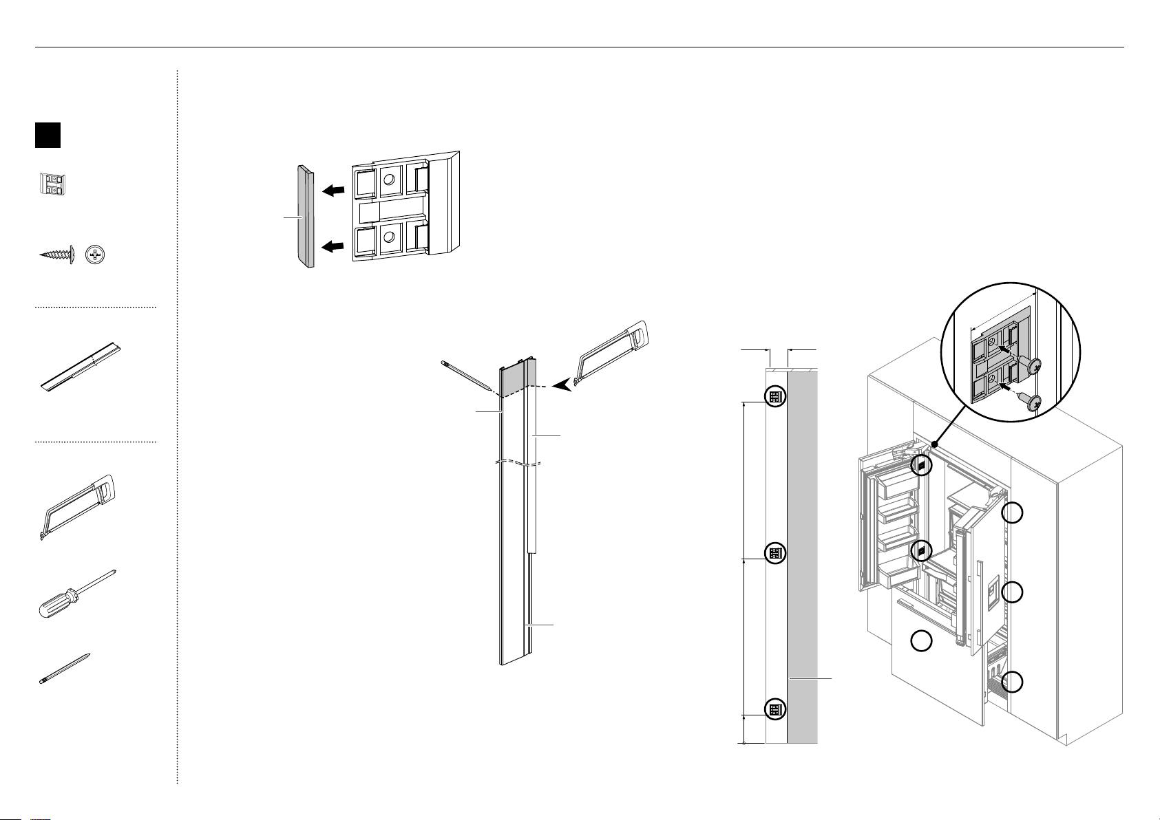
40
0
Devant de
l’appareil
C
~10po
(254mm)
~40po
(1016mm)
~69po
(1753mm)
2po (50mm)
2po (50mm)
D
4
Placez trois supports de garniture latérale sur une garniture latérale.
Reportez-vous à (B) pour connaître les emplacements des supports.
5
Ouvrez les portes françaises. Mesurez 2po (50mm) du devant de
l’appareil (depuis l’arrière des portes) vers le devant de l’alcôve, puis
marquez une ligne verticale précise (C).
6
Alignez le bord du support sur la ligne marquée, puis fixez le support
à l’armoire à l’aide de vis rondelles n°8x16 (D).
Répétez sur l’autre côté.
IMPORTANT!
Un positionnement imprécis du support peut entraîner l’incapacité
à installer la garniture latérale ou un espace entre la garniture
latérale et le réfrigérateur.
B
1
Brisez la languette de référence sur chaque support de garniture
latérale, puis jetez-la.
Répétez cette étape pour tous les supports de garniture latérale.
Jetez
Pour l’installation dans une cavité de 80po
(2032mm) uniquement
2
Mesurez 4po (102mm) à partir du haut de
la garniture latérale avec une équerre, puis
marquez une ligne de découpage (A).
3
Coupez le long de la ligne avec une scie à
dents fines pour obtenir une longueur de
76po (1930mm) (B).
IMPORTANT!
Assurez-vous de couper bien droit et
à l’équerre, car il s’agit d’une surface
exposée.
Veillez à ne pas plier la pièce de plastique,
car cela pourrait causer des marques de
contrainte visibles.
Répétez cette étape pour la garniture
latérale restante.
A
Plastique
Aluminium
B
languette courte
Boîte interne
D
Ensemble
d’installation
de garniture
latérale de bâti
Support de garniture
latérale (6)
#8 x 16
Mush Washer
Twin Thread
Philips Screw
#8 x 16
Mush Washer
Twin Thread
Philips Screw
Vis rondelle n°8x16 (12)
Boîte externe
Garniture latérale de bâti
(2)
Outils
Scie à métaux
Tournevis cruciforme
Crayon
@6INSTALLATION DES GARNITURESDE BÂTI—[B] MÉTHODE AVEC VIS FIXÉE
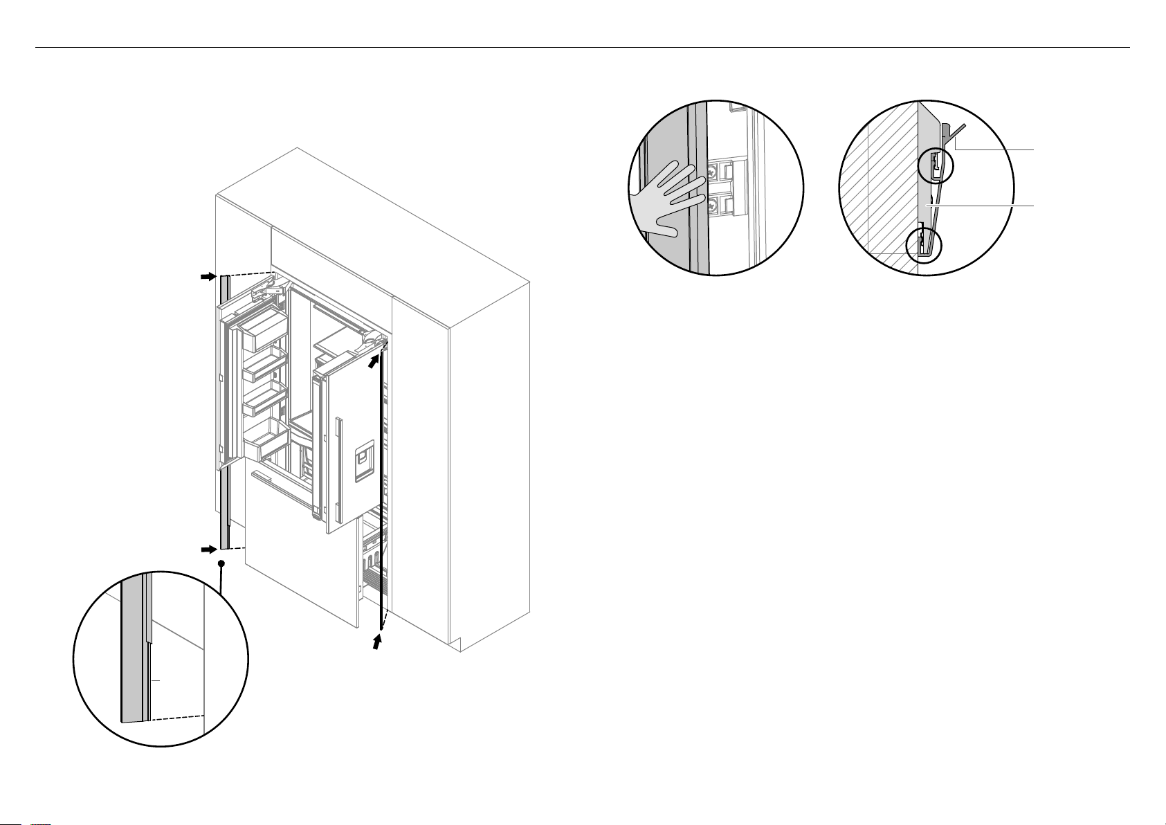
41
@6INSTALLATION DES GARNITURESDE BÂTI—[B] MÉTHODE AVEC VIS FIXÉE
7
Placez la garniture latérale contre la paroi de l’alcôve, avec la languette courte
orientée vers le bas (E).
– Assurez-vous de positionner la garniture latérale aussi haut que possible.
E
8
Enclenchez la garniture latérale dans les supports en poussant la
garniture vers l’intérieur aux emplacements des supports de garniture
latérale du haut et du centre.
9
Une fois la garniture enclenchée dans les supports du haut et du centre,
poussez sur la garniture latérale pour l’enclencher à l’emplacement du
support du bas (F).
Répétez cette étape pour les garnitures latérales restantes.
IMPORTANT!
Chaque support comporte deux points d’enclenchement permettant
d’installer la garniture. Assurez-vous d’enclencher la garniture aux deux
points (G).
Assurez-vous qu’il n’y ait aucun espace visible entre le produit et les
garnitures latérales.
Ajustez les espaces en desserrant les vis de garniture latérale afin de
déplacer la garniture dans les limites convenables. Si des ajustements
supplémentaires sont requis, déplacez les supports à l’endroit souhaité.
F
Suggestion by Derek showing
engagement in 2 places
“ensure they are fully engaged”
Support de
garniture
latérale
G
Vue de dessus de la garniture latérale
enclenchée correctement dans le support
de garniture latérale
Garniture
latérale
languette
courte

42
FISHERPAYKEL.COM
© Fisher&Paykel Products 2019. Tous droits réservés.
Les caractéristiques de produit présentées dans ce livret s’appliquent aux
modèles et produits spécifiques qui y sont décrits à la date de publication.
Dans le cadre de notre politique d’amélioration en permanence de nos
produits, ces caractéristiques peuvent être modifiées à tout moment.
Nous vous recommandons de vérifier auprès de votre détaillant que ce
livret décrit le produit actuellement disponible.
Remplir et conserver pour référence ultérieure:
Modèle _________________________________________________________
N° de série _________________________________________________________
Date d’achat _________________________________________________________
Acheteur _________________________________________________________
Adresse du détaillant _________________________________________________________
Nom de l’installateur _________________________________________________________
Signature de l’installateur _________________________________________________________
Entreprise d’installation _________________________________________________________
Date de l’installation _________________________________________________________
À ÊTRE REMPLIE PAR L’INSTALLATEUR
Tous les modèles
Assurez-vous de retirer tous les matériaux d’emballage internes et
externes du produit avant l’utilisation.
Vérifiez que toutes les pièces sont installées.
Assurez-vous que le produit est de niveau.
Assurez-vous que le produit est fixé solidement aux armoires à l’aide
du support antibasculement et des raccords fournis.
Assurez-vous que les portes/le tiroir peuvent s’ouvrir et se fermer
facilement, sans aucune résistance causée par les armoires à proximité.
Assurez-vous que la tige de limitation de charnière est ajustée pour
une rotation de porte à 90°.
Modèles Glaçons et eau uniquement
Assurez-vous de rincer le système de filtration d’eau.
Assurez-vous d’activer manuellement un cycle de l’appareil à glaçons.
@7LISTE DE VÉRIFICATION
