Owner’s Manual
Discovery™ Series Plate Loaded Line


Discovery Series Plate Loaded Line Owner's Manual: Important Safety Guidelines for Owners 1
Follow these guidelines to maintain proper working condition of the
equipment:
Important: Do not modify the equipment or any of its parts, or permanently remove
any part from the equipment. Do not use accessory attachments that are not
recommended by Precor, as such attachments might cause injuries.
Regular maintenance must be performed by qualified technicians.
Make sure that trainers, facility personnel, and maintenance technicians
understand how to use the equipment, know important safety guidelines,
and can recognize potential problems such as a cracked weld.
Strength training requires a significant focus by the facility and its staff to
maintain the quality of the fitness environment. If possible, the facility
should provide direct supervision of the fitness equipment at all times by
people knowledgeable about the safe operation of the equipment and
trained to recognize potential problems.
If any facility personnel witness unsafe use of the equipment, the staff
member should address the user directly, demonstrate the proper
technique, and review the Important Safety Information for Users. Precor
recommends posting a copy of the Important Safety Information for Users near
the equipment in a prominent location.
Make sure the equipment is stable and placed on a solid surface. The
equipment is designed to be freestanding; however, it can be bolted to the
floor for extra stability. Precor highly recommends that the equipment be
bolted to the floor to reduce the risk of toppling the equipment due to
improper use. Since floor construction varies, please consult a professional
building engineer for proper fastening.
Locate the equipment at least 40 inches (1 meter) away from walls or
furniture on either side of the equipment, and 40 inches (1 meter) away
from objects behind the equipment.
Check the equipment thoroughly based on the recommended inspection
schedules outlined in this manual, including daily, weekly, monthly and
annual checks.
Place an “out-of-order” sign on the equipment during maintenance of the
equipment or the surrounding area. Users should never be allowed to
operate the equipment until it has been inspected and works properly. If a
piece of equipment needs service, keep it out of use until repaired.
Do not attempt to free any jammed assemblies alone as this may cause
injury. With the help of another person, carefully return the mechanism to
its proper resting position.
Do not place the equipment outdoors or on wet surfaces.
Safety Approval
Precor commercial strength equipment is designed and tested according to EN
957-1/2 standards.
Important Safety Guidelines for Owners

Discovery Series Plate Loaded Line Owner's Manual: Important Safety Information for Users 2
Before beginning any fitness program, you should obtain a complete physical
examination from your physician.
French equivalent of the preceding paragraph, for the Canadian market: Il est
conseillé de subir un examen médical complet avant d’entreprendre tout programme
d’exercise. Si vous avez des étourdissements ou des faiblesses, arrêtez les exercices
immédiatement.
When using exercise equipment, you should always take basic precautions,
including the following:
If you do not understand how to operate a piece of equipment, ask
someone from the facility such as a trainer to demonstrate how to use it
and explain any safety instructions.
Do not allow children on or near the equipment. Do not leave children
unsupervised around the equipment.
Use the equipment only for its intended purpose. Do not use accessory
attachments that are not recommended by the manufacturer, as such
attachments may cause injuries.
Wear proper exercise clothing and shoes for your workout—no loose
clothing.
Do not overexert yourself or work to exhaustion. Use reasonable
judgment when working with weights. Avoid using excessive weight,
which may cause injury.
If you feel pain or abnormal symptoms, stop exercising immediately and
consult your physician.
Keep head, limbs, fingers, and hair clear of all moving parts while the
equipment is in use. Keep hands clear of racking pegs.
Never drop or insert objects into any opening in the equipment.
Always check the equipment before using it. If you spot a potential
problem, contact someone in the facility immediately. Do not use the
equipment until the facility has verified that the equipment is working
properly. Do not attempt to fix broken or jammed equipment.
Do not use the equipment outdoors or on wet surfaces.
Do not use the equipment if an "out of order" sign has been placed on it.
Read all posted instructions, including all safety instructions and warnings.
Important Safety Information for Users

Discovery Series Plate Loaded Line Owner's Manual: Table of Contents 3
Important Safety Guidelines for Owners .................................... 1
Safety Approval ...................................................................................... 1
Important Safety Information for Users ..................................... 2
Before You Begin ........................................................................ 4
Recommended Tools ........................................................................... 4
Obtaining Service .................................................................................. 5
Daily Inspection .......................................................................... 6
Clean Upholstery ...................................................................................6
Inspect Pads for Wear ..........................................................................6
Clean and Inspect Frames ...................................................................6
Check Warning and Instructional Labels ........................................ 7
Weekly Inspection ...................................................................... 9
Condition and Deep Clean Upholstery ............................................9
Inspect and Lubricate Bearings and Bushings ............................. 10
Check and Lubricate Seat Adjustment .......................................... 10
Monthly Inspection ..................................................................... 11
Inspect Frames and Movement Arms ............................................ 11
Inspect All Fasteners ........................................................................... 11
Table of Contents

Discovery Series Plate Loaded Line Owner's Manual: Before You Begin 4
Precor recommends implementing a thorough maintenance program that
incorporates regular safety inspections by qualified maintenance technicians
as outlined in this manual.
This manual explains how to maintain the Precor Discovery Plate Loaded line
of commercial strength equipment. It provides information about items that
need to be inspected and maintained on a daily, weekly, monthly, and annual
basis. You should perform those tasks that are appropriate for the equipment
you are maintaining, and skip those tasks that do not apply.
This manual covers the general maintenance procedures that you can perform
in the fitness facility. However, if the equipment requires service beyond the
maintenance procedures covered in this manual, refer to Obtaining Service.
Important: Always purchase replacement parts and hardware from Precor. Many
parts are tested and manufactured specifically for Precor commercial strength
equipment. If you use parts not approved by Precor, you could void the Precor
Limited Warranty. Use of parts not approved by Precor may cause injury.
Precor recommends that maintenance technicians thoroughly read and
understand the safety guidelines and maintenance procedures covered in this
manual.
Note: If the equipment requires assembly, a separate assembly guide is
provided. For information on how to use a piece of equipment, refer to the
instructional label found on the equipment and the Product Specifications and
Use section in this manual.
Recommended Tools
We recommend that you keep the following tools available to inspect and
maintain the equipment:
Complete combination box wrench set (common metric sizes)
Complete socket set (common metric and SAE sizes)
Complete hex key set (common metric sizes)
12-inch adjustable wrench
Rubber mallet
Before You Begin

Discovery Series Plate Loaded Line Owner's Manual: Before You Begin 5
Obtaining Service
You should not attempt to service the strength equipment, except for the
maintenance tasks described in this manual. If any items are missing, contact
your dealer. If you need more information regarding customer support
numbers or a list of Precor authorized service centers, visit the Precor website
at www.precor.com.
If you have any questions regarding a piece of equipment, locate its serial
number and contact Precor Customer Support. Precor uses the serial number
to establish the model and year of the product. You can generally find the
serial number underneath the seat support.
For future reference, write the serial numbers, model numbers, and dates of
purchase for your Precor strength training equipment in the space provided.
You may want to list all equipment information below for easy reference.
Model #: Serial #:
Date purchased:
Model #: Serial #:
Date purchased:
Model #: Serial #:
Date purchased:
Model #: Serial #:
Date purchased:
Model #: Serial #:
Date purchased:
Model #: Serial #:
Date purchased:
Model #: Serial #:
Date purchased:
Model #: Serial #:
Date purchased:
Model #: Serial #:
Date purchased:
Model #: Serial #:
Date purchased:
Model #: Serial #:
Date purchased:
Model #: Serial #:
Date purchased:

Discovery Series Plate Loaded Line Owner's Manual: Daily Inspection 6
You will need to perform the following tasks each day to maintain the
equipment and keep it operating smoothly:
Clean any upholstery on the equipment.
Inspect pads for wear.
Clean and inspect equipment frames.
Check warning and instructional labels.
Clean Upholstery
To remove surface dirt and perspiration, clean upholstery daily with a mild
soap and water solution in a spray bottle. Spray upholstered surfaces lightly
and wipe dry with a clean cloth.
Important: To clean the upholstery, do not use cleaning products that have any of
these ingredients: solvents, alcohol, ammonia, or petroleum. Use a mild detergent-
based cleaner instead.
Inspect Pads for Wear
Inspect pads for cracks in the upholstery, broken and loose stitching, loose
staples, and loose mounting bolts. Replace pads as needed (refer to Obtaining
Service to purchase new pads).
Important: Do not reupholster pads or use pads not approved by Precor.
Clean and Inspect Frames
To remove grease and dirt, clean frames daily with a mild soap and water
solution in a spray bottle. Wipe the equipment down with a damp cloth and
dry completely. Be sure to wipe down both painted parts and chrome or plated
parts.
To restore and maintain the luster of chrome parts, use a commercial chrome
cleaner.
As you clean, inspect the frames for cracks, rust, or other damage. Make sure
welds are solid and fasteners are properly secured.
Daily Inspection
Discovery Series Plate Loaded Line Owner's Manual: Daily Inspection 7
Check Warning and Instructional Labels
Inspect warning and instructional labels daily to make sure that all the
information can be clearly read. If any portion is not visible or part of the label
is not adhered properly, replace that label immediately (refer to Obtaining
Service for purchase information).
Clean labels as needed with a mild soap and water solution in a spray bottle,
and dry thoroughly with a soft cloth.
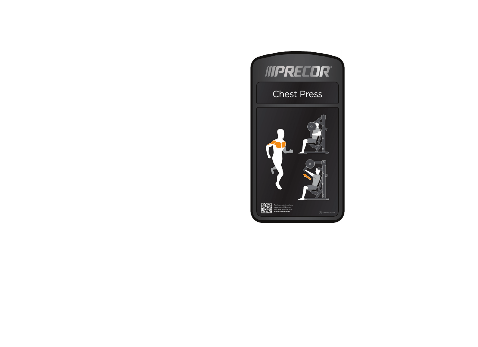
The following figure shows an example of an instructional placard assembly,
which contains labels for the name of the equipment and the workout
instructions.
Figure 1: Example instructional placard

Discovery Series Plate Loaded Line Owner's Manual: Daily Inspection 8
Precor products come equipped with a number of standard warning labels. The
following two figures show sample warning labels you may see on the
equipment depending on the model and product line:
Figure 2: Warning label indicating pinching hazard
Figure 3: General warning label mounted on the equipment frame

Discovery Series Plate Loaded Line Owner's Manual: Weekly Inspection 9
This section covers the tasks you should perform each week to maintain the
equipment. Perform the following tasks as appropriate for the unit you are
maintaining:
Condition and deep clean upholstery.
Inspect and lubricate bearings and bushings.
Check and lubricate the seat adjustment mechanism.
Condition and Deep Clean Upholstery
Condition and deep clean the upholstery weekly with a lanolin-based hand
cleaner or upholstery cleaner.
Important: To clean the upholstery, do not use cleaning products that have
any of these ingredients: solvents, alcohol, ammonia, or petroleum. Use a mild
detergent-based cleaner instead.
Weekly Inspection

Discovery Series Plate Loaded Line Owner's Manual: Weekly Inspection 10
Inspect and Lubricate Bearings and
Bushings
Precor uses high quality bearings designed for strength applications and long
service life. Each week, do the following to maintain the bearings and bushings
on the equipment:
Bronze bushings: Precor recommends using a small amount of silicone
spray lubricant to lubricate these bushings, which usually support rotary
shafts. Spray directly onto the shaft, and then rotate the shaft through its
complete range of motion several times. Inspect bushings for excessive
wear and damage. Be careful when using the spray lubricant; it can stain
carpet and clothing. Wipe off any excess lubricant with a cloth.
Sealed Bearing Pivot Points: These locations are protected from the
outside environment and require no lubrication. While cleaning the
equipment, wipe down the shafts and external bearing surfaces with a
cloth to prevent the buildup of dust and perspiration.
Check and Lubricate Seat Adjustment
The seat adjustment mechanism requires little maintenance. However,
because seat safety is important to the safety of a workout, you should check
the seat lever regularly to see if it sticks when used.
To test if the seat lever needs lubrication, elevate the seat slightly while
pressing and releasing the lever. The lever should snap back out easily. If the
lever sticks, lubricate its pivot pin with Teflon
®
spray lubricant. Wipe off any
excess lubricant with a cloth.

Discovery Series Plate Loaded Line Owner’s Manual: Monthly Inspection 11
This section covers the tasks you should perform each month to maintain the
equipment. Perform the following tasks as appropriate for the unit you are
maintaining:
Inspect frames and movement arms.
Check and lubricate ratcheting seat lever.
Inspect all fasteners.
Inspect Frames and Movement Arms
Inspect frames and movement arms monthly for proper function and integrity.
Check for cracks, chipped paint, or rust. Touch up dings and chips in the paint
as needed. Replace any component at first signs of wear.
Note: You can order touch-up paint from Precor by calling Customer Support.
Refer to Obtaining Service.
Inspect frames for cracks, particularly at the joints. If any cracks are found,
take the equipment out of service immediately and have a qualified
maintenance technician repair it. Refer to and Obtaining Service.
To remove surface rust from the frame, rub lightly with a fine wet/dry
sandpaper or fine steel wool. Finish with Precor touch-up paint if needed.
Maintain paint luster with an application of a mild automotive wax product.
To maintain the powder coated, plated, and chrome parts, use a mild
detergent-based cleaner for light dirt and grime removal. For removing heavier
dirt and grease and for polishing, use a good automotive polish. For scuffs and
marks that are not removed by the above methods, use a fine-grit cleanser. Do
not use solvents, lacquer thinner, acetone, or fingernail polish remover.
Inspect All Fasteners
Fasteners can loosen with normal use. Inspect all nuts, bolts, screws, and other
fasteners to make sure they are tight and installed correctly.
Be sure to check fasteners at bolted joints to make sure the connections are
secure. If a fastener is loose but in good condition, retighten it. If you are
concerned about the integrity of the fastener, remove it, clean the threads, and
inspect it for any damage such as cracks, bad threads, corrosion, or rust.
Reinstall the fastener if it appears to be in good condition. Otherwise, remove
the equipment from service until a new fastener can be installed properly. You
can order new fasteners from Customer Support. For additional information,
refer to Obtaining Service.
Important: Fastener quality and specifications vary considerably. Replace only with
the Precor approved fastener specifically engineered for the precise application.
Failure to do so will void the Precor Limited Warranty.
Monthly Inspection

Discovery Series Plate Loaded Line Owner’s Manual: Monthly Inspection 12
Notes:


Precor Incorporated
20031 142nd Ave NE
P.O. Box 7202
Woodinville, WA USA 98072-4002
1-800-347-4404
Precor is a registered trademark and Discovery is a trademark of Precor Incorporated.
Copyright 2014 Precor Incorporated.
Specifications subject to change without notice.
www.precor.com
NOTICE:
Precor is widely recognized for its innovative, award winning designs of exercise equipment. Precor
aggressively seeks U.S. and foreign patents for both the mechanical construction and the visual aspects of its
product design. Any party contemplating the use of Precor product designs is hereby forewarned that Precor
considers the unauthorized appropriation of its proprietary rights to be a very serious matter. Precor will
vigorously pursue all unauthorized appropriation of its proprietary rights.
Discovery™ Series Plate Loaded Line Owner’s Manual
CWP997777-201, rev B en
31 October 2014
Assembly Guide
Discovery Plate Loaded™ Line
Shoulder Press


Shoulder Press Assembly Guide: Table of Contents 1
Getting Started ............................................................................ 2
Opening the Boxes ................................................................................ 2
Installation Requirements ................................................................... 2
Hardware Kit (not to scale) ................................................................ 3
Assembling the Equipment ........................................................ 6
Stabilizing the Equipment .................................................................... 7
Attaching the Side Uprights to the Base Frame ........................... 8
Installing the Crossbar ........................................................................ 8
Installing the Center Upright Assembly ..........................................9
Installing the Movement Arms ........................................................ 10
Attaching the Movement Arm Counterweights .......................... 11
Attaching the Back Pads ..................................................................... 11
Attaching the Seat Pad ....................................................................... 12
Connecting the Gas Spring ............................................................... 13
Adjusting the Seat Rollers ................................................................. 14
Attaching Weight Horns to the Movement Arms ...................... 15
Attaching Weight Storage Horns .................................................... 15
Attaching the Instructional Placard and Safety Labels ............. 16
Table of Contents

Shoulder Press Assembly Guide: Getting Started 2
Opening the Boxes
Open the boxes and remove the packing materials. Be careful to open the
boxes and assemble the components in the sequence presented in this
manual.
Box
Contents
1 Frame members
Movement arms
Weight horns
Weight storage horns
Instructional placard
Warning labels
Hardware kit
2 Seat pads
Installation Requirements
WARNING
You will need assistance to assemble this unit. DO
NOT attempt assembly by yourself.
Follow these installation requirements when assembling the unit:
Assemble the unit near the place where you plan to use it.
Locate the equipment at least 40 inches (1 meter) away from walls or
furniture on either side of the equipment, and 40 inches (1 meter) away
from objects behind the equipment.
Set up the unit on a solid, flat surface, so that it remains level and stable. A
level unit has fewer malfunctions.
Open the box and assemble the components in the sequence presented in
this guide.
Insert, align, and thread all fasteners with your fingers. This helps prevent
cross-threading. Do not wrench tighten fasteners until instructed to do so.
Important: Before you wrench tighten a fastener, check that its head is flush
with the surface of the product. If not, cross-threading may have occurred. Do
not attempt to rework the assembly as more damage to the equipment will
occur. Instead, contact Customer Support as described in Obtaining Service.
If you plan to move the unit, get help and use a hand truck.
Getting Started
Shoulder Press Assembly Guide: Getting Started 3
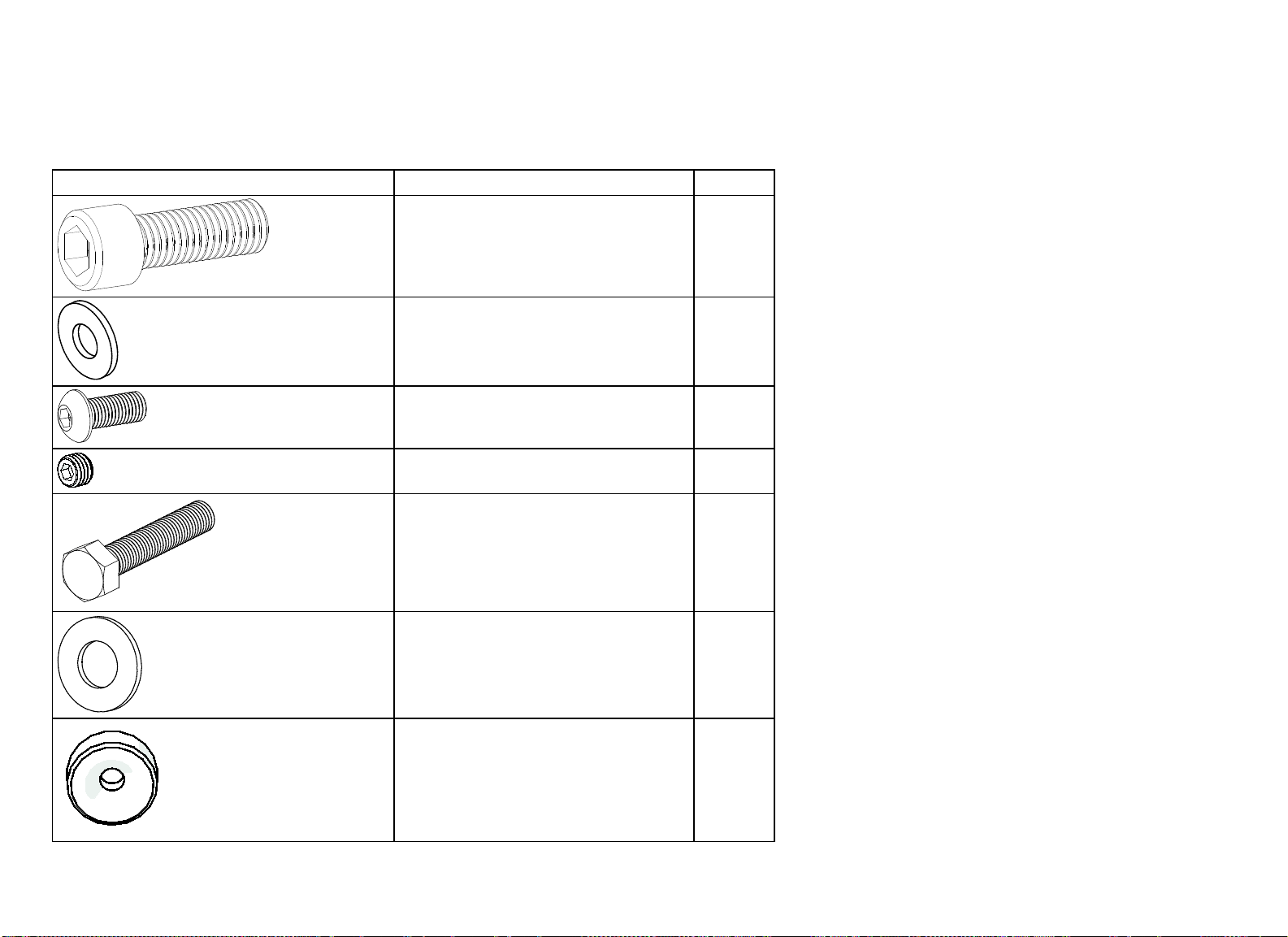
Hardware Kit (not to scale)
The following pieces of hardware are provided on a shrink-wrapped card. Each part is labeled on the card for easy reference.
Table 1. Hardware kit contents
Fastener
Quantity
Socket head cap screw (M12 x 35 mm) 16
Flat washer (9 mm internal diameter)
9
Buttonhead cap screw (M8 x 15 mm)
1
Set screw (M8 x 6 mm) 8
Hex head cap screw (⁵₁₆-inch x 1¹₂-inch)
8
Flat washer (13 mm internal diameter)
16
Axle mount end 4

Shoulder Press Assembly Guide: Getting Started 4
Fastener
Quantity
Frame plug
4
Flat head hex cap screw (M12 x 30 mm) 6
Flat head hex cap screw (M8 x 25 mm)
4
⁵₁₆-inch nylon lock nut
2
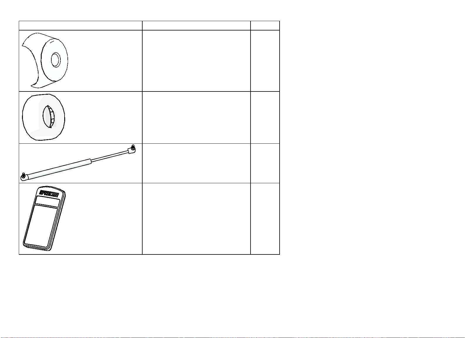
Table 2. Other Components
Part
Quantity
Weight horn
2
Weight storage horn 4
Arm pivot axle
2
Weight horn bumper
2
Shoulder Press Assembly Guide: Getting Started 5
Part
Quantity
Weight horn end cap
2
Weight storage horn bumper 4
Gas spring
1
Instructional placard
1
Shoulder Press Assembly Guide: Assembling the Equipment 6
CAUTION: At least two people are required to position the parts of this
equipment successfully. Do not attempt to assemble the equipment by
yourself.
Proper alignment and adjustment of the equipment is critical. When you
install fasteners, leave room for adjustments. Do not tighten the fasteners
completely until you are instructed to do so.
Make sure the equipment is stable and placed on a solid surface. The
equipment is designed to be freestanding, but it can be bolted to the floor
for extra stability. Precor highly recommends that the equipment be bolted
to the floor to reduce the risk of toppling due to improper use. Because floor
construction varies, consult a professional building engineer for proper
fastening.
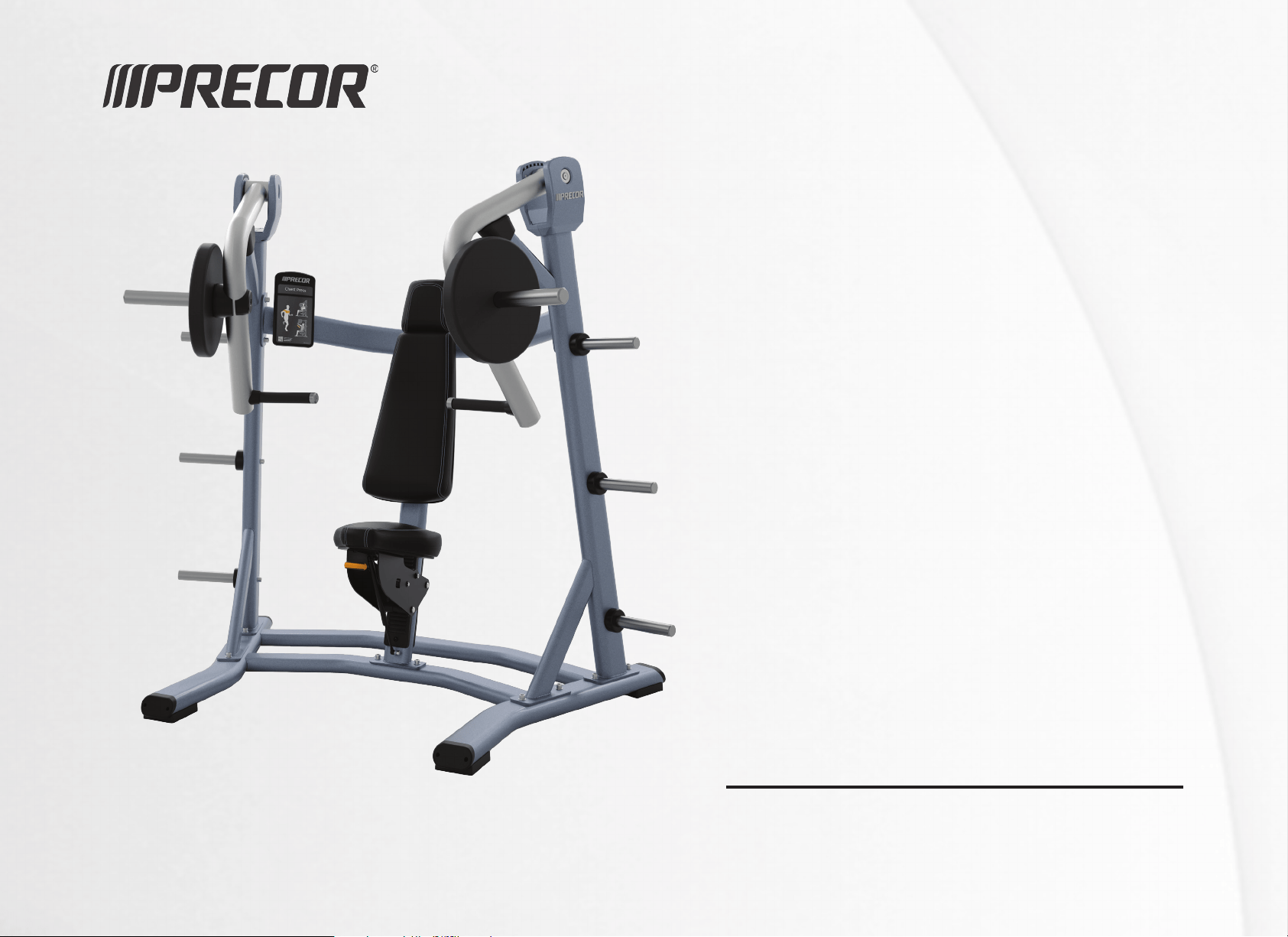
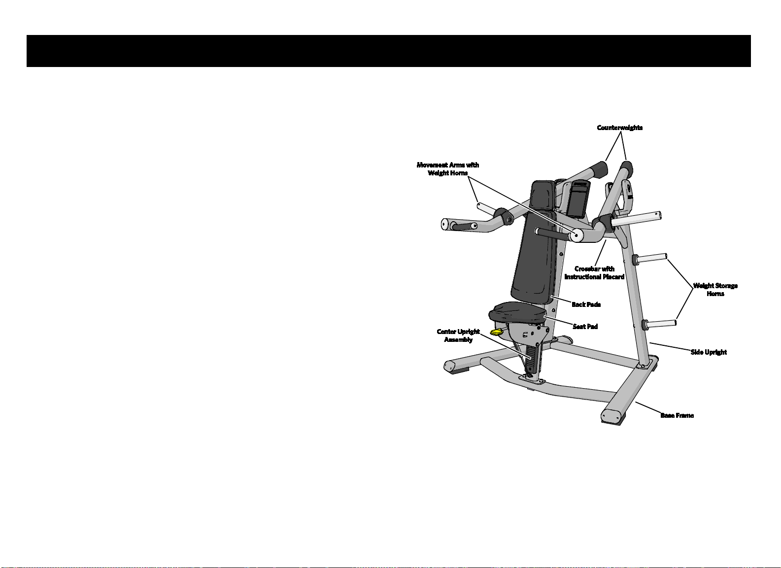
The following figure shows the names used in this manual for the major
components of the equipment.
Figure 1: Major Shoulder Press components
Assembling the Equipment
Shoulder Press Assembly Guide: Assembling the Equipment 7
Stabilizing the Equipment
Once you have positioned the base frame where you want the equipment to be
used, test it for stability by pushing down on its corners. If the base frame
rocks or wobbles at all, the height of the adjustable foot will need to be set.
To stabilize the equipment:
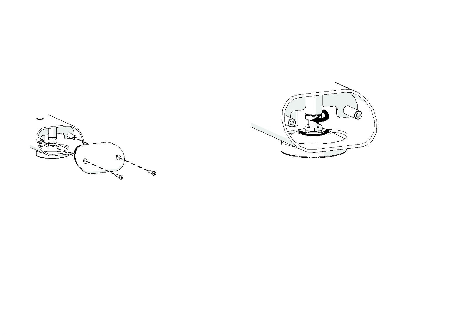
1. Locate the round, adjustable foot at one of the corners of the base frame.
2. Remove the two small buttonhead screws retaining the end cap at that
corner of the frame, as shown in the following figure. Pull out the end cap,
then set the cap and the screws aside.
Figure 2: End cap removal
3. Using an open-end wrench, turn the jam nut to the left to loosen it.
4. Using the same open-end wrench, turn the positioning bolt to the left or
the right to move the adjustable foot to the appropriate level, as shown in
the following figure.
If you want to move the adjustable foot ... Then turn the bolt ...
Upward To the right
Downward To the left
Figure 3: Adjustable foot positioning
5. Once the foot appears to be positioned correctly, test it by pressing down
on the corners of the base frame. If it continues to shift or rock, readjust
the foot as needed.
6. Re-tighten the jam nut.
7. Reinsert the end cap and its retaining screws. Tighten the screws
completely.
Shoulder Press Assembly Guide: Assembling the Equipment 8
Attaching the Side Uprights to the Base
Frame
Perform the following procedure to attach both side uprights to the base
frame.
To attach the side uprights to the base frame:
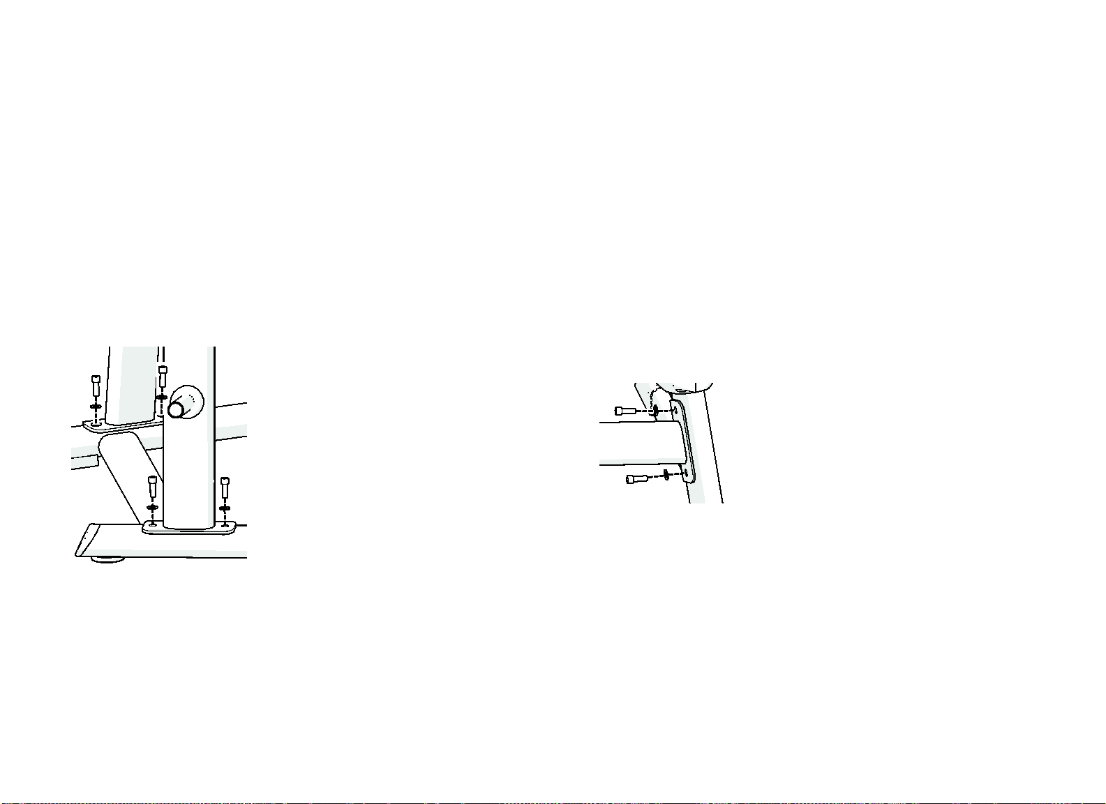
1. Position the left side upright on the base frame so that the screw holes on
the base frame and the upright line up.
Note: Ask that your assistant hold the side uprights while you secure them
into position.
2. Add one M12 x 35mm socket head cap screw and one 13mm flat washer to
each of the screw holes. Finger tighten the fasteners.
Figure 4: Side upright attachment
Installing the Crossbar
Note: Have your assistant hold the crossbar in place while you perform this
procedure.
To attach the crossbar to the side uprights:
1. Position the crossbar between the side uprights so that the curve of the
crossbar extends backward and the screw holes at either end line up with
the screw holes on the side uprights.
2. Place a 13 mm flat washer over a M12 x 35 mm socket head cap screw.
Insert the screw into the upper screw hole at one end of the crossbar and
tighten it partially.
3. Place a 13 mm flat washer over a M12 x 35 mm socket head cap screw.
Insert the screw through the lower screw hole and then tighten it.
4. Repeat steps 2 and 3 to attach the crossbar on the other side of the frame.
Figure 5: Crossbar attachment
Shoulder Press Assembly Guide: Assembling the Equipment 9
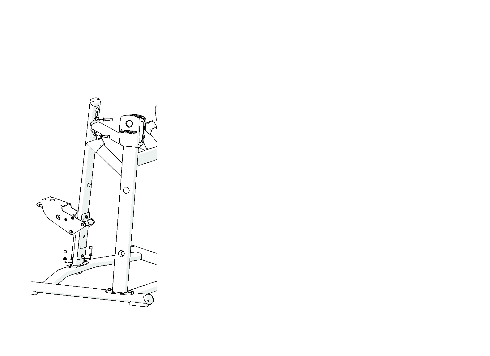
Installing the Center Upright Assembly
Attaching the center upright assembly and the accompanying seat mechanism
completes the frame of the equipment.
To attach the assembly:
1. Position the assembly on the base frame and against the crossbar as
shown in the following figure.
Figure 6: Center upright attachment
2. Place two M12 x 35 mm socket head cap screws and two 13 mm flat
washers into the screw holes in the base frame. Partially tighten the
fasteners.
3. Place two M12 x 35mm socket head cap screws and two 13mm flat
washers into the screw holes in the crossbar. Partially tighten the
fasteners.
4. Check that the frame is correctly aligned, then tighten all fasteners
completely.
Shoulder Press Assembly Guide: Assembling the Equipment 10
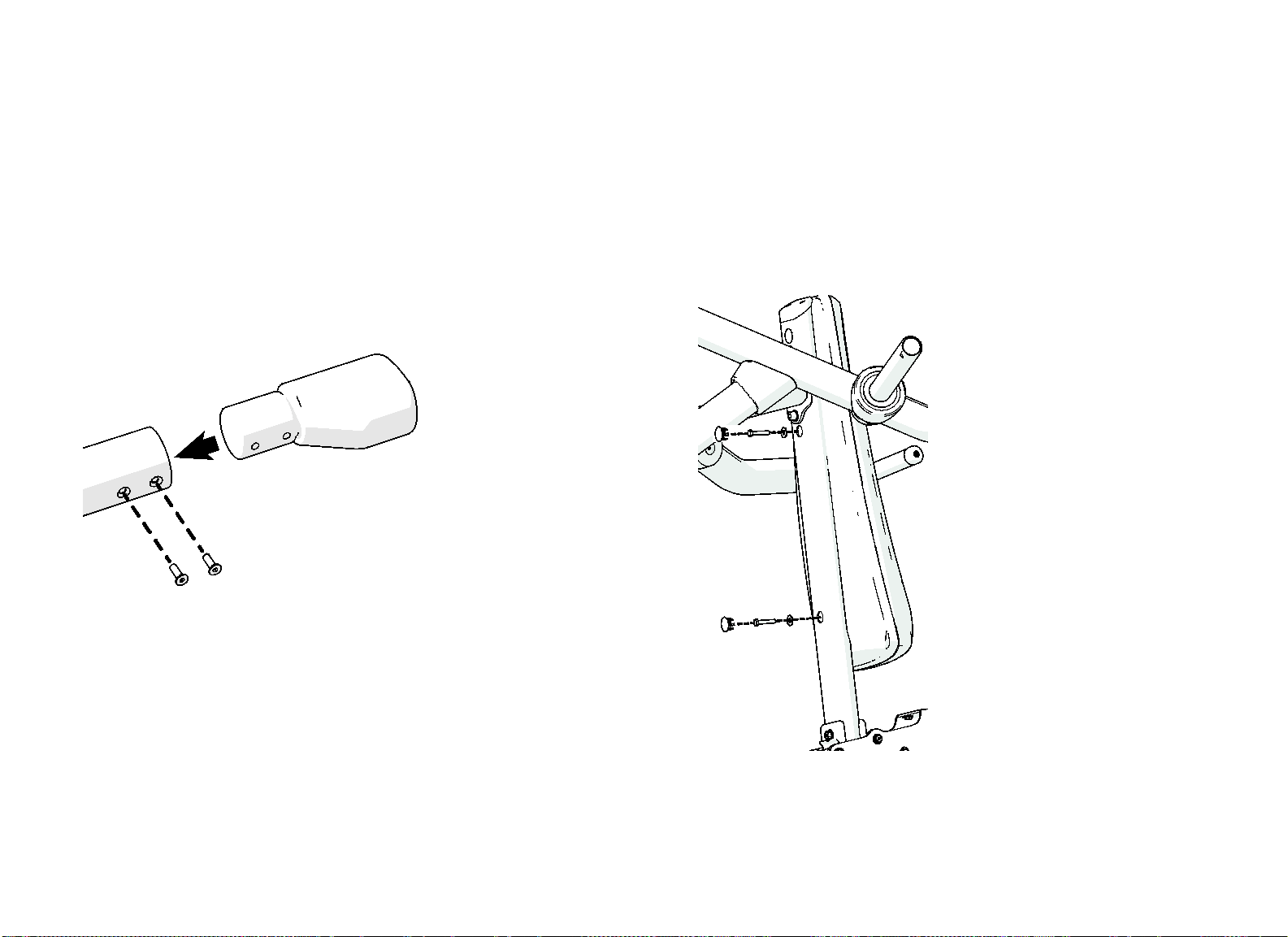
Installing the Movement Arms
You will need an assistant to hold the movement arms in place while you
complete this procedure.
To install the movement arms:
1. Position the axle end of one movement arm within its pivot bracket on the
frame so that the openings in the bracket and the movement arm are
aligned.
2. Press an axle through the openings in the bracket and the movement arm.
Note: The axle should slide easily through the openings. You should not
need to do anything more than tapping it lightly with a rubber mallet to
move it into place. If the axle becomes jammed during this step, check to
make sure the movement arm and the bracket are still aligned. If the axle
remains jammed, remove it and contact Customer Support.
3. Place an axle mount end on each end of the axle and attach a M12 x 30
mm flat head screw to each end, as shown in the following figure.
Figure 7: Movement arm axle installation
4. Check that the axle is properly positioned and centered, then tighten the
screws completely.
Important: The screws should be tight enough to prevent the movement arm
from rocking from side to side when in use.
5. Repeat steps 1 through 4 to install the other movement arm.
Important: Test the operation of the movement arms after you have installed them.
Make sure they move smoothly through their entire range, without binding or
shifting.
Shoulder Press Assembly Guide: Assembling the Equipment 11
Attaching the Movement Arm
Counterweights
The counterweights are packed separately to make movement arm installation
easier. After the movement arms are installed, add a counterweight to each
arm.
To install the counterweights:
1. Insert the narrow end of a counterweight into one of the movement arms,
making sure that the screw holes on the counterweight and the movement
arm are properly aligned.
Figure 8: Counterweight installation
2. Insert two M8 x 25 mm flat head machine screws into the screw holes and
tighten them completely.
3. Repeat steps 1 and 2 to install the other counterweight.
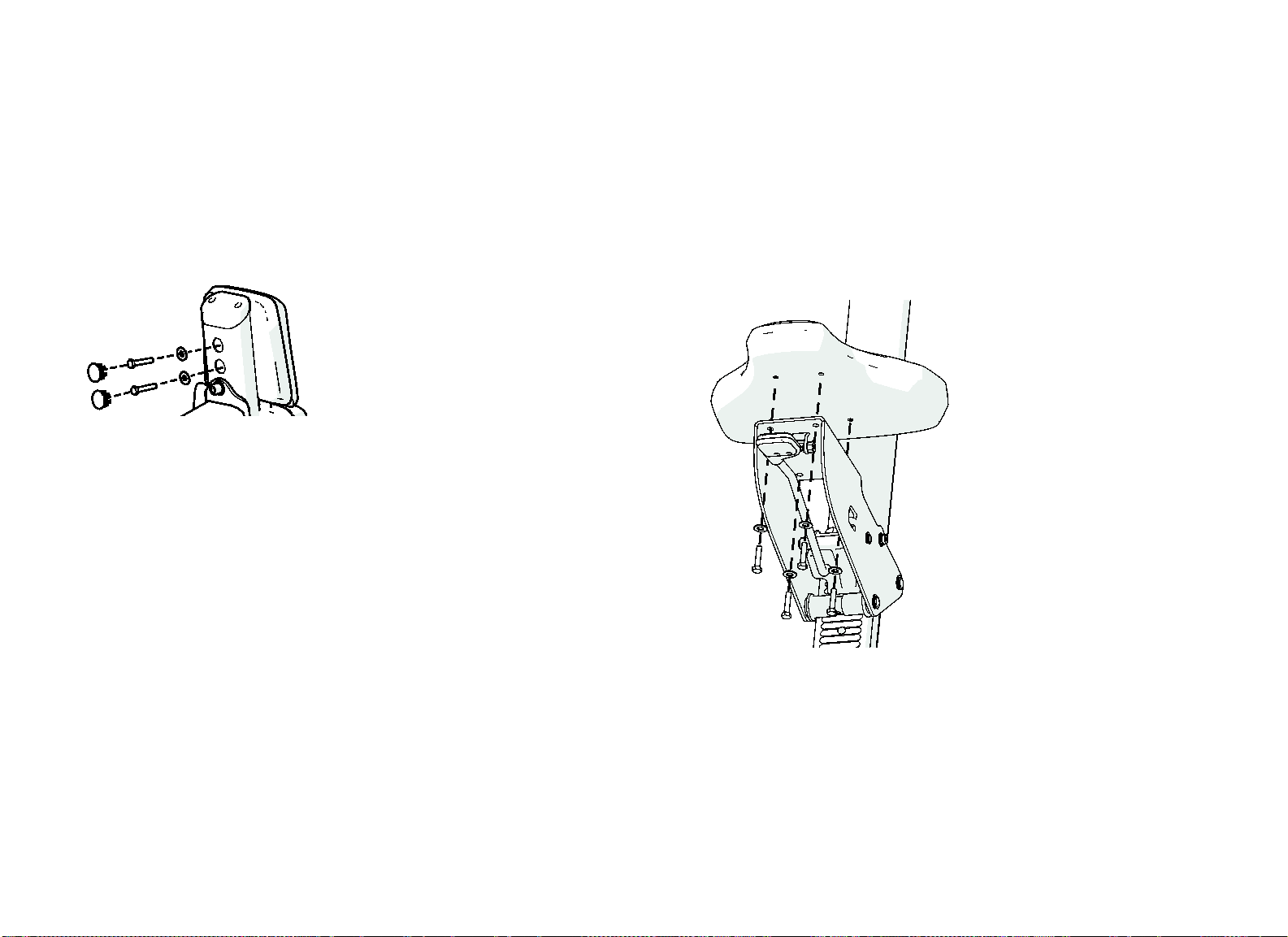
Attaching the Back Pads
Note: The back pads are common to several models of exercise equipment, so
they have more screw holes than you can use in this procedure.
To attach the back pads:
1. Place the lower back pad against the center upright assembly so that the
screw holes on the assembly line up with the outermost screw holes on the
pad, as shown in the following figure.
Figure 9: Back pad attachment
Shoulder Press Assembly Guide: Assembling the Equipment 12
Important: In the following step, be careful not to drop screws or washers into
the center upright. Inserting each screw into a socket wrench, then using the
wrench to position and tighten the screw, is recommended.
2. Place a 9mm flat washer over a ⁵₁₆-inch x 1¹₂-inch hex head screw, then
insert the screw through a screw hole in the center upright assembly and
into the corresponding hole in the pad. Partially tighten the screw. Repeat
this step to insert the other screw and washer.
3. Place the upper back pad against the center upright assembly, so that the
screw holes on the assembly and the pad line up.
Figure 10: Head pad attachment
4. Repeat step 2 to attach the upper back pad to the center upright assembly.
5. Position the back pads if necessary, then tighten all four screws
completely.
6. Press frame plugs into the screw hole openings on the center upright
assembly.
Attaching the Seat Pad
The seat mechanism is preassembled, except for the seat pad and the gas
spring.
To attach the seat pad:
1. Position the pad over the seat bracket so that the screw holes in the seat
and the bracket line up.
2. Insert four ⁵₁₆-inch x 1¹₂-inch hex head screws with 9mm flat washers into
the screw holes in the pad, as shown in the following figure.
Figure 11: Seat pad attachment
3. Position the pad if necessary, then tighten the fasteners completely.
Shoulder Press Assembly Guide: Assembling the Equipment 13
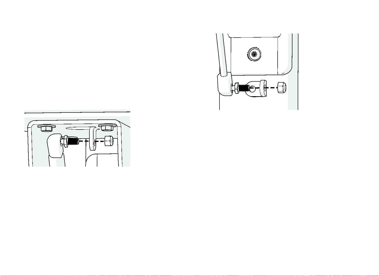
Connecting the Gas Spring
The gas spring, which lifts the seat assembly when an exerciser adjusts the
seat height, is attached to the seat assembly and the frame through two
ball-shaped stems. the underside of the seat assembly; the other is on the
center upright near the base frame.
To attach the gas spring:
1. Insert the threaded end of the upper stem through the hole in the small
bracket on the underside of the seat, as shown in the following figure.
Important: Place the wide end of the gas spring up. Also, note that the seat
adjustment handle has been omitted from this figure to keep the gas spring and
its fasteners visible.
Figure 12: Gas spring attachment, upper end
2. Place a nylon lock nut over the end of the stem and tighten it partially.
3. Insert the threaded end of the lower stem through the hole in the small
bracket on the base frame, as shown in the following figure.
Figure 13: Gas spring attachment, lower end
4. Place a nylon lock nut over the end of the lower stem. Tighten both nylon
lock nuts completely.
Shoulder Press Assembly Guide: Assembling the Equipment 14
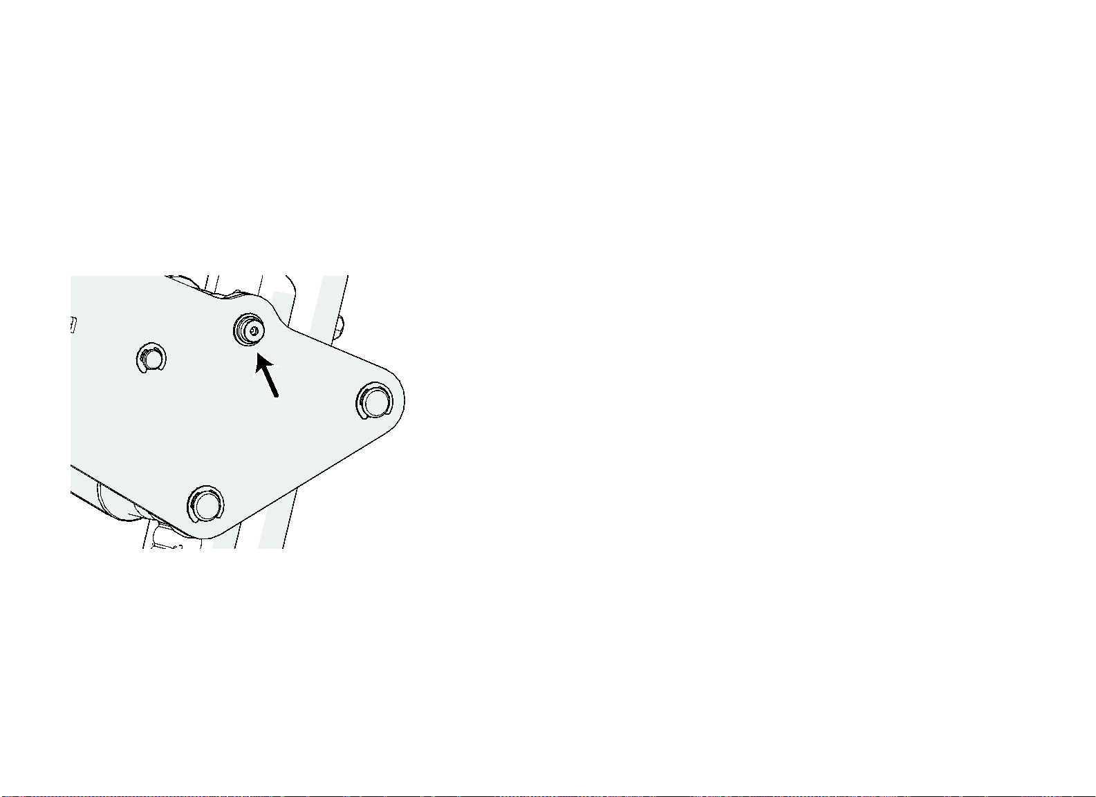
Adjusting the Seat Rollers
After you have installed the gas spring, test the seat. It should not rock from
side to side or from front to back, and it should move smoothly up and down
when you adjust it. If the seat is not stable or cannot be positioned smoothly,
you will need to adjust the seat rollers.
Note: You will need assistance to complete this procedure.
To adjust the rollers:
1. Loosen the screws securing the upper front roller. The following figure
shows the location of one of these screws.
Figure 14: Upper front roller location
2. Have your assistant press the seat pad down until the back roller contacts
the black plastic plate on the back of the frame.
3. Move the upper front roller until it contacts the black plastic plate on the
front of the frame, then tighten the screws again.
4. Have your assistant release the seat pad, then adjust the seat position up
and down a few times. Make sure that the seat moves upward and
downward freely but does not rock or shift in any direction. If the seat
cannot be adjusted easily, or if it continues to rock or shift, repeat this
procedure to readjust the upper front roller.
Shoulder Press Assembly Guide: Assembling the Equipment 15
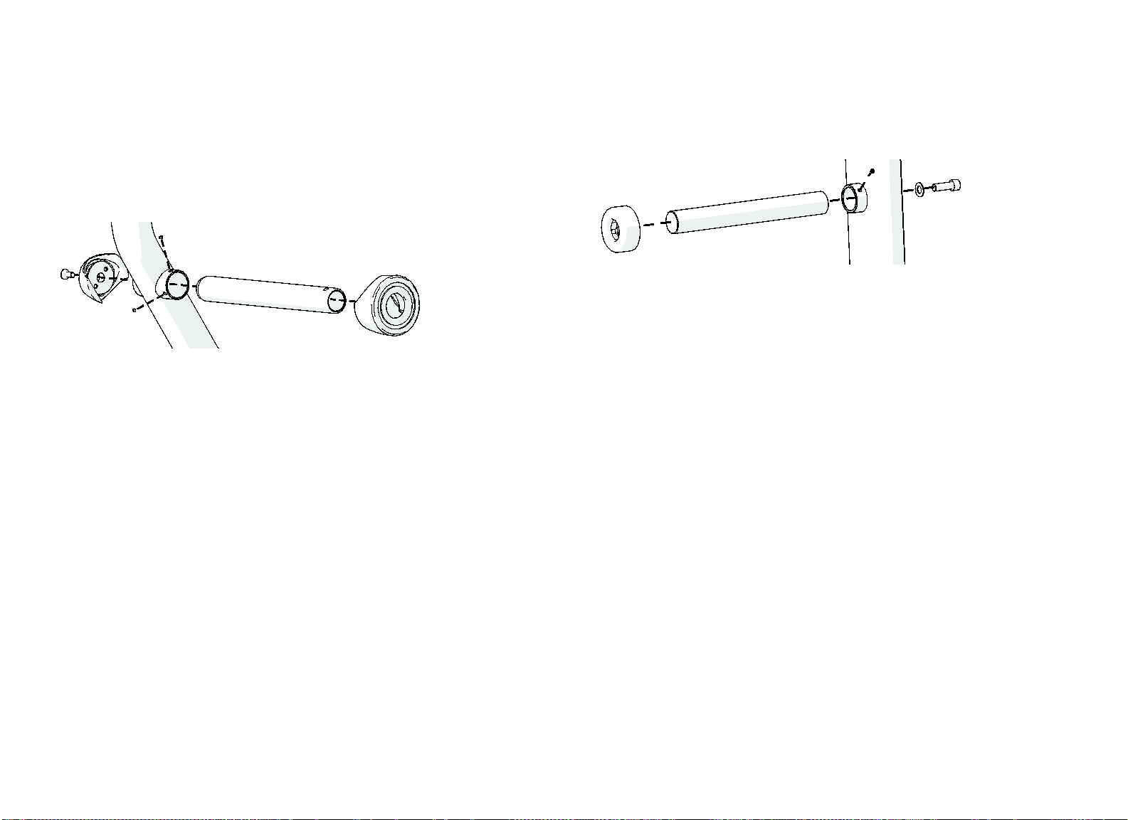
Attaching Weight Horns to
the Movement Arms
The weight horns that attach to the movement arms are slightly larger than
the weight storage horns. Before you begin this procedure, compare the
available parts to make sure you are installing the correct weight horns on the
movement arms.
Figure 15: Weight horn attachment
To attach the weight horns:
1. Insert a weight horn into the outward side of the weight horn fitting on the
movement arm. Slide the weight horn into the fitting until it stops.
2. Place a weight horn cap over the inward side of the fitting.
3. Insert a M12 x 30 mm flat head cap screw through the cap, the movement
arm, and the weight horn. Tighten the screw completely.
4. Insert two M8 x 6 mm set screws into the screw holes on the weight horn
fitting. Tighten the set screws completely.
5. Slide a bumper down over the weight horn until it rests against the
movement arm.
6. Repeat steps 1 through 5 to attach a weight horn to the other movement
arm.
Attaching Weight Storage Horns
Repeat this procedure as needed to attach all of the weight storage horns to
the equipment.
Figure 16: Weight storage horn attachment
To attach a weight storage horn:
1. Insert the horn into one of the weight storage horn fittings on the
equipment frame. Slide the horn in until it stops.
2. Insert a M12 x 35 mm socket head cap screw with 13 mm flat washer
through the screw hole opposite the weight storage horn fitting and into
the horn itself. Tighten the screw completely.
3. Insert a M8 x 6 mm set screw into the screw hole in the fitting. Position the
weight storage horn as needed, then tighten the set screw completely.
Shoulder Press Assembly Guide: Assembling the Equipment 16
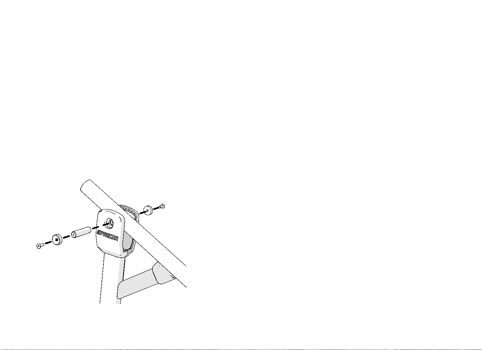
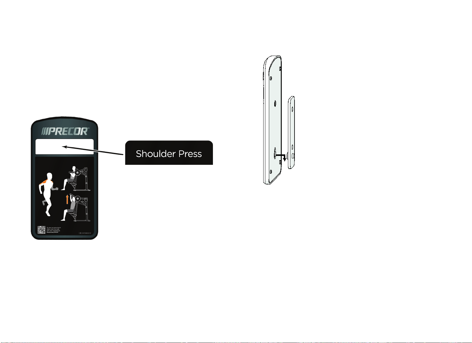
Attaching the Instructional Placard
and Safety Labels
The equipment includes a metal bracket for the instructional placard. The
placard slides over a metal button near the bottom of the bracket. A small
screw then holds it in place.
To attach the instructional placard:
1. Remove the protective backings from the machine name label. Attach the
label carefully to the recess at the upper front of the placard, as shown in
the following figure.
Figure 17: Placard label positioning
2. Place the large hole near the bottom of the placard over the button, then
slide the placard downward to lock it into place as shown in the following
figure.
Figure 18: Placard mounting

Shoulder Press Assembly Guide: Assembling the Equipment 17
3. Insert an M8 x 15 mm buttonhead screw with 9mm flat washer into the
screw hole near the top of the bracket, as shown in the following figure.
Tighten the screw completely.
Figure 19: Securing the placard in place
Note: If you are installing labels in a language other than English, remove
the general warning label attached to the equipment. Apply the general
warning label in the appropriate language where the English label was
originally applied.

Shoulder Press Assembly Guide: Notes 18
Notes:

Shoulder Press Assembly Guide: Notes 19
Notes:

Shoulder Press Assembly Guide: Notes 20
Notes:


Precor Incorporated
20031 142nd Ave NE
P.O. Box 7202
Woodinville, WA USA 98072-4002
1-800-347-4404
Precor is a registered trademark of Precor Incorporated.
Copyright 2012 Precor Incorporated.
Specifications subject to change without notice.
www.precor.com
NOTICE:
Precor is widely recognized for its innovative, award winning designs of exercise equipment. Precor
aggressively seeks U.S. and foreign patents for both the mechanical construction and the visual aspects of its
product design. Any party contemplating the use of Precor product designs is hereby forewarned that Precor
considers the unauthorized appropriation of its proprietary rights to be a very serious matter. Precor will
vigorously pursue all unauthorized appropriation of its proprietary rights.
Discovery Plate Loaded™ Shoulder Press Assembly Guide
CWP037777-141 rev B, en
August 2012