BLUETOOTH CEILING/WALL SPEAKERS
INSTALLATION MANUAL
1600-63rd Street
Brooklyn,NY 11204 USA
Thank you for purchasing this PYLE Bluetooth Ceiling / Wall Speaker system.
It is astate-of-the-art product carefully designed and manufactured for your
installationneeds,and has been thoroughly tested to ensure consistent and reliable
perfor-mance.
If you have any question about the installation or operation of your PYLE
Bluetooth Ceiling / Wall Speaker System which are not answered by this manual,
contactyour dealer immediately.
As shown is Picture C, port (1)(2) connect to the negative pole of speaker in Picture A,
port (3)(4) connect to the positive pole of speaker in Picture B,port (5) connects to power
adapter in Picture D’s D1port.
As shown in pictures, A is speaker, B is speaker, C is bluetooth controller, D is power adapter.
2 CHANNEL
Bluetooth Connection Diagram
A B
C
D
D1
-L+
-R+
DC12V
1 2 3 4
5
2 3 4
Amplification
1
Bluetooth Version:4.0
Bluetooth Network Name:Pyle
Bluetooth Network Password:‘0000’
Bluetooth Wireless Range:30’+Feet
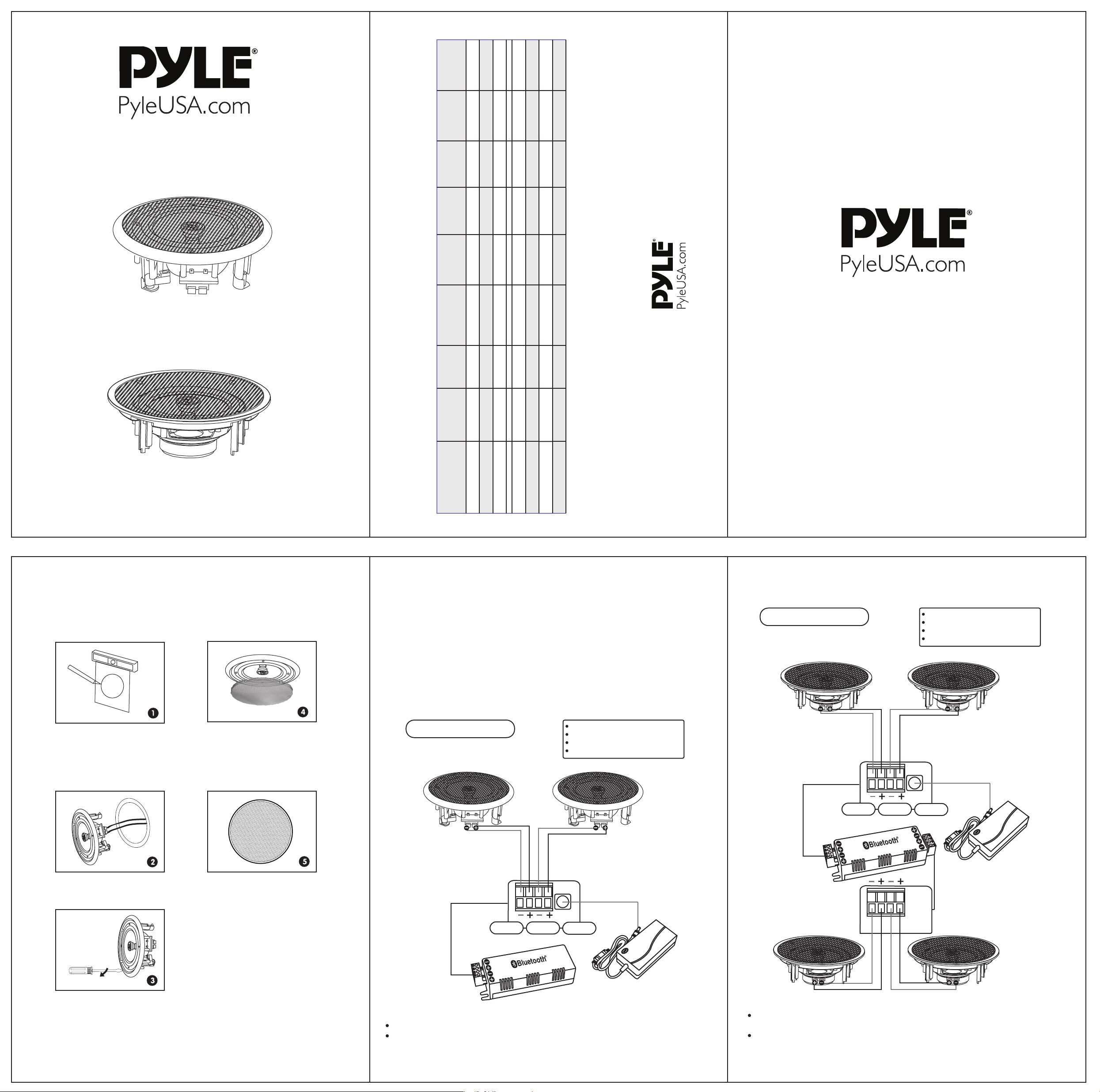
As shown is Picture C, port (1)(2) connect to the negative pole of speaker in Picture A,
port (3)(4) connect to the positive pole of speaker in Picture B,port (6)(7) connect to the
positive pole of speaker in Picture E,port (8)(9) connect to the positive pole of speaker in
Picture F,port (5) connects to power adapter in Picture D’s D1port.
As shown in pictures, A is speaker, B is speaker, C is bluetooth controller, D is power adapter,
E is speaker, F is speaker.
4 CHANNEL
Bluetooth Connection Diagram
A B
C
D
D1
-L+
-R+
DC12V
E F
6 7 8 9
2 3 4
Amplification
Amplification
1
1 2 3 4
5
Bluetooth Version:4.0
Bluetooth Network Name:Pyle
Bluetooth Network Password:‘0000’
Bluetooth Wireless Range:30’+Feet
6 7 8 9
Model
Number
Amount of
Speakers
Speaker
Size
MAX Output
Power
Frequency
Response
Sensitivity
Impedance
Cut-Out
Diameter
Mounting
Depth
PDICBT552RD 2 5.25'' 150 Watt 6.5'' 2.6''
PDICBT652RD 2 6.5'' 200 Watt 7.6'' 2.8''
2 8.0'' 250 Watt 9.3'' 3.0''
PDICBT256 4 5.25'' 150 Watt 6.8'' 3.0''
PDICBT266 4 6.5'' 200 Watt 7.9'' 3.1''
PDICBT286 4 8.0'' 250 Watt 9.4'' 3.5''
PDICBT2106 4 10.0'' 300 Watt
8 Ohm
8 Ohm
8 Ohm
8 Ohm
8 Ohm
8 Ohm
8 Ohm
88 dB
88 dB
89 dB
88 dB
89 dB
89 dB
89 dB
80-20 kHz
70-20 kHz
50-20 kHz
80-20 kHz
60-20 kHz
40-20 kHz
35-20 kHz 10.5'' 3.8''
Techical Specs Table :
PDICBT852RD
EXISTING CONSTRUCTION
IN-CEILING SPEAKERS
Connect the speaker wires to
the speaker.
Cut the drywall.
Note:Always allow at least
one-half inch between a wall
stud and the speaker cutout or
the locking tabs will not be able
to swivel into place.
Replace the metal grille.
Screw down each of the four
Phillips head screws.The
locking tabs will swivel into
place and secure the unit to
the rear surface of the drywall.
Put in the strips of adhesive to
secure the grille.
Complete.
• PDICBT552RD • PDICBT652RD • PDICBT852RD
2-Channel Bluetooth Ceiling / Wall Speaker,2-Way
Flush Mount Home Speakers
• PDICBT256 • PDICBT266 • PDICBT286 • PDICBT2106
4-Channel Bluetooth Ceiling / Wall Speaker,2-Way
Flush Mount Home Speakers