Loading ...
Loading ...
Loading ...
7
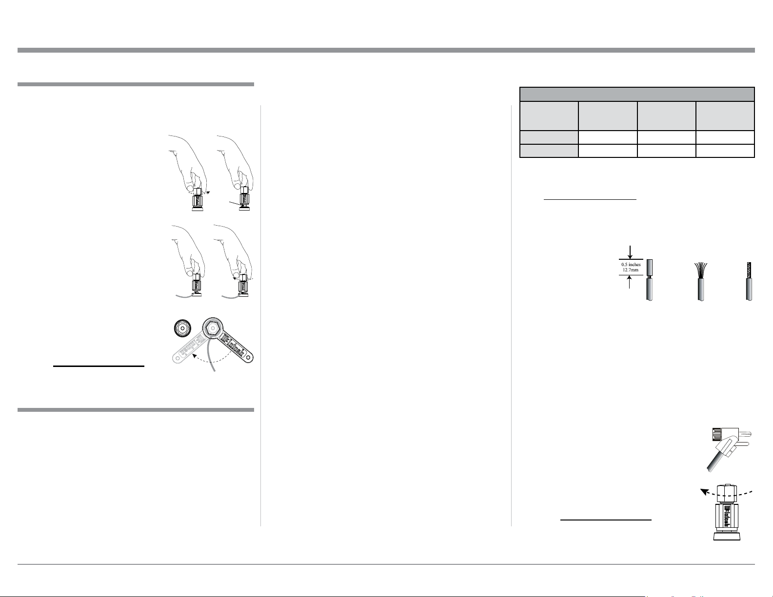
Loudspeaker Cable Distance vs Wire Gauge Guide
Loudspeaker
Impedance
25 feet
(7.62 meters)
or less
50 feet
(15.24 meters)
or less
100 feet
(30.48 meters)
or less
4 Ohms
14AWG 12AWG 10AWG
8 Ohms
16AWG 14AWG 12AWG
4. Prepare the Loudspeaker Hookup Cable for attach-
ment to the MC255 Power Amplifier:
Bare wire cable ends:
Carefully remove sufficient insulation from the
cable ends, refer to figures 2, 3 & 4. If the cable
is stranded, carefully twist the strands together
as tightly as
possible.
Notes: 1. If desired, the twisted ends can be tinned
with solder to keep the strands together.
2. The prepared bare wire cable ends may be
inserted into spade lug connectors.
3. Banana plugs are for use in the United
States and Canada only.
Banana Plugs are for use in the United States and
Canada only:
5. Attach the previously prepared bare wire cable ends
into the banana plugs and secure the
connections. Refer to figure F.
6. Rotate the top of the Output Terminal
Post clockwise until it is nger tight.
Refer to gure G. Then using the Mc-
Intosh Wrench, rotate the top of the
Output Terminal one quarter of a turn
(90° ). Do not over tighten. Refer to
gure E.
How to Connect
cable from the Audio Preamplifier or A/V Control
Center Power Control (Trigger) Output 1 to the
MC255 POWER CONTROL ZA INPUT.
2. For Zone B Operation, connect a power control
cable from the Audio Preamplifier or A/V Control
Center Power Control (Trigger) Output 2 to the
MC255 POWER CONTROL ZB INPUT.
Notes: 1. When a Power Control Cable is connected
between the MC255 and a Preamplifier
(or A/V Control Center), the AUTO OFF
Feature is bypassed. Refer to page 11.
2. When a Subwoofer Loudspeakers is being
used together with the MC255, connect
a Power Control Cable from the MC255
POWER CONTROL Output ZA to the
Power Control Input on the Subwoofer
Loudspeaker.
3. The MC255 has connections for Balanced Audio
XLR Connection Cables that come from the con-
nections on the Audio Preamplifier or A/V Control
Center. Refer to the Connections on the separate
folded sheets “Mc1A and Mc2A”. UnBalanced
Audio Cables can be used instead of the Balanced
XLR cables.
The MC255 Power Amplifier is designed for Loud-
speakers with an impedance of 4 ohms or 8 ohms.
Connect a single Loudspeaker to each of the Output
Terminals.
When connecting Loudspeakers to the MC255 it
is very important to use cables of adequate size, so
there is little to no power loss in the cables. The size is
specified in Gauge Numbers or AWG (American Wire
Gauge). The smaller the Gauge number, the larger the
wire size:
Caution: Do not connect the AC Power Cord to the
MC255 Rear Panel until after the Loudspeaker
Connections are made. Failure to observe this
could result in Electric Shock.
The connection instructions below, together with the
MC255 Connection Diagram located on the separate
folded sheets “Mc1A and Mc2A”, are examples of a
typical audio systems. Your system may vary from
this, however the actual components would be con-
nected in a similar manner. For additional information
refer to “Connector and Cable Information” on page 3.
1. For Zone A Operation, connect a power control
Figure 2
Figure 3 Figure 4
When connecting the Loudspeaker Hookup Cables to
the MC255 Power Amplifier Output Terminals please
follow the steps below:
1. Rotate the top of the Output Terminal Post coun-
terclockwise until an opening
appears. Refer to gures A and
B.
2. Insert the Loudspeaker hookup
cable into the Output Terminal
Post opening or the cable spade
lug around the center post of
the Output Terminal. Refer to
gure C.
3. Rotate the top of the Output
Terminal Post clockwise until it
is nger tight. Refer to gure D.
4. Place the supplied McIntosh
Wrench over the top of the Out-
put Terminal and rotate it one
quarter of a turn (90° ) to secure
the Loudspeaker Cable Connec-
tion. Do not over tighten. Refer
to gure E.
Output Terminals
Figure A
Opening
Figure B
Figure C Figure D
Figure E
Figure F
Figure H
Figure G
How to Connect Input Connections and Output Terminals Connections
Loading ...
Loading ...
Loading ...