Loading ...
Loading ...
Loading ...
11
Auto Off Switch
The MC255 incorporates Power Save Circuitry to
automatically place the MC255 into the power saving
Standby Mode approximately 30 minutes after there
has been an absence of an audio input signal.
When there is a Power Control Connection be-
tween the MC255 and a Preamplifier or A/V Control
Center with Power Save Circuitry, the
AUTO OFF Switch in the ENable position
is bypassed (located on the Rear Panel of
the MC255). Refer to figure 13.
In the event there is no Power Control
Connection and the Power Save Circuitry is activat-
ing inappropriately relative to your specific use of the
MC255, place the AUTO OFF Switch in the DISable
position.
Note: If the Power Save Circuitry has switched Power
to the MC255 OFF, place the POWER in the OFF
Position and then in the ON position to reset the
circuitry.
Load Switch
Place the Load Impedance Switch to the 4 Ohms posi-
tion if the Loudspeakers Connected to the
MC255 are not 8 Ohms but 4 Ohms. Refer
to figure 14.
Power On
There are two ways to have AC Power switched ON to
the MC255:
REMOTE Setting
When the MC255 Power Control Con-
nection (ZA and/or ZB) receives a Power
Control Signal from a Preamplifier or
A/V Control Center, it will turn On
automatically when the MC255 POWER
Control is set to the REMOTE Setting.
Refer to figure 9.
ON Setting
When the MC255 POWER Control is
set to the ON position, it will become
active Zone A only. Refer to figure 10.
To switch the MC255 OFF, place the
POWER Control in the OFF position.
MC255 Channel Operation
There are two Channel Operation Modes. The first
operation mode is referred to as Zone A. This occurs
when the POWER Control is positioned to ON or set
to the REMOTE position and is receiving a Power
Control Signal in the ZA connector. When the MC255
is in the Zone A operation mode, the following is a list
of Channel Operations:
MC255 ZONE A CHANNEL OPERATION
Channel Number Channel Function
1 Left Front
2 Left Surround
3 Center (Front)
4 Right Surround
5 Right Front
The other operation mode is referred to as Zone A/B
when the POWER Control is in the REMOTE posi-
tion and both the ZA and ZB connectors are receiving
Power Control Signals.
MC255 ZONE A and ZONE B OPERATION
Zone Channel Number Channel Function
A 1 Left Front
A 3 Center (Front)
A 5 Right Front
B 2 Left
B 4 Right
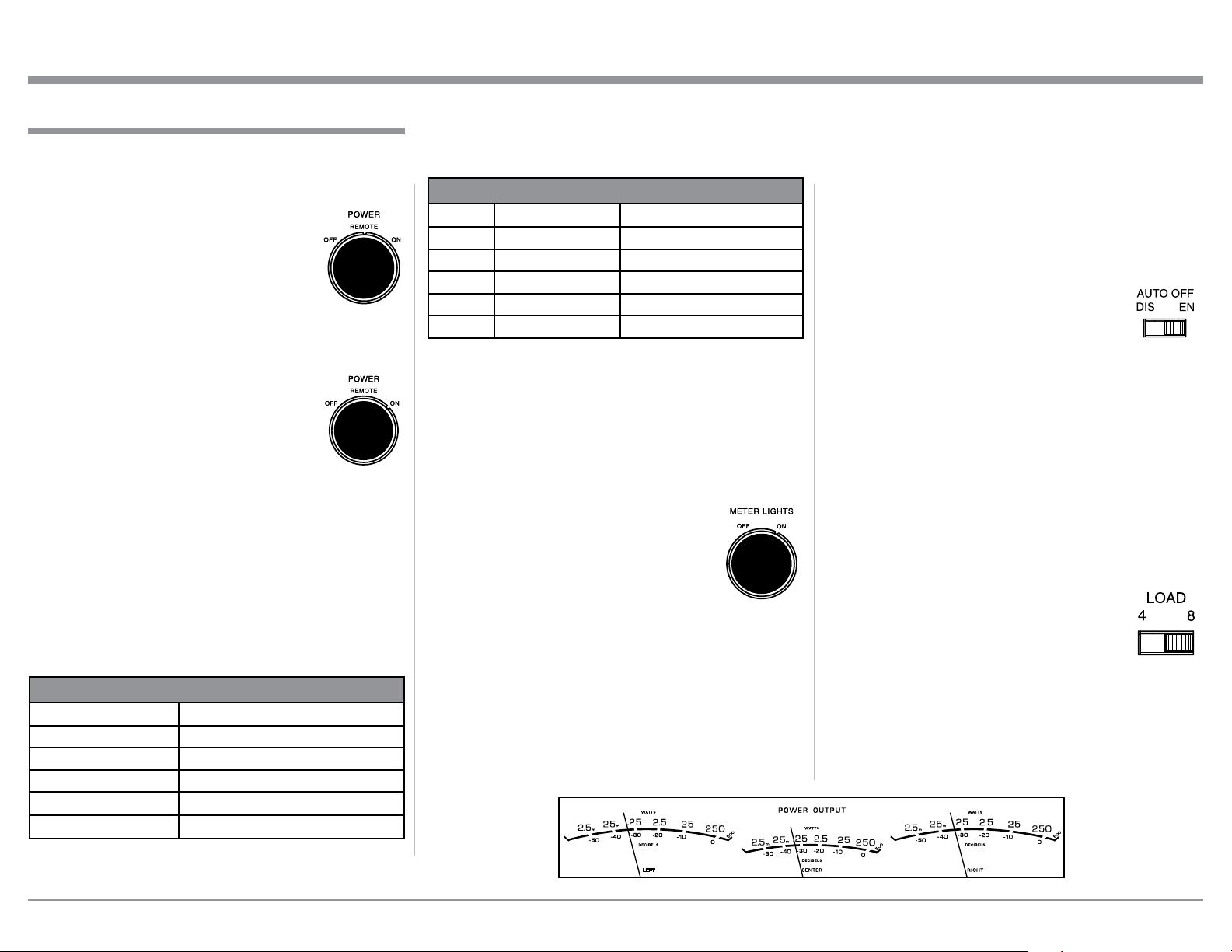
Meters
Rotate the METER LIGHTS Switch to the ON posi-
tion to Illuminate the three Front Panel Meters for the
Left, Center and Right Channels. Refer to figure 11.
Lights Off - Meter lights are turned off, the Me-
ters will continue to indicate the power
output.
Note: When Power Control
Input of the MC255 is
connected to an Audio
Preamplifier or A/V
Control Center with
Remote Meter Illumi-
nation Control, the
Meter Illumination will
automatically be remotely controlled
(On/Off).
Watts- The meters respond to all the musical infor-
mation being produced by the amplifier. They
indicate to an accuracy of at least 95% of the
power output with only a single cycle of a
2000Hz tone burst. Refer to figure 12.
How to Operate
How to Operate
Figure 10
Fig ure 11
Figure 12
Figure 9
Figure 13
2
3
Figure 14
2
3
Loading ...
Loading ...
Loading ...