Loading ...
Loading ...
Loading ...
68
1
2
Version 07/11 - Page 9
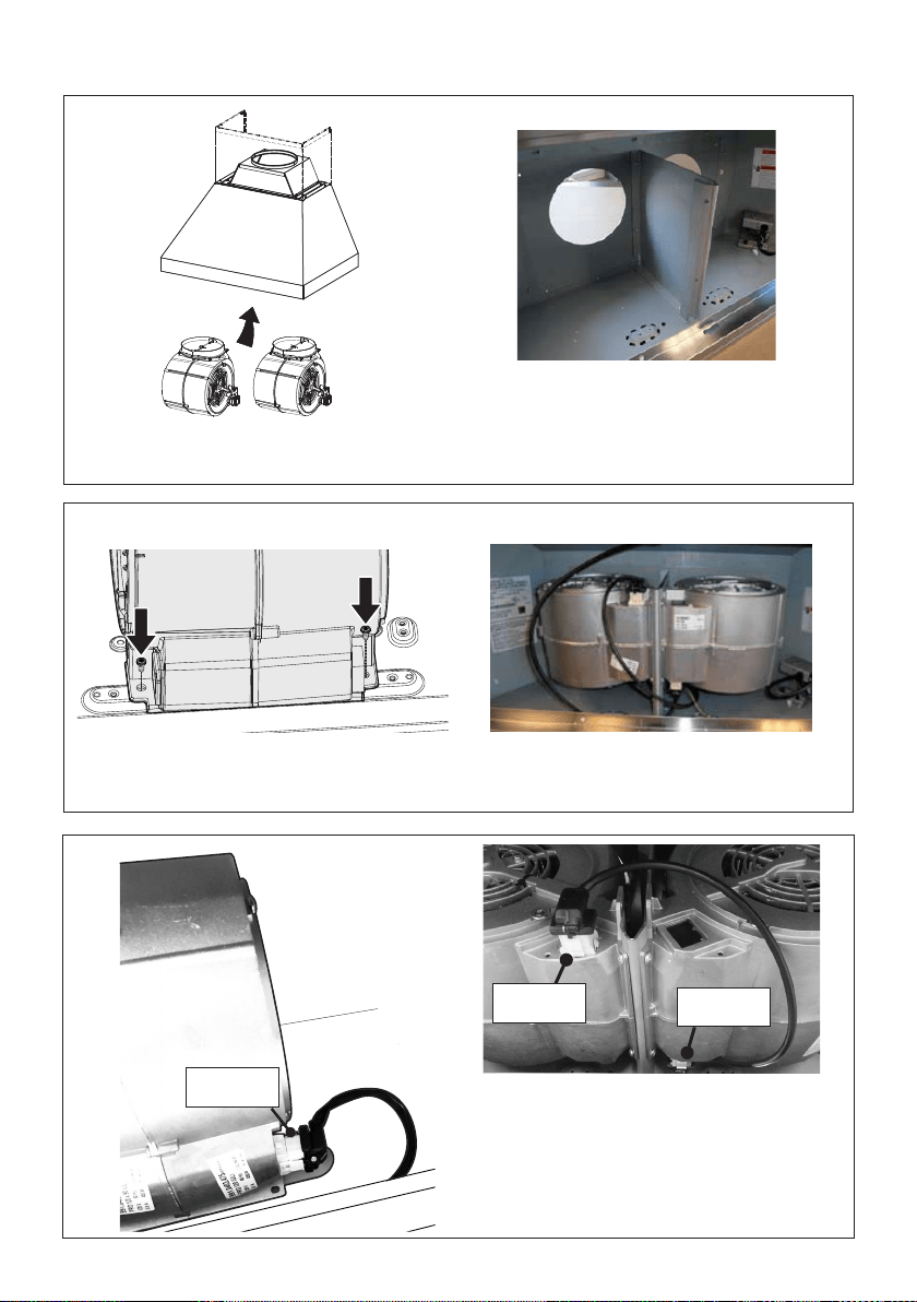
INSTALLATION WITH IB1200 INTERNAL BLOWER (1200 cfm)
1. Install the Plate B (FIGURE 14) which came with the internal
blower kit, on top of the rangehood with the holes located closer to
the front. Use 9 screws supplied with the blower kit
2. Remove the white plastic covering and Install the 4 side trim
pieces to the outside of the hood using (16) part 9b screws, see
the side rail installation in (FIGURE 15).
3. Attach the blower bracket divider inside the hood, with the 2
screws into the top of the hood and 2 screws into the back, all
supplied with the blower kit (FIGURE 16)
FIGURE 16
FIGURE 17
4. Install the 2 motor kits into the sides of the blower bracket using
the 4 screws supplied with the motor kit. (FIGURE 17)
5. Connect the wire (FIGURE 18) that comes with the motor kit
from the side of the two motors to the connection on the inside
of the light panel in the hood. The two - 9 hole ends of the wire
are installed in the two motors, the 6 hole end is connected to
the light panel (FIGURE 11 on the previous page)
FIGURE 15
FIGURE 18
FIGURE 19
6. Install the 2 dampers on top of the hood. If you want one 10"
round duct to come out of the top of the hood, use the transition
piece (FIGURE 19) that comes with the motor kit and install with
four screws. If you want to use 2 seperate 6" round ducts, do not
use the transition.
7. Attach the hood to the cabinet using (12) 9c. screws to the
cabinet. FIGURE 20
8. Follow steps 6 - 9 on the previous page to connect ducting,
wiring, and test the electrical connection.
FIGURE 14
FIGURE 20
B
Version 07/11 - Page 9
INSTALLATION WITH IB1200 INTERNAL BLOWER (1200 cfm)
1. Install the Plate B (FIGURE 14) which came with the internal
blower kit, on top of the rangehood with the holes located closer to
the front. Use 9 screws supplied with the blower kit
2. Remove the white plastic covering and Install the 4 side trim
pieces to the outside of the hood using (16) part 9b screws, see
the side rail installation in (FIGURE 15).
3. Attach the blower bracket divider inside the hood, with the 2
screws into the top of the hood and 2 screws into the back, all
supplied with the blower kit (FIGURE 16)
FIGURE 16
FIGURE 17
4. Install the 2 motor kits into the sides of the blower bracket using
the 4 screws supplied with the motor kit. (FIGURE 17)
5. Connect the wire (FIGURE 18) that comes with the motor kit
from the side of the two motors to the connection on the inside
of the light panel in the hood. The two - 9 hole ends of the wire
are installed in the two motors, the 6 hole end is connected to
the light panel (FIGURE 11 on the previous page)
FIGURE 15
FIGURE 18
FIGURE 19
6. Install the 2 dampers on top of the hood. If you want one 10"
round duct to come out of the top of the hood, use the transition
piece (FIGURE 19) that comes with the motor kit and install with
four screws. If you want to use 2 seperate 6" round ducts, do not
use the transition.
7. Attach the hood to the cabinet using (12) 9c. screws to the
cabinet. FIGURE 20
8. Follow steps 6 - 9 on the previous page to connect ducting,
wiring, and test the electrical connection.
FIGURE 14
FIGURE 20
B
3
Coloque los 2 motores en el cuerpo de la campana. Dentro de la campana hay un divisor de
soporte del ventilador y los motores estarán uno por lado.
INSTALACIÓN DE LA CAMPANA DE 2 MOTOR SUPERIOR DE CONDUCTO
Instale los 2 motores a los lados del soporte del ventilador utilizando los 4 tornillos 12e
suministrados.
Conecte el extremo de 9 agujeros del
cable al motor izquierdo y el otro extremo
de 9 agujeros del cable al motor derecho.
Extremo de
9 agujeros
Extremo de
9 agujeros
Extremo de
9 agujeros
Loading ...
Loading ...
Loading ...