Loading ...
Loading ...
Loading ...
6
Assembly
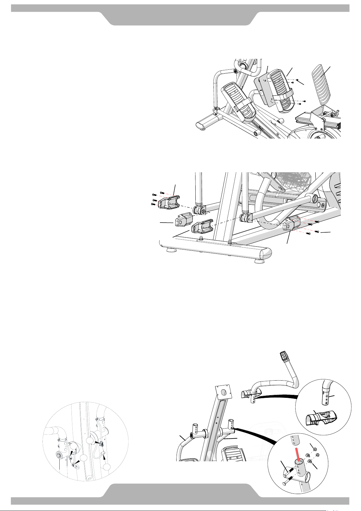
6. FOOT PEDAL INSTALLATION
6.1 Assemble Right Foot Pedal [C07] on Foot
Pedal Tube [A17] with 4 Screws M6 [B26].
6.2 Peel off the plastic cover of the foam tape
under the Cushion Pad [C08] and attach
the Cushion Pad [C08] on Foot Pedal [C07].
6.3 Repeat the same steps to assemble the Left
Foot Pedal [C07].
TIGHTEN ALL SCREWS AT THIS TIME
8. UPPER HANDRAIL TUBE INSTALLATION
8.1 Slide the upper portion of the Lower Pivot Covers (C22L/C22R) onto each of the Upper
Handrail Tubes (A12/A13, A12 is the Left and features to “GO” button control at the top)
Refer to Fig. 2
8.1 Assemble each of the Upper Handrail Tubes (A12/A13, A12 is Left) into each of the
Handrail Arms (A08/A09, A08 is Left) with Two M8 Bolts (B06), Two
M8 Curve Washers (B07) and Two M8 Nylon Nuts (B08). Refer to
Fig. 2. TIGHTEN THESE BOLTS AT THIS TIME.
8.2 Connect all connectors (D05 to D10 and D06 to D11) as shown in
Fig. 1 below) from the L/R Upper Handrails (A12/A13) to the
matching Connectors from each of the Handrail
Arms (A08/A09).
Note: The Foot Straps that are shown in the
illustration are optional accessories. Contact
BODYCRAFT for purchasing details
Attention: Do not pinch cables.
B26
A17
C07
C08
7. PIVOT CAPS INSTALLATION
7.1 Assemble the Left/Right Pivot
Caps -A/B (C35/C36) onto the
Right Handrail Arm (A15) with
Four M5 Screws (B11).
7.2 Repeat the same step to
assemble the Pivot Caps of
Right Lower Handlebar (A14).
TIGHTEN ALL SCREWS
AT THIS TIME.
C36
C35
B11
C35
C36
A14
D06
D11
D05
D10
Fig 1.
B06
A08
A09
B08
B07
Fig 2.
A13
C22R
A13
Loading ...
Loading ...
Loading ...