For your safety and benefit, please read this entire manual. Please keep the manual in a
convenient place for quick reference when needed.
Bodycraft offers a complete array of high quality fitness equipment. Please refer to our web site
at www.bodycraft.com to view more ways to enhance your lifestyle.
Your Bodycraft SCT400g has all the quality and design elements to make your workout extremely
efficient and comfortable. Your new Seated Elliptical Trainer is a serious cardio fitness machine
that will keep you motivated, challenged and within reach of your fitness goals. The Bodycraft
SCT400g will provide an efficient, low impact cardiovascular workout that will help improve
energy levels and your quality of life. Cardiovascular training is vital for all ages and the Bodycraft
SCT400g will provide an effective workout, producing results that will encourage you to reach
your fitness goals and maintain the body you have always wanted. Spending 15 to 30 minutes
a day, three times a week is all you need To start seeing the benefits of a regular exercise
program.
As a premium exercise equipment manufacturer we are committed to your complete satisfaction.
If you have questions, suggestions or find missing or damaged parts, we guarantee your
complete satisfaction through our authorized dealer network or by contacting us directly.
Please call your local dealer or Bodycraft.
Phone: 800-990-5556 9am - 5pm EST Email: [email protected]
Recreation Supply, Inc.
7699 Green Meadows Dr.
Lewis Center, OH 43035
Purchaser’s Reference Information:
IT IS IMPERATIVE THAT YOU FILL IN
THE FOLLOWING INFORMATION AND
REFER TO IT SHOULD THE NEED FOR
SERVICE ARISE.
Product Name: SCT400g Elliptical Cross Trainer
Serial Number: SC _ _ _ _ _ _ _ _ _ _ _ _
Proof of purchase must be supplied to validate warranty and the product must have
been registered with Bodycraft via online at www.bodycraft.com or by calling
800-990-5556 or 740-965-2442 M-F 9 a.m. - 5 p.m. EST.
Serial #
CONGRATULATIONS! THANK YOU for selecting the BODYCRAFT SCT400g Seated
Elliptical Trainer! Your choice reflects a wise investment in you and your family’s health and
wellness. We hope you use it for many healthy years!

Product Safety ………………………….…………………………….. 1
Parts Drawing & Contents………………………………...………….. 2
Hardware & Tools …………………………………………………… 3
Assembly ……………………………………………….…………….. 4
Troubleshooting & Adjustment ……………………………..……
9
Stretching ……………………………………………………………... 11
Computer Operation…………………………………………………... 12
Part List ………………………………………………..…………….. 18
Exploded View ……………………………………….……………… 20
Warranty ……………………………………………………………... 23
TABLE OF CONTENTS

Product Safety
1
Basic precautions should always be followed, including the following safety
instructions when using this equipment:
Read all instructions before using this equipment.
1. It is recommended that you perform warm up exercises before using this equipment.
2. Please make sure all components are not damaged and in working order before use.
3. This equipment should be placed on a flat surface while in use. Using a mat or other
material on the ground is recommended.
4. Please wear proper clothes and shoes when using this equipment; do not wear clothes
that might catch in any part of the equipment.
5. Do not attempt any maintenance or adjustments other than those described in this
manual. Should any problems arise, discontinue use and consult an Authorized Ser-
vice Representative.
6. Use caution when stepping on and off the machine. During the workout it is
recommended that you always hold onto the stationary or upper body handle bars. To
ensure the pedals run smoothly, you may need to push or pull on the upper body
handlebars first, then follow with the leg motion.
7. Do not use the equipment outdoors.
8. This equipment is for household or light commercial use only.
9. Only one person should be on the equipment while in use.
10. Keep children and pets away from the product while in use. This machine is designed
for adults only. If you feel any chest pains, nausea, dizziness, or shortness of breath,
you should stop exercising immediately and consult your physician before continuing.
11. If you feel chest pains, nausea, dizziness, or shortness of breath, you should stop
exercising immediately and consult your physician before continuing.
12. The maximum weight capacity for this product is 400 lbs /180 kgs.
WARNING: Before beginning any exercise program consult your physician.
This is especially important for the persons who are over 35 years
of age or who have pre-existing health problems. Read all
instructions before using any fitness equipment.
CAUTION: Read all instructions carefully before operating this product.
Retain this Owner’s Manual for future reference.
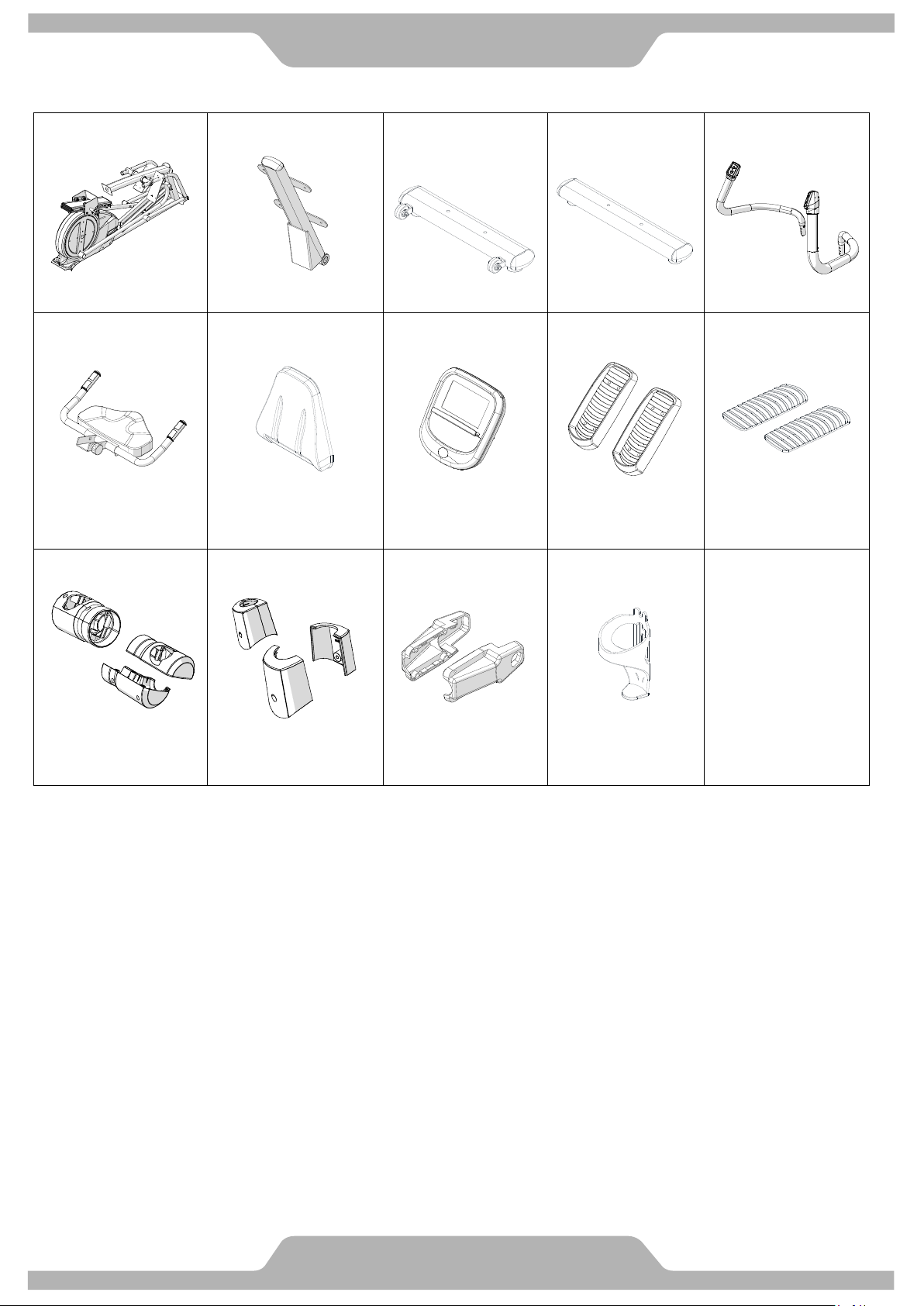
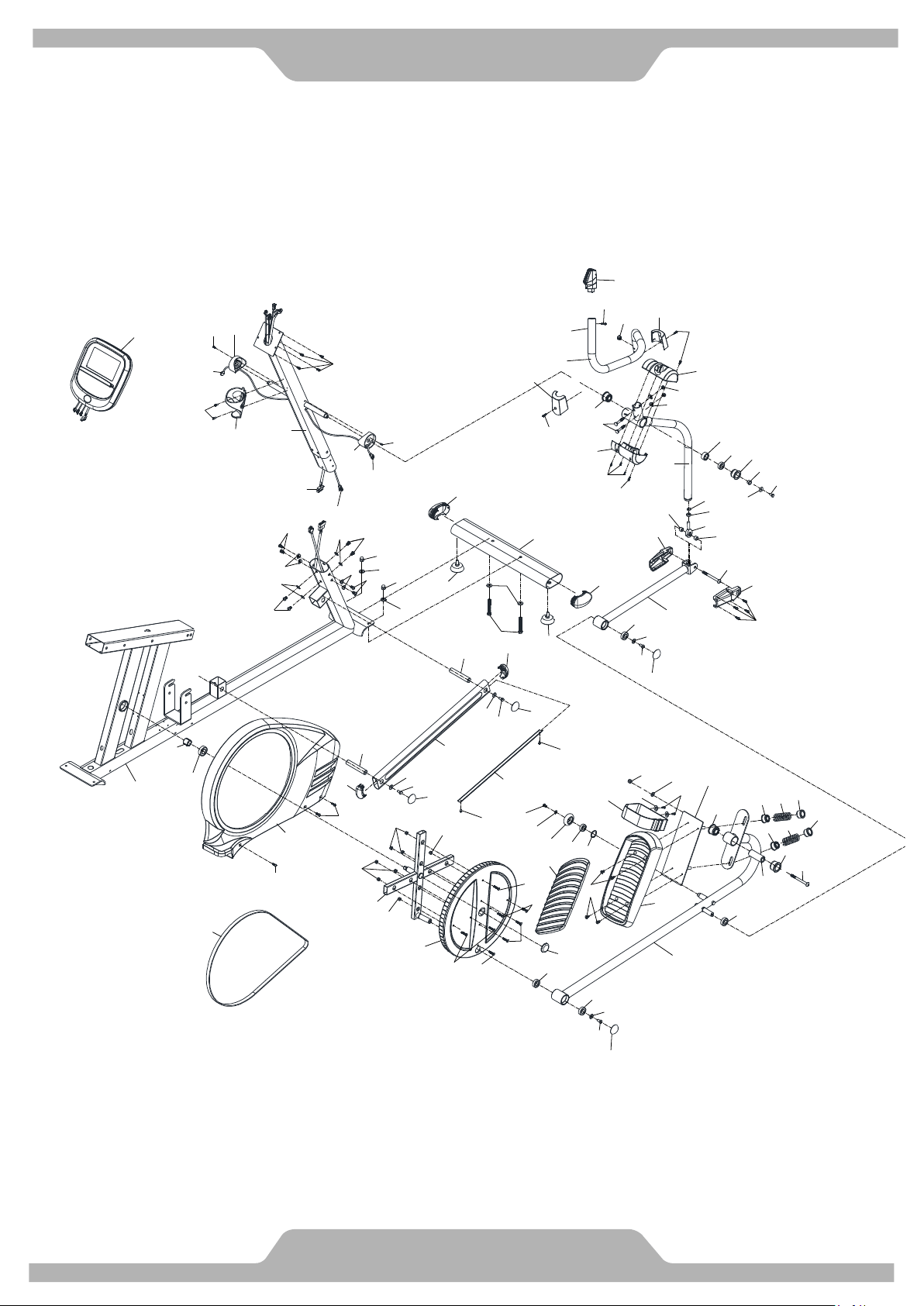
2
Part Drawing & Contents
A01 1Set A04 1Set A05 1Set A06 1Set A12/A13 1Set
Main Frame Backrest Tube Rear Stabilizer Front Stabilizer Handrail L/R
A07 1Set C10 1PC D01 1PC C07 2PC C08 2PC
Saddle Frame Upholstered,
Backrest
Computer Foot Pedal Cushion Pad
C21/C22L.R 2Set C14/C15 2Set
C35
/C36
2Set C23 1PC
Lower Pivot Cover
-A/B
Upper Pivot Cover
-A/B
Upright Joint
Cover L/R
Water Bottle
Holder
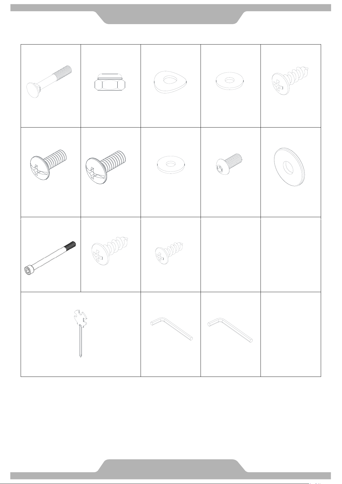
3
Hardware & Tools
B06 4PC B08 5PC B07 8PC
B30 4PC
B29 8PC
Bolt M8x50mm Nylon Nut M8 Curve Washer
M8x20x1.5T
Screw M5x16mm
B26 8PC B50 4PC B53 8PC B52
12PC
B57 1PC
Screw
M6*15 mm
Screw
5/16”*15mm
Washer
5/16”*16*1.5t
Screw
M8*16 mm
Washer
5/16”x30x2.0T
B61 1PC
Bolt M8x100mm
B11 8PC
Screw
3/16*18mm
1PC 1PC
1PC
Hex Tool with Phillips Screwdriver
(13/14/15mm)
Allen Key (M5) Allen Key (M6)
B09
6PC
Screw
M3*16mm
Washer
5/16”*20*2.0t
4
Assembly
NOTE: The 2 people are required for the safe assembly of this product.
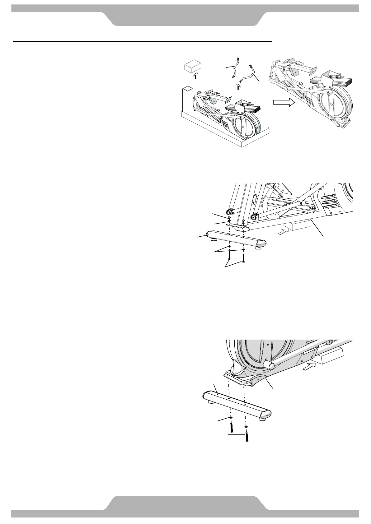
1. PREPARATION
1.1 Open the top carton and remove the
Foam Block and the Upper Handrail
Tubes L/R (A12/A13). Save the
Foam Block for use during assembly.
1.2 Remove the Elliptical Cross Trainer
from the carton.
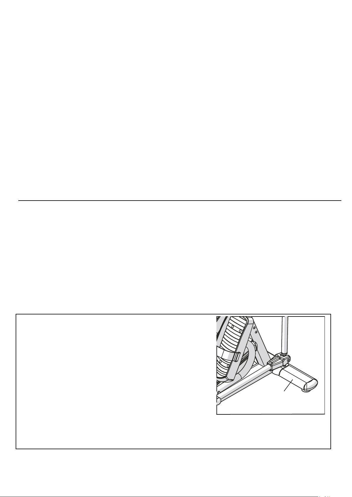
2. FRONT STABILIZER TUBE INSTALLATION
2.1 Use the Style Foam Block or a block of
wood to lift up the front of Main Frame (A01).
2.2 Remove Two 3/8” Screws (B24) and Four
Washers 3/8” (B25) and Two 3/8" Dome
Nuts (B21) from the Main Frame (A01).
2.3 Assemble the Front Stabilizer Tube (A06)
under the bracket of Main Frame (A01) with
Two 3/8” Bolts (B24), Four 3/8" Washers
(B25) and Two 3/8" Dome Nuts (B21) which
were removed from step 2.2.
3. REAR STABILIZER TUBE INSTALLATION
3.1 Use the Foam Block or a block of wood to lift
up the rear of Main Frame (A01).
3.2 Remove Two 3/8” Screws (B24) and Two
Washers 3/8” (B25) from the Main Frame (A01).
3.3 Assemble the Rear Stabilizer Tube (A05) at rear
of Main Frame (A01) with Two 3/8” Bolts (B24),
Two 3/8" Washers (B25) which were removed
from step 3.2
TIGHTEN the Front and Rear Stabilizer Bolts
at this time.
A12
A13
A05
A01
B25
B24
Foam Block
or Wood
A01
B21
B25
A06
B25
B24
Foam Block
or Wood
5
Assembly
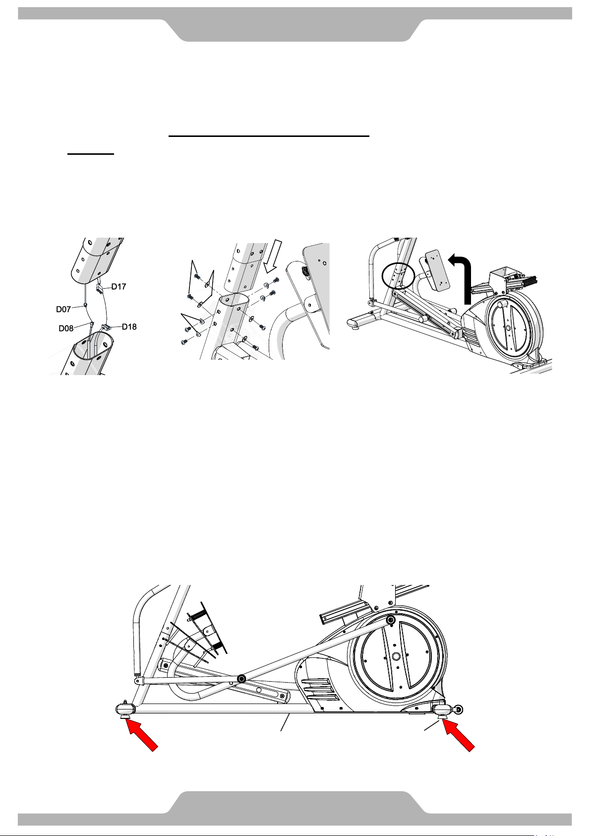
4 UPRIGHT POST INSTALLATION
4.1 While holding the Upright Post (A02) above the Main Frame (A01), connect the Cables as
shown (D07 to the D08 and D17 to D18). As shown in Fig.1.
4.2 Carefully slide the excess wires into the opening hole of Main Frame (A01), then lower the
Upright Post (A02) being careful to not pinch the wires.
4.3 DO NOT FULLY TIGHTEN THE BOLTS IN THIS STEP UNTIL ALL BOLTS ARE STARTED.
LOOSELY install Eight M8 Bolts (B52) and Four Curved Washers (B07) and Four Washers
(B30) by hand first for aligning the punched holes and threaded holes. (Refer to Fig. 2 and
Fig.3)You may have shift the Upright Post (A02) in order to get all of the bolts started.
TIGHTEN ALL EIGHT OF THE UPRIGHT POST/MAIN FRAME BOLTS AT THIS TIME.
5 LEVELING YOUR ELLIPTICAL
5.1 Adjust the Adjustable Foot Pads (C05) on the Main Frame (A01) as needed to level the
Seated Elliptical Trainer.
5.2 The Seated Elliptical Trainer must be kept level at all times to prevent from rocking and/or
shaking during use. It will also prevent unwanted noise or possible damage to the frame.
A01
C05
B30
B52
B07
Fig. 1 Fig. 2 Fig. 3
6
Assembly
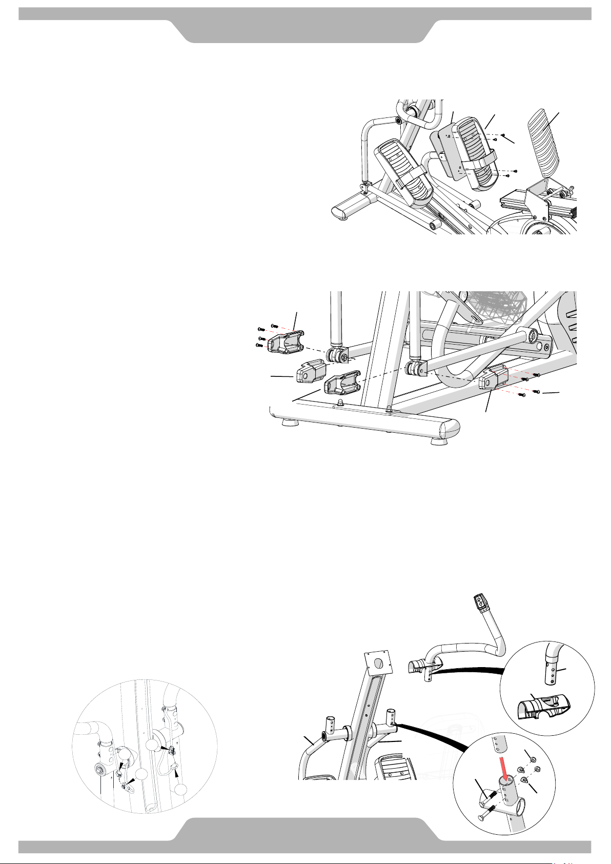
6. FOOT PEDAL INSTALLATION
6.1 Assemble Right Foot Pedal [C07] on Foot
Pedal Tube [A17] with 4 Screws M6 [B26].
6.2 Peel off the plastic cover of the foam tape
under the Cushion Pad [C08] and attach
the Cushion Pad [C08] on Foot Pedal [C07].
6.3 Repeat the same steps to assemble the Left
Foot Pedal [C07].
TIGHTEN ALL SCREWS AT THIS TIME
8. UPPER HANDRAIL TUBE INSTALLATION
8.1 Slide the upper portion of the Lower Pivot Covers (C22L/C22R) onto each of the Upper
Handrail Tubes (A12/A13, A12 is the Left and features to “GO” button control at the top)
Refer to Fig. 2
8.1 Assemble each of the Upper Handrail Tubes (A12/A13, A12 is Left) into each of the
Handrail Arms (A08/A09, A08 is Left) with Two M8 Bolts (B06), Two
M8 Curve Washers (B07) and Two M8 Nylon Nuts (B08). Refer to
Fig. 2. TIGHTEN THESE BOLTS AT THIS TIME.
8.2 Connect all connectors (D05 to D10 and D06 to D11) as shown in
Fig. 1 below) from the L/R Upper Handrails (A12/A13) to the
matching Connectors from each of the Handrail
Arms (A08/A09).
Note: The Foot Straps that are shown in the
illustration are optional accessories. Contact
BODYCRAFT for purchasing details
Attention: Do not pinch cables.
B26
A17
C07
C08
7. PIVOT CAPS INSTALLATION
7.1 Assemble the Left/Right Pivot
Caps -A/B (C35/C36) onto the
Right Handrail Arm (A15) with
Four M5 Screws (B11).
7.2 Repeat the same step to
assemble the Pivot Caps of
Right Lower Handlebar (A14).
TIGHTEN ALL SCREWS
AT THIS TIME.
C36
C35
B11
C35
C36
A14
D06
D11
D05
D10
Fig 1.
B06
A08
A09
B08
B07
Fig 2.
A13
C22R
A13
7
Assembly
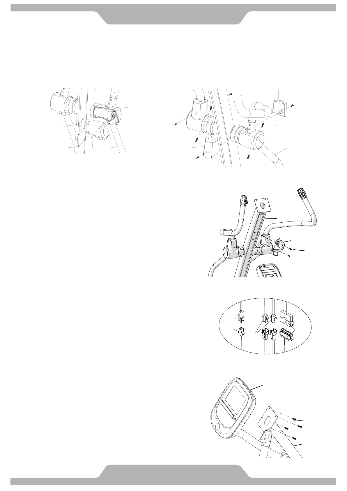
9. PIVOT COVER INSTALLATION
9.1 Assemble the lower portion of each of the Lower Pivot Covers -A/B (C21/C22R) to the
previously installed upper portion with Three M3 Screws (B09) each. Refer to Fig. 1
9.2 Assemble the Upper Pivot Covers -A/B (C14/C15) to the pivot of Right Lower Handlebar
(A09) with Four M5 Screws (B29) each. Refer to Fig. 2. Tighten Screws.
11. COMPUTER INSTALLATION
11.1 Remove the Four M5 Screws (B16) from
the bottom of Computer (D01).
11.2 Connect each of the three cables making sure that
each time you connect one coming from the
Upright Post (A02) it is connecting to one from the
Computer (D01). Once you have connected all
three, confirm that no two wires coming from the
Computer (D01) plug into themselves, and the
same with the wires from the upright post.
Refer to Fig. 4
11.3 NOTE: In this step, do not tighten the screws
until all have been loosely threaded.
Carefully push the excess wires into the Upright
Post (A02), then assemble the Computer (D01)
onto the plate of Upright Post (A02) with the Four
M5 Screws (B16) which were previously removed.
Refer to Fig. 5. Tighten Screws.
10. WATER BOTTLE HOLDER INSTALLATION
10.1 Refer to Fig. 3. Remove Two M5 Screws (B31)
from the Upright Post (A02).
10.2 Assemble the Water Bottle Holder (C23) onto
the Upright Post (A02) with Two M5 Screws
(B31). Tighten Screws.
A02
B31
C23
A09
B09
C22R
C21
C15
C14
B29
A09
Fig 1. Fig 2.
B16
D01
A02
D07
D10
D11
D17
Fig. 3
Fig. 4
Fig. 5
8
Assembly
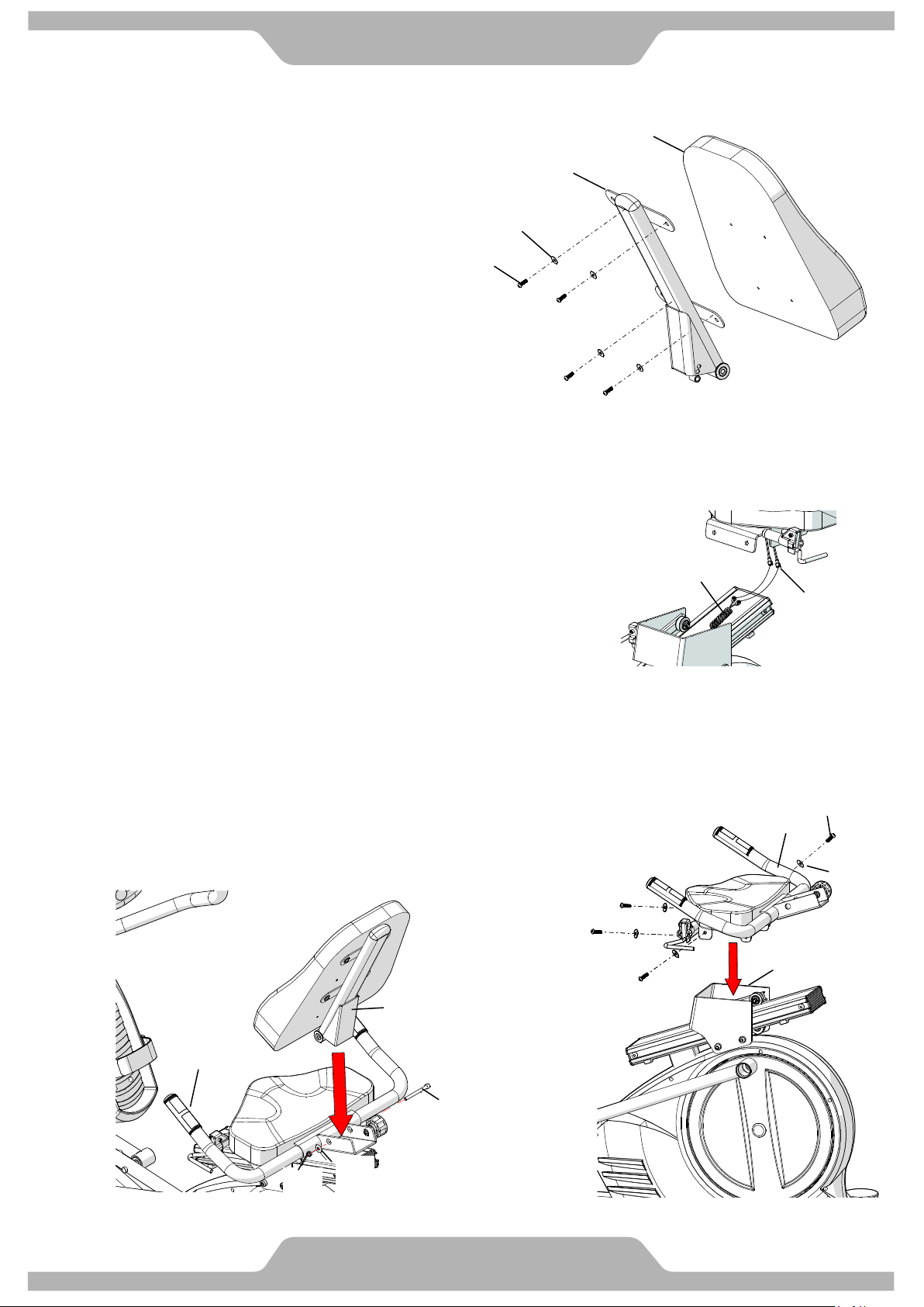
12. UPHOLSTERED BACKREST INSTALLATION
12.1 NOTE: In this step, do not tighten the
Screws until all have been loosely threaded.
Assemble the Backrest (C10) to the
Backrest Tube (A04) by loosely installing
Four 5/16” Washers (B53) and Four
5/16” Screws (B50)
As shown in Fig.1.
Tighten Screws
13. SADDLE FRAME INSTALLATION
13.1 Refer to Fig. 1 Connect the Hand Pulse Cable (D09)
and Cables (D08) to all cables that come from the
Saddle Frame (A07).
13.2 NOTE: Be careful to not pinch the wires and in
this step, do not tighten the screws
until all have been loosely threaded.
Refer to Fig. 2. Assemble the Saddle Frame (A07) to
The Moveable Seat Bracket (A03) by aligning the
Four screw holes to the holes in the Moveable Seat
Bracket [A03]. Use Four M8 Bolts (B52)
and Four Washers (B53). Tighten Screws.
13.3 Assemble the Backrest Tube (A04) to the Saddle
Frame (A07) and align the holes and secure using
One M8 Bolts (B61) One M8 Washers (B57) and
One M8 Nylon Nuts (B08). Tighten the Bolt.
B50
B53
A04
C10
D09
D08
Fig. 1
Fig. 2
A03
A07
B52
B53
Fig. 3
Fig. 3
A07
A04
B61
B08
B57
Fig. 4

Troubleshooting
9
Computer not working correctly
Check all connections to the computer at the top and base of the Mast. It is a good
idea to unplug and reconnect the connectors during your inspection to ensure all of the
computer cables are connected securely.
The Seated elliptical trainer wobbles when in use
If you have recently relocated your machine or if the jam nuts on the levelers have
worked loose, you may need to re-adjust the levelers. Follow the procedure for
leveling the machine in this manual.
Squeaking noise when in use
Inspect all frame bolts that may have worked loose on the Seated elliptical trainer.
Re-tighten any loose bolts.
No, inconsistent, or erratic heart rate reading
Your Seated Elliptical Trainer is equipped with dual contact handgrip pulse and a
wireless 5 kHz heart rate receiver. You should first try to to determine which is causing
the problem. If you are seeing a reading without holding onto the contact sensors, it is
likely the wireless receiver that is the problem.
Wireless:
Unusually high, low or random numbers in the heart rate display indicate a problem.
Try moistening the electrodes on the heart rate belt.
The batteries in the belt may be failing. Replace the batteries or the Heart Rate belt.
The problem may be caused by interference. Televisions, microwaves, wireless
alarms and electric fences are just a few items that can cause interference. You can
try relocating the machine to a different part of the room. If you continue to have
problems, please contact Bodycraft for additional troubleshooting of wireless heart rate
issues.
Contact Heart Rate:
Always hold on to the handlebar grip sensors with two hands instead of just one.
Try to maintain moderate pressure while holding onto the hand pulse sensors.
Make sure that the wire connections for the hand pulse sensors are secure.
Compare the stationary grip pulse to the grip pulse on the dual action arms. If you get
a accurate readout out with the stationary grips, the problem is that your hands are
losing grip during the workout.
Troubleshooting
10
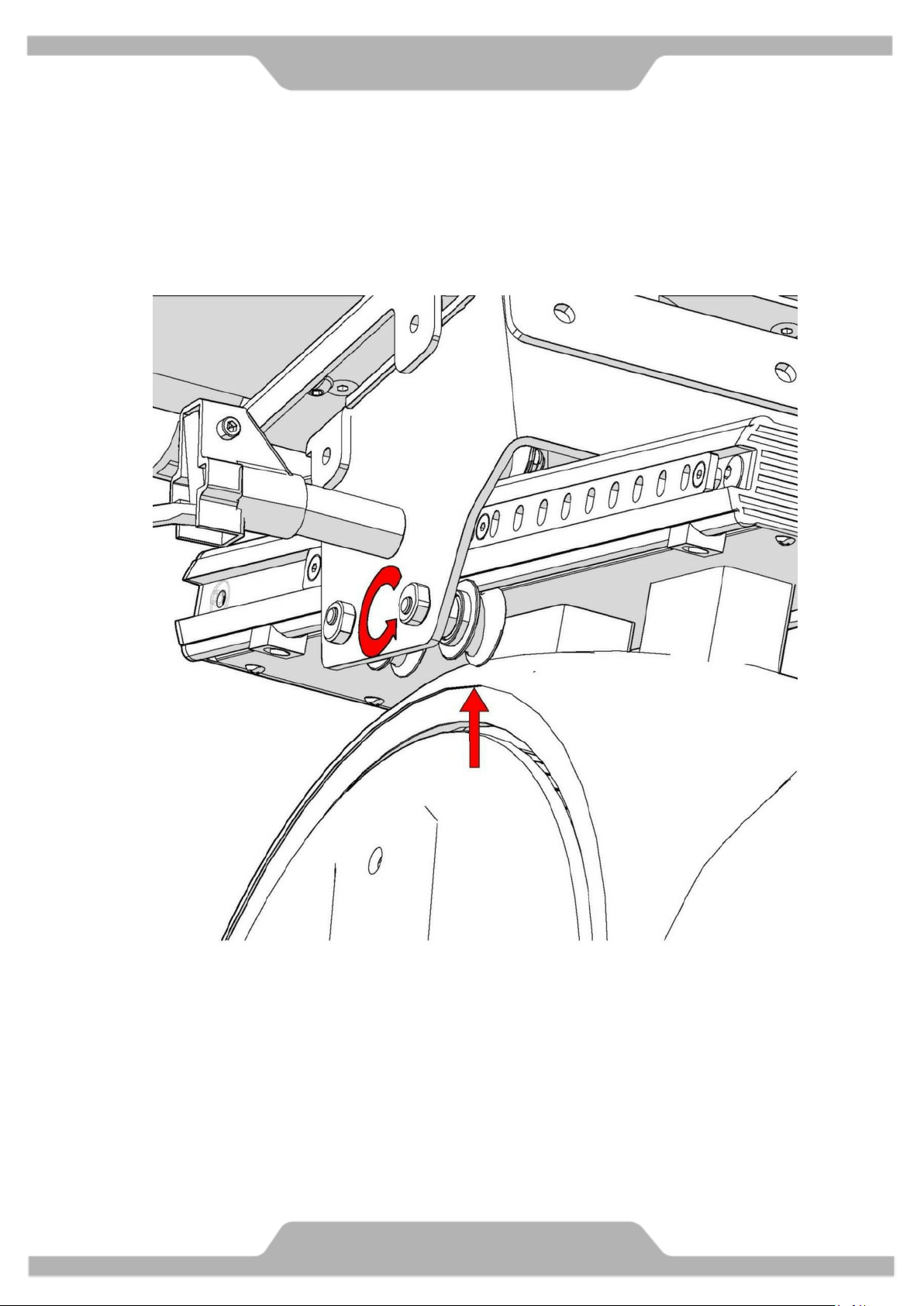
Attention:
If you find that the Seat Bracket (A03) has a wobbled or is loose, you can
use a wrench to adjust the gap between the Plastic Pulley (C16) and the
Aluminum Rail (F01 & F02). Turn the Pulley Shaft (B48) with a wrench
counter-clockwise with smaller gap.
STRETCHING
11
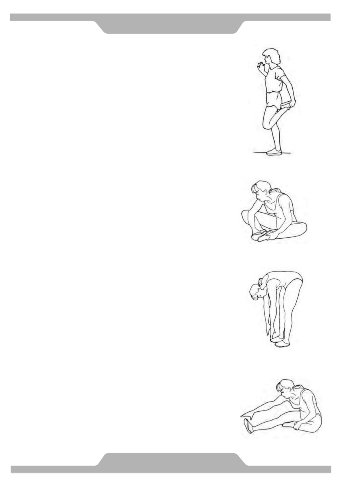
Quadriceps Stretch
With one hand against a wall for balance, reach behind you and pull your left foot
up. Bring your heel as close to your buttocks as possible. Hold for 15 counts and
repeat with right foot up.
Inner Thigh Stretch
Sit with the soles of your feet together with your knees pointing outward. Pull your
feet as close into your groin as possible. Gently push your knees towards the floor.
Hold for 10 counts.
Toe Touches
Slowly bend forward from your waist, letting you back and shoulders relax as you
stretch toward your toes. Reach down as far as you can and hold for 15 counts.
Hamstring Stretches
Sit with your right leg extended. Rest the sole of your left foot against your right inner
thigh. Stretch toward your toe as far as possible. Hold for 15 counts Relax and then
repeat with left leg extend
COMPUTER
12
Console Operation Instruction
Please thoroughly read the console operation instructions before use. It is important that you get familiar
with the computer console and understand the functions. Below is the console layout and detailed
operation instructions.
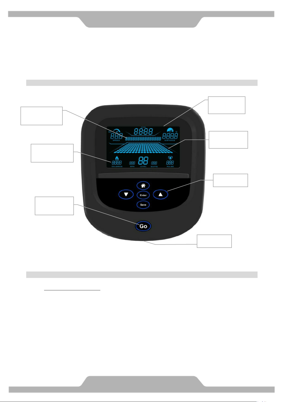
Layout:
--- *The USB port is for software updates only, please do not use for charging or other software usages. ---
Displays
� Dot matrix profile window:
Displays program profile during program setting and execution. The program profile will be
different according to which program is selected. Except HR programs, all other program profiles
will follow display rules below.
There are 20 columns of Dots representing 20 segments of time; each segment time = total program
time divided by 20 columns, except Quick Start program which represents 1 minute per column.
During exercising, a column of Dots will blink to indicate the time segment you are currently in and
show your workout progress.
There are also 10 rows of Dots representing 20 levels of resistance. Each row represents 2 levels of
resistance. The appropriate row of Dots will light up when you adjust the resistance level.
Data display
windows
Keys
Alphanumeric
display window
Data display
windows
Dot matrix
profile
USB Port*
Quick Start/
GO Key

Data display windows:
There are 8 data display windows displaying “speed, time, distance, calories, rpm, level watts, and
pulse” during exercising.
Alphanumeric display window:
This display will prompt instruction messages to assist you setting up the program and during
exercising.
Keys
Go key: Pressing this key during idle mode before you select a program will activate the Quick Start
program immediately with default user values. Or pressing this key during the program setup after
a program is selected will start the selected program.
keys: Used for toggle between different programs during idle mode, user data adjusting
during program setup and resistance level/ heart rate adjustment while a program is running.
Enter key: Used to confirm program and data entry.
Home key: Used to exit the current activities and go back home/idle mode.
Save key: Pressing this key while a program is running to save current program profile as well as user
personal data into the custom program for later use with the exception of heart rate control
programs. Heart rate control program can’t be saved as a custom program. After saving
message, it will return to previous activities.
Basic Operation
Power up: If this is a self-generating product, user must pedal the product to power up the console.
Pause a program: If a program is running and there is no RPM for 10 seconds, the console will
pause and stop accumulating data. The pause time is 3 minutes. After that, the console will reset
back to idle mode. Within pause mode, pedal again to resume the program.
Power save function: This console is equipped with power save function. If there is no RPM, the
console screen will be off and enter power save mode.
Start a program: To begin a workout program during idle mode, press the “Go” key to quick start
the program or key to toggle through different programs and “Enter” key to select a
program. Then follow the instruction on the alphanumeric window to set up the personal data.
When finished entering data, press the “Go” key to begin the workout. (You may press “Go” key
anytime during setup to bypass and start the workout immediately.)
Default values: Initially the console is coded with a set of defaults for express quick start. If you
didn’t adjust these values before the program started, they will be used for data calculations,
such as calories. It is recommended you adjust these values with your own personal data to get the
most accurate workout feedbacks. The factory defaults are:
COMPUTER
13
o Age – 35
o Weight – 150lbs or 70kg
o Program time – 30 minutes
o Target HR & Work HR – 70% max HR (Max HR is calculated as 220-age)
End a program and review summary
: When program time is reached, it will end the program and
enter summary review mode. There are 30 seconds for you to review and record the workout
summary before it resets and back home.
Units switching: The default units setting is English. To switch this to Metric system, first, press and
hold both keys at the same time in idle mode for 2 seconds to go to “engineering
mode”; second, when message window shows “UNITS: ENGLISH”, press key to switch.
Afterwards press Enter key to confirm. Anytime in “engineering mode”, you may press
“Home” key to return home.
Workout Programs
In addition to the Quick Start function, there are 8 program options for your selection: Manual, Random,
Interval, Hill Climb, Strength, Target HR, HR Interval and Custom.
Quick Start: Pressing “GO” key during idle mode will quick start the console. The program will use
factory defaults for calculation and display. The time will count up and each segment of progress profile
equals 1 minute. You may stop pedaling at any time or press “Home” key to end the program.
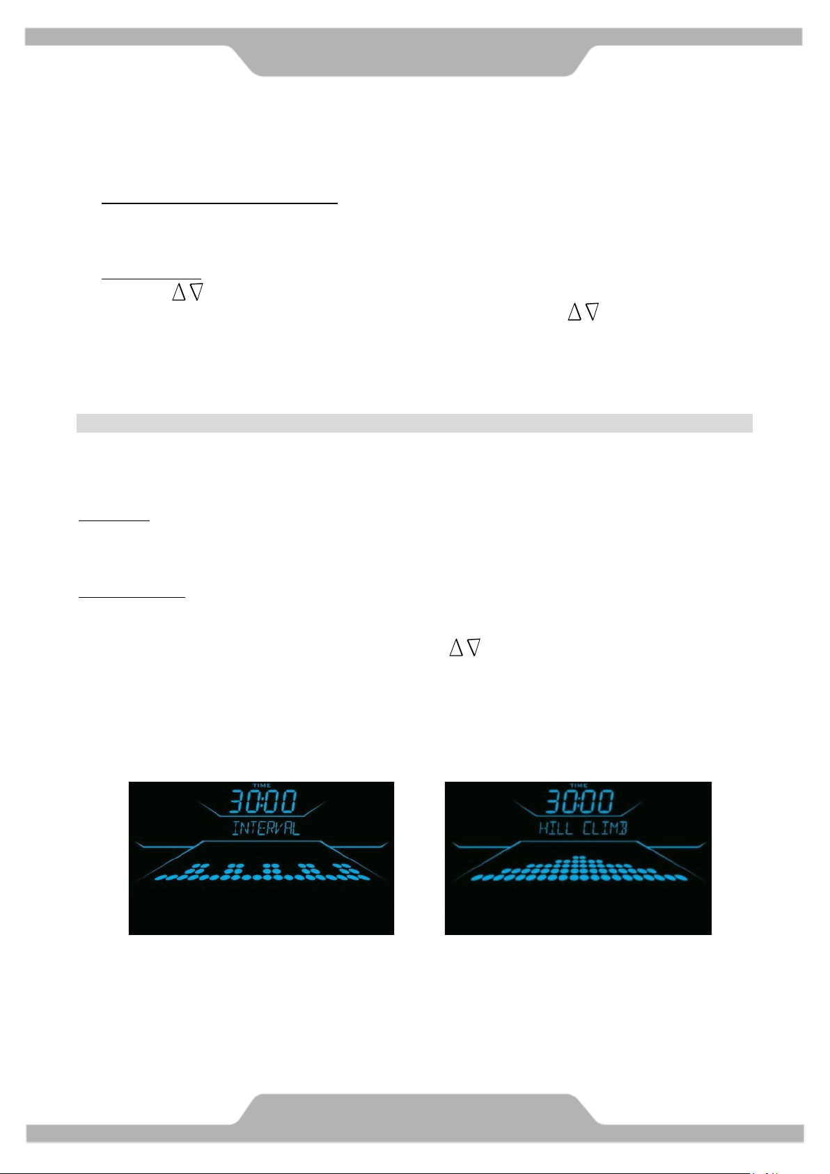
Classic Programs: This group includes Manual, Random, Intervals, Hill Climb & Strength program.
These programs are preset profile programs and behave similar. When the desired program appears on the
screen, press Enter key to confirm. Then follow the instruction to set up the user data and start the
program. You may adjust the resistance level by pressing key during program. The dot matrix
profile will update accordingly.
Manual program: The default resistance level for Manual program is L1.
Random program: This is a computer generated profile program and it is different each time.
Intervals program profile: Hill Climb program profile:
COMPUTER
14
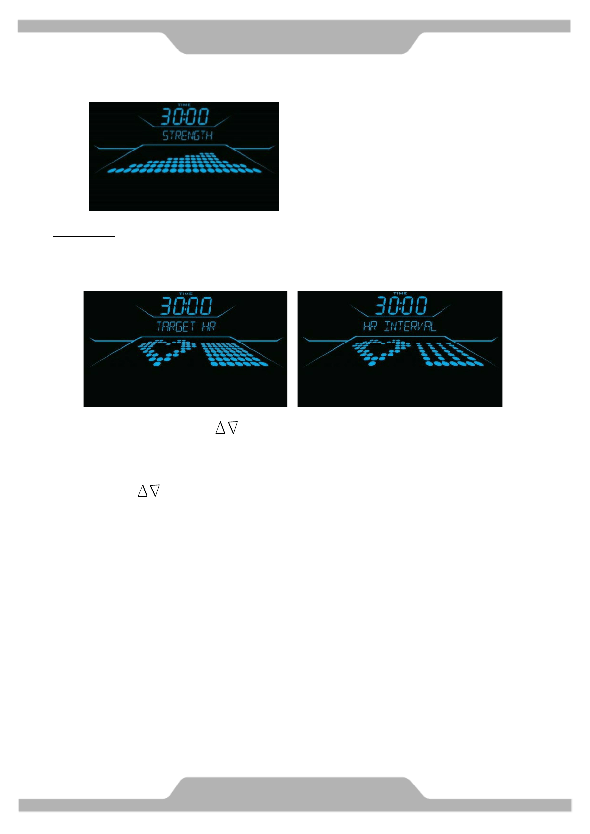
HR programs: The Heart Rate programs are designed to keep you training at the chosen heart rate level.
These programs will only work when there is a valid heart rate signal. For your safety, the program will
start with a warm up session to get the heart rate up within 20% of the target before it begins the heart
rate training session.
During warm up, user may press key to adjust the resistance and get the heart rate up. As soon
as the heart rate training session begins, the console will take control and adjust the resistance level
automatically to ensure your target heart rate is achieved and maintained during the entire program.
Target HR program: Default heart rate target is set at 70% max HR (calculated as 220-Age). You may
also press key to adjust the target heart rate setting during heart rate control session of the
exercise.
HR Interval program profile: There are two phases of this training: Work Interval and Rest Interval.
After warm up, the console will take the default target setting to begin Work interval and adjust the
resistance automatically. When the target setting is reached the Work Interval lasts for 30 seconds,
it will then enter Rest interval and reduce the resistance down to level 2 for 2 segments of time for
resting. It will repeat this process throughout the entire program.
During exercise, the profile on the Dot Matrix display will show your selected target heart rate
setting and your progress so far. The pulse data display window will show the actual heart rate.
Example: HR interval program exercising screen
COMPUTER
15
Strength program profile:

Custom program: This program is a space for you to build your own workout profile and store it for future
use. If you have previously saved a custom program, you may recall it and press “Go" key to begin
immediately without the hassle of entering user information again because it has been stored along with
the program profile you created. However if you desire, you may still go through the program setting and
change it as well. Follow the message prompts to operate this program the same way as the original
program.
Heart Rate Monitoring Devices & Exercise Tips
Pulse Hand Grips
This product comes standard with stainless steel pulse handgrips. To activate, gently grasp both handgrips
to obtain a heart rate reading. (Note: It is recommended to wear a chest strap for Heart Rate control
program, as it is more accurate. If you wear a chest strap and use hand grips at the same time for heart rate
monitoring purpose, please note the console will take the measurement of the chest strap.)
Pulse Grip Operating Tips: If you are not getting a consistent reading while using the hand pulse option, we
recommend the following suggestions:
Make sure that the palms of the hands are touching the contact area of each hand pulse grip.
Maintain an even pressure on the grips.
Do not hold the hand pulse grips too tightly.
Built in Wireless Heart Rate Receiver
Note: Chest strap transmitter does not come with this unit; contact BODYCRAFT, or your dealer for purchase.
This product is equipped with a built-in receiver for your heart rate monitoring. Any heart rate telemetry
strap that transmits at 5 kHz is compatible. To get an accurate reading using these devices, you will need to
be within three feet of the console, and a minimum of four feet from others using a heart rate monitoring
device.
(Note: The transmitter may fluctuate erratically if you are too close to other heart rate monitoring
equipment or there is other electronics near by, such as TV, Radio...)
While using heart rate control modes, the computer monitors the exact measurement of your pulse. IT is
highly recommended that you use a Heart Rate Belt for these programs. Your heart rate is displayed while the
computer continually compares heart rate to the preprogrammed personal data. The computer adjusts the
resistance to maintain heart rate at the preprogrammed level.
How to Wear Your Sensor/ Transmitter (Chest Strap)
1. Buckle one end of the chest strap onto the transmitter.
Target HR
setting
Your progress
so far
COMPUTER
16

2. Adjust the band length so that the fit is snug, but not too tight.
3. Buckle the other end of the chest strap onto the transmitter.
4. Center the transmitter on your chest below the pectoral muscle (breasts).
5. Stretch the transmitter away from your chest and moisten the conductive electrode strips located
next to the buckles with water.
(Note: The transmitter is on automatically when being worn. It is off when it is not connected to your body.
However, as moisture may activate the transmitter, thoroughly dry the transmitter to prolong battery life.)
Erratic Heart Rate Readings
Erratic readings on the receiver can be caused by electromagnetic disturbances. If the heart rate readings
appear to be abnormal, check that your product is not within range of other strong electromagnetic signals.
Common sources are televisions, computers, cars, cell phones, TV antennas and high voltage power lines
(both above and below ground). Please note: Static electricity in clothing or a flapping shirt can cause
electrical interference, so some items of clothing, i.e. man-made fibers, can also be the cause. Please try
wetting the t-shirt in the area where the transmitter is.
(In rare cases some people may be need to purchase Electrode gel. This is available online or at a local medical supply. We
recommend the brand Signa® Gel brand).
If the battery of the transmitter is running low, the transmission range decreases and may cause errors
similar to the ones listed above in this document.
Heart rate is an important key to your exercise
Medical research has shown us that there is an amount of exercise, which is enough to condition the cardio
respiratory system and the muscles of the body. This amount of exercise is between 60% and 85% of your
maximum heart rate measured during a training session. This range allows enough exercise to achieve
fitness, but not an excessive amount to cause injury. Your heart rate is an excellent indicator of the amount
of stress placed on the cardiovascular system.
If exercise intensity is too low or too high, no gains will be made in fitness. If the intensity is too low, the
stress levels are ineffective. If the intensity is too high, injury or fatigue may set your exercise program back
as you try to recover. Your target heart rate, the intensity needed to improve cardiovascular fitness,
depends primarily on your age and not your state of fitness. It is calculated as a percentage of your
maximum heart rate, estimated as 220 minus your age. It is most effective to train at your target heart rate
between 60% and 85% of your maximum heart rate.
Get a smart start on exercising
Anyone over the age of 35, as well as younger persons whom are overweight, should check with his/her
physician before beginning any type of exercise program. People who have diabetes or high blood pressure,
a family history of heart disease, high cholesterol or have lead a sedentary lifestyle should protect
themselves with a medical check-up and a stress test, preferably administered during exercise by a
healthcare professional.
Always stretch before your workout to loosen muscles, and afterwards to cool down.
The first few minutes of your workout should be devoted to warming up muscles before a vigorous
workout, and building your heart rate slowly.
After your aerobic workout of about 24-32 minutes, spend 10 minutes gradually reducing your
heart rate with a lower resistance level.
Remember, to start slow, with intensity low, until you build endurance and strength. And always consult
your physician before beginning any exercise program.
COMPUTER
17

Part List
18
Part No Description Qty
SC41:A01 MainFrame 1
SC41:A02 UprightPost 1
SC41:A03 Moveable Seat Bracket 1
SC41:A04 Backrest Tube 1
SC41:A05 Rear Stabilizer 1
SC41:A06 Front Stabilizer 1
SC41:A07 Saddle Assembly 1
SC41:A08 Dual Action Arm /L 1
SC41:A09 Dual Action Arm /R 1
SC41:A10 Foot Pedal Tube /Left 1
SC41:A11 Foot Pedal Tube /Right 1
SC41:A12 Dual Action Handlebar Tube /L 1
SC41:A13 Dual Action Handlebar Tube /R 1
SC41:A14 Picot Link 2
SC41:A15 Pedal Adjustment Frame/L 1
SC41:A16 Pedal Adjustment Frame/R 1
SC41:A17 Guide Rail Tube/L 1
SC41:A18 Guide Rail Tube/R 1
SC41:A19 Seat Bracket 1
SC41:A20 Cross Main Frame /L 1
SC41:A21 Cross Main Frame /R 1
SC41:B01 1/4" Bolt 2
SC41:B02 1/4" Washer 4
SC41:B03 1/4" Nylon Nut 2
SC41:B04 Thrust Bearing 1
SC41:B05 Spacer 4
SC41:B06 M8 Carriage Bolt 4
SC41:B07 M8 Curve Washer 8
SC41:B08 M8 Nylon Nut 11
SC41:B09 M3 Screw 6
SC41:B10 Thrust Bearing 1
SC41:B11 3/16" Screw 8
SC41:B12 Washer 5/16" 2
SC41:B13 C-ring R-34 2
SC41:B14 Spring 4
SC41:B15 Pulley Spacer 4
SC41:B16 Screws For Computer 4
SC41:B17 M8 Bolt 1
SC41:B18 M3 Screw 4
Part No Description Qty
SC41:B19 Spacer 1
SC41:B20 M20 Nut 1
SC41:B21 Cap Nut 3/8'' 2
SC41:B22 Bolt M8x16mm 2
SC41:B23 Shaft Ø20 2
SC41:B24 3/8" Bolt 4
SC41:B25 3/8" Washer 6
SC41:B26 Bolt M6x15mm 8
SC41:B27 Hex Head Bolt M8x16mm 10
SC41:B28 M5 Self Tap Screw 2
SC41:B29 M5 Screw 27
SC41:B30 5/16" Washer 12
SC41:B31 M5 Screw 2
SC41:B32 M8 Rivet Nut 5
SC41:B33 M6 Rivet Nut 3
SC41:B34 Lock Pin Plate 1
SC41:B35 M6 Screw 7
SC41:B36 Lock Pin Spacer 3
SC41:B37 M8 Bolt 5
SC41:B38 Spacer 5
SC41:B39 M4 Screw 4
SC41:B40 M6 Nylon Nut 2
SC41:B41 M5 Bolt 2
SC41:B42Y Seat Position Locking Handle 1
SC41:B42R Seat Swivel Locking Handle 1
SC41:B43 M5 Nylon Nut 2
SC41:B44 Spring 2
SC41:B45 Lock Pin 2
SC41:B46 M8 Nylon Nut 4
SC41:B47 M8 Bolt 4
SC41:B48 Pulley Shaft 4
SC41:B49 M6 Bolt 2
SC41:B50 Screw 5/16” 8
SC41:B51 Bolt M5 4
SC41:B52 M8 Bolt 16
SC41:B53 Washer 5/16" 12
SC41:B54 Shaft 1
SC41:B55 M10 Allen Key Screw 2
SC41:B56 Rod End Bearing 2
*The Exploded Views do not include the SC41: portion of the part number.

Part List
19
Part No Description Qty
SC41:B57 Washer 5/16" 5
SC41:B58 Bolt M4x16mm 4
SC41:B59 Nut M10 1
SC41:B60 Nut M10 1
SC41:B61 M8 Allen Key Bolt 1
SC41:B62 M16 Knob 1
SC41:B63 Nut M20 1
SC41:B64 M3 Bolt 2
SC41:B65 Nut M10 2
SC41:B66 Spring Washer M10 2
SC41:B67 M6 Bolt 4
SC41:B68 M6 Nylon Nut 16
SC41:B69 M4 Screw 1
SC41:B70 Shaft 2
SC41:B71 Washer 2
SC41:B72 M6 Bolt 8
SC41:C01 Plug 1-1/4" 2
SC41:C02 Main Cover /R 1
SC41:C03 Main Cover /L 1
SC41:C04 End Cap 4
SC41:C05 Adjustable Foot Pad M8 4
SC41:C06 Wheel-Stabilizer Front 2
SC41:C07 Right Foot Pedal 2
SC41:C08 Cushion Pad 2
SC41:C09 Belt 1
SC41:C10 Upholstered, Backrest 1
SC41:C11 Upright Tube Spacer 2
SC41:C12 Plug 5
SC41:C13 Rubber Grip 2
SC41:C14 Left Upper Pivot Cover(Front 2
SC41:C15 Right Upper Pivot Cover(Front 2
SC41:C16 Plastic Pulley 8
SC41:C17 Gripping Sheath 2
SC41:C18 Pvc Pad 4
SC41:C19 Plug 2
SC41:C20 Rotate Bar Wheel 2
SC41:C21 Lower Rear Pivot Cover 2
SC41:C22L Right Lower Front Pivot Cover-L 1
SC41:C22R Right Lower Front Pivot Cover-R 1
SC41:C23 Water Bottle Holder 1
SC41:C24 Bearing Bushing 2
Part No Description Qty
SC41:C25 Bearing Housing 2
SC41:C26 Bushing 6
SC41:C27 Spacer for 6003 Bearing 2
SC41:C28 Disk Cover Plug 2
SC41:C29 Upholstered,Seat 1
SC41:C30 Disk Cover /R 2
SC41:C31-A Bushing-A 4
SC41:C31-B Bushing-B 4
SC41:C32 Nut Cap 8
SC41:C33 Foam Grip 2
SC41:C34 Bushing 2
SC41:C35 Upright Joint Cover/L 2
SC41:C36 Upright Joint Cover/R 2
SC41:C37 Plug 2
SC41:C38 Snap Bushing 2
SC41:D01 Computer 1
SC41:D02 Self powered Flywheel 1
SC41:D03 Hand Pulse Sensor 1set
SC41:D04 Motor with Cable 1
SC41:D05 Quick Key /L (Cable) GO 1
SC41:D06 Quick Key /R (Cable) UP/DOWN 1
SC41:D07 Hand Pulse Sensor Cable I 1
SC41:D08 Hand Pulse Sensor Cable II 1
SC41:D09 Hand Pulse Sensor Cable III 1
SC41:D10 Quick Key Cable /L 1
SC41:D11 Quick Key Cable /R 1
SC41:D12 Motor Tension Cable 1
SC41:D13 Control Board Cable 1
SC41:D14 Control Board (CB.) 1
SC41:D15 Sensor Cable 1
SC41:D16 Generator Cable 1
SC41:D17 Upper Cable 1
SC41:D18 Lower Cable 1
SC41:E01 Bearing 6004 6
SC41:E02 Bearing 6003 8
SC41:E03 Bearing 608 16
SC41:F01 Aluminum Rail /L 1
SC41:F02 Aluminum Rail /R 1
SC41:F03
Foot Strap(Optional)
2
SC41:F04 Aluminum Guide Rail 2
*The Exploded Views do not include the SC41: portion of the part number.
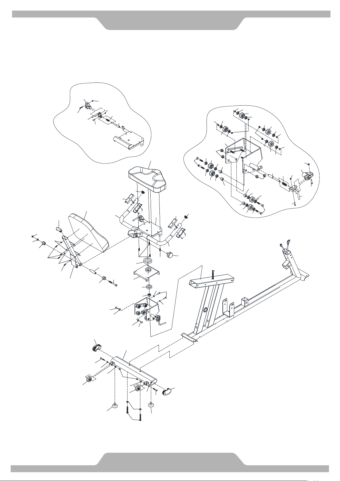
EXPLODED VIEW
20
B01
B01
B02
B02
B03
B02
B02
B25
B24
C04
C04
C05
C05
C06
C06
B18
C01
D03
A07
B18
D03
C01
C13
C13
A04
B10
B50
B50
B53
B53
B50
B50
B52
B53
B53
B52
B52
B53
B53
C10
C12
C29
B61
B57
B08
B54
C34
C34
B45
B49
B42R
B41
B40
C17
B44
B43
A19
B63
B04
B62
B30
E03
B30
B30
B30
B15
B15
B15
B15
B49
B48
B48
B47
B47
E03
E03
E03
E03
E03
E03
E03
E03
E03
E03
E03
E03
E03
E03
E03
B08
B45
B44
B43
B42Y
B41
B40
A03
C16
C16
C16
C16
C16
C16
C16
C16
C17
A05
EXPLODED VIEW
21
A01
C26
C25
E02
C24
C27
B30
B27
B20
B28
B28
B29
B29
B29
C03
B29
B29
B59
B60
E01
D02
D18
D12
B38
B38
B39
B39
B37
B37
B36
B36
B36
B35
B35
B35
B34
B33
B33
B32
B32
C18
C18
F02
B39
B39
B38
B38
B37
B37
B32
B32
C18
C18
F01
D09
C19
C19
B29
B29
E02
C20
B30
B22
B13
B64
E01
C32
B27
B71
E01
B55
A17
B27
B57
B57
B27
A08
A10
A12
A14
A15
C07
B58
D05
C33
C21
C22L
C32
C32
B29
B06
E02
C32
B27
B12
E02
B11
C26
B30
B08
C26
B46
D04
B52
B26
D16
D13
D08
F03
C36
C08
B69
D15
C31-B
C31-A
B14
C31-B
C31-A
B14
B53
B53
B23
D14
B29
C12
C12
F04
B51
C37
B08
B07
B09
C14
B29
B29
C15
B66
B05
B05
B65
B56
C35
A20
C28
C30
B17
B72
B72
B67
B35
B35
B68
B68
B68
B68
C38
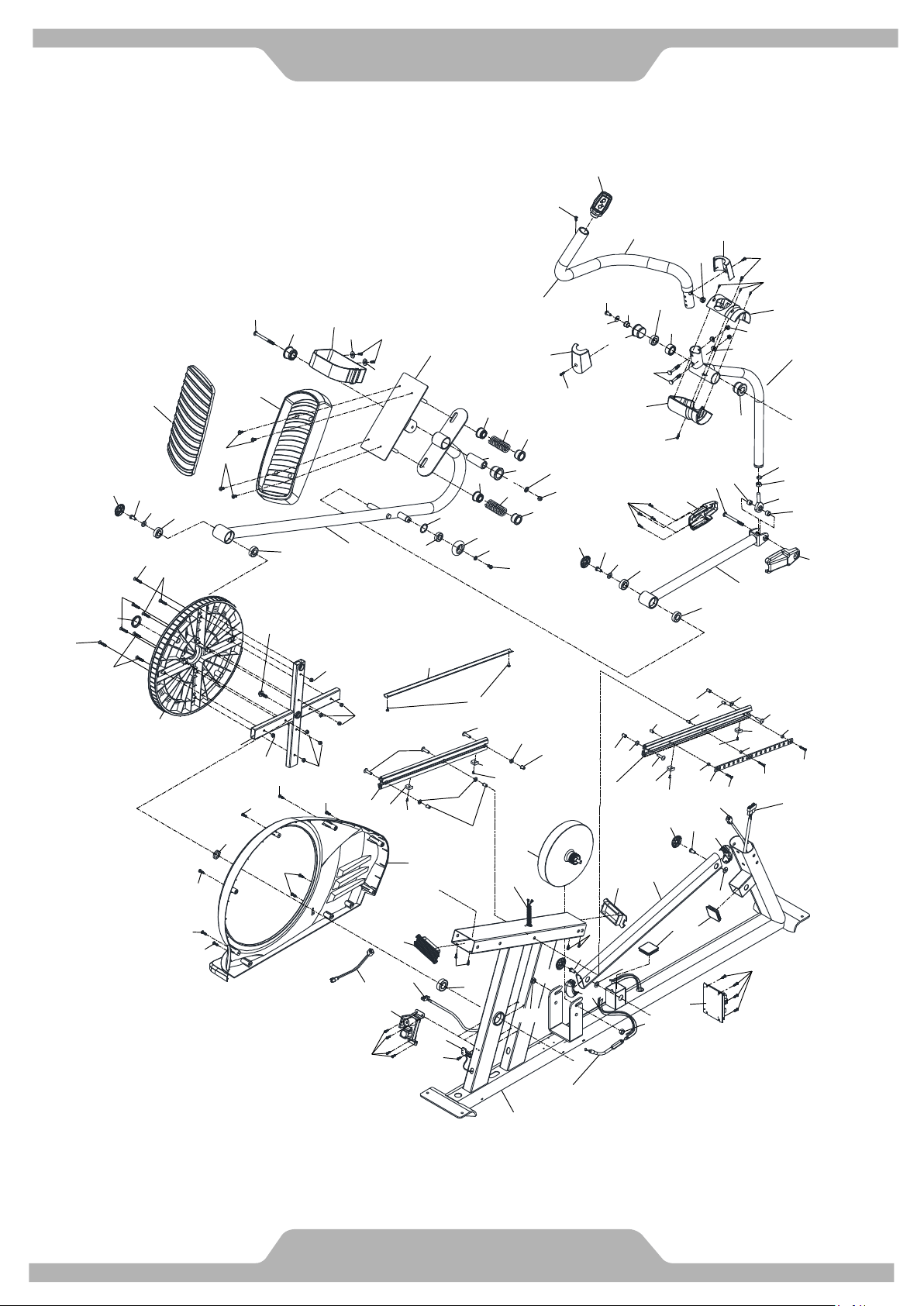
EXPLODED VIEW
22
C23
B29
A02
A01
C11
B29
C02
E01
B19
C09
B31
D10
B29
D11
B29
C11
D17
D06
A06
B21
B25
B21
B25
B25
B24
C04
C04
C05
C05
B64
C33
A13
A09
B66
B12
B27
E02
B13
C20
B30
B22
E02
B55
A18
C12
B70
B27
B57
B70
C26
B52
B26
C26
A11
A14
B11
B08
B30
A16
B46
B16
C07
D01
C32
C32
C32
B27
B30
C24
C25
E02
C27
C26
E02
B71
B27
C32
E01
B05
E01
D07
F03
B05
C35
C36
C08
C31-B
C31-A
B14
C31-B
C31-A
B14
B53
B23
C12
F04
B51
B51
B57
B27
C21
C22R
B29
B06
B08
B07
B09
C14
B29
B29
C15
B65
B56
B52
B30
B52
B30
B52
B52
B07
B07
C30
C28
A21
B68
B68
B68
B72
B35
B67
B35
B72
B68
C38

Memo

Memo

SCT400g WARRANTY
VALID FOR USA AND CANADA ONLY
(Please consult with your local distributor for warranty info specific to your region).
BODYCRAFT warrants its products to be free of defects in materials and workmanship for the time stated below to
the original purchaser.
REGISTER your product at www.bodycraft.com or call our customer service department at 800-990-
5556.
This warranty applies to Residential and Light Commercial use only.
Residential Warranty: Lifetime Frame, [7] Year(s) Parts, [1] Year(s) Wear Items and [2] Year(s) Labor.
Light Commercial Warranty: [10] Year(s) Frame, [3] Years Parts, 1 Year(s) Wear Items and [1] Year Labor.
This warranty is valid only in accordance with the following conditions:
�The warranty begins on the original purchase date at retail and ends when the original owner disposes of it, either
through sale, gift, or otherwise. This warranty is not transferable and is only valid to the original purchaser.
�This warranty is available only for purchases made within and the original purchaser currently residing in the USA and
Canada. Please consult with your local distributor for warranty info specific to your region.
�The product must have been registered within 30 days of the original purchase date or supply proof of purchase to
validate warranty (original sales invoice).
�This warranty does not cover damage resulting from accident, misuse, water, tampering, unreasonable use,
unauthorized repairs, improper repairs, alterations or normal wear and tear.
This warranty excludes the following:
1. The warranty does not cover normal maintenance or labor charges unless labor terms are listed above.
2. Normal cosmetic wear on parts such as paint, seat coverings, walk belts, pedal straps, wheels, foot rails, labels and
logos.
3. Consumables such as batteries and heart rate belts that do not have a replaceable battery.
4. Eprom/Software version upgrades unless determined as necessary.
5. Any accessories not included in the original packaging.
If the item exhibits such a defect, BODYCRAFT will, at its option, repair or replace it without cost for parts.
Shipping and handling charges may apply. (BODYCRAFT may require return of the part(s) or photographic
evidence of the damaged part(s) prior to replacement). Serial number may be required. Parts repaired or
replaced will be warranted for the remainder of the original warranty period only.
*This warranty is in lieu of all warranties, expressed or implied, and/or all other obligations or liabilities on our part and we neither assume
nor authorize any person to assume for us any other obligation or liability in connection with the sale of your BodyCraft product. Under no
circumstances shall we be liable by virtue of this warranty or otherwise for damage to any person or property whatsoever for any special,
indirect, incidental, secondary or consequential damage of any nature whatsoever arising out of the use or inability to use the BodyCraft
product.
23