Loading ...
Loading ...
Loading ...
36
7
Accesorio de caja de cableado
de conexión directa sku #
WIREBOX
(comprado por separado)
Created by
-
Denomination
-
Lang EN
Sheet
1
/1
Modif.by
Approved by
Approval date
Doc. status
Drawing N.
NEW_DRAWING_BOX
Rev
01
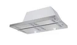
INSTALACIÓN ELÉCTRICA CON CAJA DE
CABLEADO OPCIONAL
Para la instalación de cableado permanente: utilice
solo con el kit de caja de cableado de la campana
que se incluye
sku # WIREBOX, fabricado por Faber.
Max. 33 7/16”
INSTRUCCIONES DE CONEXIÓN A TIERRA Este aparato debe estar
conectado a tierra. En el caso de un cortocircuito eléctrico, la conexión
a tierra reduce el riesgo de descarga eléctrica al proporcionar un cable
de escape para la corriente eléctrica. Este equipo está provisto de
un cable que tiene un cable de conexión a tierra con un enchufe de
conexión a tierra. El enchufe debe estar enchufado a un tomacorriente
que esté instalado y conectado a tierra correctamente.
ADVERTENCIA: una conexión a tierra incorrecta puede provocar un
riesgo de descarga eléctrica.
Consulte a un electricista calicado si las instrucciones de conexión a
tierra no se comprenden completamente o si existe una duda acerca
de si el equipo está correctamente conectado a tierra.
No utilice un cable de extensión. Si el cable de alimentación es
demasiado corto, solicite a un electricista calicado que instale un
tomacorriente cerca del dispositivo.
INSTALACIÓN ELÉCTRICA
CON CABLE DE CONEXIÓN
Version 06/14 - Page 8
USE AND CARE INFORMATION
Rangehood Control Panel
All controls are located on the right side of the rangehood.
Light On/O Switch
TheOn/O switch for the halogen light is located behind the
front trim. Moving the switch to the 1 Position turns the light
On. Moving the switch to the 0 position turns the light o.
Blower Speed Switch
B in FIGURE 10 shows the speed control switch for the
blower. Moving the switch to the 1 Position turns the blower
on LOW. Moving the switch to the 2 Position turns the blower
on MEDIUM. Moving the switch to the 3 Position turns the
blower on HIGH. Moving the switch to the 0 Position turns
the blower o.
Automatic Operation
As long as the blower and light switches are on, the blower
and light will automatically operate when the visor is opened
and shut o when the visor is closed.
For Best Results
Start the rangehood several minutes before cooking to develop
after cooking is complete to clear all smoke and odors from
the kitchen.
Cleaning
detergent solution or placed in the dishwasher. Clean exterior
surfaces with hot soapy water. Using abrasives and scouring
Replacing the halogen lamp
CAUTION the bulb MAY BE HOT
To replace the halogen bulb, see (Figure 11)
Before attempting to replace the lamp, make sure the light
switch is o, the bulb CAUTION may be hot. Remove the
cover snap-on lamp levering under the metal ring, supporting
it with one hand. Remove the halogen lamp from the lamp
holder by pulling gently. Replace the lamp with a new one of
the same type, making sure that you insert the two pins into
the slots on the lamp holder. Replace the cover snap-on lamp.
FIGURE 10
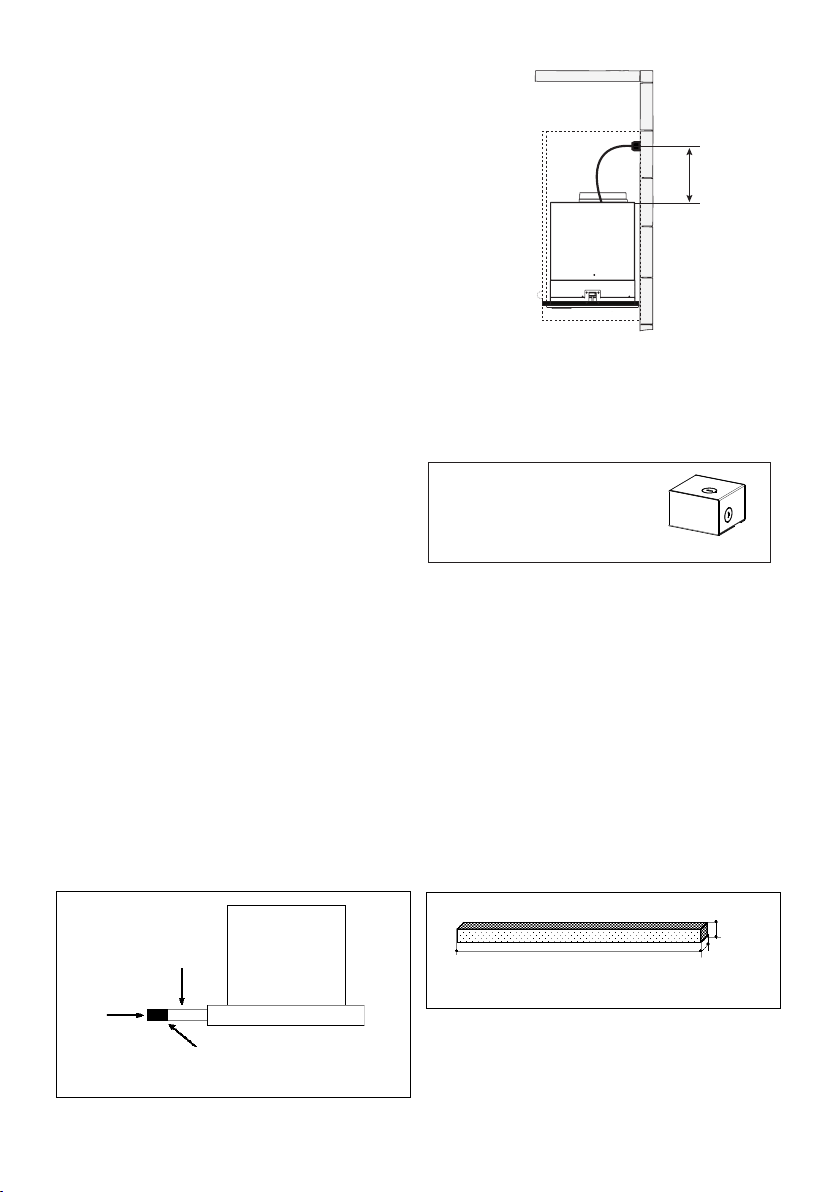
FRONT TRIM OPTIONS
The New Cristal comes with a stainless front strip installed.
Optional black and white strips are available as accessories
for purchase. To change the front strip, remove the three phil-
lips screws located behind the strip (FIGURE 8). If necessary,
the front strip can be adjusted by loosening the three phillips
screws and sliding the strip up or down. Tighten screws when
you have the strip properly placed.
For a custom front strip, a local cabinet shop can make a strip
to match your cabinets. The front strip dimensions are given
in FIGURE 9 .
FIGURE 8
1 15/32"
FIGURE 9
3/4"
29 7/8" or 35 7/8"
Visor
Front
Strip
Three Screws
B
2x
FIGURE 11
Version 06/14 - Page 8
USE AND CARE INFORMATION
Rangehood Control Panel
All controls are located on the right side of the rangehood.
Light On/O Switch
TheOn/O switch for the halogen light is located behind the
front trim. Moving the switch to the 1 Position turns the light
On. Moving the switch to the 0 position turns the light o.
Blower Speed Switch
B in FIGURE 10 shows the speed control switch for the
blower. Moving the switch to the 1 Position turns the blower
on LOW. Moving the switch to the 2 Position turns the blower
on MEDIUM. Moving the switch to the 3 Position turns the
blower on HIGH. Moving the switch to the 0 Position turns
the blower o.
Automatic Operation
As long as the blower and light switches are on, the blower
and light will automatically operate when the visor is opened
and shut o when the visor is closed.
For Best Results
Start the rangehood several minutes before cooking to develop
after cooking is complete to clear all smoke and odors from
the kitchen.
Cleaning
detergent solution or placed in the dishwasher. Clean exterior
surfaces with hot soapy water. Using abrasives and scouring
Replacing the halogen lamp
CAUTION the bulb MAY BE HOT
To replace the halogen bulb, see (Figure 11)
Before attempting to replace the lamp, make sure the light
switch is o, the bulb CAUTION may be hot. Remove the
cover snap-on lamp levering under the metal ring, supporting
it with one hand. Remove the halogen lamp from the lamp
holder by pulling gently. Replace the lamp with a new one of
the same type, making sure that you insert the two pins into
the slots on the lamp holder. Replace the cover snap-on lamp.
FIGURE 10
FRONT TRIM OPTIONS
The New Cristal comes with a stainless front strip installed.
Optional black and white strips are available as accessories
for purchase. To change the front strip, remove the three phil-
lips screws located behind the strip (FIGURE 8). If necessary,
the front strip can be adjusted by loosening the three phillips
screws and sliding the strip up or down. Tighten screws when
you have the strip properly placed.
For a custom front strip, a local cabinet shop can make a strip
to match your cabinets. The front strip dimensions are given
in FIGURE 9 .
FIGURE 8
1
15/32"
FIGURE 9
3/4"
29
7/8"
or 35
7/8"
Visor
Front
Strip
Three Screws
B
2x
FIGURE 11
OPCIONES DE MOLDURA FRONTAL
New Cristal viene con una tira frontal de acero inoxidable instalada.
Existen tiras blancas y negras opcionales disponibles como accesorios
para la compra. Para cambiar la tira frontal, retire los tres tornillos Phillips
situados detrás de la tira (FIGURA 8). Si es necesario, la tira frontal se
puede ajustar aojando los tres tornillos Phillips y deslizando la tira hacia
arriba o hacia abajo. Apriete los tornillos cuando tenga la tira colocada
correctamente.
Para una tira frontal personalizada, una tienda local de gabinetes puede
hacer una tira que combine con sus gabinetes. Las dimensiones de la
tira frontal se dan en la FIGURA 9.
Tira delantera
Visera
Tres tornillos
Loading ...
Loading ...
Loading ...