Loading ...
Loading ...
Loading ...
23
7
Boîtier de connexion directe,
no d'article WIREBOX
(acheté séparément)
Created by
-
Denomination
-
Lang EN
Sheet
1
/1
Modif.by
Approved by
Approval date
Doc. status
Drawing N.
NEW_DRAWING_BOX
Rev
01
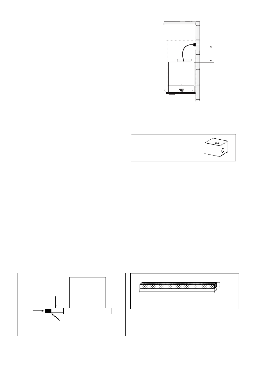
INSTALLATION ÉLECTRIQUE AVEC BOÎTIER
DE CONNEXION EN OPTION
Pour une installation avec connexion xe, utilisez
uniquement la trousse de boîtier de connexion pour
hotte indiquée,
no d'article WIREBOX, fabriquée par Faber.
Max. 33 7/16”
INSTRUCTIONS DE MISE À LA TERRE Cet appareil doit être mis à la
terre. La mise à la terre réduit le risque de choc électrique en cas de
court-circuit, car elle fournit un l d'évacuation au courant électrique.
Cet appareil est muni d'un cordon présentant un l de mise à la terre,
avec une che de mise à la terre. La che doit être insérée dans une
prise correctement installée et mise à la terre.
AVERTISSEMENT - Une mise à la terre inadéquate peut entraîner
un choc électrique.
Consultez un électricien qualié si vous ne comprenez pas parfaitement
les instructions de mise à la terre ou si vous avez des doutes quant
à la mise à la terre de l'appareil.
N'utilisez pas de rallonge. Si le cordon d’alimentation est trop court,
demandez à un électricien qualié d’installer une prise à proximité
de l'appareil.
INSTALLATION ÉLECTRIQUE
AVEC CÂBLE DE CONNEXION
Version 06/14 - Page 8
USE AND CARE INFORMATION
Rangehood Control Panel
All controls are located on the right side of the rangehood.
Light On/O Switch
TheOn/O switch for the halogen light is located behind the
front trim. Moving the switch to the 1 Position turns the light
On. Moving the switch to the 0 position turns the light o.
Blower Speed Switch
B in FIGURE 10 shows the speed control switch for the
blower. Moving the switch to the 1 Position turns the blower
on LOW. Moving the switch to the 2 Position turns the blower
on MEDIUM. Moving the switch to the 3 Position turns the
blower on HIGH. Moving the switch to the 0 Position turns
the blower o.
Automatic Operation
As long as the blower and light switches are on, the blower
and light will automatically operate when the visor is opened
and shut o when the visor is closed.
For Best Results
Start the rangehood several minutes before cooking to develop
after cooking is complete to clear all smoke and odors from
the kitchen.
Cleaning
detergent solution or placed in the dishwasher. Clean exterior
surfaces with hot soapy water. Using abrasives and scouring
Replacing the halogen lamp
CAUTION the bulb MAY BE HOT
To replace the halogen bulb, see (Figure 11)
Before attempting to replace the lamp, make sure the light
switch is o, the bulb CAUTION may be hot. Remove the
cover snap-on lamp levering under the metal ring, supporting
it with one hand. Remove the halogen lamp from the lamp
holder by pulling gently. Replace the lamp with a new one of
the same type, making sure that you insert the two pins into
the slots on the lamp holder. Replace the cover snap-on lamp.
FIGURE 10
FRONT TRIM OPTIONS
The New Cristal comes with a stainless front strip installed.
Optional black and white strips are available as accessories
for purchase. To change the front strip, remove the three phil-
lips screws located behind the strip (FIGURE 8). If necessary,
the front strip can be adjusted by loosening the three phillips
screws and sliding the strip up or down. Tighten screws when
you have the strip properly placed.
For a custom front strip, a local cabinet shop can make a strip
to match your cabinets. The front strip dimensions are given
in FIGURE 9 .
FIGURE 8
1 15/32"
FIGURE 9
3/4"
29 7/8" or 35 7/8"
Visor
Front
Strip
Three Screws
B
2x
FIGURE 11
Version 06/14 - Page 8
USE AND CARE INFORMATION
Rangehood Control Panel
All controls are located on the right side of the rangehood.
Light On/O Switch
TheOn/O switch for the halogen light is located behind the
front trim. Moving the switch to the 1 Position turns the light
On. Moving the switch to the 0 position turns the light o.
Blower Speed Switch
B in FIGURE 10 shows the speed control switch for the
blower. Moving the switch to the 1 Position turns the blower
on LOW. Moving the switch to the 2 Position turns the blower
on MEDIUM. Moving the switch to the 3 Position turns the
blower on HIGH. Moving the switch to the 0 Position turns
the blower o.
Automatic Operation
As long as the blower and light switches are on, the blower
and light will automatically operate when the visor is opened
and shut o when the visor is closed.
For Best Results
Start the rangehood several minutes before cooking to develop
after cooking is complete to clear all smoke and odors from
the kitchen.
Cleaning
detergent solution or placed in the dishwasher. Clean exterior
surfaces with hot soapy water. Using abrasives and scouring
Replacing the halogen lamp
CAUTION the bulb MAY BE HOT
To replace the halogen bulb, see (Figure 11)
Before attempting to replace the lamp, make sure the light
switch is o, the bulb CAUTION may be hot. Remove the
cover snap-on lamp levering under the metal ring, supporting
it with one hand. Remove the halogen lamp from the lamp
holder by pulling gently. Replace the lamp with a new one of
the same type, making sure that you insert the two pins into
the slots on the lamp holder. Replace the cover snap-on lamp.
FIGURE 10
FRONT TRIM OPTIONS
The New Cristal comes with a stainless front strip installed.
Optional black and white strips are available as accessories
for purchase. To change the front strip, remove the three phil-
lips screws located behind the strip (FIGURE 8). If necessary,
the front strip can be adjusted by loosening the three phillips
screws and sliding the strip up or down. Tighten screws when
you have the strip properly placed.
For a custom front strip, a local cabinet shop can make a strip
to match your cabinets. The front strip dimensions are given
in FIGURE 9 .
FIGURE 8
1
15/32"
FIGURE 9
3/4"
29
7/8"
or 35
7/8"
Visor
Front
Strip
Three Screws
B
2x
FIGURE 11
GARNITURE AVANT EN OPTION
La nouvelle hotte Cristal est équipée d’une bande d’acier inoxydable
installée. Des bandes en option, de couleur noire ou blanche, peuvent être
achetées. Pour modier la bande avant, enlevez les trois vis cruciformes
situées derrière la bande (FIGURE 8). Au besoin, la bande avant peut-
être réglée en desserrant les trois vis cruciformes et en faisant glisser la
bande) vers le haut ou vers le bas. Serrez les vis lorsque la bande est
placée correctement.
Pour une bande avant personnalisée, il est aussi possible de s’adresser
à une boutique spécialisée dans la vente d’armoires pour obtenir une
bande coordonnée à vos armoires. Les dimensions de la bande avant
sont indiquées sur la FIGURE 9.
Panneau
coulissant
Bande
avant
Trois vis
Loading ...
Loading ...
Loading ...