Loading ...
Loading ...
Loading ...
10
7
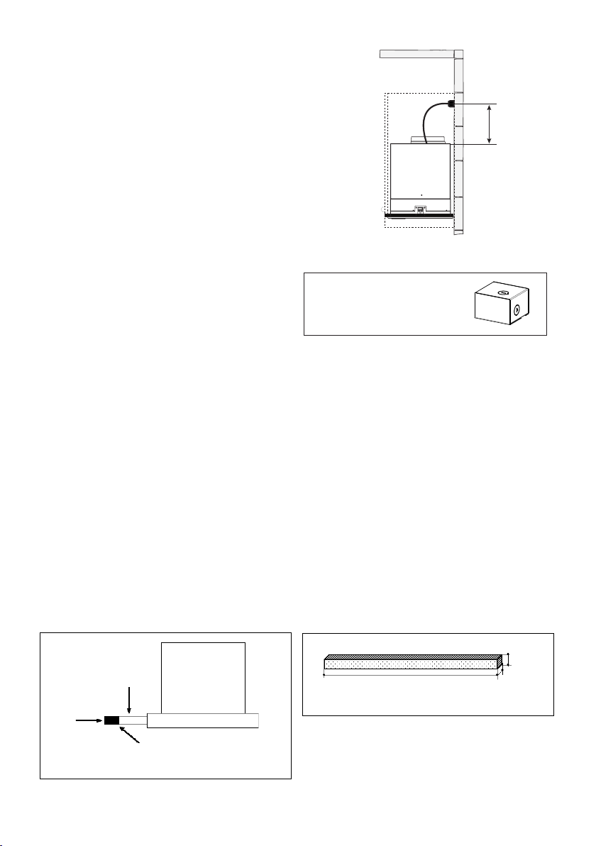
Direct Connect Wiring Box
Accessory sku # WIREBOX
(purchased separately)
Created by
-
Denomination
-
Lang EN
Sheet
1
/1
Modif.by
Approved by
Approval date
Doc. status
Drawing N.
NEW_DRAWING_BOX
Rev
01
ELECTRICAL INSTALLATION WITH OPTIONAL
WIRING BOX
For Permanent wiring Installation-Use only with Listed
rangehood Wiring Box kit
sku # WIREBOX, manufactured by Faber.
Max. 33 7/16”
GROUNDING INSTRUCTIONS This appliance must be grounded.
In the event of an electrical short circuit, grounding reduces the risk
of electric shock by providing an escape wire for the electric current.
This appliance is equipped with a cord having a grounding wire with
a grounding plug. The plug must be plugged into an outlet that is
properly installed and grounded.
WARNING - Improper grounding can result in a risk of electric shock.
Consult a qualied electrician if the grounding instructions are not
completely understood, or if doubt exists as to whether the appliance
is properly grounded.
Do not use an extension cord. If the power supply cord is too short,
have a qualied electrician install an outlet near the appliance.
Version 06/14 - Page 8
USE AND CARE INFORMATION
Rangehood Control Panel
All controls are located on the right side of the rangehood.
Light On/O Switch
TheOn/O switch for the halogen light is located behind the
front trim. Moving the switch to the 1 Position turns the light
On. Moving the switch to the 0 position turns the light o.
Blower Speed Switch
B in FIGURE 10 shows the speed control switch for the
blower. Moving the switch to the 1 Position turns the blower
on LOW. Moving the switch to the 2 Position turns the blower
on MEDIUM. Moving the switch to the 3 Position turns the
blower on HIGH. Moving the switch to the 0 Position turns
the blower o.
Automatic Operation
As long as the blower and light switches are on, the blower
and light will automatically operate when the visor is opened
and shut o when the visor is closed.
For Best Results
Start the rangehood several minutes before cooking to develop
after cooking is complete to clear all smoke and odors from
the kitchen.
Cleaning
detergent solution or placed in the dishwasher. Clean exterior
surfaces with hot soapy water. Using abrasives and scouring
Replacing the halogen lamp
CAUTION the bulb MAY BE HOT
To replace the halogen bulb, see (Figure 11)
Before attempting to replace the lamp, make sure the light
switch is o, the bulb CAUTION may be hot. Remove the
cover snap-on lamp levering under the metal ring, supporting
it with one hand. Remove the halogen lamp from the lamp
holder by pulling gently. Replace the lamp with a new one of
the same type, making sure that you insert the two pins into
the slots on the lamp holder. Replace the cover snap-on lamp.
FIGURE 10
FRONT TRIM OPTIONS
The New Cristal comes with a stainless front strip installed.
Optional black and white strips are available as accessories
for purchase. To change the front strip, remove the three phil-
lips screws located behind the strip (FIGURE 8). If necessary,
the front strip can be adjusted by loosening the three phillips
screws and sliding the strip up or down. Tighten screws when
you have the strip properly placed.
For a custom front strip, a local cabinet shop can make a strip
to match your cabinets. The front strip dimensions are given
in FIGURE 9 .
FIGURE 8
1
15/32"
FIGURE 9
3/4"
29
7/8"
or 35
7/8"
Visor
Front
Strip
Three Screws
B
2x
FIGURE 11
ELECTRICAL INSTALLATION
WITH CONNECTION CABLE
Version 06/14 - Page 8
USE AND CARE INFORMATION
Rangehood Control Panel
All controls are located on the right side of the rangehood.
Light On/O Switch
TheOn/O switch for the halogen light is located behind the
front trim. Moving the switch to the 1 Position turns the light
On. Moving the switch to the 0 position turns the light o.
Blower Speed Switch
B in FIGURE 10 shows the speed control switch for the
blower. Moving the switch to the 1 Position turns the blower
on LOW. Moving the switch to the 2 Position turns the blower
on MEDIUM. Moving the switch to the 3 Position turns the
blower on HIGH. Moving the switch to the 0 Position turns
the blower o.
Automatic Operation
As long as the blower and light switches are on, the blower
and light will automatically operate when the visor is opened
and shut o when the visor is closed.
For Best Results
Start the rangehood several minutes before cooking to develop
after cooking is complete to clear all smoke and odors from
the kitchen.
Cleaning
detergent solution or placed in the dishwasher. Clean exterior
surfaces with hot soapy water. Using abrasives and scouring
Replacing the halogen lamp
CAUTION the bulb MAY BE HOT
To replace the halogen bulb, see (Figure 11)
Before attempting to replace the lamp, make sure the light
switch is o, the bulb CAUTION may be hot. Remove the
cover snap-on lamp levering under the metal ring, supporting
it with one hand. Remove the halogen lamp from the lamp
holder by pulling gently. Replace the lamp with a new one of
the same type, making sure that you insert the two pins into
the slots on the lamp holder. Replace the cover snap-on lamp.
FIGURE 10
FRONT TRIM OPTIONS
The New Cristal comes with a stainless front strip installed.
Optional black and white strips are available as accessories
for purchase. To change the front strip, remove the three phil-
lips screws located behind the strip (FIGURE 8). If necessary,
the front strip can be adjusted by loosening the three phillips
screws and sliding the strip up or down. Tighten screws when
you have the strip properly placed.
For a custom front strip, a local cabinet shop can make a strip
to match your cabinets. The front strip dimensions are given
in FIGURE 9 .
FIGURE 8
1 15/32"
FIGURE 9
3/4"
29 7/8" or 35 7/8"
Visor
Front
Strip
Three Screws
B
2x
FIGURE 11
Version 06/14 - Page 8
USE AND CARE INFORMATION
Rangehood Control Panel
All controls are located on the right side of the rangehood.
Light On/O Switch
TheOn/O switch for the halogen light is located behind the
front trim. Moving the switch to the 1 Position turns the light
On. Moving the switch to the 0 position turns the light o.
Blower Speed Switch
B in FIGURE 10 shows the speed control switch for the
blower. Moving the switch to the 1 Position turns the blower
on LOW. Moving the switch to the 2 Position turns the blower
on MEDIUM. Moving the switch to the 3 Position turns the
blower on HIGH. Moving the switch to the 0 Position turns
the blower o.
Automatic Operation
As long as the blower and light switches are on, the blower
and light will automatically operate when the visor is opened
and shut o when the visor is closed.
For Best Results
Start the rangehood several minutes before cooking to develop
after cooking is complete to clear all smoke and odors from
the kitchen.
Cleaning
detergent solution or placed in the dishwasher. Clean exterior
surfaces with hot soapy water. Using abrasives and scouring
Replacing the halogen lamp
CAUTION the bulb MAY BE HOT
To replace the halogen bulb, see (Figure 11)
Before attempting to replace the lamp, make sure the light
switch is o, the bulb CAUTION may be hot. Remove the
cover snap-on lamp levering under the metal ring, supporting
it with one hand. Remove the halogen lamp from the lamp
holder by pulling gently. Replace the lamp with a new one of
the same type, making sure that you insert the two pins into
the slots on the lamp holder. Replace the cover snap-on lamp.
FIGURE 10
FRONT TRIM OPTIONS
The New Cristal comes with a stainless front strip installed.
Optional black and white strips are available as accessories
for purchase. To change the front strip, remove the three phil-
lips screws located behind the strip (FIGURE 8). If necessary,
the front strip can be adjusted by loosening the three phillips
screws and sliding the strip up or down. Tighten screws when
you have the strip properly placed.
For a custom front strip, a local cabinet shop can make a strip
to match your cabinets. The front strip dimensions are given
in FIGURE 9 .
FIGURE 8
1
15/32"
FIGURE 9
3/4"
29
7/8"
or 35
7/8"
Visor
Front
Strip
Three Screws
B
2x
FIGURE 11
Loading ...
Loading ...
Loading ...