To change the pump voltage from the factory setting of 230 volts, a qualified electrician should:
Disconnect the power supply to the pump
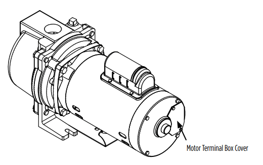
Remove the cover from the motor terminal box
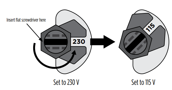
FOR 1 HP MODELS
Changing voltage from 230 Volts to 115 Volts:
The cutout in the voltage change indicator will display 230 prominently, as shown below. Insert a flat screwdriver into the black voltage change indicator. To change from 230 Volts to 115 Volts, rotate the voltage change indicator counterclockwise until 115 is displayed in the cutout.
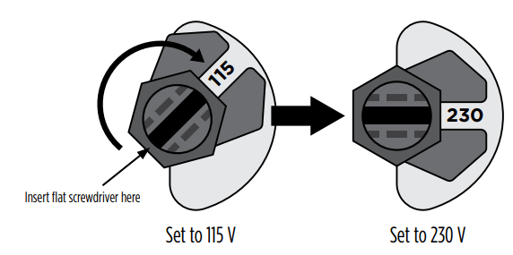
Changing voltage from 115 Volts to 230 Volts:
The cutout in the voltage change indicator will display 115 prominently, as shown below. Insert a flat screwdriver into the black voltage change indicator. To change from 115 Volts to 230 Volts, rotate the voltage change indicator clockwise until 230 is displayed in the cutout.
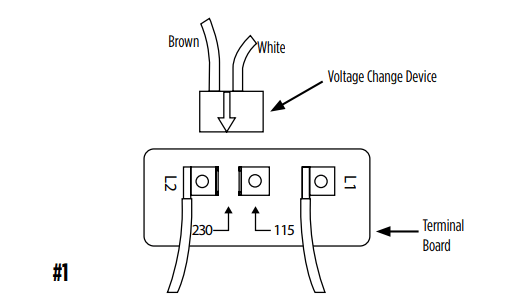
FOR 1-1/2 HP MODELS
In #1, the motor's switch is shown before the black voltage change device is pressed down onto the voltage terminals.
NOTE: DO NOT MOVE LEAD WIRES ON L1 & L2.
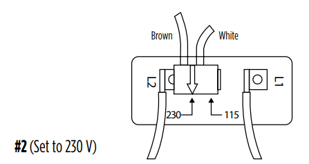
In #2, the motor's switch is set for 230 V. The white arrow on the voltage change device points directly to the 230 V arrow on the terminal board.
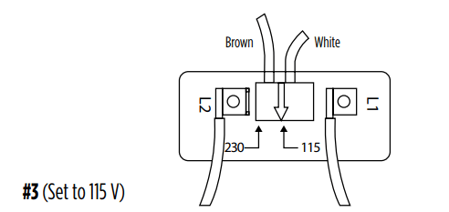
In #3, the motor's switch is set for 115 V. The white arrow on the voltage change device points directly to the 115 V arrow on the terminal board.
FOR 2 HP MODELS
2 HP models are available in 230 Volts only.
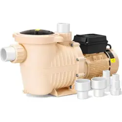
INSTALLATION
Pump Location
Install the pump in a clean, dry, and ventilated location that provides adequate drainage, room for servicing, and protection from freezing temperatures.
Bolt down the pump evenly on a good foundation, preferably concrete, to prevent the development of unnecessary stress. Locate the pump as close as possible to the water supply to reduce friction losses in the suction pipe and to provide for maximum capacities. A foot valve must be used.
Suction Pipe
Use only new, clean pipe or hose the same size as that of the pump suction tapping. If the pump is installed any appreciable distance away from the water supply, increase the suction pipe by one size. The suction pipe must always slope upwards from the water source to the pump to avoid air pockets in the line. It is advisable to use a 90° or 45° elbow on the suction line. This enables the pump to prime sooner and also prevents kinking of the hose. A check valve is recommended to ensure easier priming. In cases where a maximum volume of water is required over a prolonged period, the suction line should be led almost horizontally to the pump. Use non-toxic thread compound on all pipe joints, and tighten all connections thoroughly. Connect a strainer to the bottom end of the suction pipe and ensure that it is well submerged at all times.
Grounding the Motor
Wiring to this pump must be installed and maintained in accordance with the National Electrical Code or your local electric code. If more information is needed, call your local licensed electrician or your power company.
It is recommended that a permanent ground connection be made to the unit using a conductor of appropriate size from a metal underground water pipe or a grounded lead in the service panel. Do not ground to a gas supply line. Do not connect to electric power supply until unit is permanently grounded. Connect the ground wire to the approved ground and then connect to the terminal provided.
WARNING RISK OF ELECTRICAL SHOCK
Wiring: Make sure the voltage and frequency of the power supply agrees with the voltage of the pump. If in doubt, check with the power company. Connect wiring to terminal board located inside motor terminal box cover.
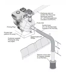
Single Shallow Well (Figure 4)
The single shallow well (Figure 4) is typically a drilled well with a 4" or 6" steel or plastic casing running vertically into the ground. The surface of the water should not exceed 25 feet in depth.
Connect the foot valve to the first length of suction pipe and lower into well. Add pipe sections as needed, securing them using one of the sealing methods previously mentioned. The foot valve should be AT LEAST 5 feet below the surface of the water to allow for water draw down. Seal the top of the 4" or 6" well casing with a well seal to prevent debris from falling into the well.
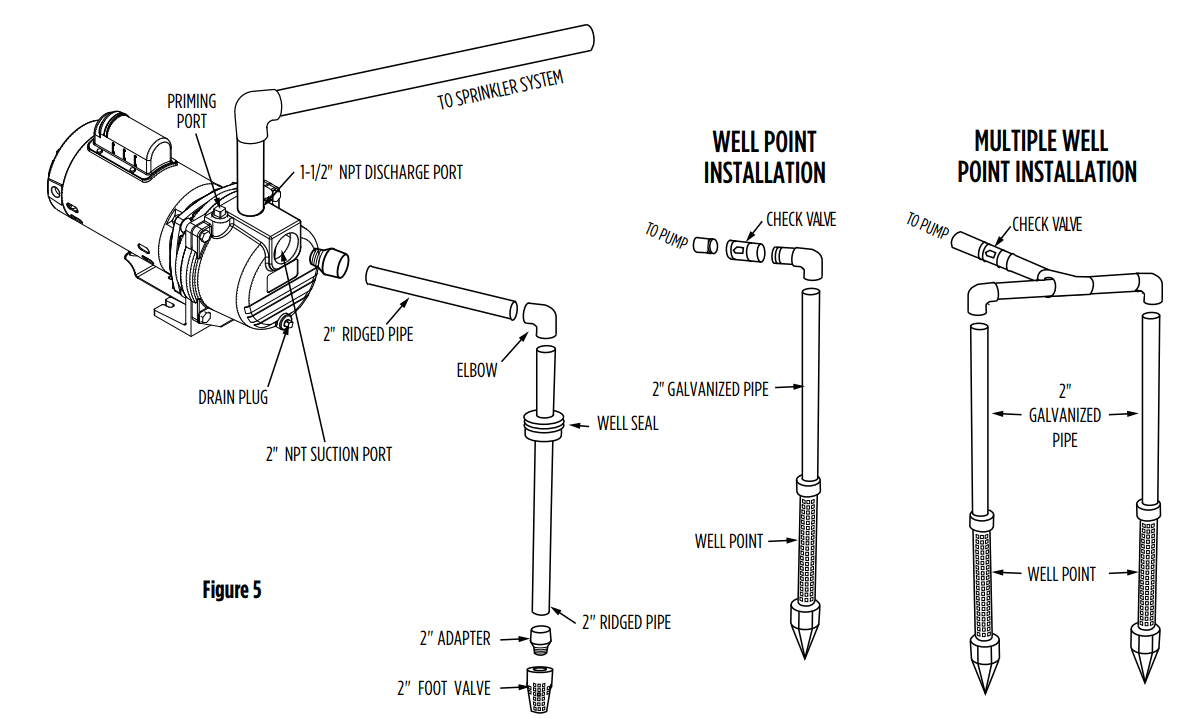
A. Suction Port Connection (Figure 5)
1. Attach the foot valve or well point to pipe assembly and lower pipe and foot valve until it is at least five feet below the water level. If you are using a well, temporarily clamp the pipe to the well casing to prevent the pipe from sliding into the well. If well is in a 4" or 6" casing, use a well seal at the surface. Never use a suction pipe size smaller than the size of the suction port on the pump.
2. Connect the necessary elbows, fittings, check valves, and pipe from the water to the pump suction port on front of pump. When using PVC, pre-assemble pipe and fittings to the pump BEFORE applying PVC cement to ensure proper cuts and inventory. Use PTFE tape on all male threads, wrapping clockwise (when facing pipe) 1 to 2 layers thick. Tighten all threaded pipe fittings until snug. DO NOT OVER-TIGHTEN PIPE AND FITTINGS. Tighten joints hand-tight plus 1/2 turn with pipe wrench.
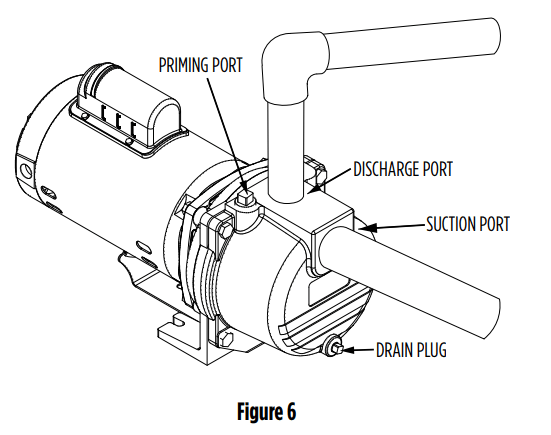
B. Discharge Port Connections (Figure 6)
1. Thread male adapter or pipe nipple into discharge port on top of pump. (Use PTFE tape on thread.)
2. Connect pipe between the sprinkler manifold and the pump discharge. Discharge pipe size should increase with long pipe runs. Discharge pipe size may equal discharge port size for distances up to 100'. Increase discharge pipe size by one size for distances of 100' to 300'. For 300' to 600', increase pipe size by two sizes. This will reduce pressure loss caused by friction.
3. Tighten all threaded pipe connections with pipe wrench until snug. Do not over-tighten.
OPERATION
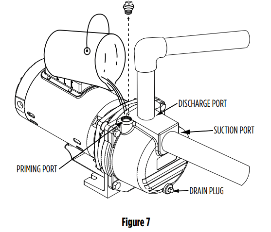
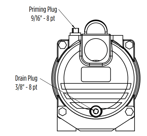
A priming port plug is provided in the top of the casing to fill the pump with water. Once filled and the priming plug replaced, the pump will prime. The priming time depends upon the vertical and horizontal distance between the pump and the water level.
Remove priming port plug from pump (Figure 7).
Open discharge valves and any hoses on discharge side of pump.
Fill pump with water through the priming port on top of pump. Allow trapped air to escape for a few minutes, then add more water until full
Replace priming port plug and tighten with wrench, using PTFE tape on pipe threads.
Start the pump. A properly primed pump should discharge water without air at a consistent pressure. If the pump does not produce water after five minutes, stop the pump, release all pressure, remove priming port plug, add more water, replace plug, and try again. Ensure that a foot valve is properly installed on the suction pipe (Figure 5). If an exceptionally long suction line is used, the water in the pump casing may become overheated or vapourlocked. Should this occur, replace the water in the casing with cold water and continue priming.
MAINTENANCE
WARNING ELECTRICAL PRECAUTIONS
All wiring, electrical connections, and system grounding must comply with the National Electrical Code (NEC) and with any local codes and ordinances. Employ a licensed electrician.
WARNING RISK OF ELECTRICAL SHOCK
• Have an electrician provide electrical power to the motor.
• Motor must be grounded and terminal cover in place to reduce electrical shock hazard.
• Keep motor operating area as dry as possible.
• A ground fault circuit interrupter (GCFI) protected circuit is recommended for use with any electrical device operating near water.
• Always disconnect power before servicing.
• Not investigated for use in swimming pool areas.
Lubrication: The pump requires no lubrication.
Draining
Should the pump be subject to freezing temperatures, it will be necessary to drain the pump completely. To drain, remove the drain plug located at the bottom of the front face of the pump casing and the priming plug and make sure that the drain hole is not restricted. After all the water has been drained, operating the pump for a few seconds will ensure that the impeller is devoid of water (make sure that the suction line is also devoid of water).
Pump Storage
Drain liquid from pump to prevent freezing. It is recommended that a good rust inhibitor be put in the liquid end to prevent excessive corrosion. Be sure motor is kept dry and covered. When restoring the use of the pump, replace all plugs and make sure all connections are tightly sealed. After a complete check is made, make the initial prime according to the OPERATION section.
Disassembly
1. Shut off the power to the pump at the main service panel and disconnect the power supply from motor.
2. Open a tap in the water system to release the pressure.
3. Remove the drain and fill plugs (8, 10) to allow the pump to drain.
4. Remove the four bolts (9), the casing (11), the gasket (12) and O-ring (6).
5. Remove the screws on the diffuser (7) to separate the diffuser (13) from the motor adapter (3). Remove the cap (16) and insert a screwdriver to prevent the shaft from turning while unscrewing the impeller (5). If impeller cannot be turned by hand, insert a flat object into the impeller vane.
NOTE: Use a strap wrench on the impeller eye to remove the impeller.
6. Slip the rotating seal (4) off the impeller hub.
7. To replace the seal seat (4A) remove four bolts to remove the case adapter (3) to separate from the motor (2). Push the seal seat (4A) out of the case adapter from the motor side.
Reassembly
1. Clean all the parts thoroughly before assembling.
2. Lightly lubricate (with soapy water) the rubber cap on the ceramic seal (4) and push it into the adapter (3) using your thumbs only. Make sure the smooth surface of the ceramic seat faces outwards
NOTE: If the pump will remain out of service for longer than one week, the seal components must be installed dry (no lubrication).
3. Put the adapter back on the motor with the four bolts removed previously.
4. Lubricate the rotating seal (4) (with soapy water) and slip it onto the impeller hub with the ‘carbon’ ring towards the ceramic seat. Apply thread locker to shaft threads prior to installing impeller.
5. Replace the impeller (5) and the diffuser (13).
6. Replace the casing (11) making sure that the gasket (12) and O-ring (6) are not damaged and is in place.
7. Reconnect the tubes to the casing and to the pressure switch.
8. Reconnect the power.
9. Prime pump, start the pump and check for leaks.
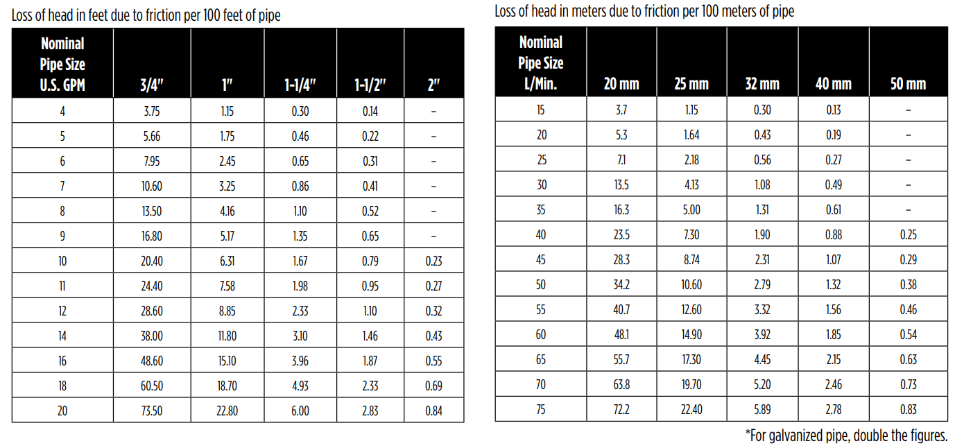
Table 2 - FRICTION LOSS FOR PLASTIC PIPE*
TROUBLESHOOTING
Problem
Possible Cause
Remedy
Failure to pump
Pump not properly primed.
Make sure pump casing and suction line are full of water. See priming instructions.
Speed too low.
WARNING ELECTRICAL PRECAUTIONS. All wiring, electrical connections and system grounding must comply with the National Electrical Code (NEC) and with any local codes and ordinances. Employ a licensed electrician. Check voltage at motor terminals and at meter when pump is operating. If low, refer to wiring instructions or check with your power company. Check loose connections.
Total head more than for which pump was intended.
A pump designed for higher head needed.
Suction lift is too great.
Locate pump closer to source of water. Make sure suction piping is large enough.
Reduced capacity and/or head
Air pockets or leaks in suction line.
Check suction piping.
Clogged impeller.
Remove and clean.
Strainer too small or clogged.
Use larger strainer or clean.
Insufficient submergence of suction line.
Add lengths of suction pipe to keep submerged end well below the water surface.
Excessive suction lift.
If caused by suction pipe friction, enlarge piping.
Total head more than that for which the pump was intended.
A pump designed for higher head is needed
Excessively worn impeller.
Order replacement parts using Replacement Parts list.
Pump loses prime
Air leaks in suction line.
Check suction piping.
Excessive lift and operating too near shut-off point.
Move pump nearer water level.
Water level drops while pumping, uncovering suction piping.
Check water supply. Add length of pipe to suction to keep submerged end under water.
Mechanical troubles and noise
Bent shaft and/or damaged bearings.
Take motor to authorized motor repair shop.
Suction and/or discharge piping not properly supported and anchored.
See that all piping is supported to relieve strain on pump assembly.
#1 Can this unit be left out in the elements or must it be put into a water proof setting?
As long as you use liquid-tight conduit and fittings, it is fine to leave it in the elements. I modified a large plastic irrigation valve box to cover mine though. I can never hurt to keep water out.
#2 Can I use this pump along with a pressure tank to boost pressure in house?
Yes you can. This is the primary use for this kind of pump in many countries where the water service is weak and unreliable.
#3 Does it ever turn off noticed keeps running even though irrigation system is off?
if the pump keeps running make sure you have water going to the pump if the pump housing is hot shut it down u have a water supply problem to the pump but if you have water to the pump and it keeps running then the pump timer is bad or it has been mis wired during the install job hope that helps it not the pump thats the problem.
#4 My pump hums but doesn't pump water. Pump is primed and holding water and supply line is full. How do I check the impeller?
You take out the 4 bolts that hold the housing and pull it off. Look to see if the impeller is plug up with grass or leave or some kind of debris. If so clean it out. Or you impeller is burned up and you have to by new guts for it. I have done both.
#5 With plastic impeller, with this run saltwater?
I can't see where it will make any different s, you may have problem with check value because of salt water which is in your intake line.
#6 I plan on using this pump for an avocado grove. I use 3 large sprinklers and a drip system. Will this one do?
No. You need a pump with a much larger capacity than this one.
 WARNING RISK OF ELECTRICAL SHOCK