
2020 OWNER’S MANUAL
2020 GIULIA
20_GA_OM_EN_USC
Second Edition
©2020 FCA US LLC. All Rights Reserved. ALFA ROMEO is a registered trademark of FCA Group Marketing S.p.A., used with
permission. App Store is a registered trademark of Apple Inc. Google Play Store is a registered trademark of Google.
Whether it’s providing information about specic product features, taking a tour through your vehicle’s heritage,
knowing what steps to take following an accident or scheduling your next appointment, we know you’ll nd the app an
important extension of your Alfa Romeo brand vehicle.
Simply download the app, select your make and model and enjoy the ride. To get this app, go directly to the App Store
®
or Google
Play
®
Store and enter the search keyword “Alfa Romeo” (U.S. residents only).
Download a FREE electronic copy of the most up-to-date documents by visiting these links:
Owner’s Manual and Media:
www.alfaromeousa.com/owners/owners-service-manual (U.S. residents); www.owners.mopar.ca (Canadian residents).
Warranty Booklet:
www.alfaromeousa.com/owners/warranty (U.S. residents); www.owners.mopar.ca (Canadian residents).

WARNING: Operating, servicing and maintaining a passenger vehicle or o-highway motor
vehicle can expose you to chemicals including engine exhaust, carbon monoxide, phthalates, and
lead, which are known to the State of California to cause cancer and birth defects or other
reproductive harm. To minimize exposure, avoid breathing exhaust, do not idle the engine
except as necessary, service your vehicle in a well-ventilated area and wear gloves or wash your
hands frequently when servicing your vehicle. For more information go to
www.P65Warnings.ca.gov/passenger-vehicle.
This Owner’s Manual illustrates and describes the operation of features and equipment that are either standard or optional on this vehicle. This manual
may also include a description of features and equipment that are no longer available or were not ordered on this vehicle. Please disregard any
features and equipment described in this manual that are not on this vehicle. FCA US LLC reserves the right to make changes in design and
specications, and/or make additions to or improvements to its products without imposing any obligation upon itself to install them on products
previously manufactured.
With respect to any vehicles sold in Canada, the name FCA US LLC shall be deemed to be deleted and the name FCA Canada Inc. used in
substitution therefore.
If you are the rst registered retail owner of your vehicle, you may obtain a complimentary printed copy of the Warranty Booklet by calling
1-844-253-2872 (U.S.) or 1-800-387-1143 (Canada) or by contacting your dealer.
This Owner’s Manual is intended to familiarize you with the important features of your vehicle. Your most up-to-date Owner’s Manual, Navigation /
Uconnect manuals and Warranty Booklet can be found by visiting the website on the back cover. U.S. residents can purchase replacement kits by
visiting www.techauthority.com and Canadian residents can purchase replacement kits by calling 1-800-387-1143.
The driver’s primary responsibility is the safe operation of the vehicle. Driving while distracted can result in loss of vehicle control, resulting in an
accident and personal injury. FCA US LLC strongly recommends that the driver use extreme caution when using any device or feature that may
take their attention o the road. Use of any electrical devices, such as cellular telephones, computers, portable radios, vehicle navigation or other
devices, by the driver while the vehicle is moving is dangerous and could lead to a serious accident. Texting while driving is also dangerous and
should never be done while the vehicle is moving. If you nd yourself unable to devote your full attention to vehicle operation, pull o the road to a
safe location and stop your vehicle. Some states or provinces prohibit the use of cellular telephones or texting while driving. It is always the
driver’s responsibility to comply with all local laws.
This Owner’s Manual has been prepared to help you get acquainted with your new Alfa Romeo
brand vehicle and to provide a convenient
reference source for common questions.
Not all features shown in this manual may apply to your vehicle. For additional information, visit www.alfaromeousa.com (U.S.),
www.alfaromeo.ca (Canada) or your local Alfa Romeo dealer.
Driving after drinking can lead to an accident. Your perceptions are less sharp, your reexes are slower
and your judgment is impaired when you have been drinking. Never drink and then drive.
WARNING!
Drunk driving is one of the most frequent causes of accidents. Your driving ability can be seriously
impaired with blood alcohol levels far below the legal minimum. If you are drinking, don’t drive.
Ride with a designated non-drinking driver, call a cab, a friend or use public transportation.
DRIVING AND ALCOHOL

1
DEAR CUSTOMER
Dear Customer,
We would like to congratulate and thank you for choosing Alfa Romeo.
We have written this Owner’s Manual to help you get to know all of the features of your vehicle and use it in the best possible way. Please take the
necessary time to familiarize yourself with all the dynamic features of your vehicle.
Here you will find important information and warnings regarding the use of your vehicle, and how to achieve the best performance from the tech-
nical features of your Alfa Romeo.
You are advised to read through the Owner’s Manual before taking it on the road for the first time. It is important to become familiar with the
controls of your vehicle, especially with sections concerning the brakes, handling, transmission, and vehicle behavior on different road surfaces.
This Owner’s Manual also provides a description of special features and tips, as well as essential information for the safe driving, care, and main-
tenance of your Alfa Romeo over time.
In the Warranty Information Booklet available online, you will also find a description of the services that Alfa Romeo offers to its customers.
The New Vehicle Limited Warranty will detail the terms and conditions for maintaining its validity.
We are sure that these will help you to get in touch with and appreciate both your new vehicle and the service provided by the people at Alfa Romeo.
For questions or comments pertaining to your vehicle, please contact:
Alfa Romeo Customer Care Center:
P.O. Box 21–8004 Auburn Hills, MI
48321–8004
Phone: 1-844-Alfa-USA
(1-844-253-2872)
Alfa Romeo Customer Care (Canada):
P.O. Box 1621
Windsor, Ontario N9A 4H6
Phone: 1-877-230-0563 (English)
Phone: 1-877-515-9112 (French)
20_GA_OM_EN_USC_t.book Page 1

2
READ THIS CAREFULLY
Refueling
Do not use fuel containing methanol or ethanol E85. Using these mixtures may cause misfiring and driving issues, as well as damage vital
components of the supply system.
For further details on the use of the correct fuel, see "Fuel Requirements" in the "Technical Specifications".
Starting The Engine
Make sure that the electric park brake is engaged and that the transmission is in PARK (P) or NEUTRAL (N). Next, press the brake pedal,
and then push the engine START/STOP button.
Parking On Flammable Material
The catalytic converter develops high temperatures during operation. Do not park the vehicle on potential fire hazards such as: grass, dry
leaves, pine needles or other flammable material.
Respecting The Environment
The vehicle is fitted with a system that carries out a continuous diagnosis of the emission-related components in order to help protect the
environment.
Electrical Accessories
If you decide to add electrical accessories after purchasing the vehicle, (with the risk of gradually draining the battery), contact an authorized
dealer. They can calculate the overall electrical requirement and check that the vehicle's electric system can support the required load.
Scheduled Servicing
Correctly performed maintenance procedures are essential for ensuring that your vehicle continuously maintains its quality in perfor-
mance and safety features, environmental friendliness, and low running costs.
20_GA_OM_EN_USC_t.book Page 2

3
VEHICLE CHANGES / ALTERATIONS
Accessories Purchased By The Owner
If you decide to install electrical accessories that require a permanent electrical supply (e.g. radio, satellite anti-theft system, etc.) or accessories
that in any case drain the electrical supply after purchasing the vehicle, contact an authorized dealer. Dealer personnel will check whether the
vehicle's electrical system is able to withstand the load required or whether it needs to be integrated with a more powerful battery.
NOTE:
Use caution when adding additional spoilers, alloy wheel rims, or non-standard wheel hubs: they could reduce the ventilation of the brakes and
affect efficiency under sharp and repeated braking, or on long descents. Make sure that nothing obstructs the pedals (mats, etc.).
FCA US LLC shall not be liable for damage caused by the installation of accessories either not supplied or recommended by FCA US LLC and/or not
installed in compliance with the provided instructions.
Installing Electrical/Electronic Devices
FCA US LLC authorizes the installation of transceivers provided that installation is carried out at a specialized center, in compliance with manufac-
turer's specifications.
NOTE:
Local authorities may not allow the vehicle on the road if devices that modify the features of the vehicle have been installed. This also may void
the warranty in relation to faults caused by the change either directly or indirectly related to it.
FCA US LLC shall not be liable for damage caused by the installation of accessories either not supplied or recommended by FCA US LLC and/or not
installed in compliance with the provided instructions.
WARNING!
Any change or alteration of the vehicle might seriously affect its safety and road handling, thus causing accidents, in which the occupants could
even be fatally injured.
20_GA_OM_EN_USC_t.book Page 3

VEHICLE CHANGES / ALTERATIONS
4
Radio Transmitters And Mobile Phones
Radio transmitter equipment (vehicle mobile phones, CB (Citizen Band) radios, amateur radio etc.) cannot be used inside the vehicle unless a sepa-
rate antenna is mounted externally.
Transmission and reception of these devices may be affected by the shielding effect of the vehicle body. As far as the use of approved mobile
phones is concerned, follow the usage instructions provided by the mobile phone manufacturer.
CAUTION!
The use of these devices inside the passenger compartment (without an external antenna) may cause the electrical systems to malfunction.
This could compromise the safety of the vehicle in addition to constituting a potential hazard for passengers' health.
If mobile phones/laptops/smartphones/tablets are inside the vehicle and/or close to the electronic key, a reduced performance of the Passive
Entry/Keyless Start system may occur may occur.
20_GA_OM_EN_USC_t.book Page 4

5
HOW TO USE THIS MANUAL
Operating Instructions
Each time an instruction is given that concerns direction (left/right or forward/backward), it is written to be read from the perspective of an occu-
pant in the driver's seat. If a direction is written from a different perspective, it will be specified as such in the text as appropriate.
The figures in the manual are only examples: this might imply that some details of the image do not correspond to the actual arrangement of your
vehicle.
To identify the chapter with the information necessary, you can consult the Index at the end of this manual.
Chapters can be rapidly identified with dedicated graphic tabs, located at the side of each odd page. There is also a key for getting to know the
chapter order and the relevant symbols in the tabs. Additionally, there is a textual indication of each current chapter at the side of each even page.
Warnings And Cautions
While reading this Owner’s Manual you will find a series of WARNINGS that must be carefully followed to prevent incorrect use of the components
of the vehicle, which could cause accidents or injuries.
There are also CAUTIONS to prevent procedures that could damage your vehicle.
Therefore all WARNINGS and CAUTIONS must always be carefully followed.
WARNINGS and CAUTIONS are recalled in the text with the following symbols:
Personal Safety:
Vehicle Safety:
NOTE:
This Owner’s Manual describes all vehicle models. Optional contents, equipment meant for specific Markets or particular models are not identified
as such in the text: you need to consider only the information related to the model you own. Any content introduced throughout the production of
the model, outside the specific request of options at the time of purchase, will be identified by the indicator: — if equipped.The data contained in
this publication is intended to help you use your vehicle in the best possible way. FCA US LLC aims for constant improvement of the vehicles
produced. For this reason, it reserves the right to make changes to the model described for technical and/or commercial reasons.For further infor-
mation, contact an authorized dealer.
20_GA_OM_EN_USC_t.book Page 5
HOW TO USE THIS MANUAL
6
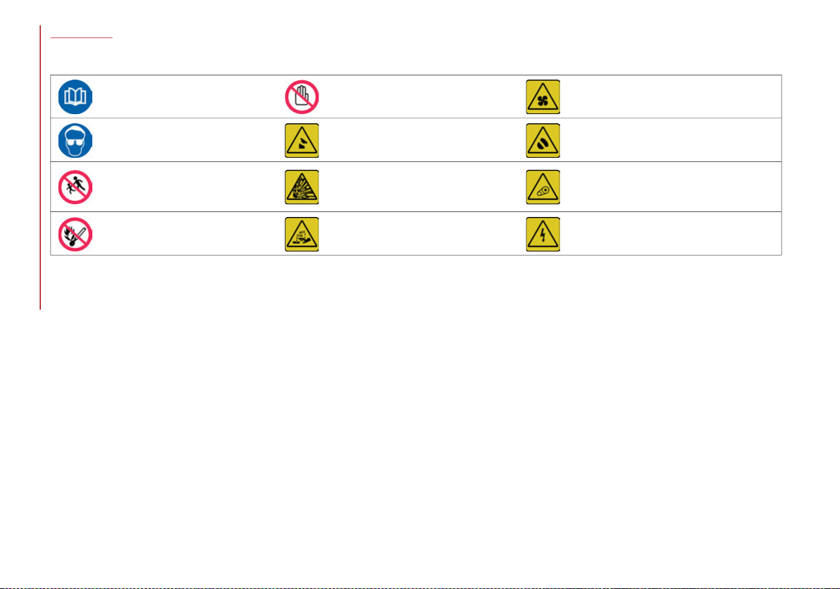
Symbols
Some car components have colored labels with symbols indicating precautions to be observed when using this component. It is important to follow
all warnings when operating your vehicle. See below for a brief description of each symbol.
READ THE OWNER’S
MANUAL
DO NOT TOUCH WITH
HANDS
IT CAN START AUTOMATICALLY
ALSO WITH ENGINE OFF
PROTECT YOUR EYES
DO NOT OPEN THE CAP
WHEN THE ENGINE IS HOT
DO NOT OPEN: HIGH
PRESSURE GAS
KEEP CHILDREN AT A
DISTANCE
BURSTING
MOVING PARTS KEEP PARTS
OF YOUR BODY AND CLOTHES
AWAY
DO NOT APPROACH
FLAMES
CORROSIVE LIQUID HIGH VOLTAGE
20_GA_OM_EN_USC_t.book Page 6


8
DEAR CUSTOMER
READ THIS CAREFULLY
Refueling.....................................................2
Starting The Engine....................................2
Parking On Flammable Material ...............2
Respecting The Environment .................... 2
Electrical Accessories ................................2
Scheduled Servicing .................................. 2
VEHICLE CHANGES / ALTERATIONS
Accessories Purchased By The Owner......3
Installing Electrical/Electronic Devices .... 3
Radio Transmitters And Mobile Phones ... 4
HOW TO USE THIS MANUAL
Operating Instructions ...............................5
Warnings And Cautions..............................5
Symbols ...................................................... 6
GETTING TO KNOW YOUR VEHICLE
KEYS..........................................................14
Key Fob ..................................................14
Operation................................................ 14
Replacing The Electronic Key Fob
Battery .................................................... 15
Request For Additional Keys.................16
General Information .............................. 16
IGNITION SYSTEM ....................................17
Operation................................................ 17
Starting With A Discharged Key Fob
Battery .................................................... 18
General Information .............................. 18
ENGINE IMMOBILIZER ............................ 19
Engine Immobilizer Operation .............. 19
SECURITY ALARM SYSTEM —
IF EQUIPPED............................................. 19
Alarm Activation..................................... 19
To Arm The Alarm .................................. 20
To Disarm The Alarm............................. 20
Volumetric/Anti-Lift Protection —
If Equipped............................................. 21
To Disarm The Alarm Using Passive
Entry ....................................................... 21
DOORS...................................................... 21
Locking And Unlocking Doors From
The Inside .............................................. 21
Locking/Unlocking Doors From The
Outside................................................... 22
Passive Entry ........................................ 22
General Information .............................. 25
Child Safety Locks ................................. 26
Locking The Doors With A Discharged
Battery.................................................... 26
SEATS ....................................................... 27
Power Seats........................................... 27
Sparco Racing Seats (Quadrifoglio
Vehicles) — If Equipped......................... 29
Heated Seats — If Equipped ................ 29
Rear Seats ............................................. 30
Split Folding Rear Seat ......................... 30
Easy Entry Function............................... 32
HEAD RESTRAINTS ................................. 32
Sparco Racing Seat Head Restraints
(Quadrifoglio Vehicles) — If Equipped .. 32
Front Head Restraints (Adjustments) .. 32
Rear Head Restraints (Adjustments) ... 33
Head Restraints (Removal)................... 33
STEERING WHEEL ....................................34
Adjustments ...........................................34
Heated Steering Wheel — If Equipped..35
MIRRORS ..................................................36
Electrochromic Mirror ............................36
Outside Power Mirrors ...........................36
Heated Mirrors ......................................37
EXTERIOR LIGHTS ....................................37
Headlight Switch ....................................37
Automatic Headlights ............................37
Daytime Running Lights (DRL) ..............37
Rear Fog Light ........................................38
Parking Lights.........................................38
Headlight Off Delay ................................38
Adaptive Frontlight System
(AFS Function) — If Equipped ................38
High Beam Headlights ...........................39
Turn Signals............................................39
Static Bending Light Function (SBL) —
If Equipped .............................................40
INTERIOR LIGHTS .....................................40
Front Map Reading Lights .....................40
Glove Compartment Light......................41
Interior Ambient Lighting .......................41
Door Light ...............................................42
Rear Overhead Light ..............................42
Courtesy Trunk Lights ............................43
Instrument Panel Dimmer Control .......43
WINDSHIELD WIPERS ..............................43
Windshield Wiper Stalk..........................43
Windshield Wiper/Washers ..................44
Rain Sensor ............................................45
20_GA_OM_EN_USC_t.book Page 8

9
CLIMATE CONTROL .................................46
Passenger Compartment Air Vents ..... 46
Automatic Dual-Zone Climate
Control System ......................................47
Description ............................................. 49
Operating Mode ..................................... 49
Climate Control Display Settings .........50
Air Temperature Adjustment.................50
Air Distribution Selection....................... 50
Fan Speed Adjustment.......................... 50
AUTO Button...........................................51
SYNC Button........................................... 51
Air Recirculation And Air Quality
System (AQS).......................................... 51
A/C Compressor..................................... 51
Front Defroster And MAX-DEF
Function..................................................52
Rear Defroster ....................................... 52
Humidity Sensor.....................................52
Switching Off/On The Climate
Control System....................................... 52
Stop/Start .............................................. 53
System Maintenance............................. 53
POWER WINDOWS ...................................53
Power Window Switches........................53
POWER SUNROOF — IF EQUIPPED ..........54
Power Sunroof........................................ 54
Opening ..................................................55
Closing ....................................................55
Vent Opening..........................................55
Sun Shade Movement........................... 55
Pinch Protect Feature............................ 55
Re-Initialization Procedure.................... 56
HOOD ....................................................... 56
Opening.................................................. 56
Closing.................................................... 57
TRUNK ...................................................... 57
Opening.................................................. 57
Closing.................................................... 58
Trunk Initialization................................. 58
Trunk Specifications ............................. 59
GARAGE DOOR OPENER.......................... 59
Before You Begin Programming
HomeLink®............................................ 60
Canadian/Gate Operator
Programming ......................................... 61
Using HomeLink® ................................. 62
Security .................................................. 62
Troubleshooting Tips............................. 62
General Information .............................. 63
INTERNAL EQUIPMENT............................ 64
Glove Compartment ............................. 64
Sun Visors .............................................. 64
Center Console ...................................... 64
Cupholder............................................... 65
Power Outlet .......................................... 65
Cigar Lighter And Ash Tray —
If Equipped............................................. 66
Wireless Charging Pad — If Equipped .. 66
ENVIRONMENTAL PROTECTION
SYSTEMS.................................................. 67
ACTIVE AERODYNAMIC SPOILER
(QUADRIFOGLIO VEHICLES) .................... 67
Carbon Fiber Active Aero Front
Spoiler .................................................... 67
GETTING TO KNOW YOUR INSTRUMENT
PANEL
INSTRUMENT PANEL FEATURES .............68
Instrument Cluster .................................68
Tachometer ............................................69
Engine Oil Temperature Gauge.............69
Fuel Level Gauge....................................70
Speedometer..........................................70
INSTRUMENT CLUSTER DISPLAY ............70
Instrument Cluster Display
Description .............................................70
Reconfigurable Instrument Cluster
Display ....................................................70
Reconfigurable Display Items ...............70
Customer Programmable Settings........74
WARNING LIGHTS AND MESSAGES
ON THE INSTRUMENT PANEL..................75
Red Warning Lights................................76
Amber Warning Lights............................78
Green Telltale Indicator Lights ..............83
Blue Telltale Indicator Light...................84
Red Symbols...........................................84
Amber Symbols ......................................88
Green Symbols .......................................95
Blue Symbols..........................................96
ONBOARD DIAGNOSTIC SYSTEM ............97
Onboard Diagnostic System (OBD II)
Cybersecurity..........................................97
EMISSIONS INSPECTION AND
MAINTENANCE PROGRAMS.....................97
20_GA_OM_EN_USC_t.book Page 9

10
SAFETY
ACTIVE SAFETY SYSTEMS ........................99
Anti-Lock Braking System (ABS) .......... 99
Active Torque Vectoring (ATV) — If
Equipped ................................................ 99
Dynamic Steering Torque (DST) .........100
Drive Train Control (DTC) System — If
Equipped ..............................................100
Electronic Stability Control (ESC)........100
Hill Start Assist (HSA)...........................101
Panic Brake Assist (PBA).....................101
Traction Control System (TCS) ............102
AUXILIARY DRIVING SYSTEMS.............. 102
Blind Spot Monitoring (BSM)
System — If Equipped .........................103
Active Blind Spot Assist (ABSA)
System — If Equipped .........................105
Forward Collision Warning (FCW)
System..................................................109
Tire Pressure Monitoring
System (TPMS).....................................115
OCCUPANT RESTRAINT SYSTEMS ....... 118
Occupant Restraint Systems
Features ..............................................118
Important Safety Precautions .............118
Seat Belt Systems ...............................119
Supplemental Restraint
Systems (SRS)......................................125
Child Restraints....................................136
Transporting Pets ................................148
SAFETY TIPS ..........................................149
Transporting Passengers .................... 149
Exhaust Gas.........................................149
Safety Checks You Should Make
Inside The Vehicle ..............................150
Periodic Safety Checks You Should
Make Outside The Vehicle .................. 151
STARTING AND OPERATING
STARTING THE ENGINE .........................152
Starting Procedure ..............................152
Remote Starting System ..................... 152
Cold Weather Operation...................... 153
Extended Park Starting ....................... 153
If Engine Fails To Start ........................ 154
After Starting — Warming Up The
Engine .................................................. 154
Stopping The Engine ...........................154
Turbocharger Cool Down .................... 155
ENGINE BLOCK HEATER —
IF EQUIPPED ..........................................155
ENGINE BREAK-IN
RECOMMENDATIONS ............................155
Engine Break-In ...................................155
ELECTRIC PARK BRAKE.........................156
Electric Park Brake Operating
Modes ..................................................157
Safe Hold ............................................. 158
AUTOMATIC TRANSMISSION................. 158
Display ................................................. 159
Gear Selector....................................... 159
Transmission Operating Modes ......... 160
Automatic Transmission Limp
Home Mode......................................... 162
Brake/Transmission Shift
Interlock (BTSI) System ...................... 163
Important Notes .................................. 163
ALFA DNA / PRO SELECTOR ................. 164
Alfa DNA System ................................. 164
Driving Modes ..................................... 165
ALFA ACTIVE SUSPENSION (AAS) — IF
EQUIPPED .............................................. 167
STOP/START SYSTEM ........................... 167
Stop/Start System .............................. 167
Operating Mode .................................. 167
System Manual Activation/
Deactivation ........................................ 168
Possible Reasons The Engine
Does Not Autostop .............................. 168
Engine Restarting Conditions............. 169
Safety Functions ................................. 169
Irregular Operation.............................. 169
Vehicle Inactivity ................................. 169
SPEED LIMITER ..................................... 170
Description .......................................... 170
Activation ............................................. 170
Speed Limit Programming.................. 170
Exceeding The Programmed Speed... 170
Programmed Speed Icon Flashing..... 170
Deactivation ........................................ 170
20_GA_OM_EN_USC_t.book Page 10

11
SPEED CONTROL
(CRUISE CONTROL) ............................... 171
Speed Control Description ..................171
Activating..............................................171
Setting The Desired Speed .................172
Increasing/Decreasing Speed ............172
Recalling The Speed............................172
Deactivating .........................................173
ADAPTIVE CRUISE CONTROL (ACC) —
IF EQUIPPED .......................................... 173
System Description..............................173
Activation/Deactivation.......................175
Setting The Desired Speed .................175
To Vary The Speed Setting ..................176
Accelerating When Overtaking............177
Resuming The Speed ..........................177
Setting The Distance Between
Vehicles ................................................177
“Stop And Go” Function.......................178
Deactivation .........................................178
Limited Operation Warning .................178
Precautions While Driving ...................179
General Information ............................181
HIGHWAY ASSIST SYSTEM (HAS) —
IF EQUIPPED .......................................... 182
Activation/Deactivation.......................182
Operation..............................................183
Indications On The Display..................183
System Status......................................184
Limited System Availability/
Operation..............................................185
TRAFFIC JAM ASSIST (TJA) SYSTEM —
IF EQUIPPED...........................................186
Activation/Deactivation ......................186
Operation ............................................. 187
Indications On The Display ................. 187
System Status...................................... 187
Limited System Availability/
Operation ............................................. 188
TRAFFIC SIGN RECOGNITION (TSR)
SYSTEM — IF EQUIPPED ........................189
Activation/Deactivation ......................190
Indications On The Display ................. 190
INTELLIGENT SPEED CONTROL (ISC)
SYSTEM — IF EQUIPPED ........................191
Activation/Deactivation ......................191
Indications On The Display ................. 191
Acceptance/Rejection Of The
Suggested Speed ................................ 191
DRIVER ATTENTION ASSIST (DAA)
SYSTEM — IF EQUIPPED ........................192
Activation/Deactivation ......................192
System Intervention ............................193
PARKSENSE SYSTEM ............................194
Vehicles With Rear Sensors Only .......194
Vehicles With Front And Rear
Sensors ................................................ 196
LANE DEPARTURE WARNING (LDW)
SYSTEM — IF EQUIPPED ........................198
Description...........................................198
System Activation/Deactivation .........199
Symbols And Messages On The
Display.................................................. 199
LANE KEEPING ASSIST (LKA)
SYSTEM —IF EQUIPPED......................... 201
Activation/Deactivation ...................... 201
Symbols And Messages On The
Display ................................................. 201
REAR BACK-UP CAMERA / DYNAMIC
GRIDLINES............................................. 204
Description .......................................... 204
Symbols And Messages On The
Display ................................................. 205
Important Notes .................................. 205
REFUELING THE VEHICLE ..................... 206
Refueling The Vehicle ......................... 206
Refueling Capacity .............................. 206
Refueling Procedure .......................... 206
VEHICLE LOADING ................................ 207
Certification Label............................... 207
TRAILER TOWING .................................. 208
SUGGESTIONS FOR DRIVING ............... 208
Saving Fuel .......................................... 208
Driving Style......................................... 209
Conditions Of Use................................ 209
Transporting Passengers.................... 209
Transporting Animals.......................... 210
Exhaust Gas......................................... 210
Performance — Quadrifoglio............... 210
20_GA_OM_EN_USC_t.book Page 11

12
IN CASE OF EMERGENCY
HAZARD WARNING FLASHERS ............ 212
SOS - EMERGENCY CALL ...................... 212
BULB REPLACEMENT ........................... 215
General Instructions ............................215
Types Of Bulbs .....................................216
Replacement Bulbs .............................217
Replacing Exterior Bulbs ....................218
Replacing Interior Bulbs .....................219
FUSES ................................................... 221
General Information ............................221
Fuse Location.......................................223
Control Unit Under Passenger Side
Footboard .............................................223
Luggage Compartment Fuse Box .......223
Control Unit Under Passenger Side
Footboard .............................................224
Under hood Power Distribution
Center (PDC).........................................225
TIRE SERVICE KIT .................................. 226
Description ...........................................226
Inflation Procedure ..............................227
Checking And Restoring Tire
Pressure ...............................................229
Sealant Cartridge Replacement .........229
JUMP STARTING ................................... 230
Remote Battery Connection Posts......230
Jump Starting.......................................231
Bump Starting ......................................232
ENGINE OVERHEATING ......................... 232
MANUAL PARK RELEASE ...................... 233
TOWING A DISABLED VEHICLE ............. 233
Rear Wheel Drive (RWD) Models ........234
All Wheel Drive (AWD) Models ............234
TOW EYES ..............................................234
ENHANCED ACCIDENT RESPONSE
SYSTEM (EARS) .....................................235
EVENT DATA RECORDER (EDR) ............235
SERVICING AND MAINTENANCE
SCHEDULED SERVICING .......................236
Periodic Checks ...................................236
Heavy Usage Of The Vehicle ............... 236
Maintenance Plan — 2.0L T4 MAir
Engine .................................................. 237
Maintenance Plan — 2.9 V6 Engine... 240
ENGINE COMPARTMENT .......................243
Checking Levels — 2.0L T4 MAir
Engine .................................................. 243
Checking Levels — 2.9L V6 Engine ... 244
Engine Oil ............................................. 245
Engine Coolant Fluid ...........................246
Washer Fluid For Windshield/
Headlights............................................246
Brake Fluid...........................................246
Automatic Transmission Activation
System Oil ............................................246
Useful Advice For Extending The
Life Of Your Battery .............................246
Battery.................................................. 246
Pressure Washing ............................... 247
BATTERY RECHARGING .........................247
Important Notes .................................. 247
DEALER SERVICE .................................. 249
Engine Oil............................................. 249
Engine Oil Filter ................................... 249
Air Filter................................................ 249
Air Conditioning System
Maintenance ....................................... 249
Lubricating Moving Parts Of The
Bodywork ............................................. 250
Windshield Wiper ................................ 250
Exhaust System................................... 251
Cooling System.................................... 252
Braking System ................................... 253
Automatic Transmission ..................... 254
Replacing The Battery......................... 254
RAISING THE VEHICLE ......................... 255
TIRES ..................................................... 255
Tire Safety Information ...................... 255
Tires — General Information .............. 262
Spare Tires — If Equipped .................. 267
Wheel And Wheel Trim Care .............. 268
Tire Types............................................. 268
Tire Chains And Traction Devices ...... 269
Tire Rotation Recommendations ....... 270
DEPARTMENT OF TRANSPORTATION
UNIFORM TIRE QUALITY GRADES ....... 271
Treadwear............................................ 271
Traction Grades................................... 271
Temperature Grades........................... 271
STORING THE VEHICLE ........................ 272
20_GA_OM_EN_USC_t.book Page 12

13
BODYWORK ........................................... 273
Protection Against Atmospheric
Agents...................................................273
Corrosion Warranty..............................273
Preserving The Bodywork....................273
INTERIORS ............................................. 274
Seats And Fabric Parts ........................274
Leather Seats.......................................275
Plastic And Coated Parts.....................275
Alcantara Parts — If Equipped.............275
Genuine Leather Parts —
If Equipped ...........................................275
Carbon Fiber Parts...............................275
TECHNICAL SPECIFICATIONS
IDENTIFICATION DATA........................... 276
Vehicle Identification Number ............276
Vehicle Identification
Number (VIN) Plate..............................276
ENGINE .................................................. 277
POWER SUPPLY..................................... 278
TRANSMISSION ..................................... 278
BRAKES.................................................. 279
SUSPENSION ......................................... 279
STEERING SYSTEM ............................... 279
DIMENSIONS — 2.0L T4 MAir Engine... 280
DIMENSIONS — 2.9L V6 Engine ........... 281
WEIGHTS — 2.0L T4 MAir Engine..........282
WEIGHTS — 2.9L V6 Engine ..................282
FUEL REQUIREMENTS ...........................283
Reformulated Gasoline ...................... 283
Gasoline/Oxygenate Blends ............... 283
CNG And LP Fuel System
Modifications ....................................... 283
MMT In Gasoline.................................. 283
Materials Added To Fuel .....................284
Fuel System Cautions ......................... 284
FLUID CAPACITIES..................................285
2.0L T4 MAir Engine............................ 285
2.9L V6 Engine ....................................286
FLUIDS AND LUBRICANTS.....................287
Engine Lubrication — 2.0L T4 MAir
Engine .................................................. 287
Engine Lubrication —
2.9L V6 Engine ....................................287
Chassis Lubrication —
2.0L T4 MAir Engine............................ 288
Chassis Lubrication —
2.9L V6 Engine ....................................289
PERFORMANCE — 2.0L T4 MAir
Engine.....................................................289
PERFORMANCE — 2.9L V6 Engine .......289
CUSTOMER ASSISTANCE
SUGGESTIONS FOR OBTAINING SERVICE
FOR YOUR VEHICLE .............................. 290
Prepare For The Appointment ............ 290
Prepare A List ...................................... 290
Be Reasonable With Requests........... 290
IF YOU NEED ASSISTANCE.................... 290
Alfa Romeo Customer Center............. 290
Alfa Romeo Customer Care
(Canada) .............................................. 290
Customer Assistance For The Hearing
Or Speech Impaired (TDD/TTY).......... 291
Service Contract.................................. 291
WARRANTY INFORMATION .................. 291
REPORTING SAFETY DEFECTS ............. 291
In The 50 United States And
Washington, D.C.................................. 291
In Canada ............................................ 292
PUBLICATION ORDER FORMS .............. 292
20_GA_OM_EN_USC_t.book Page 13
14
(Continued)
GETTING TO KNOW YOUR VEHICLE
In this section, you will find important informa-
tion to help you become familiar with the
features needed to operate your vehicle, and
how they function.
KEYS
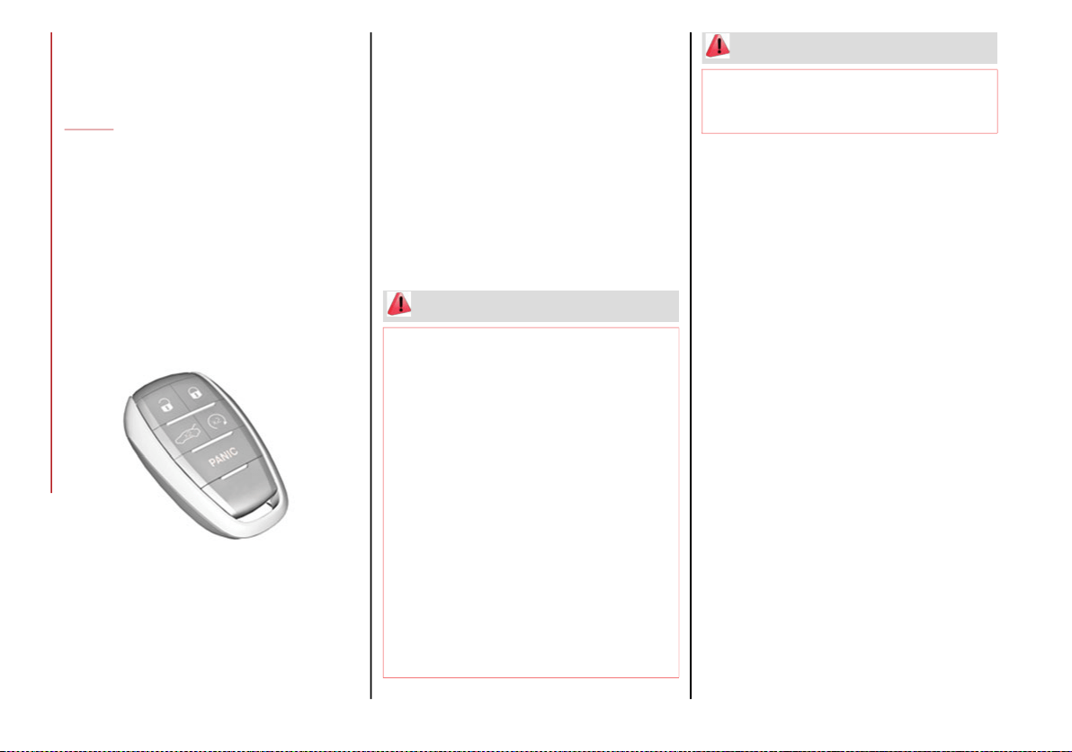
Key Fob
Your vehicle uses a keyless ignition system.
This system includes a key fob and a keyless
push button ignition.
The Remote Keyless Entry key fob allows you
to lock or unlock the doors and trunk or acti-
vate the panic alarm from distances. The key
fob does not need to be pointed at the vehicle
to activate the system.
Key Fob
PANIC Function
The key fob contains a PANIC button. Should
you ever feel threatened, push this button and
the vehicle security alarm will sound.
To activate the PANIC function, push and hold
the PANIC button for at least one second.
When the panic alarm is active, the headlights
turn on, the turn signals flash, the horn honks
intermittently, and all interior adjustable lights
turn on. The panic alarm will remain active for
three minutes, and can be deactivated:
By pushing the PANIC button again
Automatically if the vehicle speed exceeds
5 mph (8 km/h)
In both cases, the panic alarm is immediately
deactivated.
Operation
Door And Trunk Lid Unlock
Push and release the unlock button on the key
fob once to unlock the driver side front door or
twice within one second to unlock all doors
and the trunk lid.
The current unlock setting can be changed
through the radio system menu, so that the
system unlocks:
All doors on the first push of the key fob
unlock button.
The driver door on the first push of the key
fob unlock button.
Flashing of the turn signals upon locking/
unlocking the doors and activation of the cour-
tesy light upon unlocking the doors can be acti-
vated or deactivated through the radio system.
For further information, refer to the Information
and Entertainment System Owner’s Manual
Supplement.
The doors can also be unlocked by using the
emergency key, located inside the key fob.
WARNING!
Before exiting a vehicle, always shift the
automatic transmission into PARK, apply
the parking brake, turn the engine OFF,
remove the key fob from the vehicle and
lock your vehicle.
Never leave children alone in a vehicle, or
with access to an unlocked vehicle.
Allowing children to be in a vehicle unat-
tended is dangerous for a number of
reasons. A child or others could be seri-
ously or fatally injured. Children should be
warned not to touch the parking brake,
brake pedal or the gear selector.
Do not leave the key fob in or near the
vehicle, or in a location accessible to chil-
dren. A child could operate power windows,
other controls, or move the vehicle.
Do not leave children or animals inside
parked vehicles in hot weather. Interior heat
build-up may cause serious injury or death.
WARNING! (Continued)
20_GA_OM_EN_USC_t.book Page 14
15
Door And Trunk Lid Lock
Briefly pushing the lock button on the key fob will
lock the doors and trunk lid, turn off the interior
lights, and flash the turn signals (if activated in
the radio system).
If one or more doors are open, these doors will
also lock, and this is indicated by a rapid
flashing of the turn signals. The doors prepare
for locking, which becomes active from the
moment they are closed. The doors will unlock
again only if the key fob is detected inside the
passenger compartment.
The doors can be locked by using the emer-
gency key in the driver’s side door lock.
Trunk Lid Opening
Rapidly push the trunk lid key fob button twice
to open the trunk lid. The turn signals will flash
to indicate that the trunk lid has been opened.
Remote Start
The remote start button on the key fob
enables engine starting (push the button twice
within five seconds to start the engine).
Car Finder
Push the lock or unlock button to remotely and
temporarily turn on the turn signals and headlights.
This is useful for finding the vehicle easily in a
crowded area like a parking garage, for example.
Pushing the lock or unlock button again will
restart the lights turn on timer (if the parking
lights functions were already active, it will
remain active).
This function is available only if the doors are
closed.
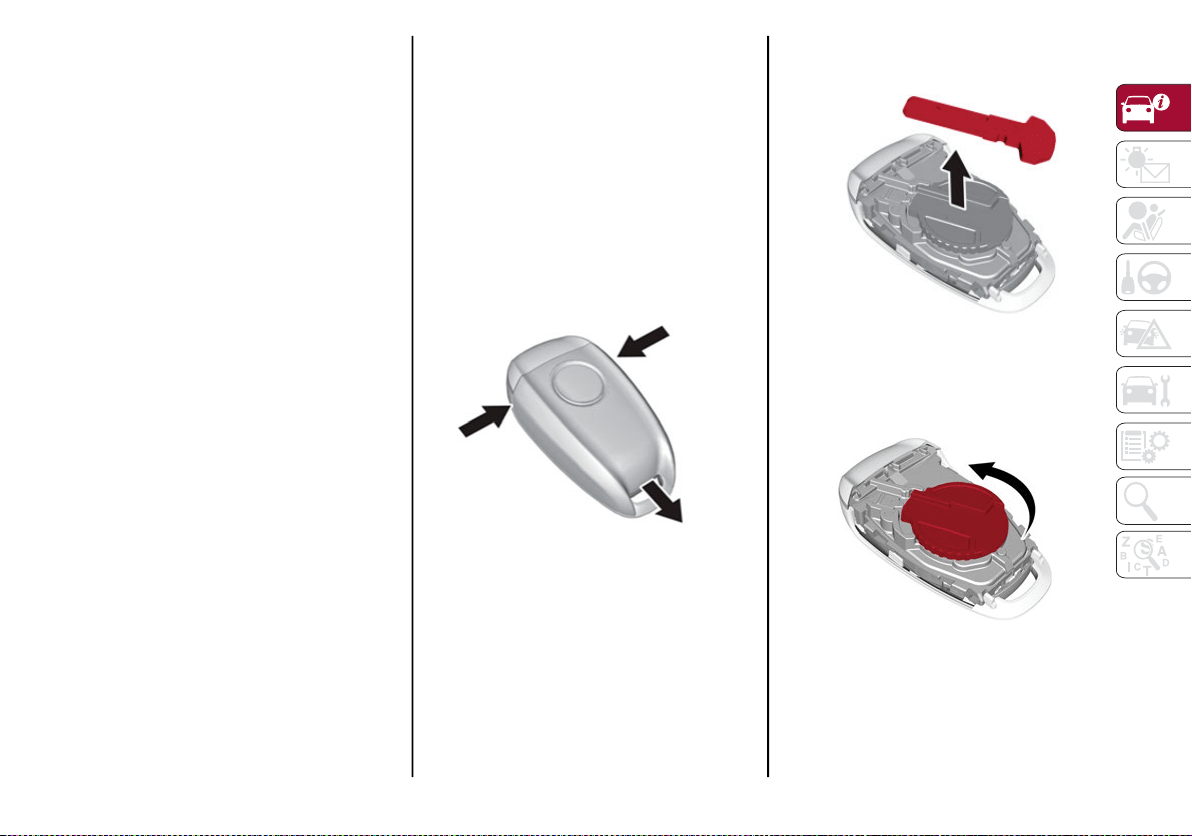
Replacing The Electronic Key Fob Battery
To replace the battery, proceed as follows:
1. Push the sides of the key fob inward and
extract the cover pulling downwards.
Key Fob Cover Removal
2. Remove the emergency key from its
housing.
Removing Emergency Key
3. Remove the battery plug by rotating it
counter clockwise.
Removing Battery Plug
20_GA_OM_EN_USC_t.book Page 15
GETTING TO KNOW YOUR VEHICLE
16
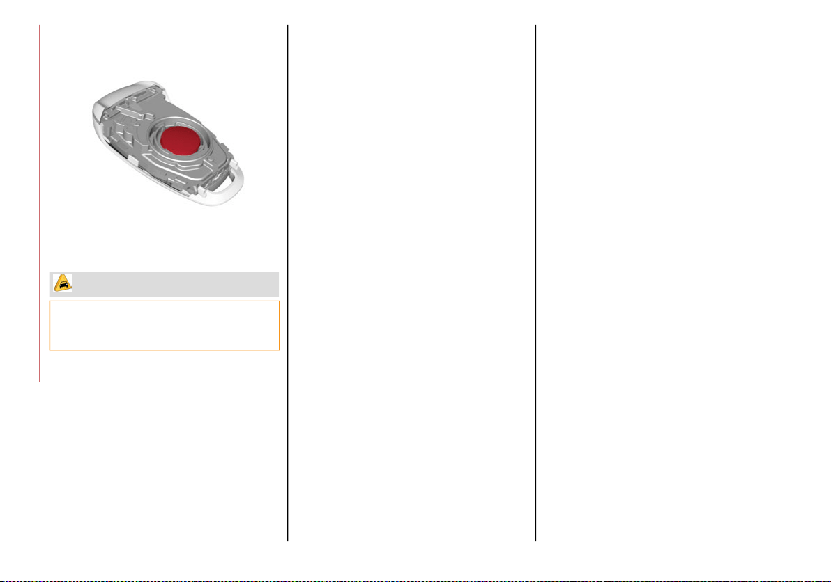
4. Remove the battery from its slot and
replace it with a new one of the same type.
Battery Location
Proceed in reverse order to reassemble the key.
Request For Additional Keys
The system can recognize up to eight key fobs
with remote control.
To guarantee that the engine starts and the
vehicle operates correctly, use only electronic
key fobs specifically coded for the vehicle’s
electronics.
If an electronic key fob is coded for a vehicle,
it cannot be used on any other vehicle.
Duplicating Keys
If you need a replacement key fob, go to an
authorized dealer.
General Information
The following regulatory statement applies to
all Radio Frequency (RF) devices equipped in
this vehicle:
This device complies with Part 15 of the FCC
Rules and with Innovation, Science and
Economic Development Canada license-exempt
RSS standard(s). Operation is subject to the
following two conditions:
1. This device may not cause harmful inter-
ference, and
2. This device must accept any interference
received, including interference that may
cause undesired operation.
Le présent appareil est conforme aux CNR
d`Innovation, Science and Economic Develop-
ment applicables aux appareils radio exempts
de licence. L'exploitation est autorisée aux
deux conditions suivantes:
1. l'appareil ne doit pas produire de brouil-
lage, et
2. l'utilisateur de l'appareil doit accepter tout
brouillage radioélectrique subi, même si le
brouillage est susceptible d'en comprom-
ettre le fonctionnement.
La operación de este equipo está sujeta a las
siguientes dos condiciones:
1. es posible que este equipo o dispositivo no
cause interferencia perjudicial y
2. este equipo o dispositivo debe aceptar
cualquier interferencia, incluyendo la que
pueda causar su operación no deseada.
RF Exposure Requirements
To comply with FCC RF exposure compliance
requirements, the device must be installed
and operated to provide a separation distance
of at least 20 cm from all persons.
This equipment complies with Canada radiation
exposure limits set forth for an uncontrolled envi-
ronment. This equipment should be installed and
operated with minimum distance 20 cm between
the radiator and your body.
NOTE:
Changes or modifications not expressly
approved by the party responsible for compli-
ance could void the user’s authority to operate
the equipment.
Déclaration d’exposition aux radiations
Cet équipement est conforme aux limites
d’exposition aux rayonnements ISED établies
pour un environnement non contrôlé. Cet équi-
pement doit être installé et utilisé avec un
minimum de 20 cm de distance entre la
source de rayonnement et votre corps.
CAUTION!
The battery replacement operation must be
done with care, in order not to damage the
electronic key.
20_GA_OM_EN_USC_t.book Page 16
17
(Continued)
REMARQUE:
Des changements ou des modifications
n’ayant pas été expressément approuvés par
la partie responsable de la conformité pour-
raient révoquer l’autorisation d’utilisation de
l’équipement.
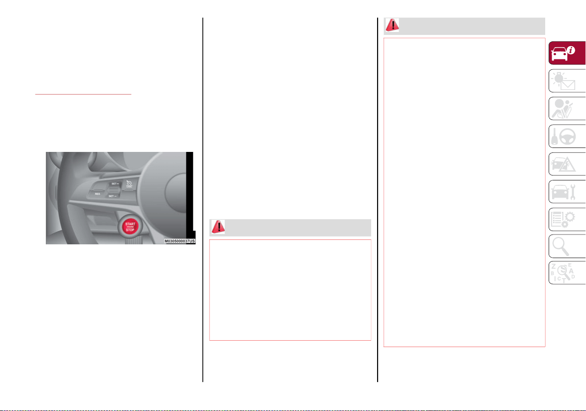
IGNITION SYSTEM
Operation
To activate the keyless ignition, the key fob
must be inside the passenger compartment.
Keyless Ignition START/STOP Ignition Button
The keyless ignition has the following modes:
OFF: engine off, steering locked. Some elec-
trical devices (e.g. central door locking
system, alarm, etc.) are still available.
ACC: all electrical devices are available. This
state can be entered by pushing the ignition
button once, without pressing the brake
pedal.
ON/RUN: engine starting. This state can be
entered by pushing the ignition button once
while pressing the brake pedal.
NOTE:
With the keyless ignition in the ACC position:
if 30 minutes pass with the gear selector in
PARK and the engine stopped, the keyless
ignition will automatically reset to the OFF
position.
With the engine started, it is possible to
remove the key fob from the vehicle. The
engine will remain running and the instru-
ment cluster will indicate the absence of the
key fob when the door is closed.
For more information on the engine start-up,
refer to "Starting The Engine" in "Starting And
Operating."
WARNING!
Never use the PARK position as a substi-
tute for the parking brake. Always apply
the parking brake fully when parked to
guard against vehicle movement and
possible injury or damage.
When exiting the vehicle, always make
sure the ignition is in the OFF mode,
remove the key fob from the vehicle, and
lock your vehicle.
Never leave children alone in a vehicle, or
with access to an unlocked vehicle.
Allowing children to be in a vehicle unat-
tended is dangerous for a number of
reasons. A child or others could be seri-
ously or fatally injured. Children should be
warned not to touch the parking brake,
brake pedal or the transmission gear
selector.
Do not leave the key fob in or near the
vehicle, (or in a location accessible to chil-
dren), and do not leave the ignition in the
ACC or ON/RUN mode. A child could
operate power windows, other controls, or
move the vehicle.
Be sure the parking brake is fully disen-
gaged before driving; failure to do so can
lead to brake failure and a collision.
Always fully apply the parking brake when
leaving your vehicle, or it may roll and
cause damage or injury. Also be certain to
leave the transmission in PARK. Failure to
do so may allow the vehicle to roll and
cause damage or injury.
Driving the vehicle with the parking brake
engaged, or repeated use of the parking
brake to slow the vehicle may cause
serious damage to the brake system.
WARNING! (Continued)
20_GA_OM_EN_USC_t.book Page 17
GETTING TO KNOW YOUR VEHICLE
18
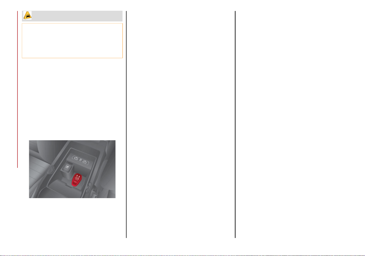
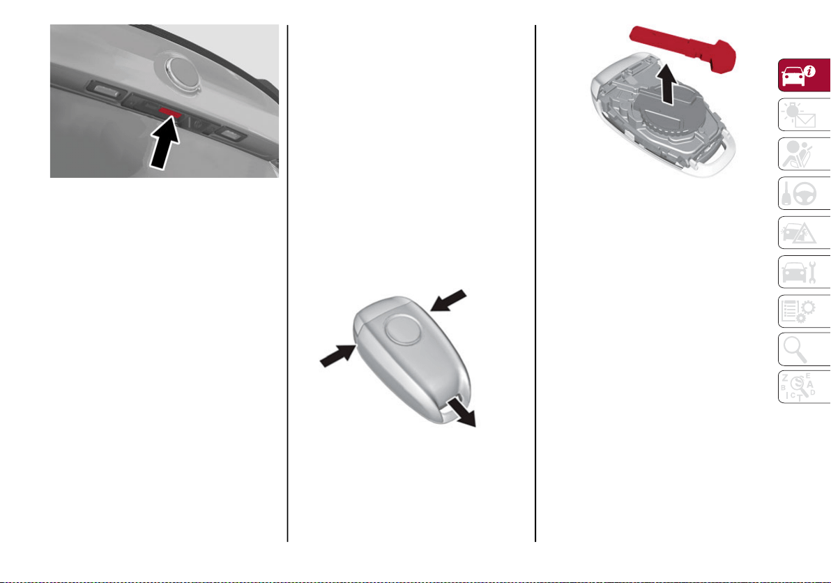
Starting With A Discharged Key Fob Battery
If the key fob battery is discharged, proceed as
follows to start the vehicle:
1. Lift the front armrest.
2. Lay the key fob on the indicated spot in the
bottom of the center console, positioning
the key fob as shown in the following
image, while pushing the START/STOP
ignition button to start the ignition.
Key Fob Placement Location
General Information
The following regulatory statement applies to
all Radio Frequency (RF) devices equipped in
this vehicle:
This device complies with Part 15 of the FCC
Rules and with Innovation, Science and
Economic Development Canada license-exempt
RSS standard(s). Operation is subject to the
following two conditions:
1. This device may not cause harmful inter-
ference, and
2. This device must accept any interference
received, including interference that may
cause undesired operation.
Le présent appareil est conforme aux CNR
d`Innovation, Science and Economic Develop-
ment applicables aux appareils radio exempts
de licence. L'exploitation est autorisée aux
deux conditions suivantes:
1. l'appareil ne doit pas produire de brouil-
lage, et
2. l'utilisateur de l'appareil doit accepter tout
brouillage radioélectrique subi, même si le
brouillage est susceptible d'en comprom-
ettre le fonctionnement.
La operación de este equipo está sujeta a las
siguientes dos condiciones:
1. es posible que este equipo o dispositivo no
cause interferencia perjudicial y
2. este equipo o dispositivo debe aceptar
cualquier interferencia, incluyendo la que
pueda causar su operación no deseada.
RF Exposure Requirements
To comply with FCC RF exposure compliance
requirements, the device must be installed
and operated to provide a separation distance
of at least 20 cm from all persons.
This equipment complies with Canada radiation
exposure limits set forth for an uncontrolled envi-
ronment. This equipment should be installed and
operated with minimum distance 20 cm between
the radiator and your body.
NOTE:
Changes or modifications not expressly
approved by the party responsible for compli-
ance could void the user’s authority to operate
the equipment.
Déclaration d’exposition aux radiations
Cet équipement est conforme aux limites
d’exposition aux rayonnements ISED établies
pour un environnement non contrôlé. Cet équi-
pement doit être installé et utilisé avec un
minimum de 20 cm de distance entre la
source de rayonnement et votre corps
REMARQUE:
Des changements ou des modifications
n’ayant pas été expressément approuvés par
la partie responsable de la conformité pour-
raient révoquer l’autorisation d’utilisation de
l’équipement.
CAUTION!
If the Brake System Warning Light remains
on with the parking brake released, a brake
system malfunction is indicated. Have the
brake system serviced by an authorized
dealer immediately.
20_GA_OM_EN_USC_t.book Page 18
19
ENGINE IMMOBILIZER
Engine Immobilizer Operation
The Engine Immobilizer system prevents unau-
thorized use of the vehicle by disabling engine
starting.
The system does not need to be enabled or
activated. Operation of the immobilizer is auto-
matic whether the vehicle's doors are locked
or unlocked.
When the ignition is placed in the ACC posi-
tion, the Engine Immobilizer system identifies
the code transmitted by the key. If the code is
recognized as valid, the Engine Immobilizer
system enables engine starting.
When the ignition is brought back to OFF, the
Engine Immobilizer system deactivates the
control unit controlling the engine, disabling
engine starting.
For the correct engine starting procedures,
refer to “Starting The Engine” in “Starting And
Operating.”
Irregular Operation
If the key code is not recognized during starting, the
Engine Immobilizer Failure/Break-in Attempt
icon is displayed on the instrument panel. Refer to
"Warning Lights And Messages" in "Getting To Know
Your Instrument Panel". This condition leads to the
engine turning off after two seconds. In this case,
cycle the ignition to the OFF position, and then to
ACC; if it is still blocked, try with the other keys
provided. If it is still not possible to start the engine,
contact an authorized dealer.
If the Engine Immobilizer Failure/Break-in
Attempt icon is displayed while driving, this
means that the system is running a self-diag-
nosis (e.g. due to a voltage drop). If the display
persists, contact an authorized dealer.
NOTE:
Do not tamper with the Engine Immobilizer
system. Any modifications or alterations
could cause the protection function to be
deactivated.
The Engine Immobilizer system is not compat-
ible with certain aftermarket remote starting
systems. The use of these devices could
cause problems when starting, as well as the
deactivation of the protection function.
All keys provided with the vehicle have been
programmed in accordance with the elec-
tronics on the vehicle itself.
Each key has its own code which must be
stored by the system's control unit. Contact
an authorized dealer to have new keys (up
to eight) stored with a code.
SECURITY ALARM SYSTEM — IF
EQUIPPED
Alarm Activation
While armed, the alarm will sound in the
following scenarios:
Opening of doors/hood/trunk lid (perimeter
protection)
Operation of ignition with a key which is not
validated
Cutting of the battery cables
Movement inside the passenger compart-
ment (volumetric protection — if equipped)
Unexpected lifting/tilting of the vehicle
(anti-lift protection — if equipped)
Activation of the alarm triggers the acoustic
warning and the turn signals.
NOTE:
The alarm system is activated by the Engine
Immobilizer system, which is automatically
activated when you get out of the vehicle with
the key fob and lock the doors.
20_GA_OM_EN_USC_t.book Page 19
GETTING TO KNOW YOUR VEHICLE
20
To Arm The Alarm
With the doors, hood, and trunk lid closed and
the keyless ignition system placed in the OFF
position, push and release the lock button on
the key fob. The alarm can also be armed by
pushing the Passive Entry door handle button,
located on the exterior door handle. For
further information, refer to "Passive Entry" in
this chapter.
Passive Entry Door Handle Button
When the alarm is armed, the warning lights
on the panels of the interior front door handles
will flash.
Lock/Unlock Buttons
The activation of the alarm is preceded by a
self-diagnosis stage: if a fault is detected, the
system emits a further acoustic signal.
If a second acoustic signal is emitted after the
alarm is already armed, wait about four seconds
and disarm the alarm by pushing the unlock
button. Verify that the doors, hood, and trunk lid
are closed correctly and then rearm the system
by pushing the lock button on the key fob.
If the alarm emits an acoustic signal even when
the doors, hood, and trunk lid are correctly
closed, a fault has occurred in system operation.
In this case, contact an authorized dealer.
To Disarm The Alarm
Push the unlock button to disarm the alarm.
While disarming, the following operations are
performed:
Two brief flashes of the turn signals (if
programmed)
Two brief acoustic signals (if programmed)
Doors are unlocked
The alarm can also be disarmed using the
Passive Entry system, by grasping one of the
Passive Entry front door handles with a valid
key fob in hand to unlock. For further informa-
tion refer to "Passive Entry" in this chapter.
Passive Entry Door Handle Button
NOTE:
The alarm does not disarm when the doors are
unlocked by inserting the blade of the emer-
gency key, found inside the key fob, into the
door handle lock cylinder.
20_GA_OM_EN_USC_t.book Page 20
21
Volumetric/Anti-Lift Protection — If Equipped
To ensure the correct operation of the Volu-
metric/Anti-Lift Protection system, completely
close the side windows.
To disable the function, push the Volumetric/Anti-Lift
Protection button before activating the alarm.
When the function is disabled, this is indicated
by the light on the Volumetric/Anti-Lift Protec-
tion button flashing for several seconds.
Volumetric/Anti-Lift Protection Button
Any disabling of the Volumetric/Anti-Lift
Protection must be repeated each time the
instrument panel is switched off.
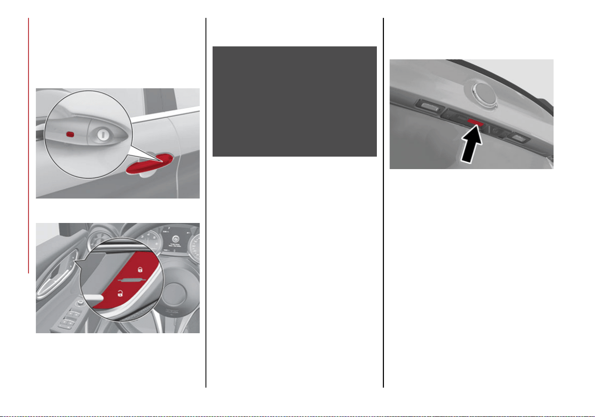
To Disarm The Alarm Using Passive Entry
To completely deactivate the alarm (e.g.
during a long period of vehicle inactivity),
insert the blade of the emergency key, found
inside the key fob, into the door handle lock
cylinder and turn the emergency key to the
right (clockwise) to lock the door(s).
DOORS
Locking And Unlocking Doors From The
Inside
If all doors are closed properly, they will automati-
cally lock once the vehicle has exceeded approxi-
mately 12 mph (20 km/h) (“Auto Relock” function
active).
Push the interior lock button on the driver or
passenger side door panel trim to lock the
doors.
With doors locked, push the unlock button on
the interior trim panel to unlock the doors.
NOTE:
The key fob may not be found if it is located
next to a mobile phone, lap top or other elec-
tronic device; these devices may block the key
fob’s wireless signal.
Door Lock And Unlock Switch Panel
WARNING!
Do not leave children or animals inside
parked vehicles in hot weather. Interior
heat build-up may cause serious injury or
death.
For personal security and safety in the
event of a collision, lock the vehicle doors
as you drive as well as when you park and
leave the vehicle.
Before exiting a vehicle, always shift the
automatic transmission into PARK, apply
the parking brake, turn the engine OFF,
remove the key fob from the vehicle and
lock your vehicle.
Never leave children alone in a vehicle, or
with access to an unlocked vehicle.
Allowing children to be in a vehicle unat-
tended is dangerous for a number of
reasons. A child or others could be seri-
ously or fatally injured. Children should be
warned not to touch the parking brake,
brake pedal or the gear selector.
Do not leave the key fob in or near the
vehicle, or in a location accessible to chil-
dren. A child could operate power windows,
other controls, or move the vehicle.
20_GA_OM_EN_USC_t.book Page 21
GETTING TO KNOW YOUR VEHICLE
22
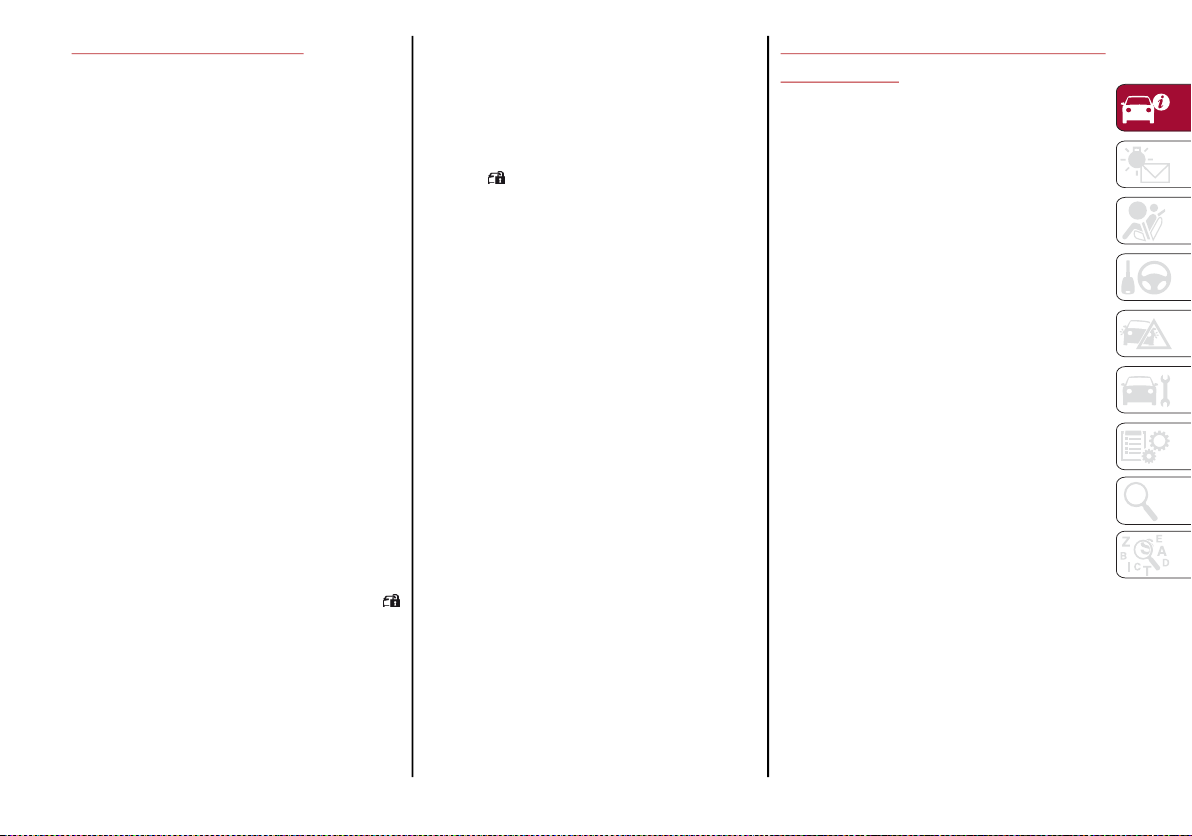
Locking/Unlocking Doors From The
Outside
When locking the doors from the outside with
the doors closed, push the lock button on the
key fob.
The door lock can be activated with all doors
locked and the trunk lid open. When the lock
button on the key fob is pushed, all locks are
activated, including the open trunk lid. The
trunk lid will be locked when it is closed.
When unlocking the doors from the outside,
push the unlock button on the key fob.
Locking/Unlocking Doors From The Outside In
An Emergency
If the battery is discharged or the key fob is
inoperable, you can lock or unlock the doors
from the outside by inserting the blade of the
emergency key, found inside the key fob, into
the door handle lock cylinder and turn the
emergency key as follows.
Lock — Turn the emergency key to the right
(clockwise)
Unlock — Turn the emergency key to the left
(counter clockwise)
Passive Entry
The Passive Entry system can identify the pres-
ence of a key fob near the doors and trunk lid.
The system enables the doors and trunk lid to
be locked or unlocked without pushing any
button on the key fob.
The key fob is detected only after the system
recognizes the presence of a hand on one of
the front door handles. If the detected key fob
is valid, the doors and the trunk lid are
unlocked. Refer to the Information and Enter-
tainment System Owner’s Manual Supple-
ment for Passive Entry Settings.
NOTE:
The key fob may not be able to be detected by
the vehicle keyless entry system if it is located
next to a mobile phone, laptop or other elec-
tronic device; these devices may block the key
fob’s wireless signal and prevent the keyless
entry system from starting the vehicle.
Grasping the handle of the driver's door
unlocks the driver's side door, or all doors
depending on the mode set using the radio
system. Refer to the Information and Enter-
tainment System Owner’s Manual Supple-
ment for Passive Entry Settings.
NOTE:
If wearing gloves, or if it has rained and the
door handle is wet, the activation sensitivity of
the Passive Entry function may be reduced,
resulting in a longer reaction time.
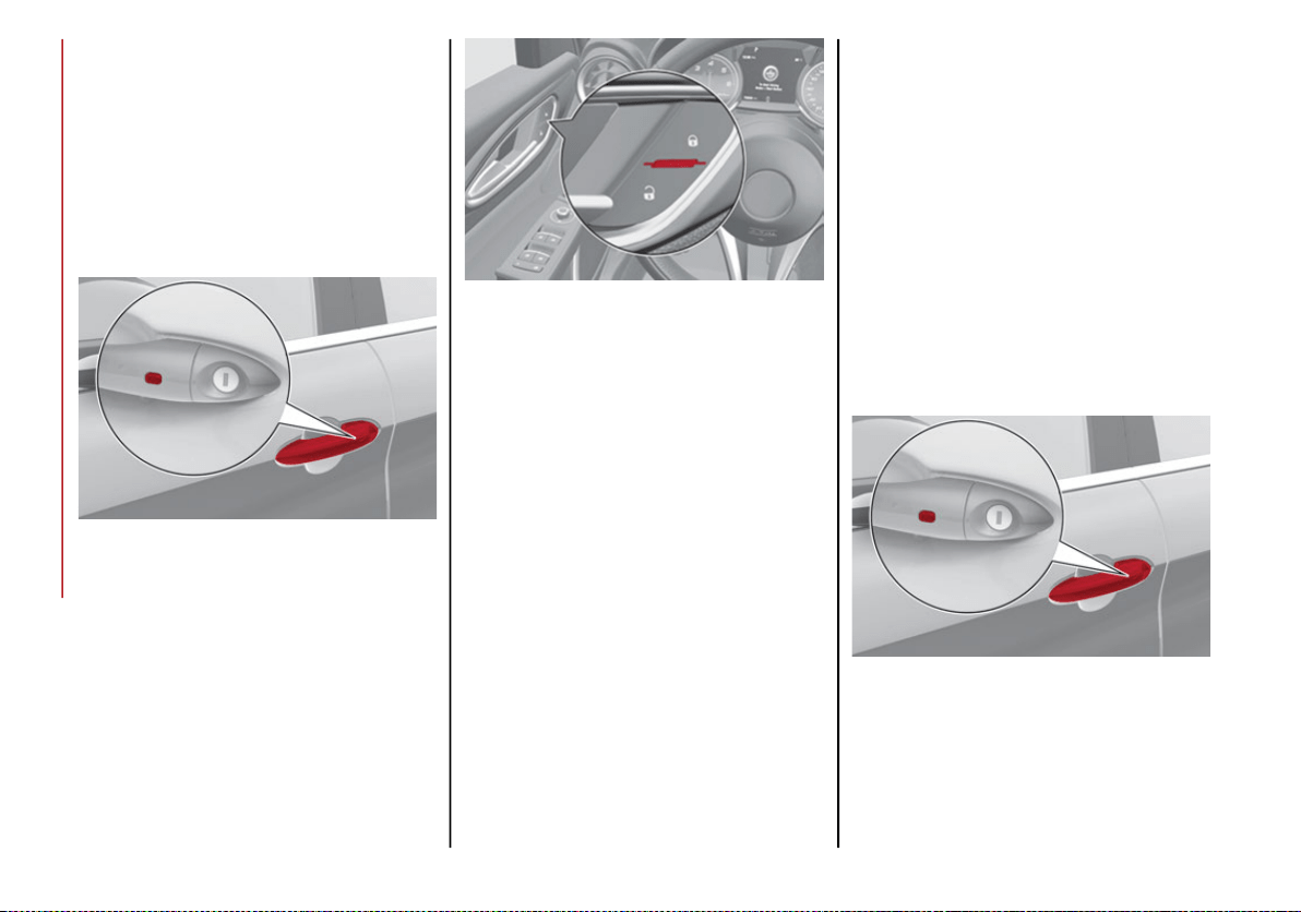
Door Locking
To lock the doors, proceed as follows:
1. Make sure that you have the key fob and
are close to the driver’s or passenger’s
side door handle.
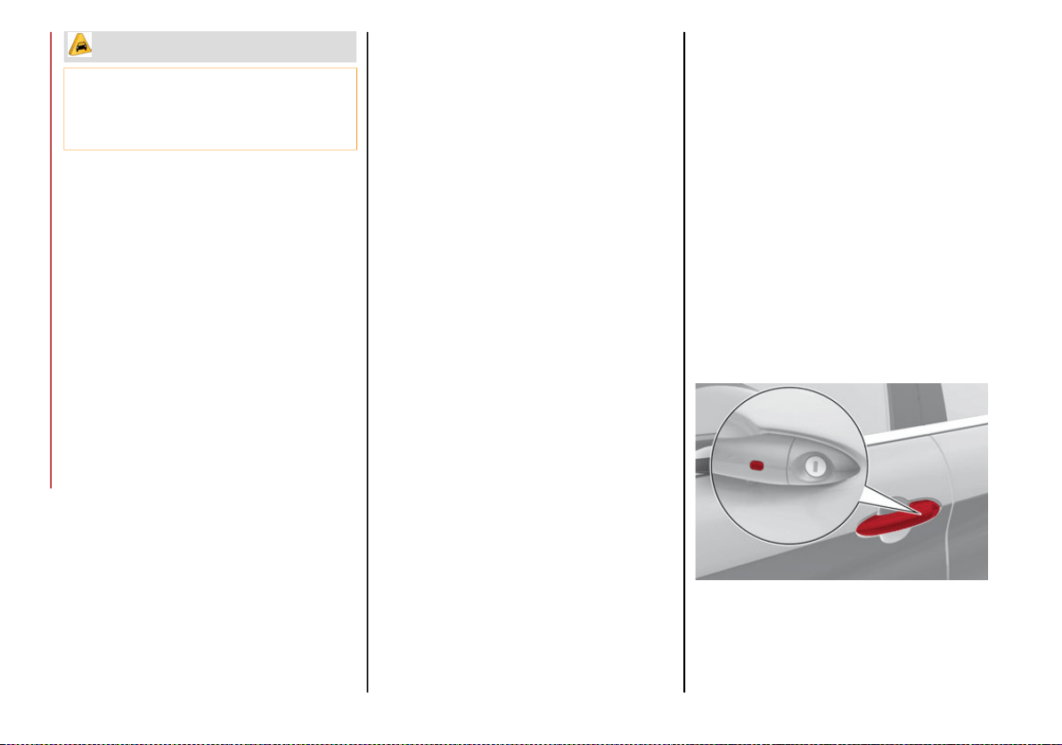
2. Push the Passive Entry door handle button
or the Passive Entry trunk lid button, which
is located next to the exterior trunk lid
release button. This will lock all doors and
the trunk lid. Door locking will activate the
alarm as well.
Passive Entry Door Handle Button
CAUTION!
An unlocked vehicle is an invitation. Always
remove the key from the ignition and lock
all of the doors when leaving the vehicle
unattended.
20_GA_OM_EN_USC_t.book Page 22
23
Exterior Trunk Lid Release Switch (Vehicles
With Passive Entry)
NOTE:
After pushing the Passive Entry door handle
button, you must wait two seconds before the
doors can be unlocked again using the passive
entry door handle button. This feature makes
it possible to check whether the vehicle has
been locked correctly by pulling the door
handle within two seconds. The doors will not
be unlocked again.
The vehicle doors and trunk lid can be locked
by pushing the lock button on the key fob or on
the interior door lock.
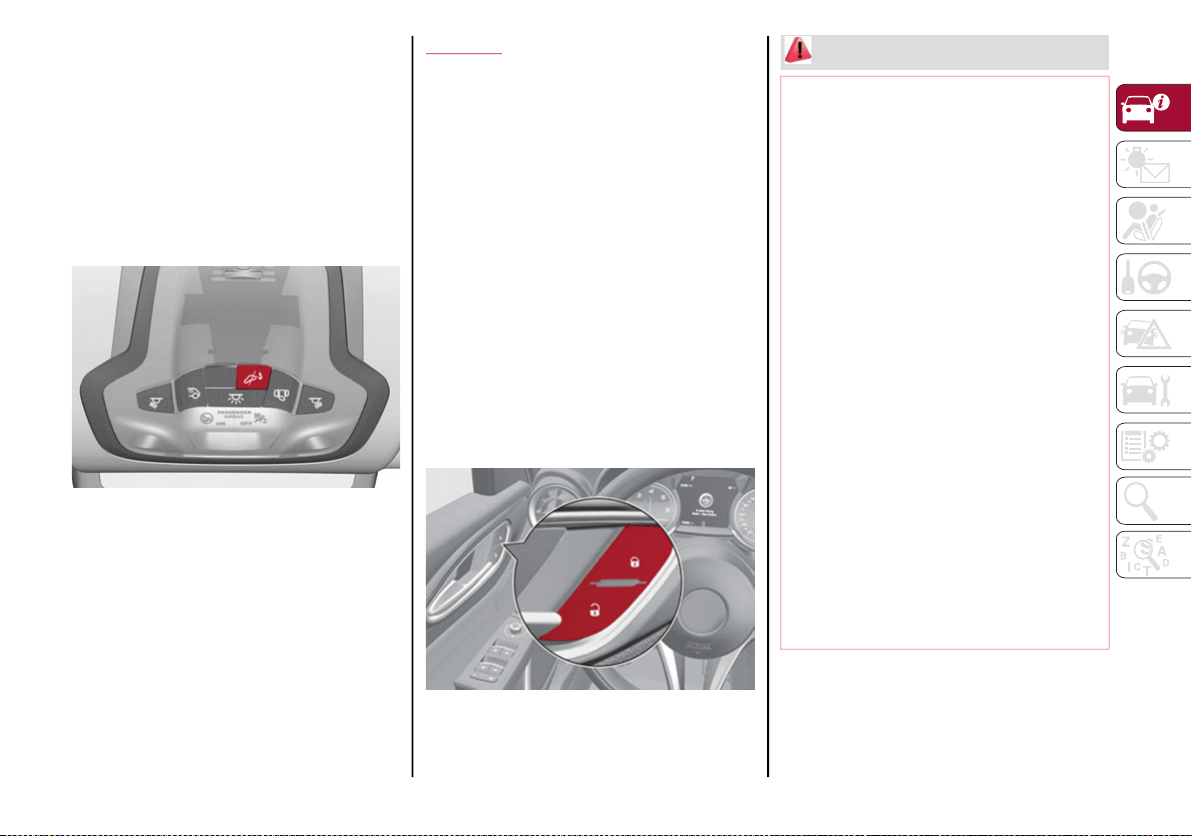
Driver Side Door Emergency Opening
If the key fob does not work, e.g. because its
battery is discharged or the vehicle battery is
discharged, the emergency key can be used to
unlock the driver side door.
To remove the emergency key from the key
fob, proceed as follows:
1. Push the sides of the key fob inward and
extract the cover pulling downwards.
2. Remove the emergency key from the key
fob housing.
3. Insert the emergency key in the driver side
door lock cylinder and turn it to the left
(counter clockwise) to unlock the door.
Emergency Key Release Buttons
Emergency Key
NOTE:
The emergency key blade is not directional
and can be inserted in either direction into
the lock.
To avoid leaving the key fob inside the
vehicle accidentally, the Passive Entry func-
tion features an automatic door unlocking
function.
20_GA_OM_EN_USC_t.book Page 23
GETTING TO KNOW YOUR VEHICLE
24
If one of the vehicle doors is open and the
Passive Entry door handle button or the
interior door lock switch is pushed, a check
of the inside and outside of the vehicle for
the presence of the key fob is made once all
the open doors are closed.
Passive Entry Door Handle Button
Interior Lock Switch Panel
While pulling the handle, do not push the door
lock/unlock button on the handle.
Do NOT Grab The Door Handle When Locking
If the key fob is detected inside the vehicle, the
Passive Entry function automatically unlocks
all the vehicle doors and flashes the turn
signals.
If one or more key fobs are inside the passenger
compartment, the lock button on the key fob
inside the passenger compartment is tempo-
rarily disabled.
The vehicle will not unlock the doors if an
unauthorized key fob has been detected close
to the outside of the vehicle.
If the Passive Entry function is disabled using
the radio system, the protections to avoid acci-
dentally leaving the key fob inside the vehicle
are deactivated.
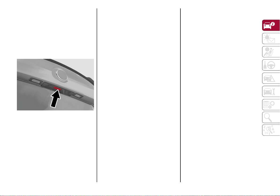
Trunk Lid Access
Approaching the trunk lid with a valid key fob,
push the trunk lid release button.
Exterior Trunk Lid Release Button
NOTE:
If the key fob is inadvertently forgotten
inside of the trunk, and an attempt is made
to close it from outside, the trunk lid will not
lock. With the doors locked, the trunk lid
unlocked, and the key fob detected inside
the vehicle, the trunk lid will unlock again
and the lights flash twice.
Before driving, make sure the trunk lid is
closed correctly.
20_GA_OM_EN_USC_t.book Page 24
25
Trunk Lid Lock
The trunk lid of the vehicle may be locked by
pushing the lock button on the key fob,
pushing the door lock button on the door
handles, or pushing the lock button on the
interior door panel of the vehicle.
The trunk lid and the doors can be locked by
pushing the passive entry button located as
part of the trunk lid release button switch.
Exterior Trunk Lid Release Switch (Vehicles
With Passive Entry)
System Activation/Deactivation
The Passive entry system can be activated or
deactivated using the radio system.
General Information
The following regulatory statement applies to
all Radio Frequency (RF) devices equipped in
this vehicle:
This device complies with Part 15 of the FCC Rules
and with Innovation, Science and Economic Devel-
opment Canada license-exempt RSS standard(s).
Operation is subject to the following two conditions:
1. This device may not cause harmful inter-
ference, and
2. This device must accept any interference
received, including interference that may
cause undesired operation.
Le présent appareil est conforme aux CNR
d`Innovation, Science and Economic Develop-
ment applicables aux appareils radio exempts
de licence. L'exploitation est autorisée aux
deux conditions suivantes:
1. l'appareil ne doit pas produire de brouil-
lage, et
2. l'utilisateur de l'appareil doit accepter tout
brouillage radioélectrique subi, même si le
brouillage est susceptible d'en comprom-
ettre le fonctionnement.
La operación de este equipo está sujeta a las
siguientes dos condiciones:
1. es posible que este equipo o dispositivo no
cause interferencia perjudicial y
2. este equipo o dispositivo debe aceptar
cualquier interferencia, incluyendo la que
pueda causar su operación no deseada.
RF Exposure Requirements
To comply with FCC RF exposure compliance
requirements, the device must be installed
and operated to provide a separation distance
of at least 20 cm from all persons.
This equipment complies with Canada radiation
exposure limits set forth for an uncontrolled envi-
ronment. This equipment should be installed and
operated with minimum distance 20 cm between
the radiator and your body.
NOTE:
Changes or modifications not expressly
approved by the party responsible for compli-
ance could void the user’s authority to operate
the equipment.
20_GA_OM_EN_USC_t.book Page 25
GETTING TO KNOW YOUR VEHICLE
26
Déclaration d’exposition aux radiations
Cet équipement est conforme aux limites
d’exposition aux rayonnements ISED établies
pour un environnement non contrôlé. Cet équi-
pement doit être installé et utilisé avec un
minimum de 20 cm de distance entre la
source de rayonnement et votre corps
REMARQUE:
Des changements ou des modifications n’ayant
pas été expressément approuvés par la partie
responsable de la conformité pourraient révo-
quer l’autorisation d’utilisation de l’équipement.
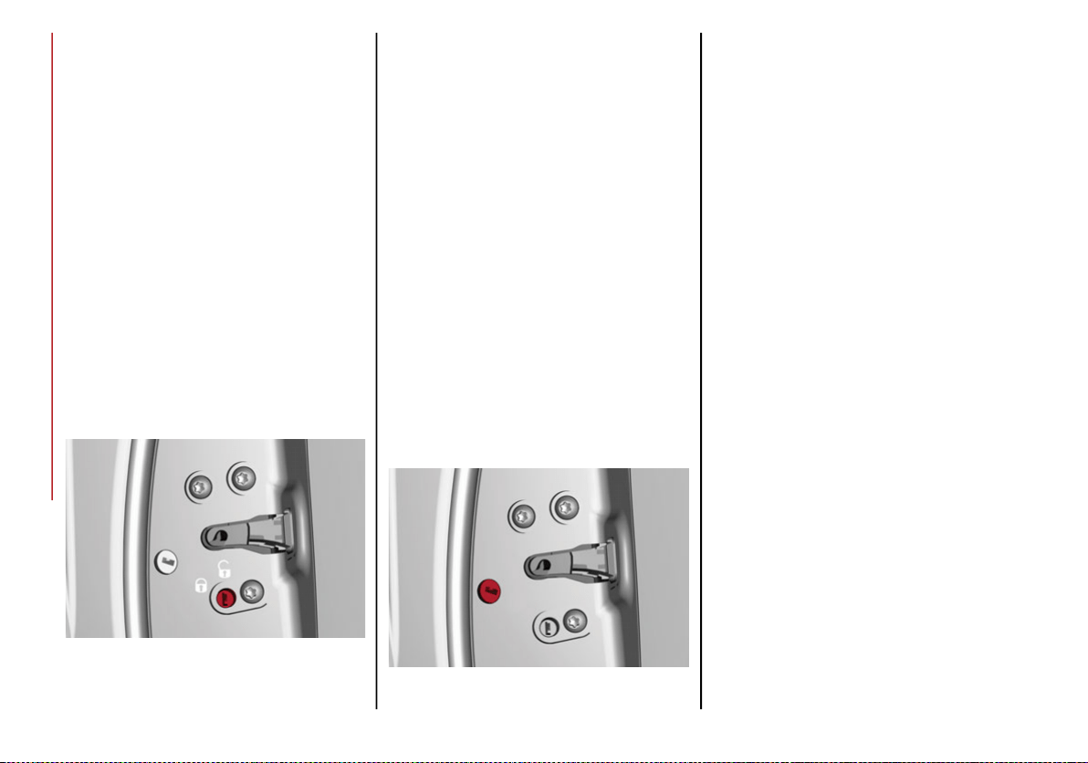
Child Safety Locks
To provide a safer environment for small children
riding in the rear seats, the rear doors are equipped
with Child-Protection Door Lock system.
This device can be engaged only with the
doors open.
Child Safety Lock Positions
Lock position: device locked (door opened
from exterior only)
Unlock position: device unlocked (door may
be opened from the inside)
The Child Safety Locks remain locked even if
the doors are unlocked.
NOTE:
The rear doors cannot be opened from the
inside when the Child Safety Lock is engaged.
Locking The Doors With A Discharged
Battery
Proceed as follows to lock the doors if the
vehicle battery is discharged.
Rear Doors And Passenger Door
1. With the doors unlocked insert the emer-
gency key from the key fob or a flat bladed
screwdriver into the door lock manual
release lock cylinder.
Door Lock Manual Release Lock Cylinder
2. Turn the manual release lock cylinder
clockwise for the right door locks or coun-
terclockwise for the left door locks.
3. Remove the key/screwdriver from the
manual release lock.
Proceed in one of the following ways to realign
the door lock device (only when the battery
charge has been restored):
Push the lock button on the key fob
Push the unlock button on the door panel
Unlock the driver’s door lock cylinder with
the emergency key
Operate the internal door handle
NOTE:
For the rear doors, if the Child Safety Locks are
engaged, and the previously described locking
procedure is carried out, operating the internal
handle will not open the door. Instead, it will
only realign the lock release device. To open
the door, the outside handle must be used.
The door central locking/unlocking buttons
are not deactivated when the emergency lock
is engaged.
20_GA_OM_EN_USC_t.book Page 26
27
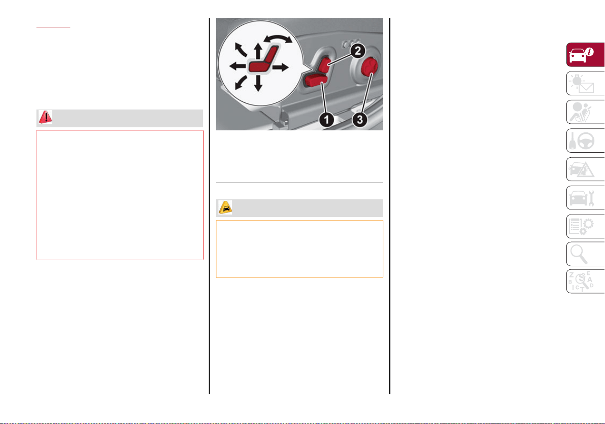
SEATS
The front seats can be adjusted to ensure
maximum comfort for the occupants. When
adjusting the driver’s seat, keep the shoulders
resting firmly against the backrest, and the
wrists within reach of the top of the steering
wheel. The driver must also be able to fully
press the brake pedal.
Power Seats
NOTE:
The seat layout may vary according to the
versions.
The power seat switches are located on the
outboard side of the seat near the floor. Use these
switches to move the driver's seat up, down,
forward, rearward, or to recline the seatback.
Power Seat Adjustment
Forward/Rearward Adjustment
Push the seat switch forward or rearward to
adjust to your desired position.
Seatback Recline
The angle of the seatback can be adjusted
forward or rearward. Push the seatback switch
in the desired direction, and the seat will move
in the direction of the switch. Release the
switch when the desired position is reached.
Power Lumbar
The power lumbar switch is located on the
outboard side of the power seat. Push the
switch forward or rearward to increase or
decrease the lumbar support. Push the switch
upward or downward to raise or lower the
lumbar support.
Height Adjustment
The height of the seats can be adjusted up or
down. Pull upward or push downward on the
seat switch, and the seat will move in the
direction of the switch. Release the switch
when the desired position is reached.
Seat Angle Adjustment (Tilting) — If Equipped
The seat angle can be adjusted in four directions.
Lift or push the front part of seat switch to move
the front part of the seat in the corresponding
direction. Release the seat switch when the seat
has reached the desired position.
WARNING!
It is dangerous to ride in a cargo area,
inside or outside of a vehicle. In a colli-
sion, people riding in these areas are
more likely to be seriously injured or killed.
Do not allow people to ride in any area of
your vehicle that is not equipped with
seats and seat belts. In a collision, people
riding in these areas are more likely to be
seriously injured or killed.
Be sure everyone in your vehicle is in a
seat and using a seat belt properly.
1 — Seat Adjustment
2 — Recline Adjustment
3 — Lumbar Adjustment
CAUTION!
Do not place any article under a power seat or
impede its ability to move as it may cause
damage to the seat controls. Seat travel may
become limited if movement is stopped by an
obstruction in the seat's path.
20_GA_OM_EN_USC_t.book Page 27
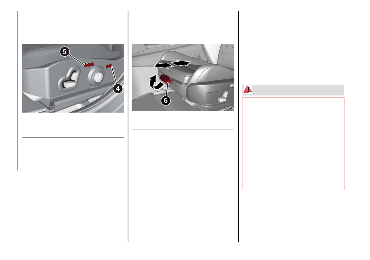
GETTING TO KNOW YOUR VEHICLE
28
Power Bolster Adjustment — If Equipped
Push the power bolster adjustment buttons to
regulate the width of the backrest through the
lateral padding.
Seatback Width Adjustment
Seat Cushion Extension — If Equipped
Lift the adjustment lever and push the front of
the cushion forward or rearward to extend the
cushion by a few inches (centimeters).
Seat Cushion Extension
Driver Memory Seat
Storing and recalling can be done with the igni-
tion in the ACC position, vehicle speed at
0 mph (0 km/h), and the driver’s side door
closed, or for three minutes after having
opened the driver's side door. An audible
chime is heard to confirm a memory profile is
set or recalled. To set a memory profile, first
adjust your seat (and power mirror position if
desired) until you are in the desired position.
Then, push the memory button you want to
assign the set position to for 1.5 seconds.
When a new seat position is memorized, the
previously memorized position on the same
button is automatically overwritten. Recalling
a memorized position can also be done for
approximately three minutes after the doors
are opened and for approximately one minute
after the engine is stopped. To recall a memo-
rized position, push the assigned button
briefly.
4 — Power Adjustable Bolster Buttons
5 — Driver Memory Seat Buttons
6 — Adjustment Lever
WARNING!
Adjusting a seat while driving may be
dangerous. Moving a seat while driving
could result in loss of control which could
cause a collision and serious injury or death.
Seats should be adjusted before fastening
the seat belts and while the vehicle is
parked. Serious injury or death could
result from a poorly adjusted seat belt.
Do not ride with the seatback reclined so
that the shoulder belt is no longer resting
against your chest. In a collision you could
slide under the seat belt, which could
result in serious injury or death.
20_GA_OM_EN_USC_t.book Page 28
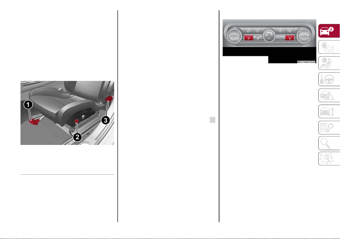
29
Sparco Racing Seats (Quadrifoglio
Vehicles) — If Equipped
Forward/Rearward Adjustment
The adjustment lever is at the front of the seat,
near the floor. Pull the bar upward to move the
seat forward or rearward. Release the bar
once the seat is in the desired position. Using
body pressure, move forward and rearward on
the seat to be sure that the seat adjusters
have latched.
Manual Seat Adjustment
Height Adjustment
Push the height adjustment button upward or
downward to obtain your desired height.
Seatback Recline
To adjust the seatback, lift the recline lever
located on the outboard side of the seat, lean
back to the desired position and release the
lever. To return the seatback, lift the lever,
lean forward and release the lever.
Heated Seats — If Equipped
NOTE:
Quadrifoglio vehicles equipped with Sparco
Racing Seats will not be equipped with the
heated seat feature.
With the ignition in the ON/RUN position, push
the driver or passenger heated seat button
located on the instrument panel.
NOTE:
The heated seat function can also be activated
through the radio system. Refer to the Infor-
mation and Entertainment System Owner’s
Manual Supplement for further information.
Heated Seat Buttons
You can select three heating levels:
Maximum — three LED indicators illumi-
nated on the buttons
Average — two LED indicators illuminated
on the buttons
Minimum — one LED indicator illuminated
on the buttons
After selecting a heating level, heat will be felt
within a few minutes.
A quick push of the heated seat button will
select the heat levels in order of highest to
lowest. A fourth push of the button will turn the
heated seat off.
The “minimum” setting is automatically deacti-
vated once a certain period of time has elapsed.
This varies on a case-by-case basis, in accor-
dance with the specific operating conditions.
NOTE:
The heated seat function can only be activated
with the ignition in the ON/RUN position.
1 — Adjustment Lever
2 — Height Adjustment Button
3 — Recline Lever
20_GA_OM_EN_USC_t.book Page 29
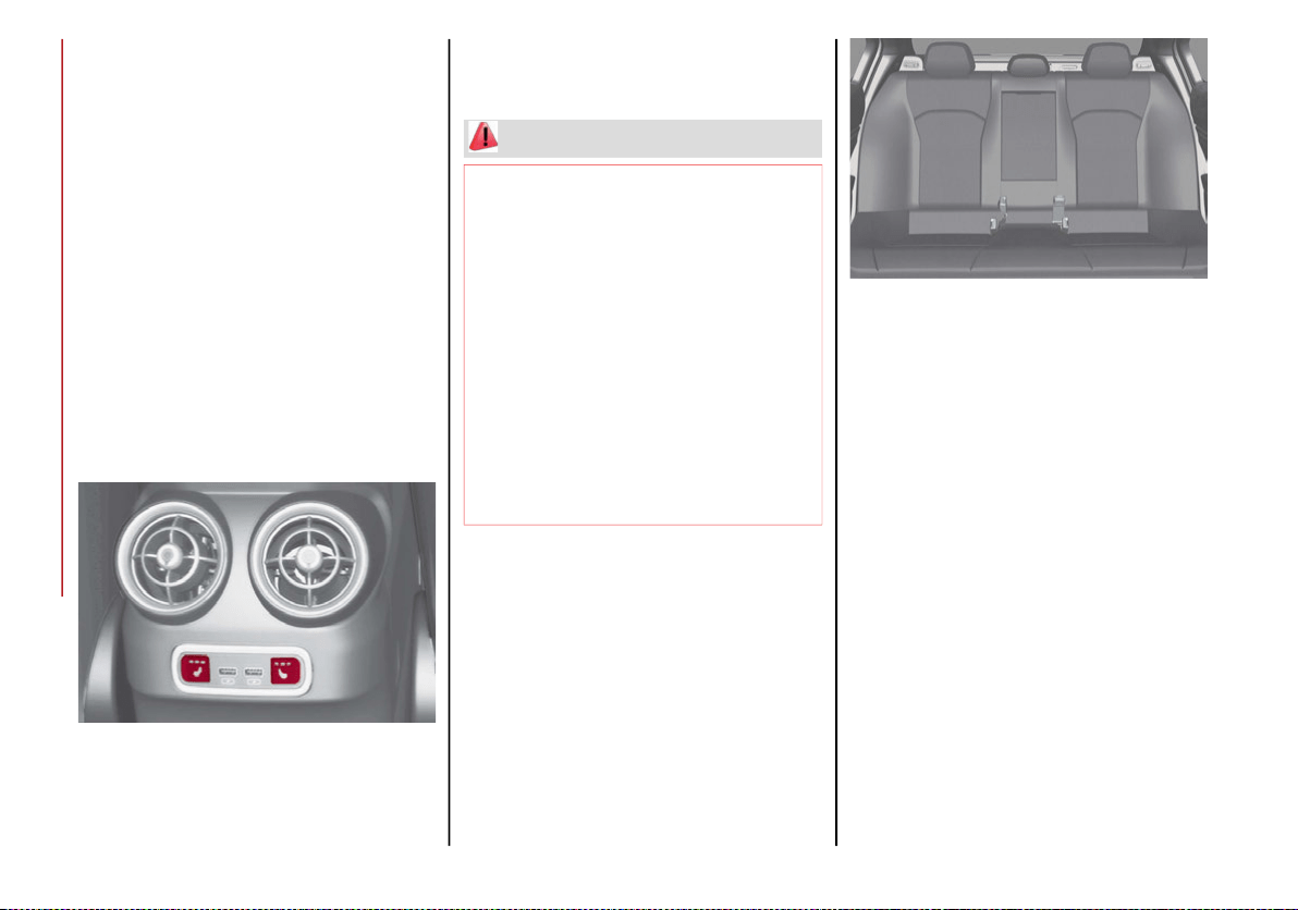
GETTING TO KNOW YOUR VEHICLE
30
Vehicles Equipped With Remote Start
On models that are equipped with remote
start, the front heated seats can be
programmed to come on during remote start.
The feature can be activated through the radio
system. Refer to the Information and Enter-
tainment System Owner’s Manual Supple-
ment for further information.
NOTE:
The heated seat function can only be activated
with remote start in temperatures below 39°F
(4°C).
Rear Heated Seats
If equipped with rear heated seats, the
controls can be found on the rear of the center
console and will function the same as the front
heated seat controls.
Rear Heated Seat Buttons
NOTE:
To preserve the battery charge, this function
cannot be activated when the engine is off.
Rear Seats
The rear seats allow for three passengers.
NOTE:
Middle Seat: The rear seat is designed as a
4+1 seat vehicle. The middle seat is of limited
use. It is recommended that this seat only be
used by a person who can use the backrest as
a substitute for the head restraint.
Rear Seat
The seats and the seat belts are considered
components of the vehicle’s Occupant
Restraint System.
NOTE:
Refer to "Seat Belt Systems" in "Safety" for
further information.
Split Folding Rear Seat
The rear seatbacks can be folded forward to
provide an additional storage area.
Partial Extension Of The Luggage Compart-
ment (1/3 Or 2/3)
Extending the right side of the trunk allows you
to carry two passengers on the left part of the
rear seat, while extending the left side allows
you to carry one passenger.
WARNING!
Persons who are unable to feel pain to the
skin because of advanced age, chronic
illness, diabetes, spinal cord injury, medi-
cation, alcohol use, exhaustion or other
physical condition must exercise care
when using the seat heater. It may cause
burns even at low temperatures, espe-
cially if used for long periods of time.
Do not place anything on the seat or seat-
back that insulates against heat, such as
a blanket or cushion. This may cause the
seat heater to overheat. Sitting in a seat
that has been overheated could cause
serious burns due to the increased
surface temperature of the seat.
20_GA_OM_EN_USC_t.book Page 30
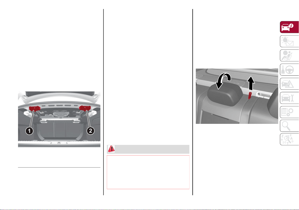
31
Proceed as follows:
1. Completely lower the rear seat head
restraints. Refer to “Head Restraints” in
this chapter for further information.
2. Place the seat belt so that it doesn't
impede the movement of the backrest
while tilting it.
3. From inside the luggage compartment,
operate lever 1 to tilt the left part or lever
2 to tilt the right part of the backrest: it will
automatically tilt forward. If necessary,
assist the backrest during the initial stage
of tilting.
Seat Release Levers
Full Expansion Of The Trunk
Tilting the rear seat forward completely allows
maximum loading volume.
Proceed as follows:
1. Completely lower the rear seat head
restraints.
2. Place the seat belts so that they don't
impede the movement of the backrest
while tilting it.
3. From inside the luggage compartment,
use levers 1 and 2 to fold down the back-
rests; these will fold down forwards auto-
matically. If necessary, accompany the
backrests during the initial stage of tilting.
Repositioning The Backrests
Move the seat belts to the side, making sure that
they are correctly extended and not twisted, and
that they are not trapped behind the backrests of
the seats. Make sure the seat belts are in the
front of the seatback and lift the backrests,
pushing them back until you hear the locking
click on both latch mechanisms.
Center Backrest Section Tilting
The center backrest can be tilted forward for a
“Ski-Pass Through” feature from the trunk.
Before tilting the backrest, make sure that the
rear center seat belt is not fastened and that
there are not any objects in the middle part of
the cushion.
Using the release strap, release the center
part of the backrest from its housing and tilt it
using the head restraint.
Center Backrest Section Tilting
Center Backrest Section Repositioning
Using the head restraint, lift the center portion
upwards, accompanying it during its move-
ment, and lightly push to make sure that it is
properly attached. Make sure that the armrest
is properly attached by attempting to move it.
If it is not attached, repeat the operation.
1 — Left Side Seat Release Lever
2 — Right Side Seat Release Lever
WARNING!
Be certain that the seatback is securely
locked into position. If the seatback is not
securely locked into position the seat will
not provide the proper stability for child
seats and/or passengers. An improperly
latched seat could cause serious injury.
20_GA_OM_EN_USC_t.book Page 31

GETTING TO KNOW YOUR VEHICLE
32
(Continued)
Easy Entry Function
The Easy Entry function is designed to move
the driver side seat forward automatically by
2.36 inches (60 mm) to make it easier for the
driver to get in and out of the car.
The movement is activated only if the seat is
set to a driving position which is in front of the
B-Pillar of the vehicle.
The function is associated with power driver
seats for each of the three stored positions.
The Easy Entry function can be activated/
deactivated through the radio system.
HEAD RESTRAINTS
Head restraints are designed to reduce the
risk of injury by restricting head movement in
the event of a rear impact. Head restraints
should be adjusted so that the top of the head
restraint is located above the top of your ear.
Sparco Racing Seat Head Restraints
(Quadrifoglio Vehicles) — If Equipped
Your vehicle may be equipped with non-adjust-
able head restraints on the driver's and
passenger's seatbacks.
The non-adjustable head restraints consist of a
trimmed foam covering over the upper structure
of the seatbacks and are intended to help
protect you and the passenger from neck injury.
Adjust the seatbacks to their upright, on-road
positions so that the head restraint is positioned
as close as possible to the back of your head.
Front Head Restraints (Adjustments)
The front head restraints may be
height-adjustable. To adjust them, operate as
follows:
Upward adjustment: Raise the head
restraint until it clicks into place.
Downward adjustment: Push the adjust-
ment button and push downward on the
head restraint to lower.
NOTE:
To allow maximum visibility for the driver, if the
head restraints are not in use, lower the head
restraint all the way.
WARNING!
A loose head restraint thrown forward in a
collision or hard stop could cause serious
injury or death to occupants of the vehicle.
Always securely stow removed head
restraints in a location outside the occu-
pant compartment.
ALL the head restraints MUST be rein-
stalled in the vehicle to properly protect
the occupants. Follow the re-installation
instructions above prior to operating the
vehicle or occupying a seat.
Do not place items over the top of the
Reactive Head Restraint, such as coats,
seat covers or portable DVD players.
These items may interfere with the opera-
tion of the Reactive Head Restraint in the
event of a collision and could result in
serious injury or death.
WARNING! (Continued)
WARNING!
All occupants, including the driver, should
not operate a vehicle or sit in a vehicle’s seat
until the head restraints are placed in their
proper positions in order to minimize the risk
of neck injury in the event of a crash.
Head restraints should never be adjusted
while the vehicle is in motion. Driving a
vehicle with the head restraints improp-
erly adjusted or removed could cause
serious injury or death in the event of a
collision.
20_GA_OM_EN_USC_t.book Page 32
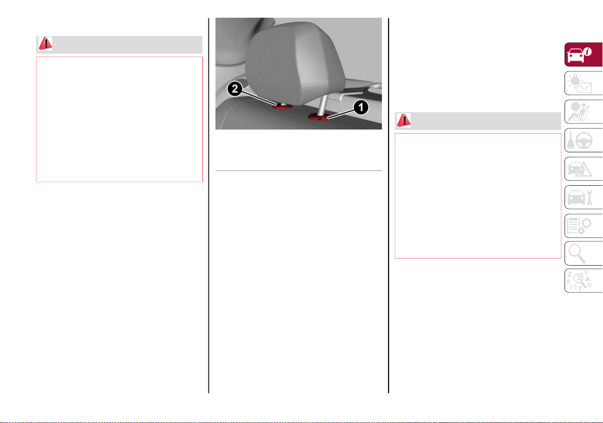
33
Rear Head Restraints (Adjustments)
The height of the outboard head restraints can
be adjusted. The head restraint of the center
seat can only be removed. The height cannot
be adjusted.
For upward adjustment, pull up on the head
restraint until it clicks into place.
For downward adjustment, push in the adjust-
ment button and lower the head restraint
while holding the button to the desired height.
Rear Head Restraint
NOTE:
To allow maximum visibility for the driver, if the
head restraints are not in use, lower the head
restraint all the way.
Head Restraints (Removal)
To remove the head restraints, proceed as
follows:
1. Raise the head restraints to their
maximum height.
2. Push the adjustment button and the release
button at the side of the two supports.
3. Remove the head restraints by pulling
them upwards.
To reinstall the head restraints, proceed as
follows:
1. Hold down both the adjustment button
and release button while placing the head
restraint post into the holes.
2. Then, reposition the head restraint to the
appropriate height for the passengers.
WARNING!
All occupants, including the driver, should
not operate a vehicle or sit in a vehicle’s seat
until the head restraints are placed in their
proper positions in order to minimize the risk
of neck injury in the event of a crash.
Head restraints should never be adjusted
while the vehicle is in motion. Driving a
vehicle with the head restraints improp-
erly adjusted or removed could cause
serious injury or death in the event of a
collision.
1 — Adjustment Button
2 — Release Button
WARNING!
A loose head restraint thrown forward in a
collision or hard stop could cause serious
injury or death to occupants of the vehicle.
Always securely stow removed head
restraints in a location outside the occu-
pant compartment.
ALL the head restraints MUST be rein-
stalled in the vehicle to properly protect
the occupants. Follow the re-installation
instructions above prior to operating the
vehicle or occupying a seat.
20_GA_OM_EN_USC_t.book Page 33
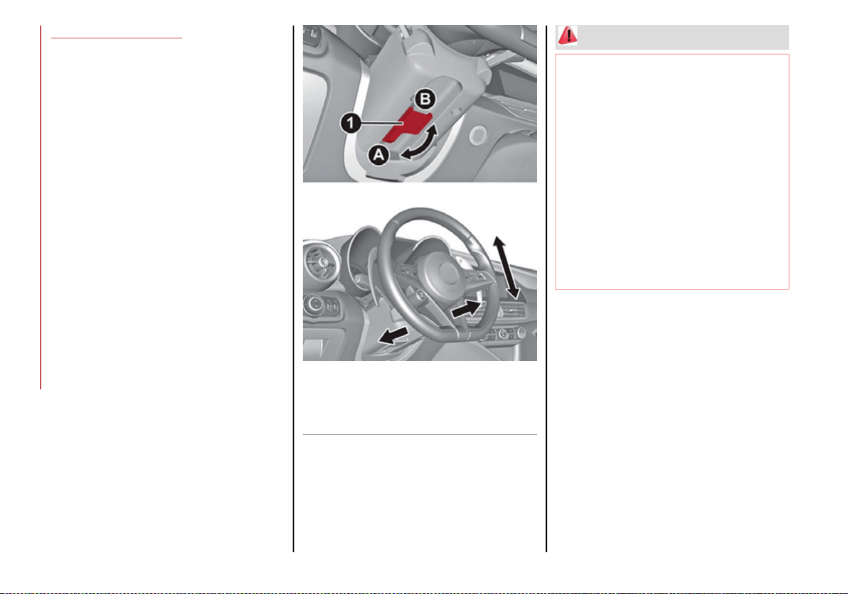
GETTING TO KNOW YOUR VEHICLE
34
STEERING WHEEL
Adjustments
This feature allows you to tilt the steering
column upward or downward. It also allows
you to lengthen or shorten the steering
column. The tilt/telescoping lever is located
below the steering wheel at the end of the
steering column.
Steering Wheel Adjustment
1 — Tilt/Telescoping Control Handle
A — Open
B — Closed
WARNING!
Do not adjust the steering column while
driving. Adjusting the steering column
while driving or driving with the steering
column unlocked, could cause the driver
to lose control of the vehicle. Failure to
follow this warning may result in serious
injury or death.
Do not place any objects on the steering
wheel (e.g. permanently fixed covers of
any type or material) which could interfere
with the capacitive hand detection sensor
on the steering wheel of the Active Blind
Spot Assist (ABSA), Lane Keeping Assist
(LKA), Traffic Jam Assist (TJA) or Highway
Assist (HAS) systems (if equipped).
20_GA_OM_EN_USC_t.book Page 34
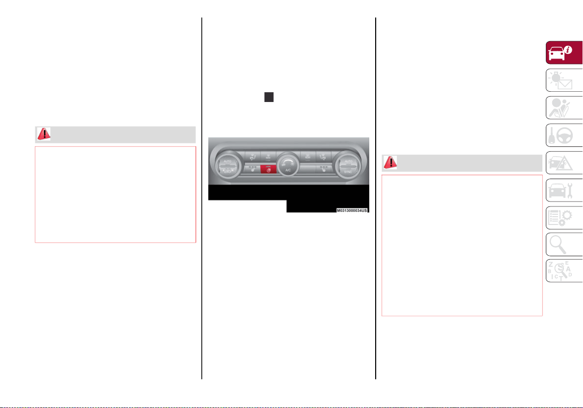
35
To Adjust The Position:
1. Pull the Tilt/Telescoping Control Handle
down to the open position.
2. Adjust the steering wheel to the desired
position.
3. Lock the desired position by pushing the
Tilt/Telescoping Control Handle to the
closed position.
Heated Steering Wheel — If Equipped
NOTE:
Quadrifoglio vehicles equipped with Sparco
Racing Seats will not be equipped with the
heated steering wheel feature.
While the engine is running, push the heated
steering wheel button on the instrument
panel.
Heated Steering Wheel Button
When the function is enabled, the indicator on
the button will illuminate.
Vehicles Equipped With Remote Start
On models that are equipped with remote
start, the heated steering wheel can be
programmed to come on during remote start.
The feature can be activated through the radio
system. Refer to the Information and Enter-
tainment System Owner’s Manual Supple-
ment for further information.
NOTE:
The heated steering wheel function can only
be activated with remote start in temperatures
below 39°F (4°C).
WARNING!
It is absolutely forbidden to carry out any
after-market operation involving steering
system or steering column modifications (e.g.
installation of anti-theft device) that could
adversely affect performance. Doing so could
void the New Vehicle Limited Warrant, cause
SERIOUS SAFETY PROBLEMS INCLUDING
INJURY, and also result in the vehicle not
meeting type-approval requirements.
WARNING!
Persons who are unable to feel pain to the
skin because of advanced age, chronic
illness, diabetes, spinal cord injury, medi-
cation, alcohol use, exhaustion, or other
physical conditions must exercise care
when using the steering wheel heater. It
may cause burns even at low tempera-
tures, especially if used for long periods.
Do not place anything on the steering
wheel that insulates against heat, such as
a blanket or steering wheel covers of any
type and material. This may cause the
steering wheel heater to overheat.
20_GA_OM_EN_USC_t.book Page 35
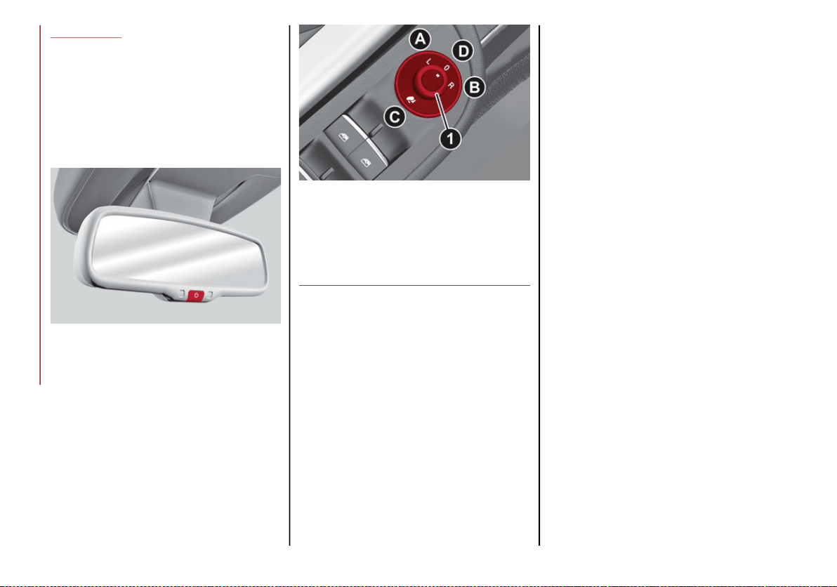
GETTING TO KNOW YOUR VEHICLE
36
MIRRORS
Electrochromic Mirror
This mirror automatically adjusts for headlight
glare from vehicles behind you.
The electrochromic mirror has a power button to
activate/deactivate the automatic dimming/
anti-glaring function.
Electrochromic Mirror Power Button
Outside Power Mirrors
Power Adjustment
The power mirrors can be adjusted with the
ignition in the ACC or ON/RUN position.
To adjust the power mirrors, first select the
desired mirror using the power mirror control.
Power Mirror Control
To adjust the selected mirror, push the knob in
the direction desired.
NOTE:
Once adjustment is complete, rotate the knob
to the neutral position to prevent accidental
movements.
Power Folding
To fold the door mirrors in using the Power
Folding Mirror function, make sure the power
mirror control knob is in the neutral position,
and move the knob to the power folding posi-
tion. Move the knob again to return the mirrors
to the driving position.
If the power mirror control knob is moved
again during door mirror folding (from closed
to open position and vice versa), the move-
ment direction is reversed.
Automatic Activation
Activating the central door locking system
from outside the vehicle automatically folds
the mirrors. The mirrors return to the driving
position when the vehicle is then unlocked.
If the door mirrors were folded using the power
mirror control knob, they can only be returned
to the driving position by moving the knob to
the power folding position again.
NOTE:
The power folding operation can be enabled
only when the vehicle speed is lower than
31 mph (50 km/h).
1 — Power Mirror Control Knob
A — Left
B — Right
C — Power Folding Position
D — Neutral
20_GA_OM_EN_USC_t.book Page 36
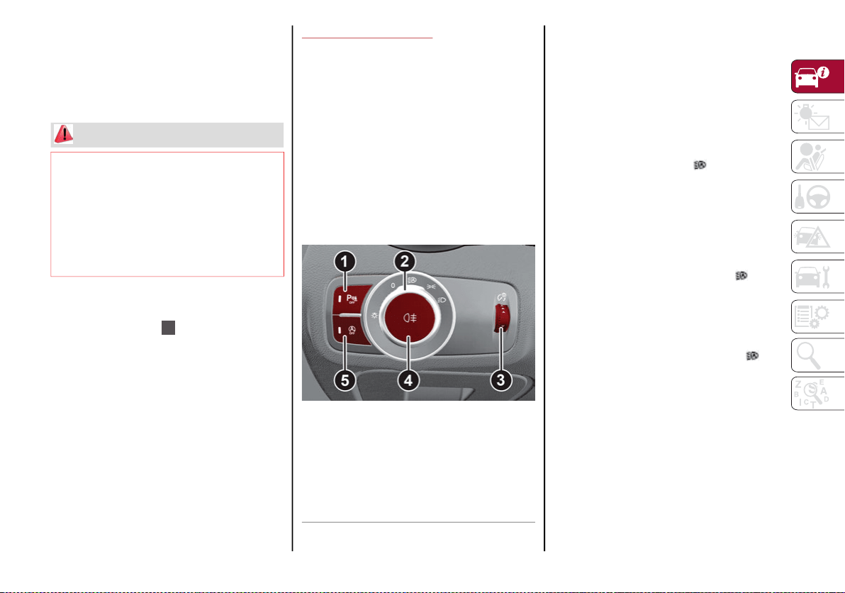
37
Automatic Dimming Mirrors — If Equipped
Like the inside electrochromic mirror, an auto-
matic dimming feature is also available on the
outside rear view mirrors to prevent glare. The
automatic dimming button is the same for all
rear view mirrors.
Heated Mirrors
Push the rear defrost button in the climate
controls to activate the heated mirrors.
EXTERIOR LIGHTS
Headlight Switch
The headlight switch is located to the left of
the steering wheel on the instrument panel.
This switch controls the operation of the head-
lights, parking lights, instrument panel lights,
instrument panel light dimming, interior lights
and rear fog lights.
In addition, there are buttons for parking
sensors deactivation and Engine Stop/Start.
Refer to “Starting And Operating” for further
information.
Headlight Switch
The instrument panel and the various controls
on the dashboard will be illuminated when the
exterior lights are turned on.
Automatic Headlights
This system automatically turns the headlights
on or off according to ambient light levels.
Function Activation
Rotate the light switch to the (AUTO) position.
NOTE:
The function can only operate with the ignition
position cycled to ON/RUN.
Function Deactivation
To deactivate the function, turn the light
switch to a position other than the (AUTO)
position.
Daytime Running Lights (DRL)
With the ignition placed in the ON/RUN posi-
tion, and the light switch turned to the posi-
tion, if the dusk sensor detects sufficient
external light, the Daytime Running Lights will
turn on automatically while the other lights
remain off.
If the turn signals are operated, the brightness
of the corresponding Daytime Running Lights
will be decreased as long as the turn signals
are on.
WARNING!
Vehicles and other objects seen in an
outside convex mirror will look smaller and
farther away than they really are. Relying
too much on side convex mirrors could
cause you to collide with another vehicle or
other object. Use your inside mirror when
judging the size or distance of a vehicle
seen in a side convex mirror.
1 — Parking Sensors Deactivation Button
2 — Parking Light, Daylight Running Lights,
Headlight Switch
3 — Instrument Panel Dimmer
4 — Rear Fog Light Button
5 — Engine Stop/Start Button
20_GA_OM_EN_USC_t.book Page 37

GETTING TO KNOW YOUR VEHICLE
38
The DRL can be activated/deactivated from
the radio system, by selecting the following
functions in sequence on the main MENU:
1. “Settings.”
2. “Lights.”
3. “Daytime Running Lights.”
NOTE:
The Daytime Running Lights cannot be deacti-
vated in Canadian markets.
Rear Fog Light
The rear fog light switch is integrated with the
headlight switch.
Push the button to turn the rear fog lights
on/off.
The rear fog lights turn on only when the head-
lights or parking lights are turned on. The lights
can be turned off by pushing the button
again or by turning the headlight switch to the
O (off) position and holding it there for a few
seconds.
When the engine is stopped with the rear fog
lights on, they will remain off the next time the
engine is started.
Parking Lights
With the ignition in the OFF position, turn the
headlight switch to the position to turn the
parking lights on. All of the parking lights will
turn on for eight minutes, and opening the
door activates an audible warning.
To leave only the lights on one side (right/left)
illuminated, you must move the multifunction
lever (located on the left side of the steering
wheel) to the side that you want to remain on.
With the parking lights on, the warning light
on the instrument panel will illuminate.
Headlight Off Delay
The “Headlight Off Delay” function delays the
turning off of the headlights for a set time
when the ignition is placed in the OFF position.
The function can be activated from the radio
system by selecting the following functions in
sequence on the main menu:
1. “Settings.”
2. “Lights.”
3. “Headlight Off Delay.”
The side lights and the headlights stay on for a
time that can be set between 30, 60, and 90
seconds.
Function Activation
With the headlights on, place the ignition in
the OFF position, the timer will then start.
NOTE:
To activate this function, the headlights must
be deactivated within two minutes after the
ignition has been placed in the OFF position.
Function Deactivation
This function is deactivated by turning on the
headlights, the side lights, or by placing the
ignition in the ON/RUN position.
Adaptive Frontlight System (AFS Function) —
If Equipped
This is a system combined with Xenon head-
lights (Bi-Xenon 35 W headlamp if equipped)
which directs the headlights horizontally, and
continuously and automatically adapts them
to the driving conditions around bends or
when cornering.
The system directs the headlights to light up
the road in the best way, taking into account
the speed of the vehicle and the bend or
corner angle, as well as the speed at which the
steering wheel is turned.
The adaptive lights are automatically activated
when the vehicle is started.
20_GA_OM_EN_USC_t.book Page 38
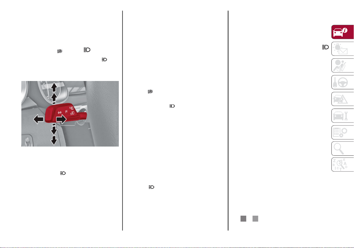
39
High Beam Headlights
To activate the fixed high beam headlights,
push the multifunction lever, located on the
left side of the steering wheel, towards the
instrument panel. The headlight switch must
be turned to the (auto) or (on) position.
With high beam headlights on, the High
Beam Indicator on the instrument panel will
illuminate.
Multifunction Lever
The high beam headlights are turned off by
pulling the lever to its original position. The
warning light/icon will turn off in the instru-
ment panel when the headlights are turned off.
Flashing The Headlights
Pulling the multifunction lever toward the
steering wheel will activate the high beam
headlights manually. The lights will remain on
as long as the lever is held. Once the lever is
released, the lights will resume the previous
position.
Automatic High Beam Headlights — If
Equipped
The Automatic High Beam Headlights system
provides increased forward lighting at night by
automating high beam control through the use
of a digital camera mounted on the wind-
shield. This camera detects vehicle specific
light and automatically switches from high
beams to low beams until the approaching
vehicle is out of view.
This function is enabled with the radio system,
and can only be activated with the light switch
turned to (auto).
If the high beam headlights are on, the blue
icon/warning light will illuminate in the
instrument panel.
When the speed is higher than 25 mph
(40 km/h) and the function is active, the lights
will turn off if the multifunction lever is pushed
again.
When the speed is lower than 15 mph
(25 km/h) and the function is active, the func-
tion switches the high beam headlights off.
If the high beam headlights are operated
quickly again (pushing the multifunction lever
towards the instrument panel), the warning
light/icon will illuminate in the instrument
panel, and the high beam headlights will turn
on constantly until the speed exceeds 25 mph
(40 km/h).
When the speed of 25 mph (40 km/h) is
exceeded again, the automatic functioning is
reactivated.
If the multifunction lever is pushed again with
the Automatic High Beam Headlights acti-
vated, the Automatic High Beam Headlights
function deactivates.
To deactivate the automatic headlight func-
tion, rotate the headlight switch to the
position.
NOTE:
If the system recognizes heavy traffic areas,
the automatic functions remain disabled
independently of the vehicle’s speed.
The Automatic High Beam functionality may
also be influenced by:
• Reflections on road signs
• Dim headlights from oncoming traffic
• Poor weather conditions
• Presence of dirt or other obstructions on
the sensor
• Damage to the windshield
Turn Signals
To activate the turn signals function, move the
multifunction lever, located on the left side of
the steering wheel, up or down until it reaches
the detent. Moving the lever upward flashes
the right turn signal and moving the lever
downward will flash the left turn signal.
The or turn signal will blink on the instru-
ment panel.
20_GA_OM_EN_USC_t.book Page 39
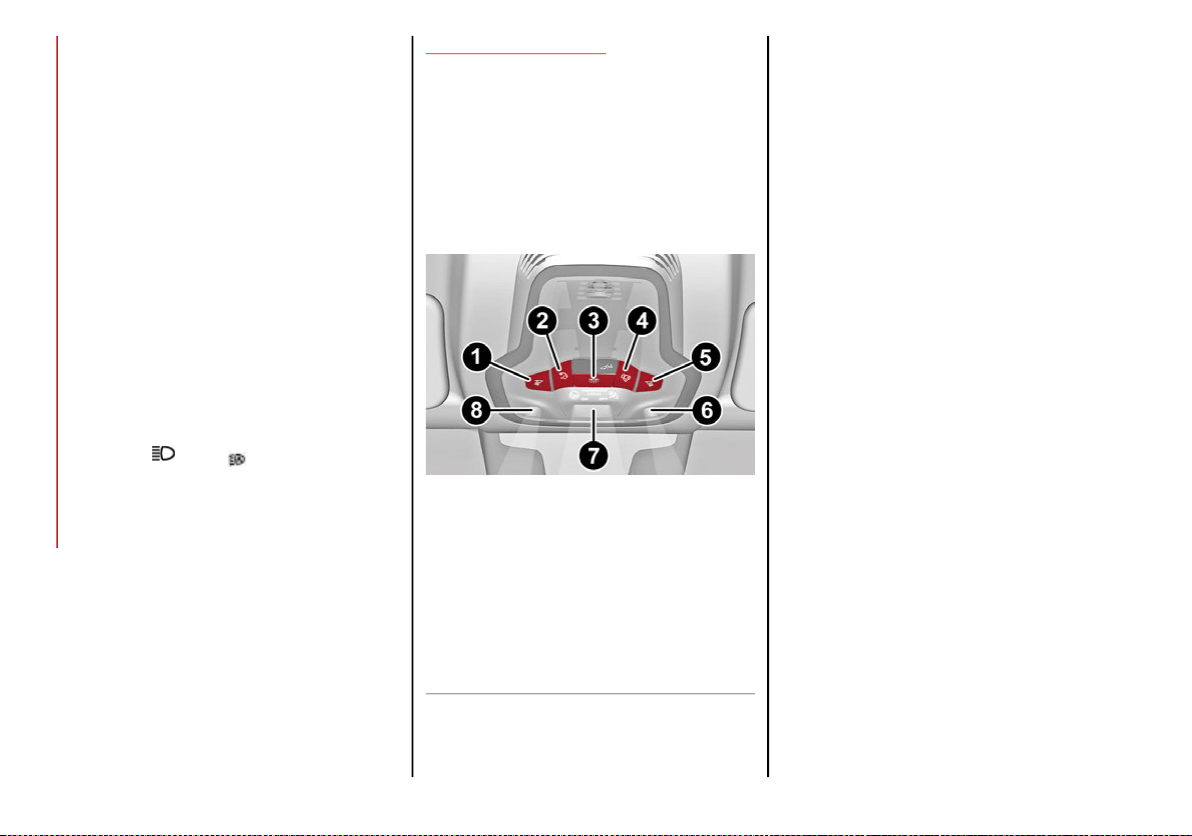
GETTING TO KNOW YOUR VEHICLE
40
The turn signals turn off automatically when
the vehicle is brought back onto a straight
course.
Lane Change Function
Tap the lever up or down once, without moving
beyond the detent, and the turn signal (right or
left) will flash five times. Then, the turn signal
(right or left) will automatically turn off.
To turn off the flashing before the end of the
cycle, move the lever in the opposite direction
until the first click (about half way).
Static Bending Light Function (SBL) — If
Equipped
The SBL function utilizes Light Emitting Diodes
(LEDs) in order to better illuminate the street
and increase the light angle while turning. This
function is enabled by rotating the light switch
to position (on) or (auto). The SBL LEDs
activate when the speed is below 25 mph
(40 km/h) and the steering radius is below
0.3 miles (500 m).
This function can be activated/deactivated on
the radio system by selecting the following
functions in sequence on the main menu:
1. “Settings.”
2. “Lights.”
3. “Cornering Lights.”
INTERIOR LIGHTS
Front Map Reading Lights
The front map/reading and overhead lights are
mounted in the overhead console. Each light can
be turned on by pushing the corresponding
switch on the console. These switches are backlit
for night time visibility. To turn the lights off, push
the switch a second time.
Overhead Console
NOTE:
Before getting out of the vehicle, ensure that
the overhead lights are off. This will prevent
the battery level from being drained once the
doors are closed. If a light is left on acciden-
tally, the overhead lights turn off automatically
approximately 15 minutes after the engine
has been turned off.
Overhead Light Timing
To assist getting in and out of the vehicle at
night or in poorly-lit areas, two timed modes
are available to keep the interior lighting on
after the engine is turned off.
Timing While Getting Into The Vehicle
The overhead lights will illuminate as follows:
For a few seconds when the doors are
unlocked.
For approximately three minutes when one
of the doors is opened.
For a few seconds when the doors are
locked.
Timing is interrupted when the ignition is
placed in the ON/RUN position.
1 — Driver’s Reading/Map Light Switch
2 — Rear Overhead Lights Switch
3 — Overhead Lights Switch
4 — Front Map Reading Lights Switch
5 — Passenger’s Reading/Map Light Switch
6 — Passenger’s Reading/Map Light
7 — Center Reading/Map Light
8 — Driver’s Reading/Map Light
20_GA_OM_EN_USC_t.book Page 40
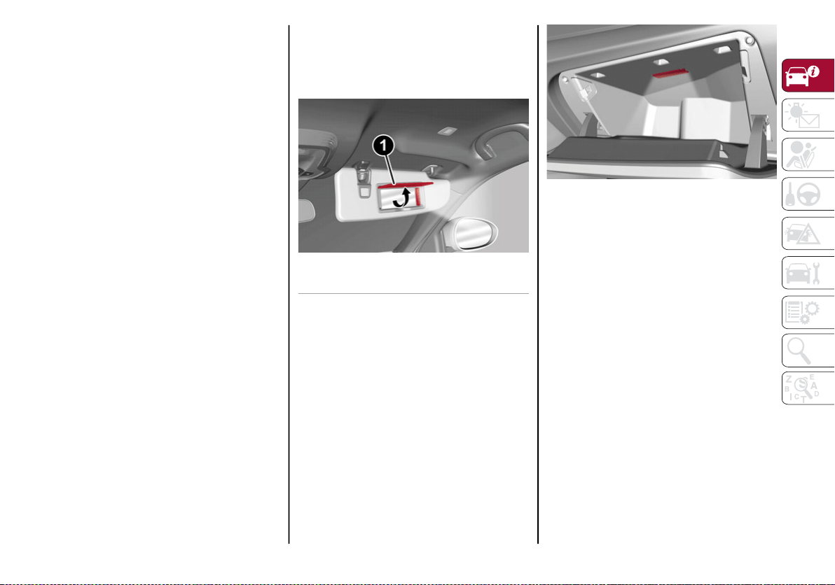
41
Exiting Overhead Light Timing
The overhead lights will turn off as follows:
After all doors are closed upon entering the
vehicle, the three minute timer will stop and
a second timer will start for the overhead
lights. This timing will end when the ignition
is placed in the ON/RUN position.
When the doors are locked (either with key
fob or with key inserted on driver’s side
door).
After 15 minutes to preserve the battery.
Timing While Getting Out Of The Vehicle
After placing the ignition in the OFF position,
the overhead lights will turn on as follows:
For a few seconds after the engine stops.
For approximately three minutes when one
of the doors is opened.
For a few seconds when the last door is
closed.
The timing ends automatically when the doors
are locked.
Vanity Mirror Lights
On the driver and passenger sun visor, there is
a light which illuminates the sun visor mirror
when folded down.
Sun Visor Mirror
The courtesy light turns on automatically by
lifting the cover.
Glove Compartment Light
This light turns on automatically when the
glove compartment is opened and turns off
when it is closed.
The light turns on and off regardless of the
ignition status.
Glove Compartment Light
Interior Ambient Lighting
The brightness of the interior lighting can be
adjusted via the radio system.
To access the adjustment function, on the
main menu select the following items in
sequence:
1. "Settings."
2. "Lights."
3. "Interior Ambient Lighting."
The lights can be adjusted to seven different
levels of brightness.
1 — Sun Visor Mirror Cover
20_GA_OM_EN_USC_t.book Page 41
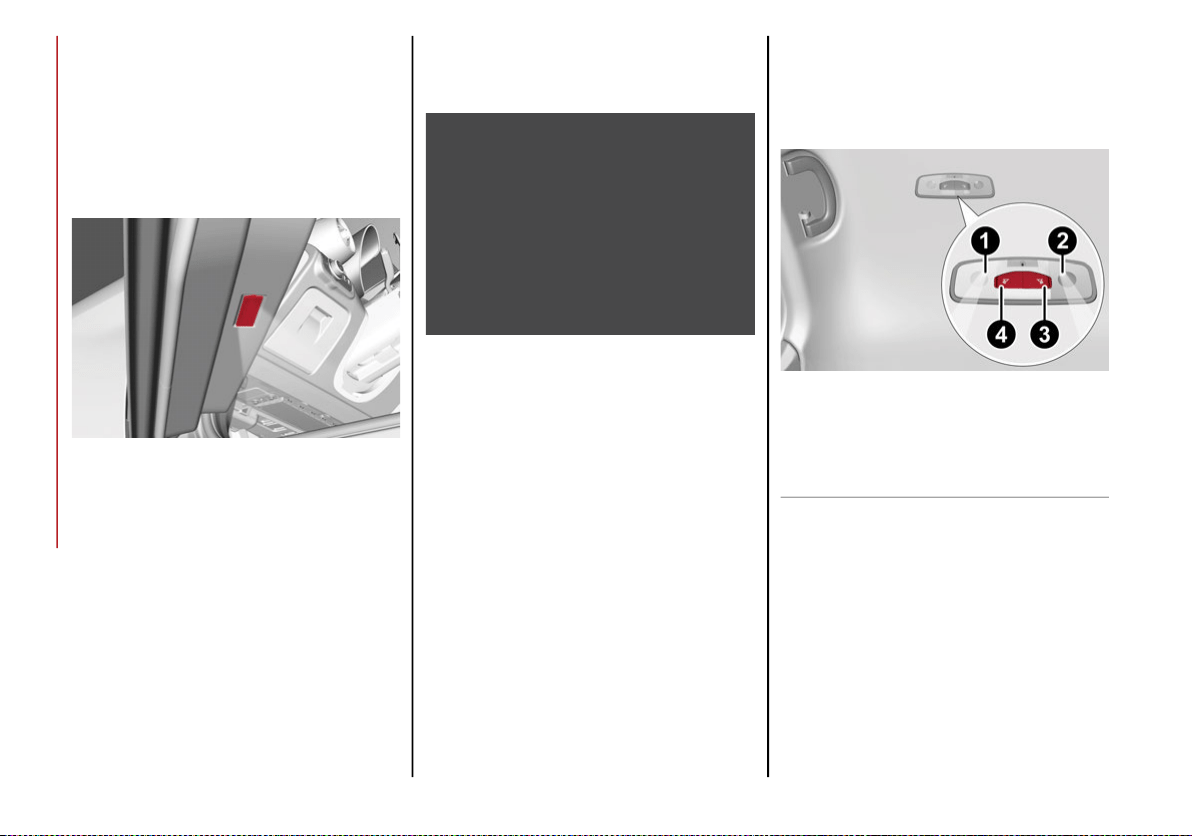
GETTING TO KNOW YOUR VEHICLE
42
Door Light
This vehicle is equipped with door courtesy
lamps that illuminate the entry way for the
driver or passenger when the door is opened,
and turns off when it is closed.
The light turns on and off regardless of the
ignition status.
Door Light
As part of the "Passive Entry" system, another
light can be found under each exterior door
handle.
Exterior Door Handle Light
Rear Overhead Light
The rear overhead lights are activated or deac-
tivated by two on/off switches located within
the lights on the ceiling above the rear seats.
Rear Overhead Light
The light turns on when a door is opened.
NOTE:
The light will turn off automatically after a few
minutes if a door is left open. To turn it on
again, open another door or close and reopen
the same door.
1 — Passenger Rear Overhead Light
2 — Driver Rear Overhead Light
3 — Driver Rear Overhead Light Switch
4 — Passenger Rear Overhead Light Switch
20_GA_OM_EN_USC_t.book Page 42
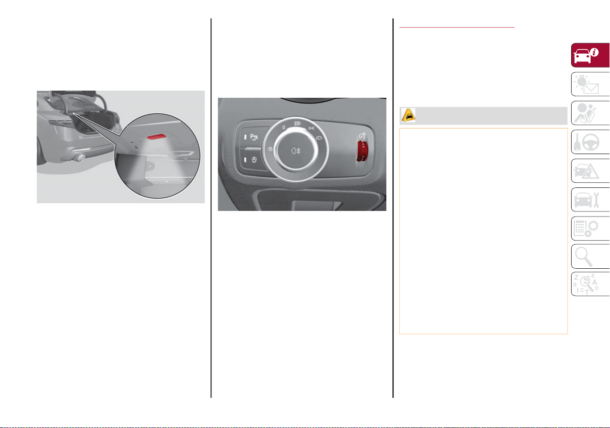
43
Courtesy Trunk Lights
The trunk features two courtesy lights.
These courtesy lights turn on automatically
when the trunk is opened and turn off when it
is closed.
Courtesy Trunk Lights
The courtesy lights will turn on and off regard-
less of the ignition status.
NOTE:
If the trunk is left open, the lights will automat-
ically turn off after 15 minutes to preserve
battery life.
Instrument Panel Dimmer Control
With the daytime running lights or headlights
on, rotate the dimmer control upward to
increase the instrument panel brightness and
the control button icons. Rotate the dimmer
control downward to decrease brightness.
Dimmer Control
WINDSHIELD WIPERS
Windshield Wiper Stalk
The windshield wiper stalk is located on the
right side of the steering wheel.
The windshield wipers will only operate with
the ignition in the ACC or ON/RUN position.
CAUTION!
Turn the windshield wipers off when
driving through an automatic car wash.
Damage to the windshield wipers may
result if the wiper control is left in any posi-
tion other than off.
In cold weather, always turn off the wiper
switch and allow the wipers to return to
the “Park” position before turning off the
engine. If the wiper switch is left on and
the wipers freeze to the windshield,
damage to the wiper motor may occur
when the vehicle is restarted.
Always remove any buildup of snow that
prevents the windshield wiper blades from
returning to the off position. If the wind-
shield wiper control is turned off and the
blades cannot return to the off position,
damage to the wiper motor may occur.
20_GA_OM_EN_USC_t.book Page 43
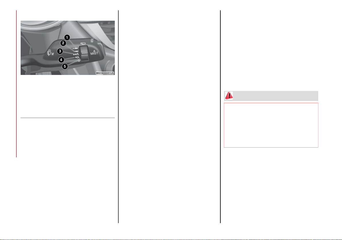
GETTING TO KNOW YOUR VEHICLE
44
Windshield Wiper/Washers
Windshield Wiper Switch
Windshield Wiper Operation
Rotating the switch to the Low Continuous
Wiper Speed position (2) activates the first
(low) level continuous speed of the windshield
wipers in manual mode.
Rotating the switch to the High Continuous
Wiper Speed position (1) activates the second
(high) level continuous speed of the wind-
shield wipers in manual mode.
Rain Sensors
Rotating the switch to the Low Sensitivity Rain
Sensing position (4), activates the first, less
sensitive level of the Rain Sensing function.
Rotating the switch to the High Sensitivity Rain
Sensing position (3), activates the second, more
sensitive level of the Rain Sensing function.
Refer to “Rain Sensor” in this section for more
information on how this system functions.
Windshield Washer Operation
Pull the stalk toward the steering wheel to
operate the windshield washer.
Keep the stalk pulled to activate both the
windshield washer jet and the windshield
wiper with a single movement. The wipers and
washers will continue to operate until you let
go of the stalk.
The windshield wiper stops working three
strokes after the stalk is released, followed by
a final stroke six seconds later to complete the
cycle.
Mist
Use this feature when weather conditions
make occasional usage of the wipers neces-
sary. Push the stalk upward to the MIST posi-
tion and release for a single wiping cycle. This
function is useful to remove small deposits of
dust from the windshield or morning dew.
NOTE:
This function does not activate the windshield
washer. To spray windshield washer fluid onto
the windshield, the washing function must be
used.
1 — High Continuous Wiper Speed
2 — Low Continuous Wiper Speed
3 — High Sensitivity Rain Sensing
4 — Low Sensitivity Rain Sensing
5 — Windshield Wiper Off
WARNING!
Sudden loss of visibility through the
windshield could lead to a collision. You
might not see other vehicles or other
obstacles. To avoid sudden icing of the
windshield during freezing weather, warm
the windshield with the defroster before
and during windshield washer use.
20_GA_OM_EN_USC_t.book Page 44
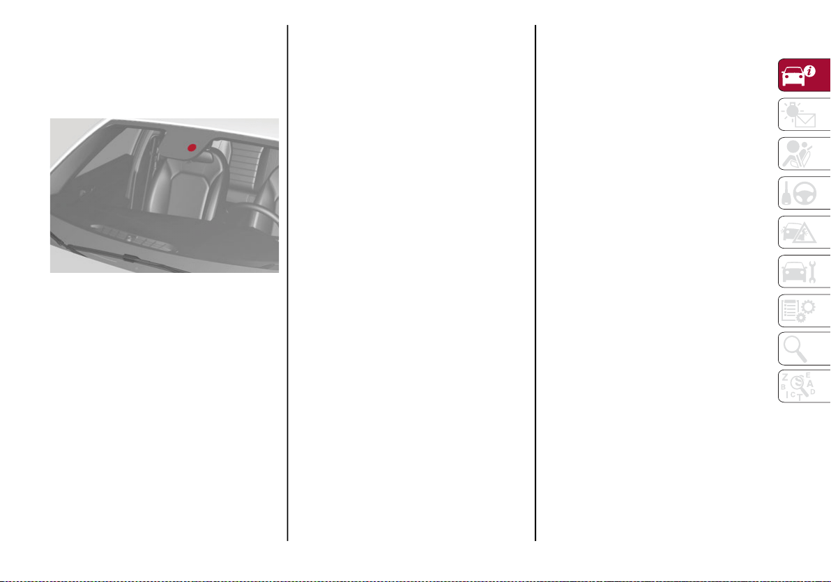
45
Rain Sensor
The Rain Sensor is located behind the interior
rear view mirror. This feature senses moisture
on the windshield and automatically activates
the wipers for the driver.
Rain Sensor
The feature is especially useful for road splash
or over spray from the windshield washers of
the vehicle ahead. Rotate the end of the multi-
function lever to one of four settings to acti-
vate this feature.
The sensor has an adjustment range that
varies progressively from wiper still (no stroke)
when the windshield is dry, to wiper at contin-
uous speed (fast operation) with intense rain.
Activation
Rotating the wiper switch to the Low Sensitivity
Rain Sensing position (4) or High Sensitivity
Rain Sensing position (3) activates the rain
sensor.
The activation of the rain sensor system is
done by tapping the wiper stalk upwards while
the switch is in the Low Sensitivity Rain
Sensing position (4) or High Sensitivity Rain
Sensing position (3).
The variation in sensitivity during rain sensor
operation is also signaled by a stroke of the
wiper (command acquired and implemented).
This stroke is also executed with the wind-
shield dry.
If the windshield washer is used with the rain
sensor activated, the normal washing cycle is
performed, after which the rain sensor
resumes its normal automatic operation.
NOTE:
Keep the glass in the sensor area clean.
With the windshield wiper lever in the Low
Sensitivity Rain Sensing position (4) or High
Sensitivity Rain Sensing position (3), wiping
operates automatically and is disabled
when the outside temperature is below
32°F (0°C).
Deactivation
Use the wiper switch or place the ignition in
the OFF position.
In the event of malfunction of the rain sensor
while it is active, the windshield wiper oper-
ates intermittently at a speed consistent with
the sensitivity setting of the rain sensor,
whether or not there is rain on the glass for as
long as the sensor failure is indicated on the
display.
The sensor continues to operate and it is
possible to set the windshield wiper to contin-
uous mode (1 or 2). The failure indication
remains on for as long as the sensor is active.
The rain sensor is able to recognize and auto-
matically adjust itself in the presence of the
following conditions:
Presence of dirt on the controlled surface
(salt, dirt, etc.).
Presence of streaks of water caused by the
worn window wiper blades.
Difference between day and night.
20_GA_OM_EN_USC_t.book Page 45
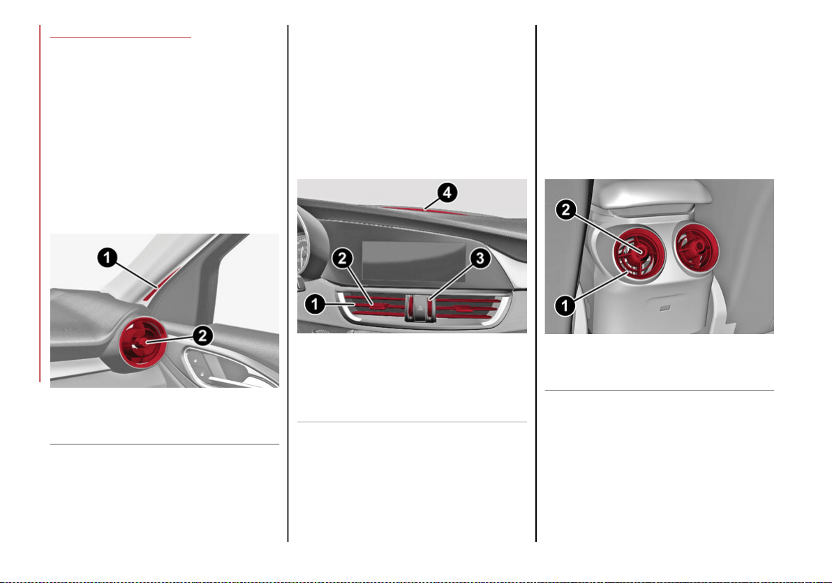
GETTING TO KNOW YOUR VEHICLE
46
CLIMATE CONTROL
Passenger Compartment Air Vents
Side Air Vents
To adjust the position of the Side Air Vents,
move the Side Air Vent Adjuster (2) in any
direction.
Rotate the Side Air Vent Adjuster (2) to
adjust the air flow. Rotating the Side Air
Vent Adjuster (2) clockwise will close the
vent. Rotating it counterclockwise will open
the vent.
Side Air Vents
Central Air Vents
To adjust the position of the Central Air
Vents, move the Central Air Vent Adjuster
(2) up or down.
Rotate the Central Air Vent Air Flow Adjuster
(3) to adjust the air flow. Rotating Central Air
Vent Air Flow Adjuster (3) up will open the
vents, allowing for maximum airflow.
Rotating it down will close the vents.
Central Air Vents
Rear Air Vents
To adjust the position of the Rear Air Vents,
move the Rear Air Vent Adjuster (2) in any
direction.
Rotate the Rear Air Vent Adjuster (2) to
adjust the air flow. Rotating the Rear Air
Vent Adjuster (2) clockwise will close the
vent. Rotating it counterclockwise will open
the vent.
Rear Air Vents
1 — Demister Air Vents
2 — Side Air Vent Adjuster
1 — Adjustable Central Air Vents
2 — Central Air Vent Adjuster
3 — Central Air Vent Air Flow Adjuster
4 — Windshield Front Defroster Vent
1 — Adjustable Rear Air Vents
2 — Rear Air Vent Adjuster
20_GA_OM_EN_USC_t.book Page 46
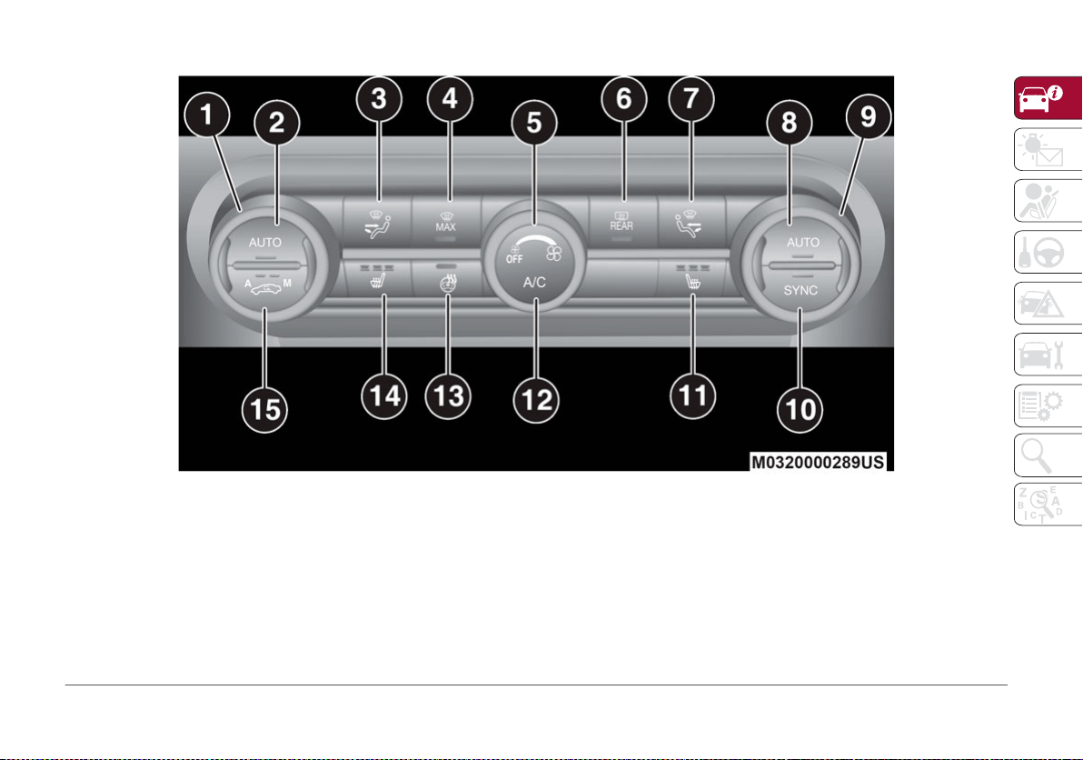
47
Automatic Dual-Zone Climate Control System
Automatic Climate Control System (Instrument Panel Controls)
1 — Driver Temperature Adjustment Knob 9 — Passenger Temperature Adjustment Knob
2 — Driver Side AUTO Button (Automatic Operation) 10 — SYNC Button (Set Temperature Alignment) Driver/Passenger Side
3 — Driver Side Air Distribution Selection Button 11 — Passenger Heated Seat Button — If Equipped
4 — Max Defrost Button 12 — Air Conditioning Button
5 — Blower Speed Adjustment Knob 13 — Steering Wheel Heater Button — If Equipped
6 — Rear Defrost Button 14 — Driver Side Heated Seat Button — If Equipped
7 — Passenger Side Air Distribution Selection Button 15 — Air Recirculation Button
8 — Passenger Side AUTO Button (Automatic Operation)
20_GA_OM_EN_USC_t.book Page 47
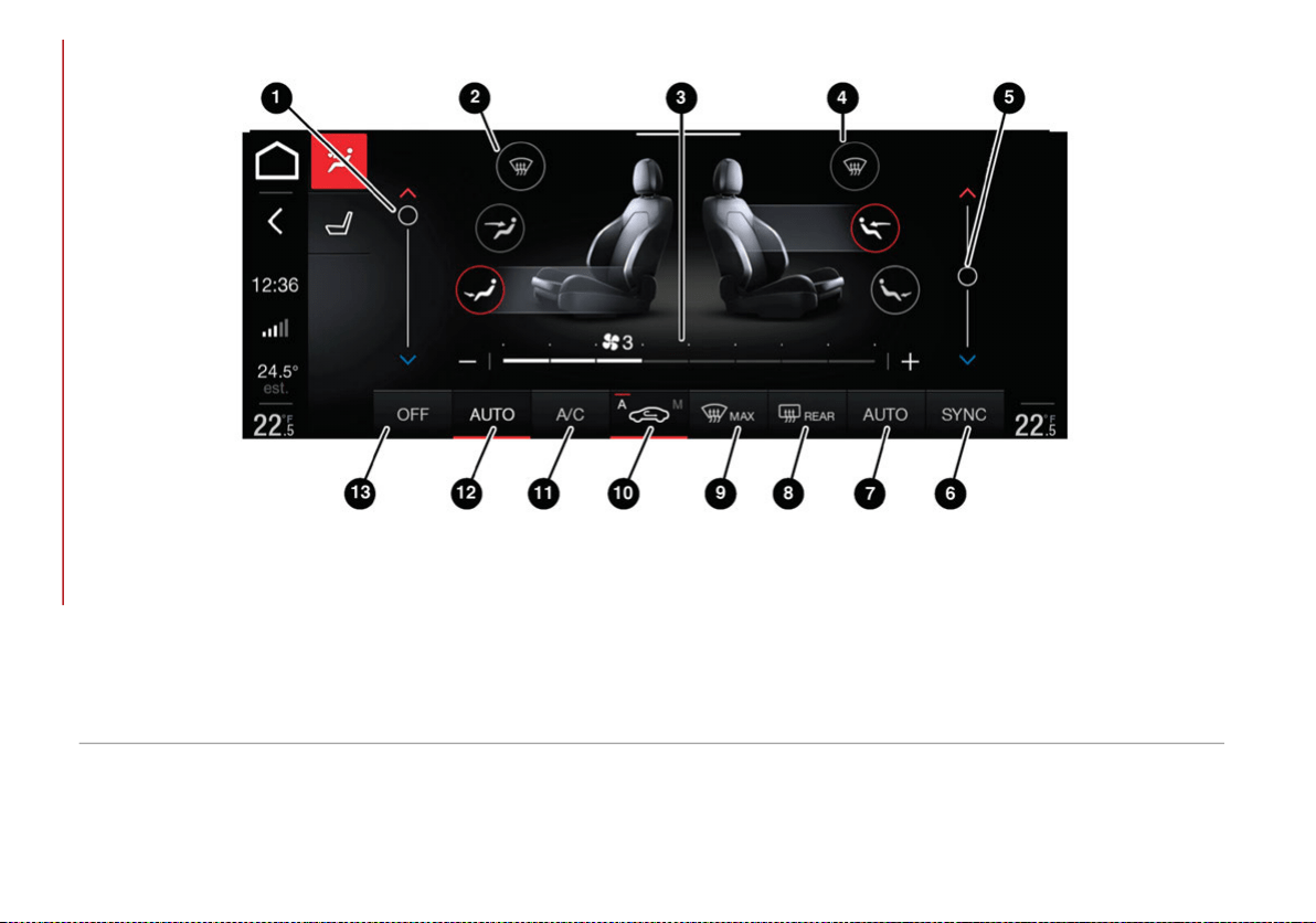
GETTING TO KNOW YOUR VEHICLE
48
Touchscreen Controls
Automatic Climate Control System (Touchscreen Controls)
1 — Driver Side Temperature Adjustment Bar 8 — Heated Rear Window On/Off Button
2 — Driver Side Air Distribution Buttons
9 — MAX-DEF Activation/Deactivation Button (Rapid Defrosting/Demisting)
3 — Fan Speed Adjustment Button 10 — Air Recirculation On/Off Button
4 — Passenger Side Air Distribution Buttons 11 — Climate Control System Compressor On/Off Button
5 — Passenger Side Temperature Adjustment Bar 12 — Driver Side AUTO Button (Automatic Operation)
6 — SYNC Button 13 — Climate Control System On/Off Button
7 — Passenger Side AUTO Button (Automatic Operation)
20_GA_OM_EN_USC_t.book Page 48
49
Description
The Automatic Dual Zone Climate Control
System adjusts the temperature and air distri-
bution independently between the driver and
passenger.
The system maintains the set temperature
inside the passenger compartment and
compensates for outside temperature change.
NOTE:
The reference temperature is 72°F (22°C) for
optimal comfort management.
The automatic setting will adjust the following
to maintain comfort within the passenger
compartment:
Air temperature from the driver/front
passenger side vents
Air distribution from the driver/front
passenger side vents
Fan speed (continuous variation of the air
flow)
Compressor variations (for cooling/dehu-
midifying the air)
Air recirculation
The Climate Control System can also be oper-
ated manually by using the buttons and knobs
on the faceplate.
Manual selections will override the automatic
settings, which are stored until the AUTO
button is pushed. If the system intervenes for
safety reasons, the automatic setting will take
control of the system.
The below operations will not deactivate the
automatic (AUTO) function:
Air Recirculation activation/deactivation
A/C activation/deactivation
SYNC function activation
Rear Window Defrost activation/deactiva-
tion
When in AUTO mode, the vehicle’s internal
temperature is controlled according to the set
temperature.
The following can be manually set or adjusted:
Driver/passenger air temperature
Blower speed (continuous variation)
Air distribution (seven positions for driver
and passenger)
A/C activation
Front Defroster
Air recirculation
Rear Defroster
System deactivation
Operating Mode
The Climate Control system can be activated
in different ways. It is recommended to use the
automatic function. Push the AUTO button and
set the desired temperatures.
The automatic system adjusts the tempera-
ture, quantity, and distribution of air intro-
duced into the passenger compartment. It
also controls air recirculation and the activa-
tion of the air conditioner.
At any time during automatic operation, you
can change the temperature, activate or deac-
tivate the Rear Defroster, activate SYNC, acti-
vate or deactivate the air conditioner, and
activate or deactivate air recirculation. The
system will automatically adjust to the new
settings.
CAUTION!
The system uses R1234yf refrigerant, which
does not pollute the environment in the event of
accidental leakage. Under no circumstances,
use R134a and R12 fluids, which are
incompatible with the components of this
system.
20_GA_OM_EN_USC_t.book Page 49
GETTING TO KNOW YOUR VEHICLE
50
Climate Control Display Settings
The Climate Control settings are visible on the
radio screen.
The display on the radio system is a pop up
window, which is activated by pushing the
buttons or turning the knobs on the Climate
Control system. The indicator lights located on
the number of buttons and knobs indicate that
the selected feature is on/off. If no operation
is performed for a predetermined time, the
pop-up will close on the display.
Air Temperature Adjustment
Rotate the driver or passenger Temperature
Adjustment Knob clockwise for warmer tempera-
tures or counterclockwise for cooler tempera-
tures. The set temperatures are shown on the
radio system.
Push the SYNC button to sync the driver and
passenger air temperatures.
Rotate the passenger Temperature Adjust-
ment Knob to cancel the SYNC function. This
will set a new passenger side temperature.
Rotate the Temperature Adjustment Knob fully
clockwise to engage the HI (maximum heating)
setting or fully counterclockwise to engage the
LO (maximum cooling) setting. To deactivate
these functions, rotate the Temperature
Adjustment Knob to the desired temperature.
Rear passengers’ temperature is linked to
driver side selection.
Air Distribution Selection
Push the Air Distribution Selection button on
the faceplate to change the mode of air distri-
bution.
Air flow to the windshield and front side
window vents to demist/defrost them.
Air flow at the central and side dash-
board vents to ventilate the chest and
face.
Air flow to the front and rear floor
vents. This setting heats the
passenger compartment the quickest.
Air flow distributed between floor
vents (hotter air) and the central and
side dashboard vents (cooler air).
This air distribution setting is useful
on sunny days during spring and autumn.
Air flow distributed between floor
vents, windshield, and front side
window defrosting/demisting vents.
This distribution setting allows the
passenger compartment to warm up without
fogging up the windows.
Air flow distribution between wind-
shield demisting/defrosting vents
and side/central dashboard vents.
This setting allows air to flow to the
windshield on sunny days.
Air flow distribution to all vents.
In AUTO mode, the Climate Controls automati-
cally manage the air distribution. When set
manually, the respective symbols on the radio
system indicate the air distribution setting.
Fan Speed Adjustment
Turn the Blower Speed Knob to increase or
decrease the blower speed. The speed is
displayed with lighted indicators in the radio
system display.
Maximum fan speed = all indicators illumi-
nated on the radio system display
Minimum fan speed = one indicator illumi-
nated on the radio system display
The fan can be turned off by rotating the
Blower Speed Knob counterclockwise to the
off position (all segments on the radio system
display are turned off).
NOTE:
To restore automatic control of the fan speed,
push the AUTO button.
20_GA_OM_EN_USC_t.book Page 50

51
AUTO Button
When the AUTO button is pushed (indicator
illuminated), the Climate Control system auto-
matically adjusts the following settings:
Quantity and distribution of air flow in the
passenger compartment
The air conditioner
Air recirculation
Cancels any manual settings
Selecting the AUTO function illuminates the
indicator on the A/C button or .
If air distribution or the fan speed is manually
adjusted, the AUTO button indicator turns off
to indicate that the Climate Control system is
no longer in AUTO mode.
After a manual adjustment, push the AUTO
button to resume the automatic system.
SYNC Button
Push the SYNC button (indicator illuminated)
to sync the passenger side air temperature
with the driver side air temperature.
This function makes temperature regulation
easier when the driver is traveling alone.
Turn the passenger Temperature Adjustment
Knob or push the passenger side Air Distribu-
tion Selection Button to change the passenger
side air temperature and return to separate air
temperature management.
Air Recirculation And Air Quality
System (AQS)
Air Recirculation is managed according to the
following operating mode:
Automatic engagement: indicator is illumi-
nated above the “A” on the Air Recirculation
Button
Forced activation (air circulation always
activated): indicator illuminated above the
icon on the Air Recirculation Button
Forced deactivation (air recirculation
always off with intake of outside air): both
indicators not illuminated on the Air Recir-
culation Button
The three operating conditions are obtained by
pushing the Air Recirculation Button in
sequence.
Enabling The Air Quality System (AQS) Func-
tion — If Equipped
When the automatic recirculation function is
selected, the AQS function automatically acti-
vates internal air recirculation when the
outside air is polluted (e.g. in heavy traffic and
tunnels).
At low external temperatures or in high
humidity, the automatic function turns off to
avoid fogging up the windows. The user can
select the function again by pushing the Air
Recirculation Button.
In automatic operation, air recirculation will be
controlled by the system according to outside
environmental conditions.
NOTE:
With the AQS function active and after the
internal air recirculation system has been
functioning for a set amount of time, the
Climate Control System enables air intake
to cycle the air in the passenger compart-
ment for a set time. The AQS function is
disabled during the air changes.
The engagement of the recirculation system
makes it possible to reach the required
heating or cooling conditions faster. It is,
however, inadvisable to use it on rainy/cold
days as it can increase the possibility of the
windows fogging. When the outside
temperature is low, recirculation is forced
off to prevent the windows from fogging up.
A/C Compressor
Push the A/C button to activate or deactivate
the A/C compressor (indicator illuminated
when activated). The A/C compressor will
remain off even after the engine has stopped.
When the A/C compressor is turned off, the
system deactivates air recirculation to prevent
the windows from fogging up. If the climate
control system can maintain the temperature,
with the A/C turned off, the AUTO feature will
remain on and the AUTO button indicator light
will not switch off.
20_GA_OM_EN_USC_t.book Page 51

GETTING TO KNOW YOUR VEHICLE
52
To restore automatic control of the A/C
compressor, push the A/C button or the AUTO
button. With the A/C compressor off, the air
speed can be set manually using the Air Speed
Adjustment Knob.
When the A/C compressor is on, and the
engine is running, air speed cannot be lower
than the minimum speed (only one indicator
light is lit).
NOTE:
When the A/C is off the Climate Control system
can not produce air that is colder than the
current outside temperature. Under certain
environmental conditions, windows could fog
up rapidly, since the air is not dehumidified.
Front Defroster And MAX-DEF Function
Push the MAX-DEF button (indicator illumi-
nated) to defrost the windshield and side
windows.
While in MAX-DEF function, the air conditioner
will:
Activate the air conditioner compressor
when the weather allows
Turn air recirculation off
Set the maximum air temperature (HI) on
both the driver and passenger side
Activate a blower speed based on the
temperature of the engine coolant
Adjust the air flow towards the windshield
and front side windows
Activate the Rear Window Defroster
Display the fan speed (indicators illumi-
nated) and current air distribution setting
NOTE:
The MAX-DEF function remains active for
approximately three minutes once the engine
coolant reaches the proper temperature.
When the function is on, AUTO mode will deac-
tivate. The only manual operations possible
are adjusting blower speed and turning off the
Rear Window Defroster.
Pushing the button switches off the
MAX-DEF function.
Rear Defroster
Push the Rear Defroster button to activate
(indicators illuminated) the Rear Defroster.
The Rear Defroster will turn off after
20 minutes or once the engine is turned off. To
reactive the Rear Defroster, push the Rear
Defroster button.
NOTE:
To avoid damage, do not apply stickers over
the interior heating filaments of the Rear
Defroster.
Humidity Sensor
The Humidity Sensor helps to prevent the
windows from fogging up. The AUTO function
(indicator illuminated) must be on for the
Humidity Sensor to function.
When outside temperature is low, the system
may turn the compressor on and turn air recir-
culation off for safer driving.
Switching Off/On The Climate Control
System
Switching Off The Climate Control System
Rotate the Air Speed Adjustment Knob
completely counterclockwise to turn off the
Climate Control System.
With the air conditioner off:
Air recirculation is on
The A/C compressor is off
The fan is off
The heated rear window can be activated/
deactivated
NOTE:
The climate control system stores the previ-
ously set temperatures and resumes opera-
tion when any button on the system is pushed.
Switching On The Climate Control System
To switch the climate control system on in
automatic mode, push the AUTO button.
20_GA_OM_EN_USC_t.book Page 52
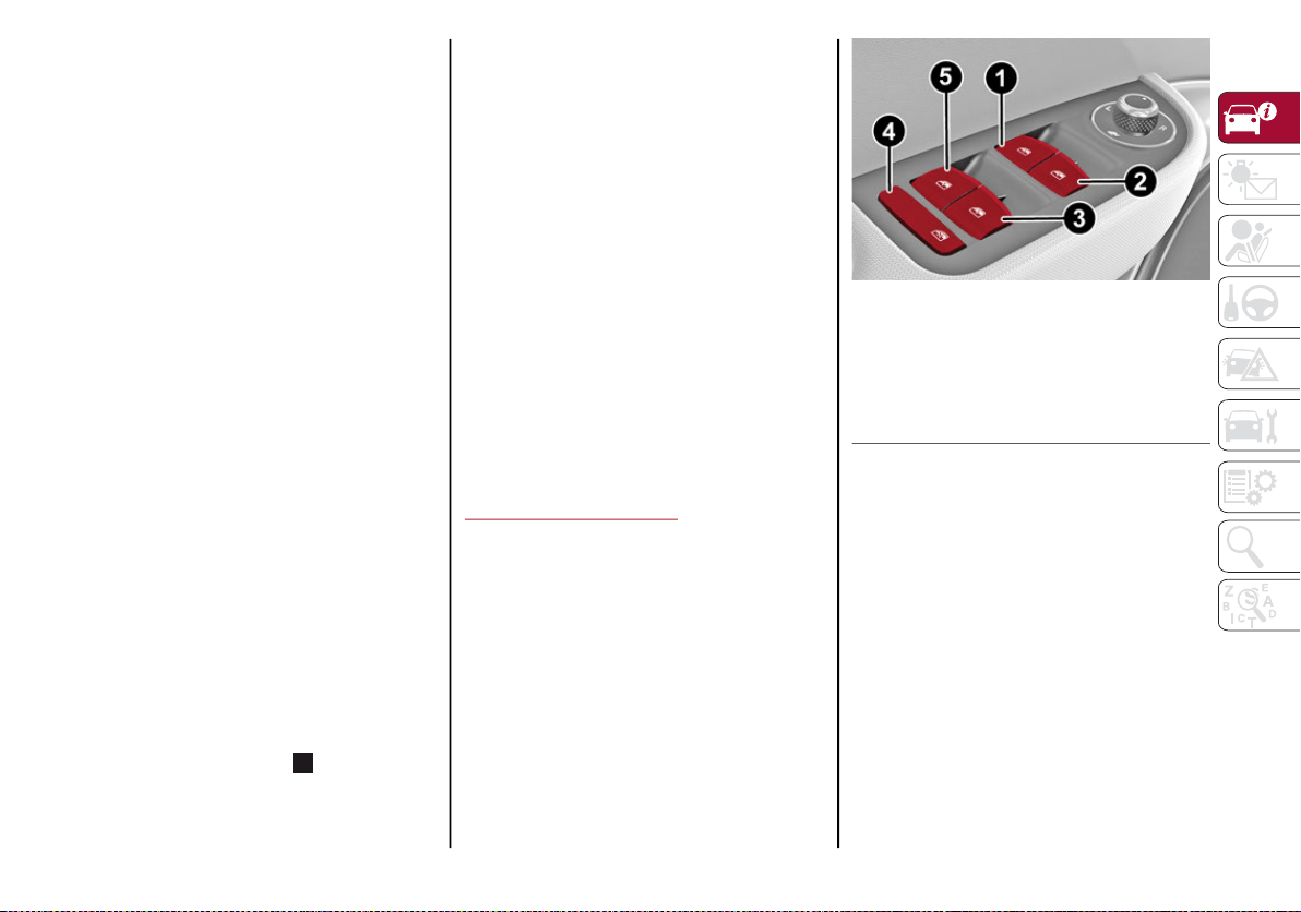
53
Stop/Start
The Stop/Start system shuts off the engine
when the vehicle speed is 0 mph (0 km/h), as
a fuel conservation measure.
In order to maintain comfort in the cabin, the
Stop/Start feature will not activate if any of the
following conditions exist:
The climate control system is in AUTO mode
(indicator illuminated), and the vehicle has
yet to reach the set temperature
The climate control system is in LO
maximum cooling
The climate control system is in HI
maximum heating
The climate control system is in the
MAX-DEF status
When the Stop/Start system is active, the
engine will restart if the inside temperature
changes significantly, or if the LO setting, or
MAX-DEF setting, is activated.
With Stop/Start system on (engine is OFF), air
flow is reduced to keep the compartment
comfort conditions for longer.
Until the temperature drastically changes
within the cabin, the climate control system
will continue to maintain the temperature
while the engine is off. By deactivating the
Stop/Start system with the button (located
by the headlight switch), the climate control
system operates normally according to the
settings.
NOTE:
In harsh climate conditions, limit the use of
the Stop/Start system to prevent the
compressor from continuously switching on
and off. This will prevent rapid misting of the
windows and the accumulation of humidity
in the passenger compartment.
When the Stop/Start system is on, the
climate control system will always take air in
from outside, reducing the probability of the
windows fogging up.
System Maintenance
In winter, the Climate Control System must be
turned on at least once a month for approxi-
mately ten minutes.
Have the system inspected at an authorized
dealer before the summer.
POWER WINDOWS
Power Window Switches
The power window switches work with the igni-
tion in the ACC or ON/RUN position and for
three minutes after the ignition has been
placed in the OFF position. When one of the
front doors is opened, this operation is
disabled.
Driver Side Front Door Controls
The switches are located on the door panel
trim. All windows can be controlled from the
driver side door panel.
Power Window Switches
Window Opening
Push the buttons to open the desired window.
Each button has two position steps. Push
gently, without going past the detent for
manual window operation, while pushing the
same button harder, past the detent, activates
“continuous automatic” operation.
If the button is pushed again, the window will
stop in the desired position.
Window Closing
Pull the window switch up to move the window
upward. Hold the switch for at least half of a
second and the window will go up automatically.
1 — Front Left Window Switch
2 — Front Right Window Switch
3 — Rear Right Window Switch
4 — Window Lockout Switch
5 — Rear Left Window Switch
20_GA_OM_EN_USC_t.book Page 53

GETTING TO KNOW YOUR VEHICLE
54
To stop the window during Auto-Up operation,
push or pull the window switch again.
Passenger Side Front Door/Rear Door Controls
There are single window controls on the
passenger and rear door trim panels which
operate the door windows.
Auto-Up Feature With Anti-Pinch Protection
The vehicle is equipped with an anti-pinch
safety device for closing the windows.
If the safety system senses any obstacle while
the window is closing, it will stop the window’s
movement and reverse it, depending on its
position.
This device is also useful if the windows are
activated accidentally by children inside the
vehicle.
The anti-pinch safety function is activated both
during the manual and the automatic opera-
tion of the window.
When the anti-pinch system is activated, the
window closing is immediately interrupted.
Then the window closing is automatically
reversed and the window lowers by about
8 inches (20 cm) in relation to the first stop
position. The window cannot be operated
during this time.
NOTE:
In the event of an error, or if the anti-pinch
protection is activated three consecutive
times, the automatic closing operation of the
window will be deactivated. In order to restore
the correct operation of the system, the
window must be lowered.
Power Window System Initialization
If power supply is interrupted, the electric
window automatic operation must be reinitial-
ized.
To perform the initialization procedure, which
must be done on each door with the doors
closed, manually fully close the window to be
initialized.
POWER SUNROOF — IF
EQUIPPED
Power Sunroof
The power sunroof consists of two glass
panels (the front one is power and the rear one
fixed) and is fitted with a power sunshade in
the front, as well as a manually operated
sunshade in the rear.
Operation of the sunroof is only possible with
the ignition placed in the ACC or ON/RUN posi-
tion. Refer to “Ignition System” in this chapter
for further information.
The sunroof has three preset positions:
Fully closed
Comfort (intermediate opening)
Fully open
NOTE:
You cannot have the sunshade closed when
the sunroof is open.
WARNING!
Never leave children unattended in a
vehicle, or with access to an unlocked
vehicle. Never leave the key fob in or near
the vehicle, or in a location accessible to
children. Do not leave the ignition of a
vehicle equipped with keyless ignition in the
ON/RUN mode. Occupants, particularly
unattended children, can become
entrapped by the power sunroof while oper-
ating the power sunroof switch. Such entrap-
ment may result in serious injury or death.
In a collision, there is a greater risk of
being thrown from a vehicle with an open
sunroof. You could also be seriously
injured or killed. Always fasten your seat
belt properly and make sure all passen-
gers are also properly secured.
Do not allow small children to operate the
sunroof. Never allow your fingers, other body
parts, or any object, to project through the
sunroof opening. Injury may result.
20_GA_OM_EN_USC_t.book Page 54
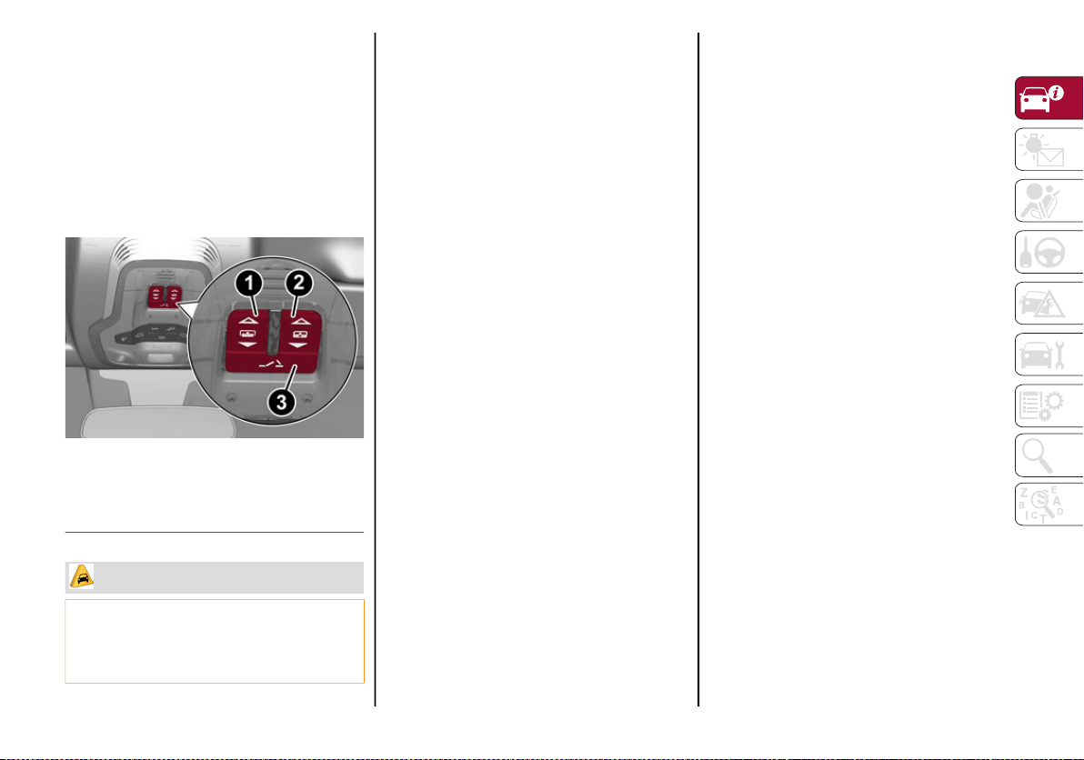
55
Opening
To open the sunroof’s front panel, push the
open/close button toward the rear of the
vehicle to open to the comfort position (half
way). Pushing the button a second time will
open to the fully open position.
The automatic motion can be interrupted in
any position by pushing the open/close button
again.
Sunroof And Power Shade Buttons
Closing
From the fully open position, push the open/
close button toward the front of the vehicle.
The roof will close completely.
The automatic motion can be interrupted in
any position by pushing the open/close button
again.
Vent Opening
To bring the roof into vent position, push and
release the vent button.
This type of vent opening can be activated
regardless of the position of the sunroof.
When starting with the roof in the closed posi-
tion, pushing the vent button automatically
causes the sunroof to open to the vent posi-
tion. If the roof is already open, the button
must be held until the roof reaches the
vent-opening position.
Pushing vent button again during automatic
movement of the roof will stop it.
Sun Shade Movement
The front sunshade is power operated.
Push the Power Shade open/close button
toward the rear of the vehicle to open the front
sun shade to the three quarter open position.
Pushing the button a second time will open the
sunshade completely.
Push the Power Shade open/close button
toward the front of the vehicle to close the sun
shade.
The automatic motion can be interrupted in
any position by pushing the Power Shade on/
off button again.
To open the rear sunshade, pull sunshade
manually toward the rear of the vehicle.
Pinch Protect Feature
The sunroof has an anti-pinch safety system
capable of detecting the presence of an
obstacle during the closing movement. If an
obstacle is detected, the system intervenes
and the movement of the sunroof is immedi-
ately reversed into opening.
1 — Power Shade Open/Close
2 — Open/Close Button
3 — Vent Open/Close
CAUTION!
Do not open the sun roof if a roof rack or
crossbars are fitted. Do not open the sun
roof if there is snow or ice on it: you may
damage it.
20_GA_OM_EN_USC_t.book Page 55
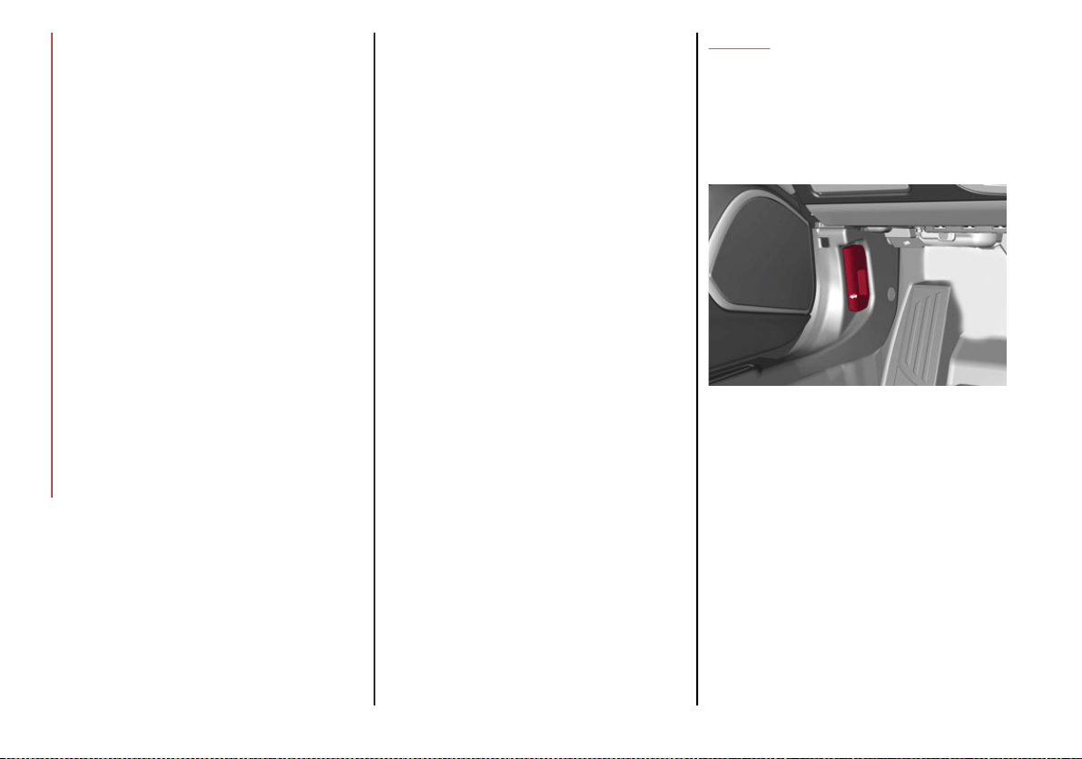
GETTING TO KNOW YOUR VEHICLE
56
Re-Initialization Procedure
Automatic operation of the sunroof must be
re-initialized in case of faulty sunroof opera-
tion. It may also be necessary to initialize the
sunroof after the vehicle’s battery has been
disconnected and then reconnected.
NOTE:
The anti-pinch safety device is deactivated
during the re-initialization procedure.
Proceed as follows:
1. With the ignition in the ON/RUN position,
make sure the sunroof glass is fully closed
(sunshade open).
2. Open the driver’s side door, and place the
ignition in the OFF position.
3. Within five seconds, place the ignition in
the ACC or ON/RUN position.
4. Within 10 seconds, push and hold the sunroof
close switch (forward). After 8 - 10 seconds of
holding the switch, the re-initialization process
will begin. Continue to hold the switch while the
sunroof motor cycles, and the sunshade will
fully close.
5. Once the sunroof glass and the power
sunshade have stopped motion, release
the sunroof close switch, then push and
hold it again within five seconds. Continue
to hold the switch while the sunshade fully
opens, the sunroof glass fully opens,
followed by the glass fully closing then the
sunshade fully closing.
6. Release the switch once the operations
stop. Re-initialization of the sunroof
motors is now complete.
NOTE:
If the switch is released prior to full completion
of the operations described, the entire
re-initialization procedure must be repeated
from step 1.
7. Confirm express operations for the
sunroof glass and sunshade is functional
for opening and closing operations.
HOOD
Opening
To open the hood, proceed as follows:
1. Pull the release lever located on the
driver’s side kick panel.
Hood Release Lever
2. Go to the outside of the vehicle and posi-
tion yourself in front of the grille.
3. Lift the hood slightly.
20_GA_OM_EN_USC_t.book Page 56
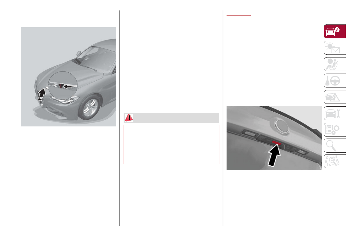
57
4. Move the under-hood latch from right to
left to release the hood.
Release Hood Latch To The Left
5. Raise the hood completely. The operation
is assisted by the addition of two gas props
which hold it in the open position.
NOTE:
Do not tamper with the props and assist the
hood while lifting it.
Use both hands to lift the hood. Before
lifting, check that the windshield wiper arms
are not raised from the windshield or in
operation, that the vehicle is stationary and
that the electric park brake is engaged.
Closing
To close, lower the hood to approximately
16 inches (40 cm) from the engine compart-
ment then let it drop. Make sure that the hood
is completely closed and fully latched. Do this
by trying to open it. If it is not perfectly closed,
do not try to push the hood lid down, but open
it and repeat the procedure.
NOTE:
Always check that the hood is closed correctly
to prevent it from opening while the vehicle is
traveling. Since the hood is equipped with a
double locking system, one for each side, you
must check that it is closed on both its side
ends.
TRUNK
The trunk unlocking is electrically operated
and is deactivated when the vehicle is in
motion.
Opening
Opening From The Outside
When unlocked, the trunk lid can be opened
from outside the vehicle using the exterior
trunk lid release button located between the
plate lights. Push the button until you hear a
“click.” The trunk lid can also be opened by
quickly pushing the exterior trunk lid release
button on the key fob twice.
Exterior Trunk Lid Release Button
The turn signal indicators will blink and the
interior lights will turn on when the trunk lid is
opened. They turn off automatically when the
trunk lid is closed.
The lights turn off automatically after a few
minutes if the trunk lid is left open.
WARNING!
Be sure the hood is fully latched before
driving your vehicle. If the hood is not fully
latched, it could open when the vehicle is in
motion and block your vision. Failure to
follow this warning could result in serious
injury or death.
20_GA_OM_EN_USC_t.book Page 57
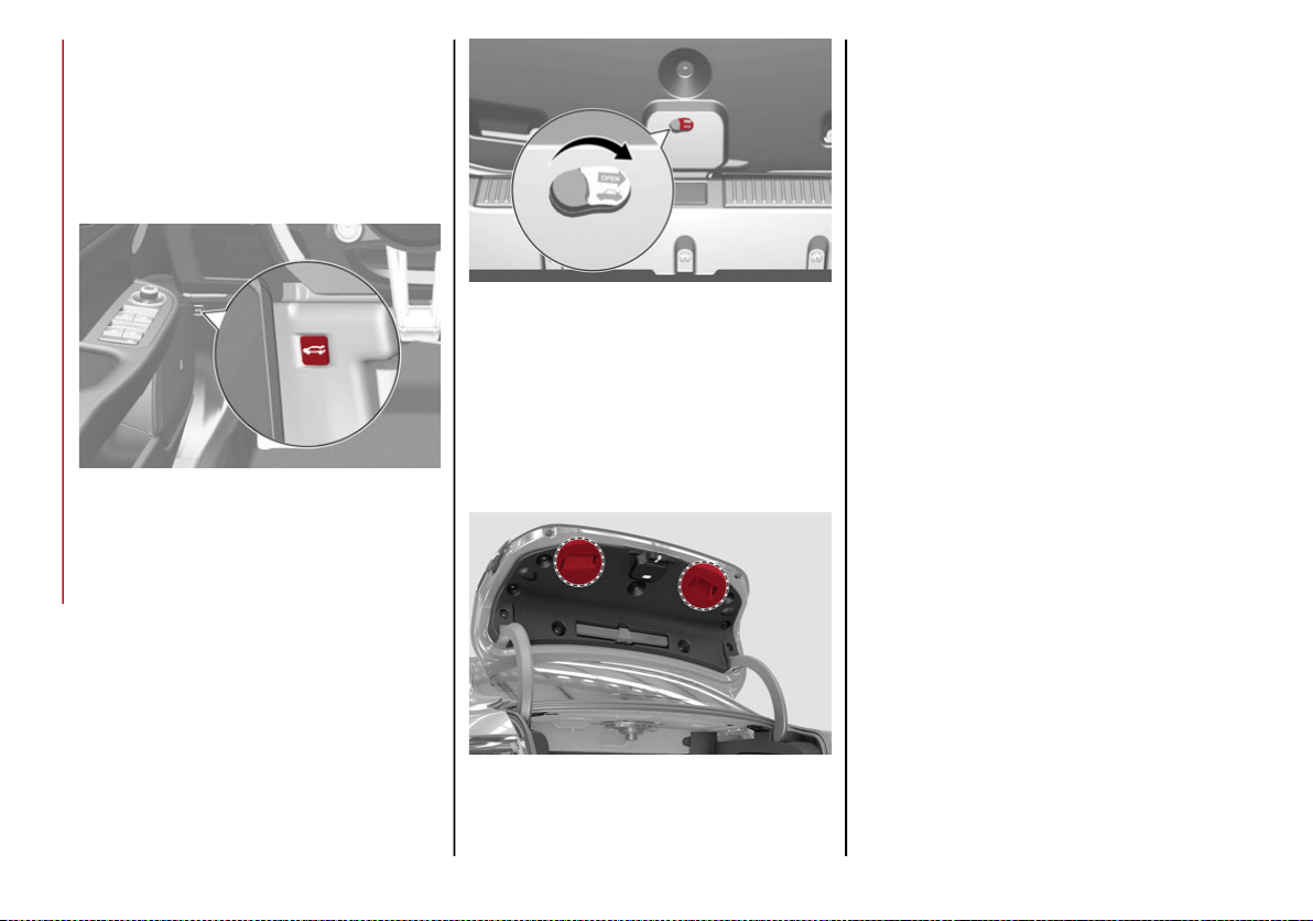
GETTING TO KNOW YOUR VEHICLE
58
Opening From The Inside
When unlocked, the trunk lid can be opened
from inside the vehicle using the interior trunk
lid release button, located under the dash-
board near the engine hood opening lever.
Push the trunk lid release button until you
hear a “click.”
Interior Trunk Lid Release Button
Trunk Lid Emergency Opening
A lever can be found in the trunk lid over the
lock to allow opening from the inside.
Emergency Release Button
Pull the lever in the direction indicated by the
arrow to open the trunk lid. The lever can be
seen in the dark.
Closing
Grip one of the handles and lower the trunk lid
until it clicks.
Trunk Lid Interior Handles
NOTE:
It will not be possible to open the trunk lid
with a key or by pushing the button in the
passenger compartment when the battery
is disconnected. So, always position the
manual trunk lid opening strap on the trunk
lid lock before disconnecting the battery.
Refer to “Storing The Vehicle” in “Servicing
And Maintenance” for the procedure.
Trunk Initialization
NOTE:
If the battery is disconnected or the protection
fuse blows, the trunk lid opening/closing
mechanism must be re-initialized as follows:
1. Close all the doors and the trunk lid.
2. Push the lock button on the remote
control.
3. Push the unlock button on the remote
control.
20_GA_OM_EN_USC_t.book Page 58
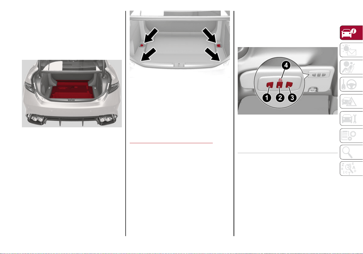
59
Trunk Specifications
Access To The Tire Service Kit (Quadrifoglio
Models)
To access the Tire Service Kit, lift the carpet in
the trunk. Refer to “Tire Service Kit” in “In
Case Of Emergency” for information on its use.
Cargo Area (Quadrifoglio Models)
Rear Cargo Tie–Downs — If Equipped
There are four hooks inside the trunk for
attaching the cargo net or cables which can
safely secure the cargo.
Rear Cargo Tie-Downs
NOTE:
Do not apply a load greater than 22 lbs (10 kg)
on a single hook.
Cargo Net — If Equipped
This is useful for correctly arranging the cargo
and/or for transporting light materials.
GARAGE DOOR OPENER
HomeLink® replaces up to three hand-held
transmitters that operate devices such as
garage door openers, motorized gates, lighting
or home security systems. The HomeLink®
unit is powered by your vehicle’s 12 Volt
battery.
The HomeLink® buttons, located on the sun
visor or the overhead console, designate the
three different HomeLink® channels. The
HomeLink® indicator is located above the
center button.
HomeLink® Buttons
NOTE:
HomeLink® is disabled when the Vehicle
Security Alarm is active.
1 — Homelink® Button 1
2 — Homelink® Button 2
3 — Homelink® Button 3
4 — Homelink® Indicator
20_GA_OM_EN_USC_t.book Page 59
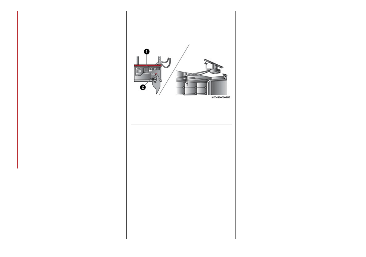
GETTING TO KNOW YOUR VEHICLE
60
Before You Begin Programming
HomeLink®
Be sure that your vehicle is parked outside of
the garage before you begin programming.
For more efficient programming and accurate
transmission of the radio-frequency signal it is
recommended that a new battery be placed in
the hand-held transmitter of the device that is
being programmed to the HomeLink® system.
To erase the channels, place the ignition in the
ON position, and push and hold the two
outside HomeLink® buttons (I and III) for up to
20 seconds or until the orange indicator
flashes.
NOTE:
Erasing all channels should only be
performed when programming HomeLink®
for the first time. Do not erase channels
when programming additional buttons.
If you have any problems, or require assis-
tance, please call toll-free 1-800-355-3515
or, on the Internet at
HomeLink.com
for
information or assistance.
Programming A Rolling Code
Garage door openers that were manufactured
after 1995 can be identified by the “LEARN” or
“TRAIN” button located where the hanging
antenna is attached to the garage door
opener.
NOTE:
It is NOT the button that is normally used to
open and close the door. The name and color
of the button may vary by manufacturer.
Training The Garage Door Opener
For programming these garage door openers,
proceed as follows:
1. Place the ignition in the ON/RUN position.
2. Place the hand-held transmitter 1 to 3 inches
(3 to 8 cm) away from the HomeLink® button
you wish to program while keeping the Home-
Link® indicator light in view.
3. Push and hold the HomeLink® button you
want to program while you push and hold
the hand-held transmitter button.
4. Continue to hold both buttons and observe
the indicator light. The HomeLink® indi-
cator will flash slowly and then rapidly after
HomeLink® has received the frequency
signal from the hand-held transmitter.
Release both buttons after the indicator
light changes from slow to rapid.
5. At the garage door opener motor (in the
garage), locate the “LEARN” or “TRAINING”
button. This can usually be found where
the hanging antenna wire is attached to
the garage door opener/device motor.
Firmly push and release the “LEARN” or
“TRAINING” button. On some garage door
openers/devices there may be a light that
blinks when the garage door opener/
device is in the LEARN/TRAIN mode.
NOTE:
You have 30 seconds in which to initiate the
next step after the LEARN button has been
pushed.
6. Return to the vehicle and push the
programmed HomeLink® button twice
(holding the button for two seconds each
time). If the garage door opener/device
activates, programming is complete.
To program the remaining two HomeLink®
buttons, repeat each step for each remain-
ing button. DO NOT erase the channels.
NOTE:
If the garage door opener/device does not
activate, push the button a third time (for two
seconds) to complete the training.
1 — Door Opener
2 — Training Button
20_GA_OM_EN_USC_t.book Page 60

61
Reprogramming A Single HomeLink® Button
(Rolling Code)
To reprogram a channel that has been previ-
ously trained, follow these steps:
1. Place the ignition in the ON/RUN position.
2. Push and hold the desired HomeLink®
button until the indicator light begins to
flash after 20 seconds. Do not release the
button.
3. Without releasing the button proceed with
“Programming A Rolling Code” step 2 and
follow all remaining steps.”
Programming A Non-Rolling Code
For programming garage door openers manu-
factured before 1995:
1. Place the ignition in the ON/RUN position.
2. Place the hand-held transmitter 1 to 3 inches
(3 to 8 cm) away from the HomeLink® button
you wish to program while keeping the Home-
Link® indicator light in view.
3. Press and hold the HomeLink® button you
want to program while you press and hold
the hand-held transmitter button.
4. Continue to hold both buttons and observe
the indicator light. The HomeLink® indi-
cator will flash slowly and then rapidly after
HomeLink® has received the frequency
signal from the hand-held transmitter.
Release both buttons after the indicator
light changes from slow to rapid.
5. Press and hold the programmed HomeLink®
button and observe the indicator light.
• If the indicator light stays on constantly,
programming is complete and the garage
door/device should activate when the
HomeLink® button is pressed.
• To program the two remaining HomeLink®
buttons, repeat each step for each
remaining button. DO NOT erase the chan-
nels.
Reprogramming A Single HomeLink® Button
(Non-Rolling Code)
To reprogram a channel that has been previ-
ously trained, follow these steps:
1. Place the ignition in the ON/RUN position.
2. Press and hold the desired HomeLink®
button until the indicator light begins to
flash after 20 seconds. Do not release the
button.
3. Without releasing the button, proceed with
“Programming A Non-Rolling Code” step 2
and follow all remaining steps.
Canadian/Gate Operator Programming
The programming of transmitters in Canada/
United States require the transmitter signals
to “time-out” after several seconds of trans-
mission.
Canadian radio frequency laws require trans-
mitter signals to time-out (or quit) after several
seconds of transmission – which may not be
long enough for HomeLink® to pick up the
signal during programming. Similar to this
Canadian law, some U.S. gate operators are
designed to time-out in the same manner.
It may be helpful to unplug the device during
the cycling process to prevent possible over-
heating of the garage door or gate motor.
1. Place the ignition in the ON/RUN position.
2. Place the hand-held transmitter 1 to 3 inches
(3 to 8 cm) away from the HomeLink® button
you wish to program while keeping the Home-
Link® indicator light in view.
3. Continue to press and hold the Home-
Link® button, while you press and release
(“cycle”) your hand-held transmitter every
two seconds until HomeLink® has
successfully accepted the frequency
signal. The indicator light will flash slowly
and then rapidly when fully trained.
20_GA_OM_EN_USC_t.book Page 61
GETTING TO KNOW YOUR VEHICLE
62
(Continued)
4. Watch for the HomeLink® indicator to
change flash rates. When it changes, it is
programmed. It may take up to 30 seconds
or longer in rare cases. The garage door may
open and close while you are programming.
5. Press and hold the programmed HomeLink®
button and observe the indicator light.
NOTE:
• If the indicator light stays on constantly,
programming is complete and the garage
door/device should activate when the
HomeLink® button is pressed.
• To program the two remaining HomeLink®
buttons, repeat each step for each
remaining button. DO NOT erase the chan-
nels.
If you unplugged the garage door opener/
device for programming, plug it back in at this
time.
Reprogramming A Single HomeLink® Button
(Canadian/Gate Operator)
To reprogram a channel that has been previ-
ously trained, follow these steps:
1. Place the ignition to the ON/RUN position.
2. Press and hold the desired HomeLink®
button until the indicator light begins to
flash after 20 seconds. Do not release the
button.
3. Without releasing the button, proceed with
“Canadian/Gate Operator Programming”
step 2 and follow all remaining steps.
Using HomeLink®
To operate, push and release the programmed
HomeLink® button. Activation will now occur
for the programmed device (i.e. garage door
opener, gate operator, security system, entry
door lock, home/office lighting, etc.). The
hand-held transmitter of the device may also
be used at any time.
Security
It is advised to erase all channels before you
sell or turn in your vehicle.
To do this, push and hold the two outside
buttons for 20 seconds until the orange indi-
cator flashes. Note that all channels will be
erased. Individual channels cannot be erased.
The HomeLink® Universal Transceiver is
disabled when the Vehicle Security Alarm is
active.
NOTE:
The universal garage door opener only oper-
ates when the engine is running for security
reasons associated with removable tops and
doors.
Troubleshooting Tips
If you are having trouble programming Home-
Link®, here are some of the most common
solutions:
Replace the battery in the garage door
opener hand-held transmitter.
Push the LEARN button on the garage door
opener to complete the training for a rolling
code.
Did you unplug the device for programming
and remember to plug it back in?
If you have any problems, or require assis-
tance, please call toll-free 1-800-355-3515 or,
on the Internet at
HomeLink.com
for informa-
tion or assistance.
WARNING!
Vehicle exhaust contains carbon monoxide,
a dangerous gas. Do not run your vehicle in
the garage while programming the trans-
ceiver. Exhaust gas can cause serious injury
or death.
20_GA_OM_EN_USC_t.book Page 62
63
General Information
The following regulatory statement applies to
all Radio Frequency (RF) devices equipped in
this vehicle:
This device complies with Part 15 of the FCC
Rules and with Innovation, Science and
Economic Development Canada license-exempt
RSS standard(s). Operation is subject to the
following two conditions:
1. This device may not cause harmful inter-
ference, and
2. This device must accept any interference
received, including interference that may
cause undesired operation.
Le présent appareil est conforme aux CNR
d`Innovation, Science and Economic Develop-
ment applicables aux appareils radio exempts
de licence. L'exploitation est autorisée aux
deux conditions suivantes:
1. l'appareil ne doit pas produire de brouil-
lage, et
2. l'utilisateur de l'appareil doit accepter tout
brouillage radioélectrique subi, même si le
brouillage est susceptible d'en comprom-
ettre le fonctionnement.
La operación de este equipo está sujeta a las
siguientes dos condiciones:
1. es posible que este equipo o dispositivo no
cause interferencia perjudicial y
2. este equipo o dispositivo debe aceptar
cualquier interferencia, incluyendo la que
pueda causar su operación no deseada.
RF Exposure Requirements
To comply with FCC RF exposure compliance
requirements, the device must be installed
and operated to provide a separation distance
of at least 20 cm from all persons.
This equipment complies with Canada radia-
tion exposure limits set forth for an uncon-
trolled environment. This equipment should
be installed and operated with minimum
distance 20 cm between the radiator and your
body.
NOTE:
Changes or modifications not expressly
approved by the party responsible for compli-
ance could void the user’s authority to operate
the equipment.
Déclaration d’exposition aux radiations
Cet équipement est conforme aux limites
d’exposition aux rayonnements ISED établies
pour un environnement non contrôlé. Cet équi-
pement doit être installé et utilisé avec un
minimum de 20 cm de distance entre la
source de rayonnement et votre corps
REMARQUE:
Des changements ou des modifications
n’ayant pas été expressément approuvés par
la partie responsable de la conformité pour-
raient révoquer l’autorisation d’utilisation de
l’équipement.
Your motorized door or gate will open and
close while you are programming the
universal transceiver. Do not program the
transceiver if people, pets or other objects
are in the path of the door or gate. Only
use this transceiver with a garage door
opener that has a “stop and reverse”
feature as required by Federal safety stan-
dards. This includes most garage door
opener models manufactured after 1982.
Do not use a garage door opener without
these safety features.
WARNING! (Continued)
20_GA_OM_EN_USC_t.book Page 63
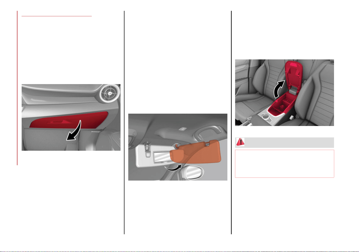
GETTING TO KNOW YOUR VEHICLE
64
INTERNAL EQUIPMENT
Glove Compartment
To open the glove compartment proceed as
follows:
1. If equipped with a lock, unlock the glove
compartment by placing the emergency
key in the lock on the handle.
2. Pull handle to open the glove compartment.
Opening The Glove Compartment
When the glove compartment is opened, a
light turns on to illuminate the inside of the
compartment.
NOTE:
Do not insert large objects that will prevent the
glove compartment from closing completely.
Always make sure that the glove compartment
is completely closed when driving.
Sun Visors
The sun visors are located at the sides of the
interior rear view mirror. They can be adjusted
forward and toward the side window.
To direct the visor toward the side window,
detach the visor from the interior rear view
mirror side hook and turn it towards the side
window.
From this position, the sun visor can also be
extended toward the rear of the vehicle for
additional blockage of sunlight.
Courtesy mirrors with lights are fitted on the
back of the sun visors and can be used even in
poor light conditions.
Rotate Sun Visor Toward Passenger Window
NOTE:
A rear facing child restraint system should
never be fitted in the front passenger seat.
Always comply with the instructions on the sun
visor. Refer to "Child Restraints" in "Safety" for
more information.
Center Console
The center console storage compartment is
located between the front seats.
To access the center console storage, lift the
upper part of the center console as shown
below.
Center Console
WARNING!
Do not operate this vehicle with a console
compartment lid in the open position.
Driving with the console compartment lid
open may result in injury in a collision.
20_GA_OM_EN_USC_t.book Page 64
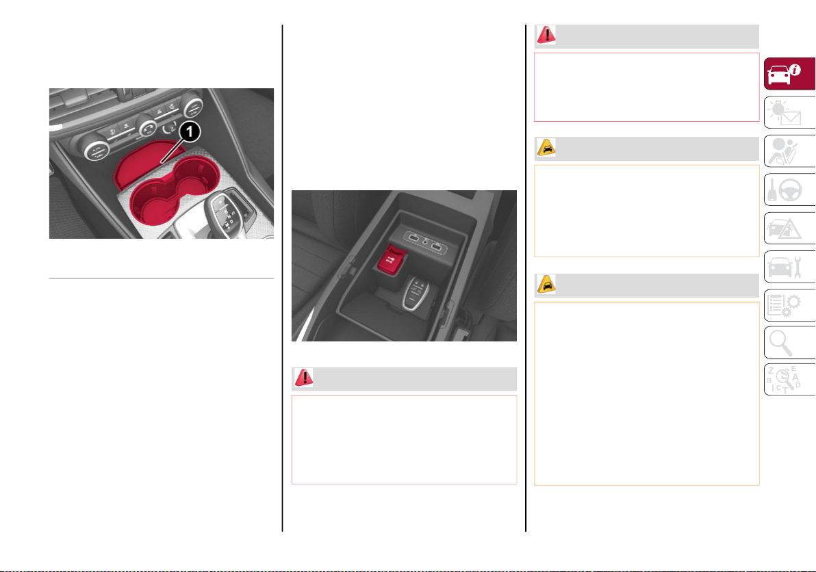
65
(Continued)
(Continued)
Cupholder
Two cupholders are available in the center
console.
Cupholders In Center Console
Power Outlet
Your vehicle is equipped with a 12 Volt (15 Amp)
power outlet that can be used to power cellular
phones, small electronics and other low powered
electrical accessories. The power outlet is
labeled with either a “key” symbol to indicate
how the outlet is powered. Power outlets labeled
with a “key” are powered when the ignition is in
the ON/RUN or ACC position.
NOTE:
All accessories connected to the “battery”
powered outlets should be removed or turned
off when the vehicle is not in use to protect the
battery against discharge.
115 Volt Power Inverter — If Equipped
The Power Inverter is located inside of the
center console. It can be used for small
battery-powered electrical appliances with
powers up to 150 W (e.g. cameras, video
camera, tablets, razors, etc.)
NOTE:
Do not connect devices with powers higher
than 150 W to the socket. Do not damage the
socket by using unsuitable adapters.
Center Console Power Outlet
1 — Storage
WARNING!
To avoid serious injury or death:
Only devices designed for use in this type of
outlet should be inserted into any 12 Volt
outlet.
Do not touch with wet hands.
Close the lid when not in use and while
driving the vehicle.
If this outlet is mishandled, it may cause
an electric shock and failure.
CAUTION!
Power outlets are designed for accessory
plugs only. Do not insert any other object in
the power outlets as this will damage the
outlet and blow the fuse. Improper use of the
power outlet can cause damage not covered
by your New Vehicle Limited Warranty.
CAUTION!
Many accessories that can be plugged in
draw power from the vehicle's battery, even
when not in use (i.e., cellular phones, etc.).
Eventually, if plugged in long enough, the
vehicle's battery will discharge sufficiently to
degrade battery life and/or prevent the
engine from starting.
Accessories that draw higher power (i.e.,
coolers, vacuum cleaners, lights, etc.) will
degrade the battery even more quickly.
Only use these intermittently and with
greater caution.
WARNING! (Continued)
20_GA_OM_EN_USC_t.book Page 65
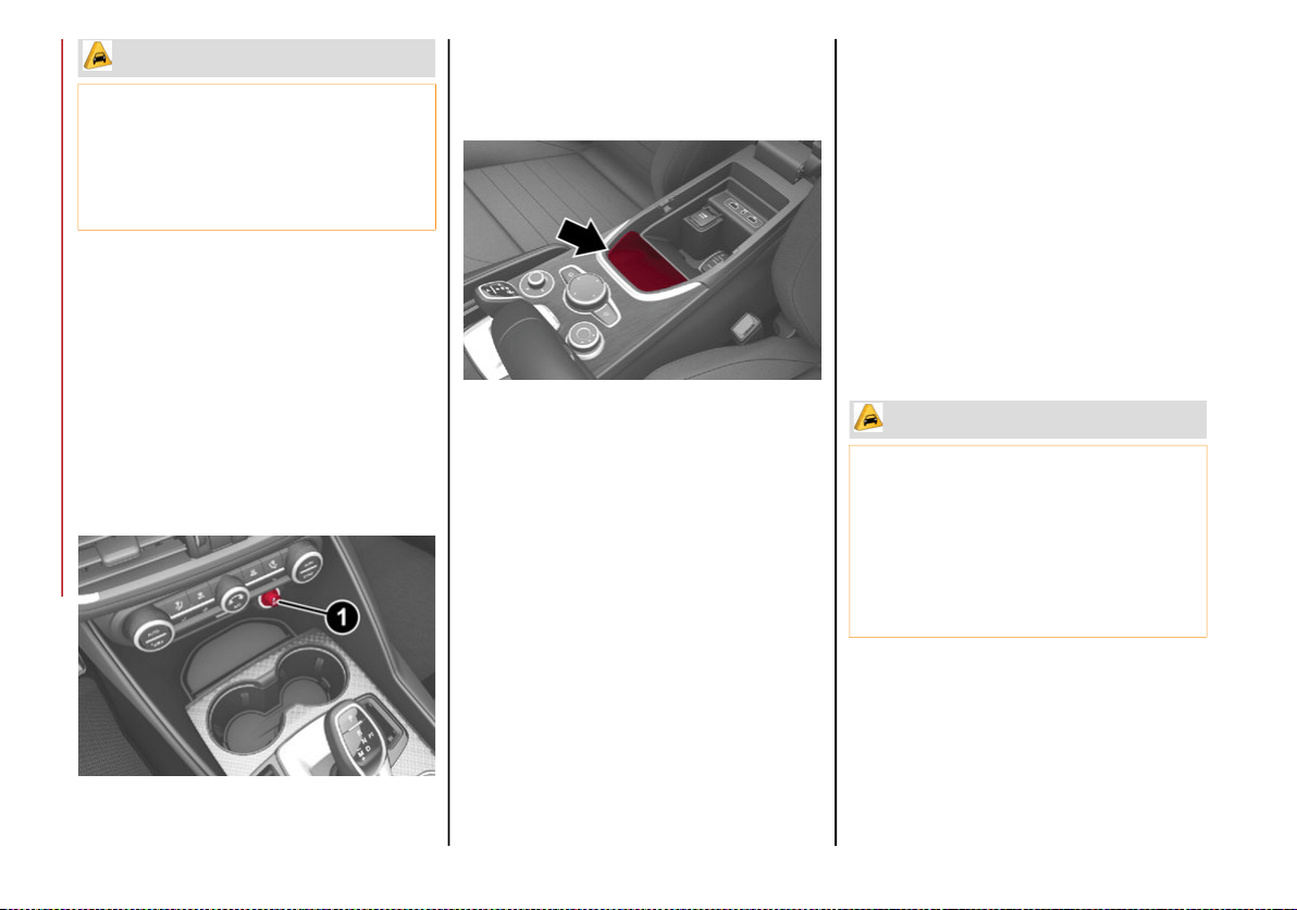
GETTING TO KNOW YOUR VEHICLE
66
Cigar Lighter And Ash Tray — If Equipped
If equipped, the cigar lighter is located on the
bottom of the center stack, in front of the
cupholders.
To activate the cigar lighter, push in and wait a
few seconds. Once the cigar lighter has returned
to its original position, it is ready for use.
NOTE:
Always ensure the cigar lighter is turned off
when not in use.
1 — Cigar Lighter
If equipped, the ash tray is a removable plastic
container located inside the cupholder.
Wireless Charging Pad — If Equipped
Wireless Charging Pad
Your vehicle may be equipped with a 15W 3A
Qi wireless charging pad located inside of the
center console. This charging pad is designed
to wirelessly charge your Qi enabled mobile
phone. Qi is a standard that uses magnetic
induction to transfer power to your mobile
device.
Your mobile phone must be designed for Qi
wireless charging.
NOTE:
Do not place the key fob or any other type of
metal/magnetized object inside the mobile
phone housing or near the wireless
charging pad.
Be sure to place the mobile device correctly
(display facing upward) on the wireless
charging pad.
The ignition must be in the ON/RUN position
in order for the phone to charge.
To avoid interference with the key fob
search, the wireless charging pad will stop
charging when any door is opened.
After the use of high power draw accesso-
ries, or long periods of the vehicle not being
started (with accessories still plugged in),
the vehicle must be driven a sufficient
length of time to allow the generator to
recharge the vehicle's battery.
CAUTION! (Continued)
CAUTION!
The key fob should not be placed on the
charging pad or within 15 cm (150 mm) of
it. Doing so can cause excessive heat
buildup and damage to the fob. Placing the
fob in close proximity of the charging pad
blocks the fob from being detected by the
vehicle and prevents the vehicle from
starting.
20_GA_OM_EN_USC_t.book Page 66
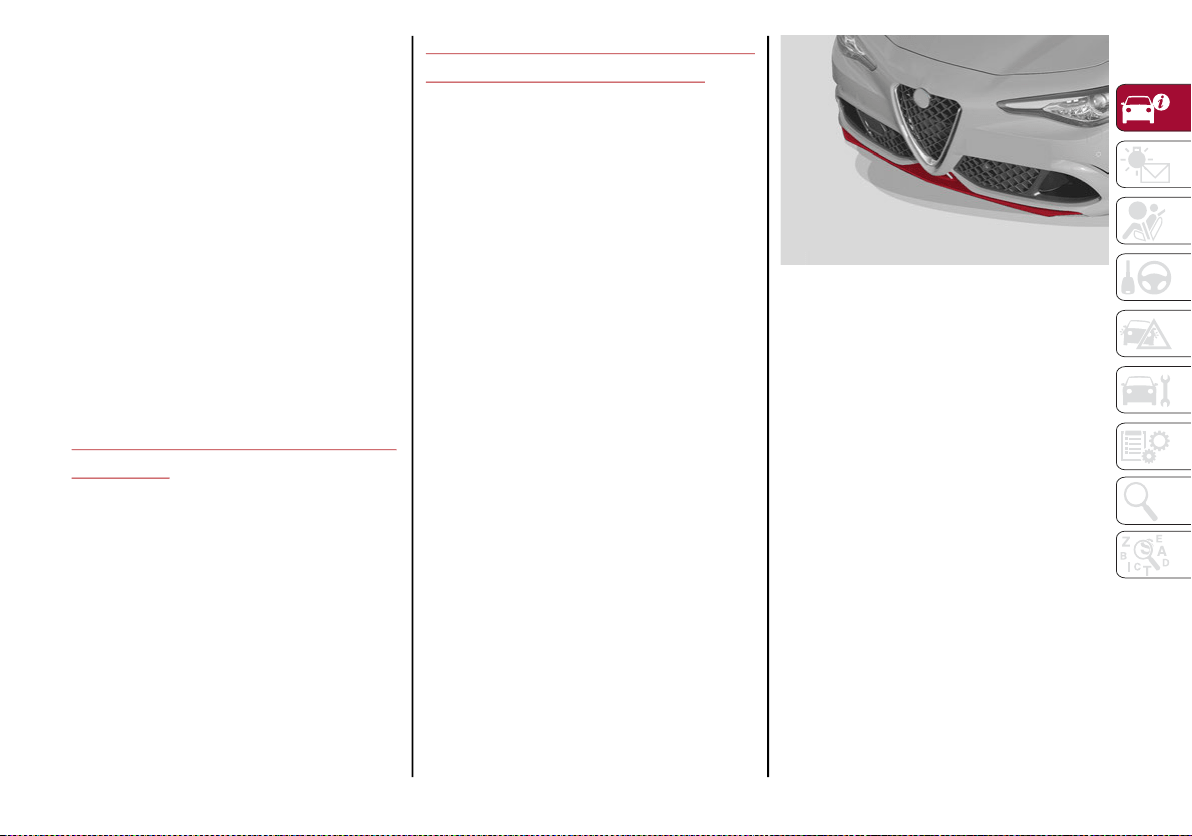
67
The following messages will display in the
radio system:
“Your phone is being charged” — The phone
has begun to charge.
“Phone Fully Charged” — The phone has
completed charging its battery.
“Foreign Object Detected” — The phone is
not enabled for wireless charging or an
object that is not permitted has been placed
on the wireless charging pad.
“Unavailable System” — There is a malfunc-
tion with the wireless charging pad.
The driver can deactivate these messages
through the radio system. Refer to the Infor-
mation and Entertainment System Owner’s
Manual Supplement for further information.
ENVIRONMENTAL PROTECTION
SYSTEMS
The following systems are used for reducing
engine emissions:
Catalytic Converter
Oxygen Sensors
Evaporation Control System
ACTIVE AERODYNAMIC SPOILER
(QUADRIFOGLIO VEHICLES)
Carbon Fiber Active Aero Front Spoiler
This is an automatic device working at vehicle
speed to regulate air flow in the lower part of
the vehicle. It allows higher reactivity at
average speeds and higher vehicle stability at
high speeds.
NOTE:
The Active Aero Spoiler is active in the
Dynamic or RACE mode of the Alfa DNA Pro
Selector; it is not active in any mode when
external temperatures are near or below zero.
Front Fascia
If there is a fault, a generic failure icon will light
up on the instrument panel display, along with
a message that will identify the type of
malfunction. See an authorized dealer if a
fault occurs.
20_GA_OM_EN_USC_t.book Page 67
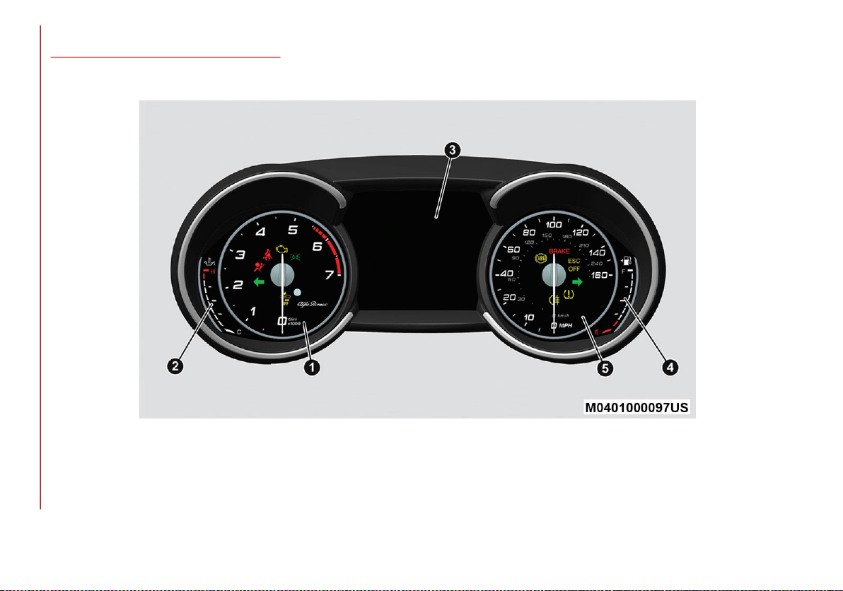
68
GETTING TO KNOW YOUR INSTRUMENT PANEL
This section gives you all the information you need to understand and use the instrument panel correctly.
INSTRUMENT PANEL FEATURES
Instrument Cluster
Base Instrument Cluster
20_GA_OM_EN_USC_t.book Page 68
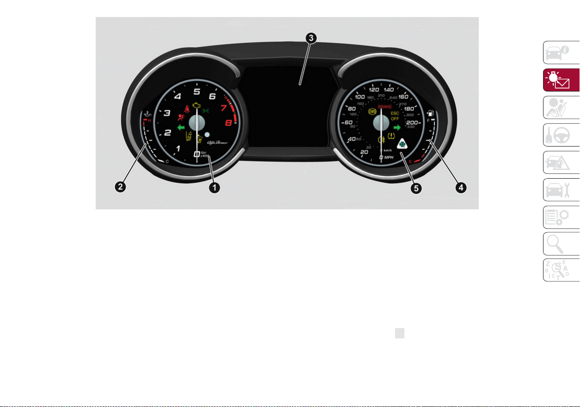
69
Quadrifoglio Instrument Cluster
1. Tachometer
2. Digital Engine Oil Temperature Gauge With
Overheating Warning Light
3. Driver Interactive Display
4. Digital Fuel Level Gauge (The Triangle On
The Left Side Of The Symbol indicates that
the Fuel Door Location is on the left side of
the vehicle)
5. Speedometer (Speed Indicator)
Tachometer
The Tachometer indicates the engine Revolu-
tions Per Minute (Giri).
Adjusting Instrument Panel Lighting
(Brightness Sensor)
Inside the Tachometer there is a light sensor
capable of detecting light and adjusting the
brightness of the instrument panel and the Infor-
mation and Entertainment System display.
Engine Oil Temperature Gauge
The digital indicator monitors the temperature
of the engine oil and starts supplying indica-
tions when the oil temperature reaches
approximately 122°F (50°C).
Under normal usage, the temperature should
remain around the middle of the digital scale
according to the working conditions.
The warning light will turn on to signal the
excessive increase of the engine oil temperature.
20_GA_OM_EN_USC_t.book Page 69
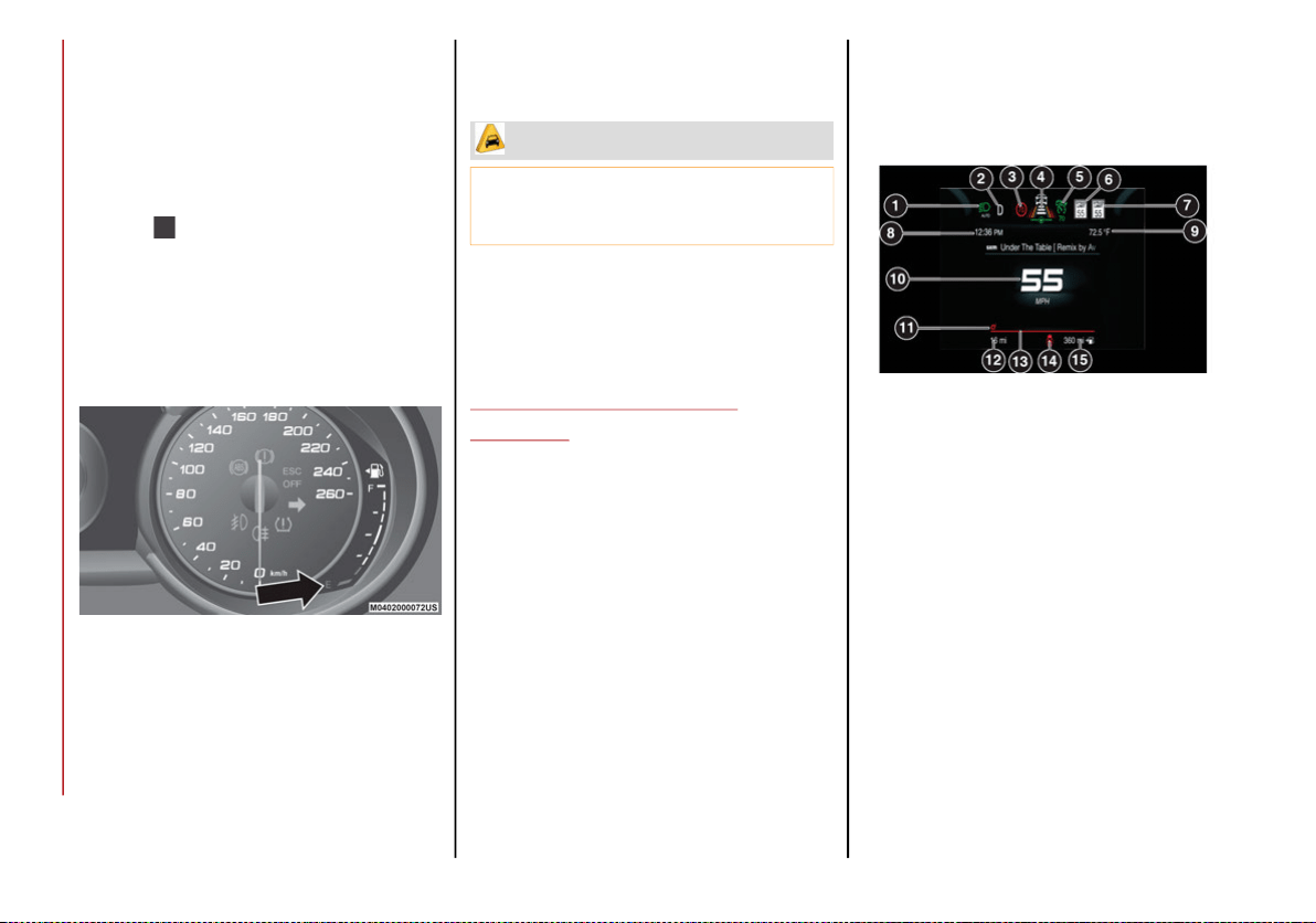
GETTING TO KNOW YOUR INSTRUMENT PANEL
70
In the event of excessive engine oil tempera-
ture, stop the engine immediately and contact
an authorized dealer.
Fuel Level Gauge
The digital fuel gauge monitors the amount of
fuel in the tank.
When the warning light turns on, a message is
displayed, and a chime will sound when 2.3 Gallons
(9.0 L) of fuel are left in the tank.
Proceeding further, the second white notch
will go off and the last one will become red,
together with the indication "E" present at the
bottom of the tank.
Fuel Level Gauge
NOTE:
If the low fuel warning light turns on, refuel the
vehicle at your nearest fuel station.
Speedometer
The speedometer shows the vehicle speed in
miles per hour and/or kilometers per hour
(mph/km/h).
INSTRUMENT CLUSTER
DISPLAY
Instrument Cluster Display Description
This vehicle is equipped with a driver-interac-
tive display that is located in the instrument
cluster.
When one or more of the doors have been
opened or closed and the ignition is in the OFF
position, the instrument cluster will display the
vehicle mileage for a few seconds.
Reconfigurable Instrument Cluster Display
During operation, the instrument cluster display
is divided into multiple sections which show
driving data, warnings and failure indications.
Instrument Cluster Display
Reconfigurable Display Items
1. External Lights (Low Beam/High Beam)
Display
2. Front, Side Anti-Collision Systems, Cruise
Control Change Information
3. Speed Limiter Display
4. Driving Assistance Systems (Forward Collision
Warning (FCW), Lane Departure Warning
(LDW), Highway Assist System (HAS)) Informa-
tion Display
5. Active Cruise Control (ACC) / Cruise
Control (CC) Information Display
CAUTION!
Do not travel with the fuel tank almost
empty: any gaps in fuel supply could
damage the catalytic converter.
20_GA_OM_EN_USC_t.book Page 70
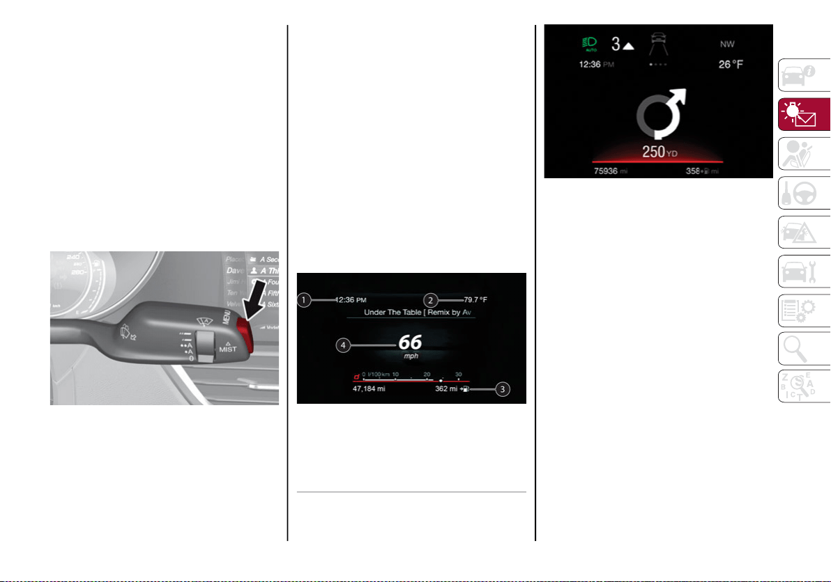
71
6. Traffic Sign Recognition (TSR) / Speed
Limiter Information Display
7. Traffic Sign Recognition (TSR) Information
Display
8. Time
9. External Temperature
10. Main Display: Vehicle Speed Display, Trip
Computer Information, etc...
The screens can be selected, on rotation,
by pushing the MENU selection button on
the windshield wiper stalk.
MENU Selection/Reset Button
Depending on the driving mode chosen us-
ing the Alfa DNA (Dynamic, Natural, and
Advanced Efficiency) the screens can be
graphically different. Navigation instruc-
tions and call information can be set and
displayed in the Information and Entertain-
ment System.
Home
The parameters shown on the display, for
the modes: Dynamic, Normal and Ad-
vanced Efficiency are:
• Time
• External Temperature
• Current speed (shown only if the repeat
mode of the “Navigation” and “Phone” func-
tions have not been previously activated)
• Range
In RACE mode (if equipped) the consump-
tion indication index is not active and a
sports gear shift indicator is displayed.
Instrument Cluster Display
Instrument Cluster Display
Trip A And B
For all driving modes (Dynamic, Natural,
and Advanced Efficiency) and with the igni-
tion device ON, the “Trip computer” can be
used to display the measurements regard-
ing the operating state of the vehicle. This
function is characterized by two separate
records, called “Trip A” and “Trip B” (the
latter can be deactivated by Information
and Entertainment System), where the
complete journeys are recorded in a recip-
rocally independent manner.
1 — Time
2 — Temperature
3 — Distance To Empty
4 — Speed
20_GA_OM_EN_USC_t.book Page 71
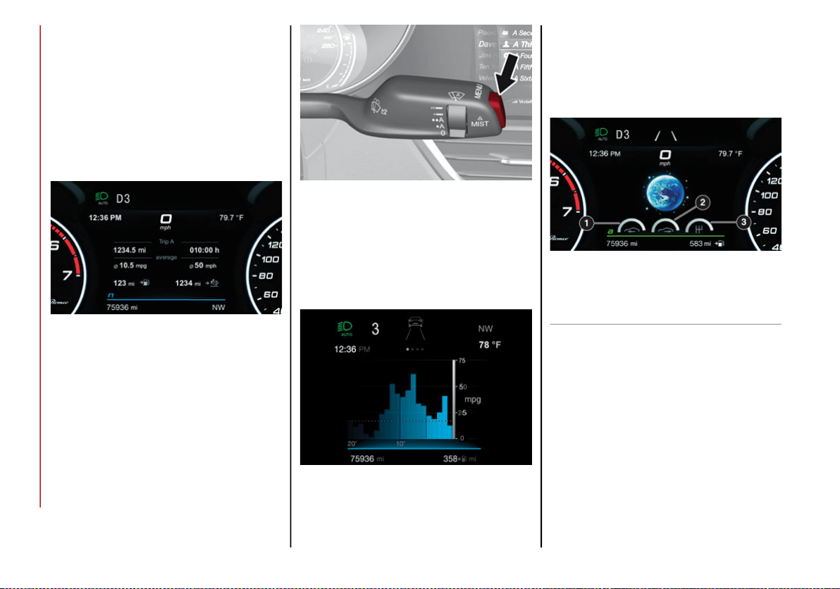
GETTING TO KNOW YOUR INSTRUMENT PANEL
72
“Trip A” and “Trip B” are used to display
the values relating to:
• Distance traveled
• Average fuel consumption
• Average speed
• Active trip
• Fuel consumption indicator
Instrument Cluster Display
To reset the values, press and hold down
the button on the windshield wiper stalk.
MENU Selection/Reset Button
Performance
The displayed parameters differ according
to the active mode. The modes which can
be selected using the Alfa DNA system are:
Natural
Efficiency Consumption Graph
The screen graphically reproduces some
parameters closely linked to the efficiency
of the driving style, with a view to limiting
consumption.
Advanced Efficiency
Dynamic Driving Style
The three central icons, on the screen, in-
dicate the effectiveness of the driving style
linked to the parameters of: acceleration,
deceleration and gear shift with a view to
reducing fuel consumption.
The graphic bar below the icons shows cur-
rent consumption and the green line rep-
resents the optimal area. The globe lights up
gradually according to lower consumption.
1 — Acceleration
2 — Deceleration
3 — Gear Shifts
20_GA_OM_EN_USC_t.book Page 72
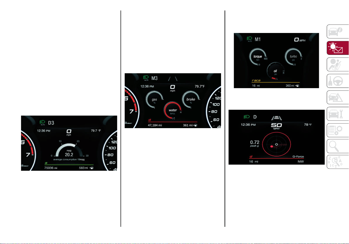
73
Alternative Performance
The displayed parameters vary depending
on the active mode. The modes can be se-
lected through the “Alfa DNA™” system
and are as follows:
Normal and Advanced Efficiency
The display graphically shows the values of:
○ instantaneous consumption
○ average fuel consumption (based
on “Trip A”)
Below a certain speed value, when the ac-
celerator pedal is not pressed or in the
event of failure, dashes are displayed in
place of the consumption value ("– –. –").
Normal and Advanced Efficiency
Dynamic
The display graphically shows the values of:
○ accelerator pedal position (expressed
in percentage)
○ brake pedal position (expressed in
percentage)
○ engine coolant temperature (H =
hot C = cold)
Dynamic
Race (If Equipped)
The display graphically shows the values of:
○ engine torque
○ turbocharger pressure
○ engine oil pressure (L = low pres-
sure/H= high pressure)
NOTE:
The engine torque and turbocharger pressure
values vary according to the engine type.
Race
Dynamic
Acceleration Gauge
The displayed parameters are related to
vehicle stability, the graphs illustrate the
trend of the longitudinal/lateral accelera-
tions (G-meter information), considering
gravity acceleration as a reference unit.
Lateral acceleration peaks are also indicated.
20_GA_OM_EN_USC_t.book Page 73
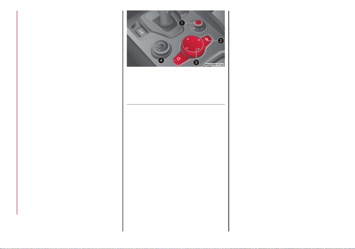
GETTING TO KNOW YOUR INSTRUMENT PANEL
74
11. Driving Mode Display (Alfa DNA System)
12. Distance Traveled (miles/km) display
13. Fuel Consumption
14. Warning Indications Display (e.g. danger of
ice, open doors, ABS operation, etc.)
15. Range
Customer Programmable Settings
Multiple settings can be programmed by the
user using the radio. This section describes
only the basic settings:
Units & Language
Clock & Date
Cluster
To access the settings list in the radio, proceed
as follows:
Press the Home button to access the main
menu.
Select Settings from the main menu using
the Rotary Knob or by pressing Settings on
the touchscreen.
Rotary Knob
Units & Language
The following settings can be modified under
the “Units & Language” menu:
Units: select US, Metric, or Custom. The
custom option allows for individual selec-
tion of the unit measures
Language: change the language of the
system
Restore Unit & Language Settings: restores
the factory settings
To access and change the setting, turn and
push the Rotary Pad or press the desired
setting on the touchscreen.
Clock & Date
The following settings can be modified under
the “Clock & Date” menu:
Sync With GPS Time: activates or deacti-
vates the clock synchronization through the
GPS. If the function is deactivated, the
options Set Time and Set Date are enabled
Set Time: set the time manually
Time Format: set the time format to either a
12-hour or a 24-hour clock
Set Date: set the date manually
Restore Clock & Date Settings: restores the
factory settings
To access and change the setting, turn and
push the Rotary Pad or press the desired
setting on the touchscreen.
1 — ON/OFF Control And Volume Knob
2 — OPTION Button
3 — Rotary Pad
4 — MENU Button
20_GA_OM_EN_USC_t.book Page 74

75
Cluster
The following settings can be modified when
this mode is selected:
Warning Buzzer Volume: allows you to set
the volume of the warning buzzer on seven
levels.
Trip B: activate or deactivate the Trip function.
Show Phone Info: allows you to activate/
deactivate repetition of the phone function
screens also on the instrument panel
display.
Show Audio Info: allows you to activate/
deactivate repetition of the audio function
screens (Radio and Media) also on the
instrument panel display.
Show Nav Info: allows you to activate/deac-
tivate repetition of the navigator function
screens also on the instrument panel
display.
Digital speed on all screens: this allows you
to activate/deactivating of digital speed on
the instrument panel display screens other
than the main screen.
Consumption Bar: allows you to activate/
deactivate the consumption baron the
display screens of the instrument panel
where it is available.
Performance pages: allows you to choose,
for each driving mode, one of the two alter-
native contents displayed in the screen.
Custom areas: allows you to select which
content to display in each of the three
customizable areas on the display of the
instrument panel: time, date, outside
temperature, radio information, compass.
Restore Cluster Settings: deletes the
current settings and restores the factory
settings.
To access and change the setting, turn and
push the Rotary Pad or press the desired
setting on the touchscreen.
WARNING LIGHTS AND
MESSAGES ON THE
INSTRUMENT PANEL
The following pages consist of warning lights
and messages.
NOTE:
The warning light turns on together with a
dedicated message and/or chime when
applicable. These indications are precau-
tionary and as such must not be considered
as exhaustive and/or alternative to the
information contained in the Owner’s
Manual, which you are advised to read care-
fully in all cases. Always refer to the informa-
tion in this section in the event of a failure
indication.
The failure indicators appearing on the
display are divided into two categories: very
serious and less serious faults. Serious
faults are indicated by a repeated and
prolonged warning "cycle.” Less serious
faults are indicated by a warning "cycle" with
a shorter duration. You can stop the
warning cycle in both cases by pushing the
button located on the windshield wiper
stalk. The instrument panel warning light
will stay on until the cause of the failure is
eliminated.
20_GA_OM_EN_USC_t.book Page 75

GETTING TO KNOW YOUR INSTRUMENT PANEL
76
Red Warning Lights
Warning Light What It Means What To Do
INSUFFICIENT BRAKE FLUID/ELECTRIC PARK BRAKE ON
This light monitors various brake functions, including
brake fluid level and parking brake application. If the
brake light turns on it may indicate that the parking
brake is applied, that the brake fluid level is low, or
that there is a problem with the anti-lock brake system
reservoir.
If the light remains on when the parking brake has
been disengaged, and the fluid level is at the full mark
on the master cylinder reservoir, it indicates a
possible brake hydraulic system malfunction or that a
problem with the Brake Booster has been detected by
the Anti-Lock Brake System (ABS) / Electronic Stability
Control (ESC) system. In this case, the light will remain
on until the condition has been corrected. If the
problem is related to the Brake Booster, the ABS
pump will run when applying the brake, and a brake
pedal pulsation may be felt during each stop.
Operation of the Brake Warning Light can be checked
by turning the ignition switch from the OFF position to
the ON/RUN position. The light should illuminate for
approximately four seconds. The light should then turn
off unless the parking brake is applied or a brake fault
is detected. If the light does not illuminate, have the
light inspected by an authorized dealer.
The light also will turn on when the parking brake is
applied with the ignition switch in the ON/RUN
position.
This light shows only that the parking brake is applied.
It does not show the degree of brake application.
For low brake fluid level, go to an authorized dealer to
have the system checked as soon as possible.
Release the electric park brake, then check that the
warning light has turned off.
If the warning light stays on, contact an authorized
dealer.
ELECTRONIC BRAKING FORCE DISTRIBUTION (EBD)
FAILURE
The simultaneous turning on of the BRAKE (red) and
(amber) warning lights with the engine on indicates
either a failure of the EBD system or that the system is
not available. In this case, the rear wheels may
suddenly lock and the vehicle may swerve when
braking abruptly.
Drive very carefully to the nearest authorized dealer to
have the system inspected immediately.
20_GA_OM_EN_USC_t.book Page 76
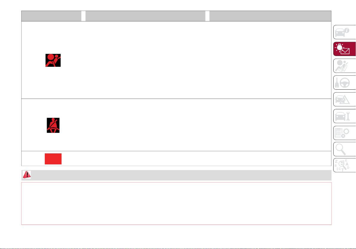
77
AIR BAG WARNING LIGHT
This light will turn on for four to eight seconds as a
bulb check when the ignition is placed in the ON/RUN
position. If the light is either not on during startup,
stays on, or turns on while driving, have the system
inspected at an authorized dealer as soon as
possible. This light will illuminate with a single chime
when a fault with the Air Bag Warning Light has been
detected, it will stay on until the fault is cleared. If the
light comes on intermittently or remains on while
driving, have an authorized dealer service the vehicle
immediately.
If the problem persists, contact an authorized dealer.
SEAT BELT REMINDER WARNING LIGHT
When the ignition is first placed in the ON/RUN position,
if the driver’s seat belt is unbuckled, a chime will sound
and the light will turn on. When driving, if the driver or
front passenger seat belt remains unbuckled, the Seat
Belt Reminder Light will flash or remain on continuously
and a chime will sound. Refer to “Occupant Restraint
Systems” in “Safety” for further information.
Always wear your seat belt when operating the vehicle.
OIL TEMPERATURE WARNING LIGHT
This telltale indicates engine oil temperature is high.
Stop the vehicle and shut off the engine as soon as possible.
If the problem persists, contact an authorized dealer.
WARNING!
The fault of the warning light is signaled by the turning on of the icon on the instrument panel. In this case, the warning light may not indicate
any faults with the restraint systems. Before proceeding, contact an authorized dealer to have the system checked immediately.
If the warning light does not turn on when the ignition device is moved to ON or if it stays on when driving (together with the message on the
display), there might be a fault in the restraint systems; in this case, the air bags or pretensioners may not deploy in the event of an accident
or, in a lower number of cases, they could deploy erroneously. Before proceeding, contact an authorized dealer to have the system checked
immediately.
Warning Light What It Means What To Do
20_GA_OM_EN_USC_t.book Page 77

GETTING TO KNOW YOUR INSTRUMENT PANEL
78
Amber Warning Lights
Warning Light What It Means What To Do
ANTI-LOCK BRAKE System (ABS) INDICATOR LIGHT
This light monitors the Anti-Lock Brake System (ABS). The
light will turn on when the ignition is placed in the ON/RUN
position and may stay on for as long as four seconds.
If the ABS light remains on or turns on while driving,
then the Anti-Lock portion of the brake system is not
functioning and service is required. However, the
conventional brake system will continue to operate
normally if the brake indicator light is not on.
If the ABS light is on, the brake system should be
serviced as soon as possible to restore the benefits of
Anti-Lock Brakes. If the ABS light does not turn on
when the ignition is placed in the ON/RUN position,
have the light inspected by an authorized dealer.
Drive carefully and contact an authorized dealer as
soon as possible.
TIRE PRESSURE MONITORING System (TPMS) INDICATOR
LIGHT
The warning light switches on and a message is
displayed to indicate that the tire pressure is lower than
the recommended value and/or that slow pressure loss
is occurring. In these cases, optimal tire duration and
fuel consumption may not be guaranteed.
Should one or more tires be in the condition mentioned
above, the display will show the indications
corresponding to each tire in sequence.
Continue driving for up to 50 miles (80 km) at a speed no
higher then 50 mph (80 km/h). Contact an authorized
dealer to have the tire repaired.
20_GA_OM_EN_USC_t.book Page 78
79
Each tire, including the spare (if provided),
should be checked monthly when cold and
inflated to the inflation pressure recommended
by the vehicle manufacturer on the vehicle
placard or tire inflation pressure label. If your
vehicle has tires of a different size than the size
indicated on the vehicle placard or tire inflation
pressure label, you should determine the proper
tire inflation pressure for those tires.
As an added safety feature, your vehicle has
been equipped with a Tire Pressure Monitoring
System (TPMS) that illuminates a low tire pres-
sure telltale when one or more of your tires is
significantly under-inflated. Accordingly, when
the low tire pressure telltale illuminates, you
should stop and check your tires as soon as
possible and inflate them to the proper pres-
sure. Driving on a significantly under-inflated
tire causes the tire to overheat and can lead to
tire failure. Under-inflation also reduces fuel
efficiency and tire tread life, and may affect
the vehicle’s handling and stopping ability.
Please note that the TPMS is not a substitute
for proper tire maintenance, and it is the
driver’s responsibility to maintain correct tire
pressure, even if under-inflation has not
reached the level to trigger illumination of the
TPMS low tire pressure telltale.
Your vehicle has also been equipped with a
TPMS malfunction indicator to indicate when
the system is not operating properly. The
TPMS malfunction indicator is combined with
the low tire pressure telltale. When the system
detects a malfunction, the telltale will flash for
approximately one minute and then remain
continuously illuminated. This sequence will
continue upon subsequent vehicle start-ups
as long as the malfunction exists. When the
malfunction indicator is illuminated, the
system may not be able to detect or signal low
tire pressure as intended. TPMS malfunctions
may occur for a variety of reasons, including
the installation of replacement or alternate
tires or wheels on the vehicle that prevent the
TPMS from functioning properly. Always check
the TPMS malfunction telltale after replacing
one or more tires or wheels on your vehicle, to
ensure that the replacement or alternate tires
and wheels allow the TPMS to continue to
function properly.
CAUTION!
The TPMS has been optimized for the original
equipment tires and wheels. TPMS pressures
and warning have been established for the
tire size equipped on your vehicle.
Undesirable system operation or sensor
damage may result when using replacement
equipment that is not of the same size, type,
and/or style. Aftermarket wheels can cause
sensor damage. Using aftermarket tire
sealants may cause the Tire Pressure
Monitoring System (TPMS) sensor to become
inoperable. After using an aftermarket tire
sealant it is recommended that you take your
vehicle to an authorized dealership to have
your sensor function checked.
20_GA_OM_EN_USC_t.book Page 79

GETTING TO KNOW YOUR INSTRUMENT PANEL
80
Warning Light What It Means What To Do
Tire Pressure Low
The indicator light will illuminate to indicate that the
tire pressure is lower than the recommended value
and/or that slow pressure loss is occurring. In these
cases, optimal tire duration and fuel consumption
may not be guaranteed.
In any situation in which the message on the display is
“See Manual”, it is ESSENTIAL to refer to “Auxiliary
Driving Systems” in “Safety,” strictly complying with
the indications that you find there.
ELECTRONIC STABILITY CONTROL (ESC) INDICATOR
LIGHT
When the ignition is cycled to ON, the indicator light
illuminates, but should turn off as soon as the engine
is started.
ESC System Intervention: Intervention by the system
is indicated by the flashing of the indicator light: it
indicates that the vehicle is in critical stability and grip
conditions.
ESC System Failure: If the indicator light does not turn
off, or if it stays on with the engine running, a failure
was found in the ESC system.
In these cases, contact an authorized dealer as soon
as possible.
Hill Start Assist System Failure: The illumination of the
indicator light indicates a Hill Start Assist system
failure.
20_GA_OM_EN_USC_t.book Page 80
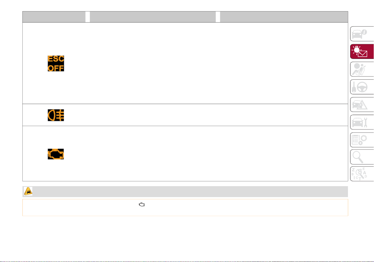
81
ELECTRONIC STABILITY CONTROL (ESC) OFF INDICATOR
LIGHT
When the ignition is cycled to ON, the indicator light
illuminates, but should turn off as soon as the engine
is started.
The indicator light illuminates to indicate that some
active safety systems have been partially or totally
deactivated.
For further details about the active safety systems,
refer to “Active Safety Systems” in “Safety.” When the
active safety systems are reactivated, the indicator
light turns off.
REAR FOG LIGHT
The indicator illuminates when the rear fog light is
activated.
ENGINE CHECK/MALFUNCTION INDICATOR LIGHT (MIL)
In normal conditions, when the ignition is cycled to
ON, the indicator light illuminates, but it should turn
off as soon as the engine is started.
The operation of the indicator light may be checked by
the traffic police using specific devices. Comply with
the laws and regulations of the country where you are
driving.
Under these conditions, the vehicle can continue
traveling at moderate speed but without demanding
excessive effort from the engine or high speed.
Prolonged use of the vehicle with the indicator light on
constantly may cause damage. Contact an authorized
dealer as soon as possible.
Warning Light What It Means What To Do
CAUTION!
If, turning the ignition device to ON, the warning light does not turn on or if it turns on steadily or flashing when traveling (on some versions together
with the message on the display), contact an authorized dealer as soon as possible.
20_GA_OM_EN_USC_t.book Page 81
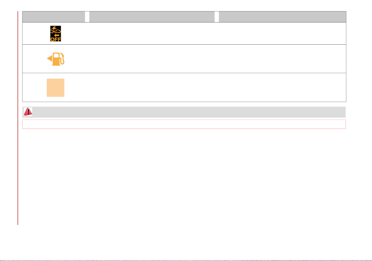
GETTING TO KNOW YOUR INSTRUMENT PANEL
82
Warning Light What It Means What To Do
FORWARD COLLISION WARNING SYSTEM (FCW)
This indicator light informs the driver that the frontal
collision alarm function is not enabled.
Drive carefully and contact an authorized dealer as
soon as possible.
FUEL RESERVE / LIMITED RANGE
The indicator light (or the symbol in the display)
illuminates when about 2.4 gallons (9 liters) of fuel is
left in the tank.
Refuel the vehicle.
FUEL RESERVE / LIMITED RANGE
The indicator light (or the symbol in the display)
illuminates when about 2.4 gallons (9 liters) of fuel is
left in the tank.
Refuel the vehicle.
WARNING!
If the warning light (or the icon on the display) flashes while driving, contact an authorized dealer.
20_GA_OM_EN_USC_t.book Page 82
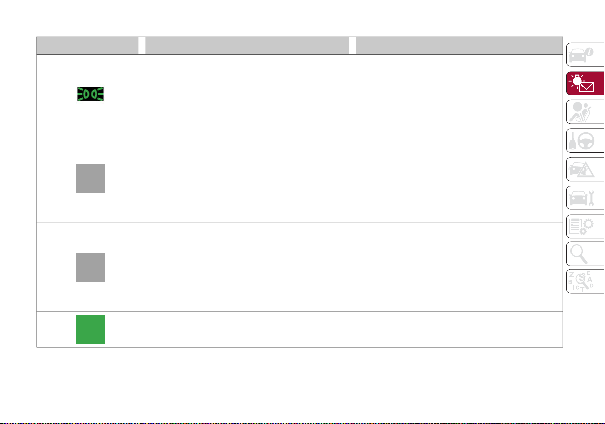
83
Green Telltale Indicator Lights
Indicator light What It Means What To Do
PARK/HEADLIGHT ON INDICATOR LIGHT
This indicator will illuminate when the park lights or
headlights are turned on.
Headlight Off Delay
This function allows the headlights to remain on for
30, 60 or 90 seconds after the ignition was placed in
the OFF position.
LEFT TURN SIGNAL
The instrument cluster directional arrow will flash
independently for the left turn signal as selected, as
well as the exterior turn signal lamp(s) (front and rear)
as selected when the multifunction lever is moved
down (left). This directional arrow will flash in
conjunction with the right directional arrow when the
hazard warning light button is pushed.
RIGHT TURN SIGNAL
The instrument cluster directional arrow will flash
independently for the right turn signal as selected, as
well as the exterior turn signal lamp(s) (front and rear)
as selected when the multifunction lever is moved up
(right). This directional arrow will flash in conjunction
with the left directional arrow when the hazard
warning light button is pushed.
AUTOMATIC HIGH BEAM HEADLIGHTS — IF EQUIPPED
This indicator light will illuminate when the automatic
high beam headlights are activated.
20_GA_OM_EN_USC_t.book Page 83

GETTING TO KNOW YOUR INSTRUMENT PANEL
84
Blue Telltale Indicator Light
Red Symbols
Indicator Light What It Means What To Do
HIGH BEAM HEADLIGHTS
This indicator shows that the high beam headlights
are on. Push the multifunction control lever away from
you to switch the headlights to high beam. Push the
lever a second time to switch the headlights back to
low beam. Pull the lever toward you for a temporary
high beam on, “flash to pass” scenario.
Symbol What It Means What To Do
LOW ENGINE OIL PRESSURE
This telltale indicates low engine oil pressure. If the
telltale turns on while driving, stop the vehicle and
shut off the engine as soon as possible. A chime will
sound when this telltale turns on. Do not operate the
vehicle until the cause is corrected. This telltale does
not indicate how much oil is in the engine.
NOTE:
Do not use the vehicle until the failure has been
solved. The turning on of the telltale does not indicate
the amount of oil in the engine: the oil level can be
checked on the display upon entering the vehicle and
also by activating the “Oil level" function on the Infor-
mation and Entertainment System.
Contact an authorized dealer as soon as possible.
CAUTION!
If the LOW ENGINE OIL PRESSURE symbol switches on when driving, stop the engine immediately and contact an authorized dealer.
20_GA_OM_EN_USC_t.book Page 84
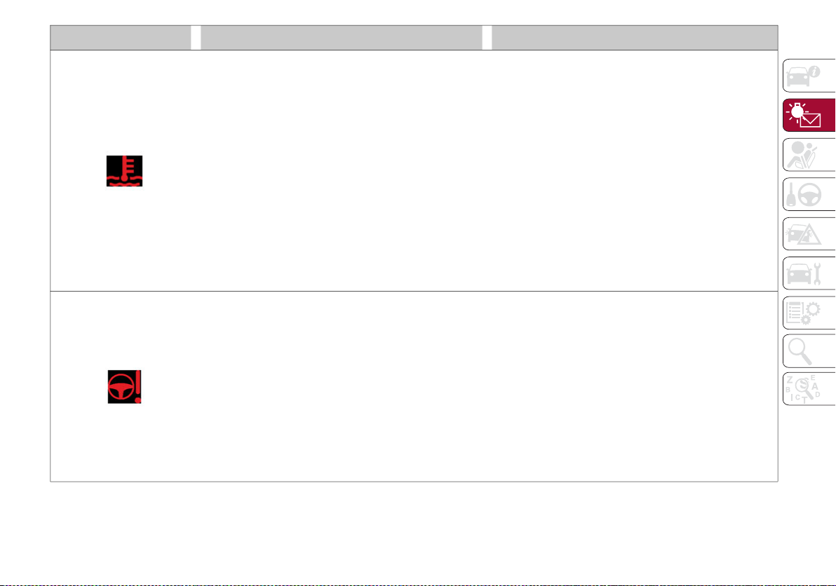
85
Symbol What It Means What To Do
ENGINE COOLANT TEMPERATURE TOO HIGH
The telltale lights up when the engine has overheated.
In normal driving conditions: stop the car, turn off the
engine and check that the coolant level in the
reservoir is not below the MIN mark. In this case, wait
for the engine to cool down, then slowly and carefully
open the cap, fill with coolant and check that the level
is between the MIN and MAX marks on the reservoir
itself. Also check visually for any fluid leaks. Contact
an authorized dealer if the telltale comes on when the
engine is started again.
If the vehicle is used under demanding conditions
(e.g. in high-performance driving): slow down and, if
the warning light stays on, stop the vehicle. Stop for 2
or 3 minutes with the engine running and slightly
accelerated to facilitate better coolant circulation,
then turn the engine off. Check that the coolant level
is correct as described above.
POWER STEERING FAILURE
If the telltale remains on, you may not have steering
assistance and the effort required to operate the
steering wheel may increased; steering is, however,
possible.
NOTE:
After the battery is disconnected, the steering wheel
must be initialized. The Power Steering Failure light on
the instrument panel will illuminate to indicate this. To
carry out this procedure, simply turn the steering wheel
all the way from one end to the other, and then turn it
back to the central position.
Contact an authorized dealer as soon as possible.
20_GA_OM_EN_USC_t.book Page 85

GETTING TO KNOW YOUR INSTRUMENT PANEL
86
DOOR OPEN
The telltale turns on when one or more doors are not
completely shut. An acoustic signal is activated with
the doors open and the car moving.
Close the doors properly.
HOOD CAP NOT PROPERLY SHUT
The telltale turns on when the hood cap is not properly
closed, along with the icon, an image of the vehicle
with an open hood cap appears on the display.
A buzzer is heard when the hood cap is open and the
vehicle is moving.
Close the hood properly.
TRUNK LID NOT PROPERLY SHUT
The telltale turns on when the trunk lid is not properly
closed, along with the icon, an image of the vehicle
with an open trunk lid appears on the display.
A buzzer is heard when the trunk lid is open and the
vehicle is moving.
Close the trunk lid properly.
AUTOMATIC TRANSMISSION FAILURE
The telltale turns on, together with a buzzer warning,
to indicate that the automatic transmission is faulty.
Contact an authorized dealer as soon as possible.
CAUTION:
Driving the vehicle with this symbol on may severely
damage the gearbox, with resulting breakage. The oil may
also overheat: contact with hot engine or with exhaust
components at high temperature could cause fires.
Symbol What It Means What To Do
20_GA_OM_EN_USC_t.book Page 86
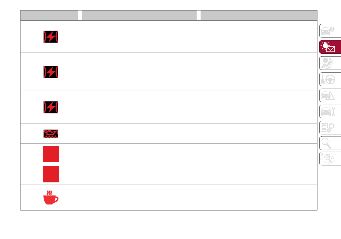
87
Symbol What It Means What To Do
ELECTRONIC THROTTLE CONTROL (ETC) WARNING
LIGHTS
This warning light, along with the related message,
signals a failure in the Electronic Throttle Control
system (ETC).
Contact an authorized dealer as soon as possible.
If a failure is detected, the warning light turns on while
the engine is running.
Place the gear selector in the P (Park) position and the
ignition in the off position: the warning light should
switch off. If the warning light stays on with engine
running, the vehicle can still be driven.
Contact an authorized dealer as soon as possible to
have the failure eliminated.
If the warning light flashes with the engine running,
immediate intervention is required. A loss of
performance, irregular/high idling speed or engine
stopping might take place and the vehicle may need
to be towed.
Contact an authorized dealer as soon as possible to
have the failure eliminated.
INSUFFICIENT ENGINE OIL LEVEL
The telltale turns on, along with the related message
on the display, to indicate low engine oil level.
Contact an authorized dealer to have the system
checked.
ALFA STEERING TORQUE (AST) FAILURE
The switching on of the telltale signals a failure in the
automatic steering correction system.
Contact an authorized dealer to have the system
checked.
ALTERNATOR FAILURE
The switching on of the telltale with engine on
corresponds to an alternator failure.
Contact an authorized dealer as soon as possible.
DAA SYSTEM ACTIVATION
The symbol appears, together with a message on the
display, in case of activation of the Drive Attention
Assist (DAA) system.
Stop to pause while driving, pulling the car over in safe
conditions.
20_GA_OM_EN_USC_t.book Page 87

GETTING TO KNOW YOUR INSTRUMENT PANEL
88
Amber Symbols
Symbol What It Means What To Do
ENGINE IMMOBILIZER FAILURE / BREAK-IN ATTEMPT
Engine Immobilizer System Failure
The telltale will illuminate to report a failure of the
Engine Immobilizer system.
Contact an authorized dealer as soon as possible.
Break-In Attempt
The telltale will illuminate when the ignition is cycled
to ON position, to indicate a possible break-in attempt
detected by the alarm system.
Electronic Key Not Recognized
The telltale will illuminate when the engine is started
and the electronic key is not recognized by the system.
Alarm System Failure
The telltale will illuminate to report an alarm system
failure.
FUEL CUT-OFF INDICATOR LIGHT
The telltale will illuminate after an accident has
occurred and the system has shut the fuel off.
For reactivating the fuel cut-off system, refer to
“Enhanced Accident Response System” in “Occupant
Restraint Systems” in “Safety” for further information.
If it is not possible to restore the fuel supply, contact
an authorized dealer.
PARK SENSORS SYSTEM FAILURE
The telltale will illuminate when the system has failed
or is not available.
Contact an authorized dealer to have the system
checked.
20_GA_OM_EN_USC_t.book Page 88
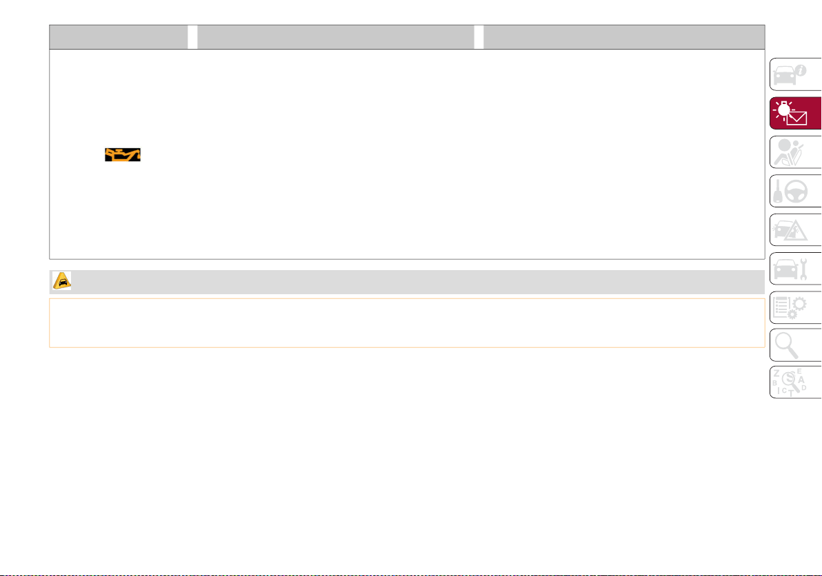
89
ENGINE OIL CHANGE REQUIRED — IF EQUIPPED
The telltale is illuminated only for a limited time.
NOTE:
After the first indication, each time the engine is
started the symbol will continue to illuminate as
described above until the oil is changed.
If the telltale flashes, this does not mean that there is
a fault on the vehicle, rather it simply reports that it is
now necessary to change the oil as a result of regular
use of the vehicle. The deterioration of engine oil is
accelerated by using the vehicle for short drives,
preventing the engine from reaching operating
temperature.
Contact an authorized dealer as soon as possible.
Symbol What It Means What To Do
CAUTION!
Deteriorated engine oil should be replaced as soon as possible after the symbol is switched on, and never more than 500 miles (805 km) after
it first switches on. Failure to observe the above may result in severe damage to the engine and invalidate the New Vehicle Limited Warranty.
When this symbol comes on, it does not mean that the level of engine oil is low, so if it flashes you do not need to top up the engine oil.
20_GA_OM_EN_USC_t.book Page 89

GETTING TO KNOW YOUR INSTRUMENT PANEL
90
Symbol What It Means What To Do
ENGINE OIL PRESSURE SENSOR FAILURE
The telltale will illuminate in the event of engine oil
pressure sensor failure.
Contact an authorized dealer as soon as possible.
ENGINE OIL LEVEL SENSOR FAILURE
The telltale will illuminate in the event of engine oil
level sensor failure.
Contact an authorized dealer as soon as possible.
FORWARD COLLISION WARNING (FCW) SYSTEM
FAILURE — IF EQUIPPED
The telltale will illuminate in the case of failure of the
Forward Collision Warning system.
Contact an authorized dealer as soon as possible.
STOP/START SYSTEM FAILURE
This telltale will illuminate to report a Stop/Start
system failure.
Contact an authorized dealer as soon as possible to
have the failure eliminated.
RAIN SENSOR FAILURE
The telltale will illuminate in the case of failure of the
automatic windshield wiper.
Contact an authorized dealer as soon as possible.
DUSK SENSOR FAILURE
The telltale will illuminate in the case of failure of the
automatic low beam alignment.
Contact an authorized dealer as soon as possible.
BLIND SPOT MONITORING SYSTEM FAILURE — IF
EQUIPPED
The telltale will illuminate in the event of a Blind Spot
Monitoring system failure.
Contact an authorized dealer as soon as possible.
FUEL LEVEL SENSOR FAILURE
The telltale will illuminate in the event of fuel level
sensor failure.
Contact an authorized dealer as soon as possible.
20_GA_OM_EN_USC_t.book Page 90
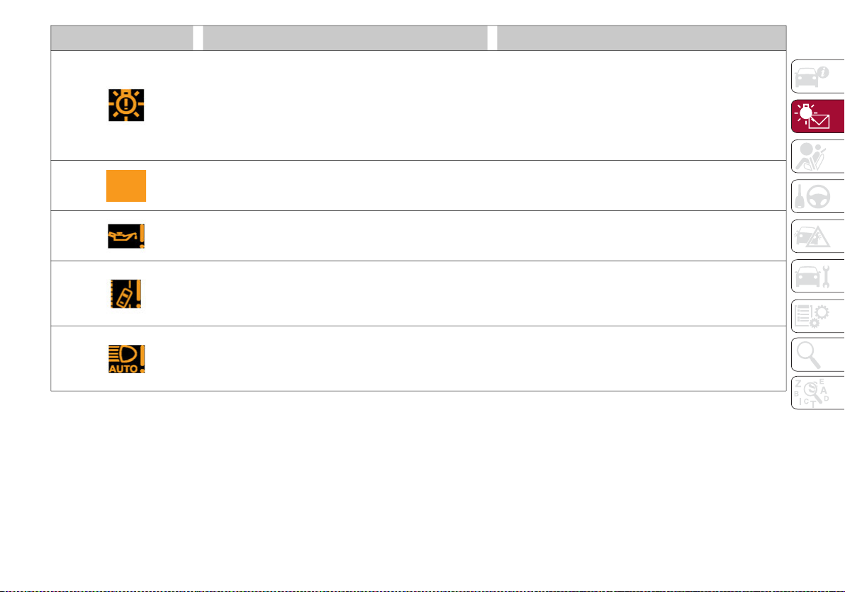
91
EXTERIOR LIGHTS FAILURE
The telltale will illuminate to indicate a failure on the
following lights: daytime running lights (DRLs) / parking
lights / trailer turn signal indicators (if present) / trailer
lights (if present) / side lights / turn signal indicators /
rear fog light / reversing light / brake lights / license
plate lights.
The failure may be caused by a blown bulb, a blown
protection fuse, or an interruption of the electrical
connection.
Replace the bulb or the relevant fuse. Contact an
authorized dealer.
KEYLESS SYSTEM FAILURE
The telltale will illuminate in the event of keyless
system failure.
Contact an authorized dealer as soon as possible.
FUEL CUT-OFF SYSTEM FAILURE
The telltale will illuminate in the event of fuel cut-off
system failure.
Contact an authorized dealer as soon as possible.
LANE DEPARTURE WARNING (LDW) SYSTEM FAILURE —
IF EQUIPPED
The telltale will illuminate in the event of a fault in the
Lane Departure Warning system.
Contact an authorized dealer as soon as possible.
AUTOMATIC HIGH BEAM HEADLIGHTS FAILURE — IF
EQUIPPED
The telltale will illuminate to report a failure of the
automatic high beam headlights.
Contact an authorized dealer as soon as possible to
have the failure eliminated.
Symbol What It Means What To Do
20_GA_OM_EN_USC_t.book Page 91
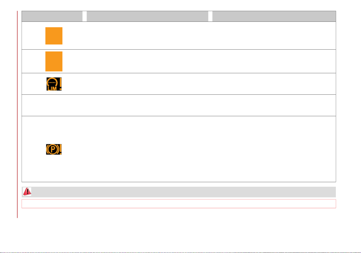
GETTING TO KNOW YOUR INSTRUMENT PANEL
92
Symbol What It Means What To Do
AUTOMATIC TRANSMISSION FLUID OVERHEATING
The telltale will illuminate in the case of transmission
overheating, after a particularly demanding use. In this
case an engine performance limitation is carried out.
Wait for the telltale to turn off with the engine off or
idling.
AUDIO SYSTEM FAILURE
The telltale will illuminate to report a failure of the
audio system.
Contact an authorized dealer as soon as possible to
have the failure eliminated.
SPEED LIMITER SYSTEM FAILURE
While driving, the telltale will illuminate to signal a
Speed Limiter system failure.
Contact an authorized dealer as soon as possible to
have the failure eliminated.
LOOSE FUEL FILLER CAP
Lights up if the fuel tank cap is open or not properly
closed.
Tighten the cap properly.
ELECTRIC PARK BRAKE FAILURE
The telltale will illuminate and a message will display
to signal a failure in the electric park brake system.
This failure may partially or completely block the vehicle
because the park brake could remain activated even if
automatically or manually disengaged using the relevant
controls. In these circumstances, you can disengage the
park brake following the emergency disengagement
procedure described in “Manual Park Release” in “In
Case Of Emergency.”
If you are still able to drive the vehicle (park brake is
not engaged), drive to the nearest authorized dealer
and remember, when executing any maneuvers/
commands, that the electric park brake is not
operational.
WARNING!
If a failure is present with sharp braking, the rear wheels may lock and the vehicle may swerve.
20_GA_OM_EN_USC_t.book Page 92
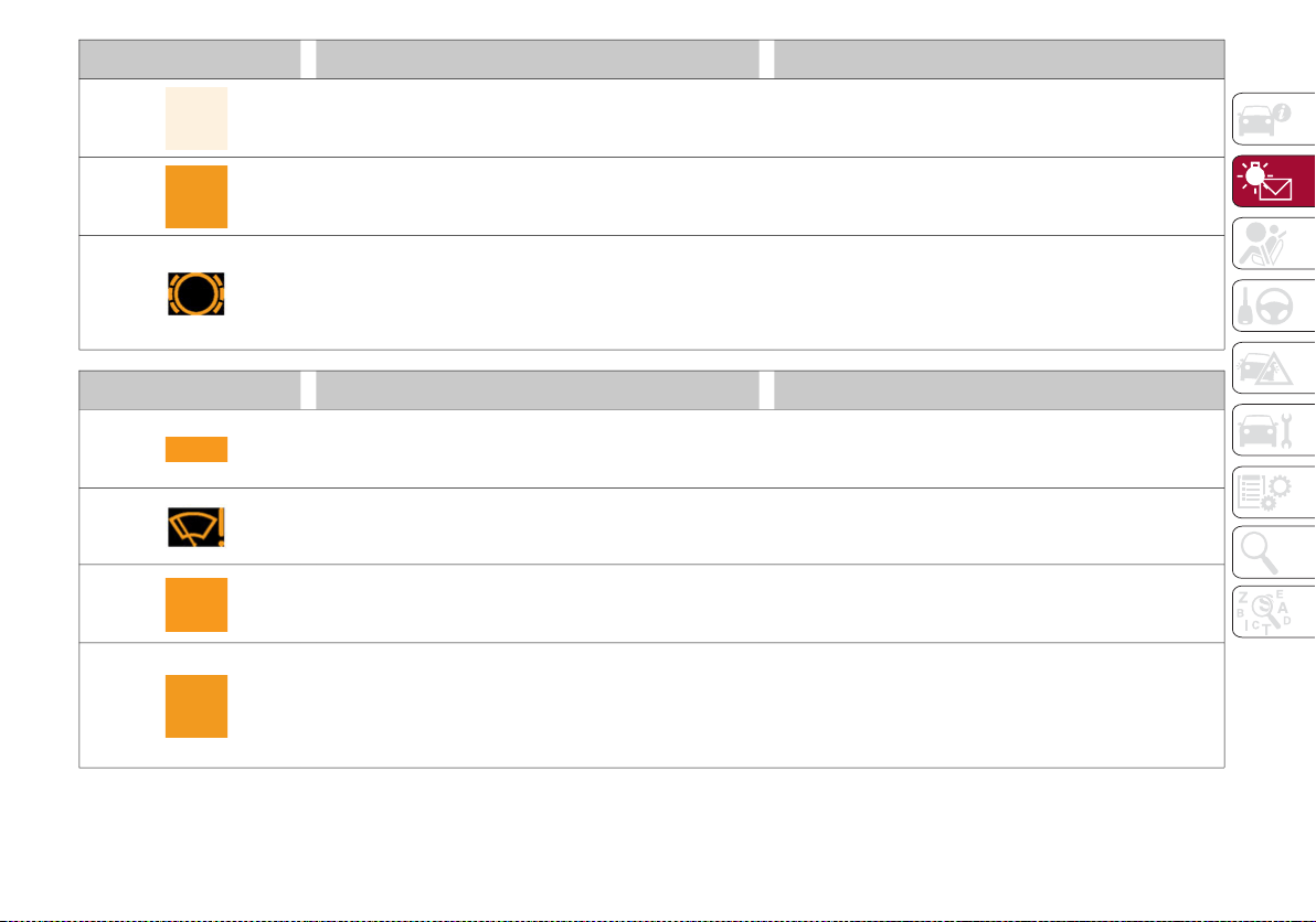
93
Symbol What It Means What To Do
LOW COOLANT LEVEL — IF EQUIPPED
This telltale will illuminate to indicate that the vehicle
coolant level is low.
Top up, as described in “Servicing And Maintenance.”
SERVICE ADAPTIVE CRUISE CONTROL SYSTEM
This light will illuminate when the Adaptive Cruise
Control (ACC) is not operating and needs service.
Contact an authorized dealer to have the system
checked.
WEAR ON BRAKE PADS
This light will illuminate when the brake pads have
reached their wear limit.
Contact an authorized dealer as soon as possible.
NOTE:
Always use genuine parts or similar because the Integrated
Brake System (IBS) system could detect anomalies.
Symbol What It Means What To Do
DYNAMIC DRIVE CONTROL SYSTEM FAILURE
The telltale will illuminate to signal a failure in the
dynamic drive control system.
WINDSHIELD WIPER FAILURE
Signals a windshield wiper failure.
Contact an authorized dealer.
GENERIC INDICATION
Signals information and failures.
The accompanying messages describe the failure.
ALL WHEEL DRIVE FAILURE
This telltale will illuminate along with an accompanying
message when the AWD dynamic control system is
temporarily deactivated to prevent damage. The traction
system will work in RWD mode in this instance.
Contact an authorized dealer as soon as possible to
have the failure eliminated.
20_GA_OM_EN_USC_t.book Page 93

GETTING TO KNOW YOUR INSTRUMENT PANEL
94
TEMPORARY ALL-WHEEL DRIVE FAILURE — IF EQUIPPED
This telltale will illuminate to indicate that the AWD
dynamic control system is temporarily deactivated to
prevent damage. The traction system will work in RWD
mode in this instance.
In the event that this telltale illuminates, reduce the
load to allow the system to cool down. The AWD
system will resume normal operation when the symbol
disappears from the display.
ABS ACTIVATION
This telltale will illuminate to indicate that the ABS
system has activated.
ADAPTIVE FRONT-LIGHTING SYSTEM FAILURE
The telltale will illuminate to indicate the automatic
directional light system failure.
Go to an authorized dealer to have the system
checked.
SOFT SUSPENSION CALIBRATION INSERTION — IF
EQUIPPED
The telltale will illuminate when the most comfortable
suspension setting is activated.
SHOCK ABSORBERS FAILURE (ADC)
While driving, if the telltale illuminates, it signals a
failure in the suspension system.
Contact an authorized dealer to have the system
checked.
WINDSHIELD WASHER LIQUID LEVEL
The telltale will illuminate to indicate that the level of the
windshield and headlight washing fluid (if any) is low.
To refill the liquid, refer to “Engine Compartment” in
“Servicing And Maintenance.” Always use liquid with
the features indicated in the “Fluids And Lubricants”
section in “Technical Specifications.”
Symbol What It Means What To Do
20_GA_OM_EN_USC_t.book Page 94
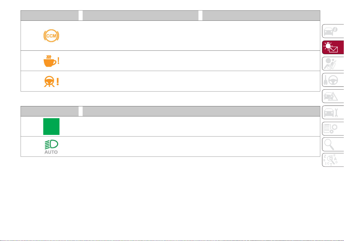
95
Green Symbols
WEAR ON Carbon Ceramic Material (CCM) BRAKE
DISCS — IF EQUIPPED
This light will illuminate when the carbon ceramic
material brake discs have reached their wear limit.
Contact an authorized dealer as soon as possible.
WARNING:
It is recommended to use only OEM brake pads to
ensure the original performance of the braking system.
DAA SYSTEM FAILURE
The symbol comes on in the event of a Driver Attention
Assist (DAA) system failure.
Contact an Alfa Romeo Dealership as soon as
possible to have the failure eliminated.
HAS SYSTEM / TJA SYSTEM FAILURE
The symbol lights up in case of Highway Assist (HAS)
or Traffic Jam Assist (TJA) system failure.
Contact an Alfa Romeo Dealership as soon as
possible to have the failure eliminated.
Symbol What It Means
HEADLIGHTS
The telltale will illuminate when the headlights are turned on.
AUTOMATIC HEADLIGHTS
The symbol lights up when the automatic headlights are on.
Symbol What It Means What To Do
20_GA_OM_EN_USC_t.book Page 95

GETTING TO KNOW YOUR INSTRUMENT PANEL
96
Blue Symbols
STOP/START OPERATION
The telltale will illuminate in the case of Stop/Start system intervention (stopping the engine).
When the engine is restarted, the telltale will shut off. (For further information on engine restarting modes, refer
to “Stop/Start System” in “Starting And Operating”).
SPEED CONTROL ACTIVATED
The telltale will illuminate when the Speed Control system is activated.
ADAPTIVE CRUISE CONTROL SYSTEM — IF EQUIPPED
The symbol comes on when the Adaptive Cruise Control system is activated.
Symbol What It Means
Symbol What it means
AUTOMATIC HIGH BEAM HEADLIGHTS — IF EQUIPPED
The telltale will illuminate when the automatic high beam headlights are activated.
HIGH BEAM HEADLIGHTS
The telltale will illuminate when the high beam headlights are activated.
20_GA_OM_EN_USC_t.book Page 96
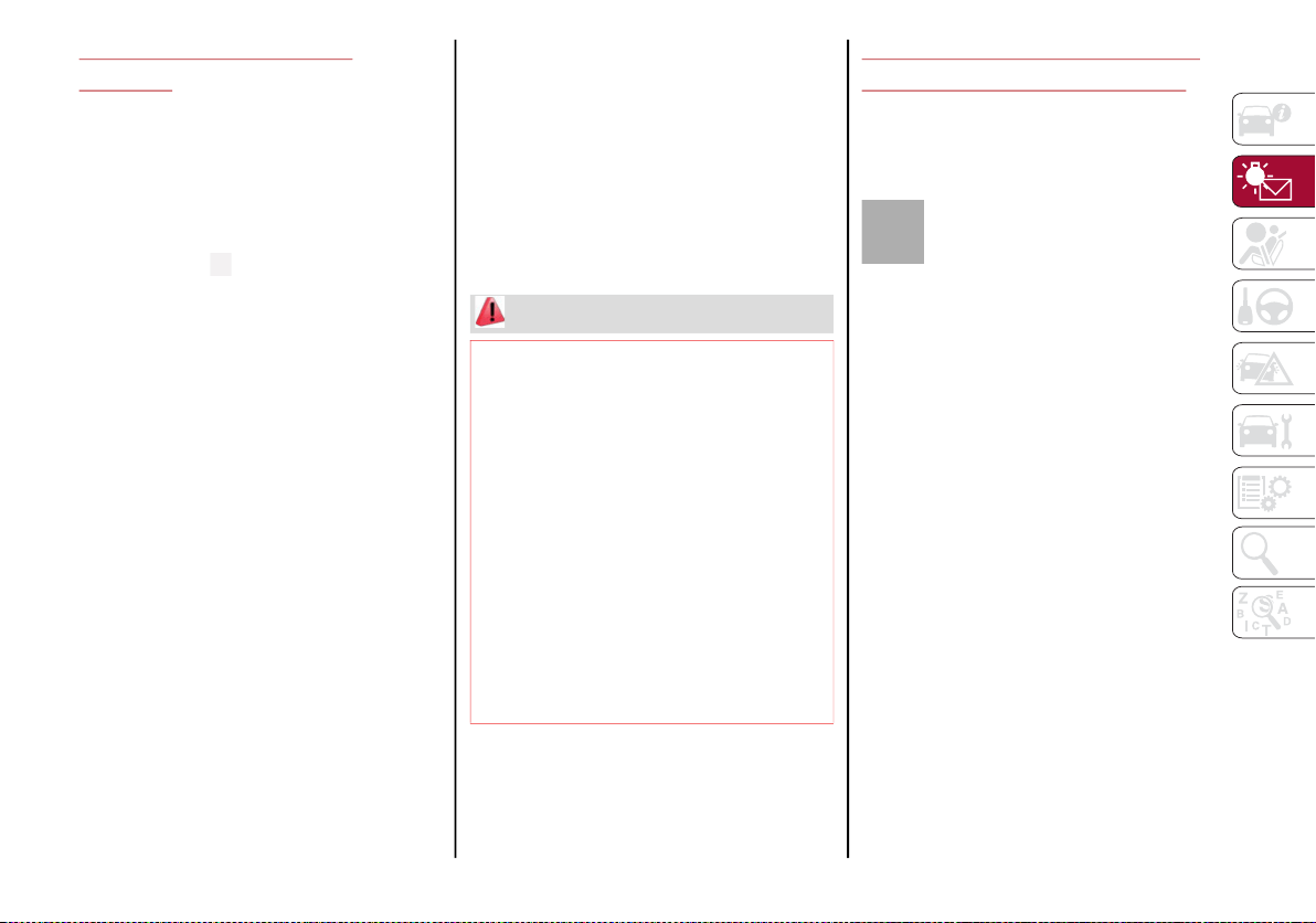
97
ONBOARD DIAGNOSTIC
SYSTEM
Operation
The Onboard Diagnostic system (OBD) carries
out a continuous diagnosis of the components
of the vehicle related to emissions.
It also alerts the driver of when these compo-
nents are no longer in peak condition by
switching on the warning light on the instru-
ment panel see “Warning Lights And
Messages” paragraph in this chapter.
The aim of the OBD system (Onboard Diag-
nostic) is to:
Monitor the efficiency of the system
Indicate an increase in emissions
Indicate the need to replace damaged
components
The vehicle also has a connector, which can
interface with appropriate tools, that makes it
possible to read the error codes stored in the
electronic control units together with a series
of specific parameters for engine operation
and diagnosis. This check can be carried out
by your authorized dealer.
NOTE:
After eliminating a fault, to check the system
completely, an authorized dealer is obliged to
run tests and, if necessary certain road tests.
Onboard Diagnostic System (OBD II)
Cybersecurity
Your vehicle is required to have an Onboard
Diagnostic system (OBD II) and a connection
port to allow access to information related to
the performance of your emissions controls.
Authorized service technicians may need to
access this information to assist with the diag-
nosis and service of your vehicle and emis-
sions system.
EMISSIONS INSPECTION AND
MAINTENANCE PROGRAMS
In some localities, it may be a legal require-
ment to pass an inspection of your vehicle's
emissions control system. Failure to pass
could prevent vehicle registration.
For states that require an Inspection
and Maintenance (I/M), this check
verifies the “Malfunction Indicator
Light (MIL)” is functioning and is not
on when the engine is running, and that the
OBD II system is ready for testing.
Normally, the OBD II system will be ready. The
OBD II system may not be ready if your vehicle
was recently serviced, recently had a depleted
battery or a battery replacement. If the OBD II
system should be determined not ready for the
I/M test, your vehicle may fail the test.
WARNING!
ONLY an authorized service technician
should connect equipment to the OBD II
connection port in order to read the VIN,
diagnose, or service your vehicle.
If unauthorized equipment is connected to
the OBD II connection port, such as a
driver-behavior tracking device, it may:
• Be possible that vehicle systems,
including safety related systems, could
be impaired or a loss of vehicle control
could occur that may result in an acci-
dent involving serious injury or death.
• Access, or allow others to access, infor-
mation stored in your vehicle systems,
including personal information.
20_GA_OM_EN_USC_t.book Page 97

GETTING TO KNOW YOUR INSTRUMENT PANEL
98
Your vehicle has a simple ignition actuated
test, which you can use prior to going to the
test station. To check if your vehicle's OBD II
system is ready, you must do the following:
1. Cycle the ignition switch to the ON posi-
tion, but do not crank or start the engine.
NOTE:
If you crank or start the engine, you will have to
start this test over.
2. As soon as you cycle the ignition switch to
the ON position, you will see the “Malfunc-
tion Indicator Light (MIL)” symbol come on
as part of a normal bulb check.
3. Approximately 15 seconds later, one of
two things will happen:
The MIL will flash for about 10 seconds and
then return to being fully illuminated until
you turn OFF the ignition or start the engine.
This means that your vehicle's OBD II
system is not ready and you should not
proceed to the I/M station.
The MIL will not flash at all and will remain
fully illuminated until you place the ignition
in the off position or start the engine. This
means that your vehicle's OBD II system is
ready and you can proceed to the I/M
station.
If your OBD II system is not ready, you should
see an authorized dealer or repair facility. If
your vehicle was recently serviced or had a
battery failure or replacement, you may need
to do nothing more than drive your vehicle as
you normally would in order for your OBD II
system to update. A recheck with the above
test routine may then indicate that the system
is now ready.
Regardless of whether your vehicle's OBD II
system is ready or not, if the MIL is illuminated
during normal vehicle operation you should
have your vehicle serviced before going to the
I/M station. The I/M station can fail your
vehicle because the MIL is on with the engine
running.
20_GA_OM_EN_USC_t.book Page 98
99
(Continued)
SAFETY
This very important section describes the
safety systems that your vehicle may be
equipped with, and provides instructions on
how to use them correctly.
ACTIVE SAFETY SYSTEMS
The vehicle may be equipped with the
following active safety devices:
Anti-Lock Braking System (ABS)
Active Torque Vectoring (ATV)
Dynamic Steering Torque (DST)
Drive Train Control (DTC)
Electronic Stability Control (ESC)
Hill Start Assist (HSA)
Panic Brake Assist (PBA)
Traction Control System (TCS)
For the operation of the systems, see the
following pages.
Anti-Lock Braking System (ABS)
An integral part of the braking system, the
Anti-Lock Braking System (ABS) prevents one
or more wheels from locking and slipping in all
road surface conditions, regardless of the
intensity of the braking action. The system
ensures that the vehicle can be controlled
even during emergency braking, allowing the
driver to optimize stopping distances.
The system intervenes during braking when
the wheels are about to lock, typically in emer-
gency braking or low-grip conditions where
locking may be more frequent.
The system also improves control and stability
of the vehicle when braking on a surface
where the grip of the left and right wheels
varies, such as in a corner.
The Electronic Braking Force Distribution
(EBD) system works with the ABS, allowing the
brake force to be distributed between the front
and rear wheels.
System Intervention
The ABS equipped on this vehicle is provided
with the "Brake-by-wire" (Integrated Brake
System — IBS) function. With this system, the
command given by pressing the brake pedal is
not transmitted hydraulically, but electrically.
Therefore, the light pulsation that is felt on the
pedal with the traditional system is no longer
noticeable.
Active Torque Vectoring (ATV) — If Equipped
The dynamic drive control is used to optimize
and balance the drive torque between the
wheels of the same axles. The Active Torque
Vectoring (ATV) system improves the grip in
turns, sending more drive torque to the
external wheel.
WARNING!
The ABS contains sophisticated electronic
equipment that may be susceptible to inter-
ference caused by improperly installed or
high output radio transmitting equipment.
This interference can cause possible loss of
anti-lock braking capability. Installation of
such equipment should be performed by
qualified professionals.
Pumping of the Anti-Lock Brakes will
diminish their effectiveness and may lead
to a collision. Pumping makes the stop-
ping distance longer. Just press firmly on
your brake pedal when you need to slow
down or stop.
The ABS cannot prevent the natural laws
of physics from acting on the vehicle, nor
can it increase braking or steering effi-
ciency beyond that afforded by the condi-
tion of the vehicle brakes and tires or the
traction afforded.
The ABS cannot prevent collisions,
including those resulting from excessive
speed in turns, following another vehicle
too closely, or hydroplaning.
The capabilities of an ABS equipped
vehicle must never be exploited in a reck-
less or dangerous manner that could jeop-
ardize the user’s safety or the safety of
others.
WARNING! (Continued)
20_GA_OM_EN_USC_t.book Page 99

SAFETY
100
Given that, in a turn, the external wheels of the
car travel more than the internal ones and
therefore turn faster, sending a higher thrust
to the external rear wheel allows for the car to
be more stable and to not suffer an "under-
steer" condition. Understeer occurs when the
vehicle is turning less than appropriate for the
steering wheel position.
Dynamic Steering Torque (DST)
Dynamic Steering Torque (DST) uses the inte-
gration of the Electronic Stability Control (ESC)
system with the electric power steering to
increase the safety level of the whole vehicle.
In critical situations (braking on surfaces with
different grip conditions), the ESC system
controls the steering through the DST function
to implement an additional torque contribu-
tion on the steering wheel in order to suggest
the most correct maneuver to the driver.
The coordinated action of the brakes and
steering increases the sensation of safety and
control of the vehicle.
NOTE:
The DST feature is only meant to help the driver
realize the correct course of action through small
torques on the steering wheel, which means the
effectiveness of the DST feature is highly depen-
dent on the driver’s sensitivity and overall reac-
tion to the applied torque. It is very important to
realize that this feature will not steer the vehicle,
meaning the driver is still responsible for
steering the vehicle.
Drive Train Control (DTC) System — If
Equipped
Some models of this vehicle are equipped with
an All-Wheel Drive (AWD) system, which offers
an optimal drive for countless driving condi-
tions and road surfaces. The system reduces
the slipping of the tires to a minimum, auto-
matically redistributing the torque to the front
and rear wheels as needed.
To maximize fuel savings, the vehicle with
AWD automatically passes to Rear-Wheel
Drive (RWD) when the road and environmental
conditions are such that they wouldn't cause
the tires to slip. When the road and environ-
mental conditions require better traction, the
vehicle automatically goes to AWD mode.
NOTE:
If the system failure symbol switches on, after
starting the engine or while driving, it means
that the AWD system is not working properly. If
the warning message activates frequently, it is
recommended to carry out the maintenance
operations.
Electronic Stability Control (ESC)
The Electronic Stability Control (ESC) system
improves the directional control and stability
of the vehicle in various driving conditions.
The ESC system corrects the vehicle’s under-
steer and oversteer, distributing the brake
force on the appropriate wheels. The torque
supplied by the engine can also be reduced in
order to maintain control of the vehicle.
The ESC system uses sensors installed on the
vehicle to determine the path that the driver
intends to follow and compares it with the
vehicle’s effective path. When the real path
deviates from the desired path, the ESC
system intervenes to counter the vehicle’s
oversteer or understeer.
Oversteer occurs when the vehicle is
turning more than it should according to the
angle of the steering wheel.
Understeer occurs when the vehicle is
turning less than it should according to the
angle of the steering wheel.
System Intervention
The intervention of the system is indicated by
the flashing of the ESC warning light on the
instrument panel, to inform the driver that the
vehicle stability and grip are critical.
20_GA_OM_EN_USC_t.book Page 100
101
Hill Start Assist (HSA)
This is an integral part of the ESC system and
facilitates starting on slopes, activating auto-
matically in the following cases:
Uphill: vehicle stationary on a road with a
gradient higher than 5%, engine running,
brake pressed and transmission in NEUTRAL
(N) or gear other than REVERSE (R) engaged.
Downhill: vehicle stationary on a road with a
gradient higher than 5%, engine running,
brake pressed and reverse gear engaged.
When starting to move forward from a
complete stop, the ESC system control unit
maintains the braking pressure on the wheels
until the engine torque necessary for starting
is reached, or in any case for a maximum of
two seconds, allowing your right foot to be
moved easily from the brake pedal to the
accelerator.
The system will automatically deactivate after
two seconds without starting, gradually
releasing the braking pressure. During this
release stage, it is possible to hear a typical
mechanical brake release noise, indicating
the imminent movement of the vehicle.
Panic Brake Assist (PBA)
The Panic Brake Assist (PBA) system is
designed to improve the vehicle’s braking
capacity during emergency braking.
The system detects emergency braking by
monitoring the speed and force with which the
brake pedal is pressed, and consequently
applies the optimal brake pressure. This can
reduce the braking distance: the PBA system
therefore complements the ABS.
WARNING!
Electronic Stability Control (ESC) cannot
prevent the natural laws of physics from
acting on the vehicle, nor can it increase the
traction afforded by prevailing road condi-
tions. ESC cannot prevent accidents,
including those resulting from excessive
speed in turns, driving on very slippery
surfaces, or hydroplaning. ESC also cannot
prevent accidents resulting from loss of
vehicle control due to inappropriate driver
input for the conditions. Only a safe, atten-
tive, and skillful driver can prevent acci-
dents. The capabilities of an ESC equipped
vehicle must never be exploited in a reckless
or dangerous manner which could jeopar-
dize the user’s safety or the safety of others.
Vehicle modifications, or failure to prop-
erly maintain your vehicle, may change
the handling characteristics of your
vehicle, and may negatively affect the
performance of the ESC system. Changes
to the steering system, suspension,
braking system, tire type and size or wheel
size may adversely affect ESC perfor-
mance. Improperly inflated and unevenly
worn tires may also degrade ESC perfor-
mance. Any vehicle modification or poor
vehicle maintenance that reduces the
effectiveness of the ESC system can
increase the risk of loss of vehicle control,
vehicle rollover, personal injury and death.
WARNING!
There may be situations where the Hill Start
Assist (HSA) will not activate and slight
rolling may occur, such as on minor hills or
with a loaded vehicle, or while pulling a
trailer. HSA is not a substitute for active
driving involvement. It is always the driver’s
responsibility to be attentive to distance to
other vehicles, people, and objects, and
most importantly brake operation to ensure
safe operation of the vehicle under all road
conditions. Your complete attention is
always required while driving to maintain
safe control of your vehicle. Failure to follow
these warnings can result in a collision or
serious personal injury.
20_GA_OM_EN_USC_t.book Page 101

SAFETY
102
Maximum assistance from the PBA system is
obtained by pressing the brake pedal very
quickly. In addition, the brake pedal should be
pressed continuously during braking, avoiding
intermittent presses, to get the most out of the
system. Do not reduce pressure on the brake
pedal until braking is no longer necessary.
The PBA system is deactivated when the brake
pedal is released.
Traction Control System (TCS)
The Traction Control System (TCS) automati-
cally operates in the event of slipping, loss of
grip on wet roads (hydroplaning), and acceler-
ation on one or both drive wheels on roads
that are slippery, snowy, icy, etc. Depending on
the slipping conditions, two different control
systems are activated:
If the slipping involves both drive wheels,
the system intervenes, reducing the power
transmitted by the engine.
If the slipping only involves one of the drive
wheels, the Brake Limited Differential (BLD)
function is activated, automatically braking
the wheel which is slipping (the behavior of
a self-locking differential is simulated). This
will increase the engine torque transferred
to the wheel which isn't slipping.
System Intervention
The intervention of the system is indicated by
the flashing of the ESC warning light on the
instrument panel, to inform the driver that the
vehicle stability and grip are critical.
AUXILIARY DRIVING SYSTEMS
The following auxiliary driving systems are
available in this vehicle:
Forward Collision Warning (FCW)
Tire Pressure Monitoring System (TPMS)
Driver Attention Assist (DAA)
The vehicle may also be fitted with the
following driving assistance systems:
Blind Spot Monitoring (BSM) — If Equipped
Lane Departure Warning (LDW)
Lane Keeping Assist (LKA)
Highway Assist System (HAS)
Traffic Jam Assist (TJA)
Adaptive Cruise Control (ACC)
Intelligent Speed Control (ISC)
Traffic Sign Recognition (TSR)
For the operation of the DAA, LDW, LKA, HAS,
TJA, ACC, ISC, or TSR systems, refer to the
“Starting And Operating” chapter.
NOTE:
When driving on two-way roads where there is
no lane dividing center line (e.g. on unpaved
roads), the use of the ABSA, HAS, TJA, LKA
systems is strongly discouraged as the system
could detect the entire road as single-lane
dividing lines.
WARNING!
The Panic Brake Assist (PBA) cannot
prevent the natural laws of physics from
acting on the vehicle, nor can it increase
the traction afforded by prevailing road
conditions. PBA cannot prevent collisions,
including those resulting from excessive
speed in turns, driving on very slippery
surfaces, or hydroplaning. The capabilities
of a PBA-equipped vehicle must never be
exploited in a reckless or dangerous
manner, which could jeopardize the user's
safety or the safety of others.
20_GA_OM_EN_USC_t.book Page 102
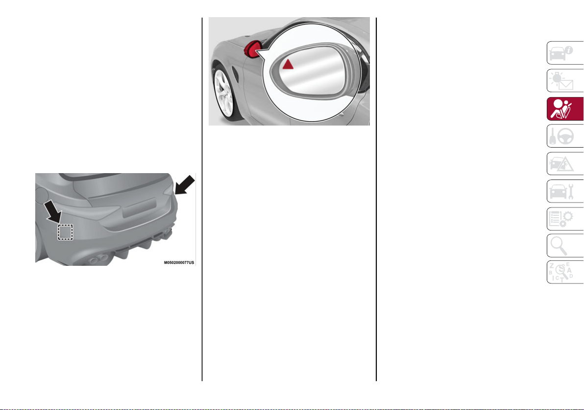
103
NOTE:
The driving assistance systems are designed
to aid in driving the car. The driver must always
maintain a sufficient level of attention to the
traffic and road conditions and control the
trajectory of the car.
Blind Spot Monitoring (BSM) System — If
Equipped
The Blind Spot Monitoring (BSM) system uses
two radar sensors, located in the rear bumper
(one on each side), to detect the presence of
other vehicles in the rear side blind spots of
your vehicle.
Rear Sensor Location
The system warns the driver about the pres-
ence of other vehicles in the detection area by
illuminating the warning light located within
the door mirror on the side in which the other
vehicle was detected. If equipped, an audible
chime will also be heard to alert the driver (if
option is selected within the radio system).
BSM Indicator Light
When the engine is started, the warning light
illuminates briefly to signal the driver that the
system is active.
Sensors
The sensors are activated when any forward
gear is engaged at a speed higher than
approximately 6 mph (10 km/h) or when
REVERSE is engaged.
The sensors are temporarily deactivated when
the vehicle is stationary or the vehicle is in
PARK.
The detection area of the system covers
approximately one lane on both sides of the
vehicle.
This area begins from the door mirror and
extends for approximately 19 ft (6 m) towards
the rear part of the vehicle.
When the sensors are active, the system moni-
tors the detection areas on both sides of the
vehicle and warns the driver about the
possible presence of vehicles in these areas.
While driving, the system monitors the detec-
tion zone to check whether it is necessary to
send a signal to the driver on both sides. The
system monitors this detection zone in three
different situations:
When you are being overtaken by a vehicle.
When you are overtaking a vehicle.
When a vehicle approaches from the side.
NOTE:
The system does not alert the driver of the
presence of fixed objects (e.g. safety barriers,
poles, walls, etc.). However, in some circum-
stances, the system may activate in the pres-
ence of these objects. This is normal and does
not indicate a system malfunction.
The system does not alert the driver about
the presence of vehicles coming from the
opposite direction, in the adjacent lanes.
If a trailer is hitched to the car, the system
automatically deactivates.
20_GA_OM_EN_USC_t.book Page 103

SAFETY
104
Rear View
The system detects vehicles coming from the
rear part of your vehicle on both sides and
entering the rear detection area with a differ-
ence in speed of less than 25 mph (40 km/h)
in relation to your vehicle.
Overtaking Vehicles
If another vehicle is overtaken slowly, with a
difference in speed of less than 15 mph
(25 km/h) and the vehicle stays in the blind
spot for approximately 1.5 seconds, the
warning light on the door mirror of the corre-
sponding side illuminates.
If the difference in speed between the two
vehicles is greater than 15 mph (25 km/h),
the warning light does not illuminate.
Rear Cross Path Detection (RCP) System
The Rear Cross Path Detection (RCP) system
assists the driver during reverse maneuvers in
the case of reduced visibility.
The RCP system monitors the rear detection
areas on both sides of the vehicle to detect
objects moving toward the sides of the vehicle,
with a minimum speed between 1 mph (1 km/h)
and 2 mph (3 km/h) and objects moving at a
maximum speed of 21 mph (35 km/h), in areas
such as parking lots.
The system activation is signaled to the driver
by an audible warning.
NOTE:
If the sensors are covered by objects or
vehicles, the system may not work as
intended.
For the system to operate correctly, the rear
bumper area where the radar sensors are
located must stay free from snow, ice and
dirt gathered from the road surface.
Do not cover the rear bumper area where
the radar sensors are located with any
object (e.g. adhesives, bike rack, etc.).
Operating Mode
The system may be activated/deactivated via
the radio system. To access the function,
select the following items on the main menu in
sequence:
1. “Settings”
2. “Safety”
3. “Blind Spot Alert”
“Blind Spot Alert”, “Visual” Mode
When the system is enabled, the warning light
within the door mirror on the side of the
detected object illuminates.
The visual warning on the mirror will blink if the
driver activates the turn signals, indicating a
lane change.
The warning light will be constant if the driver
stays in the same lane.
WARNING!
The Blind Spot Monitoring system is only an
aid to help detect objects in the blind spot
zones. The BSM system is not designed to
detect pedestrians, bicyclists, or animals.
Even if your vehicle is equipped with the BSM
system, always check your vehicle’s mirrors,
glance over your shoulder, and use your turn
signal before changing lanes. Failure to do so
can result in serious injury or death.
WARNING!
Rear Cross Path Detection (RCP) is not a
back up aid system. It is intended to be
used to help a driver detect an oncoming
vehicle in a parking lot situation. Drivers
must be careful when backing up, even
when using RCP. Always check carefully
behind your vehicle, look behind you, and
be sure to check for pedestrians, animals,
other vehicles, obstructions, and blind
spots before backing up. Failure to do so
can result in serious injury or death.
20_GA_OM_EN_USC_t.book Page 104

105
“Blind Spot Alert” Function Deactivation
When the system is deactivated (“Blind Spot
Alert” mode off), the BSM or RCP systems will
not emit an audible or a visual warning.
The BSM system will store the operating mode
that was active when the engine was stopped.
Each time the engine is started, the operating
mode stored previously will be recalled and
used.
General Information
The following regulatory statement applies to
all Radio Frequency (RF) devices equipped in
this vehicle:
This device complies with Part 15 of the FCC
Rules and with Innovation, Science and
Economic Development Canada license-exempt
RSS standard(s). Operation is subject to the
following two conditions:
1. This device may not cause harmful inter-
ference, and
2. This device must accept any interference
received, including interference that may
cause undesired operation.
Le présent appareil est conforme aux CNR
d`Innovation, Science and Economic Develop-
ment applicables aux appareils radio exempts
de licence. L'exploitation est autorisée aux
deux conditions suivantes:
1. l'appareil ne doit pas produire de brouil-
lage, et
2. l'utilisateur de l'appareil doit accepter tout
brouillage radioélectrique subi, même si le
brouillage est susceptible d'en comprom-
ettre le fonctionnement.
La operación de este equipo está sujeta a las
siguientes dos condiciones:
1. es posible que este equipo o dispositivo no
cause interferencia perjudicial y
2. este equipo o dispositivo debe aceptar
cualquier interferencia, incluyendo la que
pueda causar su operación no deseada.
RF Exposure Requirements
To comply with FCC RF exposure compliance
requirements, the device must be installed
and operated to provide a separation distance
of at least 20 cm from all persons.
This equipment complies with Canada radia-
tion exposure limits set forth for an uncon-
trolled environment. This equipment should
be installed and operated with minimum
distance 20 cm between the radiator and your
body.
NOTE:
Changes or modifications not expressly
approved by the party responsible for compli-
ance could void the user’s authority to operate
the equipment.
Déclaration d’exposition aux radiations
Cet équipement est conforme aux limites
d’exposition aux rayonnements ISED établies
pour un environnement non contrôlé. Cet équi-
pement doit être installé et utilisé avec un
minimum de 20 cm de distance entre la
source de rayonnement et votre corps
REMARQUE:
Des changements ou des modifications n’ayant
pas été expressément approuvés par la partie
responsable de la conformité pourraient révo-
quer l’autorisation d’utilisation de l’équipement.
Active Blind Spot Assist (ABSA) System — If
Equipped
The Active Blind Spot Assist (ABSA) System
function is to help avoid/limit lateral collisions
with cars located in the blind spot zones, even
changing the vehicle’s trajectory in order to
keep it in the detected lane.
The system warns the driver about the pres-
ence of other vehicles in the detection area by
illuminating the warning light in the door
mirror on the side in which the other vehicle
was detected. It will alert you with an acoustic
signal, vibration on the steering wheel, and/or
counter-steering torque on the steering wheel
(if the respective item on the “Driver Assis-
tance” menu is set up and “Safety” is selected
on the radio system).
20_GA_OM_EN_USC_t.book Page 105
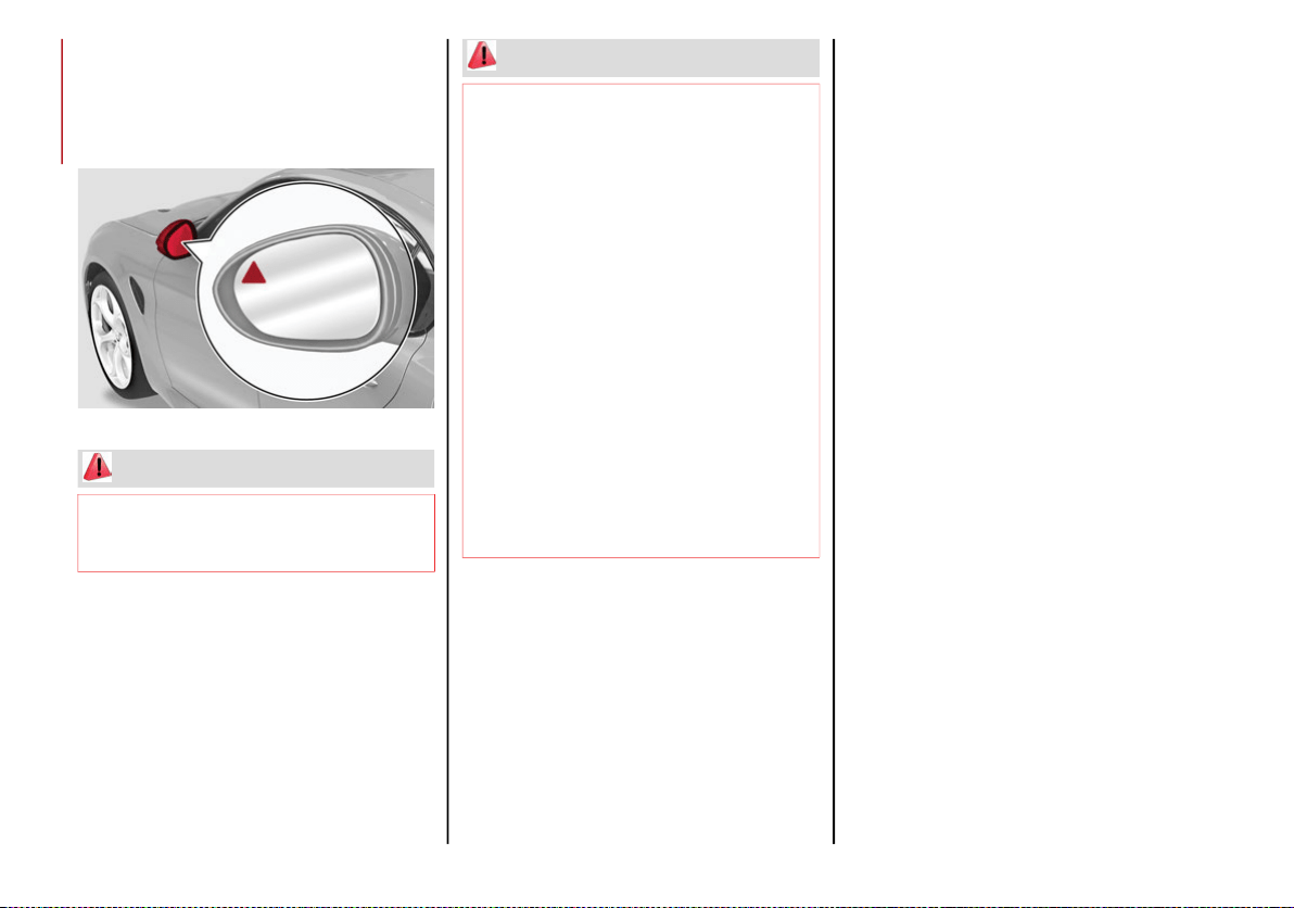
SAFETY
106
(Continued)
When the engine is started, the warning light
illuminates briefly to signal the driver that the
system is active (the warning light comes on
even if the system is activated through the
radio system menu).
ABSA Indicator Light
Sensors
The system uses two radar sensors, located in
the rear bumper (one for each side) to detect the
presence of vehicles (cars, trucks, motorbikes,
etc.) in the rear side blind spots of the car.
The sensors are activated when any forward
gear is engaged at a speed higher than about
6 mph (10 km/h), or when REVERSE (R) is
engaged.
The sensors are temporarily deactivated when
the car is stationary and in PARK (P).
The detection area of the system covers about
a lane on both sides of the car around 10 ft
(3 meters).
This area begins from the door mirror and
extends for about 20 ft (6 meters) towards the
rear part of the car.
When the sensors are active the system moni-
tors the detection areas on both sides of the
car and warns the driver about the possible
presence of cars in these areas.
WARNING!
The accident risk persists despite the
application of torque to the steering wheel
by the ABSA system.
Applying a torque that corrects the steering
wheel alignment does not always prevent an
accident. It is always the driver's responsi-
bility to steer, brake or accelerate, especially
after the ABSA system warning or after the
steering wheel torque intervention. The
driver is responsible for ensuring that there
are no pedestrians, other vehicles or objec-
tives along the direction of the vehicle.
Failure to comply with these precautions
may cause serious accidents and injuries.
The driver is fully responsible for holding a
safe distance from the vehicle ahead
respecting the highway code in force in the
respective country.
In some cases, the system could apply an
improper torque to the steering wheel.
This application can be interrupted at any
time by turning the steering wheel in the
opposite direction.
WARNING! (Continued)
20_GA_OM_EN_USC_t.book Page 106
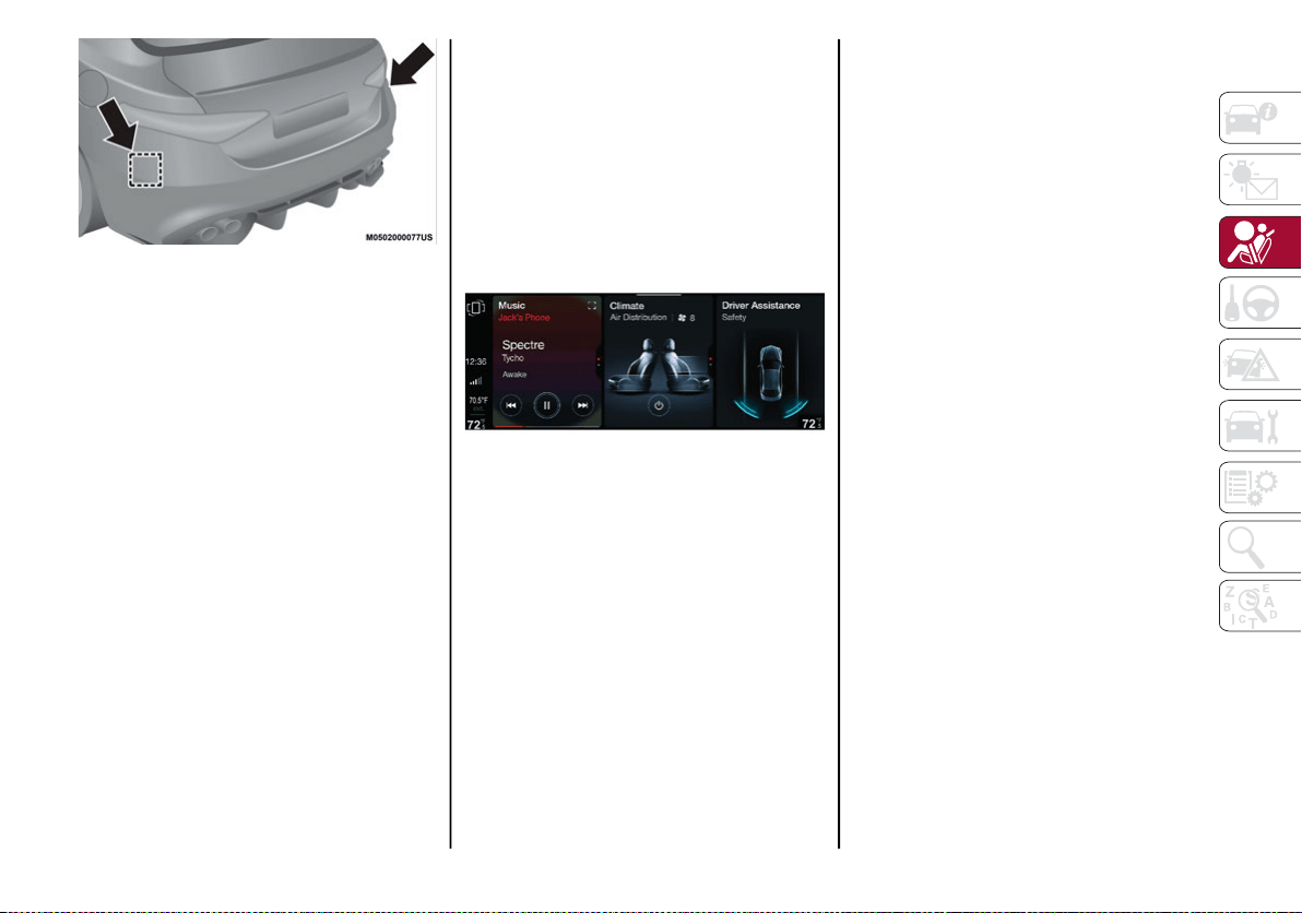
107
Rear Sensor Location
While driving, the system monitors the detec-
tion zone in three different situations:
When you are being overtaken by a vehicle;
When you are overtaking a vehicle;
When a vehicle approaches from the side;
to check if it is necessary to intervene in order
to keep the vehicle inside the lane on both
sides.
NOTE:
The system does not signal the presence of
fixed object (e.g. safety barriers, poles, walls,
etc.). However, in some circumstances, the
system may activate in the presence of these
objects.This is normal and does not indicate a
system malfunction.
The system does not warn the driver about the
presence of cars coming from the opposite
direction in the adjacent lanes.
Activation /deactivation
The system can be activated/deactivated
using the “Driver Assistance” menu in the
radio system. Select signal type, strength
levels and sensitivity.
NOTE:
Vehicles with an active system will display the
following screen, on the radio system.
System intervention
The system intervenes in the following condi-
tions:
The direction indicators have been turned on;
There is a vehicle in the adjacent lane on
the same side of the direction indicator
(blind spot area);
Lane lines are not correctly detected;
The driver tries to change lane intentionally.
If the system detects the presence of a vehicle
in the rear side blind spots of the car, it applies
a torque on the steering wheel (if it has been
set through the “Settings” menu of the radio
system), in order to warn the driver of the need
to keep the car inside the lane and thus avoid
collisions with other vehicles.
However, the application of torque and vibra-
tion is only available with car speed between
37 mph (60 km/h) and 110 mph (180 km/h).
The application of torque, as well as of the
vibration, is suppressed/inhibited if:
The torque given by the driver of the
steering wheel is high
Lateral acceleration is high
The trailer is connected to the correct
control module
At least one hand is not detected on the
steering wheel for longer than a specific time
The turn signal is turned off
NOTE:
The steering wheel torque is not applied if the
system is unable to detect a lane and if the
direction indicator for the appropriate side has
not been switched on.
The steering wheel detects the presence of the
driver’s hands by a capacitive sensor installed in
the steering wheel and by the applied torque
measured on the steering column.
20_GA_OM_EN_USC_t.book Page 107
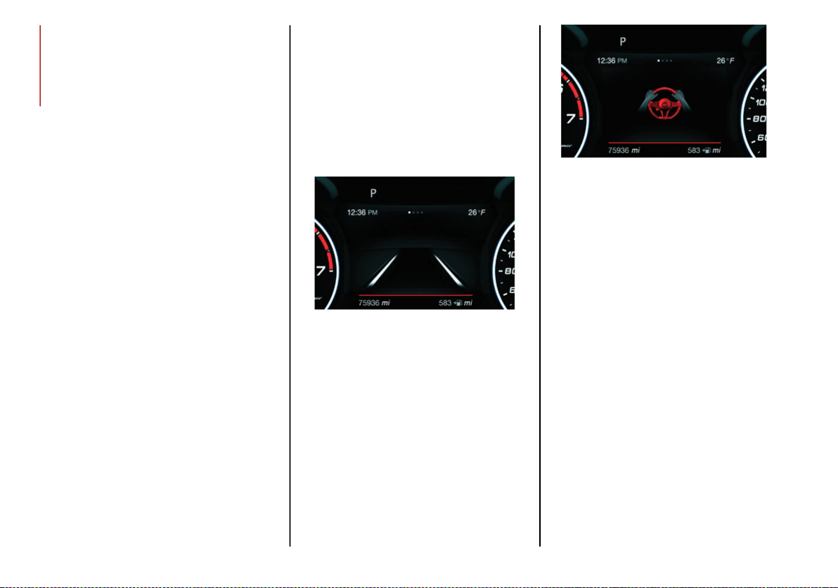
SAFETY
108
System availability
Aggressive driving of the car, or driving on the
median lines, will prevent the correct opera-
tion of the system.
In case of intervention of the stability and
braking systems (FCW, ESC, ABS) they will
prevent the system from operating.
Lane change will disable the system for a
certain period of time.
The road must also comply with some specific
characteristics, such as:
Maximum/minimum lane width.
Clearly identified and defined double yellow
lines and, for a limited period of time, a lane
with a single demarcation line.
NOTE:
In some cases, for a limited period of time, the
system may be activate by a lane with a single
median line.
In cases of good road surface conditions, the
system could correctly recognize other types
of valid lane markings (e.g. road edges, side-
walks, etc.).
Hands Presence On The Steering Wheel
Detection
The system is able to detect the presence of
the driver’s hands on the steering wheel.
When the system does not detect the presence of
hands on the steering wheel for 0 to 6 seconds, the
following screen will be displayed on the instrument
cluster display. No acoustic warning will be emitted
in this case.
Hand Presence On The Steering Wheel Not
Detected Display (Up To 6 Seconds)
When the system does not detect the presence of
hands on the steering wheel from 6 to 15 seconds,
the following screen will be displayed on the instru-
ment cluster display. A short acoustic signal will
sound if hands are not detected on the steering
wheel for 6 to 12 seconds. A continuous signal will
sound if hands are not detected on the steering
wheel for 12 to 15 seconds.
Hand Presence On The Steering Wheel Not
Detected Display (6 To 15 Seconds)
After 15 seconds with the hands removed
from the steering wheel, the LKA system will
be deactivated and a dedicated message will
be shown on the instrument cluster display. A
short acoustic signal will sound in this case.
In any of the situations above where the hands
are removed from the steering wheel for more
than 6 seconds, it is necessary to reposition
the hands on the steering wheel.
Changing The System Sensitivity
The system's sensitivity can be set through the
radio system in the “Driver Assistance” menu
and then selecting “Comfort”. Sensitivity
“High” or “Low” can be selected.
20_GA_OM_EN_USC_t.book Page 108
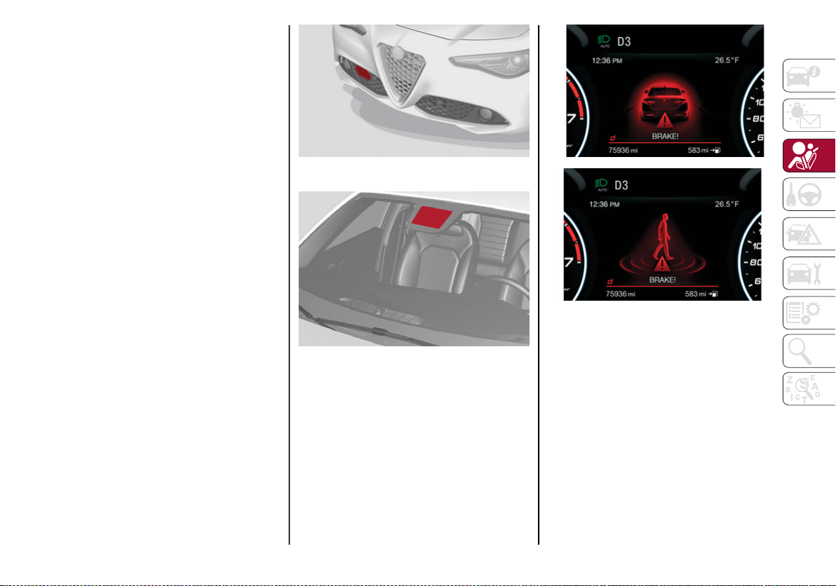
109
Rear Cross Path Detection (RCP) System
The Rear Cross Path Detection (RCP) system
assists the driver during reverse maneuvers in
the case of reduced visibility.
When the ABSA system is active, the RCP
system monitors the rear detection areas on
both sides of the vehicle to detect objects
moving towards the sides of the vehicle at a
minimum speed between 0.6 mph and 2 mph
(1 km/h and 3km/h) from objects moving at a
maximum speed of 22 mph (35 km/h).
These are generally occurrences that happen
in parking areas.
The system activation is signaled to the driver
by means of a visual and audible warning.
NOTE:
If the sensors are covered by objects or vehi-
cles, the system may not work as intended.
Changing the system sensitivity
To change the sensitivity and the strength of
the torque intervention on the steering wheel,
refer to “Settings” of the radio system.
Forward Collision Warning (FCW) System
This is a driving assistance system composed
of a radar located behind the front bumper
and a camera located in the center of the
windshield.
Front Bumper Radar Location
Windshield Camera Location
In the event of an imminent collision, the
system intervenes by automatically applying
the vehicle’s brakes to prevent a the collision
or reduce its effects.
The system provides the driver with audible
and visual signals through specific messages
on the instrument cluster display.
The system may lightly brake to warn the driver if
a potential front end collision is detected (limited
braking). Signals and limited braking are
intended to allow the driver time to intervene.
In situations with the risk of collision, if the
system detects no intervention by the driver, it
provides automatic braking to help slow the
vehicle and mitigate the potential front end colli-
sion (automatic braking). If intervention by the
driver on the brake pedal is detected, but not
deemed sufficient, the system may intervene in
order to improve the reaction of the braking
system by reducing vehicle speed further (addi-
tional assistance in braking stage).
20_GA_OM_EN_USC_t.book Page 109

SAFETY
110
The system will intervene automatically in
case of imminent collision or impact against a
pedestrian crossing the road (speed under
31 mph (50 km/h)).
NOTE:
For safety reasons, when the vehicle has
stopped, the brake calipers may remain
blocked for about two seconds. Make sure to
press the brake pedal if the vehicle moves
slightly forward.
Engagement/Disengagement
The system may be disengaged (and engaged
again) in the “Driver Assistance” menu of the
Information and Entertainment system.
The system can be deactivated even with the
ignition device in the ON position.
NOTE:
The system status can be changed with car at
a standstill only.
Select from among three operating modes:
Warning And Braking: the system (if active), in
addition to the visual and audible warnings,
provides limited braking, automatic braking,
and additional assistance in braking stage
where the driver does not brake sufficiently in
the event of a potential front end collision.
Only Warning: the system (if active), does
not provide limited braking, but guarantees
automatic braking or additional assistance
in braking stage where the driver does not
brake at all or not sufficiently enough in the
event of a potential front end collision.
Disabled: the system does not provide visual
and audible warnings, limited braking, auto-
matic braking, or additional assistance in
braking stage. The system will therefore
provide no indication of a possible collision.
Activation/Deactivation
The Forward Collision Warning system is acti-
vated whenever the engine is started regard-
less of what is shown on the radio system.
Following a deactivation, the system will not
warn the driver about the possible collision
with the preceding vehicle, regardless of the
setting selected with the radio system.
NOTE:
Each time the engine is started, the system is
activated regardless of what setting was
selected when the engine was turned off.
The system is active:
Each time the engine is started
In the radio system
When the ignition is in the ON position
The vehicle speed is between 2 mph (4 km/h)
and 124 mph (200 km/h)
When the front seat belts are fastened
NOTE:
If the safety belts of the front seats are not
correctly fastened, the system will not inter-
vene on the braking system (only audible and
visual signals will be provided).
Changing The System Sensitivity
The sensitivity of the system can be changed
through the radio system menu, choosing from
one of the following three options: "Near",
"Medium" or "Far". Refer to the description in
the radio system supplement for how to
change the settings.
The default setting is "Medium". With this
setting, the system warns the driver of a
possible collision with the vehicle in front
when that vehicle is at a standard distance,
between that of the other two settings.
With the system sensitivity set to "Far", the
system will warn the driver of a possible colli-
sion with the vehicle in front when that vehicle
is at a greater distance, thus providing the
possibility of acting on the brakes more lightly
WARNING!
Forward Collision Warning (FCW) is not
intended to avoid a collision on its own, nor
can FCW detect every type of potential
collision. The driver has the responsibility to
avoid a collision by controlling the vehicle via
braking and steering. Failure to follow this
warning could lead to serious injury or death.
20_GA_OM_EN_USC_t.book Page 110

111
and gradually. This setting provides the drivers
with the maximum possible reaction time to
prevent a potential collision.
With the option set to "Near", the system will
alert the driver of a possible collision with the
vehicle in front when that vehicle is close. This
setting offers the driver a lower reaction time
compared to the "Medium" and "Far" settings,
in the event of a potential collision, but
permits more dynamic driving of the vehicle.
The system sensitivity setting is kept in the
memory when the engine is turned off.
System Limited Operation Warning
If a dedicated message is displayed, a condi-
tion limiting the system operation may have
occurred. The possible reasons of this limita-
tion are if something is blocking the camera
view, or a fault is present.
If an obstruction is signaled, clean the area of
the windshield.
Although the vehicle can still be driven in
normal conditions, the system may be not
completely available.
When the conditions limiting the system func-
tions end, this will go back to normal and
complete operation. Should the fault persist,
contact an authorized dealer.
System Failure Signaling
If the system turns off and a dedicated
message is shown on the display, it means
that there is a fault with the system.
In this case, it is still possible to drive the
vehicle, but you are advised to contact an
authorized dealer as soon as possible.
Radar Indication Not Available
If conditions are such that the radar cannot
detect obstacles correctly, the system is deac-
tivated and a dedicated message appears on
the display. This generally occurs in the event
of poor visibility, such as when it is snowing or
raining heavily.
The function of this system can also be tempo-
rarily reduced due to obstructions such as
mud, dirt or ice on the bumper. In such cases,
a dedicated message will be shown on the
display and the system will be deactivated.
This message can sometimes appear in condi-
tions of high reflectivity (e.g. tunnels with
reflective tiles or ice or snow). When the condi-
tions limiting the system functions end, it will
go back to normal and complete operation.
In certain cases, this dedicated message
could be displayed when the radar is not
detecting any vehicles or objects within its
view range.
If atmospheric conditions are not the reason
behind this message, check if the sensor is
dirty. It could be necessary to clean or remove
any obstructions in the area.
If the message appears frequently, even in the
absence of atmospheric conditions such as
snow, rain, mud or other obstructions, contact an
authorized dealer for a sensor alignment check.
In the absence of visible obstructions, manu-
ally removing the decorative cover trim and
cleaning the radar surface could be required.
Have this operation performed at an autho-
rized dealer.
NOTE:
It is recommended that you do not install
devices, accessories, or aerodynamic attach-
ments in front of the sensor or darken it in any
way, as this can compromise the correct func-
tioning of the system.
Frontal Collision Alarm With Active Braking
If this function is selected, the brakes are
operated to reduce the speed of the vehicle in
the event of potential collision.
This function applies an additional braking
pressure if the braking pressure applied by the
driver does not suffice to prevent potential
collision.
The function is active with speed above 2 mph
(4 km/h).
NOTE:
When using an automatic car wash it is recom-
mended to deactivate the system through the
settings of the radio system. The system may
detect the presence of a car, a wall or another
obstacle and activate.
20_GA_OM_EN_USC_t.book Page 111
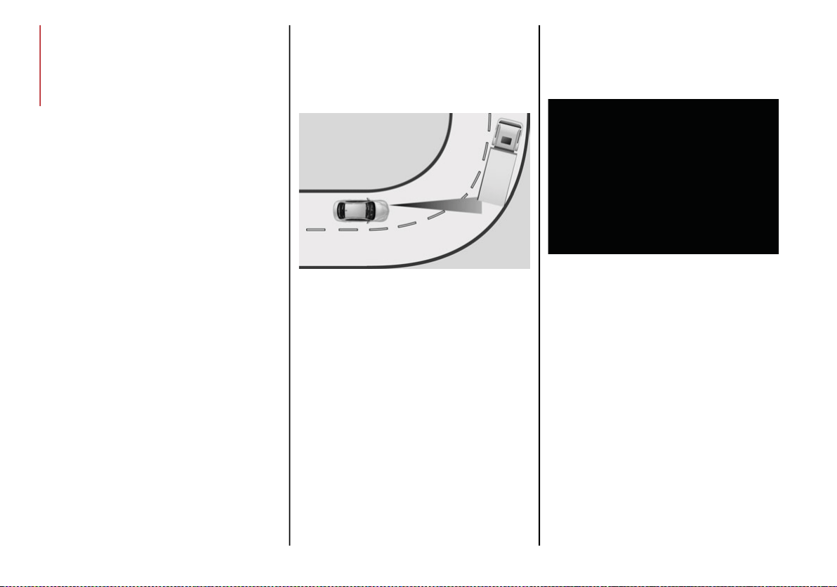
SAFETY
112
Driving In Special Conditions
In certain driving conditions, system interven-
tion might be unexpected or delayed. The
driver must therefore be very careful, keeping
control of the vehicle.
Driving close to a bend.
The vehicle ahead is leaving a roundabout.
Vehicles with small dimensions and/or not
aligned in the driving lane.
Lane change by other vehicles.
Vehicles traveling at right angles to the
vehicle.
NOTE:
In particularly complex traffic conditions,
the driver can deactivate the system manu-
ally through the radio system.
If the driver depresses the brake pedal fully
or makes an excessive steering maneuver
during system operation, the automatic
braking function may deactivate (e.g. to
allow a possible maneuverer to avoid the
obstacle).
The FCW system is automatically deacti-
vated when operating in race mode and a
warning message will be displayed on the
instrument cluster.
Driving Close To A Bend
When entering or leaving a wide bend, the
system may detect a vehicle in front you, but
not in the same driving lane. In cases such as
these, the system may intervene.
Driving Around Wide Curves
The Vehicle Ahead Is Leaving A Roundabout
On a roundabout, the system could intervene
if it detects a vehicle ahead which is leaving
the roundabout.
Driving In Roundabouts
20_GA_OM_EN_USC_t.book Page 112
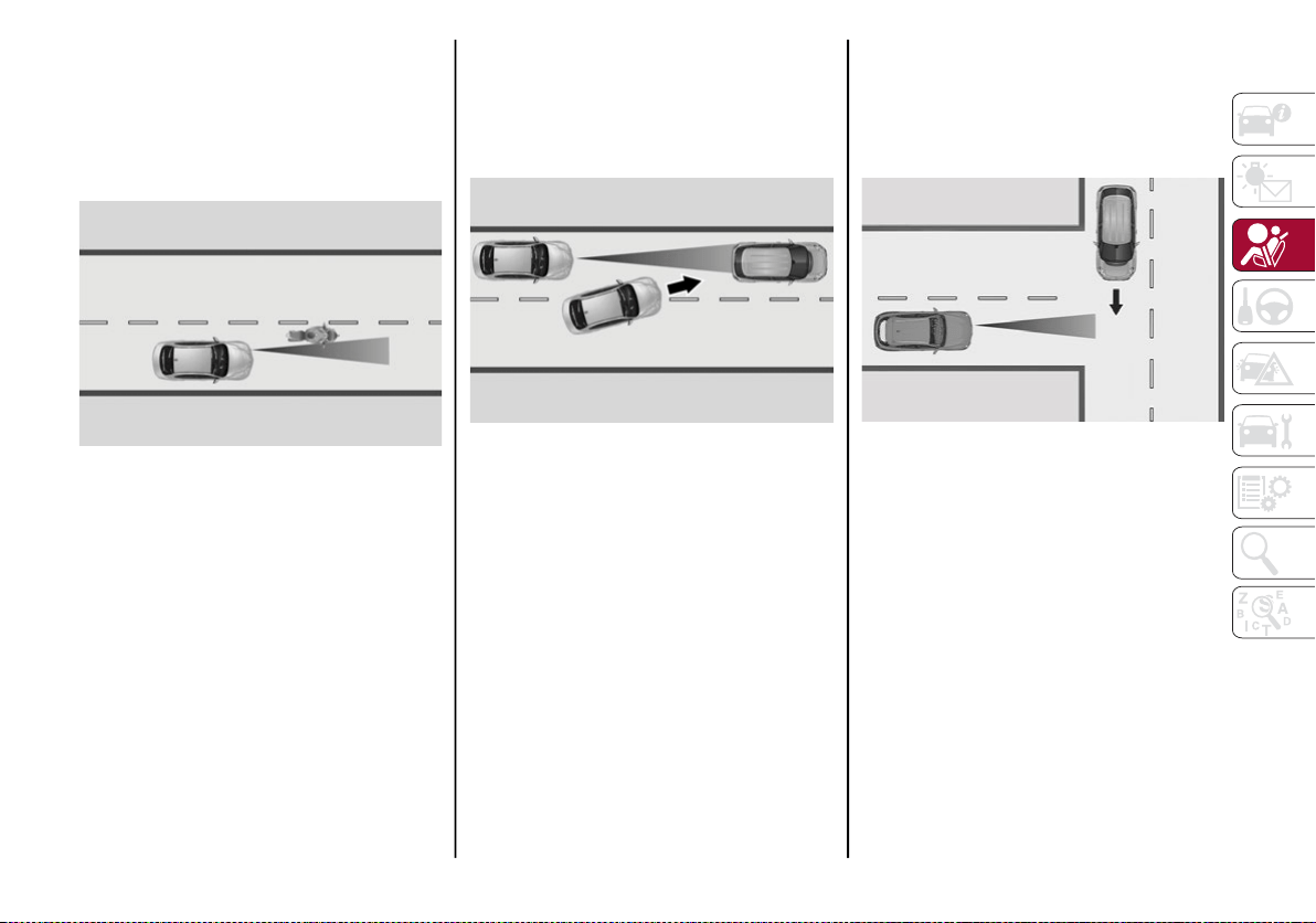
113
Vehicles With Small Dimensions And/Or Not
Aligned In The Driving Lane
The system cannot detect vehicles in front of you
but outside the range of the radar sensor and
may therefore not react in the presence of small
vehicles, such as bicycles or motorcycles.
Driving Near Small Vehicles
Lane Change By Other Vehicles
Vehicles suddenly changing lanes to enter the
same lane as your vehicle within the operating
range of the radar sensor, may cause the
system to intervene.
Other Vehicles Changing Lanes
Vehicles Traveling At Right Angles To The
Vehicle
The system may temporarily react to a vehicle
that is passing through the radar sensor’s
operating range at right angles.
Other Vehicle Passing Through Radar Range
20_GA_OM_EN_USC_t.book Page 113

SAFETY
114
IFETEL: RCPBOMR 14-0766
La operación de este equipo está sujeta a las
siguientes dos condiciones:
1. es posible que este equipo o dispositivo no
cause interferencia perjudicial y
2. este equipo o dispositivo debe aceptar
cualquier interferencia, incluyendo la que
pueda causar su operación no deseada.
Changes or modifications made to this equip-
ment not expressly approved by Robert
BOSCH GmbH may void the FCC authorization
to operate this equipment.
This equipment has been tested and found to
comply with the limits for a Class A digital device,
pursuant to Part 15 of the FCC Rules. These
limits are designed to provide reasonable protec-
tion against harmful interference when the
equipment is operated in a commercial environ-
ment. This equipment generates, uses, and can
radiate radio frequency energy and, if not
installed and used in accordance with the
instruction manual, may cause harmful interfer-
ence to radio communications. Operation of this
equipment in a residential area is likely to cause
harmful interference in which case the user will
be required to correct the interference at his own
expense.
Toutes modifications apportées à cet équipe-
ment qui ne sont pas expressément homo-
loguées par Robert BOSCH GmbH peuvent
annuler l'autorisation de la FCC de faire
fonctionner cet équipement.
Cet appareil a été vérifié et s'est révélé conforme
aux normes applicables aux appareils
numériques de catégorie A, en vertu de la
section 15 des règlements de la FCC. Ces
normes sont définies pour fournir une protection
raisonnable contre les interférences nuisibles
lorsque l'équipement est utilisé dans les installa-
tions résidentielles. Cet appareil génère, utilise
et peut émettre des ondes radioélectriques et,
s'il n'est pas installé et utilisé conformément au
manuel d’instruction, peut causer un brouillage
radioélectrique nuisible aux communications
radio. Le fonctionnement de cet équipement
dans une zone résidentielle est susceptible de
causer des interférences nuisibles; dans ce cas,
l'usager doit corriger les interférences à ses
propres frais.
Radio Frequency Exposure Information
This equipment complies with FCC radiation
exposure limits set forth for an uncontrolled
environment. This equipment should be
installed and operated with minimum distance
of 20 cm between the radiator and your body.
This transmitter must not be co-located or
operating in conjunction with any other
antenna or transmitter.
WARNING!
The system has not been designed to
prevent impacts and cannot detect possible
conditions leading to an accident in
advance. Failure to take into account this
warning may lead to serious or fatal injuries.
The system may activate, assessing the
trajectory of the vehicle, for the presence
of reflecting metal objects different from
other vehicles, such as safety barriers,
road signs, barriers before parking lots,
tollgates, level crossings, gates, railways,
objects near road constructions sites or
higher than the vehicle (e.g. a fly-over). In
the same way, the system may intervene
inside multi-story parking lots or tunnels,
or due to a glare on the road surface.
These possible activations are a conse-
quence of the real driving scenario
coverage by the system and must not be
regarded as faults.
The system has been designed for road use
only. If the vehicle is driven on a track, the
system must be deactivated to avoid unnec-
essary warnings. Automatic deactivation is
signaled by the dedicated warning light/
symbol switching on in the instrument panel
(refer to the instructions in the "Warning
Lights And Messages On The Instrument
Panel" in "Getting To Know Your Instrument
Panel" for further information).
20_GA_OM_EN_USC_t.book Page 114

115
Déclaration d’exposition aux radiations
Cet équipement est conforme aux limites
d'exposition aux rayonnements IC établies
pour un environnement non contrôlé. Cet équi-
pement doit être installé et utilisé avec un
minimum de 20 cm de distance entre la
source de rayonnement et votre corps.
Ce transmetteur ne doit pas etre place au
meme endroit ou utilise simultanement avec
un autre transmetteur ou antenne.
General Information
The following regulatory statement applies to
all Radio Frequency (RF) devices equipped in
this vehicle:
This device complies with Part 15 of the FCC Rules
and with Innovation, Science and Economic Devel-
opment Canada license-exempt RSS standard(s).
Operation is subject to the following two conditions:
1. This device may not cause harmful inter-
ference, and
2. This device must accept any interference
received, including interference that may
cause undesired operation.
Le présent appareil est conforme aux CNR
d`Innovation, Science and Economic Develop-
ment applicables aux appareils radio exempts
de licence. L'exploitation est autorisée aux
deux conditions suivantes:
1. l'appareil ne doit pas produire de brouil-
lage, et
2. l'utilisateur de l'appareil doit accepter tout
brouillage radioélectrique subi, même si le
brouillage est susceptible d'en comprom-
ettre le fonctionnement.
La operación de este equipo está sujeta a las
siguientes dos condiciones:
1. es posible que este equipo o dispositivo no
cause interferencia perjudicial y
2. este equipo o dispositivo debe aceptar
cualquier interferencia, incluyendo la que
pueda causar su operación no deseada.
RF Exposure Requirements
To comply with FCC RF exposure compliance
requirements, the device must be installed
and operated to provide a separation distance
of at least 20 cm from all persons.
This equipment complies with Canada radiation
exposure limits set forth for an uncontrolled envi-
ronment. This equipment should be installed and
operated with minimum distance 20 cm between
the radiator and your body.
NOTE:
Changes or modifications not expressly
approved by the party responsible for compli-
ance could void the user’s authority to operate
the equipment.
Déclaration d’exposition aux radiations
Cet équipement est conforme aux limites
d’exposition aux rayonnements ISED établies
pour un environnement non contrôlé. Cet équi-
pement doit être installé et utilisé avec un
minimum de 20 cm de distance entre la
source de rayonnement et votre corps
REMARQUE:
Des changements ou des modifications n’ayant
pas été expressément approuvés par la partie
responsable de la conformité pourraient révo-
quer l’autorisation d’utilisation de l’équipement.
Tire Pressure Monitoring System (TPMS)
The vehicle is equipped with a Tire Pressure
Monitoring System (TPMS) that sends the
inflation pressure information of each tire to
the control unit, and will signal the driver in the
event of insufficient tire pressure.
The TPMS uses wireless technology with wheel
rim mounted electronic sensors to monitor tire
pressure levels. Sensors, mounted to each
wheel as part of the valve stem, transmit tire
pressure readings to the receiver module.
Tire pressure will vary with temperature by approxi-
mately 1 psi (7 kPa) for every 12°F (6.5°C). This
means that when the outside temperature
decreases, the tire pressure will also decrease. Tire
pressure should always be set based on cold infla-
tion tire pressure. This is defined as the tire pres-
sure after the vehicle has not been driven for at
least three hours, or driven less than 1 mile
(1.6 km) after a three hour period. The cold tire
20_GA_OM_EN_USC_t.book Page 115

SAFETY
116
(Continued)
inflation pressure must not exceed the maximum
inflation pressure molded into the tire sidewall.
Refer to “Tires” in “Servicing And Maintenance” for
information on how to properly inflate the vehicle’s
tires. The tire pressure will also increase as the
vehicle is driven. This is normal, and there should
be no adjustment for this increased pressure.
The TPMS will signal the driver if pressure falls
below the warning limit for any reason,
including the effects of low temperature and
normal loss of pressure from the tire.
The TPMS will stop indicating insufficient tire
pressure when pressure is equal to or greater
than the prescribed cold inflation level. There-
fore, if insufficient tire pressure is indicated by
the ( ) warning light displaying in the instru-
ment cluster, increase the inflation pressure
up to the prescribed cold inflation value.
The system will automatically update, and the
Tire Pressure Monitoring Warning Light will
turn off once the system receives the updated
tire pressures. The vehicle may need to be
driven for up to 20 minutes above 15 mph
(24 km/h) in order for the TPMS to receive this
information.
NOTE:
The TPMS cannot indicate sudden tire pres-
sure drops (e.g. if a tire bursts). In this case,
proceed with caution and avoid abrupt
steering.
Operating Example
For example, your vehicle may have a recom-
mended cold (parked for more than three hours)
placard pressure of 33 psi (227 kPa). If the ambient
temperature is 68°F (20°C), and the measured tire
pressure is 28 psi (193 kPa), a temperature drop to
20°F (-7°C) will decrease the tire pressure to
approximately 24 psi (165 kPa). This tire pressure
is low enough to turn on the Tire Pressure Moni-
toring Warning Light. Driving the vehicle may cause
the tire pressure to rise to approximately 28 psi
(193 kPa), but the Tire Pressure Monitoring
Warning Light will still be on. In this situation, the
Tire Pressure Monitoring Warning Light will turn off
only after the tires are inflated to the vehicle’s
recommended cold placard pressure value.
Insufficient Tire Pressure Indication
If an insufficient pressure value is detected on
one or more tires, the warning light in the
instrument cluster will display alongside the
dedicated messages, the system will highlight
the tire or tires with insufficient pressure
graphically, and an acoustic signal will be
emitted.
In this case, stop the vehicle, check the infla-
tion pressure of each tire, and inflate the
necessary tire or tires to the correct cold infla-
tion pressure value, shown on the display or in
the dedicated TPMS menu.
CAUTION!
The TPMS has been optimized for the orig-
inal equipment tires and wheels. TPMS
pressures and warning have been estab-
lished for the tire size equipped on your
vehicle. Undesirable system operation or
sensor damage may result when using
replacement equipment that is not of the
same size, type, and/or style. The TPM
sensor is not designed for use on after-
market wheels and may contribute to a
poor overall system performance or
sensor damage. Customers are encour-
aged to use OEM wheels to assure proper
TPM feature operation.
Using aftermarket tire sealants may cause
the Tire Pressure Monitoring System
(TPMS) sensor to become inoperable.
After using an aftermarket tire sealant it is
recommended that you take your vehicle
to an authorized dealer to have your
sensor function checked.
After inspecting or adjusting the tire pres-
sure always reinstall the valve stem cap.
This will prevent moisture and dirt from
entering the valve stem, which could
damage the TPMS sensor.
CAUTION! (Continued)
20_GA_OM_EN_USC_t.book Page 116

117
TPMS Temporarily Disabled:
TPMS Check Message
When a system fault is detected, the Tire Pres-
sure Monitoring Warning Light will flash on
and off for 75 seconds, and then remain on
solid. The system fault will also sound a chime.
If the ignition is cycled, this sequence will
repeat, provided that the system fault still
exists. The Tire Pressure Monitoring Warning
Light will turn off when the fault condition no
longer exists. A system fault can occur due to
any of the following:
Jamming due to electronic devices or
driving next to facilities emitting the same
radio frequencies as the TPMS sensors.
Installing some form of aftermarket window
tinting that affects radio wave signals.
Packed snow or ice around the wheels or
wheel housings.
Using tire chains on the vehicle.
Using wheels/tires not equipped with TPM
sensors.
After the punctured tire has been repaired
with the original tire sealant contained in the
Tire Kit, the previous condition must be
restored so that the warning light is off
during normal driving.
TPMS Deactivation
The TPMS can be deactivated by replacing all
four wheel and tire assemblies (road tires)
with wheel and tire assemblies that do not
have TPMS sensors, such as when installing
winter wheel and tire assemblies on your
vehicle.
To deactivate the TPMS, first replace all four
wheel and tire assemblies (road tires) with
tires not equipped with Tire Pressure Moni-
toring (TPM) sensors. Then, drive the vehicle
for 20 minutes above 15 mph (24 km/h). The
TPMS will chime, the TPMS Warning Light will
flash on and off for 75 seconds and then
remain on. The instrument cluster will display
the “SERVICE TPM SYSTEM” message and
then display dashes (--) in place of the pres-
sure values.
Beginning with the next ignition switch cycle,
the TPMS will no longer chime or display the
“SERVICE TPM SYSTEM” message in the
instrument cluster. Instead, dashes (--) will
remain in place of the pressure values.
To reactivate the TPMS, replace all four wheel
and tire assemblies (road tires) with tires
equipped with TPM sensors. Then, drive the
vehicle for up to 20 minutes above 15 mph
(24 km/h). The TPMS will chime, the TPM
Warning Light will flash on and off for 75 seconds
and then turn off. The instrument cluster will
display the “SERVICE TPM SYSTEM” message
and then display pressure values in place of the
dashes. On the next ignition switch cycle the
"SERVICE TPM SYSTEM" message will no longer
be displayed, as long as no system fault exists.
NOTE:
The TPMS is not intended to replace normal
tire care and maintenance, or to provide
warning of a tire failure or condition.
The TPMS should not be used as a tire pres-
sure gauge while adjusting your tire pressure.
Driving on a significantly underinflated tire
will cause the tire to overheat, and can lead
to tire failure. Underinflation also reduces
fuel efficiency and tire tread life, and may
affect the vehicle’s handling and stopping
ability.
The TPMS is not a substitute for proper tire
maintenance, and it is the driver’s responsi-
bility to maintain correct tire pressure using
an accurate tire pressure gauge, even if
underinflation has not reached the level to
trigger illumination of the Tire Pressure
Monitoring Warning Light.
Seasonal temperature changes will affect
tire pressure, and the TPMS will monitor the
actual tire pressure in the tire.
20_GA_OM_EN_USC_t.book Page 117

SAFETY
118
General Information
The following regulatory statement applies to
all Radio Frequency (RF) devices equipped in
this vehicle:
This device complies with Part 15 of the FCC
Rules and with Innovation, Science and
Economic Development Canada license-exempt
RSS standard(s). Operation is subject to the
following two conditions:
1. This device may not cause harmful inter-
ference, and
2. This device must accept any interference
received, including interference that may
cause undesired operation.
Le présent appareil est conforme aux CNR
d`Innovation, Science and Economic Develop-
ment applicables aux appareils radio exempts
de licence. L'exploitation est autorisée aux
deux conditions suivantes:
1. l'appareil ne doit pas produire de brouil-
lage, et
2. l'utilisateur de l'appareil doit accepter tout
brouillage radioélectrique subi, même si le
brouillage est susceptible d'en comprom-
ettre le fonctionnement.
La operación de este equipo está sujeta a las
siguientes dos condiciones:
1. es posible que este equipo o dispositivo no
cause interferencia perjudicial y
2. este equipo o dispositivo debe aceptar
cualquier interferencia, incluyendo la que
pueda causar su operación no deseada.
RF Exposure Requirements
To comply with FCC RF exposure compliance
requirements, the device must be installed
and operated to provide a separation distance
of at least 20 cm from all persons.
This equipment complies with Canada radiation
exposure limits set forth for an uncontrolled envi-
ronment. This equipment should be installed and
operated with minimum distance 20 cm between
the radiator and your body.
NOTE:
Changes or modifications not expressly
approved by the party responsible for compli-
ance could void the user’s authority to operate
the equipment.
Déclaration d’exposition aux radiations
Cet équipement est conforme aux limites
d’exposition aux rayonnements ISED établies
pour un environnement non contrôlé. Cet équi-
pement doit être installé et utilisé avec un
minimum de 20 cm de distance entre la
source de rayonnement et votre corps
REMARQUE:
Des changements ou des modifications n’ayant
pas été expressément approuvés par la partie
responsable de la conformité pourraient révo-
quer l’autorisation d’utilisation de l’équipement.
OCCUPANT RESTRAINT
SYSTEMS
Some of the most important safety features in
your vehicle are the restraint systems:
Occupant Restraint Systems Features
Seat Belt Systems
Supplemental Restraint Systems (SRS) Air Bags
Child Restraints
Some of the safety features described in this
section may be standard equipment on some
models, or may be optional equipment on others.
If you are not sure, ask an authorized dealer.
Important Safety Precautions
Please pay close attention to the information
in this section. It tells you how to use your
restraint system properly, to keep you and
your passengers as safe as possible.
Here are some simple steps you can take to mini-
mize the risk of harm from a deploying air bag:
1. Children 12 years old and under should
always ride buckled up in the rear seat of
a vehicle with a rear seat.
2. A child who is not big enough to wear the
vehicle seat belt properly (Refer to “Child
Restraints” in this section for further infor-
mation) must be secured in the appro-
priate child restraint or belt-positioning
booster seat in a rear seating position.
20_GA_OM_EN_USC_t.book Page 118
119
3. If a child from 2 to 12 years old (not in a
rear-facing child restraint) must ride in the
front passenger seat, move the seat as far
back as possible and use the proper child
restraint. Refer to “Child Restraints” in this
section for further information.
4. Never allow children to slide the shoulder
belt behind them or under their arm.
5. You should read the instructions provided
with your child restraint to make sure that
you are using it properly.
6. All occupants should always wear their lap
and shoulder belts properly.
7. The driver and front passenger seats
should be moved back as far as practical
to allow the front air bags room to inflate.
8. Do not lean against the door or window. If
your vehicle has side air bags, and deploy-
ment occurs, the side air bags will inflate
forcefully into the space between occu-
pants and the door and occupants could
be injured.
9. If the air bag system in this vehicle needs to be
modified to accommodate a disabled person,
refer to the “Customer Assistance” section for
customer service contact information.
Seat Belt Systems
Buckle up even though you are an excellent
driver, even on short trips. Someone on the
road may be a poor driver and could cause a
collision that includes you. This can happen far
away from home or on your own street.
Research has shown that seat belts save lives,
and they can reduce the seriousness of inju-
ries in a collision. Some of the worst injuries
happen when people are thrown from the
vehicle. Seat belts reduce the possibility of
ejection and the risk of injury caused by
striking the inside of the vehicle. Everyone in a
motor vehicle should be belted at all times.
Enhanced Seat Belt Use Reminder System
(BeltAlert)
Driver and Passenger BeltAlert (If Equipped)
BeltAlert is a feature intended to remind
the driver and outboard front seat passenger
(if equipped with outboard front passenger
seat BeltAlert) to buckle their seat belts. The
BeltAlert feature is active whenever the igni-
tion switch is in the ON/RUN position.
Initial Indication
If the driver is unbuckled when the ignition
switch is first in the ON/RUN position, a chime
will signal for a few seconds. If the driver or
outboard front seat passenger (if equipped
with outboard front passenger seat BeltAlert)
is unbuckled when the ignition switch is first in
the ON/RUN position the Seat Belt Reminder
Light will turn on and remain on until both
outboard front seat belts are buckled. The
outboard front passenger seat BeltAlert is not
active when an outboard front passenger seat
is unoccupied.
WARNING!
Never place a rear-facing child restraint in front
of an air bag. A deploying passenger front air
bag can cause death or serious injury to a child
12 years or younger, including a child in a
rear-facing child restraint.
Never install a rear-facing child restraint in
the front seat of a vehicle. Only use a
rear-facing child restraint in the rear seat.
If the vehicle does not have a rear seat, do
not transport a rear-facing child restraint
in that vehicle.
20_GA_OM_EN_USC_t.book Page 119

SAFETY
120
(Continued)
BeltAlert Warning Sequence
The BeltAlert warning sequence is activated
when the vehicle is moving above a specified
vehicle speed range and the driver or outboard
front seat passenger is unbuckled (if equipped
with outboard front passenger seat BeltAlert)
(the outboard front passenger seat BeltAlert is
not active when the outboard front passenger
seat is unoccupied). The BeltAlert warning
sequence starts by blinking the Seat Belt
Reminder Light and sounding an intermittent
chime. Once the BeltAlert warning sequence
has completed, the Seat Belt Reminder Light
will remain on until the seat belts are buckled.
The BeltAlert warning sequence may repeat
based on vehicle speed until the driver and
occupied outboard front seat passenger seat
belts are buckled. The driver should instruct all
occupants to buckle their seat belts.
Change of Status
If the driver or outboard front seat passenger
(if equipped with outboard front passenger
seat BeltAlert) unbuckles their seat belt while
the vehicle is traveling, the BeltAlert warning
sequence will begin until the seat belts are
buckled again.
The outboard front passenger seat BeltAlert is
not active when the outboard front passenger
seat is unoccupied. BeltAlert may be triggered
when an animal or other items are placed on
the outboard front passenger seat or when the
seat is folded flat (if equipped). It is recom-
mended that pets be restrained in the rear
seat (if equipped) in pet harnesses or pet
carriers that are secured by seat belts, and
cargo is properly stowed.
Lap/Shoulder Belts
All seating positions in your vehicle are
equipped with lap/shoulder belts.
The seat belt webbing retractor will lock only
during very sudden stops or collisions. This
feature allows the shoulder part of the seat
belt to move freely with you under normal
conditions. However, in a collision the seat
belt will lock and reduce your risk of striking
the inside of the vehicle or being thrown out of
the vehicle.
WARNING!
Relying on the air bags alone could lead to
more severe injuries in a collision. The air
bags work with your seat belt to restrain
you properly. In some collisions, the air
bags won’t deploy at all. Always wear your
seat belt even though you have air bags.
In a collision, you and your passengers
can suffer much greater injuries if you are
not properly buckled up. You can strike
the interior of your vehicle or other
passengers, or you can be thrown out of
the vehicle. Always be sure you and others
in your vehicle are buckled up properly.
It is dangerous to ride in a cargo area,
inside or outside of a vehicle. In a colli-
sion, people riding in these areas are
more likely to be seriously injured or killed.
Do not allow people to ride in any area of
your vehicle that is not equipped with
seats and seat belts.
Be sure everyone in your vehicle is in a
seat and using a seat belt properly. Occu-
pants, including the driver, should always
wear their seat belts whether or not an air
bag is also provided at their seating posi-
tion to minimize the risk of severe injury or
death in the event of a crash.
20_GA_OM_EN_USC_t.book Page 120

121
(Continued)
(Continued)
Wearing your seat belt incorrectly could
make your injuries in a collision much
worse. You might suffer internal injuries,
or you could even slide out of the seat
belt. Follow these instructions to wear
your seat belt safely and to keep your
passengers safe, too.
Two people should never be belted into a
single seat belt. People belted together can
crash into one another in a collision, hurting
one another badly. Never use a lap/shoulder
belt or a lap belt for more than one person,
no matter what their size.
WARNING!
A lap belt worn too high can increase the
risk of injury in a collision. The seat belt
forces won’t be at the strong hip and
pelvic bones, but across your abdomen.
Always wear the lap part of your seat belt
as low as possible and keep it snug.
A twisted seat belt may not protect you
properly. In a collision, it could even cut
into you. Be sure the seat belt is flat
against your body, without twists. If you
can’t straighten a seat belt in your vehicle,
take it to an authorized dealer immedi-
ately and have it fixed.
WARNING! (Continued)
A seat belt that is buckled into the wrong
buckle will not protect you properly. The
lap portion could ride too high on your
body, possibly causing internal injuries.
Always buckle your seat belt into the
buckle nearest you.
A seat belt that is too loose will not protect
you properly. In a sudden stop, you could
move too far forward, increasing the
possibility of injury. Wear your seat belt
snugly.
A seat belt that is worn under your arm is
dangerous. Your body could strike the
inside surfaces of the vehicle in a colli-
sion, increasing head and neck injury. A
seat belt worn under the arm can cause
internal injuries. Ribs aren’t as strong as
shoulder bones. Wear the seat belt over
your shoulder so that your strongest
bones will take the force in a collision.
WARNING! (Continued)
A shoulder belt placed behind you will not
protect you from injury during a collision.
You are more likely to hit your head in a
collision if you do not wear your shoulder
belt. The lap and shoulder belt are meant
to be used together.
A frayed or torn seat belt could rip apart in a
collision and leave you with no protection.
Inspect the seat belt system periodically,
checking for cuts, frays, or loose parts.
Damaged parts must be replaced immedi-
ately. Do not disassemble or modify the seat
belt system. Seat belt assemblies must be
replaced after a collision.
WARNING! (Continued)
20_GA_OM_EN_USC_t.book Page 121
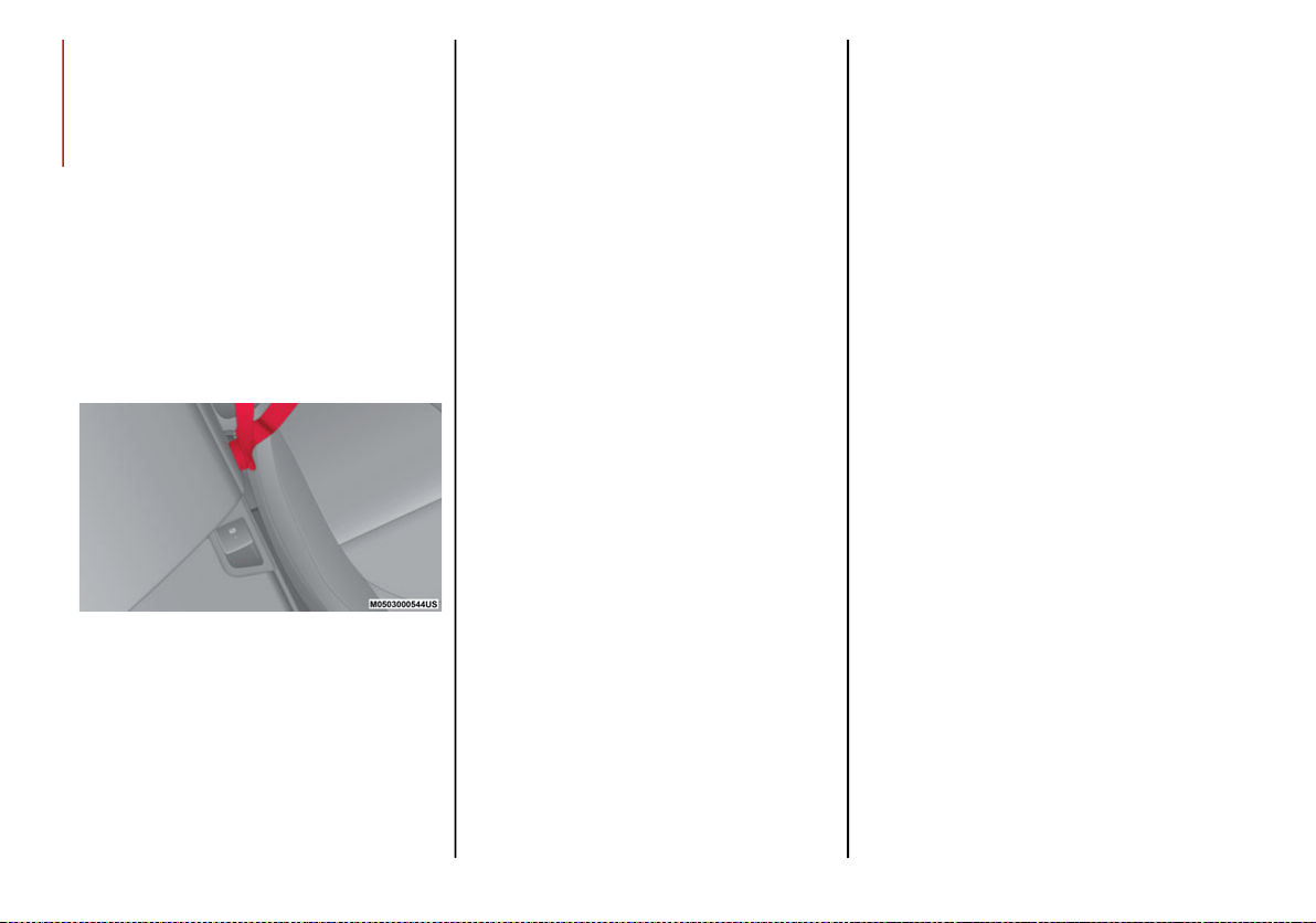
SAFETY
122
Lap/Shoulder Belt Operating Instructions
1. Enter the vehicle and close the door. Sit
back and adjust the seat.
2. The seat belt latch plate is above the back
of the front seat, and next to your arm in
the rear seat (for vehicles equipped with a
rear seat). Grasp the latch plate and pull
out the seat belt. Slide the latch plate up
the webbing as far as necessary to allow
the seat belt to go around your lap.
3. When the seat belt is long enough to fit,
insert the latch plate into the buckle until
you hear a “click.”
Seat Belt Latch Plate Inserted Into Seat Belt
Buckle
4. Position the lap belt so that it is snug and
lies low across your hips, below your
abdomen. To remove slack in the lap belt
portion, pull up on the shoulder belt. To
loosen the lap belt if it is too tight, tilt the
latch plate and pull on the lap belt. A snug
seat belt reduces the risk of sliding under
the seat belt in a collision.
5. Position the shoulder belt across the
shoulder and chest with minimal, if any
slack so that it is comfortable and not
resting on your neck. The retractor will
withdraw any slack in the shoulder belt.
6. To release the seat belt, push the red
button on the buckle. The seat belt will
automatically retract to its stowed posi-
tion. If necessary, slide the latch plate
down the webbing to allow the seat belt to
retract fully.
Lap/Shoulder Belt Untwisting Procedure
Use the following procedure to untwist a
twisted lap/shoulder belt.
1. Position the latch plate as close as
possible to the anchor point.
2. At about 6 to 12 inches (15 to 30 cm)
above the latch plate, grasp and twist the
seat belt webbing 180 degrees to create a
fold that begins immediately above the
latch plate.
3. Slide the latch plate upward over the
folded webbing. The folded webbing must
enter the slot at the top of the latch plate.
4. Continue to slide the latch plate up until it
clears the folded webbing and the seat
belt is no longer twisted.
20_GA_OM_EN_USC_t.book Page 122
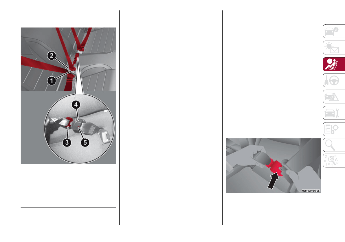
123
Second Row Center Seat Belt Operating
Instructions
Second Row Seat Belts
The second row center seat belt features a
seat belt with a mini-latch plate and buckle,
which allows the seat belt to detach from the
lower anchor when the seat is folded. The
mini-latch plate and regular latch plate can
then be stored out of the way in the parcel tray
for added convenience to open up utilization
of the storage areas behind the front seats
when the seat is not occupied.
1. Remove the mini-latch plate and regular
latch plate from its stowed position in the
right rear side trim panel.
2. Grasp the mini-latch plate and pull the
seat belt over the seat.
3. Route the shoulder belt to the inside of the
right head restraint.
4. When the seat belt is long enough to fit,
insert the mini-latch plate into the
mini-buckle until you hear a “click.”
5. Sit back in seat. Slide the regular latch
plate up the webbing as far as necessary
to allow the seat belt to go around your lap.
6. When the seat belt is long enough to fit,
insert the latch plate into the buckle until
you hear a “click.”
7. Position the lap belt so that it is snug and lies
low across your hips, below your abdomen.
To remove slack in the lap belt portion, pull
up on the shoulder belt. To loosen the lap
belt if it is too tight, pull on the lap belt. A
snug seat belt reduces the risk of sliding
under the seat belt in a collision.
8. Position the shoulder belt on your chest so
that it is comfortable and not resting on
your neck. The retractor will withdraw any
slack in the seat belt.
9. To release the seat belt, push the red
button on the buckle.
10. To disengage the mini-latch plate from the
mini-buckle for storage, insert the regular
latch plate into the black button on the top
of the mini-buckle. The seat belt will auto-
matically retract to its stowed position. If
necessary, slide the latch plate down the
webbing to allow the seat belt to retract
fully. Insert the mini-latch plate and regular
latch plate into its stowed position.
Detaching Mini-Buckle With Seat Belt Tongue
1 — Seat Belt Buckle
2 — Seat Belt Latch Plate
3 — Mini Latch Plate
4 — Mini Seat Belt Buckle
5 — Mini Buckle Release
20_GA_OM_EN_USC_t.book Page 123
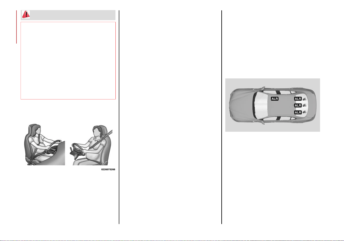
SAFETY
124
Seat Belts And Pregnant Women
Seat Belts And Pregnant Women
Seat belts must be worn by all occupants
including pregnant women: the risk of injury in
the event of an accident is reduced for the
mother and the unborn child if they are
wearing a seat belt.
Position the lap belt snug and low below the
abdomen and across the strong bones of the
hips. Place the shoulder belt across the chest
and away from the neck. Never place the
shoulder belt behind the back or under the arm.
Seat Belt Pretensioner
The front outboard seat belt system is
equipped with pretensioning devices that are
designed to remove slack from the seat belt in
the event of a collision. These devices may
improve the performance of the seat belt by
removing slack from the seat belt early in a
collision. Pretensioners work for all size occu-
pants, including those in child restraints.
NOTE:
These devices are not a substitute for proper
seat belt placement by the occupant. The seat
belt still must be worn snugly and positioned
properly.
The pretensioners are triggered by the Occu-
pant Restraint Controller (ORC). Like the air
bags, the pretensioners are single use items. A
deployed pretensioner or a deployed air bag
must be replaced immediately.
Energy Management Feature
The front outboard seat belt system is
equipped with an Energy Management feature
that may help further reduce the risk of injury
in the event of a collision. The seat belt system
has a retractor assembly that is designed to
release webbing in a controlled manner.
Switchable Automatic Locking Retractors (ALR)
The seat belts in the passenger seating positions
are equipped with a Switchable Automatic
Locking Retractor (ALR) which is used to secure
a child restraint system. For additional informa-
tion, refer to “Installing Child Restraints Using
The Vehicle Seat Belt” under the “Child
Restraints” section of this manual. The figure
below illustrates the locking feature for each
seating position.
Switchable Automatic Locking Retractor (ALR)
Locations
If the passenger seating position is equipped
with an ALR and is being used for normal usage,
only pull the seat belt webbing out far enough to
comfortably wrap around the occupant’s
mid-section so as to not activate the ALR. If the
ALR is activated, you will hear a clicking sound as
the seat belt retracts. Allow the webbing to
retract completely in this case and then carefully
pull out only the amount of webbing necessary to
comfortably wrap around the occupant’s
mid-section. Slide the latch plate into the buckle
until you hear a "click."
WARNING!
If the mini-latch plate and mini-buckle are
not properly connected when the seat belt
is used by an occupant, the seat belt will
not be able to provide proper restraint and
will increase the risk of injury in a collision.
When reattaching the mini-latch plate and
mini-buckle, ensure the seat belt webbing
is not twisted. If the webbing is twisted,
follow the preceding procedure to detach
the mini-latch plate and mini-buckle,
untwist the webbing, and reattach the
mini-latch plate and mini-buckle.
20_GA_OM_EN_USC_t.book Page 124
125
In Automatic Locking Mode, the shoulder belt
is automatically pre-locked. The seat belt will
still retract to remove any slack in the shoulder
belt. Use the Automatic Locking Mode anytime
a child restraint is installed in a seating posi-
tion that has a seat belt with this feature. Chil-
dren 12 years old and under should always be
properly restrained in the rear seat of a vehicle
with a rear seat.
How To Engage The Automatic Locking Mode
1. Buckle the combination lap and shoulder belt.
2. Grasp the shoulder portion and pull down-
ward until the entire seat belt is extracted.
3. Allow the seat belt to retract. As the seat
belt retracts, you will hear a clicking sound.
This indicates the seat belt is now in the
Automatic Locking Mode.
How To Disengage The Automatic Locking
Mode
Unbuckle the combination lap/shoulder belt
and allow it to retract completely to disengage
the Automatic Locking Mode and activate the
vehicle sensitive (emergency) locking mode.
Supplemental Restraint Systems (SRS)
Some of the safety features described in this
section may be standard equipment on some
models, or may be optional equipment on
others. If you are not sure, ask an authorized
dealer.
The air bag system must be ready to protect
you in a collision. The Occupant Restraint
Controller (ORC) monitors the internal circuits
and interconnecting wiring associated with the
electrical Air Bag System Components. Your
vehicle may be equipped with the following Air
Bag System Components:
Air Bag System Components
Occupant Restraint Controller (ORC)
Air Bag Warning Light
Steering Wheel and Column
Instrument Panel
Knee Impact Bolsters
Driver and Front Passenger Air Bags
Seat Belt Buckle Switch
Supplemental Side Air Bags
Supplemental Knee Air Bags
Front and Side Impact Sensors
Seat Belt Pretensioners
Seat Track Position Sensors
WARNING!
Never place a rear-facing child restraint in front
of an air bag. A deploying passenger front air
bag can cause death or serious injury to a child
12 years or younger, including a child in a
rear-facing child restraint.
Never install a rear-facing child restraint in
the front seat of a vehicle. Only use a
rear-facing child restraint in the rear seat.
If the vehicle does not have a rear seat, do
not transport a rear-facing child restraint
in that vehicle.
WARNING!
The seat belt assembly must be replaced
if the switchable Automatic Locking
Retractor (ALR) feature or any other seat
belt function is not working properly when
checked according to the procedures in
the Service Manual.
Failure to replace the seat belt assembly
could increase the risk of injury in colli-
sions.
Do not use the Automatic Locking Mode to
restrain occupants who are wearing the seat
belt or children who are using booster seats.
The locked mode is only used to install
rear-facing or forward-facing child restraints
that have a harness for restraining the child.
20_GA_OM_EN_USC_t.book Page 125

SAFETY
126
Air Bag Warning Light
The Occupant Restraint Controller
(ORC) monitors the readiness of the
electronic parts of the air bag system
whenever the ignition switch is in the
START or ON/RUN position. If the ignition
switch is in the OFF position or in the ACC posi-
tion, the air bag system is not on and the air
bags will not inflate.
The ORC contains a backup power supply
system that may deploy the air bag system
even if the battery loses power or it becomes
disconnected prior to deployment.
The ORC turns on the Air Bag Warning Light in
the instrument panel for approximately four to
eight seconds for a self-check when the igni-
tion switch is first in the ON/RUN position.
After the self-check, the Air Bag Warning Light
will turn off. If the ORC detects a malfunction
in any part of the system, it turns on the Air
Bag Warning Light, either momentarily or
continuously. A single chime will sound to alert
you if the light comes on again after initial
startup.
The ORC also includes diagnostics that will illu-
minate the instrument panel Air Bag Warning
Light if a malfunction is detected that could
affect the air bag system. The diagnostics also
record the nature of the malfunction. While
the air bag system is designed to be mainte-
nance free, if any of the following occurs, have
an authorized dealer service the air bag
system immediately.
The Air Bag Warning Light does not come on
during the four to eight seconds when the igni-
tion switch is first in the ON/RUN position.
The Air Bag Warning Light remains on after
the four to eight-second interval.
The Air Bag Warning Light comes on inter-
mittently or remains on while driving.
NOTE:
If the speedometer, tachometer, or any engine
related gauges are not working, the Occupant
Restraint Controller (ORC) may also be
disabled. In this condition the air bags may not
be ready to inflate for your protection. Have an
authorized dealer service the air bag system
immediately.
Redundant Air Bag Warning Light
If a fault with the Air Bag Warning
Light is detected, which could affect
the Supplemental Restraint System
(SRS), the Redundant Air Bag
Warning Light will illuminate on the instrument
panel. The Redundant Air Bag Warning Light
will stay on until the fault is cleared. In addi-
tion, a single chime will sound to alert you that
the Redundant Air Bag Warning Light has
come on and a fault has been detected. If the
Redundant Air Bag Warning Light comes on
intermittently or remains on while driving have
an authorized dealer service the vehicle imme-
diately.
For additional information regarding the
Redundant Air Bag Warning Light refer to
“Getting To Know Your Instrument Panel”
section of this manual.
WARNING!
Ignoring the Air Bag Warning Light in your
instrument panel could mean you won’t have
the air bag system to protect you in a collision.
If the light does not come on as a bulb check
when the ignition is first turned on, stays on
after you start the vehicle, or if it comes on as
you drive, have an authorized dealer service
the air bag system immediately.
20_GA_OM_EN_USC_t.book Page 126
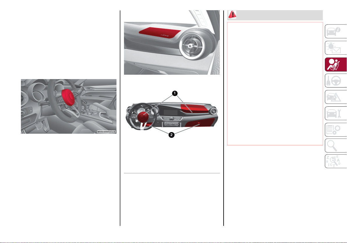
127
Front Air Bags
This vehicle has front air bags and lap/shoulder
belts for both the driver and front passenger. The
front air bags are a supplement to the seat belt
restraint systems. The driver front air bag is
mounted in the center of the steering wheel. The
passenger front air bag is mounted in the instru-
ment panel, above the glove compartment. The
words “SRS AIRBAG” or “AIRBAG” are embossed
on the air bag covers.
Driver Air Bag
Passenger Air Bag
Front Air Bag/Knee Bolster Locations
1 — Driver And Passenger Front Air Bags
2 — Driver And Passenger Knee Impact
Bolsters/Supplemental Knee Air Bags
WARNING!
Being too close to the steering wheel or
instrument panel during front air bag
deployment could cause serious injury,
including death. Air bags need room to
inflate. Sit back, comfortably extending
your arms to reach the steering wheel or
instrument panel.
Never place a rear-facing child restraint in
front of an air bag. A deploying passenger
front air bag can cause death or serious
injury to a child 12 years or younger,
including a child in a rear-facing child
restraint.
Never install a rear-facing child restraint in
the front seat of a vehicle. Only use a
rear-facing child restraint in the rear seat.
If the vehicle does not have a rear seat, do
not transport a rear-facing child restraint
in that vehicle.
20_GA_OM_EN_USC_t.book Page 127

SAFETY
128
Driver And Passenger Front Air Bag
Features
The Advanced Front Air Bag system has multi-
stage driver and front passenger air bags. This
system provides output appropriate to the
severity and type of collision as determined by
the Occupant Restraint Controller (ORC), which
may receive information from the front impact
sensors (if equipped) or other system compo-
nents.
The first stage inflator is triggered immediately
during an impact that requires air bag deploy-
ment. A low energy output is used in less
severe collisions. A higher energy output is
used for more severe collisions.
This vehicle may be equipped with a driver
and/or front passenger seat belt buckle
switch that detects whether the driver or front
passenger seat belt is buckled. The seat belt
buckle switch may adjust the inflation rate of
the Advanced Front Air Bags.
This vehicle may be equipped with driver and/
or front passenger seat track position sensors
that may adjust the inflation rate of the
Advanced Front Air Bags based upon seat
position.
Front Air Bag Operation
Front Air Bags are designed to provide additional
protection by supplementing the seat belts. Front
air bags are not expected to reduce the risk of injury
in rear, side, or rollover collisions. The front air bags
will not deploy in all frontal collisions, including
some that may produce substantial vehicle damage
— for example, some pole collisions, truck under-
rides, and angle offset collisions.
On the other hand, depending on the type and
location of impact, front air bags may deploy in
crashes with little vehicle front-end damage
but that produce a severe initial deceleration.
Because air bag sensors measure vehicle
deceleration over time, vehicle speed and
damage by themselves are not good indicators
of whether or not an air bag should have
deployed.
Seat belts are necessary for your protection in
all collisions, and also are needed to help keep
you in position, away from an inflating air bag.
When the ORC detects a collision requiring the
front air bags, it signals the inflator units. A
large quantity of non-toxic gas is generated to
inflate the front air bags.
The steering wheel hub trim cover and the
upper passenger side of the instrument panel
separate and fold out of the way as the air
bags inflate to their full size. The front air bags
fully inflate in less time than it takes to blink
your eyes. The front air bags then quickly
deflate while helping to restrain the driver and
front passenger.
WARNING!
No objects should be placed over or near the
air bag on the instrument panel or steering
wheel because any such objects could
cause harm if the vehicle is in a collision
severe enough to cause the air bag to
inflate.
Do not put anything on or around the air
bag covers or attempt to open them
manually. You may damage the air bags
and you could be injured because the air
bags may no longer be functional. The
protective covers for the air bag cushions
are designed to open only when the air
bags are inflating.
Relying on the air bags alone could lead to
more severe injuries in a collision. The air
bags work with your seat belt to restrain
you properly. In some collisions, air bags
won’t deploy at all. Always wear your seat
belts even though you have air bags.
20_GA_OM_EN_USC_t.book Page 128
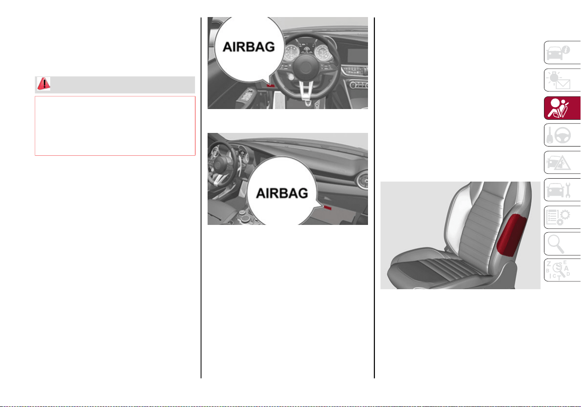
129
Knee Impact Bolsters
The Knee Impact Bolsters help protect the
knees of the driver and front passenger, and
position the front occupants for improved
interaction with the front air bags.
Supplemental Driver And Front Passenger
Knee Air Bags
This vehicle is equipped with a Supplemental
Driver Knee Air Bag mounted in the instrument
panel below the steering column and a Supple-
mental Passenger Knee Air Bag mounted in the
instrument panel below the glove compartment.
The Supplemental Knee Air Bags provide
enhanced protection during a frontal impact by
working together with the seat belts, preten-
sioners, and front air bags.
Driver Knee Air Bag
Front Passenger Knee Air Bag
Supplemental Side Air Bags
Supplemental Seat-Mounted Side Air Bags
(SABs)
This vehicle is equipped with Supplemental
Seat-Mounted Side Air Bags (SABs).
Supplemental Seat-Mounted Side Air Bags
(SABs) are located in the outboard side of the
front seats. The SABs are marked with a “SRS
AIRBAG” or “AIRBAG” on a label or on the seat
trim on the outboard side of the seats.
The SABs may help to reduce the risk of occu-
pant injury during certain side impacts, in addi-
tion to the injury reduction potential provided
by the seat belts and body structure.
Front Supplemental Seat-Mounted Side Air Bag
WARNING!
Do not drill, cut, or tamper with the knee
impact bolsters in any way.
Do not mount any accessories to the knee
impact bolsters such as alarm lights,
stereos, citizen band radios, etc.
20_GA_OM_EN_USC_t.book Page 129
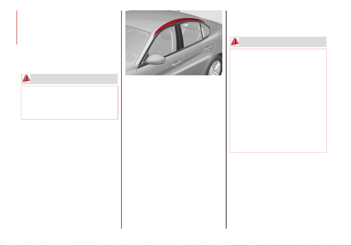
SAFETY
130
When the SAB deploys, it opens the seam on the
outboard side of the seatback’s trim cover. The
inflating SAB deploys through the seat seam into
the space between the occupant and the door.
The SAB moves at a very high speed and with
such a high force that it could injure occupants if
they are not seated properly, or if items are posi-
tioned in the area where the SAB inflates. Chil-
dren are at an even greater risk of injury from a
deploying air bag.
Supplemental Side Air Bag Inflatable Curtains
(SABICs)
This vehicle is equipped with Supplemental
Side Air Bag Inflatable Curtains (SABICs).
Supplemental Side Air Bag Inflatable Curtains
(SABICs) are located above the side windows.
The trim covering the SABICs is labeled “SRS
AIRBAG” or “AIRBAG.”
Supplemental Side Air Bag Inflatable Curtain
(SABIC) Location
SABICs may help reduce the risk of head and
other injuries to front and rear seat outboard
occupants in certain side impacts, in addition
to the injury reduction potential provided by
the seat belts and body structure.
The SABIC deploys downward, covering the
side windows. An inflating SABIC pushes the
outside edge of the headliner out of the way
and covers the window. The SABICs inflate
with enough force to injure occupants if they
are not belted and seated properly, or if items
are positioned in the area where the SABICs
inflate. Children are at an even greater risk of
injury from a deploying air bag.
The SABICs may help reduce the risk of partial
or complete ejection of vehicle occupants
through side windows in certain side impact
events.
WARNING!
Do not use accessory seat covers or place
objects between you and the Side Air Bags;
the performance could be adversely affected
and/or objects could be pushed into you,
causing serious injury.
WARNING!
Do not mount equipment, or stack
luggage or other cargo up high enough to
block the deployment of the SABICs. The
trim covering above the side windows
where the SABIC and its deployment path
are located should remain free from any
obstructions.
In order for the SABICs to work as
intended, do not install any accessory
items in your vehicle which could alter the
roof. Do not add an aftermarket sunroof to
your vehicle. Do not add roof racks that
require permanent attachments (bolts or
screws) for installation on the vehicle roof.
Do not drill into the roof of the vehicle for
any reason.
20_GA_OM_EN_USC_t.book Page 130
131
(Continued)
Side Impacts
The Side Air Bags are designed to activate in
certain side impacts. The Occupant Restraint
Controller (ORC) determines whether the
deployment of the Side Air Bags in a particular
impact event is appropriate, based on the
severity and type of collision. The side impact
sensors aid the ORC in determining the appro-
priate response to impact events. The system
is calibrated to deploy the Side Air Bags on the
impact side of the vehicle during impacts that
require Side Air Bag occupant protection. In
side impacts, the Side Air Bags deploy inde-
pendently; a left side impact deploys the left
Side Air Bags only and a right-side impact
deploys the right Side Air Bags only. Vehicle
damage by itself is not a good indicator of
whether or not Side Air Bags should have
deployed.
The Side Air Bags will not deploy in all side
collisions, including some collisions at certain
angles, or some side collisions that do not
impact the area of the passenger compart-
ment. The Side Air Bags may deploy during
angled or offset frontal collisions where the
front air bags deploy.
Side Air Bags are a supplement to the seat belt
restraint system. Side Air Bags deploy in less
time than it takes to blink your eyes.
NOTE:
Air bag covers may not be obvious in the inte-
rior trim, but they will open during air bag
deployment.
Rollover Events
Side Air Bags and seat belt pretensioners are
designed to activate in certain rollover events. The
Occupant Restraint Controller (ORC) determines
whether deployment in a particular rollover event is
appropriate, based on the severity and type of colli-
sion. Vehicle damage by itself is not a good indi-
cator of whether or not Side Air Bags and seat belt
pretensioners should have deployed.
The Side Air Bags and seat belt pretensioners
will not deploy in all rollover events. The roll-
over sensing system determines if a rollover
event may be in progress and whether deploy-
ment is appropriate. In the event the vehicle
experiences a rollover or near rollover event,
and deployment is appropriate, the rollover
sensing system will deploy the side air bags
and seat belt pretensioners on both sides of
the vehicle.
WARNING!
Occupants, including children, who are up
against or very close to Side Air Bags can
be seriously injured or killed. Occupants,
including children, should never lean on or
sleep against the door, side windows, or
area where the side air bags inflate, even
if they are in an infant or child restraint.
Seat belts (and child restraints where appro-
priate) are necessary for your protection in
all collisions. They also help keep you in
position, away from an inflating Side Air Bag.
To get the best protection from the Side Air
Bags, occupants must wear their seat belts
properly and sit upright with their backs
against the seats. Children must be properly
restrained in a child restraint or booster seat
that is appropriate for the size of the child.
WARNING!
Side Air Bags need room to inflate. Do not
lean against the door or window. Sit
upright in the center of the seat.
Being too close to the Side Air Bags during
deployment could cause you to be severely
injured or killed.
Relying on the Side Air Bags alone could
lead to more severe injuries in a collision.
The Side Air Bags work with your seat belt
to restrain you properly. In some colli-
sions, Side Air Bags won’t deploy at all.
Always wear your seat belt even though
you have Side Air Bags.
WARNING! (Continued)
20_GA_OM_EN_USC_t.book Page 131

SAFETY
132
The SABICs may help reduce the risk of partial
or complete ejection of vehicle occupants
through side windows in certain rollover or
side impact events.
Air Bag System Components
NOTE:
The Occupant Restraint Controller (ORC) moni-
tors the internal circuits and interconnecting
wiring associated with electrical Air Bag
System Components listed below:
Occupant Restraint Controller (ORC)
Air Bag Warning Light
Steering Wheel and Column
Instrument Panel
Knee Impact Bolsters
Driver and Front Passenger Air Bags
Seat Belt Buckle Switch
Supplemental Side Air Bags
Supplemental Knee Air Bags
Front and Side Impact Sensors
Seat Belt Pretensioners
Seat Track Position Sensors
If A Deployment Occurs
The front air bags are designed to deflate
immediately after deployment.
NOTE:
Front and/or side air bags will not deploy in all
collisions. This does not mean something is
wrong with the air bag system.
If you do have a collision which deploys the air
bags, any or all of the following may occur:
The air bag material may sometimes cause
abrasions and/or skin reddening to the
occupants as the air bags deploy and
unfold. The abrasions are similar to friction
rope burns or those you might get sliding
along a carpet or gymnasium floor. They are
not caused by contact with chemicals. They
are not permanent and normally heal
quickly. However, if you haven’t healed
significantly within a few days, or if you have
any blistering, see your doctor immediately.
As the air bags deflate, you may see some
smoke-like particles. The particles are a
normal by-product of the process that
generates the non-toxic gas used for air bag
inflation. These airborne particles may irri-
tate the skin, eyes, nose, or throat. If you
have skin or eye irritation, rinse the area
with cool water. For nose or throat irritation,
move to fresh air. If the irritation continues,
see your doctor. If these particles settle on
your clothing, follow the garment manufac-
turer’s instructions for cleaning.
Do not drive your vehicle after the air bags
have deployed. If you are involved in another
collision, the air bags will not be in place to
protect you.
NOTE:
Air bag covers may not be obvious in the
interior trim, but they will open during air
bag deployment.
After any collision, the vehicle should be
taken to an authorized dealer immediately.
WARNING!
Deployed air bags and seat belt pretensioners
cannot protect you in another collision. Have the
air bags, seat belt pretensioners, and the seat
belt retractor assemblies replaced by an
authorized dealer immediately. Also, have the
Occupant Restraint Controller System serviced
as well.
20_GA_OM_EN_USC_t.book Page 132

133
Enhanced Accident Response System
In the event of an impact, if the communica-
tion network remains intact, and the power
remains intact, depending on the nature of the
event, the Occupant Restraint Controller (ORC)
will determine whether to have the Enhanced
Accident Response System perform the
following functions:
Cut off fuel to the engine (if equipped)
Cut off battery power to the electric motor (if
equipped)
Flash hazard lights as long as the battery
has power
Turn on the interior lights, which remain on
as long as the battery has power or for
15 minutes from the intervention of the
Enhanced Accident Response System
Unlock the power door locks
Your vehicle may also be designed to perform
any of these other functions in response to the
Enhanced Accident Response System:
Turn off the Fuel Filter Heater, Turn off the
HVAC Blower Motor, Close the HVAC Circula-
tion Door
Cut off battery power to the:
• Engine
• Electric Motor (if equipped)
• Electric power steering
• Brake booster
• Electric park brake
• Automatic transmission gear selector
• Horn
• Front wiper
• Headlamp washer pump
NOTE:
After an accident, remember to cycle the ignition
to the OFF position and remove the key from the
ignition switch to avoid draining the battery.
Carefully check the vehicle for fuel leaks in the
engine compartment and on the ground near the
engine compartment and fuel tank before reset-
ting the system and starting the engine. If there
are no fuel leaks or damage to the vehicle elec-
trical devices (e.g. headlights) after an accident,
reset the system by following the procedure
described below. If you have any doubt, contact
an authorized dealer.
Enhanced Accident Response System
Reset Procedure
After the event occurs, when the system is
active, a message regarding fuel cutoff is
displayed. Turn the ignition switch from igni-
tion ACC or ON/RUN to ignition OFF. Carefully
check the vehicle for fuel leaks in the engine
compartment and on the ground near the
engine compartment and fuel tank before
resetting the system and starting the engine.
Depending on the nature of the event the left
and right turn signal lights, located in the
instrument panel, may both be blinking and
will continue to blink. In order to move your
vehicle to the side of the road, you must follow
the system reset procedure.
20_GA_OM_EN_USC_t.book Page 133

SAFETY
134
If a reset procedure step is not completed within 60 seconds, then the turn signal lights will blink and the reset procedure must be performed again in order to be
successful.
Customer Action
Customer Will See
NOTE:
Each step MUST BE held for at least two seconds
1. Turn ignition OFF. (Turn Signal Switch Must be placed in Neutral State).
2. Turn ignition ACC/ON/RUN.
Right turn light BLINKS.
Left turn light is OFF.
3. Turn right turn signal switch ON.
Right turn light is ON SOLID.
Left turn light BLINKS.
4. Place turn signal in neutral state.
Right turn light is OFF.
Left turn light BLINKS.
5. Turn left turn signal switch ON.
Right turn light BLINKS.
Left turn light is ON SOLID.
6. Place turn signal in neutral state.
Right turn light BLINKS.
Left turn light is OFF.
7. Turn right turn signal switch ON.
Right turn light is ON SOLID.
Left turn light BLINKS.
8. Place turn signal in neutral state.
Right turn light is OFF.
Left turn light BLINKS.
9. Turn left turn signal switch ON.
Right turn light is ON SOLID.
Left turn light is ON SOLID.
10. Turn left turn signal switch OFF. (Turn Signal Switch Must be placed
in Neutral State).
Right turn light is OFF.
Left turn light is OFF.
11. Turn ignition OFF.
12. Turn ignition ACC/ON/RUN. (Entire sequence needs to be
completed within one minute or sequence will need to be repeated).
System is now reset and the engine may be started.
Turn hazard flashers OFF (Manually).
20_GA_OM_EN_USC_t.book Page 134
135
Maintaining Your Air Bag System Event Data Recorder (EDR)
This vehicle is equipped with an event data
recorder (EDR). The main purpose of an EDR is to
record, in certain crash or near crash-like situa-
tions, such as an air bag deployment or hitting a
road obstacle, data that will assist in under-
standing how a vehicle’s systems performed.
The EDR is designed to record data related to
vehicle dynamics and safety systems for a short
period of time, typically 30 seconds or less. The
EDR in this vehicle is designed to record such
data as:
How various systems in your vehicle were
operating;
Whether or not the driver and passenger
safety belts were buckled/fastened;
How far (if at all) the driver was depressing
the accelerator and/or brake pedal; and,
How fast the vehicle was traveling.
These data can help provide a better under-
standing of the circumstances in which
crashes and injuries occur.
NOTE:
EDR data are recorded by your vehicle only if a
non-trivial crash situation occurs; no data are
recorded by the EDR under normal driving
conditions and no personal data (e.g., name,
gender, age, and crash location) are recorded.
However, other parties, such as law enforce-
ment, could combine the EDR data with the
type of personally identifying data routinely
acquired during a crash investigation.
To read data recorded by an EDR, special
equipment is required, and access to the
vehicle or the EDR is needed. In addition to the
vehicle manufacturer, other parties, such as
law enforcement, that have the special equip-
ment, can read the information if they have
access to the vehicle or the EDR.
WARNING!
Modifications to any part of the air bag system
could cause it to fail when you need it. You
could be injured if the air bag system is not
there to protect you. Do not modify the compo-
nents or wiring, including adding any kind of
badges or stickers to the steering wheel hub
trim cover or the upper passenger side of the
instrument panel. Do not modify the front
bumper, vehicle body structure, or add after-
market side steps or running boards.
It is dangerous to try to repair any part of
the air bag system yourself. Be sure to tell
anyone who works on your vehicle that it
has an air bag system.
Do not attempt to modify any part of your air
bag system. The air bag may inflate acciden-
tally or may not function properly if modifica-
tions are made. Take your vehicle to an
authorized dealer for any air bag system
service. If your seat, including your trim
cover and cushion, needs to be serviced in
any way (including removal or loosening/
tightening of seat attachment bolts), take
the vehicle to an authorized dealer. Only
manufacturer approved seat accessories
may be used. If it is necessary to modify the
air bag system for persons with disabilities,
contact an authorized dealer.
20_GA_OM_EN_USC_t.book Page 135

SAFETY
136
Child Restraints
Everyone in your vehicle needs to be buckled
up at all times, including babies and children.
Every state in the United States, and every
Canadian province, requires that small chil-
dren ride in proper restraint systems. This is
the law, and you can be prosecuted for
ignoring it.
Children 12 years or younger should ride prop-
erly buckled up in a rear seat, if available.
According to crash statistics, children are
safer when properly restrained in the rear
seats rather than in the front.
There are different sizes and types of
restraints for children from newborn size to
the child almost large enough for an adult
safety belt. Always check the child seat
Owner’s Manual to make sure you have the
correct seat for your child. Carefully read and
follow all the instructions and warnings in the
child restraint Owner’s Manual and on all the
labels attached to the child restraint.
Before buying any restraint system, make sure
that it has a label certifying that it meets all
applicable Safety Standards. You should also
make sure that you can install it in the vehicle
where you will use it.
NOTE:
For additional information, refer to
http://
www.nhtsa.gov/parents-and-caregivers
or
call: 1–888–327–4236
Canadian residents should refer to Trans-
port Canada’s website for additional infor-
mation:
https://www.tc.gc.ca/en/services/
road/child-car-seat-safety.html
WARNING!
In a collision, an unrestrained child can
become a projectile inside the vehicle. The
force required to hold even an infant on
your lap could become so great that you
could not hold the child, no matter how
strong you are. The child and others could
be badly injured or killed. Any child riding in
your vehicle should be in a proper restraint
for the child’s size.
20_GA_OM_EN_USC_t.book Page 136

137
Summary Of Recommendations For Restraining Children In Vehicles
Child Size, Height, Weight Or Age Recommended Type Of Child Restraint
Infants and Toddlers
Children who are two years old or younger
and who have not reached the height or
weight limits of their child restraint
Either an Infant Carrier or a Convertible
Child Restraint, facing rearward in a rear
seat of the vehicle
Small Children
Children who are at least two years old or
who have outgrown the height or weight limit
of their rear-facing child restraint
Forward-Facing Child Restraint with a
five-point Harness, facing forward in a rear
seat of the vehicle
Larger Children
Children who have outgrown their
forward-facing child restraint, but are too
small to properly fit the vehicle’s seat belt
Belt Positioning Booster Seat and the
vehicle seat belt, seated in a rear seat of the
vehicle
Children Too Large for Child Restraints
Children 12 years old or younger, who have
outgrown the height or weight limit of their
booster seat
Vehicle Seat Belt, seated in a rear seat of
the vehicle
20_GA_OM_EN_USC_t.book Page 137

SAFETY
138
(Continued)
Infant And Child Restraints
Safety experts recommend that children ride
rear-facing in the vehicle until they are two
years old or until they reach either the height
or weight limit of their rear-facing child
restraint. Two types of child restraints can be
used rear-facing: infant carriers and convert-
ible child seats.
The infant carrier is only used rear-facing in
the vehicle. It is recommended for children
from birth until they reach the weight or height
limit of the infant carrier. Convertible child
seats can be used either rear-facing or
forward-facing in the vehicle. Convertible child
seats often have a higher weight limit in the
rear-facing direction than infant carriers do, so
they can be used rear-facing by children who
have outgrown their infant carrier but are still
less than at least two years old. Children
should remain rear-facing until they reach the
highest weight or height allowed by their
convertible child seat.
Older Children And Child Restraints
Children who are two years old or who have
outgrown their rear-facing convertible child
seat can ride forward-facing in the vehicle.
Forward-facing child seats and convertible
child seats used in the forward-facing direc-
tion are for children who are over two years old
or who have outgrown the rear-facing weight
or height limit of their rear-facing convertible
child seat. Children should remain in a
forward-facing child seat with a harness for as
long as possible, up to the highest weight or
height allowed by the child seat.
All children whose weight or height is above
the forward-facing limit for the child seat
should use a belt-positioning booster seat
until the vehicle’s seat belts fit properly. If the
child cannot sit with knees bent over the
vehicle’s seat cushion while the child’s back is
against the seatback, they should use a
belt-positioning booster seat. The child and
belt-positioning booster seat are held in the
vehicle by the seat belt.
WARNING!
Never place a rear-facing child restraint in
front of an air bag. A deploying passenger
front air bag can cause death or serious
injury to a child 12 years or younger,
including a child in a rear-facing child
restraint.
Never install a rear-facing child restraint in
the front seat of a vehicle. Only use a
rear-facing child restraint in the rear seat.
If the vehicle does not have a rear seat, do
not transport a rear-facing child restraint
in that vehicle.
WARNING!
Improper installation can lead to failure of
an infant or child restraint. It could come
loose in a collision. The child could be badly
injured or killed. Follow the child restraint
manufacturer’s directions exactly when
installing an infant or child restraint.
20_GA_OM_EN_USC_t.book Page 138

139
Children Too Large For Booster Seats
Children who are large enough to wear the
shoulder belt comfortably, and whose legs are
long enough to bend over the front of the seat
when their back is against the seatback,
should use the seat belt in a rear seat. Use this
simple 5-step test to decide whether the child
can use the vehicle’s seat belt alone:
1. Can the child sit all the way back against
the back of the vehicle seat?
2. Do the child’s knees bend comfortably
over the front of the vehicle seat – while
the child is still sitting all the way back?
3. Does the shoulder belt cross the child’s
shoulder between the neck and arm?
4. Is the lap part of the belt as low as
possible, touching the child’s thighs and
not the stomach?
5. Can the child stay seated like this for the
whole trip?
If the answer to any of these questions was
“no,” then the child still needs to use a booster
seat in this vehicle. If the child is using the lap/
shoulder belt, check seat belt fit periodically
and make sure the seat belt buckle is latched.
A child’s squirming or slouching can move the
belt out of position. If the shoulder belt
contacts the face or neck, move the child
closer to the center of the vehicle, or use a
booster seat to position the seat belt on the
child correctly.
After a child restraint is installed in the
vehicle, do not move the vehicle seat
forward or rearward because it can loosen
the child restraint attachments. Remove
the child restraint before adjusting the
vehicle seat position. When the vehicle
seat has been adjusted, reinstall the child
restraint.
When your child restraint is not in use,
secure it in the vehicle with the seat belt or
LATCH anchorages, or remove it from the
vehicle. Do not leave it loose in the
vehicle. In a sudden stop or accident, it
could strike the occupants or seatbacks
and cause serious personal injury.
WARNING! (Continued)
WARNING!
Never allow a child to put the shoulder belt
under an arm or behind their back. In a
crash, the shoulder belt will not protect a
child properly, which may result in serious
injury or death. A child must always wear
both the lap and shoulder portions of the
seat belt correctly.
20_GA_OM_EN_USC_t.book Page 139

SAFETY
140
Recommendations For Attaching Child Restraints
Restraint Type
Combined Weight
of the Child + Child
Restraint
Use Any Attachment Method Shown With An “X” Below
LATCH – Lower
Anchors Only
Seat Belt Only
LATCH – Lower
Anchors + Top
Tether Anchor
Seat Belt + Top
Tether Anchor
Rear-Facing Child
Restraint
Up to 65 lbs (29.5 kg) X X
Rear-Facing Child
Restraint
More than 65 lbs
(29.5 kg)
X
Forward-Facing Child
Restraint
Up to 65 lbs (29.5 kg) X X
Forward-Facing Child
Restraint
More than 65 lbs
(29.5 kg)
X
20_GA_OM_EN_USC_t.book Page 140
141
Lower Anchors And Tethers For CHildren
(LATCH) Restraint System
LATCH Label
Your vehicle is equipped with the child restraint
anchorage system called LATCH, which stands
for Lower Anchors and Tethers for CHildren. The
LATCH system has three vehicle anchor points
for installing LATCH-equipped child seats. There
are two lower anchorages located at the back
of the seat cushion where it meets the seat-
back and one top tether anchorage located
behind the seating position. These anchor-
ages are used to install LATCH-equipped child
seats without using the vehicle’s seat belts.
Some seating positions may have a top tether
anchorage but no lower anchorages. In these
seating positions, the seat belt must be used
with the top tether anchorage to install the
child restraint. Please see the following table
for more information.
LATCH Positions For Installing Child
Restraints In This Vehicle
LATCH Positions
Lower Anchorage Symbol (2 Anchorages
Per Seating Position)
Top Tether Anchorage Symbol
20_GA_OM_EN_USC_t.book Page 141

SAFETY
142
Frequently Asked Questions About Installing Child Restraints With LATCH
What is the weight limit (child’s weight + weight
of the child restraint) for using the LATCH
anchorage system to attach the child restraint?
65 lbs (29.5 kg)
Use the LATCH anchorage system until the combined weight of the
child and the child restraint is 65 lbs (29.5 kg). Use the seat belt and
tether anchor instead of the LATCH system once the combined weight
is more than 65 lbs (29.5 kg).
Can the LATCH anchorages and the seat belt
be used together to attach a rear-facing or
forward-facing child restraint?
No
Do not use the seat belt when you use the LATCH anchorage system
to attach a rear-facing or forward-facing child restraint.
Booster seats may be attached to the LATCH anchorages if allowed
by the booster seat manufacturer. See your booster seat owner’s
manual for more information.
Can a child seat be installed in the center
position using the inner LATCH lower anchorages
from the outboard seating positions?
No
Use the seat belt and tether anchor to install a child seat in the
center seating position.
Can two child restraints be attached using a
common lower LATCH anchorage?
No
Never “share” a LATCH anchorage with two or more child restraints. If
the center position does not have dedicated LATCH lower
anchorages, use the seat belt to install a child seat in the center
position next to a child seat using the LATCH anchorages in an
outboard position.
Can the rear-facing child restraint touch the
back of the front passenger seat?
Yes
The child seat may touch the back of the front passenger seat if the
child restraint manufacturer also allows contact. See your child
restraint owner’s manual for more information.
Can the rear head restraints be removed? Yes
The head restraints can be removed in every seating position if they
interfere with the installation of the child restraint. Refer to “Head
Restraints” in “Getting To Know Your Vehicle” for further information.
20_GA_OM_EN_USC_t.book Page 142
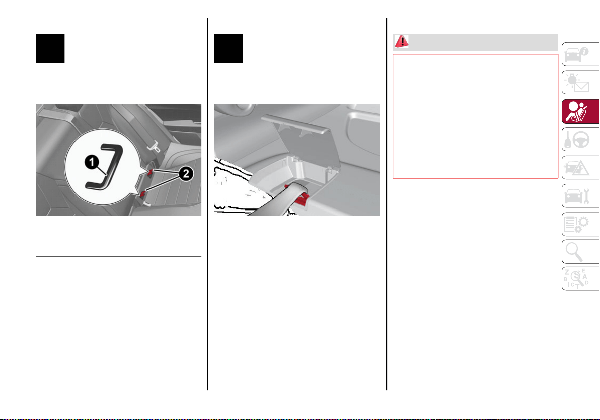
143
Locating The LATCH Anchorages
The lower anchorages are round
bars that are found at the rear of the
seat cushion where it meets the
seatback. Each anchorage is under a
cover with the anchorage symbol on it. Lift the
cover to access the lower anchorage.
LATCH Anchorage Locations
Locating The Upper Tether Anchorages
There are tether strap anchorages
behind each rear seating position
located in the panel between the
rear seatback and the rear window.
They are found under a plastic cover with the
tether anchorage symbol on it.
Upper Tether Anchorage Location
LATCH-compatible child restraint systems will
be equipped with a rigid bar or a flexible strap
on each side. Each will have a hook or
connector to attach to the lower anchorage
and a way to tighten the connection to the
anchorage. Forward-facing child restraints
and some rear-facing child restraints will also
be equipped with a tether strap. The tether
strap will have a hook at the end to attach to
the top tether anchorage and a way to tighten
the strap after it is attached to the anchorage.
Center Seat LATCH
Always follow the directions of the child
restraint manufacturer when installing your
child restraint. Not all child restraint systems
will be installed as described here.
1 — LATCH Anchorage Bar
2 — LATCH Anchorage Locations
WARNING!
Do not install a child restraint in the center
position using the LATCH system. This posi-
tion is not approved for installing child seats
using the LATCH attachments. You must use
the seat belt and tether anchor to install a
child seat in the center seating position.
Never use the same lower anchorage to
attach more than one child restraint. Please
refer to “Installing The LATCH-Compatible
Child Restraint System” for typical installa-
tion instructions.
20_GA_OM_EN_USC_t.book Page 143

SAFETY
144
To Install A LATCH-Compatible Child
Restraint
If the selected seating position has a Switch-
able Automatic Locking Retractor (ALR) seat
belt, stow the seat belt, following the instruc-
tions below. See the section “Installing Child
Restraints Using the Vehicle Seat Belt” to
check what type of seat belt each seating posi-
tion has.
1. Loosen the adjusters on the lower straps
and on the tether strap of the child seat so
that you can more easily attach the hooks
or connectors to the vehicle anchorages.
2. Place the child seat between the lower
anchorages for that seating position. If the
second row seat can be reclined, you may
recline the seat and/or raise the head
restraint (if adjustable) to get a better fit. If
the rear seat can be moved forward and
rearward in the vehicle, you may wish to
move it to its rear-most position to make
room for the child seat. You may also move
the front seat forward to allow more room
for the child seat.
3. Attach the lower hooks or connectors of
the child restraint to the lower anchorages
in the selected seating position.
4. If the child restraint has a tether strap,
connect it to the top tether anchorage. See
the section “Installing Child Restraints
Using the Top Tether Anchorage” for direc-
tions to attach a tether anchor.
5. Tighten all of the straps as you push the
child restraint rearward and downward
into the seat. Remove slack in the straps
according to the child restraint manufac-
turer’s instructions.
6. Test that the child restraint is installed
tightly by pulling back and forth on the
child seat at the belt path. It should not
move more than 1 inch (25.4 mm) in any
direction.
How To Stow An Unused Switchable-ALR
(ALR) Seat Belt:
When using the LATCH attaching system to
install a child restraint, stow all ALR seat belts
that are not being used by other occupants or
being used to secure child restraints. An
unused belt could injure a child if they play
with it and accidentally lock the seat belt
retractor. Before installing a child restraint
using the LATCH system, buckle the seat belt
behind the child restraint and out of the child’s
reach. If the buckled seat belt interferes with
the child restraint installation, instead of buck-
ling it behind the child restraint, route the seat
belt through the child restraint belt path and
then buckle it. Do not lock the seat belt.
Remind all children in the vehicle that the seat
belts are not toys and that they should not play
with them.
20_GA_OM_EN_USC_t.book Page 144
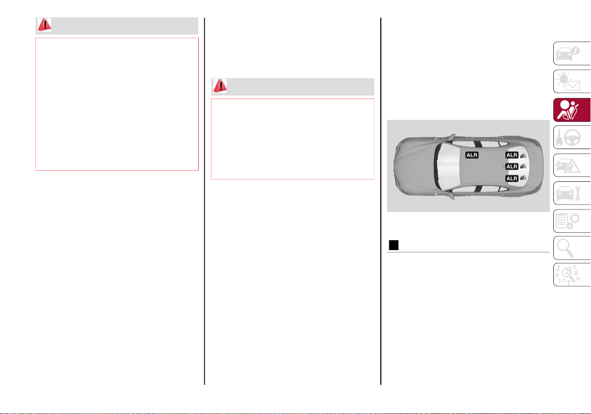
145
Installing Child Restraints Using The Vehicle
Seat Belt
Child restraint systems are designed to be
secured in vehicle seats by lap belts or the lap
belt portion of a lap/shoulder belt.
The seat belts in the passenger seating posi-
tions are equipped with a Switchable Auto-
matic Locking Retractor (ALR) that is designed
to keep the lap portion of the seat belt tight
around the child restraint so that it is not
necessary to use a locking clip. The ALR
retractor can be “switched” into a locked
mode by pulling all of the webbing out of the
retractor and then letting the webbing retract
back into the retractor. If it is locked, the ALR
will make a clicking noise while the webbing is
pulled back into the retractor.
Refer to the “Automatic Locking Mode”
description in “Switchable Automatic Locking
Retractors (ALR)” under “Occupant Restraint
Systems” for additional information on ALR.
Please see the table below and the following
sections for more information.
Lap/Shoulder Belt Systems For Installing
Child Restraints In This Vehicle
Automatic Locking Retractor (ALR) Locations
WARNING!
Improper installation of a child restraint to
the LATCH anchorages can lead to failure
of the restraint. The child could be badly
injured or killed. Follow the child restraint
manufacturer’s directions exactly when
installing an infant or child restraint.
Child restraint anchorages are designed to
withstand only those loads imposed by
correctly-fitted child restraints. Under no
circumstances are they to be used for adult
seat belts, harnesses, or for attaching other
items or equipment to the vehicle.
WARNING!
Improper installation or failure to properly
secure a child restraint can lead to failure
of the restraint. The child could be badly
injured or killed.
Follow the child restraint manufacturer’s
directions exactly when installing an
infant or child restraint.
ALR — Switchable Automatic Locking Retractor
Top Tether Anchorage Symbol
20_GA_OM_EN_USC_t.book Page 145

SAFETY
146
Frequently Asked Questions About Installing Child Restraints With Seat Belts
What is the weight limit (child’s weight + weight
of the child restraint) for using the Tether
Anchor with the seat belt to attach a forward
facing child restraint?
Weight limit of the Child Restraint
Always use the tether anchor when using the seat belt
to install a forward facing child restraint, up to the
recommended weight limit of the child restraint.
Can the rear-facing child restraint touch the
back of the front passenger seat?
Yes
Contact between the front passenger seat and the
child restraint is allowed, if the child restraint
manufacturer also allows contact.
Can the rear head restraints be removed? Yes
The head restraints can be removed in every
seating position if they interfere with the
installation of the child restraint. Refer to “Head
Restraints” in “Getting To Know Your Vehicle” for
further information.
Can the buckle stalk be twisted to tighten the
seat belt against the belt path of the child
restraint?
No
Do not twist the buckle stalk in a seating position
with an ALR retractor.
20_GA_OM_EN_USC_t.book Page 146
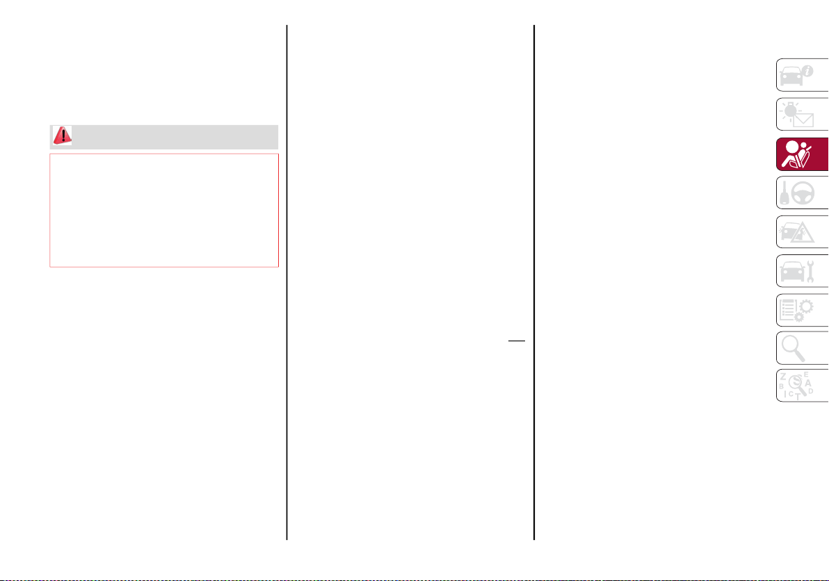
147
Installing A Child Restraint With A
Switchable Automatic Locking Retractor
(ALR):
Child restraint systems are designed to be
secured in vehicle seats by lap belts or the lap
belt portion of a lap/shoulder belt.
1. Place the child seat in the center of the
seating position. If the second row seat
can be reclined, you may recline the seat
and/or raise the head restraint (if adjust-
able) to get a better fit. If the rear seat can
be moved forward and rearward in the
vehicle, you may wish to move it to its
rear-most position to make room for the
child seat. You may also move the front
seat forward to allow more room for the
child seat.
2. Pull enough of the seat belt webbing from
the retractor to pass it through the belt
path of the child restraint. Do not twist the
belt webbing in the belt path.
3. Slide the latch plate into the buckle until
you hear a “click.”
4. Pull on the webbing to make the lap
portion tight against the child seat.
5. To lock the seat belt, pull down on the
shoulder part of the belt until you have
pulled all the seat belt webbing out of the
retractor. Then, allow the webbing to
retract back into the retractor. As the
webbing retracts, you will hear a clicking
sound. This means the seat belt is now in
the Automatic Locking mode.
6. Try to pull the webbing out of the retractor.
If it is locked, you should not be able to pull
out any webbing. If the retractor is not
locked, repeat step 5.
7. Finally, pull up on any excess webbing to
tighten the lap portion around the child
restraint while you push the child restraint rear-
ward and downward into the vehicle seat.
8. If the child restraint has a top tether strap
and the seating position has a top tether
anchorage, connect the tether strap to the
anchorage and tighten the tether strap.
See the section “Installing Child Restraints
Using the Top Tether Anchorage” for direc-
tions to attach a tether anchor.
9. Test that the child restraint is installed
tightly by pulling back and forth on the
child seat at the belt path. It should not
move more than 1 inch (25.4 mm) in any
direction.
Any seat belt system will loosen with time, so
check the belt occasionally, and pull it tight if
necessary.
WARNING!
Improper installation or failure to properly
secure a child restraint can lead to failure
of the restraint. The child could be badly
injured or killed.
Follow the child restraint manufacturer’s
directions exactly when installing an
infant or child restraint.
20_GA_OM_EN_USC_t.book Page 147
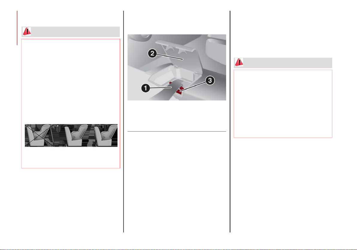
SAFETY
148
Installing Child Restraints Using The Top
Tether Anchorage:
1. Look behind the seating position where you
plan to install the child restraint to find the
tether anchorage. You may need to move the
seat forward to provide better access to the
tether anchorage. If there is no top tether
anchorage for that seating position, move
the child restraint to another position in the
vehicle if one is available.
2. Rotate or lift the cover to access the
anchor directly behind the seat where you
are placing the child restraint.
Upper Tether Anchorage Location
3. Route the tether strap to provide the most
direct path for the strap between the anchor
and the child seat. If your vehicle is equipped
with adjustable rear head restraints, raise
the head restraint, and where possible, route
the tether strap under the head restraint and
between the two posts. If not possible, lower
the head restraint and pass the tether strap
around the outboard side of the head
restraint.
4. Attach the tether strap hook of the child
restraint to the top tether anchorage as
shown in the diagram.
5. Remove slack in the tether strap according
to the child restraint manufacturer’s
instructions.
Transporting Pets
Air Bags deploying in the front seat could harm
your pet. An unrestrained pet will be thrown
about and possibly injured, or injure a
passenger during panic braking or in a colli-
sion.
Pets should be restrained in the rear seat (if
equipped) in pet harnesses or pet carriers that
are secured by seat belts.
WARNING!
Do not attach a tether strap for a
rear-facing car seat to any location in front
of the car seat, including the seat frame or
a tether anchorage. Only attach the tether
strap of a rear-facing car seat to the tether
anchorage that is approved for that seating
position, located behind the top of the
vehicle seat. See the section “Lower
Anchors and Tethers for CHildren (LATCH)
Restraint System” for the location of
approved tether anchorages in your vehicle.
1 — Tether Strap Hook
2 — Cover
3 — Tether Anchor
WARNING!
An incorrectly anchored tether strap could
lead to increased head motion and
possible injury to the child. Use only the
anchorage position directly behind the
child seat to secure a child restraint top
tether strap.
If your vehicle is equipped with a split rear
seat, make sure the tether strap does not
slip into the opening between the seat-
backs as you remove slack in the strap.
20_GA_OM_EN_USC_t.book Page 148
149
SAFETY TIPS
Transporting Passengers
NEVER TRANSPORT PASSENGERS IN THE
CARGO AREA.
Exhaust Gas
The best protection against carbon monoxide
entry into the vehicle body is a properly main-
tained engine exhaust system.
Whenever a change is noticed in the sound of
the exhaust system, when exhaust fumes can
be detected inside the vehicle, or when the
underside or rear of the vehicle is damaged,
have a competent mechanic inspect the
complete exhaust system and adjacent body
areas for broken, damaged, deteriorated, or
mispositioned parts. Open seams or loose
connections could permit exhaust fumes to
seep into the passenger compartment. In
addition, inspect the exhaust system each
time the vehicle is raised for lubrication or oil
change. Replace as required.
WARNING!
Do not leave children or animals inside
parked vehicles in hot weather. Interior
heat build-up may cause serious injury or
death.
It is extremely dangerous to ride in a cargo
area, inside or outside of a vehicle. In a
collision, people riding in these areas are
more likely to be seriously injured or killed.
Do not allow people to ride in any area of
your vehicle that is not equipped with
seats and seat belts.
Be sure everyone in your vehicle is in a
seat and using a seat belt properly.
WARNING!
Exhaust gases can injure or kill. They
contain carbon monoxide (CO), which is
colorless and odorless. Breathing it can
make you unconscious and can eventually
poison you. To avoid breathing (CO), follow
these safety tips:
Do not run the engine in a closed garage
or in confined areas any longer than
needed to move your vehicle in or out of
the area.
If you are required to drive with the trunk/lift-
gate/rear doors open, make sure that all
windows are closed and the climate control
BLOWER switch is set at high speed. DO NOT
use the recirculation mode.
If it is necessary to sit in a parked vehicle
with the engine running, adjust your
heating or cooling controls to force
outside air into the vehicle. Set the blower
at high speed.
20_GA_OM_EN_USC_t.book Page 149

SAFETY
150
(Continued)
Safety Checks You Should Make Inside The
Vehicle
Seat Belts
Inspect the seat belt system periodically,
checking for cuts, frays, and loose parts.
Damaged parts must be replaced immediately.
Do not disassemble or modify the system.
Front seat belt assemblies must be replaced
after a collision. Rear seat belt assemblies
must be replaced after a collision if they have
been damaged (i.e., bent retractor, torn
webbing, etc.). If there is any question
regarding seat belt or retractor condition,
replace the seat belt.
Air Bag Warning Light
The Air Bag warning light will turn on for
four to eight seconds as a bulb check when the
ignition switch is first turned to ON/RUN. If the
light is either not on during starting, stays on,
or turns on while driving, have the system
inspected at an authorized dealer as soon as
possible. After the bulb check, this light will
illuminate with a single chime when a fault
with the Air Bag System has been detected. It
will stay on until the fault is removed. If the
light comes on intermittently or remains on
while driving, have an authorized dealer
service the vehicle immediately.
Refer to “Occupant Restraint Systems” in this
section for further information.
Defroster
Check operation by selecting the defrost mode
and place the blower control on high speed. You
should be able to feel the air directed against the
windshield. See an authorized dealer for service
if your defroster is inoperable.
Floor Mat Safety Information
Always use floor mats designed to fit your
vehicle. Only use a floor mat that does not
interfere with the operation of the accelerator,
brake or clutch pedals. Only use a floor mat
that is securely attached using the floor mat
fasteners so it cannot slip out of position and
interfere with the accelerator, brake or clutch
pedals or impair safe operation of your vehicle
in other ways.
WARNING!
An improperly attached, damaged, folded, or
stacked floor mat, or damaged floor mat
fasteners may cause your floor mat to
interfere with the accelerator, brake, or clutch
pedals and cause a loss of vehicle control. To
prevent SERIOUS INJURY or DEATH:
ALWAYS securely attach your floor mat
using the floor mat fasteners. DO NOT
install your floor mat upside down or turn
your floor mat over. Lightly pull to confirm
mat is secured using the floor mat
fasteners on a regular basis.
ALWAYS REMOVE THE EXISTING FLOOR
MAT FROM THE VEHICLE before
installing any other floor mat. NEVER
install or stack an additional floor mat on
top of an existing floor mat.
20_GA_OM_EN_USC_t.book Page 150

151
(Continued)
Periodic Safety Checks You Should Make
Outside The Vehicle
Tires
Examine tires for excessive tread wear and
uneven wear patterns. Check for stones, nails,
glass, or other objects lodged in the tread or
sidewall. Inspect the tread for cuts and cracks.
Inspect sidewalls for cuts, cracks, and bulges.
Check the wheel nuts for tightness. Check the
tires (including spare) for proper cold inflation
pressure.
Lights
Have someone observe the operation of brake
lights and exterior lights while you work the
controls. Check turn signal and high beam
indicator lights on the instrument panel.
Door Latches
Check for proper closing, latching, and locking.
Fluid Leaks
Check area under the vehicle after overnight
parking for fuel, coolant, oil, or other fluid
leaks. Also, if gasoline fumes are detected or if
fuel, or brake fluid leaks are suspected, the
cause should be located and corrected imme-
diately.
ONLY install floor mats designed to fit your
vehicle. NEVER install a floor mat that
cannot be properly attached and secured
to your vehicle. If a floor mat needs to be
replaced, only use a FCA approved floor
mat for the specific make, model, and
year of your vehicle.
ONLY use the driver’s side floor mat on the
driver’s side floor area. To check for interfer-
ence, with the vehicle properly parked with
the engine off, fully depress the accelerator,
the brake, and the clutch pedal (if present)
to check for interference. If your floor mat
interferes with the operation of any pedal, or
is not secure to the floor, remove the floor
mat from the vehicle and place the floor mat
in your trunk.
ONLY use the passenger’s side floor mat
on the passenger’s side floor area.
ALWAYS make sure objects cannot fall or
slide into the driver’s side floor area when
the vehicle is moving. Objects can become
trapped under accelerator, brake, or
clutch pedals and could cause a loss of
vehicle control.
WARNING! (Continued)
NEVER place any objects under the floor
mat (e.g., towels, keys, etc.). These
objects could change the position of the
floor mat and may cause interference with
the accelerator, brake, or clutch pedals.
If the vehicle carpet has been removed and
re-installed, always properly attach carpet to
the floor and check the floor mat fasteners
are secure to the vehicle carpet. Fully
depress each pedal to check for interfer-
ence with the accelerator, brake, or clutch
pedals then re-install the floor mats.
It is recommended to only use mild soap
and water to clean your floor mats. After
cleaning, always check your floor mat has
been properly installed and is secured to
your vehicle using the floor mat fasteners
by lightly pulling mat.
WARNING! (Continued)
20_GA_OM_EN_USC_t.book Page 151

152
(Continued)
STARTING AND OPERATING
STARTING THE ENGINE
Before starting the engine, be sure to adjust the
seat, the interior rear view mirror, and the door
mirrors, and fasten the seat belt correctly.
Never press the accelerator pedal before
starting the engine.
If necessary, messages indicating the starting
procedure will be shown in the display.
Starting Procedure
Proceed as follows:
1. Apply the electric park brake and set the
gear selector to PARK (P) or NEUTRAL (N).
2. Fully depress the brake pedal without
touching the accelerator.
3. Briefly push the ignition button.
4. If the engine doesn't start within a few
seconds, you need to repeat the procedure.
If the problem persists, contact an authorized
dealer.
Remote Starting System
This system uses the key fob to start the
engine conveniently from outside the vehicle
while still maintaining security. The system
has a range of at least 300 feet (91 meters).
The remote starting system also activates the
climate control, the heated seats (if equipped),
and the heated steering wheel (if equipped),
depending on temperatures outside and inside
of the vehicle.
NOTE:
Obstructions between the vehicle and key fob
may reduce this range.
WARNING!
When leaving the vehicle, always remove
the key fob from the vehicle and lock your
vehicle.
Never leave children alone in a vehicle, or
with access to an unlocked vehicle.
Allowing children to be in a vehicle unat-
tended is dangerous for a number of
reasons. A child or others could be seriously
or fatally injured. Children should be warned
not to touch the parking brake, brake pedal
or the transmission gear selector.
Do not leave the key fob in or near the
vehicle, or in a location accessible to chil-
dren. A child could operate power windows,
other controls, or move the vehicle.
Do not leave children or animals inside
parked vehicles in hot weather. Interior heat
build-up may cause serious injury or death.
WARNING!
Never pour fuel or other flammable liquid
into the throttle body air inlet opening in an
attempt to start the vehicle. This could result
in flash fire causing serious personal injury.
Do not attempt to push or tow your vehicle to
get it started. Vehicles equipped with an
automatic transmission cannot be started
this way. Unburned fuel could enter the cata-
lytic converter and once the engine has
started, ignite and damage the converter
and vehicle.
If the vehicle has a discharged battery,
booster cables may be used to obtain a
start from a booster battery or the battery
in another vehicle. This type of start can
be dangerous if done improperly. Refer to
“Jump Starting” in “In Case Of Emergency”
for further information.
CAUTION!
To prevent damage to the starter, do not
continuously crank the engine for more than
25 seconds at a time. Wait 60 seconds before
trying again.
WARNING! (Continued)
20_GA_OM_EN_USC_t.book Page 152
153
How to use Remote Start
All of the following conditions must be met
before the engine will remote start:
Gear selector in PARK (P).
Doors closed.
Hood closed.
Trunk closed.
Hazard switch off.
Brake switch inactive (brake pedal not
pressed).
Battery at an acceptable charge level.
PANIC button not pushed.
System not disabled from previous remote
start event.
Vehicle alarm system indicator flashing.
Ignition in the OFF mode.
Fuel level meets minimum requirement.
Remote Start Comfort Systems — If Equipped
When Remote Start is activated, the heated
steering wheel and driver heated seat features
will automatically turn on in cold weather.
These features will stay on through the dura-
tion of remote start also until the ignition is
placed in the ON/RUN mode.
Remote Start Windshield Wiper De–Icer Acti-
vation — If Equipped
When remote start is active and the outside
ambient temperature is less than 39°F (4°C), the
Windshield Wiper De-Icer will be enabled. Exiting
remote start will resume previous operation, except
if the Windshield Wiper De-Icer is active.
The Windshield Wiper De-Icer timer and oper-
ation will continue.
Cold Weather Operation
To prevent possible engine damage while
starting at low temperatures, this vehicle will
inhibit engine cranking when the ambient
temperature is less than –22°F (–30°C) and
the oil temperature sensor reading indicates
an engine block heater has not been used. An
externally-powered electric engine block
heater is available as optional equipment or
from an authorized dealer.
The message “plug in engine heater” will be
displayed in the instrument cluster when the
ambient temperature is below 5°F (–15°C) at
the time the engine is shut off as a reminder to
avoid possible crank delays at the next cold start.
Extended Park Starting
If the vehicle has not been started or driven for
at least 30 days, it is advisable to follow the
indications below.
To start the engine, proceed as follows:
1. Briefly push the ignition button
2. If the engine does not start, wait five seconds
and let the starter cool down and then repeat
the starting procedure
3. If the engine does not start after eight
attempts, let the starter cool down for at
least 10 seconds, and then repeat the
starting procedure
If the problem persists, contact an authorized
dealer.
NOTE:
After prolonged vehicle inactivity, very difficult
starting, that can be noticed through rapid
fatigue of the starter, might also be due to a
discharged battery. In this case, see the “Jump
Starting” section in the “In Case Of Emer-
gency” chapter.
CAUTION!
Use of the recommended oil and adhering to
the prescribed oil change intervals is
important to prevent engine damage and
ensure satisfactory starting in cold conditions.
20_GA_OM_EN_USC_t.book Page 153

STARTING AND OPERATING
154
(Continued)
If Engine Fails To Start
Starting the Engine with Key Fob Battery Run
Down or Drained
If the ignition does not respond when the
button is pushed, the key fob battery might be
run down or drained. Therefore, the system
does not detect the presence of the key fob in
the vehicle, and will display a dedicated
message.
In this case, follow the instructions outlined in
“Starting With A Discharged Key Fob Battery”
in the “Getting To Know Your Vehicle” chapter,
and start the engine normally.
After Starting — Warming Up The Engine
Proceed as follows:
Travel slowly, letting the engine run at a
reduced RPM, without accelerating suddenly.
It is recommended to wait until the digital
engine coolant temperature indicator starts
to rise for maximum performance.
Stopping The Engine
To stop the engine, proceed as follows:
1. Park the vehicle in a position that is not
dangerous for oncoming traffic.
2. Engage the PARK (P) mode.
3. With engine idling, push the ENGINE
START/STOP button on the steering wheel
to STOP the engine.
NOTE:
Do not leave the ignition in ACC mode when
the engine is off.
To shut off the engine with vehicle speed greater
than 5 mph (8 km/h), you must push and hold the
ignition or push the ENGINE START/STOP button
three times consecutively within a few seconds. The
engine will shut down, and the ignition will be
placed in the ACC mode
With the keyless ignition system, it is possible
to go away from the vehicle taking the key fob
with you, without the engine switching off. The
vehicle will inform about the absence of the
key on board, only if the doors are closed.
Stopping the engine (cycling from the ACC to
the OFF position) the accessories are still
powered for about three minutes, or until a
door is opened.
When the ignition is in the OFF mode, the window
switches remain active for three minutes.
Opening a front door will cancel this function.
WARNING!
Never pour fuel or other flammable liquid
into the throttle body air inlet opening in an
attempt to start the vehicle. This could result
in flash fire causing serious personal injury.
Do not attempt to push or tow your vehicle
to get it started. Vehicles equipped with an
automatic transmission cannot be started
this way. Unburned fuel could enter the
catalytic converter and once the engine
has started, ignite and damage the
converter and vehicle.
If the vehicle has a discharged battery,
booster cables may be used to obtain a
start from a booster battery or the battery
in another vehicle. This type of start can
be dangerous if done improperly. Refer to
“Jump Starting” in “In Case Of Emergency”
for further information.
CAUTION!
To prevent damage to the starter, do not
continuously crank the engine for more than
25 seconds at a time. Wait 60 seconds before
trying again.
WARNING! (Continued)
20_GA_OM_EN_USC_t.book Page 154
155
After severe driving, idle the engine to allow
the temperature inside the engine compart-
ment to cool before shutting off the engine.
Turbocharger Cool Down
It is recommended before switching the
vehicle off, to keep the engine idling for a few
minutes so that the turbocharger can be suit-
ably lubricated. This procedure is particularly
recommended after severe driving.
After a full load operation, keep the engine
idling for three to five minutes before
switching it off.
This time allows the lubricating oil and the
engine coolant to eliminate the excessive heat
from combustion chamber, bearings, inner
components and turbocharger.
ENGINE BLOCK HEATER — IF
EQUIPPED
The engine block heater warms the engine
and permits quicker starts in cold weather.
Connect the cord to a 110-115 Volt AC elec-
trical outlet with a grounded, three-wire exten-
sion cord.
For ambient temperatures below 0°F (-18°C),
the engine block heater is recommended. For
ambient temperatures below -20°F (-29°C),
the engine block heater is required.
Follow the steps below to properly use the
engine block heater:
1. Locate the engine block heater cord (access
door on the passenger side wiper cowl).
2. Pull the cord to the front of the vehicle and
plug it into a grounded, three-wire exten-
sion cord.
3. After the vehicle is running, properly stow
away behind access door on the passenger
side wiper cowl.
NOTE:
The engine block heater cord is a factory
installed option. If your vehicle is not
equipped, heater cords are available from
an authorized dealer.
The engine block heater will require 110 Volts
AC and 6.5 Amps to activate the heater
element.
The engine block heater must be plugged in
at least one hour to have a warming effect
on the engine and at least four hours to
have a warming effect when ambient
temperatures are below -20°F (-29°C).
ENGINE BREAK-IN
RECOMMENDATIONS
Engine Break-In
For both engines, use the following engine
break-in recommendations:
Despite modern technology and World Class
Manufacturing methods, the moving parts of
the engine must still wear in with each other.
This wearing in occurs mainly during the first
500 miles (805 km) and continues through
the first oil change interval.
NOTE:
A new engine may consume some oil during its
first few thousand miles (kilometers) of opera-
tion. This should be considered a normal part
of the break-in period and not interpreted as
an indication of a problem. Please monitor
your oil level during the break-in period and
add oil as required.
It is recommended for the operator to observe
the following driving behaviors during the new
vehicle break-in period:
0 to 100 miles (0 to 160 km):
Do not allow the engine to operate at idle for
an extended period of time.
Press the accelerator pedal slowly and not
more than halfway to avoid rapid acceleration.
Avoid aggressive braking.
WARNING!
Remember to disconnect the engine block
heater cord before driving. Damage to the
110-115 Volt electrical cord could cause
electrocution.
20_GA_OM_EN_USC_t.book Page 155
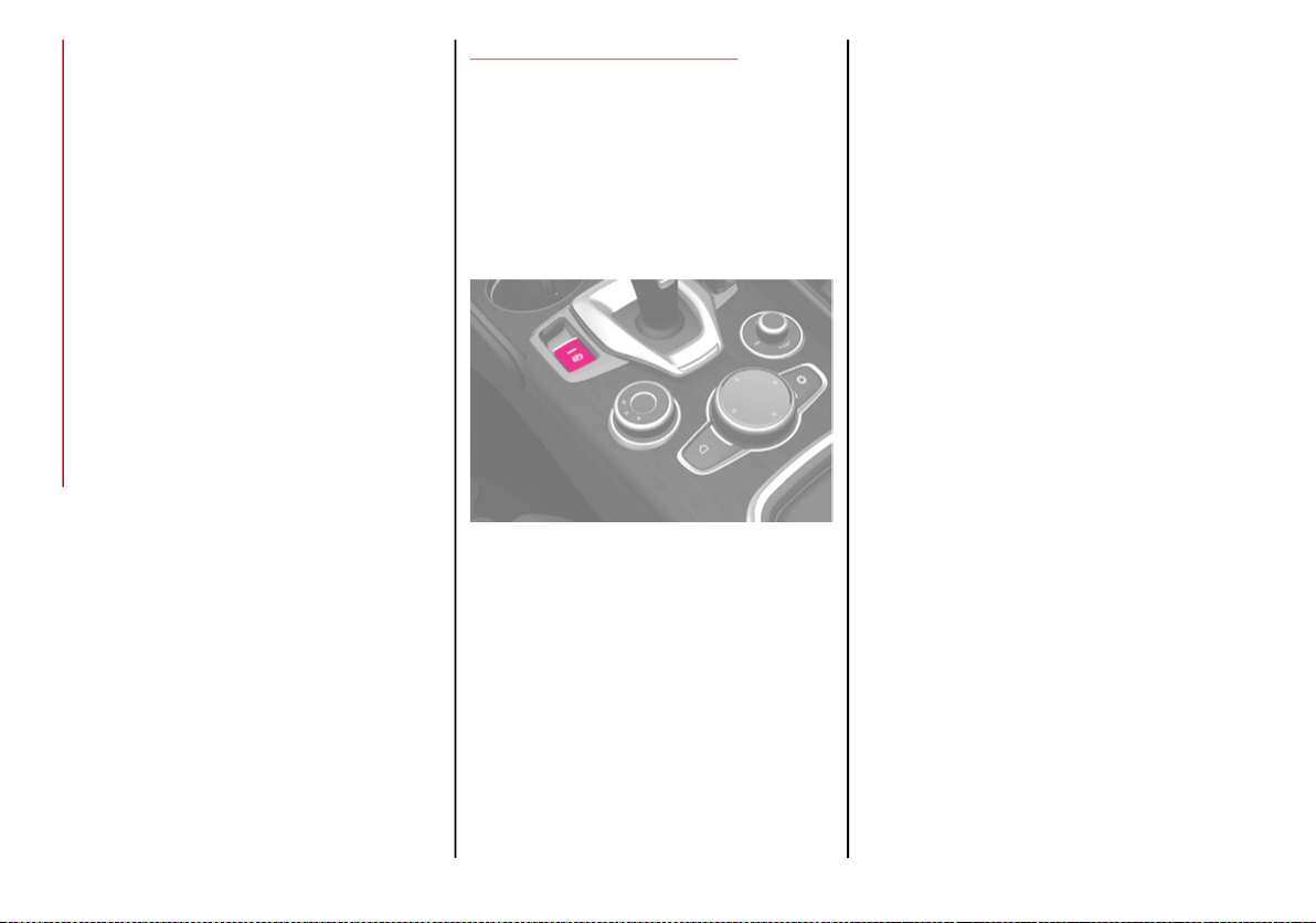
STARTING AND OPERATING
156
Drive with the engine speed less than 3,500 RPM.
Maintain vehicle speed below 55 mph
(88 km/h) and observe local speed limits.
100 to 300 miles (160 to 483 km):
Press the accelerator pedal slowly and not
more than halfway to avoid rapid accelera-
tion in lower gears (FIRST to THIRD gears).
Avoid aggressive braking.
Drive with the engine speed less than 5,000 RPM.
Maintain vehicle speed below 70 mph
(112 km/h) and observe local speed limits.
300 to 500 miles (483 to 805 km):
Exercise the full engine RPM range, shifting
manually (paddles or gear shift) at higher
RPM when possible.
Do not perform sustained operation with
the accelerator pedal at wide open throttle.
Maintain vehicle speed below 85 mph
(136 km/h) and observe local speed limits.
For the first 1,500 miles (2,414 km):
Do not participate in track events, sport
driving schools, or similar activities during
the first 1,500 miles (2,414 km).
NOTE:
Monitor engine oil with every refueling and add
if necessary. Oil and fuel consumption may be
higher through the first oil change interval.
ELECTRIC PARK BRAKE
The vehicle is equipped with electric park
brake to guarantee better use and optimal
performance compared to a manually oper-
ated park brake.
The electric parking brake features a switch
located on the center console, a caliper with
motor for each rear wheel, and an electronic
control module.
Electric Park Brake Switch
The electric parking brake can be engaged in
two ways:
Manually, by pulling the switch on the
center console.
Automatically, in “Safe Hold” or “Auto Park
Brake” conditions.
NOTE:
Normally, the electric parking brake is engaged
automatically when the engine is stopped. This
function can be deactivated/activated on the
Information and Entertainment system by
selecting the following items in sequence on the
main menu: “Settings”, “Driver Assistance” and
“Automatic Parking Brake”.
In addition to engaging the electric park brake,
along with steering and positioning chocks in
front of the wheels (when on a steep slope), you
must always place the vehicle in the PARK (P)
mode before leaving.
Should the vehicle battery be faulty, the
battery must be replaced in order to unlock the
electric park brake.
Engaging The Park Brake Manually
Briefly pull the switch located on the center
console to manually engage the electric park
brake when the vehicle is stationary.
Noise may be heard from the rear of the
vehicle when engaging the electric parking
brake.
A slight movement of the brake pedal may be
detected when engaging the electric parking
brake with the brake pedal pressed.
With the electric parking brake engaged, the
BRAKE warning light on the instrument panel
and the switch will illuminate.
20_GA_OM_EN_USC_t.book Page 156
157
(Continued)
If, under exceptional circumstances, the use of
the brake is required with the vehicle in motion,
keep the switch on the center console pulled as
long as the brake action is necessary.
The BRAKE warning light may turn on with the
hydraulic system temporarily unavailable, in
this case braking is controlled by the motors.
The brake lights will also automatically turn on
in the same way as for normal braking with the
use of the brake pedal.
Release the switch on the center console to
stop the braking action with the vehicle in
motion.
If, through this procedure, the vehicle is
braked until a speed below 1.9 mph (3 km/h)
is reached and the switch is kept pulled, the
park brake will definitively engage.
NOTE:
Driving the vehicle with the electric parking
brake engaged, or using it several times to
slow down the vehicle, may cause severe
damage to the braking system.
Disengaging The Electric Park Brake Manually
In order to manually release the park brake,
the ignition should be in the ACC mode. Press
the brake pedal, and then push the switch on
the center console briefly.
Noise may be heard from the rear of the
vehicle, and a slight movement of the brake
pedal may be detected during disengagement.
After disengaging the electric parking brake,
the BRAKE warning light on the instrument
panel and the light on the switch will turn off.
If the BRAKE warning light on the instrument
panel remains on with the electric parking
brake disengaged, this indicates a fault: in this
case, contact an authorized dealer.
Electric Park Brake Operating Modes
The electric park brake may operate as
follows:
“Dynamic Operating Mode”: this mode is
activated by pulling the switch repeatedly
while driving.
“Static Engagement and Release Mode”:
with the vehicle stationary, the electric park
brake can be activated by pulling the switch
on the center console once. On the other
hand, push the switch and the brake pedal
at the same time to disengage the brake.
CAUTION!
With the Electronic Parking Brake failure
warning light on, some functions of the
electric parking brake are deactivated. In
this case the driver is responsible for brake
activation and vehicle parking in complete
safety conditions.
WARNING!
Never leave children alone in a vehicle, or
with access to an unlocked vehicle.
Allowing children to be in a vehicle unat-
tended is dangerous for a number of
reasons. A child or others could be seri-
ously or fatally injured. Children should be
warned not to touch the park brake, brake
pedal or the gear selector.
Do not leave the key fob in or near the
vehicle or in a location accessible to chil-
dren. A child could operate power windows,
other controls, or move the vehicle.
Be sure the park brake is fully disengaged
before driving; failure to do so can lead to
brake failure and a collision.
Always fully apply the park brake when
leaving your vehicle, or it may roll and
cause damage or injury.
CAUTION!
Never use gear position PARK (P) instead of
the electric parking brake. Always engage the
electric parking brake when parking the
vehicle to prevent injury or damage caused by
the unexpected movement of the vehicle.
WARNING! (Continued)
20_GA_OM_EN_USC_t.book Page 157

STARTING AND OPERATING
158
(Continued)
“Drive Away Release”: the electric park
brake will automatically disengage with the
driver side seat belt fastened and the detec-
tion of an action performed by the driver to
move the vehicle (forward gear or reverse
gear). This feature can be turned on or off in
the Information and Entertainment System.
NOTE:
If the car is equipped with carbon-ceramic
brake discs it is necessary to fasten the seat
belts or turn off the electric park brake before
starting to avoid damages to the ceramic
brake discs.
“Safe Hold”: if the vehicle speed is lower than
1.9 mph (3 km/h), the gear selector is not in
PARK (P) position and the driver's intention of
leaving the vehicle is detected, the electric
park brake will automatically engage to hold
the vehicle in safety conditions.
“Auto Park Brake”: if the vehicle speed is
below 1.9 mph (3 km/h), the electric park
brake will automatically engage when the
gear selector is in PARK (P) position. The
light on the switch located on the center
console switches on together with the
BRAKE warning light on the instrument
panel when the park brake is engaged and
applied to the wheels. Each automatic park
brake engagement can be canceled by
pressing the switch on the center console
and at the same time moving the gear
selector for the transmission to position
PARK (P).
Safe Hold
Safe Hold is a safety function that automati-
cally engages the electric park brake in the
event of a dangerous condition for the vehicle.
The electric park brake engages automatically
to prevent vehicle movement if:
The vehicle speed is below 2 mph (3 km/h).
A transmission operating mode different
from PARK (P) is activated.
The driver's seat belt is not fastened.
The driver side door is open.
No attempts to apply pressure on the brake
pedal have been detected.
The vehicle is parked on roads with a slope
of more than 4%.
The “Safe Hold” function can be temporarily
disabled by pressing the switch located on the
center console and the brake pedal at the
same time, with the vehicle stationary and the
driver side door open.
Once disabled, the function will activate again
when the vehicle speed reaches 12 mph
(20 km/h) or the ignition is cycled to OFF and
then to ACC.
AUTOMATIC TRANSMISSION
The vehicle is equipped with an electronically
controlled 8-speed automatic transmission
where gear shifting automatically takes place,
depending on the vehicle usage instanta-
neous parameters (vehicle speed, grade, and
accelerator pedal position).
Manual gear shifting can still occur thanks to
the “sequential mode” position for the gear
selector.
WARNING!
It is dangerous to shift out of PARK or
NEUTRAL if the engine speed is higher
than idle speed. If your foot is not firmly
pressing the brake pedal, the vehicle
could accelerate quickly forward or in
reverse. You could lose control of the
vehicle and hit someone or something.
Only shift into gear when the engine is
idling normally and your foot is firmly
pressing the brake pedal.
Unintended movement of a vehicle could
injure those in or near the vehicle. As with
all vehicles, you should never exit a
vehicle while the engine is running. Before
exiting a vehicle, always apply the park
brake, shift the transmission into PARK,
and turn the ignition OFF. When the igni-
tion is in the OFF mode, the transmission
is locked in PARK, securing the vehicle
against unwanted movement.
20_GA_OM_EN_USC_t.book Page 158
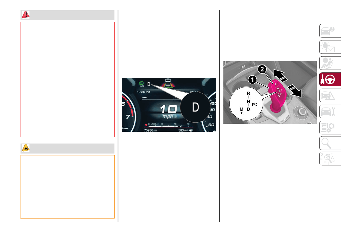
159
Display
The following information is shown on the
dedicated area of the display:
In Automatic Mode: the active mode (P, R,
N, D) and with "D" the current gear number.
In Manual Drive Mode (Sequential): the
mode (M), the current gear and the double
or single gear shift request, both up and
down (single or double arrow).
Gear Display
Gear Selector
The gear functioning is controlled by the gear
selector, which can assume the following positions:
P = PARK
R = REVERSE
N = NEUTRAL
D = DRIVE, (automatic forward speed)
AutoStick: + manually shift to higher gear; –
manually shift to lower gear
The positions diagram is illustrated on the top
of the gear selector.
Gear Selector Center Console
The letter corresponding to the mode selected
on the gear selector lights up and appears on
the instrument cluster display.
When leaving the vehicle, always make
sure the ignition is in the OFF mode,
remove the key fob from the vehicle, and
lock the vehicle.
Never leave children alone in a vehicle, or
with access to an unlocked vehicle. Allowing
children to be in a vehicle unattended is
dangerous for a number of reasons. A child
or others could be seriously or fatally
injured. Children should be warned not to
touch the parking brake, brake pedal or the
transmission gear selector.
Do not leave the key fob in or near the
vehicle (or in a location accessible to chil-
dren), and do not leave the ignition in the
ON/RUN or ACC mode. A child could
operate power windows, other controls, or
move the vehicle.
CAUTION!
Damage to the transmission may occur if
the following precautions are not observed:
Shift into or out of PARK or REVERSE only after
the vehicle has come to a complete stop.
Do not shift between PARK, REVERSE,
NEUTRAL, or DRIVE when the engine is
above idle speed.
Before shifting into any gear, make sure your
foot is firmly pressing the brake pedal.
WARNING! (Continued)
1 — Gear Selector
2 — PARK (P) Button
20_GA_OM_EN_USC_t.book Page 159
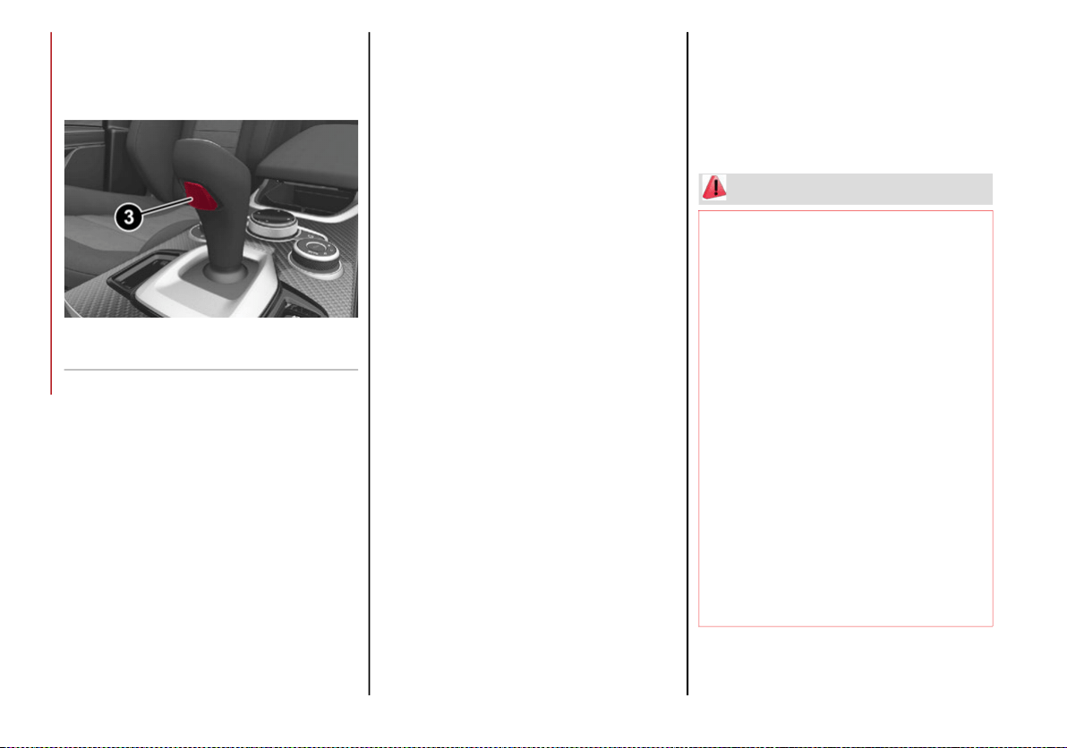
STARTING AND OPERATING
160
(Continued)
To select a mode, move the gear selector
forward or backwards, together with pressing
the brake pedal and button to engage
REVERSE (R).
Gear Selector
The gear selector is a joystick style shifting
mechanism which returns to the center posi-
tion automatically. It can be pushed forward
twice and rearward twice, based on the
starting condition.
The PARK (P) mode can be enabled/disabled
by pushing the PARK (P) button.
To transition the vehicle into REVERSE (R)
mode from DRIVE (D) mode, or into DRIVE (D)
mode from REVERSE (R) mode, it is necessary
to move the gear selector by pushing the gear
selector button.
When using AutoStick, activate it by moving
the gear selector from DRIVE (D) to the left and
then forward toward the - symbol or backward
toward the + symbol and the gear is changed.
To shift out of PARK (P), or to pass from posi-
tion NEUTRAL (N) to position DRIVE (D) or
REVERSE (R), the vehicle must be moving at a
low speed or stopped, and the brake pedal
must also be pressed.
NOTE:
DO NOT accelerate while shifting from posi-
tion PARK (P) or NEUTRAL (N) to another
position.
After selecting a gear, wait a few seconds
before accelerating. This precaution is
particularly important with engine cold.
Transmission Operating Modes
PARK (P)
The transmission is locked in this mode. The
engine can be started in this mode.
NOTE:
Never try to engage PARK (P) mode when the
vehicle is moving. Before leaving the vehicle,
make sure this mode is engaged (letter P
shown on the display and gear selector) and
that the park brake is engaged.
When parking on a flat surface, first engage
the PARK (P) mode and then engage the elec-
tric park brake.
When parking uphill, before activating the
PARK (P) mode, engage the electric park
brake. Otherwise, it could be difficult to
engage the (P) mode.
To check that the PARK (P) mode is actually
engaged, make sure (P) is illuminated on the
display and on the gear selector.
3 — Gear Selector Button
WARNING!
Never use the PARK position as a substi-
tute for the park brake. Always apply the
park brake fully when parked to guard
against vehicle movement and possible
injury or damage.
Your vehicle could move and injure you
and others if it is not in PARK. Check by
trying to move the gear selector out of
PARK with the brake pedal released.
Make sure the transmission is in PARK
before leaving the vehicle.
It is dangerous to shift out of PARK or
NEUTRAL if the engine speed is higher
than idle speed. If your foot is not firmly
pressing the brake pedal, the vehicle
could accelerate quickly forward or in
reverse. You could lose control of the
vehicle and hit someone or something.
Only shift into gear when the engine is
idling normally and your foot is firmly
pressing the brake pedal.
20_GA_OM_EN_USC_t.book Page 160
161
REVERSE (R)
Select this mode only with the vehicle at a
standstill.
NEUTRAL (N)
Use this range when the vehicle is standing for
prolonged periods with the engine running. The
engine may be started in this range. Apply the
electric park brake and shift the transmission
into PARK (P) if you must leave the vehicle.
DRIVE (D)
Use this mode in normal driving conditions.
Shifting from DRIVE (D) to PARK (P) or
REVERSE (R) modes must take place only after
releasing the accelerator pedal, with vehicle at
a standstill and brake pedal pressed.
This mode ensures automatic engagement of the
most suitable gears for driving needs and maximum
fuel economy in terms of consumption.
In this position, the transmission shifts the
gears automatically, selecting the most suit-
able for forward driving among those available
as you go. In this way the vehicle's optimal
driving characteristics are provided for all
conditions.
AutoStick
In the case of frequent shifting (e.g. for sport
driving, when the vehicle is driven with a heavy
load or on slopes), it is recommended to use
the Autostick (sequential shifting) mode to
select and keep a lower fixed ratio.
In these conditions, the use of a lower gear
improves vehicle performance, preventing
overheating.
It is possible to shift from DRIVE (D) mode to
sequential mode regardless of vehicle speed.
Unintended movement of a vehicle could
injure those in or near the vehicle. As with
all vehicles, you should never exit a
vehicle while the engine is running. Before
exiting a vehicle, always apply the park
brake, shift the transmission into PARK,
and turn the ignition STOP/OFF. When the
ignition is in the STOP/OFF mode, the
transmission is locked in PARK, securing
the vehicle against unwanted movement.
When leaving the vehicle, always make
sure the ignition is in the STOP/OFF mode,
remove the key fob from the vehicle, and
lock the vehicle.
Never leave children alone in a vehicle, or
with access to an unlocked vehicle.
Allowing children to be in a vehicle unat-
tended is dangerous for a number of
reasons. A child or others could be seri-
ously or fatally injured. Children should be
warned not to touch the park brake, brake
pedal or the transmission gear selector.
Do not leave the key fob in or near the
vehicle (or in a location accessible to chil-
dren), and do not leave the ignition in the ON
mode. A child could operate power windows,
other controls, or move the vehicle.
WARNING! (Continued)
CAUTION!
Before moving the transmission gear
selector out of PARK, you must push the
ignition button to cycle from STOP/OFF
mode to the ON mode, and also press the
brake pedal. Otherwise, damage to the
gear selector could result.
DO NOT race the engine when shifting
from PARK or NEUTRAL into another gear
range, as this can damage the drivetrain.
WARNING!
Do not coast in NEUTRAL and never turn off
the ignition to coast down a hill. These are
unsafe practices that limit your response to
changing traffic or road conditions. You
might lose control of the vehicle and have a
collision.
20_GA_OM_EN_USC_t.book Page 161
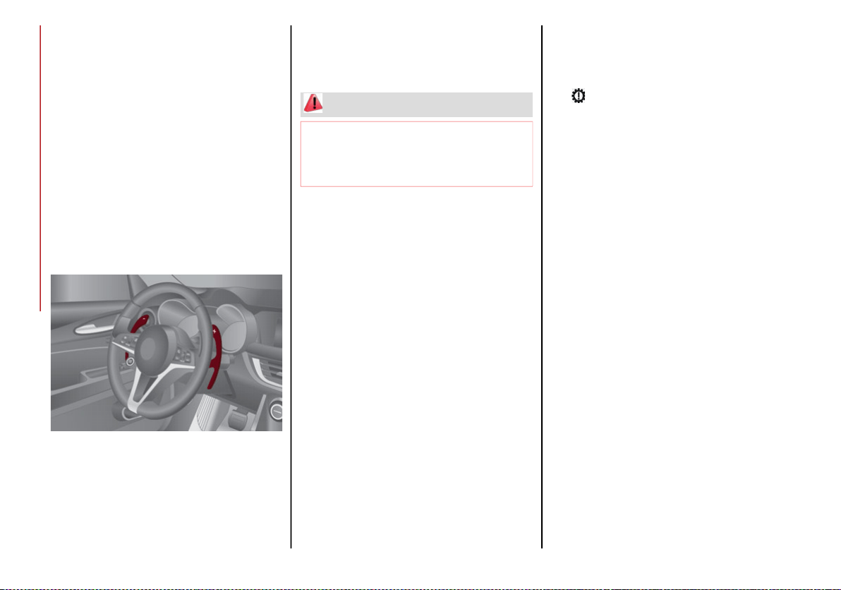
STARTING AND OPERATING
162
Activation
Starting from DRIVE (D), move the selector to
the left (– and + indication of the trim) to acti-
vate the sequential drive mode. The gear
engaged will be shown on the display.
Shifting is made by moving the gear selector
forwards, towards symbol – or backwards,
towards symbol +.
Steering Wheel Shift Paddles — If Equipped
The gear can also be manually shifted by using
the paddles behind the steering wheel. Pull
the right paddle (+) toward the steering wheel
and release it to engage a higher gear, and
perform the same operation with the left
paddle (-) to engage a lower gear.
Steering Wheel Shift Paddles
NOTE:
If only one manual shift is necessary, the letter
(D) will remain on the display with the engaged
gear next to it.
Deactivation
To deactivate the sequential driving mode,
bring the gear selector back in position DRIVE
(D) (“automatic” driving mode).
NOTE:
To select the correct gear for maximum
deceleration (engine brake), just keep the
gear paddle pulled (–): the transmission
goes to an operating mode in which the
vehicle can slow down easily.
The vehicle will keep the gear selected by
the driver until the safety conditions allow it.
This means, for example, that the system
will try to prevent the engine from switching
off, automatically downshifting if the engine
speed is too low.
Automatic Transmission Limp Home Mode
Transmission function is monitored electroni-
cally for abnormal conditions. If a condition is
detected that could result in transmission
damage, Transmission Limp Home Mode is
activated.
In this condition, the transmission stays in
fourth gear, regardless of the selected gear.
Positions PARK (P), REVERSE (R) and
NEUTRAL (N) still work.
The symbol might light up in the instrument
cluster.
Temporary failure
In the event of a momentary problem, the
transmission can be reset to regain all forward
gears by performing the following steps:
1. Stop the vehicle.
2. Shift the transmission into PARK (P), if
possible. If not, shift the transmission to
NEUTRAL (N).
3. Push and hold the ignition until the engine
turns OFF.
4. Wait for about 10 seconds, then restart
the engine.
5. Shift into the desired gear range. If the
problem is no longer detected, the trans-
mission will return to normal operation.
NOTE:
Even if the transmission can be reset, we
recommend that you visit an authorized dealer
at your earliest possible convenience. An
authorized dealer has diagnostic equipment to
determine if the problem could reoccur. If the
transmission cannot be reset, service is
required at an authorized dealer.
WARNING!
Do not downshift for additional engine braking
on a slippery surface. The drive wheels could
lose their grip and the vehicle could skid,
causing a collision or personal injury.
20_GA_OM_EN_USC_t.book Page 162
163
(Continued)
Brake/Transmission Shift Interlock (BTSI)
System
This vehicle is equipped with a Brake Trans-
mission Shift Interlock (BTSI) system that
holds the gear selector in PARK (P) unless the
brakes are applied.
This system prevents you from moving the
gear selector from position PARK (P) unless
the brakes are applied.
To shift the transmission out of PARK (P), the
ignition must be cycled to the ON/RUN mode
(engine running or not) and the brake pedal
must be pressed.
Brake/Transmission Shift Interlock Disabling
Only if strictly necessary (e.g. pushing the
vehicle, conveyor vehicle washing systems)
inhibit the automatic activation of PARK (P)
mode when stopping the engine, or proceed
as described below:
1. Vehicle at a standstill.
2. NEUTRAL (N) mode activated.
3. Push the ignition button for at least three
seconds.
The automatic park brake engagement func-
tion when the engine is stopped can also be
deactivated on the Information and Entertain-
ment system by selecting the following func-
tions on the main menu: “Settings”, “Driver
Assistance” and “Automatic Parking Brake”.
Important Notes
Failure to comply with what is reported below
may damage the transmission:
Shift into PARK (P) mode only with the
vehicle at a standstill.
Select REVERSE (R) mode, or pass from
REVERSE to another mode only with the
vehicle at a standstill and engine idling.
Do not change between PARK (P), REVERSE (R),
NEUTRAL (N) or DRIVE (D) modes with engine
running at a speed above idling.
Before activating any transmission oper-
ating mode, fully depress the brake pedal.
NOTE:
The unexpected movement of the vehicle can
injure the occupants or people nearby. Do not
leave the vehicle with engine running: before
getting out of the passenger compartment
always engage the electric park brake, select
the PARK (P) mode, stop the engine.
WARNING!
It is dangerous to shift out of PARK or NEUTRAL
if the engine speed is higher than idle speed. If
your foot is not firmly pressing the brake pedal,
the vehicle could accelerate quickly forward or
in reverse. You could lose control of the vehicle
and hit someone or something. Only shift into
gear when the engine is idling normally and
your foot is firmly pressing the brake pedal.
Unintended movement of a vehicle could
injure those in or near the vehicle. As with
all vehicles, you should never exit a
vehicle while the engine is running. Before
exiting a vehicle, always apply the park
brake, shift the transmission into PARK,
and turn the ignition OFF. When the igni-
tion is in the OFF mode, the transmission
is locked in PARK, securing the vehicle
against unwanted movement.
When leaving the vehicle, always make
sure the ignition is in the OFF mode,
remove the key fob from the vehicle, and
lock the vehicle.
Never leave children alone in a vehicle, or
with access to an unlocked vehicle. Allowing
children to be in a vehicle unattended is
dangerous for a number of reasons. A child
or others could be seriously or fatally
injured. Children should be warned not to
touch the parking brake, brake pedal or the
transmission gear selector.
20_GA_OM_EN_USC_t.book Page 163
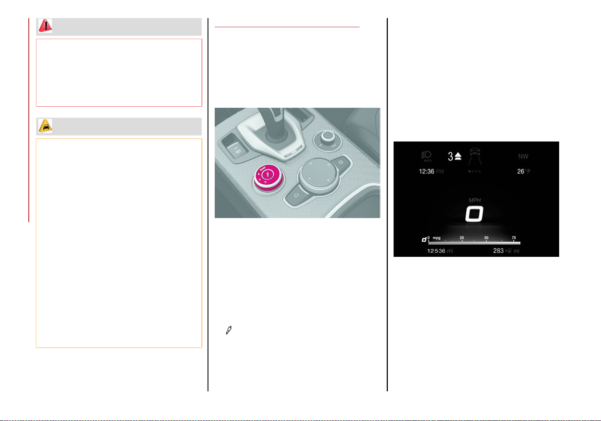
STARTING AND OPERATING
164
ALFA DNA / PRO SELECTOR
Alfa DNA System
This vehicle is equipped with an Alfa DNA system
selector (located on the center console). There
are four modes of operation to be selected
according to driving style and road conditions:
Alfa DNA System Selector
d = Dynamic (sports driving mode).
n = Normal (mode for driving in normal
conditions).
a = Advanced Efficiency (ECO driving mode
for maximum fuel savings).
RACE = track race driving mode (if equipped).
= Adjusts the calibration of the active
suspension (Quadrifoglio only).
When the engine is stopped, the selector
returns to “n” (Normal) mode.
The symbol of the active mode lights up in red
on the selector.
On the instrument panel display, the different
modes are characterized by different colors:
Normal - Blue
Dynamic - Red
Advanced Efficiency - Green
Mode Display
Each driving mode is graphically different on
color line and contents of each individual
“performance” screen.
Do not leave the key fob in or near the
vehicle (or in a location accessible to chil-
dren), and do not leave the ignition in the
ON/RUN or ACC mode. A child could
operate power windows, other controls, or
move the vehicle.
CAUTION!
Only engage the gear with engine at idling
while fully depressing the brake pedal. If the
transmission temperature exceeds the
normal operating limits, the transmission
control unit may change the gear engage-
ment order and reduce the drive torque. If
the transmission overheats, it could operate
incorrectly until it cools down.
When using the vehicle with extremely low
external temperatures, the transmission
operation may change depending on the
engine and transmission temperature, as
well as vehicle speed. Activation of the
torque converter clutch and of the eighth
gear is inhibited until the transmission oil
is correctly warmed up. Complete opera-
tion of the transmission will be enabled as
soon as the fluid temperature reaches the
predefined value.
WARNING! (Continued)
20_GA_OM_EN_USC_t.book Page 164
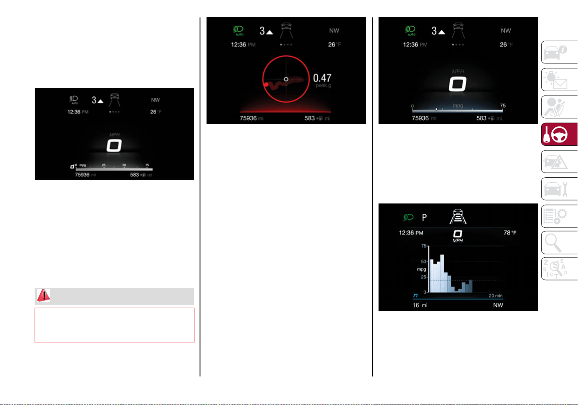
165
Driving Modes
“Dynamic” Mode
Activation
It is activated by rotating the selector to the
letter “d”, the displays light up in red.
Dynamic Mode
ESC and ASR systems: intervention thresholds
that ensure more enjoyable, sportier driving
while guaranteeing the stability of the vehicle.
“Electronic Q2” system: the system is cali-
brated to increase traction while accelerating
on turns, improving the agility of the vehicle.
Engine and transmission: adoption of sports
mapping.
Dynamic Mode Performance Display
The “Performance” screen displays parame-
ters related to vehicle stability, the graphs
illustrate the trend of the longitudinal/lateral
accelerations (G-meter information), consid-
ering gravity acceleration as a reference unit.
Lateral acceleration peaks are displayed on
the right.
“Normal” Mode
“Normal” Mode is the Default mode when the
vehicle is started up.
Activation
It is activated by rotating the selector to the
letter “n”, the displays light up in blue.
Natural Mode
Engine and transmission: standard response.
The “Performance” screen graphically repro-
duces some parameters closely linked to the
efficiency of the driving style, with a view to
limiting consumption.
Natural Mode Performance Display
WARNING!
In "Dynamic", the sensitivity of the accelerator
pedal increases considerably. Consequently,
driving is less fluid and comfortable.
20_GA_OM_EN_USC_t.book Page 165
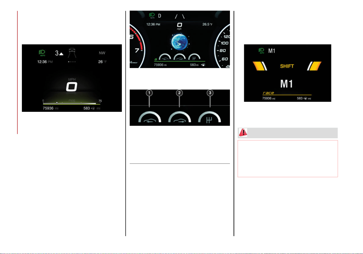
STARTING AND OPERATING
166
“Advanced Efficiency” Mode
Activation
It is activated by rotating the selector to the
letter “a”, the displays light up in green.
Advanced Efficiency Mode
ESC and ASR systems: intervention thresholds
aimed at ensuring maximum safety in low-grip
driving conditions. It is advisable to select
“Advanced Efficiency” mode in the presence
of low-grip road surfaces.
“Electronic Q2” system: the system is deactivated.
There will be reduced engine performance.
“Advanced Efficiency” Mode is characterized by
reduced engine performance and ECO shifting
strategy for the automatic transmission.
The “Performance” screen graphically displays
some parameters closely related to the
vehicle: acceleration, deceleration, and gear
selector.
Advanced Efficiency Mode Performance
Display
NOTE:
The vehicle will always start up in NORMAL
mode as a default.
“RACE” Mode (Quadrifoglio Only)
Activation
It is activated by rotating the selector to posi-
tion “RACE”, the displays light up in yellow.
RACE Mode
Engine and transmission: adoption of sports
mapping.
The “Performance” screen displays parame-
ters related to vehicle stability, the graphs
illustrate the trend of the longitudinal/lateral
accelerations (G-meter information), consid-
ering gravity acceleration as a reference unit.
1 — Acceleration
2 — Deceleration
3 — Gear Selector
WARNING!
It is recommended to activate this mode
at the track.
In "RACE", the sensitivity of the accelerator
pedal increases considerably. Conse-
quently, driving is less fluid and comfortable.
20_GA_OM_EN_USC_t.book Page 166
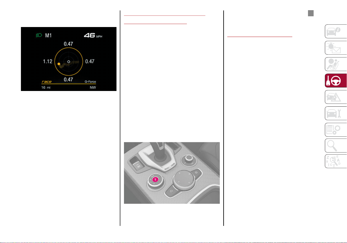
167
The screen displays the lateral and longitu-
dinal acceleration peaks.
RACE Mode Performance Display
NOTE:
If the brake system overheats, this is commu-
nicated by the Information and Entertainment
system. In this case, allow the system to cool
for a few minutes by driving the vehicle
normally without operating the brakes.
Deactivation
To deactivate the RACE mode, rotate the
selector to the RACE position again and the
system will be set to “d” Dynamic mode.
ALFA ACTIVE SUSPENSION
(AAS) — IF EQUIPPED
The vehicle's electronic suspension manage-
ment system is the result of a sophisticated
elaboration of the various sensors, aimed at
optimizing the vehicle's performance.
The system continuously monitors the
damping of the suspension through the actu-
ator installed on each shock absorber. The
calibration of the shock absorbers can be
adjusted to the conditions of the road surface
and to the dynamic conditions of the vehicle,
improving its comfort and road handling.
The driver can choose, while driving, (only in
“d” or “RACE” mode), between two types of
suspension calibration: a more sporty or a
more comfortable one.
By pressing the button, the system prepares
the shock absorber calibration in order to
favor driving comfort.
“Alfa DNA” System Selector
In case of a system failure, the symbol and
a dedicated message will be shown on the
instrument cluster display.
STOP/START SYSTEM
Stop/Start System
The Stop/Start system automatically shuts off
the engine during a vehicle stop if the required
conditions are met. Releasing the brake pedal
or accelerator pedal will automatically restart
the engine.
The function was developed to increase
vehicle efficiency by reducing fuel consump-
tion, gas emissions, and sound pollution.
Operating Mode
Stopping the Engine
With vehicle at a standstill and brake pedal
pressed, the engine switches off if the gear
selector is in a position other than REVERSE (R).
The system does not operate when the gear
selector is in REVERSE (R), in order to making
parking maneuvers easier.
In the event of stops uphill, engine switching
off is disabled to make the “Hill Start Assist”
function available (works only with running
engine).
20_GA_OM_EN_USC_t.book Page 167
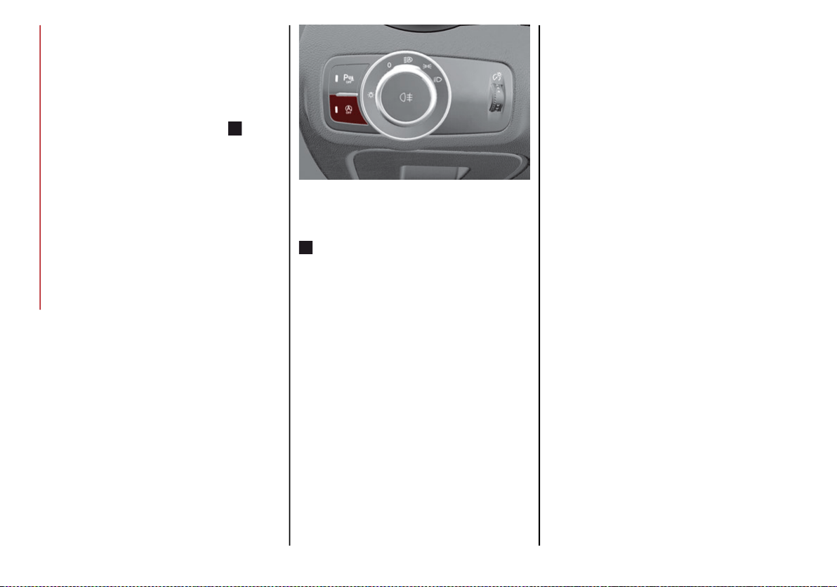
STARTING AND OPERATING
168
NOTE:
The engine can only be automatically stopped
after having run at about 6 mph (10 km/h). After
an automatic restart, the vehicle only needs to
exceed a speed of 0.3 mph (0.5 km/h) to stop
the engine.
Engine stopping is signaled by the symbol
lighting up on the instrument cluster display.
Restarting the Engine
To restart the engine, release the brake pedal or
turn the steering wheel slightly (if equipped).
With the brake pressed and the transmission
in automatic mode DRIVE (D), the engine will
restart by shifting to REVERSE (R), to PARK (P)
or to “AutoStick”.
With brake pressed if the gear selector is in
“AutoStick” mode, the engine will restart by
shifting to PARK (P) or by moving the selector
to + or -.
System Manual Activation/Deactivation
To manually activate/deactivate the system,
push the button located in the control panel on
the left of the steering wheel.
Stop/Start Button
System Activation
The activation of the system is indicated by the
symbol lighting up on the display. In this
condition, the light on the button is off.
System Deactivation
A message will appear on the display when the
system is deactivated. In this condition, the
light on the button is on.
NOTE:
Each time the engine is started, the system is
activated regardless of where it was when it
was previously switched off.
Possible Reasons The Engine Does Not
Autostop
For higher comfort and increased safety, and
to reduce emissions, there are certain condi-
tions where the engine will not autostop
despite the system being active, such as:
Engine still cold.
Especially cold outside temperature.
Battery not sufficiently charged.
Driver's door not shut.
Driver's seat belt not fastened.
Reverse gear engaged (e.g. for parking
maneuvers).
With the automatic climate control active,
an adequate cabin heating or cooling
comfort has not been reached or with
MAX-DEF function active.
During the first period of use, to initialize the
system.
Steering angle beyond threshold.
20_GA_OM_EN_USC_t.book Page 168
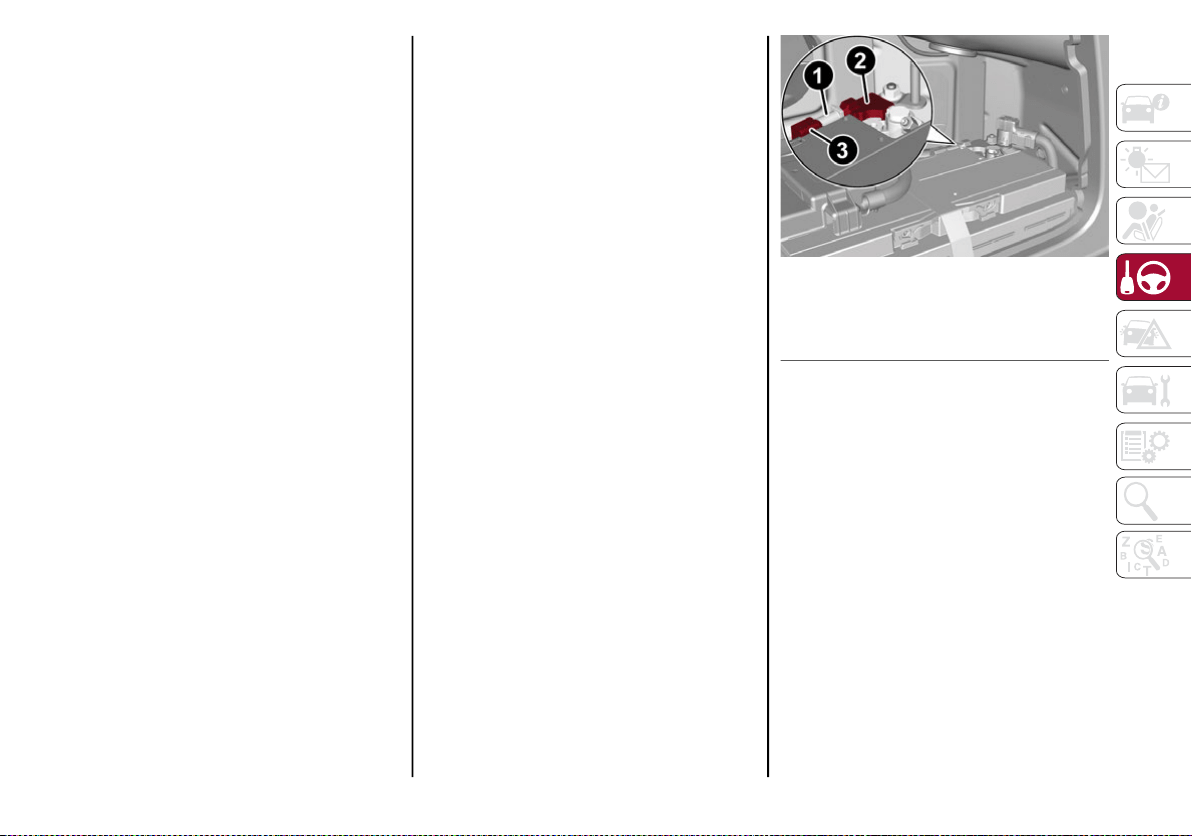
169
Engine Restarting Conditions
Due to comfort, emission control and safety
reasons, the engine can restart automatically
without any action by the driver, under special
conditions, such as:
Battery not sufficiently charged.
Reduced braking system vacuum (e.g. if the
brake pedal is pressed repeatedly).
Vehicle moving (e.g. when driving on roads
with a grade).
Engine stopping by the Stop/Start system
for more than approx. three minutes.
With the automatic climate control active,
an adjustment in cabin heating or cooling is
made or with MAX-DEF function active.
Safety Functions
When the engine is stopped through the Stop/
Start system, if the driver releases their seat belt,
opens the driver's or passenger's door, or opens
the hood from inside the vehicle, the engine can
be restarted only by using the ignition.
This condition is indicated to the driver both
through a buzzer and a message on the instru-
ment cluster display.
Irregular Operation
In the event of malfunction, the Stop/Start
system is deactivated.
For failure indications, refer to “Warning Lights
and Messages” in “Getting To Know Your
Instrument Panel” for further information.
Vehicle Inactivity
In the event of vehicle inactivity (or if the
battery is replaced), special attention must be
paid to the disconnection of the battery power
supply.
Proceed as follows:
Remove connector from socket to disconnect
sensor (battery status monitoring) installed on
the negative pole of the battery. This sensor
should never be disconnected from the pole
except if the battery is replaced.
Battery Power Supply
NOTE:
After setting the ignition to OFF and having
closed the driver side door, wait at least one
minute before disconnecting the electrical
supply from the battery. When reconnecting
the electrical supply to the battery, make sure
that the ignition is in the OFF mode and the
driver side door is closed.
1 — Socket
2 — Sensor
3 — Connector
20_GA_OM_EN_USC_t.book Page 169
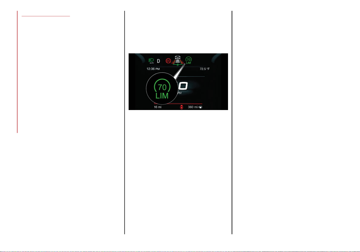
STARTING AND OPERATING
170
SPEED LIMITER
Description
This feature allows the driver to program the
maximum speed of the vehicle.
NOTE:
The maximum set speed can be exceeded by
continuing to press the accelerator pedal.
The maximum speed can be set with the
vehicle stationary or in motion. The minimum
speed that can be set is 18 mph (20 km/h).
When this feature is active, the vehicle speed
depends on the pressing of the accelerator
pedal until the programmed speed limit is
reached. Refer to “Speed Limit Programming”
in this section for further information.
Activation
The feature can be activated/deactivated
through the radio system.
Activating The Device
To access this feature, select the “Driver Assis-
tance” widget in the radio system, then select
the following items in sequence:
1. “Speed Limiter”
2. “ON”
The activation of this feature is signaled by the
illumination of the green Speed Limiter icon,
along with the last speed set, in the instrument
cluster display. The Speed Limiter feature can
remain active concurrently with the Speed
Control system. If a speed limit below the one
indicated in the Speed Control is selected, the
Speed Control speed will be lowered to that of
the Speed Limiter. This function remains avail-
able in RACE mode.
Speed Limiter Display
Speed Limit Programming
The speed limit can be programmed through
the radio system.
To access the function on the main menu,
select the following items in sequence:
1. “Settings”
2. “Safety”
3. “Speed Limiter Set Speed”
By turning the Rotary Pad, the speed increases
by 5 mph (8 km/h), from a minimum of
18 mph (30 km/h) to a maximum of 112 mph
(180 km/h).
Exceeding The Programmed Speed
By fully pressing the accelerator pedal, the
programmed speed can be exceeded even with
the device active (e.g. in the event of overtaking).
The device is disabled until the speed drops
below the set limit, after which it reactivates
automatically.
Programmed Speed Icon Flashing
The programmed speed will flash in the
following scenarios:
When the accelerator pedal has been fully
pressed and the vehicle has exceeded the
programmed speed.
Activating the system after setting a limit
below the effective speed of the vehicle.
In the event of overtake acceleration.
Deactivation
The feature can be activated/deactivated
through the radio system.
Deactivating The Device
To access this feature, select the “Driver Assis-
tance” widget in the radio system, then select
the following items in sequence:
1. “Comfort”
2. “Speed Limiter”
3. “OFF”
20_GA_OM_EN_USC_t.book Page 170
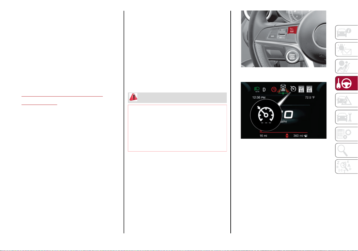
171
Automatic Deactivation Of The Device
The device deactivates automatically in the
event of fault in the system. In this case,
contact an authorized dealer.
Temporary Signal Loss
When the device loses the signal, the white
symbol without the speed indication illumi-
nates on the display.
System Failure
If there is a system failure, the amber symbol
illuminates on the display.
SPEED CONTROL (CRUISE
CONTROL)
Speed Control Description
This is an electronically controlled driving
assistance feature that allows the desired
vehicle speed to be maintained, without
having to press the accelerator pedal. This
feature can be used at a speed above 20 mph
(30 km/h) on long stretches of dry, straight
roads with few variations (highways).
The speed control buttons are located on the
left side of the steering wheel.
NOTE:
To ensure correct operation, the speed
control is designed to deactivate if more
than one function is operated simultane-
ously. In this case, the system can be reac-
tivated by pushing the on/off button and
setting the desired speed.
It is not recommended to use this feature in
city traffic.
While driving downhill, the system could brake
the vehicle to keep the set speed the same.
Activating
To activate the Speed Control System, push
the on/off button location on the left side of
the steering wheel.
Speed Control On/Off Switch
Speed Control Indicator Light
The activation of the system is signaled by the
illumination of the white warning light on the
instrument cluster.
The Speed Control function can remain active
at the same time as the Speed Limiter System.
If the set speed is higher than the speed set
with the Speed Limiter, the set speed will be
lowered to that of the Speed Limiter.
For Quadrifoglio vehicles, this function remains
available in RACE mode.
WARNING!
Speed Control can be dangerous where the
system cannot maintain a constant speed.
Your vehicle could go too fast for the
conditions, and you could lose control and
have an accident. Do not use Speed Control
in heavy traffic or on roads that are winding,
icy, snow-covered or slippery.
20_GA_OM_EN_USC_t.book Page 171
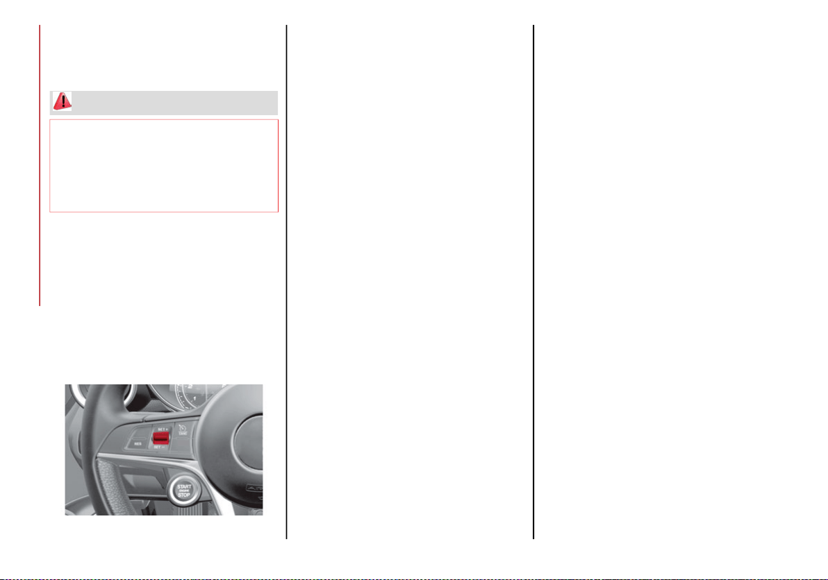
STARTING AND OPERATING
172
NOTE:
The system cannot be engaged in FIRST or
REVERSE gear. It is advisable to engage it in THIRD
gear or higher if using the AutoStick feature.
Setting The Desired Speed
To set a desired speed, proceed as follows:
1. Turn the Speed Control on.
2. When the vehicle has reached the desired
speed, push the SET switch up or down
and release to activate. When the acceler-
ator is released, the vehicle will maintain
the selected speed automatically.
SET Switch Location
If needed (when overtaking for instance), you
can accelerate beyond the set speed by
pressing the accelerator. When you release
the pedal, the vehicle will return to the previ-
ously set speed.
When traveling downhill with the system
active, the vehicle speed may slightly exceed
the set one.
NOTE:
Before pushing the SET switch, the vehicle
must be traveling at a constant speed on a flat
surface.
Increasing/Decreasing Speed
Increasing Speed
Once the Speed Control has been activated,
the speed can be increased by pushing the
SET switch upward.
By keeping the switch pushed, the set speed
will increase until the switch is released. The
new speed will then be set.
At every movement of the SET switch, the set
speed can be adjusted.
Decreasing Speed
When the system is active, to reduce the
speed, push the SET switch downward.
By keeping the switch pushed, the set speed
will decrease until the switch is released. The
new speed will then be set.
At every movement of the SET switch, the set
speed can be adjusted.
NOTE:
Moving the SET switch allows for adjusting of
the speed according to the selected unit of
measurement set on the radio system (see
dedicated supplement).
Accelerating When Overtaking
Press the accelerator as you would normally.
When the pedal is released, the vehicle will
return to the set speed.
Use Of The Feature On Hilly Routes
The system can automatically downshift to
keep the set speed when driving on hilly
routes.
On steep grades, the loss or gain in speed may
be considerable and it is advisable to deacti-
vate the Speed Control.
NOTE:
The system keeps the speed set even uphill
and downhill. A slight variation in the speed on
slight rises is completely normal.
Recalling The Speed
Once the system has been deactivated, but
not canceled, the previously set speed can be
recalled by pushing the RES button and
removing your foot from the accelerator. The
system will be set to the last stored speed.
WARNING!
Leaving the Speed Control system on when
not in use is dangerous. You could
accidentally set the system or cause it to go
faster than you want. You could lose control
and have an accident. Always leave the
system OFF when you are not using it.
20_GA_OM_EN_USC_t.book Page 172
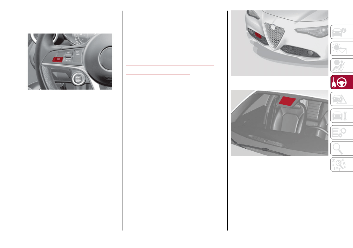
173
NOTE:
Before resuming the previously set speed, you
must accelerate to a speed close to that speed.
Resume Button Location
In AutoStick (sequential) mode, before resuming
the previously set speed, you should accelerate
until you are close to that speed. Then, push and
release the RES button.
Deactivating
Lightly pressing the brake pedal deactivates
the Speed Control without deleting the set
speed.
The Speed Control may also be deactivated by
applying the electric park brake or when the
braking system is operated (e.g. operation of
the Electronic Stability Control (ESC) system).
The set speed is deleted in the following
cases:
Pushing the on/off button a second time.
The ignition is placed in the OFF position.
If there is a malfunction with the Speed
Control.
ADAPTIVE CRUISE CONTROL
(ACC) — IF EQUIPPED
System Description
The Adaptive Cruise Control (ACC) is a driver
assist system that combines the speed control
functions with controlling the distance from
the vehicle ahead.
The system sets and holds the vehicle at the
desired speed without needing to press the
accelerator. It also sets and holds a distance
from the vehicle ahead (these settings are set
by the driver).
The Adaptive Cruise Control (ACC) uses a radar
sensor located behind the front bumper and a
camera located in the center/upper part of the
windshield, to detect the presence of a vehicle
close ahead.
Front Bumper Radar Location
Windshield Camera Location
This system enhances driving comfort while on
the highway or out of town with light traffic.
If the sensor does not detect a vehicle ahead,
the system will maintain a fixed set speed.
20_GA_OM_EN_USC_t.book Page 173

STARTING AND OPERATING
174
(Continued)
If the sensor detects a vehicle ahead, the
system automatically intervenes by braking (or
accelerating) slightly in order not to exceed the
original set speed, so that the vehicle keeps
the preset distance, seeking to adapt to the
speed of the vehicle ahead.
NOTE:
Adaptive Cruise Control performance is not
guaranteed under the following circum-
stances, and it is recommended to turn the
system off when:
Driving in fog, heavy rain, or snow.
Driving in heavy traffic or construction
zones.
Driving on icy, snowy, slippery roads, roads
with steep inclines, or roads with numerous
turns and bends.
Entering a turn lane.
When circumstances do not allow safe
driving at a constant speed.
WARNING!
Adaptive Cruise Control (ACC) is a conve-
nience system. It is not a substitute for
active driver involvement. It is always the
driver’s responsibility to be attentive of
road, traffic, and weather conditions,
vehicle speed, distance to the vehicle
ahead; and, most importantly, brake oper-
ation to ensure safe operation of the
vehicle under all road conditions. Your
complete attention is always required
while driving to maintain safe control of
your vehicle. Failure to follow these warn-
ings can result in a collision and death or
serious personal injury.
The ACC system:
• May react to pedestrians, oncoming
vehicles, and stationary objects (e.g.,
a stopped vehicle in a traffic jam or a
disabled vehicle) at speeds between
2 mph and 35 mph (4 km/h and
60 km/h).
• Cannot take street, traffic, and
weather conditions into account, and
may be limited upon adverse sight
distance conditions.
• Does not always fully recognize
complex driving conditions, which can
result in wrong or missing distance
warnings.
• Will bring the vehicle to a complete
stop while following a target vehicle
and hold the vehicle for approximately
two minutes in the stop position. If the
target vehicle does not start moving
within two minutes, the parking brake
will be activated and the ACC system
will be canceled.
You should switch off the ACC system:
When driving in fog, heavy rain, heavy snow,
sleet, heavy traffic, and complex driving situ-
ations (i.e., in highway construction zones).
When entering a turn lane or highway off
ramp; when driving on roads that are
winding, icy, snow-covered, slippery, or
hav
e steep uphill or downhill slopes.
When circumstances do not allow safe
driving at a constant speed.
WARNING! (Continued)
20_GA_OM_EN_USC_t.book Page 174
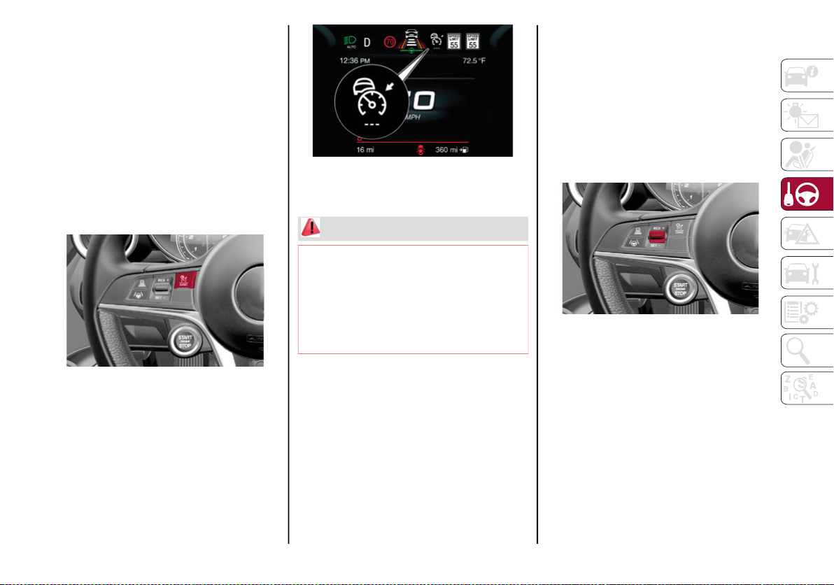
175
Activation/Deactivation
The system has four operating states:
Enabled (speed not set)
Activated (speed set)
Paused
Deactivated
Enabling/Activating
To enable the system, push and release the
on/off button located on the left side on the
steering wheel.
On/Off Button
When the system is enabled and ready to
operate, the display shows the white ACC icon
above dashes in place of the speed.
Enabled Icons
Setting a speed activates the system. The display
shows the icon in green with the set speed.
Pausing/Deactivating
With the feature enabled (speed not set), push
the on/off button to disable.
With the feature active (speed set), push the
on/off button to pause. The display will show
the icon in white with the speed in brackets. To
deactivate the feature, push the on/off button
a second time.
Setting The Desired Speed
The speed can be set from a minimum of
19 mph (30 km/h) to a maximum of 110 mph
(180 km/h).
When the vehicle reaches the desired speed,
push the RES/SET switch downward and
release it to activate the system. When the
accelerator is released, the vehicle will main-
tain the set speed automatically.
SET Switch
While the accelerator pedal is pressed, the
system will not be able to control the distance
between the vehicle and the one ahead. In this
case, the speed will be determined only by the
position of the accelerator pedal.
The system will return to normal operation as
soon as the accelerator pedal is released.
WARNING!
Leaving the Adaptive Cruise Control (ACC)
system on when not in use is dangerous.
You could accidentally set the system or
cause it to go faster than you want. You
could lose control and have a collision.
Always leave the system off when you are
not using it.
20_GA_OM_EN_USC_t.book Page 175

STARTING AND OPERATING
176
The system cannot be activated:
When pressing the brake pedal.
When the brakes are overheated.
When the electric park brake has been
operated.
When either PARK, REVERSE or NEUTRAL is
engaged.
When the engine RPM is above a maximum
threshold.
When the vehicle speed is not within the
operational speed range.
When the Electronic Stability Control (ESC)
(or Anti-Lock Braking System (ABS) or other
stability control systems) are operating or
have just operated.
When the ESC system is off.
When the Forward Collision Warning system
(if equipped) is braking automatically.
In the event of system failure.
When the engine is off.
In case of obstruction of the radar sensor (in
this case the bumper area where it is
located must be cleaned).
If the system is set, the conditions described
above also cause a cancellation or deactiva-
tion of the system. These situations may vary
according to the conditions.
NOTE:
The system will not be deactivated when
speeds higher than those set are reached by
pressing the accelerator pedal above
110 mph (180 km/h). In these situations, the
system may not work correctly and it is recom-
mended to deactivate it.
To Vary The Speed Setting
Increasing Speed
Once the system has been activated, you can
increase the speed by pushing the RES/SET
switch upward. Each time the switch is
pushed, the speed increases by 1 mph.
By pushing and holding the switch upward, the
set speed will increase in increments of 5 mph
until the switch is released. Then, the new
speed will be set.
Decreasing Speed
Once the system has been activated, you can
decrease the speed by pushing the RES/SET
switch downward. Each time the switch is
pushed, the speed decreases by 1 mph.
By pushing and holding the switch downward,
the set speed will decrease in increments of
5 mph until the switch is released. Then, the
new speed will be set.
NOTE:
Moving the RES/SET switch downward
allows you to adjust the speed according to
the selected unit of measurement ("U.S." or
"Metric") set on the radio system (see dedi-
cated supplement).
When the unit of measurement is set to
Metric, pushing and holding the RES/SET
switch will adjust the speed in 10 km/h
increments.
By keeping the accelerator pedal pressed,
the vehicle can continue to accelerate
beyond the set speed. In this case, use the
RES/SET switch to set the speed to the
vehicle’s current speed.
When you push the RES/SET button to
reduce the speed, the braking system inter-
venes automatically if the engine brake
does not slow the vehicle down sufficiently
to reach the set speed. The device holds the
set speed uphill and downhill; however a
slight variation is entirely normal, particu-
larly on slight inclines.
The transmission could shift to a lower gear
when driving downhill, or when acceler-
ating. This is normal and necessary to main-
tain the set speed.
The system will disable while driving if the
brakes overheat.
20_GA_OM_EN_USC_t.book Page 176
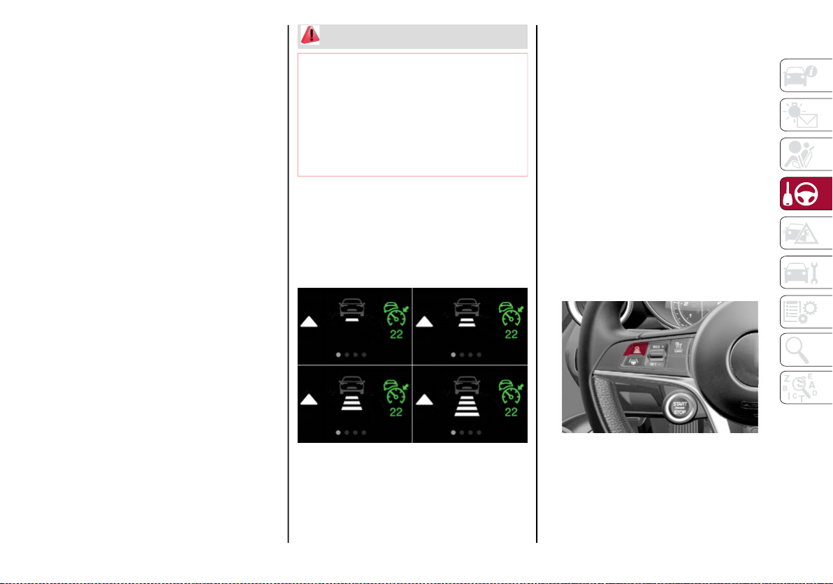
177
Accelerating When Overtaking
When driving with ACC activated and following
a vehicle at a speed greater than 45 mph
(70 km/h), the system will provide an addi-
tional acceleration up to the ACC set speed to
assist in passing the vehicle. This additional
acceleration is triggered when the driver
utilizes the left turn signal and will only be
active when passing on the left-hand side.
The system detects the direction of traffic auto-
matically when the vehicle passes from left hand
traffic to right hand traffic. In this case, the over-
taking assist function is only active when the
reference vehicle is overtaken on the right. The
additional acceleration is deactivated when the
driver uses the right direction indicator and
returns to the original lane.
Resuming The Speed
Once the system has been canceled but not
deactivated, to resume a previously set speed,
simply push the RES/SET switch upward and
remove your foot from the accelerator to recall it.
The system will be set to the last stored speed.
Setting The Distance Between Vehicles
The distance between your vehicle and the
vehicle ahead may be set to one bar (short),
two bars (medium), three bars (long), or four
bars (maximum).
Distance Icons
The distances from the vehicle ahead are
proportional to speed.
The interval of time with relation to the vehicle
ahead remains constant and varies from one
second (for the short distance one-bar setting)
to two seconds (for the maximum distance
four-bar setting).
The set distance is shown on the display by a
dedicated icon.
The setting is four (maximum) the first time the
system is used. After the distance has been
modified by the driver, the new distance will be
stored also after the system is deactivated
and reactivated.
To Decrease The Distance
Push and release the distance button to
decrease the distance setting. The distance
setting decreases by one bar (shorter) every
time the button is pushed.
Distance Button
The set speed is held if there are no vehicles
ahead. Once the shortest distance has been
selected, the next push of the button will set
the maximum distance.
WARNING!
The Resume function should only be used if
traffic and road conditions permit. Resuming
a set speed that is too high or too low for
prevailing traffic and road conditions could
cause the vehicle to accelerate or decelerate
too sharply for safe operation. Failure to follow
these warnings can result in a collision and
death or serious personal injury.
20_GA_OM_EN_USC_t.book Page 177

STARTING AND OPERATING
178
(Continued)
If a slower vehicle is detected in the same
lane, the vehicle icon on the display illumi-
nates from grey to white. The system automat-
ically adjusts the vehicle’s speed to keep the
set distance, independently of the set speed.
The vehicle holds the set distance until:
The vehicle ahead accelerates to a speed
higher than the set speed.
The vehicle ahead leaves the lane or the
detection field of the Adaptive Cruise
Control system sensor.
The distance setting is changed.
The Adaptive Cruise Control system is deac-
tivated/paused.
“Stop And Go” Function
The “Stop and Go” operating strategy allows
you to maintain a safe distance from the
vehicle ahead until the vehicle has completely
stopped. It will also restart the vehicle auto-
matically if the vehicle ahead drives away
within two seconds, otherwise it is necessary
to press the accelerator pedal or move the
RES/SET switch upward to restart.
Deactivation
The system is deactivated and the set speed is
canceled if:
The on/off button is pushed (when the
system is on or paused).
The ignition is placed in the OFF position
RACE mode is activated (Quadrifoglio models)
The system is canceled (the set speed and
distance are stored):
When the system is paused (Refer to the
“Activation / Deactivation” section)
When the conditions shown in the “Setting
The Desired Speed” section occur
Limited Operation Warning
If the dedicated message is shown on the
display, a condition limiting the Adaptive
Cruise Control operation may have occurred.
This could be due to an obstruction of the
vehicle’s sensor or camera. It could also be due
to a fault in the system. If an obstruction is
detected, clean the area of the windshield oppo-
site the interior rear view mirror, where the
camera is located, as well as the area of the front
bumper where the sensor is located. Then check
that the message has disappeared.
When the conditions limiting the system func-
tions end, normal operation will resume.
Should the fault persist, contact an authorized
dealer.
WARNING!
The maximum breaking applied by the
system is limited. The driver may apply the
brakes in all cases if needed.
If the system predicts that the braking
level is insufficient to hold the set
distance, either “BRAKE!” or a dedicated
message is displayed to warn the driver of
approaching the vehicle ahead. An
acoustic signal is also emitted. In this
case, it is advised to brake immediately as
necessary to hold a safe distance from the
vehicle ahead.
The driver is responsible for ensuring that
there are no pedestrians, other vehicles or
objectives along the direction of the
vehicle. Failure to comply with these
precautions may cause serious accidents
and injuries.
The driver is fully responsible for holding a
safe distance from the vehicle ahead
respecting the highway code in force in
the respective country.
WARNING!
When the ACC system is resumed, the
driver must ensure that there are no
pedestrians, vehicles or objects in the path
of the vehicle. Failure to follow these
warnings can result in a collision and death
or serious personal injury.
WARNING! (Continued)
20_GA_OM_EN_USC_t.book Page 178
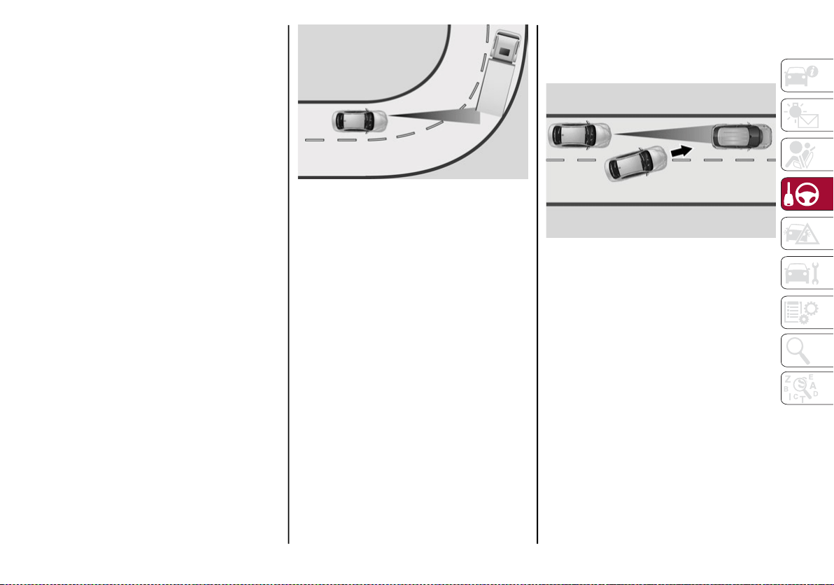
179
Precautions While Driving
The system may not work correctly in some
driving conditions (see below). The driver must
control the vehicle at all times.
Vehicle Not Aligned
The system may not detect a vehicle traveling
in the same lane, in the same direction, but is
not aligned. It also may not detect a vehicle
which is cutting in from a side lane. Sufficient
distance from the vehicles ahead may not be
guaranteed in these cases.
The non-aligned vehicle can weave in and out
of the driving lane causing the vehicle to brake
or accelerate unexpectedly.
Steering And Curves
Driving on curves with the system set could
limit speed and acceleration to guarantee
vehicle stability, even if no vehicles are
detected ahead.
When leaving the curve, the system resets the
previously set speed.
Steering And Curves
NOTE:
In cases of narrow curves, the performance
of the system could be limited. In this case,
it is advisable to deactivate the system.
The system only limits the speed DURING a
bend and not BEFORE it.
Using The System On Slopes
When driving on roads with a variable incline,
the system may not detect the presence of a
vehicle in the lane. System performance could
be limited according to speed, load, traffic
conditions and steep slopes.
Lane Change
The system may not detect the presence of a
vehicle until it is fully in your lane.
Lane Change
In this case, sufficient distance from the
vehicle which is changing lanes may not be
guaranteed. It is advisable to pay the utmost
attention at all times and be always ready to
apply the brakes if needed.
20_GA_OM_EN_USC_t.book Page 179
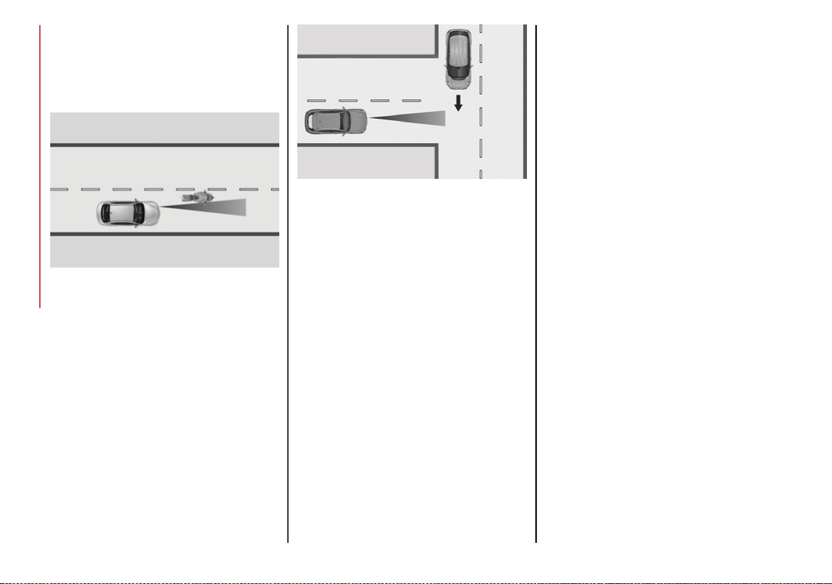
STARTING AND OPERATING
180
Small Vehicles
Some narrow vehicles (e.g. bicycles and
motorcycles) traveling near the outer edges of
the lane or which enter the lane from curb side
are not detected until they are fully in the lane.
Small Vehicles
Sufficient distance from the vehicles ahead
may not be guaranteed in these cases.
Stationary Objects And Vehicles
The system can detect stationary vehicles when
the vehicle is traveling at speeds between 2 mph
and 35 mph (4 km/h and 60 km/h). The driver
should always pay attention and be ready to
press the brakes if needed.
Objects And Vehicles Moving In Opposite Or
Crosswise Direction
The system cannot detect the presence of
objects or vehicles traveling in opposite or
crosswise directions and consequently will not
activate.
Objects And Vehicles Moving In Opposite Or
Crosswise Direction
IFETEL: RCPBOMR 14-0766
La operación de este equipo está sujeta a las
siguientes dos condiciones:
1. es posible que este equipo o dispositivo no
cause interferencia perjudicial y
2. este equipo o dispositivo debe aceptar
cualquier interferencia, incluyendo la que
pueda causar su operación no deseada.
Changes or modifications made to this equip-
ment not expressly approved by Robert
BOSCH GmbH may void the FCC authorization
to operate this equipment.
This equipment has been tested and found to
comply with the limits for a Class A digital
device, pursuant to Part 15 of the FCC Rules.
These limits are designed to provide reason-
able protection against harmful interference
when the equipment is operated in a commer-
cial environment. This equipment generates,
uses, and can radiate radio frequency energy
and, if not installed and used in accordance
with the instruction manual, may cause
harmful interference to radio communica-
tions. Operation of this equipment in a resi-
dential area is likely to cause harmful
interference in which case the user will be
required to correct the interference at his own
expense.
Toutes modifications apportées à cet équipe-
ment qui ne sont pas expressément homo-
loguées par Robert BOSCH GmbH peuvent
annuler l'autorisation de la FCC de faire
fonctionner cet équipement.
Cet appareil a été vérifié et s'est révélé conforme
aux normes applicables aux appareils
numériques de catégorie A, en vertu de la
section 15 des règlements de la FCC. Ces
normes sont définies pour fournir une protection
raisonnable contre les interférences nuisibles
lorsque l'équipement est utilisé dans les installa-
tions résidentielles. Cet appareil génère, utilise
et peut émettre des ondes radioélectriques et,
s'il n'est pas installé et utilisé conformément au
manuel d’instruction, peut causer un brouillage
radioélectrique nuisible aux communications
radio. Le fonctionnement de cet équipement
dans une zone résidentielle est susceptible de
causer des interférences nuisibles; dans ce cas,
l'usager doit corriger les interférences à ses
propres frais.
20_GA_OM_EN_USC_t.book Page 180

181
Radio Frequency Exposure Information
This equipment complies with FCC radiation
exposure limits set forth for an uncontrolled envi-
ronment. This equipment should be installed and
operated with minimum distance of 20 cm
between the radiator and your body.
This transmitter must not be co-located or
operating in conjunction with any other
antenna or transmitter.
Déclaration d’exposition aux radiations
Cet équipement est conforme aux limites
d'exposition aux rayonnements IC établies
pour un environnement non contrôlé. Cet équi-
pement doit être installé et utilisé avec un
minimum de 20 cm de distance entre la
source de rayonnement et votre corps.
Ce transmetteur ne doit pas etre place au
meme endroit ou utilise simultanement avec
un autre transmetteur ou antenne.
General Information
The following regulatory statement applies to
all Radio Frequency (RF) devices equipped in
this vehicle:
This device complies with Part 15 of the FCC
Rules and with Innovation, Science and
Economic Development Canada license-exempt
RSS standard(s). Operation is subject to the
following two conditions:
1. This device may not cause harmful inter-
ference, and
2. This device must accept any interference
received, including interference that may
cause undesired operation.
Le présent appareil est conforme aux CNR
d`Innovation, Science and Economic Develop-
ment applicables aux appareils radio exempts
de licence. L'exploitation est autorisée aux
deux conditions suivantes:
1. l'appareil ne doit pas produire de brouil-
lage, et
2. l'utilisateur de l'appareil doit accepter tout
brouillage radioélectrique subi, même si le
brouillage est susceptible d'en comprom-
ettre le fonctionnement.
La operación de este equipo está sujeta a las
siguientes dos condiciones:
1. es posible que este equipo o dispositivo no
cause interferencia perjudicial y
2. este equipo o dispositivo debe aceptar
cualquier interferencia, incluyendo la que
pueda causar su operación no deseada.
RF Exposure Requirements
To comply with FCC RF exposure compliance
requirements, the device must be installed
and operated to provide a separation distance
of at least 20 cm from all persons.
This equipment complies with Canada radiation
exposure limits set forth for an uncontrolled envi-
ronment. This equipment should be installed and
operated with minimum distance 20 cm between
the radiator and your body.
NOTE:
Changes or modifications not expressly
approved by the party responsible for compli-
ance could void the user’s authority to operate
the equipment.
Déclaration d’exposition aux radiations
Cet équipement est conforme aux limites
d’exposition aux rayonnements ISED établies
pour un environnement non contrôlé. Cet équi-
pement doit être installé et utilisé avec un
minimum de 20 cm de distance entre la
source de rayonnement et votre corps
REMARQUE:
Des changements ou des modifications
n’ayant pas été expressément approuvés par
la partie responsable de la conformité pour-
raient révoquer l’autorisation d’utilisation de
l’équipement.
20_GA_OM_EN_USC_t.book Page 181
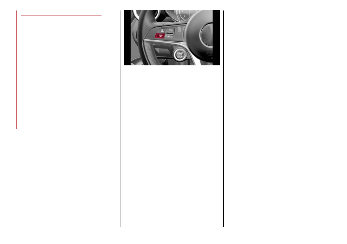
STARTING AND OPERATING
182
HIGHWAY ASSIST SYSTEM
(HAS) — IF EQUIPPED
The Highway Assist System (HAS) is a driving
assistance operation that is only available
when driving on highways. The system oper-
ates up to speeds of 90 mph (145 km/h)
when horizontal signs are detected.
The system uses information from the front
camera and radar to help keep the vehicle in
the center of the lane and at a constant speed.
The HAS system combines Adaptive Cruise
Control (ACC) functions with lane centering
logic to control the trajectory of the vehicle.
The HAS system requires the driver’s hands to
remain on the steering wheel.
Once HAS is activated, a dedicated screen will
appear on the instrument cluster display.
Activation/Deactivation
Activation
To activate the HAS system, push the button
located on the left side of the steering wheel.
Highway Assist Button
Suspension Conditions
The following operations will suspend the HAS
system:
Start steering manually
Press the brake pedal
Disable the ACC device
Activate the turn signals
Push the ACC activation setting button for
two seconds to activate Speed Control
Place the gear selector in PARK, REVERSE,
or NEUTRAL
Reactivating the ACC system will reactivate
HAS. Refer to “Adaptive Cruise Control” in this
chapter.
Automatic Deactivation
The system can be deactivated in any of the
following situations:
If there are narrow bends
When hands are removed from the steering
wheel
If the left or right turn signal is activated
If the driver intentionally changes lanes
without using the turn signal
If the driver’s seat belt is released
If the gear selector is placed in DRIVE
If the “Active Braking” function is activated
(refer to “Forward Collision Warning” in
“Safety for further information)
If the vehicle exits the highway
If the lane markings are not detected by the
camera
If the ACC device is deactivated
If the vehicle speed exceeds 90 mph
(145 km/h)
NOTE:
When the HAS system is turned off, the symbol
on the display turns red and then grey.
Hands on the steering wheel are detected
by a capacitive sensor installed in it.
20_GA_OM_EN_USC_t.book Page 182

183
When the automatic suspension conditions are
over, HAS will be automatically reactivated.
Operation
The HAS system only operates when the
driver’s hands are on the steering wheel.
If the system detects that the driver’s hands
have been removed from the steering wheel,
the system will alert the driver to place their
hands back on the steering wheel. Refer to
“System Status” in this section for further
information.
If the vehicle crosses the lane boundary, the
steering wheel will vibrate and the dedicated
screen will appear in the instrument cluster
display.
NOTE:
The HAS system may take up to five seconds
to turn on once all conditions are met. During
this time, a grey indicator light will appear on
the instrument cluster display and the system
will automatically activate as soon as all of the
conditions are met with no intervention from
the driver.
The following conditions must be met before
the HAS system turns on:
The HAS system must be enabled by
pushing the button on the steering wheel
The vehicle must be on a highway
ACC must be activated
The right and left lane boundaries must be
visible
The vehicle speed must be between 0 and
90 mph (0 and 145 km/h)
The camera, radar, and radio system must
be functioning properly
The road lane width must be between 8.5 ft
and 13.7 ft (2.6 m and 4.2 m)
The turn signals must not be activated
The HAS system must be functioning properly
Other operating limits:
If the speed of ACC can be set to a higher
value (top speed 110 mph (180 km/h), HAS
is only available as long as the vehicle
speed is equal to or less than 90 mph
(145 km/h).
When the ACC speed is reduced and the
vehicle speed is less than 90 mph
(145 km/h), the system will automatically
reactivate.
If the ACC speed is set to 90 mph (145 km/h),
traveling downhill may increase the vehicle
speed. The HAS system will deactivate until
the speed returns to 90 mph (145 km/h).
Indications On The Display
The HAS system status can always be viewed
in the instrument cluster display.
The system status is indicated by the color of
the symbol on the display.
The HAS system uses sensors in the steering
wheel to detect if the driver’s hands are on it.
If the driver’s hands are not on the steering
wheel, a series of warnings will appear in the
instrument cluster display to alert the driver to
reposition their hands on the steering wheel.
An acoustic signal will also sound. After a
period of time, the HAS system will disable if
the driver’s hands do not return to the steering
wheel.
After a period of time, the HAS system will
disable if the driver has not repositioned their
hands on the steering wheel.
When the system does not detect hands on
the steering wheel, it will warn the driver by
displaying a dedicated screen on the instru-
ment cluster display.
20_GA_OM_EN_USC_t.book Page 183
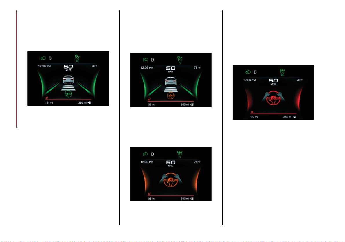
STARTING AND OPERATING
184
System Status
Active System
When the system is active, the screen below
will appear in the “Driver Assistance” menu on
the instrument cluster display.
HAS Active
If on a different menu screen, a symbol will
appear on the instrument cluster display indi-
cating that the system is active.
When the driver’s hands are removed from the
steering wheel, the system disables after a few
seconds. A screen will appear in the instru-
ment cluster display warning the driver to
return their hands to the steering wheel.
Active System (Hands Removed From The
Steering Wheel For A Short Time)
As soon as the driver removes their hands
from the steering wheel, the screen below will
appear in the instrument cluster display. The
system will remain active at this time.
Hands Removed Initial Warning
If the driver does not return their hands to the
steering wheel within a few seconds, the
screen below will appear in the instrument
cluster display.
Hands Removed Secondary Warning
Active System (Hands Removed From The
Steering Wheel For A Long Time)
If the driver still has not returned their hands
to the steering wheel after the screen above is
displayed, the below screen will now appear in
the instrument cluster display, and an
acoustic signal will sound until the driver
regains control of the vehicle.
Hands Removed Final Warning
If the driver’s hands are not returned to the
steering wheel after an extended period of
time, a deactivation message will appear on
the instrument cluster display. The steering
wheel control will be deactivated.
This display will remain active even when the
driver’s hands are removed from the steering
wheel. The symbol on the display will turn grey.
The ACC system and Lane Departure Warning
systems will also be disabled.
When HAS is active, the Lane Keeping Assist
(LKA)/ Lane Departure Warning (LDW) systems
(if equipped), if previously activated, will remain
activated.
20_GA_OM_EN_USC_t.book Page 184
185
Limited System Availability/Operation
System Availability
External factors and conditions may affect the
proper operation of the HAS system, such as:
Narrow, winding, curvy streets
Poor visibility (due to heavy rain, snow, fog,
etc.)
Front lights of oncoming vehicles or direct
sunlight or shade
Damage or obstructions caused by mud,
ice, snow, etc.
Bumper damaged or not aligned
Interference with other equipment that
causes electromagnetic waves
Presence of roadwork/road construction
sites
If the indications given by the navigation
system (if any) of the radio system are not
yet ready and/or if the navigation system is
recalculating the route
System Limited Operation
The HAS system may have limited or reduced
functionality when one of the following condi-
tions occur:
Lane markings are not clear or in conditions
of poor visibility (e.g. in heavy rain, snow,
fog, etc.)
Either the camera or radar are damaged,
covered, or obstructed (e.g. by mud, ice,
snow, etc.)
When driving on hills or roads with narrow
bends
Near highway toll booths
When the highway entrance or exit is wider
than 20 ft (6 m)
If the camera is exposed to glare caused by
reflections or direct sunlight
If the navigation system information is
unavailable or being recalculated
NOTE:
If the vehicle approaches a bend that is too
narrow with respect to the current speed,
the HAS system will disable.
If damage to the windshield occurs, have
the windshield replaced by an authorized
dealer as soon as possible.
WARNING!
To prevent serious injury or death:
Always remain alert and be ready to take
control of the vehicle in the event that the
HAS system disables.
Always keep your hands on the steering
wheel when the HAS system is activated.
Maintain a safe distance from other vehicles
and pay attention to traffic conditions.
Do not place any objects on the steering wheel
(e.g. steering wheel covers) which could inter-
fere with the hand detection sensor.
20_GA_OM_EN_USC_t.book Page 185

STARTING AND OPERATING
186
TRAFFIC JAM ASSIST (TJA)
SYSTEM — IF EQUIPPED
The Traffic Jam Assist (TJA) system can be acti-
vated on all road types. The system uses a
camera to detect lane markings and keep the
vehicle in the center of the lane.
When the system is unable to detect lane
markings, it will still operate using surrounding
traffic. This can occur in congested traffic
scenarios, when the vehicles ahead or
surrounding obstruct the visibility of the lane
markings. When the speed is below 12 mph
(20 km/h), the system can use a lock-on
strategy that allows the vehicle to automati-
cally follow the vehicle ahead.
The TJA system combines Adaptive Cruise
Control (ACC) functions with Lane Departure
Warning functions to maintain vehicle speed
and steering wheel behavior.
NOTE:
Do not use the TJA system while driving in
urban areas.
Activation/Deactivation
Activation
To activate the system, push the button on the
left side of the steering wheel.
To deactivate the system, push the button
again.
Traffic Jam Assist Button
Suspension Conditions
The following operations will suspend the TJA
system:
Pressing the brake pedal
Opening the driver’s door
Disabling ACC
If the vehicle speed exceeds 37 mph
(60 km/h)
Releasing the driver’s seat belt
Placing the gear selector in PARK,
REVERSE, or NEUTRAL
If the Forward Collision Warning system or
“Active Braking” intervenes
Automatic Deactivation
System operation will be temporarily disabled
under the following conditions:
When traveling around narrow bends
If the lane boundaries are not detected
One of the two lines is interrupted
The sun is low and reflects on the radar
camera
If the turn signals are activated
If the driver intentionally changes lanes
without using the turn signal
If manual steering begins
If the driver’s hands are removed from the
steering wheel
When there is no surrounding traffic and
there are no horizontal lane boundaries
If the system is not functioning properly
If lateral acceleration is high
NOTE:
When TJA is turned off, the symbol in the
instrument cluster display will turn red, and
then grey.
A sensor in the steering wheel detects
whether the driver’s hands are placed on
the steering wheel.
20_GA_OM_EN_USC_t.book Page 186
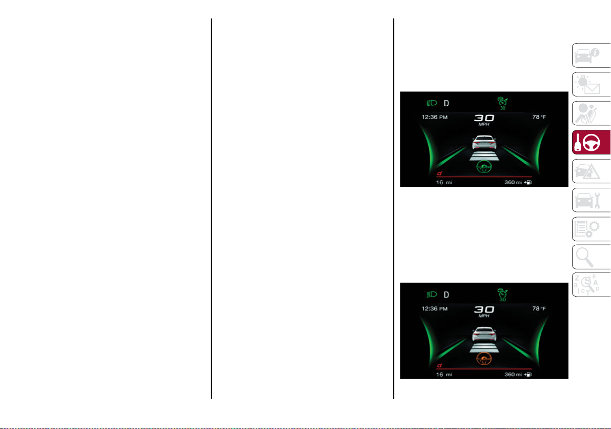
187
When the automatic suspension conditions
are over, the TJA system will be automatically
reactivated.
Operation
The TJA system can only operate when the
driver’s hands are on the steering wheel.
If the system detects that the driver’s hands
have been removed from the steering wheel, a
message will appear in the instrument cluster
display to alert the driver to place their hands
back on the wheel.
NOTE:
If the vehicle begins to cross the lane
boundary, the steering wheel will vibrate
and a dedicated screen will appear in the
instrument cluster display.
The TJA system may take up to five seconds to
become active once all conditions are met.
The following conditions must be met in order
to activate the system:
The TJA system must be enabled
The Adaptive Cruise Control (ACC) system
must be turned on
The right and left lane boundaries must be
recognized by the system
The vehicle must be traveling at a speed
between 0 and 37 mph (0 and 60 km/h)
The camera, radar, and radio system must
be functioning properly
The road lane width must be between 8.5 ft
and 13.7 ft (2.6 m and 4.2 m)
The turn signals must be turned off
The TJA system must be functioning properly
If the ACC speed is set to 37 mph (60 km/h)
or less, traveling downhill may increase the
vehicle speed. The system will remain inac-
tive until the speed returns to 37 mph
(60 km/h) or less.
Indications On The Display
The TJA system status is indicated by the color
of the symbol in the instrument cluster display.
The system uses sensors in the steering wheel
to detect if the driver’s hands are present. If
the driver’s hands are removed, a series of
warnings will appear in the instrument cluster
display to alert the driver to reposition their
hands on the steering wheel. Acoustic signals
will also be emitted.
If the driver’s hands are not returned to the
steering wheel after a period of time, the
system will be disabled.
System Status
Active System
An active system is indicated by the following
screen in the “Driver Assistance” menu on the
instrument cluster display.
TJA System Active
Active System (Hands Removed From The
Steering Wheel For A Short Time)
The following screen will appear in the instrument
cluster display immediately after the driver’s hands
are removed from the steering wheel. The system
still remains active at this time.
Hands Removed Initial Warning
20_GA_OM_EN_USC_t.book Page 187

STARTING AND OPERATING
188
If the driver does not return their hands to the
steering wheel within a few seconds, the
following screen will appear in the instrument
cluster display.
Hands Removed Secondary Warning
Active System (Hands Removed From The
Steering Wheel For A Long Time)
If the driver’s hands have still not been
returned to the steering wheel, the following
screen will appear in the instrument cluster
display.
Hands Removed Final Warning
An acoustic signal will sound until the driver
regains control of the vehicle (hands on
steering wheel). The system is still active at
this time.
If the driver’s hands are not returned to the
steering wheel after a period of time, a deacti-
vation message will appear on the instrument
cluster display and the steering wheel control
will be deactivated.
Once the indicator light on the display turns
grey, the system is no longer active and the
driver must take control of the vehicle. At this
time, the Adaptive Cruise Control (ACC) system
and Lane Departure Warning system will also
be disabled.
When the TJA system is active, the Lane Keeping
Assist (LKA)/Lane Departure Warning (LDW)
systems (if equipped) will be temporarily
disabled. When TJA is not active, the LKA/LDW
systems will remain active. Refer to “Lane
Keeping Assist” and “Land Departure Warning”
in this chapter for further information.
Limited System Availability/Operation
System Availability
Performance of the TJA system may be
affected by the following factors:
Narrow, winding, curvy streets
Lane boundaries that are not clear or in
conditions of poor visibility (e.g. heavy rain,
snow, fog, etc.)
If the camera is exposed to glare from direct
sunlight or headlights of an oncoming
vehicle
If the camera or sensor is damaged,
covered, or obstructed (e.g. by mud, ice,
snow, etc.)
The bumper is damaged or misaligned
Interference with other equipment causes
electromagnetic waves
Construction sites
If the indications given by the navigation
system of the radio system are not yet ready
or if the system is recalculating
20_GA_OM_EN_USC_t.book Page 188
189
System Limited Operation
The TJA system may have limited or reduced
functionality when one of the following condi-
tions occurs:
Lane boundaries are not clear or in condi-
tions of poor visibility (e.g. in heavy rain,
snow, fog, etc.)
Either the camera or radar are damaged,
covered, or obstructed (e.g. by mud, ice,
snow, etc.)
When driving on hills or narrow bends
Near highway toll booths
When the highway entrance or exit is more
than 20 ft (6 m) wide
If the camera is exposed to glare from
reflections or direct sunlight
NOTE:
If damage to the windshield occurs, have
the windshield replaced by an authorized
dealer as soon as possible.
If the vehicle approaches a bend that is too
narrow with respect to the current speed,
the TJA system will deactivate.
TRAFFIC SIGN RECOGNITION
(TSR) SYSTEM — IF EQUIPPED
The Traffic Sign Recognition (TSR) system
uses a camera mounted on the windshield to
detect recognizable road signs such as:
Speed limits
Signs indicating the end of the situations
indicated above
If the camera does not detect valid speed
limits, the radio system navigation system may
suggest unregulated speed limits.
The system always checks the traffic signs
indicating the current speed limit. The system
is able to recognize and display up to two
different road signs in the instrument cluster
display.
Depending on the unit of measurement (km or
mph) set through the “Unit of Measurement”
menu in the radio system, the TSR system will
automatically show the indication of the road
sign in the unit of measurements selected in
the instrument cluster display.
WARNING!
To prevent serious injury or death:
Always remain alert and be ready to take
control of the car in the event that the TJA
system disables.
Always keep your hands on the steering
wheel when the TJA system is activated.
Maintain a safe distance from other vehicles
and pay attention to traffic conditions.
The TJA system should only be used as a
driving aid. The drive must always pay
attention to their surroundings when the
system is operating and be ready to take
control of the vehicle at any time.
Do not place any objects on the steering
wheel (e.g. steering wheel covers) that
could interfere with the hand detection
sensor on the steering wheel.
20_GA_OM_EN_USC_t.book Page 189
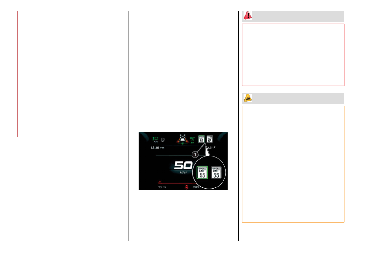
STARTING AND OPERATING
190
Activation/Deactivation
The TSR System can be activated/deactivated
in the radio system by selecting “Comfort” in
the “Driver Assistance” menu. The system acti-
vation is signaled by road signs shown on the
instrument cluster display.
NOTE:
By selecting “Blinking”, the driver can activate
a warning to display when the speed exceeds
the limit indicated by the TSR System. The
speed road sign on the instrument cluster
display will blink until the vehicle speed drops
below the displayed limit.
Selecting “Offset” will set the speed at
which “Blinking” is activated up to a
maximum of 6 mph (10 km/h) above the
limit detected by the system.
If no speed limit signs are found, the system
will revert to the speed limit signs that are
stored in the NAV system.
Indications On The Display
The system status can always be viewed
through the instrument cluster display.
The instrument cluster display shows only the
speed limit indications and consists of the
following steps:
The new speed limit recognized by the
system, which is indicated by means of a
predetermined color. The road sign indi-
cating the end of the speed limit or a “Road
Sign Not Detected” message may appear in
this zone.
After a predetermined distance, the previ-
ously displayed road sign changes color to
inform the driver that the speed limit
provided may no longer be valid.
1 — Traffic Sign Recognized
WARNING!
To prevent serious injury or death:
Always remain alert and be ready to take
control of the vehicle in the event that the
TJA system disables.
Always keep your hands on the steering
wheel when the TJA system is activated.
Maintain a safe distance from other vehicles
and pay attention to traffic conditions.
CAUTION!
Functionality may be limited or the system
may not work if the sensor is obstructed.
The system may have limited operation or
not work at all in weather conditions such as
heavy rain, hail, thick fog, and low tempera-
tures. Strong light contrasts can influence
the recognition capability of the sensor.
The area surrounding the sensor must not
be covered with stickers or any other object.
Do not tamper or perform any operations
in the area of the windshield glass directly
surrounding the sensor.
Clean foreign matters such as bird drop-
pings, insects, snow or ice on the wind-
shield. Use specific detergents and clean
cloths to avoid scratching the windshield.
20_GA_OM_EN_USC_t.book Page 190
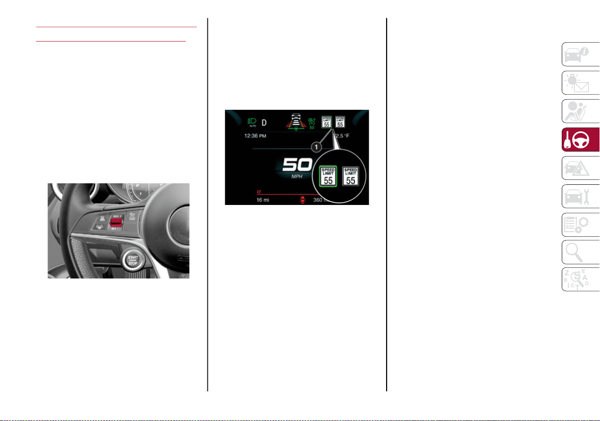
191
INTELLIGENT SPEED CONTROL
(ISC) SYSTEM — IF EQUIPPED
The Intelligent Speed Control (ISC) system is
always paired with the Adaptive Cruise Control
(ACC) system. The ISC system suggests an
automatic speed adjustment to the driver
based on the speed limit for the road being
traveled. The driver can decide whether to
accept or reject the automatic speed adjust-
ment, using the switch on the steering wheel.
If the speed limit is exceeded according to the
road signs or traffic conditions, a dedicated
graphic message is displayed on the instru-
ment panel display.
RES/SET Switch
Activation/Deactivation
Activation
The system can be activated in the radio
system by selecting the “Driver Assistance”
menu and then selecting “Comfort”. The
symbol illuminates in the instrument cluster
display when the system is active.
1 — ISC System Active
Deactivation
The system is deactivated under the following
conditions:
When the Traffic Sign Recognition (TSR)
system is deactivated
When the Adaptive Cruise Control (ACC)
system is deactivated
NOTE:
Selecting “Speed Offset” allows the driver to
set the speed up to a maximum of 6 mph
(10 km/h) above or below the suggested
speed set by the ISC system. In this instance,
the road sign information shown in the instru-
ment cluster display will continue to be
detected by the TSR system.
Indications On The Display
The system status is indicated by a white or
green icon in the instrument cluster display
(similar to the Adaptive Cruise Control (ACC)
device) to the left of the road sign indications
provided by the Traffic Sign Recognition (TSR)
system.
Acceptance/Rejection Of The Suggested Speed
The system can be activated if the driver has
activated the following systems beforehand:
Adaptive Cruise Control (ACC)
Traffic Sign Recognition (TSR)
When these systems are active, a telltale will
display in the instrument cluster display indi-
cating the suggested speed provided by the
TSR system. The driver has the option to
accept or reject this using the RES/SET switch
on the steering wheel.
20_GA_OM_EN_USC_t.book Page 191
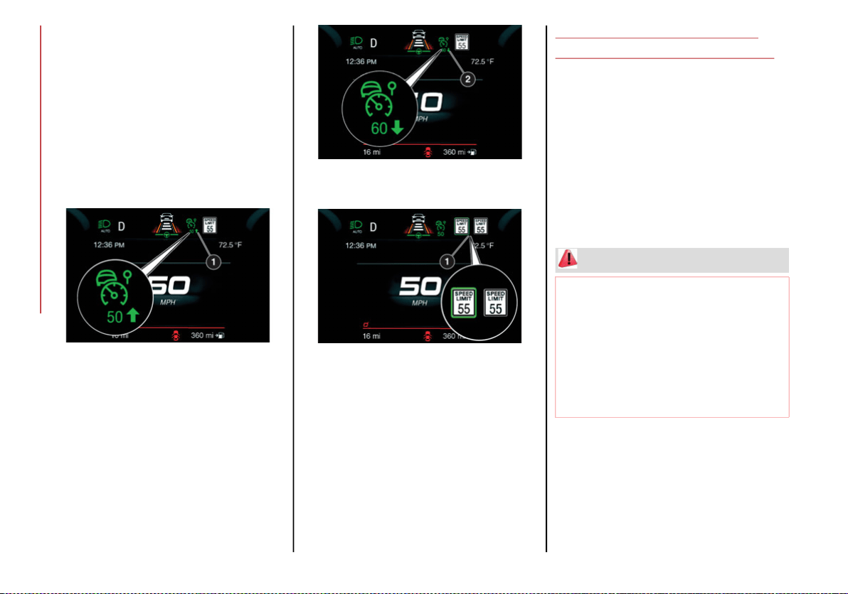
STARTING AND OPERATING
192
To accept the proposed speed and adjust the
speed set by ACC, move the RES/SET switch up
or down in the direction indicated in the telltale.
To reject the proposed speed, move the RES/SET
switch up or down in the direction opposite of the
arrow in the telltale. The ACC system will
continue to regulate to the previously set speed.
If the speed set by the ACC system is the same
as the speed detected by the TSR system, the
speed limit indicator on the instrument cluster
display will be highlighted with a green circle.
1 — Suggested Speed Higher Than Current
Speed
2 — Suggested Speed Lower Than Current
Speed
1 —Road Sign Recognized
DRIVER ATTENTION ASSIST
(DAA) SYSTEM — IF EQUIPPED
The Driver Attention Assist (DAA) system
detects when the driver is feeling fatigued and
warns the driver to pull over and take a break.
Activation/Deactivation
The DAA system can be activated and deacti-
vated through the radio system by selecting
the following in order:
1. “Driver Assistance”
2. “Safety”
WARNING!
The DAA System is an aid for driving and
does not relieve the driver of the
responsibility of driving the vehicle. If you
experience fatigue while driving, pull over
safely for a break without waiting for the
DAA to intervene. Only return to the road
when you are in the right physical and
mental condition to prevent endangering
yourself and other drivers.
20_GA_OM_EN_USC_t.book Page 192
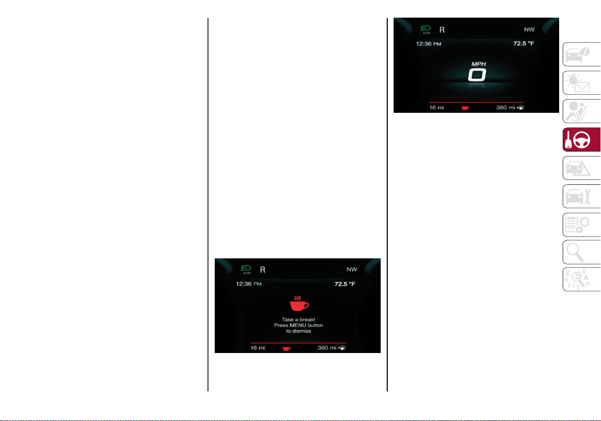
193
System Intervention
Using information from the front camera, the
system implements two operating logics:
The first operating logic takes the driving
style into account, observing the road and
detecting to what extent the driver can
continue driving with few lane crossing
events.
The second operating logic measures the
time spent behind the wheel with the
vehicle speed above 40 mph (60 km/h)
and below 110 mph (180 km/h). If the
“Standard” option is selected, in these
conditions, the “Dozy Driver” message may
appear after three hours of driving. If the
“Early” option is selected and these condi-
tions occur, the “Dozy Driver” message will
be displayed after two hours of driving.
NOTE:
If the conditions described above are not
detected continuously during the entire driving
period, the “Dozy Driver” message may be
displayed later than 2 or 3 hours. If the driving
style indicates that the driver is unable to
follow the road trajectory and respect the hori-
zontal lane markings, the red symbol will
appear on the instrument cluster display to
suggest that the driver should stop for a break.
An audible signal will also sound.
If the driver accepts the suggestion provided
by the system by pushing the MENU button on
the multifunction lever, the message will
disappear from the display and the symbol will
be displayed in the dedicated area of the
instrument cluster display until the next
engine shutdown.
If the driver ignores the warning provided by
the system and does not stop, the message
will continue to remain on the display, along
with the symbol.
NOTE:
In the event of a DAA system failure, an
amber symbol will appear in the instrument
cluster display along with a dedicated
message.
If the ABS system activates, “ABS ACTIVE”
will display in place of the DAA symbol and
will remain active until the ABS system
deactivates.
DAA Warning Message
DAA Warning Icon
Changing The System Sensitivity
The system intervention sensitivity can be
adjusted through the radio system by selecting
the following in order:
1. “Driver Assistance”
2. “Safety”
NOTE:
If “Race” mode (if equipped) is activated,
the DAA system will be automatically deacti-
vated.
The system sensitivity cannot be changed in
the event of a camera system failure.
20_GA_OM_EN_USC_t.book Page 193
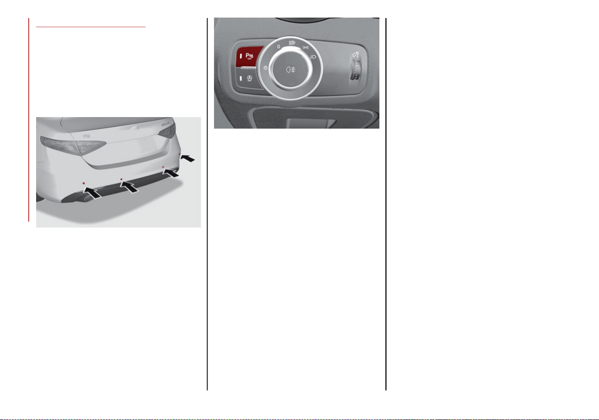
STARTING AND OPERATING
194
PARKSENSE SYSTEM
Vehicles With Rear Sensors Only
The parking sensors, located in the rear
bumper, detect obstacles while the vehicle is
in REVERSE. When an obstacle is detected, an
acoustic alert will sound and visual indications
will be displayed on the instrument cluster.
Rear Sensor Location
Engagement/Disengagement
To turn the system off, push the ParkSense
button located to the left of the headlight
switch. The indicator light within the button will
illuminate when the system is turned off.
Pushing the button a second time will turn the
system back on, and the indicator light will
turn off.
ParkSense On/Off Switch
The indicator light within the ParkSense
button will also be on in case of system failure.
If the button is pushed with a system failure,
the indicator light will flash for approximately
five seconds. The light will then stay on
constantly.
NOTE:
When the ignition is placed in the ON/RUN
position, the ParkSense System keeps the last
state when the engine was stopped (activated
or deactivated) in its memory.
System Activation/Deactivation
The system, when engaged, is automatically
activated by engaging the REVERSE gear. It is
deactivated by engaging another gear.
Acoustic Signal
When REVERSE is engaged and there is an
obstacle behind the vehicle, an acoustic signal
with variable frequency will sound.
The acoustic signal increases in frequency
as the distance between the vehicle and the
obstacle decreases.
The acoustic signal becomes continuous
when the distance between the vehicle and
the obstacle is less than 11 inches (30 cm),
and stops if the distance increases.
The acoustic signal is constant if the
distance between the vehicle and the
obstacle is unchanged.
NOTE:
If several obstacles are detected by the
sensors, only the nearest one is considered.
An acoustic signal will not sound if the vehicle
is in PARK.
20_GA_OM_EN_USC_t.book Page 194

195
Indication On Display
The driver can select the type of warning they
would like to be displayed through the radio
system. To access the function on the main
menu, select in the following order:
1. “Settings”
2. “Driver Assistance”
3. “ParkSense”
4. “Mode”
5. “Sound and Display”
Visual Indications
The system indicates the presence of an
obstacle by displaying a single red arc in the
detected area, in relation to the distance of
the object and the position of the vehicle.
If the obstacle is detected in the rear central
area, a single red arc will be displayed as the
obstacle approaches, first constant, then
flashing, in addition to an acoustic signal.
If the obstacle is detected in the rear left and/or
right area, a single red flashing arc will be shown
in the corresponding area on the display and the
system will emit an acoustic signal, either at
frequent intervals or constantly.
In general, the vehicle is closer to the obstacle
when a single red flashing arc is shown on the
display and the acoustic signal becomes
continuous.
If several obstacles are detected simultane-
ously in the rear area, the display will show all
of them, regardless of the area in which they
were detected.
It is not possible to exit from the display screen
while the vehicle is in REVERSE.
Fault Indication
Parking sensor faults, if any, will be indicated
when REVERSE is engaged by a message on
the instrument cluster display. Refer to
"Warning Lights And Messages" in "Getting To
Know Your Instrument Panel" for further infor-
mation.
Messages On The Display
In case of system failure, a dedicated
message appears on the instrument cluster
for about five seconds.
Cleaning The Sensors: If the display shows
a message requiring the sensors to be
cleaned, make sure that the outer surface
and the underside of the rear bumper is free
of debris (e.g. snow, mud, ice, etc.). Once
these areas are clear, place the ignition in
the OFF position, then return it to ON/RUN.
If the message is still displayed, contact an
authorized dealer.
Audio System Not Available: If the display
shows a message that the audio system is not
available, it means that the acoustic signal will
be emitted by the instrument panel, and not
through the vehicles speakers.
NOTE:
Some conditions may influence the perfor-
mance of the ParkSense System:
Reduced sensor sensitivity could be due to
the presence of ice, snow, mud, or thick
paint on the surface of the sensor.
The sensors may detect a false obstacle
(echo interference) due to mechanical inter-
ference, for example when washing the
vehicle or in extreme weather.
The signals sent by the sensors can be
altered by the presence of ultrasonic
systems (e.g. pneumatic brake systems of
trucks or pneumatic drills) near the vehicle.
System performance can be influenced by
the position of the sensors. For example,
due to a change in the ride setting (caused
by wear to the shock absorbers or suspen-
sion), by changing tires, overloading the
vehicle or operations that require the
vehicle to be lowered.
Be sure not to place bumper stickers or
other adhesives over the sensors as this will
affect system performance.
20_GA_OM_EN_USC_t.book Page 195
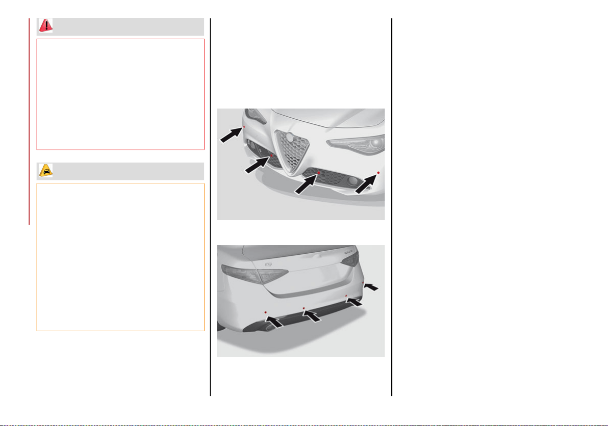
STARTING AND OPERATING
196
Vehicles With Front And Rear Sensors
The parking sensors, located in the front and
rear bumpers, detect the presence of any
obstacles and warn the driver through an
acoustic signal and visual indications, which
will be displayed on the instrument cluster
display.
Front Sensor Location
Rear Sensor Location
Engagement/Disengagement
To turn the front parking sensors off, push the
ParkSense button located to the left of the
headlight switch. The indicator light within the
switch will illuminate when the system is
turned off. Pushing the button a second time
will turn the front sensors back on, and the
indicator light will turn off.
NOTE:
Deactivation of both the front and rear parking
sensors can only be done through the radio
system.
The indicator light within the ParkSense
System switch will also be on in case of system
failure. If the switch is pushed with a system
failure, the indicator light will flash for approx-
imately five seconds. The light will then stay on
constantly.
NOTE:
When the ignition is placed in the ON/RUN
position, the ParkSense System keeps the last
state when the engine was stopped (activated
or deactivated) in its memory.
System Activation/Deactivation
When the REVERSE gear is engaged and the
system is on, the front and rear sensors are acti-
vated. If the vehicle moves from REVERSE to a
forward gear, the rear sensors are deactivated,
while the front sensors remain active until the
speed of 9 mph (15 km/h) is exceeded.
WARNING!
Drivers must be careful when backing up
even when using the ParkSense system.
Always check carefully behind your vehicle,
and be sure to check for pedestrians,
animals, other vehicles, obstructions, or
blind spots before backing up. You are
responsible for the safety of your
surroundings and must continue to pay
attention while backing up. Failure to do so
can result in serious injury or death.
CAUTION!
The ParkSense System is only a parking aid
and it is unable to recognize every obstacle,
including small obstacles. Parking curbs
might be temporarily detected or not
detected at all. Obstacles located above or
below the sensors will not be detected when
they are in close proximity
The vehicle must be driven slowly when
using the ParkSense System in order to be
able to stop in time when an obstacle is
detected. It is recommended that the
driver looks over his/her shoulder when
using the ParkSense system.
20_GA_OM_EN_USC_t.book Page 196

197
NOTE:
In certain operating conditions, the system
could start detecting an obstacle only after the
vehicle has moved slightly (a few inches).
Acoustic Signal
In the presence of an obstacle at the front or
the rear of the vehicle, an acoustic signal with
variable frequency will sound:
The acoustic signal increases in frequency
as the distance between the vehicle and the
obstacle decreases.
The acoustic signal becomes continuous
when the distance between the vehicle and
the obstacle is less than 11 inches (30 cm),
and stops if the distance increases.
The acoustic signal is constant if the
distance between the vehicle and the
obstacle is unchanged.
NOTE:
If the sensors detect several front and rear
obstacles, the closest obstacle is considered.
An intermittent signal will sound if the obsta-
cles are at the same distance (front and rear).
When the system emits an acoustic signal, the
volume of the radio system, if activated, is
automatically lowered.
Indication On Display
The driver can select the type of warning they
would like to be displayed through the radio
system. To access the function on the main
menu, select in the following order:
1. “Settings”
2. “Driver Assistance”
3. “ParkSense”
4. “Mode”
5. “Sound and Display”
Visual Indications
The system indicates the presence of an
obstacle by displaying a single red arc in the
detected areas, in relation to the distance of
the object and the position of the vehicle.
If the obstacle is detected in the front or rear
central area, a single red arc will be displayed
as the obstacle approaches, first constant,
then flashing, in addition to an acoustic signal.
If the obstacle is detected in the front or rear left
and/or right area, a single red flashing arc will be
shown in the corresponding area on the display
and the system will emit an acoustic signal,
either at frequent intervals or constantly.
If several obstacles are detected simultane-
ously in the front and rear area, the display will
show all of them, regardless of the area in
which they were detected.
In general, the vehicle is closer to the obstacle
when a single or several flashing arcs are
shown on the display and the acoustic signal
becomes continuous.
It is not possible to exit from the display screen
while the vehicle is in REVERSE.
Fault Indication
Parking sensor faults, if any, will be indicated by
a message on the display on the instrument
cluster. Refer to "Warning Lights And Messages"
in "Getting To Know Your Instrument Panel" for
further information.
Messages On The Display
In case of system failure, a dedicated
message appears on the instrument cluster
for about five seconds.
Cleaning The Front Or Rear Sensors: If the
display shows a message requiring the
sensors to be cleaned, make sure that the
outer surface and the underside of the front
and rear bumpers are free of debris (e.g.
snow, mud, ice, etc.). Once these areas are
clear, place the ignition in the OFF position,
then return it to ON/RUN. If the message is
still displayed, contact an authorized dealer.
Audio System Not Available: If the display
shows a message that the audio system is not
available, it means that the acoustic signal will
be emitted by the instrument panel, and not
through the vehicle’s speakers.
20_GA_OM_EN_USC_t.book Page 197

STARTING AND OPERATING
198
(Continued)
NOTE:
Some conditions may influence the perfor-
mance of the ParkSense System:
Reduced sensor sensitivity could be due to
the presence of ice, snow, mud, or thick
paint on the surface of the sensor.
The sensors may detect a false obstacle
(echo interference) due to mechanical inter-
ference, for example when washing the
vehicle or in extreme weather.
The signals sent by the sensors can be
altered by the presence of ultrasonic
systems (e.g. pneumatic brake systems of
trucks or pneumatic drills) near the vehicle.
System performance can be influenced by
the position of the sensors. For example,
due to a change in the ride setting (caused
by wear to the shock absorbers or suspen-
sion), by changing tires, overloading the
vehicle or operations that require the
vehicle to be lowered.
Be sure not to place bumper stickers or
other adhesives over the sensors as this will
affect system performance.
LANE DEPARTURE WARNING
(LDW) SYSTEM — IF EQUIPPED
Description
The Lane Departure Warning system uses a
forward looking camera located on the wind-
shield to detect lane markings and measure
vehicle position within the lane boundaries.
When one or both lane limits are detected and
the vehicle passes over one without an acti-
vated turn signal, the system emits a visual as
well as an audible signal.
If the vehicle continues to go beyond the line
of the lane without any intervention from the
driver, the surpassed line will light up on the
display (left or right) to urge the driver to bring
the vehicle back into the limits of the lane.
WARNING!
Drivers must be careful when backing up
even when using the ParkSense system.
Always check carefully behind your vehicle,
and be sure to check for pedestrians,
animals, other vehicles, obstructions, or
blind spots before backing up. You are
responsible for the safety of your
surroundings and must continue to pay
attention while backing up. Failure to do so
can result in serious injury or death.
CAUTION!
The ParkSense System is only a parking
aid and it is unable to recognize every
obstacle, including small obstacles.
Parking curbs might be temporarily
detected or not detected at all. Obstacles
located above or below the sensors will
not be detected when they are in close
proximity
The vehicle must be driven slowly when
using the ParkSense System in order to be
able to stop in time when an obstacle is
detected. It is recommended that the
driver looks over his/her shoulder when
using the ParkSense system.
CAUTION!
Projecting loads on the roof of the vehicle
may interfere with the correct operation of
the camera. Before starting, make sure
the load is correctly positioned in order to
not cover the camera operating range.
Do not cover the operating range of the
camera with stickers or other objects.
Do not tamper with nor operate on the
camera. Do not close the openings in the
aesthetic cover located under the interior
rear view mirror. In the event of a failure of
the camera, contact an authorized dealer.
20_GA_OM_EN_USC_t.book Page 198
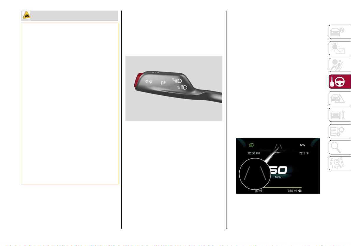
199
System Activation/Deactivation
The system is activated/deactivated by
pushing the button located on the end of the
multifunction lever, or through the “Driver
Assistance” widget though the radio system
within the “Comfort” menu.
Lane Departure Warning System Activation/
Deactivation Button
NOTE:
When the engine is started, the system main-
tains the operating mode that was selected
when it was turned off.
Activation Conditions
Once turned on, the system becomes active
only if the following conditions are met:
The vehicle speed is equal to or above
37 mph (60 km/h) (the system is deacti-
vated at speeds equal to or greater than
110 mph (180 km/h)).
The lane limit lines are visible at least on
one side.
There are suitable visibility conditions.
The road is straight or with wide radius
bends.
A suitable distance is kept from the vehicle
in front.
The turn signal is not active.
Symbols And Messages On The Display
The Lane Departure Warning system advises
the driver when the vehicle leaves the driving
lane by showing symbols and messages on the
instrument cluster display.
When the system is active and the lane limits
have not been detected, the display shows two
grey lane lines.
Lane Limits Not Detected
The camera may have limited or absent
operation due to weather conditions such
as: heavy rain, hail, thick fog, heavy snow,
formation of ice layers on the windshield.
Camera operation may also be compro-
mised by the presence of dust, condensa-
tion, dirt or ice on the windshield, by traffic
conditions (e.g. vehicles that are driving
not aligned with yours, vehicle driving in a
transverse or opposite way on the same
lane, bend with a small radius of curva-
ture), by road surface conditions and by
driving conditions (e.g. off-road driving).
Make sure the windshield is always clean.
Use specific detergents and clean cloths
to avoid scratching the windshield. The
camera operation may also be limited or
absent in some driving, traffic and road
surface conditions.
If the windshield must be replaced due to
scratches, chipping or breakage, contact
exclusively your authorized dealer. Do not
replace the windshield on your own. It is
advisable to replace the windshield if it is
damaged in the area of the camera.
CAUTION! (Continued)
20_GA_OM_EN_USC_t.book Page 199
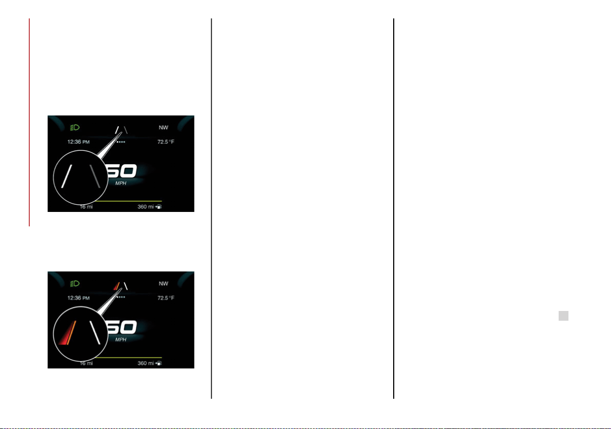
STARTING AND OPERATING
200
Exiting A Lane With Detection Of A Single Limit
When the system is active and only, for
example, the left lane limit has been detected,
the detected lane illuminates in white on the
display; the system is ready to provide visual
warnings on the display in the event of unin-
tentional exiting of the lane (turn signal not
activated) to the left.
Left Lane Limit Detected
When the system detects that the vehicle has
approached the lane line and is about to pass it,
the left line on the display illuminates in yellow.
Left Lane Limit Approached
The system operates in the same way, but
mirrored, in the event of exiting the right lane
when only the right lane limit has been
detected.
Exiting A Lane With Detection Of Both Limits
When the system is active, both lane lines on
the display illuminate in white to indicate the
successful detection of both limits.
When lane limits are detected, the system is
ready to provide indications in case the driver
unintentionally leaves the lane (turn signal not
activated).
As the Lane Departure Warning system
detects the lane limits while the vehicle is in
motion, it will adjust the display accordingly
(from white to yellow and vice versa, and
increase their thickness).
If a line is crossed, the driver is alerted by an
audible signal as well as the visual indication
in the instrument cluster. The signal is emitted
through the speakers on the side of the lane
limit which is being crossed (e.g. if the vehicle
is exceeding the left line of the lane, the
audible signal will come from the speakers on
the left of the vehicle).
Changing The System Settings
The system's sensitivity can be set through the
radio system. Sensitivity “High” or “Low” can
be selected.
To access the function, from the main menu
select the following in order:
1. “Settings”
2. “Comfort”
3. “Lane Departure Warning”
4. “Sensitivity”
Limited Operation Warning
If a message appears on the display, a condi-
tion limiting the Lane Departure Warning
system operation may have occurred. This
could be an obstruction of the camera view, or
a fault in the system.
If an obstruction is detected, clean the area of
the windshield by the interior rear view mirror.
Although the vehicle can still be driven in
normal conditions, the system may not func-
tion properly.
When the conditions limiting the system are
corrected, it will go back to normal operation.
Should a fault persist, contact an authorized
dealer.
System Failure Warning
If the system turns off and the warning light
appears on the display, it means that there is
a system fault.
In this case, it is still possible to drive the
vehicle, but you are advised to contact an
authorized dealer as soon as possible.
20_GA_OM_EN_USC_t.book Page 200
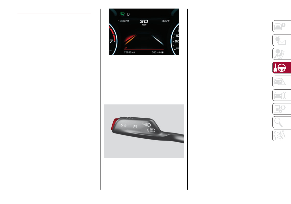
201
LANE KEEPING ASSIST (LKA)
SYSTEM —IF EQUIPPED
The Lane Keeping Assist (LKA) system uses a
camera located on the windshield to detect
the lane limits and calculate the position of the
vehicle within such limits, in order to make
sure that the vehicle remains inside the lane.
This is an active system that will apply torque
to the steering wheel if it senses that the
vehicle is drifting out of the lane.
When one or both lane limits are detected and
the vehicle passes over one without a turn
signal being applied, the system will apply
torque to the steering wheel and a visual
signal will be displayed in the instrument
cluster display. An audible signal may also
sound.
If the vehicle continues to go beyond the lane
line without any driver intervention, the
surpassed lane line (left or right) will light up
on the instrument cluster display to urge the
driver to bring the vehicle back inside the lane
limits.
Lane Crossed
Activation/Deactivation
The system is activated/deactivated by pressing
the button at the end of the multifunction lever.
Each time the engine is started, the system main-
tains the operating mode that was selected when
it was previously turned off.
Activation/Deactivation Button
Activation Conditions
Once the activation button is pushed, the
system becomes active only if the following
conditions are met:
The car speed is higher than 37 mph
(60 km/h). (The system is deactivated at
speeds equal to or higher than 110 mph
(180 km/h))
The lane limit lines are visible at least on
one side
There are suitable visibility conditions
The road is straight or with wide radius
bends
A suitable distance is kept from the vehicle
in front
The turn signal (to indicate leaving the lane)
is not active
Symbols And Messages On The Display
The Lane Keeping Assist system also advises
the driver when the car changes lanes by
showing symbols and messages on the instru-
ment cluster display.
The message at the top of the display remains
active only until the main reconfigurable area
of the display is activated by pressing the TRIP
button located on the end of the windshield
wiper lever. Refer to “Instrument Cluster
Display” in “Getting To Know Your Instrument
Panel” for further information.
20_GA_OM_EN_USC_t.book Page 201
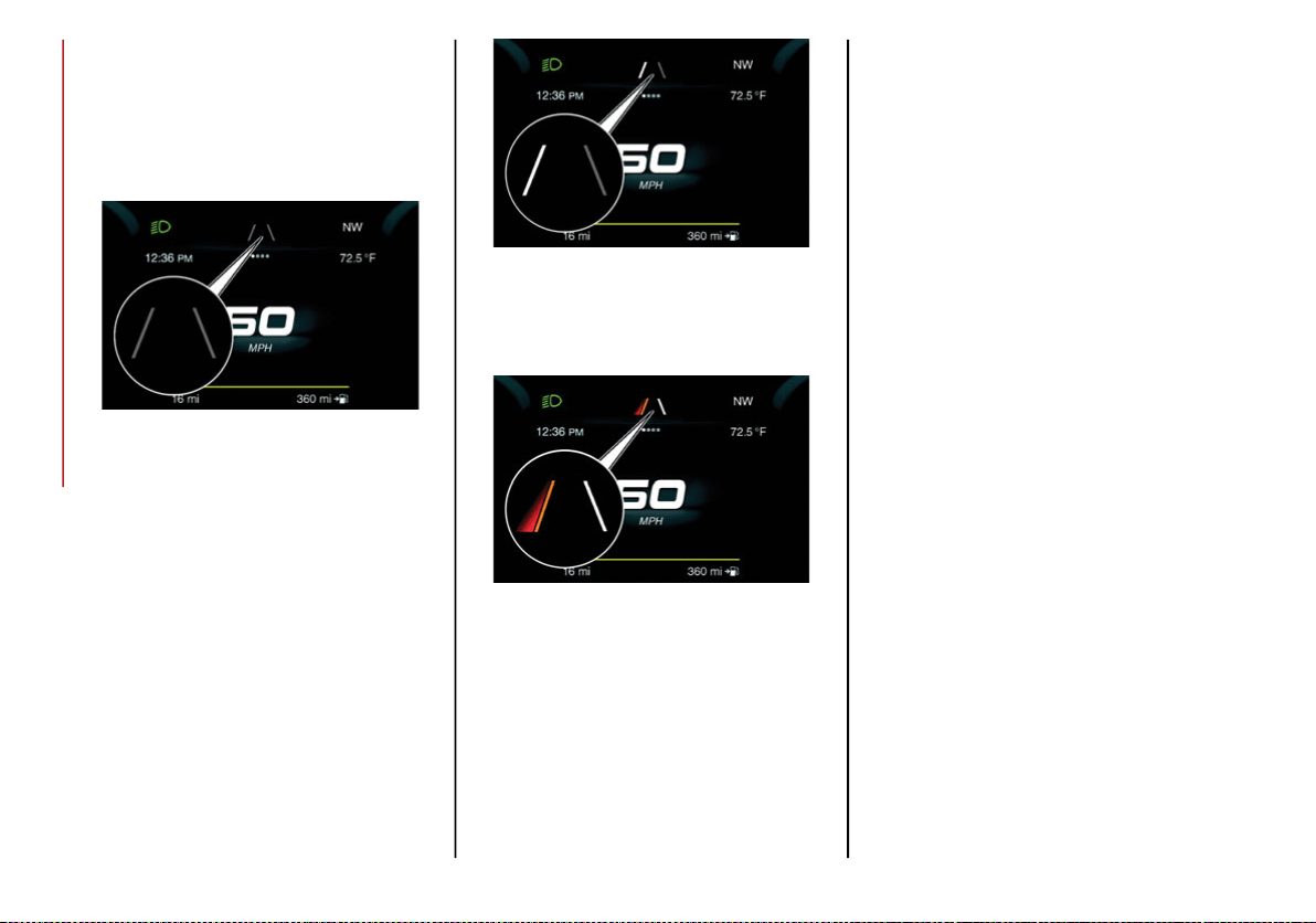
STARTING AND OPERATING
202
After activating the main reconfigurable area,
the Lane Keeping Assist system messages will
be shown in the instrument cluster display.
When the system is active and the lane limits
have not been detected, the display shows two
grey lane lines.
Lane Limits Not Detected
Exiting A Lane With Detection Of A Single Limit
When the system is active and only, for
example, the left lane limit has been detected,
the detected lane lights up in white on the
display; the system is ready to provide visual
warnings on the display in the event of unin-
tentional exiting of the lane (turn signal indi-
cator not activated) to the left.
Left Lane Limit Detected
When the system detects that the vehicle has
approached the lane line and is about to pass
it, the left line on the display lights up in yellow.
Left Lane Limit Approached
NOTE:
The system operates in the same way, but
mirrored, in the event of exiting the right lane
when only the right lane limit has been
detected.
Exiting A Lane With Detection Of Both Limits
When the system is active, both lane lines on
the display illuminate in white to indicate the
successful detection of both limits.
When lane limits are detected, the system is
ready to provide indications in case the driver
unintentionally leaves the lane (turn signal not
activated).
As the Lane Keeping Assist system detects the
lane limits while the vehicle is in motion, it will
adjust the display accordingly (from white to
yellow and yellow to white, and increase their
thickness).
If a line is crossed, the driver is alerted by an
audible signal as well as the visual indication
in the instrument cluster. The signal is emitted
through the speakers on the side of the lane
limit which is being crossed (e.g. if the vehicle
is exceeding the left line of the lane, the
audible signal will come from the speakers on
the left of the vehicle).
20_GA_OM_EN_USC_t.book Page 202
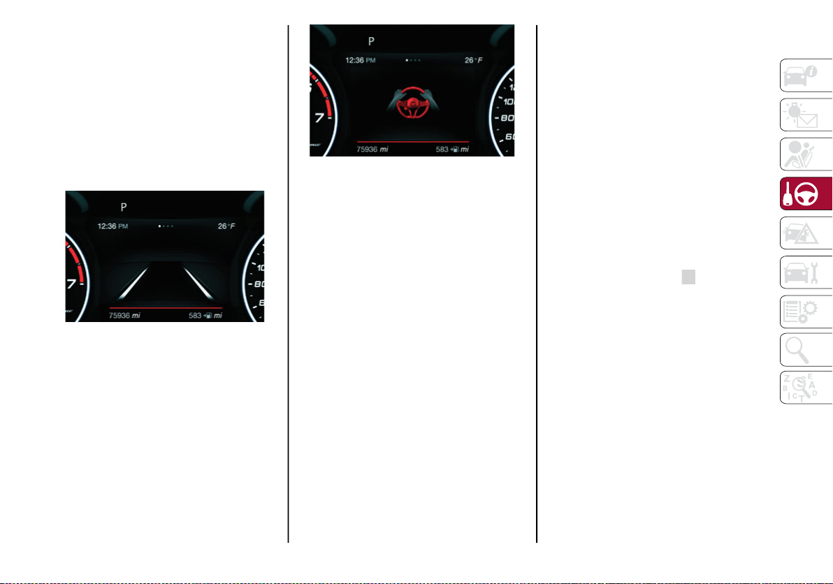
203
Hands Presence On The Steering Wheel
Detection
The system is able to detect the presence of
the driver’s hands on the steering wheel.
When the system does not detect the pres-
ence of hands on the steering wheel for a few
seconds (up to 6 seconds), the following
screen will be displayed on the instrument
cluster display. No acoustic warning will be
emitted in this case.
Hand Presence On The Steering Wheel Not
Detected Display (Up To 6 Seconds)
When the system does not detect the presence of
hands on the steering wheel for a few seconds
(from 6 to 15 seconds), the following screen will be
displayed on the instrument cluster display. A short
acoustic signal will sound if hands are not detected
on the steering wheel for 6 to 12 seconds. A contin-
uous signal will sound if hands are not detected on
the steering wheel for 12 to 15 seconds.
Hand Presence On The Steering Wheel Not
Detected Display (6 To 15 Seconds)
After 15 seconds with the hands removed
from the steering wheel, the LKA system will
be deactivated and a dedicated message will
be shown on the instrument cluster display. A
short acoustic signal will sound in this case.
In any of the situations above where the hands
are removed from the steering wheel for more
than 6 seconds, it is necessary to reposition
the hands on the steering wheel.
Changing The System Sensitivity
The system's sensitivity can be set through the
radio system in the “Driver Assistance” menu.
Sensitivity “Early” or “Late” can be selected.
Changing The System Strength
The system’s strength can be set through the
radio system in the “Driver Assistance” menu.
Strength “Low” or “High” can be selected.
Limited Operation Warning
If a message appears on the display, a condi-
tion limiting the LKA system operation may
have occurred. This could be an obstruction of
the camera view, or a fault in the system.
If an obstruction is detected, clean the area of
the windshield by the interior rear view mirror.
Although the vehicle can still be driven in
normal conditions, the system may not func-
tion properly.
When the conditions limiting the system are
corrected, it will go back to normal operation.
Should a fault persist, contact an authorized
dealer.
System Failure Signaling
If the system turns off and appears on the
display, it means that there is a system fault.
In this case, it is still possible to drive the
vehicle, but you are advised to contact an
authorized dealer as soon as possible.
20_GA_OM_EN_USC_t.book Page 203
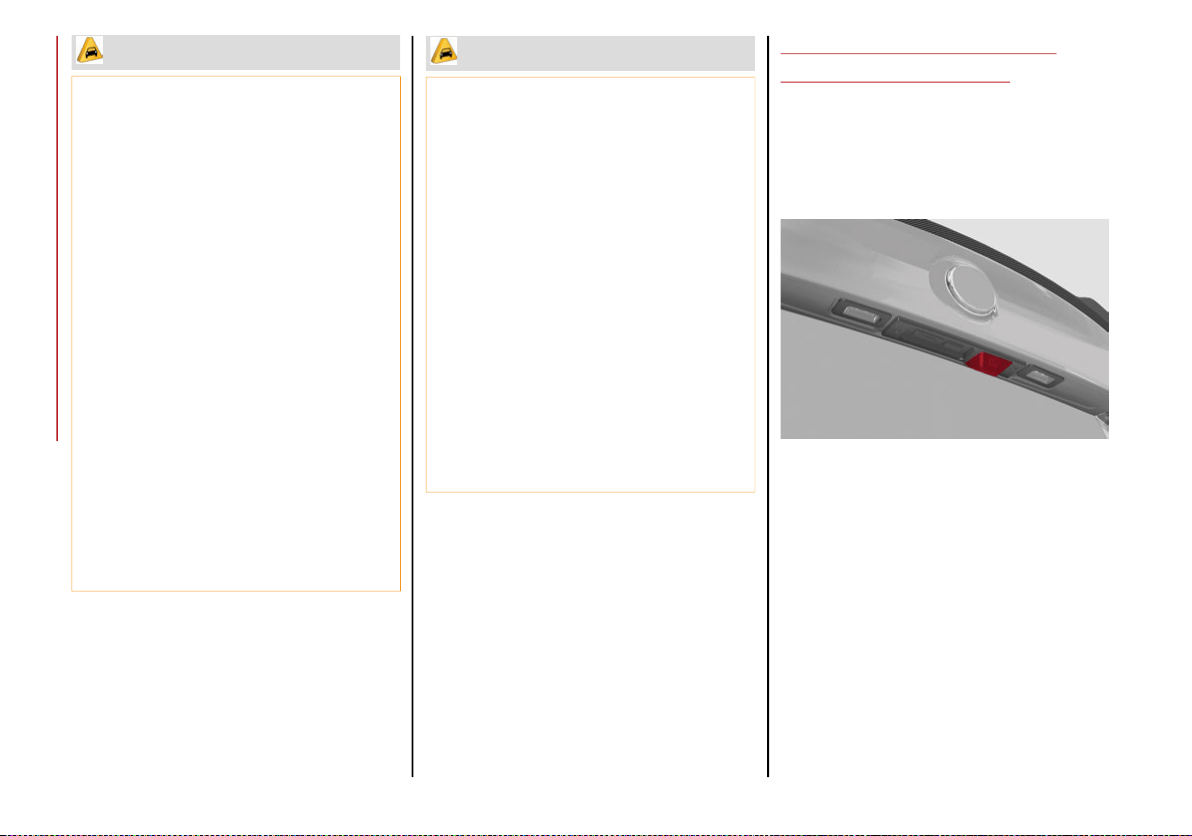
STARTING AND OPERATING
204
(Continued)
REAR BACK-UP CAMERA /
DYNAMIC GRIDLINES
Description
The Rear Back-Up Camera is located just
under the vehicle’s trunk lid, above the rear
license plate.
Rear Back-Up Camera Location
Camera Activation/Deactivation
The Rear Back-Up Camera can be activated
and deactivated through the radio system by
selecting the “Settings” option on the menu.
Once the Rear Back-Up Camera is activated,
choose from one of the following options:
“Activate”
“Switch-Off Delay”
“Camera Guidelines”
CAUTION!
Projecting loads on the roof of the vehicle
may interfere with the correct operation of
the camera. Before starting, make sure
the load is correctly positioned, in order
not to cover the camera operating range.
If the windshield must be replaced due to
scratches, chippings or breakage, contact
an authorized dealer. Do not replace the
windshield on your own; there is risk of
malfunction. It is advisable to replace the
windshield if it is damaged in the area of
the camera.
Do not tamper with or operate on the
camera. Do not close the openings in the
aesthetic cover located under the interior
rearview mirror. In the event of a failure of
the camera, contact an authorized dealer
immediately.
Do not cover the operating range of the
camera with stickers or other objects. Also
pay attention to other objects on the hood
(e.g. a layer of snow) and make sure they
do not interfere with the camera.
The camera may have limited or absent
operation due to weather conditions such
as: heavy rain, hail, thick fog, heavy snow,
formation of ice layers on the windshield.
Camera operation may also be compro-
mised by the presence of dust, condensa-
tion, dirt or ice on the windshield, traffic
conditions (e.g. vehicles that are driving
not aligned with yours, vehicle driving in a
transverse or opposite way on the same
lane, bend with a small radius of curva-
ture), or road surface conditions and
driving conditions (e.g. off-road driving).
Make sure the windshield is always clean.
Use specific detergents and clean cloths
to avoid scratching the windshield. The
camera operation may also be limited or
absent in some driving, traffic and road
surface conditions.
CAUTION! (Continued)
20_GA_OM_EN_USC_t.book Page 204
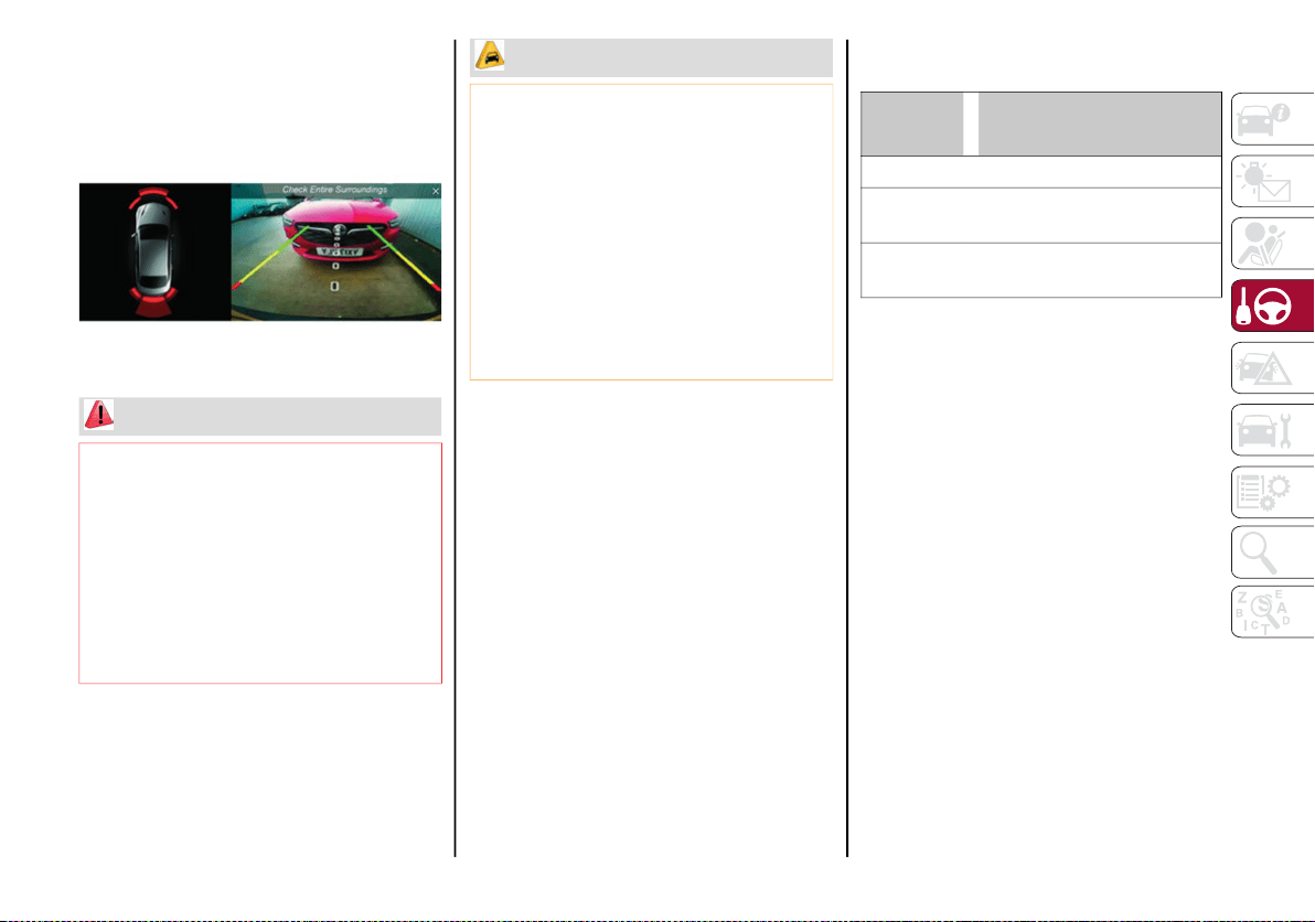
205
When the vehicle is in REVERSE, the radio
system display will show the area behind the
vehicle, as seen by the Rear Back-Up Camera,
along with a warning message.
Rear Back-Up Camera Display
Symbols And Messages On The Display
Indications On The Display
Through the radio system settings, by acti-
vating the "Camera Guidelines" feature, guide-
lines can be seen on the rear camera display.
If activated, the guidelines are positioned on
the image to highlight the width of the vehicle
and the expected reverse path based on the
steering wheel position.
A superimposed central line indicates the
center of the vehicle to assist in rear parking
maneuvers. The various colored areas indi-
cate the distance from the rear of the vehicle.
The table below shows the approximate
distances for each area:
Messages On The Display
If the trunk lid is lifted, the camera will not detect
any obstacle behind the vehicle. The display will
show a dedicated warning message.
Make sure the trunk lid is closed by pushing
next to the lock until it clicks.
Important Notes
Ice, snow or mud on the surface of the
camera may reduce its sensitivity. It is
important to keep the camera surface
clean, and free from debris.
When parking, be aware of obstacles that
may be above or under the camera range.
WARNING!
Drivers must be careful when backing up
even when using the Rear Back-Up Camera.
Always check carefully behind your vehicle,
and be sure to check for pedestrians,
animals, other vehicles, obstructions, or
blind spots before backing up. You are
responsible for the safety of your
surroundings and must continue to pay
attention while backing up. Failure to do so
can result in serious injury or death.
CAUTION!
To avoid vehicle damage, Rear Back-Up
Camera should only be used as a parking
aid. The Rear Back-Up Camera is unable
to view every obstacle or object in your
drive path.
To avoid vehicle damage, the vehicle must
be driven slowly when using the Rear
Back-Up Camera to be able to stop in time
when an obstacle is seen. It is recom-
mended that the driver look frequently
over his/her shoulder when using the
Rear Back-Up Camera.
Area
Distance From The Rear Of
The Vehicle
Red 0–11.8 inches (0–30 cm)
Yellow
11.8 inches to 3.3 feet
(30 cm–1 m)
Green
3.3 feet or more
(1 m or more)
20_GA_OM_EN_USC_t.book Page 205
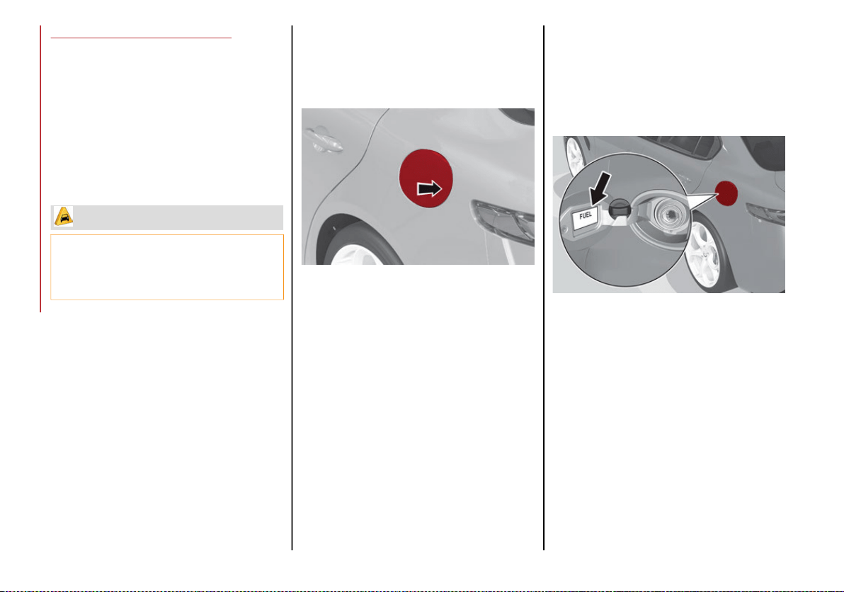
STARTING AND OPERATING
206
REFUELING THE VEHICLE
Refueling The Vehicle
Before refueling, make sure that the fuel type
is correct.
Also, stop the engine before refueling.
NOTE:
An inefficient catalytic converter leads to
harmful exhaust emissions, thus contributing
to air pollution.
Refueling Capacity
To ensure that you fill the tank completely, top
off twice after the first click of the fuel nozzle.
Further top-off could cause faults in the fuel
feeding system.
Refueling Procedure
The fuel filler door is unlocked when the
central door locking system is unlocked. It is
automatically locked when the central locking
system is applied.
Opening The Fuel Filler Door
To refuel proceed as follows:
1. Open fuel filler door by pressing on the
point shown by the arrow.
Fuel Door
2. Remove the fuel filler cap.
3. Insert the fuel nozzle fully into the filler
pipe.
4. When the fuel nozzle “clicks” or shuts off,
before removing the nozzle, wait for at
least 10 seconds in order for the fuel to
flow inside the tank.
5. Remove the fuel filler nozzle, tighten the
gas cap about ¼ turn until you hear one
click. This is an indication that cap is prop-
erly tightened.
The label indicates the fuel type (UNLEADED
FUEL = gasoline).
Fuel Door Label
CAUTION!
Never introduce leaded fuel to the tank,
even in small amounts in an emergency, as
this would damage the catalytic converter
beyond repair.
20_GA_OM_EN_USC_t.book Page 206
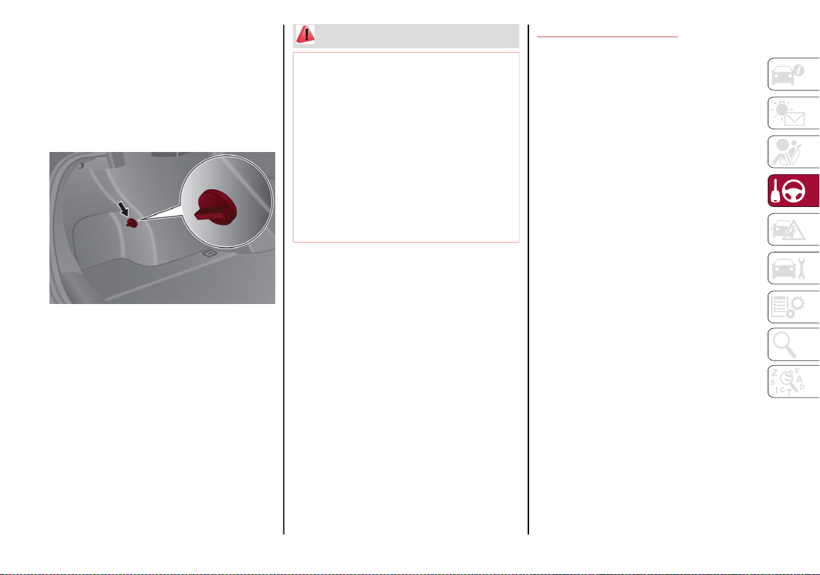
207
Emergency Fuel Door Opening
In the event of an emergency the fuel filler
door can be opened by operating from inside
the trunk.
Proceed as follows:
1. Open the trunk and locate the emergency
fuel filler release cap on the inside lining.
Fuel Door Release Cap
2. Open the cap, and pull the cord inside to
unlock the fuel filler door.
3. Open the fuel filler door by pressing on it
(see the previous instructions).
NOTE:
If the filler compartment is washed with a pres-
sure washer, keep it at a distance of at least
8 inches (20 cm).
VEHICLE LOADING
Certification Label
As required by National Highway Traffic Safety
Administration regulations, your vehicle has a
certification label affixed to the driver's side
door or pillar.
This label contains the month and year of
manufacture, Gross Vehicle Weight Rating
(GVWR), Gross Axle Weight Rating (GAWR)
front and rear, and Vehicle Identification
Number (VIN). A Month-Day-Hour (MDH)
number is included on this label and indicates
the Month, Day and Hour of manufacture. The
bar code that appears on the bottom of the
label is your VIN.
Gross Vehicle Weight Rating (GVWR)
The GVWR is the total permissible weight of
your vehicle including driver, passengers,
vehicle, options and cargo. The label also
specifies maximum capacities of front and
rear axle systems (GAWR). Total load must be
limited so GVWR and front and rear GAWR are
not exceeded.
WARNING!
Never have any smoking materials lit in or
near the vehicle when the fuel door is
open or the tank is being filled.
Never add fuel when the engine is
running. This is in violation of most state
and federal fire regulations and may
cause the MIL to turn on.
A fire may result if gasoline is pumped into
a portable container that is inside of a
vehicle. You could be burned. Always
place gas containers on the ground while
filling.
20_GA_OM_EN_USC_t.book Page 207

STARTING AND OPERATING
208
Payload
The payload of a vehicle is defined as the
allowable load weight a truck can carry,
including the weight of the driver, all passen-
gers, options and cargo.
Gross Axle Weight Rating (GAWR)
The GAWR is the maximum permissible load
on the front and rear axles. The load must be
distributed in the cargo area so that the GAWR
of each axle is not exceeded.
Each axle GAWR is determined by the compo-
nents in the system with the lowest load
carrying capacity (axle, springs, tires or
wheels). Heavier axles or suspension compo-
nents sometimes specified by purchasers for
increased durability do not necessarily
increase the vehicle's GVWR.
Tire Size
The tire size on the Vehicle Certification Label
represents the actual tire size on your vehicle.
Replacement tires must be equal to the load
capacity of this tire size.
Rim Size
This is the rim size that is appropriate for the
tire size listed.
Inflation Pressure
This is the cold tire inflation pressure for your
vehicle for all loading conditions up to full
GAWR.
Curb Weight
The curb weight of a vehicle is defined as the
total weight of the vehicle with all fluids,
including vehicle fuel, at full capacity condi-
tions, and with no occupants or cargo loaded
into the vehicle. The front and rear curb weight
values are determined by weighing your
vehicle on a commercial scale before any
occupants or cargo are added.
Loading
The actual total weight and the weight of the
front and rear of your vehicle at the ground can
best be determined by weighing it when it is
loaded and ready for operation.
The entire vehicle should first be weighed on a
commercial scale to ensure that the GVWR
has not been exceeded. The weight on the
front and rear of the vehicle should then be
determined separately to be sure that the load
is properly distributed over the front and rear
axle. Weighing the vehicle may show that the
GAWR of either the front or rear axles has
been exceeded but the total load is within the
specified GVWR. If so, weight must be shifted
from front to rear or rear to front as appro-
priate until the specified weight limitations are
met. Store the heavier items down low and be
sure that the weight is distributed equally.
Stow all loose items securely before driving.
Improper weight distributions can have an
adverse effect on the way your vehicle steers
and handles and the way the brakes operate.
TRAILER TOWING
Trailer towing is not recommended for this
vehicle.
SUGGESTIONS FOR DRIVING
Saving Fuel
Below are some suggestions which may help
you save fuel and lower the amount of harmful
emissions released into the atmosphere.
Vehicle Maintenance
Checks and operations should be carried out
in accordance with the Maintenance Plan.
Refer to “Scheduled Servicing” in “Servicing
And Maintenance” for further information.
Tires
Check the tire pressures at least once every
four weeks: if the pressure is too low,
consumption levels increase as resistance to
rolling is higher.
CAUTION!
Do not load your vehicle any heavier than
the GVWR or the maximum front and rear
GAWR. If you do, parts on your vehicle can
break, or it can change the way your vehicle
handles. This could cause you to lose
control. Also overloading can shorten the
life of your vehicle.
20_GA_OM_EN_USC_t.book Page 208
209
Unnecessary Loads
Do not travel with an overloaded trunk. The
weight of the vehicle and its arrangement
greatly affect fuel consumption and stability.
Electric Devices
Use electrical systems only for the amount of
time needed. The rear window defroster, addi-
tional headlights, windshield wipers and
heater blower fan require a considerable
amount of energy; increasing the current
uptake increases fuel consumption (by up to
+25% when city driving).
Climate Control System
Using the climate control system will increase
consumption: use standard ventilation when
the temperature outside permits.
Devices for Aerodynamic Control
The use of non-certified devices for aerody-
namic control may adversely affect air drag
and consumption levels.
Driving Style
Starting
Do not warm up the engine at low or high revs
when the vehicle is stationary; this causes the
engine to warm up more slowly, thereby
increasing fuel consumption and emissions. It
is therefore advisable to drive off immediately,
slowly, avoiding high speeds: by doing this the
engine will warm up more quickly.
Unnecessary Actions
Avoid revving up when starting at traffic lights
or before stopping the engine. This action is
unnecessary and causes increased fuel
consumption and pollution.
Gear Selection
Use a high gear when traffic and road conditions
allow it. Using a low gear for faster acceleration
will increase fuel consumption. Improper use of a
high gear increases consumption, emissions and
engine wear.
Max. Speed
Fuel consumption considerably increases as
speed increases. Maintain a constant speed,
avoiding unnecessary braking and accelera-
tion, which cost in terms of both fuel consump-
tion and emissions.
Acceleration
Accelerating violently severely affects consump-
tion and emissions: acceleration should be
gradual and should not exceed the maximum
torque.
Conditions Of Use
Cold Starting
Short trips and frequent cold starts will not
allow the engine to reach optimum operating
temperature. This results in a significant
increase in consumption levels (from +15 to
+30% in city driving) and emissions.
Traffic And Road Conditions
High fuel consumption is caused by heavy
traffic, for instance when traveling in traffic
with frequent use of low gears or in cities with
many traffic lights. Winding mountain roads
and rough road surfaces also adversely affect
consumption.
Stops In Traffic
During prolonged stops (e.g. railway crossings)
turn off the engine.
Transporting Passengers
WARNING!
It is extremely dangerous to leave children in
a parked vehicle when the temperature
outside is very high. The heat inside the
passenger compartment may have serious,
or even fatal, consequences.
Never travel in the trunk of the vehicle. In
the event of an accident, anyone inside
the trunk would be at greater risk of
serious or even fatal injury.
Ensure that all the occupants of the
vehicle wear their seat belts correctly and
that any children are positioned correctly
on the dedicated child restraint systems.
20_GA_OM_EN_USC_t.book Page 209

STARTING AND OPERATING
210
Transporting Animals
The intervention of the airbags may be
dangerous for an animal on the front seat. It is
therefore advised to arrange animals on the
rear seat inside dedicated cages restrained by
the vehicle’s seat belts.
Keep in mind that, in the event of a sudden
braking or an accident, an inadequately
restrained animal may be projected within the
passenger compartment, risking injury to the
animal itself and the other occupants of the
vehicle.
Exhaust Gas
Exhaust emissions are very dangerous, and
may be lethal. They contain carbon monoxide,
a colorless, odorless gas which can cause
fainting and poisoning if inhaled.
To avoid inhaling carbon monoxide, take the
following measures:
Do not keep the engine running in closed
spaces.
If, for some reason (e.g. transporting bulky
loads), it is necessary to drive with the trunk
open, close all the windows and run the
climate control fan at maximum speed. DO
NOT activate air recirculation mode.
Should it be necessary to stay in the
stationary vehicle with engine running,
adjust the ventilation/heating system and
operate the fan in such a way that outside
air will enter the passenger compartment.
Activate the maximum fan speed.
Maintenance of the exhaust system provides
the best protection against leaks of carbon
monoxide into the passenger compartment.
Should an unusual noise from the exhaust
system or the presence of exhaust gas in the
passenger compartment be identified, or if the
underbody or rear section of the vehicle is
damaged, have the entire exhaust system and
bodywork areas checked to identify any
components which are broken, damaged,
worn or have moved from their correct fitting
position. If any of these things occur, contact
an authorized dealer.
Open welding or loose connections may permit
exhaust gas to enter the passenger compart-
ment.
Check the exhaust system each time the
vehicle is raised for lubrication or oil change
operations. Replace the components if neces-
sary, contact an authorized dealer.
Performance — Quadrifoglio
This vehicle is equipped with an engine
capable of delivering exceptionally fast accel-
eration and speed:
Peak power: 505 HP at 6500 RPM.
Peak torque: 443 ft-lbs at 2500–5000 RPM.
Top speed: 191 mph (307 km/h).
Acceleration from 0 to 60 mph (0 to
100 km/h): 3.8 seconds.
For safe driving, it is essential, particularly
during the first days of use, to get to know the
car by driving carefully and gradually discov-
ering its performance.
Brakes
The car braking system may be available with
four carbon-ceramic material brake discs, one
on each wheel.
In order to guarantee the maximum braking
capacity for the first use, Alfa Romeo performs
a “run-in” procedure for discs and pads
directly at the factory.
The use of carbon-ceramic material brake discs
guarantees braking features (better decelera-
tion/pedal load ratio, braking distances, fading
resistance) proportional to the dynamic features
of the car in addition to considerably decreasing
the unsprung component weight.
20_GA_OM_EN_USC_t.book Page 210

211
The materials used and the structural features
of the system could generate unusual noises
which have absolutely no adverse effect on
correct operation and reliability of the braking
system.
Greater pressure may need to be applied to
the brake pedal the first time to keep the same
braking capacities in presence of condensa-
tion or salt on the braking surfaces, for
example after washing or if the car is not used
for a long time.
NOTE:
Given the high technological level of this
system, any servicing on it must be performed
by an authorized dealer which exclusively has
the skills needed for the repair and mainte-
nance operations.
In case of intensive, high-performance use of the
car, have the efficiency of the carbon-ceramic
material braking system inspected as shown on
the Maintenance Plan at an authorized dealer.
Driving On Race Tracks
Before driving on a track using a racing style, it
is necessary to:
Attend a race track driving course.
Check the liquid levels in the engine
compartment. For more information, see
the “Checking Levels” section in the
“Servicing And Maintenance” chapter.
Have the car inspected at an authorized
dealer.
Remember that the car was not designed to be
driven exclusively on the race track and that
this use increases stress and component
wear.
NOTE:
Quadrifoglio front brakes are equipped with
NAO type pads (Non-Asbestos Organic). These
pads are NOT suitable for high thermal loads
(for example track use). If you want to use
vehicle on a track it is recommended to use
the optional CCM Brakes (Carbon Ceramic
Brake disc).
Preheating The Carbon Ceramic Material
Brake Discs (If Equipped)
The brake discs must be warmed up to make
them fully efficient. You are advised to perform
the following procedure to achieve optimal
efficiency:
Brake nine times from 80 mph to 18 mph
(130 km/h to 30 km/h) with deceleration equal
to 0.7g (the longitudinal acceleration value is
shown on the instrument panel display by setting
RACE mode and selecting the “Performance”
page) with 20 second intervals between brake
applications; keep the car at a speed comprised
between 37 mph and 62 mph (60 km/h and
100 km/h) and do not brake for four minutes to
allow the brakes to cool down;
Then brake three times from 124 mph to
18 mph (200 km/h to 30 km/h) with decel-
eration equal to 1.1g (ABS operation) with
30 second intervals between brake applica-
tions; keep the car at a speed comprised
between 37 mph and 62 mph (60 km/h
and 100 km/h) and do not brake for five
minutes to allow the brakes to cool down.
20_GA_OM_EN_USC_t.book Page 211
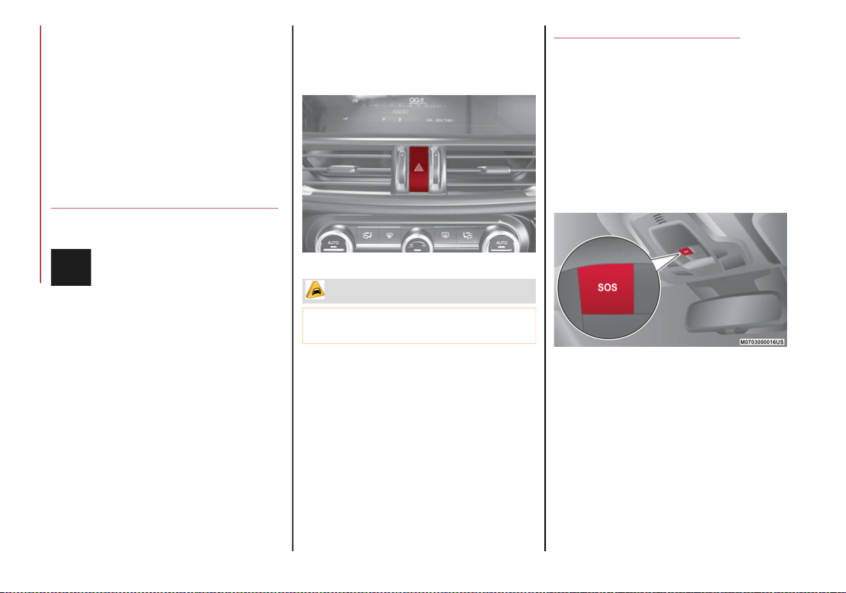
212
IN CASE OF EMERGENCY
Have a flat tire or a burnt-out bulb?
At times, a problem such as these may inter-
fere with your driving experience.
The section on emergencies can help you to
deal with critical situations independently.
In an emergency, we recommend that you call
the phone number found in the Warranty
Book.
You may also consider contacting an autho-
rized dealer.
HAZARD WARNING FLASHERS
The Hazard Warning Flashers switch is located
in the switch bank below the radio screen.
Push the switch once to turn the
Hazard Warning Flashers on. When
the switch is activated, all directional
turn signals will flash on and off to warn
oncoming traffic of an emergency. Push the
switch a second time to turn the Hazard
Warning Flashers off.
This is an emergency warning system and it
should not be used when the vehicle is in motion.
Use it when your vehicle is disabled and is
creating a safety hazard for other motorists.
When you must leave the vehicle to seek
assistance, the Hazard Warning Flashers will
continue to operate even though the ignition is
cycled to OFF.
Hazard Warning Flashers Switch
SOS - EMERGENCY CALL
Your vehicle has an on-board assistance
feature that is designed to provide support in
case of an accident and/or emergency. This
feature is automatically activated by air bag
intervention, or can be activated manually by
pushing the button located on the base of the
rear view mirror.
NOTE:
SOS - Emergency Call will only work with an
enabled network operator.
SOS - Emergency Call Button
The SOS - Emergency Call system automati-
cally forwards a call to emergency services in
the event of an accident with air bag interven-
tion providing that the ignition device is in RUN
position and the air bags are working.
CAUTION!
Prolonged use of the Hazard Warning
Flashers may discharge the vehicle’s battery.
20_GA_OM_EN_USC_t.book Page 212
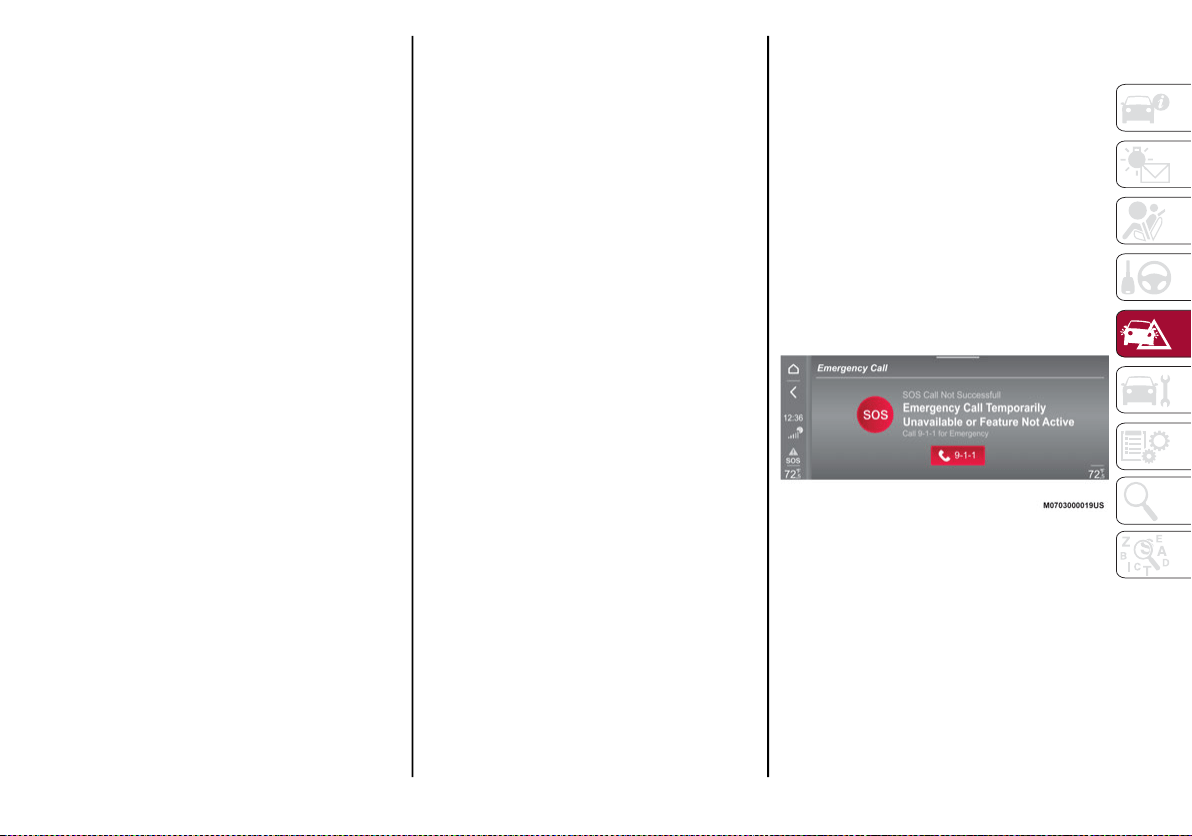
213
The manual Emergency Call is also possible
when the ignition device is OFF until its back-
light stays on by pushing the SOS button at the
base of the mirror. When the connection
between the vehicle and a public safety oper-
ator is made, your vehicle will automatically
transmit location and vehicle information to
the emergency service operator.
Only a public safety operator can remotely end
the SOS - Emergency Call and, if necessary,
call the vehicle back through the Emergency
Call system. Once the call has ended, you can
still call the emergency service operator to
indicate additional information by pushing the
button again.
To Use SOS - Emergency Call
Push and hold the SOS - Emergency Call
button for a few seconds. The LED, located
next to the SOS button, will blink once and
then stay on indicating a call has been placed.
NOTE:
If the SOS - Emergency Call button is acciden-
tally pushed, there is a 10 second delay before
the call is placed. The system will issue a
verbal alert that a call is about to be made. To
cancel the call connection, push the SOS -
Emergency Call button again.
Once a connection between the vehicle and an
emergency service operator is made, the SOS
- Emergency Call system will transmit the
following important vehicle information to the
operator:
Indication that the occupant placed an SOS
- Emergency Call.
The Vehicle Identification Number (VIN).
The last known GPS coordinates of the
vehicle.
You will then be able to speak with the emer-
gency service operator to determine if addi-
tional help is needed.
The SOS - Emergency Call has priority over
other audio sources, which will be muted. If
you have a phone connected via Bluetooth, it
is disconnected and reconnected at the end of
the SOS - Emergency Call. Voice prompts will
guide you during the SOS - Emergency Call. If a
connection is made between an emergency
service operator and your vehicle, emergency
service operators may record conversations
and sounds within your vehicle once a connec-
tion is made, and by using the service you
consent to having this information shared.
NOTE:
If you have not subscribed to the SOS service
or if the service is not available or has expired,
the Connect system will display a dedicated
screen when the button is pressed informing
you to contact the national emergency number
9-1-1 (the respective graphic button will be
displayed to make the call if you have
connected your mobile phone via Bluetooth®
The call to the national emergency number
9-1-1 will be made via the mobile phone by
pressing red graphic button shown on the
Connect system display.
SOS Screen Message
20_GA_OM_EN_USC_t.book Page 213

IN CASE OF EMERGENCY
214
(Continued)
SOS - Emergency Call System Limitations
When the ignition switches to the RUN posi-
tion, the Emergency Call system runs a routine
check. During this check, a red indicator will
illuminate for about three seconds. This signal
must not be confused with a fault warning. In
the event of a malfunction, the red indicator
would remain on. If the SOS - Emergency Call
system detects a malfunction, any of the
following may occur at the time the malfunc-
tion is detected:
NOTE:
The SOS Call function may not be available for
the first minute after the vehicle is started
The LED next to the SOS button will be
continuously illuminated red.
The Emergency Call system is powered by its
own non-rechargeable battery to ensure oper-
ation, even when the vehicle battery is
discharged or disconnected. When system
battery is discharged, the instrument cluster
display will show a special message, different
than other messages referring to other types
of faults. In this case, the system works only if
powered by the vehicle’s battery.
The instrument cluster will display a
message alerting you to contact the Service
Network along with a failure warning light.
Even if the SOS - Emergency Call system is fully
functional, external or uncontrolled factors
may prevent or stop SOS - Emergency Call
operation. These include, but are not limited
to, the following factors:
The key fob has been removed from the
vehicle, and the delayed accessories mode
is active.
The ignition is in OFF position.
The vehicle’s electrical systems are not
intact.
The SOS - Emergency Call system software
and/or hardware is damaged during a
vehicle collision.
There are network problems that could limit
or impair service operation (e.g., error by
operator, busy network, bad weather, etc.).
If the vehicle battery connection fails due to a
collision or accident, the system can support
an SOS - Emergency Call for a limited period of
time. If the battery is disconnected for service,
the system turns off. In this case, it will be
possible to make an SOS - Emergency Call only
when the battery is reconnected to the
vehicle’s electrical system.
System Requirements
Vehicle must have an operable 3G network
connection.
Vehicle must be powered with a properly
functioning electrical system.
The ignition must be in the RUN or ACC posi-
tion, or in OFF position until its backlight
stays on.
WARNING!
Never place anything on or near the vehicle’s
3G and GPS aerials. You could prevent 3G and
GPS signal reception, which can prevent your
vehicle from placing an emergency call. An
operable 3G network connection and a GPS
signal is required for the SOS-Emergency Call
system to function properly.
Do not add any aftermarket electrical equip-
ment to the vehicle’s electrical system. This
may prevent your vehicle from sending a signal
to initiate an emergency call. To avoid interfer-
ence that can cause the SOS-Emergency Call
system to fail, never add aftermarket equip-
ment (e.g., two-way mobile radio, CB radio,
data recorder, etc.) to your vehicle’s electrical
system or modify the antennas on your vehicle.
IF YOUR VEHICLE AND SYSTEM LOSES
BATTERY POWER FOR ANY REASON
(INCLUDING DURING OR AFTER AN ACCIDENT)
THE SOS FEATURES, APPS AND SERVICES
AMONG OTHERS WILL NOT OPERATE.
20_GA_OM_EN_USC_t.book Page 214
215
Frequently Asked Questions:
What happens if I accidentally push the SOS -
Emergency Call Button? You have 10 seconds
after pushing the emergency button to cancel
the call. To cancel the call, push the button
again.
What type of information is sent when I make
an SOS - Emergency Call from my vehicle?
Certain vehicle information, such as the VIN, is
transmitted along with last known GPS loca-
tion. Also note that emergency service opera-
tors may record conversations and sounds
within your vehicle once a connection is made,
and by using the service you consent to having
this information shared.
When can I use the SOS - Emergency
Call button? You can ONLY Use the
SOS - Emergency Call button to
make a call if you or someone else
needs emergency assistance.
BULB REPLACEMENT
General Instructions
Before replacing a bulb, check the contacts
for oxidation.
Replace blown bulbs with others of the
same type and power.
After replacing a headlight bulb, always
check its alignment.
When a light is not working, check that the
corresponding fuse is intact before changing
the bulb. For the location of fuses, refer to
“Fuses” in this chapter.
NOTE:
In some particular climate conditions, such as
low temperature, humidity, or after washing
the car, a thin condensation layer may form on
the internal surfaces of the front and rear
headlights. This condensation will disappear
after switching on the headlights.
The Occupant Restraint Controller (ORC)
turns on the air bag warning light in the
instrument cluster if a malfunction in any
part of the air bag system is detected. If
the air bag warning light is illuminated, the
air bag system may not be working prop-
erly and the SOS-Emergency Call system
may not be able to send a signal to an
emergency service operator. If the air bag
warning light is illuminated, contact the
Service Network to have the air bag
system checked immediately.
Ignoring the LED on the SOS-Emergency
Call button could mean you will not have
emergency call services if needed. If the
LED on SOS-Emergency Call button is illu-
minated red, contact the Service Network
to have the emergency call system
checked immediately.
If anyone in the vehicle could be in danger
(e.g., fire or smoke is visible, dangerous road
conditions or location), do not wait for voice
contact from an emergency service oper-
ator. All occupants should exit the vehicle
immediately and move to a safe location.
Failure to perform scheduled maintenance
and regularly inspect your vehicle may result
in vehicle damage, accident or injury.
WARNING! (Continued)
20_GA_OM_EN_USC_t.book Page 215
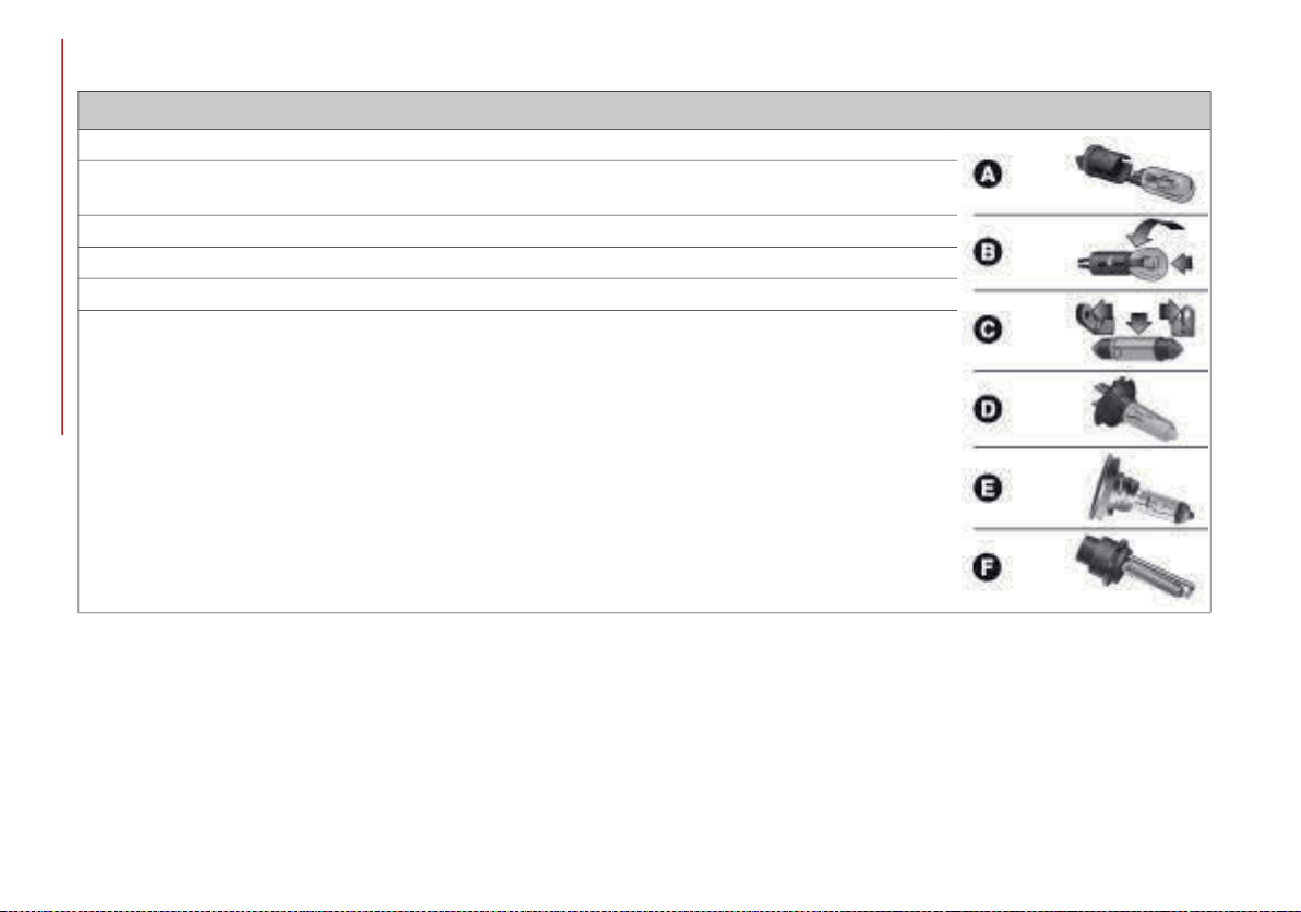
IN CASE OF EMERGENCY
216
Types Of Bulbs
The vehicle may be equipped with the following bulbs
Glass Bulbs (Type A): They are press-fitted. Pull to extract.
Bayonet-Type Bulbs (Type B): To remove them from their holder, press the bulb and turn it counterclockwise,
then extract it.
Tubular Bulbs (Type C): Release them from their contacts to remove.
Halogen Bulbs (Type D): To remove the bulb, turn the connector to the side and pull it out.
Halogen Bulbs (Type E): To remove the bulb, turn it counterclockwise.
Xenon Gas Discharge Bulb (Type F): to remove the bulb, contact an authorized dealer.
20_GA_OM_EN_USC_t.book Page 216
217
Replacement Bulbs
Light bulbs Type Power
Front direction indicators PY24W 24 W
Rear Fog lights H11 55 W
Main beam headlights (Xenon gas discharge) D5S 25 W
Main beam headlights (Xenon gas discharge) D3S 35 W
Sun visor light 1.5CP 2.1 W
Glove compartment light W5W 4 W
Trunk lid light W5W 5 W
Puddle lights (under door panel) W5W 5 W
20_GA_OM_EN_USC_t.book Page 217
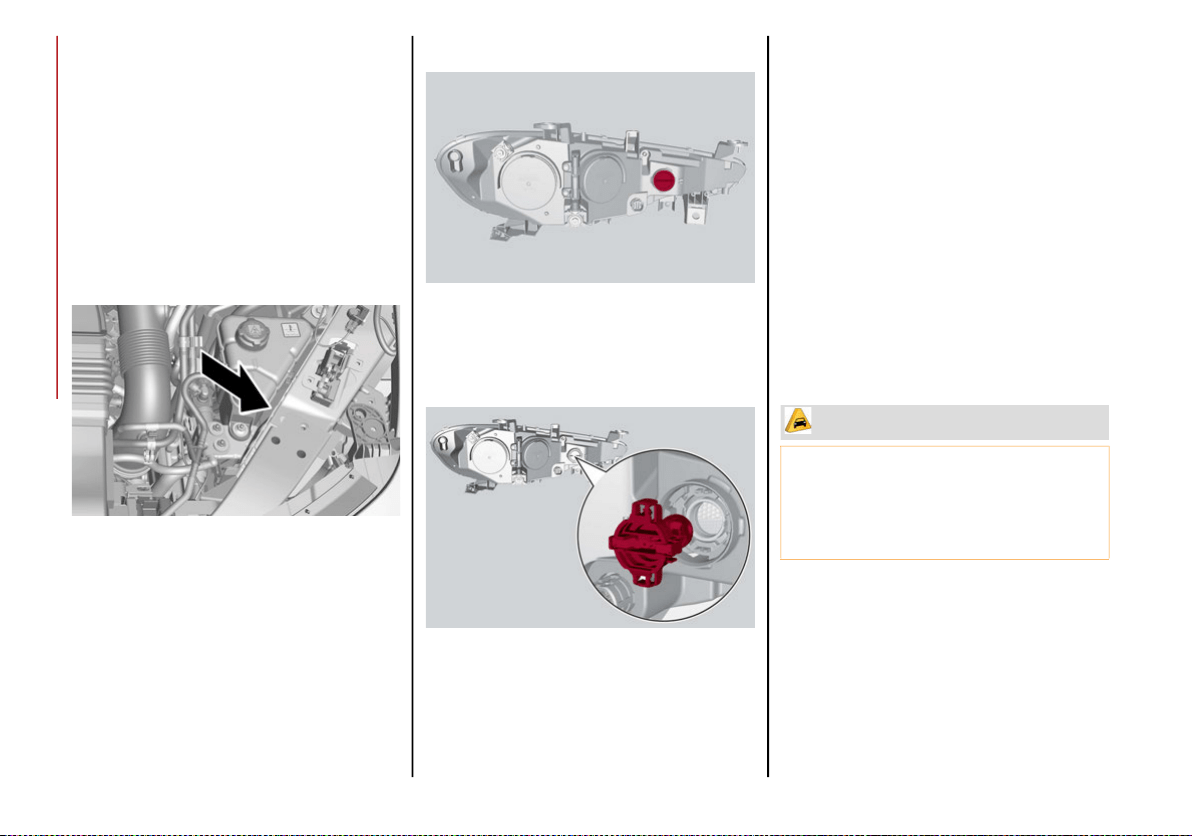
IN CASE OF EMERGENCY
218
Replacing Exterior Bulbs
NOTE:
Only replace the bulb when the engine is off.
Also ensure that the engine is cold, to prevent
the risk of burns.
Direction Indicators
To change the bulb of these lights, proceed as
follows:
1. Operating inside the engine compartment,
remove the protective cover.
Protective Cover Location
2. Remove protective cover.
Protective Cover
3. Turn the bulb/connector assembly coun-
terclockwise, and then slide it off the head-
light body.
Bulb/Connector
4. Remove the bulb by sliding it off the bulb
holder.
5. Install the new bulb, making sure it is
correctly inserted in the bulb holder.
6. Insert the bulb/connector assembly in the
housing on the headlight body and turn it
clockwise, making sure that it is locked
correctly.
7. Install the protective cover.
Front Light Cluster with Main Beam Xenon Gas
Discharge Headlights
To replace the bulbs of the main beam head-
lights, contact an authorized dealer.
CAUTION!
Do not touch the new bulb with your fingers.
Oil contamination will severely shorten bulb
life. If the bulb comes in contact with any
oily surface, clean the bulb with rubbing
alcohol.
20_GA_OM_EN_USC_t.book Page 218
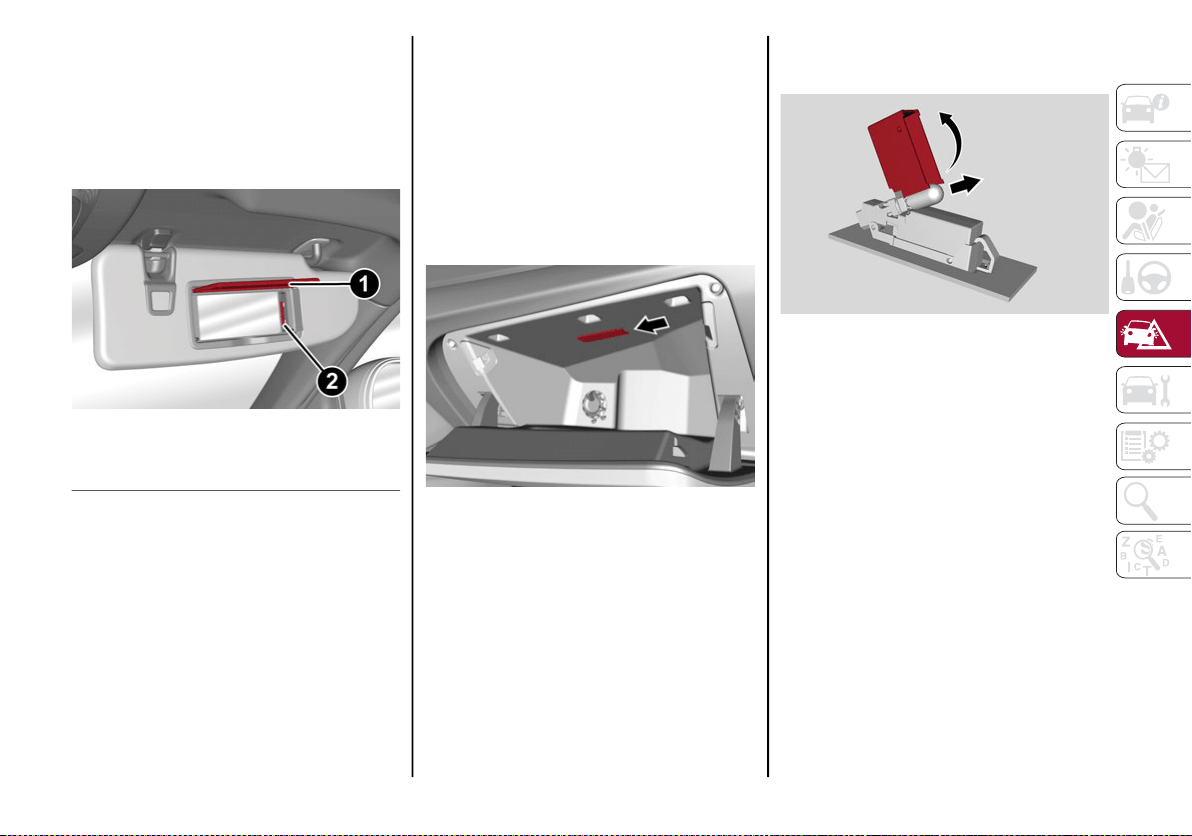
219
Replacing Interior Bulbs
Courtesy Mirror Light
To replace the bulbs, proceed as follows:
1. Lift the mirror cover and remove the lens,
using a suitable tool.
Sun Visor
2. Change the bulb, releasing it from the side
contacts, then insert the new bulb, making
sure that it is correctly fastened between
the contacts.
3. Install the lens, inserting it firstly on one
side and then pressing on the other side
until it clicks into place.
Glove Compartment Light
To replace the bulb, proceed as follows:
1. Open the glove compartment.
2. Remove the courtesy light assembly, using
a suitable tool.
Courtesy Lamp Indent
3. Open protective cover up and remove the
bulb pulling out of the connector.
Cover And Bulb Removal Direction
4. Install bulb, making sure that it is correctly
inserted fully.
5. Close the protective cover on the lens.
6. Install courtesy light, inserting it first on
one side and then pressing on the other
side until it clicks into place.
1 — Mirror Cover
2 — Lens
20_GA_OM_EN_USC_t.book Page 219
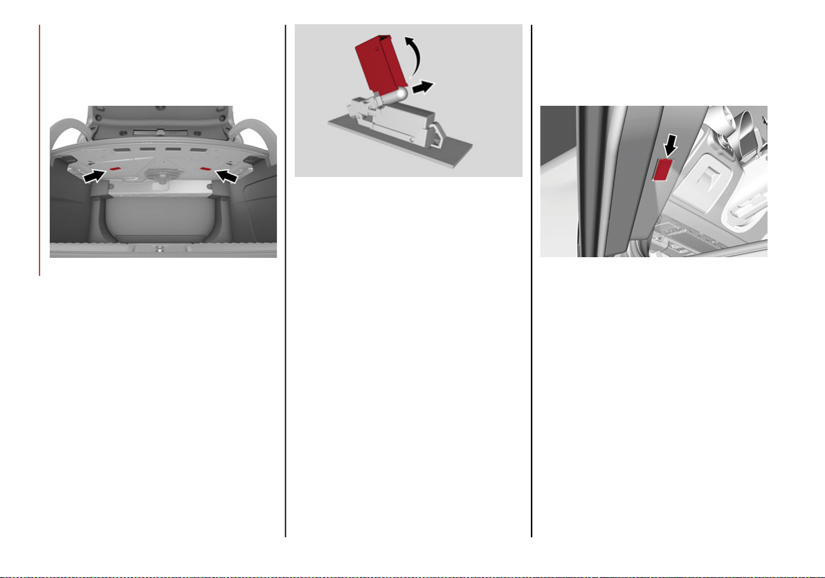
IN CASE OF EMERGENCY
220
Luggage Compartment Courtesy Lights
To replace the bulbs, proceed as follows:
1. Open the trunk, and remove the trunk
lamp assembly using a suitable tool.
Ceiling Light Indent
2. Open protective cover up and remove the
bulb pulling out of the connector.
Cover And Bulb Removal Direction
3. Install bulb, making sure that it is correctly
inserted fully.
4. Close the protective cover on the lens.
5. Install trunk lamp in the correct position,
inserting it firstly on one side, and then
pressing on the other side until it clicks
into place.
Puddle Lights On Door Panel
To replace the bulb, proceed as follows:
1. Open the door and remove the puddle light
assembly, using a suitable tool.
Puddle Light Indent
20_GA_OM_EN_USC_t.book Page 220
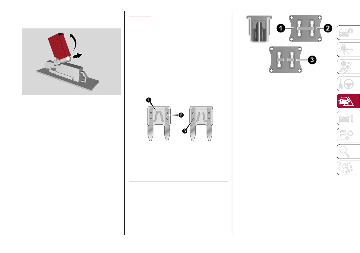
221
2. Open protective cover up and remove the
bulb pulling out of the connector.
Cover And Bulb Removal Direction
3. Install bulb, making sure that it is correctly
inserted fully.
4. Close the protective cover on the lens.
5. Install puddle light in the correct position,
inserting it firstly on one side and then
pressing on the other side until it clicks
into place.
FUSES
General Information
The fuses protect electrical systems against
excessive current.
When a device does not work, you must check
the electrical circuit inside of the fuse for a
break/melt.
Also, please be aware that using power outlets
for extended periods of time with the engine
off may result in vehicle battery discharge.
Blade Fuses
J-CASE Fuse
1 — Electrical Circuit
2 — Blade Fuse With Good Electrical Circuit
3 — Blade Fuse With Bad Electrical Circuit
1 — Electrical Circuit
2 — Case Fuse With Good Electrical Circuit
3 — Case Fuse With Bad Electrical Circuit
20_GA_OM_EN_USC_t.book Page 221
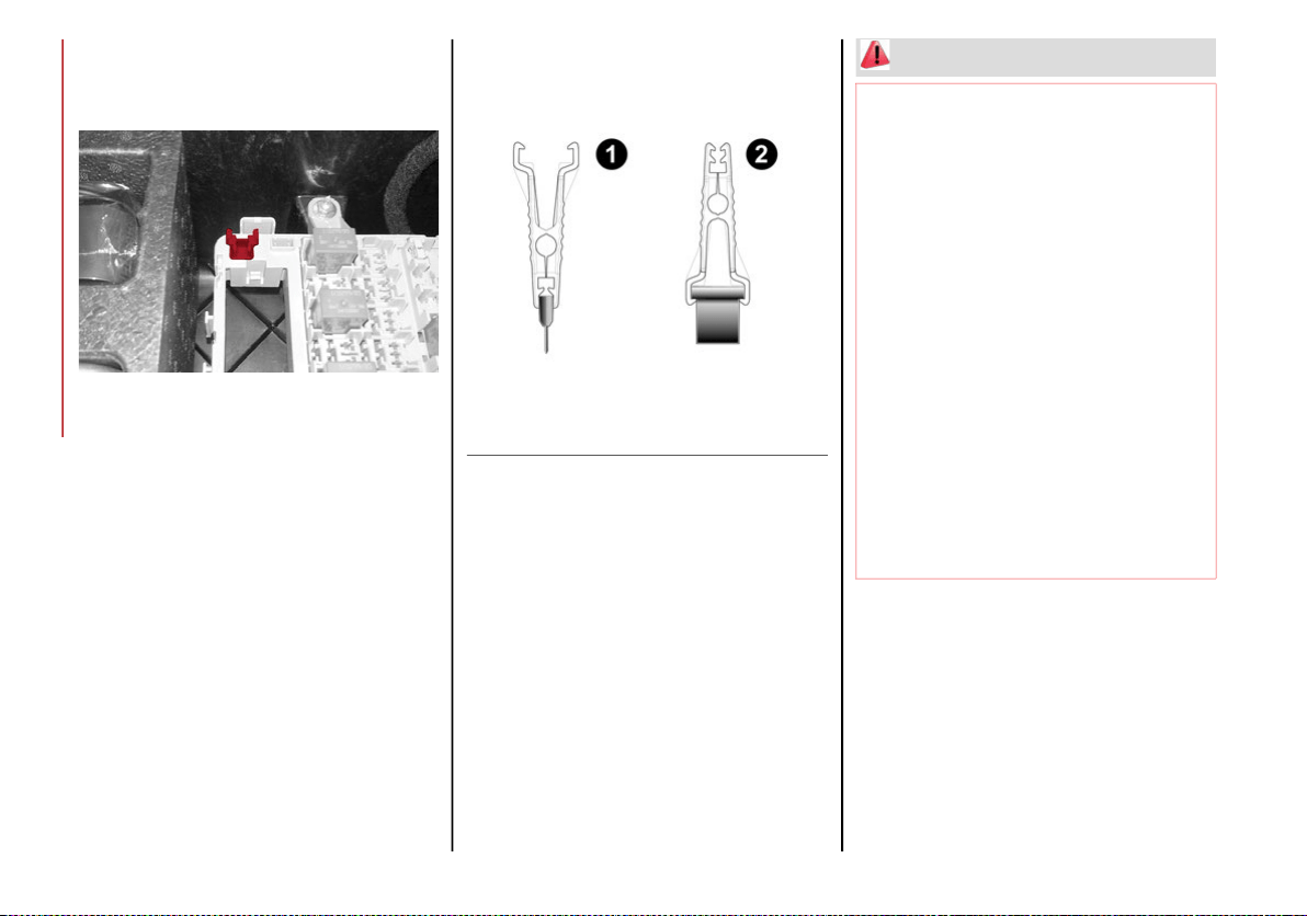
IN CASE OF EMERGENCY
222
Fuse Extracting Pliers
To replace a fuse, use the pliers hooked to the
fuse box.
Fuse Box
Grab the pliers from the upper tabs, press
them, and extract the pliers pulling upwards.
The pliers have two different ends, both of
which are specifically designed to remove the
different types of fuses present in the vehicle:
Fuse Extracting Pliers
After use, return the pliers to their proper posi-
tion by following the below procedures:
Grasp the pliers from the upper tabs and
insert them into their housing.
Push downward on the pliers into their
housing until they click into place.
1 — MINI fuse
2 — J-CASE fuse
WARNING!
When replacing a blown fuse, always use an
appropriate replacement fuse with the same
amp rating as the original fuse. Never
replace a fuse with another fuse of higher
amp rating. Never replace a blown fuse with
metal wires or any other material. Do not
place a fuse inside a circuit breaker cavity or
vice versa. Failure to use proper fuses may
result in serious personal injury, fire and/or
property damage.
Before replacing a fuse, make sure that the
ignition is off and that all the other services
are switched off and/or disengaged.
If the replaced fuse blows again, contact
an authorized dealer.
If a general protection fuse for safety
systems (air bag system, braking system),
power unit systems (engine system, trans-
mission system) or steering system blows,
contact an authorized dealer.
20_GA_OM_EN_USC_t.book Page 222
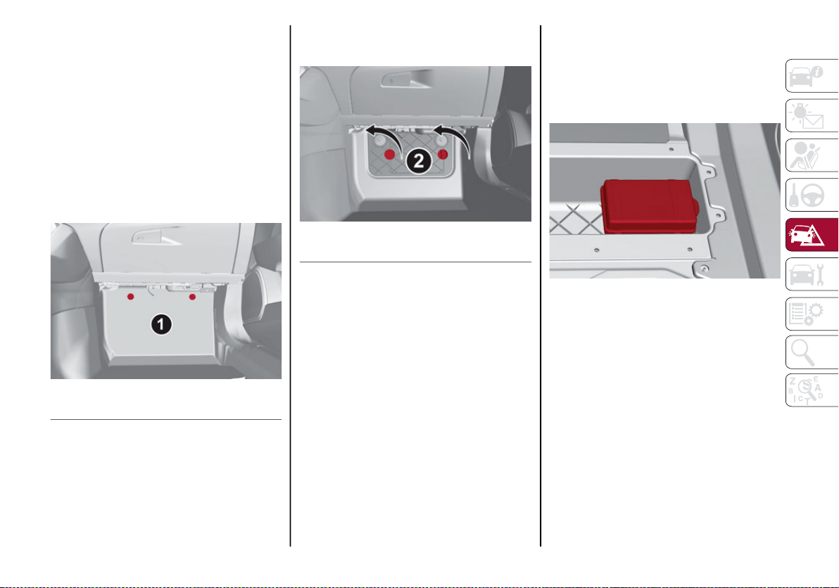
223
Fuse Location
The fuses, which can be replaced by the user,
are grouped in two boxes below the passenger
side foot board and inside the trunk.
Control Unit Under Passenger Side
Footboard
To access the fuses, proceed as follows:
1. Lift the upper end of the footboard on the
passenger side, pulling to release the two
buttons.
Release Buttons On Footboard
2. Unscrewing the two hooks, remove the
panel pulling downward.
Release Hooks On Footboard
The fuses are freely accessible on the control
unit.
After replacing the fuse, make sure that panel
and footboard are correctly locked.
Luggage Compartment Fuse Box
To access the fuses, proceed as follows:
1. Lift the luggage compartment cover.
2. Remove the control unit cover.
Control Unit
The fuses are freely accessible on the control
unit.
The number identifying the electrical compo-
nent corresponding to each fuse is shown on
the cover.
After replacing a fuse, make sure that you
have closed cover correctly.
1 — Footboard
2 — Panel
20_GA_OM_EN_USC_t.book Page 223
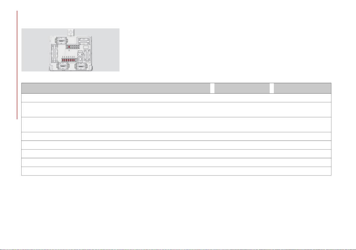
IN CASE OF EMERGENCY
224
Control Unit Under Passenger Side
Footboard
Passenger Side Control Unit
FUNCTION FUSE AMPERAGE
Front power window (driver side) F33 25
Front power window (passenger side)
F34
25
Supply for Information and Entertainment system, Climate Control system, Alarm,
Power door mirror folding, EOBD system, USB port
F36 15
Safe Lock device (driver side door unlock – if equipped), Doors unlock, Central lock F38 20
Windshield washer pump F43 20
Rear left power window F47 25
Rear right power window F48 25
Heater rear window coil F94 15
20_GA_OM_EN_USC_t.book Page 224
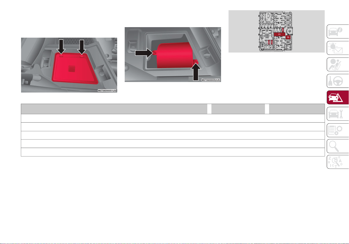
225
Under hood Power Distribution Center (PDC)
To access the fuses, remove the access door that is
located under the hood on the left side rear.
Under Hood Access Cover
To remove fuse cover, remove the screws with
a suitable tool.
Under hood Fuse Panel Cover
Under hood Control Unit
FUNCTION FUSE AMPERAGE
Tow Hook Module (TTM) F1 40
Hi-Fi system F8 30
KL15/a USB Recharge (C070) F17 7.5
I-Drive / USB / AUX port F21 10
KL15/a 12 Volts Power outlet (R053) F22 20
20_GA_OM_EN_USC_t.book Page 225

IN CASE OF EMERGENCY
226
TIRE SERVICE KIT
Description
If a tire is punctured, you can make an emer-
gency repair using the Tire Service Kit located
in the trunk beneath the load floor.
Tire Service Kit Location
The Tire Service Kit includes:
Sealant cartridge containing the sealing
fluid.
Filler tube.
Adhesive label with the writing "Max.
50 mph (80 km/h)”, to be attached in a
position easily visible to the driver (e.g on
the dashboard) after repairing the tire.
Air compressor, complete with pressure
gauge and connectors.
An instruction pamphlet for reference in
prompt and correct use of the Tire Service Kit,
which must be then given to the personnel
dealing with the sealant-treated tire.
A pair of protective gloves.
Adapters for inflating different elements.
Tire Service Kit Components
NOTE:
The sealant is effective with external tempera-
tures of between -40°F (-40°C) and 122°F
(50°C). The sealant has an expiration date.
To use the Tire Service Kit, proceed as follows:
1. Stop the vehicle in a position where you
can repair the tire safely. You should be as
far as possible from the side of the road,
and in a position that is not dangerous for
oncoming traffic. Activate the hazard
warning flashers, remove the safety
triangle from the trunk, and place it at a
suitable distance from the vehicle to make
other drivers aware of your presence.
2. Verify that the valve stem (on the wheel
with the deflated tire) is in a position that
is near to the ground. This will allow the tire
service kit hoses to reach the valve stem
and keep the tire repair kit flat on the
ground.
3. Place the gear selector to PARK (P).
4. Apply the electric park brake and cycle the
engine OFF.
1 — Sealant Cartridge
2 — Filler Tube
3 — Adhesive Label
4 — Air Compressor
20_GA_OM_EN_USC_t.book Page 226
227
(Continued)
Inflation Procedure
To use your Tire Service Kit, proceed as
follows:
1. Apply the electric park brake.
2. Insert the sealant cartridge containing the
sealing fluid in the proper compressor
holder, pushing down hard. Unscrew the
tire valve cap, take out the filler tube and
tighten the fitting on the tire valve.
Attaching Filler Tube To Deflated Tire
WARNING!
Do not attempt to seal a tire on the side of
the vehicle closest to traffic. Pull far
enough off the road to avoid the danger of
being hit when using the Tire Service Kit.
Do not use Tire Service Kit or drive the
vehicle under the following circumstances:
• If the puncture in the tire tread is approx-
imately 1/4 inch (6 mm) or larger.
• If the tire has any sidewall damage.
• If the tire has any damage from driving
with extremely low tire pressure.
• If the tire has any damage from driving
on a flat tire.
• If the wheel has any damage.
• If you are unsure of the condition of
the tire or the wheel.
Keep Tire Service Kit away from open
flames or heat sources.
A loose Tire Service Kit thrown forward in
a collision or hard stop could endanger
the occupants of the vehicle. Always stow
the Tire Service Kit in the place provided.
Failure to follow these warnings can result
in injuries that are serious or fatal to you,
your passengers, and others around you.
Take care not to allow the contents of Tire
Service Kit to come in contact with hair,
eyes, or clothing. Tire Service Kit sealant is
harmful if inhaled, swallowed, or absorbed
through the skin. It causes skin, eye, and
respiratory irritation. Flush immediately with
plenty of water if there is any contact with
eyes or skin. Change clothing as soon as
possible, if there is any contact with clothing.
Tire Service Kit Sealant solution contains
latex. In case of an allergic reaction or
rash, consult a physician immediately.
Keep Tire Service Kit out of reach of chil-
dren. If swallowed, rinse mouth immedi-
ately with plenty of water and drink plenty
of water. Do not induce vomiting! Consult
a physician immediately.
WARNING! (Continued)
1 — Sealant Cartridge
2 — Filler Tube
20_GA_OM_EN_USC_t.book Page 227
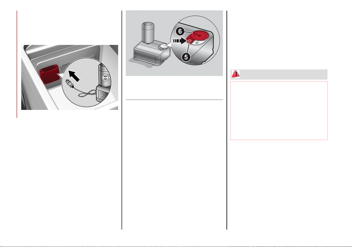
IN CASE OF EMERGENCY
228
3. Make sure the power switch of the
compressor is in the O (off) position.
4. Insert the plug into the power outlet in the
center console, then start the engine.
Center Console Power Outlet
5. Start the compressor by placing the power
switch in the I (on) position.
6. Inflate the tire to the pressure indicated on
the tire placard, located on the driver’s
side B-Pillar or the rear edge of the driver’s
side door. Refer to “Tires” in “Servicing
And Maintenance” for more information.
In order to obtain a more precise reading,
check the pressure value on pressure
gauge with the compressor off.
Air Compressor
7. If the pressure is not at least 26.1 psi (1.8 bar)
after 15 minutes, disengage the compressor
from the valve and power outlet. Then, move
the vehicle forwards approximately five tire
turns in order to distribute the sealant inside
the tire evenly, and then repeat the inflation
operation.
8. If you still cannot obtain a pressure of at
least 26 psi (1.8 bar) within 15 minutes of
turning the compressor on, do not drive
the vehicle, and contact an authorized
dealer.
9. Drive the vehicle for about 5 miles (8 km),
stop, apply the electric park brake, and
recheck the tire pressure.
10. If the pressure is less than 26 psi (1.8 bar),
DO NOT drive the vehicle, and see an
authorized dealer.
11. If a pressure value of at least 26 psi (1.8 bar)
is detected, restore the correct pressure
(with engine running and electric park brake
applied), and drive immediately with great
care to an authorized dealer.
12. Apply the adhesive label from the sealant
bottle where it can be easily seen by the
driver as a reminder that the tire has been
treated with a Tire Service Kit, as well as
not to exceed the speed restriction for the
treated tire.
5 — Power Switch
6 — Pressure Gauge
WARNING!
Tire Service Kit is not a permanent flat tire
repair. Have the tire inspected and repaired or
replaced after using Tire Service Kit. Do not
exceed 50 mph (80 km/h) until the tire is
repaired or replaced. Failure to follow this
warning can result in injuries that are serious
or fatal to you, your passengers, and others
around you. Have the tire checked as soon as
possible at an authorized dealer.
20_GA_OM_EN_USC_t.book Page 228
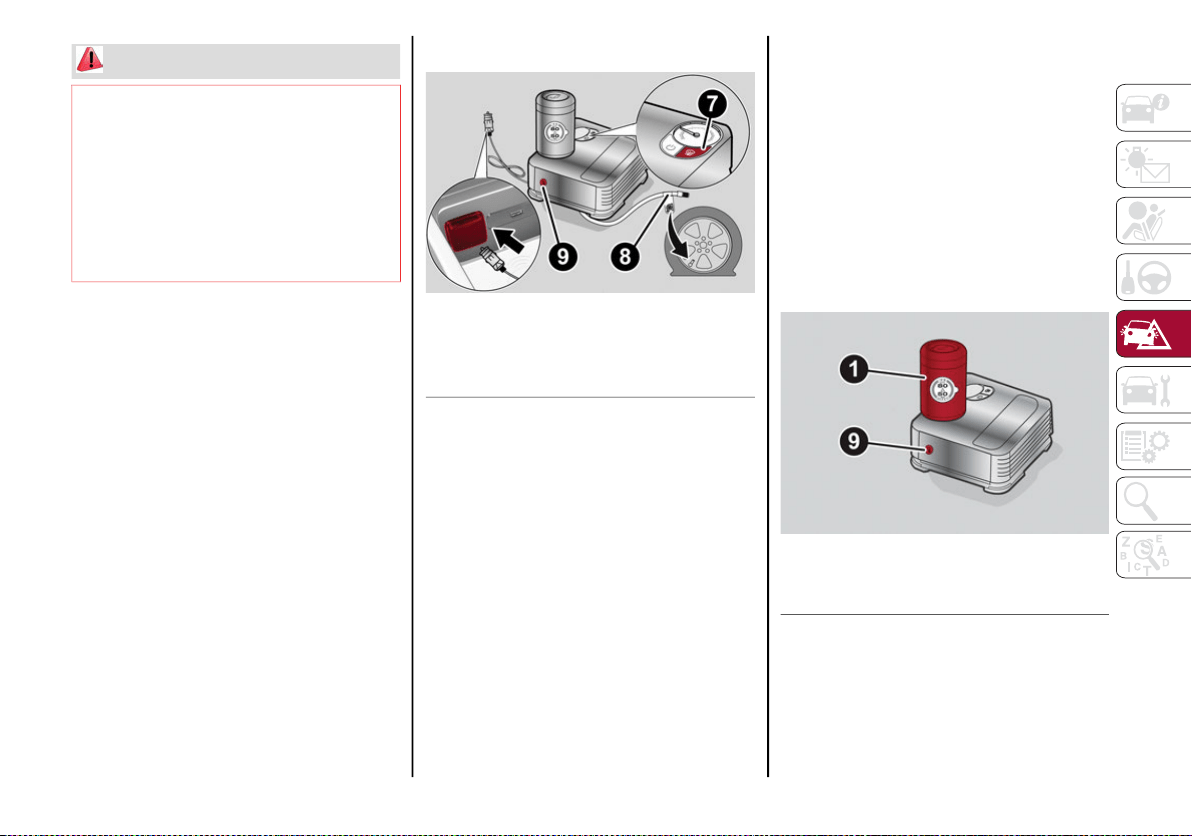
229
Checking And Restoring Tire Pressure
The compressor can also be used to check
and, if necessary, restore the tire pressure.
Proceed as follows:
1. Release the quick connector and connect
it directly to the valve of the tire to be
inflated.
2. Push the air release button.
Air Compressor Components
Sealant Cartridge Replacement
NOTE:
Only use original cartridges, which can be
purchased at an authorized dealer.
Proceed as follows:
1. Remove the sealant cartridge by pushing
the release button located on the side of
the compressor.
2. Insert the new sealant cartridge by
pushing downward firmly.
Sealant Cartridge Replacement
WARNING!
Do not adhere the speed restriction sticker
to the padded area on the steering wheel.
Adhering the speed restriction sticker to the
padded area on the steering wheel is
dangerous because the air bag may not
operate (deploy) normally resulting in
serious injury. In addition, do not adhere
the sticker to areas where warning lights or
the speedometer cannot be viewed.
7— Air Release Button
8— Quick Connector
9— Release Button
1 — Sealant Cartridge
9 — Release Button
20_GA_OM_EN_USC_t.book Page 229
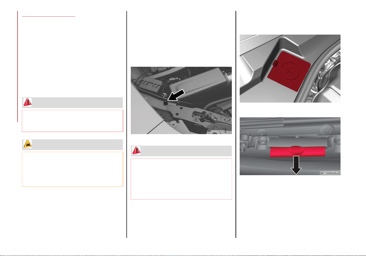
IN CASE OF EMERGENCY
230
JUMP STARTING
If your vehicle has a discharged battery, it can
be jump started using a set of jumper cables
and a battery in another vehicle, or by using a
portable battery booster pack. Jump starting
can be dangerous if done improperly, so
please follow the procedures in this section
carefully.
NOTE:
When using a portable battery booster pack,
follow the manufacturer's operating instruc-
tions and precautions.
Remote Battery Connection Posts
The remote posts of the battery for jump
starting can be found inside the engine
compartment. The battery itself is located in
the luggage compartment.
The negative terminal (-) is positioned next to
the passenger side hood lock.
Remote Negative Post Location
The positive post (+) can be accessed by
removing the cover, and opening the protec-
tive flap.
Protective Cover
Protective Flap
WARNING!
Do not attempt jump starting if the battery
is frozen. It could rupture or explode and
cause personal injury.
CAUTION!
Do not use a portable battery booster pack
or any other booster source with a system
voltage greater than 12 Volts or damage to
the battery, starter motor, alternator or
electrical system may occur.
WARNING!
Do not connect the jumper cable to the
negative (-) post of the discharged battery.
The resulting electrical spark could cause the
battery to explode and could result in serious
injury. Only use the specific ground point, do
not use any other exposed metal parts.
20_GA_OM_EN_USC_t.book Page 230
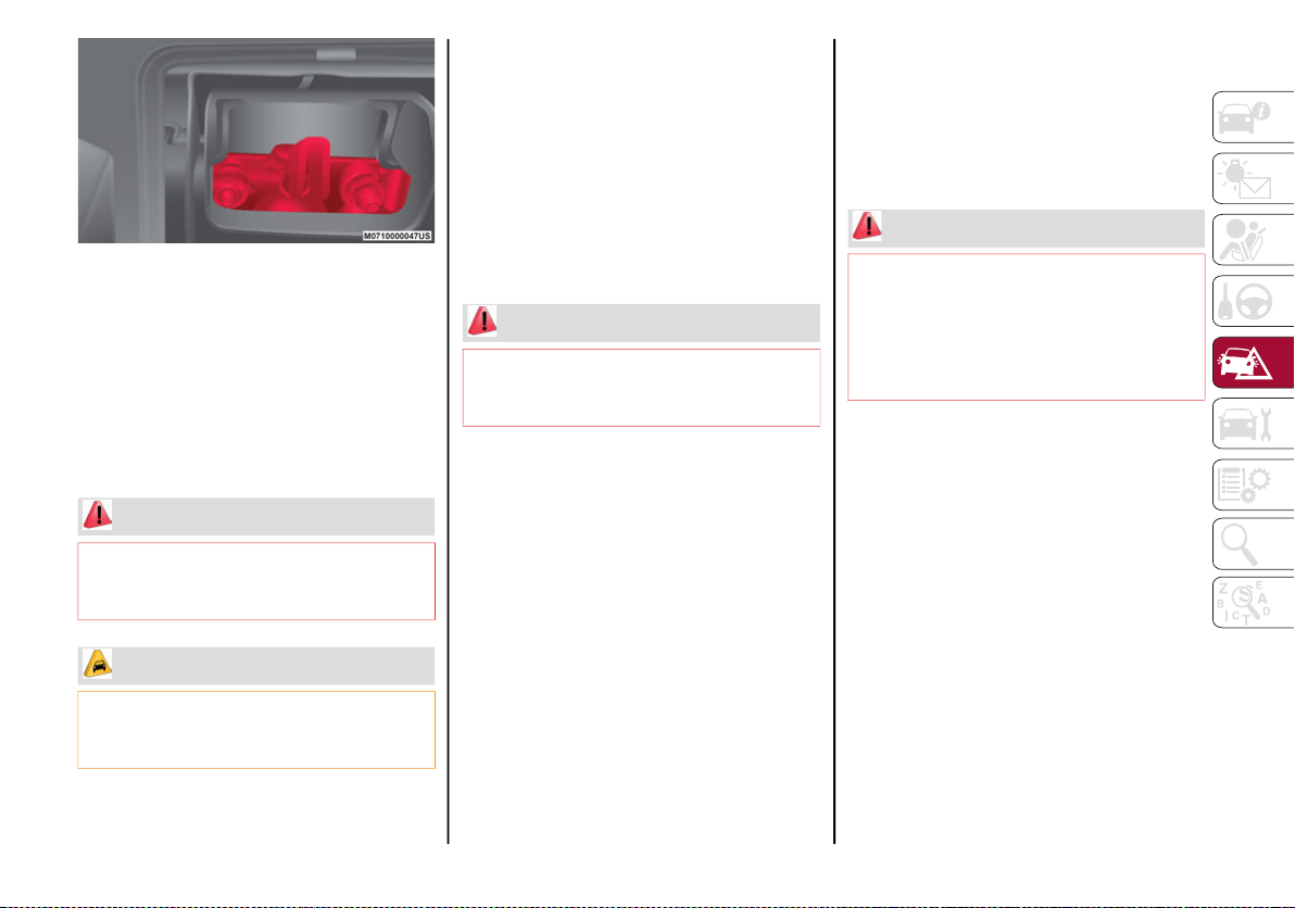
231
Remote Positive Post
To carry out the operation, you need to have the
correct cables to connect to the battery of
another vehicle or a portable battery booster
pack to the remote posts of the discharged
battery. Usually, these cables have terminals at
the ends and are identified by different sheath
colors (red = positive, black = negative).
Jump Starting
Preparation For Jump Starting:
1. Firmly apply the park brake, and cycle the
ignition to OFF.
2. Turn off all electrical features in the
vehicle.
3. If using another vehicle to jump start the
battery, park the vehicle within the jumper
cables reach, apply the park brake and
make sure the ignition is OFF.
Cable Connection
Proceed as follows to perform a jump starting
procedure:
1. Connect the positive (+) end of the jumper
cable to the positive (+) post of the vehicle
with the discharged battery.
2. Connect the opposite end of the positive
(+) jumper cable to the positive (+) post of
the booster battery.
3. Connect the negative end (-) of the jumper
cable to the negative (-) post of the booster
battery.
4. Connect the opposite end of the negative
(-) jumper cable to the remote negative (-)
post of the discharged vehicle.
5. Start the engine in the vehicle that has the
booster battery, let the engine idle a few
minutes, and then start the engine in the
vehicle with the discharged battery. If
using a portable battery booster pack,
before starting the vehicle, wait a few
seconds after completing the connection.
WARNING!
Failure to follow this jump starting
procedure could result in personal injury or
property damage due to battery explosion.
CAUTION!
Failure to follow these procedures could result
in damage to the charging system of the
booster vehicle or the discharged vehicle.
WARNING!
Do not allow vehicles to touch each other
as this could establish a ground connection
and personal injury could result.
WARNING!
Do not connect the jumper cable to the
negative (-) post of the discharged battery.
The resulting electrical spark could cause the
battery to explode and could result in serious
injury. Only use the specific ground point, do
not use any other exposed metal parts.
20_GA_OM_EN_USC_t.book Page 231

IN CASE OF EMERGENCY
232
Cable Disconnection
Once the engine is started, remove the
connection cables in reverse sequence, as
described below:
1. Disconnect the negative (-) jumper cable
from the remote negative (-) post of the
discharged vehicle.
2. Disconnect the negative end (-) of the
jumper cable from the negative (-) post of
the booster battery.
3. Disconnect the opposite end of the posi-
tive (+) jumper cable from the positive (+)
post of the booster battery.
4. Disconnect the positive (+) end of the
jumper cable from the positive (+) post of
the vehicle with the discharged battery.
If frequent jump starting is required to start your
vehicle, you should have the battery and charging
system inspected at an authorized dealer.
Bump Starting
Never jump start the engine by pushing,
towing or coasting downhill.
NOTE:
You cannot start a vehicle with an automatic
transmission by pushing it.
ENGINE OVERHEATING
Engine overheating may occur in situations of
extreme environmental temperatures, frequent
engine stops/starts, or driving in heavy traffic. If
the engine becomes overheated, the Engine
Temperature Warning Light in the instrument
cluster will illuminate along with a dedicated
message. Refer to “Warning Lights And
Messages” in the “Getting To Know Your Instru-
ment Panel” for more information.
In any of the following situations, you can
reduce the potential for overheating by taking
the appropriate action.
On the highways — slow down.
In city traffic — while stopped, place the
transmission in NEUTRAL, but do not
increase engine idle speed.
NOTE:
There are steps that you can take to slow down
an impending overheat condition:
If your Air Conditioner (A/C) is on, turn it off.
The A/C system adds heat to the engine
cooling system and turning the A/C off can
help remove this heat.
You can also turn the temperature control
to maximum heat, the mode control to floor
and the blower control to high. This allows
the heater core to act as a supplement to
the radiator and aids in removing heat from
the engine cooling system.
If Steam Is Coming From The Engine Compartment
Do not go near the front of the vehicle. Stop
the engine. Wait until the steam dissipates.
Then, open the hood and start the engine.
CAUTION!
Accessories plugged into the vehicle power
outlets draw power from the vehicle’s
battery, even when not in use (i.e., cellular
phones, etc.). Eventually, if plugged in long
enough without engine operation, the
vehicle’s battery will discharge sufficiently
to degrade battery life and/or prevent the
engine from starting.
WARNING!
You or others can be badly burned by hot
engine coolant (antifreeze) or steam from
your radiator. If you see or hear steam
coming from under the hood, do not open
the hood until the radiator has had time to
cool. Never try to open a cooling system
pressure cap when the radiator or coolant
bottle is hot.
CAUTION!
Driving with a hot cooling system could
damage your vehicle. If temperature gauge
reads “H”, pull over and stop the vehicle.
Idle the vehicle with the air conditioner
turned off until the pointer drops back into
the normal range. If the pointer remains on
the “H”, turn the engine off immediately,
and call for service.
20_GA_OM_EN_USC_t.book Page 232
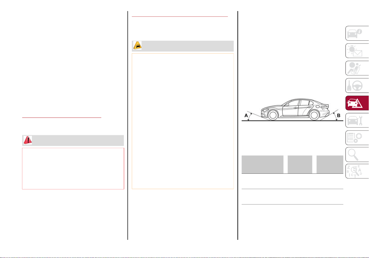
233
If Neither Coolant Nor Steam Is Escaping
Open the hood and idle the engine until it
cools.
NOTE:
If the cooling fan does not operate while the
engine is running, the engine temperature
will increase. Stop the engine and contact
an authorized dealer.
If the engine continues to overheat or
frequently overheats, have the cooling
system inspected. The engine could be seri-
ously damaged unless repairs are made.
Contact an authorized dealer.
MANUAL PARK RELEASE
See an authorized dealer to disengage the
manual park release lever.
TOWING A DISABLED VEHICLE
This section describes procedures for towing a
disabled vehicle using a commercial towing
service.
The operators of the assistance vehicle must
be informed with regard to the vehicle's
minimum height from ground in order to avoid
contact between the ends of the bumpers with
the equipment of the breakdown truck.
The following image illustrates the front and
rear attachment corners of the vehicle, to be
taken into consideration when loading the
vehicle on the assistance vehicle.
Front And Rear Loading Angles
WARNING!
A special tool is required to perform this
procedure. Damage to the vehicle or
serious injury or death may occur if the
procedure is performed improperly. Please
contact an authorized dealer to have this
procedure performed.
CAUTION!
The vehicle should be transported with all
four wheels OFF the ground on the flatbed of
a roadside assistance vehicle. Avoid towing
with only the front (or rear) wheels lifted.
When towing with only the front (or rear)
wheels lifted, in addition to damaging the
body, it could damage the transmission.
Do not use sling-type equipment when
towing. Vehicle damage may occur.
When securing the vehicle to a flatbed
truck, do not attach to front or rear
suspension components. Damage to your
vehicle may result from improper towing.
Ensure that the Electric Park Brake is
released, and remain released, while
being towed.
Damage from improper towing is not
covered under the New Vehicle Limited
Warranty.
RWD
Models
AWD
Models
A — Front
Loading Angle
12.880° 15.160°
B — Rear
Loading Angle
17.105° 18.400°
20_GA_OM_EN_USC_t.book Page 233
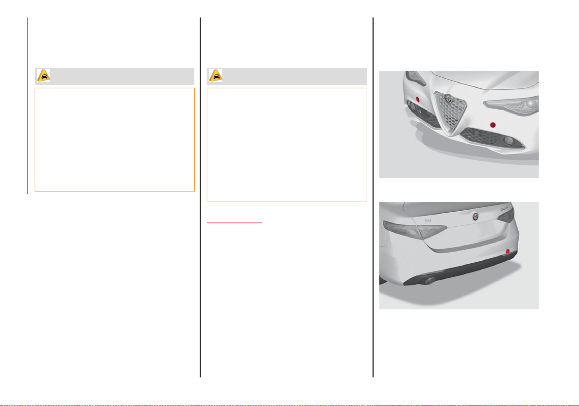
IN CASE OF EMERGENCY
234
Rear Wheel Drive (RWD) Models
It is recommended to tow the vehicle with all
four wheels OFF the ground on the flatbed of a
roadside assistance vehicle.
If an assistance vehicle with a flatbed is not
available, the vehicle must be towed with the
rear wheels lifted from the ground using a
trailer or special equipment allowing lifting of
the rear wheels.
All Wheel Drive (AWD) Models
It is recommended to tow the vehicle with all
four wheels OFF the ground on the flatbed of a
roadside assistance vehicle.
TOW EYES
If the vehicle has been in an accident or has
broken down, a tow eye is provided in the tools
container located inside the luggage compart-
ment for vehicle towing. There are two loca-
tions on the front bumper available for Tow
Eye installation, and one in the rear on the
passenger side. Towing is meant only for short
distances on a paved road surface.
Proceed as follows to use the tow eye:
1. Unhook the cap on the front (left or right
side) or rear bumper, pushing on the upper
part.
Front Tow Eye Cap Locations
Rear Tow Eye Cap Location
CAUTION!
Do not use sling type equipment when
towing. Vehicle damage may occur.
When securing the vehicle to a flat bed
truck, do not attach to front or rear
suspension components. Damage to your
vehicle may result from improper towing.
Ensure that the Electric Park Brake is
released, and remains released, while
being towed.
CAUTION!
DO NOT flat tow this vehicle. Damage to
the drivetrain will result.
DO NOT dolly tow this vehicle. Use of a
towing dolly can cause significant damage
to your vehicle.
Towing this vehicle in violation of the above
requirements can cause severe transmission
damage. Damage from improper towing is not
covered under the New Vehicle Limited
Warranty.
20_GA_OM_EN_USC_t.book Page 234
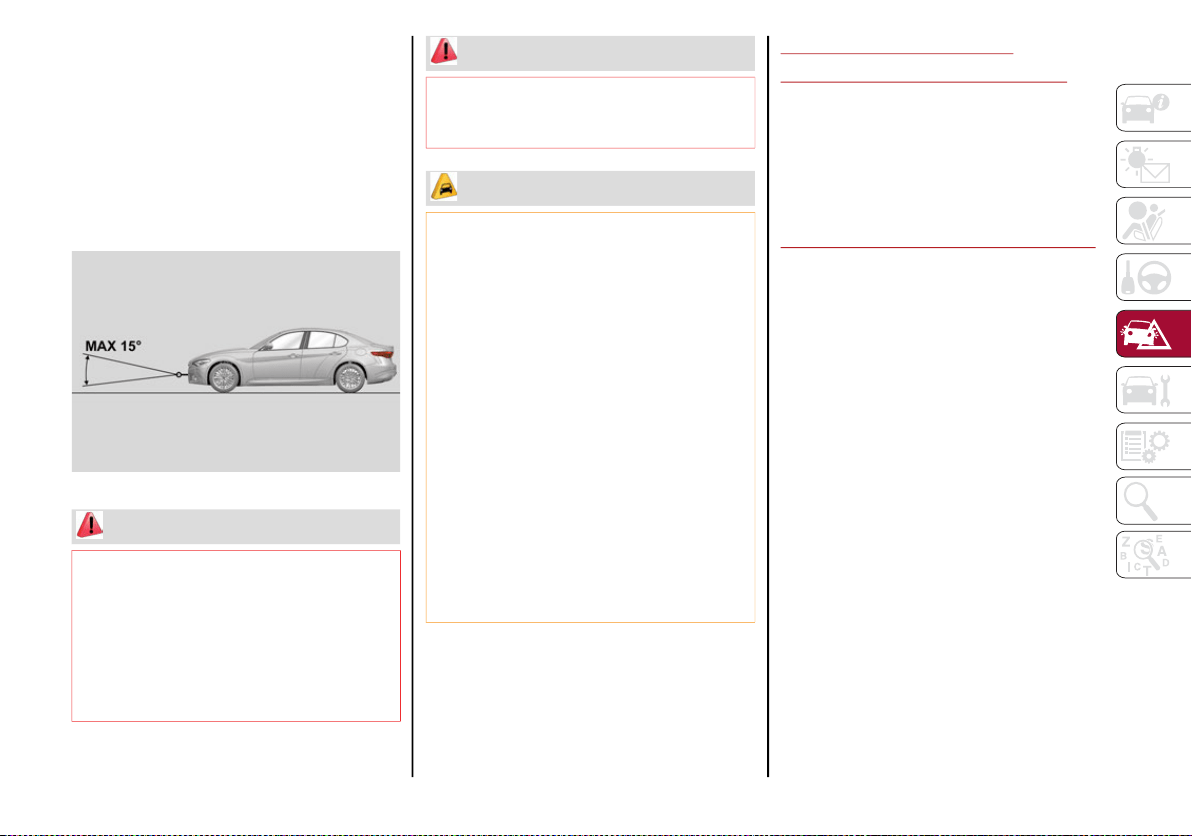
235
(Continued)
2. Remove the tow eye from its housing in the
trunk and carefully clean the threaded
housing on the vehicle before using it.
3. Tighten the vehicle's tow eye in place
(about 11 turns).
NOTE:
The largest work angle of a tow cable to fix on
the tow hook must not exceed 15°.
Work Angle Of Tow Cable
ENHANCED ACCIDENT
RESPONSE SYSTEM (EARS)
This vehicle is equipped with an Enhanced
Accident Response System.
Please refer to “Occupant Restraint Systems”
in “Safety” for further information on the
Enhanced Accident Response System (EARS)
function.
EVENT DATA RECORDER (EDR)
This vehicle is equipped with an Event Data
Recorder (EDR). The main purpose of an EDR
is to record data that will assist in under-
standing how a vehicle’s systems performed
under certain crash or near crash-like situa-
tions, such as an air bag deployment or hitting
a road obstacle.
Please refer to “Occupant Restraint Systems”
in “Safety” for further information on the Event
Data Recorder (EDR).
WARNING!
Stand clear of vehicles when pulling with
tow eyes.
Do not use a chain with a tow eye. Chains
may break, causing serious injury or death.
Do not use a tow strap with a tow eye. Tow
straps may break or become disengaged,
causing serious injury or death.
Failure to follow proper tow eye usage may
cause components to break resulting in
serious injury or death.
CAUTION!
The tow eye must be used exclusively for
roadside assistance operations. Only use
the tow eye with an appropriate device in
accordance with the highway code (a rigid
bar or rope) to flat tow the vehicle for a short
distance to the nearest service location.
Tow eyes MUST NOT be used to tow vehicles
off the road or where there are obstacles.
In compliance with the above conditions,
towing with a tow eye must take place with
two vehicles (one towing, the other towed)
aligned as much as possible along the same
center line. Damage to your vehicle may
occur if these guidelines are not followed.
When towing, only use a facility that can
tow vehicles with low ground clearances
as extensive damage can result by using a
standard tow truck platform.
WARNING! (Continued)
20_GA_OM_EN_USC_t.book Page 235

236
SERVICING AND MAINTENANCE
Correct servicing permits the performance of
the vehicle to be maintained over time, as well
as limited running costs and safeguarding the
efficiency of the safety systems.
This chapter explains how.
SCHEDULED SERVICING
Correct servicing is crucial for guaranteeing a
long life for the vehicle under the best conditions.
For this reason, Alfa Romeo has planned a
series of checks and services for your vehicle
at fixed intervals based on distance and time,
as described in the Scheduled Servicing Plan.
Before each service, it is always necessary to
carefully follow the instructions in the Sched-
uled Servicing Plan (e.g. periodically check
level of fluids, tire pressure, etc.).
Scheduled Servicing is offered by an autho-
rized dealer according to a set time schedule.
If, during each operation, in addition to the
ones scheduled, the need arises for further
replacements or repairs, these may be carried
out with the owner’s explicit consent only.
NOTE:
Scheduled Servicing intervals are required by
the Manufacturer. Failure to have them
carried out may invalidate the New Vehicle
Limited Warranty.
You are advised to inform an authorized
dealer of any small operating irregularities
without waiting for the next service.
Periodic Checks
Every month or every 600 miles (1,000 km) or
before long trips check and, if necessary, top off:
Engine coolant level.
Brake fluid level (if insufficient, see an
authorized dealer as soon as possible).
Windshield washer fluid level.
Tire inflation pressure and condition.
Operation of lighting system (headlights, direc-
tion indicators, hazard warning lights, etc.).
Operation of windshield washing/wiping
system and positioning/wear of wiper blades.
Inspect the CV/Universal joints.
Oil consumption of the engine depends on
conditions and driving style. For this reason,
the engine oil level must be checked every
1,860 miles (3,000 km), and top off if neces-
sary refer to “Engine Oil” in this chapter for
further information.
Heavy Usage Of The Vehicle
If the vehicle is used under one of the following
conditions:
Dusty roads.
Short, repeated journeys less than 4 miles
(7 km) at sub-zero outside temperatures.
Engine often idling or driving long distances
at low speeds or long periods of inactivity.
In the event of a long period of inactivity.
The following checks must be carried out more
often than indicated in the Scheduled Servicing
Plan:
Check cleanliness of hood and trunk locks,
cleanliness and lubrication of linkage.
Visually inspect conditions of: engine, transmis-
sion, pipes and hoses (exhaust/fuel system/
brakes) and rubber elements (sleeves/bushes,
etc.).
Check battery charge and battery fluid level
(electrolyte).
Visually inspect conditions of the accessory
drive belts.
Check and, if necessary, change engine oil
and replace oil filter.
Check and, if necessary, replace cabin air
filter.
Check and, if necessary, replace air cleaner.
Severe Duty All Models
Change engine oil at 4,000 miles (6,500 km)
if the vehicle is operated in a dusty and
off-road environment or is operated predomi-
nately at idle or only very low engine RPM. This
type of vehicle use is considered Severe Duty.
20_GA_OM_EN_USC_t.book Page 236
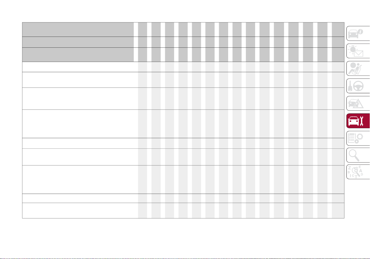
237
Maintenance Plan — 2.0L T4 MAir Engine
Thousands of miles
10
20
30
40
50
60
70
80
90
100
110
120
130
140
150
Years 1 2 3 4 5 6 7 8 9 10 11 12 13 14 15
Thousands of kilometers
16
32
48
64
80
96
112
128
144
160
176
192
208
224
240
SOS backup battery replacement (if equipped)
1
● ● ●
Check battery charge status with the proper
instrument
● ● ● ● ● ● ● ● ● ● ● ● ● ● ●
Check tire condition/wear and adjust pressure, if
necessary. Check the tire repair kit recharge
condition and expiration date
● ● ● ● ● ● ● ● ● ● ● ● ● ● ●
Check operation of lighting system (headlights,
direction indicators, hazard warning lights, trunk
lid, passenger compartment, glove compartment,
instrument panel warning lights, etc.)
● ● ● ● ● ● ● ● ● ● ● ● ● ● ●
Check and, if necessary, top up fluid levels
2
● ● ● ● ● ● ● ● ● ● ● ● ● ● ●
Check engine control system operation (via diagnostic
tool) and, if equipped, engine oil degradation
3
● ● ● ● ● ● ● ● ● ● ● ● ● ● ●
Visually inspect conditions of: exterior bodywork,
underbody protection, pipes and hoses (exhaust,
fuel system, brakes), rubber elements (sleeves,
bushes, etc.)
● ● ● ● ● ● ●
Check position/wear of front windshield wiper blade
● ● ● ● ● ● ● ●
Check operation of the windshield wiper/washer
system and adjust nozzles, if necessary
● ● ● ● ● ● ● ●
20_GA_OM_EN_USC_t.book Page 237

SERVICING AND MAINTENANCE
238
Check cleanliness of hood and luggage compartment
locks, cleanliness and lubrication of linkage
● ● ● ● ● ● ●
Visually inspect conditions and wear of front/rear
disc brake pads and operation of pad wear
indicators
● ● ● ● ● ● ● ● ● ● ● ● ● ● ●
Visually inspect the condition and tensioning of
the accessory drive belt(s)
● ● ● ● ● ● ● ● ● ● ● ●
Change engine coolant
●
Change engine oil and replace oil filter
4
Replace transfer case oil (AWD models only)
●
Replace accessory drive belt(s) ●
Replace air cleaner cartridge
5
● ● ● ● ●
Replace the additional fuel filter (if equipped)
● ● ● ● ● ● ● ● ● ● ● ● ● ● ●
Change the brake fluid
6
Thousands of miles
10
20
30
40
50
60
70
80
90
100
110
120
130
140
150
Years 1 2 3 4 5 6 7 8 9 10 11 12 13 14 15
Thousands of kilometers
16
32
48
64
80
96
112
128
144
160
176
192
208
224
240
20_GA_OM_EN_USC_t.book Page 238
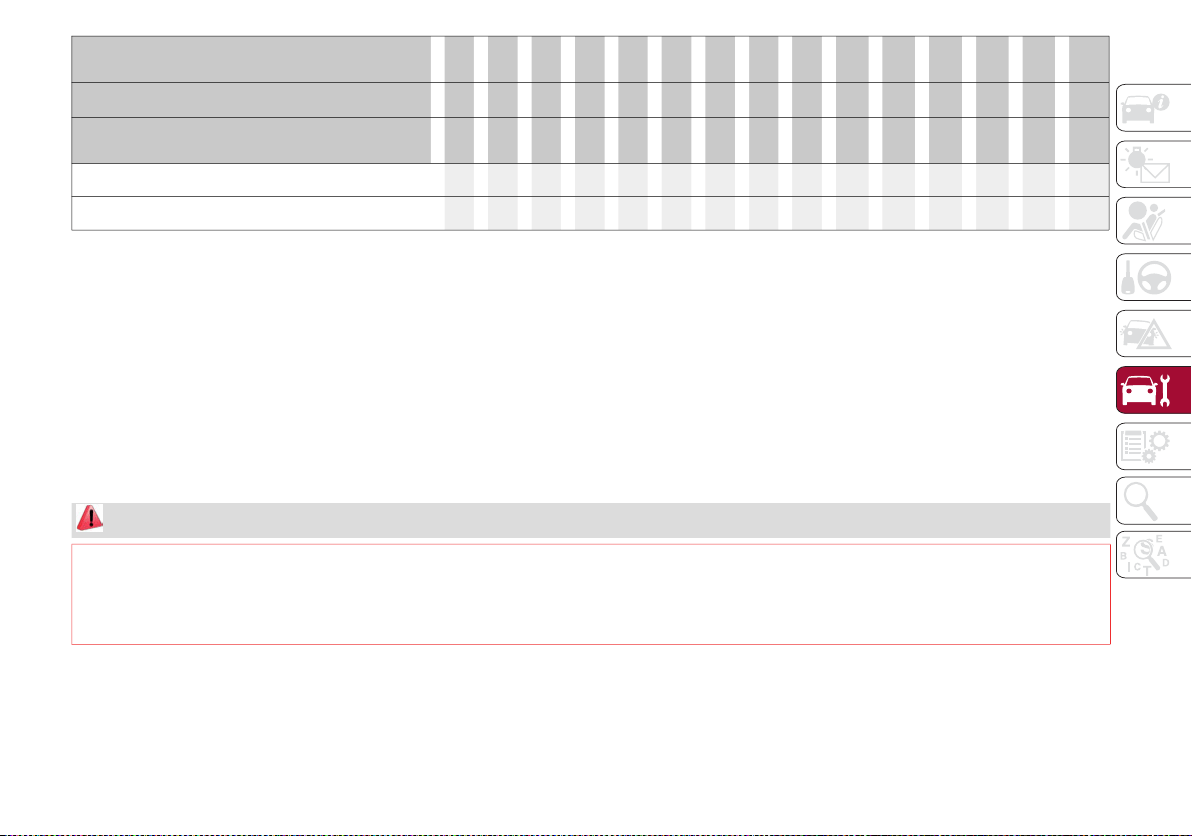
239
(o) Recommended operations
(●) Mandatory operations
Replace the passenger compartment cleaner
7
o ● o ● o ● o ● o ● o ● o ● o
Spark plug replacement
8
● ●
1. The SOS backup battery must be replaced every five years, regardless of mileage.
2. Top up using the fluids indicated in the “Fluids And Lubricants” section of the “Technical Specifications” chapter only after checking that the
system is intact.
3. If oil degradation ratio (data collectible from diagnostic device) is more than 80% (oil quality less than 20%) engine oil and filter replacement is
recommended.
4. The actual interval for changing engine oil and replacing the engine oil filter depends on the vehicle usage conditions and is signaled by the
warning light or message in the instrument panel. In all cases, never exceed 1 year/10,000 miles.
5. If the vehicle is used in dusty areas, this cleaner must be replaced every 10,000 miles (16,000 km).
6. The brake fluid replacement has to be done every two years, irrespective of the mileage.
7. If the vehicle is used in dusty areas, this cleaner must be replaced every 10,000 miles (16,000 km).
8. The spark plug change interval is mileage-based only. Yearly intervals do not apply.
Thousands of miles
10
20
30
40
50
60
70
80
90
100
110
120
130
140
150
Years 1 2 3 4 5 6 7 8 9 10 11 12 13 14 15
Thousands of kilometers
16
32
48
64
80
96
112
128
144
160
176
192
208
224
240
WARNING!
You can be badly injured working on or around a motor vehicle. Do only service work for which you have the knowledge and the right equipment.
If you have any doubt about your ability to perform a service job, take your vehicle to a competent mechanic.
Failure to properly inspect and maintain your vehicle could result in a component malfunction and effect vehicle handling and performance.
This could cause an accident.
20_GA_OM_EN_USC_t.book Page 239

SERVICING AND MAINTENANCE
240
Maintenance Plan — 2.9 V6 Engine
Thousands of miles
10
20
30
40
50
60
70
80
90
100
110
120
130
140
150
Years 1 2 3 4 5 6 7 8 9 10 11 12 13 14 15
Thousands of kilometers
16
32
48
64
80
96
112
128
144
160
176
192
208
224
240
SOS backup battery replacement (if equipped)
1
● ● ●
Check battery charge status with the proper
instrument
● ● ● ● ● ● ● ● ● ● ● ● ● ● ●
Check tire condition/wear and adjust pressure, if
necessary. Check the tire repair kit recharge
condition and expiration date
● ● ● ● ● ● ● ● ● ● ● ● ● ● ●
Check operation of lighting system (headlights,
direction indicators, hazard warning lights, trunk
lid, passenger compartment, glove compartment,
instrument panel warning lights, etc.)
● ● ● ● ● ● ● ● ● ● ● ● ● ● ●
Check and, if necessary, top up fluid levels
2
● ● ● ● ● ● ● ● ● ● ● ● ● ● ●
Check engine control system operation (via
diagnostic tool)
● ● ● ● ● ● ● ● ● ● ● ● ● ● ●
Visually inspect conditions of: exterior bodywork,
underbody protection, pipes and hoses (exhaust,
fuel system, brakes), rubber elements (sleeves,
bushes, etc.)
● ● ● ● ● ● ●
Check position/wear of front windshield wiper blade
● ● ● ● ● ● ● ●
Check operation of the windshield wiper/washer
system and adjust nozzles, if necessary
● ● ● ● ● ● ● ●
20_GA_OM_EN_USC_t.book Page 240
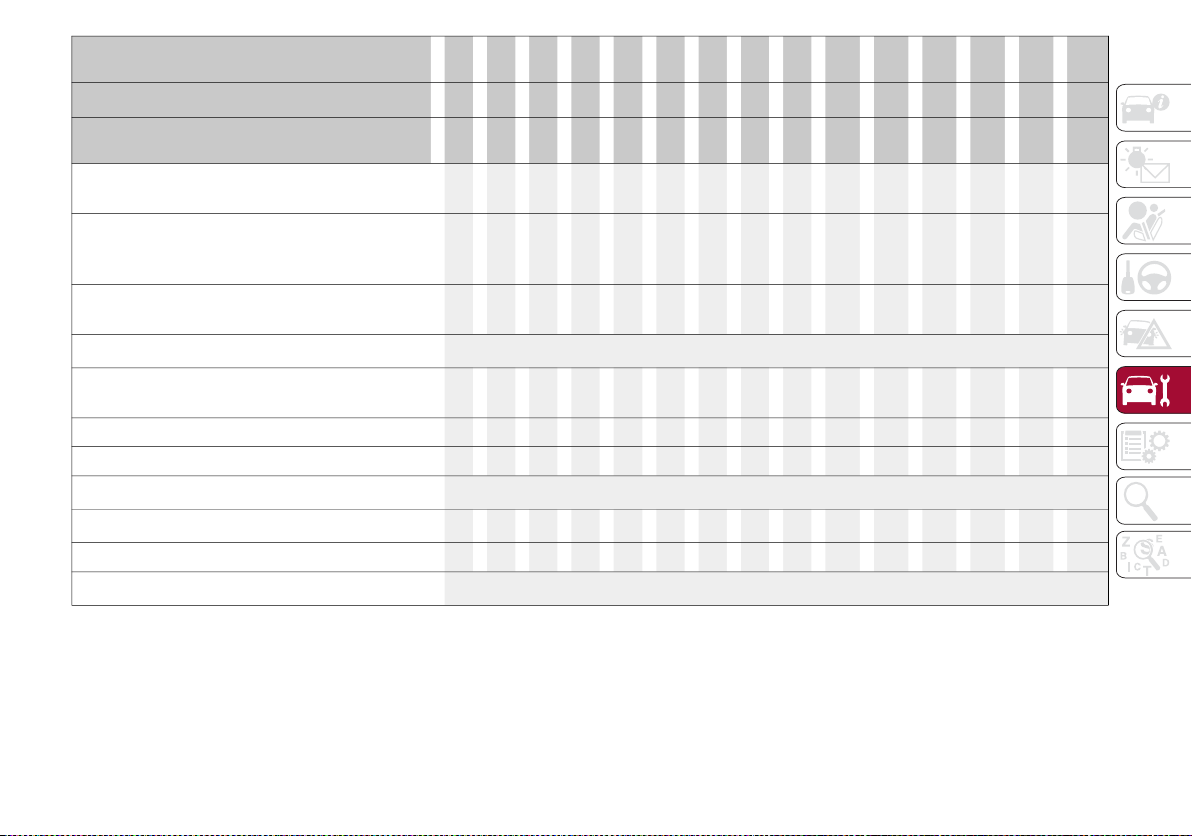
241
Check cleanliness of hood and luggage compartment
locks, cleanliness and lubrication of linkage
● ● ● ● ● ● ●
Visually inspect conditions and wear of front/
rear disc brake pads and operation of pad wear
indicators
● ● ● ● ● ● ● ● ● ● ● ● ● ● ●
Visually inspect the brake discs surface and
edge
● ● ● ● ● ● ● ● ● ● ● ● ● ● ●
Brake pads/brake discs replacement
3
Visually inspect the condition and tensioning of
the accessory drive belt(s)
● ● ● ● ● ● ● ● ● ● ● ●
Change engine coolant ●
Change engine oil and replace oil filter ● ● ● ● ● ● ● ● ● ● ● ● ● ● ●
Replace accessory drive belt/s
4
Replace air cleaner
5
● ● ● ● ● ● ●
Replace the additional fuel filter (if equipped) ● ● ● ● ● ● ● ● ● ● ● ● ● ● ●
Change the brake fluid
6
Thousands of miles
10
20
30
40
50
60
70
80
90
100
110
120
130
140
150
Years 1 2 3 4 5 6 7 8 9 10 11 12 13 14 15
Thousands of kilometers
16
32
48
64
80
96
112
128
144
160
176
192
208
224
240
20_GA_OM_EN_USC_t.book Page 241
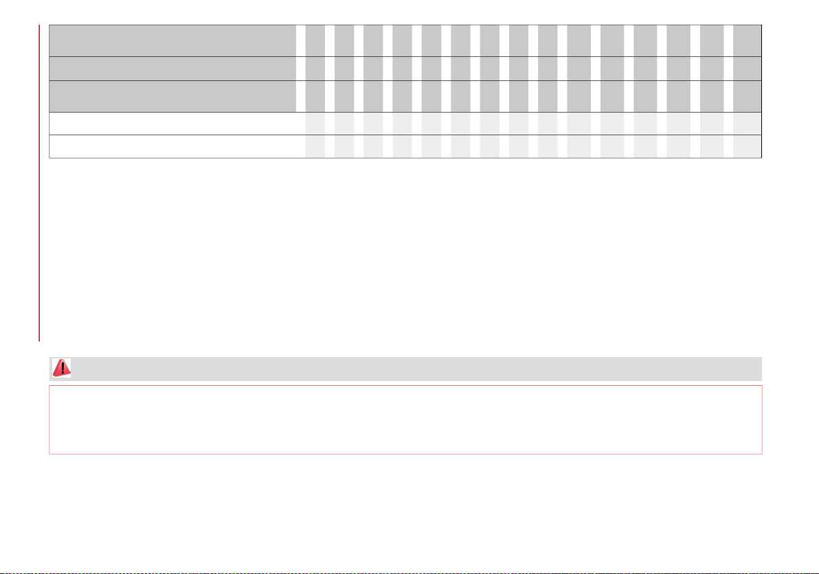
SERVICING AND MAINTENANCE
242
(o) Recommended operations
(●) Mandatory operations
Replace the cabin air filter
7
o ● o ● o ● o ● o ● o ● o ● o
Spark plug replacement
8
● ● ● ● ●
1. The SOS backup battery must be replaced every five years, regardless of mileage.
2. Top up using the fluids indicated in the “Fluids And Lubricants” section of the “Technical Specifications” chapter only after checking that the
system is intact.
3. The actual interval for changing the brake pads and the carbon ceramic brake discs depends on the vehicle usage conditions and is signaled
by the warning light or message on the instrument panel. After each discs replacement, reset the warning light using the diagnostic socket.
4. Areas that are not dusty: recommended maximum mileage 36,000 miles (60,00 km). Regardless of the mileage, the belt must be replaced
every 4 years. Dusty areas and/or demanding use of the vehicle (cold climates, town use, long periods of idling): advised maximum mileage
18,000 miles (30,000 km). Regardless of the mileage, the belt must be replaced every 2 years.
5. If the vehicle is used in dusty areas, this cleaner must be replaced every 10,000 miles (16,000 km).
6. The brake fluid replacement has to be done every two years, irrespective of the mileage.
7. If the vehicle is used in dusty areas, this cleaner must be replaced every 10,000 miles (16,000 km).
8. The spark plug change interval is mileage-based only. Yearly intervals do not apply.
Thousands of miles
10
20
30
40
50
60
70
80
90
100
110
120
130
140
150
Years 1 2 3 4 5 6 7 8 9 10 11 12 13 14 15
Thousands of kilometers
16
32
48
64
80
96
112
128
144
160
176
192
208
224
240
WARNING!
You can be badly injured working on or around a motor vehicle. Do only service work for which you have the knowledge and the right equipment.
If you have any doubt about your ability to perform a service job, take your vehicle to a competent mechanic.
Failure to properly inspect and maintain your vehicle could result in a component malfunction and effect vehicle handling and performance.
This could cause an accident.
20_GA_OM_EN_USC_t.book Page 242
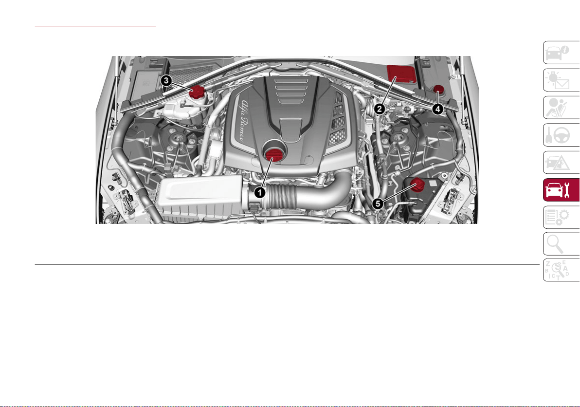
243
ENGINE COMPARTMENT
Checking Levels — 2.0L T4 MAir Engine
1 – Engine Oil Filler Cap 4 –Windshield/Headlights Washer Fluid Reservoir Cap
2 – Brake Fluid Reservoir Access Cover 5 – Intercooler Coolant Reservoir Cap
3 – Engine Coolant Reservoir Cap
20_GA_OM_EN_USC_t.book Page 243
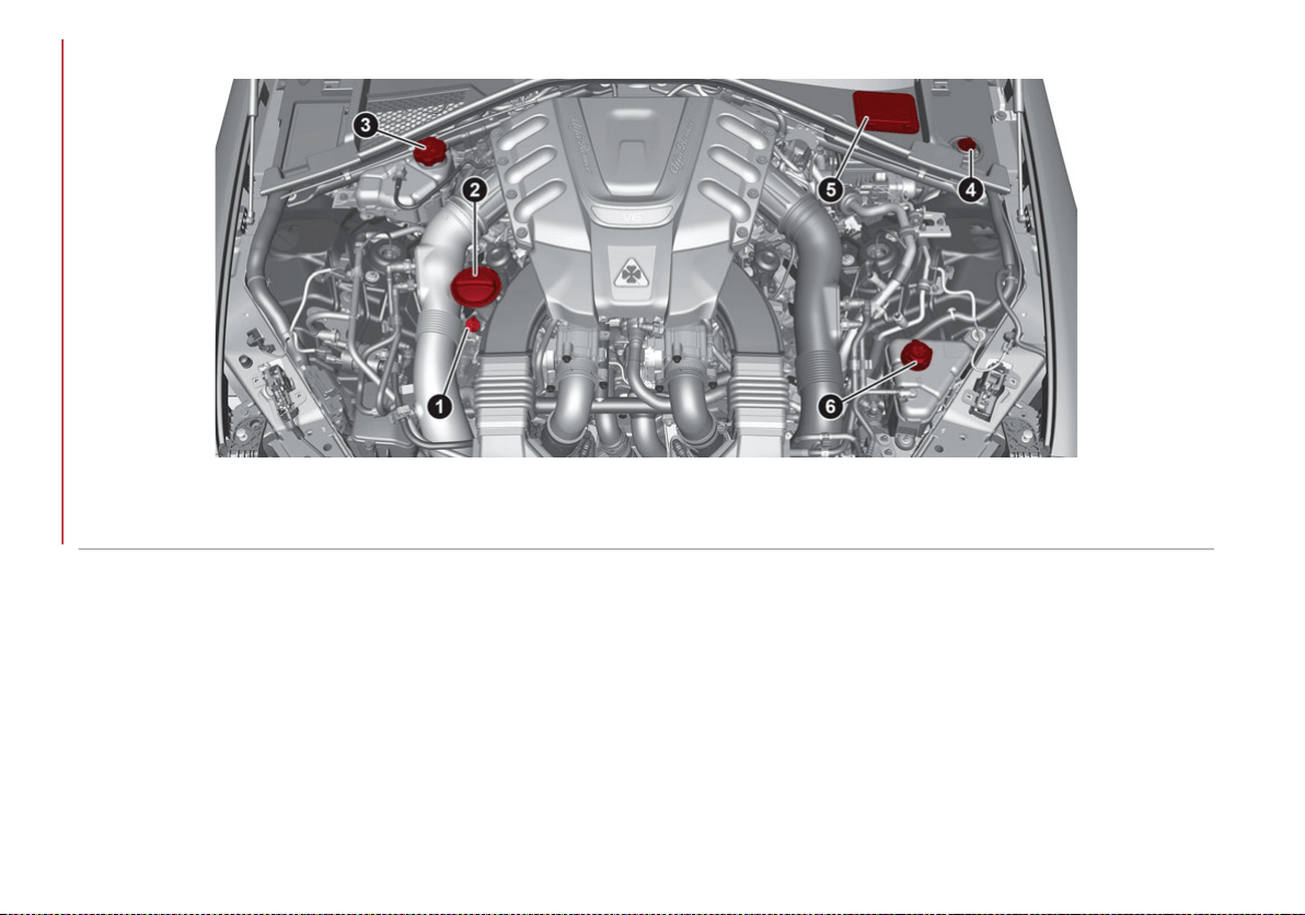
SERVICING AND MAINTENANCE
244
Checking Levels — 2.9L V6 Engine
1 – Engine Oil Dipstick 4 – Windshield/Headlight Washer Fluid Reservoir Cap
2 – Engine Oil Filler 5 – Brake Fluid Reservoir Cap Access Cover
3 – Engine Coolant Reservoir Cap 6 – Intercooler Coolant Reservoir Cap
20_GA_OM_EN_USC_t.book Page 244

245
Engine Oil
The engine oil level can be seen on the instru-
ment cluster display every time the engine is
started, or on the Information and Entertain-
ment system display by activating on the main
menu (MENU button) the following functions in
sequence: “Apps”; “My Car” and “Oil Level”.
Check on the display using the six notches that
the oil level is between the MIN and MAX level:
one notch MIN level, six notches MAX level.
If the oil level is close to or below the MIN
mark, add oil gradually through the filler, (refer
to “Top-Up And Oil Level Indication Update On
Display” in this section) considering that each
notch shown on the display corresponds to
approximately 8.8 fl oz (250 ml).
The oil level can also be checked manually on
2.9L Quadrifoglio models.
NOTE:
Always reinstall the oil cap and tighten to
proper torque whenever it is removed to add
oil to engine. Never run the engine with cap
removed as this could cause oil to leak from
engine.
Manual Oil Level Checking Procedure —
2.9L Quadrifoglio
Check that the oil level is between the MIN and
MAX marks on dipstick, clean it with a lint-free
cloth and reinsert it. Extract the dipstick again
and check that the level is between the MIN
and MAX marks.
Top-Up And Oil Level Indication Update On
Display — 2.9L Quadrifoglio
If an engine oil top-off is needed, in order to
ensure the correct indication of the oil level on
the display, proceed with the process below:
Leave the car on flat ground with the engine
running for approximately five minutes
(temperature higher than 198°F (90°C)
and shut the engine off
Wait for five minutes, turn the ignition to the
ON mode without starting the engine and
wait for a few seconds.
NOTE:
If the level indication is not updated after the
previously described procedure, repeat the
engine adjustment, shut the engine off and
wait another five minutes before starting it
again. If the indication is not updated after the
second start, contact an authorized dealer.
Top-Up And Oil Level Indication Update On
Display — 2.0L T4 MAir
If an engine oil top-off is needed, in order to
ensure the correct indication of the oil level on
the display, proceed with the process below:
Leave the car on flat ground with the engine
running for approximately five minutes
(temperature higher than 176°F (80°C)
and shut the engine off.
Start the engine again and idle it for about
two minutes.
NOTE:
If you have added the specified amount of oil
and the indicator is not reading “Full”, please
contact an authorized dealer.
CAUTION!
Make sure not to add too much oil when
topping off the engine. Engine oil in excess
may damage the engine. Have the vehicle
checked. Never exceed the MAX level when
topping off engine oil. It is advisable to check
the oil level in intermediate steps using the oil
dipstick (2.9L Quadrifoglio Only).
CAUTION!
The oil level is not refreshed immediately on
the display after topping off. Consequently,
wait for the oil level to be refreshed on the
display and follow the procedure below.
WARNING!
If the engine oil is being topped up, wait for
the engine to cool down before loosening
the filler cap, particularly for vehicles with
aluminum cap (if equipped). WARNING: risk
of burns!
20_GA_OM_EN_USC_t.book Page 245

SERVICING AND MAINTENANCE
246
Engine Coolant Fluid
If the level is too low, unscrew the cap of reser-
voir and add the fluid described in the “Tech-
nical Specifications” chapter.
Washer Fluid For Windshield/Headlights
The windshield and headlights washer fluid
reservoir has a telescopic filler.
If the level is too low, remove reservoir cap and
lift the filler. Then, add the fluid described in
the “Technical Specifications” chapter.
NOTE:
The headlight washing system will not work if
the liquid level is low (as indicated by the
symbol on the instrument cluster display). On
vehicles equipped with headlight washers,
there is a reference notch on the dipstick:
ONLY the windshield/rear window washer
operates with the level below this reference.
Brake Fluid
Check that the fluid is at the maximum level. If
the fluid level in the tank is low, contact an
authorized dealer to have the system checked.
Automatic Transmission Activation System Oil
The transmission control oil level should only
be checked at an authorized dealer.
Useful Advice For Extending The Life Of
Your Battery
To avoid draining your battery and make it last
longer, observe the following instructions:
When you park the car, ensure that the
doors and trunk are closed properly to
prevent any lights from remaining on inside
the passenger's compartment.
Do not keep accessories (e.g. radio, hazard
warning lights, etc.) switched on for a long
time when the engine is not running.
Before performing any operation on the
electrical system, disconnect the negative
battery cable.
If you wish to install electrical accessories
after purchasing the car that require perma-
nent electrical supply (e.g. alarm, etc.), or
accessories which influence the electrical
supply requirements, contact an authorized
dealer, whose qualified staff will evaluate the
overall electrical consumption.
NOTE:
After the battery is disconnected, the steering
must be initialized. The warning light on the
instrument panel switches on to indicate this. To
carry out this procedure, simply turn the steering
wheel all the way from one end to the other, and
then turn it back to the central position.
Battery
The battery does not require the electrolyte to
be topped up with distilled water. A periodic
check carried out at an authorized dealer,
however, is necessary to check efficiency.
Follow the battery manufacturer's instructions
for maintenance.
CAUTION!
The oil level must never exceed the MAX mark.
If the MAX mark is exceeded (last notch on
the right turns red) after the fill-up, go to an
authorized dealer as soon as possible to
have the oil in excess removed.
Do not add oil with specifications different
from those of the oil already in the engine.
Used engine oil and oil filters contain
substances which are harmful to the
environment. To change the oil and filters, we
advise you to contact an authorized dealer.
CAUTION!
If the charge level remains under 50% for a
long time, the battery may be damaged by
sulphation, reducing its capacity and
efficiency at start the vehicle. The battery is
also more prone to the risk of freezing (at
temperatures as high as 14°F (-10°C).
20_GA_OM_EN_USC_t.book Page 246
247
Replacing The Battery
If necessary, replace the battery with another
original battery with the same specifications.
Follow the battery manufacturer’s instructions
for maintenance.
NOTE:
It will not be possible to open the trunk with a
key or by pressing the button in the passenger
compartment when the battery is discon-
nected. So, always position the manual trunk
opening strap on the trunk lock before discon-
necting the battery. The procedure is
described in the “Storing The Vehicle” para-
graph in this chapter.
Pressure Washing
BATTERY RECHARGING
Important Notes
NOTE:
Before using the charging device, always
make sure that it is appropriate for the
installed battery, with constant voltage
(below 14.8 Volts) and low amperage
(maximum 15 Amps).
Recharge the battery in a well ventilated
environment.
Before using any devices to charge or to
maintain the charge of the battery, carefully
follow the instructions provided with the
device in order to properly and safely
connect it to the car battery.
WARNING!
Battery acid is a corrosive solution and
can burn or even blind you. Do not allow
battery acid to contact your eyes, skin, or
clothing. Do not lean over a battery when
attaching clamps. If acid splashes in eyes
or on skin, flush the area immediately with
large amounts of water. Refer to “Jump
Starting” in “In Case Of Emergency” for
further information.
Battery gas is flammable and explosive.
Keep flame or sparks away from the
battery. Do not use a booster battery or
any other booster source with an output
greater than 12 Volts. Do not allow cable
clamps to touch each other.
Battery posts, terminals, and related
accessories contain lead and lead
compounds. Wash hands after handling.
CAUTION!
Cleaning the engine compartment with a
high pressure washer is not recommended.
Precautions have been taken to safeguard
all parts and connections however, the
pressures generated by these machines is
such that complete protection against
water ingress cannot be guaranteed.
WARNING!
Never charge or recharge a frozen battery:
it may explode because of the nitrogen
trapped inside the ice crystals.
At all times while charging or recharging
the battery, make sure that any sparks or
open flames are kept sufficiently far away
from the battery.
20_GA_OM_EN_USC_t.book Page 247
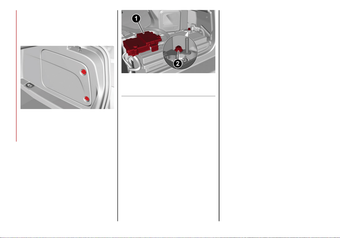
SERVICING AND MAINTENANCE
248
You can recharge the battery without discon-
necting the wires of the vehicle's electrical
system.
To reach the battery, remove the access
panel inside the trunk.
Battery Access Panel
Remove the protective cover and connect
the positive cable terminal of the charger
(usually red) to the positive terminal (+) of
the battery.
Connect the negative terminal of the
charger (usually black) to nut next to the
negative terminal (-) of the battery.
Battery
The vehicle is equipped with an IBS (Intelligent
Battery Sensor), which is able to measure the
charge and discharge voltage and calculate
the charge level and the general condition of
the battery. The sensor is placed next to the
negative terminal (-) of the battery.
For a correct charge/discharge procedure, the
charge voltage must go through the IBS
sensor.
1. Turn the charger on and follow the instruc-
tions on the user's manual to completely
recharge the battery.
2. When the battery is charged, turn the
charger off before disconnecting it from
the battery.
3. Disconnect the black cable terminal of the
battery charger and then the red cable
terminal.
4. Refit the protective cover of the positive
terminal of the battery and the access
cover to the battery compartment.
NOTE:
If a “quick-type” battery charger is used with
the battery fitted on the vehicle, before
connecting it disconnect both cables of the
battery itself. Do not use a “quick-type” battery
charger to provide the starting voltage.
1 — Protective Cover
2 — Negative Post (Nut)
20_GA_OM_EN_USC_t.book Page 248
249
DEALER SERVICE
The following pages contain instructions on
the required maintenance from the technical
personnel who designed the vehicle.
In addition to these specific maintenance
instructions specified for routine scheduled
servicing, there are other components which
may require periodic maintenance or replace-
ment over the vehicle’s life cycle.
Engine Oil
Engine Oil Level Check
To ensure correct engine lubrication, the oil
must always be kept at the prescribed level
(see “Engine Compartment” in this chapter).
Check the oil level at regular intervals, for
example every 1,864 miles (3,000 km).
It must be checked once full operating
temperature is reached.
The vehicle must also be parked on as level a
surface as possible.
The engine oil level can be checked using the
Information and Entertainment system. To
access the function, activate the main menu
(MENU button) and select the following
options in sequence: “Applications”; “My Car”;
“Oil level”.
Changing The Engine Oil
See the “Maintenance Plan” for the correct
servicing intervals.
Choice Of Engine Oil Type
To ensure optimal performance and maximum
protection in all operating conditions, it is
advisable to use solely certified engine oils
(see description in “Fluid And Lubricants” in
the “Technical Specifications” chapter).
Additives For Engine Oil
It is strongly recommended not to use addi-
tives (other than leak detection dyes) with the
engine oil.
The engine oil is a product designed specially for
the vehicle and its performance may be deterio-
rated through the use of further additives.
Disposal Of Used Engine Oil And Filters
For the disposal of the engine oil and filters,
contact the appropriate body to determine
local regulations.
NOTE:
Used engine oil disposed of incorrectly may
seriously harm the environment.
Engine Oil Filter
Replacing The Engine Oil Filter
The engine oil filter must be replaced each
time the engine oil is changed. It is advised to
replace it with a genuine spare part, specifi-
cally designed for this vehicle.
Air Filter
Replacing The Air Cleaner
See the “Maintenance Plan” for the correct
servicing intervals. It is advised to replace it with
a genuine spare part, specifically designed for
this vehicle.
Air Conditioning System Maintenance
To ensure the best possible performance, the
air conditioning system must be checked and
undergo maintenance at an authorized dealer
at the beginning of the summer.
CAUTION!
Do not use chemicals to clean the air
conditioning system, since the internal
components may be damaged. This kind of
damage is not covered by warranty.
20_GA_OM_EN_USC_t.book Page 249

SERVICING AND MAINTENANCE
250
Replace The Cabin Air Filter
See the “Maintenance Plan” for the correct
servicing intervals. For cleaner replacement,
contact an authorized dealer.
Lubricating Moving Parts Of The Bodywork
Ensure that the locks and bodywork junction
points, including components such as the seat
guides, door hinges (and rollers), trunk and hood
are periodically lubricated with lithium-based
grease to ensure correct, silent operation and to
protect them from rust and wear.
Thoroughly clean the components, eliminating
every trace of dirt and dust. After lubricating,
eliminate excess oil and grease. Also pay
particular attention to the hood closing
devices, to ensure correct operation. During
operations on the hood, to be carried out with
the engine cold, also remember to check,
clean and lubricate the locking, release and
safety devices.
Lubricate the external lock barrels twice a
year. Apply a small amount of high-quality
lubricant directly into the lock barrel.
If necessary, contact an authorized dealer as
soon as possible.
Windshield Wiper
Periodically clean the windshield and rear
window and rubber profile of the windshield
wiper blades, using a sponge or a soft cloth and
a non-abrasive detergent. This eliminates the
salt or impurities accumulated when driving.
Prolonged operation of the windshield window
wipers with dry glass may cause the deteriora-
tion of the blades, in addition to abrasion of
the surface of the glass. To eliminate the impu-
rities on the dry glass, always operate the
windshield washers.
In the event of very low outdoor temperatures,
below 0°F (-17.8°C) , ensure that the move-
ment of the rubber part in contact with the
glass is not obstructed. Use a suitable deicing
product to release it if required.
Avoid using the windshield wipers to remove
frost or ice.
Also avoid contact of the rubber profile of the
blades with petroleum derivatives such as
engine oil, gas, etc.
NOTE:
The life of the windshield wiper blades varies
according to the usage frequency. In any case,
it is advised to replace the blades approxi-
mately once a year. When the blades are worn,
noise, marks on the glass or streaks of water
may be noticed. In the presence of these
conditions, clean the windshield wiper blades
or, if necessary, replace them.
Raising The Windshield Wiper Blades
(“Service Position” Function)
The “service position” function allows the
driver to replace the windshield wiper blades
more easily. It is also recommended to acti-
vate this function when it is snowing and to
make it easier to remove any dirt deposits in
the area where the blades are normally posi-
tioned, when washing.
Activation Of The Function
To activate this function, disable the wind-
shield wiper before setting the ignition device
to OFF.
This function can only be activated within two
minutes of placing the ignition in OFF.
WARNING!
Use only refrigerants and compressor lubricants
approved by the manufacturer for your air
conditioning system. Some unapproved
refrigerants are flammable and can explode,
injuring you. Other unapproved refrigerants or
lubricants can cause the system to fail, requiring
costly repairs. Refer to Warranty Information
Book, located in your owner’s information kit, for
further warranty information.
WARNING!
Driving with worn windshield wiper blades
is a serious hazard, because visibility is
reduced in bad weather conditions.
20_GA_OM_EN_USC_t.book Page 250
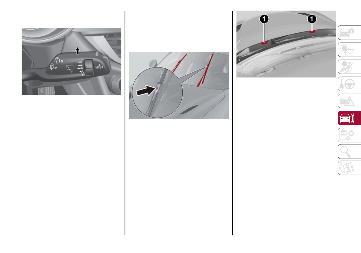
251
To activate this function, move the lever
upward for at least three seconds.
Windshield Wiper Stalk
Function Deactivation
The function is deactivated if:
More than two minutes passes before
placing the ignition in the STOP position
after having raised the lever and putting the
wipers into service position.
The ignition is placed in the ACC position
and the windshield wiper control is used.
If, after using the function, the ignition is set
back to ACC with the blades in a position other
than rest position (at the base of the wind-
shield), they will only return to rest position
following a command given using the stalk
(stalk upwards, into unstable position) or
when a speed of 3 mph (5 km/h) is exceeded.
Replacing The Windshield Wiper Blades
Proceed as follows:
1. Raise the wiper arm, press tab of the
attachment spring and remove the blade
from the arm.
Wiper Release Tab
2. Fit the new blade, inserting the tab in the
dedicated housing in the arm and
checking that it is locked.
3. Lower the wiper arm onto the windshield.
NOTE:
Do not operate the windshield wiper with the
blades lifted from the windshield.
Windshield Washer
The window washer nozzles are fixed. If there
is no jet of fluid, first check that there is fluid in
the reservoir (see paragraph “Engine Compart-
ment” in this chapter).
Windshield Washers
Then, check that the nozzle holes are not
clogged; use a needle to unblock them if
necessary.
Exhaust System
Adequate maintenance of the engine exhaust
system represents the best protection against
leaks of carbon monoxide into the passenger
compartment.
If an unusual noise from the exhaust or the
presence of smoke in the passenger compart-
ment is identified, or if the underbody or rear
section of the vehicle have been damaged,
have the entire exhaust system and adjoining
bodywork areas checked at an authorized
dealer to identify any components which are
broken, damaged, worn or have moved from
their correct fitting position.
1 — Washer Nozzles
20_GA_OM_EN_USC_t.book Page 251

SERVICING AND MAINTENANCE
252
(Continued)
Open welding or loose connections may permit
exhaust gas to enter the passenger compartment.
Have the exhaust system checked every time
the vehicle is raised. Replace the components
where necessary (for these operations,
contact an authorized dealer).
In normal operating conditions, the catalytic
converter does not require maintenance. To
ensure that it operates correctly, however, and
prevent it from getting damaged, it is
extremely important that the engine operates
perfectly.
To minimize the risk of damaging the catalytic
converter, proceed as follows:
Do not stop the engine or deactivate the
ignition with gear engaged and vehicle in
motion.
Do not attempt to start the engine by bump
starting.
Do not persist in using the vehicle if idling is
very irregular or the operating conditions
are very notably irregular.
Cooling System
Coolant Check
Your vehicle has two cooling systems and they
both need to be checked to ensure they are at
proper fill levels. Refer to the “Engine
Compartment” section for the locations.
Check the engine coolant and intercooler
coolant level every oil change or before long
trips.
If there are impurities in the engine coolant,
the system must be drained, flushed and
refilled: contact an authorized dealer.
Check the front part of the condenser to check
for any build-up of insects, leaves or other
debris. Should it be dirty, clean it by spraying
delicately with water.
Check the hoses of the engine/intercooler
cooling system to ensure that the rubber has
not deteriorated and that there are no cracks,
tears, cuts or obstructions in the expansion
tank side and radiator side connectors. Should
there be any doubt regarding leaks from the
system (e.g. if frequent top ups are required),
have the seal checked at an authorized
dealer.
With the engine off and at normal operating
temperature, check that the cooling system
radiator cap is closed properly.
WARNING!
Exhaust gases can injure or kill. They
contain carbon monoxide (CO), which is
colorless and odorless. Breathing it can
make you unconscious and can eventually
poison you.
A hot exhaust system can start a fire if you
park over materials that can burn. Such
materials might be grass or leaves coming
into contact with your exhaust system. Do
not park or operate your vehicle in areas
where your exhaust system can contact
anything that can burn.
WARNING!
You or others can be badly burned by hot
engine coolant (antifreeze) or steam from
your radiator. If you see or hear steam
coming from under the hood, do not open
the hood until the radiator has had time to
cool. Never open a cooling system pres-
sure cap when the radiator or coolant
bottle is hot.
Keep hands, tools, clothing, and jewelry
away from the radiator cooling fan when
the hood is raised. The fan starts automat-
ically and may start at any time, whether
the engine is running or not.
When working near the radiator cooling
fan, disconnect the fan motor lead or turn
the ignition to the OFF mode. The fan is
temperature controlled and can start at
any time the ignition is in the ON mode.
WARNING! (Continued)
20_GA_OM_EN_USC_t.book Page 252
253
NOTE:
Before removing the coolant reservoir cap,
wait for the system to cool down.
Topping Up / Draining / Flushing The Engine/
Intercooler Coolant
If the engine coolant (antifreeze) is dirty, have
cleaning and flushing carried out at an autho-
rized dealer.
See the “Maintenance Plan” for the correct
servicing intervals.
NOTE:
For topping up, use a fluid with the same
characteristics as those indicated in the
“Fluids And Lubricants” table (see “Tech-
nical Specifications” chapter).
Do not use pure water, alcohol-based cool-
ants, corrosions inhibitors or additional
anti-rust products because they may be
incompatible with the engine coolant and
cause the clogging of the radiator. The use
of propylene glycol-based coolant is also not
recommended.
Engine Cooling/Intercooler System Cap
To prevent loss of engine coolant, make sure
that the expansion tank cap is closed. If it is
open, screw it completely until you reach/hear
the click.
Periodically check the cap and clean it from
any foreign bodies that may have deposited on
the external surface.
Disposal Of Used Coolant
Disposal of engine/intercooler coolant is subject
to legal requirements: contact the appropriate
body to determine local regulations.
NOTE:
To prevent the fluid from being ingested by
children or animals, do not keep it in open
containers or pour it on the ground. If
ingested, contact a doctor immediately.
Eliminate any traces of fluid from the
ground immediately.
When the vehicle stops after a short trip,
steam may be seen coming out from front of
the hood. This is a normal phenomenon which
is due to the presence of rain, snow or a lot of
moisture on the surface of the radiator.
With engine and system cold, do not top up
with coolant beyond the maximum level
indicated on the reservoir in the engine
compartment.
Braking System
In order to guarantee the efficiency of the
braking system, periodically check its compo-
nents; for this operation, contact an autho-
rized dealer.
See the “Maintenance Plan” for the correct
servicing intervals.
WARNING!
Do not open hot engine cooling system.
Never add engine coolant (antifreeze) when
the engine is overheated. Do not loosen or
remove the cap to cool an overheated
engine. Heat causes pressure to build up in
the cooling system. To prevent scalding or
injury, do not remove the pressure cap while
the system is hot or under pressure.
Do not use a pressure cap other than the
one specified for your vehicle. Personal
injury or engine damage may result.
WARNING!
Never add coolant with the engine hot or
overheated.
Do not attempt to cool an overheated
engine by loosening or removing the cap.
The heat causes a considerable increase
in pressure in the cooling system.
To prevent damage to the engine, only use
the engine cooling circuit caps provided.
20_GA_OM_EN_USC_t.book Page 253

SERVICING AND MAINTENANCE
254
(Continued)
NOTE:
Driving with your foot resting on the brake pedal
may compromise its efficiency, increasing the
risk of accidents. When driving, never keep your
foot on the brake pedal and don’t put unneces-
sary strain on it to prevent the brakes from over-
heating: excess pad wear may cause damage to
the braking system.
When an insufficient oil level is detected,
contact an authorized dealer to have the
system checked.
Always keep the cap of the brake fluid reser-
voir (in the engine compartment) completely
closed.
Automatic Transmission
Use only a transmission oil with the same char-
acteristics as those indicated in the “Fluids
and Lubricants” table (see “Technical Specifi-
cations” chapter).
Special Additives
Do not use any type of additive with the auto-
matic transmission oil. The automatic transmis-
sion oil is a product designed specially for this
vehicle and its performance may be compro-
mised through the use of further additives.
Frequency Of Oil Changes
In normal vehicle operating conditions, it is not
necessary to change the transmission oil.
Replacing The Battery
If necessary, replace the battery with another
battery with the same specifications. It is
advised to contact an authorized dealer for
replacement.
WARNING!
Use only manufacturer's recommended
brake fluid. Refer to “Fluids And Lubricants”
in “Technical Specifications” for further
information. Using the wrong type of brake
fluid can severely damage your brake
system and/or impair its performance. The
proper type of brake fluid for your vehicle is
also identified on the original factory
installed hydraulic master cylinder reservoir.
To avoid contamination from foreign
matter or moisture, use only new brake
fluid or fluid that has been in a tightly
closed container. Keep the master
cylinder reservoir cap secured at all times.
Brake fluid in a open container absorbs
moisture from the air resulting in a lower
boiling point. This may cause it to boil
unexpectedly during hard or prolonged
braking, resulting in sudden brake failure.
This could result in a collision.
Overfilling the brake fluid reservoir can
result in spilling brake fluid on hot engine
parts, causing the brake fluid to catch fire.
Brake fluid can also damage painted and
vinyl surfaces, care should be taken to
avoid its contact with these surfaces.
Do not allow petroleum based fluid to
contaminate the brake fluid. Brake seal
components could be damaged, causing
partial or complete brake failure. This
could result in a collision.
WARNING! (Continued)
CAUTION!
Do not use chemical flushes in your
transmission as the chemicals can damage
your transmission components. Such damage
is not covered by the New Vehicle Limited
Warranty.
CAUTION!
If a transmission fluid leak occurs, visit an
authorized dealer immediately. Severe
transmission damage may occur. An
authorized dealer has the proper tools to
adjust the fluid level accurately.
20_GA_OM_EN_USC_t.book Page 254
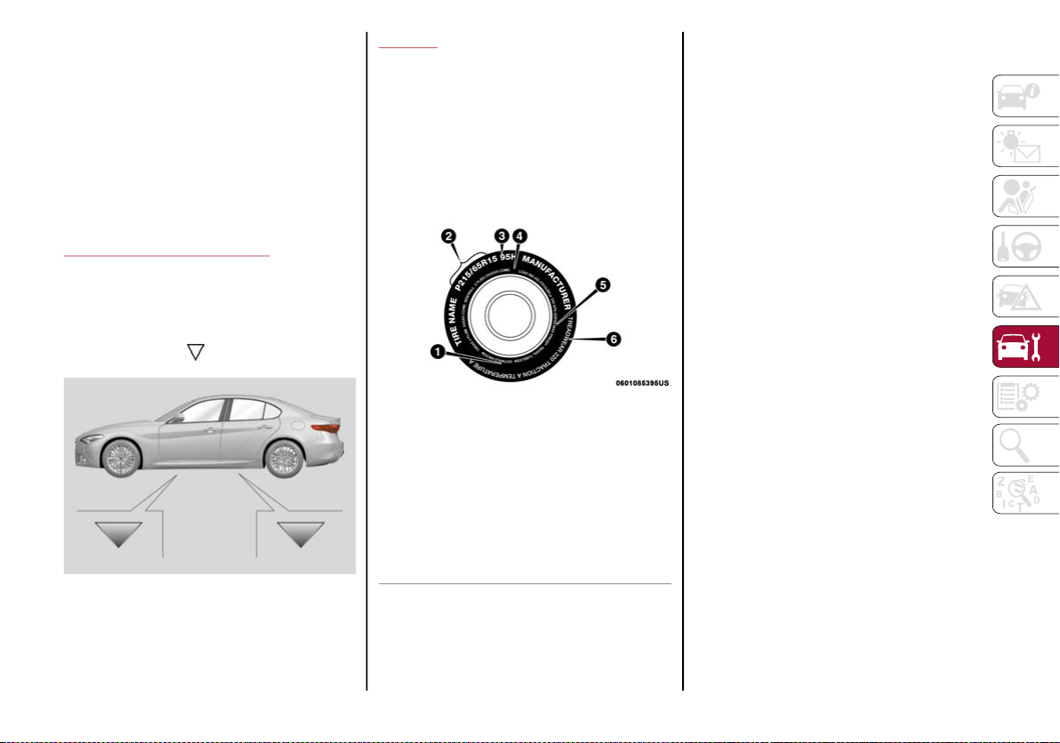
255
Follow the battery manufacturer's instructions
for maintenance.
NOTE:
It will not be possible to open the trunk with a key
or by pressing the button in the passenger
compartment when the battery is disconnected.
So, always position the manual trunk opening
strap on the trunk lock before disconnecting the
battery. The procedure is described in the
“Storing The Vehicle” section in this chapter.
RAISING THE VEHICLE
If the vehicle requires lifting, visit an autho-
rized dealer which is equipped with shop jacks
or jack arms.
The vehicle lifting points are marked on the
side skirts with the symbols.
Vehicle Lift Point Locations
TIRES
Tire Safety Information
Tire safety information will cover aspects of
the following information: Tire Markings, Tire
Identification Numbers, Tire Terminology and
Definitions, Tire Pressures, and Tire Loading.
Tire Markings
Tire Markings
NOTE:
P (Passenger) — Metric tire sizing is based
on US design standards. P-Metric tires have
the letter “P” molded into the sidewall
preceding the size designation. Example:
P215/65R15 95H.
European — Metric tire sizing is based on Euro-
pean design standards. Tires designed to this
standard have the tire size molded into the
sidewall beginning with the section width. The
letter "P" is absent from this tire size designa-
tion. Example: 215/65R15 96H.
LT (Light Truck) — Metric tire sizing is based
on US design standards. The size designa-
tion for LT-Metric tires is the same as for
P-Metric tires except for the letters “LT” that
are molded into the sidewall preceding the
size designation. Example: LT235/85R16.
Temporary spare tires are designed for
temporary emergency use only. Temporary
high pressure compact spare tires have the
letter “T” or “S” molded into the sidewall
preceding the size designation. Example:
T145/80D18 103M.
High flotation tire sizing is based on US
design standards and it begins with the tire
diameter molded into the sidewall.
Example: 31x10.5 R15 LT.
1 — US DOT Safety Standards Code (TIN)
2 — Size Designation
3 — Service Description
4 — Maximum Load
5 — Maximum Pressure
6 — Treadwear, Traction and Tempera-
ture Grades
20_GA_OM_EN_USC_t.book Page 255

SERVICING AND MAINTENANCE
256
Tire Sizing Chart
EXAMPLE:
Example Size Designation: P215/65R15XL 95H, 215/65R15 96H, LT235/85R16C, T145/80D18 103M, 31x10.5 R15 LT
P = Passenger car tire size based on US design standards, or
"....blank...." = Passenger car tire based on European design standards, or
LT = Light truck tire based on US design standards, or
T or S = Temporary spare tire or
31 = Overall diameter in inches (in)
215, 235, 145 = Section width in millimeters (mm)
65, 85, 80 = Aspect ratio in percent (%)
Ratio of section height to section width of tire, or
10.5 = Section width in inches (in)
R = Construction code
"R" means radial construction, or
"D" means diagonal or bias construction
15, 16, 18 = Rim diameter in inches (in)
Service Description:
95 = Load Index
A numerical code associated with the maximum load a tire can carry
H = Speed Symbol
A symbol indicating the range of speeds at which a tire can carry a load corresponding to its load index under certain operating conditions
The maximum speed corresponding to the speed symbol should only be achieved under specified operating conditions (i.e., tire pressure,
vehicle loading, road conditions, and posted speed limits)
20_GA_OM_EN_USC_t.book Page 256
257
Tire Identification Number (TIN)
The TIN may be found on one or both sides of the tire; however, the date code may only be on one side. Tires with white sidewalls will have the full
TIN, including the date code, located on the white sidewall side of the tire. Look for the TIN on the outboard side of black sidewall tires as mounted
on the vehicle. If the TIN is not found on the outboard side, then you will find it on the inboard side of the tire.
Load Identification:
Absence of the following load identification symbols on the sidewall of the tire indicates a Standard Load (SL) tire:
XL = Extra load (or reinforced) tire, or
LL = Light load tire or
C, D, E, F, G = Load range associated with the maximum load a tire can carry at a specified pressure
Maximum Load – Maximum load indicates the maximum load this tire is designed to carry
Maximum Pressure – Maximum pressure indicates the maximum permissible cold tire inflation pressure for this tire
EXAMPLE:
DOT MA L9 ABCD 0301
DOT = Department of Transportation
This symbol certifies that the tire is in compliance with the US Department of Transportation tire safety standards and is approved for highway use
MA = Code representing the tire manufacturing location (two digits)
L9 = Code representing the tire size (two digits)
ABCD = Code used by the tire manufacturer (one to four digits)
03 = Number representing the week in which the tire was manufactured (two digits)
03 means the 3rd week
01 = Number representing the year in which the tire was manufactured (two digits)
01 means the year 2001
Prior to July 2000, tire manufacturers were only required to have one number to represent the year in which the tire was manufactured.
Example: 031 could represent the 3rd week of 1981 or 1991
EXAMPLE:
20_GA_OM_EN_USC_t.book Page 257

SERVICING AND MAINTENANCE
258
Tire Terminology And Definitions
Term Definition
B-Pillar
The vehicle B-Pillar is the structural member of the body located behind the front door.
Cold Tire Inflation Pressure
Cold tire inflation pressure is defined as the tire pressure after the vehicle has not
been driven for at least three hours, or driven less than 1 mile (1.6 km) after sitting
for a minimum of three hours. Inflation pressure is measured in units of PSI (pounds
per square inch) or kPa (kilopascals).
Maximum Inflation Pressure
The maximum inflation pressure is the maximum permissible cold tire inflation
pressure for this tire. The maximum inflation pressure is molded into the sidewall.
Recommended Cold Tire Inflation Pressure
Vehicle manufacturer's recommended cold tire inflation pressure as shown on the
tire placard.
Tire Placard
A label permanently attached to the vehicle describing the vehicle’s loading capacity,
the original equipment tire sizes and the recommended cold tire inflation pressures.
20_GA_OM_EN_USC_t.book Page 258
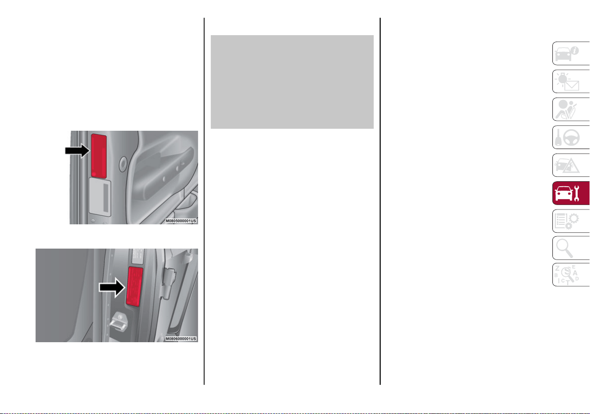
259
Tire Loading And Tire Pressure
NOTE:
The proper cold tire inflation pressure is listed
on the driver’s side B-Pillar or the rear edge of
the driver's side door.
Check the inflation pressure of each tire,
including the spare tire (if equipped), at least
monthly and inflate to the recommended pres-
sure for your vehicle.
Example Tire Placard Location (Door)
Example Tire Placard Location (B-Pillar)
Tire And Loading Information Placard
Tire And Loading Information Placard
This placard tells you important information
about the:
1. Number of people that can be carried in
the vehicle.
2. Total weight your vehicle can carry.
3. Tire size designed for your vehicle.
4. Cold tire inflation pressures for the front,
rear, and spare tires.
Loading
The vehicle maximum load on the tire must not
exceed the load carrying capacity of the tire on
your vehicle. You will not exceed the tire's load
carrying capacity if you adhere to the loading
conditions, tire size, and cold tire inflation pres-
sures specified on the Tire and Loading Informa-
tion placard in “Vehicle Loading” in the “Starting
And Operating” section of this manual.
NOTE:
Under a maximum loaded vehicle condition,
gross axle weight ratings (GAWRs) for the front
and rear axles must not be exceeded. For further
information on GAWRs, vehicle loading, and
trailer towing, refer to “Vehicle Loading” in the
“Starting And Operating” section of this manual.
To determine the maximum loading conditions
of your vehicle, locate the statement “The
combined weight of occupants and cargo
should never exceed XXX kg or XXX lbs” on the
Tire and Loading Information placard. The
combined weight of occupants, cargo/luggage
and trailer tongue weight (if applicable) should
never exceed the weight referenced here.
20_GA_OM_EN_USC_t.book Page 259

SERVICING AND MAINTENANCE
260
Steps For Determining Correct Load
Limit—
(1) Locate the statement “The
combined weight of occupants and
cargo should never exceed XXX kg or
XXX lbs.” on your vehicle's placard.
(2) Determine the combined weight of
the driver and passengers that will be
riding in your vehicle.
(3) Subtract the combined weight of the
driver and passengers from XXX kg or
XXX lbs.
(4) The resulting figure equals the avail-
able amount of cargo and luggage load
capacity. For example, if “XXX” amount
equals 1400 lbs. and there will be five
150 lb passengers in your vehicle, the
amount of available cargo and luggage
load capacity is 650 lbs. (1400-750
(5x150) = 650 lbs.)
(5) Determine the combined weight of
luggage and cargo being loaded on the
vehicle. That weight may not safely
exceed the available cargo and luggage
load capacity calculated in Step 4.
(6) If your vehicle will be towing a trailer,
load from your trailer will be transferred
to your vehicle. Consult this manual to
determine how this reduces the avail-
able cargo and luggage load capacity of
your vehicle.
Metric Example For Load Limit
For example, if “XXX” amount equals 635 kg
and there will be five 68 kg passengers in your
vehicle, the amount of available cargo and
luggage load capacity is 295 kg (635-340
(5x68) = 295 kg) as shown in step 4.
NOTE:
If your vehicle will be towing a trailer, load
from your trailer will be transferred to your
vehicle. The following table shows examples
on how to calculate total load, cargo/
luggage, and towing capacities of your
vehicle with varying seating configurations
and number and size of occupants. This
table is for illustration purposes only and
may not be accurate for the seating and
load carry capacity of your vehicle.
For the following example, the combined
weight of occupants and cargo should never
exceed 865 lbs (392 kg).
20_GA_OM_EN_USC_t.book Page 260

261
20_GA_OM_EN_USC_t.book Page 261

SERVICING AND MAINTENANCE
262
(Continued)
Tires — General Information
Tire Pressure
Proper tire inflation pressure is essential to
the safe and satisfactory operation of your
vehicle. Four primary areas are affected by
improper tire pressure:
Safety
Fuel Economy
Tread Wear
Ride Comfort and Vehicle Stability
Safety
Both underinflation and overinflation affect
the stability of the vehicle and can produce a
feeling of sluggish response or over respon-
siveness in the steering.
NOTE:
Unequal tire pressures from side to side
may cause erratic and unpredictable
steering response.
Unequal tire pressure from side to side may
cause the vehicle to drift left or right.
Fuel Economy
Underinflated tires will increase tire rolling resis-
tance resulting in higher fuel consumption.
Tread Wear
Improper cold tire inflation pressures can
cause abnormal wear patterns and reduced
tread life, resulting in the need for earlier tire
replacement.
Ride Comfort And Vehicle Stability
Proper tire inflation contributes to a comfort-
able ride. Overinflation produces a jarring and
uncomfortable ride.
Tire Inflation Pressures
The proper cold tire inflation pressure is listed
on the driver's side B-Pillar or rear edge of the
driver's side door.
At least once a month:
Check and adjust tire pressure with a good
quality pocket-type pressure gauge. Do not
make a visual judgment when determining
proper inflation. Tires may look properly
inflated even when they are underinflated.
Inspect tires for signs of tire wear or visible
damage.
WARNING!
Overloading of your tires is dangerous.
Overloading can cause tire failure, affect vehicle
handling, and increase your stopping distance.
Use tires of the recommended load capacity for
your vehicle. Never overload them.
WARNING!
Improperly inflated tires are dangerous
and can cause collisions.
Underinflation increases tire flexing and
can result in overheating and tire failure.
Overinflation reduces a tire's ability to
cushion shock. Objects on the road and
chuckholes can cause damage that result
in tire failure.
Overinflated or underinflated tires can affect
vehicle handling and can fail suddenly,
resulting in loss of vehicle control.
Unequal tire pressures can cause steering
problems. You could lose control of your
vehicle.
Unequal tire pressures from one side of
the vehicle to the other can cause the
vehicle to drift to the right or left.
Always drive with each tire inflated to the
recommended cold tire inflation pressure.
WARNING! (Continued)
20_GA_OM_EN_USC_t.book Page 262
263
Inflation pressures specified on the placard
are always “cold tire inflation pressure”. Cold
tire inflation pressure is defined as the tire
pressure after the vehicle has not been driven
for at least three hours, or driven less than
1 mile (1.6 km) after sitting for a minimum of
three hours. The cold tire inflation pressure
must not exceed the maximum inflation pres-
sure molded into the tire sidewall.
Check tire pressures more often if subject to a
wide range of outdoor temperatures, as tire
pressures vary with temperature changes.
Tire pressures change by approximately 1 psi
(7 kPa) per 12°F (7°C) of air temperature
change. Keep this in mind when checking tire
pressure inside a garage, especially in the
Winter.
Example: If garage temperature = 68°F
(20°C) and the outside temperature = 32°F
(0°C) then the cold tire inflation pressure
should be increased by 3 psi (21 kPa), which
equals 1 psi (7 kPa) for every 12°F (7°C) for
this outside temperature condition.
Tire pressure may increase from 2 to 6 psi (13
to 40 kPa) during operation. DO NOT reduce
this normal pressure build up or your tire pres-
sure will be too low.
Tire Pressures For High Speed Operation
The manufacturer advocates driving at safe
speeds and within posted speed limits. Where
speed limits or conditions are such that the
vehicle can be driven at high speeds, main-
taining correct tire inflation pressure is very
important. Increased tire pressure and
reduced vehicle loading may be required for
high-speed vehicle operation. Refer to an
authorized tire dealer or original equipment
vehicle dealer for recommended safe oper-
ating speeds, loading and cold tire inflation
pressures.
Recommended Cold Tire Inflation Pressures
For vehicle speeds below 100 mph (160 km/h),
recommended cold tire inflation pressures are
listed on the Tire And Loading Information
Placard located on driver’s side B-pillar or the
rear edge of the driver's side door.
When driving at speeds 100 mph (160 km/h)
and above, increased tire pressures and
reduced vehicle loading are required for
high-speed vehicle operation.
For driving speeds above 100 mph (160 km/h)
recommended cold tire inflation pressures are
listed below under "High Speed Tire Inflation
Pressure". Vehicle loading condition must not
exceed 688 lbs. (312 kg) (driver + three passen-
gers + 88 lbs. (40kg) luggage).
CAUTION!
After inspecting or adjusting the tire
pressure, always reinstall the valve stem
cap. This will prevent moisture and dirt from
entering the valve stem, which could
damage the valve stem.
WARNING!
High speed driving with your vehicle under
maximum load is dangerous. The added
strain on your tires could cause them to fail.
You could have a serious collision. Do not
drive a vehicle loaded to the maximum
capacity at continuous speeds above
75 mph (120 km/h).
WARNING!
High speed driving with your vehicle under
maximum load is dangerous. The added
strain on your tires could cause them to fail.
You could have a serious collision.
20_GA_OM_EN_USC_t.book Page 263

SERVICING AND MAINTENANCE
264
2.0L Engine
(*) All Season Tires, If Equipped
(**) Matching Rims/Tires
2.9L Engine
(*) Recommended tire size when tire chains are necessary. Refer to “Tire Chains” in “Servicing and Maintenance” for further information.
Tires Wheel
Recommended Cold Tire Inflation
Pressure
High Speed Tire Inflation Pressure
Front Rear Front Rear
225/50 R17 94W or 225/50
R17 94V *
17x7.5J 32 psi/220 kpa 35 psi/240 kpa 39 psi/270 kpa 43 psi/300 kpa
225/45 R18 91W or 225/45
R18 91V *
18x8J 32 psi/220 kpa 36 psi/250 kpa 39 psi/270 kpa 43 psi/300 kpa
225/40 R19 89W 19x8J 35 psi/240 kpa 39 psi/270 kpa 39 psi/270 kpa 43 psi/300 kpa
225/40 R19 89W ** 19x8J ** 35 psi/240 kpa – 39 psi/270 kpa –
255/35 R19 92W ** 19x9J** – 35 psi/240 kpa – 42 psi/290 kpa
Tires Wheel
Recommended Cold Tire Inflation
Pressure
High Speed Tire Inflation Pressure
Front Rear Front Rear
245/35 Z R19 (93Y) XL 19x8.5J 35 psi/240 kpa - 42 psi/290 kpa -
265/35 R19 98V* - - 32 psi/220 kpa - 42 psi/290 kpa
285/30 ZR19 (98Y) XL 19x10J - 32 psi/220 kpa - 42 psi/290 kpa
20_GA_OM_EN_USC_t.book Page 264
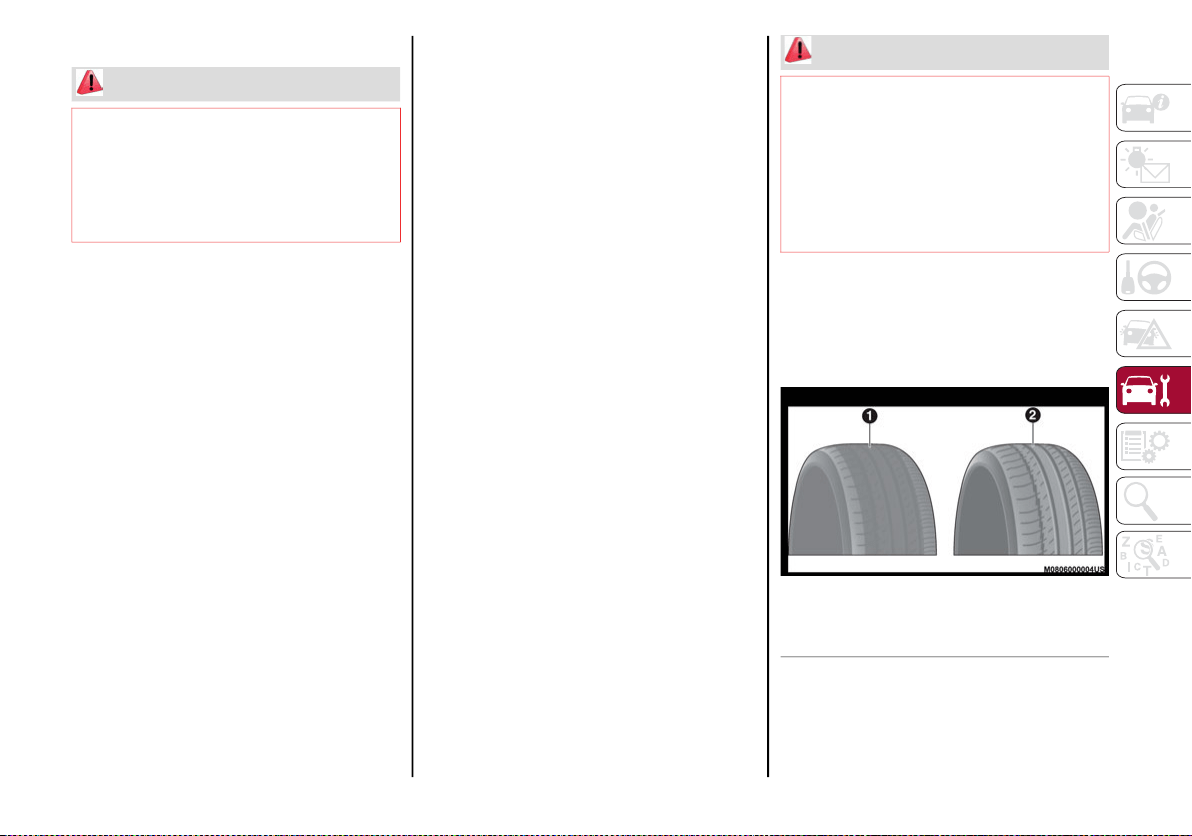
265
Radial Ply Tires
Tire Repair
If your tire becomes damaged, it may be
repaired if it meets the following criteria:
The tire has not been driven on when flat.
The damage is only on the tread section of
your tire (sidewall damage is not repair-
able).
The puncture is no greater than a ¼ of an
inch (6 mm).
Consult an authorized tire dealer for tire
repairs and additional information.
Damaged Run Flat tires, or Run Flat tires that
have experienced a loss of pressure should be
replaced immediately with another Run Flat
tire of identical size and service description
(Load Index and Speed Symbol). Replace the
tire pressure sensor as well as it is not
designed to be reused.
Run Flat Tires — If Equipped
Run Flat tires allow you the capability to drive
50 miles (80 km) at 50 mph (80 km/h) after a
rapid loss of inflation pressure. This rapid loss
of inflation is referred to as the Run Flat mode.
A Run Flat mode occurs when the tire inflation
pressure is of/or below 14 psi (96 kPa). Once
a Run Flat tire reaches the run flat mode it has
limited driving capabilities and needs to be
replaced immediately. A Run Flat tire is not
repairable. When a run flat tire is changed
after driving with underinflated tire condition,
please replace the TPM sensor as it is not
designed to be reused when driven under run
flat mode 14 psi (96 kPa) condition.
NOTE:
TPM Sensor must be replaced after driving the
vehicle on a flat tire condition.
It is not recommended driving a vehicle loaded
at full capacity or to tow a trailer while a tire is
in the run flat mode.
See the tire pressure monitoring section for
more information.
Tire Spinning
When stuck in mud, sand, snow, or ice condi-
tions, do not spin your vehicle's wheels above
30 mph (48 km/h) or for longer than 30 seconds
continuously without stopping.
Tread Wear Indicators
Tread wear indicators are in the original equip-
ment tires to help you in determining when
your tires should be replaced.
Tire Tread
WARNING!
Combining radial ply tires with other types
of tires on your vehicle will cause your
vehicle to handle poorly. The instability
could cause a collision. Always use radial
ply tires in sets of four. Never combine them
with other types of tires.
WARNING!
Fast spinning tires can be dangerous. Forces
generated by excessive wheel speeds may cause
tire damage or failure. A tire could explode and
injure someone. Do not spin your vehicle's
wheels faster than 30 mph (48 km/h) for more
than 30 seconds continuously when you are
stuck, and do not let anyone near a spinning
wheel, no matter what the speed.
1 — Worn Tire
2 — New Tire
20_GA_OM_EN_USC_t.book Page 265

SERVICING AND MAINTENANCE
266
(Continued)
These indicators are molded into the bottom of
the tread grooves. They will appear as bands
when the tread depth becomes a 1/16 of an inch
(1.6 mm). When the tread is worn to the tread
wear indicators, the tire should be replaced.
Refer to “Replacement Tires” in this section
for further information.
Life Of Tire
The service life of a tire is dependent upon
varying factors including, but not limited to:
Driving style.
Tire pressure - Improper cold tire inflation
pressures can cause uneven wear patterns
to develop across the tire tread. These
abnormal wear patterns will reduce tread
life, resulting in the need for earlier tire
replacement.
Distance driven.
Performance tires, tires with a speed rating
of V or higher, and Summer tires typically
have a reduced tread life. Rotation of these
tires per the vehicle scheduled mainte-
nance is highly recommended.
NOTE:
Wheel Valve Stem must be replaced as well
when installing new tires due to wear and tear
in existing tires.
Keep dismounted tires in a cool, dry place with
as little exposure to light as possible. Protect
tires from contact with oil, grease, and gasoline.
Replacement Tires
The tires on your new vehicle provide a
balance of many characteristics. They should
be inspected regularly for wear and correct
cold tire inflation pressures. The manufacturer
strongly recommends that you use tires equiv-
alent to the originals in size, quality and perfor-
mance when replacement is needed. Refer to
the paragraph on “Tread Wear Indicators” in
this section. Refer to the Tire and Loading
Information placard or the Vehicle Certifica-
tion Label for the size designation of your tire.
The Load Index and Speed Symbol for your tire
will be found on the original equipment tire
sidewall.
See the Tire Sizing Chart example found in the
“Tire Safety Information” section of this
manual for more information relating to the
Load Index and Speed Symbol of a tire.
It is recommended to replace the two front
tires or two rear tires as a pair. Replacing just
one tire can seriously affect your vehicle’s
handling. If you ever replace a wheel, make
sure that the wheel’s specifications match
those of the original wheels.
It is recommended you contact an authorized
tire dealer or original equipment dealer with
any questions you may have on tire specifica-
tions or capability. Failure to use equivalent
replacement tires may adversely affect the
safety, handling, and ride of your vehicle.
WARNING!
Tires and the spare tire should be replaced
after six years, regardless of the remaining
tread. Failure to follow this warning can
result in sudden tire failure. You could lose
control and have a collision resulting in
serious injury or death.
WARNING!
Do not use a tire, wheel size, load rating, or
speed rating other than that specified for your
vehicle. Some combinations of unapproved
tires and wheels may change suspension
dimensions and performance characteristics,
resulting in changes to steering, handling, and
braking of your vehicle. This can cause unpre-
dictable handling and stress to steering and
suspension components. You could lose
control and have a collision resulting in serious
injury or death. Use only the tire and wheel
sizes with load ratings approved for your
vehicle.
20_GA_OM_EN_USC_t.book Page 266
267
Spare Tires — If Equipped
NOTE:
For vehicles equipped with Tire Service Kit
instead of a spare tire, please refer to “Tire
Service Kit” in “In Case Of Emergency” for
further information.
Spare Tire Matching Original Equipped Tire
And Wheel — If Equipped
Your vehicle may be equipped with a spare tire
and wheel equivalent in look and function to
the original equipment tire and wheel found on
the front or rear axle of your vehicle. This spare
tire may be used in the tire rotation for your
vehicle. If your vehicle has this option, refer to
an authorized tire dealer for the recom-
mended tire rotation pattern.
Full Size Spare — If Equipped
The full size spare is for temporary emergency
use only. This tire may look like the originally
equipped tire on the front or rear axle of your
vehicle, but it is not. This spare tire may have
limited tread life. When the tread is worn to the
tread wear indicators, the temporary use full
size spare tire needs to be replaced. Since it is
not the same as your original equipment tire,
replace (or repair) the original equipment tire
and reinstall on the vehicle at the first oppor-
tunity.
Limited Use Spare — If Equipped
The limited use spare tire is for temporary
emergency use only. This tire is identified by a
label located on the limited use spare wheel.
This label contains the driving limitations for
this spare. This tire may look like the original
equipped tire on the front or rear axle of your
vehicle, but it is not. Installation of this limited
use spare tire affects vehicle handling. Since it
is not the same as your original equipment
tire, replace (or repair) the original equipment
tire and reinstall on the vehicle at the first
opportunity.
Never use a tire with a smaller load index
or capacity, other than what was originally
equipped on your vehicle. Using a tire with
a smaller load index could result in tire
overloading and failure. You could lose
control and have a collision.
Failure to equip your vehicle with tires
having adequate speed capability can
result in sudden tire failure and loss of
vehicle control.
CAUTION!
Replacing original tires with tires of a different
size may result in false speedometer and
odometer readings.
WARNING! (Continued)
CAUTION!
Because of the reduced ground clearance,
do not take your vehicle through an
automatic car wash with a compact or
limited use temporary spare installed.
Damage to the vehicle may result.
WARNING!
Limited use spares are for emergency use
only. Installation of this limited use spare
tire affects vehicle handling. With this tire,
do not drive more than the speed listed on
the limited use spare wheel. Keep inflated
to the cold tire inflation pressures listed on
your Tire and Loading Information Placard
located on the driver’s side B-Pillar or the
rear edge of the driver’s side door. Replace
(or repair) the original equipment tire at the
first opportunity and reinstall it on your
vehicle. Failure to do so could result in loss
of vehicle control.
20_GA_OM_EN_USC_t.book Page 267

SERVICING AND MAINTENANCE
268
Wheel And Wheel Trim Care
All wheels and wheel trim, especially aluminum
and chrome plated wheels, should be cleaned
regularly using mild (neutral Ph) soap and water
to maintain their luster and to prevent corrosion.
Wash wheels with the same soap solution
recommended for the body of the vehicle and
remember to always wash when the surfaces are
not hot to the touch.
Your wheels are susceptible to deterioration
caused by salt, sodium chloride, magnesium
chloride, calcium chloride, etc., and other road
chemicals used to melt ice or control dust on
dirt roads. Use a soft cloth or sponge and mild
soap to wipe away promptly. Do not use harsh
chemicals or a stiff brush. They can damage
the wheel’s protective coating that helps keep
them from corroding and tarnishing.
When cleaning extremely dirty wheels including
excessive brake dust, care must be taken in the
selection of tire and wheel cleaning chemicals
and equipment to prevent damage to the wheels.
Select a non-abrasive, non-acidic cleaner for
aluminum or chrome wheels.
NOTE:
If you intend parking or storing your vehicle for
an extended period after cleaning the wheels
with wheel cleaner, drive your vehicle and
apply the brakes to remove the water droplets
from the brake components. This activity will
remove the red rust on the brake rotors and
prevent vehicle vibration when braking.
Dark Or Low Gloss Wheels
Tire Types
All Season Tires — If Equipped
All Season tires provide traction for all seasons
(Spring, Summer, Autumn, and Winter). Trac-
tion levels may vary between different all
season tires. All season tires can be identified
by the M+S, M&S, M/S or MS designation on
the tire sidewall. Use all season tires only in
sets of four; failure to do so may adversely
affect the safety and handling of your vehicle.
Summer Or Three Season Tires — If
Equipped
Summer tires provide traction in both wet and
dry conditions, and are not intended to be
driven in snow or on ice. If your vehicle is
equipped with Summer tires, be aware these
tires are not designed for Winter or cold driving
conditions. Install Winter tires on your vehicle
when ambient temperatures are less than
40°F (5°C) or if roads are covered with ice or
snow. For more information, contact an autho-
rized dealer.
Summer tires do not contain the all season
designation or mountain/snowflake symbol on
the tire sidewall. Use Summer tires only in sets
of four; failure to do so may adversely affect
the safety and handling of your vehicle.
CAUTION!
Avoid products or automatic car washes that
use acidic solutions or strong alkaline
additives or harsh brushes. Many aftermarket
wheel cleaners and automatic car washes
may damage the wheel's protective finish.
Such damage is not covered by the New
Vehicle Limited Warranty. Only car wash soap
is recommended.
CAUTION!
Do not use scouring pads, steel wool, a bristle
brush, metal polishes or oven cleaner. These
products may damage the wheel's protective
finish. Such damage is not covered by the
New Vehicle Limited Warranty. Only car wash
soap is recommended.
CAUTION!
If your vehicle is equipped with these
specialty wheels, DO NOT USE wheel
cleaners, abrasives, or polishing compounds.
They will permanently damage this finish and
such damage is not covered by the New
Vehicle Limited Warranty. HAND WASH ONLY
USING MILD SOAP AND WATER WITH A SOFT
CLOTH. Used on a regular basis; this is all that
is required to maintain this finish.
20_GA_OM_EN_USC_t.book Page 268
269
Snow Tires
Some areas of the country require the use of
snow tires during the Winter. Snow tires can
be identified by a “mountain/snowflake”
symbol on the tire sidewall.
If you need snow tires, select tires
equivalent in size and type to the
original equipment tires. Use snow
tires only in sets of four; failure to do
so may adversely affect the safety and
handling of your vehicle.
Snow tires generally have lower speed ratings
than what was originally equipped with your
vehicle and should not be operated at
sustained speeds over 75 mph (120 km/h).
For speeds above 75 mph (120 km/h) refer to
original equipment or an authorized tire dealer
for recommended safe operating speeds,
loading and cold tire inflation pressures.
While studded tires improve performance on
ice, skid and traction capability on wet or dry
surfaces may be poorer than that of
non-studded tires. Some states prohibit
studded tires; therefore, local laws should be
checked before using these tire types.
Tire Chains And Traction Devices
Use of traction devices require sufficient
tire-to-body clearance. Follow these recom-
mendations to guard against damage.
NOTE:
Traction device must be of proper size for
the tire, as recommended by the traction
device manufacturer
Use on rear tires only
Due to limited clearance, the following trac-
tion devices are recommended:
For a 255/35R19 tire, use of a snow trac-
tion device with a maximum projection of
7 mm beyond the tire profile is recom-
mended.
For 225/50R17, 225/45R18 or 225/40R19
tires, use of a snow traction device with a
maximum projection of 9 mm beyond the tire
profile is recommended.
For a 265/35R19 98V tire, use of a
zero-clearance snow traction device recom-
mended.
It is not possible to install traction devices on
285/30R19 tires.
WARNING!
Do not use Summer tires in snow/ice
conditions. You could lose vehicle control,
resulting in severe injury or death. Driving
too fast for conditions also creates the
possibility of loss of vehicle control.
CAUTION!
To avoid damage to your vehicle or tires,
observe the following precautions:
Because of restricted traction device
clearance between tires and other
suspension components, it is important
that only traction devices in good condi-
tion are used. Broken devices can cause
serious damage. Stop the vehicle immedi-
ately if noise occurs that could indicate
device breakage. Remove the damaged
parts of the device before further use.
Install device as tightly as possible and
then retighten after driving about ½ mile
(0.8 km).
Do not exceed 30 mph (48 km/h).
Drive cautiously and avoid severe turns
and large bumps, especially with a loaded
vehicle.
Do not drive for a prolonged period on dry
pavement.
Observe the traction device manufac-
turer’s instructions on the method of
installation, operating speed, and condi-
tions for use. Always use the suggested
operating speed of the device manufac-
turer’s if it is less than 30 mph (48 km/h).
Do not use traction devices on a compact
spare tire.
20_GA_OM_EN_USC_t.book Page 269
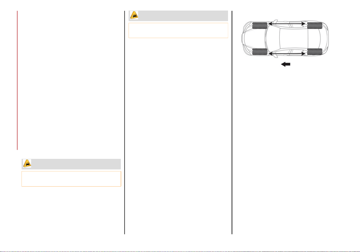
SERVICING AND MAINTENANCE
270
Tire Rotation Recommendations
Tires on the front and rear axles of vehicles
operate at different loads and perform
different steering, driving, and braking func-
tions. For these reasons, they wear at unequal
rates. These effects can be reduced by timely
rotation of tires. Rotation will increase tread
life, maintain traction levels and contribute to
a smooth, quiet ride.
To resolve this problem, tires should be rotated
at each service interval (approximately every
10,000 miles [16,000km]). More frequent rota-
tion is permissible if desired. The reasons for any
rapid or unusual wear should be corrected prior
to rotation being performed.
Tire Rotations Not Recommended — If
Equipped
Due to different size tires and wheels on front
and rear axles tire rotation is not possible for:
2.0T GME Engine Equipped with a 225/40R19
front and 255/35R19 rear tires
2.9L V6 Engine Equipped with 19” tires and
wheels
Tire rotation contributes to the preservation of
the grip and traction performance on wet,
muddy or snowy roads, guaranteeing optimal
driveability of the vehicle.
In the case of irregular wear of the tires iden-
tify the cause and correct it as soon as
possible, by contacting an authorized dealer.
Tire Rotation for Directional Tires — If
Equipped
Directional tires are equipped on the following:
2.0T GME Engine equipped with same size
tires and wheels on front and rear axles
The rotational direction of the tire must be
taken into consideration when rotating the
tires. The recommended rotation pattern for
directional tires is shown below.
Tire Rotation
All Wheel Drive (AWD) Models
It is recommended to avoid situations with a
large difference in wear between the front and
rear tires and to strictly use Winter tires of the
sizes given on the tire placard.
The AWD system and the original tires are
developed together to ensure the vehicle’s
best performance. When changing the tires, it
is recommended to us the same “AR” marked
tires, to maintain the same level of perfor-
mance and component life.
CAUTION!
Damage to the vehicle may occur if 225/40R19
front and 255/35R19 rear tires are rotated
CAUTION!
Damage to the vehicle may occur if 19”
front and rear tires are rotated
20_GA_OM_EN_USC_t.book Page 270
271
DEPARTMENT OF
TRANSPORTATION UNIFORM
TIRE QUALITY GRADES
The following tire grading categories were
established by the National Highway
Traffic Safety Administration. The specific
grade rating assigned by the tire's manu-
facturer in each category is shown on the
sidewall of the tires on your vehicle.
All passenger vehicle tires must
conform to Federal safety require-
ments in addition to these grades.
Treadwear
The Treadwear grade is a comparative
rating, based on the wear rate of the tire
when tested under controlled conditions on
a specified government test course. For
example, a tire graded 150 would wear one
and one-half times as well on the govern-
ment course as a tire graded 100. The rela-
tive performance of tires depends upon the
actual conditions of their use, however, and
may depart significantly from the norm due
to variations in driving habits, service prac-
tices, and differences in road characteris-
tics and climate.
Traction Grades
The Traction grades, from highest to
lowest, are AA, A, B, and C. These
grades represent the tire's ability to
stop on wet pavement, as measured
under controlled conditions on speci-
fied government test surfaces of
asphalt and concrete. A tire marked C
may have poor traction performance.
Temperature Grades
The temperature grades are A (the
highest), B, and C, representing the
tire's resistance to the generation of
heat and its ability to dissipate heat,
when tested under controlled condi-
tions on a specified indoor laboratory
test wheel. Sustained high temperature
can cause the material of the tire to
degenerate and reduce tire life, and
excessive temperature can lead to
sudden tire failure. The grade C corre-
sponds to a level of performance, which
all passenger vehicle tires must meet
under the Federal Motor Vehicle Safety
Standard No. 109. Grades B and A
represent higher levels of performance
on the laboratory test wheel, than the
minimum required by law.
WARNING!
The traction grade assigned to this tire is
based on straight-ahead braking traction
tests, and does not include acceleration,
cornering, hydroplaning, or peak traction
characteristics.
WARNING!
The temperature grade for this tire is
established for a tire that is properly inflated
and not overloaded. Excessive speed,
underinflation, or excessive loading, either
separately or in combination, can cause heat
buildup and possible tire failure.
20_GA_OM_EN_USC_t.book Page 271
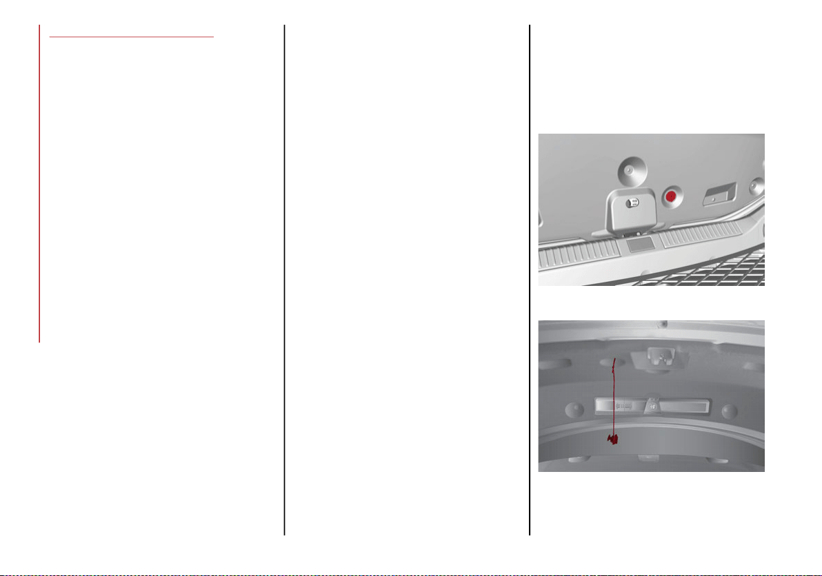
SERVICING AND MAINTENANCE
272
STORING THE VEHICLE
If the vehicle is left inactive for longer than a
month, the following precautions should be
observed:
Park the vehicle in an area that is covered
and dry, and well-ventilated if possible.
Slightly open the windows.
Check that the electric park brake is not
activated.
Carry out the procedure: “manual trunk
opening device” procedure described in this
paragraph.
Disconnect the negative battery terminal
and check the battery charge. Repeat this
check once every three months during
storage.
If the battery is not disconnected from the
electrical system, check its state of charge
every thirty days.
Clean and protect the painted parts using
protective wax.
Clean and protect the shiny metal parts using
special compounds available commercially.
Sprinkle talcum powder on the windshield
wiper rubber blades, and lift them off the
glass.
Cover the vehicle with a fabric or perforated
plastic sheet, paying particular care not to
damage the painted surface by dragging
any dust that may have accumulated on it.
Do not use compact plastic sheets, as they
do not allow humidity to evaporate from the
surface of the vehicle.
Inflate tires to +7.25 psi (+0.5 bar) above
the standard prescribed pressure and
check it periodically.
Do not drain the engine cooling system.
Any time the vehicle is left inactive for two weeks
or more, operate the air conditioning system with
engine idling for at least five minutes, setting
external air and with fan set to maximum speed.
This operation will ensure appropriate lubrica-
tion for the system, thus minimizing the possi-
bility of damage to the compressor when the
system is operated again.
NOTE:
After placing the ignition in STOP and having
closed the driver side door, wait at least one
minute before disconnecting the electrical
supply from the battery. When reconnecting
the electrical supply to the battery, make sure
that the ignition is in the STOP position and the
driver side door is closed.
Manual Trunk Opening Device
Proceed as follows if the battery needs to be
disconnected:
1. From the trunk interior covering, rotate the
plug counterclockwise of the lock and
extract the cord connected to it.
Trunk Compartment
Trunk Manual Release Cord
20_GA_OM_EN_USC_t.book Page 272
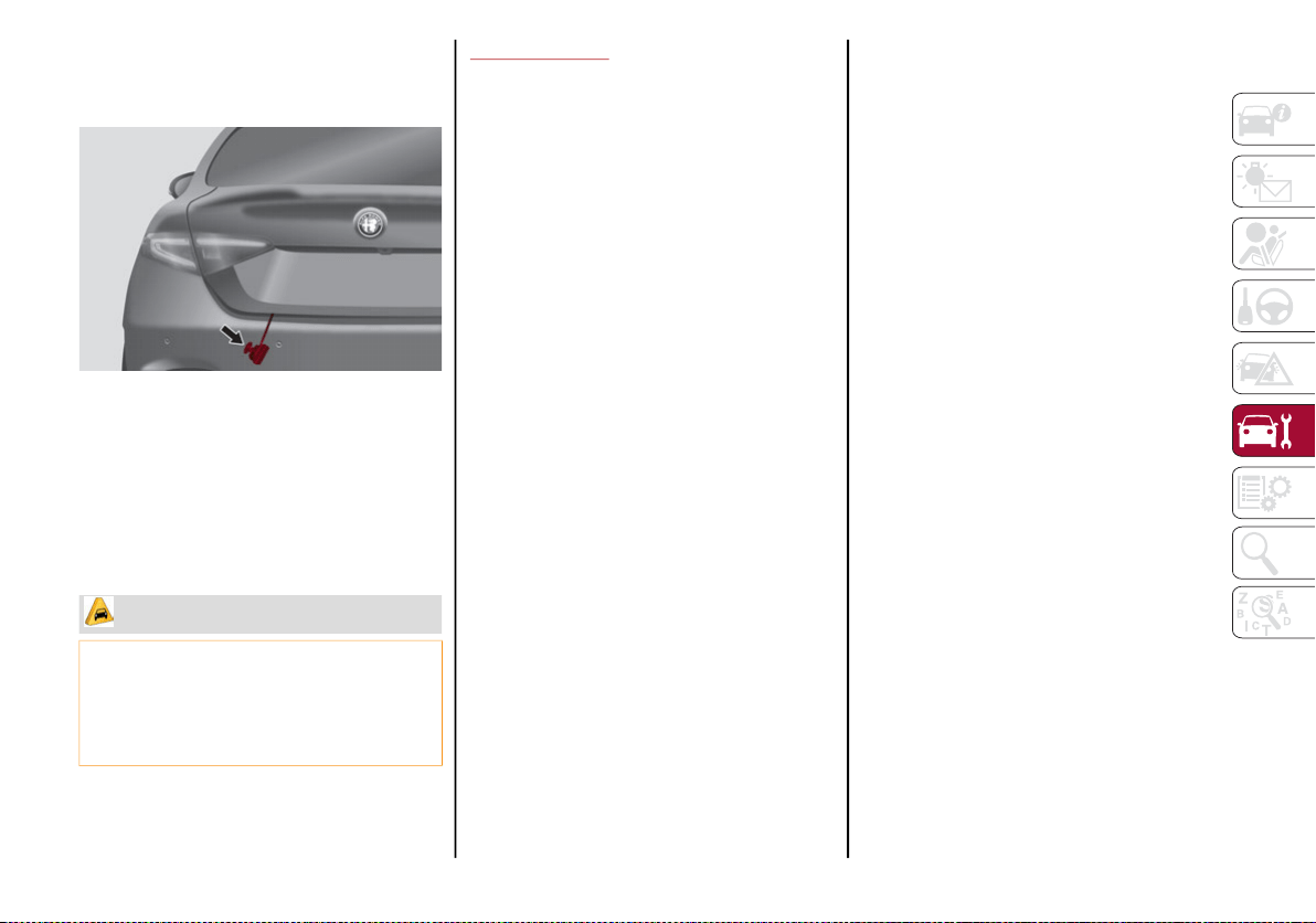
273
2. Make sure the free end of the cord
remains outside the trunk when closing
the trunk lid.
Manual Release Cord Shown With Trunk
Closed
3. The trunk can now be opened manually by
pulling the cord.
4. After releasing the trunk, rewind the strap
around the plug, put it back into its
housing and turn it clockwise.
BODYWORK
Protection Against Atmospheric Agents
The vehicle is equipped with the best available
technological solutions to protect the body-
work against corrosion.
These include:
Painting products and systems which give
the vehicle resistance to corrosion and
abrasion.
Use of galvanized (or pre-treated) steel
sheets, with high resistance to corrosion.
Spraying of plastic parts, with a protective
function in the more exposed points: under-
door, inner wing, edges, etc.
Use of “open” boxed sections to prevent
condensation and pockets of moisture which
could favor the formation of rust inside.
Use of special films to protect against abrasion in
exposed areas (e.g. rear wing, doors, etc.).
Corrosion Warranty
Your vehicle is covered by Corrosion Warranty
against perforation due to rust of any original
element of the structure or bodywork. For the
general terms of this warranty, refer to the
Warranty Booklet.
Preserving The Bodywork
Paint
Touch up abrasions and scratches immedi-
ately to prevent the formation of rust.
Maintenance of paintwork consists of washing
the car: the frequency depends on the condi-
tions and environment where the car is used.
For example, it is advisable to wash the vehicle
more often in areas with high levels of atmo-
spheric pollution or salted roads.
Some parts of the vehicle may be covered with
a matte paint which, in order to be maintained
intact, requires special care.
To correctly wash the vehicle, follow these
instructions:
If high pressure jets or cleaners are used to
wash the vehicle, keep a distance of at least
15 inches (40 cm) from the bodywork to
avoid damage or alteration. Build up of
water could cause damage to the vehicle in
the long term.
To make it easier to remove any dirt
deposits in the area where the blades are
normally located it is recommended to posi-
tion the windshield wipers vertically (service
position), for more information, refer to
“Dealer Service” in this chapter.
CAUTION!
The Manual Trunk Opening Device allows
the trunk to be opened without a key, even
if the vehicle is locked. Do not use this
Device unless the vehicle is parked in a
secure area.
20_GA_OM_EN_USC_t.book Page 273

SERVICING AND MAINTENANCE
274
Wash the bodywork using a low pressure jet
of water if possible.
Wipe a sponge with a slightly soapy solution
over the bodywork, frequently rinsing the
sponge.
Rinse well with water and dry with a leather
chamois.
Dry the less visible parts (e.g. door frames,
hood, headlight frames, etc.) with special care,
as water may stagnate more easily in these
areas. Do not wash the car after it has been
left in the sun or with the hood hot: this may
alter the shine of the paintwork.
Exterior plastic parts must be cleaned in the
same way as the rest of the vehicle.
If washing the car in a service that moves the
car, for cars with automatic transmissions,
PARK (P) must be cut out. You have to shut off
the engine in the following conditions: car
stopped, transmission in NEUTRAL (N), push
the starter button for at least three seconds.
NOTE:
Avoid parking under trees; the resin dropped
by trees makes the paintwork go opaque and
increases the possibility of corrosion.
Windows
Use specific detergents and clean cloths to
prevent scratching or altering the transparency.
Front Headlights
Use a soft cloth soaked in water and detergent
for washing cars.
NOTE:
Never use aromatic substances (e.g. gaso-
line) or ketones (e.g. acetone) for cleaning
the plastic lenses of the headlights.
When cleaning with a pressure washer,
keep the pressure washer at least eight
inches (20 cm) away from the headlights.
Engine Compartment
At the end of every Winter, wash the engine
compartment thoroughly, taking care not to
aim the jet of water directly at the electronic
control units or at the windshield wiper
motors. Have this operation performed at a
specialized workshop. Refer to “Pressure
Washing” in “Engine Compartment” for further
information.
NOTE:
The washing should take place with the engine
cold and the ignition device in the STOP position.
After the washing operation, make sure that the
various protections (e.g. rubber caps and guards)
have not been removed or damaged.
INTERIORS
Periodically check the cleanliness of the inte-
rior, beneath the mats, which could cause
oxidation of the sheet metal.
Seats And Fabric Parts
Remove dust with a soft brush or a vacuum
cleaner. Rub the seats with a sponge moist-
ened with a solution of water and neutral
detergent.
Cleaning heat press images on seats — if
equipped:
Due to the color, opacity and wear-resistant
protection with which the heat press images
on some seats are made, they may be subject
to temporary scratching if they are touched by
finger nails, keys, or other hard objects. In
such cases, the visible signs do not impair the
profiled images, and can easily be removed by
wiping the affected area with a microfiber
cloth moistened with water (not dry) to restore
the seat to its original condition. The micro-
fiber cloth must not have been previously
soaked in other substances or detergents.
CAUTION!
Wipe the rear window inside gently with a
cloth following the direction of the filaments
to avoid damaging the heating device.
20_GA_OM_EN_USC_t.book Page 274
275
Leather Seats
Remove the dry dirt with a chamois or slightly
damp cloth, without exerting too much pressure.
Remove any liquid or grease stains using an
absorbent dry cloth, without rubbing. Then
clean with a soft cloth or buckskin cloth damp-
ened with water and mild soap. If the stain
persists, use specific products and observe
the instructions carefully.
NOTE:
Never use alcohol. Make sure that the
cleaning products used contain no alcohol or
alcohol derivatives, even in small quantities.
Plastic And Coated Parts
Clean interior plastic parts with a damp cloth (if
possible made from microfiber), and a solution of
water and neutral, non-abrasive detergent.
To clean oily or persistent stains, use specific
products free from solvents and designed to
maintain the original appearance and color of
the components.
Remove any dust using a microfiber cloth, if
necessary moistened with water. The use of
paper tissues is not recommended as these
may leave residues.
Alcantara Parts — If Equipped
Alcantara parts maintenance procedure:
Treat the surface with a microfiber cloth
moistened with mild marseille soap and
water, taking care to apply a uniform light
pressure over the entire area (do not rub
vigorously).
Rinse and wring out the microfiber cloth,
and pass it over the entire area again.
Let it dry, and then brush gently with a soft
brush.
Genuine Leather Parts — If Equipped
Use only water and mild soap to clean these
parts. Never use alcohol or alcohol-based
products.
Before using a specific product for cleaning
interiors, make sure that it does not contain
alcohol and/or alcohol based substances.
Carbon Fiber Parts
To eliminate small scratches and marks on the
carbon, contact an authorized dealer. An
improperly performed operation may irrepa-
rably damage the carbon.
CAUTION!
Do not use “hard” synthetic brushes as
they can damage the fabric.
Do not clean small areas because it could
cause “aesthetic” differences between
treated and untreated areas.
Do not use alcohol or acetone-based
solvents.
20_GA_OM_EN_USC_t.book Page 275
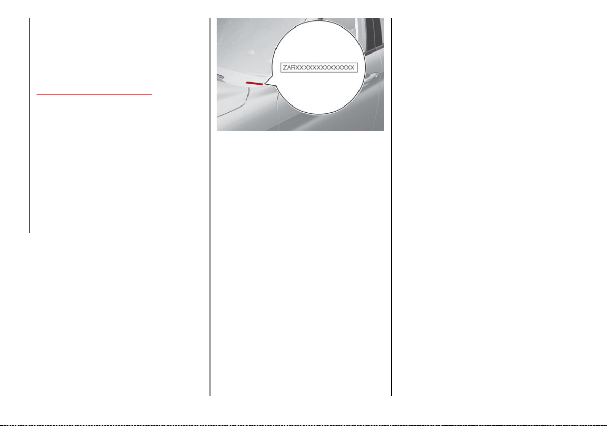
276
TECHNICAL SPECIFICATIONS
For the enthusiasts, the technician, or those
who just want to know every detail of their
vehicle, useful information on understanding
how your vehicle works is contained in this
chapter and illustrated with data, tables, and
graphics.
IDENTIFICATION DATA
Vehicle Identification Number
The Vehicle Identification Number (VIN) is
stamped on a plate on the front left corner of
the dashboard cover, which can be seen from
outside the vehicle, through the windshield.
Windshield VIN Location
Vehicle Identification Number (VIN) Plate
The plates are located on the left side A-pillar
and contain the data about:
Vehicle Identification Number (VIN).
Vehicle type (USA and Canada only).
Color code.
Place of manufacturing of the vehicle (USA and
Mexico only).
Vehicle manufacturing date.
Maximum permitted weights.
Permitted tire inflation pressure (USA and
Canada only).
20_GA_OM_EN_USC_t.book Page 276

277
ENGINE
2.0L T4 MAir Engine 280 HP
Cycle Four
Number and position of cylinders 4 inline
Piston bore and stroke (mm) 84 / 90
Total displacement (cm³) 1,995
Compression ratio 10:1
Maximum power (SAE) (HP) 280
Maximum power (kW) 209
Corresponding engine speed (RPM) 5,200
Maximum torque (SAE) (ft-lb) 306
Maximum torque (Nm) 415
Corresponding engine speed (RPM) 3,300 – 4,400
Fuel
87 Octane (R+M)/2 Method Minimum, 91 Recommended,
ethanol percentage is 0–15%.
2.9L V6 Engine
Cycle Four
Number and position of cylinders 6 / V
Piston bore and stroke (mm) 86.5 × 82
Total displacement (cm³) 2,891
Compression ratio 9.3:1
Maximum power (SAE) (kW) 375
20_GA_OM_EN_USC_t.book Page 277

TECHNICAL SPECIFICATIONS
278
POWER SUPPLY
TRANSMISSION
Maximum power (SAE) (HP) 505
Corresponding engine speed (RPM) 6,500
Maximum torque (SAE) (Nm) 600
Maximum torque (SAE) (ft. lb) 443
Corresponding engine speed (RPM) 2,500
Fuel
87 Octane (R+M)/2 Method Minimum, 91 Recommended,
ethanol percentage is 0–15%.
Power Supply
2.0L T4 MAir Engine Electronic timed sequential injection with knock control
Power supply
2.9L V6 Engine
Phased sequential electronic injection with knock control and variable
intake valve actuation
Model Transmission Traction
2.0L T4 MAir Engine Eight forward gears plus reverse
Rear-wheel drive
or
All-wheel drive
Model Transmission Traction
2.9L V6 Engine Eight forward gears plus reverse Rear
2.9L V6 Engine
20_GA_OM_EN_USC_t.book Page 278
279
BRAKES
SUSPENSION
STEERING SYSTEM
Model Front brakes Rear brakes Parking brake
2.0L T4 MAir Engine Disc Disc Electric
Model Front brakes Rear brakes Parking brake
2.9L V6 Engine
Disc
or
Carbon Ceramic disc
Disc
or
Carbon Ceramic disc
Electric
CAUTION!
Water, ice and salt spread on the roads may deposit on the brake discs, reducing braking efficiency the first time the brakes are applied.
To obtain the maximum efficiency of the braking system, a bedding-in period of about 300 miles (500 km) is needed: during this period it is
better to avoid sharp, repeated and prolonged braking.
Model Front Rear
2.0L T4 MAir Engine and 2.9L V6 Engine
Independent wheel double-wishbone
suspension
Independent wheel with multi-link system
Model Curb-to-curb turning circle Type
2.0L T4 MAir Engine 35.50 ft (10.80 m)
Rack and pinion with electric power
steering
Model Curb-to-curb turning circle Type
2.9L V6 Engine 37.10 ft (11.30 m)
Rack and pinion with electric power
steering
20_GA_OM_EN_USC_t.book Page 279
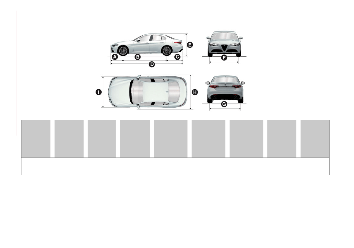
TECHNICAL SPECIFICATIONS
280
DIMENSIONS — 2.0L T4 MAir Engine
Dimensions are expressed in inches and refer to the vehicle equipped with its standard-supplied tires. Height is measured with vehicle unladen.
Small variations with respect to the reported values are possible depending on the dimensions of the rims.
A
Front
Overhang
B
Wheelbase
C
Rear
Overhang
D
Overall
Length
E
Overall
Height
F
Front Track
G
Rear Track
H
Overall
Width (Incl.
Mirrors)
I
Overall
Width
(Excl.
Mirrors)
31.30
Inches
111.02
Inches
40.47
Inches
182.80
Inches
56.54 Inches
1
57.09 Inches
2
1. RWD models
2. AWD models
61.3
0 Inches
3
61.38 Inches
4
3. RWD models
4. AWD models
63.9
8 Inches
5
63.15 Inches
6
5. RWD models
6. AWD models
79.6
9
Inches
73.23
Inches
20_GA_OM_EN_USC_t.book Page 280
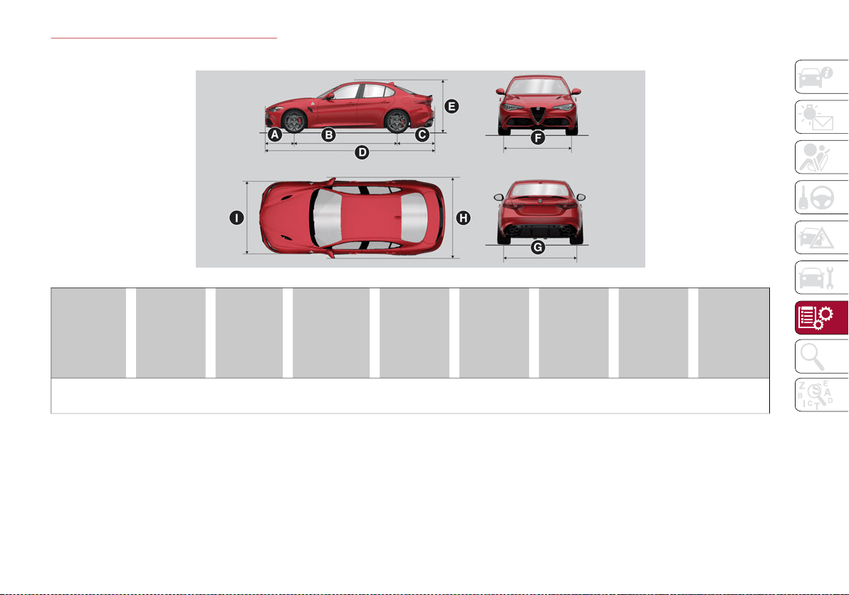
281
DIMENSIONS — 2.9L V6 Engine
Dimensions are expressed in inches and refer to the vehicle equipped with its standard-supplied tires. Height is measured with vehicle unladen.
A
Front
Overhang
B
Wheelbase
C
Rear
Overhang
D
Overall
Length
E
Overall
Height
F
Front Track
G
Rear Track
H
Overall
Width (Incl.
Mirrors)
I
Overall
Width
(Excl.
Mirrors)
31.30
Inches
111.02
Inches
40.31
Inches
182.64
Inches
56.14
Inches
61.22
Inches
63.27
Inches
79.69
Inches
73.74
Inches
20_GA_OM_EN_USC_t.book Page 281

TECHNICAL SPECIFICATIONS
282
WEIGHTS — 2.0L T4 MAir Engine
WEIGHTS — 2.9L V6 Engine
Weights (lbs) 2.0L T4 MAir Engine With AWD 2.0 T4 MAir Engine With RWD
Unloaded weight (with all fluids, fuel tank filled to 90%
and without optional equipment)
3,622 3,522
Payload including the driver
1
1. If special equipment is fitted (trailer towing equipment, etc.) the empty weight will increase and consequently the payload will decrease in rela-
tion to the maximum permitted loads.
905 90
5
Maximum permitted loads
2
2. Loads not to be exceeded. The user is responsible for arranging goods in the luggage compartment and/or on the load platform within the
maximum permitted loads.
155 15
5
Front axle 2,205 2,205
Rear axle 2,646 2,646
Total 4,723 4,612
Weights (lbs) 2.9L V6 Engine
Unloaded weight (with all fluids, fuel tank filled to 90% and without optional equipment) 3,820
Payload including the driver
1
1. If special equipment is fitted (trailer towing equipment, etc.) the empty weight will increase and consequently the payload will decrease in rela-
tion to the maximum permitted loads.
905
Ma
ximum permitted loads
2
2. Loads not to be exceeded. The user is responsible for arranging goods in the luggage compartment and/or on the load platform within the
maximum permitted loads.
155
Fro
nt axle 2,260
Rear axle 2,646
Total 4,774
20_GA_OM_EN_USC_t.book Page 282
283
FUEL REQUIREMENTS
This engine is designed to meet all emis-
sion regulations, and provide satisfac-
tory fuel economy and performance
when using high-quality unleaded
“Regular” gasoline having a posted octane number
of 87 as specified by the (R+M)/2 method. For
optimal performance the use of 91 or higher octane
“Premium” gasoline is recommended in these
engines.
While operating on gasoline with the required
octane number, hearing a light knocking
sound from the engine is not a cause for
concern. However, if the engine is heard
making a heavy knocking sound, see a dealer
immediately. Use of gasoline with a lower than
recommended octane number can cause
engine failure and may void or not be covered
by the New Vehicle Limited Warranty.
Poor quality gasoline can cause problems
such as hard starting, stalling, and hesitations.
If you experience these symptoms, try another
brand of gasoline before considering service
for the vehicle.
Reformulated Gasoline
Many areas of the country require the use of
cleaner burning gasoline referred to as “Refor-
mulated Gasoline”. Reformulated gasoline
contains oxygenates and are specifically
blended to reduce vehicle emissions and
improve air quality.
The use of reformulated gasoline is recom-
mended. Properly blended reformulated gaso-
line will provide improved performance and
durability of engine and fuel system compo-
nents.
Gasoline/Oxygenate Blends
Some fuel suppliers blend unleaded gasoline
with oxygenates such as ethanol.
Problems that result from using gasoline
containing more than 15% ethanol (E-15) or
gasoline containing methanol are not the
responsibility of the manufacturer and may
void or not be covered under New Vehicle
Limited Warranty.
CNG And LP Fuel System Modifications
Modifications that allow the engine to run on
Compressed Natural Gas (CNG) or Liquid
Propane (LP) may result in damage to the
engine, emissions, and fuel system compo-
nents. Problems that result from running CNG
or LP are not the responsibility of the manufac-
turer and may void or not be covered under the
New Vehicle Limited Warranty.
MMT In Gasoline
Methylcyclopentadienyl Manganese Tricar-
bonyl (MMT) is a manganese-containing
metallic additive that is blended into some
gasoline to increase octane. Gasoline blended
with MMT provides no performance advantage
beyond gasoline of the same octane number
without MMT. Gasoline blended with MMT
reduces spark plug life and reduces emissions
system performance in some vehicles. The
manufacturer recommends that gasoline
without MMT be used in your vehicle. The MMT
content of gasoline may not be indicated on
the gasoline pump; therefore, you should ask
your gasoline retailer whether the gasoline
contains MMT. MMT is prohibited in Federal
and California reformulated gasoline.
CAUTION!
DO NOT use E-85, gasoline containing
methanol, or gasoline containing more than
15% ethanol (E-15). Use of these blends
may result in starting and drivability
problems, damage critical fuel system
components, cause emissions to exceed
the applicable standard, and/or cause the
Malfunction Indicator Light to illuminate.
Please observe pump labels as they should
clearly communicate if a fuel contains
greater than 15% ethanol (E-15).
20_GA_OM_EN_USC_t.book Page 283

TECHNICAL SPECIFICATIONS
284
(Continued)
Materials Added To Fuel
Besides using unleaded gasoline with the
proper octane rating, gasolines that contain
detergents, corrosion and stability additives
are recommended. Using gasolines that have
these additives will help improve fuel
economy, reduce emissions, and maintain
vehicle performance.
Designated TOP TIER Detergent Gasoline
contains a higher level of detergents to
further aide in minimizing engine and
fuel system deposits. When available,
the usage of TOP TIER Detergent Gasoline is recom-
mended. Visit
www.toptiergas.com
for a list of TOP
TIER Detergent Gasoline Retailers.
Indiscriminate use of fuel system cleaning
agents should be avoided. Many of these
materials intended for gum and varnish
removal may contain active solvents or similar
ingredients. These can harm fuel system
gasket and diaphragm materials.
Fuel System Cautions
NOTE:
Intentional tampering with the emissions
control system can result in civil penalties
being assessed against you.
CAUTION!
Follow these guidelines to maintain your
vehicle’s performance:
The use of leaded gasoline is prohibited by
Federal law. Using leaded gasoline can
impair engine performance and damage
the emissions control system.
An out-of-tune engine or certain fuel or
ignition malfunctions can cause the cata-
lytic converter to overheat. If you notice a
pungent burning odor or some light
smoke, your engine may be out of tune or
malfunctioning and may require imme-
diate service. Contact an authorized
dealer for service assistance.
The use of fuel additives, which are now
being sold as octane enhancers, is not
recommended. Most of these products
contain high concentrations of methanol.
Fuel system damage or vehicle perfor-
mance problems resulting from the use of
such fuels or additives is not the responsi-
bility of the manufacturer and may void or
not be covered under the New Vehicle
Limited Warranty.
CAUTION! (Continued)
20_GA_OM_EN_USC_t.book Page 284

285
FLUID CAPACITIES
2.0L T4 MAir Engine
US Metric
Fuel tank 15.3 Gallons 58 Liters
Fuel tank reserve 2.3 Gallons 9 Liters
Engine cooling system 2.2 Gallons 8.6 Liters
Intercooler cooling system 1.1 Gallons 4.3 Liters
Engine oil sump and filter 5.5 Quarts 5.2 Liters
Hydraulic brake circuit 0.9 Quarts 0.9 Liters
Windshield washer fluid reservoir 1.1 Gallons 4.2 Liters
Automatic transmission, 2.0 T4 MAir engine
9.9 Quarts (RWD Model) / 9.8 Quarts
(AWD Model)
9.4 Liters (RWD Model) / 9.3 Liters (AWD Model)
Differentials and reduction gears RDU 195 0.9 Quarts 0.9 Liters
Differentials and reduction gears RDU 230-TV – –
RDU 230-LSD differential - if equipped 0.9 Quarts 0.9 Liters
RDU 210/215-LSD differential - if equipped 1.1 Quarts 1.1 Liters
AWD System FAD transfer case 0.5 Quarts 0.5 Liters
AWD System Transfer Case 0.7 Quarts 0.7 Liters
20_GA_OM_EN_USC_t.book Page 285

TECHNICAL SPECIFICATIONS
286
2.9L V6 Engine
US Metric
Fuel tank 15.3 Gallons 58 Liters
Fuel tank reserve 2.3 Gallons 9 Liters
Engine cooling system 2.95 Gallons 11.2 Liters
Intercooler cooling system 1.4 Gallons 5.5 Liters
Engine sump and filter 7.2 Quarts 7 Liters
Hydraulic brake circuit 0.9 Quarts 0.9 Liters
Windshield washer fluid reservoir 1.1 Gallons 4.2 Liters
Automatic transmission – –
Differentials and reduction gears RDU 195 – –
Differentials and reduction gears RDU 230-TV
Main body: 0.8 Quarts
Left TV: 0.5 Quarts
Right TV: 0.6 Quarts
Main body: 0.8 Liters
Left TV: 0.5 Liters
Right TV: 0.6 Liters
RDU 230-LSD differential – –
RDU 210-eLSD differential (if equipped) – –
RDU 210/215-LSD differential – –
20_GA_OM_EN_USC_t.book Page 286
287
FLUIDS AND LUBRICANTS
Your vehicle is equipped with an engine oil that has been thoroughly developed and tested in order to meet the requirements of the Scheduled
Servicing Plan. Constant use of the prescribed lubricants guarantees the fuel consumption and emission specifications. Lubricant quality is crucial
for engine operation and durability.
Engine Lubrication — 2.0L T4 MAir Engine
If lubricants conforming to the specific request are not available, products that meet the indicated specifications can be used to top up; in this case
optimal performance of the engine is not guaranteed.
Engine Lubrication — 2.9L V6 Engine
If lubricants conforming to the specific request are not available, products that meet the indicated specifications can be used to top up; in this case
optimal performance of the engine is not guaranteed.
Features Specification Replacement interval
Mopar API SN PLUS Certified SAE 0W-30 Full
Synthetic Engine Oil
FCA Material Standards MS-13340 According to the Maintenance Plan
CAUTION!
Using lubricants that do not meet the recommended SN PLUS or equivalent oil specifications can cause engine damage not covered by the
vehicle warranty.
Features Specification Replacement interval
5W-40
ACEA C3
API SN
FPT 9.55535-GH2
MS-12991
According to the Maintenance Plan
20_GA_OM_EN_USC_t.book Page 287

TECHNICAL SPECIFICATIONS
288
Chassis Lubrication — 2.0L T4 MAir Engine
Use Features Specification Applications
Lubricants and
greases
ZF 8HP 50 - Synthetic ATF – Automatic transmission
SAE 75W-85 Synthetic lubricant FPW9.55550-DA9
Differential
RDU 195; RDU 230-LSD; RDU
210-eLSD; RDU 210/215-LSD /
2.0 T4 MAir engine
SAE 75W-80 APL GL-5 Synthetic
lubricant
FPW9.55550-DA10 AWD System FAD transfer case
SAE 75W Synthetic lubricant FPW9.55550-DA11 AWD System TRANSFER CASE
Brake fluid DOT 4 MS.90039 Hydraulic brakes
Engine coolant
CUNA NC 956-16
ASTMD3306
MS.90032
Use rate 50% Not mixable with
different formulation products.
1
1. For particularly harsh climate conditions, a mixture of 60% product and 40% distilled water is recommended.
Wind
shield washer
fluid
CUNA NC 956-11
MS.90043
To be used diluted or undiluted in
windshield washer/wiper systems
HVAC
R1234yf or R134yf
(depending on market)
– –
20_GA_OM_EN_USC_t.book Page 288
289
Chassis Lubrication — 2.9L V6 Engine
PERFORMANCE — 2.0L T4 MAir Engine
Top performance after the initial period of vehicle usage.
*Bas
ed on manufacturer testing.
PERFORMANCE — 2.9L V6 Engine
Top performance after the initial period of vehicle usage.
*Based on manufacturer testing.
Use Features Specification Applications
Lubricants and
greases
ZF 8HP 50 - Synthetic ATF – Automatic transmission
SAE 75W-85 API GL-5 Synthetic
lubricant
FPW9.55550-DA8
Differential and reduction units
RDU 230-TV / 2.9 V6 engine
Brake fluid DOT 4 MS.90039 Hydraulic brakes
Engine coolant
CUNA NC 956-16
ASTMD3306
MS.90032
Use rate 50% Not mixable with
different formulation products.
1
1. For particularly harsh climate conditions, a mixture of 60% product and 40% distilled water is recommended.
Wind
shield washer
fluid
CUNA NC 956-11 MS.90043
To be used diluted or undiluted in
windshield washer/wiper systems
HVAC
R1234yf or R134yf
(depending on market)
– –
Models Maximum speed mph Acceleration from 0–60 mph/0-100 km/h sec.
RWD 149 * 5.5 *
AWD 149 * 5.1 *
Maximum speed mph Acceleration from 0–60 mph/0-100 km/h sec.
191 * 3.8 *
20_GA_OM_EN_USC_t.book Page 289

290
CUSTOMER ASSISTANCE
SUGGESTIONS FOR OBTAINING
SERVICE FOR YOUR VEHICLE
Prepare For The Appointment
If you are having warranty work done, be sure
to bring the right papers with you, as well as
your warranty folder. All work to be performed
may not be covered by the warranty. Discuss
additional charges with the service manager.
Keep a maintenance log of your vehicle's
service history, as this can often provide a clue
to the current problem.
Prepare A List
Make a written list of your vehicle's problems or
the specific work you want done. If you've had an
accident or work done that is not on your mainte-
nance log, let the service advisor know.
Be Reasonable With Requests
If you list a number of items and you must
have your vehicle by the end of the day,
discuss the situation with the service advisor
and list the items in order of priority. At many
authorized dealers, you may obtain a rental
vehicle at a minimal daily charge. If you need
a rental, it is advisable to make these arrange-
ments when you call for an appointment.
IF YOU NEED ASSISTANCE
The manufacturer and its authorized dealers
are vitally interested in your satisfaction. We
want you to be happy with our products and
services.
Warranty service must be done by an autho-
rized dealer. We strongly recommend that you
take the vehicle to an authorized dealer. They
know your vehicle the best, and are most
concerned that you get prompt and high
quality service. The manufacturer's authorized
dealers have the facilities, factory-trained
technicians, special tools, and the latest infor-
mation to ensure the vehicle is fixed correctly
and in a timely manner.
This is why you should always talk to an autho-
rized dealer service manager first. Most
matters can be resolved with this process.
If for some reason you are still not satisfied,
talk to the general manager or owner of the
authorized dealer. They want to know if you
need assistance.
If an authorized dealer is unable to resolve
the concern, you may contact the manufac-
turer's customer center.
Any communication to the manufacturer's
customer center should include the following
information:
Owner's name and address
Owner's telephone number (mobile, home
and office)
Authorized dealer name
Vehicle Identification Number (VIN)
Vehicle delivery date and mileage
Alfa Romeo Customer Center
P.O. Box 21–8004
Auburn Hills, MI 48321–8004
Phone: 1-844-Alfa-USA (1-844-253-2872)
Alfa Romeo Customer Care (Canada)
P.O. Box 1621
Windsor, Ontario N9A 4H6
Phone: 1-877-230-0563 (English) Phone:
1-877-515-9112 (French)
20_GA_OM_EN_USC_t.book Page 290
291
Customer Assistance For The Hearing Or
Speech Impaired (TDD/TTY)
To assist customers who have hearing difficul-
ties, the manufacturer has installed special
TDD Telecommunication Devices for the Deaf
(TDD) equipment at its customer center. Any
hearing or speech impaired customer, who
has access to a TDD or a conventional tele-
typewriter (TTY) in the United States, can
communicate with the manufacturer by dialing
1-800-380-2479.
Canadian residents with hearing difficulties
that require assistance can use the special
needs relay service offered by Bell Canada.
For TTY teletypewriter users, dial 711 and for
Voice callers, dial 1-800-855-0511 to connect
with a Bell Relay Service operator.
Service Contract
You may have purchased a service contract for
a vehicle to help protect you from the high cost
of unexpected repairs after the manufac-
turer's New Vehicle Limited Warranty expires.
The Mopar Vehicle Protection plans are the
ONLY vehicle extended protection plans
authorized, endorsed and backed by FCA US
LLC to provide additional protection beyond
your vehicle’s warranty. If you purchased a
Mopar Vehicle Protection Plan, you will receive
Plan Provisions and an Owner Identification
Card in the mail within three weeks of the
vehicle delivery date. If you have any ques-
tions about the service contract, call the
manufacturer's Service Contract National
Customer Hotline at 1-800-521-9922 (Cana-
dian residents, call (877) 230-0563 English /
(877) 515-9112 French).
The manufacturer will not stand behind any
service contract that is not the manufacturer's
service contract. It is not responsible for any
service contract other than the manufacturer's
service contract. If you purchased a service
contract that is not a manufacturer's service
contract, and you require service after the
manufacturer's New Vehicle Limited Warranty
expires, please refer to the contract docu-
ments, and contact the person listed in those
documents.
We appreciate that you have made a major
investment when you purchased the vehicle.
An authorized dealer has also made a major
investment in facilities, tools, and training to
assure that you are absolutely delighted with
the ownership experience. You will be pleased
with their sincere efforts to resolve any
warranty issues or related concerns.
WARRANTY INFORMATION
See the Warranty Information for the terms
and provisions of FCA US LLC and FCA Canada
Inc. warranties applicable to this vehicle and
market.
REPORTING SAFETY DEFECTS
In The 50 United States And Washington, D.C.
If you believe that your vehicle has a
defect that could cause a crash or
cause injury or death, you should imme-
diately inform the National Highway
Traffic Safety Administration (NHTSA) in
addition to notifying FCA US LLC.
If NHTSA receives similar complaints, it
may open an investigation, and if it finds
that a safety defect exists in a group of
vehicles, it may order a recall and remedy
campaign. However, NHTSA cannot
become involved in individual problems
between you, an authorized dealer or FCA
US LLC.
WARNING!
Engine exhaust (internal combustion engines
only), some of its constituents, and certain
vehicle components contain, or emit, chemicals
known to the State of California to cause cancer
and birth defects, or other reproductive harm. In
addition, certain fluids contained in vehicles and
certain products of component wear contain, or
emit, chemicals known to the State of California
to cause cancer and birth defects, or other
reproductive harm.
20_GA_OM_EN_USC_t.book Page 291

CUSTOMER ASSISTANCE
292
To contact NHTSA, you may call the Vehicle
Safety Hotline toll free at 1-888-327-4236
(TTY: 1-800-424-9153); or go to
http://
www.safercar.gov
; or write to: Administrator,
NHTSA, 1200 New Jersey Avenue, SE., West
Building, Washington, D.C. 20590. You can
also obtain other information about motor
vehicle safety from
http://www.safercar.gov
.
In Canada
If you believe that your vehicle has a safety
defect, you should contact the Customer
Service Department immediately. Canadian
customers who wish to report a safety
defect to the Canadian government should
contact Transport Canada, Motor Vehicle
Defect Investigations and Recalls at
1-800-333-0510 or go to
http://
www.tc.gc.ca/roadsafety/
.
PUBLICATION ORDER FORMS
To order the following manuals, you may use
either the website or the phone numbers listed
below. Visa, Mastercard, American Express,
and Discover orders are accepted.
Service Manuals
These comprehensive Service Manuals
provide the information that students and
professional technicians need in diagnosing/
troubleshooting, problem solving, maintaining,
servicing, and repairing FCA US LLC vehicles. A
complete working knowledge of the vehicle,
system, and/or components is written in
straightforward language with illustrations,
diagrams, and charts.
Diagnostic Procedure Manuals
Diagnostic Procedure Manuals are filled with
diagrams, charts and detailed illustrations.
These practical manuals make it easy for
students and technicians to find and fix prob-
lems on computer-controlled vehicle systems
and features. They show exactly how to find
and correct problems the first time, using
step-by-step troubleshooting and drivability
procedures, proven diagnostic tests and a
complete list of all tools and equipment.
Owner's Manuals
These Owner's Manuals have been prepared
with the assistance of service and engineering
specialists to acquaint you with specific FCA
US LLC vehicles. Included are starting, oper-
ating, emergency and maintenance proce-
dures as well as specifications, capabilities
and safety tips.
To access your Owner’s Information online,
visit
www.mopar.com
To order a hard copy of your Owner’s Informa-
tion, call Tech Authority toll free at:
1-800-890-4038 (US)
1-800-387-1143 (Canada)
Or
To obtain a hard copy of your Owner’s Informa-
tion, visit:
www.techauthority.com
20_GA_OM_EN_USC_t.book Page 292

293
A
Accessories Purchased By The Owner.......... 3
Active Blind Spot Assist .............................105
Active Safety Systems.................................. 99
Active Torque Vectoring (ATV) System ........ 99
Adaptive Cruise Control (ACC)
(Cruise Control) ..........................................173
Off ...........................................................175
On............................................................175
Additives, Fuel ............................................284
Air Bag.........................................................127
Air Bag Operation...................................128
Air Bag Warning Light ............................126
Driver Knee Air Bag................................129
Enhanced Accident Response .....133, 235
Event Data Recorder (EDR)...................235
Front Air Bag...........................................127
If Deployment Occurs ............................132
Knee Impact Bolsters ............................129
Maintaining Your Air Bag System..........135
Maintenance ..........................................135
Redundant Air Bag Warning Light.........126
Side Air Bags ..........................................129
Transporting Pets...................................148
Air Bag Light ......................................126, 150
Air Pressure
Tires ........................................................262
Alarm
Security Alarm .......................................... 19
Alfa Active Suspension (AAS).....................167
Alfa DNA System ........................................164
Anti-Lock Braking (ABS) System.................. 99
Automatic Headlights................................... 37
Automatic Temperature Control (ATC)........ 47
Automatic Transmission............................ 158
Auxiliary Driving Systems .......................... 102
B
Back-Up Camera ........................................ 204
Battery ........................................................246
Battery Recharging ....................................247
Belts, Seat ..................................................150
Blind Spot Monitoring................................ 103
Bodywork (Cleaning And Maintenance) ... 273
B-Pillar Location......................................... 259
Brakes ........................................................ 279
Brake Fluid Level ...................................246
Bulbs, Light ................................................151
C
Camera, Rear ............................................. 204
Carbon Monoxide Warning........................ 149
Cargo Tie-Downs .......................................... 59
Certification Label...................................... 207
Chart, Tire Sizing........................................ 256
Check Engine Light (Malfunction
Indicator Light)............................................. 97
Checking Levels ................................243, 244
Checking Your Vehicle For Safety............. 149
Checks, Safety ...........................................149
Child Restraint ...........................................136
Child Restraints
Booster Seats ........................................ 139
Child Seat Installation ........................... 147
How To Stow An unused ALR
Seat Belt ............................................ 144
Infant And Child Restraints................... 138
LATCH Positions.....................................141
Lower Anchors And Tethers For
Children ............................................. 141
Older Children And Child Restraints .... 138
Seating Positions................................... 140
Using The Top Tether Anchorage ......... 148
Clean Air Gasoline ..................................... 283
Cleaning
Wheels ................................................... 268
Climate Control...................................... 46, 50
Contract, Service ....................................... 291
Cruise Control (Speed Control)................. 171
Cupholders....................................................65
Customer Assistance ................................ 290
D
Daytime Running Lights...............................37
Deck Lid
Power Release..........................................57
Defroster, Windshield ............................... 150
Dimmer Switch
Headlight ..................................................43
Door Opener, Garage ...................................59
Drive Train Control (DTC) System ............. 100
Driving Modes............................................ 165
Dynamic Steering Torque (DST) System .. 100
E
Electric Park Brake.................................... 156
Electronic Speed Control
(Cruise Control).......................................... 171
Electronic Stability Control (ESC)
System ....................................................... 100
Emergency
In Case Of ..................................... 212, 226
SOS Emergency Call.............................. 212
20_GA_OM_EN_USC_t.book Page 293

294
INDEX
Emergency, In Case Of
Jacking....................................................255
Jump Starting .........................................230
Overheating............................................232
Tow Hooks ..............................................234
Towing.....................................................233
Emission Control System Maintenance...... 97
Engine .........................................................277
Block Heater...........................................155
Engine Coolant Level .............................246
Exhaust Gas Caution .............................149
Fuel Requirements ................................283
Jump Starting .........................................231
Overheating............................................232
Engine Compartment.................................243
Engine Compartment (Washing) ...............274
Engine Oil
Level Check ............................................245
Enhanced Accident Response
Feature...............................................133, 235
Ethanol........................................................283
Exhaust Gas Cautions................................149
Exhaust System..........................................149
Exterior Lights.............................37, 151, 218
F
Flashers
Turn Signals............................................151
Fluid Leaks .................................................151
Fluids And Lubricants ................................287
Fog Lights, Rear ...........................................38
Forward Collision Warning.........................109
Front Light Cluster With Main Beam Xenon
Gas Discharge Headlights
(Bulb Replacement) ...................................218
Fuel
Additives.................................................284
Clean Air .................................................283
Ethanol ...................................................283
Materials Added .................................... 284
Methanol................................................ 283
Fuses ................................................. 221, 223
G
Garage Door Opener (HomeLink) ............... 59
Gasoline, Clean Air .................................... 283
Gasoline, Reformulated ............................ 283
Gauges
Engine Oil Temperature .......................... 69
Fuel........................................................... 70
Speedometer ........................................... 70
Tachometer.............................................. 69
Glove Compartment Storage ...................... 64
GVWR.......................................................... 207
H
Hazard Warning Flashers.......................... 212
Head Restraints ........................................... 32
Head Rests................................................... 32
Headlights .................................................... 37
Automatic................................................. 37
Delay......................................................... 38
High Beam ............................................... 39
Switch....................................................... 37
Headlights (Cleaning) ................................ 274
Heated Mirrors............................................. 37
Heated Seats ............................................... 29
Heated Steering Wheel ............................... 35
Heater, Engine Block .................................155
Hill Start Assist (HSA) System ................... 101
HomeLink (Garage Door Opener)................59
Hood
Closing ......................................................56
Opening.....................................................56
Hood Release ...............................................56
I
Identification Data..................................... 276
Ignition ..........................................................17
Switch .......................................................17
Immobilizer (Sentry Key)..............................19
In Case Of Emergency ............................... 212
Installing Electrical/Electronic Devices......... 3
Instrument Cluster
Display ......................................................70
Instrument Panel
Features....................................................68
Interior And Instrument Lights.............. 41, 43
Interior Lights.......................................40, 219
Interiors (Cleaning).................................... 274
Internal Equipment.......................................64
Cupholders ...............................................65
J
Jacking And Tire Changing........................ 255
Jump Starting............................................. 230
K
Keyless Enter-N-Go.......................................22
Passive Entry ............................................22
Keys...............................................................14
L
Lane Change And Turn Signals ...................39
Lane Change Assist......................................39
20_GA_OM_EN_USC_t.book Page 294

295
LaneSense..................................................198
Lap/Shoulder Belts....................................120
Latches .......................................................151
Leaks, Fluid ................................................151
Life Of Tires.................................................266
Light Bulbs..................................................151
Types Of Bulbs .......................................216
Lights ..........................................................151
Air Bag ...........................................126, 150
Ambient .................................................... 41
Courtesy/Reading............................. 40, 42
Daytime Running .....................................37
Exterior ............................................ 37, 151
Fog ............................................................ 38
Hazard Warning Flasher........................212
High Beam/Low Beam Select .................39
Interior ...................................................... 40
Park........................................................... 38
Turn Signals.....................................39, 151
Loading Vehicle ..........................................207
Tires ........................................................259
Locks
Child Protection........................................ 26
M
Malfunction Indicator Light
(Check Engine) .............................................97
Manual
Service ....................................................292
Methanol.....................................................283
Mirrors
Automatic Dimming................................. 36
Electric Powered...................................... 36
Exterior Folding........................................ 36
Heated...................................................... 37
Rearview................................................... 36
Vanity......................................................219
O
Occupant Restraints.................................. 118
Onboard Diagnostic System........................ 97
Opener, Garage Door (Homelink) ............... 59
Operator Manual
Owner's Manual..................................... 292
P
Paintwork (Cleaning And Maintenance)... 273
Panic Brake Assist (PBA) System..............101
ParkSense System.....................................194
Passive Entry................................................ 22
Performance (Top Speed) ......................... 289
Pets............................................................. 148
Pinch Protection........................................... 55
Placard, Tire And Loading Information..... 259
Power
Deck Lid Release..................................... 57
Seats ........................................................ 27
Sunroof..................................................... 54
Power Supply.............................................. 278
Pregnant Women And Seat Belts ............. 124
Pretensioners
Seat Belts............................................... 124
Prolonged Vehicle Inactivity ......................272
R
Radial Ply Tires .......................................... 265
Radio Transmitters And Mobile Phones ....... 4
Rear Camera.............................................. 204
Rear Cross Path......................................... 103
Reformulated Gasoline ............................. 283
Refueling Procedure.................................. 206
Refueling The Vehicle................................ 206
Refuelling................................................... 285
Reminder, Seat Belt .................................. 119
Remote Keyless Entry ..................................14
Remote Starting System ........................... 152
Remote Trunk Release ................................57
Replacement Bulbs................. 215, 218, 219
Replacement Tires .................................... 266
Reporting Safety Defects .......................... 291
Restraints, Child ........................................ 136
Rims And Tires........................................... 255
S
Safety Checks Inside Vehicle.................... 150
Safety Checks Outside Vehicle................. 151
Safety Defects, Reporting ......................... 291
Safety Information, Tire ............................ 255
Safety Tips ................................................. 149
Safety, Exhaust Gas .................................. 149
Saving Fuel ................................................ 208
Scheduled Servicing.................................. 236
Scheduled Servicing Program
(2.0 T4 MAir Engine Versions) .................. 237
Scheduled Servicing Program
(2.9 V6 Gasoline Engine Versions)........... 240
20_GA_OM_EN_USC_t.book Page 295

296
INDEX
Seat Belts ..........................................119, 150
Child Restraints......................................136
Energy Management Feature ...............124
Front Seat......................................119, 120
Inspection...............................................150
Lap/Shoulder Belt Untwisting...............122
Lap/Shoulder Belts................................120
Pregnant Women ...................................124
Pretensioners.........................................124
Rear Seat................................................120
Reminder................................................119
Seat Belt Pretensioner ..........................124
Untwisting Procedure ............................122
Seats ............................................................. 27
Adjustment ............................................... 27
Head Restraints ....................................... 32
Heated ...................................................... 29
Power........................................................ 27
Security Alarm .............................................. 19
Service Assistance .....................................290
Service Contract.........................................291
Service Manuals.........................................292
Servicing Procedures .................................249
Shoulder Belts............................................120
Signals, Turn...............................................151
Snow Chains...............................................269
Snow Tires ..................................................269
Spare Tires..................................................267
Speed Control
Accel/Decel............................................172
Accel/Decel (ACC Only) ......................... 176
Cancel .................................................... 173
Distance Setting (ACC Only).................. 177
Resume .................................................. 172
Set .......................................................... 172
Speed Control (Cruise Control) ................. 171
Starting
Button....................................................... 17
Cold Weather ......................................... 153
Starting The Engine ................................... 152
Steering
Tilt Column ............................................... 34
Wheel, Heated ......................................... 35
Wheel, Tilt ................................................ 34
Steering System......................................... 279
Stop/Start System .....................................167
Storage
Console .................................................... 64
Glove Compartment ................................ 64
Suggestions For Driving............................. 208
Sun Roof....................................................... 54
Sun Visor ...................................................... 64
Supplemental Restraint System –
Air Bag ........................................................127
Suspension ................................................ 279
Symbols ...........................................................6
T
Tie Down Hooks, Cargo ................................59
Tire And Loading Information Placard ..... 259
Tire Markings ............................................. 255
Tire Safety Information ............................. 255
Tire Service Kit........................................... 226
Tires................................. 151, 262, 267, 271
Aging (Life Of Tires) ............................... 266
Air Pressure ........................................... 262
Flat Changing......................................... 226
General Information..................... 262, 267
High Speed ............................................ 263
Inflation Pressure.................................. 262
Life Of Tires............................................ 266
Load Capacity........................................ 259
Quality Grading...................................... 271
Radial..................................................... 265
Replacement ......................................... 266
Safety ............................................ 255, 262
Sizes....................................................... 256
Snow Tires ............................................. 269
Spare Tires............................................. 267
Spinning................................................. 265
Tread Wear Indicators .......................... 265
Tow Hooks.................................................. 234
Towing
Disabled Vehicle.................................... 233
Towing Trailers........................................... 208
20_GA_OM_EN_USC_t.book Page 296

297
TPMS (Tire Pressure Monitoring
System) .......................................................115
Traction Control System (TCS)...................102
Transmission ..............................................278
Transporting Animals.................................210
Transporting Passengers...........................209
Transporting Pets.......................................148
Tread Wear Indicators ...............................265
Trunk Lid (Deck Lid) .....................................57
Turn Signals..................................................39
U
Uconnect Settings
Customer Programmable Features ........ 22
Passive Entry Programming .................... 22
Uniform Tire Quality Grades ......................271
Universal Transmitter................................... 59
Untwisting Procedure, Seat Belt ...............122
Use Of The Owner’s Manual.......................... 5
V
Vehicle Changes/Alterations .........................3
Vehicle Identification Number .................. 276
Vehicle Loading................................. 207, 259
Vent Operation ............................................. 46
W
Warranty Information ................................ 291
Washer Fluid For Windshield/
Headlights ..................................................246
Washers, Windshield................................... 44
Weights.......................................................282
Wheel And Wheel Tire Care....................... 268
Wheel And Wheel Tire Trim .......................268
Wheels And Tires....................................... 255
Windows (Cleaning)................................... 274
Windshield Defroster ................................ 150
Windshield Washers.....................................44
Windshield Wiper
Replacing Blades .................................. 251
Windshield Wipers........................................43
Wipers, Intermittent .....................................44
Wipers, Rain Sensitive .................................44
20_GA_OM_EN_USC_t.book Page 297


WARNING: Operating, servicing and maintaining a passenger vehicle or o-highway motor
vehicle can expose you to chemicals including engine exhaust, carbon monoxide, phthalates, and
lead, which are known to the State of California to cause cancer and birth defects or other
reproductive harm. To minimize exposure, avoid breathing exhaust, do not idle the engine
except as necessary, service your vehicle in a well-ventilated area and wear gloves or wash your
hands frequently when servicing your vehicle. For more information go to
www.P65Warnings.ca.gov/passenger-vehicle.
This Owner’s Manual illustrates and describes the operation of features and equipment that are either standard or optional on this vehicle. This manual
may also include a description of features and equipment that are no longer available or were not ordered on this vehicle. Please disregard any
features and equipment described in this manual that are not on this vehicle. FCA US LLC reserves the right to make changes in design and
specications, and/or make additions to or improvements to its products without imposing any obligation upon itself to install them on products
previously manufactured.
With respect to any vehicles sold in Canada, the name FCA US LLC shall be deemed to be deleted and the name FCA Canada Inc. used in
substitution therefore.
If you are the rst registered retail owner of your vehicle, you may obtain a complimentary printed copy of the Warranty Booklet by calling
1-844-253-2872 (U.S.) or 1-800-387-1143 (Canada) or by contacting your dealer.
This Owner’s Manual is intended to familiarize you with the important features of your vehicle. Your most up-to-date Owner’s Manual, Navigation /
Uconnect manuals and Warranty Booklet can be found by visiting the website on the back cover. U.S. residents can purchase replacement kits by
visiting www.techauthority.com and Canadian residents can purchase replacement kits by calling 1-800-387-1143.
The driver’s primary responsibility is the safe operation of the vehicle. Driving while distracted can result in loss of vehicle control, resulting in an
accident and personal injury. FCA US LLC strongly recommends that the driver use extreme caution when using any device or feature that may
take their attention o the road. Use of any electrical devices, such as cellular telephones, computers, portable radios, vehicle navigation or other
devices, by the driver while the vehicle is moving is dangerous and could lead to a serious accident. Texting while driving is also dangerous and
should never be done while the vehicle is moving. If you nd yourself unable to devote your full attention to vehicle operation, pull o the road to a
safe location and stop your vehicle. Some states or provinces prohibit the use of cellular telephones or texting while driving. It is always the
driver’s responsibility to comply with all local laws.
This Owner’s Manual has been prepared to help you get acquainted with your new Alfa Romeo
brand vehicle and to provide a convenient
reference source for common questions.
Not all features shown in this manual may apply to your vehicle. For additional information, visit www.alfaromeousa.com (U.S.),
www.alfaromeo.ca (Canada) or your local Alfa Romeo dealer.
Driving after drinking can lead to an accident. Your perceptions are less sharp, your reexes are slower
and your judgment is impaired when you have been drinking. Never drink and then drive.
WARNING!
Drunk driving is one of the most frequent causes of accidents. Your driving ability can be seriously
impaired with blood alcohol levels far below the legal minimum. If you are drinking, don’t drive.
Ride with a designated non-drinking driver, call a cab, a friend or use public transportation.
DRIVING AND ALCOHOL
2020 OWNER’S MANUAL
2020 GIULIA
20_GA_OM_EN_USC
Second Edition
©2020 FCA US LLC. All Rights Reserved. ALFA ROMEO is a registered trademark of FCA Group Marketing S.p.A., used with
permission. App Store is a registered trademark of Apple Inc. Google Play Store is a registered trademark of Google.
Whether it’s providing information about specic product features, taking a tour through your vehicle’s heritage,
knowing what steps to take following an accident or scheduling your next appointment, we know you’ll nd the app an
important extension of your Alfa Romeo brand vehicle.
Simply download the app, select your make and model and enjoy the ride. To get this app, go directly to the App Store
®
or Google
Play
®
Store and enter the search keyword “Alfa Romeo” (U.S. residents only).
Download a FREE electronic copy of the most up-to-date documents by visiting these links:
Owner’s Manual and Media:
www.alfaromeousa.com/owners/owners-service-manual (U.S. residents); www.owners.mopar.ca (Canadian residents).
Warranty Booklet:
www.alfaromeousa.com/owners/warranty (U.S. residents); www.owners.mopar.ca (Canadian residents).