Loading ...
Loading ...
3
Exhaust Information
WARNING:
TO REDUCE THE RISK OF FIRE
AND PERSONAL INJURY
• Use only metal duct for exhausting dryer to outdoors.
• Do not terminate exhaust in a chimney, any gas vent,
under an enclosed floor (crawl space), or into an attic.
The accumulated lint could create a fire hazard.
• Provide an access for inspection and cleaning of the
exhaust system, especially at turns. Inspect and clean
at least once per year.
• Never terminate the exhaust into a common duct with
a kitchen exhaust. A combination of lint and grease
could create a fire hazard.
• Do not obstruct incoming or exhausted air.
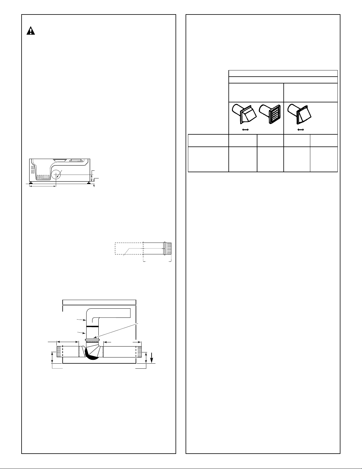
Rear Exhaust Location
This dryer comes ready for rear exhausting. If space is limited,
use the following instructions to exhaust directly from the side
or bottom of the cabinet.
Steps to Change Dryer to Side or Bottom Exhaust
Directly on Cabinet
WARNING: Protect your hands and arms from sharp edges
when working inside the dryer cabinet.
1. Detach and remove the desired knockout.
2. Remove the screw inside the
dryer exhaust duct end. Keep
the screw for step 5. Pull on
the duct to remove it.
3. Cut the duct as shown. Keep portion A.
4. Through the rear opening, locate the tab in the
middle of the dryer base. Lift the tab to about 45°
using a flat screwdriver.
5. Reconnect and secure the cut portion (A) of the duct
to the blower housing. Make sure the fixing hole is
aligned with the tab in the base. Use the screw from
step 2 to secure the duct in place through the tab on
the dryer base.
6. Use standard metal elbows and duct to complete
the exhaust system. Insert standard elbows and ducts
through rear and side or bottom openings.
7. Cover the opening at the back with the plate (Kit
WE1M454
) available from your local service provider.
WARNING: NEVER LEAVE THE BACK OPENING WITHOUT THE PLATE.
Exhaust Length
The MAXIMUM ALLOWABLE length of the exhaust
system depends upon the type of duct, number of turns,
type of exhaust hood (wall cap) and all conditions noted
below. The maximum allowable length for both rigid and
flexible metal duct is shown in the table below. More than
two 90° turns are not recommended.
• Do not use non-metallic flexible duct.
Hood or Wall Cap
• Terminate in a manner to prevent back drafts or entry
of birds or other wildlife.
• Termination should present minimal resistance
to the exhaust airflow and should require little
or no maintenance to prevent clogging.
• Never install screen over exhaust duct.
• Wall caps must be installed at least 300 mm (12″)
above ground level or any other obstruction with the
opening pointed down.
•
If roof vents or louvered plenums are used, they must be
equivalent to a 100 mm (4″) dampered wall cap in regard
to resistance to airflow, prevention of back drafts and
maintenance required to prevent clogging.
Separation of Turns
For best performance, separate all turns by at least 1.2 m
(4′ ) of straight duct, including distance between last turn
and dampered wall cap.
Turns Other Than 90°
• One turn of 45° or less may be ignored.
• Two 45° turns should be treated as one 90°.
• Each turn over 45° should be treated as one 90°.
Sealing of Joints
• All joints should be tight to avoid leaks. The male end
of each section of duct must point away from the dryer.
• Do not assemble the duct work with fasteners that
extend into the duct. They will serve as a collection
point for lint.
• Duct joints can be made air- and moisture-tight by
wrapping the overlapped joints with duct tape.
NOTE: Add to vertical dimension the
distance between cabinet bottom
and floor surface.
Back
of side
panel
Only metal
duct may be
used inside the
dryer cabinet
229 mm (9″)
Cut portion
Blower housing
Number of
Rigid Flexible Rigid Flexible
90° elbows
Metal Metal
0 10.7m (35 ft) 7.6m (25 ft) 7.6m (25 ft) 4.0m (13 ft)
1 9.1m (30 ft) 4.6m (15 ft) 4.6m (15 ft) 3.0m (10 ft)
2 6.1m (20 ft) 3.0m (10 ft) 3.0m (10 ft)
RECOMMENDED MAXIMUM LENGTH
Weather Hood Type
Recommended Use only for
short run
installations
10 cm (4″) 6 cm (2
1
/
2
″)
FOR ELECTRIC
DRYER ONLY
298 mm (11
3
⁄4″)
90 mm (3
1
⁄2″)
121 mm (4
3
⁄4″)
216 mm
(8
1
⁄
2
″)
285 mm
(11
1
⁄4″)
Screw inside duct
229 mm (9″)
Fixing hole
B A
121 mm (4
3
⁄4″)
A
Base tab
location
(under duct)
Loading ...