Loading ...
Loading ...
Loading ...
9
English
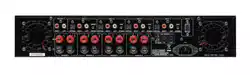
Speaker Outputs
See figure 2
The RKB amplifier has four pairs of speaker connectors, one for each amplifier
channel. The eight speaker connectors may be used in many different
configurations. The Hook-up Illustration, Figure 2, shows just one example,
with the connections for a typical six-speaker system. Here, the remaining two
channels are still available to power up to two more speakers as required.
Speaker Selection
We recommend using loudspeakers with a nominal impedance of 4 ohms
or higher with the RKB amplifiers. You should not drive more than one pair
of speaker for each output channel. Driving more than one set of speakers
from an output may damage the RKB amplifier. Speaker impedance ratings
are less than precise. In practice, very few loudspeakers will present any
problems for the RKB amplifiers. See your authorized Rotel dealer if you
have any questions.
Speaker Wire Selection
Use insulated two-conductor stranded wire to connect the RKB amplifier to
the speakers. The size and quality of the wire can have an audible effect
on the performance of the system. Standard speaker wire will work, but
can result in lower output or diminished bass response, particularly over
longer distances. In general, heavier wire will improve the sound. For
best performance, you may want to consider special high-quality speaker
cables. Your authorized Rotel dealer can help in the selection of cables for
your system.
Polarity and Phasing
The polarity – the positive/negative orientation of the connections – for every
speaker and amplifier connection must be consistent so all the speakers will
be in phase. If the polarity of one connection is reversed, bass output will
be very weak and stereo imaging degraded. All wire is marked so you can
identify the two conductors. There may be ribs or a stripe on the insulation
of one conductor. The wire may have clear insulation with different color
conductors (copper and silver). There may be polarity indications printed
on the insulation. Identify the positive and negative conductors and be
consistent with every speaker and amplifier connection.
Speaker Connections
6
NOTE: The following text describes both binding post and plug-in
connections. DO NOT use both connection methods in combination to
connect multiple speakers.
Turn off all the components in the system before connecting the speakers.
The RKB amplifier has a pair of two color coded binding posts for each
channel. These connectors accept bare wire, connector lugs, or dual banana
type connectors (except in the European Community countries where their
use is not permitted).
Route the wire from the RKB amplifier to the speakers. Give yourself enough
slack so you can move the components to allow access to the speaker
connectors.
If you are using dual banana plugs, connect them to the wires and then
plug into the backs of the binding posts. The thumbscrews of the binding
posts should be screwed in all the way (clockwise).
If you are using terminal lugs, connect them to the wires. If you are attaching
bare wires directly to the binding posts, separate the wire conductors and
strip the insulation from the end of each conductor. Be careful not to cut into
the wire strands. Unscrew (turn counterclockwise) the binding post. Place
the connector lug or wire around the binding post shaft. Turn the binding
post clockwise to clamp the connector lug or wire firmly in place.
NOTE: Be sure there are no loose wire strands that could touch adjacent
wires or connectors.
RS232 Connector
5
The RKB amplifier can be controlled via RS232 for integration with
automation systems. The RS232 input accepts a standard straight DB-9
Male-to-Female cable.
For additional information on the connections, software, and operating
codes for computer control of the RKB amplifier, contact your authorized
Rotel dealer.
Cooling Fans
The RKB amplifier includes 2 cooling fans to help exhaust the heat generated
by the power supply and amplifier modules. These fans will operate at
NORMAL speed when the RKB is powered on and not in STANDBY mode.
The fans will automatic switch to HIGH SPEED mode when required by
internal thermostat sensors.
NOTE: Depending on the installation location the cooling fans may
need to be cleaned periodically to ensure proper ventilation. Please
contact your authorized Rotel dealer for more information.
Troubleshooting
Most difficulties in audio systems are the result of incorrect connections, or
improper control settings. If you encounter problems, isolate the area of the
difficulty, check the control settings, determine the cause of the fault and
make the necessary changes. If you are unable to get sound from the RKB
amplifier, refer to the suggestions for the following conditions:
Power Indicator Is Not Illuminated
No main power to the RKB amplifier. Check AC power connections at the
amplifier and the AC outlet. Check the front panel power switch. Make sure
that it is set to the ON position. If using 12V trigger power-on, make sure
that a trigger signal is present at rear panel 12V TRIGGER IN connector.
No Sound
If the amplifier is getting AC power, but is producing no sound, check the
POWER INDICATOR on the front panel. If blinking, see below. If not, check
all of your connections and control settings on associated components.
Power Indicator Is Blinking
The front panel POWER INDICATOR is blinking when the amplifier protection
circuits have shut off the amplifier. Typically, this occurs only when the
ventilation openings are blocked, when there is faulty speaker wiring, or
after a period of extreme use. Turn off the system and wait for the amplifier
to cool. Then push the front panel power switch in and out to reset the
protection devices. If the problem is not corrected or reoccurs, there is a
problem with the system or the amplifier itself.
Loading ...
Loading ...
Loading ...