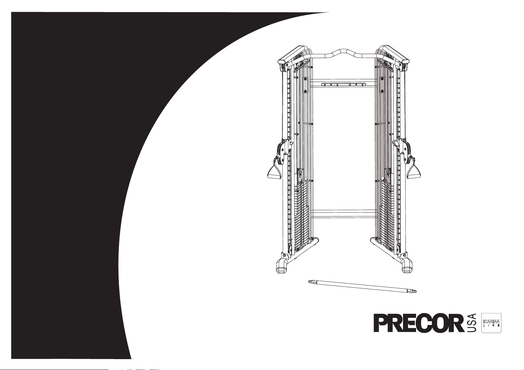
Assembly and Maintenance Guide
FTS Glide

FTS Glide Assembly and Maintenance Guide
page 2
IMPORTANT SAFETY INSTRUCTIONS
Important Safety Instructions
Important Safety Instructions
Before beginning any fitness program, see your
physician for a complete physical examination.
Il est conseillé de subir un examen médical complet
avant d’entreprendre tout programme d’exercise. Si
vous avez des étourdissements ou des faiblesses,
arrêtez les exercices immédiatement.
When using exercise equipment, basic precautions
should always be taken, including the following:
• Read all instructions and labels before using the
Functional Trainer System Glide
TM
equipment. These
instructions are written for your safety and to protect
the unit.
• Do not allow children or those unfamiliar with its
operation on or near the equipment. Do not leave
children unsupervised around the unit.
• Use the equipment only for its intended purpose as
described in this manual. Do not use accessory
attachments that are not recommended by the
manufacturer, as such attachments may cause
injuries.
• Wear proper exercise clothing and shoes for your
workout and avoid loose clothing. Tie long hair back.
• Always check the unit and its cables before each
use. Make sure that all fasteners and cables are
secure and in good working condition.
• Do not overexert yourself or work to exhaustion.
• If you feel any pain or abnormal symptoms,
stop your workout immediately and consult
your physician.
• Never drop or insert objects into any opening. Keep
hands away from moving parts.
• Never operate the unit when it has been dropped or
damaged. Return the equipment to a service center
for examination and repair.
• Before exercising, make sure that all fasteners and
cables are secure and in good working condition.
Inspect the unit for loose, frayed or worn parts,
fasteners, cables, and any indications that the
equipment may be in need of service. If you notice
any of these, obtain service immediately.
• If you determine that service is needed, move the
equipment away from the exercising area. Place
and OUT OF SERVICE sign on it and make sure all
patrons know that they must not use the equipment.
• Do not use outdoors.
Personal Safety During Assembly
• It is strongly recommended that a qualified
dealer assemble the equipment. Assistance is
required.
• Read each step in the assembly instructions and
follow the steps in sequence. Do not skip ahead. If
you skip ahead, you may learn later that you have
to disassemble components and that you may have
damaged the equipment.
• Assemble and operate the FTS Glide
TM
on a solid,
level surface. Locate the unit a few feet from walls
or furniture to provide easy access.
Obtaining Service
Do not attempt to service the FTS Glide
yourself except for the maintenance tasks
described in this guide. This unit does not
contain any user-serviceable parts.
For information about product operation,
refer to the instructional label. For service, refer
to the Precor web site at www.precor.com.
Should you need more information regarding
customer support numbers or a list of Precor
authorized service centers, visit the Precor
web site at www.precor.com/contact.
If you call or e-mail Customer Service, have
the serial number and part numbers available.
You can find the serial number printed on
a label affixed to the side of the FTS Glide.
For future reference, write the serial number
in the space provided below.
Serial number: _______________________

FTS Glide Assembly and Maintenance Guide
page 3
Table of Contents
1
2
3
Important Safety Instructions ...................................................................................................2
Personal Safety During Assembly ............................................................................................ 2
Obtaining Service ..................................................................................................................... 2
Before You Begin ........................................................................................... 4
Unpacking the Equipment ........................................................................................................ 4
Preparations................................................................................................... 5
Required Tools .......................................................................................................................... 5
Installation Requirements ......................................................................................................... 5
Assembly Tips ......................................................................................................................... 5
Assembly Instructions .................................................................................. 6
Open Box 1 .............................................................................................................................. 7
1. Assemble Main Structure .............................................................................................. 8
2. Assemble Weight Stack ................................................................................................ 11
Open Box 2 .............................................................................................................................. 15
3. Attach Shrouds .............................................................................................................. 16
4. Attach Handles and Accessories ................................................................................... 17
5. Move the Pulley Assemblies .......................................................................................... 18
Adjustments and Maintenance ..................................................................... 19
1. Cable Adjustments ........................................................................................................ 20
2. Maintenance .................................................................................................................. 21
Limited Warranty Statement ..................................................................................................... 22
Specifications ............................................................................................................. Back cover
4
Table of Contents
FTS Glide Assembly and Maintenance Guide
page 4
1
Before You Begin
Before You Begin
Thank you for purchasing the FTS Glide. This unit is
part of the Precor Strength line of quality strength
training machines, which let you target specific muscle
groups to achieve better muscle tone and overall body
conditioning. To maximize your use of the equipment,
please study this guide thoroughly.
Unpacking the Equipment
The FTS Glide is carefully tested and inspected before
shipment. Precor Strength ships the unit in several
pieces that require assembly. Ask for assistance during
the assembly process.
• Review the Installation Requirements found on the
next page.
• When instructed to open a box, carefully unpack the
pieces and lay them on the floor near the location
where you plan to use the equipment.
Be careful to open boxes and assemble components
in the sequence presented in this manual.
If any items are missing, contact the dealer from whom
you purchased the unit. For more information, refer to
Obtaining Service.

FTS Glide Assembly and Maintenance Guide
page 5
2
Preparations
Preparations
CAUTION: To set up this unit, you will need
assistance. Do not attempt assembly by yourself.
You must review and follow the instructions in this
guide. If you do not assemble and use the FTS Glide
according to the following guidelines, you could void
the Precor Limited Warranty.
Required Tools
Tools that you need to obtain before assembling the unit
include:
❏ Standard set of metric hex keys
❏ Two ⁹⁄₁₆-inch wrenches
❏ Wire cutter (cuts plastic tie wraps)
❏ Step ladder
Note: Use box-end, open-end, or standard crescent
wrenches.
Installation Requirements
Follow these installation requirements when assembling
the unit:
• Fill out and mail the warranty registration card.
• Set up the FTS Glide on a solid, flat surface.
A smooth, flat surface under the unit helps keep
it level.
• Provide ample space around the machine.
Open space around the machine allows for easier
access.
• Insert all fasteners in the same direction. For
aesthetic purposes, insert all the fasteners in the
same direction unless specified (in text or
illustrations) to do otherwise.
• Leave room for adjustments. With so many
assembled parts, proper alignment and adjustment is
critical. Tighten fasteners (such as screws, nuts,
and bolts), so the unit is stable, but leaves room for
adjustments. Do not fully tighten fasteners until
instructed (in the steps) to do so.
Assembly Tips
• A black 6-inch scale with white numbers is provided
at the bottom of every assembly instruction page.
Use this scale to identify the correct fastener size.
The head of a fastener is not used in measuring the
length.
To find out the length of a particular fastener,
measure its shank (the long, narrow part beneath
the head). Refer to the following diagram:
• Silver fasteners are used within the silver painted
areas. Black fasteners are used when assembling
the gray painted surfaces.
• Some pieces have extra holes that you will not use.
Use only those holes indicated in the instructions
and illustrations.
• Read all caution notes on each page before
completing that step.
• While you may be able to assemble the FTS Glide
by reading the illustrations only, refer to the text for
important safety cautions and notes.
Fastener head
Fastener threads
Shank
To determine the
length of a fastener,
measure its shank.
FTS Glide Assembly and Maintenance Guide
page 6
1 2 3 4 5 6
3
Assembly
Instructions
Assembly Instructions
Assembly of the FTS Glide takes professional installers
about 1 hour to complete. If this is the first time you
have assembled this type of equipment, plan on
significantly more time.
Professional installers are highly recommended!
However, if you acquire the appropriate tools, obtain
assistance, and follow the assembly steps sequentially,
the process will take time, but is fairly easy.
CAUTION: Obtain assistance! Do not attempt to
assemble the FTS Glide by yourself. Review
Installation Requirements before proceeding with
the following steps.
The FTS Glide comes in two long boxes with 10 smaller
boxes of weights:
• Two boxes of four 10-lb. weights
• Four boxes of five 10-lb. weights
• Four boxes of five 5-lb. weights
Each Weight Stack contains 200 lbs. The weight plates
make up 190 lbs. and the Top Weight Assembly provides
the final 10 lbs.
FTS Glide Assembly and Maintenance Guide
page 7
1 2 3 4 5 6
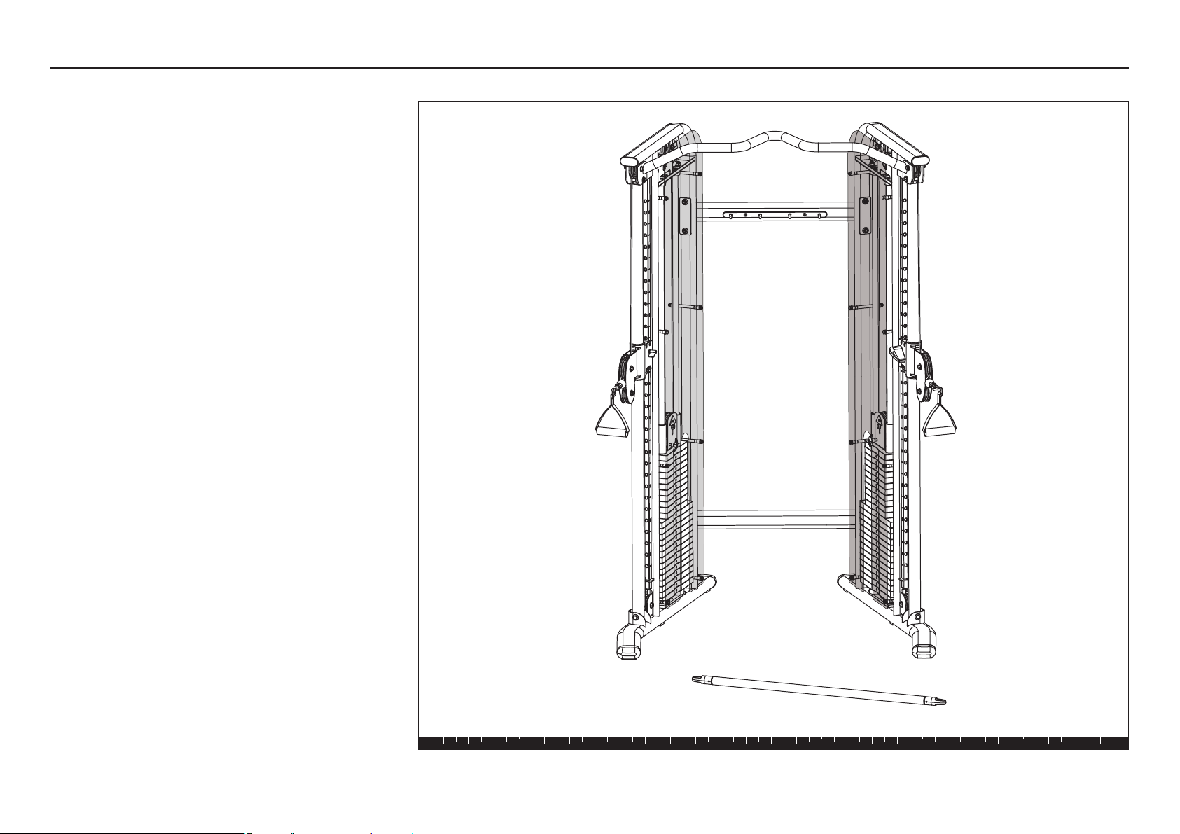
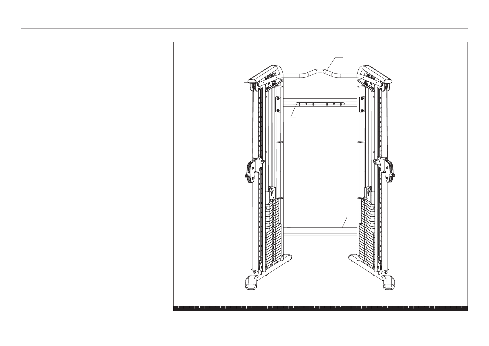
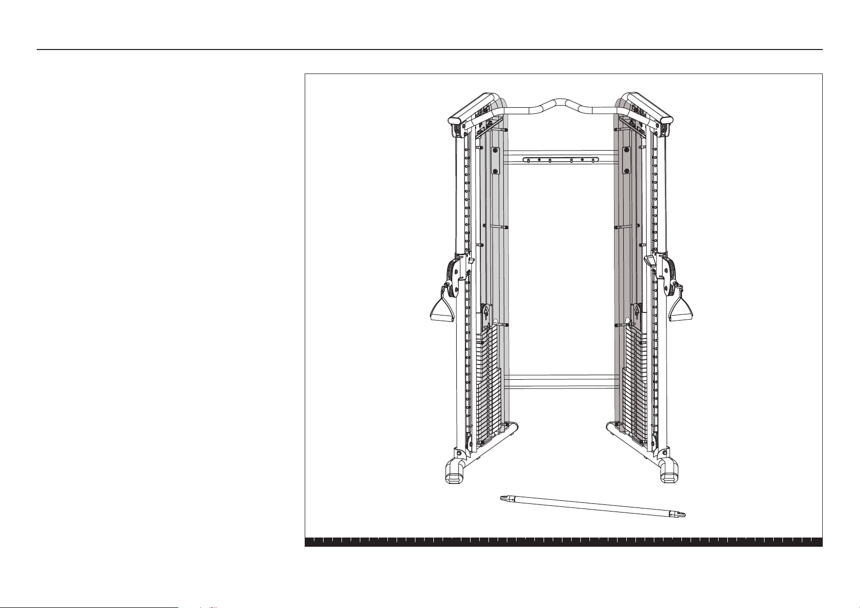
Open Box 1
Open Box 1
In this section, you will assemble the Main Structure
of the FTS Glide. The illustration shows how the Main
Structure will look when you have completed its
assembly.
Upper Cross Brace
Pull-up Bar
Main Upright
Main Upright
Lower Cross Brace
FTS Glide Assembly and Maintenance Guide
page 8
1 2 3 4 5 6
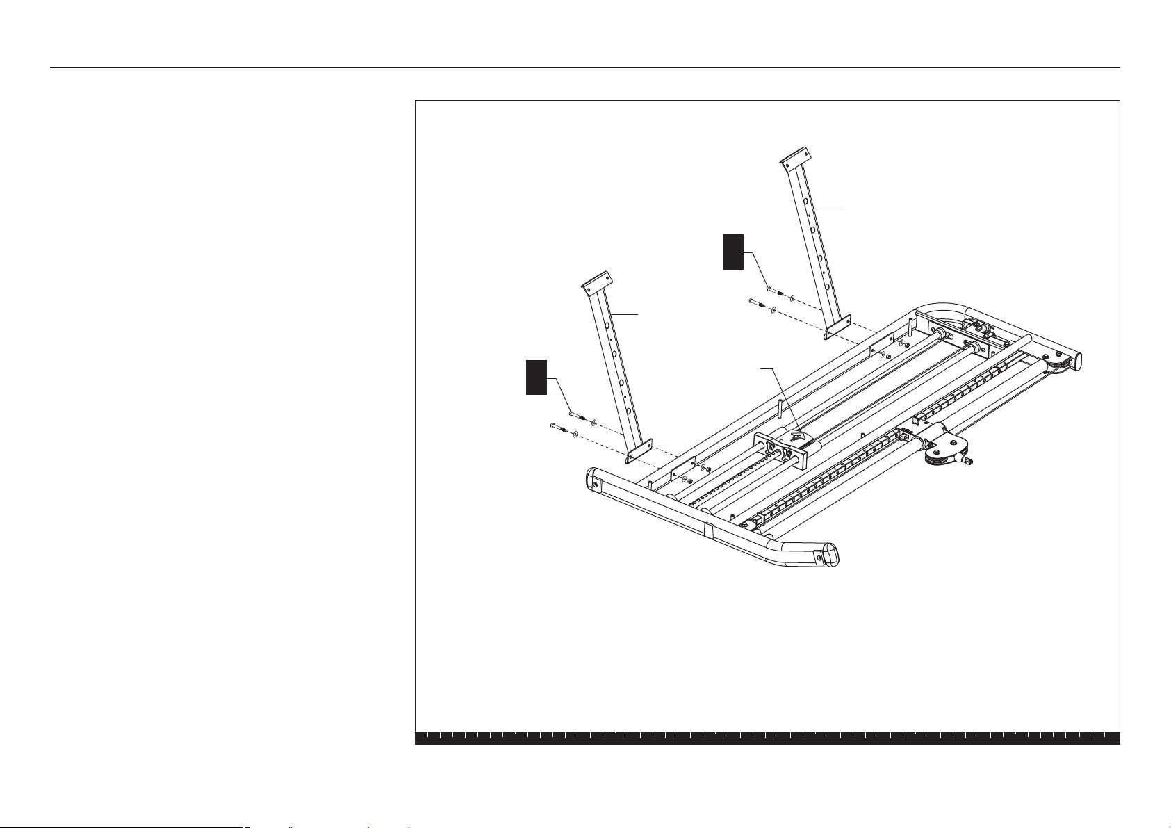
Step 1. Assemble Main Structure
1. Assemble Main Structure
A. Lay the Main Uprights on the floor where you plan to
use them and remove all packing material. Be sure
the Cam Washers on the Top Weight Assemblies are
facing up.
B. Attach the Upper and Lower Cross Braces to one
Main Upright using
four 2⁵⁄₈-inch hex head bolts
eight washers
four locknuts
Finger tighten.
Important: To keep each cross brace aligned
properly and the fasteners intact, do not lean on
or apply pressure to either cross brace.
Lower Cross
Brace
Upper Cross
Brace
2 - 2⁵⁄₈" bolts
4 - washers
2 - locknuts
B
2 - 2⁵⁄₈" bolts
4 - washers
2 - locknuts
B
Cam Washer
FTS Glide Assembly and Maintenance Guide
page 9
1 2 3 4 5 6
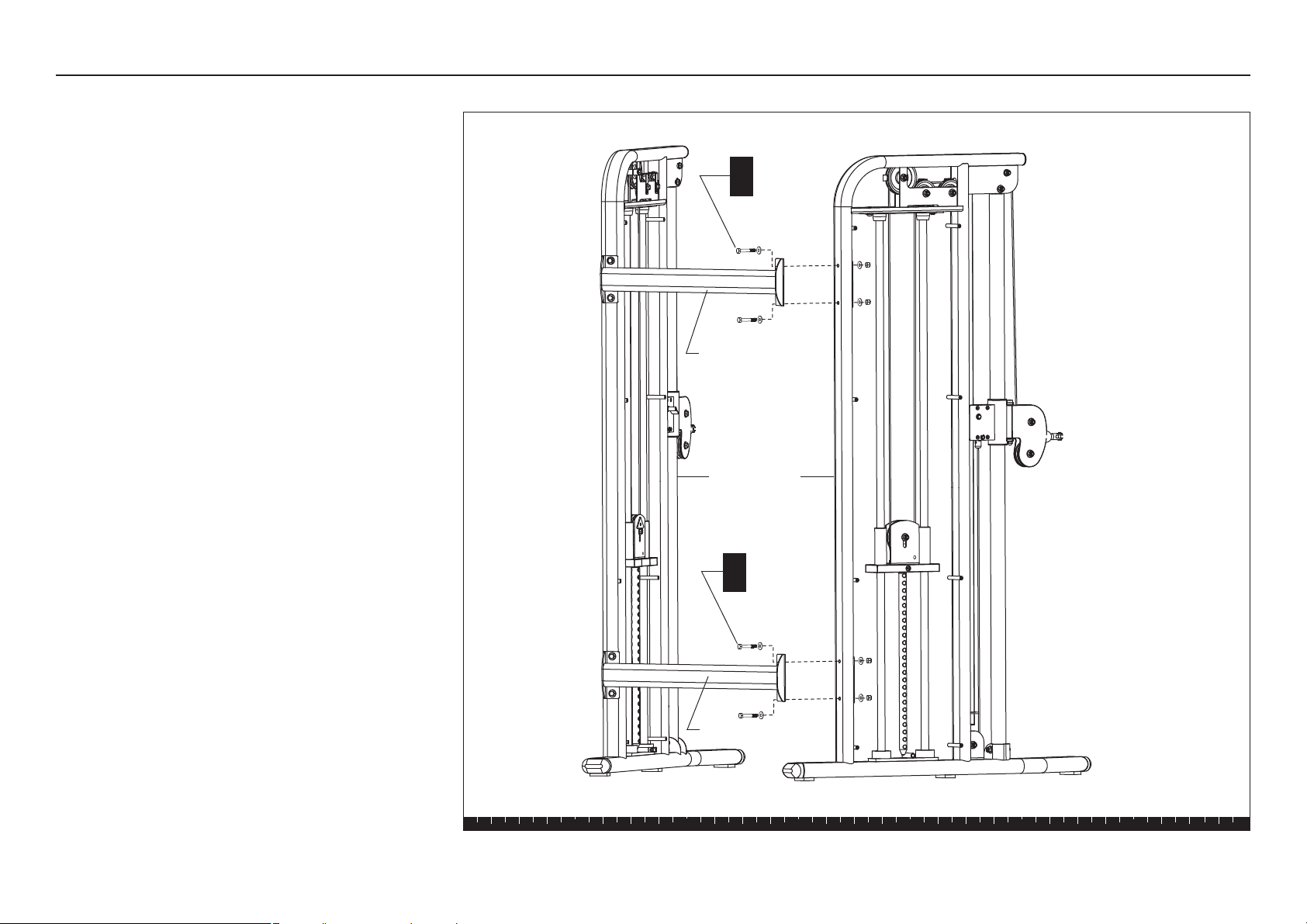
C. Lift and stabilize the two Main Uprights. Have an
assistant hold the Main Uprights steady while you
align the Upper and Lower Cross Braces and secure
them using
four 2⁵⁄₈-inch hex head bolts
eight washers
four locknuts
Use your fingers to thread the bolts while adjusting
the alignment of the Main Uprights. To allow for
adjustments, loosely secure the fasteners. Make
sure the assembly is stable and balanced before
your assistant lets go of the Main Uprights.
Main Uprights
2 - 2⁵⁄₈" bolts
4 - washers
2 - locknuts
C
Lower Cross Brace
Upper Cross Brace
Step 1. Assemble Main Structure, continued
2 - 2⁵⁄₈" bolts
4 - washers
2 - locknuts
C
FTS Glide Assembly and Maintenance Guide
page 10
1 2 3 4 5 6
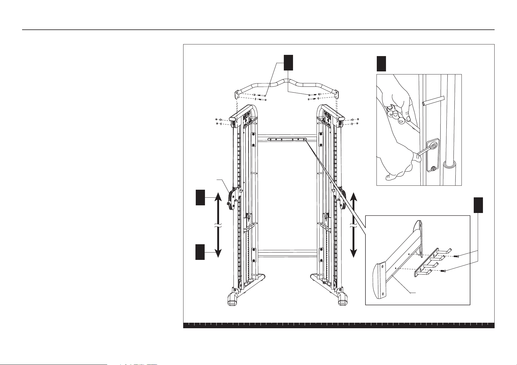
Note: You may need a step ladder to install the
Pull-up Bar.
D. Slide both Pulley Assemblies to the base of the
Main Uprights. Lift the Blue Handle up so it
disengages from the track, and then lower the
Pulley Assembly. Let go of the Blue Handle to lock
the Pulley Assembly into position.
CAUTION: The top fasteners secure a 3½-inch
pulley to each Main Upright. When you remove
the fasteners, the pulleys will fall out of the
upper bracket and may cause injury to you or
damage to the equipment. Make sure you have
an assistant hold the pulley while you remove
the fasteners.
E. Ask your assistant to hold each pulley as you
remove the fasteners on the Main Uprights. Set the
pulleys and fasteners aside.
F. Have your assistant align the Pull-up Bar with the
Main Uprights and hold it in place while you reinsert
the fasteners, spacers, and pulleys. Finger tighten
the four locknuts.
Important: Make sure you secure the top of the
Main Uprights with the lower two fasteners.
G. Move both Pulley Assemblies to the top of the Main
Uprights.
H. Use two ⁹⁄₁₆-inch wrenches to tighten the fasteners
on the Lower and Upper Cross Braces. Then, tighten
the fasteners on the Pull-up Bar.
J. Attach the accessory rack by removing two silver
fasteners from the blister pack.
K. Align the rack and insert the two fasteners. Wrench
tighten.
L. Set aside any accessories and handles found in
Box 1.
Step 1. Assemble Main Structure, continued
H
J
Tighten the eight Cross Brace
fasteners.
Pulley
Assembly
2 -bolts
4 - shoulder spacers
4 - washers
2 - locknuts
F
Accessory rack
G
D
FTS Glide Assembly and Maintenance Guide
page 11
1 2 3 4 5 6
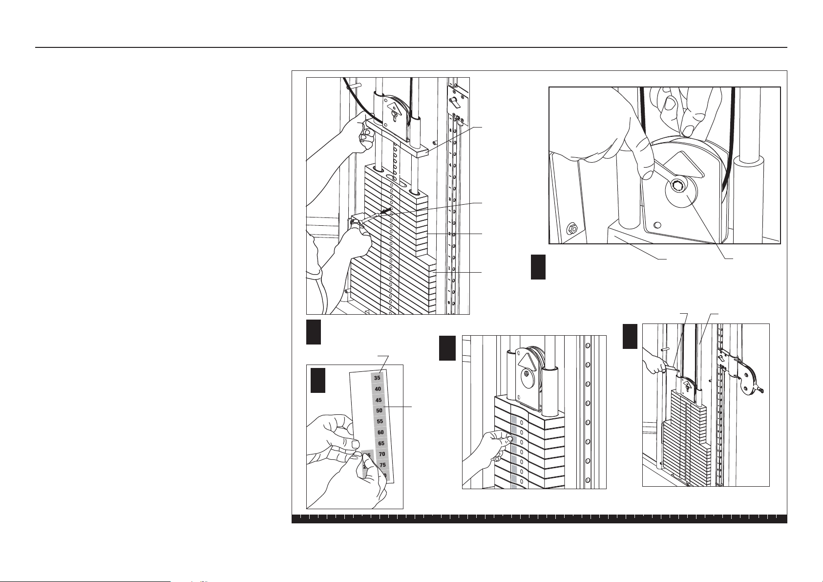
Step 2. Assemble Weight Stack
2. Assemble Weight Stack
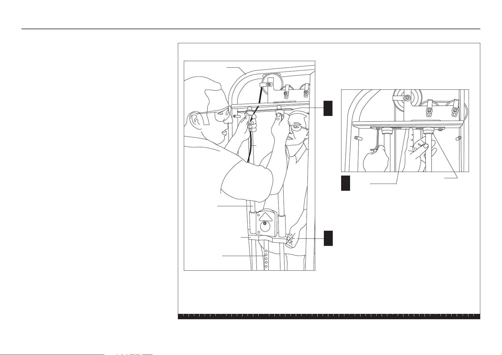
Note: Perform the following steps on each Main Upright.
Complete the assembly steps for one side before
moving the other Main Upright.
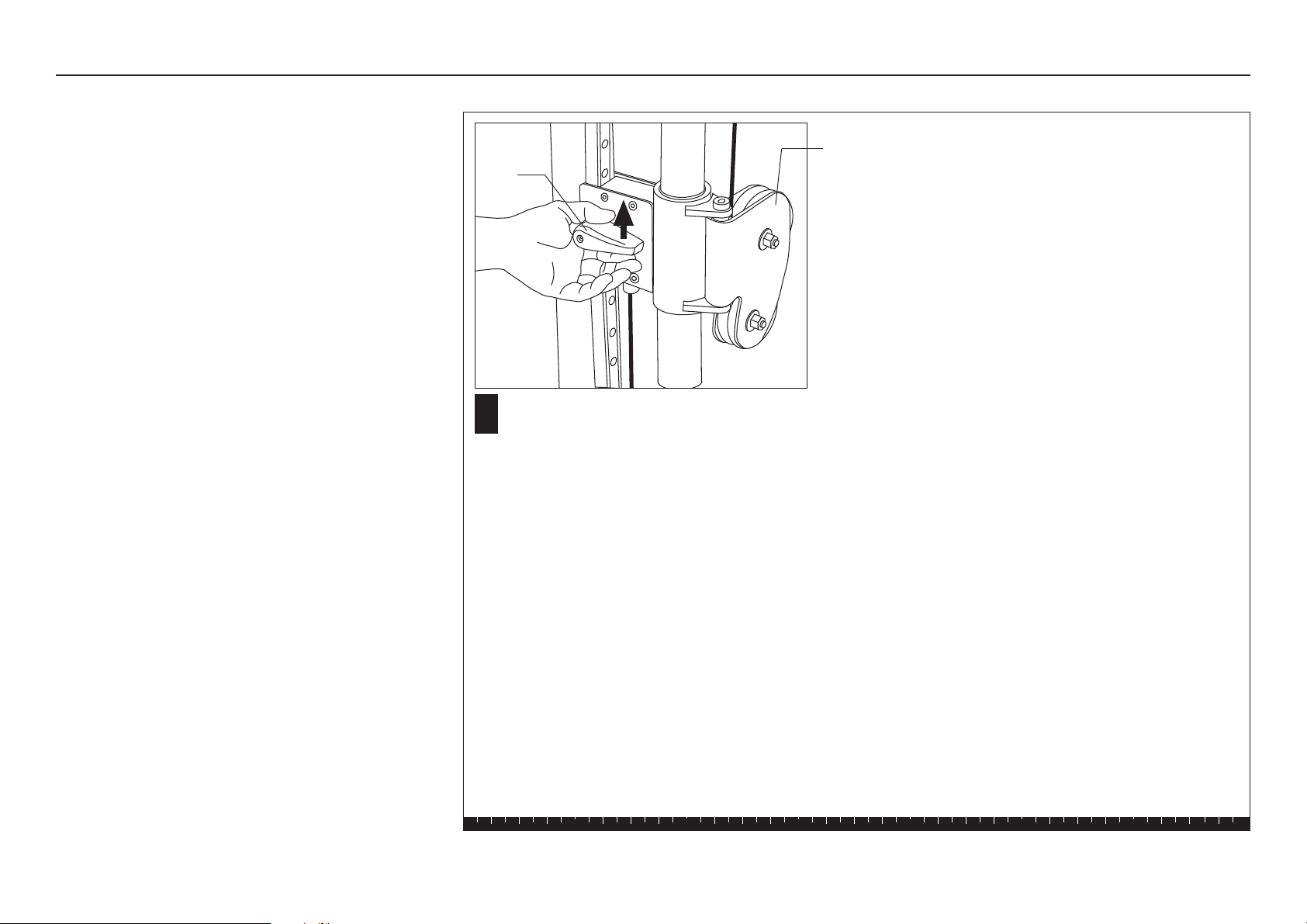
A. To remove cable tension, have your assistant lift the
Top Weight Assembly and hold it. Refer to the
illustration.
B. Use a 6mm hex key to remove the two buttonhead
screws, three washers, and one locknut that secure
the Guide Rod Bracket.
C. Remove the Guide Rod Bracket and Bumpers and
set them aside.
Top Weight Assembly
B
C
A
Guide Rod
Bracket
Bumpers
Guide Rods
Cable
Main Upright
Selector Stem
FTS Glide Assembly and Maintenance Guide
page 12
1 2 3 4 5 6
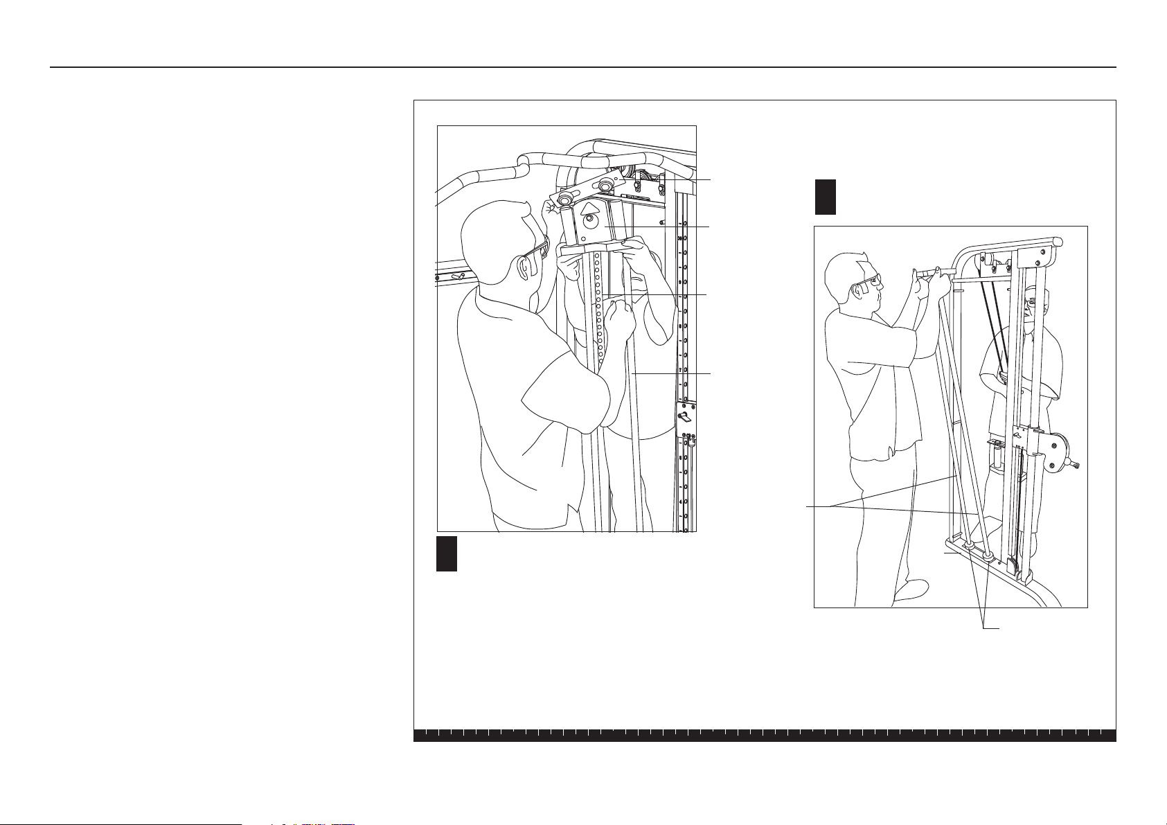
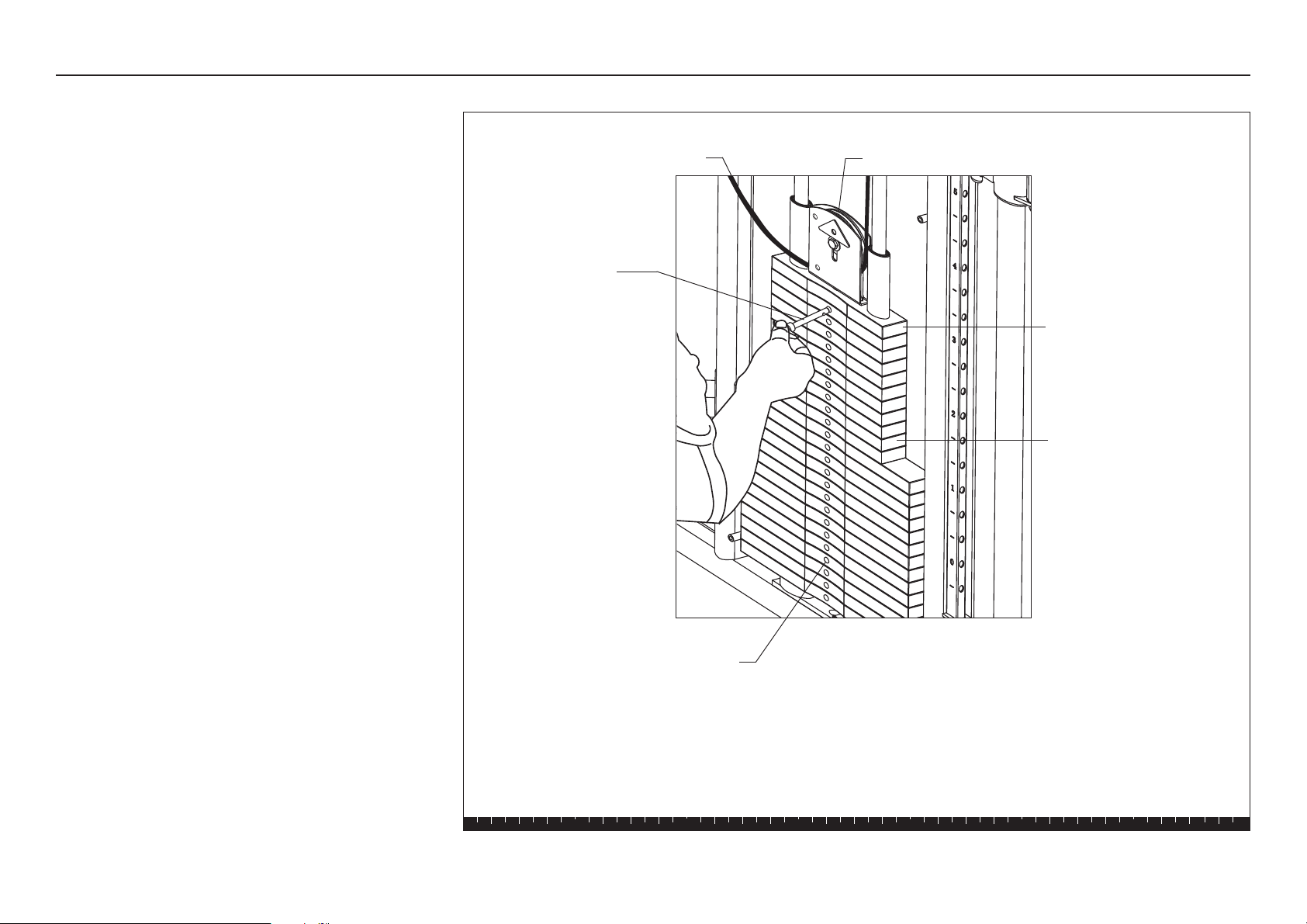
D. Have your assistant slide the Top Weight Assembly
and Selector Stem off the Guide Rods. Ask your
assistant to hold the Top Weight Assembly and the
Guide Rods while you install the weights.
E. Add the fourteen 10-lb. weights and the ten 5-lb.
weights. (Refer to the illustration for step K.) Note
that the curve on the weight plate faces inside. Hold
your finger over the plastic bushing in each weight
to prevent the bushing from popping out.
CAUTION: The weights are heavy! Handle the
weights carefully so as not to drop them or
injure yourself. Pick up and place one weight
at a time on the Guide Rods. Do not angle the
Guide Rods to such a degree that they dislodge
the Base Bumpers and come out of the Base
Frame.
Step 2. Assemble Weight Stack, continued
Top Weight
Assembly
Guide Rod
Bracket and
Bumpers
E
D
Guide Rod
Guide Rods
Ask your assistant to hold the Top Weight
Assembly and the Guide Rods while you install
the weights.
Base Bumpers
Base
Frame
Selector Stem
FTS Glide Assembly and Maintenance Guide
page 13
1 2 3 4 5 6
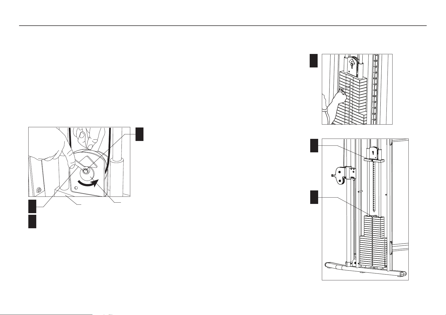
Step 2. Assemble Weight Stack, continued
H
G
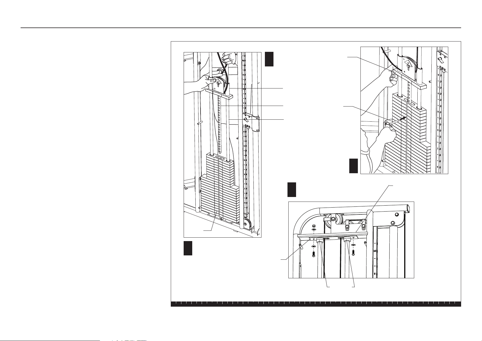
F. Hold the Guide Rods while your assistance replaces
the Selector Stem and Top Weight Assembly.
Important: During reassembly, do not lower the
Guide Rod Bracket more than three inches along
the Guide Rods. Have your assistant hold the
Guide Rods firmly because they can be pulled out
of the Base Bumpers. It is difficult to replace the
Guide Rods in an assembled Weight Stack. If the
Guide Rods become dislodged, you will need to
disassemble the Weight Stack to make sure that
the Guide Rods are seated properly in the Base
Frame.
G. Ask your assistant to hold the Guide Rods while
you check the cables to make sure they are
centered between the Guide Rods. Remove any
twists in the cables.
H. To relieve cable tension, lift the Top Weight
Assembly about a foot above the Weight Stack and
secure the Selector Stem with the Weight Pin.
J. While your assistant continues to hold the Guide
Rods, realign the Bumpers with the cutouts in the
Upper Frame Crosspiece. Replace the Guide Rod
Bracket using two buttonhead screws, three
washers, and one locknut (removed in step 2B).
Wrench tighten.
F
Guide Rod
Weight
Stack
J
Weight
Pin
Guide Rod
Bracket
Align the Bumpers with cutouts in the
Upper Frame Crosspiece.
Bumpers
Upper Frame
Crosspiece
Selector Stem
Top Weight
Assembly
Top Weight
Assembly
FTS Glide Assembly and Maintenance Guide
page 14
1 2 3 4 5 6
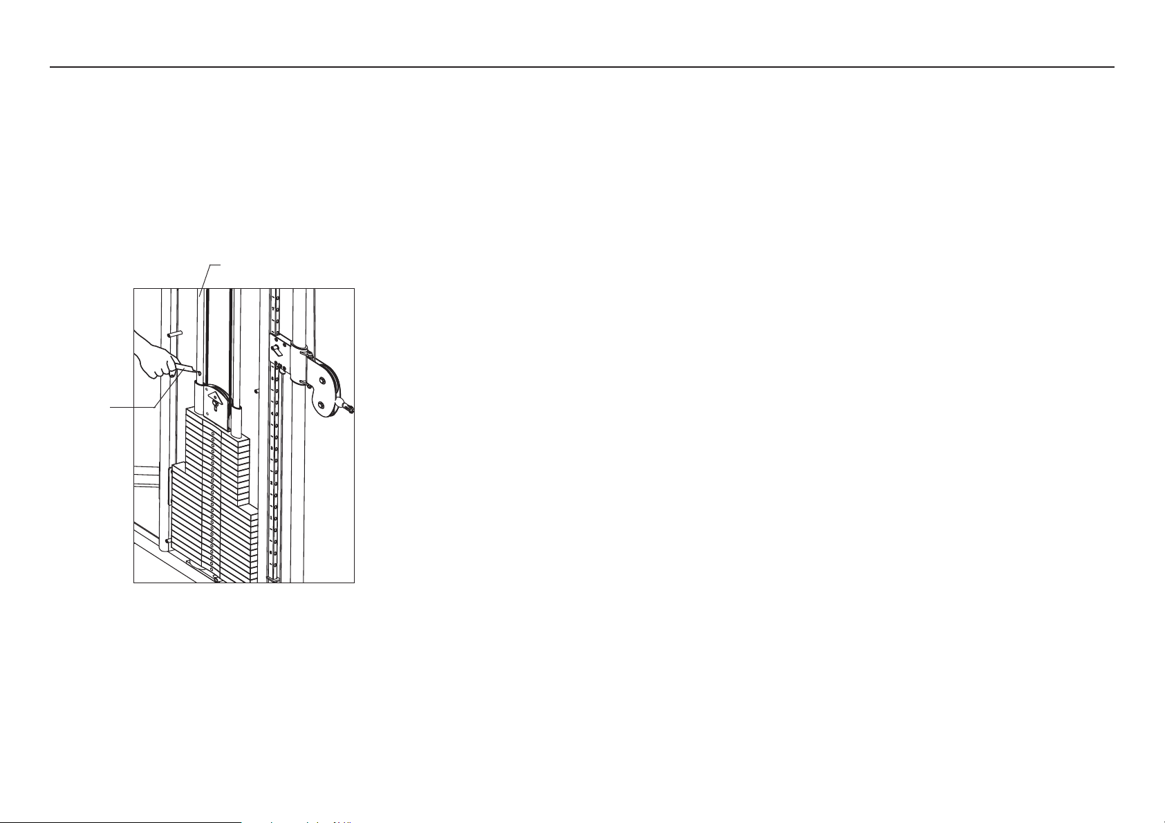
K. Remove the Weight Pin and gently lower the Top
Weight Assembly onto the Weight Stack.
L. Remove the slack in the cable. Use two ⁹⁄₁₆-inch
wrenches to loosen the fastener that holds the Cam
Washer. Rotate the Cam Washer to remove any
slack in the cable. Check the Top Weight Assembly
to make sure it remains well-seated on the Weight
Stack and then wrench tighten the Cam Washer
fasteners.
Important: Before attaching the Weight Labels,
wash your hands to remove dirt and grease.
M. Peel the Weight Label off the Weight Label Strip.
N. Peel the backing off the Weight Label to expose the
adhesive and place a label on each Weight Plate.
The recommended location of the label is toward
the rear of the unit.
P. Apply lubricant to each Guide Rod.
CAUTION: The lubricant can stain clothes. Wear
proper attire when lubricating the Guide Rods.
K
Weight
Pin
Top Weight
Assembly
L
Cam
Washer
Top Weight
Assembly
Adjust Cam Washer to
remove cable slack.
Remove Weight Pin and
lower Top Weight Assembly.
P
5-lb.
Weights
10-lb.
Weights
Lubricant Guide Rod
Step 2. Assemble Weight Stack, continued
M
10
17.5
20
22.5
25
7.5
15
12.
5
N
Weight Label Strip
Weight
Label
FTS Glide Assembly and Maintenance Guide
page 15
1 2 3 4 5 6
Open Box 2
Open Box 2
Use wire cutters to open the box.
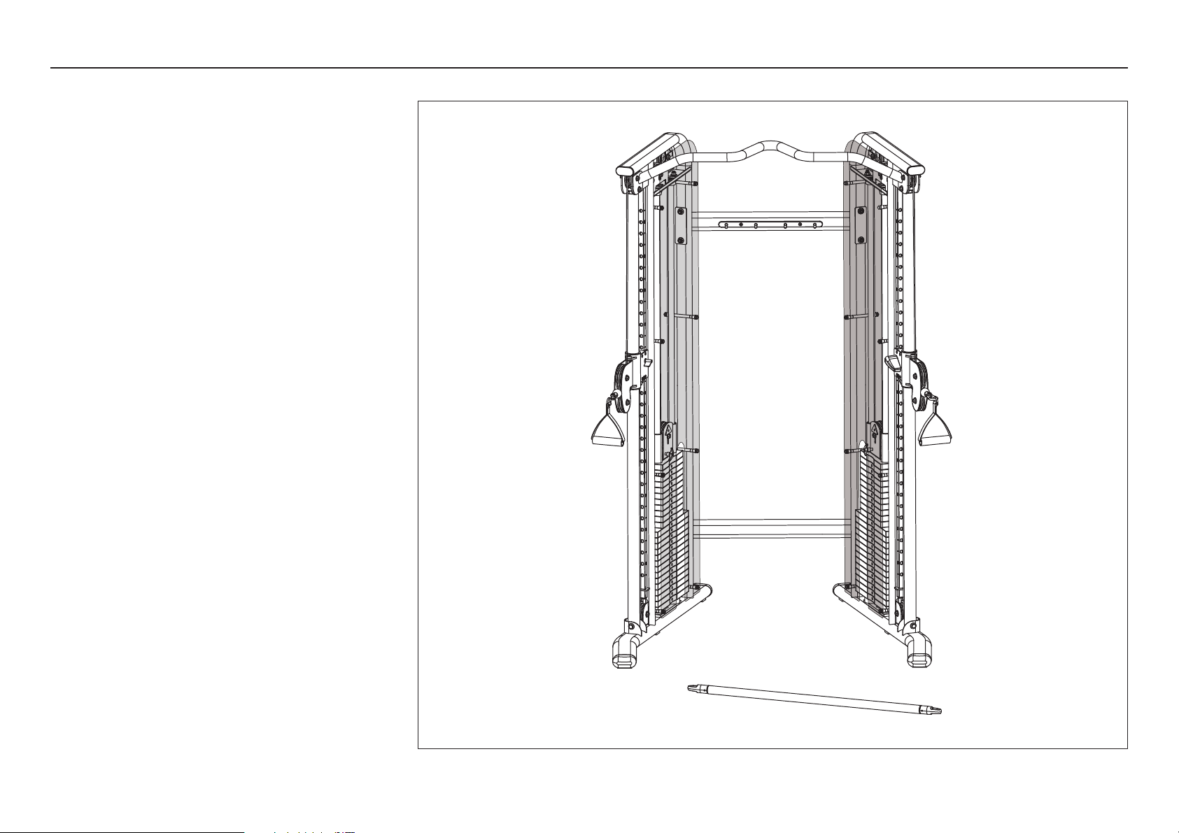
The illustration shows the entire FTS Glide assembly once
you have completed installing the contents of Box 2.
FTS Glide Assembly and Maintenance Guide
page 16
1 2 3 4 5 6
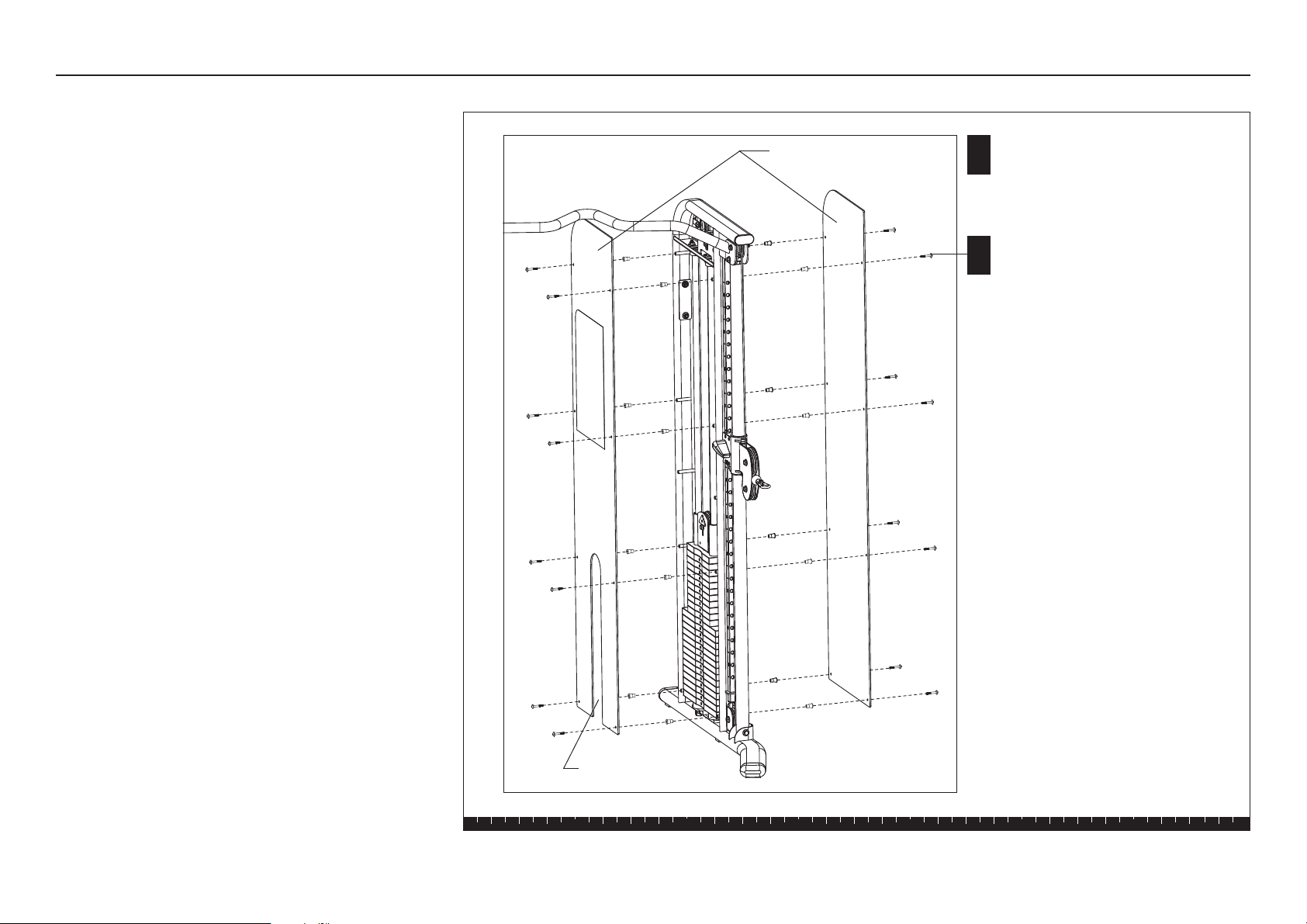
Step 3. Attach Shrouds
3. Attach Shrouds
Two Shrouds are attached to each Main Upright.
Complete the assembly steps for one side before
moving to the other Main Upright.
Important: Handle the Shroud with care. The acrylic
Shrouds require special handling as they are easily
scratched. For proper care and maintenance, refer to
the Adjustments and Maintenance section in this
guide.
A. The frosted side of the Shroud faces the Weight
Stack. Install the Shrouds so the cutouts allow
access to the Weight Stack Pin.
B. Attach a Shroud to each side of the Main Upright
using
eight 1³⁄₄-inch socket head screws
eight spacers
Note: Start with the two bottom mounts and work
toward the top. Ask your assistant to hold the
Shroud in place while you insert the spacers and
fasteners. Position the spacer so its larger diameter
rests against the shroud. Alternately finger tighten
all eight fasteners while adjusting the alignment.
C. Wrench tighten all the fasteners using a 5mm
hex key.
CAUTION: Do not over tighten. You can crack or warp
the Shroud if too much pressure is applied to the
fasteners.
Shroud (frosted side
faces weight stack)
Cutout in Shroud
C
8 - 1³⁄₄" socket head screws per Shroud
8 - spacers per Shroud
B
FTS Glide Assembly and Maintenance Guide
page 17
1 2 3 4 5 6
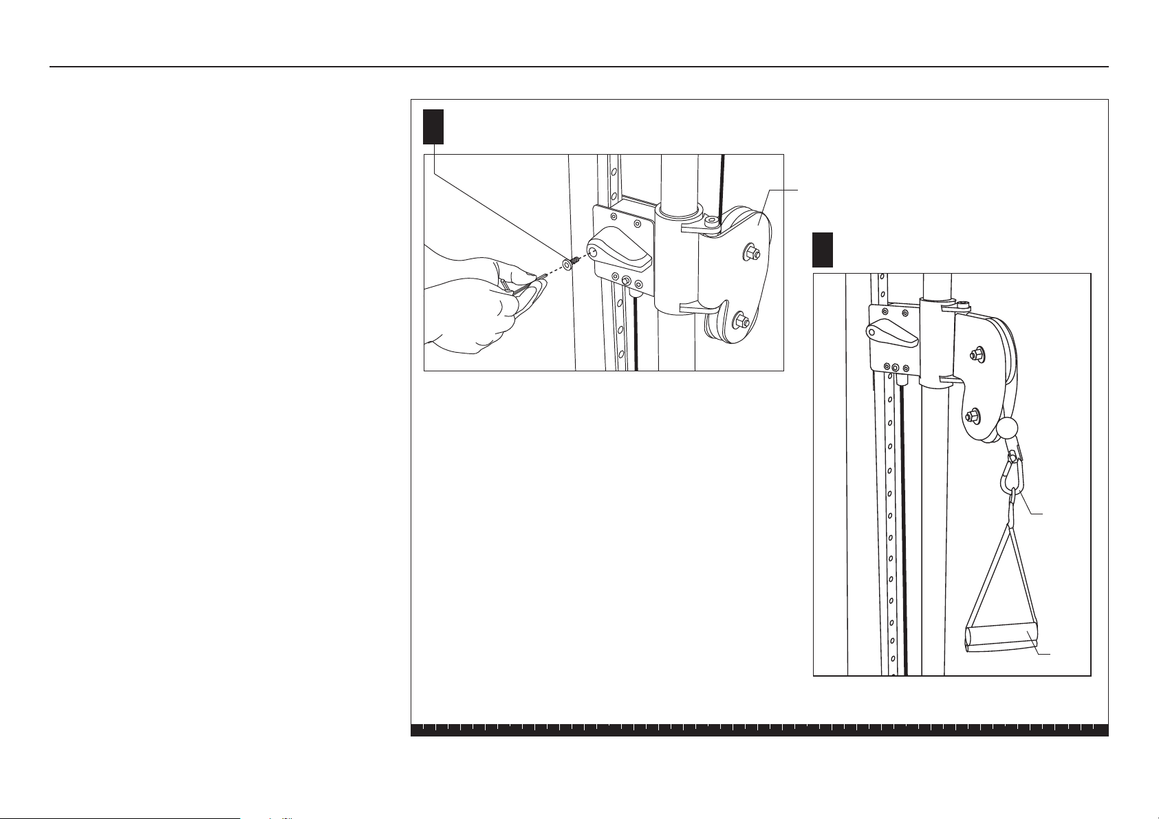
Step 4. Attach Handles and Accessories
4. Attach Handles and
Accessories
A. Install a blue handle on each Pulley Assembly
using
one 4mm socket head screw
Wrench tighten with a hex key.
Note: To adjust the outside pulley location, lift the
blue handle and slide it to the desired location.
B. Attach the two Soft Handles or a Soft Ankle Strap to
the end of the cable using a Spring Clip.
This completes the assembly of your FTS Glide
Strength-Training Fitness Equipment.
A
B
Install the Soft Handle or
Soft Ankle Strap.
Pulley Assembly
1 - 4mm socket head screw
on each Pulley Assembly
Spring
Clip
Soft
Handle
FTS Glide Assembly and Maintenance Guide
page 18
1 2 3 4 5 6
5. Move the Pulley Assemblies
A. To raise the Pulley Assembly, simply push the Blue
Handle up along the track. The Pulley Assembly
automatically locks into position.
B. To lower the Pulley Assembly, lift the Blue Handle
up so it disengages from the track and then lower
the Pulley Assembly. Let go of the Blue Handle to
lock the Pulley Assembly into position.
Step 5. Move the Pulley Assemblies
A
Pulley
Assembly
Blue
Handle
To disengage the Pulley Assembly, lift the Blue
Handle and slide the assembly along its track.
FTS Glide Assembly and Maintenance Guide
page 19
1 2 3 4 5 6
4
Adjustments and
Maintenance
Adjustments and Maintenance
When the FTS Glide is completely assembled, you
need to check the cables for proper tension. Obvious
signs that cable problems exist include:
✔ Top Weight Assembly does not rest squarely on the
top weight of the Weight Stack.
✔ Cable rubs the inside edges of the pulleys.
✔ Excess slack exists in the cable.
✔ Weight Pin cannot be easily inserted in or removed
from each hole in the Weight Stack.
✔ Selector Stem rubs inside the Weight Stack.
CAUTION: Take the time to perform the following
steps. If the cables do not have the proper tension
you could void the Precor Limited Warranty.
If you experience any of these cable problems, remove
the Weight Pin from the Weight Stack to ensure the
least cable resistance and then make the proper cable
adjustments.
Top Weight
Assembly
Weight pin
A slack cable
Pulley
Weight Stack
Holes in Weight Stack
FTS Glide Assembly and Maintenance Guide
page 20
Adjustments and Maintenance, continued
1. Cable Adjustments
The Cam Washer makes it easy to adjust the cable.
A. To remove the slack in the cable. Use two ⁹⁄₁₆-inch
wrenches to loosen the fasteners that hold the Cam
Washer.
B. Rotate the Cam Washer so that the slack is removed.
C. Check the Top Weight Assembly to make sure it
remains well-seated on the Weight Stack and then
wrench tighten the Cam Washer fasteners.
D. Check the Selector Stem alignment by inserting the
Weight Pin into every hole on the Weight Stack.
Cam Washer
Top Weight
Assembly
A
B
C
2. Selector Stem Adjustments
If the Selector Stem consistently strikes the inside of
the weight stack or it is misaligned with the Weight
Stack hole, you can re-center the Selector Stem by
taking the following steps:
A. To free the Selector Stem, remove the Weight Pin
from the Weight Stack.
B. Pull up the Selector Stem and place a cover over
the opening in the Weight Stack. Rest the Selector
Stem on the cover.
C. Use an 8mm hex key to loosen the socket head
bolt in the center of the Top Cap Weight.
Important: Do not remove the socket head bolt.
D. Remove the cover from the Weight Stack and lower
the Selector Stem so the Top Cap Weight rests on
the Weight Stack.
E. To lock the Selector Stem, insert the Weight Pin
into the Weight Plate hole at the bottom of the
Weight Stack.
F. Wrench-tighten the socket head bolt in the center of
the Top Cap Weight.
G. Check the adjustment by inserting the Weight Pin
into every Weight Plate hole. The Weight Pin should
slide easily in and out of each Weight Plate and
Selector Stem.
H. Insert the Weight Pin into the appropriate Weight
Plate for your level of fitness.
J. Replace the Shroud, if necessary.
A
C
B
FTS Glide Assembly and Maintenance Guide
page 21
3. Maintenance
Guide Rods
A Apply one tube of lubricant to each Guide Rod.
B. Lubricate the Guide Rods every six months.
CAUTION: The lubricant can stain clothes. Wear
proper attire when lubricating the Guide Rods.
Lubricant
Guide Rod
Adjustments and Maintenance, continued
Inspection
Inspect the unit daily.
Look and listen for frayed or worn parts, loose
fasteners, cable tensions issues, unusual noises, and
any other indications that the equipment may be in need
of service.
You are responsible for the proper maintenance of the
unit as discussed in this manual. For other service
issues, contact Customer Support. Refer to
Obtaining
Service.
Shrouds
CAUTION: Clean the Shrouds with product
specifically labeled as safe for acrylic. Use a clean,
nonabrasive cloth and light pressure to avoid
scratching the acrylic surface.
The acrylic Shrouds on the FTS Glide are easily
scratched or damaged through improper cleaning
techniques. To avoid problems, dust the shrouds often
with a clean, lint-free cloth and light pressure. Avoid
rubbing dirt or grit into the surface. If you use glass
cleaner or a similar product, make sure the label states
that it is safe to use on Plexiglas
®
or acrylic products.
Important: DO NOT use ketones, aromatics, esters,
halogens, window cleaning sprays, alcohol, kitchen
scouring compounds, or solvents (such as acetone,
benzene, gasoline, carbon tetrachloride, or thinners).
Do not use ammonia-based cleaning solutions
because the ammonia destroys the plastic coating.
To remove light scratches on the smooth side only, use
a buffing compound such as, car wax. Lightly buff the
acrylic sheet using a clean buffer until the scratches
disappear.

page 22
Limited Warranty
Precor, Incorporated (PRECOR) will repair or replace any of the following components which are
defective as to materials or workmanship for products manufactured and sold after June 1, 1990:
ICARIAN & STRETCH CENTER:
Lifetime: Structural Steel Framework
Five Years: Rotary Bearings, Weight Stacks, Pulleys, Guide Rods, Structural Moving
Parts
One Year: Cable, Linear Bearings, Springs
Ninety Days: Upholstery, Handgrips, All Other Items Not Listed
Not withstanding the above, all warranties provided by PRECOR shall terminate upon transfer of
ownership of the equipment by the original owner. PRECOR may require the Customer to affirm
that he is the original owner of the equipment before providing warranty services. This warranty
does not extend to any components which become defective due to abuse, misuse, or lack of
proper maintenance or if the equipment under warranty has been modified or altered in anyway.
The Customer seeking repair or replacement of defective equipment must notify PRECOR at the
address set forth on the back cover of such defect, admit PRECOR authorized service
representatives during normal business hours to effect repairs and pre-pay all defective
equipment within thirty (30) days of its receipt of notice of the defect from a Customer or the
equipment itself.
THIS WARRANTY IS LIMITED TO REPAIR AND/OR REPLACEMENT OF DEFECTIVE
EQUIPMENT. Except to the extent it is precluded from doing so in a particular state or other
jurisdiction by applicable law. PRECOR DISCLAIMS ANY AND ALL OTHER WARRANTIES
WHETHER EXPRESSED OR IMPLIED, INCLUDING BUT NOT LIMITED TO ANY IMPLIED
WARRANTY OR MERCHANTABILITY OR FITNESS FOR A PARTICULAR PURPOSE. Moreover, if
any damage or defect is caused by the transport carrier, such claims must be filed with the carrier
at the time of delivery. PRECOR DISCLAIMS ANY AND ALL RESPONSIBILITY FOR SUCH
DAMAGE OR DEFECT, NO DEALER, EMPLOYEE, SALES REPRESENTATIVE OR AGENT HAS
ANY AUTHORITY TO MAKE ANY WARRANTIES OR REPRESENTATIONS CONCERNING
PRECOR EQUIPMENT BEYOND THOSE SET FORTH IN THIS WARRANTY AND IN OTHER
OFFICIAL PRECOR LITERATURE: AND PRECOR DISCLAIMS ALL RESPONSIBILITY FOR ANY
SUCH UNAUTHORIZED WARRANTIES OR REPRESENTATIONS.
An individual purchasing PRECOR equipment in California for personal, family or household
purposes has the right to have defective equipment serviced or repaired during the warranty
period. The warranty period will be extended for the number of whole days that the equipment is
out of the buyer’s hands for warranty repairs. If a defect exists within the warranty period, the
warranty will not expire until the defect has been fixed. The warranty period will also be extended
if the warranty repairs have not been performed due to delays caused by circumstances beyond
the control of the buyer, or if the warranty repairs did not remedy the defect and the buyer notifies
PRECOR or its authorized dealer or sales representative of the failure of the repairs within sixty
(60) days after they were completed. If after a reasonable number of attempts, the defect has not
been fixed, the buyer may return the equipment for a replacement or a refund subject, in either
case, to deduction of a reasonable charge for usage. This time extension does not affect the
protections or remedies the buyer has under other laws. Purchasers of PRECOR strength
equipment have the right to bring an action at law or in equity to resolve disputes concerning or to
enforce the provisions of this warranty. Some states do not allow the exclusion of limitations of
incidental or consequential damages and/or limitation on how long an implied warranty lasts, so
the above limitations or exclusions may not apply to all Customers. This warranty gives Customers
specific legal rights; Customers may also have other rights which may vary from state to state.
Effective 27 November 2006
P/N CW31973-102


Precor is a registered trademark of Precor Incorporated.
Specifications subject to change without notice.
Copyright 2007 Precor Incorporated.
www.precor.com
Precor Incorporated
20031 142nd Avenue NE
P.O. Box 7202
Woodinville, WA USA 98072-4002
NOTICE:
Precor is widely recognized for its innovative, award winning designs of exercise equipment. Precor aggressively seeks U.S. and foreign patents for
both the mechanical construction and the visual aspects of its product design. Any party contemplating the use of Precor’s product designs is hereby
forewarned that Precor considers the unauthorized appropriation of its proprietary rights to be a very serious matter. Precor will vigorously pursue all
unauthorized appropriation of its proprietary rights.
FTS Glide Specifications
Length: 48.5 inches (123 cm)
Height: 85 inches (216 cm)
Width: 53 inches (135 cm)
FTS Glide Lit Kit CW33614-102
Warranty Statement CW31973-102
16 July 2007