Loading ...
Loading ...
Loading ...
Test Run
ENGLISH
Installation Manual 59
Self-Diagnosis Function
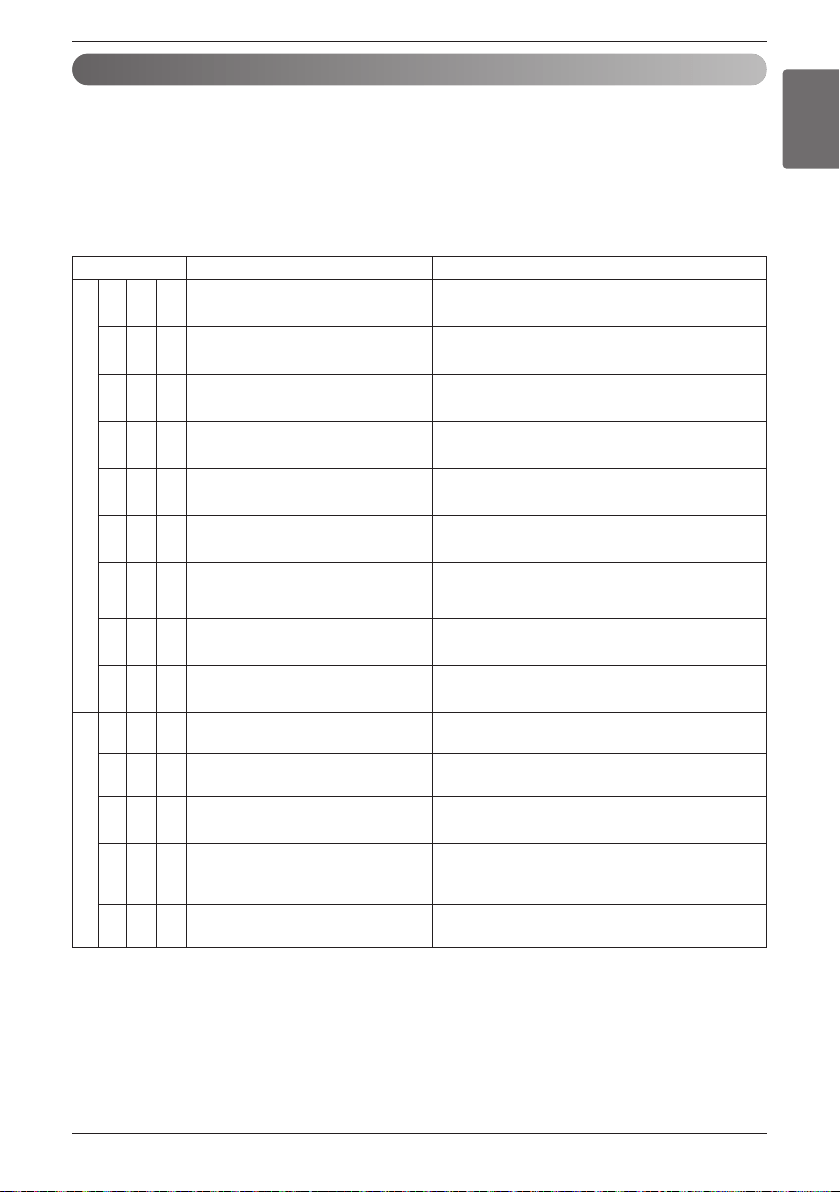
Error Indicator
• This function indicates types of failure in self-diagnosis and occurrence of failure for air condition.
• Error mark is displayed on display window of indoor units and wired remote controller, and 7-segment LEDof
outside unit control board as shown in the table.
• If more than two troubles occur simultaneously, lower number of error code is first displayed.
• After error occurrence, if error is released, error LED is also released simultaneously.
Display Error item Root cause of error
Indoor unit
0 1 - Indoor unit air temperature sensor error
Indoor unit air temperature sensor disconnection or short
circuit
0 2 -
Inlet pipe temperature sensor of indoor
unit
Indoor unit pipe inlet temperature sensor disconnection or
short circuit
0 3 -
Communication error between wired
remote controller and indoor unit
Occurs when indoor unit communication signal is not
received from the wired remote controller
0 4 - Indoor unit drain error Drain pump and float switch error
0 5 -
Communication error between outside
unit and indoor unit
When the indoor unit does not receive the outside com-
munication signal continuously for 5minutes or more
0 6 -
Indoor unit pipe outlet temperature sen-
sor error
Indoor unit pipe outlet temperature sensor disconnection
or short circuit
0 9 - Indoor unit EEPROM error
Communication error between MICOM and EEPROM or
when there is
no indoor unit EEPROM data
1 0 -
Indoor unit BLDC motor feedback signal
error
When motor connector is removed or defective
1 7 - Inlet Air temperature sensor of FAU Air temperature sensor of indoor unit is open or short
Outside unit
2 1 1
Outside unit inverter compressor IPM
fault
Outside unit inverter compressor drive IPM error
2 2 1
Inverter Board Input Over Current(RMS)
of Outside Unit
Outside Unit Inverter Board Input Current excess (RMS)
2 3 1
Outside unit inverter compressor DC link
under-voltage
DC voltage is not charged after master outside unit oper-
ating relay is turned on
2 4 1 Outside unit high pressure switch
Compressor maintenance by master outside unit high
pressure switch Flow rate insufficiency or flow switch
trouble of master outside unit
2
6 1
Outside unit inverter compressor opera-
tion failure error
Outside unit input voltage is 487V and above or less than
270V
Loading ...
Loading ...
Loading ...