
ASSEMBLY MANUAL / OWNER’S MANUAL
Rower
™

2
Important Safety Instructions 3
Safety Warning Labels / Serial Number 5
Specications 6
BeforeAssembly 6
Parts 7
Hardware 8
Tools 8
Assembly 9
Leveling the Machine 13
Moving and Storing the Machine 14
Features 15
ConsoleFeatures 16
Remote Heart Rate Monitor 17
Operations 19
Adjustments 19
Power Up 19
Maintenance 20
Replacing the Console Batteries 21
Maintenance Parts 22
Troubleshooting 23
Nautilus, Inc., www.nautilusinternational.com | Nautilus, Inc., 5415 Centerpoint Parkway, Groveport, OH 43125 USA | Printed in China
|©2017Nautilus,Inc.|Schwinn,theSchwinnQualitylogo,Nautilus,Bowex,andUniversalaretrademarksownedbyorlicensed
to Nautilus, Inc., which are registered or otherwise protected by common law in the United States and other countries. Polar® and
OwnCode® are registered trademarks of their owner.
ORIGINAL MANUAL - ENGLISH VERSION ONLY
TABLE OF CONTENTS
To validate warranty support, keep the original proof of purchase and record the following information:
Serial Number __________________________
Date of Purchase ____________________
To register your product warranty, contact your local distributor.
If you have questions or problems with your product, please contact your local Schwinn
™
distributor.
Tondyourlocaldistributor,goto:www.nautilusinternational.com

3
IMPORTANT SAFETY INSTRUCTIONS
When using an electrical appliance, basic precautions should always be followed, including the following:
This icon means a potentially hazardous situation which, if not avoided, could result in death or serious
injury.
Obey the following warnings:
Read and understand all warnings on this machine.
Carefully read and understand the Assembly instructions. Read and understand the complete Manual. Keep
the Manual for future reference.
• Keep bystanders and children away from the product you are assembling at all times.
• Donotinstallthebatteriesintothemachineuntilthetimespeciedintheassemblymanual.
• Beforeeachuse,examinethismachineforloosepartsorsignsofwear.Donotuseiffoundinthiscondition.Contact
your local distributor for repair information.
• Not intended for use by persons with medical conditions where those conditions may impact the safe operation of the
machine or pose a risk of injury to the user
• Do not allow the pull strap to retract by itself. Use a controlled motion while gripping the handles with hands. Allowing
the pull strap to snap back in an uncontrolled manner could cause damage to the rower engine or injury to the user or
bystanders.
• Do not drop or put objects into any opening of the machine.
• Do not assemble this machine outdoors or in a wet or moist location.
• Makesureassemblyisdoneinanappropriateworkspaceawayfromfoottrafcandexposuretobystanders.
• Some components of the machine can be heavy or awkward. Use a second person when doing the assembly steps
involving these parts. Do not do steps that involve heavy lifting or awkward movements on your own.
• Set up this machine on a solid, level, horizontal surface.
• Do not try to change the design or functionality of this machine. This could compromise the safety of this machine and
will void the warranty.
• If replacement parts are necessary use only genuine replacement parts and hardware supplied by Nautilus. Failure
to use genuine replacement parts can cause a risk to users, keep the machine from operating correctly and void the
warranty.
• Do not use or put the machine into service until the machine has been fully assembled and inspected for correct
performance in accordance with the Manual.
• Use this machine only for its intended use as described in this manual. Do not use attachments not recommended by
the manufacturer.
• Do all assembly steps in the sequence given. Incorrect assembly can lead to injury or incorrect function.
• SAVE THESE INSTRUCTIONS.
Before using this equipment, obey the following warnings:
Read and understand the complete Manual. Keep the Manual for future reference.
Read and understand all warnings on this machine. If at any time the Warning stickers become loose,
unreadable or dislodged, contact your local distributor for replacement stickers.
• Children must not be let on or near to this machine. Moving parts and other features of the machine can be dangerous
to children.
• Not intended for use by anyone under 14 years of age.
• Consultaphysicianbeforeyoustartanexerciseprogram.Stopexercisingifyoufeelpainortightnessinyour
chest, become short of breath, or feel faint. Contact your doctor before you use the machine again. Use the values
calculated or measured by the machine’s computer for reference purposes only.

4
• Beforeeachuse,examinethismachinefordamage,loosepartsorsignsofwear.Donotuseiffoundinthiscondition.
Monitor the Foot Plate, Seat and Pull Strap closely. Contact your local distributor for repair information.
• Maximumuserweightlimit:136kg(300lbs.).Donotuseifyouareoverthisweight.
• This machine is for home use only. Do not place or use the machine in a commercial or institutional setting. This
includesgyms,corporations,workplaces,clubs,tnesscentersandanypublicorprivateentitythathasamachinefor
usebyitsmembers,customers,employeesorafliates.
• Donotwearlooseclothingorjewelry.Thismachinecontainsmovingparts.Donotputngersorotherobjectsinto
movingpartsoftheexerciseequipment.
• Always wear rubber soled athletic shoes when you use this machine. Do not use the machine with bare feet or only
wearing socks.
• Set up and operate this machine on a solid, level, horizontal surface.
• Do not step off the machine until the Seat is stationary.
• Make the Seat stable before you sit on it. Use caution when you step on and off the machine.
• Disconnect all power before servicing this machine.
• Do not operate this machine outdoors or in moist or wet locations.
• Keepatleast0.6m(24”)oneachsideofthemachineclear.Thisistherecommendedsafedistanceforaccessand
passage around and emergency dismounts from the machine. Keep third parties out of this space when machine is in
use.
• Donotoverexertyourselfduringexercise.Operatethemachineinthemannerdescribedinthismanual.
• Perform all regular and periodic maintenance procedures recommended in the Owner’s Manual.
• Do not remove the Handle from the pull strap after it is installed.
• Do not try to disassemble your Rower engine. The product is not designed to be serviced by the customer. Contact
your local distributor for repair information.
• Do not drop or put objects into any opening of the machine.
• Correctly adjust and safely engage all Positional Adjustment Devices. Make sure that the Adjustment Devices do not
hit the user.
• Keep the Foot Plates clean and dry.
• Exerciseonthismachinerequirescoordinationandbalance.Besuretoanticipatethatchangesinspeedand
resistance level can occur during workouts, and be attentive in order to avoid loss of balance and possible injury.
• This appliance is not intended for use by persons with reduced physical, sensory or mental capabilities, or lack of
knowledge, unless they have been given supervision or instruction concerning use of the appliance by a person
responsible for their safety. Keep children under the age of 14 away from this machine.
• Keep batteries away from heat source and hot surfaces.
• Donotmixoldandnewbatteries.Removeexhaustedbatteriesanddisposeofthemsafely.
• Donotmixalkaline,standard(carbon-zinc),orrechargeable(Ni-Cd,Ni-MH,etc)batteries.
• Do not short-circuit the supply terminals on the batteries.
• For safe storage of the machine, remove the batteries and use the locking pin to secure the Seat Rail. Place the
machine in a secure location away from children and pets.
• Children should be supervised to ensure that they do not play with the appliance.
5
SAFETY WARNING LABELS AND SERIAL NUMBER
Product specification
Serial number
6
SPECIFICATIONS
Before Assembly
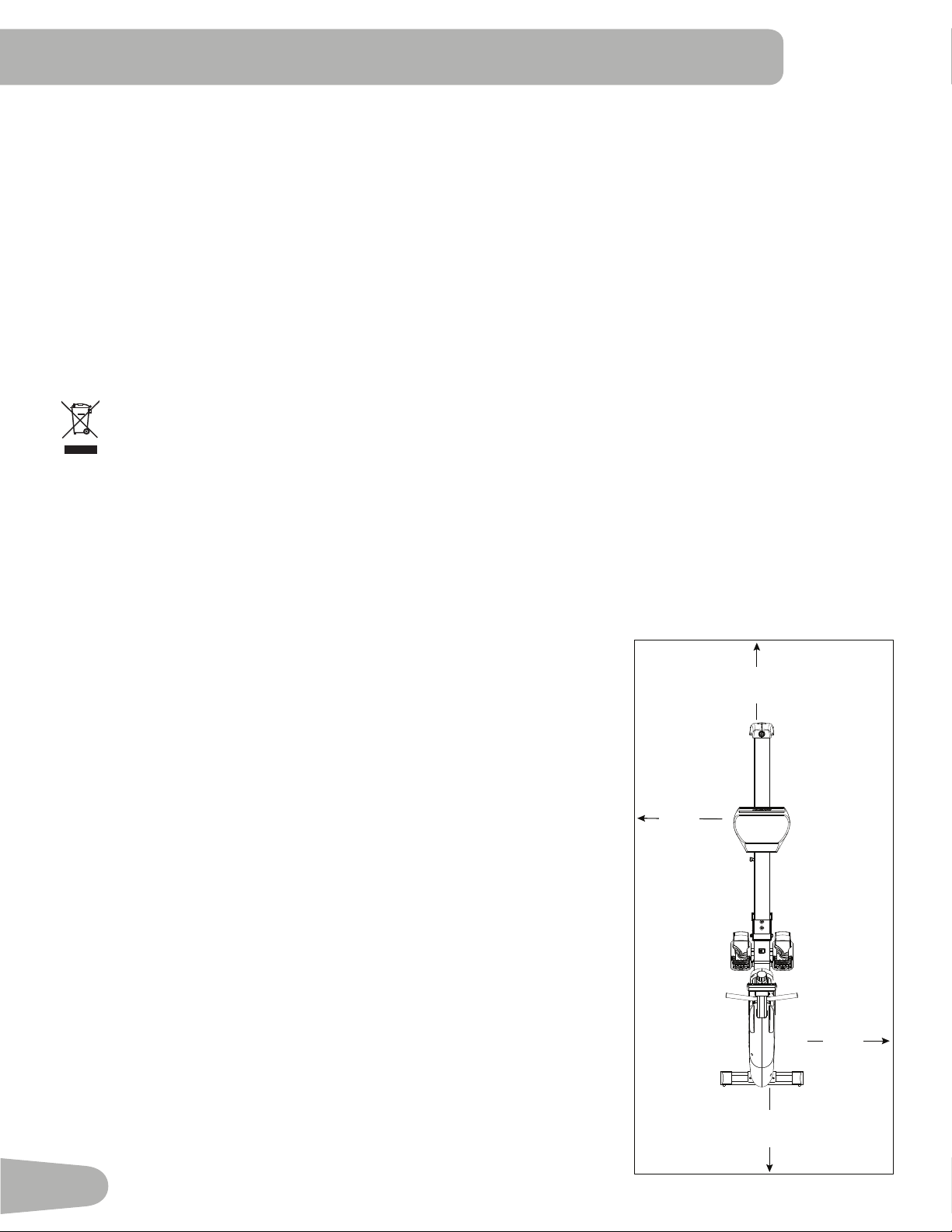
Select the area where you are going to set up and operate your
machine. For safe operation, the location must be on a hard, level
surface.Allowaworkoutareaofaminimum3.5mx1.8m(138”x69”).
Basic Assembly Tips
Follow these basic points when you assemble your machine:
• Readandunderstandthe“ImportantSafetyInstructions”before
assembly.
• Collect all the pieces necessary for each assembly step.
• Using the recommended wrenches, turn the bolts and nuts to the
right(clockwise)totighten,andtheleft(counterclockwise)toloosen,
unless instructed otherwise.
• When attaching 2 pieces, carefully lift and look through the bolt holes
to help insert the bolt through the holes.
• The assembly requires 2 people.
Maximum User Weight: 136kg(300lbs.)
Machine Weight: 40.8kg(90lbs.)
Dimensions (at): 226.3cmx53.5cmx80.5cm(89.1”x21.1”x31.7”)
Total Surface Area (footprint) of equipment: 12,107 cm
2
Dimensions (folded): 129.5cmx53.5cmx144.8cm(51”x21.1”x57”)
Power Requirements: 2AAAlkalineBatteries(UN-3)
Operating Voltage: 3VDC
Specications
DO NOT dispose of this product as refuse. This product is to be recycled. For proper disposal of this product,
please follow the prescribed methods at an approved waste center.
0.6m
24”
0.6m
24”
0.6m
24”
0.6m
24”
3.5m
138”
1.8m
69”
7
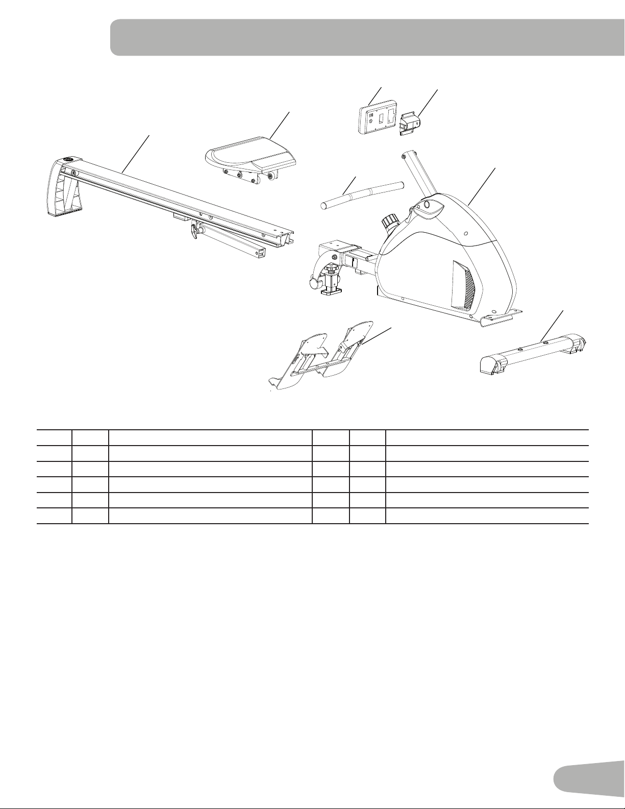
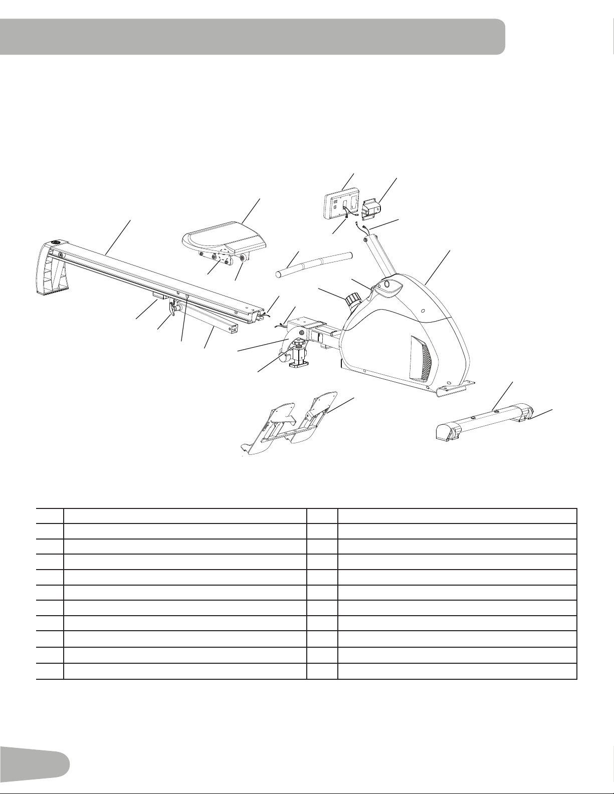
Item Qty Description Item Qty Description
1 1 Main Frame 6 1 Console
2 1 Stabilizer, Front 7 1 Console Bracket
3 1 Foot Plate 8 1 Handle
4 1 Seat Rail Assembly 9 2 AA-sizeAlkalineBatteries(notshown)
5 1 Seat
PARTS
1
2
3
4
5
6
7
8
8
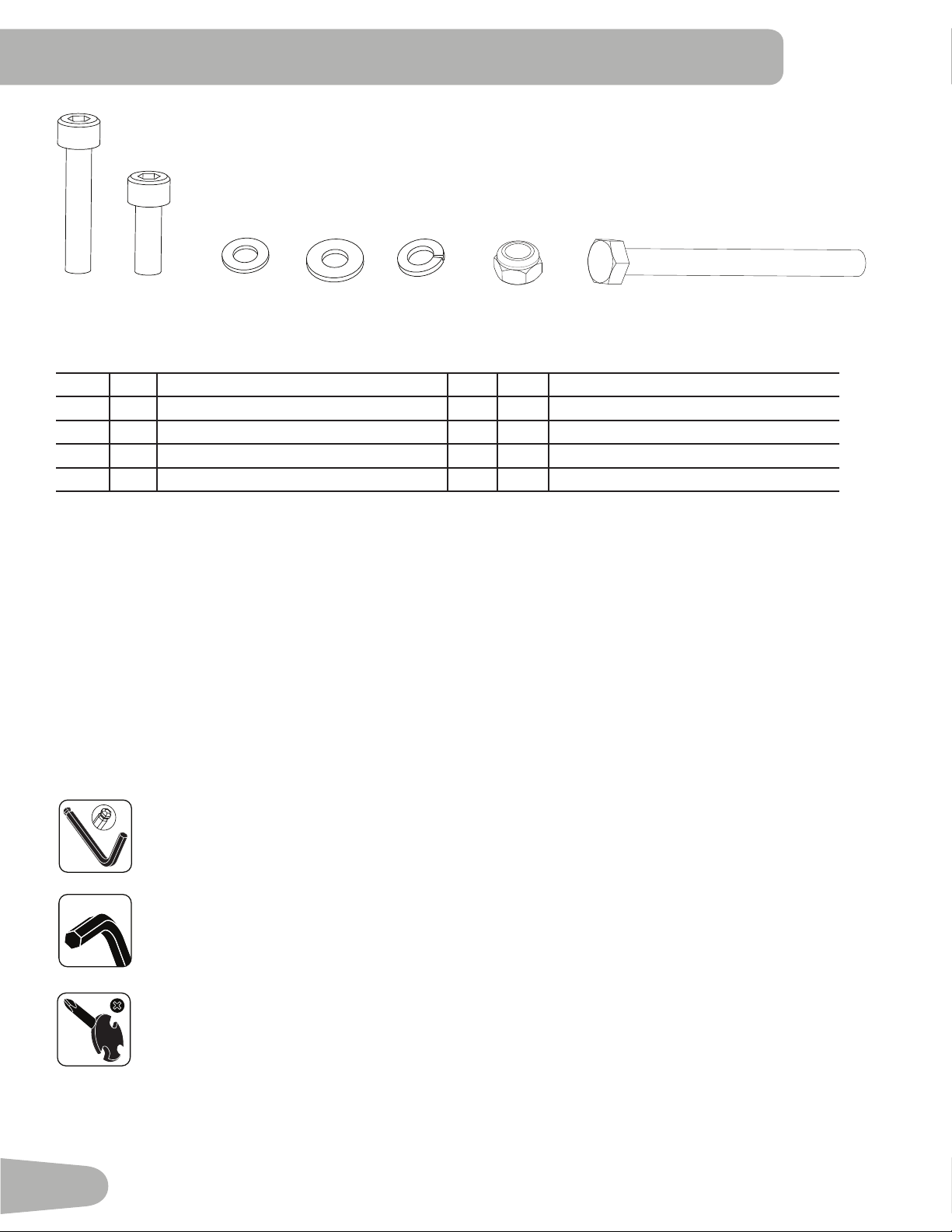
Tools
Included
5 mm
Item Qty Description Item Qty Description
A 1 SocketHeadCapScrew,M8x57 E 8 Spring Washer, M8
B 8 SocketHeadCapScrew,M8x20 F 2 Lock Nut, M8
C 1 Flat Washer, M8, Narrow G 1 HexHeadCapScrew,M8x90
D 9 Flat Washer, M8, Regular
HARDWARE / TOOLS
#2
13 mm
14 mm
15 mm
A B C D
E
F
G
6mm
9
NOTICE: Do not remove the cardboard stop tube from the pull strap until thetimespeciedintheassemblysteps.
Do not remove rubberbands from the cables until thetimespeciedintheassemblysteps.
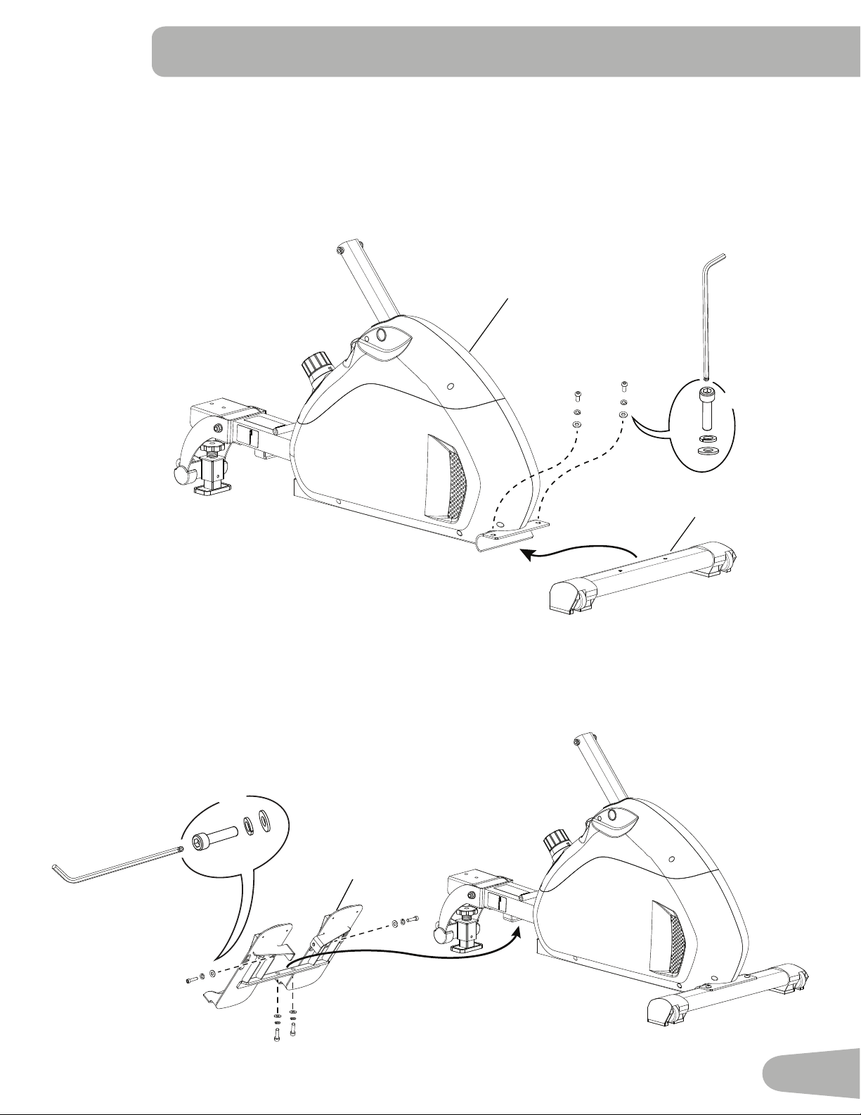
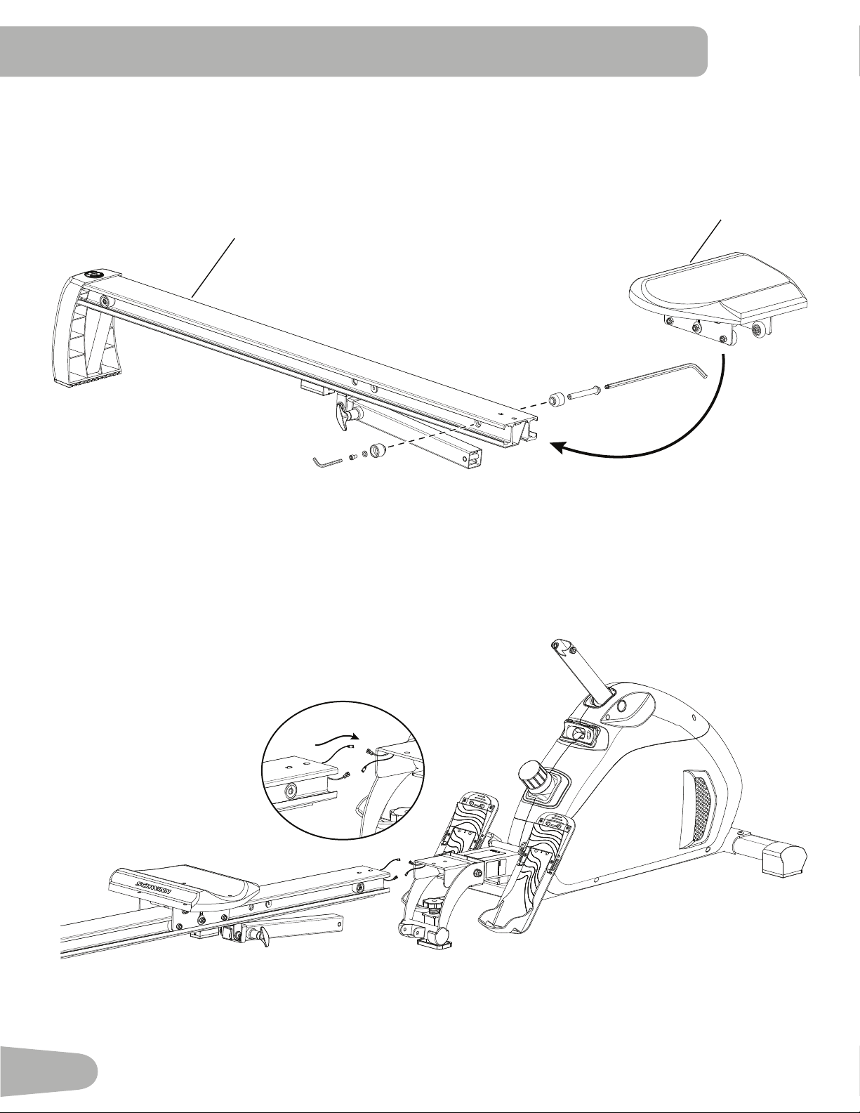
1. Attach Front Stabilizer to Main Frame
Note: Remove packaging material from the bracket and set it safely aside.
ASSEMBLY
2. Attach Foot Plate to Main Frame
Note: It may be easier to install the side screws and washers first, then the bottom screws and washers.
3
6mm
X4
B
D
E
1
2
6mm
X2
B
E
D
10
3. Slide Seat onto Seat Rail Assembly and Install Bushings
Note:Thebushingsandhardware(*)arepre-installedandnotontheHardwareCard.RemoveziptiefromtheSeatRail.
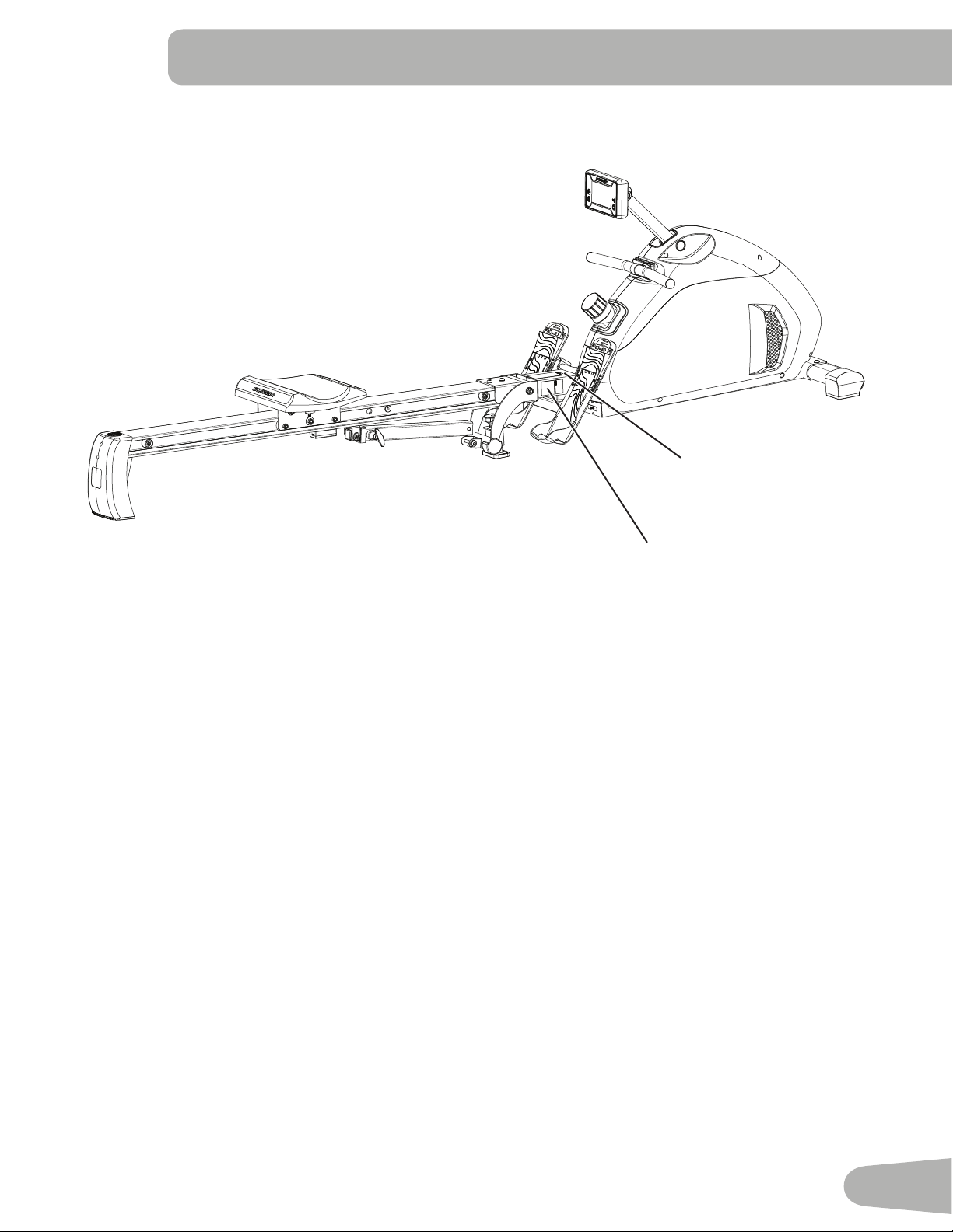
4. Connect Wires from Seat Rail Assembly to Frame Assembly
Note: Remove rubberbands from the cables on the Seat Rail Assembly. Do not crimp the cables.
4
5
*
*
6mm
5mm
11
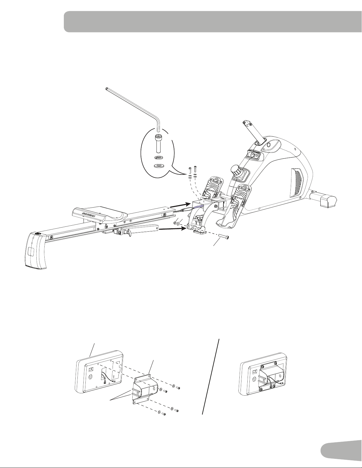
5. Attach Seat Rail Assembly to Frame Assembly
Note:Installthetopscrewsandwashersfirst,thenthelongscrew(A)throughthebracket.ItmaybeeasieriftheSeatRail
Locking Pin is pulled.
NOTICE: Do not crimp the cables.
6mm
X2
B
E
A
D
F
C
6. Attach Console Bracket to the Console
Note:Removethepre-installedhardware(*)fromthebackoftheConsole,thenroutethecablesthroughtheConsole
Bracket.Besurethe2ribs(7a)ontheConsoleBracketareontherightsidesothattheopeningpointsdownward.
NOTICE: Do not crimp the cables.
7a
7
6
12
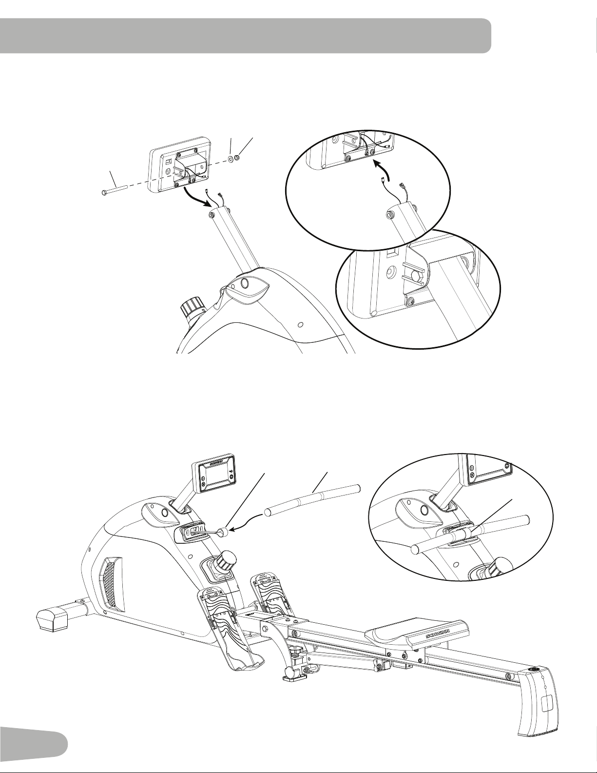
7. Install the Console on the Mast
NOTICE: Remove the rubberbands from the cables and connect the cables from the mast to the Console cables. Do not
crimpthecables.Inserttheboltthroughtheholebetweentheribs(7a)onthesideoftheConsoleBracket.
8. Attach the Handle to the Pull Strap
NOTICE:PushtheHandleintothepullstraploop(1a).Removetheziptieandcardboardtubefromthepullstrap.Do not
allow the pull strap to retract by itself.
G
D F
8
1a
1a
13
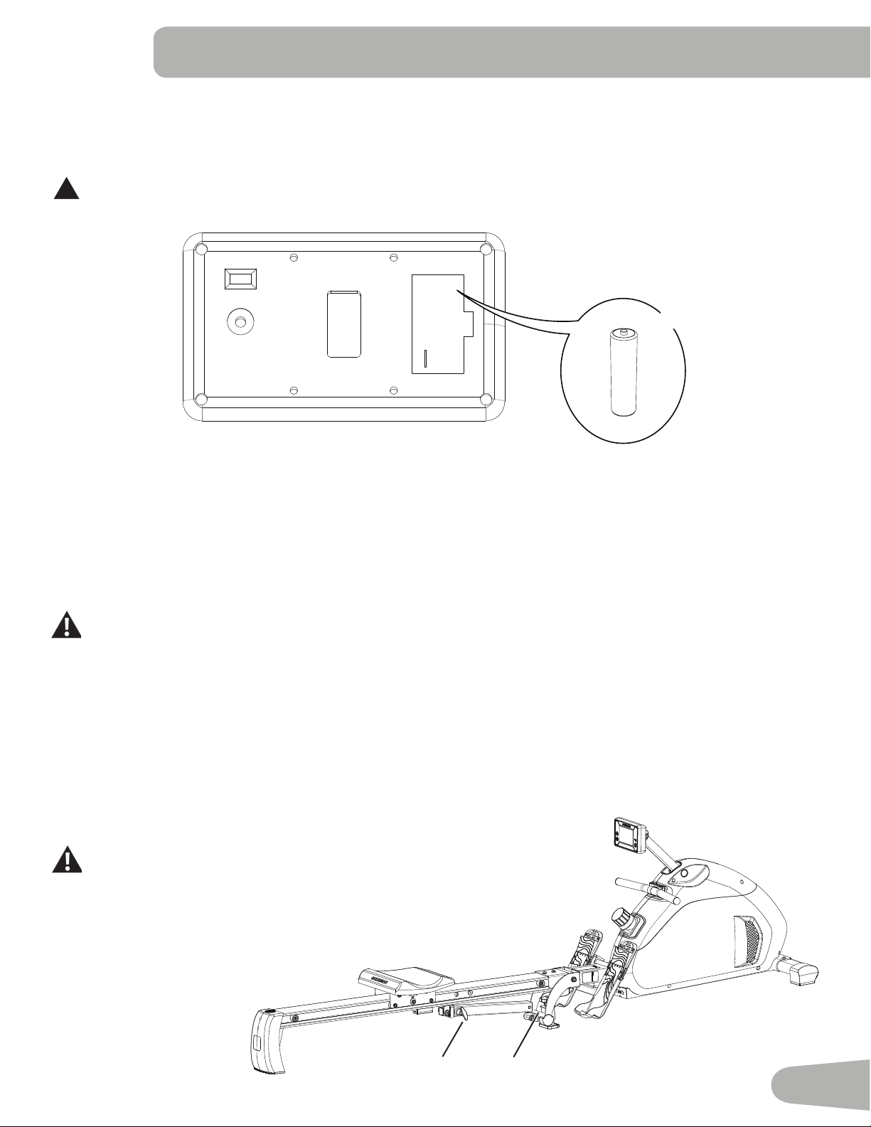
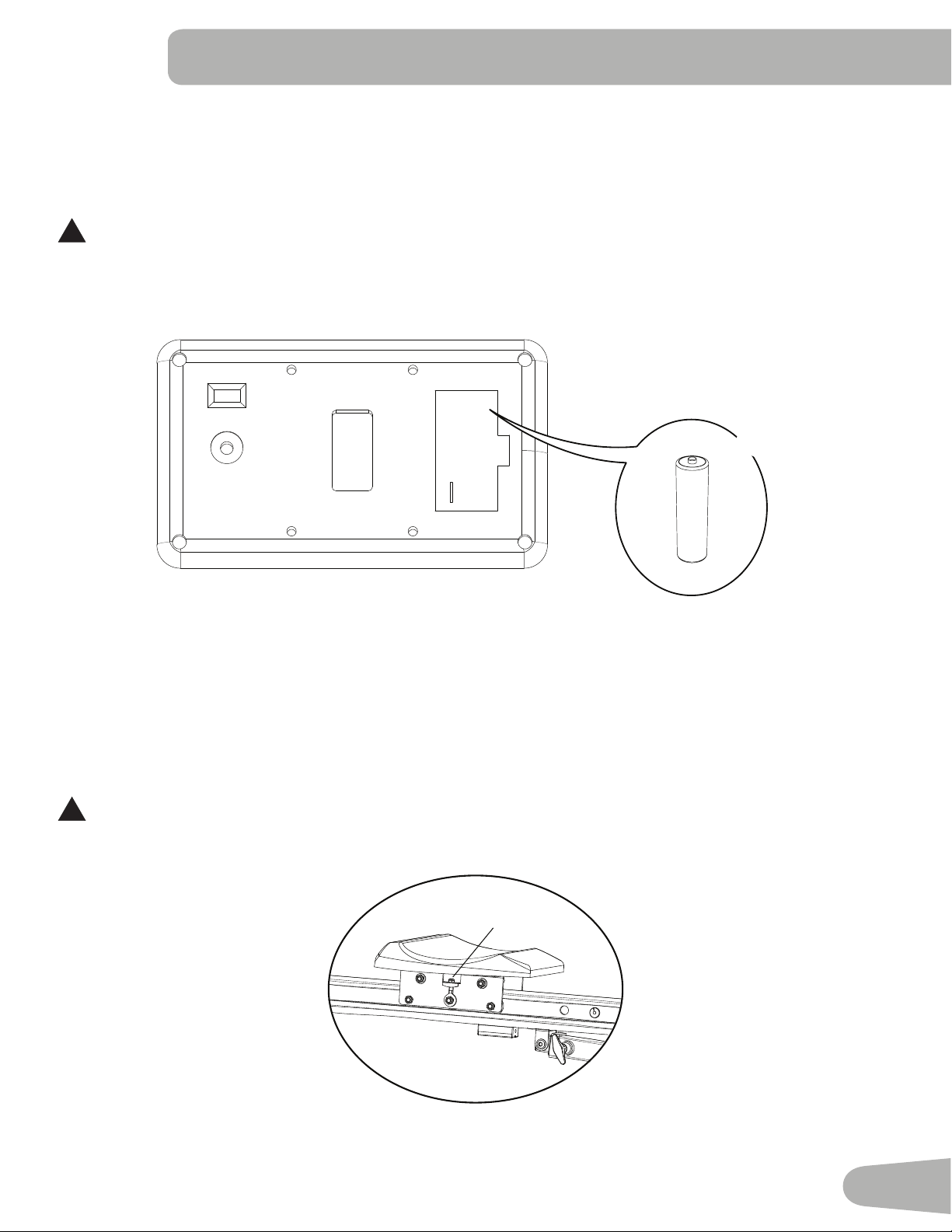
9. Install Batteries in Console
Note:TheconsoleusesAAsizealkalinebatteries(UN-3).Makesurethatthebatteriespointinthedirectionofthe+/–
indicators in the battery bay.
!
Do not mix old and new batteries.
Do not mix alkaline, standard (carbon-zinc), or rechargeable (Ni-Cd, Ni-MH, etc) batteries.
10. Final Inspection
Inspect your machine to ensure that all hardware is tight and components are properly assembled.
NOTICE: Make sure the Seat Rail Locking Pin is engaged to ensure smooth operation. If the Level Adjustment Knob at the
junction of the Seat Rail Assembly and Main Unit is adjusted too low, the Seat Rail Locking Pin will not engage.
Turn the adjustment knob to increase the height.
Be sure to record the serial number in the field provided at the front of this manual.
Do not use or put the machine into service until the machine has been fully assembled and inspected for
correct performance in accordance with the Owner’s Manual.
+
-
X2
IM
Leveling the Machine
The machine needs to be leveled if your workout area is uneven. The Level Adjustment Knob is below the junction of the
Seat Rail Assembly and the Main Unit. To adjust:
1. Place the machine in your workout area.
2. TurntheLevelAdjustmentKnob(I)toadjustuntiltheSeatRailLockingPin(M)
engages securely.
Do not adjust the knob to such a height that it becomes unstable.
Injury to you or damage to the machine can occur.
Makesurethemachineislevelandstablebeforeyouexercise.
BEFORE YOU START
14
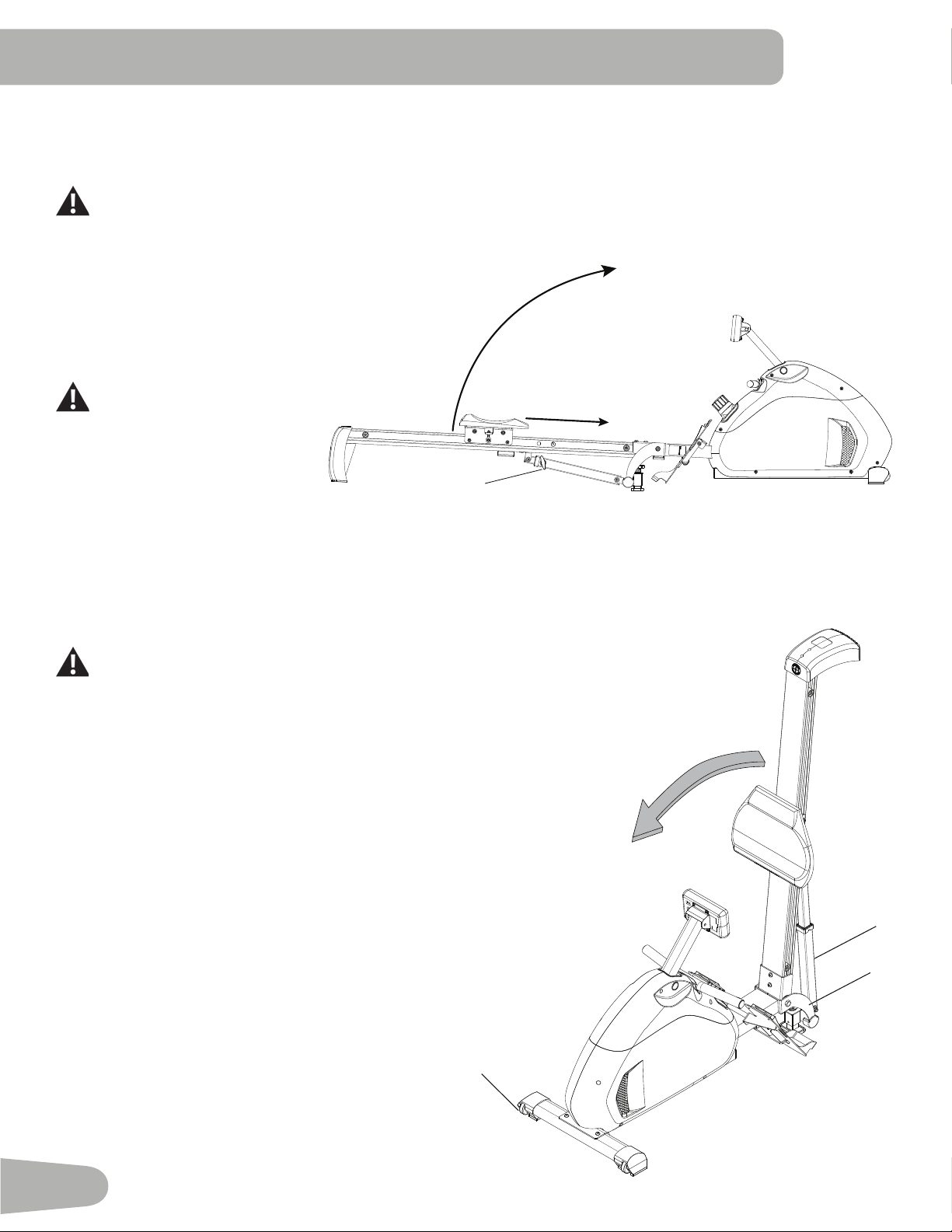
Moving and Storing the Machine
Whenthemachineisnotinuse,itshouldbestoredinanappropriatespaceawayfromfoottrafc.Toconservespace,
fold the Seat Rail Assembly and secure it with the Seat Rail Locking Pin.
For safe storage of the machine, remove the batteries. Place the machine in a secure location away from
children and pets.
1. Move the Seat to the front of the Seat Rail.
2. Pull the Seat Rail Locking
Pin(M)toreleaseandraise
the Seat Rail Assembly to the
folded position. Make sure that
you have a secure grip when
raising the Seat Rail Assembly.
Stay clear of the movement
path of the Seat Rail As-
sembly.
3. Release the Seat Rail Locking
Pin to engage the support
tube. Be sure that the Seat Rail
Locking Pin is fully engaged.
You will hear an audible click
M
when the Seat Rail Locking Pin
shifts into the locked position. If
it is not fully engaged, injury to
the user can occur.
The machine may be moved by one or more persons depending on their
physical abilities and capacities. Make sure that you and others are all
physically t and able to move the machine safely. Use proper safety
precautions and lifting techniques.
4. GrasponeofthecurvedSupportPlates(J)andtheLiftHandle(N).Carefullytiltthe
machineontotheTransportRollers(L).
5. HoldingtheLiftHandle(N),pushthemachineintoposition.
NOTICE: Be careful when you move the machine. Abrupt motions can affect the
computer operation.
6. Carefullylowerthemachinetotheooranddonotletitdropfromanyheight.
N
L
J
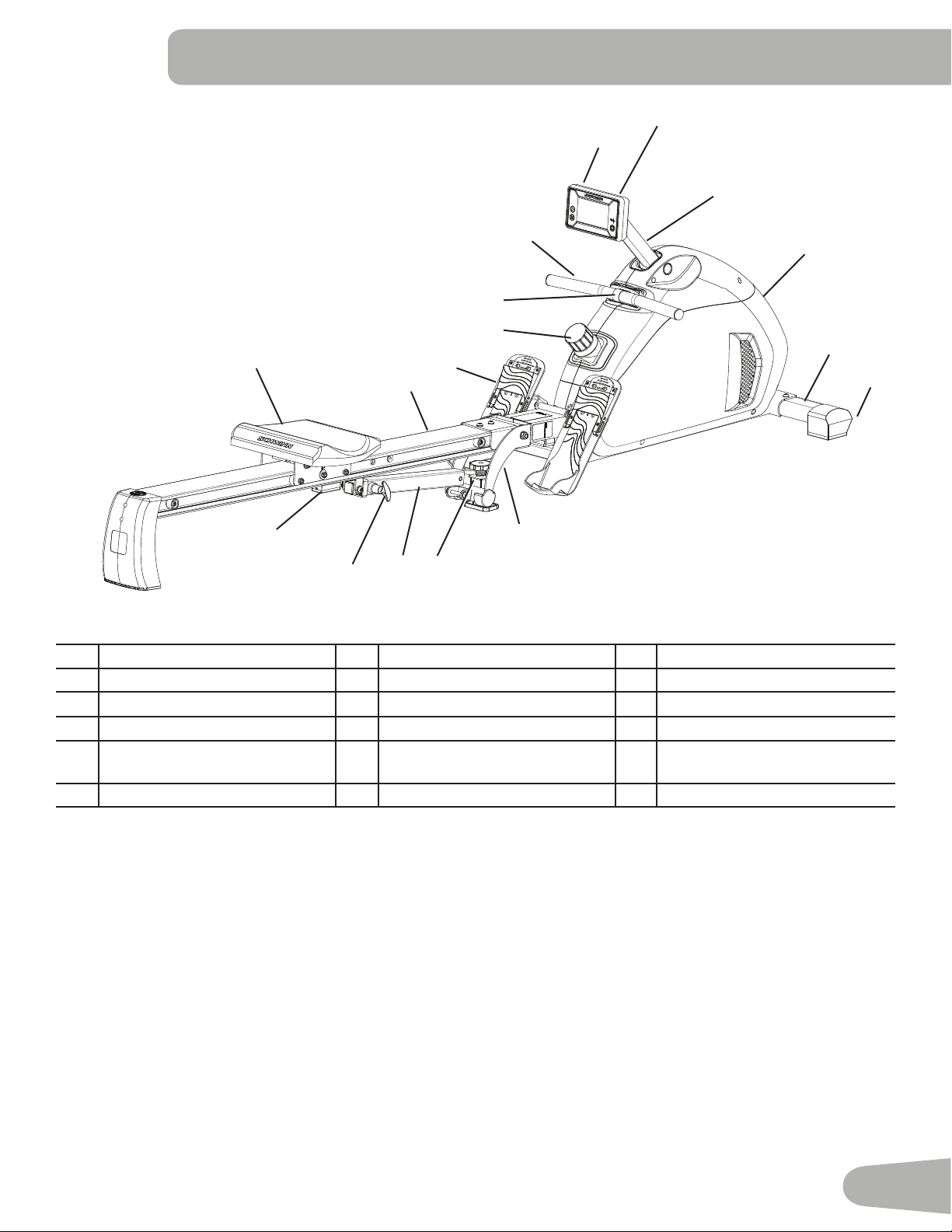
15
A Console G Seat Rail Assembly M Seat Rail Locking Pin
B Mast H Rower Engine N Lift Handle
C Handle I Level Adjustment Knob O Seat Assembly
D Pull Strap J Support Plates P Battery Compartment
E Resistance Adjustment Knob K Front Stabilizer Q TelemetryHeartRate(HR)
Receiver
F Foot Plate L Transport Roller
FEATURES
M
A
B
C
D
E
F
G
H
I
J
K
L
N
O
P
Q
WARNING! Use the values calculated or measured by the machine’s computer for reference purposes only. The
heart rate displayed is an approximation and should be used for reference only. Over exercising may
result in serious injury or death. If you feel faint stop exercising immediately.
16
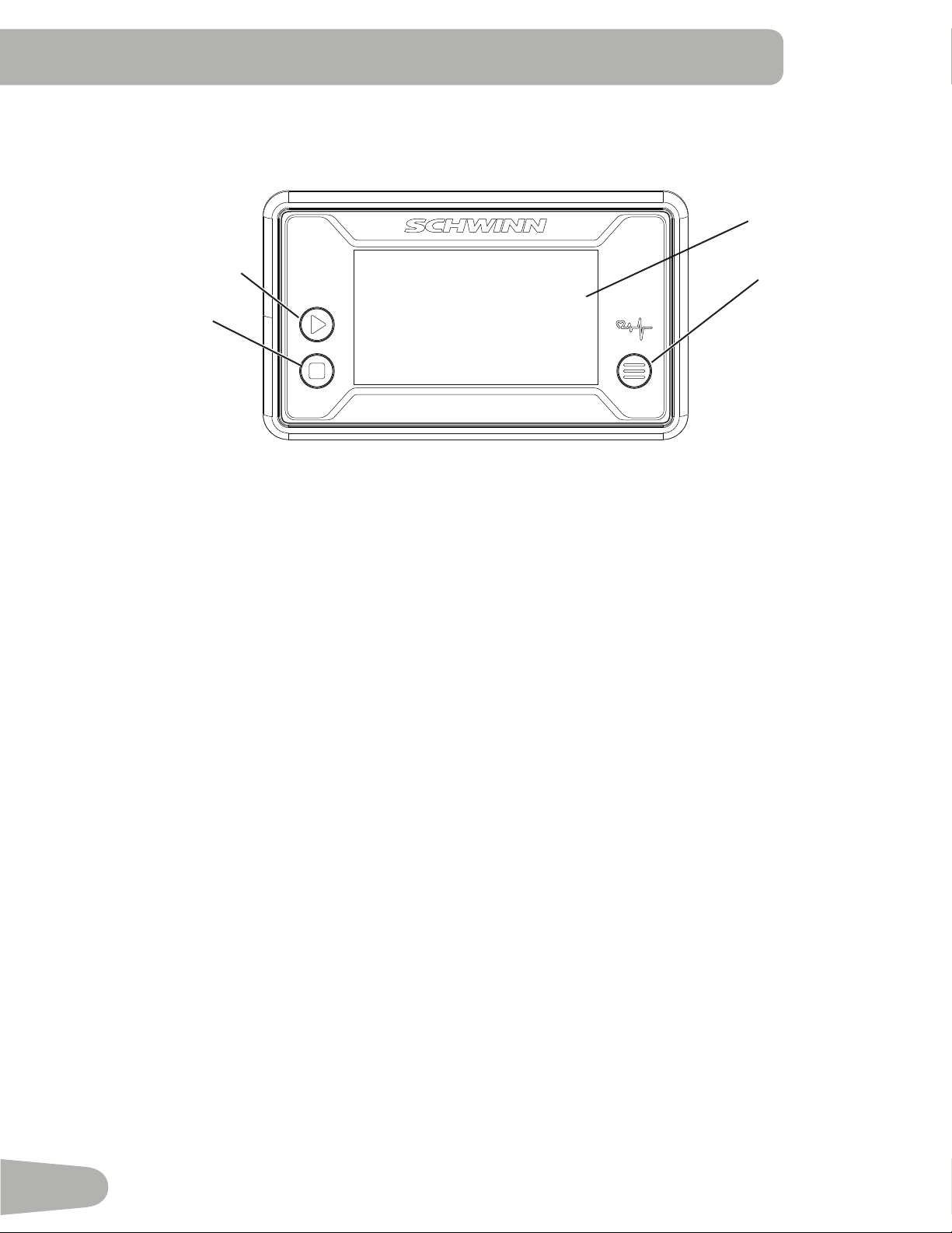
Console Features
The Console provides information about your workout on the display screens.
Keypad Functions
MODE button- Selects functions. Push and hold the button for 3 seconds to go to SCAN mode and cycle through the
functionsautomatically—TIME,CNT,DIST,TOTAL,CAL,RPM,PULSE.Eachfunctionisdisplayedfor6seconds.Toexit
SCAN mode, push the MODE button.
SETbutton-Setsthevalue(TIME,COUNT,DISTANCE,CALORIES).
RESET button- Push to reset TIME, COUNT, DISTANCE, CALORIES.
The console will beep when a button is pushed.
Program Data Display
TIME
TheTIMEdisplayeldshowstherowingtimefromstarttonishofworkout.Tosetatimegoalfortheworkout,push
MODEuntilTIMEappears.PushSETtosetthetimegoal(minutes).Duringtheworkout,thedisplayshowstheremaining
time. When it reaches zero, the console will sound an alert.
Themaximumtimeis99minutesand59seconds.
COUNT (CNT)
TheCNTdisplayeldshowsthenumberofrowingstrokesfromstarttonishofworkout.Tosetagoalfortheworkout,
push MODE until CNT appears. Push SET to set the rowing strokes in increments of 10. During the workout, the display
shows the remaining strokes. When it reaches zero, the console will sound an alert.
Themaximumcountis9999.
DISTANCE (DIST)
TheDISTdisplayeldshowstherowingdistancefromstarttonishofworkout.Tosetadistancegoalfortheworkout,
push MODE until DIST appears. Push SET to set the distance in increments of 0.10 km. During the workout, the display
shows the remaining distance. When it reaches zero, the console will sound an alert.
Themaximumdistanceis99.99km.
RESET
MODE
Data Display
SET

17
TOTAL COUNT (TOTAL)
TheTOTALdisplayeldshowsthetotalnumberofrowingstrokesforthemachine.Themaximumcountis9999.
CALORIES (CAL)
TheCALdisplayeldshowstheestimatedtotalcaloriesfromstarttonishofworkout.Tosetacaloriesgoalforthe
workout, push MODE until CAL appears. Push SET to set the calories. During the workout, the display shows the
remaining calories. When it reaches zero, the console will sound an alert.
Themaximumcaloriesis999.9Kcal.
RPM
TheRPMdisplayeldshowsthecurrentnumberofrowingstrokesperminute.Themaximumis999.
HEART RATE (PULSE)
ThePULSEdisplayshowstheheartrateinbeatsperminute(BPM)fromatelemetricheartratesensor.PushSETto
activate the Heart Rate. This display value will be blank if a heart rate signal is not detected. The PULSE range is 40 - 240
BPM.
Consult a physician before you start an exercise program. Stop exercising if you feel pain or tightness in
your chest, become short of breath, or feel faint. Contact your doctor before you use the machine again.
Use the values calculated or measured by the machine’s computer for reference purposes only. The heart
rate displayed on the console is an approximation and should be used for reference only.
Remote Heart Rate Monitor
MonitoringyourHeartRateisoneofthebestprocedurestocontroltheintensityofyourexercise.TheConsolecanread
telemetry HR signals from a Heart Rate Chest Strap Transmitter that operates in the 4.5kHz - 5.5kHz range.
Note: The heart rate chest strap must be an uncoded heart rate strap from Polar Electro or an uncoded POLAR
®
com-
patiblemodel.(CodedPOLAR
®
heart rate straps such as POLAR
®
OwnCode
®
chest straps will not work with this
equipment.)
If you have a pacemaker or other implanted electronic device, consult your doctor before using a wireless
chest strap or other telemetric heart rate monitor.
Heart Rate Calculations
Yourmaximumheartrateusuallydecreasesfrom220BeatsPerMinute(BPM)inchildhoodtoapproximately160BPMby
age60.Thisfallinheartrateisusuallylinear,decreasingbyapproximatelyoneBPMforeachyear.Thereisnoindication
thattraininginuencesthedecreaseinmaximumheartrate.Individualsofthesameagecouldhavedifferentmaximum
heartrates.Itismoreaccuratetondthisvaluebycompletingastresstestthanbyusinganagerelatedformula.
Yourat-restheartrateisinuencedbyendurancetraining.Thetypicaladulthasanat-restheartrateofapproximately72
BPM, where as highly trained runners may have readings of 40 BPM or lower.
TheHeartRatetableisanestimateofwhatHeartRateZone(HRZ)iseffectivetoburnfatandimproveyourcardiovas-
cular system. Physical conditions vary, therefore your individual HRZ could be several beats higher or lower than what is
shown.
Themostefcientproceduretoburnfatduringexerciseistostartataslowpaceandgraduallyincreaseyourintensityun-
tilyourheartratereachesbetween60–85%ofyourmaximumheartrate.Continueatthatpace,keepingyourheartrate
in that target zone for over 20 minutes. The longer you maintain your target heart rate, the more fat your body will burn.
18
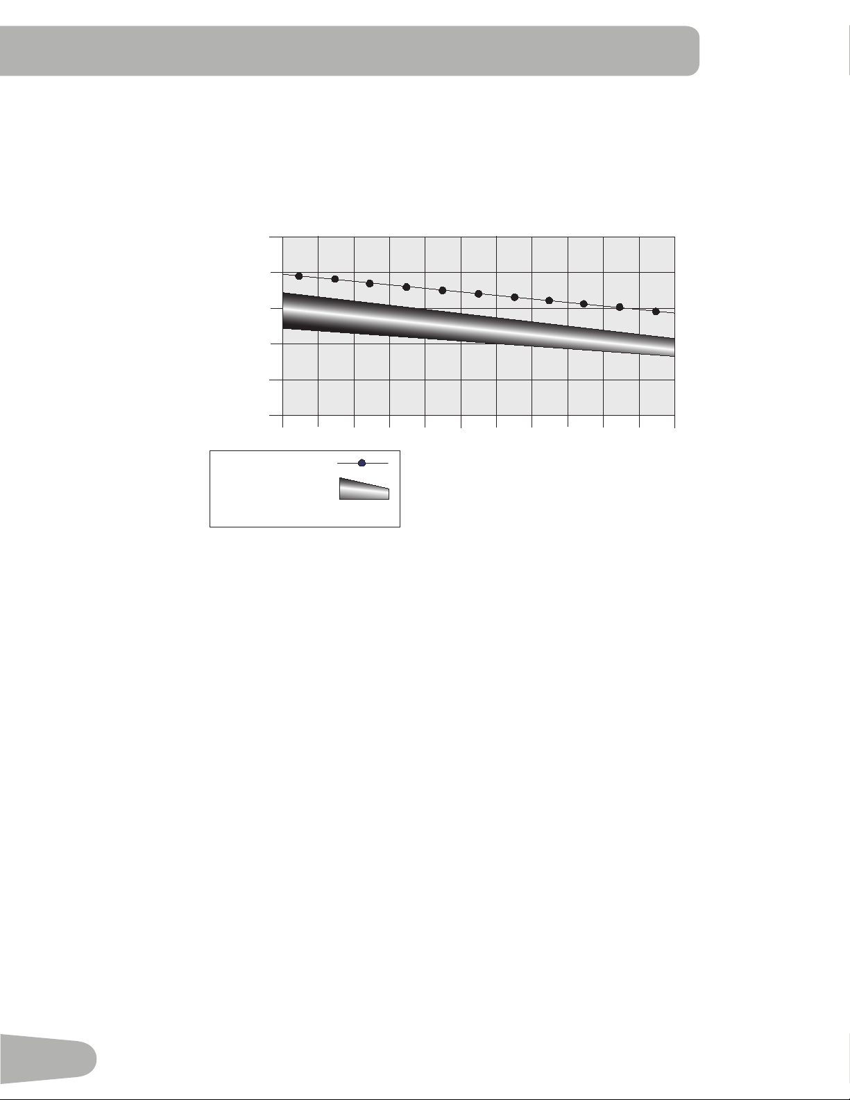
The graph is a brief guideline, describing the generally suggested target heart rates based on age. As noted above, your
optimal target rate may be higher or lower. Consult your physician for your individual target heart rate zone.
Note:Aswithallexercisesandtnessregimens,alwaysuseyourbestjudgmentwhenyouincreaseyourexercise
time or intensity.
20-24
FAT-BURNING TARGET HEART RATE
Heart Rate BPM (beats per minute)
Age
25-29
0
50
100
150
200
250
30-34 35-39 40-44 45-49 50-54 55-59 60-64 65-69 70+
196
191
186
181
176
171
166
161
156
151
146
167
162
158
154
150
145
141
137
133
128
126
Maximum Heart Rate
Target Heart Rate Zone
(keep within this range
for optimum fat-burning)
11 8
11 5
11 2
109
106
103
100
97
94
91
88

19
OPERATIONS
What to Wear
Wearrubber-soledathleticshoes.Youwillneedtheappropriateclothesforexercisethatallowyoutomovefreely.
How Often Should You Exercise
Consult a physician before you start an exercise program. Stop exercising if you feel pain or tightness in
your chest, become short of breath, or feel faint. Contact your doctor before you use the machine again.
Use the values calculated or measured by the machine’s computer for reference purposes only. The heart
rate displayed is an approximation and should be used for reference purposes only.
• 3 times a week for 20 minutes each day.
• Schedule workouts in advance and try to follow the schedule.
Using the Rower
Properfootpositionandstabilityensuremaximumexerciseefciencyandcomfort.Therowingstrokeconsistsofastart
positionandtwoblendedmovements–theCatch,theDriveandtheRecovery.Letyourlegs,armsandshouldersdothe
worktomaximizeyourworkoutandhelpreducetheriskofinjury.
1. Sit on the seat facing the Rower Engine. Place feet on Foot Plate, heels against the back of the pads, and strap feet
securely in place.
The Catch:
2. Lean toward the Rower Engine, and move forward on the rower, drawing your knees to your chest.
3. Grasp the Handle with both hands, palms down. Keep your arms straight and head up.
The Drive:
4. PushagainsttheFootPlateandstraightenlegs.Exhalethroughthemovement.
5. Asthelegsareextended,leanbackslightly.Becarefulnottohyper-extend.PulltheHandletoyourabdomenusing
the arms and shoulders, not the back.
The Recovery:
6. Extendthearmsandpushforwardwithpalmsandwrists.Thenswingthebodyforwardatthehipsandreturntothe
Catch position. This eliminates interference between the hands and knees in the motion forward.
Note: Thebodyshouldnevercometoacompletestopthroughtherowingmotion.Allmovementsshouldbeuidand
integrated. DO NOT hold your breath. Allow breathing to occur naturally. Do not force it.
Resistance Adjustment
To adjust the resistance and workload, turn the Resistance Adjustment Knob. Toexerciseallthemusclegroupsinyour
arms, alter your grasp to palms up for part of the workout.
Power-Up Mode
The Console will enter Power-Up Mode if any button is pushed, or if it receives a signal from the RPM sensor as a result
of pulling the Handle.
Note: TheConsoledisplaywilldimifthebatterylevelis25%orless.
Auto Shut-Off (Sleep Mode)
IftheConsoledoesnotreceiveanyinputinapproximately4minutes,itwillautomaticallyshutoff.TheLCDdisplayisoff
while in Sleep Mode.
Note: The Console does not have an On/Off switch.
Results
Push and hold the MODE button for 3 seconds to go to SCAN mode and cycle through the functions automatically—TIME,
CNT,DIST,TOTAL,CAL,RPM,PULSE.Eachfunctionisdisplayedfor6seconds.

20
Read all maintenance instructions fully before you start any repair work. In some conditions, an assistant is required to do
the necessary tasks.
Equipment must be regularly examined for damage and repairs. The owner is responsible to make sure that
regular maintenance is done. Worn or damaged components must be repaired or replaced immediately.
Only manufacturer supplied components can be used to maintain and repair the equipment.
If at any time the Warning labels become loose, unreadable or dislodged, contact your local distributor for
replacement labels.
Disconnect all power to the machine before you service it.
Daily: Beforeeachuse,examinetheexercisemachineforloose,broken,damaged,or
worn parts. Do not use if found in this condition. Repair or replace all parts at the
rstsignofwearordamage.Aftereachworkout,useadampclothtowipeyour
machine and Console free of moisture.
NOTICE: If necessary, only use a mild dish soap with a soft cloth to clean the
Console. Do not clean with a petroleum based solvent, automotive
cleaner, or any product that contains ammonia. Do not clean the
Console in direct sunlight or at high temperatures. Be sure to keep the
Console free of moisture.
Weekly: Clean the machine to remove any dust, dirt, or grime from the surfaces.
Check for smooth seat operation. If needed, sparingly apply a thin coating of
100%siliconelubricanttoeaseoperation.
Silicone lubricant is not intended for human consumption. Keep out
of reach of children. Store in a safe place.
Note: Do not use petroleum based products.
Monthly
or after 20
hours:
Check foot plate, seat and pull strap. Make sure all bolts and screws are tight.
Tighten as necessary.
Check pull strap and seat rollers for signs of wear.
MAINTENANCE
21
Replacing the Console Batteries
When the batteries are low on power, the console display contrast will dim.
Whenreplacingthebatteries,makesurethebatteriespointinthe+/-directionshowninthebatterybay.
Note:TheconsoleusesAAsizealkalinebatteries(UN-3)
!
Do not mix old and new batteries.
Do not mix alkaline, standard (carbon-zinc), or rechargeable (Ni-Cd, Ni-MH, etc) batteries.
Besuretoremovethebatteriestopreventcorrosiondamageifyouarenotgoingtousethemachineforanextended
period of time.
+
-
X2
Adjusting the Seat Rollers
If the machine is level but the seat rolls unevenly, check the seat roller assembly under the seat. To adjust the seat rollers,
turntheadjustmentnuts(O2).
!
Do not adjust the nuts to such a height that they detach or the seat roller assembly becomes unstable.
O2 (X2)
22
Maintenance
Parts
A Console L Storage Support Tube
B Console cables M Seat Rail Locking Pin
C Data Cables, Main Unit N Foot Plate
D Rower engine O Seat Assembly
E Stabilizer, Front P Seat Rollers
F Transport Wheel Q RPM Sensor Magnet
G Pull Strap R RPM Sensor Assembly
H Handle S Data Cables, Seat Rail
I Resistance Adjustment Knob T Console Bracket
J Level Adjustment Knob U TelemetryHeartRate(HR)Receiver
K Seat Rail Assembly V Support Plate
D
E
N
K
O
A
T
H
M
R
L
Q
P
V
C
F
G
I
S
C
B
U
J

23
TROUBLESHOOTING
Condition/Problem Things to Check Solution
Console will not power up/
turn on/start
Check batteries. Make sure batteries are installed correctly. If batteries are
correctly installed, replace with a set of new batteries.
Check data cable integrity All wires in cable should be intact. If any are visibly crimped or
cut, replace cable.
Check data cable
connections/orientation
Make sure cable is connected securely and oriented properly.
Small latch on connector should line up and snap into place.
Check console display for
damage
Check for visual sign that console display is cracked or
otherwise damaged. Replace Console if damaged.
If the above steps do not resolve the problem, contact your
local distributor for further assistance.
Speed displayed is not
accurate
Check RPM Sensor
Magnetposition(requires
seatremoval)
RPM Sensor Magnet should be in place on Seat slider frame.
Speed displayed is always
“0”/stuckinPausemode
Data cable Make sure the data cable is connected to the back of the
Console and the main frame assembly.
RPM Sensor Make sure the RPM Sensor Magnet and the RPM Sensor are
in place.
No Count/RPM reading Check data cable integrity All wires in cable should be intact. If any are cut or crimped,
replace cable.
Check data cable
connections/orientation
Be sure cable is connected securely and oriented properly.
Small latch on connector should line up and snap into place.
Check RPM Sensor
Magnetposition(requires
seatremoval)
RPM Sensor Magnet should be in place on Seat slider frame.
Check RPM Sensor
Assembly
RPM Sensor Assembly should be aligned with magnets and
connected to data cable. Realign sensor if necessary. Replace
if there is any damage to the sensor or the connecting wire.
Console display is dim Batteries Replace batteries
Unit operates but
Telemetric Heart Rate not
displayed
ChestStrap(optional) Strap should be “POLAR
®
”compatibleanduncoded.Make
sure strap is directly against skin and contact area is wet.
Check data cable integrity All wires in cable should be intact. If any are visibly crimped or
cut, replace cable.
Check data cable
connections/orientation
Be sure cable is connected securely and oriented properly.
Small latch on connector should line up and snap into place.
Check Telemetry HR
Receiver
Telemetry HR Receiver should be in place on Seat Rail
Assembly. Check for visual sign that HR Receiver is damaged.
Replace HR Receiver if damaged.
Chest Strap Batteries If strap has replaceable batteries, install new batteries.
Interference Trymovingunitawayfromsourcesofinterference(TV,Micro-
wave,etc).
Replace Chest Strap If interference is eliminated and HR does not function, replace
strap.
Replace Console If HR still does not function, replace Console.
Consoleshutsoff(enters
sleepmode)whileinuse
Check data cable integrity All wires in the cable should be intact. If any are cut or crimped,
replace cable.
Check data cable
connections/orientation
Be sure cable is connected securely and oriented properly.
Small latch on connector should line up and snap into place.

24
Condition/Problem Things to Check Solution
Check batteries. Make sure batteries are installed correctly. If batteries are
correctly installed, replace with a set of new batteries.
Check RPM Sensor
Magnetposition(requires
seatremoval)
RPM Sensor Magnet should be in place on Seat slider frame.
Check RPM Sensor
Assembly
RPM Sensor Assembly should be aligned with magnet and
connected to data cable. Realign sensor if necessary. Replace
if there is any damage to the sensor or the connecting wire.
Contact your local distributor for further assistance.
Unit rocks/does not sit
level
Check level adjustment Level adjustment knob may be turned to level machine.
Check surface under unit Adjustmentmaynotbeabletocompensateforextremelyun-
even surfaces. Move machine to level area.
Seat Rail locking pin does
notengage(SeatRailin
horizontalposition)
Level adjustment knob Turn the level adjustment knob until the Seat Rail locking pin
engages the support tube.
Seat rolls unevenly Seat roller adjustment
hardware
Turn the adjustment nuts under the seat to adjust the seat
rollers.

25

Nautilus™ Bowex™ Schwinn™ Universal™
™
8015825.11518.D
EN