Ed : 03/17 Rev : 00
INSTRUCTION

2
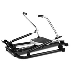
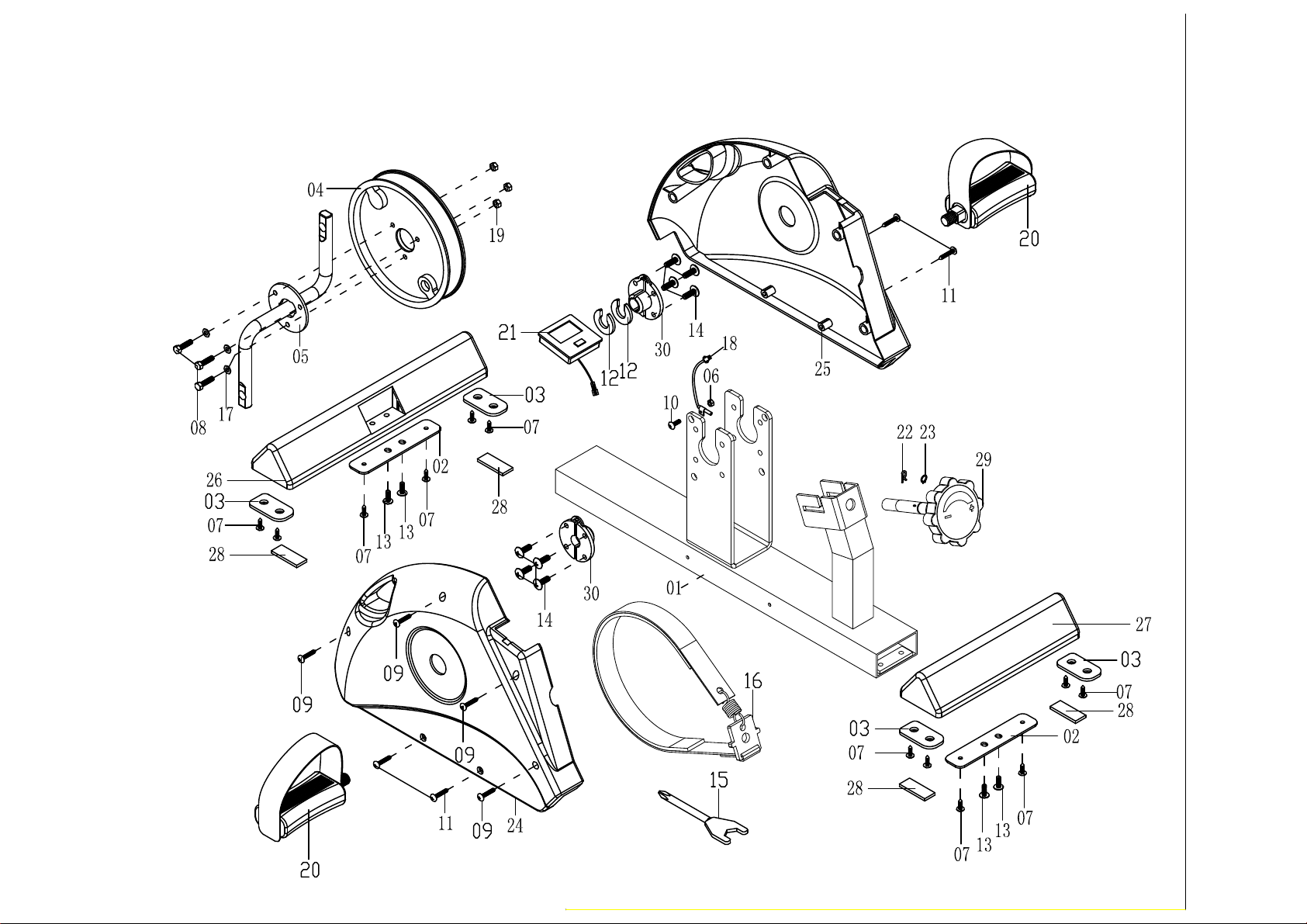
PARTS LIST
PART NO. DESCRIPTION Q’TY
1 MAIN FRAME 1
2 FIXED CONNECTING PLATE 2
3 TENSION CONTROL ADJUSTING PLATE 1
4 FLYWHEEL 1
5 CRANK 1
6 ADJUSTING BOLT 1
7 ADJUSTING NUT 1
8 HEXAGON SCREWS 3
9 HEXAGON SCREWS 1
10 CROSS HALF SCREWS 1
11 CROSS UMBRELLA HEAD TAPPING SCREW 4
12 CROSS UMBRELLA HEAD TAPPING SCREW 4
13 CROSS UMBRELLA HEAD SCREW 4
14 CROSS UMBRELLA HEAD SCREW 8
15
CROSS COLLATERAL RESISTANCE UMBRELLA HEAD
SCREW
1
16 CROSS COUNTERSUNK HEAD SCREW 1
17 FLAT WASHER 3
18 SENSOR MAGNETIC 1
19 NYLON NUT 4
20 NYLON NUT 1
21 NUT 1
22 FIXED PIN 1
23 C TYPE CLIP 1
24 CHAIN COVER LEFT 1
25 CHAIN COVER RIGHT 1
26 FRONT STABILIZER 1

3
27 REAR STABILIZER 1
28 LEVELING PAD 4
29 TENSION KNOB 1
30 BUCKLE FOR CRANK 2
31 BELT BUCKLE 1
32 CURVE WASHER 2
33 MONITOR 1
34 PEDAL L/R 1/1
35 STRAP WITH SPRING SET 1
36 COMBINATION WRENCH 1
37 HEXAGON SCREWS 1
38 SELF-TAPPING SCREW 4
39 SELF-TAPPING SCREW 8
40 NUT 1
41 SEAL COVER OF STABILIZER 4

WELLY-M Spare parts
PART REF CODE DESCRIPTION QTY
01 WELLM-001 MAIN FRAME 1
02 WELLM-002 FIXED CONNECTING PLATE 2
03 WELLM-003 SEAL COVER OF STABILIZER 4
04 WELLM-004 FLYWHEEL 1
05 WELLM-005 CRANK 1
06 WELLM-006 ADJUSTING BOLT 1
07 WELLM-007 ADJUSTING NUT 12
08 WELLM-008 HEX HEAD BOLT M6*20 3
09 WELLM-009 SELF-TAPPING SCREW M6*20 4
10 WELLM-010 SCREW M4*10 1
11 WELLM-011 SCREW M4*25 4
12 WELLM-012 CURVE WASHER 2
13 WELLM-013 SCREW M5*15 4
14 WELLM-014 SCREW M6*10 8
15 WELLM-015 COMBINATION WRENCH 1
16 WELLM-016 STRAP WITH SPRING SET 1
17 WELLM-017 FLAT WASHER 3
18 WELLM-018 SENSOR WIRE 1
19 WELLM-019 NYLON NUT 3
20 WELLM-020 PEDAL L & R 1 & 1
21 WELLM-021 MONITOR 1
22 WELLM-022 FIXED PIN 1
23 WELLM-023 C - CLIP 1
24 WELLM-024 CHAIN COVER LEFT 1
25 WELLM-025 CHAIN COVER RIGHT 1
26 WELLM-026 FRONT STABILIZER 1
27 WELLM-027 REAR STABILIZER 1
28 WELLM-028 EVA PAD 4
29 WELLM-029 TENSION KNOB 1
30 WELLM-030 BUCKLE FOR CRANK 2
6
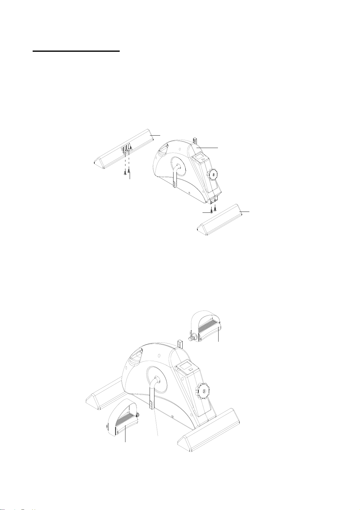
ASSEMBLY STEPS
1. Attach the Front Stabilizer (26) to the Main Body (1) with 2 sets of Cross
umbrella head screw (13) and tighten.
Attach the Rear Stabilizer (27) to the Main Body (1) with 2 sets of Cross
umbrella head screw (13) and tighten.
2. The Right Pedal (34) is marked "R" on the tip of the pedal axle. Attach to the
appropriate Crank(5).
The Left Pedal (34) is marked "L" at the tip of the pedal axle, attach to
the appropriate Crank (5).
13 27
26
1
13
5
34R
34L
7
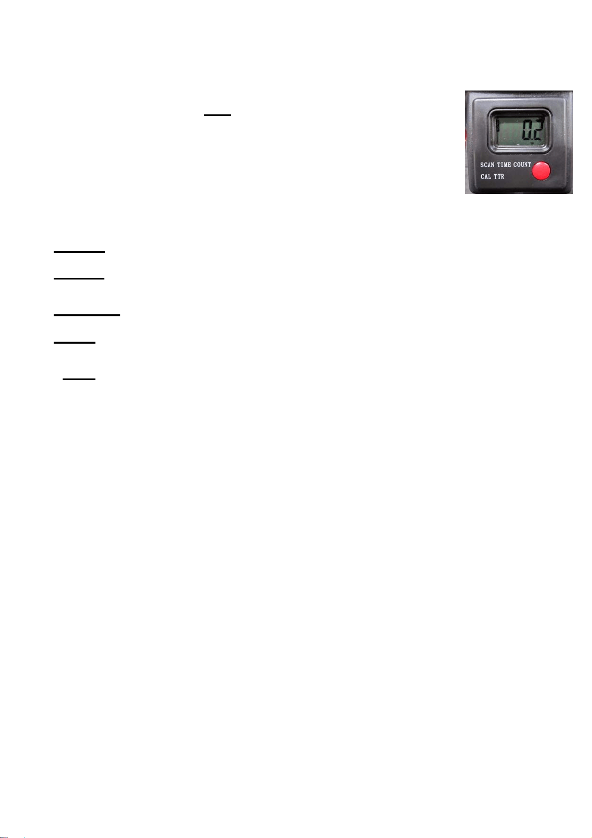
COMPUTER INSTRUCTIONS
To activate the LCD display, Press the Red Display Button or turn the pedals.
(The Display will also power-on just by moving the pedals forward)
The following functions will appear as you press the Red display Button:
>SCAN Scan will appear on the bottom left of the display once you have pressed through
>TIME The time displays the actual minutes and seconds the pedals have been in motion.
STOP will appear on the left side of the display when the timer is paused.
>COUNTDisplays the number of completed 360 degree rotations within a session.
>CAL Shows the approximate calories burned while pedaling.
>TTR Total Time Rotated shows the number of completed 360 degree rotations made over
multiple sessions.
RESET: Reset all statistics (except for Total Count which will remain in memory) by pressing and
holding the Red Display Button for 4 seconds.
BATTERY REPLACEMENT: The display uses 1 battery of AAA 1.5V

GARLANDO SPA
Via Regione Piemonte, 32 - Zona Industriale D1
15068 - Pozzolo Formigaro (AL) - Italy
www.evert.it - info@evert.it