
Loading ...
Loading ...
Loading ...
User Manual esatto.house 8 9
Installation Instructions
Note: All manual illustrations are for explanation purpose only. Your air conditioner may be slightly dierent.
Accessories
North America
Check your window size and choose the fit window slider.
Part Description
1 pc 2 pc
1 pc 2 pc
1 pc 2 pc
1 pc
1 pc
1 pc
2 pc
2 pc
1 pc
2 pc
1 pc
1 pc
1 pc
1 pc
1 pc
1 pc
1 set
1 set
Unit Adaptor
Window Slider Adaptor
Window Slider A
Window Slider A
Window Slider B
Window Slider C(optional)
Exhaust Hose
Bolt
Foam Seal A (Adhesive)
Foam Seal B (Adhesive)
Foam Seal C (Non-adhesive)
Security Bracket and Screw
Drain Hose
Drain Hose Adaptor(only for
heat pump mode)
Quantity
single-exhaust
unit(MODEL A)
double-exhaust
unit(MODEL B)
Part Description Quantity
2 pc
1 pc
Bolt(optional)
Remote Controller
and Battery
ON/OFF
TEMP
SHORT
CUT
TIMER
ON
TIMER
OFF
MODE
FAN
SLEE P
SWING
LED
NOTE: Items with are optional. Slight variations in design may occur.
*
Foam Seal A (Adhesive)(optional)
Foam Seal B (Adhesive)(optional)
Foam Seal C (Non-adhesive)
(optional)
*
*
*
*
*
Power Cord Buckle
Installation
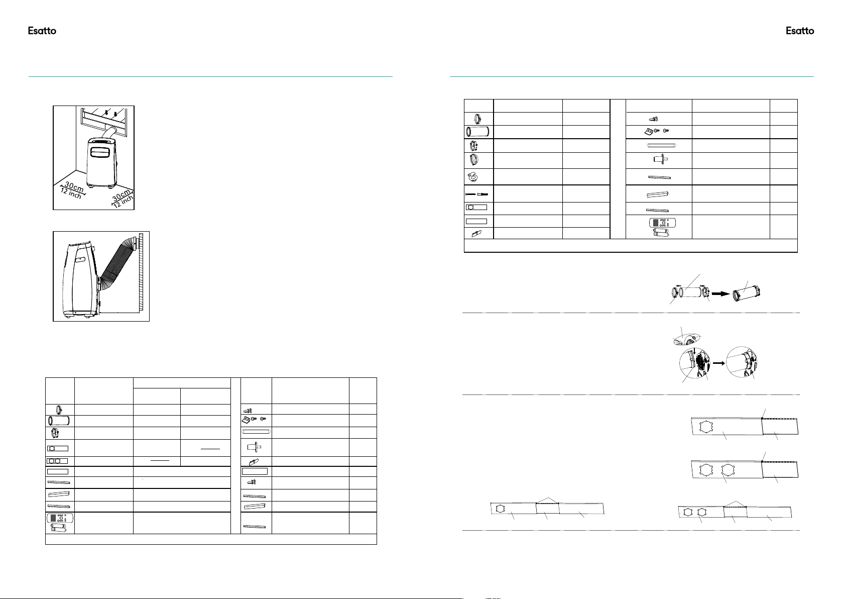
Choosing The Right Location
Recommend Installation
Your installation location should meet the following requirements:
-Make sure that you install your unit on an even surface to
minimize noise and vibration.
-The unit must be installed near a grounded plug, and the
Collection Tray Drain (found on the back of the unit) must be
accessible.
-The unit should be located at least 30cm (12”) from the nearest
wall to ensure proper air conditioning.
-DO NOT cover the Intakes, Outlets or Remote Signal Receptor
of the unit, as this could cause damage to the unit.
NOTE:
All the illustrations in the manual are for explanation
purpose only. Your machine may be slightly different.
The actual shape shall prevail.
The unit can be controlled by the unit control panel
alone or with the remote controller. This manual does
not include Remote Controller Operations, see the
<<Remote Controll Illustration>> packed with the unit
for details.
When there are wide differences between
“INSTRUCTION MANUAL” and “Remote controll
Illustration” on function description, the description on
“INSTRUCTION MANUAL ” shall prevail.
Tools Needed
-Medium Philips screwdriver; -Tape measure or ruler; -Knife or scissors; -Saw (optional, to shorten window
adaptor for narrow windows)
5
50cm
19.7inch
Installation
6
Window Installation Kit
Press the exhaust hose into the window slider adaptor
and unit adaptor, clamp automatically by elastic buckles
of the adaptors.
Step One: Preparing the Exhaust Hose assembly
Step Two: Install the Exhaust hose assembly to the unit
Insert unit adaptor of the Exhaust hose assembly into the
lower groove of the air outlet of the unit while the hook of
the adaptor is aligned with the hole seat of the air outlet
and slide down the Exhaust hose assembly along the arrow
direction for installation.
Unit adaptor
Window slider
adaptor
Exhaust hose
Press into Press into
Exhaust hose
assembly
or
Make sure the hook of the adaptor is aligned
with the hole seat of the air outlet.
Hook
Hole Seat
Lower groove
adaptor
Type round:
Make sure the adaptor is
inserted into the lower
groove of the air outlet.
Step Three: Preparing the Adjustable Window Slider
1. Depending on the size of your window, adjust the size of the
window slider.
2. If the length of the window requires two window sliders, use the bolt
to fasten the window sliders once they are adjusted to the proper
length.
3. For some models, if the length of the window requires three window
sliders(optional), use two bolts to fasten the window sliders once they
are adjusted to proper length.
Window slider A
MODEL A
MODEL A
MODEL B
MODEL B
Window slider B
Bolt
Window slider A Window slider B
Bolt
or
or
Window slider A Window slider B
Window slider C
Bolts
Window slider A Window slider B
Window slider C
Bolts
Other Regions
Part Description
1 pc
1 pc
1 pc
1 pc
1 pc
1 pc
1 pc
1 pc
1 pc
2 pc
1 pc
1 pc
1 pc
2 pc
1 set
1 set
Unit Adaptor
Window Slider Adaptor
Window Slider A
Window Slider B
Exhaust Hose
Bolt
Foam Seal A (Adhesive)
Foam Seal B (Adhesive)
Foam Seal C (Non-adhesive)
Security Bracket and Screw
Drain Hose
Drain Hose Adaptor(only for
heat pump mode)
Quantity Part Description Quantity
Remote Controller
and Battery
ON/OFF
TEMP
SHORT
CUT
TIMER
ON
TIMER
OFF
MODE
FAN
SLEE P
SWING
LED
4 set
Wall Exhaust Adaptor A
(only for wall installation)
Wall Exhaust Adaptor B(with cap)
(only for wall installation)
Screw and anchor
(only for wall installation)
NOTE: Items with are optional. Slight variations in design may occur.
*
*
*
*
*
*
*
*
*
*
*
*
Power Cord Buckle
Loading ...
Loading ...
Loading ...