Please read this entire manual carefully
before operating your new recumbent
bike and save it for future use.
User manual
Register your product and get support at
www.philips.com/welcome
PTE7000MR
ReCare
Recumbent bike
7.0 R

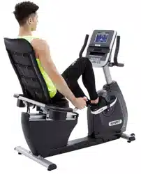
Thank you for your recent purchase of the Philips physical
rehabilitation recumbent bike, 7.0 R Philips physical therapy and exer-
cise solutions provide simple, reliable products that oer the most
relevant feedback to caregivers and users to achieve best-in-class
outcomes and empower individuals to build condence in rebuilding
and maintaining healthy lifestyles and keep in touch with their
communities.
Your new product has been manufactured by one of the world’s
leading medical product manufactures. It is backed by one of the
most comprehensive warranties in the industry. Through our dealers,
distributors and manufacturer’s representatives, we will do all we can
to provide many years of successful and prosperous ownership.
Your warranty and service needs will be addressed either through
your regional sales representative or our highly trained service
technicians.
It is their responsibility to provide you with both the technical
knowledge and access to service personnel to make your ownership
experience more informed, and resolve any issues quickly.
Product registration
Register your product and get support at :
www.philips.com/welcome .
This will ensure we have all your details quickly at hand in dealing with
any after sales support. For fastest support visit us online for chat and
self service solution at :
www.philips.com/support .
Philips therapy solutions
Delivering better outcomes

Contents
Important safety instructions 5
Important electrical information
Important operation instructions 10
Application specication 11
Operating principle 13
Signicant physical characteristics 13
8
Signicant performance characteristic
14
Intended user prole 15

42
46
64
69
72
Operating the 7.0 R 17
Features 19
Data transfer software instructions 38
Operation of your new bike 22
Using a heart rate transmitter
Assembly instructions for 7.0 R
Maintenance
Specications
Description of packaging symbols

5
Attention
Read all instructions in this manual before using this device.
Danger
To reduce the risk of electric shock disconnect your from the
electrical outlet prior to cleaning and/or service work.
Warning
• Do not modify this equipment without authorization of the
manufacturer.
• To reduce the risk of burns, re, electric shock, or injury to persons,
install the bike on a at level surface with access to a 90 to
240-volt AC, 50/60 Hz, 15-amp grounded outlet. Do not use an
extension cord unless it is 16awg or larger, with only one outlet on
the end. The bike should be the only appliance in the electrical circuit.
Do not attempt to disable the grounded plug by using improper
adapters, or in any way modify the cord set; a serious shock or re
hazard may result along with computer malfunctions.
• Use this device only for it’s intended use as described in this
manual.
• Keep children away from the bike. There are moving parts, obvious
pinch points and other caution areas that can cause harm.
• Except as instructed for use of the device, keep hands away from all
moving parts.
Important
safety
instructions

6
• Keep the electrical cord away from heated surfaces and out of all
travel lanes and do not operate the bike if the cord or plug is
damaged.
• The pulse sensors are not medical devices. Various factors, including
the user’s movement, may aect the accuracy of heart rate readings.
The pulse sensors are intended only as exercise aids in determining
heart rate trends in general.
• Heart rate monitoring system may be inaccurate. Over exercise may
result in injury or death. If you feel faint stop exercising immediately.
• Ensure there is a minimum space on the sides of the bike of two feet
for proper operation, easy access and to prevent possible injuries to
others standing or walking nearby. There should be a minimum of at
least one foot of free space at the front and rear of the unit.
• Do not use any after market parts on this device, other than those
recommended by Philips.
• Do not attempt any servicing or adjustments other than those
described in this manual. All else must be left to trained service
personnel familiar with electro-mechanical equipment and autho-
rized under the laws of the country in question to carry out mainte-
nance and repair work.
• Installation and assembly of this product should be performed by
trained personnel only.

7
• Hold the handlebar for support when getting on or o the bike.
• To avoid injury please observe all minimum and maximum seat
adjustment settings.
• Never drop or insert any object into any openings.
• Do not use outdoors.
• To disconnect, turn all controls to the o position then remove the
plug from the outlet.
• This device is designed for commercial use and will meet the
demands of orthopedic, sports wellness and general conditioning
programs.
• Do not attempt to use your bike for any purpose other than for the
purpose it is intended.
• Warning: The adjustable crank arms may become entangled in pant
legs if the pant legs are loose tting. To avoid injury roll up the pant
legs or secure the pant legs in some other fashion.
• The ywheel in the bike does not have a freewheel, but is directly
connected to the pedals. The bike is equipped with auto-braking
software that will stop the ywheel when it detects the user is trying
to stop pedaling. In the unlikely event that the electronics fails, or
the Auto-brake function is disabled in the software, a spinning
ywheel can make the bike dicult to stop when pedaling at higher
RPM(Revolutions per minute). There is an emergency brake lever
provided that will stop the ywheel when pressed.

8
Warning
• Never remove any cover without rst disconnecting AC power. If
voltage varies by 10% or more outside of specied range (90 to 240
V), the performance of your bike may be aected. Such conditions
are not covered under your warranty. If you suspect the voltage is
low, contact your local power company or a licensed electrician for
proper testing.
• Never expose this bike to rain or moisture. This product is not
designed for use outdoors, near a pool or spa, or in any other high
humidity environment.
• The recumbent bike is not protected against the ingress of water or
particulate matter.
• The recumbent bike is not suitable for use in an oxygen rich envi-
ronment.
• If not stated otherwise Philips devices are designed for operation in
normal climatic surroundings (IEC 60601-1):
- Temperature: + 10° ... + 36° C
- Relative humidity: 30 ... 90 % (non condensing)
- Air pressure: 700 ... 1060 mbar
- Maximum operating altitude: approx. 10,000 feet (3000m), with
out pressurization
- Transport and store the devices at a temperature of – 20° ...
+ 50° C.
Important
electrical
information

9
Grounding instructions
• This product must be grounded. In the unlikely event that the
bike’s electrical system should malfunction or breakdown
grounding provides a path of least resistance for electric current,
reducing the risk of electric shock. This product is equipped with
a cord having an equipment-grounding plug. The plug must be
plugged into an appropriate outlet that is properly installed and
grounded in accordance with all local codes and ordinances.
Danger
• Improper connection of the equipment-grounding conductor can
result in a risk of electric shock. Check with a qualied electrician
or serviceman if you are in doubt as to whether the product is
properly grounded. Do not modify the plug provided with the
product if it will not t the outlet; have a proper outlet installed
by a qualied electrician.

10
• Never use your bike during an electrical storm. Surges may occur in
your facility power supply that could damage the bike’s compnents.
• All users should have medical clearance before starting any rigorous
exercise program. This is especially important for persons with a
history of heart disease or other high risk factors.
• The user should adjust the seat to a position that is comfortable
during exercise. The console has a program in the setup menu that
can aid in setting the correct seat position.
• Start at a safe exercise level. Do not allow the user to be over
exerted. Symptoms to watch for, but not limited to, are: shortness of
breath or diculty in breathing, pain or discomfort, feeling faint.
• Make sure the user warms up and cools down properly to avoid over
taxing the cardio vascular system. Allow three to ve minutes of
warm up and cool down during each exercise session.
Important
operation
instructions

11
Medical purpose
• Patient warm up before physical therapy session.
• Have the patient pedal to improve range of motion after
knee/hip/ankle surgery.
• Allow patients to perform cardiovascular exercise.
Intended patient population
• There is no particular restriction on age, gender, height and nationality.
• Maximal patient’s weight is 200kg.
• Patient must be ambulatory.
• Patient should have medical clearance before starting any rigorous
exercise program. This is especially important for person with a history
of heart disease or other high risk factors.
Intended part of the body or type of tissue applied to or
interacted with:
• Contact site: hands, feet, and trunk
• Condition: should not have any trauma
Application
specication

12
Intended conditions of use
• Environment including hygienic requirements
- General: intended for indoors use. This product is not designed
for use outdoors, near a pool or spa, or in any other high humidity
environment.
- Conditions of visibility:
Ambient luminance: standard ambient room lighting is sucient.
Viewing distance: 1 m
Viewing angle: 120°
- Physical
Temperature range: 10°C ~ 36°C
Relative humidity range: 30% R.H. ~ 90% R.H., non condensing
- Hygienic requirements: there is no particular restriction on
hygienic requirements.
• Frequency of use
- Dependent on therapist’s plan.
• Location
- Intended for hospital use, clinic use, home use and research in
academic institutions.
• Mobility
- The product is intended to be xed.
2
3
1
2
1

13
The patient pushes the pedals with their feet. The operator can
increase the workload using the Up and Down Key on the console.
When the workload change is requested an electromagnet is
energized at eld strengths relative to the workload requested. The
magnetic eld generated by the coil is induced into a ywheel
creating eddy currents to ow in the ywheel. The eddy currents then
create an opposing magnetic eld to the electromagnetic eld
creating more or less resistance at the pedal, determined by
workload setting by the operator.
Operating
principle
Please refer to Features of 7.0 R manual.
Signicant
physical
characteristics

14
Please refer to “Unique uses for the 7.0 R” in Operating
the 7.0 R.
Signicant
performance
characteristic

15
Intended
user
prole
Intended operator
• There is no particular restriction on age, gender, height, weight,
ability and culture.
• Education: University or above
• Knowledge: The operator should read the User’s Manual before use.
• Discipline: The operator should receive training from the manufac-
turer before use.
• Experience: The operator must have experience in physical therapy.
• Background: The operator must be a major in physical therapy.
• Professional competence: The operator should have the physical
therapist license.
Intended installer
• There is no particular restriction on age, gender, height, weight,
ability and culture.
• Education: High School or above
• Knowledge: The installer shall be able to manipulate this product
properly.
• Discipline: The installer shall be given a specic training by manu-
facturer.
• Experience: The installer must have experience in product assembly
and disassembly.
• Background: The installer must be electro-mechanically trained.
• Professional competence: Normal vision ability required.

16

17
The recumbent bike is intended to be used in aiding in the physical
rehabilitation process for patients with orthopedic and neurological
problems. Also used in sports medicine, wellness and general
conditioning programs.
Typical applications for this type of product are:
• Patient warm up before physical therapy session.
• Have the patient pedal to improve range of motion after knee/hip/
ankle surgery.
• Allow patients to perform cardiovascular exercise
Unique uses for the 7.0 R
• Adjustable crank allows patients to pedal in smaller range of knee
motion, from 15 degrees to full range.
• Symmetry program measures distance between left and right step
lengths. Graphical Bio-feedback display motivates patients to main-
tain even step symmetry between left and right legs.
Operating
the 7.0 R

18
Other features of the 7.0 R
• Work range up to 750 watts (60 RPM) when level settings are at 15
watts per level
(see Setup under Console section for Level settings).
• Indexed seat positioning accommodates users from 147 cm to 200 cm
(4’ 10” to 6’ 7”).
• Heart Rate monitoring using the optional heart rate chest-strap.
Heart rate measurements are not for medical use
The heart rate function on this product is not a medical device and
should not be relied on when accurate readings are necessary. Some
people, including those in a cardiac rehab program, may benet from
using an alternate heart rate monitoring system like a chest or wrist
strap. Various factors, including movement of the user, may aect the
accuracy of your heart rate reading. The heart rate reading is intended
only as an exercise aid for measuring heart rate trends in general.
19
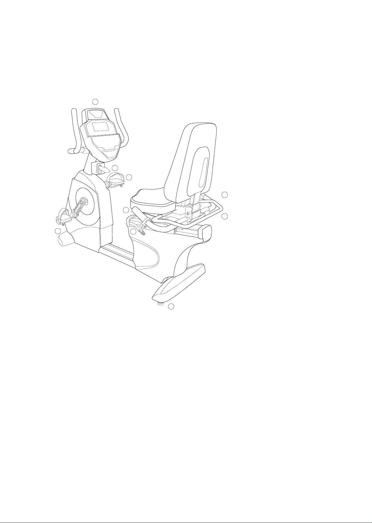
7.0 U – Upright bike
Parts and adjustments
1. Electronic console
2. Mechanical brake
3. Pedal adjustment
4. A.C. Power input
5. Seat swivel adjustment
6. Hand pulse sensors
7. Seat back angle adjustment
8. Leveling glide
9. Seat angle adjustment
Optional parts (not shown)
2.1 Neurological pedal set
Features
1
2
3
4
5
9
6
8
7

20
The 7.0 R is an easy product to set up and use, from the adjustments to
the intuitive interface. This section explains how to set up, adjust and
operate your 7.0 R.
Leveling the 7.0 R
Once the 7.0 R is assembled, and placed on a at level oor, it may
be necessary to adjust the leveling glides on the bottom of the unit
to ensure proper stability of the 7.0 R. Use a 1/2” wrench to loosen
the top nut of the leveler. Adjust the levelers by hand as necessary to
remove any wobble in the unit. Then tighten the top nut against the
bottom of the stabilizer tube. Make sure the bottom nut remains
cinched against the leveling foot.
Connecting to A.C. power
The 7.0 R has a built-in universal power supply. You can plug the 7.0
R into any A.C. power source from 90 to 240 volts, 50 to 60 Hz. The
A.C. input is located in the front of the unit. The input module has an
input connector for the line cord, a power switch and a 5 amp fuse.
Turn the power switch to o when the 7.0 R is not in use.
Adjusting the seat fore/aft position
Squeeze the brake handle located on the left side handle bar. Move
the seat slightly until the seat lock clicks in place. There is anumbered
scale located on the aluminum seat slide tube for repeatable set-
tings. Seatposition is indicated by the front of the seat carriage lining
up with the number on the scale.
Adjusting the seat back angle
The seat back angle can be adjusted for comfort, but also may be
adjusted to change the hip angle for patients. To adjust the seat back
angle, squeeze the brake handle located on the left side handle bar
and move the seat back to the desired position. There is a numbered
scale located just below the seat back cushion for repeatable set-
tings.
Rotating the swivel seat
Lift the handle behind the seat to disengage the latch. Rotate the
seat to the desired position; lower the handle when approaching
position to activate latch. The seat will latch into place every 45
degrees

21
Pedal adjustment
Loosen the knob on the adjustable crank and pull up to disengage
the pin. Slide the pedal up or down the crank arm to the desired
setting then tighten the knob. There is a numbered scale for repeat-
ability and a program in the Set Up function of the console that can
assist in setting up the pedal position to accommodate various
patient knee angles.
Warning : Avoid wearing pants with loose tting legs as they may get
caught on the crank arm while pedaling.
Auto-braking feature
The 7.0 R has built-in sensing technology and software that will auto-
matically stop the ywheel when it senses the user is attempting to
stop pedaling. This Auto-braking software can be disabled during
program set up before beginning a session. The Auto-Brake is set to
o for the Symmetry and VO2 programs and can be turned on during
program set up.
Mechanical brake lever function
The brake’s ywheel is also equipped with a mechanical brake that
can be activated to stop the ywheel by pressing down on the lever.
17
22
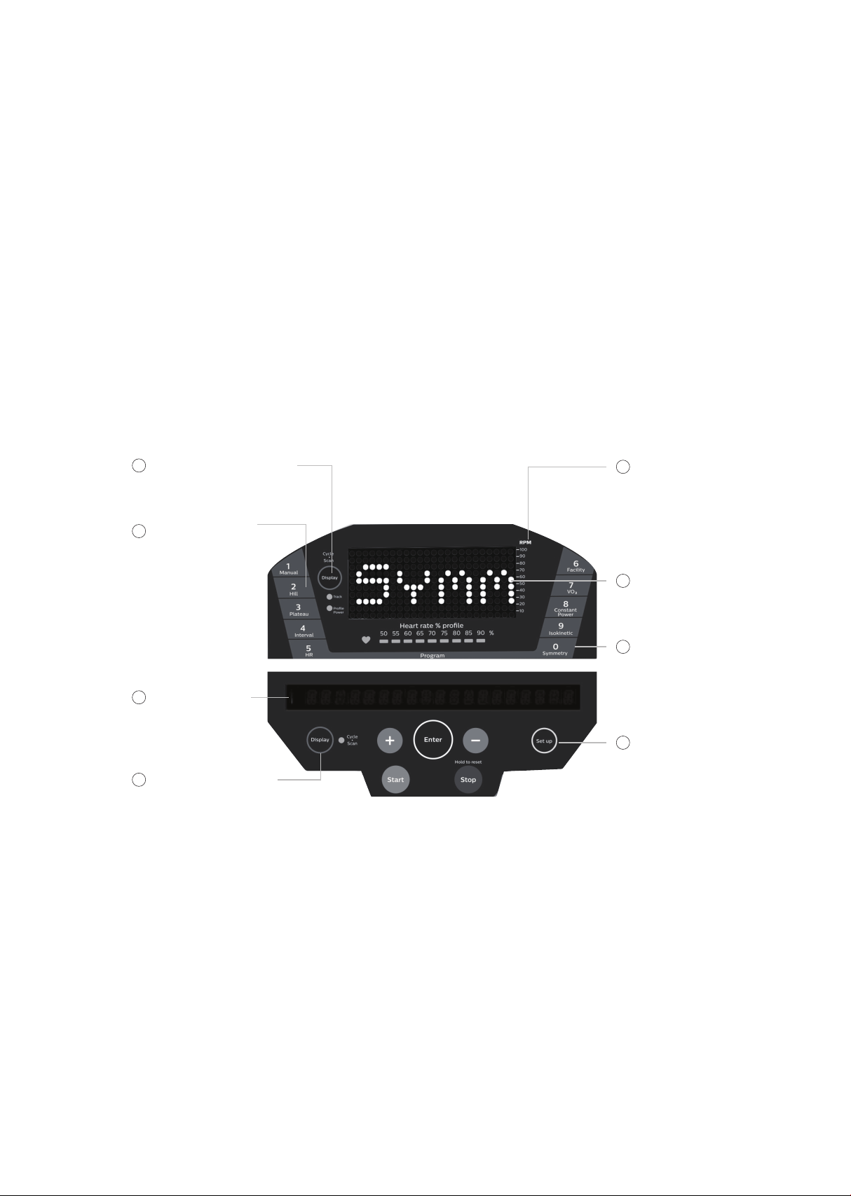
7.0 R electronic console
Power on
When initially powered on the console will perform an internal
self-test. During this time all the lights will turn on for a short time.
The dot matrix display will then show a software version (i.e. VER 1.0)
and the message window will display an odometer reading. The
odometer reading displays how many hours the bike has been used
and how many virtual miles the bike has been ridden. The display will
look like this: ODO 123 MI 123 HRS.
Operation
of your
new bike
3
o
r g
v
w
a t t s l r
o
RPM scale for
isokinetics only
5
Dot matrix
display
6
Program keys
7
Function keys
8
Program keys
2
Message window
3
Change data display
4
Change graphic display
1
A

23
The odometer will remain displayed for only a few seconds then the
console will go to the start up display, also known as Idle Mode. The
message window will be scrolling the start up message. You may now
begin to use the 7.0 R.
The console will automatically power down after 20 minutes of inac-
tivity. Press any key to wake the console up again. Always turn o the
main power switch when the 7.0 R is not in use.
Console operation
Set up
The Set Up key function will allow you to enter patient data, set seat
and pedal adjustments for various knee ranges of motion and custom-
ize the settings of the 7.0 R. When the Set Up key is pressed the rst
option in the menu appears. Use the up/down arrows to scroll through
the menu and press the enter key to select an option.
Set up menu
• Patient data
- Age : used in VO2 and heart rate programs.
- Gender : used in VO2 program.
- Weight : used in METS and Calorie calculations and VO2 program.
- Height : used in the Symmetry program.
• Seat position
- User may input desired knee exion angles (6 options) and the
software will calculate the seat’s vertical position and pedal
posi tion settings.
- This feature is intended to aid in patient set up but may not be the
nal settings as patient’s body symmetry may vary slightly.
- This program uses the height from the Patient Data settings fo
limb length. The seat Fore/Aft position is assumed to be in the
center of the adjustment range.

24
The six knee angle options are:
• R Min (Right leg minimum exion)
L Min (Left leg minimum exion)
• R Max (Right leg maximum exion)
L Max (Left leg maximum exion)
• R Max (Right leg maximum exion)
L Min (Left leg minimum exion)
• R Min (Right leg minimum exion)
L Max (Left leg maximum exion)
• R Max (Right leg maximum exion)
R Min (Right leg minimum exion)
• L Max (Left leg maximum exion)
L Min (Left leg minimum exion)
• Watts per row
- Adjusts the scale of the dot matrix when power (watts) is
displayed. The default setting is 10 watts per row. The default of 10
watts per row means the full display (all 10 rows lit) equal 100
watts.
- The setting can be adjusted from 10 to 100 watts per row of lights
on the graph.
• Level Scale
- Set the amount of change in the level adjustment of workload
(resistance at the pedals) each time the arrow keys are pressed.
- This feature allows you to have very ne increments of resistance
for physically challenged patients or set very high resistance
levels for sports training. The default setting is; Fine, 5 watts per
level. The three options are:
Fine – 5 watts per level (at 60 RPM)
Medium – 10 watts per level (at 60 RPM)
Coarse – 15 watts per level (at 60 RPM)
Quick start
This is the quickest way to start an exercise session. After the console
powers up you just press the Start key to begin; this will initiate the
Quick start mode. In Quick start, the Time will count up from zero, all
workout data will start to accrue and the workload may be adjusted
manually by pressing the Up or Down key. The dot matrix will display a
workload level at the lowest resistance. As you increase the workload
more rows will light indicating a harder workout. The bike will get harder
to pedal as the rows increase.
1
2
3

25
The dot matrix has 24 columns of lights and each column represents 1
minute in the Quick start program (time per column can be modied in
other programs). At the end of the 24th column (or 24 minutes of work)
the display will wrap around and restart at the rst column again. There
are 50 levels of resistance displayed in 10 rows of LED lights. The
amount of workload for each level can be modied in the Set up menu.
Basic information
The Dot Matrix Display is used for displaying graphic feedback and has
three basic displays for most programs, except for Isokinetic and Sym-
metry programs which are described later. When you begin a program
the dot matrix will display a workload prole (constant resistance). To
the left of the dot matrix there is a key labeled Display. Pressing this key
will switch the display to show a Power graph (watt prole) and then a
track. When both LEDs under the key are blinking the graph will scan
through the three displays.
The Message Window is the main display for programming instructions
and relevant measurements during a program. The measurement data
shown varies depending on the program. Measurements include: Time
and Segment Time, RPM, Pulse, Work level, Watts and Average Watts
(Left and Right leg), METS, Calories and Symmetry.
Below the Dot matrix display is a Heart Icon and a Bar Graph. Simply
grasping the hand pulse sensors, or wearing a heart rate chest belt
transmitter, will start the Heart Icon blinking (this may take a few sec-
onds). The Message Window will display your heart rate in beats per
minute. The Bar Graph represents the percentage of maximum heart
rate. NOTE: Enter the correct age in Set Up for the Bar Graph to be
accurate. Refer to Heart Rate section for details about these features.
The Stop / Reset key provides several functions
• Pressing the Stop/Reset key once during a program will pause the
program. To resume the exercise session just press the Start key or
start pedaling.

26
• If the Stop/Reset button is pressed twice during a workout the pro-
gram will end and a summary of information of the exercise session
will be displayed.
• If the Stop/Reset key is held down for 3 seconds the console will per-
form a complete Reset.
• During data entry for a program the Stop/Reset key performs a Previ-
ous Screen function. This allows you to go back one step in the pro-
gramming each time you press the Stop/Reset key.
The program keys may be used to preview each program when in the
idle mode. Press each program key to preview what the program
prole looks like. To begin a program press the corresponding pro-
gram key and then press the Enter key to select the program.
The program keys also function as a Number Key Pad when you are in
the data-setup mode. The number for each key is shown above the
program name. If you are entering new data such as Time, Age, weight
etc., you can use these keys to enter the numbers quickly.
Selecting and customizing programs
When you enter a program you have the option of modifying the
settings. If you want to begin without entering new settings just press
the Start key. This will bypass the programming of data and take you
directly to the start of the program. If you want to change the settings
just follow the instructions in the message window. If you start a
program without changing the settings the data from the Set Up
menu will be used.
Manual
The Manual program works as the name implies, manually. This
means that you control the workload yourself, not the computer. To
start the Manual program follow the instructions below or just press
the Manual button then the Enter button and follow the directions in
the message window.
• Press the Manual key then press the Enter key.

27
• The message window will prompt you to enter the time for the
program. You may enter the time using the Up and Down keys or the
numeric key pad then press the Enter key to accept and proceed to the
next screen.
• The next setting is for the Auto-braking feature. You may turn the
auto-brake on or o then press enter to continue.
• Now you are nished editing the settings and can begin the program
by pressing the start key. You can also go back and modify your
settings by pressing the Enter key. Note: At any time during the
editing of data you can press the Stop key to go back one level, or
screen.
• During the manual program you will be able to scroll through the data
in the message window by pressing the display key. You may also
switch between the prole or power displays and a quarter mile track
by pressing the display key adjacent to the dot matrix display.
• When the program ends you may press start to begin the same
program again or stop to exit the program, or you can save the
program you just completed as the Facility program by pressing the
Facility key and following the instructions in the message window.
Preset programs
The bike has three preset exercise programs that have been designed
for a variety of workout goals. The initial built-in level of diculty for
each program is set to a relatively easy level. You may adjust the level
of diculty (Max level) for each program before beginning.
The proles shown in the dot matrix are merely pictures of the whole
prole and will not change in size when the work level keys are
pressed. When setting up a program you will enter the maximum
resistance setting for the peak of the prole. During the program the
resistance levels will change as the prole progresses. When the up
key is pressed to request more resistance the prole picture will not
change, but the workload will increase. The message window will
display the level setting for the current segment and also the maxi-
mum level for the peak of the prole. Pressing the work keys actually
change the peak level of the program not the current segment level.
You may need to change the peak setting several times before the
current segment increases.

28
Hill
The Hill program simulates going up and down a hill. The resistance
in the pedals will steadily increase and then decrease during the
program.
Plateau
The Plateau program provides a steady state exercise with warm up
and cool down periods.
Interval
The Interval program takes you through high levels of intensity fol-
lowed by periods of low intensity. This program increases your endur-
ance by depleting your oxygen level followed by periods of recovery
to replenish oxygen. Your cardio vascular system gets programmed to
use oxygen more eciently this way.

29
Programming preset programs
• Select the desired program button then press the Enter key.
• The message window will prompt you to enter the time for the
program. You may enter the time using the Up and Down keys or the
numeric key pad then press the Enter key to accept and proceed to
the next screen.
• The next setting is for the Auto-braking feature. You may turn the
auto-brake on or o then press enter to continue.
• Now you are nished editing the settings and can begin the
program by pressing the Start key. You can also go back and modify
your settings by pressing the Enter key.
• Note: At any time during the editing of data you can press the Stop
key to go back one level, or screen.
• During the Manual program you will be able to scroll through the
data in the message window by pressing the Display key. You may
also switch between the prole or power displays and a quarter
mile track by pressing the Display key adjacent to the dot matrix
display.
• When the program ends you may press Start to begin the same
program again or Stop to exit the program, or you can save the
program you just completed as the Facility program by pressing the
Facility key and following the instructions in the message window.
Facility program
The Facility program allows you to build and save a custom program.
You can build your own custom program by following the instructions
below or you can save any other preset program you complete as a
custom program. The Facility program allows you to further
personalize it by adding your facility name.
Designing and saving a new program
Press the Facility key. The message window will show a welcome
message; if you had previously saved a program the message will
contain the name you gave it. Then press the Enter key to begin
programming.

30
• When you press enter, the message window will show “Name – A”, if
there is no name saved. If the name “Custom Workout” had been
previously saved the message window will show “Name – Custom
Workout” and the C in Custom will be blinking. If there is a name
saved you can change it or you may press the Stop keyto keep the
name and continue to the next step. If you want to enter a name
use the Up and/or the Down key to change the rst letter then
press Enter to save the rst letter and continue to the next letter.
When you have nished entering the name press the Stop key to
save the name and continue to the next step.
• The message window will ask you to enter an Age. You may enter an
Age, using the Up and Down keys or the numeric key pad, then
press the Enter key to accept the new number and proceed on to
the next screen.
• You are now asked to enter a Weight. You may adjust the Weight
number using the Up and Down keys or the numeric key pad then
press enter to continue.
• Next is Time. You may adjust the Time and press enter to continue.
• Now you are asked to adjust the Max Level. This is the peak exertion
level you will experience during the program. Adjust the level and
then press enter.
• Now the rst column will be blinking and you are asked to adjust
the level for the rst segment of the workout. When you nish
adjusting the rst segment, or if you don’t want to change, then
press enter to continue to the next segment.

31
• The next segment will show the same level as the previously adjust-
ed segment. Repeat the same process as the last segment then
press enter. Continue this process until all twenty four segments
have been set.
• The message window will then tell you to press enter to save the
program. After saving the program the message window says “New
program saved” then will give you the option to Start or modify the
program. Pressing Stop will exit to the start up screen.
• During the Facility program you will be able to scroll through the
data in the message window by pressing the adjacent Display key.
Running a saved program
• Press Facility key then Enter
• Enter Time then set Auto-brake on or o and press enter. Then
press start to begin program.
VO2 Test
The VO2 program is based on the YMCA protocol and is a
sub-maximal test that uses pre-determined, xed work levels that
are determined based on the heart rate readings measured as the
test progresses. The test will take anywhere between 6 to 15 minutes
to complete, depending on the tness level of the user. The test ends
when the user’s heart rate reaches 85% of maximum at any time
during the test, or the heart rate is between 110 bpm and 85% at the
end of two consecutive stages. At the end of the test a VO2max score
will be displayed.
The YMCA protocol employs two to four stages, lasting 3 minutes
each, of continuous exercise (see charts below). You will be prompted
to choose either, Male or Female at the beginning of the test. This
choice determines which protocol will be used during the test as
shown in the charts below. The only caveat is if you are a very
de-conditioned male you may need to choose option Female. If you
are a very conditioned female you may need to choose option Male.

32
Workload chart for male or very t female
Workload chart for female or de-conditioned male
VO2 test programming
• Press the VO2 button and press enter.
• The message window will prompt you to enter your Gender. Use the
Up and Down keys to change and press the Enter key to accept and
proceed on to the next screen.
• You are now prompted to enter your Age. You may adjust the age
using the Up or Down key then press enter to continue.
• You are now prompted to enter your Weight. You may adjust the
weight using the Up or Down key then press enter to continue
• Now press Start to begin the test.
1st
Stage
HR
2nd
Stage
125-750
kgm/min
50-300
kgm/min
100-600
kgm/min
150-900
kgm/min
225-1350
kgm/min
150-900
kgm/min
150-900
kgm/min
125-750
kgm/min
200-1200
kgm/min
200-1200
kgm/min
175-1050
kgm/min
175-1050
kgm/min
175-1050
kgm/min
HR
>135 >135 >135
<120 <120<120
<90 90-105 >105
120-135 120-135120-135
3rd
stage
1st Stage
25W
150 kgm/min
Heart Rate
HR<80
HR: 80-90
HR: 90-100
HR>100
2nd Stage
125W
750 kgm/min
100W
600 kgm/min
75W
450 kgm/min
50W
300 kgm/min
3rd Stage
150W
900 kgm/min
125W
750 kgm/min
100W
600 kgm/min
75W
450 kgm/min
4th Stage (if needed)
175W
1050 kgm/min
150W
900 kgm/min
117W
700 kgm/min
100W
600 kgm/min

33
Before the test
• Make sure you are in good health; check with your physician before
performing any exercise if you are over the age of 35 or persons with
pre-existing health conditions.
• Adjust the seat to the proper position so that when your leg is
extended during pedaling there is a slight bend at the knee of
about 5 degrees.
• Make sure you have warmed up and stretched before taking the
test.
• Do not take caeine before the test.
During the test
• The console must be receiving a steady heart rate for the test to
begin. You may use the hand pulse sensors or wear a heart rate
chest strap transmitter, although chest strap transmitter is
recommended.
• The user must maintain a steady 50 RPM pedal speed. If the pedal
speed drops below 48 RPM or goes above 52 RPM the console will
emit a steady beeping sound and the RPM number will ash until
the speed is within this range.
• You may scroll through the various data readings in the message
window by pressing the Display button under the message window.
• The message window will always display your pedal speed on the
right side to help you maintain 50 RPM.
• The data shown during the test is
- Work in KGM is actually an abbreviated form of kg-m/min. which
is a work measure ment of kilogram-force meter/minute
- Work in Watts (1 watt is equal to 6.11829727787 kg-m/min.)
- HR is your actual heart rate; TGT is the target heart rate to reach
to end the test.
- Time is the total elapsed time of the test.
After the test
• Cool down for about one to three minutes.
• Take note of the score because the console will automatically return
to the start-up mode after a few minutes.

34
What the score means
VO2max Chart for males and very t females
VO2max Chart for females and de-conditioned males
Constant Power
The Constant Power program automatically controls the resistance
level at the pedals, depending on user speed, to maintain a
steady power workload.
• Press the Constant Power key then press the Enter key.
• The message window will prompt you to enter the Time for the
program. You may enter the time using the Up and Down keys or the
numeric key pad then press the Enter key to accept and proceed to
the next screen.
18-25
26-35
36-45
46-55
65+
years
old
years
old
years
old
years
old
years
old
years
old
excellent
>60 >56
>51 >45 >41 >37
good 43-51
49-56
52-60
39-45
36-41
33-37
above
average
47-51
43-48
39-42
35-38
32-35
29-32
average
42-46
40-42
35-38
32-35
30-31
26-28
below
average
37-41
35-39
31-34
29-31
26-29
22-25
poor
30-
34
26-
30
30-
36
25-28
22-25
20-21
very
poor <30 <30
<26 <25 <22 <20
18-25 26-35 36-45 46-55 65+
years
old
years
old
years
old
years
old
years
old
years
old
excellent
56
52
45
40
37
32
good
47-56
45-52
38-45
34-40
32-37
28-32
above
average
42-46
39-44
34-37
31-33
28-31
25-27
average
38-41
35-38
31-33 28-30
25-27
22-24
below
average
33-37
31-34
27-30
25-27
22-24
19-22
poor
28-32
26-30
22-26
20-24
18-21
17-18
very
poor <28 <26
<22 <20 <18 <17
56-65
56-65

35
• Set the target Watt Level for the program then press Enter. The
default setting is 50 watts.
• You may turn the Auto-brake on or o then press enter to continue.
• Now you are nished editing the settings and can begin your work-
out by pressing theStart key. You can also go back and modify your
settings by pressing the Enter key.
• Note: At any time during the editing of Data you can press the Stop
key to go back one level, or screen.
• During the program you will be able to scroll through the data in the
message window by pressing the Display key. You may also switch
between the power prole, resistanceprole or a quarter mile track
by pressing the Display key adjacent to the dot matrix display.
• When the program ends you may press Start to begin the same
program again or Stop to exit the program, or you can save the
program you just completed as the facility program by pressing the
Facility key and following the instructions in the message window.
Isokinetic
The Isokinetic program provides accommodating resistance at a xed
speed level. The user controls the resistance at the pedals by pushing
harder or lighter. The desired pedaling speed is entered and the
computer increases the resistance automatically if the user tries to
overcome the set speed.
• Press the Isokinetic key then press the Enter key.
• The message window will prompt you to enter the Time for the
program. You may enter the time using the Up and Down keys or the
numeric key pad then press the Enter key to accept and proceed to
the next screen.
• Set the target RPM Level for the program then press Enter. The
default setting is 30 RPM.
• You may turn the Auto-brake on or o then press enter to continue.
• Now you are nished editing the settings and can begin your
workout by pressing the Start key. You can also go back and modify
your settings by pressing the Enter key.
Note: At any time during the editing of data you can press the Stop key to
go back one level, or screen.
26-
29

36
• During the program you will be able to scroll through the data in the
message window by pressing the Display key. You may also switch
between the speed prole, power prole or a quarter mile track by
pressing the Display key adjacent to the dot matrix display. There is
an RPM graph to the right of the dot matrix to monitor user speed.
• When the program ends you may press Start to begin the same
program again or Stop to exit the program, or you can save the
program you just completed as the Facility program by pressing the
Facility key and following the instructions in the message window.
Symmetry
The Symmetry program may aid in achieving a more balanced pedaling
stroke for patients with lower limb deciencies, such as stroke patients
and post-op knee patients. The program will measure the left and right
power around the pedal rotation and display the watt measurements in
the message window. The dot matrix display will show a graph indicating
the leg power symmetry so the user has a visual feedback to aid in
improving the involved limb’s strength.
• Press the Symmetry key then press the Enter key.
• The message window will prompt you to enter the Time for the
program. You may enter the time using the Up and Down keys or the
numeric key pad then press the Enter key to accept and proceed to
the next screen.
• You may turn the Auto-brake on or o then press enter to continue.
Since the auto-brake may be activated with severe asymmetry the
auto-brake default setting is o. If you want the auto-brake feature
operational please set to on and press enter.
• Now you are nished editing the settings and can begin by pressing
the Start key. You can also go back and modify your settings by
pressing the Enter key.
For best results
The Symmetry program starts at level 1 and the resistance needs to
be increased manually by pressing the Up arrow. Make sure to set the
resistance to a level where the patient is doing enough work to generate
a meaningful measurement. It is recommended to set the resistance as
high as the patient can perform without discomfort, but low enough so
they can complete full pedal revolutions. Very low resistance settings
result in erratic or inconsistent measurements.
37
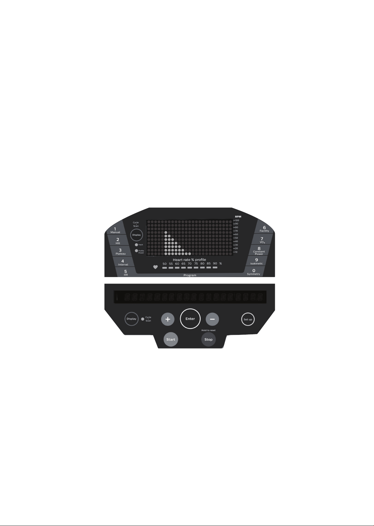
Biofeedback measurements and graph
Below is a sample picture showing the symmetry graph. In the
message window there is an average watt measurement and it is
indicating that the left leg is producing more power than the right leg,
41 vs. 34 watts. The graph reects the higher wattage of the left leg. If
the power is equal in both legs only two dots would be lit on the
bottom center of the graphic screen.
To view the Symmetry Index number press the Display key located
under the message window. The Symmetry Index number is the
percentage of dierence between the left and right leg power. If the
left and right legs are producing the same power the Symmetry Index
will be 0%.
Note: The Symmetry program employs a proprietary algorithm using a
power table and velocity calculations to generate the watt readings;
they are not from direct force measurements.
3
4
r g
v
w
a t t s l r
4 1
A
38
• Works with newer 7.0 T, 7.0 S, 7.5 S, 7.0 R and 7.0 U consoles with
USB ports on the back
• The software works with Windows 10, 7 and XP series, with .Net •
Framework 2.0.
• The output for the data is in a .CSV le format.
• http://www.dyaco.com/software
Please follow the website instructions to download software.
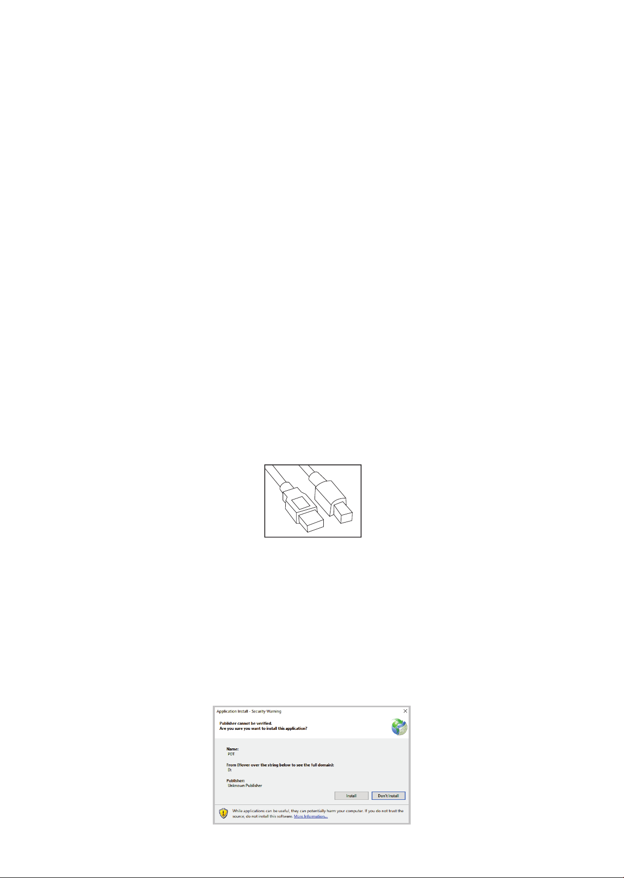
• Use a USB cable (type a to type b, illustrated to the right) to con-
nect the product and the computer.
Step 1.
Download the software from the link (http://www.dyaco.com/soft-
ware) and connect the console of the product to the computer via
USB cable. Click "Install" when you see the pop-up window as below
during installation.
Data transfer
software
instructions
39
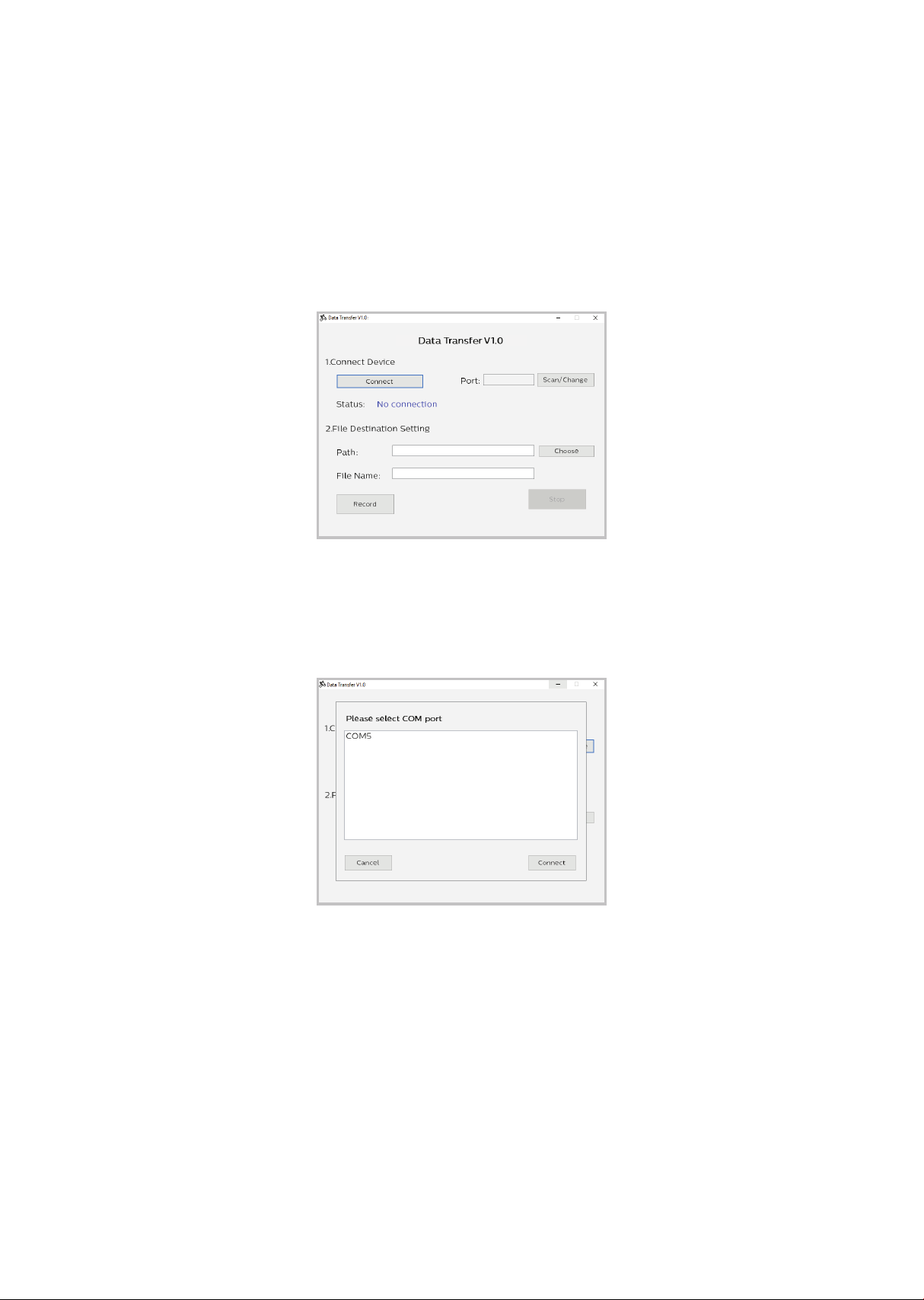
Step 2.
Click "Connect" or "Change" to select the connecting port (left gure).
After clicking the "Change", or connecting to the wrong port, the COM
port selection window pops up (right gure). Select the correct COM
port and click "Connect".
Selecting COM port
Pop-Up COM Port Selection Window
40
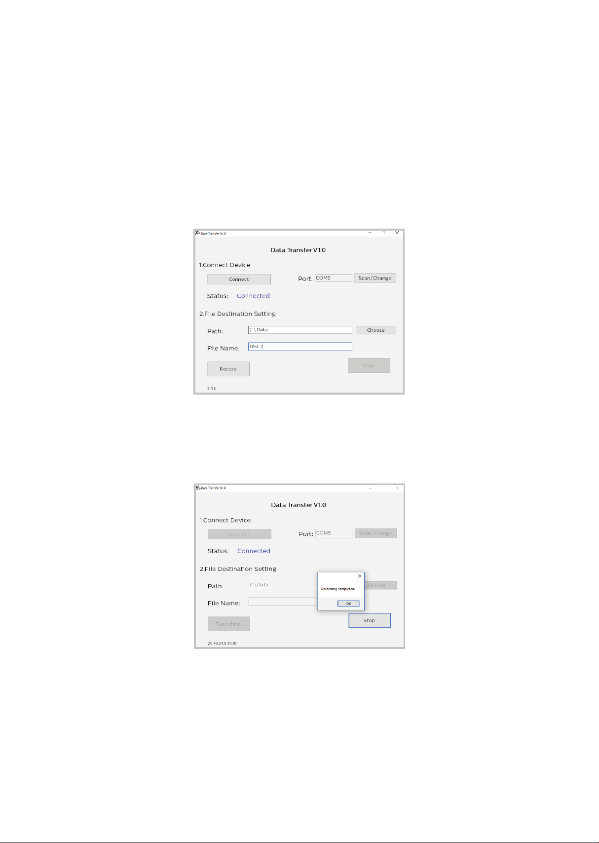
Step3.
After the status shows “Connected” and the product model name to
the right, choose the le path and create the le name for saving the
data. Click the “Record” button to start collecting data. Click “Stop” or
quit the program from the console of the product to stop the data
collection process. The saved data can be found at the assigned
destination.
Click record button
Recording complete
Philips Data Transfer V1.0
Philips Data Transfer V1.0
Philips Data Transfer V1.0
Philips Data Transfer V1.0
7.0 R
7.0 R

41
The le is saved in .CSV format, which can be opened by Microsoft
Excel. Example shown below.

42
Note: The chest strap transmitter is not a standard part, but is a
separate purchase. Most transmitters that operate at 5kHz frequency
will also work.
How to wear your wireless chest strap transmitter?
• Attach the transmitter to the elastic strap using the locking parts.
• Adjust the strap as tightly as possible as long as the strap is not too
tight to remain comfortable.
• Position the transmitter with the logo centered in the middle of your
body facing away from your chest (some people must position the
transmitter slightly left of center). Attach the nal end of the elastic
strap by inserting the round end and, using the locking parts, secure
the transmitter and strap around your chest.
• Position the transmitter immediately below the pectoral muscles.
Using
a heart rate
transmitter

43
• Sweat is the best conductor to measure very minute heart beat
electrical signals. However, plain water can also be used to pre-wet
the electrodes (2 black square areas on the reverse side of the belt
and either side of transmitter). It’s also recommended that you wear
the transmitter strap a few minutes before your work out. Some users,
because of body chemistry, have a more dicult time in achieving a
strong, steady signal at the beginning. After “warming up”, this problem
lessens. As noted, wearing clothing over the transmitter/strap doesn’t
aect performance.
• Your workout must be within range - distance between transmitter
/ receiver – to achieve a strong steady signal. The length of range may
vary somewhat but generally stay close enough to the console to
maintain good, strong, reliable readings. Wearing the transmitter
immediately against bare skin assures you of proper operation. If you
wish, you may wear the transmitter over a shirt. To do so, moisten the
areas of the shirt that the electrodes will rest upon.
Note: The transmitter is automatically activated when it detects
activity from the user’s heart. Additionally, it automatically deacti-
vates when it does not receive any activity. Although the transmitter
is water resistant, moisture can have the eect of creating false sig-
nals, so you should take precautions to completely dry the transmit-
ter after use to prolong battery life (estimated transmitter battery life
is 2500 hours). If your chest strap has a replaceable battery the
replacement battery is CR2032.
!

44
Erratic operation
Caution! Do not use this bike for Heart Rate Control unless a steady,
solid Actual Heart Rate value is being displayed. High, wild, random
numbers being displayed indicate a problem.
Areas to look at for interference, which may cause erratic heart rate
• Microwave ovens, TVs, small appliances, etc.
• Fluorescent lights.
• Some household security systems.
• Perimeter fence for a pet.
• Some people have problems with the transmitter picking up a signal
from their skin. If you have problems try wearing the transmitter upside
down. Normally the transmitter will be oriented so the logo is right side
up.
• The antenna that picks up your heart rate is very sensitive. If there is an
outside noise source, turning the whole machine 90 degrees may
de-tune the interference.
• If there is another person wearing a chest strap within 1 meter, it will
interfere.
• If you continue to experience problems contact your dealer.
Heart rate program operation
To start the HR program follow the instructions below or just press
the HR key then the Enter button and follow the directions in the
message window.
• Press the HR key then press the Enter key.
• The message window will ask you to enter your Age. You may enter
your Age, using the Up and Down keys or the numeric key pad, then
press the Enter key to accept the new number and proceed on to the
next screen.

45
• You are now asked to enter your Weight. You may adjust the Weight
number using the Up and Down keys or the numeric key pad, then
press enter to continue.
• Next is Time. You may adjust the Time and press enter to continue.
• Now you are asked to adjust the Heart rate Level. This is the heart rate
level you will experience during the program. Adjust the level and then
press enter.
• Now you are nished editing the settings and can begin your workout
by pressing the Start key. You can also go back and modify your
settings by pressing the Enter key. NOTE: At any time during the
editing of data you can press the Stop key to go back one level, or
screen.
• If you want to increase or decrease the workload at any time during the
program press the Up or Down key. This will allow you to change your
target heart rate at any time during the program.
• During the HR program you will be able to scroll through the data in
the message window by pressing the adjacent Display key.
• When the program ends you may press Start to begin the same
program again or Stop to exit the program or you can save the
program you just completed as a custom user program by pressing the
Facility key and following the instructions in the message window.
46
Hardware
Step 1.
Assembly
instructions
for 7.0 R
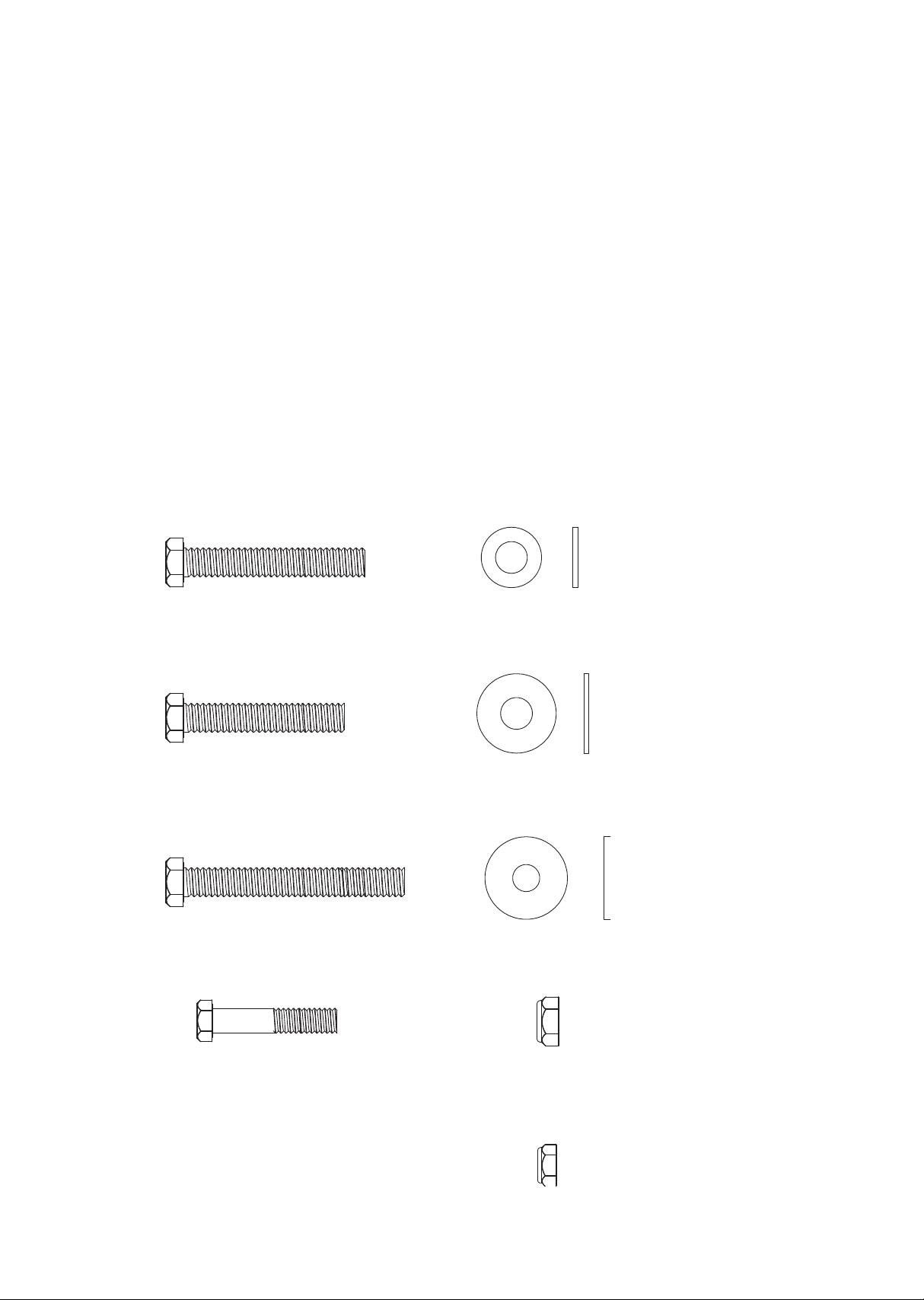
#65- 3/8" × 2- 1/4" (4PCS)
#71- 3/8" × 2" (4PCS)
#175- 3/8" × 2-3/4" (2PCS)
#208- 5/16" ×1-1/4" (1PC)
#77- 3/8" × 3/4" (8PCS)
#84- 3/8" × 1" (4PCS)
#205- 8.5mm × 26mm
(2PCS)
#89- 3/8" (6PCS)
#213- 5/16" (1PC)
47
Step 2.
Step 3.
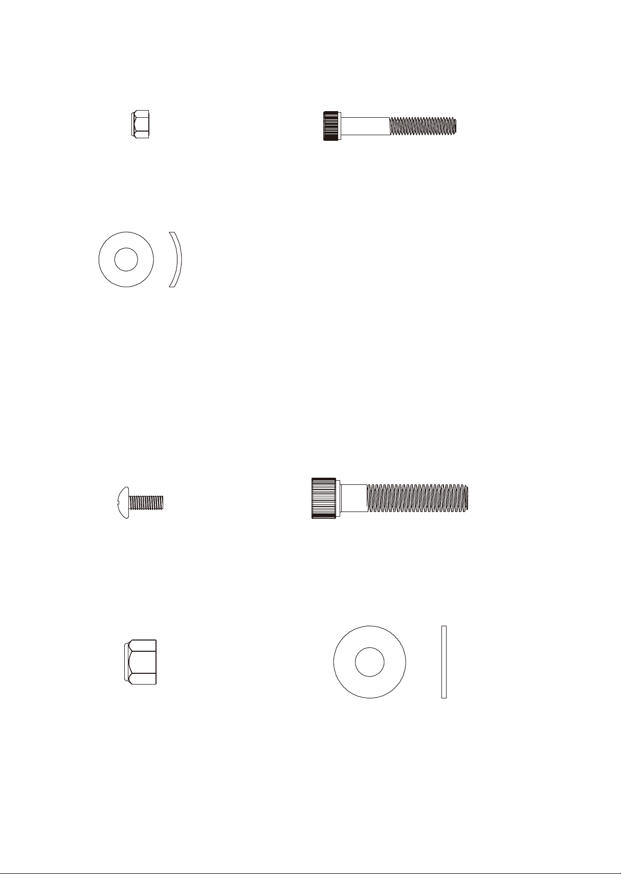
#216- M6 × P1.0 (2PCS)
#221- M6 × P1.0 × 40L
(2PCS)
#83- 5/16" × 3/4" (4PCS)
#136- M5 × 20L (4PCS)
#220- 3/8" × 1-3/4" (2PCS)
#215- 3/8" (2PCS)
#206- 10mm × 25mm
(2PCS)

48
#68- 5/16" × 5/8" (8PCS)
#82- 5/16" (2PCS)
#76- 5/16" × 3/4" (6PCS)
#83- 5/16" × 3/4" (2PCS)
#187- M4 × 5L (4PCS)
#98- M6 × 15L (2PCS)
#99- M5 × 12L (8PCS)
#222- M6 × 25L (4PCS)
Step 4.
Step 5.
49
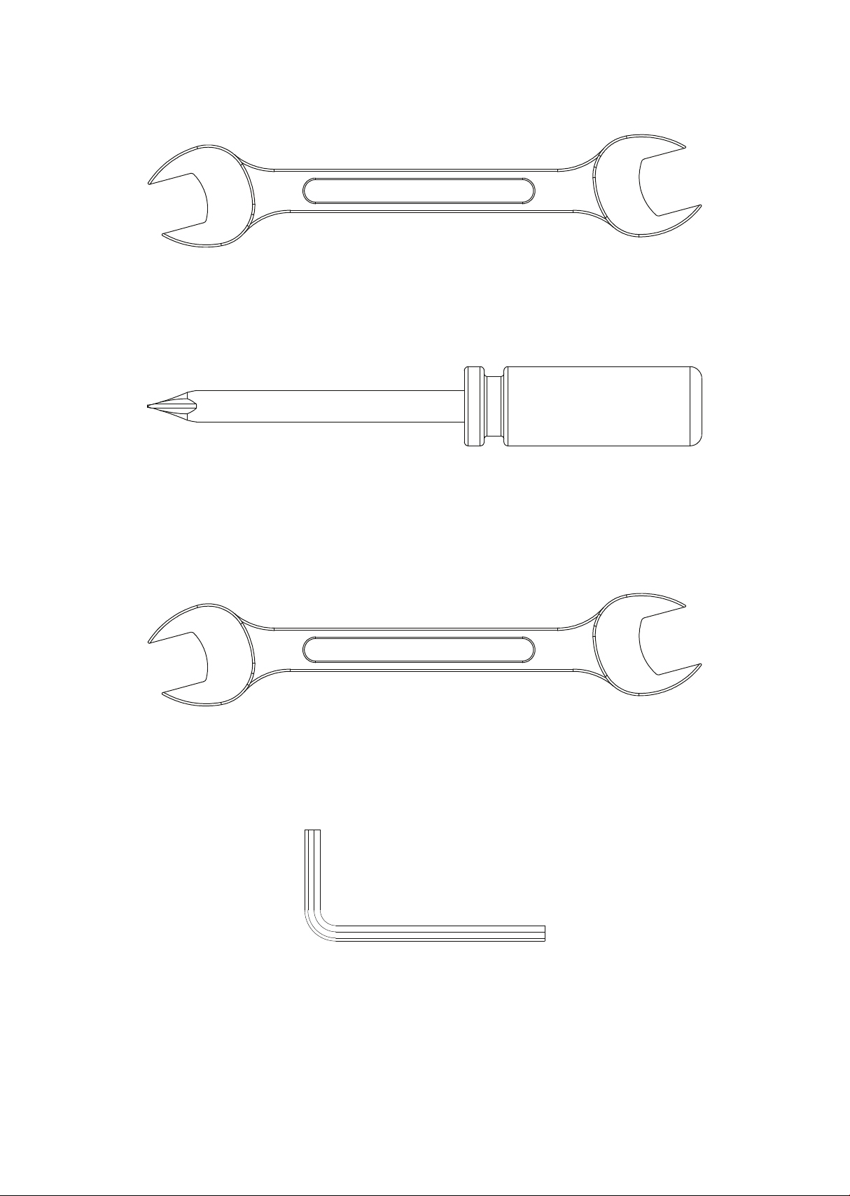
Tools
#200- 5m/m L Allen Wrench (1PC)
#114- Phillips Head Screw Driver (1PC)
#112- 12.14m/m Open wrench (1PC)
12 14
#132- 14.15m/m Open wrench (1PC)
15 14

50
Assembly
Read each step’s instructions and study the drawing carefully to become
familiar with all the parts and procedures before beginning each step.
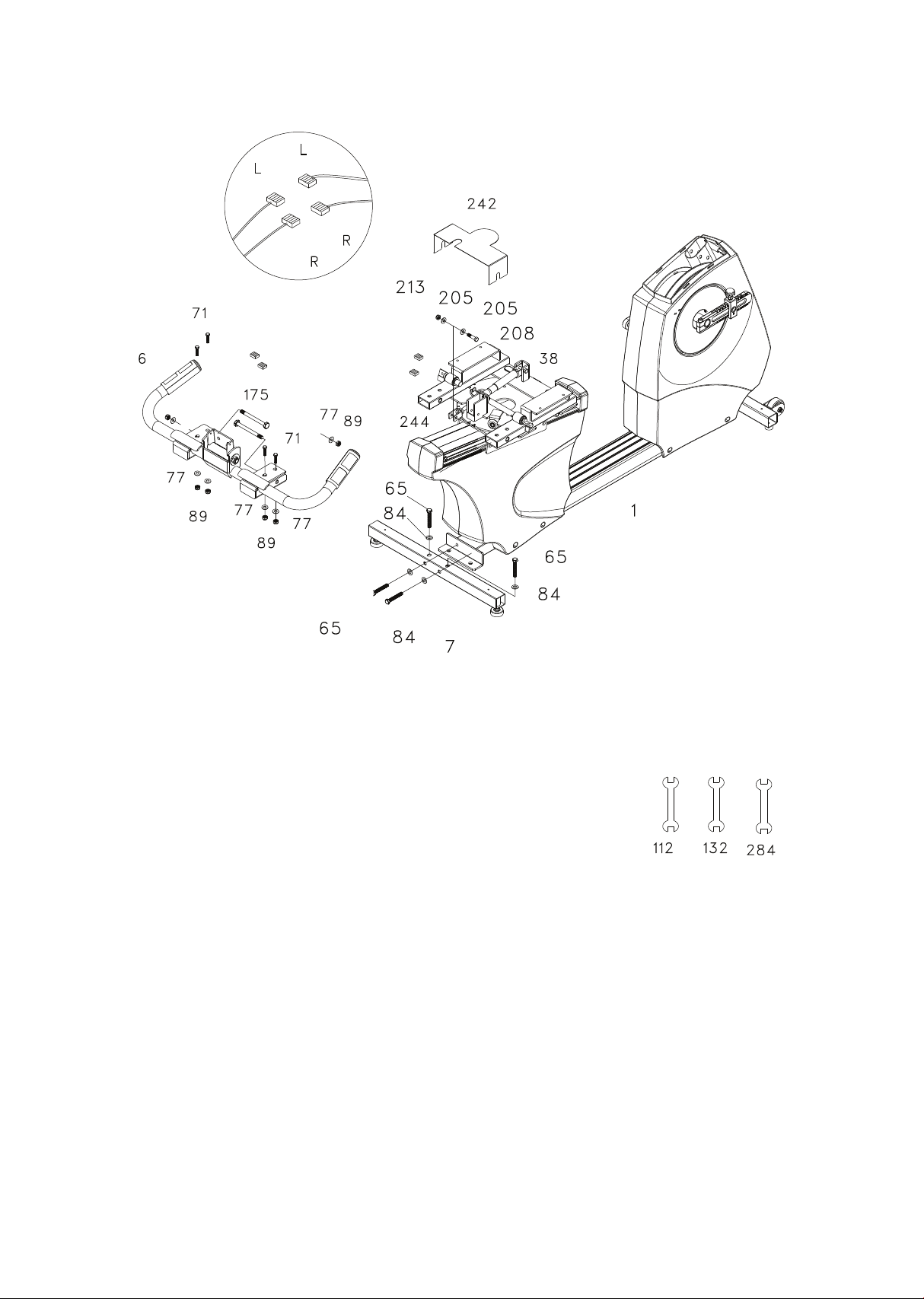
Step 1. Rear stabilizer and handle bar assembly
• Install the Rear Stabilizer (7) onto the Main Frame (1) with the four 3/8” x
2-1/4” Hex Head Bolts (65) and four 3/8” Flat Washers (84).
• This section is easier if you slide the seat carriage (38) all the way back
before starting. Slide the handle bar assembly (6) onto the receiving
tubes of the seat frame (38). Secure the handle bar assembly starting
with the two 3/8” x 2-3/4” bolts (175) (install from the inside hole of the
receiving tube), four at washers (77) and two nuts (89). *Do not tighten
the hardware for this section until the very end, after the safety cover
(242) is attached. Install the four 3/8” x 2” bolts (71) from the top side of
the tubes and assemble the four 3/8” at washers (77) and 3/8” nuts
(89).
• Attach the end of the gas shock (244) to the seat back angle adjustment
bracket and secure with the 5/16” x 1-1/4” bolt (208), two 5/16” at
washers (205) and 5/16” nut (213).
• Connect the left (L) and right (R) hand pulse wires together. Slide the
safety cover (242) onto the handle bar bolts (175), between the frame
and washer & nuts. Tighten all hardware securely.
51
52
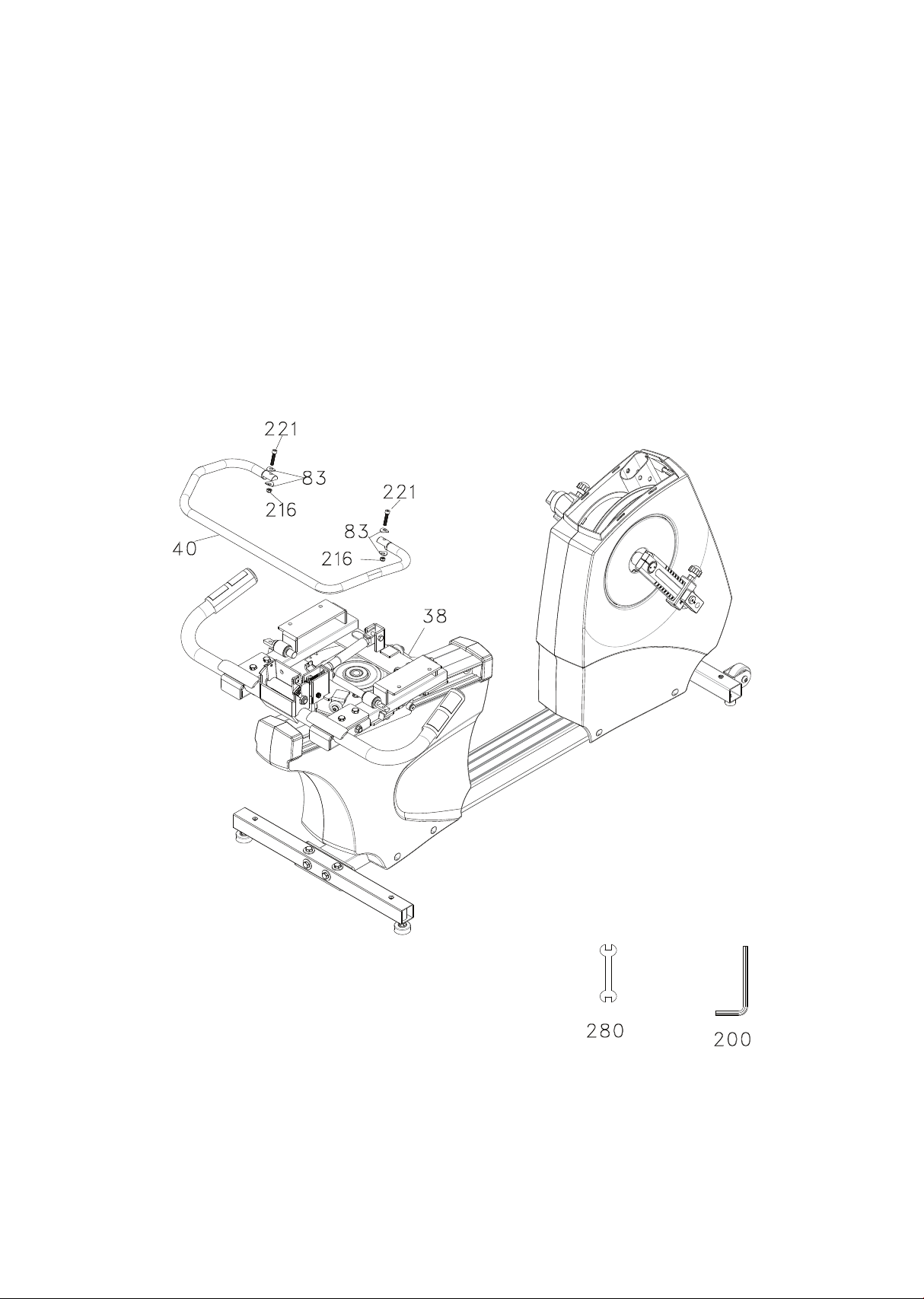
Step 2. Swivel seat release handle assembly
• Install the swivel seat release handle (40) onto the mating at area of
the solid round bars and secure with the two M6 x 40mm bolts (221),
four curved washers (83) and two M6 nuts (216).
53
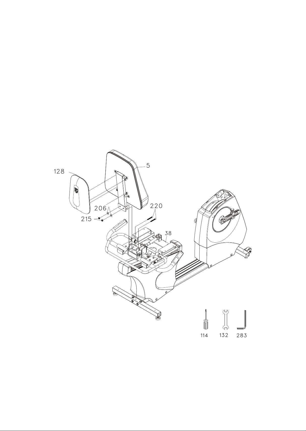
Step 3. Seat back and cover assembly
• Slide the seat back assembly (5) into the seat back angle adjustment
bracket and secure with the two 3/8” x 1-3/4” bolts (220), 3/8” washers
(206) and 3/8” nuts (215).
• Install the seat back cover (128) onto the seat back assembly (5) by
snapping into locking sockets on seat back.

54
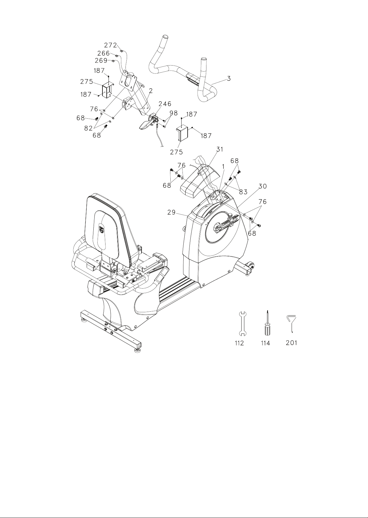
Step 4. Console mast, brake lever and handle bar assembly
• Locate the console mast cover (31) and route the computer and hand
pulse cables (266, 269, 272) and the brake lever & cable (246) through
the cover. Temporarily place the cover down on the main body of the
bike. Do not snap the cover in place yet.
• Unravel the computer and hand pulse cables (266, 269, 272) and snake
them through the Console Mast (2) until the cables exit the top open-
ing of the console mast. Be sure the brake cable (133) is in the groove
of the cover when installing the mast during the next step.
• Holding the console mast in one hand, and gently keeping tension on
the cables at the top of the mast with the other, install the Console
Mast (2) into the Main Frame receiving tube under the cover (31). Keep-
ing tension on the cables will ensure the wires don’t get caught
between the mast and receiving tube. Do not bolt the mast in place at
this time
• Install the brake lever assembly (246) on the mast with the two 6mm
Phillips screws (98). Install the covers (275) with the four 4mm screws
(187). The top screws need to be tightened with the short screw driver.
• Slide the mast cover (31) up the mast and bolt the mast in place with
six 5/16” x 5/8” Hex Head bolts (68), four 5/16” Flat Washers (76) on
the side bolts, and two 5/16” Curved Washers (83) on the front bolts.
Slide the cover down and snap in place on the main body.
• Assemble the handle bar to the mast with two 5/16” x 5/8” bolts (68),
two 5/16” split washers (82) and two 5/16” at washers (76).
55

56
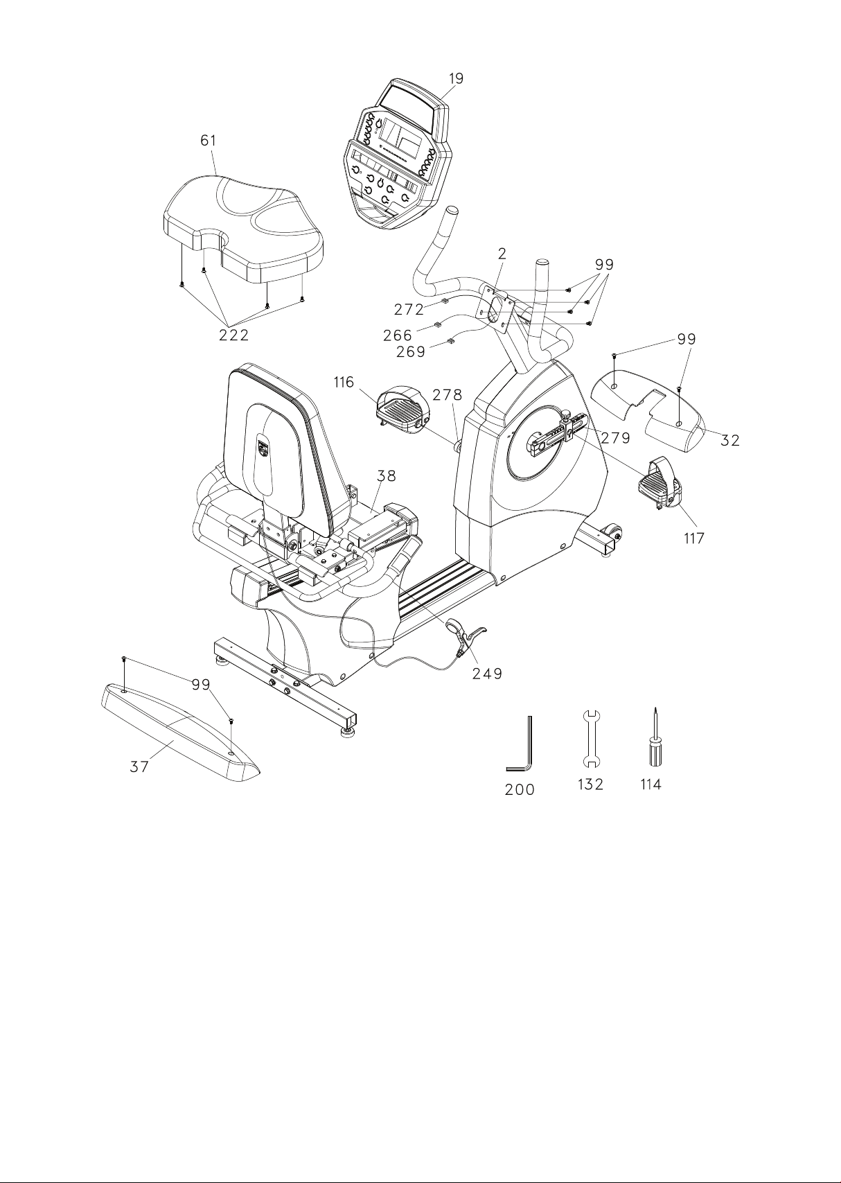
Step 5. Console, seat, pedals and covers assembly
• Install the front and rear stabilizer covers (32 & 37) with the four 5mm
screws (99).
• Install the seat cushion (61) with the four M6 x 25mm bolts (222).
• Plug in all the connectors in their mating sockets in the back of the
console. Install the console onto the mounting plate and secure with
the four 5mm screws (99). Make sure to store the excess wire into the
console mast and check that no wire is caught between the back of
the console and the mounting plate before installing and tightening
the screws. If the wires get pinched between the console and plate,
damage could occur to the electronics.
• Install the left (116) and right (117) pedals onto the crank arms. Remem-
ber that the left pedal has a reverse thread and will be screwed into
the crank in the opposite rotation from normal threads. There is an “L”
stamped into the end of the threaded post of the left pedal and an “R”
in the right. Make sure to tighten the pedals as much as you possibly
can. It may be necessary to re-tighten the pedals if you feel a thump-
ing during pedaling the bike. A noise or feeling such as a thumping or
clicking is usually caused by the pedals not being tight enough.
• Remove the Allen screws from the lever clamps (249), t them onto the
Handle Bar (6) and secure with the Allen screws. Make sure the levers
are positioned under the hand position and they are adjusted so the
patient can comfortably reach them during use. The release levers are
labeled Left and Right; the left lever with gray cable is for the fore/aft
seat adjustment and the right lever with black cable is for the seat
back angle.
57
58
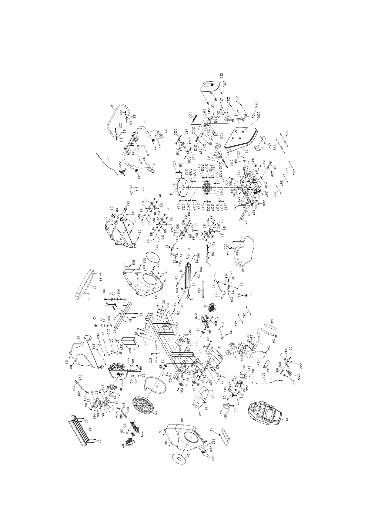
Exploded view drawing

59
7.0 R parts list
Item Qty
1
2
3
4
5
6
7
9l
9r
10
11
12
13
14
15
16
17
18
19
20
21
22
23
24
25
27
28
29
30
31
32
33
34
35
1
1
1
1
1
1
1
2
2
1
2
2
3
1
1
2
2
2
1
1
1
2
2
2
8
1
2
1
1
1
1
1
2
1
Description
Main frame
Console mAst
Handle bar, front
Seat carriage
Seat back bracket
Handle bar, rear
Rear stabilizer
Seat wheel adjustment plate (l)
Seat wheel adjustment plate (r)
Idler bracke
Axle, seat stop
Seat position latch
Backing plate
Aluminum track
Rack, seat position index
Seat assembly stop
Rubber foot, leveler
Transportation wheel
Console assembly
Drive pulley
Hand pulse sensor w/cable
Rubber foot pad
Cap, rear handle bar
End cap, front handle bar
Wheel, seat track
Hand pulse sensor w/cable (white )
End cap, crank arm
Front shroud (l)
Front shroud (r)
Cover, console mast
Cover, front stabilizer
Step cover, aluminum
Round disk, crank
Rear shroud (l)

60
Item
36
37
38
103
109
110
111
112
114
116
117
126
127
128
129
131
132
136
141
143
148
160
161
162
163
164
165
166
167
173
175
177
178
179
3/8" × 7t nut
3/8" × 2" at head socket bolt
M5 × 10mm at phillips head screw
12/14mm wrench
Phillips head screw driver
Pedal(l)
Pedal(r)
Wire grommet, hgp
5/16" × 5/8" at washer
Seat back cover
M6 nylon nut
Swivel latch bar (l)
14/15mm wrench
M5 × 20mm phillips head screw
Handle bar cover
Seat position scale, for/aft
Dummy pluG
5/16" × 5/8" at washer
M6 × 10mm at phillips head screw
1/4" × 5/8" at washer
5/8" × 13.2mm × 8mm sleeve
M6 × 19mm nut
M6 × 10mm button head socket bolt
Wheel, poly urethane
Steel cable(1100l )
M5 × 5.0t_nyloc nut
3/8" × 2-3/4" hex head bolt
Rubber foot pad
End cap, seat back tube
Ø13.5 × 60L spring
Rear shroud (r)
Cover, rear stabilizer
Swivel seat frame
Phillips head self-tapping screw, ø3.5x12
Qty
1
1
18
4
2
8
1
1
1
1
1
3
1
3
1
1
4
1
1
1
6
4
4
4
4
4
7
1
2
2
1
1
1
Description

61
180
181
185
187
188
190
191
197
198
200
201
202
203
205
206
207
208
209
213
215
216
217
220
221
222
223
225
227
228
229
230
231
232
234
Item DescriptionItem Description Qty
M6 × P1.0 × 5.0t Nut
10mm × 24mm × 3t nylon washer
M5 allen wrench
Short phillips head screw driver
5.5mm × 15mm at washer
8.5mm × 18mm at washer
8.5mm × 26mm at Washer
10mm × 25mm at washer
5/16" × Unc18 × 3/4" Hex head bolt
5/16" × Unc18 × 1-1/4" hex head bolt
M8× 16Mm hex head bolt
5/16" × Unc18 nylon nut
3/8" × Unc16 × 7t(mm) Nyloc nut
M6 × P1.0 nylon nut
M12 × P1.75 nylon nut
3/8" × Unc16 × 1-3/4" socket head cap bolt
M6 × P1.0 × 40 mm socket head cap bolt
M6 × P1.0 × 25 mm socket head cap bolt
M12 × P1.75 × 120 mm socket head bolt
M5 × P0.8 × 70 Mm phillips head screw
M8 × P1.25 × 20mm button head socket bolt
M8 × P1.25 × 25l(mm)_button head socket bolt
5/16" × Unc18 × 3/4" button head socket bolt
M5 × P0.8 lock nut
Ø16mm c-Clip
14mm × 10mm (id) × 25mm sleeve bearing
Ø16 × 66L × 13 Tension spring, idler
M10 × 1.25mm Nut
M6 × 10mm phillips head screw
M6 × 30Mm phillips head screw
M5 × 30mm phillips head screw
M5 × 6mm phillips head screw
3/8" nut
M4 × 5mm phillipS head screw
4
2
1
4
2
4
1
3
2
1
1
1
10
2
2
8
1
2
9
2
2
1
2
2
5
1
1
4
3
1
1
3
2
2

62
Item DescriptionItem Description Qty
236
237
238
239
241
242
244
245
246
247
262
263
264
266
267
268
269
270
271
272
273
274
275
276
277
280
281
282
283
284
285
286
1
1
1
4
2
1
1
1
1
1
1
1
1
1
1
1
1
1
1
1
1
1
2
1
1
1
1
1
1
2
1
1
6
2
Switching power supply
Brake controller
Ac input module
15.9mm × 22mm powder metal bearing
Scale pointer
Cover
Gas cylinder
Swivel plate assembly
Plate, mech. Brake lever
Release lever, mechanical brake
800m/m_wire brake coil h Arness(red)
950m/m_wire brake coil harness(red)
1300m/m_sensor w/cable
1950m/m_computer cable
350m/m_connecting wire, Adaptor power cord
1200m/m_connecting wire
2100mm hand pulse sensor assy. W/cable
80mm co Nnecting wire (white)
200mm ground wire
1500m/m_computer cable
800m/m hand pulse extension cable
800m/m hand pulse wire
Cover, mech. Brake
M6 × P1.0 × 57l Eye bolt
Ø1/2" × Ø26 × 2.0t(mm) Flat washer
10mm wrench
80mm connecting wire (black)
278
279
Adjustable crank arm(l)
Adjustable crank arm(r)
12 × 18m/m powder metal bushing
M8_l allen wrench
1
3/14Mm wrench
M4 × P0.7 × 12l(mm)_phillips head screw
M4 × P0.7 × 5t(mm)_nyloc nut

Item Description Qty
289
290
291
292
293
295
296
297
298
299
300
301
4
2
1
2
2
4
1
2
2
2
2
1
M4 × 3.5t(mm)_nut
M5_star washer
M8 × P1.5 × 120l(mm)_j bolt
Ø8.5 × Ø26 × 2.0t(mm)_at washer
M8 × P1.25 × 6.0t(mm)_luck nut
Ø5 × Ø12 × 1.0t(mm)_at washer
Ø8 × 1.5t(mm)_spring was Her
25mm × 50m/m_square end cap
Ø8 × Ø20 × 1t(mm)_nylon washer
Hgp wire grommet
Split washer
Ground wire (450mm,14awg)
63
287
288
4
4
Plastic stando
Ø10 × Ø25 × 0.8t(mm)_nylon washer
305
306
1
1
Snap connector, male(4.7x14x16)
Snap connector, female(5.5x20x11.9)

64
• Wipe down all areas in the sweat path with a damp cloth after each
use to prevent rust.
• Check the pedal to make sure they are tight (monthly).
• If a squeak, thump, clicking or rough feeling develops the main
cause is most likely one of two reasons:
- The hardware was not suciently tightened during assembly. All
bolts that were installed during assembly need to be tightened as
much as possible. It may be necessary to use a larger wrench than
the one provided if you cannot tighten the bolts suciently. I
cannot stress this point enough; 90% of calls to the service
department for noise issues can be traced to loose hardware.
- The crank arm nut and/or the pedals need to be retightened.
• If squeaks or other noises persist, check that the unit is properly
leveled. There are 2 leveling pads on the bottom of the rear
stabilizer, use a ½” wrench (or adjustable wrench) to adjust the
levelers.
Maintenance menu in console software
The console has built in maintenance/diagnostic software. The software
will allow you to change the console settings from English to Metric and
turn o the beeping of the speaker when a key is pressed for example. To
enter the Maintenance menu (may be called Engineering mode, depend-
ing on version) press and hold down the Start, Stop and Enter keys. Keep
holding the keys down for about 5 seconds and the message window will
display “Maintenance mode”. Press the enter button to access the menu
below:
Maintenance

65
• Key test
- Will allow you to test all the keys to make sure they are function
ing. Press all the keys one at a time.
• Display test
- Tests all the display functions by lighting each LED light
sequentially.
• Functions (press enter to access menu)
- Sleep mode
Turn on to have the console power down automatically after 20
minutes of inactivity, this is the default setting. Turn o and the
console will remain on always unless the main power switch is
turned o.
- Pause mode
Turn on allow 5 minutes of pause, turn o to have the console
pause indenitely.
- Odometer reset
Resets the odometer to zero (Time and distance)
- Units
Set to english (imperial units) or metric display readings. The
default is imperial, which means data such as bodyweight and
height will be in pounds and inches.
- Beep sound
Turn on or o the speaker to silence beeping sound.
• Security
- Allows you to lock the keypad so no unauthorized use is allowed.
When the keypad is locked press the start and enter key for 3
seconds to unlock.
• Factory settings
- Brake TestAllows you to manually change resistance levels one bit
at a time to test whether the brake is functioning properly. There
are 512 levels.

66
• Sensor test
- The bike has two sensors, one angle sensor for speed/velocity
measurements located on the brake, and one reed switch that
measures crank rotation which we use to determine crank
position.
- MW will show: ANGLE 0 REED 0
- When sensors operate correctly: rotate the crank and the Angle
reading will show pedal RPM measurement and the Reed will
change from 0 to 1 once per pedal revolution.
• Crank position cali
- Software calibration to set the position of the right pedal at 12
o’clock. Set right pedal to 6 o’clock position then press start.
- Rotate the right pedal clockwise until the console beeps.
• Watts calibration (Factory use only)
• Unit type
- Selects recumbent bike (7.0 R).
Error messages
EEPROM error: Solution for this is to replace the console (Note: this is
the only error message)
Troubleshooting
Below are common problems and basic checks to solve them. If these
tips do not solve your problem then call your local distributor for
service)
No power
• Make sure the A.C. outlet has power (90~240VAC), the line cord
plugged in securely and the power switch is on.
• Check the fuse in the Input module (located between the power
switch and line cord input).
• Make sure all connectors in back of the console are securely seated
in place.

67
Console programs do not start
• Perform Keypad test in Maintenance mode
• If you cannot access the test, and the keys seem to have no aect
when pressed, then the keypad has malfunctioned.
Program starts but no data registers when bike is pedaled
• Check that the connectors are properly seated in the back of the
consoles.
• Perform the Sensor tests in Maintenance mode. If one of the sen-
sors does not work it needs replacement. If both sensors do not
work then it could be a bad console or both sensors are bad.
Symmetry measurement is incorrect
• Perform the sensor tests in Maintenance Mode
• If sensors are functioning then perform Crank Position Calibration
• If calibration is ok then check the Unit Type is set to 7.0 R.
Pedal resistance seems harder/dierent than before
Check the watts per level setting in the Set Up menu (see page 9).
The default setting from the factory is 5 watts per level..
Cannot adjust seat fore/aft or back angle, or seat adjust-
ments will not lock in place
Adjust the thumb nuts located to the rear of the seat adjustment
levers. If the cables attached to the levers stretch it is possible the
latch for the seat will not disengage, or engage, properly. Adjusting
the thumb nut can remedy this.

68
Clicking noise when pedaling
• Make sure the pedal is tightened properly. It is common to have to
retighten the pedal after the rst few hours use.
• Make sure the adjustment knob for the pedal slide is tightened as
much as possible.
• Check that the leveling feet on the bottom of the bike are adjusted
properly.

69
Dimensions
Length : 57” (145cm)
Width : 30” (77cm)
Height : 51” (130cm)
Weight
180.1 lbs. (81.7 kg)
Resistance
Constant and Isokinetic with
50 levels of eort.
Work load
5 watts up to 750 watts.
Disposal
Reference should be made to local regulations concerning the disposal of
this product at the end of useful life.
Certications
TUV listed to ANSI/AAMI ES60601-1:2005+A2 (R2012) +A1, CAN/CSA-C22.2
No. 60601-1:14,
CE conformity to EN 60601-1 EMC, Compliance to EN 60601-1-2
Classication
Class I measuring, Type B, ordinary equipment, continuous operation. This
product is classed as ordinary equipment according to IEC/EN/UL60601-1
and is not protected against the ingress of water.
Manufacturer
Patient weight capacity
440 Lbs. (200 Kgs.)
Power
90-240V ~: 50/60 Hz: 1.76–0.71A
Fuse rating
Replace with only 5A, 250V glass
fuse.
Fast acting ψ5.2 x 20 mm.
Readouts
Time and Segment time remaining,
RPM, Watts (Left and Right), METS,
Symmetry Index, Heart Rate, Calories,
Work Level
7.0 R
Specications
70
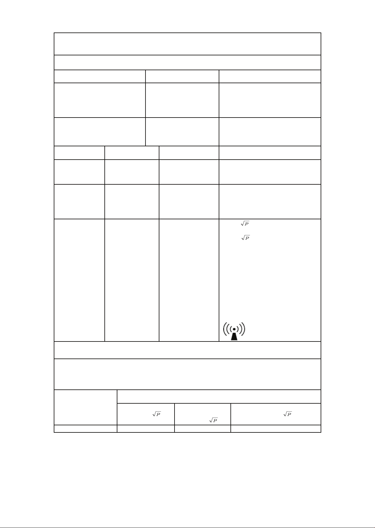
Guidance and manufacturer’s declaration –
electromagnetic compatibility
The 7.0 R is intended for use in the electromagnetic environment specied below. The customer or the
user of the 7.0 R should assure that it is used in such an environment.
Emissions test
Compliance
Electromagnetic environment –
guidance
RF emissions
CISPR 11
Group 1
The 7.0 R uses RF energy only for its
internal function. Therefore, its RF
emissions are very low and are not
likely to cause any interference in
nearby electronic equipment.
RF emissions
CISPR 11
Class B
The 7.0 R is suitable for use in all
establishments, including domestic
establishments
Immunity test
IEC 60601
test level
Compliance level
Electromagnetic environment
–
guidance
Electrostatic
discharge (ESD)
IEC 61000-4-2
6 kV contact
8 kV air
6 kV contact
8 kV air
Floors should be wood, concrete or
ceramic tile. If oors are covered with
synthetic material, the relative
humidity should be at least 30 %.
Power frequency
(50/60 Hz)
magnetic eld
IEC 61000-4-8
3 A/m
3 A/m
Power frequency magnetic elds
should be at levels characteristic of a
typical location in a typical
commercial or hospital environment.
Radiated RF
IEC 61000-4-3
3 V/m
80 MHz to 2,5 GHz
3 V/m
d = 1,2 80 MHz to 800 MHz
d = 2,3 800 MHz to 2,5 GHz
Where P is the maximum output
power rating of the transmitter in
watts (W) according to the transmitter
manufacturer and d is the
recommended separation distance in
meters (m).
Field strengths from xed RF
transmitters, as determined by an
electromagnetic site survey, a) should
be less than the compliance level in
each frequency range. B) Interference
may occur in the vicinity of equipment
marked with the following symbol:
Recommended separation distances between
portable and mobile RF communications equipment and the 7.0 R
The 7.0 R is intended for use in an electromagnetic environment in which radiated RF disturbances are
controlled. The customer or the user of the 7.0 R can help prevent electromagnetic interference by
maintaining a minimum distance between portable and mobile RF communications equipment
(transmitters) and the 7.0 R as recommended below, according to the maximum output power of the
communications equipment.
Rated maximum
output power of
transmitter
W
Separation distance according to frequency of transmitter
m
150 kHz to 80 MHz
d =
1,2
80 MHz to 800
MHz
d =
1,2
800 MHz to 2,5 GHz
d =
2,3
0,01
0,12
0,12
0,23
Dimensions
Length : 57” (145cm)
Width : 30” (77cm)
Height : 51” (130cm)
Weight
180.1 lbs. (81.7 kg)
Resistance
Constant and Isokinetic with
50 levels of eort.
Work load
5 watts up to 750 watts.
Disposal
Reference should be made to local regulations concerning the disposal of
this product at the end of useful life.
Certications
TUV listed to ANSI/AAMI ES60601-1:2005+A2 (R2012) +A1, CAN/CSA-C22.2
No. 60601-1:14,
CE conformity to EN 60601-1 EMC, Compliance to EN 60601-1-2
Classication
Class I measuring, Type B, ordinary equipment, continuous operation. This
product is classed as ordinary equipment according to IEC/EN/UL60601-1
and is not protected against the ingress of water.
Manufacturer

71
Immunity test
IEC 60601
test level
Compliance level
Electromagnetic environment
–
guidance
Electrical fast
transient/burst
IEC 61000-4-4
+/-2 kV for power
supply lines
+/-1 kV for
input/output lines
+/-2 kV for power
supply lines
+/-1 kV for
input/output lines
Mains power quality should be that
of a typical commercial or hospital
environment.
Note
• If the device is interfered by power or signal cable, image quality
may be reduced or abnormally displayed. Such kind of interference
images could be easily identied and dierentiated from the physi-
ological characteristics of patient and longer clinical time consumed
but wouldn’t have any diagnostic accuracy issue.
• If there is a certain frequency of image interference, there is a need
of isolation or ltering of the RF signal.

72
Package contains fragile electronic equipment.
Care should be used when handling.
The product inside the packaging could be easily
damaged if dropped or handled without care and
attention. The contents are fragile!
Do not use forklift truck here.
Do not use Spade truck here.
Do not use Razorback truck here.
Hand truck only.
Description
of packaging
symbols
Indicates that the package is heavy and two or more
people are required to lift.
Warning
Warning

73
Indicates that an object is capable of being recycled
- not that the object has been recycled or will be
accepted in all recycling collection systems.
Top. This side up.

70
74
Warranty
commercial
Frame
Lifetime
Drive motor
10 years
Parts
3 years
Labor
3 years
Wear items
6 months
EMS brake
5 years
Product warranty
Dyaco Commercial & Medical North America LLC (hereinafter
“Dyaco”), the manufacturer of the Philips Professional Series Physical
Therapy Products (hereinafter “Products”) warrants all of the Prod-
ucts and their components listed below for the periods of time set
out on this page below from the date of sale, as determined by sale
receipt, or in the absence of a sales receipt, eighteen (18) months
from the original factory shipping date. During the applicable war-
ranty periods, Dyaco’s responsibilities under these warranties include
providing, at no charge, new or remanufactured parts, as determined
by Dyaco at its sole and absolute discretion, and covering the cost of
labor deemed necessary by Dyaco, at its sole and absolute discretion,
to remedy faults giving rise to applicable warranty claims. The war-
ranty periods set out below are subject to the performance of proper
care and maintenance, as set out in this user manual, by the original
purchaser of the equipment. Warranties are not transferable.
* Wear items are rubber hand grips, pedals, console overlay and drive belt
Normal responsibilities of the facility
The facility is responsible for the items listed below
• The warranty registration must be completed online to validate the
manufacturer’s limited warranty.
• Proper use of the tness equipment in accordance with the instruc-
tions provided in this manual.
• Proper installation in accordance with instructions provided with
the tness equipment and with all local electric codes.

75
• Proper connection to a grounded power supply of sucient voltage,
replacement of blown fuses, repair of loose connections or defects
in house or facility wiring.
• Expenses for making the tness equipment accessible for servicing,
including any item that was not part of the tness equipment at the
time it was shipped from the factory.
• Damages to the tness equipment nish during shipping,
installation or following installation.
• Routine maintenance of this unit as specied in this manual.
Exclusions
This warranty does not cover the following:
• Consequential, collateral, or incidental damages such as property
damage and incidental expenses resulting from any breach of this
written or any implied warranty. Note: Some states do not allow the
exclusion or limitation of incidental or consequential damages, so
this limitation or exclusion may not apply to you.
• Service call reimbursement to the consumer. Service call
reimbursement to the dealer that does not involve malfunction or
defects in workmanship or material, for units that are beyond the
warranty period, for units that are beyond the service call
reimbursement period, or units not requiring component
replacement.
• Damages caused by services performed by persons other than
authorized Dyaco service companies, use of parts other than
original Dyaco parts, or external causes such as alterations,
modications, abuse, misuse, accident, improper maintenance,
inadequate power supply.
• Products with original serial numbers that have been removed or
altered.
• Products that have been; sold, transferred, bartered, or given to a
third party.
• Products that are used as store display models.
• Products that do not have a warranty registration on le at Dyaco.
Dyaco reserves the right to request proof of purchase if no warranty
record exists for the product.

• Manufacturer, distributor, or the Licensor shall not be responsible or
liable of any direct, indirect, general, special, punitive, incidental or
consequential damages; loss of or damage to property; claims of
third parties; loss of life; personal injury (including further injury, or
re-injury), and any other losses or damages of any kind or character,
arising out of or in connection with the use of Biophysical Agents by
the facilities or clinicians. The facilities or clinicians that select,
prescribe, and implement the use of Biophysical Agents will assume
the related responsibility.
• Denitions of “ Biophysical agents ” : Biophysical agents are a broad
group of agents that use various forms of energy and are intended
to assist muscle force generation and contraction; decrease
unwanted muscular activity; maintain strength after injury or sur-
gery; modulate or decrease pain; reduce or eliminate edema;
improve circulation; decrease inammation, connective tissue
extensibility, or restriction associated with musculoskeletal injury or
circulatory dysfunction; increase joint mobility, muscle performance,
and neuromuscular performance.
• Physical therapists select, prescribe, and implement the use of
biophysical agents when the examination ndings, diagnosis, and
prognosis indicate the use of these agents to reduce risk factors
and complications; enhance health, wellness, or tness; enhance or
maintain physical performance; or prevent or remediate impair-
ments in body functions and structures, activity limitations, or par-
ticipation restrictions. The use of biophysical agents in the absence
of other interventions should not be considered to be physical ther-
apy unless there is documentation that justies the necessity of
their exclusive use.
• Use of the products in any way other than described within
products’ operation manual, either intentionally or by error.
• Damages due to improper storage or transport or other causes not
solely attributable to Manufacturer.
• The exact amount of indemnication or cost arising out of breach of
this written or any implied warranty shall be fairly negotiated by
both you and Manufacturer.
• This warranty is expressly in lieu of all other warranties expressed or
implied, including the warranties of merchantability and/or tness
for a particular purpose.
76

77
Service
Keep your bill of sale. Twenty four (24) months from the date on the
bill of sale or eighteen (18) months from the date of factory shipping
as determined by the serial number establishes the warranty period
should service be required. If service is performed, it is in your best
interest to obtain and keep all receipts. This written warranty gives
you specic legal rights. You may also have other rights that vary from
state to state. Service under this warranty must be obtained by fol-
lowing these steps, in order:
• Contact your selling authorized Dyaco dealer. OR
• Contact your local authorized Dyaco service organization.
• If there is a question as to where to obtain service, contact our
service department at 1-866-869-4409.
• Dyaco’s obligation under this warranty is limited to repairing or
replacing, at Dyaco’s option, the product through one of our
authorized service centers. All repairs must be preauthorized by
Dyaco. If the product is shipped to a service center freight charges
to and from the service center will be the customer’s responsibility.
For replacement parts shipped while the product is under warranty,
the customer will be responsible for shipping and handling charges.
• The owner is responsible for adequate packaging upon return to
Dyaco. Dyaco is not responsible for damages in shipping. Make all
freight damage claims with the appropriate freight carrier. Do not
ship any unit to our factory without a return authorization number.
All units arriving without a return authorization number will be
refused.
• For any further information, or to contact our service department by
email, or phone call, and also please refer to website for additional
information:
- Consumer care service email address: [email protected]om
- Consumer care service phone number: 1-886-869-4409
Product features or specications as described or illustrated are
subject to change without notice. All warranties are made by
Dyaco Commercial & Medical North America LLC. This warranty
applies only in the 48 contiguous United States.
Note: This warranty does not apply to Alaska or Hawaii.

2019© Dyaco Commercial & Medical North America LLC. All right reserved.
The Philips trademark and the Philips Shield Emblem are registered trademarks of Koninklijke Philips N.V. used under license.
This product has been manufactured by and is sold under the responsibility of Dyaco Commercial & Medical North America LLC,
and Dyaco Commercial & Mediacl North America LLC is the warrantor in relation to this product.