User Manual
Smart Cross Trainer Magnetic Recumbent Bike with
Arm Exercisers
RB100
EN
IMPORTANT! Please retain owner’s manual for maintenance and adjustment instructions. Your
satisfaction is very important to us, PLEASE DO NOT RETURN UNTIL YOU HAVE CONTACTED US.

Important Safety Information
We thank you for choosing our product. To ensure your safety and health, please use this equipment
correctly. It is important to read this entire manual before assembling and using the equipment. Safe and
effective use can only be achieved if the equipment is assembled, maintained, and used properly. It is
your responsibility to ensure that all users of the equipment are informed of all warnings and precautions.
1. Before starting any exercise program, you should consult your physician to determine if you have any
medical or physical condition that could put your health and safety at risk or prevent you from using
the equipment properly. Your physician’s advice is essential if you are taking medication that affects
your heart rate, blood pressure or cholesterol level.
2. Be aware of your body’s signals. Incorrect or excessive exercise can damage your health. Stop
exercising if you experience any of the following symptoms: pain, tightness in your chest, irregular
heartbeat, shortness of breath, lightheadedness, dizziness, or feelings of nausea. If you do experience
any of these conditions, you should consult your physician before continuing with your exercise
program.
3. Keep children and pets away from the equipment. The equipment is designed for adult use only.
4. Use the equipment on a solid, flat level surface with a protective cover for your floor or carpet. To
ensure safety, the equipment should have at least 2 feet (60 cm) of free space all around it.
5. Ensure that all nuts and bolts are securely tightened before using the equipment. The safety of the
equipment can only be maintained if it is regularly examined for damage and/or wear and tear.
6. Always use the equipment as indicated. If you find any defective components while assembling or
checking the equipment, or if you hear any unusual noises coming from the equipment during
exercise, discontinue use of the equipment immediately and do not use until the problem has been
rectified.
7. Wear suitable clothing while using the equipment. Avoid wearing loose clothing that may become
entangled in the equipment.
8. Do not place fingers or objects into the moving parts of the equipment.
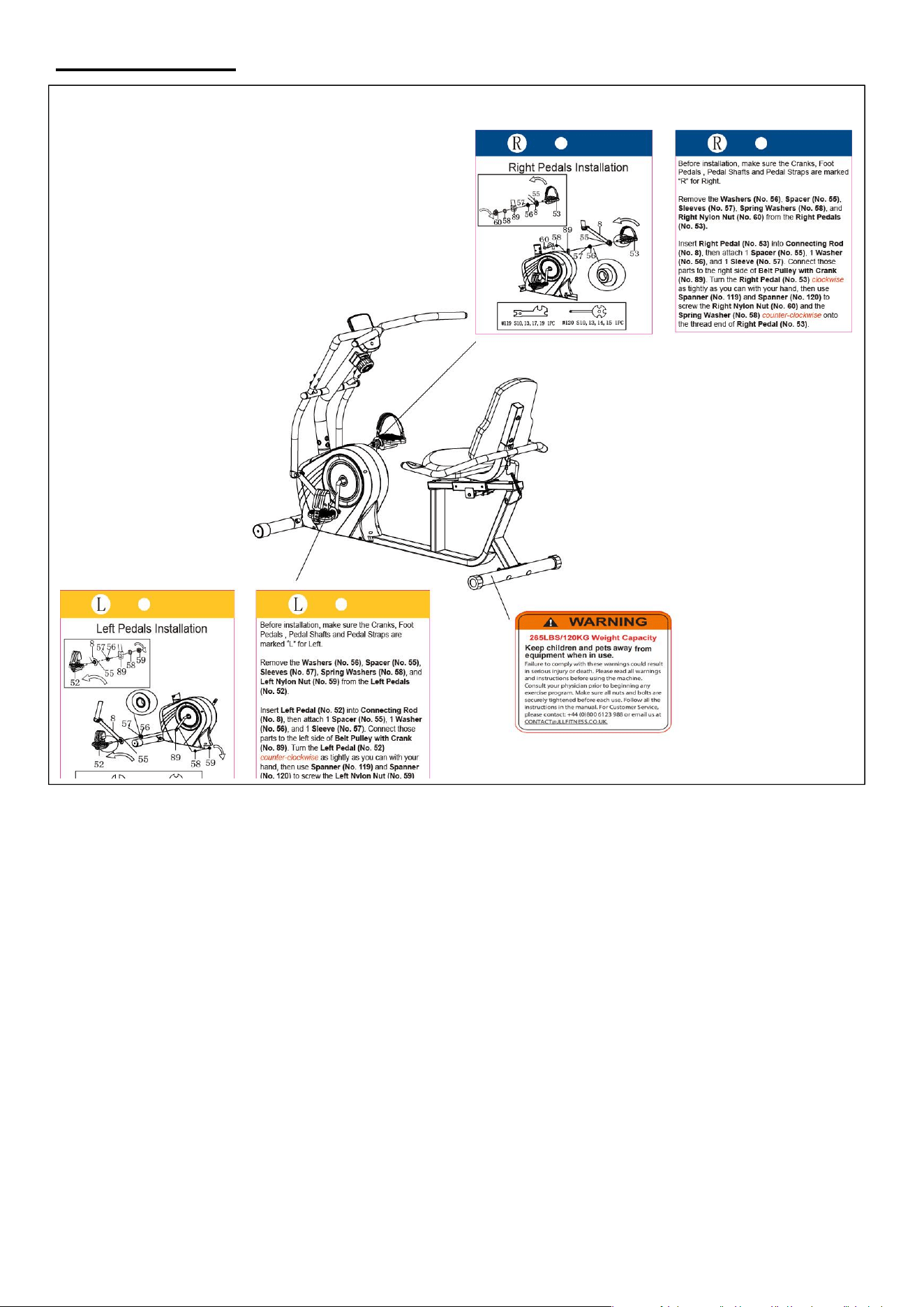
9. The maximum weight capacity of this unit is 265 lbs (120 kg).
10.The equipment is not suitable for therapeutic use.
11.To avoid bodily injury and/or damage to the product or property, proper lifting and moving are
required.
12.Your product is intended for use in cool and dry conditions. You should avoid storage in extremely cold,
hot or damp areas as this may lead to corrosion and other related problems.
13.This equipment is designed for indoor and home use only; it is not intended for commercial use.
Statement Of Purpose
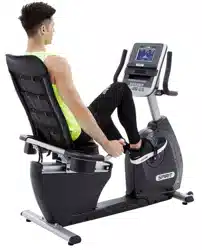
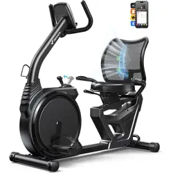
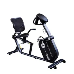
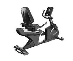
The Smart Cross Trainer Magnetic Recumbent Bike with Arm Exercisers empowers users to improve
cardio health and build full-body strength through low-impact, and joint-friendly movement.
Waste Disposal
JLL Fitness products are recyclable. At the end of its useful life please dispose of this article correctly and
safely (local refuse sites).
EU Declaration Of Conformity
You can find the declaration of conformity at the following link:
https://jllfitness.co.uk/pages/declaration-of-conformity
Technical Data
Connectivity: Bluetooth LE
Frequency Range: 2400~2483.5Mhz
Transmitting Power: 0dBm
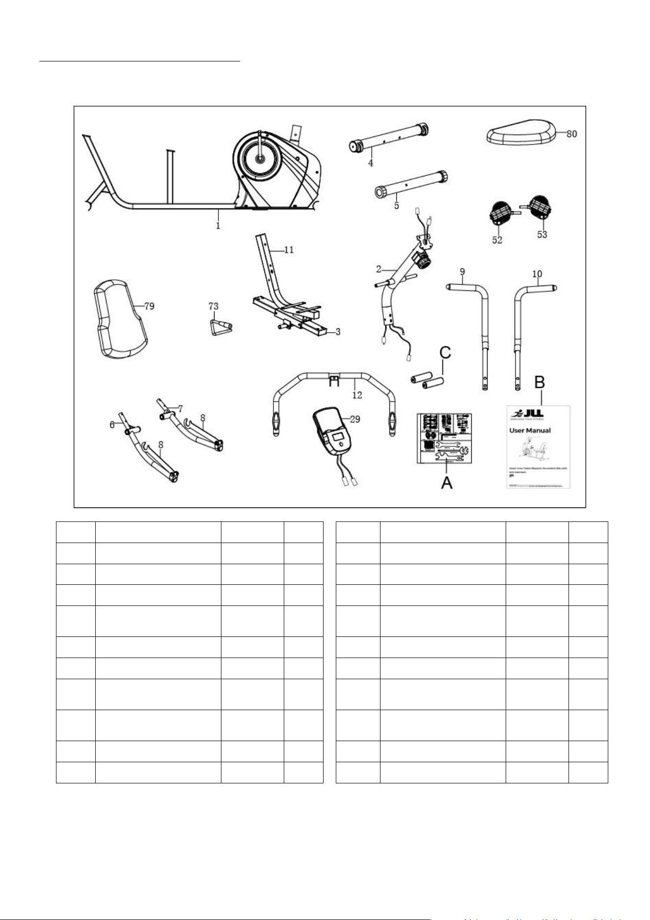
Pre-Assembly Check List
When you open the carton, you will find the following parts:
No.
Description
Spec.
Qty.
No.
Description
Spec.
Qty.
1
Main Frame
1
12
Handlebar
1
2
Front Post
1
29
Computer
1
3
Seat Adjusting Tube
1
52
Left Pedal
1
11
Seat Support
Bracket
1
53
Right Pedal
1
4
Front Stabilizer
1
73
Brake Handle
1
5
Rear Stabilizer
1
79
Backrest Cushion
1
6/8
Left Swing Tube
Assembly
1
80
Seat
1
7/8
Right Swing Tube
Assembly
1
A
Hardware Package
1
9
Left Handlebar
1
B
Manual
1
10
Right Handlebar
1
C
Battery
AAA
2
Warning Labels
Assembly Instructions
We value your experience using JLL Fitness products. For assistance with parts or troubleshooting, please
contact us at contact@jllfitness.co.uk or +44 (0)800 6123 988.
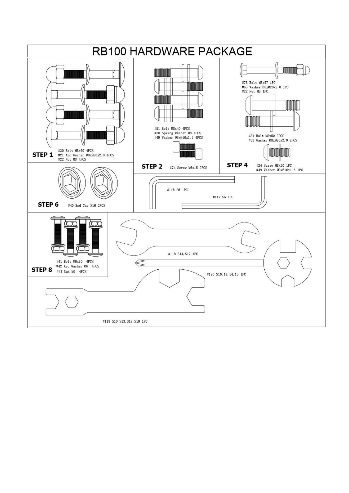
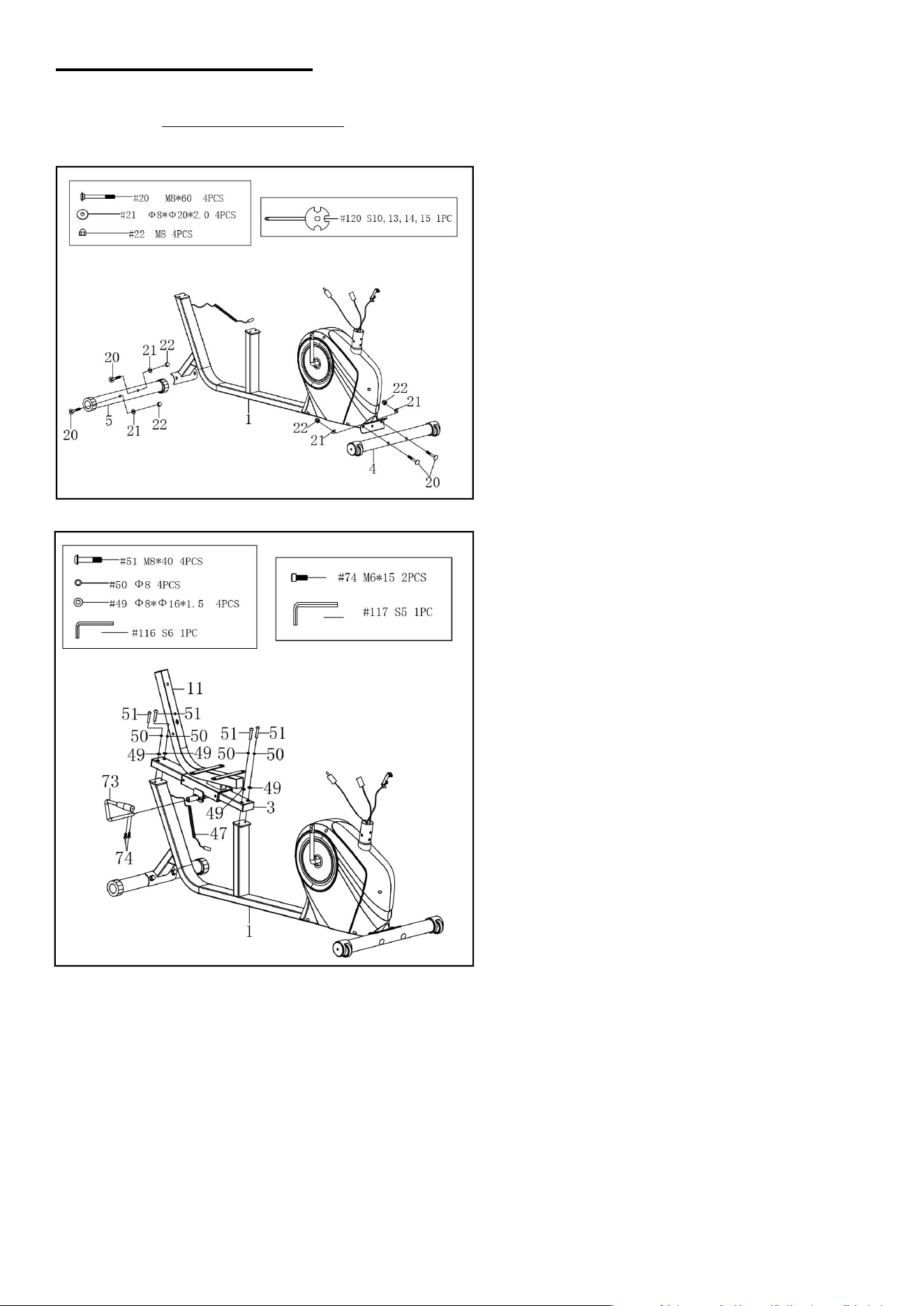
STEP 1:
Attach the Front Stabilizer (No. 4) and Rear
Stabilizer (No. 5) to the Main Frame (No. 1)
with 4 Bolts (No. 20), 4 Nuts (No. 22), and 4
Arc Washers (No. 21). Tighten and secure
with the Spanner (No. 120).
STEP 2:
Attach the Brake Handle (No. 73) to the Seat
Adjusting Tube (No. 3) with 2 Screws (No. 74).
Tighten and secure with Allen Wrench (No.
117).
CAUTION: Please move Seat Support Bracket
(No. 11) forward before assembling the Seat
Adjusting Tube (No. 3). To adjust the seat
forward or backward, press down Brake
Handle (No. 73), then slide the seat to the
desired position, lift the Brake Handle (No.
73) to tighten.
Attach the Seat Adjusting Tube (No. 3) to the
Main Frame (No. 1) with 4 Washers (No. 49), 4
Spring Washers (No. 50) and 4 Bolts (No. 51).
Tighten and secure with Allen Wrench (No.
116).
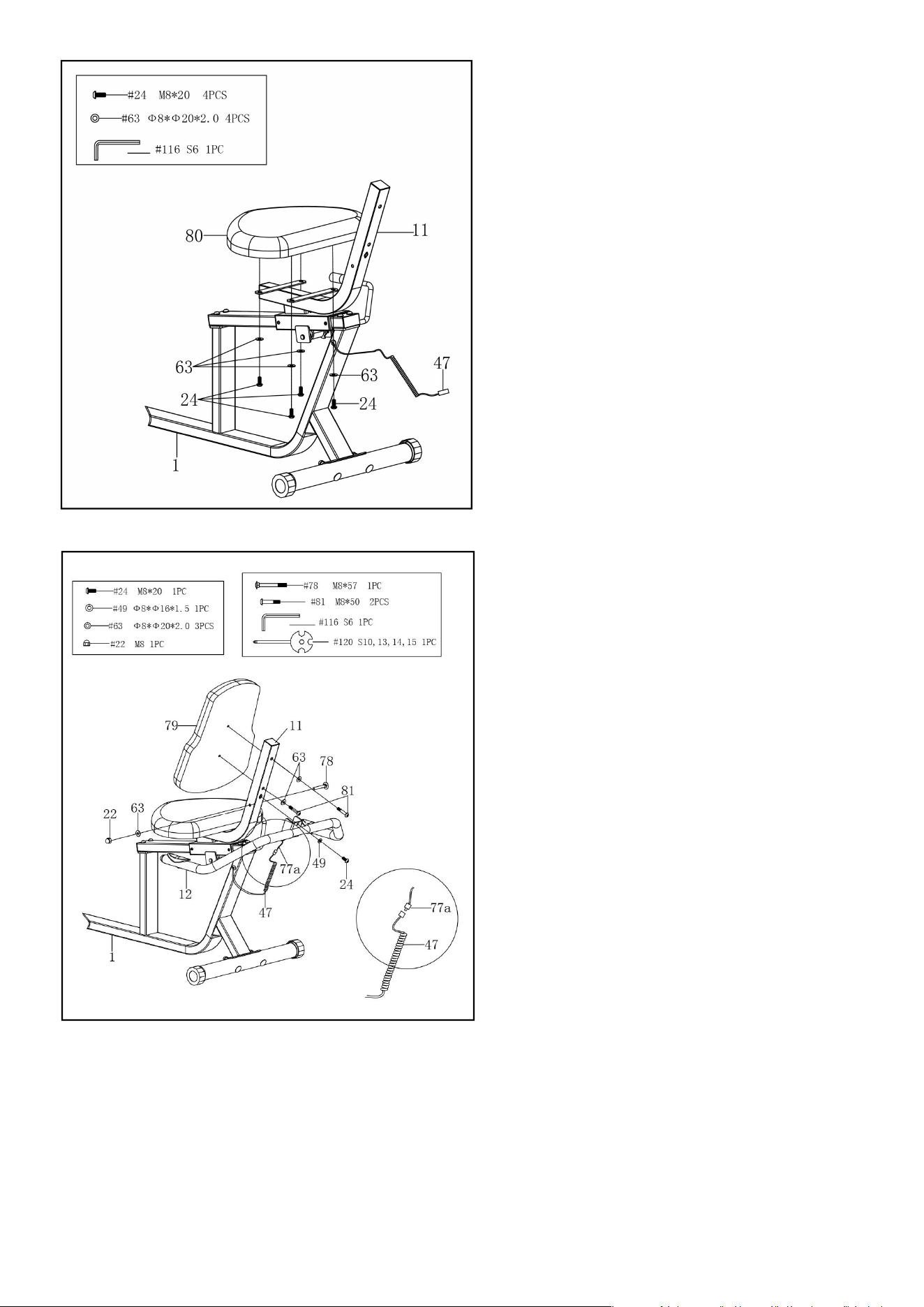
STEP 4:
Attach the Handlebar (No. 12) onto the Seat
Support Bracket (No. 11) with 1 Bolt (No. 78), 1
Washer (No. 63), 1 Nut (No. 22), 1 Screw (No. 24)
and 1 Washer (No. 49). Tighten and secure with
Spanner (No. 120) and Allen Wrench (No. 116).
Connect the Flexible Wire (No. 47) to the
Handle Pulse Wire (No. 77a).
Attach the Backrest Cushion (No. 79) to the
Seat Support Bracket (No. 11) with 2 Bolts (No.
81) and 2 Washers (No. 63). Tighten and secure
with Allen Wrench (No. 116).
STEP 3:
Remove 4 Screws (No. 24) and 4 Washers (No.
63) from Seat (No. 80) using the Allen Wrench
(No. 116).
Attach the Seat (No. 80) to the Seat Support
Bracket (No. 11) with 4 Screws (No. 24) and 4
Washers (No. 63) that were removed. Tighten
and secure with Allen Wrench (No. 116).
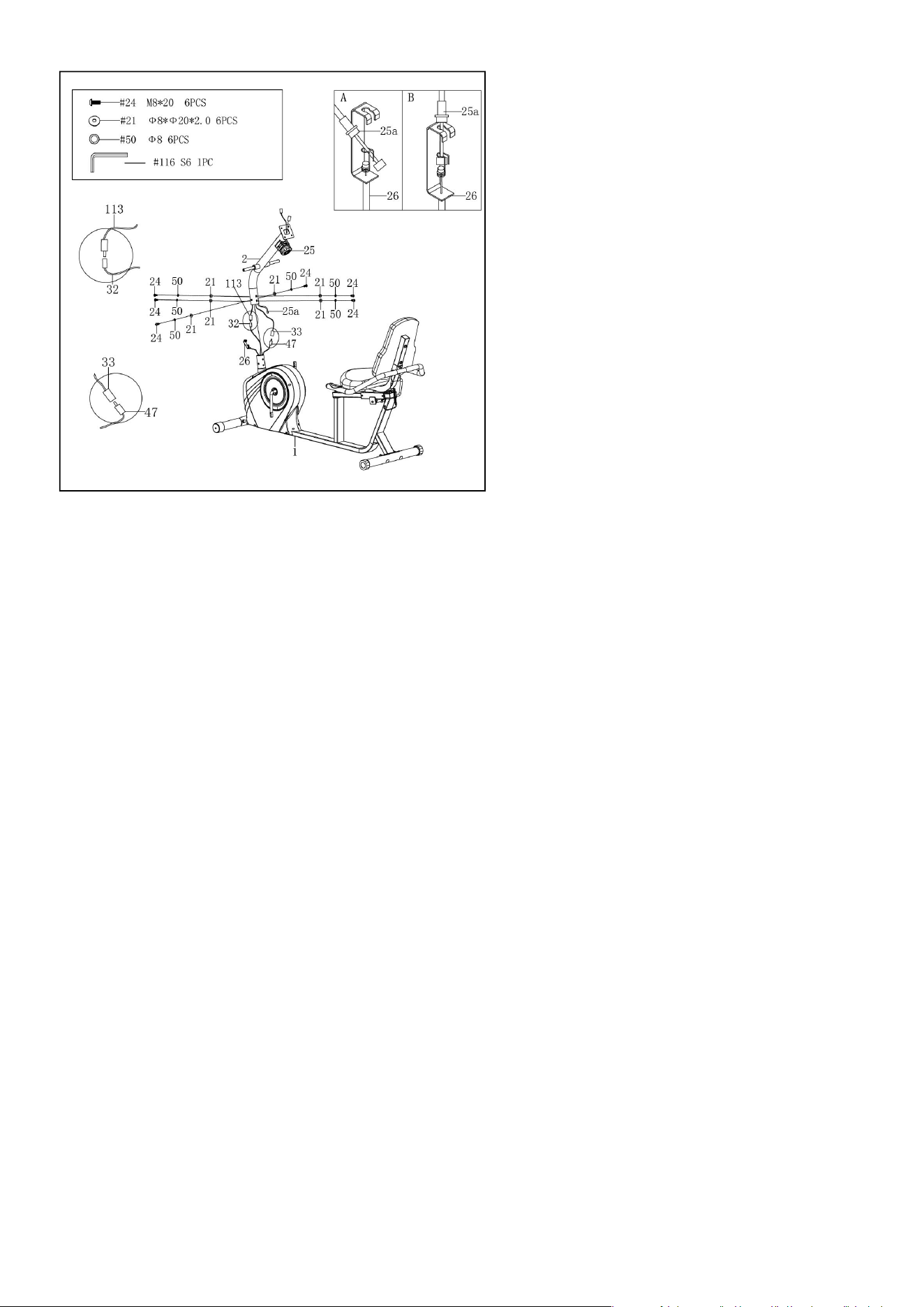
STEP 5:
Remove 6 Screws (No. 24), 6 Arc Washers (No.
21) and 6 Spring Washers (No. 50) from the
Main Frame (No. 1) with Allen Wrench (No.
116).
CAUTION: Please make sure the Tension
Control Knob (No. 25) is at the lowest
resistance level (level 1, all the way to the left)
before you connect any wires together.
Attach the Tension Control Wire (No. 25a) into
the metal bracket of Tension Wire (No. 26) as
shown in drawing A. Then, pull Tension Control
Wire (No. 25a) upward and insert it into the
slot of metal bracket of Tension Wire (No. 26)
as shown in drawing B. Make sure the metal
fitting on Tension Control Wire (No. 25a) is
secured in the metal bracket.
Connect the Handle Pulse Wire (No. 33) to
Flexible Wire (No. 47); and connect Sensor Wire
(No. 32) to the Extension Sensor Wire (No. 113).
Insert the connecting wires into Front Post (No.
2).
Attach the Front Post (No. 2) to the Main Frame
(No. 1) with 6 Screws (No. 24), 6 Arc Washers
(No. 21) and 6 Spring Washer (No. 50) that were
removed. Tighten and secure with Allen
Wrench (No. 116).
NOTE: Be careful not to pinch any wires when
attaching Front Post (No. 2) to Main Frame (No.
1)
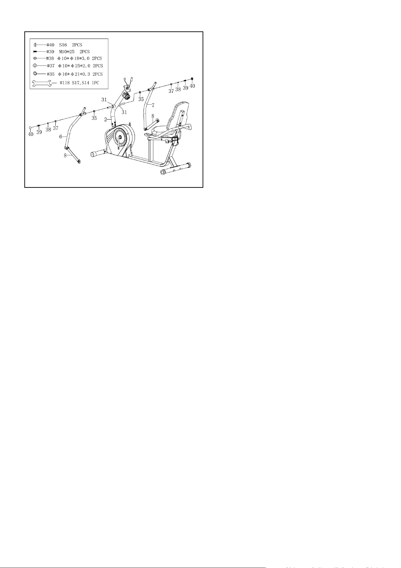
STEP 6:
Remove 2 Screws (No. 39), 2 Spring Washers
(No. 38), 2 Washers (No. 37) from the Front
Post (No. 2) with Spanner (No. 118).
NOTES: Keep 2 Wave Washers (No. 35) same
position on the Front Post (No. 2).
Attach the Left & Right Swing Tubes (No. 6 &
No. 7) to Front Post (No. 2) with 2 Screws (No.
39), 2 Spring Washers (No. 38), 2 Washers (No.
37) that were removed. Tighten and secure
with Spanner (No. 118). Then cover with 2 End
Caps (No. 40).
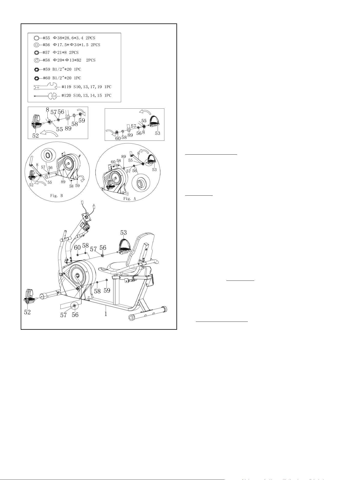
STEP 7:
Remove the 2 Washers (No. 56), 2 Spacers (No.
55), 2 Sleeves (No. 57), 2 Spring Washers (No.
58), 1 Left Nylon Nut (No. 59), and 1 Right
Nylon Nut (No. 60) from the Left & Right Pedals
(No. 52 & No. 53).
Insert Left Pedal (No. 52) into Connecting Rod
(No. 8), then attach 1 Spacer (No. 55), 1 Washer
(No. 56), and 1 Sleeve (No. 57). Connect those
parts to the left side of Belt Pulley with Crank
(No. 89). Turn the Left Pedal (No. 52)
counter-clockwise
as tightly as you can with
your hand, then use Spanner (No. 119) and
Spanner (No. 120) to screw the Left Nylon Nut
(No. 59) and the Spring Washer (No. 58)
clockwise
onto the thread end of Left Pedal
(No. 52). (See Fig. B)
Insert Right Pedal (No. 53) into Connecting
Rod (No. 8), then attach 1 Spacer (No. 55), 1
Washer (No. 56), and 1 Sleeve (No. 57).
Connect those parts to the right side of Belt
Pulley with Crank (No. 89). Turn the Right
Pedal (No. 53)
clockwise
as tightly as you can
with your hand, then use Spanner (No. 119)
and Spanner (No. 120) to screw the Right
Nylon Nut (No. 60) and the Spring Washer (No.
58)
counter-clockwise
onto the thread end of
Right Pedal (No. 53). (See Fig. A)
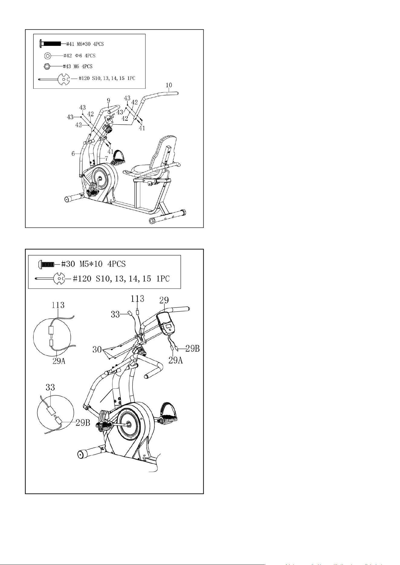
STEP 9:
Remove 4 Screws (No. 30) from the back of
the Computer (No. 29) with the Spanner (No.
120).
Connect the Extension Sensor Wire (No. 113)
to the Computer Wire A (No. 29a), Connect
the Handle Pulse Wire (No. 33) to the
Computer Wire B (No. 29B), then insert them
into the Front Post (No. 2).
Attach Computer (No. 29) to the top end of
the Front Post (No. 2) with 4 Screws (No. 30)
that were removed. Tighten and secure with
Spanner (No. 120).
The assembly is complete!
STEP 8:
Attach the Left & Right Handlebars (No. 9 &
No. 10) to the Left & Right Swing Tubes (No. 6
& No. 7) with 4 Bolts (No. 41), 4 Arc Washers
(No. 42), and 4 Nuts (No. 43). Tighten and
secure with the Spanner (No. 120).
2
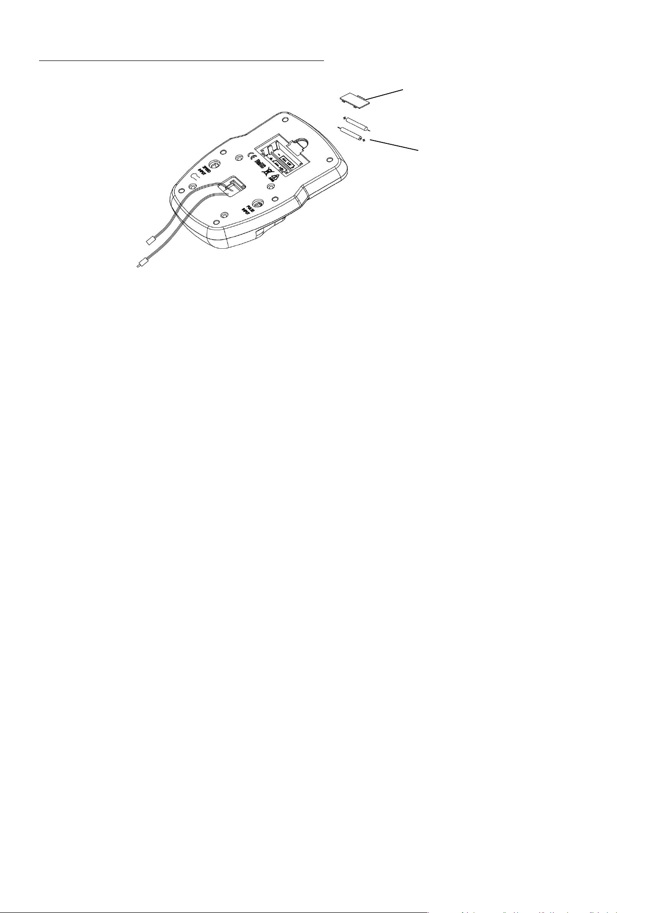
Battery Installation & Replacement
BATTERY INSTALLATION
1. Take out 2 AAA batteries from computer box.
2. Press the buckle of battery cover on the Computer (No. 29), then remove battery cover.
3. Install 2 AAA batteries into the battery case on the back of the Computer (No. 29). Pay attention to the
battery + and – poles before installing.
4. Press the buckle of battery cover, then put the battery cover back to the back of the Computer (No. 29).
The installation is complete!
BATTERY REPLACEMENT
1. Press the buckle of battery cover on the back of the Computer (No. 29), then remove battery cover.
2. Remove the 2 old AAA batteries in the battery case and install 2 new AAA batteries into the battery
case on the back of the Computer (No. 29). Pay attention to the battery + and –poles before installing.
3. Press the buckle of battery cover, then put the battery cover back to the back of the Computer (No. 29).
The replacement is complete!
BATTERY DISPOSAL
Dispose the batteries according to the laws and regulations of your local region. Some batteries may be
recycled. When disposing or recycling, do not mix battery types.
Batteries
Battery Cover
Adjustment Guide
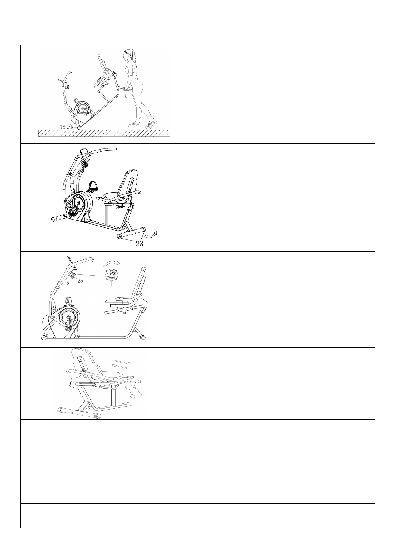
MOVING THE RECUMBENT BIKE
Lift the Rear Stabilizer (No. 5) and tilt the recumbent
bike until the transportation wheels on the Left &
Right End Caps (No. 18L/R) touch the ground. Now
you can transport the recumbent bike to the desired
location with ease.
ADJUSTING THE BALANCE
In order to achieve a smooth and comfortable ride,
you must ensure that the recumbent bike is stabled
and secured. If you notice that the recumbent bike is
unbalanced during use, you should adjust the End
Caps (No. 23) located on the rear stabilizer until the
recumbent bike becomes levelled with the floor
surface.
ADJUSTING THE TENSION
Adjust the tension by rotating the Tension Control
Knob (No. 25)
clockwise
to increase the level of
resistance. Rotate the Tension Control Knob (No. 25)
counter-clockwise
to decrease the level of resistance.
Tension levels are set at Level 1 being the lowest and
Level 8 being the highest.
ADJUSTING THE SEAT
To adjust the seat forward or backward, press down
Brake Handle (No. 73), then slide the seat to the
desired position, lift the Brake Handle (No. 73) to
tighten.
CLEANING
The recumbent bike can be cleaned with a soft, clean, damp cloth. Do not use abrasives or solvents on
plastic parts. Please wipe your perspiration off the recumbent bike after each use. Be careful not to get
excessive moisture on the computer display panel as this might cause electrical hazard or electronics to
fail. Please keep the recumbent bike, especially the computer, out of direct sunlight to prevent screen
damage. Please inspect all assembly bolts and pedals on the recumbent bike for proper tightness every
week.
STORAGE
Store the recumbent bike in a clean and dry environment, away from children.
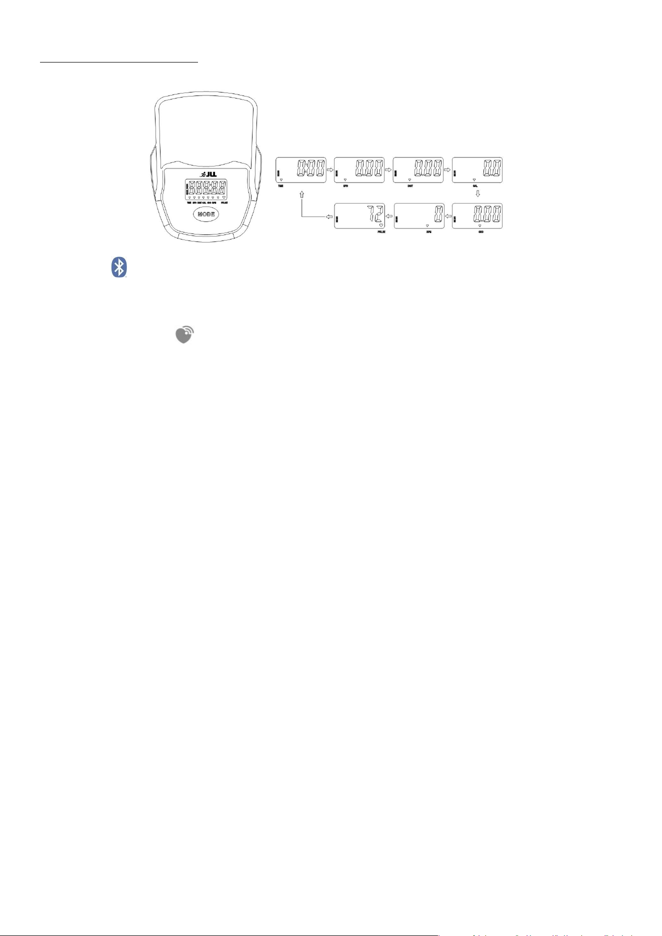
Exercise Computer
BLUETOOTH :
1. The Bluetooth icon will flash when the meter is on or wakes from sleep mode.
If no Bluetooth connection is established within 3 minutes, the Bluetooth icon
will turn off.
2. The Bluetooth icon will stay on when it is connected.
WIRELESS HEART RATE :
1. The wireless heart rate icon will flash when the meter is on. If the heart rate monitor is not connected
within 1 minute, the wireless heart rate icon will turn off.
2. After exercise resumes, the wireless heart rate icon will flash. If the heart rate monitor is not connected
within 1 minute, the wireless heart rate icon will turn off.
3. When the meter wakes from sleep mode, the wireless heart rate icon will flash. If the heart rate monitor
is not connected within 1 minute, the wireless heart rate icon will turn off.
4. The wireless heart rate icon will flash when the MODE key is pressed. If the heart rate monitor is not
connected within 1 minute, the wireless heart rate icon will turn off.
5. The wireless heart rate icon will stay on when the heart rate monitor is connected.
NOTE: The heart rate monitor is not included. Wireless heart rate function works with SunnyFit Heart Rate
Monitor HR200. HR200 can only connect to the computer when the wireless heart rate icon is flashing.
MODE:
This key lets you to select and lock on to a particular function you want. SCAN→TIME→SPD →DIST
→CAL→ ODO →RPM →PULSE.
Hold the MODE key for 2 seconds to reset all values except ODO when the Bluetooth is not
connected.
Press and hold the MODE key for 6 seconds to disconnect from both the SunnyFit APP and the heart
rate monitor; then, the meter will enter sleep mode.
SLEEP MODE
The meter will shut off automatically and disconnect the heart rate monitor if there is no activity for 4
minutes when the Bluetooth is not connected.
The system turns on when the MODE key is depressed or a signal input from the sensor.
FUNCTION
SCAN: Display changes according to the next diagram every 6 seconds.
TIME: The total working time with starting exercise.
SPEED: The current speed with starting exercise.
DISTANCE: The current distance with starting exercise.
CALORIE: The current calories burned with starting exercise.
TOTAL DIST: Counts the total distance with from start to finish. If the battery is replaced, the value
returns to zero.
RPM: The average number of turns per minute of the wheel to measure the speed of the pedal.
PULSE: The current pulse rate.
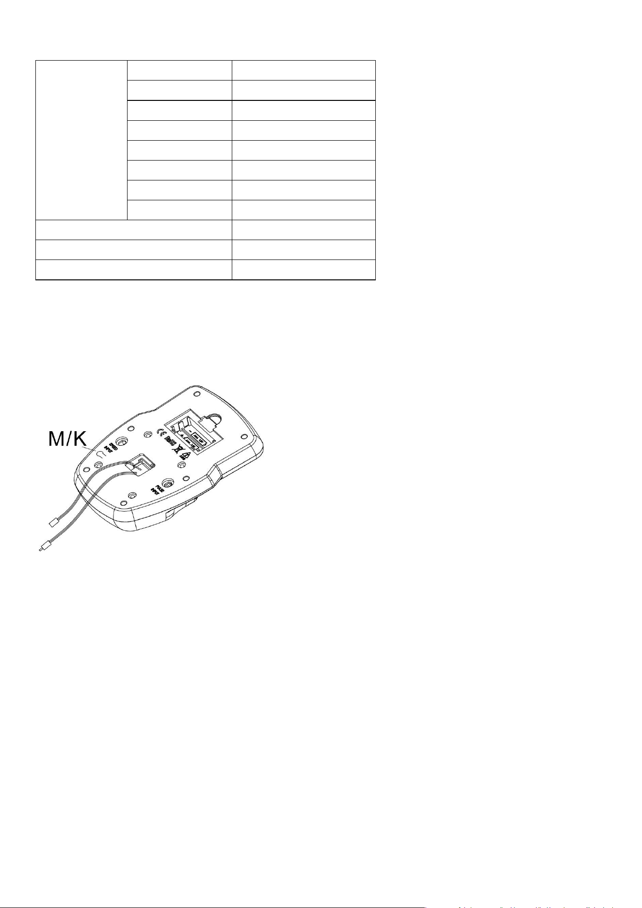
SPECIFICATIONS
UNIT CONVERTIONS FROM IMPERIAL TO METRIC SYSTEM
Pressing the button “M/K” on the back of the meter to convert Imperial/Metric System. The display will
show “K” or “M”. It's in Imperial System when “M” is displayed. It's in Metric System when “K” is displayed.
NOTE: If the bike is converted to Metric System, speed and distance will be measured in Kilometers/Hour
and Kilometers.
FUNCTION
SCAN
6 S
TIME
0:00-999:59 M:S
SPEED
0.0~999.99 M/H (KM/H)
DIST
0.0~9999.9 M/KM
ODO
0.00~9999.9 M/KM
CAL
0.0~9999.9 Kcal
RPM
0~299
PULSE RATE
40~240 BPM
BATTERY
SIZE-AAA*2
Operating temperature
0~40℃(32℉-104℉)
Storage temperature
-10~60℃(14℉-140℉)
Troubleshooting
App Connection:
CONNECT SMART EQUIPMENT TO SUNNYFIT APP:
1. Scan to download SunnyFit from the app store.
2. Ensure that the Bluetooth function is turned on from your mobile device.
3. If this is your first time using the SunnyFit app, follow the in-app instructions to register for your free
SunnyFit account and log in.
4. Begin any workout activity that matches your smart equipment, then follow the onscreen prompts to
search for and connect to your smart equipment.
5. When connected, your stats and records will be displayed at the end of your course/session, and
recorded in your account profile!
TROUBLESHOOTING:
If you are having trouble connecting your smart equipment, visit www.sunnyfit.com/guide or scan
the QR code below:
If you require additional support, please contact support@sunnyfit.com.
ISSUES
SOLUTIONS
There is no display on the computer.
1. Remove the computer and verify that the wire from
the computer is properly connected to the wire that
comes from the front post.
2. Check if the batteries are correctly positioned and
battery springs are in proper contact with batteries.
3. The batteries in the computer may be unresponsive.
Change to new batteries.
The recumbent bike wobbles when in use.
Turn the rear end caps on the rear stabilizer as needed to
level the recumbent bike.
The recumbent bike makes squeaking noise
when in use.
Some bolts on the recumbent bike might have become
loose. Please inspect all the bolts and tighten any loosened
bolts.

Parts List
No.
Description
Spec.
Qty.
No.
Description
Spec.
Qty
.
1
Main Frame
1
41
Bolt
M6*30
4
2
Front Post
Ф50*1.5*651
1
42
Arc Washer
Ф6
4
3
Seat Adjusting
Tube
1
43
Nut
M6
4
4
Front Stabilizer
1
44
Foam Grip
Ф24*Ф30*500
2
5
Rear Stabilizer
1
45
End Cap
4
6
Left Swing Tube
1
46
Plug
Ф
12.5
2
7
Right Swing Tube
1
47
Flexible Wire
L=1650mm
1
8
Connecting Rod
2
48
End Cap
2
9
Left Handlebar
1
49
Washer
Ф
8*
Ф
16*1.5
6
10
Right Handlebar
1
50
Spring Washer
Ф8
10
11
Seat Support
Bracket
1
51
Bolt
M8*40
4
12
Handlebar
1
52
Left Pedal
1
13
Brake Fixing Plate
1
53
Right Pedal
1
14
Connecting Axle
1
54
Single Thrust Bearing
2
15
Magnetic Bracket
1
55
Spacer
Φ
38*
Ф
28.6*3.4
2
16
Idler Wheel Shaft
1
56
Washer
Ф17.5*Φ34*1.5
2
17
Bearing End Cover
2
57
Sleeve
Ф21*8
2
18L
End Cap Left
1
58
Spring Washer
Ф20*Ф13*B2
2
18R
End Cap Right
1
59
Left Nylon Nut
B1/2“*20
1
19
Self-tapping Screw
ST4.2*20
4
60
Right Nylon Nut
B1/2“*20
1
20
Bolt
M8*60
4
61
Sleeve
Ф18*Ф8*10
4
21
Arc Washer
Ф8*Ф20*2.0
10
62
Bolt
M8*45
2
22
Nut
M8
5
63
Washer
Ф
8*
Ф
20*2.0
9
23
End Cap
2
64
Nut
M8
3
24
Screw
M8*20
11
65
Round End Cap
2
25
Tension Control
Knob
1
66
Bushing
2
25a
Tension Control
Wire
1
67
Self-tapping Screw
ST4.2*6
4
26
Tension Wire
L=850mm
1
68
Square End Cap
38*38*1.5
2
27
Flat Washer
Ф5
1
69
Shaft
Φ25*38
1
28
Bolt
M5*40
1
70
Limited Block
1
29
Computer
1
71
Shaft Snap Ring
Ф12*1.0
3
29A
Computer Wire A
1
72
Screw
M8*12
1
29B
Computer Wire B
1
73
Brake Handle
Ф
12*367
1
30
Screw
M5*10
4
74
Screw
M6*15
2
31
Sleeve
Ф28.6*Ф16.5*42
2
75
Pan Head Screw
M6*15
2
32
Sensor Wire
L=700mm
1
76
Foam Grip
Ф
24*
Ф
30*520
2
33
Handle Pulse Wire
L=750mm
1
77
Handle Pulse Sensor
L=750mm
2
34
Plastic sleeve
Ф
18*
Ф
28.6*21
4
77a
Handle Pulse Wire
L=750mm
1
35
Wave Washer
Ф16*Ф21*0.3
2
78
Bolt
M8*57
1
36
Shaft sleeve
Ф23.5*Ф16.2*20
4
79
Backrest Cushion
1
37
Washer
Ф10*Ф25*2.0
2
80
Seat
1
38
Spring Washer
Ф10*Ф18*3.0
2
81
Bolt
M8*50
2
39
Screw
M10*25
2
82
Plastic Lattice
1
40
End Cap
S16
2
83
Square Magnet
40*25*10
4

No.
Description
Spec.
Qty.
No.
Description
Spec.
Qty.
84
Self-tapping Screw
ST2.1*8
5
103
Screw
M6*10
7
85
Magnetic Plate Axle
Ф12*61*M6
1
104
Idler Wheel
1
86
Washer
Ф6*Ф16
4
105
PC Pad
1
87
Screw
M6*15
2
106
Screw
M8*18.5
1
88
Spring
1
107
Spring
1
89
Belt Pulley with
Crank
1
108
Left Belt Cover
1
90
Locking Washer
Ф
24*
Ф
40
1
109
Right Belt Cover
1
91
Locking Nut-Right
15/16”
1
110
Decorative Circle
2
92
Open Face Bearing
2
111
Self-tapping Drilling
Screw
ST4.2*20
5
93
Bearing Housing
2
112
Self-tapping Screw
ST4.2*25
7
94
Locking Nut–Left
7/8”
1
113
Extension Sensor
Wire
L=700mm
1
95
Locking Washer
Ф23*Ф34.5
1
114
Bolt
M6*45
1
96
Hexagon Nut
7/8”
2
115
Nut
M6
1
97
Belt
PJ330
1
116
Allen Wrench
S6
1
98
Flywheel
Ф200
1
117
Allen Wrench
S5
1
99
Bearing
Ф
28*
Ф
12*8
2
118
Spanner
S17, S14
1
100
Screw
M6*12
2
119
Spanner
S10,13,17,19
1
101
Bearing Seat
2
120
Spanner
S10,13,14,15
1
102
Washer
Ф
6*
Ф
12*1.0
7
121
Cover
Ф
40*
Ф
25*10
2
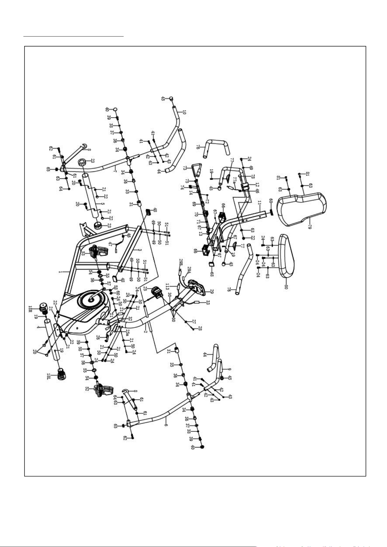
Exploded Diagram 1
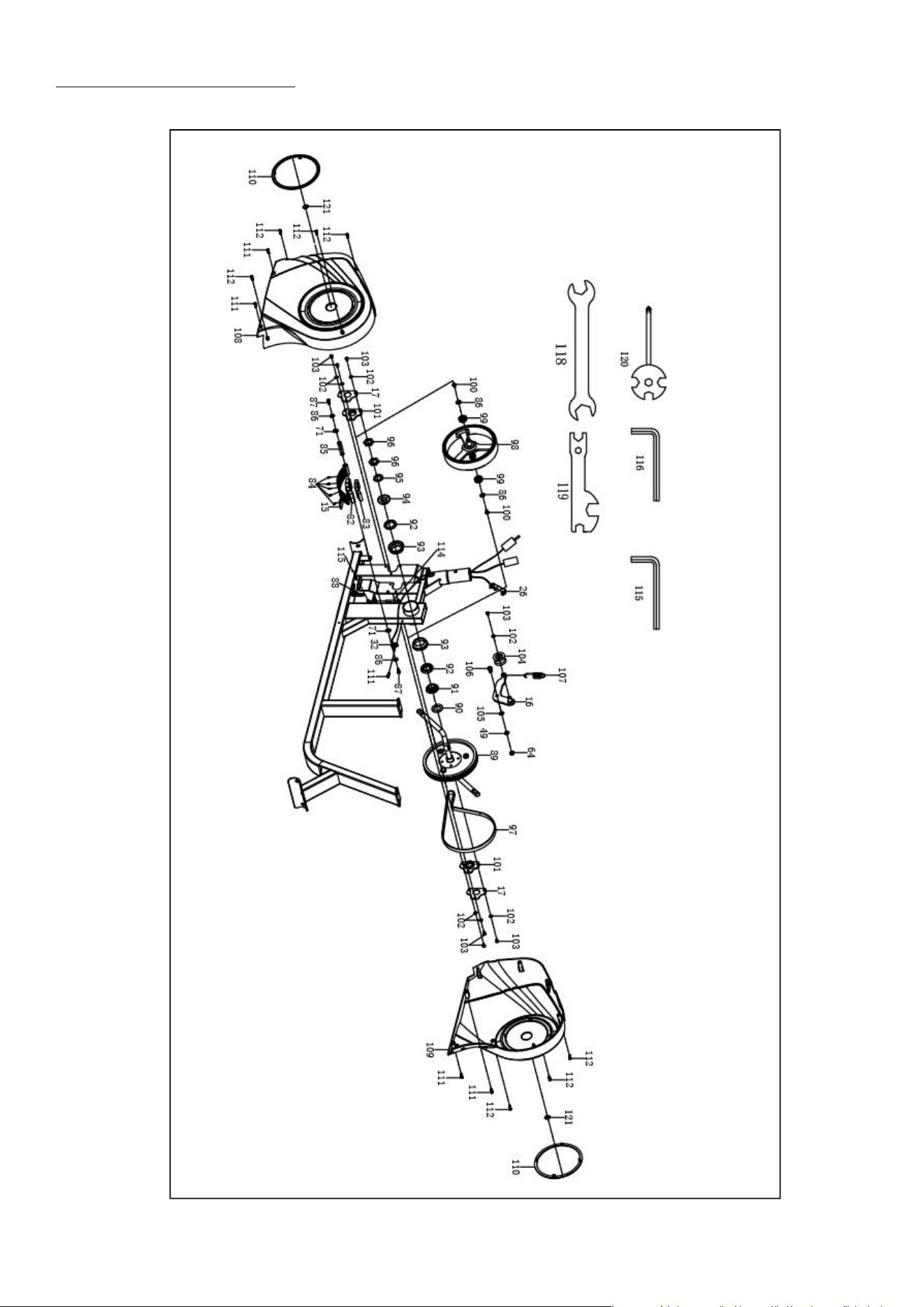
Exploded Diagram 2
Version 1.0

Register
Register your product and verify warranty terms:
jllfitness.co.uk/warranty
Download
Track your fitness progress & join FREE workout courses!
Download SunnyFit App today!
Follow
Find us on social media
Contact
Get in touch with us for any questions
www.jllfitness.co.uk