Loading ...
Loading ...
Loading ...
8
10 1/4”
1/2”
19
1/2
” - 26
9/16
” - 32
7/8
”
EN
7
7
INSTALLATION
Fitting the Hood canopy
BEFORE FITTING THE HOOD TO THE WALL UNIT, PROCEED AS FOLLOWS:
• Disconnect the wires to the Commands at the connectors.
• Disconnect the wires to the Light at the con-
nectors.
• The Hood can be installed directly on the
underside of
the wall unit (Minimum 650 mm
from the Cooker Hob).
• Create an opening in the bottom of the wall unit,
as shown.
• Insert the hood until the side supports snap into
place.
• Fasten using the 10 screws 12a provided.
• Lock in position by tightening the screws Vf from
underneath the hood.
• Open the suction panel by turning the specific knob.
• Disconnect the panel from the hood canopy by sliding the
fixing pin lever.
• Remove grease filters.
• Screw the Frame into place
using the 6 scr
ews 12f, re-
connect the wires to the
Commands and Light, re-
place the metal grease filter
and the Panel.
260
13
495 - 675
Vf
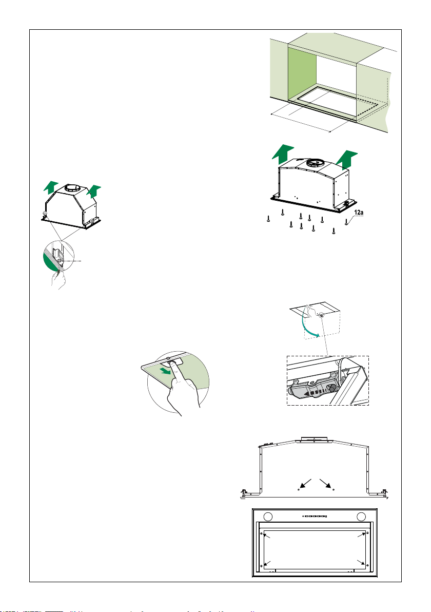
The Hood can be installed directly on the underside of the wall unit
(Minimum 24" - 30" from the Cooking Surface).
Create an opening in the bottom of the wall unit, as shown.
Insert the hood until the side supports snap into place.
Fasten using the 10 screws 12a provided.
Lock in position by tightening the screws Vf from underneath the hood.
Open the lter cover panel by turning the specic knob.
Disconnect the panel from the hood canopy by sliding the xing
pin levers.
Remove grease lters
and set aside.
Screw the Frame into place using the 6 screws
12f(1/8"x5/16" torx), reconnect the wires to the
Connector and the
Electrical ground cable (Yellow/
Green) removed previously. R
eplace the metal grease
lter and the Panel.
Loading ...
Loading ...
Loading ...