Loading ...
Loading ...
Loading ...
22
10 1/4”
1/2”
19
1/2
” - 26
9/16
” - 32
7/8
”
EN
7
7
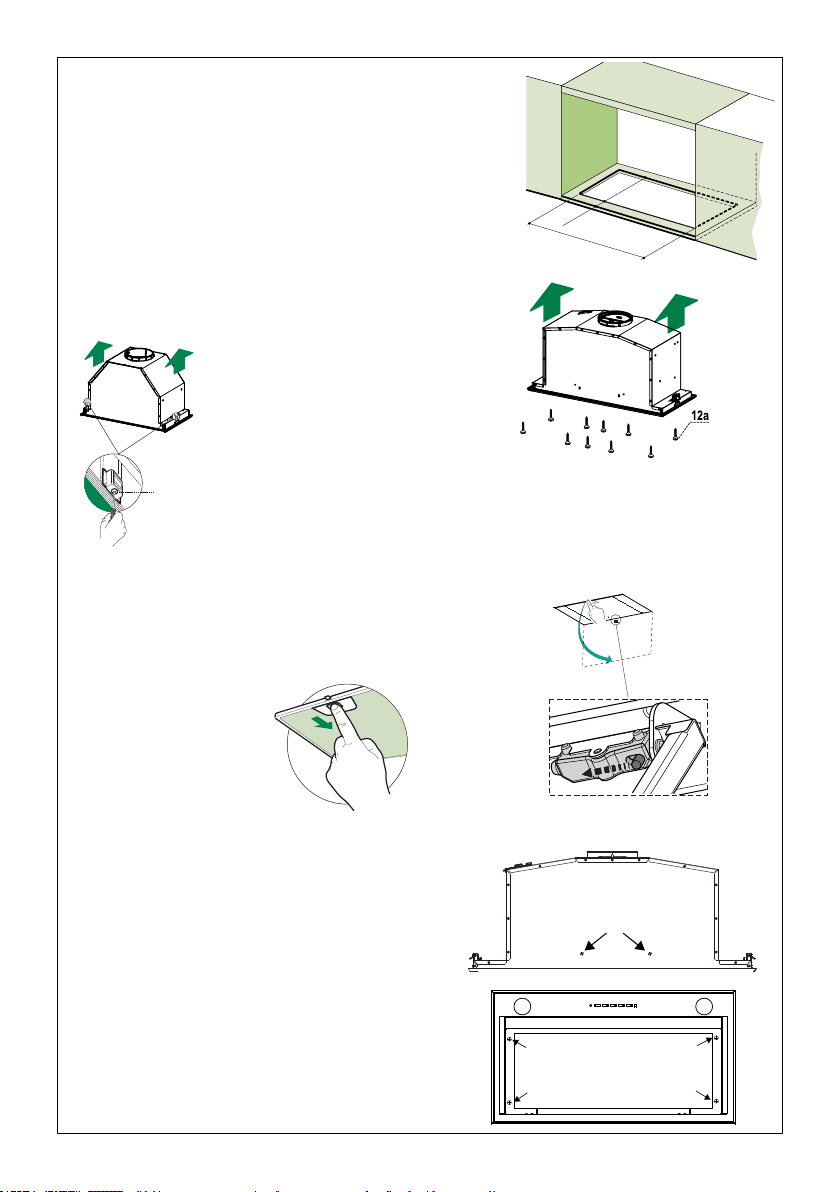
INSTALLATION
Fitting the Hood canopy
BEFORE FITTING THE HOOD TO THE WALL UNIT, PROCEED AS FOLLOWS:
• Disconnect the wires to the Commands at the connectors.
• Disconnect the wires to the Light at the con-
nectors.
• The Hood can be installed directly on the
underside of
the wall unit (Minimum 650 mm
from the Cooker Hob).
• Create an opening in the bottom of the wall unit,
as shown.
• Insert the hood until the side supports snap into
place.
• Fasten using the 10 screws 12a provided.
• Lock in position by tightening the screws Vf from
underneath the hood.
• Open the suction panel by turning the specific knob.
• Disconnect the panel from the hood canopy by sliding the
fixing pin lever.
• Remove grease filters.
• Screw the Frame into place
using the 6 scr
ews 12f, re-
connect the wires to the
Commands and Light, re-
place the metal grease filter
and the Panel.
260
13
495 - 675
EN
7
7
INSTALLATION
Fitting the Hood canopy
BEFORE FITTING THE HOOD TO THE WALL UNIT, PROCEED AS FOLLOWS:
• Disconnect the wires to the Commands at the connectors.
• Disconnect the wires to the Light at the con-
nectors.
• The Hood can be installed directly on the
underside of
the wall unit (Minimum 650 mm
from the Cooker Hob).
• Create an opening in the bottom of the wall unit,
as shown.
• Insert the hood until the side supports snap into
place.
• Fasten using the 10 screws 12a provided.
• Lock in position by tightening the screws Vf from
underneath the hood.
• Open the suction panel by turning the specific knob.
• Disconnect the panel from the hood canopy by sliding the
fixing pin lever.
• Remove grease filters.
• Screw the Frame into place
using the 6 scr
ews 12f, re-
connect the wires to the
Commands and Light, re-
place the metal grease filter
and the Panel.
260
13
495 - 675
Vf
La hotte peut être installée directement sur la face inférieure de
l'unité murale (à au moins 24" - 30" de la surface de cuisson).
Pratiquez une ouverture sur le fond de l'unité murale, comme
illustré.
Insérez la hotte jusqu'à ce que les appuis latéraux s'enclenchent.
Fixez-la à l'aide des 10 vis 12a fournies.
Verrouillez en serrant les vis Vf du dessous de la hotte.
Ouvrez le panneau de protection du ltre en tournant le bouton
requis.
Détachez le panneau de l'auvent de la hotte en faisant glisser les
leviers des chevilles de xation.
Retirez les ltres à graisse
et mettez-les à part.
Vissez le bâti en place à l'aide des 6 vis
12f(1/8"x5/16" torx), et rebranchez les câbles
au connecteur et le câble de mise à la terre
électrique (jaune/vert) retirés précédemment.
Remettez en place le ltre à graisse métallique et
le panneau.
Loading ...
Loading ...
Loading ...